EP0438140B1 - Dispositif de détection de mise au point d'une caméra - Google Patents
Dispositif de détection de mise au point d'une caméra Download PDFInfo
- Publication number
- EP0438140B1 EP0438140B1 EP91100463A EP91100463A EP0438140B1 EP 0438140 B1 EP0438140 B1 EP 0438140B1 EP 91100463 A EP91100463 A EP 91100463A EP 91100463 A EP91100463 A EP 91100463A EP 0438140 B1 EP0438140 B1 EP 0438140B1
- Authority
- EP
- European Patent Office
- Prior art keywords
- focus
- prs
- camera
- sns
- distance measurement
- Prior art date
- Legal status (The legal status is an assumption and is not a legal conclusion. Google has not performed a legal analysis and makes no representation as to the accuracy of the status listed.)
- Expired - Lifetime
Links
Images


Classifications
-
- G—PHYSICS
- G02—OPTICS
- G02B—OPTICAL ELEMENTS, SYSTEMS OR APPARATUS
- G02B7/00—Mountings, adjusting means, or light-tight connections, for optical elements
- G02B7/28—Systems for automatic generation of focusing signals
- G02B7/34—Systems for automatic generation of focusing signals using different areas in a pupil plane
- G02B7/346—Systems for automatic generation of focusing signals using different areas in a pupil plane using horizontal and vertical areas in the pupil plane, i.e. wide area autofocusing
Definitions
- This invention relates to a camera having a multifocus detecting device for detecting the defocus amounts of a plurality of object areas and effecting focus detection.
- Document DE-A 32 11 234 discloses an apparatus for detecting a focus condition of an objective lens of a single-lens reflex camera, wherein a photodetector array, comprising a plurality of different particular photosensors, is arranged to receive a central part of an object image formed by the objective lens, and a focusing condition of the objective lens is accordingly detected by calculating an evaluation function from image signals supplied from the particular photosensors of the photodetector array.
- a presetting dial is provided at such a position that a part of the dial is exposed to the outside of the camera through an opening of the rear wall, so that the user of the camera can easily select specific photosensors from among the plurality of sensors of the photodetector array.
- a corresponding light emitting diode array is provided on the focusing screen in a manner so as to be seen by the user through the view finder. During the manual selection operation only the light emitting diodes which directly correspond to the selected photosensors of the photodetector array are lighted to indicate to the user which photo sensor is selected to be used for detecting the focusing condition of the camera.
- document GB-A 2 077 448 discloses a remote control camera, wherein a device for measuring the distance between the remote control camera and a photographic object is mounted on the camera and supplies electrical signals to a read-out device enabling the camera operator to focus the camera lens with respect to the signals generated.
- the distance measuring process is performed by means of ultrasonic or infra-red waves.
- three or more distance measuring devices are provided and oriented to correspondingly partly overlapping distance measuring zones. The distance measuring results in the form of signals representing the focus state of each zone are evaluated and the two signals which represent the most similar distance measured are selected while the other signals, representing a considerable different distance are rejected.
- the selected signals are further processed and averaged to obtain a distance measuring result based on the distance measuring process related to the two selected zones. Subsequently, the lens can be adjusted from a defocus state to an in-focus position on the basis of the distance measuring result previously obtained.
- the exposure value is displayed, but in a time period that starts with the depression of the shutter release button and ends when the film winding is completed, the number of exposed film frames is displayed. That is, with a single display the operator is not only informed of two different data, but also of the fact that a specific operation (here: shutter charging and film winding) has been completed and that the camera is ready for the next take.
- a specific operation here: shutter charging and film winding
- a focus detecting device in a camera there is well known a method of causing light beams from an object area passed through the different exit pupil areas of a photo-taking lens to be imaged on a pair of line sensors, and finding the amount of displacement of the relative position of a pair of image signals obtained by photoelectrically converting an object image, to thereby detect the defocus amount of the object area. Also, in the above-described method, there have been a number of methods of preparing a plurality of sets of focus detecting systems (optical systems and sensors) to thereby detect the defocus amounts of a plurality of object areas.
- indicating means for indicating the selected area in a viewfinder to let the selected area, i.e., the focus-adjusted area, be known.
- the construction as described above is adopted, one of a plurality of areas is selected and only that area is indicated and thus, even when there are areas which exhibit defocus amounts approximate to the defocus amount in said selected area, only one area is indicated, and in spite of the fact that objects in a plurality of areas originally exhibit the same or substantially the same defocus amount and if the camera is focused on the object in one of those areas, the camera is also in focus on the objects in the other areas, the photographer becomes unable to know it. Also, when the objects in the respective areas are substantially at the same distance, the area selected changes each time the focus detecting operation is repeated, and the area indicated changes each time, and this leads to the possibility that the photographer thinks that focus detection is done unstably.
- One object of the application is to provide an indicating device which is provided with indicating means for indicating which of a plurality of distance measurement areas has been designated and in which said indicating means is driven for a predetermined time at the start of the focus detecting operation and thereafter said indicating means is driven only when an in-focus state is obtained for said designated area so that said indication may not be cumbersome to the photographer when the photographer is informed of the selected area by said indication.
- Another object of the application is to provide an indicating device in which when during the indication for a designated area during said focusing, the defocus amount in other area exhibits a defocus amount approximate to the detected defocus amount in said designated area, that area is indicated by indicating means together with the designated area.
- a further object of the application is to provide an indicating device in which when one of a plurality of areas is manually designated, the designated area is indicated by indicating means before focus detection while, on the other hand, in an auto-mode wherein one of the areas is automatically designated in conformity with the focus state, that area is indicated by the indicating means when in-focus is achieved for that area after focus detection.
- a camera provided with a focus detecting device for independently detecting a focus state of a plurality of different areas of a scene as recited in claim 1.
- Figure 1 shows the construction of a focus detecting device adopted in a focus adjusting apparatus according to the present invention.
- Figure 2 shows the arrangement when the focus adjusting apparatus according to the present invention is contained in a camera.
- Figure 3 is a circuit diagram showing an embodiment of a camera provided with the focus detecting device shown in Figure 1.
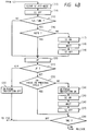
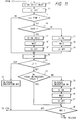
- Figures 4 and 5 are flow charts for illustrating the operation of the camera shown in Figure 3.
- Figure 6 is a plan view in which the optical paths of the viewfinder system and the illuminating system shown in Figure 2 are developed.
- Figure 7 is a side view in which the development of Figure 6 is seen from a side.
- Figure 8 shows the construction of the focusing screen shown in Figure 6.
- Figure 9 shows the construction of the indicating portion of the focusing screen shown in Figure 6.
- Figure 10 shows the construction of another example of the indicating portion in the viewfinder.
- Figure 11 is an illustration showing a modification of the flow shown in Figure 4.
- Figure 1 schematically shows the construction of a focus detecting device adopted in an automatic focus adjusting apparatus according to the present invention.
- MSK designates a field mask having a cruciform opening MSK-1 at the center thereof and vertically long openings MSK-2 and MSK-3 in the opposite marginal portions thereof.
- FLDL denotes a field lens comprising three portions FLDL-1, FLDL-2 and FLDL-3 correspondingly to the three openings MSK-1, MSK-2 and MSK-3 in the field mask.
- DP designates a diaphragm formed with two vertical and horizontal pairs of openings DP-1a, DP-1b, DP-4a and DP-4b in the central portion thereof and two pairs of openings DP-2a, DP-2b and DP-3a, DP-3b in the right and left marginal portions thereof.
- AFL denotes a secondary imaging lens comprising four pairs of lenses AFL-1a, AFL-1b, AFL-4a, AFL-4b, AFL-2a, AFL-2b, AFL-3a and AFL-3b.
- the secondary imaging lens AFL is disposed rearwardly of the diaphragm DP correspondingly to the openings in the diaphragm DP.
- SNS designates a sensor comprising four pairs of sensor arrays SNS-R, SNS-C, SNS-L and SNS-CH and disposed so as to receive the image of each secondary imaging lens AFL correspondingly thereto.
- distance measurement becomes possible even for an object whose distribution of quantity of light changes only in one direction such as the vertical or horizontal direction, and distance measurement can also be accomplished for objects lying at locations corresponding to the marginal openings MSK-2 and MSK-3 in the field mask.
- Figure 2 shows the arrangement when the focus detecting device having the focus detecting system of Figure 1 is contained in a camera.
- LNS designates a zoom photo-taking lens
- QRM denotes a quick return mirror
- FSCRN designates a focusing screen
- PP denotes a pentaprism
- EPL designates an eyepiece
- FPL denotes a film plane
- SM designates a sub-mirror
- MSK denotes a field mask
- ICF designates an infrared cut filter
- FLDL denotes a field lens
- RM1 and RM2 designate first and second reflecting mirrors, respectively
- SHMSK denotes a shield mask
- DP designates a diaphragm
- AFL denotes a secondary imaging lens
- AFP designates a prism member having a reflecting surface AFP-1 and an exit surface AFP-2
- SNS denotes a sensor having cover glass SNSCG and a light receiving surface SNSPLN.
- the prism member AFP has the reflecting surface AFP-1 formed by depositing reflecting film of a metal such as aluminum by evaporation, and has the function of reflecting a light beam from the secondary imaging lens AFL and deflecting it to the exit surface AFP-2.
- SPI designates a light emitting diode
- LNSA designates an index gradient type lens array
- LNSB denotes a light projecting lens.
- the light beam of the light emitting diode SPI is reflected on the quick return mirror QRM through the lens array LNSA and the light projecting lens LNSB, whereafter it illuminates the indicating portion on the focusing screen SCRN.
- Figure 3 is a circuit diagram showing a specific example of the construction of a camera provided with the focus detecting device as shown in Figure 1, and the construction of each portion thereof will first be described.
- PRS designates a controller for the camera, which controller is for example a 1-chip type microcomputer (hereinafter referred to as the microcomputer) having therein a CPU (central processing unit), an ROM, an RAM and the A/D converting function.
- the microcomputer PRS performs a series of operations of the camera such as the automatic exposure control function, the automatic focus adjusting function and the winding and rewinding of film in accordance with the sequence program of the camera stored in the ROM.
- the microcomputer PRS effects communications with the surrounding circuits in the camera body and the controller in the lens by the use of signals for communication SO, SI and SCLK and communication selection signals CLCM, CSDR and CDDR.
- SO is a data signal output from the microcomputer PRS
- SI is a data signal input to the microcomputer PRS
- SCLK is a synchronizing clock for the signals SO and SI.
- LCM designates a lens communication buffer circuit which supplies electric power to a power source terminal VL for the lens when the camera is operating, and which provides a communication buffer between the camera and the lens when the selection signal CLCM from the microcomputer is at a high potential level (hereinafter referred to as "H", and a low potential level will hereinafter be referred to as "L").
- H high potential level
- L low potential level
- the buffer circuit LCM When the microcomputer PRS sets the selection signal CLCM to "H” and delivers predetermined data as the signal SO in synchronism with SCLK, the buffer circuit LCM outputs the buffer signals LCK and DCL of SCLK and SO, respectively, to the lens through the communication contact between the camera and the lens. Simultaneously therewith, it outputs the buffer signal of the signal DLC from the lens LNS as the signal SI, and the microcomputer PRS inputs the signal SI as the data of the lens in synchronism with SCLK.
- DDR denotes a switch detecting and indicating circuit which is selected when signal CDDR is at "H", and is controlled from the microcomputer PRS by the use of SO, SI and SCLK.
- the circuit DDR When there is a change in the state of a switch SWS, the circuit DDR sets IRQ to "L" and informs the microcomputer PRS that there has been a change in the state of the switch.
- the microcomputer PRS communicates a switch changed state transmission command by SO, SI and SCLK and detects the changed state of the switch.
- the circuit DDR When it receives the switch changed state transmission command, the circuit DDR outputs the changed state of the switch to the microcomputer PRS and restores IRQ to "H".
- the microcomputer PRS communicates a display command and display data to the circuit DDR by the use of SO, SI and SCLK to thereby effect display control.
- the circuit DDR switches on and off an external display member DSP and transistors TR-L, TR-C and TR-R for driving the display in the viewfinder, in conformity with that command.
- SW1 and SW2 designate switches operatively associated with a release button, not shown, and the switch SW1 is closed by the first-stage depression of the release button, and the switch SW2 is closed by the second-stage depression of the release button.
- the microcomputer PRS effects photometry and automatic focus adjustment upon the closing of the switch SW1, and effects exposure control and thereafter the winding of the film with the closing of the switch SW2 as a trigger.
- the switch SW2 is connected to the "interruption input terminal" of the microcomputer PRS and thus, even when the program during the closing of the switch SW1 is being executed, interruption is applied by the closing of the switch SW2 and immediately the control can be shifted to a predetermined interruption program.
- MTR1 denotes a film feeding motor
- MTR2 designates a motor for mirror up and down and for shutter spring charge, and the forward rotation and reverse rotation thereof are controlled by their respective driving circuits MDR1 and MDR2.
- Signals M1F, M1R, M2F and M2R input from the microcomputer PRS to the driving circuits MDR1 and MDR2 are signals for controlling the motors.
- MG1 and MG2 denote magnets for starting the movement of the forward and rearward shutter curtains. These magnets are electrically energized by signals SMG1 and SMG2 and amplifying transistors TR1 and TR2, and shutter control is effected by the microcomputer PRS.
- LPRS designates a control circuit in the lens. A signal DCL input to this circuit LPRS in synchronism with LCK is command data from the camera to the photo-taking lens LNS, and the operation of the lens to the command is predetermined.
- the control circuit LPRS analyzes that command in accordance with a predetermined procedure, and effects the operations of focus adjustment and aperture control, and the outputting of the operative situations of the various portions of the lens (such as the driving situation of the focus adjusting optical system and the driven state of the diaphragm) and various parameters (such as the fully open F-number, the focal length, and the coefficient of the defocus amount vs. the amount of movement of the focus adjusting optical system) from the output DLC.
- various portions of the lens such as the driving situation of the focus adjusting optical system and the driven state of the diaphragm
- various parameters such as the fully open F-number, the focal length, and the coefficient of the defocus amount vs. the amount of movement of the focus adjusting optical system
- the microcomputer PRS which is the controller for the camera need not be concerned at all in the lens driving until the driving of the lens is terminated.
- LTMR denotes a motor for moving the focus adjusting optical system in the direction of the optic axis thereof to thereby effect focus adjustment.
- This motor LTMR is controlled by the control circuit LPRS.
- the control circuit LPRS drives a conventional stepping motor DMTR for diaphragm driving in accordance with the number of aperture steps sent thereto at the same time.
- SPC designates a photometric sensor for exposure control which receives the light from an object passed through the photo-taking lens.
- the output SSPC of the photometric sensor SPC is input to the analog input terminal of the microcomputer PRS and is A/D-converted thereby, whereafter it is used for automatic exposure control in accordance with a predetermined program.
- SDR designates a driving circuit for the focus detecting line sensor device SNS, and this driving circuit SDR is selected when signal CSDR is at "H", and is controlled from the microcomputer PRS by the use of SO, SI and SCLK.
- the output VIDEO of the sensor driving circuit SDR is an image signal amplified by a gain determined by the luminance of the object after the difference between the image signal VOUT from the sensor device SNS and a dark current output has been taken out.
- Said dark current output is the output value of a picture element in the sensor array which has been shielded from light, and the sensor driving circuit SDR retains its output in a capacitor by a signal from the microcomputer PRS, and effects the differential amplification of this output and the image signal.
- the output VIDEO is input to the analog input terminal of the microcomputer PRS, and the microcomputer PRS A/D-converts said signal and thereafter successively stores the digital value thereof into a predetermined address on the RAM.
- Signals TINTER, TINTEC, TINTEL and TINTECH are signals which are made adequate by charges accumulated in the pairs of sensor arrays SNS-R, SNS-C, SNS-L and SNS-CH, respectively, and which are indicative of the fact that the accumulation has been terminated, and in response to these signals, the microcomputer PRS executes the reading-out of the image signal.
- the operations of the sensor driving circuit SDR and the sensor device SNS are disclosed as a focus detecting device having two pairs of sensor arrays by the applicant in Japanese Laid-Open Patent Application No. 63-216905, etc. and therefore need not be described in detail herein.
- the microcomputer PRS receives the image information of the object images formed on each pair of sensor arrays, whereafter it effects a predetermined focus detection calculation and can know the defocus amount of the photo-taking lens.
- the setting of the distance measurement field automatic select mode for automatically changing over the distance measurement field is also effected.
- step (7) the ON or OFF state of a switch adapted to be closed and opened in response, for example, to the rotation of an operation dial provided externally of the camera (predetermined one of the group of switches SWS) is detected by the microcomputer PRS through the communication between the circuit DDR and the microcomputer PRS.
- an operation dial provided externally of the camera (predetermined one of the group of switches SWS)
- step (8) advance is made to the step (8) as described above.
- the central vertical sensors SNS-C, the horizontal sensors SNS-CH and the right and left sensors SNS-R and SNS-L are provided as sensors and three portions (left, central and right) are the distance measurement fields, and each time the detection of the dial operation is effected, the left, central and right sensors and all sensors are cyclically designated in succession and the designated sensors are memorized.
- the designation of all sensors means the designation of the automatic select mode.
- step (9) communication is done from the microcomputer PRS to the circuit DDR to drive transistors TRL, TRC and TRL corresponding to the sensors memorized at the step (8), and one of light emitting diodes SPIL, SPIC and SPIL corresponding to the memorized sensors is selected and turned on, thereby indicating the selected field in the viewfinder as will be described later. It is to be understood that when all sensors are designated, that is, when the mode is the automatic select mode, the light emitting diodes are maintained in their non-turned-on state.
- the distance measurement field selected by the photographer is indicated in the viewfinder as described above.
- SI indication is effected for a predetermined time to thereby effect the indication of the distance measurement field, and in the case of the automatic select mode, the indication is not effected.
- JF flag is set in the AF subroutine and here, judgment is done by the JF flag.
- step (22) If the JF flag is cleared, advance is made to a step (22), and if the JF flag is set, the program branches off to a step (23).
- SI indication corresponding to the designated distance measurement field is effected, and in the case of the automatic distance measurement field selection, SI indication corresponding to the distance measurement field determined by the automatic select routine is effected.
- Figure 5 is a flow chart showing the focus detecting operation at the step (20) of Figure 4B.
- the focus detecting operation will hereinafter be described with reference to Figure 5.
- Focus detection is effected by repetitively executing the AF routine.
- the accumulation in the sensor which has been flag-designated at the step (33) or (34) is effected and after the termination of the accumulation, the sensor signal is read in while being A/D-converted. Further, the sensor signal is corrected and converted into data suitable for focus detection.
- step (39) If the distance measurement field is automatically selected, advance is made to a step (39), and if the distance measurement field is designated, the step (39) is not executed, but the program branches off to a step (40).
- the distance measurement field is designated, whether the defocus amount of the designated distance measurement field is within the in-focus range is judged, and in the case of the automatic distance measurement field selection, whether the defocus amount of the selected distance measurement field is within the in-focus range is judged.
- step (42) the program proceeds to a step (42), and in the case of non-in-focus, the program branches off to a step (47).
- the program proceeds to a step (44), and if the distance measurement field is designated, the program proceeds to a step (49).
- the indicating flag corresponding to that distance measurement field is turned on.
- the amount of lens driving is calculated from the defocus amount of the selected distance measurement field and lens driving is effected.
- the distance measurement field is manually selected, when the switch SW1 is closed, one of the light emitting diodes SPIL, SPIC and SPIR is turned on for a predetermined time and the field selected at the steps (17), (18) and (19) is indicated in the viewfinder. Thereafter, in the AF subroutine, the defocus amount in the manually selected distance measurement field is found and whether the lens is in focus is judged on the basis of the defocus amount in that field, and if the lens is not in focus, the lens is driven by an amount corresponding to that defocus amount. Then the focus detecting operation is again repeated. During this repeated focus detection, advance is made from the step (15) to the step (20) and thus, SI indication is not effected.
- lens driving is not done but the above-described indicating operation is performed. It is to be understood that the auto focus and the manual focus mode are selected by a mode setting switch provided in the lens LNS.
- the SI indication when the switch SW1 is ON is not executed, but advance is made to the AF subroutine.
- the defocus amount of a predetermined field is selected at a step (39) and whether this selected defocus amount can be regarded as in-focus is judged at a step (41), and if it is judged as in-focus, steps (42), (43), (44) and (45) are executed.
- steps (42), (43), (44) and (45) are executed.
- steps (42), (43), (44) and (45) are executed.
- steps (42), (43), (44) and (45) are executed.
- a field which exhibits a defocus amount within a predetermined value relative to said selected defocus amount is judged.
- a Fresnel lens FSCRN-f as shown in Figure 8
- a light diffusing surface FSCRN-g as shown in Figure 8.
- an indicating member comprising three indicating portions AFMK-R, AFMK-C and AFMK-L is provided correspondingly to each distance measurement field.
- the indicating portions AFMK-R, AFMK-C and AFMK-L, as shown in Figure 9, indicate areas showing the distance measurement ranges in the photographing picture plane, and each of them is comprised of a number of prism aggregates.
- the indicating portions AFMK-R, AFMK-C and AFMK-L are disposed so that the ridgelines of the prisms constituting the indicating portions may be substantially orthogonal to the direction of the ridgeline of the Fresnel lens FSCRN-f.
- the indicating portions efficiently direct an illuminating light beam which will be described later to the eyepiece side by the refracting action of the prisms thereof and also, good observation of the indicating portions and the object image is accomplished in such a manner that ghost light created from the ridgeline of the Fresnel lens does not enter the eyepiece side.
- a light beam from the light emitting diode SPI is directed onto the quick return mirror QRM through the lens array LNSA and the light projecting lens LNSB shown in Figure 2, is reflected by the quick return mirror QRM and thereafter illuminates selected predetermined one of the indicating portions AFMK-R, AFMK-C and AFMK-L of the focusing screen FSCRN.
- the indicating portions are observed through the viewfinder system together with the object formed on the focusing screen FSCRN.
- Figures 6 and 7 are schematic views in which the optical paths of the viewfinder system and the illuminating system shown in Figure 2 are developed, Figure 6 being a plan view, and Figure 7 being a side view seen from a side thereof.
- the light projecting lens LNSB is comprised of three lens portions LNSB-R, LNSB-C and LNSB-L.
- the light projecting lens LNSB selects and illuminates any one of the three areas AFMK-R, AFMK-C and AFMK-L on the focusing screen FSCRN.
- the light projecting lens LNSB as shown in Figure 7, illuminates the focusing screen FSCRN from an oblique direction at an angle ⁇ .
- the indicating portions AFMK-R, AFMK-C and AFMK-L on the focusing screen FSCRN illuminated by the light projecting lens LNSB are each comprised of an aggregate of a number of prisms, and refract the illuminating light which has entered each prism to thereby direct it toward the eyepiece EPL. Thereby it accomplishes bright indication.
- one of the indicating portions AFMK-R, AFMK-C and AFMK-L is selectively illuminated by the light emitting diodes SPI-R, SPI-C, SPI-L and the light projecting lens LNSB, whereby it is made possible that the currently selected distance measurement field is indicated, for example, in red and the other fields are indicated in black.
- the selected field or the in-focus field is superimpose-indicated in the viewfinder together with the object image by the above-described operation.
- Figure 10 shows another example of the SI indication in the viewfinder.
- Distance measurement frame designating LEDs AFLED-R, AFLED-C and AFLED-L are provided below the distance measurement frames AFMK-R, AFMK-C and AFMK-L, respectively, within the viewfinder so that they may be indicated by the above-described SI indication operation.
- Figure 11 is a flow chart showing another example of the flow chart of the automatic focus adjusting apparatus of the present invention shown in Figures 4A and 4B.
Landscapes
- Physics & Mathematics (AREA)
- General Physics & Mathematics (AREA)
- Optics & Photonics (AREA)
- Focusing (AREA)
- Automatic Focus Adjustment (AREA)
Claims (6)
- Appareil photographique comprenant:un dispositif (SNS, SDR, PRS) de détection de foyer pour détecter indépendamment l'état de focalisation d'une pluralité de différentes zones (SNS-C, SNS-L, SNS-R, SNS-CH) d'une scène,un circuit de désignation (PRS) pour désigner une zone prédéterminée de ladite pluralité de zones afin d'effectuer un réglage de focalisation en fonction de l'état de focalisation de ladite zone désignée,un circuit indicateur (DDR, SPIL, SPIC, SPIR) pour indiquer à l'opérateur ladite zone désignée dans un dispositif d'affichage (DSP), ledit dispositif d'affichage effectuant un affichage dans un viseur,un moyen (PRS) de commande d'affichage pour commencer l'opération d'affichage de ladite zone désignée par ledit circuit indicateur en fonction d'une opération d'un élément opérationnel de l'appareil photographique et pour effectuer ladite opération d'affichage pendant un laps de temps prédéterminé, et pour arrêter ensuite ladite opération d'affichage par ledit circuit indicateur, etun moyen (PRS) de commande d'une opération de détection de foyer pour conduire ledit dispositif de détection de foyer à détecter ledit état de focalisation de ladite zone désignée en fonction de ladite opération dudit élément opérationnel dudit appareil photographique,dans lequel ledit moyen de commande d'affichage est agencé pour effectuer à nouveau ladite opération d'affichage de ladite zone désignée par ledit circuit indicateur lorsque ledit état de focalisation de ladite zone désignée est détecté comme un état de focalisation par ledit dispositif de détection de foyer.
- Appareil photographique selon la revendication 1, dans lequel ledit circuit de désignation (PRS) désigne une zone par l'actionnement d'un élément (SWS) à actionnement manuel.
- Appareil photographique selon la revendication 1, dans lequel ledit dispositif (SNS, SDR, PRS) de détection de foyer exécute de manière répétitive l'opération de détection de foyer par l'actionnement d'un élément opérationnel de libération et ledit moyen de commande (PRS) conduit ledit circuit indicateur (DDR; SPIL, SPIC, SPIR) à indiquer une zone désignée par ledit circuit de désignation (PRS) avant que la première opération de détection de focalisation soit commencée pour un temps prédéterminé.
- Appareil photographique selon la revendication 1, dans lequel ledit moyen de commande (PRS) conduit le circuit indicateur (DDR, SPIL, SPIC, SPIR) à indiquer un état de focalisation pour un temps prédéterminé.
- Appareil photographique selon la revendication 4, dans lequel ledit moyen de commande (PRS) conduit le circuit indicateur (DDR, SPIL, SPIC, SPIR) à indiquer l'état de focalisation chaque fois que l'état de focalisation détecté par le dispositif (SNS, SDR, PRS) de détection de foyer varie entre un état de défocalisation et un état de focalisation.
- Appareil photographique selon la revendication 1, dans lequel ledit dispositif d'affichage effectue un affichage superposé à l'intérieur du cadre du viseur.
Applications Claiming Priority (4)
| Application Number | Priority Date | Filing Date | Title |
|---|---|---|---|
| JP8708/90 | 1990-01-17 | ||
| JP8707/90 | 1990-01-17 | ||
| JP2008707A JPH03212633A (ja) | 1990-01-17 | 1990-01-17 | 焦点検出装置を有するカメラ |
| JP870890A JPH03212605A (ja) | 1990-01-17 | 1990-01-17 | 焦点検出装置 |
Publications (2)
| Publication Number | Publication Date |
|---|---|
| EP0438140A1 EP0438140A1 (fr) | 1991-07-24 |
| EP0438140B1 true EP0438140B1 (fr) | 1996-05-29 |
Family
ID=26343277
Family Applications (1)
| Application Number | Title | Priority Date | Filing Date |
|---|---|---|---|
| EP91100463A Expired - Lifetime EP0438140B1 (fr) | 1990-01-17 | 1991-01-16 | Dispositif de détection de mise au point d'une caméra |
Country Status (3)
| Country | Link |
|---|---|
| US (1) | US5307112A (fr) |
| EP (1) | EP0438140B1 (fr) |
| DE (1) | DE69119795T2 (fr) |
Families Citing this family (7)
| Publication number | Priority date | Publication date | Assignee | Title |
|---|---|---|---|---|
| JP3259996B2 (ja) * | 1992-12-03 | 2002-02-25 | キヤノン株式会社 | カメラ |
| US5701524A (en) * | 1993-10-29 | 1997-12-23 | Nikon Corporation | Focus detection device and focus detection method |
| JPH07301742A (ja) * | 1994-05-06 | 1995-11-14 | Nikon Corp | カメラ |
| US6088539A (en) * | 1997-12-24 | 2000-07-11 | Canon Kabushiki Kaisha | Optical apparatus with focus adjusting function and focus adjustment control circuit |
| US6812968B1 (en) | 1998-12-31 | 2004-11-02 | Lucent Technologies Inc. | Camera with configurable focus area |
| US7544919B2 (en) | 2006-11-20 | 2009-06-09 | Red.Com, Inc. | Focus assist system and method |
| US9690168B2 (en) | 2006-11-20 | 2017-06-27 | Red.Com, Inc. | Focus assist system and method |
Citations (2)
| Publication number | Priority date | Publication date | Assignee | Title |
|---|---|---|---|---|
| US4298257A (en) * | 1977-12-22 | 1981-11-03 | Canon Kabushiki Kaisha | Display device for camera |
| EP0325229A2 (fr) * | 1988-01-19 | 1989-07-26 | Minolta Co., Ltd. | Système d'indication pour caméra |
Family Cites Families (10)
| Publication number | Priority date | Publication date | Assignee | Title |
|---|---|---|---|---|
| GB2077448A (en) * | 1980-04-18 | 1981-12-16 | Samuelson Film Service Ltd | Remote control camera |
| JPS57161708A (en) * | 1981-03-28 | 1982-10-05 | Olympus Optical Co Ltd | Focusing detector having variable visual field of detection |
| US4575212A (en) * | 1982-12-28 | 1986-03-11 | Minolta Camera Kabushiki Kaisha | Camera with an improved focus detecting system |
| JPS59129809A (ja) * | 1983-01-18 | 1984-07-26 | Asahi Optical Co Ltd | カメラの自動焦点装置 |
| US4827303A (en) * | 1983-02-08 | 1989-05-02 | Canon Kabushiki Kaisha | Distance measuring device |
| JPS6030971A (ja) * | 1983-07-29 | 1985-02-16 | 三菱電機株式会社 | 冷凍装置のス−パヒ−ト検出器 |
| US4746947A (en) * | 1985-02-25 | 1988-05-24 | Minolta Camera Kabushiki Kaisha | Exposure calculating device |
| JPS63246712A (ja) * | 1986-05-16 | 1988-10-13 | Minolta Camera Co Ltd | 焦点検出装置 |
| US4812912A (en) * | 1986-05-26 | 1989-03-14 | Minolta Camera Kabushiki Kaisha | Focus detection condition display device for camera |
| GB2222337B (en) * | 1988-08-25 | 1992-12-16 | Asahi Optical Co Ltd | Automatic focusing camera |
-
1991
- 1991-01-16 EP EP91100463A patent/EP0438140B1/fr not_active Expired - Lifetime
- 1991-01-16 DE DE69119795T patent/DE69119795T2/de not_active Expired - Fee Related
-
1992
- 1992-06-29 US US07/905,233 patent/US5307112A/en not_active Expired - Lifetime
Patent Citations (2)
| Publication number | Priority date | Publication date | Assignee | Title |
|---|---|---|---|---|
| US4298257A (en) * | 1977-12-22 | 1981-11-03 | Canon Kabushiki Kaisha | Display device for camera |
| EP0325229A2 (fr) * | 1988-01-19 | 1989-07-26 | Minolta Co., Ltd. | Système d'indication pour caméra |
Also Published As
| Publication number | Publication date |
|---|---|
| US5307112A (en) | 1994-04-26 |
| DE69119795D1 (de) | 1996-07-04 |
| EP0438140A1 (fr) | 1991-07-24 |
| DE69119795T2 (de) | 1997-01-09 |
Similar Documents
| Publication | Publication Date | Title |
|---|---|---|
| US5091742A (en) | Camera having an auto focusing device | |
| US5485239A (en) | Camera incorporating an auto-zoom function | |
| EP0438116B1 (fr) | Appareil de détection de mise au point | |
| US5198856A (en) | Camera having camera-shake detecting device | |
| US5909598A (en) | Viewfinder display device | |
| US5604562A (en) | Auto-zoom camera | |
| US5293194A (en) | Focus detection apparatus having an auxiliary light | |
| EP0438140B1 (fr) | Dispositif de détection de mise au point d'une caméra | |
| US5669022A (en) | Optical apparatus including a light modulation finder optical system | |
| US5585882A (en) | Focus detecting apparatus detecting focus to a plurality of areas | |
| US6118943A (en) | Camera | |
| US5194888A (en) | Camera with focus and hand trembling detecting apparatus | |
| JP3352453B2 (ja) | カメラ | |
| EP0653655B1 (fr) | Appareil d'ajustage de mise au point | |
| JP2974637B2 (ja) | 自動焦点調節装置 | |
| JP3294636B2 (ja) | オートフォーカスカメラ | |
| JPH06138378A (ja) | 焦点検出手段と視線検出手段とを有したカメラ | |
| JPH01288816A (ja) | 自動焦点調節装置 | |
| JP2756333B2 (ja) | 自動焦点調節装置 | |
| JPH086184A (ja) | 撮影装置 | |
| JP2771005B2 (ja) | 自動焦点調節装置 | |
| JP2663653B2 (ja) | 焦点検出装置 | |
| JPH06148510A (ja) | 視線検出機能付カメラ | |
| JP2832054B2 (ja) | 焦点検出装置 | |
| JPH03214130A (ja) | カメラ |
Legal Events
| Date | Code | Title | Description |
|---|---|---|---|
| PUAI | Public reference made under article 153(3) epc to a published international application that has entered the european phase |
Free format text: ORIGINAL CODE: 0009012 |
|
| AK | Designated contracting states |
Kind code of ref document: A1 Designated state(s): DE FR GB |
|
| 17P | Request for examination filed |
Effective date: 19911213 |
|
| 17Q | First examination report despatched |
Effective date: 19931222 |
|
| GRAA | (expected) grant |
Free format text: ORIGINAL CODE: 0009210 |
|
| STAA | Information on the status of an ep patent application or granted ep patent |
Free format text: STATUS: THE PATENT HAS BEEN GRANTED |
|
| AK | Designated contracting states |
Kind code of ref document: B1 Designated state(s): DE FR GB |
|
| REF | Corresponds to: |
Ref document number: 69119795 Country of ref document: DE Date of ref document: 19960704 |
|
| ET | Fr: translation filed | ||
| GRAH | Despatch of communication of intention to grant a patent |
Free format text: ORIGINAL CODE: EPIDOS IGRA |
|
| PLBE | No opposition filed within time limit |
Free format text: ORIGINAL CODE: 0009261 |
|
| 26N | No opposition filed | ||
| REG | Reference to a national code |
Ref country code: GB Ref legal event code: IF02 |
|
| PGFP | Annual fee paid to national office [announced via postgrant information from national office to epo] |
Ref country code: DE Payment date: 20090131 Year of fee payment: 19 |
|
| PGFP | Annual fee paid to national office [announced via postgrant information from national office to epo] |
Ref country code: GB Payment date: 20090127 Year of fee payment: 19 |
|
| PGFP | Annual fee paid to national office [announced via postgrant information from national office to epo] |
Ref country code: FR Payment date: 20090121 Year of fee payment: 19 |
|
| GBPC | Gb: european patent ceased through non-payment of renewal fee |
Effective date: 20100116 |
|
| REG | Reference to a national code |
Ref country code: FR Ref legal event code: ST Effective date: 20100930 |
|
| PG25 | Lapsed in a contracting state [announced via postgrant information from national office to epo] |
Ref country code: FR Free format text: LAPSE BECAUSE OF NON-PAYMENT OF DUE FEES Effective date: 20100201 |
|
| PG25 | Lapsed in a contracting state [announced via postgrant information from national office to epo] |
Ref country code: DE Free format text: LAPSE BECAUSE OF NON-PAYMENT OF DUE FEES Effective date: 20100803 |
|
| PG25 | Lapsed in a contracting state [announced via postgrant information from national office to epo] |
Ref country code: GB Free format text: LAPSE BECAUSE OF NON-PAYMENT OF DUE FEES Effective date: 20100116 |