WO2018123715A1 - 異物除去装置及び異物除去方法 - Google Patents
異物除去装置及び異物除去方法 Download PDFInfo
- Publication number
- WO2018123715A1 WO2018123715A1 PCT/JP2017/045465 JP2017045465W WO2018123715A1 WO 2018123715 A1 WO2018123715 A1 WO 2018123715A1 JP 2017045465 W JP2017045465 W JP 2017045465W WO 2018123715 A1 WO2018123715 A1 WO 2018123715A1
- Authority
- WO
- WIPO (PCT)
- Prior art keywords
- cleaning head
- foreign matter
- sheet body
- ejection slit
- fluid
- Prior art date
Links
Images


Classifications
-
- B—PERFORMING OPERATIONS; TRANSPORTING
- B08—CLEANING
- B08B—CLEANING IN GENERAL; PREVENTION OF FOULING IN GENERAL
- B08B11/00—Cleaning flexible or delicate articles by methods or apparatus specially adapted thereto
-
- B—PERFORMING OPERATIONS; TRANSPORTING
- B08—CLEANING
- B08B—CLEANING IN GENERAL; PREVENTION OF FOULING IN GENERAL
- B08B5/00—Cleaning by methods involving the use of air flow or gas flow
-
- B—PERFORMING OPERATIONS; TRANSPORTING
- B08—CLEANING
- B08B—CLEANING IN GENERAL; PREVENTION OF FOULING IN GENERAL
- B08B5/00—Cleaning by methods involving the use of air flow or gas flow
- B08B5/02—Cleaning by the force of jets, e.g. blowing-out cavities
- B08B5/023—Cleaning travelling work
- B08B5/026—Cleaning moving webs
-
- B—PERFORMING OPERATIONS; TRANSPORTING
- B08—CLEANING
- B08B—CLEANING IN GENERAL; PREVENTION OF FOULING IN GENERAL
- B08B5/00—Cleaning by methods involving the use of air flow or gas flow
- B08B5/04—Cleaning by suction, with or without auxiliary action
- B08B5/043—Cleaning travelling work
- B08B5/046—Cleaning moving webs
Definitions
- the present invention relates to a foreign substance removing device that blows a fluid such as air onto the surface of a single sheet, such as an individual film, sheet or plate, and removes foreign substances from the surface of the single sheet.
- the present invention relates to a foreign matter removal method.
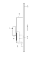
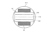
- This dust removing apparatus has a cleaning head 10 (dust removing head) having a structure as shown in FIG. 1A.
- the cleaning head 10 includes a first air suction chamber 12, an air ejection chamber 11, and a second air suction chamber 13 such that the first air suction chamber 12 and the second air suction chamber 13 sandwich the air ejection chamber 11. It is formed in a row.
- Each of the first air suction chamber 12 and the second air suction chamber 13 is connected to an intake pump (not shown) via communication holes 121 and 131.
- the inside of the first air suction chamber 12 and the second air suction chamber 13 is depressurized by the intake action of the intake pump with respect to the first air suction chamber 12 and the second air suction chamber 13.
- the air ejection chamber 11 is connected to an air pump (positive pressure pump) (not shown) through a communication hole 111.
- the inside of the air ejection chamber 11 is pressurized by the air feeding action to the air ejection chamber 11 of this air pump.
- an ejection slit 112 having a predetermined length is formed in the air ejection chamber 11, and each of the first air suction chamber 121 and the second air suction chamber 13.
- the suction slits 122 and 132 having a predetermined length are formed so as to be parallel to the ejection slit 112. Air is ejected from the ejection slit 112 by the pressurization of the air ejection chamber 11 by the air pump described above, and the air is passed through the suction slits 122 and 132 by the decompression of the first air suction chamber 12 and the second air suction chamber 13 by the intake pump.
- the flow paths of the suction slits 122 and 132 formed in the respective portions of the first air suction chamber 12 and the second air suction chamber 13 are formed so as to incline toward the ejection slit 112 toward the outside. Thereby, the airflow ejected from the ejection slit 112 is easily drawn into the suction slits 122 and 132 on both sides.
- the flow paths of the suction slits 122 and 132 may not be inclined as described above, but may be formed vertically like the flow path of the ejection slit 112.
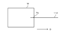
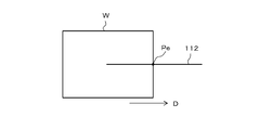
- one piece of individual glass substrate W (a single wafer), which is a target of foreign matter removal, is placed on the transport table 15 and moved in a predetermined direction D.
- one glass substrate W is moved in the direction D.
- the ejection slit 112 and the two suction slits 122 and 132 are transported so that a predetermined gap is formed between the cleaning head 10 and the glass substrate W above the transport table 15. It arrange
- the cleaning head 10 has the ejection slit 112 and the two suction slits 122 and 132 orthogonal to the moving direction D of the transport table 15 (the transport direction of the glass substrate W), and the first air suction chamber 12 is 2 It arrange
- the cleaning head 10 air is drawn into the air suction chambers 12 and 13 through the two suction slits 122 and 132 while air is ejected from the ejection slit 112 of the air ejection chamber 11 by the operations of the air pump and the intake pump.
- the transfer table 15 moves in the direction D.
- foreign matter dust, dust, etc.
- the foreign matter is drawn into the air suction chambers 12 and 13 by drawing air through the intake slits 122 and 132 (see FIG. 1A). Thereby, the foreign material on the surface of the glass substrate W is removed and the surface is cleaned.
- a sheet of a flexible display film-like (sheet-like) base material, a battery film-like (sheet-like) electrode or a film-like (sheet-like) insulator which is required to take measures against contamination. It is desired to use the cleaning head 10 described above for removing foreign matter from a film (sheet-fed sheet). In this case, since the single-wafer film (single-sheet) to be removed of the foreign matter is relatively light and thin, for example, as shown in FIGS.
- the ejection provided in the air ejection chamber 11 of the cleaning head 10 Immediately before the downstream edge portion of the sheet film W passes under the slit 112, the downstream edge portion may be turned up by the air ejected from the ejection slit 112. Further, immediately after the upstream edge portion of the single-wafer film W that has been moved by blowing air on the surface passes below the ejection slit 112 of the cleaning head 10 as shown in FIGS. 3A and 3B, for example. In addition, there is a possibility that the upstream edge portion of the jet slit 112 is turned up by the air jetted from the jet slit 112. If the downstream edge portion or the upstream edge portion of the moving sheet W moves in this way, the sheet film may not be properly conveyed, and therefore, it may not be possible to properly remove foreign matter. There is.
- the internal pressure of the air ejection chamber 11 is reduced to reduce the flow velocity of the air ejected from the ejection slit 112, or the gap between the cleaning head 10 and the single wafer film W is increased to blow on the surface of the single wafer film W. It is conceivable to reduce the pressure of the applied air. However, even in these cases, a new problem that the effect of removing the foreign matter is lowered may occur.
- the present invention has been made in view of these circumstances, and even if the sheet body to be removed of foreign matter is in the form of a film or a sheet, strong suction fixing is performed without reducing the effect of removing foreign matter.
- the present invention provides a foreign matter removing apparatus and a foreign matter removing method capable of removing foreign matter in a stable state without requiring the above mechanism.
- the foreign matter removing apparatus includes a cleaning head having a predetermined length of a jet slit for jetting a fluid, and moves the cleaning head and the sheet body relative to each other while moving the cleaning head to a predetermined operating flow velocity.
- a head setting mechanism for setting the cleaning head at a predetermined operating position facing the surface of the sheet body, and after the cleaning head is set at the operating position, fluid is supplied from the ejection slit to the operating flow velocity.
- the cleaning head is maintained in a state where the cleaning head is opposed to the surface of the sheet body in a state where the cleaning head is ejected.
- the cleaning head is set at the operation position facing the surface of the sheet body in a state where the flow velocity of the fluid ejected from the ejection slit is smaller than the predetermined operation flow velocity.
- the flow velocity of the fluid ejected from the ejection slit can be set to zero.
- the cleaning head is set at the operating position facing the surface of the single wafer in a state where the flow velocity of the fluid from the ejection slit is zero, that is, the fluid is not ejected from the ejection slit. For this reason, when the cleaning head is set at the operating position, it is possible to eliminate the force acting on the single body of the fluid ejected from the ejection slit.
- the headset mechanism may be configured such that the cleaning slit moves the cleaning head in a direction in which the ejection slit sequentially enters the sheet body across the edge line of the sheet body from one end thereof. It can be set as the said movement position by moving with respect to.
- the linear ejection slit is moved from the one end to the sheet body in a direction that sequentially crosses the edge line of the sheet body. Since it moves relative to the single wafer, the influence of the fluid ejected from the ejection slit on the edge portion of the single wafer can be minimized. Thereby, the force which spouts the edge line part of a single wafer can be made small as much as possible.
- the foreign matter removing apparatus includes a cleaning head having a predetermined length of a jet slit for jetting a fluid, and moves the cleaning head and the sheet body relative to each other while moving the cleaning head to a predetermined operating flow velocity.
- a foreign matter removing device that blows off the ejected fluid onto the surface of the single wafer and removes foreign matter from the surface of the single wafer, wherein the fluid is ejected from the ejection slit at the operating flow velocity.
- the cleaning slit is moved in a direction to enter the sheet body sequentially from one end thereof across the edge line of the sheet body from one end thereof to a predetermined operation position facing the surface of the sheet body.
- a head setting mechanism for setting, and after the cleaning head is set at the operating position, the state in which the fluid is ejected from the ejection slit at the operating flow rate is maintained.
- a structure and a rotation mechanism for relatively rotating said sheet member and the cleaning head.
- the cleaning head set at the operating position facing the surface of the sheet body and the sheet body are relatively rotated while the state in which the fluid is ejected from the ejection slit at the operation flow velocity is maintained. .
- fluid ejected from the ejection slit of the cleaning head at the operating flow velocity is sprayed onto the surface of the sheet body.
- the headset mechanism moves the cleaning head in a direction in which the ejection slit enters the sheet body sequentially from one end thereof across the edge line of the sheet body at a right angle. It can be configured.
- the head set mechanism moves the cleaning sheet even when the cleaning head is moved when the cleaning head is set at the operating position facing the surface of the sheet.
- both the cleaning head and the sheet body may be moved.
- the rotating mechanism also maintains the state in which the cleaning head is opposed to the sheet body, and rotates the cleaning head, rotates the sheet body, or both the cleaning head and the sheet body. May be used.
- the fluid ejected from the ejection slit at a predetermined operating flow velocity while relatively moving the cleaning head having the ejection slit of a predetermined length for ejecting the fluid and the sheet body is relatively moving the cleaning head having the ejection slit of a predetermined length for ejecting the fluid and the sheet body.
- the cleaning head and the sheet body are relatively moved while maintaining the cleaning head facing the surface of the sheet body.
- the foreign matter removing method according to the present invention is ejected from the ejection slit at a predetermined operating flow velocity while relatively moving the cleaning head having the ejection slit having a predetermined length for ejecting the fluid and the sheet body.
- a slit is sequentially moved from one end of the sheet body to the sheet body in a direction of crossing the edge line of the sheet body to move to the sheet body, and a predetermined face that opposes the surface of the sheet body.
- a head setting step for setting to an operating position, and maintaining a state in which fluid is ejected from the ejection slit at the operating flow rate after the cleaning head is set to the operating position.
- the foreign matter removing apparatus and the foreign matter removing method according to the present invention even if the sheet body that is the subject of foreign matter removal is a film or a sheet, strong adsorption fixing without reducing the effect of foreign matter removal.
- the foreign matter can be removed in a stable state without requiring the above mechanism.
- FIG. 1A is a cross-sectional view showing the basic structure of a cleaning head and the relative positional relationship between the cleaning head and a single wafer conveyed by a conveyance table in a conventional foreign matter removing apparatus.
- FIG. 1B is a plan view showing a relative positional relationship between a cleaning head and a sheet conveyed by a conveyance table in a conventional foreign matter removing apparatus.
- FIG. 2A is a cross-sectional view illustrating an example of a state when the downstream edge portion of the sheet body passes below the ejection slit of the cleaning head.
- FIG. 2B is a plan view showing an example of the state of the downstream edge portion of the single-piece body that is affected by the air ejected from the ejection slit of the cleaning head.
- FIG. 3A is a cross-sectional view illustrating an example of a state when the upstream edge portion of the single wafer passes below the ejection slit of the cleaning head.
- FIG. 3B is a plan view showing an example of the state of the upstream edge picture portion of the single-piece body that is affected by the air ejected from the ejection slit of the cleaning head.
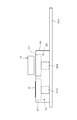
- FIG. 4A is a side view showing the configuration of the foreign matter removing apparatus according to the first embodiment of the present invention.
- FIG. 4B is a plan view showing the configuration of the foreign matter removing apparatus according to the first embodiment of the present invention.
- FIG. 5A is a side view showing a state in which the single wafer film is being transported by the transport table in the foreign matter removing apparatus shown in FIGS. 4A and 4B.
- FIG. 5B is a plan view showing a state in which the sheet film is being conveyed by the conveyance table in the foreign matter removing apparatus shown in FIGS. 4A and 4B.
- FIG. 6A is a plan view showing the relative positional relationship (part 1) between the moving sheet film and the cleaning head in the foreign matter removing apparatus shown in FIGS. 4A and 4B.
- FIG. 6B is a plan view showing the relative positional relationship (part 2) between the moving sheet film and the cleaning head in the foreign matter removing apparatus shown in FIGS. 4A and 4B.
- FIG. 6C is a plan view showing the relative positional relationship between the moving sheet film and the cleaning head (part 3: the state where the cleaning head is set at the operating position) in the foreign matter removing apparatus shown in FIGS. 4A and 4B. It is.
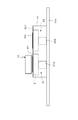
- FIG. 7A is a side view showing a state where the cleaning head is set at the operating position in the foreign matter removing apparatus shown in FIGS. 4A and 4B.
- FIG. 7B is a plan view showing a state in which the cleaning head is set at the operating position in the foreign matter removing apparatus shown in FIGS. 4A and 4B.
- FIG. 8A is an enlarged plan view showing a relative positional relationship between the cleaning head and the sheet film in a state where the cleaning head is set at the operating position in the foreign matter removing apparatus shown in FIGS. 4A and 4B.
- FIG. 8B is a plan view showing a state in which the turntable on which the single-wafer film is placed is rotating with the cleaning head set in the operating position in the foreign matter removing apparatus shown in FIGS. 4A and 4B.
- . 9A is an enlarged view showing the relative positional relationship between the ejection slit and the two suction slits and the single wafer film when the cleaning head is set at the operating position in the foreign matter removing apparatus shown in FIGS. 4A and 4B. It is a top view.
- FIG. 4A and 4B It is a top view.
- FIG. 9B is a plan view showing a relative positional relationship between the cleaning head set at the operating position and the sheet film placed on the rotating turntable in the foreign matter removing apparatus shown in FIGS. 4A and 4B. is there.
- FIG. 10 is a plan view showing a state in which the single-wafer film after removing the foreign matter is discharged from the turntable in the foreign matter removing apparatus shown in FIGS. 4A and 4B.
- FIG. 11A is a side view showing the configuration of the foreign matter removing apparatus according to the second embodiment of the present invention.
- FIG. 11B is a plan view showing the configuration of the foreign matter removing apparatus according to the second embodiment of the present invention.
- FIG. 12 is a plan view showing a state in which the cleaning head is set at the operating position in the foreign matter removing apparatus shown in FIGS. 11A and 11B.
- FIG. 13A is an enlarged plan view showing a relative positional relationship between the cleaning head and the sheet film in a state where the cleaning head is set at the operating position in the foreign matter removing apparatus shown in FIGS. 11A and 11B.
- FIG. 13B is a plan view illustrating a state in which the turntable on which the sheet film is placed is rotating in a state where the cleaning head is set at the operating position in the foreign matter removing apparatus illustrated in FIGS. 11A and 11B. .
- FIG. 13A is an enlarged plan view showing a relative positional relationship between the cleaning head and the sheet film in a state where the cleaning head is set at the operating position in the foreign matter removing apparatus shown in FIGS. 11A and 11B.
- FIG. 13B is a plan view illustrating a state in which the turntable on which the sheet film is placed is rotating in
- FIG. 14 is a plan view showing a state in which the single-wafer film after removing the foreign matter is discharged from the turntable in the foreign matter removing apparatus shown in FIGS. 11A and 11B.
- FIG. 15A is a side view showing the configuration of the foreign matter removing apparatus according to the third embodiment of the present invention.
- FIG. 15B is a plan view showing the configuration of the foreign matter removing apparatus according to the third embodiment of the present invention.
- FIG. 16A is a side view showing a state where the cleaning head is set at the first operating position in the foreign matter removing apparatus shown in FIGS. 15A and 15B.
- FIG. 16B is a plan view showing a state in which the cleaning head is set at the first operating position in the foreign matter removing apparatus shown in FIGS.
- FIG. 17 is a plan view showing a state in which the first turntable on which the sheet-fed film is placed is rotating with the cleaning head set at the first operating position in the foreign matter removing apparatus shown in FIGS. 15A and 15B.
- FIG. 18 is a plan view showing a state where the single-wafer film after removing the foreign matter is discharged from the first turntable in the foreign matter removing apparatus shown in FIGS. 15A and 15B.
- FIG. 19 shows the foreign matter removing apparatus shown in FIGS.
- FIG. 15A and 15B in a state in which the second turntable on which the sheet film is placed is rotating with the cleaning head set at the second operating position, It is a top view which shows the state by which a new sheet
- FIG. 20 is a plan view showing a state in which the cleaning head is set at the first operation position and a state in which the single wafer film is discharged from the second turntable in the foreign matter removing apparatus shown in FIGS. 15A and 15B.
- FIG. 20 is a plan view showing a state in which the cleaning head is set at the first operation position and a state in which the single wafer film is discharged from the second turntable in the foreign matter removing apparatus shown in FIGS. 15A and 15B.
- the foreign matter removing apparatus is configured as shown in FIGS. 4A and 4B.
- 4A is a side view showing the configuration of the foreign matter removing apparatus
- FIG. 4B is a plan view showing the configuration of the foreign matter removing apparatus.
- This foreign matter removing apparatus is intended for removal of foreign matters, for example, a film-like substrate of a flexible display, a film-like electrode of a battery for which countermeasures against foreign matter mixing, and a film-like insulator are required.
- the foreign material transport apparatus includes a cleaning head 10, a transport carrier 20, a rotating mechanism 21, and two rails 30a and 30b.
- the transport carrier 20 is installed on the two rails 30a and 30b arranged in parallel so as to be able to reciprocate.
- the transport carrier 20 is placed on the two rails 30a and 30b by a transport drive mechanism (not shown) on the input / discharge position (position shown in FIGS. 4A and 4B) and the headset position (position shown in FIGS. 7A and 7B described later). ).
- a rotation mechanism 21 is provided in the transport carrier 20.
- the rotation mechanism 21 has a disk-shaped turntable 211 whose surface is exposed from the surface of the carrier 20 and a drive unit 212 (including a motor and the like) that rotates the turntable 211 around its axis. .
- a large number of air intake holes are formed on the surface of the turntable 211 so that a single-wafer film W placed on the turntable 211 and subject to foreign matter removal is sucked and fixed.
- the cleaning head 10 has the same configuration as that shown in FIG. 1A described above, and the first air suction chamber 12, the air ejection chamber 11, and the second air suction chamber 13 include the first air suction chamber 12 and the second air suction chamber 12.
- the suction chamber 13 is formed in a row so as to sandwich the air ejection chamber 11.
- An ejection slit 112 having a predetermined length is formed for the air ejection chamber 11, and suction slits 122 and 132 are formed in parallel to the ejection slit 112 for the first air suction chamber 12 and the second air suction chamber 13, respectively. Yes.
- the positional relationship between the turntable 211 and the cleaning head 10 in the moving direction of the transport carrier 20 is such that when the transport carrier 20 is in the loading / unloading position, the turntable 211 and the cleaning head 10 have a predetermined interval in the moving direction.
- the cleaning head 10 is positioned directly above the turntable 211.
- Each of the turntable 211 and the cleaning head 10 is located at the center in the width direction (direction orthogonal to the moving direction) of the transport carrier 20.
- the cleaning head 10 directs the ejection slit 112 and the two intake slits 122 and 132 toward the surface of the transport carrier 20, and the ejection slit 112 and the two intake slits 122 and 132 are parallel to the movement direction of the transport carrier 20. Is arranged. Further, the cleaning head 10 has a predetermined gap (for example, 1 mm) between the conveyance carrier 20 and the single-wafer film W placed on the turntable 211 when the transport carrier 20 is at the head set position (see FIGS. 7A and 7B). It faces the carrier 20 so as to form (about 5 mm).
- a predetermined gap for example, 1 mm
- the sheet film W to be dealt with the removal of foreign matter is put into the turntable 211 (see FIG. 4B), and the foreign matter has been removed.
- a loading / discharging mechanism for discharging the leaf film W from the turntable 211 is provided.
- Each operation of the intake pump for decompressing the air suction chamber 13 is controlled by a control device (not shown).
- the foreign substance removing apparatus configured as described above operates as follows.
- the sheet-fed film W is loaded in a predetermined posture onto the turntable 211 by a loading / discharging mechanism (not shown). .
- the single wafer film W is placed on the center of the turntable 211 and fixed by suction.
- the cleaning head 10 separated from the turntable 211 is already in a state where air is ejected from the ejection slit 112 at a predetermined operating flow rate, as in the case of removing foreign matter.
- the cleaning head 10 is also in a state where air is sucked through the two suction slits 122 and 132.
- the pressure (pressurized state) in the air ejection chamber 11 in the cleaning head 10 controls the flow velocity of the air ejected from the ejection slit 112 , and the first air suction chamber 12 and the second air suction chamber 13 are controlled.
- the pressure (depressurized state) controls the suction force of air through the two suction slits 122 and 132 .
- the transport carrier 20 moves on the two rails 30a and 30b toward the headset position (see FIGS. 7A and 7B).
- the cleaning head 10 moves above the sheet film W when the sheet film W moves together with the transport carrier 20 in the direction D toward the headset position. Move relative to the direction of entering.
- the linear ejection slit 112 that ejects air at an operating flow velocity is enlarged from FIGS. 6A, 6B, and 6C together with FIG. Is moved in the direction of entering the single wafer film W across a right angle.
- the cleaning head 10 is positioned directly above the turntable 211 (sheet-fed film W) and moved to the operating position as shown in FIGS. 7A and 7B.
- Set headset step
- a head set mechanism in which the carrier 20 moving on the rails 30a and 30b from the loading / unloading position to the headset position sets the cleaning head 10 in a state in which air is ejected from the ejection slit 112 at the operating flow velocity to the operating position.
- the linear ejection slit 112 sequentially forms the edge line of the sheet film W from one end thereof.
- the cleaning head 10 moves relative to the sheet film W in a direction crossing at a right angle and entering the sheet film W (see FIGS. 6A, 6B, and 6C).
- the linear ejection slit 112 moves so as to intersect the edge line of the sheet film W at one point Pe as shown in FIGS. 6A, 6B, and 6C.
- the limit is that the air ejected from the ejection slit 112 corresponds to the one point Pe of the edge line portion of the single wafer film W. It is sprayed only to the range, and the influence exerted on the edge line portion of the single wafer film W by the air ejected from the ejection slit 112 is small.
- the cleaning head 10 is set to the operating position, the force that blows up the edge line portion of the sheet film W by the air ejected from the ejection slit 112 becomes small, and the sheet placed on the turntable 211. Even if the force for adsorbing and fixing the film W is small, the sheet film W is not turned up from the edge line portion, and the sheet film W is maintained in a stable posture on the turntable 211.
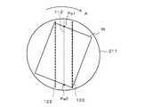
- FIG. 8A together with FIG. 7A and FIG. 7B, when the cleaning head 10 is set at the operation position directly above the turntable 211, the turntable 21 is operated by the operation of the drive unit 212 of the rotation mechanism 21. 211 is rotated in a predetermined direction A as shown in FIG. 8B (rotation step). At this time, a state is maintained in which air is ejected from the ejection slit 112 of the cleaning head 10 at an operating flow velocity and air is sucked through the two suction slits 122 and 132.
- the air ejected from the ejection slit 112 of the cleaning head 10 at the operating flow velocity is a single-wafer. Sprayed onto the surface of the film W.
- the blown air blows up foreign matter (dust, dust, etc.) on the surface of the single-wafer film W, and the sucked-up foreign matter draws air through the two suction slits 122, 132 to draw the air suction chamber 12. , 13 (see the state of FIG. 1A).
- the foreign material on the surface of the single wafer film W is removed and the surface is cleaned.
- the cleaning head 10 set at the operating position has a linear ejection slit 112 on one edge line of the single-wafer film W fixed to the turntable 211 as shown in FIG. 9A. While intersecting at one point Pe1, it is in a state of intersecting at one point Pe2 with an edge line opposite to the edge line of the sheet film W. Even when the cleaning head 10 and the sheet film W are relatively rotated by the rotation of the turntable 211, the cleaning head 10 has the linear ejection slit 112 as one edge of the sheet film W. The line intersects the line at one point Pe1 and continues to be maintained at the point Pe2 intersecting the edge line of the sheet film W opposite to the edge line.
- the sheet film W receives a force pressed by the air ejected from the ejection slit 112 and removes foreign matters from the surface. .
- seat film W can blow air only to the limited range corresponding to 1 point Pe1 and Pe2, the air which blows off from the ejection slit 112 is the edge line of the sheet
- seat film W The influence on the portion is extremely small, and the single-wafer film W does not turn up from the edge portion, and the single-wafer film W is maintained on the turntable 211 in a stable posture.
- the turntable 211 rotates a predetermined number of times (half rotation or more) in a state where air is ejected from the ejection slit 112 of the cleaning head 10 in the operating position at an operating flow velocity and air is sucked through the two suction slits 122 and 132.
- the transport carrier 20 moves from the headset position (see FIGS. 7A and 7B) to the original loading / discharging position. As shown in FIG.
- the cleaning head 10 Even when the air is ejected from the ejection slit 112 of the cleaning head 10 at a predetermined operating flow rate, the cleaning head 10 The air ejected from the ejection slit 112 both in the operation position (see FIGS. 7A and 7B) and in the relative rotation of the cleaning head 10 and the single wafer film W (see FIG. 8B).
- the influence on the edge portion of the single wafer film W is small. For this reason, without reducing the effect of removing foreign matter, and without setting a large suction fixing force for the turntable 211 of the single wafer film W, the single wafer film W is stabilized on the turntable 211. Foreign matter can be removed from the surface.
- the flow velocity of the air ejected from the ejection slit 112 is maintained at the operational flow velocity used for removing foreign matter. Therefore, it is possible to efficiently remove the foreign matter from the surface of the single wafer film W.
- the flow velocity of the air ejected from the ejection slit 112 is made smaller than the operation flow velocity used for removing foreign matter, or the air is not ejected from the ejection slit 112 (the flow velocity is set to zero). can do. In this case, it is possible to further reduce the suction and fixing force of the turntable 211 with respect to the single-wafer film W, which is more suitable for removing foreign matter from the thin and soft single-wafer film W.
- FIGS. 11A and 11B The foreign matter removing apparatus according to the second embodiment of the present invention is configured as shown in FIGS. 11A and 11B.
- FIG. 11A is a side view showing the configuration of the foreign matter removing apparatus
- FIG. 11B is a plan view showing the configuration of the foreign matter removing apparatus.
- the cleaning head 10 is arranged so that the ejection slit 112 and the two suction slits 122 and 132 extend in a direction orthogonal to the moving direction of the transport carrier 20.
- the transport carrier 20 that reciprocates between the loading / discharging position and the headset position on the two rails 30a and 30b and the rotation mechanism 21 (turn table 211, drive unit 212) provided on the transport carrier 20 are described above. This is the same as the foreign matter removing apparatus according to the first embodiment.
- FIG. 13A and FIG. 13A in an enlarged manner, when the cleaning head 10 is set at the operation position directly above the turntable 211, the turntable 211 is moved by the operation of the drive unit 212 of the rotation mechanism 21. As shown in FIG. 13B, it is rotated in a predetermined direction A (rotation step). At this time, air is ejected from the ejection slit 112 of the cleaning head 10 at a predetermined operating flow velocity, and air is sucked through the two suction slits 122 and 132. As a result, the cleaning head 10 is placed on the surface of the single-wafer film W that rotates together with the turntable 211, as in the foreign matter removing apparatus (see FIGS.
- the air ejected from the ejection slit 112 at the operating flow velocity is blown.
- the blown air blows up foreign matter (dust, dust, etc.) on the surface of the single-wafer film W, and the sucked-up foreign matter draws air through the two suction slits 122, 132 to draw the air suction chamber 12. , 13 (see the state of FIG. 1A).
- the foreign material on the surface of the single wafer film W is removed and the surface is cleaned.
- the sheet is removed in the same manner as the foreign matter removing apparatus according to the first embodiment described above. Since each edge line portion of the leaf film W is blown only in a limited range corresponding to one point, the influence of the air ejected from the ejection slit 112 on the edge line portion of the sheet film W is extremely high.
- the sheet film W is small and does not turn up from the edge portion, and the sheet film W is maintained in a stable posture on the turntable 211.
- the transport carrier 20 at the headset position returns to the loading / discharging position. Then, the adsorption and fixing of the sheet film W on the turntable 211 is released, and as shown in FIG. 14, the sheet film W from which foreign matter has been removed is discharged from the turntable 211 by the loading / unloading mechanism and put into a predetermined case or the like. Be contained. Thereafter, the foreign matter removal process from the surface of the single wafer film W is performed one by one according to the same procedure (see FIGS. 11A, 11B, 12, 13, 13A, 13B, and 14).
- the cleaning head 10 is set at the operating position without causing air to be ejected from the ejection slit 112 of the cleaning head 10.
- the edge line portion of the sheet film W adsorbed and fixed to the table 10 passes below the ejection slit 112 of the cleaning head 10, the edge line portion is not affected by the ejection air.
- the cleaning head 10 and the single-wafer film W are rotated relative to each other (see FIG. 13B), the ejection from the ejection slit 112 is performed as in the case of the foreign matter removing apparatus according to the first embodiment described above.
- the influence of the air to the edge line portion of the single wafer film W is small.
- the single wafer film W is stabilized on the turntable 211. Foreign matter can be removed from the surface.
- air is not ejected from the ejection slit 112 (zero flow velocity).
- Air may be ejected from the ejection slit 112 at a predetermined flow velocity smaller than the operating flow velocity.
- the force acting on the single wafer film W of the air ejected from the ejection slit 112 can be made relatively small.
- FIGS. 15A and 15B The foreign matter removing apparatus according to the third embodiment of the present invention is configured as shown in FIGS. 15A and 15B.
- 15A is a side view showing the configuration of the foreign matter removing apparatus
- FIG. 15B is a plan view showing the configuration of the foreign matter removing apparatus.
- this foreign matter removing apparatus is the first embodiment described above in that the transport carrier 20 is provided with two rotating mechanisms, a first rotating mechanism 21 and a second rotating mechanism 22.
- the foreign matter removing apparatus according to the embodiment (see FIGS. 4A and 4B) and the foreign matter removing apparatus according to the second embodiment (see FIGS. 11A and 11B) are different.
- the configuration in which the transport carrier 20 reciprocates on the two rails 30a and 30b is the same as the foreign matter removing apparatus according to each of the first embodiment and the second embodiment.
- the first turntable 211 of the first rotating mechanism 21 and the second turntable 221 of the second rotating mechanism 22 are arranged at a predetermined interval along the moving direction on the transport carrier 20. .
- the first turntable 211 is rotated by the first driving unit 212
- the second turntable 221 is rotated by the second driving unit 222.
- the first drive unit 212 and the second drive unit 222 are controlled by the control device described above.
- the surface of the first turntable 211 and the surface of the second turntable 221 are exposed from the surface of the transport carrier 20.
- the transport carrier 20 reciprocates on the two rails 30a and 30b between a first position (position shown in FIGS. 15A and 15B) and a second position (position shown in FIGS. 16A and 16 described later). To do.
- the cleaning head 10 is located immediately above the second turntable 221 when the transport carrier 20 is in the first position (see FIGS. 15A and 15B), and when the transport carrier 20 is in the second position (see FIG. 15). 16A and FIG. 16B), the first turntable 211 is disposed so as to be positioned directly above.
- the cleaning head 10 includes a linear ejection slit 112 and two suction slits 122 and 132 of the transport carrier 20, as in the foreign matter removing apparatus according to the first embodiment (see FIGS.
- a predetermined gap (for example, about 1 mm to 5 mm) is formed between the cleaning head 10 provided above the transport carrier 20 and the single wafer film W adsorbed and fixed to the turntables 211 and 221. .
- the transport carrier 20 when the transport carrier 20 is in the first position, the sheet-fed film W1 that is the object of foreign matter removal is loaded into the first turntable 211 by the loading / discharging mechanism, and the sheet-fed film is W1 is placed on the first turntable 211 and fixed by suction.
- the transport carrier 20 moves in the state where the single-wafer film W1 is adsorbed and fixed to the first turntable 211, and stops when it reaches the second position as shown in FIGS. 16A and 16B.
- the cleaning head 10 When the transport carrier 20 reaches the second position, the cleaning head 10 is positioned immediately above the first turntable 211 and is set to the first operating position.
- the first turntable 211 rotates as shown in FIG.
- the cleaning head 10 set at the first operation position and the sheet film W1 sucked and fixed to the first turntable 211 rotate relatively, and in the process, the cleaning head
- the air ejected from the ten ejection slits 112 at the operating flow velocity is blown onto the surface of the single wafer film W1, and the foreign matter on the surface of the single wafer film W1 is removed.
- the transport carrier 20 When the first turntable 211 rotates a predetermined number of times and the processing related to the removal of foreign matter on the sheet film W1 is completed, the transport carrier 20 is returned to the first position.
- the transport carrier 20 When the transport carrier 20 is in the first position, as shown in FIG. 18, the sheet film W1 from which foreign matter has been removed is discharged from the first turntable 211 by the input / discharge mechanism and stored in a predetermined case or the like.
- the cleaning head 10 is positioned immediately above the second turntable 221 and is set to the second operating position.
- the second turntable 221 rotates as shown in FIG.
- the cleaning head 10 set at the second operation position and the sheet film W2 attracted and fixed to the second turntable 221 rotate relatively, and in the process, the cleaning head
- the air ejected from the ten ejection slits 112 at the operating flow velocity is blown onto the surface of the single wafer film W2, and the foreign matter on the surface of the single wafer film W2 is removed.
- the second turntable 221 is rotated by the clean head 10 set at the second operation position. As shown in FIG. 19, a new sheet film W3 is loaded into the first turntable 211 at an appropriate timing until the processing related to the removal of foreign matter from the adsorbed and fixed sheet film W2 is completed. A new sheet film W3 is sucked and fixed to the first turntable 211.
- the transport carrier 20 moves from the first position shown in FIG. 19 to the second position shown in FIG. In this way, when the transport carrier 20 is in the second position, as shown in FIG. 19, the single-wafer film W2 from which the foreign matter has been removed is discharged from the second turntable 221 by the loading / discharging mechanism, and is put into a predetermined case or the like. Be contained.
- the cleaning head 10 is positioned right above the first turntable 211 and set at the first operating position. Then, in the same manner as described above, the foreign matter on the surface of the single wafer film W3 adsorbed and fixed to the first turntable 211 rotated by the cleaning head 10 is removed.
- the foreign matter removing process for the single-wafer film W alternately placed on the first turntable 211 and the second turntable 221 is a single cleaning. Since the single-wafer film W from which the foreign matter has been removed is discharged alternately from the first turntable 211 and the second turntable 221 while being performed by the head 10, the processing relating to the removal of foreign matter on the single-wafer film W is more efficient. Can be done.
- the cleaning head 10 is moved to the first operation position. (See FIGS. 16A and 16B) and the second operating position (see FIG. 18), and when the cleaning head 10 and the sheet film W are relatively rotated (see FIGS. 17 and 19).
- the influence of the air ejected from the ejection slit 112 on the edge line portion of the single wafer film W is small. Therefore, the sheet film W can be placed on the turntables 211 and 221 without reducing the foreign matter removal effect and without setting a large suction fixing force for the turntables 211 and 221 of the sheet film W. Foreign matters can be removed from the surface in a stable state.
- the single wafer film W is fixed and the cleaning head 10 is reciprocated, or both the single wafer film W and the cleaning head 10 are reciprocated. Also good.
- the sheet film W may be fixed and the cleaning head 10 may be rotated, or both the sheet film W and the cleaning head 10 may be rotated.
- the sheet body for the foreign object is not limited to a film-like one (sheet-fed film), and even a sheet-like one (sheet-fed sheet) thicker than the film-like one is thicker than the sheet-like one. It may be a plate (sheet-fed plate).
- At least the ejection slits 112 need only be formed in the cleaning head 10, and even if a plurality of ejection slits are formed, or even if only one suction slit is formed in addition to the ejection slits, suction may be further performed.
- the slit may not be formed.
- the arrangement thereof is not particularly limited.
- each slit may be formed such that one suction slit is sandwiched between two ejection slits.
- the fluid ejected from the ejection slit 112 is not limited to air, and even if it is other gas, in a cleaning device or the like as a foreign matter removing device that cleans a single substrate such as a glass substrate, liquid such as water or cleaning liquid is used. There may be.
- the foreign matter removing apparatus and the foreign matter removing method according to the present invention provide strong suction fixing without deteriorating the effect of removing foreign matter, even if the single wafer targeted for foreign matter removal is a film or sheet. It is possible to remove foreign substances in a stable state without the need for a mechanism, and on the surface of a single sheet of individual films, sheets or plates, etc.
- the present invention is useful as a foreign matter removing device and a foreign matter removing method for removing foreign matter from the surface of the sheet by blowing a fluid such as air.
Landscapes
- Cleaning In General (AREA)
- Cleaning Or Drying Semiconductors (AREA)
Priority Applications (2)
| Application Number | Priority Date | Filing Date | Title |
|---|---|---|---|
| KR1020197018146A KR102157973B1 (ko) | 2016-12-28 | 2017-12-19 | 이물질 제거 장치 및 이물질 제거 방법 |
| CN201780078289.0A CN110087784B (zh) | 2016-12-28 | 2017-12-19 | 异物除去装置和异物除去方法 |
Applications Claiming Priority (2)
| Application Number | Priority Date | Filing Date | Title |
|---|---|---|---|
| JP2016255096A JP6975953B2 (ja) | 2016-12-28 | 2016-12-28 | 異物除去装置及び異物除去方法 |
| JP2016-255096 | 2016-12-28 |
Publications (1)
| Publication Number | Publication Date |
|---|---|
| WO2018123715A1 true WO2018123715A1 (ja) | 2018-07-05 |
Family
ID=62708125
Family Applications (1)
| Application Number | Title | Priority Date | Filing Date |
|---|---|---|---|
| PCT/JP2017/045465 WO2018123715A1 (ja) | 2016-12-28 | 2017-12-19 | 異物除去装置及び異物除去方法 |
Country Status (5)
| Country | Link |
|---|---|
| JP (1) | JP6975953B2 (zh) |
| KR (1) | KR102157973B1 (zh) |
| CN (1) | CN110087784B (zh) |
| TW (1) | TWI668056B (zh) |
| WO (1) | WO2018123715A1 (zh) |
Families Citing this family (2)
| Publication number | Priority date | Publication date | Assignee | Title |
|---|---|---|---|---|
| US11318509B2 (en) * | 2017-11-06 | 2022-05-03 | Air Systems Design, Inc. | Dust hood |
| CN110963564B (zh) * | 2019-12-19 | 2020-08-18 | 浙江海盐力源环保科技股份有限公司 | 一种工业废水中去除重金属离子的处理设备 |
Citations (4)
| Publication number | Priority date | Publication date | Assignee | Title |
|---|---|---|---|---|
| JPS62119781A (ja) * | 1985-11-20 | 1987-06-01 | Hitachi Ltd | 表面清掃装置 |
| JP2001156033A (ja) * | 1999-11-25 | 2001-06-08 | Yokogawa Electric Corp | ドライ洗浄方法及び装置 |
| US20030196773A1 (en) * | 2000-08-05 | 2003-10-23 | Kleissler Company | Method for controlling dust on paper machinery and the like |
| JP2014100622A (ja) * | 2012-11-16 | 2014-06-05 | Nitto Kogyo:Kk | 除塵装置 |
Family Cites Families (30)
| Publication number | Priority date | Publication date | Assignee | Title |
|---|---|---|---|---|
| GB2282463A (en) * | 1993-09-10 | 1995-04-05 | Manfred George Michelson | Cleaning photographic film |
| JPH1064868A (ja) * | 1996-08-15 | 1998-03-06 | Dainippon Screen Mfg Co Ltd | 基板洗浄装置および基板洗浄方法 |
| JPH11300301A (ja) * | 1998-04-27 | 1999-11-02 | Dainippon Screen Mfg Co Ltd | 基板洗浄方法及びその装置 |
| JP2000262989A (ja) * | 1999-01-13 | 2000-09-26 | Uct Kk | 基板洗浄装置 |
| EP1091388A3 (en) * | 1999-10-06 | 2005-09-21 | Ebara Corporation | Method and apparatus for cleaning a substrate |
| JP3728406B2 (ja) * | 2000-06-15 | 2005-12-21 | シャープ株式会社 | 基板洗浄装置 |
| JP3625766B2 (ja) * | 2000-12-27 | 2005-03-02 | 大日本スクリーン製造株式会社 | 基板表面処理装置および基板表面処理方法 |
| JP4179592B2 (ja) * | 2002-08-21 | 2008-11-12 | 大日本スクリーン製造株式会社 | 基板周縁処理装置および基板周縁処理方法 |
| JP2005034782A (ja) * | 2003-07-17 | 2005-02-10 | Sony Corp | 洗浄装置及び洗浄方法 |
| JP4040063B2 (ja) * | 2003-11-18 | 2008-01-30 | 東京エレクトロン株式会社 | 基板洗浄方法、基板洗浄装置およびコンピュータ読み取り可能な記録媒体 |
| JP2005296809A (ja) * | 2004-04-12 | 2005-10-27 | Hugle Electronics Inc | 除塵装置用異物検出装置 |
| JP2005349291A (ja) * | 2004-06-10 | 2005-12-22 | Sharp Corp | スピン洗浄装置 |
| CN100508159C (zh) * | 2004-06-14 | 2009-07-01 | 大日本网目版制造株式会社 | 基板处理装置和基板处理方法 |
| JP4255459B2 (ja) * | 2005-06-15 | 2009-04-15 | 大日本スクリーン製造株式会社 | 基板洗浄装置および基板洗浄方法 |
| JP4579071B2 (ja) * | 2005-07-06 | 2010-11-10 | ヒューグルエレクトロニクス株式会社 | 基板用搬送除塵装置 |
| JP5016351B2 (ja) * | 2007-03-29 | 2012-09-05 | 東京エレクトロン株式会社 | 基板処理システム及び基板洗浄装置 |
| CN101327572B (zh) * | 2007-06-22 | 2012-01-25 | 中芯国际集成电路制造(上海)有限公司 | 晶圆背面减薄工艺 |
| JP5151629B2 (ja) * | 2008-04-03 | 2013-02-27 | 東京エレクトロン株式会社 | 基板洗浄方法、基板洗浄装置、現像方法、現像装置及び記憶媒体 |
| JP5403407B2 (ja) * | 2008-06-18 | 2014-01-29 | 株式会社リコー | 洗浄装置 |
| JP5889537B2 (ja) * | 2011-03-23 | 2016-03-22 | ファスフォードテクノロジ株式会社 | ダイボンダ |
| JP2013051301A (ja) * | 2011-08-31 | 2013-03-14 | Dainippon Screen Mfg Co Ltd | 基板処理装置および基板処理方法 |
| US9991141B2 (en) * | 2012-03-23 | 2018-06-05 | SCREEN Holdings Co., Ltd. | Substrate processing apparatus and heater cleaning method |
| JP6090837B2 (ja) * | 2012-06-13 | 2017-03-08 | 株式会社Screenホールディングス | 基板処理装置および基板処理方法 |
| JP6058312B2 (ja) * | 2012-08-06 | 2017-01-11 | ヒューグル開発株式会社 | クリーニングヘッド |
| US20140261572A1 (en) * | 2013-03-15 | 2014-09-18 | Dainippon Screen Mfg.Co., Ltd. | Substrate treatment apparatus and substrate treatment method |
| JP6182347B2 (ja) * | 2013-04-19 | 2017-08-16 | 株式会社荏原製作所 | 基板処理装置 |
| CN103977973B (zh) * | 2014-05-09 | 2016-10-05 | 欧蒙医学诊断(中国)有限公司 | 一种载片清洗装置和方法 |
| KR101598360B1 (ko) * | 2014-09-05 | 2016-02-29 | 지에스티 반도체장비(주) | 기판 세척용 기판 위치 제어 장치 |
| JP6504890B2 (ja) * | 2015-04-09 | 2019-04-24 | 東京エレクトロン株式会社 | 異物除去装置、異物除去方法および剥離装置 |
| CN105977547B (zh) * | 2016-05-18 | 2018-09-18 | 合肥国轩高科动力能源有限公司 | 一种用于卷绕叠片电池极片清理装置及清理方法 |
-
2016
- 2016-12-28 JP JP2016255096A patent/JP6975953B2/ja active Active
-
2017
- 2017-12-19 KR KR1020197018146A patent/KR102157973B1/ko active IP Right Grant
- 2017-12-19 CN CN201780078289.0A patent/CN110087784B/zh active Active
- 2017-12-19 WO PCT/JP2017/045465 patent/WO2018123715A1/ja active Application Filing
- 2017-12-25 TW TW106145506A patent/TWI668056B/zh active
Patent Citations (4)
| Publication number | Priority date | Publication date | Assignee | Title |
|---|---|---|---|---|
| JPS62119781A (ja) * | 1985-11-20 | 1987-06-01 | Hitachi Ltd | 表面清掃装置 |
| JP2001156033A (ja) * | 1999-11-25 | 2001-06-08 | Yokogawa Electric Corp | ドライ洗浄方法及び装置 |
| US20030196773A1 (en) * | 2000-08-05 | 2003-10-23 | Kleissler Company | Method for controlling dust on paper machinery and the like |
| JP2014100622A (ja) * | 2012-11-16 | 2014-06-05 | Nitto Kogyo:Kk | 除塵装置 |
Also Published As
| Publication number | Publication date |
|---|---|
| TW201829079A (zh) | 2018-08-16 |
| CN110087784A (zh) | 2019-08-02 |
| TWI668056B (zh) | 2019-08-11 |
| KR102157973B1 (ko) | 2020-09-18 |
| JP6975953B2 (ja) | 2021-12-01 |
| JP2018103153A (ja) | 2018-07-05 |
| KR20190089182A (ko) | 2019-07-30 |
| CN110087784B (zh) | 2022-03-18 |
Similar Documents
| Publication | Publication Date | Title |
|---|---|---|
| JP4451385B2 (ja) | 塗布処理装置及び塗布処理方法 | |
| TWI620238B (zh) | Substrate processing method and substrate processing device | |
| CN1908819B (zh) | 显影处理装置以及显影处理方法 | |
| TWI531411B (zh) | 塗佈裝置及噴嘴的維護方法 | |
| WO2018123715A1 (ja) | 異物除去装置及び異物除去方法 | |
| JP2006043889A (ja) | 画像記録装置 | |
| TWI517283B (zh) | 液體處理裝置及液體處理裝置之控制方法 | |
| JP5261356B2 (ja) | インクジェット記録装置 | |
| GB2528052A (en) | Contact cleaning apparatus | |
| JP6720659B2 (ja) | 基材の液切り装置 | |
| JP2009018427A (ja) | 液体噴射装置、および液体噴射装置における液体吐出ヘッドのクリーニング方法 | |
| JP2007196094A (ja) | 処理液供給ユニットおよびそれを備えた基板処理装置 | |
| JP4931699B2 (ja) | 基板処理装置及び基板処理方法 | |
| JP2012196832A (ja) | 画像記録装置 | |
| KR20140058348A (ko) | 절삭 장치 | |
| JP6579594B1 (ja) | テープ剥離装置 | |
| JP2005272113A (ja) | 基板搬送装置および基板搬送方法 | |
| JP5848812B1 (ja) | 吸着装置、及び、吸着装置の制御方法 | |
| JP6544539B2 (ja) | 噴射加工装置および被加工物の表面加工方法 | |
| JP2011194297A (ja) | 吸着装置および液滴吐出装置 | |
| JP3851370B2 (ja) | 基板の液切り装置 | |
| JP2011230463A (ja) | 吸着装置および液滴吐出装置 | |
| JPH08338686A (ja) | 基板乾燥方法及びその装置 | |
| JP2005152817A (ja) | 洗浄装置及び半導体装置の製造装置 | |
| KR20220135342A (ko) | 잉크젯 프린팅 프로세스의 제어 방법 |
Legal Events
| Date | Code | Title | Description |
|---|---|---|---|
| 121 | Ep: the epo has been informed by wipo that ep was designated in this application |
Ref document number: 17889354 Country of ref document: EP Kind code of ref document: A1 |
|
| ENP | Entry into the national phase |
Ref document number: 20197018146 Country of ref document: KR Kind code of ref document: A |
|
| NENP | Non-entry into the national phase |
Ref country code: DE |
|
| 122 | Ep: pct application non-entry in european phase |
Ref document number: 17889354 Country of ref document: EP Kind code of ref document: A1 |