WO2017188239A1 - 工作機械システム及び表面粗さ検出方法 - Google Patents
工作機械システム及び表面粗さ検出方法 Download PDFInfo
- Publication number
- WO2017188239A1 WO2017188239A1 PCT/JP2017/016355 JP2017016355W WO2017188239A1 WO 2017188239 A1 WO2017188239 A1 WO 2017188239A1 JP 2017016355 W JP2017016355 W JP 2017016355W WO 2017188239 A1 WO2017188239 A1 WO 2017188239A1
- Authority
- WO
- WIPO (PCT)
- Prior art keywords
- workpiece
- grinding
- surface roughness
- machine tool
- tool system
- Prior art date
Links
Images


Classifications
-
- B—PERFORMING OPERATIONS; TRANSPORTING
- B23—MACHINE TOOLS; METAL-WORKING NOT OTHERWISE PROVIDED FOR
- B23Q—DETAILS, COMPONENTS, OR ACCESSORIES FOR MACHINE TOOLS, e.g. ARRANGEMENTS FOR COPYING OR CONTROLLING; MACHINE TOOLS IN GENERAL CHARACTERISED BY THE CONSTRUCTION OF PARTICULAR DETAILS OR COMPONENTS; COMBINATIONS OR ASSOCIATIONS OF METAL-WORKING MACHINES, NOT DIRECTED TO A PARTICULAR RESULT
- B23Q11/00—Accessories fitted to machine tools for keeping tools or parts of the machine in good working condition or for cooling work; Safety devices specially combined with or arranged in, or specially adapted for use in connection with, machine tools
-
- B—PERFORMING OPERATIONS; TRANSPORTING
- B23—MACHINE TOOLS; METAL-WORKING NOT OTHERWISE PROVIDED FOR
- B23Q—DETAILS, COMPONENTS, OR ACCESSORIES FOR MACHINE TOOLS, e.g. ARRANGEMENTS FOR COPYING OR CONTROLLING; MACHINE TOOLS IN GENERAL CHARACTERISED BY THE CONSTRUCTION OF PARTICULAR DETAILS OR COMPONENTS; COMBINATIONS OR ASSOCIATIONS OF METAL-WORKING MACHINES, NOT DIRECTED TO A PARTICULAR RESULT
- B23Q17/00—Arrangements for observing, indicating or measuring on machine tools
- B23Q17/20—Arrangements for observing, indicating or measuring on machine tools for indicating or measuring workpiece characteristics, e.g. contour, dimension, hardness
-
- B—PERFORMING OPERATIONS; TRANSPORTING
- B23—MACHINE TOOLS; METAL-WORKING NOT OTHERWISE PROVIDED FOR
- B23Q—DETAILS, COMPONENTS, OR ACCESSORIES FOR MACHINE TOOLS, e.g. ARRANGEMENTS FOR COPYING OR CONTROLLING; MACHINE TOOLS IN GENERAL CHARACTERISED BY THE CONSTRUCTION OF PARTICULAR DETAILS OR COMPONENTS; COMBINATIONS OR ASSOCIATIONS OF METAL-WORKING MACHINES, NOT DIRECTED TO A PARTICULAR RESULT
- B23Q17/00—Arrangements for observing, indicating or measuring on machine tools
- B23Q17/24—Arrangements for observing, indicating or measuring on machine tools using optics or electromagnetic waves
-
- B—PERFORMING OPERATIONS; TRANSPORTING
- B24—GRINDING; POLISHING
- B24B—MACHINES, DEVICES, OR PROCESSES FOR GRINDING OR POLISHING; DRESSING OR CONDITIONING OF ABRADING SURFACES; FEEDING OF GRINDING, POLISHING, OR LAPPING AGENTS
- B24B49/00—Measuring or gauging equipment for controlling the feed movement of the grinding tool or work; Arrangements of indicating or measuring equipment, e.g. for indicating the start of the grinding operation
- B24B49/02—Measuring or gauging equipment for controlling the feed movement of the grinding tool or work; Arrangements of indicating or measuring equipment, e.g. for indicating the start of the grinding operation according to the instantaneous size and required size of the workpiece acted upon, the measuring or gauging being continuous or intermittent
- B24B49/04—Measuring or gauging equipment for controlling the feed movement of the grinding tool or work; Arrangements of indicating or measuring equipment, e.g. for indicating the start of the grinding operation according to the instantaneous size and required size of the workpiece acted upon, the measuring or gauging being continuous or intermittent involving measurement of the workpiece at the place of grinding during grinding operation
-
- B—PERFORMING OPERATIONS; TRANSPORTING
- B24—GRINDING; POLISHING
- B24B—MACHINES, DEVICES, OR PROCESSES FOR GRINDING OR POLISHING; DRESSING OR CONDITIONING OF ABRADING SURFACES; FEEDING OF GRINDING, POLISHING, OR LAPPING AGENTS
- B24B49/00—Measuring or gauging equipment for controlling the feed movement of the grinding tool or work; Arrangements of indicating or measuring equipment, e.g. for indicating the start of the grinding operation
- B24B49/10—Measuring or gauging equipment for controlling the feed movement of the grinding tool or work; Arrangements of indicating or measuring equipment, e.g. for indicating the start of the grinding operation involving electrical means
-
- B—PERFORMING OPERATIONS; TRANSPORTING
- B24—GRINDING; POLISHING
- B24B—MACHINES, DEVICES, OR PROCESSES FOR GRINDING OR POLISHING; DRESSING OR CONDITIONING OF ABRADING SURFACES; FEEDING OF GRINDING, POLISHING, OR LAPPING AGENTS
- B24B49/00—Measuring or gauging equipment for controlling the feed movement of the grinding tool or work; Arrangements of indicating or measuring equipment, e.g. for indicating the start of the grinding operation
- B24B49/12—Measuring or gauging equipment for controlling the feed movement of the grinding tool or work; Arrangements of indicating or measuring equipment, e.g. for indicating the start of the grinding operation involving optical means
-
- B—PERFORMING OPERATIONS; TRANSPORTING
- B24—GRINDING; POLISHING
- B24B—MACHINES, DEVICES, OR PROCESSES FOR GRINDING OR POLISHING; DRESSING OR CONDITIONING OF ABRADING SURFACES; FEEDING OF GRINDING, POLISHING, OR LAPPING AGENTS
- B24B5/00—Machines or devices designed for grinding surfaces of revolution on work, including those which also grind adjacent plane surfaces; Accessories therefor
- B24B5/02—Machines or devices designed for grinding surfaces of revolution on work, including those which also grind adjacent plane surfaces; Accessories therefor involving centres or chucks for holding work
- B24B5/04—Machines or devices designed for grinding surfaces of revolution on work, including those which also grind adjacent plane surfaces; Accessories therefor involving centres or chucks for holding work for grinding cylindrical surfaces externally
-
- B—PERFORMING OPERATIONS; TRANSPORTING
- B24—GRINDING; POLISHING
- B24B—MACHINES, DEVICES, OR PROCESSES FOR GRINDING OR POLISHING; DRESSING OR CONDITIONING OF ABRADING SURFACES; FEEDING OF GRINDING, POLISHING, OR LAPPING AGENTS
- B24B51/00—Arrangements for automatic control of a series of individual steps in grinding a workpiece
-
- B—PERFORMING OPERATIONS; TRANSPORTING
- B24—GRINDING; POLISHING
- B24B—MACHINES, DEVICES, OR PROCESSES FOR GRINDING OR POLISHING; DRESSING OR CONDITIONING OF ABRADING SURFACES; FEEDING OF GRINDING, POLISHING, OR LAPPING AGENTS
- B24B53/00—Devices or means for dressing or conditioning abrasive surfaces
-
- B—PERFORMING OPERATIONS; TRANSPORTING
- B24—GRINDING; POLISHING
- B24B—MACHINES, DEVICES, OR PROCESSES FOR GRINDING OR POLISHING; DRESSING OR CONDITIONING OF ABRADING SURFACES; FEEDING OF GRINDING, POLISHING, OR LAPPING AGENTS
- B24B55/00—Safety devices for grinding or polishing machines; Accessories fitted to grinding or polishing machines for keeping tools or parts of the machine in good working condition
- B24B55/02—Equipment for cooling the grinding surfaces, e.g. devices for feeding coolant
-
- B—PERFORMING OPERATIONS; TRANSPORTING
- B24—GRINDING; POLISHING
- B24B—MACHINES, DEVICES, OR PROCESSES FOR GRINDING OR POLISHING; DRESSING OR CONDITIONING OF ABRADING SURFACES; FEEDING OF GRINDING, POLISHING, OR LAPPING AGENTS
- B24B55/00—Safety devices for grinding or polishing machines; Accessories fitted to grinding or polishing machines for keeping tools or parts of the machine in good working condition
- B24B55/12—Devices for exhausting mist of oil or coolant; Devices for collecting or recovering materials resulting from grinding or polishing, e.g. of precious metals, precious stones, diamonds or the like
-
- G—PHYSICS
- G01—MEASURING; TESTING
- G01B—MEASURING LENGTH, THICKNESS OR SIMILAR LINEAR DIMENSIONS; MEASURING ANGLES; MEASURING AREAS; MEASURING IRREGULARITIES OF SURFACES OR CONTOURS
- G01B11/00—Measuring arrangements characterised by the use of optical techniques
- G01B11/24—Measuring arrangements characterised by the use of optical techniques for measuring contours or curvatures
Definitions
- the present invention relates to a machine tool system and a surface roughness detection method using the machine tool system.
- Patent Document 1 describes a sizing device that measures the outer diameter of a workpiece supported by a workpiece support device.
- the sizing device measures the outer diameter of the workpiece on the machine by rotating the workpiece supported by the workpiece support device while bringing the contact into contact with the surface of the workpiece.
- Patent Document 2 discloses a surface roughness measurement for measuring the surface shape of a workpiece by detecting the amount of displacement generated in the stylus when the stylus supported by the cantilever is moved in contact with the workpiece. An apparatus is disclosed.
- Patent Document 3 describes a technique related to constant pressure feed lap processing performed with a constant applied pressure and fixed amount feed lap processing with a constant movement amount. Further, Patent Document 4 describes that the lapping is finished when a predetermined cutting amount is reached by moving in a cutting direction with a constant pressure.
- Patent Document 5 prepares in advance data indicating the correlation between the waveform of the AE wave and the surface roughness of the sensor, and estimates the surface roughness of the workpiece from the detected waveform of the AE wave based on the data. Is disclosed.
- Patent Document 6 the surface of the workpiece W is measured during grinding, and when the size of the surface of the workpiece W reaches a predetermined value, the speed of the grinding feed is slowed down.
- a technique for attempting to bring the surface roughness of a sheet into a desired state is disclosed.
- the coolant liquid of the machine tool is collected in the tank after being supplied to the machining area, and is supplied again to the machining area. Since the coolant liquid that circulates between the processing region and the tank is contaminated by containing chips or dust, it is generally performed to purify the coolant liquid by installing a filter in the circulation path. However, since the coolant cannot be completely purified by the filter, it is necessary to periodically replace the contaminated coolant.
- Patent Document 7 discloses a technique for managing the contamination degree of the coolant liquid by using an optical sensor or a pressure sensor provided in a pipe line that circulates from the processing region to the tank, and determining the replacement timing of the coolant liquid. Yes.
- Patent Document 8 a gas flow supply path is formed in a head to which a non-contact sensor is attached, and clean air is ejected from the gas flow supply path to prevent dust and oil mist from adhering to the non-contact sensor. A measuring device is described.
- Patent Document 1 requires that a contactor be brought into contact with a workpiece when measuring the outer diameter of the workpiece. In this case, the surface of the workpiece may be scratched due to the contact between the contact and the workpiece.
- the surface roughness measuring device described in Patent Document 2 measures the surface roughness of the cylindrical portion of the crankpin by traversing the stylus in the axial direction of the crankpin, and is therefore not parallel to the traverse direction. For a part, the surface roughness of the part cannot be measured.
- the pressure in the constant pressure control or the feed amount in the quantitative feed control is set so that the surface state of the workpiece at the end of the processing becomes a desired state. Is set. In this case, the surface state of the workpiece at the end of the processing is not a desired state, and there is a possibility that it is determined as a defective product in the inspection after the processing.
- Patent Document 5 is merely a technique for estimating the surface roughness of the workpiece, and does not calculate the surface roughness of the workpiece based on the actually measured result.
- the surface roughness of the surface to be ground is estimated from the dimensions of the surface to be ground, and the speed of grinding feed is adjusted based on the estimated surface roughness.
- the actual surface roughness of the surface to be ground is not always as expected, and there is a possibility that the surface roughness of the surface to be ground cannot be brought into a desired state when the grinding process is completed.
- Patent Document 7 it is not easy to provide an optical sensor or a pressure sensor other than the circulation line from the processing region to the tank.
- An object of the present invention is to provide a machine tool system capable of suitably measuring the shape of a workpiece. It is another object of the present invention to provide a machine tool system for suitably calculating the surface roughness of a workpiece and a surface roughness detection method using the machine tool system. It is another object of the present invention to provide a machine tool system including a coolant evaluation device that can provide a sensor in the tank body and can evaluate the contamination of the coolant.
- a first machine tool system includes a workpiece support device that rotatably supports a workpiece, a tool that processes the workpiece, a detection unit that performs non-contact sensing of the workpiece, and detection of the detection unit
- a calculation unit that extracts shape information of the workpiece or calculates a surface roughness of the workpiece based on a result.
- the detection unit performs non-contact sensing of the workpiece. Then, the calculation unit calculates the shape information of the workpiece or calculates the surface roughness of the workpiece based on the detection result of the detection unit. Therefore, the machine tool system can extract the shape information of the workpiece or calculate the surface roughness of the workpiece without contacting the workpiece.
- the detection unit emits light toward the workpiece supported by the workpiece support device and receives reflected light from the surface of the workpiece, and the calculation unit detects the workpiece. Shape information of the workpiece is extracted based on the amount of light received by the detection unit in the rotated state.
- This machine tool system can efficiently detect the surface roughness of a workpiece.
- the calculation unit extracts a distance from the workpiece based on the amount of light received by the detection unit, and extracts the shape information based on the extracted distance.
- the sensor emits light toward the workpiece supported by the workpiece support device and receives reflected light reflected by the surface of the workpiece. Then, the calculation unit obtains the shape information of the workpiece based on the amount of light received by the sensor. Therefore, the machine tool system can acquire the shape information of the workpiece W without contacting the workpiece and can measure the shape of the workpiece W.
- the machine tool system includes a long main body formed in a rod shape, and a driving unit that applies a driving force for rotating the main body about an axis, and the detection unit It is fixed to the outer surface on the tip side and detects the surface roughness of the workpiece without contact.
- This machine tool system can detect the surface roughness of two or more parts with different orientations in the workpiece by rotating the detection unit around the axis of the main body. Can be performed efficiently.
- the tool is a lapping tool for lapping the workpiece after grinding, and the machine tool system performs lapping by the lapping tool based on the surface roughness detected by the detection unit. . Since this machine tool system performs lapping based on the detected surface roughness of the workpiece, the surface roughness of the workpiece at the end of lapping can be reliably brought into a desired state.
- the machine tool system ends the lapping when the surface roughness detected by the detection unit becomes smaller than a predetermined threshold.
- the surface roughness of the workpiece W at the end of lapping can be surely brought into a desired state.
- the calculation unit is a calculation unit that detects a surface roughness of the workpiece by performing a first process on a detection value of the detection unit during grinding.
- the detection unit can sense the surface of the workpiece being ground by the grinding wheel, and the calculation unit performs the first process on the detection value of the detection unit, Calculate the roughness of the workpiece.
- the machine tool system can increase the accuracy of the calculation result of the surface roughness even when sensing is performed on the workpiece being cut. As a result, the machine tool system can achieve both improvement in work efficiency when sensing and improvement in accuracy of the calculation result of the surface roughness.
- the tool is a grinding wheel that grinds the workpiece
- the machine tool system includes a grinding resistance detection unit that detects a grinding resistance generated in the tool during grinding of the workpiece.
- the calculation unit is configured to remove the influence of grinding resistance on the detection value of the detection unit based on the detection value of the detection unit and the detection value of the grinding resistance detection unit during the grinding process. Is performed to calculate the surface roughness of the workpiece during grinding by the grinding wheel.
- the calculation unit removes the influence of the grinding resistance on the detection value of the sensor by performing the first process. Therefore, the machine tool system can increase the accuracy of the calculation result of the surface roughness even when sensing is performed on the workpiece W that is being cut.
- the tool is a grinding wheel for grinding the workpiece
- the detection unit detects a surface roughness of the workpiece ground by the grinding wheel
- the machine tool system includes the detection unit. The conditions for grinding performed after detection are determined based on the surface roughness detected by.
- This machine tool system determines the grinding conditions based on the surface roughness of the workpiece ground by the grinding wheel, and performs subsequent grinding under the determined conditions.
- the surface roughness of the workpiece can be surely brought into a desired state.
- the machine tool system determines a condition for the surface roughness to be equal to or less than the threshold by the detection unit as a condition for grinding performed after detection, Grinding is performed under the determined conditions.
- This machine tool system can obtain a desired surface roughness at the end of grinding.
- the machine tool system is formed in a rod shape from a supply source toward a main body in which the detection unit is fixed to a distal end side and a detection region formed between the detection unit and the workpiece.
- a first air discharge unit that discharges the supplied air.
- the detection unit is fixed to the front end side of the main body formed in a rod shape. Therefore, the machine tool system detects the surface roughness of the workpiece by the sensor, and the workpiece is detected by the workpiece. It can carry out with the state supported by the support apparatus. In other words, the machine tool system does not require the work of transporting the workpiece supported by the workpiece support device to another position in order to detect the surface roughness. Work efficiency can be improved.
- the machine tool system since the machine tool system includes the first air discharge unit that discharges air toward the detection region, it is possible to prevent the foreign matter attached to the workpiece from being scattered toward the detection unit. Moreover, since the machine tool system can suppress the mist containing chips and the like from entering the detection region, the detection accuracy can be maintained when detecting the surface roughness of the workpiece.
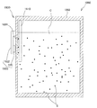
- the second machine tool system is a machine tool system provided with a pollution evaluation device provided in a tank body that stores coolant liquid, and the pollution evaluation device includes a reflective member that can be immersed in the coolant liquid.
- a detection unit that is provided in the tank body and performs sensing of the reflection member in a non-contact manner, and a calculation unit that calculates based on a detection result of the detection unit, and the detection unit is directed toward the reflection member
- a light-emitting element that emits light and a light-receiving element that receives reflected light from the reflecting member, and the calculation unit is an evaluation unit that determines the contamination of the coolant based on the amount of light received by the light-receiving element.
- the light emitting element emits light toward the reflecting member that can be immersed in the coolant liquid stored in the tank body, and the light receiving element receives the reflected light. Since the contamination degree of the coolant is evaluated based on the amount of light received by the light receiving element, it is possible to grasp an appropriate replacement time for the coolant based on the evaluation. Moreover, since the detection unit is provided in the tank body, the degree of freedom in designing the machine tool system can be increased.
- the surface roughness detection method of the present invention includes a workpiece support device that rotatably supports a workpiece, a tool that processes the workpiece, a detection unit that performs non-contact sensing of the workpiece, and the detection unit. For extracting shape information of the workpiece or calculating the surface roughness of the workpiece based on the detection result, a long main body formed in a rod shape, and for rotating the main body about an axis. Using a machine tool system that detects the surface roughness of the workpiece in a non-contact manner, and is fixed to an outer surface on the distal end side of the main body.
- a surface roughness detection method for detecting a surface roughness of the workpiece processed by a tool by the detection unit wherein the machine tool system rotates the detection unit around an axis of the body, The direction of the workpiece is different Detecting a surface roughness of more sites.
- the machine tool system detects the surface roughness of two or more parts having different orientations in the workpiece by rotating the detection unit around the axis of the main body.
- the surface roughness can be detected efficiently.
- the machine tool system includes a table traverse type grinding machine 1 that performs grinding while rotating a cylindrical workpiece W.
- the present invention may be applied to machine tool systems other than the grinding machine 1.
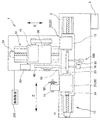
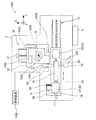
- a grinding machine 1 as a machine tool system includes a bed 2, a table 10, a workpiece support device 20, a grinding wheel base 30, a grinding wheel 40 as a tool, a truer 50, a coolant supply device 60, a fixed size.
- the apparatus 70, the air supply apparatus 80, the sensor 100, and the control apparatus 200 are provided.
- the bed 2 is a part that becomes the base of the grinding machine 1.
- the bed 2 is provided with an operation panel 3 into which various parameters relating to grinding conditions and the like are input, and the operation panel 3 is operated by an operator.
- the table 10 is provided on the bed 2 so as to be movable in the Z-axis direction.
- the table 10 reciprocates in the Z-axis direction by driving a screw feeder 12 having a Z-axis motor 11.
- the workpiece support device 20 includes a headstock 21 and a tailstock 22.
- the headstock 21 is fixed on the table 10.
- the headstock 21 includes a main shaft 23 that rotates about an axis parallel to the Z-axis direction, and a main shaft motor 24 that applies a driving force for rotating the main shaft 23.
- the headstock 21 rotatably supports one end of the workpiece W by the spindle 23 and rotationally drives the workpiece W by the spindle motor 24.
- the tailstock 22 is provided on the table 10 at a position facing the headstock 21 and supports the other end of the workpiece W.
- the grinding wheel platform 30 is provided on the bed 2 so as to be movable in the X-axis direction.
- the grindstone table 30 reciprocates in the X-axis direction by driving a screw feed mechanism 32 having an X-axis motor 31.
- the grinding wheel 40 is supported by the grinding wheel base 30 so as to be rotatable about an axis parallel to the Z-axis direction.
- the grinding wheel 40 rotates when a driving force is applied from a grinding wheel motor 41 fixed to the grinding wheel base 30, and grinds the outer peripheral surface of the workpiece W.
- the grinding machine 1 supports only one end of the workpiece W on the headstock 21 by a chuck or the like so as to be rotatable, and reciprocates the grinding wheel 40 from the tailstock 22 side (right side shown in FIG.
- the truer 50 is supported by the headstock 21 so as to be rotatable about an axis parallel to the Z axis.
- the truer 50 is rotated by the driving force applied from the truer motor 51 provided on the headstock 21 and performs truing (shape shaping and sharpening) of the grinding wheel 40.
- the coolant supply device 60 is provided on the bed 2.
- the coolant supply device 60 supplies coolant to a grinding site via a coolant nozzle (not shown) provided on the grindstone table 30.
- the sizing device 70 is provided so as to be in contact with the workpiece W on the opposite side of the grinding wheel 40 across the table 10.
- the sizing device 70 measures the outer diameter of the workpiece W ground by the grinding wheel 40.
- the air supply device 80 is provided on the opposite side of the grinding wheel 40 across the table 10.
- the air supply device 80 includes air supply portions 81 and 82 (see FIG. 2) arranged toward the machining area of the workpiece W.
- the air supply device 80 removes deposits such as coolant adhered to the outer peripheral surface of the workpiece W by blowing air to the workpiece W from the air supply portions 81 and 82.
- the case where air is blown onto the workpiece W has been described as an example. However, instead of air, an inert gas or the like that does not affect machining on the workpiece W is blown. Also good.
- the sensor 100 is disposed on the opposite side of the grinding wheel 40 with the table 10 interposed therebetween.
- the sensor 100 performs sensing on the workpiece W, converts an optical signal indicating the surface state of the workpiece W into an electrical signal, and transmits the electrical signal to the control device 200.
- the sensing by the sensor 100 is performed in a state where the workpiece W is supported by the headstock 21 and the tailstock 22. Accordingly, when the grinding machine 1 performs sensing by the sensor 100, the grinding machine 1 is more sensitive to the workpiece W than when the workpiece W supported by the headstock 21 and the tailstock 22 needs to be transported to another position. The work efficiency at the time of sensing can be improved.
- the sensor 100 includes a main body 110, a detection unit 120, a main body cover 140, a first air discharge unit 150, an air flow path 160, a second air discharge unit 170, and a wind plate. 180.
- the main body 110 is formed in a long bar shape, and the detection unit 120 is fixed on one outer surface on the distal end side (right side in FIG. 2) of the main body 110.
- the detection unit 120 performs sensing of the workpiece W that is a measurement target, and transmits an electrical signal indicating the sensing result to a calculation unit 220 (see FIG. 4) described later.
- the detection unit 120 includes a substrate 121, a light emitting element 122, a first light receiving element 123 and a second light receiving element 124, a lid part 125, and three lenses 125a to 125c.
- the substrate 121 is made of a semiconductor material (N-type, P-type, bipolar type, etc.), and is mounted on one outer side surface (surface facing downward in FIG. 3) of the main body 110.
- the light emitting element 122 is a light emitting diode mounted on the substrate 121, and emits light in a normal direction (downward in FIG. 3) on one outer side surface of the main body 110.
- the first light receiving element 123 and the second light receiving element 124 are photodiodes mounted on the substrate 121, and are disposed in the vicinity of the light emitting element 122.
- the light emitting element 122, the first light receiving element 123, and the second light receiving element 124 are arranged in a straight line along the longitudinal direction of the main body 110 (left and right direction in FIG. 3). It arrange
- the light emitting element 122, the first light receiving element 123, and the second light receiving element 124 arranged on the substrate 121 are partitioned by a partition plate 126. Therefore, the detection unit 120 can efficiently perform light emission from the light emitting element 122 and light reception to the first light receiving element 123 and the second light receiving element 124.
- the case where a light emitting diode is used as the light emitting element 122 has been described as an example.
- electroluminescence, a laser element, or the like may be used as the light emitting element 122.
- the case where photodiodes are used as the first light receiving element 123 and the second light receiving element 124 has been described as an example.
- a CCD, a CMOS element, or the like is used as the first light receiving element.
- 123 and the second light receiving element 124 may be used.
- the lid 125 covers the substrate 121, the light emitting element 122, the first light receiving element 123, and the second light receiving element 124.
- the lid 125 holds one lens 125a to 125c at a position facing each of the light emitting element 122, the first light receiving element 123, and the second light receiving element 124.
- the three lenses 125a to 125c may be aspherical lenses. For easy detection, the lens shape may be changed to adjust the focal position and depth of focus of the lens.
- the light emitted from the light emitting element 122 is incident on the lens 125a disposed at a position facing the light emitting element 122.
- the lens 125a bends the light emitted from the light emitting element 122 and guides the bent light to a specific position P.
- the light that has been made is guided to the first light receiving element 123 or the second light receiving element 124.
- the detection unit 120 arranges the light emitting element 122, the first light receiving element 123, and the second light receiving element 124 on one substrate 121, so that the light emitting element 122, the first light receiving element 123, and the second light receiving element 124 are mutually connected. Can be placed in close proximity. Therefore, the detection unit 120 can reduce the size of the detection unit 120 compared to the case where the light emitting element 122, the first light receiving element 123, and the second light receiving element 124 are formed on separate substrates.
- the main body cover 140 covers the front end side of the main body 110 and prevents other members and the like from hitting the detection unit 120 directly.
- An inflow port 141 communicating with the inside and the outside of the main body cover 140 is formed through the upper surface of the main body cover 140.
- an air supply unit 81 connected to the air supply device 80 is connected to the upper surface of the main body cover 140, and the air discharged from the air supply unit 81 is supplied from the inflow port 141 to the inside of the main body cover 140. .
- a detection port 142 is formed through the lower surface of the main body cover 140 at a position facing the detection unit 120.
- the detection unit 120 faces the workpiece W that is a measurement object through the detection port 142.
- the light emitted from the detection unit 120 passes through the detection port 142 and enters the workpiece W, and the reflected light passes through the detection port 142 and enters the detection unit 120.
- a detection region A through which light from the detection unit 120 to the workpiece W and from the workpiece W to the detection unit 120 passes is formed between the detection unit 120 and the workpiece W.
- the first air discharge unit 150 is a lower surface of the main body cover 140 and is a nozzle-like part formed around the detection port 142.
- a plurality of outlets 151 communicating with the inside and the outside of the main body cover 140 are formed through the first air discharge portion 150. Air supplied from the air supply unit 81 to the inside of the main body cover 140 is discharged toward the workpiece W from the plurality of outlets 151.
- the first air discharge unit 150 is formed around the detection port 142 and discharges air toward the workpiece W from the detection unit 120 side.
- the sensor 100 can prevent the scattered foreign matter from adhering to the detection unit 120 and can prevent the mist containing chips and the like from entering the detection region A.
- the plurality of outlets 151 are formed radially so as to spread from the inner side of the main body cover 140 toward the outer side as viewed from the detection unit 120. Therefore, the air discharged from the first air discharge unit 150 is blown toward the workpiece W in a direction away from the detection area A. Thereby, the sensor 100 can prevent the foreign matter blown by the air from the first air release unit 150 from scattering and adhering to the detection unit 120. Further, the sensor 100 can suppress the mist containing chips and the like from entering the detection region A by the air discharged from the first air discharge unit 150. Therefore, the sensor 100 can maintain the detection accuracy of the workpiece W.
- the air flow path 160 guides the air that has flowed into the main body cover 140 from the air supply device 80 via the air supply unit 81 to the first air discharge unit 150.
- the air channel 160 is formed between the outer peripheral surface of the main body 110 and the inner peripheral surface of the main body cover 140, and communicates with the first air discharge unit 150.
- the sensor 100 can simplify the structure of the sensor 100 compared with the case where the hose etc. which guide air from the air supply part 81 to the 1st air discharge
- the sensor 100 can be downsized.
- the main body cover 140 is fixed to the outer peripheral surface of the main body 110 at a position farther from the first air discharge portion 150 than the inlet 141, and the space between the outer peripheral surface of the main body 110 and the inner peripheral surface of the main body cover 140 is Sealed by an O-ring 143.
- the sensor 100 can prevent the air flowing into the air flow path 160 from leaking from parts other than the first air discharge part 150, so that the air is discharged from the first air discharge part 150 toward the workpiece W. Can be sprayed strongly.
- the second air discharge unit 170 is a nozzle formed integrally with the air supply unit 82 of the air supply device 80.
- the second air discharge unit 170 is disposed between the grinding wheel 40 and the sensor 100 and discharges air from the grinding position ground by the grinding wheel 40 toward the detection area A in the workpiece W. .
- the sensor 100 can blow off foreign matters such as coolant adhering to the workpiece W by air discharged from the second air discharge unit 170. Therefore, the sensor 100 can prevent the workpiece W from entering the detection area A in a state where foreign matter is attached. Further, the sensor 100 can prevent a mist containing chips or the like from entering the detection area A. Therefore, the sensor 100 can ensure detection accuracy.
- Wind cut plate 180 is a plate-like member that partitions between sensor 100 and second air discharge unit 170, and is fixed to main body cover 140. An end 180 a of the wind-cut plate 180 facing the workpiece W is located closer to the workpiece W than the first air discharge unit 150. The second air discharge unit 170 discharges air from a position farther from the workpiece W than the end portion 180a of the wind cutting plate 180 facing the workpiece W.
- the sensor 100 can prevent the air discharged from the second air discharge unit 170 from being blown toward the detection area A, the foreign matter scattered by the air sprayed from the second air discharge unit 170 is detected. It can suppress adhering to the part 120.
- the sensor 100 since the air discharged from the second air discharge unit 170 is directed to the workpiece W while being guided by the wind cutting plate 180, the sensor 100 can strongly blow the air against the workpiece W. Therefore, the sensor 100 can easily remove the foreign matter adhering to the workpiece W.
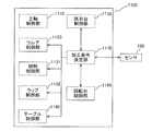
- control device 200 (1-3. Control device 200) Next, the control device 200 will be described with reference to FIG. As shown in FIG. 4, the control device 200 includes a sensor control unit 210 and a calculation unit 220.
- the sensor control unit 210 performs control related to the sensor 100.
- the sensor control unit 210 causes the sensor 100 to approach the workpiece W to a position where the distance between the detection unit 120 and the workpiece W becomes a predetermined dimension, and then emits light toward the workpiece W. The reflected light from the surface of the workpiece W is received.
- the calculation unit 220 performs a calculation for extracting the shape information of the workpiece W based on the amount of light received by the sensor 100.
- the calculation unit 220 includes a dimension determination unit 221, a rotation shake determination unit 222, a chatter determination unit 223, and a roundness determination unit 224.
- Dimension determination unit 221 determines whether or not the outer diameter of workpiece W has reached a desired dimension based on the amount of light received by sensor 100.
- the dimension determination unit 221 stores a reference threshold value related to the amount of light received when light is emitted toward the workpiece W having a desired outer diameter and received from the workpiece W.
- the dimension determination unit 221 determines whether or not the amount of received light received by the detection unit 120 is equal to or less than a reference threshold, and the outer diameter of the workpiece W when the amount of received light received by the detection unit 120 is equal to or less than the reference threshold. Is determined to have reached the desired dimension.
- the dimension determination unit 221 performs a process of removing the rotational shake component from the data obtained by the sensor 100, and whether or not the outer diameter of the workpiece W has reached a desired dimension based on the data after the process. Judgment is made.
- Rotational shake determination unit 222 performs frequency analysis using FFT on the data obtained by sensor 100, and determines the presence or absence of rotational shake based on the analysis result. As shown in FIG. 5 and FIG. 6A, when sensing is performed by the sensor 100 on the workpiece W having rotational shake and frequency analysis using FFT is performed on the obtained light reception amount data, frequencies from f1 to f2 are obtained. A large amplitude exceeding a certain level is generated in the band.
- the rotational shake determination unit 222 determines that the amplitude in the frequency band from f1 to f2 after the FFT analysis is greater than or equal to a predetermined reference threshold based on the received light amount data obtained by the sensor 100.
- the workpiece W is determined to have rotational runout.
- the rotational shake determination unit 222 calculates the magnitude of the rotational shake of the workpiece W based on the amplitude in the frequency band from f1 to f2 after the FFT analysis.
- the chatter determination unit 223 performs frequency analysis using FFT on the received light amount data obtained by the sensor 100, and determines the presence or absence of chatter based on the analysis result.
- FIGS. 5 and 6B when sensing is performed by the sensor 100 on the workpiece W having chatter, and frequency analysis using FFT is performed on the obtained light reception amount data, f3 to f4 are obtained. A large amplitude exceeding a certain level is generated in the frequency band.
- the chatter determination unit 223, based on the received light amount data obtained by the sensor 100, when the amplitude in the frequency band from f3 to f4 after the FFT analysis is equal to or greater than a predetermined reference threshold value, It is determined that the workpiece W has chatter.
- the chatter determination unit 223 outputs a frequency whose amplitude is equal to or greater than a reference threshold in the frequency band from f3 to f4 after the FFT analysis. In this case, the operator can find out the cause of chatter using the output frequency as a clue.
- the roundness determination unit 224 uses the data obtained by removing the rotational shake component from the received light amount data obtained by the sensor 100 (the frequency band from f2 to f5 after the FFT analysis is extracted). Calculate roundness.
- the roundness determination unit 224 stores in advance a reference threshold relating to the amount of received light that is obtained when a desired roundness is satisfied.
- the roundness determination unit 224 compares the roundness calculated from the received light amount data after removing the rotational shake component and the reference threshold value, and determines whether or not the workpiece W has a desired roundness. To do.
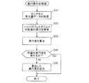
- the dimension determination process executed by the dimension determination unit 221 will be described with reference to FIGS. 7A and 7B.
- the dimension determination unit 221 acquires received light amount data from the sensor 100 (S1), and removes the rotational shake component from the received light amount data by a high-pass filter (S2). Thereafter, the dimension determination processing determines whether or not the received light amount received by the sensor 100 is equal to or less than the reference threshold Th based on the received light amount data from which the rotational shake component has been removed (S3).
- the grinding machine 1 fixes the sensor 100 to the bed 2 in a state where the detection unit 120 is brought close to the workpiece W when sensing by the sensor 100 in parallel with the grinding process. Then, the dimension determination unit 221 determines that the outer diameter of the workpiece W has reached the desired dimension L when the amount of light received by the sensor 100 is equal to or less than the reference threshold Th.
- the dimension determination process returns to the process of S1 when it is determined that the received light amount of the workpiece W is larger than the reference threshold Th (S3: No).
- the dimension determination process when it is determined that the amount of light received by the workpiece W is equal to or less than the reference threshold Th (S3: Yes), it is notified that the outer diameter of the workpiece W has reached the desired dimension L (S4). This process is terminated.
- the grinding machine 1 can extract the distance from the workpiece W based on the amount of light received by the sensor 100 and acquire shape information such as the outer diameter of the workpiece W based on the extracted distance. it can.
- the rotational shake determination unit 222 acquires received light amount data from the sensor 100 (S11). Then, the rotational shake determination unit 222 extracts low-frequency components (frequency components from f1 to f2 shown in FIG. 5) from the received light amount data as a rotational shake component using a bandpass filter (S12), and performs FFT analysis ( S13).
- the rotational shake determination unit 222 determines whether or not the peak value of the amplitude in the extracted rotational shake component is greater than or equal to the reference threshold based on the result of the FFT analysis performed in the process of S13. It is determined whether or not rotational swing has occurred in the object W. As a result, in the process of S14, when it is determined that the rotational shake is not generated in the workpiece W (S14: No), the rotational shake determination process ends this process as it is.
- chatter determination processing executed by the chatter determination unit 223 will be described with reference to FIG.
- the chatter determination unit 223 acquires received light amount data from the sensor 100 (S21). And the chatter determination part 223 extracts the high frequency component (frequency component from f3 to f4 shown in FIG. 5) from the received light amount data by the band pass filter (S22), and performs the FFT analysis (S23).
- the chatter determination unit 223 determines whether or not the peak value of the amplitude in the extracted chatter component is equal to or greater than a reference threshold based on the result of the FFT analysis performed in the process of S23, and the workpiece W It is determined whether or not chatter has occurred.
- the chatter determination process when the chatter determination unit 223 determines that chatter has not occurred in the workpiece W (S24: No), the process ends.
- the chatter determination process uses the frequency value at which the amplitude is greater than or equal to the reference threshold value. Output (S25), and this process is terminated.
- the grinding machine 1 can determine whether or not the workpiece W is chattered without contacting the workpiece W.
- the roundness determination unit 224 acquires the received light amount data from the sensor 100 (S31), and uses the high-pass filter to convert the low frequency component as the rotational shake component into the received light amount data. (S32). Thereafter, the roundness determination unit 224 calculates the roundness of the workpiece W based on the received light amount data from which the rotational shake component is removed.
- the roundness determination unit 224 calculates the roundness based on the amplitude of the received light amount data from which the rotational shake component has been removed (S33). Subsequently, the roundness determination unit 224 compares the calculated roundness of the workpiece W with a reference threshold value, and determines whether or not the workpiece W has a desired roundness (S34). As a result, in the process of S34, when the roundness determination unit 224 determines that the workpiece W has a desired roundness (S34: Yes), the roundness determination process ends the process as it is. . On the other hand, the roundness determination process is performed when the roundness determination unit 224 determines that the workpiece W does not have a desired roundness in the process of S34 (S34: No), Is output (S35), and this process is terminated.
- the grinding machine 1 can perform information on the roundness of the workpiece W without contacting the workpiece W. Further, the roundness determination unit 224 performs processing for removing the low frequency component as the rotational shake component of the workpiece W from the information of the received light amount with respect to the rotational phase of the workpiece W, and then the roundness as the high frequency component. Since the components are extracted, the grinding machine 1 can accurately extract information on the roundness of the workpiece W.
- the grinding machine 1 acquires the shape information (outer diameter, runout, chatter, roundness, etc. of the workpiece W) without contacting the workpiece W after grinding.
- the shape of the workpiece W can be measured.
- the grinding machine 1 determines the cause of the rotational runout or chatter, etc., so that the grinding condition can be corrected quickly. Can be done. Therefore, the grinding machine 1 can suppress the number of defective products.
- the grinding machine 1 extracts the roundness component based on the received light amount data obtained from the sensor 100, after removing a specific low frequency component from the received light amount data as a rotational shake component, The roundness of the workpiece W is calculated. Thereby, the grinding machine 1 can extract the information regarding the roundness of the workpiece W with high accuracy. As a result, the grinding machine 1 can increase the accuracy of determination by the roundness determination unit 224.
- the grinding machine 1 can acquire the shape information of the workpiece W while the workpiece W is supported by the workpiece support device 20. Therefore, the grinding machine 1 can shorten the time required for processing the workpiece W as compared with the case of acquiring the shape information of the workpiece after moving the workpiece W to a different position.
- the detection part 120 can detect the shape information of the workpiece W non-contactingly, it can avoid that the workpiece W is damaged with sensing by the sensor 100. Furthermore, when the detection unit 120 emits light from one light emitting element 122, the change of reflected light reflected at a specific position P is confirmed by two light receiving elements (first light receiving element 123 and second light receiving element 124). can do. Therefore, the detection unit 120 can acquire the shape of the workpiece W with high accuracy.
- the machine tool system includes a plurality of grinders and an analysis unit provided on a network outside the plurality of grinders and connected to the plurality of grinders, and is controlled in each of the above embodiments.
- the calculation unit 220 provided in the apparatus 200 may be provided in the analysis unit.
- the machine tool system simultaneously changes the grinding conditions performed by the plurality of grinding machines 1 when it is determined that the conditions for grinding the workpiece W should be changed as a result of analysis by the analysis unit. It is good also as a structure.
- the analysis unit may accumulate, for example, shape information of the workpiece W extracted under a specific machining condition (a specific workpiece W, a specific grinding machine, a specific environment (temperature or humidity), etc.). .
- the analysis unit analyzes the accumulated data, and the calculation unit 220 sets a reference threshold value regarding the amount of reflected light from the workpiece W based on the analysis result (trend, abnormality occurrence, etc.) by the analysis unit. decide. Thereby, the machine tool system can accurately extract the shape information of the workpiece W.
- a grinding machine 301 as a machine tool system has the same configuration as the grinding machine 1 (see FIG. 1) in the first embodiment except for the arrangement of the air supply device 80 and the sensor 100 and the control device 400.
- the air supply device 80 and the sensor 100 are disposed on the grinding wheel base 30 and move integrally with the grinding wheel 40.
- the grinding machine 301 when the grinding machine 301 performs sensing by the sensor 100 on the cam surface of the workpiece W, the grinding machine 301 can maintain a constant interval between the detection unit 120 (see FIG. 2) and the cam surface of the workpiece W. it can.
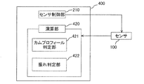
- control device 400 includes a sensor control unit 210 and a calculation unit 420, and the calculation unit 420 includes a cam profile determination unit 421 and a shake determination unit 422.
- the cam profile determination unit 421 determines whether or not the cam surface of the workpiece W has a desired cam profile based on the amount of light received by the sensor 100 while the sensor 100 is moved along the cam surface. To do.
- the cam profile determination unit 421 stores a reference threshold value related to the amount of light received by the sensor 100 when the sensor 100 emits light to the workpiece W having a desired cam profile on the cam surface.
- the cam profile determination unit 421 determines whether or not the amount of received light received by the sensor 100 is less than or equal to a reference threshold. When the amount of received light received by the sensor 100 is less than or equal to the reference threshold, Determine that it has the desired cam profile.
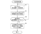
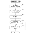
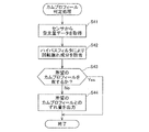
- cam profile determination process executed by the cam profile determination unit 421 will be described with reference to FIG. As shown in FIG. 13, in the cam profile determination process, the cam profile determination unit 421 acquires the received light amount data from the sensor 100 (S41), and removes the low frequency component as the rotational shake component from the received light amount data by the high pass filter. (S42).
- the cam profile determination unit 421 calculates a deviation amount between the cam profile of the workpiece W and a desired cam profile stored in advance based on the received light amount data from which the rotational shake component has been removed. It is determined whether or not the cam surface has a desired cam profile (S43). As a result, in the cam profile determination process, when the cam profile determination unit 421 determines that the workpiece W has a desired cam profile (S43: Yes), the process ends. On the other hand, in the cam profile determination process, when the cam profile determination unit 421 determines that the workpiece W does not have the desired cam profile (S43: No), the calculated cam profile of the workpiece W and the desired cam profile are calculated. Is output (S44), and this process is terminated.
- the grinding machine 301 can determine whether or not the cam surface of the workpiece W has a desired cam profile without contacting the workpiece. . Therefore, the grinding machine 301 can prevent the workpiece from being damaged when the cam profile is measured.
- the present invention is used when extracting the outer diameter, rotational runout, chatter, roundness, and cam profile of the workpiece W is taken as an example. explained. However, the present invention is not limited to this, and the present invention may be used when other shape information (such as a tooth surface shape after crowning of a gear) is extracted.
- the case where the extraction of received light amount data is performed using a high-pass filter or a banded pass filter has been described as an example.
- the present invention is not limited to this.
- the received light amount data may be extracted using a low-pass filter, or may be combined with a low-pass filter, a high-pass filter, and a band-pass filter.
- the calculating part 630 calculates the surface roughness of two or more site
- symbol is attached
- the structure of the grinding machine 501 which is an example of the machine tool system in 3rd embodiment is demonstrated.
- the machine tool system includes one table traverse type grinding machine 501 that performs grinding while rotating a cylindrical workpiece W.
- a grinding machine 501 as a machine tool system includes a bed 2, a table 10, a workpiece support device 20, a grinding wheel base 30, a grinding wheel 40, a tourer 50, a coolant supply device 60, and a sizing device 70.
- the air supply device 80, the sensor 600, and the control device 700 are provided.
- the control device 700 controls driving of various motors (Z-axis motor 11, main shaft motor 24, X-axis motor 31, grinding wheel motor 41), control of the amount of coolant supplied from the coolant supply device 60, and work by the sizing device 70. Management of the diameter of the object W, control related to sensing by the sensor 600, and the like are performed.
- the sensor 600 includes a main body 110, a detection section 120, a calculation section 630, a main body cover 140, a first air discharge section 150, an air flow path 160, and a second air discharge section 170. And a wind-cut plate 180 and a drive unit 690.
- the arithmetic unit 630 may be disposed inside the sensor 600 or may be disposed outside the sensor 600 and connected to the main body 110 by a cable or the like.
- the calculation unit 630 calculates the surface roughness at a specific position P based on the light amount detected by the first light receiving element 123 and the second light receiving element 124 when light is emitted from the light emitting element 122. That is, when light is emitted from the light emitting element 122, if the light amount detected by the first light receiving element 123 and the second light receiving element 124 is large, the calculation unit 630 indicates a calculation result that the surface roughness is small. On the other hand, if the amount of light detected by the first light receiving element 123 and the second light receiving element 124 is small, the calculation unit 630 indicates a calculation result that the surface roughness is large.
- the incident light at the specific position P and the reflected light from the specific position have a spread, and the incident angle and the reflection angle have a spread of angles.
- the calculation unit 630 determines whether the incident angle at the peak position with the strongest intensity in the distribution of incident light is equal to the reflection angle at the peak position with the highest intensity in the distribution of reflected light, or the spread of incident light. When the distribution and the spread distribution of the reflected light are similar, it is determined that the incident angle and the reflection angle are equal.
- the detection unit 120 can detect the surface roughness of the workpiece W in a non-contact manner, the workpiece W after grinding can be prevented from being damaged along with the detection of the surface roughness. Furthermore, when the detection unit 120 emits light from one light emitting element 122, the change of reflected light reflected at a specific position P is confirmed by two light receiving elements (first light receiving element 123 and second light receiving element 124). can do. Therefore, the detection unit 120 can measure the surface roughness of the workpiece W with high accuracy.
- the driving unit 690 is connected to the base end side (the left side in FIG. 2) of the main body 110 and applies a driving force for rotating the main body 110 around the axis.
- the detection unit 120 rotates around the axis of the main body 110.
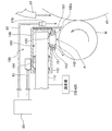
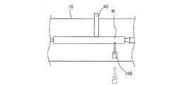
- FIGS. 16A, 16B, and 17 a surface roughness detection method using the sensor 600 will be described with reference to FIGS. 16A, 16B, and 17.
- the case where the crankshaft is the workpiece W and the surface roughness of the crank journal after the grinding process is detected by the sensor 600 will be described as an example, but the surface roughness of the workpiece W other than the crankshaft is described. It is also possible to detect using the sensor 600.
- FIGS. 16A, 16B, and 17 only the main body 110 and the detection unit 120 of the sensor 600 are illustrated.
- the grinding machine 1 first performs grinding with the grinding wheel 40 on one of the plurality of crank journals Wa.
- the sensor 600 stands by at a position away from the workpiece W.
- the grinding machine 501 can prevent the coolant or the like scattered during the grinding process from adhering to the sensor 600.
- the table 10 moves in the Z-axis direction (see FIG. 14).
- the grinding wheel 40 performs grinding on the crank journal Wb adjacent to the one crank journal Wa that has been previously ground.
- the sensor 600 approaches one crank journal Wa that has been previously ground, and detects the surface roughness of the one crank journal Wa.
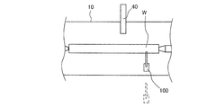
- the sensor 600 first directs the detection unit 120 to one end face Wa1 (the face facing the left side in FIG. 17) of one crank journal Wa that has been previously ground. The surface roughness of the end face Wa1 is detected. Subsequently, the sensor 600 rotates the main body 110 about the axis so that the detection unit 120 faces the cylindrical surface Wa3 of one crank journal Wa. At this time, the sensor 600 directs the detection unit 120 to a connection portion Wa2 between one end surface Wa1 of one crank journal Wa and the cylindrical surface Wa3, so that the connection portion Wa2 between the one end surface Wa1 and the cylindrical surface Wa3 is aligned. Surface roughness can be detected.
- the grinding machine 501 moves the sensor 600 along the axial direction of one crank journal Wa in a state where the one crank journal Wa is rotated after the detection unit 120 is directed to the cylindrical surface Wa3 of the one crank journal Wa. While traversing, the surface roughness of the cylindrical surface Wa3 is detected. Thereby, the grinding machine 501 can detect the surface roughness of the entire cylindrical surface Wa3. After detecting the surface roughness of the cylindrical surface Wa3, the grinding machine 501 rotates the main body 110 about the axis so that the detection unit 120 faces the other end surface Wa5 (the surface facing the right side in FIG. 17), and the other end surface Wa5 and the surface roughness of the connecting portion Wa4 between the cylindrical surface Wa3 and the other end surface Wa5 are detected.
- the sensor 600 is provided with the detection unit 120 on the distal end side of the long main body 110 formed in a rod shape, the sensor 100 can be reduced in size.
- the grinding machine 501 can bring the detection unit 120 closer to the workpiece W located in a narrow region where sensing is difficult with a large sensor device. Therefore, the grinding machine 501 can detect the surface roughness of the workpiece W located in such a narrow region by the sensor 100.
- the grinding machine 501 reduces the size of the sensor 600 so that the surface roughness of the workpiece W is detected by the sensor 600 and the workpiece W is supported by the workpiece support device 20 (see FIG. 14). Can be done as is. In other words, the grinding machine 501 does not need to carry out the work of transporting the workpiece W supported by the workpiece support device 20 to another position in order to detect the surface roughness. The work efficiency at the time of performing can be improved.
- the sensor 600 can detect the surface roughness of two or more parts having different directions in the workpiece W by rotating the detection unit 120 around the axis of the main body 110. Therefore, the grinding machine 501 can efficiently detect the surface roughness of the workpiece W.
- the grinding machine 501 can simultaneously detect the surface roughness by the sensor 600 for the workpiece W that has been ground, while grinding the workpiece W by the grinding wheel 40. . Therefore, the grinding machine 501 starts grinding the workpiece W after the grinding of the workpiece W by the grinding wheel 40 is completed, as compared with the case where the surface roughness of the workpiece W is detected by the sensor 600. After that, the time required until the detection of the surface roughness of the workpiece W after grinding is completed can be shortened.
- the grinding machine 501 can blow off deposits such as coolant adhering at the time of grinding by the air discharged from the second air discharge unit 170. Furthermore, the grinding machine 501 can prevent foreign matter such as coolant or mist containing chips from entering the detection area A by the air discharged from the first air discharge unit 150. Therefore, the grinding machine 501 increases the detection accuracy of the sensor 600 even when the surface roughness of the workpiece W is detected by the sensor 600 while the workpiece W is ground by the grinding wheel 40. Can be maintained.
- the grinding machine 501 performs detection of the surface roughness of the workpiece W by the sensor 600 in parallel while grinding the workpiece W by the grinding wheel 40. It is not limited to. That is, the grinding machine 501 may detect the surface roughness of the workpiece W by the sensor 600 after the grinding of the workpiece W by the grinding wheel 40 is completed. In this case, the grinding machine 501 does not need to detect the surface roughness while removing the foreign matter adhering to the workpiece W. That is, since the grinding machine 501 does not need to provide the first air discharge part 150 and the second air discharge part 170 in the sensor 600, the size of the sensor 600 can be reduced. Moreover, since the grinding machine 501 can detect the surface roughness of the workpiece W while the workpiece W is stationary, the detection accuracy of the sensor 600 can be increased.
- the machine tool system is composed of one grinder 501, but the present invention is not limited to this.
- the machine tool system includes a plurality of grinders and an analysis unit provided on a network outside the plurality of grinders and connected to the plurality of grinders.
- the calculation unit 630 provided in the above may be provided in the analysis unit.
- the analysis unit can perform advanced analysis based on the detection result transmitted from the sensor 600 to derive the surface roughness. Therefore, the machine tool system can improve the detection accuracy when detecting the surface roughness of the workpiece W.
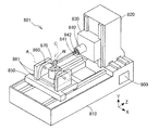
- machining center 801 (4-1. Schematic configuration of machining center 801)
- the machine tool system has five axes having three linear axes (X axis, Y axis and Z axis) and two rotation axes (A axis and C axis) orthogonal to each other as drive axes. It consists of a machining center 801.
- the machining center 801 is a gear machining apparatus that forms a gear on the workpiece W by cutting will be described as an example.
- the present invention is applied to a machining center other than the gear machining apparatus. Is also possible.
- a machining center 801 as a machine tool system includes a bed 810, a column 820, a saddle 830, a rotary spindle 840, a table 850, a tilt table 860, a turntable 870 as a workpiece support device, and a control device 900. .
- the bed 810 is formed in a substantially rectangular shape and is arranged on the floor.
- a column 820 is provided on the upper surface of the bed 810 so as to be movable in the X-axis direction with respect to the bed 810.
- a saddle 830 is provided on a side surface parallel to the X axis of the column 820 so as to be movable in the Y axis direction with respect to the column 820.
- the rotation main shaft 840 is provided so as to be rotatable with respect to the saddle 830 and supports the machining tool 841.
- the processing tool 841 is a tool for processing the workpiece W.
- the machining tool 841 is held by the tool holder 842 and is fixed to the tip of the rotation main shaft 840, and rotates with the rotation of the rotation main shaft 840. Further, the machining tool 841 moves in the X-axis direction and the Y-axis direction with respect to the bed 810 as the column 820 and the saddle 830 move.
- a table 850 is provided on the upper surface of the bed 810 so as to be movable in the Z-axis direction with respect to the bed 810, and a tilt table support portion 861 for supporting the tilt table 860 is provided on the upper surface of the table 850.
- the tilt table support portion 861 is provided with a tilt table 860 that can rotate (swing) around the horizontal A axis.
- a turntable 870 is provided so as to be relatively rotatable about a C axis perpendicular to the A axis.
- the turntable 870 is a workpiece support device that rotatably supports the workpiece W, and the workpiece W is chucked on the turntable 870.
- the control device 900 controls the movement of the column 820, the saddle 830, the rotation spindle 840, the table 850, the tilt table 860, and the turntable 870, and moves the workpiece W and the processing tool 841 in the X-axis direction, the Y-axis direction,
- the workpiece W is cut by relative movement in the Z-axis direction, the A-axis and the C-axis.
- the machining center 801 creates teeth by rotating the machining tool 841 and the workpiece W synchronously at high speed, and sending the machining tool 841 in the direction of the rotation axis of the workpiece W for cutting.
- the machining center 801 directs the detection unit 120 to a position where the surface roughness is to be detected. . Then, the machining center 801 displaces the sensor 600 along the shape of the tooth while maintaining the distance between the portion where the surface roughness is to be detected and the detection unit 120. Thereby, the machining center 801 can efficiently detect the surface roughness of the tooth surface of the gear.
- the machining center 801 can detect the surface roughness of the part located in such a narrow region by the sensor 600.
- the senor 600 can detect the surface roughness of two or more parts having different directions in the workpiece W by rotating the detection unit 120 around the axis of the main body 110. Therefore, the machining center 801 can efficiently detect the surface roughness of the workpiece W.
- the senor 100 detects the surface roughness of the workpiece W during lapping.
- symbol is attached
- the machine tool system includes a single machine tool 1001 that performs grinding and lapping while rotating a cylindrical workpiece W.
- a machine tool 1001 as a machine tool system includes a bed 2, a table 10, a workpiece support device 20, a grinding wheel table 30, a rotating table 1035, a grinding tool 1041 and a lapping tool 1042, a truer 50, and coolant supply.
- a device 60, a sizing device 70, an air supply device 80, a sensor 100, and a control device 1100 are provided.
- the turntable 1035 is provided on the upper surface of the grindstone table 30.
- the turntable 1035 is supported by the rotation mechanism 1036 so as to be rotatable about the Y axis with respect to the grindstone table 30.
- the grinding tool 1041 and the lapping tool 1042 are provided at positions that are symmetric with respect to the rotation axis of the turntable 1035, and are supported by the turntable 1035 so as to be rotatable about an axis orthogonal to the Y axis.
- the grinding tool 1041 is a grinding wheel used when grinding the workpiece W, and is rotated by applying a driving force from a grinding tool motor 1043 fixed to the rotary table 1035.
- the lapping tool 1042 is a grinding wheel that is used when lapping the workpiece W that has been ground, and uses finer abrasive grains than the grinding tool 1041.
- the lapping tool 1042 rotates when a driving force is applied from a lapping tool motor 1044 fixed to the turntable 1035.
- the truer 50 performs truing (shape forming and sharpening) of the grinding tool 1041 and the lapping tool 1042.
- the sensor 100 performs sensing on the workpiece W, converts an optical signal indicating the surface roughness of the workpiece W into an electrical signal, and transmits the electrical signal to the control device 1100.
- sensing by the sensor 100 is performed in a state where the workpiece W is supported by the workpiece support device 20. Accordingly, when the machine tool 1001 performs sensing by the sensor 100, the machine tool 1001 performs sensing on the workpiece W as compared to the case where the workpiece W supported by the workpiece support device 20 needs to be transported to another position. The working efficiency can be improved.
- the control device 1100 controls driving of various motors (Z-axis motor 11, main shaft motor 24, X-axis motor 31, grinding tool motor 1043, and lapping tool motor 1044), and controls the amount of coolant supplied from the coolant supply device 60. Then, management of the diameter of the workpiece W by the sizing device 70, control related to sensing by the sensor 100, and the like are performed.
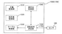
- the control device 1100 includes a spindle control unit 1110, a truer control unit 1120, a grinding control unit 1131 and a lapping control unit 1132, a table control unit 1140, a grindstone table control unit 1150, and a turntable.
- a control unit 1160 and a processing condition determination unit 1170 as a calculation unit are mainly provided.
- the spindle control unit 1110 controls the rotation of the workpiece W (see FIG. 20) by controlling the driving of the spindle motor 24 (see FIG. 20).
- the truer control unit 1120 controls the rotation of the truer 50 (see FIG. 20) by controlling the driving of the truer motor 51 (see FIG. 20).
- the grinding control unit 1131 controls the rotation of the grinding tool 1041 (see FIG. 20) by controlling the driving of the grinding tool motor 1043 (see FIG. 20).
- the lap control unit 1132 controls the rotation of the lap tool 1042 by performing drive control of the lap tool motor 1044 (see FIG. 20).
- the table control unit 1140 controls the position and feed speed of the table 10 (see FIG. 20) in the Z-axis direction by performing drive control of the Z-axis motor 11 (see FIG. 20).
- the wheel head control unit 1150 controls the position and feed speed of the wheel head 30 in the X-axis direction by performing drive control of the X-axis motor 31 (see FIG. 20).
- the turntable control unit 1160 controls the rotation of the turntable 1035 by controlling the rotation mechanism 1036.
- the machining condition determination unit 1170 determines a condition for grinding or lapping performed thereafter based on the detection result regarding the surface roughness of the workpiece W obtained from the sensor 100.
- the table control unit 1140 and the grindstone table control unit 1150 control the position and feed speed of the table 10 and the grindstone table 30 according to the grinding conditions set in the processing condition determination unit 1170. In this way, when the grinding tool 1041 or the lapping tool 1042 is moved relative to the workpiece W and the workpiece W is ground until the outer diameter of the workpiece W reaches a desired dimension, a machining condition determination unit 1170 determines a grinding condition based on the detection result of the sensor 100 so that a desired surface roughness can be obtained after the grinding process is completed while improving efficiency.
- the grindstone table control unit 1150 controls the rotation mechanism 1036 so that the outer peripheral surface of the grinding tool 1041 is disposed at a position facing the workpiece W, and rotates the rotation table 1035.
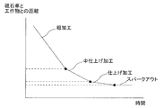
- the machine tool 1001 rotates the grinding tool 1041 in a state where the feed of the grinding wheel platform 30 in the X-axis direction is stopped at the time of sparking out. It should be noted that the traverse speed in the Z-axis direction of the table 10 in each step, the number of times of traverse grinding, and the amount of movement (cutting amount) of the grindstone table 30 in the X-axis direction after one traverse grinding is completed, It is predetermined.
- the depth of cut during rough machining is greater than the depth of cut during intermediate finishing, and the depth of cut during intermediate finishing is greater than the depth of cut during finishing.
- the machine tool 1001 rotates the grinding tool 1041 in a state where the feed of the grinding wheel platform 30 in the X-axis direction is stopped at the time of sparking out.
- the sizing device 70 measures the outer diameter of the workpiece W after the traverse feed in the Z-axis direction of the table 10 is completed until the next traverse feed is started.
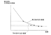
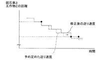
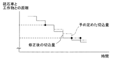
- the machine tool 1001 detects the surface roughness (for example, the maximum height Rz) of the ground portion with the sensor 100 in the process of grinding the workpiece W.
- the machining condition determination unit 1170 determines a grinding condition that causes the surface roughness to be equal to or less than the threshold value.
- the table control unit 1140 and the wheel head control unit 1150 perform control for performing grinding under the conditions determined by the processing condition determination unit 1170. Thereby, the machine tool 1001 can make the surface state of the workpiece W a desired state at the end of the grinding process.
- the machine tool 1001 performs lapping using the lapping tool 1042 after the grinding using the grinding tool 1041 is completed. Accordingly, the turntable control unit 1160 drives and controls the rotation mechanism 1036 to rotate the turntable 1035 by 180 degrees so that the outer peripheral surface of the lapping tool 1042 faces the workpiece W.
- Lapping is performed while rotating the workpiece W while feeding the grinding wheel base 30 in the X-axis direction.
- the sensor 100 detects the surface roughness of the lapped portion of the workpiece W, and the machining condition determination unit 1170 determines that the surface roughness of the workpiece W has become smaller than a predetermined threshold value. Then, the lapping by the lapping tool 1042 is terminated.
- the machine tool 1001 detection of the surface roughness of the part ground by the grinding tool 1041 of the workpiece W and detection of the surface roughness of the part lapped by the lapping tool 1042 of the workpiece W are performed in one.
- the sensor 100 is used. Accordingly, the machine tool 1001 can share the sensor 100.
- the machine tool 1001 includes one sensor 100, and the sensor 100 detects the surface roughness of the workpiece W during grinding and the surface roughness of the workpiece W during lapping.
- the detection is performed has been described.
- the present invention is not limited to this, and a sensor used for detecting the surface roughness of the workpiece W during grinding and a sensor used for detecting the surface roughness of the workpiece W during lapping are separately provided. May be.
- the machine tool 1001 by using a detection unit with higher accuracy than the sensor used during grinding as the sensor used during lapping, the machine tool 1001 more reliably desires the surface roughness of the workpiece W at the end of lapping. Can be brought close to.
- the machine tool 1001 can suppress the component cost of the sensor used during grinding.
- the present invention is applied to the machine tool 1001 capable of performing grinding with the grinding tool 1041 and lapping with the lapping tool 1042 as an example.
- the present invention is not limited to this, and it is naturally possible to apply the present invention to each of a grinding machine capable of performing only grinding and a lapping machine capable of performing only lapping.
- the machine tool system is constituted by one machine tool 1001, but the present invention is not limited to this.
- a machine tool system includes a plurality of machine tools and an analysis unit provided on a network that is external to the plurality of machine tools and to which the plurality of machine tools are connected.
- the machining condition determination unit 1170 as the calculation unit provided in 1100 may be provided in the analysis unit.
- the analysis unit calculates the value of the surface roughness of the workpiece W ground under a specific machining condition (such as a specific workpiece W, a specific machine tool, or a specific environment (temperature or humidity)). accumulate.
- the analysis unit analyzes the accumulated data, and the machining condition determination unit 1170 determines an optimum machining condition based on the analysis result (trend, occurrence of abnormality, etc.) by the analysis unit. Thereby, the machine tool system can make the surface roughness of the workpiece W into a desired state reliably.
- a grinding machine 1201 shown in FIG. 22 has the same configuration as that of the grinding machine 1 (see FIG. 1) in the first embodiment except for the shape of the sensor 100 and the control device 1300.
- control device 1300 mainly includes a grinding process control unit 1310 and a calculation unit 1320 as a calculation unit. Note that the control device 1300 may be disposed inside the sensor 100 or may be disposed outside the sensor 100 and connected to the main body 110 by a cable or the like.
- the grinding process control unit 1310 performs control related to the grinding process performed on the workpiece W.
- the grinding control unit 1310 is, for example, drive control of various motors (Z-axis motor 11, main shaft motor 24, X-axis motor 31, grinding wheel motor 41), control of the amount of coolant supplied from the coolant supply device 60, and sizing.
- the diameter of the workpiece W is managed by the apparatus 70.
- the grinding control unit 1310 also performs control related to a transport device (not shown) that transports the workpiece W.
- the calculation unit 1320 calculates the surface roughness of the part that has been sensed by the sensor 100.
- the calculation unit 1320 includes a first process execution unit 1321, a second process execution unit 1322, and a selection unit 1323.
- the first process execution unit 1321 and the second process execution unit 1322 calculate the surface roughness of the part that has been sensed based on the detection value of the sensor 100.
- the selection unit 1323 selects whether to execute the process by the first process execution unit 1321 or to execute the process by the second process execution unit 1322 in calculating the surface roughness of the part subjected to sensing.
- the waveform of the electric signal received by the control device 1300 from the sensor 100 differs between when the workpiece W being ground is sensed and when the workpiece W is not ground. This is because when the workpiece W being ground is sensed, the influence of the grinding resistance during the grinding is reflected in the waveform of the electrical signal transmitted from the sensor 100.
- the grinding wheel base 30 is provided with a grinding resistance detector 1242 that detects a grinding resistance generated in the grinding wheel 40 based on a current change of the grinding wheel motor 41.
- the first process execution unit 1321 calculates a value obtained by removing the influence of the grinding resistance from the detection value of the sensor 100 based on the detection value of the grinding resistance detection unit 1242. That is, in the first process, the first process execution unit 1321 calculates the surface roughness of the workpiece W based on the detection value of the sensor 100 and the detection value of the grinding resistance detection unit 1242.
- the second process execution unit 1322 does not need to consider the influence of the grinding resistance during the grinding process. Therefore, in the second process, the second process execution unit 1322 calculates the surface roughness of the workpiece W without referring to the detection value of the grinding resistance detection unit 1242.
- the selection unit 1323 selects that the surface roughness of the workpiece W is calculated by the first process when the workpiece W being sensed is being ground. On the other hand, when the workpiece W that is being sensed is not being ground, the selection unit 1323 selects that the surface roughness of the workpiece W is calculated by the second process.
- the grinding machine 1201 detects the surface shape of the workpiece W by the sensor 100, and calculates the surface roughness of the workpiece W based on the detected value. Therefore, the grinding machine 1201 can increase the accuracy of the calculation result of the surface roughness of the workpiece W by the calculation unit 1320.
- the calculation unit 1320 includes a case where sensing is performed on the workpiece W which is being ground and a case where sensing is performed on the workpiece W which is not being ground. Different processing is performed on the detection value of the sensor 100.
- the grinding machine 1201 calculates the surface roughness in the first process
- the grinding machine 1201 calculates the surface roughness based on the detection value of the sensor 100 and the detection value of the grinding resistance detection unit 1242 during the grinding process. Remove the influence of grinding resistance. Therefore, when the grinding machine 1201 calculates the surface roughness of the workpiece W calculated by the calculation unit 1320 regardless of whether or not the workpiece W to be sensed is being ground, the accuracy of the calculation result Can be increased.
- FIGS. 24A to 24C (6-4. Operation of grinding wheel 40 and sensor 100)
- the sensor 100 stands by at a position away from the workpiece W in the initial stage of performing grinding with the grinding wheel 40.
- the grinding machine 1201 can prevent the coolant or the like scattered during the grinding process from adhering to the sensor 100.
- the workpiece W is traversed in the Z-axis direction (right direction in FIG. 24B) as the table 10 traverses.
- the sensor 100 approaches the workpiece W while moving in the X-axis direction (upward in FIG. 24B), and senses a portion of the workpiece W that has been ground by the grinding wheel 40.
- the grinding machine 1201 can simultaneously perform sensing of the workpiece W by the sensor 100 while grinding the workpiece W by the grinding wheel 40.
- the grinding machine 1201 since the grinding machine 1201 performs sensing on the workpiece W traversed while rotating, the surface roughness of the entire outer peripheral surface of the workpiece W can be calculated.
- the grinding machine 1201 when the grinding machine 1201 performs sensing by the sensor 100 on the workpiece W that is not being ground, the grinding machine 1201 sets the sensor W to the workpiece W after the grinding by the grinding wheel 40 is finished. Move closer. In this case, the grinding machine 1201 can perform sensing on the workpiece W in a state in which foreign matter such as coolant or mist including chips is removed, so that the accuracy of the calculation result of the surface roughness can be increased. Can do.
- the sensor 100 since the sensor 100 is provided with the detection unit 120 on the distal end side of the long main body 110 formed in a rod shape, the sensor 100 can be reduced in size. Thereby, the grinding machine 1201 can detect the surface roughness of the workpiece W by the sensor 100 while the workpiece W is supported by the headstock 21. That is, the grinder 1201 does not need to perform an operation of transporting the workpiece W supported by the workpiece support device 20 to another position in order to detect the surface roughness. The work efficiency at the time of performing can be improved.
- the grinding machine 1201 can detect the surface roughness by the sensor 100 in parallel with respect to the workpiece W after the grinding processing, while grinding the workpiece W by the grinding wheel 40. Therefore, after the grinding of the workpiece W by the grinding wheel 40 is completed, the grinding machine 1201 starts grinding the workpiece W compared to the case where the sensor 100 detects the surface roughness of the workpiece W. After that, the time required until the detection of the surface roughness of the workpiece W after grinding is completed can be shortened.
- the sensor 100 can sense the surface of the workpiece W that is being ground by the grinding wheel 40, and the calculation unit 1320 performs the first process on the detection value of the sensor 100 to thereby detect the workpiece W.
- the surface roughness of is calculated. Therefore, the grinding machine 1201 can increase the accuracy of the calculation result of the surface roughness even when sensing is performed on the workpiece W that is being cut. As a result, the grinding machine 1201 can achieve both improvement in work efficiency when performing sensing and improvement in accuracy of the calculation result of the surface roughness.
- the grinding machine 1201 does not need to detect the surface roughness while removing the foreign matter adhering to the workpiece W. That is, since the grinding machine 1201 does not need to provide the first air discharge part 150 and the second air discharge part 170 in the sensor 100, the size of the sensor 100 can be reduced. Moreover, since the grinding machine 1201 can detect the surface roughness of the workpiece W while the workpiece W is stationary, the detection accuracy of the sensor 100 can be increased.
- a machine tool system includes a plurality of grinding machines and an analysis unit provided on a network outside the plurality of grinding machines and connected to the plurality of grinding machines.
- the calculation unit 1320 as the calculation unit provided in 1300 may be provided in the analysis unit.
- the analysis unit can perform advanced analysis based on the detection result transmitted from the sensor 100 that has sensed the workpiece W to derive the surface roughness. Therefore, the machine tool system can improve the detection accuracy when detecting the surface roughness of the workpiece W.
- the machine tool system includes a single table traverse type grinding machine 1401 that performs grinding while rotating a crankshaft as a workpiece W.
- a table traverse type grinder the case where the present invention is applied to a table traverse type grinder will be described as an example. However, the present invention may be applied to a grindstone traverse type grinder.
- control device 1500 includes a spindle control unit 1510, a grinding wheel control unit 1520, a table control unit 1530, a grinding wheel base control unit 1540, and a grinding condition determination unit 1550 as a calculation unit. Prepare.
- the spindle control unit 1510 controls the rotation of the workpiece W (see FIG. 25) by performing drive control of the spindle motor 24 (see FIG. 25).
- the grinding wheel control unit 1520 controls the rotation of the grinding wheel 40 (see FIG. 25) by controlling the driving of the grinding wheel motor 41 (see FIG. 25).
- the table control unit 1530 controls the position and feed speed of the table 10 (see FIG. 25) in the Z-axis direction by performing drive control of the Z-axis motor 11 (see FIG. 25).
- the wheel head control unit 1540 controls the position and feed speed of the wheel head 30 (see FIG. 25) in the X-axis direction by performing drive control of the X-axis motor 31 (see FIG. 25).
- Grinding condition determination unit 1550 determines a condition for grinding performed thereafter based on the detection result regarding the surface roughness of workpiece W obtained from sensor 100.
- the wheel head control unit 1540 controls the position and feed rate of the wheel head 30 in accordance with the grinding conditions determined by the grinding condition determination unit 1550.
- the grinding process sequentially executes four steps of roughing, intermediate finishing, finishing, and spark-out.
- the grinding wheel 40 is moved with the feed of the grinding wheel base 30 stopped. Rotate.
- the feed rate of the grinding wheel base 30 in roughing, intermediate finishing, and finishing is predetermined.
- the feed rate of the grindstone table 30 during rough machining is faster than the feed rate of the grindstone table 30 during intermediate finishing, and the feed rate of the grindstone table 30 during intermediate finish machining is the feed rate of the grindstone table 30 during finish machining. Faster than.
- the grinding condition determination unit 1550 determines that the outer diameter of the workpiece W has reached the predetermined dimension D1 based on the measurement result by the sizing device 70, the grinding condition determination unit 1550 changes the feed rate of the grindstone table 30 and starts the rough machining. Transition to finishing.
- the grinding condition determination unit 1550 determines that the outer diameter of the workpiece W has reached the predetermined dimension D2 (D2 ⁇ D1), the grinding speed determination unit 1550 changes the feed rate of the grindstone table 30 and performs the intermediate finishing process to the finishing process.
- the grinding condition determining unit 1550 determines that the outer diameter of the workpiece W has reached the predetermined dimension D3 (D3 ⁇ D2), the grinding condition determining unit 1550 stops the feed of the grindstone table 30, and shifts from finishing to sparking out. .
- the dimension D3 corresponds to a desired outer diameter of the workpiece W after grinding.
- the feed speed of the grindstone 30 in each process is set as high as possible within a range where it is estimated that a desired surface roughness can be obtained at the end of grinding.
- the grinding machine 1401 can reduce the time required for grinding, so that grinding can be performed efficiently.
- the state of the black skin covering the surface of the workpiece W after cutting is not uniform, even if grinding is performed at a predetermined feed rate, the surface roughness of the workpiece W after grinding is It may not be in the desired state.
- the sensor 100 detects the surface roughness (for example, the maximum height Rz) of the ground part in the process of grinding the workpiece W by the grinding wheel 40.
- the grinding condition determination unit 1550 compares the surface roughness detected by the sensor 100 with a predetermined threshold value and determines that the detected surface roughness value is larger than the predetermined threshold value. Grinding conditions that are below the threshold are determined.
- the wheel head control unit 1540 controls the drive of the X-axis motor 31 according to the conditions determined by the grinding condition determination unit 1550, and changes the feed rate of the wheel head 30.
- sensing by the sensor 100 is performed while rotating the workpiece W while driving and controlling the spindle motor 24 by the spindle control unit 1510.
- the sensor 100 can detect the surface roughness of the range for one round in the predetermined
- the grinding machine 1401 can suppress the occurrence of a problem such that a portion that does not have the desired surface roughness remains in a part of the ground portion of the workpiece W when the grinding process is completed.
- the grinding condition determination unit 1550 performs sensing by the sensor 100 during rough machining and before the outer diameter of the workpiece W reaches D1. Note that the timing for sensing is determined based on the elapsed time from the start of grinding, the position of the grinding wheel base 30 (the distance from the workpiece W to the grinding wheel base 30), and the like.
- the sensor 100 detects the surface roughness of the ground part of the workpiece W, and the grinding condition determination unit 1550 determines whether the value of the surface roughness detected by the sensor 100 is larger than a predetermined threshold value. Determine.
- the grindstone base control unit 1540 drives and controls the X-axis motor 31 to delay the feed rate of the grindstone base 30.
- the grinding machine 1401 corrects the feed rate of the grindstone table 30 when the surface roughness of the workpiece W does not reach the previously assumed surface roughness in the course of rough machining, thereby making the machine The surface roughness of the object W is improved.
- the grinder 1401 monitors the surface roughness of the workpiece W during the grinding process, and corrects the grinding conditions as necessary to ensure the surface roughness of the workpiece W at the time when the grinding process is completed. The desired state can be obtained.
- sensing is performed by the sensor 100 during rough machining
- sensing is performed by the sensor 100 during intermediate finishing and finishing, and grinding is performed later based on the detection result of the surface roughness.
- sensing by the sensor 100 may be performed a plurality of times in one process.
- the grinding condition determination unit 1550 performs sensing by the sensor 100 when the outer diameter of the workpiece W reaches D1.
- the sensor 100 detects the surface roughness of the ground part of the workpiece W, and the grinding condition determination unit 1550 determines whether or not the detection value detected by the sensor 100 is larger than a predetermined threshold value. .
- the grindstone table control unit 1540 controls the drive of the X-axis motor 31 to perform the intermediate finishing process.
- the feed speed of the grinding wheel platform 30 is made slower than the feed speed in the predetermined intermediate finishing process.
- the feed rate of the grindstone table 30 is adjusted at the time of intermediate finishing based on the surface roughness of the workpiece W when the outer diameter of the workpiece W reaches D1 has been described as an example. However, it is of course possible to adjust the feed rate of the grindstone table 30 during finishing based on the surface roughness of the workpiece W when the outer diameter of the workpiece W reaches D2.
- the grinding machine 1401 performs sensing by the sensor 100 when the outer diameter of the workpiece W reaches D1, and the detected surface roughness value is larger than a predetermined threshold value. If it is determined that, roughing may be continued. In this case, the grinding machine 1401 can shorten the time required for the entire grinding process as compared with the case where the feed rate of the grinding wheel base 30 is slowed in the intermediate finishing process. In this case, the grinding machine 1401 switches the process from roughing to semi-finishing when the surface roughness of the workpiece W detected thereafter becomes a predetermined threshold value or less.
- the grinding wheel base control unit 1540 sets the feed speed of the grinding wheel base 30 in the intermediate finishing process in advance so that the time until the intermediate finishing process is completed matches the predetermined time. It is slower than the specified feed rate.
- the present invention is not limited to this, and the grinding wheel base control unit 1540 performs sensing by the sensor 100 after the continuous roughing is completed, and the grinding wheel base in the intermediate finishing processing based on the detected surface roughness. Thirty feed rates may be determined.
- the feed speed of the rough machining that is continuously performed is the same as the feed speed at the time of rough machining that has been performed just before.
- it may be set to a feed rate that is slower than the feed rate at the time of rough machining, which has been carried out until just before, and faster than the feed rate at the time of predetermined intermediate finishing.
- the grinding condition determination unit 1550 detects the surface roughness of the ground portion of the workpiece W when the outer diameter of the workpiece W reaches D1, and based on the detection result, the grinding process is started. Determine when to switch the process to finishing. Thereby, the grinding machine 1401 can avoid that the grinding process is switched from the roughing process to the semi-finishing process with the black skin remaining on the surface of the workpiece W. As a result, the grinding machine 1401 can reliably set the surface roughness of the workpiece W to a desired surface roughness at the end of the grinding process.
- the sensor 100 detects the surface roughness of the ground portion of the workpiece W.
- the grinding machine 1401 determines conditions for subsequent grinding based on the value of the surface roughness of the workpiece W detected by the sensor 100, and performs grinding according to the determined grinding conditions. As a result, the grinding machine 1401 can ensure that the surface roughness of the workpiece W is in a desired state when the grinding process is completed.
- the grinding machine 1401 can reduce the time required for the entire grinding process by setting the feed speed in each step of the predetermined grinding process as high as possible.
- the grinding condition determination unit 1550 detects the surface roughness of the ground portion of the workpiece W during grinding, and determines that the detected surface roughness value is greater than a predetermined threshold value.
- the feed rate of the grindstone table 30 is delayed so as to achieve a grinding condition in which the roughness is equal to or less than a predetermined threshold value. By setting such grinding conditions, the grinding machine 1401 can ensure that the surface roughness of the workpiece W is in a desired state while performing grinding efficiently.
- the grinding condition determination unit 1550 has been described based on the measurement result of the outer diameter of the workpiece W by the sizing device 70, but the timing for sensing by the sensor 100 has been described. It is not something that can be done. That is, the grinding condition determination unit 1550 may determine the timing at which the sensor 100 performs sensing based on the position of the grinding wheel base 30 (the distance between the workpiece W and the grinding wheel 40).
- the grinding machine 1401 detects the surface roughness of the workpiece W while rotating the workpiece W has been described.
- the sensor 100 The workpiece W may be sensed.
- the machine tool system is constituted by one grinder 1401, but the present invention is not limited to this.
- a machine tool system includes a plurality of grinding machines and an analysis unit provided on a network outside the plurality of grinding machines and connected to the plurality of grinding machines.
- a grinding condition determination unit 1550 as a calculation unit provided in 1500 may be provided in the analysis unit.
- the analysis unit for example, the workpiece ground under specific machining conditions (such as the value of the surface roughness of the specific workpiece W, the specific grinder 1401 and the specific environment (temperature and humidity)). Accumulate the surface roughness value of W.
- the analysis unit analyzes the accumulated data, and the grinding condition determination unit 1550 determines the optimum grinding condition based on the analysis result (trend, occurrence of abnormality, etc.) by the analysis unit. Thereby, the grinding machine 1401 can ensure that the surface roughness of the workpiece W is in a desired state.
- the processing by traverse grinding sequentially executes four steps of roughing, intermediate finishing, finishing and spark-out.
- the switching of the process is performed mainly based on the position of the grinding wheel platform 30 in the X-axis direction (distance from the workpiece W) and the outer diameter of the ground workpiece W. It should be noted that the traverse speed in the Z-axis direction of the table 10 in each step, the number of times of traverse grinding, and the amount of movement (cutting amount) of the grindstone table 30 in the X-axis direction after one traverse grinding is completed, It is predetermined.
- the depth of cut during rough machining is greater than the depth of cut during intermediate finishing, and the depth of cut during intermediate finishing is greater than the depth of cut during finishing. Further, at the time of sparking out, the grinding machine 1601 rotates the grinding wheel 40 in a state where the feeding of the grinding wheel base 30 in the X-axis direction is stopped. Note that the sizing device 70 measures the outer diameter of the workpiece W after the traverse feed of the table 10 in the Z-axis direction is completed and before the next traverse feed is started.
- the grinding condition determination unit 1750 determines that the outer diameter of the workpiece W has reached the predetermined dimension D1 based on the measurement result by the sizing device 70 and the position of the grinding wheel base 30 in the X-axis direction, Change the feed rate and switch the process from roughing to semi-finishing. Similarly, when it is determined that the outer diameter of the workpiece W has reached the predetermined dimension D2, the grinding condition determination unit 1750 changes the feed rate of the grinding wheel base 30, and switches the process from intermediate finishing to finishing. I do. When the grinding condition determination unit 1750 determines that the outer diameter of the workpiece W has reached the predetermined dimension D3, the grinding condition determination unit 1750 stops the feeding of the grinding wheel base 30, and switches the process from finishing to sparking out.
- the sensing by the sensor 100 is performed while driving the spindle motor 24 by the spindle controller 1510 and driving the Z-axis motor 11 by the table controller 1530. That is, the sensor 100 detects the surface roughness of the workpiece W while rotating the workpiece W and traversing the workpiece W relative to the sensor 100 in the Z-axis direction.
- the grinding machine 1601 can detect the entire surface roughness of the workpiece W by the sensor 100. Therefore, the grinding machine 1601 reliably detects the portion of the ground portion of the workpiece W where the surface roughness is equal to or less than the predetermined threshold, and detects the surface of the workpiece W. Grinding conditions can be determined so that the whole is below a predetermined threshold. As a result, the grinding machine 1601 can reliably bring the surface roughness of the entire workpiece W to a desired state when the grinding process is completed.
- the detection of the surface roughness of the workpiece W by the sensor 100 is performed after the predetermined number of times of traverse grinding is completed and before the next traverse grinding is started.
- the grinding machine 1601 can improve the detection accuracy of the surface roughness as compared with the case where sensing is performed by the sensor 100 while performing traverse grinding.
- the grinding machine 1601 performs sensing by the sensor 100 at the time when a predetermined number of times of traverse grinding have been completed and before the outer diameter of the workpiece W reaches D1. Then, the grinding condition determination unit 1750 detects the surface roughness of the ground portion of the workpiece W and determines whether or not the value of the surface roughness is larger than a predetermined threshold value.
- the table control unit 1530 causes the Z-axis motor 11 to operate so that the surface roughness becomes equal to or less than the threshold value. Drive control is performed, and the feed speed of the table 10 is delayed.
- the grinding machine 1601 can delay the relative moving speed of the workpiece W with respect to the grinding wheel 40, the surface roughness of the workpiece W can be improved.
- the grinding machine 1601 monitors the surface roughness of the workpiece W during the grinding process, and corrects the grinding conditions as necessary, so that the surface of the workpiece W is finished when the grinding process is completed. Roughness can be reliably brought into a desired state.
- the grinding machine 1601 drives and controls the spindle motor 24 by the spindle control unit 1510, instead of driving the Z-axis motor 11 by the table control unit 1530, or simultaneously with the drive control of the Z-axis motor 11.
- the relative moving speed of the workpiece W with respect to the grinding wheel 40 may be delayed.
- the grinding machine 1601 performs sensing by the sensor 100 at the time when the predetermined number of times of traverse grinding is completed and before the outer diameter of the workpiece W reaches D1. Do. Then, the grinding condition determination unit 1750 determines the number of times of remaining traverse grinding in rough machining according to the surface roughness of the ground portion of the workpiece W.
- the grinding condition determination unit 1750 indicates that the surface roughness of the ground portion of the workpiece W is smaller than a predetermined threshold value (the surface roughness is better than expected). If determined, reduce the number of times of remaining traverse grinding.
- the grinding wheel base control unit 1540 increases the movement amount (cutting amount) of the grinding wheel base 30 after one traverse grinding so that the outer diameter of the workpiece W reaches D1 when the roughing is finished. To do.
- the grinding machine 1601 can reduce the number of times of traverse grinding in the roughing process, so that the time required for the roughing process can be shortened.
- the grinding condition determination unit 1750 determines that the surface roughness of the ground portion of the workpiece W is larger than a predetermined threshold (the surface roughness is not better than expected). Increase the number of remaining traverse grindings.
- the wheel head control unit 1540 reduces the amount of movement of the wheel head 30 after one traverse grinding so that the outer diameter of the workpiece W reaches D1 when the roughing is finished. Thereby, since the grinding machine 1601 can improve the surface roughness, the surface roughness of the workpiece W can be surely brought into a desired state when the grinding process is completed.
- the sensor 100 detects the surface roughness of the ground portion of the workpiece W.
- the grinding machine 1601 determines grinding conditions to be performed later based on the surface roughness value of the workpiece W detected by the sensor 100, and performs grinding according to the determined grinding conditions.
- the grinding machine 1601 can reliably bring the surface roughness of the workpiece W into a desired state at the time when the grinding process is completed.
- 32A and 32B exemplify a case where the number of times of remaining traverse grinding is determined based on the surface roughness of the ground portion after performing a predetermined number of times of traverse grinding during rough machining.
- it is not limited to this. That is, it is naturally possible to determine the number of times of remaining traverse grinding based on the detection result of the surface roughness of the workpiece W after performing a predetermined number of times of traverse grinding in intermediate finishing, finishing and sparking out. is there.
- the grinding machine 1601 detects the surface roughness of the workpiece W by the sensor 100 after the predetermined number of times of traverse grinding has been completed and before the next traverse grinding is started.
- the present invention is not limited to this. That is, the grinding machine 1601 may detect the surface roughness of the workpiece W by the sensor 100 while performing traverse grinding with the grinding wheel 40. In this case, since the grinding machine 1601 can perform sensing by the sensor 100 in parallel with the traverse grinding, the time required for the entire grinding process can be reduced.
- the machine tool 1801 as the machine tool system uses the sensor 1920 to determine the coolant fluid replacement time.
- symbol is attached
- the machine tool 1801 is composed of one table traverse type grinding machine that performs grinding while rotating a cylindrical workpiece W.
- the machine tool 1801 includes a bed 2, a table 10, a workpiece support device 20, a grinding wheel base 30, a grinding wheel 40, a sizing device 70, and a coolant supply device 1860.
- the coolant supply device 1860 is provided at a position away from the bed 2 and supplies the coolant liquid C from a coolant nozzle (not shown) toward the grinding site.
- the coolant supply device 1860 includes a tank body 1890 and a pollution evaluation device 1900.
- the tank body 1890 is a container for storing the coolant liquid C.
- the coolant C stored in the tank body 1890 is supplied to the grinding site, and then collected and returned to the tank body 1890.
- a transparent window 1891 that forms a storage area for the coolant C in the tank body 1890 is provided on the outer surface of the tank body 1890.
- the liquid level of the coolant C stored in the tank body 1890 is located above the position where the transparent window 1891 is disposed, and the degree of contamination of the coolant C is determined from the outside of the tank body 1890 via the transparent window 1891. Can be confirmed.
- the pollution evaluation device 1900 is a device for determining the replacement time of the coolant liquid C stored in the tank main body 1890.
- the pollution evaluation apparatus 1900 includes a reflecting member 1910, a sensor 1920, and an evaluation unit 1930.
- the reflection member 1910 is disposed at a position facing the transparent window 1891 inside the tank main body 1890, and a space in which the coolant liquid C stored in the tank main body 1890 can flow between the transparent window 1891 and the reflection member 1910. Is formed.
- the senor 1920 includes a holding unit 1921 and a detection unit 120.
- the holding unit 1921 is fixed to the outer surface of the tank body 1890 and holds the detection unit 120.
- the detection unit 120 is disposed at a position facing the reflection member 1910 with the transparent window 1891 interposed therebetween.
- the evaluation unit 1930 determines, for example, whether or not the light amounts received by the first light receiving element 123 and the second light receiving element 124 are smaller than a predetermined light amount. Then, the evaluation unit 1930 determines that it is time to replace the coolant liquid C when the amount of light received by the first light receiving element 123 and the second light receiving element 124 is smaller than a predetermined amount of light. In this case, the pollution evaluation device 1900 provides a notification device such as a lamp or a buzzer to the sensor 1920, and when the evaluation unit 1930 determines that it is time to replace the coolant C, the notification device notifies the operator of that fact. May be.
- the pollution evaluation apparatus 1900 senses and evaluates the degree of contamination of the coolant liquid C by the sensor 1920.
- the operator can grasp the appropriate replacement time of the coolant based on the evaluation by the pollution evaluation device 1900.
- the sensor 1920 is provided in the tank body 1890, the degree of freedom in designing the machine tool 1801 can be increased.
- the machine tool 1801 as the machine tool system is configured by one grinder, but is not limited thereto.
- the machine tool system includes a plurality of machine tools (grinding machines) and an analysis unit provided on a network outside the plurality of machine tools and connected to the plurality of machine tools.
- the evaluation unit 130 as a calculation unit provided in the pollution evaluation apparatus 100 in the form may be provided in the analysis unit.
- the analysis unit for example, specific processing conditions (specific workpiece W, specific machine tool 1, specific environment (air temperature, temperature, etc.)), the degree of contamination of the coolant C in a specific processing state, or the like. Accumulate data about.
- the analysis unit analyzes the accumulated data, and the evaluation unit 130 predicts the replacement timing of the coolant C and determines appropriate processing conditions based on the analysis results (trends, abnormalities, etc.) by the analysis unit. I do. Thereby, the machine tool system can replace the coolant C at an appropriate time.
- the light emitting element 122 emits light toward the reflecting member 1910 immersed in the coolant liquid C, and the first light receiving element 123 and the second light receiving element 124 are reflected by the reflecting member 1910 and the coolant.
- the case where the reflected light from the liquid C is received has been described.
- the light emitting element 122 emits light to the reflecting member 2110 taken out from the coolant liquid C, and the first light receiving element 123 and the second light receiving element 124 are reflected by the reflecting member 2110 and the reflecting member. The reflected light from the suspended matter S attached to the member 2110 is received.
- the machine tool 2001 according to the tenth embodiment has the same configuration as the machine tool 1801 according to the ninth embodiment except for the pollution evaluation device 2100 in the coolant supply device 2060.
- the same parts as those in the above-described embodiments are denoted by the same reference numerals, and the description thereof is omitted.
- the pollution evaluation device 2100 includes a reflective member 2110, a sensor 2120, and an evaluation unit 1930.
- the reflecting member 2110 is provided so as to be movable between the coolant liquid C and the outside of the liquid coolant C with respect to the tank main body 1890, and is formed so that the suspended matter S in the liquid can adhere to the tank body 1890 when it is taken out of the liquid.
- the sensor 2120 includes a holding unit 2121 and a detection unit 120.
- the holding unit 2121 is fixed to the outer surface of the tank body 1890 and holds the detection unit 120.
- the detection unit 120 is arranged above the storage area for the coolant C in the tank body 1890.
- the sensor 2120 emits light toward the reflecting member 2110 taken out from the coolant C, and receives the reflected light from the reflecting member 2110 and the suspended matter S attached to the reflecting member 2110.
- the evaluation unit 1930 evaluates the degree of contamination of the coolant C based on the amount of reflected light from the reflecting member 2110 and reflected light from the suspended matter S received by the first light receiving element 123 and the second light receiving element 124.
- the pollution evaluation apparatus 2100 performs sensing by the sensor 2120 on the reflection member 2110 taken out of the coolant liquid C and evaluates the pollution degree of the coolant liquid C. Therefore, the pollution evaluation apparatus 2100 can accurately evaluate the pollution degree of the coolant liquid C even if the coolant liquid is colored.
- the detection unit 120 is fixed to the front end surface of the main body 110.
- the sensor 2200 is located on the opposite side of the workpiece W from the processing position of the grinding wheel 40 and the workpiece W, and the front end surface of the main body 110 to which the detection unit 120 is fixed faces the workpiece W. Be placed.
- the sensor 2200 can provide the detection region A at a position away from the machining position as compared with the case where the detection unit 120 is disposed above the workpiece W. Therefore, the sensor 2200 can easily prevent foreign matters from scattering into the detection unit 120 and mist from entering the detection area.
- a detection port 2242 is formed on the front end surface of the main body cover 2240 (a surface facing the right side in FIG. 37), and the first air is formed around the detection port 2242.
- a discharge part 150 is formed.
- the second air discharge part 2270 is arranged on the upper surface of the main body cover 2240 and at a position closer to the workpiece W than the air supply part 81.
- the wind cutting plate 2280 is disposed between the second air discharge portion 2270 and the first air discharge portion 150, and the second air discharge portion 2270 is located on the workpiece W rather than the end surface 2280a of the wind cutting plate 2280 facing the workpiece. The air is radiated toward the workpiece W from a position apart from.
- the sensor 2200 detects the foreign matter scattered by the air blown from the second air discharge portion 2270. It can suppress adhering to the part 120. Further, since the air discharged from the second air discharge portion 2270 is directed to the workpiece W while being guided by the wind cutting plate 2280, the sensor 2200 can strongly blow the air against the workpiece W. Therefore, the sensor 2200 can easily remove foreign matters attached to the workpiece W.
- the main body 110 is fixed to the main body cover 140 in the first to eighth embodiments.
- the main body 110 is configured to be movable relative to the main body cover 140 in the X-axis direction. May be.
- the sensors 100 and 600 can move the detection unit 120 to a position where the detection unit 120 is not exposed from the detection port 142 in a state where the surface roughness is not detected. Can be prevented.
- the machine tools 1001, 1801, 2001, the grinding machines 1,301, 501, 1201, 1401, 1601, and the machining center 801 as the machine tool system according to the present invention support the workpiece W in a rotatable manner.
- Unit 120 calculation units 220, 420, 630 for calculating shape information of the workpiece W or calculating the surface roughness of the workpiece W based on the detection result of the detection unit 120, or a machining condition determination unit 1170 as the calculation unit, A calculation unit 1320, grinding condition determination units 1550 and 1750, and an evaluation unit 1930.
- the detection unit 120 performs sensing of the workpiece W in a non-contact manner. Then, the processing units 220, 420, 630 or the processing condition determination unit 1170, the calculation unit 1320, the grinding condition determination units 1550, 1750 and the evaluation unit 1930 as the calculation unit are used for the workpiece W based on the detection result of the detection unit 120. Extraction of shape information or surface roughness of the workpiece W is calculated. Therefore, the machine tool system can extract the shape information of the workpiece W or calculate the surface roughness of the workpiece W without contacting the workpiece W.
- the grinding machines 1 and 301 as the machine tool system include the workpiece support device 20 that rotatably supports the workpiece W, and the workpiece support device 20. Light is emitted toward the grinding wheel 40 as a tool for machining the workpiece W supported on the workpiece and the workpiece W supported by the workpiece support device 20, and the reflected light from the surface of the workpiece W is received.
- the sensor 100 and arithmetic units 220 and 420 that extract shape information of the workpiece W based on the amount of light received by the sensor 100 when the workpiece W is rotated are provided.
- the sensor 100 emits light toward the workpiece W supported by the workpiece support device 20 and is reflected by the surface of the workpiece W. Is received. Then, the arithmetic units 220 and 420 obtain shape information of the workpiece W based on the amount of light received by the sensor 100. Therefore, the shape information of the workpiece W can be acquired without contacting the workpiece W, and the shape of the workpiece W can be measured.
- the calculation units 220 and 420 extract the distance from the workpiece W based on the amount of light received by the sensor 100, and obtain shape information based on the extracted distance. Extract.
- the grinding machine 1,301 as the machine tool system can acquire the shape information of the workpiece W without contacting the workpiece W.
- the arithmetic units 220 and 420 extract rotational runout components that can occur in the workpiece W.
- the grinding machine 1 as this machine tool system can determine whether or not the workpiece W has runout without contacting the workpiece W.
- the workpiece W is formed in a cylindrical shape
- the calculation unit 220 removes the rotational shake component of the workpiece from the information on the amount of light received with respect to the rotational phase of the workpiece W, A roundness component is extracted as shape information.
- the grinding machine 1 as the machine tool system can perform information on the roundness of the workpiece W without contacting the workpiece W.
- the calculation unit 220 removes the low frequency component as the rotational shake from the received light amount information and extracts the high frequency component as the roundness component.
- the grinding machine 1 as a machine tool system having this measurement function can accurately extract information on the roundness of the workpiece W.
- the calculation unit 220 extracts chatter components that can occur in the workpiece W.
- the grinding machine 1 as the machine tool system can determine whether or not the workpiece W is chattered without contacting the workpiece W.
- the workpiece W is a cam
- the calculation unit 420 rotates the workpiece W while moving the sensor 100 along the cam surface.
- the components of the cam profile are extracted based on the amount of received light.
- the machine tool system having this measurement function can perform information on the cam profile without contacting the workpiece W.
- the sensor 100 is mounted on the substrate 121, the light emitting element 122 mounted on the substrate 121 and emitting light toward the workpiece W, and mounted on the substrate 121 in the vicinity of the light emitting element.
- the surface roughness detection method is a surface roughness detection method in which the sensor 600 detects the surface roughness of the workpiece W ground by the grinding wheel 40.
- the sensor 600 includes a long main body 110 formed in a rod shape, and a detection unit 120 that is fixed to a side surface located on the distal end side of the main body 110 and can detect the surface roughness of the workpiece W in a non-contact manner.
- the surface roughness detection method the surface roughness of two or more parts having different directions in the workpiece W is detected by rotating the detection unit 120 around the axis of the main body 110.
- the surface roughness of the workpiece W is detected by rotating the detection unit 120 around the axis of the main body 110 to detect the surface roughness of two or more parts of the workpiece W having different directions.
- the height can be detected efficiently.
- the detection of the surface roughness of the workpiece W by the sensor 600 is performed in parallel with the grinding of the workpiece W by the grinding wheel 40.
- the grinding of the workpiece W is performed compared to the case of detecting the surface roughness of the workpiece W by the sensor 600. The time required from the start to the end of the detection of the surface roughness of the workpiece W after grinding can be shortened.
- the workpiece W is a crankshaft
- the detection unit 120 can detect the surface roughness of the crank journal Wa of the crankshaft.
- This surface roughness detecting method can efficiently detect the surface roughness when detecting the surface roughness of the crank journal Wa of the crankshaft.
- the above-described surface roughness detection method rotates the detection unit 120 around the axis of the main body 110, thereby causing the end surfaces Wa1, Wa5, the cylindrical surface Wa3, and the end surfaces Wa1, Wa5, and the cylindrical surface of the crank journal Wa to rotate.
- the surface roughness of at least two or more of the connecting portions Wa2 and Wa4 with Wa3 is detected.
- This surface roughness detection method includes the end surfaces Wa1 and Wa5 of the crank journal crank journal Wa of the crankshaft, the cylindrical surface Wa3, and the surfaces of at least two of the connecting portions Wa2 and Wa4 of the end surfaces Wa1, Wa5 and the cylindrical surface Wa3. In detecting the roughness, the surface roughness can be detected efficiently.
- the grinding machine 501 and the machining center 801 as the machine tool system include the headstock 21 as the workpiece support device 20 that rotatably supports the workpiece W.
- control devices 700 and 900 that perform control related to the sensor 600.
- the sensor 600 includes a long main body 110 formed in a rod shape, a detection unit 120 that is fixed to the outer surface on the distal end side of the main body 110 and can detect the surface roughness of the workpiece W in a non-contact manner, and the main body 110. And a drive unit 690 for applying a drive force for rotating around the axis.
- the grinding machine 501 and the machining center 801 as the machine tool system can detect the surface roughness of two or more parts having different directions in the workpiece W by rotating the detection unit 120 around the axis of the main body 110. it can. Therefore, the machine tool system can efficiently detect the surface roughness of the workpiece W.
- the sensor 600 is mounted on the substrate 121, a light emitting element that is mounted on the substrate 121, and emits light toward the workpiece W, and in the vicinity of the light emitting element on the substrate 121. And a light receiving element as the first light receiving element 123 and the second light receiving element 124 that can receive the reflected light from the workpiece W, and a calculation unit 630 that calculates the surface roughness based on the amount of light received by the light receiving element, . Since the grinding machine 501 and the machining center 801 as the machine tool system can detect the surface roughness of the workpiece W in a non-contact manner, the workpiece W after grinding is damaged as the surface roughness is detected. You can avoid sticking.
- a machine tool 1001 as a machine tool system is a machine tool system that performs lapping on a workpiece W after grinding, and a lapping tool 1042 that performs lapping on the workpiece W. And a sensor 100 that detects the surface roughness of the workpiece W, and a control device 1100 that performs lapping by the lapping tool 1042 based on the surface roughness detected by the sensor 100.
- the surface roughness of the workpiece W is detected by the sensor 100 and lapping is performed based on the detected surface roughness of the workpiece W.
- the surface roughness of the workpiece W at the end of lapping can be surely brought into a desired state.
- the control device 1100 ends the lapping when the detected surface roughness is smaller than a predetermined threshold value.
- a machine tool 1001 as this machine tool system can reliably set the surface roughness of the workpiece W at the end of lapping to a desired state.
- the machine tool 1001 as the above-described machine tool system includes a workpiece support device 20 that rotatably supports the workpiece W, a grinding tool 1041 that grinds the workpiece W supported by the workpiece support device 20, Is provided.
- the machine tool 1001 as the machine tool system is configured to use the workpiece W supported by the workpiece support device 20 when performing lapping with the lapping tool 1042 on the workpiece W that has been ground by the grinding tool 1041.
- the work of transporting to another place can be made unnecessary. Therefore, the machine tool system can shorten the time required from the end of the grinding process to the start of the lapping process.
- control device 1100 detects the surface roughness of the part ground by the grinding tool 1041 of the workpiece W and lapping is performed by the lapping tool 1042 of the workpiece W.
- the surface roughness of the part is detected by using one sensor 100.
- the machine tool 1001 as the above-described machine tool system detects the surface roughness of the part ground by the grinding tool 1041 and the surface roughness of the part lapped by the lapping tool 1042 by one sensor 100.
- the sensor 100 can be shared.
- the machine tool 1001 as the machine tool system described above includes a plurality of sensors, and the plurality of sensors includes a grinding process sensor that detects the surface roughness of a portion ground by the grinding tool 1041 of the workpiece W, and A lapping process sensor for detecting the surface roughness of the part lapped by the lapping tool 1042 of the workpiece.
- a machine tool 1001 as this machine tool system detects a grinding process sensor that is a sensor for detecting the surface roughness of the workpiece W during grinding and a surface roughness of the workpiece W during lapping. It is possible to separately provide a lapping sensor which is a sensor for performing the above process. Therefore, the machine tool system can reliably bring the surface roughness of the workpiece W after grinding and lapping into a desired state.
- the sensor 100 is mounted on the substrate 121, the light emitting element that is mounted on the substrate 121 and emits light toward the workpiece W, and is mounted on the substrate 121 in the vicinity of the light emitting element.
- the grinding machine 1201 as a machine tool system includes a workpiece support device 20 that rotatably supports the workpiece W, a grinding wheel 40 that grinds the workpiece W, and a grinding wheel.
- the sensor 100 capable of sensing the surface of the workpiece W being ground by the vehicle 40, and the surface roughness of the workpiece W is detected by performing a first process on the detection value of the sensor 100 during grinding.
- a calculating unit 1320 a calculating unit 1320.
- the sensor 100 can sense the surface of the workpiece W that is being ground by the grinding wheel 40, and the calculation unit 1320 can detect the detection value of the sensor 100.
- the machine tool system can increase the accuracy of the calculation result of the surface roughness even when sensing is performed on the workpiece W that is being cut. It is possible to achieve both improvement in efficiency and improvement in accuracy of the calculation result of the surface roughness.
- the grinding machine 1201 as the machine tool system described above includes a grinding resistance detection unit 1242 that detects grinding resistance generated in the grinding wheel 40 during grinding of the workpiece W.
- the calculation unit 1320 performs a first process for removing the influence of the grinding resistance on the detection value of the sensor 100 based on the detection value of the sensor 100 and the detection value of the grinding resistance detection unit 1242 during grinding. Then, the surface roughness of the workpiece during grinding by the grinding wheel 40 is calculated.
- the calculation unit 1320 performs the first process to remove the influence of the grinding resistance on the detection value of the sensor 100. Therefore, the machine tool system can increase the accuracy of the calculation result of the surface roughness even when sensing is performed on the workpiece W that is being cut.
- the calculation unit 1320 performs the first process on the detection value of the sensor 100 when the surface of the workpiece W is sensed by the sensor 100 during grinding. Then, the surface roughness of the workpiece W is calculated. On the other hand, when sensing the surface of the workpiece W that is not being ground by the grinding wheel 40, the calculation unit 1320 performs a second process different from the first process on the detection value of the sensor 100, thereby causing the workpiece. The surface roughness of is calculated.
- the grinding machine 1201 as the machine tool system includes a case where sensing is performed on the workpiece W being ground and a case where sensing is performed on the workpiece W which is not being ground. Do different processing. Therefore, the machine tool system calculates the surface roughness regardless of whether the sensing is performed on the workpiece W that is being ground or the sensing is performed on the workpiece W that is not being ground. Can improve the accuracy.
- the sensor 100 is mounted on the substrate 121, the light emitting element that is mounted on the substrate 121 and emits light toward the workpiece W, and is mounted on the substrate 121 in the vicinity of the light emitting element.
- the grinding machines 1401 and 1601 as machine tool systems include a grinding wheel 40 as a tool for grinding the workpiece W, and a workpiece ground by the grinding wheel 40.
- a sensor 100 that detects the surface roughness of W, and control devices 1500 and 1700 that determine grinding conditions to be performed after detection based on the surface roughness detected by the sensor 100, and perform grinding under the determined conditions; Is provided.
- the grinding machines 1401 and 1601 as the machine tool system determine grinding conditions based on the surface roughness of the workpiece W ground by the grinding wheel 40, and perform subsequent grinding under the determined conditions. A desired surface roughness can be obtained while performing grinding efficiently.
- control devices 1500 and 1700 are configured so that the surface roughness is equal to or less than the threshold as a condition for grinding performed after detection when the detected surface roughness is larger than a predetermined threshold. Is determined, and grinding is performed under the determined condition.
- the grinding machines 1401 and 1601 as the machine tool system can obtain a desired surface roughness at the end of grinding.
- the control devices 1500 and 1700 sequentially execute a plurality of grinding processes, and switch between the plurality of grinding processes based on the surface roughness detected by the sensor 100. Determine timing. Since the grinding machines 1401 and 1601 as the machine tool system switch the grinding process based on the surface roughness of the ground portion of the workpiece W, the desired surface roughness is obtained at the end of the grinding process. be able to.
- the grinding machine 1401 as the machine tool system described above grinds the workpiece W by plunge grinding.
- the grinding machine 1401 as the machine tool system can obtain a desired surface roughness while performing efficient grinding when performing plunge grinding.
- the grinding machine 1601 as the machine tool system described above grinds the workpiece W by traverse grinding.
- the grinding machine 1601 as the machine tool system can obtain a desired surface roughness while performing efficient grinding when performing traverse grinding.
- the control device 1700 determines the number of remaining traverses as a condition for traverse grinding after detection based on the surface roughness detected by the sensor 100, and the determined remaining traverse is determined. Perform traverse grinding a number of times.
- the grinding machine 1601 as this machine tool system determines the optimum remaining traverse number based on the surface roughness of the ground part of the workpiece W, and performs traverse grinding for the determined remaining traverse number. A desired surface roughness can be obtained while performing efficient grinding.
- the sensor 100 detects the surface roughness after the traverse grinding by the grinding wheel 40 is completed a predetermined number of times and before the next traverse grinding is started.
- the grinding machine 1601 as the machine tool system can improve the detection accuracy of the surface roughness as compared with the case where sensing is performed by the sensor 100 while performing traverse grinding.
- the sensor 100 detects the surface roughness while performing traverse grinding with the grinding wheel 40. Since the grinding machine 1601 as this machine tool system can perform sensing by the sensor 100 in parallel with the traverse grinding, the time required for the entire grinding process can be shortened.
- the sensor 100 is in a state where the workpiece W is rotating and the workpiece W is traversed relative to the sensor 100, and the workpiece is The ground part of W is detected.
- the grinding machine 1601 as this machine tool system can perform sensing by the sensor 100 on the entire surface of the workpiece W. Therefore, the machine tool system can reliably detect the part of the surface of the workpiece W when the part whose surface roughness is equal to or less than the predetermined threshold remains. As a result, the machine tool system can set grinding conditions such that the entire surface of the workpiece W has a desired surface roughness.
- the sensor 100 detects the surface roughness in a range corresponding to one round of a predetermined axial position of the workpiece W among the ground portions of the workpiece W. To do.
- the grinding machines 1401 and 1601 as the machine tool system can easily prevent the occurrence of a problem such that a portion that does not have a desired surface roughness remains at the time when the grinding process is completed.
- the sensor 100 includes the substrate 121, the light emitting element 122 that is mounted on the substrate 121 and emits light toward the workpiece W, and the vicinity of the light emitting element on the substrate 121. And a light receiving element as a second light receiving element 124 and a first light receiving element 123 capable of receiving reflected light from the workpiece W. Since the grinding machines 1401 and 1601 as the machine tool system can detect the surface roughness of the workpiece W in a non-contact manner, the workpiece W after grinding is damaged as the surface roughness is detected. You can avoid that.
- the machine tools 1801 and 2001 as the machine tool system include the pollution evaluation apparatuses 1900 and 2100 provided in the tank main body 1890 that stores the coolant liquid C.
- the pollution evaluation apparatuses 1900 and 2100 include reflection members 1910 and 2110 that can be immersed in the coolant liquid C, a light emitting element 122 that is provided in the tank body 1890 and emits light toward the reflection members 1910 and 2110, and the reflection member.
- the sensors 1920 and 2120 having the first light receiving element 123 and the second light receiving element 124 as light receiving elements for receiving the reflected light from 1910 and 2110, and the degree of contamination of the coolant C are evaluated based on the amount of light received by the light receiving elements.
- An evaluation unit 1930 An evaluation unit 1930.
- the light emitting element 122 can be immersed in the coolant C stored in the tank body 1890.
- Light is emitted toward 1910 and 2110, and the reflected light is received by a first light receiving element 123 and a second light receiving element 124 as light receiving elements. Since the pollution degree of the coolant liquid C is evaluated based on the amount of light received by the light receiving element, an appropriate replacement time of the coolant liquid C can be grasped based on the evaluation. Further, since the sensors 1920 and 2120 are provided in the tank main body 1890, the degree of freedom in designing the machine tool system can be increased.
- the light emitting element 122 emits light toward the reflecting member 1910 existing in the coolant liquid C, and the first as the light receiving element.
- the light receiving element 123 and the second light receiving element 124 receive the reflected light from the reflecting member 1910 and the reflected light from the coolant liquid C.
- the contamination evaluation apparatus 1900 for the coolant C of the machine tool 1801 as the machine tool system can accurately evaluate the pollution degree of the coolant C stored in the tank body 1890, the coolant C can be obtained at an appropriate time. Can be exchanged.
- the tank body 1890 includes a transparent window 1891 that forms a storage area for the coolant C, and the reflection member 1910 is transparent inside the tank body 1890. Provided at a position facing the window 1891.
- the sensor 1920 is provided on the outer surface of the transparent window 1891 of the tank body 1890, and the light emitting element 122 emits light toward the reflecting member 1910 through the transparent window 1891, and the first light receiving element 123 and the second light receiving element as the light receiving elements.
- the light receiving element 124 receives the reflected light through the transparent window 1891.
- the coolant evaluation apparatus 1900 for the coolant C of the machine tool 1801 as the machine tool system accurately evaluates the pollution of the coolant C stored in the tank body 1890 while increasing the design freedom of the machine tool system. Can do.
- the reflecting member 2110 is provided so as to be movable between the coolant liquid C and the coolant liquid C.
- the suspended matter S in the coolant liquid C can be attached.
- the light emitting element 122 emits light toward the reflecting member 2110 moved out of the coolant liquid C, and the first light receiving element 123 and the second light receiving element 124 as light receiving elements are moved out of the coolant liquid C.
- the reflected light from the reflecting member 2110 and the reflected light from the suspended matter S attached to the reflecting member 2110 are received.
- the contamination evaluation apparatus 2100 for the coolant C of the machine tool 2001 as the machine tool system evaluates the contamination of the coolant C by the reflecting member 2110 moved to the outside of the coolant C. Thereby, even if the coolant liquid C is colored, the pollution evaluation apparatus 2100 can accurately evaluate the pollution degree of the coolant liquid C.
- the machine tool 1001 as the machine tool system, the grinding machines 1, 301, 501, 1201, 1401, 1601, and the machining center 801 are the workpiece support device 20 or the turntable 870 that rotatably supports the workpiece W.
- the sensors 100 and 600 are formed in a rod shape.
- Main body 110 detection unit 120 fixed to the front end side of main body 110 and capable of detecting the surface roughness of workpiece W in a non-contact manner, and detection area A formed between detection unit 120 and workpiece W And a first air discharge unit 150 that discharges air supplied from an air supply device 80 serving as a supply source.
- the sensors 100 and 600 are arranged on the front end side of the main body 110 formed in a rod shape. Is fixed, the size of the sensors 100 and 600 can be reduced. Therefore, the machine tool system can detect the surface roughness of the workpiece W by the sensors 100 and 600 while the workpiece W is supported by the workpiece support device 20. That is, since the work of transporting the workpiece W supported by the workpiece support device 20 to another position is not required in order to detect the surface roughness, it is not necessary to perform sensing using the sensors 100 and 600. Work efficiency can be improved.
- the sensors 100 and 600 include the first air discharge unit 150 that discharges air toward the detection area A, it is possible to prevent the foreign matter attached to the workpiece W from being scattered toward the detection unit 120. Moreover, the sensors 100 and 600 can suppress the mist containing chips and the like from entering the detection area A. Therefore, the machine tool system can maintain the detection accuracy when detecting the surface roughness of the workpiece W.
- the first air discharge unit 150 discharges air in a direction away from the detection area A.
- the machine tool 1001, the grinders 1,301,501,1201,1401,1601, and the machining center 801 as the machine tool system have a mist containing foreign matters and chips scattered by the air discharged from the first air discharge unit 150. , Scattering to the detection area A can be prevented. Therefore, the machine tool system can maintain the detection accuracy of the surface roughness of the workpiece W by the sensors 100 and 600.
- the sensors 100 and 600 are the body covers 140 and 2240 that cover at least a part of the body 110.
- the first air discharge unit 150 is formed around the detection ports 142 and 2242.
- the detection ports 142 and 2242 are formed in the main body covers 140 and 2240 and disposed at positions facing the detection unit 120. .
- the machine tool 1001, the grinding machines 1,301, 501, 1201, 1401, 1601, and the machining center 801 as the machine tool system can prevent scattered foreign matter from adhering to the detection unit 120, and include mist containing chips and the like. Can be prevented from entering the detection area A.
- the sensors 100, 600 are the outer peripheral surface of the main body 110 and the inner peripheral surfaces of the main body covers 140, 2240.
- the air flow path 160 into which the air supplied from the air supply device 80 as a supply source flows is provided, and the first air discharge unit 150 communicates with the air flow path 160.
- the machine tool 1001, the grinders 1,301,501,1201,1401,1601, and the machining center 801 as the machine tool system can simplify the structure of the sensors 100 and 600, so that the sensors 100 and 600 can be downsized. Can do.
- the machine tool 1001, the grinding machines 1,301, 501, 1201, 1401, 1601, and the machining center 801 as the machine tool system described above are detected from the processing position processed by the grinding wheel 40 or the processing tool 841 as a tool.
- part which goes to are provided.
- the machine tool 1001, the grinding machines 1,301,501,1201,1401,1601, and the machining center 801 as the machine tool system foreign matter adhering to the workpiece W during processing is removed from the second air discharge portions 170,2270. It can be blown away by the released air. Therefore, the machine tool system can prevent the workpiece W from entering the detection area A in a state of being attached to the foreign matter.
- the machine tool 1001, the grinding machines 1,301,501,1201,1401,1601, and the machining center 801 as the machine tool system described above are configured by the wind plate 180 that partitions the detection area A and the second air discharge portions 170,2270. , 2280, and the second air discharge portions 170, 2270 supply air from a position farther from the workpiece W than the end of the wind-cut plates 180, 2280 facing the workpiece W.
- the machine tool 1001, the grinding machines 1,301,501,1201,1401,1601 and the machining center 801 as the machine tool system are sprayed toward the detection area A by the air discharged from the second air discharge portions 170,2270. Can be prevented. Therefore, the machine tool system can suppress foreign matter scattered by the air blown from the second air discharge units 170 and 2270 from adhering to the detection unit 120. Further, in the machine tool system, since the air discharged from the second air discharge portions 170 and 2270 is directed to the workpiece W while being guided by the wind cutting plates 180 and 2280, the air can be strongly blown against the workpiece W. it can. Therefore, the machine tool system can make it easier to remove the foreign matter adhering to the workpiece W.
Abstract
好適に工作物の形状を測定可能な工作機械システムを提供すること、好適に工作物の表面粗さを演算する工作機械システム及び工作機械システムを用いた表面粗さ検出方法を提供すること、及び、タンク本体にセンサを設けることができ、クーラント液の汚濁度を評価できるクーラント液の汚濁評価装置を備えた工作機械システムを提供することを課題とする。工作機械システムは、工作物Wを回転可能に支持する工作物支持装置20と、工作物Wを加工する工具としての砥石車40と、工作物Wのセンシングを非接触で行う検出部120と、検出部120の検出結果に基づいて工作物Wの形状情報の抽出又は工作物Wの表面粗さを演算する演算部220と、を備える。
Description
本発明は、工作機械システム及び工作機械システムを用いた表面粗さ検出方法に関する。
特許文献1には、工作物支持装置に支持された工作物の外径を測定する定寸装置が記載されている。定寸装置は、工作物支持装置に支持された工作物を回転させながら、接触子を工作物の表面に接触させることにより、工作物の外径を機上で測定する。
特許文献2には、カンチレバーに支持された触針をワークに接触させた状態で移動させたときに、触針に生じる変位量を検出することにより、ワークの表面形状を測定する表面粗さ測定装置が開示されている。
特許文献3には、加圧力を一定にして行う定圧送りラップ加工、及び、移動量を一定とする定量送りラップ加工に関する技術が記載されている。また、特許文献4には、一定圧で切込方向に移動させ、所定の切込量に達したときにラップ加工を終了することが記載されている。
特許文献5には、予め、AE波の波形とセンサの表面粗さとの相関関係を示すデータを用意し、そのデータに基づき、検出されたAE波の波形からワークの表面粗さを推定する技術が開示されている。
特許文献6には、研削加工中に工作物Wの研削対象面の寸法を測定し、その研削対象面の寸法が所定値に達した場合に研削送りの速度を遅くすることにより、研削対象面の表面粗さを所望の状態にしようとする技術が開示されている。
また、工作機械のクーラント液は、加工領域に供給された後にタンクに回収され、再び加工領域に供給される。加工領域とタンクとを循環したクーラント液は、切粉や粉塵などを含むことにより汚濁するため、循環経路にフィルタを設置し、クーラント液の浄化を図ることが一般に行われている。しかし、フィルタによってクーラント液を完全に浄化することはできないため、汚濁したクーラント液を定期的に交換する必要がある。
この点に関し、特許文献7には、加工領域からタンクへ循環させる管路に設けられる光センサや圧力センサによりクーラント液の汚濁度を管理し、クーラント液の交換時期を判断する技術が開示されている。
特許文献8には、非接触センサが取り付けられるヘッドに気体流供給路を形成し、その気体流供給路からクリーンエアーを噴出することにより、非接触センサに塵やオイルミストが付着することを防止する計測装置が記載されている。
特許文献1に記載の定寸装置は、工作物の外径を測定する場合に、接触子を工作物に接触させる必要がある。この場合、接触子と工作物との接触に起因して工作物の表面に擦過傷が生じるおそれがある。
特許文献2に記載の表面粗さ測定装置は、触針をクランクピンの軸方向へトラバースさせることにより、クランクピンの円筒部の表面粗さを測定しているので、トラバース方向に対して平行でない部位について、その部位の表面粗さを測定することはできない。
特許文献3及び特許文献4に記載された従来のラップ加工では、加工終了時点における工作物の表面状態が所望の状態となるように、一定圧制御における圧力、又は、定量送り制御における送り量が設定されている。この場合、加工終了時点における工作物の表面状態が所望の状態となっておらず、加工後の検査において、不良品として判定されるおそれがあった。
特許文献5に記載の技術は、あくまでワークの表面粗さを推定する技術に過ぎず、実測した結果に基づいてワークの表面粗さを算出するものではない。
特許文献6に記載の技術では、研削対象面の寸法から研削対象面の表面粗さを推測し、その推測される表面粗さを目安に研削送りの速度が調整される。この場合、実際の研削対象面の表面粗さが推測通りになるとは限らず、研削加工が終了した時点において、研削対象面の表面粗さを所望の状態にできないおそれがある。
特許文献7に関し、光センサや圧力センサを、加工領域からタンクへの循環管路以外に設けることは、容易ではない。
特許文献8に記載の技術では、計測装置によって被検物の形状を計測するにあたり、加工機械による加工が終了した被検物を計測装置のステージ上へ搬送する必要がある。特に、被検物が大型である場合には、加工機械から計測装置への移動に時間を要するため、特許文献8に記載の技術は、効率的でない。
本発明は、好適に工作物の形状を測定可能な工作機械システムを提供することを目的とする。また、本発明は、好適に工作物の表面粗さを演算する工作機械システム及び工作機械システムを用いた表面粗さ検出方法を提供することを目的とする。また、本発明は、タンク本体にセンサを設けることができ、クーラント液の汚濁度を評価できるクーラント液の汚濁評価装置を備えた工作機械システムを提供することを目的とする。
第一の工作機械システムは、工作物を回転可能に支持する工作物支持装置と、前記工作物を加工する工具と、前記工作物のセンシングを非接触で行う検出部と、前記検出部の検出結果に基づいて前記工作物の形状情報の抽出又は前記工作物の表面粗さを演算する演算部と、を備える。
第一の工作機械システムによれば、検出部は、工作物のセンシングを非接触で行う。そして、演算部は、検出部の検出結果に基づいて工作物の形状情報の抽出又は工作物の表面粗さを演算する。よって、工作機械システムは、工作物に接触することなく工作物の形状情報の抽出又は工作物の表面粗さの演算を行うことができる。
好ましくは、前記検出部は、前記工作物支持装置に支持された前記工作物に向けて発光し、且つ、前記工作物の表面からの反射光を受光し、前記演算部は、前記工作物を回転させた状態における前記検出部の受光量に基づいて前記工作物の形状情報を抽出する。この工作機械システムは、工作物の表面粗さの検出を効率よく行うことができる。
好ましくは、前記演算部は、前記検出部の受光量に基づいて前記工作物との距離を抽出し、その抽出された距離に基づいて前記形状情報を抽出する。この工作機械システムによれば、センサは、工作物支持装置に支持された工作物に向けて発光し、且つ、工作物の表面にて反射した反射光を受光する。そして、演算部は、センサの受光量に基づいて、工作物の形状情報を得る。よって、工作機械システムは、工作物に対して接触することなく工作物Wの形状情報を取得し、工作物Wの形状測定を行うことができる。
好ましくは、前記工作機械システムは、棒状に形成された長尺の本体と、前記本体を軸回りに回転させるための駆動力を付与する駆動部と、を備え、前記検出部は、前記本体の先端側における外側面に固定され、非接触で前記工作物の表面粗さを検出する。
この工作機械システムは、本体の軸まわりに検出部を回転させることにより、工作物のうち向きが異なる2以上の部位の表面粗さを検出することができるので、工作物の表面粗さの検出を効率よく行うことができる。
好ましくは、前記工具は、研削後の前記工作物にラップ加工を行うラップ工具であり、前記工作機械システムは、前記検出部により検出される表面粗さに基づいて前記ラップ工具によるラップ加工を行う。この工作機械システムは、検出した工作物の表面粗さに基づいてラップ加工を行うので、ラップ加工の終了時点における工作物の表面粗さを確実に所望の状態とすることができる。
好ましくは、前記工作機械システムは、前記検出部により検出された表面粗さが所定閾値よりも小さくなった場合に、ラップ加工を終了する。この工作機械システムは、ラップ加工終了時における工作物Wの表面粗さを、確実に所望の状態とすることができる。
好ましくは、前記演算部は、研削加工中の前記検出部の検出値に対して第一処理を行うことにより、前記工作物の表面粗さを検出する算出部である。この工作機械システムによれば、検出部は、砥石車による研削加工中である工作物の表面をセンシング可能であり、算出部は、検出部の検出値に対して第一処理を行うことにより、工作物の粗さを算出する。この場合、工作機械システムは、切削加工中である工作物に対してセンシングを行った場合であっても、表面粗さの算出結果の精度を高めることができる。その結果、工作機械システムは、センシングを行う際の作業効率の向上と表面粗さの算出結果の精度向上との両立を図ることができる。
好ましくは、前記工具は、前記工作物を研削する砥石車であって、前記工作機械システムは、前記工作物の研削加工中において前記工具に発生する研削抵抗を検出する研削抵抗検出部を備える。前記算出部は、前記研削加工中における前記検出部の検出値と前記研削抵抗検出部の検出値とに基づき、前記検出部の検出値に対して研削抵抗の影響分を除去する前記第一処理を行うことにより、前記砥石車による研削加工中の前記工作物の表面粗さを算出する。
この工作機械システムによれば、算出部は、第一処理を行うことにより、センサの検出値に対して研削抵抗の影響分を除去する。よって、工作機械システムは、切削加工中である工作物Wに対してセンシングを行った場合であっても、表面粗さの算出結果の精度を高めることができる。
好ましくは、前記工具は、前記工作物を研削する砥石車であり、前記検出部は、前記砥石車により研削された前記工作物の表面粗さを検出し、前記工作機械システムは、前記検出部により検出される表面粗さに基づいて検出後に行う研削の条件を決定する。
この工作機械システムは、砥石車により研削された工作物の表面粗さに基づいて研削の条件を決定し、その決定された条件で後の研削を行うので、効率的に研削加工を行いつつ、工作物の表面粗さを確実に所望の状態とすることができる。
好ましくは、前記工作機械システムは、検出された表面粗さが所定閾値よりも大きい場合に、検出後に行う研削の条件として、前記検出部により表面粗さが前記閾値以下となる条件を決定し、その決定された条件で研削を行う。この工作機械システムは、研削加工終了時において、所望の表面粗さを得ることができる。
好ましくは、前記工作機械システムは、棒状に形成され、前記検出部が先端側に固定される本体と、前記検出部と前記工作物との間に形成される検出領域へ向けて、供給源から供給されたエアを放出する第一エア放出部と、を備える。
この工作機械システムによれば、検出部は、棒状に形成された本体の先端側に固定されているので、工作機械システムは、センサによる工作物の表面粗さの検出を、工作物が工作物支持装置に支持された状態のまま行うことができる。即ち、工作機械システムは、表面粗さの検出を行うために、工作物支持装置に支持された工作物を別の位置へ搬送する、といった作業が不要となるので、センサによるセンシングを行う際の作業効率の向上を図ることができる。
また、工作機械システムは、検出領域へ向けてエアを放出する第一エア放出部を備えるので、工作物に付着した異物が検出部へ向けて飛散することを防止できる。また、工作機械システムは、切粉等を含むミストが検出領域に進入することを抑制できるので、工作物の表面粗さを検出にあたり、その検出精度を維持することができる。
第二の工作機械システムは、クーラント液を貯留するタンク本体に設けられる汚濁評価装置を備えた工作機械システムであって、前記汚濁評価装置は、前記クーラント液の液中に浸漬され得る反射部材と、前記タンク本体に設けられ、前記反射部材のセンシングを非接触で行う検出部と、前記検出部の検出結果に基づいて演算する演算部と、を備え、前記検出部は、前記反射部材に向けて発光する発光素子と、前記反射部材からの反射光を受光する受光素子と、を備え、前記演算部は、前記受光素子の受光量に基づいて前記クーラント液の汚濁を判定する評価部である。
第二の工作機械システムによれば、発光素子は、タンク本体に貯留されたクーラント液の液中に浸漬され得る反射部材に向けて発光し、その反射光を受光素子が受光する。クーラント液の汚濁度は、受光素子の受光量に基づいて評価されるので、その評価に基づいてクーラント液の適切な交換時期を把握することができる。また、検出部は、タンク本体に設けられるので、工作機械システムの設計自由度を高めることができる。
本発明の表面粗さ検出方法は、工作物を回転可能に支持する工作物支持装置と、前記工作物を加工する工具と、前記工作物のセンシングを非接触で行う検出部と、前記検出部の検出結果に基づいて前記工作物の形状情報の抽出又は前記工作物の表面粗さを演算する演算部と、棒状に形成された長尺の本体と、前記本体を軸回りに回転させるための駆動力を付与する駆動部と、を備え、前記検出部は、前記本体の先端側における外側面に固定され、非接触で前記工作物の表面粗さを検出する工作機械システムを用いて、前記工具により加工された前記工作物の表面粗さを前記検出部により検出する表面粗さ検出方法であって、前記工作機械システムは、前記本体の軸回りに前記検出部を回転させることにより、前記工作物のうち向きが異なる2以上の部位の表面粗さを検出する。
この表面粗さ検出方法によれば、工作機械システムは、本体の軸まわりに検出部を回転させることにより、工作物のうち向きが異なる2以上の部位の表面粗さを検出するので、工作物の表面粗さの検出を効率よく行うことができる。
<1.第一実施形態>
(1-1.研削盤1の構成)
以下、本発明に係る工作機械システム及び工作機械システムを用いた表面粗さ検出方法の各実施形態について、図面を参照しながら説明する。まず、図1を参照して、本発明の第一実施形態における工作機械システムの構成について説明する。図1に示すように、工作機械システムは、円筒状の工作物Wを回転させながら研削加工を行う1台のテーブルトラバース型の研削盤1から構成される。なお、本発明は、研削盤1以外の工作機械システムに適用してもよい。
(1-1.研削盤1の構成)
以下、本発明に係る工作機械システム及び工作機械システムを用いた表面粗さ検出方法の各実施形態について、図面を参照しながら説明する。まず、図1を参照して、本発明の第一実施形態における工作機械システムの構成について説明する。図1に示すように、工作機械システムは、円筒状の工作物Wを回転させながら研削加工を行う1台のテーブルトラバース型の研削盤1から構成される。なお、本発明は、研削盤1以外の工作機械システムに適用してもよい。
工作機械システムとしての研削盤1は、ベッド2と、テーブル10と、工作物支持装置20と、砥石台30と、工具としての砥石車40と、ツルア50と、クーラント供給装置60と、定寸装置70と、エア供給装置80と、センサ100と、制御装置200と、を備える。
ベッド2は、研削盤1の基台となる部位である。ベッド2には、研削条件等に関する各種パラメータが入力される操作盤3が設けられ、操作盤3は、作業者により操作される。テーブル10は、ベッド2上において、Z軸方向へ移動可能に設けられる。テーブル10は、Z軸モータ11を有するねじ送り装置12を駆動させることにより、Z軸方向へ往復移動する。
工作物支持装置20は、主軸台21及び心押台22を備える。主軸台21は、テーブル10上に固定される。主軸台21は、Z軸方向に平行な軸回りに回転する主軸23と、主軸23を回転させるための駆動力を付与する主軸モータ24とを備える。主軸台21は、主軸23により工作物Wの一端を回転可能に支持し、主軸モータ24により工作物Wを回転駆動する。心押台22は、テーブル10上において主軸台21と対向する位置に設けられ、工作物Wの他端を支持する。
砥石台30は、ベッド2上においてX軸方向へ移動可能に設けられる。砥石台30は、X軸モータ31を有するねじ送り機構32を駆動させることにより、X軸方向へ往復移動する。砥石車40は、砥石台30に対し、Z軸方向に平行な軸回りに回転自在に支持される。砥石車40は、砥石台30に固定された砥石車モータ41から駆動力を付与されることで回転し、工作物Wの外周面を研削する。或いは、研削盤1は、主軸台21に工作物Wの一端のみをチャック等により回転可能に支持し、砥石車40を心押台22側(図1に示す右側)からZ軸方向へ往復移動させることにより、工作物Wの内周面を研削する。ツルア50は、主軸台21に対し、Z軸に平行な軸まわりに回転自在に支持される。ツルア50は、主軸台21に設けられたツルアモータ51から付与される駆動力により回転し、砥石車40のツルーイング(形状成形及び目立て)を行う。
クーラント供給装置60は、ベッド2上に設けられる。クーラント供給装置60は、砥石台30に設けられたクーラントノズル(図示せず)を介して、研削部位にクーラントを供給する。定寸装置70は、テーブル10を挟んだ砥石車40の反対側において、工作物Wに接触可能に設けられる。定寸装置70は、砥石車40により研削された工作物Wの外径を計測する。
エア供給装置80は、テーブル10を挟んだ砥石車40の反対側に設けられる。エア供給装置80は、工作物Wの加工領域へ向けて配置されたエア供給部81,82(図2参照)を備える。エア供給装置80は、エア供給部81,82から工作物Wにエアを吹き付けることにより、工作物Wの外周面に付着したクーラント等の付着物を除去する。なお、本実施形態では、工作物Wにエアが吹き付けられる場合を例に挙げて説明しているが、エアの代わりに、工作物Wに対する加工に影響を与えない不活性ガス等が吹き付けられてもよい。
センサ100は、テーブル10を挟んだ砥石車40の反対側に配置される。センサ100は、工作物Wに対するセンシングを行い、工作物Wの表面状態を示す光信号を電気信号に変換した後、制御装置200に送信する。
なお、センサ100によるセンシングは、工作物Wが主軸台21及び心押台22に支持された状態で行う。従って、研削盤1は、センサ100によるセンシングを行う際に、主軸台21及び心押台22に支持された工作物Wを別の位置へ搬送する必要がある場合と比べて、工作物Wに対するセンシングを行う際の作業効率を向上させることができる。
(1-2.センサ100の構成)
次に、図2及び図3を参照して、センサ100の構成を説明する。図2に示すように、センサ100は、本体110と、検出部120と、本体カバー140と、第一エア放出部150と、エア流路160と、第二エア放出部170と、風切板180と、を備える。
次に、図2及び図3を参照して、センサ100の構成を説明する。図2に示すように、センサ100は、本体110と、検出部120と、本体カバー140と、第一エア放出部150と、エア流路160と、第二エア放出部170と、風切板180と、を備える。
図3に示すように、本体110は、長尺の棒状に形成され、本体110の先端側(図2右側)における一外側面上には、検出部120が固定される。検出部120は、測定対象物である工作物Wのセンシングを行い、そのセンシングの結果を示す電気信号を後述する演算部220(図4参照)に送信する。
図3に示すように、検出部120は、基板121と、発光素子122と、第一受光素子123及び第二受光素子124と、蓋部125と、3つのレンズ125a~125cとを備える。
基板121は、半導体材料(N型、P型、バイポーラ型など)から構成され、本体110の一外側面(図3において下方を向く表面)上に装着される。発光素子122は、基板121に装着される発光ダイオードであり、本体110の一外側面の法線方向(図3下方向)へ向けて発光する。第一受光素子123及び第二受光素子124は、基板121に装着されたフォトダイオードであり、発光素子122の近傍に配置される。発光素子122、第一受光素子123及び第二受光素子124は、本体110の長手方向(図3左右方向)に沿って直線状に並設され、発光素子122は、第一受光素子123と第二受光素子124との間に配置される。なお、基板121上に配置された発光素子122、第一受光素子123及び第二受光素子124は、仕切板126により仕切られている。従って、検出部120は、発光素子122からの発光及び第一受光素子123及び第二受光素子124への受光を効率的に行うことができる。
また、本実施形態では、発光素子122として発光ダイオードが用いられる場合を例に挙げて説明したが、発光ダイオードの代わりに、エレクトロルミネッセンスやレーザー素子等が発光素子122として用いられてもよい。また、本実施形態では、第一受光素子123及び第二受光素子124としてフォトダイオードが用いられる場合を例に挙げて説明したが、フォトダイオードの代わりに、CCDやCMOS素子等が第一受光素子123及び第二受光素子124として用いられてもよい。
蓋部125は、基板121、発光素子122、第一受光素子123及び第二受光素子124を覆う。蓋部125には、発光素子122、第一受光素子123及び第二受光素子124のそれぞれと対向する位置にレンズ125a~125cが一つずつ保持される。3つのレンズ125a~125cは、非球面レンズでもよく、検出し易くするためにレンズ形状を変更して、レンズの焦点位置や焦点深度を調整してもよい。
3つのレンズ125a~125cのうち、発光素子122と対向する位置に配置されるレンズ125aには、発光素子122から照射される光が入射する。レンズ125aは、発光素子122から照射された光を屈曲させ、その屈曲させた光を特定の位置Pに導く。
3つのレンズ125a~125cのうち、第一受光素子123及び第二受光素子124と対向する位置に配置される2つのレンズ125b,125cは、特定の位置Pから入射する光を屈曲させ、その屈曲させた光を第一受光素子123又は第二受光素子124に導く。
また、検出部120は、発光素子122、第一受光素子123及び第二受光素子124を1つの基板121に配置することで、発光素子122、第一受光素子123及び第二受光素子124を互いに近接した位置に配置できる。よって、検出部120は、発光素子122、第一受光素子123及び第二受光素子124を別々の基板に形成する場合と比べて、検出部120の小型化を図ることができる。
図2に戻り、センサ100の構成についての説明を続ける。本体カバー140は、本体110の先端側を被覆し、検出部120に他の部材等が直撃することを防止する。本体カバー140の上面には、本体カバー140の内部と外部とに連通する流入口141が貫通形成される。また、本体カバー140の上面には、エア供給装置80に接続されたエア供給部81が連結され、エア供給部81から放出されたエアは、流入口141から本体カバー140の内部へ供給される。
一方、本体カバー140の下面には、検出部120と対向する位置に検出口142が貫通形成される。検出部120は、検出口142を介して測定対象物である工作物Wに対向する。検出部120から発光した光は、検出口142を通過して工作物Wに入射し、反射した光が検出口142を通過して検出部120に入射する。このように、検出部120と工作物Wとの間には、検出部120から工作物Wへ、及び、工作物Wから検出部120へ向かう光が通過する検出領域Aが形成される。
第一エア放出部150は、本体カバー140の下面であって、検出口142の周囲に形成されたノズル状の部位である。第一エア放出部150には、本体カバー140の内部と外部とに連通する複数の流出口151が貫通形成される。エア供給部81から本体カバー140の内部へ供給されるエアは、複数の流出口151から工作物Wへ向けて放出される。
このように、第一エア放出部150は、検出口142の周囲に形成され、検出部120側から工作物Wへ向けてエアを放出する。これにより、センサ100は、飛散した異物が検出部120に付着することを防止できると共に、切粉等を含むミストが検出領域Aに進入することを防止できる。
さらに、複数の流出口151は、本体カバー140の内部側から外部側へ向かうにつれて、検出部120から見て外周側へ広がる放射状に形成される。よって、第一エア放出部150から放出されたエアは、工作物Wに対し、検出領域Aから離れる方向へ向けて吹き付けられる。これにより、センサ100は、第一エア放出部150からエアを吹き付けられた異物が、飛散して検出部120に付着することを防止できる。また、センサ100は、第一エア放出部150から放出するエアによって切粉等を含むミストが検出領域Aに進入することを抑制できる。よって、センサ100は、工作物Wの検出精度を維持することができる。
エア流路160は、エア供給装置80からエア供給部81を介して本体カバー140の内部に流入したエアを第一エア放出部150まで導く。エア流路160は、本体110の外周面と本体カバー140の内周面との間に形成され、第一エア放出部150に連通する。これにより、センサ100は、例えば、エア供給部81から第一エア放出部150までエアを導くためのホース等を本体カバー140の内部に配置する場合と比べて、センサ100の構造を簡素化でき、センサ100の小型化を図ることができる。
なお、本体カバー140は、流入口141よりも第一エア放出部150から離れた位置で本体110の外周面に固定され、本体110の外周面と本体カバー140の内周面との間が、Oリング143によりシールされている。これにより、センサ100は、エア流路160に流入したエアが、第一エア放出部150以外の部位から漏出することを防止できるので、第一エア放出部150から工作物Wへ向けてエアを強く吹き付けることができる。
第二エア放出部170は、エア供給装置80のエア供給部82に一体形成されたノズルである。第二エア放出部170は、砥石車40とセンサ100との間に配置され、工作物Wのうち、砥石車40により研削される研削位置から検出領域Aへ向かう部位へ向けてエアを放出する。これにより、センサ100は、工作物Wに付着したクーラント等の異物を第二エア放出部170から放出するエアにより吹き飛ばすことができる。従って、センサ100は、異物が付着した状態で工作物Wが検出領域Aに進入することを防止できる。また、センサ100は、切粉等を含むミストが検出領域Aに進入することを防止できる。よって、センサ100は、検出精度を確保することができる。
風切板180は、センサ100と第二エア放出部170との間を仕切る板状の部材であり、本体カバー140に固定される。風切板180の工作物Wを向く端部180aは、第一エア放出部150よりも工作物Wに近接した位置にある。第二エア放出部170は、風切板180の工作物Wを向く端部180aよりも工作物Wとは離れた位置からエアを放出する。
この場合、センサ100は、第二エア放出部170から放出されたエアが、検出領域Aに向けて吹き付けられることを防止できるので、第二エア放出部170から吹き付けたエアにより飛散した異物が検出部120に付着することを抑制できる。また、センサ100は、第二エア放出部170から放出したエアが、風切板180に案内されながら工作物Wへ向かうので、工作物Wに対し、エアを強く吹き付けることができる。よって、センサ100は、工作物Wに付着した異物を取り除きやすくすることができる。
(1-3.制御装置200について)
次に、図4を参照して、制御装置200について説明する。図4に示すように、制御装置200は、センサ制御部210と、演算部220とを備える。
次に、図4を参照して、制御装置200について説明する。図4に示すように、制御装置200は、センサ制御部210と、演算部220とを備える。
センサ制御部210は、センサ100に関する制御を行う。センサ100によるセンシングを行う際、センサ制御部210は、検出部120と工作物Wとの間隔が所定寸法となる位置までセンサ100を工作物Wに近づけた後、工作物Wに向けて発光し、工作物Wの表面からの反射光を受光する。
演算部220は、センサ100の受光量に基づき、工作物Wの形状情報を抽出するための演算を行う。演算部220は、寸法判定部221と、回転振れ判定部222と、びびり判定部223と、真円度判定部224とを備える。
寸法判定部221は、センサ100が受光した受光量に基づいて、工作物Wの外径が所望の寸法に到達したか否かを判定する。寸法判定部221には、所望の外径となった工作物Wに向けて発光し、工作物Wから受光した際の受光量に関する基準閾値が記憶されている。寸法判定部221は、検出部120が受光した受光量が基準閾値以下であるか否かを判定し、検出部120の受光した受光量が基準閾値以下である場合に、工作物Wの外径が所望の寸法に到達したと判断する。
ここで、工作物Wに回転振れが生じている場合、その回転振れの影響がセンサ100の検出結果に反映される。従って、工作物Wの外径が所望の寸法に到達したか否かの判定を正確に行うに際し、回転振れが発生している場合には、その回転振れの成分を検出結果から取り除く必要がある。そこで、寸法判定部221は、センサ100により得られたデータから回転振れ成分を除去する処理を行い、その処理後のデータに基づき、工作物Wの外径が所望の寸法に到達したか否かの判定を行う。
回転振れ判定部222は、センサ100により得られたデータに対してFFTを用いた周波数分析を行い、その分析結果に基づいて、回転振れの有無を判定する。図5及び図6Aに示すように、回転振れを有する工作物Wに対してセンサ100によるセンシングを行い、得られた受光量データにFFTを用いた周波数分析を行うと、f1からf2までの周波数帯において一定以上の大きな振幅が発生する。
この点に着目し、回転振れ判定部222は、センサ100により得られた受光量データに基づき、FFT解析後のf1からf2までの周波数帯における振幅が予め定められた基準閾値以上である場合に、工作物Wが回転振れを有すると判定する。これに加え、回転振れ判定部222は、FFT解析後のf1からf2までの周波数帯における振幅に基づき、工作物Wの回転振れの大きさを算出する。
びびり判定部223は、センサ100により得られた受光量データに対してFFTを用いた周波数分析を行い、その分析結果に基づいて、びびりの有無を判定する。ここで、図5及び図6Bに示すように、びびりを有する工作物Wに対してセンサ100によるセンシングを行い、得られた受光量データにFFTを用いた周波数分析を行うと、f3からf4までの周波数帯において一定以上の大きな振幅が発生する。
この点に着目し、びびり判定部223は、センサ100により得られた受光量データに基づき、FFT解析後のf3からf4までの周波数帯における振幅が予め定められた基準閾値以上である場合に、工作物Wがびびりを有すると判定する。これに加え、びびり判定部223は、FFT解析後のf3からf4までの周波数帯において、振幅が基準閾値以上となった周波数を出力する。この場合、作業者は、出力された周波数を手掛かりとして、びびりの発生原因を突き止めることができる。
真円度判定部224は、センサ100により得られた受光量データから回転振れ成分を除去したもの(FFT解析後のf2からf5までの周波数帯を抽出したもの)を用いて、工作物Wの真円度を算出する。真円度判定部224には、所望の真円度を充足した場合に得られる受光量に関する基準閾値が予め記憶されている。真円度判定部224は、回転振れ成分を除去した後の受光量データから算出される真円度と基準閾値とを比較し、工作物Wが所望の真円度を有するか否かを判定する。
(1-4.寸法判定処理)
次に、図7A及び図7Bを参照して、寸法判定部221により実行される寸法判定処理について説明する。図7Aに示すように、寸法判定処理において、寸法判定部221は、センサ100から受光量データを取得し(S1)、ハイパスフィルタにより回転振れ成分を受光量データから除去する(S2)。その後、寸法判定処理は、回転振れ成分が除去された受光量データに基づき、センサ100が受光した受光量が基準閾値Th以下であるか否かを判定する(S3)。
次に、図7A及び図7Bを参照して、寸法判定部221により実行される寸法判定処理について説明する。図7Aに示すように、寸法判定処理において、寸法判定部221は、センサ100から受光量データを取得し(S1)、ハイパスフィルタにより回転振れ成分を受光量データから除去する(S2)。その後、寸法判定処理は、回転振れ成分が除去された受光量データに基づき、センサ100が受光した受光量が基準閾値Th以下であるか否かを判定する(S3)。
ここで、図7Bに示すように、センサ100が工作物Wに向けて発光した場合に工作物Wからの反射光を受光する受光量は、100と工作物Wとの距離が広がるにつれて小さくなる。従って、研削盤1は、研削加工と並行しながらセンサ100によるセンシングを行う場合に、検出部120を工作物Wに近づけた状態でセンサ100をベッド2に固定する。そして、寸法判定部221は、センサ100が受光した受光量が基準閾値Th以下となった場合に、工作物Wの外径が所望の寸法Lに到達したと判断する。
S3の処理において、寸法判定処理は、工作物Wの受光量が基準閾値Thよりも大きいと判定した場合に(S3:No)、S1の処理に戻る。一方、寸法判定処理は、工作物Wの受光量が基準閾値Th以下と判定した場合に(S3:Yes)、工作物Wの外径が所望の寸法Lに到達したことを通知し(S4)、本処理を終了する。このように、研削盤1は、センサ100の受光量に基づいて工作物Wとの距離を抽出し、その抽出された距離に基づいて工作物Wの外径等の形状情報を取得することができる。
(1-5.回転振れ判定処理)
次に、図8を参照して、回転振れ判定部222により実行される回転振れ判定処理について説明する。図8に示すように、回転振れ判定処理において、回転振れ判定部222は、センサ100から受光量データを取得する(S11)。そして、回転振れ判定部222は、バンドパスフィルタにより回転振れ成分としての低周波成分(図5に示すf1からf2までにおける周波数成分)を受光量データから抽出し(S12)、FFT解析を行う(S13)。
次に、図8を参照して、回転振れ判定部222により実行される回転振れ判定処理について説明する。図8に示すように、回転振れ判定処理において、回転振れ判定部222は、センサ100から受光量データを取得する(S11)。そして、回転振れ判定部222は、バンドパスフィルタにより回転振れ成分としての低周波成分(図5に示すf1からf2までにおける周波数成分)を受光量データから抽出し(S12)、FFT解析を行う(S13)。
S14の処理において、回転振れ判定部222は、S13の処理で行ったFFT解析の結果に基づき、抽出された回転振れ成分における振幅のピーク値が基準閾値以上であるか否かを判定し、工作物Wに回転振れが発生しているか否かを判断する。その結果、S14の処理において、回転振れ判定処理は、工作物Wに回転振れが発生していないと判定した場合に(S14:No)、そのまま本処理を終了する。
一方、S14の処理において、回転振れ判定処理は、工作物Wに回転振れが発生していると判定した場合に(S14:Yes)、回転振れの値(回転振れの大きさ)を出力し(S15)、本処理を終了する。このように、研削盤1は、工作物Wに回転振れが発生しているか否かの判定を、工作物Wに接触せずに行うことができる。
(1-6.びびり判定処理)
次に、図9を参照して、びびり判定部223により実行されるびびり判定処理について説明する。図9に示すように、びびり判定処理において、びびり判定部223は、センサ100から受光量データを取得する(S21)。そして、びびり判定部223は、バンドパスフィルタによりびびり成分としての高周波成分(図5に示すf3からf4までにおける周波数成分)を受光量データから抽出し(S22)、FFT解析を行う(S23)。
次に、図9を参照して、びびり判定部223により実行されるびびり判定処理について説明する。図9に示すように、びびり判定処理において、びびり判定部223は、センサ100から受光量データを取得する(S21)。そして、びびり判定部223は、バンドパスフィルタによりびびり成分としての高周波成分(図5に示すf3からf4までにおける周波数成分)を受光量データから抽出し(S22)、FFT解析を行う(S23)。
S24の処理において、びびり判定部223は、S23の処理で行ったFFT解析の結果に基づき、抽出されたびびり成分における振幅のピーク値が基準閾値以上であるか否かを判定し、工作物Wにびびりが発生しているか否かを判断する。その結果、S24の処理において、びびり判定処理は、びびり判定部223が工作物Wにびびりが発生していないと判断した場合に(S24:No)、そのまま本処理を終了する。一方、S24の処理において、びびり判定処理は、びびり判定部223が工作物Wにびびりが発生していると判定した場合に(S24:Yes)、振幅が基準閾値以上となった周波数の値を出力し(S25)、本処理を終了する。このように、研削盤1は、工作物Wにびびりが発生しているか否かの判定を、工作物Wに接触せずに行うことができる。
(1-7.真円度判定処理)
次に、図10を参照して、真円度判定部224により実行される真円度判定処理について説明する。図10に示すように、真円度判定処理において、真円度判定部224は、センサ100から受光量データを取得し(S31)、ハイパスフィルタにより回転振れ成分としての低周波成分を受光量データから除去する(S32)。その後、真円度判定部224は、回転振れ成分が除去された受光量データに基づき、工作物Wの真円度を算出する。
次に、図10を参照して、真円度判定部224により実行される真円度判定処理について説明する。図10に示すように、真円度判定処理において、真円度判定部224は、センサ100から受光量データを取得し(S31)、ハイパスフィルタにより回転振れ成分としての低周波成分を受光量データから除去する(S32)。その後、真円度判定部224は、回転振れ成分が除去された受光量データに基づき、工作物Wの真円度を算出する。
次に、真円度判定部224は、回転振れ成分が除去された受光量データの振幅に基づいて、真円度を算出する(S33)。続いて、真円度判定部224は、算出された工作物Wの真円度と基準閾値とを比較し、工作物Wが所望の真円度を有するか否かを判定する(S34)。その結果、S34の処理において、真円度判定処理は、真円度判定部224が工作物Wが所望の真円度を有すると判定した場合に(S34:Yes)、そのまま本処理を終了する。一方、真円度判定処理は、真円度判定部224がS34の処理において、工作物Wが所望の真円度を有しないと判定した場合に(S34:No)、真円度の算出値を出力し(S35)、本処理を終了する。
このように、研削盤1は、工作物Wの真円度に関する情報を、工作物Wに接触せずに行うことができる。また、真円度判定部224は、工作物Wの回転位相に対する受光量の情報から工作物Wの回転振れ成分としての低周波成分を除去する処理を行った後、高周波成分としての真円度成分を抽出するので、研削盤1は、工作物Wの真円度に関する情報を精度よく抽出することができる。
以上説明したように、研削盤1は、研削加工後の工作物Wに接触することなく、工作物Wの形状情報(工作物Wの外径、振れ、びびり、真円度等)を取得し、工作物Wの形状測定を行うことができる。また、研削盤1は、工作物Wに回転振れやびびり等が発生していると判定された場合に、回転振れやびびり等の発生原因を突き止めることにより、研削条件の修正等の対応を早期に行うことができる。よって、研削盤1は、不良品の発生数を抑制できる。
また、研削盤1は、センサ100から得られた受光量データに基づいて真円度成分を抽出するにあたり、そのデータから回転振れ成分として特定の低周波成分を受光量データから除去した上で、工作物Wの真円度を算出する。これにより、研削盤1は、工作物Wの真円度に関する情報を精度よく抽出することができる。その結果、研削盤1は、真円度判定部224による判定の精度を高めることができる。
さらに、研削盤1は、工作物Wが工作物支持装置20に支持された状態で、工作物Wの形状情報を取得することができる。よって、研削盤1は、工作物Wを別に位置へ移動させた後に工作物の形状情報を取得する場合と比べて、工作物Wの加工に要する時間の短縮を図ることができる。
そして、検出部120は、工作物Wの形状情報を非接触で検出することができるので、センサ100によるセンシングに伴って工作物Wに傷がつくことを回避できる。さらに、検出部120は、1つの発光素子122から照射した場合に、特定の位置Pにおいて反射する反射光の変化を、2つの受光素子(第一受光素子123及び第二受光素子124)で確認することができる。よって、検出部120は、工作物Wの形状を精度よく取得することができる。
なお、本実施形態において、工作機械システムが1台の研削盤1から構成される場合について説明したが、これに限られるものではない。例えば、工作機械システムが、複数の研削盤と、複数の研削盤の外部であって、それら複数の研削盤が接続されるネットワーク上に設けられる解析部と、を備え、上記各実施形態において制御装置200に設けられていた演算部220を、解析部に設けてもよい。そしてこの場合、工作機械システムは、解析部による解析の結果、工作物Wの研削を行う条件を変更すべきであると判断した場合に、複数の研削盤1が行う研削の条件を同時に変更する構成としてもよい。また、解析部は、例えば、特定の加工条件下(特定の工作物Wや特定の研削盤、特定の環境(気温や湿度)等)で抽出した工作物Wの形状情報を蓄積してもよい。この場合、解析部は、蓄積されたデータを解析し、演算部220は、解析部による解析結果(傾向や異常の発生等)に基づき、工作物Wからの反射光の受光量に関する基準閾値を決定する。これにより、工作機械システムは、工作物Wの形状情報を精度よく抽出することができる。
<2.第二実施形態>
次に、図11から図13を参照して、第二実施形態について説明する。第一実施形態では、工作物Wが円筒形状である場合について説明したが、第二実施形態では、工作物Wがカムである。なお、上記した第一実施形態と同一の部品には同一の符号を付し、その説明を省略する。
次に、図11から図13を参照して、第二実施形態について説明する。第一実施形態では、工作物Wが円筒形状である場合について説明したが、第二実施形態では、工作物Wがカムである。なお、上記した第一実施形態と同一の部品には同一の符号を付し、その説明を省略する。
(2-1.研削盤301の概略構成)
まず、図11を参照して、第二実施形態における研削盤301の概略構成について説明する。図11に示すように、工作機械システムとしての研削盤301は、エア供給装置80及びセンサ100の配置及び制御装置400を除き、第一実施形態における研削盤1(図1参照)と同等の構成を有する。
まず、図11を参照して、第二実施形態における研削盤301の概略構成について説明する。図11に示すように、工作機械システムとしての研削盤301は、エア供給装置80及びセンサ100の配置及び制御装置400を除き、第一実施形態における研削盤1(図1参照)と同等の構成を有する。
エア供給装置80及びセンサ100は、砥石台30に配置され、砥石車40と一体的に移動する。この場合、研削盤301は、工作物Wのカム表面に対してセンサ100によるセンシングを行う際、検出部120(図2参照)と工作物Wのカム表面との間隔を一定に維持することができる。
(2-2.制御装置400)
次に、図12を参照して、制御装置400について説明する。図12に示すように、制御装置400は、センサ制御部210と演算部420とを備え、演算部420は、カムプロフィール判定部421と、振れ判定部422とを備える。
次に、図12を参照して、制御装置400について説明する。図12に示すように、制御装置400は、センサ制御部210と演算部420とを備え、演算部420は、カムプロフィール判定部421と、振れ判定部422とを備える。
カムプロフィール判定部421は、センサ100をカム面に沿って移動させている状態でセンサ100が受光した受光量に基づいて、工作物Wのカム表面が所望のカムプロフィールを有するか否かを判定する。カムプロフィール判定部421には、カム表面が所望のカムプロフィールとなった工作物Wに対してセンサ100が発光した場合に、センサ100が受光する受光量に関する基準閾値が記憶されている。カムプロフィール判定部421は、センサ100が受光した受光量が基準閾値以下であるか否かを判定し、センサ100の受光した受光量が基準閾値以下である場合に、工作物Wのカム表面が所望のカムプロフィールを有すると判断する。
(2-3.カムプロフィール判定処理)
次に、図13を参照して、カムプロフィール判定部421により実行されるカムプロフィール判定処理について説明する。図13に示すように、カムプロフィール判定処理において、カムプロフィール判定部421は、センサ100から受光量データを取得し(S41)、ハイパスフィルタにより回転振れ成分としての低周波成分を受光量データから除去する(S42)。
次に、図13を参照して、カムプロフィール判定部421により実行されるカムプロフィール判定処理について説明する。図13に示すように、カムプロフィール判定処理において、カムプロフィール判定部421は、センサ100から受光量データを取得し(S41)、ハイパスフィルタにより回転振れ成分としての低周波成分を受光量データから除去する(S42)。
次に、カムプロフィール判定部421は、回転振れ成分が除去された受光量データに基づき、工作物Wのカムプロフィールと予め記憶された所望のカムプロフィールとのずれ量を算出し、工作物Wのカム表面が所望のカムプロフィールを有するか否かを判定する(S43)。その結果、カムプロフィール判定処理は、工作物Wが所望のカムプロフィールを有するとカムプロフィール判定部421が判定した場合に(S43:Yes)、そのまま処理を終了する。一方、カムプロフィール判定処理は、工作物Wが所望のカムプロフィールを有しないとカムプロフィール判定部421が判定した場合に(S43:No)、算出された工作物Wのカムプロフィールと所望のカムプロフィールとのずれ量を出力し(S44)、本処理を終了する。
このように、研削盤301は、工作物Wがカムである場合に、工作物Wのカム表面が所望のカムプロフィールを有するか否かの判定を、工作物に接触することなく行うことができる。よって、研削盤301は、カムプロフィールの測定を行う際に、工作物に傷がつくことを防止できる。
なお、上記した第一実施形態及び第二実施形態では、工作物Wの外径、回転振れ、びびり、真円度及びカムプロフィールを抽出する際に、本発明が用いられる場合を例に挙げて説明した。しかしながらこれに限られるものではなく、他の形状情報(歯車のクラウニング後の歯面形状等)を抽出する場合に、本発明が用いられてもよい。
さらに、上記第一実施形態及び第二実施形態では、受光量データの抽出が、ハイパスフィルタ又はバンドンドパスフィルタを用いて行われる場合を例に挙げて説明したが、これに限られるものではない。例えば、受光量データの抽出は、ローパスフィルタを用いて行ってもよく、ローパスフィルタ、ハイパスフィルタ及びバンドパスフィルタを組み合わせて行ってもよい。
<3.第三実施形態>
次に、第三実施形態について説明する。第三実施形態において、演算部630は、工作物Wのうち向きが異なる2以上の部位の表面粗さを演算する。なお、上記した各実施形態と同一の部品には同一の符号を付し、その説明を省略する。
次に、第三実施形態について説明する。第三実施形態において、演算部630は、工作物Wのうち向きが異なる2以上の部位の表面粗さを演算する。なお、上記した各実施形態と同一の部品には同一の符号を付し、その説明を省略する。
(3-1.研削盤501の構成)
まず、図14を参照して、第三実施形態における工作機械システムの一例である研削盤501の構成を説明する。図14に示すように、工作機械システムは、円筒状の工作物Wを回転させながら研削加工を行う1台のテーブルトラバース型の研削盤501から構成される。工作機械システムとしての研削盤501は、ベッド2と、テーブル10と、工作物支持装置20と、砥石台30と、砥石車40と、ツルア50と、クーラント供給装置60と、定寸装置70と、エア供給装置80と、センサ600と、制御装置700とを備える。
まず、図14を参照して、第三実施形態における工作機械システムの一例である研削盤501の構成を説明する。図14に示すように、工作機械システムは、円筒状の工作物Wを回転させながら研削加工を行う1台のテーブルトラバース型の研削盤501から構成される。工作機械システムとしての研削盤501は、ベッド2と、テーブル10と、工作物支持装置20と、砥石台30と、砥石車40と、ツルア50と、クーラント供給装置60と、定寸装置70と、エア供給装置80と、センサ600と、制御装置700とを備える。
制御装置700は、各種モータ(Z軸モータ11、主軸モータ24、X軸モータ31、砥石車モータ41)の駆動制御や、クーラント供給装置60から供給するクーラント量の制御、定寸装置70による工作物Wの径寸法の管理、センサ600によるセンシングに関する制御等を行う。
(3-2.センサ600の構成)
次に、図15を参照して、センサ600の構成を説明する。図15に示すように、センサ600は、本体110と、検出部120と、演算部630と、本体カバー140と、第一エア放出部150と、エア流路160と、第二エア放出部170と、風切板180と、駆動部690と、を備える。なお、演算部630は、センサ600の内部に配置してもよく、センサ600の外部に配置し、ケーブル等により本体110に接続してもよい。
次に、図15を参照して、センサ600の構成を説明する。図15に示すように、センサ600は、本体110と、検出部120と、演算部630と、本体カバー140と、第一エア放出部150と、エア流路160と、第二エア放出部170と、風切板180と、駆動部690と、を備える。なお、演算部630は、センサ600の内部に配置してもよく、センサ600の外部に配置し、ケーブル等により本体110に接続してもよい。
演算部630は、発光素子122から光を照射した際に第一受光素子123及び第二受光素子124が検出する光量に基づき、特定の位置Pにおける表面粗さの演算を行う。即ち、発光素子122から光を照射した場合に、第一受光素子123及び第二受光素子124が検出した光量が多ければ、演算部630は、表面粗さが小さいとの演算結果を示す。一方、第一受光素子123及び第二受光素子124が検出した光量が少なければ、演算部630は、表面粗さが大きいとの演算結果を示す。
なお、特定の位置Pへの入射光と特定の位置からの反射光は広がりを持っており、入射角及び反射角は、角度の広がりを有する。演算部630は、入射光の分布のうち、最も強度の強いピーク位置における入射角と、反射光の分布のうち、最も強度の高いピーク位置における反射角とが等しい場合、或いは、入射光の広がり分布と反射光の広がり分布とが相似関係にある場合に、入射角と反射角とが等しいと判断する。
検出部120は、工作物Wの表面粗さを非接触で検出することができるので、表面粗さの検出に伴って研削加工後の工作物Wに傷がつくことを回避できる。さらに、検出部120は、1つの発光素子122から照射した場合に、特定の位置Pにおいて反射する反射光の変化を、2つの受光素子(第一受光素子123及び第二受光素子124)で確認することができる。よって、検出部120は、高精度に工作物Wの表面粗さを測定することができる。
駆動部690は、本体110の基端側(図2左側)に連結され、本体110を軸回りに回転させるための駆動力を付与する。駆動部690に駆動された本体110が軸まわりに回転することにより、検出部120は、本体110の軸回りを回転する。
(3-3.表面粗さ検出方法)
次に、図16A、図16B及び図17を参照して、センサ600を用いた表面粗さ検出方法について説明する。ここでは、クランクシャフトを工作物Wとし、研削加工が終了したクランクジャーナルの表面粗さをセンサ600により検出する場合を例に挙げて説明するが、クランクシャフト以外の工作物Wの表面粗さを、センサ600を用いて検出することも可能である。なお、図16A、図16B及び図17では、センサ600のうち本体110及び検出部120のみを図示する。
次に、図16A、図16B及び図17を参照して、センサ600を用いた表面粗さ検出方法について説明する。ここでは、クランクシャフトを工作物Wとし、研削加工が終了したクランクジャーナルの表面粗さをセンサ600により検出する場合を例に挙げて説明するが、クランクシャフト以外の工作物Wの表面粗さを、センサ600を用いて検出することも可能である。なお、図16A、図16B及び図17では、センサ600のうち本体110及び検出部120のみを図示する。
図16Aに示すように、研削盤1は、最初に、複数のクランクジャーナルのうちの一のクランクジャーナルWaに対し、砥石車40による研削加工を行う。このとき、センサ600は、工作物Wから離れた位置で待機する。これにより、研削盤501は、研削加工中に飛散するクーラント等がセンサ600に付着することを防止できる。一のクランクジャーナルWaの研削加工が終了すると、テーブル10がZ軸方向へ移動する(図14参照)。
図16Bに示すように、砥石車40は、先に研削加工が終了した一のクランクジャーナルWaに隣接するクランクジャーナルWbに対し、研削加工を行う。これと同時に、センサ600は、先に研削加工が終了した一のクランクジャーナルWaに接近し、一のクランクジャーナルWaの表面粗さを検出する。
図17に示すように、センサ600は、まず、先に研削加工が終了した一のクランクジャーナルWaのうち、一方の端面Wa1(図17において左側を向く面)に検出部120を向け、一方の端面Wa1の表面粗さを検出する。続いて、センサ600は、一のクランクジャーナルWaの円筒面Wa3に検出部120が向くように、本体110を軸まわりに回転させる。このとき、センサ600は、一のクランクジャーナルWaの一方の端面Wa1と円筒面Wa3との接続部分Wa2に検出部120を向けることにより、その一方の端面Wa1と円筒面Wa3との接続部分Wa2の表面粗さを検出できる。
研削盤501は、一のクランクジャーナルWaの円筒面Wa3に検出部120が向けられた後、一のクランクジャーナルWaを回転させた状態で、一のクランクジャーナルWaの軸方向に沿ってセンサ600をトラバースしながら、円筒面Wa3の表面粗さを検出する。これにより、研削盤501は、円筒面Wa3全体の表面粗さを検出することができる。研削盤501は、円筒面Wa3の表面粗さを検出した後、他方の端面Wa5(図17において右側を向く面)に検出部120が向くように本体110を軸まわりに回転させ、他方の端面Wa5、及び、円筒面Wa3と他方の端面Wa5との接続部分Wa4の表面粗さを検出する。
このように、センサ600は、棒状に形成された長尺の本体110の先端側に検出部120が設けられているので、センサ100の小型化を図ることができる。これにより、研削盤501は、大型のセンサ装置ではセンシングが困難な狭い領域に位置する工作物Wに対し、検出部120を近づけることができる。よって、研削盤501は、そうした狭い領域に位置する工作物Wの表面粗さを、センサ100により検出することができる。
また、研削盤501は、センサ600を小型化することにより、センサ600による工作物Wの表面粗さの検出を、工作物Wが工作物支持装置20(図14参照)に支持された状態のまま行うことができる。即ち、研削盤501は、表面粗さの検出を行うために、工作物支持装置20に支持された工作物Wを別の位置へ搬送する、といった作業が不要となるので、センサ600によるセンシングを行う際の作業効率の向上を図ることができる。
これに加え、センサ600は、検出部120を本体110の軸まわりに回転させることにより、工作物Wのうち向きが異なる2以上の部位の表面粗さを検出できる。よって、研削盤501は、工作物Wの表面粗さの検出を効率よく行うことができる。
このように、研削盤501は、砥石車40による工作物Wの研削加工を行いつつ、研削加工が終了した工作物Wに対し、センサ600による表面粗さの検出を並行して行うことができる。よって、研削盤501は、砥石車40による工作物Wの研削加工が終了した後に、センサ600による工作物Wの表面粗さの検出を行う場合と比べて、工作物Wに対する研削加工を開始してから、研削加工後の工作物Wの表面粗さの検出が終了するまでに要する時間を短縮できる。
また、研削盤501は、研削時に付着したクーラント等の付着物を、第二エア放出部170から放出するエアによって吹き飛ばすことができる。さらに、研削盤501は、第一エア放出部150から放出するエアにより、検出領域Aにクーラント等の異物や切粉を含むミスト等が進入することを防止できる。よって、研削盤501は、砥石車40による工作物Wの研削加工を行いながら、センサ600による工作物Wの表面粗さの検出を並行して行う場合であっても、センサ600の検出精度を維持できる。
なお、本実施形態では、研削盤501が、砥石車40による工作物Wの研削加工を行いながら、センサ600による工作物Wの表面粗さの検出を並行して行う場合について説明したが、これに限られるものではない。即ち、研削盤501は、砥石車40による工作物Wの研削加工が全て終了した後に、センサ600による工作物Wの表面粗さの検出を行ってもよい。この場合、研削盤501は、工作物Wに付着した異物を除去しながら表面粗さの検出を行う必要がない。即ち、研削盤501は、第一エア放出部150や第二エア放出部170をセンサ600に設ける必要がないので、センサ600の小型化を図ることができる。また、研削盤501は、工作物Wを静止させた状態で工作物Wの表面粗さの検出を行うことができるので、センサ600の検出精度を高めることができる。
また、本実施形態において、工作機械システムが1台の研削盤501から構成されているが、これに限られるものではない。例えば、工作機械システムが、複数の研削盤と、複数の研削盤の外部であって、それら複数の研削盤が接続されるネットワーク上に設けられる解析部と、を備え、本実施形態においてセンサ600に設けられていた演算部630を、解析部に設けてもよい。この場合、解析部は、センサ600から送信された検出結果に基づいた高度な解析を行い、表面粗さを導き出すことができる。よって、工作機械システムは、工作物Wの表面粗さを検出するにあたり、その検出精度を高めることができる。
<4.第四実施形態>
次に、図18及び図19を参照して、第四実施形態について説明する。第三実施形態では、工作機械システムの一例である研削盤501に本発明を適用する場合について説明した。これに対し、第二実施形態では、工作機械システムの一例であるマシニングセンタ801に本発明を適用する場合について説明する。
次に、図18及び図19を参照して、第四実施形態について説明する。第三実施形態では、工作機械システムの一例である研削盤501に本発明を適用する場合について説明した。これに対し、第二実施形態では、工作機械システムの一例であるマシニングセンタ801に本発明を適用する場合について説明する。
(4-1.マシニングセンタ801の概略構成)
図18に示すように、工作機械システムは、相互に直交する3つの直線軸(X軸、Y軸及びZ軸)と2つの回転軸(A軸及びC軸)とを駆動軸として有する5軸マシニングセンタ801から構成される。なお、本実施形態では、マシニングセンタ801が、切削加工により工作物Wに歯車を形成する歯車加工装置である場合を例に挙げて説明するが、歯車加工装置以外のマシニングセンタに本発明を適用することも可能である。
図18に示すように、工作機械システムは、相互に直交する3つの直線軸(X軸、Y軸及びZ軸)と2つの回転軸(A軸及びC軸)とを駆動軸として有する5軸マシニングセンタ801から構成される。なお、本実施形態では、マシニングセンタ801が、切削加工により工作物Wに歯車を形成する歯車加工装置である場合を例に挙げて説明するが、歯車加工装置以外のマシニングセンタに本発明を適用することも可能である。
工作機械システムとしてのマシニングセンタ801は、ベッド810と、コラム820と、サドル830と、回転主軸840と、テーブル850と、チルトテーブル860と、工作物支持装置としてのターンテーブル870と、制御装置900と、を備える。
ベッド810は、ほぼ矩形状に形成され、床上に配置される。このベッド810の上面には、コラム820がベッド810に対してX軸方向へ移動可能に設けられる。コラム820のX軸に平行な側面には、サドル830がコラム820に対してY軸方向へ移動可能に設けられる。
回転主軸840は、サドル830に対して回転可能に設けられ、加工用工具841を支持する。加工用工具841は、工作物Wを加工する工具である。加工用工具841は、工具ホルダ842に保持されて回転主軸840の先端に固定され、回転主軸840の回転に伴って回転する。また、加工用工具841は、コラム820及びサドル830の移動に伴い、ベッド810に対してX軸方向及びY軸方向へ移動する。
さらに、ベッド810の上面には、テーブル850がベッド810に対してZ軸方向へ移動可能に設けられ、テーブル850の上面には、チルトテーブル860を支持するチルトテーブル支持部861が設けられる。そして、チルトテーブル支持部861には、チルトテーブル860が水平方向のA軸回りに回転(揺動)可能に設けられる。チルトテーブル860には、ターンテーブル870がA軸に直角なC軸回りに相対回転可能に設けられる。ターンテーブル870は、工作物Wを回転可能に支持する工作物支持装置であり、ターンテーブル870には工作物Wがチャッキングされる。
制御装置900は、コラム820、サドル830と、回転主軸840、テーブル850、チルトテーブル860及びターンテーブル870の移動を制御し、工作物Wと加工用工具841とをX軸方向、Y軸方向、Z軸方向、A軸回り及びC軸回りに相対移動させることにより、工作物Wの切削加工を行う。
このように、マシニングセンタ801は、加工用工具841と工作物Wとを高速で同期回転させ、加工用工具841を工作物Wの回転軸線方向に送って切削加工することにより、歯を創成する。
(4-2:表面粗さ検出方法)
図19に示すように、マシニングセンタ801は、工作物Wに形成された歯車の歯の表面粗さをセンサ600によって検出する場合に、表面粗さを検出しようとする一部位に検出部120を向ける。そして、マシニングセンタ801は、表面粗さを検出しようとする部位と検出部120との間隔を維持しながら、歯の形状に沿ってセンサ600を変位させる。これにより、マシニングセンタ801は、歯車の歯面の表面粗さを効率よく検出することができる。
図19に示すように、マシニングセンタ801は、工作物Wに形成された歯車の歯の表面粗さをセンサ600によって検出する場合に、表面粗さを検出しようとする一部位に検出部120を向ける。そして、マシニングセンタ801は、表面粗さを検出しようとする部位と検出部120との間隔を維持しながら、歯の形状に沿ってセンサ600を変位させる。これにより、マシニングセンタ801は、歯車の歯面の表面粗さを効率よく検出することができる。
このように、センサ600は、棒状に形成された長尺の本体110の先端側に検出部120が設けられているので、大型のセンサ装置ではセンシングが困難な狭い領域に位置する部位に検出部120を近づけることができる。よって、マシニングセンタ801は、そうした狭い領域に位置する部位の表面粗さを、センサ600により検出することができる。
これに加え、センサ600は、検出部120を本体110の軸まわりに回転させることにより、工作物Wのうち向きが異なる2以上の部位の表面粗さを検出できる。よって、マシニングセンタ801は、工作物Wの表面粗さの検出を効率よく行うことができる。
<第五実施形態>
次に、第五実施形態について説明する。第五実施形態では、ラップ加工時における工作物Wの表面粗さを、センサ100により検出する。なお、上記した各実施形態と同一の部品には同一の符号を付し、その説明を省略する。
次に、第五実施形態について説明する。第五実施形態では、ラップ加工時における工作物Wの表面粗さを、センサ100により検出する。なお、上記した各実施形態と同一の部品には同一の符号を付し、その説明を省略する。
(5-1.工作機械1001の概略構成)
まず、図20を参照して、工作機械システムの概略構成について説明する。図19に示すように、工作機械システムは、円筒状の工作物Wを回転させながら研削加工及びラップ加工を行う1台の工作機械1001から構成される。工作機械システムとしての工作機械1001は、ベッド2と、テーブル10と、工作物支持装置20と、砥石台30と、回転台1035と、研削工具1041及びラップ工具1042と、ツルア50と、クーラント供給装置60と、定寸装置70と、エア供給装置80と、センサ100と、制御装置1100とを備える。
まず、図20を参照して、工作機械システムの概略構成について説明する。図19に示すように、工作機械システムは、円筒状の工作物Wを回転させながら研削加工及びラップ加工を行う1台の工作機械1001から構成される。工作機械システムとしての工作機械1001は、ベッド2と、テーブル10と、工作物支持装置20と、砥石台30と、回転台1035と、研削工具1041及びラップ工具1042と、ツルア50と、クーラント供給装置60と、定寸装置70と、エア供給装置80と、センサ100と、制御装置1100とを備える。
回転台1035は、砥石台30の上面に設けられる。回転台1035は、砥石台30に対し回転機構1036によりY軸まわりに回転可能に支持される。研削工具1041及びラップ工具1042は、回転台1035の回転軸に対して軸対称となる位置に設けられ、回転台1035に対してY軸に直交する軸回りに回転可能に支持される。
研削工具1041は、工作物Wに対して研削加工を行う際に用いる砥石車であり、回転台1035に固定された研削工具用モータ1043から駆動力を付与されることで回転する。ラップ工具1042は、研削加工が終了した工作物Wに対してラップ加工を行う際に用いる砥石車であり、研削工具1041よりも細かい砥粒を用いている。ラップ工具1042は、回転台1035に固定されたラップ工具用モータ1044から駆動力を付与されることで回転する。
また、ツルア50は、研削工具1041及びラップ工具1042のツルーイング(形状成形及び目立て)を行う。センサ100は、工作物Wに対するセンシングを行い、工作物Wの表面粗さを示す光信号を電気信号に変換した後、制御装置1100に送信する。
なお、センサ100によるセンシングは、工作物Wが工作物支持装置20に支持された状態で行う。従って、工作機械1001は、センサ100によるセンシングを行う際、工作物支持装置20に支持された工作物Wを別の位置へ搬送する必要がある場合と比べて、工作物Wに対するセンシングを行う際の作業効率を向上させることができる。
制御装置1100は、各種モータ(Z軸モータ11、主軸モータ24、X軸モータ31、研削工具用モータ1043及びラップ工具用モータ1044)の駆動制御や、クーラント供給装置60から供給するクーラント量の制御、定寸装置70による工作物Wの径寸法の管理、センサ100によるセンシングに関する制御等を行う。
(5-2.制御装置1100について)
次に、図21を参照して、制御装置1100について説明する。図21に示すように、制御装置1100は、主軸制御部1110と、ツルア制御部1120と、研削制御部1131及びラップ制御部1132と、テーブル制御部1140と、砥石台制御部1150と、回転台制御部1160と、演算部としての加工条件決定部1170と、を主に備える。
次に、図21を参照して、制御装置1100について説明する。図21に示すように、制御装置1100は、主軸制御部1110と、ツルア制御部1120と、研削制御部1131及びラップ制御部1132と、テーブル制御部1140と、砥石台制御部1150と、回転台制御部1160と、演算部としての加工条件決定部1170と、を主に備える。
主軸制御部1110は、主軸モータ24(図20参照)の駆動制御を行うことにより、工作物W(図20参照)の回転を制御する。ツルア制御部1120は、ツルアモータ51(図20参照)の駆動制御を行うことにより、ツルア50(図20参照)の回転を制御する。研削制御部1131は、研削工具用モータ1043(図20参照)の駆動制御を行うことにより、研削工具1041(図20参照)の回転を制御する。ラップ制御部1132は、ラップ工具用モータ1044(図20参照)の駆動制御を行うことにより、ラップ工具1042の回転を制御する。
テーブル制御部1140は、Z軸モータ11(図20参照)の駆動制御を行うことにより、Z軸方向におけるテーブル10(図20参照)の位置及び送り速度を制御する。砥石台制御部1150は、X軸モータ31(図20参照)の駆動制御を行うことにより、X軸方向における砥石台30の位置及び送り速度を制御する。回転台制御部1160は、回転機構1036を制御することにより、回転台1035の回転を制御する。
加工条件決定部1170は、センサ100から得られた工作物Wの表面粗さに関する検出結果に基づき、その後に実施する研削加工又はラップ加工の条件を決定する。テーブル制御部1140及び砥石台制御部1150は、加工条件決定部1170に設定された研削条件に従ってテーブル10及び砥石台30の位置及び送り速度を制御する。このように、研削工具1041又はラップ工具1042を工作物Wに対して相対移動させながら、工作物Wの外径が所望の寸法となるまで工作物Wに研削加工を施すにあたり、加工条件決定部1170は、センサ100による検出結果に基づき、効率性を高めつつ、研削加工終了後に所望の表面粗さが得られるような研削条件を決定する。
(5-3.研削加工の流れ)
次に、研削工具1041を用いて行う研削加工の流れについて説明する。ここでは、円筒状の工作物Wに対し、トラバース研削による研削加工を行う場合を例に挙げて説明する。研削加工を行う際、砥石台制御部1150は、研削工具1041の外周面が工作物Wと対向する位置に配置されるように回転機構1036を制御し、回転台1035を回転させる。
次に、研削工具1041を用いて行う研削加工の流れについて説明する。ここでは、円筒状の工作物Wに対し、トラバース研削による研削加工を行う場合を例に挙げて説明する。研削加工を行う際、砥石台制御部1150は、研削工具1041の外周面が工作物Wと対向する位置に配置されるように回転機構1036を制御し、回転台1035を回転させる。
研削加工は、粗加工、中仕上げ加工、仕上げ加工及びスパークアウトの4つの工程を順次実行する。工作機械1001は、スパークアウト時に、砥石台30のX軸方向への送りを停止した状態で、研削工具1041を回転させる。なお、各々の工程におけるテーブル10のZ軸方向へのトラバース速度及びトラバース研削の回数、1回のトラバース研削が終了した後における砥石台30のX軸方向への移動量(切込量)は、予め定められている。
粗加工時における切込量は、中仕上げ加工時における切込量よりも大きく、中仕上げ加工時における切込量は、仕上げ加工時における切込量よりも大きい。工作機械1001は、スパークアウト時に、砥石台30のX軸方向への送りを停止した状態で、研削工具1041を回転させる。定寸装置70は、テーブル10のZ軸方向へのトラバース送りが終了してから次のトラバース送りを開始するまでの間に、工作物Wの外径を測定する。
ここで、工作物Wの表面を覆う黒皮の状態は一様でないため、予め定めた送り速度で研削加工を行ったとしても、工作物Wの表面状態が所望の状態となっていない場合がある。そこで、工作機械1001は、工作物Wの研削加工を行う過程で、研削された部位の表面粗さ(例えば、最大高さRz)をセンサ100により検出する。加工条件決定部1170は、センサ100により検出された表面粗さが予め定めた所定閾値よりも大きい場合に、表面粗さが閾値以下となる研削条件を決定する。そして、テーブル制御部1140及び砥石台制御部1150は、加工条件決定部1170により決定された条件で研削を行うための制御を行う。これにより、工作機械1001は、研削加工終了時において、工作物Wの表面状態を所望の状態とすることができる。
(5-4.ラップ加工の流れ)
工作機械1001は、研削工具1041を用いた研削加工が終了した後、ラップ工具1042を用いてラップ加工を行う。これに伴い、回転台制御部1160は、回転機構1036を駆動制御し、回転台1035を180度回転させ、ラップ工具1042の外周面を工作物Wに対向させる。
工作機械1001は、研削工具1041を用いた研削加工が終了した後、ラップ工具1042を用いてラップ加工を行う。これに伴い、回転台制御部1160は、回転機構1036を駆動制御し、回転台1035を180度回転させ、ラップ工具1042の外周面を工作物Wに対向させる。
ラップ加工は、砥石台30をX軸方向へ送りつつ、工作物Wを回転させながら行う。これと同時に、センサ100は、工作物Wのラップ加工された部位の表面粗さを検出し、加工条件決定部1170は、工作物Wの表面粗さが所定閾値よりも小さくなったと判断した場合に、ラップ工具1042によるラップ加工を終了させる。
なお、工作機械1001において、工作物Wの研削工具1041により研削された部位の表面粗さの検出、及び、工作物Wのラップ工具1042によりラップ加工された部位の表面粗さの検出が、一のセンサ100を用いて行われる。よって、工作機械1001は、センサ100の共用化を図ることができる。
なお、本実施形態では、工作機械1001がセンサ100を1つ備え、その1つのセンサ100によって研削加工時における工作物Wの表面粗さの検出、及び、ラップ加工時における工作物Wの表面粗さの検出を行う場合について説明した。しかしながら、これに限られるものではなく、研削加工時における工作物Wの表面粗さの検出に用いるセンサと、ラップ加工時における工作物Wの表面粗さの検出に用いるセンサとが別個に設けられてもよい。
この場合、ラップ加工時に用いるセンサとして、研削加工時に用いるセンサよりも精度の高い検出部を用いることにより、工作機械1001は、ラップ加工終了時における工作物Wの表面粗さを、より確実に所望の状態へ近づけることができる。一方、研削加工時に用いるセンサとして、ラップ加工時に用いるセンサよりも精度の低い検出部を用いることにより、工作機械1001は、研削加工時に用いるセンサの部品コストを抑制できる。
また、本実施形態では、研削工具1041による研削加工及びラップ工具1042によりラップ加工を実施可能な工作機械1001に本発明が適用される場合を例に挙げて説明した。しかしながら、これに限られるものではなく、研削加工のみを実施可能な研削盤、及び、ラップ加工のみを実施可能なラップ加工機のそれぞれに本発明を適用することは当然可能である。
また、本実施形態において、工作機械システムが1台の工作機械1001から構成されているが、これに限られるものではない。例えば、工作機械システムが、複数の工作機械と、複数の工作機械の外部であって、それら複数の工作機械が接続されるネットワーク上に設けられる解析部と、を備え、本実施形態において制御装置1100に設けられていた演算部としての加工条件決定部1170を、解析部に設けてもよい。この場合において、解析部は、例えば、特定の加工条件下(特定の工作物Wや特定の工作機械、特定の環境(気温や湿度)等)で研削した工作物Wの表面粗さの値を蓄積する。そして、解析部は、蓄積されたデータを解析し、加工条件決定部1170が、解析部による解析結果(傾向や異常の発生等)に基づいて最適な加工条件を決定する。これにより、工作機械システムは、工作物Wの表面粗さを確実に所望の状態とすることができる。
<第六実施形態>
次に、第六実施形態について説明する。第六実施形態では、工作物Wに対するセンシングを行い、演算部としての算出部1320は、検出された検出値に対して所定の処理を行うことにより、工作物Wの表面粗さを演算する。なお、上記した各実施形態と同一の部品には同一の符号を付し、その説明を省略する。また、図22に示す研削盤1201は、センサ100の形状及び制御装置1300を除き、第一実施形態における研削盤1(図1参照)と同一の構成を有する。
次に、第六実施形態について説明する。第六実施形態では、工作物Wに対するセンシングを行い、演算部としての算出部1320は、検出された検出値に対して所定の処理を行うことにより、工作物Wの表面粗さを演算する。なお、上記した各実施形態と同一の部品には同一の符号を付し、その説明を省略する。また、図22に示す研削盤1201は、センサ100の形状及び制御装置1300を除き、第一実施形態における研削盤1(図1参照)と同一の構成を有する。
(6-1.制御装置1300の概略)
次に、図23を参照して、制御装置1300について説明する。図23に示すように、制御装置1300は、研削加工制御部1310と、演算部としての算出部1320と、を主に備える。なお、制御装置1300は、センサ100の内部に配置してもよく、センサ100の外部に配置し、ケーブル等により本体110に接続してもよい。
次に、図23を参照して、制御装置1300について説明する。図23に示すように、制御装置1300は、研削加工制御部1310と、演算部としての算出部1320と、を主に備える。なお、制御装置1300は、センサ100の内部に配置してもよく、センサ100の外部に配置し、ケーブル等により本体110に接続してもよい。
(6-2:研削加工制御部1310)
研削加工制御部1310は、工作物Wに対して行う研削加工に関する制御を行う。研削加工制御部1310は、例えば、各種モータ(Z軸モータ11、主軸モータ24、X軸モータ31、砥石車モータ41)の駆動制御や、クーラント供給装置60から供給するクーラント量の制御、定寸装置70による工作物Wの径寸法の管理等を行う。また、研削加工制御部1310は、工作物Wの搬送を行う搬送装置(図示せず)等に関する制御も行う。
研削加工制御部1310は、工作物Wに対して行う研削加工に関する制御を行う。研削加工制御部1310は、例えば、各種モータ(Z軸モータ11、主軸モータ24、X軸モータ31、砥石車モータ41)の駆動制御や、クーラント供給装置60から供給するクーラント量の制御、定寸装置70による工作物Wの径寸法の管理等を行う。また、研削加工制御部1310は、工作物Wの搬送を行う搬送装置(図示せず)等に関する制御も行う。
(6-3:算出部1320)
算出部1320は、センサ100によるセンシングを行った部位の表面粗さを算出する。算出部1320は、第一処理実行部1321と、第二処理実行部1322と、選択部1323とを備える。
算出部1320は、センサ100によるセンシングを行った部位の表面粗さを算出する。算出部1320は、第一処理実行部1321と、第二処理実行部1322と、選択部1323とを備える。
第一処理実行部1321及び第二処理実行部1322は、センサ100の検出値に基づき、センシングを行った部位の表面粗さを算出する。選択部1323は、センシングを行った部位の表面粗さを算出するにあたり、第一処理実行部1321による処理を実行するか、或いは、第二処理実行部1322による処理を実行するかを選択する。
ここで、研削加工中の工作物Wにセンシングを行った場合と研削加工中ではない工作物Wにセンシングを行った場合とでは、制御装置1300がセンサ100から受信する電気信号の波形が異なる。これは、研削加工中の工作物Wにセンシングを行った場合に、研削加工時における研削抵抗の影響が、センサ100から送信される電気信号の波形に反映されることに起因する。
そこで、研削盤1201において、砥石台30には、砥石車モータ41の電流変化に基づき、砥石車40に発生する研削抵抗を検出する研削抵抗検出部1242が設けられる。そして、第一処理において、第一処理実行部1321は、研削抵抗検出部1242の検出値に基づき、センサ100の検出値に対して研削抵抗の影響分を除去した値を算出する。即ち、第一処理において、第一処理実行部1321は、センサ100の検出値と研削抵抗検出部1242の検出値とに基づき、工作物Wの表面粗さを算出する。一方、第二処理において、第二処理実行部1322は、研削加工時における研削抵抗の影響を考慮する必要がない。従って、第二処理において、第二処理実行部1322は、研削抵抗検出部1242の検出値を参照することなく、工作物Wの表面粗さを算出する。
そして、選択部1323は、センシングを行っている工作物Wが研削加工中である場合に、工作物Wの表面粗さの算出を第一処理により実行することを選択する。一方、センシングを行っている工作物Wが研削加工中でない場合に、選択部1323は、工作物Wの表面粗さの算出を第二処理により実行することを選択する。
このように、研削盤1201は、工作物Wの表面形状をセンサ100により検出し、その検出値に基づいて工作物Wの表面粗さを算出する。よって、研削盤1201は、算出部1320による工作物Wの表面粗さの算出結果の精度を高めることができる。
これに加え、算出部1320は、表面粗さを算出する際、研削加工中である工作物Wに対してセンシングを行う場合と研削加工中でない工作物Wに対してセンシングを行う場合とで、センサ100の検出値に対して異なる処理を行う。そして、研削盤1201は、第一処理において表面粗さを算出する際に、研削加工中におけるセンサ100の検出値と研削抵抗検出部1242の検出値とに基づき、センサ100の検出値に対して研削抵抗の影響分を除去する。よって、研削盤1201は、センシングを行う工作物Wが研削加工中であるか否かにかかわらず、算出部1320による算出される工作物Wの表面粗さを算出するに際し、その算出結果の精度を高めることができる。
(6-4.砥石車40及びセンサ100の動作)
次に、図24Aから図24Cを参照して、砥石車40及びセンサ100の動作について、具体例を挙げながら説明する。図24Aに示すように、砥石車40による研削加工を行う初期段階において、センサ100は、工作物Wから離れた位置で待機する。これにより、研削盤1201は、研削加工中に飛散するクーラント等がセンサ100に付着することを防止できる。
次に、図24Aから図24Cを参照して、砥石車40及びセンサ100の動作について、具体例を挙げながら説明する。図24Aに示すように、砥石車40による研削加工を行う初期段階において、センサ100は、工作物Wから離れた位置で待機する。これにより、研削盤1201は、研削加工中に飛散するクーラント等がセンサ100に付着することを防止できる。
図24Bに示すように、工作物Wは、テーブル10のトラバースに伴ってZ軸方向(図24B右方向)へトラバースされる。そして、センサ100は、X軸方向(図24B上方向)へ移動しながら工作物Wに接近し、工作物Wのうち砥石車40により研削された部位のセンシングを行う。このようにすることで、研削盤1201は、砥石車40による工作物Wの研削加工を行いながら、センサ100による工作物Wのセンシングを並行して行うことができる。またこの場合、研削盤1201は、回転しながらトラバースされる工作物Wに対してセンシングを行うので、工作物Wの外周面全体の表面粗さを算出することができる。
一方、図24Cに示すように、研削盤1201は、研削加工中でない工作物Wに対してセンサ100によるセンシングを行う場合、砥石車40による研削加工が終了した後に、工作物Wにセンサ100を接近させる。この場合、研削盤1201は、クーラント等の異物や切粉等を含むミスト等が除去された状態で、工作物Wに対するセンシングを行うことができるので、表面粗さの算出結果の精度を高めることができる。
以上説明したように、センサ100は、棒状に形成された長尺の本体110の先端側に検出部120が設けられているので、センサ100の小型化を図ることができる。これにより、研削盤1201は、センサ100による工作物Wの表面粗さの検出を、工作物Wが主軸台21に支持された状態のまま行うことができる。即ち、研削盤1201は、表面粗さの検出を行うために、工作物支持装置20に支持された工作物Wを別の位置へ搬送する、といった作業が不要となるので、センサ100によるセンシングを行う際の作業効率の向上を図ることができる。
さらに、研削盤1201は、砥石車40による工作物Wの研削加工を行いつつ、研削加工が終了した工作物Wに対し、センサ100による表面粗さの検出を並行して行うことができる。よって、研削盤1201は、砥石車40による工作物Wの研削加工が終了した後に、センサ100による工作物Wの表面粗さの検出を行う場合と比べて、工作物Wに対する研削加工を開始してから、研削加工後の工作物Wの表面粗さの検出が終了するまでに要する時間を短縮できる。
また、センサ100は、砥石車40による研削加工中である工作物Wの表面をセンシング可能であり、算出部1320は、センサ100の検出値に対して第一処理を行うことにより、工作物Wの表面粗さを算出する。よって、研削盤1201は、切削加工中である工作物Wに対してセンシングを行った場合であっても、表面粗さの算出結果の精度を高めることができる。その結果、研削盤1201は、センシングを行う際の作業効率の向上と表面粗さの算出結果の精度向上との両立を図ることができる。
なお、本実施形態では、砥石車40による工作物Wの研削加工と、センサ100による工作物Wの表面粗さの検出とが並行して行われる場合について説明したが、これに限られるものではない。即ち、センサ100による工作物Wの表面粗さの検出は、砥石車40による工作物Wの研削加工が全て終了した後に行ってもよい。
この場合、研削盤1201は、工作物Wに付着した異物を除去しながら表面粗さの検出を行う必要がない。即ち、研削盤1201は、第一エア放出部150や第二エア放出部170をセンサ100に設ける必要がないので、センサ100の小型化を図ることができる。また、研削盤1201は、工作物Wを静止させた状態で工作物Wの表面粗さの検出を行うことができるので、センサ100の検出精度を高めることができる。
また、本実施形態において、工作機械システムが1台の研削盤1201から構成される場合について説明したが、これに限られるものではない。例えば、工作機械システムが、複数の研削盤と、複数の研削盤の外部であって、それら複数の研削盤が接続されるネットワーク上に設けられる解析部と、を備え、本実施形態において制御装置1300に設けられていた演算部としての算出部1320を、解析部に設けてもよい。この場合、解析部は、工作物Wのセンシングを行ったセンサ100から送信された検出結果に基づいた高度な解析を行い、表面粗さを導き出すことができる。よって、工作機械システムは、工作物Wの表面粗さを検出するにあたり、その検出精度を高めることができる。
<7.第七実施形態>
次に、第七実施形態について説明する。第七実施形態では、研削条件がセンサにより検出された工作物Wの表面粗さに基づいて行われる場合について説明する。
次に、第七実施形態について説明する。第七実施形態では、研削条件がセンサにより検出された工作物Wの表面粗さに基づいて行われる場合について説明する。
(7-1.研削盤1401の概略構成)
図25に示すように、工作機械システムは、工作物Wとしてのクランクシャフトを回転させながら研削加工を行う1台のテーブルトラバース型の研削盤1401から構成される。なお、本実施形態は、テーブルトラバース型の研削盤に本発明が適用される場合を例に挙げて説明するが、砥石台トラバース型の研削盤に本発明が適用されてもよい。
図25に示すように、工作機械システムは、工作物Wとしてのクランクシャフトを回転させながら研削加工を行う1台のテーブルトラバース型の研削盤1401から構成される。なお、本実施形態は、テーブルトラバース型の研削盤に本発明が適用される場合を例に挙げて説明するが、砥石台トラバース型の研削盤に本発明が適用されてもよい。
(7-2.制御装置1500について)
次に、図26を参照して、制御装置1500について説明する。図26に示すように、制御装置1500は、主軸制御部1510と、砥石車制御部1520と、テーブル制御部1530と、砥石台制御部1540と、演算部としての研削条件決定部1550と、を備える。
次に、図26を参照して、制御装置1500について説明する。図26に示すように、制御装置1500は、主軸制御部1510と、砥石車制御部1520と、テーブル制御部1530と、砥石台制御部1540と、演算部としての研削条件決定部1550と、を備える。
主軸制御部1510は、主軸モータ24(図25参照)の駆動制御を行うことにより、工作物W(図25参照)の回転を制御する。砥石車制御部1520は、砥石車モータ41(図25参照)の駆動制御を行うことにより、砥石車40(図25参照)の回転を制御する。テーブル制御部1530は、Z軸モータ11(図25参照)の駆動制御を行うことにより、Z軸方向におけるテーブル10(図25参照)の位置及び送り速度を制御する。砥石台制御部1540は、X軸モータ31(図25参照)の駆動制御を行うことにより、X軸方向における砥石台30(図25参照)の位置及び送り速度を制御する。
研削条件決定部1550は、センサ100から得られた工作物Wの表面粗さに関する検出結果に基づき、その後に実施する研削の条件を決定する。砥石台制御部1540は、研削条件決定部1550により決定された研削条件に従い、砥石台30の位置及び送り速度を制御する。
(7-3.研削加工の流れ)
次に、研削加工の流れについて説明する。ここでは、工作物Wとしてのクランクシャフトのクランクジャーナルに対し、プランジ研削による研削加工を行う場合を例に挙げて説明する。
次に、研削加工の流れについて説明する。ここでは、工作物Wとしてのクランクシャフトのクランクジャーナルに対し、プランジ研削による研削加工を行う場合を例に挙げて説明する。
図27に示すように、研削加工は、粗加工、中仕上げ加工、仕上げ加工及びスパークアウトの4つの工程を順次実行し、スパークアウト時には、砥石台30の送りを停止した状態で砥石車40を回転させる。粗加工、中仕上げ加工、仕上げ加工における砥石台30の送り速度は、予め定められている。粗加工時における砥石台30の送り速度は、中仕上げ加工時における砥石台30の送り速度よりも早く、中仕上げ加工時における砥石台30の送り速度は、仕上げ加工時における砥石台30の送り速度よりも早い。
研削条件決定部1550は、定寸装置70による測定結果に基づき、工作物Wの外径が予め定めた寸法D1に到達したと判断すると、砥石台30の送り速度を変更し、粗加工から中仕上げ加工へと移行する。同様に、研削条件決定部1550は、工作物Wの外径が予め定めた寸法D2(D2<D1)に到達したと判断すると、砥石台30の送り速度を変更し、中仕上げ加工から仕上げ加工へと移行する。そして、研削条件決定部1550は、工作物Wの外径が予め定めた寸法D3(D3<D2)に到達したと判断すると、砥石台30の送りを停止し、仕上げ加工からスパークアウトへ移行する。なお、寸法D3は、研削加工後における工作物Wの所望の外径に相当する。
ここで、予め各工程における砥石台30の送り速度は、研削加工終了時に所望の表面粗さを得られると推測される範囲内において、できる限り速い速度に設定されている。これにより、研削盤1401は、研削加工に要する時間の短縮を図ることができるので、効率的に研削加工を行うことができる。しかしながら、切削加工後の工作物Wの表面を覆う黒皮の状態は一様でないため、予め定めた送り速度で研削加工を行ったとしても、研削加工後の工作物Wの表面粗さが、所望の状態になっていない場合がある。
そこで、センサ100は、砥石車40による工作物Wの研削加工を行う過程で、研削された部位の表面粗さ(例えば、最大高さRz等)を検出する。研削条件決定部1550は、センサ100により検出された表面粗さを予め定めた所定閾値と比較し、検出された表面粗さの値が所定閾値よりも大きいと判定した場合に、表面粗さが閾値以下となるような研削条件を決定する。砥石台制御部1540は、研削条件決定部1550により決定された条件に従ってX軸モータ31を駆動制御し、砥石台30の送り速度の変更を行う。
(7-4:研削条件の修正)
以下において、研削加工時に検出した工作物Wの表面粗さに応じて研削条件決定部1550が行う研削条件の修正について、図28から図29Bに示す例を挙げながら説明する。
以下において、研削加工時に検出した工作物Wの表面粗さに応じて研削条件決定部1550が行う研削条件の修正について、図28から図29Bに示す例を挙げながら説明する。
なお、センサ100によるセンシングは、主軸制御部1510により主軸モータ24を駆動制御しつつ、工作物Wを回転させながら行う。これにより、センサ100は、工作物Wの研削された部位のうち、工作物Wの所定の軸方向位置において、1周分の範囲の表面粗さを検出することができる。よって、研削盤1401は、研削加工が終了した時点において、工作物Wの研削された部位の一部に所望の表面粗さとなっていない部分が残存する、といった不具合の発生を抑制できる。
図28に示す例において、研削条件決定部1550は、粗加工時であって工作物Wの外径がD1に到達する前に、センサ100によるセンシングを行う。なお、センシングを行うタイミングは、研削加工を開始してからの経過時間や砥石台30の位置(工作物Wから砥石台30までの距離)等に基づいて決定する。センサ100は、工作物Wの研削された部位の表面粗さを検出し、研削条件決定部1550は、センサ100により検出された表面粗さの値が予め定めた所定閾値よりも大きいか否かを判定する。
そして、表面粗さの値が予め定めた所定閾値よりも大きいと判断した場合に、砥石台制御部1540は、X軸モータ31を駆動制御し、砥石台30の送り速度を遅らせる。このように、研削盤1401は、粗加工を行う過程において工作物Wの表面粗さが予め想定した表面粗さに到達していない場合に、砥石台30の送り速度を修正することにより、工作物Wの表面粗さの向上を図る。研削盤1401は、研削加工中における工作物Wの表面粗さを監視し、必要に応じて研削条件の修正を行うことにより、研削加工が終了した時点において、工作物Wの表面粗さを確実に所望の状態とすることができる。
なおここでは、粗加工時にセンサ100によるセンシングを行う場合を例に挙げて説明したが、中仕上げ加工時及び仕上げ加工時にセンサ100によるセンシングを行い、表面粗さの検出結果に基づいて後に行う研削の条件を決定し、その決定された条件で研削加工を行うことは当然可能である。また、センサ100によるセンシングは、1つの工程で複数回行ってもよい。
図29Aに示す例において、研削条件決定部1550は、工作物Wの外径がD1に到達した時点でセンサ100によるセンシングを行う。センサ100は、工作物Wの研削された部位の表面粗さを検出し、研削条件決定部1550は、センサ100により検出された検出値が予め定めた所定閾値よりも大きいか否かを判定する。
そして、検出された表面粗さの値が予め定めた所定閾値よりも大きいと研削条件決定部1550が判断した場合に、砥石台制御部1540は、X軸モータ31を駆動制御し、中仕上げ加工における砥石台30の送り速度を、予め定めた中仕上げ加工における送り速度よりも遅くする。このように、研削盤1401は、工作物Wの外径がD1に到達した時点において、工作物Wの表面粗さが予め想定した表面粗さに到達していないと判断した場合に、中仕上げ加工における砥石台30の送り速度を修正する。これにより、研削盤1401は、研削加工が終了した時点において、工作物Wの表面粗さを確実に所望の状態とすることができる。
なおここでは、工作物Wの外径がD1に到達した時点における工作物Wの表面粗さに基づいて、中仕上げ加工時における砥石台30の送り速度を調整する場合を例に挙げて説明したが、工作物Wの外径がD2に到達した時点における工作物Wの表面粗さに基づき、仕上げ加工時における砥石台30の送り速度を調整することも当然可能である。
一方、図29Bに示す例のように、研削盤1401は、工作物Wの外径がD1に到達した時点でセンサ100によるセンシングを行い、検出された表面粗さの値が所定閾値よりも大きいと判断した場合に、粗加工を継続してもよい。この場合、研削盤1401は、中仕上げ加工における砥石台30の送り速度を遅くする場合と比べて、研削加工全体に要する時間の短縮を図ることができる。この場合、研削盤1401は、その後に検出する工作物Wの表面粗さが所定閾値以下となった場合に、粗加工から中仕上げ加工へと工程を切り替える。
なお、図29Bに示す例において、砥石台制御部1540は、中仕上げ加工が終了するまでの時間が、予め定めた時間と一致するように、中仕上げ加工における砥石台30の送り速度を、予め定めた送り速度よりも遅くしている。しかしながら、これに限られるものではなく、砥石台制御部1540は、継続して実施した粗加工が終了した後にセンサ100によるセンシングを行い、検出された表面粗さに基づいて中仕上げ加工における砥石台30の送り速度を決定してもよい。
なお、工作物Wの外径がD1に到達した後に粗加工を継続して行う場合、継続して行う粗加工の送り速度は、直前まで実施していた粗加工時における送り速度と同一であってもよく、直前まで実施していた粗加工時における送り速度よりも遅く、且つ、予め定めた中仕上げ加工時における送り速度よりも速い送り速度に設定してもよい。
このように、研削条件決定部1550は、工作物Wの外径がD1に到達したときに工作物Wの研削された部位の表面粗さを検出し、その検出結果に基づいて粗加工から中仕上げ加工へと工程を切り替えるタイミングを決定する。これにより、研削盤1401は、工作物Wの表面に黒皮が残存した状態で、研削加工が粗加工から中仕上げ加工へと工程が切り替わることを回避できる。その結果、研削盤1401は、研削加工終了時において、工作物Wの表面粗さを確実に所望の表面粗さとすることができる。
以上説明したように、プランジ研削により工作物Wの外径が所定寸法となるまで研削加工を行う過程において、センサ100は、工作物Wの研削された部位の表面粗さを検出する。研削盤1401は、センサ100により検出された工作物Wの表面粗さの値に基づいて後に行う研削の条件を決定し、その決定された研削条件に従って研削加工を行う。これにより、研削盤1401は、研削加工が終了した時点において、工作物Wの表面粗さを確実に所望の状態とすることができる。
また、研削盤1401は、予め定めた研削加工の各工程における送り速度を、可能な限りで速い速度に設定することにより、研削加工全体に要する時間の短縮を図ることができる。一方、研削条件決定部1550は、研削加工中に工作物Wの研削された部位の表面粗さを検出し、検出された表面粗さの値が所定閾値よりも大きいと判断した場合に、表面粗さが所定閾値以下となる研削条件にすべく、砥石台30の送り速度を遅らせる。研削盤1401は、こうした研削条件の設定を行うことにより、効率的に研削加工を行いつつ、工作物Wの表面粗さを確実に所望の状態とすることができる。
なお、本実施形態において、研削条件決定部1550が、定寸装置70による工作物Wの外径の測定結果に基づき、センサ100によるセンシングを行うタイミングを決定する場合について説明したが、これに限られるものではない。即ち、研削条件決定部1550は、砥石台30の位置(工作物Wと砥石車40との距離)に基づき、センサ100によるセンシングを行うタイミングを決定してもよい。
さらに、本実施形態では、研削盤1401が工作物Wを回転させながら、工作物Wの表面粗さを検出する場合について説明したが、工作物Wの回転を停止させた状態で、センサ100による工作物Wのセンシングを行ってもよい。
また、本実施形態において、工作機械システムが1台の研削盤1401から構成されているが、これに限られるものではない。例えば、工作機械システムが、複数の研削盤と、複数の研削盤の外部であって、それら複数の研削盤が接続されるネットワーク上に設けられる解析部と、を備え、本実施形態において制御装置1500に設けられていた演算部としての研削条件決定部1550を、解析部に設けてもよい。この場合において、解析部は、例えば、特定の加工条件下(特定の工作物Wの表面粗さの値や、特定の研削盤1401及び特定の環境(気温や湿度)等)で研削した工作物Wの表面粗さの値を蓄積する。そして、解析部は、蓄積されたデータを解析し、研削条件決定部1550が、解析部による解析結果(傾向や異常の発生等)に基づいて最適な研削条件を決定する。これにより、研削盤1401は、工作物Wの表面粗さを確実に所望の状態とすることができる。
<8.第八実施形態>
次に、図30から図32Bを参照して、第八実施形態について説明する。第七実施形態では、工作物Wとしてのクランクシャフトにプランジ研削を行う場合について説明した。これに対し、第八実施形態では、円筒状の工作物Wにトラバース研削を行う場合について説明する。なお、上記した各実施形態と同一の部品には同一の符号を付し、その説明を省略する。
次に、図30から図32Bを参照して、第八実施形態について説明する。第七実施形態では、工作物Wとしてのクランクシャフトにプランジ研削を行う場合について説明した。これに対し、第八実施形態では、円筒状の工作物Wにトラバース研削を行う場合について説明する。なお、上記した各実施形態と同一の部品には同一の符号を付し、その説明を省略する。
(8-1:研削加工の流れ)
図30に示すように、トラバース研削による加工は、粗加工、中仕上げ加工、仕上げ加工及びスパークアウトの4つの工程を順次実行する。工程の切替は、主に砥石台30のX軸方向における位置(工作物Wとの距離)及び研削された工作物Wの外径に基づいて行う。なお、各々の工程におけるテーブル10のZ軸方向へのトラバース速度及びトラバース研削の回数、1回のトラバース研削が終了した後における砥石台30のX軸方向への移動量(切込量)は、予め定められている。
図30に示すように、トラバース研削による加工は、粗加工、中仕上げ加工、仕上げ加工及びスパークアウトの4つの工程を順次実行する。工程の切替は、主に砥石台30のX軸方向における位置(工作物Wとの距離)及び研削された工作物Wの外径に基づいて行う。なお、各々の工程におけるテーブル10のZ軸方向へのトラバース速度及びトラバース研削の回数、1回のトラバース研削が終了した後における砥石台30のX軸方向への移動量(切込量)は、予め定められている。
粗加工時における切込量は、中仕上げ加工時における切込量よりも大きく、中仕上げ加工時における切込量は、仕上げ加工時における切込量よりも大きい。また、スパークアウト時に、研削盤1601は、砥石台30のX軸方向への送りを停止した状態で、砥石車40を回転させる。なお、定寸装置70は、テーブル10のZ軸方向へのトラバース送りが終了してから次のトラバース送りを開始するまでの間に、工作物Wの外径を測定する。
研削条件決定部1750は、定寸装置70による測定結果及び砥石台30のX軸方向における位置に基づき、工作物Wの外径が予め定めた寸法D1に到達したと判断すると、砥石台30の送り速度を変更し、粗加工から中仕上げ加工へと工程を切り替える。同様に、工作物Wの外径が予め定めた寸法D2に到達したと判断すると、研削条件決定部1750は、砥石台30の送り速度を変更し、中仕上げ加工から仕上げ加工へと工程の切替を行う。そして、研削条件決定部1750は、工作物Wの外径が予め定めた寸法D3に到達したと判断すると、砥石台30の送りを停止し、仕上げ加工からスパークアウトへと工程の切替を行う。
(8-2:研削条件の修正)
次に、研削加工時に検出した工作物Wの表面粗さに応じて、研削条件決定部1750が行う研削条件の修正について、図30から図31Bに示す例を挙げながら説明する。
次に、研削加工時に検出した工作物Wの表面粗さに応じて、研削条件決定部1750が行う研削条件の修正について、図30から図31Bに示す例を挙げながら説明する。
なお、センサ100によるセンシングは、主軸制御部1510により主軸モータ24を駆動制御しつつ、テーブル制御部1530によりZ軸モータ11を駆動しながら行う。即ち、センサ100は、工作物Wを回転させつつ、センサ100に対して工作物Wを相対的にZ軸方向へトラバース送りさせた状態で、工作物Wの表面粗さを検出する。この場合、研削盤1601は、工作物Wの全体の表面粗さをセンサ100により検出することができる。従って、研削盤1601は、工作物Wの研削された部位の一部に表面粗さが所定閾値以下である部分が残存している場合に、その部位を確実に検出し、工作物Wの表面全体が所定閾値以下となるような研削の条件を決定することができる。その結果、研削盤1601は、研削加工が終了した時点において、工作物W全体の表面粗さを確実に所望の状態とすることができる。
なお、センサ100による工作物Wの表面粗さの検出は、所定回数のトラバース研削が終了した後であって、次回のトラバース研削を開始する前に行う。この場合、研削盤1601は、トラバース研削を行いながらセンサ100によるセンシングを行う場合と比べて、表面粗さの検出精度を高めることができる。
図30に示す例において、研削盤1601は、予め設定された所定回数のトラバース研削が終了した時点であって工作物Wの外径がD1に到達する前に、センサ100によるセンシングを行う。そして、研削条件決定部1750は、工作物Wの研削された部位の表面粗さを検出し、その表面粗さの値が予め定めた所定閾値よりも大きいか否かを判定する。
その結果、研削条件決定部1750が表面粗さの値が所定閾値よりも大きいと判定した場合に、テーブル制御部1530は、表面粗さが閾値以下となるようにすべく、Z軸モータ11を駆動制御し、テーブル10の送り速度を遅らせる。これにより、研削盤1601は、砥石車40に対する工作物Wの相対移動速度を遅らせることができるので、工作物Wの表面粗さの向上を図ることができる。このように、研削盤1601は、研削加工中における工作物Wの表面粗さを監視し、必要に応じて研削条件の修正を行うことにより、研削加工が終了した時点において、工作物Wの表面粗さを確実に所望の状態とすることができる。
なおこの場合、研削盤1601は、テーブル制御部1530によりZ軸モータ11を駆動制御する代わりに、或いは、Z軸モータ11の駆動制御と同時に、主軸制御部1510により主軸モータ24を駆動制御し、砥石車40に対する工作物Wの相対移動速度を遅らせてもよい。
図32A及び図32Bに示す例において、研削盤1601は、予め設定された所定回数のトラバース研削が終了した時点であって工作物Wの外径がD1に到達する前に、センサ100によるセンシングを行う。そして、研削条件決定部1750は、工作物Wの研削された部位の表面粗さに応じて、粗加工時における残りトラバース研削の回数を決定する。
即ち、図32Aに示すように、研削条件決定部1750は、工作物Wの研削された部位の表面粗さが予め定めた所定閾値よりも小さい(想定よりも表面粗さが良好である)と判定した場合に、残りトラバース研削の回数を少なくする。これと同時に、砥石台制御部1540は、粗加工が終了した時点において工作物Wの外径がD1に到達するように、一度のトラバース研削後における砥石台30の移動量(切込量)大きくする。これにより、研削盤1601は、粗加工におけるトラバース研削回数を少なくできるので、粗加工に要する時間の短縮を図ることができる。
一方、図32Bに示すように、研削条件決定部1750は、工作物Wの研削された部位の表面粗さが所定閾値よりも大きい(想定よりも表面粗さが良好でない)と判定した場合に、残りトラバース研削の回数を多くする。これと同時に、砥石台制御部1540は、粗加工が終了した時点において工作物Wの外径がD1に到達するように、一度のトラバース研削後における砥石台30の移動量を小さくする。これにより、研削盤1601は、表面粗さの向上を図ることができるので、研削加工が終了した時点において、工作物Wの表面粗さを確実に所望の状態とすることができる。
以上説明したように、トラバース研削により工作物Wの外径が所定寸法となるまで研削加工を行う過程において、センサ100は、工作物Wの研削された部位の表面粗さを検出する。研削盤1601は、センサ100により検出された工作物Wの表面粗さの値に基づいて後に行う研削の条件を決定し、その決定された研削条件に従って研削加工を行う。これにより、研削盤1601は、研削加工が終了した時点において、工作物Wの表面粗さを確実に所望の状態とすることができる。
なお、図32A及び図32Bでは、粗加工時において、所定回数のトラバース研削を行った後、研削された部位の表面粗さに基づいて残りのトラバース研削の回数を決定する場合を例に挙げて説明したが、これに限られるものではない。即ち、中仕上げ加工、仕上げ加工及びスパークアウトにおいて、所定回数のトラバース研削を行った後、工作物Wの表面粗さの検出結果に基づいて残りのトラバース研削の回数を決定することは当然可能である。
また、本実施形態において、研削盤1601は、所定回数のトラバース研削が終了した後であって、次回のトラバース研削を開始する前に、センサ100による工作物Wの表面粗さの検出を行う場合について説明したが、これに限られるものでない。即ち、研削盤1601は、砥石車40によるトラバース研削を行いながら、センサ100による工作物Wの表面粗さの検出を行ってもよい。この場合、研削盤1601は、センサ100によるセンシングをトラバース研削と並行して行うことができるので、研削加工全体に要する時間の短縮を図ることができる。
<9.第九実施形態>
次に、第九実施形態について説明する。第九実施形態において、工作機械システムとしての工作機械1801は、センサ1920を用いてクーラント液の交換時期を判定する。なお、上記した各実施形態と同一の部品には同一の符号を付し、その説明を省略する。まず、図33を参照して、第九実施形態におけるクーラント液Cの汚濁評価装置1900を用いた工作機械1801の概略を説明する。
次に、第九実施形態について説明する。第九実施形態において、工作機械システムとしての工作機械1801は、センサ1920を用いてクーラント液の交換時期を判定する。なお、上記した各実施形態と同一の部品には同一の符号を付し、その説明を省略する。まず、図33を参照して、第九実施形態におけるクーラント液Cの汚濁評価装置1900を用いた工作機械1801の概略を説明する。
(9-1.工作機械1801の概略構成)
図33に示すように、工作機械1801は、円筒状の工作物Wを回転させながら研削加工を行う1台のテーブルトラバース型の研削盤から構成される。工作機械1801は、ベッド2と、テーブル10と、工作物支持装置20と、砥石台30と、砥石車40と、定寸装置70と、クーラント供給装置1860と、を備える。クーラント供給装置1860は、ベッド2から離れた位置に設けられ、図示しないクーラントノズルから研削部位へ向けてクーラント液Cを供給する。
図33に示すように、工作機械1801は、円筒状の工作物Wを回転させながら研削加工を行う1台のテーブルトラバース型の研削盤から構成される。工作機械1801は、ベッド2と、テーブル10と、工作物支持装置20と、砥石台30と、砥石車40と、定寸装置70と、クーラント供給装置1860と、を備える。クーラント供給装置1860は、ベッド2から離れた位置に設けられ、図示しないクーラントノズルから研削部位へ向けてクーラント液Cを供給する。
(9-2.クーラント供給装置1860の構成)
図34に示すように、クーラント供給装置1860は、タンク本体1890と、汚濁評価装置1900とを備える。タンク本体1890は、クーラント液Cを貯留するための容器である。タンク本体1890に貯留されたクーラント液Cは、研削部位に供給された後、回収されてタンク本体1890に戻される。
図34に示すように、クーラント供給装置1860は、タンク本体1890と、汚濁評価装置1900とを備える。タンク本体1890は、クーラント液Cを貯留するための容器である。タンク本体1890に貯留されたクーラント液Cは、研削部位に供給された後、回収されてタンク本体1890に戻される。
タンク本体1890の外側面には、タンク本体1890におけるクーラント液Cの貯留領域を形成する透明窓1891が設けられる。タンク本体1890に貯留されたクーラント液Cの液面は、透明窓1891が配置される位置よりも上方に位置し、クーラント液Cの汚濁度は、透明窓1891を介してタンク本体1890の外部から確認することができる。
汚濁評価装置1900は、タンク本体1890に貯留されたクーラント液Cの交換時期を判定するための装置である。汚濁評価装置1900は、反射部材1910と、センサ1920と、評価部1930とを備える。
反射部材1910は、タンク本体1890の内部において透明窓1891と対向する位置に配置され、透明窓1891と反射部材1910との間には、タンク本体1890に貯留されたクーラント液Cが流入可能なスペースが形成されている。
図35に示すように、センサ1920は、保持部1921と、検出部120とを備える。保持部1921は、タンク本体1890の外側面に固定され、検出部120を保持する。検出部120は、透明窓1891を挟んで反射部材1910と対向する位置に配置される。
評価部1930は、例えば、第一受光素子123及び第二受光素子124の受光した光量が、予め定められた光量よりも小さいか否かを判定する。そして、評価部1930は、第一受光素子123及び第二受光素子124が受光した光量が予め定められた光量よりも小さい場合には、クーラント液Cの交換時期であると判断する。この場合、汚濁評価装置1900は、センサ1920にランプやブザー等の報知装置を設け、評価部1930がクーラント液Cの交換時期であると判断した場合に、その旨を報知装置によって作業者に報知してもよい。
このように、汚濁評価装置1900は、センサ1920によってクーラント液Cの汚濁度をセンシングし、評価する。作業者は、汚濁評価装置1900による評価に基づいてクーラント液の適切な交換時期を把握することができる。また、センサ1920は、タンク本体1890に設けられるので、工作機械1801の設計自由度を高めることができる。
なお、本実施形態において、工作機械システムとしての工作機械1801が1台の研削盤から構成されているが、これに限られるものではない。例えば、工作機械システムが、複数の工作機械(研削盤)と、複数の工作機械の外部であって、それら複数の工作機械が接続されるネットワーク上に設けられる解析部と、を備え、本実施形態において汚濁評価装置100に設けられていた演算部としての評価部130を、解析部に設けてもよい。この場合において、解析部は、例えば、特定の加工条件(特定の工作物Wや特定の工作機械1、特定の環境(気温や温度)等)や特定の加工状態におけるクーラント液Cの汚濁度等に関するデータを蓄積する。そして、解析部は、蓄積されたデータを解析し、評価部130は、解析部による解析結果(傾向や異常の発生等)に基づいてクーラント液Cの交換時期の予測や適切な加工条件の決定を行う。これにより、工作機械システムは、適切な時期にクーラント液Cの交換を行うことができる。
<10.第十実施形態>
次に、図35を参照して、第十実施形態について説明する。第九実施形態では、発光素子122は、クーラント液Cの液中に浸漬された状態の反射部材1910に向けて発光し、第一受光素子123及び第二受光素子124が、反射部材1910及びクーラント液Cからの反射光を受光する場合について説明した。これに対し、第十実施形態では、発光素子122が、クーラント液Cの液中から取り出された反射部材2110に発光し、第一受光素子123及び第二受光素子124は、反射部材2110及び反射部材2110に付着した浮遊物Sからの反射光を受光する。なお、第十実施形態における工作機械2001は、クーラント供給装置2060における汚濁評価装置2100を除き、第九実施形態における工作機械1801と同等の構成を有する。また、上記した各実施形態と同一の部品には同一の符号を付し、その説明を省略する。
次に、図35を参照して、第十実施形態について説明する。第九実施形態では、発光素子122は、クーラント液Cの液中に浸漬された状態の反射部材1910に向けて発光し、第一受光素子123及び第二受光素子124が、反射部材1910及びクーラント液Cからの反射光を受光する場合について説明した。これに対し、第十実施形態では、発光素子122が、クーラント液Cの液中から取り出された反射部材2110に発光し、第一受光素子123及び第二受光素子124は、反射部材2110及び反射部材2110に付着した浮遊物Sからの反射光を受光する。なお、第十実施形態における工作機械2001は、クーラント供給装置2060における汚濁評価装置2100を除き、第九実施形態における工作機械1801と同等の構成を有する。また、上記した各実施形態と同一の部品には同一の符号を付し、その説明を省略する。
(10-1.汚濁評価装置2100の構成)
図36に示すように、汚濁評価装置2100は、反射部材2110と、センサ2120と、評価部1930とを備える。反射部材2110は、タンク本体1890に対し、クーラント液Cの液中と液外との間で移動可能に設けられ、液外に取り出した状態において、液中の浮遊物Sが付着可能に形成される。
図36に示すように、汚濁評価装置2100は、反射部材2110と、センサ2120と、評価部1930とを備える。反射部材2110は、タンク本体1890に対し、クーラント液Cの液中と液外との間で移動可能に設けられ、液外に取り出した状態において、液中の浮遊物Sが付着可能に形成される。
センサ2120は、保持部2121と、検出部120とを備える。保持部2121は、タンク本体1890の外側面に固定され、検出部120を保持する。検出部120は、タンク本体1890におけるクーラント液Cの貯留領域よりも上方に配置される。センサ2120は、クーラント液Cの液中から取り出された反射部材2110に向けて発光し、反射部材2110及び反射部材2110に付着した浮遊物Sからの反射光を受光する。
評価部1930は、第一受光素子123及び第二受光素子124が受光した反射部材2110からの反射光及び浮遊物Sからの反射光の光量に基づき、クーラント液Cの汚濁度を評価する。この場合、汚濁評価装置2100は、クーラント液Cの液外に取り出された反射部材2110に対してセンサ2120によるセンシングを行い、クーラント液Cの汚濁度を評価する。従って、汚濁評価装置2100は、クーラント液が有色であったとしてもクーラント液Cの汚濁度を正確に評価することができる。
<11.第十一実施形態>
次に、第十一実施形態について説明する。上記した第一実施形態では、検出部120が本体110の外周面に固定される場合について説明したが、第十一実施形態では、検出部120が本体110の先端面に固定される。なお、上記した各実施形態と同一の部品には同一の符号を付し、その説明を省略する。
次に、第十一実施形態について説明する。上記した第一実施形態では、検出部120が本体110の外周面に固定される場合について説明したが、第十一実施形態では、検出部120が本体110の先端面に固定される。なお、上記した各実施形態と同一の部品には同一の符号を付し、その説明を省略する。
図37に示すように、センサ2200では、本体110の先端面に検出部120が固定される。センサ2200は、工作物Wに対し、砥石車40と工作物Wとの加工位置とは反対側に位置し、検出部120が固定された本体110の先端面を工作物Wへ向けた状態で配置される。この場合、センサ2200は、工作物Wの上方に検出部120を配置する場合と比べて、検出領域Aを加工位置から離れた位置に設けることができる。よって、センサ2200は、検出部120への異物の飛散や検出領域へのミストの進入を防止しやすくすることができる。
また、本体110の先端面に検出部120を配置するのに伴い、検出口2242が本体カバー2240の先端面(図37右側を向く面)に形成され、その検出口2242の周囲に第一エア放出部150が形成される。
さらに、第二エア放出部2270は、本体カバー2240の上面であってエア供給部81よりも工作物Wに近接した位置に配置される。風切板2280は、第二エア放出部2270と第一エア放出部150との間に配置され、第二エア放出部2270は、風切板2280の工作物を向く端面2280aよりも工作物Wとは離れた位置から、エアを工作物Wへ向けて放射する。
これにより、第二エア放出部2270から放出されたエアが、検出領域Aに向けて吹き付けられることを防止できるので、センサ2200は、第二エア放出部2270から吹き付けたエアにより飛散した異物が検出部120に付着することを抑制できる。また、第二エア放出部2270から放出したエアが、風切板2280に案内されながら工作物Wへ向かうので、センサ2200は、工作物Wに対し、エアを強く吹き付けることができる。よって、センサ2200は、工作物Wに付着した異物を取り除きやすくすることができる。
<12.その他>
以上、上記各実施形態に基づき本発明を説明したが、本発明は上記各形態に何ら限定されるものではなく、本発明の趣旨を逸脱しない範囲内で種々の変形改良が可能であることは容易に推察できるものである。
以上、上記各実施形態に基づき本発明を説明したが、本発明は上記各形態に何ら限定されるものではなく、本発明の趣旨を逸脱しない範囲内で種々の変形改良が可能であることは容易に推察できるものである。
例えば、上記第一実施形態から第八実施形態では、本体110が本体カバー140に固定される場合について説明したが、本体110が本体カバー140に対し、X軸方向へ相対移動可能に構成されていてもよい。この場合、センサ100,600は、表面粗さの検出を行わない状態において、検出部120を検出口142から露出しない位置に移動させることができるので、検出部120に異物が付着することを確実に防止することができる。
<13.効果>
以上説明したように、本発明における工作機械システムとしての工作機械1001,1801,2001、研削盤1,301,501,1201,1401,1601及びマシニングセンタ801は、工作物Wを回転可能に支持する工作物支持装置20又は工作物支持装置としてのターンテーブル870と、工作物Wを加工する工具としての砥石車40、加工用工具841又はラップ工具1042と、工作物Wのセンシングを非接触で行う検出部120と、検出部120の検出結果に基づいて工作物Wの形状情報の抽出又は工作物Wの表面粗さを演算する演算部220,420,630又は演算部としての加工条件決定部1170、算出部1320、研削条件決定部1550,1750及び評価部1930と、を備える。
以上説明したように、本発明における工作機械システムとしての工作機械1001,1801,2001、研削盤1,301,501,1201,1401,1601及びマシニングセンタ801は、工作物Wを回転可能に支持する工作物支持装置20又は工作物支持装置としてのターンテーブル870と、工作物Wを加工する工具としての砥石車40、加工用工具841又はラップ工具1042と、工作物Wのセンシングを非接触で行う検出部120と、検出部120の検出結果に基づいて工作物Wの形状情報の抽出又は工作物Wの表面粗さを演算する演算部220,420,630又は演算部としての加工条件決定部1170、算出部1320、研削条件決定部1550,1750及び評価部1930と、を備える。
この工作機械システムとしての工作機械1001,1801,2001、研削盤1,301,501,1201,1401,1601及びマシニングセンタ801によれば、検出部120は、工作物Wのセンシングを非接触で行う。そして、演算部220,420,630又は演算部としての加工条件決定部1170、算出部1320、研削条件決定部1550,1750及び評価部1930は、検出部120の検出結果に基づいて工作物Wの形状情報の抽出又は工作物Wの表面粗さを演算する。よって、工作機械システムは、工作物Wに接触することなく工作物Wの形状情報の抽出又は工作物Wの表面粗さの演算を行うことができる。
上記した第一実施形態及び第二実施形態で説明したように、工作機械システムとしての研削盤1,301は、工作物Wを回転可能に支持する工作物支持装置20と、工作物支持装置20に支持された工作物Wを加工する工具としての砥石車40と、工作物支持装置20に支持された工作物Wに向けて発光し、且つ、工作物Wの表面からの反射光を受光するセンサ100と、工作物Wを回転させた状態におけるセンサ100の受光量に基づいて工作物Wの形状情報を抽出する演算部220,420と、を備える。
この工作機械システムとしての研削盤1,301によれば、センサ100は、工作物支持装置20に支持された工作物Wに向けて発光し、且つ、工作物Wの表面にて反射した反射光を受光する。そして、演算部220,420は、センサ100の受光量に基づいて、工作物Wの形状情報を得る。よって、工作物Wに対して接触することなく工作物Wの形状情報を取得し、工作物Wの形状測定を行うことができる。
上記した工作機械システムとしての研削盤1,301において、演算部220,420は、センサ100の受光量に基づいて工作物Wとの距離を抽出し、その抽出された距離に基づいて形状情報を抽出する。この工作機械システムとしての研削盤1,301は、工作物Wに対して接触することなく工作物Wの形状情報を取得することができる。
上記した工作機械システムとしての研削盤1において、演算部220,420は、工作物Wに生じ得る回転振れ成分を抽出する。この工作機械システムとしての研削盤1は、工作物Wに回転振れが発生しているか否かの判定を、工作物Wに接触せずに行うことができる。
上記した工作機械システムとしての研削盤1において、工作物Wは、円筒形状に形成され、演算部220は、工作物Wの回転位相に対する受光量の情報から工作物の回転振れ成分を除去し、形状情報として真円度成分を抽出する。この工作機械システムとしての研削盤1は、工作物Wの真円度に関する情報を、工作物Wに接触せずに行うことができる。
上記した工作機械システムとしての研削盤1において、演算部220は、受光量の情報から、回転振れとして低周波成分を除去し、真円度成分として高周波成分を抽出する。この測定機能を有する工作機械システムとしての研削盤1は、工作物Wの真円度に関する情報を精度よく抽出することができる。
上記した工作機械システムとしての研削盤1において、演算部220は、工作物Wに生じ得るびびり成分を抽出する。この工作機械システムとしての研削盤1は、工作物Wにびびりが発生しているか否かの判定を、工作物Wに接触せずに行うことができる。
上記した工作機械システムとしての研削盤301において、工作物Wは、カムであり、演算部420は、工作物Wを回転させつつ、センサ100をカム面に沿って移動させている状態におけるセンサ100の受光量に基づいて、カムプロフィールの成分を抽出する。この測定機能を有する工作機械システムは、カムプロフィールに関する情報を、工作物Wに接触せずに行うことができる。
上記した工作機械システムとしての研削盤1において、センサ100は、基板121と、基板121上に装着され、工作物Wに向けて発光する発光素子122と、基板121上において発光素子の近傍に装着され、工作物Wからの反射光を受光可能な第一受光素子123及び第二受光素子124としての受光素子と、を備える。この工作機械システムとしての研削盤1は、工作物Wの形状情報を非接触で検出することができるので、形状情報の検出に伴って研削加工後の工作物Wに傷がつくことを回避できる。
上記した第三実施形態及び第四実施形態で説明したように、表面粗さ検出方法は、砥石車40により研削した工作物Wの表面粗さをセンサ600で検出する表面粗さ検出方法である。センサ600は、棒状に形成された長尺の本体110と、本体110の先端側に位置する側面に固定され、工作物Wの表面粗さを非接触で検出可能な検出部120と、を備える。表面粗さ検出方法は、本体110の軸まわりに検出部120を回転させることにより、工作物Wのうち向きが異なる2以上の部位の表面粗さを検出する。
この表面粗さ検出方法は、本体110の軸まわりに検出部120を回転させることにより、工作物Wのうち向きが異なる2以上の部位の表面粗さを検出するので、工作物Wの表面粗さの検出を効率よく行うことができる。
さらに、上記した表面粗さ検出方法は、センサ600による工作物Wの表面粗さの検出は、砥石車40による工作物Wの研削加工と並行して行われる。この表面粗さ検出方法には、砥石車40による工作物Wの研削加工が終了した後に、センサ600による工作物Wの表面粗さの検出を行う場合と比べて、工作物Wに対する研削加工を開始してから、研削加工後の工作物Wの表面粗さの検出が終了するまでに要する時間を短縮できる。
上記した表面粗さ検出方法において、工作物Wは、クランクシャフトであり、検出部120は、クランクシャフトのクランクジャーナルWaの表面粗さを検出可能である。この表面粗さ検出方法は、クランクシャフトのクランクジャーナルWaの表面粗さを検出する場合において、表面粗さの検出を効率よく行うことができる。
これに加え、上記した表面粗さ検出方法は、本体110の軸まわりに検出部120を回転させることにより、クランクジャーナルWaの端面Wa1,Wa5、円筒面Wa3、及び、端面Wa1,Wa5と円筒面Wa3との接続部分Wa2,Wa4のうち少なくとも2以上の部位の表面粗さを検出する。
この表面粗さ検出方法は、クランクシャフトのクランクジャーナルWaの端面Wa1,Wa5、円筒面Wa3、及び、端面Wa1,Wa5と円筒面Wa3との接続部分Wa2,Wa4のうち少なくとも2以上の部位の表面粗さを検出する場合において、表面粗さの検出を効率よく行うことができる。
また、上記第三実施形態及び第四実施形態で説明したように、工作機械システムとしての研削盤501及びマシニングセンタ801は、工作物Wを回転可能に支持する工作物支持装置20としての主軸台21又はターンテーブル870と、工作物Wを加工する工具としての砥石車40又は加工用工具841と、工作物Wの表面粗さを検出するセンサ600と、工具としての砥石車40又は加工用工具841及びセンサ600に関する制御を行う制御装置700,900と、を備える。センサ600は、棒状に形成された長尺の本体110と、本体110の先端側における外側面に固定され、非接触で工作物Wの表面粗さを検出可能な検出部120と、本体110を軸まわりに回転させるための駆動力を付与する駆動部690と、を備える。
この工作機械システムとしての研削盤501及びマシニングセンタ801は、本体110の軸まわりに検出部120を回転させることにより、工作物Wのうち向きが異なる2以上の部位の表面粗さを検出することができる。よって、工作機械システムは、工作物Wの表面粗さの検出を効率よく行うことができる。
上記した工作機械システムとしての研削盤501及びマシニングセンタ801において、センサ600は、基板121と、基板121上に装着され、工作物Wに向けて発光する発光素子と、基板121上において発光素子の近傍に装着され、工作物Wからの反射光を受光可能な第一受光素子123及び第二受光素子124としての受光素子と、受光素子の受光量に基づいて表面粗さを演算する演算部630と、を備える。この工作機械システムとしての研削盤501及びマシニングセンタ801は、工作物Wの表面粗さを非接触で検出することができるので、表面粗さの検出に伴って研削加工後の工作物Wに傷がつくことを回避できる。
第五実施形態で説明したように、工作機械システムとしての工作機械1001は、研削後の工作物Wにラップ加工を行う工作機械システムであって、工作物Wにラップ加工を行うラップ工具1042と、工作物Wの表面粗さを検出するセンサ100と、センサ100により検出される表面粗さに基づいてラップ工具1042によるラップ加工を行う制御装置1100と、を備える。
この工作機械システムとしての工作機械1001によれば、センサ100により工作物Wの表面粗さを検出し、その検出し工作物Wの表面粗さに基づいてラップ加工を行うので、工作機械システムは、ラップ加工終了時における工作物Wの表面粗さを、確実に所望の状態とすることができる。
上記した工作機械システムとしての工作機械1001において、制御装置1100は、検出された表面粗さが所定閾値よりも小さくなった場合に、ラップ加工を終了する。この工作機械システムとしての工作機械1001は、ラップ加工終了時における工作物Wの表面粗さを、確実に所望の状態とすることができる。
さらに、上記した工作機械システムとしての工作機械1001は、工作物Wを回転可能に支持する工作物支持装置20と、工作物支持装置20に支持された工作物Wを研削する研削工具1041と、を備える。この工作機械システムとしての工作機械1001は、研削工具1041による研削加工が終了した工作物Wに対し、ラップ工具1042によるラップ加工を実施する際、工作物支持装置20に支持された工作物Wを別の場所へ搬送する作業を不要とすることができる。よって、工作機械システムは、研削加工が終了してからラップ加工を開始するまでに要する時間の短縮を図ることができる。
上記した工作機械システムとしての工作機械1001において、制御装置1100は、工作物Wの研削工具1041により研削された部位の表面粗さの検出、及び、工作物Wのラップ工具1042によりラップ加工された部位の表面粗さの検出が、一のセンサ100を用いて行われる。
上記した工作機械システムとしての工作機械1001は、研削工具1041により研削された部位の表面粗さ、及び、ラップ工具1042によりラップ加工された部位の表面粗さを、一のセンサ100により検出することにより、センサ100の共用化を図ることができる。
また、上記した工作機械システムとしての工作機械1001は、複数のセンサを備え、複数のセンサは、工作物Wの研削工具1041により研削された部位の表面粗さを検出する研削加工時用センサと、工作物のラップ工具1042によりラップ加工された部位の表面粗さを検出するラップ加工時用センサと、を備える。
この工作機械システムとしての工作機械1001は、研削加工時における工作物Wの表面粗さを検出するためのセンサである研削加工時用センサと、ラップ加工時における工作物Wの表面粗さを検出するためのセンサであるラップ加工用センサとを別個に設けることができる。よって、工作機械システムは、研削加工後及びラップ加工後の工作物Wの表面粗さを、確実に所望の状態とすることができる。
上記した工作機械システムとしての工作機械1001において、センサ100は、基板121と、基板121上に装着され、工作物Wに向けて発光する発光素子と、基板121上において発光素子の近傍に装着され、工作物Wからの反射光を受光可能な第一受光素子123及び第二受光素子124としての受光素子と、を備える。この工作機械システムとしての工作機械1001は、工作物Wの表面粗さを非接触で検出することができるので、表面粗さの検出に伴って研削加工後の工作物Wに傷がつくことを回避できる。
上記した第六実施形態で説明したように、工作機械システムとしての研削盤1201は、工作物Wを回転可能に支持する工作物支持装置20と、工作物Wを研削する砥石車40と、砥石車40による研削加工中である工作物Wの表面をセンシング可能なセンサ100と、研削加工中におけるセンサ100の検出値に対して第一処理を行うことにより、工作物Wの表面粗さを検出する算出部1320と、を備える。
この工作機械システムとしての研削盤1201によれば、センサ100は、砥石車40による研削加工中である工作物Wの表面をセンシング可能であり、算出部1320は、センサ100の検出値に対して第一処理を行うことにより、工作物Wの表面粗さを算出する。この場合、工作機械システムは、切削加工中である工作物Wに対してセンシングを行った場合であっても、表面粗さの算出結果の精度を高めることができるので、センシングを行う際の作業効率の向上と表面粗さの算出結果の精度向上との両立を図ることができる。
上記した工作機械システムとしての研削盤1201は、工作物Wの研削加工中において砥石車40に発生する研削抵抗を検出する研削抵抗検出部1242を備える。算出部1320は、研削加工中におけるセンサ100の検出値と研削抵抗検出部1242の検出値とに基づき、センサ100の検出値に対して研削抵抗の影響分を除去する第一処理を行うことにより、砥石車40による研削加工中の前記工作物の表面粗さを算出する。
この工作機械システムとしての研削盤1201によれば、算出部1320は、第一処理を行うことにより、センサ100の検出値に対して研削抵抗の影響分を除去する。よって、工作機械システムは、切削加工中である工作物Wに対してセンシングを行った場合であっても、表面粗さの算出結果の精度を高めることができる。
上記した工作機械システムとしての研削盤1201において、算出部1320は、研削加工時にセンサ100により工作物Wの表面をセンシングした場合には、センサ100の検出値に対して第一処理を行うことにより、工作物Wの表面粗さを算出する。一方、算出部1320は、砥石車40による研削加工中でない工作物Wの表面をセンシングした場合に、センサ100の検出値に対して第一処理とは異なる第二処理を行うことにより、工作物の表面粗さを算出する。
この工作機械システムとしての研削盤1201は、表面粗さを算出するにあたり、研削加工中の工作物Wにセンシングを行った場合と研削加工中ではない工作物Wにセンシングを行った場合とで、異なる処理を行う。よって、工作機械システムは、研削加工中の工作物Wにセンシングを行った場合及び研削加工中ではない工作物Wにセンシングを行った場合の何れの場合であっても、表面粗さの算出結果の精度を高めることができる。
上記した工作機械システムとしての研削盤1201において、センサ100は、基板121と、基板121上に装着され、工作物Wに向けて発光する発光素子と、基板121上において発光素子の近傍に装着され、工作物Wからの反射光を受光可能な第一受光素子123及び第二受光素子124としての受光素子と、を備える。この工作機械システムとしての研削盤1201は、工作物Wの表面粗さを非接触で検出することができるので、表面粗さの検出に伴って研削加工後の工作物Wに傷がつくことを回避できる。
第七実施形態及び第八実施形態で説明したように、工作機械システムとしての研削盤1401,1601は、工作物Wを研削する工具としての砥石車40と、砥石車40により研削された工作物Wの表面粗さを検出するセンサ100と、センサ100により検出される表面粗さに基づいて検出後に行う研削の条件を決定し、その決定された条件で研削を行う制御装置1500,1700と、を備える。
この工作機械システムとしての研削盤1401,1601は、砥石車40により研削された工作物Wの表面粗さに基づいて研削の条件を決定し、その決定された条件で後の研削を行うので、効率的に研削加工を行いつつ、所望の表面粗さを得ることができる。
上記した工作機械システムとしての研削盤1401,1601において、制御装置1500,1700は、検出された表面粗さが所定閾値よりも大きい場合に、検出後に行う研削の条件として、表面粗さが閾値以下となる条件を決定し、その決定された条件で研削を行う。この工作機械システムとしての研削盤1401,1601は、研削加工終了時において、所望の表面粗さを得ることができる。
上記した工作機械システムとしての研削盤1401,1601において、制御装置1500,1700は、複数の研削工程を順次実行し、センサ100により検出される表面粗さに基づき、複数の研削工程の切替を行うタイミングを決定する。この工作機械システムとしての研削盤1401,1601は、工作物Wの研削された部位の表面粗さに基づいて、研削工程の切替を行うので、研削加工終了時において、所望の表面粗さを得ることができる。
また、上記した工作機械システムとしての研削盤1401は、プランジ研削により工作物Wを研削する。この工作機械システムとしての研削盤1401は、プランジ研削を行う場合において、効率的に研削加工を行いつつ、所望の表面粗さを得ることができる。
上記した工作機械システムとしての研削盤1601は、トラバース研削により工作物Wを研削する。この工作機械システムとしての研削盤1601は、トラバース研削を行う場合において、効率的に研削加工を行いつつ、所望の表面粗さを得ることができる。
上記した工作機械システムとしての研削盤1601において、制御装置1700は、センサ100により検出される表面粗さに基づき、検出後のトラバース研削の条件として残りトラバース回数を決定し、その決定された残りトラバース回数のトラバース研削を行う。この工作機械システムとしての研削盤1601は、工作物Wの研削された部位の表面粗さに基づいて、最適な残りトラバース回数を決定し、その決定された残りトラバース回数のトラバース研削を行うので、効率的な研削加工を行いつつ、所望の表面粗さを得ることができる。
上記した工作機械システムとしての研削盤1601において、センサ100は、砥石車40による所定回数のトラバース研削が終了した後であって次回のトラバース研削を開始する前に、表面粗さを検出する。この工作機械システムとしての研削盤1601は、トラバース研削を行いながらセンサ100によるセンシングを行う場合と比べて、表面粗さの検出精度を高めることができる。
上記した工作機械システムとしての研削盤1601において、センサ100は、砥石車40によるトラバース研削を行いながら、表面粗さを検出する。この工作機械システムとしての研削盤1601は、センサ100によるセンシングをトラバース研削と並行して行うことができるので、研削加工全体に要する時間の短縮を図ることができる。
上記した工作機械システムとしての研削盤1601において、センサ100は、工作物Wが回転している状態であって、センサ100に対して工作物Wが相対的にトラバース送りされる状態で、工作物Wの研削された部位を検出する。この工作機械システムとしての研削盤1601は、工作物Wの表面全体に対し、センサ100によるセンシングを行うことができる。よって、工作機械システムは、工作物Wの表面の一部に表面粗さが所定閾値以下である部位が残存している場合において、その部位を確実に検出することができる。その結果、工作機械システムは、工作物Wの表面全体が所望の表面粗さとなるような研削の条件を設定することができる。
上記した工作機械システムとしての研削盤1401,1601において、センサ100は、工作物Wの研削された部位のうち、工作物Wの所定の軸方向位置の1周分の範囲の表面粗さを検出する。この工作機械システムとしての研削盤1401,1601は、研削加工が終了した時点において、所望の表面粗さとなっていない部位が残存する、といった不具合の発生を防止しやすくすることができる。
上記した工作機械システムとしての研削盤1401,1601において、センサ100は、基板121と、基板121上に装着され、工作物Wに向けて発光する発光素子122と、基板121上において発光素子の近傍に装着され、工作物Wからの反射光を受光可能な第一受光素子123及び第二受光素子124としての受光素子と、を備える。この工作機械システムとしての研削盤1401,1601は、工作物Wの表面粗さを非接触で検出することができるので、表面粗さの検出に伴って研削加工後の工作物Wに傷がつくことを回避できる。
第九実施形態及び第十実施形態で説明したように、工作機械システムとしての工作機械1801,2001は、クーラント液Cを貯留するタンク本体1890に設けられる汚濁評価装置1900,2100を備える。汚濁評価装置1900,2100は、クーラント液Cの液中に浸漬され得る反射部材1910,2110と、タンク本体1890に設けられ、反射部材1910,2110に向けて発光する発光素子122、及び、反射部材1910,2110からの反射光を受光する受光素子としての第一受光素子123及び第二受光素子124を有するセンサ1920,2120と、受光素子の受光量に基づいてクーラント液Cの汚濁度を評価する評価部1930と、を備える。
この工作機械システムとしての工作機械1801,2001のクーラント液Cの汚濁評価装置1900,2100によれば、発光素子122は、タンク本体1890に貯留されたクーラント液Cの液中に浸漬され得る反射部材1910,2110に向けて発光し、その反射光を受光素子としての第一受光素子123及び第二受光素子124受光する。クーラント液Cの汚濁度は、受光素子の受光量に基づいて評価されるので、その評価に基づいてクーラント液Cの適切な交換時期を把握することができる。また、センサ1920,2120は、タンク本体1890に設けられるので、工作機械システムの設計自由度を高めることができる。
上記した工作機械システムとしての工作機械1801のクーラント液Cの汚濁評価装置1900において、発光素子122は、クーラント液Cの液中に存在する反射部材1910に向けて発光し、受光素子としての第一受光素子123及び第二受光素子124は、反射部材1910からの反射光及びクーラント液Cからの反射光を受光する。
この工作機械システムとしての工作機械1801のクーラント液Cの汚濁評価装置1900は、タンク本体1890に貯留されたクーラント液Cの汚濁度を正確に評価することができるので、適切な時期にクーラント液Cの交換を行うことができる。
上記した工作機械1801のクーラント液Cの汚濁評価装置1900において、タンク本体1890は、クーラント液Cの貯留領域を形成する透明窓1891を備え、反射部材1910は、タンク本体1890の内部であって透明窓1891に対向する位置に設けられる。センサ1920は、タンク本体1890の透明窓1891の外側面に設けられ、発光素子122は、透明窓1891を介して反射部材1910に向けて発光し、受光素子としての第一受光素子123及び第二受光素子124は、透明窓1891を介して反射光を受光する。
この工作機械システムとしての工作機械1801のクーラント液Cの汚濁評価装置1900は、工作機械システムの設計自由度を高めつつ、タンク本体1890に貯留されたクーラント液Cの汚濁度を正確に評価することができる。
上記した工作機械システムとしての工作機械2001のクーラント液Cの汚濁評価装置2100において、反射部材2110は、クーラント液Cの液中とクーラント液Cの液外との間で移動可能に設けられ、且つ、クーラント液Cの液中の浮遊物Sを付着可能である。発光素子122は、クーラント液Cの液外に移動された反射部材2110に向けて発光し、受光素子としての第一受光素子123及び第二受光素子124は、クーラント液Cの液外に移動された反射部材2110からの反射光及び反射部材2110に付着した浮遊物Sからの反射光を受光する。
この工作機械システムとしての工作機械2001のクーラント液Cの汚濁評価装置2100は、クーラント液Cの液外に移動された反射部材2110により、クーラント液Cの汚濁度を評価する。これにより、汚濁評価装置2100は、クーラント液Cが有色であったとしても、クーラント液Cの汚濁度を正確に評価することができる。
上記したように、工作機械システムとしての工作機械1001、研削盤1,301,501,1201,1401,1601及びマシニングセンタ801は、工作物Wを回転可能に支持する工作物支持装置20又はターンテーブル870と、工作物Wを加工する工具としての砥石車40又は加工用工具841と、工作物Wの表面粗さを検出するセンサ100,600と、を備え、センサ100,600は、棒状に形成された本体110と、本体110の先端側に固定され、工作物Wの表面粗さを非接触で検出可能な検出部120と、検出部120と工作物Wとの間に形成される検出領域Aへ向けて、供給源としてのエア供給装置80から供給されたエアを放出する第一エア放出部150と、を備える。
この工作機械システムとしての工作機械1001、研削盤1,301,501,1201,1401,1601及びマシニングセンタ801によれば、センサ100,600は、棒状に形成された本体110の先端側に検出部120が固定されているので、センサ100,600の小型化を図ることができる。よって、工作機械システムは、センサ100,600による工作物Wの表面粗さの検出を、工作物Wが工作物支持装置20に支持された状態のまま行うことができる。即ち、表面粗さの検出を行うために、工作物支持装置20に支持された工作物Wを別の位置へ搬送する、といった作業が不要となるので、センサ100,600によるセンシングを行う際の作業効率の向上を図ることができる。
また、センサ100,600は、検出領域Aへ向けてエアを放出する第一エア放出部150を備えるので、工作物Wに付着した異物が検出部120へ向けて飛散することを防止できる。また、センサ100,600は、切粉等を含むミストが検出領域Aに進入することを抑制できる。よって、工作機械システムは、工作物Wの表面粗さの検出にあたり、その検出精度を維持することができる。
上記した工作機械システムとしての工作機械1001、研削盤1,301,501,1201,1401,1601及びマシニングセンタ801において、第一エア放出部150は、検出領域Aから離れる方向へ向けてエアを放出する。この工作機械システムとしての工作機械1001、研削盤1,301,501,1201,1401,1601及びマシニングセンタ801は、第一エア放出部150から放出したエアにより飛散する異物及び切粉等を含むミストが、検出領域Aへ飛散することを防止できる。よって、工作機械システムは、センサ100,600による工作物Wの表面粗さの検出精度を維持することができる。
上記した工作機械システムとしての工作機械1001、研削盤1,301,501,1201,1401,1601及びマシニングセンタ801において、センサ100,600は、本体110の少なくとも一部を被覆する本体カバー140,2240と、本体カバー140,2240に形成され、検出部120に対向する位置に配置される検出口142,2242と、を備え、第一エア放出部150は、検出口142,2242の周囲に形成される。この工作機械システムとしての工作機械1001、研削盤1,301,501,1201,1401,1601及びマシニングセンタ801は、飛散した異物が検出部120に付着することを防止できると共に、切粉等を含むミストが検出領域Aに進入することを防止できる。
上記した工作機械システムとしての工作機械1001、研削盤1,301,501,1201,1401,1601及びマシニングセンタ801において、センサ100,600は、本体110の外周面と本体カバー140,2240の内周面とにより形成され、供給源としてのエア供給装置80から供給されたエアを流入するエア流路160を備え、第一エア放出部150は、エア流路160に連通する。この工作機械システムとしての工作機械1001、研削盤1,301,501,1201,1401,1601及びマシニングセンタ801は、センサ100,600の構造を簡素化できるので、センサ100,600の小型化を図ることができる。
上記した工作機械システムとしての工作機械1001、研削盤1,301,501,1201,1401,1601及びマシニングセンタ801は、工具としての砥石車40又は加工用工具841に加工される加工位置から検出領域Aへ向かう部位へ向けてエアを放出する第二エア放出部170,2270を備える。この工作機械システムとしての工作機械1001、研削盤1,301,501,1201,1401,1601及びマシニングセンタ801によれば、加工時に工作物Wに付着した異物を、第二エア放出部170,2270から放出するエアにより吹き飛ばすことができる。よって、工作機械システムは、異物に付着した状態で工作物Wが検出領域Aに進入することを防止できる。
上記した工作機械システムとしての工作機械1001、研削盤1,301,501,1201,1401,1601及びマシニングセンタ801は、検出領域Aと第二エア放出部170,2270との間を仕切る風切板180,2280を備え、第二エア放出部170,2270は、風切板180,2280の工作物Wを向く端部よりも、工作物Wから離れた位置からエアを供給する。
この工作機械システムとしての工作機械1001、研削盤1,301,501,1201,1401,1601及びマシニングセンタ801は、第二エア放出部170,2270から放出されたエアが、検出領域Aに向けて吹き付けられることを防止できる。よって、工作機械システムは、第二エア放出部170,2270から吹き付けたエアにより飛散した異物が検出部120に付着することを抑制できる。また、工作機械システムは、第二エア放出部170,2270から放出したエアが、風切板180,2280に案内されながら工作物Wへ向かうので、工作物Wに対し、エアを強く吹き付けることができる。よって、工作機械システムは、工作物Wに付着した異物を取り除きやすくすることができる。
1,301,501,1201,1401,1601:研削盤(工作機械システムの一例)、 20:工作物支持装置、 40:砥石車(工具の一例)、 100,600,1920,2120,2200:センサ、 110:本体、 120:検出部、 122:発光素子、 123:第一受光素子(受光素子)、 124:第二受光素子(受光素子)、 150:第一エア放出部、 220,420,630:演算部、 801:マシニングセンタ(工作機械システムの一例)、 841:加工用工具(工具の一例)、 870:ターンテーブル(工作物支持装置の一例)、 1001,1801,2001:工作機械(工作機械システムの一例)、 1042:ラップ工具(工具の一例)、 1170:加工条件決定部(演算部の一例)、 1320:算出部(演算部の一例)、 1401,1601:研削盤、 1550,1750:研削条件決定部(演算部の一例)、 1890:タンク本体、 1900,2100:汚濁評価装置、 1910,2110:反射部材、 1930:評価部(演算部の一例)、 C:クーラント液、 W:工作物
Claims (14)
- 工作物を回転可能に支持する工作物支持装置と、
前記工作物を加工する工具と、
前記工作物のセンシングを非接触で行う検出部と、
前記検出部の検出結果に基づいて前記工作物の形状情報の抽出又は前記工作物の表面粗さを演算する演算部と、
を備える工作機械システム。 - 前記検出部は、前記工作物支持装置に支持された前記工作物に向けて発光し、且つ、前記工作物の表面からの反射光を受光し、
前記演算部は、前記工作物を回転させた状態における前記検出部の受光量に基づいて前記工作物の形状情報を抽出する、請求項1に記載の工作機械システム。 - 前記演算部は、前記検出部の受光量に基づいて前記工作物との距離を抽出し、その抽出された距離に基づいて前記形状情報を抽出する、請求項2に記載の工作機械システム。
- 前記工作機械システムは、
棒状に形成された長尺の本体と、
前記本体を軸回りに回転させるための駆動力を付与する駆動部と、
を備え、
前記検出部は、前記本体の先端側における外側面に固定され、非接触で前記工作物の表面粗さを検出する、請求項1に記載の工作機械システム。 - 前記工具は、研削後の前記工作物にラップ加工を行うラップ工具であり、
前記工作機械システムは、前記検出部により検出される表面粗さに基づいて前記ラップ工具によるラップ加工を行う、請求項1に記載の工作機械システム。 - 前記工作機械システムは、前記検出部により検出された表面粗さが所定閾値よりも小さくなった場合に、ラップ加工を終了する、請求項5に記載の工作機械システム。
- 前記演算部は、研削加工中の前記検出部の検出値に対して第一処理を行うことにより、前記工作物の表面粗さを検出する算出部であり、請求項1に記載の工作機械システム。
- 前記工具は、前記工作物を研削する砥石車であって、
前記工作機械システムは、前記工作物の研削加工中において前記工具に発生する研削抵抗を検出する研削抵抗検出部を備え、
前記算出部は、前記研削加工中における前記検出部の検出値と前記研削抵抗検出部の検出値とに基づき、前記検出部の検出値に対して研削抵抗の影響分を除去する前記第一処理を行うことにより、前記砥石車による研削加工中の前記工作物の表面粗さを算出する、請求項7に記載の工作機械システム。 - 前記工具は、前記工作物を研削する砥石車であり、
前記検出部は、前記砥石車により研削された前記工作物の表面粗さを検出し、
前記工作機械システムは、前記検出部により検出される表面粗さに基づいて検出後に行う研削の条件を決定する、請求項1に記載の工作機械システム。 - 前記工作機械システムは、検出された表面粗さが所定閾値よりも大きい場合に、検出後に行う研削の条件として、前記検出部により表面粗さが前記閾値以下となる条件を決定し、その決定された条件で研削を行う、請求項9に記載の工作機械システム。
- 前記工作機械システムは、
棒状に形成され、前記検出部が先端側に固定される本体と、
前記検出部と前記工作物との間に形成される検出領域へ向けて、供給源から供給されたエアを放出する第一エア放出部と、を備える、請求項1に記載の工作機械システム。 - クーラント液を貯留するタンク本体に設けられる汚濁評価装置を備えた工作機械システムであって、
前記汚濁評価装置は、
前記クーラント液の液中に浸漬され得る反射部材と、
前記タンク本体に設けられ、前記反射部材のセンシングを非接触で行う検出部と、
前記検出部の検出結果に基づいて演算する演算部と、
を備え、
前記検出部は、
前記反射部材に向けて発光する発光素子と、
前記反射部材からの反射光を受光する受光素子と、
を備え、
前記演算部は、前記受光素子の受光量に基づいて前記クーラント液の汚濁を判定する評価部である、工作機械システム。 - 前記研削盤システムは、前記検出部を少なくとも備える複数の工作機械又は前記汚濁評価装置と、
前記複数の工作機械又は前記汚濁評価装置が接続されるネットワーク上に設けられる解析部と、
を備え、
前記演算部は、前記解析部に設けられ、前記複数の工作機械又は前記汚濁評価装置から送信されたデータに基づいて、前記工作機械の加工条件の変更、前記工作物の検出結果に関する基準閾値の決定、表面粗さの演算又は前記クーラント液の交換時期の予測を行う、請求項1-12の何れか一項に記載の工作機械システム。 - 請求項4に記載の工作機械システムを用いて、前記工具により加工された前記工作物の表面粗さを前記検出部により検出する表面粗さ検出方法であって、
前記工作機械は、前記本体の軸回りに前記検出部を回転させることにより、前記工作物のうち向きが異なる2以上の部位の表面粗さを検出する、表面粗さ検出方法。
Priority Applications (2)
| Application Number | Priority Date | Filing Date | Title |
|---|---|---|---|
| CN201780025440.4A CN109070297B (zh) | 2016-04-28 | 2017-04-25 | 机床系统以及表面粗糙度检测方法 |
| DE112017002245.2T DE112017002245T5 (de) | 2016-04-28 | 2017-04-25 | Werkzeugmaschinensystem und oberflfächenrauigkeitserfassungsverfahren |
Applications Claiming Priority (14)
| Application Number | Priority Date | Filing Date | Title |
|---|---|---|---|
| JP2016-091859 | 2016-04-28 | ||
| JP2016091861 | 2016-04-28 | ||
| JP2016091859 | 2016-04-28 | ||
| JP2016-091861 | 2016-04-28 | ||
| JP2016-091860 | 2016-04-28 | ||
| JP2016091860 | 2016-04-28 | ||
| JP2016156935 | 2016-08-09 | ||
| JP2016-156935 | 2016-08-09 | ||
| JP2016-156936 | 2016-08-09 | ||
| JP2016-156934 | 2016-08-09 | ||
| JP2016-156937 | 2016-08-09 | ||
| JP2016156936 | 2016-08-09 | ||
| JP2016156934 | 2016-08-09 | ||
| JP2016156937 | 2016-08-09 |
Publications (1)
| Publication Number | Publication Date |
|---|---|
| WO2017188239A1 true WO2017188239A1 (ja) | 2017-11-02 |
Family
ID=60160500
Family Applications (1)
| Application Number | Title | Priority Date | Filing Date |
|---|---|---|---|
| PCT/JP2017/016355 WO2017188239A1 (ja) | 2016-04-28 | 2017-04-25 | 工作機械システム及び表面粗さ検出方法 |
Country Status (3)
| Country | Link |
|---|---|
| CN (2) | CN110064971A (ja) |
| DE (1) | DE112017002245T5 (ja) |
| WO (1) | WO2017188239A1 (ja) |
Cited By (7)
| Publication number | Priority date | Publication date | Assignee | Title |
|---|---|---|---|---|
| KR101940080B1 (ko) * | 2018-04-04 | 2019-01-18 | (주)신화에스티 | 인서트 스틸의 바닥면에 대한 연마 방법 |
| KR101940075B1 (ko) * | 2018-04-04 | 2019-01-18 | (주)신화에스티 | 열처리 가공된 인서트 스틸의 바닥면에 대한 연마 장치 |
| PL423978A1 (pl) * | 2017-12-21 | 2019-07-01 | Politechnika Rzeszowska im. Ignacego Łukasiewicza | Sposób i układ regulacji adaptacyjnej wielostopniowym procesem szlifowania wgłębnego walcowych powierzchni zewnętrznych |
| CN113059354A (zh) * | 2021-04-22 | 2021-07-02 | 温州欧雅眼镜有限公司 | 一种多刀头自动切换的镜框成型机 |
| CN113787382A (zh) * | 2021-09-08 | 2021-12-14 | 上海飞机制造有限公司 | 打磨系统的打磨方法及打磨系统 |
| US20220410341A1 (en) * | 2019-11-27 | 2022-12-29 | Kede Numerical Control Co., Ltd. | Planogrinder |
| CN116728227A (zh) * | 2023-08-14 | 2023-09-12 | 泉州永嘉豪机械科技有限公司 | 一种针筒加工磨损检测的磨削机床 |
Families Citing this family (4)
| Publication number | Priority date | Publication date | Assignee | Title |
|---|---|---|---|---|
| CN110640630B (zh) * | 2019-09-23 | 2021-03-26 | 郑州磨料磨具磨削研究所有限公司 | 一种适用于砂轮的高精度双端面自动修整设备 |
| CN112809463A (zh) * | 2019-11-18 | 2021-05-18 | 株式会社捷太格特 | 表面性状推断系统 |
| CN115026696A (zh) * | 2022-08-09 | 2022-09-09 | 苏州圣亚精密机械有限公司 | 一种能够自控磨盘的新型抛光器 |
| CN116900860B (zh) * | 2023-09-06 | 2023-11-17 | 广州市鑫铠铭金属制品有限公司 | 一种五金配件打磨装置 |
Citations (3)
| Publication number | Priority date | Publication date | Assignee | Title |
|---|---|---|---|---|
| JPH0699336A (ja) * | 1992-09-22 | 1994-04-12 | Toshiba Corp | 表面粗さ測定装置 |
| JP2001219338A (ja) * | 2000-02-04 | 2001-08-14 | Toshiba Ceramics Co Ltd | 加工液の汚濁度管理方法および汚濁度管理装置 |
| JP2016061631A (ja) * | 2014-09-17 | 2016-04-25 | Dmg森精機株式会社 | ねじ溝形状測定装置とそれを用いた工作機械 |
Family Cites Families (30)
| Publication number | Priority date | Publication date | Assignee | Title |
|---|---|---|---|---|
| JPS4889489A (ja) * | 1972-02-28 | 1973-11-22 | ||
| US4926309A (en) * | 1988-09-12 | 1990-05-15 | Ford Motor Company | Artificial intelligence for adaptive machining control of surface finish |
| JPH0295543A (ja) * | 1988-09-30 | 1990-04-06 | Omron Tateisi Electron Co | 研削盤制御装置 |
| JPH05177512A (ja) * | 1992-01-09 | 1993-07-20 | Mitsubishi Heavy Ind Ltd | 切削中の表面粗さ判定方法 |
| JPH07159144A (ja) * | 1993-12-08 | 1995-06-23 | Aoki Seiki Seisakusho:Kk | 非接触式測定における表面粗さの監視判定方法 |
| DE19714677C5 (de) * | 1997-04-09 | 2010-12-02 | Boehringer Werkzeugmaschinen Gmbh | Verfahren zur verwendungsfähigen Fertigbearbeitung von Rotationsteilen, insbesondere der Lagerstellen von Kurbelwellen |
| US5999264A (en) * | 1997-06-26 | 1999-12-07 | Mitutoyo Corporation | On-the-fly optical interference measurement device, machining device provided with the measurement device, and machine tool suited to on-the-fly optical measurement |
| JP4056617B2 (ja) * | 1998-04-03 | 2008-03-05 | 株式会社ミツトヨ | インプロセス計測機能付き加工装置および光計測方法 |
| JP4072929B2 (ja) | 1998-04-13 | 2008-04-09 | 株式会社ツガミ | ラップ盤及びラップ加工方法 |
| JP2000198063A (ja) | 1999-01-01 | 2000-07-18 | Ntn Corp | ナットねじ溝のラップ加工方法および装置 |
| JP2002139374A (ja) * | 2000-10-30 | 2002-05-17 | Mitsubishi Heavy Ind Ltd | 回転捩り振動計測方法及び装置 |
| JP3878519B2 (ja) | 2002-07-12 | 2007-02-07 | 株式会社ジェイテクト | 研削方法 |
| JP2005059141A (ja) * | 2003-08-12 | 2005-03-10 | Kazuhito Ohashi | 研削方法および研削盤の制御装置 |
| JP4502177B2 (ja) * | 2003-10-14 | 2010-07-14 | ルネサスエレクトロニクス株式会社 | 出力回路 |
| JP2006102864A (ja) * | 2004-10-05 | 2006-04-20 | Nagano Prefecture | 切削試験機 |
| JP4568621B2 (ja) * | 2005-02-28 | 2010-10-27 | 株式会社ミツトヨ | 表面性状測定機の真直度補正方法および表面性状測定機 |
| JP2006300823A (ja) | 2005-04-22 | 2006-11-02 | Tokyo Seimitsu Co Ltd | 表面粗さ/輪郭形状測定装置 |
| DE602006009202D1 (de) * | 2005-11-08 | 2009-10-29 | Mitutoyo Corp | Formmessgerät |
| JP4785044B2 (ja) * | 2006-01-13 | 2011-10-05 | スタンレー電気株式会社 | 反射型光学センサ及び測定面の表面粗さ検出方法 |
| JP2010044042A (ja) | 2008-07-14 | 2010-02-25 | Nikon Corp | 保管装置及び同保管装置を備えた計測装置 |
| JP2010274405A (ja) * | 2009-06-01 | 2010-12-09 | Jtekt Corp | 回転体の表面粗さの測定方法、砥石における砥粒の突き出し量の測定方法、及び研削盤 |
| JP2012190918A (ja) * | 2011-03-09 | 2012-10-04 | Sumitomo Metal Mining Co Ltd | 表面粗さ測定装置 |
| JP5711015B2 (ja) | 2011-03-22 | 2015-04-30 | 株式会社東京精密 | 定寸装置 |
| JP5814111B2 (ja) * | 2011-12-28 | 2015-11-17 | Ntn株式会社 | 研削盤の測定異常機能付き加工径測定装置 |
| JP5962242B2 (ja) * | 2012-06-15 | 2016-08-03 | 日本精工株式会社 | 研削加工装置 |
| JP6179109B2 (ja) | 2013-01-30 | 2017-08-16 | 株式会社ジェイテクト | 測定方法および研削盤 |
| JP6240488B2 (ja) * | 2013-11-27 | 2017-11-29 | Dmg森精機株式会社 | 工作物測定装置および工作機械 |
| EP3086901B1 (de) * | 2013-12-23 | 2023-06-07 | Speira GmbH | Walzenschleifvorrichtung und verfahren zum schleifen einer walze |
| CN103934729B (zh) * | 2014-04-16 | 2016-06-29 | 浙江太阳股份有限公司 | 一种曲轴轴颈磨削波纹方向性的检测方法 |
| CN104384621A (zh) * | 2014-09-10 | 2015-03-04 | 张光辉 | 一种任意连续回转体螺旋面的加工及检测方法 |
-
2017
- 2017-04-25 DE DE112017002245.2T patent/DE112017002245T5/de active Pending
- 2017-04-25 CN CN201910026081.5A patent/CN110064971A/zh active Pending
- 2017-04-25 CN CN201780025440.4A patent/CN109070297B/zh active Active
- 2017-04-25 WO PCT/JP2017/016355 patent/WO2017188239A1/ja active Application Filing
Patent Citations (3)
| Publication number | Priority date | Publication date | Assignee | Title |
|---|---|---|---|---|
| JPH0699336A (ja) * | 1992-09-22 | 1994-04-12 | Toshiba Corp | 表面粗さ測定装置 |
| JP2001219338A (ja) * | 2000-02-04 | 2001-08-14 | Toshiba Ceramics Co Ltd | 加工液の汚濁度管理方法および汚濁度管理装置 |
| JP2016061631A (ja) * | 2014-09-17 | 2016-04-25 | Dmg森精機株式会社 | ねじ溝形状測定装置とそれを用いた工作機械 |
Cited By (8)
| Publication number | Priority date | Publication date | Assignee | Title |
|---|---|---|---|---|
| PL423978A1 (pl) * | 2017-12-21 | 2019-07-01 | Politechnika Rzeszowska im. Ignacego Łukasiewicza | Sposób i układ regulacji adaptacyjnej wielostopniowym procesem szlifowania wgłębnego walcowych powierzchni zewnętrznych |
| KR101940080B1 (ko) * | 2018-04-04 | 2019-01-18 | (주)신화에스티 | 인서트 스틸의 바닥면에 대한 연마 방법 |
| KR101940075B1 (ko) * | 2018-04-04 | 2019-01-18 | (주)신화에스티 | 열처리 가공된 인서트 스틸의 바닥면에 대한 연마 장치 |
| US20220410341A1 (en) * | 2019-11-27 | 2022-12-29 | Kede Numerical Control Co., Ltd. | Planogrinder |
| CN113059354A (zh) * | 2021-04-22 | 2021-07-02 | 温州欧雅眼镜有限公司 | 一种多刀头自动切换的镜框成型机 |
| CN113787382A (zh) * | 2021-09-08 | 2021-12-14 | 上海飞机制造有限公司 | 打磨系统的打磨方法及打磨系统 |
| CN116728227A (zh) * | 2023-08-14 | 2023-09-12 | 泉州永嘉豪机械科技有限公司 | 一种针筒加工磨损检测的磨削机床 |
| CN116728227B (zh) * | 2023-08-14 | 2023-11-24 | 泉州永嘉豪机械科技有限公司 | 一种针筒加工磨损检测的磨削机床 |
Also Published As
| Publication number | Publication date |
|---|---|
| CN110064971A (zh) | 2019-07-30 |
| CN109070297A (zh) | 2018-12-21 |
| DE112017002245T5 (de) | 2019-02-28 |
| CN109070297B (zh) | 2021-07-09 |
Similar Documents
| Publication | Publication Date | Title |
|---|---|---|
| WO2017188239A1 (ja) | 工作機械システム及び表面粗さ検出方法 | |
| US8790157B2 (en) | Method and device for machining workpieces | |
| CN107443249B (zh) | 研磨机系统 | |
| KR102319943B1 (ko) | 연삭 장치 | |
| KR102494957B1 (ko) | 편평한 피가공재의 두께 측정 방법 | |
| EP2412477B1 (en) | Grinding method and grinding machine | |
| JP2009006447A (ja) | 工作物の研削方法及び加工装置 | |
| JP2015036170A (ja) | 研削装置 | |
| JP6950262B2 (ja) | 工作機械システムのクーラント液の汚濁評価装置 | |
| JP2018062052A (ja) | 切削方法及び切削装置 | |
| JP6938853B2 (ja) | 研削盤 | |
| JP2018024079A (ja) | 測定機能を有する工作機械システム | |
| JP6888396B2 (ja) | 研削盤システム | |
| JP6766922B2 (ja) | 切削装置及び切削方法 | |
| JP6888397B2 (ja) | 工作機械システム | |
| JP6932979B2 (ja) | 工作機械システム | |
| JP6938852B2 (ja) | 研削盤 | |
| JP6926626B2 (ja) | 研削盤システム | |
| JP2021074842A (ja) | 加工品質予測システム | |
| JP2017201309A (ja) | 表面粗さ検出方法及び工作機械システム | |
| JP2017200722A (ja) | 研削盤システム | |
| JP6863040B2 (ja) | 研削盤システム | |
| JP6774263B2 (ja) | 切削装置 | |
| JP2012148387A (ja) | 加工装置 | |
| JP2005057100A (ja) | 半導体基板の研磨方法及び研磨装置 |
Legal Events
| Date | Code | Title | Description |
|---|---|---|---|
| DPE1 | Request for preliminary examination filed after expiration of 19th month from priority date (pct application filed from 20040101) | ||
| NENP | Non-entry into the national phase |
Ref country code: DE |
|
| 121 | Ep: the epo has been informed by wipo that ep was designated in this application |
Ref document number: 17789521 Country of ref document: EP Kind code of ref document: A1 |
|
| 122 | Ep: pct application non-entry in european phase |
Ref document number: 17789521 Country of ref document: EP Kind code of ref document: A1 |