WO2017126442A1 - 無水塩化ニッケル及びその製造方法 - Google Patents
無水塩化ニッケル及びその製造方法 Download PDFInfo
- Publication number
- WO2017126442A1 WO2017126442A1 PCT/JP2017/001085 JP2017001085W WO2017126442A1 WO 2017126442 A1 WO2017126442 A1 WO 2017126442A1 JP 2017001085 W JP2017001085 W JP 2017001085W WO 2017126442 A1 WO2017126442 A1 WO 2017126442A1
- Authority
- WO
- WIPO (PCT)
- Prior art keywords
- nickel chloride
- chloride solution
- anhydrous
- concentrated
- less
- Prior art date
Links
- 229910021586 Nickel(II) chloride Inorganic materials 0.000 title claims abstract description 161
- QMMRZOWCJAIUJA-UHFFFAOYSA-L nickel dichloride Chemical compound Cl[Ni]Cl QMMRZOWCJAIUJA-UHFFFAOYSA-L 0.000 title claims abstract description 161
- 238000004519 manufacturing process Methods 0.000 title claims abstract description 21
- XEEYBQQBJWHFJM-UHFFFAOYSA-N Iron Chemical compound [Fe] XEEYBQQBJWHFJM-UHFFFAOYSA-N 0.000 claims abstract description 69
- PXHVJJICTQNCMI-UHFFFAOYSA-N Nickel Chemical compound [Ni] PXHVJJICTQNCMI-UHFFFAOYSA-N 0.000 claims abstract description 61
- 229910052742 iron Inorganic materials 0.000 claims abstract description 40
- 238000010438 heat treatment Methods 0.000 claims abstract description 23
- 239000012535 impurity Substances 0.000 claims abstract description 23
- VEXZGXHMUGYJMC-UHFFFAOYSA-N Hydrochloric acid Chemical compound Cl VEXZGXHMUGYJMC-UHFFFAOYSA-N 0.000 claims abstract description 22
- 238000005868 electrolysis reaction Methods 0.000 claims abstract description 12
- -1 thalium Substances 0.000 claims abstract description 12
- 238000001035 drying Methods 0.000 claims abstract description 11
- RTAQQCXQSZGOHL-UHFFFAOYSA-N Titanium Chemical compound [Ti] RTAQQCXQSZGOHL-UHFFFAOYSA-N 0.000 claims abstract description 10
- 229910052719 titanium Inorganic materials 0.000 claims abstract description 10
- 239000010936 titanium Substances 0.000 claims abstract description 10
- 239000003011 anion exchange membrane Substances 0.000 claims abstract description 9
- 239000012298 atmosphere Substances 0.000 claims abstract description 8
- 239000004020 conductor Substances 0.000 claims abstract description 6
- 239000003014 ion exchange membrane Substances 0.000 claims abstract description 6
- ZOXJGFHDIHLPTG-UHFFFAOYSA-N Boron Chemical compound [B] ZOXJGFHDIHLPTG-UHFFFAOYSA-N 0.000 claims abstract description 5
- OYPRJOBELJOOCE-UHFFFAOYSA-N Calcium Chemical compound [Ca] OYPRJOBELJOOCE-UHFFFAOYSA-N 0.000 claims abstract description 5
- VYZAMTAEIAYCRO-UHFFFAOYSA-N Chromium Chemical compound [Cr] VYZAMTAEIAYCRO-UHFFFAOYSA-N 0.000 claims abstract description 5
- RYGMFSIKBFXOCR-UHFFFAOYSA-N Copper Chemical compound [Cu] RYGMFSIKBFXOCR-UHFFFAOYSA-N 0.000 claims abstract description 5
- DGAQECJNVWCQMB-PUAWFVPOSA-M Ilexoside XXIX Chemical compound C[C@@H]1CC[C@@]2(CC[C@@]3(C(=CC[C@H]4[C@]3(CC[C@@H]5[C@@]4(CC[C@@H](C5(C)C)OS(=O)(=O)[O-])C)C)[C@@H]2[C@]1(C)O)C)C(=O)O[C@H]6[C@@H]([C@H]([C@@H]([C@H](O6)CO)O)O)O.[Na+] DGAQECJNVWCQMB-PUAWFVPOSA-M 0.000 claims abstract description 5
- FYYHWMGAXLPEAU-UHFFFAOYSA-N Magnesium Chemical compound [Mg] FYYHWMGAXLPEAU-UHFFFAOYSA-N 0.000 claims abstract description 5
- ZLMJMSJWJFRBEC-UHFFFAOYSA-N Potassium Chemical compound [K] ZLMJMSJWJFRBEC-UHFFFAOYSA-N 0.000 claims abstract description 5
- ATJFFYVFTNAWJD-UHFFFAOYSA-N Tin Chemical compound [Sn] ATJFFYVFTNAWJD-UHFFFAOYSA-N 0.000 claims abstract description 5
- HCHKCACWOHOZIP-UHFFFAOYSA-N Zinc Chemical compound [Zn] HCHKCACWOHOZIP-UHFFFAOYSA-N 0.000 claims abstract description 5
- 229910052782 aluminium Inorganic materials 0.000 claims abstract description 5
- XAGFODPZIPBFFR-UHFFFAOYSA-N aluminium Chemical compound [Al] XAGFODPZIPBFFR-UHFFFAOYSA-N 0.000 claims abstract description 5
- 229910052796 boron Inorganic materials 0.000 claims abstract description 5
- 229910052793 cadmium Inorganic materials 0.000 claims abstract description 5
- BDOSMKKIYDKNTQ-UHFFFAOYSA-N cadmium atom Chemical compound [Cd] BDOSMKKIYDKNTQ-UHFFFAOYSA-N 0.000 claims abstract description 5
- 229910052791 calcium Inorganic materials 0.000 claims abstract description 5
- 239000011575 calcium Substances 0.000 claims abstract description 5
- 229910052804 chromium Inorganic materials 0.000 claims abstract description 5
- 239000011651 chromium Substances 0.000 claims abstract description 5
- 229910052802 copper Inorganic materials 0.000 claims abstract description 5
- 239000010949 copper Substances 0.000 claims abstract description 5
- 239000003792 electrolyte Substances 0.000 claims abstract description 5
- 229910052738 indium Inorganic materials 0.000 claims abstract description 5
- APFVFJFRJDLVQX-UHFFFAOYSA-N indium atom Chemical compound [In] APFVFJFRJDLVQX-UHFFFAOYSA-N 0.000 claims abstract description 5
- 229910052749 magnesium Inorganic materials 0.000 claims abstract description 5
- 239000011777 magnesium Substances 0.000 claims abstract description 5
- WPBNNNQJVZRUHP-UHFFFAOYSA-L manganese(2+);methyl n-[[2-(methoxycarbonylcarbamothioylamino)phenyl]carbamothioyl]carbamate;n-[2-(sulfidocarbothioylamino)ethyl]carbamodithioate Chemical compound [Mn+2].[S-]C(=S)NCCNC([S-])=S.COC(=O)NC(=S)NC1=CC=CC=C1NC(=S)NC(=O)OC WPBNNNQJVZRUHP-UHFFFAOYSA-L 0.000 claims abstract description 5
- 229910052700 potassium Inorganic materials 0.000 claims abstract description 5
- 239000011591 potassium Substances 0.000 claims abstract description 5
- 229910052708 sodium Inorganic materials 0.000 claims abstract description 5
- 239000011734 sodium Substances 0.000 claims abstract description 5
- 229910052718 tin Inorganic materials 0.000 claims abstract description 5
- 229910052725 zinc Inorganic materials 0.000 claims abstract description 5
- 239000011701 zinc Substances 0.000 claims abstract description 5
- BQCADISMDOOEFD-UHFFFAOYSA-N Silver Chemical compound [Ag] BQCADISMDOOEFD-UHFFFAOYSA-N 0.000 claims abstract description 4
- 229910052785 arsenic Inorganic materials 0.000 claims abstract description 4
- RQNWIZPPADIBDY-UHFFFAOYSA-N arsenic atom Chemical compound [As] RQNWIZPPADIBDY-UHFFFAOYSA-N 0.000 claims abstract description 4
- 229910052709 silver Inorganic materials 0.000 claims abstract description 4
- 239000004332 silver Substances 0.000 claims abstract description 4
- 229910052759 nickel Inorganic materials 0.000 claims description 29
- 239000002245 particle Substances 0.000 claims description 22
- 238000000034 method Methods 0.000 claims description 20
- 239000002994 raw material Substances 0.000 claims description 16
- 239000010453 quartz Substances 0.000 claims description 15
- VYPSYNLAJGMNEJ-UHFFFAOYSA-N silicon dioxide Inorganic materials O=[Si]=O VYPSYNLAJGMNEJ-UHFFFAOYSA-N 0.000 claims description 15
- 239000007789 gas Substances 0.000 claims description 12
- QVGXLLKOCUKJST-UHFFFAOYSA-N atomic oxygen Chemical compound [O] QVGXLLKOCUKJST-UHFFFAOYSA-N 0.000 claims description 8
- 239000001301 oxygen Substances 0.000 claims description 8
- 229910052760 oxygen Inorganic materials 0.000 claims description 8
- 239000002904 solvent Substances 0.000 claims description 8
- NWUYHJFMYQTDRP-UHFFFAOYSA-N 1,2-bis(ethenyl)benzene;1-ethenyl-2-ethylbenzene;styrene Chemical compound C=CC1=CC=CC=C1.CCC1=CC=CC=C1C=C.C=CC1=CC=CC=C1C=C NWUYHJFMYQTDRP-UHFFFAOYSA-N 0.000 claims description 4
- 229910017052 cobalt Inorganic materials 0.000 claims description 4
- 239000010941 cobalt Substances 0.000 claims description 4
- GUTLYIVDDKVIGB-UHFFFAOYSA-N cobalt atom Chemical compound [Co] GUTLYIVDDKVIGB-UHFFFAOYSA-N 0.000 claims description 4
- 239000003456 ion exchange resin Substances 0.000 claims description 4
- 229920003303 ion-exchange polymer Polymers 0.000 claims description 4
- 229910052710 silicon Inorganic materials 0.000 claims description 4
- 239000010703 silicon Substances 0.000 claims description 4
- 229910052716 thallium Inorganic materials 0.000 claims description 4
- BKVIYDNLLOSFOA-UHFFFAOYSA-N thallium Chemical compound [Tl] BKVIYDNLLOSFOA-UHFFFAOYSA-N 0.000 claims description 4
- 238000007664 blowing Methods 0.000 claims description 3
- QOSATHPSBFQAML-UHFFFAOYSA-N hydrogen peroxide;hydrate Chemical compound O.OO QOSATHPSBFQAML-UHFFFAOYSA-N 0.000 claims description 3
- 239000011261 inert gas Substances 0.000 claims description 3
- 230000033116 oxidation-reduction process Effects 0.000 claims description 3
- 238000001556 precipitation Methods 0.000 claims description 2
- 238000010298 pulverizing process Methods 0.000 claims description 2
- 239000000243 solution Substances 0.000 description 64
- 239000013078 crystal Substances 0.000 description 16
- 239000000843 powder Substances 0.000 description 14
- XLYOFNOQVPJJNP-UHFFFAOYSA-N water Substances O XLYOFNOQVPJJNP-UHFFFAOYSA-N 0.000 description 11
- 238000005229 chemical vapour deposition Methods 0.000 description 8
- 238000001036 glow-discharge mass spectrometry Methods 0.000 description 8
- 229910052751 metal Inorganic materials 0.000 description 8
- 239000002184 metal Substances 0.000 description 8
- OKTJSMMVPCPJKN-UHFFFAOYSA-N Carbon Chemical compound [C] OKTJSMMVPCPJKN-UHFFFAOYSA-N 0.000 description 7
- 230000015572 biosynthetic process Effects 0.000 description 7
- 239000002243 precursor Substances 0.000 description 7
- 238000000638 solvent extraction Methods 0.000 description 6
- 238000002441 X-ray diffraction Methods 0.000 description 5
- 238000004458 analytical method Methods 0.000 description 5
- 230000000052 comparative effect Effects 0.000 description 5
- 238000005342 ion exchange Methods 0.000 description 5
- 230000003647 oxidation Effects 0.000 description 5
- 238000007254 oxidation reaction Methods 0.000 description 5
- 238000003786 synthesis reaction Methods 0.000 description 5
- IJGRMHOSHXDMSA-UHFFFAOYSA-N Atomic nitrogen Chemical compound N#N IJGRMHOSHXDMSA-UHFFFAOYSA-N 0.000 description 4
- 238000000231 atomic layer deposition Methods 0.000 description 4
- 239000010408 film Substances 0.000 description 4
- 239000001257 hydrogen Substances 0.000 description 4
- 229910052739 hydrogen Inorganic materials 0.000 description 4
- 239000000463 material Substances 0.000 description 4
- 239000012299 nitrogen atmosphere Substances 0.000 description 4
- BASFCYQUMIYNBI-UHFFFAOYSA-N platinum Chemical compound [Pt] BASFCYQUMIYNBI-UHFFFAOYSA-N 0.000 description 4
- 239000004065 semiconductor Substances 0.000 description 4
- 239000003957 anion exchange resin Substances 0.000 description 3
- 239000007788 liquid Substances 0.000 description 3
- ZDFBXXSHBTVQMB-UHFFFAOYSA-N 2-ethylhexoxy(2-ethylhexyl)phosphinic acid Chemical compound CCCCC(CC)COP(O)(=O)CC(CC)CCCC ZDFBXXSHBTVQMB-UHFFFAOYSA-N 0.000 description 2
- 239000002253 acid Substances 0.000 description 2
- 229910052799 carbon Inorganic materials 0.000 description 2
- 230000003247 decreasing effect Effects 0.000 description 2
- 230000018044 dehydration Effects 0.000 description 2
- 238000006297 dehydration reaction Methods 0.000 description 2
- 238000010586 diagram Methods 0.000 description 2
- 230000007613 environmental effect Effects 0.000 description 2
- 239000004744 fabric Substances 0.000 description 2
- 150000002431 hydrogen Chemical class 0.000 description 2
- LAIZPRYFQUWUBN-UHFFFAOYSA-L nickel chloride hexahydrate Chemical compound O.O.O.O.O.O.[Cl-].[Cl-].[Ni+2] LAIZPRYFQUWUBN-UHFFFAOYSA-L 0.000 description 2
- 229910052757 nitrogen Inorganic materials 0.000 description 2
- 229910052697 platinum Inorganic materials 0.000 description 2
- 230000002194 synthesizing effect Effects 0.000 description 2
- MGBKJKDRMRAZKC-UHFFFAOYSA-N 3-aminobenzene-1,2-diol Chemical compound NC1=CC=CC(O)=C1O MGBKJKDRMRAZKC-UHFFFAOYSA-N 0.000 description 1
- 239000004215 Carbon black (E152) Substances 0.000 description 1
- VEXZGXHMUGYJMC-UHFFFAOYSA-M Chloride anion Chemical compound [Cl-] VEXZGXHMUGYJMC-UHFFFAOYSA-M 0.000 description 1
- UFHFLCQGNIYNRP-UHFFFAOYSA-N Hydrogen Chemical compound [H][H] UFHFLCQGNIYNRP-UHFFFAOYSA-N 0.000 description 1
- AOPCTAWIMYYTKA-UHFFFAOYSA-N [As].[Ag] Chemical compound [As].[Ag] AOPCTAWIMYYTKA-UHFFFAOYSA-N 0.000 description 1
- 238000005349 anion exchange Methods 0.000 description 1
- 239000007864 aqueous solution Substances 0.000 description 1
- KZIUWSQALWALJH-UHFFFAOYSA-N bis(2-ethylhexyl)phosphinic acid Chemical compound CCCCC(CC)CP(O)(=O)CC(CC)CCCC KZIUWSQALWALJH-UHFFFAOYSA-N 0.000 description 1
- 239000013522 chelant Substances 0.000 description 1
- 239000003795 chemical substances by application Substances 0.000 description 1
- 239000012141 concentrate Substances 0.000 description 1
- 238000004090 dissolution Methods 0.000 description 1
- 239000008151 electrolyte solution Substances 0.000 description 1
- 238000001914 filtration Methods 0.000 description 1
- 229910002804 graphite Inorganic materials 0.000 description 1
- 239000010439 graphite Substances 0.000 description 1
- 238000000227 grinding Methods 0.000 description 1
- 229930195733 hydrocarbon Natural products 0.000 description 1
- 150000002430 hydrocarbons Chemical class 0.000 description 1
- 150000002505 iron Chemical class 0.000 description 1
- 238000005259 measurement Methods 0.000 description 1
- 239000012528 membrane Substances 0.000 description 1
- 239000000203 mixture Substances 0.000 description 1
- 239000004570 mortar (masonry) Substances 0.000 description 1
- 229910021334 nickel silicide Inorganic materials 0.000 description 1
- RUFLMLWJRZAWLJ-UHFFFAOYSA-N nickel silicide Chemical compound [Ni]=[Si]=[Ni] RUFLMLWJRZAWLJ-UHFFFAOYSA-N 0.000 description 1
- 125000002524 organometallic group Chemical group 0.000 description 1
- 239000012188 paraffin wax Substances 0.000 description 1
- 229910001924 platinum group oxide Inorganic materials 0.000 description 1
- 238000000746 purification Methods 0.000 description 1
- 239000011347 resin Substances 0.000 description 1
- 229920005989 resin Polymers 0.000 description 1
- 238000000926 separation method Methods 0.000 description 1
- 238000007873 sieving Methods 0.000 description 1
- 239000000126 substance Substances 0.000 description 1
- 239000010409 thin film Substances 0.000 description 1
- 229910052723 transition metal Inorganic materials 0.000 description 1
- 150000003624 transition metals Chemical class 0.000 description 1
- 238000000927 vapour-phase epitaxy Methods 0.000 description 1
Images
Classifications
-
- C—CHEMISTRY; METALLURGY
- C01—INORGANIC CHEMISTRY
- C01G—COMPOUNDS CONTAINING METALS NOT COVERED BY SUBCLASSES C01D OR C01F
- C01G53/00—Compounds of nickel
- C01G53/08—Halides
- C01G53/09—Chlorides
-
- C—CHEMISTRY; METALLURGY
- C23—COATING METALLIC MATERIAL; COATING MATERIAL WITH METALLIC MATERIAL; CHEMICAL SURFACE TREATMENT; DIFFUSION TREATMENT OF METALLIC MATERIAL; COATING BY VACUUM EVAPORATION, BY SPUTTERING, BY ION IMPLANTATION OR BY CHEMICAL VAPOUR DEPOSITION, IN GENERAL; INHIBITING CORROSION OF METALLIC MATERIAL OR INCRUSTATION IN GENERAL
- C23C—COATING METALLIC MATERIAL; COATING MATERIAL WITH METALLIC MATERIAL; SURFACE TREATMENT OF METALLIC MATERIAL BY DIFFUSION INTO THE SURFACE, BY CHEMICAL CONVERSION OR SUBSTITUTION; COATING BY VACUUM EVAPORATION, BY SPUTTERING, BY ION IMPLANTATION OR BY CHEMICAL VAPOUR DEPOSITION, IN GENERAL
- C23C16/00—Chemical coating by decomposition of gaseous compounds, without leaving reaction products of surface material in the coating, i.e. chemical vapour deposition [CVD] processes
- C23C16/44—Chemical coating by decomposition of gaseous compounds, without leaving reaction products of surface material in the coating, i.e. chemical vapour deposition [CVD] processes characterised by the method of coating
- C23C16/455—Chemical coating by decomposition of gaseous compounds, without leaving reaction products of surface material in the coating, i.e. chemical vapour deposition [CVD] processes characterised by the method of coating characterised by the method used for introducing gases into reaction chamber or for modifying gas flows in reaction chamber
- C23C16/45523—Pulsed gas flow or change of composition over time
- C23C16/45525—Atomic layer deposition [ALD]
- C23C16/45553—Atomic layer deposition [ALD] characterized by the use of precursors specially adapted for ALD
-
- C—CHEMISTRY; METALLURGY
- C25—ELECTROLYTIC OR ELECTROPHORETIC PROCESSES; APPARATUS THEREFOR
- C25B—ELECTROLYTIC OR ELECTROPHORETIC PROCESSES FOR THE PRODUCTION OF COMPOUNDS OR NON-METALS; APPARATUS THEREFOR
- C25B1/00—Electrolytic production of inorganic compounds or non-metals
- C25B1/01—Products
- C25B1/24—Halogens or compounds thereof
- C25B1/26—Chlorine; Compounds thereof
-
- H—ELECTRICITY
- H01—ELECTRIC ELEMENTS
- H01L—SEMICONDUCTOR DEVICES NOT COVERED BY CLASS H10
- H01L21/00—Processes or apparatus adapted for the manufacture or treatment of semiconductor or solid state devices or of parts thereof
- H01L21/02—Manufacture or treatment of semiconductor devices or of parts thereof
- H01L21/04—Manufacture or treatment of semiconductor devices or of parts thereof the devices having potential barriers, e.g. a PN junction, depletion layer or carrier concentration layer
- H01L21/18—Manufacture or treatment of semiconductor devices or of parts thereof the devices having potential barriers, e.g. a PN junction, depletion layer or carrier concentration layer the devices having semiconductor bodies comprising elements of Group IV of the Periodic Table or AIIIBV compounds with or without impurities, e.g. doping materials
- H01L21/28—Manufacture of electrodes on semiconductor bodies using processes or apparatus not provided for in groups H01L21/20 - H01L21/268
- H01L21/283—Deposition of conductive or insulating materials for electrodes conducting electric current
- H01L21/285—Deposition of conductive or insulating materials for electrodes conducting electric current from a gas or vapour, e.g. condensation
-
- C—CHEMISTRY; METALLURGY
- C01—INORGANIC CHEMISTRY
- C01P—INDEXING SCHEME RELATING TO STRUCTURAL AND PHYSICAL ASPECTS OF SOLID INORGANIC COMPOUNDS
- C01P2004/00—Particle morphology
- C01P2004/51—Particles with a specific particle size distribution
-
- C—CHEMISTRY; METALLURGY
- C01—INORGANIC CHEMISTRY
- C01P—INDEXING SCHEME RELATING TO STRUCTURAL AND PHYSICAL ASPECTS OF SOLID INORGANIC COMPOUNDS
- C01P2004/00—Particle morphology
- C01P2004/60—Particles characterised by their size
-
- C—CHEMISTRY; METALLURGY
- C01—INORGANIC CHEMISTRY
- C01P—INDEXING SCHEME RELATING TO STRUCTURAL AND PHYSICAL ASPECTS OF SOLID INORGANIC COMPOUNDS
- C01P2004/00—Particle morphology
- C01P2004/60—Particles characterised by their size
- C01P2004/61—Micrometer sized, i.e. from 1-100 micrometer
-
- C—CHEMISTRY; METALLURGY
- C01—INORGANIC CHEMISTRY
- C01P—INDEXING SCHEME RELATING TO STRUCTURAL AND PHYSICAL ASPECTS OF SOLID INORGANIC COMPOUNDS
- C01P2006/00—Physical properties of inorganic compounds
- C01P2006/11—Powder tap density
-
- C—CHEMISTRY; METALLURGY
- C01—INORGANIC CHEMISTRY
- C01P—INDEXING SCHEME RELATING TO STRUCTURAL AND PHYSICAL ASPECTS OF SOLID INORGANIC COMPOUNDS
- C01P2006/00—Physical properties of inorganic compounds
- C01P2006/80—Compositional purity
-
- C—CHEMISTRY; METALLURGY
- C23—COATING METALLIC MATERIAL; COATING MATERIAL WITH METALLIC MATERIAL; CHEMICAL SURFACE TREATMENT; DIFFUSION TREATMENT OF METALLIC MATERIAL; COATING BY VACUUM EVAPORATION, BY SPUTTERING, BY ION IMPLANTATION OR BY CHEMICAL VAPOUR DEPOSITION, IN GENERAL; INHIBITING CORROSION OF METALLIC MATERIAL OR INCRUSTATION IN GENERAL
- C23C—COATING METALLIC MATERIAL; COATING MATERIAL WITH METALLIC MATERIAL; SURFACE TREATMENT OF METALLIC MATERIAL BY DIFFUSION INTO THE SURFACE, BY CHEMICAL CONVERSION OR SUBSTITUTION; COATING BY VACUUM EVAPORATION, BY SPUTTERING, BY ION IMPLANTATION OR BY CHEMICAL VAPOUR DEPOSITION, IN GENERAL
- C23C16/00—Chemical coating by decomposition of gaseous compounds, without leaving reaction products of surface material in the coating, i.e. chemical vapour deposition [CVD] processes
- C23C16/06—Chemical coating by decomposition of gaseous compounds, without leaving reaction products of surface material in the coating, i.e. chemical vapour deposition [CVD] processes characterised by the deposition of metallic material
- C23C16/08—Chemical coating by decomposition of gaseous compounds, without leaving reaction products of surface material in the coating, i.e. chemical vapour deposition [CVD] processes characterised by the deposition of metallic material from metal halides
- C23C16/14—Deposition of only one other metal element
Definitions
- the present invention relates to anhydrous nickel chloride suitable for precursor raw materials of metal organic vapor phase epitaxy (hereinafter referred to as MO-CVD: Metal Organic Chemical Vapor Deposition) and atomic layer deposition (hereinafter referred to as ALD). .
- MO-CVD Metal Organic Chemical Vapor Deposition
- ALD atomic layer deposition
- Nickel thin films used in the production of next-generation ultra-high density semiconductor devices are formed by MO-CVD or ALD, and an organometallic complex is used as a precursor (precursor) as a raw material gas.
- Anhydrous nickel chloride used as a precursor raw material is required to have high purity, and several production methods have been proposed (Patent Document 1, Patent Document 2, and Patent Document 3).
- Patent Document 1 discloses a method for producing anhydrous nickel chloride with a moisture content of 0.2 to 0.3 wt% by drying nickel chloride at the first stage at 240 to 250 ° C. and second stage at 300 to 340 ° C. is doing.
- Patent Document 2 discloses a method for producing anhydrous nickel chloride by dissolving metallic nickel with hydrochloric acid, removing impurities, dehydrating / drying and granulating a nickel chloride solution. Further, particles having a particle size of 4 mm or more are 1% by mass or less, particles having a particle size of 0.3 mm or less are 60% by mass or less, and the bulk density is 1.5 to 0.9 kg / L. In anhydrous nickel chloride, the moisture content is 0.1 wt% and iron is 10 to 40 wt ppm.
- Patent Document 3 discloses a method of producing anhydrous nickel chloride having a NiO content of 0.1 to 1 wt% by heat-treating nickel chloride hexahydrate at 160 to 200 ° C. at atmospheric pressure or 100 torr.
- an object of the present invention is to provide anhydrous nickel chloride and a method for producing the same, which have a higher purity than conventional ones and a reduced content of impurity components.
- the inventor made nickel chloride aqueous solution by ion exchange membrane electrolysis using metal nickel as a raw material, and removed iron ions, which are main impurities, as necessary, and then concentrated and dehydrated steps As a result, it was found that high purity anhydrous nickel chloride can be obtained by preparing an environment in which foreign impurities are reduced.
- the present invention includes the following (1) and below.
- the total content of impurity elements other than gas components is less than 10 wtppm, boron, sodium, magnesium, aluminum, potassium, calcium, titanium, chromium, manganese, iron, copper, zinc, arsenic, silver, cadmium, indium, tin,
- the total particle size of 4 mm or more is 10 wt% or more, preferably 50 wt% or more, and the particle size of 0.3 mm or less is 30 wt% or less, preferably 10 wt% or less.
- this invention includes the following (11) or less.
- (11) Raw material nickel is used as the anode, conductive material is used as the cathode, high-purity hydrochloric acid is used as the electrolyte, anolyte and catholyte are separated by an anion exchange membrane, and ion exchange membrane electrolysis is performed.
- a method for producing anhydrous nickel chloride comprising: (12) After the step of obtaining a nickel chloride solution as anolyte, Any of the following steps (a) to (c) are provided: (A) a step of separating the nickel chloride solution after contacting with the solvent extractant to obtain a nickel chloride solution from which iron has been removed; (B) separating the nickel chloride solution after contacting with the ion exchange resin to obtain a nickel chloride solution from which iron has been removed; (C) By adding hydrogen peroxide water or blowing oxygen-containing gas to the nickel chloride solution, the oxidation-reduction potential is increased to 700 mV or more, so that iron ions are oxidized to trivalent and precipitated.
- the nickel chloride solution from which iron is removed is used as the nickel chloride solution
- the total content of impurity elements other than gas components is less than 10 wtppm, boron, sodium, magnesium, aluminum, potassium, calcium, titanium, chromium, manganese, iron, copper, zinc, arsenic, silver, cadmium, indium, tin,
- the anhydrous nickel chloride has a total particle diameter of 4 mm or more, 10 wt% or more, preferably 50 wt% or more, and particles having a particle diameter of 0.3 mm or less are 30 wt% or less, preferably 10 wt% or less.
- (11) The method for producing anhydrous nickel chloride according to any one of (19) to (19).
- (21) The anhydrous chloride according to any one of (11) to (20), wherein the bulk density is 1.5 to 3.0 g / cm 3 and the tap density is 2.0 to 3.3 g / cm 3. Nickel manufacturing method.
- anhydrous nickel chloride having a higher purity than conventional ones and a reduced content of impurity components.
- a stable gate voltage can be realized because there are few transition metal impurities affecting the work function.
- an increase in resistance due to impurities is reduced in the formation of nickel silicide.
- the yield at the time of synthesizing the precursor of the CVD material is improved.
- the production method of the present invention does not include dissolution due to a high concentration of strong acid, it can be produced with a simple facility with a smaller environmental load than conventional ones.
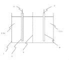
- FIG. 1 is an explanatory diagram showing the configuration of an electrolytic cell used for electrolytic synthesis.
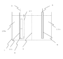
- FIG. 2 is an explanatory diagram showing the configuration of an electrolytic cell equipped with an anode basket used for electrolytic synthesis.
- the anhydrous nickel chloride of the present invention uses raw metal nickel as an anode, a conductive material as a cathode, high-purity hydrochloric acid as an electrolytic solution, anorite and catholyte separated by an anion exchange membrane, A step of obtaining a nickel chloride solution as anolyte by performing exchange membrane electrolysis, and a step of obtaining a concentrated nickel chloride solution by concentrating the purified nickel chloride solution obtained by heating to 80 to 100 ° C. under atmospheric pressure.
- the concentrated nickel chloride solution can be produced by a method comprising heating to 180 to 220 ° C. under atmospheric pressure to dry and dehydrate to obtain anhydrous nickel chloride.
- iron ions as impurities may be mixed in the resulting nickel chloride solution.
- a step of removing iron ions can be performed. This iron removal step can be performed after the step of obtaining a nickel chloride solution as the anolyte, and the nickel chloride solution purified by removing iron is heated to 80 to 100 ° C. under the above atmospheric pressure and concentrated. And can be used as a material for the step of obtaining a concentrated nickel chloride solution.
- the iron removal step the following “solvent extraction”, “ion exchange” or “iron oxidation” steps can be used.
- a solvent extraction step can be performed as the iron removal step.
- the iron ion is extracted and removed by bringing the solvent extractant into contact with the nickel chloride solution.
- the solvent extractant include 2-ethylhexyl 2-ethylhexylphosphonate hydrogen, bis (2-ethylhexyl) hydrogen phosphate, bis (2-ethylhexyl) phosphinic acid, and 2-ethylhexyl 2-ethylhexylphosphonate hydrogen Is preferred.
- the solvent extractant can be removed by separation from the nickel chloride solution, and if necessary, the removal can be completed by a known means such as activated carbon.
- an ion exchange step can be performed as the iron removal step.
- iron ions are removed by ion exchange by contacting with an ion exchange resin.
- the ion exchange resin include strong basic anion exchange resins and chelate resins, and strong basic anion exchange resins are preferred.
- an iron oxidation step can be performed as the iron removal step.
- iron ions are oxidized to make the iron ions in the nickel chloride solution trivalent, and are precipitated and precipitated, and separated by filtration.
- the oxidation of iron ions can be performed by adding hydrogen peroxide water or blowing an oxygen-containing gas into the nickel chloride solution and setting the oxidation-reduction potential to 700 mV or higher.
- the raw material nickel metal can be used without limitation as long as it has a purity of 4N (99.99%) or more, but it has a higher purity such as 5N (99.999%) or 6N (99.9999%). It is more preferable to use a material having purity because the step of removing iron, which is the main impurity, can be omitted.
- the raw metal nickel is preferably one having a flat and smooth shape in order to stabilize the electrolytic state in order to perform electrolysis.
- 4N (99.99%) metallic nickel is a metal having a purity in which the total content of impurities detected excluding gas components such as hydrogen, carbon, nitrogen and oxygen is less than 0.01%. Nickel.
- anode In electrolyzing nickel, there are a method in which nickel is directly used as an anode, or a method in which nickel is energized through an insoluble electrode.
- an insoluble electrode it can be used without limitation as long as it is a general one, but for example, platinum or titanium plated with platinum, titanium coated with a platinum group oxide, and the like are preferable.
- the cathode can be used without limitation as long as it has conductivity, but for example, titanium, nickel or graphite is preferable.
- the electrolyte can be used without limitation as long as it has a high purity, but high-grade hydrochloric acid for special grades or electronics industry can be used, which is diluted with pure water at the time of use, for example, at a concentration of 0.1 to 6. Can be used as 0N dilute hydrochloric acid.
- a known anion exchange membrane can be used as the anion exchange membrane.
- Nickel chloride solution The nickel chloride solution obtained as anolyte is already highly pure except for gas components. Therefore, the present invention is also in a high-purity nickel chloride solution and a method for producing the same.
- the nickel chloride solution is concentrated by heating to obtain a concentrated nickel chloride solution.
- the heat concentration is performed by heating to 80 to 100 ° C., preferably 90 to 100 ° C. under atmospheric pressure. In a preferred embodiment, the heat concentration is performed in the atmosphere.
- a nickel chloride solution (nickel chloride dilute hydrochloric acid solution) is heated and concentrated in a quartz container.
- Heat drying dehydration The concentrated nickel chloride solution is heated and dehydrated and dried to obtain anhydrous nickel chloride. Heat dehydration drying is performed by heating to 180 to 220 ° C., preferably 190 to 210 ° C. under atmospheric pressure. In a preferred embodiment, the heat drying is performed in an inert gas. In a preferred embodiment, the concentrated nickel chloride solution is heat dried on a quartz container.
- the concentrated nickel chloride solution can be ground with heat drying to obtain powdered anhydrous nickel chloride. In a preferred embodiment, this grinding can be performed on a quartz vessel.
- Anhydrous nickel chloride has a total content of impurity elements other than gas components of less than 10 wtppm, boron, sodium, magnesium, aluminum, potassium, calcium, titanium, chromium, manganese, iron, copper, zinc, arsenic Silver, cadmium, indium, tin, thallium, and lead content are each less than 1 wtppm, and silicon and cobalt content are each less than 5 wtppm.
- the gas component elements refer to oxygen, nitrogen, hydrogen, and carbon.
- the content of impurity elements other than gas component elements refers to a value measured by glow discharge mass spectrometry (hereinafter referred to as GD-MS: Glow Discharge Mass Spectrometry).
- anhydrous nickel chloride powder In a preferred embodiment, anhydrous nickel chloride is obtained as a powder.
- the anhydrous nickel chloride powder has a total particle size of 4 mm or more, for example, 10% by mass or more, preferably 50% by mass or more, and particles having a particle size of 0.3 mm or less, preferably 30% by mass or less, preferably It is 10 mass% or less. These particle sizes and content ratios can be measured by sieving.
- the high purity anhydrous nickel chloride according to the present invention is an excellent CVD (chemical vapor deposition) raw material. Therefore, the present invention also exists in a CVD raw material using high-purity anhydrous nickel chloride, a nickel film or nickel fine powder formed by the CVD raw material, and a semiconductor device, electronic circuit or electronic formed by the nickel film or nickel fine powder. There are also devices, etc., and these manufacturing methods.
- Example 1 An electrolytic cell equipped with an ion exchange membrane (hydrocarbon anion exchange membrane) is prepared, and 8L each of high purity hydrochloric acid diluted to 1N concentration with pure water is added to anolyte and 6L hydrochloric acid is similarly added to catholyte. It was.
- As the anode 2,409 g of nickel having a purity of 5N and a titanium plate were prepared as the cathode.
- a direct current power source was connected between the anode and the cathode, and the current value was 5 A constant current, and the current was supplied for 120 hours. Meanwhile, the voltage fluctuated between 1.4 and 2.8V.
- the liquid temperature rose from 30 ° C at the start to a maximum of 35 ° C.
- the nickel weight was measured and decreased to 1,736 g, and the dissolved weight was 673 g. In this way, a nickel chloride solution was obtained by electrolytic synthesis.
- the concentration of the solution was analyzed, the nickel concentration was 84 g / L and the iron concentration was 0.1 mg / L or less.
- Example 1 In Example 1, 1.5 L of the nickel chloride solution obtained after completion of the electrolysis step was put in a quartz container and heated to 90 ° C. on a hot plate to evaporate water. When the water was exhausted, the temperature was further increased to 160 ° C. in the atmosphere and maintained for 2 hours. When the completed crystals were recovered, 285 g was obtained. This was pulverized and sieved using a quartz container in a nitrogen atmosphere to obtain nickel chloride powder. When the crystal structure of the nickel chloride powder was analyzed by X-ray diffraction, it was confirmed that nickel chloride hexahydrate was formed in addition to anhydrous nickel chloride. The anhydrous nickel chloride crystals were subjected to impurity quality determination by GD-MS analysis. The results are shown in Table 1. Table 1 also shows the results of measuring the particle size using a sieve, the bulk density, and the tap density.
- Example 2 The same electrolytic cell as in Example 1 was prepared, and the same hydrochloric acid was added to anolyte and catholyte.
- a direct current power source was connected between the anode and the cathode, and the current value was 5 A constant current, and the current was supplied for 120 hours. Meanwhile, the voltage fluctuated between 1.5 and 3.2V.
- the liquid temperature rose from 28 ° C at the start to a maximum of 36 ° C.
- the nickel weight was measured and decreased to 1,840 g, and the dissolved weight was 680 g. In this way, a nickel chloride solution was obtained by electrolytic synthesis. When the concentration of the solution was analyzed, the nickel concentration was 86 g / L and the iron concentration was 0.6 mg / L.
- Solvent extraction in which 1.5 L of nickel chloride solution obtained after the electrolysis step was mixed with 1.0 L of a part of the solution, 830 mL of normal paraffin, and 170 mL of solvent extractant (2-ethylhexyl hydrogen 2-ethylhexylphosphonate) The agent was put in the same container and stirred for 30 minutes, and then allowed to stand for 1 hour, the solvent extractant separated in the upper layer was separated, and the lower layer nickel chloride solution was recovered. Next, 20 g of activated carbon was added to the nickel chloride solution, and the mixture was stirred for 1 hour and filtered to remove the solvent extractant remaining in the nickel chloride solution. The solvent extraction treatment was performed in this way to obtain a purified nickel chloride solution.
- the nickel chloride solution was put in a quartz container and heated to 90 ° C. on a hot plate to evaporate water. When the water was exhausted, the temperature was further increased to 200 ° C. in the atmosphere and maintained for 2 hours. When the completed crystals were collected, 278 g was obtained. This was pulverized and sieved using a quartz container in a nitrogen atmosphere to obtain nickel chloride powder. When the crystal structure of the nickel chloride powder was analyzed by X-ray diffraction, it was confirmed that anhydrous nickel chloride was formed. The anhydrous nickel chloride crystals were subjected to impurity quality determination by GD-MS analysis. The results are shown in Table 1. Table 1 also shows the results of measuring the particle size using a sieve, the bulk density, and the tap density.
- Example 3 High purity hydrochloric acid was added to 1.5 L of nickel chloride solution obtained after completion of the electrolysis step in Example 2 to adjust the acid concentration in the solution to 6N.
- the nickel chloride solution was passed through a column packed with 0.5 L of strong basic anion exchange resin manufactured by Mitsubishi Chemical Corporation at a space velocity of SV5-10. Thus, the anion exchange process was performed and the refined nickel chloride solution was obtained.
- the nickel chloride solution was put into a quartz container and heated to 80 ° C. on a hot plate to evaporate water. When the water was exhausted, the temperature was further increased to 220 ° C. in the atmosphere and maintained for 2 hours. When the completed crystals were recovered, 276 g was obtained. This was pulverized and sieved using a quartz mortar under a nitrogen atmosphere to obtain nickel chloride powder. When the crystal structure of the nickel chloride powder was analyzed by X-ray diffraction, it was confirmed that anhydrous nickel chloride was formed. The anhydrous nickel chloride crystals were subjected to impurity quality determination by GD-MS analysis. The results are shown in Table 1. Table 1 also shows the results of measuring the particle size using a sieve, the bulk density, and the tap density.
- Example 2 The same crystal formation process as in Example 2 was performed except that 1.5 L of the nickel chloride solution obtained after completion of the electrolysis process in Example 2 was used without performing the purification process to remove iron, Obtained.
- the crystal structure of the nickel chloride powder was analyzed by X-ray diffraction, it was confirmed that anhydrous nickel chloride was formed.
- the anhydrous nickel chloride crystal was subjected to impurity quality determination by GD-MS analysis and found to contain 7 wtppm of iron.
- Table 1 also shows the results of measuring the particle size using a sieve, the bulk density, and the tap density.
- Example 1 0.4
- Example 2 0.3
- Comparative Example 1 15.3 Comparative Example 2: 0.3 (wt%)
- Electrolytic synthesis was performed using the apparatus shown in FIG.
- the electrolytic cell 1 is partitioned by an anion exchange membrane 4, and the anode side is filled with anolyte 10a and the cathode side is filled with catholyte 10b.
- the anode 2 is attached to the anolyte 10a, and the raw material nickel 5 is attached in a state of being immersed in the anolyte.
- the cathode 3 is attached to the catholyte 10b, and the conductive material 6 is attached in a state of being immersed in the catholyte 10b.
- FIG. 2 shows another type of apparatus.
- the cathode side is the same as in FIG. 1, but the raw material nickel 5 is placed in the anode basket 50 on the anode side.
- An opening is provided on the surface of the anode basket 50 facing the cathode 3, and the surface is closed with a filter cloth 51 so that the raw material nickel 5 does not come out.
- anhydrous nickel chloride having a higher purity than that of the prior art and particularly a reduced content of the iron component can be obtained by a process with a lower environmental load than that of the prior art.
- the present invention is industrially useful.
Landscapes
- Chemical & Material Sciences (AREA)
- Organic Chemistry (AREA)
- Engineering & Computer Science (AREA)
- Chemical Kinetics & Catalysis (AREA)
- Materials Engineering (AREA)
- Metallurgy (AREA)
- Inorganic Chemistry (AREA)
- General Chemical & Material Sciences (AREA)
- Mechanical Engineering (AREA)
- Electrochemistry (AREA)
- Physics & Mathematics (AREA)
- Condensed Matter Physics & Semiconductors (AREA)
- General Physics & Mathematics (AREA)
- Manufacturing & Machinery (AREA)
- Computer Hardware Design (AREA)
- Microelectronics & Electronic Packaging (AREA)
- Power Engineering (AREA)
- Electrolytic Production Of Metals (AREA)
- Inorganic Compounds Of Heavy Metals (AREA)
- Electrolytic Production Of Non-Metals, Compounds, Apparatuses Therefor (AREA)
Priority Applications (4)
| Application Number | Priority Date | Filing Date | Title |
|---|---|---|---|
| JP2017531646A JPWO2017126442A1 (ja) | 2016-01-21 | 2017-01-13 | 無水塩化ニッケル及びその製造方法 |
| EP17741320.0A EP3406568A4 (en) | 2016-01-21 | 2017-01-13 | ANHYDROUS NICKEL CHLORIDE AND PROCESS FOR PRODUCING THE SAME |
| KR1020177031839A KR102048134B1 (ko) | 2016-01-21 | 2017-01-13 | 무수 염화 니켈 및 그 제조 방법 |
| US15/753,126 US10882757B2 (en) | 2016-01-21 | 2017-01-13 | Anhydrous nickel chloride and method for producing the same |
Applications Claiming Priority (2)
| Application Number | Priority Date | Filing Date | Title |
|---|---|---|---|
| JP2016010031 | 2016-01-21 | ||
| JP2016-010031 | 2016-01-21 |
Publications (1)
| Publication Number | Publication Date |
|---|---|
| WO2017126442A1 true WO2017126442A1 (ja) | 2017-07-27 |
Family
ID=59362305
Family Applications (1)
| Application Number | Title | Priority Date | Filing Date |
|---|---|---|---|
| PCT/JP2017/001085 WO2017126442A1 (ja) | 2016-01-21 | 2017-01-13 | 無水塩化ニッケル及びその製造方法 |
Country Status (6)
| Country | Link |
|---|---|
| US (1) | US10882757B2 (zh) |
| EP (1) | EP3406568A4 (zh) |
| JP (1) | JPWO2017126442A1 (zh) |
| KR (1) | KR102048134B1 (zh) |
| TW (1) | TWI639557B (zh) |
| WO (1) | WO2017126442A1 (zh) |
Cited By (3)
| Publication number | Priority date | Publication date | Assignee | Title |
|---|---|---|---|---|
| JP2020169344A (ja) * | 2019-04-01 | 2020-10-15 | 住友金属鉱山株式会社 | 電解槽および酸溶液の製造方法 |
| CN112359206A (zh) * | 2020-10-10 | 2021-02-12 | 福达合金材料股份有限公司 | 一种银氧化锡角料电解除杂和再利用的方法 |
| CN112563489A (zh) * | 2020-12-16 | 2021-03-26 | 北方特种能源集团有限公司西安庆华公司 | 一种新型热电池用氯化镍正极的制备方法 |
Families Citing this family (4)
| Publication number | Priority date | Publication date | Assignee | Title |
|---|---|---|---|---|
| CN114314699A (zh) * | 2021-12-31 | 2022-04-12 | 金川集团镍盐有限公司 | 一种氯化体系中镍丸溶解液的除铁方法 |
| CN114212836A (zh) * | 2021-12-31 | 2022-03-22 | 金川集团镍盐有限公司 | 一种无水氯化镍粉体材料的制备方法 |
| CN114835176A (zh) * | 2022-05-30 | 2022-08-02 | 金川集团镍盐有限公司 | 一种球形无水氯化镍产品的制备方法 |
| CN115403082A (zh) * | 2022-10-11 | 2022-11-29 | 金川集团镍盐有限公司 | 一种以电积镍为原料生产电镀氯化镍的方法 |
Citations (6)
| Publication number | Priority date | Publication date | Assignee | Title |
|---|---|---|---|---|
| JPS4918194B1 (zh) | 1965-12-30 | 1974-05-08 | ||
| JPH0632618A (ja) * | 1992-07-15 | 1994-02-08 | Sumitomo Metal Mining Co Ltd | 金属塩化物の精製方法 |
| JPH11263625A (ja) | 1998-03-19 | 1999-09-28 | Sumitomo Metal Mining Co Ltd | 無水塩化ニッケルの製造方法 |
| JP2002348122A (ja) * | 2001-03-22 | 2002-12-04 | Kawatetsu Mining Co Ltd | 無水塩化ニッケル及びニッケル超微粉の製造方法 |
| JP2007290937A (ja) * | 2006-04-27 | 2007-11-08 | Sumitomo Metal Mining Co Ltd | 塩化ニッケル水溶液の精製方法 |
| JP2010248043A (ja) * | 2009-04-17 | 2010-11-04 | Sumitomo Metal Mining Co Ltd | 塩化ニッケル水溶液の精製方法 |
Family Cites Families (8)
| Publication number | Priority date | Publication date | Assignee | Title |
|---|---|---|---|---|
| JPS5144974B2 (zh) | 1972-06-12 | 1976-12-01 | ||
| DE2857460C2 (de) | 1977-10-17 | 1982-05-06 | United States Surgical Corp., 06850 Norwalk, Conn. | Vorichtung zum Verhindern einer Rückwärtsverschiebung einer chirurgischen Klammer |
| KR960005510B1 (ko) | 1993-07-02 | 1996-04-25 | 포항종합제철주식회사 | 폐니켈양극활용 고순도 염화니켈의 제조방법 |
| JPH11228145A (ja) | 1998-02-20 | 1999-08-24 | Sumitomo Metal Mining Co Ltd | 塩化ニッケルの製造方法およびこれを用いたニッケル粉末の製造方法 |
| JP2000219988A (ja) | 1999-02-01 | 2000-08-08 | Japan Energy Corp | 高純度ニッケル材の製造法及び薄膜形成用高純度ニッケル材 |
| JP4918194B2 (ja) * | 2001-03-22 | 2012-04-18 | Jfeミネラル株式会社 | 無水塩化ニッケルの製造方法 |
| US6893996B2 (en) | 2001-11-26 | 2005-05-17 | Invista North America S.A.R.L. | Process for the preparation of a nickel/phosphorous ligand catalyst for olefin hydrocyanation |
| CN105220184A (zh) | 2015-08-11 | 2016-01-06 | 模德模具(苏州工业园区)有限公司 | 一种电铸镍电解液及其制备方法 |
-
2017
- 2017-01-13 EP EP17741320.0A patent/EP3406568A4/en not_active Withdrawn
- 2017-01-13 JP JP2017531646A patent/JPWO2017126442A1/ja active Pending
- 2017-01-13 KR KR1020177031839A patent/KR102048134B1/ko active IP Right Grant
- 2017-01-13 WO PCT/JP2017/001085 patent/WO2017126442A1/ja active Application Filing
- 2017-01-13 US US15/753,126 patent/US10882757B2/en active Active
- 2017-01-19 TW TW106101844A patent/TWI639557B/zh active
Patent Citations (7)
| Publication number | Priority date | Publication date | Assignee | Title |
|---|---|---|---|---|
| JPS4918194B1 (zh) | 1965-12-30 | 1974-05-08 | ||
| JPH0632618A (ja) * | 1992-07-15 | 1994-02-08 | Sumitomo Metal Mining Co Ltd | 金属塩化物の精製方法 |
| JPH11263625A (ja) | 1998-03-19 | 1999-09-28 | Sumitomo Metal Mining Co Ltd | 無水塩化ニッケルの製造方法 |
| JP2002348122A (ja) * | 2001-03-22 | 2002-12-04 | Kawatetsu Mining Co Ltd | 無水塩化ニッケル及びニッケル超微粉の製造方法 |
| JP4127477B2 (ja) | 2001-03-22 | 2008-07-30 | Jfeミネラル株式会社 | 無水塩化ニッケル及びニッケル超微粉の製造方法 |
| JP2007290937A (ja) * | 2006-04-27 | 2007-11-08 | Sumitomo Metal Mining Co Ltd | 塩化ニッケル水溶液の精製方法 |
| JP2010248043A (ja) * | 2009-04-17 | 2010-11-04 | Sumitomo Metal Mining Co Ltd | 塩化ニッケル水溶液の精製方法 |
Non-Patent Citations (1)
| Title |
|---|
| See also references of EP3406568A4 |
Cited By (4)
| Publication number | Priority date | Publication date | Assignee | Title |
|---|---|---|---|---|
| JP2020169344A (ja) * | 2019-04-01 | 2020-10-15 | 住友金属鉱山株式会社 | 電解槽および酸溶液の製造方法 |
| JP7188239B2 (ja) | 2019-04-01 | 2022-12-13 | 住友金属鉱山株式会社 | 電解槽および酸溶液の製造方法 |
| CN112359206A (zh) * | 2020-10-10 | 2021-02-12 | 福达合金材料股份有限公司 | 一种银氧化锡角料电解除杂和再利用的方法 |
| CN112563489A (zh) * | 2020-12-16 | 2021-03-26 | 北方特种能源集团有限公司西安庆华公司 | 一种新型热电池用氯化镍正极的制备方法 |
Also Published As
| Publication number | Publication date |
|---|---|
| EP3406568A1 (en) | 2018-11-28 |
| KR102048134B1 (ko) | 2019-11-22 |
| US20180237313A1 (en) | 2018-08-23 |
| JPWO2017126442A1 (ja) | 2018-11-08 |
| TWI639557B (zh) | 2018-11-01 |
| TW201730114A (zh) | 2017-09-01 |
| KR20170134618A (ko) | 2017-12-06 |
| US10882757B2 (en) | 2021-01-05 |
| EP3406568A4 (en) | 2019-08-21 |
Similar Documents
| Publication | Publication Date | Title |
|---|---|---|
| WO2017126442A1 (ja) | 無水塩化ニッケル及びその製造方法 | |
| JP7420799B2 (ja) | 銅不純物を除去するための浸出液の電気分解による電池リサイクル | |
| CN111039265B (zh) | 一种高纯硒的制备方法 | |
| KR20030023640A (ko) | 금속처리방법, 그 방법에 사용되는 장치 및 그로부터제조된 금속 | |
| JP5913639B2 (ja) | 酸化インジウム−酸化錫粉末の製造方法、itoターゲットの製造方法及び水酸化インジウム−メタ錫酸混合物の製造方法 | |
| JPS6218632B2 (zh) | ||
| JP5032400B2 (ja) | ニッケル酸化物 | |
| US20050155870A1 (en) | Method for producing indium-containing aqueous solution | |
| JP2015086436A (ja) | 有価物の回収方法 | |
| JP2017178749A (ja) | 硫酸マンガン水溶液の製造方法、及びマンガン酸化物の製造方法 | |
| JP5533770B2 (ja) | セレンの分離方法 | |
| JP4663053B2 (ja) | インジウムの回収方法 | |
| WO2016194658A1 (ja) | 塩化コバルト水溶液の浄液方法 | |
| WO2003097903A1 (fr) | Procede et dispositif de production de metal hautement pur | |
| JP5993097B2 (ja) | 高純度塩化コバルトの製造方法 | |
| JP6750454B2 (ja) | ビスマス電解液の不純物除去方法 | |
| JP7403118B2 (ja) | 金属の回収方法及び窒化ガリウムの製造方法 | |
| TWI557074B (zh) | 氯化銅、cvd原料、銅配線膜及氯化銅之製造方法 | |
| JP7368802B2 (ja) | 重金属分離方法および金属回収方法 | |
| KR102645124B1 (ko) | 전기화학적 세정 공법을 이용한 초고순도 금속 니켈 분말 및 그 제조 방법 | |
| CN116283552B (zh) | 一种草酸精制方法 | |
| CN117361620A (zh) | 一种氯化锑溶液除砷纯化方法 | |
| JP2020152615A (ja) | 高純度硫酸コバルト粉末 | |
| JPS59213622A (ja) | ガリウムの回収法 | |
| CN114717414A (zh) | 一种用于电池的硫酸锰的制备方法 |
Legal Events
| Date | Code | Title | Description |
|---|---|---|---|
| ENP | Entry into the national phase |
Ref document number: 2017531646 Country of ref document: JP Kind code of ref document: A |
|
| 121 | Ep: the epo has been informed by wipo that ep was designated in this application |
Ref document number: 17741320 Country of ref document: EP Kind code of ref document: A1 |
|
| ENP | Entry into the national phase |
Ref document number: 20177031839 Country of ref document: KR Kind code of ref document: A |
|
| WWE | Wipo information: entry into national phase |
Ref document number: 15753126 Country of ref document: US |
|
| NENP | Non-entry into the national phase |
Ref country code: DE |