WO2017119045A1 - インクジェット記録装置及び多孔質体の製造方法 - Google Patents
インクジェット記録装置及び多孔質体の製造方法 Download PDFInfo
- Publication number
- WO2017119045A1 WO2017119045A1 PCT/JP2016/005247 JP2016005247W WO2017119045A1 WO 2017119045 A1 WO2017119045 A1 WO 2017119045A1 JP 2016005247 W JP2016005247 W JP 2016005247W WO 2017119045 A1 WO2017119045 A1 WO 2017119045A1
- Authority
- WO
- WIPO (PCT)
- Prior art keywords
- layer
- fiber
- image
- softening temperature
- material forming
- Prior art date
Links
Images


Classifications
-
- B—PERFORMING OPERATIONS; TRANSPORTING
- B41—PRINTING; LINING MACHINES; TYPEWRITERS; STAMPS
- B41J—TYPEWRITERS; SELECTIVE PRINTING MECHANISMS, i.e. MECHANISMS PRINTING OTHERWISE THAN FROM A FORME; CORRECTION OF TYPOGRAPHICAL ERRORS
- B41J2/00—Typewriters or selective printing mechanisms characterised by the printing or marking process for which they are designed
- B41J2/005—Typewriters or selective printing mechanisms characterised by the printing or marking process for which they are designed characterised by bringing liquid or particles selectively into contact with a printing material
- B41J2/01—Ink jet
- B41J2/21—Ink jet for multi-colour printing
- B41J2/2103—Features not dealing with the colouring process per se, e.g. construction of printers or heads, driving circuit adaptations
-
- B—PERFORMING OPERATIONS; TRANSPORTING
- B41—PRINTING; LINING MACHINES; TYPEWRITERS; STAMPS
- B41F—PRINTING MACHINES OR PRESSES
- B41F31/00—Inking arrangements or devices
- B41F31/24—Absorbent pads
-
- B—PERFORMING OPERATIONS; TRANSPORTING
- B41—PRINTING; LINING MACHINES; TYPEWRITERS; STAMPS
- B41J—TYPEWRITERS; SELECTIVE PRINTING MECHANISMS, i.e. MECHANISMS PRINTING OTHERWISE THAN FROM A FORME; CORRECTION OF TYPOGRAPHICAL ERRORS
- B41J11/00—Devices or arrangements of selective printing mechanisms, e.g. ink-jet printers or thermal printers, for supporting or handling copy material in sheet or web form
- B41J11/0015—Devices or arrangements of selective printing mechanisms, e.g. ink-jet printers or thermal printers, for supporting or handling copy material in sheet or web form for treating before, during or after printing or for uniform coating or laminating the copy material before or after printing
-
- B—PERFORMING OPERATIONS; TRANSPORTING
- B41—PRINTING; LINING MACHINES; TYPEWRITERS; STAMPS
- B41J—TYPEWRITERS; SELECTIVE PRINTING MECHANISMS, i.e. MECHANISMS PRINTING OTHERWISE THAN FROM A FORME; CORRECTION OF TYPOGRAPHICAL ERRORS
- B41J2/00—Typewriters or selective printing mechanisms characterised by the printing or marking process for which they are designed
- B41J2/005—Typewriters or selective printing mechanisms characterised by the printing or marking process for which they are designed characterised by bringing liquid or particles selectively into contact with a printing material
- B41J2/01—Ink jet
-
- B—PERFORMING OPERATIONS; TRANSPORTING
- B41—PRINTING; LINING MACHINES; TYPEWRITERS; STAMPS
- B41L—APPARATUS OR DEVICES FOR MANIFOLDING, DUPLICATING OR PRINTING FOR OFFICE OR OTHER COMMERCIAL PURPOSES; ADDRESSING MACHINES OR LIKE SERIES-PRINTING MACHINES
- B41L27/00—Inking arrangements or devices
- B41L27/26—Absorbent pads
-
- B—PERFORMING OPERATIONS; TRANSPORTING
- B41—PRINTING; LINING MACHINES; TYPEWRITERS; STAMPS
- B41J—TYPEWRITERS; SELECTIVE PRINTING MECHANISMS, i.e. MECHANISMS PRINTING OTHERWISE THAN FROM A FORME; CORRECTION OF TYPOGRAPHICAL ERRORS
- B41J2/00—Typewriters or selective printing mechanisms characterised by the printing or marking process for which they are designed
- B41J2/005—Typewriters or selective printing mechanisms characterised by the printing or marking process for which they are designed characterised by bringing liquid or particles selectively into contact with a printing material
- B41J2/01—Ink jet
- B41J2002/012—Ink jet with intermediate transfer member
Definitions
- the present invention relates to an inkjet recording apparatus and a method for producing a porous body used in the inkjet recording apparatus.
- an image is formed by applying a liquid composition (ink) containing a color material directly or indirectly onto a recording medium such as paper.
- the recording medium may curl or cockling due to excessive absorption of the liquid component in the ink.
- a method of drying the recording medium using means such as warm air or infrared, or an image is formed on the transfer body, and then included in the image on the transfer body
- a method of transferring an image to a recording medium such as paper after removing a liquid component by heat energy or the like.
- Patent Documents 1 and 2 a method of removing the liquid component from the ink image by contacting the roller-like porous body with the ink image without using thermal energy.
- Patent Document 3 a method has been proposed in which a belt-like polymer absorber is brought into contact with an ink image to absorb and remove a liquid component from the ink image.
- an object of the present invention is to provide an ink jet recording apparatus provided with a liquid absorbing member that suppresses image flow and has high conveyance strength, and a method for manufacturing a porous body used in the ink jet recording apparatus.
- An ink jet recording apparatus is in contact with an image forming unit that forms a first image containing a first liquid and a color material on a recording medium, and the first image.
- a liquid absorbing member having a porous body that absorbs at least part of the first liquid from the first image, wherein the porous body is in contact with the first image.
- a first layer, a second layer containing a second fiber, and a third layer containing a third fiber are laminated in this order, and the first layer, the second layer
- Each of the layer and the third layer is a porous sheet, and the average fiber diameter of the second fiber is larger than the average fiber diameter of the third fiber
- the fiber has a core-sheath structure having a core structure that forms a central axis, and a sheath structure that wraps the core structure
- the softening temperature of the material forming the sheath structure is the softening temperature of the material forming the core structure, the softening temperature of the material forming the first layer, and the softening temperature of the material forming the third fiber. It is lower than any of the temperatures, and the average thickness of the sheath structure is smaller than the thickness of the first layer.
- An ink jet recording apparatus is in contact with an image forming unit that forms a first image including a first liquid and a color material on a recording medium, and the first image.
- a liquid absorbing member having a porous body that absorbs at least part of the first liquid from the first image, wherein the porous body is in contact with the first image.
- first layer, the second layer a, the second layer b, and the third layer are all porous sheets, and the second layer
- the average fiber diameter of the fiber b is larger than the average fiber diameter of the third fiber
- the second fiber a and the second fiber b are A core-sheath structure having a core structure forming a central axis and a sheath structure surrounding the core structure, and a softening temperature of a material forming the sheath structure of the second fiber a is the second
- the softening temperature of the material forming the sheath structure of the second fiber b is lower than both the softening temperature of the material forming the core structure of the fiber a and the softening temperature of the material forming the first layer.
- the average thickness of the sheath structure of the second fiber a is lower than both the softening temperature of the material forming the core structure of the second fiber b and the softening temperature of the material forming the third fiber. It is characterized by being smaller than the thickness of one layer.
- An ink jet recording apparatus includes an image forming unit that forms a first image by applying an ink containing a first liquid and a color material on a recording medium;
- An ink jet recording apparatus comprising: a liquid absorbing member having a porous body that contacts an image and concentrates the ink constituting the first image, wherein the porous body is in contact with the first image
- a first layer, a second layer containing a second fiber, and a third layer containing a third fiber are laminated in this order, and the first layer and the second layer
- the third layer is a porous sheet that is a porous layer, and the average fiber diameter of the second fiber is larger than the average fiber diameter of the third fiber, and the second fiber Has a core-sheath structure having a core structure forming a central axis, and a sheath structure surrounding the core structure.
- the softening temperature of the material forming the sheath structure is the softening temperature of the material forming the core structure, the softening temperature of the material forming the first layer, and the softening temperature of the material forming the third fiber.
- the average thickness of the sheath structure is smaller than any of the above, and the thickness of the first layer is smaller than that of the first layer.
- a porous body manufacturing method used in an ink jet recording apparatus includes an image forming unit that forms a first image including a first liquid and a color material on a recording medium;
- a porous body for use in an inkjet recording apparatus comprising: a liquid absorbing member having a porous body that is in contact with the first image and absorbs at least part of the first liquid from the first image.
- a method comprising: laminating a first layer in contact with the first image, a second layer containing second fibers, and a third layer containing third fibers in this order.
- the second fiber has a core-sheath structure having a core structure that forms a central axis and a sheath structure that wraps the core structure, and forms the sheath structure.
- the softening temperature of the material is lower than any of the softening temperature of the material forming the core structure, the softening temperature of the material forming the first layer, and the softening temperature of the material forming the third fiber,
- the average thickness of the sheath structure is smaller than the thickness of the first layer
- the heating temperature is equal to or higher than the softening temperature of the material forming the sheath structure
- the softening temperature of the material forming the core structure It is below the softening temperature of the material which forms said 1st layer, and the softening temperature of the material which forms said 3rd fiber, It is characterized by the above-mentioned.
- a porous body manufacturing method used in an ink jet recording apparatus includes: an image forming unit that forms a first image including a first liquid and a color material on a recording medium;
- a porous body for use in an inkjet recording apparatus comprising: a liquid absorbing member having a porous body that is in contact with the first image and absorbs at least part of the first liquid from the first image.
- the first layer, the second layer a, the second layer b, and the third layer are heated by laminating a third layer containing fibers in this order.
- the average fiber diameter of the second fiber b is larger than the average fiber diameter of the third fiber
- the second fiber a and the second fiber b are A core-sheath structure having a core structure forming a central axis and a sheath structure surrounding the core structure, and a softening temperature of a material forming the sheath structure of the second fiber a is The softening temperature of the material forming the sheath structure of the second fiber b is lower than both the softening temperature of the material forming the core structure of the second fiber a and the softening temperature of the material forming the first layer.
- the average thickness of the sheath structure of the second fiber a is lower than both the softening temperature of the material forming the core structure of the second fiber b and the softening temperature of the material forming the third fiber.
- the heating temperature is smaller than the thickness of the first layer, the second fiber a and the The softening temperature of the material forming the sheath structure of the second fiber b and the softening temperature of the material forming the core structure of the second fiber a and the second fiber b, the first layer
- the softening temperature of the material to be formed is equal to or lower than the softening temperature of the material to form the third fiber.
- an ink jet recording apparatus provided with a liquid absorbing member that suppresses image flow and has high conveyance strength, and a method for manufacturing a porous body used in the ink jet recording apparatus.
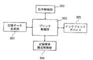
- FIG. 1 is a schematic diagram illustrating an example of a configuration of a transfer type inkjet recording apparatus according to an embodiment of the present invention. It is a schematic diagram which shows an example of a structure of the direct drawing type inkjet recording device in one Embodiment of this invention. It is a block diagram which shows the control system of the whole apparatus in the inkjet recording device shown in FIG.
- FIG. 2 is a block diagram of a printer control unit in the transfer type inkjet recording apparatus shown in FIG. 1.
- FIG. 3 is a block diagram of a printer control unit in the direct drawing type inkjet recording apparatus shown in FIG. 2. It is sectional drawing which shows an example of the porous body which concerns on 1st embodiment. It is sectional drawing to which a part of example of the porous body was expanded.
- the ink jet recording apparatus of the present invention comprises an image forming unit that forms a first image including a first liquid and a color material on a recording medium, and the first image is in contact with the first image.
- a liquid absorbing member having a porous body that absorbs at least part of the first liquid By bringing the liquid absorbing member having a porous body into contact with the first image containing the first liquid and the color material on the recording medium, at least a part of the first liquid is removed from the first image. The As a result, curling or cockling due to excessive absorption of the first liquid in the first image by the recording medium such as paper is suppressed. It is not necessary to absorb all of the first liquid.
- the porous body includes a first layer in contact with the first image, a second layer including a second fiber, and a third layer including a third fiber.
- a second layer including a second fiber
- a third layer including a third fiber.
- the average fiber diameter of the second fiber is larger than the average fiber diameter of the third fiber.
- the second fiber has a core-sheath structure having a core structure that forms a central axis and a sheath structure that wraps the core structure.
- the softening temperature of the material forming the sheath structure is the softening temperature of the material forming the core structure, the softening temperature of the material forming the first layer, and the softening temperature of the material forming the third fiber.
- the average thickness of the sheath structure is smaller than the thickness of the first layer.
- the porous body includes a first layer in contact with the first image, a second layer a including a second fiber a, and a second fiber.
- a second layer b containing b and a third layer containing a third fiber are laminated in this order, and the first layer, the second layer a, the second layer b
- the third layer is a porous sheet in which both are porous layers.
- the average fiber diameter of the second fiber b is larger than the average fiber diameter of the third fiber.
- Said 2nd fiber a and said 2nd fiber b have the core sheath structure which has the core structure which forms a central axis, and the sheath structure which wraps the said core structure.
- the softening temperature of the material forming the sheath structure of the second fiber a is any of the softening temperature of the material forming the core structure of the second fiber a and the softening temperature of the material forming the first layer. Is also low.
- the softening temperature of the material forming the sheath structure of the second fiber b is any of the softening temperature of the material forming the core structure of the second fiber b and the softening temperature of the material forming the third fiber. Is also low.
- the average thickness of the sheath structure of the second fiber a is smaller than the thickness of the first layer.
- the above-mentioned effects can be obtained, and at the same time, the first layer side surface unevenness of the second layer can be suppressed, and the first layer can be prevented from being clogged. It is possible to easily achieve both improvement in adhesive strength with the three layers. As a result, it is presumed that an ink jet recording apparatus including a liquid absorbing member that suppresses image flow and has high conveyance strength can be provided.
- the method for producing a porous body used in the ink jet recording apparatus of the present invention includes a first layer in contact with the first image, a second layer including a second fiber, and a third fiber. It has the process of forming the porous body which has said 1st layer, said 2nd layer, and said 3rd layer by heating in the state laminated
- the first layer, the second layer, and the third layer are all porous layers.
- the heating temperature is equal to or higher than the softening temperature of the material forming the sheath structure, and the softening temperature of the material forming the core structure, the softening temperature of the material forming the first layer, and the third temperature It is below the softening temperature of the material which forms this fiber. According to this method, the ink jet recording apparatus of the present invention can be preferably produced.
- the method for producing a porous body used in the other ink jet recording apparatus of the present invention comprises: a first layer that is in contact with the first image by heating; a second layer a including a second fiber a; And a step of manufacturing the porous body in which the second layer b including the second fiber b and the third layer including the third fiber are laminated in this order. Further, the first layer, the second layer a, the second layer b, and the third layer are all porous layers.
- the heating temperature is equal to or higher than the softening temperature of the material forming the sheath structure of the second fibers a and the second fibers b, and the cores of the second fibers a and the second fibers b.
- the softening temperature of the material forming the structure, the softening temperature of the material forming the first layer, and the softening temperature of the material forming the third fiber can be suitably manufactured.
- the image forming unit is not particularly limited as long as it can form a first image containing a first liquid and a color material on a recording medium.
- a first liquid composition containing the first liquid or the second liquid and an ink thickening component onto the recording medium and 2) the first liquid.
- a device for applying a second liquid composition containing the second liquid and the coloring material onto the recording medium, and the first liquid composition is a mixture of the first and second liquid compositions.
- the image is formed.
- the second liquid composition is an ink containing a coloring material
- the apparatus for applying the second liquid composition onto the recording medium is an ink jet recording device.
- the first liquid composition acts chemically or physically with the second liquid composition, and the mixture of the first and second liquid compositions is changed into the first and second liquid compositions.
- a component that is more viscous than each of the above is included.
- At least one of the first and second liquid compositions includes the first liquid.
- the first liquid includes a liquid having low volatility at room temperature (room temperature), and particularly includes water.
- the second liquid is a liquid other than the first liquid, and may be high or low in volatility, but is preferably a liquid having higher volatility than the first liquid.
- the arrangement of the apparatus for applying the first liquid composition to the recording medium and the apparatus for applying the second liquid composition to the recording medium are not particularly limited, but from the viewpoint of improving the image quality, A step of applying the first liquid composition to the recording medium, and a step of applying the second liquid composition to the recording medium so as to at least partially overlap a region to which the first liquid composition is applied. It is preferable to pass through in this order. Therefore, an apparatus for applying the first liquid composition to the recording medium and an apparatus for applying the second liquid composition to the recording medium apply the first liquid composition to the recording medium, It is preferable that the second liquid composition can be applied so as to at least partially overlap the region to which the first liquid composition has been applied.
- the first liquid composition is referred to as “reaction liquid”, and the apparatus for applying the first liquid composition onto the recording medium is referred to as “reaction liquid applying apparatus”.
- the second liquid composition is referred to as “ink”, and the device that applies the second liquid composition onto the recording medium is referred to as “ink applying device”.
- the first image refers to an ink image before liquid removal before being subjected to liquid absorption processing by a liquid absorption member.
- the ink image after liquid removal in which the content of the first liquid is reduced by performing the liquid absorption process is referred to as a second image.
- a pretreatment for the porous body used for the liquid absorbing member a process of pre-wetting the porous body with a wetting liquid will be described.
- the reaction liquid applying device may be any device that can apply the reaction liquid onto the recording medium, and various conventionally known devices can be appropriately used. Specific examples include a gravure offset roller, an inkjet head, a die coating device (die coater), a blade coating device (blade coater), and the like.
- the application of the reaction liquid by the reaction liquid application device may be performed before or after the ink application, as long as it can be mixed (reacted) with the ink on the recording medium. Preferably, the reaction liquid is applied before applying the ink.
- the reaction liquid contains a component for increasing the viscosity of the ink (ink viscosity increasing component).
- increasing the viscosity of the ink means that the coloring material or resin, which is a component of the ink, reacts chemically or physically adsorbs by contacting the increased viscosity component of the ink.
- the increase in the ink viscosity is recognized.
- the viscosity of the ink not only when an increase in the ink viscosity is observed, but also when the viscosity of the ink locally increases due to agglomeration of a part of the components constituting the ink such as a coloring material and a resin. included.
- This ink viscosity-increasing component reduces the fluidity of a part of the ink and / or the component constituting the ink on the recording medium, thereby suppressing bleeding and beading during the first image formation. effective.
- increasing the viscosity of the ink is also referred to as “viscosity of the ink”.
- an ink viscosity increasing component known ones such as polyvalent metal ions, organic acids, cationic polymers, and porous fine particles can be used. Of these, polyvalent metal ions and organic acids are particularly suitable. It is also preferable to include a plurality of types of ink thickening components.
- the content of the ink viscosity increasing component in the reaction liquid is preferably 5% by mass or more based on the total mass of the reaction liquid.
- polyvalent metal ions examples include divalent metal ions such as Ca 2+ , Cu 2+ , Ni 2+ , Mg 2+ , Sr 2+ , Ba 2+ and Zn 2+ , Fe 3+ , Cr 3+ , Y 3+ and Al 3+. Of the trivalent metal ions.
- organic acids include oxalic acid, polyacrylic acid, formic acid, acetic acid, propionic acid, glycolic acid, malonic acid, malic acid, maleic acid, ascorbic acid, levulinic acid, succinic acid, glutaric acid, glutamic acid, fumaric acid.
- examples include acids, citric acid, tartaric acid, lactic acid, pyrrolidone carboxylic acid, pyrone carboxylic acid, pyrrole carboxylic acid, furan carboxylic acid, pyridine carboxylic acid, coumaric acid, thiophene carboxylic acid, nicotinic acid, oxysuccinic acid, dioxysuccinic acid and the like.
- the reaction liquid can contain an appropriate amount of water or a low-volatile organic solvent as the first liquid.
- the water used in this case is preferably water deionized by ion exchange or the like.
- the organic solvent which can be used for the reaction liquid applied to this invention is not specifically limited, A well-known organic solvent can be used.
- the reaction liquid can be used by appropriately adjusting the surface tension and viscosity by adding a surfactant or a viscosity modifier.
- the material used is not particularly limited as long as it can coexist with the ink thickening component.
- Specific examples of the surfactant used include acetylene glycol ethylene oxide adduct (“acetylenol E100” (trade name), manufactured by Kawaken Fine Chemical Co., Ltd.), perfluoroalkylethylene oxide adduct (“megafuck F444” (trade name) And DIC Corporation).
- An ink jet head is used as an ink application device for applying ink.
- an inkjet head for example, an ink is ejected by forming a bubble by causing film boiling in the ink by an electro-thermal converter, a form in which the ink is ejected by an electro-mechanical converter, and ink is discharged using static electricity. The form etc. which discharge are mentioned.
- a known inkjet head can be used. Among these, those using an electro-thermal converter are preferably used from the viewpoint of high-speed and high-density printing. Drawing is performed by receiving an image signal and applying a necessary amount of ink to each position.
- the ink application amount can be expressed by the image density (duty) and the ink thickness.
- the ink application amount (g / m 2) is obtained by multiplying the mass of each ink dot by the application number and dividing by the printing area. ).
- the maximum ink application amount in the image area is the ink application amount applied in an area of at least 5 mm 2 or more in the area used as information on the recording medium from the viewpoint of removing the liquid component in the ink. Show.
- the ink jet recording apparatus may have a plurality of ink jet heads in order to apply ink of each color onto the recording medium.
- the ink jet recording apparatus has four ink jet heads that eject the four types of ink onto a recording medium, respectively.
- the ink applying device may include an inkjet head that discharges ink (clear ink) that does not contain a color material.
- the color material contained in the ink applied to the present invention preferably contains a pigment.
- a pigment or a mixture of a dye and a pigment as the color material.
- the kind of pigment that can be used as the color material is not particularly limited. Specific examples of the pigment include inorganic pigments such as carbon black; organic pigments such as azo, phthalocyanine, quinacridone, isoindolinone, imidazolone, diketopyrrolopyrrole, and dioxazine. These pigments can be used alone or in combination of two or more as required.
- the type of dye that can be used as the color material is not particularly limited.
- Specific examples of the dye include direct dyes, acid dyes, basic dyes, disperse dyes, food dyes, and the like, and dyes having an anionic group can be used.
- Specific examples of the dye skeleton include an azo skeleton, a triphenylmethane skeleton, a phthalocyanine skeleton, an azaphthalocyanine skeleton, a xanthene skeleton, and an anthrapyridone skeleton.
- the content of the pigment in the ink is preferably 0.5% by mass or more and 15.0% by mass or less, and more preferably 1.0% by mass or more and 10.0% by mass or less with respect to the total mass of the ink. .
- Dispersing agent for dispersing the pigment a known dispersing agent used for ink jet inks can be used.
- a water-soluble dispersant having both a hydrophilic part and a hydrophobic part in the structure.
- a pigment dispersant made of a resin obtained by copolymerizing at least a hydrophilic monomer and a hydrophobic monomer is preferably used.
- a well-known thing is used suitably.
- hydrophobic monomer examples include styrene and other styrene derivatives, alkyl (meth) acrylate, and benzyl (meth) acrylate.
- hydrophilic monomer examples include acrylic acid, methacrylic acid, maleic acid and the like.
- the acid value of the dispersant is preferably 50 mgKOH / g or more and 550 mgKOH / g or less. Moreover, it is preferable that the weight average molecular weights of this dispersing agent are 1000 or more and 50000 or less.
- the mass ratio of pigment to dispersant is preferably in the range of 1: 0.1 to 1: 3.
- a so-called self-dispersing pigment that can be dispersed by surface modification of the pigment itself without using a dispersant.
- the ink applied to the present invention can be used in a state in which various fine particles having no coloring material are contained.
- resin fine particles are preferable because they may be effective in improving image quality and fixability.
- the material of the resin fine particles that can be used in the present invention is not particularly limited, and a known resin can be appropriately used. Specifically, a homopolymer such as polyolefin, polystyrene, polyurethane, polyester, polyether, polyurea, polyamide, polyvinyl alcohol, poly (meth) acrylic acid and its salt, poly (meth) acrylate alkyl, polydiene, or the like And a copolymer obtained by polymerizing a plurality of monomers for producing these homopolymers.
- the weight average molecular weight (Mw) of the resin is preferably in the range of 1,000 to 2,000,000.
- the amount of the resin fine particles in the ink is preferably 1% by mass or more and 50% by mass or less, more preferably 2% by mass or more and 40% by mass or less with respect to the total mass of the ink.
- the resin fine particle dispersion in which the resin fine particles are dispersed in a liquid.
- a dispersion method is not particularly limited, but a so-called self-dispersing resin fine particle dispersion in which a monomer having a dissociable group is homopolymerized or a resin obtained by copolymerizing a plurality of types is preferably used.
- the dissociable group include a carboxyl group, a sulfonic acid group, and a phosphoric acid group
- examples of the monomer having this dissociable group include acrylic acid and methacrylic acid.
- a so-called emulsified dispersion type resin fine particle dispersion in which resin fine particles are dispersed with an emulsifier can also be suitably used in the present invention.
- the emulsifier here, a known surfactant is preferable regardless of low molecular weight or high molecular weight.
- the surfactant is preferably a nonionic surfactant or a surfactant having the same charge as the resin fine particles.
- the resin fine particle dispersion used in the embodiment of the present invention preferably has a dispersed particle diameter of 10 nm to 1000 nm, more preferably 50 nm to 500 nm, and more preferably 100 nm to 500 nm. It is further preferable to have
- additives for stabilization when preparing the resin fine particle dispersion used in the embodiment of the present invention.
- the additive include n-hexadecane, dodecyl methacrylate, stearyl methacrylate, chlorobenzene, dodecyl mercaptan, blue dye (bluing agent), and polymethyl methacrylate.
- either the reaction liquid or the ink preferably contains a component that cures with active energy rays.
- a component that cures with active energy rays By curing the component that is cured with active energy rays before the liquid absorption step, adhesion of the coloring material to the liquid absorption member may be suppressed.
- cures by irradiation of an active energy ray and insolubility increases from before irradiation is used.
- a general ultraviolet curable resin can be used. Many of the ultraviolet curable resins are insoluble in water, but the material suitable for the water-based ink suitably used in the present invention has at least an ethylenically unsaturated bond curable with ultraviolet rays in the structure thereof, and It preferably has a hydrophilic linking group.
- the bonding group for imparting hydrophilicity examples include a hydroxyl group, a carboxyl group, a phosphoric acid group, a sulfonic acid group and salts thereof, an ether bond, an amide bond, and the like.
- the curing component used in the present invention is preferably hydrophilic.
- active energy rays include ultraviolet rays, infrared rays, and electron beams.
- the polymerization initiator used in the present invention may be any compound as long as it is a compound that generates radicals by active energy rays.
- the ink that can be used in the present invention may contain a surfactant.
- a surfactant include acetylene glycol ethylene oxide adduct (acetylene E100 (trade name), manufactured by Kawaken Fine Chemical Co., Ltd.) and the like.
- the amount of the surfactant in the ink is preferably 0.01% by mass or more and 5.0% by mass or less with respect to the total mass of the ink.
- the ink used in the present invention can contain water and / or a water-soluble organic solvent as a solvent.
- the water is preferably water deionized by ion exchange or the like.
- the water content in the ink is preferably 30% by mass to 97% by mass with respect to the total mass of the ink, and more preferably 50% by mass to 95% by mass with respect to the total mass of the ink. preferable.
- the type of water-soluble organic solvent used is not particularly limited, and any known organic solvent can be used. Specifically, glycerin, diethylene glycol, polyethylene glycol, polypropylene glycol, ethylene glycol, propylene glycol, butylene glycol, triethylene glycol, thiodiglycol, hexylene glycol, ethylene glycol monomethyl ether, diethylene glycol monomethyl ether, 2-pyrrolidone, ethanol , Methanol, and the like. Of course, a mixture of two or more selected from these can also be used.
- the content of the water-soluble organic solvent in the ink is preferably 3% by mass or more and 70% by mass or less with respect to the total mass of the ink.
- the ink that can be used in the present invention includes a pH adjuster, a rust inhibitor, an antiseptic, an antifungal agent, an antioxidant, an anti-reducing agent, a water-soluble resin, and the like as necessary.
- Various additives such as a compatibilizer and a viscosity modifier may be contained.
- Liquid absorbing member In the present invention, at least a part of the first liquid from the first image is absorbed by contacting with the liquid absorbing member having a porous body, and the content of the liquid component in the first image is reduced.
- a contact surface with the first image of the liquid absorbing member is a first surface, and a porous body is disposed on the first surface.
- the liquid absorbing member having such a porous body moves in conjunction with the movement of the recording medium, comes into contact with the first image, and then comes into contact again with another first image at a predetermined cycle.
- Those having a shape capable of circulating and absorbing liquid are preferred. Examples of the shape include an endless belt shape and a drum shape.
- the porous body may be a material having a large number of pores.
- a material having a large number of pores formed by crossing fibers is also included in the porous body of the present invention.
- the first layer in contact with the first image, the second layer including the second fiber, and the third layer including the third fiber are in this order.
- the porous sheet is laminated with and satisfies the following requirements (1) to (4).
- the average fiber diameter of the second fiber is larger than the average fiber diameter of the third fiber.
- the second fiber has a core-sheath structure having a core structure that forms a central axis and a sheath structure that wraps the core structure.
- the softening temperature of the material forming the sheath structure is the softening temperature of the material forming the core structure, the softening temperature of the material forming the first layer, and the material forming the third fiber. Lower than any of the softening temperatures.
- the average thickness of the sheath structure is smaller than the thickness of the first layer.
- the present inventors examined using the porous material described in Patent Documents 1 to 3 as the porous material in the liquid absorbing member of the ink jet recording apparatus. As a result, it has been found that when a plurality of layers are laminated, there is a problem that image flow occurs depending on the degree of adhesion between the layers, or that the transport strength at the time of transporting the liquid absorbing member is insufficient.
- the first layer, the second layer that bonds the first layer and the third layer, and the third layer are laminated and heated.
- the first layer and the second layer are crushed and an image flow is generated.
- the present inventors have found that by adopting the configurations (2) to (4), the first layer and the second layer can be prevented from being crushed. That is, the second layer includes a second fiber having a core-sheath structure having a core structure that forms a central axis and a sheath structure that wraps the core structure.
- the softening temperature of the material forming the sheath structure is the softening temperature of the material forming the core structure, the softening temperature of the material forming the first layer, and the softening temperature of the material forming the third fiber. Lower than either.
- the core structures are not melted in the heating step, and the entire second layer is not melted. Can be prevented.
- the average thickness of the said sheath structure is smaller than the thickness of a 1st layer, the crushing of a 1st layer can be prevented. If the crushing of the first and second layers can be prevented, the flow resistance inside the porous body can be suppressed low, so that the image flow is suppressed.
- the present inventors have found that the adhesiveness between the second layer and the third layer is improved and the transport strength is improved by adopting the configuration of (1). It was. That is, when the third layer includes the third fiber, when the average fiber diameter of the second fiber is larger than the average fiber diameter of the third fiber, only the material forming the sheath structure is softened. In addition, the second fiber of the second layer enters between the third fibers of the third layer, and an anchor effect is produced. Thereby, the adhesive strength between the 2nd layer and the 3rd layer improves, and conveyance intensity improves.
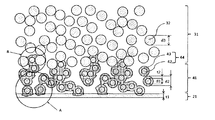
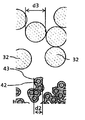
- the porous body shown in FIG. 6 includes a first layer 21, a second layer 41 including second fibers 44, and a third layer 31 including third fibers 32.
- the second fiber 44 has a core-sheath structure having a core structure 42 that forms a central axis and a sheath structure 43 that wraps the core structure 42.
- the average fiber diameter d2 of the second fibers 44 is larger than the average fiber diameter d3 of the third fibers 32.
- the average thickness t2 of the sheath structure 43 is smaller than the thickness t1 of the first layer 21.
- the porous body may be composed of a first layer, a second layer, and a third layer, and includes other layers in addition to the first layer, the second layer, and the third layer. Also good.
- the thickness of the porous body is preferably thin from the viewpoint of obtaining uniformly high air permeability, and can be, for example, 50 to 500 ⁇ m.
- the air permeability can be indicated by a Gurley value defined in JIS P8117, and the Gurley value of the porous body is preferably 10 seconds or less.
- the shape of the porous body is not particularly limited, and examples thereof include a roller shape and a belt shape.
- the first layer is a layer in contact with the first image, and is a porous layer that directly touches the first image and absorbs at least part of the first liquid.
- the material forming the first layer is not particularly limited, but it is preferable to include a fluororesin having a low surface free energy from the viewpoint of suppressing coloring material adhesion and improving cleaning properties. That is, the first layer preferably contains a fluororesin, and more preferably consists of a fluororesin.
- the fluororesin include polytetrafluoroethylene (PTFE), polychlorotrifluoroethylene (PCTFE), polyvinylidene fluoride (PVDF), polyvinyl fluoride (PVF), perfluoroalkoxy fluororesin (PFA), Examples thereof include tetrafluoroethylene / hexafluoropropylene copolymer (FEP), ethylene / tetrafluoroethylene copolymer (ETFE), and ethylene / chlorotrifluoroethylene copolymer (ECTFE).
- PTFE polytetrafluoroethylene
- PCTFE polychlorotrifluoroethylene
- PVDF polyvinylidene fluoride
- PVDF polyvinyl fluoride
- PFA perfluoroalkoxy fluororesin
- FEP tetrafluoroethylene / hexafluoropropylene copolymer
- ETFE ethylene / tetrafluoroethylene cop
- the softening temperature of the material forming the first layer is preferably 170 ° C. or higher, more preferably 180 ° C. or higher, from the viewpoint of making it higher than the softening temperature of the material forming the sheath structure in the second fiber. 200 degreeC or more is more preferable.
- the upper limit of the softening temperature range of the material forming the first layer is not particularly limited, and can be, for example, 350 ° C. or lower.
- the softening temperature is a value measured by DSC (differential scanning calorimetry). Further, when the first layer includes a plurality of materials, the softening temperature in a state including the plurality of materials is shown.
- the material forming the first layer is desirably flexible enough to leave no trace in the first image.
- the Young's modulus of the material is preferably 2.0 GPa or less, and 1.0 GPa or less. More preferred is 0.5 GPa or less.
- the lower limit of the Young's modulus range is not particularly limited, but can be, for example, 0.1 GPa or more. In the present invention, the Young's modulus is a value measured by a method defined in JIS K7161.
- the average pore diameter on the surface of the first layer on the side in contact with the first image is preferably 10.0 ⁇ m or less from the viewpoint of suppressing color material adhesion when pressed against the first image. It is more preferably 0 ⁇ m or less, and further preferably 0.2 ⁇ m or less. In particular, when the average pore diameter is 0.2 ⁇ m or less, the filterability is enhanced, and the color material adhesion to the porous body is greatly suppressed.
- the average pore diameter is an average value of values measured at 20 points or more as the diameter when the surface of the porous layer is observed with an electron microscope and the area of the pores on the surface is the area of a circle. is there.
- the lower limit of the average pore diameter range is not particularly limited, but may be, for example, 0.02 ⁇ m or more.
- the thickness of the first layer is preferably 50 ⁇ m or less, more preferably 30 ⁇ m or less, further preferably 10 ⁇ m or less, and particularly preferably 5 ⁇ m or less.
- the thickness is 50 ⁇ m or less, an increase in flow resistance can be suppressed, and image flow can be suppressed.
- the minimum of the range of this thickness is not specifically limited, For example, it can be set as 1 micrometer or more.
- the thickness is obtained by measuring the thickness at any 10 points with a straight-forward micrometer (trade name: OMV-25, manufactured by Mitutoyo Corporation) and calculating the average value. Value.
- the second layer is a porous layer that bonds the first layer and the third layer.
- the second layer includes the second fiber and may consist of the second fiber. Even if a part of the second fiber is melted, the second layer includes the second fiber as long as the second fiber remains in the fiber shape in the second layer. The same applies to the second fibers a included in the second layer a described later and the second fibers b included in the second layer b.
- the second layer may be a nonwoven fabric or a woven fabric.
- the second fiber has a core-sheath structure having a core structure that forms a central axis and a sheath structure that wraps the core structure.
- the material forming the core structure and the material forming the sheath structure are not particularly limited as long as the softening temperature relationship in this embodiment is satisfied.
- polyolefin polyethylene (PE), polypropylene (PP), etc.
- polyurethane examples thereof include polyamide such as nylon, polyester (polyethylene terephthalate (PET) and the like), polysulfone (PSF) and the like. These may use 1 type and may use 2 or more types together.
- the softening temperature of the material forming the sheath structure is the softening temperature of the material forming the core structure, the softening temperature of the material forming the first layer, and the third fiber included in the third layer. Lower than any of the softening temperatures of the materials.
- the softening temperature of the material forming the sheath structure is the softening temperature of the material forming the core structure, the softening temperature of the material forming the first layer, and the third fiber included in the third layer. It is preferably 5 ° C. or more lower than any of the softening temperatures of the materials to be processed, more preferably 10 ° C. or more.
- the softening temperature of the material forming the core structure is preferably 140 ° C. or higher, more preferably 150 ° C. or higher, from the viewpoint of satisfying the softening temperature relationship in the present embodiment.
- the upper limit of the softening temperature range of the material forming the core structure is not particularly limited, it can be, for example, 180 ° C. or lower.
- the softening temperature of the material forming the sheath structure is preferably less than 140 ° C., more preferably 130 ° C. or less, from the viewpoint of satisfying the softening temperature relationship in the present embodiment.
- the minimum of the range of the softening temperature of the material which forms the said sheath structure is not specifically limited, For example, it can be 110 degreeC or more.
- the Young's modulus of the material forming the core structure is preferably 0.1 to 3.0 GPa from the viewpoint of transportability.
- the Young's modulus of the material forming the sheath structure is preferably 0.1 to 3.0 GPa from the viewpoint of transportability.
- the average thickness of the sheath structure is smaller than the thickness of the first layer.
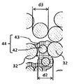
- FIG. 7A shows an enlarged view of a portion A of the porous body shown in FIG.
- the average thickness t2 of the sheath structure 43 of the second layer 41 is smaller than the thickness t1 of the first layer 21 (t2 ⁇ t1). .
- the first layer 21 is crushed, resulting in an image flow.
- the average thickness of the sheath structure is preferably 1.0 ⁇ m or less, more preferably 1.5 ⁇ m or less, than the thickness of the first layer.
- the first layer 21 and the sheath structure of the second layer are bonded to each other, so that the adhesive strength between the first layer and the second layer is also improved. Yes.
- the average thickness of the sheath structure is preferably 0.5 to 5.0 ⁇ m, more preferably 1.0 to 4.0 ⁇ m, from the viewpoint of satisfying the above relationship.
- the average diameter of the core structure is preferably 1.0 to 30.0 ⁇ m, and more preferably 5.0 to 20.0 ⁇ m.
- the average thickness of a sheath structure and the average diameter of a core structure are the average values of the measured value in 20 or more places obtained by SEM observation after forming a cross section by ion milling, FIB, etc.
- the average thickness of the said sheath structure is measured and calculated about the location which is not melted.
- the average fiber diameter of the second fiber is larger than the average fiber diameter of the third fiber.
- FIG. 7C shows an enlarged view of a portion B of the porous body shown in FIG.
- the average fiber diameter d2 of the second layer is larger than the average fiber diameter d3 of the third layer (d2> d3).
- the second fiber 44 of the second layer can be bonded to the third fiber 32 of the third layer by the anchor effect as shown in FIG. 7D.
- the second layer and the third layer easily peel off.
- the average fiber diameter of the second fiber is preferably 1 ⁇ m or more and more preferably 2 ⁇ m or more larger than the average fiber diameter of the third fiber.
- the average fiber diameter of the second fiber is preferably 10 to 50 ⁇ m and more preferably 15 to 30 ⁇ m from the viewpoint of satisfying the above relationship.
- an average fiber diameter is an average value of the measured value in 20 or more places obtained by SEM observation from the surface, or SEM observation after forming a cross section by ion milling, FIB, etc.
- the said sheath structure is partially melted, the said average fiber diameter is measured and calculated about the location which is not melted.
- the thickness of the second layer is preferably 10 to 500 ⁇ m from the viewpoint of transportability.
- the third layer is a porous layer that increases the rigidity of the liquid absorbing member.
- the third layer includes third fibers and may consist of third fibers.
- the third layer may be a nonwoven fabric or a woven fabric.
- the material forming the third fiber is not particularly limited as long as the softening temperature relationship in the present invention is satisfied, and examples thereof include polyphenylene sulfide (PPS), polyimide, and polyethylene terephthalate (PET). These may use 1 type and may use 2 or more types together.
- the third fiber preferably contains polyphenylene sulfide (PPS) or polyimide from the viewpoint of a high Young's modulus and improved conveyance strength.
- the softening temperature of the material forming the third fiber is preferably 150 ° C. or higher, more preferably 170 ° C. or higher, and more preferably 200 ° C. or higher, from the viewpoint of satisfying the softening temperature relationship in the present invention. preferable.
- the upper limit of the softening temperature range of the material forming the third fiber is not particularly limited, it can be, for example, 350 ° C. or less.
- the Young's modulus of the material forming the third fiber is preferably higher than the Young's modulus of the material forming the first layer from the viewpoint of increasing the conveyance strength and ensuring the rigidity.
- the Young's modulus of the material forming the third fiber is preferably 1.0 GPa or more, and more preferably 2.0 GPa or more, higher than the Young's modulus of the material forming the first layer.
- the Young's modulus of the material forming the third fiber is preferably 2.0 GPa or more, more preferably 2.5 GPa or more, and further preferably 3.0 GPa or more.
- the upper limit of the Young's modulus range is not particularly limited, but can be, for example, 5.0 GPa or less.
- the third layer made of a material having the Young's modulus will ultimately determine the rigidity of the porous sheet.
- a tension of about 2.5 to 10.0 mN / mm is applied during the conveyance.
- the elongation in the range of tension and elastic deformability is a value measured by “Autograph AG-X” (trade name) manufactured by Shimadzu Corporation.
- the thickness of the third layer is preferably 50 to 500 ⁇ m, more preferably 100 to 400 ⁇ m, and even more preferably 150 to 300 ⁇ m from the viewpoint of increasing the conveyance strength and ensuring the rigidity.
- the average fiber diameter of the third fiber is preferably 2 to 15 ⁇ m, more preferably 5 to 10 ⁇ m, from the viewpoint of making it smaller than the average fiber diameter of the second fiber.
- the other porous body according to the present embodiment includes a first layer in contact with the first image, a second layer a including the second fibers a, and a second layer including the second fibers b.
- b and the 3rd layer containing the 3rd fiber are the porous sheets laminated
- the average fiber diameter of the second fiber b is larger than the average fiber diameter of the third fiber.
- the second fiber a and the second fiber b have a core-sheath structure having a core structure that forms a central axis and a sheath structure that wraps the core structure.
- the softening temperature of the material forming the sheath structure of the second fiber a is the softening temperature of the material forming the core structure of the second fiber a and the softening temperature of the material forming the first layer. Lower than any of the above.
- the softening temperature of the material forming the sheath structure of the second fiber b is the softening temperature of the material forming the core structure of the second fiber b and the softening temperature of the material forming the third fiber. Lower than any of the above.
- the average thickness of the sheath structure of the second fiber a is smaller than the thickness of the first layer.
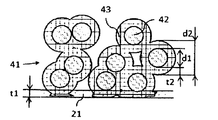
- FIG. 8 An example of the porous body according to this embodiment is shown in FIG.
- the porous body shown in FIG. 8 includes a first layer 21, a second layer a41a including a second fiber a44a, a second layer b41b including a second fiber b44b, and a third fiber 32.
- a third layer 31 containing The second fiber a44a has a core-sheath structure having a core structure 42a that forms a central axis and a sheath structure 43a that wraps the core structure 42a.
- the second fiber b44b has a core-sheath structure having a core structure 42b that forms the central axis and a sheath structure 43b that wraps the core structure 42b.
- the average fiber diameter d2b of the second fiber b44b is larger than the average fiber diameter d3 of the third fiber 32.
- the average thickness t2a of the sheath structure 43a of the second fiber a44a is smaller than the thickness t1 of the first layer 21.
- the average fiber diameter of the second fiber 44 in order to make the average fiber diameter d ⁇ b> 2 of the second fiber 44 larger than the average fiber diameter d ⁇ b> 3 of the third fiber 32, the average fiber diameter of the second fiber 44. If d2 is too large, the irregularities on the surface of the second layer 41 may spread to the first layer 21. In this case, the image may be distorted in the absorption of the first liquid from the first image.
- the second layer in the first embodiment is composed of a second layer a41a including the second fiber a44a and a second layer b41b including the second fiber b44b. ing.
- the second layer a41a is disposed on the first layer 21 side, and the second layer b41b is disposed on the third layer 31 side.
- the dimension of the core-sheath structure of the second fiber a44a and the dimension of the core-sheath structure of the second fiber b44b can be configured differently, the surface on the first layer side of the second layer
- the average fiber diameter of the second fiber can be easily made larger than the average fiber diameter of the third fiber while suppressing the unevenness.
- the average fiber diameter d2b of the second fiber b44b is larger than the average fiber diameter d3 of the third fiber 32 (d2b> d3), and the average thickness t2a of the sheath structure 43a of the second fiber a44a is the first layer.
- 21 is smaller than the thickness t1 (t1> t2a), and the first layer is prevented from being clogged while suppressing the unevenness of the surface on the first layer side of the second layer, and the second layer and the third layer. It is possible to easily achieve both improvement in adhesive strength with the layer.
- the first layer and the third layer in the present embodiment can have the same configuration as the first layer and the third layer in the first embodiment.
- the second layer a is a porous layer that is disposed on the first layer side and adheres to the first layer.
- the second layer a includes the second fiber a and may be composed of the second fiber a.
- the second layer a may be a nonwoven fabric or a woven fabric.
- Said 2nd fiber a has the core-sheath structure which has the core structure which forms a center axis
- the material for forming the core structure and the material for forming the sheath structure of the second fiber a are not particularly limited as long as the softening temperature relationship in the present embodiment is satisfied, and in the first embodiment. The same material as the second fiber can be used.
- the softening temperature of the material forming the sheath structure of the second fiber a is any of the softening temperature of the material forming the core structure of the second fiber a and the softening temperature of the material forming the first layer. Is also low. Thereby, when bonding the first layer and the second layer a by heating, only the material forming the sheath structure of the second fiber a can be softened by selecting the heating temperature, The core structure of the second fiber a does not melt. Therefore, the shape of the second fiber a can be maintained, and crushing of the second layer a can be prevented.
- the softening temperature of the material forming the sheath structure of the second fiber a is any of the softening temperature of the material forming the core structure of the second fiber a and the softening temperature of the material forming the first layer. Is preferably 5 ° C. or more, more preferably 10 ° C. or more.
- the softening temperature of the material forming the core structure of the second fiber a is preferably 140 ° C. or higher, more preferably 150 ° C. or higher, from the viewpoint of satisfying the softening temperature relationship in the present embodiment.
- the upper limit of the softening temperature range of the material forming the core structure of the second fiber a is not particularly limited, it can be, for example, 180 ° C. or lower.
- the softening temperature of the material forming the sheath structure of the second fiber a is preferably less than 140 ° C. and more preferably 130 ° C. or less from the viewpoint of satisfying the softening temperature relationship in the present embodiment. preferable.
- the lower limit of the softening temperature range of the material forming the sheath structure of the second fiber a is not particularly limited, it can be, for example, 110 ° C. or higher.
- the Young's modulus of the material forming the core structure of the second fiber a is preferably 0.1 to 3.0 GPa from the viewpoint of transportability.
- the Young's modulus of the material forming the sheath structure of the second fiber a is preferably 0.1 to 3.0 GPa from the viewpoint of transportability.
- the average thickness of the sheath structure of the second fiber a is smaller than the thickness of the first layer from the viewpoint of suppressing the image flow due to the crushing of the first layer.
- the average thickness of the sheath structure of the second fiber a is preferably 1.0 ⁇ m or more and more preferably 2.0 ⁇ m or less than the thickness of the first layer.
- the average thickness of the sheath structure of the second fiber a is preferably 0.5 to 5.0 ⁇ m, more preferably 1.0 to 3.0 ⁇ m, from the viewpoint of satisfying the above relationship.
- the average diameter of the core structure of the second fiber a is preferably 1.0 to 10.0 ⁇ m, more preferably 2.0 to 8.0 ⁇ m.
- the average fiber diameter of the second fibers a is preferably 1 to 10 ⁇ m and more preferably 2 to 8 ⁇ m from the viewpoint of suppressing unevenness on the surface of the second layer a.
- the thickness of the second layer a is preferably 10 to 500 ⁇ m from the viewpoint of transportability.
- the second layer b is a porous layer that is disposed on the third layer side and adheres to the third layer.
- the second layer b includes the second fiber b and may be composed of the second fiber b.
- the second layer b may be a nonwoven fabric or a woven fabric.
- Said 2nd fiber b has the core-sheath structure which has the core structure which forms a center axis
- the material for forming the core structure and the material for forming the sheath structure of the second fiber b are not particularly limited as long as the softening temperature relationship in the present embodiment is satisfied, and in the first embodiment. The same material as the second fiber can be used.
- the softening temperature of the material forming the sheath structure of the second fiber b is any of the softening temperature of the material forming the core structure of the second fiber b and the softening temperature of the material forming the third fiber. Is also low. Thereby, when bonding the second layer b and the third layer by heating, only the material forming the sheath structure of the second fiber b can be softened by selecting the heating temperature, The core structure of the second fiber b does not melt. Therefore, the shape of the second fiber b can be maintained, and crushing of the second layer b can be prevented.
- the softening temperature of the material forming the sheath structure of the second fiber b is any of the softening temperature of the material forming the core structure of the second fiber b and the softening temperature of the material forming the third layer. Is preferably 5 ° C. or more, more preferably 10 ° C. or more.
- the softening temperature of the material forming the core structure of the second fiber b is preferably 140 ° C. or higher and more preferably 150 ° C. or higher from the viewpoint of satisfying the softening temperature relationship in the present embodiment.
- the upper limit of the softening temperature range of the material forming the core structure of the second fiber b is not particularly limited, and can be, for example, 180 ° C. or lower.
- the softening temperature of the material forming the sheath structure of the second fiber b is preferably less than 140 ° C. and more preferably 130 ° C. or less from the viewpoint of satisfying the softening temperature relationship in the present embodiment. preferable.
- the lower limit of the softening temperature range of the material forming the sheath structure of the second fiber b is not particularly limited, and can be, for example, 110 ° C. or higher.
- the Young's modulus of the material forming the core structure of the second fiber b is preferably 0.1 to 3.0 GPa from the viewpoint of transportability.
- the Young's modulus of the material forming the sheath structure of the second fiber b is preferably 0.1 to 3.0 GPa from the viewpoint of transportability.
- the average thickness of the sheath structure of the second fiber a is preferably 0.5 to 5.0 ⁇ m, more preferably 1.0 to 4.0 ⁇ m.
- the average diameter of the core structure of the second fiber a is preferably 1.0 to 30.0 ⁇ m, and more preferably 5.0 to 20.0 ⁇ m.
- the average fiber diameter of the second fiber b is larger than the average fiber diameter of the third fiber from the viewpoint of improving the adhesive strength between the second layer b and the third layer.
- the average fiber diameter of the second fiber b is preferably 1 ⁇ m or more, and more preferably 2 ⁇ m or more larger than the average fiber diameter of the third fiber.
- the average fiber diameter of the second fiber b is preferably 10 to 50 ⁇ m and more preferably 15 to 30 ⁇ m from the viewpoint of satisfying the above relationship.
- the thickness of the second layer b is preferably 10 to 500 ⁇ m from the viewpoint of transportability.
- the heating temperature is equal to or higher than the softening temperature of the material forming the sheath structure, and the softening temperature of the material forming the core structure, the softening temperature of the material forming the first layer, and the third temperature
- the softening temperature of the material forming the fiber is set to be lower than the softening temperature.
- the heating temperature is equal to or higher than the softening temperature of the material forming the sheath structure, and the softening temperature of the material forming the core structure, the softening temperature of the material forming the first layer, and the It is preferably below the softening temperature of the material forming the third fiber.
- the heating temperature is preferably 100 to 150 ° C., for example, depending on the material used.
- the first layer in contact with the first image, the second layer a including the second fiber a, and the second layer b including the second fiber b are used.
- a porous body in which the second layer b and the third layer including the third fiber are laminated in this order can be manufactured.
- the heating temperature is equal to or higher than the softening temperature of the material forming the sheath structure of the second fibers a and the second fibers b, and the cores of the second fibers a and the second fibers b.
- the softening temperature of the material forming the structure, the softening temperature of the material forming the first layer, and the softening temperature of the material forming the third fiber are set below.
- the heating temperature is equal to or higher than the softening temperature of the material forming the sheath structure of the second fiber a and the second fiber b, and the second fiber a and the second fiber b.
- the softening temperature of the material forming the core structure, the softening temperature of the material forming the first layer, and the softening temperature of the material forming the third fiber may be, for example, 100 to 150 ° C., depending on the material used.
- pressurization may be performed at the same time.
- a method of laminating a laminate while pressing it with a heated roller is preferable.
- the material forming the sheath structure of the second layer enters the pores of the first layer and the third layer so as not to be crushed.
- all the layers may be stacked and then heated, or after two layers are stacked and heated, another layer may be stacked and heated, and so on. Good.
- FIG. 9 shows an example of a laminator that can be used in the method for producing the porous body.
- a porous body can be produced by sequentially laminating and heating each layer.
- the laminator is provided with a conveying belt 620 for conveying and laminating each sheet to be laminated.
- the conveyor belt 620 is driven by a belt conveyor roller 630.
- the first sheet 601 is conveyed by the first sheet conveying roller 611.
- the first sheet 601 and the second sheet 602 are heated and pressed by the heated nip rollers 612a and 612b and are welded.
- the welded laminate sheet 603 is taken up by a take-up roller 613.
- the temperatures of the nip rollers 612a and 612b are preferably the heating temperatures.
- an ink jet recording apparatus that forms a first image on a transfer body as a recording medium and transfers the second image after the first liquid absorption by the liquid absorbing member to a recording medium.
- an ink jet recording apparatus that forms a first image on a recording medium as a recording medium.
- the former ink jet recording apparatus is hereinafter referred to as a transfer type ink jet recording apparatus for convenience
- the latter ink jet recording apparatus is hereinafter referred to as a direct drawing type ink jet recording apparatus for convenience.
- FIG. 1 is a schematic diagram illustrating an example of a schematic configuration of a transfer type inkjet recording apparatus of the present embodiment.
- the transfer type inkjet recording apparatus 100 includes a transfer body 101 that temporarily holds a first image and a second image in which at least part of the first liquid is absorbed from the first image.
- the transfer type inkjet recording apparatus 100 includes a transfer unit including a transfer pressing member 106 that transfers the second image onto the recording medium 108 on which the image is to be formed.
- the transfer type inkjet recording apparatus 100 of the present invention includes a transfer body 101 supported by a support member 102, a reaction liquid applying device 103 for applying a reaction liquid onto the transfer body 101, and a transfer body 101 to which the reaction liquid is applied.
- the pressing member 106 that transfers the second image on the transfer body from which the liquid component has been removed onto a recording medium 108 such as paper is provided.
- the transfer type inkjet recording apparatus 100 may have a transfer body cleaning member 109 that cleans the surface of the transfer body 101 after the second image is transferred to the recording medium 108.
- the support member 102 is rotated in the direction of arrow A in FIG. 1 around the rotation shaft 102a. By the rotation of the support member 102, the outer peripheral surface of the transfer body 101 is moved in the arrow A direction.
- application of the reaction liquid by the reaction liquid application device 103 and application of ink by the ink application device 104 are sequentially performed, and a first image is formed on the transfer body 101.
- the first image formed on the transfer body 101 is moved to a position in contact with the liquid absorbing member 105 a included in the liquid absorbing device 105 by the rotational movement of the transfer body 101.
- the liquid absorbing member 105 a of the liquid absorbing device 105 moves in synchronization with the rotation of the transfer body 101.
- the first image formed on the transfer body 101 is in contact with the moving liquid absorbing member 105a. During this time, the liquid absorbing member 105a removes the liquid component from the first image.
- the liquid component contained in a 1st image is removed by passing through the state which contacted this liquid absorption member 105a.
- the liquid absorbing member 105a is preferably pressed against the first image with a predetermined pressing force in order to make the liquid absorbing member 105a function effectively.
- the removal of the liquid component is described from a different viewpoint, it can also be expressed as concentrating the ink constituting the first image formed on the transfer body. Concentrating the ink means that the content ratio of the solid component such as a coloring material or resin contained in the ink increases as the liquid component contained in the ink decreases.
- the second image from which the liquid component has been removed is moved to the transfer unit that contacts the recording medium 108 conveyed by the recording medium conveying device 107 by the rotational movement of the transfer body 101.
- the pressing member 106 presses the recording medium 108, whereby an ink image is formed on the recording medium 108.
- the transferred ink image transferred onto the recording medium 108 is a reverse image of the second image.
- this post-transfer ink image may be referred to as a third image separately from the first image (ink image before liquid removal) and the second image (ink image after liquid removal).
- the reaction liquid since the first image is formed by applying ink after the reaction liquid is applied on the transfer body, the reaction liquid does not react with the ink in the non-image area (non-ink image forming area). Remaining.
- the liquid absorbing member 105a not only removes the liquid component from the first image, but also contacts (pressure contact) with the unreacted reaction liquid, and also combines the liquid component in the reaction liquid on the surface of the transfer body 101. Has been removed from.
- the liquid component is removed from the first image, but this is not a limited meaning that the liquid component is removed only from the first image. It is used in the sense that the liquid component only needs to be removed from the image. For example, it is also possible to remove the liquid component in the reaction solution applied to the outer region of the first image together with the first image.
- the liquid component is not particularly limited as long as it does not have a certain shape, has fluidity, and has a substantially constant volume.
- water, an organic solvent, or the like contained in ink or a reaction liquid can be used as the liquid component.
- the ink can be concentrated by the liquid absorption process.
- the clear ink is applied on the color ink containing the color material applied on the transfer body 101, the clear ink is entirely present on the surface of the first image, or the first Clear ink is partially present at one or more locations on the surface of one image, and color ink is present at other locations.
- the porous body absorbs the liquid component of the clear ink on the surface of the first image, and the liquid component of the clear ink moves. Along with this, the liquid component in the color ink moves to the porous body side, so that the liquid component in the color ink is absorbed.
- the liquid components of the color ink and the clear ink move to the porous body side and are absorbed.
- the clear ink may contain a large amount of components for improving the transferability of the image from the transfer body 101 to the recording medium 108. For example, the content rate of the component which becomes more adhesive to the recording medium by heating than the color ink is increased.
- the transfer body 101 has a surface layer including an image forming surface.
- various materials such as resin and ceramic can be used as appropriate, but a material having a high compression elastic modulus is preferable in terms of durability and the like. Specific examples include condensates obtained by condensing acrylic resins, acrylic silicone resins, fluorine-containing resins, and hydrolyzable organosilicon compounds.
- surface treatment may be performed. Examples of the surface treatment include flame treatment, corona treatment, plasma treatment, polishing treatment, roughening treatment, active energy ray irradiation treatment, ozone treatment, surfactant treatment, and silane coupling treatment. A plurality of these may be combined. Moreover, arbitrary surface shapes can also be provided in the surface layer.
- the transfer body preferably has a compression layer having a function of absorbing pressure fluctuations.
- the compression layer absorbs deformation, disperses the fluctuation with respect to the local pressure fluctuation, and can maintain good transferability even during high-speed printing.
- the material for the compression layer include acrylonitrile-butadiene rubber, acrylic rubber, chloroprene rubber, urethane rubber, and silicone rubber.
- the porous rubber material includes a continuous pore structure in which the pores are continuous with each other and an independent pore structure in which the pores are independent from each other.
- any structure may be used, and these structures may be used in combination.
- the transfer body preferably has an elastic layer between the surface layer and the compression layer.
- various materials such as resin and ceramic can be used as appropriate.
- Various elastomer materials and rubber materials are preferably used in terms of processing characteristics and the like. Specifically, for example, fluorosilicone rubber, phenyl silicone rubber, fluoro rubber, chloroprene rubber, urethane rubber, nitrile rubber, ethylene propylene rubber, natural rubber, styrene rubber, isoprene rubber, butadiene rubber, ethylene / propylene / butadiene copolymer, A nitrile butadiene rubber etc. are mentioned.
- silicone rubber, fluorosilicone rubber, and phenyl silicone rubber are preferable in terms of dimensional stability and durability because they have a small compression set. Further, the change in elastic modulus with temperature is small, which is preferable in terms of transferability.
- each layer surface layer, elastic layer, compression layer
- a reinforcing layer having a high compression elastic modulus may be provided to suppress lateral elongation when mounted on the apparatus and to maintain stiffness.
- a woven fabric may be used as the reinforcing layer.
- the transfer body can be produced by arbitrarily combining the layers made of the above materials.
- the size of the transfer body can be freely selected according to the target print image size.
- the shape of the transfer body is not particularly limited, and specific examples include a sheet shape, a roller shape, a belt shape, and an endless web shape.
- the transfer body 101 is supported on a support member 102.
- Various adhesives and double-sided tapes may be used as a method for supporting the transfer body.
- the transfer member 101 may be supported on the support member 102 by using an installation member by attaching an installation member made of metal, ceramic, resin, or the like to the transfer member.
- the support member 102 is required to have a certain degree of structural strength from the viewpoint of conveyance accuracy and durability.
- metal, ceramic, resin or the like is preferably used.
- aluminum, iron, stainless steel, acetal resin, epoxy resin, polyimide, Polyethylene, polyethylene terephthalate, nylon, polyurethane, silica ceramics, and alumina ceramics are preferably used. It is also preferable to use a combination of these.
- the ink jet recording apparatus includes a reaction liquid applying device 103 that applies a reaction liquid to the transfer body 101.
- a reaction liquid applying device 103 that applies a reaction liquid to the transfer body 101.
- 1 is a gravure offset having a reaction solution storage unit 103a that stores a reaction solution, and reaction solution application members 103b and 103c that apply the reaction solution in the reaction solution storage unit 103a onto the transfer body 101.
- the case of a roller is shown.
- the ink jet recording apparatus includes an ink applying device 104 that applies ink to the transfer body 101 to which the reaction liquid is applied.
- the reaction liquid and the ink are mixed to form a first image, and the liquid component is absorbed from the first image by the next liquid absorption device 105.
- the liquid absorbing device 105 includes a liquid absorbing member 105 a and a liquid absorbing pressing member 105 b that presses the liquid absorbing member 105 a against the first image on the transfer body 101.
- the pressing member 105b has a cylindrical shape
- the liquid absorbing member 105a has a belt shape
- the belt-shaped liquid absorbing member 105a is pressed against the transfer body 101 by the cylindrical pressing member 105b. It may be a configuration.
- the pressing member 105b has a columnar shape, and the liquid absorbing member 105a has a cylindrical shape formed on the peripheral surface of the columnar pressing member 105b.
- the cylindrical pressing member 105b is a cylindrical liquid absorbing member 105a. May be configured to be pressed against the transfer body.
- the liquid absorbing member 105a is preferably belt-shaped in consideration of the space in the ink jet recording apparatus.
- the liquid absorbing device 105 having such a belt-shaped liquid absorbing member 105a may have a stretching member that stretches the liquid absorbing member 105a.
- 105c, 105d, and 105e are tension rollers as tension members.
- the pressing member 105b is also a roller member that rotates in the same manner as the stretching roller, but is not limited to this.
- the liquid absorbing member 105a having a porous body is pressed against the first image by the pressing member 105b, so that the liquid absorbing member 105a absorbs the liquid component contained in the first image,
- the second image is obtained by reducing the liquid component from the first image.
- various other conventionally used methods for example, a method using heating, a method of blowing low-humidity air, and a method of reducing pressure Etc. may be combined.
- the liquid component may be further reduced by applying these methods to the second image in which the liquid component is reduced.
- a pretreatment device (not shown in FIGS. 1 and 2) that applies a wetting liquid (also referred to as a treatment liquid) to the liquid absorption member before the liquid absorption member 105a having a porous body is brought into contact with the first image. It is preferable to perform pretreatment according to the figure.
- the wetting liquid used in the present invention preferably contains water and a water-soluble organic solvent.
- the water is preferably water deionized by ion exchange or the like.
- the kind of water-soluble organic solvent is not specifically limited, Any of well-known organic solvents, such as ethanol and isopropyl alcohol, can be used.
- the method of applying the wetting liquid to the porous body is not particularly limited, but immersion or droplet dropping is preferable. Moreover, there is no restriction
- the surfactant at least one of a silicone surfactant and a fluorine surfactant is preferably used, and a fluorine surfactant is more preferably used.
- the content of the surfactant in the wetting liquid is preferably 0.2% by mass or more, more preferably 0.4% by mass or more, and 0.5% by mass or more with respect to the total mass of the wetting liquid. Particularly preferred.
- the upper limit of the content of the surfactant in the wetting liquid is not particularly limited, but is preferably 10% by mass with respect to the total mass of the wetting liquid from the viewpoint of solubility of the surfactant in the wetting liquid.
- the pressure of the liquid absorbing member that presses the first image on the transfer body is 2.9 N / cm 2 (0.3 kgf / cm 2 ) or more, the liquid component in the first image is solidified in a shorter time. This is preferable because the liquid component can be removed from the first image. Further, the pressure is not more than 98N / cm 2 (10kgf / cm 2), preferably can be suppressed the load on the structure of the device.
- the pressure of the liquid absorbing member indicates the nip pressure between the recording medium and the liquid absorbing member, and a surface pressure distribution measuring instrument (I-SCAN (trade name), Nitta Corporation). The surface pressure is measured, and the weight in the pressurizing region is divided by the area to calculate the value.
- the working time for bringing the liquid absorbing member 105a into contact with the first image is preferably within 50 ms (milliseconds) in order to further suppress the coloring material in the first image from adhering to the liquid absorbing member.
- the operation time in this specification is calculated by dividing the pressure sensing width in the moving direction of the recording medium in the surface pressure measurement described above by the moving speed of the recording medium.
- this operation time is referred to as a liquid absorption nip time.
- the liquid component is absorbed from the first image on the transfer body 101, and a second image with a reduced liquid content is formed.
- the second image is then transferred onto the recording medium 108 at the transfer portion.
- the transfer pressing member 106 presses the recording medium 108 while the second image and the recording medium 108 conveyed by the recording medium conveying device 107 are in contact with each other. An ink image is transferred on top. By removing the liquid component contained in the first image on the transfer body 101 and then transferring it to the recording medium 108, it is possible to obtain a recorded image in which curling, cockling, and the like are suppressed.
- the pressing member 106 is required to have a certain degree of structural strength from the viewpoint of conveyance accuracy and durability of the recording medium 108.
- the material of the pressing member 106 is preferably metal, ceramic, resin, or the like.
- aluminum, iron, stainless steel, acetal resin, epoxy resin, polyimide, Polyethylene, polyethylene terephthalate, nylon, polyurethane, silica ceramics, and alumina ceramics are preferably used. Moreover, you may use combining these.
- the time for the pressing member 106 to press the second image on the transfer body 101 to the recording medium 108 is preferably 5 ms or more and 100 ms or less.
- the pressing time in this embodiment indicates the time during which the recording medium 108 and the transfer body 101 are in contact with each other, and a surface pressure distribution measuring instrument (I-SCAN (trade name), manufactured by Nitta Corporation). ), The surface pressure is measured, and the length in the conveyance direction of the pressurizing region is divided by the conveyance speed to calculate a value.
- the pressure that the pressing member 106 presses in order to transfer the second image on the transfer body 101 to the recording medium 108 is performed well and the durability of the transfer body is impaired. Be careful not to. For this reason, the pressure is preferably 9.8 N / cm 2 (1 kgf / cm 2 ) or more and 294.2 N / cm 2 (30 kgf / cm 2 ) or less.
- the pressure in the present embodiment indicates the nip pressure between the recording medium 108 and the transfer body 101.
- the surface pressure is measured by a surface pressure distribution measuring device, and the weight in the pressurizing region is divided by the area to obtain a value. Is calculated.
- the temperature at which the pressing member 106 is pressed to transfer the second image on the transfer body 101 to the recording medium 108 is not particularly limited, but it is not less than the glass transition point of the resin component contained in the ink or softened. It is preferable that it is more than a point.
- the heating preferably includes a heating device that heats the second image on the transfer body 101, the transfer body 101, and the recording medium 108.
- the shape of the pressing member 106 is not particularly limited, and examples thereof include a roller shape.
- the recording medium 108 is not particularly limited, and any known recording medium can be used.
- the recording medium include a long product wound in a roll shape, or a single sheet cut into a predetermined size.
- Examples of the material include paper, plastic film, wood board, cardboard, and metal film.
- the recording medium conveying device 107 for conveying the recording medium 108 is constituted by a recording medium feeding roller 107a and a recording medium take-up roller 107b. It is not limited to.
- FIG. 3 is a block diagram showing a control system of the entire apparatus in the transfer type ink jet recording apparatus shown in FIG.
- 301 is a recording data generation unit such as an external print server
- 302 is an operation control unit such as an operation panel
- 303 is a printer control unit for executing a recording process
- 304 is a recording medium for conveying the recording medium.
- a conveyance control unit 305 is an inkjet device for printing.
- FIG. 4 is a block diagram of a printer control unit in the transfer type ink jet recording apparatus of FIG.
- Reference numeral 401 is a CPU for controlling the entire printer
- 402 is a ROM for storing a control program for the CPU
- 403 is a RAM for executing the program.
- Reference numeral 404 denotes an application specific integrated circuit (ASIC) that includes a network controller, a serial IF controller, a head data generation controller, a motor controller, and the like.
- Reference numeral 405 denotes a liquid absorption member conveyance control unit for driving the liquid absorption member conveyance motor 406, which is command-controlled from the ASIC 404 via the serial IF.
- Reference numeral 407 denotes a transfer body drive control unit for driving the transfer body drive motor 408, which is similarly command-controlled from the ASIC 404 via the serial IF.
- Reference numeral 409 denotes a head controller that performs final ejection data generation, drive voltage generation, and the like of the inkjet device 305.
- the recording medium is a recording medium on which an image is to be formed.
- FIG. 2 is a schematic diagram showing an example of a schematic configuration of the direct drawing type inkjet recording apparatus 200 in the present embodiment.
- the direct drawing type inkjet recording apparatus does not have the transfer body 101, the support member 102, and the transfer body cleaning member 109, except that an image is formed on the recording medium 208. It has the same member as the transfer type ink jet recording apparatus.
- the reaction liquid applying device 203 for applying the reaction liquid to the recording medium 208 the ink applying device 204 for applying ink to the recording medium 208, and the liquid absorbing member 205a that contacts the first image on the recording medium 208
- the liquid absorbing device 205 that absorbs the liquid component contained in the first image has the same configuration as that of the transfer type inkjet recording device, and a description thereof will be omitted.
- the liquid absorbing device 205 includes a liquid absorbing member 205a and a liquid absorbing pressing member 205b that presses the liquid absorbing member 205a against the first image on the recording medium 208.
- a liquid absorbing member 205a and a liquid absorbing pressing member 205b that presses the liquid absorbing member 205a against the first image on the recording medium 208.
- the liquid absorbing device 205 may have a stretching member that stretches the liquid absorbing member.
- 205c, 205d, 205e, 205f, and 205g are stretching rollers as stretching members.
- the number of tension rollers is not limited to five as shown in FIG. 4, and a necessary number may be arranged according to the device design.
- an ink applying unit that applies ink to the recording medium 208 by the ink applying device 204, and a position facing the liquid component removing unit that presses the liquid absorbing member 205a against the first image on the recording medium and removes the liquid component.
- a recording medium support member (not shown) that supports the recording medium from below may be provided.
- the recording medium transporting device 207 is not particularly limited, and a transporting device used in a known direct drawing type ink jet recording apparatus can be used.
- a recording medium conveying apparatus having a recording medium feeding roller 207a, a recording medium winding roller 207b, and recording medium conveying rollers 207c, 207d, 207e, and 207f.
- the direct drawing type inkjet recording apparatus in the present embodiment has a control system for controlling each apparatus.
- a block diagram showing a control system of the entire apparatus of the direct drawing type ink jet recording apparatus shown in FIG. 2 is as shown in FIG. 3 as in the case of the transfer type ink jet recording apparatus shown in FIG.
- FIG. 5 is a block diagram of a printer control unit in the direct drawing type ink jet recording apparatus shown in FIG. Except for not having the transfer body drive control unit 407 and the transfer body drive motor 408, it is the same as the block diagram of the printer control unit in the transfer type inkjet recording apparatus shown in FIG.
- 501 is a CPU for controlling the entire printer
- 502 is a ROM for storing a control program for the CPU
- 503 is a RAM for executing the program.
- Reference numeral 504 denotes an ASIC including a network controller, a serial IF controller, a head data generation controller, a motor controller, and the like.
- Reference numeral 505 denotes a liquid absorption member conveyance control unit for driving the liquid absorption member conveyance motor 506, and is command-controlled from the ASIC 504 via the serial IF.
- Reference numeral 509 denotes a head controller that performs final ejection data generation, drive voltage generation, and the like of the inkjet device 305.
- reaction solution a reaction solution having the following composition was used.
- the “remainder” of ion-exchanged water is an amount such that the total of all the components constituting the reaction solution is 100.0% by mass.
- Surfactant (Megafac F444 (trade name), manufactured by DIC Corporation) 5.0 mass% ⁇ Ion exchange water balance
- ⁇ Preparation of resin fine particle dispersion 20 parts of ethyl methacrylate, 3 parts of 2,2′-azobis- (2-methylbutyronitrile), and 2 parts of n-hexadecane were mixed and stirred for 0.5 hour. This mixture was added dropwise to 75 parts of an 8% by mass aqueous solution of a styrene-butyl acrylate-acrylic acid copolymer (acid value: 130 mgKOH / g, weight average molecular weight (Mw): 7,000) for 0.5 hour. Stir. Next, the ultrasonic wave was irradiated for 3 hours with the ultrasonic irradiation machine. Subsequently, a polymerization reaction was performed at 80 ° C. for 4 hours in a nitrogen atmosphere, followed by filtration after cooling to room temperature to prepare a resin fine particle dispersion having a resin content of 25.0% by mass.
- the pigment dispersion and the resin fine particle dispersion were mixed with the following components.
- the “remaining part” of ion-exchanged water is an amount such that the total of all components constituting the ink is 100.0% by mass.
- Pigment dispersion 40 0% by mass ⁇ Resin fine particle dispersion 20.0% by mass ⁇ Glycerin 7.0% by mass Polyethylene glycol (number average molecular weight (Mn): 1,000) 3.0% by mass Surfactant: Acetylenol E100 (trade name, manufactured by Kawaken Fine Chemical Co., Ltd.) 0.5% by mass -Ion-exchanged water remainder After the mixture was sufficiently stirred and dispersed, pressure filtration was performed with a micro filter (manufactured by Fuji Film Co., Ltd.) having a pore size of 3.0 ⁇ m to prepare an ink.
- a micro filter manufactured by Fuji Film Co., Ltd.
- the first layer is a polytetrafluoroethylene (PTFE) porous body having an average pore diameter of 0.2 ⁇ m on the surface in contact with the first image, and is a multiaxially stretched film.
- PTFE polytetrafluoroethylene
- the first layer in Example 1 was produced by a method of compression-molding crystallized emulsion polymerized PTFE particles and multiaxially stretching at a temperature below the melting point of PTFE to obtain a fibrillated porous body. .
- the softening temperature was measured from the peak value of the heat absorption obtained using a DSC measuring instrument (Q-1000 (trade name), manufactured by T.A. Instruments Japan Co., Ltd.).
- the second layer in Examples 1 to 3, Example 5, and Comparative Examples 1 to 4 includes a second fiber having a core structure made of polypropylene (PP) and a sheath structure made of polyethylene (PE).
- PP polypropylene
- PE polyethylene
- the HOP series trade name, manufactured by Hirose Paper
- the 2nd layer in Example 5 has the 2nd layer a containing the 2nd fiber a, and the 2nd layer b containing the 2nd fiber b.
- the average fiber diameter of the second fiber a is 5 ⁇ m
- the average fiber diameter of the second fiber b is 15 ⁇ m
- the second fiber a contained in the second layer a arranged on the first layer side is more
- the second fibers b included in the second layer b that is thin and arranged on the third layer side are thicker.
- 15CN-70 (trade name) including a second fiber having a core structure made of polyethylene terephthalate (PET) and a sheath structure made of copolymerized polyethylene terephthalate (CO-PET). , Made by Hirose Paper).
- Each layer shown in Table 3 was prepared as a third layer.
- a non-woven fabric “PPS paper” (trade name) produced by wet papermaking of polyphenylene sulfide (PPS) fiber “Torcon” (trade name, manufactured by Toray Industries, Inc.) , Made by Hirose Paper).
- PPS paper trade name
- Ticon polyphenylene sulfide fiber
- Hirose Paper a non-woven fabric formed by using a polyethylene resin so as to satisfy the physical properties shown in Table 3 by a melt blown method was used.
- the first to third layers were welded by a laminator shown in FIG. Specifically, after laminating the first layer and the second layer, a porous layer was prepared by laminating a third layer. In each laminating step, the heating temperature was adjusted to be between 140 and 150 ° C.
- the transfer type inkjet recording apparatus shown in FIG. 1 was used.
- the transfer body 101 is fixed to the surface of the support member 102 with a double-sided tape.
- a sheet of 0.5 mm thick PET sheet coated with silicone rubber (trade name: KE12, manufactured by Shin-Etsu Chemical Co., Ltd.) with a thickness of 0.3 mm was used as the elastic layer of the transfer body 101.
- the atmospheric pressure plasma treatment was performed so that the contact angle of water on the elastic layer surface was 10 degrees or less. Thereafter, the mixture is applied onto the elastic layer, and formed into a film by UV irradiation (high pressure mercury lamp, cumulative exposure amount: 5000 mJ / cm 2 ) and thermosetting (150 ° C., 2 hours).
- a transfer body 101 having a surface layer with a thickness of 0.5 ⁇ m was produced. The surface of the transfer body 101 was maintained at 60 ° C. by a heating device (not shown).
- the application amount of the reaction solution applied by the reaction solution applying apparatus 103 was 1 g / m 2 .
- the ink applicator 104 an ink jet recording head that discharges ink by an on-demand method using an electro-thermal conversion element was used.
- the amount of ink applied in image formation was 20 g / m 2 .
- the liquid absorbing member 105a has the porous body on the side in contact with the first image.
- the nip pressure between the transfer body 101 and the liquid absorbing member 105a was set to be 2 kgf / cm 2 on average.
- the diameter of the pressing member 105b was 200 mm.
- the transport speed of the liquid absorbing member 105a was adjusted to be equal to the moving speed of the transfer body 101 by the stretching rollers 105c, 105d, and 105e that transport the liquid absorbing member 105a while stretching it. Further, the recording medium 108 was conveyed by the recording medium feeding roller 107a and the recording medium take-up roller 107b so as to have a speed equivalent to the moving speed of the transfer body 101. The conveyance speed of the recording medium 108 was 0.2 m / s. As the recording medium 108, aurora coated paper (Nippon Paper Industries, Ltd., basis weight 104 g / m 2 ) was used.
- ⁇ Filled second layer> The cross section of the porous body was observed with a metallographic microscope and SEM, and crushing of the second layer was confirmed.
- the evaluation criteria are as follows. A: No crushing was confirmed. B: Although clogging was confirmed, it was an acceptable level. C: The clogging was confirmed and was not acceptable.
- the second layer includes a second fiber having a core-sheath structure, and the first and third layers Since a material having a high softening temperature was used, no crushing was confirmed.
- Comparative Example 4 since the third fiber made of PE was used for the third layer, when the sheath material (PE) of the second fiber melted, the third layer also melted, and the second layer Since the material of the third layer was easy to enter, partial crushing was confirmed. However, the crushing was acceptable.
- Example 5 gave better results than Examples 1 to 4. This is presumably because the average fiber diameter of the second fibers a was smaller than the average fiber diameter of the second fibers of Examples 1 to 4, and the surface irregularities of the first layer were suppressed.
Abstract
被記録体上に第一の液体と色材とを含む第一の画像を形成する画像形成ユニットと、第一の画像と接触し、第一の画像から第一の液体の少なくとも一部を吸収する多孔質体を有する液吸収部材と、を備えるインクジェット記録装置であって、多孔質体が、第一の画像と接触する第一の層と、第二の繊維を含む第二の層と、第三の繊維を含む第三の層とがこの順で積層された多孔質シートであり、第二の繊維の平均繊維径が第三の繊維の平均繊維径よりも大きく、第二の繊維が芯鞘構造を有しており、鞘構造の材料の軟化温度が芯構造の材料の軟化温度、第一の層の材料の軟化温度及び第三の繊維の材料の軟化温度のいずれよりも低く、鞘構造の平均厚みが第一の層の厚みよりも小さいインクジェット記録装置。
Description
本発明はインクジェット記録装置及びそのインクジェット記録装置に用いられる多孔質体の製造方法に関する。
インクジェット記録方式では、色材を含む液体組成物(インク)を紙等の記録媒体上に直接または間接的に付与することで画像を形成している。この時、記録媒体がインク中の液体成分を過剰に吸収することによるカールや、コックリングが生じることがある。
そこで、インク中の液体成分を速やかに除去するため、記録媒体を温風や赤外線等の手段を用いて乾燥する方法や、転写体上で画像を形成し、その後転写体上の画像に含まれる液体成分を熱エネルギー等により除去した後、紙等の記録媒体に画像を転写する方法がある。
さらに、転写体上の画像に含まれる液体成分を除去する手段として、熱エネルギーを用いずに、ローラ状の多孔質体をインク画像と接触させてインク画像から液体成分を吸収して除去する方法が提案されている(特許文献1及び2)。また、ベルト状の高分子吸収体をインク画像と接触させてインク画像から液体成分を吸収して除去する方法が提案されている(特許文献3)。
しかしながら、特許文献1~3に記載の方法では、転写体上のインク画像から液体成分を吸収し、除去する際に、インク中の液体、色材、色材以外の固形分等の一部が画像後端側に押し流される、いわゆる「画像流れ」が発生する。また、液体成分の吸収性向上を目的として液体成分を吸収し、除去する部材を複数の層から構成する場合、該部材を搬送する際に各層間の界面が剥離する場合がある。したがって、本発明の目的は、画像流れが抑制され、高い搬送強度を有する液吸収部材を備えるインクジェット記録装置及びそのインクジェット記録装置に用いられる多孔質体の製造方法を提供することにある。
本発明の第一の観点に係るインクジェット記録装置は、被記録体上に第一の液体と色材とを含む第一の画像を形成する画像形成ユニットと、前記第一の画像と接触し、前記第一の画像から前記第一の液体の少なくとも一部を吸収する多孔質体を有する液吸収部材と、を備えるインクジェット記録装置であって、前記多孔質体が、前記第一の画像と接触する第一の層と、第二の繊維を含む第二の層と、第三の繊維を含む第三の層と、がこの順で積層され、かつ、前記第一の層、前記第二の層、及び前記第三の層がいずれも多孔質層である多孔質シートであり、前記第二の繊維の平均繊維径が、前記第三の繊維の平均繊維径よりも大きく、前記第二の繊維が、中心軸を形成する芯構造と、前記芯構造を包む鞘構造と、を有する芯鞘構造を有しており、前記鞘構造を形成する材料の軟化温度が、前記芯構造を形成する材料の軟化温度、前記第一の層を形成する材料の軟化温度、および前記第三の繊維を形成する材料の軟化温度のいずれよりも低く、前記鞘構造の平均厚みが前記第一の層の厚みよりも小さいことを特徴とする。
本発明の第二の観点に係るインクジェット記録装置は、被記録体上に第一の液体と色材とを含む第一の画像を形成する画像形成ユニットと、前記第一の画像と接触し、前記第一の画像から前記第一の液体の少なくとも一部を吸収する多孔質体を有する液吸収部材と、を備えるインクジェット記録装置であって、前記多孔質体が、前記第一の画像と接触する第一の層と、第二の繊維aを含む第二の層aと、第二の繊維bを含む第二の層bと、第三の繊維を含む第三の層と、がこの順で積層され、かつ、前記第一の層、前記第二の層a、前記第二の層b、及び前記第三の層がいずれも多孔質層である多孔質シートであり、前記第二の繊維bの平均繊維径が、前記第三の繊維の平均繊維径よりも大きく、前記第二の繊維aおよび前記第二の繊維bが、中心軸を形成する芯構造と、前記芯構造を包む鞘構造と、を有する芯鞘構造を有しており、前記第二の繊維aの鞘構造を形成する材料の軟化温度が、前記第二の繊維aの芯構造を形成する材料の軟化温度および前記第一の層を形成する材料の軟化温度のいずれよりも低く、前記第二の繊維bの鞘構造を形成する材料の軟化温度が、前記第二の繊維bの芯構造を形成する材料の軟化温度および前記第三の繊維を形成する材料の軟化温度のいずれよりも低く、前記第二の繊維aの鞘構造の平均厚みが前記第一の層の厚みよりも小さいことを特徴とする。
本発明の第三の観点に係るインクジェット記録装置は、被記録体上に第一の液体と色材とを含むインクを付与して第一の画像を形成する画像形成ユニットと、前記第一の画像と接触し、前記第一の画像を構成するインクを濃縮する多孔質体を有する液吸収部材と、を備えるインクジェット記録装置であって、前記多孔質体が、前記第一の画像と接触する第一の層と、第二の繊維を含む第二の層と、第三の繊維を含む第三の層と、がこの順で積層され、かつ、前記第一の層、前記第二の層、及び前記第三の層がいずれも多孔質層である多孔質シートであり、前記第二の繊維の平均繊維径が、前記第三の繊維の平均繊維径よりも大きく、前記第二の繊維が、中心軸を形成する芯構造と、前記芯構造を包む鞘構造と、を有する芯鞘構造を有しており、前記鞘構造を形成する材料の軟化温度が、前記芯構造を形成する材料の軟化温度、前記第一の層を形成する材料の軟化温度、および前記第三の繊維を形成する材料の軟化温度のいずれよりも低く、前記鞘構造の平均厚みが前記第一の層の厚みよりも小さいことを特徴とする。
本発明の第三の観点に係るインクジェット記録装置は、被記録体上に第一の液体と色材とを含むインクを付与して第一の画像を形成する画像形成ユニットと、前記第一の画像と接触し、前記第一の画像を構成するインクを濃縮する多孔質体を有する液吸収部材と、を備えるインクジェット記録装置であって、前記多孔質体が、前記第一の画像と接触する第一の層と、第二の繊維を含む第二の層と、第三の繊維を含む第三の層と、がこの順で積層され、かつ、前記第一の層、前記第二の層、及び前記第三の層がいずれも多孔質層である多孔質シートであり、前記第二の繊維の平均繊維径が、前記第三の繊維の平均繊維径よりも大きく、前記第二の繊維が、中心軸を形成する芯構造と、前記芯構造を包む鞘構造と、を有する芯鞘構造を有しており、前記鞘構造を形成する材料の軟化温度が、前記芯構造を形成する材料の軟化温度、前記第一の層を形成する材料の軟化温度、および前記第三の繊維を形成する材料の軟化温度のいずれよりも低く、前記鞘構造の平均厚みが前記第一の層の厚みよりも小さいことを特徴とする。
本発明の第四の観点に係るインクジェット記録装置に用いられる多孔質体の製造方法は、被記録体上に第一の液体と色材とを含む第一の画像を形成する画像形成ユニットと、前記第一の画像と接触し、前記第一の画像から前記第一の液体の少なくとも一部を吸収する多孔質体を有する液吸収部材と、を備えるインクジェット記録装置に用いられる多孔質体の製造方法であって、前記第一の画像と接触する第一の層と、第二の繊維を含む第二の層と、第三の繊維を含む第三の層とをこの順で積層した状態で加熱することで、前記第一の層と、前記第二の層と、前記第三の層とを有する多孔質体を形成する工程を有し、前記第一の層、前記第二の層、及び前記第三の層がいずれも多孔質層であり、前記第二の繊維の平均繊維径が、前記第三の繊維の平均繊維径よりも大きく、前記第二の繊維が、中心軸を形成する芯構造と、前記芯構造を包む鞘構造と、を有する芯鞘構造を有しており、前記鞘構造を形成する材料の軟化温度が、前記芯構造を形成する材料の軟化温度、前記第一の層を形成する材料の軟化温度、および前記第三の繊維を形成する材料の軟化温度のいずれよりも低く、前記鞘構造の平均厚みが前記第一の層の厚みよりも小さく、前記加熱の温度が、前記鞘構造を形成する材料の軟化温度以上であり、かつ、前記芯構造を形成する材料の軟化温度、前記第一の層を形成する材料の軟化温度、および前記第三の繊維を形成する材料の軟化温度以下であることを特徴とする。
本発明の第五の観点に係るインクジェット記録装置に用いられる多孔質体の製造方法は、被記録体上に第一の液体と色材とを含む第一の画像を形成する画像形成ユニットと、前記第一の画像と接触し、前記第一の画像から前記第一の液体の少なくとも一部を吸収する多孔質体を有する液吸収部材と、を備えるインクジェット記録装置に用いられる多孔質体の製造方法であって、前記第一の画像と接触する第一の層と、第二の繊維aを含む第二の層aと、第二の繊維bを含む第二の層bと、第三の繊維を含む第三の層とをこの順で積層した状態で加熱することで、前記第一の層と、前記第二の層aと、前記第二の層bと、前記第三の層とを有する多孔質体を形成する工程を有し、前記第一の層、前記第二の層a、前記第二の層b、及び前記第三の層がいずれも多孔質層であり、前記第二の繊維bの平均繊維径が、前記第三の繊維の平均繊維径よりも大きく、前記第二の繊維aおよび前記第二の繊維bが、中心軸を形成する芯構造と、前記芯構造を包む鞘構造と、を有する芯鞘構造を有しており、前記第二の繊維aの鞘構造を形成する材料の軟化温度が、前記第二の繊維aの芯構造を形成する材料の軟化温度および前記第一の層を形成する材料の軟化温度のいずれよりも低く、前記第二の繊維bの鞘構造を形成する材料の軟化温度が、前記第二の繊維bの芯構造を形成する材料の軟化温度および前記第三の繊維を形成する材料の軟化温度のいずれよりも低く、前記第二の繊維aの鞘構造の平均厚みが前記第一の層の厚みよりも小さく、前記加熱の温度が、前記第二の繊維aおよび前記第二の繊維bの鞘構造を形成する材料の軟化温度以上であり、かつ、前記第二の繊維aおよび前記第二の繊維bの芯構造を形成する材料の軟化温度、前記第一の層を形成する材料の軟化温度、および前記第三の繊維を形成する材料の軟化温度以下であることを特徴とする。
本発明によれば、画像流れが抑制され、高い搬送強度を有する液吸収部材を備えるインクジェット記録装置及びそのインクジェット記録装置に用いられる多孔質体の製造方法を提供することができる。
以下、好適な実施の形態を挙げて、本発明を詳細に説明する。
本発明のインクジェット記録装置は、被記録体上に第一の液体と色材とを含む第一の画像を形成する画像形成ユニットと、前記第一の画像と接触し、前記第一の画像から前記第一の液体の少なくとも一部を吸収する多孔質体を有する液吸収部材とを備える。多孔質体を有する液吸収部材を被記録体上の第一の液体と色材とを含む第一の画像と接触させることで、第一の画像から第一の液体の少なくとも一部が除去される。この結果、紙などの記録媒体が第一の画像中の第一の液体を過剰に吸収することによるカールや、コックリングが抑制される。第一の液体は全て吸収する必要はない。
本発明のインクジェット記録装置では、前記多孔質体が、前記第一の画像と接触する第一の層と、第二の繊維を含む第二の層と、第三の繊維を含む第三の層と、がこの順で積層され、かつ、前記第一の層、前記第二の層、及び前記第三の層がいずれも多孔質層である多孔質シートである。前記第二の繊維の平均繊維径は、前記第三の繊維の平均繊維径よりも大きい。前記第二の繊維は、中心軸を形成する芯構造と、前記芯構造を包む鞘構造と、を有する芯鞘構造を有している。前記鞘構造を形成する材料の軟化温度は、前記芯構造を形成する材料の軟化温度、前記第一の層を形成する材料の軟化温度、および前記第三の繊維を形成する材料の軟化温度のいずれよりも低い。前記鞘構造の平均厚みは前記第一の層の厚みよりも小さい。これらの要件を満たすことにより、第一及び第二の層の目潰れが防止され、第二の層と第三の層との間の接着強度が向上するため、画像流れが抑制され、かつ高い搬送強度を有する液吸収部材を備えるインクジェット記録装置を提供することができるものと推測される。
また、本発明の他のインクジェット記録装置では、前記多孔質体が、前記第一の画像と接触する第一の層と、第二の繊維aを含む第二の層aと、第二の繊維bを含む第二の層bと、第三の繊維を含む第三の層と、がこの順で積層され、かつ、前記第一の層、前記第二の層a、前記第二の層b、及び前記第三の層がいずれも多孔質層である多孔質シートである。前記第二の繊維bの平均繊維径は、前記第三の繊維の平均繊維径よりも大きい。前記第二の繊維aおよび前記第二の繊維bは、中心軸を形成する芯構造と、前記芯構造を包む鞘構造と、を有する芯鞘構造を有している。前記第二の繊維aの鞘構造を形成する材料の軟化温度は、前記第二の繊維aの芯構造を形成する材料の軟化温度および前記第一の層を形成する材料の軟化温度のいずれよりも低い。前記第二の繊維bの鞘構造を形成する材料の軟化温度は、前記第二の繊維bの芯構造を形成する材料の軟化温度および前記第三の繊維を形成する材料の軟化温度のいずれよりも低い。前記第二の繊維aの鞘構造の平均厚みは前記第一の層の厚みよりも小さい。これらの要件を満たすことにより、前記効果が得られると同時に、第二の層の第一の層側の表面の凹凸を抑えつつ、第一の層の目潰れ防止と、第二の層と第三の層との接着強度向上とを容易に両立することができる。その結果、画像流れが抑制され、かつ高い搬送強度を有する液吸収部材を備えるインクジェット記録装置を提供することができるものと推測される。
前記本発明のインクジェット記録装置に用いられる多孔質体の製造方法は、前記第一の画像と接触する第一の層と、第二の繊維を含む第二の層と、第三の繊維を含む第三の層とをこの順で積層した状態で加熱することで、前記第一の層と、前記第二の層と、前記第三の層とを有する多孔質体を形成する工程を有する。また、前記第一の層、前記第二の層、及び前記第三の層がいずれも多孔質層である。前記加熱の温度は、前記鞘構造を形成する材料の軟化温度以上であり、かつ、前記芯構造を形成する材料の軟化温度、前記第一の層を形成する材料の軟化温度、および前記第三の繊維を形成する材料の軟化温度以下である。該方法によれば、前記本発明のインクジェット記録装置を好適に製造することができる。
前記本発明の他のインクジェット記録装置に用いられる多孔質体の製造方法は、加熱により、前記第一の画像と接触する第一の層と、第二の繊維aを含む第二の層aと、第二の繊維bを含む第二の層bと、第三の繊維を含む第三の層と、がこの順で積層された前記多孔質体を製造する工程を有する。また、前記第一の層、前記第二の層a、前記第二の層b、及び前記第三の層がいずれも多孔質層である。前記加熱の温度は、前記第二の繊維aおよび前記第二の繊維bの鞘構造を形成する材料の軟化温度以上であり、かつ、前記第二の繊維aおよび前記第二の繊維bの芯構造を形成する材料の軟化温度、前記第一の層を形成する材料の軟化温度、および前記第三の繊維を形成する材料の軟化温度以下である。該方法によれば、前記本発明の他のインクジェット記録装置を好適に製造することができる。
本発明のインクジェット記録装置において、画像形成ユニットとしては、被記録体上に第一の液体と色材とを含む第一の画像を形成できるものであれば、特に限定されるものではない。好ましくは、1)前記第一の液体または第二の液体と、インク高粘度化成分とを含む第一の液体組成物を前記被記録体上に付与する装置と、2)前記第一の液体または第二の液体と、前記色材とを含む第二の液体組成物を前記被記録体上に付与する装置と、を含み、前記第一及び第二の液体組成物の混合物として前記第一の画像を形成するものである。通常、前記第二の液体組成物は、色材を含有するインクであり、前記第二の液体組成物を前記被記録体上に付与する装置は、インクジェット記録デバイスである。また、第一の液体組成物は、第二の液体組成物と化学的または物理的に作用して、前記第一及び第二の液体組成物の混合物を前記第一及び第二の液体組成物のそれぞれよりも粘稠する成分(インク高粘度化成分)を含む。前記第一及び第二の液体組成物の少なくとも一方は、前記第一の液体を含む。ここで、第一の液体としては、常温(室温)での揮発性の低い液体を含み、特に水を含む。第二の液体は、第一の液体以外の液体であり、揮発性の高低は問わないが、第一の液体よりも揮発性の高い液体であることが好ましい。なお、被記録体に第一の液体組成物を付与する装置と、被記録体に第二の液体組成物を付与する装置の配置は特に限定されないが、画像の高画質化の観点から、被記録体に第一の液体組成物を付与する工程と、被記録体に、該第一の液体組成物を付与した領域と少なくとも一部が重なるように該第二の液体組成物を付与する工程とを、この順に経ることが好ましい。そのため、被記録体に第一の液体組成物を付与する装置、及び、被記録体に第二の液体組成物を付与する装置は、被記録体に第一の液体組成物を付与し、該第一の液体組成物を付与した領域と少なくとも一部が重なるように該第二の液体組成物を付与することができるよう配置されていることが好ましい。以下、第一の液体組成物を「反応液」、第一の液体組成物を前記被記録体上に付与する装置を「反応液付与装置」と称す。また、第二の液体組成物を「インク」、第二の液体組成物を前記被記録体上に付与する装置を「インク付与装置」と呼ぶ。また、第一の画像とは、液吸収部材による液吸収処理に供される前の液除去前インク像のことを言う。液吸収処理を行って第一の液体の含有量が低減された液除去後インク像のことを第二の画像と称する。また、以降の説明においては、液吸収部材に用いられる多孔質体への前処理として、湿潤液によって多孔質体を予め湿らせておく処理を説明する。
<反応液付与装置>
反応液付与装置は、反応液を被記録体上に付与できるいかなる装置であってもよく、従来知られている各種装置を適宜用いる事ができる。具体的には、グラビアオフセットローラ、インクジェットヘッド、ダイコーティング装置(ダイコータ)、ブレードコーティング装置(ブレードコータ)などが挙げられる。反応液付与装置による反応液の付与は、被記録体上でインクと混合(反応)することができれば、インクの付与前に行っても、インクの付与後に行ってもよい。好ましくは、インクの付与前に反応液を付与する。反応液をインクの付与前に付与することによって、インクジェット方式による画像記録時に、隣接して付与されたインク同士が混ざり合うブリーディングや、先に着弾したインクが後に着弾したインクに引き寄せられてしまうビーディングを抑制することもできる。
反応液付与装置は、反応液を被記録体上に付与できるいかなる装置であってもよく、従来知られている各種装置を適宜用いる事ができる。具体的には、グラビアオフセットローラ、インクジェットヘッド、ダイコーティング装置(ダイコータ)、ブレードコーティング装置(ブレードコータ)などが挙げられる。反応液付与装置による反応液の付与は、被記録体上でインクと混合(反応)することができれば、インクの付与前に行っても、インクの付与後に行ってもよい。好ましくは、インクの付与前に反応液を付与する。反応液をインクの付与前に付与することによって、インクジェット方式による画像記録時に、隣接して付与されたインク同士が混ざり合うブリーディングや、先に着弾したインクが後に着弾したインクに引き寄せられてしまうビーディングを抑制することもできる。
<反応液>
反応液は、インクを高粘度化する成分(インク高粘度化成分)を含有する。ここで、インクの高粘度化とは、インクを構成している成分である色材や樹脂等がインク高粘度化成分と接触することによって化学的に反応し、あるいは物理的に吸着し、これによってインク粘度の上昇が認められることである。このインクの高粘度化には、インク粘度の上昇が認められる場合のみならず、色材や樹脂などのインクを構成する成分の一部が凝集する事により局所的に粘度の上昇を生じる場合も含まれる。このインク高粘度化成分は被記録体上でのインク及び/又はインクを構成している成分の一部の流動性を低下せしめて、第一の画像形成時のブリーディングや、ビーディングを抑制する効果がある。本発明において、インクを高粘度化することを“インクを粘稠する”とも称する。このようなインク高粘度化成分として、多価の金属イオン、有機酸、カチオンポリマー、多孔質性微粒子などの公知のものを用いることができる。中でも、特に多価の金属イオン及び有機酸が好適である。また、複数の種類のインク高粘度化成分を含有させることも好適である。尚、反応液中のインク高粘度化成分の含有量は、反応液全質量に対して5質量%以上であることが好ましい。
反応液は、インクを高粘度化する成分(インク高粘度化成分)を含有する。ここで、インクの高粘度化とは、インクを構成している成分である色材や樹脂等がインク高粘度化成分と接触することによって化学的に反応し、あるいは物理的に吸着し、これによってインク粘度の上昇が認められることである。このインクの高粘度化には、インク粘度の上昇が認められる場合のみならず、色材や樹脂などのインクを構成する成分の一部が凝集する事により局所的に粘度の上昇を生じる場合も含まれる。このインク高粘度化成分は被記録体上でのインク及び/又はインクを構成している成分の一部の流動性を低下せしめて、第一の画像形成時のブリーディングや、ビーディングを抑制する効果がある。本発明において、インクを高粘度化することを“インクを粘稠する”とも称する。このようなインク高粘度化成分として、多価の金属イオン、有機酸、カチオンポリマー、多孔質性微粒子などの公知のものを用いることができる。中でも、特に多価の金属イオン及び有機酸が好適である。また、複数の種類のインク高粘度化成分を含有させることも好適である。尚、反応液中のインク高粘度化成分の含有量は、反応液全質量に対して5質量%以上であることが好ましい。
多価金属イオンとしては、例えば、Ca2+、Cu2+、Ni2+、Mg2+、Sr2+、Ba2+及びZn2+等の二価の金属イオンや、Fe3+、Cr3+、Y3+及びAl3+等の三価の金属イオンが挙げられる。
また、有機酸としては、例えば、シュウ酸、ポリアクリル酸、ギ酸、酢酸、プロピオン酸、グリコール酸、マロン酸、リンゴ酸、マレイン酸、アスコルビン酸、レブリン酸、コハク酸、グルタル酸、グルタミン酸、フマル酸、クエン酸、酒石酸、乳酸、ピロリドンカルボン酸、ピロンカルボン酸、ピロールカルボン酸、フランカルボン酸、ピリジンカルボン酸、クマリン酸、チオフェンカルボン酸、ニコチン酸、オキシコハク酸、ジオキシコハク酸等が挙げられる。
反応液は第一の液体として水や低揮発性の有機溶剤を適量含有することができる。この場合に用いる水はイオン交換等により脱イオンした水であることが好ましい。また本発明に適用される反応液に用いることのできる有機溶剤は特に限定されず、公知の有機溶剤を用いることができる。
また、反応液は界面活性剤や粘度調整剤を加えてその表面張力や粘度を適宜調整して用いることができる。用いられる材料としてはインク高粘度化成分と共存できるものであれば特に制限は無い。具体的に用いられる界面活性剤としては、アセチレングリコールエチレンオキシド付加物(「アセチレノールE100」(商品名)、川研ファインケミカル株式会社製)、パーフルオロアルキルエチレンオキシド付加物(「メガファックF444」(商品名)、DIC株式会社製)等が挙げられる。
<インク付与装置>
インクを付与するインク付与装置として、インクジェットヘッドを用いる。インクジェットヘッドとしては、例えば電気-熱変換体によりインクに膜沸騰を生じさせ気泡を形成することでインクを吐出する形態、電気-機械変換体によってインクを吐出する形態、静電気を利用してインクを吐出する形態等が挙げられる。本発明では、公知のインクジェットヘッドを用いることができる。中でも特に高速で高密度の印刷の観点からは電気-熱変換体を利用したものが好適に用いられる。描画は、画像信号を受け、各位置に必要な量のインクを付与することにより行われる。
インクを付与するインク付与装置として、インクジェットヘッドを用いる。インクジェットヘッドとしては、例えば電気-熱変換体によりインクに膜沸騰を生じさせ気泡を形成することでインクを吐出する形態、電気-機械変換体によってインクを吐出する形態、静電気を利用してインクを吐出する形態等が挙げられる。本発明では、公知のインクジェットヘッドを用いることができる。中でも特に高速で高密度の印刷の観点からは電気-熱変換体を利用したものが好適に用いられる。描画は、画像信号を受け、各位置に必要な量のインクを付与することにより行われる。
インク付与量は画像濃度(duty)やインク厚みで表現することができるが、本発明では各インクドットの質量に付与個数を掛け、印字面積で割った平均値をインク付与量(g/m2)とした。尚、画像領域における最大インク付与量とは、インク中の液体分を除去する観点より、被記録体の情報として用いられる領域内において、少なくとも5mm2以上の面積において付与されているインク付与量を示す。
本発明に係るインクジェット記録装置は、被記録体上に各色のインクを付与するために、インクジェットヘッドを複数有していてもよい。例えば、イエローインク、マゼンタインク、シアンインク、ブラックインクを用いてそれぞれの色画像を形成する場合、インクジェット記録装置は上記4種類のインクを被記録体上にそれぞれ吐出する4つのインクジェットヘッドを有する。
また、インク付与装置は、色材を含有しないインク(クリアインク)を吐出するインクジェットヘッドを含んでいてもよい。
<インク>
本発明に適用されるインクの各成分について説明する。
本発明に適用されるインクの各成分について説明する。
(色材)
本発明に適用されるインクに含有される色材は、顔料を含むことが好ましい。例えば、色材として、顔料又は染料と顔料との混合物を用いることが好ましい。色材として用いることができる顔料の種類は特に限定されない。顔料の具体例としては、カーボンブラックなどの無機顔料;アゾ系、フタロシアニン系、キナクリドン系、イソインドリノン系、イミダゾロン系、ジケトピロロピロール系、ジオキサジン系などの有機顔料を挙げることができる。これらの顔料は、必要に応じて1種又は2種以上を用いることができる。
本発明に適用されるインクに含有される色材は、顔料を含むことが好ましい。例えば、色材として、顔料又は染料と顔料との混合物を用いることが好ましい。色材として用いることができる顔料の種類は特に限定されない。顔料の具体例としては、カーボンブラックなどの無機顔料;アゾ系、フタロシアニン系、キナクリドン系、イソインドリノン系、イミダゾロン系、ジケトピロロピロール系、ジオキサジン系などの有機顔料を挙げることができる。これらの顔料は、必要に応じて1種又は2種以上を用いることができる。
色材として用いることができる染料の種類は特に限定されない。染料の具体例としては、直接染料、酸性染料、塩基性染料、分散染料、食用染料などを挙げることができ、アニオン性基を有する染料を用いることができる。染料骨格の具体例としては、アゾ骨格、トリフェニルメタン骨格、フタロシアニン骨格、アザフタロシアニン骨格、キサンテン骨格、アントラピリドン骨格などが挙げられる。
インク中の顔料の含有量は、インク全質量に対し0.5質量%以上15.0質量%以下であることが好ましく、1.0質量%以上10.0質量%以下であることがより好ましい。
(分散剤)
顔料を分散させる分散剤としては、インクジェット用インクに用いられる公知の分散剤を使用することができる。中でも、本発明の態様においては、構造中に親水性部と疎水性部とを併せ持つ水溶性の分散剤を用いることが好ましい。特に、少なくとも親水性のモノマーと疎水性のモノマーとを含んで共重合させた樹脂からなる顔料分散剤が好ましく用いられる。ここで用いられる各モノマーについては特に制限はなく、公知のものが好適に用いられる。具体的には、疎水性モノマーとしては、スチレン及びその他のスチレン誘導体、アルキル(メタ)アクリレート、ベンジル(メタ)アクリレート等が挙げられる。また親水性モノマーとしては、アクリル酸、メタクリル酸、マレイン酸等が挙げられる。
顔料を分散させる分散剤としては、インクジェット用インクに用いられる公知の分散剤を使用することができる。中でも、本発明の態様においては、構造中に親水性部と疎水性部とを併せ持つ水溶性の分散剤を用いることが好ましい。特に、少なくとも親水性のモノマーと疎水性のモノマーとを含んで共重合させた樹脂からなる顔料分散剤が好ましく用いられる。ここで用いられる各モノマーについては特に制限はなく、公知のものが好適に用いられる。具体的には、疎水性モノマーとしては、スチレン及びその他のスチレン誘導体、アルキル(メタ)アクリレート、ベンジル(メタ)アクリレート等が挙げられる。また親水性モノマーとしては、アクリル酸、メタクリル酸、マレイン酸等が挙げられる。
該分散剤の酸価は50mgKOH/g以上550mgKOH/g以下であることが好ましい。また、該分散剤の重量平均分子量は1000以上50000以下であることが好ましい。尚、顔料と分散剤との質量比(顔料:分散剤)としては1:0.1~1:3の範囲であることが好ましい。
また分散剤を用いず、顔料自体を表面改質して分散可能としたいわゆる自己分散顔料を用いることも本発明においては好適である。
(樹脂微粒子)
本発明に適用されるインクは、色材を有しない各種微粒子を含有させた状態で用いることができる。中でも樹脂微粒子は画像品位や定着性の向上に効果がある場合があり好適である。
本発明に適用されるインクは、色材を有しない各種微粒子を含有させた状態で用いることができる。中でも樹脂微粒子は画像品位や定着性の向上に効果がある場合があり好適である。
本発明に用いることのできる樹脂微粒子の材質としては、特に限定されず、公知の樹脂を適宜用いることができる。具体的には、ポリオレフィン、ポリスチレン、ポリウレタン、ポリエステル、ポリエーテル、ポリ尿素、ポリアミド、ポリビニルアルコール、ポリ(メタ)アクリル酸及びその塩、ポリ(メタ)アクリル酸アルキル、ポリジエン等の単独重合物、または、これらの単独重合物を生成するためのモノマーを複数組み合わせて重合した共重合物が挙げられる。該樹脂の重量平均分子量(Mw)は、1,000以上2,000,000以下の範囲が好適である。またインク中における樹脂微粒子の量は、インク全質量に対して1質量%以上50質量%以下が好ましく、より好ましくは2質量%以上40質量%以下である。
さらに本発明の態様においては、該樹脂微粒子が液中に分散した樹脂微粒子分散体として用いることが好ましい。分散の手法については特に限定はないが、解離性基を有するモノマーを単独重合もしくは複数種共重合させた樹脂を用いて分散させたいわゆる自己分散型樹脂微粒子分散体は好適である。ここで解離性基としてはカルボキシル基、スルホン酸基、リン酸基等が挙げられ、この解離性基を有するモノマーとしてはアクリル酸やメタクリル酸等が挙げられる。また、乳化剤により樹脂微粒子を分散させたいわゆる乳化分散型樹脂微粒子分散体も、同様に本発明に好適に用いることができる。ここで言う乳化剤としては、低分子量、高分子量に拘らず公知の界面活性剤が好ましい。該界面活性剤としては、ノニオン性界面活性剤か、もしくは樹脂微粒子と同じ電荷を持つ界面活性剤が好ましい。
本発明の態様に用いる樹脂微粒子分散体は、10nm以上1000nm以下の分散粒径を有することが好ましく、さらに50nm以上500nm以下の分散粒径を有することがより好ましく、100nm以上500nm以下の分散粒径を有することが更に好ましい。
また、本発明の態様に用いる樹脂微粒子分散体を作製する際に、安定化のために各種添加剤を加えておくことも好ましい。該添加剤としては、例えば、n-ヘキサデカン、メタクリル酸ドデシル、メタクリル酸ステアリル、クロロベンゼン、ドデシルメルカプタン、青色染料(ブルーイング剤)、ポリメチルメタクリレート等が挙げられる。
(硬化成分)
本発明では、反応液またはインクのいずれかが活性エネルギー線で硬化する成分を含有することが好ましい。活性エネルギー線で硬化する成分を液吸収工程前に硬化させることで、液吸収部材への色材付着が抑制される場合がある。
本発明では、反応液またはインクのいずれかが活性エネルギー線で硬化する成分を含有することが好ましい。活性エネルギー線で硬化する成分を液吸収工程前に硬化させることで、液吸収部材への色材付着が抑制される場合がある。
本発明において用いる活性エネルギー線の照射により硬化する成分としては、活性エネルギー線の照射により硬化し、照射前より不溶性が増大する成分を用いる。例としては、一般的な紫外線硬化樹脂を用いることができる。紫外線硬化性樹脂は水に溶けないものが多いが、本発明に好適に用いられる水系インクに適応できる材料としては、その構造中に紫外線で硬化可能なエチレン性不飽和結合を少なくとも有し、且つ親水性の結合基を有することが好ましい。親水性を付与するための結合基としては、例えば、水酸基、カルボキシル基、燐酸基、スルホン酸基およびこれらの塩、エーテル結合、アミド結合などが挙げられる。また、本発明に用いられる該硬化する成分は親水性のものが好ましい。
また、活性エネルギー線としては、紫外線、赤外線、電子線などが挙げられる。
また、活性エネルギー線としては、紫外線、赤外線、電子線などが挙げられる。
さらに、本発明においては反応液またはインクのいずれかに重合開始剤を含むことが好ましい。本発明に用いられる重合開始剤としては、活性エネルギー線によってラジカルを生成する化合物であればいずれのものでもよい。
さらに、反応速度を向上させるために、光の吸収波長を広げる役割を有する増感材を併用することも極めて好ましい形態の一つである。
(界面活性剤)
本発明において用いることのできるインクは界面活性剤を含んでいてもよい。界面活性剤としては、具体的には、アセチレングリコールエチレンオキシド付加物(アセチレノ-ルE100(商品名)、川研ファインケミカル株式会社製)等が挙げられる。インク中の界面活性剤の量は、インク全質量に対して0.01質量%以上5.0質量%以下であることが好ましい。
本発明において用いることのできるインクは界面活性剤を含んでいてもよい。界面活性剤としては、具体的には、アセチレングリコールエチレンオキシド付加物(アセチレノ-ルE100(商品名)、川研ファインケミカル株式会社製)等が挙げられる。インク中の界面活性剤の量は、インク全質量に対して0.01質量%以上5.0質量%以下であることが好ましい。
(水及び水溶性有機溶剤)
本発明において用いるインクは、溶剤として水及び/または水溶性有機溶剤を含むことができる。水は、イオン交換等により脱イオンした水であることが好ましい。また、インク中の水の含有量は、インク全質量に対して30質量%以上97質量%以下であることが好ましく、インク全質量に対して50質量%以上95質量%以下であることがより好ましい。
本発明において用いるインクは、溶剤として水及び/または水溶性有機溶剤を含むことができる。水は、イオン交換等により脱イオンした水であることが好ましい。また、インク中の水の含有量は、インク全質量に対して30質量%以上97質量%以下であることが好ましく、インク全質量に対して50質量%以上95質量%以下であることがより好ましい。
また、用いる水溶性有機溶剤の種類は特に限定されず、公知の有機溶剤のいずれをも用いることができる。具体的には、グリセリン、ジエチレングリコール、ポリエチレングリコール、ポリプロピレングリコール、エチレングリコール、プロピレングリコール、ブチレングリコール、トリエチレングリコール、チオジグリコール、ヘキシレングリコール、エチレングリコールモノメチルエーテル、ジエチレングリコールモノメチルエーテル、2-ピロリドン、エタノール、メタノール、等が挙げられる。もちろん、これらの中から選択した2種類以上のものを混合して用いることもできる。
また、インク中の水溶性有機溶剤の含有量は、インク全質量に対して3質量%以上70質量%以下であることが好ましい。
(その他添加剤)
本発明において用いることのできるインクは、上記成分以外にも、必要に応じて、pH調整剤、防錆剤、防腐剤、防黴剤、酸化防止剤、還元防止剤、水溶性樹脂及びその中和剤、粘度調整剤など種々の添加剤を含有していてもよい。
本発明において用いることのできるインクは、上記成分以外にも、必要に応じて、pH調整剤、防錆剤、防腐剤、防黴剤、酸化防止剤、還元防止剤、水溶性樹脂及びその中和剤、粘度調整剤など種々の添加剤を含有していてもよい。
<液吸収部材>
本発明では、第一の画像から第一の液体の少なくとも一部を、多孔質体を有する液吸収部材と接触させることで吸収し、第一の画像中の液体成分の含有量を減少させる。液吸収部材の第一の画像との接触面を第一面とし、第一面に多孔質体が配置される。このような多孔質体を有する液吸収部材は、被記録体の移動に連動して移動し、第一の画像と当接した後、所定の周期で別の第一の画像に再当接する、循環して液吸収が可能な形状を有するものが好ましい。例えば、無端ベルト状やドラム状などの形状が挙げられる。
本発明では、第一の画像から第一の液体の少なくとも一部を、多孔質体を有する液吸収部材と接触させることで吸収し、第一の画像中の液体成分の含有量を減少させる。液吸収部材の第一の画像との接触面を第一面とし、第一面に多孔質体が配置される。このような多孔質体を有する液吸収部材は、被記録体の移動に連動して移動し、第一の画像と当接した後、所定の周期で別の第一の画像に再当接する、循環して液吸収が可能な形状を有するものが好ましい。例えば、無端ベルト状やドラム状などの形状が挙げられる。
(多孔質体)
以下に、多孔質体の第一の実施形態及び第二の実施形態について説明する。なお、本発明において、多孔質体は多数の孔を有する材料であればよく、例えば、繊維同士が交差することによって形成される孔を多数有する材料も本発明における多孔質体に含まれる。
以下に、多孔質体の第一の実施形態及び第二の実施形態について説明する。なお、本発明において、多孔質体は多数の孔を有する材料であればよく、例えば、繊維同士が交差することによって形成される孔を多数有する材料も本発明における多孔質体に含まれる。
(第一の実施形態)
本実施形態に係る多孔質体は、第一の画像と接触する第一の層と、第二の繊維を含む第二の層と、第三の繊維を含む第三の層と、がこの順で積層された多孔質シートであり、以下の(1)から(4)の要件を満たす。(1)前記第二の繊維の平均繊維径が、前記第三の繊維の平均繊維径よりも大きい。(2)前記第二の繊維が、中心軸を形成する芯構造と、前記芯構造を包む鞘構造と、を有する芯鞘構造を有している。(3)前記鞘構造を形成する材料の軟化温度が、前記芯構造を形成する材料の軟化温度、前記第一の層を形成する材料の軟化温度、および前記第三の繊維を形成する材料の軟化温度のいずれよりも低い。(4)前記鞘構造の平均厚みが前記第一の層の厚みよりも小さい。
本実施形態に係る多孔質体は、第一の画像と接触する第一の層と、第二の繊維を含む第二の層と、第三の繊維を含む第三の層と、がこの順で積層された多孔質シートであり、以下の(1)から(4)の要件を満たす。(1)前記第二の繊維の平均繊維径が、前記第三の繊維の平均繊維径よりも大きい。(2)前記第二の繊維が、中心軸を形成する芯構造と、前記芯構造を包む鞘構造と、を有する芯鞘構造を有している。(3)前記鞘構造を形成する材料の軟化温度が、前記芯構造を形成する材料の軟化温度、前記第一の層を形成する材料の軟化温度、および前記第三の繊維を形成する材料の軟化温度のいずれよりも低い。(4)前記鞘構造の平均厚みが前記第一の層の厚みよりも小さい。
本発明者らは、特許文献1~3に記載の多孔質体を、インクジェット記録装置の液吸収部材における多孔質体として用いることを検討した。その結果、複数の層が積層されると、層間の接着の度合いにより画像流れが発生するか、または液吸収部材の搬送時の搬送強度が不足するという課題があることがわかった。
本発明者らの詳細な検討の結果、画像流れに関して、第一の層と、第一の層と第三の層とを接着する第二の層と、第三の層とを積層し、加熱する際、第二の層の溶融が進むと第一の層及び第二の層に目潰れが発生し、画像流れが発生することがわかった。これに対し、本発明者らは、前記(2)~(4)の構成を採用することで、第一の層及び第二の層の目潰れが防止できることを見出した。すなわち、第二の層は、中心軸を形成する芯構造と、前記芯構造を包む鞘構造と、を有する芯鞘構造を有している第二の繊維を含む。また、前記鞘構造を形成する材料の軟化温度は、前記芯構造を形成する材料の軟化温度、第一の層を形成する材料の軟化温度、および第三の繊維を形成する材料の軟化温度のいずれよりも低い。このとき、前記鞘構造を形成する材料のみが軟化する条件で加熱してラミネートすることで、加熱工程で芯構造同士が溶融せず、第二の層全体が溶けつぶれないため、第二の層の目潰れを防止することができる。また、前記鞘構造の平均厚みが第一の層の厚みよりも小さいため、第一の層の目潰れが防止することができる。第一及び第二の層の目潰れを防止できると、多孔質体内部の流抵抗を低く抑えられるため、画像流れが抑制される。
また、搬送強度に関しては、本発明者らは、前記(1)の構成を採用することで、第二の層と第三の層との接着性が向上し、搬送強度が向上することを見出した。すなわち、第三の層が第三の繊維を含むとき、第二の繊維の平均繊維径が第三の繊維の平均繊維径よりも大きいことで、前記鞘構造を形成する材料のみが軟化した際に、第三の層の第三の繊維間に第二の層の第二の繊維が入り込み、アンカー効果が生じる。これにより、第二の層と第三の層との間の接着強度が向上し、搬送強度が向上する。
本実施形態に係る多孔質体の一例を図6に示す。図6に示される多孔質体は、第一の層21と、第二の繊維44を含む第二の層41と、第三の繊維32を含む第三の層31とを含む。第二の繊維44は、中心軸を形成する芯構造42と、芯構造42を包む鞘構造43と、を有する芯鞘構造を有している。第二の繊維44の平均繊維径d2は、第三の繊維32の平均繊維径d3よりも大きい。鞘構造43の平均厚みt2は第一の層21の厚みt1よりも小さい。
前記多孔質体は、第一の層、第二の層および第三の層からなっていてもよく、第一の層、第二の層および第三の層以外に他の層を含んでいてもよい。前記多孔質体の厚みは、均一に高い通気性を得る観点から薄いことが好ましく、例えば50~500μmとすることができる。通気性はJIS P8117で規定されるガーレー値で示すことができ、前記多孔質体のガーレー値は10秒以下であることが好ましい。多孔質体の形状は特に制限されないが、ローラ形状、ベルト形状等が挙げられる。
[第一の層]
第一の層は第一の画像と接触する層であり、第一の画像に直接触れて第一の液体の少なくとも一部を吸収する多孔質層である。前記第一の層を形成する材料は特に限定されないが、色材付着抑制及びクリーニング性を高くする観点から、表面自由エネルギーの低いフッ素樹脂を含むことが好ましい。すなわち、前記第一の層はフッ素樹脂を含むことが好ましく、フッ素樹脂からなることがより好ましい。フッ素樹脂としては、具体的には、ポリテトラフルオロエチレン(PTFE)、ポリクロロトリフルオロエチレン(PCTFE)、ポリフッ化ビニリデン(PVDF)、ポリフッ化ビニル(PVF)、パーフルオロアルコキシフッ素樹脂(PFA)、四フッ化エチレン・六フッ化プロピレン共重合体(FEP)、エチレン・四フッ化エチレン共重合体(ETFE)、エチレン・クロロトリフルオロエチレン共重合体(ECTFE)等が挙げられる。これらの材料は、必要に応じて1種又は2種以上を用いることができる。また、第一の層が材料の異なる複数の膜が積層された構成を有していてもよい。
第一の層は第一の画像と接触する層であり、第一の画像に直接触れて第一の液体の少なくとも一部を吸収する多孔質層である。前記第一の層を形成する材料は特に限定されないが、色材付着抑制及びクリーニング性を高くする観点から、表面自由エネルギーの低いフッ素樹脂を含むことが好ましい。すなわち、前記第一の層はフッ素樹脂を含むことが好ましく、フッ素樹脂からなることがより好ましい。フッ素樹脂としては、具体的には、ポリテトラフルオロエチレン(PTFE)、ポリクロロトリフルオロエチレン(PCTFE)、ポリフッ化ビニリデン(PVDF)、ポリフッ化ビニル(PVF)、パーフルオロアルコキシフッ素樹脂(PFA)、四フッ化エチレン・六フッ化プロピレン共重合体(FEP)、エチレン・四フッ化エチレン共重合体(ETFE)、エチレン・クロロトリフルオロエチレン共重合体(ECTFE)等が挙げられる。これらの材料は、必要に応じて1種又は2種以上を用いることができる。また、第一の層が材料の異なる複数の膜が積層された構成を有していてもよい。
前記第一の層を形成する材料の軟化温度は、前記第二の繊維における鞘構造を形成する材料の軟化温度よりも高くするという観点から、170℃以上が好ましく、180℃以上がより好ましく、200℃以上がさらに好ましい。前記第一の層を形成する材料の軟化温度の範囲の上限は特に限定されないが、例えば350℃以下とすることができる。なお、本発明において軟化温度は、DSC(示差走査熱量測定)によって測定した値である。また、第一の層が複数の材料を含む場合には、複数の材料を含む状態での軟化温度を示す。
前記第一の層を形成する材料は、第一の画像に痕跡を残さない程度に柔軟性を有することが望ましく、該材料のヤング率としては、2.0GPa以下が好ましく、1.0GPa以下がより好ましく、0.5GPa以下がさらに好ましい。該ヤング率の範囲の下限は特に限定されないが、例えば0.1GPa以上とすることができる。なお、本発明においてヤング率は、JIS K7161に規定される方法によって測定した値である。
前記第一の層の第一の画像と接する側の面における平均孔径は、第一の画像に圧接させた際の色材付着抑制の観点から、10.0μm以下であることが好ましく、1.0μm以下であることがより好ましく、0.2μm以下であることがさらに好ましい。特に、該平均孔径が0.2μm以下であることにより、濾過性が高まり、多孔質体への色材付着が大幅に抑制される。なお、本発明において平均孔径は、電子顕微鏡で多孔質層の表面を観察し、該表面の孔部分の面積を円の面積とした場合の直径として、20点以上で計測した値の平均値である。該平均孔径の範囲の下限は特に限定されないが、例えば0.02μm以上とすることができる。
前記第一の層の厚みは50μm以下であることが好ましく、30μm以下がより好ましく、10μm以下がさらに好ましく、5μm以下が特に好ましい。該厚みが50μm以下であることにより、流抵抗の増加を抑制でき、画像流れを抑制できる。該厚みの範囲の下限は特に限定されないが、例えば1μm以上とすることができる。なお、本発明において、厚みは、直進式のマイクロメーター(商品名:OMV-25、株式会社ミツトヨ製)で任意の10点での厚さを測定し、その平均値を算出することで得られる値である。
[第二の層]
第二の層は、前記第一の層と第三の層とを接着する多孔質層である。第二の層は第二の繊維を含み、第二の繊維からなってもよい。なお、第二の繊維の一部が溶融していても、第二の層内において第二の繊維が繊維形状として残っていれば、第二の層は第二の繊維を含むものとする。後述する第二の層aに含まれる第二の繊維a、第二の層bに含まれる第二の繊維bについても同様である。第二の層は不織布でも良く、織布でも良い。前記第二の繊維は、中心軸を形成する芯構造と、前記芯構造を包む鞘構造と、を有する芯鞘構造を有している。前記芯構造を形成する材料および前記鞘構造を形成する材料は、本実施形態における軟化温度の関係を満たせば特に限定されないが、例えばポリオレフィン(ポリエチレン(PE)、ポリプロピレン(PP)など)、ポリウレタン、ナイロンなどのポリアミド、ポリエステル(ポリエチレンテレフタレート(PET)など)、ポリスルホン(PSF)等が挙げられる。これらは一種を用いてもよく、二種以上を併用してもよい。
第二の層は、前記第一の層と第三の層とを接着する多孔質層である。第二の層は第二の繊維を含み、第二の繊維からなってもよい。なお、第二の繊維の一部が溶融していても、第二の層内において第二の繊維が繊維形状として残っていれば、第二の層は第二の繊維を含むものとする。後述する第二の層aに含まれる第二の繊維a、第二の層bに含まれる第二の繊維bについても同様である。第二の層は不織布でも良く、織布でも良い。前記第二の繊維は、中心軸を形成する芯構造と、前記芯構造を包む鞘構造と、を有する芯鞘構造を有している。前記芯構造を形成する材料および前記鞘構造を形成する材料は、本実施形態における軟化温度の関係を満たせば特に限定されないが、例えばポリオレフィン(ポリエチレン(PE)、ポリプロピレン(PP)など)、ポリウレタン、ナイロンなどのポリアミド、ポリエステル(ポリエチレンテレフタレート(PET)など)、ポリスルホン(PSF)等が挙げられる。これらは一種を用いてもよく、二種以上を併用してもよい。
前記鞘構造を形成する材料の軟化温度は、前記芯構造を形成する材料の軟化温度、前記第一の層を形成する材料の軟化温度、および第三の層に含まれる第三の繊維を形成する材料の軟化温度のいずれよりも低い。これにより、第一~第三の層を加熱により接着する際に、加熱温度を選択することで前記鞘構造を形成する材料のみを軟化させることができ、芯構造が溶融しないため、第二の繊維の形状を維持することができる。したがって、第二の層全体が溶けつぶれないため、第二の層の目潰れを防止することができる。前記鞘構造を形成する材料の軟化温度は、前記芯構造を形成する材料の軟化温度、前記第一の層を形成する材料の軟化温度、および第三の層に含まれる第三の繊維を形成する材料の軟化温度のいずれよりも5℃以上低いことが好ましく、10℃以上低いことがより好ましい。
前記芯構造を形成する材料の軟化温度は、本実施形態における軟化温度の関係を満たす観点から、140℃以上であることが好ましく、150℃以上であることがより好ましい。前記芯構造を形成する材料の軟化温度の範囲の上限は特に限定されないが、例えば180℃以下であることができる。また、前記鞘構造を形成する材料の軟化温度は、本実施形態における軟化温度の関係を満たす観点から、140℃未満であることが好ましく、130℃以下であることがより好ましい。前記鞘構造を形成する材料の軟化温度の範囲の下限は特に限定されないが、例えば110℃以上であることができる。
前記芯構造を形成する材料のヤング率は、搬送性の観点から、0.1~3.0GPaであることが好ましい。また、前記鞘構造を形成する材料のヤング率は、搬送性の観点から、0.1~3.0GPaであることが好ましい。
前記鞘構造の平均厚みは、前記第一の層の厚みよりも小さい。図6に示される多孔質体のA部分の拡大図を図7Aに示す。図7Aに示されるように、第一の層21を目潰れさせないため、第二の層41の鞘構造43の平均厚みt2は、第一の層21の厚みt1よりも小さい(t2<t1)。一方、仮にt2≧t1の関係を満たす場合、図7Bに示されるように、第一の層21において目潰れが発生するため、画像流れが生じる。前記鞘構造の平均厚みは、前記第一の層の厚みよりも1.0μm以上小さいことが好ましく、1.5μm以上小さいことがより好ましい。また、図7Aに示されるように、第一の層21と第二の層の鞘構造とが接着しているため、第一の層と第二の層との間の接着強度も向上している。
前記鞘構造の平均厚みは、前記関係を満たす観点から、0.5~5.0μmが好ましく、1.0~4.0μmがより好ましい。また、前記芯構造の平均直径は、1.0~30.0μmが好ましく、5.0~20.0μmがより好ましい。なお、本発明において、鞘構造の平均厚み及び芯構造の平均直径は、イオンミリングやFIB等で断面を形成した後のSEM観察によって得られる20箇所以上での測定値の平均値である。また、前記鞘構造は一部溶融しているが、溶融していない箇所について前記鞘構造の平均厚みを測定し、算出する。
前記第二の繊維の平均繊維径は、第三の繊維の平均繊維径よりも大きい。図6に示される多孔質体のB部分の拡大図を図7Cに示す。図7Cに示されるように、第三の層の平均繊維径d3よりも第二の層の平均繊維径d2の方が大きい(d2>d3)。これにより、第三の層の第三の繊維32の間に第二の層の第二の繊維44が入り込んだ際、鞘構造43の溶融により第三の繊維32と第二の繊維44とが接着し、アンカー効果により接着強度が向上する。一方、仮にd2≦d3の関係を満たす場合、図7Dに示されるように、第二の層の第二の繊維44は第三の層の第三の繊維32にアンカー効果により接着することができず、図7Eに示されるように、第二の層と第三の層とは容易に剥離する。前記第二の繊維の平均繊維径は、第三の繊維の平均繊維径よりも1μm以上大きいことが好ましく、2μm以上大きいことがより好ましい。
前記第二の繊維の平均繊維径は、前記関係を満たす観点から、10~50μmが好ましく、15~30μmがより好ましい。なお、本発明において平均繊維径は、表面からのSEM観察、又はイオンミリングやFIB等で断面を形成した後のSEM観察によって得られる20箇所以上での測定値の平均値である。また、前記鞘構造は一部溶融しているが、溶融していない箇所について前記平均繊維径を測定し、算出する。
前記第二の層の厚みは、搬送性の観点から、10~500μmであることが好ましい。
[第三の層]
第三の層は、液吸収部材の剛性を高める多孔質層である。第三の層は第三の繊維を含み、第三の繊維からなってもよい。第三の層は不織布でも良く、織布でも良い。前記第三の繊維を形成する材料は、本発明における軟化温度の関係を満たせば特に限定されないが、例えば、ポリフェニレンサルファイド(PPS)、ポリイミド、ポリエチレンテレフタレート(PET)等が挙げられる。これらは一種を用いてもよく、二種以上を併用してもよい。しかしながら、後述するようにヤング率が高く、搬送強度を向上できる観点から、前記第三の繊維はポリフェニレンサルファイド(PPS)又はポリイミドを含むことが好ましい。
第三の層は、液吸収部材の剛性を高める多孔質層である。第三の層は第三の繊維を含み、第三の繊維からなってもよい。第三の層は不織布でも良く、織布でも良い。前記第三の繊維を形成する材料は、本発明における軟化温度の関係を満たせば特に限定されないが、例えば、ポリフェニレンサルファイド(PPS)、ポリイミド、ポリエチレンテレフタレート(PET)等が挙げられる。これらは一種を用いてもよく、二種以上を併用してもよい。しかしながら、後述するようにヤング率が高く、搬送強度を向上できる観点から、前記第三の繊維はポリフェニレンサルファイド(PPS)又はポリイミドを含むことが好ましい。
前記第三の繊維を形成する材料の軟化温度は、本発明における軟化温度の関係を満たす観点から、150℃以上であることが好ましく、170℃以上であることがより好ましく、200℃以上がさらに好ましい。前記第三の繊維を形成する材料の軟化温度の範囲の上限は特に限定されないが、例えば350℃以下であることができる。
前記第三の繊維を形成する材料のヤング率は、搬送強度を高め、剛性を確保する観点から、前記第一の層を形成する材料のヤング率よりも高いことが好ましい。前記第三の繊維を形成する材料のヤング率は、前記第一の層を形成する材料のヤング率よりも1.0GPa以上高いことが好ましく、2.0GPa以上高いことがより好ましい。前記第三の繊維を形成する材料のヤング率は、2.0GPa以上であることが好ましく、2.5GPa以上であることがより好ましく、3.0GPa以上であることがさらに好ましい。該ヤング率の範囲の上限は特に限定されないが、例えば5.0GPa以下とすることができる。該ヤング率を有する材料からなる第三の層は、最終的に多孔質シートの剛性を概ね決定することになる。多孔質シートには、安定搬送させるため、搬送時に2.5~10.0mN/mm程度の張力がかけられる。その際、多孔質シートの伸びが大きいと、張力変動等に対して搬送安定性が確保できない。搬送安定性を確保するためには、2.5~10.0mN/mmの範囲で弾性変形能の範囲で2%以下の伸びに抑えることが好ましい。なお、張力と弾性変形能の範囲での伸びは、島津製作所製「オートグラフAG-X」(商品名)によって測定した値である。
前記第三の層の厚みは、搬送強度を高め、剛性を確保する観点から、50~500μmであることが好ましく、100~400μmであることがより好ましく、150~300μmであることがさらに好ましい。前記第三の繊維の平均繊維径は、前記第二の繊維の平均繊維径よりも小さくする観点から、2~15μmが好ましく、5~10μmがより好ましい。
(第二の実施形態)
本実施形態に係る他の多孔質体は、第一の画像と接触する第一の層と、第二の繊維aを含む第二の層aと、第二の繊維bを含む第二の層bと、第三の繊維を含む第三の層と、がこの順で積層された多孔質シートであり、以下の(1)から(5)の要件を満たす。(1)前記第二の繊維bの平均繊維径が、前記第三の繊維の平均繊維径よりも大きい。(2)前記第二の繊維aおよび前記第二の繊維bが、中心軸を形成する芯構造と、前記芯構造を包む鞘構造と、を有する芯鞘構造を有している。(3)前記第二の繊維aの鞘構造を形成する材料の軟化温度が、前記第二の繊維aの芯構造を形成する材料の軟化温度および前記第一の層を形成する材料の軟化温度のいずれよりも低い。(4)前記第二の繊維bの鞘構造を形成する材料の軟化温度が、前記第二の繊維bの芯構造を形成する材料の軟化温度および前記第三の繊維を形成する材料の軟化温度のいずれよりも低い。(5)前記第二の繊維aの鞘構造の平均厚みが前記第一の層の厚みよりも小さい。
本実施形態に係る他の多孔質体は、第一の画像と接触する第一の層と、第二の繊維aを含む第二の層aと、第二の繊維bを含む第二の層bと、第三の繊維を含む第三の層と、がこの順で積層された多孔質シートであり、以下の(1)から(5)の要件を満たす。(1)前記第二の繊維bの平均繊維径が、前記第三の繊維の平均繊維径よりも大きい。(2)前記第二の繊維aおよび前記第二の繊維bが、中心軸を形成する芯構造と、前記芯構造を包む鞘構造と、を有する芯鞘構造を有している。(3)前記第二の繊維aの鞘構造を形成する材料の軟化温度が、前記第二の繊維aの芯構造を形成する材料の軟化温度および前記第一の層を形成する材料の軟化温度のいずれよりも低い。(4)前記第二の繊維bの鞘構造を形成する材料の軟化温度が、前記第二の繊維bの芯構造を形成する材料の軟化温度および前記第三の繊維を形成する材料の軟化温度のいずれよりも低い。(5)前記第二の繊維aの鞘構造の平均厚みが前記第一の層の厚みよりも小さい。
本実施形態に係る多孔質体の一例を図8に示す。図8に示される多孔質体は、第一の層21と、第二の繊維a44aを含む第二の層a41aと、第二の繊維b44bを含む第二の層b41bと、第三の繊維32を含む第三の層31とを含む。第二の繊維a44aは、中心軸を形成する芯構造42aと、芯構造42aを包む鞘構造43aと、を有する芯鞘構造を有している。また、第二の繊維b44bは、中心軸を形成する芯構造42bと、芯構造42bを包む鞘構造43bと、を有する芯鞘構造を有している。第二の繊維b44bの平均繊維径d2bは、第三の繊維32の平均繊維径d3よりも大きい。第二の繊維a44aの鞘構造43aの平均厚みt2aは、第一の層21の厚みt1よりも小さい。
図6に示される前記第一の実施形態において、第二の繊維44の平均繊維径d2を第三の繊維32の平均繊維径d3よりも大きくするために、第二の繊維44の平均繊維径d2を大きくし過ぎると、第二の層41表面の凹凸が第一の層21に波及する場合がある。この場合、第一の画像からの第一の液体の吸収において画像が乱れる場合がある。一方、本実施形態では、前記第一の実施形態における第二の層が、第二の繊維a44aを含む第二の層a41aと、第二の繊維b44bを含む第二の層b41bとから構成されている。第二の層a41aは第一の層21側に配置され、第二の層b41bは第三の層31側に配置されている。ここで、第二の繊維a44aの芯鞘構造の寸法と、第二の繊維b44bの芯鞘構造の寸法とを異なる構成とすることができるため、第二の層の第一の層側の表面の凹凸を抑えつつ、第二の繊維の平均繊維径を、第三の繊維の平均繊維径よりも容易に大きくできる。すなわち、第二の繊維b44bの平均繊維径d2bが第三の繊維32の平均繊維径d3よりも大きく(d2b>d3)、第二の繊維a44aの鞘構造43aの平均厚みt2aが第一の層21の厚みt1よりも小さい(t1>t2a)ことで、第二の層の第一の層側の表面の凹凸を抑えつつ、第一の層の目潰れ防止と、第二の層と第三の層との接着強度向上とを容易に両立させることができる。
[第一の層及び第三の層]
本実施形態における第一の層及び第三の層は、前記第一の実施形態における第一の層及び第三の層と同様の構成とすることができる。
本実施形態における第一の層及び第三の層は、前記第一の実施形態における第一の層及び第三の層と同様の構成とすることができる。
[第二の層a]
第二の層aは、前記第一の層側に配置され、前記第一の層と接着する多孔質層である。第二の層aは第二の繊維aを含み、第二の繊維aからなってもよい。第二の層aは不織布でも良く、織布でも良い。前記第二の繊維aは、中心軸を形成する芯構造と、前記芯構造を包む鞘構造と、を有する芯鞘構造を有している。前記第二の繊維aの、前記芯構造を形成する材料および前記鞘構造を形成する材料は、本実施形態における軟化温度の関係を満たす限り、特に限定はされず、前記第一の実施形態における第二の繊維と同様の材料を用いることができる。
第二の層aは、前記第一の層側に配置され、前記第一の層と接着する多孔質層である。第二の層aは第二の繊維aを含み、第二の繊維aからなってもよい。第二の層aは不織布でも良く、織布でも良い。前記第二の繊維aは、中心軸を形成する芯構造と、前記芯構造を包む鞘構造と、を有する芯鞘構造を有している。前記第二の繊維aの、前記芯構造を形成する材料および前記鞘構造を形成する材料は、本実施形態における軟化温度の関係を満たす限り、特に限定はされず、前記第一の実施形態における第二の繊維と同様の材料を用いることができる。
前記第二の繊維aの鞘構造を形成する材料の軟化温度は、前記第二の繊維aの芯構造を形成する材料の軟化温度および前記第一の層を形成する材料の軟化温度のいずれよりも低い。これにより、第一の層と第二の層aとを加熱により接着する際に、加熱温度を選択することで前記第二の繊維aの鞘構造を形成する材料のみを軟化させることができ、前記第二の繊維aの芯構造が溶融しない。したがって、前記第二の繊維aの形状を維持することができ、第二の層aの目潰れを防止することができる。前記第二の繊維aの鞘構造を形成する材料の軟化温度は、前記第二の繊維aの芯構造を形成する材料の軟化温度および前記第一の層を形成する材料の軟化温度のいずれよりも5℃以上低いことが好ましく、10℃以上低いことがより好ましい。
前記第二の繊維aの芯構造を形成する材料の軟化温度は、本実施形態における軟化温度の関係を満たす観点から、140℃以上であることが好ましく、150℃以上であることがより好ましい。前記第二の繊維aの芯構造を形成する材料の軟化温度の範囲の上限は特に限定されないが、例えば180℃以下であることができる。また、前記第二の繊維aの鞘構造を形成する材料の軟化温度は、本実施形態における軟化温度の関係を満たす観点から、140℃未満であることが好ましく、130℃以下であることがより好ましい。前記第二の繊維aの鞘構造を形成する材料の軟化温度の範囲の下限は特に限定されないが、例えば110℃以上であることができる。
前記第二の繊維aの芯構造を形成する材料のヤング率は、搬送性の観点から、0.1~3.0GPaであることが好ましい。また、前記第二の繊維aの鞘構造を形成する材料のヤング率は、搬送性の観点から、0.1~3.0GPaであることが好ましい。
前記第二の繊維aの鞘構造の平均厚みは、第一の層の目潰れによる画像流れ抑制の観点から、前記第一の層の厚みよりも小さい。前記第二の繊維aの鞘構造の平均厚みは、前記第一の層の厚みよりも1.0μm以上小さいことが好ましく、2.0μm以上小さいことがより好ましい。前記第二の繊維aの鞘構造の平均厚みは、前記関係を満たす観点から、0.5~5.0μmが好ましく、1.0~3.0μmがより好ましい。また、前記第二の繊維aの芯構造の平均直径は、1.0~10.0μmが好ましく、2.0~8.0μmがより好ましい。
前記第二の繊維aの平均繊維径は、第二の層a表面の凹凸を抑制する観点から、1~10μmが好ましく、2~8μmがより好ましい。前記第二の層aの厚みは、搬送性の観点から、10~500μmであることが好ましい。
[第二の層b]
第二の層bは、前記第三の層側に配置され、前記第三の層と接着する多孔質層である。第二の層bは第二の繊維bを含み、第二の繊維bからなっていてもよい。第二の層bは不織布でも良く、織布でも良い。前記第二の繊維bは、中心軸を形成する芯構造と、前記芯構造を包む鞘構造と、を有する芯鞘構造を有している。前記第二の繊維bの、前記芯構造を形成する材料および前記鞘構造を形成する材料は、本実施形態における軟化温度の関係を満たす限り、特に限定はされず、前記第一の実施形態における第二の繊維と同様の材料を用いることができる。
第二の層bは、前記第三の層側に配置され、前記第三の層と接着する多孔質層である。第二の層bは第二の繊維bを含み、第二の繊維bからなっていてもよい。第二の層bは不織布でも良く、織布でも良い。前記第二の繊維bは、中心軸を形成する芯構造と、前記芯構造を包む鞘構造と、を有する芯鞘構造を有している。前記第二の繊維bの、前記芯構造を形成する材料および前記鞘構造を形成する材料は、本実施形態における軟化温度の関係を満たす限り、特に限定はされず、前記第一の実施形態における第二の繊維と同様の材料を用いることができる。
前記第二の繊維bの鞘構造を形成する材料の軟化温度は、前記第二の繊維bの芯構造を形成する材料の軟化温度および前記第三の繊維を形成する材料の軟化温度のいずれよりも低い。これにより、第二の層bと第三の層とを加熱により接着する際に、加熱温度を選択することで前記第二の繊維bの鞘構造を形成する材料のみを軟化させることができ、前記第二の繊維bの芯構造が溶融しない。したがって、前記第二の繊維bの形状を維持することができ、第二の層bの目潰れを防止することができる。前記第二の繊維bの鞘構造を形成する材料の軟化温度は、前記第二の繊維bの芯構造を形成する材料の軟化温度および前記第三の層を形成する材料の軟化温度のいずれよりも5℃以上低いことが好ましく、10℃以上低いことがより好ましい。
前記第二の繊維bの芯構造を形成する材料の軟化温度は、本実施形態における軟化温度の関係を満たす観点から、140℃以上であることが好ましく、150℃以上であることがより好ましい。前記第二の繊維bの芯構造を形成する材料の軟化温度の範囲の上限は特に限定されないが、例えば180℃以下であることができる。また、前記第二の繊維bの鞘構造を形成する材料の軟化温度は、本実施形態における軟化温度の関係を満たす観点から、140℃未満であることが好ましく、130℃以下であることがより好ましい。前記第二の繊維bの鞘構造を形成する材料の軟化温度の範囲の下限は特に限定されないが、例えば110℃以上であることができる。
前記第二の繊維bの芯構造を形成する材料のヤング率は、搬送性の観点から、0.1~3.0GPaであることが好ましい。また、前記第二の繊維bの鞘構造を形成する材料のヤング率は、搬送性の観点から、0.1~3.0GPaであることが好ましい。
前記第二の繊維aの鞘構造の平均厚みは、0.5~5.0μmが好ましく、1.0~4.0μmがより好ましい。また、前記第二の繊維aの芯構造の平均直径は、1.0~30.0μmが好ましく、5.0~20.0μmがより好ましい。
前記第二の繊維bの平均繊維径は、前記第二の層bと前記第三の層との接着強度向上の観点から、前記第三の繊維の平均繊維径よりも大きい。前記第二の繊維bの平均繊維径は、第三の繊維の平均繊維径よりも1μm以上大きいことが好ましく、2μm以上大きいことがより好ましい。前記第二の繊維bの平均繊維径は、前記関係を満たす観点から、10~50μmが好ましく、15~30μmがより好ましい。前記第二の層bの厚みは、搬送性の観点から、10~500μmであることが好ましい。
(多孔質体の製造方法)
前記第一の実施形態においては、加熱により、前記第一の画像と接触する第一の層と、第二の繊維を含む第二の層と、第三の繊維を含む第三の層と、がこの順で積層された多孔質体を製造することができる。前記加熱の温度は、前記鞘構造を形成する材料の軟化温度以上であり、かつ、前記芯構造を形成する材料の軟化温度、前記第一の層を形成する材料の軟化温度、および前記第三の繊維を形成する材料の軟化温度以下とする。これにより、前記鞘構造を形成する材料のみを軟化させることができ、芯構造が溶融しないため、第二の繊維の形状を維持することができる。したがって、第二の層全体が溶けつぶれないため、第二の層の目潰れを防止できる。また、前記加熱の温度は、前記鞘構造を形成する材料の軟化温度以上であり、かつ、前記芯構造を形成する材料の軟化温度、前記第一の層を形成する材料の軟化温度、および前記第三の繊維を形成する材料の軟化温度未満であることが好ましい。また、前記加熱の温度は、用いる材料にもよるが、例えば100~150℃であることが好ましい。
前記第一の実施形態においては、加熱により、前記第一の画像と接触する第一の層と、第二の繊維を含む第二の層と、第三の繊維を含む第三の層と、がこの順で積層された多孔質体を製造することができる。前記加熱の温度は、前記鞘構造を形成する材料の軟化温度以上であり、かつ、前記芯構造を形成する材料の軟化温度、前記第一の層を形成する材料の軟化温度、および前記第三の繊維を形成する材料の軟化温度以下とする。これにより、前記鞘構造を形成する材料のみを軟化させることができ、芯構造が溶融しないため、第二の繊維の形状を維持することができる。したがって、第二の層全体が溶けつぶれないため、第二の層の目潰れを防止できる。また、前記加熱の温度は、前記鞘構造を形成する材料の軟化温度以上であり、かつ、前記芯構造を形成する材料の軟化温度、前記第一の層を形成する材料の軟化温度、および前記第三の繊維を形成する材料の軟化温度未満であることが好ましい。また、前記加熱の温度は、用いる材料にもよるが、例えば100~150℃であることが好ましい。
また、前記第二の実施形態においては、加熱により、前記第一の画像と接触する第一の層と、第二の繊維aを含む第二の層aと、第二の繊維bを含む第二の層bと、第三の繊維を含む第三の層と、がこの順で積層された多孔質体を製造することができる。前記加熱の温度は、前記第二の繊維aおよび前記第二の繊維bの鞘構造を形成する材料の軟化温度以上であり、かつ、前記第二の繊維aおよび前記第二の繊維bの芯構造を形成する材料の軟化温度、前記第一の層を形成する材料の軟化温度、および前記第三の繊維を形成する材料の軟化温度以下とする。これにより、前記第二の繊維aおよび前記第二の繊維bの前記鞘構造を形成する材料のみを軟化させることができ、前記第二の繊維aおよび前記第二の繊維bの芯構造が溶融しないため、第二の繊維a及び第二の繊維bの形状を維持することができる。したがって、第二の層a及び第二の層b全体が溶けつぶれないため、第二の層a及び第二の層bの目潰れを防止できる。また、前記加熱の温度は、前記第二の繊維aおよび前記第二の繊維bの鞘構造を形成する材料の軟化温度以上であり、かつ、前記第二の繊維aおよび前記第二の繊維bの芯構造を形成する材料の軟化温度、前記第一の層を形成する材料の軟化温度、および前記第三の繊維を形成する材料の軟化温度未満とする。また、前記加熱の温度は、用いる材料にもよるが、例えば100~150℃とすることができる。
前記加熱を行う際には、同時に加圧を行ってもよい。例えば、加熱されたローラで積層体を挟み込んで加圧しながらラミネートする方法が好ましい。その際、第二の層(第二の層a及び第二の層b)の鞘構造を形成する材料は、第一の層および第三の層の細孔内に目潰れしない程度に入り込むことが好ましい。また、全ての層を積層してから加熱してもよく、二層を積層して加熱した後に、さらに他の層を積層して加熱する、というように、順次、積層及び加熱を行ってもよい。
前記多孔質体の製造方法に用いることができるラミネーターの一例を図9に示す。図9に示されるラミネーターでは、各層に対して順次積層及び加熱を行うことにより多孔質体を製造することができる。該ラミネーターには、ラミネートする各シートを搬送し、積層するための搬送ベルト620が設けられている。搬送ベルト620はベルト搬送ローラ630によって駆動される。第一のシート601は第一のシート搬送ローラ611により搬送される。第一のシート601および第二のシート602は、加熱されたニップローラ612aおよび612bにより加熱加圧され、溶着される。溶着されたラミネートシート603は、巻き取りローラ613により巻き取られる。ニップローラ612aおよび612bの温度は前記加熱の温度であることが好ましい。
次に本発明のインクジェット記録装置の具体的な実施形態例について説明する。
本発明のインクジェット記録装置としては、被記録体としての転写体上に第一の画像を形成し、液吸収部材による第一の液体吸収後の第二の画像を記録媒体へ転写するインクジェット記録装置と、被記録体としての記録媒体上に第一の画像を形成するインクジェット記録装置とが挙げられる。なお、本発明において、前者のインクジェット記録装置を、以下便宜的に転写型インクジェット記録装置と称し、後者のインクジェット記録装置を、以下便宜的に直接描画型インクジェット記録装置と称する。
以下にそれぞれのインクジェット記録装置について説明する。
(転写型インクジェット記録装置)
図1は、本実施形態の転写型インクジェット記録装置の概略構成の一例を示す模式図である。
転写型インクジェット記録装置100は、第一の画像と、前記第一の画像から第一の液体の少なくとも一部を吸収した第二の画像とを一時的に保持する転写体101を備えている。また、転写型インクジェット記録装置100は、前記第二の画像を、画像を形成すべき記録媒体108上に転写する転写用の押圧部材106を備えた転写ユニットを含む。
図1は、本実施形態の転写型インクジェット記録装置の概略構成の一例を示す模式図である。
転写型インクジェット記録装置100は、第一の画像と、前記第一の画像から第一の液体の少なくとも一部を吸収した第二の画像とを一時的に保持する転写体101を備えている。また、転写型インクジェット記録装置100は、前記第二の画像を、画像を形成すべき記録媒体108上に転写する転写用の押圧部材106を備えた転写ユニットを含む。
本発明の転写型インクジェット記録装置100は、支持部材102によって支持された転写体101と、転写体101上に反応液を付与する反応液付与装置103と、反応液が付与された転写体101上にインクを付与し転写体上にインク像(第一の画像)を形成するインク付与装置104と、転写体上の第一の画像から液体成分を吸収する液吸収装置105と、記録媒体を押圧することによって、液体成分が除去された転写体上の第二の画像を紙などの記録媒体108上に転写する押圧部材106と、を有する。また、転写型インクジェット記録装置100は、第二の画像を記録媒体108に転写した後の転写体101の表面をクリーニングする転写体クリーニング部材109を有していてもよい。
支持部材102を、その回転軸102aを中心として図1の矢印Aの方向に回転する。この支持部材102の回転により、転写体101の外周面が矢印A方向に移動される。移動される転写体101上には、反応液付与装置103による反応液の付与、および、インク付与装置104によるインクの付与が順次行われ、転写体101上に第一の画像が形成される。転写体101上に形成された第一の画像は、転写体101の回転移動により、液吸収装置105が有する液吸収部材105aと接触する位置まで移動される。
液吸収装置105の液吸収部材105aは、転写体101の回転に同期して移動する。転写体101上に形成された第一の画像はこの移動する液吸収部材105aと接触した状態を経る。この間に液吸収部材105aは第一の画像から液体成分を除去する。
なお、この液吸収部材105aと接触した状態を経ることで、第一の画像に含まれる液体成分が除かれる。この接触した状態において、液吸収部材105aは、所定の押圧力をもって第一の画像に押圧されることが、液吸収部材105aを効果的に機能させる上で好ましい。
液体成分の除去を異なる視点で説明すれば、転写体上に形成された第一の画像を構成するインクを濃縮するとも表現することができる。インクを濃縮するとは、インクに含まれる液体成分が減少することによって、インクに含まれる色材や樹脂といった固形分の液体成分に対する含有割合が増加することを意味する。
そして、液体成分が除去された後の第二の画像は、転写体101の回転移動により、記録媒体搬送装置107によって搬送される記録媒体108と接触する転写部に移動される。液体成分が除去された後の第二の画像が記録媒体108と接触している間に、押圧部材106が記録媒体108を押圧することによって、記録媒体108上にインク像が形成される。記録媒体108上に転写された転写後のインク像は第二の画像の反転画像である。以降の説明では、上述した第一の画像(液除去前インク像)、第二の画像(液除去後インク像)とは別に、この転写後インク像を第三の画像ということがある。
なお、転写体上には反応液が付与されてからインクが付与されて第一の画像が形成されるため、非画像領域(非インク像形成領域)には反応液がインクと反応することなく残っている。本装置では液吸収部材105aは第一の画像から液体成分を除去するのみならず、未反応の反応液とも接触(圧接)し、反応液中の液体成分をも併せて転写体101の表面上から除去している。
したがって、以上では、第一の画像から液体成分を除去すると表現し説明しているが、第一の画像のみから液体成分を除去するという限定的な意味合いではなく、少なくとも転写体上の第一の画像から液体成分を除去していればよいという意味合いで用いている。例えば、第一の画像とともに第一の画像の外側領域に付与された反応液中の液体成分を除去することも可能である。
なお、液体成分は、一定の形状を有さず、流動性を有し、ほぼ一定の体積を有するものであれば、特に限定されるものではない。例えば、インクや反応液に含まれる水や有機溶媒等が液体成分として挙げられる。
また、上述したクリアインクが第一の画像に含まれている場合においても、液吸収処理によるインクの濃縮を行うことができる。例えば、転写体101上に付与された色材を含有するカラーインクの上にクリアインクが付与されると、第一の画像の表面には全面的にクリアインクが存在しているか、若しくは、第一の画像の表面の一箇所または複数箇所にクリアインクが部分的に存在し、他の箇所にはカラーインクが存在する。第1の画像において、カラーインク上にクリアインクが存在している箇所では、多孔質体が第一の画像の表面のクリアインクの液体成分を吸収し、クリアインクの液体成分が移動する。それに伴ってカラーインク中の液体成分が多孔質体側へ移動することで、カラーインク中の液体成分が吸収される。一方、第一の画像の表面にクリアインクの領域とカラーインクの領域が存在している箇所では、カラーインク及びクリアインクのそれぞれの液体成分が多孔質体側へ移動することで液体成分が吸収される。なお、このクリアインクには、転写体101から記録媒体108への画像の転写性を向上させるための成分を多く含ませておいてもよい。例えばカラーインクよりも加熱により記録媒体への粘着性が高くなる成分の含有率を高くしておくことが挙げられる。
また、上述したクリアインクが第一の画像に含まれている場合においても、液吸収処理によるインクの濃縮を行うことができる。例えば、転写体101上に付与された色材を含有するカラーインクの上にクリアインクが付与されると、第一の画像の表面には全面的にクリアインクが存在しているか、若しくは、第一の画像の表面の一箇所または複数箇所にクリアインクが部分的に存在し、他の箇所にはカラーインクが存在する。第1の画像において、カラーインク上にクリアインクが存在している箇所では、多孔質体が第一の画像の表面のクリアインクの液体成分を吸収し、クリアインクの液体成分が移動する。それに伴ってカラーインク中の液体成分が多孔質体側へ移動することで、カラーインク中の液体成分が吸収される。一方、第一の画像の表面にクリアインクの領域とカラーインクの領域が存在している箇所では、カラーインク及びクリアインクのそれぞれの液体成分が多孔質体側へ移動することで液体成分が吸収される。なお、このクリアインクには、転写体101から記録媒体108への画像の転写性を向上させるための成分を多く含ませておいてもよい。例えばカラーインクよりも加熱により記録媒体への粘着性が高くなる成分の含有率を高くしておくことが挙げられる。
本実施形態の転写型インクジェット記録装置の各構成について以下に説明する。
<転写体>
転写体101は、画像形成面を含む表面層を有する。表面層の部材としては、樹脂、セラミック等各種材料を適宜用いることができるが、耐久性等の点で圧縮弾性率の高い材料が好ましい。具体的には、アクリル樹脂、アクリルシリコーン樹脂、フッ素含有樹脂、加水分解性有機ケイ素化合物を縮合して得られる縮合物等が挙げられる。反応液の濡れ性、転写性等を向上させるために、表面処理を施して用いてもよい。表面処理としては、フレーム処理、コロナ処理、プラズマ処理、研磨処理、粗化処理、活性エネルギー線照射処理、オゾン処理、界面活性剤処理、シランカップリング処理などが挙げられる。これらを複数組み合わせてもよい。また、表面層に任意の表面形状を設けることもできる。
転写体101は、画像形成面を含む表面層を有する。表面層の部材としては、樹脂、セラミック等各種材料を適宜用いることができるが、耐久性等の点で圧縮弾性率の高い材料が好ましい。具体的には、アクリル樹脂、アクリルシリコーン樹脂、フッ素含有樹脂、加水分解性有機ケイ素化合物を縮合して得られる縮合物等が挙げられる。反応液の濡れ性、転写性等を向上させるために、表面処理を施して用いてもよい。表面処理としては、フレーム処理、コロナ処理、プラズマ処理、研磨処理、粗化処理、活性エネルギー線照射処理、オゾン処理、界面活性剤処理、シランカップリング処理などが挙げられる。これらを複数組み合わせてもよい。また、表面層に任意の表面形状を設けることもできる。
また転写体は、圧力変動を吸収する機能を有する圧縮層を有することが好ましい。圧縮層を設けることで、圧縮層が変形を吸収し、局所的な圧力変動に対してその変動を分散し、高速印刷時においても良好な転写性を維持することができる。圧縮層の材料としては、例えば、アクリロニトリル-ブタジエンゴム、アクリルゴム、クロロプレンゴム、ウレタンゴム、シリコーンゴム等が挙げられる。上記各ゴム材料の成形時に、所定量の加硫剤、加硫促進剤等を配合し、さらに発泡剤、中空微粒子或いは食塩等の充填剤を必要に応じて配合し多孔質としたものが好ましい。これにより、様々な圧力変動に対して気泡部分が体積変化を伴って圧縮されるため、圧縮方向以外への変形が小さく、より安定した転写性、耐久性を得ることができる。多孔質のゴム材料としては、各気孔が互いに連続した連続気孔構造のものと、各気孔がそれぞれ独立した独立気孔構造のものがある。本発明ではいずれの構造であってもよく、これらの構造を併用してもよい。
さらに転写体は、表面層と圧縮層との間に弾性層を有することが好ましい。弾性層の材料としては、樹脂、セラミック等、各種材料を適宜用いることができる。加工特性等の点で、各種エラストマー材料、ゴム材料が好ましく用いられる。具体的には、例えばフルオロシリコーンゴム、フェニルシリコーンゴム、フッ素ゴム、クロロプレンゴム、ウレタンゴム、ニトリルゴム、エチレンプロピレンゴム、天然ゴム、スチレンゴム、イソプレンゴム、ブタジエンゴム、エチレン/プロピレン/ブタジエンのコポリマー、ニトリルブタジエンゴム等が挙げられる。特に、シリコーンゴム、フルオロシリコーンゴム、フェニルシリコーンゴムは、圧縮永久ひずみが小さいため、寸法安定性、耐久性の面で好ましい。また、温度による弾性率の変化が小さく、転写性の点でも好ましい。
転写体を構成する各層(表面層、弾性層、圧縮層)の間に、これらを固定・保持するために各種接着剤や両面テープを用いてもよい。また、装置に装着する際の横伸びの抑制や、コシの保持のために圧縮弾性率が高い補強層を設けてもよい。また、織布を補強層としてもよい。転写体は前記材質による各層を任意に組み合わせて作製することができる。
転写体の大きさは、目的の印刷画像サイズに合わせて自由に選択することができる。転写体の形状としては、特に制限されず、具体的にはシート形状、ローラ形状、ベルト形状、無端ウェブ形状等が挙げられる。
<支持部材>
転写体101は、支持部材102上に支持されている。転写体の支持方法として、各種接着剤や両面テープを用いてもよい。または、転写体に金属、セラミック、樹脂等を材質とした設置用部材を取り付けることで、設置用部材を用いて転写体101を支持部材102上に支持してもよい。
転写体101は、支持部材102上に支持されている。転写体の支持方法として、各種接着剤や両面テープを用いてもよい。または、転写体に金属、セラミック、樹脂等を材質とした設置用部材を取り付けることで、設置用部材を用いて転写体101を支持部材102上に支持してもよい。
支持部材102は、その搬送精度や耐久性の観点からある程度の構造強度が求められる。支持部材の材質には金属、セラミック、樹脂等が好ましく用いられる。中でも特に、転写時の加圧に耐え得る剛性や寸法精度のほか、動作時のイナーシャを軽減して制御の応答性を向上するために、アルミニウム、鉄、ステンレス、アセタール樹脂、エポキシ樹脂、ポリイミド、ポリエチレン、ポリエチレンテレフタレート、ナイロン、ポリウレタン、シリカセラミクス、アルミナセラミクスが好ましく用いられる。またこれらを組み合わせて用いることも好ましい。
<反応液付与装置>
本実施形態のインクジェット記録装置は、転写体101に反応液を付与する反応液付与装置103を有する。図1の反応液付与装置103は、反応液を収容する反応液収容部103aと、反応液収容部103aにある反応液を転写体101上に付与する反応液付与部材103b、103cを有するグラビアオフセットローラの場合を示している。
本実施形態のインクジェット記録装置は、転写体101に反応液を付与する反応液付与装置103を有する。図1の反応液付与装置103は、反応液を収容する反応液収容部103aと、反応液収容部103aにある反応液を転写体101上に付与する反応液付与部材103b、103cを有するグラビアオフセットローラの場合を示している。
<インク付与装置>
本実施形態のインクジェット記録装置は、反応液を付与された転写体101にインクを付与するインク付与装置104を有する。反応液とインクとが混合されることで第一の画像が形成され、次の液吸収装置105によって第一の画像から液体成分が吸収される。
本実施形態のインクジェット記録装置は、反応液を付与された転写体101にインクを付与するインク付与装置104を有する。反応液とインクとが混合されることで第一の画像が形成され、次の液吸収装置105によって第一の画像から液体成分が吸収される。
<液吸収装置>
本実施形態において、液吸収装置105は、液吸収部材105a、および、液吸収部材105aを転写体101上の第一の画像に押し当てる液吸収用の押圧部材105bを有する。なお、液吸収部材105aおよび押圧部材105bの形状については特に制限がない。例えば、図1に示すように、押圧部材105bが円柱形状であり、液吸収部材105aがベルト形状であって、円柱形状の押圧部材105bでベルト形状の液吸収部材105aを転写体101に押し当てる構成であってもよい。また、押圧部材105bが円柱形状であり、液吸収部材105aが円柱形状の押圧部材105bの周面上に形成された円筒形状であって、円柱形状の押圧部材105bで円筒形状の液吸収部材105aを転写体に押し当てる構成であってもよい。
本実施形態において、液吸収装置105は、液吸収部材105a、および、液吸収部材105aを転写体101上の第一の画像に押し当てる液吸収用の押圧部材105bを有する。なお、液吸収部材105aおよび押圧部材105bの形状については特に制限がない。例えば、図1に示すように、押圧部材105bが円柱形状であり、液吸収部材105aがベルト形状であって、円柱形状の押圧部材105bでベルト形状の液吸収部材105aを転写体101に押し当てる構成であってもよい。また、押圧部材105bが円柱形状であり、液吸収部材105aが円柱形状の押圧部材105bの周面上に形成された円筒形状であって、円柱形状の押圧部材105bで円筒形状の液吸収部材105aを転写体に押し当てる構成であってもよい。
本発明において、インクジェット記録装置内でのスペース等を考慮すると、液吸収部材105aはベルト形状であることが好ましい。
また、このようなベルト形状の液吸収部材105aを有する液吸収装置105は、液吸収部材105aを張架する張架部材を有していてもよい。図1において、105c、105d、105eは張架部材としての張架ローラである。図1において、押圧部材105bも張架ローラと同様に回転するローラ部材としているが、これに限定されるものではない。
液吸収装置105においては、多孔質体を有する液吸収部材105aを押圧部材105bによって第一の画像に押圧させることで、第一の画像に含まれる液体成分を液吸収部材105aに吸収させ、第一の画像から液体成分を減少させた第二の画像とする。第一の画像中の液体成分を減少させる方法として、液吸収部材を押圧する本方式に加え、その他従来用いられている各種手法、例えば、加熱による方法、低湿空気を送風する方法、減圧する方法等を組み合わせても良い。また、液体成分を減少させた第二の画像にこれらの方法を適用してさらに液体成分を減少させてもよい。
以下、液吸収装置105における、各種条件と構成について詳細に述べる。
(前処理)
本実施形態において、多孔質体を有する液吸収部材105aを第一の画像に接触させる前に、液吸収部材に湿潤液(処理液ともいう)を付与する前処理装置(図1および2では不図示)によって前処理を施すことが好ましい。本発明に用いる湿潤液は、水及び水溶性有機溶剤を含有することが好ましい。水は、イオン交換等により脱イオンした水であることが好ましい。また、水溶性有機溶剤の種類は特に限定されず、エタノールやイソプロピルアルコール等の公知の有機溶剤のいずれも用いることができる。本発明に用いる液吸収部材の前処理において、多孔質体への湿潤液の付与方法は特に限定されないが、浸漬や液滴滴下が好ましい。また、この湿潤液の表面張力を調整する成分としては特に制限は無いが、界面活性剤を用いることが好ましい。界面活性剤としては、シリコーン系界面活性剤及びフッ素系界面活性剤の少なくとも1種を用いることが好ましく、フッ素系界面活性剤を用いることがより好ましい。また、湿潤液中の界面活性剤の含有量は、湿潤液全質量に対して0.2質量%以上であることが好ましく、0.4質量%以上がより好ましく、0.5質量%以上が特に好ましい。また、湿潤液中の界面活性剤の含有量の上限は特に限定されないが、界面活性剤の湿潤液中における溶解性の観点から、湿潤液全質量に対して10質量%であることが好ましい。
本実施形態において、多孔質体を有する液吸収部材105aを第一の画像に接触させる前に、液吸収部材に湿潤液(処理液ともいう)を付与する前処理装置(図1および2では不図示)によって前処理を施すことが好ましい。本発明に用いる湿潤液は、水及び水溶性有機溶剤を含有することが好ましい。水は、イオン交換等により脱イオンした水であることが好ましい。また、水溶性有機溶剤の種類は特に限定されず、エタノールやイソプロピルアルコール等の公知の有機溶剤のいずれも用いることができる。本発明に用いる液吸収部材の前処理において、多孔質体への湿潤液の付与方法は特に限定されないが、浸漬や液滴滴下が好ましい。また、この湿潤液の表面張力を調整する成分としては特に制限は無いが、界面活性剤を用いることが好ましい。界面活性剤としては、シリコーン系界面活性剤及びフッ素系界面活性剤の少なくとも1種を用いることが好ましく、フッ素系界面活性剤を用いることがより好ましい。また、湿潤液中の界面活性剤の含有量は、湿潤液全質量に対して0.2質量%以上であることが好ましく、0.4質量%以上がより好ましく、0.5質量%以上が特に好ましい。また、湿潤液中の界面活性剤の含有量の上限は特に限定されないが、界面活性剤の湿潤液中における溶解性の観点から、湿潤液全質量に対して10質量%であることが好ましい。
(加圧条件)
転写体上の第一の画像を押圧する液吸収部材の圧力が2.9N/cm2(0.3kgf/cm2)以上であれば、第一の画像中の液体成分をより短時間に固体から分離でき、第一の画像中から液体成分を除去できるため好ましい。また、上記圧力が98N/cm2(10kgf/cm2)以下であれば、装置への構造上の負荷が抑制できるため好ましい。尚、本明細書における液吸収部材の圧力とは、被記録体と液吸収部材との間のニップ圧を示しており、面圧分布測定器(I-SCAN(商品名)、新田株式会社製)によって面圧測定を行い、加圧領域における加重を面積で割り、値を算出したものである。
転写体上の第一の画像を押圧する液吸収部材の圧力が2.9N/cm2(0.3kgf/cm2)以上であれば、第一の画像中の液体成分をより短時間に固体から分離でき、第一の画像中から液体成分を除去できるため好ましい。また、上記圧力が98N/cm2(10kgf/cm2)以下であれば、装置への構造上の負荷が抑制できるため好ましい。尚、本明細書における液吸収部材の圧力とは、被記録体と液吸収部材との間のニップ圧を示しており、面圧分布測定器(I-SCAN(商品名)、新田株式会社製)によって面圧測定を行い、加圧領域における加重を面積で割り、値を算出したものである。
(作用時間)
第一の画像に液吸収部材105aを接触させる作用時間は、第一の画像中の色材が液吸収部材へ付着することをより抑制するために、50ms(ミリ秒)以内であることが好ましい。尚、本明細書における作用時間とは、上述した面圧測定における、被記録体の移動方向における圧力感知幅を、被記録体の移動速度で割って算出される。以降、この作用時間を液吸収ニップ時間と称する。
第一の画像に液吸収部材105aを接触させる作用時間は、第一の画像中の色材が液吸収部材へ付着することをより抑制するために、50ms(ミリ秒)以内であることが好ましい。尚、本明細書における作用時間とは、上述した面圧測定における、被記録体の移動方向における圧力感知幅を、被記録体の移動速度で割って算出される。以降、この作用時間を液吸収ニップ時間と称する。
このようにして、転写体101上には、第一の画像から液体成分が吸収され、液体分の減少した第二の画像が形成される。第二の画像は次に転写部において記録媒体108上に転写される。転写時の装置構成及び条件について説明する。
<転写用の押圧部材>
本実施形態では、第二の画像と記録媒体搬送装置107によって搬送される記録媒体108とが接触している間に、転写用の押圧部材106が記録媒体108を押圧することによって、記録媒体108上にインク像が転写される。転写体101上の第一の画像に含まれる液体成分を除去した後に、記録媒体108へ転写することにより、カールや、コックリング等を抑制した記録画像を得ることが可能となる。
本実施形態では、第二の画像と記録媒体搬送装置107によって搬送される記録媒体108とが接触している間に、転写用の押圧部材106が記録媒体108を押圧することによって、記録媒体108上にインク像が転写される。転写体101上の第一の画像に含まれる液体成分を除去した後に、記録媒体108へ転写することにより、カールや、コックリング等を抑制した記録画像を得ることが可能となる。
押圧部材106は、記録媒体108の搬送精度や耐久性の観点からある程度の構造強度が求められる。押圧部材106の材質には金属、セラミック、樹脂等が好ましく用いられる。中でも特に、転写時の加圧に耐え得る剛性や寸法精度のほか、動作時のイナーシャを軽減して制御の応答性を向上するために、アルミニウム、鉄、ステンレス、アセタール樹脂、エポキシ樹脂、ポリイミド、ポリエチレン、ポリエチレンテレフタレート、ナイロン、ポリウレタン、シリカセラミクス、アルミナセラミクスが好ましく用いられる。またこれらを組み合わせて用いてもよい。
転写体101上の第二の画像を記録媒体108に転写するために押圧部材106が押圧する時間については特に制限はないが、転写が良好に行われ、かつ転写体の耐久性を損なわないようにするために、5ms以上100ms以下であることが好ましい。尚、本実施形態における押圧する時間とは、記録媒体108と転写体101間が接触している時間を示しており、面圧分布測定器(I-SCAN(商品名)、新田株式会社製)によって面圧測定を行い、加圧領域の搬送方向長さを搬送速度で割り、値を算出したものである。
また、転写体101上の第二の画像を記録媒体108に転写するために押圧部材106が押圧する圧力についても特に制限はないが、転写が良好に行われ、かつ転写体の耐久性を損なわないよう留意する。このために、圧力が9.8N/cm2(1kgf/cm2)以上294.2N/cm2(30kgf/cm2)以下であることが好ましい。尚、本実施形態における圧力とは、記録媒体108と転写体101間のニップ圧を示しており、面圧分布測定器により面圧測定を行い、加圧領域における加重を面積で割って、値を算出したものである。
転写体101上の第二の画像を記録媒体108に転写するために押圧部材106が押圧しているときの温度についても特に制限はないが、インクに含まれる樹脂成分のガラス転移点以上又は軟化点以上であることが好ましい。また、加熱には転写体101上の第二の画像、転写体101及び記録媒体108を加熱する加熱装置を備える態様が好ましい。
押圧部材106の形状については特に制限されないが、例えばローラ形状のものが挙げられる。
<記録媒体および記録媒体搬送装置>
本実施形態において、記録媒体108は特に限定されず、公知の記録媒体のいずれをも用いることができる。記録媒体としては、ロール状に巻回された長尺物、あるいは所定の寸法に裁断された枚葉のものが挙げられる。材質としては、紙、プラスチックフィルム、木板、段ボール、金属フィルムなどが挙げられる。
本実施形態において、記録媒体108は特に限定されず、公知の記録媒体のいずれをも用いることができる。記録媒体としては、ロール状に巻回された長尺物、あるいは所定の寸法に裁断された枚葉のものが挙げられる。材質としては、紙、プラスチックフィルム、木板、段ボール、金属フィルムなどが挙げられる。
また、図1において、記録媒体108を搬送するための記録媒体搬送装置107は、記録媒体繰り出しローラ107aおよび記録媒体巻き取りローラ107bによって構成されているが、記録媒体を搬送できればよく、特にこの構成に限定されるものではない。
<制御システム>
本実施形態における転写型インクジェット記録装置は、各装置を制御する制御システムを有する。図3は図1に示す転写型インクジェット記録装置における、装置全体の制御システムを示すブロック図である。
本実施形態における転写型インクジェット記録装置は、各装置を制御する制御システムを有する。図3は図1に示す転写型インクジェット記録装置における、装置全体の制御システムを示すブロック図である。
図3において、301は外部プリントサーバー等の記録データ生成部、302は操作パネル等の操作制御部、303は記録プロセスを実施するためのプリンタ制御部、304は記録媒体を搬送するための記録媒体搬送制御部、305は印刷するためのインクジェットデバイスである。
図4は図1の転写型インクジェット記録装置におけるプリンタ制御部のブロック図である。
401はプリンタ全体を制御するCPU、402は前記CPUの制御プログラムを格納するためのROM、403はプログラムを実行するためのRAMである。404はネットワークコントローラ、シリアルIFコントローラ、ヘッドデータ生成用コントローラ、モーターコントローラ等を内蔵した特定用途向けの集積回路(Application Specific Integrated Circuit:ASIC)である。405は液吸収部材搬送モータ406を駆動するための液吸収部材搬送制御部であり、ASIC404からシリアルIFを介して、コマンド制御される。407は転写体駆動モータ408を駆動するための転写体駆動制御部であり、同様にASIC404からシリアルIFを介してコマンド制御される。409はヘッド制御部であり、インクジェットデバイス305の最終吐出データ生成、駆動電圧生成等を行う。
(直接描画型のインクジェット記録装置)
本発明における別の実施形態として、直接描画型インクジェット記録装置が挙げられる。直接描画型インクジェット記録装置において、被記録体は画像を形成すべき記録媒体である。
本発明における別の実施形態として、直接描画型インクジェット記録装置が挙げられる。直接描画型インクジェット記録装置において、被記録体は画像を形成すべき記録媒体である。
図2は、本実施形態における直接描画型インクジェット記録装置200の概略構成の一例を示す模式図である。直接描画型インクジェット記録装置は、前述した転写型インクジェット記録装置と比較し、転写体101、支持部材102、転写体クリーニング部材109を有さず、記録媒体208上で画像を形成する点以外は、転写型インクジェット記録装置と同様の部材を有する。
したがって、記録媒体208に反応液を付与する反応液付与装置203、記録媒体208にインクを付与するインク付与装置204、および、記録媒体208上の第一の画像に接触する液吸収部材205aにより、第一の画像に含まれる液体成分を吸収する液吸収装置205は、転写型インクジェット記録装置と同様の構成を有しており、説明を省略する。
なお、本実施形態の直接描画型インクジェット記録装置において、液吸収装置205は液吸収部材205a、および、液吸収部材205aを記録媒体208上の第一の画像に押し当てる液吸収用の押圧部材205bを有する。また、液吸収部材205aおよび押圧部材205bの形状については特に制限がなく、転写型インクジェット記録装置で使用可能な液吸収部材および押圧部材と同様の形状のものを用いることができる。また、液吸収装置205は、液吸収部材を張架する張架部材を有していてもよい。図2において、205c、205d、205e、205f、205gは張架部材としての張架ローラである。張架ローラの数は図4に示す5個に限定されるものではなく、装置設計に応じて必要数を配置すれば良い。また、インク付与装置204によって記録媒体208にインクを付与するインク付与部、および、液吸収部材205aを記録媒体上の第一の画像に圧接し液体成分を除去する液体成分除去部と対向する位置に、記録媒体を下方から支持する不図示の記録媒体支持部材が設けられていてもよい。
<記録媒体搬送装置>
本実施形態の直接描画型インクジェット記録装置において、記録媒体搬送装置207は特に限定されず、公知の直接描画型インクジェット記録装置において用いられている搬送装置を用いることができる。例として、図2に示すように、記録媒体繰り出しローラ207a、記録媒体巻き取りローラ207b、記録媒体搬送ローラ207c、207d、207e、207fを有する記録媒体搬送装置が挙げられる。
本実施形態の直接描画型インクジェット記録装置において、記録媒体搬送装置207は特に限定されず、公知の直接描画型インクジェット記録装置において用いられている搬送装置を用いることができる。例として、図2に示すように、記録媒体繰り出しローラ207a、記録媒体巻き取りローラ207b、記録媒体搬送ローラ207c、207d、207e、207fを有する記録媒体搬送装置が挙げられる。
<制御システム>
本実施形態における直接描画型インクジェット記録装置は、各装置を制御する制御システムを有する。図2に示す直接描画型インクジェット記録装置における、装置全体の制御システムを示すブロック図は、図1に示す転写型インクジェット記録装置と同様に、図3に示す通りである。
本実施形態における直接描画型インクジェット記録装置は、各装置を制御する制御システムを有する。図2に示す直接描画型インクジェット記録装置における、装置全体の制御システムを示すブロック図は、図1に示す転写型インクジェット記録装置と同様に、図3に示す通りである。
図5は図2に示す直接描画型インクジェット記録装置におけるプリンタ制御部のブロック図である。転写体駆動制御部407及び転写体駆動モータ408を有さない以外は図4に示す転写型インクジェット記録装置におけるプリンタ制御部のブロック図と同等である。
すなわち、501はプリンタ全体を制御するCPU、502は前記CPUの制御プログラムを格納するためのROM、503はプログラムを実行するためのRAMである。504はネットワークコントローラ、シリアルIFコントローラ、ヘッドデータ生成用コントローラ、モーターコントローラ等を内蔵したASICである。505は液吸収部材搬送モータ506を駆動するための液吸収部材搬送制御部であり、ASIC504からシリアルIFを介して、コマンド制御される。509はヘッド制御部であり、インクジェットデバイス305の最終吐出データ生成、駆動電圧生成等を行う。
以下、実施例及び比較例を用いて本発明を更に詳細に説明する。本発明は、その要旨を逸脱しない限り、下記の実施例によって何ら限定されるものではない。尚、以下の実施例の記載において、「部」とあるのは特に断りのない限り質量基準である。
<反応液の調製>
反応液には、以下に示される組成を有する反応液を用いた。尚、イオン交換水の「残部」は、反応液を構成する全成分の合計が100.0質量%となる量のことである。
・グルタル酸 21.0質量%
・グリセリン 5.0質量%
・界面活性剤(メガファックF444(商品名)、DIC株式会社製) 5.0質量%
・イオン交換水 残部
反応液には、以下に示される組成を有する反応液を用いた。尚、イオン交換水の「残部」は、反応液を構成する全成分の合計が100.0質量%となる量のことである。
・グルタル酸 21.0質量%
・グリセリン 5.0質量%
・界面活性剤(メガファックF444(商品名)、DIC株式会社製) 5.0質量%
・イオン交換水 残部
<顔料分散体の調製>
カーボンブラック(モナク1100(商品名)、キャボット製)10部、樹脂水溶液(スチレン-アクリル酸エチル-アクリル酸共重合体、酸価150、重量平均分子量(Mw)8,000、樹脂の含有量が20.0質量%の水溶液を水酸化カリウム水溶液で中和したもの)15部、純水75部を混合した。この混合液をバッチ式縦型サンドミル(アイメックス製)に仕込み、0.3mm径のジルコニアビーズを200部充填し、水冷しつつ、5時間分散処理を行った。この分散液を遠心分離して、粗大粒子を除去することで、顔料の含有量が10.0質量%の顔料分散体を得た。
カーボンブラック(モナク1100(商品名)、キャボット製)10部、樹脂水溶液(スチレン-アクリル酸エチル-アクリル酸共重合体、酸価150、重量平均分子量(Mw)8,000、樹脂の含有量が20.0質量%の水溶液を水酸化カリウム水溶液で中和したもの)15部、純水75部を混合した。この混合液をバッチ式縦型サンドミル(アイメックス製)に仕込み、0.3mm径のジルコニアビーズを200部充填し、水冷しつつ、5時間分散処理を行った。この分散液を遠心分離して、粗大粒子を除去することで、顔料の含有量が10.0質量%の顔料分散体を得た。
<樹脂微粒子分散体の調製>
エチルメタクリレート20部、2,2’-アゾビス-(2-メチルブチロニトリル)3部、及びn-ヘキサデカン2部を混合し、0.5時間攪拌した。この混合物を、スチレン-アクリル酸ブチル-アクリル酸共重合体(酸価:130mgKOH/g、重量平均分子量(Mw):7,000)の8質量%水溶液75部に滴下して、0.5時間攪拌した。次に超音波照射機で超音波を3時間照射した。続いて、窒素雰囲気下で80℃、4時間重合反応を行い、室温冷却後にろ過して、樹脂の含有量が25.0質量%である樹脂微粒子分散体を調製した。
エチルメタクリレート20部、2,2’-アゾビス-(2-メチルブチロニトリル)3部、及びn-ヘキサデカン2部を混合し、0.5時間攪拌した。この混合物を、スチレン-アクリル酸ブチル-アクリル酸共重合体(酸価:130mgKOH/g、重量平均分子量(Mw):7,000)の8質量%水溶液75部に滴下して、0.5時間攪拌した。次に超音波照射機で超音波を3時間照射した。続いて、窒素雰囲気下で80℃、4時間重合反応を行い、室温冷却後にろ過して、樹脂の含有量が25.0質量%である樹脂微粒子分散体を調製した。
<インクの調製>
前記顔料分散体及び前記樹脂微粒子分散体を下記各成分と混合した。尚、イオン交換水の「残部」は、インクを構成する全成分の合計が100.0質量%となる量のことである。
・顔料分散体 40.0質量%
・樹脂微粒子分散体 20.0質量%
・グリセリン 7.0質量%
・ポリエチレングリコール(数平均分子量(Mn):1,000) 3.0質量%
・界面活性剤:アセチレノールE100(商品名、川研ファインケミカル株式会社製) 0.5質量%
・イオン交換水 残部
混合物を十分撹拌して分散した後、ポアサイズ3.0μmのミクロフィルター(富士フイルム株式会社製)によって加圧ろ過を行い、インクを調製した。
前記顔料分散体及び前記樹脂微粒子分散体を下記各成分と混合した。尚、イオン交換水の「残部」は、インクを構成する全成分の合計が100.0質量%となる量のことである。
・顔料分散体 40.0質量%
・樹脂微粒子分散体 20.0質量%
・グリセリン 7.0質量%
・ポリエチレングリコール(数平均分子量(Mn):1,000) 3.0質量%
・界面活性剤:アセチレノールE100(商品名、川研ファインケミカル株式会社製) 0.5質量%
・イオン交換水 残部
混合物を十分撹拌して分散した後、ポアサイズ3.0μmのミクロフィルター(富士フイルム株式会社製)によって加圧ろ過を行い、インクを調製した。
<多孔質体の作製>
第一の層として表1に示される各層を準備した。第一の層は、第一の画像と接する側の面における平均孔径が0.2μmのポリテトラフルオロエチレン(PTFE)製の多孔質体であり、多軸延伸膜である。例えば、実施例1における第一の層は、結晶化したPTFEの乳化重合粒子を圧縮成形し、PTFEの融点以下の温度で多軸延伸することによりフィブリル化した多孔質体を得る方法により作製した。なお、軟化温度は、DSC測定器(Q-1000(商品名)、ティー・エイ・インスツルメント・ジャパン株式会社製)を用いて得られた熱吸収量のピーク値より測定した。
第一の層として表1に示される各層を準備した。第一の層は、第一の画像と接する側の面における平均孔径が0.2μmのポリテトラフルオロエチレン(PTFE)製の多孔質体であり、多軸延伸膜である。例えば、実施例1における第一の層は、結晶化したPTFEの乳化重合粒子を圧縮成形し、PTFEの融点以下の温度で多軸延伸することによりフィブリル化した多孔質体を得る方法により作製した。なお、軟化温度は、DSC測定器(Q-1000(商品名)、ティー・エイ・インスツルメント・ジャパン株式会社製)を用いて得られた熱吸収量のピーク値より測定した。
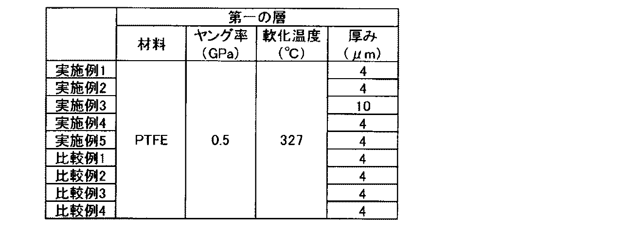
第二の層として表2に示される各層を準備した。実施例1~3、実施例5、比較例1~4における第二の層としては、ポリプロピレン(PP)からなる芯構造と、ポリエチレン(PE)からなる鞘構造とを有する第二の繊維を含むHOPシリーズ(商品名、廣瀬製紙製)を使用した。なお、実施例5における第二の層は、第二の繊維aを含む第二の層aと、第二の繊維bを含む第二の層bとを有する。第二の繊維aの平均繊維径は5μm、第二の繊維bの平均繊維径は15μmであり、第一の層側に配置された第二の層aに含まれる第二の繊維aをより細く、第三の層側に配置された第二の層bに含まれる第二の繊維bをより太くしている。実施例4における第二の層としては、ポリエチレンテレフタレート(PET)からなる芯構造と、共重合ポリエチレンテレフタレート(CO-PET)からなる鞘構造とを有する第二の繊維を含む15CN-70(商品名、廣瀬製紙製)を使用した。

第三の層として表3に示される各層を準備した。実施例1~5、比較例1~3における第三の層としては、ポリフェニレンサルファイド(PPS)繊維「トルコン」(商品名、東レ製)を湿式抄紙して作製した不織布「PPSペーパー」(商品名、廣瀬製紙製)を使用した。比較例4における第三の層としては、ポリエチレン樹脂をメルトブローン法により表3の物性を満たすように形成した不織布を使用した。
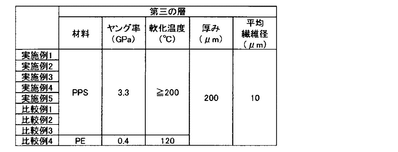
前記第一から第三の層を、図9に示されるラミネーターにより溶着した。具体的には、第一の層と第二の層とをラミネートした後、さらに第三の層をラミネートすることで多孔質体を作製した。なお、各ラミネート工程では、加熱温度が140~150℃の間となるように調整した。
<インクジェット記録装置及び画像形成>
図1に示す転写型インクジェット記録装置を用いた。転写体101は両面テープにより支持部材102の表面に固定されている。厚さ0.5mmのPETシートに、シリコーンゴム(商品名:KE12、信越化学工業株式会社製)を0.3mmの厚さでコーティングしたシートを転写体101の弾性層として用いた。さらに、グリシドキシプロピルトリエトキシシランとメチルトリエトキシシランとをモル比1:1で混合し、加熱還流することで得られる縮合物と、光カチオン重合開始剤(商品名:SP150、ADEKA製)との混合物を調製した。前記弾性層表面の水の接触角が10度以下となるように大気圧プラズマ処理を行った。その後、前記混合物を前記弾性層上に付与し、UV照射(高圧水銀ランプ、積算露光量:5000mJ/cm2)、熱硬化(150℃、2時間)により成膜し、前記弾性層上に厚さ0.5μmの表面層が形成された転写体101を作製した。なお、転写体101の表面は図示しない加熱装置により60℃に維持した。
図1に示す転写型インクジェット記録装置を用いた。転写体101は両面テープにより支持部材102の表面に固定されている。厚さ0.5mmのPETシートに、シリコーンゴム(商品名:KE12、信越化学工業株式会社製)を0.3mmの厚さでコーティングしたシートを転写体101の弾性層として用いた。さらに、グリシドキシプロピルトリエトキシシランとメチルトリエトキシシランとをモル比1:1で混合し、加熱還流することで得られる縮合物と、光カチオン重合開始剤(商品名:SP150、ADEKA製)との混合物を調製した。前記弾性層表面の水の接触角が10度以下となるように大気圧プラズマ処理を行った。その後、前記混合物を前記弾性層上に付与し、UV照射(高圧水銀ランプ、積算露光量:5000mJ/cm2)、熱硬化(150℃、2時間)により成膜し、前記弾性層上に厚さ0.5μmの表面層が形成された転写体101を作製した。なお、転写体101の表面は図示しない加熱装置により60℃に維持した。
反応液付与装置103により付与される前記反応液の付与量は1g/m2とした。インク付与装置104には、電気-熱変換素子を用いオンデマンド方式によってインクの吐出を行うインクジェット記録ヘッドを使用した。画像形成における前記インクの付与量は20g/m2とした。
液吸収部材105aは、第一の画像と接触する側に前記多孔質体を有する。押圧部材105bで圧力を印加することで、転写体101と液吸収部材105aとの間のニップ圧を、平均2kgf/cm2となるようにした。なお、押圧部材105bの直径は200mmであった。
液吸収部材105aの搬送速度は、液吸収部材105aを張架しつつ搬送する張架ローラ105c、105d及び105eによって、転写体101の移動速度と同等の速度になるよう調節した。また、転写体101の移動速度と同等の速度となるように、記録媒体108を記録媒体繰り出しローラ107aおよび記録媒体巻き取りローラ107bによって搬送した。記録媒体108の搬送速度は0.2m/sとした。記録媒体108としては、オーロラコート紙(日本製紙株式会社製、坪量104g/m2)を用いた。
[評価]
以下の評価方法により、各実施例及び各比較例において得られたインクジェット記録装置の評価を行った。評価結果を表4に示す。本発明においては、下記の各評価項目の評価基準のAおよびBを好ましいレベルとし、CおよびDを許容できないレベルとした。
以下の評価方法により、各実施例及び各比較例において得られたインクジェット記録装置の評価を行った。評価結果を表4に示す。本発明においては、下記の各評価項目の評価基準のAおよびBを好ましいレベルとし、CおよびDを許容できないレベルとした。
<第二の層の目潰れ>
多孔質体の断面を金属顕微鏡およびSEMによって観察し、第二の層の目潰れを確認した。評価基準は以下の通りである。
A:目潰れは確認されなかった。
B:目潰れが確認されたが、許容できる程度であった。
C:目潰れが確認され、許容できない程度であった。
多孔質体の断面を金属顕微鏡およびSEMによって観察し、第二の層の目潰れを確認した。評価基準は以下の通りである。
A:目潰れは確認されなかった。
B:目潰れが確認されたが、許容できる程度であった。
C:目潰れが確認され、許容できない程度であった。
<搬送強度>
液吸収部材105aの幅1mmあたり0.5Nの張力をかけて、液吸収部材105aを搬送駆動することで、多孔質体の各層の間に剥離が発生しないか確認した。評価基準は以下の通りである。
A:層間剥離が発生しなかった。
B:層間剥離がわずかに発生したが、許容できる程度であった。
C:層間剥離が発生し、許容できない程度であった。
D:張力により液吸収部材105aに伸びが発生し、液吸収部材105aを搬送できなかった。
液吸収部材105aの幅1mmあたり0.5Nの張力をかけて、液吸収部材105aを搬送駆動することで、多孔質体の各層の間に剥離が発生しないか確認した。評価基準は以下の通りである。
A:層間剥離が発生しなかった。
B:層間剥離がわずかに発生したが、許容できる程度であった。
C:層間剥離が発生し、許容できない程度であった。
D:張力により液吸収部材105aに伸びが発生し、液吸収部材105aを搬送できなかった。
<画像流れ>
前記第二の層の目潰れおよび前記搬送強度の評価においてAまたはBであった実施例および比較例について、前記画像形成における、第一の液体を吸収した後の、画像端部における色材の移動量、すなわち画像流れを観察した。評価基準は以下の通りである。
A:繰り返し使用しても画像流れがみられなかった。
B:わずかに画像流れがみられたが、気にならない程度であった。
C:画像流れが大きくみられた。
前記第二の層の目潰れおよび前記搬送強度の評価においてAまたはBであった実施例および比較例について、前記画像形成における、第一の液体を吸収した後の、画像端部における色材の移動量、すなわち画像流れを観察した。評価基準は以下の通りである。
A:繰り返し使用しても画像流れがみられなかった。
B:わずかに画像流れがみられたが、気にならない程度であった。
C:画像流れが大きくみられた。
<色材付着>
前記第二の層の目潰れ、前記搬送強度および前記画像流れの評価においてAまたはBであった実施例について、前記画像形成における、液吸収部材105aの第一の画像への接触後の、液吸収部材105aに対する色材付着を観察した。評価基準は以下の通りである。
A:色材付着はみられなかった。
B:わずかに色材付着がみられたが、気にならない程度であった。
C:色材付着が多くみられた。
前記第二の層の目潰れ、前記搬送強度および前記画像流れの評価においてAまたはBであった実施例について、前記画像形成における、液吸収部材105aの第一の画像への接触後の、液吸収部材105aに対する色材付着を観察した。評価基準は以下の通りである。
A:色材付着はみられなかった。
B:わずかに色材付着がみられたが、気にならない程度であった。
C:色材付着が多くみられた。
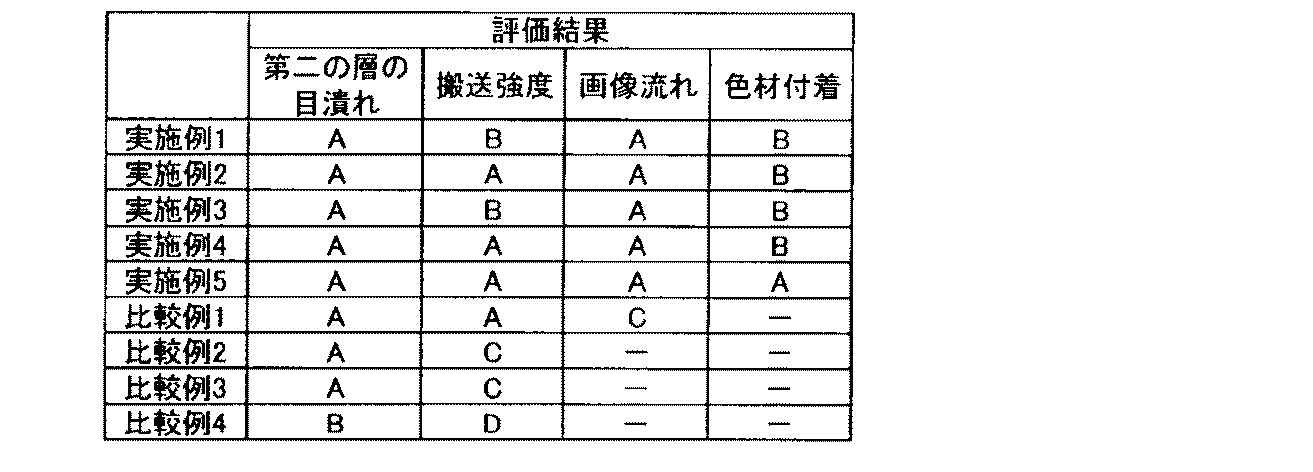
第二の層の目潰れの評価に関して、実施例1~5および比較例1~3では、いずれも第二の層が芯鞘構造を有する第二の繊維を含み、第一および第三の層に軟化温度の高い材料を使用したため、目潰れは確認されなかった。一方、比較例4では、第三の層にPEからなる第三の繊維を用いたため、第二の繊維の鞘材料(PE)が溶融する際、第三の層も溶融し、第二の層に第三の層の材料が入り込みやすかったため、一部目潰れが確認された。しかし、該目潰れは許容できる程度であった。
搬送強度の評価に関して、比較例2および3では第二の層と第三の層との間で剥離が発生した。また、比較例4では、剛性を確保するための第三の層における第三の繊維の材料がPEであったため、搬送張力をかけた段階で液吸収部材105aに著しい伸びが発生し、塑性変形した。その結果、液吸収部材105aを搬送することができなかった。
画像流れの評価に関して、比較例1の多孔質体の断面をSEMで観察すると、第二の繊維の鞘材料であるPEが、第一の層の細孔内部を埋めるように入り込んでおり、第一の層の孔が塞がれていることが確認された。これにより、画像流れが発生したと推測される。
色材付着の評価に関して、実施例5では実施例1~4より良好な結果が得られた。これは、第二の繊維aの平均繊維径が実施例1~4の第二の繊維の平均繊維径よりも小さく、第一の層の表面の凹凸が抑えられたためと推測される。
また、図2に示す直接描画型インクジェット記録装置を用いて同様の実験を行った。図2に示す直接描画型インクジェット記録装置による画像形成においては、記録媒体208としてグロリアピュアホワイト紙坪量210g/m2(五條製紙株式会社製)を用いた。記録媒体208以外の、反応液、反応液付与装置203、インク、インク付与装置204、記録媒体208の搬送速度及び液吸収装置205は、実施例1における転写型インクジェット記録装置と同様として、実施例1と同様に評価した。その結果、実施例1と同じ評価結果が得られることが確認された。
この出願は2016年1月5日に出願された日本国特許出願番号2016-000746、2016年1月29日に出願された日本国特許出願番号2016-016272、2016年5月26日に出願された日本国特許出願番号2016-105334、および2016年5月27日に出願された日本国特許出願番号2016-106189の優先権を主張するものであり、それらの内容を引用してこの出願の一部とするものである。
21 第一の層
31 第三の層
32 第三の繊維
41 第二の層
41a 第二の層a
41b 第二の層b
42、42a、42b 芯構造
43、43a、43b 鞘構造
44 第二の繊維
44a 第二の繊維a
44b 第二の繊維b
d1、d1a、d1b 芯構造の平均直径
d2 第二の繊維の平均繊維径
d2a 第二の繊維aの平均繊維径
d2b 第二の繊維bの平均繊維径
d3 第三の繊維の平均繊維径
t1 第一の層の厚み
t2、t2a、t2b 鞘構造の平均厚み
31 第三の層
32 第三の繊維
41 第二の層
41a 第二の層a
41b 第二の層b
42、42a、42b 芯構造
43、43a、43b 鞘構造
44 第二の繊維
44a 第二の繊維a
44b 第二の繊維b
d1、d1a、d1b 芯構造の平均直径
d2 第二の繊維の平均繊維径
d2a 第二の繊維aの平均繊維径
d2b 第二の繊維bの平均繊維径
d3 第三の繊維の平均繊維径
t1 第一の層の厚み
t2、t2a、t2b 鞘構造の平均厚み
Claims (12)
- 被記録体上に第一の液体と色材とを含む第一の画像を形成する画像形成ユニットと、
前記第一の画像と接触し、前記第一の画像から前記第一の液体の少なくとも一部を吸収する多孔質体を有する液吸収部材と、
を備えるインクジェット記録装置であって、
前記多孔質体が、
前記第一の画像と接触する第一の層と、
第二の繊維を含む第二の層と、
第三の繊維を含む第三の層と、
がこの順で積層され、かつ、前記第一の層、前記第二の層、及び前記第三の層がいずれも多孔質層である多孔質シートであり、
前記第二の繊維の平均繊維径が、前記第三の繊維の平均繊維径よりも大きく、
前記第二の繊維が、中心軸を形成する芯構造と、前記芯構造を包む鞘構造と、を有する芯鞘構造を有しており、
前記鞘構造を形成する材料の軟化温度が、前記芯構造を形成する材料の軟化温度、前記第一の層を形成する材料の軟化温度、および前記第三の繊維を形成する材料の軟化温度のいずれよりも低く、
前記鞘構造の平均厚みが前記第一の層の厚みよりも小さいことを特徴とするインクジェット記録装置。 - 被記録体上に第一の液体と色材とを含む第一の画像を形成する画像形成ユニットと、
前記第一の画像と接触し、前記第一の画像から前記第一の液体の少なくとも一部を吸収する多孔質体を有する液吸収部材と、
を備えるインクジェット記録装置であって、
前記多孔質体が、
前記第一の画像と接触する第一の層と、
第二の繊維aを含む第二の層aと、
第二の繊維bを含む第二の層bと、
第三の繊維を含む第三の層と、
がこの順で積層され、かつ、前記第一の層、前記第二の層a、前記第二の層b、及び前記第三の層がいずれも多孔質層である多孔質シートであり、
前記第二の繊維bの平均繊維径が、前記第三の繊維の平均繊維径よりも大きく、
前記第二の繊維aおよび前記第二の繊維bが、中心軸を形成する芯構造と、前記芯構造を包む鞘構造と、を有する芯鞘構造を有しており、
前記第二の繊維aの鞘構造を形成する材料の軟化温度が、前記第二の繊維aの芯構造を形成する材料の軟化温度および前記第一の層を形成する材料の軟化温度のいずれよりも低く、
前記第二の繊維bの鞘構造を形成する材料の軟化温度が、前記第二の繊維bの芯構造を形成する材料の軟化温度および前記第三の繊維を形成する材料の軟化温度のいずれよりも低く、
前記第二の繊維aの鞘構造の平均厚みが前記第一の層の厚みよりも小さいことを特徴とするインクジェット記録装置。 - 前記第三の繊維を形成する材料のヤング率が、前記第一の層を形成する材料のヤング率よりも高い請求項1又は2に記載のインクジェット記録装置。
- 前記第一の層の前記第一の画像と接する側の面における平均孔径が0.2μm以下である請求項1~3のいずれか一項に記載のインクジェット記録装置。
- 前記第一の層がフッ素樹脂を含む請求項1~4のいずれか一項に記載のインクジェット記録装置。
- 前記第三の繊維がポリフェニレンサルファイド又はポリイミドを含む請求項1~5のいずれか一項に記載のインクジェット記録装置。
- 前記画像形成ユニットは、
前記第一の液体または第二の液体と、インク高粘度化成分とを含む第一の液体組成物を前記被記録体上に付与する装置と、
前記第一の液体または第二の液体と、前記色材とを含む第二の液体組成物を前記被記録体上に付与する装置と、
を含み、
前記第一の画像は前記第一及び第二の液体組成物の混合物であって、前記第一及び第二の液体組成物のいずれよりも粘稠されている請求項1~6のいずれか一項に記載のインクジェット記録装置。 - 前記被記録体は、前記第一の画像と、前記第一の画像から前記第一の液体を吸収して得た第二の画像を一時的に保持する転写体であって、
前記第二の画像を、画像を形成すべき記録媒体上に転写する転写用の押圧部材を備えた転写ユニットを含む請求項1~7のいずれか一項に記載のインクジェット記録装置。 - 前記被記録体は画像を形成すべき記録媒体である請求項1~7のいずれか一項に記載のインクジェット記録装置。
- 被記録体上に第一の液体と色材とを含むインクを付与して第一の画像を形成する画像形成ユニットと、
前記第一の画像と接触し、前記第一の画像を構成するインクを濃縮する多孔質体を有する液吸収部材と、
を備えるインクジェット記録装置であって、
前記多孔質体が、
前記第一の画像と接触する第一の層と、
第二の繊維を含む第二の層と、
第三の繊維を含む第三の層と、
がこの順で積層され、かつ、前記第一の層、前記第二の層、及び前記第三の層がいずれも多孔質層である多孔質シートであり、
前記第二の繊維の平均繊維径が、前記第三の繊維の平均繊維径よりも大きく、
前記第二の繊維が、中心軸を形成する芯構造と、前記芯構造を包む鞘構造と、を有する芯鞘構造を有しており、
前記鞘構造を形成する材料の軟化温度が、前記芯構造を形成する材料の軟化温度、前記第一の層を形成する材料の軟化温度、および前記第三の繊維を形成する材料の軟化温度のいずれよりも低く、
前記鞘構造の平均厚みが前記第一の層の厚みよりも小さいことを特徴とするインクジェット記録装置。 - 被記録体上に第一の液体と色材とを含む第一の画像を形成する画像形成ユニットと、
前記第一の画像と接触し、前記第一の画像から前記第一の液体の少なくとも一部を吸収する多孔質体を有する液吸収部材と、
を備えるインクジェット記録装置に用いられる多孔質体の製造方法であって、
前記第一の画像と接触する第一の層と、第二の繊維を含む第二の層と、第三の繊維を含む第三の層とをこの順で積層した状態で加熱することで、前記第一の層と、前記第二の層と、前記第三の層とを有する多孔質体を形成する工程を有し、
前記第一の層、前記第二の層、及び前記第三の層がいずれも多孔質層であり、
前記第二の繊維の平均繊維径が、前記第三の繊維の平均繊維径よりも大きく、
前記第二の繊維が、中心軸を形成する芯構造と、前記芯構造を包む鞘構造と、を有する芯鞘構造を有しており、
前記鞘構造を形成する材料の軟化温度が、前記芯構造を形成する材料の軟化温度、前記第一の層を形成する材料の軟化温度、および前記第三の繊維を形成する材料の軟化温度のいずれよりも低く、
前記鞘構造の平均厚みが前記第一の層の厚みよりも小さく、
前記加熱の温度が、前記鞘構造を形成する材料の軟化温度以上であり、かつ、前記芯構造を形成する材料の軟化温度、前記第一の層を形成する材料の軟化温度、および前記第三の繊維を形成する材料の軟化温度以下であることを特徴とする多孔質体の製造方法。 - 被記録体上に第一の液体と色材とを含む第一の画像を形成する画像形成ユニットと、
前記第一の画像と接触し、前記第一の画像から前記第一の液体の少なくとも一部を吸収する多孔質体を有する液吸収部材と、
を備えるインクジェット記録装置に用いられる多孔質体の製造方法であって、
前記第一の画像と接触する第一の層と、第二の繊維aを含む第二の層aと、第二の繊維bを含む第二の層bと、第三の繊維を含む第三の層とをこの順で積層した状態で加熱することで、前記第一の層と、前記第二の層aと、前記第二の層bと、前記第三の層とを有する多孔質体を形成する工程を有し、
前記第一の層、前記第二の層、及び前記第三の層がいずれも多孔質層であり、
前記第二の繊維bの平均繊維径が、前記第三の繊維の平均繊維径よりも大きく、
前記第二の繊維aおよび前記第二の繊維bが、中心軸を形成する芯構造と、前記芯構造を包む鞘構造と、を有する芯鞘構造を有しており、
前記第二の繊維aの鞘構造を形成する材料の軟化温度が、前記第二の繊維aの芯構造を形成する材料の軟化温度および前記第一の層を形成する材料の軟化温度のいずれよりも低く、
前記第二の繊維bの鞘構造を形成する材料の軟化温度が、前記第二の繊維bの芯構造を形成する材料の軟化温度および前記第三の繊維を形成する材料の軟化温度のいずれよりも低く、
前記第二の繊維aの鞘構造の平均厚みが前記第一の層の厚みよりも小さく、
前記加熱の温度が、前記第二の繊維aおよび前記第二の繊維bの鞘構造を形成する材料の軟化温度以上であり、かつ、前記第二の繊維aおよび前記第二の繊維bの芯構造を形成する材料の軟化温度、前記第一の層を形成する材料の軟化温度、および前記第三の繊維を形成する材料の軟化温度以下であることを特徴とする多孔質体の製造方法。
Priority Applications (2)
| Application Number | Priority Date | Filing Date | Title |
|---|---|---|---|
| EP16883551.0A EP3401102B1 (en) | 2016-01-05 | 2016-12-28 | Inkjet recording apparatus and method for manufacturing porous body |
| US16/022,143 US10507666B2 (en) | 2016-01-05 | 2018-06-28 | Ink jet recording apparatus and method of producing porous body |
Applications Claiming Priority (8)
| Application Number | Priority Date | Filing Date | Title |
|---|---|---|---|
| JP2016000746 | 2016-01-05 | ||
| JP2016-000746 | 2016-01-05 | ||
| JP2016016272 | 2016-01-29 | ||
| JP2016-016272 | 2016-01-29 | ||
| JP2016-105334 | 2016-05-26 | ||
| JP2016105334 | 2016-05-26 | ||
| JP2016-106189 | 2016-05-27 | ||
| JP2016106189 | 2016-05-27 |
Related Child Applications (1)
| Application Number | Title | Priority Date | Filing Date |
|---|---|---|---|
| US16/022,143 Continuation US10507666B2 (en) | 2016-01-05 | 2018-06-28 | Ink jet recording apparatus and method of producing porous body |
Publications (1)
| Publication Number | Publication Date |
|---|---|
| WO2017119045A1 true WO2017119045A1 (ja) | 2017-07-13 |
Family
ID=59273454
Family Applications (1)
| Application Number | Title | Priority Date | Filing Date |
|---|---|---|---|
| PCT/JP2016/005247 WO2017119045A1 (ja) | 2016-01-05 | 2016-12-28 | インクジェット記録装置及び多孔質体の製造方法 |
Country Status (3)
| Country | Link |
|---|---|
| US (1) | US10507666B2 (ja) |
| EP (1) | EP3401102B1 (ja) |
| WO (1) | WO2017119045A1 (ja) |
Cited By (7)
| Publication number | Priority date | Publication date | Assignee | Title |
|---|---|---|---|---|
| US10507666B2 (en) | 2016-01-05 | 2019-12-17 | Canon Kabushiki Kaisha | Ink jet recording apparatus and method of producing porous body |
| US10538118B2 (en) | 2017-07-04 | 2020-01-21 | Canon Kabushiki Kaisha | Inkjet recording apparatus and inkjet recording method |
| US10543705B2 (en) | 2016-01-05 | 2020-01-28 | Canon Kabushiki Kaisha | Ink jet recording method using porous body |
| US10569531B2 (en) | 2016-01-05 | 2020-02-25 | Canon Kabushiki Kaisha | Transfer type ink jet recording method with cooled transfer body |
| US10569586B2 (en) | 2016-01-05 | 2020-02-25 | Canon Kabushiki Kaisha | Ink jet recording apparatus |
| US10576771B2 (en) | 2017-07-04 | 2020-03-03 | Canon Kabushiki Kaisha | Ink jet recording method and ink jet recording apparatus |
| US10857784B2 (en) | 2016-01-05 | 2020-12-08 | Canon Kabushiki Kaisha | Printing method and printing apparatus |
Families Citing this family (2)
| Publication number | Priority date | Publication date | Assignee | Title |
|---|---|---|---|---|
| EP3626469A4 (en) | 2017-06-30 | 2021-03-31 | Canon Kabushiki Kaisha | INKJET IMAGING METHOD AND INKJET IMAGING DEVICE |
| WO2019013254A1 (ja) | 2017-07-14 | 2019-01-17 | キヤノン株式会社 | 転写体、画像記録方法及び画像記録装置 |
Citations (4)
| Publication number | Priority date | Publication date | Assignee | Title |
|---|---|---|---|---|
| JP2006088486A (ja) * | 2004-09-22 | 2006-04-06 | Fuji Xerox Co Ltd | インクジェット記録装置及びインクジェット記録方法 |
| JP2006264080A (ja) * | 2005-03-23 | 2006-10-05 | Fuji Xerox Co Ltd | インクジェット記録方法およびインクジェット記録装置 |
| JP2008055852A (ja) * | 2006-09-01 | 2008-03-13 | Fujifilm Corp | インクジェット記録装置 |
| JP2008213333A (ja) * | 2007-03-05 | 2008-09-18 | Fujifilm Corp | インクジェット記録方法及び装置 |
Family Cites Families (61)
| Publication number | Priority date | Publication date | Assignee | Title |
|---|---|---|---|---|
| JP3223927B2 (ja) | 1991-08-23 | 2001-10-29 | セイコーエプソン株式会社 | 転写式記録装置 |
| JP2000103157A (ja) | 1998-09-28 | 2000-04-11 | Fuji Xerox Co Ltd | 画像形成方法及び画像形成装置 |
| JP2001171143A (ja) | 1999-12-15 | 2001-06-26 | Canon Inc | 画像形成装置および予備吐出回復方法 |
| JP4016559B2 (ja) | 1999-12-28 | 2007-12-05 | コニカミノルタホールディングス株式会社 | 画像形成装置及び画像形成方法 |
| JP3945326B2 (ja) | 2002-07-09 | 2007-07-18 | ブラザー工業株式会社 | 搬送体清掃装置及びそれを使用したインクジェット記録装置 |
| US7129284B2 (en) | 2002-12-03 | 2006-10-31 | Hewlett-Packard Development Company, L.P. | Fluorosurfactant packages for use in inkjet printing and methods of controlling puddling in inkjet pens |
| JP4060787B2 (ja) | 2003-12-01 | 2008-03-12 | 三星電子株式会社 | プリンタ |
| JP2006082428A (ja) * | 2004-09-16 | 2006-03-30 | Fuji Xerox Co Ltd | 液体吸収部材及びインクジェット記録装置 |
| JP2006102981A (ja) | 2004-09-30 | 2006-04-20 | Fuji Photo Film Co Ltd | 画像形成装置 |
| JP2006205677A (ja) * | 2005-01-31 | 2006-08-10 | Fuji Photo Film Co Ltd | 画像形成装置及び方法 |
| JP2006264169A (ja) * | 2005-03-24 | 2006-10-05 | Fuji Photo Film Co Ltd | 画像形成装置 |
| US7481526B2 (en) | 2005-03-31 | 2009-01-27 | Fujifilm Corporation | Image forming apparatus |
| JP4920934B2 (ja) | 2005-09-09 | 2012-04-18 | キヤノン株式会社 | インクジェット記録装置 |
| US7926933B2 (en) | 2005-12-27 | 2011-04-19 | Canon Kabushiki Kaisha | Ink jet printing method and ink jet printing apparatus |
| JP2007268974A (ja) | 2006-03-31 | 2007-10-18 | Fujifilm Corp | 画像形成装置および画像形成方法 |
| JP2007268975A (ja) | 2006-03-31 | 2007-10-18 | Fujifilm Corp | 画像形成装置 |
| JP2008087283A (ja) | 2006-09-29 | 2008-04-17 | Fujifilm Corp | 画像形成装置 |
| JP2008246787A (ja) | 2007-03-29 | 2008-10-16 | Fujifilm Corp | 溶媒吸収装置及び画像形成装置 |
| JP2009000916A (ja) | 2007-06-21 | 2009-01-08 | Fujifilm Corp | インクジェット記録装置及び記録方法 |
| JP2009000915A (ja) | 2007-06-21 | 2009-01-08 | Fujifilm Corp | インクジェット記録装置及び記録方法 |
| CN101332708B (zh) | 2007-06-29 | 2010-12-01 | 富准精密工业(深圳)有限公司 | 喷墨头及使用该喷墨头的打印装置 |
| JP2009045851A (ja) | 2007-08-21 | 2009-03-05 | Fujifilm Corp | 画像形成方法及び装置 |
| JP2009061644A (ja) * | 2007-09-05 | 2009-03-26 | Fujifilm Corp | 溶媒回収機構及びこれを備えた画像形成装置並びに溶媒回収方法 |
| JP2009072927A (ja) | 2007-09-18 | 2009-04-09 | Fujifilm Corp | 画像形成装置および画像形成方法 |
| US8042906B2 (en) | 2007-09-25 | 2011-10-25 | Fujifilm Corporation | Image forming method and apparatus |
| JP2009086348A (ja) | 2007-09-28 | 2009-04-23 | Fujifilm Corp | 画像形成装置および画像形成方法 |
| JP5056403B2 (ja) | 2007-12-25 | 2012-10-24 | 富士ゼロックス株式会社 | 画像処理装置、画像記録装置、及びプログラム |
| JP2009166387A (ja) | 2008-01-17 | 2009-07-30 | Ricoh Co Ltd | 画像形成方法および画像形成記録物 |
| JP2009214439A (ja) | 2008-03-11 | 2009-09-24 | Fujifilm Corp | インクジェット記録装置及び画像形成方法 |
| JP2009226852A (ja) | 2008-03-25 | 2009-10-08 | Fujifilm Corp | インクジェット記録装置および記録方法 |
| JP2009234219A (ja) | 2008-03-28 | 2009-10-15 | Fujifilm Corp | 画像形成方法、画像形成装置 |
| JP5094555B2 (ja) * | 2008-05-23 | 2012-12-12 | キヤノン株式会社 | インクタンク |
| JP2010000712A (ja) | 2008-06-20 | 2010-01-07 | Fuji Xerox Co Ltd | 画像記録用組成物、画像記録用インクセット、および記録装置 |
| JP5259458B2 (ja) | 2009-03-04 | 2013-08-07 | セーレン株式会社 | インクジェット記録装置及び記録ヘッドのメンテナンス方法 |
| JP2011063001A (ja) | 2009-09-18 | 2011-03-31 | Fujifilm Corp | 画像形成方法 |
| JP5569366B2 (ja) | 2010-11-30 | 2014-08-13 | コニカミノルタ株式会社 | ベルトクリーニング装置、ベルト搬送装置及び画像記録装置 |
| JP5938571B2 (ja) | 2011-03-08 | 2016-06-22 | 株式会社リコー | 液体吐出方法、及び液体吐出装置 |
| JP5738693B2 (ja) | 2011-06-29 | 2015-06-24 | 富士フイルム株式会社 | インクジェット記録用メンテナンス液、インクジェット記録用インクセット、及び画像形成方法 |
| US9616653B2 (en) | 2012-08-30 | 2017-04-11 | Xerox Corporation | Systems and methods for ink-based digital printing using dampening fluid imaging member and image transfer member |
| US9102137B2 (en) | 2013-02-07 | 2015-08-11 | Canon Kabushiki Kaisha | Transfer image forming method, transfer image forming apparatus, and intermediate transfer member to be used therein |
| JP2014172327A (ja) | 2013-03-11 | 2014-09-22 | Seiko Epson Corp | 記録装置及び記録方法 |
| US9821584B2 (en) | 2013-06-14 | 2017-11-21 | Canon Kabushiki Kaisha | Image recording method |
| JP2015071291A (ja) | 2013-09-03 | 2015-04-16 | 株式会社リコー | インクジェット記録方法、及びインクジェット記録装置 |
| JP6268962B2 (ja) | 2013-11-15 | 2018-01-31 | セイコーエプソン株式会社 | インクジェット捺染用インク及び捺染方法 |
| JP2015098097A (ja) | 2013-11-18 | 2015-05-28 | 株式会社リコー | 画像形成装置及び画像形成方法 |
| JP6217420B2 (ja) | 2014-02-04 | 2017-10-25 | 株式会社リコー | 画像形成装置及び画像形成方法 |
| JP2015150789A (ja) | 2014-02-14 | 2015-08-24 | 株式会社リコー | 画像形成装置 |
| JP6284818B2 (ja) | 2014-04-24 | 2018-02-28 | 株式会社ダイセル | 微細孔と取り扱い強度を有した多孔膜積層体及びその製造方法 |
| JP2016120625A (ja) | 2014-12-24 | 2016-07-07 | 京セラドキュメントソリューションズ株式会社 | インクジェット記録装置 |
| EP3401104A4 (en) | 2016-01-05 | 2019-08-14 | C/o Canon Kabushiki Kaisha | INK JET RECORDING APPARATUS AND INK JET RECORDING METHOD |
| EP3401103A4 (en) | 2016-01-05 | 2019-08-14 | C/o Canon Kabushiki Kaisha | RECORDING METHOD AND RECORDING APPARATUS |
| WO2017119049A1 (ja) | 2016-01-05 | 2017-07-13 | キヤノン株式会社 | インクジェット記録方法 |
| CN108430780B (zh) | 2016-01-05 | 2020-03-06 | 佳能株式会社 | 喷墨记录设备和喷墨记录方法 |
| WO2017119046A1 (ja) | 2016-01-05 | 2017-07-13 | キヤノン株式会社 | インクジェット記録方法 |
| KR102087531B1 (ko) | 2016-01-05 | 2020-03-10 | 캐논 가부시끼가이샤 | 잉크젯 기록 장치 |
| EP3401100A4 (en) | 2016-01-05 | 2019-08-21 | C/o Canon Kabushiki Kaisha | INK INJECTION DEVICE AND INK INJECTION METHOD |
| KR20180098375A (ko) | 2016-01-05 | 2018-09-03 | 캐논 가부시끼가이샤 | 잉크젯 기록 장치 및 잉크젯 기록 방법 |
| EP3401102B1 (en) | 2016-01-05 | 2020-09-16 | C/o Canon Kabushiki Kaisha | Inkjet recording apparatus and method for manufacturing porous body |
| WO2017131072A1 (ja) | 2016-01-29 | 2017-08-03 | キヤノン株式会社 | インクジェット記録装置 |
| JP6448673B2 (ja) | 2016-01-29 | 2019-01-09 | キヤノン株式会社 | 多孔質体及びその製造方法、インクジェット記録方法、並びにインクジェット記録装置 |
| JP6781617B2 (ja) | 2016-12-07 | 2020-11-04 | キヤノン株式会社 | 液吸収装置、記録システム、記録方法および製造方法 |
-
2016
- 2016-12-28 EP EP16883551.0A patent/EP3401102B1/en active Active
- 2016-12-28 WO PCT/JP2016/005247 patent/WO2017119045A1/ja active Application Filing
-
2018
- 2018-06-28 US US16/022,143 patent/US10507666B2/en active Active
Patent Citations (4)
| Publication number | Priority date | Publication date | Assignee | Title |
|---|---|---|---|---|
| JP2006088486A (ja) * | 2004-09-22 | 2006-04-06 | Fuji Xerox Co Ltd | インクジェット記録装置及びインクジェット記録方法 |
| JP2006264080A (ja) * | 2005-03-23 | 2006-10-05 | Fuji Xerox Co Ltd | インクジェット記録方法およびインクジェット記録装置 |
| JP2008055852A (ja) * | 2006-09-01 | 2008-03-13 | Fujifilm Corp | インクジェット記録装置 |
| JP2008213333A (ja) * | 2007-03-05 | 2008-09-18 | Fujifilm Corp | インクジェット記録方法及び装置 |
Cited By (7)
| Publication number | Priority date | Publication date | Assignee | Title |
|---|---|---|---|---|
| US10507666B2 (en) | 2016-01-05 | 2019-12-17 | Canon Kabushiki Kaisha | Ink jet recording apparatus and method of producing porous body |
| US10543705B2 (en) | 2016-01-05 | 2020-01-28 | Canon Kabushiki Kaisha | Ink jet recording method using porous body |
| US10569531B2 (en) | 2016-01-05 | 2020-02-25 | Canon Kabushiki Kaisha | Transfer type ink jet recording method with cooled transfer body |
| US10569586B2 (en) | 2016-01-05 | 2020-02-25 | Canon Kabushiki Kaisha | Ink jet recording apparatus |
| US10857784B2 (en) | 2016-01-05 | 2020-12-08 | Canon Kabushiki Kaisha | Printing method and printing apparatus |
| US10538118B2 (en) | 2017-07-04 | 2020-01-21 | Canon Kabushiki Kaisha | Inkjet recording apparatus and inkjet recording method |
| US10576771B2 (en) | 2017-07-04 | 2020-03-03 | Canon Kabushiki Kaisha | Ink jet recording method and ink jet recording apparatus |
Also Published As
| Publication number | Publication date |
|---|---|
| EP3401102B1 (en) | 2020-09-16 |
| EP3401102A1 (en) | 2018-11-14 |
| US10507666B2 (en) | 2019-12-17 |
| US20180319166A1 (en) | 2018-11-08 |
| EP3401102A4 (en) | 2019-08-14 |
Similar Documents
| Publication | Publication Date | Title |
|---|---|---|
| WO2017119045A1 (ja) | インクジェット記録装置及び多孔質体の製造方法 | |
| JP6448673B2 (ja) | 多孔質体及びその製造方法、インクジェット記録方法、並びにインクジェット記録装置 | |
| JP6862184B2 (ja) | インクジェット記録装置及びインクジェット記録方法 | |
| US10569531B2 (en) | Transfer type ink jet recording method with cooled transfer body | |
| WO2017119041A1 (ja) | インクジェット記録装置及びインクジェット記録方法 | |
| US10543705B2 (en) | Ink jet recording method using porous body | |
| JP6821439B2 (ja) | 画像形成装置及び画像形成方法 | |
| JP2017213856A (ja) | インクジェット記録装置及びインクジェット記録方法 | |
| JP6840552B2 (ja) | インクジェット記録方法及びインクジェット記録装置 | |
| WO2017119047A1 (ja) | 記録方法および記録装置 | |
| WO2017141843A1 (ja) | インクジェット記録装置及びインクジェット記録方法 | |
| JP2017144735A (ja) | 転写型インクジェット記録方法、及び転写型インクジェット記録装置 | |
| JP2017144733A (ja) | インクジェット記録方法、及びインクジェット記録装置 | |
| JP6415610B2 (ja) | 記録方法および記録装置 | |
| JP6838973B2 (ja) | インクジェット記録装置及び多孔質体の製造方法 | |
| JP6869782B2 (ja) | インクジェット記録方法 | |
| JP2020040330A (ja) | インクジェット記録方法及びインクジェット記録装置 | |
| JP2017144736A (ja) | インクジェット記録方法 | |
| JP2017209932A (ja) | インクジェット記録方法、及びインクジェット記録装置 | |
| JP2019010812A (ja) | インクジェット記録方法及びインクジェット記録装置 | |
| JP2018034438A (ja) | 画像形成方法及び画像形成装置 |
Legal Events
| Date | Code | Title | Description |
|---|---|---|---|
| 121 | Ep: the epo has been informed by wipo that ep was designated in this application |
Ref document number: 16883551 Country of ref document: EP Kind code of ref document: A1 |
|
| NENP | Non-entry into the national phase |
Ref country code: DE |
|
| WWE | Wipo information: entry into national phase |
Ref document number: 2016883551 Country of ref document: EP |
|
| ENP | Entry into the national phase |
Ref document number: 2016883551 Country of ref document: EP Effective date: 20180806 |