WO2016114039A1 - ステントおよびステントグラフト - Google Patents
ステントおよびステントグラフト Download PDFInfo
- Publication number
- WO2016114039A1 WO2016114039A1 PCT/JP2015/084453 JP2015084453W WO2016114039A1 WO 2016114039 A1 WO2016114039 A1 WO 2016114039A1 JP 2015084453 W JP2015084453 W JP 2015084453W WO 2016114039 A1 WO2016114039 A1 WO 2016114039A1
- Authority
- WO
- WIPO (PCT)
- Prior art keywords
- circumferential
- unit
- woven structure
- circumferential unit
- loop
- Prior art date
Links
Images


Classifications
-
- A—HUMAN NECESSITIES
- A61—MEDICAL OR VETERINARY SCIENCE; HYGIENE
- A61F—FILTERS IMPLANTABLE INTO BLOOD VESSELS; PROSTHESES; DEVICES PROVIDING PATENCY TO, OR PREVENTING COLLAPSING OF, TUBULAR STRUCTURES OF THE BODY, e.g. STENTS; ORTHOPAEDIC, NURSING OR CONTRACEPTIVE DEVICES; FOMENTATION; TREATMENT OR PROTECTION OF EYES OR EARS; BANDAGES, DRESSINGS OR ABSORBENT PADS; FIRST-AID KITS
- A61F2/00—Filters implantable into blood vessels; Prostheses, i.e. artificial substitutes or replacements for parts of the body; Appliances for connecting them with the body; Devices providing patency to, or preventing collapsing of, tubular structures of the body, e.g. stents
- A61F2/82—Devices providing patency to, or preventing collapsing of, tubular structures of the body, e.g. stents
- A61F2/86—Stents in a form characterised by the wire-like elements; Stents in the form characterised by a net-like or mesh-like structure
- A61F2/90—Stents in a form characterised by the wire-like elements; Stents in the form characterised by a net-like or mesh-like structure characterised by a net-like or mesh-like structure
-
- A—HUMAN NECESSITIES
- A61—MEDICAL OR VETERINARY SCIENCE; HYGIENE
- A61F—FILTERS IMPLANTABLE INTO BLOOD VESSELS; PROSTHESES; DEVICES PROVIDING PATENCY TO, OR PREVENTING COLLAPSING OF, TUBULAR STRUCTURES OF THE BODY, e.g. STENTS; ORTHOPAEDIC, NURSING OR CONTRACEPTIVE DEVICES; FOMENTATION; TREATMENT OR PROTECTION OF EYES OR EARS; BANDAGES, DRESSINGS OR ABSORBENT PADS; FIRST-AID KITS
- A61F2/00—Filters implantable into blood vessels; Prostheses, i.e. artificial substitutes or replacements for parts of the body; Appliances for connecting them with the body; Devices providing patency to, or preventing collapsing of, tubular structures of the body, e.g. stents
- A61F2/02—Prostheses implantable into the body
- A61F2/04—Hollow or tubular parts of organs, e.g. bladders, tracheae, bronchi or bile ducts
- A61F2/06—Blood vessels
- A61F2/07—Stent-grafts
-
- A—HUMAN NECESSITIES
- A61—MEDICAL OR VETERINARY SCIENCE; HYGIENE
- A61F—FILTERS IMPLANTABLE INTO BLOOD VESSELS; PROSTHESES; DEVICES PROVIDING PATENCY TO, OR PREVENTING COLLAPSING OF, TUBULAR STRUCTURES OF THE BODY, e.g. STENTS; ORTHOPAEDIC, NURSING OR CONTRACEPTIVE DEVICES; FOMENTATION; TREATMENT OR PROTECTION OF EYES OR EARS; BANDAGES, DRESSINGS OR ABSORBENT PADS; FIRST-AID KITS
- A61F2/00—Filters implantable into blood vessels; Prostheses, i.e. artificial substitutes or replacements for parts of the body; Appliances for connecting them with the body; Devices providing patency to, or preventing collapsing of, tubular structures of the body, e.g. stents
- A61F2/82—Devices providing patency to, or preventing collapsing of, tubular structures of the body, e.g. stents
- A61F2/844—Devices providing patency to, or preventing collapsing of, tubular structures of the body, e.g. stents folded prior to deployment
-
- A—HUMAN NECESSITIES
- A61—MEDICAL OR VETERINARY SCIENCE; HYGIENE
- A61F—FILTERS IMPLANTABLE INTO BLOOD VESSELS; PROSTHESES; DEVICES PROVIDING PATENCY TO, OR PREVENTING COLLAPSING OF, TUBULAR STRUCTURES OF THE BODY, e.g. STENTS; ORTHOPAEDIC, NURSING OR CONTRACEPTIVE DEVICES; FOMENTATION; TREATMENT OR PROTECTION OF EYES OR EARS; BANDAGES, DRESSINGS OR ABSORBENT PADS; FIRST-AID KITS
- A61F2/00—Filters implantable into blood vessels; Prostheses, i.e. artificial substitutes or replacements for parts of the body; Appliances for connecting them with the body; Devices providing patency to, or preventing collapsing of, tubular structures of the body, e.g. stents
- A61F2/02—Prostheses implantable into the body
- A61F2/04—Hollow or tubular parts of organs, e.g. bladders, tracheae, bronchi or bile ducts
- A61F2002/045—Stomach, intestines
-
- A—HUMAN NECESSITIES
- A61—MEDICAL OR VETERINARY SCIENCE; HYGIENE
- A61F—FILTERS IMPLANTABLE INTO BLOOD VESSELS; PROSTHESES; DEVICES PROVIDING PATENCY TO, OR PREVENTING COLLAPSING OF, TUBULAR STRUCTURES OF THE BODY, e.g. STENTS; ORTHOPAEDIC, NURSING OR CONTRACEPTIVE DEVICES; FOMENTATION; TREATMENT OR PROTECTION OF EYES OR EARS; BANDAGES, DRESSINGS OR ABSORBENT PADS; FIRST-AID KITS
- A61F2210/00—Particular material properties of prostheses classified in groups A61F2/00 - A61F2/26 or A61F2/82 or A61F9/00 or A61F11/00 or subgroups thereof
- A61F2210/0076—Particular material properties of prostheses classified in groups A61F2/00 - A61F2/26 or A61F2/82 or A61F9/00 or A61F11/00 or subgroups thereof multilayered, e.g. laminated structures
-
- A—HUMAN NECESSITIES
- A61—MEDICAL OR VETERINARY SCIENCE; HYGIENE
- A61F—FILTERS IMPLANTABLE INTO BLOOD VESSELS; PROSTHESES; DEVICES PROVIDING PATENCY TO, OR PREVENTING COLLAPSING OF, TUBULAR STRUCTURES OF THE BODY, e.g. STENTS; ORTHOPAEDIC, NURSING OR CONTRACEPTIVE DEVICES; FOMENTATION; TREATMENT OR PROTECTION OF EYES OR EARS; BANDAGES, DRESSINGS OR ABSORBENT PADS; FIRST-AID KITS
- A61F2240/00—Manufacturing or designing of prostheses classified in groups A61F2/00 - A61F2/26 or A61F2/82 or A61F9/00 or A61F11/00 or subgroups thereof
- A61F2240/001—Designing or manufacturing processes
Definitions
- the present invention relates to a stent and a stent graft for preventing narrowing or blockage of a tubular organ by being placed in a tubular organ in the body such as a digestive tract.
- the stent placed in the digestive tract is used to push open the lumen of the digestive tract narrowed by the tumor.
- Such gastrointestinal stents have high diameter expansion force to sufficiently expand the stenosis, good diameter reduction for smooth insertion into the delivery sheath, and followability to the curved shape of the gastrointestinal tract Is required to be good.
- tumor tissue may enter the lumen of the gastrointestinal stent through the mesh of the stent due to the growth of the tumor, and the gastrointestinal tract may be restenulated.
- the number of meshes arranged in the circumferential direction and the axial direction increases, and accordingly, a connecting portion of the wire (for example, a hooking portion that is a connecting portion of the bent portions of the wire) The number of increases.
- Patent Document 1 after forming a first cylindrical lattice structure with a wire (first member), the wire (second member) is shifted from the first tubular lattice structure by a quarter pitch in the circumferential direction.
- a stent formed by forming a second lattice structure having the same shape is disclosed.
- the area of the mesh by one cylindrical lattice structure can be divided into four by the wire constituting the other cylindrical lattice structure, and the mesh of the stent can be made fine (Patent Literature). 1 (see FIG. 13).
- the present invention has been made based on the above situation.
- the object of the present invention is to make the mesh fine without impairing the reduced diameter and followability to the curved shape required for the stent, and after placement in the tubular organ, the tumor tissue enters the lumen and is regenerated.
- An object of the present invention is to provide a stent capable of preventing stenosis.
- the stent of the present invention is a stent formed by braiding one or more wire rods into a cylindrical shape, A first loop composed of a bent portion and a straight portion formed by advancing the wire rod along the circumferential direction while turning back and forth, and the first loop so that the phase is shifted by 1/2 pitch with respect to the first loop.
- a plurality of meshes are arranged along the circumferential direction formed by a second loop composed of a bent portion and a straight portion formed by causing the wire rod to advance along the circumferential direction while being folded back and forth continuously from the loop.
- a first woven structure in which a plurality of circumferential units are provided along the axial direction; With the same pitch length as the circumferential unit of the first woven structure and with an amplitude smaller than the circumferential unit of the first woven structure, the wire is advanced along the circumferential direction while being folded back to the left and right.
- a formed first loop composed of a bent portion and a straight portion, and a circumferential direction while turning the wire rod left and right continuously to the first loop so that the phase is shifted by 1/2 pitch with respect to the first loop.
- a circumferential unit in which a plurality of meshes are arranged along the circumferential direction is formed by a second loop composed of a bent portion and a straight portion that are formed to advance along the circumferential direction of the first woven structure.
- a plurality of second woven structures are provided along the axial direction.
- a bent portion of one circumferential unit is connected to a bent portion or a wire crossing portion of the other circumferential unit,
- the circumferential unit of the second woven structure is shifted from the corresponding circumferential unit of the first woven structure by 1/4 pitch in the circumferential direction, and the corresponding circumferential unit of the first woven structure. Is braided, In the circumferential units adjacent to each other in the second woven structure, the bent part of one circumferential unit is not connected to any of the bent part and the wire crossing part of the other circumferential unit.
- the circumferential unit of the second woven structure is shifted by 1 ⁇ 4 pitch in the circumferential direction with respect to the circumferential unit of the first woven structure corresponding thereto. Since the area of the mesh in one woven structure can be divided into four by the wire constituting the second woven structure, the mesh of the stent can be made fine.
- the circumferential unit of the first woven structure is shifted by 1/4 pitch in the circumferential direction with respect to the circumferential unit of the first woven structure corresponding to the second woven structure. Since the connecting portion by the bent portion of the second woven structure and the connecting portion by the bent portion in the circumferential unit of the second woven structure are not arranged along the axial direction at the same circumferential position, they are arranged at the same circumferential position. It can be avoided that the number of connecting portions is doubled and the followability to the curved shape is impaired.
- the connecting portion by the bent portion in the circumferential unit of the first woven structure, and the second woven Since the connecting portion by the bent portion of the circumferential unit of the structure is not arranged along the circumferential direction at the same axial position, the number of connecting portions arranged at the same axial position is doubled. It can be avoided that the diameter reduction is impaired.
- the bent portion of one circumferential unit is not connected to either the bent portion or the wire crossing portion of the other circumferential unit. Compared with the case where it has, the followable
- the first woven structure is moved straight without being bent at the end of the loop forming the circumferential unit, and shifted in the axial direction with respect to the circumferential unit.
- a plurality of circumferential units are provided along the axial direction
- the second woven structure is straightly moved as it is without bending the end of the loop forming the circumferential unit, and the circumferential unit between the circumferential units adjacent to each other in the first woven structure with respect to the circumferential unit. It is preferable that a plurality of circumferential units are provided along the axial direction by forming the next circumferential unit at a position shifted in the axial direction by the same amount as the shift amount.
- the amplitude of the second woven structure in the circumferential unit is preferably 25 to 95% of the amplitude of the first woven structure in the circumferential unit.
- the circumferential unit of the first woven structure is substantially 1 ⁇ 2 pitch (1/2 of the amplitude) in the axial direction with respect to the previous circumferential unit, and in the circumferential direction.
- the bent portion of one circumferential unit and the wire crossing portion of the other circumferential unit are connected to each other. It is preferable.
- the bent portion of the second woven structure in the circumferential unit is a circumferential direction of the first woven structure adjacent to the corresponding circumferential unit of the first woven structure. It is preferable that the unit is not connected to the bent portion.
- the stent graft of the present invention is characterized by comprising the stent of the present invention and a graft covering the inner periphery and / or outer periphery of the stent.
- the stent of the present invention it is possible to make the mesh fine without impairing the required diameter reduction and followability to the curved shape of the tubular organ, and the tumor tissue enters the lumen after placement in the tubular organ. Thus, restenosis can be prevented.
- FIG. 3 is a development view showing a formation process of the stent shown in FIG. 2.
- FIG. 3 is a development view showing a formation process of the stent shown in FIG. 2.
- FIG. 3 is a development view showing a formation process of the stent shown in FIG. 2.
- FIG. 3 is a development view showing a formation process of the stent shown in FIG. 2.
- FIG. 3 is a development view showing a formation process of the stent shown in FIG. 2.
- FIG. 3 is a development view showing a formation process of the stent shown in FIG. 2.
- FIG. 3 is a development view showing a formation process of the stent shown in FIG. 2.
- FIG. 3 is a development view showing a formation process of the stent shown in FIG. 2.
- FIG. 3 is a development view showing a formation process of the stent shown in FIG. 2.
- FIG. 3 is a development view showing a formation process of the stent shown in FIG. 2.
- FIG. 3 is a development view showing a formation process of the stent shown in FIG. 2.
- FIG. 3 is a development view showing a formation process of the stent shown in FIG. 2.
- FIG. 3 is a development view showing a formation process of the stent shown in FIG. 2.
- FIG. 3 is a development view showing a formation process of the stent shown in FIG. 2.
- FIG. 3 is a development view showing a formation process of the stent shown in FIG. 2. It is an expanded view which shows the principal part of the stent which concerns on 2nd Embodiment of this invention.
- FIG. 3 is a development view showing a formation process of the stent shown in FIG. 2.
- FIG. 5 is a development view for explaining differences between the stent according to the second embodiment shown in FIG. 4 and the stent according to the first embodiment shown in FIG. 2. It is an expanded view which shows the principal part of the stent which concerns on 3rd Embodiment of this invention. It is an expanded view which shows the principal part of the stent which concerns on 4th Embodiment of this invention.
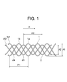
- FIG. 1 schematically shows a state in which the circumferential unit 1 of the first woven structure and the circumferential unit 2 of the second woven structure constituting the stent of the present invention are knitted.
- the circumferential unit 1 and the circumferential unit 2 have the same pitch length (pitch lengths P1 and P2 in the circumferential direction), but are out of phase by 1/4 pitch.
- the amplitudes (A1 and A2) of each other are also different.
- the pitch length (P1 and P2) of the circumferential unit 1 and the circumferential unit 2 is, for example, 12 to 48 mm, and preferably 18 to 36 mm.
- the amplitude (A1) of the circumferential unit 1 is, for example, 8 to 24 mm, preferably 12 to 20 mm.
- the circumferential unit 1 of the first woven structure is composed of a bent portion and a straight portion formed by the wire W1, and a plurality of (5) meshes that are spaces surrounded by the wire W1 are circumferentially (indicated by arrows X). In the direction shown).
- This circumferential unit 1 has a phase that is 1/2 pitch away from the first loop 1a formed by advancing the wire W1 along the circumferential direction while turning back and forth with a constant amplitude A1.
- the second loop 1b formed by making the wire rod W1 proceed along the circumferential direction while being folded back to the left and right with an amplitude A1 in succession to the first loop 1a.
- the second loop 1b crosses the cross at the straight line portion of the first loop 1a, and proceeds so as to alternately pass above and below the first loop 1a (that is, to form a weave with the first loop 1a). Yes.
- the circumferential unit 2 of the second woven structure is composed of a bent portion and a straight portion formed by the wire W2, and a plurality of (five) meshes that are spaces surrounded by the wire W2 are along the circumferential direction.
- the circumferential unit 2 includes a first loop 2a formed by advancing the wire W2 along the circumferential direction while turning back and forth with a constant amplitude A2 (where A2 ⁇ A1), and a first loop 2a.
- the second loop 2b is formed by advancing the wire W2 along the circumferential direction while turning back to the left and right continuously to the first loop 2a so that the phase is shifted by 1/2 pitch.
- a metal is preferable, and in particular, a shape memory alloy to which a shape memory effect and superelasticity by heat treatment are imparted is preferable.
- stainless steel, Ta, Ti, Pt, Au, W, etc. may be used depending on the application.
- the pitch length P1 of the circumferential unit 1 and the pitch length P2 of the circumferential unit 2 are the same, and the phases of the circumferential unit 1 and the circumferential unit 2 are shifted by 1 ⁇ 4 pitch.
- the area of the mesh of the first woven structure (circumferential unit 1) can be divided into four by the wire W2 constituting the second woven structure (circumferential unit 2), so only the first woven structure
- the mesh can be made finer than a stent made of
- the circumferential unit 2 of the second woven structure is displaced from the circumferential unit 1 of the first woven structure by 1/4 pitch in the circumferential direction, and the circumferential unit 1 is bent.
- the bent portion of the circumferential unit 2 are not at the same circumferential position, but the connecting portion by the bent portion of the circumferential unit 1 and the connecting portion by the bent portion of the circumferential unit 2 are arranged at the same circumferential position. Since it does not (densely), it can be avoided that the followability to the curved shape of the tubular organ is impaired.
- the amplitude (A2) of the circumferential unit 2 of the second woven structure is smaller than the amplitude (A1) of the circumferential unit 1 of the first woven structure. Since the connecting portion by the bent portion and the connecting portion by the bent portion of the circumferential unit 2 are not arranged (congested) at the same axial position, it is possible to avoid the loss of the diameter-reducing property of the stent. .
- the ratio (A2 / A1) of the amplitude A2 of the circumferential unit 2 to the amplitude A1 of the circumferential unit 1 is preferably 25 to 95%, more preferably 40 to 80%, and a suitable example is shown. 75%.
- the value of the ratio (A2 / A1) is too small, when the area of the mesh in one woven structure is divided into four by the wire constituting the other woven structure, along with two relatively small meshes, Two relatively large meshes that allow the tumor tissue to pass through are formed, making it difficult to achieve the object of the present invention.
- the value of the ratio (A2 / A1) is close to 100%, the axial position of the bent portion in the circumferential unit of the first woven structure and the bent portion in the circumferential unit of the second woven structure The distance from the axial position may be shortened, and the stent diameter may be impaired.
- the circumferential unit 11 of the first stage, the circumferential unit 12 of the second stage, and the circumferential unit 13 of the third stage are adjacent to each other.
- the circumferential unit 23 is constituted by a second woven structure 20 provided along the axial direction without overlapping between adjacent circumferential units.
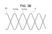
- the first-stage circumferential unit 11 constituting the first woven structure 10 includes a first loop 11a formed by advancing the wire W1 along the circumferential direction while being folded back to the left and right, and continuous to the first loop 11a.
- the second loop 11b is formed by advancing the wire W1 along the circumferential direction while folding back left and right so that the phase is shifted by 1/2 pitch with respect to the first loop 11a.
- the second loop 11b crosses the cross at the straight line portion of the first loop 11a, and proceeds so as to pass alternately above and below the first loop 11a.
- the second-stage circumferential unit 12 constituting the first woven structure 10 is 1 ⁇ 2 pitch in the axial direction with respect to the first-stage circumferential unit 11 (the axial length of the circumferential unit 11 is The corresponding amplitude is shifted by 1/2) and is shifted by 1/4 pitch in the circumferential direction.
- the circumferential unit 12 is continuous with the second loop 11b of the circumferential unit 11 in the first stage, and the first loop 12a formed by advancing along the circumferential direction while folding the wire W1 left and right, Continuing from the first loop 12a, the second loop 12b is formed by advancing along the circumferential direction while turning the wire W1 back and forth so that the phase is shifted by 1/2 pitch with respect to the first loop 12a.
- the second loop 12b crosses the cross at the straight line portion of the first loop 12a, and proceeds so as to alternately pass above and below the first loop 12a.
- the second-stage circumferential unit 12 that is shifted by 1/2 pitch in the axial direction with respect to the first-stage circumferential unit 11 has a portion overlapping the circumferential unit 11. Further, the bent portion of the circumferential unit 12 that is shifted by 1/4 pitch in the circumferential direction with respect to the circumferential unit 11 in the first stage is connected to the wire crossing portion of the circumferential unit 11, and the circumferential unit 12 The wire crossing portion is connected to the bent portion of the circumferential unit 11.
- the third-stage circumferential unit 13 constituting the first woven structure 10 is shifted from the second-stage circumferential unit 12 by 1/2 pitch in the axial direction and shifted by 1/4 pitch in the circumferential direction. ing.
- the circumferential unit 13 is continuous with the second loop 12b of the circumferential unit 12 in the second stage, and the first loop 13a formed by advancing along the circumferential direction while turning the wire W1 back and forth, Continuing from the first loop 13a, it is formed by a second loop 13b formed by advancing along the circumferential direction while turning the wire W1 back and forth so that the phase is shifted by 1/2 pitch with respect to the first loop 13a.
- the second loop 13b crosses the cross at the straight line portion of the first loop 13a, and proceeds so as to alternately pass above and below the first loop 13a.
- the first-stage circumferential unit 21 constituting the second woven structure 20 has the same pitch length as the circumferential unit 11 of the first woven structure 10 corresponding thereto, and is smaller than the corresponding circumferential unit 11.
- a first loop 21a formed by advancing along the circumferential direction while turning the wire W2 left and right with the amplitude and the corresponding circumferential unit 11 shifted by a quarter pitch in the circumferential direction, and the first loop Continuing from 21a, it is formed by a second loop 21b formed by advancing along the circumferential direction while turning the wire W2 back and forth so that the phase is shifted by 1/2 pitch with respect to the first loop 21a.
- the second loop 21b crosses the cross at the straight line portion of the first loop 21a, and proceeds so as to alternately pass above and below the first loop 21a.
- the circumferential unit 21 is braided to the circumferential unit 11 of the corresponding first woven structure 10. Further, the bent portion of the circumferential unit 21 is connected (interlocked) with the bent portion of the circumferential unit 12 of the first woven structure 10.
- the second-stage circumferential unit 22 constituting the second woven structure 20 has the same pitch length as the circumferential unit 12 of the first woven structure 10 corresponding thereto, and is smaller than the corresponding circumferential unit 12.
- a first loop 22a formed by advancing the wire W2 in the circumferential direction while turning back to the left and right in a state where the amplitude and the corresponding circumferential unit 12 are shifted by 1/4 pitch in the circumferential direction, and the first loop Continuing from 22a, it is formed by a second loop 22b formed by advancing along the circumferential direction while turning the wire W2 left and right so that the phase is shifted by 1/2 pitch with respect to the first loop 22a.
- the second loop 22b crosses the cross at the straight line portion of the first loop 22a, and proceeds so as to alternately pass above and below the first loop 22a.
- the circumferential unit 22 is braided on the circumferential unit 12 of the corresponding first woven structure 10. Further, the bent portion of the circumferential unit 22 is connected (interposed) with the bent portion of the circumferential unit 11 of the first woven structure 10, and the bent portion of the circumferential unit 13 of the first woven structure 10. They are also linked together. The circumferential unit 22 and the circumferential unit 21 do not overlap each other, and the bent portion of the circumferential unit 22 is not connected to either the bent portion or the wire crossing portion of the first circumferential unit 21. .
- the third-stage circumferential unit 23 constituting the second woven structure 20 has the same pitch length as the circumferential unit 13 of the first woven structure 10 corresponding thereto, and is smaller than the corresponding circumferential unit 13.
- the second loop 23b crosses the cross at the straight line portion of the first loop 23a, and proceeds so as to alternately pass above and below the first loop 23a.
- the circumferential unit 23 is braided into the circumferential unit 13 of the corresponding first woven structure 10. Further, the bent portion of the circumferential unit 23 is connected (interlocked) with the bent portion of the circumferential unit 12 of the first woven structure 10. The circumferential unit 23 and the circumferential unit 22 do not overlap each other, and the bent portion of the circumferential unit 23 is not connected to either the bent portion of the second circumferential unit 22 or the wire crossing portion. .
- the stent 100 of the present embodiment can be formed by knitting the wire W1 and the wire W2 in the following procedure, for example. This knitting operation is usually performed by winding a wire in a predetermined pattern around the outer periphery of the mandrel.
- the first loop 11a is formed by causing the wire W1 to advance along the circumferential direction while turning back to the left and right with a constant amplitude (see FIG. 3A).
- the wire W1 is advanced in the circumferential direction while being folded back to the left and right with the same amplitude so as to form a weave with the first loop 11a with the phase shifted by 1/2 pitch.
- Two loops 11b are formed.
- a first-stage circumferential unit 11 in which a plurality of meshes are arranged along the circumferential direction is formed (see FIG. 3B).
- the end of the second loop 11b forming the circumferential unit 11 is advanced by 1/2 pitch (1/2 of the amplitude) and 1/4 pitch in the circumferential direction without bending.
- the first loop 12a is formed by causing the wire W1 to advance along the circumferential direction while turning back to the left and right (see FIG. 3C).
- the phase with respect to the first loop 12a is 1 /
- the second loop 12b is formed by advancing along the circumferential direction while folding the wire W1 left and right continuously to the first loop 12a so as to form a weave with the first loop 12a with a shift of 2 pitches.
- a second-stage circumferential unit 12 in which a plurality of meshes are arranged along the circumferential direction is formed (see FIG. 3D).
- the end of the second loop 12b forming the circumferential unit 12 is advanced by 1/2 pitch in the axial direction and 1/4 pitch in the circumferential direction without bending, and then the wire W1 is moved left and right.
- the first loop 13a is formed by advancing along the circumferential direction while turning back (see FIG. 3E). After the wire rod W1 makes one turn, the phase is shifted by 1/2 pitch with respect to the first loop 13a.
- the second loop 13b is formed by advancing along the circumferential direction while folding the wire W1 left and right continuously to the first loop 13a so as to form a weave with a.
- a third-stage circumferential unit 13 in which a plurality of meshes are arranged along the circumferential direction is formed (see FIG.
- the circumferential unit 11 in the first stage, the circumferential unit 12 in the second stage, and the circumferential unit 13 in the third stage have an overlapping portion between adjacent circumferential units.
- the 1st woven structure 10 formed along an axial direction is formed (refer FIG. 3G).
- the circumferential unit 13 is woven with the wire W2 folded back to the left and right.
- the second loop 23b is formed by proceeding along the circumferential direction so as to be formed (see FIG. 3H), the wire W2 is made to make one turn, and then the phase is shifted by 1/2 pitch with respect to the second loop 23b.
- the first loop 23a is formed by proceeding along the circumferential direction so as to form a weave with the second loop 23b and the circumferential unit 13 while the wire W2 is folded back left and right continuously with the two loops 23b.
- a third-stage circumferential unit 23 (corresponding to circumferential unit 13) is formed (see FIG. 3I).
- the end portion of the first loop 23a forming the circumferential unit 23 is not bent, and the amount corresponding to 1 ⁇ 2 pitch of the circumferential unit of the first woven structure 10 in the axial direction (first woven structure)
- the same amount of displacement between adjacent circumferential units in the body 10 after advancing 1/4 pitch in the circumferential direction, the pitch length is the same as the circumferential unit 12 of the first woven structure 10, and the circumferential direction
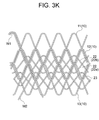
- the second loop 22b is formed by advancing along the circumferential direction so as to form a weave with the circumferential unit 12 while folding the wire W2 left and right with an amplitude smaller than the unit 12 (see FIG. 3J).
- the phase is shifted by 1/2 pitch with respect to the second loop 22b, and the second loop 22b and the circumferential unit 12 are woven while the wire W2 is folded back left and right continuously with the second loop 22b.
- a plurality of meshes are arranged along the circumferential direction, shifted by a quarter pitch in the circumferential direction with respect to the circumferential unit 12 of the first woven structure 10, and braided in the circumferential unit 12
- a second stage circumferential unit 22 (corresponding to circumferential unit 12) is formed (see FIG. 3K).
- the end portion of the first loop 22a forming the circumferential unit 22 is not bent, and the amount corresponding to 1 ⁇ 2 pitch of the circumferential unit of the first woven structure 10 in the axial direction (first woven structure) The same pitch length as the circumferential unit 11 of the first woven structure 10, and the circumferential direction.
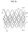
- the second loop 21b is formed by advancing along the circumferential direction so as to form a weave with the circumferential unit 11 while turning the wire W2 left and right with an amplitude smaller than the unit 11 (see FIG. 3L).
- the phase is shifted by 1/2 pitch with respect to the second loop 21b, and the second loop 21b and the circumferential unit 11 are woven while the wire W2 is folded back left and right continuously with the second loop 21b.
- the plurality of meshes are arranged along the circumferential direction, shifted by a quarter pitch in the circumferential direction with respect to the circumferential unit 11 of the first woven structure 10, and braided in the circumferential unit 11
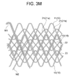
- a first-stage circumferential unit 21 (corresponding to circumferential unit 11) is formed (see FIG. 3M).
- the structure 20 is formed, and the stent 100 of this embodiment shown in FIG. 2 is configured.
- each of the circumferential units 11 to 13 of the first woven structure 10 and each of the circumferential units 21 to 23 of the second woven structure 20 have the same pitch length.
- the phase is shifted by 1/4 pitch, so that the circumferential units 11 to 11 of the first woven structure 10 13 can be divided into four by the wire W2 constituting each of the circumferential units 21 to 23 of the second woven structure 20, so that the stent formed only from the first woven structure 10 Compared with, the mesh can be made finer.
- each of the circumferential units 21 to 23 of the second woven structure 20 is shifted by 1/4 pitch in the circumferential direction with respect to each of the circumferential units 11 to 13 of the first woven structure 10, and thus the circumferential direction
- the bent portions of the units 11 to 13 and the bent portions of the circumferential units 21 to 23 are not at the same circumferential position, and are connected by the bent portions of the circumferential units 11 to 13 of the first woven structure 10 (circumferential units).
- each of the circumferential units 21 to 23 of the second woven structure 20 is smaller than the amplitude of each of the circumferential units 11 to 13 of the first woven structure 10, the circumferential units 11 to 13 of the second woven structure 20 are smaller.
- the bent portions and the bent portions of the circumferential units 21 to 23 are not located at the same axial position, and are connected by the bent portions of the circumferential units 11 to 13 of the first woven structure 10 (bending of the circumferential units 11 to 13).
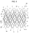
- the stent 200 of the present embodiment shown in FIGS. 4 and 5 is similar to the stent 100 of the first embodiment in that the first-stage circumferential unit 11 ′, the second-stage circumferential unit 12 ′, and the third stage A first woven structure 10 ′ in which a circumferential unit 13 ′ at the stage is provided along the axial direction, a circumferential unit 21 ′ at the first stage, and a circumferential unit 22 ′ at the second stage
- the circumferential unit 23 ′ at the third stage is constituted by a second woven structure 20 ′ provided along the axial direction.
- FIG. 5 is different from the structure shown in FIG. 2 in the structure shown in FIG. 4 (intersection of the wire W1 constituting the first woven structure and the wire W2 constituting the second woven structure. In the portion, a portion where the front-rear relationship between the wire W1 and the wire W2 is opposite to the structure shown in FIG.
- the first woven structure 10 ′ constituting the stent 200 of the present embodiment has the same structure as the first woven structure 10 constituting the stent 100 of the first embodiment.
- the second woven structure 20 ′ constituting the stent 200 has the same structure as the second woven structure 20 constituting the stent 100 of the first embodiment, but is knitted with the first woven structure 10 ′.
- the way of assembling is different from the way of braiding with the first woven structure 10 in the second woven structure 20 of the stent 100.
- the bent portion of the circumferential unit 21 ′ of the second woven structure 20 ′ and the circumferential unit 12 ′ of the first woven structure 10 ′ does not cross.
- bent portion of the circumferential unit 22 'of the second woven structure 20' and the bent portion of the circumferential unit 11 'of the first woven structure 10' are overlapped but not crossed.
- bent portion of the circumferential unit 22 ′ of the second woven structure 20 ′ and the bent portion of the circumferential unit 13 ′ of the first woven structure 10 ′ are overlapped but not overlapped.
- bent portion of the circumferential unit 23 ′ of the second woven structure 20 ′ and the bent portion of the circumferential unit 12 ′ of the first woven structure 10 ′ overlap, but do not cross each other.
- the same effects as those of the stent 100 of the first embodiment can be obtained.
- the bent portion of the circumferential unit (21 ′, 22 ′, 23 ′) of the second woven structure 20 ′ corresponds to the circumferential unit (21 ′, 22 ′, 23 ′).
- the circumferential units (12 ′, 11 ′ and 13 ′, 12 ′) adjacent to the circumferential units (11 ′, 12 ′, 13 ′) of the first woven structure 10 ′ are not engaged with each other.
- the first woven structure 10 ′, and thus the stent 200 can be sufficiently stretched (reduced in diameter), and compared with the stent 100 of the first embodiment having such an engagement portion. Further improvement in performance can be achieved.
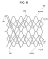
- the stent 300 of the present embodiment shown in FIG. 6 includes a first woven structure 60 in which a first-stage circumferential unit 61 and a second-stage circumferential unit 62 are provided along the axial direction;
- the first-stage circumferential unit 71 and the second-stage circumferential unit 72 are constituted by a second woven structure 70 provided along the axial direction.
- Each circumferential unit (61, 62, 71, 72) is composed of two loops, the two loops crossing each other in a straight line portion, and one loop is located above and below the other loop. Progressing alternately.
- the first-stage circumferential unit 61 and the second-stage circumferential unit 62 constituting the first woven structure 60 are shifted by one pitch (amplitude) in the axial direction,
- the bent portion of the direction unit 61 and the bent portion of the circumferential unit 62 are connected (interlocked).
- the first-stage circumferential unit 71 constituting the second woven structure 70 has the same pitch length as the circumferential unit 61 of the first woven structure 60 corresponding thereto, and an amplitude smaller than the circumferential unit 61. And is braided in the circumferential unit 61 in a state where the circumferential unit 61 is shifted by 1/4 pitch in the circumferential direction.
- the circumferential unit 71 does not overlap with the circumferential unit 62 of the first woven structure 60, and the bent part of the circumferential unit 71 is connected to both the bent part and the wire crossing part of the circumferential unit 62. Not.
- the second-stage circumferential unit 72 constituting the second woven structure 70 has the same pitch length as the circumferential unit 62 of the first woven structure 60 corresponding thereto, and an amplitude smaller than the circumferential unit 62.
- the circumferential unit 71 is braided on the circumferential unit 62 in a state of being continuously formed at the end portion of the circumferential unit 71 and being shifted from the circumferential unit 62 by 1/4 pitch in the circumferential direction.
- the circumferential unit 72 does not overlap with the circumferential unit 61 of the first woven structure 60, and the bent portion of the circumferential unit 72 is connected to both the bent portion and the wire crossing portion of the circumferential unit 61. Not. Further, the circumferential unit 72 does not overlap with the circumferential unit 71 of the second woven structure 70, and the bent portion of the circumferential unit 72 is connected to both the bent portion and the wire crossing portion of the circumferential unit 71. Not.
- each of the circumferential units 61 and 62 of the first woven structure 60 and each of the circumferential units 71 and 72 of the second woven structure 70 have the same pitch length. And the phase is shifted by 1 ⁇ 4 pitch, the area of the mesh in each of the circumferential units 61 and 62 of the first woven structure 60 is changed to the circumferential units 71 and 72 of the second woven structure 70. Since the wire can be divided into four by the wire W2 constituting each of the above, the mesh can be made finer than a stent formed only from the first woven structure 60.
- each of the circumferential units 71 and 72 is shifted by a quarter pitch in the circumferential direction with respect to each of the circumferential units 61 and 62 of the first woven structure 60.
- the bent portions of the circumferential units 71 and 72 are not at the same circumferential position, and the connecting portion by the bent portions of the circumferential units 61 and 62 and the connecting portion by the bent portions of the circumferential units 71 and 72 have the same circumference. Since it is not arranged in a directional position, it can be avoided that the followability to the curved shape of the tubular organ is impaired.
- each of the circumferential units 71 and 72 is smaller than the amplitude of each of the circumferential units 61 and 62 of the first woven structure 60, the bent portion of the circumferential units 61 and 62 and the circumferential unit The bent portions of 71 and 72 are not at the same axial position, and the connecting portions by the bent portions of the circumferential units 61 and 62 and the connecting portions by the bent portions of the circumferential units 71 and 72 are arranged at the same axial position. Therefore, it is possible to avoid the loss of the diameter reduction of the stent.
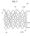
- the stent 400 of the present embodiment shown in FIG. 7 includes a first woven structure 60 in which a first-stage circumferential unit 61 ′ and a second-stage circumferential unit 62 ′ are provided along the axial direction. And a second woven structure 70 ′ in which a circumferential unit 71 ′, a circumferential unit 73 ′, and a circumferential unit 72 ′ are provided along the axial direction.
- the stent 400 is formed of a circumferential unit (circumferential unit 73 ′) that does not correspond to any of the circumferential units 61 ′ and 62 ′ of the first woven structure 60 ′ in the second woven structure 70 ′. It is characterized in that
- the first woven structure 60 'constituting the stent 400 of the present embodiment has the same structure as the first woven structure 60 constituting the stent 300 of the third embodiment.
- the circumferential unit 71 ′ constituting the second woven structure 70 ′ has the same pitch length as the circumferential unit 61 ′ of the first woven structure 60 ′ corresponding thereto, and an amplitude smaller than the circumferential unit 61 ′. And is braided in the circumferential unit 61 ′ in a state of being shifted by a quarter pitch in the circumferential direction with respect to the circumferential unit 61 ′.
- the circumferential unit 71 ′ does not overlap with the circumferential unit 62 ′ of the first woven structure 60 ′, and the bent part of the circumferential unit 71 ′ is a bent part and a wire crossing part of the circumferential unit 62 ′. It is not connected with any of these.
- the circumferential unit 72 ′ constituting the second woven structure 70 ′ has the same pitch length as the circumferential unit 62 ′ of the first woven structure 60 ′ corresponding thereto, and an amplitude smaller than the circumferential unit 62 ′. And is braided in the circumferential unit 62 ′ in a state where the circumferential unit 62 ′ is shifted by a quarter pitch in the circumferential direction. Note that the circumferential unit 72 ′ has no overlapping portion with the circumferential unit 61 ′ of the first woven structure 60 ′, and the bent part of the circumferential unit 72 ′ includes the bent part of the circumferential unit 61 ′ and the wire crossing part. It is not connected with any of these.
- the circumferential unit 73 ′ constituting the second woven structure 70 ′ has the same pitch length and the same amplitude (a smaller amplitude than the circumferential units 61 ′ and 62 ′) as the circumferential units 71 ′ and 72 ′. It is formed between a direction unit 71 ′ and a circumferential unit 72 ′ and is braided into a circumferential unit 61 ′ and a circumferential unit 62 ′.
- the bent portion of the circumferential unit 73 ′ is connected (interlocked) with the bent portion of the circumferential unit 61 ′ of the first woven structure 60 ′, and the bent unit of the circumferential unit 62 ′ of the first woven structure 60 ′. It is also connected (interlocked) with the bent portion.
- the circumferential unit 73 ′ does not overlap with the circumferential unit 71 ′, and the bent part of the circumferential unit 73 ′ is not connected to any of the bent part and the wire crossing part of the circumferential unit 71 ′.
- the circumferential unit 73 ′ has no overlapping portion with the circumferential unit 72 ′, and the bent part of the circumferential unit 73 ′ is not connected to any of the bent part and the wire crossing part of the circumferential unit 72 ′.
- the stent 400 of this embodiment there exists an effect similar to the stent 300 of 3rd Embodiment. Moreover, the area of the mesh surrounded by the circumferential unit 61 ′ and the circumferential unit 62 ′ of the first woven structure 60 ′ is determined by the wire W2 constituting the circumferential unit 73 ′ of the second woven structure 70 ′. Since it can divide
- the number of circumferential units formed along the axial direction is 2 to 20 instead of 3 (FIGS. 2 and 3) or 2 (FIGS. 6 and 7). It is said to be about.
- the stent of the present invention can be used as a stent graft by covering at least a part of its inner periphery and / or outer periphery with a graft.
- a graft it is possible to use any of those that constitute a conventionally known stent graft, for example, a thermoplastic resin processed into a cylindrical shape by a molding method such as extrusion molding, blow molding, A knitted fabric of thermoplastic resin fibers formed into a cylindrical shape, a nonwoven fabric of thermoplastic resin formed into a cylindrical shape, a flexible resin sheet or a porous sheet formed into a cylindrical shape, and the like can be used.
- the knitted fabric known knitted fabrics and woven fabrics such as plain weave and twill weave can be used.
- the thing with a crimp, such as crimping can also be used.
Abstract
縮径性および湾曲形状に対する追従性が損なわれず網目を細かくすることができ、管状器官に留置後、腫瘍組織が内腔に侵入して再狭窄することを防止できるステントの提供を課題とする。 本発明のステントは、複数の網目が周方向に沿って配列された周方向単位(11~13)が、軸方向に沿って設けられてなる第1織構造体(10)と、複数の網目が周方向に沿って配列された周方向単位(21~23)が、第1織構造体(10)の周方向単位(11~13)に対応して、軸方向に沿って設けられてなる第2織構造体(20)とにより構成され、第2織構造体(20)の周方向単位は、対応する第1織構造体の周方向単位に対して周方向に1/4ピッチずれていて、対応する第1織構造体の周方向単位に編み組まれており、第2織構造体(20)の隣り合う周方向単位どうしにおいて、一方の周方向単位の屈曲部は、他方の周方向単位の屈曲部および線材交差部の何れとも連結していない。
Description
本発明は、消化管などの体内の管状器官に留置することにより、管状器官の狭窄や閉塞を防止するためのステントおよびステントグラフトに関する。
消化管に留置されるステント(消化管ステント)は、腫瘍により狭窄した消化管の内腔を押し開けるために使用される。
かかる消化管ステントには、狭窄部を十分に押し広げるために高い拡径力を有すること、デリバリーシースへスムーズに挿入できるように縮径性が良好であること、消化管の湾曲形状に対する追従性が良好であることが要求される。
ところで、消化管ステントの留置後において、腫瘍の成長によって腫瘍組織がステントの網目から消化管ステントの内腔に侵入して、消化管を再狭窄することがある。
このような消化管の再狭窄を防止するためには、ステントの網目を、できるだけ細かく(網目を形成する線材の隙間を狭く)することが望ましい。
このような消化管の再狭窄を防止するためには、ステントの網目を、できるだけ細かく(網目を形成する線材の隙間を狭く)することが望ましい。
しかしながら、ステントの網目を細かく形成すると、周方向および軸方向に配列する網目の数が増加し、これに伴って、線材の連結部(例えば、線材の屈曲部どうしの連結部である掛け合い部)の数が増加する。
ここに、同一軸方向位置において周方向に配列される連結部(掛け合い部)が増加することにより、ステントの縮径性が損なわれる傾向がある。
また、同一周方向位置において軸方向に配列される連結部(掛け合い部)が増加することにより、管状器官の湾曲形状に対する追従性が損なわれる傾向がある。
また、同一周方向位置において軸方向に配列される連結部(掛け合い部)が増加することにより、管状器官の湾曲形状に対する追従性が損なわれる傾向がある。
また、下記特許文献1には、線材(第1部材)により第1筒状格子構造を形成した後、線材(第2部材)により、第1筒状格子構造から周方向に1/4ピッチずらして、同一形状の第2格子構造体を形成してなるステントが開示されている。
このようなステントによれば、一方の筒状格子構造による網目の面積を、他方の筒状格子構造を構成する線材によって4分割することができ、ステントの網目を細かくすることができる(特許文献1の図13参照)。
しかしながら、上記特許文献1に記載されたステントにおいては、第1筒状格子構造のみからなるステントと比較して、いくつかの同一周方向位置(例えば、同文献の図13のy1,y3,y7,y9およびy13)において軸方向に沿って配列する掛け合い部の数が2倍となり、いくつかの同一軸方向位置(例えば、同文献の図13のx1およびx9)において周方向に沿って配列する掛け合い部の数が2倍となる。
このため、上記特許文献1に記載されたステントは、湾曲形状に対する追従性に劣るものであり、縮径性にも劣るものである。
このため、上記特許文献1に記載されたステントは、湾曲形状に対する追従性に劣るものであり、縮径性にも劣るものである。
本発明は以上のような事情に基いてなされたものである。
本発明の目的は、ステントに要求される縮径性および湾曲形状に対する追従性が損なわれることなく網目を細かくすることができ、管状器官に留置した後に、腫瘍組織が内腔に侵入して再狭窄することを防止することができるステントを提供することにある。
本発明の目的は、ステントに要求される縮径性および湾曲形状に対する追従性が損なわれることなく網目を細かくすることができ、管状器官に留置した後に、腫瘍組織が内腔に侵入して再狭窄することを防止することができるステントを提供することにある。
(1)本発明のステントは、1本以上の線材を編み組んで、筒状に形成してなるステントにおいて、
前記線材を左右に折り返しながら周方向に沿って進行させて形成された屈曲部と直線部とからなる第1ループと、この第1ループに対して位相が1/2ピッチずれるように前記第1ループに連続して前記線材を左右に折り返しながら周方向に沿って進行させて形成された屈曲部と直線部とからなる第2ループとによって形成される、複数の網目が周方向に沿って配列された周方向単位が、軸方向に沿って複数設けられてなる第1織構造体と、
前記第1織構造体の周方向単位と同じピッチ長さで、かつ、前記第1織構造体の周方向単位よりも小さい振幅で、前記線材を左右に折り返しながら周方向に沿って進行させて形成された屈曲部と直線部とからなる第1ループと、この第1ループに対して位相が1/2ピッチずれるように前記第1ループに連続して前記線材を左右に折り返しながら周方向に沿って進行させて形成された屈曲部と直線部とからなる第2ループとにより形成される、複数の網目が周方向に沿って配列された周方向単位が、前記第1織構造体の周方向単位に対応して、軸方向に沿って複数設けられてなる第2織構造体とにより構成され、
前記第1織構造体の周方向単位どうしが重なる部分において、一方の周方向単位の屈曲部と、他方の周方向単位の屈曲部または線材交差部とが連結しており、
前記第2織構造体の周方向単位は、対応する前記第1織構造体の周方向単位に対して周方向に1/4ピッチずれていて、対応する前記第1織構造体の周方向単位に編み組まれており、
前記第2織構造体の隣り合う周方向単位どうしにおいて、一方の周方向単位の屈曲部は、他方の周方向単位の屈曲部および線材交差部の何れとも連結していないことを特徴とする。
このような構成のステントによれば、第2織構造体の周方向単位がこれと対応する第1織構造体の周方向単位に対して周方向に1/4ピッチずれていることにより、第1織構造体における網目の面積を第2織構造体を構成する線材によって4分割することができるので、当該ステントの網目を細かくすることができる。
また、第2織構造体の周方向単位がこれと対応する第1織構造体の周方向単位に対して周方向に1/4ピッチずれていることにより、第1織構造体の周方向単位の屈曲部による連結部と、第2織構造体の周方向単位の屈曲部による連結部とが同一周方向位置において軸方向に沿って配列されることがないので、同一周方向位置に配列する連結部の数が2倍に増加して湾曲形状に対する追従性が損なわれるようなことを回避することができる。
また、第2織構造体の周方向単位の振幅が第1織構造体の周方向単位の振幅より小さいことにより、第1織構造体の周方向単位の屈曲部による連結部と、第2織構造体の周方向単位の屈曲部による連結部とが同一軸方向位置において周方向に沿って配列されることがないので、同一軸方向位置に配列する連結部の数が2倍に増加して縮径性が損なわれることを回避することができる。
また、第2織構造体の隣り合う周方向単位どうしにおいて、一方の周方向単位の屈曲部は、他方の周方向単位の屈曲部および線材交差部の何れとも連結していないことにより、連結している場合と比較して、湾曲形状に対する追従性や縮径性を良好なものとすること
ができる。
ができる。
(2)本発明のステントにおいて、前記第1織構造体は、周方向単位を形成するループの端部を屈曲させずにそのまま直進させて、この周方向単位に対して軸方向にずれた位置で次の周方向単位を形成することにより、複数の周方向単位が軸方向に沿って設けられてなり、
前記第2織構造体は、周方向単位を形成するループの端部を屈曲させずにそのまま直進させて、この周方向単位に対して、前記第1織構造体において隣り合う周方向単位間のずれ量と同じだけ軸方向にずれた位置で次の周方向単位を形成することにより、複数の周方向単位が軸方向に沿って設けられてなることが好ましい。
前記第2織構造体は、周方向単位を形成するループの端部を屈曲させずにそのまま直進させて、この周方向単位に対して、前記第1織構造体において隣り合う周方向単位間のずれ量と同じだけ軸方向にずれた位置で次の周方向単位を形成することにより、複数の周方向単位が軸方向に沿って設けられてなることが好ましい。
これにより、第2織構造体の周方向単位のすべてが、第1織構造体の周方向単位と対応することになる。
(3)本発明のステントにおいて、前記第2織構造体の周方向単位の振幅は、前記第1織構造体の周方向単位の振幅の25~95%であることが好ましい。
(4)本発明のステントにおいて、前記第1織構造体の周方向単位は、前の周方向単位に対して軸方向にほぼ1/2ピッチ(振幅の1/2)ずれるとともに、周方向にほぼ1/4ピッチずれており、前記第1織構造体の周方向単位どうしが重なる部分において、一方の周方向単位の屈曲部と、他方の周方向単位の線材交差部とが連結していることが好ましい。
(5)上記(4)のステントにおいて、前記第2織構造体の周方向単位の屈曲部は、対応する前記第1織構造体の周方向単位に隣り合う前記第1織構造体の周方向単位の屈曲部と連結されていないことが好ましい。
(6)本発明のステントグラフトは、本発明のステントと、このステントの内周および/または外周を覆うグラフトとを備えてなることを特徴とする。
本発明のステントによれば、要求される縮径性および管状器官の湾曲形状に対する追従性が損なわれることなく網目を細かくすることができ、管状器官に留置した後に腫瘍組織が内腔に侵入して再狭窄することを防止することができる。
<基本構造>
以下、本発明のステントの基本構造について詳細に説明する。
図1は、本発明のステントを構成する第1織構造体の周方向単位1と、第2織構造体の周方向単位2とが編み込まれている状態を模式的に示している。
以下、本発明のステントの基本構造について詳細に説明する。
図1は、本発明のステントを構成する第1織構造体の周方向単位1と、第2織構造体の周方向単位2とが編み込まれている状態を模式的に示している。
図1に示すように、周方向単位1および周方向単位2は、それぞれのピッチ長さ(周方向のピッチ長さP1およびP2)が同じであるが、位相が1/4ピッチずれており、互いの振幅(A1およびA2)も異なっている。
ここに、周方向単位1および周方向単位2のピッチ長さ(P1およびP2)としては、例えば12~48mmとされ、好ましくは18~36mmとされる。
また、周方向単位1の振幅(A1)としては、例えば8~24mmとされ、好ましくは12~20mmとされる。
また、周方向単位1の振幅(A1)としては、例えば8~24mmとされ、好ましくは12~20mmとされる。
第1織構造体の周方向単位1は、線材W1により形成された屈曲部と直線部とからなり、線材W1で囲まれた空間である複数(5つ)の網目が周方向(矢印Xで示す方向)に沿って配列されてなる。
この周方向単位1は、線材W1を一定の振幅A1で左右に折り返しながら周方向に沿って進行させて形成された第1ループ1aと、第1ループ1aに対して位相が1/2ピッチずれるように、当該第1ループ1aに連続して線材W1を振幅A1で左右に折り返しながら周方向に沿って進行させて形成された第2ループ1bとにより形成されている。
第2ループ1bは、第1ループ1aの直線部において十字に交差し、第1ループ1aの上下を交互に通過するように(すなわち、第1ループ1aと織りを形成するように)進行している。
この周方向単位1は、線材W1を一定の振幅A1で左右に折り返しながら周方向に沿って進行させて形成された第1ループ1aと、第1ループ1aに対して位相が1/2ピッチずれるように、当該第1ループ1aに連続して線材W1を振幅A1で左右に折り返しながら周方向に沿って進行させて形成された第2ループ1bとにより形成されている。
第2ループ1bは、第1ループ1aの直線部において十字に交差し、第1ループ1aの上下を交互に通過するように(すなわち、第1ループ1aと織りを形成するように)進行している。
また、第2織構造体の周方向単位2は、線材W2により形成された屈曲部と直線部とからなり、線材W2で囲まれた空間である複数(5つ)の網目が周方向に沿って配列されてなる。
この周方向単位2は、線材W2を一定の振幅A2(但し、A2<A1である)で左右に折り返しながら周方向に沿って進行させて形成された第1ループ2aと、第1ループ2aに対して位相が1/2ピッチずれるように、当該第1ループ2aに連続して線材W2を左右に折り返しながら周方向に沿って進行させて形成された第2ループ2bとによって形成されている。
この周方向単位2は、線材W2を一定の振幅A2(但し、A2<A1である)で左右に折り返しながら周方向に沿って進行させて形成された第1ループ2aと、第1ループ2aに対して位相が1/2ピッチずれるように、当該第1ループ2aに連続して線材W2を左右に折り返しながら周方向に沿って進行させて形成された第2ループ2bとによって形成されている。
本発明のステントを構成する線材(線材W1,W2)の構成材料としては金属が好ましく、特に、熱処理による形状記憶効果および超弾性が付与される形状記憶合金が好ましい。ただし、用途によってはステンレス、Ta、Ti、Pt、Au、Wなどを用いてもよい
図1に示すように、周方向単位1のピッチ長さP1と周方向単位2のピッチ長さP2が同じで、周方向単位1と周方向単位2の位相が1/4ピッチずれていることにより、第1織構造体(周方向単位1)の網目の面積を、第2織構造体(周方向単位2)を構成する線
材W2によって4分割することができるので、第1織構造体のみからなるステントと比較して網目を細かくすることができる。
材W2によって4分割することができるので、第1織構造体のみからなるステントと比較して網目を細かくすることができる。
また、図1に示すように、第2織構造体の周方向単位2が第1織構造体の周方向単位1に対して周方向に1/4ピッチずれていて、周方向単位1の屈曲部と周方向単位2の屈曲部とが同一周方向位置になく、周方向単位1の屈曲部による連結部と、周方向単位2の屈曲部による連結部とが同一周方向位置に配列される(密集する)ことがないので、管状器官の湾曲形状に対する追従性が損なわれることを回避することができる。
また、図1に示すように、第2織構造体の周方向単位2の振幅(A2)が第1織構造体の周方向単位1の振幅(A1)より小さいことにより、周方向単位1の屈曲部による連結部と、周方向単位2の屈曲部による連結部とが同一軸方向位置に配列される(密集する)ことがないので、ステントの縮径性が損なわれるを回避することができる。
ここに、周方向単位1の振幅A1に対する周方向単位2の振幅A2の比(A2/A1)としては25~95%であることが好ましく、更に好ましくは40~80%、好適な一例を示せば75%である。
比(A2/A1)の値が過小である場合には、一方の織構造体における網目の面積を他方の織構造体を構成する線材によって4分割する際に、比較的小さい2つの網目とともに、腫瘍組織を通過させてしまう程度の比較的大きな2つの網目が形成されてしまい、本発明の目的を達成することが困難となる。
一方、比(A2/A1)の値が100%に近い場合には、第1織構造体の周方向単位における屈曲部の軸方向位置と、第2織構造体の周方向単位における屈曲部の軸方向位置との離間距離が短くなり、ステントの縮径性が損なわれることがある。
一方、比(A2/A1)の値が100%に近い場合には、第1織構造体の周方向単位における屈曲部の軸方向位置と、第2織構造体の周方向単位における屈曲部の軸方向位置との離間距離が短くなり、ステントの縮径性が損なわれることがある。
<第1実施形態>
以下、本発明の具体的な実施形態について詳細に説明する。
図2に示す本実施形態のステント100は、第1段目の周方向単位11と第2段目の周方向単位12と第3段目の周方向単位13とが、隣り合う周方向単位どうしで重なり合う部分を有しながら、軸方向に沿って設けられてなる第1織構造体10と、第1段目の周方向単位21と第2段目の周方向単位22と第3段目の周方向単位23とが、隣り合う周方向単位どうしで重なり合うことなく、軸方向に沿って設けられてなる第2織構造体20とにより構成されている。
以下、本発明の具体的な実施形態について詳細に説明する。
図2に示す本実施形態のステント100は、第1段目の周方向単位11と第2段目の周方向単位12と第3段目の周方向単位13とが、隣り合う周方向単位どうしで重なり合う部分を有しながら、軸方向に沿って設けられてなる第1織構造体10と、第1段目の周方向単位21と第2段目の周方向単位22と第3段目の周方向単位23とが、隣り合う周方向単位どうしで重なり合うことなく、軸方向に沿って設けられてなる第2織構造体20とにより構成されている。
第1織構造体10を構成する第1段目の周方向単位11は、線材W1を左右に折り返しながら周方向に沿って進行させて形成した第1ループ11aと、この第1ループ11aに連続して、第1ループ11aに対して位相が1/2ピッチずれるように、線材W1を左右に折り返しながら周方向に沿って進行させて形成した第2ループ11bとにより形成されている。
第2ループ11bは、第1ループ11aの直線部において十字に交差し、第1ループ11aの上下を交互に通過するように進行している。
第2ループ11bは、第1ループ11aの直線部において十字に交差し、第1ループ11aの上下を交互に通過するように進行している。
第1織構造体10を構成する第2段目の周方向単位12は、第1段目の周方向単位11に対して軸方向に1/2ピッチ(周方向単位11の軸方向長さに相当する振幅の1/2)ずれるとともに、周方向に1/4ピッチずれている。
この周方向単位12は、第1段目の周方向単位11の第2ループ11bに連続して、線材W1を左右に折り返しながら周方向に沿って進行させて形成した第1ループ12aと、この第1ループ12aに連続して、第1ループ12aに対して位相が1/2ピッチずれるように、線材W1を左右に折り返しながら周方向に沿って進行させて形成した第2ループ
12bとにより形成されている。
第2ループ12bは、第1ループ12aの直線部において十字に交差し、第1ループ12aの上下を交互に通過するように進行している。
この周方向単位12は、第1段目の周方向単位11の第2ループ11bに連続して、線材W1を左右に折り返しながら周方向に沿って進行させて形成した第1ループ12aと、この第1ループ12aに連続して、第1ループ12aに対して位相が1/2ピッチずれるように、線材W1を左右に折り返しながら周方向に沿って進行させて形成した第2ループ
12bとにより形成されている。
第2ループ12bは、第1ループ12aの直線部において十字に交差し、第1ループ12aの上下を交互に通過するように進行している。
第1段目の周方向単位11に対して軸方向に1/2ピッチずれている第2段目の周方向単位12は、周方向単位11と重なる部分を有する。
また、第1段目の周方向単位11に対して周方向に1/4ピッチずれている周方向単位12の屈曲部は周方向単位11の線材交差部と連結しており、周方向単位12の線材交差部は周方向単位11の屈曲部と連結している。
また、第1段目の周方向単位11に対して周方向に1/4ピッチずれている周方向単位12の屈曲部は周方向単位11の線材交差部と連結しており、周方向単位12の線材交差部は周方向単位11の屈曲部と連結している。
第1織構造体10を構成する第3段目の周方向単位13は、第2段目の周方向単位12に対して軸方向に1/2ピッチずれるとともに、周方向に1/4ピッチずれている。
この周方向単位13は、第2段目の周方向単位12の第2ループ12bに連続して、線材W1を左右に折り返しながら周方向に沿って進行させて形成した第1ループ13aと、この第1ループ13aに連続して、第1ループ13aに対して位相が1/2ピッチずれるように、線材W1を左右に折り返しながら周方向に沿って進行させて形成した第2ループ13bとにより形成されている。
第2ループ13bは、第1ループ13aの直線部において十字に交差し、第1ループ13aの上下を交互に通過するように進行している。
この周方向単位13は、第2段目の周方向単位12の第2ループ12bに連続して、線材W1を左右に折り返しながら周方向に沿って進行させて形成した第1ループ13aと、この第1ループ13aに連続して、第1ループ13aに対して位相が1/2ピッチずれるように、線材W1を左右に折り返しながら周方向に沿って進行させて形成した第2ループ13bとにより形成されている。
第2ループ13bは、第1ループ13aの直線部において十字に交差し、第1ループ13aの上下を交互に通過するように進行している。
第2段目の周方向単位12に対して軸方向に1/2ピッチずれている第3段目の周方向単位13は、周方向単位12と重なる部分を有する。
また、第2段目の周方向単位12に対して周方向に1/4ピッチずれている周方向単位13の屈曲部は周方向単位12の線材交差部と連結しており、周方向単位13の線材交差部は周方向単位12の屈曲部と連結している。
また、第2段目の周方向単位12に対して周方向に1/4ピッチずれている周方向単位13の屈曲部は周方向単位12の線材交差部と連結しており、周方向単位13の線材交差部は周方向単位12の屈曲部と連結している。
第2織構造体20を構成する第1段目の周方向単位21は、これと対応する第1織構造体10の周方向単位11と同じピッチ長さ、対応する周方向単位11よりも小さい振幅、対応する周方向単位11に対して周方向に1/4ピッチずらした状態で、線材W2を左右に折り返しながら周方向に沿って進行させて形成した第1ループ21aと、この第1ループ21aに連続して、第1ループ21aに対して位相が1/2ピッチずれるように、線材W2を左右に折り返しながら周方向に沿って進行させて形成した第2ループ21bとにより形成されている。
第2ループ21bは、第1ループ21aの直線部において十字に交差し、第1ループ21aの上下を交互に通過するように進行している。
第2ループ21bは、第1ループ21aの直線部において十字に交差し、第1ループ21aの上下を交互に通過するように進行している。
この周方向単位21は、対応する第1織構造体10の周方向単位11に編み組まれている。また、この周方向単位21の屈曲部は、第1織構造体10の周方向単位12の屈曲部と連結(掛け合い)している。
第2織構造体20を構成する第2段目の周方向単位22は、これと対応する第1織構造体10の周方向単位12と同じピッチ長さ、対応する周方向単位12よりも小さい振幅、対応する周方向単位12に対して周方向に1/4ピッチずらした状態で、線材W2を左右に折り返しながら周方向に沿って進行させて形成した第1ループ22aと、この第1ループ22aに連続して、第1ループ22aに対して位相が1/2ピッチずれるように、線材W2を左右に折り返しながら周方向に沿って進行させて形成した第2ループ22bとにより形成されている。
第2ループ22bは、第1ループ22aの直線部において十字に交差し、第1ループ22aの上下を交互に通過するように進行している。
第2ループ22bは、第1ループ22aの直線部において十字に交差し、第1ループ22aの上下を交互に通過するように進行している。
この周方向単位22は、対応する第1織構造体10の周方向単位12に編み組まれている。また、この周方向単位22の屈曲部は、第1織構造体10の周方向単位11の屈曲部と連結(掛け合い)しているとともに、第1織構造体10の周方向単位13の屈曲部とも連結(掛け合い)している。
なお、周方向単位22と周方向単位21とは重なり合う部分がなく、周方向単位22の屈曲部は、第1段目の周方向単位21の屈曲部および線材交差部の何れとも連結していない。
なお、周方向単位22と周方向単位21とは重なり合う部分がなく、周方向単位22の屈曲部は、第1段目の周方向単位21の屈曲部および線材交差部の何れとも連結していない。
第2織構造体20を構成する第3段目の周方向単位23は、これと対応する第1織構造体10の周方向単位13と同じピッチ長さ、対応する周方向単位13よりも小さい振幅、対応する周方向単位13に対して周方向に1/4ピッチずらした状態で、線材W2を左右に折り返しながら周方向に沿って進行させて形成した第1ループ23aと、この第1ループ23aに連続して、第1ループ23aに対して位相が1/2ピッチずれるように、線材W2を左右に折り返しながら周方向に沿って進行させて形成した第2ループ23bとにより形成されている。
第2ループ23bは、第1ループ23aの直線部において十字に交差し、第1ループ23aの上下を交互に通過するように進行している。
第2ループ23bは、第1ループ23aの直線部において十字に交差し、第1ループ23aの上下を交互に通過するように進行している。
この周方向単位23は、対応する第1織構造体10の周方向単位13に編み組まれている。また、この周方向単位23の屈曲部は、第1織構造体10の周方向単位12の屈曲部と連結(掛け合い)している。
なお、周方向単位23と周方向単位22とは重なり合う部分がなく、周方向単位23の屈曲部は、第2段目の周方向単位22の屈曲部および線材交差部の何れとも連結していない。
なお、周方向単位23と周方向単位22とは重なり合う部分がなく、周方向単位23の屈曲部は、第2段目の周方向単位22の屈曲部および線材交差部の何れとも連結していない。
本実施形態のステント100は、線材W1および線材W2を、例えば下記のような手順で編むことにより形成することができる。
なお、この編み作業は、通常、マンドレルの外周に所定のパターンで線材を巻き付けることにより行う。
なお、この編み作業は、通常、マンドレルの外周に所定のパターンで線材を巻き付けることにより行う。
(1)線材W1を、一定の振幅で左右に折り返しながら周方向に沿って進行させることにより第1ループ11aを形成し(図3A参照)、線材W1を一周させた後、第1ループ11aに対して位相を1/2ピッチずらして第1ループ11aと織りを形成するように、第1ループ11aに連続して同じ振幅で線材W1を左右に折り返しながら周方向に沿って進行させることにより第2ループ11bを形成する。これにより、複数の網目が周方向に沿って配列された第1段目の周方向単位11が形成される(図3B参照)。
(2)次に、周方向単位11を形成する第2ループ11bの端部を屈曲させずに軸方向に1/2ピッチ(振幅の1/2)、周方向に1/4ピッチ進行させた後、線材W1を左右に折り返しながら周方向に沿って進行させることにより第1ループ12aを形成し(図3C参照)、線材W1を一周させた後、第1ループ12aに対して位相を1/2ピッチずらして第1ループ12aと織りを形成するように、第1ループ12aに連続して線材W1を左右に折り返しながら周方向に沿って進行させることにより第2ループ12bを形成する。これにより、複数の網目が周方向に沿って配列された第2段目の周方向単位12が形成される(図3D参照)。
(3)次に、周方向単位12を形成する第2ループ12bの端部を屈曲させずに軸方向に1/2ピッチ、周方向に1/4ピッチ進行させた後、線材W1を左右に折り返しながら周方向に沿って進行させることにより第1ループ13aを形成し(図3E参照)、線材W1を一周させた後、第1ループ13aに対して位相を1/2ピッチずらして第1ループ13
aと織りを形成するように、第1ループ13aに連続して線材W1を左右に折り返しながら周方向に沿って進行させることにより第2ループ13bを形成する。これにより、複数の網目が周方向に沿って配列された第3段目の周方向単位13を形成される(図3F参照)。
このようにして、第1段目の周方向単位11と、第2段目の周方向単位12と、第3段目の周方向単位13とが、隣り合う周方向単位どうしで重なり合う部分を有しながら、軸方向に沿って設けられてなる第1織構造体10が形成される(図3G参照)。
aと織りを形成するように、第1ループ13aに連続して線材W1を左右に折り返しながら周方向に沿って進行させることにより第2ループ13bを形成する。これにより、複数の網目が周方向に沿って配列された第3段目の周方向単位13を形成される(図3F参照)。
このようにして、第1段目の周方向単位11と、第2段目の周方向単位12と、第3段目の周方向単位13とが、隣り合う周方向単位どうしで重なり合う部分を有しながら、軸方向に沿って設けられてなる第1織構造体10が形成される(図3G参照)。
(4)次に、第1織構造体10の周方向単位13と同じピッチ長さで、かつ、周方向単位13よりも小さい振幅で、線材W2を左右に折り返しながら周方向単位13と織りを形成するように周方向に沿って進行させて第2ループ23bを形成し(図3H参照)、線材W2を一周させた後、第2ループ23bに対して位相を1/2ピッチずらして、第2ループ23bに連続して、線材W2を左右に折り返しながら、第2ループ23bおよび周方向単位13と織りを形成するように周方向に沿って進行させて第1ループ23aを形成する。これにより、複数の網目が周方向に沿って配列され、第1織構造体10の周方向単位13に対して周方向に1/4ピッチずれていて、当該周方向単位13に編み組まれた(周方向単位13に対応する)第3段目の周方向単位23が形成される(図3I参照)。
(5)次に、周方向単位23を形成する第1ループ23aの端部を屈曲させずに軸方向に第1織構造体10の周方向単位の1/2ピッチ相当量(第1織構造体10において隣り合う周方向単位間のずれ量と同じ)、周方向に1/4ピッチ進行させた後、第1織構造体10の周方向単位12と同じピッチ長さで、かつ、周方向単位12よりも小さい振幅で、線材W2を左右に折り返しながら周方向単位12と織りを形成するように周方向に沿って進行させて第2ループ22bを形成し(図3J参照)、線材W2を一周させた後、第2ループ22bに対して位相を1/2ピッチずらして、第2ループ22bに連続して、線材W2を左右に折り返しながら、第2ループ22bおよび周方向単位12と織りを形成するように周方向に沿って進行させて第1ループ22aを形成する。これにより、複数の網目が周方向に沿って配列され、第1織構造体10の周方向単位12に対して周方向に1/4ピッチずれていて、当該周方向単位12に編み組まれた(周方向単位12に対応する)第2段目の周方向単位22が形成される(図3K参照)。
(6)次に、周方向単位22を形成する第1ループ22aの端部を屈曲させずに軸方向に第1織構造体10の周方向単位の1/2ピッチ相当量(第1織構造体10において隣り合う周方向単位間のずれ量と同じ)、周方向に1/4ピッチ進行させた後、第1織構造体10の周方向単位11と同じピッチ長さで、かつ、周方向単位11よりも小さい振幅で、線材W2を左右に折り返しながら周方向単位11と織りを形成するように周方向に沿って進行させて第2ループ21bを形成し(図3L参照)、線材W2を一周させた後、第2ループ21bに対して位相を1/2ピッチずらして、第2ループ21bに連続して、線材W2を左右に折り返しながら、第2ループ21bおよび周方向単位11と織りを形成するように周方向に沿って進行させて第1ループ21aを形成する。これにより、複数の網目が周方向に沿って配列され、第1織構造体10の周方向単位11に対して周方向に1/4ピッチずれていて、当該周方向単位11に編み組まれた(周方向単位11に対応する)第1段目の周方向単位21が形成される(図3M参照)。
このようにして、第1段目の周方向単位21と、第2段目の周方向単位22と、第3段目の周方向単位23とが軸方向に沿って設けられてなる第2織構造体20が形成され、図2に示した本実施形態のステント100が構成される。
このようにして、第1段目の周方向単位21と、第2段目の周方向単位22と、第3段目の周方向単位23とが軸方向に沿って設けられてなる第2織構造体20が形成され、図2に示した本実施形態のステント100が構成される。
この実施形態のステント100によれば、第1織構造体10の周方向単位11~13の各々と、第2織構造体20の周方向単位21~23の各々とが、互いに同じピッチ長さを有し、位相が1/4ピッチずれていることにより、第1織構造体10の周方向単位11~
13の各々における網目の面積を、第2織構造体20の周方向単位21~23の各々を構成する線材W2によって4分割することができるので、第1織構造体10のみから形成されるステントと比較して網目を細かくすることができる。
13の各々における網目の面積を、第2織構造体20の周方向単位21~23の各々を構成する線材W2によって4分割することができるので、第1織構造体10のみから形成されるステントと比較して網目を細かくすることができる。
また、第2織構造体20の周方向単位21~23の各々が、第1織構造体10の周方向単位11~13の各々に対して周方向に1/4ピッチずれていて、周方向単位11~13の屈曲部と、周方向単位21~23の屈曲部とが同一周方向位置になく、第1織構造体10の周方向単位11~13の屈曲部による連結部(周方向単位11~13の屈曲部と、他の周方向単位の屈曲部または線材交差部との連結部)と、第2織構造体20の周方向単位21~23の屈曲部による連結部(周方向単位21~23の屈曲部と、他の周方向単位の屈曲部または線材交差部との連結部)とが同一周方向位置に配列されることがないので、管状器官の湾曲形状に対する追従性が損なわれることを回避することができる。
また、第2織構造体20の周方向単位21~23の各々の振幅が、第1織構造体10の周方向単位11~13の各々の振幅より小さいことにより、周方向単位11~13の屈曲部と、周方向単位21~23の屈曲部とが同一軸方向位置になく、第1織構造体10の周方向単位11~13の屈曲部による連結部(周方向単位11~13の屈曲部と、他の周方向単位の屈曲部または線材交差部との連結部)と、第2織構造体20の周方向単位21~23の屈曲部による連結部(周方向単位21~23の屈曲部と、他の周方向単位の屈曲部または線材交差部との連結部)とが同一軸方向位置に配列されることがないので、ステントの縮径性が損なわれるを回避することができる。
<第2実施形態>
図4および図5に示す本実施形態のステント200は、第1実施形態のステント100と同様に、第1段目の周方向単位11’と第2段目の周方向単位12’と第3段目の周方向単位13’とが軸方向に沿って設けられてなる第1織構造体10’と、第1段目の周方向単位21’と第2段目の周方向単位22’と第3段目の周方向単位23’とが軸方向に沿って設けられてなる第2織構造体20’とにより構成されている。
図4および図5に示す本実施形態のステント200は、第1実施形態のステント100と同様に、第1段目の周方向単位11’と第2段目の周方向単位12’と第3段目の周方向単位13’とが軸方向に沿って設けられてなる第1織構造体10’と、第1段目の周方向単位21’と第2段目の周方向単位22’と第3段目の周方向単位23’とが軸方向に沿って設けられてなる第2織構造体20’とにより構成されている。
なお、図5は、図4に示した構造において、図2に示した構造と相違する箇所(第1織構造体を構成する線材W1と、第2織構造体を構成する線材W2との交差部分において、線材W1および線材W2の前後関係が、図2で示される構造と逆である箇所)を「○」で囲んで示している。
本実施形態のステント200を構成する第1織構造体10’は、第1実施形態のステント100を構成する第1織構造体10と同じ構造である。
また、ステント200を構成する第2織構造体20’は、第1実施形態のステント100を構成する第2織構造体20と同様の構造であるが、第1織構造体10’との編み組み方が、ステント100の第2織構造体20における第1織構造体10との編み組み方と異なっている。
また、ステント200を構成する第2織構造体20’は、第1実施形態のステント100を構成する第2織構造体20と同様の構造であるが、第1織構造体10’との編み組み方が、ステント100の第2織構造体20における第1織構造体10との編み組み方と異なっている。
図4(図5)に示すように、本実施形態のステント200において、第2織構造体20’の周方向単位21’の屈曲部と、第1織構造体10’の周方向単位12’の屈曲部とは、重なり合っているが、掛け合ってはいない。
また、第2織構造体20’の周方向単位22’の屈曲部と、第1織構造体10’の周方向単位11’の屈曲部とは、重なり合っているが、掛け合ってはいない。
また、第2織構造体20’の周方向単位22’の屈曲部と、第1織構造体10’の周方向単位13’の屈曲部とは、重なり合っているが、掛け合ってはいない。
更に、第2織構造体20’の周方向単位23’の屈曲部と、第1織構造体10’の周方向単位12’の屈曲部とは、重なり合っているが、掛け合ってはいない。
この実施形態のステント200によれば、第1実施形態のステント100と同様の効果を奏する。
しかも、上記のように、第2織構造体20’の周方向単位(21’,22’,23’)の屈曲部と、当該周方向単位(21’,22’,23’)が対応する第1織構造体10’の周方向単位(11’,12’,13’)に隣り合う周方向単位(12’,11’および13’,12’)の屈曲部とが掛け合いされていないことによって、第1織構造体10’、延いてはステント200を十分に伸ばす(縮径させる)ことが可能となり、そのような掛け合い部を有する第1実施形態のステント100と比較して、縮径性のさらなる向上を図ることができる。
しかも、上記のように、第2織構造体20’の周方向単位(21’,22’,23’)の屈曲部と、当該周方向単位(21’,22’,23’)が対応する第1織構造体10’の周方向単位(11’,12’,13’)に隣り合う周方向単位(12’,11’および13’,12’)の屈曲部とが掛け合いされていないことによって、第1織構造体10’、延いてはステント200を十分に伸ばす(縮径させる)ことが可能となり、そのような掛け合い部を有する第1実施形態のステント100と比較して、縮径性のさらなる向上を図ることができる。
<第3実施形態>
図6に示す本実施形態のステント300は、第1段目の周方向単位61と第2段目の周方向単位62とが軸方向に沿って設けられている第1織構造体60と、第1段目の周方向単位71と第2段目の周方向単位72とが軸方向に沿って設けられている第2織構造体70とにより構成されている。
それぞれの周方向単位(61,62,71,72)は、2つのループから構成され、当該2つのループは、各々の直線部において十字に交差し、一方のループは、他方のループの上下を交互に通過するように進行している。
図6に示す本実施形態のステント300は、第1段目の周方向単位61と第2段目の周方向単位62とが軸方向に沿って設けられている第1織構造体60と、第1段目の周方向単位71と第2段目の周方向単位72とが軸方向に沿って設けられている第2織構造体70とにより構成されている。
それぞれの周方向単位(61,62,71,72)は、2つのループから構成され、当該2つのループは、各々の直線部において十字に交差し、一方のループは、他方のループの上下を交互に通過するように進行している。
図6に示すように、第1織構造体60を構成する第1段目の周方向単位61と第2段目の周方向単位62とは軸方向に1ピッチ(振幅)ずれていて、周方向単位61の屈曲部と周方向単位62の屈曲部とは連結(掛け合い)している。
第2織構造体70を構成する第1段目の周方向単位71は、これと対応する第1織構造体60の周方向単位61と同じピッチ長さ、この周方向単位61よりも小さい振幅で形成され、周方向単位61に対して周方向に1/4ピッチずれている状態で、この周方向単位61に編み組まれている。
なお、周方向単位71は、第1織構造体60の周方向単位62と重なり合う部分がなく、周方向単位71の屈曲部は、周方向単位62の屈曲部および線材交差部の何れとも連結していない。
第2織構造体70を構成する第2段目の周方向単位72は、これと対応する第1織構造体60の周方向単位62と同じピッチ長さ、この周方向単位62よりも小さい振幅で、周方向単位71の端部に連続して形成され、周方向単位62に対して周方向に1/4ピッチずれている状態で、この周方向単位62に編み組まれている。
なお、周方向単位72は、第1織構造体60の周方向単位61と重なり合う部分がなく、周方向単位72の屈曲部は、周方向単位61の屈曲部および線材交差部の何れとも連結していない。
また、周方向単位72は、第2織構造体70の周方向単位71と重なり合う部分がなく、周方向単位72の屈曲部は、周方向単位71の屈曲部および線材交差部の何れとも連結していない。
また、周方向単位72は、第2織構造体70の周方向単位71と重なり合う部分がなく、周方向単位72の屈曲部は、周方向単位71の屈曲部および線材交差部の何れとも連結していない。
この実施形態のステント300によれば、第1織構造体60の周方向単位61および62の各々と、第2織構造体70の周方向単位71および72の各々とが、互いに同じピッ
チ長さを有し、位相が1/4ピッチずれていることにより、第1織構造体60の周方向単位61および62の各々における網目の面積を、第2織構造体70の周方向単位71および72の各々を構成する線材W2によって4分割することができるので、第1織構造体60のみから形成されるステントと比較して網目を細かくすることができる。
チ長さを有し、位相が1/4ピッチずれていることにより、第1織構造体60の周方向単位61および62の各々における網目の面積を、第2織構造体70の周方向単位71および72の各々を構成する線材W2によって4分割することができるので、第1織構造体60のみから形成されるステントと比較して網目を細かくすることができる。
また、周方向単位71および72の各々が、第1織構造体60の周方向単位61および62の各々に対して周方向に1/4ピッチずれていて、周方向単位61および62の屈曲部と、周方向単位71および72の屈曲部とが同一周方向位置になく、周方向単位61および62の屈曲部による連結部と、周方向単位71および72の屈曲部による連結部とが同一周方向位置に配列されることがないので、管状器官の湾曲形状に対する追従性が損なわれることを回避することができる。
また、周方向単位71および72の各々の振幅が、第1織構造体60の周方向単位61および62の各々の振幅より小さいことにより、周方向単位61および62の屈曲部と、周方向単位71および72の屈曲部とが同一軸方向位置になく、周方向単位61および62の屈曲部による連結部と、周方向単位71および72の屈曲部による連結部とが同一軸方向位置に配列されることがないので、ステントの縮径性が損なわれるを回避することができる。
<第4実施形態>
図7に示す本実施形態のステント400は、第1段目の周方向単位61’と第2段目の周方向単位62’とが軸方向に沿って設けられている第1織構造体60’と、周方向単位71’と周方向単位73’と周方向単位72’とが軸方向に沿って設けられている第2織構造体70’とにより構成されている。
図7に示す本実施形態のステント400は、第1段目の周方向単位61’と第2段目の周方向単位62’とが軸方向に沿って設けられている第1織構造体60’と、周方向単位71’と周方向単位73’と周方向単位72’とが軸方向に沿って設けられている第2織構造体70’とにより構成されている。
このステント400は、第2織構造体70’において、第1織構造体60’の周方向単位61’および62’の何れにも対応していない周方向単位(周方向単位73’)が形成されている点に特徴を有する。
本実施形態のステント400を構成する第1織構造体60’は、第3実施形態のステント300を構成する第1織構造体60と同じ構造である。
第2織構造体70’を構成する周方向単位71’は、これと対応する第1織構造体60’の周方向単位61’と同じピッチ長さ、この周方向単位61’よりも小さい振幅で形成され、周方向単位61’に対して周方向に1/4ピッチずれている状態で、この周方向単位61’に編み組まれている。
なお、周方向単位71’は、第1織構造体60’の周方向単位62’と重なり合う部分がなく、周方向単位71’の屈曲部は、周方向単位62’の屈曲部および線材交差部の何れとも連結していない。
なお、周方向単位71’は、第1織構造体60’の周方向単位62’と重なり合う部分がなく、周方向単位71’の屈曲部は、周方向単位62’の屈曲部および線材交差部の何れとも連結していない。
第2織構造体70’を構成する周方向単位72’は、これと対応する第1織構造体60’の周方向単位62’と同じピッチ長さ、この周方向単位62’よりも小さい振幅で形成され、周方向単位62’に対して周方向に1/4ピッチずれている状態で、この周方向単位62’に編み組まれている。
なお、周方向単位72’は、第1織構造体60’の周方向単位61’と重なり合う部分がなく、周方向単位72’の屈曲部は、周方向単位61’の屈曲部および線材交差部の何れとも連結していない。
なお、周方向単位72’は、第1織構造体60’の周方向単位61’と重なり合う部分がなく、周方向単位72’の屈曲部は、周方向単位61’の屈曲部および線材交差部の何れとも連結していない。
第2織構造体70’を構成する周方向単位73’は、周方向単位71’および72’と同じピッチ長さ、同じ振幅(周方向単位61’および62’よりも小さい振幅)で、周方
向単位71’と周方向単位72’との間に形成され、周方向単位61’および周方向単位62’に編み組まれている。
向単位71’と周方向単位72’との間に形成され、周方向単位61’および周方向単位62’に編み組まれている。
周方向単位73’の屈曲部は、第1織構造体60’の周方向単位61’の屈曲部と連結(掛け合い)しているとともに、第1織構造体60’の周方向単位62’の屈曲部とも連結(掛け合い)している。
なお、周方向単位73’は、周方向単位71’と重なり合う部分がなく、周方向単位73’の屈曲部は、周方向単位71’の屈曲部および線材交差部の何れとも連結していない。また、周方向単位73’は、周方向単位72’と重なり合う部分がなく、周方向単位73’の屈曲部は、周方向単位72’の屈曲部および線材交差部の何れとも連結していない。
なお、周方向単位73’は、周方向単位71’と重なり合う部分がなく、周方向単位73’の屈曲部は、周方向単位71’の屈曲部および線材交差部の何れとも連結していない。また、周方向単位73’は、周方向単位72’と重なり合う部分がなく、周方向単位73’の屈曲部は、周方向単位72’の屈曲部および線材交差部の何れとも連結していない。
この実施形態のステント400によれば、第3実施形態のステント300と同様の効果を奏する。
しかも、第1織構造体60’の周方向単位61’と周方向単位62’とにより囲まれた網目の面積を、第2織構造体70’の周方向単位73’を構成する線材W2によって分割することができるので、周方向単位73’を有しない第3実施形態のステント300と比較して網目を更に細かくすることができる。
しかも、第1織構造体60’の周方向単位61’と周方向単位62’とにより囲まれた網目の面積を、第2織構造体70’の周方向単位73’を構成する線材W2によって分割することができるので、周方向単位73’を有しない第3実施形態のステント300と比較して網目を更に細かくすることができる。
以上、本発明の実施形態について説明したが、本発明はこれらに限定されるものでなく、種々の変更が可能である。
例えば、第1織構造体において、軸方向に沿って形成される周方向単位の数は、3個(図2および図3)や2個(図6および図7)ではなく、2~20個程度とされる。
例えば、第1織構造体において、軸方向に沿って形成される周方向単位の数は、3個(図2および図3)や2個(図6および図7)ではなく、2~20個程度とされる。
本発明のステントは、その内周および/または外周の少なくとも一部をグラフトで被覆することにより、ステントグラフトとして使用することができる。
ここに、グラフトとしては、従来公知のステントグラフトを構成するものをすべて使用することができ、例えば、熱可塑性樹脂を、押出成形、ブロー成形などの成形方法で加工して円筒状に形成したもの、円筒状に形成した熱可塑性樹脂の繊維の編織物、円筒状に形成した熱可塑性樹脂の不織布、円筒状に形成した可撓性樹脂のシートや多孔質シートなどを用いることができる。編織物としては、平織、綾織などの公知の編物や織物を用いることができる。また、クリンプ加工などのヒダの付いたものを使用することもできる。
ここに、グラフトとしては、従来公知のステントグラフトを構成するものをすべて使用することができ、例えば、熱可塑性樹脂を、押出成形、ブロー成形などの成形方法で加工して円筒状に形成したもの、円筒状に形成した熱可塑性樹脂の繊維の編織物、円筒状に形成した熱可塑性樹脂の不織布、円筒状に形成した可撓性樹脂のシートや多孔質シートなどを用いることができる。編織物としては、平織、綾織などの公知の編物や織物を用いることができる。また、クリンプ加工などのヒダの付いたものを使用することもできる。
100,200,300,400 ステント
10,10’ 第1織構造体
11,11’ 周方向単位(第1段目)
11a 第1ループ
11b 第2ループ
12,12’ 周方向単位(第2段目)
12a 第1ループ
12b 第2ループ
13,13’ 周方向単位(第3段目)
13a 第1ループ
13b 第2ループ
20,20’ 第2織構造体
21,21’ 周方向単位(第1段目)
21a 第1ループ
21b 第2ループ
22,22’ 周方向単位(第2段目)
22a 第1ループ
22b 第2ループ
23,23’ 周方向単位(第3段目)
23a 第1ループ
23b 第2ループ
60,60’ 第1織構造体
61,61’ 周方向単位
62,62’ 周方向単位
70,70’ 第2織構造体
71,71’ 周方向単位
72,72’ 周方向単位
73’ 周方向単位
W1,W2 線材
P1,P2 ピッチ長さ
A1,A2 振幅
Claims (6)
- 1本以上の線材を編み組んで、筒状に形成してなるステントにおいて、
前記線材を左右に折り返しながら周方向に沿って進行させて形成された屈曲部と直線部とからなる第1ループと、この第1ループに対して位相が1/2ピッチずれるように前記第1ループに連続して前記線材を左右に折り返しながら周方向に沿って進行させて形成された屈曲部と直線部とからなる第2ループとによって形成される、複数の網目が周方向に沿って配列された周方向単位が、軸方向に沿って複数設けられてなる第1織構造体と、
前記第1織構造体の周方向単位と同じピッチ長さで、かつ、前記第1織構造体の周方向単位よりも小さい振幅で、前記線材を左右に折り返しながら周方向に沿って進行させて形成された屈曲部と直線部とからなる第1ループと、この第1ループに対して位相が1/2ピッチずれるように前記第1ループに連続して前記線材を左右に折り返しながら周方向に沿って進行させて形成された屈曲部と直線部とからなる第2ループとにより形成される、複数の網目が周方向に沿って配列された周方向単位が、前記第1織構造体の周方向単位に対応して、軸方向に沿って複数設けられてなる第2織構造体とにより構成され、
前記第1織構造体の周方向単位どうしが重なる部分において、一方の周方向単位の屈曲部と、他方の周方向単位の屈曲部または線材交差部とが連結しており、
前記第2織構造体の周方向単位は、対応する前記第1織構造体の周方向単位に対して周方向に1/4ピッチずれていて、対応する前記第1織構造体の周方向単位に編み組まれており、
前記第2織構造体の隣り合う周方向単位どうしにおいて、一方の周方向単位の屈曲部は、他方の周方向単位の屈曲部および線材交差部の何れとも連結していないことを特徴とするステント。 - 前記第1織構造体は、周方向単位を形成するループの端部を屈曲させずにそのまま直進させて、この周方向単位に対して軸方向にずれた位置で次の周方向単位を形成することにより、複数の周方向単位が軸方向に沿って設けられてなり、
前記第2織構造体は、周方向単位を形成するループの端部を屈曲させずにそのまま直進させて、この周方向単位に対して、前記第1織構造体において隣り合う周方向単位間のずれ量と同じだけ軸方向にずれた位置で次の周方向単位を形成することにより、複数の周方向単位が軸方向に沿って設けられてなることを特徴とする請求項1に記載のステント。 - 前記第2織構造体の周方向単位の振幅は、前記第1織構造体の周方向単位の振幅の25~95%であることを特徴とする請求項1または請求項2に記載のステント。
- 前記第1織構造体の周方向単位は、前の周方向単位に対して軸方向にほぼ1/2ピッチずれるとともに、周方向にほぼ1/4ピッチずれており、前記第1織構造体の周方向単位どうしが重なる部分において、一方の周方向単位の屈曲部と、他方の周方向単位の線材交差部とが連結していることを特徴とする請求項1乃至請求項3の何れかに記載のステント。
- 前記第2織構造体の周方向単位の屈曲部は、対応する前記第1織構造体の周方向単位に隣り合う前記第1織構造体の周方向単位の屈曲部と連結されていないことを特徴とする請求項4に記載のステント。
- 請求項1乃至請求項5の何れかに記載のステントと、このステントの内周および/または外周を覆うグラフトとを備えてなることを特徴とするステントグラフト。
Priority Applications (3)
| Application Number | Priority Date | Filing Date | Title |
|---|---|---|---|
| EP15877990.0A EP3245984B1 (en) | 2015-01-13 | 2015-12-08 | Stent and stent graft |
| KR1020177019055A KR101796430B1 (ko) | 2015-01-13 | 2015-12-08 | 스텐트 및 스텐트 그래프트 |
| CN201580070716.1A CN107106311B (zh) | 2015-01-13 | 2015-12-08 | 支架以及覆膜支架 |
Applications Claiming Priority (2)
| Application Number | Priority Date | Filing Date | Title |
|---|---|---|---|
| JP2015004541A JP6177259B2 (ja) | 2015-01-13 | 2015-01-13 | ステントおよびステントグラフト |
| JP2015-004541 | 2015-01-13 |
Publications (1)
| Publication Number | Publication Date |
|---|---|
| WO2016114039A1 true WO2016114039A1 (ja) | 2016-07-21 |
Family
ID=56405595
Family Applications (1)
| Application Number | Title | Priority Date | Filing Date |
|---|---|---|---|
| PCT/JP2015/084453 WO2016114039A1 (ja) | 2015-01-13 | 2015-12-08 | ステントおよびステントグラフト |
Country Status (5)
| Country | Link |
|---|---|
| EP (1) | EP3245984B1 (ja) |
| JP (1) | JP6177259B2 (ja) |
| KR (1) | KR101796430B1 (ja) |
| CN (1) | CN107106311B (ja) |
| WO (1) | WO2016114039A1 (ja) |
Cited By (1)
| Publication number | Priority date | Publication date | Assignee | Title |
|---|---|---|---|---|
| EP3643274A4 (en) * | 2017-10-31 | 2021-03-24 | Japan Lifeline Co., Ltd. | STENT AND MEDICAL DEVICE |
Families Citing this family (5)
| Publication number | Priority date | Publication date | Assignee | Title |
|---|---|---|---|---|
| WO2020054027A1 (ja) * | 2018-09-13 | 2020-03-19 | オリンパス株式会社 | ステント |
| BR102019019522A2 (pt) * | 2018-09-20 | 2020-04-07 | Depuy Synthes Products Inc | stent com fios conformados |
| WO2020196912A1 (ja) * | 2019-03-28 | 2020-10-01 | 株式会社ジェイ・エム・エス | 合成樹脂ステント及びステントデリバリーシステム |
| CN116236330A (zh) * | 2021-12-07 | 2023-06-09 | 微创优通医疗科技(嘉兴)有限公司 | 支架及其编织方法 |
| CN116370008B (zh) * | 2023-04-24 | 2024-01-30 | 上海励楷科技有限公司 | 多节距编织支架 |
Citations (6)
| Publication number | Priority date | Publication date | Assignee | Title |
|---|---|---|---|---|
| JPH1033692A (ja) * | 1996-04-30 | 1998-02-10 | Schneider Usa Inc | 3次元織込構造により被覆されたステント |
| JP2005523107A (ja) * | 2002-04-25 | 2005-08-04 | ボストン・サイエンティフィック・リミテッド | Ptfe製冷間延伸ヤーンを有した埋設可能な織布プロテーゼ |
| JP2006026329A (ja) * | 2004-07-21 | 2006-02-02 | Piolax Medical Device:Kk | ステント及びステントグラフト |
| JP2010524568A (ja) * | 2007-04-18 | 2010-07-22 | デイビッド・エルマレー | ネットシステムを有する脈管内器具 |
| JP2014217487A (ja) * | 2013-05-02 | 2014-11-20 | 日本ライフライン株式会社 | ステント |
| EP2918251A1 (en) * | 2012-11-08 | 2015-09-16 | Lifetech Scientific (Shenzhen) Co., Ltd. | Braided self-expanding endoluminal stent and manufacturing method thereof |
Family Cites Families (2)
| Publication number | Priority date | Publication date | Assignee | Title |
|---|---|---|---|---|
| US8348991B2 (en) * | 2006-03-29 | 2013-01-08 | Boston Scientific Scimed, Inc. | Stent with overlap and high expansion |
| KR101330825B1 (ko) * | 2011-01-14 | 2013-11-15 | 신경민 | 굽힘 특성이 양호한 스텐트의 제조방법과 그 스텐트 |
-
2015
- 2015-01-13 JP JP2015004541A patent/JP6177259B2/ja active Active
- 2015-12-08 EP EP15877990.0A patent/EP3245984B1/en active Active
- 2015-12-08 CN CN201580070716.1A patent/CN107106311B/zh active Active
- 2015-12-08 WO PCT/JP2015/084453 patent/WO2016114039A1/ja active Application Filing
- 2015-12-08 KR KR1020177019055A patent/KR101796430B1/ko active IP Right Grant
Patent Citations (6)
| Publication number | Priority date | Publication date | Assignee | Title |
|---|---|---|---|---|
| JPH1033692A (ja) * | 1996-04-30 | 1998-02-10 | Schneider Usa Inc | 3次元織込構造により被覆されたステント |
| JP2005523107A (ja) * | 2002-04-25 | 2005-08-04 | ボストン・サイエンティフィック・リミテッド | Ptfe製冷間延伸ヤーンを有した埋設可能な織布プロテーゼ |
| JP2006026329A (ja) * | 2004-07-21 | 2006-02-02 | Piolax Medical Device:Kk | ステント及びステントグラフト |
| JP2010524568A (ja) * | 2007-04-18 | 2010-07-22 | デイビッド・エルマレー | ネットシステムを有する脈管内器具 |
| EP2918251A1 (en) * | 2012-11-08 | 2015-09-16 | Lifetech Scientific (Shenzhen) Co., Ltd. | Braided self-expanding endoluminal stent and manufacturing method thereof |
| JP2014217487A (ja) * | 2013-05-02 | 2014-11-20 | 日本ライフライン株式会社 | ステント |
Cited By (1)
| Publication number | Priority date | Publication date | Assignee | Title |
|---|---|---|---|---|
| EP3643274A4 (en) * | 2017-10-31 | 2021-03-24 | Japan Lifeline Co., Ltd. | STENT AND MEDICAL DEVICE |
Also Published As
| Publication number | Publication date |
|---|---|
| JP2016129575A (ja) | 2016-07-21 |
| EP3245984A4 (en) | 2018-03-21 |
| CN107106311A (zh) | 2017-08-29 |
| EP3245984B1 (en) | 2018-11-07 |
| CN107106311B (zh) | 2018-03-06 |
| EP3245984A1 (en) | 2017-11-22 |
| JP6177259B2 (ja) | 2017-08-09 |
| KR20170086666A (ko) | 2017-07-26 |
| KR101796430B1 (ko) | 2017-11-09 |
Similar Documents
| Publication | Publication Date | Title |
|---|---|---|
| WO2016114039A1 (ja) | ステントおよびステントグラフト | |
| JP6470150B2 (ja) | ステントおよび医療機器 | |
| KR100974308B1 (ko) | 스텐트 | |
| JP6317826B2 (ja) | ステント及びその製造方法 | |
| WO2017163457A1 (ja) | ステントおよび医療機器 | |
| KR20110064090A (ko) | 스텐트 | |
| KR101735702B1 (ko) | 셀 확장이 용이한 스텐트와 그 제조방법 | |
| JP2011504407A (ja) | 円筒形ステント | |
| JP4920274B2 (ja) | 脈管用ステント | |
| JP7085010B2 (ja) | ステント | |
| KR20170012975A (ko) | 미끄럼 방지 기능이 향상된 스텐트 | |
| JP4327548B2 (ja) | ステント | |
| JP2023148363A (ja) | ステント、ステントグラフト | |
| JP6892623B2 (ja) | ステント | |
| JP4429833B2 (ja) | ステント及びステントグラフト | |
| JP2021142319A (ja) | ステント | |
| JP7333433B2 (ja) | ステント | |
| WO2023203596A1 (ja) | ステントの製造方法およびステント | |
| WO2021131857A1 (ja) | ステント | |
| JP4159962B2 (ja) | ステント及びステントグラフト | |
| TWI767128B (zh) | 支架和支架移植物 | |
| JP6955679B2 (ja) | ステント | |
| KR102459751B1 (ko) | 스텐트 및 의료 기기 | |
| KR20230127280A (ko) | 스텐트 | |
| JP2023081529A (ja) | 編み込みステント、編み込みステント製造用治具および編み込みステントの製造方法 |
Legal Events
| Date | Code | Title | Description |
|---|---|---|---|
| 121 | Ep: the epo has been informed by wipo that ep was designated in this application |
Ref document number: 15877990 Country of ref document: EP Kind code of ref document: A1 |
|
| REEP | Request for entry into the european phase |
Ref document number: 2015877990 Country of ref document: EP |
|
| ENP | Entry into the national phase |
Ref document number: 20177019055 Country of ref document: KR Kind code of ref document: A |
|
| NENP | Non-entry into the national phase |
Ref country code: DE |