WO2015198541A1 - ドライバの運転不能状態検出装置 - Google Patents
ドライバの運転不能状態検出装置 Download PDFInfo
- Publication number
- WO2015198541A1 WO2015198541A1 PCT/JP2015/002864 JP2015002864W WO2015198541A1 WO 2015198541 A1 WO2015198541 A1 WO 2015198541A1 JP 2015002864 W JP2015002864 W JP 2015002864W WO 2015198541 A1 WO2015198541 A1 WO 2015198541A1
- Authority
- WO
- WIPO (PCT)
- Prior art keywords
- driver
- head
- detected
- inoperable state
- detection unit
- Prior art date
- Legal status (The legal status is an assumption and is not a legal conclusion. Google has not performed a legal analysis and makes no representation as to the accuracy of the status listed.)
- Ceased
Links
Images







Classifications
-
- B—PERFORMING OPERATIONS; TRANSPORTING
- B60—VEHICLES IN GENERAL
- B60W—CONJOINT CONTROL OF VEHICLE SUB-UNITS OF DIFFERENT TYPE OR DIFFERENT FUNCTION; CONTROL SYSTEMS SPECIALLY ADAPTED FOR HYBRID VEHICLES; ROAD VEHICLE DRIVE CONTROL SYSTEMS FOR PURPOSES NOT RELATED TO THE CONTROL OF A PARTICULAR SUB-UNIT
- B60W40/00—Estimation or calculation of non-directly measurable driving parameters for road vehicle drive control systems not related to the control of a particular sub unit, e.g. by using mathematical models
- B60W40/08—Estimation or calculation of non-directly measurable driving parameters for road vehicle drive control systems not related to the control of a particular sub unit, e.g. by using mathematical models related to drivers or passengers
-
- B—PERFORMING OPERATIONS; TRANSPORTING
- B60—VEHICLES IN GENERAL
- B60R—VEHICLES, VEHICLE FITTINGS, OR VEHICLE PARTS, NOT OTHERWISE PROVIDED FOR
- B60R11/00—Arrangements for holding or mounting articles, not otherwise provided for
- B60R11/04—Mounting of cameras operative during drive; Arrangement of controls thereof relative to the vehicle
-
- B—PERFORMING OPERATIONS; TRANSPORTING
- B60—VEHICLES IN GENERAL
- B60W—CONJOINT CONTROL OF VEHICLE SUB-UNITS OF DIFFERENT TYPE OR DIFFERENT FUNCTION; CONTROL SYSTEMS SPECIALLY ADAPTED FOR HYBRID VEHICLES; ROAD VEHICLE DRIVE CONTROL SYSTEMS FOR PURPOSES NOT RELATED TO THE CONTROL OF A PARTICULAR SUB-UNIT
- B60W30/00—Purposes of road vehicle drive control systems not related to the control of a particular sub-unit, e.g. of systems using conjoint control of vehicle sub-units
- B60W30/08—Active safety systems predicting or avoiding probable or impending collision or attempting to minimise its consequences
- B60W30/09—Taking automatic action to avoid collision, e.g. braking and steering
-
- B—PERFORMING OPERATIONS; TRANSPORTING
- B60—VEHICLES IN GENERAL
- B60W—CONJOINT CONTROL OF VEHICLE SUB-UNITS OF DIFFERENT TYPE OR DIFFERENT FUNCTION; CONTROL SYSTEMS SPECIALLY ADAPTED FOR HYBRID VEHICLES; ROAD VEHICLE DRIVE CONTROL SYSTEMS FOR PURPOSES NOT RELATED TO THE CONTROL OF A PARTICULAR SUB-UNIT
- B60W30/00—Purposes of road vehicle drive control systems not related to the control of a particular sub-unit, e.g. of systems using conjoint control of vehicle sub-units
- B60W30/14—Adaptive cruise control
-
- G—PHYSICS
- G06—COMPUTING OR CALCULATING; COUNTING
- G06T—IMAGE DATA PROCESSING OR GENERATION, IN GENERAL
- G06T7/00—Image analysis
- G06T7/20—Analysis of motion
- G06T7/292—Multi-camera tracking
-
- G—PHYSICS
- G06—COMPUTING OR CALCULATING; COUNTING
- G06T—IMAGE DATA PROCESSING OR GENERATION, IN GENERAL
- G06T7/00—Image analysis
- G06T7/50—Depth or shape recovery
- G06T7/55—Depth or shape recovery from multiple images
- G06T7/593—Depth or shape recovery from multiple images from stereo images
-
- G—PHYSICS
- G06—COMPUTING OR CALCULATING; COUNTING
- G06T—IMAGE DATA PROCESSING OR GENERATION, IN GENERAL
- G06T7/00—Image analysis
- G06T7/70—Determining position or orientation of objects or cameras
- G06T7/73—Determining position or orientation of objects or cameras using feature-based methods
-
- G—PHYSICS
- G06—COMPUTING OR CALCULATING; COUNTING
- G06V—IMAGE OR VIDEO RECOGNITION OR UNDERSTANDING
- G06V20/00—Scenes; Scene-specific elements
- G06V20/50—Context or environment of the image
- G06V20/59—Context or environment of the image inside of a vehicle, e.g. relating to seat occupancy, driver state or inner lighting conditions
- G06V20/597—Recognising the driver's state or behaviour, e.g. attention or drowsiness
-
- G—PHYSICS
- G06—COMPUTING OR CALCULATING; COUNTING
- G06V—IMAGE OR VIDEO RECOGNITION OR UNDERSTANDING
- G06V40/00—Recognition of biometric, human-related or animal-related patterns in image or video data
- G06V40/10—Human or animal bodies, e.g. vehicle occupants or pedestrians; Body parts, e.g. hands
- G06V40/16—Human faces, e.g. facial parts, sketches or expressions
- G06V40/161—Detection; Localisation; Normalisation
-
- G—PHYSICS
- G06—COMPUTING OR CALCULATING; COUNTING
- G06V—IMAGE OR VIDEO RECOGNITION OR UNDERSTANDING
- G06V40/00—Recognition of biometric, human-related or animal-related patterns in image or video data
- G06V40/10—Human or animal bodies, e.g. vehicle occupants or pedestrians; Body parts, e.g. hands
- G06V40/16—Human faces, e.g. facial parts, sketches or expressions
- G06V40/168—Feature extraction; Face representation
- G06V40/171—Local features and components; Facial parts ; Occluding parts, e.g. glasses; Geometrical relationships
-
- G—PHYSICS
- G08—SIGNALLING
- G08B—SIGNALLING SYSTEMS, e.g. PERSONAL CALLING SYSTEMS; ORDER TELEGRAPHS; ALARM SYSTEMS
- G08B21/00—Alarms responsive to a single specified undesired or abnormal condition and not otherwise provided for
- G08B21/02—Alarms for ensuring the safety of persons
-
- H—ELECTRICITY
- H04—ELECTRIC COMMUNICATION TECHNIQUE
- H04N—PICTORIAL COMMUNICATION, e.g. TELEVISION
- H04N13/00—Stereoscopic video systems; Multi-view video systems; Details thereof
- H04N13/20—Image signal generators
- H04N13/204—Image signal generators using stereoscopic image cameras
-
- B—PERFORMING OPERATIONS; TRANSPORTING
- B60—VEHICLES IN GENERAL
- B60K—ARRANGEMENT OR MOUNTING OF PROPULSION UNITS OR OF TRANSMISSIONS IN VEHICLES; ARRANGEMENT OR MOUNTING OF PLURAL DIVERSE PRIME-MOVERS IN VEHICLES; AUXILIARY DRIVES FOR VEHICLES; INSTRUMENTATION OR DASHBOARDS FOR VEHICLES; ARRANGEMENTS IN CONNECTION WITH COOLING, AIR INTAKE, GAS EXHAUST OR FUEL SUPPLY OF PROPULSION UNITS IN VEHICLES
- B60K28/00—Safety devices for propulsion-unit control, specially adapted for, or arranged in, vehicles, e.g. preventing fuel supply or ignition in the event of potentially dangerous conditions
- B60K28/02—Safety devices for propulsion-unit control, specially adapted for, or arranged in, vehicles, e.g. preventing fuel supply or ignition in the event of potentially dangerous conditions responsive to conditions relating to the driver
- B60K28/06—Safety devices for propulsion-unit control, specially adapted for, or arranged in, vehicles, e.g. preventing fuel supply or ignition in the event of potentially dangerous conditions responsive to conditions relating to the driver responsive to incapacity of driver
-
- B—PERFORMING OPERATIONS; TRANSPORTING
- B60—VEHICLES IN GENERAL
- B60W—CONJOINT CONTROL OF VEHICLE SUB-UNITS OF DIFFERENT TYPE OR DIFFERENT FUNCTION; CONTROL SYSTEMS SPECIALLY ADAPTED FOR HYBRID VEHICLES; ROAD VEHICLE DRIVE CONTROL SYSTEMS FOR PURPOSES NOT RELATED TO THE CONTROL OF A PARTICULAR SUB-UNIT
- B60W40/00—Estimation or calculation of non-directly measurable driving parameters for road vehicle drive control systems not related to the control of a particular sub unit, e.g. by using mathematical models
- B60W40/08—Estimation or calculation of non-directly measurable driving parameters for road vehicle drive control systems not related to the control of a particular sub unit, e.g. by using mathematical models related to drivers or passengers
- B60W2040/0818—Inactivity or incapacity of driver
-
- B—PERFORMING OPERATIONS; TRANSPORTING
- B60—VEHICLES IN GENERAL
- B60W—CONJOINT CONTROL OF VEHICLE SUB-UNITS OF DIFFERENT TYPE OR DIFFERENT FUNCTION; CONTROL SYSTEMS SPECIALLY ADAPTED FOR HYBRID VEHICLES; ROAD VEHICLE DRIVE CONTROL SYSTEMS FOR PURPOSES NOT RELATED TO THE CONTROL OF A PARTICULAR SUB-UNIT
- B60W2420/00—Indexing codes relating to the type of sensors based on the principle of their operation
- B60W2420/40—Photo, light or radio wave sensitive means, e.g. infrared sensors
- B60W2420/403—Image sensing, e.g. optical camera
-
- B—PERFORMING OPERATIONS; TRANSPORTING
- B60—VEHICLES IN GENERAL
- B60W—CONJOINT CONTROL OF VEHICLE SUB-UNITS OF DIFFERENT TYPE OR DIFFERENT FUNCTION; CONTROL SYSTEMS SPECIALLY ADAPTED FOR HYBRID VEHICLES; ROAD VEHICLE DRIVE CONTROL SYSTEMS FOR PURPOSES NOT RELATED TO THE CONTROL OF A PARTICULAR SUB-UNIT
- B60W2540/00—Input parameters relating to occupants
- B60W2540/043—Identity of occupants
-
- B—PERFORMING OPERATIONS; TRANSPORTING
- B60—VEHICLES IN GENERAL
- B60W—CONJOINT CONTROL OF VEHICLE SUB-UNITS OF DIFFERENT TYPE OR DIFFERENT FUNCTION; CONTROL SYSTEMS SPECIALLY ADAPTED FOR HYBRID VEHICLES; ROAD VEHICLE DRIVE CONTROL SYSTEMS FOR PURPOSES NOT RELATED TO THE CONTROL OF A PARTICULAR SUB-UNIT
- B60W2540/00—Input parameters relating to occupants
- B60W2540/10—Accelerator pedal position
-
- B—PERFORMING OPERATIONS; TRANSPORTING
- B60—VEHICLES IN GENERAL
- B60W—CONJOINT CONTROL OF VEHICLE SUB-UNITS OF DIFFERENT TYPE OR DIFFERENT FUNCTION; CONTROL SYSTEMS SPECIALLY ADAPTED FOR HYBRID VEHICLES; ROAD VEHICLE DRIVE CONTROL SYSTEMS FOR PURPOSES NOT RELATED TO THE CONTROL OF A PARTICULAR SUB-UNIT
- B60W2540/00—Input parameters relating to occupants
- B60W2540/12—Brake pedal position
-
- B—PERFORMING OPERATIONS; TRANSPORTING
- B60—VEHICLES IN GENERAL
- B60W—CONJOINT CONTROL OF VEHICLE SUB-UNITS OF DIFFERENT TYPE OR DIFFERENT FUNCTION; CONTROL SYSTEMS SPECIALLY ADAPTED FOR HYBRID VEHICLES; ROAD VEHICLE DRIVE CONTROL SYSTEMS FOR PURPOSES NOT RELATED TO THE CONTROL OF A PARTICULAR SUB-UNIT
- B60W2540/00—Input parameters relating to occupants
- B60W2540/18—Steering angle
-
- B—PERFORMING OPERATIONS; TRANSPORTING
- B60—VEHICLES IN GENERAL
- B60W—CONJOINT CONTROL OF VEHICLE SUB-UNITS OF DIFFERENT TYPE OR DIFFERENT FUNCTION; CONTROL SYSTEMS SPECIALLY ADAPTED FOR HYBRID VEHICLES; ROAD VEHICLE DRIVE CONTROL SYSTEMS FOR PURPOSES NOT RELATED TO THE CONTROL OF A PARTICULAR SUB-UNIT
- B60W2540/00—Input parameters relating to occupants
- B60W2540/223—Posture, e.g. hand, foot, or seat position, turned or inclined
-
- B—PERFORMING OPERATIONS; TRANSPORTING
- B60—VEHICLES IN GENERAL
- B60W—CONJOINT CONTROL OF VEHICLE SUB-UNITS OF DIFFERENT TYPE OR DIFFERENT FUNCTION; CONTROL SYSTEMS SPECIALLY ADAPTED FOR HYBRID VEHICLES; ROAD VEHICLE DRIVE CONTROL SYSTEMS FOR PURPOSES NOT RELATED TO THE CONTROL OF A PARTICULAR SUB-UNIT
- B60W2554/00—Input parameters relating to objects
-
- B—PERFORMING OPERATIONS; TRANSPORTING
- B60—VEHICLES IN GENERAL
- B60W—CONJOINT CONTROL OF VEHICLE SUB-UNITS OF DIFFERENT TYPE OR DIFFERENT FUNCTION; CONTROL SYSTEMS SPECIALLY ADAPTED FOR HYBRID VEHICLES; ROAD VEHICLE DRIVE CONTROL SYSTEMS FOR PURPOSES NOT RELATED TO THE CONTROL OF A PARTICULAR SUB-UNIT
- B60W2554/00—Input parameters relating to objects
- B60W2554/80—Spatial relation or speed relative to objects
-
- B—PERFORMING OPERATIONS; TRANSPORTING
- B60—VEHICLES IN GENERAL
- B60W—CONJOINT CONTROL OF VEHICLE SUB-UNITS OF DIFFERENT TYPE OR DIFFERENT FUNCTION; CONTROL SYSTEMS SPECIALLY ADAPTED FOR HYBRID VEHICLES; ROAD VEHICLE DRIVE CONTROL SYSTEMS FOR PURPOSES NOT RELATED TO THE CONTROL OF A PARTICULAR SUB-UNIT
- B60W2554/00—Input parameters relating to objects
- B60W2554/80—Spatial relation or speed relative to objects
- B60W2554/802—Longitudinal distance
-
- B—PERFORMING OPERATIONS; TRANSPORTING
- B60—VEHICLES IN GENERAL
- B60W—CONJOINT CONTROL OF VEHICLE SUB-UNITS OF DIFFERENT TYPE OR DIFFERENT FUNCTION; CONTROL SYSTEMS SPECIALLY ADAPTED FOR HYBRID VEHICLES; ROAD VEHICLE DRIVE CONTROL SYSTEMS FOR PURPOSES NOT RELATED TO THE CONTROL OF A PARTICULAR SUB-UNIT
- B60W2554/00—Input parameters relating to objects
- B60W2554/80—Spatial relation or speed relative to objects
- B60W2554/804—Relative longitudinal speed
-
- G—PHYSICS
- G06—COMPUTING OR CALCULATING; COUNTING
- G06T—IMAGE DATA PROCESSING OR GENERATION, IN GENERAL
- G06T2207/00—Indexing scheme for image analysis or image enhancement
- G06T2207/10—Image acquisition modality
- G06T2207/10004—Still image; Photographic image
- G06T2207/10012—Stereo images
-
- G—PHYSICS
- G06—COMPUTING OR CALCULATING; COUNTING
- G06T—IMAGE DATA PROCESSING OR GENERATION, IN GENERAL
- G06T2207/00—Indexing scheme for image analysis or image enhancement
- G06T2207/10—Image acquisition modality
- G06T2207/10016—Video; Image sequence
-
- G—PHYSICS
- G06—COMPUTING OR CALCULATING; COUNTING
- G06T—IMAGE DATA PROCESSING OR GENERATION, IN GENERAL
- G06T2207/00—Indexing scheme for image analysis or image enhancement
- G06T2207/10—Image acquisition modality
- G06T2207/10028—Range image; Depth image; 3D point clouds
-
- G—PHYSICS
- G06—COMPUTING OR CALCULATING; COUNTING
- G06T—IMAGE DATA PROCESSING OR GENERATION, IN GENERAL
- G06T2207/00—Indexing scheme for image analysis or image enhancement
- G06T2207/20—Special algorithmic details
- G06T2207/20081—Training; Learning
-
- G—PHYSICS
- G06—COMPUTING OR CALCULATING; COUNTING
- G06T—IMAGE DATA PROCESSING OR GENERATION, IN GENERAL
- G06T2207/00—Indexing scheme for image analysis or image enhancement
- G06T2207/30—Subject of image; Context of image processing
- G06T2207/30196—Human being; Person
- G06T2207/30201—Face
-
- G—PHYSICS
- G06—COMPUTING OR CALCULATING; COUNTING
- G06T—IMAGE DATA PROCESSING OR GENERATION, IN GENERAL
- G06T2207/00—Indexing scheme for image analysis or image enhancement
- G06T2207/30—Subject of image; Context of image processing
- G06T2207/30241—Trajectory
-
- G—PHYSICS
- G06—COMPUTING OR CALCULATING; COUNTING
- G06T—IMAGE DATA PROCESSING OR GENERATION, IN GENERAL
- G06T2207/00—Indexing scheme for image analysis or image enhancement
- G06T2207/30—Subject of image; Context of image processing
- G06T2207/30248—Vehicle exterior or interior
- G06T2207/30268—Vehicle interior
-
- G—PHYSICS
- G06—COMPUTING OR CALCULATING; COUNTING
- G06V—IMAGE OR VIDEO RECOGNITION OR UNDERSTANDING
- G06V2201/00—Indexing scheme relating to image or video recognition or understanding
- G06V2201/10—Recognition assisted with metadata
-
- G—PHYSICS
- G06—COMPUTING OR CALCULATING; COUNTING
- G06V—IMAGE OR VIDEO RECOGNITION OR UNDERSTANDING
- G06V2201/00—Indexing scheme relating to image or video recognition or understanding
- G06V2201/12—Acquisition of 3D measurements of objects
-
- G—PHYSICS
- G08—SIGNALLING
- G08B—SIGNALLING SYSTEMS, e.g. PERSONAL CALLING SYSTEMS; ORDER TELEGRAPHS; ALARM SYSTEMS
- G08B21/00—Alarms responsive to a single specified undesired or abnormal condition and not otherwise provided for
- G08B21/02—Alarms for ensuring the safety of persons
- G08B21/06—Alarms for ensuring the safety of persons indicating a condition of sleep, e.g. anti-dozing alarms
-
- G—PHYSICS
- G08—SIGNALLING
- G08G—TRAFFIC CONTROL SYSTEMS
- G08G1/00—Traffic control systems for road vehicles
- G08G1/16—Anti-collision systems
Definitions
- This disclosure relates to a driver inoperability state detection device that detects a state in which the driver has become inoperable.
- the driver's line-of-sight information, blink information, face orientation information, and the like are recognized from the captured image of the driver, and the driver's heartbeat information, respiratory information, brain wave information, and the like are measured. . Then, in the device described in Patent Document 1, using the acquired various information, when the driver's state such as the driver's consciousness reduction degree, arousal degree, posture, etc. is recognized and the driver state is low, Emergency evacuation support is provided.
- Patent Document 1 acquires various information and recognizes the state of the driver, so that the process for detecting the inoperable state of the driver is complicated.
- This disclosure mainly aims to provide an inoperable state detection device for a driver that can easily detect that the driver has become inoperable.
- the driver's inoperable state detection device sequentially detects the head above the driver's neck based on the driver's seat image captured by the imaging device mounted on the vehicle.
- the driver is incapable of driving when the head detection unit to detect and the head detected by the head detection unit during running of the vehicle are out of a predetermined range of the image.
- the driver's head is sequentially detected based on the image of the driver's seat.
- the driver's head often falls within a predetermined range of the driver's seat image.
- the driver's head may be out of the predetermined range. Therefore, when the head is out of the predetermined range, it is possible to easily detect the inoperable state of the driver by detecting that the driver is in an inoperable state.
- the inoperable state detection device for the driver sequentially detects the head above the driver's neck based on the driver's seat image captured by the image capturing device mounted on the vehicle. Based on the head detection unit to detect, the trajectory acquisition unit for acquiring the trajectory of the head from the position of the head detected by the head detection unit, and the trajectory acquired by the trajectory acquisition unit And a state detecting unit for detecting that the driver is in an inoperable state.
- the head of the driver is sequentially detected based on the image of the driver's seat, and the trajectory of the head is acquired from the detected position of the head.
- the driver's head often moves from the driving position and does not return to the driving position. Therefore, the inoperable state of the driver can be easily detected based on the trajectory of the driver's head.
- FIG. 1 is a block diagram showing the configuration of the inoperable state detection device
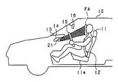
- FIG. 2 is a diagram showing a passenger compartment equipped with an inoperable state detection device
- FIG. 3 is a diagram showing a driver's seat of a vehicle equipped with an inoperable state detection device
- FIG. 4 is a block diagram showing functions of the control device
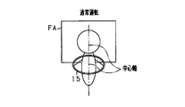
- FIG. 5A is a diagram showing a posture during normal operation
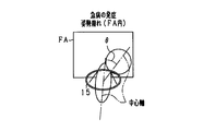
- FIG. 5B is a diagram showing a posture when sudden illness occurs and posture collapse (within FA) occurs
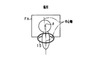
- FIG. 5C is a diagram showing a posture when sudden illness occurs and posture collapse (outside FA) occurs
- FIG. 5A is a diagram showing a posture during normal operation
- FIG. 5B is a diagram showing a posture when sudden illness occurs and posture collapse (within FA) occurs
- FIG. 5C is a diagram showing a posture when sudden illness occurs and posture collapse (outside FA) occurs
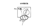
- FIG. 6 is a diagram showing the posture when taking things
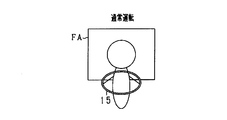
- FIG. 7A is a diagram showing a posture during normal operation
- FIG. 7B is a diagram showing the posture when sudden disease develops
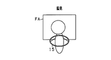
- FIG. 8 is a diagram showing a posture when looking aside.
- FIG. 9 is a diagram showing the posture when taking things
- FIG. 10A is a diagram showing the face orientation during normal operation
- FIG. 10B is a diagram showing a face orientation when sudden illness develops
- FIG. 11 is a diagram showing changes in face orientation when looking aside.
- FIG. 12 is a diagram showing the shaking of the head accompanying the generation of an external force
- FIG. 13 is a diagram illustrating an amplitude range of the head shake that is determined to be an inoperable state
- FIG. 14A is a diagram showing a facial expression during normal operation;
- FIG. 14B is a diagram showing a facial expression when sudden illness develops;
- FIG. 15A is a diagram showing a normal state,
- FIG. 15B is a diagram showing a state in which the whites are facing;
- FIG. 15C is a diagram showing a state in which the eyes are completely facing,
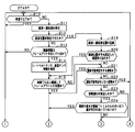
- FIG. 16A is a flowchart showing a processing procedure for detecting an inoperable state;
- FIG. 16B is a continuation of FIG. 16A, and is a flowchart showing a processing procedure for detecting an inoperable state;
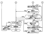
- FIG. 17 is a subroutine showing a processing procedure for detecting posture collapse.
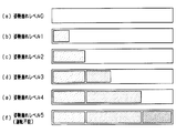
- FIG. 18 is a diagram illustrating a mode of notifying the driver of the posture collapse level.
- FIG. 18 is a diagram illustrating a mode of notifying the driver of the posture collapse level.
- FIG. 19 is a diagram illustrating a frame range of frame-out determination according to Modification Example 1
- FIG. 20 is a diagram illustrating a frame range of frame-out determination according to Modification Example 2
- FIG. 21 is a diagram illustrating a frame range for frame-out determination according to Modification Example 3
- FIG. 22 is a diagram showing a frame range for frame-out determination according to Modification Example 4
- FIG. 23 is a diagram showing a frame range and determination time for frame-out determination according to the second embodiment.
- the driver's inoperable state includes a state in which the driver develops sudden illness and becomes unconscious and cannot perform driving operation, and a driver develops a sudden illness such as a heart attack and is conscious but cannot move the body. Therefore, it includes a state in which the driving operation cannot be performed.
- parts that are the same or equivalent to each other are denoted by the same reference numerals in the drawings, and the description of the same reference numerals is used.
- the detection device 100 includes a control device 50, a driver state recognition device 20, a vehicle information recognition device 30, a traveling environment recognition device 40, an HMI (Human Machine Interface) 80, and a storage device 52, and detects an inoperable state of the driver. To do. And the detection apparatus 100 transmits the instruction
- the driver state recognition device 20 includes a plurality of driver cameras 21, a seat belt sensor 22, and a seating surface sensor 23.
- the driver camera 21 corresponds to the imaging device
- the seat belt sensor 22 corresponds to the amount detection unit
- the seating surface sensor 23 corresponds to the seat pressure detection unit.
- the driver camera 21 is a CCD camera, for example, and images the driver's seat illuminated by an illumination device such as a near infrared LED.
- the driver camera 21 is mounted on the meter panel 14, the approximate center of the lower end of the rearview mirror 16, and the left and right A pillars 17 toward the driver.
- a driver camera 21 may be installed on the dashboard 13 (shown by a broken line) or on a steering column.
- the lower end of the rearview mirror 16 it may be installed at the left end or the right end (shown by a broken line) of the rearview mirror 16.
- These four driver cameras 21 constitute a driver status monitor, which captures several tens of images per second from the front side of the driver sitting on the driver's seat 11.
- the seat belt sensor 22 is a sensor that detects the amount by which the seat belt 12 is pulled out. Specifically, the seat belt sensor 22 is an encoder that detects a rotation angle of a motor that feeds and winds the seat belt 12.
- the seat surface sensor 23 is a sensor that detects the pressure distribution of the seat portion 11a of the seat 11 of the driver's seat.
- the vehicle information recognition device 30 includes a vehicle speed sensor 31, a steering angle sensor 32, an accelerator sensor 33, and a brake sensor 34.
- the vehicle speed sensor 31 is a sensor that detects the speed of the vehicle 10.
- the steering angle sensor 32 is a sensor that detects the steering angle of the steering wheel 15.
- the accelerator sensor 33 is a sensor that detects an accelerator opening, that is, an operation amount of an accelerator pedal.
- the brake sensor 34 is a sensor that detects an operation amount of a brake pedal.
- the traveling environment recognition device 40 includes a front / rear camera 41, a front / rear sensor 42, a car navigation device 43, and a G sensor 44.
- the front / rear camera 41 is a camera that images the front of the vehicle 10 including the white line of the road, and a camera that images the rear and rear sides of the vehicle 10.
- the front / rear sensor 42 is a sensor such as an ultrasonic sensor, a laser radar, or a millimeter wave radar, and detects an object in front or rear of the vehicle 10 and acquires a distance between the vehicle 10 and an object in front or rear. Based on the distance between the vehicle 10 acquired by the front / rear sensor 42 and the front or rear vehicle, the relative speed between the front vehicle and the rear vehicle can be calculated.
- the car navigation device 43 calculates the current position of the vehicle 10 by using the GPS signal received by the GPS receiver and information acquired by various sensors including the G sensor, and guide routes from the current position to the destination Is calculated.
- the G sensor 44 is, for example, a sensor that is installed on the seat 11 and detects three-dimensional acceleration in the front, rear, left, and right directions of the vehicle 10.
- the G sensor 44 may be a sensor included in the car navigation device 43.
- the G sensor 44 is a sensor included in the AVOS. May be. That is, the G sensor 44 may be shared if there is one installed for other purposes.
- the control device 50 is a microcomputer including a CPU, ROM, RAM, I / O, and the like, and acquires various information from the driver state recognition device 20, the vehicle information recognition device 30, the traveling environment recognition device 40, the storage device 52, and the HMI 80. To do.
- the control device 50 and the various devices are connected by wired communication such as CAN or wireless communication such as LAN or Bluetooth (registered trademark).
- the control device 50 realizes the functions of the image analysis unit 60, the learning unit 51, and the state detection unit 70 by the CPU executing various programs stored in the ROM, and detects an inoperable state of the driver. . Detailed description of each part will be given later.
- the HMI 80 (attitude notification unit, confirmation unit) includes a display 81, a speaker 82, and a cancel switch 83.
- the display 81 is a display of the car navigation device 43 or an in-vehicle display provided in the meter panel 14.
- the display 81 may be a touch display including a liquid crystal panel or an organic EL panel.
- the display 81 reports the degree of the driver's posture collapse based on the driver's posture detected from the image. Specifically, the display 81 displays the status of the driver's posture in five stages.
- the posture collapse level 5 with the highest degree of collapse is a level at which it is determined that the driver has developed a sudden illness and is unable to maintain the driving posture, that is, a driving impossible state. Since the driver can check his / her driving posture by looking at the posture status displayed on the display 81, when the posture collapse level approaches 5, the driving posture can be corrected before being determined as being incapable of driving. .
- the speaker 82 is an in-vehicle speaker that is shared with the car navigation device 43, the audio device, and the like.
- the speaker 82 confirms to the driver by voice whether the inoperable state.
- the display 81 may display a screen for confirming the inoperable state. Further, the speaker 82 may notify the driver of the posture collapse level by voice.
- the cancel switch 83 is a switch that stops detection of the inoperable state.
- detection of the inoperable state is stopped for one trip.
- the cancel switch 83 is operated during the trip, the detection of the inoperable state is stopped while the cancel switch 83 is operated or for a certain period of time (about several seconds) after the cancel switch 83 is operated. Therefore, if the driver operates the cancel switch 83 in advance when taking an action, there is no possibility that the driver is erroneously detected as being inoperable even if the driver's posture collapses.
- the image analysis unit 60 includes a head detection unit 61, a trajectory acquisition unit 62, a convulsion detection unit 63, an inclination detection unit 64, a face orientation detection unit 65, and a white eye detection unit 66.
- the head detection unit 61 sequentially detects the head above the driver's neck based on the driver's seat image captured by the driver camera 21. Specifically, the head detection unit 61 extracts an edge representing the outline of the driver's head from the driver's seat image each time a driver's seat image is captured by the driver camera 21, and a region surrounded by the extracted edges Is detected as the head.
- the trajectory acquisition unit 62 acquires the trajectory of the driver's head from the driver's head position sequentially detected by the head detection unit 61. For example, the trajectory acquisition unit 62 uses the center of the driver's head detected in each image as the head position, and acquires the head trajectory by connecting the head positions in each image.
- the convulsions detection unit 63 detects driver's convulsions, that is, involuntary contraction of the muscles of the torso below the driver's head and neck. Specifically, the convulsions detection unit 63 extracts edges representing the contours of the driver's head and torso in each image, and when the extracted edges vibrate regularly (periodically) in successive images, Detect that the driver is spasm.
- the inclination detector 64 detects the inclination ⁇ of the head relative to the driver's body based on the driver's seat image. Specifically, the tilt detection unit 64 detects the regions surrounded by the edges representing the contours of the head and the torso as the head and the torso, respectively, and detects the central axes of the head and the torso. Then, the inclination detection unit 64 sets the inclination of the central axis of the head relative to the central axis of the body part as the inclination ⁇ of the head. The center axis of the body part is detected from the body part in which the direction of the body part is determined by matching the prepared body direction pattern with the detected body part direction to determine the body part direction.
- the central axis of the head is detected from the three-dimensional arrangement of the facial feature points by extracting the facial features such as the eyes, nose and mouth of the face included in the head.
- the facial features such as the eyes, nose and mouth of the face included in the head.
- the distance between the facial feature point and the front of the vehicle approaches, and when the head turns back, the distance between the facial feature point and the front of the vehicle increases.
- the distance between facial feature points in the front-rear direction of the vehicle may be used.
- the tilt detection unit 64 detects the seat belt 12 of the driver's seat from the image of the driver's seat, and detects the tilt ⁇ of the head relative to the body from the positional relationship between the seat belt 12 and the head. Since the body part of the driver is restrained by the seat belt 12, the position of the body part can be estimated from the position of the seat belt 12.
- the face orientation detection unit 65 detects the orientation of the driver's face relative to the front of the vehicle 10 based on the driver's seat image.
- the face orientation detection unit 65 detects the inclination of the face relative to the vertical plane facing the front surface of the vehicle 10 as the face orientation.
- the white eye detection unit 66 includes a facial expression detection unit 67 and a white eye degree calculation unit 68, and detects a state in which the driver has white eyes.
- the state where the whites are removed is not limited to the state where the whites are completely removed as shown in FIG. 15C, but also includes the state where the black-eye area is smaller than a predetermined amount as shown in FIG. 15B. That is, the state where the whites are peeled is a state where the visual field is narrower than a predetermined range due to the biased black eyes.
- the facial expression detection unit 67 detects the driver's eye contour and black eye area based on the driver's seat image.
- the outline of the eyes of the driver is a boundary line between the eyelids and the eyes.
- the black eye region is a region having lightness lower than that of the white eye in a region inside the outline of the eye, and is not limited to black, but is a region having a color such as blue, brown, or gray.
- the facial expression detection unit 67 detects the opening of the driver's mouth from the edge representing the extracted mouth outline.
- the white eye degree calculation unit 68 calculates the white eye degree of the driver's eyes based on the eye outline and the black eye region detected by the facial expression detection unit 67.
- the white eye degree calculation unit 68 calculates the white eye degree from the ratio between the vertical length Lw + Lb of the region surrounded by the outline of the eye and the vertical length Lb of the black eye region (see FIG. 15A to FIG. 15C). The smaller the length Lb with respect to the length Lw + Lb, the greater the degree of white eye. Alternatively, the white eye degree calculation unit 68 calculates the white eye degree based on the distance Lb from the upper part of the eye outline to the lowest part of the black eye region. The smaller the distance Lb, the greater the degree of white eye.
- the white eye degree calculation unit 68 calculates the white eye degree based on the ratio of the area of the white eye region obtained by subtracting the area of the black eye region from the area of the entire eye region surrounded by the outline of the eye and the area of the black eye region. calculate. The smaller the area of the black eye region relative to the area of the white eye region, the greater the degree of white eye.
- the white eye degree calculation unit 68 calculates the white eye degree based on the flatness ratio of the black eye region. In a state where the whites are peeled off, the black eye region faces upward, so that the flatness of the black eye region increases apparently, and the degree of white eye increases as the flatness of the black eye region increases.
- the white eye degree calculation unit 68 calculates the white eye degree based on the distance Lc from the center line in the vertical direction of the region surrounded by the outline of the eye to the lowest part of the black eye region.
- the learning unit 51 learns the head inclination ⁇ detected by the inclination detection unit 64 when the driver is not in an inoperable state. Further, the learning unit 51 learns the face orientation detected by the face orientation detection unit 65 when the driver is not in an inoperable state. Further, the learning unit 51 learns the amplitude of the head shake detected by the head detection unit 61 when the driver is not in an inoperable state. That is, the learning unit 51 learns a driver's driving posture habit. When there are a plurality of drivers who drive the vehicle 10, the driver learns the habit of driving posture for each driver.
- the state detection unit 70 includes a frame-out state detection unit 71, a posture collapse state detection unit 72, a direction collapse state detection unit 73, a shaking state detection unit 74, and a white-eye state detection unit 75.
- the frame-out state detection unit 71 determines frame out while the vehicle 10 is traveling, and detects that the driver is inoperable when out of frame. Specifically, the frame-out state detection unit 71 detects that the driver is inoperable when the head of the driver detected by the head detection unit 61 is out of the image range FA.
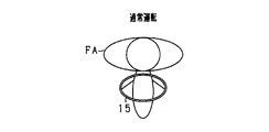
- the range FA is a predetermined range in an image captured by the driver camera 21. During normal driving, the driver's head does not deviate from the range FA.
- the range FA may be the entire captured image.
- the frame-out state detection unit 71 detects that the driver is inoperable when the head of the driver is out of the image range FA.
- the frame-out state detection unit 71 can improve the accuracy of detecting the inoperable state of the driver in consideration of the trajectory acquired by the trajectory acquisition unit 62 before the head is out of the range FA.
- the trajectory of the head when the driver's head could not be detected within the range FA due to image ambiguity and when the driver's head moved and could not be detected within the range FA Since the determination can be made, the detection accuracy of the inoperable state of the driver is improved.
- the head detection unit 61 searches for the vicinity of the final position of the trajectory acquired by the trajectory acquisition unit 62. In this way, even when the driver's head is not detected, the head detection can be efficiently performed again using the head trajectory.
- the posture collapse state detection unit 72 determines whether the driver is out of posture while the vehicle 10 is traveling, and detects that the driver is in an inoperable state when the posture is broken. Specifically, the posture collapse state detection unit 72 detects that the driver is incapable of driving when the head inclination ⁇ detected by the inclination detection unit 64 is larger than a threshold Th1 (relative inclination threshold). .
- the body of the driver is restrained by the seat 11 and the seat belt 12 of the driver's seat, so the body is relatively difficult to move even if the driver's consciousness is lost.
- the driver's head is often not restrained, it is necessary to maintain the position of the head with the driver's intention. Therefore, when sudden illness develops and the driver's consciousness disappears, the driver cannot maintain the position of the head, and the head is greatly inclined in either direction with respect to the trunk as shown in FIGS. 7A and 7B. There are many cases.
- the posture collapse state detection unit 72 detects that the driver is incapable of driving when the head inclination ⁇ is larger than the threshold value Th1.
- the posture collapsed state detection unit 72 further detects that the driver is in an inoperable state on the condition that the driver's face is not facing the front of the vehicle 10, erroneous detection of the inoperable state can be suppressed. .
- the direction change state detection unit 73 determines that the driver's face is broken while the vehicle 10 is traveling, and detects that the driver is incapable of driving when the face is broken. Specifically, the direction change state detection unit 73 causes the face direction relative to the front of the vehicle 10 detected by the face direction detection unit 65 to exceed the threshold Th2 (face direction threshold) beyond the time T2 (direction change determination time). When it is larger, it is detected that the driver is in an inoperable state.
- the direction change state detection unit 73 detects that the driver is in an inoperable state in the above case.
- the direction change state detection unit 73 may detect that the driver has detected that the face direction relative to the front of the vehicle 10 detected by the face direction detection unit 65 is greater than the threshold Th2 and the driver releases the steering wheel 15. Detects that the vehicle is inoperable. Whether the driver releases the steering wheel 15 may be detected from an image, or may be detected by a pressure sensor or the like installed on the steering wheel 15.
- the direction change state detection unit 73 detects that the driver is in an inoperable state in the above case.
- the direction change state detection unit 73 is incapable of driving the driver when the face direction detected by the face direction detection unit 65 is larger than the threshold Th2 and the accelerator opening is larger than a predetermined opening. Detect that.
- the direction change state detection unit 73 detects that the driver is in an inoperable state in the above case.
- the direction change state detection unit 73 has been subjected to the accelerator operation and the brake operation for a time longer than the time Th3 (operation determination time) when the face direction detected by the face direction detection unit 65 is greater than the threshold Th2. If not, it is detected that the driver is in an inoperable state.
- the direction change state detection unit 73 detects that the driver is in an inoperable state in the above case.
- the swing state detection unit 74 determines a swing state of the head of the driver accompanying the external force while the vehicle 10 is traveling, and the driver is incapable of driving when the head is shaking differently than usual. Detect that. Specifically, the shaking state detection unit 74 detects the amplitude of the shaking of the head detected by the head detection unit 61 from the time when the external force is applied to the vehicle 10 until the time T5 (swing determination time) elapses. When it is smaller than (first amplitude) or larger than amplitude Am2 (second amplitude), it is detected that the driver is in an inoperable state. The amplitude Am2 is larger than the amplitude Am1.
- the time T5 is a time from when an external force is applied to the vehicle 10 until the driver's movement becomes a movement unrelated to the external force.
- the amplitude Am1 and the amplitude Am2 are functions of time, and FIG. 13 shows an example thereof.
- the minimum value of the amplitude Am1 and the maximum value of the amplitude Am2 from when an external force is applied until the time T5 elapses may be simply used as threshold values.
- the white-eye state detection unit 75 determines white eyes while the vehicle 10 is traveling, and detects that the driver is in an inoperable state when the white-eye detection unit 66 detects a state in which white eyes have been peeled off. Specifically, the white-eye state detection unit 75 detects that the driver is in an inoperable state when the white-eye degree calculated by the white-eye degree calculation unit 68 is larger than a threshold Th3 (white-eye threshold).
- Th3 white-eye threshold
- the white-eye state detection unit 75 detects that the driver is in an inoperable state when a state in which white eyes have been peeled is detected.
- the storage device 52 stores each threshold value and each determination value used by each state detection unit. Further, the storage device 52 stores the head inclination ⁇ , the face orientation, and the amplitude of the head shake learned by the learning unit 51. In the storage device 52, personal information including the medical history and age of the driver is registered. When there are a plurality of drivers, personal information of each driver is registered. Further, the storage device 52 is registered with the posture of the driver that is not determined as being incapable of driving and the posture of the driver that is determined as being incapable of driving. The posture of the driver who is not determined to be incapable of driving is, for example, a normal driving posture or a posture improved during driving.
- the posture of the driver that is determined as being incapable of driving is, for example, the posture that a driver who has illness makes during an attack.
- the driver captures the posture desired to be registered in the driver's seat in advance with the driver camera 21 and registers it in the storage device 52.
- This processing procedure is executed by the control device 50.
- V may be 0 km / h (stop) or a sufficiently low speed (for example, 1 km / h) to be regarded as a stop.
- V may be 0 km / h (stop) or a sufficiently low speed (for example, 1 km / h) to be regarded as a stop.
- the determination of S10 is repeatedly executed until it is determined that the vehicle speed is higher than V.
- the vehicle speed is higher than V (S10: N0)
- the determination of S10 it is also determined whether or not the driver is performing a driving operation.
- the determination of S10 is repeatedly performed so that the driving operation is performed while traveling. If not, the detection process of the inoperable state of the driver may be started. For example, it is determined whether the vehicle speed of the vehicle 10 is V2 (for example, 50 km / h) or higher, the steering angle detected by the steering angle sensor 32 is higher than a predetermined angle, or the steering angular velocity is higher than a predetermined angular velocity.
- V2 is a value that can be regarded as the driver operating the accelerator pedal, the predetermined angle, and the predetermined angular velocity are values that the driver can be regarded as operating the steering wheel. If at least one of the above three conditions is satisfied, it is determined that the driver is performing a driving operation, and the driver's inoperable state detection process is not started.
- the driver's head and torso are detected from the driver's seat image (S11).
- the facial feature point included in the head of the driver is detected to authenticate the driver.
- Driver authentication may be performed in advance by communication with a mobile terminal such as a smartphone, or may be performed by communication with a key of the vehicle 10 in which personal information is registered.
- the head trajectory information is acquired from the head position recorded in the process of S19 described later, and it is determined whether the trajectory information indicates frame out. (S13). That is, it is determined whether the non-detection of the head position is non-detection due to the head being out of the imaging range or non-detection due to unclearness of the image.
- trajectory information of the head does not indicate frame out (S13: NO)
- the trajectory information of the head indicates frame out (S13: YES)
- information on the seat belt sensor 22 and the seating surface sensor 23, which are used auxiliary to confirm that the head is outside the imaging range, is acquired (S14).
- the head position is out of the range FA for more than time T0, and the pull-out amount of the seat belt 12 exceeds the first pull-out amount than the pull-out amount detected when the seat belt 12 is worn.
- the high pressure portion is biased toward the end of the seat 11a in the pressure distribution of the seat 11a. Then, when the above three conditions are satisfied, it is determined that the frame is out of time T0.
- the pull-out amount per amount detection time detected by the seat belt sensor 22, that is, the pull-out speed of the seat belt 12 may be set to be larger than the second pull-out amount.
- the process of S14 is not executed, and the process of S15 may continue to determine whether or not the head position is out of the range FA continuously for time T0 or more.
- the time T0 is set based on the personal information registered in the storage device 52. For example, the time T0 is shortened for an older person than for a younger person. In addition, a person with a specific medical history has a shorter time T0 than a person without a specific medical history. Furthermore, the time T0 is changed according to the state of the driver and the driving environment. In a driving environment where there is a sign that the driver may become inoperable, where the driver is likely to be incapable of driving, or in a driving environment where there is a high probability of a collision when the driver is disabled T0 is shortened to make it easier to detect an inoperable state of the driver.
- the head position recorded in the process of S19 is oscillating with an amplitude larger than a predetermined amplitude, that is, when the head is swaying, there is a high probability of being inoperable.
- the time T0 is shortened.
- the higher the moving speed of the head the higher the possibility of posture collapse due to sudden illness rather than posture collapse when taking a thing. Therefore, in the acquired head trajectory information, the time T0 is shortened as the moving speed of the head position increases. In the case of posture collapse due to a sudden illness, the moving speed of the head often increases as the head approaches the end of the range FA.
- the time T0 is shortened when the moving speed of the head increases as the recorded head position approaches the end of the range FA.
- the probability of becoming inoperable is high, so the time T0 is shortened.
- the time T0 is shortened as the vehicle speed of the vehicle 10 is high.
- the TTC collision margin time
- the TTC collision margin time
- the driver may break the posture for a long time, so the time T0 is extended.
- the time T0 may be shortened on days of the week and times of day when statistically appearing sudden attacks such as heart attacks are likely to occur.
- the process proceeds to S21. If the frame is continuously out of time T0 or more (S15: YES), it is detected that the driver is in an inoperable state, and the driver is confirmed to be in an inoperable state. Specifically, the detection of the inoperable state is notified by voice from the speaker 82, display on the display 81, blinking of an indicator (not shown), and the like, and it is determined whether or not there is a response from the driver within a predetermined time ( S16).
- the driver recognizes that the driver can drive by voice from the speaker 82 or a display on the display 81 (S17).
- an instruction is issued to the vehicle control device 90 so that appropriate braking and steering are performed and the vehicle is safely stopped.
- the vehicle control device 90 is instructed to turn on the headlight and listen to the horn (S18). Furthermore, the situation is also notified to other passengers of the vehicle 10.
- the positions of the head and the torso are recorded (S19).
- the trajectory information of the head can be acquired from the position of the head recorded in each image.
- the driver's posture is a posture determined to be an inoperable state registered in advance in the storage device 52 (S21). If the posture of the driver is determined to be an inoperable state (S21: YES), it is detected that the driver is in an inoperable state, and the process proceeds to S16.
- attitude of the driver is not an attitude determined to be incapable of driving (S21: NO)
- attitude of the driver is an attitude not previously determined to be incapable of driving registered in the storage device 52 (S22). If the posture of the driver is not determined to be an inoperable state (S22: YES), the process returns to S10.
- the posture collapse is next determined.
- posture collapse it is determined whether or not posture collapse has been detected (S23). Specifically, the posture collapse is detected by the processing of the subroutine of FIG. First, the head tilt and the head tilt direction are calculated (S231). Subsequently, the inclination of the body part and the direction of the inclination of the body part are calculated (S232). Subsequently, an angle formed by the calculated inclination of the trunk and the inclination of the head, that is, the inclination ⁇ of the head with respect to the trunk is calculated (S233). The calculated head inclination ⁇ is learned when an inoperable state of the driver is not detected.
- posture collapse is detected (S23: YES)
- the calculated head inclination direction and body inclination direction do not change continuously for the time T1 or more, that is, the head position and the body position are within the range UA (non-moving determination). Range).
- the range UA is a range in which it can be considered that the head and the body are not moving.
- the calculated head inclination ⁇ may be a condition that is greater than the learned head inclination beyond the determination value D1 (inclination determination value).
- the steering wheel 15 may not be operated for a time longer than the time T3 (operation determination time).
- the time T1 is set based on personal information registered in the storage device 52, and is changed depending on whether the vehicle speed, TTC, or driving support control is executed.
- the threshold value Th1 is reduced when convulsions are detected.
- the time T1 may be shortened on a day of the week or a time zone in which a sudden illness such as a heart attack that is statistically likely occurs.
- the head inclination ⁇ is greater than the threshold Th1 and the face does not face the front of the vehicle 10 after the time T1 (S24: YES), it is detected that the driver is unable to drive, S16 Proceed to the confirmation process. If the head inclination ⁇ is not greater than the threshold Th1 for a time T1 or longer, or if the face is facing the front of the vehicle (S24: NO), then the determination of face collapse is performed.
- a face orientation collapse it is determined whether or not a face orientation collapse has been detected (S25). Specifically, the direction of the driver's face relative to the front of the vehicle is detected. Then, when the detected face orientation is larger than the threshold Th2 (face orientation threshold), the collapse of the face orientation is detected. When the collapse of the face direction is not detected (S25: NO), the process proceeds to the determination of the shaking state in S28. The detected face orientation is learned when the driver's inoperability is not detected.
- the time T2 is set based on the personal information registered in the storage device 52, and is changed depending on whether the vehicle speed, TTC, or driving support control is executed. Further, similarly to the time T0, the time T2 may be shortened on a day of the week or a time zone on which a sudden illness such as a heart attack that is statistically likely occurs. The threshold value Th2 is reduced when convulsions are detected.
- the driver has released the steering wheel 15 for a time T3 or longer, or the accelerator opening is predetermined. It is determined whether it is larger than the opening or there is no accelerator operation and brake operation (S27). If at least one of the three conditions in S27 is satisfied (S27: YES), it is detected that the driver is in an inoperable state, and the process proceeds to S16. When none of the three conditions in the process of S27 is satisfied (S27: NO), the determination of the shaking state is performed next.
- the determination in S26 may further satisfy a condition that at least one of the three conditions in the process of S27 is satisfied. Further, the determination in S26 and S27 may be made on the condition that the detected face orientation is larger than the learned face orientation by exceeding the determination value D1 (inclination determination value). In general, since the driver's hand remains above the driver's neck, the driver will not be disabled, so the driver's hand may be below the driver's neck. .
- the amplitude of the head shake is smaller than the amplitude Am1 (first amplitude) or the amplitude Am2 (second amplitude) from the time when the external force is applied to the vehicle 10 until the time T5 (swing determination time) elapses. ) Is determined.
- the head vibrates with an amplitude different from normal, and after the time T5 elapses, the position of the head is within the range UA.
- This may be a condition.
- the head may be oscillated according to the external force, and the head position may not be changed after the influence of the external force is eliminated.
- the head swing amplitude is learned, and the detected head swing amplitude is larger than the learned head swing amplitude. It is good also as a condition that it exceeds the judgment value D2 (amplitude judgment value).
- D2 amplitude judgment value
- a state in which white eyes are peeled is detected (S29). Specifically, when the calculated white eye degree is larger than the threshold value Th3 (white eye threshold value), it is determined that a state where white eyes have been peeled is detected.
- Th3 white eye threshold value
- the degree of white eyes of both eyes of the driver is calculated, and it is determined that the state of having white eyes is detected on the condition that the degree of white eyes of both eyes is greater than the threshold Th3.
- the detection of the state where the white of the eye is removed may be determined based on the degree of the white of the one eye.
- the driver determines that the frame out determination, the posture collapse determination, the face direction collapse determination, the shaking state determination, and the white eye state determination are all performed. Since it is not detected that the vehicle is in an inoperable state, the process returns to S10.
- the condition may be that the steering wheel 15 is not operated continuously for the time T3 or more.
- the time T4 is set based on the personal information registered in the storage device 52 and is changed according to the vehicle speed and TTC, similarly to the time T0.
- the threshold value Th3 is reduced when convulsions are detected.
- the time T4 may be shortened on a day of the week or a time zone in which a sudden illness such as a heart attack that is statistically likely occurs.
- the degree of the posture collapse of the driver is displayed on the display 81 as shown in FIG.
- the posture collapse level increases as the detected head inclination ⁇ increases.
- the posture collapse level is increased as the detected face orientation increases.
- the posture collapse level is increased as the detected head position is further away from the standard position during driving.
- the standard position during driving is the position of the head when the vehicle 10 is started, or the average position of the head when it is not detected that the driver is unable to drive.
- the detection process can be simplified.
- the pull-out amount of the seat belt 12 exceeds the first pull-out amount than the pull-out amount at the time of wearing.
- the position of the driver's head is out of the imaging range when the pull-out amount of the seat belt 12 is greater than the pull-out amount when the seat belt 12 is worn. It can be seen that Therefore, when the pull-out amount of the seat belt 12 is larger than the pull-out amount when the seat belt 12 is worn, the inoperable state of the driver can be detected with high accuracy.
- the high pressure portion in the pressure distribution of the seat 11a of the driver's seat is considered to be biased toward the end of the seat 11a. Even when the driver's head is not detected, the driver's head is out of the imaging range when the high-pressure portion of the pressure distribution of the driver's seat 11a is biased toward the end of the seat. It can be seen that it exists at the position. Therefore, when the high pressure portion in the pressure distribution of the seat portion 11a is biased toward the end portion of the seat portion 11a, it is possible to detect the inoperable state of the driver with high accuracy.
- the time required for determining the inoperable state of the driver can be shortened by reducing the time T0.
- the execution of the vehicle control when the driver is unable to drive can be quickly started.
- the time required for determining the driver's inoperable state can be shortened by shortening the time T0.
- the time required to determine the inoperable state of the driver can be shortened by reducing the time required to determine the inoperable state.
- the inclination ⁇ of the head with respect to the torso is larger than the threshold Th1
- the threshold value Th1 it is possible to detect the driver's inoperable state with high accuracy by detecting that the driver is in an inoperable state.
- the driver If the detected head inclination ⁇ is larger than the learned head inclination beyond the judgment value D1, the driver has a tendency to tilt the head with respect to the body part. Even if it is, it can suppress misdetecting the driving
- the face direction with respect to the front of the vehicle 10 exceeds the threshold Th2 beyond the time T2
- the face direction is broken due to a sudden illness. Therefore, by detecting that the driver is inoperable in the above case, the inoperable state of the driver can be detected with high accuracy.
- the face direction with respect to the front of the vehicle 10 is larger than the threshold value Th2 and the driver releases the steering wheel 15, the face direction may not be broken due to looking aside, but the face direction may be broken due to a sudden illness. high. Therefore, by detecting that the driver is inoperable in the above case, the inoperable state of the driver can be detected with high accuracy.
- the face direction with respect to the front of the vehicle 10 is larger than the threshold value Th2 and the accelerator opening is larger than the predetermined opening degree, there is a possibility that the face direction is not broken due to a side look or the like, but the face direction is broken due to sudden illness. Is expensive. Therefore, by detecting that the driver is inoperable in the above case, the inoperable state of the driver can be detected with high accuracy.
- the face direction with respect to the front of the vehicle 10 is larger than the threshold Th2 and the accelerator and the brake are not operated for a time longer than the time T3, the face direction is not changed due to looking aside, but the face direction due to sudden illness There is a high possibility of collapse. Therefore, by detecting that the driver is inoperable in the above case, the inoperable state of the driver can be detected with high accuracy.
- the steering wheel is operated within time T3. Therefore, by detecting that the steering wheel is not operated for a time longer than time T3, it is possible to suppress erroneous detection of the driver's inoperable state.
- the accelerator will not be depressed greatly for a time longer than time T3. Therefore, it is possible to suppress erroneous detection of an inoperable state of the driver by setting that the accelerator opening is larger than the predetermined opening for a time longer than the time T3.
- the head vibrates according to the external force, and the head stops moving when the influence of the external force disappears.
- the driver vibrates the head with a scissors, the head vibrates regardless of the influence of external force. Therefore, it is possible to suppress erroneous detection of an inoperable state of the driver by assuming that the head vibrates according to the external force and the position of the head does not change after the influence of the external force is eliminated.
- the driver's eye contour and black eye area are detected. Then, based on the detected eye contour and black eye area, the white eye degree is calculated, and when the white eye degree is larger than the threshold value Th3, it is detected that the driver is in an inoperable state. Therefore, it is possible to detect with high accuracy the state in which the driver has white eyes, and thus to detect with high accuracy the inoperable state of the driver.
- the degree of white eyes on both sides is greater than the threshold Th3
- the threshold Th3 By assuming that the degree of white eyes on both sides is greater than the threshold Th3, even if the eye patch is worn on one eye, or one eye is a prosthetic eye, it is erroneously detected that the white eye is peeled off. When one eye does not have white eyes, the driver's inoperable state is not detected. Therefore, it is possible to suppress erroneous detection of the inoperable state of the driver.
- the ratio between the vertical length Lw + Lb of the eye and the vertical length Lb of the black eye area has a correlation with the ratio of the white eye area to the total eye area, so the vertical length Lw + Lb of the eye and the black eye area
- the degree of white eye can be calculated from the ratio to the vertical length Lb.
- the white eye degree can be calculated from the distance Lb from the upper part of the eye contour to the lowermost part of the black eye region.
- the white eye degree can be calculated from the ratio of the white eye area to the black eye area.
- the white eye degree can be calculated from the flatness ratio of the black eye region.
- the white eye degree can be calculated from the distance Lc from the center line to the lowermost part of the black eye region.
- the times T0, T1, T2, and T4 are shortened.
- the time required for determining the driver's inoperable state is shortened, so that appropriate vehicle control can be quickly started.
- the time required to determine the inoperable state can be set according to the characteristics of the driver.
- the driver can recognize his / her posture by notifying the driver of the degree of collapse of the driver's posture. For this reason, the driver can correct his / her posture so that even if the driving posture collapses, the driver is not detected as being incapable of driving. Thereby, the erroneous detection of a driving impossible state can be suppressed.
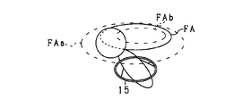
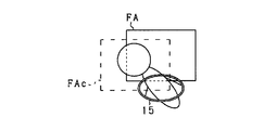
- the shape of the range FA that is a predetermined range may be an elliptical shape as shown in FIG.
- the elliptical shape is a shape in which the width direction of the vehicle 10 is a long axis and the height direction of the vehicle 10 is a short axis.
- the driver's heads move in the right and left directions when turning right and left, so they move within an elliptical shape with the left and right direction as the major axis. . Therefore, by setting the shape of the range FA to the above-described elliptical shape, it is possible to suppress erroneous detection of an inoperable state even when the driver moves the head in a normal driving operation.
- the detection apparatus 100 may include a deforming unit that deforms the range FA according to the intention of the user including the driver or the driver information related to the driver. What is necessary is just to implement
- the deformation includes enlargement, reduction, and change of shape of the range FA.
- the deforming unit deforms the range FA according to the input operation of the HMI 80 by the user.
- the HMI 80 may include an enlargement switch or a reduction switch, and the display 81 may be a touch display.
- the driver when the driver has a driving posture that deviates from the standard position or when it is difficult to detect the inoperable state, the driver operates the enlargement switch or the like to operate the range FA. Is expanded to the range FAa.
- the driver when the driver is an elderly person or a person with chronic illness, the driver himself or his / her family can easily detect the inoperable state by operating a reduction switch or the like to reduce the range FA to the range FAb. Good.
- the manager of the bus or taxi may reduce the range FA to the range FAb by operating a reduction switch or the like in order to facilitate detection of the inoperable state.
- the ranges FA, FAa, and FAb are elliptical, but may be rectangular.
- the deformation unit may enlarge or reduce the range FA according to the driver information regardless of the user's intention.
- the driver information is information including at least one of the driver's age, medical history, and driving posture, and is stored in the storage device 52.
- the driving posture wrinkle may be obtained by learning the position of the head of the driver by the learning unit 51 or may be obtained by the driver capturing and registering the driving posture in advance.
- the deforming unit expands the range FA to the range FAa when the driver has a habit of driving posture, and reduces the range FA to the range FAb when the driver is an elderly person or a person with a medical history.
- the deforming unit may expand or contract the range FA according to the vehicle speed, TTC, or the presence or absence of driving support control, or the day of the week or the time zone in which a sudden illness such as a heart attack that is statistically likely occurs. Then, the range FA may be reduced.
- the deformation unit changes the range FA according to at least one of the user's intention and driver information, and may change the range FA according to both the user's intention and driver information. Further, the deforming unit may perform only one of enlargement and reduction of the range FA. Further, the deforming unit may change the shape of the range FA according to the user's intention and driver information.
- the range FA is deformed according to the user's intention or the driver information, so that the inoperable state can be detected according to the user's intention or the driver information.
- the inoperable state can be easily detected.
- the driver has a wrinkle in which the driving posture deviates from the standard position, the erroneous detection of the inoperable state can be suppressed by changing the range FA according to the wrinkle.
- the detection apparatus 100 includes a moving unit that moves the range FA on the image according to the intention of the user including the driver or driver information related to the driver.
- the moving unit may be realized as a function provided in the state detection unit 70.
- the moving unit moves the range FA in response to an input operation of the HMI 80 by the user, for example, a drag operation on the touch display.
- the second embodiment is different from the second modification in that the range FA is changed while the range FA is changed according to the user's intention or driver information.
- the range FA when the driver has a wrinkle whose driving posture deviates from the standard position, the range FA is moved to a position corresponding to the wrinkle to make the range FAc, thereby preventing erroneous detection of the inoperable state. it can.
- the range FA has a rectangular shape, but may have an elliptical shape.
- the modification example 2 and the modification example 3 may be combined to move the range FA and the range FA may be modified.
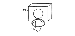
- the driver camera 21 includes a stereo camera.
- the range FA is set as a three-dimensionally set range that extends not only in the width direction of the vehicle 10 but also in the front-rear direction.
- the stereo camera is installed on the left and right ends of the rearview mirror 16, for example.
- the range FA is not limited to a cubic shape, but may be an elliptical spherical shape or the like. When the range FA is an elliptical sphere, the major axis of the elliptical sphere is in the width direction of the vehicle 10. Further, Modification 2 or 3 may be applied to Modification 4.
- the driver's head position can be acquired in three dimensions. That is, not only the position of the head in the width direction of the vehicle 10 but also the position of the head in the front-rear direction of the vehicle 10 can be acquired. Therefore, by setting the range FA three-dimensionally, not only when the driver is inoperable and falls in the left-right direction, but also when the driver is inoperable and falls forward, frame out determination Thus, it is possible to detect the inoperable state of the driver.
- the difference between the detection apparatus 100 according to the second embodiment and the detection apparatus 100 according to the first embodiment will be described.
- the method of frame-out determination by the frame-out state detection unit 71 is different from the detection device 100 according to the first embodiment.
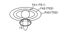
- the frame-out state detection unit 71 has three ranges of a range FA1 (first predetermined range), a range FA2 (second predetermined range), and a range FA3 as a range FA that is a predetermined range in frame-out determination.
- the range FA1 is the smallest range.
- the range FA2 is larger than the range FA1, and includes a range FA1 and a range outside the range FA1 (the end side of the image).
- the range FA3 is larger than the range FA2 and includes a range FA2 and a range outside the range FA2.
- the centers of the range FA1, the range FA2, and the range FA3 are a common center.
- three ranges are set as the predetermined ranges in the frame-out determination, but at least two ranges may be set.
- the frame-out state detection unit 71 sets a frame-out determination time for each predetermined range. That is, the frame-out state detection unit 71 sets times T01, T02, and T03 as frame-out determination times for each of the ranges FA1, FA2, and FA3.
- the frame-out state detection unit 71 is incapable of driving the driver on condition that the head of the driver is out of at least one predetermined range beyond the frame-out determination time corresponding to the predetermined range. Detect that.
- the frame-out state detection unit 71 detects that the driver is in an inoperable state when at least one of the three conditions (1) to (3) is satisfied.
- the frame-out state detection unit 71 sets the frame-out determination time as shorter as it corresponds to a wider predetermined range. That is, the frame-out state detection unit 71 sets the frame-out determination time such that time T01> time T02> time T03.
- the times T01, T02, and T03 are set based on the personal information registered in the storage device 52, and are changed according to the vehicle speed, TTC, and whether or not the driving support control is executed. Further, the times T01, T02, and T03 may be shortened on the day of the week and the time of day when a sudden illness such as a heart attack that statistically appears is likely to occur, similarly to the time T0. Furthermore, the times T01, T02, and T03 may be shortened according to the detection of the amplitude of the head position, the moving speed of the head, and the convulsions, similar to the time T0.
- the range FA1, the range FA2, and the range FA3 have an elliptical shape, but the range FA1, the range FA2, and the range FA3 may have a rectangular shape. Furthermore, the range FA1, the range FA2, and the range FA3 may be respectively deformed or moved by applying the second and third modifications of the first embodiment. Further, the range FA1, the range FA2, and the range FA3 may be set three-dimensionally by applying the fourth modification of the first embodiment.
- a plurality of predetermined ranges having different widths and overlapping central portions are set, and a frame-out determination time is set for each predetermined range. That is, the frame-out determination time is set according to the degree of deviation from the normal driving position. Therefore, the inoperable state of the driver can be detected according to the degree of deviation from the normal driving position.
- the frame-out determination time is set shorter, so that erroneous detection of the inoperable state is suppressed, and when the driver becomes inoperable, the early Can be detected.
- the driver camera 21 may be a part of the four cameras mounted in the vehicle interior. There may be at least one driver camera 21.
- the frame-out state detection unit 71 may detect that the driver is in an inoperable state based on the trajectory acquired by the trajectory acquisition unit 62.
- the driver's head often moves from the driving position and does not return to the driving position. It is possible to detect an inoperable state.
- the direction-displacement state detection unit 73 further allows the driver's face to face the lower side than the threshold Th2d (downward threshold) or to the upper side above the threshold Th2u (upward threshold). May be detected as being inoperable.
- Th2d downward threshold
- Th2u upward threshold
- the swing state detection unit 74 detects the direction of the external force when the head detected by the head detection unit 61 exceeds the time T6 (return determination time) when an external force is applied to the vehicle 10 while the vehicle 10 is traveling. If the driver is leaning, it may be detected that the driver is in an inoperable state. Normally, when there is a driver's consciousness, when an external force (specifically, an external force in the left-right direction and the front-rear direction) is applied to the vehicle 10, the driver's head tilts in the direction of the external force, but returns to its original location within time T6 Return.
- T6 return determination time
- the shaking state detection unit 74 can detect the inoperable state of the driver in the case described above.
- the white-eye state detection unit 75 further detects that the driver is in an inoperable state even when the mouth opening (specifically, the vertical opening) detected by the facial expression detection unit 67 is larger than the opening determination amount. May be. When a driver develops a sudden illness and has white eyes, the mouth is often opened. Therefore, even when the opening of the driver's mouth is larger than the open determination amount, it may be detected that the driver is in an inoperable state.
- the detection accuracy of the inoperable state of the driver is the highest, but at least one determination may be performed. Moreover, you may perform combining any number of determinations. In that case, it is preferable to perform the priority in the order of frame-out determination, posture collapse determination, face direction collapse determination, shaking state determination, and white-eye state determination.
- the posture failure determination when combining the posture collapse determination and the swing state determination, if the posture failure determination does not detect that the driver is in an inoperable state, performing the shake state determination increases the driver's inoperability state. It can be detected with accuracy.
- the driver's inoperable state can be detected with high accuracy.
- the white-eye state determination is performed when the driver state is not detected in the shaking state determination, the driver's inoperability state is increased. It can be detected with accuracy.
- the learning unit 51 may learn the attitude of the driver when it is erroneously detected that the driver is in an inoperable state. That is, although it is detected that the driver is incapable of driving, the posture of the driver when there is a response from the driver may be learned. Then, the learned posture may be a posture that is not determined as an inoperable state.
- Statistic values of each threshold value and each judgment value may be stored in the storage device 52 and used as initial values.
- the statistical value of each threshold value and each determination value is obtained by statistically calculating each threshold value and each determination value corresponding to each of a plurality of vehicle drivers. Moreover, it is good to make it statistics in an information center by transmitting each threshold value and each determination value which are set corresponding to the driver from the vehicle 10 to an information center.
- the driver may recognize that the vehicle is in an operable state for a certain period of time. Moreover, you may make it perform the process which detects the driving
- the external force applied to the vehicle 10 may be detected by the seat sensor 23 other than the G sensor 44, for example.
- the inoperable state detection device for the driver sequentially detects the head above the driver's neck based on the image of the driver's seat imaged by the imaging device mounted on the vehicle.
- the driver detects that the driver is in an inoperable state.
- a frame-out state detection unit A frame-out state detection unit.
- the driver's head is sequentially detected based on the image of the driver's seat.
- the driver's head often falls within a predetermined range of the driver's seat image.
- the driver's head may be out of the predetermined range. Therefore, when the head is out of the predetermined range, it is possible to easily detect the inoperable state of the driver by detecting that the driver is in an inoperable state.
- the inoperable state detection device for the driver sequentially detects the head above the driver's neck based on the image of the driver's seat imaged by the imaging device mounted on the vehicle.
- the driver based on the trajectory acquired by the trajectory detection unit, the trajectory acquisition unit that acquires the trajectory of the head from the position of the head detected by the head detection unit, and the trajectory acquired by the trajectory acquisition unit And a state detecting unit that detects that the vehicle is in an inoperable state.
- the head of the driver is sequentially detected based on the image of the driver's seat, and the trajectory of the head is acquired from the detected position of the head.
- the driver's head often moves from the driving position and does not return to the driving position. Therefore, the inoperable state of the driver can be easily detected based on the trajectory of the driver's head.
- each step is expressed as S10, for example. Further, each step can be divided into a plurality of sub-steps, while a plurality of steps can be combined into one step.
- the embodiment, configuration, and aspect of the driver inoperability state detection device have been illustrated, the embodiment, configuration, and aspect relating to the driver inoperability state detection device are the same as the above-described embodiments, configurations, and aspects. It is not limited. For example, embodiments, configurations, and aspects obtained by appropriately combining technical sections described in different embodiments, configurations, and aspects are also included in the scope of the embodiments, configurations, and aspects related to the driver inoperability state detection device. It is.
Landscapes
- Engineering & Computer Science (AREA)
- Physics & Mathematics (AREA)
- General Physics & Mathematics (AREA)
- Theoretical Computer Science (AREA)
- Multimedia (AREA)
- Mechanical Engineering (AREA)
- Transportation (AREA)
- Oral & Maxillofacial Surgery (AREA)
- Health & Medical Sciences (AREA)
- Computer Vision & Pattern Recognition (AREA)
- Automation & Control Theory (AREA)
- General Health & Medical Sciences (AREA)
- Human Computer Interaction (AREA)
- Mathematical Physics (AREA)
- Signal Processing (AREA)
- Emergency Management (AREA)
- Business, Economics & Management (AREA)
- Traffic Control Systems (AREA)
- Chemical & Material Sciences (AREA)
- Combustion & Propulsion (AREA)
- Control Of Driving Devices And Active Controlling Of Vehicle (AREA)
Abstract
Description
まず、本実施形態に係る検出装置100(ドライバの運転不能状態検出装置)の構成について、図1~3を参照して説明する。検出装置100は、制御装置50、ドライバ状態認識装置20、車両情報認識装置30、走行環境認識装置40、HMI(Human Machine Interface)80、及び記憶装置52を備えて、ドライバの運転不能状態を検出する。そして、検出装置100は、ドライバが運転不能状態であることをドライバに確認して応答がなかった場合に、車両を安全に停止させる指令を車両制御装置90へ送信する。
フレームアウト状態検出部71によるフレームアウト判定において、所定の範囲である範囲FAの形状を、図19で示すような楕円形状としてもよい。この楕円形状は、車両10の幅方向が長軸、車両10の高さ方向が短軸の形状とする。
検出装置100は、ドライバを含むユーザの意図、又はドライバに関するドライバ情報に応じて、範囲FAを変形させる変形部を備えていてもよい。変形部は、状態検出部70が備える機能として実現すればよい。変形は、範囲FAの拡大、縮小、及び形状の変更を含む。変形部は、ユーザによるHMI80の入力操作に応じて、範囲FAを変形させる。HMI80が拡大スイッチや縮小スイッチを備えていてもよいし、ディスプレイ81がタッチディスプレイであってもよい。
検出装置100は、ドライバを含むユーザの意図、又はドライバに関するドライバ情報に応じて、範囲FAを画像上で移動させる移動部を備える。移動部は、状態検出部70が備える機能として実現すればよい。移動部は、ユーザによるHMI80の入力操作、例えばタッチディスプレイ上でのドラッグ操作に応じて、範囲FAを移動させる。すなわち、ユーザの意図又はドライバ情報に応じて、範囲FAを変形させるのに対して、範囲FAを移動させる点が変形例2と異なる。
ドライバカメラ21は、ステレオカメラを含むものとする。そして、図22に示すように、範囲FAを、車両10の幅方向だけでなく前後方向にも広がりを持つ、三次元的に設定された範囲とする。ステレオカメラは、例えば、バックミラー16に左右の端部に設置する。範囲FAは、立方形状に限らず、楕円球形状等でもよい。範囲FAを楕円球形状とする場合は、楕円球形状の長軸を車両10の幅方向にする。また、変形例4に、変形例2又は3を適用してもよい。
以下、第2実施形態に係る検出装置100について、第1実施形態に係る検出装置100と異なる点を説明する。第2実施形態に係る検出装置100では、フレームアウト状態検出部71によるフレームアウト判定の手法が、第1実施形態に係る検出装置100と異なる。
ドライバカメラ21は、車室内に搭載された4つのカメラのうちの一部でもよい。ドライバカメラ21は、最低限1つあればよい。
Claims (25)
- 車両(10)に搭載された撮像装置(21)により撮像された運転席の画像に基づいて、ドライバの首よりも上の頭部を逐次検出する頭部検出部(61)と、
前記車両(10)の走行中に、前記頭部検出部(61)により検出された前記頭部が、前記画像の所定範囲から外れている場合に、前記ドライバが運転不能状態であることを検出するフレームアウト状態検出部(71)と、を備えるドライバの運転不能状態検出装置。 - 前記ドライバを含むユーザの意図、又は前記ドライバに関するドライバ情報に応じて、前記所定範囲を変形させる変形部を備える請求項1に記載のドライバの運転不能状態検出装置。
- 前記ドライバを含むユーザの意図、又は前記ドライバに関するドライバ情報に応じて、前記所定範囲を移動させる移動部を備える請求項1又は2に記載のドライバの運転不能状態検出装置。
- 前記ドライバ情報は、前記ドライバの年齢、病歴及び運転姿勢の癖の少なくとも1つを含む請求項2又は3に記載のドライバの運転不能状態検出装置。
- 前記所定範囲の形状は、前記車両(10)の幅方向を長軸とする楕円形状である請求項1~4のいずれかに記載のドライバの運転不能状態検出装置。
- 前記フレームアウト状態検出部(71)は、前記頭部が、フレームアウト判定時間(T0)を超えて前記所定範囲から外れていることを条件として、前記ドライバが運転不能状態であることを検出する請求項1~5のいずれかに記載のドライバの運転不能状態検出装置。
- 前記所定範囲として、少なくとも、第1所定範囲と、前記第1所定範囲及び前記第1所定範囲よりも外側の範囲を含む第2所定範囲とが設定されており、
前記フレームアウト判定時間(T0)は、前記所定範囲ごとに設定されており、
前記フレームアウト状態検出部(71)は、前記頭部が、少なくとも1つの前記所定範囲から、前記所定範囲に対応する前記フレームアウト判定時間(T0)を超えて外れていることを条件として、前記ドライバが運転不能状態であることを検出する請求項6に記載のドライバの運転不能状態検出装置。 - 前記フレームアウト判定時間(T0)は、前記所定範囲が広いほど短く設定されている請求項7に記載のドライバの運転不能状態検出装置。
- 前記撮像装置(21)はステレオカメラであり、
前記所定範囲は、三次元的に設定された範囲である請求項1~8のいずれかに記載のドライバの運転不能状態検出装置。 - 前記頭部検出部(61)により検出された前記頭部の位置から、前記頭部の軌跡を取得する軌跡取得部(62)を備え、
前記車両(10)の走行中に、前記フレームアウト状態検出部(71)は、前記頭部検出部(61)により検出された前記頭部が、前記画像の所定範囲から外れていることと、前記頭部が前記所定範囲から外れるまでに前記軌跡取得部(62)により取得された前記軌跡とに基づいて、前記ドライバが運転不能状態であることを検出する請求項1~9のいずれかに記載のドライバの運転不能状態検出装置。 - 車両(10)に搭載された撮像装置(21)により撮像された運転席の画像に基づいて、ドライバの首よりも上の頭部を逐次検出する頭部検出部(61)と、
前記頭部検出部(61)により検出された前記頭部の位置から、前記頭部の軌跡を取得する軌跡取得部(62)と、
前記車両(10)の走行中に、前記軌跡取得部(62)により取得された前記軌跡に基づいて、前記ドライバが運転不能状態であることを検出するフレームアウト状態検出部(71)と、を備えるドライバの運転不能状態検出装置。 - 前記所定範囲は、前記画像の全体である請求項1に記載のドライバの運転不能状態検出装置。
- 前記頭部検出部(61)により前記頭部が検出されなくなった場合に、前記頭部検出部(61)は、前記軌跡取得部(62)により取得された前記軌跡の最終位置付近を探索する請求項10又は11に記載のドライバの運転不能状態検出装置。
- 前記運転席のシートベルトの引き出し量を検出する量検出部(22)を備え、
前記フレームアウト状態検出部(71)は、前記量検出部(22)により検出された前記引き出し量が、前記シートベルトの装着時に検出された前記引き出し量よりも、第1引き出し量を超えて多いことを条件として、前記ドライバが運転不能状態であることを検出する請求項6~8のいずれかに記載のドライバの運転不能状態検出装置。 - 前記フレームアウト状態検出部(71)は、前記量検出部(22)により検出された量検出時間あたりの前記引き出し量が、第2引き出し量よりも多いことを条件として、前記ドライバが運転不能状態であることを検出する請求項14に記載のドライバの運転不能状態検出装置。
- 前記運転席の座部(11a)の圧力分布を検出する座圧検出部(23)を備え、
前記フレームアウト状態検出部(71)は、前記座圧検出部(23)により検出された圧力分布における高圧部分が、前記座部(11a)の端部に偏っていることを条件として、前記ドライバが運転不能状態であることを検出する請求項6~8、14、15のいずれかに記載のドライバの運転不能状態検出装置。 - 前記頭部検出部(61)により逐次検出された前記頭部の位置が、所定振幅よりも大きい振幅で振動している場合に、前記フレームアウト判定時間(T0)を短縮する請求項6~8、14~16のいずれかに記載のドライバの運転不能状態検出装置。
- 前記頭部検出部(61)により逐次検出された前記頭部の移動速度が大きいほど、前記フレームアウト判定時間(T0)を短くする請求項6~8、14~17のいずれかに記載のドライバの運転不能状態検出装置。
- 前記頭部検出部(61)により逐次検出された前記頭部の位置が前記所定範囲の端に近づくほど、前記頭部の移動速度が大きくなる場合に、前記フレームアウト判定時間(T0)を短縮する請求項6~8、14~18のいずれかに記載のドライバの運転不能状態検出装置。
- 前記ドライバの痙攣を検出する痙攣検出部(63)を備え、
前記痙攣検出部(63)により前記痙攣が検出された場合に、前記フレームアウト判定時間(T0)を短縮する請求項6~8、14~19のいずれかに記載のドライバの運転不能状態検出装置。 - 前記車両(10)の車速が高いほど、前記フレームアウト判定時間(T0)を短くする請求項6~8、14~20のいずれかに記載のドライバの運転不能状態検出装置。
- 先行車両との車間距離を前記先行車両との相対速度で除した衝突余裕時間が短いほど、前記フレームアウト判定時間(T0)を短くする請求項6~8、14~21のいずれかに記載のドライバの運転不能状態検出装置。
- 前記ドライバの病歴及び年齢を含む個人情報が登録された記憶部(52)を備え、
前記記憶部(52)に登録された個人情報に基づいて、前記フレームアウト判定時間(T0)を設定する請求項6~8、14~22のいずれかに記載のドライバの運転不能状態検出装置。 - 前記車両(10)において運転支援制御が実行されている場合には、前記フレームアウト判定時間(T0)を延長する請求項6~8、14~23のいずれかに記載のドライバの運転不能状態検出装置。
- 前記運転不能状態は、前記ドライバが急病を発症した状態である請求項1~24のいずれかに記載のドライバの運転不能状態検出装置。
Priority Applications (7)
| Application Number | Priority Date | Filing Date | Title |
|---|---|---|---|
| DE112015002944.3T DE112015002944B4 (de) | 2014-06-23 | 2015-06-08 | Vorrichtung zum Erfassen eines Fahrunvermögenzustands eines Fahrers |
| US15/321,048 US10474914B2 (en) | 2014-06-23 | 2015-06-08 | Apparatus detecting driving incapability state of driver |
| CN202010192765.5A CN111311963B (zh) | 2014-06-23 | 2015-06-08 | 驾驶员的驾驶不能状态检测装置 |
| CN202210176883.6A CN114512030B (zh) | 2014-06-23 | 2015-06-08 | 驾驶员的驾驶不能状态检测装置 |
| CN201580033574.1A CN106463065B (zh) | 2014-06-23 | 2015-06-08 | 驾驶员的驾驶不能状态检测装置 |
| US16/665,044 US10936888B2 (en) | 2014-06-23 | 2019-10-28 | Apparatus detecting driving incapability state of driver |
| US17/164,868 US11820383B2 (en) | 2014-06-23 | 2021-02-02 | Apparatus detecting driving incapability state of driver |
Applications Claiming Priority (4)
| Application Number | Priority Date | Filing Date | Title |
|---|---|---|---|
| JP2014128387 | 2014-06-23 | ||
| JP2014-128387 | 2014-06-23 | ||
| JP2015028001A JP6372388B2 (ja) | 2014-06-23 | 2015-02-16 | ドライバの運転不能状態検出装置 |
| JP2015-028001 | 2015-02-16 |
Related Child Applications (2)
| Application Number | Title | Priority Date | Filing Date |
|---|---|---|---|
| US15/321,048 A-371-Of-International US10474914B2 (en) | 2014-06-23 | 2015-06-08 | Apparatus detecting driving incapability state of driver |
| US16/665,044 Continuation US10936888B2 (en) | 2014-06-23 | 2019-10-28 | Apparatus detecting driving incapability state of driver |
Publications (1)
| Publication Number | Publication Date |
|---|---|
| WO2015198541A1 true WO2015198541A1 (ja) | 2015-12-30 |
Family
ID=54937652
Family Applications (1)
| Application Number | Title | Priority Date | Filing Date |
|---|---|---|---|
| PCT/JP2015/002864 Ceased WO2015198541A1 (ja) | 2014-06-23 | 2015-06-08 | ドライバの運転不能状態検出装置 |
Country Status (5)
| Country | Link |
|---|---|
| US (3) | US10474914B2 (ja) |
| JP (1) | JP6372388B2 (ja) |
| CN (4) | CN106463065B (ja) |
| DE (1) | DE112015002944B4 (ja) |
| WO (1) | WO2015198541A1 (ja) |
Cited By (3)
| Publication number | Priority date | Publication date | Assignee | Title |
|---|---|---|---|---|
| EP3239899A1 (en) * | 2016-04-28 | 2017-11-01 | Panasonic Intellectual Property Management Co., Ltd. | Determination apparatus, determination method, and recording medium storing determination program |
| CN115320578A (zh) * | 2022-07-11 | 2022-11-11 | 东风汽车集团股份有限公司 | 一种车辆避让行人控制方法及相关设备 |
| US11615632B2 (en) * | 2017-12-08 | 2023-03-28 | Denso Corporation | Abnormality detection device and abnormality detection program |
Families Citing this family (64)
| Publication number | Priority date | Publication date | Assignee | Title |
|---|---|---|---|---|
| DE112015002934B4 (de) | 2014-06-23 | 2021-12-16 | Denso Corporation | Vorrichtung zum Erfassen eines Fahrunvermögenzustands eines Fahrers |
| JP6372388B2 (ja) * | 2014-06-23 | 2018-08-15 | 株式会社デンソー | ドライバの運転不能状態検出装置 |
| US10430676B2 (en) | 2014-06-23 | 2019-10-01 | Denso Corporation | Apparatus detecting driving incapability state of driver |
| WO2017065315A1 (ja) * | 2015-10-15 | 2017-04-20 | ダイキン工業株式会社 | 運転者状態判定装置及び運転者状態判定方法 |
| JP6575293B2 (ja) * | 2015-10-21 | 2019-09-18 | いすゞ自動車株式会社 | 状態判定装置 |
| KR101745190B1 (ko) * | 2015-12-03 | 2017-06-08 | 현대자동차주식회사 | 입체감 설정 시스템 및 방법 |
| KR101777518B1 (ko) * | 2016-04-07 | 2017-09-11 | 엘지전자 주식회사 | 인테리어 카메라 장치, 이를 포함하는 차량 운전 보조장치 및 이를 포함하는 차량 |
| JP5997410B1 (ja) * | 2016-05-10 | 2016-09-28 | 勇 大森 | 運転者異常発生検出器及びこれを用いた安全装置 |
| JP6775135B2 (ja) * | 2016-05-20 | 2020-10-28 | マツダ株式会社 | ドライバ状態検出装置 |
| US10318831B2 (en) * | 2016-07-21 | 2019-06-11 | Gestigon Gmbh | Method and system for monitoring the status of the driver of a vehicle |
| US10357186B2 (en) * | 2016-08-09 | 2019-07-23 | Georgia Tech Research Corporation | Wheelchair in-seat activity tracker |
| US10719724B2 (en) * | 2016-08-23 | 2020-07-21 | Blinkeyelabs Electronics Private Limited | Safety system for an automobile |
| JP6895731B2 (ja) * | 2016-10-11 | 2021-06-30 | 株式会社東海理化電機製作所 | 運転者状態推定装置 |
| TW201821313A (zh) * | 2016-12-14 | 2018-06-16 | 鴻海精密工業股份有限公司 | 汽車行車安全智能檢測環及汽車方向盤 |
| DE102017201405B4 (de) * | 2017-01-30 | 2018-12-13 | Audi Ag | Verfahren zum Betreiben eines Kraftfahrzeugs |
| JP2018131029A (ja) * | 2017-02-14 | 2018-08-23 | 株式会社東海理化電機製作所 | 車両用制御装置 |
| JP6737212B2 (ja) * | 2017-03-14 | 2020-08-05 | オムロン株式会社 | 運転者状態推定装置、及び運転者状態推定方法 |
| DE102017205386A1 (de) * | 2017-03-30 | 2018-10-04 | Robert Bosch Gmbh | Fahrerbeobachtungsvorrichtung und Verfahren zum Beobachten eines Fahrers in einem Fahrzeug zum Bestimmen zumindest einer Position des Fahrers in dem Fahrzeug |
| US11117515B2 (en) * | 2017-05-19 | 2021-09-14 | Yazaki Corporation | Monitoring system |
| JP6594595B2 (ja) * | 2017-08-09 | 2019-10-23 | 三菱電機株式会社 | 運転不能状態判定装置および運転不能状態判定方法 |
| JP6804416B2 (ja) | 2017-09-25 | 2020-12-23 | 矢崎総業株式会社 | 監視システム |
| CN107891806A (zh) * | 2017-10-13 | 2018-04-10 | 信利光电股份有限公司 | 一种车辆安全系统及其使用方法 |
| JP7091632B2 (ja) * | 2017-10-25 | 2022-06-28 | いすゞ自動車株式会社 | 安全運転促進装置及び安全運転促進方法 |
| JP7024332B2 (ja) * | 2017-11-07 | 2022-02-24 | トヨタ自動車株式会社 | ドライバモニタシステム |
| JP2019091267A (ja) * | 2017-11-15 | 2019-06-13 | オムロン株式会社 | 脇見判定装置、脇見判定方法、およびプログラム |
| JP2019091281A (ja) * | 2017-11-15 | 2019-06-13 | オムロン株式会社 | 脇見判定装置、脇見判定方法及び脇見判定のためのプログラム |
| US11188074B1 (en) * | 2017-11-29 | 2021-11-30 | United Services Automobile Association (Usaa) | Systems and methods for remotely controlling operation of a vehicle |
| US11465631B2 (en) * | 2017-12-08 | 2022-10-11 | Tesla, Inc. | Personalization system and method for a vehicle based on spatial locations of occupants' body portions |
| CN110163908A (zh) * | 2018-02-12 | 2019-08-23 | 北京宝沃汽车有限公司 | 找寻目标物的方法、装置及存储介质 |
| US10776644B1 (en) * | 2018-03-07 | 2020-09-15 | State Farm Mutual Automobile Insurance Company | Image analysis technologies for assessing safety of vehicle operation |
| US10275670B1 (en) | 2018-03-07 | 2019-04-30 | State Farm Mutual Automobile Insurance Company | Image analysis technologies for identifying abnormal vehicle conditions |
| JP7068606B2 (ja) * | 2018-03-15 | 2022-05-17 | オムロン株式会社 | 運転評価装置、車載機、運転評価方法、及びコンピュータプログラム |
| JP6848912B2 (ja) | 2018-03-23 | 2021-03-24 | 株式会社デンソー | 状態判定装置、状態判定プログラム及びコンピュータ読み出し可能持続的有形記録媒体 |
| JP6844568B2 (ja) * | 2018-03-27 | 2021-03-17 | 日本電気株式会社 | 余所見判定装置、余所見判定システム、余所見判定方法、プログラム |
| JP7102850B2 (ja) * | 2018-03-28 | 2022-07-20 | マツダ株式会社 | ドライバ状態判定装置 |
| US11254270B1 (en) | 2018-05-02 | 2022-02-22 | State Farm Mutual Automobile Insurance Company | Technologies for using image analysis to facilitate adjustments of vehicle components |
| CN108438000A (zh) * | 2018-05-15 | 2018-08-24 | 北京兴科迪电子技术研究院 | 驾驶员突发疾病察觉装置、方法和系统 |
| WO2019220572A1 (ja) * | 2018-05-16 | 2019-11-21 | 三菱電機株式会社 | 運転不能検知装置及び運転不能検知方法 |
| JP7283037B2 (ja) | 2018-07-26 | 2023-05-30 | ソニーグループ株式会社 | 情報処理装置、情報処理方法、およびプログラム |
| JP6811218B2 (ja) | 2018-09-05 | 2021-01-13 | 矢崎総業株式会社 | ワイヤハーネス |
| JP2020039674A (ja) * | 2018-09-12 | 2020-03-19 | トヨタ紡織株式会社 | シート及び姿勢推定システム |
| JP7187918B2 (ja) * | 2018-09-20 | 2022-12-13 | いすゞ自動車株式会社 | 車両用監視装置 |
| JP7180228B2 (ja) * | 2018-09-20 | 2022-11-30 | いすゞ自動車株式会社 | 車両用監視装置 |
| CN111079475A (zh) * | 2018-10-19 | 2020-04-28 | 上海商汤智能科技有限公司 | 驾驶状态检测方法和装置、驾驶员监控系统、车辆 |
| US11417122B2 (en) * | 2018-11-21 | 2022-08-16 | Lg Electronics Inc. | Method for monitoring an occupant and a device therefor |
| WO2020225969A1 (ja) * | 2019-05-09 | 2020-11-12 | 国立研究開発法人産業技術総合研究所 | 疾患状態判定装置、疾患状態判定方法、疾患状態判定装置用プログラム、および、疾患状態判定システム |
| KR102921223B1 (ko) * | 2019-05-17 | 2026-02-02 | 삼성전자주식회사 | 첨단 운전자 지원 장치 및 이의 객체를 검출하는 방법 |
| US11571155B2 (en) | 2019-06-06 | 2023-02-07 | Honda Motor Co., Ltd. | System and method for completing a measurement of anxiety |
| CN110281870A (zh) * | 2019-07-11 | 2019-09-27 | 安徽富煌科技股份有限公司 | 一种基于3d全景技术的车厢内安全辅助系统及危险处理方法 |
| KR102725067B1 (ko) * | 2019-11-19 | 2024-11-04 | 현대모비스 주식회사 | 운전자 상태 경고 시스템용 카메라의 자동 초점을 위한 카메라 조립체 및 이의 동작 방법 |
| CN112277940B (zh) * | 2019-12-05 | 2024-06-18 | 北京宏诚伟信人力资源管理服务有限公司 | 基于图像信息的司机状态控制系统 |
| JP7485521B2 (ja) * | 2020-02-28 | 2024-05-16 | 株式会社Subaru | 車両用制御装置 |
| CN111931640B (zh) * | 2020-08-07 | 2022-06-10 | 上海商汤临港智能科技有限公司 | 异常坐姿识别方法、装置、电子设备及存储介质 |
| DE102020214910A1 (de) * | 2020-11-27 | 2022-06-02 | Robert Bosch Gesellschaft mit beschränkter Haftung | Verfahren zur Überwachung eines Fahrzeuginnenraums |
| JP2022089223A (ja) * | 2020-12-04 | 2022-06-16 | ダイハツ工業株式会社 | 居眠り検出システム |
| CN112622892B (zh) * | 2020-12-14 | 2023-03-24 | 深圳技术大学 | 基于人脸和肢体姿态识别的紧急制动方法及系统 |
| US20240051547A1 (en) * | 2021-03-24 | 2024-02-15 | Nec Corporation | Driver collation system, driver collation method, and recording medium |
| US20220319045A1 (en) * | 2021-04-01 | 2022-10-06 | MohammadSado Lulu | System For Posture Detection Using The Camera Of A Hand-Held Device |
| CN113561982A (zh) * | 2021-08-06 | 2021-10-29 | 上汽通用五菱汽车股份有限公司 | 一种驾驶员昏迷处理方法、装置及可读存储介质 |
| JP2023080479A (ja) * | 2021-11-30 | 2023-06-09 | 豊田合成株式会社 | 乗員見守りシステム |
| JP7808491B2 (ja) * | 2022-03-10 | 2026-01-29 | 本田技研工業株式会社 | 車両の走行支援装置 |
| WO2024075205A1 (ja) * | 2022-10-05 | 2024-04-11 | 三菱電機株式会社 | 乗員状態判定装置、乗員状態判定システム、乗員状態判定方法及びプログラム |
| CN115984831A (zh) * | 2023-01-05 | 2023-04-18 | 武汉东湖学院 | 一种基于多状态融合模型的驾驶学习行为识别方法 |
| US20240428447A1 (en) * | 2023-06-22 | 2024-12-26 | Honeywell International S.R.O. | System and method for detecting the positioning of a person relative to a seat |
Citations (11)
| Publication number | Priority date | Publication date | Assignee | Title |
|---|---|---|---|---|
| JPH09188163A (ja) * | 1996-01-10 | 1997-07-22 | Kazunari Konishi | オ−トマチック自動車におけるフ−トペダル装置 |
| JP2001250183A (ja) * | 2000-03-07 | 2001-09-14 | Denso Corp | 車両用緊急通報システム |
| JP2005108033A (ja) * | 2003-09-30 | 2005-04-21 | Toshiba Corp | 運転者状況判定装置および運転者状況判定方法 |
| JP2005173635A (ja) * | 2003-12-05 | 2005-06-30 | Fujitsu Ten Ltd | 居眠り検出装置、カメラ、光遮断センサおよびシートベルトセンサ |
| US20060187067A1 (en) * | 2002-08-14 | 2006-08-24 | Simpson William A | Instantaneous sleep activated alarm |
| JP2008084141A (ja) * | 2006-09-28 | 2008-04-10 | Takata Corp | 乗員検出システム、警報システム、制動システム、車両 |
| JP2009176288A (ja) * | 2008-01-24 | 2009-08-06 | Nec Lab America Inc | 運転監視方法および運転監視装置 |
| JP2010128649A (ja) * | 2008-11-26 | 2010-06-10 | Nissan Motor Co Ltd | 覚醒状態判断装置及び覚醒状態判断方法 |
| JP2011043961A (ja) * | 2009-08-20 | 2011-03-03 | Toyota Motor Corp | 運転者監視装置 |
| JP2011164825A (ja) * | 2010-02-08 | 2011-08-25 | Daihatsu Motor Co Ltd | 運転状態判断装置 |
| JP2011203869A (ja) * | 2010-03-24 | 2011-10-13 | Toyota Motor Corp | 車両用居眠り防止装置 |
Family Cites Families (109)
| Publication number | Priority date | Publication date | Assignee | Title |
|---|---|---|---|---|
| JPS60152904A (ja) * | 1984-01-20 | 1985-08-12 | Nippon Denso Co Ltd | 車両運転者位置認識装置 |
| JPS60178596A (ja) | 1984-02-25 | 1985-09-12 | 株式会社デンソー | 居眼り運転防止装置 |
| JPH01158579A (ja) * | 1987-09-09 | 1989-06-21 | Aisin Seiki Co Ltd | 像認識装置 |
| US8604932B2 (en) * | 1992-05-05 | 2013-12-10 | American Vehicular Sciences, LLC | Driver fatigue monitoring system and method |
| JPH06222258A (ja) * | 1993-01-23 | 1994-08-12 | Asahi Optical Co Ltd | パッシブ自動焦点カメラ |
| US5353013A (en) * | 1993-05-13 | 1994-10-04 | Estrada Richard J | Vehicle operator sleep alarm |
| JP3115457B2 (ja) | 1993-08-16 | 2000-12-04 | 三菱電機株式会社 | 運転者異常事態発生警報装置 |
| JP3433554B2 (ja) | 1995-02-17 | 2003-08-04 | マツダ株式会社 | 自動車の走行制御装置 |
| JP3183161B2 (ja) * | 1996-04-12 | 2001-07-03 | 三菱自動車工業株式会社 | 覚醒度推定装置 |
| JPH10960A (ja) * | 1996-06-12 | 1998-01-06 | Yazaki Corp | 運転者監視装置 |
| FR2773521B1 (fr) * | 1998-01-15 | 2000-03-31 | Carlus Magnus Limited | Procede et dispositif pour surveiller en continu l'etat de vigilance du conducteur d'un vehicule automobile, afin de detecter et prevenir une tendance eventuelle a l'endormissement de celui-ci |
| JP3622533B2 (ja) | 1998-10-23 | 2005-02-23 | 株式会社デンソー | 車間制御装置 |
| JP4337130B2 (ja) * | 1999-06-10 | 2009-09-30 | マツダ株式会社 | 運転装置の制御装置 |
| DE10121192A1 (de) * | 2000-05-09 | 2001-11-15 | Denso Corp | Klimaanlage mit kontaktfreiem Temperatursensor |
| JP2003022500A (ja) * | 2001-07-09 | 2003-01-24 | Mitsubishi Motors Corp | ドライバーの覚醒度検出装置 |
| US6927694B1 (en) * | 2001-08-20 | 2005-08-09 | Research Foundation Of The University Of Central Florida | Algorithm for monitoring head/eye motion for driver alertness with one camera |
| JP3943367B2 (ja) * | 2001-10-31 | 2007-07-11 | 株式会社デンソー | 車両用乗員頭部検出装置 |
| US7044742B2 (en) | 2001-12-26 | 2006-05-16 | Kabushikikaisha Equos Research | Emergency reporting apparatus |
| US6937745B2 (en) * | 2001-12-31 | 2005-08-30 | Microsoft Corporation | Machine vision system and method for estimating and tracking facial pose |
| EP1499129B1 (en) * | 2002-04-25 | 2011-12-28 | Panasonic Corporation | Object detection device, object detection server, and object detection method |
| WO2004004320A1 (en) * | 2002-07-01 | 2004-01-08 | The Regents Of The University Of California | Digital processing of video images |
| ATE454849T1 (de) * | 2002-10-15 | 2010-01-15 | Volvo Technology Corp | Verfahren für die auswertung der kopf- und augenaktivität einer person |
| JP4325271B2 (ja) * | 2003-05-12 | 2009-09-02 | 日産自動車株式会社 | 状態検出装置及び状態検出システム |
| KR100527466B1 (ko) * | 2003-07-28 | 2005-11-09 | 현대자동차주식회사 | 운전자 머리 위치 측정방법 및 장치 |
| US7508979B2 (en) * | 2003-11-21 | 2009-03-24 | Siemens Corporate Research, Inc. | System and method for detecting an occupant and head pose using stereo detectors |
| CN1879135B (zh) * | 2003-11-30 | 2010-07-14 | 沃尔沃技术公司 | 用于识别驾驶员机能障碍的方法和系统 |
| JP4059224B2 (ja) * | 2004-04-13 | 2008-03-12 | 株式会社デンソー | 運転者の外観認識システム |
| DE102004036119B4 (de) * | 2004-07-24 | 2007-06-28 | Fendt, Günter | Fahrerassistenzsystem zur Müdigkeitserkennung bzw. Aufmerksamkeitsbeurteilung eines Fahrzeugführers |
| WO2006054542A1 (ja) * | 2004-11-16 | 2006-05-26 | Nihon University | 疲労判定システム及び疲労判定方法 |
| JP4622544B2 (ja) * | 2005-01-27 | 2011-02-02 | アイシン精機株式会社 | 車両の運転支援装置 |
| CN101714210B (zh) * | 2005-02-23 | 2013-08-21 | 富士通株式会社 | 图像处理方法、图像处理装置以及图像处理系统 |
| JP4735310B2 (ja) | 2005-04-15 | 2011-07-27 | 株式会社デンソー | 走行支援装置 |
| US8846016B2 (en) * | 2005-12-21 | 2014-09-30 | Avon Products, Inc. | Hair treatment compositions |
| US7860280B2 (en) * | 2006-06-09 | 2010-12-28 | Samsung Electronics Co., Ltd. | Facial feature detection method and device |
| WO2007145566A1 (en) * | 2006-06-11 | 2007-12-21 | Volvo Technology Corporation | Method and apparatus for determining and analyzing a location of visual interest |
| US8050453B2 (en) * | 2006-06-15 | 2011-11-01 | Omron Corporation | Robust object tracking system |
| JP2007331652A (ja) | 2006-06-16 | 2007-12-27 | Toyota Motor Corp | 車両停止装置 |
| JP4497133B2 (ja) * | 2006-07-12 | 2010-07-07 | アイシン・エィ・ダブリュ株式会社 | 運転支援方法及び運転支援装置 |
| JP4420002B2 (ja) * | 2006-09-14 | 2010-02-24 | トヨタ自動車株式会社 | 視線先推定装置 |
| JP2008094221A (ja) * | 2006-10-11 | 2008-04-24 | Denso Corp | 目状態検出装置および目状態検出装置の取り付け方法 |
| JP4211841B2 (ja) * | 2006-11-15 | 2009-01-21 | トヨタ自動車株式会社 | ドライバ状態推定装置、サーバ、ドライバ情報収集装置及び運転者状態推定システム |
| US20080204239A1 (en) * | 2007-02-28 | 2008-08-28 | Christopher Marszalek | Apparatus, system and/or method for wirelessly securing and/or for wirelessly monitoring an article |
| JP2008269496A (ja) * | 2007-04-24 | 2008-11-06 | Takata Corp | 乗員情報検出システム、乗員拘束システム、車両 |
| US7848548B1 (en) * | 2007-06-11 | 2010-12-07 | Videomining Corporation | Method and system for robust demographic classification using pose independent model from sequence of face images |
| JP4946672B2 (ja) * | 2007-07-04 | 2012-06-06 | オムロン株式会社 | 脇見検出装置および方法、並びに、プログラム |
| JP4332813B2 (ja) * | 2007-07-23 | 2009-09-16 | 株式会社デンソー | 自動車用ユーザーもてなしシステム |
| CN101406390B (zh) * | 2007-10-10 | 2012-07-18 | 三星电子株式会社 | 检测人体部位和人的方法和设备以及对象检测方法和设备 |
| JP4582137B2 (ja) * | 2007-10-11 | 2010-11-17 | 株式会社デンソー | 眠気度判定装置 |
| JP4941678B2 (ja) * | 2008-05-30 | 2012-05-30 | トヨタ自動車株式会社 | 警報制御装置 |
| US20100014711A1 (en) * | 2008-07-16 | 2010-01-21 | Volkswagen Group Of America, Inc. | Method for controlling an illumination in a vehicle interior in dependence on a head pose detected with a 3D sensor |
| US8538072B2 (en) * | 2008-08-27 | 2013-09-17 | Imprivata, Inc. | Systems and methods for operator detection |
| EP2359748B1 (en) * | 2008-09-18 | 2020-04-08 | Chubu University Educational Foundation | Sleepiness signal detector |
| JP4666062B2 (ja) * | 2008-11-17 | 2011-04-06 | 株式会社デンソー | 画像撮影装置および方法 |
| CN201423980Y (zh) * | 2009-01-05 | 2010-03-17 | 陈新杰 | 车辆驾驶的视觉辅助标志组合 |
| CN101732055B (zh) * | 2009-02-11 | 2012-04-18 | 北京智安邦科技有限公司 | 驾驶员疲劳检测方法及系统 |
| US8063786B2 (en) * | 2009-02-24 | 2011-11-22 | Panasonic Automotive Systems Company Of America Division Of Panasonic Corporation Of North America | Method of detecting drowsiness of a vehicle operator |
| US8344894B2 (en) * | 2009-04-02 | 2013-01-01 | GM Global Technology Operations LLC | Driver drowsy alert on full-windshield head-up display |
| CN101593352A (zh) * | 2009-06-12 | 2009-12-02 | 浙江大学 | 基于面部朝向和视觉焦点的驾驶安全监测系统 |
| US9460601B2 (en) * | 2009-09-20 | 2016-10-04 | Tibet MIMAR | Driver distraction and drowsiness warning and sleepiness reduction for accident avoidance |
| US8564534B2 (en) * | 2009-10-07 | 2013-10-22 | Microsoft Corporation | Human tracking system |
| US8963829B2 (en) * | 2009-10-07 | 2015-02-24 | Microsoft Corporation | Methods and systems for determining and tracking extremities of a target |
| CN102054163B (zh) * | 2009-10-27 | 2013-06-05 | 南京理工大学 | 基于单目视觉的驾驶员疲劳检测方法 |
| JP5178797B2 (ja) * | 2010-09-13 | 2013-04-10 | キヤノン株式会社 | 表示制御装置及び表示制御方法 |
| CN102567710B (zh) * | 2010-12-30 | 2014-09-24 | 财团法人车辆研究测试中心 | 用以检测车辆内驾驶者的驾驶状态的方法及系统 |
| BRPI1105777A2 (pt) * | 2011-03-17 | 2017-05-23 | Toyota Motor Co Ltd | "aparelho de suporte de deslocamento e método de suporte de deslocamento" |
| JP2012203551A (ja) * | 2011-03-24 | 2012-10-22 | Komatsu Ltd | 居眠り抑制システム及びダンプトラック |
| US9041789B2 (en) | 2011-03-25 | 2015-05-26 | Tk Holdings Inc. | System and method for determining driver alertness |
| CN202088896U (zh) * | 2011-05-26 | 2011-12-28 | 臧安迪 | 基于驾驶员面部识别的机动车安全控制系统 |
| JP5288045B2 (ja) | 2011-07-11 | 2013-09-11 | トヨタ自動車株式会社 | 車両の緊急退避装置 |
| WO2013008301A1 (ja) * | 2011-07-11 | 2013-01-17 | トヨタ自動車株式会社 | 車両の緊急退避装置 |
| US9205816B2 (en) | 2011-07-11 | 2015-12-08 | Toyota Jidosha Kabushiki Kaisha | Vehicle emergency evacuation device |
| CN102881116A (zh) * | 2011-07-13 | 2013-01-16 | 上海库源电气科技有限公司 | 一种疲劳驾驶预警系统及方法 |
| EP2564765B1 (en) | 2011-09-02 | 2017-12-13 | Volvo Car Corporation | System and method for improving a performance estimation of an operator of a vehicle |
| JP2013097456A (ja) * | 2011-10-28 | 2013-05-20 | Denso Corp | 運転者顔状態報知装置 |
| CN102436715B (zh) * | 2011-11-25 | 2013-12-11 | 大连海创高科信息技术有限公司 | 疲劳驾驶检测方法 |
| CN102426757A (zh) * | 2011-12-02 | 2012-04-25 | 上海大学 | 基于模式识别的安全驾驶监控系统和方法 |
| KR101283304B1 (ko) * | 2011-12-12 | 2013-07-12 | 기아자동차주식회사 | 운전자의 눈부심 검출 장치 및 그 방법과 이를 이용한 눈부심 차단 시스템 및 그 방법 |
| US9274597B1 (en) * | 2011-12-20 | 2016-03-01 | Amazon Technologies, Inc. | Tracking head position for rendering content |
| CN202383802U (zh) * | 2011-12-31 | 2012-08-15 | 长安大学 | 货车疲劳驾驶声光警告系统 |
| CN102592143B (zh) * | 2012-01-09 | 2013-10-23 | 清华大学 | 一种驾驶员行车中手持电话违规行为检测方法 |
| JP2013156707A (ja) * | 2012-01-26 | 2013-08-15 | Nissan Motor Co Ltd | 運転支援装置 |
| JP5505434B2 (ja) * | 2012-02-09 | 2014-05-28 | 株式会社デンソー | 脇見判定装置 |
| US20130257620A1 (en) | 2012-03-30 | 2013-10-03 | Utechzone Co., Ltd. | Device and method for detecting driver's attention through interactive voice questioning |
| JP6047318B2 (ja) * | 2012-07-06 | 2016-12-21 | 矢崎総業株式会社 | ドライバ状態検出装置及びドライバ状態報知装置 |
| US20140019167A1 (en) | 2012-07-16 | 2014-01-16 | Shuli Cheng | Method and Apparatus for Determining Insurance Risk Based on Monitoring Driver's Eyes and Head |
| JP2014019301A (ja) | 2012-07-18 | 2014-02-03 | Toyota Motor Corp | 緊急退避装置 |
| US9679209B2 (en) * | 2012-07-25 | 2017-06-13 | Denso Corporation | State monitoring apparatus |
| KR101390906B1 (ko) * | 2012-08-21 | 2014-05-02 | 자동차부품연구원 | 타이어 방향 감지에 따른 방향 지시등 제어 시스템 및 그 방법 |
| WO2014057309A1 (en) * | 2012-10-10 | 2014-04-17 | Freescale Semiconductor, Inc. | Method and apparatus for determining a risk level in manually operated systems |
| US20150379362A1 (en) | 2013-02-21 | 2015-12-31 | Iee International Electronics & Engineering S.A. | Imaging device based occupant monitoring system supporting multiple functions |
| CN203242124U (zh) * | 2013-05-22 | 2013-10-16 | 重庆工业职业技术学院 | 基于头部运动检测的疲劳驾驶报警器 |
| CN103315754B (zh) * | 2013-07-01 | 2015-11-25 | 深圳市飞瑞斯科技有限公司 | 一种疲劳检测方法及装置 |
| US20150009010A1 (en) * | 2013-07-03 | 2015-01-08 | Magna Electronics Inc. | Vehicle vision system with driver detection |
| CN103434400B (zh) * | 2013-08-09 | 2018-07-06 | 浙江吉利汽车研究院有限公司 | 防酒驾和防瞌睡系统及防酒驾和防瞌睡方法 |
| CN103473890B (zh) * | 2013-09-12 | 2015-09-16 | 合肥工业大学 | 基于多信息的驾驶员疲劳实时监测系统及监测方法 |
| US9330305B2 (en) * | 2013-12-29 | 2016-05-03 | Google Technology Holdings LLC | Method and device for detecting a seating position in a vehicle |
| CN103770733B (zh) * | 2014-01-15 | 2017-01-11 | 中国人民解放军国防科学技术大学 | 一种驾驶员安全驾驶状态检测方法及装置 |
| CN103767715B (zh) * | 2014-01-15 | 2015-10-28 | 中国人民解放军国防科学技术大学 | 一种驾驶员安全驾驶状态检测装置 |
| US9721173B2 (en) * | 2014-04-04 | 2017-08-01 | Conduent Business Services, Llc | Machine learning approach for detecting mobile phone usage by a driver |
| CN106687037B (zh) * | 2014-06-20 | 2019-11-19 | 弗劳恩霍夫应用研究促进协会 | 用于检测瞬时睡眠的设备、方法和计算机程序 |
| JP6372388B2 (ja) * | 2014-06-23 | 2018-08-15 | 株式会社デンソー | ドライバの運転不能状態検出装置 |
| JP6379720B2 (ja) | 2014-06-23 | 2018-08-29 | 株式会社デンソー | ドライバの運転不能状態検出装置 |
| JP6331751B2 (ja) | 2014-06-23 | 2018-05-30 | 株式会社デンソー | ドライバの運転不能状態検出装置 |
| US10430676B2 (en) * | 2014-06-23 | 2019-10-01 | Denso Corporation | Apparatus detecting driving incapability state of driver |
| DE112015002934B4 (de) * | 2014-06-23 | 2021-12-16 | Denso Corporation | Vorrichtung zum Erfassen eines Fahrunvermögenzustands eines Fahrers |
| JP6331875B2 (ja) | 2014-08-22 | 2018-05-30 | 株式会社デンソー | 車載制御装置 |
| JP2016045714A (ja) | 2014-08-22 | 2016-04-04 | 株式会社デンソー | 車載制御装置 |
| JP6341055B2 (ja) | 2014-10-24 | 2018-06-13 | 株式会社デンソー | 車載制御装置 |
| CN104318714B (zh) * | 2014-11-12 | 2018-06-15 | 沈阳美行科技有限公司 | 一种疲劳驾驶预警方法 |
-
2015
- 2015-02-16 JP JP2015028001A patent/JP6372388B2/ja active Active
- 2015-06-08 CN CN201580033574.1A patent/CN106463065B/zh active Active
- 2015-06-08 WO PCT/JP2015/002864 patent/WO2015198541A1/ja not_active Ceased
- 2015-06-08 DE DE112015002944.3T patent/DE112015002944B4/de active Active
- 2015-06-08 CN CN202210176883.6A patent/CN114512030B/zh active Active
- 2015-06-08 CN CN202010547995.9A patent/CN111710190A/zh active Pending
- 2015-06-08 CN CN202010192765.5A patent/CN111311963B/zh active Active
- 2015-06-08 US US15/321,048 patent/US10474914B2/en active Active
-
2019
- 2019-10-28 US US16/665,044 patent/US10936888B2/en active Active
-
2021
- 2021-02-02 US US17/164,868 patent/US11820383B2/en active Active
Patent Citations (11)
| Publication number | Priority date | Publication date | Assignee | Title |
|---|---|---|---|---|
| JPH09188163A (ja) * | 1996-01-10 | 1997-07-22 | Kazunari Konishi | オ−トマチック自動車におけるフ−トペダル装置 |
| JP2001250183A (ja) * | 2000-03-07 | 2001-09-14 | Denso Corp | 車両用緊急通報システム |
| US20060187067A1 (en) * | 2002-08-14 | 2006-08-24 | Simpson William A | Instantaneous sleep activated alarm |
| JP2005108033A (ja) * | 2003-09-30 | 2005-04-21 | Toshiba Corp | 運転者状況判定装置および運転者状況判定方法 |
| JP2005173635A (ja) * | 2003-12-05 | 2005-06-30 | Fujitsu Ten Ltd | 居眠り検出装置、カメラ、光遮断センサおよびシートベルトセンサ |
| JP2008084141A (ja) * | 2006-09-28 | 2008-04-10 | Takata Corp | 乗員検出システム、警報システム、制動システム、車両 |
| JP2009176288A (ja) * | 2008-01-24 | 2009-08-06 | Nec Lab America Inc | 運転監視方法および運転監視装置 |
| JP2010128649A (ja) * | 2008-11-26 | 2010-06-10 | Nissan Motor Co Ltd | 覚醒状態判断装置及び覚醒状態判断方法 |
| JP2011043961A (ja) * | 2009-08-20 | 2011-03-03 | Toyota Motor Corp | 運転者監視装置 |
| JP2011164825A (ja) * | 2010-02-08 | 2011-08-25 | Daihatsu Motor Co Ltd | 運転状態判断装置 |
| JP2011203869A (ja) * | 2010-03-24 | 2011-10-13 | Toyota Motor Corp | 車両用居眠り防止装置 |
Cited By (3)
| Publication number | Priority date | Publication date | Assignee | Title |
|---|---|---|---|---|
| EP3239899A1 (en) * | 2016-04-28 | 2017-11-01 | Panasonic Intellectual Property Management Co., Ltd. | Determination apparatus, determination method, and recording medium storing determination program |
| US11615632B2 (en) * | 2017-12-08 | 2023-03-28 | Denso Corporation | Abnormality detection device and abnormality detection program |
| CN115320578A (zh) * | 2022-07-11 | 2022-11-11 | 东风汽车集团股份有限公司 | 一种车辆避让行人控制方法及相关设备 |
Also Published As
| Publication number | Publication date |
|---|---|
| JP6372388B2 (ja) | 2018-08-15 |
| CN106463065A (zh) | 2017-02-22 |
| JP2016027452A (ja) | 2016-02-18 |
| US20210158064A1 (en) | 2021-05-27 |
| US20200057898A1 (en) | 2020-02-20 |
| CN111710190A (zh) | 2020-09-25 |
| CN114512030B (zh) | 2024-04-30 |
| CN114512030A (zh) | 2022-05-17 |
| CN111311963A (zh) | 2020-06-19 |
| DE112015002944B4 (de) | 2025-11-06 |
| CN111311963B (zh) | 2024-05-07 |
| DE112015002944T5 (de) | 2017-03-16 |
| CN106463065B (zh) | 2020-07-21 |
| US10474914B2 (en) | 2019-11-12 |
| US10936888B2 (en) | 2021-03-02 |
| US20170161576A1 (en) | 2017-06-08 |
| US11820383B2 (en) | 2023-11-21 |
Similar Documents
| Publication | Publication Date | Title |
|---|---|---|
| JP6372388B2 (ja) | ドライバの運転不能状態検出装置 | |
| US10909399B2 (en) | Apparatus detecting driving incapability state of driver | |
| JP6379720B2 (ja) | ドライバの運転不能状態検出装置 | |
| US10572746B2 (en) | Apparatus detecting driving incapability state of driver | |
| JP6364997B2 (ja) | ドライバの運転不能状態検出装置 | |
| JP6331751B2 (ja) | ドライバの運転不能状態検出装置 | |
| JP6361312B2 (ja) | ドライバの運転不能状態検出装置 | |
| JP6331875B2 (ja) | 車載制御装置 | |
| WO2016027412A1 (ja) | 車載制御装置 | |
| JP6593486B2 (ja) | 車載制御装置及び車載システム | |
| US20200307639A1 (en) | Vehicle control system | |
| JP6614286B2 (ja) | ドライバの運転不能状態検出装置 | |
| JP6607287B2 (ja) | ドライバの運転不能状態検出装置 |
Legal Events
| Date | Code | Title | Description |
|---|---|---|---|
| 121 | Ep: the epo has been informed by wipo that ep was designated in this application |
Ref document number: 15812311 Country of ref document: EP Kind code of ref document: A1 |
|
| WWE | Wipo information: entry into national phase |
Ref document number: 15321048 Country of ref document: US |
|
| WWE | Wipo information: entry into national phase |
Ref document number: 112015002944 Country of ref document: DE |
|
| 122 | Ep: pct application non-entry in european phase |
Ref document number: 15812311 Country of ref document: EP Kind code of ref document: A1 |
|
| WWG | Wipo information: grant in national office |
Ref document number: 112015002944 Country of ref document: DE |