WO2015163402A1 - 偏光子、偏光板および画像表示装置 - Google Patents
偏光子、偏光板および画像表示装置 Download PDFInfo
- Publication number
- WO2015163402A1 WO2015163402A1 PCT/JP2015/062358 JP2015062358W WO2015163402A1 WO 2015163402 A1 WO2015163402 A1 WO 2015163402A1 JP 2015062358 W JP2015062358 W JP 2015062358W WO 2015163402 A1 WO2015163402 A1 WO 2015163402A1
- Authority
- WO
- WIPO (PCT)
- Prior art keywords
- polarizer
- resin film
- dichroic substance
- content
- low concentration
- Prior art date
- Legal status (The legal status is an assumption and is not a legal conclusion. Google has not performed a legal analysis and makes no representation as to the accuracy of the status listed.)
- Ceased
Links
Images
Classifications
-
- G—PHYSICS
- G02—OPTICS
- G02B—OPTICAL ELEMENTS, SYSTEMS OR APPARATUS
- G02B5/00—Optical elements other than lenses
- G02B5/30—Polarising elements
-
- G—PHYSICS
- G02—OPTICS
- G02B—OPTICAL ELEMENTS, SYSTEMS OR APPARATUS
- G02B5/00—Optical elements other than lenses
- G02B5/30—Polarising elements
- G02B5/3025—Polarisers, i.e. arrangements capable of producing a definite output polarisation state from an unpolarised input state
- G02B5/3033—Polarisers, i.e. arrangements capable of producing a definite output polarisation state from an unpolarised input state in the form of a thin sheet or foil, e.g. Polaroid
-
- G—PHYSICS
- G02—OPTICS
- G02B—OPTICAL ELEMENTS, SYSTEMS OR APPARATUS
- G02B5/00—Optical elements other than lenses
- G02B5/30—Polarising elements
- G02B5/3025—Polarisers, i.e. arrangements capable of producing a definite output polarisation state from an unpolarised input state
-
- H—ELECTRICITY
- H10—SEMICONDUCTOR DEVICES; ELECTRIC SOLID-STATE DEVICES NOT OTHERWISE PROVIDED FOR
- H10K—ORGANIC ELECTRIC SOLID-STATE DEVICES
- H10K59/00—Integrated devices, or assemblies of multiple devices, comprising at least one organic light-emitting element covered by group H10K50/00
- H10K59/50—OLEDs integrated with light modulating elements, e.g. with electrochromic elements, photochromic elements or liquid crystal elements
-
- G—PHYSICS
- G02—OPTICS
- G02F—OPTICAL DEVICES OR ARRANGEMENTS FOR THE CONTROL OF LIGHT BY MODIFICATION OF THE OPTICAL PROPERTIES OF THE MEDIA OF THE ELEMENTS INVOLVED THEREIN; NON-LINEAR OPTICS; FREQUENCY-CHANGING OF LIGHT; OPTICAL LOGIC ELEMENTS; OPTICAL ANALOGUE/DIGITAL CONVERTERS
- G02F1/00—Devices or arrangements for the control of the intensity, colour, phase, polarisation or direction of light arriving from an independent light source, e.g. switching, gating or modulating; Non-linear optics
- G02F1/01—Devices or arrangements for the control of the intensity, colour, phase, polarisation or direction of light arriving from an independent light source, e.g. switching, gating or modulating; Non-linear optics for the control of the intensity, phase, polarisation or colour
- G02F1/13—Devices or arrangements for the control of the intensity, colour, phase, polarisation or direction of light arriving from an independent light source, e.g. switching, gating or modulating; Non-linear optics for the control of the intensity, phase, polarisation or colour based on liquid crystals, e.g. single liquid crystal display cells
- G02F1/133—Constructional arrangements; Operation of liquid crystal cells; Circuit arrangements
- G02F1/1333—Constructional arrangements; Manufacturing methods
- G02F1/1335—Structural association of cells with optical devices, e.g. polarisers or reflectors
- G02F1/133528—Polarisers
-
- H—ELECTRICITY
- H10—SEMICONDUCTOR DEVICES; ELECTRIC SOLID-STATE DEVICES NOT OTHERWISE PROVIDED FOR
- H10K—ORGANIC ELECTRIC SOLID-STATE DEVICES
- H10K50/00—Organic light-emitting devices
- H10K50/80—Constructional details
- H10K50/86—Arrangements for improving contrast, e.g. preventing reflection of ambient light
-
- H—ELECTRICITY
- H10—SEMICONDUCTOR DEVICES; ELECTRIC SOLID-STATE DEVICES NOT OTHERWISE PROVIDED FOR
- H10K—ORGANIC ELECTRIC SOLID-STATE DEVICES
- H10K59/00—Integrated devices, or assemblies of multiple devices, comprising at least one organic light-emitting element covered by group H10K50/00
- H10K59/80—Constructional details
- H10K59/8791—Arrangements for improving contrast, e.g. preventing reflection of ambient light
Definitions
- the present invention relates to a polarizer, a polarizing plate, and an image display device. More specifically, the present invention relates to a polarizer having a non-polarizing portion, and a polarizing plate and an image display device using such a polarizer.
- Some image display devices such as mobile phones and notebook personal computers (PCs) are equipped with internal electronic components such as cameras.
- Various studies have been made for the purpose of improving the camera performance and the like of such an image display device (for example, Patent Documents 1 to 5).
- Patent Documents 1 to 5 For example, Patent Documents 1 to 5
- smartphones and touch panel type information processing devices further improvements in camera performance and the like are desired.
- polarizing plate partially having polarization performance.
- the present invention has been made to solve the above-described conventional problems, and a main object of the present invention is to provide a polarizer that can realize multi-function and high-functionality of an electronic device such as an image display device.
- the polarizer of the present invention is composed of a resin film containing a dichroic substance, and has a low concentration part of the dichroic substance having a relatively low content of the dichroic substance in the resin film.
- the content of the alkali metal and / or alkaline earth metal in the low concentration part of the dichroic substance is 3.6% by weight or less.
- the low concentration part of the dichroic substance is formed by bringing a basic solution into contact with the resin film.
- the basic solution is an aqueous solution containing an alkali metal and / or alkaline earth metal hydroxide.
- the content of the dichroic substance in the low concentration part of the dichroic substance is 1.0% by weight or less.
- permeability of the said dichroic substance low concentration part is 50% or more.
- the thickness of the polarizer is 30 ⁇ m or less.
- corresponds to the camera part of the image display apparatus mounted.
- a polarizing plate is provided. This polarizing plate has said polarizer.
- an image display device is provided. This image display device includes the polarizing plate.
- the polarizer of the present invention has a dichroic substance low concentration part in which the content of the dichroic substance is relatively lower than the other part of the resin film. Since the content of the dichroic material is relatively lower than the other parts, the transmittance of the low density part can be improved. Furthermore, the polarizer of the present invention is excellent in dimensional stability in a low-concentration part (for example, dimensional stability in a humidified environment). The polarizer of the present invention can be suitably used for an electronic device.
- the polarizer of the present invention ensures not only receiving electronic devices such as images and monitors, but also transmitting electronic devices such as LED lights and infrared sensors, and transmission to the naked eye and light straightness. It can also be suitably used for an image display device.
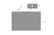
- FIG. 1 is a plan view of a polarizer according to one embodiment of the present invention.
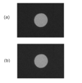
- FIG. (A) is an observation photograph which shows the transparent part of the polarizing plate of Example 1 before a humidification test
- (b) is an observation photograph which shows the transparent part of the polarizing plate of Example 1 after a humidification test.
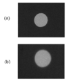
- (A) is an observation photograph which shows the transparent part of the polarizing plate of the comparative example 2 before a humidification test
- (b) is an observation photograph which shows the transparent part of the polarizing plate of the comparative example 2 after a humidification test.
- FIG. 1 is a plan view of a polarizer according to one embodiment of the invention.
- the polarizer 1 is composed of a resin film containing a dichroic substance.
- a low concentration portion 2 having a relatively low content of the dichroic material is formed in the polarizer (resin film) 1.
- the polarizer 1 is formed with a low concentration portion 2 having a lower dichroic substance content than the other portions 3.
- the low density part can function as a non-polarizing part. According to such a configuration, cracks and delamination are mechanically compared (for example, by a method of mechanical engraving using a sculpture blade punching, a plotter, a water jet, or the like), compared to a case where a through hole is formed.
- the small circular low-density portion 2 is formed at the center of the upper end of the polarizer 1, but the number, arrangement, shape, size, etc. of the low-density portions can be appropriately designed.
- it is designed according to the position, shape, size, etc. of the camera unit of the mounted image display device.
- the low density portion does not correspond to a portion (for example, an image display portion) other than the camera of the image display device.
- the transmittance of the low-concentration part is preferably 50% or more, more preferably 60% or more, still more preferably 75% or more, and particularly preferably 90% or more. It is. With such transmittance, desired transparency can be ensured. For example, when the low density portion is associated with the camera portion of the image display device, it is possible to prevent an adverse effect on the shooting performance of the camera.
- the polarizer (excluding the low concentration portion) preferably exhibits absorption dichroism in the wavelength range of 380 nm to 780 nm.
- the single transmittance (Ts) of the polarizer (excluding the low concentration part) is preferably 39% or more, more preferably 39.5% or more, still more preferably 40% or more, and particularly preferably 40.5% or more. .
- the theoretical upper limit of the single transmittance is 50%, and the practical upper limit is 46%.
- the single transmittance (Ts) is a Y value measured by a JIS Z8701 two-degree field of view (C light source) and corrected for visibility. Can be measured.
- the degree of polarization of the polarizer (excluding the low concentration part) is preferably 99.8% or more, more preferably 99.9% or more, and further preferably 99.95% or more.
- the thickness of the polarizer can be set to any appropriate value.
- the thickness is typically 0.5 ⁇ m or more and 80 ⁇ m or less, preferably 30 ⁇ m or less, more preferably 25 ⁇ m or less, further preferably 18 ⁇ m or less, particularly preferably 12 ⁇ m or less, and even more particularly preferable. Is less than 8 ⁇ m.
- the lower limit of the thickness is preferably 1 ⁇ m or more. The lower the thickness, the better the low density part can be formed. For example, when contacting a basic solution described later, the low concentration portion can be formed in a shorter time. Moreover, the thickness of the part which contacted the basic solution may become thinner than another part. When the thickness is small, the difference in thickness between the portion brought into contact with the basic solution and the other portion can be reduced, and bonding with other constituent members such as a protective film can be favorably performed.
- dichroic substance examples include iodine and organic dyes. These may be used alone or in combination of two or more. Preferably iodine is used. This is because the low-concentration portion can be favorably formed by contact with a basic solution described later.
- the low concentration portion is a portion where the content of the dichroic substance is lower than that of the other portion.
- the content of the dichroic substance in the low concentration part is preferably 1.0% by weight or less, more preferably 0.5% by weight or less, and still more preferably 0.2% by weight or less. If the content of the dichroic substance in the low concentration part is within such a range, the desired transparency can be sufficiently imparted to the low concentration part.
- the lower limit value of the content of the dichroic substance in the low concentration part is usually not more than the detection limit value.
- the iodine content is obtained from a calibration curve prepared in advance using a standard sample, for example, from the X-ray intensity measured by fluorescent X-ray analysis.
- the difference between the content of the dichroic substance in the other part and the content of the dichroic substance in the low concentration part is preferably 0.5% by weight or more, more preferably 1% by weight or more. When the difference in content is within such a range, a low concentration part having desired transparency can be formed.
- the low concentration part has an alkali metal and / or alkaline earth metal content of 3.6% by weight or less, preferably 2.5% by weight or less, more preferably 1.0% by weight or less. More preferably, it is 0.5% by weight or less. If the content of alkali metal and / or alkaline earth metal in the low concentration part is within such a range, the shape of the low concentration part formed by contact with the basic solution described later can be maintained well. (In other words, a low concentration part having excellent dimensional stability can be realized).
- the said content can be calculated
- PVA resin polyvinyl alcohol resin
- examples of the PVA resin include polyvinyl alcohol and ethylene-vinyl alcohol copolymer.
- Polyvinyl alcohol is obtained by saponifying polyvinyl acetate.
- the ethylene-vinyl alcohol copolymer can be obtained by saponifying an ethylene-vinyl acetate copolymer.
- the saponification degree of the PVA resin is usually 85 mol% or more and less than 100 mol%, preferably 95.0 mol% to 99.95 mol%, more preferably 99.0 mol% to 99.93 mol%. is there.
- the degree of saponification can be determined according to JIS K 6726-1994. By using a PVA-based resin having such a saponification degree, a polarizer having excellent durability can be obtained. If the degree of saponification is too high, there is a risk of gelation.
- the average degree of polymerization of the PVA resin can be appropriately selected according to the purpose.
- the average degree of polymerization is usually 1000 to 10,000, preferably 1200 to 4500, and more preferably 1500 to 4300.
- the average degree of polymerization can be determined according to JIS K 6726-1994.
- the low-concentration part can be formed by bringing a basic solution into contact with the resin film containing the dichroic substance. Further, the alkali metal and / or alkaline earth metal content as described above in the low concentration part can be realized by reducing the alkali metal and / or alkaline earth metal contained in the contact part with the basic solution. . Therefore, the method for producing a polarizer of the present invention includes bringing a basic solution into contact with a resin film containing a dichroic substance and reducing alkali metal and / or alkaline earth metal contained in the contact portion. Including.
- the low concentration portion is formed by bringing a basic solution into contact with a resin film containing a dichroic substance.
- the iodine content in the contact portion can be easily reduced by bringing the basic solution into contact with a desired portion of the resin film.
- the basic solution can penetrate into the resin film by contact.
- the iodine complex contained in the resin film is reduced by the base contained in the basic solution to become iodine ions.
- the iodine which became the iodine ion moves to the solvent of a basic solution from a resin film.
- the transparency of the low concentration part obtained in this way can be maintained well.
- iodine remaining in the resin film may form an iodine complex again with the use of the polarizer, and the transmittance may decrease. Such a problem is prevented when the content is reduced.
- any appropriate method can be adopted as the contact method of the basic solution.
- a method of dropping, coating, and spraying a basic solution on a resin film, and a method of immersing the resin film in the basic solution can be mentioned.
- the resin film When the basic solution is contacted, the resin film may be protected with any appropriate protective material so that the basic solution does not come in contact with other than the desired site (so that the concentration of the dichroic substance is not lowered).
- the protective material for the resin film include a protective film and a surface protective film.
- the protective film can be used as it is as a protective film for a polarizer.
- the surface protective film is temporarily used when manufacturing the polarizer. Since the surface protective film is removed from the resin film at any appropriate timing, the surface protective film is typically bonded to the resin film via an adhesive layer.
- Another specific example of the protective material is a photoresist.
- any appropriate basic compound can be used as the basic compound.
- the basic compound include alkali metal hydroxides such as sodium hydroxide, potassium hydroxide and lithium hydroxide, alkaline earth metal hydroxides such as calcium hydroxide, and inorganic alkali metal salts such as sodium carbonate. , Organic alkali metal salts such as sodium acetate, aqueous ammonia and the like. Among these, an alkali metal and / or alkaline earth metal hydroxide is preferably used, and sodium hydroxide, potassium hydroxide, and lithium hydroxide are more preferably used. A dichroic substance can be ionized efficiently, and a low concentration part can be formed more easily. These basic compounds may be used alone or in combination of two or more.
- Any appropriate solvent can be used as a solvent for the basic solution.
- Specific examples include water, alcohols such as ethanol and methanol, ethers, benzene, chloroform, and mixed solvents thereof.
- water and alcohol are preferably used because the ionized dichroic substance can be transferred to the solvent satisfactorily.
- the concentration of the basic solution is, for example, 0.01N to 5N, preferably 0.05N to 3N, and more preferably 0.1N to 2.5N. When the concentration is in such a range, a desired low concentration portion can be formed satisfactorily.
- the liquid temperature of the basic solution is, for example, 20 ° C. to 50 ° C.
- the contact time between the resin film and the basic solution can be set according to the thickness of the resin film, the type of the basic compound, and the concentration of the basic solution, and is, for example, 5 seconds to 30 minutes.
- the resin film surface is covered with a surface protective film so that at least a part of the resin film surface is exposed when contacting with the basic solution.
- the polarizer in the illustrated example is produced by, for example, attaching a surface protective film in which small circular through holes are formed to a resin film, and bringing a basic solution into contact therewith. At that time, it is preferable that the other side of the resin film (the side on which the surface protective film is not disposed) is also protected.
- stacking with a resin film and a protective material is performed by roll toe roll.
- roll-to-roll refers to laminating with each other aligned in the longitudinal direction while conveying a roll-shaped film.
- through holes are formed at predetermined intervals in the longitudinal direction and / or the width direction.
- the thickness of the surface protective film is typically 20 ⁇ m to 250 ⁇ m, preferably 30 ⁇ m to 150 ⁇ m.
- the surface protective film is preferably a film having a high hardness (for example, elastic modulus). This is because deformation of the through hole can be prevented.
- Surface protective film forming materials include ester resins such as polyethylene terephthalate resins, cycloolefin resins such as norbornene resins, olefin resins such as polypropylene, polyamide resins, polycarbonate resins, and copolymer resins thereof. Etc. Preference is given to ester resins (especially polyethylene terephthalate resins).
- the resin film When the basic solution is contacted, the resin film is preferably in a state that can be used as a polarizer. Specifically, it is preferable that various treatments such as a swelling treatment, a stretching treatment, a dyeing treatment with the dichroic substance, a crosslinking treatment, a washing treatment, and a drying treatment are performed. In addition, when performing various processes, the resin film formed on the base material may be sufficient as the resin film.
- the laminated body of a base material and a resin layer can be obtained by the method of apply
- the dyeing process is typically performed by adsorbing a dichroic substance.
- the adsorption method include a method of immersing a resin film in a staining solution containing a dichroic substance, a method of applying the staining solution to a resin film, and a method of spraying the staining solution onto a resin film.
- the resin film is immersed in the dyeing solution. It is because a dichroic substance can adsorb
- an aqueous iodine solution is preferably used as the staining solution.
- the amount of iodine is preferably 0.04 to 5.0 parts by weight per 100 parts by weight of water.
- an iodide is preferably used as the iodide.
- potassium iodide is preferably used as the iodide.
- the blending amount of iodide is preferably 0.3 to 15 parts by weight with respect to 100 parts by weight of water.
- the resin film is typically uniaxially stretched 3 to 7 times.
- the stretching direction can correspond to the absorption axis direction of the obtained polarizer.
- the resin film may contain boric acid by the above various treatments.
- boric acid can be contained in the resin film by bringing a boric acid solution (for example, a boric acid aqueous solution) into contact with each other during the stretching treatment and the crosslinking treatment.
- the boric acid content of the resin film is, for example, 10 to 30% by weight.
- the boric acid content in the contact portion with the basic solution is, for example, 5% by weight to 12% by weight.
- alkali metal and / or alkaline earth metal hydroxide By bringing a basic solution into contact with the resin film, alkali metal and / or alkaline earth metal hydroxide can remain in the contact portion. Further, by bringing a basic solution into contact with the resin film, an alkali metal and / or alkaline earth metal salt can be produced at the contact portion. These can generate hydroxide ions, and the generated hydroxide ions act (decompose and reduce) on the dichroic substance (for example, iodine complex) existing around the contact portion, thereby causing a non-polarized region (low level). Concentration range) can be widened. Therefore, by reducing the alkali metal and / or alkaline earth metal salt, it is considered that the non-polarized region can be prevented from spreading over time and the desired non-polarized part shape can be maintained.
- dichroic substance for example, iodine complex
- borate As a metal salt which can produce
- the borate can be generated by neutralizing boric acid contained in the resin film with a basic solution (a solution of an alkali metal hydroxide and / or an alkaline earth metal hydroxide).
- the borate (metaborate) can be hydrolyzed to generate hydroxide ions as shown in the following formula, for example, when a polarizer is placed in a humidified environment. (Wherein X represents an alkali metal or alkaline earth metal)
- the content of alkali metal and / or alkaline earth metal in the contact portion is 3.6% by weight or less, preferably 2.5% by weight or less, more preferably 1.0% by weight. % Or less, more preferably 0.5% by weight or less.
- the alkali metal and / or alkaline-earth metal can be previously contained in the resin film by performing various treatments for forming a polarizer.
- potassium can be contained in the resin film by contacting an iodide solution such as potassium iodide.
- an iodide solution such as potassium iodide.
- a method of bringing the treatment liquid into contact with the basic solution is preferably used. According to such a method, the content of the alkali metal and / or alkaline earth metal can be reduced by transferring the alkali metal and / or alkaline earth metal from the resin film to the treatment liquid.
- any appropriate method can be adopted as the contact method of the treatment liquid.
- the method of dripping, coating, and spraying the treatment liquid on the contact portion with the basic solution and the method of immersing the contact portion with the basic solution in the basic solution can be mentioned.
- the resin film When the resin film is protected with any appropriate protective material when contacting with the basic solution, it is preferable to contact the treatment liquid as it is (particularly when the temperature of the treatment liquid is 50 ° C. or higher). According to such a form, it is possible to prevent the polarization characteristics from being deteriorated by the treatment liquid at a portion other than the contact portion with the basic solution.
- the treatment liquid may contain any appropriate solvent.
- the solvent include water, alcohols such as ethanol and methanol, ether, benzene, chloroform, and mixed solvents thereof.
- water and alcohol are preferably used from the viewpoint of efficiently transferring alkali metal and / or alkaline earth metal. Any appropriate water can be used as the water. For example, tap water, pure water, deionized water and the like can be mentioned.
- the temperature of the treatment liquid at the time of contact is, for example, 20 ° C. or higher, preferably 50 ° C. or higher, more preferably 60 ° C. or higher, and further preferably 70 ° C. or higher. If it is such temperature, an alkali metal and / or alkaline-earth metal can be efficiently transferred to a processing liquid. Specifically, the swelling rate of the resin film can be remarkably improved, and the alkali metal and / or alkaline earth metal in the resin film can be physically removed. On the other hand, the temperature of water is substantially 95 ° C. or less.
- the contact time can be appropriately adjusted according to the contact method, the temperature of the treatment liquid (water), the thickness of the resin film, and the like.
- the contact time is preferably 10 seconds to 30 minutes, more preferably 30 seconds to 15 minutes, and even more preferably 60 seconds to 10 minutes.
- an acidic solution is used as the treatment liquid.
- an acidic solution By using an acidic solution, the alkali metal and / or alkaline earth metal hydroxide remaining in the resin film is neutralized, and the alkali metal and / or alkaline earth metal in the resin film is chemically removed. be able to.
- any appropriate acidic compound can be used as the acidic compound contained in the acidic solution.
- the acidic compound include inorganic acids such as hydrochloric acid, sulfuric acid, nitric acid, hydrogen fluoride, and boric acid, and organic acids such as formic acid, oxalic acid, citric acid, acetic acid, and benzoic acid.
- the acidic compound contained in the acidic solution is preferably an inorganic acid, more preferably hydrochloric acid, sulfuric acid, or nitric acid. These acidic compounds may be used alone or in combination of two or more.
- an acidic compound having a higher acidity than boric acid is suitably used as the acidic compound. It is because it can act also on the metal salt (borate) of the alkali metal and / or alkaline earth metal. Specifically, boric acid can be liberated from the borate and the alkali metal and / or alkaline earth metal in the resin film can be chemically removed.
- the acidity index examples include an acid dissociation constant (pKa), and an acidic compound having a pKa smaller than that of boric acid (pKa (9.2)) is preferably used.
- pKa is preferably less than 9.2, more preferably 5 or less.
- the pKa may be measured using any appropriate measuring device, and values described in documents such as the Chemical Handbook, Basic Edition, Rev. 5 (Edited by The Chemical Society of Japan, Maruzen Publishing) may be referred to.
- the pKa value can change at each stage. When such an acidic compound is used, one having a pKa value in each stage within the above range is used.
- pKa means the value in 25 degreeC aqueous solution.
- the difference between the pKa of the acidic compound and the pKa of boric acid is, for example, 2.0 or more, preferably 2.5 to 15, and more preferably 2.5 to 13.
- the alkali metal and / or alkaline earth metal can be efficiently transferred to the treatment liquid, and as a result, the desired alkali metal and / or alkaline earth metal content in the low concentration part. Can be realized.
- Examples of acidic compounds that can satisfy the above pKa include hydrochloric acid (pKa: -3.7), sulfuric acid (pK 2 : 1.96), nitric acid (pKa: -1.8), hydrogen fluoride (pKa: 3 .17), inorganic acids such as boric acid (pKa: 9.2), formic acid (pKa: 3.54), oxalic acid (pK 1 : 1.04, pK 2 : 3.82), citric acid (pK 1 : 3.09, pK 2 : 4.75, pK 3 : 6.41), acetic acid (pKa: 4.8), benzoic acid (pKa: 4.0), and other organic acids.
- hydrochloric acid pKa: -3.7
- sulfuric acid pK 2 : 1.96
- nitric acid pKa: -1.8
- hydrogen fluoride pKa: 3 .17
- inorganic acids such as boric acid (pK
- treatment liquid The solvent of the acidic solution (treatment liquid) is as described above, and physical removal of the alkali metal and / or alkaline earth metal in the resin film occurs also in this embodiment using the acidic solution as the treatment liquid. obtain.
- the concentration of the acidic solution is, for example, 0.01N to 5N, preferably 0.05N to 3N, and more preferably 0.1N to 2.5N.
- the liquid temperature of the acidic solution is, for example, 20 ° C. to 50 ° C.
- the contact time with the acidic solution can be set according to the thickness of the resin film, the type of acidic compound, and the concentration of the acidic solution, and is, for example, 5 seconds to 30 minutes.
- the polarizer of the present invention can be obtained by subjecting a resin film containing a dichroic substance to these treatments.
- the resin film may be further subjected to any appropriate other treatment in addition to the above treatment.
- Other treatments include removal of the basic solution and / or acidic solution, and washing.
- Specific examples of the method for removing the basic solution and / or the acidic solution include wiping removal with a waste cloth, suction removal, natural drying, heat drying, air drying, vacuum drying, and the like.
- the drying temperature is, for example, 20 ° C. to 100 ° C.
- the cleaning process is performed by any appropriate method.
- the solution used for the washing treatment include pure water, alcohols such as methanol and ethanol, acidic aqueous solutions, and mixed solvents thereof.
- the cleaning process can be performed at any suitable stage.
- the cleaning process may be performed a plurality of times.
- the polarizing plate of this invention has the said polarizer.
- the polarizing plate of the present invention is typically used by laminating a protective film on at least one side thereof.
- the material for forming the protective film include cellulose resins such as diacetyl cellulose and triacetyl cellulose, (meth) acrylic resins, cycloolefin resins, olefin resins such as polypropylene, and ester resins such as polyethylene terephthalate resins. , Polyamide resins, polycarbonate resins, copolymer resins thereof, and the like.
- the surface of the protective film on which the polarizer is not laminated may be subjected to a treatment for the purpose of a hard coat layer, antireflection treatment, diffusion or antiglare as a surface treatment layer.
- the thickness of the protective film is preferably 10 ⁇ m to 100 ⁇ m.
- the protective film is typically laminated on the polarizer via an adhesive layer (specifically, an adhesive layer or an adhesive layer).
- the adhesive layer is typically formed of a PVA adhesive or an activated energy ray curable adhesive.
- the pressure-sensitive adhesive layer is typically formed of an acrylic pressure-sensitive adhesive.
- the image display device of the present invention includes the polarizing plate.
- Examples of the image display device include a liquid crystal display device and an organic EL device.
- the liquid crystal display device includes a liquid crystal panel including a liquid crystal cell and the polarizer disposed on one side or both sides of the liquid crystal cell.
- the organic EL device includes an organic EL panel in which the polarizer is disposed on the viewing side.
- the polarizer is disposed so as to correspond to the camera unit of the image display device on which the low density portion is mounted.
- Example 1 As the base material, an amorphous isophthalic acid copolymerized polyethylene terephthalate (IPA copolymerized PET) film (thickness: 100 ⁇ m) having a long water absorption rate of 0.75% and Tg of 75 ° C. was used.
- IPA copolymerized PET film thickness: 100 ⁇ m
- One side of the substrate was subjected to corona treatment, and polyvinyl alcohol (degree of polymerization 4200, saponification degree 99.2 mol%) and acetoacetyl-modified PVA (degree of polymerization 1200, degree of acetoacetyl modification 4.6) were applied to this corona-treated surface.
- the laminate was immersed in an insolubilization bath (a boric acid aqueous solution obtained by blending 4 parts by weight of boric acid with respect to 100 parts by weight of water) for 30 seconds (insolubilization treatment). Subsequently, it was immersed in a dyeing bath having a liquid temperature of 30 ° C. while adjusting the iodine concentration and the immersion time so that the polarizing plate had a predetermined transmittance.
- 0.2 parts by weight of iodine was blended with 100 parts by weight of water and immersed in an aqueous iodine solution obtained by blending 1.5 parts by weight of potassium iodide (dyeing treatment). .
- a boric acid aqueous solution obtained by blending 3 parts by weight of potassium iodide and 3 parts by weight of boric acid with respect to 100 parts by weight of water was immersed for 30 seconds in a crosslinking bath having a liquid temperature of 30 ° C.
- a boric acid aqueous solution obtained by blending 3 parts by weight of potassium iodide and 3 parts by weight of boric acid with respect to 100 parts by weight of water (Crosslinking treatment).
- the laminate was immersed in a boric acid aqueous solution (an aqueous solution obtained by blending 4 parts by weight of boric acid and 5 parts by weight of potassium iodide with respect to 100 parts by weight of water) at a liquid temperature of 70 ° C.
- a protective film (thickness 25 ⁇ m) was bonded, and this was heated in an oven maintained at 60 ° C. for 5 minutes. Thereafter, the substrate was peeled from the PVA resin layer to obtain a polarizing plate (polarizer (transmittance 42.3%, thickness 5 ⁇ m) / protective film).
- a sodium hydroxide aqueous solution (1.0 mol / L (1.0 N)) at room temperature was dropped onto the polarizer-side surface of the polarizing plate having a total thickness of 30 ⁇ m obtained above so as to have a diameter of 4 mm and left for 60 seconds. . Thereafter, the dropped sodium hydroxide aqueous solution was removed with a waste cloth. Next, room temperature hydrochloric acid (1.0 mol / L (1.0 N)) was added dropwise to the contact portion with the aqueous sodium hydroxide solution and allowed to stand for 30 seconds. Thereafter, the dropped hydrochloric acid was removed with a waste cloth to form a transparent portion in the polarizer.
- Example 2 A transparent portion was formed on the polarizer in the same manner as in Example 1 except that the concentration of hydrochloric acid was changed to 0.1 mol / L (0.1N).
- Example 3 A pressure-sensitive adhesive (acrylic pressure-sensitive adhesive) was applied to one surface of the ester film (thickness 38 ⁇ m) so as to have a thickness of 10 ⁇ m. A through hole having a diameter of 4 mm was formed in this ester film with adhesive using a picnal blade. An ester film was bonded to the polarizer side of the polarizing plate having a total thickness of 30 ⁇ m used in Example 1 via an adhesive layer to obtain a polarizing film laminate. A sodium hydroxide aqueous solution (1.0 mol / L (1.0 N)) at room temperature was dropped onto a portion where the polarizer was exposed from the ester film of the obtained polarizing film laminate, and left for 60 seconds.
- a sodium hydroxide aqueous solution 1.0 mol / L (1.0 N)
- the dropped sodium hydroxide aqueous solution was removed with a waste cloth.
- the polarizing film laminate was immersed in a water bath set at 55 ° C. for 60 seconds. After immersion, the water adhering to the surface was removed with a waste cloth, and then the ester film was peeled off to form a transparent portion on the polarizer.
- Example 4 A transparent portion was formed on the polarizer in the same manner as in Example 3 except that the temperature of the water bath was 70 ° C.
- Example 5 The temperature of the water bath was set to 40 ° C., and hydrochloric acid (1.0 mol / L (1.0 N)) was dropped onto the exposed portion of the polarizer after removing the water with a waste cloth, and left for 30 seconds. A transparent portion was formed on the polarizer in the same manner as in Example 3 except that hydrochloric acid was removed in step (b).
- Example 6 A transparent portion was formed on the polarizer in the same manner as in Example 5 except that the temperature of the water bath was 70 ° C.
- Example 7 A transparent portion was formed on the polarizer in the same manner as in Example 3 except that the temperature of the water bath was 30 ° C.
- Example 8 A transparent portion was formed on the polarizer in the same manner as in Example 3 except that the temperature of the water bath was 40 ° C.
- Example 2 A transparent part was formed on the polarizer in the same manner as in Example 1 except that hydrochloric acid was not contacted.
- Ts Transmittance
- the measurement was performed using a spectrophotometer (product name “DOT-3” manufactured by Murakami Color Research Laboratory Co., Ltd.).
- the transmittance (T) is a Y value obtained by correcting the visibility with a 2-degree field of view (C light source) of JlS Z 8701-1982.
- Iodine content The iodine content in the contact part of a polarizer was calculated
- the iodine content of the polarizer was determined from an X-ray intensity measured under the following conditions, using a calibration curve prepared in advance using a standard sample.
- ⁇ Analyzer X-ray fluorescence analyzer (XRF) manufactured by Rigaku Denki Kogyo Co., Ltd.
- Reduction rate (sodium content in contact part immediately after contact) ⁇ (sodium content in contact part (transparent part) of the obtained polarizer) / (sodium content in contact part immediately after contact) ⁇ 100 5.
- Example 2 the content of iodine was low in the transparent part, and the iodine was a low concentration part. Compared to Comparative Example 2, the size of the transparent portion was maintained in each Example. As shown in FIGS. 2 and 3, high dimensional stability was confirmed in Examples 1 to 6.
- the polarizer of the present invention is suitably used for a mobile phone such as a smartphone, an image display device with a camera (liquid crystal display device, organic EL device) such as a notebook PC or tablet PC.
- a mobile phone such as a smartphone
- an image display device with a camera liquid crystal display device, organic EL device
- a notebook PC or tablet PC such as a notebook PC or tablet PC.
Landscapes
- Physics & Mathematics (AREA)
- General Physics & Mathematics (AREA)
- Optics & Photonics (AREA)
- Nonlinear Science (AREA)
- Mathematical Physics (AREA)
- Chemical & Material Sciences (AREA)
- Crystallography & Structural Chemistry (AREA)
- Polarising Elements (AREA)
- Liquid Crystal (AREA)
Abstract
Description
1つの実施形態においては、上記二色性物質低濃度部は、該樹脂フィルムに塩基性溶液を接触させることにより形成される。
1つの実施形態においては、上記塩基性溶液は、アルカリ金属および/またはアルカリ土類金属の水酸化物を含む水溶液である。
1つの実施形態においては、上記二色性物質低濃度部の二色性物質含有量は1.0重量%以下である。
1つの実施形態においては、上記二色性物質低濃度部の透過率は50%以上である。
1つの実施形態においては、上記偏光子の厚みは30μm以下である。
1つの実施形態においては、上記二色性物質低濃度部は、搭載される画像表示装置のカメラ部に対応する。
本発明の別の局面によれば、偏光板が提供される。この偏光板は、上記の偏光子を有する。
本発明のさらに別の局面によれば、画像表示装置が提供される。この画像表示装置は、上記の偏光板を備える。
図1は、本発明の1つの実施形態による偏光子の平面図である。偏光子1は、二色性物質を含む樹脂フィルムから構成される。偏光子(樹脂フィルム)1は、二色性物質の含有量が相対的に低い低濃度部2が形成されている。具体的には、偏光子1には他の部位3よりも二色性物質の含有量が低い低濃度部2が形成されている。低濃度部は、非偏光部として機能し得る。このような構成によれば、機械的に(例えば、彫刻刃打抜き、プロッター、ウォータージェット等を用いて機械的に抜き落とす方法により)、貫通穴が形成されている場合に比べて、クラック、デラミ(層間剥離)、糊はみ出し等の品質上の問題が回避される。また、低濃度部は二色性物質自体の含有量が低いので、レーザー光等により二色性物質を分解して非偏光部が形成されている場合に比べて、非偏光部の透明性が良好に維持される。
上記低濃度部は、上記二色性物質を含む上記樹脂フィルムに塩基性溶液を接触させることにより形成され得る。さらに、低濃度部における上記のようなアルカリ金属および/またはアルカリ土類金属含有量は、塩基性溶液との接触部に含まれるアルカリ金属および/またはアルカリ土類金属を低減させることにより実現され得る。したがって、本発明の偏光子の製造方法は、二色性物質を含む樹脂フィルムに塩基性溶液を接触させることと、この接触部に含まれるアルカリ金属および/またはアルカリ土類金属を低減させることを含む。
上記のとおり、低濃度部は、二色性物質を含む樹脂フィルムに塩基性溶液を接触させることにより形成される。二色性物質としてヨウ素を用いる場合、樹脂フィルムの所望の部位に塩基性溶液を接触させることで、接触部のヨウ素含有量を容易に低減させることができる。具体的には、接触により、塩基性溶液は樹脂フィルム内部へと浸透し得る。樹脂フィルムに含まれるヨウ素錯体は塩基性溶液に含まれる塩基により還元され、ヨウ素イオンとなる。ヨウ素錯体がヨウ素イオンに還元されることにより、接触部の透過率が向上し得る。そして、ヨウ素イオンとなったヨウ素は、樹脂フィルムから塩基性溶液の溶媒中に移動する。こうして得られる低濃度部は、その透明性が良好に維持され得る。具体的には、ヨウ素錯体を破壊して透過率を向上させた場合、樹脂フィルム内に残存するヨウ素が、偏光子の使用に伴い再度ヨウ素錯体を形成して透過率が低下し得るが、ヨウ素含有量を低減させた場合はそのような問題は防止される。
上記塩基性溶液との接触後、塩基性溶液を接触させた接触部において、樹脂フィルムに含まれるアルカリ金属および/またはアルカリ土類金属を低減させる。アルカリ金属および/またはアルカリ土類金属を低減させることにより、寸法安定性に優れた低濃度部を得ることができる。具体的には、加湿環境下においても、塩基性溶液との接触により形成された低濃度部の形状をそのまま維持することができる。

本発明の偏光板は、上記偏光子を有する。本発明の偏光板は、代表的には、少なくともその片側に保護フィルムを積層させて使用される。保護フィルムの形成材料としては、例えば、ジアセチルセルロース、トリアセチルセルロース等のセルロース系樹脂、(メタ)アクリル系樹脂、シクロオレフィン系樹脂、ポリプロピレン等のオレフィン系樹脂、ポリエチレンテレフタレート系樹脂等のエステル系樹脂、ポリアミド系樹脂、ポリカーボネート系樹脂、これらの共重体樹脂等が挙げられる。
本発明の画像表示装置は、上記偏光板を備える。画像表示装置としては、例えば、液晶表示装置、有機ELデバイスが挙げられる。具体的には、液晶表示装置は、液晶セルと、この液晶セルの片側もしくは両側に配置された上記偏光子とを含む液晶パネルを備える。有機ELデバイスは、視認側に上記偏光子が配置された有機ELパネルを備える。偏光子は、その低濃度部が搭載される画像表示装置のカメラ部に対応するように配置される。
基材として、長尺状で、吸水率0.75%、Tg75℃の非晶質のイソフタル酸共重合ポリエチレンテレフタレート(IPA共重合PET)フィルム(厚み:100μm)を用いた。基材の片面に、コロナ処理を施し、このコロナ処理面に、ポリビニルアルコール(重合度4200、ケン化度99.2モル%)およびアセトアセチル変性PVA(重合度1200、アセトアセチル変性度4.6%、ケン化度99.0モル%以上、日本合成化学工業社製、商品名「ゴーセファイマーZ200」)を9:1の比で含む水溶液を25℃で塗布および乾燥して、厚み11μmのPVA系樹脂層を形成し、積層体を作製した。
得られた積層体を、120℃のオーブン内で周速の異なるロール間で縦方向(長手方向)に2.0倍に自由端一軸延伸した(空中補助延伸)。
次いで、積層体を、液温30℃の不溶化浴(水100重量部に対して、ホウ酸を4重量部配合して得られたホウ酸水溶液)に30秒間浸漬させた(不溶化処理)。
次いで、液温30℃の染色浴に、偏光板が所定の透過率となるようにヨウ素濃度、浸漬時間を調整しながら浸漬させた。本実施例では、水100重量部に対して、ヨウ素を0.2重量部配合し、ヨウ化カリウムを1.5重量部配合して得られたヨウ素水溶液に60秒間浸漬させた(染色処理)。
次いで、液温30℃の架橋浴(水100重量部に対して、ヨウ化カリウムを3重量部配合し、ホウ酸を3重量部配合して得られたホウ酸水溶液)に30秒間浸漬させた(架橋処理)。
その後、積層体を、液温70℃のホウ酸水溶液(水100重量部に対して、ホウ酸を4重量部配合し、ヨウ化カリウムを5重量部配合して得られた水溶液)に浸漬させながら、周速の異なるロール間で縦方向(長手方向)に総延伸倍率が5.5倍となるように一軸延伸を行った(水中延伸)。
その後、積層体を液温30℃の洗浄浴(水100重量部に対して、ヨウ化カリウムを4重量部配合して得られた水溶液)に浸漬させた(洗浄処理)。
続いて、積層体のPVA系樹脂層表面に、PVA系樹脂水溶液(日本合成化学工業社製、商品名「ゴーセファイマー(登録商標)Z-200」、樹脂濃度:3重量%)を塗布して保護フィルム(厚み25μm)を貼り合わせ、これを60℃に維持したオーブンで5分間加熱した。その後、基材をPVA系樹脂層から剥離し、偏光板(偏光子(透過率42.3%、厚み5μm)/保護フィルム)を得た。
次いで、常温の塩酸(1.0mol/L(1.0N))を水酸化ナトリウム水溶液との接触部に滴下し、30秒間放置した。その後、滴下した塩酸をウエスで除去し、偏光子に透明部を形成した。
塩酸の濃度を0.1mol/L(0.1N)とした以外は実施例1と同様にして、偏光子に透明部を形成した。
エステル系フィルム(厚み38μm)の一方の面に粘着剤(アクリル系粘着剤)を厚みが10μmになるよう塗布した。この粘着剤付エステル系フィルムに、ピクナル刃を用いて直径4mmの貫通穴を形成した。
実施例1で用いた総厚30μmの偏光板の偏光子側に、エステル系フィルムを、粘着剤層を介して貼り合わせ、偏光フィルム積層体を得た。
得られた偏光フィルム積層体のエステル系フィルムから偏光子が露出した部分に、常温の水酸化ナトリウム水溶液(1.0mol/L(1.0N))を滴下し、60秒間放置した。その後、滴下した水酸化ナトリウム水溶液をウエスで除去した。
次いで、偏光フィルム積層体を55℃に設定したウォーターバスに60秒間浸漬した。浸漬後、表面に付着した水をウエスで除去してからエステル系フィルムを剥離し、偏光子に透明部を形成した。
ウォーターバスの温度を70℃にしたこと以外は実施例3と同様にして、偏光子に透明部を形成した。
ウォーターバスの温度を40℃にしたこと、および、水をウエスで除去した後に偏光子が露出した部分に塩酸(1.0mol/L(1.0N))を滴下して30秒間放置し、ウエスで塩酸を除去したこと以外は実施例3と同様にして、偏光子に透明部を形成した。
ウォーターバスの温度を70℃にした以外は実施例5と同様にして、偏光子に透明部を形成した。
ウォーターバスの温度を30℃とした以外は実施例3と同様にして、偏光子に透明部を形成した。
ウォーターバスの温度を40℃とした以外は実施例3と同様にして、偏光子に透明部を形成した。
水酸化ナトリウム水溶液に代えて純水を用いたこと、および、塩酸を接触させなかったこと以外は実施例1と同様にして、透明部の形成を試みた。
塩酸を接触させなかったこと以外は実施例1と同様にして、偏光子に透明部を形成した。
1.透過率(Ts)
分光光度計(村上色彩技術研究所(株)製 製品名「DOT-3」)を用いて測定した。透過率(T)は、JlS Z 8701-1982の2度視野(C光源)により、視感度補正を行ったY値である。
2.ヨウ素含有量
蛍光X線分析により、偏光子の接触部におけるヨウ素含有量を求めた。具体的には、下記条件により測定したX線強度から、あらかじめ標準試料を用いて作成した検量線により、偏光子のヨウ素含有量を求めた。
・分析装置:理学電機工業製 蛍光X線分析装置(XRF) 製品名「ZSX100e」
・対陰極:ロジウム
・分光結晶:フッ化リチウム
・励起光エネルギー:40kV-90mA
・ヨウ素測定線:I-LA
・定量法:FP法
・2θ角ピーク:103.078deg(ヨウ素)
・測定時間:40秒
3.ナトリウム含有量
蛍光X線分析により、偏光子の接触部におけるナトリウム含有量を求めた。具体的には、下記条件により測定したX線強度から、あらかじめ標準試料を用いて作成した検量線により、偏光子のナトリウム含有量を求めた。
・分析装置:理学電機工業製 蛍光X線分析装置(XRF) 製品名「ZSX100e」
・対陰極:ロジウム
・分光結晶:フッ化リチウム
・励起光エネルギー:40kV-90mA
・ナトリウム測定線:Na-KA
・定量法:FP法
・測定時間:40秒
4.ナトリウム低減率
接触させた水酸化ナトリウム水溶液をウエスで除去し、接触直後の接触部のナトリウム含有量を測定した。その後、最終的に得られた偏光子の接触部(透明部)のナトリウム含有量を測定した。これらの測定値を用いて、下記式から低減率を算出した。
低減率=(接触直後の接触部のナトリウム含有量)-(得られた偏光子の接触部(透明部)のナトリウム含有量)/(接触直後の接触部のナトリウム含有量)×100
5.サイズ変化率
得られた偏光板を、65℃/90%RHの環境下に500時間おいた。加湿試験前後における透明部のサイズを測定し、以下の式を用いてサイズ変化率を算出した。
なお、加湿試験後においては、超高速フレキシブル画像処理システム(キーエンス社製、商品名:XG-7500)を用いてエッジ検出を行い透明部と他の部位との境界線を引き、その最大寸法となる部分を測定した。
サイズ変化率(%)=100×(加湿試験後の透明部のサイズ)/(加湿環試験前の透明部のサイズ)

2 低濃度部
Claims (9)
- 二色性物質を含む樹脂フィルムから構成され、該樹脂フィルム内に該二色性物質の含有量が相対的に低い二色性物質低濃度部を有する偏光子であって、
該二色性物質低濃度部のアルカリ金属および/またはアルカリ土類金属の含有量が3.6重量%以下である、偏光子。 - 該二色性物質低濃度部が該樹脂フィルムに塩基性溶液を接触させることにより形成される、請求項1に記載の偏光子。
- 前記塩基性溶液がアルカリ金属および/またはアルカリ土類金属の水酸化物を含む水溶液である、請求項2に記載の偏光子。
- 前記二色性物質低濃度部の二色性物質含有量が1.0重量%以下である、請求項1から3のいずれかに記載の偏光子。
- 前記二色性物質低濃度部の透過率が50%以上である、請求項1から4のいずれかに記載の偏光子。
- 厚みが30μm以下である、請求項1から5のいずれかに記載の偏光子。
- 前記二色性物質低濃度部が、搭載される画像表示装置のカメラ部に対応する、請求項1から6のいずれかに記載の偏光子。
- 請求項1から7のいずれかに記載の偏光子を有する、偏光板。
- 請求項8に記載の偏光板を備える、画像表示装置。
Priority Applications (5)
| Application Number | Priority Date | Filing Date | Title |
|---|---|---|---|
| US15/306,362 US20170045657A1 (en) | 2014-04-25 | 2015-04-23 | Polarizer, polarizing plate, and image display apparatus |
| KR1020187003521A KR102017434B1 (ko) | 2014-04-25 | 2015-04-23 | 편광자, 편광판 및 화상 표시 장치 |
| CN201580022075.2A CN106461837B (zh) | 2014-04-25 | 2015-04-23 | 偏振片、偏光板及图像显示装置 |
| KR1020157036599A KR20160012220A (ko) | 2014-04-25 | 2015-04-23 | 편광자, 편광판 및 화상 표시 장치 |
| US16/801,670 US11061176B2 (en) | 2014-04-25 | 2020-02-26 | Polarizer, polarizing plate, and image display apparatus |
Applications Claiming Priority (4)
| Application Number | Priority Date | Filing Date | Title |
|---|---|---|---|
| JP2014091842 | 2014-04-25 | ||
| JP2014-091842 | 2014-04-25 | ||
| JP2015-087686 | 2015-04-22 | ||
| JP2015087686A JP6214594B2 (ja) | 2014-04-25 | 2015-04-22 | 偏光子、偏光板および画像表示装置 |
Related Child Applications (2)
| Application Number | Title | Priority Date | Filing Date |
|---|---|---|---|
| US15/306,362 A-371-Of-International US20170045657A1 (en) | 2014-04-25 | 2015-04-23 | Polarizer, polarizing plate, and image display apparatus |
| US16/801,670 Division US11061176B2 (en) | 2014-04-25 | 2020-02-26 | Polarizer, polarizing plate, and image display apparatus |
Publications (1)
| Publication Number | Publication Date |
|---|---|
| WO2015163402A1 true WO2015163402A1 (ja) | 2015-10-29 |
Family
ID=54332564
Family Applications (1)
| Application Number | Title | Priority Date | Filing Date |
|---|---|---|---|
| PCT/JP2015/062358 Ceased WO2015163402A1 (ja) | 2014-04-25 | 2015-04-23 | 偏光子、偏光板および画像表示装置 |
Country Status (6)
| Country | Link |
|---|---|
| US (2) | US20170045657A1 (ja) |
| JP (1) | JP6214594B2 (ja) |
| KR (2) | KR102017434B1 (ja) |
| CN (1) | CN106461837B (ja) |
| TW (2) | TW201937217A (ja) |
| WO (1) | WO2015163402A1 (ja) |
Families Citing this family (19)
| Publication number | Priority date | Publication date | Assignee | Title |
|---|---|---|---|---|
| JP6215864B2 (ja) | 2014-04-25 | 2017-10-18 | 日東電工株式会社 | 偏光子、偏光板および画像表示装置 |
| JP6214594B2 (ja) | 2014-04-25 | 2017-10-18 | 日東電工株式会社 | 偏光子、偏光板および画像表示装置 |
| JP6215261B2 (ja) | 2014-06-27 | 2017-10-18 | 日東電工株式会社 | 長尺状の偏光子、長尺状の偏光板および画像表示装置 |
| JP6152083B2 (ja) * | 2014-11-11 | 2017-06-21 | 日東電工株式会社 | 非偏光部を有する偏光子の製造方法 |
| JP7163000B2 (ja) | 2015-06-25 | 2022-10-31 | 日東電工株式会社 | 非偏光部を有する偏光子 |
| JP6152138B2 (ja) * | 2015-06-25 | 2017-06-21 | 日東電工株式会社 | 偏光子の製造方法 |
| JP6619619B2 (ja) * | 2015-11-04 | 2019-12-11 | 日東電工株式会社 | 偏光子、偏光板および偏光子の製造方法 |
| JP6945286B2 (ja) * | 2016-09-13 | 2021-10-06 | 日東電工株式会社 | 偏光子の製造方法 |
| JP7456748B2 (ja) | 2019-10-25 | 2024-03-27 | 住友化学株式会社 | 光学積層体 |
| JP7456747B2 (ja) | 2019-10-25 | 2024-03-27 | 住友化学株式会社 | 光学積層体 |
| JP7516027B2 (ja) | 2019-10-25 | 2024-07-16 | 住友化学株式会社 | 光学積層体 |
| JP7404029B2 (ja) | 2019-10-25 | 2023-12-25 | 住友化学株式会社 | 光学積層体 |
| JP7408346B2 (ja) | 2019-10-25 | 2024-01-05 | 住友化学株式会社 | 光学積層体 |
| JP7516028B2 (ja) | 2019-10-25 | 2024-07-16 | 住友化学株式会社 | 偏光子複合体及び光学積層体 |
| CN110727142B (zh) * | 2019-10-29 | 2023-04-28 | Oppo广东移动通信有限公司 | 偏光片、显示屏以及电子设备 |
| KR102593639B1 (ko) * | 2020-03-09 | 2023-10-24 | 삼성에스디아이 주식회사 | 편광판 및 이를 포함하는 광학표시장치 |
| JPWO2023276936A1 (ja) | 2021-06-30 | 2023-01-05 | ||
| KR20240023016A (ko) | 2021-06-30 | 2024-02-20 | 닛토덴코 가부시키가이샤 | 편광 필름 및 화상 표시 장치 |
| KR102522294B1 (ko) | 2022-02-22 | 2023-04-17 | 김연옥 | 결로 방지용 기능성 창호 |
Citations (6)
| Publication number | Priority date | Publication date | Assignee | Title |
|---|---|---|---|---|
| JPS5849901A (ja) * | 1981-09-19 | 1983-03-24 | Nitto Electric Ind Co Ltd | 部分偏光フィルムの製法 |
| JPS58168019A (ja) * | 1982-03-29 | 1983-10-04 | Nitto Electric Ind Co Ltd | 部分カラ−偏光フイルムの製法 |
| JPS59172610A (ja) * | 1983-03-22 | 1984-09-29 | Nitto Electric Ind Co Ltd | 偏光フイルムの製法 |
| JPS60133401A (ja) * | 1983-12-21 | 1985-07-16 | Nitto Electric Ind Co Ltd | マルチカラ−偏光子の製法 |
| WO2008155873A1 (ja) * | 2007-06-15 | 2008-12-24 | Panasonic Corporation | 画像処理装置 |
| JP2013065995A (ja) * | 2011-09-16 | 2013-04-11 | Ricoh Co Ltd | 撮像装置及びこれを用いた物体識別装置 |
Family Cites Families (102)
| Publication number | Priority date | Publication date | Assignee | Title |
|---|---|---|---|---|
| US2409923A (en) | 1944-01-12 | 1946-10-22 | Polaroid Corp | Process of forming iodine images |
| US2647440A (en) | 1947-08-08 | 1953-08-04 | Miles P Rehorn | Molecularly aligned sheet material |
| JPS5024624B2 (ja) * | 1971-09-13 | 1975-08-16 | ||
| JPS4864941A (ja) * | 1971-12-09 | 1973-09-07 | ||
| US4181756A (en) * | 1977-10-05 | 1980-01-01 | Fergason James L | Process for increasing display brightness of liquid crystal displays by bleaching polarizers using screen-printing techniques |
| US4466704A (en) * | 1981-07-20 | 1984-08-21 | Polaroid Corporation | Patterned polarizer having differently dyed areas |
| US4396646A (en) | 1981-07-20 | 1983-08-02 | Polaroid Corporation | Method of making patterned polarizers |
| JPH0666001B2 (ja) | 1982-03-29 | 1994-08-24 | 日東電工株式会社 | 多色カラ−偏光フイルムの製法 |
| JPS6036563B2 (ja) | 1982-03-29 | 1985-08-21 | 日東電工株式会社 | 部分偏光フイルムの製法 |
| JPH0769535B2 (ja) * | 1982-09-28 | 1995-07-31 | 日東電工株式会社 | 偏光子 |
| JPH07770B2 (ja) | 1986-05-07 | 1995-01-11 | 王子化工株式会社 | 透気性粘着紙 |
| US5327285A (en) * | 1990-06-11 | 1994-07-05 | Faris Sadeg M | Methods for manufacturing micropolarizers |
| CA2081626A1 (en) | 1991-11-08 | 1993-05-09 | Taiichi Sakaya | Phase retarder |
| US5374477A (en) | 1993-02-09 | 1994-12-20 | Minnesota Mining And Manufacturing Company | Barrier laminate and method for sealing gaps in building construction |
| JPH09241594A (ja) | 1996-03-09 | 1997-09-16 | Nitto Denko Corp | ロール状粘着テープ |
| JP3512596B2 (ja) * | 1996-07-04 | 2004-03-29 | シャープ株式会社 | 旋光光学素子およびその製造方法と、それを用いた画像表示装置 |
| JP3357803B2 (ja) | 1996-10-30 | 2002-12-16 | タレックス光学工業株式会社 | 眼鏡用偏光膜および偏光眼鏡 |
| JPH10183390A (ja) | 1996-12-25 | 1998-07-14 | Nikko Kinzoku Kk | 長尺金属条体のパターンめっき方法 |
| US6258429B1 (en) | 1997-03-11 | 2001-07-10 | Stephen G. Nelson | One-way see-thru panel and method of making same |
| JP3632387B2 (ja) * | 1997-07-31 | 2005-03-23 | 住友化学株式会社 | 偏光フィルムの製造方法 |
| US6590605B1 (en) | 1998-10-14 | 2003-07-08 | Dimension Technologies, Inc. | Autostereoscopic display |
| US20020071179A1 (en) | 1999-06-30 | 2002-06-13 | Kazuo Maeda | Method for manufacturing 3D image display body |
| JP3786824B2 (ja) * | 1999-06-30 | 2006-06-14 | 株式会社有沢製作所 | 3d映像表示体の製造方法 |
| JP4281261B2 (ja) | 2000-09-21 | 2009-06-17 | 住友化学株式会社 | ヨウ素系偏光板及びその製造方法 |
| JP2003207608A (ja) | 2001-11-12 | 2003-07-25 | Sony Corp | Ndフィルターとその製造方法及び撮像装置 |
| JP3960520B2 (ja) | 2002-02-05 | 2007-08-15 | 日東電工株式会社 | 偏光子、偏光板および画像表示装置 |
| JP2004054031A (ja) * | 2002-07-22 | 2004-02-19 | Seiko Epson Corp | 偏光層形成基板、偏光層の製造方法、液晶表示装置、液晶表示装置の製造方法、電子機器 |
| AU2003280606A1 (en) | 2002-12-27 | 2004-07-29 | Lintec Corporation | Pressure sensitive adhesive sheet and method of manufacturing the adhesive sheet |
| US20040212555A1 (en) | 2003-04-23 | 2004-10-28 | Falco Mark A. | Portable electronic device with integrated display and camera and method therefore |
| JP2005089783A (ja) | 2003-09-12 | 2005-04-07 | Tdk Corp | 薄板のエッチング方法 |
| JP2005089782A (ja) | 2003-09-12 | 2005-04-07 | Tdk Corp | 板状体のエッチング方法 |
| KR100521227B1 (ko) | 2003-12-30 | 2005-10-17 | 김동수 | 감압접착층을 구비한 패널 지지용 스틸 빔 및 이를 이용한시공방법 |
| JP4357360B2 (ja) | 2004-05-14 | 2009-11-04 | 富士通株式会社 | 表面形状測定方法及び表面形状測定装置 |
| JP2005336249A (ja) | 2004-05-25 | 2005-12-08 | Lintec Corp | 易貼付性粘着シート及びその製造方法 |
| WO2006095815A1 (ja) | 2005-03-10 | 2006-09-14 | Nippon Kayaku Kabushiki Kaisha | ヨウ素系偏光フィルム、その製造方法及びそれを用いた偏光板 |
| US20080192345A1 (en) | 2005-03-10 | 2008-08-14 | Noriaki Mochizuki | Iodine Polarizing Film, a Method for Producing the Same, and a Polarizing Plate Using the Same |
| JP2006308923A (ja) | 2005-04-28 | 2006-11-09 | Kyocera Corp | 光レセプタクルおよび光モジュール |
| JP4587307B2 (ja) | 2005-04-28 | 2010-11-24 | 日本合成化学工業株式会社 | ポリビニルアルコール系フィルム、及び偏光膜、偏光板 |
| JP4810165B2 (ja) | 2005-09-06 | 2011-11-09 | リンテック株式会社 | 貫通孔形成粘着シートおよびその製造方法 |
| JP2008102274A (ja) | 2006-10-18 | 2008-05-01 | Nitto Denko Corp | 偏光子、偏光板、光学フィルムおよび画像表示装置 |
| JP4707146B2 (ja) * | 2006-10-18 | 2011-06-22 | 日東電工株式会社 | 偏光子の製造方法 |
| JP4646951B2 (ja) | 2007-06-06 | 2011-03-09 | 株式会社半導体エネルギー研究所 | センサ付き表示装置 |
| JP2009130317A (ja) | 2007-11-28 | 2009-06-11 | Seiko Epson Corp | フィルム状接着剤及びその搬送方法 |
| JP2009157361A (ja) | 2007-12-06 | 2009-07-16 | Nitto Denko Corp | 偏光板及び画像表示装置 |
| KR100950854B1 (ko) | 2008-04-10 | 2010-03-31 | 주식회사 에이스 디지텍 | 폴리비닐알콜 편광자 제조방법 |
| WO2009128115A1 (ja) | 2008-04-15 | 2009-10-22 | 日東電工株式会社 | 光学フィルム積層体ロールならびにその製造方法および装置 |
| JP2009300768A (ja) | 2008-06-13 | 2009-12-24 | Sumitomo Chemical Co Ltd | 偏光板ロールおよびそれを用いた感圧式接着剤層付き偏光板ロール、偏光板、液晶表示装置 |
| KR100962543B1 (ko) * | 2008-06-20 | 2010-06-14 | 동아대학교 산학협력단 | 용액상태에서 요오드화시킨 폴리비닐알코올계 수지를이용한 편광필름의 제조방법 |
| JP5628025B2 (ja) | 2008-12-18 | 2014-11-19 | 株式会社クラレ | ポリビニルアルコールフィルム |
| TW201028436A (en) | 2009-01-17 | 2010-08-01 | Plastics Industry Dev Ct | Method of polarizing plate high-value recycling |
| KR20100087837A (ko) | 2009-01-29 | 2010-08-06 | 동우 화인켐 주식회사 | 편광격자 스크린, 이의 제조방법 및 이것이 구비된 3차원 화상표시장치 |
| JP5244848B2 (ja) | 2009-05-01 | 2013-07-24 | 日東電工株式会社 | 偏光子の製造方法 |
| US20160025910A1 (en) | 2009-05-01 | 2016-01-28 | Nitto Denko Corporation | Method for producing polarizer |
| KR20100125558A (ko) | 2009-05-21 | 2010-12-01 | 동우 화인켐 주식회사 | 편광격자 스크린의 제조방법, 편광격자 스크린 및 이것이 구비된 3차원 화상표시장치 |
| KR20100125537A (ko) | 2009-05-21 | 2010-12-01 | 동우 화인켐 주식회사 | 편광격자 스크린의 제조방법, 편광격자 스크린 및 이것이 구비된 3차원 화상표시장치 |
| WO2011043023A1 (ja) | 2009-10-06 | 2011-04-14 | ソニー株式会社 | 光学ユニットおよび撮像装置 |
| JP5434457B2 (ja) | 2009-10-09 | 2014-03-05 | ソニー株式会社 | 光学ユニットおよび撮像装置 |
| JPWO2011108442A1 (ja) | 2010-03-04 | 2013-06-27 | リンテック株式会社 | 粘着シート |
| KR20110110889A (ko) | 2010-04-02 | 2011-10-10 | 동우 화인켐 주식회사 | 패턴화된 편광판, 이의 제조방법 및 이것이 구비된 3차원 화상표시장치 |
| WO2012002194A1 (ja) | 2010-07-02 | 2012-01-05 | 日本合成化学工業株式会社 | ポリビニルアルコール系フィルム、ポリビニルアルコール系フィルムの製造方法、偏光フィルム及び偏光板 |
| JP4691205B1 (ja) | 2010-09-03 | 2011-06-01 | 日東電工株式会社 | 薄型高機能偏光膜を含む光学フィルム積層体の製造方法 |
| JP5502023B2 (ja) | 2010-09-03 | 2014-05-28 | 日東電工株式会社 | 偏光膜を有する光学フィルム積層体ロールの製造方法 |
| JP5011444B2 (ja) | 2010-09-03 | 2012-08-29 | 日東電工株式会社 | 粘着型光学フィルム、その製造方法および画像表示装置 |
| JP5701679B2 (ja) | 2010-09-03 | 2015-04-15 | 日東電工株式会社 | 矩形形状のパネルに偏光膜を有する光学フィルムを順次的に貼り付ける方法及び装置 |
| JP5361941B2 (ja) | 2010-09-03 | 2013-12-04 | 日東電工株式会社 | 偏光膜を有する積層体ストリップロールの製造方法 |
| JP5511730B2 (ja) | 2010-09-03 | 2014-06-04 | 日東電工株式会社 | 光学的パネル組立体の連続的製造方法及び装置 |
| JP5478553B2 (ja) | 2010-09-03 | 2014-04-23 | 日東電工株式会社 | 連続ウェブ状光学フィルム積層体ロール及びその製造方法 |
| JP5474869B2 (ja) | 2010-09-03 | 2014-04-16 | 日東電工株式会社 | 偏光膜を有する積層体ストリップロールの製造方法 |
| US8467177B2 (en) * | 2010-10-29 | 2013-06-18 | Apple Inc. | Displays with polarizer windows and opaque masking layers for electronic devices |
| US9143668B2 (en) | 2010-10-29 | 2015-09-22 | Apple Inc. | Camera lens structures and display structures for electronic devices |
| KR101293210B1 (ko) | 2010-12-15 | 2013-08-05 | 주식회사 엘지화학 | 디스플레이 기기용 편광판의 구멍 형성 장치 및 방법 |
| KR101495759B1 (ko) | 2011-04-18 | 2015-02-26 | 주식회사 엘지화학 | 디스플레이 장치용 편광판, 이를 이용한 액정 패널 및 디스플레이 장치 |
| JP2012247574A (ja) | 2011-05-26 | 2012-12-13 | Nitto Denko Corp | 粘着型偏光板および画像表示装置 |
| JP5838080B2 (ja) | 2011-11-24 | 2015-12-24 | 日東電工株式会社 | ポリビニルアルコール系樹脂フィルムの接合方法、及び、偏光フィルムの製造方法 |
| JP5886718B2 (ja) * | 2011-11-29 | 2016-03-16 | 株式会社コロプラ | 情報処理方法及び装置 |
| KR20130062194A (ko) * | 2011-12-02 | 2013-06-12 | 제일모직주식회사 | 고내구성 편광자 및 그 제조방법 |
| KR102129135B1 (ko) | 2012-02-28 | 2020-07-01 | 스미또모 가가꾸 가부시키가이샤 | 편광막, 원편광판 및 이들의 제조 방법 |
| JP6112921B2 (ja) | 2012-03-14 | 2017-04-12 | 日東電工株式会社 | 液晶表示パネルの製造方法 |
| CN104040614B (zh) | 2012-07-11 | 2017-05-03 | Lg化学株式会社 | 用于形成显示基板的边框图案的方法 |
| JP2014081482A (ja) | 2012-10-16 | 2014-05-08 | Nitto Denko Corp | 偏光子および画像表示装置 |
| JP6114160B2 (ja) | 2012-10-22 | 2017-04-12 | 日東電工株式会社 | 偏光膜および偏光膜の製造方法 |
| US9075199B2 (en) | 2012-10-30 | 2015-07-07 | Apple Inc. | Displays with polarizer layers for electronic devices |
| JP2014164085A (ja) | 2013-02-25 | 2014-09-08 | Nitto Denko Corp | 偏光子および画像表示装置 |
| JP2014167548A (ja) | 2013-02-28 | 2014-09-11 | Nitto Denko Corp | 画像表示装置の製造方法および該製造方法により得られる画像表示装置 |
| JP2014211548A (ja) | 2013-04-19 | 2014-11-13 | 住友化学株式会社 | 偏光能を示さない領域を有する偏光性積層フィルムの製造方法及び偏光板 |
| KR20150037550A (ko) | 2013-09-30 | 2015-04-08 | 주식회사 엘지화학 | 국지적으로 편광 해소 영역을 갖는 편광판 및 그 제조 방법 |
| WO2015046969A1 (ko) | 2013-09-30 | 2015-04-02 | 주식회사 엘지화학 | 국지적으로 편광 해소 영역을 갖는 편광판 및 그 제조 방법 |
| WO2015076169A1 (ja) | 2013-11-21 | 2015-05-28 | 株式会社クラレ | ポリビニルアルコールフィルム |
| US20150160390A1 (en) | 2013-12-10 | 2015-06-11 | Apple Inc. | Display Having Polarizer with Unpolarized Strip |
| KR20150086159A (ko) | 2014-01-17 | 2015-07-27 | 주식회사 엘지화학 | 국지적으로 편광 해소 영역을 갖는 편광자 제조 방법, 이를 이용하여 제조된 편광자 및 편광판 |
| WO2015108261A1 (ko) * | 2014-01-17 | 2015-07-23 | 주식회사 엘지화학 | 국지적으로 편광 해소 영역을 갖는 편광자 제조 방법, 이를 이용하여 제조된 편광자 및 편광판 |
| CN105247395B (zh) | 2014-03-26 | 2018-09-14 | Lg化学株式会社 | 制造含有局部漂白区域的偏光元件的方法、制造偏光元件辊的方法以及制造单片式偏光元件的方法 |
| JP6215865B2 (ja) | 2014-04-25 | 2017-10-18 | 日東電工株式会社 | 偏光子の製造方法 |
| JP6214594B2 (ja) | 2014-04-25 | 2017-10-18 | 日東電工株式会社 | 偏光子、偏光板および画像表示装置 |
| JP6215864B2 (ja) | 2014-04-25 | 2017-10-18 | 日東電工株式会社 | 偏光子、偏光板および画像表示装置 |
| JP6215262B2 (ja) | 2014-06-27 | 2017-10-18 | 日東電工株式会社 | 長尺状の偏光子の製造方法 |
| JP6215261B2 (ja) * | 2014-06-27 | 2017-10-18 | 日東電工株式会社 | 長尺状の偏光子、長尺状の偏光板および画像表示装置 |
| JP6713189B2 (ja) * | 2014-06-27 | 2020-06-24 | 日東電工株式会社 | 長尺状の偏光フィルム積層体 |
| CN105474055B (zh) | 2014-06-30 | 2018-09-25 | Lg化学株式会社 | 制备偏光板的方法及偏光板 |
| KR101706863B1 (ko) | 2014-10-06 | 2017-02-15 | 주식회사 엘지화학 | 편광판의 제조방법 및 이를 이용하여 제조된 편광판 |
| JP6351559B2 (ja) | 2015-09-28 | 2018-07-04 | 日東電工株式会社 | 偏光子、偏光板および画像表示装置 |
| JP6422415B2 (ja) | 2015-09-28 | 2018-11-14 | 日東電工株式会社 | 偏光子、偏光板および画像表示装置 |
-
2015
- 2015-04-22 JP JP2015087686A patent/JP6214594B2/ja active Active
- 2015-04-23 KR KR1020187003521A patent/KR102017434B1/ko active Active
- 2015-04-23 US US15/306,362 patent/US20170045657A1/en not_active Abandoned
- 2015-04-23 CN CN201580022075.2A patent/CN106461837B/zh active Active
- 2015-04-23 KR KR1020157036599A patent/KR20160012220A/ko not_active Ceased
- 2015-04-23 WO PCT/JP2015/062358 patent/WO2015163402A1/ja not_active Ceased
- 2015-04-24 TW TW108115417A patent/TW201937217A/zh unknown
- 2015-04-24 TW TW104113350A patent/TWI686627B/zh active
-
2020
- 2020-02-26 US US16/801,670 patent/US11061176B2/en active Active
Patent Citations (6)
| Publication number | Priority date | Publication date | Assignee | Title |
|---|---|---|---|---|
| JPS5849901A (ja) * | 1981-09-19 | 1983-03-24 | Nitto Electric Ind Co Ltd | 部分偏光フィルムの製法 |
| JPS58168019A (ja) * | 1982-03-29 | 1983-10-04 | Nitto Electric Ind Co Ltd | 部分カラ−偏光フイルムの製法 |
| JPS59172610A (ja) * | 1983-03-22 | 1984-09-29 | Nitto Electric Ind Co Ltd | 偏光フイルムの製法 |
| JPS60133401A (ja) * | 1983-12-21 | 1985-07-16 | Nitto Electric Ind Co Ltd | マルチカラ−偏光子の製法 |
| WO2008155873A1 (ja) * | 2007-06-15 | 2008-12-24 | Panasonic Corporation | 画像処理装置 |
| JP2013065995A (ja) * | 2011-09-16 | 2013-04-11 | Ricoh Co Ltd | 撮像装置及びこれを用いた物体識別装置 |
Also Published As
| Publication number | Publication date |
|---|---|
| US20170045657A1 (en) | 2017-02-16 |
| US11061176B2 (en) | 2021-07-13 |
| KR20160012220A (ko) | 2016-02-02 |
| CN106461837A (zh) | 2017-02-22 |
| JP6214594B2 (ja) | 2017-10-18 |
| KR20180015768A (ko) | 2018-02-13 |
| CN106461837B (zh) | 2019-09-20 |
| TWI686627B (zh) | 2020-03-01 |
| JP2015215609A (ja) | 2015-12-03 |
| TW201546505A (zh) | 2015-12-16 |
| KR102017434B1 (ko) | 2019-09-02 |
| TW201937217A (zh) | 2019-09-16 |
| US20200225395A1 (en) | 2020-07-16 |
Similar Documents
| Publication | Publication Date | Title |
|---|---|---|
| JP6214594B2 (ja) | 偏光子、偏光板および画像表示装置 | |
| JP6215865B2 (ja) | 偏光子の製造方法 | |
| TWI763634B (zh) | 偏光件、偏光件之製造方法、偏光板及影像顯示裝置 | |
| CN111596401B (zh) | 偏振片 | |
| JP6152127B2 (ja) | 偏光子、偏光板および画像表示装置 | |
| JP6215864B2 (ja) | 偏光子、偏光板および画像表示装置 | |
| JP6142045B2 (ja) | 粘着フィルムの製造方法および偏光子の製造方法 | |
| CN113866862A (zh) | 偏振片、偏光板和图像显示装置 | |
| JP2018156010A (ja) | 偏光子の製造方法 | |
| WO2016208464A1 (ja) | 粘着フィルムの製造方法および偏光子の製造方法 |
Legal Events
| Date | Code | Title | Description |
|---|---|---|---|
| 121 | Ep: the epo has been informed by wipo that ep was designated in this application |
Ref document number: 15782515 Country of ref document: EP Kind code of ref document: A1 |
|
| ENP | Entry into the national phase |
Ref document number: 20157036599 Country of ref document: KR Kind code of ref document: A |
|
| WWE | Wipo information: entry into national phase |
Ref document number: 15306362 Country of ref document: US |
|
| NENP | Non-entry into the national phase |
Ref country code: DE |
|
| 122 | Ep: pct application non-entry in european phase |
Ref document number: 15782515 Country of ref document: EP Kind code of ref document: A1 |