WO2015025924A1 - ガスセンサ - Google Patents
ガスセンサ Download PDFInfo
- Publication number
- WO2015025924A1 WO2015025924A1 PCT/JP2014/071897 JP2014071897W WO2015025924A1 WO 2015025924 A1 WO2015025924 A1 WO 2015025924A1 JP 2014071897 W JP2014071897 W JP 2014071897W WO 2015025924 A1 WO2015025924 A1 WO 2015025924A1
- Authority
- WO
- WIPO (PCT)
- Prior art keywords
- electrode
- gas
- sensor
- solid electrolyte
- electrolyte body
- Prior art date
Links
Images


Classifications
-
- G—PHYSICS
- G01—MEASURING; TESTING
- G01N—INVESTIGATING OR ANALYSING MATERIALS BY DETERMINING THEIR CHEMICAL OR PHYSICAL PROPERTIES
- G01N27/00—Investigating or analysing materials by the use of electric, electrochemical, or magnetic means
- G01N27/26—Investigating or analysing materials by the use of electric, electrochemical, or magnetic means by investigating electrochemical variables; by using electrolysis or electrophoresis
- G01N27/416—Systems
- G01N27/417—Systems using cells, i.e. more than one cell and probes with solid electrolytes
- G01N27/419—Measuring voltages or currents with a combination of oxygen pumping cells and oxygen concentration cells
-
- G—PHYSICS
- G01—MEASURING; TESTING
- G01N—INVESTIGATING OR ANALYSING MATERIALS BY DETERMINING THEIR CHEMICAL OR PHYSICAL PROPERTIES
- G01N27/00—Investigating or analysing materials by the use of electric, electrochemical, or magnetic means
- G01N27/26—Investigating or analysing materials by the use of electric, electrochemical, or magnetic means by investigating electrochemical variables; by using electrolysis or electrophoresis
- G01N27/403—Cells and electrode assemblies
- G01N27/406—Cells and probes with solid electrolytes
- G01N27/407—Cells and probes with solid electrolytes for investigating or analysing gases
- G01N27/4071—Cells and probes with solid electrolytes for investigating or analysing gases using sensor elements of laminated structure
-
- G—PHYSICS
- G01—MEASURING; TESTING
- G01N—INVESTIGATING OR ANALYSING MATERIALS BY DETERMINING THEIR CHEMICAL OR PHYSICAL PROPERTIES
- G01N27/00—Investigating or analysing materials by the use of electric, electrochemical, or magnetic means
- G01N27/26—Investigating or analysing materials by the use of electric, electrochemical, or magnetic means by investigating electrochemical variables; by using electrolysis or electrophoresis
- G01N27/403—Cells and electrode assemblies
- G01N27/406—Cells and probes with solid electrolytes
- G01N27/407—Cells and probes with solid electrolytes for investigating or analysing gases
- G01N27/409—Oxygen concentration cells
-
- G—PHYSICS
- G01—MEASURING; TESTING
- G01N—INVESTIGATING OR ANALYSING MATERIALS BY DETERMINING THEIR CHEMICAL OR PHYSICAL PROPERTIES
- G01N27/00—Investigating or analysing materials by the use of electric, electrochemical, or magnetic means
- G01N27/26—Investigating or analysing materials by the use of electric, electrochemical, or magnetic means by investigating electrochemical variables; by using electrolysis or electrophoresis
- G01N27/403—Cells and electrode assemblies
- G01N27/406—Cells and probes with solid electrolytes
- G01N27/407—Cells and probes with solid electrolytes for investigating or analysing gases
- G01N27/41—Oxygen pumping cells
Definitions
- the present invention relates to a gas sensor that measures the concentration of a predetermined gas component contained in a gas containing oxygen.
- Patent Document 1 listed below discloses a gas sensor that includes two solid electrolyte bodies having oxygen ion conductivity and measures the concentration of NOx contained in automobile exhaust gas.
- the two solid electrolyte bodies are each in sheet form and are opposed to each other in the thickness direction.
- a space exists between the two solid electrolyte bodies, and this space is a gas chamber into which gas (exhaust gas) is introduced.
- Each of the solid electrolyte bodies has a surface exposed to a gas and a surface exposed to a reference gas such as air on the opposite side.
- Each of the solid electrolyte bodies has electrodes formed on both sides thereof.
- a pump cell is formed by one of the two solid electrolyte bodies (hereinafter also referred to as a first solid electrolyte body) and electrodes formed on both surfaces thereof.
- a monitor cell and a sensor cell are formed by the other solid electrolyte body (hereinafter also referred to as a second solid electrolyte body) and electrodes formed on both surfaces thereof.
- These pump cells, monitor cells, and sensor cells have different functions. Using these three cells, the concentration of a predetermined gas component such as NOx contained in the gas is measured.
- the gas sensor includes a heater that heats the first solid electrolyte body and the second solid electrolyte body to the activation temperature.
- the heater is disposed so as to face a surface of the first solid electrolyte body opposite to the surface facing the second solid electrolyte body.
- a space exists between the heater and the first solid electrolyte body, and this space serves as a reference gas chamber into which the reference gas is introduced.
- the gas sensor since the gas sensor includes the reference gas chamber, the first solid electrolyte body, and the gas chamber between the heater and the second solid electrolyte body, the distance from the heater to the second solid electrolyte body. Becomes longer. Therefore, there exists a problem that a gas sensor is easy to enlarge.
- the gas sensor since the gas sensor has a long distance from the heater to the second solid electrolyte body, it is difficult to keep the temperature of the second solid electrolyte body constant. That is, the temperature of the second solid electrolyte body varies. For this reason, the variation in temperature of the monitor cell or sensor cell constituted by the second solid electrolyte body becomes large, and the desired measurement accuracy of the concentration of the predetermined gas component may not be obtained.
- the heater and the second solid electrolyte body since there is a distance between the heater and the second solid electrolyte body, there is also a problem that power consumption of the heater for heating the second solid electrolyte body to a desired temperature is large.
- the present invention has been made in view of the above problems, and provides a gas sensor that can reduce the temperature variation of each of the plurality of cells, reduce the power consumption of the heater, and can be miniaturized.
- One aspect of the present invention is a gas sensor that measures the concentration of a predetermined gas component contained in a gas containing oxygen, A gas chamber into which the gas is introduced; A reference gas chamber into which the reference gas is introduced; It has oxygen ion conductivity, and is arranged between the gas chamber and the reference gas chamber, and has a first main surface facing the gas chamber and a second main surface facing the reference gas chamber.
- One plate-like solid electrolyte body A plurality of electrodes formed on the first main surface of the solid electrolyte body; A reference electrode formed on the second main surface of the solid electrolyte body; A pump electrode which is one of the electrodes formed on the first main surface of the solid electrolyte body and which constitutes a pump cell for adjusting the oxygen concentration in the gas together with the reference electrode and a part of the solid electrolyte body; , One of the electrodes formed on the first main surface of the solid electrolyte body, together with the reference electrode and a part of the solid electrolyte body, the predetermined concentration in the gas after adjusting the oxygen concentration by the pump cell A sensor electrode constituting a sensor cell that outputs a signal corresponding to the concentration of the gas component; A plate-like heater that is disposed opposite to the solid electrolyte body via the gas chamber or the reference gas chamber and has a predetermined thickness for heating the solid electrolyte body, In the gas sensor, the ratio of the shortest distance between the pump electrode and the sensor electrode
- the condition that the ratio is 3 or more is satisfied by increasing the shortest distance between the pump electrode and the sensor electrode with respect to the thickness of the solid electrolyte body.
- the resistance between the pump electrode and the sensor electrode is increased, and current leakage from the pump electrode to the sensor electrode is reduced. This ensures the necessary current flow in the pump cell.
- the condition that the ratio is 3 or more is satisfied by reducing the thickness of the solid electrolyte body with respect to the shortest distance between the pump electrode and the sensor electrode.
- the resistance between the pump electrode and the reference electrode constituting the pump cell is reduced, whereby the leakage of current from the pump electrode to the sensor electrode is reduced, and the inflow of leakage current to the sensor cell can be suppressed. Therefore, the accuracy of measuring the concentration of the predetermined gas component is improved.
- the ratio of the shortest distance between the pump electrode and the sensor electrode to the thickness of the solid electrolyte body is 3 or more, only one solid electrolyte body is provided on the first main surface of the solid electrolyte body.
- a pump cell that adjusts the oxygen concentration in the gas using the plurality of electrodes formed and a reference electrode formed on the second main surface of the solid electrolyte body, and the oxygen concentration in the gas after adjusting the oxygen concentration by the pump cell A sensor cell that outputs a signal corresponding to the concentration of a predetermined gas component can be formed.
- the gas chamber and the reference gas chamber are interposed between the solid electrolyte body and the heater. Therefore, the distance between the pump cell and sensor cell and the heater can be reduced, and the pump cell and sensor cell can be easily heated by the heater. Moreover, the thickness of the whole gas sensor can be made small and a gas sensor can be reduced in size.
- a gas sensor with high accuracy of concentration measurement of a predetermined gas component is provided.
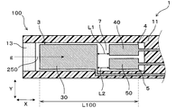
- FIG. 3 is a cross-sectional view of the gas sensor in the first embodiment.
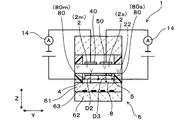
- II-II sectional drawing of FIG. III-III sectional drawing of FIG. 1 is an exploded perspective view of a gas sensor in Embodiment 1.
- the graph which shows the experimental result regarding the ratio of the thickness of a solid electrolyte body, and the shortest distance of a pump electrode and a sensor electrode.
- Example 1 The gas sensor 1 of Example 1 will be described with reference to FIGS.
- the gas sensor 1 is used for measuring the concentration of a predetermined gas component contained in the gas g containing oxygen.
- the gas sensor 1 includes a gas chamber 7, a reference gas chamber 8, a plate-shaped solid electrolyte body 2 (2p, 2m, 2s), a pump electrode 30, a monitor electrode 40, and a sensor electrode 50. And a reference electrode 80 and a plate-like heater 6 having a predetermined thickness.
- a gas g containing oxygen is introduced into the gas chamber 7, and a reference gas is introduced into the reference gas chamber 8.
- the solid electrolyte body 2 is provided between the gas chamber 7 and the reference gas chamber 8.
- the solid electrolyte body 2 is a plate-like body made of a material having oxygen ion conductivity, such as zirconia or ceria.
- the solid electrolyte body 2 has a predetermined thickness d, and has a first main surface 21 and a second main surface 22 that face each other through the thickness d.
- the pump electrode 30, the monitor electrode 40, and the sensor electrode 50 are formed on the first main surface 21 that is exposed to the gas chamber 7 in the solid electrolyte body 2.
- the reference electrode 80 is formed on the second main surface 22 exposed to the reference gas chamber 8 in the solid electrolyte body 2.
- the thickness d of the solid electrolyte body 2 is an average value when the thicknesses of five locations in the longitudinal direction of the solid electrolyte body 2 are measured.
- the heater 6 heats the reference electrode 80 in addition to the pump electrode 30, the monitor electrode 40, the sensor electrode 50, and the solid electrolyte body 2, and raises the temperature to a predetermined temperature necessary for the activity of the solid electrolyte body 2.
- the activity of the solid electrolyte body 2 indicates that the solid electrolyte body 2 has reached a temperature necessary for measuring the concentration of oxygen and NOx, and NOx is measured by decomposing NOx into oxygen ions and nitrogen ions. It has the effect
- the pump cell 3 for adjusting the oxygen concentration in the gas g is formed by the solid electrolyte body 2, the pump electrode 30, and the reference electrode 80. Further, as shown in FIG. 3, the solid electrolyte body 2, the monitor electrode 40, and the reference electrode 80 form a monitor cell 4 for detecting the oxygen concentration in the gas g after adjusting the oxygen concentration using the pump cell 3. is there. Further, as shown in FIGS. 1 and 3, the solid electrolyte body 2, the sensor electrode 50, and the reference electrode 80 detect the concentration of a predetermined gas component in the gas g after adjusting the oxygen concentration using the pump cell 3. A sensor cell 5 is formed. Specifically, the sensor cell 5 outputs a signal indicating the concentration of a predetermined gas component.
- the heater 6 is disposed opposite to the solid electrolyte body 2 with the reference gas chamber 8 interposed therebetween.
- the heater 6 includes a ceramic heater sheet 62, a heater pattern 63 that is formed on the surface of the heater sheet 62 and generates heat when energized, and an insulating layer 61 that covers the heater pattern 63.
- the distance D1 is the shortest distance between the region of the part 2p that is a part of the main surface 22 of the solid electrolyte body 2 and that constitutes the pump cell 3, and the main surface 90 of the insulating layer 61 that faces the main surface 22.
- the distance D2 is the shortest distance between the region 2m of the main surface 22 of the solid electrolyte body 2 and constituting the monitor cell 4 and the main surface 90 of the insulating layer 61, as shown in FIG. Yes
- the distance D3 is the shortest distance between the region of the part 2s that is a part of the main surface 22 of the solid electrolyte body 2 and that constitutes the sensor cell 5, and the main surface 90 of the insulating layer 61.
- the gas sensor 1 of this example functions as a NOx sensor for measuring the concentration of NOx contained in the exhaust gas of an automobile. That is, the gas g in this example is an exhaust gas of an automobile having an internal combustion engine, and the predetermined gas component is NOx.
- the entire gas sensor 1 is accommodated in a cylindrical case (not shown), which is attached to the exhaust pipe of an automobile. At this time, the front end portion 100 of the gas sensor 1 is inserted into the exhaust pipe, and the rear end portion is exposed to the atmosphere as the reference gas.
- the gas sensor 1 includes an insulating plate 10 made of ceramic or the like, a sheet-like first spacer 11 for forming the gas chamber 7, the solid electrolyte body 2, and the reference gas chamber 8.
- a sheet-like second spacer 12 for forming and a heater 6 for heating the pump cell 3, the monitor cell 4 and the sensor cell 5 are stacked in the Z direction.
- the gas chamber 7 is a space into which exhaust gas (gas g) is introduced from the exhaust pipe of the automobile.
- the gas g flows in the direction indicated by the arrow 250 in the gas chamber 7 as shown in FIGS.
- a cutout 79 is formed in the first spacer 11, and this cutout 79 becomes the gas chamber 7.
- the first spacer 11 is provided with a diffusion resistance layer 13. Gas g is introduced from the exhaust pipe into the gas chamber 7 through the diffusion resistance layer 13. The diffusion resistance layer 13 limits the inflow speed of the gas g.
- the reference gas chamber 8 is a space into which air as a reference gas having a constant oxygen concentration is introduced, and is formed by a through hole 89 provided in the second spacer 12.
- the through-hole 89 is formed outside the gas sensor 1 where the atmosphere exists through a passage portion 121 including a groove extending in the gas g flow direction X (that is, the direction 250 flowing in the gas chamber 7 shown in FIGS. 1 and 2). It communicates with space. Air is introduced into the reference gas chamber 8 through the passage portion 121.
- the first spacer 11 and the second spacer 12 are made of an insulating material such as alumina.
- the pump electrode 30 and the monitor electrode 40 are made of a metal material having a low decomposition activity for NOx. Specifically, the pump electrode 30 and the monitor electrode 40 are made of a porous cermet electrode containing gold Au and platinum Pt as main components.
- the sensor electrode 50 is made of a metal material having a high decomposition activity for NOx. Specifically, the sensor electrode 50 is composed of a porous cermet electrode containing platinum Pt and rhodium Rh as main components.
- the pump electrode 30, the monitor electrode 40, the sensor electrode 50, and the reference electrode 80 have leads 16 that serve as a current path.
- the first spacer 11 and the insulating plate 10 are formed with through holes 17 penetrating in the Z direction.
- the through holes 17 allow the pump electrode 30, the monitor electrode 40, and the sensor electrode 50 to be on the surface of the insulating plate 10. Electrically conductive up to.
- a plurality of lead connection electrodes 15 are provided on the surface of the insulating plate 10 for electrical connection with an external device.
- the heater 6 includes a ceramic heater sheet 62, a heater pattern 63 that is formed on the surface of the heater sheet 62 and generates heat when energized, and an insulating layer 61 that covers the heater pattern 63.
- the heater 6 generates heat by heating the heater pattern 63 from the outside, and heats the pump cell 3, the monitor cell 4 and the sensor cell 5 to the activation temperature.
- the heater sheet 62 has a through hole 17 and a pad 18, and the heater pattern 63 and the pad 18 are electrically connected through the through hole 17.
- the reference electrode 80 is also electrically connected to the lead connection electrode 180 formed on the surface of the heater sheet 62 through the through hole 17.
- the heat generation center of the heater pattern 63 is biased toward the pump cell 3. That is, the pump cell 3, the monitor cell 4, and the sensor cell 5 are heated using the heater pattern 63 so that the pump cell 3 has a higher temperature than the monitor cell 4 and the sensor cell 5.
- the solid electrolyte body 2 has a thickness d. Further, the pump electrode 30 and the sensor electrode 50 are separated by the shortest distance L2. In this embodiment, the gas sensor 1 is configured so that the ratio (L2 / d) between the shortest distance L2 and the thickness d of the solid electrolyte body 2 is 3 or more.
- the thickness d of the solid electrolyte body 2 is an average value obtained by measuring the thickness of five locations in the longitudinal direction of the plate-like solid electrolyte body 2.
- the shortest distance L2 between the pump electrode 30 and the sensor electrode 50 is along the longitudinal direction of the gas sensor 1 of the solid electrolyte body 2 in which the pump electrode 30 and the sensor electrode 50 are formed, that is, along the gas flow direction 250. This is the distance between the pump electrode 30 and the sensor electrode 50.
- the condition that the ratio of 3 or more is satisfied by increasing the shortest distance L2 between the pump electrode 30 and the sensor electrode 50 with respect to the thickness d of the solid electrolyte body 2.
- the resistance between the pump electrode 30 and the sensor electrode 50 increases, and current leakage from the pump electrode 30 to the sensor electrode 50 is reduced. Thereby, a necessary current flow is secured in the pump cell 3.
- the condition that the ratio is 3 or more is satisfied.
- the resistance between the pump electrode 30 and the reference electrode 80 (that is, the reference electrode 80p) constituting the pump cell 3 is reduced.
- the leak of the current from the pump electrode 30 to the sensor electrode 50 is reduced, and the inflow of the leak current to the sensor cell 5 can be suppressed. Therefore, the accuracy of measuring the concentration of the predetermined gas component is improved.
- the ratio of the shortest distance L2 between the pump electrode 30 and the sensor electrode 50 to the thickness d of the solid electrolyte body 2 is set to 3 or more, so that the gas sensor 1 includes only one solid electrolyte body 2. Can do. Then, by forming the pump electrode 30, the monitor electrode 40, the sensor electrode 50, and the reference electrode 80 on the solid electrolyte body 2, three types of cells, that is, the pump cell 3, the monitor cell 4, and the sensor cell 5, can be configured. .
- the shortest distance L2 is preferably 0.3 mm to 0.7 mm, and the thickness d of the solid electrolyte body 2 is preferably 0.1 mm to 0.3 mm. Furthermore, it is preferable that the ratio (L2 / d) between the shortest distance L2 and the thickness d is 7 or less.
- Each numerical range is defined from the viewpoint of the strength of the solid electrolyte body 2 and the functions of the pump cell 3, the monitor cell 4, and the sensor cell 5.
- the concentration of the predetermined gas component (NOx) of the gas g having oxygen is measured by measuring the residual oxygen concentration of the gas g after the oxygen concentration is adjusted by the pump cell 3 using the monitor cell 4.
- the oxygen concentration corresponding to the sum of the concentration of the gas component (NOx) and the residual oxygen concentration is measured by the sensor cell 5, and the difference between the output of the sensor cell 5 and the output of the monitor cell 4 is taken to change the output of the sensor cell 5 to the residual oxygen concentration. This is done by eliminating the corresponding components.
- the gas chamber 7 is composed of a single space formed by the first spacer 11, the insulating plate 10, and the solid electrolyte body 2. Therefore, the flow of the gas g in the gas chamber 7 can be made smooth, and the fluctuation of the output of the sensor cell 5 indicating the concentration of the predetermined gas component can be detected with high responsiveness.
- the gas chamber 7 is formed by a single space having a predetermined thickness along the thickness direction (that is, the Z direction) of the heater 6 and a predetermined width. The thickness of the gas chamber 7 is constant at least from the portion of the main surface 21 of the solid electrolyte body 2 where the pump electrode 30 is formed to the portion of the main surface 21 where the monitor electrode 40 and the sensor electrode 50 are formed.
- the width of the gas chamber 7 is the distance between the inner walls of the first spacer 11 along the direction perpendicular to the gas flow direction 250 and the thickness direction in the gas chamber 7, that is, the Y direction in FIG.
- the portion from the portion of the main surface 21 where the pump electrode 30 is formed to the portion of the main surface 21 where the monitor electrode 40 and the sensor electrode 50 are formed is constant. That is, in the gas chamber 7, between the pump electrode 30 and the monitor electrode 40 and the sensor electrode 50, there is an object that narrows the dimension in the Z direction or the Y direction of the gas chamber 7, such as a throttle portion or a partition wall. do not do. Thereby, in the gas chamber 7, the gas g flows from the pump electrode 30 to the monitor electrode 40 and the sensor electrode 50 without being diffusion-controlled.
- the distance L1 from the pump electrode 30 to the monitor electrode 40 and the distance L2 from the pump electrode 30 to the sensor electrode 50 in the X direction are equal to each other.
- the reference electrode 80 is shared by the pump cell 3, the monitor cell 4, and the sensor cell 5. That is, the reference electrode 80 is formed of a single conductor integrally including a reference electrode 80p constituting the pump cell 3, a reference electrode 80m constituting the monitor cell 4, and a reference electrode 80s constituting the sensor cell 5.
- the gas sensor 1 for detecting the concentration of a predetermined gas
- the gas g is introduced into the gas chamber 7 through the diffusion resistance layer 13. Since the introduced gas g contains oxygen molecules, the pump cells 3 are used to discharge oxygen molecules. That is, a DC voltage is applied between the reference electrode 80 and the pump electrode 30 so that the reference electrode 80 has a high potential. If it does in this way, an oxygen molecule will be reduced in pump electrode 30 and will become oxygen ion, and will be exhausted to standard gas room 8 by a pumping action.
- the oxygen concentration in the gas chamber 7 is controlled by adjusting the magnitude of the DC voltage applied to the pump cell 3.
- the gas g having a reduced oxygen concentration is introduced into the monitor cell 4 and the sensor cell 5. Since the gas g contains oxygen molecules that could not be exhausted in the pump cell 3, the concentration of the oxygen molecules is measured by the monitor cell 4. As shown in FIG. 3, in the monitor cell 4, a DC voltage is applied between the reference electrode 80 and the monitor electrode 40 so that the reference electrode 80 has a high potential. If it does in this way, the oxygen molecule contained in gas g will be reduced and it will become oxygen ion, and will be exhausted to standard gas room 8 by pumping action.
- the monitor electrode 40 is a Pt—Au cermet electrode that is inactive for NOx decomposition
- the oxygen ion current flowing through the monitor cell 4 depends only on the concentration of oxygen molecules contained in the gas g, and depends on the concentration of NOx. do not do. Therefore, if the oxygen ion current value is measured using the ammeter 14, the concentration of oxygen molecules contained in the gas g can be measured.
- a DC voltage is applied between the reference electrode 80 and the sensor electrode 50 so that the reference electrode 80 has a high potential. Since the sensor electrode 50 is a Pt—Rh cermet electrode that is active in decomposing NOx, oxygen molecules and NOx molecules are reduced on the sensor electrode 50 to oxygen ions, and are discharged to the reference gas chamber 8 by a pumping action. The Therefore, if the oxygen ion current value is measured using the ammeter 14, the total concentration of oxygen molecules and NOx molecules contained in the gas g can be calculated.
- the monitor cell 4 is used to measure the concentration A of oxygen molecules contained in the gas g
- the sensor cell 5 is used to measure the total concentration B of oxygen molecules and NOx molecules. Then, the concentration of NOx in the gas g is calculated by subtracting the concentration A from the concentration B.
- oxygen is discharged from the gas g using the pump cell 3, but oxygen may be introduced from the reference gas chamber 8 to the gas g by reversing the direction of the applied voltage.
- the solid electrolyte body 2 has a thickness d. Further, the pump electrode 30 and the sensor electrode 50 are separated by the shortest distance L2.
- the gas sensor 1 is configured such that the ratio (L2 / d) between the shortest distance L2 and the thickness d of the solid electrolyte body 2 is 3 or more. In other words, by increasing the distance L2 between the pump electrode 30 and the sensor electrode 50 with respect to the thickness d of the solid electrolyte body 2, the condition that the ratio is 3 or more is satisfied. As a result, the resistance between the pump electrode 30 and the sensor electrode 50 increases, and current leakage from the pump electrode 30 to the sensor electrode 50 is reduced. Thereby, a necessary current flow is secured in the pump cell 3.
- the condition that the ratio is 3 or more is satisfied.
- the resistance between the pump electrode 30 and the reference electrode 80 (that is, the reference electrode 80p) constituting the pump cell 3 is reduced, current leakage from the pump electrode 30 to the sensor electrode 50 is reduced, and the pump cell 3 The necessary current flow is ensured. Therefore, the accuracy of measuring the concentration of the predetermined gas component is improved.
- the pump cell 3, the monitor cell 4, and the sensor cell 5 through one solid electrolyte body 2. Therefore, only one of the gas chamber 7 and the reference gas chamber 8 is interposed between the solid electrolyte body 2 and the heater 6, and the pump cell 3, the monitor cell 4, the sensor cell 5, the heater 6, The heater cell 6 makes it easy to heat the pump cell 3, the sensor cell 5, and the monitor cell 4. Furthermore, the thickness of the gas sensor 1 in the Z direction can be reduced, and the gas sensor 1 can be downsized.
- a reference gas chamber 8 is interposed between the heater 6 and the solid electrolyte body 2.
- the distances D1, D2, and D3 are equal to each other.
- the three cells of the pump cell 3, the monitor cell 4, and the sensor cell 5 can be brought close to the heater 6, respectively. That is, in this example, since only the reference gas chamber 8 is interposed between the solid electrolyte body 2 and the heater 6, the intervals between the pump cell 3, the monitor cell 4, the sensor cell 5 and the heater 6 can be reduced.
- the pump cell 3, the monitor cell 4, and the sensor cell 5 all at an equal distance from the heater 6, the heat energy transmitted from the heater 6 to the pump cell 3, the monitor cell 4, and the sensor cell 5 becomes equal, and the pump cell 3, the temperature variation of the monitor cell 4 and the sensor cell 5 can be reduced. Further, the pump cell 3, the monitor cell 4, and the sensor cell 5 can be heated by the heater 6 with the minimum power consumption.
- a single solid electrolyte body 2 a pump electrode 30, a monitor electrode 40, and a sensor electrode 50 constitute a pump cell 3, a monitor cell 4, and a sensor cell 5, respectively. Therefore, the manufacturing cost of the gas sensor 1 can be reduced.
- the gas chamber 7 is formed by a single space having a predetermined thickness and a predetermined width along the thickness direction of the heater 6 (that is, the Z direction).
- the thickness of the gas chamber 7 is constant at least from the portion of the main surface 21 of the solid electrolyte body 2 where the pump electrode 30 is formed to the portion of the main surface 21 where the monitor electrode 40 and the sensor electrode 50 are formed.
- the width of the gas chamber 7 is the distance between the inner walls of the first spacer 11 along the direction perpendicular to the gas flow direction 250 and the thickness direction in the gas chamber 7, that is, the Y direction in FIG.
- the portion from the portion of the main surface 21 where the pump electrode 30 is formed to the portion of the main surface 21 where the monitor electrode 40 and the sensor electrode 50 are formed is constant. That is, in the gas chamber 7, between the pump electrode 30 and the monitor electrode 40 and the sensor electrode 50, there is an object that narrows the dimension in the Z direction or the Y direction of the gas chamber 7, such as a throttle portion or a partition wall. do not do. Thereby, in the gas chamber 7, the gas g flows from the pump electrode 30 to the monitor electrode 40 and the sensor electrode 50 without being diffusion-controlled. Therefore, when the concentration of the predetermined gas component (NOx) in the gas g changes, the change can be detected in a short time. That is, the output responsiveness of the gas sensor 1 can be improved.
- NOx predetermined gas component
- the reference electrode 80p constituting the pump cell 3, the reference electrode 80m constituting the monitor cell 4, and the reference electrode 80s constituting the sensor cell 5 are formed by a single conductor.
- the configuration of the gas sensor 1 can be simplified.
- the gas sensor assembly is configured by incorporating the gas sensor 1 into the housing, an energization member is connected to the lead 16b.
- the lead 16b can be integrated into one, so the energization member is also integrated into one.
- the configuration of the gas sensor can be simplified.
- the distance L1 from the pump electrode 30 to the monitor electrode 40 and the distance L2 from the pump electrode 30 to the sensor electrode 50 in the X direction are equal to each other. Therefore, the gas g whose oxygen concentration has been reduced by the pump cell 3 reaches the monitor electrode 40 and the sensor electrode 50 almost simultaneously. Therefore, the oxygen concentration of the gas g on the monitor electrode 40 and the oxygen concentration of the gas g on the sensor electrode 50 are almost the same. Therefore, when the concentration subtraction (concentration B ⁇ concentration A) is performed as described above, the oxygen concentration can be canceled accurately. This makes it possible to accurately measure the concentration of a predetermined gas component.
- the gas chamber 7 is configured such that the gas g flows in a predetermined direction 250 therein.
- the pump electrode 30 is located upstream of the predetermined direction 250, while the monitor electrode 40 and the sensor electrode 50 are located downstream of the predetermined direction 250. Further, the monitor electrode 40 and the sensor electrode 50 are arranged in parallel in the predetermined direction 250, whereby the concentration of the predetermined gas component (NOx) of the gas g having oxygen is measured by the pump cell 3. Is an error in the difference between the output of the monitor cell 4 indicating the residual oxygen concentration of the gas g after the adjustment of the gas g and the output of the sensor cell 5 indicating the oxygen concentration corresponding to the sum of the concentration of the predetermined gas component (NOx) and the residual oxygen concentration.
- the measurement accuracy of the predetermined gas component (NOx) concentration can be improved.
- the pump cell 3 since the pump cell 3 has a larger amount of oxygen ions flowing than the monitor cell 4 and the sensor cell 5, it is desirable that the pump cell 3 has a higher temperature than the monitor cell 4 and the sensor cell 5. Therefore, in this example, as is clear from FIG. 4, the heat generation center of the heater 6 is biased toward the pump cell 3 side. Thereby, the temperature of the pump cell 3 is made slightly higher than the temperatures of the monitor cell 4 and the sensor cell 5. Note that the heat generation center of the heater 6 is the highest temperature portion of the heat distribution generated from the heater 6.
- the temperature variation of the pump cell 3, the monitor cell 4, and the sensor cell 5 can be reduced, the power consumption of the heater 6 can be reduced, and the gas sensor 1 that can be miniaturized can be provided.
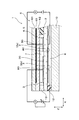
- FIG. 5 shows a gas sensor 1 according to the second embodiment.
- the gas sensor 1 has a plurality of solid electrolyte bodies 2.
- the gas sensor 1 includes two solid electrolyte bodies 2 (2a, 2b).
- the pump cell 3 is comprised using one solid electrolyte body 2a
- the monitor cell 4 and the sensor cell 5 are comprised using the other solid electrolyte body 2b.
- a distance Da between one solid electrolyte body 2a and the heater 6 and a distance Db between the other solid electrolyte body 2b and the heater 6 in the Z direction are equal to each other.
- the distance Da is the shortest distance between the main surface 22a of the solid electrolyte body 2a and the main surface 90 of the insulating layer 61 facing the main surface 22a.
- the distance Db is the distance of the solid electrolyte body 2b. This is the shortest distance between the main surface 22 b and the main surface 90 of the insulating layer 61.
- An insulating member 29 is interposed between the solid electrolyte bodies 2a and 2b.
- a pump cell 3 having a relatively large flowing current and a monitor cell 4 and a sensor cell 5 having a relatively small flowing current are constituted by independent solid electrolyte bodies 2a and 2b. . For this reason, a part of the current flowing through the pump cell 3 becomes a noise current, and the trouble flowing through the monitor cell 4 and the sensor cell 5 is minimized. This improves the accuracy of measuring the concentration of the predetermined gas component.
- FIG. 6 shows a gas sensor 1 according to the third embodiment.
- the gas sensor 1 differs from the first embodiment in the position of the heater 6. That is, a gas chamber 7 is provided between the heater 6 and the solid electrolyte body 2. The heater 6 faces the solid electrolyte body 2 through the gas chamber 7.
- Example 1 As those of the first embodiment. 6, the same reference numerals as those used in the first embodiment denote the same components as those in the first embodiment unless otherwise specified.
- Example 1 Here, by using the gas sensor of Example 1 shown in FIGS. 1 to 3, the thickness d of the solid electrolyte body 2 and the distance of the shortest distance L2 between the pump electrode 30 and the sensor electrode 50 are variously changed, and this shortest distance L2 The relationship between the ratio (L2 / d) of the thickness d and the NOx gas concentration detection accuracy of the gas sensor was examined.
- the ratio (L2 / d) of the shortest distance L2 between the thickness d of the solid electrolyte body 2 and the pump electrode 30 and the sensor electrode 50 is set to 3 or more. It can be seen that the output error can be greatly reduced to 2.5% or less. Further, if the ratio (L2 / d) is 3 or more, the output error can be reduced.
- the ratio (L2 / d) is 3 or more, the output error can be reduced.
- the monitor cell 4 and the sensor cell 5, 7 The following is preferable.
Abstract
Description
前記ガスが導入されるガス室と、
基準ガスが導入される基準ガス室と、
酸素イオン伝導性を有し、前記ガス室と前記基準ガス室との間に配置され、前記ガス室に面する第1の主面と、前記基準ガス室に面する第2の主面を有する一つの板状の固体電解質体と、
前記固体電解質体の第1主面に形成された複数の電極と、
前記固体電解質体の第2主面に形成された基準電極と、
前記固体電解質体の第1主面に形成された前記電極の一つであり、前記基準電極と前記固体電解質体の一部とともに、前記ガス中の酸素濃度を調整するポンプセルを構成するポンプ電極と、
前記固体電解質体の第1主面に形成された前記電極の一つであり、前記基準電極と前記固体電解質体の一部とともに、前記ポンプセルによって酸素の濃度を調整した後における前記ガス中の所定ガス成分の濃度に応じた信号を出力するセンサセルを構成するセンサ電極と、
前記ガス室又は前記基準ガス室を介して前記固体電解質体に対向配置されており、前記固体電解質体を加熱する所定の厚みを有する板状のヒータと、を有し、
前記ポンプ電極と前記センサ電極との最短距離の、前記固体電解質体の厚みに対する比率が3以上であるガスセンサである。
実施例1のガスセンサ1について、図1~図4を用いて説明する。ガスセンサ1は、酸素を含むガスgに含まれる所定のガス成分の濃度を測定するために用いられる。図1に示すごとく、ガスセンサ1は、ガス室7と、基準ガス室8と、板状の固体電解質体2(2p,2m,2s)と、ポンプ電極30と、モニタ電極40と、センサ電極50と、基準電極80と、所定の厚みを有する板状のヒータ6とを備える。ガス室7には酸素を含むガスgが導入され、基準ガス室8には基準ガスが導入される。
また、ガス室7は、ヒータ6の厚み方向(すなわちZ方向)に沿った所定の厚みと、所定の幅を有する単一の空間により形成さる。このガス室7の厚みは、少なくとも、固体電解質体2の主面21のポンプ電極30が形成された部分から主面21のモニタ電極40およびセンサ電極50が形成された部分まで一定となっている。ガス室7の幅は、ガス室7内でのガスの流れ方向250と厚み方向に直交する方向、すなわち、図2のY方向に沿った第1スペーサ11の内側壁間の間隔であり、すくなくとも、主面21のポンプ電極30が形成された部分から主面21のモニタ電極40およびセンサ電極50が形成された部分まで一定となっている。すなわち、ガス室7内における、ポンプ電極30からモニタ電極40及びセンサ電極50までの間には、絞り部や隔壁のように、ガス室7のZ方向寸法またはY方向寸法を狭くする物が存在しない。これにより、ガス室7内において、ガスgが、ポンプ電極30から、モニタ電極40及びセンサ電極50へ拡散律速することなく流れるようになる。
図5に、実施例2にかかるガスセンサ1を示す。ガスセンサ1は、複数の固体電解質体2を有している。具体的には、ガスセンサ1は、2つの固体電解質体2(2a,2b)を備える。そして、一方の固体電解質体2aを用いてポンプセル3を構成し、他方の固体電解質体2bを用いてモニタセル4及びセンサセル5を構成する。Z方向における、一方の固体電解質体2aとヒータ6との距離Daと、他方の固体電解質体2bとヒータ6との距離Dbとは、互いに等しい。正確には、距離Daは、固体電解質体2aの主面22aと、この主面22aに対面する絶縁層61の主面90との間の最短距離であり、距離Dbは、固体電解質体2bの主面22bと、絶縁層61の主面90の間の最短距離である。
図6に、実施例3にかかるガスセンサ1を示す。ガスセンサ1は、ヒータ6の位置において実施例1と異なる。すなわち、ヒータ6と固体電解質体2との間に、ガス室7が設けられている。そして、ヒータ6は、ガス室7を介して固体電解質体2に対向する。
(実験例1)
ここで、図1~3に示す実施例1のガスセンサを用いて、固体電解質体2の厚みdとポンプ電極30とセンサ電極50との最短距離L2の距離を種々変更して、この最短距離L2と厚みdとの比率(L2/d)の値とガスセンサのNOxガスの濃度検出精度の関係を調べた。
出力誤差(%)=((各寸法試料のセンサセル電流/基準としたセンサセル電流)-1)×100
2 固体電解質体
3 ポンプセル
30 ポンプ電極
4 モニタセル
40 モニタ電極
5 センサセル
50 センサ電極
6 ヒータ
7 ガス室
8 基準ガス室
80 基準電極
100 ガスセンサ先端部
g ガス
Claims (6)
- 酸素を含むガスの所定のガス成分の濃度を測定するガスセンサ(1)であって、
前記ガスが導入されるガス室(7)と、
基準ガスが導入される基準ガス室(8)と、
酸素イオン伝導性を有し、前記ガス室(7)と前記基準ガス室(8)との間に配置され、前記ガス室(7)に面する第1の主面と、前記基準ガス室(8)に面する第2の主面を有する一つの板状の固体電解質体(2)と、
前記固体電解質体(2)の第1主面に形成された複数の電極(30、50)と、
前記固体電解質体(2)の第2主面に形成された基準電極(80)と、
前記固体電解質体(2)の第1主面に形成された前記電極の一つであり、前記基準電極(80)と前記固体電解質体(2)の一部(2p)とともに、前記ガス中の酸素濃度を調整するポンプセル(3)を構成するポンプ電極(30)と、
前記固体電解質体(2)の第1主面に形成された前記電極の一つであり、前記基準電極(80)と前記固体電解質体(2)の一部(2s)とともに、前記ポンプセル(3)によって酸素の濃度を調整した後における前記ガス中の所定ガス成分の濃度に応じた信号を出力するセンサセル(5)を構成するセンサ電極(50)と、
前記ガス室(7)又は前記基準ガス室(8)を介して前記固体電解質体(2)に対向配置されており、前記固体電解質体(2)を加熱する所定の厚みを有する板状のヒータ(6)と、を有し、
前記ポンプ電極(30)と前記センサ電極(50)との最短距離(L2)と、前記固体電解質体(2)の厚み(d)との比率(L2/d)が3以上であるガスセンサ。 - 前記固体電解質体(2)の第1主面に形成された前記電極の一つであり、前記基準電極(80)と前記固体電解質体(2)の一部(2m)とともに、前記ポンプセルを使って酸素濃度を調整した後における前記ガス中の酸素濃度をモニタするモニタセルを構成するモニタ電極(40)をさらに備え、前記ガス室(7)は単一の空間により形成される請求項1に記載のガスセンサ。
- 前記ヒータ(6)の前記固体電解質体(2)に対向する表面と、前記固体電解質体(2)の第2主面の一部であって前記ポンプセル(3)を構成する部位(2p)の表面との間の、前記ヒータ(6)の厚さ方向における距離(D1)と、前記ヒータ(6)の前記固体電解質体(2)に対向する表面と、前記固体電解質体(2)の第2主面の一部であって前記モニタセル(4)を構成する部位(2m)の表面との間の、前記ヒータ(6)の厚さ方向における距離(D2)と、前記ヒータ(6)の前記固体電解質体(2)に対向する表面と、前記固体電解質体(2)の第2主面の一部であって前記センサセル(5)を構成する部位(2s)の表面との間の、前記ヒータ(6)の厚さ方向における距離(D3)が、互いに等しい請求項2に記載のガスセンサ。
- 前記ガス室(7)は、前記ヒータの厚み方向に沿った所定の厚みと、所定の幅を有する空間により形成され、この前記ガス室(7)の厚みは、前記第1主面の前記ポンプ電極(30)が形成された部分から前記第1主面の前記モニタ電極(40)および前記センサ電極(50)が形成された部分まで一定となっており、前記ガス室(7)の幅は、前記ガス室(7)内での前記ガスの流れ方向と前記厚み方向に直交し、前記第1主面の前記ポンプ電極(30)が形成された部分から前記第1主面の前記モニタ電極(40)および前記センサ電極(50)が形成された部分まで一定である請求項2または3に記載のガスセンサ。
- 前記基準電極(80)は、前記ポンプセル(30)を構成する第1の基準電極(80p)と、前記モニタセル(4)を構成する第2の基準電極(80m)と、前記センサセル(5)を構成する第3の基準電極(80s)とを一体的に有する請求項1~請求項4のいずれか1項に記載のガスセンサ。
- 前記ガス室(7)は、その中において前記ガスが所定の方向(250)に流れるように構成されており、前記ポンプ電極(30)は、この所定の方向の上流に位置する一方、前記モニタ電極(40)および前記センサ電極(50)は、この所定方向の下流に位置するとともに、並列的に配置されている請求項1~5のいずれかに記載のガスセンサ。
Priority Applications (3)
| Application Number | Priority Date | Filing Date | Title |
|---|---|---|---|
| US14/912,989 US10036724B2 (en) | 2013-08-21 | 2014-08-21 | Gas sensor |
| DE112014003820.2T DE112014003820T5 (de) | 2013-08-21 | 2014-08-21 | Gassensor |
| CN201480045958.0A CN105474008B (zh) | 2013-08-21 | 2014-08-21 | 气体传感器 |
Applications Claiming Priority (2)
| Application Number | Priority Date | Filing Date | Title |
|---|---|---|---|
| JP2013-171109 | 2013-08-21 | ||
| JP2013171109 | 2013-08-21 |
Publications (1)
| Publication Number | Publication Date |
|---|---|
| WO2015025924A1 true WO2015025924A1 (ja) | 2015-02-26 |
Family
ID=52483695
Family Applications (1)
| Application Number | Title | Priority Date | Filing Date |
|---|---|---|---|
| PCT/JP2014/071897 WO2015025924A1 (ja) | 2013-08-21 | 2014-08-21 | ガスセンサ |
Country Status (5)
| Country | Link |
|---|---|
| US (1) | US10036724B2 (ja) |
| JP (2) | JP6203687B2 (ja) |
| CN (1) | CN105474008B (ja) |
| DE (1) | DE112014003820T5 (ja) |
| WO (1) | WO2015025924A1 (ja) |
Cited By (5)
| Publication number | Priority date | Publication date | Assignee | Title |
|---|---|---|---|---|
| WO2015093488A1 (ja) * | 2013-12-16 | 2015-06-25 | 株式会社デンソー | 特定ガス成分の濃度を検出するガスセンサ |
| WO2015194490A1 (ja) * | 2014-06-16 | 2015-12-23 | 株式会社デンソー | ガスセンサ |
| JP2016212119A (ja) * | 2013-12-16 | 2016-12-15 | 株式会社日本自動車部品総合研究所 | ガスセンサ |
| WO2020158269A1 (ja) * | 2019-01-31 | 2020-08-06 | 株式会社デンソー | ガスセンサ |
| WO2020158268A1 (ja) * | 2019-01-31 | 2020-08-06 | 株式会社デンソー | ガスセンサ |
Families Citing this family (22)
| Publication number | Priority date | Publication date | Assignee | Title |
|---|---|---|---|---|
| US10036724B2 (en) * | 2013-08-21 | 2018-07-31 | Denso Corporation | Gas sensor |
| JP5892135B2 (ja) | 2013-09-24 | 2016-03-23 | 株式会社デンソー | ガス濃度検出装置 |
| JP6561719B2 (ja) * | 2014-10-30 | 2019-08-21 | 株式会社デンソー | ガスセンサ |
| JP6485364B2 (ja) | 2015-02-12 | 2019-03-20 | 株式会社デンソー | ガスセンサ |
| JP6382162B2 (ja) | 2015-07-08 | 2018-08-29 | 株式会社Soken | ガスセンサのポンプ電極及び基準電極 |
| JP6369496B2 (ja) | 2015-09-17 | 2018-08-08 | 株式会社デンソー | ガスセンサ |
| JP6382178B2 (ja) * | 2015-12-17 | 2018-08-29 | 株式会社Soken | ガスセンサ |
| JP2017116309A (ja) * | 2015-12-22 | 2017-06-29 | 株式会社デンソー | 内燃機関のガス濃度検出装置 |
| JP6731283B2 (ja) * | 2016-05-11 | 2020-07-29 | 株式会社Soken | ガスセンサ |
| CN109451749B (zh) * | 2016-06-23 | 2021-05-14 | 日本碍子株式会社 | 气体传感器以及被测定气体中的多个目标成分的浓度测定方法 |
| WO2018030369A1 (ja) | 2016-08-09 | 2018-02-15 | 日本碍子株式会社 | ガスセンサ |
| JP6669616B2 (ja) * | 2016-09-09 | 2020-03-18 | 日本碍子株式会社 | ガスセンサ |
| JP6693405B2 (ja) | 2016-12-20 | 2020-05-13 | 株式会社デンソー | ガスセンサ素子およびガスセンサユニット |
| JP6696418B2 (ja) * | 2016-12-21 | 2020-05-20 | 株式会社デンソー | ガスセンサ素子及びガスセンサユニット |
| JP6720851B2 (ja) | 2016-12-21 | 2020-07-08 | 株式会社デンソー | ガスセンサ素子およびガスセンサユニット |
| JP6761369B2 (ja) * | 2017-03-30 | 2020-09-23 | 日本碍子株式会社 | ガスセンサ素子 |
| JP6998802B2 (ja) * | 2018-03-12 | 2022-02-04 | 日本碍子株式会社 | ガスセンサ |
| JP7138055B2 (ja) * | 2018-06-26 | 2022-09-15 | 株式会社Soken | ガスセンサ |
| JP7299852B2 (ja) | 2019-03-27 | 2023-06-28 | 日本碍子株式会社 | センサ素子及びガスセンサ |
| JP7118918B2 (ja) | 2019-03-28 | 2022-08-16 | 株式会社Soken | ガスセンサ |
| CN113075277B (zh) * | 2021-05-20 | 2022-08-02 | 中国科学技术大学先进技术研究院 | 氮氧化物传感器 |
| CN113075278B (zh) * | 2021-05-20 | 2022-08-02 | 中国科学技术大学先进技术研究院 | 氮氧化物传感器 |
Citations (6)
| Publication number | Priority date | Publication date | Assignee | Title |
|---|---|---|---|---|
| JPS6036949A (ja) * | 1983-08-09 | 1985-02-26 | Ngk Insulators Ltd | 酸素センサ素子 |
| JPH06213864A (ja) * | 1992-07-20 | 1994-08-05 | General Motors Corp <Gm> | 広範囲酸素センサー |
| JPH09105737A (ja) * | 1994-10-24 | 1997-04-22 | Nippon Soken Inc | 空燃比検出装置 |
| JP2000321238A (ja) * | 1996-09-17 | 2000-11-24 | Riken Corp | ガスセンサ |
| JP2004125534A (ja) * | 2002-09-30 | 2004-04-22 | Ngk Spark Plug Co Ltd | ガスセンサ素子及びこれを用いたガスセンサ |
| JP2004132840A (ja) * | 2002-10-10 | 2004-04-30 | Denso Corp | ガス濃度検出装置 |
Family Cites Families (20)
| Publication number | Priority date | Publication date | Assignee | Title |
|---|---|---|---|---|
| DE19539357B4 (de) | 1994-10-24 | 2011-09-15 | Denso Corporation | Luft-Brennstoffverhältnis-Erfassungseinrichtung |
| JP3544437B2 (ja) * | 1996-09-19 | 2004-07-21 | 日本碍子株式会社 | ガスセンサ |
| JP2001153840A (ja) | 1999-11-24 | 2001-06-08 | Nippon Soken Inc | ガスセンサ及び可燃性ガス成分濃度の検出方法 |
| TWI301915B (ja) | 2000-03-17 | 2008-10-11 | Seiko Epson Corp | |
| JP3501125B2 (ja) | 2000-03-17 | 2004-03-02 | セイコーエプソン株式会社 | 電気光学装置 |
| DE10058014C2 (de) * | 2000-11-23 | 2002-12-12 | Bosch Gmbh Robert | Sensorelement eines Gassensors |
| JP3973900B2 (ja) | 2001-02-08 | 2007-09-12 | 株式会社日本自動車部品総合研究所 | ガスセンサ素子 |
| JP2003083936A (ja) | 2001-06-25 | 2003-03-19 | Denso Corp | ガスセンサ素子 |
| JP2003149199A (ja) * | 2001-11-16 | 2003-05-21 | Nissan Motor Co Ltd | ガスセンサ |
| JP4178885B2 (ja) | 2002-08-30 | 2008-11-12 | 株式会社デンソー | ガス濃度検出装置 |
| JP3979240B2 (ja) | 2002-09-13 | 2007-09-19 | 株式会社デンソー | ガス濃度検出装置 |
| JP2004125482A (ja) | 2002-09-30 | 2004-04-22 | Denso Corp | ガス濃度検出装置 |
| JP2005249718A (ja) | 2004-03-08 | 2005-09-15 | Okutekku:Kk | 窒素酸化物濃度検出センサ |
| JP4931074B2 (ja) | 2007-08-01 | 2012-05-16 | 日本特殊陶業株式会社 | ガスセンサ及びNOxセンサ |
| JP2009150719A (ja) * | 2007-12-19 | 2009-07-09 | Toyota Motor Corp | Noxセンサ |
| JP4874282B2 (ja) | 2008-03-20 | 2012-02-15 | 株式会社デンソー | ガスセンサ制御装置 |
| JP2010048647A (ja) | 2008-08-21 | 2010-03-04 | Denso Corp | NOxセンサ素子 |
| JP5247780B2 (ja) * | 2010-09-01 | 2013-07-24 | 株式会社日本自動車部品総合研究所 | ガスセンサの校正方法 |
| JP5367044B2 (ja) * | 2011-10-13 | 2013-12-11 | 株式会社日本自動車部品総合研究所 | ガスセンサ素子および内燃機関用ガスセンサ |
| US10036724B2 (en) | 2013-08-21 | 2018-07-31 | Denso Corporation | Gas sensor |
-
2014
- 2014-08-21 US US14/912,989 patent/US10036724B2/en active Active
- 2014-08-21 JP JP2014168428A patent/JP6203687B2/ja active Active
- 2014-08-21 DE DE112014003820.2T patent/DE112014003820T5/de active Pending
- 2014-08-21 CN CN201480045958.0A patent/CN105474008B/zh active Active
- 2014-08-21 WO PCT/JP2014/071897 patent/WO2015025924A1/ja active Application Filing
-
2016
- 2016-10-05 JP JP2016197201A patent/JP6393722B2/ja active Active
Patent Citations (6)
| Publication number | Priority date | Publication date | Assignee | Title |
|---|---|---|---|---|
| JPS6036949A (ja) * | 1983-08-09 | 1985-02-26 | Ngk Insulators Ltd | 酸素センサ素子 |
| JPH06213864A (ja) * | 1992-07-20 | 1994-08-05 | General Motors Corp <Gm> | 広範囲酸素センサー |
| JPH09105737A (ja) * | 1994-10-24 | 1997-04-22 | Nippon Soken Inc | 空燃比検出装置 |
| JP2000321238A (ja) * | 1996-09-17 | 2000-11-24 | Riken Corp | ガスセンサ |
| JP2004125534A (ja) * | 2002-09-30 | 2004-04-22 | Ngk Spark Plug Co Ltd | ガスセンサ素子及びこれを用いたガスセンサ |
| JP2004132840A (ja) * | 2002-10-10 | 2004-04-30 | Denso Corp | ガス濃度検出装置 |
Cited By (12)
| Publication number | Priority date | Publication date | Assignee | Title |
|---|---|---|---|---|
| WO2015093488A1 (ja) * | 2013-12-16 | 2015-06-25 | 株式会社デンソー | 特定ガス成分の濃度を検出するガスセンサ |
| JP2015135320A (ja) * | 2013-12-16 | 2015-07-27 | 株式会社日本自動車部品総合研究所 | ガスセンサ |
| JP2016212119A (ja) * | 2013-12-16 | 2016-12-15 | 株式会社日本自動車部品総合研究所 | ガスセンサ |
| US10921283B2 (en) | 2013-12-16 | 2021-02-16 | Denso Corporation | Gas sensor for detecting concentration of specific gas component |
| WO2015194490A1 (ja) * | 2014-06-16 | 2015-12-23 | 株式会社デンソー | ガスセンサ |
| JP2016020894A (ja) * | 2014-06-16 | 2016-02-04 | 株式会社デンソー | ガスセンサ |
| WO2020158269A1 (ja) * | 2019-01-31 | 2020-08-06 | 株式会社デンソー | ガスセンサ |
| WO2020158268A1 (ja) * | 2019-01-31 | 2020-08-06 | 株式会社デンソー | ガスセンサ |
| JP2020122763A (ja) * | 2019-01-31 | 2020-08-13 | 株式会社デンソー | ガスセンサ |
| JP2020122764A (ja) * | 2019-01-31 | 2020-08-13 | 株式会社デンソー | ガスセンサ |
| JP7006629B2 (ja) | 2019-01-31 | 2022-01-24 | 株式会社デンソー | ガスセンサ |
| JP7010250B2 (ja) | 2019-01-31 | 2022-01-26 | 株式会社デンソー | ガスセンサ |
Also Published As
| Publication number | Publication date |
|---|---|
| US10036724B2 (en) | 2018-07-31 |
| DE112014003820T5 (de) | 2016-05-04 |
| US20160209354A1 (en) | 2016-07-21 |
| JP6393722B2 (ja) | 2018-09-19 |
| CN105474008A (zh) | 2016-04-06 |
| CN105474008B (zh) | 2018-11-16 |
| JP2015062013A (ja) | 2015-04-02 |
| JP6203687B2 (ja) | 2017-09-27 |
| JP2017040660A (ja) | 2017-02-23 |
Similar Documents
| Publication | Publication Date | Title |
|---|---|---|
| JP6393722B2 (ja) | ガスセンサ | |
| JP5253165B2 (ja) | ガスセンサ及び窒素酸化物センサ | |
| JP5367044B2 (ja) | ガスセンサ素子および内燃機関用ガスセンサ | |
| JP6352215B2 (ja) | ガスセンサ素子 | |
| JP3973900B2 (ja) | ガスセンサ素子 | |
| WO2015030165A1 (ja) | ガス濃度検出装置 | |
| WO2015029842A1 (ja) | ガス濃度検出装置 | |
| US6740217B2 (en) | Structure of gas sensor designed to minimize error of sensor output | |
| JP2015230220A (ja) | ガスセンサ素子 | |
| JP2004151018A (ja) | 積層型ガスセンサ素子 | |
| JP3973851B2 (ja) | ガスセンサ素子 | |
| JP2004132960A (ja) | ガスセンサ素子 | |
| WO2017195556A1 (ja) | ガスセンサ | |
| JP7379243B2 (ja) | ガスセンサの検査装置、ガスセンサの検査方法及び基準センサ | |
| JP4781950B2 (ja) | 複合センサ素子 | |
| JP2004151017A (ja) | 積層型ガスセンサ素子 | |
| US9823220B2 (en) | NOx concentration detection apparatus and NOx concentration detection method | |
| JP2002328112A (ja) | ガスセンサ素子 | |
| JP4101501B2 (ja) | 複合ガスセンサ素子 | |
| KR20160054707A (ko) | 질소산화물 센서 | |
| JP6382178B2 (ja) | ガスセンサ | |
| JP6500547B2 (ja) | ガスセンサ | |
| JP3520217B2 (ja) | ガスセンサ | |
| JP6511405B2 (ja) | ガスセンサ | |
| JPH10282053A (ja) | ガスセンサ |
Legal Events
| Date | Code | Title | Description |
|---|---|---|---|
| WWE | Wipo information: entry into national phase |
Ref document number: 201480045958.0 Country of ref document: CN |
|
| 121 | Ep: the epo has been informed by wipo that ep was designated in this application |
Ref document number: 14837673 Country of ref document: EP Kind code of ref document: A1 |
|
| WWE | Wipo information: entry into national phase |
Ref document number: 14912989 Country of ref document: US |
|
| WWE | Wipo information: entry into national phase |
Ref document number: 1120140038202 Country of ref document: DE Ref document number: 112014003820 Country of ref document: DE |
|
| 122 | Ep: pct application non-entry in european phase |
Ref document number: 14837673 Country of ref document: EP Kind code of ref document: A1 |