WO2015008766A1 - Verre chimiquement renforcé - Google Patents
Verre chimiquement renforcé Download PDFInfo
- Publication number
- WO2015008766A1 WO2015008766A1 PCT/JP2014/068836 JP2014068836W WO2015008766A1 WO 2015008766 A1 WO2015008766 A1 WO 2015008766A1 JP 2014068836 W JP2014068836 W JP 2014068836W WO 2015008766 A1 WO2015008766 A1 WO 2015008766A1
- Authority
- WO
- WIPO (PCT)
- Prior art keywords
- glass
- strength
- chemically strengthened
- hydrogen concentration
- depth
- Prior art date
Links
Images


Classifications
-
- C—CHEMISTRY; METALLURGY
- C03—GLASS; MINERAL OR SLAG WOOL
- C03C—CHEMICAL COMPOSITION OF GLASSES, GLAZES OR VITREOUS ENAMELS; SURFACE TREATMENT OF GLASS; SURFACE TREATMENT OF FIBRES OR FILAMENTS MADE FROM GLASS, MINERALS OR SLAGS; JOINING GLASS TO GLASS OR OTHER MATERIALS
- C03C21/00—Treatment of glass, not in the form of fibres or filaments, by diffusing ions or metals in the surface
- C03C21/001—Treatment of glass, not in the form of fibres or filaments, by diffusing ions or metals in the surface in liquid phase, e.g. molten salts, solutions
- C03C21/002—Treatment of glass, not in the form of fibres or filaments, by diffusing ions or metals in the surface in liquid phase, e.g. molten salts, solutions to perform ion-exchange between alkali ions
-
- C—CHEMISTRY; METALLURGY
- C03—GLASS; MINERAL OR SLAG WOOL
- C03C—CHEMICAL COMPOSITION OF GLASSES, GLAZES OR VITREOUS ENAMELS; SURFACE TREATMENT OF GLASS; SURFACE TREATMENT OF FIBRES OR FILAMENTS MADE FROM GLASS, MINERALS OR SLAGS; JOINING GLASS TO GLASS OR OTHER MATERIALS
- C03C15/00—Surface treatment of glass, not in the form of fibres or filaments, by etching
-
- C—CHEMISTRY; METALLURGY
- C03—GLASS; MINERAL OR SLAG WOOL
- C03C—CHEMICAL COMPOSITION OF GLASSES, GLAZES OR VITREOUS ENAMELS; SURFACE TREATMENT OF GLASS; SURFACE TREATMENT OF FIBRES OR FILAMENTS MADE FROM GLASS, MINERALS OR SLAGS; JOINING GLASS TO GLASS OR OTHER MATERIALS
- C03C21/00—Treatment of glass, not in the form of fibres or filaments, by diffusing ions or metals in the surface
- C03C21/001—Treatment of glass, not in the form of fibres or filaments, by diffusing ions or metals in the surface in liquid phase, e.g. molten salts, solutions
- C03C21/006—Treatment of glass, not in the form of fibres or filaments, by diffusing ions or metals in the surface in liquid phase, e.g. molten salts, solutions to perform an exchange of the type Xn+ ----> nH+
-
- C—CHEMISTRY; METALLURGY
- C03—GLASS; MINERAL OR SLAG WOOL
- C03C—CHEMICAL COMPOSITION OF GLASSES, GLAZES OR VITREOUS ENAMELS; SURFACE TREATMENT OF GLASS; SURFACE TREATMENT OF FIBRES OR FILAMENTS MADE FROM GLASS, MINERALS OR SLAGS; JOINING GLASS TO GLASS OR OTHER MATERIALS
- C03C21/00—Treatment of glass, not in the form of fibres or filaments, by diffusing ions or metals in the surface
- C03C21/008—Treatment of glass, not in the form of fibres or filaments, by diffusing ions or metals in the surface in solid phase, e.g. using pastes, powders
-
- C—CHEMISTRY; METALLURGY
- C03—GLASS; MINERAL OR SLAG WOOL
- C03C—CHEMICAL COMPOSITION OF GLASSES, GLAZES OR VITREOUS ENAMELS; SURFACE TREATMENT OF GLASS; SURFACE TREATMENT OF FIBRES OR FILAMENTS MADE FROM GLASS, MINERALS OR SLAGS; JOINING GLASS TO GLASS OR OTHER MATERIALS
- C03C23/00—Other surface treatment of glass not in the form of fibres or filaments
- C03C23/0075—Cleaning of glass
-
- C—CHEMISTRY; METALLURGY
- C03—GLASS; MINERAL OR SLAG WOOL
- C03C—CHEMICAL COMPOSITION OF GLASSES, GLAZES OR VITREOUS ENAMELS; SURFACE TREATMENT OF GLASS; SURFACE TREATMENT OF FIBRES OR FILAMENTS MADE FROM GLASS, MINERALS OR SLAGS; JOINING GLASS TO GLASS OR OTHER MATERIALS
- C03C3/00—Glass compositions
- C03C3/04—Glass compositions containing silica
- C03C3/076—Glass compositions containing silica with 40% to 90% silica, by weight
- C03C3/083—Glass compositions containing silica with 40% to 90% silica, by weight containing aluminium oxide or an iron compound
- C03C3/085—Glass compositions containing silica with 40% to 90% silica, by weight containing aluminium oxide or an iron compound containing an oxide of a divalent metal
- C03C3/087—Glass compositions containing silica with 40% to 90% silica, by weight containing aluminium oxide or an iron compound containing an oxide of a divalent metal containing calcium oxide, e.g. common sheet or container glass
-
- C—CHEMISTRY; METALLURGY
- C03—GLASS; MINERAL OR SLAG WOOL
- C03C—CHEMICAL COMPOSITION OF GLASSES, GLAZES OR VITREOUS ENAMELS; SURFACE TREATMENT OF GLASS; SURFACE TREATMENT OF FIBRES OR FILAMENTS MADE FROM GLASS, MINERALS OR SLAGS; JOINING GLASS TO GLASS OR OTHER MATERIALS
- C03C3/00—Glass compositions
- C03C3/04—Glass compositions containing silica
- C03C3/076—Glass compositions containing silica with 40% to 90% silica, by weight
- C03C3/089—Glass compositions containing silica with 40% to 90% silica, by weight containing boron
- C03C3/091—Glass compositions containing silica with 40% to 90% silica, by weight containing boron containing aluminium
-
- G—PHYSICS
- G01—MEASURING; TESTING
- G01B—MEASURING LENGTH, THICKNESS OR SIMILAR LINEAR DIMENSIONS; MEASURING ANGLES; MEASURING AREAS; MEASURING IRREGULARITIES OF SURFACES OR CONTOURS
- G01B5/00—Measuring arrangements characterised by the use of mechanical techniques
- G01B5/28—Measuring arrangements characterised by the use of mechanical techniques for measuring roughness or irregularity of surfaces
Definitions
- the present invention relates to chemically strengthened glass.
- a thin plate-like cover glass is formed so as to have a wider area than the image display portion in order to enhance display protection and beauty. Is placed in front of the display. Although glass has a high theoretical strength, the strength is greatly reduced due to scratches. Therefore, a chemically strengthened glass with a compressive stress layer formed on the glass surface by ion exchange or the like is used for the cover glass that requires strength. Yes.
- the cover glass With the demand for weight reduction and thinning of flat panel display devices, it is also required to make the cover glass itself thinner. Accordingly, the cover glass is required to have further strength on both the surface and the end surface in order to satisfy the purpose.
- Patent Document 1 In order to improve the strength of chemically strengthened glass, it is known to perform surface etching after chemical strengthening (Patent Document 1).
- Non-Patent Documents 1 and 2 the strength of the glass decreases due to the presence of hydrogen (water) in the glass.
- the present inventors have found that the strength of the glass may decrease after chemical strengthening, the main cause of which is that chemical moisture is generated when moisture in the atmosphere enters the glass surface layer. Moreover, it discovered that this phenomenon generate
- An object of the present invention is to provide a chemically tempered glass that effectively suppresses a reduction in the strength of the glass even when chemical tempering is performed.
- the inventors of the present invention have set the hydrogen concentration profile in the surface layer of the chemically strengthened glass within a specific range, and the surface roughness (Ra) is not less than a specific value, so that the glass surface after chemical strengthening is polished or covered
- the inventors have found that the surface strength of glass can be dramatically improved and the reliability of the surface strength can be improved without performing an etching treatment using an acid, and the present invention has been completed.
- the present invention is as follows.
- ⁇ 1> A chemically strengthened glass having a compressive stress layer formed by an ion exchange method on a surface layer,
- the surface roughness (Ra) is 0.20 nm or more
- the surface strength F (N) measured under the following conditions by the ball-on-ring test is F ⁇ 1500 ⁇ t 2 with respect to the plate thickness t (mm) of the glass plate,
- Ball-on-ring test conditions A glass plate having a thickness of t (mm) is disposed on a stainless steel ring having a diameter of 30 mm and a contact portion having a radius of curvature of 2.5 mm, and a steel ball having a diameter of 10 mm is in contact with the glass plate, A sphere is loaded at the center of the ring under static load conditions, the breaking load (unit N) when the glass is broken is defined as BOR strength, and the average value of 20 measurements of the BOR strength is defined as surface strength F.
- the glass surface after chemical strengthening is polished by setting the hydrogen concentration profile in the glass surface layer to a specific range and having a surface roughness (Ra) of a specific value or more. At least, the surface strength of the glass can be greatly improved and the reliability of the surface strength can be improved.
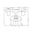
- FIG. 1 is a schematic diagram for explaining a ball-on-ring test method.
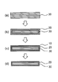
- FIG. 2 is a schematic view showing a process for producing chemically strengthened glass according to the present invention.
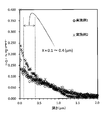
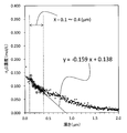
- FIG. 3 is a graph in which the hydrogen concentration profile of the surface layer of each chemically strengthened glass obtained in Example 1 and Example 2 is plotted.
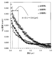
- FIG. 4 is a graph in which the hydrogen concentration profile of the surface layer of each chemically strengthened glass obtained in Example 3 and Example 4 is plotted.
- FIG. 5 is a graph in which the hydrogen concentration profile of the surface layer of each chemically strengthened glass obtained in Comparative Example 1, Comparative Example 2, and Comparative Example 3 is plotted.
- FIG. 1 is a schematic diagram for explaining a ball-on-ring test method.
- FIG. 2 is a schematic view showing a process for producing chemically strengthened glass according to the present invention.
- FIG. 3 is a graph in which the hydrogen concentration profile of the surface layer of each chemically strengthened glass obtained in Example 1 and Example 2 is plotted.
- FIG. 4 is a
- FIG. 6 is an explanatory diagram for deriving the relational expression (I) from the graph in which the hydrogen concentration profile of the surface layer of the chemically strengthened glass obtained in Example 1 is plotted.
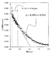
- FIG. 7 is an explanatory diagram for deriving the relational expression (I) from the graph in which the hydrogen concentration profile of the surface layer of the chemically strengthened glass obtained in Comparative Example 1 is plotted.
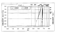
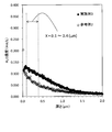
- FIG. 8 is a Weibull plot of BOR strength evaluation of each chemically strengthened glass obtained in Example 1 and Comparative Example 1.
- FIG. 9 is an AFM image of the chemically strengthened glass surface of Reference Example 1. The scanning area is 5 ⁇ 5 ⁇ m 2 .
- FIG. 10 is an AFM image of the chemically strengthened glass surface of Example 1. The scanning area is 5 ⁇ 5 ⁇ m 2 .
- FIG. 11 is a Weibull plot of BOR strength evaluation of each chemically strengthened glass obtained in Example 3 and Reference Example 2.
- FIG. 12 is a graph plotting the hydrogen concentration profile of the surface layer of each chemically strengthened glass obtained in Example 3 and Reference Example 2.
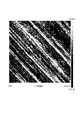
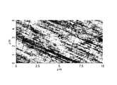
- FIG. 13 is an AFM image of a glass surface having surface polishing flaws.
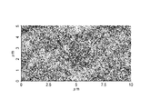
- FIG. 14 is an AFM image of the glass surface having no surface polishing scratches.
- the chemically strengthened glass according to the present invention is a chemically strengthened glass having a compressive stress layer formed on the surface layer by an ion exchange method, and a hydrogen concentration in a certain depth region from the outermost surface of the glass is a relational expression (described later) It is characterized by satisfying I) and having no polishing scratches on the glass surface.
- the compressive stress layer is a high-density layer formed by ion exchange of Na ions on the glass surface and K ions in the molten salt by bringing the raw glass into contact with an inorganic salt such as potassium nitrate. It is.
- the hydrogen concentration profile in the glass surface layer is in a specific range.
- Y aX + b (I)
- Y Hydrogen concentration (H 2 O conversion, mol / L)
- X Depth from the outermost surface of glass ( ⁇ m) a: -0.270 to -0.005 b: 0.020 to 0.220]
- the strength of glass decreases due to the presence of hydrogen (moisture) in the glass, but the present inventors may decrease the strength after chemical strengthening treatment, the main cause of which Has found that chemical defects are generated when moisture in the atmosphere penetrates into the glass. It has also been found that this phenomenon occurs not only through chemical strengthening but also through a heating process in the glass manufacturing process.
- hydrogen concentration in the glass is high, hydrogen enters the Si—O—Si bond network of the glass in the form of Si—OH, and the Si—O—Si bond is broken. If the hydrogen concentration in the glass is high, it is considered that the Si—O—Si bond is cut off more, chemical defects are easily generated, and the strength is lowered.
- the thickness of the compressive stress layer formed by ion exchange is formed in the range of 5 to 50 ⁇ m, depending on the degree of chemical strengthening.
- the penetration depth of hydrogen into the glass follows the diffusion coefficient, temperature, and time, and the penetration amount of hydrogen is influenced by the moisture content in the atmosphere in addition to these.
- the hydrogen concentration after chemical strengthening is the highest on the outermost surface and gradually decreases toward the deep part (bulk) where the compressive stress layer is not formed.
- a is a slope that defines how the hydrogen concentration decreases.
- the range of a is from ⁇ 0.270 to ⁇ 0.005, preferably from ⁇ 0.240 to ⁇ 0.030, and more preferably from ⁇ 0.210 to ⁇ 0.050.
- the range of b is 0.020 to 0.220, preferably 0.020 to 0.215, more preferably 0.030 to 0.210, and still more preferably 0.040 to 0.200. is there.
- the decrease in strength of glass is considered to be caused by the extension of microcracks existing on the glass surface due to external mechanical pressure.
- Non-Patent Document 2 it is considered that the crack is easier to extend as the glass structure at the tip of the crack is richer in Si—OH. Assuming that the crack tip is exposed to the atmosphere, the Si—OH amount at the crack tip is presumed to have a positive correlation with the hydrogen concentration on the outermost surface of the glass. Therefore, b corresponding to the hydrogen concentration on the outermost surface is preferably in a low range as shown above. As shown in FIGS. 3 to 5, no significant difference was found in the hydrogen penetration depth for the glass that had undergone the chemical strengthening process.
- the hydrogen penetration depth is likely to change depending on the chemical strengthening process conditions, but if it does not change, it corresponds to b that corresponds to the hydrogen concentration on the outermost surface and the slope that defines the degree of decrease in hydrogen concentration. A negative correlation appears in a. Accordingly, a is preferably in the high range shown above.
- the strength of chemically strengthened glass is not limited by prescribing only the hydrogen concentration itself of the surface layer, but by focusing on the hydrogen concentration profile and defining the surface hydrogen concentration and the degree of decrease in a specific range. It has been found that can be greatly improved.
- the hydrogen concentration profile (H 2 O concentration, mol / L) of glass is a profile measured under the following analysis conditions.
- Secondary ion mass spectrometry (SIMS) was used for measurement of the hydrogen concentration profile of the glass substrate.
- SIMS Secondary ion mass spectrometry
- a method for preparing a standard sample and a method for determining the hydrogen concentration are described below. 1) A part of the glass substrate to be measured is cut out. 2) A region of 50 ⁇ m or more is removed from the cut glass substrate surface by polishing or chemical etching. The removal process is performed on both sides. That is, the removal thickness on both sides is 100 ⁇ m or more.
- This removed glass substrate is used as a standard sample.
- infrared spectroscopy for the standard samples (Infrared spectroscopy: implement IR), the absorbance of the peak top in the vicinity of 3550 cm -1 of the IR spectrum the height A 3550 and 4000 cm -1 absorbance height A 4000 (the baseline) Ask. 4)
- the plate thickness d (cm) of the standard sample is measured using a plate thickness measuring instrument such as a micrometer.
- a glass substrate to be measured and a standard sample with a known hydrogen concentration obtained by the above method are simultaneously transported into the SIMS device and measured in order to obtain a depth profile of the intensity of 1 H ⁇ and 30 Si ⁇ . To do. Then, 1 H - by dividing the profile, 1 H - - 30 Si from the profile obtained of the intensity ratio of depth profile - / 30 Si. 1 H reference samples - / 30 Si - than depth profile of the intensity ratio, average in the region of from a depth 1 ⁇ m to 2 ⁇ m 1 H - / 30 Si - calculate an intensity ratio, a calibration of this value and the hydrogen concentration A line is created so that it passes through the origin (calibration curve with a 1 level standard sample).
- the 1 H ⁇ / 30 Si ⁇ intensity ratio on the vertical axis of the profile of the glass substrate to be measured is converted into a hydrogen concentration. Thereby, the hydrogen concentration profile of the glass substrate to be measured is obtained.
- the measurement conditions for SIMS and IR are as follows.
- Apparatus ADEPT1010 manufactured by ULVAC-PHI Primary ion species: Cs + Primary ion acceleration voltage: 5 kV Primary ion current value: 500 nA Primary ion incident angle: 60 ° with respect to the normal of the sample surface
- Raster size of primary ions 300 ⁇ 300 ⁇ m 2
- Secondary ion polarity Negative secondary ion detection area: 60 ⁇ 60 ⁇ m 2 (4% of the raster size of the primary ions)
- ESA Input Lens 0
- Use of neutralizing gun Method of converting the horizontal axis from sputtering time to depth: The depth of the analysis crater is measured by a stylus type surface profile measuring device (Dektak 150 manufactured by Veeco), and the sputter rate of primary ions is obtained.
- the average hydrogen concentration c can be obtained from the hydrogen concentration profile described above.
- polishing scratches The chemically strengthened glass according to the present invention has no polishing scratches on the surface.
- the term “polishing” in the present invention refers to smoothing by polishing the glass surface using abrasive grains.
- the presence or absence of polishing flaws can be determined by surface observation with an AFM (Atomic Force Microscope), and there are two or more scratches having a length of 5 ⁇ m or more and a width of 0.1 ⁇ m or more in a 10 ⁇ m ⁇ 5 ⁇ m region. If not, it can be said that there is no polishing flaw on the surface.
- FIG. 13 shows a state having surface polishing flaws
- FIG. 14 shows a state having no surface polishing flaws.
- Glass strength The strength of the chemically strengthened glass of the present invention can be evaluated by a ball-on-ring test.
- a glass plate is disposed on a ring made of stainless steel having a diameter of 30 mm and a contact portion having a radius of curvature of 2.5 mm, and a sphere made of steel having a diameter of 10 mm is brought into contact with the glass plate.
- the sphere is evaluated by a BOR strength F (N) measured by a Ball on Ring (BOR) test in which the sphere is loaded at the center of the ring under a static load condition.
- the chemically strengthened glass of the present invention has F ⁇ 1500 ⁇ t 2 and more preferably F ⁇ 1800 ⁇ t 2 [wherein F is the BOR strength (N) measured by a ball-on-ring test, t is the thickness (mm) of the glass substrate. ]. When the BOR strength F (N) is within this range, excellent strength is exhibited even when the plate is thinned.
- FIG. 1 shows a schematic diagram for explaining the ball-on-ring test used in the present invention.
- the glass plate 1 is placed on the glass plate 1 using a pressing jig 2 (hardened steel, diameter 10 mm, mirror finish) made of SUS304 with the glass plate 1 placed horizontally. Pressurize and measure the strength of the glass plate 1.
- a glass plate 1 serving as a sample is horizontally installed on a receiving jig 3 made of SUS304 (diameter 30 mm, contact portion curvature R2.5 mm, contact portion is hardened steel, mirror finish). Above the glass plate 1, a pressurizing jig 2 for pressurizing the glass plate 1 is installed.
- region of the glass plate 1 is pressurized from the upper direction of the glass plate 1 obtained after the Example and the comparative example.
- the test conditions are as follows. Lowering speed of the pressure jig 2: 1.0 (mm / min) At this time, the breaking load (unit N) when the glass is broken is defined as BOR strength, and the average value of 20 measurements is defined as BOR average strength. However, if the glass plate fracture starting point is 2 mm or more away from the ball pressing position, it is excluded from the data for calculating the average value.
- the chemically strengthened glass of the present invention has high surface strength as described above, and also has high surface strength reliability. As shown in Weibull plots for evaluating the BOR strength of each chemically strengthened glass in the examples described later, it can be seen that the chemically strengthened glass of the present invention has little variation in surface strength. The reason is not clear, but it is presumed that the hydrogen (water) concentration in the vicinity of the glass surface layer is slightly high.
- the chemically strengthened glass of the present invention further has a surface roughness (Ra) of 0.20 nm or more.
- Ra surface roughness
- the surface roughness can be measured, for example, by AFM surface observation with a measurement range of 1 ⁇ m ⁇ 1 ⁇ m.
- polished is less than 0.20 nm.
- Glass composition The glass used in the present invention only needs to contain sodium, and glass having various compositions can be used as long as it has a composition that can be strengthened by molding and chemical strengthening treatment. Specific examples include aluminosilicate glass, soda lime glass, borosilicate glass, lead glass, alkali barium glass, and aluminoborosilicate glass.
- the method for producing the glass is not particularly limited, and a desired glass raw material is charged into a continuous melting furnace, and the glass raw material is heated and melted preferably at 1500 to 1600 ° C., clarified, and then supplied to a molding apparatus. It can be manufactured by forming into a plate shape and slowly cooling.
- various methods can be employed for forming the glass.
- various forming methods such as a down draw method (for example, an overflow down draw method, a slot down method and a redraw method), a float method, a roll-out method, and a press method can be employed.
- the thickness of the glass is not particularly limited, but is usually preferably 5 mm or less and more preferably 3 mm or less in order to effectively perform the chemical strengthening treatment.
- the shape of the glass used in the present invention is not particularly limited.
- various shapes of glass such as a flat plate shape having a uniform plate thickness, a shape having a curved surface on at least one of the front surface and the back surface, and a three-dimensional shape having a bent portion can be employed.
- the total content of SiO 2 and Al 2 O 3 is 75% or less, the total content of Na 2 O and K 2 O is 12 to 25%, and the total content of MgO and CaO is 7 to 15%.
- composition which is displayed at a certain glass (iii) mol%, a SiO 2 68 ⁇ 80%, the Al 2 O 3 4 ⁇ 10% ,
- the a 2 O 5 ⁇ 15%, the K 2 O 0 to 1%, the MgO 4 ⁇ 15% and ZrO 2 is composition displaying a glass (iv) mole% containing 0 to 1%, a SiO 2 67 -75%, Al 2 O 3 0-4%, Na 2 O 7-15%, K 2 O 1-9%, MgO 6-14% and ZrO 2 0-1.5%
- the total content of SiO 2 and Al 2 O 3 is 71 to 75%, the total content of Na 2 O and K 2 O is 12 to 20%, and when CaO is contained, the content is 1% Glass that is less than
- the chemically strengthened glass according to the present invention has an ion-exchanged compressive stress layer on the glass surface.
- the surface of glass is ion exchanged to form a surface layer in which compressive stress remains.
- alkali metal ions typically Li ions, Na ions
- alkali ions typically Is substituted for Na ions or K ions for Li ions and K ions for Na ions.
- chemical strengthening is performed by bringing a glass into contact with an inorganic salt containing potassium nitrate (KNO 3 ).
- KNO 3 potassium nitrate
- Na ions on the glass surface and K ions in the inorganic salt are ion-exchanged to form a high-density compressive stress layer.
- a method of bringing glass into contact with inorganic salt a method of applying paste-like salt, a method of spraying an aqueous solution of salt onto glass, a method of immersing glass in a salt bath of molten salt heated to a melting point or higher are possible. However, among these, a method of immersing in molten salt is desirable.
- the inorganic salt those having a melting point below the strain point (usually 500 to 600 ° C.) of the glass to be chemically strengthened are preferred, and in the present invention, a molten salt containing potassium nitrate (melting point 330 ° C.) is preferred.
- a molten salt containing potassium nitrate melting point 330 ° C.
- the content of potassium nitrate in the inorganic salt is preferably 50% by mass or more.
- the inorganic salt is further selected from the group consisting of K 2 CO 3 , Na 2 CO 3 , KHCO 3 , NaHCO 3 , K 3 PO 4 , Na 3 PO 4 , K 2 SO 4 , Na 2 SO 4 , KOH and NaOH. It is preferable to contain at least one salt, and it is more preferable to contain at least one salt selected from the group consisting of K 2 CO 3 , Na 2 CO 3 , KHCO 3 and NaHCO 3 .
- the above-mentioned salt (hereinafter sometimes referred to as “flux”) has a property of cutting a glass network represented by Si—O—Si bonds. Since the temperature at which the chemical strengthening treatment is performed is as high as several hundred degrees Celsius, the covalent bond between Si—O of the glass is appropriately broken at that temperature, and the density reduction treatment described later easily proceeds.
- the degree of breaking the covalent bond varies depending on the chemical composition treatment conditions such as the glass composition, the type of salt (flux) used, the temperature and time for the chemical strengthening treatment, but the four covalent bonds extending from Si. Of these, it is considered preferable to select conditions that are sufficient to break one or two bonds.
- the chemical strengthening treatment time is 1 minute to 10 hours is preferable, 5 minutes to 8 hours is more preferable, and 10 minutes to 4 hours is more preferable.
- the amount of the flux added is preferably 0.1 mol% or more, more preferably 1 mol% or more, and particularly preferably 2 mol% or more from the viewpoint of controlling the surface hydrogen concentration. Further, from the viewpoint of productivity, the saturation solubility or less of each salt is preferable. Addition in excess may lead to glass corrosion. For example, when K 2 CO 3 is used as the flux, it is preferably 24 mol% or less, more preferably 12 mol% or less, and particularly preferably 8 mol% or less.
- the inorganic salt may contain other chemical species as long as the effects of the present invention are not impaired.
- alkali salts such as sodium chloride, potassium chloride, sodium borate, potassium borate, etc.
- chlorides and alkali borates These may be added alone or in combination of two or more.
- the production method of the present invention will be described by taking an example in which chemical strengthening is performed by a method of immersing glass in a molten salt.
- the molten salt can be produced by the steps shown below.
- Step 1a Preparation of potassium nitrate molten salt
- Step 2a Addition of flux to potassium nitrate molten salt
- Step 1a-Preparation of molten potassium nitrate salt potassium nitrate is put into a container and heated to a temperature equal to or higher than the melting point to melt, thereby preparing a molten salt. Melting is performed at a temperature within the range of the melting point (330 ° C.) and boiling point (500 ° C.) of potassium nitrate. In particular, the melting temperature is preferably 350 to 470 ° C. from the viewpoint of the balance between the surface compressive stress (CS) and the compressive stress layer depth (DOL) that can be applied to the glass, and the strengthening time.
- CS surface compressive stress
- DOL compressive stress layer depth
- metal for the container for melting potassium nitrate, metal, quartz, ceramics, or the like can be used.
- a metal material is desirable from the viewpoint of durability, and a stainless steel (SUS) material is preferable from the viewpoint of corrosion resistance.
- SUS stainless steel
- Step 2a Additional of flux to potassium nitrate molten salt-
- the above-mentioned flux is added to the potassium nitrate molten salt prepared in Step 1a, and the whole is mixed uniformly with a stirring blade while keeping the temperature within a certain range.
- the order of addition is not limited, and they may be added simultaneously.
- the temperature is preferably not less than the melting point of potassium nitrate, that is, not less than 330 ° C., more preferably 350 to 500 ° C.
- the stirring time is preferably 1 minute to 10 hours, more preferably 10 minutes to 2 hours.
- Step 1b Mixing of potassium nitrate and flux
- Step 2b Melting of mixed salt of potassium nitrate and flux
- Step 1b-Mixing of potassium nitrate and flux- potassium nitrate and a flux are put into a container and mixed with a stirring blade or the like.
- the order of addition is not limited, and they may be added simultaneously.
- the same container as that used in the above step 1a can be used.
- Step 2b-Melting of mixed salt of potassium nitrate and flux- the mixed salt obtained in step 1b is heated and melted. Melting is performed at a temperature within the range of the melting point (330 ° C.) and boiling point (500 ° C.) of potassium nitrate.
- the melting temperature is preferably 350 to 470 ° C. from the viewpoint of the balance between the surface compressive stress (CS) and the compressive stress layer depth (DOL) that can be applied to the glass, and the strengthening time.
- the stirring time is preferably 1 minute to 10 hours, and more preferably 10 minutes to 2 hours.
- the precipitates are Let stand until it settles to the bottom.
- This precipitate includes a flux exceeding the saturation solubility and a salt in which the cations of the flux are exchanged in the molten salt.
- the molten salt used in the production method of the present invention preferably has a Na concentration of 500 ppm by weight or more, more preferably 1000 ppm by weight or more. It is preferable that the Na concentration in the molten salt is 500 ppm by weight or more because the low-density layer is easily deepened by the acid treatment step described later. There is no restriction
- concentration It is permissible until a desired surface compressive stress (CS) is obtained.
- the molten salt which performed the chemical strengthening process once or more contains the sodium eluted from glass. Therefore, if the Na concentration is already within the above range, glass-derived sodium may be used as it is as the Na source.
- the molten salt can be prepared by the steps 1a and 2a or the steps 1b and 2b.
- the density of the chemically strengthened glass gradually increases from the outer edge of the intermediate layer 30 (bulk) existing in the center of the glass toward the surface of the compressive stress layer. There is no clear boundary between the density changes.
- the intermediate layer is a layer present in the center of the glass and sandwiched between the compressive stress layers. Unlike the compressive stress layer, this intermediate layer is a layer that is not ion-exchanged.
- the chemical strengthening treatment in the present invention can be performed by the following step 3.
- Process 3 Chemical strengthening treatment of glass
- step 3 the glass is preheated, and the molten salt prepared in steps 1a and 2a or steps 1b and 2b is adjusted to a temperature at which chemical strengthening is performed.
- the preheated glass is immersed in the molten salt for a predetermined time, and then the glass is pulled up from the molten salt and allowed to cool.
- shape processing according to a use, for example, mechanical processing, such as a cutting
- the preheating temperature of glass depends on the temperature immersed in the molten salt, but is generally preferably 100 ° C. or higher.
- the chemical strengthening temperature is preferably not more than the strain point (usually 500 to 600 ° C.) of the glass to be tempered, and particularly preferably 350 ° C. or more in order to obtain a higher compressive stress layer depth.
- the immersion time of the glass in the molten salt is preferably 1 minute to 10 hours, more preferably 5 minutes to 8 hours, and even more preferably 10 minutes to 4 hours. If it exists in this range, the chemically strengthened glass excellent in the balance of an intensity
- Step 4 Glass cleaning
- Step 5 Acid treatment of glass after Step 4
- the surface layer of the compressive stress layer 20 was altered on the glass surface, specifically, the density was reduced.
- the low density layer 10 is further provided [FIGS. 2B to 2C].
- the low density layer is formed by Na (leaching) from the outermost surface of the compressive stress layer (leaching) and H entering (replacement) instead.
- Step 4-Glass cleaning- glass is cleaned using industrial water, ion exchange water, or the like. Of these, ion-exchanged water is preferred.
- the washing conditions vary depending on the washing solution used, but when ion-exchanged water is used, washing at 0 to 100 ° C. is preferable from the viewpoint of completely removing the attached salt.
- Step 5-Acid treatment- the glass cleaned in step 4 is further subjected to acid treatment.
- the acid treatment of the glass is performed by immersing the chemically strengthened glass in an acidic solution, whereby Na and / or K on the surface of the chemically strengthened glass can be replaced with H.
- the solution is not particularly limited as long as it is acidic, and may be less than pH 7.
- the acid used may be a weak acid or a strong acid. Specifically, acids such as hydrochloric acid, nitric acid, sulfuric acid, phosphoric acid, acetic acid, oxalic acid, carbonic acid and citric acid are preferred. These acids may be used alone or in combination.
- the temperature at which the acid treatment is performed varies depending on the type, concentration, and time of the acid used, but is preferably 100 ° C. or less.
- the time for the acid treatment varies depending on the type, concentration and temperature of the acid used, but is preferably 10 seconds to 5 hours from the viewpoint of productivity, and more preferably 1 minute to 2 hours.
- the concentration of the acid treatment solution varies depending on the type of acid used, the time, and the temperature, but is preferably a concentration at which there is little concern about container corrosion, specifically 0.1 wt% to 20 wt%.
- the thickness of the low density layer is preferably 5 nm or more, and more preferably 20 nm or more from the viewpoint of the glass surface removal amount.
- the thickness of the low density layer can be controlled by the flux concentration, sodium concentration, temperature, time, etc. in the chemical strengthening step.
- the density of the low density layer is preferably lower than the density of the region (bulk) deeper than the ion-exchanged compressive stress layer from the viewpoint of glass surface removability.
- the thickness of the low density layer can be determined from the period ( ⁇ ) measured by the X-ray reflectivity method (X-ray-Reflectometry: XRR).
- the density of the low density layer can be determined from the critical angle ( ⁇ c) measured by XRR.
- it is also possible to confirm the formation of the low density layer and the thickness of the layer by simply observing a cross section of the glass with a scanning electron microscope (SEM).
- Step 6 Alkaline Treatment According to the above step 6, part or all of the low density layer 10 formed up to step 5 can be removed [FIGS. 2 (c) to (d)]. Hereinafter, step 6 will be described in detail.
- Step 6-alkali treatment the glass treated with acid in step 5 is further subjected to alkali treatment.
- the alkali treatment is performed by immersing the chemically strengthened glass in a basic solution, whereby a part or all of the low density layer can be removed.
- the solution is not particularly limited as long as it is basic, and may have a pH exceeding 7, and a weak base or a strong base may be used.
- bases such as sodium hydroxide, potassium hydroxide, potassium carbonate and sodium carbonate are preferred. These bases may be used alone or in combination.
- the temperature for the alkali treatment varies depending on the type, concentration and time of the base used, but is preferably 0 to 100 ° C, more preferably 10 to 80 ° C, and particularly preferably 20 to 60 ° C. If it is this temperature range, there is no possibility that glass will corrode and it is preferable.
- the alkali treatment time varies depending on the type, concentration and temperature of the base used, it is preferably 10 seconds to 5 hours from the viewpoint of productivity, and more preferably 1 minute to 2 hours.
- the concentration of the solution used for the alkali treatment varies depending on the type of base used, the time, and the temperature, but is preferably 0.1 wt% to 20 wt% from the viewpoint of glass surface removability.
- step 4 it is preferable to have a cleaning step similar to step 4 between the acid treatment step 5 and the alkali treatment step 6 or after completion of the alkali treatment step 6.
- FIG. 2D shows an embodiment in which the low density layer 10 is completely removed. However, a part of the low density layer 10 may be removed and a part may remain. From the viewpoint of improving the strength, the effect can be obtained without removing all of the low density layer, but it is preferable to remove all of the low density layer from the viewpoint of stably securing the transmittance of the glass.
- the glass removal amount thickness was determined by measuring the weight before and after the chemical treatment with an analytical electronic balance (HR-202i; manufactured by AND) and converting the thickness using the following formula.
- (Removed thickness per side) ((weight before treatment) ⁇ (weight after treatment)) / (glass specific gravity) / treated area / 2 At this time, the glass specific gravity was calculated as 2.48 (g / cm 3 ).
- FIG. 1 is a schematic diagram for explaining the ball-on-ring test used in the present invention. With the glass plate 1 placed horizontally, the glass plate 1 was pressed using a pressurizing jig 2 made of SUS304 (hardened steel, diameter 10 mm, mirror finish), and the strength of the glass plate 1 was measured.
- a pressurizing jig 2 made of SUS304 (hardened steel, diameter 10 mm, mirror finish), and the strength of the glass plate 1 was measured.
- a glass plate 1 serving as a sample is horizontally installed on a receiving jig 3 made of SUS304 (diameter 30 mm, contact portion curvature R2.5 mm, contact portion is hardened steel, mirror finish). Above the glass plate 1, a pressurizing jig 2 for pressurizing the glass plate 1 is installed.
- region of the glass plate 1 was pressurized from the upper direction of the glass plate 1 obtained after the Example and the comparative example.
- the test conditions are as follows. Lowering speed of the pressure jig 2: 1.0 (mm / min) At this time, the breaking load (unit N) when the glass was broken was defined as BOR strength, and the average value of 20 measurements was defined as BOR average strength. However, when the fracture start point of the glass plate was 2 mm or more away from the ball pressing position, it was excluded from the data for calculating the average value.
- Example 1 (Chemical strengthening process) To a SUS cup, 9700 g of potassium nitrate, 890 g of potassium carbonate, and 400 g of sodium nitrate were added and heated to 450 ° C. with a mantle heater to prepare a molten salt of 6 mol% potassium carbonate and 10,000 ppm by weight sodium. Prepare 50mm x 50mm x 0.56mm aluminosilicate glass A (specific gravity 2.48), preheat to 200-400 ° C, soak in molten salt at 450 ° C for 2 hours, and after ion exchange treatment, near room temperature The chemical strengthening process was performed by cooling to. The obtained chemically strengthened glass was washed with water and subjected to the next step.
- aluminosilicate glass A specific gravity 2.48
- Aluminosilicate glass A composition (in mol%): SiO 2 64.4%, Al 2 O 3 8.0%, Na 2 O 12.5%, K 2 O 4.0%, MgO 10.5%, CaO 0.1%, SrO 0.1%, BaO 0.1%, ZrO 2 0.5%
- a 4.0 wt% aqueous sodium hydroxide solution was prepared in a beaker, and the temperature was adjusted to 40 ° C. using a water bath.
- the glass obtained in the acid treatment step was immersed in the prepared sodium hydroxide aqueous solution for 120 seconds, subjected to alkali treatment, then washed several times with pure water, and then dried by air blowing. From the above, chemically strengthened glass of Example 1 was obtained.
- Example 2 Hydrochloric acid aqueous solution and sodium hydroxide adjusted using a glass flat-flow type washing machine, with the use of aluminosilicate glass A having the plate thickness shown in Table 1, the molten salt temperature and the ion exchange treatment time being 430 ° C. and 40 minutes, respectively.
- a chemically tempered glass was produced in the same manner as in Example 1 except that acid treatment and alkali treatment were performed by showering the aqueous solution for 277 seconds each.
- aluminosilicate glass B (specific gravity: 2.41) having a composition of 50 mm ⁇ 50 mm ⁇ 0.72 mm and having the following composition was used.
- HNO 3 manufactured by Kanto Chemical Co., Inc.
- KS14A manufactured by Yako Electric Co., Ltd.
- a chemically strengthened glass was produced in the same manner as in Example 1 except that the acid treatment was performed.
- Aluminosilicate glass B composition (in mol%): SiO 2 68%, Al 2 O 3 10%, Na 2 O 14%, MgO 8%
- Example 4 Instead of the aluminosilicate glass A, a chemically strengthened glass was produced in the same manner as in Example 3 except that an aluminoborosilicate glass (specific gravity 2.38) having a composition of 50 mm ⁇ 50 mm ⁇ 0.70 mm and having the following composition was used.
- Aluminoborosilicate glass composition (mol% display): SiO 2 67%, B 2 O 3 4%, Al 2 O 3 13%, Na 2 O 14%, K 2 O ⁇ 1%, MgO 2%, CaO ⁇ 1 %
- the amount of sodium in the molten salt is the value shown in Table 1, the potassium carbonate addition amount is 0 g, and the acid treatment step and the alkali treatment step are not carried out. Glass was produced.
- the amount of sodium in the molten salt is the value shown in Table 1, the potassium carbonate addition amount is 0 g, and the acid treatment step and the alkali treatment step are not performed. Glass was produced.
- the amount of sodium in the molten salt is the value shown in Table 1, the potassium carbonate addition amount is 0 g, and the acid treatment step and the alkali treatment step are not performed. Glass was produced.
- FIGS. 3 to 5 are graphs plotting the hydrogen concentration profile of the surface layer of each chemically strengthened glass obtained in Examples 1 to 4 and Comparative Examples 1 to 3.
- FIG. 8 shows the Weibull plot of BOR intensity
- FIG. 8 shows a Weibull plot of BOR strength evaluation results of an aluminosilicate glass plate sample having a plate thickness of 0.56 mm.
- the horizontal axis of the graph represents the logarithm ln ( ⁇ ) of the fracture load ⁇ (N), while the vertical axis represents the cumulative failure probability percentage P (%) for the samples in each of the two groups.
- Example 1 the average breaking load was 827N in Example 1 and 455N in Comparative Example 1.
- the 10% breaking load (B10) is 793 N in Example 1, whereas it is 318 N in Comparative Example 1, and the 1% breaking load (B1) is 750 N in Example 1, whereas Comparative Example 1 Then it was 200N. From this result, it can be seen that in Example 1, no low-strength product was generated, and the reliability with respect to surface strength was greatly improved.
- a slurry having a specific gravity of 0.9 was prepared by dispersing cerium oxide having an average particle size of 1.2 ⁇ m in water, and the same aluminosilicate glass B as in Example 3 was subjected to a polishing pressure of 10 kPa and a polishing pad (nonwoven fabric type). Polished on one side by 0.6 ⁇ m.
- the glass obtained in the polishing step was chemically strengthened using the same molten salt as in Comparative Example 3 at a chemical strengthening temperature of 450 degrees and a chemical strengthening treatment time of 2 hours. Table 1 shows the results of various evaluations. An image obtained by observing the glass surface with AFM is shown in FIG. The surface roughness (Ra) measured by AFM measurement was 0.40 nm. Moreover, the surface observation image of the chemically strengthened glass manufactured in Example 1 is shown in FIG. The surface roughness (Ra) measured by AFM measurement was 0.33 nm.
- the 10% breaking load (B10) is 1339N in Example 3, whereas it is 1098N in Reference Example 2, and the 1% breaking load (B1) is 1307N in Example 3, whereas Reference Example 2 It was 904N. From this result, it can be seen that in Example 3, no low-strength product was generated, and the reliability with respect to surface strength was greatly improved.
- FIG. 12 shows the hydrogen concentration profile of the surface layer of each chemically strengthened glass obtained in Reference Example 2 and Example 3.
- the surface layer hydrogen concentration in Example 3 was higher than that in Reference Example 2.
- chemically strengthened glass having significantly improved surface strength can be obtained safely and at low cost.
- the chemically strengthened glass according to the present invention can be used for a cover glass for a display such as a mobile phone, a digital camera, or a touch panel display.
Landscapes
- Chemical & Material Sciences (AREA)
- Engineering & Computer Science (AREA)
- Materials Engineering (AREA)
- Chemical Kinetics & Catalysis (AREA)
- General Chemical & Material Sciences (AREA)
- Geochemistry & Mineralogy (AREA)
- Life Sciences & Earth Sciences (AREA)
- Organic Chemistry (AREA)
- Physics & Mathematics (AREA)
- General Physics & Mathematics (AREA)
- Surface Treatment Of Glass (AREA)
- Glass Compositions (AREA)
- Mechanical Engineering (AREA)
Abstract
Priority Applications (6)
| Application Number | Priority Date | Filing Date | Title |
|---|---|---|---|
| CN201480003165.2A CN104812718B (zh) | 2013-07-19 | 2014-07-15 | 化学强化玻璃 |
| JP2014560161A JP5751390B1 (ja) | 2013-07-19 | 2014-07-15 | 化学強化ガラス |
| KR1020167001477A KR101821902B1 (ko) | 2013-07-19 | 2014-07-15 | 화학 강화 유리 |
| DE112014003344.8T DE112014003344T5 (de) | 2013-07-19 | 2014-07-15 | Chemisch Gehärtetes Glas |
| US15/000,918 US9884784B2 (en) | 2013-07-19 | 2016-01-19 | Chemically strengthened glass |
| US15/818,016 US10450226B2 (en) | 2013-07-19 | 2017-11-20 | Chemically strengthened glass |
Applications Claiming Priority (2)
| Application Number | Priority Date | Filing Date | Title |
|---|---|---|---|
| JP2013-151116 | 2013-07-19 | ||
| JP2013151116 | 2013-07-19 |
Related Child Applications (1)
| Application Number | Title | Priority Date | Filing Date |
|---|---|---|---|
| US15/000,918 Continuation US9884784B2 (en) | 2013-07-19 | 2016-01-19 | Chemically strengthened glass |
Publications (1)
| Publication Number | Publication Date |
|---|---|
| WO2015008766A1 true WO2015008766A1 (fr) | 2015-01-22 |
Family
ID=52346214
Family Applications (3)
| Application Number | Title | Priority Date | Filing Date |
|---|---|---|---|
| PCT/JP2014/068836 WO2015008766A1 (fr) | 2013-07-19 | 2014-07-15 | Verre chimiquement renforcé |
| PCT/JP2014/068832 WO2015008763A1 (fr) | 2013-07-19 | 2014-07-15 | Procédé de fabrication de verre chimiquement renforcé |
| PCT/JP2014/068834 WO2015008764A1 (fr) | 2013-07-19 | 2014-07-15 | Verre chimiquement renforcé et son procédé de fabrication |
Family Applications After (2)
| Application Number | Title | Priority Date | Filing Date |
|---|---|---|---|
| PCT/JP2014/068832 WO2015008763A1 (fr) | 2013-07-19 | 2014-07-15 | Procédé de fabrication de verre chimiquement renforcé |
| PCT/JP2014/068834 WO2015008764A1 (fr) | 2013-07-19 | 2014-07-15 | Verre chimiquement renforcé et son procédé de fabrication |
Country Status (7)
| Country | Link |
|---|---|
| US (4) | US9828286B2 (fr) |
| JP (7) | JP5751390B1 (fr) |
| KR (3) | KR101838413B1 (fr) |
| CN (7) | CN104812718B (fr) |
| DE (3) | DE112014003330T5 (fr) |
| TW (4) | TWI598311B (fr) |
| WO (3) | WO2015008766A1 (fr) |
Cited By (6)
| Publication number | Priority date | Publication date | Assignee | Title |
|---|---|---|---|---|
| WO2015108076A1 (fr) * | 2014-01-16 | 2015-07-23 | 旭硝子株式会社 | Verre chimiquement renforcé et son procédé de production |
| JP2017149628A (ja) * | 2016-02-26 | 2017-08-31 | 旭硝子株式会社 | 化学強化ガラス及び化学強化ガラスの製造方法 |
| US20170313621A1 (en) * | 2015-01-20 | 2017-11-02 | Asahi Glass Company, Limited | Chemically strengthened glass and production method for chemically strengthened glass |
| WO2018199045A1 (fr) * | 2017-04-26 | 2018-11-01 | Agc株式会社 | Verre chimiquement renforcé |
| JPWO2018235885A1 (ja) * | 2017-06-23 | 2020-05-21 | Agc株式会社 | 化学強化ガラス |
| US10730793B2 (en) * | 2015-01-20 | 2020-08-04 | AGC Inc. | Chemically strengthened glass and production method for same |
Families Citing this family (47)
| Publication number | Priority date | Publication date | Assignee | Title |
|---|---|---|---|---|
| US9950383B2 (en) | 2013-02-05 | 2018-04-24 | Illinois Tool Works Inc. | Welding wire preheating system and method |
| CN104812718B (zh) | 2013-07-19 | 2017-03-15 | 旭硝子株式会社 | 化学强化玻璃 |
| JPWO2016117479A1 (ja) * | 2015-01-20 | 2017-10-26 | 旭硝子株式会社 | ガラス基材の製造方法 |
| JP6451495B2 (ja) * | 2015-05-19 | 2019-01-16 | Agc株式会社 | 化学強化ガラスの製造方法 |
| JP6544043B2 (ja) * | 2015-05-26 | 2019-07-17 | Agc株式会社 | 化学強化ガラスの製造方法 |
| CN105130211B (zh) * | 2015-09-08 | 2017-09-22 | 安徽凤阳淮河玻璃有限公司 | 一种水热化学强化玻璃的制备方法 |
| KR20180098268A (ko) | 2015-12-28 | 2018-09-03 | 에이지씨 가부시키가이샤 | 화학 강화 유리의 제조 방법 |
| JP6582974B2 (ja) * | 2015-12-28 | 2019-10-02 | Agc株式会社 | カバーガラスおよびその製造方法 |
| CN107188398A (zh) * | 2016-03-10 | 2017-09-22 | 旭硝子株式会社 | 化学强化玻璃的制造方法 |
| WO2017179360A1 (fr) * | 2016-04-12 | 2017-10-19 | 日本電気硝子株式会社 | Procédé et dispositif de fabrication de verre trempé |
| CN107304106B (zh) * | 2016-04-22 | 2018-10-02 | Agc株式会社 | 玻璃板、显示器用玻璃基板以及太阳能电池用玻璃基板 |
| CN106102380B (zh) * | 2016-08-03 | 2024-08-20 | 安徽精卓光显技术有限责任公司 | 玻璃外壳及具有该玻璃外壳的电子产品 |
| WO2018043361A1 (fr) * | 2016-09-02 | 2018-03-08 | 旭硝子株式会社 | Procédé de production de verre trempé chimiquement |
| FR3056578B1 (fr) * | 2016-09-23 | 2018-12-07 | Commissariat A L'energie Atomique Et Aux Energies Alternatives | Procede pour ameliorer la tenue au flux laser d'un composant optique. |
| JP6919658B2 (ja) * | 2016-09-30 | 2021-08-18 | Agc株式会社 | 化学強化ガラスの製造方法 |
| CN106634619B (zh) * | 2016-12-06 | 2018-08-03 | 中国航空工业集团公司北京航空材料研究院 | 一种高强度玻璃的制造方法 |
| KR102315418B1 (ko) | 2017-03-10 | 2021-10-22 | 삼성디스플레이 주식회사 | 표시 장치 윈도우 제조 방법 및 표시 장치 윈도우 |
| JP6897270B2 (ja) * | 2017-04-20 | 2021-06-30 | Agc株式会社 | 化学強化ガラス |
| JP2019006615A (ja) * | 2017-06-21 | 2019-01-17 | Agc株式会社 | 化学強化ガラスの製造方法 |
| JP7247454B2 (ja) * | 2017-06-27 | 2023-03-29 | Agc株式会社 | 化学強化ガラスの製造方法及び化学強化ガラス |
| NL2020896B1 (en) * | 2018-05-08 | 2019-11-14 | Corning Inc | Water-containing glass-based articles with high indentation cracking threshold |
| WO2019134133A1 (fr) * | 2018-01-05 | 2019-07-11 | 南昌欧菲光学技术有限公司 | Procédé de renforcement de vitrocéramique et procédé de fabrication d'une plaque de couverture en vitrocéramique |
| JP7117616B2 (ja) * | 2018-02-02 | 2022-08-15 | パナソニックIpマネジメント株式会社 | 光学ガラス素子の処理方法および光学ガラス素子 |
| KR102584366B1 (ko) * | 2018-02-12 | 2023-10-04 | 삼성디스플레이 주식회사 | 유리 제품 및 그 제조 방법 |
| JP7024565B2 (ja) * | 2018-04-04 | 2022-02-24 | Agc株式会社 | 化学強化ガラスの製造方法 |
| JP2019199393A (ja) * | 2018-05-18 | 2019-11-21 | Agc株式会社 | 化学強化ガラスの製造方法および化学強化ガラス |
| CN112368248B (zh) * | 2018-07-04 | 2022-07-08 | Agc株式会社 | 玻璃板、带有减反射层的玻璃板以及玻璃板的制造方法 |
| JP7375762B2 (ja) * | 2018-09-18 | 2023-11-08 | Agc株式会社 | ガラス基板、ブラックマトリックス基板及びディスプレイパネル |
| WO2020069260A1 (fr) * | 2018-09-28 | 2020-04-02 | Corning Incorporated | Articles à base de verre présentant des profils de contrainte améliorés |
| TWI839392B (zh) * | 2018-09-28 | 2024-04-21 | 美商康寧公司 | 增強離子交換方法 |
| KR20200085387A (ko) * | 2019-01-04 | 2020-07-15 | 삼성디스플레이 주식회사 | 윈도우 제조 방법 |
| KR102604565B1 (ko) * | 2019-01-10 | 2023-11-23 | 삼성디스플레이 주식회사 | 윈도우 및 이의 제조 방법 |
| JP2020142952A (ja) * | 2019-03-06 | 2020-09-10 | 日本電気硝子株式会社 | 近赤外線吸収ガラス板 |
| US11926556B2 (en) | 2019-04-09 | 2024-03-12 | Corning Incorporated | Glass substrate with a textured surface with surface features having a certain ratio of height-to-width to provide anti-glare properties and increased resistance to scratches |
| TW202106647A (zh) | 2019-05-15 | 2021-02-16 | 美商康寧公司 | 在高溫下用高濃度鹼金屬氫氧化物減少紋理化玻璃、玻璃陶瓷以及陶瓷製品之厚度的方法 |
| WO2020236498A1 (fr) | 2019-05-17 | 2020-11-26 | Corning Incorporated | Procédé de modification d'un substrat en verre texturé avec une région sous contrainte de compression pour augmenter la résistance du substrat en verre |
| KR102060277B1 (ko) * | 2019-06-21 | 2019-12-30 | 김순호 | 강화유리 제조 장치 및 제조 방법 |
| KR20210088040A (ko) * | 2020-01-03 | 2021-07-14 | 삼성디스플레이 주식회사 | 유리 제품 및 이의 제조 방법 |
| LU102044B1 (de) | 2020-09-03 | 2022-03-03 | Univ Freiberg Tech Bergakademie | Glasbehälter |
| LU102045B1 (de) | 2020-09-03 | 2022-03-03 | Univ Freiberg Tech Bergakademie | Flachglasscheibe |
| LU102043B1 (de) | 2020-09-03 | 2022-03-03 | Univ Freiberg Tech Bergakademie | Verfahren zum Erhöhen der Festigkeit und/oder der Härte eines Glasgegenstandes |
| LU102046B1 (de) | 2020-09-03 | 2022-03-03 | Univ Freiberg Tech Bergakademie | Verfahren und Anlage zum Erhöhen der Bruchfestigkeit und/oder der Härte von Glasgegenständen |
| LU102041B1 (de) | 2020-09-03 | 2022-03-03 | Univ Freiberg Tech Bergakademie | Glasgegenstand und Verfahren zum Herstellen eines Glasgegenstandes |
| CN114538793A (zh) * | 2020-11-24 | 2022-05-27 | 日本电气硝子株式会社 | 强化玻璃的制造方法 |
| CN112358198B (zh) * | 2020-11-24 | 2022-11-18 | 中国建筑材料科学研究总院有限公司 | 一种高碱铝硅酸盐玻璃的复合增强方法 |
| KR20230173686A (ko) * | 2021-04-16 | 2023-12-27 | 코닝 인코포레이티드 | 이온-교환 방법 및 이를 사용하여 제조된 이온-교환된 유리 물품 |
| JP7511120B1 (ja) | 2022-11-15 | 2024-07-05 | Agc株式会社 | 化学強化ガラス及びその製造方法 |
Citations (4)
| Publication number | Priority date | Publication date | Assignee | Title |
|---|---|---|---|---|
| JP2008195602A (ja) * | 2007-01-16 | 2008-08-28 | Nippon Electric Glass Co Ltd | 強化ガラス基板の製造方法及び強化ガラス基板 |
| JP2010108592A (ja) * | 2008-09-30 | 2010-05-13 | Hoya Corp | 磁気ディスク用ガラス基板及び磁気ディスク |
| JP2012250861A (ja) * | 2011-05-31 | 2012-12-20 | Asahi Glass Co Ltd | 化学強化ガラス板 |
| JP2013040086A (ja) * | 2011-08-19 | 2013-02-28 | Asahi Glass Co Ltd | 強化ガラス板及びカバーガラスの製造方法並びにカバーガラス |
Family Cites Families (35)
| Publication number | Priority date | Publication date | Assignee | Title |
|---|---|---|---|---|
| US3791809A (en) * | 1973-01-12 | 1974-02-12 | Owens Illinois Inc | Method of strengthening glass articles using powdered salts for ion exchange |
| JPS6022661B2 (ja) * | 1977-09-13 | 1985-06-03 | 山村硝子株式会社 | ガラス容器の化学的強化法 |
| JPS5720866A (en) | 1980-07-14 | 1982-02-03 | Hitachi Ltd | Retrieving system of picture response information |
| CN1044448A (zh) * | 1990-02-27 | 1990-08-08 | 中国科学院光电技术研究所 | 光学玻璃元件表面增强方法及其高强度产品 |
| US6119483A (en) * | 1996-12-30 | 2000-09-19 | Hoya Corporation | Process for producing glass substrate for information recording medium |
| JP2001002451A (ja) * | 1999-06-16 | 2001-01-09 | Matsushita Electric Ind Co Ltd | ガラス基板およびその製造方法 |
| JP4368548B2 (ja) * | 2000-10-27 | 2009-11-18 | 株式会社リコー | 画像形成装置及び複写機 |
| JP2002150547A (ja) * | 2000-11-06 | 2002-05-24 | Nippon Sheet Glass Co Ltd | 情報記録媒体用ガラス基板の製造方法 |
| JP4185266B2 (ja) * | 2001-07-25 | 2008-11-26 | Hoya株式会社 | 情報記録媒体用基板の製造方法 |
| JP2003141718A (ja) * | 2001-10-31 | 2003-05-16 | Nippon Sheet Glass Co Ltd | 情報記録媒体用ガラス基板の製造方法 |
| JP2003277102A (ja) * | 2002-01-18 | 2003-10-02 | Nippon Sheet Glass Co Ltd | 情報記録媒体用ガラス基板の製造方法及び情報記録媒体用ガラス基板 |
| JP2003212602A (ja) * | 2002-01-18 | 2003-07-30 | Nippon Sheet Glass Co Ltd | 情報記録媒体用ガラス基板の製造方法 |
| US6911261B2 (en) | 2002-06-13 | 2005-06-28 | International Business Machines Corporation | pH adjustment of a melt for use in microetching glass substrates |
| RU2365547C2 (ru) | 2003-04-22 | 2009-08-27 | Дзе Кока-Кола Компани | Способ и устройство для упрочнения стекла |
| JP4535692B2 (ja) * | 2003-05-28 | 2010-09-01 | セントラル硝子株式会社 | 化学強化ガラス |
| SG10201606460SA (en) * | 2006-06-08 | 2016-09-29 | Hoya Corp | Glass for use in substrate for information recording medium, substrate for information recording medium and information recording medium, and their manufacturing method |
| WO2008062662A1 (fr) * | 2006-11-21 | 2008-05-29 | Konica Minolta Opto, Inc. | Procédé pour produire un substrat en verre pour un support d'enregistrement d'informations, substrat en verre pour un support d'enregistrement d'informations et support d'enregistrement d'informations |
| JPWO2009031401A1 (ja) * | 2007-09-04 | 2010-12-09 | コニカミノルタオプト株式会社 | 情報記録媒体用ガラス基板の製造方法、情報記録媒体用ガラス基板及び磁気記録媒体 |
| WO2009099615A1 (fr) * | 2008-02-05 | 2009-08-13 | Corning Incorporated | Article en verre résistant à l'endommagement destiné à être utilisé comme cache de verre dans des dispositifs électroniques |
| CN101648776A (zh) * | 2008-08-14 | 2010-02-17 | 比亚迪股份有限公司 | 一种提高玻璃强度的方法 |
| JP2010168270A (ja) * | 2008-12-26 | 2010-08-05 | Hoya Corp | ガラス基材及びその製造方法 |
| CN102108011B (zh) * | 2009-12-24 | 2013-05-29 | 比亚迪股份有限公司 | 一种玻璃元件的强化方法 |
| WO2011085190A1 (fr) | 2010-01-07 | 2011-07-14 | Corning Incorporated | Feuille de verre résistante aux dommages par impact |
| CN102473423B (zh) * | 2010-03-31 | 2016-03-30 | Hoya株式会社 | 磁盘用玻璃基板的制造方法 |
| JP2012126615A (ja) | 2010-12-16 | 2012-07-05 | Asahi Glass Co Ltd | フラットパネルディスプレイ用カバーガラス |
| JP2012218995A (ja) * | 2011-04-12 | 2012-11-12 | Asahi Glass Co Ltd | 強化ガラス板及びカバーガラスの製造方法並びにカバーガラス |
| JP2012236737A (ja) * | 2011-05-11 | 2012-12-06 | Asahi Glass Co Ltd | ガラスの製造方法及びガラス |
| KR101537918B1 (ko) * | 2011-07-01 | 2015-07-17 | 아사히 가라스 가부시키가이샤 | 화학 강화용 플로트 유리 |
| CN102992600B (zh) * | 2011-09-09 | 2016-04-06 | Hoya株式会社 | 离子交换玻璃制品的制造方法 |
| WO2013035840A1 (fr) * | 2011-09-09 | 2013-03-14 | Hoya株式会社 | Procédé de production d'un verre protecteur pour appareil portatif |
| WO2013047675A1 (fr) | 2011-09-29 | 2013-04-04 | セントラル硝子株式会社 | Verre trempé chimiquement et son procédé de production |
| JP6099034B2 (ja) * | 2011-09-30 | 2017-03-22 | Hoya株式会社 | 磁気ディスク用ガラス基板の製造方法、磁気ディスク、磁気記録再生装置 |
| SG188775A1 (en) | 2011-09-30 | 2013-04-30 | Hoya Corp | Manufacturing method of glass substrate for magnetic disk, magnetic disk, and magnetic data recording/reproducing device |
| KR20150102018A (ko) | 2012-12-27 | 2015-09-04 | 아사히 가라스 가부시키가이샤 | 화학 강화 시의 휨을 저감할 수 있는 유리판의 제조 방법 및 유리판 |
| CN104812718B (zh) | 2013-07-19 | 2017-03-15 | 旭硝子株式会社 | 化学强化玻璃 |
-
2014
- 2014-07-15 CN CN201480003165.2A patent/CN104812718B/zh active Active
- 2014-07-15 JP JP2014560161A patent/JP5751390B1/ja active Active
- 2014-07-15 JP JP2014560159A patent/JP5720866B1/ja active Active
- 2014-07-15 CN CN201610681805.6A patent/CN106277840B/zh active Active
- 2014-07-15 WO PCT/JP2014/068836 patent/WO2015008766A1/fr active Application Filing
- 2014-07-15 KR KR1020167001453A patent/KR101838413B1/ko active IP Right Grant
- 2014-07-15 CN CN201480005222.0A patent/CN104918898B/zh active Active
- 2014-07-15 JP JP2014560160A patent/JP5776859B2/ja active Active
- 2014-07-15 CN CN201480002735.6A patent/CN104736495B/zh active Active
- 2014-07-15 DE DE112014003330.8T patent/DE112014003330T5/de active Pending
- 2014-07-15 WO PCT/JP2014/068832 patent/WO2015008763A1/fr active Application Filing
- 2014-07-15 KR KR1020167001477A patent/KR101821902B1/ko active IP Right Grant
- 2014-07-15 WO PCT/JP2014/068834 patent/WO2015008764A1/fr active Application Filing
- 2014-07-15 DE DE112014003344.8T patent/DE112014003344T5/de active Pending
- 2014-07-15 CN CN201610702194.9A patent/CN106316155A/zh active Pending
- 2014-07-15 CN CN201710224616.0A patent/CN107434361A/zh active Pending
- 2014-07-15 DE DE112014003338.3T patent/DE112014003338T5/de active Pending
- 2014-07-15 KR KR1020167001452A patent/KR101821901B1/ko active IP Right Grant
- 2014-07-15 CN CN201610008793.0A patent/CN105669050B/zh active Active
- 2014-07-18 TW TW103124838A patent/TWI598311B/zh active
- 2014-07-18 TW TW103124841A patent/TWI600631B/zh active
- 2014-07-18 TW TW106122089A patent/TWI620727B/zh active
- 2014-07-18 TW TW103124843A patent/TWI613172B/zh active
-
2015
- 2015-03-25 JP JP2015063311A patent/JP6010165B2/ja active Active
- 2015-05-19 JP JP2015102032A patent/JP6292171B2/ja active Active
- 2015-06-23 JP JP2015125703A patent/JP6292178B2/ja active Active
- 2015-09-30 JP JP2015193072A patent/JP2015231952A/ja active Pending
-
2016
- 2016-01-19 US US15/000,675 patent/US9828286B2/en active Active
- 2016-01-19 US US15/000,918 patent/US9884784B2/en active Active
- 2016-01-19 US US15/000,719 patent/US10308549B2/en active Active
-
2017
- 2017-11-20 US US15/818,016 patent/US10450226B2/en active Active
Patent Citations (4)
| Publication number | Priority date | Publication date | Assignee | Title |
|---|---|---|---|---|
| JP2008195602A (ja) * | 2007-01-16 | 2008-08-28 | Nippon Electric Glass Co Ltd | 強化ガラス基板の製造方法及び強化ガラス基板 |
| JP2010108592A (ja) * | 2008-09-30 | 2010-05-13 | Hoya Corp | 磁気ディスク用ガラス基板及び磁気ディスク |
| JP2012250861A (ja) * | 2011-05-31 | 2012-12-20 | Asahi Glass Co Ltd | 化学強化ガラス板 |
| JP2013040086A (ja) * | 2011-08-19 | 2013-02-28 | Asahi Glass Co Ltd | 強化ガラス板及びカバーガラスの製造方法並びにカバーガラス |
Cited By (17)
| Publication number | Priority date | Publication date | Assignee | Title |
|---|---|---|---|---|
| JPWO2015108076A1 (ja) * | 2014-01-16 | 2017-03-23 | 旭硝子株式会社 | 化学強化ガラス及びその製造方法 |
| WO2015108076A1 (fr) * | 2014-01-16 | 2015-07-23 | 旭硝子株式会社 | Verre chimiquement renforcé et son procédé de production |
| US10730793B2 (en) * | 2015-01-20 | 2020-08-04 | AGC Inc. | Chemically strengthened glass and production method for same |
| US20170313621A1 (en) * | 2015-01-20 | 2017-11-02 | Asahi Glass Company, Limited | Chemically strengthened glass and production method for chemically strengthened glass |
| US10927039B2 (en) * | 2015-01-20 | 2021-02-23 | AGC Inc. | Chemically strengthened glass and production method for chemically strengthened glass |
| JP2017149628A (ja) * | 2016-02-26 | 2017-08-31 | 旭硝子株式会社 | 化学強化ガラス及び化学強化ガラスの製造方法 |
| WO2018199045A1 (fr) * | 2017-04-26 | 2018-11-01 | Agc株式会社 | Verre chimiquement renforcé |
| JPWO2018199045A1 (ja) * | 2017-04-26 | 2020-02-27 | Agc株式会社 | 化学強化ガラス |
| JP7056652B2 (ja) | 2017-04-26 | 2022-04-19 | Agc株式会社 | 化学強化ガラス |
| JP2022082723A (ja) * | 2017-04-26 | 2022-06-02 | Agc株式会社 | 化学強化ガラス |
| JP7310966B2 (ja) | 2017-04-26 | 2023-07-19 | Agc株式会社 | 化学強化ガラス |
| JPWO2018235885A1 (ja) * | 2017-06-23 | 2020-05-21 | Agc株式会社 | 化学強化ガラス |
| JP2021102554A (ja) * | 2017-06-23 | 2021-07-15 | Agc株式会社 | 化学強化ガラス |
| JP7067558B2 (ja) | 2017-06-23 | 2022-05-16 | Agc株式会社 | 化学強化ガラス |
| US11427503B2 (en) * | 2017-06-23 | 2022-08-30 | AGC Inc. | Chemically-strengthened glass |
| JP7276372B2 (ja) | 2017-06-23 | 2023-05-18 | Agc株式会社 | 化学強化ガラス |
| US11661374B2 (en) | 2017-06-23 | 2023-05-30 | AGC Inc. | Chemically-strengthened glass |
Also Published As
Similar Documents
| Publication | Publication Date | Title |
|---|---|---|
| JP6292171B2 (ja) | 化学強化ガラス | |
| WO2016117476A1 (fr) | Verre chimiquement renforcé et son procédé de production | |
| JP7310966B2 (ja) | 化学強化ガラス | |
| JP6702470B2 (ja) | 化学強化ガラス及びその製造方法 | |
| WO2016117478A1 (fr) | Verre flotté | |
| JP2016132598A (ja) | 化学強化ガラス及び化学強化ガラスの製造方法 |
Legal Events
| Date | Code | Title | Description |
|---|---|---|---|
| ENP | Entry into the national phase |
Ref document number: 2014560161 Country of ref document: JP Kind code of ref document: A |
|
| 121 | Ep: the epo has been informed by wipo that ep was designated in this application |
Ref document number: 14826048 Country of ref document: EP Kind code of ref document: A1 |
|
| ENP | Entry into the national phase |
Ref document number: 20167001477 Country of ref document: KR Kind code of ref document: A |
|
| WWE | Wipo information: entry into national phase |
Ref document number: 112014003344 Country of ref document: DE |
|
| 122 | Ep: pct application non-entry in european phase |
Ref document number: 14826048 Country of ref document: EP Kind code of ref document: A1 |