WO2015008766A1 - 化学強化ガラス - Google Patents
化学強化ガラス Download PDFInfo
- Publication number
- WO2015008766A1 WO2015008766A1 PCT/JP2014/068836 JP2014068836W WO2015008766A1 WO 2015008766 A1 WO2015008766 A1 WO 2015008766A1 JP 2014068836 W JP2014068836 W JP 2014068836W WO 2015008766 A1 WO2015008766 A1 WO 2015008766A1
- Authority
- WO
- WIPO (PCT)
- Prior art keywords
- glass
- strength
- chemically strengthened
- hydrogen concentration
- depth
- Prior art date
Links
Images


Classifications
-
- C—CHEMISTRY; METALLURGY
- C03—GLASS; MINERAL OR SLAG WOOL
- C03C—CHEMICAL COMPOSITION OF GLASSES, GLAZES OR VITREOUS ENAMELS; SURFACE TREATMENT OF GLASS; SURFACE TREATMENT OF FIBRES OR FILAMENTS MADE FROM GLASS, MINERALS OR SLAGS; JOINING GLASS TO GLASS OR OTHER MATERIALS
- C03C21/00—Treatment of glass, not in the form of fibres or filaments, by diffusing ions or metals in the surface
- C03C21/001—Treatment of glass, not in the form of fibres or filaments, by diffusing ions or metals in the surface in liquid phase, e.g. molten salts, solutions
- C03C21/002—Treatment of glass, not in the form of fibres or filaments, by diffusing ions or metals in the surface in liquid phase, e.g. molten salts, solutions to perform ion-exchange between alkali ions
-
- C—CHEMISTRY; METALLURGY
- C03—GLASS; MINERAL OR SLAG WOOL
- C03C—CHEMICAL COMPOSITION OF GLASSES, GLAZES OR VITREOUS ENAMELS; SURFACE TREATMENT OF GLASS; SURFACE TREATMENT OF FIBRES OR FILAMENTS MADE FROM GLASS, MINERALS OR SLAGS; JOINING GLASS TO GLASS OR OTHER MATERIALS
- C03C15/00—Surface treatment of glass, not in the form of fibres or filaments, by etching
-
- C—CHEMISTRY; METALLURGY
- C03—GLASS; MINERAL OR SLAG WOOL
- C03C—CHEMICAL COMPOSITION OF GLASSES, GLAZES OR VITREOUS ENAMELS; SURFACE TREATMENT OF GLASS; SURFACE TREATMENT OF FIBRES OR FILAMENTS MADE FROM GLASS, MINERALS OR SLAGS; JOINING GLASS TO GLASS OR OTHER MATERIALS
- C03C21/00—Treatment of glass, not in the form of fibres or filaments, by diffusing ions or metals in the surface
- C03C21/001—Treatment of glass, not in the form of fibres or filaments, by diffusing ions or metals in the surface in liquid phase, e.g. molten salts, solutions
- C03C21/006—Treatment of glass, not in the form of fibres or filaments, by diffusing ions or metals in the surface in liquid phase, e.g. molten salts, solutions to perform an exchange of the type Xn+ ----> nH+
-
- C—CHEMISTRY; METALLURGY
- C03—GLASS; MINERAL OR SLAG WOOL
- C03C—CHEMICAL COMPOSITION OF GLASSES, GLAZES OR VITREOUS ENAMELS; SURFACE TREATMENT OF GLASS; SURFACE TREATMENT OF FIBRES OR FILAMENTS MADE FROM GLASS, MINERALS OR SLAGS; JOINING GLASS TO GLASS OR OTHER MATERIALS
- C03C21/00—Treatment of glass, not in the form of fibres or filaments, by diffusing ions or metals in the surface
- C03C21/008—Treatment of glass, not in the form of fibres or filaments, by diffusing ions or metals in the surface in solid phase, e.g. using pastes, powders
-
- C—CHEMISTRY; METALLURGY
- C03—GLASS; MINERAL OR SLAG WOOL
- C03C—CHEMICAL COMPOSITION OF GLASSES, GLAZES OR VITREOUS ENAMELS; SURFACE TREATMENT OF GLASS; SURFACE TREATMENT OF FIBRES OR FILAMENTS MADE FROM GLASS, MINERALS OR SLAGS; JOINING GLASS TO GLASS OR OTHER MATERIALS
- C03C23/00—Other surface treatment of glass not in the form of fibres or filaments
- C03C23/0075—Cleaning of glass
-
- C—CHEMISTRY; METALLURGY
- C03—GLASS; MINERAL OR SLAG WOOL
- C03C—CHEMICAL COMPOSITION OF GLASSES, GLAZES OR VITREOUS ENAMELS; SURFACE TREATMENT OF GLASS; SURFACE TREATMENT OF FIBRES OR FILAMENTS MADE FROM GLASS, MINERALS OR SLAGS; JOINING GLASS TO GLASS OR OTHER MATERIALS
- C03C3/00—Glass compositions
- C03C3/04—Glass compositions containing silica
- C03C3/076—Glass compositions containing silica with 40% to 90% silica, by weight
- C03C3/083—Glass compositions containing silica with 40% to 90% silica, by weight containing aluminium oxide or an iron compound
- C03C3/085—Glass compositions containing silica with 40% to 90% silica, by weight containing aluminium oxide or an iron compound containing an oxide of a divalent metal
- C03C3/087—Glass compositions containing silica with 40% to 90% silica, by weight containing aluminium oxide or an iron compound containing an oxide of a divalent metal containing calcium oxide, e.g. common sheet or container glass
-
- C—CHEMISTRY; METALLURGY
- C03—GLASS; MINERAL OR SLAG WOOL
- C03C—CHEMICAL COMPOSITION OF GLASSES, GLAZES OR VITREOUS ENAMELS; SURFACE TREATMENT OF GLASS; SURFACE TREATMENT OF FIBRES OR FILAMENTS MADE FROM GLASS, MINERALS OR SLAGS; JOINING GLASS TO GLASS OR OTHER MATERIALS
- C03C3/00—Glass compositions
- C03C3/04—Glass compositions containing silica
- C03C3/076—Glass compositions containing silica with 40% to 90% silica, by weight
- C03C3/089—Glass compositions containing silica with 40% to 90% silica, by weight containing boron
- C03C3/091—Glass compositions containing silica with 40% to 90% silica, by weight containing boron containing aluminium
-
- G—PHYSICS
- G01—MEASURING; TESTING
- G01B—MEASURING LENGTH, THICKNESS OR SIMILAR LINEAR DIMENSIONS; MEASURING ANGLES; MEASURING AREAS; MEASURING IRREGULARITIES OF SURFACES OR CONTOURS
- G01B5/00—Measuring arrangements characterised by the use of mechanical techniques
- G01B5/28—Measuring arrangements characterised by the use of mechanical techniques for measuring roughness or irregularity of surfaces
Definitions
- the present invention relates to chemically strengthened glass.
- a thin plate-like cover glass is formed so as to have a wider area than the image display portion in order to enhance display protection and beauty. Is placed in front of the display. Although glass has a high theoretical strength, the strength is greatly reduced due to scratches. Therefore, a chemically strengthened glass with a compressive stress layer formed on the glass surface by ion exchange or the like is used for the cover glass that requires strength. Yes.
- the cover glass With the demand for weight reduction and thinning of flat panel display devices, it is also required to make the cover glass itself thinner. Accordingly, the cover glass is required to have further strength on both the surface and the end surface in order to satisfy the purpose.
- Patent Document 1 In order to improve the strength of chemically strengthened glass, it is known to perform surface etching after chemical strengthening (Patent Document 1).
- Non-Patent Documents 1 and 2 the strength of the glass decreases due to the presence of hydrogen (water) in the glass.
- the present inventors have found that the strength of the glass may decrease after chemical strengthening, the main cause of which is that chemical moisture is generated when moisture in the atmosphere enters the glass surface layer. Moreover, it discovered that this phenomenon generate
- An object of the present invention is to provide a chemically tempered glass that effectively suppresses a reduction in the strength of the glass even when chemical tempering is performed.
- the inventors of the present invention have set the hydrogen concentration profile in the surface layer of the chemically strengthened glass within a specific range, and the surface roughness (Ra) is not less than a specific value, so that the glass surface after chemical strengthening is polished or covered
- the inventors have found that the surface strength of glass can be dramatically improved and the reliability of the surface strength can be improved without performing an etching treatment using an acid, and the present invention has been completed.
- the present invention is as follows.
- ⁇ 1> A chemically strengthened glass having a compressive stress layer formed by an ion exchange method on a surface layer,
- the surface roughness (Ra) is 0.20 nm or more
- the surface strength F (N) measured under the following conditions by the ball-on-ring test is F ⁇ 1500 ⁇ t 2 with respect to the plate thickness t (mm) of the glass plate,
- Ball-on-ring test conditions A glass plate having a thickness of t (mm) is disposed on a stainless steel ring having a diameter of 30 mm and a contact portion having a radius of curvature of 2.5 mm, and a steel ball having a diameter of 10 mm is in contact with the glass plate, A sphere is loaded at the center of the ring under static load conditions, the breaking load (unit N) when the glass is broken is defined as BOR strength, and the average value of 20 measurements of the BOR strength is defined as surface strength F.
- the glass surface after chemical strengthening is polished by setting the hydrogen concentration profile in the glass surface layer to a specific range and having a surface roughness (Ra) of a specific value or more. At least, the surface strength of the glass can be greatly improved and the reliability of the surface strength can be improved.
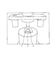
- FIG. 1 is a schematic diagram for explaining a ball-on-ring test method.
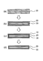
- FIG. 2 is a schematic view showing a process for producing chemically strengthened glass according to the present invention.
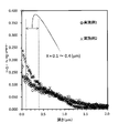
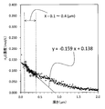
- FIG. 3 is a graph in which the hydrogen concentration profile of the surface layer of each chemically strengthened glass obtained in Example 1 and Example 2 is plotted.
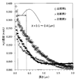
- FIG. 4 is a graph in which the hydrogen concentration profile of the surface layer of each chemically strengthened glass obtained in Example 3 and Example 4 is plotted.
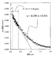
- FIG. 5 is a graph in which the hydrogen concentration profile of the surface layer of each chemically strengthened glass obtained in Comparative Example 1, Comparative Example 2, and Comparative Example 3 is plotted.
- FIG. 1 is a schematic diagram for explaining a ball-on-ring test method.
- FIG. 2 is a schematic view showing a process for producing chemically strengthened glass according to the present invention.
- FIG. 3 is a graph in which the hydrogen concentration profile of the surface layer of each chemically strengthened glass obtained in Example 1 and Example 2 is plotted.
- FIG. 4 is a
- FIG. 6 is an explanatory diagram for deriving the relational expression (I) from the graph in which the hydrogen concentration profile of the surface layer of the chemically strengthened glass obtained in Example 1 is plotted.
- FIG. 7 is an explanatory diagram for deriving the relational expression (I) from the graph in which the hydrogen concentration profile of the surface layer of the chemically strengthened glass obtained in Comparative Example 1 is plotted.
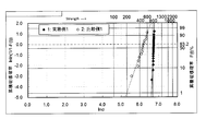
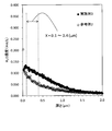
- FIG. 8 is a Weibull plot of BOR strength evaluation of each chemically strengthened glass obtained in Example 1 and Comparative Example 1.
- FIG. 9 is an AFM image of the chemically strengthened glass surface of Reference Example 1. The scanning area is 5 ⁇ 5 ⁇ m 2 .
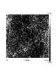
- FIG. 10 is an AFM image of the chemically strengthened glass surface of Example 1. The scanning area is 5 ⁇ 5 ⁇ m 2 .
- FIG. 11 is a Weibull plot of BOR strength evaluation of each chemically strengthened glass obtained in Example 3 and Reference Example 2.
- FIG. 12 is a graph plotting the hydrogen concentration profile of the surface layer of each chemically strengthened glass obtained in Example 3 and Reference Example 2.
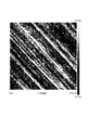
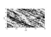
- FIG. 13 is an AFM image of a glass surface having surface polishing flaws.
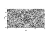
- FIG. 14 is an AFM image of the glass surface having no surface polishing scratches.
- the chemically strengthened glass according to the present invention is a chemically strengthened glass having a compressive stress layer formed on the surface layer by an ion exchange method, and a hydrogen concentration in a certain depth region from the outermost surface of the glass is a relational expression (described later) It is characterized by satisfying I) and having no polishing scratches on the glass surface.
- the compressive stress layer is a high-density layer formed by ion exchange of Na ions on the glass surface and K ions in the molten salt by bringing the raw glass into contact with an inorganic salt such as potassium nitrate. It is.
- the hydrogen concentration profile in the glass surface layer is in a specific range.
- Y aX + b (I)
- Y Hydrogen concentration (H 2 O conversion, mol / L)
- X Depth from the outermost surface of glass ( ⁇ m) a: -0.270 to -0.005 b: 0.020 to 0.220]
- the strength of glass decreases due to the presence of hydrogen (moisture) in the glass, but the present inventors may decrease the strength after chemical strengthening treatment, the main cause of which Has found that chemical defects are generated when moisture in the atmosphere penetrates into the glass. It has also been found that this phenomenon occurs not only through chemical strengthening but also through a heating process in the glass manufacturing process.
- hydrogen concentration in the glass is high, hydrogen enters the Si—O—Si bond network of the glass in the form of Si—OH, and the Si—O—Si bond is broken. If the hydrogen concentration in the glass is high, it is considered that the Si—O—Si bond is cut off more, chemical defects are easily generated, and the strength is lowered.
- the thickness of the compressive stress layer formed by ion exchange is formed in the range of 5 to 50 ⁇ m, depending on the degree of chemical strengthening.
- the penetration depth of hydrogen into the glass follows the diffusion coefficient, temperature, and time, and the penetration amount of hydrogen is influenced by the moisture content in the atmosphere in addition to these.
- the hydrogen concentration after chemical strengthening is the highest on the outermost surface and gradually decreases toward the deep part (bulk) where the compressive stress layer is not formed.
- a is a slope that defines how the hydrogen concentration decreases.
- the range of a is from ⁇ 0.270 to ⁇ 0.005, preferably from ⁇ 0.240 to ⁇ 0.030, and more preferably from ⁇ 0.210 to ⁇ 0.050.
- the range of b is 0.020 to 0.220, preferably 0.020 to 0.215, more preferably 0.030 to 0.210, and still more preferably 0.040 to 0.200. is there.
- the decrease in strength of glass is considered to be caused by the extension of microcracks existing on the glass surface due to external mechanical pressure.
- Non-Patent Document 2 it is considered that the crack is easier to extend as the glass structure at the tip of the crack is richer in Si—OH. Assuming that the crack tip is exposed to the atmosphere, the Si—OH amount at the crack tip is presumed to have a positive correlation with the hydrogen concentration on the outermost surface of the glass. Therefore, b corresponding to the hydrogen concentration on the outermost surface is preferably in a low range as shown above. As shown in FIGS. 3 to 5, no significant difference was found in the hydrogen penetration depth for the glass that had undergone the chemical strengthening process.
- the hydrogen penetration depth is likely to change depending on the chemical strengthening process conditions, but if it does not change, it corresponds to b that corresponds to the hydrogen concentration on the outermost surface and the slope that defines the degree of decrease in hydrogen concentration. A negative correlation appears in a. Accordingly, a is preferably in the high range shown above.
- the strength of chemically strengthened glass is not limited by prescribing only the hydrogen concentration itself of the surface layer, but by focusing on the hydrogen concentration profile and defining the surface hydrogen concentration and the degree of decrease in a specific range. It has been found that can be greatly improved.
- the hydrogen concentration profile (H 2 O concentration, mol / L) of glass is a profile measured under the following analysis conditions.
- Secondary ion mass spectrometry (SIMS) was used for measurement of the hydrogen concentration profile of the glass substrate.
- SIMS Secondary ion mass spectrometry
- a method for preparing a standard sample and a method for determining the hydrogen concentration are described below. 1) A part of the glass substrate to be measured is cut out. 2) A region of 50 ⁇ m or more is removed from the cut glass substrate surface by polishing or chemical etching. The removal process is performed on both sides. That is, the removal thickness on both sides is 100 ⁇ m or more.
- This removed glass substrate is used as a standard sample.
- infrared spectroscopy for the standard samples (Infrared spectroscopy: implement IR), the absorbance of the peak top in the vicinity of 3550 cm -1 of the IR spectrum the height A 3550 and 4000 cm -1 absorbance height A 4000 (the baseline) Ask. 4)
- the plate thickness d (cm) of the standard sample is measured using a plate thickness measuring instrument such as a micrometer.
- a glass substrate to be measured and a standard sample with a known hydrogen concentration obtained by the above method are simultaneously transported into the SIMS device and measured in order to obtain a depth profile of the intensity of 1 H ⁇ and 30 Si ⁇ . To do. Then, 1 H - by dividing the profile, 1 H - - 30 Si from the profile obtained of the intensity ratio of depth profile - / 30 Si. 1 H reference samples - / 30 Si - than depth profile of the intensity ratio, average in the region of from a depth 1 ⁇ m to 2 ⁇ m 1 H - / 30 Si - calculate an intensity ratio, a calibration of this value and the hydrogen concentration A line is created so that it passes through the origin (calibration curve with a 1 level standard sample).
- the 1 H ⁇ / 30 Si ⁇ intensity ratio on the vertical axis of the profile of the glass substrate to be measured is converted into a hydrogen concentration. Thereby, the hydrogen concentration profile of the glass substrate to be measured is obtained.
- the measurement conditions for SIMS and IR are as follows.
- Apparatus ADEPT1010 manufactured by ULVAC-PHI Primary ion species: Cs + Primary ion acceleration voltage: 5 kV Primary ion current value: 500 nA Primary ion incident angle: 60 ° with respect to the normal of the sample surface
- Raster size of primary ions 300 ⁇ 300 ⁇ m 2
- Secondary ion polarity Negative secondary ion detection area: 60 ⁇ 60 ⁇ m 2 (4% of the raster size of the primary ions)
- ESA Input Lens 0
- Use of neutralizing gun Method of converting the horizontal axis from sputtering time to depth: The depth of the analysis crater is measured by a stylus type surface profile measuring device (Dektak 150 manufactured by Veeco), and the sputter rate of primary ions is obtained.
- the average hydrogen concentration c can be obtained from the hydrogen concentration profile described above.
- polishing scratches The chemically strengthened glass according to the present invention has no polishing scratches on the surface.
- the term “polishing” in the present invention refers to smoothing by polishing the glass surface using abrasive grains.
- the presence or absence of polishing flaws can be determined by surface observation with an AFM (Atomic Force Microscope), and there are two or more scratches having a length of 5 ⁇ m or more and a width of 0.1 ⁇ m or more in a 10 ⁇ m ⁇ 5 ⁇ m region. If not, it can be said that there is no polishing flaw on the surface.
- FIG. 13 shows a state having surface polishing flaws
- FIG. 14 shows a state having no surface polishing flaws.
- Glass strength The strength of the chemically strengthened glass of the present invention can be evaluated by a ball-on-ring test.
- a glass plate is disposed on a ring made of stainless steel having a diameter of 30 mm and a contact portion having a radius of curvature of 2.5 mm, and a sphere made of steel having a diameter of 10 mm is brought into contact with the glass plate.
- the sphere is evaluated by a BOR strength F (N) measured by a Ball on Ring (BOR) test in which the sphere is loaded at the center of the ring under a static load condition.
- the chemically strengthened glass of the present invention has F ⁇ 1500 ⁇ t 2 and more preferably F ⁇ 1800 ⁇ t 2 [wherein F is the BOR strength (N) measured by a ball-on-ring test, t is the thickness (mm) of the glass substrate. ]. When the BOR strength F (N) is within this range, excellent strength is exhibited even when the plate is thinned.
- FIG. 1 shows a schematic diagram for explaining the ball-on-ring test used in the present invention.
- the glass plate 1 is placed on the glass plate 1 using a pressing jig 2 (hardened steel, diameter 10 mm, mirror finish) made of SUS304 with the glass plate 1 placed horizontally. Pressurize and measure the strength of the glass plate 1.
- a glass plate 1 serving as a sample is horizontally installed on a receiving jig 3 made of SUS304 (diameter 30 mm, contact portion curvature R2.5 mm, contact portion is hardened steel, mirror finish). Above the glass plate 1, a pressurizing jig 2 for pressurizing the glass plate 1 is installed.
- region of the glass plate 1 is pressurized from the upper direction of the glass plate 1 obtained after the Example and the comparative example.
- the test conditions are as follows. Lowering speed of the pressure jig 2: 1.0 (mm / min) At this time, the breaking load (unit N) when the glass is broken is defined as BOR strength, and the average value of 20 measurements is defined as BOR average strength. However, if the glass plate fracture starting point is 2 mm or more away from the ball pressing position, it is excluded from the data for calculating the average value.
- the chemically strengthened glass of the present invention has high surface strength as described above, and also has high surface strength reliability. As shown in Weibull plots for evaluating the BOR strength of each chemically strengthened glass in the examples described later, it can be seen that the chemically strengthened glass of the present invention has little variation in surface strength. The reason is not clear, but it is presumed that the hydrogen (water) concentration in the vicinity of the glass surface layer is slightly high.
- the chemically strengthened glass of the present invention further has a surface roughness (Ra) of 0.20 nm or more.
- Ra surface roughness
- the surface roughness can be measured, for example, by AFM surface observation with a measurement range of 1 ⁇ m ⁇ 1 ⁇ m.
- polished is less than 0.20 nm.
- Glass composition The glass used in the present invention only needs to contain sodium, and glass having various compositions can be used as long as it has a composition that can be strengthened by molding and chemical strengthening treatment. Specific examples include aluminosilicate glass, soda lime glass, borosilicate glass, lead glass, alkali barium glass, and aluminoborosilicate glass.
- the method for producing the glass is not particularly limited, and a desired glass raw material is charged into a continuous melting furnace, and the glass raw material is heated and melted preferably at 1500 to 1600 ° C., clarified, and then supplied to a molding apparatus. It can be manufactured by forming into a plate shape and slowly cooling.
- various methods can be employed for forming the glass.
- various forming methods such as a down draw method (for example, an overflow down draw method, a slot down method and a redraw method), a float method, a roll-out method, and a press method can be employed.
- the thickness of the glass is not particularly limited, but is usually preferably 5 mm or less and more preferably 3 mm or less in order to effectively perform the chemical strengthening treatment.
- the shape of the glass used in the present invention is not particularly limited.
- various shapes of glass such as a flat plate shape having a uniform plate thickness, a shape having a curved surface on at least one of the front surface and the back surface, and a three-dimensional shape having a bent portion can be employed.
- the total content of SiO 2 and Al 2 O 3 is 75% or less, the total content of Na 2 O and K 2 O is 12 to 25%, and the total content of MgO and CaO is 7 to 15%.
- composition which is displayed at a certain glass (iii) mol%, a SiO 2 68 ⁇ 80%, the Al 2 O 3 4 ⁇ 10% ,
- the a 2 O 5 ⁇ 15%, the K 2 O 0 to 1%, the MgO 4 ⁇ 15% and ZrO 2 is composition displaying a glass (iv) mole% containing 0 to 1%, a SiO 2 67 -75%, Al 2 O 3 0-4%, Na 2 O 7-15%, K 2 O 1-9%, MgO 6-14% and ZrO 2 0-1.5%
- the total content of SiO 2 and Al 2 O 3 is 71 to 75%, the total content of Na 2 O and K 2 O is 12 to 20%, and when CaO is contained, the content is 1% Glass that is less than
- the chemically strengthened glass according to the present invention has an ion-exchanged compressive stress layer on the glass surface.
- the surface of glass is ion exchanged to form a surface layer in which compressive stress remains.
- alkali metal ions typically Li ions, Na ions
- alkali ions typically Is substituted for Na ions or K ions for Li ions and K ions for Na ions.
- chemical strengthening is performed by bringing a glass into contact with an inorganic salt containing potassium nitrate (KNO 3 ).
- KNO 3 potassium nitrate
- Na ions on the glass surface and K ions in the inorganic salt are ion-exchanged to form a high-density compressive stress layer.
- a method of bringing glass into contact with inorganic salt a method of applying paste-like salt, a method of spraying an aqueous solution of salt onto glass, a method of immersing glass in a salt bath of molten salt heated to a melting point or higher are possible. However, among these, a method of immersing in molten salt is desirable.
- the inorganic salt those having a melting point below the strain point (usually 500 to 600 ° C.) of the glass to be chemically strengthened are preferred, and in the present invention, a molten salt containing potassium nitrate (melting point 330 ° C.) is preferred.
- a molten salt containing potassium nitrate melting point 330 ° C.
- the content of potassium nitrate in the inorganic salt is preferably 50% by mass or more.
- the inorganic salt is further selected from the group consisting of K 2 CO 3 , Na 2 CO 3 , KHCO 3 , NaHCO 3 , K 3 PO 4 , Na 3 PO 4 , K 2 SO 4 , Na 2 SO 4 , KOH and NaOH. It is preferable to contain at least one salt, and it is more preferable to contain at least one salt selected from the group consisting of K 2 CO 3 , Na 2 CO 3 , KHCO 3 and NaHCO 3 .
- the above-mentioned salt (hereinafter sometimes referred to as “flux”) has a property of cutting a glass network represented by Si—O—Si bonds. Since the temperature at which the chemical strengthening treatment is performed is as high as several hundred degrees Celsius, the covalent bond between Si—O of the glass is appropriately broken at that temperature, and the density reduction treatment described later easily proceeds.
- the degree of breaking the covalent bond varies depending on the chemical composition treatment conditions such as the glass composition, the type of salt (flux) used, the temperature and time for the chemical strengthening treatment, but the four covalent bonds extending from Si. Of these, it is considered preferable to select conditions that are sufficient to break one or two bonds.
- the chemical strengthening treatment time is 1 minute to 10 hours is preferable, 5 minutes to 8 hours is more preferable, and 10 minutes to 4 hours is more preferable.
- the amount of the flux added is preferably 0.1 mol% or more, more preferably 1 mol% or more, and particularly preferably 2 mol% or more from the viewpoint of controlling the surface hydrogen concentration. Further, from the viewpoint of productivity, the saturation solubility or less of each salt is preferable. Addition in excess may lead to glass corrosion. For example, when K 2 CO 3 is used as the flux, it is preferably 24 mol% or less, more preferably 12 mol% or less, and particularly preferably 8 mol% or less.
- the inorganic salt may contain other chemical species as long as the effects of the present invention are not impaired.
- alkali salts such as sodium chloride, potassium chloride, sodium borate, potassium borate, etc.
- chlorides and alkali borates These may be added alone or in combination of two or more.
- the production method of the present invention will be described by taking an example in which chemical strengthening is performed by a method of immersing glass in a molten salt.
- the molten salt can be produced by the steps shown below.
- Step 1a Preparation of potassium nitrate molten salt
- Step 2a Addition of flux to potassium nitrate molten salt
- Step 1a-Preparation of molten potassium nitrate salt potassium nitrate is put into a container and heated to a temperature equal to or higher than the melting point to melt, thereby preparing a molten salt. Melting is performed at a temperature within the range of the melting point (330 ° C.) and boiling point (500 ° C.) of potassium nitrate. In particular, the melting temperature is preferably 350 to 470 ° C. from the viewpoint of the balance between the surface compressive stress (CS) and the compressive stress layer depth (DOL) that can be applied to the glass, and the strengthening time.
- CS surface compressive stress
- DOL compressive stress layer depth
- metal for the container for melting potassium nitrate, metal, quartz, ceramics, or the like can be used.
- a metal material is desirable from the viewpoint of durability, and a stainless steel (SUS) material is preferable from the viewpoint of corrosion resistance.
- SUS stainless steel
- Step 2a Additional of flux to potassium nitrate molten salt-
- the above-mentioned flux is added to the potassium nitrate molten salt prepared in Step 1a, and the whole is mixed uniformly with a stirring blade while keeping the temperature within a certain range.
- the order of addition is not limited, and they may be added simultaneously.
- the temperature is preferably not less than the melting point of potassium nitrate, that is, not less than 330 ° C., more preferably 350 to 500 ° C.
- the stirring time is preferably 1 minute to 10 hours, more preferably 10 minutes to 2 hours.
- Step 1b Mixing of potassium nitrate and flux
- Step 2b Melting of mixed salt of potassium nitrate and flux
- Step 1b-Mixing of potassium nitrate and flux- potassium nitrate and a flux are put into a container and mixed with a stirring blade or the like.
- the order of addition is not limited, and they may be added simultaneously.
- the same container as that used in the above step 1a can be used.
- Step 2b-Melting of mixed salt of potassium nitrate and flux- the mixed salt obtained in step 1b is heated and melted. Melting is performed at a temperature within the range of the melting point (330 ° C.) and boiling point (500 ° C.) of potassium nitrate.
- the melting temperature is preferably 350 to 470 ° C. from the viewpoint of the balance between the surface compressive stress (CS) and the compressive stress layer depth (DOL) that can be applied to the glass, and the strengthening time.
- the stirring time is preferably 1 minute to 10 hours, and more preferably 10 minutes to 2 hours.
- the precipitates are Let stand until it settles to the bottom.
- This precipitate includes a flux exceeding the saturation solubility and a salt in which the cations of the flux are exchanged in the molten salt.
- the molten salt used in the production method of the present invention preferably has a Na concentration of 500 ppm by weight or more, more preferably 1000 ppm by weight or more. It is preferable that the Na concentration in the molten salt is 500 ppm by weight or more because the low-density layer is easily deepened by the acid treatment step described later. There is no restriction
- concentration It is permissible until a desired surface compressive stress (CS) is obtained.
- the molten salt which performed the chemical strengthening process once or more contains the sodium eluted from glass. Therefore, if the Na concentration is already within the above range, glass-derived sodium may be used as it is as the Na source.
- the molten salt can be prepared by the steps 1a and 2a or the steps 1b and 2b.
- the density of the chemically strengthened glass gradually increases from the outer edge of the intermediate layer 30 (bulk) existing in the center of the glass toward the surface of the compressive stress layer. There is no clear boundary between the density changes.
- the intermediate layer is a layer present in the center of the glass and sandwiched between the compressive stress layers. Unlike the compressive stress layer, this intermediate layer is a layer that is not ion-exchanged.
- the chemical strengthening treatment in the present invention can be performed by the following step 3.
- Process 3 Chemical strengthening treatment of glass
- step 3 the glass is preheated, and the molten salt prepared in steps 1a and 2a or steps 1b and 2b is adjusted to a temperature at which chemical strengthening is performed.
- the preheated glass is immersed in the molten salt for a predetermined time, and then the glass is pulled up from the molten salt and allowed to cool.
- shape processing according to a use, for example, mechanical processing, such as a cutting
- the preheating temperature of glass depends on the temperature immersed in the molten salt, but is generally preferably 100 ° C. or higher.
- the chemical strengthening temperature is preferably not more than the strain point (usually 500 to 600 ° C.) of the glass to be tempered, and particularly preferably 350 ° C. or more in order to obtain a higher compressive stress layer depth.
- the immersion time of the glass in the molten salt is preferably 1 minute to 10 hours, more preferably 5 minutes to 8 hours, and even more preferably 10 minutes to 4 hours. If it exists in this range, the chemically strengthened glass excellent in the balance of an intensity
- Step 4 Glass cleaning
- Step 5 Acid treatment of glass after Step 4
- the surface layer of the compressive stress layer 20 was altered on the glass surface, specifically, the density was reduced.
- the low density layer 10 is further provided [FIGS. 2B to 2C].
- the low density layer is formed by Na (leaching) from the outermost surface of the compressive stress layer (leaching) and H entering (replacement) instead.
- Step 4-Glass cleaning- glass is cleaned using industrial water, ion exchange water, or the like. Of these, ion-exchanged water is preferred.
- the washing conditions vary depending on the washing solution used, but when ion-exchanged water is used, washing at 0 to 100 ° C. is preferable from the viewpoint of completely removing the attached salt.
- Step 5-Acid treatment- the glass cleaned in step 4 is further subjected to acid treatment.
- the acid treatment of the glass is performed by immersing the chemically strengthened glass in an acidic solution, whereby Na and / or K on the surface of the chemically strengthened glass can be replaced with H.
- the solution is not particularly limited as long as it is acidic, and may be less than pH 7.
- the acid used may be a weak acid or a strong acid. Specifically, acids such as hydrochloric acid, nitric acid, sulfuric acid, phosphoric acid, acetic acid, oxalic acid, carbonic acid and citric acid are preferred. These acids may be used alone or in combination.
- the temperature at which the acid treatment is performed varies depending on the type, concentration, and time of the acid used, but is preferably 100 ° C. or less.
- the time for the acid treatment varies depending on the type, concentration and temperature of the acid used, but is preferably 10 seconds to 5 hours from the viewpoint of productivity, and more preferably 1 minute to 2 hours.
- the concentration of the acid treatment solution varies depending on the type of acid used, the time, and the temperature, but is preferably a concentration at which there is little concern about container corrosion, specifically 0.1 wt% to 20 wt%.
- the thickness of the low density layer is preferably 5 nm or more, and more preferably 20 nm or more from the viewpoint of the glass surface removal amount.
- the thickness of the low density layer can be controlled by the flux concentration, sodium concentration, temperature, time, etc. in the chemical strengthening step.
- the density of the low density layer is preferably lower than the density of the region (bulk) deeper than the ion-exchanged compressive stress layer from the viewpoint of glass surface removability.
- the thickness of the low density layer can be determined from the period ( ⁇ ) measured by the X-ray reflectivity method (X-ray-Reflectometry: XRR).
- the density of the low density layer can be determined from the critical angle ( ⁇ c) measured by XRR.
- it is also possible to confirm the formation of the low density layer and the thickness of the layer by simply observing a cross section of the glass with a scanning electron microscope (SEM).
- Step 6 Alkaline Treatment According to the above step 6, part or all of the low density layer 10 formed up to step 5 can be removed [FIGS. 2 (c) to (d)]. Hereinafter, step 6 will be described in detail.
- Step 6-alkali treatment the glass treated with acid in step 5 is further subjected to alkali treatment.
- the alkali treatment is performed by immersing the chemically strengthened glass in a basic solution, whereby a part or all of the low density layer can be removed.
- the solution is not particularly limited as long as it is basic, and may have a pH exceeding 7, and a weak base or a strong base may be used.
- bases such as sodium hydroxide, potassium hydroxide, potassium carbonate and sodium carbonate are preferred. These bases may be used alone or in combination.
- the temperature for the alkali treatment varies depending on the type, concentration and time of the base used, but is preferably 0 to 100 ° C, more preferably 10 to 80 ° C, and particularly preferably 20 to 60 ° C. If it is this temperature range, there is no possibility that glass will corrode and it is preferable.
- the alkali treatment time varies depending on the type, concentration and temperature of the base used, it is preferably 10 seconds to 5 hours from the viewpoint of productivity, and more preferably 1 minute to 2 hours.
- the concentration of the solution used for the alkali treatment varies depending on the type of base used, the time, and the temperature, but is preferably 0.1 wt% to 20 wt% from the viewpoint of glass surface removability.
- step 4 it is preferable to have a cleaning step similar to step 4 between the acid treatment step 5 and the alkali treatment step 6 or after completion of the alkali treatment step 6.
- FIG. 2D shows an embodiment in which the low density layer 10 is completely removed. However, a part of the low density layer 10 may be removed and a part may remain. From the viewpoint of improving the strength, the effect can be obtained without removing all of the low density layer, but it is preferable to remove all of the low density layer from the viewpoint of stably securing the transmittance of the glass.
- the glass removal amount thickness was determined by measuring the weight before and after the chemical treatment with an analytical electronic balance (HR-202i; manufactured by AND) and converting the thickness using the following formula.
- (Removed thickness per side) ((weight before treatment) ⁇ (weight after treatment)) / (glass specific gravity) / treated area / 2 At this time, the glass specific gravity was calculated as 2.48 (g / cm 3 ).
- FIG. 1 is a schematic diagram for explaining the ball-on-ring test used in the present invention. With the glass plate 1 placed horizontally, the glass plate 1 was pressed using a pressurizing jig 2 made of SUS304 (hardened steel, diameter 10 mm, mirror finish), and the strength of the glass plate 1 was measured.
- a pressurizing jig 2 made of SUS304 (hardened steel, diameter 10 mm, mirror finish), and the strength of the glass plate 1 was measured.
- a glass plate 1 serving as a sample is horizontally installed on a receiving jig 3 made of SUS304 (diameter 30 mm, contact portion curvature R2.5 mm, contact portion is hardened steel, mirror finish). Above the glass plate 1, a pressurizing jig 2 for pressurizing the glass plate 1 is installed.
- region of the glass plate 1 was pressurized from the upper direction of the glass plate 1 obtained after the Example and the comparative example.
- the test conditions are as follows. Lowering speed of the pressure jig 2: 1.0 (mm / min) At this time, the breaking load (unit N) when the glass was broken was defined as BOR strength, and the average value of 20 measurements was defined as BOR average strength. However, when the fracture start point of the glass plate was 2 mm or more away from the ball pressing position, it was excluded from the data for calculating the average value.
- Example 1 (Chemical strengthening process) To a SUS cup, 9700 g of potassium nitrate, 890 g of potassium carbonate, and 400 g of sodium nitrate were added and heated to 450 ° C. with a mantle heater to prepare a molten salt of 6 mol% potassium carbonate and 10,000 ppm by weight sodium. Prepare 50mm x 50mm x 0.56mm aluminosilicate glass A (specific gravity 2.48), preheat to 200-400 ° C, soak in molten salt at 450 ° C for 2 hours, and after ion exchange treatment, near room temperature The chemical strengthening process was performed by cooling to. The obtained chemically strengthened glass was washed with water and subjected to the next step.
- aluminosilicate glass A specific gravity 2.48
- Aluminosilicate glass A composition (in mol%): SiO 2 64.4%, Al 2 O 3 8.0%, Na 2 O 12.5%, K 2 O 4.0%, MgO 10.5%, CaO 0.1%, SrO 0.1%, BaO 0.1%, ZrO 2 0.5%
- a 4.0 wt% aqueous sodium hydroxide solution was prepared in a beaker, and the temperature was adjusted to 40 ° C. using a water bath.
- the glass obtained in the acid treatment step was immersed in the prepared sodium hydroxide aqueous solution for 120 seconds, subjected to alkali treatment, then washed several times with pure water, and then dried by air blowing. From the above, chemically strengthened glass of Example 1 was obtained.
- Example 2 Hydrochloric acid aqueous solution and sodium hydroxide adjusted using a glass flat-flow type washing machine, with the use of aluminosilicate glass A having the plate thickness shown in Table 1, the molten salt temperature and the ion exchange treatment time being 430 ° C. and 40 minutes, respectively.
- a chemically tempered glass was produced in the same manner as in Example 1 except that acid treatment and alkali treatment were performed by showering the aqueous solution for 277 seconds each.
- aluminosilicate glass B (specific gravity: 2.41) having a composition of 50 mm ⁇ 50 mm ⁇ 0.72 mm and having the following composition was used.
- HNO 3 manufactured by Kanto Chemical Co., Inc.
- KS14A manufactured by Yako Electric Co., Ltd.
- a chemically strengthened glass was produced in the same manner as in Example 1 except that the acid treatment was performed.
- Aluminosilicate glass B composition (in mol%): SiO 2 68%, Al 2 O 3 10%, Na 2 O 14%, MgO 8%
- Example 4 Instead of the aluminosilicate glass A, a chemically strengthened glass was produced in the same manner as in Example 3 except that an aluminoborosilicate glass (specific gravity 2.38) having a composition of 50 mm ⁇ 50 mm ⁇ 0.70 mm and having the following composition was used.
- Aluminoborosilicate glass composition (mol% display): SiO 2 67%, B 2 O 3 4%, Al 2 O 3 13%, Na 2 O 14%, K 2 O ⁇ 1%, MgO 2%, CaO ⁇ 1 %
- the amount of sodium in the molten salt is the value shown in Table 1, the potassium carbonate addition amount is 0 g, and the acid treatment step and the alkali treatment step are not carried out. Glass was produced.
- the amount of sodium in the molten salt is the value shown in Table 1, the potassium carbonate addition amount is 0 g, and the acid treatment step and the alkali treatment step are not performed. Glass was produced.
- the amount of sodium in the molten salt is the value shown in Table 1, the potassium carbonate addition amount is 0 g, and the acid treatment step and the alkali treatment step are not performed. Glass was produced.
- FIGS. 3 to 5 are graphs plotting the hydrogen concentration profile of the surface layer of each chemically strengthened glass obtained in Examples 1 to 4 and Comparative Examples 1 to 3.
- FIG. 8 shows the Weibull plot of BOR intensity
- FIG. 8 shows a Weibull plot of BOR strength evaluation results of an aluminosilicate glass plate sample having a plate thickness of 0.56 mm.
- the horizontal axis of the graph represents the logarithm ln ( ⁇ ) of the fracture load ⁇ (N), while the vertical axis represents the cumulative failure probability percentage P (%) for the samples in each of the two groups.
- Example 1 the average breaking load was 827N in Example 1 and 455N in Comparative Example 1.
- the 10% breaking load (B10) is 793 N in Example 1, whereas it is 318 N in Comparative Example 1, and the 1% breaking load (B1) is 750 N in Example 1, whereas Comparative Example 1 Then it was 200N. From this result, it can be seen that in Example 1, no low-strength product was generated, and the reliability with respect to surface strength was greatly improved.
- a slurry having a specific gravity of 0.9 was prepared by dispersing cerium oxide having an average particle size of 1.2 ⁇ m in water, and the same aluminosilicate glass B as in Example 3 was subjected to a polishing pressure of 10 kPa and a polishing pad (nonwoven fabric type). Polished on one side by 0.6 ⁇ m.
- the glass obtained in the polishing step was chemically strengthened using the same molten salt as in Comparative Example 3 at a chemical strengthening temperature of 450 degrees and a chemical strengthening treatment time of 2 hours. Table 1 shows the results of various evaluations. An image obtained by observing the glass surface with AFM is shown in FIG. The surface roughness (Ra) measured by AFM measurement was 0.40 nm. Moreover, the surface observation image of the chemically strengthened glass manufactured in Example 1 is shown in FIG. The surface roughness (Ra) measured by AFM measurement was 0.33 nm.
- the 10% breaking load (B10) is 1339N in Example 3, whereas it is 1098N in Reference Example 2, and the 1% breaking load (B1) is 1307N in Example 3, whereas Reference Example 2 It was 904N. From this result, it can be seen that in Example 3, no low-strength product was generated, and the reliability with respect to surface strength was greatly improved.
- FIG. 12 shows the hydrogen concentration profile of the surface layer of each chemically strengthened glass obtained in Reference Example 2 and Example 3.
- the surface layer hydrogen concentration in Example 3 was higher than that in Reference Example 2.
- chemically strengthened glass having significantly improved surface strength can be obtained safely and at low cost.
- the chemically strengthened glass according to the present invention can be used for a cover glass for a display such as a mobile phone, a digital camera, or a touch panel display.
Landscapes
- Chemical & Material Sciences (AREA)
- Engineering & Computer Science (AREA)
- Materials Engineering (AREA)
- Chemical Kinetics & Catalysis (AREA)
- General Chemical & Material Sciences (AREA)
- Geochemistry & Mineralogy (AREA)
- Life Sciences & Earth Sciences (AREA)
- Organic Chemistry (AREA)
- Physics & Mathematics (AREA)
- General Physics & Mathematics (AREA)
- Surface Treatment Of Glass (AREA)
- Glass Compositions (AREA)
- Mechanical Engineering (AREA)
Abstract
Description
<1>
表層にイオン交換法により形成された圧縮応力層を有する化学強化ガラスであって、
表面粗さ(Ra)が0.20nm以上であり、
ガラスの最表面から深さXの領域における水素濃度Yが、X=0.1~0.4(μm)において下記関係式(I)を満たし、
ボールオンリング試験により下記条件で測定した面強度F(N)が、ガラス板の板厚t(mm)に対して、F≧1500×t2であり、
かつ、表面に研磨傷を有さない化学強化ガラス。
Y=aX+b (I)
〔式(I)における各記号の意味は下記の通りである。
Y:水素濃度(H2O換算、mol/L)
X:ガラス最表面からの深さ(μm)
a:-0.270~-0.005
b:0.020~0.220〕
ボールオンリング試験条件:
板厚t(mm)のガラス板を、直径30mm、接触部が曲率半径2.5mmの丸みを持つステンレスリング上に配置し、該ガラス板に直径10mmの鋼球体を接触させた状態で、該球体を静的荷重条件下で該リングの中心に荷重し、ガラスが破壊された際の破壊荷重(単位N)をBOR強度とし、該BOR強度の20回の測定平均値を面強度Fとする。ただし、ガラスの破壊起点が、該球体の荷重点から2mm以上離れている場合は、平均値算出のためのデータより除外する。
<2>
前記ガラスがアルミノシリケートガラス、アルミノボロシリケートガラス又はソーダライムガラスである、上記<1>に記載の化学強化ガラス。
ここで、本明細書において“質量%”と“重量%”、“質量ppm”と“重量ppm”とは、それぞれ同義である。また、単に“ppm”と記載した場合は、“重量ppm”のことを示す。
本発明に係る化学強化ガラスは、表層にイオン交換法により形成された圧縮応力層を有する化学強化ガラスであって、ガラスの最表面からの一定の深さ領域における水素濃度が後述する関係式(I)を満たし、かつ、ガラス表面に研磨傷を有さないことを特徴とする。
Y=aX+b (I)
〔式(I)における各記号の意味は下記の通りである。
Y:水素濃度(H2O換算、mol/L)
X:ガラスの最表面からの深さ(μm)
a:-0.270~-0.005
b:0.020~0.220〕
ガラス中の水素濃度が高いと、ガラスのSi-O-Siの結合ネットワークの中に水素がSi-OHの形で入り、Si-O-Siの結合が切れる。ガラス中の水素濃度が高いとSi-O-Siの結合が切れる部分が多くなり、化学的欠陥が生成され易くなり、強度が低下すると考えられる。
式(I)において、bは最表面(X=0μm)における水素濃度に相当する。bの範囲は0.020~0.220であり、好ましくは0.020~0.215であり、より好ましくは0.030~0.210であり、さらに好ましくは0.040~0.200である。
図3~図5に示す通り、化学強化工程を経たガラスについては、水素の侵入深さに顕著な違いが認められなかった。水素の侵入深さは化学強化工程条件に依存して変化する可能性が高いが、仮に変化しないとすれば、最表面の水素濃度に相当するbと水素濃度の低下具合を規定する傾きに相当するaには負の相関が現れる。従って、aは上記に示す程度の高い範囲が好ましい。
ここで、ガラスの水素濃度プロファイル(H2O濃度、mol/L)とは以下の分析条件下で測定したプロファイルである。
ガラス基板の水素濃度プロファイルの測定には二次イオン質量分析法(Secondary Ion Mass Spectrometory:SIMS)を用いた。SIMSにて定量的な水素濃度プロファイルを得る場合には、水素濃度既知の標準試料が必要である。標準試料の作製方法および水素濃度定量方法を以下に記す。
1)測定対象のガラス基板の一部を切り出す。
2)切り出したガラス基板の表面から50μm以上の領域を研磨あるいはケミカルエッチングによって除去する。除去処理は両面とも行う。すなわち、両面での除去厚みは100μm以上となる。この除去処理済みガラス基板を標準試料とする。
3)標準試料について赤外分光法(Infrared spectroscopy:IR)を実施し、IRスペクトルの3550cm-1付近のピークトップの吸光度高さA3550および4000cm-1の吸光度高さA4000(ベースライン)を求める。
4)標準試料の板厚d(cm)をマイクロメーターなどの板厚測定器を用いて測定する。
5)文献Aを参考に、ガラスのH2Oの赤外実用吸光係数εpract(L/(mol・cm))を75とし、式IIを用いて標準試料の水素濃度(H2O換算、mol/L)を求める。
標準試料の水素濃度 = (A3550-A4000)/(εpract・d)・・・式II
文献A)S. Ilievski et al., Glastech. Ber. Glass Sci. Technol., 73 (2000) 39.
装置:アルバック・ファイ社製 ADEPT1010
一次イオン種:Cs+
一次イオンの加速電圧:5kV
一次イオンの電流値:500nA
一次イオンの入射角:試料面の法線に対して60°
一次イオンのラスターサイズ:300×300μm2
二次イオンの極性:マイナス
二次イオンの検出領域:60×60μm2(一次イオンのラスターサイズの4%)
ESA Input Lens:0
中和銃の使用:有
横軸をスパッタ時間から深さへ変換する方法:分析クレータの深さを触針式表面形状測定器(Veeco社製Dektak150)によって測定し、一次イオンのスパッタレートを求める。このスパッタレートを用いて、横軸をスパッタ時間から深さへ変換する。
1H-検出時のField Axis Potential:装置ごとに最適値が変化する可能性がある。バックグラウンドが十分にカットされるように測定者が注意しながら値を設定する。
装置:Thermo Fisher Scientific社製Nic-plan/ Nicolet 6700
分解能:4cm-1
積算:16
検出器:TGS検出器
また、a及びbを制御する手段としては、例えば、化学強化工程における融剤濃度、ナトリウム濃度、温度、時間等を変更することが挙げられる。
本発明に係る化学強化ガラスは、表面に研磨傷を有さない。ここで、本発明における研磨とは、砥粒を用いてガラス表面を削ることにより平滑化することをいう。また、研磨傷の有無はAFM(Atomic Force Microscope;原子間力顕微鏡)による表面観察によって判別することができ、10μm×5μm領域内に長さ5μm以上幅0.1μm以上のスクラッチが2本以上存在しないという場合に、表面に研磨傷がない状態ということができる。図13に、表面研磨傷を有する状態を、図14に、表面研磨傷を有さない状態をそれぞれ示す。
本発明の化学強化ガラスの強度は、ボールオンリング試験により評価することができる。
本発明の化学強化ガラスは、ガラス板を直径30mm、接触部が曲率半径2.5mmの丸みを持つステンレスからなるリング上に配置し、該ガラス板に直径10mmの鋼からなる球体を接触させた状態で、該球体を静的荷重条件下で該リングの中心に荷重するボールオンリング(Ball on Ring;BOR)試験により測定したBOR強度F(N)で評価する。
本発明の化学強化ガラスは、F≧1500×t2であり、F≧1800×t2であることがより好ましい[式中、Fはボールオンリング試験により測定したBOR強度(N)であり、tはガラス基板の板厚(mm)である。]。BOR強度F(N)がかかる範囲であることにより、薄板化した場合にも優れた強度を示す。
加圧治具2の下降速度:1.0(mm/min)
この時、ガラスが破壊された際の、破壊荷重(単位N)をBOR強度とし、20回の測定の平均値をBOR平均強度とする。ただし、ガラス板の破壊起点がボール押しつけ位置より2mm以上離れている場合は、平均値算出のためのデータより除外する。
本発明の化学強化ガラスは、さらに、表面粗さ(Ra)が0.20nm以上である。表面粗さが上記数値以上であることにより、面強度の高い化学強化ガラスとすることができる。ガラス表面がある程度の表面粗さを有することで、応力集中が抑制され、強度が上がることが推測される。
表面粗さは、例えば、AFM表面観察により、測定範囲を1μm×1μmとして測定することができる。
なお、従来の研磨していない化学強化ガラス板の表面粗さは0.20nm未満である。
〔AFMの測定条件〕
装置:Bruker社製 NanoscopeV + MultiMode8あるいはDimension ICON
モード:ScanAsystモード
プローブ:RTESPA(バネ定数:40N/m)
Samples/Line:256
Lines:256
Scan Rate:1Hz
測定視野:1×1μm2(汚染のないところを狙う)
本発明に係る化学強化ガラスを製造する方法の一態様を以下に説明するが、本発明はこれに限定されない。
本発明で使用されるガラスはナトリウムを含んでいればよく、成形、化学強化処理による強化が可能な組成を有するものである限り、種々の組成のものを使用することができる。具体的には、例えば、アルミノシリケートガラス、ソーダライムガラス、ボロシリケートガラス、鉛ガラス、アルカリバリウムガラス、アルミノボロシリケートガラス等が挙げられる。
(i)モル%で表示した組成で、SiO2を50~80%、Al2O3を2~25%、Li2Oを0~10%、Na2Oを0~18%、K2Oを0~10%、MgOを0~15%、CaOを0~5%およびZrO2を0~5%を含むガラス
(ii)モル%で表示した組成が、SiO2を50~74%、Al2O3を1~10%、Na2Oを6~14%、K2Oを3~11%、MgOを2~15%、CaOを0~6%およびZrO2を0~5%含有し、SiO2およびAl2O3の含有量の合計が75%以下、Na2OおよびK2Oの含有量の合計が12~25%、MgOおよびCaOの含有量の合計が7~15%であるガラス
(iii)モル%で表示した組成が、SiO2を68~80%、Al2O3を4~10%、Na2Oを5~15%、K2Oを0~1%、MgOを4~15%およびZrO2を0~1%含有するガラス
(iv)モル%で表示した組成が、SiO2を67~75%、Al2O3を0~4%、Na2Oを7~15%、K2Oを1~9%、MgOを6~14%およびZrO2を0~1.5%含有し、SiO2およびAl2O3の含有量の合計が71~75%、Na2OおよびK2Oの含有量の合計が12~20%であり、CaOを含有する場合その含有量が1%未満であるガラス
以下、ガラスを溶融塩に浸漬させる方法により化学強化を行う態様を例に、本発明の製造方法を説明する。
溶融塩は下記に示す工程により製造することができる。
工程1a:硝酸カリウム溶融塩の調製
工程2a:硝酸カリウム溶融塩への融剤の添加
工程1aでは、硝酸カリウムを容器に投入し、融点以上の温度に加熱して溶融することで、溶融塩を調製する。溶融は硝酸カリウムの融点(330℃)と沸点(500℃)の範囲内の温度で行う。特に溶融温度を350~470℃とすることが、ガラスに付与できる表面圧縮応力(CS)と圧縮応力層深さ(DOL)のバランスおよび強化時間の点からより好ましい。
工程2aでは、工程1aで調製した硝酸カリウム溶融塩中に、先述した融剤を添加し、温度を一定範囲に保ちながら、攪拌翼などにより、全体が均一になるように混合する。複数の融剤を併用する場合、添加順序は限定されず、同時に添加してもよい。
温度は硝酸カリウムの融点以上、すなわち330℃以上が好ましく、350~500℃がより好ましい。また、攪拌時間は1分~10時間が好ましく、10分~2時間がより好ましい。
上記の溶融塩の製造1では、硝酸カリウムの溶融塩の調製後に融剤を加える方法を例示したが、溶融塩はまた、下記に示す工程により製造することができる。
工程1b:硝酸カリウムと融剤の混合
工程2b:硝酸カリウムと融剤との混合塩の溶融
工程1bでは、硝酸カリウムと融剤とを容器に投入して、攪拌翼などにより混合する。複数の融剤を併用する場合、添加順序は限定されず、同時に添加してもよい。容器は上記工程1aで用いるものと同様のものを用いることができる。
工程2bでは、工程1bにより得られる混合塩を加熱して溶融する。溶融は硝酸カリウムの融点(330℃)と沸点(500℃)の範囲内の温度で行う。特に溶融温度を350~470℃とすることが、ガラスに付与できる表面圧縮応力(CS)と圧縮応力層深さ(DOL)のバランスおよび強化時間の点からより好ましい。攪拌時間は1分~10時間が好ましく、10分~2時間がより好ましい。
なお、化学強化処理を1回以上行なった溶融塩にはガラスから溶出したナトリウムが含まれている。したがって、Na濃度が既に上記範囲内であれば、ガラス由来のナトリウムをそのままNa源として用いてもよいし、Na濃度が満たない場合や、化学強化未使用の溶融塩を用いる場合には、硝酸ナトリウム等の無機ナトリウム塩を添加することにより調整することができる。
以上、上記工程1a及び工程2a、又は工程1b及び工程2bにより、溶融塩を調製することができる。
次に、調製した溶融塩を用いて化学強化処理を行う。化学強化処理は、ガラスを溶融塩に浸漬し、ガラス中の金属イオン(Naイオン)を、溶融塩中のイオン半径の大きな金属イオン(Kイオン)と置換することで行われる。このイオン交換によってガラス表面の組成を変化させ、ガラス表面が高密度化した圧縮応力層20を形成することができる[図2(a)~(b)]。このガラス表面の高密度化によって圧縮応力が発生することから、ガラスを強化することができる。
工程3:ガラスの化学強化処理
工程3では、ガラスを予熱し、上記工程1a及び工程2a又は工程1b及び工程2bで調製した溶融塩を、化学強化を行う温度に調整する。次いで予熱したガラスを溶融塩中に所定の時間浸漬したのち、ガラスを溶融塩中から引き上げ、放冷する。なお、ガラスには、化学強化処理の前に、用途に応じた形状加工、例えば、切断、端面加工および穴あけ加工などの機械的加工を行うことが好ましい。
工程4:ガラスの洗浄
工程5:工程4を経た後のガラスの酸処理
上記工程5まで経た時点で、ガラス表面には圧縮応力層20の表層が変質した、具体的には低密度化された、低密度層10をさらに有することとなる[図2(b)~(c)]。低密度層とは、圧縮応力層の最表面からNaやKが抜け(リーチングし)、代わりにHが入り込む(置換する)ことによって形成される。
以下、工程4及び工程5について詳述する。
工程4では工水、イオン交換水等を用いてガラスの洗浄を行う。中でもイオン交換水が好ましい。洗浄の条件は用いる洗浄液によっても異なるが、イオン交換水を用いる場合には0~100℃で洗浄することが付着した塩を完全に除去させる点から好ましい。
工程5では、工程4で洗浄したガラスに対して、さらに酸処理を行う。
ガラスの酸処理とは、酸性の溶液中に、化学強化ガラスを浸漬させることによって行い、これにより化学強化ガラス表面のNa及び/又はKをHに置換することができる。
溶液は酸性であれば特に制限されずpH7未満であればよく、用いられる酸が弱酸であっても強酸であってもよい。具体的には塩酸、硝酸、硫酸、リン酸、酢酸、シュウ酸、炭酸及びクエン酸等の酸が好ましい。これらの酸は単独で用いても、複数を組み合わせて用いてもよい。
酸処理を行う時間は、用いる酸の種類や濃度、温度によっても異なるものの、10秒~5時間が生産性の点から好ましく、1分~2時間がより好ましい。
酸処理を行う溶液の濃度は、用いる酸の種類や時間、温度によって異なるものの、容器腐食の懸念が少ない濃度が好ましく、具体的には0.1wt%~20wt%が好ましい。
低密度層の密度はXRRによって測定した臨界角(θc)により求めることができる。
なお、簡易的には走査型電子顕微鏡(SEM)でガラスの断面を観察することによって、低密度層の形成と層の厚みを確認することも可能である。
工程6:アルカリ処理
上記工程6により、工程5までに形成された低密度層10の一部又は全部を除去することができる[図2(c)~(d)]。
以下、工程6について詳述する。
工程6では、工程5で酸処理したガラスに対して、さらにアルカリ処理を行う。
アルカリ処理とは、塩基性の溶液中に、化学強化ガラスを浸漬させることによって行い、これにより低密度層の一部又は全部を除去することができる。
溶液は塩基性であれば特に制限されずpH7超過であればよく、弱塩基を用いても強塩基を用いてもよい。具体的には水酸化ナトリウム、水酸化カリウム、炭酸カリウム、炭酸ナトリウム等の塩基が好ましい。これらの塩基は単独で用いても、複数を組み合わせて用いてもよい。
アルカリ処理を行う時間は、用いる塩基の種類や濃度、温度によっても異なるものの、10秒間~5時間が生産性の点から好ましく、1分間~2時間がより好ましい。
アルカリ処理を行う溶液の濃度は、用いる塩基の種類や時間、温度によって異なるものの、ガラス表面除去性の観点から0.1wt%~20wt%が好ましい。
本実施例における各種評価は以下に示す分析方法により行った。
(ガラスの評価:表面応力)
本発明の化学強化ガラスの圧縮応力層の圧縮応力値および圧縮応力層の深さは、EPMA(electron probe micro analyzer)または表面応力計(例えば、折原製作所製FSM-6000)等を用いて測定することができる。実施例では、表面圧縮応力値(CS、単位はMPa)および圧縮応力層の深さ(DOL、単位はμm)は折原製作所社製表面応力計(FSM-6000)を用いて測定した。
ガラスの除去量厚みは、薬液処理前後の重量を分析用電子天秤(HR-202i;AND製)により測定し、次の式を用いて厚み換算することにより求めた。
(片面あたりの除去量厚み)=((処理前重量)-(処理後重量))/(ガラス比重)/処理面積/2
このとき、ガラス比重を2.48(g/cm3)として計算した。
ガラス面強度はボールオンリング(Ball on Ring;BOR)試験により測定した。図1に、本発明で用いたボールオンリング試験を説明するための概略図を示す。ガラス板1を水平に載置した状態で、SUS304製の加圧治具2(焼入れ鋼、直径10mm、鏡面仕上げ)を用いてガラス板1を加圧し、ガラス板1の強度を測定した。
加圧治具2の下降速度:1.0(mm/min)
この時、ガラスが破壊された際の、破壊荷重(単位N)をBOR強度とし、20回の測定の平均値をBOR平均強度とした。ただし、ガラス板の破壊起点がボール押しつけ位置より2mm以上離れていた場合は、平均値算出のためのデータより除外した。
AFMを用いた下記条件により、ガラスの表面粗さを測定した。
〔AFMの測定条件〕
装置:Bruker社製NanoscopeV + MultiMode8あるいはDimension ICON
モード:ScanAsystモード
プローブ:RTESPA(バネ定数:40N/m)
Samples/Line:256
Lines:256
Scan Rate:1Hz
測定視野:1×1μm2(汚染のないところを狙う)
前述の〔水素濃度プロファイル測定方法〕にて記載した方法に従い、水素濃度プロファイルを測定し、関係式〔I〕と平均水素濃度(c値)を導出した。
(化学強化工程)
SUS製のカップに硝酸カリウム9700g、炭酸カリウム890g、硝酸ナトリウム400gを加え、マントルヒーターで450℃まで加熱して炭酸カリウム6mol%、ナトリウム10000重量ppmの溶融塩を調製した。50mm×50mm×0.56mmのアルミノシリケートガラスA(比重2.48)を用意し、200~400℃に予熱した後、450℃の溶融塩に2時間浸漬し、イオン交換処理した後、室温付近まで冷却することにより化学強化処理を行った。得られた化学強化ガラスは水洗いし、次の工程に供した。
アルミノシリケートガラスA組成(モル%表示):SiO2 64.4%、Al2O3 8.0%、Na2O 12.5%、K2O 4.0%、MgO 10.5%、CaO 0.1%、SrO 0.1%、BaO 0.1%、ZrO2 0.5%
13.4重量%の塩酸(HCl;関東化学社製)をビーカーに用意し、ウォーターバスを用いて41℃に温度調整を行った。前記化学強化工程で得られたガラスを、調整した塩酸中に180秒間浸漬させ、酸処理を行い、その後純水で数回洗浄した後、エアブローにより乾燥した。こうして得られたガラスを次の工程に供した。
4.0重量%の水酸化ナトリウム水溶液をビーカーに用意し、ウォーターバスを用いて40℃に温度調整を行った。酸処理工程で得られたガラスを、調整した水酸化ナトリウム水溶液中に120秒間浸漬させ、アルカリ処理を行い、その後純水で数回洗浄した後、エアブローにより乾燥した。
以上より、実施例1の化学強化ガラスを得た。
表1に示す板厚のアルミノシリケートガラスAを用いた点、溶融塩温度とイオン交換処理時間をそれぞれ430℃、40分とし、ガラス平流し式洗浄機を用いて調整した塩酸水溶液と水酸化ナトリウム水溶液をそれぞれ277秒ずつシャワーにてかけることで酸処理、アルカリ処理を行った以外は実施例1と同様に化学強化ガラスを製造した。
アルミノシリケートガラスAに代えて、50mm×50mm×0.72mmであって下記組成のアルミノシリケートガラスB(比重:2.41)を用いた点、酸処理工程において、6.0重量%の硝酸(HNO3;関東化学社製)を樹脂製の槽に用意し、フッ素樹脂被覆ヒーター(KKS14A;八光電機製)を用いて41℃に温度調整を行った点、調整した硝酸中に120秒間浸漬させ、酸処理を行った点以外は、実施例1と同様に化学強化ガラスを製造した。
アルミノシリケートガラスB組成(モル%表示):SiO2 68%、Al2O3 10%、Na2O 14%、MgO 8%
アルミノシリケートガラスAに代えて、50mm×50mm×0.70mmであって下記組成のアルミノボロシリケートガラス(比重2.38)を用いた点以外は実施例3と同様に化学強化ガラスを製造した。
アルミノボロシリケートガラス組成(モル%表示):SiO2 67%、B2O3 4%、Al2O3 13%、Na2O 14%、K2O <1%、MgO 2%、CaO <1%
化学強化工程において溶融塩中のナトリウム量が表1に示す値であり、炭酸カリウム添加量を0gとし、酸処理工程、アルカリ処理工程を実施していないこと以外は実施例1と同様に化学強化ガラスを製造した。
化学強化工程において溶融塩中のナトリウム量が表1に示す値であり、炭酸カリウム添加量を0gとし、酸処理工程、アルカリ処理工程を実施していないこと以外は実施例2と同様に化学強化ガラスを製造した。
化学強化工程において溶融塩中のナトリウム量が表1に示す値であり、炭酸カリウム添加量を0gとし、酸処理工程、アルカリ処理工程を実施していないこと以外は実施例3と同様に化学強化ガラスを製造した。
また、図3~図5に、実施例1~4及び比較例1~3で得られた各化学強化ガラスの表層の水素濃度プロファイルをプロットしたグラフを示す。
さらに、図8に、実施例1及び比較例1で得られた各化学強化ガラスのBOR強度評価のワイブルプロットを示す。図8は、板厚が0.56mmであるアルミノシリケートガラス板サンプルのBOR強度評価結果のワイブルプロットを示している。グラフの横軸は、破壊荷重σ(N)の対数ln(σ)を示すのに対し、縦軸は、2つの群の各々におけるサンプルに関する累積破壊確率パーセントP(%)を示す。

平均粒径1.2μmの酸化セリウムを水に分散させて比重0.9のスラリーを作製し、実施例3と同様のアルミノシリケートガラスBを、研磨圧10kPa、研磨パッド(不織布タイプ)の条件で片面0.6μm研磨した。研磨工程にて得られたガラスを比較例3と同様の溶融塩を用い、化学強化温度450度、化学強化処理時間2時間で化学強化した。各種評価を行なった結果を表1に示す。このガラス表面をAFMで観察した画像を図9に示す。なお、AFM測定により測定された表面粗さ(Ra)は0.40nmであった。
また、実施例1で製造した化学強化ガラスの表面観察画像を図10に示す。なお、AFM測定により測定された表面粗さ(Ra)は0.33nmであった。
実施例3と同様のアルミノシリケートガラスBを、比較例3と同様の溶融塩を用い、化学強化処理温度を450℃、化学強化処理時間を2時間で化学強化した。化学強化後のガラスを、濃度1.0wt%のフッ化水素酸と18.5wt%塩酸からなる25℃の溶液に60秒間浸漬して、片面1.06μmをエッチングした。
さらに、図11に、参考例2及び実施例3で得られた各化学強化ガラスのBOR強度評価のワイブルプロットを示す。平均破壊荷重が実施例3では1362N、参考例2では1266Nであった。10%破壊荷重(B10)は、実施例3では1339Nであるのに対し、参考例2では1098Nで、1%破壊荷重(B1)は、実施例3では1307Nであるのに対し、参考例2では904Nであった。この結果より、実施例3では低強度品が発生せず、面強度に対する信頼性が大幅に向上した製品であることが分かる。
20 圧縮応力層
30 中間層
Claims (2)
- 表層にイオン交換法により形成された圧縮応力層を有する化学強化ガラスであって、
表面粗さ(Ra)が0.20nm以上であり、
ガラスの最表面から深さXの領域における水素濃度Yが、X=0.1~0.4(μm)において下記関係式(I)を満たし、
ボールオンリング試験により下記条件で測定した面強度F(N)が、ガラス板の板厚t(mm)に対して、F≧1500×t2であり、
かつ、表面に研磨傷を有さない化学強化ガラス。
Y=aX+b (I)
〔式(I)における各記号の意味は下記の通りである。
Y:水素濃度(H2O換算、mol/L)
X:ガラス最表面からの深さ(μm)
a:-0.270~-0.005
b:0.020~0.220〕
ボールオンリング試験条件:
板厚t(mm)のガラス板を、直径30mm、接触部が曲率半径2.5mmの丸みを持つステンレスリング上に配置し、該ガラス板に直径10mmの鋼球体を接触させた状態で、該球体を静的荷重条件下で該リングの中心に荷重し、ガラスが破壊された際の破壊荷重(単位N)をBOR強度とし、該BOR強度の20回の測定平均値を面強度Fとする。ただし、ガラスの破壊起点が、該球体の荷重点から2mm以上離れている場合は、平均値算出のためのデータより除外する。 - 前記ガラスがアルミノシリケートガラス、アルミノボロシリケートガラス又はソーダライムガラスである、請求項1に記載の化学強化ガラス。
Priority Applications (6)
| Application Number | Priority Date | Filing Date | Title |
|---|---|---|---|
| CN201480003165.2A CN104812718B (zh) | 2013-07-19 | 2014-07-15 | 化学强化玻璃 |
| DE112014003344.8T DE112014003344T5 (de) | 2013-07-19 | 2014-07-15 | Chemisch Gehärtetes Glas |
| KR1020167001477A KR101821902B1 (ko) | 2013-07-19 | 2014-07-15 | 화학 강화 유리 |
| JP2014560161A JP5751390B1 (ja) | 2013-07-19 | 2014-07-15 | 化学強化ガラス |
| US15/000,918 US9884784B2 (en) | 2013-07-19 | 2016-01-19 | Chemically strengthened glass |
| US15/818,016 US10450226B2 (en) | 2013-07-19 | 2017-11-20 | Chemically strengthened glass |
Applications Claiming Priority (2)
| Application Number | Priority Date | Filing Date | Title |
|---|---|---|---|
| JP2013-151116 | 2013-07-19 | ||
| JP2013151116 | 2013-07-19 |
Related Child Applications (1)
| Application Number | Title | Priority Date | Filing Date |
|---|---|---|---|
| US15/000,918 Continuation US9884784B2 (en) | 2013-07-19 | 2016-01-19 | Chemically strengthened glass |
Publications (1)
| Publication Number | Publication Date |
|---|---|
| WO2015008766A1 true WO2015008766A1 (ja) | 2015-01-22 |
Family
ID=52346214
Family Applications (3)
| Application Number | Title | Priority Date | Filing Date |
|---|---|---|---|
| PCT/JP2014/068834 WO2015008764A1 (ja) | 2013-07-19 | 2014-07-15 | 化学強化ガラス及びその製造方法 |
| PCT/JP2014/068832 WO2015008763A1 (ja) | 2013-07-19 | 2014-07-15 | 化学強化ガラスの製造方法 |
| PCT/JP2014/068836 WO2015008766A1 (ja) | 2013-07-19 | 2014-07-15 | 化学強化ガラス |
Family Applications Before (2)
| Application Number | Title | Priority Date | Filing Date |
|---|---|---|---|
| PCT/JP2014/068834 WO2015008764A1 (ja) | 2013-07-19 | 2014-07-15 | 化学強化ガラス及びその製造方法 |
| PCT/JP2014/068832 WO2015008763A1 (ja) | 2013-07-19 | 2014-07-15 | 化学強化ガラスの製造方法 |
Country Status (7)
| Country | Link |
|---|---|
| US (4) | US9828286B2 (ja) |
| JP (7) | JP5751390B1 (ja) |
| KR (3) | KR101821901B1 (ja) |
| CN (7) | CN105669050B (ja) |
| DE (3) | DE112014003338T5 (ja) |
| TW (4) | TWI598311B (ja) |
| WO (3) | WO2015008764A1 (ja) |
Cited By (6)
| Publication number | Priority date | Publication date | Assignee | Title |
|---|---|---|---|---|
| WO2015108076A1 (ja) * | 2014-01-16 | 2015-07-23 | 旭硝子株式会社 | 化学強化ガラス及びその製造方法 |
| JP2017149628A (ja) * | 2016-02-26 | 2017-08-31 | 旭硝子株式会社 | 化学強化ガラス及び化学強化ガラスの製造方法 |
| US20170313621A1 (en) * | 2015-01-20 | 2017-11-02 | Asahi Glass Company, Limited | Chemically strengthened glass and production method for chemically strengthened glass |
| WO2018199045A1 (ja) * | 2017-04-26 | 2018-11-01 | Agc株式会社 | 化学強化ガラス |
| JPWO2018235885A1 (ja) * | 2017-06-23 | 2020-05-21 | Agc株式会社 | 化学強化ガラス |
| US10730793B2 (en) * | 2015-01-20 | 2020-08-04 | AGC Inc. | Chemically strengthened glass and production method for same |
Families Citing this family (45)
| Publication number | Priority date | Publication date | Assignee | Title |
|---|---|---|---|---|
| US9950383B2 (en) | 2013-02-05 | 2018-04-24 | Illinois Tool Works Inc. | Welding wire preheating system and method |
| CN105669050B (zh) | 2013-07-19 | 2018-04-17 | 旭硝子株式会社 | 化学强化玻璃 |
| JPWO2016117479A1 (ja) * | 2015-01-20 | 2017-10-26 | 旭硝子株式会社 | ガラス基材の製造方法 |
| JP6451495B2 (ja) * | 2015-05-19 | 2019-01-16 | Agc株式会社 | 化学強化ガラスの製造方法 |
| JP6544043B2 (ja) * | 2015-05-26 | 2019-07-17 | Agc株式会社 | 化学強化ガラスの製造方法 |
| CN105130211B (zh) * | 2015-09-08 | 2017-09-22 | 安徽凤阳淮河玻璃有限公司 | 一种水热化学强化玻璃的制备方法 |
| JP6582974B2 (ja) * | 2015-12-28 | 2019-10-02 | Agc株式会社 | カバーガラスおよびその製造方法 |
| CN108473368B (zh) * | 2015-12-28 | 2021-10-29 | Agc株式会社 | 化学强化玻璃的制造方法 |
| CN107188398A (zh) * | 2016-03-10 | 2017-09-22 | 旭硝子株式会社 | 化学强化玻璃的制造方法 |
| CN108463443B (zh) * | 2016-04-12 | 2021-07-13 | 日本电气硝子株式会社 | 强化玻璃的制造方法及强化玻璃制造装置 |
| CN107304106B (zh) * | 2016-04-22 | 2018-10-02 | Agc株式会社 | 玻璃板、显示器用玻璃基板以及太阳能电池用玻璃基板 |
| CN106102380A (zh) * | 2016-08-03 | 2016-11-09 | 南昌欧菲光学技术有限公司 | 玻璃外壳及具有该玻璃外壳的电子产品 |
| WO2018043361A1 (ja) * | 2016-09-02 | 2018-03-08 | 旭硝子株式会社 | 化学強化ガラスの製造方法 |
| FR3056578B1 (fr) * | 2016-09-23 | 2018-12-07 | Commissariat A L'energie Atomique Et Aux Energies Alternatives | Procede pour ameliorer la tenue au flux laser d'un composant optique. |
| WO2018062141A1 (ja) * | 2016-09-30 | 2018-04-05 | 旭硝子株式会社 | 化学強化ガラスの製造方法 |
| CN106634619B (zh) * | 2016-12-06 | 2018-08-03 | 中国航空工业集团公司北京航空材料研究院 | 一种高强度玻璃的制造方法 |
| KR102315418B1 (ko) | 2017-03-10 | 2021-10-22 | 삼성디스플레이 주식회사 | 표시 장치 윈도우 제조 방법 및 표시 장치 윈도우 |
| JP6897270B2 (ja) * | 2017-04-20 | 2021-06-30 | Agc株式会社 | 化学強化ガラス |
| JP2019006615A (ja) * | 2017-06-21 | 2019-01-17 | Agc株式会社 | 化学強化ガラスの製造方法 |
| JP7247454B2 (ja) * | 2017-06-27 | 2023-03-29 | Agc株式会社 | 化学強化ガラスの製造方法及び化学強化ガラス |
| NL2020896B1 (en) * | 2018-05-08 | 2019-11-14 | Corning Inc | Water-containing glass-based articles with high indentation cracking threshold |
| WO2019134133A1 (zh) * | 2018-01-05 | 2019-07-11 | 南昌欧菲光学技术有限公司 | 微晶玻璃的强化方法及微晶玻璃盖板的制作方法 |
| JP7117616B2 (ja) * | 2018-02-02 | 2022-08-15 | パナソニックIpマネジメント株式会社 | 光学ガラス素子の処理方法および光学ガラス素子 |
| KR102584366B1 (ko) * | 2018-02-12 | 2023-10-04 | 삼성디스플레이 주식회사 | 유리 제품 및 그 제조 방법 |
| JP7024565B2 (ja) * | 2018-04-04 | 2022-02-24 | Agc株式会社 | 化学強化ガラスの製造方法 |
| JP2019199393A (ja) * | 2018-05-18 | 2019-11-21 | Agc株式会社 | 化学強化ガラスの製造方法および化学強化ガラス |
| WO2020009081A1 (ja) * | 2018-07-04 | 2020-01-09 | Agc株式会社 | ガラス板、反射防止層付きガラス板、およびガラス板の製造方法 |
| CN116282905A (zh) * | 2018-09-18 | 2023-06-23 | Agc株式会社 | 玻璃基板、黑色矩阵基板和显示面板 |
| US11447417B2 (en) | 2018-09-28 | 2022-09-20 | Corning Incorporated | Enhanced ion exchange methods |
| WO2020069260A1 (en) * | 2018-09-28 | 2020-04-02 | Corning Incorporated | Glass-based articles with improved stress profiles |
| KR20200085387A (ko) * | 2019-01-04 | 2020-07-15 | 삼성디스플레이 주식회사 | 윈도우 제조 방법 |
| KR102604565B1 (ko) * | 2019-01-10 | 2023-11-23 | 삼성디스플레이 주식회사 | 윈도우 및 이의 제조 방법 |
| JP2020142952A (ja) * | 2019-03-06 | 2020-09-10 | 日本電気硝子株式会社 | 近赤外線吸収ガラス板 |
| CN114072363B (zh) * | 2019-04-09 | 2023-10-03 | 康宁股份有限公司 | 具有一定高度/宽度比以提供抗眩光性及增加耐刮擦性的表面特征的纹理表面的玻璃基板 |
| TW202106647A (zh) * | 2019-05-15 | 2021-02-16 | 美商康寧公司 | 在高溫下用高濃度鹼金屬氫氧化物減少紋理化玻璃、玻璃陶瓷以及陶瓷製品之厚度的方法 |
| CN113840810A (zh) | 2019-05-17 | 2021-12-24 | 康宁股份有限公司 | 改良具有处于压应力下的区域的纹理化玻璃基板以增加玻璃基板强度的方法 |
| KR102060277B1 (ko) * | 2019-06-21 | 2019-12-30 | 김순호 | 강화유리 제조 장치 및 제조 방법 |
| KR20210088040A (ko) * | 2020-01-03 | 2021-07-14 | 삼성디스플레이 주식회사 | 유리 제품 및 이의 제조 방법 |
| LU102043B1 (de) | 2020-09-03 | 2022-03-03 | Univ Freiberg Tech Bergakademie | Verfahren zum Erhöhen der Festigkeit und/oder der Härte eines Glasgegenstandes |
| LU102044B1 (de) | 2020-09-03 | 2022-03-03 | Univ Freiberg Tech Bergakademie | Glasbehälter |
| LU102045B1 (de) | 2020-09-03 | 2022-03-03 | Univ Freiberg Tech Bergakademie | Flachglasscheibe |
| LU102041B1 (de) | 2020-09-03 | 2022-03-03 | Univ Freiberg Tech Bergakademie | Glasgegenstand und Verfahren zum Herstellen eines Glasgegenstandes |
| LU102046B1 (de) | 2020-09-03 | 2022-03-03 | Univ Freiberg Tech Bergakademie | Verfahren und Anlage zum Erhöhen der Bruchfestigkeit und/oder der Härte von Glasgegenständen |
| CN112358198B (zh) * | 2020-11-24 | 2022-11-18 | 中国建筑材料科学研究总院有限公司 | 一种高碱铝硅酸盐玻璃的复合增强方法 |
| CN117242041A (zh) * | 2021-04-16 | 2023-12-15 | 康宁股份有限公司 | 离子交换方法和采用其制得的离子交换玻璃制品 |
Citations (4)
| Publication number | Priority date | Publication date | Assignee | Title |
|---|---|---|---|---|
| JP2008195602A (ja) * | 2007-01-16 | 2008-08-28 | Nippon Electric Glass Co Ltd | 強化ガラス基板の製造方法及び強化ガラス基板 |
| JP2010108592A (ja) * | 2008-09-30 | 2010-05-13 | Hoya Corp | 磁気ディスク用ガラス基板及び磁気ディスク |
| JP2012250861A (ja) * | 2011-05-31 | 2012-12-20 | Asahi Glass Co Ltd | 化学強化ガラス板 |
| JP2013040086A (ja) * | 2011-08-19 | 2013-02-28 | Asahi Glass Co Ltd | 強化ガラス板及びカバーガラスの製造方法並びにカバーガラス |
Family Cites Families (35)
| Publication number | Priority date | Publication date | Assignee | Title |
|---|---|---|---|---|
| US3791809A (en) * | 1973-01-12 | 1974-02-12 | Owens Illinois Inc | Method of strengthening glass articles using powdered salts for ion exchange |
| JPS6022661B2 (ja) * | 1977-09-13 | 1985-06-03 | 山村硝子株式会社 | ガラス容器の化学的強化法 |
| JPS5720866A (en) | 1980-07-14 | 1982-02-03 | Hitachi Ltd | Retrieving system of picture response information |
| CN1044448A (zh) * | 1990-02-27 | 1990-08-08 | 中国科学院光电技术研究所 | 光学玻璃元件表面增强方法及其高强度产品 |
| MY123825A (en) * | 1996-12-30 | 2006-06-30 | Hoya Corp | Process for producing glass substrate for information recording medium and process for producing recording medium using said glass substrate. |
| JP2001002451A (ja) * | 1999-06-16 | 2001-01-09 | Matsushita Electric Ind Co Ltd | ガラス基板およびその製造方法 |
| JP4368548B2 (ja) * | 2000-10-27 | 2009-11-18 | 株式会社リコー | 画像形成装置及び複写機 |
| JP2002150547A (ja) * | 2000-11-06 | 2002-05-24 | Nippon Sheet Glass Co Ltd | 情報記録媒体用ガラス基板の製造方法 |
| JP4185266B2 (ja) * | 2001-07-25 | 2008-11-26 | Hoya株式会社 | 情報記録媒体用基板の製造方法 |
| JP2003141718A (ja) * | 2001-10-31 | 2003-05-16 | Nippon Sheet Glass Co Ltd | 情報記録媒体用ガラス基板の製造方法 |
| JP2003212602A (ja) * | 2002-01-18 | 2003-07-30 | Nippon Sheet Glass Co Ltd | 情報記録媒体用ガラス基板の製造方法 |
| JP2003277102A (ja) * | 2002-01-18 | 2003-10-02 | Nippon Sheet Glass Co Ltd | 情報記録媒体用ガラス基板の製造方法及び情報記録媒体用ガラス基板 |
| US6911261B2 (en) | 2002-06-13 | 2005-06-28 | International Business Machines Corporation | pH adjustment of a melt for use in microetching glass substrates |
| RU2365547C2 (ru) * | 2003-04-22 | 2009-08-27 | Дзе Кока-Кола Компани | Способ и устройство для упрочнения стекла |
| JP4535692B2 (ja) * | 2003-05-28 | 2010-09-01 | セントラル硝子株式会社 | 化学強化ガラス |
| CN102432171B (zh) | 2006-06-08 | 2014-12-31 | Hoya株式会社 | 供信息记录介质用基板使用的玻璃及化学强化玻璃 |
| WO2008062662A1 (fr) * | 2006-11-21 | 2008-05-29 | Konica Minolta Opto, Inc. | Procédé pour produire un substrat en verre pour un support d'enregistrement d'informations, substrat en verre pour un support d'enregistrement d'informations et support d'enregistrement d'informations |
| US20110195279A1 (en) * | 2007-09-04 | 2011-08-11 | Konica Minolta Opto, Inc. | Method for manufacturing glass substrate for information recording medium, glass substrate for information recording medium, and magnetic recording medium |
| EP2252557A4 (en) * | 2008-02-05 | 2013-07-03 | Corning Inc | DAMAGE-RESISTANT GLASS ARTICLE FOR USE AS A GLASS COVER IN ELECTRONIC DEVICES |
| CN101648776A (zh) * | 2008-08-14 | 2010-02-17 | 比亚迪股份有限公司 | 一种提高玻璃强度的方法 |
| JP2010168270A (ja) | 2008-12-26 | 2010-08-05 | Hoya Corp | ガラス基材及びその製造方法 |
| CN102108011B (zh) * | 2009-12-24 | 2013-05-29 | 比亚迪股份有限公司 | 一种玻璃元件的强化方法 |
| US8889254B2 (en) * | 2010-01-07 | 2014-11-18 | Corning Incorporated | Impact-damage-resistant glass sheet |
| WO2011125895A1 (ja) * | 2010-03-31 | 2011-10-13 | Hoya株式会社 | 磁気ディスク用ガラス基板の製造方法 |
| JP2012126615A (ja) | 2010-12-16 | 2012-07-05 | Asahi Glass Co Ltd | フラットパネルディスプレイ用カバーガラス |
| JP2012218995A (ja) * | 2011-04-12 | 2012-11-12 | Asahi Glass Co Ltd | 強化ガラス板及びカバーガラスの製造方法並びにカバーガラス |
| JP2012236737A (ja) * | 2011-05-11 | 2012-12-06 | Asahi Glass Co Ltd | ガラスの製造方法及びガラス |
| JP5660214B2 (ja) * | 2011-07-01 | 2015-01-28 | 旭硝子株式会社 | 化学強化用フロートガラス |
| CN102992600B (zh) | 2011-09-09 | 2016-04-06 | Hoya株式会社 | 离子交换玻璃制品的制造方法 |
| JP2013067555A (ja) * | 2011-09-09 | 2013-04-18 | Hoya Corp | 携帯機器用カバーガラスの製造方法 |
| US20140248495A1 (en) | 2011-09-29 | 2014-09-04 | Central Glass Company, Limited | Chemically strengthened glass and method for producing same |
| JP6099034B2 (ja) * | 2011-09-30 | 2017-03-22 | Hoya株式会社 | 磁気ディスク用ガラス基板の製造方法、磁気ディスク、磁気記録再生装置 |
| SG188775A1 (en) | 2011-09-30 | 2013-04-30 | Hoya Corp | Manufacturing method of glass substrate for magnetic disk, magnetic disk, and magnetic data recording/reproducing device |
| CN104884399B (zh) | 2012-12-27 | 2017-12-29 | 旭硝子株式会社 | 能够减小化学强化时的翘曲的玻璃板的制造方法及玻璃板 |
| CN105669050B (zh) | 2013-07-19 | 2018-04-17 | 旭硝子株式会社 | 化学强化玻璃 |
-
2014
- 2014-07-15 CN CN201610008793.0A patent/CN105669050B/zh active Active
- 2014-07-15 JP JP2014560161A patent/JP5751390B1/ja active Active
- 2014-07-15 JP JP2014560160A patent/JP5776859B2/ja active Active
- 2014-07-15 WO PCT/JP2014/068834 patent/WO2015008764A1/ja active Application Filing
- 2014-07-15 KR KR1020167001452A patent/KR101821901B1/ko active IP Right Grant
- 2014-07-15 KR KR1020167001477A patent/KR101821902B1/ko active IP Right Grant
- 2014-07-15 CN CN201480005222.0A patent/CN104918898B/zh active Active
- 2014-07-15 DE DE112014003338.3T patent/DE112014003338T5/de active Pending
- 2014-07-15 CN CN201610702194.9A patent/CN106316155A/zh active Pending
- 2014-07-15 WO PCT/JP2014/068832 patent/WO2015008763A1/ja active Application Filing
- 2014-07-15 CN CN201480003165.2A patent/CN104812718B/zh active Active
- 2014-07-15 DE DE112014003344.8T patent/DE112014003344T5/de active Pending
- 2014-07-15 CN CN201610681805.6A patent/CN106277840B/zh active Active
- 2014-07-15 DE DE112014003330.8T patent/DE112014003330T5/de active Pending
- 2014-07-15 JP JP2014560159A patent/JP5720866B1/ja active Active
- 2014-07-15 KR KR1020167001453A patent/KR101838413B1/ko active IP Right Grant
- 2014-07-15 WO PCT/JP2014/068836 patent/WO2015008766A1/ja active Application Filing
- 2014-07-15 CN CN201710224616.0A patent/CN107434361A/zh active Pending
- 2014-07-15 CN CN201480002735.6A patent/CN104736495B/zh active Active
- 2014-07-18 TW TW103124838A patent/TWI598311B/zh active
- 2014-07-18 TW TW106122089A patent/TWI620727B/zh active
- 2014-07-18 TW TW103124843A patent/TWI613172B/zh active
- 2014-07-18 TW TW103124841A patent/TWI600631B/zh active
-
2015
- 2015-03-25 JP JP2015063311A patent/JP6010165B2/ja active Active
- 2015-05-19 JP JP2015102032A patent/JP6292171B2/ja active Active
- 2015-06-23 JP JP2015125703A patent/JP6292178B2/ja active Active
- 2015-09-30 JP JP2015193072A patent/JP2015231952A/ja active Pending
-
2016
- 2016-01-19 US US15/000,675 patent/US9828286B2/en active Active
- 2016-01-19 US US15/000,918 patent/US9884784B2/en active Active
- 2016-01-19 US US15/000,719 patent/US10308549B2/en active Active
-
2017
- 2017-11-20 US US15/818,016 patent/US10450226B2/en active Active
Patent Citations (4)
| Publication number | Priority date | Publication date | Assignee | Title |
|---|---|---|---|---|
| JP2008195602A (ja) * | 2007-01-16 | 2008-08-28 | Nippon Electric Glass Co Ltd | 強化ガラス基板の製造方法及び強化ガラス基板 |
| JP2010108592A (ja) * | 2008-09-30 | 2010-05-13 | Hoya Corp | 磁気ディスク用ガラス基板及び磁気ディスク |
| JP2012250861A (ja) * | 2011-05-31 | 2012-12-20 | Asahi Glass Co Ltd | 化学強化ガラス板 |
| JP2013040086A (ja) * | 2011-08-19 | 2013-02-28 | Asahi Glass Co Ltd | 強化ガラス板及びカバーガラスの製造方法並びにカバーガラス |
Cited By (17)
| Publication number | Priority date | Publication date | Assignee | Title |
|---|---|---|---|---|
| JPWO2015108076A1 (ja) * | 2014-01-16 | 2017-03-23 | 旭硝子株式会社 | 化学強化ガラス及びその製造方法 |
| WO2015108076A1 (ja) * | 2014-01-16 | 2015-07-23 | 旭硝子株式会社 | 化学強化ガラス及びその製造方法 |
| US10730793B2 (en) * | 2015-01-20 | 2020-08-04 | AGC Inc. | Chemically strengthened glass and production method for same |
| US20170313621A1 (en) * | 2015-01-20 | 2017-11-02 | Asahi Glass Company, Limited | Chemically strengthened glass and production method for chemically strengthened glass |
| US10927039B2 (en) * | 2015-01-20 | 2021-02-23 | AGC Inc. | Chemically strengthened glass and production method for chemically strengthened glass |
| JP2017149628A (ja) * | 2016-02-26 | 2017-08-31 | 旭硝子株式会社 | 化学強化ガラス及び化学強化ガラスの製造方法 |
| WO2018199045A1 (ja) * | 2017-04-26 | 2018-11-01 | Agc株式会社 | 化学強化ガラス |
| JPWO2018199045A1 (ja) * | 2017-04-26 | 2020-02-27 | Agc株式会社 | 化学強化ガラス |
| JP7056652B2 (ja) | 2017-04-26 | 2022-04-19 | Agc株式会社 | 化学強化ガラス |
| JP2022082723A (ja) * | 2017-04-26 | 2022-06-02 | Agc株式会社 | 化学強化ガラス |
| JP7310966B2 (ja) | 2017-04-26 | 2023-07-19 | Agc株式会社 | 化学強化ガラス |
| JPWO2018235885A1 (ja) * | 2017-06-23 | 2020-05-21 | Agc株式会社 | 化学強化ガラス |
| JP2021102554A (ja) * | 2017-06-23 | 2021-07-15 | Agc株式会社 | 化学強化ガラス |
| JP7067558B2 (ja) | 2017-06-23 | 2022-05-16 | Agc株式会社 | 化学強化ガラス |
| US11427503B2 (en) * | 2017-06-23 | 2022-08-30 | AGC Inc. | Chemically-strengthened glass |
| JP7276372B2 (ja) | 2017-06-23 | 2023-05-18 | Agc株式会社 | 化学強化ガラス |
| US11661374B2 (en) | 2017-06-23 | 2023-05-30 | AGC Inc. | Chemically-strengthened glass |
Also Published As
Similar Documents
| Publication | Publication Date | Title |
|---|---|---|
| JP6292171B2 (ja) | 化学強化ガラス | |
| WO2016117476A1 (ja) | 化学強化ガラス及びその製造方法 | |
| JP6702470B2 (ja) | 化学強化ガラス及びその製造方法 | |
| JP7310966B2 (ja) | 化学強化ガラス | |
| WO2016117478A1 (ja) | フロートガラス | |
| JP2016132598A (ja) | 化学強化ガラス及び化学強化ガラスの製造方法 |
Legal Events
| Date | Code | Title | Description |
|---|---|---|---|
| ENP | Entry into the national phase |
Ref document number: 2014560161 Country of ref document: JP Kind code of ref document: A |
|
| 121 | Ep: the epo has been informed by wipo that ep was designated in this application |
Ref document number: 14826048 Country of ref document: EP Kind code of ref document: A1 |
|
| ENP | Entry into the national phase |
Ref document number: 20167001477 Country of ref document: KR Kind code of ref document: A |
|
| WWE | Wipo information: entry into national phase |
Ref document number: 112014003344 Country of ref document: DE |
|
| 122 | Ep: pct application non-entry in european phase |
Ref document number: 14826048 Country of ref document: EP Kind code of ref document: A1 |