WO2014196339A1 - トルクコンバータのロックアップ装置 - Google Patents
トルクコンバータのロックアップ装置 Download PDFInfo
- Publication number
- WO2014196339A1 WO2014196339A1 PCT/JP2014/063076 JP2014063076W WO2014196339A1 WO 2014196339 A1 WO2014196339 A1 WO 2014196339A1 JP 2014063076 W JP2014063076 W JP 2014063076W WO 2014196339 A1 WO2014196339 A1 WO 2014196339A1
- Authority
- WO
- WIPO (PCT)
- Prior art keywords
- intermediate member
- torque converter
- output
- damper mechanism
- turbine
- Prior art date
- Legal status (The legal status is an assumption and is not a legal conclusion. Google has not performed a legal analysis and makes no representation as to the accuracy of the status listed.)
- Ceased
Links
Images




Classifications
-
- F—MECHANICAL ENGINEERING; LIGHTING; HEATING; WEAPONS; BLASTING
- F16—ENGINEERING ELEMENTS AND UNITS; GENERAL MEASURES FOR PRODUCING AND MAINTAINING EFFECTIVE FUNCTIONING OF MACHINES OR INSTALLATIONS; THERMAL INSULATION IN GENERAL
- F16H—GEARING
- F16H45/00—Combinations of fluid gearings for conveying rotary motion with couplings or clutches
- F16H45/02—Combinations of fluid gearings for conveying rotary motion with couplings or clutches with mechanical clutches for bridging a fluid gearing of the hydrokinetic type
-
- F—MECHANICAL ENGINEERING; LIGHTING; HEATING; WEAPONS; BLASTING
- F16—ENGINEERING ELEMENTS AND UNITS; GENERAL MEASURES FOR PRODUCING AND MAINTAINING EFFECTIVE FUNCTIONING OF MACHINES OR INSTALLATIONS; THERMAL INSULATION IN GENERAL
- F16F—SPRINGS; SHOCK-ABSORBERS; MEANS FOR DAMPING VIBRATION
- F16F15/00—Suppression of vibrations in systems; Means or arrangements for avoiding or reducing out-of-balance forces, e.g. due to motion
- F16F15/10—Suppression of vibrations in rotating systems by making use of members moving with the system
- F16F15/12—Suppression of vibrations in rotating systems by making use of members moving with the system using elastic members or friction-damping members, e.g. between a rotating shaft and a gyratory mass mounted thereon
- F16F15/121—Suppression of vibrations in rotating systems by making use of members moving with the system using elastic members or friction-damping members, e.g. between a rotating shaft and a gyratory mass mounted thereon using springs as elastic members, e.g. metallic springs
- F16F15/123—Wound springs
- F16F15/12353—Combinations of dampers, e.g. with multiple plates, multiple spring sets, i.e. complex configurations
-
- F—MECHANICAL ENGINEERING; LIGHTING; HEATING; WEAPONS; BLASTING
- F16—ENGINEERING ELEMENTS AND UNITS; GENERAL MEASURES FOR PRODUCING AND MAINTAINING EFFECTIVE FUNCTIONING OF MACHINES OR INSTALLATIONS; THERMAL INSULATION IN GENERAL
- F16F—SPRINGS; SHOCK-ABSORBERS; MEANS FOR DAMPING VIBRATION
- F16F15/00—Suppression of vibrations in systems; Means or arrangements for avoiding or reducing out-of-balance forces, e.g. due to motion
- F16F15/10—Suppression of vibrations in rotating systems by making use of members moving with the system
- F16F15/14—Suppression of vibrations in rotating systems by making use of members moving with the system using masses freely rotating with the system, i.e. uninvolved in transmitting driveline torque, e.g. rotative dynamic dampers
- F16F15/1407—Suppression of vibrations in rotating systems by making use of members moving with the system using masses freely rotating with the system, i.e. uninvolved in transmitting driveline torque, e.g. rotative dynamic dampers the rotation being limited with respect to the driving means
- F16F15/1414—Masses driven by elastic elements
- F16F15/1421—Metallic springs, e.g. coil or spiral springs
-
- F—MECHANICAL ENGINEERING; LIGHTING; HEATING; WEAPONS; BLASTING
- F16—ENGINEERING ELEMENTS AND UNITS; GENERAL MEASURES FOR PRODUCING AND MAINTAINING EFFECTIVE FUNCTIONING OF MACHINES OR INSTALLATIONS; THERMAL INSULATION IN GENERAL
- F16H—GEARING
- F16H45/00—Combinations of fluid gearings for conveying rotary motion with couplings or clutches
- F16H45/02—Combinations of fluid gearings for conveying rotary motion with couplings or clutches with mechanical clutches for bridging a fluid gearing of the hydrokinetic type
- F16H2045/0205—Combinations of fluid gearings for conveying rotary motion with couplings or clutches with mechanical clutches for bridging a fluid gearing of the hydrokinetic type two chamber system, i.e. without a separated, closed chamber specially adapted for actuating a lock-up clutch
-
- F—MECHANICAL ENGINEERING; LIGHTING; HEATING; WEAPONS; BLASTING
- F16—ENGINEERING ELEMENTS AND UNITS; GENERAL MEASURES FOR PRODUCING AND MAINTAINING EFFECTIVE FUNCTIONING OF MACHINES OR INSTALLATIONS; THERMAL INSULATION IN GENERAL
- F16H—GEARING
- F16H45/00—Combinations of fluid gearings for conveying rotary motion with couplings or clutches
- F16H45/02—Combinations of fluid gearings for conveying rotary motion with couplings or clutches with mechanical clutches for bridging a fluid gearing of the hydrokinetic type
- F16H2045/0221—Combinations of fluid gearings for conveying rotary motion with couplings or clutches with mechanical clutches for bridging a fluid gearing of the hydrokinetic type with damping means
- F16H2045/0226—Combinations of fluid gearings for conveying rotary motion with couplings or clutches with mechanical clutches for bridging a fluid gearing of the hydrokinetic type with damping means comprising two or more vibration dampers
-
- F—MECHANICAL ENGINEERING; LIGHTING; HEATING; WEAPONS; BLASTING
- F16—ENGINEERING ELEMENTS AND UNITS; GENERAL MEASURES FOR PRODUCING AND MAINTAINING EFFECTIVE FUNCTIONING OF MACHINES OR INSTALLATIONS; THERMAL INSULATION IN GENERAL
- F16H—GEARING
- F16H45/00—Combinations of fluid gearings for conveying rotary motion with couplings or clutches
- F16H45/02—Combinations of fluid gearings for conveying rotary motion with couplings or clutches with mechanical clutches for bridging a fluid gearing of the hydrokinetic type
- F16H2045/0221—Combinations of fluid gearings for conveying rotary motion with couplings or clutches with mechanical clutches for bridging a fluid gearing of the hydrokinetic type with damping means
- F16H2045/0263—Combinations of fluid gearings for conveying rotary motion with couplings or clutches with mechanical clutches for bridging a fluid gearing of the hydrokinetic type with damping means the damper comprising a pendulum
-
- F—MECHANICAL ENGINEERING; LIGHTING; HEATING; WEAPONS; BLASTING
- F16—ENGINEERING ELEMENTS AND UNITS; GENERAL MEASURES FOR PRODUCING AND MAINTAINING EFFECTIVE FUNCTIONING OF MACHINES OR INSTALLATIONS; THERMAL INSULATION IN GENERAL
- F16H—GEARING
- F16H45/00—Combinations of fluid gearings for conveying rotary motion with couplings or clutches
- F16H45/02—Combinations of fluid gearings for conveying rotary motion with couplings or clutches with mechanical clutches for bridging a fluid gearing of the hydrokinetic type
- F16H2045/0273—Combinations of fluid gearings for conveying rotary motion with couplings or clutches with mechanical clutches for bridging a fluid gearing of the hydrokinetic type characterised by the type of the friction surface of the lock-up clutch
- F16H2045/0278—Combinations of fluid gearings for conveying rotary motion with couplings or clutches with mechanical clutches for bridging a fluid gearing of the hydrokinetic type characterised by the type of the friction surface of the lock-up clutch comprising only two co-acting friction surfaces
-
- F—MECHANICAL ENGINEERING; LIGHTING; HEATING; WEAPONS; BLASTING
- F16—ENGINEERING ELEMENTS AND UNITS; GENERAL MEASURES FOR PRODUCING AND MAINTAINING EFFECTIVE FUNCTIONING OF MACHINES OR INSTALLATIONS; THERMAL INSULATION IN GENERAL
- F16H—GEARING
- F16H45/00—Combinations of fluid gearings for conveying rotary motion with couplings or clutches
- F16H45/02—Combinations of fluid gearings for conveying rotary motion with couplings or clutches with mechanical clutches for bridging a fluid gearing of the hydrokinetic type
- F16H2045/0273—Combinations of fluid gearings for conveying rotary motion with couplings or clutches with mechanical clutches for bridging a fluid gearing of the hydrokinetic type characterised by the type of the friction surface of the lock-up clutch
- F16H2045/0294—Single disk type lock-up clutch, i.e. using a single disc engaged between friction members
Definitions
- the present invention relates to a lockup device, in particular, a torque converter that is disposed between a front cover coupled to a member on an engine side and a torque converter main body, and directly transmits torque from the front cover to a turbine of the torque converter main body.
- the present invention relates to a lock-up device.
- the torque converter is equipped with a lock-up device to reduce fuel consumption.
- the lockup device is disposed between the turbine and the front cover, and mechanically connects the front cover and the turbine to directly transmit torque between the two.
- the lockup device generally has a piston and a damper mechanism.
- the piston is pressed against the front cover by the action of hydraulic pressure, and torque is transmitted from the front cover.
- the damper mechanism has a plurality of torsion springs, and the pistons are elastically connected to an output side member connected to the turbine by the plurality of torsion springs. In such a lockup device, the torque transmitted to the piston is transmitted to the output side member via a plurality of torsion springs and further transmitted to the turbine.
- Patent Document 1 discloses a lock-up device that suppresses engine rotation fluctuations by attaching an inertia member to an output-side member.
- an inertia member is attached to an output member fixed to a turbine so as to be relatively rotatable.
- a torsion spring as an elastic member is provided between the output member and the inertia member.
- Patent Document 2 discloses a lockup device in which a mechanism for generating a variable hysteresis torque is provided between an inertia member and an output member in the lockup device as disclosed in Patent Document 1. .
- a mechanism for generating a variable hysteresis torque is provided between an inertia member and an output member in the lockup device as disclosed in Patent Document 1. .
- this apparatus even when the lockup rotational speed is set to a low rotational speed, fluctuations in the rotational speed on the output side can be suppressed in a wide rotational speed range.
- the hysteresis torque generating mechanism generates a relatively small first hysteresis torque in the low rotation speed range, and a second hysteresis torque larger than the first hysteresis torque in the medium rotation speed range to the high rotation speed range. It is trying to occur. Thereby, the rotational speed fluctuation
- the device of Patent Document 2 requires a slider and a pair of plates that support the slider, in addition to the inertia member constituting the dynamic damper device, and increases the number of parts. Moreover, a space in the axial direction is required for the hysteresis torque generating mechanism.
- An object of the present invention is to make it possible to effectively attenuate fluctuations in rotational speed in a wide rotational speed range with a compact configuration without increasing the number of parts.
- a torque converter lock-up device is disposed between a front cover coupled to an engine-side member and a torque converter main body, and directly transmits torque from the front cover to a turbine of the torque converter main body. It is a device for doing.
- the lockup device includes a clutch portion, an intermediate member, an input side damper mechanism, an output side damper mechanism, and a dynamic damper device.
- the clutch portion transmits torque from the front cover to the output side.
- the intermediate member is disposed in a power transmission system path between the clutch unit and the turbine.
- the input side damper mechanism is provided between the clutch portion and the intermediate member, and attenuates rotational speed fluctuations.
- the output-side damper mechanism is provided between the intermediate member and the turbine, generates a hysteresis torque larger than that of the input-side damper mechanism, and attenuates rotational speed fluctuations.
- the dynamic damper device is coupled to the intermediate member and attenuates rotational speed fluctuations.
- an output-side damper mechanism that generates a hysteresis torque larger than the hysteresis torque in the input-side damper mechanism is provided between the intermediate member to which the dynamic damper device is coupled and the turbine. For this reason, the damping effect of the rotational speed fluctuation can be increased as in the case of increasing the hysteresis torque in the dynamic damper device.
- the input side damper mechanism is arranged on the inner peripheral side of the output side damper mechanism.
- This arrangement makes it easier to increase the hysteresis torque in the output-side damper mechanism compared to that in the input-side damper mechanism.
- the clutch unit includes a piston, a friction member, and a drive plate.
- the piston is movable in the axial direction with respect to the front cover.
- the friction member is attached to the outer peripheral portion of the piston and pressed against the front cover.
- the drive plate is fixed to the piston.
- the intermediate member has a pair of plates provided so as to be rotatable relative to the drive plate and sandwich the drive plate in the axial direction.
- the input-side damper mechanism includes a drive plate, a pair of plates, and a plurality of input-side elastic members that elastically connect the drive plate and the pair of plates in the rotation direction.
- the hysteresis torque in the input side damper mechanism can be reduced by configuring the input side damper mechanism as described above.
- the output-side damper mechanism includes an outer peripheral portion of the intermediate member, a driven plate, a plurality of output-side elastic members, and a support member.
- the driven plate is connected to the turbine.
- the plurality of output-side elastic members elastically connect the intermediate member and the driven plate in the rotation direction.
- the support member restricts the movement in the radial direction and the movement to one side in the axial direction of the plurality of output side elastic members.
- the support member is formed by the outer peripheral portion of the intermediate member.
- the dynamic damper device includes an inertia member, a damper plate, and a plurality of dynamic damper elastic members.
- the inertia member is arrange
- the damper plate is connected to the intermediate member.
- the plurality of dynamic damper elastic members elastically connect the inertia member and the damper plate in the rotational direction.
- the inertia member which comprises a dynamic damper apparatus is arrange
- the inertia member has first and second inertia rings that are divided in the axial direction and have receiving recesses that face each other in the axial direction.
- the plurality of dynamic damper elastic members are accommodated in the accommodating recesses of the first and second inertia rings.
- the elastic member for the dynamic damper is accommodated in the accommodating recesses of the two inertia rings, the occupied space of the dynamic damper device can be reduced as compared with the conventional dynamic damper device. Further, since the elastic member can function as inertia, it is possible to effectively suppress fluctuations in rotational speed while suppressing an increase in the weight of the entire torque converter.
- the inertia member is divided in the axial direction, and the elastic member is arranged in the accommodating recess provided in each inertia ring. Therefore, assembly of the elastic member is facilitated.
- the rotational speed fluctuation can be effectively attenuated in a wide rotational speed range with a compact configuration without increasing the number of parts.
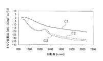
- FIG. 3 is a characteristic diagram of engine speed and rotational speed fluctuation.
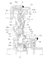
- FIG. 1 is a partial sectional view of a torque converter 1 having a lockup device according to an embodiment of the present invention.
- An engine (not shown) is arranged on the left side of FIG. 1, and a transmission (not shown) is arranged on the right side of the figure.
- OO shown in FIG. 1 is a rotation axis of the torque converter and the lockup device.
- the torque converter 1 is a device for transmitting torque from an engine-side crankshaft (not shown) to an input shaft of a transmission, and includes a front cover 2 fixed to an input-side member and three types of impellers ( A torque converter main body 6 including an impeller 3, a turbine 4, and a stator 5) and a lockup device 7 are included.
- the front cover 2 is a disk-shaped member, and an outer peripheral cylindrical portion 10 that protrudes toward the transmission side is formed on the outer peripheral portion thereof.
- the impeller 3 includes an impeller shell 12 fixed to the outer peripheral cylindrical portion 10 of the front cover 2 by welding, a plurality of impeller blades 13 fixed to the inside thereof, and a cylindrical shape provided on the inner peripheral side of the impeller shell 12. And the impeller hub 14.
- the turbine 4 is disposed opposite to the impeller 3 in the fluid chamber.
- the turbine 4 includes a turbine shell 15, a plurality of turbine blades 16 fixed to the turbine shell 15, and a turbine hub 17 fixed to the inner peripheral side of the turbine shell 15.
- the turbine hub 17 has a flange 17 a extending to the outer peripheral side, and an inner peripheral portion of the turbine shell 15 is fixed to the flange 17 a by a plurality of rivets 18.
- An input shaft of a transmission (not shown) is splined to the inner peripheral portion of the turbine hub 17.
- the stator 5 is a mechanism for rectifying the hydraulic oil that is disposed between the impeller 3 and the inner peripheral portion of the turbine 4 and returns from the turbine 4 to the impeller 3.
- the stator 5 mainly includes a stator carrier 20 and a plurality of stator blades 21 provided on the outer peripheral surface thereof.
- the stator carrier 20 is supported by a fixed shaft (not shown) via a one-way clutch 22.
- Thrust bearings 24 and 25 are provided on both axial sides of the stator carrier 20.
- FIG. 2 shows the lock-up device 7 extracted from FIG.
- the lockup device 7 is disposed in an annular space between the front cover 2 and the turbine 4.
- the lock-up device 7 includes a clutch portion 28, a plurality of inner peripheral side torsion springs 29, an intermediate member 30, a plurality of outer peripheral side torsion springs 31, a driven plate (output rotating member) 32, and a dynamic damper device 33. ,have.
- the clutch portion 28 is disposed so as to be movable in the axial direction facing the front cover 2, and power from the front cover 2 is input thereto.
- the clutch portion 28 has a piston 35, a friction member 36, and a drive plate 37.
- the piston 35 is formed in an annular shape, and has a disc part 35a, an inner peripheral cylindrical part 35b, and an outer peripheral cylindrical part 35c.
- the disc portion 35a is disposed to face the front cover 2.
- the inner peripheral cylindrical portion 35b extends in the axial direction, and is formed by bending the inner peripheral portion of the disc portion 35a to the transmission side. And this inner peripheral cylindrical part 35b is supported by the outer peripheral surface of the turbine hub 17 so that axial movement is possible.
- the outer peripheral cylindrical portion 35c extends in the axial direction, and is formed by bending the outer peripheral portion of the disc portion 35a to the transmission side.
- the outer peripheral cylindrical portion 35 c is located on the inner peripheral side of the outer peripheral cylindrical portion 10 of the front cover 2.
- a seal member 39 is provided on the outer peripheral surface of the turbine hub 17, thereby sealing between the inner peripheral cylindrical portion 35 b of the piston 35 and the outer peripheral surface of the turbine hub 17.
- the friction member 36 is fixed so as to face the front cover 2 at the outer peripheral portion of the disc portion 35 a of the piston 35.
- the clutch is turned on (power transmission state).
- the drive plate 37 is a disk-shaped member, and an inner peripheral portion thereof is fixed to an inner peripheral portion of the piston 35 by a rivet 40.
- a plurality of window holes 37 a are formed on the outer peripheral portion of the drive plate 37.
- a plurality of inner peripheral torsion springs 29 are accommodated in the plurality of window holes 37a.
- the intermediate member 30 is disposed between the piston 35 and the turbine 4, and includes a first plate 41 and a second plate 42 that are disposed so as to sandwich the drive plate 37 in the axial direction.
- the first plate 41 and the second plate 42 are annular and disk-shaped members, and are rotatable relative to the drive plate 37 and the driven plate 32.
- the first plate 41 is disposed on the engine side, and the second plate 42 is disposed on the transmission side.
- the first plate 41 and the second plate 42 are connected to each other by a plurality of rivets 43 so that they cannot rotate relative to each other and cannot move in the axial direction.
- window holes 41a and 42a penetrating in the axial direction are formed.
- the window holes 41a and 42a are formed to extend in the circumferential direction, and a cut-and-raised portion cut and raised in the axial direction is formed in the inner peripheral portion and the outer peripheral portion.
- the inner peripheral side torsion spring 29 is accommodated in the window holes 41a and 42a and the window hole 37a of the drive plate 37, and the inner peripheral side torsion spring 29 is formed by the cut and raised portions of the window holes 41a and 42a of the plates 41 and 42. It is supported.
- a spring support 41b having a C-shaped cross section is formed on the outer periphery of the first plate 41.
- the outer periphery side torsion spring 31 is supported inside the spring support portion 41b. That is, the spring support portion 41b is provided so as to cover the radially outer periphery of the outer peripheral side torsion spring 31 and the axial engine side.
- a plurality of locking portions 42 b formed by bending toward the transmission side are formed on the outer peripheral portion of the second plate 42.
- the plurality of locking portions 42b are arranged at a predetermined interval in the circumferential direction, and the outer peripheral side torsion spring 31 is arranged between the two locking portions 42b.
- the inner peripheral side torsion spring 29 and the outer peripheral side torsion spring 31 can be caused to act in series.
- the driven plate 32 is an annular and disk-shaped member, and an inner peripheral portion thereof is fixed to the flange 17 a of the turbine hub 17 by the rivet 18 together with the turbine shell 15.
- the driven plate 32 is disposed between the intermediate member 30 and the turbine 4.
- a plurality of engaging portions 32 a that engage with both ends of the outer peripheral side torsion spring 31 are formed on the outer peripheral portion of the driven plate 32.
- the plurality of engaging portions 32a are formed by bending the outer peripheral portion of the driven plate 32 to the engine side.
- An output side damper mechanism Do is configured.
- the hysteresis torque generated in the output side damper mechanism Do is larger than the hysteresis torque generated in the input side damper mechanism Di.
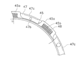
- the dynamic damper device 33 includes a damper plate 45, first and second inertia rings 46 and 47, and a plurality of coil springs (dynamic damper elastic members) 48.
- the damper plate 45 is a disk-shaped member, and the inner periphery is fixed to the first plate 41 and the second plate 42 by rivets 43.
- the damper plate 45 has a plurality of spring accommodating portions 45a at predetermined intervals in the circumferential direction.
- the spring accommodating portion 45a is formed with an opening 45b having a predetermined length in the circumferential direction.
- the first and second inertia rings 46 and 47 are disposed further on the outer peripheral side of the outer peripheral torsion spring 31 and are disposed at positions overlapping the outer peripheral torsion spring 31 in the axial direction.
- the first and second inertia rings 46 and 47 are disposed on the inner peripheral side of the outer peripheral cylindrical portion 35 c of the piston 35, and are disposed at positions overlapping the friction member 36 in the radial direction.
- FIG. 5 shows a part of the first inertia ring 46
- FIG. 6 shows a part of the second inertia ring 47.
- the first inertia ring 46 is formed with a plurality of recesses 46a at predetermined intervals in the circumferential direction.
- the recess 46a is formed to be recessed toward the engine side.
- the circumferential length of the recess 46 a is the same as the length of the opening 45 b of the damper plate 45.
- the hole 46b is a hole through which a bolt (not shown) connecting the inertia rings 46 and 47 passes.
- the inlay projection 46c is formed on the outer peripheral side of the hole 46b and has a predetermined length in the circumferential direction.
- the second inertia ring 47 has a plurality of concave portions 47a formed at predetermined intervals in the circumferential direction.
- the recess 47a is formed so as to be recessed toward the transmission side and facing the first inertia ring 46.
- the length of the recess 47a in the circumferential direction is the same as the length of the opening 45b of the damper plate 45.
- the screw hole 47b extended in an axial direction and the recessed part 47c for inlays are formed.
- Bolts (not shown) that connect the inertia rings 46 and 47 are screwed into the screw holes 47b.
- the inlay recess 47c is formed on the outer peripheral side of the screw hole 47b, and has a predetermined length in the circumferential direction.
- the inlay protrusions 46c of the first inertia ring 46 engage with the inlay recesses 47c.
- a predetermined angle is included between these circumferential directions, that is, including portions where the recesses 46a and 47a are formed. Between the ranges, a predetermined gap is formed in the axial direction.
- the spring accommodating portion 45a of the damper plate 45 is inserted into this gap.
- the spring accommodating portion 45a of the damper plate 45 can be relatively rotated within a predetermined angle range in a state where the spring accommodating portion 45a is inserted into the gap between the inertia rings 46 and 47.
- the plurality of coil springs 48 are housed in housing spaces formed by the recesses 46a and 47a of the inertia rings 46 and 47, respectively, and are housed in the openings 45b of the spring housing portion 45a of the damper plate 45.
- the lockup device 7 transmits torque and absorbs and attenuates torque fluctuations input from the front cover 2. Specifically, when torsional vibration is generated in the lockup device 7, the inner peripheral torsion spring 29 and the outer peripheral torsion spring 31 are compressed in series between the drive plate 37 and the driven plate 32. For this reason, the twist angle can be widened.
- the dynamic damper device 33 is fixed to the intermediate member 30, and the outer peripheral side torsion spring 31 for suppressing vibration is disposed between the dynamic damper device 33 and the turbine hub 17. Due to the action of the outer peripheral side torsion spring 31, it is possible to more effectively suppress rotational fluctuations as shown in FIG.
- the characteristic C1 indicates the engine rotational fluctuation.
- Characteristic C2 shows the fluctuation when the dynamic damper device is mounted on the turbine hub and there is no elastic member (torsion spring) on the output side of the dynamic damper device.
- the characteristic C3 shows the fluctuation when the dynamic damper device is attached to the intermediate member and the elastic member (outer peripheral torsion spring 31) is provided on the output side of the dynamic damper device as in the present embodiment.
- the characteristic C3 is a characteristic when the hysteresis torque in the output-side damper mechanism Do is larger than that in the input-side damper mechanism Di as in the present embodiment.
- the rotational speed fluctuation ratio (torque fluctuation ratio) from the middle speed range to the high speed range is lower than the characteristic C2. However, it is slightly higher than the characteristic C3.
- the input side damper mechanism Di is configured such that the drive plate 37 and the inner peripheral side torsion spring 29 are sandwiched between the pair of plates 41 and 42, the hysteresis torque in the input side damper mechanism Di is reduced. be able to.
- the first and second inertia rings 46 and 47 are arranged on the further outer peripheral side of the outer peripheral torsion spring 31 at a position overlapping the outer peripheral torsion spring 31 in the axial direction. Therefore, the space occupied by the inertia rings 46 and 47 in the axial direction can be shortened, and the axial space of the entire lockup device including the dynamic damper device 33 can be shortened.
- the coil spring 48 Since the coil spring 48 is housed inside the first and second inertia rings 46 and 47, the space occupied by the dynamic damper device in the axial direction can be further shortened.
- the coil spring 48 can function as inertia, and the weight of the entire torque converter can be reduced.
- the outer peripheral side torsion spring 31 is supported by the outer peripheral portion of the first plate 41, but a member for supporting may be provided separately from the first plate 41.
- the elastic member is configured by a coil spring, but an elastic member formed of another resin or the like may be used.
- the torque converter lock-up device of the present invention can effectively attenuate fluctuations in rotational speed in a wide rotational speed range with a compact configuration without increasing the number of parts.
Landscapes
- Engineering & Computer Science (AREA)
- General Engineering & Computer Science (AREA)
- Mechanical Engineering (AREA)
- Physics & Mathematics (AREA)
- Acoustics & Sound (AREA)
- Aviation & Aerospace Engineering (AREA)
- Mechanical Operated Clutches (AREA)
Abstract
Description
トルクコンバータ1は、エンジン側のクランクシャフト(図示せず)からトランスミッションの入力シャフトにトルクを伝達するための装置であり、入力側の部材に固定されるフロントカバー2と、3種の羽根車(インペラ3、タービン4、ステータ5)からなるトルクコンバータ本体6と、ロックアップ装置7と、から構成されている。
図2に、図1のロックアップ装置7を抽出して示している。ロックアップ装置7は、フロントカバー2とタービン4との間の環状の空間に配置されている。ロックアップ装置7は、クラッチ部28と、複数の内周側トーションスプリング29と、中間部材30と、複数の外周側トーションスプリング31と、ドリブンプレート(出力回転部材)32と、ダイナミックダンパ装置33と、を有している。
クラッチ部28は、フロントカバー2に対向して軸方向に移動自在に配置されており、フロントカバー2からの動力が入力される。クラッチ部28は、ピストン35と、摩擦部材36と、ドライブプレート37と、を有している。
ドライブプレート37は、円板状の部材であり、内周部がリベット40によってピストン35の内周部に固定されている。また、ドライブプレート37の外周部には複数の窓孔37aが形成されている。この複数の窓孔37aに複数の内周側トーションスプリング29が収容されている。
中間部材30は、ピストン35とタービン4との間に配置されており、ドライブプレート37を軸方向において挟むように配置された第1プレート41と第2プレート42とから構成されている。第1プレート41及び第2プレート42は、環状かつ円板状の部材であり、ドライブプレート37及びドリブンプレート32に対して相対回転自在である。第1プレート41はエンジン側に配置され、第2プレート42はトランスミッション側に配置されている。第1プレート41と第2プレート42とは、複数のリベット43により互いに相対回転不能でかつ軸方向に移動不能に連結されている。
ドリブンプレート32は、環状かつ円板状の部材であり、内周部がタービンシェル15とともにリベット18によってタービンハブ17のフランジ17aに固定されている。このドリブンプレート32は、中間部材30とタービン4との間に配置されている。そして、ドリブンプレート32の外周部には、外周側トーションスプリング31の両端に係合する複数の係合部32aが形成されている。複数の係合部32aは、ドリブンプレート32の外周部をエンジン側に折り曲げて形成されたものである。
以上のような構成では、ドライブプレート37と、ドライブプレート37を軸方向に挟む1対の第1及び第2プレート41,42と、ドライブプレート37と第1及び第2プレート41,42とを回転方向に弾性的に連結する複数の内周側トーションスプリング29と、によって、入力側ダンパ機構Diが構成されている。このような構成では、ドライブプレート37及び内周側トーションスプリング29が第1及び第2プレート41,42によって軸方向に挟み込まれている。このタイプの入力側ダンパ機構Diにおいて発生するヒステリシストルクは比較的小さい。
図3及び図4にダイナミックダンパ装置33を抽出して示している。ダイナミックダンパ装置33は、ダンパプレート45と、第1及び第2イナーシャリング46,47と、複数のコイルスプリング(ダイナミックダンパ用弾性部材)48と、を有している。
まず、トルクコンバータ本体の動作について簡単に説明する。フロントカバー2及びインペラ3が回転している状態では、インペラ3からタービン4へ作動油が流れ、作動油を介してインペラ3からタービン4へトルクが伝達される。タービン4に伝達されたトルクはタービンハブ17を介してトランスミッションの入力シャフト(図示せず)に伝達される。
中間部材30に伝達されたトルクは、外周側トーションスプリング31を介してドリブンプレート32に伝達され、さらにタービンハブ17を介してトランスミッション側の部材に伝達される。このとき、中間部材30にはダイナミックダンパ装置33が設けられているので、エンジンの回転変動を効果的に抑制することができる。すなわち、ダンパプレート45の回転と2つのイナーシャリング46,47との回転は、コイルスプリング48の作用によって位相にズレが生じる。具体的には、イナーシャリング46,47の回転はダンパプレート45の回転に対して遅れる。この位相のズレによって、回転変動を吸収することができる。
(1)ダイナミックダンパ装置33の出力側に、入力側ダンパ機構Diにおけるヒステリシストルクよりも大きなヒステリシストルクを発生する出力側ダンパ機構Doが設けられている。このため、特に、中回転数域から高回転数域における回転速度変動の減衰効果を大きくすることができる。
本発明は以上のような実施形態に限定されるものではなく、本発明の範囲を逸脱することなく種々の変形又は修正が可能である。
2 フロントカバー
4 タービン
6 トルクコンバータ本体
7 ロックアップ装置
28 クラッチ部
29 内周側トーションスプリング
30 中間部材
31 外周側トーションスプリング
37 ドリブンプレート
33 ダイナミックダンパ装置
36 摩擦部材
45 ダンパプレート
46 第1イナーシャリング
46a 凹部
47 第2イナーシャリング
47a 凹部
48 コイルスプリング(ダイナミックダンパ用弾性部材)
Di 入力側ダンパ機構
Do 出力側ダンパ機構
Claims (7)
- エンジン側の部材に連結されるフロントカバーとトルクコンバータ本体との間に配置され、前記フロントカバーからのトルクを前記トルクコンバータ本体のタービンに直接伝達するためのロックアップ装置であって、
前記フロントカバーからのトルクを出力側に伝達するクラッチ部と、
前記クラッチ部と前記タービンとの間の動力伝達系路に配置された中間部材と、
前記クラッチ部と前記中間部材との間に設けられ、回転速度変動を減衰するための入力側ダンパ機構と、
前記中間部材と前記タービンとの間に設けられ、前記入力側ダンパ機構より大きいヒステリシストルクを発生し、回転速度変動を減衰するための出力側ダンパ機構と、
前記中間部材に連結され、回転速度変動を減衰するダイナミックダンパ装置と、
を備えたトルクコンバータのロックアップ装置。 - 前記入力側ダンパ機構は前記出力側ダンパ機構より内周側に配置されている、請求項1に記載のトルクコンバータのロックアップ装置。
- 前記クラッチ部は、
前記フロントカバーに対して軸方向に移動自在なピストンと、
前記ピストンの外周部に装着され、前記フロントカバーに圧接される摩擦部材と、
前記ピストンに固定されたドライブプレートと、
を有し、
前記中間部材は、前記ドライブプレートと相対回転自在にかつ前記ドライブプレートを軸方向において挟むように設けられた1対のプレートを有し、
前記入力側ダンパ機構は、
前記ドライブプレートと、
前記1対のプレートと、
前記ドライブプレートと前記1対のプレートとを回転方向に弾性的に連結する複数の入力側弾性部材と、
を有する、
請求項2に記載のトルクコンバータのロックアップ装置。 - 前記出力側ダンパ機構は、
前記中間部材の外周部と、
前記タービンに連結されたドリブンプレートと、
前記中間部材と前記ドリブンプレートとを回転方向に弾性的に連結する複数の出力側弾性部材と、
前記複数の出力側弾性部材の径方向の移動規制及び軸方向の一方側への移動規制を行う支持部材と、
を有する、請求項2又は3に記載のトルクコンバータのロックアップ装置。 - 前記支持部材は前記中間部材の外周部によって形成されている、請求項4に記載のトルクコンバータのロックアップ装置。
- 前記ダイナミックダンパ装置は、
前記出力側弾性部材の外周側に配置されたイナーシャ部材と、
前記中間部材に連結されたダンパプレートと、
前記イナーシャ部材と前記ダンパプレートとを回転方向に弾性的に連結する複数のダイナミックダンパ用弾性部材と、
を有する、請求項4又は5に記載のトルクコンバータのロックアップ装置。 - 前記イナーシャ部材は、軸方向に分割され互いに軸方向に対向する収容凹部を有する第1及び第2イナーシャリングを有し、
前記複数のダイナミックダンパ用弾性部材は前記第1及び第2イナーシャリングの収容凹部に収容されている、
請求項6に記載のトルクコンバータのロックアップ装置。
Priority Applications (4)
| Application Number | Priority Date | Filing Date | Title |
|---|---|---|---|
| US14/894,344 US9784352B2 (en) | 2013-06-04 | 2014-05-16 | Lock-up device for torque converter |
| CN201480026934.0A CN105209793B (zh) | 2013-06-04 | 2014-05-16 | 液力变矩器的锁定装置 |
| KR1020157032288A KR20160016780A (ko) | 2013-06-04 | 2014-05-16 | 토크 컨버터의 록업 장치 |
| DE112014002668.9T DE112014002668T5 (de) | 2013-06-04 | 2014-05-16 | Überbrückungsvorrichtung für einen Drehmomentwandler |
Applications Claiming Priority (4)
| Application Number | Priority Date | Filing Date | Title |
|---|---|---|---|
| JP2013-117889 | 2013-06-04 | ||
| JP2013117889 | 2013-06-04 | ||
| JP2013154506A JP5734365B2 (ja) | 2013-06-04 | 2013-07-25 | トルクコンバータのロックアップ装置 |
| JP2013-154506 | 2013-07-25 |
Publications (1)
| Publication Number | Publication Date |
|---|---|
| WO2014196339A1 true WO2014196339A1 (ja) | 2014-12-11 |
Family
ID=52007992
Family Applications (1)
| Application Number | Title | Priority Date | Filing Date |
|---|---|---|---|
| PCT/JP2014/063076 Ceased WO2014196339A1 (ja) | 2013-06-04 | 2014-05-16 | トルクコンバータのロックアップ装置 |
Country Status (6)
| Country | Link |
|---|---|
| US (1) | US9784352B2 (ja) |
| JP (1) | JP5734365B2 (ja) |
| KR (1) | KR20160016780A (ja) |
| CN (1) | CN105209793B (ja) |
| DE (1) | DE112014002668T5 (ja) |
| WO (1) | WO2014196339A1 (ja) |
Cited By (2)
| Publication number | Priority date | Publication date | Assignee | Title |
|---|---|---|---|---|
| CN111442035A (zh) * | 2019-01-16 | 2020-07-24 | 株式会社艾科赛迪 | 阻尼器装置 |
| DE112015000321B4 (de) * | 2014-02-28 | 2020-08-13 | Aisin Aw Co., Ltd. | Dämpfervorrichtung und Startvorrichtung |
Families Citing this family (11)
| Publication number | Priority date | Publication date | Assignee | Title |
|---|---|---|---|---|
| JP5878893B2 (ja) | 2013-07-11 | 2016-03-08 | 株式会社エクセディ | トルクコンバータのロックアップ装置 |
| JP6530604B2 (ja) | 2015-01-06 | 2019-06-12 | 株式会社エクセディ | 動力伝達装置 |
| FR3037626B1 (fr) * | 2015-06-18 | 2018-08-10 | Valeo Embrayages | Dispositif de filtration des vibrations |
| KR101707804B1 (ko) * | 2015-07-16 | 2017-02-17 | 한국파워트레인 주식회사 | 진자를 이용한 진동저감장치를 포함하는 차량용 토크 컨버터 |
| JP6182192B2 (ja) * | 2015-10-16 | 2017-08-16 | 株式会社ユタカ技研 | 流体式動力伝達装置 |
| JP6345200B2 (ja) * | 2015-10-30 | 2018-06-20 | 株式会社ユタカ技研 | トルクコンバータ |
| JP6505035B2 (ja) * | 2016-03-01 | 2019-04-24 | 本田技研工業株式会社 | トルク伝達装置 |
| JP6637802B2 (ja) * | 2016-03-18 | 2020-01-29 | 株式会社エクセディ | 振動低減装置 |
| CN107599822A (zh) * | 2016-07-12 | 2018-01-19 | 舍弗勒技术股份两合公司 | 混合动力汽车和p2混合动力模块 |
| US11549567B2 (en) * | 2018-12-28 | 2023-01-10 | Valeo Kapec Co., Ltd. | Lock-up device for torque converter |
| KR102660126B1 (ko) * | 2019-09-09 | 2024-04-23 | 주식회사 카펙발레오 | 토크 컨버터 |
Citations (5)
| Publication number | Priority date | Publication date | Assignee | Title |
|---|---|---|---|---|
| JPS62185924U (ja) * | 1986-05-19 | 1987-11-26 | ||
| JP2009115112A (ja) * | 2007-11-01 | 2009-05-28 | Honda Motor Co Ltd | 流体伝動装置 |
| WO2011055622A1 (ja) * | 2009-11-05 | 2011-05-12 | 株式会社エクセディ | トルクコンバータの動力伝達装置 |
| JP2012057694A (ja) * | 2010-09-08 | 2012-03-22 | Aisin Aw Industries Co Ltd | ダンパ装置 |
| WO2012063586A1 (ja) * | 2010-11-11 | 2012-05-18 | 株式会社エクセディ | 流体継手用のロックアップ装置 |
Family Cites Families (35)
| Publication number | Priority date | Publication date | Assignee | Title |
|---|---|---|---|---|
| JPH0227238Y2 (ja) | 1986-01-29 | 1990-07-24 | ||
| JPS62185924A (ja) | 1986-02-10 | 1987-08-14 | Yoshiyuki Ogushi | 鋼管杭の防蝕方法 |
| US5020647A (en) | 1989-03-20 | 1991-06-04 | Kabushiki Kaisha Daikin Seisakusho | Lock-up damper device for torque converter |
| JPH05288239A (ja) | 1992-04-10 | 1993-11-02 | Unisia Jecs Corp | 自動変速機の動力伝達装置 |
| JPH10169756A (ja) | 1996-12-06 | 1998-06-26 | Toyota Motor Corp | 直結クラッチ付トルクコンバータ |
| JPH11303940A (ja) | 1998-04-21 | 1999-11-02 | Unisia Jecs Corp | 捩り振動低減装置及びそれを用いるトルクコンバータのロックアップクラッチ |
| JP3752404B2 (ja) | 1999-09-17 | 2006-03-08 | 株式会社エクセディ | トルクコンバータ用ロックアップ装置 |
| JP2001330105A (ja) | 2000-05-19 | 2001-11-30 | Exedy Corp | ダンパー機構 |
| JP2002213567A (ja) | 2001-01-19 | 2002-07-31 | Exedy Corp | 流体式トルク伝達装置のロックアップ装置 |
| EP1503104B1 (de) | 2003-07-28 | 2006-11-29 | LuK Lamellen und Kupplungsbau Beteiligungs KG | Drehschwingungsdämpfer |
| JP4056452B2 (ja) | 2003-09-29 | 2008-03-05 | ジヤトコ株式会社 | トルク振動抑制装置 |
| JP2008038951A (ja) | 2006-08-02 | 2008-02-21 | Valeo Unisia Transmission Kk | 流体式トルク伝達装置 |
| JP4987617B2 (ja) | 2007-08-08 | 2012-07-25 | 本田技研工業株式会社 | ロックアップクラッチ付きトルクコンバータ |
| JP5473933B2 (ja) * | 2007-11-29 | 2014-04-16 | シェフラー テクノロジーズ アクチエンゲゼルシャフト ウント コンパニー コマンディートゲゼルシャフト | 回転数適応型の動吸振器を備えた力伝達装置および減衰特性を改善するための方法 |
| JP5205068B2 (ja) | 2008-01-18 | 2013-06-05 | 株式会社エクセディ | ロックアップ装置 |
| JP4648428B2 (ja) | 2008-06-03 | 2011-03-09 | 株式会社エクセディ | 流体式動力伝達装置 |
| WO2010000220A1 (de) * | 2008-07-04 | 2010-01-07 | Luk Lamellen Und Kupplungsbau Beteiligungs Kg | Hydrodynamischer drehmomentwandler |
| JP5619015B2 (ja) | 2008-10-17 | 2014-11-05 | シェフラー テクノロジーズアクチエンゲゼルシャフト ウント コンパニー コマンディートゲゼルシャフトSchaeffler Technologies AG & Co. KG | ダブルパストーショナルダンパ |
| DE102010014674B4 (de) * | 2009-04-27 | 2019-07-04 | Schaeffler Technologies AG & Co. KG | Hydrodynamischer Drehmomentwandler |
| JP4684348B1 (ja) | 2009-12-17 | 2011-05-18 | 株式会社エクセディ | ダンパ装置 |
| JP4926228B2 (ja) | 2009-11-05 | 2012-05-09 | 株式会社エクセディ | トルクコンバータの動力伝達装置 |
| JP4684347B1 (ja) | 2009-12-09 | 2011-05-18 | 株式会社エクセディ | ダンパ装置 |
| JP5407947B2 (ja) | 2010-03-10 | 2014-02-05 | アイシン・エィ・ダブリュ株式会社 | ダンパ装置および流体伝動装置 |
| EP2567120B1 (de) | 2010-05-07 | 2015-03-18 | ZF Friedrichshafen AG | Drehmomentübertragungsbaugruppe, insbesondere hydrodynamischer drehmomentwandler, fluidkupplung oder nasslaufende kupplung |
| DE102011101156A1 (de) | 2010-05-18 | 2011-11-24 | Schaeffler Technologies Gmbh & Co. Kg | Einreihiger Seriendämpfer mit Antriebsflansch |
| JP5477249B2 (ja) | 2010-09-30 | 2014-04-23 | アイシン・エィ・ダブリュ株式会社 | 発進装置 |
| JP4932934B2 (ja) | 2010-10-19 | 2012-05-16 | 株式会社エクセディ | 流体式動力伝達装置のロックアップ装置 |
| JP4892630B1 (ja) | 2010-12-10 | 2012-03-07 | 株式会社エクセディ | 流体継手用ロックアップ装置 |
| JP4930867B1 (ja) | 2010-11-11 | 2012-05-16 | 株式会社エクセディ | トルクコンバータ用ロックアップ装置 |
| JP5672164B2 (ja) * | 2011-02-15 | 2015-02-18 | アイシン・エィ・ダブリュ株式会社 | ダンパ装置 |
| JP5418519B2 (ja) | 2011-02-15 | 2014-02-19 | アイシン・エィ・ダブリュ株式会社 | ダンパ装置 |
| JP5315377B2 (ja) | 2011-04-14 | 2013-10-16 | 株式会社エクセディ | トルクコンバータ用のロックアップ装置 |
| JP5222979B2 (ja) | 2011-06-07 | 2013-06-26 | 株式会社エクセディ | トルクコンバータのロックアップ装置 |
| JP5609897B2 (ja) | 2012-01-16 | 2014-10-22 | マツダ株式会社 | トルクコンバータ |
| DE112013001087B4 (de) | 2012-04-26 | 2018-08-30 | Aisin Aw Co., Ltd. | Startvorrichtung |
-
2013
- 2013-07-25 JP JP2013154506A patent/JP5734365B2/ja active Active
-
2014
- 2014-05-16 US US14/894,344 patent/US9784352B2/en active Active
- 2014-05-16 CN CN201480026934.0A patent/CN105209793B/zh active Active
- 2014-05-16 WO PCT/JP2014/063076 patent/WO2014196339A1/ja not_active Ceased
- 2014-05-16 DE DE112014002668.9T patent/DE112014002668T5/de not_active Withdrawn
- 2014-05-16 KR KR1020157032288A patent/KR20160016780A/ko not_active Ceased
Patent Citations (5)
| Publication number | Priority date | Publication date | Assignee | Title |
|---|---|---|---|---|
| JPS62185924U (ja) * | 1986-05-19 | 1987-11-26 | ||
| JP2009115112A (ja) * | 2007-11-01 | 2009-05-28 | Honda Motor Co Ltd | 流体伝動装置 |
| WO2011055622A1 (ja) * | 2009-11-05 | 2011-05-12 | 株式会社エクセディ | トルクコンバータの動力伝達装置 |
| JP2012057694A (ja) * | 2010-09-08 | 2012-03-22 | Aisin Aw Industries Co Ltd | ダンパ装置 |
| WO2012063586A1 (ja) * | 2010-11-11 | 2012-05-18 | 株式会社エクセディ | 流体継手用のロックアップ装置 |
Cited By (3)
| Publication number | Priority date | Publication date | Assignee | Title |
|---|---|---|---|---|
| DE112015000321B4 (de) * | 2014-02-28 | 2020-08-13 | Aisin Aw Co., Ltd. | Dämpfervorrichtung und Startvorrichtung |
| CN111442035A (zh) * | 2019-01-16 | 2020-07-24 | 株式会社艾科赛迪 | 阻尼器装置 |
| CN111442035B (zh) * | 2019-01-16 | 2023-04-21 | 株式会社艾科赛迪 | 阻尼器装置 |
Also Published As
| Publication number | Publication date |
|---|---|
| US20160116043A1 (en) | 2016-04-28 |
| DE112014002668T5 (de) | 2016-02-18 |
| JP2015014357A (ja) | 2015-01-22 |
| CN105209793B (zh) | 2018-03-27 |
| CN105209793A (zh) | 2015-12-30 |
| JP5734365B2 (ja) | 2015-06-17 |
| KR20160016780A (ko) | 2016-02-15 |
| US9784352B2 (en) | 2017-10-10 |
Similar Documents
| Publication | Publication Date | Title |
|---|---|---|
| JP5734365B2 (ja) | トルクコンバータのロックアップ装置 | |
| JP5685304B2 (ja) | トルクコンバータのロックアップ装置 | |
| JP6245871B2 (ja) | トルクコンバータのロックアップ装置 | |
| JP5878893B2 (ja) | トルクコンバータのロックアップ装置 | |
| US9605729B2 (en) | Lock-up device for torque converter | |
| JP4773553B2 (ja) | トルクコンバータ用ロックアップ装置 | |
| JP6626506B2 (ja) | タービン−ピストンロックアップクラッチを有する流体動力学トルク連結装置、及び関連する方法 | |
| JP2011122622A (ja) | トルクコンバータ用ロックアップ装置 | |
| JP2011214635A (ja) | 流体伝動装置 | |
| JP4949503B2 (ja) | トルクコンバータ用のロックアップ装置 | |
| KR20170072895A (ko) | 터빈-피스톤 로크업 클러치를 구비하는 유체역학적 토크 커플링 장치, 및 관련 방법 | |
| WO2011070888A1 (ja) | トルクコンバータ用ロックアップ装置 | |
| JP5791772B1 (ja) | 流体式動力伝達装置 | |
| JP6182434B2 (ja) | トルクコンバータのロックアップ装置 | |
| JP4892630B1 (ja) | 流体継手用ロックアップ装置 | |
| JP5791773B1 (ja) | 流体式動力伝達装置 | |
| JP6408778B2 (ja) | 動力伝達装置 | |
| JP2015121256A (ja) | トルクコンバータのロックアップ装置 | |
| JP2020143749A (ja) | ロックアップダンパ |
Legal Events
| Date | Code | Title | Description |
|---|---|---|---|
| 121 | Ep: the epo has been informed by wipo that ep was designated in this application |
Ref document number: 14807673 Country of ref document: EP Kind code of ref document: A1 |
|
| ENP | Entry into the national phase |
Ref document number: 20157032288 Country of ref document: KR Kind code of ref document: A |
|
| WWE | Wipo information: entry into national phase |
Ref document number: 14894344 Country of ref document: US |
|
| WWE | Wipo information: entry into national phase |
Ref document number: 112014002668 Country of ref document: DE |
|
| 122 | Ep: pct application non-entry in european phase |
Ref document number: 14807673 Country of ref document: EP Kind code of ref document: A1 |