WO2014168188A1 - 積層体 - Google Patents
積層体 Download PDFInfo
- Publication number
- WO2014168188A1 WO2014168188A1 PCT/JP2014/060340 JP2014060340W WO2014168188A1 WO 2014168188 A1 WO2014168188 A1 WO 2014168188A1 JP 2014060340 W JP2014060340 W JP 2014060340W WO 2014168188 A1 WO2014168188 A1 WO 2014168188A1
- Authority
- WO
- WIPO (PCT)
- Prior art keywords
- polymer
- surface layer
- piezoelectric material
- group
- compound
- Prior art date
- Legal status (The legal status is an assumption and is not a legal conclusion. Google has not performed a legal analysis and makes no representation as to the accuracy of the status listed.)
- Ceased
Links
Images

Classifications
-
- B—PERFORMING OPERATIONS; TRANSPORTING
- B32—LAYERED PRODUCTS
- B32B—LAYERED PRODUCTS, i.e. PRODUCTS BUILT-UP OF STRATA OF FLAT OR NON-FLAT, e.g. CELLULAR OR HONEYCOMB, FORM
- B32B27/00—Layered products comprising a layer of synthetic resin
- B32B27/06—Layered products comprising a layer of synthetic resin as the main or only constituent of a layer, which is next to another layer of the same or of a different material
- B32B27/08—Layered products comprising a layer of synthetic resin as the main or only constituent of a layer, which is next to another layer of the same or of a different material of synthetic resin
-
- B—PERFORMING OPERATIONS; TRANSPORTING
- B32—LAYERED PRODUCTS
- B32B—LAYERED PRODUCTS, i.e. PRODUCTS BUILT-UP OF STRATA OF FLAT OR NON-FLAT, e.g. CELLULAR OR HONEYCOMB, FORM
- B32B27/00—Layered products comprising a layer of synthetic resin
- B32B27/30—Layered products comprising a layer of synthetic resin comprising vinyl (co)polymers; comprising acrylic (co)polymers
- B32B27/308—Layered products comprising a layer of synthetic resin comprising vinyl (co)polymers; comprising acrylic (co)polymers comprising acrylic (co)polymers
-
- B—PERFORMING OPERATIONS; TRANSPORTING
- B32—LAYERED PRODUCTS
- B32B—LAYERED PRODUCTS, i.e. PRODUCTS BUILT-UP OF STRATA OF FLAT OR NON-FLAT, e.g. CELLULAR OR HONEYCOMB, FORM
- B32B27/00—Layered products comprising a layer of synthetic resin
- B32B27/36—Layered products comprising a layer of synthetic resin comprising polyesters
-
- H—ELECTRICITY
- H10—SEMICONDUCTOR DEVICES; ELECTRIC SOLID-STATE DEVICES NOT OTHERWISE PROVIDED FOR
- H10N—ELECTRIC SOLID-STATE DEVICES NOT OTHERWISE PROVIDED FOR
- H10N30/00—Piezoelectric or electrostrictive devices
- H10N30/80—Constructional details
- H10N30/85—Piezoelectric or electrostrictive active materials
- H10N30/857—Macromolecular compositions
-
- H—ELECTRICITY
- H10—SEMICONDUCTOR DEVICES; ELECTRIC SOLID-STATE DEVICES NOT OTHERWISE PROVIDED FOR
- H10N—ELECTRIC SOLID-STATE DEVICES NOT OTHERWISE PROVIDED FOR
- H10N30/00—Piezoelectric or electrostrictive devices
- H10N30/80—Constructional details
- H10N30/88—Mounts; Supports; Enclosures; Casings
- H10N30/883—Additional insulation means preventing electrical, physical or chemical damage, e.g. protective coatings
-
- B—PERFORMING OPERATIONS; TRANSPORTING
- B32—LAYERED PRODUCTS
- B32B—LAYERED PRODUCTS, i.e. PRODUCTS BUILT-UP OF STRATA OF FLAT OR NON-FLAT, e.g. CELLULAR OR HONEYCOMB, FORM
- B32B2307/00—Properties of the layers or laminate
- B32B2307/20—Properties of the layers or laminate having particular electrical or magnetic properties, e.g. piezoelectric
-
- B—PERFORMING OPERATIONS; TRANSPORTING
- B32—LAYERED PRODUCTS
- B32B—LAYERED PRODUCTS, i.e. PRODUCTS BUILT-UP OF STRATA OF FLAT OR NON-FLAT, e.g. CELLULAR OR HONEYCOMB, FORM
- B32B2307/00—Properties of the layers or laminate
- B32B2307/50—Properties of the layers or laminate having particular mechanical properties
- B32B2307/51—Elastic
-
- B—PERFORMING OPERATIONS; TRANSPORTING
- B32—LAYERED PRODUCTS
- B32B—LAYERED PRODUCTS, i.e. PRODUCTS BUILT-UP OF STRATA OF FLAT OR NON-FLAT, e.g. CELLULAR OR HONEYCOMB, FORM
- B32B2307/00—Properties of the layers or laminate
- B32B2307/50—Properties of the layers or laminate having particular mechanical properties
- B32B2307/54—Yield strength; Tensile strength
-
- B—PERFORMING OPERATIONS; TRANSPORTING
- B32—LAYERED PRODUCTS
- B32B—LAYERED PRODUCTS, i.e. PRODUCTS BUILT-UP OF STRATA OF FLAT OR NON-FLAT, e.g. CELLULAR OR HONEYCOMB, FORM
- B32B2307/00—Properties of the layers or laminate
- B32B2307/70—Other properties
- B32B2307/704—Crystalline
-
- B—PERFORMING OPERATIONS; TRANSPORTING
- B32—LAYERED PRODUCTS
- B32B—LAYERED PRODUCTS, i.e. PRODUCTS BUILT-UP OF STRATA OF FLAT OR NON-FLAT, e.g. CELLULAR OR HONEYCOMB, FORM
- B32B2457/00—Electrical equipment
- B32B2457/20—Displays, e.g. liquid crystal displays, plasma displays
-
- B—PERFORMING OPERATIONS; TRANSPORTING
- B32—LAYERED PRODUCTS
- B32B—LAYERED PRODUCTS, i.e. PRODUCTS BUILT-UP OF STRATA OF FLAT OR NON-FLAT, e.g. CELLULAR OR HONEYCOMB, FORM
- B32B2457/00—Electrical equipment
- B32B2457/20—Displays, e.g. liquid crystal displays, plasma displays
- B32B2457/202—LCD, i.e. liquid crystal displays
Definitions
- the present invention relates to a laminate.
- polymer piezoelectric materials using helical chiral polymers having optical activity have been reported.
- a polymer piezoelectric material that exhibits a piezoelectric constant of about 10 pC / N at room temperature by stretching a molded product of polylactic acid has been disclosed (for example, see JP-A-5-152638).
- high piezoelectricity of about 18 pC / N is produced by a special orientation method called forging (see, for example, JP-A-2005-213376). .
- a touch panel using a molecular oriented polylactic acid film and a touch input device using this touch panel are also known (see, for example, International Publication No. 2010/143528 pamphlet).
- a linear polarizer may be used in a display device such as a liquid crystal display device or an organic electroluminescence display device (for example, Japanese Patent Application Laid-Open Nos. 2006-268018, 2009-192611, and 2009-). No. 21408).
- the crystalline polymer piezoelectric material may be provided with a surface layer for adhesion for the purpose of adhering to other members such as electrodes, or a protective surface layer for the purpose of protection.
- a surface layer for adhesion for the purpose of adhering to other members such as electrodes, or a protective surface layer for the purpose of protection.
- the formation of such a surface layer tends to lower the piezoelectric constant in the laminate of the crystalline polymer piezoelectric material and the surface layer.
- peeling may occur in the surface layer formed so as to be in contact with at least a part of the crystalline polymer piezoelectric material, and further improvement in the adhesion between the crystalline polymer piezoelectric material and the surface layer is desired.
- the subject of the 1st aspect of this invention is providing the laminated body by which the fall of the sensitivity was suppressed.
- the subject of the 2nd aspect of this invention is providing the laminated body excellent in the adhesive force of a crystalline polymer piezoelectric material and
- 1st aspect of this invention is a laminated body as described in following [1].
- a second aspect of the present invention is the laminate described in the following [6].
- An overlapping portion may exist between the range of the first aspect and the range of the second aspect.
- the surface layer is an acrylic compound, methacrylic compound, vinyl compound, allyl compound, urethane compound, epoxy compound, epoxide compound, glycidyl compound, oxetane compound, melamine compound, cellulose type. Including at least one material selected from the group consisting of compounds, ester compounds, silane compounds, silicone compounds, siloxane compounds, silica-acrylic hybrid compounds, silica-epoxy hybrid compounds, metals, and metal oxides, [1] The laminate according to any one of [4].
- Crystalline polymer piezoelectric material having a normalized molecular orientation MORc of 2.0 to 10.0 when the reference thickness measured by a microwave transmission type molecular orientation meter is 50 ⁇ m, and the crystalline polymer And a surface layer including at least a part of the piezoelectric body and including a carbonyl group and a polymer.
- the laminate described in [6] is preferably the laminate described in any one of [1] to [5]. That is, in the laminated body according to any one of [1] to [5], the crystalline polymer piezoelectric material has a reference thickness measured by a microwave transmission molecular orientation meter of 50 ⁇ m.
- the normalized molecular orientation MORc is 2.0 to 10.0, the surface layer is disposed so as to be at least partially in contact with the crystalline polymer piezoelectric material, includes a carbonyl group and includes a polymer. preferable.
- the crystalline polymer piezoelectric material includes a polymer having a repeating unit structure having a functional group of at least one of a carbonyl group and an oxy group (preferably a helical chiral polymer having optical activity). ] To [10].
- the crystalline polymer piezoelectric material includes an optically active helical chiral polymer having a weight average molecular weight of 50,000 to 1,000,000, and has a crystallinity of 20% to 80% obtained by a DSC method.
- the laminate according to any one of [1] to [11].
- the crystalline polymer piezoelectric material includes a stabilizer having a weight average molecular weight of 200 to 60,000 having at least one functional group selected from the group consisting of a carbodiimide group, an epoxy group, and an isocyanate group,
- the stabilizer has one functional group selected from the group consisting of a carbodiimide group, an epoxy group, and an isocyanate group in one molecule.
- the laminated body by which the fall of the sensitivity was suppressed can be provided.
- the laminated body excellent in the adhesive force of a crystalline polymer piezoelectric material and a surface layer can be provided.
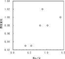
- FIG. 6 is a graph showing the relationship between Ec / d and sensitivity change in Examples 1A to 7A and Comparative Examples 1A to 2A.
- FIG. 1 is a graph showing a range where Ec / d is 0 to 1.5.
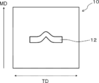
- FIG. 5 is a conceptual diagram showing the cut-out direction of a test piece in the measurement of tear strength in Examples 15B to 21B.
- the laminate according to the first aspect of the present invention includes a crystalline polymer piezoelectric material having molecular orientation and a surface layer.
- the relationship between the tensile modulus Ec (GPa) and the thickness d ( ⁇ m) satisfies the following formula (A). 0.6 ⁇ Ec / d Formula (A)
- a crystalline polymer piezoelectric body (hereinafter also simply referred to as “piezoelectric body”) is provided with an adhesive surface layer for the purpose of adhering to other members such as electrodes, or a protective surface layer for the purpose of protection.
- an adhesive surface layer for the purpose of adhering to other members such as electrodes, or a protective surface layer for the purpose of protection.
- the formation of such a surface layer tends to lower the piezoelectric constant in the laminate of the piezoelectric body and the surface layer.
- the decrease in the sensitivity of the piezoelectric body can be suppressed by adjusting the relationship between the thickness d of the surface layer and the tensile elastic modulus Ec to a range satisfying the above formula (A). it can.
- the surface layer in the first aspect refers to a layer existing on the surface side of the piezoelectric body. Therefore, another member may be provided on the surface layer, and the surface layer does not necessarily indicate a layer that is the outermost surface of the final molded product.
- an electrode is mentioned, for example.
- the electrode may be an electrode layer that covers the entire surface layer, or an electrode pattern that is formed so as to cover a part of the surface layer.
- the surface layer in the first aspect may be composed of only one layer or a multilayer film in which a plurality of functional layers are laminated.
- the surface layer in the first embodiment may be on both sides as well as on one side of the piezoelectric body, and the functions and materials may be different.
- the surface layer in the first aspect satisfies the formula (A).
- the ratio (Ec / d) between the tensile elastic modulus Ec and the thickness d satisfies the above formula, a decrease in sensitivity of the piezoelectric body in the laminate can be suppressed.
- the ratio (Ec / d) is more preferably 1.0 or more, further preferably 1.4 or more, and further preferably 3 or more. Although there is no restriction
- the ratio (Ec / d) is more preferably 30 or less, further preferably 25 or less, and further preferably 17.72 or less.
- the ratio (Ec / d) is particularly preferably 1.4 or more and 17.72 or less.
- the tensile modulus Ec of the surface layer is not particularly limited, but is preferably in the range of 0.1 GPa to 1000 GPa.
- the tensile elastic modulus Ec is equal to or higher than the lower limit, a decrease in the tensile elastic modulus of the laminate can be suppressed.
- the tensile elastic modulus Ec is less than or equal to the above upper limit value, the laminate can be deformed by a general human force and can be used as a sensor.
- the upper limit value of the tensile elastic modulus Ec is more preferably 300 GPa or less, and still more preferably 100 GPa or less. Further, the lower limit value is more preferably 1 GPa or more, and further preferably 2 GPa or more.
- the surface layer in the first aspect may be a very thin layer, it may be difficult to directly measure the tensile elastic modulus of only the surface layer. Therefore, in this specification, calculation of the tensile elastic modulus Ec of the surface layer is performed by the following formula.
- Tensile modulus of surface layer Ec [tensile modulus of laminate- ⁇ tensile modulus of piezoelectric body only ⁇ (thickness of piezoelectric body / thickness of laminate) ⁇ ] / (thickness of surface layer / laminate) Thickness)
- the tensile elastic modulus Ec represents an average tensile elastic modulus in the entire multilayer film.
- the tensile elastic modulus Ec represents the average tensile elastic modulus in the entire surface layer on both sides.
- the “tensile modulus of the laminate” in the above formula is measured by the following method.
- the laminated body is cut into 120 mm in a direction of 45 ° with respect to the stretching direction (for example, MD direction) of the crystalline polymer piezoelectric material, and 10 mm in a direction orthogonal to the direction of 45 ° to produce a rectangular sample.
- the obtained sample is set in a tensile testing machine (manufactured by AND, TENSILON RTG-1250) with a distance between chucks of 70 mm so as not to be loosened.
- “Tensile elastic modulus of piezoelectric body only” is the same as the tensile elastic modulus of the laminated body after removing the surface layer from the laminated body or forming the same piezoelectric body as the piezoelectric body in the laminated body. To measure.
- control of the tensile elasticity modulus Ec in a surface layer is performed by selecting the material which comprises a surface layer, for example.
- the material constituting the surface layer includes a cured product of a curable compound
- the crosslink density can be increased and the tensile modulus Ec can be increased.
- the thickness (average thickness) d of the surface layer is not particularly limited, but is preferably in the range of 0.01 ⁇ m to 10 ⁇ m.
- the thickness d is equal to or greater than the lower limit value, for example, the surface layer exhibits functions such as a hard coat layer described later.
- the thickness d is equal to or less than the above upper limit value, a large charge is generated in the electrode when an electrode is further provided on the surface layer in the laminate.
- the upper limit value of the thickness d is more preferably 6 ⁇ m or less, and even more preferably 3 ⁇ m or less. Further, the lower limit value is more preferably 0.2 ⁇ m or more, and further preferably 0.3 ⁇ m or more.
- the thickness d represents the thickness of the entire multilayer film.
- the surface layer may be provided on both sides of the piezoelectric body. In this case, the thickness d is the sum of the thicknesses on both sides.
- the thickness d of the surface layer is determined by the following formula using a digital length measuring device DIGIMICRO STAND MS-11C manufactured by Nikon Corporation.
- Formula d dt ⁇ dp dt: Average thickness of 10 laminated bodies
- dt Average thickness of 10 piezoelectric bodies before forming the surface layer or after removing the surface layer
- Examples of the surface layer formed on the surface of the piezoelectric body include various functional layers.
- a functional layer for example, an easy adhesion layer, a hard coat layer, a refractive index adjustment layer, an antireflection layer, an antiglare layer, an easy slip layer, an antiblock layer, a protective layer, an adhesive layer, an adhesive layer, an antistatic layer, a heat dissipation layer, Examples include an ultraviolet absorbing layer, an anti-Newton ring layer, a light scattering layer, a polarizing layer, a gas barrier layer, and a hue adjusting layer.
- Another member may be formed on the surface layer of the laminate in which the piezoelectric body and the surface layer are laminated.
- Examples of the other member include an electrode.
- functional layers such as an easy-adhesion layer, a hard coat layer, and a refractive index adjustment layer are generally provided as the surface layer in the aspect in which the electrode is provided. Further, by forming the surface layer, defects such as die lines and dents on the surface of the piezoelectric body are filled, and the appearance is improved. In this case, the smaller the refractive index difference between the piezoelectric body and the surface layer, the more the reflection at the interface between the piezoelectric body and the surface layer is reduced, and the appearance is further improved.
- the material of the surface layer is not particularly limited, but for example, acrylic compounds, methacrylic compounds, vinyl compounds, allyl compounds, urethane compounds, epoxy compounds, epoxide compounds, glycidyl compounds Compound, oxetane compound, melamine compound, cellulose compound, ester compound, silane compound, silicone compound, siloxane compound, silica-acrylic hybrid compound, silica-epoxy hybrid compound, metal, and metal oxide It is preferable to include at least one material selected from the group. Among these, acrylic compounds, epoxy compounds, silane compounds, and metal oxides are more preferable.
- ⁇ Formation method As a method for forming the surface layer, a known method that has been generally used can be appropriately used. For example, a wet coating method is first given. For example, acrylic compounds, methacrylic compounds, vinyl compounds, allyl compounds, urethane compounds, epoxy compounds, epoxide compounds, glycidyl compounds, oxetane compounds, melamine compounds, cellulose compounds, ester compounds, A surface layer is formed by applying a coating liquid in which a material such as a silane compound, a silicone compound, a siloxane compound, a silica-acrylic hybrid compound, or a silica-epoxy hybrid compound is dispersed or dissolved.
- a material such as a silane compound, a silicone compound, a siloxane compound, a silica-acrylic hybrid compound, or a silica-epoxy hybrid compound is dispersed or dissolved.
- the surface layer is cured by applying heat or active energy rays (ultraviolet rays, electron beams, radiation, etc.) to the material (curable compound) applied as described above.
- active energy rays ultraviolet rays, electron beams, radiation, etc.
- the surface layer contains a cured product of the curable compound as described above, by reducing the equivalent of the polymerizable functional group of the curable compound (that is, the polymerizability contained per unit molecular weight of the curable compound).
- the crosslink density can be increased and the tensile modulus Ec can be increased.
- the material contained in the surface layer is preferably an active energy ray curable resin cured by irradiation with active energy rays (ultraviolet rays, electron beams, radiation, etc.) among the above cured products.
- active energy rays ultraviolet rays, electron beams, radiation, etc.
- the production efficiency can be improved, and the performance deterioration of the piezoelectric body caused by the surface layer formation can be further suppressed.
- a cured product having a three-dimensional cross-linked structure is preferable among the cured products.
- a crosslinking density can be raised and the tensile elasticity modulus Ec can be enlarged.
- a method using a monomer having three or more polymerizable functional groups as a curable compound, or a crosslinking having three or more polymerizable functional groups.
- examples include a method using a crosslinking agent (a trifunctional or higher functional crosslinking agent), and a method using a crosslinking agent such as an organic peroxide as the crosslinking agent.
- a crosslinking agent a trifunctional or higher functional crosslinking agent
- a crosslinking agent such as an organic peroxide
- Examples of the tri- or higher functional monomer include (meth) acrylic compounds having three or more (meth) acrylic groups in one molecule, and epoxy compounds having three or more epoxy groups in one molecule. .
- (meth) acrylic group represents at least one of an acrylic group and a methacrylic group.
- “having three or more (meth) acrylic groups in one molecule” means having at least one of an acrylic group and a methacrylic group in one molecule, and an acrylic group and a methacrylic group in one molecule. The total number is 3 or more.
- the gel fraction can be derived from the insoluble matter after the surface layer is immersed in a solvent for 24 hours.
- a solvent having a gel fraction of a certain level or more has a three-dimensional crosslinked structure, whether the solvent is a hydrophilic solvent such as water or a new oily solvent such as toluene.
- the use of the surface layer by the wet coating method can be applied to any of the above-listed layers.
- the piezoelectric liquid may be stretched after the coating liquid has been applied to the original film before stretching of the piezoelectric body, or the coating liquid may be applied after the piezoelectric body film has been stretched.
- the thickness (one layer) of the surface layer by wet coating is preferably in the range of several tens of nm to 10 ⁇ m.
- various organic substances such as a refractive index adjusting agent, an ultraviolet absorber, a leveling agent, an antistatic agent, and an antiblocking agent and inorganic substances can be added to the surface layer according to the purpose.
- a dry coating method may also be used as a method for forming the surface layer.
- a vacuum deposition method, a sputtering method, an ion plating method, a CVD method, and the like can be given, and it is suitably used when forming a metal film, a metal oxide film, or the like.
- Examples of the use of the surface layer by the dry coating method include an easy adhesion layer, a refractive index adjustment layer, an anti-reflection layer, and the like.
- the thickness (one layer) of the surface layer by the dry coating method is preferably in the range of several tens of nm to several hundreds of nm.
- the surface of the piezoelectric body is treated by corona treatment, itro treatment, ozone treatment, plasma treatment, etc. You can also.
- the relative dielectric constant of the surface layer is preferably 1.5 or more, more preferably 2.0 or more and 20000 or less, and further preferably 2.5 or more and 10,000 or less. When the relative dielectric constant is in the above range, a large charge is generated by the electrode when an electrode is further provided on the surface layer in the laminate.
- the relative dielectric constant of the surface layer is measured by the following method. After a surface layer is formed on one side of the piezoelectric body, Al of about 50 nm is deposited on both sides of the laminate using Showa Vacuum SIP-600. A 50 mm ⁇ 50 mm film is cut out from this laminate. This test piece is connected to LCR METER 4284A manufactured by HEWLETT PACKARD, the capacitance C is measured, and the relative dielectric constant ⁇ c of the surface layer is calculated by the following equation.
- ⁇ c (C ⁇ d ⁇ 2.7) / ( ⁇ 0 ⁇ 2.7 ⁇ S ⁇ C ⁇ dp)
- d surface layer thickness
- ⁇ 0 vacuum dielectric constant
- S specimen area
- dp piezoelectric thickness
- the internal haze of the surface layer is preferably 10% or less, more preferably 0.0% or more and 5% or less, and further preferably 0.01% or more and 2% or less.
- excellent transparency is exhibited, and it can be effectively used as a touch panel, for example.
- the internal haze Hc of the surface layer is calculated by the following formula.
- Hc H ⁇ Hp H: Internal haze of laminate
- Hp Internal haze of piezoelectric body before surface layer formation or after removal of surface layer
- the internal haze of the piezoelectric body is a crystalline polymer having a thickness of 0.03 mm to 0.05 mm This is the value when the piezoelectric body is measured at 25 ° C. using a haze measuring machine (manufactured by Tokyo Denshoku Co., Ltd., TC-HIII DPK) according to JIS-K7105. This will be described in detail in Examples.
- the internal haze of the laminate is also measured according to the method for measuring the internal haze of the piezoelectric body.
- the surface layer in the first aspect described above may correspond to the surface layer in the second aspect described later.
- the surface layer in the first aspect includes a carbonyl group (—C ( ⁇ O) —) and may include a polymer.
- the polymer may have a three-dimensional crosslinked structure.
- the polymer may be a polymer of a compound having a (meth) acryl group.
- the polymer may be an active energy ray curable resin cured by active energy ray irradiation (for example, an ultraviolet curable resin cured by ultraviolet ray irradiation). Details of the surface layer in the second aspect will be described later.
- crystalline polymer piezoelectric material piezoelectric material
- piezoelectric material piezoelectric material
- a conventionally known crystalline polymer piezoelectric material can be used without any particular limitation.
- a crystalline polymer piezoelectric material including a helical chiral polymer having optical activity which is preferably used in the first embodiment, will be described as an example.
- the helical chiral polymer having optical activity refers to a polymer having molecular optical activity whose molecular structure is a helical structure.
- the above-mentioned “helical chiral polymer having optical activity” is also referred to as “optically active polymer”.
- the optically active polymer include polypeptides, cellulose, cellulose derivatives, polylactic acid polymers, polypropylene oxide, poly ( ⁇ -hydroxybutyric acid), and the like.
- the polypeptide include poly (glutarate ⁇ -benzyl), poly (glutarate ⁇ -methyl) and the like.
- the cellulose derivative include cellulose acetate and cyanoethyl cellulose.
- the optically active polymer preferably has an optical purity of 95.00% ee or more, more preferably 99.00% ee or more, from the viewpoint of improving the piezoelectricity of the crystalline polymer piezoelectric material. More preferably, it is 99% ee or more. Desirably, it is 100.00% ee.
- the optical purity of the optically active polymer is a value calculated by the following formula.
- Optical purity (% ee) 100 ⁇
- Optical purity (% ee) 100 ⁇
- the value obtained by the method using a high performance liquid chromatography is used for the quantity [mass%] of the L form of an optically active polymer and the quantity [mass%] of the D form of an optically active polymer. Details of the specific measurement will be described later.
- a polymer having a main chain containing a repeating unit represented by the following formula (1) is preferable from the viewpoint of increasing optical purity and improving piezoelectricity.
- polylactic acid-based polymers examples include polylactic acid-based polymers.
- polylactic acid is preferable, and L-lactic acid homopolymer (PLLA) or D-lactic acid homopolymer (PDLA) is most preferable.
- PLLA L-lactic acid homopolymer
- PDLA D-lactic acid homopolymer
- the polylactic acid polymer refers to “polylactic acid”, “a copolymer of L-lactic acid or D-lactic acid and a copolymerizable polyfunctional compound”, or a mixture of both.
- the above-mentioned “polylactic acid” is a polymer in which lactic acid is polymerized by an ester bond and is connected for a long time, a lactide method via lactide, a direct polymerization method in which lactic acid is heated in a solvent under reduced pressure and polymerized while removing water. It is known that can be manufactured by.
- polylactic acid examples include a homopolymer of L-lactic acid, a homopolymer of D-lactic acid, a block copolymer containing at least one polymer of L-lactic acid and D-lactic acid, and L-lactic acid and D-lactic acid.
- Examples of the “copolymerizable polyfunctional compound” include glycolic acid, dimethyl glycolic acid, 3-hydroxybutyric acid, 4-hydroxybutyric acid, 2-hydroxypropanoic acid, 3-hydroxypropanoic acid, 2-hydroxyvaleric acid, 3 -Hydroxyvaleric acid, 4-hydroxyvaleric acid, 5-hydroxyvaleric acid, 2-hydroxycaproic acid, 3-hydroxycaproic acid, 4-hydroxycaproic acid, 5-hydroxycaproic acid, 6-hydroxycaproic acid, 6-hydroxy Hydroxycarboxylic acids such as methylcaproic acid and mandelic acid, glycolides, cyclic esters such as ⁇ -methyl- ⁇ -valerolactone, ⁇ -valerolactone and ⁇ -caprolactone, oxalic acid, malonic acid, succinic acid, glutaric acid, adipic acid , Pimelic acid, azelaic acid, sebacic acid, undecanedioic acid, Polyvalent carboxylic acids such as decaned
- the “copolymer of L-lactic acid or D-lactic acid and a copolymerizable polyfunctional compound” includes a block copolymer or a graft copolymer having a polylactic acid sequence capable of forming a helical crystal.
- the concentration of the structure derived from the copolymer component in the optically active polymer is preferably 20 mol% or less.
- the optically active polymer is a polylactic acid polymer
- the copolymer component is preferably 20 mol% or less based on the total.
- the optically active polymer (for example, polylactic acid polymer) is obtained by, for example, a method of directly dehydrating and condensing lactic acid described in JP-A-59-096123 and JP-A-7-033861. US Pat. Nos. 2,668,182 and 4,057,357 can be used for the production by ring-opening polymerization using lactide, which is a cyclic dimer of lactic acid. Furthermore, the optically active polymer (for example, polylactic acid-based polymer) obtained by each of the above production methods has, for example, a case where polylactic acid is produced by the lactide method so that the optical purity is 95.00% ee or more. It is preferable to polymerize lactide having an optical purity of 95.00% ee or higher by crystallization operation.
- the optically active polymer in the first aspect preferably has a weight average molecular weight (Mw) of 50,000 to 1,000,000.
- Mw weight average molecular weight
- the lower limit of the weight average molecular weight of the optically active polymer is 50,000 or more, sufficient mechanical strength can be obtained when the optically active polymer is a molded body.
- the lower limit of the weight average molecular weight of the optically active polymer is preferably 100,000 or more, and more preferably 150,000 or more.
- the upper limit of the weight average molecular weight of the optically active polymer is 1,000,000 or less, the optically active polymer can be easily molded (for example, formed into a film shape by extrusion molding or the like).
- the upper limit of the weight average molecular weight is preferably 800,000 or less, and more preferably 300,000 or less.
- the molecular weight distribution (Mw / Mn) of the optically active polymer is preferably 1.1 to 5 and more preferably 1.2 to 4 from the viewpoint of the strength of the crystalline polymer piezoelectric material. preferable. Further, it is preferably 1.4 to 3.
- the weight average molecular weight Mw and molecular weight distribution (Mw / Mn) of a polylactic acid-type polymer are measured by the following GPC measuring method using a gel permeation chromatograph (GPC).
- -GPC measuring device Waters GPC-100 -column- Made by Showa Denko KK, Shodex LF-804 -Sample preparation-
- a polylactic acid polymer is dissolved in a solvent (for example, chloroform) at 40 ° C. to prepare a sample solution having a concentration of 1 mg / mL.
- a solvent for example, chloroform
- -Measurement condition 0.1 mL of the sample solution is introduced into the column at a solvent [chloroform], a temperature of 40 ° C., and a flow rate of 1 mL / min.
- a universal calibration curve is created with a polystyrene standard sample, and the weight average molecular weight (Mw) and molecular weight distribution (Mw / Mn) of the polylactic acid polymer are calculated based on the created universal calibration curve.
- polylactic acid polymer commercially available polylactic acid may be used.
- examples of commercially available polylactic acid include PURASORB (PD, PL) manufactured by PURAC, LACEA (H-100, H-400) manufactured by Mitsui Chemicals, Ingeo 4032D, 4043D manufactured by NatureWorks, and the like.
- the optically active polymer is produced by the lactide method or the direct polymerization method in order to increase the weight average molecular weight (Mw) of the polylactic acid polymer to 50,000 or more. It is preferable to do.
- the crystalline polymer piezoelectric material in the first embodiment may contain only one kind of the optically active polymer described above, or may contain two or more kinds.
- the content of the optically active polymer (the total content in the case of two or more types; the same shall apply hereinafter) is not particularly limited, but the crystalline polymer piezoelectric material is not particularly limited. It is preferable that it is 80 mass% or more with respect to the whole body mass. When the content is 80% by mass or more, the piezoelectric constant tends to be larger.
- the crystalline polymer piezoelectric material according to the first aspect includes other components other than the above-described optically active polymer (for example, known resins typified by polyvinylidene fluoride, polyethylene resin and polystyrene resin, silica, hydroxyapatite) , Inorganic fillers such as montmorillonite, and known crystal nucleating agents such as phthalocyanine).
- the crystalline polymer piezoelectric material in the first embodiment includes a stabilizer such as a carbodiimide compound typified by Carbodilite (registered trademark) from the viewpoint of further suppressing structural changes due to hydrolysis or the like.
- the crystalline polymer piezoelectric material in the first aspect may contain at least one inorganic filler.
- an inorganic filler such as hydroxyapatite may be nano-dispersed in the crystalline polymer piezoelectric material in order to make the crystalline polymer piezoelectric material a transparent film in which voids such as bubbles are suppressed.
- voids such as bubbles are suppressed.
- the inorganic filler In order to nano-disperse the inorganic filler, a large amount of energy is required for crushing the aggregate, and when the inorganic filler is not nano-dispersed, the transparency of the film may be lowered.
- the content of the inorganic filler with respect to the total mass of the crystalline polymer piezoelectric material is preferably less than 1% by mass.
- the content of the component other than the optically active polymer is 20% by mass or less based on the total mass of the crystalline polymer piezoelectric material. It is preferably 10% by mass or less.
- the crystalline polymer piezoelectric material in the first aspect may contain at least one crystal accelerator (crystal nucleating agent).
- the crystal accelerator (crystal nucleator) is not particularly limited as long as the effect of promoting crystallization is recognized, but is a substance having a crystal structure having a face spacing close to the face spacing of the crystal lattice of the optically active polymer. It is desirable to select. This is because a substance with a close spacing is more effective as a nucleating agent.
- the organic material is zinc phenylsulfonate, melamine polyphosphate, melamine cyanurate, zinc phenylphosphonate, calcium phenylphosphonate, magnesium phenylphosphonate,
- examples include inorganic substances such as talc and clay.
- zinc phenylphosphonate is most preferable because the plane spacing is most similar to the plane spacing of polylactic acid and provides a good crystal formation promoting effect.
- the commercially available crystal accelerator can be used. Specific examples include zinc phenylphosphonate; Eco Promote (manufactured by Nissan Chemical Industries, Ltd.) and the like.
- the content of the crystal nucleating agent is usually 0.01 to 1.0 part by weight, preferably 0.01 to 0.5 part by weight, based on 100 parts by weight of the optically active polymer. From the viewpoint of maintenance, it is particularly preferably 0.02 to 0.2 parts by weight. When the content of the crystal nucleating agent is 0.01 parts by weight or more, the effect of promoting crystallization can be obtained more effectively. When the content of the crystal nucleating agent is less than 1.0 part by weight, the crystallization rate can be more easily controlled.
- a crystalline polymer piezoelectric material does not contain components other than the helical chiral polymer (optically active polymer) having optical activity from the viewpoint of transparency.
- the crystalline polymer piezoelectric material in the first embodiment may contain a stabilizer.
- the stabilizer used in the first embodiment is a compound having one or more functional groups selected from the group consisting of a carbodiimide group, an epoxy group, and an isocyanate group and having a weight average molecular weight of 200 to 60,000. This stabilizer is used to suppress the hydrolyzability of the optically active polymer and to improve the moisture and heat resistance of the obtained piezoelectric body.
- a method of reducing low molecular weight compounds such as unreacted monomers and impurities in a polymer such as polyester and chain / cyclic oligomers for example, And JP-A-9-12688, a method for adding an aromatic carbodiimide (for example, JP-T-2001-525473), a method for adding an oxazoline compound (for example, JP-A-2007-77193), and the like.
- the method is known.
- the present inventors have added a specific amount of a stabilizer having a specific functional group to the optically active polymer, so that the hydrolysis of the optically active polymer can be achieved without greatly reducing the piezoelectricity and transparency. It has been found that the heat resistance and reliability of the piezoelectric body can be improved.
- the specific functional group capable of interacting with both a hydroxyl group and a carboxy group includes at least one functional group selected from the group consisting of a carbodiimide group, an isocyanate group, and an epoxy group having the following structure.
- a carbodiimide group is preferable from the viewpoint of effects.
- the weight average molecular weight of the stabilizer used in the present embodiment is preferably 200 to 60000, more preferably 200 to 30000, and further preferably 300 to 18000. If the molecular weight is within the above range, it is presumed that the stabilizer can be easily transferred as described above, and the effect of improving the heat and moisture resistance can be sufficiently obtained.
- the weight average molecular weight of the stabilizer is particularly preferably 200 to 900. Note that the weight average molecular weight of 200 to 900 is almost the same as the number average molecular weight of 200 to 900. In particular, when the weight average molecular weight is 200 to 900, the molecular weight distribution may be 1.0. In this case, “weight average molecular weight 200 to 900” is simply rephrased as “molecular weight 200 to 900”. You can also.
- the carbodiimide compound having a carbodiimide group used as a stabilizer in the first embodiment has one or more carbodiimide groups in the molecule.
- the carbodiimide compound including the polycarbodiimide compound
- those synthesized by a generally well-known method can be used.
- an organophosphorus compound or organometallic compound is used as a catalyst, and various isocyanates can be synthesized by subjecting them to a decarboxylation condensation reaction in a solvent-free or inert solvent at a temperature of about 70 ° C. or higher. Can be mentioned.
- Examples of the monocarbodiimide compound contained in the carbodiimide compound include dicyclohexylcarbodiimide, dimethylcarbodiimide, diisobutylcarbodiimide, dioctylcarbodiimide, t-butylisopropylcarbodiimide, diphenylcarbodiimide, di-t-butylcarbodiimide, di- ⁇ -naphthylcarbodiimide and the like.
- dicyclohexylcarbodiimide or bis-2,6-diisopropylphenylcarbodiimide is preferable from the viewpoint of easy industrial availability.
- polycarbodiimide compound contained in the carbodiimide compound those produced by various methods can be used.
- Conventional methods for producing polycarbodiimides see, for example, US Pat. No. 2,941,956, Japanese Patent Publication No. 47-33279, J.0rg.Chem.28, 2069-2075 (1963), Chemical Review 1981, Vol. 4, p619-621) can be used.
- a carbodiimide compound described in Japanese Patent No. 4084953 can also be used.
- polycarbodiimide compound examples include poly (4,4′-dicyclohexylmethanecarbodiimide), poly (tetramethylxylylenecarbodiimide), poly (N, N-dimethylphenylcarbodiimide), and poly (N, N′-di-2,6).
- -Diisopropylphenylcarbodiimide and the like, and any carbodiimide compound having one or more carbodiimide groups in the molecule having such a function is not particularly limited.
- the carbodiimide compound a commercially available product may be used.
- Examples of the compound having an isocyanate group (isocyanate compound) used as a stabilizer in the first embodiment include hexyl isocyanate, cyclohexyl isocyanate, benzyl isocyanate, phenethyl isocyanate, butyl isocyanatoacetate, dodecyl isocyanate, octadecyl isocyanate, and isocyanate 3- (Triethoxysilyl) propyl, 2,4-tolylene diisocyanate, 2,6-tolylene diisocyanate, m-phenylene diisocyanate, p-phenylene diisocyanate, 4,4'-diphenylmethane diisocyanate, 2,4'-diphenylmethane diisocyanate, 2 , 2'-diphenylmethane diisocyanate, 3,3'-dimethyl-4,4'-biphenylene diisocyan
- Examples of the compound having an epoxy group (epoxy compound) used as a stabilizer in the first embodiment include N-glycidylphthalimide, orthophenylphenyl glycidyl ether, phenyl glycidyl ether, pt-butylphenyl glycidyl ether, hydroquinone diester.
- Glycidyl ether Glycidyl ether, resorcin diglycidyl ether, 1,6-hexanediol diglycidyl ether, diethylene glycol diglycidyl ether, polyethylene glycol diglycidyl ether, trimethylolpropane triglycidyl ether, bisphenol A-diglycidyl ether, hydrogenated bisphenol A-diglycidyl Ether, phenol novolac epoxy resin, cresol novolac epoxy resin, epoxidized polybutadiene, etc. It is.
- a preferred embodiment of the stabilizer is a stabilizer (B1) having at least one functional group selected from the group consisting of a carbodiimide group, an epoxy group, and an isocyanate group, and having a number average molecular weight of 200 to 900. And a stabilizer (B2) having two or more functional groups selected from the group consisting of a carbodiimide group, an epoxy group, and an isocyanate group in one molecule and having a weight average molecular weight of 1,000 to 60,000. The aspect of using together is mentioned.
- the weight average molecular weight of the stabilizer (B1) having a number average molecular weight of 200 to 900 is about 200 to 900, and the number average molecular weight and the weight average molecular weight of the stabilizer (B1) are almost the same value. .
- the stabilizer (B1) specifically, dicyclohexylcarbodiimide, bis-2,6-diisopropylphenylcarbodiimide, hexyl isocyanate, octadecyl isocyanate, 3- (triethoxysilyl) propyl isocyanate, N-glycidyl
- examples thereof include phthalimide, orthophenylphenyl glycidyl ether, phenyl glycidyl ether, pt-butylphenyl glycidyl ether, and the like.
- the stabilizer (B2) include poly (4,4′-dicyclohexylmethanecarbodiimide), poly (tetramethylxylylene carbodiimide), poly (N, N-dimethylphenylcarbodiimide), poly ( N, N'-di-2,6-diisopropylphenylcarbodiimide), diphenylmethane diisocyanate polyisocyanate, 1,6-hexamethylene diisocyanate polyisocyanate, xylylene diisocyanate polyisocyanate, isophorone diisocyanate polyisocyanate, phenol novolac epoxy Examples thereof include resins, cresol novolac type epoxy resins, and epoxidized polybutadiene.
- the moisture and heat resistance is particularly improved by including a stabilizer (B1) having a relatively low molecular weight and a stabilizer (B2) having a multifunctional and relatively high molecular weight.
- a stabilizer (B1) having a relatively low molecular weight and a stabilizer (B2) having a multifunctional and relatively high molecular weight.
- the stabilizer (B2) is preferably in the range of 10 parts by weight to 150 parts by weight from the viewpoint of achieving both transparency and wet heat resistance, and more preferably in the range of 50 parts by weight to 100 parts by weight. .
- the stabilizer includes a stabilizer (B3) having one functional group in one molecule selected from the group consisting of a carbodiimide group, an epoxy group, and an isocyanate group, and the dimensional stability is improved.
- the stabilizer (B3) has only one functional group selected from the group consisting of a carbodiimide group, an epoxy group, and an isocyanate group in one molecule, it has an optical activity having a hydroxyl group or a carboxyl group generated by hydrolysis. The polymer portion is less likely to be cross-linked with the stabilizer (B3) interposed therebetween.
- the weight average molecular weight of the compound having one functional group selected from the group consisting of a carbodiimide group, an epoxy group, and an isocyanate group in one molecule is preferably 200 to 2000, more preferably 200 to 1500, and more preferably 300 to 900. Further preferred.
- the compound having one functional group selected from the group consisting of a carbodiimide group, an epoxy group, and an isocyanate group in one molecule include dicyclohexylcarbodiimide, bis-2,6-diisopropylphenylcarbodiimide, hexyl isocyanate, and octadecyl isocyanate.
- 3- (triethoxysilyl) propyl isocyanate N-glycidylphthalimide, orthophenylphenyl glycidyl ether, phenyl glycidyl ether, and pt-butylphenyl glycidyl ether.
- dicyclohexylcarbodiimide and bis-2,6-diisopropylphenylcarbodiimide are preferable, and bis-2,6-diisopropylphenylcarbodiimide is more preferable.
- the stabilizer (B3) and the stabilizer (B4) having two or more functional groups selected from the group consisting of a carbodiimide group, an epoxy group, and an isocyanate group in one molecule for example, the aforementioned stabilizer (B2 ) May be used in combination.
- the stabilizer (B4) having two or more functional groups selected from the group consisting of a carbodiimide group, an epoxy group, and an isocyanate group in one molecule with respect to 100 parts by weight of the stabilizer (B3)
- the range of 200 parts by weight is preferable from the viewpoint of the balance of transparency, heat-and-moisture resistance, and dimensional stability, and the range of 10 to 100 parts by weight is more preferable.
- Weight average molecular weight and number average molecular weight of stabilizer Both the number average molecular weight (Mn) and the weight average molecular weight (Mw) of the stabilizer are similarly measured by a measurement method using a gel permeation chromatograph (GPC) described in the section of the optically active polymer.
- GPC gel permeation chromatograph
- the addition amount of the stabilizer is preferably 0.01 to 10 parts by weight with respect to 100 parts by weight of the optically active polymer. Further, in order to obtain higher reliability (specifically, reliability in a reliability test of 500 hours), the amount added is more preferably 0.7 parts by weight or more. In particular, when aliphatic carbodiimide is used as a stabilizer, it is more preferably contained in an amount of 0.01 to 2.8 parts by weight from the viewpoint of transparency. When the addition amount is in the above range, the reliability of the piezoelectric body can be enhanced without significantly impairing the internal haze of the piezoelectric body of the first aspect. In addition, the said addition amount shows those total amounts, when using together 2 or more types of stabilizers.
- the addition amount of the stabilizer is 0.01 to 1.2 parts by weight with respect to 100 parts by weight of the optically active polymer.
- Part by weight preferably 0.01 part by weight to 0.7 part by weight, more preferably 0.01 part by weight to 0.6 part by weight.
- the polymer preferably optically active polymer
- the polymer is oriented.
- an index representing this orientation there is a “molecular orientation degree MOR”.
- the molecular orientation MOR Molecular Orientation Ratio
- the microwave measurement method That is, the sample surface (film surface) is placed in the microwave resonance waveguide of a known microwave molecular orientation degree measuring apparatus (also referred to as a microwave transmission type molecular orientation meter) in the microwave traveling direction. ) To be vertical.
- the sample is rotated by 0 to 360 ° in a plane perpendicular to the traveling direction of the microwave, and the microwave transmitted through the sample is transmitted.
- the degree of molecular orientation MOR is determined by measuring the strength.
- the normalized molecular orientation MORc can be measured with a known molecular orientation meter, for example, a microwave molecular orientation meter MOA-2012A or MOA-6000 manufactured by Oji Scientific Instruments Co., Ltd. at a resonance frequency near 4 GHz or 12 GHz.
- the normalized molecular orientation MORc can be controlled by the crystallization conditions (for example, heating temperature and heating time) and the stretching conditions (for example, stretching temperature and stretching speed) in manufacturing the crystalline polymer piezoelectric material. .
- the normalized molecular orientation MORc can also be converted into a birefringence ⁇ n obtained by dividing the retardation amount (retardation) by the thickness of the piezoelectric body. Specifically, retardation can be measured using RETS100 manufactured by Otsuka Electronics Co., Ltd. MORc and ⁇ n are approximately in a linear proportional relationship, and when ⁇ n is 0, MORc is 1.
- Crystalline polymeric piezoelectric member in the first embodiment it piezoelectric constant is large (preferably, at 25 ° C. stress - it is the piezoelectric constant d 14 is 1 pC / N or more as measured by a charge method) is preferred. Furthermore, it is preferable that the crystalline polymer piezoelectric material in the first aspect is excellent in transparency and longitudinal tear strength (that is, tear strength in a specific direction; the same applies hereinafter).
- the piezoelectric constant of the crystalline polymer piezoelectric material is a value measured as follows. First, the crystalline polymer piezoelectric material is cut to 150 mm in a direction formed by 45 ° with respect to the stretching direction (for example, MD direction) of the crystalline polymer piezoelectric material, and is cut to 50 mm in a direction orthogonal to the direction formed by 45 ° to form a rectangular shape. A test piece is prepared. Next, the test piece obtained on the test stand of Showa vacuum SIP-600 is set, and Al is vapor-deposited on one surface of the test piece so that the deposition thickness of Al is about 50 nm. Next, Al is vapor-deposited in the same manner on the other surface of the test piece. As described above, an Al conductive layer is formed on both sides of the test piece.
- a test piece (crystalline polymer piezoelectric body) of 150 mm ⁇ 50 mm in which an Al conductive layer is formed on both surfaces is 120 mm in a direction that makes 45 ° with respect to the stretching direction (for example, MD direction) of the crystalline polymer piezoelectric body, Cut to 10 mm in a direction orthogonal to the 45 ° direction, and cut out a 120 mm ⁇ 10 mm rectangular film. This is a piezoelectric constant measurement sample.
- the obtained sample is set in a tensile testing machine (manufactured by AND, TENSILON RTG-1250) with a distance between chucks of 70 mm so as not to be loosened. A force is periodically applied so that the applied force reciprocates between 4N and 9N at a crosshead speed of 5 mm / min.
- a capacitor having a capacitance Qm (F) is connected in parallel to the sample, and the voltage Vm between terminals of the capacitor Cm (95 nF) is converted into a buffer amplifier. Measure through.
- the generated charge amount Q (C) is calculated as the product of the capacitor capacitance Cm and the terminal voltage Vm.
- the stress at 25 ° C. - piezoelectric constant d 14 measured by the charge method is preferably more than 1 pC / N, more preferably at least pC / N, more preferably more than 4Pc / N.
- the upper limit of the piezoelectric constant is not particularly limited, but from the viewpoint of balance such as transparency described later, a crystalline polymer piezoelectric material using a helical chiral polymer (optically active polymer) having optical activity is 50 pC. / N or less is preferable, and 30 pC / N or less is more preferable.
- a piezoelectric constant d 14 measured by a resonance method is not more than 15pC / N.
- the “MD direction” is a direction in which the film flows (Machine Direction)
- the “TD direction” is a direction perpendicular to the MD direction and parallel to the main surface of the film (Transverse Direction). ).
- the crystallinity of the crystalline polymer piezoelectric material in the first embodiment is preferably 20% to 80%, more preferably 30% to 70%.
- the crystallinity of the crystalline polymer piezoelectric material refers to the crystallinity obtained by the DSC method. If the degree of crystallinity is within the above range, the crystalline polymer piezoelectric material has good balance of piezoelectricity, transparency, and longitudinal crack strength, and when the crystalline polymer piezoelectric material is stretched, whitening or breakage occurs. Easy to manufacture. Specifically, when the crystallinity is 20% or more, a decrease in piezoelectricity is suppressed.
- crystallinity is 80% or less.
- the crystallinity is more preferably 70% or less, further preferably 40.8% or less, and particularly preferably 40.0% or less, from the viewpoint of further improving the longitudinal crack strength and transparency.
- the crystallinity of the crystalline polymer piezoelectric material is in the range of 20% to 80%. Can be adjusted.
- the crystalline polymer piezoelectric material in the first embodiment includes a helical chiral polymer having optical activity with a weight average molecular weight of 50,000 to 1,000,000, and has a crystallinity of 20% to 80% obtained by the DSC method. It is particularly preferred that
- the transparency of the crystalline polymer piezoelectric material can be evaluated by, for example, visual observation or haze measurement.
- the crystalline polymer piezoelectric material preferably has an internal haze with respect to visible light of 50% or less.
- the internal haze is measured with respect to a crystalline polymer piezoelectric material having a thickness of 0.03 mm to 0.05 mm in accordance with JIS-K7105, according to JIS-K7105 [Tokyo Denshoku, TC-HIII DPK. ] Is a value measured at 25 ° C., and details of the measuring method will be described in detail in Examples.
- the internal haze of the crystalline polymer piezoelectric material is preferably 40% or less, more preferably 20% or less, further preferably 13% or less, and further preferably 5% or less. preferable. Further, the internal haze of the crystalline polymer piezoelectric material is preferably 2.0% or less, particularly preferably 1.0% or less, from the viewpoint of further improving the longitudinal crack strength. Further, the internal haze of the crystalline polymer piezoelectric material is preferably as low as possible, but from the viewpoint of balance with the piezoelectric constant and the like, it is preferably 0.0% to 40%, preferably 0.01% to It is more preferably 20%, more preferably 0.01% to 13%, further preferably 0.01% to 5%, and more preferably 0.01% to 2.0%.
- the “internal haze” of the crystalline polymer piezoelectric material referred to in the present application is a haze excluding the haze due to the shape of the outer surface of the crystalline polymer piezoelectric material as described later in Examples.
- Crystalline polymeric piezoelectric member in the first embodiment is 50% or less internal haze to visible light, and the stress at 25 ° C. - particularly that the piezoelectric constant d 14 measured by the charge method is 1 pC / N or more preferable.
- the crystalline polymer piezoelectric material in the first embodiment preferably has a normalized molecular orientation MORc of 1.0 to 15.0, more preferably 2.0 to 10.0, and 4.0 to More preferably, it is 10.0. If the normalized molecular orientation MORc is 1.0 or more, there are many optically active polymer molecular chains (for example, polylactic acid molecular chains) arranged in the stretching direction, and as a result, the rate of formation of oriented crystals increases. High piezoelectricity can be expressed. If the normalized molecular orientation MORc is 15.0 or less, the longitudinal crack strength is further improved. Further, from the viewpoint of further improving the adhesion between the crystalline polymer piezoelectric material and the surface layer, the normalized molecular orientation MORc is preferably 7.0 or less.
- the product of the crystallinity of the crystalline polymer piezoelectric material and the normalized molecular orientation MORc is preferably 25 to 700, more preferably 40 to 700, and more preferably 40 to 250. More preferably.
- the product of the crystallinity of the crystalline polymer piezoelectric material and the normalized molecular orientation MORc is 25 or more, a decrease in piezoelectricity is suppressed.
- the product of the crystallinity of the crystalline polymer piezoelectric material and the normalized molecular orientation MORc is 700 or less, the longitudinal crack strength and the transparency are prevented from being lowered.
- the product of the crystallinity and MORc is more preferably 50 to 200, more preferably 100 to 190.
- the product of the crystallinity of the crystalline polymer piezoelectric material and the normalized molecular orientation MORc is obtained. Can be adjusted within the above range.
- the crystalline polymer piezoelectric material has a low dimensional change rate at a temperature under heating, particularly in an environment where it is incorporated and used in a device or equipment such as a speaker or a touch panel described later. This is because if the dimensions of the crystalline polymer piezoelectric material change in the usage environment of the device, etc., the position of the wiring connected to the crystalline polymer piezoelectric material may move, causing malfunction of the device, etc. .
- the dimensional stability of the crystalline polymer piezoelectric material is evaluated by the dimensional change rate before and after being treated for 10 minutes at 150 ° C., which is a temperature slightly higher than the usage environment of the device.
- the dimensional change rate is preferably 10% or less, and more preferably 5% or less.
- crystalline polymer piezoelectric material for example, crystallization and stretching (whichever is first) may be performed on an amorphous sheet containing the optically active polymer described above. ).
- the non-crystalline sheet refers to a sheet obtained by heating an optically active polymer alone or a mixture containing an optically active polymer to a temperature equal to or higher than the melting point Tm of the optically active polymer and then rapidly cooling it.
- An example of the rapid cooling temperature is 50 ° C.
- the optically active polymer such as a polylactic acid polymer
- the optically active polymer is used as a raw material for the crystalline polymer piezoelectric material (or an amorphous sheet).
- One kind may be used alone, or a mixture of two or more of the optically active polymers described above (such as polylactic acid polymers), or at least one of the optically active polymers described above and other components.
- a mixture with at least one kind may be used.
- the above mixture is preferably a mixture obtained by melt kneading.
- optically active polymers to be mixed are mixed with a melt kneader (manufactured by Toyo Seiki Co., Ltd., Laboplast Mixer) under conditions of mixer rotation speed 30 rpm to 70 rpm, 180 ° C. to 250 ° C.
- a melt kneader manufactured by Toyo Seiki Co., Ltd., Laboplast Mixer
- mixer rotation speed 30 rpm to 70 rpm 180 ° C. to 250 ° C.
- the crystalline polymer piezoelectric material according to the first aspect includes a step of stretching a sheet containing an optically active polymer (preferably an amorphous sheet) mainly in a uniaxial direction and an annealing treatment step in this order. It can also be manufactured by a manufacturing method including
- the crystalline polymer piezoelectric material in the first aspect described above may correspond to a crystalline polymer piezoelectric body in the second aspect described later.
- the crystalline polymer piezoelectric material in the first aspect may be a crystalline polymer piezoelectric material having the normalized molecular orientation MORc of 2.0 to 10.0.
- the crystalline polymer piezoelectric material in the first aspect further improves the adhesion between the crystalline polymer piezoelectric material and the surface layer, and further improves the moisture and heat resistance and tear strength of the crystalline polymer piezoelectric material. From the viewpoint of improvement, the ratio of the acrylic terminal of the polymer contained in the crystalline polymer piezoelectric material may be adjusted.
- the crystalline polymer piezoelectric material according to the first aspect was obtained by measuring a 1 H-NMR spectrum of a solution in which 20 mg of the crystalline polymer piezoelectric material was dissolved in 0.6 mL of deuterated chloroform.
- the ratio of the acrylic terminal of the polymer was determined when the ratio of the acrylic terminal of the polymer contained in the crystalline polymer piezoelectric material was determined by the following formula (X). May be 2.0 ⁇ 10 ⁇ 5 to 10.0 ⁇ 10 ⁇ 5 .
- Ratio of acrylic end of the polymer integral value of peak derived from acrylic end of polymer / integral value of peak derived from methine in the main chain of the polymer Formula (X)
- the crystalline polymer piezoelectric material in the first embodiment may contain at least one colorant in order to adjust the hue.
- the colorant include a bluing agent for correcting yellowishness.
- the laminate according to the first aspect includes a speaker, a headphone, a touch panel, a remote controller, a microphone, an underwater microphone, an ultrasonic transducer, an ultrasonic applied measuring instrument, a piezoelectric vibrator, a mechanical filter, a piezoelectric transformer, a delay device, a sensor, Acceleration sensor, shock sensor, vibration sensor, pressure sensor, tactile sensor, electric field sensor, sound pressure sensor, display, fan, pump, variable focus mirror, sound insulation material, sound insulation material, keyboard, sound equipment, information processing machine, measurement equipment It can be used in various fields such as medical equipment.
- the laminate according to the first aspect further has an electrode part, and is suitably used as a piezoelectric device having a crystalline polymer piezoelectric material, a surface layer, and an electrode part in this order.
- the crystalline polymer piezoelectric material in the first aspect has at least two surfaces, and is used as a piezoelectric element in which electrodes are provided on one surface (surface having at least a surface layer) and the other surface. It is preferred that The electrode may be provided on at least two surfaces of the crystalline polymer piezoelectric material. Although it does not restrict
- a hard coat layer is formed as a surface layer on the piezoelectric material, and an ITO electrode is formed on the hard coat layer.
- the thermal deformation of the piezoelectric body at the time of ITO crystallization can be relaxed by the hard coat layer, and ITO with few defects can be formed.
- ITO in addition, by providing a refractive index adjustment layer between the hard coat layer and ITO, it is possible to reduce reflectance, prevent bone appearance, and reduce coloring.
- the crystalline polymer piezoelectric material in the first aspect and the electrode can be repeatedly stacked, and the surface layer can be interposed between at least a part of the piezoelectric material and the electrode, so that it can be used as a laminated piezoelectric element.
- a unit of a crystalline polymer piezoelectric material having a surface layer on both sides and an electrode unit are repeatedly stacked, and finally the main surface of the crystalline polymer piezoelectric material not covered with an electrode is covered with an electrode.
- the electrode, surface layer, crystalline polymer piezoelectric material, surface layer, electrode, surface layer, crystalline polymer piezoelectric material, surface layer, electrode are stacked in this order.
- the crystalline polymer piezoelectric material used in the laminated piezoelectric element may be a laminated body in which the crystalline polymer piezoelectric material of one layer and the surface layer of one layer are the first embodiment, and the other layers are the first layer.
- the surface layer and the crystalline polymer piezoelectric material in the laminate of the aspect may not be used.
- the optical activity of the optically active polymer contained in the crystalline polymer piezoelectric material of a certain layer If L is an L-form, the optically active polymer contained in the crystalline polymer piezoelectric material of the other layer may be an L-form or a D-form.
- the arrangement of the crystalline polymer piezoelectric material can be appropriately adjusted according to the use of the piezoelectric element.
- the transparency of the electrode specifically means that the internal haze is 40% or less (total light transmittance is 60% or more).
- the laminated body which concerns on the 1st aspect demonstrated above may correspond to the laminated body which concerns on the below-mentioned 2nd aspect.
- the crystalline polymer piezoelectric material has a normalized molecular orientation MORc of 2.0 when the reference thickness measured by a microwave transmission type molecular orientation meter is 50 ⁇ m.
- the surface layer may be disposed so as to be at least partially in contact with the crystalline polymer piezoelectric material, and may include a carbonyl group and a polymer.
- the laminate according to the second aspect of the present invention includes a crystalline polymer piezoelectric material and a surface layer disposed so as to be at least partially in contact with the crystalline polymer piezoelectric material.
- the crystalline polymer piezoelectric material (hereinafter also simply referred to as “piezoelectric material”) has a normalized molecular orientation MORc of 2.0 to 2.0 when the reference thickness measured by a microwave transmission type molecular orientation meter is 50 ⁇ m. 10.0.
- the surface layer includes a carbonyl group and a polymer.
- the crystalline polymer piezoelectric material may be provided with an adhesive surface layer for the purpose of adhering to other members such as electrodes, or a protective surface layer for the purpose of protection.
- peeling may occur in the surface layer formed so as to be in contact with at least a part of the piezoelectric body, and further improvement in the adhesion between the piezoelectric body and the surface layer is desired.
- the piezoelectric body has a normalized molecular orientation MORc of 2.0 to 10.0, a surface layer containing a carbonyl group and a polymer. Excellent adhesion to the surface layer.
- the surface layer in the second aspect refers to a layer that is present on the surface side of the piezoelectric body and at least a part of which is in contact with the piezoelectric body. Therefore, another member may be provided on the surface layer, and the surface layer does not necessarily indicate a layer that is the outermost surface of the final molded product.
- an electrode is mentioned, for example.
- the electrode may be an electrode layer that covers the entire surface layer, or an electrode pattern that is formed so as to cover a part of the surface layer.
- a multilayer film formed by laminating a plurality of functional layers may be formed on the piezoelectric body in the second aspect, and in this case, the surface layer is at least partially in contact with the piezoelectric body. It refers to the layer that is placed. Further, the surface layer in the second aspect may be on both sides as well as on one side of the piezoelectric body, and the functions and materials may be different.
- Examples of the surface layer formed on the surface of the piezoelectric body include various functional layers. For example, easy adhesion layer, hard coat layer, refractive index adjustment layer, hue adjustment layer, anti-reflection layer, anti-glare layer, slippery layer, anti-block layer, protective layer, adhesive layer, adhesive layer, antistatic layer, heat dissipation layer, Examples include an ultraviolet absorption layer, an anti-Newton ring layer, a light scattering layer, a polarizing layer, and a gas barrier layer.
- Another member may be formed on the surface layer of the laminate in which the piezoelectric body and the surface layer are laminated. Examples of the other member include an electrode.
- functional layers such as an easy-adhesion layer, a hard coat layer, and a refractive index adjustment layer are generally provided as the surface layer in the aspect in which the electrode is provided. Further, by forming the surface layer, defects such as die lines and dents on the surface of the piezoelectric body are filled, and the appearance is improved. In this case, the smaller the refractive index difference between the piezoelectric body and the surface layer, the more the reflection at the interface between the piezoelectric body and the surface layer is reduced, and the appearance is further improved.
- an adhesive layer as a surface layer on the piezoelectric body by the wet coating method described later, not only defects on the surface are filled, but also when OCA (Optical Clear Adhesive) is used when bonding with other materials in a later process. Film rolls that do not need to be used can be produced. If the OCA or adhesive layer is thick, the mechanical energy applied from the outside or the mechanical energy generated by the piezoelectric body is relaxed by the OCA or adhesive layer, and the sensor performance and actuator performance deteriorate. The thickness of the pressure-sensitive adhesive layer formed by the coating method is also advantageous in that it can be easily made thinner than OCA.
- the adhesive layer as the surface layer may or may not include a three-dimensional crosslinked structure, and may be formed only on one side of the piezoelectric body or on both sides.
- the surface layer contains a carbonyl group (—C ( ⁇ O) —) and contains a polymer.
- the surface layer contains a carbonyl group
- the adhesion with the piezoelectric body having the normalized molecular orientation MORc in the above range is excellent.
- the polymer in the surface layer has a three-dimensional crosslinked structure. By having a three-dimensional cross-linking structure, the adhesion to the piezoelectric body can be further improved.
- Examples of the method for forming a surface layer containing a carbonyl group and a polymer include a method of polymerizing a composition containing a compound having a carbonyl group and a functional compound having a reactive group.
- the compound having the carbonyl group and the functional compound may or may not be the same.
- the reactive group of the functional compound itself may contain a carbonyl group, and other than the reactive group of the functional compound.
- the structure may contain a carbonyl group.
- the compound having the carbonyl group and the functional compound are not the same, the compound having the carbonyl group has one or more reactive groups capable of reacting with the functional compound.
- the polymerization reaction in the above polymerization may be a reaction between one type of reactive group or a reaction between two or more different types of reactive groups.
- the polymerization reaction is a reaction of two or more types of reactive groups
- compounds having two or more types of reactive groups in the same compound may be used for the polymerization reaction, or the same reactive group
- a functional compound having two or more different reactive groups capable of reacting with the reactive group may be used in combination.
- Examples of the reactive group that reacts with one kind of reactive group include an acryl group, a methacryl group, a vinyl group, an allyl group, an isocyanate group, and an epoxy group. It is done.
- An acrylic group, a methacryl group, and an isocyanate group have a carbonyl group in the reactive group.
- a vinyl group, an allyl group, or an epoxy group a compound having a carbonyl group in the structure other than the reactive group can be used. From the viewpoint of imparting a three-dimensional crosslinked structure to the polymer, a three-dimensional crosslinked structure can be formed if any of these bifunctional or higher functional compounds having the same reactive group is present in the composition.
- the reactive group that reacts with two or more types of reactive groups includes an epoxy group and a carboxyl group, an epoxy group and an amino group, an epoxy group and a hydroxyl group, and an epoxy group.
- the carboxyl group, acid anhydride group, hydrazide group, and isocyanate group have a carbonyl group among the reactive groups.
- compounds having a carbonyl group in the structure other than the reactive group can be used.
- Examples of the functional compound having an epoxy group and a carbonyl group in the same molecule include epoxy acrylate.
- Examples of the functional compound having a hydroxyl group and a carbonyl group in the same molecule include polyester polyol, polyurethane polyol, acrylic polyol, polycarbonate polyol, and partial carboxymethyl cellulose.
- Examples of the functional compound having an amino group and a carbonyl group in the same molecule include terminal amine polyamide, terminal amine polyimide, terminal amine polyurethane and the like.
- the polymer of the compound which has a (meth) acryl group among the above is more preferable.
- the “(meth) acryl group” represents at least one of an acryl group and a methacryl group as described above.
- the surface layer As a method for forming the surface layer, known methods that have been generally used can be used as appropriate, and examples thereof include a wet coating method.
- the surface layer is formed by applying a coating liquid in which a material for forming the surface layer (polymerizable compound or polymerized polymer compound) is dispersed or dissolved, and performing an operation such as drying as necessary. It is formed. Polymerization of the polymerizable compound may be performed before coating or after coating.
- the surface layer may be cured by irradiating the material (polymerizable compound) with heat or active energy rays (ultraviolet rays, electron beams, radiation, etc.) during the polymerization.
- active energy rays ultraviolet rays, electron beams, radiation, etc.
- by reducing the equivalent of the reactive group in the material (polymerizable compound) for forming the surface layer that is, by increasing the number of reactive groups contained per unit molecular weight of the polymerizable compound.
- the crosslink density is increased, and the adhesion to the piezoelectric body can be further improved.
- an active energy ray-curable resin cured by irradiation with active energy rays is preferable.
- active energy rays ultraviolet rays, electron beams, radiation, etc.
- the production efficiency can be improved, and the adhesion with the piezoelectric body can be further improved.
- an ultraviolet curable resin cured by ultraviolet irradiation is particularly preferable.
- a surface layer contains the polymer which contains a carbonyl group and has a three-dimensional crosslinked structure.
- the adhesion with the piezoelectric body can be further improved.
- a means for producing a polymer having a three-dimensional cross-linked structure there is a method of polymerizing a composition containing a functional compound having two or more reactive groups. Moreover, the method of using isocyanate, a polyol, an organic peroxide etc. as a crosslinking agent is also mentioned. A plurality of these means may be used in combination.
- Examples of the bifunctional or higher functional compound include (meth) acrylic compounds having two or more (meth) acrylic groups in one molecule.
- “having two or more (meth) acrylic groups in one molecule” means having at least one of an acrylic group and a methacrylic group in one molecule, and an acrylic group and a methacrylic group in one molecule.
- the total number is 2 or more.
- Examples of the trifunctional or higher functional compound include an epoxy compound having three or more epoxy groups in one molecule and an isocyanate compound having three or more isocyanate groups in one molecule.
- the gel fraction can be derived from the insoluble matter after the surface layer is immersed in a solvent for 24 hours.
- a solvent having a gel fraction of a certain level or more has a three-dimensional crosslinked structure, whether the solvent is a hydrophilic solvent such as water or a lipophilic solvent such as toluene.
- the coating liquid may be applied to the raw material before stretching of the piezoelectric material and then the piezoelectric material may be stretched and then cured, or the piezoelectric material may be stretched and then the coating solution may be applied and cured.
- various organic substances such as a refractive index adjusting agent, an ultraviolet absorber, a leveling agent, an antistatic agent, and an antiblocking agent and inorganic substances can be added to the surface layer according to the purpose.
- the surface of the piezoelectric body is treated by corona treatment, itro treatment, ozone treatment, plasma treatment, etc. You can also.
- the thickness (average thickness) d of the surface layer is not particularly limited, but is preferably in the range of 0.01 ⁇ m to 10 ⁇ m.
- the thickness d is equal to or greater than the lower limit, for example, the surface layer exhibits functions such as a hard coat layer.
- the thickness d is equal to or less than the above upper limit value, a large charge is generated in the electrode when an electrode is further provided on the surface layer in the laminate.
- the upper limit value of the thickness d is more preferably 6 ⁇ m or less, and even more preferably 3 ⁇ m or less. Further, the lower limit is more preferably 0.2 ⁇ m or more, and further preferably 0.3 ⁇ m or more.
- the surface layer may be provided on both sides of the piezoelectric body. In this case, the thickness d is the sum of the thicknesses of both sides.
- the thickness d of the surface layer in the second aspect is determined by the same method as the thickness of the surface layer in the first aspect.
- the dielectric constant of a surface layer is 1.5 or more, Furthermore, 2.0 or more and 20000 or less are more preferable, and 2.5 or more and 10,000 or less are still more preferable.
- the relative dielectric constant is in the above range, a large charge is generated by the electrode when an electrode is further provided on the surface layer in the laminate.
- the relative dielectric constant of the surface layer in the second aspect is measured by the same method as the relative dielectric constant in the first aspect.
- the surface layer internal haze is preferably 10% or less, more preferably 0.0% or more and 5% or less, and further preferably 0.01% or more and 2% or less. When the internal haze is in the above range, excellent transparency is exhibited, and it can be effectively used as a touch panel, for example.
- the internal haze of the surface layer in the second aspect is measured by the same method as the internal haze of the surface layer in the first aspect. Moreover, the internal haze of the laminated body in the second aspect is also measured by the same method as the internal haze of the laminated body in the first aspect.
- the polymers are oriented.
- molecular orientation degree MOR As an index representing this orientation, there is the aforementioned “molecular orientation degree MOR”.
- the molecular orientation degree MOR in the second aspect is synonymous with the molecular orientation degree MOR in the first aspect, and is obtained by the same method as the molecular orientation degree MOR in the first aspect.
- the normalized molecular orientation MORc in the second aspect is an MOR value when the reference thickness tc is 50 ⁇ m, and is obtained by the same method as the normalized molecular orientation MORc in the first aspect.
- the piezoelectric body in the second embodiment has a normalized molecular orientation MORc of 2.0 to 10.0.
- the normalized molecular orientation MORc is less than 2.0, high adhesion to the surface layer cannot be obtained.
- polymer molecular chains for example, polylactic acid molecular chains
- arranged in the stretching direction are reduced, and as a result, the rate of formation of oriented crystals is reduced, and high piezoelectricity is not exhibited.
- the normalized molecular orientation MORc is preferably 8.0 or less, and more preferably 7.0 or less.
- the normalized molecular orientation MORc is preferably 2.5 to 8.0, more preferably 2.5 to 7.0, and more preferably 3.0 to 4.5.
- the normalized molecular orientation MORc can be controlled by the crystallization conditions (for example, heating temperature and heating time) and the stretching conditions (for example, stretching temperature and stretching speed) in manufacturing the crystalline polymer piezoelectric material. .
- the ratio of the acrylic terminal of the polymer contained in the crystalline polymer piezoelectric material is determined by the formula (X)
- the ratio of the acrylic terminal of the polymer is 2.0 ⁇ 10 ⁇ 5 to 10.0 ⁇ 10. It is preferably -5 .
- the acrylic terminal can also be referred to as an acryloyl group.
- the integrated value of the peak derived from the acrylic terminal of the polymer refers to the average value of the integrated value of each peak derived from the three protons in the acrylic terminal (acryloyl group).
- the present inventors presume as follows.
- the ratio is 2.0 ⁇ 10 ⁇ 5 or more
- the acrylic terminal of the polymer and the reactive group of the surface layer react to form a sufficient amount of chemical bond, and this sufficient amount of chemical bond is formed. It is considered that the bonding effectively contributes to the improvement of the adhesion.
- the ratio of the acrylic terminal (acryloyl group) of the polymer is 10.0 ⁇ 10 ⁇ 5 or less, the heat resistance and tear strength of the crystalline polymer piezoelectric material are further improved.
- the ratio is 10.0 ⁇ 10 ⁇ 5 or less because the polymer is irradiated with active energy rays (for example, ultraviolet rays) or heat (for example, a melt-kneading process at the time of producing a crystalline polymer piezoelectric material).
- active energy rays for example, ultraviolet rays
- heat for example, a melt-kneading process at the time of producing a crystalline polymer piezoelectric material.
- the ratio of the acrylic terminal of the polymer is more preferably 3.0 ⁇ 10 ⁇ 5 or more, still more preferably 4.0 ⁇ 10 ⁇ 5 or more, and 5.0 ⁇ 10 ⁇ 5 or more. Is more preferably 6.0 ⁇ 10 ⁇ 5 or more.
- the acrylic terminal ratio of the polymer is more preferably 9.0 ⁇ 10 ⁇ 5 or less, and further preferably 8.0 ⁇ 10 ⁇ 5 or less.
- the integral value of the peak derived from the acrylic terminal of the polymer is an average value (I 5.9-6 4 )
- the integrated value of the peak derived from methine in the main chain of the polymer is the integrated value of the peak at the position of ⁇ 5.1 ppm (I 5.1 )
- An example in which the ratio is the ratio [I 5.9-6.4 / I 5.1 ] is given.
- each peak derived from the three protons in the acrylic terminal (acryloyl group) appears in the region of ⁇ 5.9-6.4 ppm.
- the average value of the integrated values (I 5.9-6.4 ) refers to the average value of the integrated values of each peak that appears.
- the 1 H-NMR spectrum is measured by the proton single pulse method under the following conditions.
- -1 H-NMR spectrum measurement conditions ECA-500 manufactured by JEOL Ltd. or equivalent device (proton nuclear resonance frequency 500 MHz or more)
- Solvent deuterated chloroform (chloroform-d) Measurement temperature: Room temperature Pulse angle: 45 ° Pulse interval: 6.53 seconds Integration count: 512 times or more
- the material of the piezoelectric body in the second embodiment is not particularly limited, but for example, at least one functional group of a carbonyl group (—C ( ⁇ O) —) and an oxy group (—O—) It is preferable to include a polymer having a repeating unit structure.
- a polymer having a repeating unit structure having at least one functional group of carbonyl group and oxy group in the piezoelectric body due to the interaction with the carbonyl group (—C ( ⁇ O) —) contained in the surface layer, The adhesion with the surface layer can be further effectively improved.
- a helical chiral polymer having optical activity is particularly preferably used as the polymer.
- the helical chiral polymer having optical activity in the second aspect (hereinafter also referred to as “optically active polymer”) is synonymous with the helical chiral polymer having optical activity in the first aspect, and its preferred range ( For example, the preferable ranges such as the type and the weight average molecular weight are the same.
- the preferred range of the weight average molecular weight of the optically active polymer is 50,000 to 1,000,000.
- the preferable range of the optical purity of the optically active polymer is 95.00% ee or more.
- a polymer having a main chain containing a repeating unit represented by the following formula (1) is preferable from the viewpoint of increasing optical purity and improving piezoelectricity.
- polylactic acid polymers examples include polylactic acid polymers.
- polylactic acid is preferable, and L-lactic acid homopolymer (PLLA) or D-lactic acid homopolymer (PDLA) is most preferable.
- PLLA L-lactic acid homopolymer
- PDLA D-lactic acid homopolymer
- the polylactic acid-based polymer that can be used in the second aspect has the same meaning as the polylactic acid-based polymer that can be used in the first aspect, and the preferred range thereof is also the same.
- the preferred range of the content of the optically active polymer in the crystalline polymer piezoelectric material in the second aspect is the preferred range of the content of the optically active polymer in the crystalline polymer piezoelectric material in the first aspect. (That is, 80% by mass or more with respect to the total mass of the crystalline polymer piezoelectric material).
- the crystalline polymer piezoelectric material in the second embodiment may contain other components other than the optically active polymer described above.
- the other components that can be contained in the crystalline polymer piezoelectric material in the second embodiment are the same as the other components that can be contained in the crystalline polymer piezoelectric material in the first embodiment, and their preferred ranges (for example, types This also applies to the preferred range of the content that can be contained in the crystalline polymer piezoelectric material.
- the crystalline polymer piezoelectric material in the second embodiment preferably contains a stabilizer such as a carbodiimide compound typified by Carbodilite (registered trademark) from the viewpoint of further suppressing structural changes due to hydrolysis or the like.
- the crystalline polymer piezoelectric material in the second embodiment does not contain components other than the helical chiral polymer having optical activity from the viewpoint of transparency.
- the crystalline polymer piezoelectric material in the second embodiment may contain a stabilizer.
- the stabilizer that can be used in the second embodiment is the same as the stabilizer that can be used in the first embodiment, and a preferred range thereof (for example, a preferred range of types and addition amounts, two or more stabilizers). The same applies to preferred embodiments and the like when used in combination.
- the crystalline polymer piezoelectric material according to the second aspect may contain at least one colorant in order to adjust the hue.
- a bluing agent is used to correct yellowness.
- the purpose of hue adjustment is to correct the hue of the crystalline polymer piezoelectric material itself, or to correct the hue of other layers when the crystalline polymer piezoelectric material is made into various laminates to make a device.
- An example of the laminate is a laminate of a crystalline polymer piezoelectric material and a transparent conductive film on which an ITO electrode is formed. In this case, since the ITO electrode has a yellow tint, the hue of the laminate can be corrected by adding a bluing agent to the crystalline polymer piezoelectric material.
- a colorant is added to the surface layer to adjust the hue of the crystalline polymer piezoelectric material or a laminate including the polymer piezoelectric material. You can also. The amount of colorant added is adjusted considering the crystalline polymer piezoelectric material to which the colorant is added and the thickness of the surface layer, the absorbance of the wavelength of the light used by the colorant to be added, and the strength of the hue that needs to be corrected. To do. Regarding the bluing agent, for example, the description in paragraphs 0172 to 0190 of JP2013-227547A can be appropriately referred to.
- the content of the bluing agent is preferably 0.1 ⁇ 10 ⁇ 4 to 100.0 when the crystalline polymer piezoelectric material is 100 parts by weight. ⁇ 10 ⁇ 4 parts by weight, more preferably 0.3 ⁇ 10 ⁇ 4 to 70.0 ⁇ 10 ⁇ 4 parts by weight.
- the blending time and blending method of the bluing agent are not particularly limited.
- a blending method for example, a method of mixing or kneading a blueing agent directly with a polymer (for example, the above-described helical chiral polymer) to a predetermined concentration, or a master batch containing a high concentration of bluing agent in advance.
- examples include a method of preparing and blending with a polymer (for example, the above-described helical chiral polymer) and blending to a predetermined concentration.
- a colorant (pigment or dye) exhibiting blue to purple by absorbing orange or yellow light
- the maximum absorption wavelength is 520 nm to 600 nm (preferably 540 nm to 580 nm).
- Colorants preferably dyes).
- Examples of the dye having a maximum absorption wavelength of 520 nm to 600 nm include, for example, monoazo dyes represented by the general name SolventSViolet 21, the general name Solvent Blue 2 [CA. No (Color Index No) 42563], a general name Solvent ⁇ Blue ⁇ 25 [CA. No. 74350], a general name Solvent Violet 13 [CA. No60725], generic name Solvent ⁇ ⁇ ⁇ Violet36, anthraquinone dyes represented by generic name Solvent Blue97, cobalt blue, alkali blue, Victoria blue lake, phthalocyanine blue, metal-free phthalocyanine blue, phthalocyanine blue partially chlorinated, fast sky blue, indanth Ren blue BC is mentioned. Among these, anthraquinone dyes are preferable because they are easily available.
- anthraquinone dye may be used as long as it has an anthraquinone structure in its molecular structure and can be used for dyeing thermoplastic resins.
- the compound represented by following formula (2) is used suitably at the point which raises the brightness of a crystalline polymer piezoelectric material.
- R 1 to R 8 each independently represents a hydrogen atom, a halogen atom, a hydroxyl group, an alkyl group having 1 to 3 carbon atoms, or an amino group which may have a substituent.
- examples of the substituent that the amino group may have include an alkyl group and an aryl group.
- examples of the alkyl group that the amino group may have as a substituent include an alkyl group having 1 to 6 carbon atoms, and the aryl group that the amino group may have as a substituent has a ring structure. Examples include 3 or less aryl groups.
- Examples of the aryl group having a ring structure of 3 or less include a phenyl group, a naphthyl group, an anthryl group, and a phenanthryl group, and these aryl groups may be substituted with an alkyl group having 3 or less carbon atoms.
- the aryl group that the amino group may have as a substituent is more preferably a phenyl group that may be substituted with an alkyl group, and more preferably an alkyl group with 3 or less carbon atoms.
- anthraquinone dyes include, for example, the general name Solvent® Violet 13 [CA. No. (Color Index No.) 60725; Trademark Name “Malex Rex Violet B” manufactured by Lanxess, “Diaresin Blue G” manufactured by Mitsubishi Chemical Corporation, “Sumiplast Violet B” manufactured by Sumitomo Chemical Co., Ltd.], Solvent Violet 14 Generic name Solvent Violet 31 [CA. No. 68210; trade names “Diaresin Violet D” manufactured by Mitsubishi Chemical Corporation, Solvent® Violet 33 [CA. No. 60725; trade name: “Diaresin Blue J” manufactured by Mitsubishi Chemical Corporation, Solvent® Violet 36 [CA. No.
- the general name Solvent Violet 13 (“Macrolex Violet B” manufactured by LANXESS), the general name Solvent®Violet36 [“Macrolex Violet 3R” manufactured by LANXESS ”, and the general name Solvent ⁇ Blue97 [“ Macrolex Blue RR ”manufactured by LANXESS) ], KAYASET Blue FR [Nippon Kayaku Co., Ltd.], KAYASET Blue N [Nippon Kayaku Co., Ltd.], KAYASET Blue 814 [Nippon Kayaku Co., Ltd.], FS Blue 1504 [Arimoto Chemical Industry ( Product)] is preferable.
- a pigment having a maximum absorption wavelength of 520 to 600 nm (more preferably 540 to 580 nm) can be used, and a dye having a maximum absorption wavelength of 520 to 600 nm (more preferably 540 to 580 nm) and a maximum are used.
- a pigment having an absorption wavelength of 520 to 600 nm (more preferably 540 to 580 nm) can be used in combination.
- Crystalline polymeric piezoelectric member in the second embodiment it piezoelectric constant is large (preferably, at 25 ° C. stress - it is the piezoelectric constant d 14 is 1 pC / N or more as measured by a charge method) is preferred. Furthermore, the crystalline polymer piezoelectric material in the second aspect is preferably excellent in transparency and longitudinal tear strength (tear strength in a specific direction).
- the piezoelectric constant d 14 by the stress-charge method in the second embodiment is synonymous with the piezoelectric constant d 14 by the stress-charge method in the first embodiment, and its preferred range (that is, preferably 1 pC / N or more, etc.) Is the same.
- the crystallinity of the crystalline polymer piezoelectric material in the second embodiment is synonymous with the crystallinity of the crystalline polymer piezoelectric material in the first embodiment, and its preferred range (ie, preferably 20% to 80%). And more preferably 30% to 70%, etc.).
- the crystallinity of the crystalline polymer piezoelectric material is in the range of 20% to 80%. Can be adjusted.
- the crystalline polymer piezoelectric material in the second embodiment includes a helical chiral polymer having optical activity with a weight average molecular weight of 50,000 to 1,000,000, and a crystallinity obtained by DSC method of 20% to 80%. It is particularly preferred that
- the internal haze with respect to visible light in the second aspect is synonymous with the internal haze with respect to visible light in the first aspect, and its preferred range (that is, preferably 50% or less, more preferably 40% or less, and still more preferably 20). % Or less, more preferably 13% or less, etc.).
- Crystalline polymeric piezoelectric member in the second embodiment is no more than 50% internal haze to visible light, and the stress at 25 ° C. - particularly that the piezoelectric constant d 14 measured by the charge method is 1 pC / N or more preferable.
- the preferred range of the product of the crystallinity of the crystalline polymer piezoelectric material and the normalized molecular orientation MORc is the crystallinity of the crystalline polymer piezoelectric material and the normalized molecule in the first embodiment. This is the same as the preferred range of the product with the orientation MORc (that is, preferably 25 to 700, more preferably 40 to 700, still more preferably 40 to 250, etc.).
- the product of the crystallinity of the crystalline polymer piezoelectric material and the normalized molecular orientation MORc is obtained. Can be adjusted to a preferred range.
- the preferred range of the dimensional stability of the crystalline polymer piezoelectric material (the dimensional change rate before and after the treatment at 150 ° C. for 10 minutes) is the dimensional stability of the crystalline polymer piezoelectric material in the first embodiment. This is the same as the preferable range of (dimensional change rate before and after treatment at 150 ° C. for 10 minutes).
- the method for producing the crystalline polymer piezoelectric material in the second embodiment includes the same method as the method for producing the crystalline polymer piezoelectric material in the first embodiment, and the preferred range thereof is also the same.
- Example of the first aspect >> Examples of the first aspect (Examples 1A to 7A) and comparative examples (Comparative Examples 1A to 2A) are shown below.
- Example 1A ⁇ Production of piezoelectric body> For 100 parts by weight of polylactic acid (registered trademark LACEEA, H-400 (weight average molecular weight Mw: 200,000)) manufactured by Mitsui Chemicals, a stabilizer (manufactured by Rhein Chemie, Stabaxol I (trade name), bis- 2,6-diisopropylphenylcarbodiimide) was added and dry blended to prepare a raw material, which was put into an extruder hopper and extruded from a T die while being heated to 220 ° C. to 230 ° C., A pre-crystallized sheet having a thickness of 150 ⁇ m was formed by contact with a cast roll at 50 ° C.
- polylactic acid registered trademark LACEEA, H-400 (weight average molecular weight Mw: 200,000)
- a stabilizer manufactured by Rhein Chemie, Stabaxol I (trade name), bis- 2,6-diisopropylphenylcarbod
- pre-crystallization step The crystallinity of the pre-crystallized sheet was measured to be 6%. It was.
- the obtained pre-crystallized sheet was stretched by roll-to-roll while being heated to 70 ° C. at a stretching speed of 3 m / min, and uniaxially stretched in the MD direction up to 3.5 times (stretching step). The thickness of the obtained film was 47.2 ⁇ m. Thereafter, the uniaxially stretched film is roll-rolled and contacted on a roll heated to 145 ° C. for 15 seconds, annealed, and then rapidly cooled to obtain a crystalline polymer piezoelectric material (hereinafter simply referred to as “piezoelectric material”). (Annealing process).
- the sample solution was cooled to room temperature, neutralized by adding 20 mL of a 1.0 mol / L hydrochloric acid solution, and the Erlenmeyer flask was sealed and mixed well.
- 1.0 mL of the sample solution was divided into a 25 mL volumetric flask, and HPLC sample solution 1 was prepared with 25 mL of mobile phase.
- 5 ⁇ L of the HPLC sample solution 1 was injected into the HPLC apparatus, the D / L body peak area of polylactic acid was determined under the following HPLC conditions, and the amount of L body and the amount of D body were calculated. Based on the obtained results, the optical purity (% ee) was determined.
- Table 1 In Table 1 below, “LA” represents polylactic acid.
- Measurement conditions 0.1 mL of the sample solution was introduced into the column at a solvent (chloroform), a temperature of 40 ° C. and a flow rate of 1 mL / min, and the sample concentration in the sample solution separated by the column was measured with a differential refractometer.
- the weight average molecular weight (Mw) of the polymer was calculated based on a universal calibration curve created using a polystyrene standard sample.
- Haze (H2) and haze (H3) were measured by measuring light transmittance in the thickness direction using the following apparatus under the following measurement conditions.
- Measuring device Tokyo Denshoku Co., Ltd., HAZE METER TC-HIIIDPK Sample size: 30mm width x 30mm length
- Measurement conditions Conforms to JIS-K7105 Measurement temperature: Room temperature (25 ° C)
- the piezoelectric body was cut to 150 mm in a direction of 45 ° with respect to the extending direction (MD direction) of the piezoelectric body and 50 mm in a direction perpendicular to the direction of 45 ° to produce a rectangular test piece.
- the test piece was set on a test stand of Showa Vacuum SIP-600, and Al was vapor-deposited on one surface of the test piece so that the deposition thickness of Al was about 50 nm. Subsequently, Al was similarly vapor-deposited on the other surface of the test piece. As described above, an Al conductive layer was formed on both sides of the test piece.
- a 150 mm ⁇ 50 mm test piece (crystalline polymer piezoelectric body) having an Al conductive layer formed on both sides is formed in a direction of 120 mm in a direction of 45 ° with respect to the extending direction (MD direction) of the piezoelectric body in a direction of 45 °.
- a rectangular film of 120 mm ⁇ 10 mm was cut into 10 mm in the orthogonal direction. This was used as a piezoelectric constant measurement sample.
- the obtained sample was set on a tensile testing machine (manufactured by AND, TENSILON RTG-1250) with a distance between chucks of 70 mm so as not to be loosened.
- the force was periodically applied so that the applied force reciprocated between 4N and 9N at a crosshead speed of 5 mm / min.
- a capacitor having a capacitance Qm (F) is connected in parallel to the sample, and the voltage Vm between terminals of the capacitor Cm (95 nF) is converted into a buffer amplifier. Measured through.
- the generated charge amount Q (C) was calculated as the product of the capacitor capacity Cm and the terminal voltage Vm.
- the piezoelectric body prepared above was prepared by changing only the thickness to the values shown in Table 2 below.
- Acrylic resin Mitsubishi Chemicals Co., Ltd., Olester RA1353, solid content concentration 82 mass%
- butyl acetate to a solid content concentration of 40 mass%
- 1-hydroxycyclohexyl phenyl ketone manufactured by BASF Corporation
- Irgacure 184 was mixed so as to be 2% by mass with respect to the solid content.
- the coating liquid is applied to the piezoelectric body with an applicator, dried at 60 ° C.
- a cured product having a crosslinked structure was produced to form a surface layer, and a laminate was produced.
- d dt ⁇ dp dt: Average thickness at 10 locations of the laminated body dt: Average thickness at 10 locations of the piezoelectric body before surface layer formation
- the “tensile modulus of the laminate” in the above formula was measured by the following method.
- the laminate was cut into 120 mm in the direction of 45 ° with respect to the stretching direction (MD direction) of the crystalline polymer piezoelectric material and 10 mm in the direction perpendicular to the direction of 45 ° to prepare a rectangular sample.
- the obtained sample was set on a tensile testing machine (manufactured by AND, TENSILON RTG-1250) with a distance between chucks of 70 mm so as not to be loosened.
- an applied force was periodically applied so as to reciprocate between 4N and 9N, and the tensile elastic modulus E was calculated from the obtained stress-strain relationship.
- the “tensile elastic modulus of only the piezoelectric body” was measured in the same manner as the measurement of the tensile elastic modulus of the laminate with respect to the piezoelectric body before forming the surface layer.
- the measurement result of the tensile elastic modulus of only the piezoelectric body was 3.70 GPa.
- “Sensitivity change” means the product of the piezoelectric constant “d 14 (laminate)” and “tensile modulus E” (d 14 (laminate) ⁇ E (laminate)) of the laminate,
- Example 2A Comparative Example 1A
- a cured product having a three-dimensional crosslinked structure was produced to form a surface layer.
- the laminate of Example 2A was produced.
- a laminated body of Comparative Example 1A was produced in the same manner except that the thickness of the piezoelectric body and the thickness of the surface layer in Example 1A were changed to the values shown in Table 2 below.
- the physical-property measurement and evaluation were implemented like Example 1A. The results are shown in Table 2 below.
- Example 3A The piezoelectric body prepared above was prepared by changing only the thickness to the values shown in Table 2 below.
- the acrylic resin Pertron A2002 manufactured by Pernox Co., Ltd.
- the acrylic resin was applied to the piezoelectric body with an applicator, dried at 60 ° C. for 5 minutes, and then irradiated with ultraviolet rays having an integrated light intensity of 1000 mJ / cm 2 with a metal halide lamp.
- a cured product having a three-dimensional cross-linked structure in which a base resin was polymerized was produced to form a surface layer, and a laminate was produced.
- the physical-property measurement and evaluation were implemented like Example 1A. The results are shown in Table 2 below.
- Examples 4A to 6A In the same manner as in Example 3A, except that the thickness of the piezoelectric body, the material used for the surface layer, and the thickness of the surface layer were changed to those shown in Table 2 below, the three-dimensional cross-linked polymer of the acrylic resin was used. A cured product having a structure was produced to form a surface layer, and laminates of Examples 4A to 6A were produced. About the obtained laminated body, the physical-property measurement and evaluation were implemented like Example 1A. The results are shown in Table 2 below.
- Example 7A The piezoelectric body prepared above was prepared by changing only the thickness to the values shown in Table 2 below. Dipentaerythritol hexaacrylate (manufactured by Shin-Nakamura Chemical Co., Ltd., photocurable monomer DPHA) is diluted with butyl acetate to a solid content concentration of 40% by mass, and 1-hydroxycyclohexyl phenyl ketone (manufactured by BASF Corporation) is used as a photopolymerization initiator. A coating solution was prepared by mixing Irgacure 184) at 2% by mass with respect to the solid content. The coating liquid is applied to the piezoelectric body with an applicator, dried at 60 ° C.
- Dipentaerythritol hexaacrylate manufactured by Shin-Nakamura Chemical Co., Ltd., photocurable monomer DPHA
- butyl acetate to a solid content concentration of 40% by mass
- RA1353 Acrylic resin, manufactured by Mitsui Chemicals, Olester RA1353
- RA3091 Acrylic resin, manufactured by Mitsui Chemicals, Olester RA3091
- A2002 Acrylic resin, manufactured by Pernox, Pertron A2002
- A2101 Acrylic resin, manufactured by Pernox, Pertron A2101
- A2102 Acrylic resin, manufactured by Pernox, Pertron A2102
- DPHA Shin-Nakamura Chemical Co., Ltd., photocurable monomer DPHA
- FIG. 1 is a graph showing the relationship between Ec / d and sensitivity change in Examples 1A to 7A and Comparative Examples 1A to 2A.
- FIG. 2 is a graph showing a range where Ec / d is 0 to 1.5 in FIG.
- Examples 1A to 7A in which Ec / d is 0.6 or more are compared with Comparative Examples 1A to 2A in which Ec / d is less than 0.6.
- the numerical value of sensitivity change was remarkably high. That is, in Examples 1A to 7A in which Ec / d is 0.6 or more, compared with Comparative Examples 1A to 2A in which Ec / d is less than 0.6, the sensitivity is lowered due to the provision of the surface layer. Remarkably suppressed.
- Example of the second aspect >> Examples of the second aspect (Examples 1B to 21B) and comparative examples (Comparative Examples 1B to 4B) are shown below.
- a pre-crystallized sheet having a thickness of 150 ⁇ m was formed by contact with a cast roll at 50 ° C. for 0.3 minutes (pre-crystallization step)
- the crystallinity of the pre-crystallized sheet was measured to be 6%. It was.
- the obtained pre-crystallized sheet was stretched by roll-to-roll while being heated to 70 ° C. at a stretching speed of 3 m / min, and uniaxially stretched in the MD direction up to 3.5 times (stretching step).
- the thickness of the obtained film was 47.2 ⁇ m.
- the uniaxially stretched film is annealed by roll-to-roll contact with a roll heated to 145 ° C. for 15 seconds, and then rapidly cooled to obtain a piezoelectric body (piezoelectric body) that is a crystalline polymer piezoelectric body (piezoelectric body).
- P1 was produced (annealing process).
- piezoelectric body (P2) In the production of the piezoelectric body (P1), the stretching method in the stretching process is changed from uniaxial stretching to simultaneous biaxial stretching, the stretching ratio is 1.5 times in the MD direction and 4.4 times in the TD direction, and the stretching speed is increased.
- a piezoelectric body (P2) which is a crystalline polymer piezoelectric body (piezoelectric body), is produced by the same method as the piezoelectric body (P1) except that the temperature of the pre-crystallization sheet is changed to 80 ° C. at 8 m / min. did.
- the measurement results of various physical properties are shown in Table 3 below.
- piezoelectric body (B) In the production of the piezoelectric body (P1), the obtained pre-crystallized sheet is heated in an oven at 110 ° C. for 30 minutes without performing the stretching step and the annealing process step, and is a crystalline polymer piezoelectric body (piezoelectric body). A piezoelectric body (B) was produced. The measurement results of various physical properties are shown in Table 3 below.
- Example 1B ⁇ Formation of surface layer>
- the piezoelectric body (P1) produced above was prepared by changing only the thickness to the values shown in Table 4 below.
- Acrylic resin Mitsubishi Chemicals Co., Ltd., Olester RA1353, solid content concentration 82 mass%
- butyl acetate to a solid content concentration of 40 mass%
- 1-hydroxycyclohexyl phenyl ketone manufactured by BASF Corporation
- Irgacure 184 was mixed so as to be 2% by mass with respect to the solid content.
- the coating liquid is applied to the piezoelectric body with an applicator, dried at 60 ° C.
- a polymer having a crosslinked structure was produced to form a surface layer, and a laminate was produced.
- d dt ⁇ dp dt: Average thickness at 10 locations of the laminated body dt: Average thickness at 10 locations of the piezoelectric body before surface layer formation
- Example 1B the acrylic resin was changed in the same manner except that the type of piezoelectric material, the thickness of the piezoelectric material, the material used for the surface layer, and the thickness of the surface layer were changed to those shown in Table 4 below.
- a polymer having a polymerized three-dimensional crosslinked structure was produced to form a surface layer, and laminates of Examples 2B to 7B and 13B to 14B were produced.
- the physical-property measurement and evaluation were implemented like Example 1B. The results are shown in Table 4 below.
- Example 8B The piezoelectric body (P1) produced above was prepared by changing only the thickness to the values shown in Table 4 below.
- the acrylic resin Pertron A2002 manufactured by Pernox Co., Ltd.
- the acrylic resin was applied to the piezoelectric body with an applicator, dried at 60 ° C. for 5 minutes, and then irradiated with ultraviolet rays having an integrated light intensity of 1000 mJ / cm 2 with a metal halide lamp.
- a polymer having a three-dimensional cross-linked structure obtained by polymerizing a system resin was produced to form a surface layer, and a laminate of Example 8B was produced. About the obtained laminated body, the physical-property measurement and evaluation were implemented like Example 1B. The results are shown in Table 4 below.
- Example 9B to 10B In Example 8B, except that the thickness of the piezoelectric body, the material used for the surface layer, and the thickness of the surface layer were changed to those shown in Table 4, the three-dimensional crosslinked structure in which the acrylic resin was polymerized A surface layer was formed by preparing a polymer having the above, and the laminates of Examples 9B to 10B were prepared. About the obtained laminated body, the physical-property measurement and evaluation were implemented like Example 1B. The results are shown in Table 4 below.
- Example 11B The piezoelectric body (P1) produced above was prepared by changing only the thickness to the values shown in Table 4 below.
- Acrylic resin (Seika Beam EXF-01, manufactured by Dainichi Seika Co., Ltd.) is applied to the piezoelectric body with an applicator, dried at 60 ° C. for 5 minutes, and then irradiated with ultraviolet light with an integrated light quantity of 1000 mJ / cm 2 with a metal halide lamp. Then, a polymer having a three-dimensional cross-linked structure in which the acrylic resin was polymerized was produced to form a surface layer, and a laminate of Example 11B was produced. About the obtained laminated body, the physical-property measurement and evaluation were implemented like Example 1B. The results are shown in Table 4 below.
- Example 12B The piezoelectric body (P1) produced above was prepared by changing only the thickness to the values shown in Table 4 below. Dipentaerythritol hexaacrylate (manufactured by Shin-Nakamura Chemical Co., Ltd., photocurable monomer A-DPH) is diluted with butyl acetate to a solid concentration of 40% by mass, and 1-hydroxycyclohexyl phenyl ketone (BASF) is used as a photopolymerization initiator. A coating solution was prepared by mixing Irgacure 184) and 2% by mass with respect to the solid content. The coating liquid is applied to the piezoelectric body with an applicator, dried at 60 ° C.
- Example 12B A polymer having an original crosslinked structure was produced to form a surface layer, and a laminate of Example 12B was produced. About the obtained laminated body, the physical-property measurement and evaluation were implemented like Example 1B. The results are shown in Table 4 below.
- Example 1B In Example 1B, except that the type of piezoelectric material, the thickness of the piezoelectric material, and the thickness of the surface layer were changed to those shown in Table 4, the weight having a three-dimensional cross-linked structure in which an acrylic resin was polymerized was similarly obtained. A coalescence was produced to form a surface layer, and laminates of Comparative Examples 1B to 2B were produced. About the obtained laminated body, the physical-property measurement and evaluation were implemented like Example 1B. The results are shown in Table 4 below.
- the piezoelectric body (P1) produced above was prepared by changing only the thickness to the values shown in Table 4 below. After mixing 720 parts by weight of water, 1080 parts by weight of 2-propanol and 46 parts by weight of acetic acid, 480 parts by weight of ⁇ -glycidoxypropyltrimethoxysilane (trade name “KBM403” manufactured by Shin-Etsu Chemical Co., Ltd.) and methyltri 240 parts by weight of methoxysilane (trade name “KBM13” manufactured by Shin-Etsu Chemical Co., Ltd.) and 120 parts by weight of N- ⁇ (aminoethyl) ⁇ -aminopropyltrimethoxysilane (trade name “KBM603” manufactured by Shin-Etsu Chemical Co., Ltd.) Were sequentially mixed and stirred for 3 hours to hydrolyze and partially condense the mixed solution of the three alkoxysilanes to prepare a coating solution.
- KBM403 manufactured by Shin-E
- the coating liquid is applied to the piezoelectric body with an applicator and heated at 130 ° C. for 10 minutes to produce a polymer having a three-dimensional crosslinked structure to form a surface layer, thereby producing a laminate of Comparative Example 3B. did. About the obtained laminated body, the physical-property measurement and evaluation were implemented like Example 1B. The results are shown in Table 4 below.
- Comparative Example 4B In Comparative Example 3B, a silane-based cured product was prepared to form a surface layer, except that the type of piezoelectric material, the thickness of the piezoelectric material, and the thickness of the surface layer were changed to those shown in Table 4 below. A laminate of Comparative Example 4B was produced. About the obtained laminated body, the physical-property measurement and evaluation were implemented like Example 1B. The results are shown in Table 4 below.
- RA1353 Acrylic resin, manufactured by Mitsui Chemicals, Olester RA1353
- RA3091 Acrylic resin, manufactured by Mitsui Chemicals, Olester RA3091
- RA4040 Acrylic resin, Mitsui Chemicals, Olester RA4040 RA5000: acrylic resin, Mitsui Chemicals, Olester RA5000
- RA6800 Acrylic resin, Mitsui Chemicals, Olester RA6800
- A2002 Acrylic resin, manufactured by Pernox, Pertron A2002 A2101: Acrylic resin, manufactured by Pernox, Pertron A2101 A2102: Acrylic resin, manufactured by Pernox, Pertron A2102 EXF-01: Acrylic resin, manufactured by Dainichi Seika Co., Ltd., Seika Beam EXF-01 A-DPH: Shin-Nakamura Chemical Co., Ltd., photocurable monomer DPHA Silane cured product: ⁇ -glycidoxypropyltrimethoxysilane /
- the laminates of Examples 1B to 14B were excellent in the adhesion (adhesion) between the piezoelectric body and the surface layer.
- Example 1A the tensile elastic modulus Ec of the surface layer was measured by the method shown in Example 1A, and the tensile elastic modulus Ec of the surface layer was measured.
- the ratio [Ec / d] with the thickness d of the surface layer was determined, and the sensitivity change was evaluated. The results are shown in Table 5 below.
- Examples 1B, 2B, 5B, 6B, and 8B to 14B satisfy 0.6 ⁇ Ec / d and are provided with a surface layer, as in Example 1A. The decrease in sensitivity due to this was remarkably suppressed. As is clear from the above, Examples 1B, 2B, 5B, 6B, and 8B to 14B correspond not only to the example of the second aspect but also to the example of the first aspect.
- Example 15B [Production of Piezoelectric Material (P3)]
- polylactic acid product name: Ingeo TM biopolymer, brand: 4032D, weight average molecular weight Mw: 200,000, melting point (Tm): 166 ° C., glass transition temperature (Tg): 57 to 60 ° C.
- Tm melting point
- Tg glass transition temperature
- FS Blue 1504 0.01 part by weight of FS Blue 1504 was added as a bluing agent, dry blended, and kneaded with a twin screw extruder to prepare a masterbatch containing the bluing agent.
- Pre-crystallization step The crystallinity of the pre-crystallized sheet was measured and found to be 6%.
- the obtained pre-crystallized sheet was stretched at a stretching speed of 10 m / min by roll-to-roll while heating to 70 ° C., and uniaxially stretched in the MD direction up to 3.5 times (stretching step).
- the thickness of the obtained film was 49.2 ⁇ m.
- the uniaxially stretched film is annealed by roll-to-roll contact with a roll heated to 145 ° C. for 15 seconds, and then rapidly cooled to obtain a piezoelectric body (piezoelectric body) that is a crystalline polymer piezoelectric body (piezoelectric body). P3) was produced (annealing process).
- a piezoelectric body (P3) in which only the thickness was changed to the values shown in Table 7 below was prepared.
- Acrylic resin coating liquid (Toyo Ink, anti-block hard coat LIODURAS TYAB-014) was applied to the piezoelectric body with an applicator, dried at 60 ° C. for 5 minutes, and then integrated with a high-pressure mercury lamp (no filter).
- a polymer cured product having a three-dimensional cross-linked structure in which the acrylic resin was polymerized was produced by irradiating with an ultraviolet ray of cm 2 to form a surface layer, and a laminate of Example 15B was produced.
- the physical-property measurement and adhesive evaluation were implemented like Example 1B. The results are shown in Table 7 below.
- Example 15B The laminate of Example 15B was cut into a 50 mm ⁇ 50 mm square to produce a test piece. Two test pieces (hereinafter referred to as “test piece 1” and “test piece 2”) were produced.
- test piece 1 the molecular weight Mw was measured in the same manner as in the “GPC measurement method” described above, and the obtained value was defined as “Mw before test”.
- the test piece 2 was suspended in a constant temperature and humidity chamber maintained at 85 ° C. and RH 85%, held in the constant temperature and humidity chamber for 192 hours (moisture and heat resistance test), and then removed from the constant temperature and humidity chamber.
- Mw after wet heat resistance test / Mw before test 0.7 or higher
- Example 15B has a three-dimensional cross-linked structure in which an acrylic resin is polymerized in the same manner as Example 15B, except that the thickness of the piezoelectric body and the thickness of the surface layer are changed as shown in Table 7 below.
- a polymer cured product was produced to form a surface layer, and a laminate of Example 16B was produced. About the obtained laminated body, physical-property measurement and evaluation were implemented like Example 15B. The results are shown in Table 7 below.
- Example 17B In Example 15B, a filter (Tempax manufactured by Shot Corp., thickness 2 mm) was attached to a high-pressure mercury lamp, ultraviolet rays having a specific wavelength were cut, and the thickness of the piezoelectric body and the thickness of the surface layer were as follows. A cured polymer material having a three-dimensional cross-linked structure in which an acrylic resin was polymerized to form a surface layer in the same manner as in Example 15B, except that the change was made as shown in FIG. The body was made. About the obtained laminated body, physical-property measurement and evaluation were implemented like Example 15B. The results are shown in Table 7 below.
- Example 18B In Example 15B, except that the light source was changed to an electrodeless H bulb, and the thickness of the piezoelectric body and the thickness of the surface layer were changed as shown in Table 7 below, the same as in Example 15B, A polymer cured product having a three-dimensional cross-linked structure in which an acrylic resin was polymerized was produced to form a surface layer, and a laminate of Example 18B was produced. About the obtained laminated body, physical-property measurement and evaluation were implemented like Example 15B. The results are shown in Table 7 below.
- Example 19B In Example 18B, a filter (Tempax manufactured by Schott Corp., thickness 2 mm) was attached to the electrodeless H bulb, ultraviolet rays having a specific wavelength were cut, and the thickness of the piezoelectric body and the thickness of the surface layer were set. Except having changed as shown in Table 7 below, in the same manner as in Example 18B, a polymer cured product having a three-dimensional crosslinked structure in which an acrylic resin was polymerized was produced to form a surface layer, and Example 19B A laminate was prepared. About the obtained laminated body, physical-property measurement and evaluation were implemented similarly to Example 18B. The results are shown in Table 7 below.
- Example 20B In Example 15B, the addition of TINUVIN120 (manufactured by BASF) as an ultraviolet absorber to the acrylic resin coating liquid (TYAB-014) to a solid content concentration of 1 wt%, and the thickness of the piezoelectric body
- TINUVIN120 manufactured by BASF
- TYAB-014 acrylic resin coating liquid
- Table 7 A polymer cured product having a three-dimensional cross-linked structure obtained by polymerizing an acrylic resin was prepared in the same manner as in Example 15B except that the thickness and the thickness of the surface layer were changed as shown in Table 7 below.
- a layer was formed to produce a laminate of Example 20B. About the obtained laminated body, physical-property measurement and evaluation were implemented like Example 15B. The results are shown in Table 7 below.
- Example 21B In Example 20B, the addition amount of TINUVIN 120 (manufactured by BASF) was changed to be 10 wt% in solid content, and the thickness of the piezoelectric body and the thickness of the surface layer were as shown in Table 7 below. Except for the change, a cured polymer having a three-dimensional cross-linked structure in which an acrylic resin was polymerized was produced in the same manner as in Example 20B to form a surface layer, and a laminate of Example 21B was produced. About the obtained laminated body, physical-property measurement and evaluation were implemented like Example 20B. The results are shown in Table 7 below.
- the laminated bodies of Examples 15B to 21B were excellent in the adhesion (adhesive force) between the piezoelectric body and the surface layer, similarly to the laminated bodies of Examples 1B to 14B. Further, in the laminates of Examples 15B to 21B, the ratio of the acrylic terminal of the polymer (polylactic acid) contained in the piezoelectric body is in the range of 2.0 ⁇ 10 ⁇ 5 to 10.0 ⁇ 10 ⁇ 5. In Examples 15B, 17B, and 19B, the heat resistance and tear strength of the piezoelectric body were also excellent.
- Example 15B the tensile elastic modulus Ec of the surface layer was measured by the method shown in Example 1A, and the ratio between the tensile elastic modulus Ec of the surface layer and the thickness d of the surface layer was measured. [Ec / d] was obtained and the sensitivity change was evaluated. The results are shown in Table 8 below.
- Examples 15B to 21B satisfy 0.6 ⁇ Ec / d similarly to Example 1A and the like, and the decrease in sensitivity due to the provision of the surface layer is remarkably suppressed. It had been.
- Examples 15B to 21B not only correspond to the example of the second aspect but also correspond to the example of the first aspect.
Landscapes
- Physics & Mathematics (AREA)
- Spectroscopy & Molecular Physics (AREA)
- Laminated Bodies (AREA)
- Compositions Of Macromolecular Compounds (AREA)
- Coating Of Shaped Articles Made Of Macromolecular Substances (AREA)
- Biological Depolymerization Polymers (AREA)
Priority Applications (5)
| Application Number | Priority Date | Filing Date | Title |
|---|---|---|---|
| KR1020157024646A KR101743379B1 (ko) | 2013-04-10 | 2014-04-09 | 적층체 |
| JP2015511289A JP5956677B2 (ja) | 2013-04-10 | 2014-04-09 | 積層体 |
| US14/779,399 US20160099403A1 (en) | 2013-04-10 | 2014-04-09 | Layered body |
| CN201480016310.0A CN105189106B (zh) | 2013-04-10 | 2014-04-09 | 叠层体 |
| EP14783153.1A EP2985142A4 (en) | 2013-04-10 | 2014-04-09 | LAMINATE |
Applications Claiming Priority (6)
| Application Number | Priority Date | Filing Date | Title |
|---|---|---|---|
| JP2013082392 | 2013-04-10 | ||
| JP2013-082392 | 2013-04-10 | ||
| JP2013-090766 | 2013-04-23 | ||
| JP2013090766 | 2013-04-23 | ||
| JP2014-022550 | 2014-02-07 | ||
| JP2014022550 | 2014-02-07 |
Publications (1)
| Publication Number | Publication Date |
|---|---|
| WO2014168188A1 true WO2014168188A1 (ja) | 2014-10-16 |
Family
ID=51689593
Family Applications (1)
| Application Number | Title | Priority Date | Filing Date |
|---|---|---|---|
| PCT/JP2014/060340 Ceased WO2014168188A1 (ja) | 2013-04-10 | 2014-04-09 | 積層体 |
Country Status (6)
| Country | Link |
|---|---|
| US (1) | US20160099403A1 (enExample) |
| EP (1) | EP2985142A4 (enExample) |
| JP (2) | JP5956677B2 (enExample) |
| KR (1) | KR101743379B1 (enExample) |
| CN (1) | CN105189106B (enExample) |
| WO (1) | WO2014168188A1 (enExample) |
Cited By (13)
| Publication number | Priority date | Publication date | Assignee | Title |
|---|---|---|---|---|
| JP2015188055A (ja) * | 2014-10-20 | 2015-10-29 | 三井化学株式会社 | 積層体 |
| JP2015212982A (ja) * | 2013-10-04 | 2015-11-26 | 株式会社村田製作所 | タッチセンサ |
| WO2016067976A1 (ja) * | 2014-10-27 | 2016-05-06 | 三井化学株式会社 | 高分子圧電フィルム |
| WO2016129400A1 (ja) * | 2015-02-13 | 2016-08-18 | 三井化学株式会社 | 高分子圧電フィルム及びその製造方法 |
| WO2016140110A1 (ja) * | 2015-03-02 | 2016-09-09 | 三井化学株式会社 | フィルム巻層体及びその製造方法 |
| JPWO2016076071A1 (ja) * | 2014-11-14 | 2017-04-27 | 三井化学株式会社 | 高分子圧電フィルム |
| JPWO2016002604A1 (ja) * | 2014-07-02 | 2017-04-27 | 三井化学株式会社 | 高分子圧電材料、積層体、高分子圧電材料の製造方法および積層体の製造方法 |
| JPWO2016098597A1 (ja) * | 2014-12-17 | 2017-06-08 | 三井化学株式会社 | 積層体 |
| WO2017155006A1 (ja) * | 2016-03-09 | 2017-09-14 | 三井化学株式会社 | 積層体 |
| WO2017209080A1 (ja) * | 2016-05-30 | 2017-12-07 | 日東電工株式会社 | 圧電フィルム |
| JP2017216450A (ja) * | 2016-05-30 | 2017-12-07 | 日東電工株式会社 | 圧電フィルム |
| WO2017209081A1 (ja) * | 2016-05-30 | 2017-12-07 | 日東電工株式会社 | 透明電極付き圧電フィルムおよび圧力センサ |
| JP2017216451A (ja) * | 2016-05-30 | 2017-12-07 | 日東電工株式会社 | 透明電極付き圧電フィルムおよび圧力センサ |
Families Citing this family (7)
| Publication number | Priority date | Publication date | Assignee | Title |
|---|---|---|---|---|
| JP5819548B2 (ja) * | 2013-02-01 | 2015-11-24 | 三井化学株式会社 | 表示装置及び積層光学フィルム |
| US20160204337A1 (en) * | 2013-09-02 | 2016-07-14 | Mitsui Chemicals, Inc. | Layered body |
| CN108028311B (zh) * | 2015-10-06 | 2020-12-29 | 三井化学株式会社 | 长条平板状压电体及其制造方法、层叠体及其制造方法、织物、衣物、以及生物体信息获取装置 |
| CN108701753B (zh) * | 2015-12-25 | 2023-06-27 | 三井化学株式会社 | 压电基材、压电机织物、压电针织物及压电装置 |
| EP3443601A4 (en) * | 2016-04-12 | 2020-02-19 | Northwestern University | SOFT PIEZOELECTRIC AND FERROELECTRIC HALOIMIDAZOLE CRYSTALS |
| KR102287122B1 (ko) * | 2016-10-28 | 2021-08-05 | 데이진 가부시키가이샤 | 압전 소자에 사용하는 구조체, 끈목상 압전 소자, 끈목상 압전 소자를 사용한 포백상 압전 소자 및 그것들을 사용한 디바이스 |
| CN113534316B (zh) * | 2020-04-15 | 2023-10-31 | 中国科学院宁波材料技术与工程研究所 | 旋光膜及其制备方法、光电器件 |
Citations (23)
| Publication number | Priority date | Publication date | Assignee | Title |
|---|---|---|---|---|
| US2668182A (en) | 1950-07-13 | 1954-02-02 | William T Miller | Polyunsaturated fluoroolefins |
| US2941956A (en) | 1956-08-15 | 1960-06-21 | Socony Mobil Oil Co Inc | Regeneration of contact material |
| JPS4733279B1 (enExample) | 1968-12-20 | 1972-08-24 | ||
| US4057357A (en) | 1975-11-24 | 1977-11-08 | Mueller Co. | Chipless shell cutter for large diameter plastic pipe |
| JPS5996123A (ja) | 1982-11-25 | 1984-06-02 | Showa Highpolymer Co Ltd | 高分子量ポリラクタイドの製造方法 |
| JPH05152638A (ja) | 1991-07-31 | 1993-06-18 | Takiron Co Ltd | 高分子圧電材 |
| JPH0733861A (ja) | 1993-07-22 | 1995-02-03 | Mitsui Toatsu Chem Inc | ポリヒドロキシカルボン酸の製造方法 |
| JPH0912688A (ja) | 1995-06-27 | 1997-01-14 | Toyobo Co Ltd | ポリ乳酸系樹脂組成物 |
| JP2001525473A (ja) | 1997-12-09 | 2001-12-11 | バイエル・アクチエンゲゼルシヤフト | 生物分解性物質の安定化された成形組成物 |
| JP2005213376A (ja) | 2004-01-29 | 2005-08-11 | Mitsui Chemicals Inc | ポリ乳酸系樹脂と無機化合物からなる高分子圧電材料 |
| JP2006268018A (ja) | 2005-02-25 | 2006-10-05 | Nitto Denko Corp | 偏光素子、液晶パネル、液晶テレビ、および液晶表示装置 |
| JP2006328284A (ja) * | 2005-05-30 | 2006-12-07 | Kuraray Co Ltd | 樹脂組成物及び成形物 |
| JP2007077193A (ja) | 2005-09-12 | 2007-03-29 | Kohjin Co Ltd | ポリ乳酸加水分解抑制剤およびそれを含有するポリ乳酸樹脂組成物 |
| JP4084953B2 (ja) | 2002-04-18 | 2008-04-30 | 日清紡績株式会社 | 生分解性プラスチック組成物とその成形品及び生分解速度制御方法 |
| JP2009021408A (ja) | 2007-07-12 | 2009-01-29 | Canon Inc | 有機el表示装置 |
| JP2009192611A (ja) | 2008-02-12 | 2009-08-27 | Nitto Denko Corp | 積層光学フィルム、積層光学フィルムを用いた液晶パネルおよび液晶表示装置 |
| JP2010259000A (ja) * | 2009-04-28 | 2010-11-11 | Murata Mfg Co Ltd | 弾性表面波素子の製造方法 |
| WO2010143528A1 (ja) | 2009-06-11 | 2010-12-16 | 株式会社村田製作所 | タッチパネルおよびタッチ式入力装置 |
| JP2011089072A (ja) * | 2009-10-26 | 2011-05-06 | Namics Corp | チップ抵抗器または圧電発音体の保護膜用樹脂組成物 |
| WO2012026494A1 (ja) * | 2010-08-25 | 2012-03-01 | 三井化学株式会社 | 高分子圧電材料、およびその製造方法 |
| JP2012056239A (ja) * | 2010-09-10 | 2012-03-22 | Mitsui Chemicals Inc | 圧電性積層体及びその製造方法 |
| JP2012109399A (ja) * | 2010-11-17 | 2012-06-07 | Ngk Insulators Ltd | 複合基板及びその製法 |
| JP2013227547A (ja) | 2012-03-30 | 2013-11-07 | Mitsubishi Chemicals Corp | ポリカーボネート樹脂プレート |
Family Cites Families (44)
| Publication number | Priority date | Publication date | Assignee | Title |
|---|---|---|---|---|
| EP0528279B1 (en) * | 1991-08-09 | 1996-12-04 | Kureha Kagaku Kogyo Kabushiki Kaisha | Flexible piezoelectric device |
| FI930259A7 (fi) * | 1992-11-06 | 1994-05-07 | Takiron Co | Polymeerinen pietsosähköinen materiaali |
| JP3470471B2 (ja) * | 1995-10-19 | 2003-11-25 | トヨタ自動車株式会社 | 高分子エレクトレット材料及びその製造法 |
| US6074047A (en) * | 1996-05-21 | 2000-06-13 | Minolta Co., Ltd. | Ink-jet recording head |
| JP2001076802A (ja) * | 1999-09-03 | 2001-03-23 | Auto Network Gijutsu Kenkyusho:Kk | 回転接続装置 |
| JP2002107503A (ja) * | 2000-10-03 | 2002-04-10 | Fuji Photo Film Co Ltd | ハードコートフイルム及び機能性膜付きハードコートフイルム |
| CN1286640C (zh) * | 2001-09-25 | 2006-11-29 | 富士胶片株式会社 | 硬涂层薄膜、层压有硬涂层薄膜的基材以及设置有该薄膜和基材的图像显示装置 |
| JP3980446B2 (ja) * | 2002-08-13 | 2007-09-26 | 富士通株式会社 | 生分解性樹脂組成物、並びに、生分解性樹脂組成物用充填材及び成形体 |
| EP1418448A1 (en) * | 2002-11-06 | 2004-05-12 | Koninklijke DSM N.V. | Preparation of a mechanically durable single layer coating with anti-reflective properties |
| DE602004029339D1 (de) * | 2003-03-28 | 2010-11-11 | Toray Industries | Polymilchsäure-harzzusammensetzung, herstellungsverfahren dafür, biaxial gedehnter polymilchsäurefilm und daraus geformte artikel |
| JP2005111756A (ja) * | 2003-10-06 | 2005-04-28 | Fuji Photo Film Co Ltd | ハードコート処理物品、硬化性組成物、および情報記録担体 |
| JP4784041B2 (ja) * | 2003-11-07 | 2011-09-28 | パナソニック株式会社 | タッチパネルを用いた入力装置 |
| EP1787918B1 (en) * | 2004-06-10 | 2012-06-13 | Unitika, Ltd. | Biodegradable gas barrier vessel and process for producing the same |
| WO2006054475A1 (ja) * | 2004-11-16 | 2006-05-26 | Mitsubishi Plastics, Inc. | 脂肪族ポリエステル系樹脂反射フィルム及び反射板 |
| CN101146865A (zh) * | 2005-03-25 | 2008-03-19 | 三菱树脂株式会社 | 聚乳酸类卡片基材和卡片 |
| US7602108B2 (en) * | 2005-05-26 | 2009-10-13 | Eastman Chemical Company | Micro-coextruded film modified with piezoelectric layers |
| JP5078362B2 (ja) * | 2007-01-10 | 2012-11-21 | 株式会社クレハ | 高分子圧電体フィルムの製造方法および高分子圧電体フィルム |
| US20090072670A1 (en) * | 2007-09-13 | 2009-03-19 | Sony Ericsson Mobile Communications Ab | Input device and method for registering user input on an electronic device |
| WO2009057489A1 (ja) * | 2007-10-29 | 2009-05-07 | Kyocera Corporation | 積層型圧電素子、これを備えた噴射装置及び燃料噴射システム |
| JP4595992B2 (ja) * | 2007-11-06 | 2010-12-08 | 凸版印刷株式会社 | 機能性無機薄膜付きハードコートフィルムもしくはシート |
| EP2290719B1 (en) * | 2008-05-12 | 2015-08-12 | Murata Manufacturing Co., Ltd. | Piezoelectric element and audio equipment |
| CN102047459B (zh) * | 2008-05-29 | 2013-10-16 | 株式会社村田制作所 | 片材型振动体以及音响设备 |
| WO2009144964A1 (ja) * | 2008-05-29 | 2009-12-03 | 株式会社村田製作所 | 圧電スピーカ、スピーカ装置およびタクタイルフィードバック装置 |
| JP3146054U (ja) * | 2008-08-22 | 2008-10-30 | 株式会社アスク | 発電シート |
| EP2408034B1 (en) * | 2009-03-13 | 2015-12-23 | Mitsui Chemicals, Inc. | Piezoelectric polymer material, process for producing same, and piezoelectric element |
| ES2603742T5 (es) * | 2009-05-15 | 2020-03-06 | Lanxess Deutschland Gmbh | Procedimiento para la producción de carbodiimidas |
| CN102803357B (zh) * | 2009-06-15 | 2014-07-09 | 株式会社村田制作所 | 压电体片以及压电体片的制造方法及制造装置 |
| JP2011074354A (ja) * | 2009-09-03 | 2011-04-14 | Nishikawa Rubber Co Ltd | 樹脂組成物 |
| JP5515567B2 (ja) * | 2009-09-29 | 2014-06-11 | 凸版印刷株式会社 | 透明導電性フィルム |
| KR101573973B1 (ko) * | 2009-09-30 | 2015-12-02 | 다이니폰 인사츠 가부시키가이샤 | 광학 적층체 및 광학 적층체의 제조 방법 |
| WO2011087155A1 (ja) * | 2010-01-18 | 2011-07-21 | 帝人株式会社 | ポリ乳酸組成物 |
| KR101156880B1 (ko) * | 2010-02-26 | 2012-06-20 | 삼성전기주식회사 | 터치스크린의 제조장치와 제조방법 |
| WO2011125408A1 (ja) * | 2010-04-09 | 2011-10-13 | 株式会社村田製作所 | タッチパネルおよびタッチパネルを備える入出力装置 |
| JP5355515B2 (ja) * | 2010-05-06 | 2013-11-27 | 株式会社村田製作所 | タッチパネル、ならびにタッチ式入力装置およびその制御方法 |
| KR20130109090A (ko) * | 2010-06-11 | 2013-10-07 | 쓰리엠 이노베이티브 프로퍼티즈 컴파니 | 힘 측정을 갖는 포지셔널 터치 센서 |
| JP5131939B2 (ja) * | 2010-08-26 | 2013-01-30 | 株式会社村田製作所 | 圧電デバイス |
| WO2012049970A1 (ja) * | 2010-10-15 | 2012-04-19 | 株式会社村田製作所 | 圧電スピーカ装置 |
| EP2696163B1 (en) * | 2011-04-08 | 2018-05-23 | Murata Manufacturing Co., Ltd. | Displacement sensor, displacement detecting apparatus, and operation device |
| JP5647943B2 (ja) | 2011-05-02 | 2015-01-07 | 帝人株式会社 | 積層フィルム |
| US8629944B2 (en) * | 2011-05-03 | 2014-01-14 | Innovation & Infinity Global Corp. | Transparent conductive structure applied to a touch panel and method of making the same |
| CN105131541B (zh) * | 2011-10-13 | 2017-05-24 | 三井化学株式会社 | 高分子压电材料及其制造方法 |
| JP5313414B1 (ja) * | 2011-12-13 | 2013-10-09 | 三井化学株式会社 | 高分子圧電材料、およびその製造方法 |
| US8600450B2 (en) * | 2011-12-28 | 2013-12-03 | Sony Corporation | Receiving user input on a graphical user interface |
| US20160204337A1 (en) * | 2013-09-02 | 2016-07-14 | Mitsui Chemicals, Inc. | Layered body |
-
2014
- 2014-04-09 US US14/779,399 patent/US20160099403A1/en not_active Abandoned
- 2014-04-09 KR KR1020157024646A patent/KR101743379B1/ko active Active
- 2014-04-09 JP JP2015511289A patent/JP5956677B2/ja active Active
- 2014-04-09 WO PCT/JP2014/060340 patent/WO2014168188A1/ja not_active Ceased
- 2014-04-09 EP EP14783153.1A patent/EP2985142A4/en not_active Withdrawn
- 2014-04-09 CN CN201480016310.0A patent/CN105189106B/zh active Active
-
2015
- 2015-12-24 JP JP2015251680A patent/JP6278947B2/ja active Active
Patent Citations (23)
| Publication number | Priority date | Publication date | Assignee | Title |
|---|---|---|---|---|
| US2668182A (en) | 1950-07-13 | 1954-02-02 | William T Miller | Polyunsaturated fluoroolefins |
| US2941956A (en) | 1956-08-15 | 1960-06-21 | Socony Mobil Oil Co Inc | Regeneration of contact material |
| JPS4733279B1 (enExample) | 1968-12-20 | 1972-08-24 | ||
| US4057357A (en) | 1975-11-24 | 1977-11-08 | Mueller Co. | Chipless shell cutter for large diameter plastic pipe |
| JPS5996123A (ja) | 1982-11-25 | 1984-06-02 | Showa Highpolymer Co Ltd | 高分子量ポリラクタイドの製造方法 |
| JPH05152638A (ja) | 1991-07-31 | 1993-06-18 | Takiron Co Ltd | 高分子圧電材 |
| JPH0733861A (ja) | 1993-07-22 | 1995-02-03 | Mitsui Toatsu Chem Inc | ポリヒドロキシカルボン酸の製造方法 |
| JPH0912688A (ja) | 1995-06-27 | 1997-01-14 | Toyobo Co Ltd | ポリ乳酸系樹脂組成物 |
| JP2001525473A (ja) | 1997-12-09 | 2001-12-11 | バイエル・アクチエンゲゼルシヤフト | 生物分解性物質の安定化された成形組成物 |
| JP4084953B2 (ja) | 2002-04-18 | 2008-04-30 | 日清紡績株式会社 | 生分解性プラスチック組成物とその成形品及び生分解速度制御方法 |
| JP2005213376A (ja) | 2004-01-29 | 2005-08-11 | Mitsui Chemicals Inc | ポリ乳酸系樹脂と無機化合物からなる高分子圧電材料 |
| JP2006268018A (ja) | 2005-02-25 | 2006-10-05 | Nitto Denko Corp | 偏光素子、液晶パネル、液晶テレビ、および液晶表示装置 |
| JP2006328284A (ja) * | 2005-05-30 | 2006-12-07 | Kuraray Co Ltd | 樹脂組成物及び成形物 |
| JP2007077193A (ja) | 2005-09-12 | 2007-03-29 | Kohjin Co Ltd | ポリ乳酸加水分解抑制剤およびそれを含有するポリ乳酸樹脂組成物 |
| JP2009021408A (ja) | 2007-07-12 | 2009-01-29 | Canon Inc | 有機el表示装置 |
| JP2009192611A (ja) | 2008-02-12 | 2009-08-27 | Nitto Denko Corp | 積層光学フィルム、積層光学フィルムを用いた液晶パネルおよび液晶表示装置 |
| JP2010259000A (ja) * | 2009-04-28 | 2010-11-11 | Murata Mfg Co Ltd | 弾性表面波素子の製造方法 |
| WO2010143528A1 (ja) | 2009-06-11 | 2010-12-16 | 株式会社村田製作所 | タッチパネルおよびタッチ式入力装置 |
| JP2011089072A (ja) * | 2009-10-26 | 2011-05-06 | Namics Corp | チップ抵抗器または圧電発音体の保護膜用樹脂組成物 |
| WO2012026494A1 (ja) * | 2010-08-25 | 2012-03-01 | 三井化学株式会社 | 高分子圧電材料、およびその製造方法 |
| JP2012056239A (ja) * | 2010-09-10 | 2012-03-22 | Mitsui Chemicals Inc | 圧電性積層体及びその製造方法 |
| JP2012109399A (ja) * | 2010-11-17 | 2012-06-07 | Ngk Insulators Ltd | 複合基板及びその製法 |
| JP2013227547A (ja) | 2012-03-30 | 2013-11-07 | Mitsubishi Chemicals Corp | ポリカーボネート樹脂プレート |
Non-Patent Citations (3)
| Title |
|---|
| CHEMICAL REVIEW, vol. 81, no. 4, 1981, pages 619 - 621 |
| J. ORG. CHEM., vol. 28, 1963, pages 2069 - 2075 |
| See also references of EP2985142A1 |
Cited By (35)
| Publication number | Priority date | Publication date | Assignee | Title |
|---|---|---|---|---|
| US9690414B2 (en) | 2013-10-04 | 2017-06-27 | Murata Manufacturing Co., Ltd. | Touch sensor having a pressure detecting sensor with an electrode non-forming section |
| JP2015212982A (ja) * | 2013-10-04 | 2015-11-26 | 株式会社村田製作所 | タッチセンサ |
| US10101866B2 (en) | 2013-10-04 | 2018-10-16 | Murata Manufacturing Co., Ltd. | Touch sensor having a hard coat layer |
| JPWO2016002604A1 (ja) * | 2014-07-02 | 2017-04-27 | 三井化学株式会社 | 高分子圧電材料、積層体、高分子圧電材料の製造方法および積層体の製造方法 |
| JP2015188055A (ja) * | 2014-10-20 | 2015-10-29 | 三井化学株式会社 | 積層体 |
| WO2016067976A1 (ja) * | 2014-10-27 | 2016-05-06 | 三井化学株式会社 | 高分子圧電フィルム |
| KR20170044692A (ko) * | 2014-10-27 | 2017-04-25 | 미쯔이가가꾸가부시끼가이샤 | 고분자 압전 필름 |
| CN107078207A (zh) * | 2014-10-27 | 2017-08-18 | 三井化学株式会社 | 高分子压电膜 |
| JPWO2016067976A1 (ja) * | 2014-10-27 | 2017-04-27 | 三井化学株式会社 | 高分子圧電フィルム |
| JPWO2016076071A1 (ja) * | 2014-11-14 | 2017-04-27 | 三井化学株式会社 | 高分子圧電フィルム |
| CN107078208B (zh) * | 2014-11-14 | 2020-06-30 | 三井化学株式会社 | 高分子压电膜 |
| CN107078208A (zh) * | 2014-11-14 | 2017-08-18 | 三井化学株式会社 | 高分子压电膜 |
| JPWO2016098597A1 (ja) * | 2014-12-17 | 2017-06-08 | 三井化学株式会社 | 積層体 |
| CN107251252A (zh) * | 2015-02-13 | 2017-10-13 | 三井化学株式会社 | 高分子压电膜及其制造方法 |
| WO2016129400A1 (ja) * | 2015-02-13 | 2016-08-18 | 三井化学株式会社 | 高分子圧電フィルム及びその製造方法 |
| JPWO2016129400A1 (ja) * | 2015-02-13 | 2017-06-29 | 三井化学株式会社 | 高分子圧電フィルム及びその製造方法 |
| US10669397B2 (en) | 2015-02-13 | 2020-06-02 | Mitsui Chemicals, Inc. | Polymeric piezoelectric film and method for manufacturing thereof |
| TWI687450B (zh) * | 2015-02-13 | 2020-03-11 | 日商三井化學股份有限公司 | 高分子壓電膜及其製造方法 |
| CN107251252B (zh) * | 2015-02-13 | 2019-11-29 | 三井化学株式会社 | 高分子压电膜及其制造方法 |
| WO2016140110A1 (ja) * | 2015-03-02 | 2016-09-09 | 三井化学株式会社 | フィルム巻層体及びその製造方法 |
| JPWO2016140110A1 (ja) * | 2015-03-02 | 2017-11-02 | 三井化学株式会社 | フィルム巻層体及びその製造方法 |
| CN107000403A (zh) * | 2015-03-02 | 2017-08-01 | 三井化学株式会社 | 膜卷绕层叠体及其制造方法 |
| JPWO2017155006A1 (ja) * | 2016-03-09 | 2019-01-10 | 三井化学株式会社 | 積層体 |
| KR20180105226A (ko) * | 2016-03-09 | 2018-09-27 | 미쯔이가가꾸가부시끼가이샤 | 적층체 |
| KR102107328B1 (ko) | 2016-03-09 | 2020-05-06 | 미쯔이가가꾸가부시끼가이샤 | 적층체 |
| WO2017155006A1 (ja) * | 2016-03-09 | 2017-09-14 | 三井化学株式会社 | 積層体 |
| US11088313B2 (en) | 2016-03-09 | 2021-08-10 | Mitsui Chemicals, Inc. | Layered body |
| JP2017216451A (ja) * | 2016-05-30 | 2017-12-07 | 日東電工株式会社 | 透明電極付き圧電フィルムおよび圧力センサ |
| CN109196673A (zh) * | 2016-05-30 | 2019-01-11 | 日东电工株式会社 | 压电薄膜 |
| CN109219895A (zh) * | 2016-05-30 | 2019-01-15 | 日东电工株式会社 | 带有透明电极的压电薄膜和压力传感器 |
| KR20190013777A (ko) * | 2016-05-30 | 2019-02-11 | 닛토덴코 가부시키가이샤 | 투명 전극 형성 압전 필름 및 압력 센서 |
| WO2017209081A1 (ja) * | 2016-05-30 | 2017-12-07 | 日東電工株式会社 | 透明電極付き圧電フィルムおよび圧力センサ |
| JP2017216450A (ja) * | 2016-05-30 | 2017-12-07 | 日東電工株式会社 | 圧電フィルム |
| WO2017209080A1 (ja) * | 2016-05-30 | 2017-12-07 | 日東電工株式会社 | 圧電フィルム |
| KR102452755B1 (ko) * | 2016-05-30 | 2022-10-07 | 닛토덴코 가부시키가이샤 | 투명 전극 형성 압전 필름 및 압력 센서 |
Also Published As
| Publication number | Publication date |
|---|---|
| KR20150119103A (ko) | 2015-10-23 |
| KR101743379B1 (ko) | 2017-06-02 |
| CN105189106A (zh) | 2015-12-23 |
| US20160099403A1 (en) | 2016-04-07 |
| JP2016104567A (ja) | 2016-06-09 |
| CN105189106B (zh) | 2017-10-27 |
| JP5956677B2 (ja) | 2016-07-27 |
| EP2985142A4 (en) | 2016-08-31 |
| EP2985142A1 (en) | 2016-02-17 |
| JPWO2014168188A1 (ja) | 2017-02-16 |
| JP6278947B2 (ja) | 2018-02-14 |
Similar Documents
| Publication | Publication Date | Title |
|---|---|---|
| JP6278947B2 (ja) | 積層体 | |
| JP5259026B1 (ja) | 高分子圧電材料、およびその製造方法 | |
| JP6591041B2 (ja) | 積層体 | |
| JP5819548B2 (ja) | 表示装置及び積層光学フィルム | |
| JP6408124B2 (ja) | フィルム巻層体及びその製造方法 | |
| KR101885970B1 (ko) | 적층체 | |
| JP6271121B2 (ja) | 高分子圧電材料及びその製造方法並びに高分子圧電材料用組成物 | |
| JP2015186910A (ja) | 積層体 | |
| JP6509876B2 (ja) | 高分子圧電フィルム | |
| JP6487178B2 (ja) | 積層体 | |
| JP2015186909A (ja) | 積層体 | |
| EP3006972A1 (en) | Film and polymeric piezoelectric material | |
| EP3220432A1 (en) | Piezoelectric polymer film | |
| JP2015186908A (ja) | 積層体 | |
| EP3216596A1 (en) | Laminated body | |
| JP2017191951A (ja) | 高分子圧電材料及びその製造方法並びに高分子圧電材料用組成物 |
Legal Events
| Date | Code | Title | Description |
|---|---|---|---|
| WWE | Wipo information: entry into national phase |
Ref document number: 201480016310.0 Country of ref document: CN |
|
| 121 | Ep: the epo has been informed by wipo that ep was designated in this application |
Ref document number: 14783153 Country of ref document: EP Kind code of ref document: A1 |
|
| ENP | Entry into the national phase |
Ref document number: 2015511289 Country of ref document: JP Kind code of ref document: A |
|
| ENP | Entry into the national phase |
Ref document number: 20157024646 Country of ref document: KR Kind code of ref document: A |
|
| WWE | Wipo information: entry into national phase |
Ref document number: 14779399 Country of ref document: US |
|
| WWE | Wipo information: entry into national phase |
Ref document number: 2014783153 Country of ref document: EP |
|
| NENP | Non-entry into the national phase |
Ref country code: DE |