WO2013145172A1 - 車両用空調装置 - Google Patents
車両用空調装置 Download PDFInfo
- Publication number
- WO2013145172A1 WO2013145172A1 PCT/JP2012/058201 JP2012058201W WO2013145172A1 WO 2013145172 A1 WO2013145172 A1 WO 2013145172A1 JP 2012058201 W JP2012058201 W JP 2012058201W WO 2013145172 A1 WO2013145172 A1 WO 2013145172A1
- Authority
- WO
- WIPO (PCT)
- Prior art keywords
- vehicle
- air
- flow
- outlet
- fan
- Prior art date
Links
Images


Classifications
-
- B—PERFORMING OPERATIONS; TRANSPORTING
- B60—VEHICLES IN GENERAL
- B60H—ARRANGEMENTS OF HEATING, COOLING, VENTILATING OR OTHER AIR-TREATING DEVICES SPECIALLY ADAPTED FOR PASSENGER OR GOODS SPACES OF VEHICLES
- B60H1/00—Heating, cooling or ventilating [HVAC] devices
- B60H1/24—Devices purely for ventilating or where the heating or cooling is irrelevant
- B60H1/26—Ventilating openings in vehicle exterior; Ducts for conveying ventilating air
-
- B—PERFORMING OPERATIONS; TRANSPORTING
- B60—VEHICLES IN GENERAL
- B60H—ARRANGEMENTS OF HEATING, COOLING, VENTILATING OR OTHER AIR-TREATING DEVICES SPECIALLY ADAPTED FOR PASSENGER OR GOODS SPACES OF VEHICLES
- B60H1/00—Heating, cooling or ventilating [HVAC] devices
- B60H1/24—Devices purely for ventilating or where the heating or cooling is irrelevant
- B60H1/247—Disposition of several air-diffusers in a vehicle for ventilation-air circulation in a vehicle cabin
-
- B—PERFORMING OPERATIONS; TRANSPORTING
- B60—VEHICLES IN GENERAL
- B60H—ARRANGEMENTS OF HEATING, COOLING, VENTILATING OR OTHER AIR-TREATING DEVICES SPECIALLY ADAPTED FOR PASSENGER OR GOODS SPACES OF VEHICLES
- B60H1/00—Heating, cooling or ventilating [HVAC] devices
- B60H1/00007—Combined heating, ventilating, or cooling devices
- B60H1/00021—Air flow details of HVAC devices
- B60H2001/00078—Assembling, manufacturing or layout details
- B60H2001/00092—Assembling, manufacturing or layout details of air deflecting or air directing means inside the device
-
- B—PERFORMING OPERATIONS; TRANSPORTING
- B60—VEHICLES IN GENERAL
- B60H—ARRANGEMENTS OF HEATING, COOLING, VENTILATING OR OTHER AIR-TREATING DEVICES SPECIALLY ADAPTED FOR PASSENGER OR GOODS SPACES OF VEHICLES
- B60H1/00—Heating, cooling or ventilating [HVAC] devices
- B60H1/00007—Combined heating, ventilating, or cooling devices
- B60H1/00207—Combined heating, ventilating, or cooling devices characterised by the position of the HVAC devices with respect to the passenger compartment
- B60H2001/00235—Devices in the roof area of the passenger compartment
-
- B—PERFORMING OPERATIONS; TRANSPORTING
- B60—VEHICLES IN GENERAL
- B60H—ARRANGEMENTS OF HEATING, COOLING, VENTILATING OR OTHER AIR-TREATING DEVICES SPECIALLY ADAPTED FOR PASSENGER OR GOODS SPACES OF VEHICLES
- B60H1/00—Heating, cooling or ventilating [HVAC] devices
- B60H1/00007—Combined heating, ventilating, or cooling devices
- B60H1/00207—Combined heating, ventilating, or cooling devices characterised by the position of the HVAC devices with respect to the passenger compartment
- B60H2001/00242—Devices in the rear area of the passenger compartment
Definitions
- the present invention relates to a vehicle air conditioner.
- the present invention has been made in view of the above facts, and an object of the present invention is to provide a vehicle air conditioner that can suppress a decrease in cabin space.
- a vehicle air conditioner includes a fan that generates an air flow when activated, a flow path into which an air flow generated by the fan is introduced, and an air flow introduced into the flow path as a cabin.
- a first air outlet that is blown out toward the air flow, and an air flow introduced into the flow path is blown out toward the cabin, and the air flow that is blown out is blown out from the first air outlet.
- a second air outlet arranged so as to intersect with.
- the air flow generated by the operation of the fan is introduced into the flow path, the air flow is blown out from the first air outlet and the second air outlet toward the cabin.
- the airflow blown out from the first air outlet and the airflow blown out from the second air outlet intersect each other.
- the air flow blown out from the second air outlet merges from the side of the air flow blown out from the first air outlet without providing a register for adjusting the wind direction separately.
- the wind direction of the airflow blown out from the outlet 1 is changed.
- the vehicle air conditioner according to the second aspect is the vehicle air conditioner according to the first aspect, further comprising a flow rate adjusting unit that adjusts the flow rate of the air flow blown from the second air outlet.
- the flow rate adjusting unit that adjusts the flow rate of the airflow blown from the second air outlet is provided. Therefore, the wind direction of the airflow blown out from the first outlet can be adjusted to an arbitrary wind direction by operating this flow rate adjusting unit.
- the vehicle air conditioner according to a third aspect is the vehicle air conditioner according to the second aspect, wherein the first air outlet is blown out from a position facing the first air outlet and the second air outlet.
- the lever which operates the said flow volume adjustment part is provided in the position offset in the direction which cross
- the lever for operating the flow rate adjusting unit is arranged at the above position. Therefore, when an operator operates this lever by hand, the air flow blown from the first air outlet and the second air outlet does not directly hit the operator's hand. In other words, the operator's hand does not block the air flow blown out from the first air outlet and the second air outlet. As a result, the operator can adjust the wind direction while directly feeling the change in the wind direction.
- the vehicle air conditioner according to a fourth aspect is the vehicle air conditioner according to any one of the first to third aspects, wherein an air flow generated by the fan is introduced into a ceiling portion of the cabin. And a blowout body including the first air outlet provided so as to open toward the vehicle rear side and the second air outlet provided so as to open toward the vehicle lower side. Is provided.
- the blowout body having the above configuration is provided on the ceiling of the cabin. Therefore, the airflow blown out from the second air outlet toward the vehicle lower side merges from the upper side of the airflow blown out from the first air outlet toward the vehicle rear side. As a result, the wind direction of the airflow blown out from the first air outlet is changed to a wind direction that flows toward the obliquely lower side of the vehicle. In other words, the wind direction of the airflow blown from the first air outlet is changed without providing a register or the like for adjusting the wind direction separately on the ceiling of the cabin.
- the vehicle air conditioner according to a fifth aspect is the vehicle air conditioner according to the fourth aspect, wherein the first air outlet is provided on the upstream side of the air flow introduced into the blowing body, The second air outlet is provided on the downstream side of the air flow.
- the 1st blower outlet and the 2nd blower outlet are provided in said position in the blowing body. Therefore, the pressure of the air flow blown from the first blower outlet can be made higher than the pressure of the air flow blown from the second blower outlet. That is, according to this aspect, a high-pressure air flow (main flow) and a low-pressure air flow (air flow for adjusting the wind direction of the main flow) can be obtained without providing a plurality of fans.
- the vehicle air conditioner according to a sixth aspect is the vehicle air conditioner according to the fourth or fifth aspect, wherein the air inlet introduced into the fan is the first air outlet and the second air outlet. It is provided in front of the vehicle from the exit.
- the inlet of the air introduced into the fan is provided on the front side of the vehicle with respect to the first outlet and the second outlet. Therefore, it is possible to suck the air on the front side of the cabin from the introduction port and flow this air to the rear side of the cabin.
- an air conditioner outlet is provided only on the front side of the cabin, it is possible to efficiently flow the air cooled (warmed) by the air conditioner to the rear of the cabin.
- the vehicle air conditioner according to a seventh aspect is the vehicle air conditioner according to any one of the fourth to sixth aspects, wherein the second air outlet is air blown from the first air outlet. It is arranged at a position away from the flow.
- the second air outlet is disposed so as to be separated from the air flow blown from the first air outlet. Therefore, compared with the case where the second air outlet is not separated from the air flow blown from the first air outlet, the air flow blown from the second air outlet is blown from the first air outlet. Occurrence of eddy current due to merging with the air flow is suppressed. As a result, the generation of noise due to this vortex is suppressed.
- the vehicle air conditioner according to an eighth aspect is the vehicle air conditioner according to the sixth aspect, wherein the introduction port is provided with a wall surface arranged to be inclined toward the ceiling direction of the cabin. Yes.
- the wall surface having the above configuration is provided. For this reason, even if fan noise is released from the inlet to the cabin, the noise abuts against the cabin ceiling.
- the roof of the cabin is provided with a roof head lining formed using a nonwoven fabric having a sound absorbing effect. Therefore, the noise of the fan discharged from the inlet to the cabin is attenuated by coming into contact with the cabin ceiling (roof head lining).
- the vehicle air conditioner according to a ninth aspect is the vehicle air conditioner according to any one of the fourth to eighth aspects, wherein the fan is provided in a ceiling portion of the cabin with the vehicle vertical direction as an axial direction. ing.
- the physique of the fan tends to increase in the radial direction of the fan.
- the axial direction of a fan is arrange
- the vehicular air conditioner according to the first aspect has an excellent effect that the reduction of the cabin space can be suppressed.
- the vehicle air conditioner according to the second aspect has an excellent effect that the wind direction of the airflow blown from the first air outlet can be adjusted to an arbitrary wind direction.
- the vehicle air conditioner according to the third aspect has an excellent effect that the wind direction can be adjusted while directly feeling the change of the wind direction caused by the operator operating the lever.
- the vehicle air conditioner according to the fourth aspect has an excellent effect that the cabin space can be prevented from decreasing in the vehicle vertical direction.
- the vehicle air conditioner according to the fifth aspect has an excellent effect that a main flow and an air flow that adjusts the wind direction of the main flow can be obtained without providing a plurality of fans.
- the air conditioner for vehicles according to the sixth aspect has an excellent effect that the air whose temperature is adjusted by the air conditioner can be efficiently flowed to the rear side of the cabin.
- the vehicle air conditioner according to the seventh and eighth aspects has an excellent effect that noise due to the operation of the vehicle air conditioner can be suppressed.
- the vehicle air conditioner according to the ninth aspect has an excellent effect that the cabin space can be further suppressed from decreasing in the vehicle vertical direction.
- FIG. 4 is an enlarged cross-sectional view showing a cross section of the blowout body cut along line 1-1 in FIG. 3. It is sectional drawing which shows the cross section which looked at the vehicle to which the vehicle air conditioner of this embodiment was applied from the vehicle side. It is the top view which looked at the air-conditioner for vehicles of this embodiment from the vehicles lower part side.
- FIG. 4 is an enlarged cross-sectional view showing a cross section of the vehicle air conditioner and a cross section of the vehicle ceiling section cut along line 4-4 in FIG. 3;
- FIG. 5 is an enlarged cross-sectional view showing a cross section of the vehicle air conditioner and a cross section of the vehicle ceiling section cut along line 5-5 in FIG.
- FIG. 3 It is a disassembled perspective view which shows the damper and lever provided in the blowing body of the vehicle air conditioner of this embodiment. It is a schematic diagram which shows the airflow which flows around the damper shown by FIG. It is a schematic diagram which shows the airflow which flows through the inside of a blowing body. It is an expanded sectional view equivalent to FIG. 1 which shows the cross section of the blowing body which concerns on a 1st modification. It is an expanded sectional view which expands and shows the wind direction control flow blower outlet in the blowing object concerning the 2nd modification. It is an expanded sectional view equivalent to FIG. 1 which shows the cross section of the blowing body which concerns on a 3rd modification. It is an expanded sectional view equivalent to FIG.
- FIG. 1 which shows the cross section of the blowing body which concerns on a 4th modification. It is an expanded sectional view equivalent to FIG. 1 which shows the cross section of the blowing body which concerns on a 1st reference example. It is an expanded sectional view equivalent to FIG. 1 which shows the cross section of the blowing body which concerns on a 2nd reference example. It is an expanded sectional view equivalent to FIG. 1 which shows the cross section of the blowing body which concerns on a 3rd reference example. It is an expanded sectional view equivalent to FIG. 1 which shows the cross section of the blowing body which concerns on a 4th reference example. It is an expansion perspective view equivalent to FIG. 1 which shows the cross section of the blowing body which concerns on a 5th reference example. It is an expanded sectional view equivalent to FIG.
- FIG. 1 which shows the cross section of the blowing body which concerns on a 6th reference example. It is an expansion perspective view equivalent to FIG. 1 which shows the cross section of the blowing body which concerns on a 7th reference example.
- Drawing 2 which looked at arrangement of a fan concerning the 1st modification from the vehicles lower part side. It is the top view equivalent to Drawing 2 which looked at arrangement of a fan concerning the 2nd modification from the vehicles lower part side. It is the top view equivalent to Drawing 2 which looked at arrangement of a fan concerning the 3rd modification from the vehicles lower part side. It is the top view equivalent to Drawing 2 which looked at arrangement of a fan concerning the 4th modification from the vehicles lower part side.
- FIG. 12B is an enlarged cross-sectional view showing a cross section taken along line 12C-12C of FIG. 12A.
- FIG. 12B is an enlarged cross-sectional view showing a cross section taken along line 12C-12C of FIG. 12A.
- 15C is a cross-sectional view showing a cross section taken along line 15C-15C of FIG. 15B. It is an expansion perspective view which shows the flow volume adjustment part which concerns on a 5th modification. It is an expansion perspective view which shows the flow volume adjustment part which concerns on a 5th modification.
- the arrow UP indicates the upward direction
- the arrow RH indicates the right direction
- the arrow LH indicates the left direction
- the direction of the arrow FR is unique with respect to the vehicle front direction
- the direction of the arrow UP coincides with the vehicle upward direction
- the directions of the arrows RH and LH coincide with the vehicle width direction.
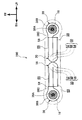
- the vehicle air conditioner 10 of the present embodiment is a blower provided on the ceiling 14 of the cabin 12.
- the vehicle air conditioner 10 includes a fan 16 that generates an air flow and an air outlet that blows out the air flow generated by the operation of the fan 16 toward the cabin 12.
- the provided blowing bodies 18 and 20 and the duct 22 for introducing the air flow generated by the operation of the fan 16 into the blowing bodies 18 and 20 are provided.
- the vehicle air conditioner 10 includes a fan cover 26 that covers the fan 16 and includes an air inlet 24 that is introduced into the fan 16.
- the cabin 12 of the vehicle 28 provided with the vehicle air conditioner 10 of the present embodiment will be described, and then the fan 16, the blowing bodies 18, 20, the duct 22 and the fan cover 26 will be described in this order.
- the vehicle 28 including the vehicle air conditioner 10 according to the present embodiment is a so-called minivan type vehicle having seven passengers.
- the cabin 12 of the vehicle 28 is provided with seats 30, 32, 34 in the first to third rows.
- the seat 30 in the first row is a driver seat or a passenger seat
- the seat 32 in the second row is a bench-type seat that can be seated by three passengers.
- the seat 34 is a bench-type seat that can be seated by two passengers.
- the fan 16 is a sirocco fan that has a large number of blades on the outer side in the radial direction and blows out air sucked into the shaft core portion toward the outer side in the radial direction.
- the fan 16 is fixed to the shaft of a motor 36 whose axial direction is the vehicle vertical direction.
- the fan 16 has a circular opening 38 ⁇ / b> A on the vehicle lower side and is covered with a shroud 38 having a peripheral wall 38 ⁇ / b> B extending along the circumferential direction of the fan 16.
- the shroud 38 is provided with a flange portion 38C to which a duct 22 described later is connected.
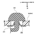
- the fan 16, the motor 36, and the shroud 38 described above are fixed to a roof reinforcement 42 that constitutes the ceiling portion 14 of the cabin 12 via a bracket 40. Further, as shown in FIGS. 4 and 5, a sealing material 44 is provided around the bracket 40. By this sealing material 44, air between the roof panel 46 and the roof head lining 48 constituting the ceiling portion 14 of the cabin 12 (air cooled or warmed by outside air, sunlight, or the like) is not sucked into the fan 16. It is like that.
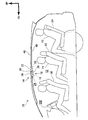
- blowing body 18, 20 As shown in FIG. 3, the blowing bodies 18 and 20 are provided on the left and right sides of the cabin 12, and as shown in FIG. 2, the rear of the first row of seats 30 in the ceiling portion 14 of the cabin 12. And it is provided in front of the seats 32 in the second row.
- the blowing body 18 and the blowing body 20 are substantially configured in the vehicle width direction, the blowing body 20 will be described here, and the blowing body 18 will be denoted by the same reference numerals and description thereof will be omitted.
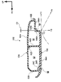
- the blowout body 20 includes a substantially U-shaped flow path 50 that opens to the inner side in the vehicle width direction.
- the blowing body 20 has a first flow path 52 extending outward in the vehicle width direction, and a substantially U-shape from the outer end of the first flow path 52 in the vehicle width direction toward the vehicle rear side.
- a third flow path 56 extending inward in the vehicle width direction through the second flow path 54.
- the end of the first flow path 52 on the inner side in the vehicle width direction is an introduction port 58 through which the air flow from the fan 16 is introduced, and the end of the third flow path 56 on the inner side in the vehicle width direction is a closed end.
- the blowing body 20 includes a flow rate adjusting unit that adjusts the flow rate of the air flow flowing from the first flow path 52 into the third flow path 56 through the second flow path 54.
- the damper 60 is provided.
- the blowout body 20 has a vertically divided structure with an upper structure body 62 and a lower structure body 64 formed using a resin material.
- the upper structural body 62 constituting the upper part of the blowing body 20 includes an upper wall portion 62A that extends in the vehicle front-rear direction and the vehicle width direction, and a front wall that bends and extends downward from the front end portion of the upper wall portion 62A. Part 62B.
- the upper structural body 62 includes an inclined wall portion 62C that extends from the lower end portion of the front wall portion 62B so as to incline toward the vehicle rear side.
- the upper structural body 62 protrudes from the middle portion of the upper wall portion 62A in the vehicle front-rear direction toward the vehicle lower side and extends in the vehicle width direction, and from the rear end portion of the upper wall portion 62A toward the vehicle lower side. And a rear wall 62E extending toward the front.
- the lower structure 64 constituting the lower part of the blowing body 20 extends from the lower wall portion 64A extending in the vehicle front-rear direction and the vehicle width direction and bent from the front end portion of the lower wall portion 64A toward the vehicle upper side. And an inclined wall portion 64B. Further, the lower structure body 64 is bent toward the vehicle upper side from the front end portion of the inclined wall portion 64B, and has a predetermined distance C1 from the wall surface on the vehicle rear side of the inclined wall portion 62C of the upper structure body 62. The front wall portion 64C is provided.
- the lower structure body 64 includes a partition wall portion 64D that protrudes from the middle portion of the lower wall portion 64A in the vehicle front-rear direction toward the vehicle upper side and has a tip portion extending along the rib 62D of the upper structure body 62.
- the lower structure body 64 extends from the rear end portion of the lower wall portion 64A toward the vehicle upper side, and the front end portion has a predetermined distance C2 from the wall surface on the vehicle front side of the rear wall portion 62E of the upper structure body 62E.
- a rear wall portion 64E is provided.
- the upper structure 62A, the front wall 62B and the inclined wall 62C described above and the partition wall 64D, the lower wall 64A, the inclined wall 64B and the front wall 64C of the lower structure 64 are used for the first.
- a flow path 52 is formed.
- a third flow path 56 is formed by the upper wall portion 62A and the rear wall portion 62E of the upper structure 62, and the partition wall portion 64D, the lower wall portion 64A, and the rear wall portion 64E of the lower structure 64.
- the second flow path 54 (see FIG. 3) is formed by the upper wall 62A of the upper structure 62, the lower wall 64A of the lower structure 64, and the like.
- an opening is formed toward the obliquely rear side of the vehicle and is formed in a long hole shape with the vehicle width direction as the longitudinal direction.
- a main flow outlet 66 is formed as the first outlet.
- a gap between the rear wall portion 62E of the upper structure 62 and the rear wall portion 64E of the lower structure 64 is formed in a long hole shape that opens toward the vehicle lower side and has the vehicle width direction as a longitudinal direction.
- a wind direction adjusting flow outlet 68 as a second outlet is formed.
- the airflow that has flowed from the fan 16 into the blowing body 20 via the duct 22 can be blown out from the main flow outlet 66 and the airflow direction adjusting outlet 68.
- an air flow flowing from the fan 16 into the blowing body 20 through the duct 22 is supplied to the lower wall portion 64 ⁇ / b> A of the lower structural body 64 from the main flow outlet 66 and the airflow direction adjustment outlet.
- Guide ribs 70, 72 for guiding to 68 are provided.
- a main flow outlet 66 is provided on the upstream side of the air flow introduced into the blowing body 20, and a wind direction adjusting flow blow is provided on the downstream side of the air flow.
- the outlet 68 is provided. Further, in the present embodiment, the air flow F3 blown from the airflow direction adjusting outlet 68 intersects with the air flow F1 blown from the mainstream outlet 66 and flowing along the lower wall portion 64A of the lower structure 64. In this way, a wind direction adjusting outlet 68 is arranged. Further, the wind direction adjusting flow outlet 68 is disposed so as to be separated from the air flow F1 by a distance D1 (the wind direction adjusting flow outlet 68 is located above the vehicle by a distance D1 from the lower wall portion 64A of the lower structure 64. Placed on the side).
- FIG. 6 shows an exploded perspective view of a state in which the damper 60 provided at the boundary between the first flow path 52 and the second flow path 54 in the blowing body 20 is in the closed position.
- the damper 60 includes a substantially cylindrical shaft portion 74.
- One end portion (end portion on the vehicle upper side) of the shaft portion 74 is loosely inserted into a circular shaft support hole 62 ⁇ / b> F provided in the upper wall portion 62 ⁇ / b> A of the upper structure 62.
- a connecting portion 74 ⁇ / b> A of the lever 76 is formed at the other end portion (end portion on the vehicle lower side) of the shaft portion 74.
- the lever 76 is connected to the connecting portion 74A, and the shaft portion 76A of the lever 76 is loosely inserted into a circular shaft support hole 64F provided in the lower wall portion 64A of the lower structure 64. As a result, the shaft portion 74 is rotated by operating the lever 76 (by moving in the directions of the arrow A and the arrow B).
- the damper 60 includes a first flap portion 78 and a second flap portion 80 that are formed integrally with the shaft portion 74 and extend outward in the radial direction of the shaft portion 74.
- the first flap portion 78 has an upper end portion, an end portion on the vehicle rear side, and a lower end portion along the upper wall portion 62A of the upper structural body 62, the partition wall portion 64D of the lower structural body 64, and the lower wall portion 64A of the lower structural body 64. It is formed in the substantially rectangular plate shape extended.
- the second flap portion 80 is formed in a substantially rectangular plate shape whose upper end portion and lower end portion extend along the upper wall portion 62A of the upper structure body 62 and the lower wall portion 64A of the lower structure body 64, respectively. Further, the tip end portion of the second flap portion 80 is formed to bend outward in the vehicle width direction.
- the tip end portion of the second flap portion 80 is formed to be concentric with the outer wall of the second flow path 54 when the damper 60 is in the open position (see FIG. 8). Furthermore, the area S1 of the outer surface of the first flap part 78 and the area S2 of the outer surface of the second flap part 80 are set to be substantially the same.
- the lever 76 is disposed at a position where the air flows F1 and F3 blown out from the main flow outlet 66 and the wind direction adjusting outlet 68 do not hit. More specifically, the lever 76 intersects with both the blowing direction of the main flow outlet 66 and the blowing direction of the wind direction adjusting outlet 68 from a position facing the main flow outlet 66 and the wind direction adjusting outlet 68 ( It is arranged at a position offset in the vehicle width direction).
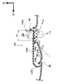
- the duct 22 is a Y-shaped branch pipe having a branch in the left-right direction of the vehicle.
- the duct 22 includes a first duct portion 82 that extends in the vehicle front-rear direction.
- the base end side (vehicle front side) of the first duct portion 82 is connected to the flange portion 38 ⁇ / b> C of the shroud 38.
- the duct 22 includes a second duct portion 84 that extends from the front end of the first duct portion 82 to the left in the vehicle width direction, and a third duct that extends from the front end of the first duct portion 82 to the right in the vehicle width direction. Part 86.
- the tips of the second duct portion 84 and the third duct portion 86 are connected to the introduction port 58 of the blowing body 18 and the introduction port 58 of the blowing body 20, respectively. Further, the tip end of the first duct portion 82 branches into the second duct portion 84 and the third duct portion 86, so that the opening area on the tip end side of the first duct portion 82 gradually increases toward the vehicle rear side. However, in this embodiment, the change in the opening area is set to be as small as possible. Furthermore, in the present embodiment, the joint portion 88 between the second duct portion 84 and the third duct portion 86 protrudes toward the vehicle front side and is formed to have a shape narrowed toward the vehicle front side. ing.
- the fan cover 26 is formed in a substantially box shape that covers the fan 16, the motor 36, and the shroud 38 fixed to the ceiling portion of the cabin 12 via the bracket 40 and covers the duct 22. ing. Specifically, the fan cover 26 includes a fan cover portion 90 that covers the fan 16, the motor 36, and the shroud 38, and a duct cover portion 92 that covers the duct 22.
- the fan cover 90 opens to the upper side of the vehicle and has a substantially U-shaped cross section when viewed from the front of the vehicle.
- the fan cover 90 includes a bottom wall 90A extending in the vehicle front-rear direction and the vehicle width direction, and a right side wall extending from the left and right ends of the bottom wall 90A toward the vehicle upper side. 90B and left side wall 90C.
- the bottom wall portion 90A of the fan cover portion 90 is disposed so as to be separated from the opening portion 38A formed in the lower portion of the shroud 38 by a distance C3.
- the distance C3 is appropriately set in consideration of the flow rate of air sucked from the opening 38A formed in the lower portion of the shroud 38, the head clearance of the cabin 12, and the like.
- an air inlet 24 to be introduced into the fan 16 is formed at the front end portion of the fan cover portion 90.
- the introduction port 24 is formed in a substantially rectangular shape with the vehicle width direction as a longitudinal direction when viewed from the front of the vehicle, and as shown in FIG. 2, slightly behind the upper side of the first row of seats 30. Has been placed.
- the introduction port 24 is provided with a plurality of (two in this embodiment) louvers 94 along the vehicle vertical direction.
- the louver 94 is formed in a plate shape, and is fixed to the peripheral portion of the introduction port 24 in a state where the front end portion is inclined toward the vehicle upper side.
- the introduction port 24 is partitioned in the height direction by the louver 94.
- each introduction opening 96 formed by being partitioned by the louver 94 opens toward the roof head lining 48.
- a sealing material 98 that allows the first duct portion 82 of the duct 22 to pass through is provided at the rear end portion of the fan cover portion 90.
- the seal material 98 separates the space covered by the fan cover portion 90 and the space covered by the duct cover portion 92.
- the fan cover 90 described above is fixed to the roof head lining 48 via a clip or the like (not shown).
- the duct cover portion 92 opens toward the vehicle upper side and has a substantially U-shaped cross section when viewed from the front of the vehicle. As shown in FIG. 3, the front end portion of the duct cover portion 92 is formed so as to connect the blowing body 18 and the blowing body 20 provided on the ceiling portion 14 of the cabin 12 in the vehicle width direction. These are fixed to the blowing bodies 18 and 20 via clips or the like (not shown).
- the air on the front side of the cabin 12 is introduced from the introduction port 24 formed at the front end portion of the fan cover 26.
- the air introduced from the introduction port 24 is introduced into the shaft core portion of the fan 16 from the opening 38 ⁇ / b> A formed in the lower portion of the shroud 38.
- the air introduced into the shaft core portion of the fan 16 flows into the first duct portion 82 of the duct 22 and then branches into the second duct portion 84 and the third duct portion 86. Then flow.
- the airflow that has flowed into the second duct portion 84 and the third duct portion 86 flows into the blowing body 18 and the blowing body 20.
- blowing body 18 and the blowing body 20 are comprised substantially symmetrically in the vehicle width direction as above-mentioned, the effect
- a part of the air flow that has flowed into the first flow path 52 of the blowing body 20 flows along the guide ribs 70 and 72 (see FIG. 3) and then blows out from the main flow outlet 66. .
- the air flow F1 blown out from the main flow outlet 66 flows toward the vehicle rear side along the lower wall portion 64A of the lower structure 64. Further, the air on the lower side of the air flow F1 is entrained by the air flow F1 flowing along the lower wall portion 64A (hereinafter, the air flow of the entrained air is referred to as “air flow F2”).
- air flow F2 the air flow of the entrained air
- FIG. 7 shows an air flow through the second flow path 54 when the damper 60 is fully opened. As shown in this figure, the other part of the air flow that has flowed into the first flow path 52 of the blowing body 20 flows into the third flow path 56 through the second flow path 54.
- the airflow that has flowed into the third flow path 56 of the blowing body 20 flows along the guide ribs 70 and 72 (see FIG. 3), and is then blown out from the wind direction adjusting flow outlet 68.
- the air flow F3 blown out from the wind direction adjusting flow outlet 68 flows toward the vehicle lower side. Then, the air flow F3 blown out from the air flow adjusting flow outlet 68 joins from the side of the air flow F1 blown out from the main flow blowout outlet 66 and the air flow F2 generated by being caught in the air flow F1.
- air flow F4 the changed air direction
- the damper 60 when the damper 60 is fully opened, the air flow F4 flows toward the occupant P1 (see FIG. 2) seated on the seat 32 in the second row.
- the damper 60 when the damper 60 is fully closed, the air flow that has flowed into the first flow path 52 is less likely to flow into the third flow path 56 through the second flow path 54. Therefore, as shown in FIG. 1, the flow rate of the air flow F1 blown from the main flow outlet 66 increases, and conversely, the flow rate of the air flow F3 blown from the airflow direction adjustment outlet 68 decreases. As a result, the air flow F1 blown from the main flow outlet 66 (and the air flow F2 of the air entrained in the air flow F1) is greatly affected by the air flow F3 blown from the wind direction adjusting outlet 68. It flows toward the rear side of the vehicle without any problems. In the present embodiment, when the damper 60 is fully closed, the air flow F4 flows toward the passenger P2 (see FIG. 2) seated on the third row of seats 34. .
- the air flow F1 blown from the main flow outlet 66 in a stepless manner (and the air entrained in the air flow F1).
- the air direction of the air flow F2) can be changed.
- the lever 76 for operating the damper 60 is located at a position where the air flows F1 and F3 blown from the main flow outlet 66 and the airflow direction adjustment outlet 68 do not hit. Has been placed. For this reason, when an operator (for example, an occupant P1 seated on the second row of seats 32 or an occupant P2 seated on the third row of seats 34) operates the lever 76 by hand, The air flows F1 and F3 blown out from the outlet 66 and the wind direction adjusting flow outlet 68 do not directly hit each other. In other words, the operator's hand does not block the air flows F1 and F3 blown out from the main flow outlet 66 and the wind direction adjusting outlet 68. As a result, the operator can adjust the wind direction while directly feeling the change in the wind direction.
- an operator for example, an occupant P1 seated on the second row of seats 32 or an occupant P2 seated on the third row of seats 34
- a main flow outlet 66 is provided on the upstream side of the air flow introduced into the blowing body 20, and a wind direction adjusting flow outlet 68 is provided on the downstream side of the air flow. Therefore, the pressure of the air flow F1 blown from the main flow outlet 66 can be made higher than the pressure of the air flow F3 blown from the airflow direction adjustment outlet 68. That is, in this embodiment, without providing a plurality of fans, a high-pressure air flow (air flow F1 blown out from the main flow outlet 66) and a low-pressure air flow (air flow F1 blown out from the main flow outlet 66) or the like. For adjusting the wind direction can be obtained.
- the air inlet 24 introduced into the fan 16 is provided on the vehicle front side from the main flow outlet 66 and the wind direction adjusting outlet 68. Therefore, it is possible to suck the air on the front side of the cabin 12 from the introduction port 24 and flow this air to the rear side of the cabin 12.
- the air cooled by the air conditioner is heated (warmed). It becomes possible to flow to the rear of the cabin 12 efficiently.
- the airflow direction adjusting outlet 68 is disposed on the vehicle upper side by a distance D1 from the lower wall portion 64A of the lower structure 64. Therefore, generation
- each introduction opening 96 formed by dividing the introduction port 24 by the louver 94 is formed so as to open toward the roof head lining 48. Has been. Therefore, even if the noise of the fan 16 is released from the introduction port 24 to the cabin 12, the noise abuts against the roof head lining 48.
- the roof head lining 48 constituting the ceiling portion 14 of the cabin 12 is formed using a nonwoven fabric having a sound absorbing effect. As a result, in the present embodiment, the roof head lining 48 can absorb the noise of the fan 16 discharged from the introduction port 24 to the cabin 12.
- a rib 62 ⁇ / b> D extending in the vehicle width direction is provided on the upper wall portion 62 ⁇ / b> A of the upper structure 62 constituting the upper portion of the blowing body 20, and the blowing body A partition wall 64 ⁇ / b> D extending in the vehicle width direction is provided on the lower wall 64 ⁇ / b> A of the lower structure 64 constituting the lower part of the vehicle 20. Therefore, when the upper structure body 62 and the lower structure body 64 are molded, the upper structure body 62 and the lower structure body 64 can be prevented from being deformed so as to warp in the vehicle width direction.
- the opening area on the front end side of the first duct portion 82 gradually increases toward the vehicle rear side, and the change in the opening area is possible. Is set to be smaller. Furthermore, in the present embodiment, the joint portion 88 between the second duct portion 84 and the third duct portion 86 protrudes toward the vehicle front side and is formed to have a shape narrowed toward the vehicle front side. ing. Therefore, separation of the air flow in this portion is suppressed, and consequently generation of noise and pressure loss due to separation of the air flow can be suppressed.
- the area S1 of the outer surface of the first flap part 78 and the area S2 of the outer surface of the second flap part 80 are set to be substantially the same. . Therefore, the moment around the shaft portion 74 generated by the pressure applied to the outer surface of the first flap portion 78 is canceled by the moment around the shaft portion 74 generated by the pressure applied to the outer surface of the second flap portion 80. As a result, the damper 60 can be held at an arbitrary position between the fully open position and the front closed position without separately providing a fixing means for fixing the rotation of the shaft portion 74 of the damper 60.
- the damper 60 is provided at the boundary between the first flow path 52 and the second flow path 54 in the blowing body 20 .
- the present invention is not limited to this, and the damper 60 is provided. It is good also as a structure which does not provide.
- the blowing body 102 according to this modification is characterized in that the wind direction adjusting flow outlet 68 is offset to the front side of the vehicle as compared with the blowing body 20 according to the above embodiment.
- the upper structural body 104 constituting the upper part of the blowing body 102 includes an intermediate wall portion 104A extending from the lower end portion of the rear wall portion 64E toward the vehicle front side, and a vehicle from the front end portion of the intermediate wall portion 104A. And an inclined wall portion 104B extending inclinedly toward the lower side.
- the lower structure 106 constituting the lower part of the blowing body 102 extends from the rear end portion of the lower wall portion 64 ⁇ / b> A toward the vehicle upper side, and the front end portion is on the vehicle front side of the inclined wall portion 104 ⁇ / b> B of the upper structure 104.
- the rear wall portion 106A is disposed with a predetermined distance C2 from the wall surface.
- the airflow direction adjustment outlet 68 opens toward the vehicle front side and the vehicle diagonally lower side as compared with the blowing body 20 according to the above embodiment. It is characterized by being formed in this way.
- the upper structural body 110 constituting the upper part of the blowing body 108 includes an inclined portion 110A formed so that the lower end portion of the rear wall portion 62E is inclined obliquely downward toward the vehicle front side. ing.
- the lower structure body 112 constituting the lower part of the blowing body 108 is inclined obliquely upward in the vehicle from the rear end portion of the lower wall portion 64A toward the vehicle rear side, and the front end portion is on the vehicle front side of the inclined portion 110A.
- the rear wall 112A is disposed along the surface of the rear wall 112A.
- the blowing body 114 according to this modification is configured to blow the wind direction control flow through a circular through hole 118 formed in the lower wall portion 64 ⁇ / b> A of the lower structure 116 constituting the lower portion of the blowing body 114.
- a feature is that an outlet 68 is formed.
- the through hole 118 is formed at an intermediate portion in the vehicle longitudinal direction of the lower wall portion 64A of the lower structure 116 in the third flow path 56, and is predetermined along the vehicle longitudinal direction and the vehicle width direction. (In this embodiment, the through holes 118 are arranged in three rows in the vehicle front-rear direction).
- the air flow F1 (and this air flow F1) blown out from the main flow outlet 66 by the air flow F3 blown out from the airflow control flow outlet 68 formed by the through hole 118.
- the wind direction of the air flow F2) of the air entrained in can be adjusted.
- the blowing body 120 according to this modification has a partition wall that separates the first flow path 52 and the third flow path 56 from the blowing body 114 according to the third modification.
- Adjustment as a flow rate adjusting unit that adjusts the flow rate of the air flow F3 blown out from the airflow direction adjusting outlet 68 by closing the through hole 118 that forms the airflow direction adjusting outlet 68.
- a feature is that a plate 122 is provided. Specifically, the adjustment plate 122 is provided on the vehicle upper side of the lower wall portion 64A, and is supported by a guide rail (not shown) so as to be slidable in the vehicle front-rear direction. Further, a lever (not shown) is connected to the adjustment plate 122. By operating this lever, the adjustment plate 122 slides in the vehicle front-rear direction.
- the flow rate of the air flow F3 blown out from the through-hole 118 that forms the wind direction adjusting flow outlet 68 is adjusted by operating the lever (adjustment plate 122) in the vehicle longitudinal direction. as a result.
- the wind direction of the airflow F1 blown out from the main flow outlet 66 can be adjusted.
- a blowing body 124 includes a blowing body main body 126 having a main flow outlet 66 and a first flow path 52, and a register 128 supported by the blowing body main body 126.
- the blowing body main body 126 has an upper wall portion 126A extending in the vehicle front-rear direction and the vehicle width direction, and is bent from the front end portion of the upper wall portion 126A toward the vehicle lower side, and the front end portion is rearward of the vehicle.
- a front wall portion 126B extending so as to incline toward the side.
- the blowing body main body 126 includes a first inclined wall portion 126C extending obliquely downward from the rear end portion of the upper wall portion 126A toward the vehicle front side, and a lower end of the first inclined wall portion 126C. And a lower wall portion 126D that bends and extends from the portion toward the vehicle front side. Further, the blowing body main body 126 includes a second inclined wall portion 126E that extends obliquely from the front end portion of the lower wall portion 126D toward the vehicle upper side and is disposed along the front end portion of the front wall portion 126B. Between the second inclined wall portion 126E and the front wall portion 126B, there is formed a main flow outlet 66 that is opened obliquely rearward of the vehicle.
- an air flow F1 that is blown out from the main flow outlet 66 and flows along the lower wall portion 126D and the first inclined wall portion 126C of the blowing body main body 126 is registered 128.
- a guide wall 126 ⁇ / b> F is provided for guiding toward the front.
- a register 128 is disposed between the front end portion of the guide wall 126F and the front end portion of the blowing body main body 126, and the register 128 is rotatably supported with the vehicle width direction as an axial direction.
- the blowing body 124 according to this reference example described above is blown out from the main flow outlet 66 and flows along the lower wall portion 126D and the first inclined wall portion 126C of the blowing body main body 126 (and this air).
- the wind direction of the air flow F2) of the air entrained in the flow F1 can be adjusted by rotating the register 128.
- the blowing body 130 according to the present reference example is characterized in that a wind direction adjusting flap 132 is provided instead of the register 128 of the blowing body 124 according to the first reference example. is there.
- the flap 132 is formed in a plate shape extending in the vehicle width direction, and is disposed at the rear end portion of the blowing body main body 126.
- the base end portion of the flap 132 is pivotally supported by a bearing means (not shown) whose axial direction is the vehicle width direction. As a result, the flap 132 can be rotated in the vehicle vertical direction.
- the blowing body 130 according to this reference example described above is blown out from the main flow outlet 66 and flows along the lower wall portion 126D and the first inclined wall portion 126C of the blowing body main body 126 (and this air).
- the wind direction of the air flow F2) of the air entrained in the flow F1 can be adjusted by rotating the flap 132.
- the blowing body 134 according to the present reference example is characterized in that an arc wall 136 is provided at the tip of the flap 132 of the blowing body 130 according to the second reference example.
- the arc wall 136 is formed so that a cross section viewed from the side of the vehicle has an arc shape, and from the tip of the flap 132 toward the vehicle upper side and from the rotation axis of the flap 132. The distance is extended to R1.
- the arc wall 136 is inserted through an opening 138 formed in the upper wall portion 126A of the blower body main body 126.
- a bent portion 136 ⁇ / b> A that is bent outward in the radial direction of the arc wall 136 is formed at the tip of the arc wall 136.
- the bent portion 136A is in contact with the edge of the opening 138 through which the arc wall 136 is inserted, whereby the rotation angle of the flap 132 is regulated.
- the blowing body 134 according to this reference example described above is blown out from the main flow outlet 66 and flows along the lower wall portion 126D and the first inclined wall portion 126C of the blowing body main body 126 (and this air).
- the wind direction of the air flow F2) of the air entrained in the flow F1 can be adjusted by rotating the flap 132.
- the arc wall 136 having the above-described configuration is provided, a sharp portion is not formed at the tip of the flap 132. As a result, the texture of the appearance design of the blowout body 134 can be improved.
- the blowing body 140 according to the present reference example is characterized in that an extension flap 142 is provided in addition to the flap 132 of the blowing body 130 according to the second reference example.
- the extension flap 142 is formed in a substantially plate shape extending in the vehicle width direction and is slidably supported on the upper surface of the flap 132. As a result, the extension flap 142 can slide along the direction from the proximal end portion of the flap 132 to the distal end portion.
- a bent portion 142 ⁇ / b> A is formed at the end of the extension flap 142 to restrict the sliding amount of the extension flap 142 by abutting the contacted member 144.
- the blowing body 140 according to this reference example described above can adjust the length of the flaps (the flap 132 and the extension flap 142) by sliding the extension flap 142. As a result, the length of the flap 132 can be reduced.
- the blowout body 146 has a main flow outlet 66 formed by a slit 148 formed so as to open obliquely downward in the vehicle toward the vehicle rear side.
- Each of the slits 148 can be opened and closed by the opening / closing lid 150.
- the blowing body 146 is provided with a plurality of slits 148 having the vehicle width direction as a longitudinal direction along the vehicle vertical direction.
- the opening / closing lid 150 for opening and closing the slit 148 is formed in a long plate shape along the opening shape of the slit 148 and is supported so as to be slidable along the longitudinal direction of the slit 148.
- the slit 148 is opened and closed by sliding the opening / closing lid 150.
- the blowing body 146 can blow the air introduced into the blowing body 146 from any slit 148 (main flow outlet 66) by sliding the opening / closing lid 150.
- the air direction of the airflow blown out from the blowing body 146 can be adjusted by sliding the opening / closing lid 150.
- the blowing body 152 includes an opening / closing lid 154 that opens and closes the slit 148 and a selection member 156 that selectively opens and closes the opening / closing lid 154.
- the open / close lid 154 is formed in a substantially plate shape along the opening shape of the slit 148, and the base end portion is pivotally supported along the edge of the slit 148.
- the slit 148 is opened and closed by rotating the opening / closing lid 154.
- the opening / closing lid 154 is urged by a spring 158 in a direction in which the slit 148 is opened.
- the selection member 156 is formed in a substantially circular plate shape extending in the vehicle front-rear direction, and includes a general surface 156A formed along the shape of the inner wall of the blowing body 152 in the portion where the slit 148 is provided. Yes. Furthermore, the selection member 156 includes a recess 156B formed so as to be recessed from the general surface 156A toward the inside in the radial direction of the selection member. Further, the opening / closing lid 154 at a position facing the recess 156B can be rotated to a position where the slit 148 is in an open state without interfering with the general surface 156A.
- the opening / closing lid 154 at a position facing the general surface 156A is restricted to a position where the slit 148 is closed by interference with the general surface 156A.
- the selection member 156 is connected to a lever (not shown). By operating this lever, the selection member 156 rotates along the inner wall of the blowing body 152 in the portion where the slit 148 is provided.
- the slit 148 is selectively opened and closed by the selection member 156 rotating.
- the air introduced into the blowing body 152 from any slit 148 (main flow outlet 66) can be blown out.
- the wind direction of the airflow blown out from the blowing body 152 can be adjusted by rotating the selection member 156.
- the blowing body 160 according to the present reference example has a selection member 162 that selectively opens and closes the slit 148 instead of the opening / closing lid 150 of the blowing body 146 according to the fifth reference example. It has the feature that it is provided in the inside.
- the selection member 162 is formed in a substantially cylindrical shape having the vehicle width direction as an axial direction, and includes a general portion 162A that extends along the inner wall of the blowing body 160 in a portion where the slit 148 is provided. ing.
- the general portion 162A is formed with an opening 162B whose longitudinal direction is the vehicle width direction.
- the opening 162 ⁇ / b> B and the slit 148 communicate with each other so that the air that has flowed into the blowing body 160 can be blown out through the opening 162 ⁇ / b> B and the slit 148.
- the selection member 162 is connected to a lever (not shown).
- the slit 148 is selectively opened and closed by the rotation of the selection member 162.
- the air introduced into the blowing body 160 can be blown out from an arbitrary slit 148 (main flow outlet 66).
- the wind direction of the airflow blown out from the blowing body 160 can be adjusted by rotating the selection member 162.
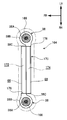
- the vehicle air conditioner 164 As shown in FIG. 11A, the vehicle air conditioner 164 according to the present modification generates an air flow that is blown out from the main flow fan 166 that generates an air flow that is blown out from the main flow blower outlet 66 and the airflow direction adjustment flow outlet 68.
- the wind direction adjusting flow fans 168 are provided on the left and right sides of the blower body 170 in the vehicle width direction.
- the blower body 170 is formed in an elongated shape having the vehicle width direction as a longitudinal direction, and a first flow path 172 provided on the vehicle front side and a second channel provided on the vehicle rear side. A flow path 174.
- the blower body 170 is provided along the first flow path 172 with a main flow outlet 66 that opens toward the obliquely rear side of the vehicle and is formed in a long hole shape with the vehicle width direction as a longitudinal direction.
- a main flow outlet 66 that opens toward the obliquely rear side of the vehicle and is formed in a long hole shape with the vehicle width direction as a longitudinal direction.
- an airflow direction adjusting outlet 68 that opens toward the vehicle lower side and is formed in a long hole shape with the vehicle width direction as the longitudinal direction is provided.
- an inlet 176 into which an air flow generated by the main flow fan 166 is introduced is formed at one end (the end on the right side in the vehicle width direction) of the first flow path 172.
- the introduction port 176 is connected to the flange portion 38 ⁇ / b> C of the shroud 38 of the mainstream fan 166.
- the other end portion (the left end portion in the vehicle width direction) of the first flow path 172 is a closed end.
- an introduction port 178 into which an air flow generated by the airflow direction adjusting flow fan 168 is introduced is formed at one end portion (the end portion on the right side in the vehicle width direction) of the second flow path 174.
- the introduction port 178 is connected to the flange portion 38 ⁇ / b> C of the shroud 38 of the wind direction adjusting flow fan 168.
- the other end (the left end in the vehicle width direction) of the second flow path 174 is a closed end.
- the mainstream fan 166 and the airflow direction adjusting fan 168 are the same sirocco fans as in the above embodiment.
- the air flow generated by the operation of the mainstream fan 166 flows into the first flow path 172 of the blowing body 170. Further, the air flow that has flowed into the first flow path 172 is blown out from the main flow outlet 66 and then flows toward the rear side of the cabin 12 (see FIG. 2).
- the air flow generated by the operation of the wind direction adjusting flow fan 168 flows into the second flow path 174 of the blowing body 170.
- the airflow that has flowed into the second flow path 174 collides (combines) with the side of the airflow that is blown out from the main flow outlet 66 after being blown out from the airflow regulating outlet 68.
- the wind direction of the air flow F1 (and the air flow F2 of the air entrained in the air flow F1) blown from the main flow outlet 66 is changed.
- the air flow F1 blown from the main flow outlet 66 (and the air flow of the air caught in the air flow F1).
- the wind direction of F2) can be adjusted.
- the vehicle air conditioner 180 is characterized in that the fan 16 is disposed between the blowing body 18 and the blowing body 20. Specifically, the fan 16 is covered with a shroud 182 having a flange portion 182 ⁇ / b> A connected to the inlet 58 of the blowing body 18 and the inlet 58 of the blowing body 20.
- the vehicle air conditioner 180 according to the present modification can set the dimension in the vehicle front-rear direction to be more compact than the vehicle air conditioner 180 according to the above embodiment.
- the vehicle air conditioner 184 is provided with a single blowing body 186 that is formed in a long shape in the vehicle width direction, and the vehicle of the blowing body 186. It is characterized in that the fan 16 is arranged at the end on the right side in the width direction.
- the blowing body 186 of this modification is elongate in the vehicle width direction rather than the blowing body 18 of the said embodiment. It is formed in a shape.
- the inlet 188 of the blowing body 186 is provided on the right side in the vehicle width direction, and a flange portion 38C of the shroud 38 that covers the fan 16 is connected to the inlet 188.
- the vehicle air conditioner 184 according to this modification can set the dimension in the vehicle front-rear direction to be more compact than the vehicle air conditioner 184 according to the above embodiment.
- positioned the fan 16 to the vehicle width direction right end part of the blowing body 186 has been demonstrated in this modification, this invention is not limited to this, The fan 16 is the vehicle of the blowing body 186. It is good also as a structure arrange
- the blower body 20 of the above embodiment is disposed on the left side in the vehicle width direction, and the blower body 18 is disposed on the right side in the vehicle width direction.
- the fans 16 are respectively disposed on the outer sides in the vehicle width direction of the blowing body 20 and the blowing body 18, and the flange portion 38 ⁇ / b> C of the shroud 38 that covers each fan 16 is the introduction port 58 of the blowing body 20.
- the vehicle air conditioner 190 it is possible to adjust the air volume of the air flow blown from the blowing body 20 and the blowing body 18 to an arbitrary air volume, respectively.
- the flow rate adjusting unit according to this modification is characterized by being configured by a shutter 192 that opens and closes between the first flow path 52 and the second flow path 54.
- a shutter 192 a plurality of pieces 194 formed in a substantially prismatic shape having a longitudinal direction in the vehicle up-down direction are connected via a pin (not shown), and adjacent pieces 194 are pivotally connected to each other. It is comprised so that rotation is possible.
- the shutter 192 is integrally formed using a resin material, the shutter 192 may be configured by connecting a plurality of pieces 194 with integral pins.
- a guide for supporting the shutter 192 in a slidable manner is provided on the upper wall 62A of the upper structure 62 constituting the upper part of the blower 20 and the lower wall 64A of the lower structure 64 constituting the lower part of the blower 20.
- Grooves 196 and 198 are respectively formed.
- the guide grooves 196, 198 are formed in a third flow from the first groove portions 196A, 198A crossing between the first flow path 52 and the second flow path 54, and from the vehicle rear side end portions of the first groove portions 196A, 198A. It has 2nd groove part 196B, 198B extended along the path
- the shutter 192 is connected to a lever 200 for sliding the shutter 192 along the guide grooves 196 and 198.
- the lever 200 protrudes from an opening 202 formed in the lower wall portion 64A of the lower structure 64.
- the opening 202 is formed in a long hole shape along the first groove 198A.
- a sealing material 204 is provided between the lever 200 and the opening 202.
- the shutter 192 opens and closes between the first flow path 52 and the second flow path 54 by operating the lever 200 along the opening 202.
- the flow rate of the air flow flowing from the first flow path 52 into the third flow path 56 via the second flow path 54 is adjusted.
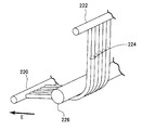
- the flow rate adjustment unit according to this modification is characterized by being configured by a bellows plate 206 that opens and closes between the first flow path 52 and the second flow path 54. is there.
- the bellows plate 206 is formed by folding a plate-like member along the vehicle front-rear direction (mountain folding and valley folding are alternately performed).
- the bellows plate 206 is configured to be stretchable along the longitudinal direction of the vehicle.
- the bellows plate 206 is connected to a lever 200 having the same configuration as that of the flow rate adjusting unit (shutter 192) according to the first modification.
- the bellows plate 206 opens and closes between the first flow path 52 and the second flow path 54. As a result, the flow rate of the air flow flowing from the first flow path 52 into the third flow path 56 via the second flow path 54 is adjusted.
- the flow rate adjusting unit according to this modification includes a plurality of rotating shafts 208 arranged at a predetermined interval in the vehicle front-rear direction and a base end portion on the rotating shaft 208. It is characterized by being constituted by a multi-shutter 212 having a substantially rectangular closing plate 210 supported.
- the length L1 from the proximal end portion to the distal end portion of the closing plate 210 is set to be substantially the same as the interval between the adjacent rotating shafts 208, and the width B1 ( The length in the vertical direction of the vehicle) is set to be substantially the same as the distance (the distance in the vertical direction of the vehicle) between the upper wall portion 62A and the lower wall portion 64A (see FIG. 13A, etc.) of the blowout body 20. .
- each closing plate 210 supported by each rotation shaft 208 is rotated at substantially the same angle via a rod 214. In the present embodiment, the rotation shaft 208 is rotated 90 degrees from the fully opened state shown by the solid line in FIG. 14 to be in the fully closed state shown by the two-dot chain line.
- the multi-shutter 212 described above is provided between the first flow path 52 and the second flow path 54.
- the flow rate adjusting unit according to this modification is characterized by being configured by a shutter 218 having a plurality of closing plates 216 formed in a plate shape.
- the closing plate 216 constituting the shutter 218 includes a general portion 216A formed in a substantially rectangular shape.
- a bent portion 216B that is bent and extends in the thickness direction of the general portion 216A is formed at one end of the general portion 216A.
- a vertical wall 216C extending in a direction orthogonal to the direction in which the general portion 216A extends is formed at the other end of the general portion 216A.
- the first passage 52 and the second passage 54 are configured to be open.
- the plurality of closing plates 216 are developed in a direction orthogonal to the plate thickness direction of the general portion 216A, so that the gap between the first channel 52 and the second channel 54 is closed. It is comprised so that it may be in a state.
- FIG. 15C in the process in which the plurality of closing plates 216 are deployed in the direction perpendicular to the plate thickness direction of the general portion 216A, the bent portions 216B and the vertical walls 216C of the adjacent closing plates 216 contact each other.
- Each closing plate 216 is arranged so as to contact. As a result, all the closing plates 216 can be deployed by moving only the closing plate 216 (219A) in the direction of arrow C or moving only the closing plate 216 (219B) in the direction of arrow D. .
- the shutter 218 described above is provided between the first flow path 52 and the second flow path 54.
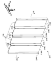
- the flow rate adjusting unit according to the present modification includes a plurality of closing yarns provided so as to be spanned between a support shaft 220 and a support shaft 222 formed in a columnar shape.
- 224 is characteristic.
- the closing yarn 224 is formed to have a predetermined thickness by knitting a resin material as an example, and the closing yarns 224 are adjacent to each other at one end side thereof.
- the support shaft 220 is fixed in the arranged state.
- the other end side of the closing thread 224 is fixed to the support shaft 222 in a state where the adjacent closing threads 224 are arranged so as to be close to each other.
- a support shaft 226 that supports an intermediate portion of the closing thread 224 is provided between the support shaft 220 and the support shaft 222.
- FIG. 16A when the support shaft 220 is moved in the direction of arrow E, tensile tension is applied to the closing thread 224 and adjacent closing threads 224 are brought into close contact with each other. As a result, the air flow cannot pass between the closing yarns 224.
- FIG. 16B when the support shaft 220 is moved in the direction of arrow F, the tension applied to the closing thread 224 is released and a gap is formed between the adjacent closing threads 224. . As a result, the air flow can pass between the closing yarns 224.
- the closing thread 224 described above is provided between the first flow path 52 and the second flow path 54.
Landscapes
- Physics & Mathematics (AREA)
- Thermal Sciences (AREA)
- Engineering & Computer Science (AREA)
- Mechanical Engineering (AREA)
- Air-Conditioning For Vehicles (AREA)
Priority Applications (6)
| Application Number | Priority Date | Filing Date | Title |
|---|---|---|---|
| PCT/JP2012/058201 WO2013145172A1 (ja) | 2012-03-28 | 2012-03-28 | 車両用空調装置 |
| JP2014507139A JP5962753B2 (ja) | 2012-03-28 | 2012-03-28 | 車両用空調装置 |
| EP12872920.9A EP2832565A4 (en) | 2012-03-28 | 2012-03-28 | VEHICLE AIR CONDITIONING DEVICE |
| CN201280071936.2A CN104220282B (zh) | 2012-03-28 | 2012-03-28 | 车辆用空调装置 |
| US14/387,919 US20150017902A1 (en) | 2012-03-28 | 2012-03-28 | Vehicular air-conditioning device |
| KR1020147024683A KR101586776B1 (ko) | 2012-03-28 | 2012-03-28 | 차량용 공조 장치 |
Applications Claiming Priority (1)
| Application Number | Priority Date | Filing Date | Title |
|---|---|---|---|
| PCT/JP2012/058201 WO2013145172A1 (ja) | 2012-03-28 | 2012-03-28 | 車両用空調装置 |
Publications (1)
| Publication Number | Publication Date |
|---|---|
| WO2013145172A1 true WO2013145172A1 (ja) | 2013-10-03 |
Family
ID=49258537
Family Applications (1)
| Application Number | Title | Priority Date | Filing Date |
|---|---|---|---|
| PCT/JP2012/058201 WO2013145172A1 (ja) | 2012-03-28 | 2012-03-28 | 車両用空調装置 |
Country Status (6)
| Country | Link |
|---|---|
| US (1) | US20150017902A1 (ko) |
| EP (1) | EP2832565A4 (ko) |
| JP (1) | JP5962753B2 (ko) |
| KR (1) | KR101586776B1 (ko) |
| CN (1) | CN104220282B (ko) |
| WO (1) | WO2013145172A1 (ko) |
Cited By (17)
| Publication number | Priority date | Publication date | Assignee | Title |
|---|---|---|---|---|
| JP2014083919A (ja) * | 2012-10-22 | 2014-05-12 | Denso Corp | 空調装置 |
| WO2014097605A1 (ja) * | 2012-12-20 | 2014-06-26 | 株式会社デンソー | 車両用送風装置 |
| JP2015016843A (ja) * | 2013-07-12 | 2015-01-29 | トヨタ自動車株式会社 | 車両用空調装置 |
| WO2016006187A1 (ja) * | 2014-07-10 | 2016-01-14 | 株式会社デンソー | 送風装置 |
| WO2016051754A1 (ja) * | 2014-10-02 | 2016-04-07 | 株式会社デンソー | 送風装置 |
| WO2016051753A1 (ja) * | 2014-10-02 | 2016-04-07 | 株式会社デンソー | 送風装置 |
| WO2016056186A1 (ja) * | 2014-10-07 | 2016-04-14 | 株式会社デンソー | 車両空調装置 |
| WO2016059778A1 (ja) * | 2014-10-17 | 2016-04-21 | 株式会社デンソー | 送風装置 |
| JP2016074414A (ja) * | 2014-10-02 | 2016-05-12 | 株式会社デンソー | 送風装置 |
| JP2016074413A (ja) * | 2014-10-02 | 2016-05-12 | 株式会社デンソー | 送風装置 |
| WO2016117348A1 (ja) * | 2015-01-23 | 2016-07-28 | 株式会社デンソー | 送風装置 |
| JP2016137889A (ja) * | 2015-01-23 | 2016-08-04 | 株式会社デンソー | 送風装置 |
| JP2017213921A (ja) * | 2016-05-30 | 2017-12-07 | 株式会社デンソー | 車載用サーキュレータ |
| JP2020023216A (ja) * | 2018-08-06 | 2020-02-13 | 株式会社デンソー | 自動車用空調制御システム、自動車用空調システム、制御装置 |
| JP2020049976A (ja) * | 2018-09-24 | 2020-04-02 | 株式会社デンソー | 車両用送風装置 |
| JP2020075598A (ja) * | 2018-11-07 | 2020-05-21 | 三菱自動車工業株式会社 | 車両用サーキュレータ |
| JP2021133847A (ja) * | 2020-02-28 | 2021-09-13 | ダイハツ工業株式会社 | 車両の空調装置 |
Families Citing this family (17)
| Publication number | Priority date | Publication date | Assignee | Title |
|---|---|---|---|---|
| FR3036658B1 (fr) * | 2015-06-01 | 2017-06-02 | Peugeot Citroen Automobiles Sa | Console pavillon de diffusion d’air conditionne dans la partie arriere de l’habitacle d’un vehicule automobile |
| CN105352101B (zh) * | 2015-12-10 | 2018-01-02 | 南华大学 | 基于科恩达效应的室内通风装置 |
| KR101803836B1 (ko) * | 2017-03-09 | 2017-12-04 | 최승혁 | 유증기 및 연기 정화 순환시스템을 구비한 전기구이기 |
| FR3075111B1 (fr) * | 2017-12-20 | 2020-07-31 | Valeo Systemes Thermiques | Dispositif de ventilation a tubes pour systeme de ventilation, de chauffage et/ou de climatisation |
| JP7047582B2 (ja) * | 2018-05-07 | 2022-04-05 | 株式会社デンソー | 吹出装置 |
| KR102559761B1 (ko) | 2018-08-24 | 2023-07-27 | 한온시스템 주식회사 | 차량용 공조장치 |
| KR102581848B1 (ko) | 2018-12-28 | 2023-09-25 | 한온시스템 주식회사 | 차량용 공조장치 |
| KR102559754B1 (ko) | 2018-08-24 | 2023-07-27 | 한온시스템 주식회사 | 차량용 송풍장치 |
| KR20200081691A (ko) | 2018-12-28 | 2020-07-08 | 한온시스템 주식회사 | 차량용 공조장치 |
| KR102581875B1 (ko) | 2018-12-28 | 2023-09-25 | 한온시스템 주식회사 | 차량용 공조장치 |
| KR20200099685A (ko) | 2019-02-15 | 2020-08-25 | 한온시스템 주식회사 | 차량용 공조시스템 |
| KR102575996B1 (ko) | 2019-03-07 | 2023-09-08 | 한온시스템 주식회사 | 차량용 공조장치 |
| KR102344298B1 (ko) | 2020-04-14 | 2021-12-29 | 한국전력공사 | 1차원 다공성 금속산화물 나노섬유 기반 가스센서 및 그 제조방법 |
| KR20210136701A (ko) | 2020-05-08 | 2021-11-17 | 현대자동차주식회사 | 차량용 에어써큘레이터 |
| KR20210142935A (ko) | 2020-05-19 | 2021-11-26 | 한온시스템 주식회사 | 차량용 공조장치 |
| KR20210155193A (ko) | 2020-06-15 | 2021-12-22 | 한온시스템 주식회사 | 차량용 공조장치 |
| KR20220016579A (ko) | 2020-08-03 | 2022-02-10 | 한온시스템 주식회사 | 플랜지, 배관 및 플랜지 구조 |
Citations (7)
| Publication number | Priority date | Publication date | Assignee | Title |
|---|---|---|---|---|
| JPS62163816A (ja) * | 1986-01-16 | 1987-07-20 | Nippon Denso Co Ltd | 車両用の空気調和装置 |
| JPH01257616A (ja) * | 1988-04-07 | 1989-10-13 | Matsushita Electric Ind Co Ltd | 自動車用空気調和装置 |
| JP2004148965A (ja) | 2002-10-30 | 2004-05-27 | Denso Corp | 車両用空調装置 |
| JP2005035423A (ja) | 2003-07-16 | 2005-02-10 | Calsonic Kansei Corp | 車両用空調装置 |
| JP2005212746A (ja) * | 2004-02-02 | 2005-08-11 | Denso Corp | 吹出方向可変装置および車両用空調装置 |
| JP2007050781A (ja) | 2005-08-18 | 2007-03-01 | Denso Corp | 車両用空調装置 |
| JP2010077969A (ja) | 2008-09-23 | 2010-04-08 | Dyson Technology Ltd | 送風機 |
Family Cites Families (19)
| Publication number | Priority date | Publication date | Assignee | Title |
|---|---|---|---|---|
| HU197258B (en) * | 1986-12-12 | 1989-03-28 | Koezlekedesi Es Tavkoezlesi Mu | Air distributing duct for cooling, heating and aerating the internal spaces of air-conditioned vehicles |
| ATE94848T1 (de) * | 1989-09-22 | 1993-10-15 | Inventio Ag | Vorrichtung fuer die belueftung von schnellaufenden aufzugskabinen. |
| US6062635A (en) * | 1998-03-20 | 2000-05-16 | Lear Automotive Dearborn, Inc, | Plastic air duct integrated to headliner |
| MXPA01006120A (es) * | 1998-12-16 | 2002-09-18 | Grumman Olson Ind Inc | Ventilacion del conductor para camion de entrega. |
| JP3578952B2 (ja) * | 1999-11-26 | 2004-10-20 | 本田技研工業株式会社 | 車両のエアダクト及びガーニッシュ構造 |
| US6786541B2 (en) * | 2001-01-05 | 2004-09-07 | Johnson Controls Technology Company | Air distribution system for ventilated seat |
| JP4380946B2 (ja) * | 2001-07-24 | 2009-12-09 | 三菱重工業株式会社 | 空調装置 |
| JP3969082B2 (ja) | 2001-08-10 | 2007-08-29 | 株式会社デンソー | 車両用送風装置 |
| JP4055467B2 (ja) * | 2002-05-16 | 2008-03-05 | 株式会社デンソー | 車両用空調装置 |
| DE10354032A1 (de) * | 2002-11-20 | 2004-06-03 | Denso Corp., Kariya | Fahrzeug-Klimaanlage |
| JP4193667B2 (ja) * | 2003-10-07 | 2008-12-10 | 株式会社デンソー | 気体送風装置および空調装置 |
| US20050087325A1 (en) * | 2003-10-27 | 2005-04-28 | Tim Roland | Air conditioning apparatus for rear seat arrangement |
| US6899381B1 (en) * | 2003-12-30 | 2005-05-31 | Lear Corporation | Vehicle headliner with a flexible duct |
| US7181918B2 (en) * | 2004-03-25 | 2007-02-27 | Oxycell Holding B.V. | Vehicle cooler |
| JP4758782B2 (ja) | 2006-01-31 | 2011-08-31 | 日本プラスト株式会社 | 車両用空調装置 |
| US8568209B2 (en) * | 2006-06-23 | 2013-10-29 | Dometic Corporation | Vehicle air-conditioning systems |
| JP2009040304A (ja) * | 2007-08-10 | 2009-02-26 | Denso Corp | 車両用空調装置 |
| ES2791424T3 (es) * | 2009-01-18 | 2020-11-04 | Lux Et Libertas B V | Dispositivo de refrigeración |
| US9278605B2 (en) * | 2012-03-23 | 2016-03-08 | Faurecia Interior Systems, Inc. | Air distribution arrangement for use with vehicle HVAC system and method of distributing air |
-
2012
- 2012-03-28 JP JP2014507139A patent/JP5962753B2/ja not_active Expired - Fee Related
- 2012-03-28 US US14/387,919 patent/US20150017902A1/en not_active Abandoned
- 2012-03-28 WO PCT/JP2012/058201 patent/WO2013145172A1/ja active Application Filing
- 2012-03-28 CN CN201280071936.2A patent/CN104220282B/zh not_active Expired - Fee Related
- 2012-03-28 EP EP12872920.9A patent/EP2832565A4/en not_active Withdrawn
- 2012-03-28 KR KR1020147024683A patent/KR101586776B1/ko not_active IP Right Cessation
Patent Citations (7)
| Publication number | Priority date | Publication date | Assignee | Title |
|---|---|---|---|---|
| JPS62163816A (ja) * | 1986-01-16 | 1987-07-20 | Nippon Denso Co Ltd | 車両用の空気調和装置 |
| JPH01257616A (ja) * | 1988-04-07 | 1989-10-13 | Matsushita Electric Ind Co Ltd | 自動車用空気調和装置 |
| JP2004148965A (ja) | 2002-10-30 | 2004-05-27 | Denso Corp | 車両用空調装置 |
| JP2005035423A (ja) | 2003-07-16 | 2005-02-10 | Calsonic Kansei Corp | 車両用空調装置 |
| JP2005212746A (ja) * | 2004-02-02 | 2005-08-11 | Denso Corp | 吹出方向可変装置および車両用空調装置 |
| JP2007050781A (ja) | 2005-08-18 | 2007-03-01 | Denso Corp | 車両用空調装置 |
| JP2010077969A (ja) | 2008-09-23 | 2010-04-08 | Dyson Technology Ltd | 送風機 |
Non-Patent Citations (1)
| Title |
|---|
| See also references of EP2832565A4 |
Cited By (30)
| Publication number | Priority date | Publication date | Assignee | Title |
|---|---|---|---|---|
| JP2014083919A (ja) * | 2012-10-22 | 2014-05-12 | Denso Corp | 空調装置 |
| WO2014097605A1 (ja) * | 2012-12-20 | 2014-06-26 | 株式会社デンソー | 車両用送風装置 |
| JP2014139066A (ja) * | 2012-12-20 | 2014-07-31 | Denso Corp | 車両用送風装置 |
| US10195923B2 (en) | 2013-07-12 | 2019-02-05 | Toyota Jidosha Kabushiki Kaisha | Vehicle air conditioning unit |
| JP2015016843A (ja) * | 2013-07-12 | 2015-01-29 | トヨタ自動車株式会社 | 車両用空調装置 |
| WO2016006187A1 (ja) * | 2014-07-10 | 2016-01-14 | 株式会社デンソー | 送風装置 |
| US10625574B2 (en) | 2014-07-10 | 2020-04-21 | Denso Corporation | Ventilation apparatus |
| WO2016051753A1 (ja) * | 2014-10-02 | 2016-04-07 | 株式会社デンソー | 送風装置 |
| JP2016074414A (ja) * | 2014-10-02 | 2016-05-12 | 株式会社デンソー | 送風装置 |
| JP2016074413A (ja) * | 2014-10-02 | 2016-05-12 | 株式会社デンソー | 送風装置 |
| WO2016051754A1 (ja) * | 2014-10-02 | 2016-04-07 | 株式会社デンソー | 送風装置 |
| WO2016056186A1 (ja) * | 2014-10-07 | 2016-04-14 | 株式会社デンソー | 車両空調装置 |
| JP2016074310A (ja) * | 2014-10-07 | 2016-05-12 | 株式会社デンソー | 車両空調装置 |
| WO2016059778A1 (ja) * | 2014-10-17 | 2016-04-21 | 株式会社デンソー | 送風装置 |
| JP2016078653A (ja) * | 2014-10-17 | 2016-05-16 | 株式会社デンソー | 送風装置 |
| CN106794745A (zh) * | 2014-10-17 | 2017-05-31 | 株式会社电装 | 送风装置 |
| JP2016137889A (ja) * | 2015-01-23 | 2016-08-04 | 株式会社デンソー | 送風装置 |
| WO2016117348A1 (ja) * | 2015-01-23 | 2016-07-28 | 株式会社デンソー | 送風装置 |
| JP2017213921A (ja) * | 2016-05-30 | 2017-12-07 | 株式会社デンソー | 車載用サーキュレータ |
| JP2020023216A (ja) * | 2018-08-06 | 2020-02-13 | 株式会社デンソー | 自動車用空調制御システム、自動車用空調システム、制御装置 |
| WO2020031575A1 (ja) * | 2018-08-06 | 2020-02-13 | 株式会社デンソー | 自動車用空調制御システム、自動車用空調システム、制御装置 |
| US11535082B2 (en) | 2018-08-06 | 2022-12-27 | Denso Corporation | Vehicle air-conditioning control system, vehicle air-conditioning system, and controller |
| JP7135555B2 (ja) | 2018-08-06 | 2022-09-13 | 株式会社デンソー | 自動車用空調制御システム、自動車用空調システム、制御装置 |
| JP7103110B2 (ja) | 2018-09-24 | 2022-07-20 | 株式会社デンソー | 車両用送風装置 |
| WO2020066524A1 (ja) * | 2018-09-24 | 2020-04-02 | 株式会社デンソー | 車両用送風装置 |
| JP2020049976A (ja) * | 2018-09-24 | 2020-04-02 | 株式会社デンソー | 車両用送風装置 |
| JP2020075598A (ja) * | 2018-11-07 | 2020-05-21 | 三菱自動車工業株式会社 | 車両用サーキュレータ |
| JP7480471B2 (ja) | 2018-11-07 | 2024-05-10 | 三菱自動車工業株式会社 | 車両用サーキュレータ |
| JP2021133847A (ja) * | 2020-02-28 | 2021-09-13 | ダイハツ工業株式会社 | 車両の空調装置 |
| JP7086493B2 (ja) | 2020-02-28 | 2022-06-20 | ダイハツ工業株式会社 | 車両の空調装置 |
Also Published As
| Publication number | Publication date |
|---|---|
| CN104220282A (zh) | 2014-12-17 |
| JPWO2013145172A1 (ja) | 2015-08-03 |
| EP2832565A1 (en) | 2015-02-04 |
| EP2832565A4 (en) | 2015-12-02 |
| CN104220282B (zh) | 2016-10-05 |
| KR20140123563A (ko) | 2014-10-22 |
| JP5962753B2 (ja) | 2016-08-03 |
| KR101586776B1 (ko) | 2016-01-19 |
| US20150017902A1 (en) | 2015-01-15 |
Similar Documents
| Publication | Publication Date | Title |
|---|---|---|
| JP5962753B2 (ja) | 車両用空調装置 | |
| JP5935769B2 (ja) | 車両用空調装置 | |
| US10330339B2 (en) | Aerodynamic sound decreasing apparatus | |
| JP6201621B2 (ja) | 車両用空調ユニット | |
| JP5151591B2 (ja) | 車両用空調装置 | |
| JP6318931B2 (ja) | 空気吹出装置 | |
| JP2014210564A (ja) | 空気吹出装置 | |
| JP2014019270A (ja) | 車両用空調装置 | |
| JP2015189258A (ja) | 空気吹出装置 | |
| JP2008183917A (ja) | ダンパ、空気調和ユニットおよび車両用空気調和装置 | |
| JP6477970B2 (ja) | 空気吹出装置 | |
| JP6371533B2 (ja) | 車両用空調装置 | |
| JP4484636B2 (ja) | 空調装置 | |
| JP5640902B2 (ja) | 空力騒音低減装置 | |
| JP5640928B2 (ja) | 空力音低減装置 | |
| JP7394541B2 (ja) | 風向調整装置 | |
| JP2008114650A (ja) | 車両用空気調和装置 | |
| JP3747816B2 (ja) | 車両用空調ダクト | |
| JP6540542B2 (ja) | 車両用空気吹き出し装置 | |
| JP5822619B2 (ja) | 車両用空調装置 | |
| JP5398170B2 (ja) | 車両用空調装置 | |
| JP6399211B2 (ja) | 空気吹出装置 | |
| JP2014224643A (ja) | 送風装置 | |
| JP2012240482A (ja) | 自動車用空調装置 | |
| JP2011218824A (ja) | 空調装置 |
Legal Events
| Date | Code | Title | Description |
|---|---|---|---|
| 121 | Ep: the epo has been informed by wipo that ep was designated in this application |
Ref document number: 12872920 Country of ref document: EP Kind code of ref document: A1 |
|
| ENP | Entry into the national phase |
Ref document number: 2014507139 Country of ref document: JP Kind code of ref document: A |
|
| ENP | Entry into the national phase |
Ref document number: 20147024683 Country of ref document: KR Kind code of ref document: A |
|
| WWE | Wipo information: entry into national phase |
Ref document number: 14387919 Country of ref document: US |
|
| REEP | Request for entry into the european phase |
Ref document number: 2012872920 Country of ref document: EP |
|
| WWE | Wipo information: entry into national phase |
Ref document number: 2012872920 Country of ref document: EP |
|
| NENP | Non-entry into the national phase |
Ref country code: DE |