WO2013141138A1 - リンク作動装置 - Google Patents
リンク作動装置 Download PDFInfo
- Publication number
- WO2013141138A1 WO2013141138A1 PCT/JP2013/057233 JP2013057233W WO2013141138A1 WO 2013141138 A1 WO2013141138 A1 WO 2013141138A1 JP 2013057233 W JP2013057233 W JP 2013057233W WO 2013141138 A1 WO2013141138 A1 WO 2013141138A1
- Authority
- WO
- WIPO (PCT)
- Prior art keywords
- link
- end side
- actuator
- hub
- posture
- Prior art date
Links
Images


Classifications
-
- B—PERFORMING OPERATIONS; TRANSPORTING
- B25—HAND TOOLS; PORTABLE POWER-DRIVEN TOOLS; MANIPULATORS
- B25J—MANIPULATORS; CHAMBERS PROVIDED WITH MANIPULATION DEVICES
- B25J9/00—Programme-controlled manipulators
- B25J9/003—Programme-controlled manipulators having parallel kinematics
- B25J9/0045—Programme-controlled manipulators having parallel kinematics with kinematics chains having a rotary joint at the base
- B25J9/0048—Programme-controlled manipulators having parallel kinematics with kinematics chains having a rotary joint at the base with kinematics chains of the type rotary-rotary-rotary
-
- B—PERFORMING OPERATIONS; TRANSPORTING
- B25—HAND TOOLS; PORTABLE POWER-DRIVEN TOOLS; MANIPULATORS
- B25J—MANIPULATORS; CHAMBERS PROVIDED WITH MANIPULATION DEVICES
- B25J13/00—Controls for manipulators
- B25J13/08—Controls for manipulators by means of sensing devices, e.g. viewing or touching devices
- B25J13/087—Controls for manipulators by means of sensing devices, e.g. viewing or touching devices for sensing other physical parameters, e.g. electrical or chemical properties
-
- B—PERFORMING OPERATIONS; TRANSPORTING
- B25—HAND TOOLS; PORTABLE POWER-DRIVEN TOOLS; MANIPULATORS
- B25J—MANIPULATORS; CHAMBERS PROVIDED WITH MANIPULATION DEVICES
- B25J9/00—Programme-controlled manipulators
- B25J9/10—Programme-controlled manipulators characterised by positioning means for manipulator elements
- B25J9/12—Programme-controlled manipulators characterised by positioning means for manipulator elements electric
-
- B—PERFORMING OPERATIONS; TRANSPORTING
- B25—HAND TOOLS; PORTABLE POWER-DRIVEN TOOLS; MANIPULATORS
- B25J—MANIPULATORS; CHAMBERS PROVIDED WITH MANIPULATION DEVICES
- B25J9/00—Programme-controlled manipulators
- B25J9/16—Programme controls
- B25J9/1615—Programme controls characterised by special kind of manipulator, e.g. planar, scara, gantry, cantilever, space, closed chain, passive/active joints and tendon driven manipulators
- B25J9/1623—Parallel manipulator, Stewart platform, links are attached to a common base and to a common platform, plate which is moved parallel to the base
-
- G—PHYSICS
- G05—CONTROLLING; REGULATING
- G05B—CONTROL OR REGULATING SYSTEMS IN GENERAL; FUNCTIONAL ELEMENTS OF SUCH SYSTEMS; MONITORING OR TESTING ARRANGEMENTS FOR SUCH SYSTEMS OR ELEMENTS
- G05B2219/00—Program-control systems
- G05B2219/30—Nc systems
- G05B2219/39—Robotics, robotics to robotics hand
- G05B2219/39476—Orient hand relative to object
-
- G—PHYSICS
- G05—CONTROLLING; REGULATING
- G05B—CONTROL OR REGULATING SYSTEMS IN GENERAL; FUNCTIONAL ELEMENTS OF SUCH SYSTEMS; MONITORING OR TESTING ARRANGEMENTS FOR SUCH SYSTEMS OR ELEMENTS
- G05B2219/00—Program-control systems
- G05B2219/30—Nc systems
- G05B2219/40—Robotics, robotics mapping to robotics vision
- G05B2219/40555—Orientation and distance
Definitions
- the present invention relates to a link actuating device used for a parallel link mechanism, a robot joint mechanism, or the like that performs complicated processing or article handling in a three-dimensional space at high speed and precisely, and more specifically, medical equipment and industrial equipment.
- the present invention relates to a link actuating device that requires a precise and wide range of operation, and its operation device, control method, and control device.
- the parallel link mechanism of Patent Document 1 is relatively simple in configuration, but since the operating angle of each link is small, if the operating range of the traveling plate is set large, the link length becomes long and the overall dimensions of the mechanism increase. As a result, there is a problem that the apparatus becomes larger. Further, when the link length is increased, the rigidity of the entire mechanism is reduced. For this reason, there is a problem that the weight of the tool mounted on the traveling plate, that is, the transportable weight of the traveling plate is limited to a small one. For these reasons, it is difficult to use in a medical device or the like that requires a precise and wide range of operation while having a compact configuration.
- the link actuating device of Patent Document 2 has a configuration in which a distal end side link hub is connected to a proximal end side link hub via three or more sets of three-joint linkage mechanisms so that the posture can be changed.
- the distal end posture which is the posture of the distal end side link hub with respect to the proximal end side link hub, is determined by defining the states of two or more sets of link mechanisms among the three or more sets of link mechanisms. “Defining the state of the link mechanism” means, for example, defining the rotation angle of the link connected to the link hub on the distal end side of the link mechanism with respect to the link hub on the proximal end side.
- a link operating device provided with three or more sets of three-link linkage mechanisms determines the tip posture by a folding angle and a turning angle, calculates a rotation angle of the link from the folding angle and the turning angle, The operating position of the actuator to be rotated is positioned. For this reason, conventionally, when the tip posture is changed, the target tip posture is specified by inputting the folding angle and the turning angle.
- the bend angle is a vertical angle in which the central axis of the link hub on the distal end side is inclined with respect to the central axis of the link hub on the proximal end side, and the turning angle is relative to the central axis of the link hub on the proximal end side. This is a horizontal angle at which the central axis of the link hub on the tip side is inclined.
- the link actuating device of Patent Document 2 changes the position and posture of the distal end member with respect to the proximal end member via the link mechanism, the link actuating device can change the position and orientation of the distal end member at high speed.
- the settling time which is the time until the positioning of the distal end side member is completed, becomes longer due to the rigidity of the mechanism.
- An object of the present invention is to operate a link actuator capable of teaching intuitively by designating a target tip posture in an orthogonal coordinate system in a link actuator in which control of an actuator for changing the tip posture is handled in an angular coordinate system. Is to provide a device.
- Another object of the present invention is to achieve a high-speed and high-accuracy positioning operation with a wide operating range. Even when the parallel link mechanism is installed downward, the lubricant dropped from the parallel link mechanism or the like is covered below. It is possible to provide a link actuating device that can be prevented from being applied to a work and is compact and inexpensive.
- Still another object of the present invention is to be applied to a link actuator capable of operating in a wide operating range while having a compact configuration, and to realize a high-speed and highly accurate positioning operation of the tip side member. It is an object of the present invention to provide a method of controlling a link actuating device and a control device thereof.
- An operating device for a link actuating device is an operating device for operating a link actuating device via an actuator, wherein a distal end side link hub is connected to three or more sets of link mechanisms with respect to a proximal end side link hub.
- the link mechanisms are respectively connected to the base end side link hub and the front end side link hub so that one end is rotatably connected to the base end side link hub and the front end side link member.
- a central link member having both ends rotatably connected to the other ends of the end link members on the base end side and the tip end side, and a geometric model expressing the link mechanism as a straight line
- This is a parallel link mechanism in which the base end side portion and the tip end side portion are symmetrical with respect to the central portion of the central link member.
- two or more sets of the three or more sets of the link mechanisms of the parallel link mechanism are provided in two or more sets of link mechanisms, and a distal end posture that is an attitude of the distal end side link hub with respect to the proximal end side link hub is arbitrarily set.
- the actuator to be changed and a control device for controlling the actuator are provided.
- the control device is configured such that the distal end posture is a bending angle that is a vertical angle in which a central axis of the distal end side link hub is inclined with respect to a central axis of the proximal end side link hub, and the proximal end side link hub Is defined by a turning angle which is a horizontal angle at which the central axis of the link hub on the distal end side is inclined with respect to the central axis.
- the operating device has an origin located on an extension axis of the central axis of the link hub on the base end side, and is a target at a coordinate position on a two-dimensional orthogonal coordinate system orthogonal to the extension axis of the central axis.
- Posture specifying means for specifying the tip posture by human operation
- posture acquisition means for acquiring the tip posture represented by the bending angle and the turning angle by calculation from the coordinate position specified by the posture specifying means
- the posture Posture information giving means for giving information on the tip posture acquired by the acquisition means to the control device.
- the target tip posture is designated by the coordinate position of the orthogonal coordinate system by human operation by the posture designation means.
- the posture acquisition means acquires the tip posture represented by the bending angle and the turning angle by calculation from the designated coordinate position.
- Information on the tip posture is given to the control device by the posture information adding means. Then, the control device controls the actuator using information on the tip posture represented by the bending angle and the turning angle.
- the posture acquisition means can use, for example, a convergence calculation by a least square method as a calculation for acquiring the tip posture represented by the bending angle and the turning angle. According to the least square method, an appropriate folding angle and turning angle representing the tip posture can be obtained by a simple calculation.
- the rotation angle of each base end side end link member in the target distal end posture is obtained, and the obtained rotation angle and the current distal end posture are
- the command operation amount of each actuator is calculated from
- control device may calculate the command operation amount of each actuator as follows. That is, the rotation angle of the end link member on the base end side with respect to the link hub on the base end side is ⁇ n, the connecting end shaft of the central link member rotatably connected to the end link member on the base end side, The angle formed by the connecting end shaft of the central link member rotatably connected to the end link member on the front end side is ⁇ , and the end link members on the base end side with respect to the reference end link member on the base end side
- the circumferential separation angle is ⁇ n
- the bending angle is ⁇
- the turning angle is ⁇
- cos ( ⁇ / 2) sin ⁇ n ⁇ sin ( ⁇ / 2) sin ( ⁇ + ⁇ n) cos ⁇ n + sin ( ⁇ / 2) 0
- a table indicating the relationship between the distal end posture and the rotation angle of the end link member on each proximal end side is created by inversely transforming the expression represented by the equation, and this table is used as a target.
- the rotation angle of the end link member on the base end side in the distal end posture is obtained, and from the difference between the calculated rotation angle and the rotation angle of the end link member on the base end side, Calculate the command operation amount of the actuator.
- the calculation time of the command operation amount using the above formula can be shortened by tabulating the relationship between the tip posture and the rotation angle of each proximal end link in advance,
- the actuator can be controlled at a higher speed.
- the posture designation means designates a coordinate position on the orthogonal coordinate system by inputting a numerical value.
- the designation of the coordinate position on the orthogonal coordinate system may be input of a numerical value of an absolute coordinate with respect to a predetermined reference point or a numerical value of a difference from the current coordinate position to a target coordinate position.
- the posture designation means may designate the coordinate position on the orthogonal coordinate system with an operation amount determined according to an operation time or the number of operations. In this case, the relationship between the operation and the coordinate position is easy to understand sensuously.
- the link actuating device comprises a speed reducing portion (drive transmitting mechanism) for transmitting the driving force of the actuator to a corresponding link mechanism by the link actuating device, and the link hub on the distal end side than the link hub on the proximal end side. May be provided on the parallel link mechanism or the speed reduction part, and a lubricant receiving member that receives a lubricant that falls from at least one of the parallel link mechanism and the speed reduction part may be provided.
- the parallel link mechanism which is a movable part of the link actuating device, includes a link hub on the proximal end side, a link hub on the distal end side, and three or more sets of link mechanisms, and a link hub on the distal end side with respect to the link hub on the proximal end side.
- the movable range of the distal end side link hub relative to the proximal end side link hub can be widened.
- the bending angle between the central axis of the proximal-side link hub and the central axis of the distal-side link hub is about ⁇ 90 ° at the maximum, and the turning angle of the distal-side link hub with respect to the proximal-side link hub is set to 0. It can be set in the range of ° to 360 °.
- the parallel link mechanism is installed in the downward direction so that the link hub on the distal end side is positioned below the link hub on the proximal end side by providing a lubricant receiving member in the parallel link mechanism or the speed reduction part
- the lubricant falling from the link mechanism or the speed reduction unit is received by the lubricant receiving member.
- the lubricant receiving member is a lubricant receiving member that leaks from the gear provided in the bearing or the speed reduction unit provided in the parallel link mechanism, falls through the parallel link mechanism, or falls directly from the bearing or gear. Can be received. This prevents the lubricant from being applied to the work piece below.
- the lubricant receiving member has a simple configuration that simply receives the lubricant falling from the parallel link mechanism or the speed reduction unit, the lubricant receiving member can be manufactured at low cost. Further, the lubricant receiving member only needs to be provided at a position below the parallel link mechanism or the speed reduction unit, and does not cover the entire parallel link mechanism, so that it is compact.
- a lubricant receiving member it is possible to allow the lubricant to leak from the gears of the parallel link mechanism bearings and reduction gears, so that the seal structure of the bearing mounting portions and gear mounting portions can be simplified. .
- the size of the bearing or the like can be reduced to make the mechanism compact, and the parallel link mechanism can be positioned at high speed.
- the lubricant in the bearing mounting portion and the gear mounting portion can be easily replaced, and the maintenance is excellent. Furthermore, it leads to cost reduction.
- the lubricant receiving member has a plate-like portion and a dish-like shape having a protruding portion protruding in one direction intersecting the surface of the plate-like portion from the outer peripheral edge of the plate-like portion.
- the lubricant receiving member may be installed on the distal end side link hub so that the protruding portion faces the proximal end side link hub.
- the lubricant receiving member has a protruding portion on the outer peripheral edge of the plate-like portion, the lubricant received by the plate-like portion does not sag from the outer peripheral edge of the plate-like portion.
- the protruding portion of the lubricant receiving member may be inclined at the protruding end side toward the central axis of the link hub on the leading end side. In that case, it is desirable that the inclination angle of the protruding portion of the lubricant receiving member be equal to or greater than the maximum value of the bending angle in the operation range of the parallel link mechanism.
- the bending angle is a vertical angle at which the central axis of the link hub on the distal end side is inclined with respect to the central axis of the link hub on the proximal end side.
- the lubricant receiving member may have an upper plate that is coupled to the projecting end of the projecting portion and is parallel to the plate-like portion and has a through hole formed in an inner peripheral portion thereof.
- the upper plate is oriented in a direction perpendicular to the ground even when the distal end side link hub is inclined by 90 ° (the maximum folding angle of the parallel link mechanism). Even when a large amount of lubricant is accumulated in the receiving member, it is possible to reliably prevent the lubricant from dripping from the lubricant receiving member.
- a base member on which the base-side link hub and the actuator are installed and a fixed base member supported by the base member and having a through-hole formed in the inner peripheral portion thereof in parallel with the base member.
- the lubricant receiving member covers a plate-like portion fixed to the link hub on the distal end side, covers the entire circumference between the plate-like portion and the fixing member, and connects and contracts them together. It is good also as a structure which has a free connection part. With this configuration, the entire circumference between the fixing member and the plate portion of the lubricant receiving member can be covered by the connecting portion.
- the portion of the parallel link mechanism that is closer to the tip than the fixing member is covered with the lubricant receiving member so that the lubricant scattered from the parallel link mechanism and the speed reduction portion during operation can be received by the lubricant receiving member. Since the connecting portion is extendable and contractable, the connecting portion of the lubricant receiving member can be deformed accordingly even if the posture of the distal end side link hub with respect to the proximal end side link hub changes.
- the connecting portion of the lubricant receiving member may have a bellows shape, and may be assembled to the plate-like portion and the fixing member in a compressed state smaller than a natural state where no external force acts. Alternatively, it may be made of a sheet-like elastic material. In any case, while the connecting portion of the lubricant receiving member has a function that can be expanded and contracted, the connecting portion can cover the entire circumference between the fixing member and the plate-like portion of the lubricant receiving member.
- the fixing member may have a protruding portion protruding toward the base member on the outer peripheral portion thereof. In this case, even if the lubricant falls on the fixing member, the lubricant does not fall to the outside of the fixing member, so that it is possible to prevent the lubricant from being applied to the work piece.
- the lubricant receiving member includes a plate-shaped portion and a plate-shaped portion extending from an outer peripheral edge of the plate-shaped portion.
- the control method of the link actuator according to the present invention is a control method for controlling the operation of the actuator in the link actuator, and controls so that all of the actuators start to operate at the same time and complete the operation at the same time.
- the operation for each actuator is controlled to perform posture control for changing the link hub on the distal end side to an arbitrary posture, and the deceleration time of all the actuators is set to the resonance frequency of the link actuator.
- the synchronization control and the attitude control are performed by setting the vicinity of one cycle.
- the resonance frequency said here is a resonance frequency in the state which installed the object in the link hub of the front end side.
- the settling time is the time from the completion of the actuator operation until the link hub on the tip side is completely stationary.
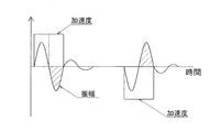
- the link hub on the tip side vibrates in a direction that cancels acceleration after about half a cycle of the resonance frequency, if the deceleration time of the actuator is set near one cycle of the resonance frequency of the link actuator, When performing step acceleration to accelerate, the vibration of the link hub on the tip side after step acceleration is reduced. As a result, the vibration of the link hub on the distal end side after the operation of the actuator is reduced even at high speed operation, and the link hub on the distal end side can be positioned at high speed and with high accuracy.
- the positioning operation has the same meaning as the posture changing operation because the position of the link hub on the distal end side with respect to the link hub on the proximal end side changes at the same time.
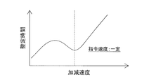
- the deceleration time may be set within a range of 0.8 to 1.2 periods of the resonance frequency of the link actuator.
- the maximum amplitude of the sine wave is 0.75 period and 1.25 period. Therefore, in order to avoid a state of oscillating with the maximum amplitude after completion of deceleration, the deceleration time is set to 0.8 to 1.2 periods of the resonance frequency of the link actuator.
- the synchronization control and the attitude control may be performed by setting the acceleration time of all the actuators in the vicinity of one cycle of the resonance frequency of the link actuator.
- the link hub on the tip side vibrates in a direction that cancels acceleration after about half a cycle of the resonance frequency. Therefore, if the acceleration time of the actuator is set near one cycle of the resonance frequency of the link actuator, the link hub accelerates periodically.
- step acceleration vibration of the link hub on the tip side after step acceleration is reduced.
- the vibration of the link hub on the distal end side that occurs at the time of starting is reduced, and the link hub on the distal end side can be positioned at high speed and with high accuracy.
- the acceleration time may be set within a range of 0.8 to 1.2 periods of the resonance frequency of the link actuator.
- the maximum amplitude of the sine wave is 0.75 period and 1.25 period. Therefore, in order to avoid a state of oscillating at the maximum amplitude after completion of acceleration, the acceleration time is set to 0.8 to 1.2 periods of the resonance frequency of the link actuator.
- the posture control determines a command operation amount for each actuator from a target posture of the link hub on the tip side, and the synchronous control is a ratio of command operation amounts of all the actuators.
- the operating speed of each actuator may be set.
- the command operation amount of each actuator is different. Therefore, if the command speed is set according to the ratio, synchronous control can be easily performed.
- the command operation amount of each actuator can be obtained as follows. That is, the rotation angle of the end link member on the base end side with respect to the link hub on the base end side is ⁇ n, the connecting end shaft of the central link member rotatably connected to the end link member on the base end side, The angle formed by the connecting end shaft of the central link member rotatably connected to the end link member on the front end side is ⁇ , and the end link members on the base end side with respect to the reference end link member on the base end side Is the vertical angle at which the central axis of the link hub on the distal end side is inclined with respect to the central axis of the link hub on the proximal end side, and ⁇ is the central axis of the link hub on the proximal end side.
- the command operation amount of each actuator may be obtained as follows. That is, the rotation angle of the end link member on the base end side with respect to the link hub on the base end side is ⁇ n, the connecting end shaft of the central link member rotatably connected to the end link member on the base end side, The angle formed by the connecting end shaft of the central link member rotatably connected to the end link member on the front end side is ⁇ , and the end link members on the base end side with respect to the reference end link member on the base end side Is the vertical angle at which the central axis of the link hub on the distal end side is inclined with respect to the central axis of the link hub on the proximal end side, and ⁇ is the central axis of the link hub on the proximal end side.
- the above formula was used by preliminarily tabulating the relationship between the attitude of the distal-side link hub with respect to the proximal-side link hub and the rotation angle of each proximal-side end link member.
- the calculation time of the command operation amount can be shortened, and the posture control can be performed at higher speed.
- the operating speed of each actuator is Vn
- the base speed is V
- the current rotation angle of the end link member on the base end side is ⁇ n
- the end link member on the base end side in the posture control is When the target rotation angle is ⁇ n ′, You may calculate using the formula represented by these.
- the base speed V becomes the combined speed of the operating speed Vn of each actuator, and can be controlled so that the moving speed of the link hub on the base end side is almost constant in any situation.
- each actuator The operating speed of each actuator is Vn, the maximum speed is Vmax, the current rotation angle of the end link member on the base end side is ⁇ n, and the end link on the base end side in the posture control
- Vn Vmax ( ⁇ n′ ⁇ n) / ⁇ max
- all of the three or more sets of link mechanisms are provided with actuators for arbitrarily changing the attitude of the distal end side link hub with respect to the proximal end side link hub, and each of these actuators is subjected to redundant control. You may control. By performing redundancy control, the driving balance of each actuator can be improved regardless of the posture of the link hub on the distal end side, and the settling time of the link hub on the distal end side can be shortened. Furthermore, since it is possible to control the backlash of the actuator and its peripheral part and the backlash of the link mechanism, the vibration of the link hub on the tip side due to the backlash after stopping the actuator can be suppressed, and the settling time is shortened.
- a resonance frequency detection sensor for detecting the resonance frequency of the link actuator is installed in the link hub on the distal end side, and the resonance frequency is calculated from the signal by a resonance frequency measuring device, and the calculation is performed.
- the set values of the acceleration time and deceleration time of the actuator may be updated from the result. Even if the tip load or the rigidity of the link actuator changes, the acceleration time and deceleration time can be easily updated, so the vibration of the link hub on the tip side after stopping the actuator is reduced in any situation and at high speed. High-precision positioning operation is possible.
- an acceleration pickup as the resonance frequency detection sensor and an FFT analyzer as the resonance frequency measuring device.
- the acceleration pickup is small and easy to install, and the FFT analyzer can easily set the acceleration time and deceleration time.
- the control device for the link actuator is a controller for controlling the operation of the actuator in the link actuator, and controls so that all of the actuators start to operate at the same time and complete the operation at the same time.
- synchronous control the operation for each actuator is controlled to perform posture control for changing the link hub on the distal end side to an arbitrary posture, and the deceleration time of all the actuators is set to the resonance frequency of the link actuator.
- Synchronous / attitude control means for performing the synchronous control and attitude control is set near one cycle.
- the link hub on the tip side vibrates in a direction that cancels acceleration after about half a cycle of the resonance frequency, if the deceleration time of the actuator is set near one cycle of the resonance frequency of the link actuator, When performing step acceleration to accelerate, the vibration of the link hub on the tip side after step acceleration is reduced. As a result, the vibration of the link hub on the distal end side after the operation of the actuator is reduced even at high speed operation, and the link hub on the distal end side can be positioned at high speed and with high accuracy.
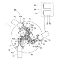
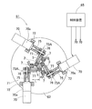
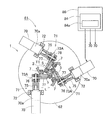
- the link actuating device 51 includes a parallel link mechanism 1, a plurality of (the same number of link mechanisms 4 as described later) actuators 53 that actuate the parallel link mechanism 1, and a control device 54 that controls these actuators 53. And an operation device 55 for inputting an operation command to the control device 54.
- the control device 54 and the operation device 55 are provided in the controller 56, but the control device 54 may be provided separately from the controller 56.
- the parallel link mechanism 1 is installed in a suspended state on the base member 52.
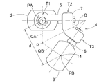
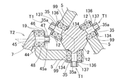
- FIGS. 2 and 3 are front views showing different states of the parallel link mechanism 1.
- the parallel link mechanism 1 includes three sets of link mechanisms 4 in which the link hub 3 on the distal end side is linked to the link hub 2 on the proximal end side. It is connected so that the posture can be changed via. 2 and 3, only one set of link mechanisms 4 is shown.
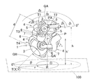
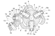
- FIG. 4 is a perspective view showing the parallel link mechanism 1 three-dimensionally.
- Each link mechanism 4 includes a base end side end link member 5, a front end side end link member 6, and a central link member 7, and forms a three-joint link mechanism including four rotating pairs.
- a rotating pair and its peripheral part are shown as rotating pairs T1 to T4.
- the end link members 5 and 6 on the base end side and the front end side are L-shaped, and the base ends are rotatably connected to the link hub 2 on the base end side and the link hub 3 on the front end side, respectively.
- the central link member 7 is rotatably connected to the distal ends of the end link members 5 and 6 on the proximal end side and the distal end side at both ends.
- the end link members 5 and 6 on the base end side and the front end side have a spherical link structure, and the spherical link centers PA and PB (FIGS. 2 and 3) in the three sets of link mechanisms 4 coincide with each other, and the spherical surfaces thereof The distance d from the link centers PA and PB is the same.
- the central axis of each rotational pair of the end link members 5 and 6 and the central link member 7 may have a certain crossing angle ⁇ (FIG. 4) or may be parallel.
- each link member 5, 6, and 7 is expressed by a straight line, that is, each rotation pair T1 to T4 and a straight line connecting these rotation pairs T1 to T4.
- a model says that the base end side part and front end side part with respect to the center part of the center link member 7 are the shapes which comprise a symmetry.
- FIG. 5 is a diagram representing a set of link mechanisms 4 in a straight line.
- the link mechanism 4 of this embodiment is a rotationally symmetric type, and includes a link hub 2 on the proximal end side and an end link member 5 on the proximal end side, a link hub 3 on the distal end side, and an end on the distal end side.
- the positional relationship with the partial link member 6 is a position configuration that is rotationally symmetric with respect to the center line C of the central link member 7.
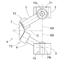
- 2 shows a state where the central axis QA of the link hub 2 on the proximal end side and the central axis QB of the link hub 3 on the distal end side are on the same line
- FIG. 3 shows the central axis of the link hub 2 on the proximal end side.
- the link hub 2 on the proximal end side, the link hub 3 on the distal end side, and the three link mechanisms 4 allow the distal link hub 3 to move in the two orthogonal directions relative to the link hub 2 on the proximal end side.
- a degree mechanism is configured. In other words, it is a mechanism that can freely change the posture of the link hub 3 on the distal end side with respect to the link hub 2 on the proximal end side with two degrees of freedom of rotation.
- This two-degree-of-freedom mechanism is based on the intersection P between the center axis QA of the link hub 2 on the proximal end side, the center axis QB of the link hub 3 on the distal end side, and the center line C of the center link member 7.
- the link hub 3 on the distal end side changes the posture with respect to the link hub 2.
- This two-degree-of-freedom mechanism is compact but can widen the movable range of the link hub 3 on the distal end side relative to the link hub 2 on the proximal end side.
- the maximum value (maximum folding angle) of the folding angle ⁇ between the central axis QA of the proximal side link hub 2 and the central axis QB of the distal side link hub 3 is about ⁇ 90 °. be able to.
- the turning angle ⁇ of the distal end side link hub 3 relative to the proximal end side link hub 2 can be set in a range of 0 ° to 360 °.
- the bending angle ⁇ is a vertical angle in which the central axis QB of the distal end side link hub 3 is inclined with respect to the central axis QA of the proximal end side link hub 2, and the turning angle ⁇ is the proximal end side link hub.
- This is a horizontal angle at which the central axis QB of the link hub 3 on the distal end side is inclined with respect to the central axis QA of the second axis.
- the angular positional relationship with the base link members 5 and 6 is the same between the base end side and the tip end side, the base end side link hub 2 and the base end side end link member 5 from the geometric symmetry,
- the distal end side link hub 3 and the distal end side end link member 6 move in the same manner.
- the rotation hubs are provided coaxially with the center axes QA and QB on the link hubs 2 and 3 on the proximal end side and the distal end side, and rotation is transmitted from the proximal end side to the distal end side, the proximal end side and the distal end side are It becomes a constant velocity universal joint that rotates at the same speed at the same rotation angle.
- the plane of symmetry of the central link member 7 when rotating at a constant speed is referred to as a uniform speed bisector.
- the plurality of link mechanisms 4 can move without contradiction.
- the central link member 7 is limited to movement only on the equal speed bisector. Thereby, even if the proximal end side and the distal end side have arbitrary operating angles, the proximal end side and the distal end side rotate at a constant speed.
- the proximal-side link hub 2 and the distal-side link hub 3 have a donut with a through hole 10 formed in the center thereof along the axial direction and the outer shape being spherical. It has a shape.
- the center of the through hole 10 coincides with the central axes QA and QB of the link hubs 2 and 3 as shown in FIG.
- the proximal end link member 5 and the distal end link member 6 rotate at equal intervals in the circumferential direction of the outer peripheral surface of the proximal link hub 2 and distal link hub 3 respectively. It is connected freely.
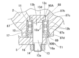
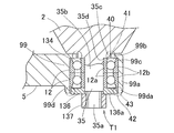
- FIG. 6 shows a rotation pair T1 of the base end side link hub 2 and the base end side end link member 5, and a portion showing the base end side end link member 5 and the rotation link portion T2 of the central link member 7. It is sectional drawing.
- radial communication holes 11 that communicate the axial through hole 10 and the outer peripheral side are formed at three locations in the circumferential direction, and two bearings provided in each communication hole 11. 12, shaft members 13 are rotatably supported. The outer end of the shaft member 13 protrudes from the link hub 2 on the base end side, and the end link member 5 on the base end side is coupled to the protruding screw portion 13 a and is fastened and fixed by a nut 14.
- the bearing 12 is a rolling bearing such as a deep groove ball bearing, for example, and an outer ring (not shown) is fitted to the inner circumference of the communication hole 11, and an inner ring (not shown) is the outer circumference of the shaft member 13. Is fitted.
- the outer ring is retained by a retaining ring 15.
- a spacer 16 is interposed between the inner ring and the end link member 5 on the base end side, and the tightening force of the nut 14 is transmitted to the inner ring via the end link member 5 and the spacer 16 on the base end side.
- a predetermined preload is applied to the bearing 12.
- two bearings 19 are provided in the communication holes 18 formed at both ends of the center link member 7, and the base end is provided by these bearings 19.
- a shaft portion 20 at the tip of the end link member 5 on the side is rotatably supported.
- the bearing 19 is fastened and fixed by a nut 22 via a spacer 21.
- the bearing 19 is a rolling bearing such as a deep groove ball bearing, for example, and an outer ring (not shown) is fitted to the inner circumference of the communication hole 18, and an inner ring (not shown) is the outer circumference of the shaft portion 20. Is fitted.
- the outer ring is retained by a retaining ring 23. A tightening force of the nut 22 screwed to the tip screw portion 20a of the shaft portion 20 is transmitted to the inner ring through the spacer 21 to apply a predetermined preload to the bearing 19.
- the radial gap and the thrust gap can be eliminated, and rattling of the rotating pair can be suppressed.
- the rotational phase difference between the link hub 3 side on the second side and the distal end side is eliminated, so that the constant velocity can be maintained and the occurrence of vibration and noise can be suppressed.
- the bearing clearance between the bearings 12 and 19 to be a negative clearance, backlash generated between input and output can be reduced.
- the base end side link hub 2 and the front end side link hub 2 are not enlarged without increasing the overall shape of the parallel link mechanism 1.
- the outer shape of the link hub 3 can be enlarged. Therefore, it is easy to secure a mounting space for mounting the proximal-side link hub 2 and the distal-side link hub 3 to other members.
- the parallel link mechanism 1 is in a state in which the base end side link hub 2 is fixed to the lower surface of the base member 52 and the front end side link hub 3 is suspended.
- the same number of actuators 53 that is, three actuators 53, which are rotary actuators, are installed.
- the output shaft 53a of the actuator 53 protrudes downward through the base member 52, and is a fan-shaped cap attached to the bevel gear 57 attached to the output shaft 53a and the shaft member 13 (FIG. 6) of the link hub 2 on the proximal end side.
- the gear 58 is meshed.
- the bevel gear 57 and the bevel gear 58 constitute a gear-type reduction unit 73.
- each actuator 53 When the actuator 53 is rotated, the rotation is transmitted to the shaft member 13 through a pair of bevel gears 57 and 58, and the angle of the end link member 5 on the base end side with respect to the link hub 2 on the base end side changes.
- the attitude of the link hub 3 on the front end side with respect to the link hub 2 on the base end side ( Hereinafter, “tip posture” is determined.
- the operation of each actuator 53 is controlled by the control device 54 based on an operation command from the operation device 55.
- the operating device 55 includes posture designation means 55a, posture acquisition means 55b, and posture information provision means 55c.
- the posture designation means 55a is a means for manually designating a target tip posture, and designates the tip posture at a coordinate position on a two-dimensional orthogonal coordinate system.
- the orthogonal coordinate system is an XY in which the origin O is defined at an arbitrary position on the extension axis QA ′, which is orthogonal to the extension axis QA ′ of the center axis QA of the link hub 2 on the base end side.
- An orthogonal coordinate system 100 is shown.
- the target tip posture is represented by target coordinates T (X, Y) which are the coordinates of the point where the center axis QB of the link hub 3 on the tip side intersects the XY orthogonal coordinate system 100.
- T target coordinates
- the posture acquisition unit 55b converts the tip posture represented by the coordinate position of the XY orthogonal coordinate system 100 designated by the posture designation unit 55a into the tip posture represented by the bending angle ⁇ and the turning angle ⁇ of the angle coordinate system. Means. The principle of conversion will be described.
- h ′ is the height from the intersection point P, which is the rotation center of the posture change of the link hub 3 on the distal end side, to the target coordinate T, as shown in FIG.
- h ′ is obtained from Equation 3.
- h ′ obtained by Equation 3 the distance r ′ between the origin O and the target coordinate T in the angular coordinate system is obtained.
- d and h are fixed values determined by the dimensions of the parallel link mechanism 1 and the dimensions of the device on which the link actuating device 51 is mounted.
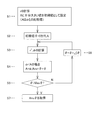
- the distance r between the origin O and the target coordinate T in the XY coordinate system 100 thus obtained is compared with the distance r ′ between the origin O and the target coordinate T in the angle coordinate system, and the difference is minimum.
- the convergence calculation by the least square method is performed in the order shown in the flowchart of FIG. First, in S1, the calculation of the distance r by Equation 1 and the setting of the initial value of the comparison value A are performed.
- the comparison value A is a comparison value with dr, and a value sufficiently larger than the value of dr calculated in the search process is set as an initial value.
- the target tip posture is defined by the bending angle ⁇ obtained by the operation shown in the flowchart of FIG. 7 and the turning angle ⁇ obtained by the calculation of Expression 5 or 6.
- the number of computations can be reduced by performing the convergence calculation by the least square method to obtain the bending angle ⁇ by sequentially searching from the vicinity of the current coordinate position as a reference.
- the posture information giving unit 55c gives the control device 54 the information on the tip posture acquired by the posture acquiring unit 55b, that is, the folding angle ⁇ and the turning angle ⁇ .
- the control device 54 is of a numerical control type by a computer, and the target rotation of the end link member 5 on the base end side is determined in accordance with the tip posture information given from the posture information giving means 55c of the operation device 55.
- the angle ⁇ n (FIG. 4) is obtained, and each actuator 53 is feedback-controlled so that the actual rotation angle ⁇ n detected by the posture detection means 59 (FIG. 1) becomes the target rotation angle ⁇ n.
- the rotation angle ⁇ n is obtained, for example, by inversely transforming the following equation (7).
- the inverse transformation is a transformation for calculating the rotation angle ⁇ n from the bending angle ⁇ and the turning angle ⁇ .
- the bending angle ⁇ , the turning angle ⁇ , and the rotation angle ⁇ n are mutually related, and the other value can be derived from one value.
- ⁇ (FIG.
- ⁇ n ( ⁇ 1 , ⁇ 2 , ⁇ 3 in FIG. 4) is a circumferential separation angle of each end-side end link member 5 with respect to the reference end-side end link member 5.
- the rotation angle ⁇ n may be obtained by inversely transforming Equation 7 for each command, a table showing the relationship between the tip position / posture and the rotation angle ⁇ n as shown in Table 1 may be created in advance.
- a table if there is a command to change the tip posture, the target rotation angle ⁇ n can be obtained immediately using the table. For this reason, the actuator 53 can be controlled at a higher speed.
- a table storage area can be saved by registering a table indicating the relationship between the tip position and orientation and the rotation angle ⁇ n at the time of pattern registration as shown in Table 2. .
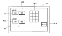
- FIG. 8 shows an example of the operation unit of the operation device 55.
- This operation unit is a method of designating a coordinate position by numerical input, and present value display units 101 and 102 for displaying the X coordinate value and Y coordinate value of the current coordinate position, respectively, and the target X coordinate value and Y coordinate.
- Target value display sections 103 and 104 for displaying values
- a numerical value input button 105 including 10 keys for inputting the target X coordinate value and Y coordinate value to the target value display sections 103 and 104
- an operation execution button 106 Is provided.
- the designation of the coordinate position on the XY Cartesian coordinate system is a method of numerically inputting absolute coordinates with respect to a predetermined reference point (for example, the origin O), and a method of numerically inputting a difference from the current coordinate position to the target coordinate position. Any of these may be used.
- the values are displayed on the target value display sections 103 and 104.
- the target X- and Y-coordinate values, the distance from the link hub 3 on the distal end side to the work surface of the work piece (not shown), the dimensions of each part of the parallel link mechanism 1, and the like The bending angle ⁇ and the turning angle ⁇ of the tip posture are calculated. Further, the operation amount of each actuator 53 is calculated from the tip posture.
- the operation execution button 106 is pressed, each actuator 53 is driven, and the tip posture is changed so that the input X coordinate value and Y coordinate value are obtained.
- the link actuator 51 (FIG. 1) is provided even when the coordinate position of the work piece is handled by the rectangular coordinate system. Intuitive operation.
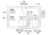
- FIG. 9 shows different examples of the operation unit of the operation device 55.
- This operation unit is a method of designating a coordinate position by an operation amount, and is a current value display unit 101 and 102 for displaying the X coordinate value and the Y coordinate value of the current coordinate position, respectively, and a push operation for changing the tip posture.
- Buttons 107-110 When the push operation button 107 is pressed, the posture is changed to the side where the X coordinate value is increased. When the push operation button 108 is pressed, the posture is changed to the side where the X coordinate value is decreased. When the push operation button 109 is pressed, the Y coordinate value is increased. The posture is changed to the side where the Y coordinate value is decreased when the push operation button 110 is pressed.
- each of the push operation buttons 107 to 110 includes a low-speed button 107a, 108a, 109a, 110a in which the posture change is performed at a low speed, and a high-speed button 107b, 108b, 109b, 110b in which the posture change is performed at a high speed. Therefore, the posture can be changed in two stages, low speed and high speed.
- the X coordinate value and the Y coordinate value are sequentially changed by the operation of the push operation buttons 107 to 110, and the target folding angle ⁇ and turning angle ⁇ are calculated each time, and the actuator 53 corresponding thereto is calculated. It is a system that determines the amount of movement. That is, the tip posture continues to change only while the push operation buttons 107 to 110 are being pressed. For this reason, the relationship between the operation and the coordinate position is easy to understand intuitively.
- the control device 54 used in combination with the operation device 55 converts the tip posture information given from the posture designation means 55c of the operation device 55 into an operation amount of the actuator 53 by a predetermined conversion formula, and the operation thereof.
- the actuator 53 is controlled to be operated by the amount.
- the control device 54 uses the equation 7 to calculate the bending angle ⁇ and the turning angle ⁇ .
- the rotation angle ⁇ n of the end link member 5 on each proximal end side is obtained by inverse conversion, and the operation amount Rn of each actuator 53 is calculated by calculating Expression 8 using the obtained rotation angle ⁇ n. .
- k is a coefficient determined by a reduction ratio of a reduction gear (not shown) attached to the actuator 53. In this way, when the tip posture information is converted into the operation amount of the actuator 53 by the conversion formula, the actuator 53 can be easily controlled.
- the amount of movement of the actuator 53 and the changing speed of the tip posture can be changed stepwise, and the amount of movement of the actuator 53 and the changing speed of the tip posture per operation of the push buttons 107 to 110 can be arbitrarily changed. You may do it. Further, as in this example, the operation may be performed with one operation means such as a joystick, instead of operating with the plurality of push operation buttons 107 to 110.
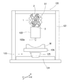
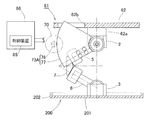
- FIG. 10 shows a working device 120 provided with the link actuating device 51.
- the base link 52 is fixed to a base member 52 that forms the ceiling of the work chamber 121, and the parallel link mechanism 1 is installed in a suspended state.
- An end effector 122 is mounted on the link hub 3 on the distal end side.
- the end effector 122 is, for example, a painting machine.
- the moving mechanism 123 that moves the work W in the XY-axis direction is installed.
- the moving mechanism 123 includes an X-axis rail 124 that is long and fixed along the X-axis direction that is fixedly installed on the floor surface, and a Y-axis rail 125 that can move forward and backward along the X-axis rail 124 and that is long along the Y-axis direction.
- the Y-axis rail 125 and the work table 126 are moved in the X-axis direction and the Y-axis direction, respectively, by driving a drive source (not shown).
- the end effector 122 When the end effector 122 is a coating machine, the work place 126 by the moving mechanism 123 is moved back and forth in the X-axis and Y-axis directions, so that the coating location of the work W is positioned at the tip of the paint spraying port 122a of the coating machine. . Further, by changing the tip posture of the link actuating device 51 and changing the direction of the end effector 122, the paint spraying port 122a is always adjusted to face the painted surface of the work W.
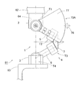
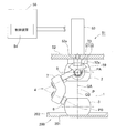
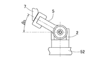
- the link actuating device 61 is provided with a parallel link mechanism 1 suspended from a base member 62. That is, in the parallel link mechanism 1, the base end side link hub 2 is fixed to the base member 62 via the base member 62, and the front end mounting member 63 for mounting various instruments etc. is mounted on the front end side link hub 3. ing.
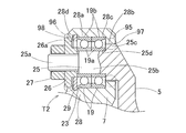
- the parallel link mechanism 1 includes a bearing 31 that rotatably supports the end link members 5 and 6 with respect to the link hub 2 on the proximal end side and the link hub 3 on the distal end side.
- Outer ring rotation type The rotation pair T1 of the base end side link hub 2 and the base end side end link member 5 will be described as an example.
- Shaft portions 32 are formed at three locations in the circumferential direction of the base end side link hub 2,
- the inner rings (not shown) of the two bearings 31 are fitted on the outer periphery of the shaft portion 32, and the outer rings (not shown) of the bearing 31 are arranged on the inner periphery of the communication hole 33 formed in the end link member 5 on the proximal end side. Are fitted).
- the bearing 31 is a ball bearing such as a deep groove ball bearing or an angular ball bearing, for example, and is fixed in a state where a predetermined preload is applied by tightening with a nut 34.
- the rotation pair T4 of the link hub 3 on the distal end side and the end link member 6 on the distal end side has the same structure as described above.
- the bearing 36 provided in the rotation pair T2 of the end link member 5 and the central link member 7 on the base end side is the inner periphery of the communication hole 37 formed at the tip of the end link member 5 on the base end side.
- An outer ring (not shown) is fitted to the inner ring (not shown), and an inner ring (not shown) is fitted to the outer periphery of the shaft portion 38 integral with the central link member 7.
- the bearing 36 is, for example, a ball bearing such as a deep groove ball bearing or an angular ball bearing, and is fixed in a state where a predetermined preload is applied by tightening with a nut 39.
- the rotating pair T3 of the end link member 6 and the center link member 7 on the front end side has the same structure as described above.
- All three sets of the link mechanisms 4 of the parallel link mechanism 1 have an actuator 70 for arbitrarily changing the distal end position and posture by rotating the end link member 5 on the proximal end side, and the operation amount of the actuator 70 as the proximal end.
- a speed reduction mechanism 71 that decelerates and transmits to the side end link member 5 is provided.
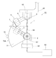
- the actuator 70 is a rotary actuator, more specifically a servo motor with a speed reducer 70 a, and is fixed to the base member 62 by a motor fixing member 72.
- the speed reducing mechanism 71 includes a speed reducer 70a of the actuator 70 and a gear type speed reducing portion 73A.
- the gear-type speed reducing portion 73A is connected to the output shaft 70b of the actuator 70 through a coupling 75 so as to be able to transmit rotation, and is fixed to the end link member 5 on the base end side and is connected to the small gear 76. It is comprised with the large gear 77 which meshes
- the small gear 76 and the large gear 77 are spur gears, and the large gear 77 is a sector gear in which teeth are formed only on a sector-shaped peripheral surface.
- the large gear 77 has a larger pitch circle radius than the small gear 76, and the rotation of the output shaft 70 b of the actuator 70 is transferred to the end link member 5 on the base end side, and the link hub 2 on the base end side and the end link on the base end side.
- the rotation is transmitted to the member 5 while being decelerated to the rotation around the rotation axis O1 of the rotation pair T1.
- the reduction ratio is 10 or more.
- the pitch circle radius of the large gear 77 is set to 1/2 or more of the arm length L of the end link member 5 on the base end side.
- the arm length L is determined from the axial center point P1 of the central axis O1 of the rotation pair T1 between the proximal-side link hub 2 and the proximal-side end link member 5 to the proximal-side end link member 5.
- the center point P2 in the axial direction of the central axis O2 of the rotational pair portion T2 between the central link member 7 and the central link member 7 is perpendicular to the rotational pair axis O1 of the proximal end side link hub 2 and the proximal end side end link member 5. This is the distance to the point P3 projected on the plane passing through the direction center point P1.
- the pitch circle radius of the large gear 77 is not less than the arm length L. Therefore, it is advantageous to obtain a high reduction ratio.
- the small gear 76 has shaft portions 76 b protruding on both sides of a tooth portion 76 a meshing with the large gear 77, and both shaft portions 76 b are two bearings provided on a rotation support member 79 installed on the base member 62. 80 are rotatably supported by each.
- the bearing 80 is a ball bearing such as a deep groove ball bearing or an angular ball bearing. In addition to arranging ball bearings in double rows as in the illustrated example, roller bearings or sliding bearings may be used.
- a shim (not shown) is provided between the outer rings (not shown) of the two bearings 80, and a preload is applied to the bearing 80 by tightening a nut 81 screwed into the shaft portion 76b.
- the outer ring of the bearing 80 is press-fitted into the rotation support member 79.
- the large gear 77 is a member separate from the end link member 5 on the base end side, and is detachably attached to the end link member 5 on the base end side by a coupler 82 such as a bolt. ing.
- the large gear 77 may be integrated with the end link member 5 on the base end side.
- the rotation axis O3 of the actuator 70 and the rotation axis O4 of the small gear 76 are located on the same axis. These rotation axes O3 and O4 are parallel to the rotation pair axis O1 of the base end side link hub 2 and the base end side end link member 5 and have the same height from the base member 62.
- the link actuating device 61 also includes a controller 84 that controls the actuator 70 and an operating device 85 that inputs an operation command to the controller 84 in the controller 86.
- the control device 84 and the operation device 85 have the same configuration as that of the above embodiment, and the same operation and effect as described above can be obtained.
- the operation device 85 includes posture designation means 55a, posture acquisition means 55b, and posture information provision means 55c as in the first embodiment, but these are not shown.
- This link actuating device 61 is provided with the actuator 70 and the speed reduction mechanism 71 in all of the three sets of link mechanisms 4, so that it is possible to control the backlash of the parallel link mechanism 1 and the speed reduction mechanism 71 to be reduced.
- the positioning accuracy of the link hub 3 on the side can be improved, and the link actuator 61 itself can be made highly rigid.
- the gear type reduction unit 73A of the reduction mechanism 71 is a combination of the small gear 76 and the large gear 77, and a high reduction ratio of 10 or more can be obtained. If the reduction ratio is high, the positioning resolution of the encoder or the like is increased, so that the positioning resolution of the link hub 3 on the distal end side is improved. Also, a low output actuator 70 can be used. In this embodiment, the actuator 70 with the reduction gear 70a is used. However, if the reduction ratio of the gear-type reduction gear 73A is high, the actuator 70 without the reduction gear can be used, and the actuator 70 can be downsized. it can.
- the pitch circle radius of the large gear 77 By setting the pitch circle radius of the large gear 77 to 1 ⁇ 2 or more of the arm length L of the end link member 5 on the base end side, the bending moment of the end link member 5 on the base end side due to the tip load is reduced. . Therefore, it is not necessary to increase the rigidity of the entire link operating device 61 more than necessary, and the weight of the end link member 5 on the base end side can be reduced.
- the end link member 5 on the base end side can be changed from stainless steel (SUS) to aluminum. Further, since the pitch circle radius of the large gear 77 is relatively large, the surface pressure of the tooth portion of the large gear 77 is reduced, and the rigidity of the entire link actuator 61 is increased.
- the large gear 77 is connected to the rotating pair T1 of the base end side link hub 2 and the base end side end link member 5. Since the diameter is sufficiently larger than the outer diameter of the bearing 12 to be installed, a space is created between the tooth portion of the large gear 77 and the bearing 12, and the large gear 77 can be easily installed.
- the pitch circle radius of the large gear 77 is equal to or greater than the arm length L, so that the pitch circle radius of the large gear 77 is further increased, and the above-described operation and effect are more prominent.
- the small gear 76 can be installed on the outer diameter side of the link mechanism 4. As a result, an installation space for the small gear 76 can be easily secured, and the degree of freedom in design increases. Further, interference between the small gear 76 and other members is less likely to occur, and the movable range of the link actuator 61 is widened.
- the small gear 76 and the large gear 77 are spur gears, they are easy to manufacture and have high rotation transmission efficiency. Since the small gear 76 is supported by the bearings 80 on both sides in the axial direction, the support rigidity of the small gear 76 is high. As a result, the angle holding rigidity of the end link member 5 on the proximal end side due to the distal end load is increased, and the rigidity and positioning accuracy of the link actuator 61 are improved. Further, the rotational axis O3 of the actuator 70, the rotational axis O4 of the small gear 76, and the central axis O1 of the rotation pair T1 between the proximal-side link hub 2 and the proximal-side end link member 5 are coplanar. Since it is above, the overall balance is good and the assemblability is good.
- the large gear 77 is detachable with respect to the end link member 5 on the base end side, the reduction ratio of the gear type reduction portion 73A and the operation of the link hub 3 on the front end side with respect to the link hub 2 on the base end side. It becomes easy to change the specifications such as the range, and the mass productivity of the link actuating device 61 is improved. In other words, the same link actuating device 61 can be applied to various uses by simply changing the large gear 77. Also, maintainability is good. For example, when a failure occurs in the gear-type reduction unit 73A, it is possible to cope with the problem by replacing only the reduction unit 73A.
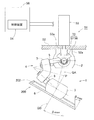
- a link actuator according to a third embodiment of the present invention will be described with reference to FIG. 14 and FIGS. 2 to 6 used in the first embodiment. Note that components that are the same as or correspond to those in the first embodiment are denoted by the same reference numerals, detailed description thereof is omitted, and different components are described. The difference from FIG. 1 showing the first embodiment is that this link actuating device 51 shown in FIG. 14 has a lubricant receiving member 200 that receives the lubricant falling from the parallel link mechanism 1 and the speed reduction portion 73. It is.
- the lubricant receiving member 200 is a dish-shaped member having a plate-like portion 201 and a protruding portion 202 protruding in one direction intersecting the surface of the plate-like portion 201 from the outer peripheral edge of the plate-like portion 201. And the central portion of the plate-like portion 201 is fixed to the distal end surface of the link hub 3 on the distal end side so that the protruding portion 202 faces the link hub 2 side on the proximal end side.
- the plate-like portion 201 is fixed to the link hub 3 on the distal end side by, for example, a bolt (not shown). Since the lubricant receiving member 200 has a simple configuration, it can be manufactured at low cost. Further, the lubricant receiving member 200 only needs to be provided at a position below the parallel link mechanism 1 and the speed reduction portion 73 and does not cover the entire parallel link mechanism 1, so that it is compact.
- the lubricant receiving member 200 Since the lubricant receiving member 200 has a plate shape having the protruding portion 202 at the outer peripheral edge of the plate-like portion 201, the received lubricant is received even when the lubricant receiving member 200 is inclined as the posture of the link hub 3 on the front end side is inclined. The agent does not sag from the outer peripheral edge of the plate-like portion 201. Therefore, the lubricant is prevented from being applied to the work piece (not shown) below.
- the lubricant receiving member 200 when the lubricant receiving member 200 is provided, it is possible to allow the lubricant to leak from the bearings 12 and 19 and the bevel gears 57 and 58, so that the seal structure of the bearings 12 and 19 and the bevel gears 57 and 58 is simplified.
- the lubricant receiving member 200 is provided in the link hub 3 on the distal end side, and the lubricant receiving member 200 moves in accordance with the change in the posture of the link hub 3. 4 is large, the lubricant receiving member 200 is not positioned directly below the bevel gears 57 and 58 and some of the bearings 12 and 19, but from the bevel gears 57 and 58 and the bearings 12 and 19. The falling lubricant may not be received by the lubricant receiving member 200. Therefore, it is effective to apply the configuration of this embodiment when the parallel link mechanism 1 is used at a folding angle of ⁇ 45 ° or less.
- the protruding portion 202 of the lubricant receiving member 200 has a shape in which the protruding end side is inclined toward the central axis QB of the link hub 3 on the distal end side. Then, even when the link hub 3 on the distal end side is greatly inclined, the lubricant can be prevented from dripping from the lubricant receiving member 200. In that case, it is desirable that the inclination angle of the protrusion 202 of the lubricant receiving member 200 be equal to or greater than the maximum value (maximum folding angle) ⁇ max of the bending angle ⁇ in the operation range of the parallel link mechanism 1.
- the protruding end side of the protruding portion 202 is always inclined in the center direction, so that it is possible to reliably prevent the lubricant from dripping over the protruding portion 202.
- the lubricant receiving member 200 is coupled to the projecting end of the projecting portion 202 and is parallel to the plate-shaped portion 201 and has a through hole in the inner peripheral portion. It is good also as a structure which has the upper board 203 in which 203a was formed.
- the upper plate 203 is oriented in a direction perpendicular to the ground even when the link hub 3 on the distal end side of the parallel link mechanism 1 is inclined by 90 ° (maximum folding angle). Therefore, even if a large amount of lubricant is accumulated in the lubricant receiving member 200, it is possible to reliably prevent the lubricant from dripping from the lubricant receiving member 200.
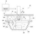
- FIG. 17 shows a sixth embodiment.
- the link actuating device 51 includes a ring-shaped fixing member 205 that is supported by a base member 52 via a support column 204 and is parallel to the base member 52 and has a through hole 205a formed in an inner peripheral portion.
- a protruding portion 206 that protrudes toward the base member 52 is formed at the outer peripheral end of the fixed member 205, and an inner peripheral standing edge 207 that protrudes toward the opposite side of the base member 52 is formed at the inner peripheral end.
- the lubricant receiving member 200 includes a plate-like portion 201 fixed to the link hub 3 on the front end side, and a stretchable connecting portion that covers the entire circumference between the plate-like portion 201 and the fixing member 205 and connects them together. 208.
- the connecting portion 208 is made of a sheet-like elastic material, and is installed with both ends fitted to the outer peripheral surface of the plate-like portion 201 and the outer peripheral surface of the inner peripheral standing edge portion 207 of the fixing member 205.
- the connecting portion 208 may be fixed to the outer peripheral surface of the plate-like portion 201 and the outer peripheral surface of the inner peripheral standing edge portion 207 of the fixing member 205 with a fixing band or the like.
- the portion of the parallel link mechanism 1 that is closer to the tip than the fixing member 205 is covered with the lubricant receiving member 200 so that the lubricant scattered from the parallel link mechanism 1 and the speed reducer 73 during operation is also lubricant. It can be received by the receiving member 200. Since the protrusion 206 is provided at the outer peripheral end of the fixing member 205, even if the lubricant falls on the fixing member 205, the lubricant does not fall outside the fixing member 205, and lubricates the work piece. It is possible to prevent the agent from being applied. Since the connecting portion 208 can be expanded and contracted, the connecting portion 208 of the lubricant receiving member 200 can be deformed accordingly even if the posture of the distal end side link hub 3 with respect to the proximal end side link hub 2 changes.
- the connecting portion 208 ⁇ / b> A of the lubricant receiving member 200 may have a bellows shape covering the entire periphery between the plate-like portion 201 and the fixing member 205.
- the connecting portion 208A is assembled to the plate-like portion 201 and the fixing member 205 in a compressed state smaller than the natural state where no external force acts.
- the connecting portion 208A of the lubricant receiving member 200 can be deformed accordingly.
- FIG. 19 shows an eighth embodiment.
- This link actuating device 51 is provided with a lubricant receiving member 210 that receives the lubricant that falls from the bevel gears 57 and 58 of the speed reducing portion 73.
- the lubricant receiving member 210 is a dish-like member having a plate-like portion 211 positioned directly below the speed reduction portion 73 and a protruding portion 212 protruding from the outer peripheral edge of the plate-like portion 211 to the base member 52 side. It is attached to the base member 52 with a bolt (not shown) or the like via an attachment portion 213 connected to a part of the protruding portion 212.
- the lubricant receiving member 210 is made of, for example, a sheet metal.
- the bearings 12 and 19 may be sealed bearings, or the bearing mounting portion may have a sealing function.
- FIG. 20 shows a rotating pair T1 of the link hub 2 on the base end side and the end link member 5 on the base end side.
- the two bearings 12 are angular contact ball bearings, and are arranged, for example, in a rear combination.
- the inner end portion of the shaft member 13 is a stepped portion 13c having a larger outer diameter than the portion 13b fitted to the inner periphery of the inner ring 12a of the bearing 12, and the stepped surface 13d of the stepped portion 13c is the inner ring of the inner bearing 12.
- the inner ring 12a is positioned in the axial direction by contacting the end surface of 12a.
- a spacer 16 is provided with both ends in contact with them. Therefore, by tightening the nut 14, the inner ring 12 a is pressed against the stepped surface 13 d via the end-side end link member 5 and the spacer 16, and the inner ring 12 a is tightened and fixed. Apply preload.
- the peripheral part of the communication hole 11 in the link hub 2 on the base end side is an annular inner surface forming part 87.
- the annular inner surface forming portion 87 is a part of the proximal side link hub 2, but the annular inner surface forming portion 87 may be separate from the proximal side link hub 2.
- the shaft member 13 that is the shaft portion is a separate member from the base end side end link member 5, but the shaft portion is provided integrally with the base end side end link member 5. May be.
- a part of the annular inner surface forming portion 87 is a portion fitted to the outer periphery of the outer ring 12b of the bearing 12, that is, a stepped portion 87b having a smaller inner diameter than the outer ring fitting portion 87a, and the stepped surface 87c of the stepped portion 87b is on the inner side.
- the outer ring 12b is positioned in the axial direction by contacting the end surface of the outer ring 12b of the bearing 12. Further, the outer ring 12 b of the outer bearing 12 is prevented from coming off by a retaining ring 17 attached to the annular inner surface forming portion 87.
- the outer peripheral surface of the stepped portion 13c of the shaft member 13 and the inner peripheral surface of the stepped portion 87b of the annular inner surface forming portion 87 are opposed to each other through a slight gap 90A.
- the stepped portion 13c of the shaft member 13 and the stepped portion 87b of the annular inner surface forming portion 87 can rotate with each other, but the seal structure 88 that restricts the entry and exit of the lubricant between the inside and the outside of the bearing 12 is provided.
- the seal structure 88 that restricts the entry and exit of the lubricant between the inside and the outside of the bearing 12 is provided.
- the narrower the gap 90A the higher the sealing effect.
- the outer portion of the spacer 16 in the axial direction is formed as a flange portion 16 a extending to the outer diameter side while avoiding the retaining ring 17, and an outer peripheral surface of the flange portion 16 a and an annular inner surface forming portion 87.
- the outer end portion 87d which is a portion, is opposed in a non-contact manner through a slight gap 90B.
- the collar structure 16a of the spacer 16 and the outer end portion 87d of the annular inner surface forming portion 87 can rotate with each other, and a seal structure 89 having the same sealing function as described above is constructed.
- the narrower the gap 90B the higher the sealing effect.
- a seal structure 88 is constructed by the shaft member 13 provided in the part link member 5 (6) and the annular inner surface forming part 87 provided in the link hub 2 (3) which is the other pair of components, and the other in the axial direction.
- a seal structure 89 is constructed by the spacer 16 fitted to the outer periphery of the shaft member 13 and the annular inner surface forming portion 87.
- the link hub 2 (3) and the end link member 5 (6) are parts constituting the parallel link mechanism 1.
- the spacer 16 is a component that is generally provided between the inner ring 12a and the nut 14 so that a uniform load is applied to the inner ring 12a when the inner ring 12a of the bearing 12 is fastened and fixed with the nut 14. is there.
- the seal structures 88 and 89 with only indispensable parts, it is not necessary to provide a seal made of another member, and the width dimension of the bearing 12 can be suppressed. Therefore, interference between the components of the link mechanism 4 hardly occurs and the work range is widened. Further, since the dimensions around the bearing 12 are reduced, the entire parallel link mechanism 1 can be reduced in weight and size.
- the seal structure 88 is formed by a gap 90 ⁇ / b> A between the outer peripheral surface of the stepped portion 13 c that is a part of the shaft member 13 and the inner peripheral surface of the stepped portion 87 b that is a part of the annular inner surface forming portion 87.
- the step portion 13c of the shaft member 13 is used for positioning the inner ring 12a
- the step portion 87b of the annular inner surface forming portion 87 is used for positioning the outer ring 12b. Since both the stepped portions 87c and 87b are at a distance close to each other, the seal structure 88 by the gap 90A can be easily constructed without installing another member.
- the seal structure 89 is constructed by a gap 90 ⁇ / b> B between the outer peripheral surface of the flange-shaped portion 16 a that is a part of the spacer 16 and the inner peripheral surface of the outer end portion 87 d that is a part of the annular inner surface forming portion 87.
- the spacer 16 is used for tightening and fixing the inner ring 12 a, and the outer end 87 d of the annular inner surface forming portion 87 is used for holding the retaining ring 17.
- FIG. 21 shows the rotating pair T2 of the end link member 5 and the center link member 7 on the base end side.
- the two bearings 19 are angular ball bearings, and are arranged, for example, in a rear combination.
- the base end portion of the shaft portion 25 is a stepped portion 25c having a larger outer diameter than the portion 25b fitted to the inner periphery of the inner ring 19a of the bearing 19, and the stepped surface 25d of the stepped portion 25c is the base end side bearing 19.
- the inner ring 19a is positioned in the axial direction by contacting the end face of the inner ring 19a. Further, the inner ring 19 a of the bearing 19 on the distal end side is in contact with the spacer 26. Therefore, by tightening the nut 27, the inner ring 19a is pressed against the stepped surface 25d through the spacer 26, and the inner ring 19a is fastened and fixed, and a preload is applied to the bearing 19.
- the peripheral portion of the communication hole 23 in the central link member 7 is an annular inner surface forming portion 28.
- the annular inner surface forming portion 28 is a part of the central link member 7, but the annular inner surface forming portion 28 may be separate from the central link member 7.
- the shaft portion 25 is provided integrally with the base end side end link member 5. However, the shaft portion 25 may be a separate member from the base end side end link member 5.
- a part of the annular inner surface forming portion 28 is a portion fitted to the outer periphery of the outer ring 19b of the bearing 19, that is, a step portion 28b having a smaller inner diameter than the outer ring fitting portion 28a, and the step surface 28c of the step portion 28b is a base end.
- the outer ring 19b is positioned in the axial direction by contacting the end surface of the outer ring 19b of the bearing 19 on the inner side. Further, the outer ring 19 b of the bearing 19 on the distal end side is prevented from coming off by a retaining ring 29 attached to the annular inner surface forming portion 28.
- the outer peripheral surface of the step portion 25 c of the shaft portion 25 and the inner peripheral surface of the step portion 28 b of the annular inner surface forming portion 28 are opposed to each other through a slight gap 97.
- the stepped portion 25c of the shaft portion 25 and the stepped portion 28b of the annular inner surface forming portion 28 can rotate with each other, but the seal structure 95 that restricts the entry and exit of the lubricant between the inside and the outside of the bearing 19 is provided.
- the seal structure 95 that restricts the entry and exit of the lubricant between the inside and the outside of the bearing 19 is provided.
- the narrower the gap 97 the higher the sealing effect.
- the axially distal end portion of the spacer 26 is formed as a flange-like portion 26a that extends to the outer diameter side while avoiding the retaining ring 29.
- the outer peripheral surface of the flange-like portion 26a and the annular inner surface forming portion 28 are formed.
- the tip part 28d, which is a part, is opposed in a non-contact manner through a slight gap 98.
- the collar structure 26a of the spacer 26 and the distal end portion 28d of the annular inner surface forming portion 28 can rotate with each other, and a seal structure 96 having the same sealing function as described above is constructed.
- the narrower the gap 98 the higher the sealing effect.
- a seal structure 95 is constructed by the shaft portion 25 provided in the member 5 (6) and the annular inner surface forming portion 28 provided in the central link member 7 which is the other pair component member, and on the other side in the axial direction,
- a seal structure 96 is constructed by the spacer 26 fitted to the outer periphery of the shaft portion 25 and the annular inner surface forming portion 28.
- the seal structures 95 and 96 with only indispensable parts, it is not necessary to provide a seal made of another member, and the width dimension of the bearing 19 can be suppressed. Therefore, interference between the components of the link mechanism 4 hardly occurs and the work range is widened. In addition, since the dimensions around the bearing 19 are reduced, the entire parallel link mechanism 1 can be reduced in weight and size.
- the seal structure 95 is formed by a gap 97 between the outer peripheral surface of the step portion 25 c that is a part of the shaft portion 25 and the inner peripheral surface of the step portion 28 b that is a part of the annular inner surface forming portion 28.
- the step portion 25c of the shaft portion 25 is used for positioning the inner ring 19a
- the step portion 28b of the annular inner surface forming portion 28 is used for positioning the outer ring 19b. Since both the step portions 25c and 28b are at a distance close to each other, the seal structure 95 by the gap 97 can be easily constructed without installing another member.
- the seal structure 96 is constructed by a gap 98 between the outer peripheral surface of the collar-shaped portion 26 a that is a part of the spacer 26 and the inner peripheral surface of the outer end portion 28 d that is a part of the annular inner surface forming portion 28.
- the spacer 26 is used for fastening and fixing the inner ring 19 a
- the outer end portion 28 d of the annular inner surface forming portion 28 is used for holding the retaining ring 29.
- the seal structure 96 with the gap 98 can be easily constructed.
- the ninth embodiment shown in FIG. 22 to FIG. 25 shows a link operating device in which the configuration of the parallel link mechanism is different from that of the above embodiment.
- this link actuating device 61 also has a horizontal base member 62 and a parallel link mechanism 1 installed downward on the base member 62 via a spacer 62a, like the link actuating device 51.
- a plurality of actuators 70 that operate the parallel link mechanism 1 a speed reduction unit 73 ⁇ / b> A that transmits the driving force of each actuator 70 to the parallel link mechanism 1, and a control device 65 that controls each actuator 70.
- the base member 62 is formed with an opening 62b into which a large gear 77, which will be described later, is fitted.
- the link actuating device 61 has a lubricant receiving member 200 that receives the lubricant that falls from the parallel link mechanism 1 and the speed reducing portion 73A.
- the lubricant receiving member 200 in the illustrated example is the same as that shown in FIG. 14, but may be the one shown in FIG. 15 or FIG.
- the parallel link mechanism 1 of the link actuating device 61 includes bearings 12 (FIG. 24) that rotatably support the end link members 5 and 6 with respect to the link hub 2 on the proximal end side and the link hub 3 on the distal end side.
- Outer ring rotation type Accordingly, the shape of each part is slightly different from that of the parallel link mechanism 1 of FIGS. 2 and 3, but the basic configuration is the same. Therefore, description of portions having basically the same configuration is omitted, and the same reference numerals are given to the drawings.
- FIG. 23 shows a state where the central axis QA of the link hub 2 on the proximal end side and the central axis QB of the link hub 3 on the distal end side are on the same line.
- the rotation pair T2 of the central link member 7 will be described as an example.
- the rotation pair T1 has shaft portions 35 formed at three locations in the circumferential direction of the link hub 2 on the proximal end side, and two bearings provided in parallel on the outer periphery of these shaft portions 35.
- An end link member 5 on the base end side is rotatably supported via 12.
- the two bearings 12 are provided in a communication hole 134 formed in the end link member 5 on the base end side, and are tightened by a nut 137 screwed to a distal end screw portion 35 a of the shaft portion 35 via a spacer 136. It is fixed.
- the rotating pair T2 has a structure in which two bearings 19 are provided in the communication hole 44 of the end link member 5 on the base end side, and the shaft portion 45 of the central link member 7 is rotatably supported by these bearings 19. is there.
- the bearing 19 is fastened and fixed by a nut 47 screwed to the tip screw portion 45 a of the shaft portion 45 via the spacer 46.
- the actuator 70 of the link actuating device 61 is a rotary actuator, more specifically, a servo motor with a speed reducer 70a. It is fixed to the base member 62 by a fixing member 72.
- the reduction part 73A is configured as a gear type reduction mechanism.
- the actuator 70 and the speed reducer 73A are provided in all of the three sets of link mechanisms 4 of the parallel link mechanism 1, but if provided in at least two of the three sets of link mechanisms 4, The operation of the parallel link mechanism 1 can be defined.
- the same lubricant receiving member 200 as that shown in FIG. 14 is used.
- the lubricant receiving member 100 receives the lubricant falling from the bearings 12 and 19 of the parallel link mechanism 1 and the large and small gears 77 and 76 of the speed reduction portion 73A and the bearing 80, and the work piece below (not shown) ) Can be prevented.
- the lubricant receiving member 100 one shown in FIG. 15 or FIG. 16 may be used.
- a lubricant receiving member (not shown) that receives only the lubricant that falls from the speed reduction portion 73A is provided, and the bearings 12 and 19 of the parallel link mechanism 1 are either bearings with a seal or have a sealing function on the bearing mounting portion. It is good also as the structure given.
- FIG. 26 shows a rotation pair T1 of the link hub 2 on the base end side and the end link 5 on the base end side.
- the two bearings 12 are angular contact ball bearings, and are arranged, for example, in a rear combination.
- the base end portion of the shaft portion 35 is a stepped portion 35c having a larger outer diameter than the portion 35b fitted to the inner periphery of the inner ring 12a of the bearing 12, and the stepped surface 35d of the stepped portion 35c is the base end side bearing 12.
- the inner ring 12a is positioned in the axial direction by contacting the end face of the inner ring 12a.
- the inner ring 12 a of the bearing 12 on the distal end side is in contact with the spacer 136. Therefore, by tightening the nut 137, the inner ring 12a is pressed against the stepped surface 35d via the spacer 136, and the inner ring 12a is fastened and fixed, and a preload is applied to the bearing 12.
- the peripheral part of the communication hole 134 in the end link member 5 on the base end side is an annular inner surface forming part 99.
- the annular inner surface forming portion 99 is a part of the proximal end side end link member 5, but the annular inner surface forming portion 99 may be separate from the proximal end side end link member 5. good.
- the shaft portion 35 is provided integrally with the base end side link hub 2. However, the shaft portion 35 may be a separate member from the base end side link hub 2.
- a part of the annular inner surface forming portion 99 is a portion fitted to the outer periphery of the outer ring 12b of the bearing 12, that is, a step portion 99b having an inner diameter smaller than that of the outer ring fitting portion 99a, and the step surface 99c of the step portion 99b is a base end.
- the outer ring 12b is positioned in the axial direction by contacting the end surface of the outer ring 12b of the bearing 12 on the side.
- the end link member 5 on the base end side has an annular collar portion 99d that protrudes from the side surface thereof and has a base end that is a part of the outer ring fitting portion 99a.
- the flange portion 99d is crimped to the inner diameter side in a state where the outer ring 12b is fitted, whereby the outer ring 12b is tightly fitted, or the base end of the distal end portion 99da which is a portion protruding from the outer ring 12b of the collar portion 99d. Is engaged with the end face of the outer ring 12b, so that the outer ring 12b is positioned in the axial direction between the stepped portion 99b and the caulking portion.
- the outer peripheral surface of the stepped portion 35 c of the shaft portion 35 and the inner peripheral surface of the stepped portion 99 b of the annular inner surface forming portion 99 are opposed to each other through a slight gap 40.
- the stepped portion 35c of the shaft portion 35 and the stepped portion 99b of the annular inner surface forming portion 99 can rotate with each other, but the seal structure 41 that regulates the entry and exit of the lubricant between the inside and the outside of the bearing 12 is provided.
- the seal structure 41 that regulates the entry and exit of the lubricant between the inside and the outside of the bearing 12 is provided.
- a front end portion of the spacer 136 in the axial direction is formed as a collar portion 136a extending to the outer diameter side while avoiding contact with the outer ring 12a. Is opposed to the inner peripheral surface of the tip end portion 99da through a slight gap 42 in a non-contact manner. Thereby, the collar structure 136a of the spacer 136 and the tip end portion 99da of the annular inner surface forming portion 99 can rotate with each other, and the seal structure 43 having the same sealing function as described above is constructed. The narrower the gap 42, the higher the sealing effect.
- FIG. 27 shows the rotating pair T2 of the end link member 5 and the center link member 7 on the proximal end side.
- the two bearings 19 are angular ball bearings, and are arranged, for example, in a rear combination.
- a base end portion of the shaft portion 45 is a stepped portion 45 c having a larger outer diameter than a portion 45 b fitted to the inner periphery of the inner ring 19 a of the bearing 19.
- the step 45c has two steps 45ca and 45cb, and the step surface 45d of the first step 45ca abuts against the end surface of the inner ring 19a of the bearing 19 on the base end side, thereby causing the inner ring 19a to move in the axial direction. Positioning.
- the second step 45cb may be a separate member.
- the second step 45cb may be a ring member, and its inner peripheral surface may be fitted and fixed to the outer peripheral surface of the first step 45ca.
- the inner ring 19 a of the bearing 19 on the distal end side is in contact with the spacer 46. Therefore, by tightening the nut 47, the inner ring 19a is pressed against the stepped surface 45d via the spacer 46, and the inner ring 19a is fastened and fixed, and a preload is applied to the bearing 19.
- a peripheral portion of the communication hole 44 in the end link member 5 on the base end side is an annular inner surface forming portion 48.
- the annular inner surface forming portion 48 is a part of the proximal end side end link member 5, but the annular inner surface forming portion 48 may be separate from the proximal end side end link member 5. good.
- the shaft portion 45 is provided integrally with the central link member 7, but the shaft portion 45 may be a separate member from the central link member 7.
- a part of the annular inner surface forming portion 48 is a portion fitted to the outer periphery of the outer ring 19b of the bearing 19, that is, a stepped portion 48b having an inner diameter smaller than that of the outer ring fitting portion 48a.
- the outer ring 19b is positioned in the axial direction by coming into contact with the end face of the outer ring 19b of the bearing 19.
- the end link member 5 on the base end side has an annular collar portion 48d that protrudes from the side surface thereof and has a base end that is a part of the outer ring fitting portion 48a.
- the outer ring 19b By caulking the collar portion 48d toward the inner diameter side with the outer ring 19b fitted, the outer ring 19b is tightly fitted, or the base end of the distal end portion 48da that is a portion protruding from the outer ring 19b of the collar portion 48d. Is engaged with the end face of the outer ring 19b, so that the outer ring 19b is positioned in the axial direction between the stepped portion 48b and the caulking portion.
- the outer peripheral surface of the stepped portion 45 c of the shaft portion 45 and the inner peripheral surface of the tip end portion 48 da of the annular inner surface forming portion 48 are opposed to each other through a slight gap 50.
- the stepped portion 45c of the shaft portion 45 and the tip portion 48da of the annular inner surface forming portion 48 can rotate with each other, but the seal structure 151 for restricting the entry and exit of the lubricant between the inside and the outside of the bearing 19 is provided.
- the narrower the gap 50 the higher the sealing effect.
- the outer peripheral surface of the spacer 46 and the inner peripheral surface of the stepped portion 48b of the annular inner surface forming portion 48 are opposed to each other with a slight gap 152 therebetween. Thereby, the spacer 46 and the stepped portion 48b of the annular inner surface forming portion 48 can rotate with each other, and a seal structure 153 having the same sealing function as described above is constructed. The narrower the gap 152, the higher the sealing effect.
- the rotation pair T1 of the base end side link hub 2 and the base end side end link member 5 and the rotation end portion T2 of the base end side end link member 5 and the central link member 7 have been described. Although the detailed description is omitted, the rotation pair T4 of the link hub 3 on the distal end side and the end link member 6 on the distal end side has the same structure as the rotation pair portion T1, and the end link member 6 on the distal end side and the center link
- the rotating pair portion T3 of the member 7 has the same configuration as the rotating pair portion T2.
- the link operating device 51 includes a parallel link mechanism 1, a base 64 that supports the parallel link mechanism 1, and a plurality (the same number as the link mechanism 4 described later) that operate the parallel link mechanism 1.
- An actuator 53 and a control device 54 for controlling the actuator 53 are provided.
- the control device 54 is provided in the controller 56, but the control device 54 may be provided separately from the controller 56.
- the base 64 is a vertically long member, and the base end side link hub 2 of the parallel link mechanism 1 is fixed to the upper surface thereof.
- a collar-shaped base member 52 is provided on the outer periphery of the upper portion of the base 64, and the actuator 53 is attached to the base member 52 in a suspended state.
- the number of actuators 53 is three, which is the same number as the link mechanism 4.
- the actuator 53 is a rotary actuator, and a bevel gear 57 attached to the output shaft of the actuator 53 and a fan-shaped bevel gear 58 attached to the shaft member 13 (FIG. 6) of the link hub 2 on the proximal end side mesh with each other.
- the link operating device 51 operates the parallel link mechanism 1 by operating the controller 56 to rotationally drive each actuator 53. Specifically, when the actuator 53 is driven to rotate, the rotation is transmitted to the shaft member 13 through a pair of bevel gears 57 and 58, and the angle of the end link member 5 on the base end side with respect to the link hub 2 on the base end side. Will change. As a result, the position and posture of the distal end side link hub 3 with respect to the proximal end side link hub 2 (hereinafter referred to as “front end position and posture”) are determined. Here, the angle of the end link member 5 on the base end side is changed using the bevel gears 57 and 58, but other mechanisms (for example, a spur gear or a worm mechanism) may be used.
- Rotational drive of the actuator 53 for operating the parallel link mechanism 1 is performed by automatic control by the control device 54 based on a command from a command operating device (not shown) provided in the controller 56.
- the control device 54 is of a numerical control type by a computer and has synchronization / attitude control means 54a.
- the synchronization / attitude control means 54a controls the operation of each of the three actuators 53 so that all the three actuators 53 start to operate at the same time and complete the operation at the same time. Attitude control to change 3 to an arbitrary attitude is performed.
- ⁇ Attitude control is performed as follows. First, the rotation angle ⁇ n (FIG. 29) of each base end side end link member 5 is obtained according to the commanded tip position and orientation.
- the rotation angle ⁇ n referred to here is the rotation angle (angle from the horizontal plane) of each proximal-side end link member 5 corresponding to the commanded tip position and orientation.
- each actuator 53 When the rotation angle ⁇ n ( ⁇ 1, ⁇ 2, ⁇ 3) is obtained, the control parameter is determined for each actuator 53 (53 1 , 53 2 , 53 3 ).
- the control parameter of each actuator 53 has a waveform as shown in FIG. 30, for example. That is, the vehicle accelerates from the start of rotation to t1 and maintains the command speed Vn (V1, V2, V3) from t1 to t2, and then decelerates and stops rotating at t3.
- the actuator 53 showing the area of the range indicated by hatching
- the operation amount of the actuator 53 that is, the rotation angle ⁇ 1 of the end link member 5 of the base end side.
- the other actuators 53 2 and 53 3 The same applies to the other actuators 53 2 and 53 3 .
- the respective actuators 53 start to operate simultaneously and complete the simultaneous operation, and the acceleration time and the deceleration time also correspond to each actuator 53 (53 1 , 53 2 , 53 3 ).
- the command speed Vn (V1, V2, V3) is a ratio of the difference between the current rotation angle ⁇ n ( ⁇ 1, ⁇ 2, ⁇ 3) and the command posture rotation angle ⁇ n ′ ( ⁇ 1 ′, ⁇ 2 ′, ⁇ 3 ′). If the base speed that serves as a reference for the command speed Vn is V, the command speed Vn is expressed by Equation 9. ... (Formula 9) In this case, the base speed V is a combined speed of the command speed Vn of each actuator 53, and can be controlled so that the moving speed of the link hub 5 on the base end side is almost constant in any situation.
- the command speed Vn is a relational expression expressed by Expression 10 when the maximum speed is Vmax and the maximum difference ( ⁇ n′ ⁇ n) between the current rotation angle ⁇ n and the rotation angle ⁇ n ′ of the command posture is ⁇ max.
- at least one actuator 53 can always be driven at the maximum speed, and the rotation speed of the link member 5 on the base end side can be controlled to be maximum.
- the base speed V and the maximum speed Vmax may be adjusted by the settling time of the link hub 3 on the distal end side.
- the settling time is the time from the completion of the operation of the actuator 53 until the distal end side link hub 3 completely stops.
- the acceleration from when the actuator 53 starts to rotate until it reaches the command speed Vn and the deceleration from the command speed Vn until it stops rotating are represented by the slope of the straight line in FIG. 30, and the acceleration time and the command speed Vn, In addition, the speed is determined by the deceleration time and the command speed Vn.
- Acceleration time and deceleration time (referred to as “acceleration / deceleration time”) of each actuator 53 is set near one cycle of the resonance frequency of the link actuator 1. Specifically, it is desirable to set within the range of 0.8 to 1.2 periods of the resonance frequency of the link actuator 1. The reason will be described below.
- the resonance frequency said here is a resonance frequency in the state which installed the mounted object in the link hub 3 of the front end side.
- FIG. 31 is a graph showing the relationship between the acceleration / deceleration and the settling time when the acceleration / deceleration time is constant and the acceleration / deceleration is changed by the base speed V (or command speed Vn).
- FIG. 32 is a graph showing the relationship between acceleration / deceleration and settling time when the base speed V (or command speed Vn) is constant and the acceleration / deceleration is changed by the acceleration / deceleration time.
- the settling time As shown in FIG. 31, as the acceleration / deceleration is smaller, the settling time is generally shorter. However, in FIG. 32, the settling time becomes shorter until a certain acceleration / deceleration, and then the settling time tends to be constant or longer. It is done.
- FIG. 33 the inflection point at which the tendency of settling time changes can be seen in the vicinity of one cycle of the resonance frequency of the link actuator 51.
- FIG. 34 shows the amplitude of vibration of the link hub 3 on the distal end side when performing step acceleration that accelerates every one period of the resonance frequency.
- the link hub 3 on the distal end side vibrates in a direction to cancel the acceleration after a half cycle, so that it is considered that the vibration of the link hub 3 on the distal end side after the step acceleration is reduced. Therefore, if the acceleration / deceleration time is set in the vicinity (0.8 to 1.2 cycles), the settling time can be shortened.
- the sine wave has the maximum amplitude in 0.75 period and 1.25 period. Therefore, in order to avoid a state of oscillating at the maximum amplitude after completion of acceleration or deceleration, the acceleration / deceleration time is set to 0.8 to 1.2 periods of the resonance frequency of the link actuator.
- the acceleration / deceleration time may be set within a range of 0.9 to 1.1 periods ( ⁇ 10%) of the resonance frequency of the link actuator 51. If the acceleration / deceleration time is set within the above range, the amplitude at the end of acceleration / deceleration becomes 1/2 or less with respect to the maximum amplitude of the resonance frequency, and the surplus energy becomes small. As a result, the vibration of the link hub on the tip side after the actuator completes operation even during high-speed operation is reduced, and the link hub on the tip side can be positioned at high speed and with high accuracy, and further settling time can be increased. Shortening is possible.
- the parallel link mechanism 1 of the link actuating device 51 is configured to include three sets of three-joint link mechanisms 4 each having four rotating pairs, and at least two of the three sets of link mechanisms 4 have actuators 53. If provided, the tip position / posture can be determined. However, in this link actuating device 51, actuators 53 are provided in all three sets of link mechanisms 4, and the rotation of each actuator 53 is controlled by redundant control. Thereby, the balance of the driving torque of each actuator 53 can be improved in any tip position and posture, and the settling time of the link hub 3 on the tip side can be shortened.
- this link actuating device 61 can change the posture of a distal end mounting member 63 to which various instruments are mounted on the distal end side with respect to the base 62 on the proximal end side via the parallel link mechanism 1. It is connected to.
- a spacer 67 is interposed between the base 62 and the link hub 2 on the base end side of the parallel link mechanism 1.
- this link actuating device 61 is also automatically controlled by the control device 84 based on a command from a command operating device (not shown) provided in the controller 86.
- the control device 84 has synchronization / attitude control means 84a. With this attitude control means 84a, synchronous control for controlling all three actuators 70 to start operation simultaneously and complete the operation at the same time; The posture control for changing the distal end side link hub 3 to an arbitrary posture is performed. Thereby, the same operation and effect as described above can be obtained.
- FIG. 37 shows a link actuating device that controls an actuator by a control method different from the above control method.
- the link actuator 91 has the same configuration as that of the link actuator 61 although the parallel link mechanism 1 has the same configuration as that of the link actuator 61. This control method can be applied to either case.
- a resonance frequency detection sensor 92 that detects the resonance frequency of the link operating device 91 is installed in the link hub 3 on the distal end side.
- the resonance frequency detection sensor 92 only needs to change its output as the tip position / posture changes, and for example, an acceleration pickup is used.
- the accelerometer is small and easy to install.
- an inclination angle sensor may be used.
- a resonance frequency measuring device 93 that calculates the resonance frequency from the signal of the resonance frequency detection sensor 92 is installed on the base end side of the link actuator 91.
- an FFT analyzer is used as the resonance frequency measuring device 93. Acceleration time and deceleration time can be set easily with FFT analyzer.
- the resonance frequency detecting sensor 92 and the resonance frequency measuring device 93 are connected by a flexible cable 94.
- the resonance frequency measuring device 93 calculates the resonance frequency from the signal of the resonance frequency detection sensor 92, and changes the set value of the acceleration / deceleration time of the actuator (not shown) based on the calculation result.
- the acceleration time and the deceleration time can be easily updated.
- the acceleration time and the deceleration time can be set optimally even when the load on the link hub 3 on the distal end side is changed or the mounting position is changed. Therefore, in any situation, the vibration of the link hub 3 on the distal end side after the actuator is stopped can be reduced, and high-speed and highly accurate positioning operation can be performed.
- Acceleration time and deceleration time may be updated at power-on, at regular intervals, or artificially at arbitrary timing. Also, during normal operation, the resonance frequency detection sensor 92 always monitors the resonance frequency and automatically sets the acceleration time and deceleration time setting values when there is a deviation compared to the acceleration time and deceleration time setting values. May be updated.
- the control device 54 of the actuator 53 has the tip posture, and the center axis QB of the link hub 3 on the tip end side is inclined with respect to the center axis QA of the link hub 2 on the base end side.
- the operating device 55 is The target distal end posture is a target position at a coordinate position on a two-dimensional orthogonal coordinate system in which the origin O is located on the extension axis of the center axis QA of the link hub 2 on the base end side and orthogonal to the extension axis of the center axis.
- Posture designating means for designating by human operation, Posture acquiring means 55b for acquiring the tip posture represented by the bending angle ⁇ and the turning angle ⁇ by calculation from the coordinate position specified by the posture specifying means 55a;
- Posture information giving means 55c for giving the control device 54 information on the tip posture acquired by the posture acquisition means 55b; Including the following modes 1 to 10 that do not require the precondition of “comprising”.
- the distal end side link hub 3 is connected to the proximal end side link hub 2 via three or more sets of link mechanisms 4 so that the posture thereof can be changed, and each of the link mechanisms 4 is connected to the proximal end side link hub. 2 and the end link member on the distal end side, one end of which is rotatably connected to the link hub 3 on the distal end side, and the other end of the end link member on the proximal end side and the distal end side, respectively.
- the link mechanisms 4 are connected to each other, and each link mechanism 4 has a geometric model in which the link mechanism is expressed by a straight line, a proximal end portion and a distal end portion with respect to the central portion of the central link member 7.
- the parallel link mechanism 1 having a symmetrical shape and two or more sets of link mechanisms 4 of the three or more sets of link mechanisms 4 of the parallel link mechanism 1 are driven, and the link hub 2 on the base end side is driven.
- a link actuator 51 and a drive transmission mechanism for transmitting to the link mechanism 4 corresponding to driving force of the actuator 53
- the link hub 3 on the distal end side is located below the link hub 2 on the base end side, and at least one of the parallel link mechanism 1 and the drive transmission mechanism 73 is connected to the parallel link mechanism 1 or the drive transmission mechanism 73.
- Link actuating device 51 provided with a lubricant receiving member 200 for receiving the lubricant falling from the pipe.
- the parallel link mechanism 1 which is a movable part of the link actuating device includes a link hub 2 on the proximal end side, a link hub 3 on the distal end side, and three or more sets of link mechanisms 4 with respect to the link hub 2 on the proximal end side.
- the link hub 3 on the distal end side is configured as a two-degree-of-freedom mechanism that can move in two orthogonal axes. In other words, it is a mechanism that can freely change the posture of the link hub 3 on the distal end side with respect to the link hub 2 on the proximal end side with two degrees of freedom of rotation.
- the movable range of the link hub 3 on the distal end side with respect to the link hub 2 on the proximal end side can be widened.
- the bending angle ⁇ between the central axis QA of the proximal-side link hub 2 and the central axis QB of the distal-side link hub 3 is about ⁇ 90 ° at the maximum, and the distal-side link with respect to the proximal-side link hub 2
- the turning angle ⁇ of the hub 3 can be set in the range of 0 ° to 360 °.
- the parallel link mechanism 1 faces downward so that the distal end side link hub 3 is positioned below the proximal end side link hub 2. Even when installed, the lubricant falling from the parallel link mechanism 1 and the drive transmission mechanism 73 is received by the lubricant receiving member 200. Specifically, it leaks from the bearings 12 and 19 provided in the parallel link mechanism 1 and the gears 57 and 58 provided in the drive transmission mechanism 73 and falls through the parallel link mechanism 1, or the bearings 12, 19 and The lubricant that falls directly from the gears 57 and 58 is received by the lubricant receiving member 200. This prevents the lubricant from being applied to the work piece below.
- the lubricant receiving member 200 has a simple configuration that simply receives the lubricant falling from the parallel link mechanism 1 or the drive transmission mechanism 73, the lubricant receiving member 200 can be manufactured at low cost. Further, the lubricant receiving member 200 may be provided only at a position below the parallel link mechanism 1 or the drive transmission mechanism 73, and does not cover the entire parallel link mechanism 1, and thus is compact.
- the lubricant receiving member 200 it is possible to allow the lubricant to leak from the bearings 12 and 19 of the parallel link mechanism 1 and the gears 57 and 58 of the drive transmission mechanism 73, so that the bearing mounting portion or The seal structure of the gear mounting portion can be simplified. As a result, the size of the bearing or the like can be reduced to make the mechanism compact, and the parallel link mechanism 1 can be positioned at high speed. Further, the lubricant in the bearing mounting portion and the gear mounting portion can be easily replaced, and the maintenance is excellent. Furthermore, it leads to cost reduction.
- the lubricant receiving member 200 includes a plate-like portion 201 and a protruding portion 202 that protrudes in one direction intersecting the surface of the plate-like portion 201 from the outer peripheral edge of the plate-like portion 201.
- a link actuating device 51 installed on the distal end side link hub 3 so as to face the proximal end side link hub 2 side.
- the projecting portion 202 of the lubricant receiving member 200 is a link actuating device in which the projecting end side is inclined toward the central axis QB of the link hub 3 on the distal end side.
- the lubricant receiving member 200 is a link actuating device 51 having an upper plate 203 that is coupled to the projecting end of the projecting portion 202 and is parallel to the plate-like portion 201 and has a through-hole formed in the inner periphery thereof.
- the base member 52 on which the base end side link hub 2 and the actuator 53 are installed, and the fixing member supported by the base member 52 and parallel to the base member 52 and having a through hole in the inner peripheral portion 205, and the lubricant receiving member 200 covers a plate-like portion 201 fixed to the link hub 2 on the distal end side, and covers the entire circumference between the plate-like portion 201 and the fixing member 205, both A link actuating device 51 having a telescopic connecting part 207 that connects the two to each other.
- the connecting portion 207 of the lubricant receiving member 200 has an accordion shape, and is assembled to the plate-like portion 201 and the fixing member 205 in a compressed state smaller than a natural state where no external force acts.
- Link actuating device 51
- the connecting portion 207 of the lubricant receiving member 200 is the link actuating device 51 made of a sheet-like elastic material.
- the base member 52 having the base end side link hub 2 and the actuator 53 is provided, and the lubricant receiving member 200 includes a plate-like portion 201 and an outer peripheral edge of the plate-like portion 201.
- the tenth to twelfth embodiments also include the following aspects 11 to 23 that do not require the preconditions.
- the distal end side link hub 3 is connected to the proximal end side link hub 2 via three or more sets of link mechanisms 4 so that the posture thereof can be changed, and each of the link mechanisms 4 is connected to the proximal end side link hub. 2 and the end link members 5 and 6 on the proximal end side and the distal end side, which are rotatably connected to the link hub 3 on the distal end side, and the end link members 5 and 6 on the proximal end side and the distal end side.
- Each link mechanism 4 has a geometric model expressing the link mechanism 4 as a straight line based on a central portion of the center link member 7.
- the end side portion and the distal end side portion have a symmetrical shape, and two or more sets of the link mechanisms 4 out of the three or more sets of link mechanisms 4 are connected to the distal end side link hub 2 with respect to the proximal end side link hub 2.
- the action to change the posture of 3 arbitrarily In link actuator provided with Yueta 53, a method of controlling the operation of the actuator 53, By controlling synchronously so that all of the actuators 53 start operating simultaneously and complete the operation simultaneously, the operation of each actuator 53 is controlled to change the link hub 3 on the distal end side to an arbitrary posture.
- a control method of the link actuator 51 that performs attitude control, sets the deceleration time of all the actuators 53 to be close to one cycle of the resonance frequency of the link actuator, and performs the synchronization control and attitude control.
- the settling time is shortened.
- the settling time is the time from the completion of the operation of the actuator 53 until the distal end side link hub 3 completely stops.
- the link hub 3 on the distal end side vibrates in a direction to cancel acceleration after about half a cycle of the resonance frequency, if the deceleration time of the actuator 53 is set near one cycle of the resonance frequency of the link actuator, When step acceleration is performed, the vibration of the link hub 3 on the tip side after step acceleration is reduced. As a result, the vibration of the link hub 3 on the distal end side after the operation of the actuator 53 is reduced even during high speed operation, and the link hub 3 on the distal end side can be positioned at high speed and with high accuracy. Since the position of the link hub 3 on the distal end side with respect to the link hub 2 on the proximal end changes simultaneously with the attitude, the positioning operation has the same meaning as the attitude changing operation.
- the posture control determines a command operation amount for each actuator 53 from a target posture of the link hub 3 on the distal end side, and the synchronous control A control method of the link actuator 51 that sets the operation speed of each actuator 53 by the ratio of the command operation amount of the actuator 53.
- the central link member 7 is rotatably connected to the base end side end link member 5 by ⁇ n as the rotation angle of the base end side end link member 5 with respect to the base end side link hub 2.
- ⁇ is an angle formed by the connecting end shaft of the central link member 7 rotatably connected to the end link member 6 on the distal end side, and is relative to the reference end link member 5 on the base end side
- the clearance angle in the circumferential direction of the end link member 5 on the base end side is ⁇ n, and the vertical angle at which the center axis QB of the link hub on the tip end side is inclined with respect to the center axis QA of the link hub on the base end side.
- the central link member 7 is rotatably connected to the base end side end link member 5 by ⁇ n as the rotation angle of the base end side end link member 5 with respect to the base end side link hub 2.
- ⁇ is an angle formed by the connecting end shaft of the central link member 7 rotatably connected to the end link member 6 on the distal end side, and is relative to the reference end link member 5 on the base end side
- the circumferential angle of the end link member 5 on the base end side is ⁇ n, and the center axis QB of the link hub 3 on the tip end side is inclined perpendicular to the center axis QA of the link hub 2 on the base end side.
- the table shown is created, and using this table, the target rotation angle of each base end side end link member 5 in the posture control is obtained, and the target rotation angle and each base end side The control method of the link actuator 51 which calculates the command operation amount of each said actuator by the difference with the present rotation angle of the edge part link member 5.
- a resonance frequency detecting sensor 92 for detecting a resonance frequency of the link operating device 51 is installed in the link hub 3 on the distal end side, and a resonance frequency measuring device 93 is determined from the signal.
- the distal end side link hub 3 is connected to the proximal end side link hub 2 via three or more sets of link mechanisms 4 so that the posture thereof can be changed, and each of the link mechanisms 4 is connected to the proximal end side link hub. 2 and the end link members 5 and 6 on the proximal end side and the distal end side, which are rotatably connected to the link hub 3 on the distal end side, and the end link members 5 and 6 on the proximal end side and the distal end side.
- Each link mechanism 4 has a geometric model expressing the link mechanism 4 as a straight line based on a central portion of the center link member 7.
- the end side portion and the distal end side portion have a symmetrical shape, and the distal end side link hub 3 with respect to the proximal end side link hub 2 is connected to two or more sets of link mechanisms 4 among the three or more sets of link mechanisms.
- Acti to change the posture of the In the link operating device 51 provided with the eta 53 the device controls the operation of the actuator 53, and all the actuators 53 start the operation at the same time and complete the operation at the same time.
- the deceleration time of all the actuators 53 is set to 1 of the resonance frequency of the link actuator 51.
- a control device for the link actuating device 51 characterized in that it is provided with synchronization / attitude control means 54a for setting the vicinity of the cycle and performing the synchronization control and attitude control.
Landscapes
- Engineering & Computer Science (AREA)
- Robotics (AREA)
- Mechanical Engineering (AREA)
- Health & Medical Sciences (AREA)
- General Health & Medical Sciences (AREA)
- Orthopedic Medicine & Surgery (AREA)
- Human Computer Interaction (AREA)
- Transmission Devices (AREA)
- Manipulator (AREA)
Priority Applications (4)
| Application Number | Priority Date | Filing Date | Title |
|---|---|---|---|
| CN201380015207.XA CN104203502B9 (zh) | 2012-03-23 | 2013-03-14 | 连杆动作装置 |
| EP13764312.8A EP2829367B1 (de) | 2012-03-23 | 2013-03-14 | Verknüpfungsbetätigungsvorrichtung |
| US14/385,931 US9522469B2 (en) | 2012-03-23 | 2013-03-14 | Link actuation device |
| EP19152653.2A EP3511129B1 (de) | 2012-03-23 | 2013-03-14 | Verfahren zur steuerung des betriebs einer verbindungsbetätigungsvorrichtung und steuerungsvorrichtung dafür |
Applications Claiming Priority (6)
| Application Number | Priority Date | Filing Date | Title |
|---|---|---|---|
| JP2012066888A JP5864322B2 (ja) | 2012-03-23 | 2012-03-23 | リンク作動装置の制御方法およびその制御装置 |
| JP2012-066888 | 2012-03-23 | ||
| JP2012073373A JP5973201B2 (ja) | 2012-03-28 | 2012-03-28 | リンク作動装置の操作装置 |
| JP2012-073373 | 2012-03-28 | ||
| JP2012-144106 | 2012-06-27 | ||
| JP2012144106A JP5992228B2 (ja) | 2012-06-27 | 2012-06-27 | リンク作動装置 |
Publications (1)
| Publication Number | Publication Date |
|---|---|
| WO2013141138A1 true WO2013141138A1 (ja) | 2013-09-26 |
Family
ID=49222597
Family Applications (1)
| Application Number | Title | Priority Date | Filing Date |
|---|---|---|---|
| PCT/JP2013/057233 WO2013141138A1 (ja) | 2012-03-23 | 2013-03-14 | リンク作動装置 |
Country Status (4)
| Country | Link |
|---|---|
| US (1) | US9522469B2 (de) |
| EP (2) | EP2829367B1 (de) |
| CN (1) | CN105269557B (de) |
| WO (1) | WO2013141138A1 (de) |
Families Citing this family (22)
| Publication number | Priority date | Publication date | Assignee | Title |
|---|---|---|---|---|
| DE102012002400B4 (de) * | 2011-03-17 | 2020-06-18 | Eb-Invent Gmbh | Manipulator |
| WO2013065675A1 (ja) * | 2011-11-04 | 2013-05-10 | Ntn株式会社 | パラレルリンク機構、等速自在継手およびリンク作動装置 |
| JP6104701B2 (ja) * | 2013-05-16 | 2017-03-29 | Ntn株式会社 | リンク作動装置 |
| JP6250372B2 (ja) * | 2013-11-22 | 2017-12-20 | Ntn株式会社 | 自動溶接機 |
| JP6271288B2 (ja) | 2014-02-20 | 2018-01-31 | Ntn株式会社 | リンク作動装置の制御装置および制御方法 |
| JP6453066B2 (ja) | 2014-12-05 | 2019-01-16 | Ntn株式会社 | リンク作動装置の制御方法 |
| JP6527782B2 (ja) | 2015-08-10 | 2019-06-05 | Ntn株式会社 | パラレルリンク機構を用いた作業装置 |
| JP6067805B1 (ja) * | 2015-09-07 | 2017-01-25 | Ntn株式会社 | リンク作動装置を用いた複合作業装置 |
| JP6602620B2 (ja) | 2015-09-24 | 2019-11-06 | Ntn株式会社 | 組合せ型リンク作動装置 |
| US9762521B2 (en) * | 2016-01-15 | 2017-09-12 | International Business Machines Corporation | Semantic analysis and delivery of alternative content |
| JP6719956B2 (ja) * | 2016-04-20 | 2020-07-08 | Ntn株式会社 | 双腕型作動装置 |
| JP6275196B2 (ja) * | 2016-06-05 | 2018-02-07 | Ntn株式会社 | リンク作動装置の操作装置およびリンク作動システム |
| WO2017213034A1 (ja) * | 2016-06-08 | 2017-12-14 | Ntn株式会社 | リンク作動装置 |
| JP6799950B2 (ja) * | 2016-06-15 | 2020-12-16 | Ntn株式会社 | 作業装置および双腕型作業装置 |
| EP3281753B1 (de) * | 2016-08-12 | 2021-10-06 | Schneider Electric Industries SAS | Roboter |
| JP6800044B2 (ja) * | 2017-02-24 | 2020-12-16 | Ntn株式会社 | リンク作動装置の制御装置および制御方法 |
| AT519718B1 (de) | 2017-02-28 | 2018-12-15 | Fill Gmbh | Knickarmroboter und Verfahren zum spanenden Bearbeiten eines Werkstückes mittels dem Knickarmroboter |
| JP6498738B1 (ja) * | 2017-09-26 | 2019-04-10 | Ntn株式会社 | リンク作動装置 |
| JP7140508B2 (ja) * | 2018-02-26 | 2022-09-21 | Ntn株式会社 | パラレルリンク機構を用いた作業装置およびその制御方法 |
| JP6823007B2 (ja) | 2018-04-27 | 2021-01-27 | ファナック株式会社 | パラレルリンクロボット |
| JP7274846B2 (ja) * | 2018-09-28 | 2023-05-17 | Ntn株式会社 | リンク作動装置 |
| JP6648246B1 (ja) * | 2018-11-29 | 2020-02-14 | Ntn株式会社 | リンク作動装置の制御装置 |
Citations (9)
| Publication number | Priority date | Publication date | Assignee | Title |
|---|---|---|---|---|
| JPH07116983A (ja) * | 1993-10-25 | 1995-05-09 | Toshiba Mach Co Ltd | パラレルリンクマニピュレータ |
| US5893296A (en) | 1997-03-13 | 1999-04-13 | Ross-Hime Designs, Incorporated | Multiple rotatable links robotic manipulator |
| JP2000094245A (ja) | 1998-09-17 | 2000-04-04 | Fanuc Ltd | パラレルリンク機構を具備する作業装置 |
| JP2002273676A (ja) * | 2001-03-14 | 2002-09-25 | Toyoda Mach Works Ltd | 工作機械の制御方法 |
| JP2003184857A (ja) * | 2001-12-18 | 2003-07-03 | Ntn Corp | 多自由度自在継手のシール構造 |
| JP2005226777A (ja) * | 2004-02-13 | 2005-08-25 | Ntn Corp | リンク作動装置 |
| JP2009214211A (ja) * | 2008-03-10 | 2009-09-24 | Nachi Fujikoshi Corp | 産業用ロボット及び産業用ロボットを用いた搬送装置 |
| JP2009255194A (ja) * | 2008-04-14 | 2009-11-05 | Murata Mach Ltd | パラレルメカニズム |
| JP2011240440A (ja) * | 2010-05-19 | 2011-12-01 | Ntn Corp | リンク作動装置 |
Family Cites Families (24)
| Publication number | Priority date | Publication date | Assignee | Title |
|---|---|---|---|---|
| JP2576268B2 (ja) | 1990-06-19 | 1997-01-29 | 富士通株式会社 | ロボットの関節機構 |
| GB9107207D0 (en) * | 1991-04-05 | 1991-05-22 | Tycho Technology Ltd | Mechanical manipulator |
| US5890396A (en) * | 1996-10-31 | 1999-04-06 | Agency Of Industrial Science & Technology, Ministry Of International Trade & Industry | Arm mechanism with independent control of position and orientation |
| JP2001290541A (ja) | 2000-04-11 | 2001-10-19 | Yaskawa Electric Corp | 産業用機械の加減速方法 |
| JP2002096232A (ja) | 2000-09-21 | 2002-04-02 | Toyoda Mach Works Ltd | 工作機械の制御方法 |
| JP2002337078A (ja) * | 2001-03-15 | 2002-11-26 | Ricoh Co Ltd | ロボットの制御方法およびロボットの制御装置 |
| JP2005144627A (ja) * | 2003-11-18 | 2005-06-09 | Ntn Corp | リンク作動装置 |
| EP1690650A4 (de) * | 2003-12-03 | 2008-01-09 | Ntn Toyo Bearing Co Ltd | Verbindungsgliedbetätigungsvorrichtung |
| US7971505B2 (en) * | 2004-03-11 | 2011-07-05 | Ntn Corporation | Link actuating device |
| JP2005305585A (ja) * | 2004-04-20 | 2005-11-04 | Ntn Corp | 遠隔操作システム |
| WO2006066401A1 (en) * | 2004-12-20 | 2006-06-29 | Simon Fraser University | Spherical linkage and force feedback controls |
| CN1836849A (zh) | 2005-03-21 | 2006-09-27 | 北京理工大学 | 基于增量式码盘的机器人初始位置确定系统 |
| US7860609B2 (en) | 2005-05-06 | 2010-12-28 | Fanuc Robotics America, Inc. | Robot multi-arm control system |
| JP2007272597A (ja) * | 2006-03-31 | 2007-10-18 | Yaskawa Electric Corp | ロボットの加減速パターン生成方法 |
| JP2008264904A (ja) * | 2007-04-17 | 2008-11-06 | Fanuc Ltd | パラレルリンク型作業装置 |
| JP2010260139A (ja) * | 2009-05-08 | 2010-11-18 | Ntn Corp | 遠隔操作型加工ロボット |
| US8601897B2 (en) * | 2009-11-30 | 2013-12-10 | GM Global Technology Operations LLC | Force limiting device and method |
| BR112012022919A2 (pt) * | 2010-03-11 | 2018-05-22 | Sumitomo Metal Ind | aparelho de posicionamento, sistema de trabalho, e aparelho de trabalho a quente |
| KR101213452B1 (ko) * | 2010-08-27 | 2012-12-18 | 한양대학교 에리카산학협력단 | 4자유도 병렬기구를 이용한 마스터?슬레이브 시스템 |
| JP5675258B2 (ja) * | 2010-10-14 | 2015-02-25 | Ntn株式会社 | リンク作動装置 |
| JP2013068280A (ja) * | 2011-09-22 | 2013-04-18 | Ntn Corp | リンク作動装置 |
| CN103857942B (zh) * | 2011-09-29 | 2016-12-14 | Ntn株式会社 | 连杆动作装置 |
| JP5628873B2 (ja) * | 2012-08-31 | 2014-11-19 | ファナック株式会社 | パラレルリンクロボット |
| US9283671B2 (en) * | 2013-04-23 | 2016-03-15 | Northwestern University | Translational parallel manipulators and methods of operating the same |
-
2013
- 2013-03-14 CN CN201510639754.6A patent/CN105269557B/zh active Active
- 2013-03-14 EP EP13764312.8A patent/EP2829367B1/de active Active
- 2013-03-14 WO PCT/JP2013/057233 patent/WO2013141138A1/ja active Application Filing
- 2013-03-14 EP EP19152653.2A patent/EP3511129B1/de active Active
- 2013-03-14 US US14/385,931 patent/US9522469B2/en active Active
Patent Citations (9)
| Publication number | Priority date | Publication date | Assignee | Title |
|---|---|---|---|---|
| JPH07116983A (ja) * | 1993-10-25 | 1995-05-09 | Toshiba Mach Co Ltd | パラレルリンクマニピュレータ |
| US5893296A (en) | 1997-03-13 | 1999-04-13 | Ross-Hime Designs, Incorporated | Multiple rotatable links robotic manipulator |
| JP2000094245A (ja) | 1998-09-17 | 2000-04-04 | Fanuc Ltd | パラレルリンク機構を具備する作業装置 |
| JP2002273676A (ja) * | 2001-03-14 | 2002-09-25 | Toyoda Mach Works Ltd | 工作機械の制御方法 |
| JP2003184857A (ja) * | 2001-12-18 | 2003-07-03 | Ntn Corp | 多自由度自在継手のシール構造 |
| JP2005226777A (ja) * | 2004-02-13 | 2005-08-25 | Ntn Corp | リンク作動装置 |
| JP2009214211A (ja) * | 2008-03-10 | 2009-09-24 | Nachi Fujikoshi Corp | 産業用ロボット及び産業用ロボットを用いた搬送装置 |
| JP2009255194A (ja) * | 2008-04-14 | 2009-11-05 | Murata Mach Ltd | パラレルメカニズム |
| JP2011240440A (ja) * | 2010-05-19 | 2011-12-01 | Ntn Corp | リンク作動装置 |
Also Published As
| Publication number | Publication date |
|---|---|
| CN104203502A (zh) | 2014-12-10 |
| EP2829367A4 (de) | 2016-10-26 |
| CN105269557B (zh) | 2017-06-23 |
| EP3511129B1 (de) | 2021-03-10 |
| CN104203502B (zh) | 2016-01-13 |
| US20150088308A1 (en) | 2015-03-26 |
| US9522469B2 (en) | 2016-12-20 |
| CN105269557A (zh) | 2016-01-27 |
| EP2829367B1 (de) | 2019-03-06 |
| EP2829367A1 (de) | 2015-01-28 |
| EP3511129A1 (de) | 2019-07-17 |
Similar Documents
| Publication | Publication Date | Title |
|---|---|---|
| WO2013141138A1 (ja) | リンク作動装置 | |
| JP5973201B2 (ja) | リンク作動装置の操作装置 | |
| JP5951224B2 (ja) | リンク作動装置の原点位置初期設定方法およびリンク作動装置 | |
| US11154994B2 (en) | Work device and dual-arm work device | |
| JP6502115B2 (ja) | リンク作動装置を用いた多関節ロボット | |
| JP5864322B2 (ja) | リンク作動装置の制御方法およびその制御装置 | |
| WO2015076201A1 (ja) | リンク作動装置 | |
| WO2013069533A1 (ja) | リンク作動装置 | |
| JP6482767B2 (ja) | 塗布装置 | |
| WO2013042577A1 (ja) | リンク作動装置 | |
| JP5992228B2 (ja) | リンク作動装置 | |
| JP6282764B2 (ja) | パラレルリンク機構、等速自在継手、およびリンク作動装置 | |
| US20170268640A1 (en) | Operation device for link actuating device | |
| JP2013096547A (ja) | パラレルリンク機構、等速自在継手、およびリンク作動装置 | |
| JP6576646B2 (ja) | リンク作動装置を用いた多関節ロボット | |
| JP6029969B2 (ja) | リンク作動装置 | |
| JP2012066323A (ja) | 操作機構 | |
| JP6133162B2 (ja) | リンク作動装置 | |
| JP6162006B2 (ja) | リンク作動装置 | |
| JP2019077031A (ja) | 双腕型の作業装置 | |
| WO2019078283A1 (ja) | 双腕型の作業装置 |
Legal Events
| Date | Code | Title | Description |
|---|---|---|---|
| 121 | Ep: the epo has been informed by wipo that ep was designated in this application |
Ref document number: 13764312 Country of ref document: EP Kind code of ref document: A1 |
|
| WWE | Wipo information: entry into national phase |
Ref document number: 14385931 Country of ref document: US |
|
| WWE | Wipo information: entry into national phase |
Ref document number: 2013764312 Country of ref document: EP |
|
| NENP | Non-entry into the national phase |
Ref country code: DE |