WO2013141138A1 - リンク作動装置 - Google Patents
リンク作動装置 Download PDFInfo
- Publication number
- WO2013141138A1 WO2013141138A1 PCT/JP2013/057233 JP2013057233W WO2013141138A1 WO 2013141138 A1 WO2013141138 A1 WO 2013141138A1 JP 2013057233 W JP2013057233 W JP 2013057233W WO 2013141138 A1 WO2013141138 A1 WO 2013141138A1
- Authority
- WO
- WIPO (PCT)
- Prior art keywords
- link
- end side
- actuator
- hub
- posture
- Prior art date
Links
Images


Classifications
-
- B—PERFORMING OPERATIONS; TRANSPORTING
- B25—HAND TOOLS; PORTABLE POWER-DRIVEN TOOLS; MANIPULATORS
- B25J—MANIPULATORS; CHAMBERS PROVIDED WITH MANIPULATION DEVICES
- B25J9/00—Programme-controlled manipulators
- B25J9/003—Programme-controlled manipulators having parallel kinematics
- B25J9/0045—Programme-controlled manipulators having parallel kinematics with kinematics chains having a rotary joint at the base
- B25J9/0048—Programme-controlled manipulators having parallel kinematics with kinematics chains having a rotary joint at the base with kinematics chains of the type rotary-rotary-rotary
-
- B—PERFORMING OPERATIONS; TRANSPORTING
- B25—HAND TOOLS; PORTABLE POWER-DRIVEN TOOLS; MANIPULATORS
- B25J—MANIPULATORS; CHAMBERS PROVIDED WITH MANIPULATION DEVICES
- B25J13/00—Controls for manipulators
- B25J13/08—Controls for manipulators by means of sensing devices, e.g. viewing or touching devices
- B25J13/087—Controls for manipulators by means of sensing devices, e.g. viewing or touching devices for sensing other physical parameters, e.g. electrical or chemical properties
-
- B—PERFORMING OPERATIONS; TRANSPORTING
- B25—HAND TOOLS; PORTABLE POWER-DRIVEN TOOLS; MANIPULATORS
- B25J—MANIPULATORS; CHAMBERS PROVIDED WITH MANIPULATION DEVICES
- B25J9/00—Programme-controlled manipulators
- B25J9/10—Programme-controlled manipulators characterised by positioning means for manipulator elements
- B25J9/12—Programme-controlled manipulators characterised by positioning means for manipulator elements electric
-
- B—PERFORMING OPERATIONS; TRANSPORTING
- B25—HAND TOOLS; PORTABLE POWER-DRIVEN TOOLS; MANIPULATORS
- B25J—MANIPULATORS; CHAMBERS PROVIDED WITH MANIPULATION DEVICES
- B25J9/00—Programme-controlled manipulators
- B25J9/16—Programme controls
- B25J9/1615—Programme controls characterised by special kind of manipulator, e.g. planar, scara, gantry, cantilever, space, closed chain, passive/active joints and tendon driven manipulators
- B25J9/1623—Parallel manipulator, Stewart platform, links are attached to a common base and to a common platform, plate which is moved parallel to the base
-
- G—PHYSICS
- G05—CONTROLLING; REGULATING
- G05B—CONTROL OR REGULATING SYSTEMS IN GENERAL; FUNCTIONAL ELEMENTS OF SUCH SYSTEMS; MONITORING OR TESTING ARRANGEMENTS FOR SUCH SYSTEMS OR ELEMENTS
- G05B2219/00—Program-control systems
- G05B2219/30—Nc systems
- G05B2219/39—Robotics, robotics to robotics hand
- G05B2219/39476—Orient hand relative to object
-
- G—PHYSICS
- G05—CONTROLLING; REGULATING
- G05B—CONTROL OR REGULATING SYSTEMS IN GENERAL; FUNCTIONAL ELEMENTS OF SUCH SYSTEMS; MONITORING OR TESTING ARRANGEMENTS FOR SUCH SYSTEMS OR ELEMENTS
- G05B2219/00—Program-control systems
- G05B2219/30—Nc systems
- G05B2219/40—Robotics, robotics mapping to robotics vision
- G05B2219/40555—Orientation and distance
Definitions
- the present invention relates to a link actuating device used for a parallel link mechanism, a robot joint mechanism, or the like that performs complicated processing or article handling in a three-dimensional space at high speed and precisely, and more specifically, medical equipment and industrial equipment.
- the present invention relates to a link actuating device that requires a precise and wide range of operation, and its operation device, control method, and control device.
- the parallel link mechanism of Patent Document 1 is relatively simple in configuration, but since the operating angle of each link is small, if the operating range of the traveling plate is set large, the link length becomes long and the overall dimensions of the mechanism increase. As a result, there is a problem that the apparatus becomes larger. Further, when the link length is increased, the rigidity of the entire mechanism is reduced. For this reason, there is a problem that the weight of the tool mounted on the traveling plate, that is, the transportable weight of the traveling plate is limited to a small one. For these reasons, it is difficult to use in a medical device or the like that requires a precise and wide range of operation while having a compact configuration.
- the link actuating device of Patent Document 2 has a configuration in which a distal end side link hub is connected to a proximal end side link hub via three or more sets of three-joint linkage mechanisms so that the posture can be changed.
- the distal end posture which is the posture of the distal end side link hub with respect to the proximal end side link hub, is determined by defining the states of two or more sets of link mechanisms among the three or more sets of link mechanisms. “Defining the state of the link mechanism” means, for example, defining the rotation angle of the link connected to the link hub on the distal end side of the link mechanism with respect to the link hub on the proximal end side.
- a link operating device provided with three or more sets of three-link linkage mechanisms determines the tip posture by a folding angle and a turning angle, calculates a rotation angle of the link from the folding angle and the turning angle, The operating position of the actuator to be rotated is positioned. For this reason, conventionally, when the tip posture is changed, the target tip posture is specified by inputting the folding angle and the turning angle.
- the bend angle is a vertical angle in which the central axis of the link hub on the distal end side is inclined with respect to the central axis of the link hub on the proximal end side, and the turning angle is relative to the central axis of the link hub on the proximal end side. This is a horizontal angle at which the central axis of the link hub on the tip side is inclined.
- the link actuating device of Patent Document 2 changes the position and posture of the distal end member with respect to the proximal end member via the link mechanism, the link actuating device can change the position and orientation of the distal end member at high speed.
- the settling time which is the time until the positioning of the distal end side member is completed, becomes longer due to the rigidity of the mechanism.
- An object of the present invention is to operate a link actuator capable of teaching intuitively by designating a target tip posture in an orthogonal coordinate system in a link actuator in which control of an actuator for changing the tip posture is handled in an angular coordinate system. Is to provide a device.
- Another object of the present invention is to achieve a high-speed and high-accuracy positioning operation with a wide operating range. Even when the parallel link mechanism is installed downward, the lubricant dropped from the parallel link mechanism or the like is covered below. It is possible to provide a link actuating device that can be prevented from being applied to a work and is compact and inexpensive.
- Still another object of the present invention is to be applied to a link actuator capable of operating in a wide operating range while having a compact configuration, and to realize a high-speed and highly accurate positioning operation of the tip side member. It is an object of the present invention to provide a method of controlling a link actuating device and a control device thereof.
- An operating device for a link actuating device is an operating device for operating a link actuating device via an actuator, wherein a distal end side link hub is connected to three or more sets of link mechanisms with respect to a proximal end side link hub.
- the link mechanisms are respectively connected to the base end side link hub and the front end side link hub so that one end is rotatably connected to the base end side link hub and the front end side link member.
- a central link member having both ends rotatably connected to the other ends of the end link members on the base end side and the tip end side, and a geometric model expressing the link mechanism as a straight line
- This is a parallel link mechanism in which the base end side portion and the tip end side portion are symmetrical with respect to the central portion of the central link member.
- two or more sets of the three or more sets of the link mechanisms of the parallel link mechanism are provided in two or more sets of link mechanisms, and a distal end posture that is an attitude of the distal end side link hub with respect to the proximal end side link hub is arbitrarily set.
- the actuator to be changed and a control device for controlling the actuator are provided.
- the control device is configured such that the distal end posture is a bending angle that is a vertical angle in which a central axis of the distal end side link hub is inclined with respect to a central axis of the proximal end side link hub, and the proximal end side link hub Is defined by a turning angle which is a horizontal angle at which the central axis of the link hub on the distal end side is inclined with respect to the central axis.
- the operating device has an origin located on an extension axis of the central axis of the link hub on the base end side, and is a target at a coordinate position on a two-dimensional orthogonal coordinate system orthogonal to the extension axis of the central axis.
- Posture specifying means for specifying the tip posture by human operation
- posture acquisition means for acquiring the tip posture represented by the bending angle and the turning angle by calculation from the coordinate position specified by the posture specifying means
- the posture Posture information giving means for giving information on the tip posture acquired by the acquisition means to the control device.
- the target tip posture is designated by the coordinate position of the orthogonal coordinate system by human operation by the posture designation means.
- the posture acquisition means acquires the tip posture represented by the bending angle and the turning angle by calculation from the designated coordinate position.
- Information on the tip posture is given to the control device by the posture information adding means. Then, the control device controls the actuator using information on the tip posture represented by the bending angle and the turning angle.
- the posture acquisition means can use, for example, a convergence calculation by a least square method as a calculation for acquiring the tip posture represented by the bending angle and the turning angle. According to the least square method, an appropriate folding angle and turning angle representing the tip posture can be obtained by a simple calculation.
- the rotation angle of each base end side end link member in the target distal end posture is obtained, and the obtained rotation angle and the current distal end posture are
- the command operation amount of each actuator is calculated from
- control device may calculate the command operation amount of each actuator as follows. That is, the rotation angle of the end link member on the base end side with respect to the link hub on the base end side is ⁇ n, the connecting end shaft of the central link member rotatably connected to the end link member on the base end side, The angle formed by the connecting end shaft of the central link member rotatably connected to the end link member on the front end side is ⁇ , and the end link members on the base end side with respect to the reference end link member on the base end side
- the circumferential separation angle is ⁇ n
- the bending angle is ⁇
- the turning angle is ⁇
- cos ( ⁇ / 2) sin ⁇ n ⁇ sin ( ⁇ / 2) sin ( ⁇ + ⁇ n) cos ⁇ n + sin ( ⁇ / 2) 0
- a table indicating the relationship between the distal end posture and the rotation angle of the end link member on each proximal end side is created by inversely transforming the expression represented by the equation, and this table is used as a target.
- the rotation angle of the end link member on the base end side in the distal end posture is obtained, and from the difference between the calculated rotation angle and the rotation angle of the end link member on the base end side, Calculate the command operation amount of the actuator.
- the calculation time of the command operation amount using the above formula can be shortened by tabulating the relationship between the tip posture and the rotation angle of each proximal end link in advance,
- the actuator can be controlled at a higher speed.
- the posture designation means designates a coordinate position on the orthogonal coordinate system by inputting a numerical value.
- the designation of the coordinate position on the orthogonal coordinate system may be input of a numerical value of an absolute coordinate with respect to a predetermined reference point or a numerical value of a difference from the current coordinate position to a target coordinate position.
- the posture designation means may designate the coordinate position on the orthogonal coordinate system with an operation amount determined according to an operation time or the number of operations. In this case, the relationship between the operation and the coordinate position is easy to understand sensuously.
- the link actuating device comprises a speed reducing portion (drive transmitting mechanism) for transmitting the driving force of the actuator to a corresponding link mechanism by the link actuating device, and the link hub on the distal end side than the link hub on the proximal end side. May be provided on the parallel link mechanism or the speed reduction part, and a lubricant receiving member that receives a lubricant that falls from at least one of the parallel link mechanism and the speed reduction part may be provided.
- the parallel link mechanism which is a movable part of the link actuating device, includes a link hub on the proximal end side, a link hub on the distal end side, and three or more sets of link mechanisms, and a link hub on the distal end side with respect to the link hub on the proximal end side.
- the movable range of the distal end side link hub relative to the proximal end side link hub can be widened.
- the bending angle between the central axis of the proximal-side link hub and the central axis of the distal-side link hub is about ⁇ 90 ° at the maximum, and the turning angle of the distal-side link hub with respect to the proximal-side link hub is set to 0. It can be set in the range of ° to 360 °.
- the parallel link mechanism is installed in the downward direction so that the link hub on the distal end side is positioned below the link hub on the proximal end side by providing a lubricant receiving member in the parallel link mechanism or the speed reduction part
- the lubricant falling from the link mechanism or the speed reduction unit is received by the lubricant receiving member.
- the lubricant receiving member is a lubricant receiving member that leaks from the gear provided in the bearing or the speed reduction unit provided in the parallel link mechanism, falls through the parallel link mechanism, or falls directly from the bearing or gear. Can be received. This prevents the lubricant from being applied to the work piece below.
- the lubricant receiving member has a simple configuration that simply receives the lubricant falling from the parallel link mechanism or the speed reduction unit, the lubricant receiving member can be manufactured at low cost. Further, the lubricant receiving member only needs to be provided at a position below the parallel link mechanism or the speed reduction unit, and does not cover the entire parallel link mechanism, so that it is compact.
- a lubricant receiving member it is possible to allow the lubricant to leak from the gears of the parallel link mechanism bearings and reduction gears, so that the seal structure of the bearing mounting portions and gear mounting portions can be simplified. .
- the size of the bearing or the like can be reduced to make the mechanism compact, and the parallel link mechanism can be positioned at high speed.
- the lubricant in the bearing mounting portion and the gear mounting portion can be easily replaced, and the maintenance is excellent. Furthermore, it leads to cost reduction.
- the lubricant receiving member has a plate-like portion and a dish-like shape having a protruding portion protruding in one direction intersecting the surface of the plate-like portion from the outer peripheral edge of the plate-like portion.
- the lubricant receiving member may be installed on the distal end side link hub so that the protruding portion faces the proximal end side link hub.
- the lubricant receiving member has a protruding portion on the outer peripheral edge of the plate-like portion, the lubricant received by the plate-like portion does not sag from the outer peripheral edge of the plate-like portion.
- the protruding portion of the lubricant receiving member may be inclined at the protruding end side toward the central axis of the link hub on the leading end side. In that case, it is desirable that the inclination angle of the protruding portion of the lubricant receiving member be equal to or greater than the maximum value of the bending angle in the operation range of the parallel link mechanism.
- the bending angle is a vertical angle at which the central axis of the link hub on the distal end side is inclined with respect to the central axis of the link hub on the proximal end side.
- the lubricant receiving member may have an upper plate that is coupled to the projecting end of the projecting portion and is parallel to the plate-like portion and has a through hole formed in an inner peripheral portion thereof.
- the upper plate is oriented in a direction perpendicular to the ground even when the distal end side link hub is inclined by 90 ° (the maximum folding angle of the parallel link mechanism). Even when a large amount of lubricant is accumulated in the receiving member, it is possible to reliably prevent the lubricant from dripping from the lubricant receiving member.
- a base member on which the base-side link hub and the actuator are installed and a fixed base member supported by the base member and having a through-hole formed in the inner peripheral portion thereof in parallel with the base member.
- the lubricant receiving member covers a plate-like portion fixed to the link hub on the distal end side, covers the entire circumference between the plate-like portion and the fixing member, and connects and contracts them together. It is good also as a structure which has a free connection part. With this configuration, the entire circumference between the fixing member and the plate portion of the lubricant receiving member can be covered by the connecting portion.
- the portion of the parallel link mechanism that is closer to the tip than the fixing member is covered with the lubricant receiving member so that the lubricant scattered from the parallel link mechanism and the speed reduction portion during operation can be received by the lubricant receiving member. Since the connecting portion is extendable and contractable, the connecting portion of the lubricant receiving member can be deformed accordingly even if the posture of the distal end side link hub with respect to the proximal end side link hub changes.
- the connecting portion of the lubricant receiving member may have a bellows shape, and may be assembled to the plate-like portion and the fixing member in a compressed state smaller than a natural state where no external force acts. Alternatively, it may be made of a sheet-like elastic material. In any case, while the connecting portion of the lubricant receiving member has a function that can be expanded and contracted, the connecting portion can cover the entire circumference between the fixing member and the plate-like portion of the lubricant receiving member.
- the fixing member may have a protruding portion protruding toward the base member on the outer peripheral portion thereof. In this case, even if the lubricant falls on the fixing member, the lubricant does not fall to the outside of the fixing member, so that it is possible to prevent the lubricant from being applied to the work piece.
- the lubricant receiving member includes a plate-shaped portion and a plate-shaped portion extending from an outer peripheral edge of the plate-shaped portion.
- the control method of the link actuator according to the present invention is a control method for controlling the operation of the actuator in the link actuator, and controls so that all of the actuators start to operate at the same time and complete the operation at the same time.
- the operation for each actuator is controlled to perform posture control for changing the link hub on the distal end side to an arbitrary posture, and the deceleration time of all the actuators is set to the resonance frequency of the link actuator.
- the synchronization control and the attitude control are performed by setting the vicinity of one cycle.
- the resonance frequency said here is a resonance frequency in the state which installed the object in the link hub of the front end side.
- the settling time is the time from the completion of the actuator operation until the link hub on the tip side is completely stationary.
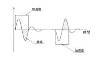
- the link hub on the tip side vibrates in a direction that cancels acceleration after about half a cycle of the resonance frequency, if the deceleration time of the actuator is set near one cycle of the resonance frequency of the link actuator, When performing step acceleration to accelerate, the vibration of the link hub on the tip side after step acceleration is reduced. As a result, the vibration of the link hub on the distal end side after the operation of the actuator is reduced even at high speed operation, and the link hub on the distal end side can be positioned at high speed and with high accuracy.
- the positioning operation has the same meaning as the posture changing operation because the position of the link hub on the distal end side with respect to the link hub on the proximal end side changes at the same time.
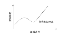
- the deceleration time may be set within a range of 0.8 to 1.2 periods of the resonance frequency of the link actuator.
- the maximum amplitude of the sine wave is 0.75 period and 1.25 period. Therefore, in order to avoid a state of oscillating with the maximum amplitude after completion of deceleration, the deceleration time is set to 0.8 to 1.2 periods of the resonance frequency of the link actuator.
- the synchronization control and the attitude control may be performed by setting the acceleration time of all the actuators in the vicinity of one cycle of the resonance frequency of the link actuator.
- the link hub on the tip side vibrates in a direction that cancels acceleration after about half a cycle of the resonance frequency. Therefore, if the acceleration time of the actuator is set near one cycle of the resonance frequency of the link actuator, the link hub accelerates periodically.
- step acceleration vibration of the link hub on the tip side after step acceleration is reduced.
- the vibration of the link hub on the distal end side that occurs at the time of starting is reduced, and the link hub on the distal end side can be positioned at high speed and with high accuracy.
- the acceleration time may be set within a range of 0.8 to 1.2 periods of the resonance frequency of the link actuator.
- the maximum amplitude of the sine wave is 0.75 period and 1.25 period. Therefore, in order to avoid a state of oscillating at the maximum amplitude after completion of acceleration, the acceleration time is set to 0.8 to 1.2 periods of the resonance frequency of the link actuator.
- the posture control determines a command operation amount for each actuator from a target posture of the link hub on the tip side, and the synchronous control is a ratio of command operation amounts of all the actuators.
- the operating speed of each actuator may be set.
- the command operation amount of each actuator is different. Therefore, if the command speed is set according to the ratio, synchronous control can be easily performed.
- the command operation amount of each actuator can be obtained as follows. That is, the rotation angle of the end link member on the base end side with respect to the link hub on the base end side is ⁇ n, the connecting end shaft of the central link member rotatably connected to the end link member on the base end side, The angle formed by the connecting end shaft of the central link member rotatably connected to the end link member on the front end side is ⁇ , and the end link members on the base end side with respect to the reference end link member on the base end side Is the vertical angle at which the central axis of the link hub on the distal end side is inclined with respect to the central axis of the link hub on the proximal end side, and ⁇ is the central axis of the link hub on the proximal end side.
- the command operation amount of each actuator may be obtained as follows. That is, the rotation angle of the end link member on the base end side with respect to the link hub on the base end side is ⁇ n, the connecting end shaft of the central link member rotatably connected to the end link member on the base end side, The angle formed by the connecting end shaft of the central link member rotatably connected to the end link member on the front end side is ⁇ , and the end link members on the base end side with respect to the reference end link member on the base end side Is the vertical angle at which the central axis of the link hub on the distal end side is inclined with respect to the central axis of the link hub on the proximal end side, and ⁇ is the central axis of the link hub on the proximal end side.
- the above formula was used by preliminarily tabulating the relationship between the attitude of the distal-side link hub with respect to the proximal-side link hub and the rotation angle of each proximal-side end link member.
- the calculation time of the command operation amount can be shortened, and the posture control can be performed at higher speed.
- the operating speed of each actuator is Vn
- the base speed is V
- the current rotation angle of the end link member on the base end side is ⁇ n
- the end link member on the base end side in the posture control is When the target rotation angle is ⁇ n ′, You may calculate using the formula represented by these.
- the base speed V becomes the combined speed of the operating speed Vn of each actuator, and can be controlled so that the moving speed of the link hub on the base end side is almost constant in any situation.
- each actuator The operating speed of each actuator is Vn, the maximum speed is Vmax, the current rotation angle of the end link member on the base end side is ⁇ n, and the end link on the base end side in the posture control
- Vn Vmax ( ⁇ n′ ⁇ n) / ⁇ max
- all of the three or more sets of link mechanisms are provided with actuators for arbitrarily changing the attitude of the distal end side link hub with respect to the proximal end side link hub, and each of these actuators is subjected to redundant control. You may control. By performing redundancy control, the driving balance of each actuator can be improved regardless of the posture of the link hub on the distal end side, and the settling time of the link hub on the distal end side can be shortened. Furthermore, since it is possible to control the backlash of the actuator and its peripheral part and the backlash of the link mechanism, the vibration of the link hub on the tip side due to the backlash after stopping the actuator can be suppressed, and the settling time is shortened.
- a resonance frequency detection sensor for detecting the resonance frequency of the link actuator is installed in the link hub on the distal end side, and the resonance frequency is calculated from the signal by a resonance frequency measuring device, and the calculation is performed.
- the set values of the acceleration time and deceleration time of the actuator may be updated from the result. Even if the tip load or the rigidity of the link actuator changes, the acceleration time and deceleration time can be easily updated, so the vibration of the link hub on the tip side after stopping the actuator is reduced in any situation and at high speed. High-precision positioning operation is possible.
- an acceleration pickup as the resonance frequency detection sensor and an FFT analyzer as the resonance frequency measuring device.
- the acceleration pickup is small and easy to install, and the FFT analyzer can easily set the acceleration time and deceleration time.
- the control device for the link actuator is a controller for controlling the operation of the actuator in the link actuator, and controls so that all of the actuators start to operate at the same time and complete the operation at the same time.
- synchronous control the operation for each actuator is controlled to perform posture control for changing the link hub on the distal end side to an arbitrary posture, and the deceleration time of all the actuators is set to the resonance frequency of the link actuator.
- Synchronous / attitude control means for performing the synchronous control and attitude control is set near one cycle.
- the link hub on the tip side vibrates in a direction that cancels acceleration after about half a cycle of the resonance frequency, if the deceleration time of the actuator is set near one cycle of the resonance frequency of the link actuator, When performing step acceleration to accelerate, the vibration of the link hub on the tip side after step acceleration is reduced. As a result, the vibration of the link hub on the distal end side after the operation of the actuator is reduced even at high speed operation, and the link hub on the distal end side can be positioned at high speed and with high accuracy.
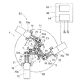
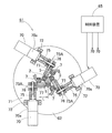
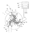
- the link actuating device 51 includes a parallel link mechanism 1, a plurality of (the same number of link mechanisms 4 as described later) actuators 53 that actuate the parallel link mechanism 1, and a control device 54 that controls these actuators 53. And an operation device 55 for inputting an operation command to the control device 54.
- the control device 54 and the operation device 55 are provided in the controller 56, but the control device 54 may be provided separately from the controller 56.
- the parallel link mechanism 1 is installed in a suspended state on the base member 52.
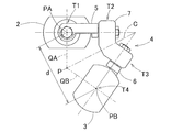
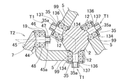
- FIGS. 2 and 3 are front views showing different states of the parallel link mechanism 1.
- the parallel link mechanism 1 includes three sets of link mechanisms 4 in which the link hub 3 on the distal end side is linked to the link hub 2 on the proximal end side. It is connected so that the posture can be changed via. 2 and 3, only one set of link mechanisms 4 is shown.
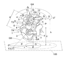
- FIG. 4 is a perspective view showing the parallel link mechanism 1 three-dimensionally.
- Each link mechanism 4 includes a base end side end link member 5, a front end side end link member 6, and a central link member 7, and forms a three-joint link mechanism including four rotating pairs.
- a rotating pair and its peripheral part are shown as rotating pairs T1 to T4.
- the end link members 5 and 6 on the base end side and the front end side are L-shaped, and the base ends are rotatably connected to the link hub 2 on the base end side and the link hub 3 on the front end side, respectively.
- the central link member 7 is rotatably connected to the distal ends of the end link members 5 and 6 on the proximal end side and the distal end side at both ends.
- the end link members 5 and 6 on the base end side and the front end side have a spherical link structure, and the spherical link centers PA and PB (FIGS. 2 and 3) in the three sets of link mechanisms 4 coincide with each other, and the spherical surfaces thereof The distance d from the link centers PA and PB is the same.
- the central axis of each rotational pair of the end link members 5 and 6 and the central link member 7 may have a certain crossing angle ⁇ (FIG. 4) or may be parallel.
- each link member 5, 6, and 7 is expressed by a straight line, that is, each rotation pair T1 to T4 and a straight line connecting these rotation pairs T1 to T4.
- a model says that the base end side part and front end side part with respect to the center part of the center link member 7 are the shapes which comprise a symmetry.
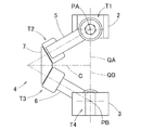
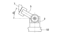
- FIG. 5 is a diagram representing a set of link mechanisms 4 in a straight line.
- the link mechanism 4 of this embodiment is a rotationally symmetric type, and includes a link hub 2 on the proximal end side and an end link member 5 on the proximal end side, a link hub 3 on the distal end side, and an end on the distal end side.
- the positional relationship with the partial link member 6 is a position configuration that is rotationally symmetric with respect to the center line C of the central link member 7.
- 2 shows a state where the central axis QA of the link hub 2 on the proximal end side and the central axis QB of the link hub 3 on the distal end side are on the same line
- FIG. 3 shows the central axis of the link hub 2 on the proximal end side.
- the link hub 2 on the proximal end side, the link hub 3 on the distal end side, and the three link mechanisms 4 allow the distal link hub 3 to move in the two orthogonal directions relative to the link hub 2 on the proximal end side.
- a degree mechanism is configured. In other words, it is a mechanism that can freely change the posture of the link hub 3 on the distal end side with respect to the link hub 2 on the proximal end side with two degrees of freedom of rotation.
- This two-degree-of-freedom mechanism is based on the intersection P between the center axis QA of the link hub 2 on the proximal end side, the center axis QB of the link hub 3 on the distal end side, and the center line C of the center link member 7.
- the link hub 3 on the distal end side changes the posture with respect to the link hub 2.
- This two-degree-of-freedom mechanism is compact but can widen the movable range of the link hub 3 on the distal end side relative to the link hub 2 on the proximal end side.
- the maximum value (maximum folding angle) of the folding angle ⁇ between the central axis QA of the proximal side link hub 2 and the central axis QB of the distal side link hub 3 is about ⁇ 90 °. be able to.
- the turning angle ⁇ of the distal end side link hub 3 relative to the proximal end side link hub 2 can be set in a range of 0 ° to 360 °.
- the bending angle ⁇ is a vertical angle in which the central axis QB of the distal end side link hub 3 is inclined with respect to the central axis QA of the proximal end side link hub 2, and the turning angle ⁇ is the proximal end side link hub.
- This is a horizontal angle at which the central axis QB of the link hub 3 on the distal end side is inclined with respect to the central axis QA of the second axis.
- the angular positional relationship with the base link members 5 and 6 is the same between the base end side and the tip end side, the base end side link hub 2 and the base end side end link member 5 from the geometric symmetry,
- the distal end side link hub 3 and the distal end side end link member 6 move in the same manner.
- the rotation hubs are provided coaxially with the center axes QA and QB on the link hubs 2 and 3 on the proximal end side and the distal end side, and rotation is transmitted from the proximal end side to the distal end side, the proximal end side and the distal end side are It becomes a constant velocity universal joint that rotates at the same speed at the same rotation angle.
- the plane of symmetry of the central link member 7 when rotating at a constant speed is referred to as a uniform speed bisector.
- the plurality of link mechanisms 4 can move without contradiction.
- the central link member 7 is limited to movement only on the equal speed bisector. Thereby, even if the proximal end side and the distal end side have arbitrary operating angles, the proximal end side and the distal end side rotate at a constant speed.
- the proximal-side link hub 2 and the distal-side link hub 3 have a donut with a through hole 10 formed in the center thereof along the axial direction and the outer shape being spherical. It has a shape.
- the center of the through hole 10 coincides with the central axes QA and QB of the link hubs 2 and 3 as shown in FIG.
- the proximal end link member 5 and the distal end link member 6 rotate at equal intervals in the circumferential direction of the outer peripheral surface of the proximal link hub 2 and distal link hub 3 respectively. It is connected freely.
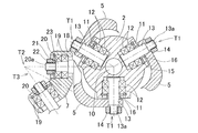
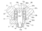
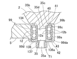
- FIG. 6 shows a rotation pair T1 of the base end side link hub 2 and the base end side end link member 5, and a portion showing the base end side end link member 5 and the rotation link portion T2 of the central link member 7. It is sectional drawing.
- radial communication holes 11 that communicate the axial through hole 10 and the outer peripheral side are formed at three locations in the circumferential direction, and two bearings provided in each communication hole 11. 12, shaft members 13 are rotatably supported. The outer end of the shaft member 13 protrudes from the link hub 2 on the base end side, and the end link member 5 on the base end side is coupled to the protruding screw portion 13 a and is fastened and fixed by a nut 14.
- the bearing 12 is a rolling bearing such as a deep groove ball bearing, for example, and an outer ring (not shown) is fitted to the inner circumference of the communication hole 11, and an inner ring (not shown) is the outer circumference of the shaft member 13. Is fitted.
- the outer ring is retained by a retaining ring 15.
- a spacer 16 is interposed between the inner ring and the end link member 5 on the base end side, and the tightening force of the nut 14 is transmitted to the inner ring via the end link member 5 and the spacer 16 on the base end side.
- a predetermined preload is applied to the bearing 12.
- two bearings 19 are provided in the communication holes 18 formed at both ends of the center link member 7, and the base end is provided by these bearings 19.
- a shaft portion 20 at the tip of the end link member 5 on the side is rotatably supported.
- the bearing 19 is fastened and fixed by a nut 22 via a spacer 21.
- the bearing 19 is a rolling bearing such as a deep groove ball bearing, for example, and an outer ring (not shown) is fitted to the inner circumference of the communication hole 18, and an inner ring (not shown) is the outer circumference of the shaft portion 20. Is fitted.
- the outer ring is retained by a retaining ring 23. A tightening force of the nut 22 screwed to the tip screw portion 20a of the shaft portion 20 is transmitted to the inner ring through the spacer 21 to apply a predetermined preload to the bearing 19.
- the radial gap and the thrust gap can be eliminated, and rattling of the rotating pair can be suppressed.
- the rotational phase difference between the link hub 3 side on the second side and the distal end side is eliminated, so that the constant velocity can be maintained and the occurrence of vibration and noise can be suppressed.
- the bearing clearance between the bearings 12 and 19 to be a negative clearance, backlash generated between input and output can be reduced.
- the base end side link hub 2 and the front end side link hub 2 are not enlarged without increasing the overall shape of the parallel link mechanism 1.
- the outer shape of the link hub 3 can be enlarged. Therefore, it is easy to secure a mounting space for mounting the proximal-side link hub 2 and the distal-side link hub 3 to other members.
- the parallel link mechanism 1 is in a state in which the base end side link hub 2 is fixed to the lower surface of the base member 52 and the front end side link hub 3 is suspended.
- the same number of actuators 53 that is, three actuators 53, which are rotary actuators, are installed.
- the output shaft 53a of the actuator 53 protrudes downward through the base member 52, and is a fan-shaped cap attached to the bevel gear 57 attached to the output shaft 53a and the shaft member 13 (FIG. 6) of the link hub 2 on the proximal end side.
- the gear 58 is meshed.
- the bevel gear 57 and the bevel gear 58 constitute a gear-type reduction unit 73.
- each actuator 53 When the actuator 53 is rotated, the rotation is transmitted to the shaft member 13 through a pair of bevel gears 57 and 58, and the angle of the end link member 5 on the base end side with respect to the link hub 2 on the base end side changes.
- the attitude of the link hub 3 on the front end side with respect to the link hub 2 on the base end side ( Hereinafter, “tip posture” is determined.
- the operation of each actuator 53 is controlled by the control device 54 based on an operation command from the operation device 55.
- the operating device 55 includes posture designation means 55a, posture acquisition means 55b, and posture information provision means 55c.
- the posture designation means 55a is a means for manually designating a target tip posture, and designates the tip posture at a coordinate position on a two-dimensional orthogonal coordinate system.
- the orthogonal coordinate system is an XY in which the origin O is defined at an arbitrary position on the extension axis QA ′, which is orthogonal to the extension axis QA ′ of the center axis QA of the link hub 2 on the base end side.
- An orthogonal coordinate system 100 is shown.
- the target tip posture is represented by target coordinates T (X, Y) which are the coordinates of the point where the center axis QB of the link hub 3 on the tip side intersects the XY orthogonal coordinate system 100.
- T target coordinates
- the posture acquisition unit 55b converts the tip posture represented by the coordinate position of the XY orthogonal coordinate system 100 designated by the posture designation unit 55a into the tip posture represented by the bending angle ⁇ and the turning angle ⁇ of the angle coordinate system. Means. The principle of conversion will be described.
- h ′ is the height from the intersection point P, which is the rotation center of the posture change of the link hub 3 on the distal end side, to the target coordinate T, as shown in FIG.
- h ′ is obtained from Equation 3.
- h ′ obtained by Equation 3 the distance r ′ between the origin O and the target coordinate T in the angular coordinate system is obtained.
- d and h are fixed values determined by the dimensions of the parallel link mechanism 1 and the dimensions of the device on which the link actuating device 51 is mounted.
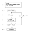
- the distance r between the origin O and the target coordinate T in the XY coordinate system 100 thus obtained is compared with the distance r ′ between the origin O and the target coordinate T in the angle coordinate system, and the difference is minimum.
- the convergence calculation by the least square method is performed in the order shown in the flowchart of FIG. First, in S1, the calculation of the distance r by Equation 1 and the setting of the initial value of the comparison value A are performed.
- the comparison value A is a comparison value with dr, and a value sufficiently larger than the value of dr calculated in the search process is set as an initial value.
- the target tip posture is defined by the bending angle ⁇ obtained by the operation shown in the flowchart of FIG. 7 and the turning angle ⁇ obtained by the calculation of Expression 5 or 6.
- the number of computations can be reduced by performing the convergence calculation by the least square method to obtain the bending angle ⁇ by sequentially searching from the vicinity of the current coordinate position as a reference.
- the posture information giving unit 55c gives the control device 54 the information on the tip posture acquired by the posture acquiring unit 55b, that is, the folding angle ⁇ and the turning angle ⁇ .
- the control device 54 is of a numerical control type by a computer, and the target rotation of the end link member 5 on the base end side is determined in accordance with the tip posture information given from the posture information giving means 55c of the operation device 55.
- the angle ⁇ n (FIG. 4) is obtained, and each actuator 53 is feedback-controlled so that the actual rotation angle ⁇ n detected by the posture detection means 59 (FIG. 1) becomes the target rotation angle ⁇ n.
- the rotation angle ⁇ n is obtained, for example, by inversely transforming the following equation (7).
- the inverse transformation is a transformation for calculating the rotation angle ⁇ n from the bending angle ⁇ and the turning angle ⁇ .
- the bending angle ⁇ , the turning angle ⁇ , and the rotation angle ⁇ n are mutually related, and the other value can be derived from one value.
- ⁇ (FIG.
- ⁇ n ( ⁇ 1 , ⁇ 2 , ⁇ 3 in FIG. 4) is a circumferential separation angle of each end-side end link member 5 with respect to the reference end-side end link member 5.
- the rotation angle ⁇ n may be obtained by inversely transforming Equation 7 for each command, a table showing the relationship between the tip position / posture and the rotation angle ⁇ n as shown in Table 1 may be created in advance.
- a table if there is a command to change the tip posture, the target rotation angle ⁇ n can be obtained immediately using the table. For this reason, the actuator 53 can be controlled at a higher speed.
- a table storage area can be saved by registering a table indicating the relationship between the tip position and orientation and the rotation angle ⁇ n at the time of pattern registration as shown in Table 2. .
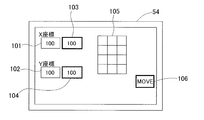
- FIG. 8 shows an example of the operation unit of the operation device 55.
- This operation unit is a method of designating a coordinate position by numerical input, and present value display units 101 and 102 for displaying the X coordinate value and Y coordinate value of the current coordinate position, respectively, and the target X coordinate value and Y coordinate.
- Target value display sections 103 and 104 for displaying values
- a numerical value input button 105 including 10 keys for inputting the target X coordinate value and Y coordinate value to the target value display sections 103 and 104
- an operation execution button 106 Is provided.
- the designation of the coordinate position on the XY Cartesian coordinate system is a method of numerically inputting absolute coordinates with respect to a predetermined reference point (for example, the origin O), and a method of numerically inputting a difference from the current coordinate position to the target coordinate position. Any of these may be used.
- the values are displayed on the target value display sections 103 and 104.
- the target X- and Y-coordinate values, the distance from the link hub 3 on the distal end side to the work surface of the work piece (not shown), the dimensions of each part of the parallel link mechanism 1, and the like The bending angle ⁇ and the turning angle ⁇ of the tip posture are calculated. Further, the operation amount of each actuator 53 is calculated from the tip posture.
- the operation execution button 106 is pressed, each actuator 53 is driven, and the tip posture is changed so that the input X coordinate value and Y coordinate value are obtained.
- the link actuator 51 (FIG. 1) is provided even when the coordinate position of the work piece is handled by the rectangular coordinate system. Intuitive operation.
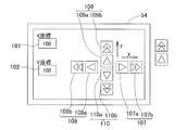
- FIG. 9 shows different examples of the operation unit of the operation device 55.
- This operation unit is a method of designating a coordinate position by an operation amount, and is a current value display unit 101 and 102 for displaying the X coordinate value and the Y coordinate value of the current coordinate position, respectively, and a push operation for changing the tip posture.
- Buttons 107-110 When the push operation button 107 is pressed, the posture is changed to the side where the X coordinate value is increased. When the push operation button 108 is pressed, the posture is changed to the side where the X coordinate value is decreased. When the push operation button 109 is pressed, the Y coordinate value is increased. The posture is changed to the side where the Y coordinate value is decreased when the push operation button 110 is pressed.
- each of the push operation buttons 107 to 110 includes a low-speed button 107a, 108a, 109a, 110a in which the posture change is performed at a low speed, and a high-speed button 107b, 108b, 109b, 110b in which the posture change is performed at a high speed. Therefore, the posture can be changed in two stages, low speed and high speed.
- the X coordinate value and the Y coordinate value are sequentially changed by the operation of the push operation buttons 107 to 110, and the target folding angle ⁇ and turning angle ⁇ are calculated each time, and the actuator 53 corresponding thereto is calculated. It is a system that determines the amount of movement. That is, the tip posture continues to change only while the push operation buttons 107 to 110 are being pressed. For this reason, the relationship between the operation and the coordinate position is easy to understand intuitively.
- the control device 54 used in combination with the operation device 55 converts the tip posture information given from the posture designation means 55c of the operation device 55 into an operation amount of the actuator 53 by a predetermined conversion formula, and the operation thereof.
- the actuator 53 is controlled to be operated by the amount.
- the control device 54 uses the equation 7 to calculate the bending angle ⁇ and the turning angle ⁇ .
- the rotation angle ⁇ n of the end link member 5 on each proximal end side is obtained by inverse conversion, and the operation amount Rn of each actuator 53 is calculated by calculating Expression 8 using the obtained rotation angle ⁇ n. .
- k is a coefficient determined by a reduction ratio of a reduction gear (not shown) attached to the actuator 53. In this way, when the tip posture information is converted into the operation amount of the actuator 53 by the conversion formula, the actuator 53 can be easily controlled.
- the amount of movement of the actuator 53 and the changing speed of the tip posture can be changed stepwise, and the amount of movement of the actuator 53 and the changing speed of the tip posture per operation of the push buttons 107 to 110 can be arbitrarily changed. You may do it. Further, as in this example, the operation may be performed with one operation means such as a joystick, instead of operating with the plurality of push operation buttons 107 to 110.
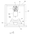
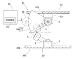
- FIG. 10 shows a working device 120 provided with the link actuating device 51.
- the base link 52 is fixed to a base member 52 that forms the ceiling of the work chamber 121, and the parallel link mechanism 1 is installed in a suspended state.
- An end effector 122 is mounted on the link hub 3 on the distal end side.
- the end effector 122 is, for example, a painting machine.
- the moving mechanism 123 that moves the work W in the XY-axis direction is installed.
- the moving mechanism 123 includes an X-axis rail 124 that is long and fixed along the X-axis direction that is fixedly installed on the floor surface, and a Y-axis rail 125 that can move forward and backward along the X-axis rail 124 and that is long along the Y-axis direction.
- the Y-axis rail 125 and the work table 126 are moved in the X-axis direction and the Y-axis direction, respectively, by driving a drive source (not shown).
- the end effector 122 When the end effector 122 is a coating machine, the work place 126 by the moving mechanism 123 is moved back and forth in the X-axis and Y-axis directions, so that the coating location of the work W is positioned at the tip of the paint spraying port 122a of the coating machine. . Further, by changing the tip posture of the link actuating device 51 and changing the direction of the end effector 122, the paint spraying port 122a is always adjusted to face the painted surface of the work W.
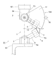
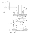
- the link actuating device 61 is provided with a parallel link mechanism 1 suspended from a base member 62. That is, in the parallel link mechanism 1, the base end side link hub 2 is fixed to the base member 62 via the base member 62, and the front end mounting member 63 for mounting various instruments etc. is mounted on the front end side link hub 3. ing.
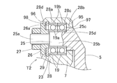
- the parallel link mechanism 1 includes a bearing 31 that rotatably supports the end link members 5 and 6 with respect to the link hub 2 on the proximal end side and the link hub 3 on the distal end side.
- Outer ring rotation type The rotation pair T1 of the base end side link hub 2 and the base end side end link member 5 will be described as an example.
- Shaft portions 32 are formed at three locations in the circumferential direction of the base end side link hub 2,
- the inner rings (not shown) of the two bearings 31 are fitted on the outer periphery of the shaft portion 32, and the outer rings (not shown) of the bearing 31 are arranged on the inner periphery of the communication hole 33 formed in the end link member 5 on the proximal end side. Are fitted).
- the bearing 31 is a ball bearing such as a deep groove ball bearing or an angular ball bearing, for example, and is fixed in a state where a predetermined preload is applied by tightening with a nut 34.
- the rotation pair T4 of the link hub 3 on the distal end side and the end link member 6 on the distal end side has the same structure as described above.
- the bearing 36 provided in the rotation pair T2 of the end link member 5 and the central link member 7 on the base end side is the inner periphery of the communication hole 37 formed at the tip of the end link member 5 on the base end side.
- An outer ring (not shown) is fitted to the inner ring (not shown), and an inner ring (not shown) is fitted to the outer periphery of the shaft portion 38 integral with the central link member 7.
- the bearing 36 is, for example, a ball bearing such as a deep groove ball bearing or an angular ball bearing, and is fixed in a state where a predetermined preload is applied by tightening with a nut 39.
- the rotating pair T3 of the end link member 6 and the center link member 7 on the front end side has the same structure as described above.
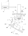
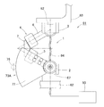
- All three sets of the link mechanisms 4 of the parallel link mechanism 1 have an actuator 70 for arbitrarily changing the distal end position and posture by rotating the end link member 5 on the proximal end side, and the operation amount of the actuator 70 as the proximal end.
- a speed reduction mechanism 71 that decelerates and transmits to the side end link member 5 is provided.
- the actuator 70 is a rotary actuator, more specifically a servo motor with a speed reducer 70 a, and is fixed to the base member 62 by a motor fixing member 72.
- the speed reducing mechanism 71 includes a speed reducer 70a of the actuator 70 and a gear type speed reducing portion 73A.
- the gear-type speed reducing portion 73A is connected to the output shaft 70b of the actuator 70 through a coupling 75 so as to be able to transmit rotation, and is fixed to the end link member 5 on the base end side and is connected to the small gear 76. It is comprised with the large gear 77 which meshes
- the small gear 76 and the large gear 77 are spur gears, and the large gear 77 is a sector gear in which teeth are formed only on a sector-shaped peripheral surface.
- the large gear 77 has a larger pitch circle radius than the small gear 76, and the rotation of the output shaft 70 b of the actuator 70 is transferred to the end link member 5 on the base end side, and the link hub 2 on the base end side and the end link on the base end side.
- the rotation is transmitted to the member 5 while being decelerated to the rotation around the rotation axis O1 of the rotation pair T1.
- the reduction ratio is 10 or more.
- the pitch circle radius of the large gear 77 is set to 1/2 or more of the arm length L of the end link member 5 on the base end side.
- the arm length L is determined from the axial center point P1 of the central axis O1 of the rotation pair T1 between the proximal-side link hub 2 and the proximal-side end link member 5 to the proximal-side end link member 5.
- the center point P2 in the axial direction of the central axis O2 of the rotational pair portion T2 between the central link member 7 and the central link member 7 is perpendicular to the rotational pair axis O1 of the proximal end side link hub 2 and the proximal end side end link member 5. This is the distance to the point P3 projected on the plane passing through the direction center point P1.
- the pitch circle radius of the large gear 77 is not less than the arm length L. Therefore, it is advantageous to obtain a high reduction ratio.
- the small gear 76 has shaft portions 76 b protruding on both sides of a tooth portion 76 a meshing with the large gear 77, and both shaft portions 76 b are two bearings provided on a rotation support member 79 installed on the base member 62. 80 are rotatably supported by each.
- the bearing 80 is a ball bearing such as a deep groove ball bearing or an angular ball bearing. In addition to arranging ball bearings in double rows as in the illustrated example, roller bearings or sliding bearings may be used.
- a shim (not shown) is provided between the outer rings (not shown) of the two bearings 80, and a preload is applied to the bearing 80 by tightening a nut 81 screwed into the shaft portion 76b.
- the outer ring of the bearing 80 is press-fitted into the rotation support member 79.
- the large gear 77 is a member separate from the end link member 5 on the base end side, and is detachably attached to the end link member 5 on the base end side by a coupler 82 such as a bolt. ing.
- the large gear 77 may be integrated with the end link member 5 on the base end side.
- the rotation axis O3 of the actuator 70 and the rotation axis O4 of the small gear 76 are located on the same axis. These rotation axes O3 and O4 are parallel to the rotation pair axis O1 of the base end side link hub 2 and the base end side end link member 5 and have the same height from the base member 62.
- the link actuating device 61 also includes a controller 84 that controls the actuator 70 and an operating device 85 that inputs an operation command to the controller 84 in the controller 86.
- the control device 84 and the operation device 85 have the same configuration as that of the above embodiment, and the same operation and effect as described above can be obtained.
- the operation device 85 includes posture designation means 55a, posture acquisition means 55b, and posture information provision means 55c as in the first embodiment, but these are not shown.
- This link actuating device 61 is provided with the actuator 70 and the speed reduction mechanism 71 in all of the three sets of link mechanisms 4, so that it is possible to control the backlash of the parallel link mechanism 1 and the speed reduction mechanism 71 to be reduced.
- the positioning accuracy of the link hub 3 on the side can be improved, and the link actuator 61 itself can be made highly rigid.
- the gear type reduction unit 73A of the reduction mechanism 71 is a combination of the small gear 76 and the large gear 77, and a high reduction ratio of 10 or more can be obtained. If the reduction ratio is high, the positioning resolution of the encoder or the like is increased, so that the positioning resolution of the link hub 3 on the distal end side is improved. Also, a low output actuator 70 can be used. In this embodiment, the actuator 70 with the reduction gear 70a is used. However, if the reduction ratio of the gear-type reduction gear 73A is high, the actuator 70 without the reduction gear can be used, and the actuator 70 can be downsized. it can.
- the pitch circle radius of the large gear 77 By setting the pitch circle radius of the large gear 77 to 1 ⁇ 2 or more of the arm length L of the end link member 5 on the base end side, the bending moment of the end link member 5 on the base end side due to the tip load is reduced. . Therefore, it is not necessary to increase the rigidity of the entire link operating device 61 more than necessary, and the weight of the end link member 5 on the base end side can be reduced.
- the end link member 5 on the base end side can be changed from stainless steel (SUS) to aluminum. Further, since the pitch circle radius of the large gear 77 is relatively large, the surface pressure of the tooth portion of the large gear 77 is reduced, and the rigidity of the entire link actuator 61 is increased.
- the large gear 77 is connected to the rotating pair T1 of the base end side link hub 2 and the base end side end link member 5. Since the diameter is sufficiently larger than the outer diameter of the bearing 12 to be installed, a space is created between the tooth portion of the large gear 77 and the bearing 12, and the large gear 77 can be easily installed.
- the pitch circle radius of the large gear 77 is equal to or greater than the arm length L, so that the pitch circle radius of the large gear 77 is further increased, and the above-described operation and effect are more prominent.
- the small gear 76 can be installed on the outer diameter side of the link mechanism 4. As a result, an installation space for the small gear 76 can be easily secured, and the degree of freedom in design increases. Further, interference between the small gear 76 and other members is less likely to occur, and the movable range of the link actuator 61 is widened.
- the small gear 76 and the large gear 77 are spur gears, they are easy to manufacture and have high rotation transmission efficiency. Since the small gear 76 is supported by the bearings 80 on both sides in the axial direction, the support rigidity of the small gear 76 is high. As a result, the angle holding rigidity of the end link member 5 on the proximal end side due to the distal end load is increased, and the rigidity and positioning accuracy of the link actuator 61 are improved. Further, the rotational axis O3 of the actuator 70, the rotational axis O4 of the small gear 76, and the central axis O1 of the rotation pair T1 between the proximal-side link hub 2 and the proximal-side end link member 5 are coplanar. Since it is above, the overall balance is good and the assemblability is good.
- the large gear 77 is detachable with respect to the end link member 5 on the base end side, the reduction ratio of the gear type reduction portion 73A and the operation of the link hub 3 on the front end side with respect to the link hub 2 on the base end side. It becomes easy to change the specifications such as the range, and the mass productivity of the link actuating device 61 is improved. In other words, the same link actuating device 61 can be applied to various uses by simply changing the large gear 77. Also, maintainability is good. For example, when a failure occurs in the gear-type reduction unit 73A, it is possible to cope with the problem by replacing only the reduction unit 73A.
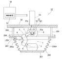
- a link actuator according to a third embodiment of the present invention will be described with reference to FIG. 14 and FIGS. 2 to 6 used in the first embodiment. Note that components that are the same as or correspond to those in the first embodiment are denoted by the same reference numerals, detailed description thereof is omitted, and different components are described. The difference from FIG. 1 showing the first embodiment is that this link actuating device 51 shown in FIG. 14 has a lubricant receiving member 200 that receives the lubricant falling from the parallel link mechanism 1 and the speed reduction portion 73. It is.
- the lubricant receiving member 200 is a dish-shaped member having a plate-like portion 201 and a protruding portion 202 protruding in one direction intersecting the surface of the plate-like portion 201 from the outer peripheral edge of the plate-like portion 201. And the central portion of the plate-like portion 201 is fixed to the distal end surface of the link hub 3 on the distal end side so that the protruding portion 202 faces the link hub 2 side on the proximal end side.
- the plate-like portion 201 is fixed to the link hub 3 on the distal end side by, for example, a bolt (not shown). Since the lubricant receiving member 200 has a simple configuration, it can be manufactured at low cost. Further, the lubricant receiving member 200 only needs to be provided at a position below the parallel link mechanism 1 and the speed reduction portion 73 and does not cover the entire parallel link mechanism 1, so that it is compact.
- the lubricant receiving member 200 Since the lubricant receiving member 200 has a plate shape having the protruding portion 202 at the outer peripheral edge of the plate-like portion 201, the received lubricant is received even when the lubricant receiving member 200 is inclined as the posture of the link hub 3 on the front end side is inclined. The agent does not sag from the outer peripheral edge of the plate-like portion 201. Therefore, the lubricant is prevented from being applied to the work piece (not shown) below.
- the lubricant receiving member 200 when the lubricant receiving member 200 is provided, it is possible to allow the lubricant to leak from the bearings 12 and 19 and the bevel gears 57 and 58, so that the seal structure of the bearings 12 and 19 and the bevel gears 57 and 58 is simplified.
- the lubricant receiving member 200 is provided in the link hub 3 on the distal end side, and the lubricant receiving member 200 moves in accordance with the change in the posture of the link hub 3. 4 is large, the lubricant receiving member 200 is not positioned directly below the bevel gears 57 and 58 and some of the bearings 12 and 19, but from the bevel gears 57 and 58 and the bearings 12 and 19. The falling lubricant may not be received by the lubricant receiving member 200. Therefore, it is effective to apply the configuration of this embodiment when the parallel link mechanism 1 is used at a folding angle of ⁇ 45 ° or less.
- the protruding portion 202 of the lubricant receiving member 200 has a shape in which the protruding end side is inclined toward the central axis QB of the link hub 3 on the distal end side. Then, even when the link hub 3 on the distal end side is greatly inclined, the lubricant can be prevented from dripping from the lubricant receiving member 200. In that case, it is desirable that the inclination angle of the protrusion 202 of the lubricant receiving member 200 be equal to or greater than the maximum value (maximum folding angle) ⁇ max of the bending angle ⁇ in the operation range of the parallel link mechanism 1.
- the protruding end side of the protruding portion 202 is always inclined in the center direction, so that it is possible to reliably prevent the lubricant from dripping over the protruding portion 202.
- the lubricant receiving member 200 is coupled to the projecting end of the projecting portion 202 and is parallel to the plate-shaped portion 201 and has a through hole in the inner peripheral portion. It is good also as a structure which has the upper board 203 in which 203a was formed.
- the upper plate 203 is oriented in a direction perpendicular to the ground even when the link hub 3 on the distal end side of the parallel link mechanism 1 is inclined by 90 ° (maximum folding angle). Therefore, even if a large amount of lubricant is accumulated in the lubricant receiving member 200, it is possible to reliably prevent the lubricant from dripping from the lubricant receiving member 200.
- FIG. 17 shows a sixth embodiment.
- the link actuating device 51 includes a ring-shaped fixing member 205 that is supported by a base member 52 via a support column 204 and is parallel to the base member 52 and has a through hole 205a formed in an inner peripheral portion.
- a protruding portion 206 that protrudes toward the base member 52 is formed at the outer peripheral end of the fixed member 205, and an inner peripheral standing edge 207 that protrudes toward the opposite side of the base member 52 is formed at the inner peripheral end.
- the lubricant receiving member 200 includes a plate-like portion 201 fixed to the link hub 3 on the front end side, and a stretchable connecting portion that covers the entire circumference between the plate-like portion 201 and the fixing member 205 and connects them together. 208.
- the connecting portion 208 is made of a sheet-like elastic material, and is installed with both ends fitted to the outer peripheral surface of the plate-like portion 201 and the outer peripheral surface of the inner peripheral standing edge portion 207 of the fixing member 205.
- the connecting portion 208 may be fixed to the outer peripheral surface of the plate-like portion 201 and the outer peripheral surface of the inner peripheral standing edge portion 207 of the fixing member 205 with a fixing band or the like.
- the portion of the parallel link mechanism 1 that is closer to the tip than the fixing member 205 is covered with the lubricant receiving member 200 so that the lubricant scattered from the parallel link mechanism 1 and the speed reducer 73 during operation is also lubricant. It can be received by the receiving member 200. Since the protrusion 206 is provided at the outer peripheral end of the fixing member 205, even if the lubricant falls on the fixing member 205, the lubricant does not fall outside the fixing member 205, and lubricates the work piece. It is possible to prevent the agent from being applied. Since the connecting portion 208 can be expanded and contracted, the connecting portion 208 of the lubricant receiving member 200 can be deformed accordingly even if the posture of the distal end side link hub 3 with respect to the proximal end side link hub 2 changes.
- the connecting portion 208 ⁇ / b> A of the lubricant receiving member 200 may have a bellows shape covering the entire periphery between the plate-like portion 201 and the fixing member 205.
- the connecting portion 208A is assembled to the plate-like portion 201 and the fixing member 205 in a compressed state smaller than the natural state where no external force acts.
- the connecting portion 208A of the lubricant receiving member 200 can be deformed accordingly.
- FIG. 19 shows an eighth embodiment.
- This link actuating device 51 is provided with a lubricant receiving member 210 that receives the lubricant that falls from the bevel gears 57 and 58 of the speed reducing portion 73.
- the lubricant receiving member 210 is a dish-like member having a plate-like portion 211 positioned directly below the speed reduction portion 73 and a protruding portion 212 protruding from the outer peripheral edge of the plate-like portion 211 to the base member 52 side. It is attached to the base member 52 with a bolt (not shown) or the like via an attachment portion 213 connected to a part of the protruding portion 212.
- the lubricant receiving member 210 is made of, for example, a sheet metal.
- the bearings 12 and 19 may be sealed bearings, or the bearing mounting portion may have a sealing function.
- FIG. 20 shows a rotating pair T1 of the link hub 2 on the base end side and the end link member 5 on the base end side.
- the two bearings 12 are angular contact ball bearings, and are arranged, for example, in a rear combination.
- the inner end portion of the shaft member 13 is a stepped portion 13c having a larger outer diameter than the portion 13b fitted to the inner periphery of the inner ring 12a of the bearing 12, and the stepped surface 13d of the stepped portion 13c is the inner ring of the inner bearing 12.
- the inner ring 12a is positioned in the axial direction by contacting the end surface of 12a.
- a spacer 16 is provided with both ends in contact with them. Therefore, by tightening the nut 14, the inner ring 12 a is pressed against the stepped surface 13 d via the end-side end link member 5 and the spacer 16, and the inner ring 12 a is tightened and fixed. Apply preload.
- the peripheral part of the communication hole 11 in the link hub 2 on the base end side is an annular inner surface forming part 87.
- the annular inner surface forming portion 87 is a part of the proximal side link hub 2, but the annular inner surface forming portion 87 may be separate from the proximal side link hub 2.
- the shaft member 13 that is the shaft portion is a separate member from the base end side end link member 5, but the shaft portion is provided integrally with the base end side end link member 5. May be.
- a part of the annular inner surface forming portion 87 is a portion fitted to the outer periphery of the outer ring 12b of the bearing 12, that is, a stepped portion 87b having a smaller inner diameter than the outer ring fitting portion 87a, and the stepped surface 87c of the stepped portion 87b is on the inner side.
- the outer ring 12b is positioned in the axial direction by contacting the end surface of the outer ring 12b of the bearing 12. Further, the outer ring 12 b of the outer bearing 12 is prevented from coming off by a retaining ring 17 attached to the annular inner surface forming portion 87.
- the outer peripheral surface of the stepped portion 13c of the shaft member 13 and the inner peripheral surface of the stepped portion 87b of the annular inner surface forming portion 87 are opposed to each other through a slight gap 90A.
- the stepped portion 13c of the shaft member 13 and the stepped portion 87b of the annular inner surface forming portion 87 can rotate with each other, but the seal structure 88 that restricts the entry and exit of the lubricant between the inside and the outside of the bearing 12 is provided.
- the seal structure 88 that restricts the entry and exit of the lubricant between the inside and the outside of the bearing 12 is provided.
- the narrower the gap 90A the higher the sealing effect.
- the outer portion of the spacer 16 in the axial direction is formed as a flange portion 16 a extending to the outer diameter side while avoiding the retaining ring 17, and an outer peripheral surface of the flange portion 16 a and an annular inner surface forming portion 87.
- the outer end portion 87d which is a portion, is opposed in a non-contact manner through a slight gap 90B.
- the collar structure 16a of the spacer 16 and the outer end portion 87d of the annular inner surface forming portion 87 can rotate with each other, and a seal structure 89 having the same sealing function as described above is constructed.
- the narrower the gap 90B the higher the sealing effect.
- a seal structure 88 is constructed by the shaft member 13 provided in the part link member 5 (6) and the annular inner surface forming part 87 provided in the link hub 2 (3) which is the other pair of components, and the other in the axial direction.
- a seal structure 89 is constructed by the spacer 16 fitted to the outer periphery of the shaft member 13 and the annular inner surface forming portion 87.
- the link hub 2 (3) and the end link member 5 (6) are parts constituting the parallel link mechanism 1.
- the spacer 16 is a component that is generally provided between the inner ring 12a and the nut 14 so that a uniform load is applied to the inner ring 12a when the inner ring 12a of the bearing 12 is fastened and fixed with the nut 14. is there.
- the seal structures 88 and 89 with only indispensable parts, it is not necessary to provide a seal made of another member, and the width dimension of the bearing 12 can be suppressed. Therefore, interference between the components of the link mechanism 4 hardly occurs and the work range is widened. Further, since the dimensions around the bearing 12 are reduced, the entire parallel link mechanism 1 can be reduced in weight and size.
- the seal structure 88 is formed by a gap 90 ⁇ / b> A between the outer peripheral surface of the stepped portion 13 c that is a part of the shaft member 13 and the inner peripheral surface of the stepped portion 87 b that is a part of the annular inner surface forming portion 87.
- the step portion 13c of the shaft member 13 is used for positioning the inner ring 12a
- the step portion 87b of the annular inner surface forming portion 87 is used for positioning the outer ring 12b. Since both the stepped portions 87c and 87b are at a distance close to each other, the seal structure 88 by the gap 90A can be easily constructed without installing another member.
- the seal structure 89 is constructed by a gap 90 ⁇ / b> B between the outer peripheral surface of the flange-shaped portion 16 a that is a part of the spacer 16 and the inner peripheral surface of the outer end portion 87 d that is a part of the annular inner surface forming portion 87.
- the spacer 16 is used for tightening and fixing the inner ring 12 a, and the outer end 87 d of the annular inner surface forming portion 87 is used for holding the retaining ring 17.
- FIG. 21 shows the rotating pair T2 of the end link member 5 and the center link member 7 on the base end side.
- the two bearings 19 are angular ball bearings, and are arranged, for example, in a rear combination.
- the base end portion of the shaft portion 25 is a stepped portion 25c having a larger outer diameter than the portion 25b fitted to the inner periphery of the inner ring 19a of the bearing 19, and the stepped surface 25d of the stepped portion 25c is the base end side bearing 19.
- the inner ring 19a is positioned in the axial direction by contacting the end face of the inner ring 19a. Further, the inner ring 19 a of the bearing 19 on the distal end side is in contact with the spacer 26. Therefore, by tightening the nut 27, the inner ring 19a is pressed against the stepped surface 25d through the spacer 26, and the inner ring 19a is fastened and fixed, and a preload is applied to the bearing 19.
- the peripheral portion of the communication hole 23 in the central link member 7 is an annular inner surface forming portion 28.
- the annular inner surface forming portion 28 is a part of the central link member 7, but the annular inner surface forming portion 28 may be separate from the central link member 7.
- the shaft portion 25 is provided integrally with the base end side end link member 5. However, the shaft portion 25 may be a separate member from the base end side end link member 5.
- a part of the annular inner surface forming portion 28 is a portion fitted to the outer periphery of the outer ring 19b of the bearing 19, that is, a step portion 28b having a smaller inner diameter than the outer ring fitting portion 28a, and the step surface 28c of the step portion 28b is a base end.
- the outer ring 19b is positioned in the axial direction by contacting the end surface of the outer ring 19b of the bearing 19 on the inner side. Further, the outer ring 19 b of the bearing 19 on the distal end side is prevented from coming off by a retaining ring 29 attached to the annular inner surface forming portion 28.
- the outer peripheral surface of the step portion 25 c of the shaft portion 25 and the inner peripheral surface of the step portion 28 b of the annular inner surface forming portion 28 are opposed to each other through a slight gap 97.
- the stepped portion 25c of the shaft portion 25 and the stepped portion 28b of the annular inner surface forming portion 28 can rotate with each other, but the seal structure 95 that restricts the entry and exit of the lubricant between the inside and the outside of the bearing 19 is provided.
- the seal structure 95 that restricts the entry and exit of the lubricant between the inside and the outside of the bearing 19 is provided.
- the narrower the gap 97 the higher the sealing effect.
- the axially distal end portion of the spacer 26 is formed as a flange-like portion 26a that extends to the outer diameter side while avoiding the retaining ring 29.
- the outer peripheral surface of the flange-like portion 26a and the annular inner surface forming portion 28 are formed.
- the tip part 28d, which is a part, is opposed in a non-contact manner through a slight gap 98.
- the collar structure 26a of the spacer 26 and the distal end portion 28d of the annular inner surface forming portion 28 can rotate with each other, and a seal structure 96 having the same sealing function as described above is constructed.
- the narrower the gap 98 the higher the sealing effect.
- a seal structure 95 is constructed by the shaft portion 25 provided in the member 5 (6) and the annular inner surface forming portion 28 provided in the central link member 7 which is the other pair component member, and on the other side in the axial direction,
- a seal structure 96 is constructed by the spacer 26 fitted to the outer periphery of the shaft portion 25 and the annular inner surface forming portion 28.
- the seal structures 95 and 96 with only indispensable parts, it is not necessary to provide a seal made of another member, and the width dimension of the bearing 19 can be suppressed. Therefore, interference between the components of the link mechanism 4 hardly occurs and the work range is widened. In addition, since the dimensions around the bearing 19 are reduced, the entire parallel link mechanism 1 can be reduced in weight and size.
- the seal structure 95 is formed by a gap 97 between the outer peripheral surface of the step portion 25 c that is a part of the shaft portion 25 and the inner peripheral surface of the step portion 28 b that is a part of the annular inner surface forming portion 28.
- the step portion 25c of the shaft portion 25 is used for positioning the inner ring 19a
- the step portion 28b of the annular inner surface forming portion 28 is used for positioning the outer ring 19b. Since both the step portions 25c and 28b are at a distance close to each other, the seal structure 95 by the gap 97 can be easily constructed without installing another member.
- the seal structure 96 is constructed by a gap 98 between the outer peripheral surface of the collar-shaped portion 26 a that is a part of the spacer 26 and the inner peripheral surface of the outer end portion 28 d that is a part of the annular inner surface forming portion 28.
- the spacer 26 is used for fastening and fixing the inner ring 19 a
- the outer end portion 28 d of the annular inner surface forming portion 28 is used for holding the retaining ring 29.
- the seal structure 96 with the gap 98 can be easily constructed.
- the ninth embodiment shown in FIG. 22 to FIG. 25 shows a link operating device in which the configuration of the parallel link mechanism is different from that of the above embodiment.
- this link actuating device 61 also has a horizontal base member 62 and a parallel link mechanism 1 installed downward on the base member 62 via a spacer 62a, like the link actuating device 51.
- a plurality of actuators 70 that operate the parallel link mechanism 1 a speed reduction unit 73 ⁇ / b> A that transmits the driving force of each actuator 70 to the parallel link mechanism 1, and a control device 65 that controls each actuator 70.
- the base member 62 is formed with an opening 62b into which a large gear 77, which will be described later, is fitted.
- the link actuating device 61 has a lubricant receiving member 200 that receives the lubricant that falls from the parallel link mechanism 1 and the speed reducing portion 73A.
- the lubricant receiving member 200 in the illustrated example is the same as that shown in FIG. 14, but may be the one shown in FIG. 15 or FIG.
- the parallel link mechanism 1 of the link actuating device 61 includes bearings 12 (FIG. 24) that rotatably support the end link members 5 and 6 with respect to the link hub 2 on the proximal end side and the link hub 3 on the distal end side.
- Outer ring rotation type Accordingly, the shape of each part is slightly different from that of the parallel link mechanism 1 of FIGS. 2 and 3, but the basic configuration is the same. Therefore, description of portions having basically the same configuration is omitted, and the same reference numerals are given to the drawings.
- FIG. 23 shows a state where the central axis QA of the link hub 2 on the proximal end side and the central axis QB of the link hub 3 on the distal end side are on the same line.
- the rotation pair T2 of the central link member 7 will be described as an example.
- the rotation pair T1 has shaft portions 35 formed at three locations in the circumferential direction of the link hub 2 on the proximal end side, and two bearings provided in parallel on the outer periphery of these shaft portions 35.
- An end link member 5 on the base end side is rotatably supported via 12.
- the two bearings 12 are provided in a communication hole 134 formed in the end link member 5 on the base end side, and are tightened by a nut 137 screwed to a distal end screw portion 35 a of the shaft portion 35 via a spacer 136. It is fixed.
- the rotating pair T2 has a structure in which two bearings 19 are provided in the communication hole 44 of the end link member 5 on the base end side, and the shaft portion 45 of the central link member 7 is rotatably supported by these bearings 19. is there.
- the bearing 19 is fastened and fixed by a nut 47 screwed to the tip screw portion 45 a of the shaft portion 45 via the spacer 46.
- the actuator 70 of the link actuating device 61 is a rotary actuator, more specifically, a servo motor with a speed reducer 70a. It is fixed to the base member 62 by a fixing member 72.
- the reduction part 73A is configured as a gear type reduction mechanism.
- the actuator 70 and the speed reducer 73A are provided in all of the three sets of link mechanisms 4 of the parallel link mechanism 1, but if provided in at least two of the three sets of link mechanisms 4, The operation of the parallel link mechanism 1 can be defined.
- the same lubricant receiving member 200 as that shown in FIG. 14 is used.
- the lubricant receiving member 100 receives the lubricant falling from the bearings 12 and 19 of the parallel link mechanism 1 and the large and small gears 77 and 76 of the speed reduction portion 73A and the bearing 80, and the work piece below (not shown) ) Can be prevented.
- the lubricant receiving member 100 one shown in FIG. 15 or FIG. 16 may be used.
- a lubricant receiving member (not shown) that receives only the lubricant that falls from the speed reduction portion 73A is provided, and the bearings 12 and 19 of the parallel link mechanism 1 are either bearings with a seal or have a sealing function on the bearing mounting portion. It is good also as the structure given.
- FIG. 26 shows a rotation pair T1 of the link hub 2 on the base end side and the end link 5 on the base end side.
- the two bearings 12 are angular contact ball bearings, and are arranged, for example, in a rear combination.
- the base end portion of the shaft portion 35 is a stepped portion 35c having a larger outer diameter than the portion 35b fitted to the inner periphery of the inner ring 12a of the bearing 12, and the stepped surface 35d of the stepped portion 35c is the base end side bearing 12.
- the inner ring 12a is positioned in the axial direction by contacting the end face of the inner ring 12a.
- the inner ring 12 a of the bearing 12 on the distal end side is in contact with the spacer 136. Therefore, by tightening the nut 137, the inner ring 12a is pressed against the stepped surface 35d via the spacer 136, and the inner ring 12a is fastened and fixed, and a preload is applied to the bearing 12.
- the peripheral part of the communication hole 134 in the end link member 5 on the base end side is an annular inner surface forming part 99.
- the annular inner surface forming portion 99 is a part of the proximal end side end link member 5, but the annular inner surface forming portion 99 may be separate from the proximal end side end link member 5. good.
- the shaft portion 35 is provided integrally with the base end side link hub 2. However, the shaft portion 35 may be a separate member from the base end side link hub 2.
- a part of the annular inner surface forming portion 99 is a portion fitted to the outer periphery of the outer ring 12b of the bearing 12, that is, a step portion 99b having an inner diameter smaller than that of the outer ring fitting portion 99a, and the step surface 99c of the step portion 99b is a base end.
- the outer ring 12b is positioned in the axial direction by contacting the end surface of the outer ring 12b of the bearing 12 on the side.
- the end link member 5 on the base end side has an annular collar portion 99d that protrudes from the side surface thereof and has a base end that is a part of the outer ring fitting portion 99a.
- the flange portion 99d is crimped to the inner diameter side in a state where the outer ring 12b is fitted, whereby the outer ring 12b is tightly fitted, or the base end of the distal end portion 99da which is a portion protruding from the outer ring 12b of the collar portion 99d. Is engaged with the end face of the outer ring 12b, so that the outer ring 12b is positioned in the axial direction between the stepped portion 99b and the caulking portion.
- the outer peripheral surface of the stepped portion 35 c of the shaft portion 35 and the inner peripheral surface of the stepped portion 99 b of the annular inner surface forming portion 99 are opposed to each other through a slight gap 40.
- the stepped portion 35c of the shaft portion 35 and the stepped portion 99b of the annular inner surface forming portion 99 can rotate with each other, but the seal structure 41 that regulates the entry and exit of the lubricant between the inside and the outside of the bearing 12 is provided.
- the seal structure 41 that regulates the entry and exit of the lubricant between the inside and the outside of the bearing 12 is provided.
- a front end portion of the spacer 136 in the axial direction is formed as a collar portion 136a extending to the outer diameter side while avoiding contact with the outer ring 12a. Is opposed to the inner peripheral surface of the tip end portion 99da through a slight gap 42 in a non-contact manner. Thereby, the collar structure 136a of the spacer 136 and the tip end portion 99da of the annular inner surface forming portion 99 can rotate with each other, and the seal structure 43 having the same sealing function as described above is constructed. The narrower the gap 42, the higher the sealing effect.
- FIG. 27 shows the rotating pair T2 of the end link member 5 and the center link member 7 on the proximal end side.
- the two bearings 19 are angular ball bearings, and are arranged, for example, in a rear combination.
- a base end portion of the shaft portion 45 is a stepped portion 45 c having a larger outer diameter than a portion 45 b fitted to the inner periphery of the inner ring 19 a of the bearing 19.
- the step 45c has two steps 45ca and 45cb, and the step surface 45d of the first step 45ca abuts against the end surface of the inner ring 19a of the bearing 19 on the base end side, thereby causing the inner ring 19a to move in the axial direction. Positioning.
- the second step 45cb may be a separate member.
- the second step 45cb may be a ring member, and its inner peripheral surface may be fitted and fixed to the outer peripheral surface of the first step 45ca.
- the inner ring 19 a of the bearing 19 on the distal end side is in contact with the spacer 46. Therefore, by tightening the nut 47, the inner ring 19a is pressed against the stepped surface 45d via the spacer 46, and the inner ring 19a is fastened and fixed, and a preload is applied to the bearing 19.
- a peripheral portion of the communication hole 44 in the end link member 5 on the base end side is an annular inner surface forming portion 48.
- the annular inner surface forming portion 48 is a part of the proximal end side end link member 5, but the annular inner surface forming portion 48 may be separate from the proximal end side end link member 5. good.
- the shaft portion 45 is provided integrally with the central link member 7, but the shaft portion 45 may be a separate member from the central link member 7.
- a part of the annular inner surface forming portion 48 is a portion fitted to the outer periphery of the outer ring 19b of the bearing 19, that is, a stepped portion 48b having an inner diameter smaller than that of the outer ring fitting portion 48a.
- the outer ring 19b is positioned in the axial direction by coming into contact with the end face of the outer ring 19b of the bearing 19.
- the end link member 5 on the base end side has an annular collar portion 48d that protrudes from the side surface thereof and has a base end that is a part of the outer ring fitting portion 48a.
- the outer ring 19b By caulking the collar portion 48d toward the inner diameter side with the outer ring 19b fitted, the outer ring 19b is tightly fitted, or the base end of the distal end portion 48da that is a portion protruding from the outer ring 19b of the collar portion 48d. Is engaged with the end face of the outer ring 19b, so that the outer ring 19b is positioned in the axial direction between the stepped portion 48b and the caulking portion.
- the outer peripheral surface of the stepped portion 45 c of the shaft portion 45 and the inner peripheral surface of the tip end portion 48 da of the annular inner surface forming portion 48 are opposed to each other through a slight gap 50.
- the stepped portion 45c of the shaft portion 45 and the tip portion 48da of the annular inner surface forming portion 48 can rotate with each other, but the seal structure 151 for restricting the entry and exit of the lubricant between the inside and the outside of the bearing 19 is provided.
- the narrower the gap 50 the higher the sealing effect.
- the outer peripheral surface of the spacer 46 and the inner peripheral surface of the stepped portion 48b of the annular inner surface forming portion 48 are opposed to each other with a slight gap 152 therebetween. Thereby, the spacer 46 and the stepped portion 48b of the annular inner surface forming portion 48 can rotate with each other, and a seal structure 153 having the same sealing function as described above is constructed. The narrower the gap 152, the higher the sealing effect.
- the rotation pair T1 of the base end side link hub 2 and the base end side end link member 5 and the rotation end portion T2 of the base end side end link member 5 and the central link member 7 have been described. Although the detailed description is omitted, the rotation pair T4 of the link hub 3 on the distal end side and the end link member 6 on the distal end side has the same structure as the rotation pair portion T1, and the end link member 6 on the distal end side and the center link
- the rotating pair portion T3 of the member 7 has the same configuration as the rotating pair portion T2.
- the link operating device 51 includes a parallel link mechanism 1, a base 64 that supports the parallel link mechanism 1, and a plurality (the same number as the link mechanism 4 described later) that operate the parallel link mechanism 1.
- An actuator 53 and a control device 54 for controlling the actuator 53 are provided.
- the control device 54 is provided in the controller 56, but the control device 54 may be provided separately from the controller 56.
- the base 64 is a vertically long member, and the base end side link hub 2 of the parallel link mechanism 1 is fixed to the upper surface thereof.
- a collar-shaped base member 52 is provided on the outer periphery of the upper portion of the base 64, and the actuator 53 is attached to the base member 52 in a suspended state.
- the number of actuators 53 is three, which is the same number as the link mechanism 4.
- the actuator 53 is a rotary actuator, and a bevel gear 57 attached to the output shaft of the actuator 53 and a fan-shaped bevel gear 58 attached to the shaft member 13 (FIG. 6) of the link hub 2 on the proximal end side mesh with each other.
- the link operating device 51 operates the parallel link mechanism 1 by operating the controller 56 to rotationally drive each actuator 53. Specifically, when the actuator 53 is driven to rotate, the rotation is transmitted to the shaft member 13 through a pair of bevel gears 57 and 58, and the angle of the end link member 5 on the base end side with respect to the link hub 2 on the base end side. Will change. As a result, the position and posture of the distal end side link hub 3 with respect to the proximal end side link hub 2 (hereinafter referred to as “front end position and posture”) are determined. Here, the angle of the end link member 5 on the base end side is changed using the bevel gears 57 and 58, but other mechanisms (for example, a spur gear or a worm mechanism) may be used.
- Rotational drive of the actuator 53 for operating the parallel link mechanism 1 is performed by automatic control by the control device 54 based on a command from a command operating device (not shown) provided in the controller 56.
- the control device 54 is of a numerical control type by a computer and has synchronization / attitude control means 54a.
- the synchronization / attitude control means 54a controls the operation of each of the three actuators 53 so that all the three actuators 53 start to operate at the same time and complete the operation at the same time. Attitude control to change 3 to an arbitrary attitude is performed.
- ⁇ Attitude control is performed as follows. First, the rotation angle ⁇ n (FIG. 29) of each base end side end link member 5 is obtained according to the commanded tip position and orientation.
- the rotation angle ⁇ n referred to here is the rotation angle (angle from the horizontal plane) of each proximal-side end link member 5 corresponding to the commanded tip position and orientation.
- each actuator 53 When the rotation angle ⁇ n ( ⁇ 1, ⁇ 2, ⁇ 3) is obtained, the control parameter is determined for each actuator 53 (53 1 , 53 2 , 53 3 ).
- the control parameter of each actuator 53 has a waveform as shown in FIG. 30, for example. That is, the vehicle accelerates from the start of rotation to t1 and maintains the command speed Vn (V1, V2, V3) from t1 to t2, and then decelerates and stops rotating at t3.
- the actuator 53 showing the area of the range indicated by hatching
- the operation amount of the actuator 53 that is, the rotation angle ⁇ 1 of the end link member 5 of the base end side.
- the other actuators 53 2 and 53 3 The same applies to the other actuators 53 2 and 53 3 .
- the respective actuators 53 start to operate simultaneously and complete the simultaneous operation, and the acceleration time and the deceleration time also correspond to each actuator 53 (53 1 , 53 2 , 53 3 ).
- the command speed Vn (V1, V2, V3) is a ratio of the difference between the current rotation angle ⁇ n ( ⁇ 1, ⁇ 2, ⁇ 3) and the command posture rotation angle ⁇ n ′ ( ⁇ 1 ′, ⁇ 2 ′, ⁇ 3 ′). If the base speed that serves as a reference for the command speed Vn is V, the command speed Vn is expressed by Equation 9. ... (Formula 9) In this case, the base speed V is a combined speed of the command speed Vn of each actuator 53, and can be controlled so that the moving speed of the link hub 5 on the base end side is almost constant in any situation.
- the command speed Vn is a relational expression expressed by Expression 10 when the maximum speed is Vmax and the maximum difference ( ⁇ n′ ⁇ n) between the current rotation angle ⁇ n and the rotation angle ⁇ n ′ of the command posture is ⁇ max.
- at least one actuator 53 can always be driven at the maximum speed, and the rotation speed of the link member 5 on the base end side can be controlled to be maximum.
- the base speed V and the maximum speed Vmax may be adjusted by the settling time of the link hub 3 on the distal end side.
- the settling time is the time from the completion of the operation of the actuator 53 until the distal end side link hub 3 completely stops.
- the acceleration from when the actuator 53 starts to rotate until it reaches the command speed Vn and the deceleration from the command speed Vn until it stops rotating are represented by the slope of the straight line in FIG. 30, and the acceleration time and the command speed Vn, In addition, the speed is determined by the deceleration time and the command speed Vn.
- Acceleration time and deceleration time (referred to as “acceleration / deceleration time”) of each actuator 53 is set near one cycle of the resonance frequency of the link actuator 1. Specifically, it is desirable to set within the range of 0.8 to 1.2 periods of the resonance frequency of the link actuator 1. The reason will be described below.
- the resonance frequency said here is a resonance frequency in the state which installed the mounted object in the link hub 3 of the front end side.
- FIG. 31 is a graph showing the relationship between the acceleration / deceleration and the settling time when the acceleration / deceleration time is constant and the acceleration / deceleration is changed by the base speed V (or command speed Vn).
- FIG. 32 is a graph showing the relationship between acceleration / deceleration and settling time when the base speed V (or command speed Vn) is constant and the acceleration / deceleration is changed by the acceleration / deceleration time.
- the settling time As shown in FIG. 31, as the acceleration / deceleration is smaller, the settling time is generally shorter. However, in FIG. 32, the settling time becomes shorter until a certain acceleration / deceleration, and then the settling time tends to be constant or longer. It is done.
- FIG. 33 the inflection point at which the tendency of settling time changes can be seen in the vicinity of one cycle of the resonance frequency of the link actuator 51.
- FIG. 34 shows the amplitude of vibration of the link hub 3 on the distal end side when performing step acceleration that accelerates every one period of the resonance frequency.
- the link hub 3 on the distal end side vibrates in a direction to cancel the acceleration after a half cycle, so that it is considered that the vibration of the link hub 3 on the distal end side after the step acceleration is reduced. Therefore, if the acceleration / deceleration time is set in the vicinity (0.8 to 1.2 cycles), the settling time can be shortened.
- the sine wave has the maximum amplitude in 0.75 period and 1.25 period. Therefore, in order to avoid a state of oscillating at the maximum amplitude after completion of acceleration or deceleration, the acceleration / deceleration time is set to 0.8 to 1.2 periods of the resonance frequency of the link actuator.
- the acceleration / deceleration time may be set within a range of 0.9 to 1.1 periods ( ⁇ 10%) of the resonance frequency of the link actuator 51. If the acceleration / deceleration time is set within the above range, the amplitude at the end of acceleration / deceleration becomes 1/2 or less with respect to the maximum amplitude of the resonance frequency, and the surplus energy becomes small. As a result, the vibration of the link hub on the tip side after the actuator completes operation even during high-speed operation is reduced, and the link hub on the tip side can be positioned at high speed and with high accuracy, and further settling time can be increased. Shortening is possible.
- the parallel link mechanism 1 of the link actuating device 51 is configured to include three sets of three-joint link mechanisms 4 each having four rotating pairs, and at least two of the three sets of link mechanisms 4 have actuators 53. If provided, the tip position / posture can be determined. However, in this link actuating device 51, actuators 53 are provided in all three sets of link mechanisms 4, and the rotation of each actuator 53 is controlled by redundant control. Thereby, the balance of the driving torque of each actuator 53 can be improved in any tip position and posture, and the settling time of the link hub 3 on the tip side can be shortened.
- this link actuating device 61 can change the posture of a distal end mounting member 63 to which various instruments are mounted on the distal end side with respect to the base 62 on the proximal end side via the parallel link mechanism 1. It is connected to.
- a spacer 67 is interposed between the base 62 and the link hub 2 on the base end side of the parallel link mechanism 1.
- this link actuating device 61 is also automatically controlled by the control device 84 based on a command from a command operating device (not shown) provided in the controller 86.
- the control device 84 has synchronization / attitude control means 84a. With this attitude control means 84a, synchronous control for controlling all three actuators 70 to start operation simultaneously and complete the operation at the same time; The posture control for changing the distal end side link hub 3 to an arbitrary posture is performed. Thereby, the same operation and effect as described above can be obtained.
- FIG. 37 shows a link actuating device that controls an actuator by a control method different from the above control method.
- the link actuator 91 has the same configuration as that of the link actuator 61 although the parallel link mechanism 1 has the same configuration as that of the link actuator 61. This control method can be applied to either case.
- a resonance frequency detection sensor 92 that detects the resonance frequency of the link operating device 91 is installed in the link hub 3 on the distal end side.
- the resonance frequency detection sensor 92 only needs to change its output as the tip position / posture changes, and for example, an acceleration pickup is used.
- the accelerometer is small and easy to install.
- an inclination angle sensor may be used.
- a resonance frequency measuring device 93 that calculates the resonance frequency from the signal of the resonance frequency detection sensor 92 is installed on the base end side of the link actuator 91.
- an FFT analyzer is used as the resonance frequency measuring device 93. Acceleration time and deceleration time can be set easily with FFT analyzer.
- the resonance frequency detecting sensor 92 and the resonance frequency measuring device 93 are connected by a flexible cable 94.
- the resonance frequency measuring device 93 calculates the resonance frequency from the signal of the resonance frequency detection sensor 92, and changes the set value of the acceleration / deceleration time of the actuator (not shown) based on the calculation result.
- the acceleration time and the deceleration time can be easily updated.
- the acceleration time and the deceleration time can be set optimally even when the load on the link hub 3 on the distal end side is changed or the mounting position is changed. Therefore, in any situation, the vibration of the link hub 3 on the distal end side after the actuator is stopped can be reduced, and high-speed and highly accurate positioning operation can be performed.
- Acceleration time and deceleration time may be updated at power-on, at regular intervals, or artificially at arbitrary timing. Also, during normal operation, the resonance frequency detection sensor 92 always monitors the resonance frequency and automatically sets the acceleration time and deceleration time setting values when there is a deviation compared to the acceleration time and deceleration time setting values. May be updated.
- the control device 54 of the actuator 53 has the tip posture, and the center axis QB of the link hub 3 on the tip end side is inclined with respect to the center axis QA of the link hub 2 on the base end side.
- the operating device 55 is The target distal end posture is a target position at a coordinate position on a two-dimensional orthogonal coordinate system in which the origin O is located on the extension axis of the center axis QA of the link hub 2 on the base end side and orthogonal to the extension axis of the center axis.
- Posture designating means for designating by human operation, Posture acquiring means 55b for acquiring the tip posture represented by the bending angle ⁇ and the turning angle ⁇ by calculation from the coordinate position specified by the posture specifying means 55a;
- Posture information giving means 55c for giving the control device 54 information on the tip posture acquired by the posture acquisition means 55b; Including the following modes 1 to 10 that do not require the precondition of “comprising”.
- the distal end side link hub 3 is connected to the proximal end side link hub 2 via three or more sets of link mechanisms 4 so that the posture thereof can be changed, and each of the link mechanisms 4 is connected to the proximal end side link hub. 2 and the end link member on the distal end side, one end of which is rotatably connected to the link hub 3 on the distal end side, and the other end of the end link member on the proximal end side and the distal end side, respectively.
- the link mechanisms 4 are connected to each other, and each link mechanism 4 has a geometric model in which the link mechanism is expressed by a straight line, a proximal end portion and a distal end portion with respect to the central portion of the central link member 7.
- the parallel link mechanism 1 having a symmetrical shape and two or more sets of link mechanisms 4 of the three or more sets of link mechanisms 4 of the parallel link mechanism 1 are driven, and the link hub 2 on the base end side is driven.
- a link actuator 51 and a drive transmission mechanism for transmitting to the link mechanism 4 corresponding to driving force of the actuator 53
- the link hub 3 on the distal end side is located below the link hub 2 on the base end side, and at least one of the parallel link mechanism 1 and the drive transmission mechanism 73 is connected to the parallel link mechanism 1 or the drive transmission mechanism 73.
- Link actuating device 51 provided with a lubricant receiving member 200 for receiving the lubricant falling from the pipe.
- the parallel link mechanism 1 which is a movable part of the link actuating device includes a link hub 2 on the proximal end side, a link hub 3 on the distal end side, and three or more sets of link mechanisms 4 with respect to the link hub 2 on the proximal end side.
- the link hub 3 on the distal end side is configured as a two-degree-of-freedom mechanism that can move in two orthogonal axes. In other words, it is a mechanism that can freely change the posture of the link hub 3 on the distal end side with respect to the link hub 2 on the proximal end side with two degrees of freedom of rotation.
- the movable range of the link hub 3 on the distal end side with respect to the link hub 2 on the proximal end side can be widened.
- the bending angle ⁇ between the central axis QA of the proximal-side link hub 2 and the central axis QB of the distal-side link hub 3 is about ⁇ 90 ° at the maximum, and the distal-side link with respect to the proximal-side link hub 2
- the turning angle ⁇ of the hub 3 can be set in the range of 0 ° to 360 °.
- the parallel link mechanism 1 faces downward so that the distal end side link hub 3 is positioned below the proximal end side link hub 2. Even when installed, the lubricant falling from the parallel link mechanism 1 and the drive transmission mechanism 73 is received by the lubricant receiving member 200. Specifically, it leaks from the bearings 12 and 19 provided in the parallel link mechanism 1 and the gears 57 and 58 provided in the drive transmission mechanism 73 and falls through the parallel link mechanism 1, or the bearings 12, 19 and The lubricant that falls directly from the gears 57 and 58 is received by the lubricant receiving member 200. This prevents the lubricant from being applied to the work piece below.
- the lubricant receiving member 200 has a simple configuration that simply receives the lubricant falling from the parallel link mechanism 1 or the drive transmission mechanism 73, the lubricant receiving member 200 can be manufactured at low cost. Further, the lubricant receiving member 200 may be provided only at a position below the parallel link mechanism 1 or the drive transmission mechanism 73, and does not cover the entire parallel link mechanism 1, and thus is compact.
- the lubricant receiving member 200 it is possible to allow the lubricant to leak from the bearings 12 and 19 of the parallel link mechanism 1 and the gears 57 and 58 of the drive transmission mechanism 73, so that the bearing mounting portion or The seal structure of the gear mounting portion can be simplified. As a result, the size of the bearing or the like can be reduced to make the mechanism compact, and the parallel link mechanism 1 can be positioned at high speed. Further, the lubricant in the bearing mounting portion and the gear mounting portion can be easily replaced, and the maintenance is excellent. Furthermore, it leads to cost reduction.
- the lubricant receiving member 200 includes a plate-like portion 201 and a protruding portion 202 that protrudes in one direction intersecting the surface of the plate-like portion 201 from the outer peripheral edge of the plate-like portion 201.
- a link actuating device 51 installed on the distal end side link hub 3 so as to face the proximal end side link hub 2 side.
- the projecting portion 202 of the lubricant receiving member 200 is a link actuating device in which the projecting end side is inclined toward the central axis QB of the link hub 3 on the distal end side.
- the lubricant receiving member 200 is a link actuating device 51 having an upper plate 203 that is coupled to the projecting end of the projecting portion 202 and is parallel to the plate-like portion 201 and has a through-hole formed in the inner periphery thereof.
- the base member 52 on which the base end side link hub 2 and the actuator 53 are installed, and the fixing member supported by the base member 52 and parallel to the base member 52 and having a through hole in the inner peripheral portion 205, and the lubricant receiving member 200 covers a plate-like portion 201 fixed to the link hub 2 on the distal end side, and covers the entire circumference between the plate-like portion 201 and the fixing member 205, both A link actuating device 51 having a telescopic connecting part 207 that connects the two to each other.
- the connecting portion 207 of the lubricant receiving member 200 has an accordion shape, and is assembled to the plate-like portion 201 and the fixing member 205 in a compressed state smaller than a natural state where no external force acts.
- Link actuating device 51
- the connecting portion 207 of the lubricant receiving member 200 is the link actuating device 51 made of a sheet-like elastic material.
- the base member 52 having the base end side link hub 2 and the actuator 53 is provided, and the lubricant receiving member 200 includes a plate-like portion 201 and an outer peripheral edge of the plate-like portion 201.
- the tenth to twelfth embodiments also include the following aspects 11 to 23 that do not require the preconditions.
- the distal end side link hub 3 is connected to the proximal end side link hub 2 via three or more sets of link mechanisms 4 so that the posture thereof can be changed, and each of the link mechanisms 4 is connected to the proximal end side link hub. 2 and the end link members 5 and 6 on the proximal end side and the distal end side, which are rotatably connected to the link hub 3 on the distal end side, and the end link members 5 and 6 on the proximal end side and the distal end side.
- Each link mechanism 4 has a geometric model expressing the link mechanism 4 as a straight line based on a central portion of the center link member 7.
- the end side portion and the distal end side portion have a symmetrical shape, and two or more sets of the link mechanisms 4 out of the three or more sets of link mechanisms 4 are connected to the distal end side link hub 2 with respect to the proximal end side link hub 2.
- the action to change the posture of 3 arbitrarily In link actuator provided with Yueta 53, a method of controlling the operation of the actuator 53, By controlling synchronously so that all of the actuators 53 start operating simultaneously and complete the operation simultaneously, the operation of each actuator 53 is controlled to change the link hub 3 on the distal end side to an arbitrary posture.
- a control method of the link actuator 51 that performs attitude control, sets the deceleration time of all the actuators 53 to be close to one cycle of the resonance frequency of the link actuator, and performs the synchronization control and attitude control.
- the settling time is shortened.
- the settling time is the time from the completion of the operation of the actuator 53 until the distal end side link hub 3 completely stops.
- the link hub 3 on the distal end side vibrates in a direction to cancel acceleration after about half a cycle of the resonance frequency, if the deceleration time of the actuator 53 is set near one cycle of the resonance frequency of the link actuator, When step acceleration is performed, the vibration of the link hub 3 on the tip side after step acceleration is reduced. As a result, the vibration of the link hub 3 on the distal end side after the operation of the actuator 53 is reduced even during high speed operation, and the link hub 3 on the distal end side can be positioned at high speed and with high accuracy. Since the position of the link hub 3 on the distal end side with respect to the link hub 2 on the proximal end changes simultaneously with the attitude, the positioning operation has the same meaning as the attitude changing operation.
- the posture control determines a command operation amount for each actuator 53 from a target posture of the link hub 3 on the distal end side, and the synchronous control A control method of the link actuator 51 that sets the operation speed of each actuator 53 by the ratio of the command operation amount of the actuator 53.
- the central link member 7 is rotatably connected to the base end side end link member 5 by ⁇ n as the rotation angle of the base end side end link member 5 with respect to the base end side link hub 2.
- ⁇ is an angle formed by the connecting end shaft of the central link member 7 rotatably connected to the end link member 6 on the distal end side, and is relative to the reference end link member 5 on the base end side
- the clearance angle in the circumferential direction of the end link member 5 on the base end side is ⁇ n, and the vertical angle at which the center axis QB of the link hub on the tip end side is inclined with respect to the center axis QA of the link hub on the base end side.
- the central link member 7 is rotatably connected to the base end side end link member 5 by ⁇ n as the rotation angle of the base end side end link member 5 with respect to the base end side link hub 2.
- ⁇ is an angle formed by the connecting end shaft of the central link member 7 rotatably connected to the end link member 6 on the distal end side, and is relative to the reference end link member 5 on the base end side
- the circumferential angle of the end link member 5 on the base end side is ⁇ n, and the center axis QB of the link hub 3 on the tip end side is inclined perpendicular to the center axis QA of the link hub 2 on the base end side.
- the table shown is created, and using this table, the target rotation angle of each base end side end link member 5 in the posture control is obtained, and the target rotation angle and each base end side The control method of the link actuator 51 which calculates the command operation amount of each said actuator by the difference with the present rotation angle of the edge part link member 5.
- a resonance frequency detecting sensor 92 for detecting a resonance frequency of the link operating device 51 is installed in the link hub 3 on the distal end side, and a resonance frequency measuring device 93 is determined from the signal.
- the distal end side link hub 3 is connected to the proximal end side link hub 2 via three or more sets of link mechanisms 4 so that the posture thereof can be changed, and each of the link mechanisms 4 is connected to the proximal end side link hub. 2 and the end link members 5 and 6 on the proximal end side and the distal end side, which are rotatably connected to the link hub 3 on the distal end side, and the end link members 5 and 6 on the proximal end side and the distal end side.
- Each link mechanism 4 has a geometric model expressing the link mechanism 4 as a straight line based on a central portion of the center link member 7.
- the end side portion and the distal end side portion have a symmetrical shape, and the distal end side link hub 3 with respect to the proximal end side link hub 2 is connected to two or more sets of link mechanisms 4 among the three or more sets of link mechanisms.
- Acti to change the posture of the In the link operating device 51 provided with the eta 53 the device controls the operation of the actuator 53, and all the actuators 53 start the operation at the same time and complete the operation at the same time.
- the deceleration time of all the actuators 53 is set to 1 of the resonance frequency of the link actuator 51.
- a control device for the link actuating device 51 characterized in that it is provided with synchronization / attitude control means 54a for setting the vicinity of the cycle and performing the synchronization control and attitude control.
Abstract
先端姿勢を変更するアクチュエータの制御が角度座標系で扱われるリンク作動装置(51)の操作装置(55)であって、リンク作動装置(51)は、基端側のリンクハブ(2)に対し先端側のリンクハブ(3)が3組以上のリンク機構(4)を介して姿勢を変更可能に連結され、2組以上のリンク機構(4)に設けたアクチュエータ(53)により、基端側のリンクハブ(2)に対する先端側のリンクハブ(3)の姿勢である先端姿勢を任意に変更させる。操作装置(55)は、直交座標系上の座標位置で目標とする先端姿勢を人為操作で指定する姿勢指定手段(55a)と、指定された座標位置から、演算により角度座標系で表される先端姿勢を取得する姿勢取得手段(55b)と、取得された先端姿勢の情報を、アクチュエータ(53)を制御する制御装置(54)に与える姿勢情報付与手段(55c)とを備える。このような構成とすることで、目標とする先端姿勢を直交座標系で指定して、直感的にティーチングできる。
Description
本出願は、2012年3月23日出願の特願2012-066888、2012年3月28日出願の特願2012-073373、および2012年6月27日出願の特願2012-144106の優先権を主張するものであり、その全体を参照により本願の一部をなすものとして引用する。
この発明は、3次元空間における複雑な加工や物品の取り回し等の作業を高速かつ精密に実行するパラレルリンク機構やロボット関節機構等に利用されるリンク作動装置に関し、詳しくは、医療機器や産業機器等の精密で広範な作動範囲を必要とするリンク作動装置ならびにその操作装置、制御方法、およびその制御装置に関する。
作動装置に適用されるパラレルリンク機構が、特許文献1、2に提案されている。
特許文献1のパラレルリンク機構は、構成が比較的簡単であるが、各リンクの作動角が小さいため、トラベリングプレートの作動範囲を大きく設定すると、リンク長が長くなり、機構全体の寸法が大きくなって装置が大型化するという問題があった。また、リンク長さを長くすると、機構全体の剛性の低下を招く。そのため、トラベリングプレートに搭載されるツールの重量、つまりトラベリングプレートの可搬重量も小さいものに制限されるという問題もあった。これらの理由から、コンパクトな構成でありながら、精密で広範な作動範囲の動作が要求される医療機器等に用いるのは難しい。
これに対し、特許文献2のリンク作動装置は、基端側のリンクハブに対し先端側のリンクハブを、3節連鎖の3組以上のリンク機構を介して姿勢を変更可能に連結した構成としたことにより、コンパクトな構成でありながら、精密で広範な作動範囲の動作が可能である。基端側のリンクハブに対する先端側のリンクハブの姿勢である先端姿勢は、3組以上のリンク機構のうちの2組以上のリンク機構の状態を規定することで決定される。「リンク機構の状態を規定する」とは、例えば、基端側のリンクハブに対する、リンク機構のうちの先端側のリンクハブに連結されたリンクの回転角を規定することである。
一般に、上記3節連鎖のリンク機構を3組以上設けたリンク作動装置は、前記先端姿勢を折れ角と旋回角によって定め、その折れ角と旋回角から前記リンクの回転角を演算し、リンクを回転駆動させるアクチュエータの動作位置を位置決めしている。このため、従来は、先端姿勢を変更するに際して、目標とする先端姿勢の指定を、折れ角と旋回角を入力することで行っていた。なお、折れ角は、基端側のリンクハブの中心軸に対して先端側のリンクハブの中心軸が傾斜した垂直角度であり、旋回角は、基端側のリンクハブの中心軸に対して先端側のリンクハブの中心軸が傾斜した水平角度である。
一方、先端側のリンクハブにエンドエフェクタを設置して、リンク作動装置を実際に使用する場合、エンドエフェクタが作業する被作業物の座標位置は直交座標系で扱われることが多い。そのため、折れ角と旋回角による先端姿勢の指定では、リンク作動装置を直感的に操作することが難しかった。例えば、先端側のリンクハブがある先端姿勢で位置決めされていて、その先端姿勢から、直交座標系で指定された移動量だけエンドエフェクタが移動するように先端姿勢を変更する場合、操作者は、直交座標系での移動を折れ角と旋回角で表される角度座標系での移動に変換してアクチュエータの操作量を決めなければならない。そのため、リンク作動装置の操作が難しく、経験や特別な訓練を必要とした。
また、上記特許文献1,2のパラレルリンク機構を、作業装置の取付けられる側が下向きとなるように設置する場合、このパラレルリンク機構に設けられている軸受や、パラレルリンク機構に駆動力を伝達する駆動伝達機構(減速部)の歯車からグリース等の潤滑剤が落下して、その潤滑剤が下方の被作業物に掛かることを避けなければならない。理想的には、軸受取付部や歯車取付部のシール性を向上させて、軸受や歯車から潤滑剤が漏れないようにすればよいが、それは、軸受取付部や歯車取付部が大掛かりなものとなり、機構全体の大型化やコストアップに繋がる。また、パラレルリンク機構全体を覆うカバーを設置することも考えられるが、そのようなカバーを、パラレルリンク機構の動作を阻害することなく設置するのは難しい。
さらに、上記特許文献2のリンク作動装置は、リンク機構を介して基端側部材に対する先端側部材の位置および姿勢を変更するため、先端側部材の位置および姿勢の変更を高速で行う場合、リンク機構の剛性により先端側部材の位置決めが完了するまでの時間である整定時間が長くなるといった問題があった。
この発明の目的は、先端姿勢を変更するアクチュエータの制御が角度座標系で扱われるリンク作動装置において、目標とする先端姿勢を直交座標系で指定して、直感的にティーチングできるリンク作動装置の操作装置を提供することである。
この発明の他の目的は、広い作動範囲を有し、高速で高精度の位置決め動作を実現し、パラレルリンク機構を下向きに設置する場合でも、パラレルリンク機構等から落下した潤滑剤が下方の被作業物に掛かることを防止でき、コンパクトで安価なリンク作動装置を提供することである。
この発明のさらに他の目的は、コンパクトな構成でありながら、広範な作動範囲で動作を行うことができるリンク作動装置に適用され、先端側部材の高速で高精度の位置決め動作を実現することが可能なリンク作動装置の制御方法、およびその制御装置を提供することである。
この発明のリンク作動装置の操作装置は、アクチュエータを介してリンク作動装置を操作する操作装置であって、基端側のリンクハブに対し先端側のリンクハブが、3組以上のリンク機構を介して姿勢を変更可能に連結され、前記各リンク機構は、それぞれ前記基端側のリンクハブおよび先端側のリンクハブに一端が回転可能に連結された基端側および先端側の端部リンク部材と、これら基端側および先端側の端部リンク部材の他端に両端がそれぞれ回転可能に連結された中央リンク部材とを有し、かつ、このリンク機構を直線で表現した幾何学モデルが、前記中央リンク部材の中央部に対する基端側部分と先端側部分とが対称を成す形状であるパラレルリンク機構である。さらに、前記パラレルリンク機構の前記3組以上のリンク機構のうち2組以上のリンク機構に設けられて、前記基端側のリンクハブに対する前記先端側のリンクハブの姿勢である先端姿勢を任意に変更させる前記アクチュエータと、このアクチュエータを制御する制御装置とを備えている。
前記制御装置は、前記先端姿勢を、前記基端側のリンクハブの中心軸に対して前記先端側のリンクハブの中心軸が傾斜した垂直角度である折れ角と、前記基端側のリンクハブの中心軸に対して前記先端側のリンクハブの中心軸が傾斜した水平角度である旋回角とによって規定する。前記操作装置は、前記基端側のリンクハブの中心軸の延長軸上に原点が位置し、前記中心軸の延長軸と直交する2次元の直交座標系上の座標位置で、目標とする前記先端姿勢を人為操作で指定する姿勢指定手段と、この姿勢指定手段により指定された座標位置から、演算により前記折れ角および旋回角で表される前記先端姿勢を取得する姿勢取得手段と、この姿勢取得手段により取得された前記先端姿勢の情報を前記制御装置に与える姿勢情報付与手段とを備えている。
この構成によると、姿勢指定手段による人為操作で、目標とする先端姿勢を直交座標系の座標位置で指定する。姿勢取得手段は、指定された座標位置から、演算により折れ角および旋回角で表される先端姿勢を取得する。この先端姿勢の情報を、姿勢情報付与手段により制御装置に与える。そして、制御装置が、折れ角および旋回角で表される先端姿勢の情報を用いて、アクチュエータを制御する。このように、直交座標系上の座標位置で目標とする先端姿勢の指定を行うので、被作業物の座標位置が直交座標系で扱われる場合でも、リンク作動装置を直感的に操作することができる。
前記姿勢取得手段は、前記折れ角および旋回角で表される前記先端姿勢を取得するための演算として、例えば最小二乗法による収束演算を用いることができる。最小二乗法によると、先端姿勢を表わす適切な折れ角および旋回角を簡単な演算で得られる。
前記制御装置は、次のようにして前記各アクチュエータの指令動作量を算出すると良い。すなわち、前記基端側のリンクハブに対する前記基端側の端部リンク部材の回転角をβn、前記基端側の端部リンク部材に回転自在に連結された中央リンク部材の連結端軸と、前記先端側の端部リンク部材に回転自在に連結された中央リンク部材の連結端軸とが成す角度をγ、基準となる基端側の端部リンク部材に対する各基端側の端部リンク部材の円周方向の離間角をδn、前記折れ角度をθ、前記旋回角をφとした場合に、
cos(θ/2)sinβn-sin(θ/2)sin(φ+δn)cosβn+sin(γ/2)=0
で表される式を逆変換することにより、目標とする前記先端姿勢における前記各基端側の端部リンク部材の回転角を求め、この求められた回転角と、現在の前記先端姿勢における前記各基端側の端部リンク部材の回転角との差分から、前記各アクチュエータの指令動作量を算出する。この手法によると、容易に指令動作量を求めることができ、アクチュエータの制御が簡略になる。
cos(θ/2)sinβn-sin(θ/2)sin(φ+δn)cosβn+sin(γ/2)=0
で表される式を逆変換することにより、目標とする前記先端姿勢における前記各基端側の端部リンク部材の回転角を求め、この求められた回転角と、現在の前記先端姿勢における前記各基端側の端部リンク部材の回転角との差分から、前記各アクチュエータの指令動作量を算出する。この手法によると、容易に指令動作量を求めることができ、アクチュエータの制御が簡略になる。
また、制御装置は、次のようにして前記各アクチュエータの指令動作量を算出しても良い。すなわち、前記基端側のリンクハブに対する前記基端側の端部リンク部材の回転角をβn、前記基端側の端部リンク部材に回転自在に連結された中央リンク部材の連結端軸と、前記先端側の端部リンク部材に回転自在に連結された中央リンク部材の連結端軸とが成す角度をγ、基準となる基端側の端部リンク部材に対する各基端側の端部リンク部材の円周方向の離間角をδn、前記折れ角をθ、前記旋回角をφとした場合に、
cos(θ/2)sinβn-sin(θ/2)sin(φ+δn)cosβn+sin(γ/2)=0
で表される式を逆変換することにより、前記先端姿勢と前記各基端側の端部リンク部材の回転角との関係を示すテーブルを作成しておき、このテーブルを用いて、目標とする前記先端姿勢における前記各基端側の端部リンク部材の回転角を求め、この求められた回転角と、現在の前記各基端側の端部リンク部材の回転角との差分から、前記各アクチュエータの指令動作量を算出する。この手法によると、事前に先端姿勢と各基端側の端部リンクの回転角との関係をテーブル化しておくことにより、上記式を用いた指令動作量の計算時間を短くすることができ、アクチュエータの制御をより一層高速で行うことが可能となる。
例えば、前記姿勢指定手段は、前記直交座標系上での座標位置の指定を、数値入力により行う。
その場合、前記直交座標系上での座標位置の指定は、定められた基準点に対する絶対座標の数値入力、または現在の座標位置から目標とする座標位置までの差分の数値入力であってもよい。
また、前記姿勢指定手段は、前記直交座標系上での座標位置を、操作時間または操作回数に応じて決まる操作量で指定してもよい。この場合、操作と座標位置との関係が感覚的に分かり易い。
この発明のリンク作動装置は、前記リンク作動装置がアクチュエータの駆動力を対応するリンク機構へ伝達する減速部(駆動伝達機構)を備え、前記基端側のリンクハブよりも前記先端側のリンクハブが下方に位置し、前記パラレルリンク機構または前記減速部に、これらパラレルリンク機構および減速部の少なくともどちらかから落下する潤滑剤を受ける潤滑剤受け部材を設けても良い。
リンク作動装置の可動部分であるパラレルリンク機構は、基端側のリンクハブと、先端側のリンクハブと、3組以上のリンク機構とで、基端側のリンクハブに対し先端側のリンクハブが直交2軸方向に移動自在な2自由度機構として構成される。言い換えると、基端側のリンクハブに対して先端側のリンクハブを、回転が2自由度で姿勢変更自在な機構である。この2自由度機構は、コンパクトでありながら、基端側のリンクハブに対する先端側のリンクハブの可動範囲を広くとれる。例えば、基端側のリンクハブの中心軸と先端側のリンクハブの中心軸の折れ角は最大で約±90°であり、基端側のリンクハブに対する先端側のリンクハブの旋回角を0°~360°の範囲に設定できる。
パラレルリンク機構または減速部に潤滑剤受け部材を設けたことにより、基端側のリンクハブに対して先端側のリンクハブが下方に位置するようにパラレルリンク機構を下向きに設置した場合でも、パラレルリンク機構や減速部から落下する潤滑剤が、潤滑剤受け部材に受けられる。具体的には、パラレルリンク機構に設けられた軸受や減速部に設けられた歯車から漏れ出て、パラレルリンク機構を伝って落下、または軸受や歯車から直接落下する潤滑剤が、潤滑剤受け部材に受けられる。そのため、下方の被作業物に潤滑剤が掛かることが防止される。潤滑剤受け部材は、単にパラレルリンク機構または減速部から落下する潤滑剤を受けるだけの簡単な構成であるため、安価に製作することができる。また、潤滑剤受け部材は、パラレルリンク機構または減速部の下方位置にだけ設ければよく、パラレルリンク機構の全体を覆うものではないため、コンパクトである。
言い換えると、潤滑剤受け部材を設けると、パラレルリンク機構の軸受や減速部の歯車から少しだけなら潤滑剤が漏れ出ることを許容できるため、軸受取付部や歯車取付部のシール構造を簡素化できる。それにより、軸受等の寸法を小さくして、機構のコンパクト化を図ることができ、パラレルリンク機構の高速位置決めが可能となる。また、軸受取付部や歯車取付部の潤滑剤の交換を容易に行うことができ、メンテナンス性に優れる。さらに、コスト低減に繋がる。
この発明のリンク作動装置において、前記潤滑剤受け部材を、板状部と、この板状部の外周縁から板状部の表面に対して交差する一方向に突出した突出部とを有する皿状の部材とし、この潤滑剤受け部材を、前記突出部が前記基端側のリンクハブの側を向くように、前記先端側のリンクハブに設置しても良い。パラレルリンク機構の先端部となる先端側のリンクハブに皿状の潤滑剤受け部材を設けることで、パラレルリンク機構や減速部から落下するすべての潤滑剤を潤滑剤受け部材で受けることができる。そのため、下方の被作業物に潤滑剤が掛かることを効果的に防止できる。潤滑剤受け部材は、板状部の外周縁に突出部を有しているため、板状部で受けた潤滑剤が板状部の外周縁から垂れることがない。
前記潤滑剤受け部材の突出部は、その突出端側が前記先端側のリンクハブの中心軸に向かって傾いていても良い。その場合、前記潤滑剤受け部材の突出部の傾き角度を、前記パラレルリンク機構の動作範囲における折れ角の最大値以上とするのが望ましい。前記折れ角は、前記基端側のリンクハブの中心軸に対して前記先端側のリンクハブの中心軸が傾斜した垂直角度のことである。この場合、潤滑剤受け部材が設置されている先端側のリンクハブが傾いた状態でも、潤滑剤受け部材により受けられた潤滑剤が、突出部を乗り越えて垂れることを防止できる。特に、突出部の傾き角度を前記折れ角の最大値以上とすると、常に突出部の突出端側が中心方向に傾いた状態に保たれるため、潤滑剤受け部材で受けた潤滑剤が突出部を乗り越えて垂れることを確実に防止できる。
前記潤滑剤受け部材は、前記突出部の突出端に結合され前記板状部と平行で内周部に貫通孔が形成された上板を有していても良い。潤滑剤受け部材が上板を有すると、先端側のリンクハブが90°(パラレルリンク機構の最大折れ角)傾いた状態でも、上板が地面に対して垂直方向に向いているため、潤滑剤受け部材に多量の潤滑剤が溜まっている場合でも、潤滑剤受け部材から潤滑剤が垂れることを確実に防止できる。
この発明のリンク作動装置において、さらに、前記基端側のリンクハブおよび前記アクチュエータが設置されたベース部材と、このベース部材に支持されベース部材と平行で内周部に貫通孔が形成された固定部材とを有し、前記潤滑剤受け部材は、前記先端側のリンクハブに固定された板状部と、この板状部と前記固定部材間の全周を覆い、これら両者を互いに連結する伸縮自在な連結部とを有する構成としても良い。この構成であると、連結部により、固定部材と潤滑剤受け部材の板状部間の全周を覆うことができる。それにより、パラレルリンク機構における固定部材よりも先端側の部分が潤滑剤受け部材で広範に覆われるため、動作時にパラレルリンク機構や減速部から飛び散る潤滑剤も潤滑剤受け部材で受けることができる。連結部は伸縮自在であるため、基端側のリンクハブに対する先端側のリンクハブの姿勢が変わっても、それに応じて潤滑剤受け部材の連結部が変形することができる。
前記潤滑剤受け部材の連結部は、蛇腹状の形状であり、外力が作用しない自然状態よりも小さく圧縮された状態で前記板状部および前記固定部材に組み付けられたものであっても良く、あるいはシート状の弾性材料からなるものであっても良い。いずれの場合も、潤滑剤受け部材の連結部が伸縮自在な機能を有しながら、この連結部により、固定部材と潤滑剤受け部材の板状部間の全周を覆うことができる。
前記固定部材は、その外周部に前記ベース部材側へ突出する突出部を有するのが良い。この場合、固定部材の上に潤滑剤が落下しても、その潤滑剤が固定部材の外側へ落ちることがないので、被作業物に潤滑剤がかかることを防止できる。
この発明において、さらに、前記基端側のリンクハブおよび前記アクチュエータが設置されたベース部材を有し、前記潤滑剤受け部材は、板状部と、この板状部の外周縁から板状部の表面に対して交差する一方向に突出した突出部とを有する皿状の部材であり、前記板状部が前記減速部の下方を覆い、前記突出部が前記ベース部材の側を向くように、前記ベース部材または前記減速部の固定部に設置しても良い。このような潤滑剤受け部材を設けることで、減速部からの潤滑剤の落下を防止することができる。そのため、減速部に設けられている歯車のシール構造を簡素化できる。
この発明のリンク作動装置の制御方法は、前記リンク作動装置における、前記アクチュエータの動作を制御する制御方法であって、前記アクチュエータのすべてが同時に動作を開始して同時に動作を完了するように制御する同期制御により、前記アクチュエータごとの動作を制御して、前記先端側のリンクハブを任意の姿勢に変更する姿勢制御を行い、前記すべてのアクチュエータの減速時間を、前記リンク作動装置の持つ共振周波数の1周期付近に設定して、前記同期制御および姿勢制御を行うようにしたものである。なお、ここで言う共振周波数は、先端側のリンクハブに搭載物を設置した状態での共振周波数のことである。
同時制御を行うことで、すべてのアクチュエータが同時に動作を完了するため、動作完了時における各リンク機構から先端側のリンクハブに作用する力のバランスが良くなり、先端側のリンクハブの整定時間が短くなる。なお、整定時間は、アクチュエータの動作完了から先端側のリンクハブが完全に静止するまでの時間のことである
さらに、先端側のリンクハブは共振周波数の約半周期後に加速を打ち消す方向に振動するため、アクチュエータの減速時間がリンク作動装置の持つ共振周波数の1周期付近に設定されていると、周期的に加速するステップ加速を行う場合に、ステップ加速後の先端側のリンクハブの振動が小さくなる。その結果、高速動作時でもアクチュエータの動作完了後の先端側のリンクハブの振動が小さくなり、先端側のリンクハブを高速で高精度の位置決め動作させることが可能となる。なお、基端側のリンクハブに対する先端側のリンクハブの位置が変わると同時に姿勢も変わるので、位置決め動作は姿勢変更動作と同じ意味である。
この発明の制御方法において、前記減速時間は、前記リンク作動装置の持つ共振周波数の0.8ないし1.2周期の範囲内に設定しても良い。正弦波が最大振幅となるのは、0.75周期と1.25周期である。そこで、減速終了後に最大振幅で振動している状態となるのを避けるために、減速時間をリンク作動装置の持つ共振周波数の0.8ないし1.2周期としている。
この発明の制御方法において、前記すべてのアクチュエータの加速時間を、前記リンク作動装置の持つ共振周波数の1周期付近に設定して、前記同期制御および姿勢制御を行っても良い。先端側のリンクハブは共振周波数の約半周期後に加速を打ち消す方向に振動するため、アクチュエータの加速時間がリンク作動装置の持つ共振周波数の1周期付近に設定されていると、周期的に加速するステップ加速を行う場合に、ステップ加速後の先端側のリンクハブの振動が小さくなる。その結果、始動時に発生する先端側のリンクハブの振動が小さくなり、先端側のリンクハブを高速で高精度の位置決め動作させることが可能となる。
この発明の制御方法において、前記加速時間は、前記リンク作動装置の持つ共振周波数の0.8ないし1.2周期の範囲内に設定しても良い。正弦波が最大振幅となるのは、0.75周期と1.25周期である。そこで、加速終了後に最大振幅で振動している状態となるのを避けるために、加速時間をリンク作動装置の持つ共振周波数の0.8ないし1.2周期としている。
この発明の制御方法において、前記姿勢制御は、目標となる前記先端側のリンクハブの姿勢から前記アクチュエータごとに指令動作量を決定し、前記同期制御は、前記すべてのアクチュエータの指令動作量の比率により各アクチュエータの動作速度を設定しても良い。
リンク作動装置の姿勢制御時には、各アクチュエータの指令動作量が異なるため、その比率により指令速度を設定すれば、容易に同期制御が可能になる。
リンク作動装置の姿勢制御時には、各アクチュエータの指令動作量が異なるため、その比率により指令速度を設定すれば、容易に同期制御が可能になる。
前記各アクチュエータの指令動作量は、次のようにして求めることができる。すなわち、前記基端側のリンクハブに対する前記基端側の端部リンク部材の回転角をβn、前記基端側の端部リンク部材に回転自在に連結された中央リンク部材の連結端軸と、前記先端側の端部リンク部材に回転自在に連結された中央リンク部材の連結端軸とが成す角度をγ、基準となる基端側の端部リンク部材に対する各基端側の端部リンク部材の円周方向の離間角をδn、前記基端側のリンクハブの中心軸に対して前記先端側のリンクハブの中心軸が傾斜した垂直角度をθ、前記基端側のリンクハブの中心軸に対して前記先端側のリンクハブの中心軸が傾斜した水平角度をφとした場合に、
cos(θ/2)sinβn-sin(θ/2)sin(φ+δn)cosβn+sin(γ/2)=0
で表される式を逆変換することにより、前記姿勢制御における前記各基端側の端部リンク部材の目標とする回転角を求め、この目標とする回転角と、前記各基端側の端部リンク部材の現在の回転角との差分により、前記各アクチュエータの指令動作量を算出する。この手法によると、容易に指令動作量を求めることができ、姿勢制御が簡略になる。
cos(θ/2)sinβn-sin(θ/2)sin(φ+δn)cosβn+sin(γ/2)=0
で表される式を逆変換することにより、前記姿勢制御における前記各基端側の端部リンク部材の目標とする回転角を求め、この目標とする回転角と、前記各基端側の端部リンク部材の現在の回転角との差分により、前記各アクチュエータの指令動作量を算出する。この手法によると、容易に指令動作量を求めることができ、姿勢制御が簡略になる。
また、前記各アクチュエータの指令動作量は、次のようにして求めてもよい。すなわち、前記基端側のリンクハブに対する前記基端側の端部リンク部材の回転角をβn、前記基端側の端部リンク部材に回転自在に連結された中央リンク部材の連結端軸と、前記先端側の端部リンク部材に回転自在に連結された中央リンク部材の連結端軸とが成す角度をγ、基準となる基端側の端部リンク部材に対する各基端側の端部リンク部材の円周方向の離間角をδn、前記基端側のリンクハブの中心軸に対して前記先端側のリンクハブの中心軸が傾斜した垂直角度をθ、前記基端側のリンクハブの中心軸に対して前記先端側のリンクハブの中心軸が傾斜した水平角度をφとした場合に、
cos(θ/2)sinβn-sin(θ/2)sin(φ+δn)cosβn+sin(γ/2)=0
で表される式を逆変換することにより、前記基端側のリンクハブに対する前記先端側のリンクハブの姿勢と、前記各基端側の端部リンク部材の回転角との関係を示すテーブルを作成し、このテーブルを用いて、前記姿勢制御における前記各基端側の端部リンク部材の目標とする回転角を求め、この目標とする回転角と、前記各基端側の端部リンク部材の現在の回転角との差分により、前記各アクチュエータの指令動作量を算出する。
cos(θ/2)sinβn-sin(θ/2)sin(φ+δn)cosβn+sin(γ/2)=0
で表される式を逆変換することにより、前記基端側のリンクハブに対する前記先端側のリンクハブの姿勢と、前記各基端側の端部リンク部材の回転角との関係を示すテーブルを作成し、このテーブルを用いて、前記姿勢制御における前記各基端側の端部リンク部材の目標とする回転角を求め、この目標とする回転角と、前記各基端側の端部リンク部材の現在の回転角との差分により、前記各アクチュエータの指令動作量を算出する。
この手法によると、事前に基端側のリンクハブに対する先端側のリンクハブの姿勢と各基端側の端部リンク部材の回転角との関係をテーブル化しておくことにより、上記式を用いた指令動作量の計算時間が短くすることができ、より一層高速な姿勢制御が可能となる。
前記各アクチュエータの動作速度は、この動作速度をVn、ベース速度をV、前記基端側の端部リンク部材の現在の回転角をβn、前記姿勢制御における前記基端側の端部リンク部材の目標とする回転角をβn´とした場合に、
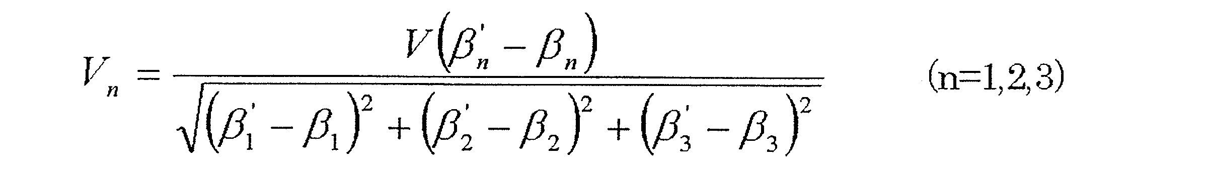
で表される式を用いて計算しても良い。上記式を用いることで、ベース速度Vは各アクチュエータの動作速度Vnの合成速度となり、どのような状況においても基端側のリンクハブの移動速度がほぼ一定となるように制御できる。
また、前記各アクチュエータの動作速度は、この動作速度をVn、最高速度をVmax、前記基端側の端部リンク部材の現在の回転角をβn、前記姿勢制御における前記基端側の端部リンク部材の目標とする回転角をβn´、(βn´-βn)の最大値をΔβmaxとした場合に、
Vn=Vmax(βn´-βn)/Δβmax
で表される式を用いて計算しても良い。
この場合は、常に少なくとも1つのアクチュエータを最高速度で位置決め駆動することができ、基端側のリンクハブの移動速度が最大となるように制御できる。
Vn=Vmax(βn´-βn)/Δβmax
で表される式を用いて計算しても良い。
この場合は、常に少なくとも1つのアクチュエータを最高速度で位置決め駆動することができ、基端側のリンクハブの移動速度が最大となるように制御できる。
この発明の制御方法において、前記3組以上のリンク機構のすべてに、前記基端側のリンクハブに対する前記先端側のリンクハブの姿勢を任意に変更させるアクチュエータを設け、これら各アクチュエータを冗長制御により制御しても良い。冗長制御を行うことで、先端側のリンクハブがどのような姿勢である場合においても、各アクチュエータの駆動バランスを良くすることができ、また先端側のリンクハブの整定時間を短くできる。さらに、アクチュエータおよびその周辺部分のガタやリンク機構のガタを詰めるように制御できるため、アクチュエータを停止した後のガタによる先端側のリンクハブの振動を抑制でき、整定時間が短くなる。
この発明の制御方法において、前記先端側のリンクハブに前記リンク作動装置の持つ共振周波数を検出する共振周波数検出用センサを設置し、その信号から共振周波数測定器により共振周波数を計算し、その計算結果から前記アクチュエータの加速時間および減速時間の設定値を更新しても良い。先端負荷やリンク作動装置の剛性が変わっても、容易に加速時間および減速時間を更新できるため、どのような状況においてもアクチュエータを停止した後の先端側のリンクハブの振動が小さくなり、高速で高精度の位置決め動作が可能となる。
前記共振周波数検出用センサとして加速度ピックアップを用い、かつ前記共振周波数測定器としてFFTアナライザを用いると良い。加速度ピックアップは小型で設置しやすく、FFTアナライザは容易に加速時間および減速時間を設定できる。
この発明のリンク作動装置の制御装置は、前記リンク作動装置における、前記アクチュエータの動作を制御する制御装置であって、前記アクチュエータのすべてが同時に動作を開始して同時に動作を完了するように制御する同期制御により、前記アクチュエータごとの動作を制御して、前記先端側のリンクハブを任意の姿勢に変更する姿勢制御を行い、前記すべてのアクチュエータの減速時間を、前記リンク作動装置の持つ共振周波数の1周期付近に設定して、前記同期制御および姿勢制御を行う同期・姿勢制御手段を設けたものである。
同時制御を行うことで、すべてのアクチュエータが同時に動作を完了するため、動作完了時における各リンク機構から先端側のリンクハブに作用する力のバランスが良くなり、先端側のリンクハブの整定時間が短くなる。
さらに、先端側のリンクハブは共振周波数の約半周期後に加速を打ち消す方向に振動するため、アクチュエータの減速時間がリンク作動装置の持つ共振周波数の1周期付近に設定されていると、周期的に加速するステップ加速を行う場合に、ステップ加速後の先端側のリンクハブの振動が小さくなる。その結果、高速動作時でもアクチュエータの動作完了後の先端側のリンクハブの振動が小さくなり、先端側のリンクハブを高速で高精度の位置決め動作させることが可能となる。
請求の範囲および/または明細書および/または図面に開示された少なくとも2つの構成のどのような組合せも、本発明に含まれる。特に、請求の範囲の各請求項の2つ以上のどのような組合せも、本発明に含まれる。
この発明は、添付の図面を参考にした以下の好適な実施形態の説明から、より明瞭に理解されるであろう。しかしながら、実施形態および図面は単なる図示および説明のためのものであり、この発明の範囲を定めるために利用されるべきものではない。この発明の範囲は添付の請求の範囲によって定まる。添付図面において、複数の図面における同一の符号は、同一または相当する部分を示す。
この発明の操作装置を備えたリンク作動装置の第1実施形態の一部を省略した正面図である。
同リンク作動装置のパラレルリンク機構の一状態を示す一部を省略した正面図である。
同リンク作動装置のパラレルリンク機構の異なる状態を示す一部を省略した正面図である。
同リンク作動装置のパラレルリンク機構を3次元的に表わした斜視図である。
同リンク作動装置の一つのリンク機構を直線で表現した図である。
同リンク作動装置のパラレルリンク機構の部分断面図である。
折れ角を求める最小二乗法による収束演算のフローチャートである。
操作装置の操作部の一例を示す図である。
操作装置の操作部の異なる例を示す図である。
同リンク作動装置を備えた作業装置の概略構成を示す図である。
この発明の操作装置を備えたリンク作動装置の第2実施形態の一部を省略した正面図である。
同リンク作動装置のパラレルリンク機構の部分断面図である。
図12の部分拡大図である。
この発明の第3実施形態にかかるリンク作動装置の一部を省略した正面図である。
この発明の第4実施形態にかかるリンク作動装置の一部を省略した正面図である。
この発明の第5実施形態にかかるリンク作動装置の一部を省略した正面図である。
この発明の第6実施形態にかかるリンク作動装置の一部を省略した正面図である。
この発明の第7実施形態にかかるリンク作動装置の一部を省略した正面図である。
この発明の第8実施形態にかかるリンク作動装置の一部を省略した側面図である。
基端側のリンクハブと基端側の端部リンク部材の回転対偶部の断面図である。
基端側の端部リンク部材と中央リンク部材の回転対偶部の断面図である。
この発明の第9実施形態にかかるリンク作動装置の一部を省略した正面図である。
同リンク作動装置のパラレルリンク機構の一状態を示す一部を省略した正面図である。
同パラレルリンク機構の基端側のリンクハブ等の水平断面図である。
同リンク作動装置の水平断面図である。
基端側のリンクハブと基端側の端部リンク部材の回転対偶部の断面図である。
基端側の端部リンク部材と中央リンク部材の回転対偶部の断面図である。
この発明の制御方法が適用されるリンク作動装置の第10実施形態の一部を省略した正面図である。
同リンク作動装置の基端側の端部リンク部材の回転角を示す図である。
制御パラメータの時間と速度の関係を示すグラフである。
加減速時間が一定である場合の加減速度を整定時間の関係を示すグラフである。
指令速度が一定である場合の加減速度を整定時間の関係を示すグラフである。
指令速度が一定である場合の加減速時間と整定時間の関係を示す図である。
共振周波数の1周期分のステップ加速を加えた場合の先端側のリンクハブの振動の振幅を示すグラフである。
この発明の第11実施形態にかかる制御方法が適用されるリンク作動装置の一部を省略した正面図である
同リンク作動装置のパラレルリンク機構の部分断面図である。
この発明の第12実施形態にかかる制御方法が適用されるリンク作動装置の一部を省略した正面図である。
この発明の操作装置を備えたリンク作動装置の第1実施形態を図1~図6と共に説明する。図1に示すように、このリンク作動装置51は、パラレルリンク機構1と、パラレルリンク機構1を作動させる複数(後記リンク機構4と同数)のアクチュエータ53と、これらアクチュエータ53を制御する制御装置54と、この制御装置54に操作指令を入力する操作装置55とを備える。この例では、制御装置54および操作装置55が共にコントローラ56に設けられているが、制御装置54はコントローラ56と別に設けてもよい。この例では、パラレルリンク機構1は、ベース部材52に吊り下げ状態で設置されている。
パラレルリンク機構1について説明する。図2および図3はパラレルリンク機構1のそれぞれ異なる状態を示す正面図であり、このパラレルリンク機構1は、基端側のリンクハブ2に対し先端側のリンクハブ3を3組のリンク機構4を介して姿勢変更可能に連結したものである。図2および図3では、1組のリンク機構4のみが示されている。
図4は、パラレルリンク機構1を三次元的に表わした斜視図である。各リンク機構4は、基端側の端部リンク部材5、先端側の端部リンク部材6、および中央リンク部材7で構成され、4つの回転対偶からなる3節連鎖のリンク機構をなす。回転対偶とその周辺部を回転対偶部T1~T4として示す。基端側および先端側の端部リンク部材5,6はL字状をなし、基端がそれぞれ基端側のリンクハブ2および先端側のリンクハブ3にそれぞれ回転自在に連結されている。中央リンク部材7は、両端に基端側および先端側の端部リンク部材5,6の先端がそれぞれ回転自在に連結されている。
基端側および先端側の端部リンク部材5,6は球面リンク構造で、3組のリンク機構4における球面リンク中心PA,PB(図2、図3)は一致しており、また、その球面リンク中心PA,PBからの距離dも同じである。端部リンク部材5,6と中央リンク部材7との各回転対偶の中心軸は、ある交差角γ(図4)をもっていてもよいし、平行であってもよい。
つまり、3組のリンク機構4は、幾何学的に同一形状をなす。幾何学的に同一形状とは、各リンク部材5,6,7を直線で表現した幾何学モデル、すなわち各回転対偶部T1~T4と、これら回転対偶T1~T4間を結ぶ直線とで表現したモデルが、中央リンク部材7の中央部に対する基端側部分と先端側部分が対称を成す形状であることを言う。図5は、一組のリンク機構4を直線で表現した図である。
図5に示すように、この実施形態のリンク機構4は回転対称タイプで、基端側のリンクハブ2および基端側の端部リンク部材5と、先端側のリンクハブ3および先端側の端部リンク部材6との位置関係が、中央リンク部材7の中心線Cに対して回転対称となる位置構成になっている。図2は、基端側のリンクハブ2の中心軸QAと先端側のリンクハブ3の中心軸QBとが同一線上にある状態を示し、図3は、基端側のリンクハブ2の中心軸QAに対して先端側のリンクハブ3の中心軸QBが所定の作動角をとった状態を示す。各リンク機構4の姿勢が変化しても、基端側と先端側の球面リンク中心PA,PB間の距離dは変化しない。
基端側のリンクハブ2と先端側のリンクハブ3と3組のリンク機構4とで、基端側のリンクハブ2に対し先端側のリンクハブ3が直交2軸方向に移動自在な2自由度機構が構成される。言い換えると、基端側のリンクハブ2に対して先端側のリンクハブ3を、回転が2自由度で姿勢変更自在な機構である。この2自由度機構は、基端側のリンクハブ2の中心軸QA、先端側のリンクハブ3の中心軸QB、および中央リンク部材7の中心線Cの交点Pを中心として、基端側のリンクハブ2に対して先端側のリンクハブ3が姿勢を変更する。
この2自由度機構は、コンパクトでありながら、基端側のリンクハブ2に対する先端側のリンクハブ3の可動範囲を広くとれる。例えば、図4に示すように、基端側のリンクハブ2の中心軸QAと先端側のリンクハブ3の中心軸QBの折れ角θの最大値(最大折れ角)を約±90°とすることができる。また、基端側のリンクハブ2に対する先端側のリンクハブ3の旋回角φを0°~360°の範囲に設定できる。折れ角θは、基端側のリンクハブ2の中心軸QAに対して先端側のリンクハブ3の中心軸QBが傾斜した垂直角度のことであり、旋回角φは、基端側のリンクハブ2の中心軸QAに対して先端側のリンクハブ3の中心軸QBが傾斜した水平角度のことである。
このパラレルリンク機構1において、各リンク機構4の端部リンク部材5,6の軸部材13(図6)の角度、および長さが等しく、かつ基端側の端部リンク部材5と先端側の端部リンク部材6の幾何学的形状が等しく、かつ中央リンク部材7についても基端側と先端側とで形状が等しいとき、中央リンク部材7の対称面に対して、中央リンク部材7と端部リンク部材5,6との角度位置関係を基端側と先端側とで同じにすれば、幾何学的対称性から基端側のリンクハブ2および基端側の端部リンク部材5と、先端側のリンクハブ3および先端側の端部リンク部材6とは同じに動く。例えば、基端側と先端側のリンクハブ2,3にそれぞれの中心軸QA,QBと同軸に回転軸を設け、基端側から先端側へ回転伝達を行う場合、基端側と先端側は同じ回転角になって等速で回転する等速自在継手となる。この等速回転するときの中央リンク部材7の対称面を等速二等分面という。
このため、基端側のリンクハブ2および先端側のリンクハブ3を共有する同じ幾何学形状のリンク機構4を円周上に複数配置させることにより、複数のリンク機構4が矛盾なく動ける位置として中央リンク部材7が等速二等分面上のみの動きに限定される。これにより、基端側と先端側とが任意の作動角をとっても、基端側と先端側とが等速回転する。
後で説明する図6に示すように、基端側のリンクハブ2および先端側のリンクハブ3は、その中心部に貫通孔10が軸方向に沿って形成され、外形が球面状をしたドーナツ形状をしている。貫通孔10の中心は図4に示すように、リンクハブ2,3の中心軸QA,QBと一致している。これら基端側のリンクハブ2および先端側のリンクハブ3の外周面の円周方向に等間隔の位置に、基端側の端部リンク部材5および先端側の端部リンク部材6がそれぞれ回転自在に連結されている。
図6は、基端側のリンクハブ2と基端側の端部リンク部材5の回転対偶部T1、および基端側の端部リンク部材5と中央リンク部材7の回転対偶部T2を示す部分断面図である。基端側のリンクハブ2は、前記軸方向の貫通孔10と外周側とを連通する半径方向の連通孔11が円周方向3箇所に形成され、各連通孔11内に設けた二つの軸受12により軸部材13がそれぞれ回転自在に支持されている。軸部材13の外側端部は基端側のリンクハブ2から突出し、その突出ねじ部13aに基端側の端部リンク部材5が結合され、ナット14によって締付け固定されている。
前記軸受12は、例えば深溝玉軸受等の転がり軸受であり、その外輪(図示せず)が前記連通孔11の内周に嵌合し、その内輪(図示せず)が前記軸部材13の外周に嵌合している。外輪は止め輪15によって抜け止めされている。また、内輪と基端側の端部リンク部材5の間には間座16が介在し、ナット14の締付力が基端側の端部リンク部材5および間座16を介して内輪に伝達されて、軸受12に所定の予圧を付与している。
基端側の端部リンク部材5と中央リンク部材7の回転対偶部T2は、中央リンク部材7の両端に形成された連通孔18に二つの軸受19が設けられ、これら軸受19により、基端側の端部リンク部材5の先端の軸部20が回転自在に支持されている。軸受19は、間座21を介して、ナット22によって締付け固定されている。
前記軸受19は、例えば深溝玉軸受等の転がり軸受であり、その外輪(図示せず)が前記連通孔18の内周に嵌合し、その内輪(図示せず)が前記軸部20の外周に嵌合している。外輪は止め輪23によって抜け止めされている。軸部20の先端ねじ部20aに螺着したナット22の締付力が間座21を介して内輪に伝達されて、軸受19に所定の予圧を付与している。
以上、基端側のリンクハブ2と基端側の端部リンク部材5の回転対偶部T1、および基端側の端部リンク部材5と中央リンク部材7の回転対偶部T2について説明したが、先端側のリンクハブ3と先端側の端部リンク部材6の回転対偶部T4および先端側の端部リンク部材6と中央リンク部材7の回転対偶部T3も同じ構成である(図示省略)。
このように、各リンク機構4における4つの回転対偶部T1~T4、つまり、基端側のリンクハブ2と基端側の端部リンク部材5の回転対偶部T1、先端側のリンクハブ3と先端側の端部リンク部材6の回転対偶部T4、基端側の端部リンク部材5と中央リンク部材7と回転対偶部T2、および先端側の端部リンク部材6と中央リンク部材7の回転対偶部T3に、軸受12,19を設けた構造とすることにより、各回転対偶部T1~T4での摩擦抵抗を抑えて回転抵抗の軽減を図ることができ、滑らかな動力伝達を確保できると共に耐久性を向上できる。
この軸受12,19を設けた構造では、軸受12,19に予圧を付与することにより、ラジアル隙間とスラスト隙間をなくし、回転対偶部のがたつきを抑えることができ、基端側のリンクハブ2側と先端側のリンクハブ3側間の回転位相差がなくなり等速性を維持できると共に振動や異音の発生を抑制できる。特に、前記軸受12,19の軸受隙間を負すきまとすることにより、入出力間に生じるバックラッシュを少なくすることができる。
軸受12を基端側のリンクハブ2および先端側のリンクハブ3に埋設状態で設けたことにより、パラレルリンク機構1全体の外形を大きくすることなく、基端側のリンクハブ2および先端側のリンクハブ3の外形を拡大することができる。そのため、基端側のリンクハブ2および先端側のリンクハブ3を他の部材に取付けるための取付スペースの確保が容易である。
図1において、パラレルリンク機構1は、基端側のリンクハブ2がベース部材52の下面に固定され、先端側のリンクハブ3が垂下した状態となっている。ベース部材52の上面には、ロータリアクチュエータからなるアクチュエータ53が、リンク機構4と同数すなわち3個設置されている。アクチュエータ53の出力軸53aはベース部材52を貫通して下方に突出し、その出力軸53aに取付けたかさ歯車57と基端側のリンクハブ2の軸部材13(図6)に取付けた扇形のかさ歯車58とが噛み合っている。前記かさ歯車57とかさ歯車58とで、歯車式の減速部73が構成されている。
アクチュエータ53を回転させると、その回転が一対のかさ歯車57,58を介して軸部材13に伝達されて、基端側のリンクハブ2に対する基端側の端部リンク部材5の角度が変わる。各アクチュエータ53の動作量を制御して、リンク機構4ごとに基端側の端部リンク部材5の角度を調整することにより、基端側のリンクハブ2に対する先端側のリンクハブ3の姿勢(以下、「先端姿勢」とする)が決まる。各アクチュエータ53の動作は、操作装置55の操作指令に基づき、制御装置54により制御される。
操作装置55は、姿勢指定手段55aと姿勢取得手段55bと姿勢情報付与手段55cとを有する。姿勢指定手段55aは、目標とする先端姿勢を人為操作で指定する手段であり、2次元の直交座標系上の座標位置で先端姿勢を指定する。直交座標系は、図4に示すように、基端側のリンクハブ2の中心軸QAの延長軸QA´と直交し、前記延長軸QA´上の任意の位置に原点Oが定められたXY直交座標系100である。目標とする先端姿勢は、先端側のリンクハブ3の中心軸QBがXY直交座標系100と交わる点の座標である目標座標T(X,Y)で表わされる。目標座標Tの指定方法については、後で説明する。
姿勢取得手段55bは、姿勢指定手段55aにより指定されたXY直交座標系100の座標位置で表される先端姿勢を、角度座標系の折れ角θおよび旋回角φで表される先端姿勢に変換する手段である。変換の原理について説明する。
XY座標系100での原点Oと目標座標Tとの距離rは、式1を用いて求められる。

また、角度座標系での原点Oと目標座標Tとの距離r´は、式2を用いて求められる。
r´=h´×tanθ ・・・(式2)
r´=h´×tanθ ・・・(式2)
ここで、h´は、図4に示すように、先端側のリンクハブ3の姿勢変更の回転中心である交点Pから目標座標Tまでの高さである。球面リンク中心PA,PB間の距離をd、基端側のリンクハブ2の球面リンク中心PAから目標座標Tまでの高さをhとした場合、h´は式3から求められる。式3で求められたh´を式2に代入することで、角度座標系での原点Oと目標座標Tとの距離r´が求められる。なお、dおよびhは、パラレルリンク機構1の寸法やリンク作動装置51を搭載した装置の寸法により決定される固定値である。
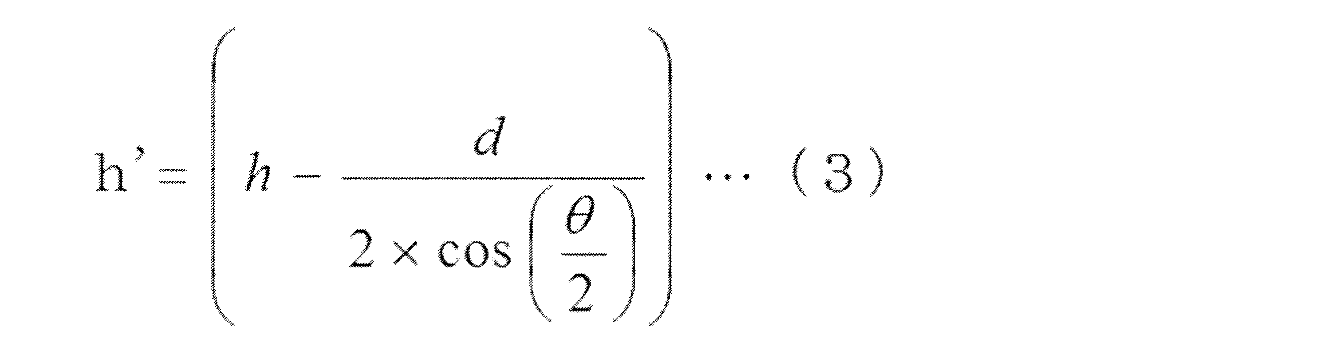
このようにして求められたXY座標系100での原点Oと目標座標Tとの距離rと、角度座標系での原点Oと目標座標Tとの距離r´とを比較し、差が最小となる折れ角θを探索する。折れ角θの探索は、例えば式4に示すように、最小二乗法による収束演算を用いて行う。
dr=(r-r´)2 ・・・(式4)
dr=(r-r´)2 ・・・(式4)
最小二乗法による収束演算は、図7のフローチャートに示す順序で行われる。まず、S1において、式1による距離rの計算と、比較値Aの初期値の設定とを行う。比較値Aはdrとの比較値であり、探索過程で計算されるdrの値よりも十分大きい値を初期値として設定する。
次に、S2においてθ=0°として、S3においてr2、drを計算する。また、S4において、drがAよりも小さければ、Aにdrを代入し、そのときのθをAnsθに代入する。drがAよりも大きければ、AおよびAnsはそのままの値にする。さらに、S5において、θを予め定めた角度範囲の最大値Maxθと比較し、小さい場合は、S6において、θ=θ+Δθとして、ある定めた値を加算する。
上記S3,S4,S6の操作を、θがある設定した角度範囲の最大値Maxθになるまで繰り返す。そして、S7において、最終的に得られたAnsθを求める折れ角θとする。
上記探索により得られた折れ角θを用いて、旋回角φを求める。その際、θ=0である場合は、
φ=0 ・・・(式5)
とし、θ≠0である場合は、

とする。
φ=0 ・・・(式5)
とし、θ≠0である場合は、
図7のフローチャートで示す操作で求められた折れ角θ、および式5または式6の計算で求められた旋回角φにより、目標とする先端姿勢が規定される。上記のように、最小二乗法による収束演算により、現在の座標位置を基準にその近辺から順に探索して折れ角θを求めると、演算回数を減らすことができる。
姿勢情報付与手段55cは、姿勢取得手段55bにより取得された先端姿勢の情報、すなわち折れ角θおよび旋回角φを制御装置54に与える。
制御装置54は、コンピュータによる数値制御式のものであり、操作装置55の姿勢情報付与手段55cから与えられる先端姿勢の情報に応じて、各基端側の端部リンク部材5の目標とする回転角βn(図4)を求め、姿勢検出手段59(図1)によって検出される実際の回転角βnが目標とする回転角βnとなるように、各アクチュエータ53をフィードバック制御する。
回転角βnは、例えば、下記の式7を逆変換することで求められる。逆変換とは、折れ角θおよび旋回角φから回転角βnを算出する変換のことである。折れ角θおよび旋回角φと、回転角βnとは相互関係があり、一方の値から他方の値を導くことができる。
cos(θ/2)sinβn-sin(θ/2)sin(φ+δn)cosβn+sin(γ/2)=0
;(n=1,2,3) ・・・(式7)
ここで、γ(図4)は、基端側の端部リンク部材5に回転自在に連結された中央リンク部材7の連結端軸と、先端側の端部リンク部材6に回転自在に連結された中央リンク部材7の連結端軸とが成す角度である。δn(図4におけるδ1,δ2,δ3)は、基準となる基端側の端部リンク部材5に対する各基端側の端部リンク部材5の円周方向の離間角である。
cos(θ/2)sinβn-sin(θ/2)sin(φ+δn)cosβn+sin(γ/2)=0
;(n=1,2,3) ・・・(式7)
ここで、γ(図4)は、基端側の端部リンク部材5に回転自在に連結された中央リンク部材7の連結端軸と、先端側の端部リンク部材6に回転自在に連結された中央リンク部材7の連結端軸とが成す角度である。δn(図4におけるδ1,δ2,δ3)は、基準となる基端側の端部リンク部材5に対する各基端側の端部リンク部材5の円周方向の離間角である。
指令ごとに式7を逆変換して回転角βnを求めてもよいが、事前に、表1のように先端位置姿勢と回転角βnとの関係を示すテーブルを作成しておいても良い。テーブル化されていると、先端姿勢変更の指令があったら、すぐにテーブルを用いて目標とする回転角βnを求めることができる。そのため、アクチュエータ53の制御をより一層高速で行うことが可能となる。また、あらかじめ指令パターンを登録して登録順に動作する場合は、表2のようにパターン登録時に先端位置姿勢と回転角βnとの関係を示すテーブルを登録することで、テーブルの記憶領域を節約できる。
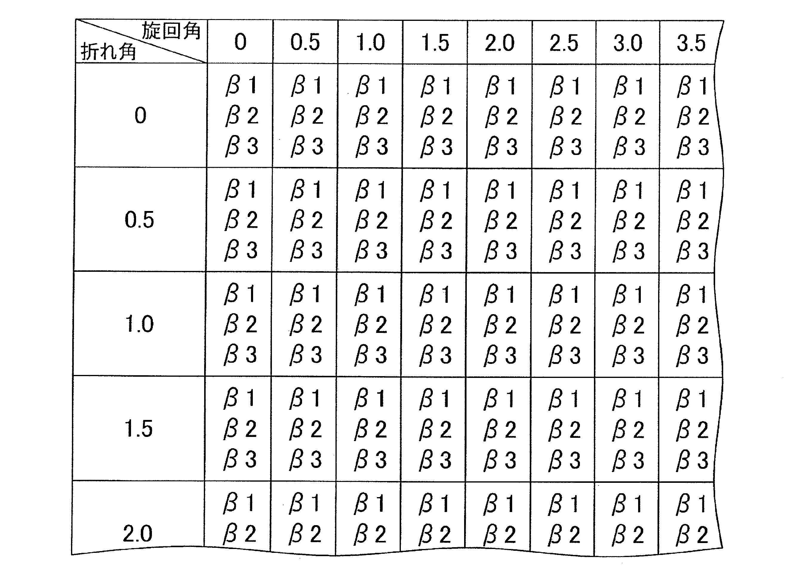

図8は、操作装置55の操作部の一例を示す。この操作部は、座標位置を数値入力により指定する方式であり、現在の座標位置のX座標値およびY座標値をそれぞれ表示する現在値表示部101,102と、目標のX座標値およびY座標値をそれぞれ表示する目標値表示部103,104と、目標値表示部103,104に目標のX座標値およびY座標値を入力する10キー等からなる数値入力ボタン105と、動作実行ボタン106とを備える。XY直交座標系上での座標位置の指定は、定められた基準点(例えば原点O)に対する絶対座標を数値入力する方式、現在の座標位置から目標とする座標位置までの差分を数値入力する方式の何れであってもよい。
数値入力ボタン105を用いて目標のX座標値およびY座標値を入力すると、その値が目標値表示部103,104を表示される。それと共に、入力されたX座標値およびY座標値、先端側のリンクハブ3から被作業物(図示せず)の作業面までの距離、パラレルリンク機構1の各部の寸法等のパラメータにより、目標とする先端姿勢の折れ角θおよび旋回角φが計算される。また、この先端姿勢から、各アクチュエータ53の動作量が計算される。動作実行ボタン106を押すと、各アクチュエータ53が駆動されて、入力されたX座標値およびY座標値となるように先端姿勢が変更される。このように、XY直交座標系100上の座標位置で目標とする先端姿勢の指定を行うので、被作業物の座標位置が直交座標系で扱われる場合でも、リンク作動装置51(図1)を直感的に操作することができる。
図9は、操作装置55の操作部の異なる例を示す。この操作部は、座標位置を操作量で指定する方式であり、現在の座標位置のX座標値およびY座標値をそれぞれ表示する現在値表示部101,102と、先端姿勢を変更操作する押し操作ボタン107~110とを有する。押し操作ボタン107を押すとX座標値が大きくなる側へ姿勢変更し、押し操作ボタン108を押すとX座標値が小さくなる側へ姿勢変更し、押し操作ボタン109を押すとY座標値が大きくなる側へ姿勢変更し、押し操作ボタン110を押すとY座標値が小さくなる側へ姿勢変更する。
姿勢変更の程度は、押し操作ボタン107~110を押している時間または押した回数に応じて変わる。また、この例では、各押し操作ボタン107~110は、姿勢変更が低速で行われる低速ボタン107a,108a,109a,110aと、姿勢変更が高速で行われる高速ボタン107b,108b,109b,110bとからなり、姿勢変更を低速および高速の2段階で行えるようになっている。
この操作装置55の場合、押し操作ボタン107~110の操作によりX座標値およびY座標値が逐次変更され、その都度、目標とする折れ角θおよび旋回角φを計算し、それに応じたアクチュエータ53の動作量を決定するシステムとなっている。つまり、押し操作ボタン107~110を押している間だけ、先端姿勢が変更し続ける。そのため、操作と座標位置との関係が感覚的に分かり易い。
上記操作装置55と組み合して用いられる制御装置54は、操作装置55の姿勢指定手段55cから与えられる先端姿勢の情報を、定められた変換式によりアクチュエータ53の動作量に変換し、その動作量だけアクチュエータ53を動作させるように制御する。詳しくは、姿勢指定手段55cから折れ角θおよび旋回角φで表される先端姿勢が制御装置54に与えられると、制御装置54は、前記式7を用いて上記折れ角θおよび旋回角φを逆変換することで各基端側の端部リンク部材5の回転角βnを求め、その求められた回転角βnを用いて式8を演算することで、各アクチュエータ53の動作量Rnを算出する。
Rn=βn×k;(n=1,2,3) ・・・(式8)
ここで、kは、アクチュエータ53に付設されている減速機(図示せず)の減速比によって決まる係数である。このように先端姿勢の情報を、変換式によりアクチュエータ53の動作量に変換すると、アクチュエータ53の制御を容易に行える。
Rn=βn×k;(n=1,2,3) ・・・(式8)
ここで、kは、アクチュエータ53に付設されている減速機(図示せず)の減速比によって決まる係数である。このように先端姿勢の情報を、変換式によりアクチュエータ53の動作量に変換すると、アクチュエータ53の制御を容易に行える。
アクチュエータ53の動作量や先端姿勢の変更速度を段階的に変更可能とするのではなく、押し操作ボタン107~110の一操作当たりのアクチュエータ53の動作量や先端姿勢の変更速度を任意に変えられるようにしても良い。また、この例のように、複数の押し操作ボタン107~110で操作するのではなく、ジョイスティックのような一つの操作手段で操作するようにしても良い。
図10は、上記リンク作動装置51を備えた作業装置120を示す。この作業装置120は、作業室121の天井部を構成するベース部材52に基端側のリンクハブ2を固定して、パラレルリンク機構1が吊り下げ状態で設置されており、このパラレルリンク機構1の先端側のリンクハブ3にエンドエフェクタ122が搭載されている。エンドエフェクタ122は、例えば塗装機である。
エンドエフェクタ122の下方には、被作業物WをXY軸方向に移動させる移動機構123が設置されている。移動機構123は、床面に固定して設置されたX軸方向に沿って長いX軸レール124と、このX軸レール124に沿って進退自在でY軸方向に沿って長いY軸レール125と、このY軸レール125に沿って進退自在で上面に被作業物が載せられる作業台126とを備える。Y軸レール125および作業台126は、それぞれ図示しない駆動源の駆動によりX軸方向およびY軸方向に移動させられる。
エンドエフェクタ122が塗装機である場合、移動機構123による作業台126をX軸およびY軸方向に進退させることで、被作業物Wの塗装箇所を塗装機の塗料噴射口122aの先に位置させる。また、リンク作動装置51の先端姿勢を変更してエンドエフェクタ122の向きを変えることで、常に前記塗料噴射口122aが被作業物Wの塗装面に向くように調整する。
以下に、この発明の第2~第12実施形態について説明する。以下の説明においては、各実施形態で先行する実施形態で説明している事項に対応している部分には同一の符号を付し、重複する説明を略する。構成の一部のみを説明している場合、構成の他の部分は、先行して説明している実施形態と同様とする。実施形態で具体的に説明している部分の組合せばかりではなく、特に組合せに支障が生じなければ、実施形態同士を部分的に組合せることも可能である。
図11ないし図13は、リンク作動装置の第2実施形態を示す。このリンク作動装置61は、図11に示すように、ベース部材62にパラレルリンク機構1が吊り下げ状態で設けられている。すなわち、パラレルリンク機構1は、基端側のリンクハブ2がベース部材62を介して前記ベース部材62に固定され、先端側のリンクハブ3に、各種器具等を取付ける先端取付部材63が搭載されている。
図12および図13に示すように、パラレルリンク機構1は、基端側のリンクハブ2および先端側のリンクハブ3に対して端部リンク部材5,6をそれぞれ回転自在に支持する軸受31を外輪回転タイプとしたものである。基端側のリンクハブ2と基端側の端部リンク部材5の回転対偶部T1を例にとって説明すると、基端側のリンクハブ2の円周方向の3箇所に軸部32が形成され、この軸部32の外周に二つの軸受31の内輪(図示せず)が嵌合し、基端側の端部リンク部材5に形成された連通孔33の内周に軸受31の外輪(図示せず)が嵌合している。軸受31は、例えば深溝玉軸受、アンギュラ玉軸受等の玉軸受であって、ナット34による締付けでもって所定の予圧量が付与された状態で固定されている。先端側のリンクハブ3と先端側の端部リンク部材6の回転対偶部T4も、上記同様の構造である。
また、基端側の端部リンク部材5と中央リンク部材7の回転対偶部T2に設けられた軸受36は、基端側の端部リンク部材5の先端に形成された連通孔37の内周に外輪(図示せず)が嵌合し、中央リンク部材7と一体の軸部38の外周に内輪(図示せず)が嵌合している。軸受36は、例えば深溝玉軸受、アンギュラ玉軸受等の玉軸受であって、ナット39による締付けでもって所定の予圧量が付与された状態で固定されている。先端側の端部リンク部材6と中央リンク部材7の回転対偶部T3も、上記同様の構造である。
パラレルリンク機構1の3組のリンク機構4のすべてに、基端側の端部リンク部材5を回動させて先端位置姿勢を任意に変更させるアクチュエータ70と、このアクチュエータ70の動作量を基端側の端部リンク部材5に減速して伝達する減速機構71とが設けられている。アクチュエータ70はロータリアクチュエータ、より詳しくは減速機70a付きのサーボモータであって、モータ固定部材72によりベース部材62に固定されている。減速機構71は、アクチュエータ70の減速機70aと、歯車式の減速部73Aとでなる。
歯車式の減速部73Aは、アクチュエータ70の出力軸70bにカップリング75を介して回転伝達可能に連結された小歯車76と、基端側の端部リンク部材5に固定され前記小歯車76と噛み合う大歯車77とで構成されている。図示例では、小歯車76および大歯車77は平歯車であり、大歯車77は、扇形の周面にのみ歯が形成された扇形歯車である。大歯車77は小歯車76よりもピッチ円半径が大きく、アクチュエータ70の出力軸70bの回転が基端側の端部リンク部材5へ、基端側のリンクハブ2と基端側の端部リンク部材5との回転対偶部T1の回転軸O1回りの回転に減速して伝達される。その減速比は10以上とされている。
大歯車77のピッチ円半径は、基端側の端部リンク部材5のアーム長Lの1/2以上としてある。前記アーム長Lは、基端側のリンクハブ2と基端側の端部リンク部材5との回転対偶部T1の中心軸O1の軸方向中心点P1から、基端側の端部リンク部材5と中央リンク部材7との回転対偶部T2の中心軸O2の軸方向中心点P2を基端側のリンクハブ2と基端側の端部リンク部材5の回転対偶軸O1に直交してその軸方向中心点P1を通る平面に投影した点P3までの距離である。この実施形態の場合、大歯車77のピッチ円半径が前記アーム長L以上である。そのため、高い減速比を得るのに有利である。
小歯車76は、大歯車77と噛み合う歯部76aの両側に突出する軸部76bを有し、これら両軸部76bが、ベース部材62に設置された回転支持部材79に設けられた二つの軸受80によりそれぞれ回転自在に支持されている。軸受80は、例えば深溝玉軸受、アンギュラ玉軸受等の玉軸受である。図示例のように玉軸受を複列で配列する以外に、ローラ軸受や滑り軸受を用いてもよい。二つの軸受80の各外輪(図示せず)間にはシム(図示せず)を設け、軸部76bに螺合したナット81を締め付けることにより、軸受80に予圧を付与する構成としてある。軸受80の外輪は、回転支持部材79に圧入されている。
この実施形態の場合、大歯車77は、基端側の端部リンク部材5と別部材であり、基端側の端部リンク部材5に対してボルト等の結合具82により着脱可能に取付けられている。大歯車77は基端側の端部リンク部材5と一体であってもよい。
アクチュエータ70の回転軸心O3および小歯車76の回転軸心O4は同軸上に位置する。これら回転軸心O3,O4は、基端側のリンクハブ2と基端側の端部リンク部材5の回転対偶軸O1と平行で、かつベース部材62からの高さが同じとされている。
このリンク作動装置61も、アクチュエータ70を制御する制御装置84と、この制御装置84に操作指令を入力する操作装置85とを、コントローラ86内に備える。制御装置84および操作装置85は、前記実施形態のものと同じ構成であり、前記同様の作用・効果が得られる。操作装置85は、前記第1実施形態と同様に姿勢指定手段55a、姿勢取得手段55b、および姿勢情報付与手段55cを有するが、これらの図示を省略している。
このリンク作動装置61は、3組のリンク機構4のすべてにアクチュエータ70および減速機構71を設けたことで、パラレルリンク機構1や減速機構71のガタを詰めるように制御することが可能となり、先端側のリンクハブ3の位置決め精度が向上すると共に、リンク作動装置61自体の高剛性化を実現できる。
また、減速機構71の歯車式の減速部73Aは、小歯車76と大歯車77の組合せからなり、10以上の高い減速比が得られる。減速比が高いと、エンコーダ等による位置決め分解能が高くなるため、先端側のリンクハブ3の位置決め分解能が向上する。また、低出力のアクチュエータ70を使用することができる。この実施形態では減速機70a付きのアクチュエータ70を使用しているが、歯車式の減速部73Aの減速比が高ければ、減速機無しのアクチュエータ70を使用することも可能となり、アクチュエータ70を小型化できる。
大歯車77のピッチ円半径を、基端側の端部リンク部材5のアーム長Lの1/2以上としたことで、先端負荷による基端側の端部リンク部材5の曲げモーメントが小さくなる。そのため、リンク作動装置61全体の剛性を必要以上に高くしなくて済むと共に、基端側の端部リンク部材5の軽量化を図れる。例えば、基端側の端部リンク部材5をステンレス鋼(SUS)からアルミに変更できる。また、大歯車77のピッチ円半径が比較的大きいため、大歯車77の歯部の面圧が減少し、リンク作動装置61全体の剛性が高くなる。また、大歯車77のピッチ円半径が前記アーム長の1/2以上であると、大歯車77が、基端側のリンクハブ2と基端側の端部リンク部材5の回転対偶部T1に設置する軸受12の外径よりも十分大きな径となるため、大歯車77の歯部と軸受12との間にスペースができ、大歯車77の設置が容易である。
特にこの第2実施形態の場合、大歯車77のピッチ円半径が前記アーム長L以上であるため、大歯車77のピッチ円半径がさらに大きくなり、前記作用・効果がより一層顕著に現れる。加えて、小歯車76をリンク機構4よりも外径側に設置することが可能となる。その結果、小歯車76の設置スペースを容易に確保することができ、設計の自由度が増す。また、小歯車76と他の部材との干渉が起こり難くなり、リンク作動装置61の可動範囲が広くなる。
小歯車76および大歯車77は、それぞれ平歯車であるため、製作が容易であり、しかも回転の伝達効率が高い。小歯車76は軸方向両側で軸受80により支持されているため、小歯車76の支持剛性が高い。それにより、先端負荷による基端側の端部リンク部材5の角度保持剛性が高くなり、リンク作動装置61の剛性や位置決め精度の向上に繋がる。また、アクチュエータ70の回転軸心O3、小歯車76の回転軸心O4、および基端側のリンクハブ2と基端側の端部リンク部材5との回転対偶部T1の中心軸O1が同一平面上にあるため、全体的なバランスが良く、組立性が良い。
大歯車77は、基端側の端部リンク部材5に対して着脱自在であるため、歯車式の減速部73Aの減速比や、基端側のリンクハブ2に対する先端側のリンクハブ3の作動範囲等の仕様の変更が容易となり、リンク作動装置61の量産性が向上する。つまり、同じリンク作動装置61を、大歯車77を変えるだけで、様々な用途に適用することが可能である。また、メンテナンス性が良い。例えば、歯車式の減速部73Aに障害が生じた場合に、同減速部73Aのみを交換するだけで対処可能である。
この発明の第3実施形態にかかるリンク作動装置を図14、および前記した第1実施形態で用いた図2~図6を援用して説明する。なお、第1実施形態と同一または相当する構成部分には同一の符号を付してその詳しい説明を省略し、相違する構成について説明する。第1実施形態を示す図1との相違は、図14に示すこのリンク作動装置51は、パラレルリンク機構1および減速部73から落下する潤滑剤を受ける潤滑剤受け部材200を有している点である。
前記潤滑剤受け部材200は、板状部201と、この板状部201の外周縁から板状部201の表面に対して交差する一方向に突出した突出部202とを有する皿状の部材であり、突出部202が基端側のリンクハブ2の側を向くように、板状部201の中央部を先端側のリンクハブ3の先端面に固定して設置されている。板状部201の先端側のリンクハブ3への固定は、例えばボルト(図示せず)によって行われる。この潤滑剤受け部材200は、簡単な構成であるため、安価に製作することができる。また、潤滑剤受け部材200は、パラレルリンク機構1および減速部73の下方位置にだけ設ければよく、パラレルリンク機構1の全体を覆うものではないため、コンパクトである。
潤滑剤受け部材200を設けたことにより、図14のように基端側のリンクハブ2に対して先端側のリンクハブ3が下方に位置するようにパラレルリンク機構1を下向きに設置した場合でも、パラレルリンク機構1の軸受12,19や減速部73のかさ歯車57,58から漏れ出て、パラレルリンク機構1を伝って落下または歯車部や軸受部から直接落下する潤滑剤が、潤滑剤受け部材200に受けられる。潤滑剤受け部材200は、板状部201の外周縁に突出部202を有する皿状であるため、先端側のリンクハブ3の姿勢変化に伴い潤滑剤受け部材200が傾いても、受けた潤滑剤が板状部201の外周縁から垂れることがない。そのため、下方の被作業物(図示せず)に潤滑剤が掛かることが防止される。
言い換えると、潤滑剤受け部材200を設けると、軸受12,19やかさ歯車57,58から少しだけなら潤滑剤が漏れ出ることを許容できるため、軸受12,19やかさ歯車57,58のシール構造を簡素化できる。それにより、軸受12,19の寸法を小さくして、機構のコンパクト化を図ることができ、パラレルリンク機構1の高速位置決めが可能となる。また、軸受12,19やかさ歯車57,58の潤滑剤の交換を容易に行うことができ、メンテナンス性に優れる。さらに、コスト低減に繋がる。
上記第3実施形態の場合、先端側のリンクハブ3に潤滑剤受け部材200が設けられており、同リンクハブ3の姿勢の変化に応じて潤滑剤受け部材200が動くため、パラレルリンク機構1の折れ角θ(図4)が大きい場合、潤滑剤受け部材200がかさ歯車57,58や一部の軸受12,19の真下に位置せずに、かさ歯車57,58や軸受12,19から落下する潤滑剤を潤滑剤受け部材200で受けられないことがある。よって、この実施形態の構成は、パラレルリンク機構1の折れ角が±45°以下で使用する場合に適用するのが有効である。
図15に示す第4実施形態にかかるリンク作動装置51のように、潤滑剤受け部材200の突出部202を、その突出端側が、先端側のリンクハブ3の中心軸QBに向かって傾く形状とすると、先端側のリンクハブ3が大きく傾いた場合でも、潤滑剤受け部材200から潤滑剤が垂れることを防止できる。その場合、潤滑剤受け部材200の突出部202の傾き角度は、パラレルリンク機構1の動作範囲における折れ角θの最大値(最大折れ角)θmax以上とするのが望ましい。突出部202の傾き角度を上記のように定めると、常に突出部202の突出端側が中心方向に傾く状態となるため、潤滑剤が突出部202を乗り越えて垂れることを確実に防止できる。
また、図16に示す第5実施形態にかかるリンク作動装置51のように、潤滑剤受け部材200を、突出部202の突出端に結合され、板状部201と平行で内周部に貫通孔203aが形成された上板203を有する構成としてもよい。潤滑剤受け部材200が上板203を有すると、パラレルリンク機構1の先端側のリンクハブ3が90°(最大折れ角)傾いた状態でも、上板203が地面に対して垂直方向に向いているため、潤滑剤受け部材200に多量の潤滑剤が溜まっていても、潤滑剤受け部材200から潤滑剤が垂れることを確実に防止できる。
図17は、第6実施形態を示す。このリンク作動装置51は、ベース部材52に支柱204を介して支持され、ベース部材52と平行で内周部に貫通孔205aが形成されたリング状の固定部材205を有する。固定部材205の外周端には、ベース部材52側へ突出する突出部206が形成され、内周端にはベース部材52と反対側へ突出する内周立縁部207が形成されている。潤滑剤受け部材200は、先端側のリンクハブ3に固定された板状部201と、この板状部201と固定部材205間の全周を覆い、これら両者を互いに連結する伸縮自在な連結部208とでなる。具体的には、連結部208は、シート状の弾性材料からなり、両端を板状部201の外周面および固定部材205の内周立縁部207の外周面にそれぞれ嵌合させて設置されている。連結部208を板状部201の外周面および固定部材205の内周立縁部207の外周面に対して固定バンドなどで固定すると良い。
この構成であると、パラレルリンク機構1における固定部材205よりも先端側の部分が潤滑剤受け部材200で広範に覆われるため、動作時にパラレルリンク機構1や減速部73から飛び散る潤滑剤も潤滑剤受け部材200で受けることができる。固定部材205の外周端に突出206が設けられているため、固定部材205の上に潤滑剤が落下しても、その潤滑剤が固定部材205の外側へ落ちることがなく、被作業物に潤滑剤が掛かることを防止できる。連結部208は伸縮自在であるため、基端側のリンクハブ2に対する先端側のリンクハブ3の姿勢が変わっても、それに応じて潤滑剤受け部材200の連結部208が変形することができる。
図18に示す第7実施形態のように、潤滑剤受け部材200の連結部208Aは、板状部201と固定部材205間の全周を覆う蛇腹状の形状としても良い。その場合、連結部208Aは、外力が作用しない自然状態よりも小さく圧縮された状態で、板状部201および固定部材205に組み付けておく。この場合も、前記同様に、基端側のリンクハブ2に対する先端側のリンクハブ3の姿勢が変わっても、それに応じて潤滑剤受け部材200の連結部208Aが変形することができる。
図19は、第8実施形態を示す。このリンク作動装置51は、減速部73のかさ歯車57,58から落下する潤滑剤を受ける潤滑剤受け部材210を設けたものである。潤滑剤受け部材210は、減速部73の真下に位置する板状部211と、この板状部211の外周縁からベース部材52側へ突出した突出部212とを有する皿状の部材であり、突出部212の一部分と繋がる取付部213を介して、ボルト(図示せず)等によりベース部材52に取付けられている。潤滑剤受け部材210は、例えば板金等により製作される。
このような潤滑剤受け部材210を設けることで、減速部73から落下した潤滑剤が被作業物に掛かることを防止できる。ただし、パラレルリンク機構1から落下した潤滑剤が被作業物にかかることは防止できない。そのため、二点鎖線で示すように、図14、図15、図16の潤滑剤受け部材200を併用するのが望ましい。あるいは、軸受12,19(図6)をシール付き軸受とするか、軸受取付部にシール機能を持たせても良い。
シール機能を持たせた軸受取付部の構造の一例を以下に示す。図20は、基端側のリンクハブ2と基端側の端部リンク部材5の回転対偶部T1を示す。前記二つの軸受12はアンギュラ玉軸受であり、例えば背面組合せで配置されている。軸部材13の内端部分は、軸受12の内輪12aの内周に嵌合した部分13bよりも外径が大きい段差部13cとされ、この段差部13cの段差面13dが内側の軸受12の内輪12aの端面に当接することで、内輪12aを軸方向に位置決めしている。また、外側の軸受12の内輪12aと基端側の端部リンク部材5との間には、両端をこれらに接して間座16が設けられている。よって、前記ナット14を締付けることにより、基端側の端部リンク部材5および間座16を介して内輪12aが前記段差面13dに押付けられて、内輪12aを締付け固定すると共に、軸受12に対して予圧を付与する。
基端側のリンクハブ2における前記連通孔11の周辺部分は、環状内面形成部87とされる。図示例では、環状内面形成部87は基端側のリンクハブ2の一部とされているが、環状内面形成部87は基端側のリンクハブ2と別体であっても良い。また、図示例では、軸部である軸部材13は基端側の端部リンク部材5とは別部材とされているが、軸部は基端側の端部リンク部材5と一体に設けられていても良い。
環状内面形成部87の一部は、軸受12の外輪12bの外周に嵌合した部分すなわち外輪嵌合部87aよりも内径が小さい段差部87bとされ、この段差部87bの段差面87cが内側の軸受12の外輪12bの端面に当接することで、外輪12bを軸方向に位置決めしている。また、外側の軸受12の外輪12bは、環状内面形成部87に取付けた止め輪17によって抜け止めされている。
前記軸部材13の段差部13cの外周面と前記環状内面形成部87の段差部87bの内周面とは、僅かな隙間90Aを介して非接触で対向している。これにより、軸部材13の段差部13cと環状内面形成部87の段差部87bとは互いに回転が可能でありながら、軸受12の内部と外部間の潤滑剤等の出入りを規制するシール構造88が構築されている。つまり、隙間90Aを狭くすることで、軸受12の内部の潤滑剤が外部に漏れることや、外部から軸受12の内部へ異物が侵入することを防いでいる。上記隙間90Aが狭いほどシール効果が高い。
前記間座16の軸方向外側部分は、前記止め輪17を避けて外径側へ延びたつば状部16aとして形成されており、このつば状部16aの外周面と環状内面形成部87の一部である外端部87dとが、僅かな隙間90Bを介して非接触で対向している。これにより、間座16のつば状部16aと環状内面形成部87の外端部87dとは互いに回転が可能であり、かつ前記同様のシール機能を有するシール構造89が構築されている。上記隙間90Bが狭いほどシール効果が高い。
このように、リンクハブ2(3)と端部リンク部材5(6)の回転対偶部T1(T4)では、軸受12の軸方向一方側に、回転対偶部の一方の対偶構成部材である端部リンク部材5(6)に設けられた軸部材13と他方の対偶構成部材であるリンクハブ2(3)に設けられた環状内面形成部87とでシール構造88が構築され、かつ軸方向他方側に、前記軸部材13の外周に嵌合する間座16と前記環状内面形成部87とでシール構造89が構築されている。
リンクハブ2(3)および端部リンク部材5(6)は、パラレルリンク機構1を構成する部品である。また、間座16は、軸受12の内輪12aをナット14で締付け固定する場合に、内輪12aに対して均一に荷重がかかるように、一般的に内輪12aとナット14の間に設けられる部品である。このように、必要不可欠な部品だけでシール構造88,89を構築することで、別部材からなるシールを設ける必要がなくなり、軸受12の幅寸法を抑えることができる。そのため、リンク機構4の部品間の干渉が起り難く、作業範囲が広くなる。また、軸受12周辺の寸法が小さくなるため、パラレルリンク機構1全体の軽量・コンパクト化を実現できる。
組立性等の問題により、軸部材13と環状内面形成部87だけでは軸受12の両端にシール構造を構築することは難しいが、間座16と環状内面形成部87とによるシール構造を併用することで、軸受12の両端にシール構造88,89を容易に構築することができる。
より詳しくは、前記シール構造88は、軸部材13の一部である段差部13cの外周面と、環状内面形成部87の一部である段差部87bの内周面との間の隙間90Aにより構築されている。軸部材13の段差部13cは内輪12aの位置決めに利用され、環状内面形成部87の段差部87bは外輪12bの位置決めに利用される。両段差部87c,87bは互いに近い距離にあるため、別部材を設置することなく、容易に隙間90Aによるシール構造88を構築できる。
また、前記シール構造89は、間座16の一部であるつば状部16aの外周面と環状内面形成部87の一部である外端部87dの内周面との間の隙間90Bにより構築されている。間座16は内輪12aの締付け固定に利用され、環状内面形成部87の外端部87dは止め輪17の保持に利用される。間座16につば状部16aを設けて、つば状部16aの外周面と環状内面形成部87の外端部87dの内周面との距離を近くすることにより、別部材を設置することなく、容易に隙間90Bによるシール構造89を構築できる。
図21は、基端側の端部リンク部材5と中央リンク部材7の回転対偶部T2を示す。前記二つの軸受19はアンギュラ玉軸受であり、例えば背面組合せで配置されている。軸部25の基端部分は、軸受19の内輪19aの内周に嵌合した部分25bよりも外径が大きい段差部25cとされ、この段差部25cの段差面25dが基端側の軸受19の内輪19aの端面に当接することで、内輪19aを軸方向に位置決めしている。また、先端側の軸受19の内輪19aは、前記間座26に接している。よって、前記ナット27を締付けることにより、間座26を介して内輪19aが前記段差面25dに押付けられて、内輪19aを締付け固定すると共に、軸受19に対して予圧を付与する。
中央リンク部材7における前記連通孔23の周辺部分は、環状内面形成部28とされる。図示例では、環状内面形成部28は中央リンク部材7の一部とされているが、環状内面形成部28は中央リンク部材7と別体であっても良い。また、図示例では、軸部25は基端側の端部リンク部材5と一体に設けられているが、軸部25は基端側の端部リンク部材5と別部材であっても良い。
環状内面形成部28の一部は、軸受19の外輪19bの外周に嵌合した部分すなわち外輪嵌合部28aよりも内径が小さい段差部28bとされ、この段差部28bの段差面28cが基端側内側の軸受19の外輪19bの端面に当接することで、外輪19bを軸方向に位置決めしている。また、先端側の軸受19の外輪19bは、環状内面形成部28に取付けた止め輪29によって抜け止めされている。
前記軸部25の段差部25cの外周面と前記環状内面形成部28の段差部28bの内周面とは、僅かな隙間97を介して非接触で対向している。これにより、軸部25の段差部25cと環状内面形成部28の段差部28bとは互いに回転が可能でありながら、軸受19の内部と外部間の潤滑剤等の出入りを規制するシール構造95が構築されている。つまり、隙間97を狭くすることで、軸受19の内部の潤滑剤が外部に漏れることや、外部から軸受19の内部へ異物が侵入することを防いでいる。上記隙間97が狭いほどシール効果が高い。
前記間座26の軸方向先端側部分は、前記止め輪29を避けて外径側へ延びたつば状部26aとして形成されており、このつば状部26aの外周面と環状内面形成部28の一部である先端部28dとが、僅かな隙間98を介して非接触で対向している。これにより、間座26のつば状部26aと環状内面形成部28の先端部28dとは互いに回転が可能であり、かつ前記同様のシール機能を有するシール構造96が構築されている。上記隙間98が狭いほどシール効果が高い。
このように、端部リンク部材5(6)と中央リンク部材7の回転対偶部T2(T3)では、軸受19の軸方向一方側に、回転対偶部の一方の対偶構成部材である端部リンク部材5(6)に設けられた軸部25と他方の対偶構成部材である中央リンク部材7に設けられた環状内面形成部28とでシール構造95が構築され、かつ軸方向他方側に、前記軸部25の外周に嵌合する間座26と前記環状内面形成部28とでシール構造96が構築されている。
前記同様に、必要不可欠な部品だけでシール構造95,96を構築することで、別部材からなるシールを設ける必要がなくなり、軸受19の幅寸法を抑えることができる。そのため、リンク機構4の部品間の干渉が起り難く、作業範囲が広くなる。また、軸受19周辺の寸法が小さくなるため、パラレルリンク機構1全体の軽量・コンパクト化を実現できる。
組立性等の問題により、軸部25と環状内面形成部28だけでは軸受19の両端にシール構造を構築することは難しいが、間座26と環状内面形成部28とによるシール構造を併用することで、軸受19の両端にシール構造95,96を容易に構築することができる。
より詳しくは、前記シール構造95は、軸部25の一部である段差部25cの外周面と、環状内面形成部28の一部である段差部28bの内周面との間の隙間97により構築されている。軸部25の段差部25cは内輪19aの位置決めに利用され、環状内面形成部28の段差部28bは外輪19bの位置決めに利用される。両段差部25c,28bは互いに近い距離にあるため、別部材を設置することなく、容易に隙間97によるシール構造95を構築できる。
また、前記シール構造96は、間座26の一部であるつば状部26aの外周面と環状内面形成部28の一部である外端部28dの内周面との間の隙間98により構築されている。間座26は内輪19aの締付け固定に利用され、環状内面形成部28の外端部28dは止め輪29の保持に利用される。間座26につば状部26aを設けて、つば状部26aの外周面と環状内面形成部28の外端部28dの内周面との距離を近くすることにより、別部材を設置することなく、容易に隙間98によるシール構造96を構築できる。
図22ないし図25に示す第9実施形態は、上記実施形態と比べてパラレルリンク機構の構成が異なるリンク作動装置を示す。図22に示すように、このリンク作動装置61も、前記リンク作動装置51と同様に、水平状のベース部材62と、このベース部材62にスペーサ62aを介して下向きに設置されたパラレルリンク機構1と、このパラレルリンク機構1を作動させる複数のアクチュエータ70と、各アクチュエータ70の駆動力をパラレルリンク機構1へ伝達する減速部73Aと、各アクチュエータ70を制御する制御装置65とを備える。なお、ベース部材62には、減速部73Aの後記大歯車77が嵌り込む開口62bが形成されている。また、リンク作動装置61は、パラレルリンク機構1および減速部73Aから落下する潤滑剤を受ける潤滑剤受け部材200を有している。図示例の潤滑剤受け部材200は、図14に示すものと同じであるが、図15または図16に示すものとしても良い。
このリンク作動装置61のパラレルリンク機構1は、基端側のリンクハブ2および先端側のリンクハブ3に対して端部リンク部材5,6をそれぞれ回転自在に支持する軸受12(図24)を外輪回転タイプとしたものである。それに伴い、図2、図3のパラレルリンク機構1と比べて、各部の形状が少し異なるが、基本的な構成は同じである。よって、基本的に同じ構成である箇所については、説明を省略し、図面に同一符号を付してある。なお、図23は、基端側のリンクハブ2の中心軸QAと先端側のリンクハブ3の中心軸QBとが同一線上にある状態を示している。
図2、図3のパラレルリンク機構1と比べて異なる点を、基端側のリンクハブ2と基端側の端部リンク部材5の回転対偶部T1、および基端側の端部リンク部材5と中央リンク部材7の回転対偶部T2を例にとって説明する。図24に示すように、回転対偶部T1は、基端側のリンクハブ2の円周方向の3箇所に軸部35が形成され、これら軸部35の外周に、並列に設けた二つの軸受12を介して基端側の端部リンク部材5が回転自在に支持されている。二つの軸受12は、基端側の端部リンク部材5に形成された連通孔134内に設けられ、間座136を介して、軸部35の先端ねじ部35aに螺着したナット137によって締付け固定されている。
また、回転対偶部T2は、基端側の端部リンク部材5の連通孔44内に二つの軸受19を設け、これら軸受19により中央リンク部材7の軸部45を回転自在に支持する構造である。軸受19は、間座46を介して、軸部45の先端ねじ部45aに螺着したナット47によって締付け固定されている。
図25およびその部分拡大図である第2実施形態で引用した図13に示すように、このリンク作動装置61のアクチュエータ70はロータリアクチュエータ、より詳しくは減速機70a付きのサーボモータであって、モータ固定部材72によりベース部材62に固定されている。減速部73Aは、歯車式の減速機構として構成されている。この実施形態では、アクチュエータ70および減速部73Aが、パラレルリンク機構1の3組のリンク機構4のすべてに設けられているが、3組のリンク機構4のうちの少なくとも2組に設ければ、パラレルリンク機構1の動作を規定することができる。
この実施形態では、潤滑剤受け部材200として、図14に示すものと同じものが用いられている。それにより、パラレルリンク機構1の軸受12,19、並びに減速部73Aの大小歯車77,76および軸受80から落下する潤滑剤を潤滑剤受け部材100が受けて、下方の被作業物(図示せず)に掛かるのを防止することができる。潤滑剤受け部材100としては、図15または図16に示すものを用いてもよい。また、減速部73Aから落下する潤滑剤のみを受ける潤滑剤受け部材(図示せず)を設け、パラレルリンク機構1の軸受12,19は、シール付き軸受とするか、軸受取付部にシール機能を持たせた構成としてもよい。
シール機能を持たせた軸受取付部の構造の一例を以下に示す。図26は、基端側のリンクハブ2と基端側の端部リンク5の回転対偶部T1を示す。前記二つの軸受12はアンギュラ玉軸受であり、例えば背面組合せで配置されている。軸部35の基端部分は、軸受12の内輪12aの内周に嵌合した部分35bよりも外径が大きい段差部35cとされ、この段差部35cの段差面35dが基端側の軸受12の内輪12aの端面に当接することで、内輪12aを軸方向に位置決めしている。また、先端側の軸受12の内輪12aは、前記間座136に接している。よって、前記ナット137を締付けることにより、間座136を介して内輪12aが前記段差面35dに押付けられて、内輪12aを締付け固定すると共に、軸受12に対して予圧を付与する。
基端側の端部リンク部材5における前記連通孔134の周辺部分は、環状内面形成部99とされる。図示例では、環状内面形成部99は基端側の端部リンク部材5の一部とされているが、環状内面形成部99は基端側の端部リンク部材5と別体であっても良い。また、図示例では、軸部35は基端側のリンクハブ2と一体に設けられているが、軸部35は基端側のリンクハブ2と別部材であっても良い。
環状内面形成部99の一部は、軸受12の外輪12bの外周に嵌合した部分すなわち外輪嵌合部99aよりも内径が小さい段差部99bとされ、この段差部99bの段差面99cが基端側の軸受12の外輪12bの端面に当接することで、外輪12bを軸方向に位置決めしている。また、基端側の端部リンク部材5には、その側面から突出して基端が外輪嵌合部99aの一部となる環状のつば状部99dを有しており、外輪嵌合部99aに外輪12bが嵌合した状態で前記つば状部99dを内径側へかしめることで、外輪12bを締まり嵌めとし、またはつば状部99dの外輪12bよりも突出した部分である先端部99daの基端を外輪12bの端面に係合させることで、前記段差部99bとかしめ部分の間で外輪12bを軸方向に抜け止めした状態に位置決めしている。
前記軸部35の段差部35cの外周面と前記環状内面形成部99の段差部99bの内周面とは、僅かな隙間40を介して非接触で対向している。これにより、軸部35の段差部35cと環状内面形成部99の段差部99bとは互いに回転が可能でありながら、軸受12の内部と外部間の潤滑剤等の出入りを規制するシール構造41が構築されている。つまり、隙間40を狭くすることで、軸受12の内部の潤滑剤が外部に漏れることや、外部から軸受12の内部へ異物が侵入することを防いでいる。上記隙間40が狭いほどシール効果が高い。
前記間座136の軸方向先端側部分は、外輪12aとの接触を避けて外径側へ延びたつば状部136aとして形成されており、このつば状部136aの外周面と環状内面形成部99の一部である前記先端部99daの内周面とが、僅かな隙間42を介して非接触で対向している。これにより、間座136のつば状部136aと環状内面形成部99の先端部99daとは互いに回転が可能であり、かつ前記同様のシール機能を有するシール構造43が構築されている。上記隙間42が狭いほどシール効果が高い。
図27は、基端側の端部リンク部材5と中央リンク部材7の回転対偶部T2を示す。前記二つの軸受19はアンギュラ玉軸受であり、例えば背面組合せで配置されている。軸部45の基端部分は、軸受19の内輪19aの内周に嵌合した部分45bよりも外径が大きい段差部45cとされている。この段差部45cは2段の段差45ca,45cbを有し、1段目の段差45caの段差面45dが基端側の軸受19の内輪19aの端面に当接することで、内輪19aを軸方向に位置決めしている。2段目の段差45cbは別部材としても良い。例えば、2段目の段差45cbをリング部材とし、その内周面を1段目の段差45caの外周面に嵌合させて固定しても良い。また、先端側の軸受19の内輪19aは、前記間座46に接している。よって、前記ナット47を締付けることにより、間座46を介して内輪19aが前記段差面45dに押付けられて、内輪19aを締付け固定すると共に、軸受19に対して予圧を付与する。
基端側の端部リンク部材5における前記連通孔44の周辺部分は、環状内面形成部48とされる。図示例では、環状内面形成部48は基端側の端部リンク部材5の一部とされているが、環状内面形成部48は基端側の端部リンク部材5と別体であっても良い。また、図示例では、軸部45は中央リンク部材7と一体に設けられているが、軸部45は中央リンク部材7と別部材であっても良い。
環状内面形成部48の一部は、軸受19の外輪19bの外周に嵌合した部分すなわち外輪嵌合部48aよりも内径が小さい段差部48bとされ、この段差部48bの段差面48cが先端側の軸受19の外輪19bの端面に当接することで、外輪19bを軸方向に位置決めしている。また、基端側の端部リンク部材5には、その側面から突出して基端が外輪嵌合部48aの一部となる環状のつば状部48dを有しており、外輪嵌合部48aに外輪19bが嵌合した状態で前記つば状部48dを内径側へかしめることで、外輪19bを締まり嵌めとし、またはつば状部48dの外輪19bよりも突出した部分である先端部48daの基端を外輪19bの端面に係合させることで、前記段差部48bとかしめ部分の間で外輪19bを軸方向に抜け止めした状態に位置決めしている。
前記軸部45の段差部45cの外周面と前記環状内面形成部48の先端部48daの内周面とは、僅かな隙間50を介して非接触で対向している。これにより、軸部45の段差部45cと環状内面形成部48の先端部48daとは互いに回転が可能でありながら、軸受19の内部と外部間の潤滑剤等の出入りを規制するシール構造151が構築されている。つまり、隙間50を狭くすることで、軸受19の内部の潤滑剤が外部に漏れることや、外部から軸受19の内部へ異物が侵入することを防いでいる。上記隙間50が狭いほどシール効果が高い。
前記間座46の外周面と環状内面形成部48の段差部48bの内周面とが、僅かな隙間152を介して非接触で対向している。これにより、間座46と環状内面形成部48の段差部48bとは互いに回転が可能であり、かつ前記同様のシール機能を有するシール構造153が構築されている。上記隙間152が狭いほどシール効果が高い。
以上、基端側のリンクハブ2と基端側の端部リンク部材5の回転対偶部T1、および基端側の端部リンク部材5と中央リンク部材7の回転対偶部T2について説明した。詳細な説明は省略するが、先端側のリンクハブ3と先端側の端部リンク部材6の回転対偶部T4は回転対偶部T1と同じ構造であり、先端側の端部リンク部材6と中央リンク部材7の回転対偶部T3は回転対偶部T2と同じ構成である。このように、各リンク機構4における4つの回転対偶部T1~T4に軸受12,19を設けた構造とすることにより、前記実施形態の場合と同様の作用・効果が得られる。
この発明にかかる制御方法が適用されたリンク作動装置の第10実施形態を図28~図29と共に説明する。図28に示すように、このリンク作動装置51は、パラレルリンク機構1と、このパラレルリンク機構1を支持する基台64と、パラレルリンク機構1を作動させる複数(後記リンク機構4と同数)のアクチュエータ53と、これらアクチュエータ53を制御する制御装置54とを備える。この例では、制御装置54がコントローラ56内に設けられているが、制御装置54はコントローラ56と別に設けてもよい。
図28において、基台64は縦長の部材であって、その上面にパラレルリンク機構1の基端側のリンクハブ2が固定されている。基台64の上部の外周にはつば状のベース部材52が設けられ、このベース部材52に前記アクチュエータ53が垂下状態で取付けられている。アクチュエータ53の数は、リンク機構4と同数の3個である。アクチュエータ53はロータリアクチュエータからなり、その出力軸に取付けたかさ歯車57と基端側のリンクハブ2の軸部材13(図6)に取付けた扇形のかさ歯車58とが噛み合っている。
このリンク作動装置51は、コントローラ56を操作して各アクチュエータ53を回転駆動することで、パラレルリンク機構1を作動させる。詳しくは、アクチュエータ53が回転駆動すると、その回転が一対のかさ歯車57,58を介して軸部材13に伝達されて、基端側のリンクハブ2に対する基端側の端部リンク部材5の角度が変更する。それにより、基端側のリンクハブ2に対する先端側のリンクハブ3の位置および姿勢(以下、「先端位置姿勢」とする)が決まる。ここでは、かさ歯車57,58を用いて基端側の端部リンク部材5の角度を変更しているが、その他の機構(例えば、平歯車やウォーム機構)でも良い。
パラレルリンク機構1を作動させるためのアクチュエータ53の回転駆動は、コントローラ56に設けられた指令操作器(図示せず)による指令に基づき、制御装置54による自動制御で行う。制御装置54は、コンピュータによる数値制御式のものであり、同期・姿勢制御手段54aを有する。同期・姿勢制御手段54aは、3つのアクチュエータ53のすべてが同時に動作を開始して同時に動作を完了するように制御する同期制御と、アクチュエータ53ごとの動作を制御して、前記先端側のリンクハブ3を任意の姿勢に変更する姿勢制御とを行う。
姿勢制御は以下のように行う。まず、指令された先端位置姿勢に応じて、各基端側の端部リンク部材5の回転角βn(図29)を求める。ここで言う回転角βnは、指令された先端位置姿勢に対応する各基端側の端部リンク部材5の回転角(水平面からの角度)のことである。
回転角βn(β1,β2,β3)を求めたなら、アクチュエータ53(531,532,533)ごとに制御パラメータを決める。各アクチュエータ53(531,532,533)の制御パラメータは、例えば図30のような波形になる。すなわち、回転開始からt1時までは加速し、t1時からt2時までは指令速度Vn(V1,V2,V3)を維持し、その後、減速してt3時に回転を停止する。アクチュエータ531の場合、ハッチングで示された範囲の面積が、アクチュエータ531の動作量、すなわち基端側の端部リンク部材5の回転角β1を示す。他のアクチュエータ532,533についても同様である。図から明らかなように、同期制御により、各アクチュエータ53(531,532,533)が同時に動作を開始して同時に動作を完了し、かつ加速時間および減速時間も各アクチュエータ53(531,532,533)で同じになるように制御されている。
例えば、前記指令速度Vn(V1,V2,V3)は、現在の回転角βn(β1,β2,β3)と指令姿勢の回転角βn´(β1´,β2´,β3´)との差分の比率で定義されており、指令速度Vnの基準となるベース速度をVとすると、指令速度Vnは式9で表される。

…(式9)
この場合、ベース速度Vは各アクチュエータ53の指令速度Vnの合成速度となり、どのような状況においても基端側のリンクハブ5の移動速度がほぼ一定となるように制御できる。
この場合、ベース速度Vは各アクチュエータ53の指令速度Vnの合成速度となり、どのような状況においても基端側のリンクハブ5の移動速度がほぼ一定となるように制御できる。
また、指令速度Vnは、最高速度をVmax、現在の回転角βnと指令姿勢の回転角βn´の差分(βn´-βn)の最大をΔβmaxとした場合に、式10で表される関係式を用いて計算しても良い。
Vn=Vmax(βn´-βn)/Δβmax ;(n=1,2,3) …(式10)
この場合、常に少なくても1つのアクチュエータ53を最高速度で駆動でき、基端側のリンク部材5の回転速度が最大となるように制御できる。
Vn=Vmax(βn´-βn)/Δβmax ;(n=1,2,3) …(式10)
この場合、常に少なくても1つのアクチュエータ53を最高速度で駆動でき、基端側のリンク部材5の回転速度が最大となるように制御できる。
このように3つのアクチュエータ53の指令速度Vnを設定することで、3つのアクチュエータ53の同期制御が可能となる。ベース速度Vや最高速度Vmaxは、先端側のリンクハブ3の整定時間により調整すればよい。整定時間とは、アクチュエータ53の動作完了から先端側のリンクハブ3が完全に静止するまでの時間のことである。アクチュエータ53が回転を開始してから指令速度Vnに達するまでの加速度、および指令速度Vnから回転を停止するまでの減速度は、図30における直線の傾きで表され、加速時間と指令速度Vn、並びに減速時間と指令速度Vnによってそれぞれ決まる。
各アクチュエータ53の加速時間および減速時間(「加減速時間」とする)は、リンク作動装置1の持つ共振周波数の1周期付近に設定してある。具体的には、リンク作動装置1の持つ共振周波数の0.8ないし1.2周期の範囲内に設定するのが望ましい。その理由を、以下に説明する。なお、ここで言う共振周波数は、先端側のリンクハブ3に搭載物を設置した状態での共振周波数のことである。
図31は、加減速時間を一定にしてベース速度V(または指令速度Vn)により加減速度を変更した場合における加減速度と整定時間との関係を示すグラフである。また、図32は、ベース速度V(または指令速度Vn)を一定にして加減速時間により加減速度を変更した場合における加減速度と整定時間との関係を示すグラフである。図31のように、加減速度が小さいほど整定時間が短くなるのが一般的であるが、図32ではある加減速度までは整定時間は短くなり、その後、整定時間は一定または長くなる傾向が見られる。整定時間の傾向が変わる変曲点は、図33で示すように、リンク作動装置51の持つ共振周波数の1周期付近で見られる。
図34は、共振周波数の1周期分ごとに加速するステップ加速を行う場合の先端側のリンクハブ3の振動の振幅を示す。先端側のリンクハブ3は半周期後に加速を打ち消す方向に振動するため、ステップ加速後の先端側のリンクハブ3の振動が小さくなると考えられる。そのため、加減速度時間をこの付近(0.8~1.2周期)に設定すれば、整定時間の短縮が可能となる。また、正弦波が最大振幅となるのは、0.75周期と1.25周期である。そこで、加速終了後や減速終了後に最大振幅で振動している状態となるのを避けるために、加減速時間をリンク作動装置の持つ共振周波数の0.8ないし1.2周期としている。
より好ましくは、加減速時間を、リンク作動装置51の持つ共振周波数の0.9~1.1周期(±10%)の範囲内に設定すると良い。上記範囲内に加減速時間を設定すれば、加減速終了時の振幅が共振周波数の最大振幅に対して1/2以下となり、余剰エネルギーが小さくなる。その結果、高速動作時でもアクチュエータが動作を完了した後の先端側のリンクハブの振動が小さくなり、さらに先端側のリンクハブの高速で高精度の位置決め動作が可能となると共に、さらなる整定時間の短縮が可能となる。
このリンク作動装置51のパラレルリンク機構1は、4つの回転対偶部からなる3節連鎖のリンク機構4を3組備えた構成であり、3組のリンク機構4のうち少なくとも2組にアクチュエータ53が設けられていれば、先端位置姿勢を確定することができる。しかし、このリンク作動装置51は、3組すべてのリンク機構4にアクチュエータ53が設けられており、各アクチュータ53の回転を冗長制御により制御するようになっている。それにより、どのような先端位置姿勢においても、各アクチュエータ53の駆動トルクのバランスを良くすることができ、また先端側のリンクハブ3の整定時間を短くできる。さらに、アクチュエータ53およびその周辺部分のガタやリンク機構4のガタを詰めるように制御できるため、アクチュエータ53を停止した後のガタによる先端側のリンクハブ3の振動を抑制でき、整定時間が短くなる。
図35および図36は、この発明の第11実施形態にかかる制御方法が適用されるリンク作動装置61を示す。このリンク作動装置61は、図35に示すように、パラレルリンク機構1を介して、基端側の基台62に対して先端側に、各種器具等が取付けられる先端取付部材63を姿勢変更可能に連結したものである。基台62と、パラレルリンク機構1の基端側のリンクハブ2との間にはスペーサ67を介在させてある。
図36に示すように、このリンク作動装置61も、コントローラ86に設けられた指令操作器(図示せず)の指令に基づき、制御装置84による自動制御で行う。制御装置84は同期・姿勢制御手段84aを有し、この姿勢制御手段84aにより、3つのアクチュエータ70のすべてが同時に動作を開始して同時に動作を完了するように制御する同期制御と、アクチュエータ70ごとの動作を制御して、前記先端側のリンクハブ3を任意の姿勢に変更する姿勢制御とを行う。それにより、前記同様の作用・効果が得られる。
この発明の第12実施形態を図37により説明する。図37は、上記制御方法とは別の制御方法によりアクチュエータを制御するリンク作動装置を示す。このリンク作動装置91は、パラレルリンク機構1が前記リンク作動装置61のものと同じ構成であるが、前記リンク作動装置51のものと同じ構成であっても良い。この制御方法は、いずれの場合にも適用できる。
この制御方法では、先端側のリンクハブ3に、先端側のリンクハブ3にリンク作動装置91の持つ共振周波数を検出する共振周波数検出用センサ92を設置する。共振周波数検出用センサ92は、先端位置姿勢の変化に伴い出力が変動するものであれば良く、例えば加速度ピックアップを用いる。加速度ピックアップは小型で設置し易い。他に、傾斜角センサを用いても良い。また、リンク作動装置91の基端側に、共振周波数検出用センサ92の信号から共振周波数を計算する共振周波数測定器93を設置する。共振周波数測定器93としては、例えばFFTアナライザを用いる。FFTアナライザで容易に加速時間および減速時間を設定できる。共振周波数検出用センサ92と共振周波数測定器93とは、可撓性のケーブル94により接続されている。
この制御方法によると、共振周波数測定器93により共振周波数検出用センサ92の信号から共振周波数を計算し、その計算結果に基づいてアクチュエータ(図示せず)の加減速時間の設定値を変更する。これにより、先端負荷やリンク作動装置91の剛性が変わっても、容易に加速時間および減速時間を更新できる。例えば、先端側のリンクハブ3の搭載物を変更したり取付け位置を変えたりした場合にも、加速時間および減速時間を最適に設定することができる。そのため、どのような状況においても、アクチュエータを停止した後の先端側のリンクハブ3の振動を小さくでき、高速で高精度の位置決め動作が可能となる。
加速時間および減速時間の更新は、電源投入時に行なってもよく、一定周期ごとに行ってもよく、人為的に任意のタイミングで行ってもよい。また、正常動作時において、共振周波数検出用センサ92が常に共振周波数を監視し、加速時間および減速時間の設定値と比較して、ずれが生じた場合に自動で加速時間および減速時間の設定値を更新するようにしてもよい。
前記第3~第9実施形態は、アクチュエータ53の制御装置54が前記先端姿勢を、前記基端側のリンクハブ2の中心軸QAに対して前記先端側のリンクハブ3の中心軸QBが傾斜した垂直角度である折れ角θと、前記基端側のリンクハブ2の中心軸QAに対して前記先端側のリンクハブ3の中心軸QBが傾斜した水平角度である旋回角φとによって規定し、
前記操作装置55が、
前記基端側のリンクハブ2の中心軸QAの延長軸上に原点Oが位置し、前記中心軸の延長軸と直交する2次元の直交座標系上の座標位置で、目標とする前記先端姿勢を人為操作で指定する姿勢指定手段と、
この姿勢指定手段55aにより指定された座標位置から、演算により前記折れ角θおよび旋回角φで表される前記先端姿勢を取得する姿勢取得手段55bと、
この姿勢取得手段55bにより取得された前記先端姿勢の情報を前記制御装置54に与える姿勢情報付与手段55cと、
を備える」という前提条件を要件としないつぎの態様1~10を含む。
前記操作装置55が、
前記基端側のリンクハブ2の中心軸QAの延長軸上に原点Oが位置し、前記中心軸の延長軸と直交する2次元の直交座標系上の座標位置で、目標とする前記先端姿勢を人為操作で指定する姿勢指定手段と、
この姿勢指定手段55aにより指定された座標位置から、演算により前記折れ角θおよび旋回角φで表される前記先端姿勢を取得する姿勢取得手段55bと、
この姿勢取得手段55bにより取得された前記先端姿勢の情報を前記制御装置54に与える姿勢情報付与手段55cと、
を備える」という前提条件を要件としないつぎの態様1~10を含む。
[態様1]
基端側のリンクハブ2に対し先端側のリンクハブ3を、3組以上のリンク機構4を介して姿勢を変更可能に連結し、前記各リンク機構4は、それぞれ前記基端側のリンクハブ2および先端側のリンクハブ3に一端が回転可能に連結された基端側および先端側の端部リンク部材と、これら基端側および先端側の端部リンク部材の他端に両端がそれぞれ回転可能に連結された中央リンク部材7とでなり、前記各リンク機構4は、このリンク機構を直線で表現した幾何学モデルが、前記中央リンク部材7の中央部に対する基端側部分と先端側部分とが対称を成す形状であるパラレルリンク機構1と、このパラレルリンク機構1の前記3組以上のリンク機構4のうち2組以上のリンク機構4を駆動して、前記基端側のリンクハブ2に対する前記先端側のリンクハブ3の姿勢を任意に変更させるアクチュエータ53と、このアクチュエータ53の駆動力を対応するリンク機構4へ伝達する駆動伝達機構とを備えたリンク作動装置51であって、
前記基端側のリンクハブ2よりも前記先端側のリンクハブ3が下方に位置し、前記パラレルリンク機構1または前記駆動伝達機構73に、これらパラレルリンク機構1および駆動伝達機構73の少なくともどちらかから落下する潤滑剤を受ける潤滑剤受け部材200を設けたリンク作動装置51。
リンク作動装置の可動部分であるパラレルリンク機構1は、基端側のリンクハブ2と、先端側のリンクハブ3と、3組以上のリンク機構4とで、基端側のリンクハブ2に対し先端側のリンクハブ3が直交2軸方向に移動自在な2自由度機構として構成される。言い換えると、基端側のリンクハブ2に対して先端側のリンクハブ3を、回転が2自由度で姿勢変更自在な機構である。この2自由度機構は、コンパクトでありながら、基端側のリンクハブ2に対する先端側のリンクハブ3の可動範囲を広くとれる。例えば、基端側のリンクハブ2の中心軸QAと先端側のリンクハブ3の中心軸QBの折れ角θは最大で約±90°であり、基端側のリンクハブ2に対する先端側のリンクハブ3の旋回角φを0°~360°の範囲に設定できる。
パラレルリンク機構1または駆動伝達機構に潤滑剤受け部材200を設けたことにより、基端側のリンクハブ2に対して先端側のリンクハブ3が下方に位置するようにパラレルリンク機構1を下向きに設置した場合でも、パラレルリンク機構1や駆動伝達機構73から落下する潤滑剤が、潤滑剤受け部材200に受けられる。具体的には、パラレルリンク機構1に設けられた軸受12,19や駆動伝達機構73に設けられた歯車57,58から漏れ出て、パラレルリンク機構1を伝って落下、または軸受12,19や歯車57,58から直接落下する潤滑剤が、潤滑剤受け部材200に受けられる。そのため、下方の被作業物に潤滑剤が掛かることが防止される。潤滑剤受け部材200は、単にパラレルリンク機構1または駆動伝達機構73から落下する潤滑剤を受けるだけの簡単な構成であるため、安価に製作することができる。また、潤滑剤受け部材200は、パラレルリンク機構1または駆動伝達機構73の下方位置にだけ設ければよく、パラレルリンク機構1の全体を覆うものではないため、コンパクトである。
言い換えると、潤滑剤受け部材200を設けると、パラレルリンク機構1の軸受12,19や駆動伝達機構73の歯車57,58から少しだけなら潤滑剤が漏れ出ることを許容できるため、軸受取付部や歯車取付部のシール構造を簡素化できる。それにより、軸受等の寸法を小さくして、機構のコンパクト化を図ることができ、パラレルリンク機構1の高速位置決めが可能となる。また、軸受取付部や歯車取付部の潤滑剤の交換を容易に行うことができ、メンテナンス性に優れる。さらに、コスト低減に繋がる。
[態様2]
態様1において、前記潤滑剤受け部材200は、板状部201と、この板状部201の外周縁から板状部201の表面に対して交差する一方向に突出した突出部202とを有する皿状の部材であり、前記突出部202前記基端側のリンクハブ2の側を向くように、前記先端側のリンクハブ3に設置されているリンク作動装置51。
態様1において、前記潤滑剤受け部材200は、板状部201と、この板状部201の外周縁から板状部201の表面に対して交差する一方向に突出した突出部202とを有する皿状の部材であり、前記突出部202前記基端側のリンクハブ2の側を向くように、前記先端側のリンクハブ3に設置されているリンク作動装置51。
[態様3]
態様2において、前記潤滑剤受け部材200の突出部202は、その突出端側が前記先端側のリンクハブ3の中心軸QBに向かって傾いているリンク作動装置。
態様2において、前記潤滑剤受け部材200の突出部202は、その突出端側が前記先端側のリンクハブ3の中心軸QBに向かって傾いているリンク作動装置。
[態様4]
態様3において、前記基端側のリンクハブ2の中心軸QAに対して前記先端側のリンクハブ3の中心軸QBが傾斜した垂直角度を折れ角θとした場合、前記潤滑剤受け部材200の突出部202の傾き角度を、前記パラレルリンク機構1の動作範囲における前記折れ角の最大値θmax以上とした作動装置。
態様3において、前記基端側のリンクハブ2の中心軸QAに対して前記先端側のリンクハブ3の中心軸QBが傾斜した垂直角度を折れ角θとした場合、前記潤滑剤受け部材200の突出部202の傾き角度を、前記パラレルリンク機構1の動作範囲における前記折れ角の最大値θmax以上とした作動装置。
[態様5]
態様2において、前記潤滑剤受け部材200は、前記突出部202の突出端に結合され前記板状部201と平行で内周部に貫通孔が形成された上板203を有するリンク作動装置51。
態様2において、前記潤滑剤受け部材200は、前記突出部202の突出端に結合され前記板状部201と平行で内周部に貫通孔が形成された上板203を有するリンク作動装置51。
[態様6]
態様1において、前記基端側のリンクハブ2および前記アクチュエータ53が設置されたベース部材52と、このベース部材52に支持されベース部材52と平行で内周部に貫通孔が形成された固定部材205とを有し、前記潤滑剤受け部材200は、前記先端側のリンクハブ2に固定された板状部201と、この板状部201と前記固定部材205間の全周を覆い、これら両者を互いに連結する伸縮自在な連結部207とを有するリンク作動装置51。
態様1において、前記基端側のリンクハブ2および前記アクチュエータ53が設置されたベース部材52と、このベース部材52に支持されベース部材52と平行で内周部に貫通孔が形成された固定部材205とを有し、前記潤滑剤受け部材200は、前記先端側のリンクハブ2に固定された板状部201と、この板状部201と前記固定部材205間の全周を覆い、これら両者を互いに連結する伸縮自在な連結部207とを有するリンク作動装置51。
[態様7]
態様6において、前記潤滑剤受け部材200の連結部207は、蛇腹状の形状であり、外力が作用しない自然状態よりも小さく圧縮された状態で前記板状部201および前記固定部材205に組み付けられているリンク作動装置51。
態様6において、前記潤滑剤受け部材200の連結部207は、蛇腹状の形状であり、外力が作用しない自然状態よりも小さく圧縮された状態で前記板状部201および前記固定部材205に組み付けられているリンク作動装置51。
[態様8]
態様6において、前記潤滑剤受け部材200の連結部207は、シート状の弾性材料からなるリンク作動装置51。
態様6において、前記潤滑剤受け部材200の連結部207は、シート状の弾性材料からなるリンク作動装置51。
[態様9]
態様6ないし態様8のいずれか1項において、前記固定部材205は、その外周部に前記ベース部材52側へ突出する突出部206を有するリンク作動装置51。
態様6ないし態様8のいずれか1項において、前記固定部材205は、その外周部に前記ベース部材52側へ突出する突出部206を有するリンク作動装置51。
[態様10]
態様1において、前記基端側のリンクハブ2および前記アクチュエータ53が設置されたベース部材52を有し、前記潤滑剤受け部材200は、板状部201と、この板状部201の外周縁から板状部201の表面に対して交差する一方向に突出した突出部206とを有する皿状の部材であり、前記板状部201が前記駆動伝達機構73の下方を覆い、前記突出部206が前記ベース部材52の側を向くように、前記ベース部材52または前記駆動伝達機構73の固定部に設置されているリンク作動装置51。
態様1において、前記基端側のリンクハブ2および前記アクチュエータ53が設置されたベース部材52を有し、前記潤滑剤受け部材200は、板状部201と、この板状部201の外周縁から板状部201の表面に対して交差する一方向に突出した突出部206とを有する皿状の部材であり、前記板状部201が前記駆動伝達機構73の下方を覆い、前記突出部206が前記ベース部材52の側を向くように、前記ベース部材52または前記駆動伝達機構73の固定部に設置されているリンク作動装置51。
また、前記第10~第12実施形態もやはり、前記前提条件を要件としないつぎの態様11~23を含む。
[態様11]
基端側のリンクハブ2に対し先端側のリンクハブ3を、3組以上のリンク機構4を介して姿勢を変更可能に連結し、前記各リンク機構4は、それぞれ前記基端側のリンクハブ2および先端側のリンクハブ3に一端が回転可能に連結された基端側および先端側の端部リンク部材5,6と、これら基端側および先端側の端部リンク部材5,6の他端に両端がそれぞれ回転可能に連結された中央リンク部材7とでなり、前記各リンク機構4は、このリンク機構4を直線で表現した幾何学モデルが、前記中央リンク部材7の中央部に対する基端側部分と先端側部分とが対称を成す形状であり、前記3組以上のリンク機構4のうち2組以上のリンク機構4に、前記基端側のリンクハブ2に対する前記先端側のリンクハブ3の姿勢を任意に変更させるアクチュエータ53を設けたリンク作動装置における、前記アクチュエータ53の動作を制御する方法であって、
前記アクチュエータ53のすべてが同時に動作を開始して同時に動作を完了するように制御する同期制御により、前記アクチュエータ53ごとの動作を制御して、前記先端側のリンクハブ3を任意の姿勢に変更する姿勢制御を行い、前記すべてのアクチュエータ53の減速時間を、前記リンク作動装置の持つ共振周波数の1周期付近に設定して、前記同期制御および姿勢制御を行うリンク作動装置51の制御方法。
同時制御を行うことで、すべてのアクチュエータ53が同時に動作を完了するため、動作完了時における各リンク機構4から先端側のリンクハブ3に作用する力のバランスが良くなり、先端側のリンクハブ3の整定時間が短くなる。なお、整定時間は、アクチュエータ53の動作完了から先端側のリンクハブ3が完全に静止するまでの時間のことである。
さらに、先端側のリンクハブ3は共振周波数の約半周期後に加速を打ち消す方向に振動するため、アクチュエータ53の減速時間がリンク作動装置の持つ共振周波数の1周期付近に設定されていると、周期的に加速するステップ加速を行う場合に、ステップ加速後の先端側のリンクハブ3の振動が小さくなる。その結果、高速動作時でもアクチュエータ53の動作完了後の先端側のリンクハブ3の振動が小さくなり、先端側のリンクハブ3を高速で高精度の位置決め動作させることが可能となる。なお、基端側のリンクハブ2に対する先端側のリンクハブ3の位置が変わると同時に姿勢も変わるので、位置決め動作は姿勢変更動作と同じ意味である。
[態様12]
態様11において、前記減速時間を、前記リンク作動装置の持つ共振周波数の0.8ないし1.2周期の範囲内に設定したリンク作動装置51の制御方法。
態様11において、前記減速時間を、前記リンク作動装置の持つ共振周波数の0.8ないし1.2周期の範囲内に設定したリンク作動装置51の制御方法。
[態様13]
態様11または態様12において、前記すべてのアクチュエータ53の加速時間を、前記リンク作動装置51の持つ共振周波数の1周期付近に設定して、前記同期制御および姿勢制御を行うリンク作動装置51の制御方法。
態様11または態様12において、前記すべてのアクチュエータ53の加速時間を、前記リンク作動装置51の持つ共振周波数の1周期付近に設定して、前記同期制御および姿勢制御を行うリンク作動装置51の制御方法。
[態様14]
態様13において、前記加速時間を、前記リンク作動装置51の持つ共振周波数の0.8ないし1.2周期の範囲内に設定したリンク作動装置51の制御方法。
態様13において、前記加速時間を、前記リンク作動装置51の持つ共振周波数の0.8ないし1.2周期の範囲内に設定したリンク作動装置51の制御方法。
[態様15]
態様11ないし態様14のいずれか1項において、前記姿勢制御は、目標となる前記先端側のリンクハブ3の姿勢から前記アクチュエータ53ごとに指令動作量を決定し、前記同期制御は、前記すべてのアクチュエータ53の指令動作量の比率により各アクチュエータ53の動作速度を設定するリンク作動装置51の制御方法。
態様11ないし態様14のいずれか1項において、前記姿勢制御は、目標となる前記先端側のリンクハブ3の姿勢から前記アクチュエータ53ごとに指令動作量を決定し、前記同期制御は、前記すべてのアクチュエータ53の指令動作量の比率により各アクチュエータ53の動作速度を設定するリンク作動装置51の制御方法。
[態様16]
態様15において、前記基端側のリンクハブ2に対する前記基端側の端部リンク部材5の回転角をβn、前記基端側の端部リンク部材5に回転自在に連結された中央リンク部材7の連結端軸と、前記先端側の端部リンク部材6に回転自在に連結された中央リンク部材7の連結端軸とが成す角度をγ、基準となる基端側の端部リンク部材5に対する各基端側の端部リンク部材5の円周方向の離間角をδn、前記基端側のリンクハブの中心軸QAに対して前記先端側のリンクハブの中心軸QBが傾斜した垂直角度をθ、前記基端側のリンクハブの中心軸QAに対して前記先端側のリンクハブの中心軸QBが傾斜した水平角度をφとした場合に、
cos(θ/2)sinβn-sin(θ/2)sin(φ+δn)cosβn+sin(γ/2)=0
で表される式を逆変換することにより、前記姿勢制御における前記各基端側の端部リンク部材5の目標とする回転角を求め、この目標とする回転角と、前記各基端側の端部リンク部材5の現在の回転角との差分により、前記各アクチュエータの指令動作量を算出するリンク作動装置51の制御方法。
[態様17]
態様15において、前記基端側のリンクハブ2に対する前記基端側の端部リンク部材5の回転角をβn、前記基端側の端部リンク部材5に回転自在に連結された中央リンク部材7の連結端軸と、前記先端側の端部リンク部材6に回転自在に連結された中央リンク部材7の連結端軸とが成す角度をγ、基準となる基端側の端部リンク部材5に対する各基端側の端部リンク部材5の円周方向の離間角をδn、前記基端側のリンクハブ2の中心軸QAに対して前記先端側のリンクハブ3の中心軸QBが傾斜した垂直角度をθ、前記基端側のリンクハブ2の中心軸QAに対して前記先端側のリンクハブ3の中心軸QBが傾斜した水平角度をφとした場合に、
cos(θ/2)sinβn-sin(θ/2)sin(φ+δn)cosβn+sin(γ/2)=0
で表される式を逆変換することにより、前記基端側のリンクハブ2に対する前記先端側のリンクハブ3の姿勢と、前記各基端側の端部リンク部材5の回転角との関係を示すテーブルを作成し、このテーブルを用いて、前記姿勢制御における前記各基端側の端部リンク部材5の目標とする回転角を求め、この目標とする回転角と、前記各基端側の端部リンク部材5の現在の回転角との差分により、前記各アクチュエータの指令動作量を算出するリンク作動装置51の制御方法。
[態様18]
態様15ないし態様17のいずれか1項において、前記各アクチュエータ53の動作速度は、この動作速度をVn、ベース速度をV、前記基端側の端部リンク部材5の現在の回転角をβn、前記姿勢制御における前記基端側の端部リンク部材5の目標とする回転角をβn´とした場合に、
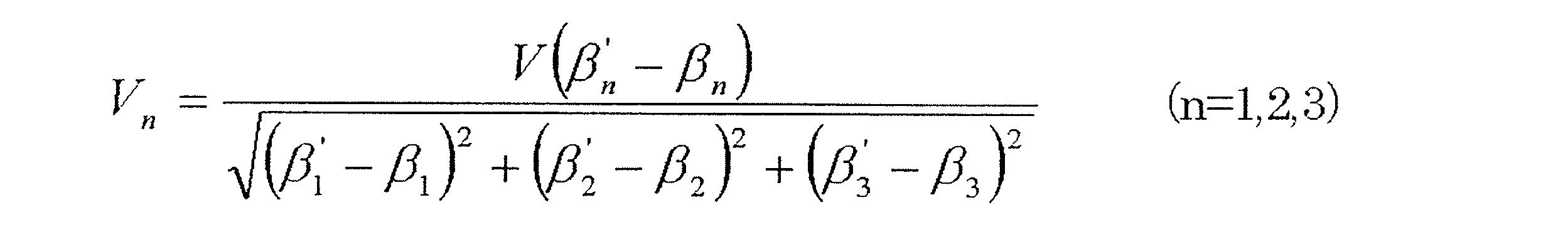
で表される式を用いて計算するリンク作動装置51の制御方法。
態様15ないし態様17のいずれか1項において、前記各アクチュエータ53の動作速度は、この動作速度をVn、ベース速度をV、前記基端側の端部リンク部材5の現在の回転角をβn、前記姿勢制御における前記基端側の端部リンク部材5の目標とする回転角をβn´とした場合に、
[態様19]
態様15ないし態様17のいずれか1項において、前記各アクチュエータ53の動作速度は、この動作速度をVn、最高速度をVmax、前記基端側の端部リンク部材5の現在の回転角をβn、前記姿勢制御における前記基端側の端部リンク部材5の目標とする回転角をβn´、(βn´-βn)の最大値をΔβmaxとした場合、
Vn=Vmax(βn´-βn)/Δβmax
で表される式を用いて計算するリンク作動装置の制御方法。
態様15ないし態様17のいずれか1項において、前記各アクチュエータ53の動作速度は、この動作速度をVn、最高速度をVmax、前記基端側の端部リンク部材5の現在の回転角をβn、前記姿勢制御における前記基端側の端部リンク部材5の目標とする回転角をβn´、(βn´-βn)の最大値をΔβmaxとした場合、
Vn=Vmax(βn´-βn)/Δβmax
で表される式を用いて計算するリンク作動装置の制御方法。
[態様20]
態様11ないし態様19のいずれか1項において、前記3組以上のリンク機構4のすべてに、前記基端側のリンクハブ2に対する前記先端側のリンクハブ3の姿勢を任意に変更させるアクチュエータ53を設け、これら各アクチュエータ53を冗長制御により制御するリンク作動装置51の制御方法。
態様11ないし態様19のいずれか1項において、前記3組以上のリンク機構4のすべてに、前記基端側のリンクハブ2に対する前記先端側のリンクハブ3の姿勢を任意に変更させるアクチュエータ53を設け、これら各アクチュエータ53を冗長制御により制御するリンク作動装置51の制御方法。
[態様21]
態様11ないし態様20のいずれか1項において、前記先端側のリンクハブ3に前記リンク作動装置51の持つ共振周波数を検出する共振周波数検出用センサ92を設置し、その信号から共振周波数測定器93により共振周波数を計算し、その計算結果から前記アクチュエータ53の加速時間および減速時間の設定値を更新するリンク作動装置51の制御方法。
態様11ないし態様20のいずれか1項において、前記先端側のリンクハブ3に前記リンク作動装置51の持つ共振周波数を検出する共振周波数検出用センサ92を設置し、その信号から共振周波数測定器93により共振周波数を計算し、その計算結果から前記アクチュエータ53の加速時間および減速時間の設定値を更新するリンク作動装置51の制御方法。
[態様22]
態様21において、前記共振周波数検出用センサ92として加速度ピックアップを用い、かつ前記共振周波数測定器93としてFFTアナライザを用いたリンク作動装置51の制御方法。
態様21において、前記共振周波数検出用センサ92として加速度ピックアップを用い、かつ前記共振周波数測定器93としてFFTアナライザを用いたリンク作動装置51の制御方法。
[態様23]
基端側のリンクハブ2に対し先端側のリンクハブ3を、3組以上のリンク機構4を介して姿勢を変更可能に連結し、前記各リンク機構4は、それぞれ前記基端側のリンクハブ2および先端側のリンクハブ3に一端が回転可能に連結された基端側および先端側の端部リンク部材5,6と、これら基端側および先端側の端部リンク部材5,6の他端に両端がそれぞれ回転可能に連結された中央リンク部材7とでなり、前記各リンク機構4は、このリンク機構4を直線で表現した幾何学モデルが、前記中央リンク部材7の中央部に対する基端側部分と先端側部分とが対称を成す形状であり、前記3組以上のリンク機構のうち2組以上のリンク機構4に、前記基端側のリンクハブ2に対する前記先端側のリンクハブ3の姿勢を任意に変更させるアクチュエータ53を設けたリンク作動装置51における、前記アクチュエータ53の動作を制御する装置であって、前記アクチュエータ53のすべてが同時に動作を開始して同時に動作を完了するように制御する同期制御により、前記アクチュエータ53ごとの動作を制御して、前記先端側のリンクハブ3を任意の姿勢に変更する姿勢制御を行い、前記すべてのアクチュエータ53の減速時間を、前記リンク作動装置51の持つ共振周波数の1周期付近に設定して、前記同期制御および姿勢制御を行う同期・姿勢制御手段54aを設けたことを特徴とするリンク作動装置51の制御装置。
基端側のリンクハブ2に対し先端側のリンクハブ3を、3組以上のリンク機構4を介して姿勢を変更可能に連結し、前記各リンク機構4は、それぞれ前記基端側のリンクハブ2および先端側のリンクハブ3に一端が回転可能に連結された基端側および先端側の端部リンク部材5,6と、これら基端側および先端側の端部リンク部材5,6の他端に両端がそれぞれ回転可能に連結された中央リンク部材7とでなり、前記各リンク機構4は、このリンク機構4を直線で表現した幾何学モデルが、前記中央リンク部材7の中央部に対する基端側部分と先端側部分とが対称を成す形状であり、前記3組以上のリンク機構のうち2組以上のリンク機構4に、前記基端側のリンクハブ2に対する前記先端側のリンクハブ3の姿勢を任意に変更させるアクチュエータ53を設けたリンク作動装置51における、前記アクチュエータ53の動作を制御する装置であって、前記アクチュエータ53のすべてが同時に動作を開始して同時に動作を完了するように制御する同期制御により、前記アクチュエータ53ごとの動作を制御して、前記先端側のリンクハブ3を任意の姿勢に変更する姿勢制御を行い、前記すべてのアクチュエータ53の減速時間を、前記リンク作動装置51の持つ共振周波数の1周期付近に設定して、前記同期制御および姿勢制御を行う同期・姿勢制御手段54aを設けたことを特徴とするリンク作動装置51の制御装置。
以上のとおり、図面を参照しながら好適な実施形態および応用形態を説明したが、当業者であれば、本件明細書を見て、自明な範囲内で種々の変更および修正を容易に想定するであろう。したがって、そのような変更および修正は、請求の範囲から定まる発明の範囲内のものと解釈される。
1…パラレルリンク機構
2…基端側のリンクハブ
3…先端側のリンクハブ
4…リンク機構
5…基端側の端部リンク部材
6…先端側の端部リンク部材
7…中央リンク部材
51,61…リンク作動装置
52,62…ベース部材
53,70…アクチュエータ
54,84…制御装置
54a,84a…同期・姿勢制御手段
55,85…操作装置
55a…姿勢指定手段
55b…姿勢取得手段
55c…姿勢情報付与手段
92…共振周波数検出センサ
93…共振周波数測定器
100…直交座標系
200,210…潤滑剤受け部材
O…原点
QA…基端側のリンクハブの中心軸
QA´…延長軸
QB…先端側のリンクハブの中心軸
θ…折れ角
φ…旋回角
2…基端側のリンクハブ
3…先端側のリンクハブ
4…リンク機構
5…基端側の端部リンク部材
6…先端側の端部リンク部材
7…中央リンク部材
51,61…リンク作動装置
52,62…ベース部材
53,70…アクチュエータ
54,84…制御装置
54a,84a…同期・姿勢制御手段
55,85…操作装置
55a…姿勢指定手段
55b…姿勢取得手段
55c…姿勢情報付与手段
92…共振周波数検出センサ
93…共振周波数測定器
100…直交座標系
200,210…潤滑剤受け部材
O…原点
QA…基端側のリンクハブの中心軸
QA´…延長軸
QB…先端側のリンクハブの中心軸
θ…折れ角
φ…旋回角
Claims (30)
- アクチュエータを介してリンク作動装置を操作する操作装置であって、
基端側のリンクハブに対し先端側のリンクハブが、3組以上のリンク機構を介して姿勢を変更可能に連結され、
前記各リンク機構は、それぞれ前記基端側のリンクハブおよび先端側のリンクハブに一端が回転可能に連結された基端側および先端側の端部リンク部材と、これら基端側および先端側の端部リンク部材の他端に両端がそれぞれ回転可能に連結された中央リンク部材とを有し、
かつ、このリンク機構を直線で表現した幾何学モデルが、前記中央リンク部材の中央部に対する基端側部分と先端側部分とが対称を成す形状であるパラレルリンク機構であり、
さらに、前記パラレルリンク機構の前記3組以上のリンク機構のうち2組以上のリンク機構に設けられて、前記基端側のリンクハブに対する前記先端側のリンクハブの姿勢である先端姿勢を任意に変更させる前記アクチュエータと、
このアクチュエータを制御する制御装置とを備え、
前記制御装置は、前記先端姿勢を、前記基端側のリンクハブの中心軸に対して前記先端側のリンクハブの中心軸が傾斜した垂直角度である折れ角と、前記基端側のリンクハブの中心軸に対して前記先端側のリンクハブの中心軸が傾斜した水平角度である旋回角とによって規定し、
前記操作装置は、
前記基端側のリンクハブの中心軸の延長軸上に原点が位置し、前記中心軸の延長軸と直交する2次元の直交座標系上の座標位置で、目標とする前記先端姿勢を人為操作で指定する姿勢指定手段と、
この姿勢指定手段により指定された座標位置から、演算により前記折れ角および旋回角で表される前記先端姿勢を取得する姿勢取得手段と、
この姿勢取得手段により取得された前記先端姿勢の情報を前記制御装置に与える姿勢情報付与手段と、
を備えるリンク作動装置の操作装置。 - 請求項1において、前記姿勢取得手段は、前記折れ角および旋回角で表される前記先端姿勢を取得するための演算として、最小二乗法による収束演算を用いるリンク作動装置の操作装置。
- 請求項1において、前記制御装置は、前記基端側のリンクハブに対する前記基端側の端部リンク部材の回転角をβn、前記基端側の端部リンク部材に回転自在に連結された中央リンク部材の連結端軸と、前記先端側の端部リンク部材に回転自在に連結された中央リンク部材の連結端軸とが成す角度をγ、基準となる基端側の端部リンク部材に対する各基端側の端部リンク部材の円周方向の離間角をδn、前記折れ角をθ、前記旋回角をφとした場合に、
cos(θ/2)sinβn-sin(θ/2)sin(φ+δn)cosβn+sin(γ/2)=0
で表される式を逆変換することにより、目標とする前記先端姿勢における前記各基端側の端部リンク部材の回転角を求め、この求められた回転角と、現在の前記先端姿勢における前記各基端側の端部リンク部材の回転角との差分から、前記各アクチュエータの指令動作量を算出するリンク作動装置の操作装置。 - 請求項1において、前記制御装置は、前記基端側のリンクハブに対する前記基端側の端部リンク部材の回転角をβn、前記基端側の端部リンク部材に回転自在に連結された中央リンク部材の連結端軸と、前記先端側の端部リンク部材に回転自在に連結された中央リンク部材の連結端軸とが成す角度をγ、基準となる基端側の端部リンク部材に対する各基端側の端部リンク部材の円周方向の離間角をδn、前記折れ角をθ、前記旋回角をφとした場合に、
cos(θ/2)sinβn-sin(θ/2)sin(φ+δn)cosβn+sin(γ/2)=0
で表される式を逆変換することにより、前記先端姿勢と前記各基端側の端部リンク部材の回転角との関係を示すテーブルを作成しておき、このテーブルを用いて、目標とする前記先端姿勢における前記各基端側の端部リンク部材の回転角を求め、この求められた回転角と、現在の前記各基端側の端部リンク部材の回転角との差分から、前記各アクチュエータの指令動作量を算出するリンク作動装置の操作装置。 - 請求項1において、前記姿勢指定手段は、前記直交座標系上での座標位置の指示を、数値入力により行うリンク作動装置の操作装置。
- 請求項5において、前記姿勢指定手段は、前記直交座標系上での座標位置の指示を、定められた基準点に対する絶対座標の数値入力、または現在の座標位置から目標とする座標位置までの差分を数値入力により行うリンク作動装置の操作装置。
- 請求項1において、前記姿勢指定手段は、前記直交座標系上での座標位置を、操作時間または操作回数に応じて決まる操作量で指定するリンク作動装置の操作装置。
- 請求項1に記載のリンク作動装置がアクチュエータの駆動力を対応するリンク機構へ伝達する減速部を備え、
前記基端側のリンクハブよりも前記先端側のリンクハブが下方に位置し、前記パラレルリンク機構または前記減速部に、これらパラレルリンク機構および減速部の少なくともどちらかから落下する潤滑剤を受ける潤滑剤受け部材を設けたリンク作動装置。 - 請求項8において、前記潤滑剤受け部材は、板状部と、この板状部の外周縁から板状部の表面に対して交差する一方向に突出した突出部とを有する皿状の部材であり、前記突出部が前記基端側のリンクハブの側を向くように、前記先端側のリンクハブに設置されているリンク作動装置。
- 請求項9において、前記潤滑剤受け部材の突出部は、その突出端側が前記先端側のリンクハブの中心軸に向かって傾いているリンク作動装置。
- 請求項10において、前記基端側のリンクハブの中心軸に対して前記先端側のリンクハブの中心軸が傾斜した垂直角度を折れ角とした場合、前記潤滑剤受け部材の突出部の傾き角度を、前記パラレルリンク機構の動作範囲における前記折れ角の最大値以上とした作動装置。
- 請求項9において、前記潤滑剤受け部材は、前記突出部の突出端に結合され前記板状部と平行で内周部に貫通孔が形成された上板を有するリンク作動装置。
- 請求項8において、さらに、前記基端側のリンクハブおよび前記アクチュエータが設置されたベース部材と、このベース部材に支持されベース部材と平行で内周部に貫通孔が形成された固定部材とを有し、
前記潤滑剤受け部材は、前記先端側のリンクハブに固定された板状部と、この板状部と前記固定部材間の全周を覆い、これら両者を互いに連結する伸縮自在な連結部とを有するリンク作動装置。 - 請求項13において、前記潤滑剤受け部材の連結部は、蛇腹状の形状であり、外力が作用しない自然状態よりも小さく圧縮された状態で前記板状部および前記固定部材に組み付けられているリンク作動装置。
- 請求項13において、前記潤滑剤受け部材の連結部は、シート状の弾性材料からなるリンク作動装置。
- 請求項13において、前記固定部材は、その外周部に前記ベース部材側へ突出する突出部を有するリンク作動装置。
- 請求項8において、さらに、前記基端側のリンクハブおよび前記アクチュエータが設置されたベース部材を有し、
前記潤滑剤受け部材は、板状部と、この板状部の外周縁から板状部の表面に対して交差する一方向に突出した突出部とを有する皿状の部材であり、前記板状部が前記減速部の下方を覆い、前記突出部が前記ベース部材の側を向くように、前記ベース部材または前記減速部の固定部に設置されているリンク作動装置。 - 請求項1に記載のリンク作動装置における、前記アクチュエータの動作を制御する制御方法であって、
前記アクチュエータのすべてが同時に動作を開始して同時に動作を完了するように制御する同期制御により、前記アクチュエータごとの動作を制御して、前記先端側のリンクハブを任意の姿勢に変更する姿勢制御を行い、前記すべてのアクチュエータの減速時間を、前記リンク作動装置の持つ共振周波数の1周期付近に設定して、前記同期制御および姿勢制御を行うリンク作動装置の制御方法。 - 請求項18において、前記減速時間を、前記リンク作動装置の持つ共振周波数の0.8ないし1.2周期の範囲内に設定したリンク作動装置の制御方法。
- 請求項18において、前記すべてのアクチュエータの加速時間を、前記リンク作動装置の持つ共振周波数の1周期付近に設定して、前記同期制御および姿勢制御を行うリンク作動装置の制御方法。
- 請求項20において、前記加速時間を、前記リンク作動装置の持つ共振周波数の0.8ないし1.2周期の範囲内に設定したリンク作動装置の制御方法。
- 請求項18において、前記姿勢制御は、目標となる前記先端側のリンクハブの姿勢から前記アクチュエータごとに指令動作量を決定し、前記同期制御は、前記すべてのアクチュエータの指令動作量の比率により各アクチュエータの動作速度を設定するリンク作動装置の制御方法。
- 請求項22において、前記基端側のリンクハブに対する前記基端側の端部リンク部材の回転角をβn、前記基端側の端部リンク部材に回転自在に連結された中央リンク部材の連結端軸と、前記先端側の端部リンク部材に回転自在に連結された中央リンク部材の連結端軸とが成す角度をγ、基準となる基端側の端部リンク部材に対する各基端側の端部リンク部材の円周方向の離間角をδn、前記基端側のリンクハブの中心軸に対して前記先端側のリンクハブの中心軸が傾斜した垂直角度をθ、前記基端側のリンクハブの中心軸に対して前記先端側のリンクハブの中心軸が傾斜した水平角度をφとした場合に、
cos(θ/2)sinβn-sin(θ/2)sin(φ+δn)cosβn+sin(γ/2)=0
で表される式を逆変換することにより、前記姿勢制御における前記各基端側の端部リンク部材の目標とする回転角を求め、この目標とする回転角と、前記各基端側の端部リンク部材の現在の回転角との差分により、前記各アクチュエータの指令動作量を算出するリンク作動装置の制御方法。 - 請求項22において、前記基端側のリンクハブに対する前記基端側の端部リンク部材の回転角をβn、前記基端側の端部リンク部材に回転自在に連結された中央リンク部材の連結端軸と、前記先端側の端部リンク部材に回転自在に連結された中央リンク部材の連結端軸とが成す角度をγ、基準となる基端側の端部リンク部材に対する各基端側の端部リンク部材の円周方向の離間角をδn、前記基端側のリンクハブの中心軸に対して前記先端側のリンクハブの中心軸が傾斜した垂直角度をθ、前記基端側のリンクハブの中心軸に対して前記先端側のリンクハブの中心軸が傾斜した水平角度をφとした場合に、
cos(θ/2)sinβn-sin(θ/2)sin(φ+δn)cosβn+sin(γ/2)=0
で表される式を逆変換することにより、前記基端側のリンクハブに対する前記先端側のリンクハブの姿勢と、前記各基端側の端部リンク部材の回転角との関係を示すテーブルを作成し、このテーブルを用いて、前記姿勢制御における前記各基端側の端部リンク部材の目標とする回転角を求め、この目標とする回転角と、前記各基端側の端部リンク部材の現在の回転角との差分により、前記各アクチュエータの指令動作量を算出するリンク作動装置の制御方法。 - 請求項22において、前記各アクチュエータの動作速度は、この動作速度をVn、ベース速度をV、前記基端側の端部リンク部材の現在の回転角をβn、前記姿勢制御における前記基端側の端部リンク部材の目標とする回転角をβn´とした場合に、

- 請求項22において、前記各アクチュエータの動作速度は、この動作速度をVn、最高速度をVmax、前記基端側の端部リンク部材の現在の回転角をβn、前記姿勢制御における前記基端側の端部リンク部材の目標とする回転角をβn´、(βn´-βn)の最大値をΔβmaxとした場合、
Vn=Vmax(βn´-βn)/Δβmax
で表される式を用いて計算するリンク作動装置の制御方法。 - 請求項18において、前記3組以上のリンク機構のすべてに、前記基端側のリンクハブに対する前記先端側のリンクハブの姿勢を任意に変更させるアクチュエータを設け、これら各アクチュエータを冗長制御により制御するリンク作動装置の制御方法。
- 請求項18において、前記先端側のリンクハブに前記リンク作動装置の持つ共振周波数を検出する共振周波数検出用センサを設置し、その信号から共振周波数測定器により共振周波数を計算し、その計算結果から前記アクチュエータの加速時間および減速時間の設定値を更新するリンク作動装置の制御方法。
- 請求項28において、前記共振周波数検出用センサとして加速度ピックアップを用い、かつ前記共振周波数測定器としてFFTアナライザを用いたリンク作動装置の制御方法。
- 請求項1に記載のリンク作動装置における、前記アクチュエータの動作を制御するリンク作動装置の制御装置であって、
前記アクチュエータのすべてが同時に動作を開始して同時に動作を完了するように制御する同期制御により、前記アクチュエータごとの動作を制御して、前記先端側のリンクハブを任意の姿勢に変更する姿勢制御を行い、前記すべてのアクチュエータの減速時間を、前記リンク作動装置の持つ共振周波数の1周期付近に設定して、前記同期制御および姿勢制御を行う同期・姿勢制御手段を設けたリンク作動装置の制御装置。
Priority Applications (4)
| Application Number | Priority Date | Filing Date | Title |
|---|---|---|---|
| EP13764312.8A EP2829367B1 (en) | 2012-03-23 | 2013-03-14 | Link actuation device |
| US14/385,931 US9522469B2 (en) | 2012-03-23 | 2013-03-14 | Link actuation device |
| EP19152653.2A EP3511129B1 (en) | 2012-03-23 | 2013-03-14 | Method of controlling operation of link actuation device and control device therefor |
| CN201380015207.XA CN104203502B9 (zh) | 2012-03-23 | 2013-03-14 | 连杆动作装置 |
Applications Claiming Priority (6)
| Application Number | Priority Date | Filing Date | Title |
|---|---|---|---|
| JP2012-066888 | 2012-03-23 | ||
| JP2012066888A JP5864322B2 (ja) | 2012-03-23 | 2012-03-23 | リンク作動装置の制御方法およびその制御装置 |
| JP2012073373A JP5973201B2 (ja) | 2012-03-28 | 2012-03-28 | リンク作動装置の操作装置 |
| JP2012-073373 | 2012-03-28 | ||
| JP2012-144106 | 2012-06-27 | ||
| JP2012144106A JP5992228B2 (ja) | 2012-06-27 | 2012-06-27 | リンク作動装置 |
Publications (1)
| Publication Number | Publication Date |
|---|---|
| WO2013141138A1 true WO2013141138A1 (ja) | 2013-09-26 |
Family
ID=49222597
Family Applications (1)
| Application Number | Title | Priority Date | Filing Date |
|---|---|---|---|
| PCT/JP2013/057233 WO2013141138A1 (ja) | 2012-03-23 | 2013-03-14 | リンク作動装置 |
Country Status (4)
| Country | Link |
|---|---|
| US (1) | US9522469B2 (ja) |
| EP (2) | EP3511129B1 (ja) |
| CN (1) | CN105269557B (ja) |
| WO (1) | WO2013141138A1 (ja) |
Families Citing this family (22)
| Publication number | Priority date | Publication date | Assignee | Title |
|---|---|---|---|---|
| DE102012002400B4 (de) * | 2011-03-17 | 2020-06-18 | Eb-Invent Gmbh | Manipulator |
| EP3276205B1 (en) * | 2011-11-04 | 2021-10-13 | NTN Corporation | Parallel link mechanism, constant velocity universal joint, and link actuator |
| JP6104701B2 (ja) * | 2013-05-16 | 2017-03-29 | Ntn株式会社 | リンク作動装置 |
| JP6250372B2 (ja) | 2013-11-22 | 2017-12-20 | Ntn株式会社 | 自動溶接機 |
| JP6271288B2 (ja) | 2014-02-20 | 2018-01-31 | Ntn株式会社 | リンク作動装置の制御装置および制御方法 |
| JP6453066B2 (ja) | 2014-12-05 | 2019-01-16 | Ntn株式会社 | リンク作動装置の制御方法 |
| JP6527782B2 (ja) | 2015-08-10 | 2019-06-05 | Ntn株式会社 | パラレルリンク機構を用いた作業装置 |
| JP6067805B1 (ja) | 2015-09-07 | 2017-01-25 | Ntn株式会社 | リンク作動装置を用いた複合作業装置 |
| JP6602620B2 (ja) | 2015-09-24 | 2019-11-06 | Ntn株式会社 | 組合せ型リンク作動装置 |
| US9762521B2 (en) * | 2016-01-15 | 2017-09-12 | International Business Machines Corporation | Semantic analysis and delivery of alternative content |
| JP6719956B2 (ja) * | 2016-04-20 | 2020-07-08 | Ntn株式会社 | 双腕型作動装置 |
| JP6275196B2 (ja) | 2016-06-05 | 2018-02-07 | Ntn株式会社 | リンク作動装置の操作装置およびリンク作動システム |
| EP3470704B1 (en) * | 2016-06-08 | 2021-04-28 | NTN Corporation | Link operating device |
| JP6799950B2 (ja) * | 2016-06-15 | 2020-12-16 | Ntn株式会社 | 作業装置および双腕型作業装置 |
| EP3281753B1 (de) * | 2016-08-12 | 2021-10-06 | Schneider Electric Industries SAS | Roboter |
| JP6800044B2 (ja) * | 2017-02-24 | 2020-12-16 | Ntn株式会社 | リンク作動装置の制御装置および制御方法 |
| AT519718B1 (de) | 2017-02-28 | 2018-12-15 | Fill Gmbh | Knickarmroboter und Verfahren zum spanenden Bearbeiten eines Werkstückes mittels dem Knickarmroboter |
| JP6498738B1 (ja) * | 2017-09-26 | 2019-04-10 | Ntn株式会社 | リンク作動装置 |
| JP7140508B2 (ja) * | 2018-02-26 | 2022-09-21 | Ntn株式会社 | パラレルリンク機構を用いた作業装置およびその制御方法 |
| JP6823007B2 (ja) | 2018-04-27 | 2021-01-27 | ファナック株式会社 | パラレルリンクロボット |
| JP7274846B2 (ja) * | 2018-09-28 | 2023-05-17 | Ntn株式会社 | リンク作動装置 |
| JP6648246B1 (ja) * | 2018-11-29 | 2020-02-14 | Ntn株式会社 | リンク作動装置の制御装置 |
Citations (9)
| Publication number | Priority date | Publication date | Assignee | Title |
|---|---|---|---|---|
| JPH07116983A (ja) * | 1993-10-25 | 1995-05-09 | Toshiba Mach Co Ltd | パラレルリンクマニピュレータ |
| US5893296A (en) | 1997-03-13 | 1999-04-13 | Ross-Hime Designs, Incorporated | Multiple rotatable links robotic manipulator |
| JP2000094245A (ja) | 1998-09-17 | 2000-04-04 | Fanuc Ltd | パラレルリンク機構を具備する作業装置 |
| JP2002273676A (ja) * | 2001-03-14 | 2002-09-25 | Toyoda Mach Works Ltd | 工作機械の制御方法 |
| JP2003184857A (ja) * | 2001-12-18 | 2003-07-03 | Ntn Corp | 多自由度自在継手のシール構造 |
| JP2005226777A (ja) * | 2004-02-13 | 2005-08-25 | Ntn Corp | リンク作動装置 |
| JP2009214211A (ja) * | 2008-03-10 | 2009-09-24 | Nachi Fujikoshi Corp | 産業用ロボット及び産業用ロボットを用いた搬送装置 |
| JP2009255194A (ja) * | 2008-04-14 | 2009-11-05 | Murata Mach Ltd | パラレルメカニズム |
| JP2011240440A (ja) * | 2010-05-19 | 2011-12-01 | Ntn Corp | リンク作動装置 |
Family Cites Families (24)
| Publication number | Priority date | Publication date | Assignee | Title |
|---|---|---|---|---|
| JP2576268B2 (ja) | 1990-06-19 | 1997-01-29 | 富士通株式会社 | ロボットの関節機構 |
| GB9107207D0 (en) | 1991-04-05 | 1991-05-22 | Tycho Technology Ltd | Mechanical manipulator |
| US5890396A (en) * | 1996-10-31 | 1999-04-06 | Agency Of Industrial Science & Technology, Ministry Of International Trade & Industry | Arm mechanism with independent control of position and orientation |
| JP2001290541A (ja) | 2000-04-11 | 2001-10-19 | Yaskawa Electric Corp | 産業用機械の加減速方法 |
| JP2002096232A (ja) * | 2000-09-21 | 2002-04-02 | Toyoda Mach Works Ltd | 工作機械の制御方法 |
| JP2002337078A (ja) | 2001-03-15 | 2002-11-26 | Ricoh Co Ltd | ロボットの制御方法およびロボットの制御装置 |
| JP2005144627A (ja) * | 2003-11-18 | 2005-06-09 | Ntn Corp | リンク作動装置 |
| WO2005053913A1 (ja) * | 2003-12-03 | 2005-06-16 | Ntn Corporation | リンク作動装置 |
| US7971505B2 (en) * | 2004-03-11 | 2011-07-05 | Ntn Corporation | Link actuating device |
| JP2005305585A (ja) * | 2004-04-20 | 2005-11-04 | Ntn Corp | 遠隔操作システム |
| US8371187B2 (en) * | 2004-12-20 | 2013-02-12 | Simon Fraser University | Spherical linkage and force feedback controls |
| CN1836849A (zh) | 2005-03-21 | 2006-09-27 | 北京理工大学 | 基于增量式码盘的机器人初始位置确定系统 |
| US7860609B2 (en) | 2005-05-06 | 2010-12-28 | Fanuc Robotics America, Inc. | Robot multi-arm control system |
| JP2007272597A (ja) | 2006-03-31 | 2007-10-18 | Yaskawa Electric Corp | ロボットの加減速パターン生成方法 |
| JP2008264904A (ja) * | 2007-04-17 | 2008-11-06 | Fanuc Ltd | パラレルリンク型作業装置 |
| JP2010260139A (ja) * | 2009-05-08 | 2010-11-18 | Ntn Corp | 遠隔操作型加工ロボット |
| US8601897B2 (en) * | 2009-11-30 | 2013-12-10 | GM Global Technology Operations LLC | Force limiting device and method |
| JP5499156B2 (ja) * | 2010-03-11 | 2014-05-21 | 株式会社安川電機 | 位置決め装置及び加工システムと、熱間加工装置 |
| KR101213452B1 (ko) * | 2010-08-27 | 2012-12-18 | 한양대학교 에리카산학협력단 | 4자유도 병렬기구를 이용한 마스터?슬레이브 시스템 |
| JP5675258B2 (ja) * | 2010-10-14 | 2015-02-25 | Ntn株式会社 | リンク作動装置 |
| JP2013068280A (ja) * | 2011-09-22 | 2013-04-18 | Ntn Corp | リンク作動装置 |
| CN103857942B (zh) * | 2011-09-29 | 2016-12-14 | Ntn株式会社 | 连杆动作装置 |
| JP5628873B2 (ja) * | 2012-08-31 | 2014-11-19 | ファナック株式会社 | パラレルリンクロボット |
| WO2014176334A1 (en) * | 2013-04-23 | 2014-10-30 | Northwestern University | Translational parallel manipulators and methods of operating the same |
-
2013
- 2013-03-14 EP EP19152653.2A patent/EP3511129B1/en active Active
- 2013-03-14 CN CN201510639754.6A patent/CN105269557B/zh active Active
- 2013-03-14 EP EP13764312.8A patent/EP2829367B1/en active Active
- 2013-03-14 US US14/385,931 patent/US9522469B2/en active Active
- 2013-03-14 WO PCT/JP2013/057233 patent/WO2013141138A1/ja active Application Filing
Patent Citations (9)
| Publication number | Priority date | Publication date | Assignee | Title |
|---|---|---|---|---|
| JPH07116983A (ja) * | 1993-10-25 | 1995-05-09 | Toshiba Mach Co Ltd | パラレルリンクマニピュレータ |
| US5893296A (en) | 1997-03-13 | 1999-04-13 | Ross-Hime Designs, Incorporated | Multiple rotatable links robotic manipulator |
| JP2000094245A (ja) | 1998-09-17 | 2000-04-04 | Fanuc Ltd | パラレルリンク機構を具備する作業装置 |
| JP2002273676A (ja) * | 2001-03-14 | 2002-09-25 | Toyoda Mach Works Ltd | 工作機械の制御方法 |
| JP2003184857A (ja) * | 2001-12-18 | 2003-07-03 | Ntn Corp | 多自由度自在継手のシール構造 |
| JP2005226777A (ja) * | 2004-02-13 | 2005-08-25 | Ntn Corp | リンク作動装置 |
| JP2009214211A (ja) * | 2008-03-10 | 2009-09-24 | Nachi Fujikoshi Corp | 産業用ロボット及び産業用ロボットを用いた搬送装置 |
| JP2009255194A (ja) * | 2008-04-14 | 2009-11-05 | Murata Mach Ltd | パラレルメカニズム |
| JP2011240440A (ja) * | 2010-05-19 | 2011-12-01 | Ntn Corp | リンク作動装置 |
Also Published As
| Publication number | Publication date |
|---|---|
| US20150088308A1 (en) | 2015-03-26 |
| EP3511129B1 (en) | 2021-03-10 |
| CN104203502B (zh) | 2016-01-13 |
| US9522469B2 (en) | 2016-12-20 |
| CN104203502A (zh) | 2014-12-10 |
| EP2829367A4 (en) | 2016-10-26 |
| CN105269557A (zh) | 2016-01-27 |
| CN105269557B (zh) | 2017-06-23 |
| EP2829367A1 (en) | 2015-01-28 |
| EP3511129A1 (en) | 2019-07-17 |
| EP2829367B1 (en) | 2019-03-06 |
Similar Documents
| Publication | Publication Date | Title |
|---|---|---|
| WO2013141138A1 (ja) | リンク作動装置 | |
| JP5973201B2 (ja) | リンク作動装置の操作装置 | |
| JP5951224B2 (ja) | リンク作動装置の原点位置初期設定方法およびリンク作動装置 | |
| EP3446836B1 (en) | Work device and dual-arm work device | |
| JP5864322B2 (ja) | リンク作動装置の制御方法およびその制御装置 | |
| WO2015076201A1 (ja) | リンク作動装置 | |
| US10890236B2 (en) | Operation method for link actuating device | |
| WO2013069533A1 (ja) | リンク作動装置 | |
| JP6482767B2 (ja) | 塗布装置 | |
| WO2013042577A1 (ja) | リンク作動装置 | |
| JP5992228B2 (ja) | リンク作動装置 | |
| JP6282764B2 (ja) | パラレルリンク機構、等速自在継手、およびリンク作動装置 | |
| JP2016147351A (ja) | リンク作動装置を用いた多関節ロボット | |
| JP5911697B2 (ja) | パラレルリンク機構、等速自在継手、およびリンク作動装置 | |
| JP6576646B2 (ja) | リンク作動装置を用いた多関節ロボット | |
| JP6029969B2 (ja) | リンク作動装置 | |
| JP2019198960A (ja) | リンク作動装置を用いた多関節ロボット | |
| JP2012066323A (ja) | 操作機構 | |
| JP2015025530A (ja) | リンク作動装置 | |
| JP6162006B2 (ja) | リンク作動装置 | |
| JP2019077031A (ja) | 双腕型の作業装置 | |
| WO2019078283A1 (ja) | 双腕型の作業装置 | |
| JP2018119688A (ja) | リンク作動装置 |
Legal Events
| Date | Code | Title | Description |
|---|---|---|---|
| 121 | Ep: the epo has been informed by wipo that ep was designated in this application |
Ref document number: 13764312 Country of ref document: EP Kind code of ref document: A1 |
|
| WWE | Wipo information: entry into national phase |
Ref document number: 14385931 Country of ref document: US |
|
| WWE | Wipo information: entry into national phase |
Ref document number: 2013764312 Country of ref document: EP |
|
| NENP | Non-entry into the national phase |
Ref country code: DE |