WO2012173143A1 - ステアリング装置 - Google Patents
ステアリング装置 Download PDFInfo
- Publication number
- WO2012173143A1 WO2012173143A1 PCT/JP2012/065126 JP2012065126W WO2012173143A1 WO 2012173143 A1 WO2012173143 A1 WO 2012173143A1 JP 2012065126 W JP2012065126 W JP 2012065126W WO 2012173143 A1 WO2012173143 A1 WO 2012173143A1
- Authority
- WO
- WIPO (PCT)
- Prior art keywords
- hole
- friction plate
- adjustment
- pair
- steering
- Prior art date
Links
Images


Classifications
-
- B—PERFORMING OPERATIONS; TRANSPORTING
- B62—LAND VEHICLES FOR TRAVELLING OTHERWISE THAN ON RAILS
- B62D—MOTOR VEHICLES; TRAILERS
- B62D1/00—Steering controls, i.e. means for initiating a change of direction of the vehicle
- B62D1/02—Steering controls, i.e. means for initiating a change of direction of the vehicle vehicle-mounted
- B62D1/16—Steering columns
- B62D1/18—Steering columns yieldable or adjustable, e.g. tiltable
- B62D1/187—Steering columns yieldable or adjustable, e.g. tiltable with tilt adjustment; with tilt and axial adjustment
-
- B—PERFORMING OPERATIONS; TRANSPORTING
- B62—LAND VEHICLES FOR TRAVELLING OTHERWISE THAN ON RAILS
- B62D—MOTOR VEHICLES; TRAILERS
- B62D1/00—Steering controls, i.e. means for initiating a change of direction of the vehicle
- B62D1/02—Steering controls, i.e. means for initiating a change of direction of the vehicle vehicle-mounted
- B62D1/16—Steering columns
- B62D1/18—Steering columns yieldable or adjustable, e.g. tiltable
- B62D1/184—Mechanisms for locking columns at selected positions
-
- B—PERFORMING OPERATIONS; TRANSPORTING
- B62—LAND VEHICLES FOR TRAVELLING OTHERWISE THAN ON RAILS
- B62D—MOTOR VEHICLES; TRAILERS
- B62D1/00—Steering controls, i.e. means for initiating a change of direction of the vehicle
- B62D1/02—Steering controls, i.e. means for initiating a change of direction of the vehicle vehicle-mounted
- B62D1/16—Steering columns
- B62D1/18—Steering columns yieldable or adjustable, e.g. tiltable
- B62D1/185—Steering columns yieldable or adjustable, e.g. tiltable adjustable by axial displacement, e.g. telescopically
-
- B—PERFORMING OPERATIONS; TRANSPORTING
- B62—LAND VEHICLES FOR TRAVELLING OTHERWISE THAN ON RAILS
- B62D—MOTOR VEHICLES; TRAILERS
- B62D1/00—Steering controls, i.e. means for initiating a change of direction of the vehicle
- B62D1/02—Steering controls, i.e. means for initiating a change of direction of the vehicle vehicle-mounted
- B62D1/16—Steering columns
- B62D1/18—Steering columns yieldable or adjustable, e.g. tiltable
- B62D1/187—Steering columns yieldable or adjustable, e.g. tiltable with tilt adjustment; with tilt and axial adjustment
- B62D1/189—Steering columns yieldable or adjustable, e.g. tiltable with tilt adjustment; with tilt and axial adjustment the entire column being tiltable as a unit
Definitions
- the present invention relates to a steering apparatus for an automobile provided with a tilt mechanism and / or a telescopic function for adjusting the vertical position and front / rear position of a steering wheel.
- the steering device for an automobile transmits the rotation of the steering wheel 1 to the input shaft 3 of the steering gear unit 2, and pushes and pulls the pair of left and right tie rods 4 as the input shaft 3 rotates.
- the front wheel is configured to give a rudder angle.
- the steering wheel 1 is supported and fixed to the rear end portion of the steering shaft 5, and the steering shaft 5 is rotatably supported by the steering column 6 with the cylindrical steering column 6 inserted in the axial direction.
- the front end portion of the steering shaft 5 is connected to the rear end portion of the intermediate shaft 8 via a universal joint 7, and the front end portion of the intermediate shaft 8 is connected to the input shaft 3 via another universal joint 9.
- the front-rear direction, the left-right direction, and the up-down direction refer to the front-rear direction, the left-right direction, and the up-down direction of the vehicle unless otherwise specified.
- a tilt mechanism for adjusting the vertical position (tilt position) of the steering wheel 1 and a telescopic mechanism for adjusting the front-rear position (telescopic position) according to the physique and driving posture of the driver is provided.
- the steering column 6 is supported with respect to the vehicle body 10 so as to be capable of swinging and moving around the pivot 11 installed in the left-right direction.
- a displacement bracket 18 fixed to a portion near the rear end of the steering column 6 is supported with respect to the support bracket 12 supported by the vehicle body 10 so as to be displaced in the vertical direction and the front-rear direction.
- the steering column 6 has a structure in which the outer column 13 and the inner column 14 are telescopically combined in a telescopic manner, and the steering shaft 5 includes the outer shaft 15 and the inner shaft 16. Are combined with each other so as to be able to transmit torque and expand and contract by spline engagement or the like.
- an electric power steering device is also incorporated that reduces the force required to operate the steering wheel 1 using the electric motor 17 as an auxiliary power source.
- the tilt mechanism or telescopic mechanism is a manual structure excluding the motorized one, the position of the steering wheel 1 can be adjusted or fixed at the adjusted position based on the operation of the adjustment handle. You can do that.
- Various types of manual tilt mechanisms and telescopic mechanisms are already widely known.
- a telescopic slot 19 that is long in the axial direction of the outer column 13 is formed in the displacement bracket 18 fixed to the outer column 13.
- the support bracket 12 includes a pair of support plate portions 20 that sandwich the displacement bracket 18 from both the left and right sides, and each of the support plate portions 20 has a long slot for tilt that is long in the vertical direction. 21 is formed.
- the tilting long hole 21 generally has a partial arc shape centered on the pivot 11.
- An adjusting rod 22 is inserted through the telescopic slot 19 and the tilt slot 21.
- the adjusting rod 22 is provided with a pair of pressing portions with the pair of support plate portions 20 sandwiched from both the left and right sides, and an expansion / contraction mechanism that operates based on the operation of the adjusting handle 23 (see FIGS. 1 to 3).
- the interval between these pressing portions can be enlarged or reduced.
- the interval between the pair of pressing portions is widened by swinging the adjustment handle 23 in a predetermined direction.
- the frictional force acting between the inner surface of the pair of support plate portions 20 and the outer surfaces on the left and right sides of the displacement bracket 18 is reduced.
- the tilt position and the telescopic position of the steering wheel 1 can be adjusted within a range in which the adjustment rod 22 can be displaced within the telescopic long hole 19 and the tilt long hole 21.
- the distance between the pair of pressing parts is reduced by swinging the adjustment handle 23 in the direction opposite to the predetermined direction. Thereby, a frictional force becomes large and it becomes possible to hold
- the steering wheel in the event of a collision, when a secondary collision occurs in which the driver's body collides with the steering wheel 1, the steering wheel is used to relieve the impact load applied to the driver. 1 is provided with a function of allowing the displacement of the forward movement. Specifically, a structure is employed in which the support bracket 12 is supported to the vehicle body 10 so as to be able to be detached forward by an impact at the time of a secondary collision.
- the outer The column 13 may move with respect to the support bracket 12 in the front-rear direction (telescopic direction) or the vertical direction (tilt direction).
- the way in which an impact is applied from the outer column 13 to the support bracket 12 changes, so that the support bracket 12 is detached from the vehicle body 10.
- the design of the shock absorbing mechanism based on it can be difficult.
- Japanese Patent Application Laid-Open No. 10-35511 describes a structure in which the number of friction surfaces is increased by overlapping a friction plate supported by a steering column and a friction plate supported by a support bracket in the left-right direction.
- a configuration is employed in which each friction plate is supported with respect to the steering column or the support bracket so that only displacement in the left-right direction is possible.
- a plurality of friction plates are required. Therefore, the increase in the lateral dimension, the number of parts, and the weight caused by increasing the friction surface increases.
- Japanese Patent Laid-Open No. 2010-52639 discloses that the inclination angle of the tilt slot with respect to a virtual plane orthogonal to the center axis of the steering column is the front and rear of the center axis of the steering column regardless of the vertical position of the steering wheel.
- a structure for preventing the steering column from being displaced rearward and upward along the inclination direction of the long slot for tilting at the time of a secondary collision by making the inclination angle larger than the direction is described.
- An object of the present invention is to provide a steering device that can sufficiently secure a force for holding an outer column on a support bracket.
- the steering device of the present invention includes a steering column, a displacement bracket, a first through hole, a support bracket, a second through hole, an expansion / contraction device, a swinging friction plate, and a support pin.
- the steering column is disposed around a steering shaft that fixes a steering wheel to a rear end portion, and rotatably supports the steering shaft.
- the displacement bracket is fixed to an intermediate portion in the axial direction of the steering column.
- the displacement bracket may be formed integrally with the steering column, or may be fixed to the steering column as a separate member from the steering column.
- the first through hole is formed in the displacement bracket in the left-right direction.
- the support bracket has a pair of left and right support plates provided with the displacement bracket sandwiched from both the left and right sides, and is supported by the vehicle body.
- the second through hole is provided at a position where the second through holes are aligned with each other in a part of the pair of left and right support plate portions.
- the expansion / contraction device includes an adjustment rod, an adjustment handle provided at a portion protruding from one outer surface of the pair of support plate portions at one end of the adjustment rod, and a part of the adjustment rod. And a pair of pressing portions provided at positions sandwiching the pair of support plate portions from the left and right sides.
- the expansion / contraction device can expand or contract the interval between the pair of pressing portions based on the operation of the adjustment handle.
- the rocking friction plate is a portion between a pair of surfaces facing each other, a portion between each inner side surface of the pair of support plate portions and outer side surfaces on both sides of the displacement bracket; and It is pinched by at least one among the part between each outer side surface of said pair of support plate part, and each inner surface of said pair of press part.
- the swing friction plate has a swing center hole and a guide slot at two positions separated from each other.
- the support pin is relative to a part of one surface that is relatively displaced from the adjusting rod when the position of the steering wheel is adjusted or to the one surface. And fixed to a portion that does not move, and is engaged with the swing center hole.
- At least one of the first through hole and the second through hole is an adjustment long hole (telescopic long hole or tilt long hole) that is long in the position adjustment direction of the steering wheel.
- the adjusting rod is inserted through the first through hole, the second through hole, and the guide long hole.
- the swing friction plate causes the adjustment rod to move along the guide slot. And swinging about the support pin. In the entire range of the swing, the length direction of the guide slot or the tangential direction of the guide slot in which the guide pin is engaged and the length direction of the adjustment slot Or it is comprised so that the tangent direction of the part in which the said adjustment rod is inserted among the said elongate holes for adjustment may not correspond.
- the first through hole is a telescopic elongated hole that is long in the axial direction of the steering column, and the swinging friction plate sandwiched between at least one of the portions between the pair of surfaces includes the adjusting rod.
- the adjusting rod When displaced along the telescopic elongated hole, the adjusting rod is swung around the support pin while being displaced along the guiding elongated hole.
- the length direction of the guide elongated hole or the tangential direction of the guide elongated hole where the adjusting rod is engaged does not match the length direction of the telescopic elongated hole (the axial direction of the steering column). It is configured as follows.
- the second through hole is a long slot for tilting that is long in the vertical direction
- the swinging friction plate sandwiched between at least one of the portions between the pair of surfaces includes the adjustment rod.
- the adjustment rod When displaced along the long slot for tilting, the adjustment rod is swung around the support pin while being displaced along the long guide hole.
- the length direction of the guide slot or the tangential direction of the guide slot where the adjusting rod is engaged, and the length direction of the tilt slot or the tilt slot It is comprised so that the tangent direction of the part which the adjustment rod penetrates may not correspond.
- the guide slot may be formed linearly along a straight line connecting the adjustment rod and the support pin, or in an arc shape along an arc connecting the adjustment rod and the support pin.
- the guide slot is straight in a state inclined with respect to a straight line connecting the adjustment rod and the support pin, or in a state inclined with respect to an arc connecting the adjustment rod and the support pin. It can also be formed in an arc shape.
- a part of the oscillating friction plate one side edge in the width direction of the guide slot from one side edge to which a shocking pressing force is applied from the adjusting rod when a secondary collision occurs, on one side edge in the width direction of the guide slot.
- the rocking friction plate and at least one of the member having one surface of the pair of surfaces sandwiching the rocking friction plate and the member having the other surface are hardened. It is preferable to be made of different metal materials.
- the rocking friction plate is subjected to surface processing for increasing the friction coefficient, specifically, surface processing for setting the friction coefficient to 0.15 or more.
- the rocking friction plate is preferably made of iron, an iron-based alloy, aluminum, or an aluminum alloy.
- the force that holds the steering column on the support bracket that is, the steering column is displaced to the support bracket in the direction of adjusting the position of the steering wheel.
- the contact between the side surfaces on both sides of the swing friction plate and the pair of surfaces sandwiching the swing friction plate in a state where the distance between the pair of pressing portions is narrowed Each part effectively functions as a friction surface for securing a holding force.
- the pair of surfaces sandwiching the oscillating friction plate are directly brought into contact with each other, compared with a structure in which the contact portion between these surfaces is the friction surface.
- the number of friction surfaces can be increased by one.
- the holding force of the steering column with respect to the support bracket can be improved.
- the number of friction surfaces can be increased only by installing a single oscillating friction plate between the pair of surfaces. For this reason, it is possible to sufficiently suppress the lateral dimension, the number of parts, and the increase in weight caused by increasing the friction surface.
- the swinging friction plate is located between the side surfaces on both sides of the swinging friction plate and a pair of contact surfaces sandwiching the swinging friction plate and the support pin. Therefore, it tends to be compressed and bent in the axial direction of the steering column. Thereby, the thickness dimension of the rocking friction plate tends to increase, and the pressing force between the pressing portions increases. As long as such an effect can be obtained, it is possible to secure a force for holding the steering column on the support bracket.
- the bridge portion provided in the rocking friction plate is plastically deformed, so that one side edge in the width direction of the guide slot provided in the rocking friction plate is Deform.
- the length direction or tangential direction of the portion where the guide pin is engaged in one side edge in the width direction of the guide long hole, and the length of the portion where the adjustment rod is inserted in the adjustment long hole The angle between the vertical direction and the tangential direction increases.
- the blocking force with respect to the displacement of the adjusting rod along the elongated slot for adjustment which is caused by the engagement of the one side edge in the width direction of the elongated guide hole with the guide pin, is increased.
- the holding force of the steering column with respect to the support bracket can be further increased.
- At least one of the contact portions between the side surfaces on both sides of the swing friction plate and the pair of surfaces sandwiching the swing friction plate is a surface having different hardness. It becomes a contact part of each other. For this reason, with the occurrence of a secondary collision, when the slip tends to occur in the contact portions of the surfaces having different hardness, the surface on the high hardness side bites into the surface on the low hardness side, It is possible to prevent slippage at the contact portion. Therefore, the holding force of the steering column with respect to the support bracket can be increased as much as such an effect can be obtained.
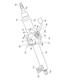
- FIG. 1 is a side view showing a first example of an embodiment of the present invention.
- 2A is an enlarged view of the right half of FIG. 1
- FIG. 2B is a cross-sectional view taken along the line aa of FIG. 2A.
- 3 is a cross-sectional view taken along the line bb of FIG.
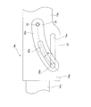
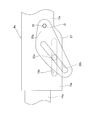
- FIG. 4 is a view corresponding to the left half portion of FIG. 2A, showing a state in which some members are omitted, and showing a state where the adjusting rod is located at the rear end portion of the telescopic slot.
- FIG. 5 is a view similar to FIG. 4 showing a state where the adjusting rod is located at the front end of the telescopic slot.
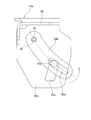
- FIG. 6 is a view similar to FIG.
- FIG. 4 showing a second example of the embodiment of the present invention in a state where some members are omitted and the adjustment rod is located at the lower end of the tilt slot.
- 7 is a cross-sectional view taken along the line cc of FIG.
- FIG. 8 is a view similar to FIG. 6, showing a state in which the adjustment rod is positioned at the upper end of the long slot for tilting.
- FIG. 9 is a view similar to FIG. 7, showing a third example of the embodiment of the present invention.
- FIG. 10 is a view similar to FIG. 1, showing a fourth example of the embodiment of the present invention.
- FIG. 11 is an enlarged view of the right half of FIG. 12 is a sectional view taken along the line dd of FIG.
- FIG. 13 is a view similar to FIG.
- FIG. 14 is a view similar to FIG. 4, showing a state in which a part of the sixth example of the embodiment of the present invention is omitted and the adjustment rod is located at the rear end of the telescopic elongated hole.
- FIG. 15 is a view similar to FIG. 14 showing a state where the adjustment rod is located at the front end of the telescopic slot.
- FIG. 16 is a view similar to FIG. 14 showing a state in which the adjustment rod is located in the middle portion of the telescopic slot.
- FIG. 17 is a view similar to FIG.
- FIG. 18 is a view similar to FIG. 17, showing the adjustment rod positioned at the lower end of the long slot for tilting.
- FIG. 19 is a view similar to FIG. 17, showing the adjustment rod positioned in the middle portion of the long slot for tilting.
- FIG. 20 is a view similar to FIG. 4, showing an eighth example of the embodiment of the present invention with some members omitted and the adjustment rod positioned at the lower end of the tilt slot.
- FIG. 21 is a view similar to FIG. 20, showing the adjustment rod positioned in the middle portion of the long slot for tilting.
- FIG. 22 is a view similar to FIG.
- FIG. 23 is a view similar to FIG. 22 showing a state where the adjusting rod is located in the middle portion of the telescopic slot.
- FIG. 24 is a view similar to FIG. 4, showing a state in which a part of the tenth example of the embodiment of the present invention is omitted and the adjusting rod is located in the middle part of the telescopic slot.
- FIG. 25 is a view similar to FIG. 4 showing a state where the eleventh example of the embodiment of the present invention is shown with a part of the members omitted and the adjusting rod positioned in the middle part of the telescopic slot.
- FIG. 26 is a view similar to FIG. 4, showing a state in which a part of the twelfth example of the embodiment of the present invention is omitted and the adjusting rod is located in the middle portion of the telescopic slot.
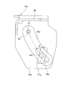
- FIG. 27 is a view similar to FIG. 4 showing a thirteenth example of the embodiment of the present invention, with some members omitted and the adjustment rod positioned at the middle portion of the long slot for tilting.
- FIG. 28 is a view similar to FIG. 4, showing a fourteenth example of the embodiment of the present invention, with some members omitted, and the adjustment rod positioned in the middle part of the long slot for tilting.
- FIG. 29 is a diagram similar to FIG. 2A, showing a fifteenth example of the embodiment of the present invention.
- FIG. 30 is a view corresponding to the left half of FIG. 29, showing a state in which some members are omitted, and showing a state in which the adjustment rod is located at the rear end of the telescopic slot.
- FIG. 31 is a view similar to FIG. 30 showing a state where the adjustment rod is located at the front end of the telescopic slot.
- FIG. 32 is a view similar to FIG. 30 showing a state where the adjusting rod is located in the middle portion of the telescopic slot.
- FIG. 33 is a view similar to FIG. 32, showing a state after the occurrence of the secondary collision.
- FIG. 34 is a view similar to FIG.
- FIG. 4 showing a sixteenth example of the embodiment of the present invention, with some members omitted and the adjustment rod positioned at the lower end of the long slot for tilting.
- FIG. 35 is a view similar to FIG. 34, showing a state where the adjustment rod is located at the upper end of the long slot for tilting.
- FIG. 36 is a view similar to FIG. 34, showing the adjustment rod positioned in the middle part of the long slot for tilting, and in a state after the occurrence of the secondary collision.
- FIG. 37 is a view similar to FIG. 1, showing a seventeenth example of the embodiment of the present invention.
- FIG. 38 is a view similar to FIG.
- FIG. 39 is a view similar to FIG. 38 showing a state where the adjusting rod is located at the front end of the telescopic slot.
- FIG. 40 is a view similar to FIG. 1 and showing a nineteenth example of the embodiment of the present invention.
- FIG. 41 is a schematic side view showing an example of a conventional steering device with a part thereof cut.
- the steering device of the present invention is characterized by a structure for holding the outer column on the support bracket. Therefore, the features of the structure will be described in detail, and the basic structure of the steering device including a telescopic mechanism, a tilt mechanism, and a mechanism for separating the support bracket forward from the vehicle body at the time of a secondary collision will be described. Unless otherwise specified, a known structure can be employed, and similar actions and effects can be obtained.
- the steering apparatus of this example includes a steering column 6a, a steering shaft 5a, a telescopic long hole 19a, a support bracket 12a, a tilt long hole 21a, an expansion / contraction device 24, and a pair of telescopic rocking friction plates 25.
- the steering column 6a has a front end portion of the outer column 13a disposed on the rear side and a rear end portion of the inner column 14a disposed on the front side, which can be displaced relative to each other in the axial direction so that the entire length can be expanded and contracted. It is configured to be possible.
- a steering shaft 5a is rotatably supported inside the steering column 6a.
- the steering shaft 5a is configured to enable torque transmission and expansion / contraction of the entire length by spline engagement of the front end portion of the circular outer shaft 15a disposed on the rear side and the rear end portion of the inner shaft 16a disposed on the front side. Has been.
- a single row deep groove type ball bearing or the like is provided at a portion near the rear end of the middle portion of the outer shaft 15a inside the rear end of the outer column 13a and a portion near the front end of the inner shaft 16a inside the front end of the inner column 14a. It is supported rotatably by a bearing that can support radial load and axial load.
- the steering wheel 1 (see FIG. 41) is fixed to a portion protruding from the rear end opening of the outer column 13a at the rear end portion of the outer shaft 15a.
- a pivot bracket 26 is fixed by welding to the upper surface of the front end portion of the inner column 14a, and the pivot bracket 26 is fixed to the vehicle body 10 (see FIG. 41) by a pivot 11a installed in the horizontal direction. It is supported so that it can be displaced.
- the displacement bracket 18a is fixed to the front half of the outer column 13a, which is an intermediate portion in the axial direction of the steering column 6a, so as to protrude below the outer column 13a.
- the outer column 13a is integrally formed with the displacement bracket 18a by die-casting a light alloy such as an aluminum alloy or a magnesium alloy.
- the outer column 13a can be obtained by welding a displacement bracket 18a to a steel pipe.
- the displacement bracket 18a is composed of a pair of sandwiched plate portions 27 that are spaced apart in the left-right direction.
- telescopic long holes 19a which are long in the axial direction of the outer column 13a, are formed at positions where the pair of sandwiched plate portions 27 are aligned with each other so as to penetrate in the left-right direction.
- the displacement bracket 18a as described above can be provided so as to protrude above the steering column 6a.
- the support bracket 12a is formed by integrally bonding and fixing a plurality of elements each made of a metal plate having sufficient strength and rigidity, such as a steel plate, by a pair of left and right mounting plates. A portion 28 and a pair of left and right support plate portions 20a are provided.
- the mounting plate portion 28 of the support bracket 12a is supported on the vehicle body 10 by a structure well known in the technical field of the steering device so that it can be detached forward by an impact during a secondary collision. Further, the support plate portion 20a is disposed in a state where the displacement bracket 18a is sandwiched from both the left and right sides.
- Tilt long holes 21a are formed at positions that are aligned with each other and are aligned with a part of the telescopic long hole 19a in a part of these support plate portions 20a.
- each of the tilt long holes 21a has a partial arc shape centered on the pivot axis 11a.
- the steering device of the present example can be configured such that a circular hole is provided in the support plate portion 20a in place of the long tilt hole 21a that is long in the vertical direction, and only the telescopic mechanism is provided.
- the expansion / contraction device 24 includes an adjustment rod 22a, an adjustment nut 29, and an adjustment handle 23.
- the adjusting rod 22a is inserted through the telescopic slot 19a and the tilt slot 21a from the right side of FIG.
- an adjustment nut 29 is screwed into a male screw portion protruding from one (left side in FIG. 3) support plate portion 20a at the tip of the adjustment rod 22a.
- the head 30 provided at the base end portion of the adjusting rod 22a is set to the tilt slot 21a formed in the other support plate section 20a (right side in FIG. 3). Only the displacement along the length direction of 21a is engaged. Further, the base end portion of the adjustment handle 23 is fixed to the adjustment nut 29.
- a cam device capable of expanding / contracting the axial dimension based on the operation of the adjustment handle can be provided at the base end portion or the distal end portion of the adjustment rod.
- the pair of telescopic oscillating friction plates 25 is an oval flat plate member made of a metal plate such as iron, an iron-based alloy, aluminum, or an aluminum alloy.
- the telescopic oscillating friction plate 25 is preferably made of a metal plate different from the steel plate constituting the support bracket 12a.
- Each of the telescopic rocking friction plates 25 has a rocking center hole 31 at one end portion in the length direction and a linear guide long hole 32 from the middle portion in the length direction to the other end portion.
- Such telescopic oscillating friction plates 25 are respectively sandwiched between the inner surface of the support plate portion 20a and the outer surface of the displacement bracket 18a.
- the adjustment rods 22a are inserted into the respective guide long holes 32 so as to be able to be displaced along the guide long holes 32, and the side surfaces on both sides of the intermediate portion of the outer column 13a are inserted into the swing center hole 31.
- the support pin 33 projecting from is engaged with only a swing displacement about the support pin 33.
- the guide long hole 32 is formed linearly along a straight line connecting the adjustment rod 22a and the support pin 33.
- the support pin 33 is located at the rear and upper portion of the telescopic long hole 19a in the side surfaces on both sides of the middle portion of the outer column 13a, and regardless of the adjustment of the front-rear position of the steering wheel 1. It is always provided in a state of projecting to a portion located rearward of the support plate portion 20a. Furthermore, as shown in FIG. 2 (B), the tip of the support pin 33 protruding from the swinging center hole 31 has a larger outer diameter than the inner diameter of the swinging center hole 31. A stop head 42 is provided.
- the support pin 33 is always in front of the telescopic long hole 19a in the side surfaces on both sides of the intermediate column of the outer column 13a, and always from the support plate portion 20a regardless of the adjustment of the front-rear position of the steering wheel 1. It can also project from the part located forward.
- the displacement bracket 18a is provided in the middle part or the latter half part of the outer column 13a.
- the support pin 33 is provided on the central axis of the steering column 6a.
- the support pins 33 can be provided above or below the central axis of the steering column 6a.
- the adjustment nut 29 and the head of the adjustment rod 22a are swung by swinging the adjustment handle 23 in a predetermined direction (generally downward).
- the interval with the part 30 is increased.
- the gap between the pair of sandwiched plate portions 27 constituting the displacement bracket 18a is elastically expanded, whereby the inner diameter of the front end portion of the outer column 13a is elastically expanded, and the inside of the front end portion of the outer column 13a is increased.
- the surface pressure of the fitting portion between the peripheral surface and the outer peripheral surface of the rear end portion of the inner column 14a is reduced or lost.
- the contact surface pressure between the side surfaces on both sides of the telescopic rocking friction plate 25, the inner surface of the support plate portion 20a and the outer surface of the displacement bracket 18a, and the outer surface of the support plate portion 20a and the adjusting nut 29 The surface pressure of the contact portion between the inner surface of the head and the inner surface of the head 30 is reduced or lost, respectively.
- the position of the steering wheel 1 can be adjusted within a range in which the adjusting rod 22a can be displaced within the telescopic long hole 19a and the tilt long hole 21a.
- the telescopic rocking friction plate 25 swings around the support pin 33. That is, when the outer column 13a is displaced forward, the adjusting rod 22a is displaced along the telescopic long hole 19a and the guide long hole 32 from the state shown in FIG. 5 to the state shown in FIG.
- the oscillating friction plate 25 is oscillated and displaced in the counterclockwise direction in FIGS. 4 and 5 around the support pin 33.
- the adjustment rod 22a and the support pin 33 are relatively displaced in the direction in which they approach each other.
- the outer column 13a is displaced rearward, the adjusting rod 22a is displaced along the telescopic long hole 19a and the guide long hole 32 from the state shown in FIG. 4 to the state shown in FIG.
- the telescopic oscillating friction plate 25 is oscillated and displaced about the support pin 33 in the clockwise direction of FIGS.
- the adjusting rod 22a and the support pin 33 are relatively displaced in a direction away from each other.
- the length direction of the guide slot 32 and the length direction of the telescopic slot 19a remain non-parallel and do not coincide with each other in the entire range of the swing. It is like that.
- the distance between the adjustment nut 29 and the head 30 is reduced by swinging the adjustment handle 23 in a direction opposite to a predetermined direction (generally upward). Thereby, the surface pressure of the contact portion between the outer side surface of the support plate portion 20a and the inner side surface of the adjustment nut 29 and the inner side surface of the head 30 is increased, and the steering wheel 1 is held at the adjusted position.
- the holding force of the outer column 13a with respect to the support bracket 12a is the steering wheel with respect to the support bracket 12a.
- the holding force of the outer bracket 13a on the support bracket 12a particularly the holding force in the front-rear direction (the axial direction of the outer column 13a). It effectively functions as a friction surface.
- the adjusting rod 22a is restrained from being displaced along the guide elongated hole 32 by the frictional force acting on these contact portions.
- the side surfaces on both sides of the telescopic rocking friction plate 25, the inner surface of the support plate portion 20a, and the outer surface of the displacement bracket 18a are used. It is not sufficient to cause only one of the abutting portions to slip, and it is necessary to cause both of the abutting portions to slip. Therefore, both of these contact portions effectively function as friction surfaces for securing the holding force in the front-rear direction.
- the number of friction surfaces is reduced.
- the number can be increased by one for each place where the telescopic rocking friction plate 25 is installed.
- the holding force in the front-rear direction can be improved accordingly.
- only one telescopic rocking friction plate 25 is installed between the inner surface of the support plate portion 20a and the outer surface of the displacement bracket 18a.
- the number of friction surfaces can be increased by one each. For this reason, the increase in the horizontal dimension, the number of parts, and the weight accompanying the increase in the friction surface can be sufficiently suppressed.
- the outer column is increased in the state where the surface pressure of the contact portion between the side surfaces on both sides of the telescopic rocking friction plate 25 and the inner surface of the support plate portion 20a and the outer surface of the displacement bracket 18a is increased.
- the support pin 33 strongly presses the inner edge of the swing center hole 31.
- the telescopic oscillating friction plate 25 tends to bend, and the width dimension of these telescopic oscillating friction plates 25 tends to increase.
- the surface pressure of the contact portion between the outer surface of the support plate portion 20a, the inner surface of the adjustment nut 29, and the inner surface of the head 30 is increased.
- the holding force related to the adjustment direction of the front-rear position can be ensured.
- the contact portions between the side surfaces on both sides of the telescopic rocking friction plate 25 and the outer surface of the support plate portion 20a of the support bracket 12a become contact portions of surfaces having different hardnesses. For this reason, with the occurrence of a secondary collision, when the slip tends to occur in the contact portions of the surfaces having different hardness, the surface on the high hardness side bites into the surface on the low hardness side, It is possible to prevent slippage at the contact portion. This also secures the holding force related to the adjustment direction of the front-rear position among the holding force of the outer column 13a with respect to the support bracket 12a.
- the oscillating friction plates 25 are arranged on both the left and right sides of the outer column 13a, but can be arranged only on one side in the left-right direction.
- the inner column 14a is disposed on the front side and the outer column 13a is disposed on the rear side.
- the present invention is applied to a steering apparatus in which the inner column is disposed on the rear side and the outer column is disposed on the front side. Is also applicable.
- the friction coefficient of the oscillating friction plate 25 is not sufficient, the surface of the friction plate can be subjected to surface treatment such as plating, painting, shot blasting, iris knurl. In this case, it is preferable that the friction coefficient of the surface of the oscillating friction plate 25 is 0.15 or more.
- FIG. 6 to 8 show a second example of the embodiment of the present invention.
- Tilt swing friction plates 34 are sandwiched one by one.
- the pair of tilting oscillating friction plates 34 is composed of an oval flat plate member made of a metal plate.
- Each of the tilting oscillating friction plates 34 has a oscillating center hole 35 at one end in the length direction and a linear guide slot 36 extending from the middle in the length direction to the other end.
- Such tilting oscillating friction plates 34 are sandwiched between the outer surface of the support plate portion 20a and the inner surface of the adjusting nut 29 and the inner surface of the head 30a of the adjusting rod 22a. In this state, the adjusting rod 22a is inserted into the guide long hole 36 of the tilting oscillating friction plate 34 so as to be displaced along the guide long hole 36.
- the support pin 37 provided in the swing center hole 35 so as to protrude from a part of the outer surface of the support plate portion 20 a away from the long slot 21 a is centered on the support pin 37. Only the swing displacement is engaged.
- the support pin 37 is provided on the outer side surface of the support plate portion 20a in front of and above the tilt long hole 21a.
- the adjustment handle 23 when adjusting the vertical position or the front-rear position of the steering wheel 1 (see FIG. 41), the adjustment handle 23 is swung in a predetermined direction as in the first example of the embodiment.
- the distance between the adjustment nut 29 and the head 30a of the adjustment rod 22a is increased, and the surface pressure of the fitting portion between the inner peripheral surface of the front end portion of the outer column 13a and the outer peripheral surface of the rear end portion of the inner column 14a is reduced or reduced.
- the position of the steering wheel 1 is adjusted within a range in which the adjusting rod 22a can be displaced within the telescopic long hole 19a and the tilt long hole 21a.
- the tilting oscillating friction plate As shown in FIGS. 6 and 8, 34 swings around the support pin 37. That is, when the outer column 13a is displaced downward, the adjusting rod 22a is displaced along the long slot 21a and the long guide hole 36 from the state shown in FIG. 8 to the state shown in FIG.
- the swing friction plate 34 swings around the support pin 37 in the clockwise direction of FIGS. 6 and 8. As a result, the adjustment rod 22a and the support pin 37 are relatively displaced in a direction away from each other.
- the distance between the adjustment nut 29 and the head 30a is reduced by swinging the adjustment handle 23 in the direction opposite to the predetermined direction. Thereby, the surface pressure of the fitting portion between the inner peripheral surface of the front end portion of the outer column 13a and the outer peripheral surface of the rear end portion of the inner column 14a is increased, and the steering wheel 1 is held at the adjusted position.
- both side surfaces of the tilting oscillating friction plate 34, the outer surface of the support plate portion 20a, the inner surface of the adjusting nut 29, and The contact portions with the inner side surface of the head 30a effectively function as a friction surface for securing the holding force in the vertical direction among the holding force of the outer column 13a with respect to the support bracket 12a. Therefore, in the case of this example, the pair of surfaces sandwiching the tilting oscillating friction plate 34 are directly brought into contact with each other, compared with a structure in which the contact portion between these surfaces is a friction surface. The number of friction surfaces can be increased by one for each installation location of the tilting swing friction plate 34.
- the holding force in the vertical direction can be improved.
- only one swinging friction plate 34 for tilting is provided on each portion between the outer surface of the support plate portion 20a and the inner surface of the adjusting nut 29 and the inner surface of the head 30a.
- the number of friction surfaces in the intermediate portion can be increased by one each. For this reason, it is possible to sufficiently suppress the increase in the lateral dimension, the number of parts, and the weight associated with increasing the friction surface.
- FIG. 9 shows a third example of the embodiment of the present invention.
- the tilting oscillating friction plate 34 is sandwiched between the inner surface of the support plate portion 20a and the outer surface of the sandwiched plate portion 27 of the outer column 13a.
- Other configurations and operations are the same as those of the second example of the embodiment.
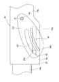
- FIG. 10 to 12 show a fourth example of the embodiment of the present invention.
- This example has a structure combining the first example and the second example of the embodiment. That is, the telescopic oscillating friction plate 25 is disposed between the inner surface of the support plate portion 20a and the outer surface of the pinched plate portion 27, and between the outer surface of the support plate portion 20a and the inner surface of the adjusting nut 29 and the support plate.
- the tilting oscillating friction plate 34 is sandwiched between the outer surface of the portion 20a and the inner surface of the head 30a of the adjusting rod 22a.
- the holding force of the outer column 13a with respect to the support bracket 12a can be ensured in the vertical direction and the front-rear direction.
- Other configurations and operations are the same as those of the first and second examples of the embodiment.
- FIG. 13 shows a fifth example of the embodiment of the present invention.
- This example has a structure in which the present invention is applied to the structure described in Japanese Patent Application Laid-Open No. 2010-52639. That is, the inclination angle ⁇ of the tilt long hole 21b with respect to the virtual plane ⁇ orthogonal to the central axis of the steering column 6a is set to the central axis of the steering column 6a regardless of the vertical position of the steering wheel 1 (see FIG. 41). It is larger than the inclination angle ⁇ with respect to the longitudinal direction ⁇ .
- the component force that displaces the adjusting rod 22a forward and downward of the tilt long hole 21b causes the adjusting rod 22a to move to the tilt length. This is surely larger than the component force to be displaced upward and rearward of the hole 21b. As a result, the outer column 13a is prevented from flying up, and the position where the steering wheel 1 and the driver's body collide can be made appropriate.
- the configuration and operation of the other parts are the same as in the first example of the embodiment.
- FIG. 14 to 16 show a sixth example of the embodiment of the present invention.
- the guide long hole 32a is formed in an arc shape, and these swing center hole 31 and the guide The long holes 32a are arranged on the same arc.
- the telescopic rocking friction plate 25a has an arc shape.
- the angle ⁇ formed by the axial direction of the outer column 13a and the tangential direction of the portion of the guide elongated hole 32a where the adjusting rod 22a is engaged is related to the front and rear positions of the steering wheel 1.
- it can be made almost constant and somewhat large.
- the adjustment rod 22a can be hardly displaced forward and downward along the guide long hole 32a.
- Other configurations and effects are the same as those of the first example of the embodiment.
- FIG. 17 to 19 show a seventh example of the embodiment of the invention.
- the guide long hole 36a has an arc shape, and the swing center hole 35 and the guide long hole 36a are arranged on the same arc.
- the tilting oscillating friction plate 34a has an arc shape.
- the tangential direction of the portion where the adjustment rod 22a is engaged in the tilting long hole 21a and the tangential direction of the portion of the guide long hole 36a where the adjustment rod 22a is engaged Can be made substantially constant and somewhat large regardless of the vertical position of the steering wheel 1.
- the adjusting rod 22a is displaced upward along the long slot for tilt 21a, and the outer column 13a rises more. Effectively prevented.
- Other configurations and effects are the same as those of the second example of the embodiment.
- FIG. 20 and 21 show an eighth example of the embodiment of the present invention.
- the shape of the tilting oscillating friction plate 34b and the direction in which the guide long hole 36b is formed are different from those in the second example of the embodiment. That is, by setting one side edge of the both sides in the width direction of the tilt swing friction plate 34b as an arc, the surface area of the tilt swing friction plate 34b can be reduced to the tilt swing friction plate 34 (second example of the embodiment). (See FIG. 6). Thereby, among the holding forces of the outer column 13a with respect to the support bracket 12a, the holding force in the vertical direction can be further increased. Other configurations and effects are the same as those of the second example of the embodiment.
- [Ninth Embodiment] 22 and 23 show a ninth example of the embodiment of the invention.
- the shape of the telescopic rocking friction plate 25b and the direction in which the guide long hole 32b is formed are different from those in the first example of the embodiment. That is, by making the telescopic rocking friction plate 25b substantially triangular, the surface area of the telescopic rocking friction plate 25b is made larger than that of the telescopic rocking friction plate 25 of the first example of the embodiment. Thereby, the holding force of the outer column 13a with respect to the support bracket 12a can be increased.
- Other configurations and effects are the same as those of the first example of the embodiment.
- FIG. 24 shows a tenth example of the embodiment of the present invention.
- the telescopic oscillating friction plate 25c has a substantially triangular shape, and the support pin 33 is provided above the outer column 13a in front of the telescopic long hole 19a.
- the surface area of the portion of the telescopic oscillating friction plate 25c sandwiched between the support plate portion 20a (see FIGS. 1 to 3) and the sandwiched plate portion 27 is increased.
- FIG. 25 shows an eleventh example of the embodiment of the present invention.
- the support pin 33 is provided in front of the telescopic slot 19a.
- Other configurations and effects are the same as those of the tenth example of the embodiment.
- FIG. 26 shows a twelfth example of the embodiment of the present invention.
- the telescopic oscillating friction plate 25d has a substantially triangular shape with the lower side being an arc, and the support pin 33 is provided above the rear end of the telescopic long hole 19a.
- the angle ⁇ formed by the tangential direction of the portion of the guide slot 32c where the adjusting rod 22a engages and the straight line connecting the adjusting rod 22a and the support pin 33 is somewhat large (the state shown in the figure). (About 60 degrees). Also, the angle ⁇ formed by the normal direction of the portion of the guide long hole 32c where the adjusting rod 22a engages and the length direction of the telescopic long hole 19a is somewhat large (approximately 75 degrees in the illustrated state). )it can. Of the holding force of the outer column 13a with respect to the support bracket 12a, in order to improve the holding force in the front-rear direction, it is desirable to increase the angles ⁇ and ⁇ as much as possible.
- the angle ⁇ and the angle ⁇ are each preferably greater than 50 degrees and 80 degrees or less, and more preferably 60 degrees or more and 70 degrees or less.
- the adjustment handle 23 is swung in a predetermined direction, the distance between the adjustment nut 29 and the head 30a of the adjustment rod 22a is widened, and the front end inner peripheral surface of the outer column 13a and the rear end outer peripheral surface of the inner column 14a are increased. The surface pressure of the fitting portion is reduced or lost.
- the front / rear position of the outer column 13a can be adjusted while the adjustment handle 23 is swung in a predetermined direction even when the angles ⁇ and ⁇ are increased to some extent. Can be performed smoothly.
- the angles ⁇ and ⁇ are less than 50 degrees, it is desirable that the friction coefficient of the telescopic rocking friction plate 25d be 0.15 or more.
- the structure and effects of other parts are the same as in the tenth example of the embodiment.
- FIG. 27 shows a thirteenth example of the embodiment of the present invention.
- the tilting oscillating friction plate 34c has a substantially triangular shape, and the support pin 33 is provided in front of the lower end portion of the support plate portion 20a.
- the surface area of the tilting oscillating friction plate 34c in contact with the support plate portion 20a is increased, and the holding force of the outer column 13a with respect to the support bracket 12a is increased.
- the guide long hole 36c is formed in an arc shape so that the swinging friction plate 34c for tilting can be smoothly swung, and the adjusting rod 22a is hardly displaced along the guide long hole 36c at the time of a secondary collision. Yes.
- Other configurations and effects are the same as those of the second example of the embodiment.
- FIG. 28 shows a fourteenth example of the embodiment of the present invention.
- the tilting oscillating friction plate 34c has a substantially triangular shape and the guide long hole 36c has an arc shape, but this is different from the thirteenth example of the embodiment.
- the support pin 37 is provided at the front upper side of the support plate portion 20a.
- the angle ⁇ formed by the tangential direction of the portion of the tilt long hole 21a with which the adjustment rod 22a engages and the normal direction of the portion of the guide long hole 36c with which the adjustment rod 22a engages. Can be increased to some extent (approximately 70 degrees in the illustrated state). Further, an angle ⁇ formed by a tangential direction of a portion of the guide long hole 36c where the adjusting rod 22a engages and a straight line connecting the adjusting rod 22a and the support pin 37 is increased to some extent (in the illustrated state, approximately 65 degrees). )it can. In order to improve the holding force of the outer column 13a with respect to the support bracket 12a, it is desirable to increase the angle ⁇ and the angle ⁇ as much as possible.
- each of the angle ⁇ and the angle ⁇ is preferably greater than 50 degrees and 80 degrees or less, and more preferably 60 degrees or more and 70 degrees or less.
- the adjustment handle 23 is swung in a predetermined direction, the distance between the adjustment nut 29 and the head 30a of the adjustment rod 22a is widened, and the front end inner peripheral surface of the outer column 13a and the rear end outer peripheral surface of the inner column 14a are increased. The surface pressure of the fitting portion is reduced or lost.
- the upper and lower positions of the outer column 13a can be adjusted while the adjustment handle 23 is swung in a predetermined direction. Adjustment can be performed smoothly.
- the angle ⁇ and the angle ⁇ are less than 50 degrees, it is desirable that the friction coefficient of the telescopic rocking friction plate is 0.15 or more.
- the structure and effects of the other parts are the same as in the thirteenth example of the embodiment.
- the telescopic oscillating friction plate 25e has a substantially triangular shape and has a larger surface area, and a linear guide slot 32e is formed in the telescopic oscillating friction plate 25e.
- a part of the telescopic oscillating friction plate 25e has a one side edge (lower side edge in FIGS. 29 to 32) to which an impact load from the adjusting rod 22a is applied during the secondary collision among both side edges in the width direction of the guide elongated hole 32e.
- a long hole 38 for adjusting the strength is provided in parallel to the guide long hole 32e in a portion spaced apart to one side in the width direction of the guide long hole 32e.
- the strength adjustment slot 38 is directed toward the strength adjustment slot 38.
- a bridge portion 39 capable of plastic deformation is provided.
- FIGS. 34 to 36 show a sixteenth example of the embodiment of the invention.
- one of the side edges in the width direction of the tilt swing friction plate 34d is an arc, and its surface area is increased, and a linear guide slot 36d is provided in the tilt swing friction plate 34d.
- a strength adjusting long hole 40 is provided in parallel with the guide long hole 36d in a portion of the guide long hole 36d that is separated to one side in the width direction.
- a bridge portion 41 that is plastically deformable toward the strength adjusting long hole 40 side is provided between the guide long hole 36d and the strength adjusting long hole 40.
- FIG. 37 shows a seventeenth example of the embodiment of the present invention.
- This example has a structure in which the fifteenth and sixteenth examples of the embodiment are combined. That is, the bridge portion 39 is provided by providing the strength adjusting long hole 38 in the telescopic swing friction plate 25e, and the bridge portion 41 is provided by providing the strength adjusting long hole 40 in the tilt swing friction plate 34d. .
- Other configurations and effects are the same as those of the fifteenth and sixteenth examples of the embodiment.
- FIG. 38 and 39 show an eighteenth example of the embodiment of the present invention.
- an arc-shaped guide long hole 32f is provided in the telescopic rocking friction plate 25f.
- an arc-shaped bridge portion 39a that can be plastically deformed at the time of a secondary collision is provided by providing an arc-shaped strength adjusting slot 38a in parallel with the guide slot 32f in a part of the telescopic rocking friction plate 25f. ing.
- a notch portion 42 is provided in one end edge in the length direction (lower end edge in FIG. 38) where stress concentrates with the impact load applied from the adjusting rod 22a at the time of the secondary collision in the guide long hole 32f. . By providing such a notch portion 42, the bridge portion 39a is easily deformed at the time of a secondary collision.
- the configuration and effects of other parts are the same as in the fifteenth example of the embodiment.
- FIG. 40 shows a nineteenth example of the embodiment of the present invention.
- This example has a structure combining the fifth example and the fifteenth example of the embodiment. That is, the inclination angle ⁇ of the tilt long hole 21b with respect to the virtual plane ⁇ orthogonal to the central axis of the steering column 6a is set to the central axis of the steering column 6a regardless of the vertical position of the steering wheel 1 (see FIG. 41).
- the bridge portion 39 is provided by making the inclination angle ⁇ larger than the longitudinal direction ⁇ and providing the telescopic rocking friction plate 25e with the strength adjusting long hole 38.
- Other structures and effects are the same as those of the fifth and fifteenth embodiments.
- a telescopic rocking friction plate or a tilt rocking friction plate is provided on each of the left and right sides of the steering column, or the telescopic rocking friction plate and the tilt rocking friction plate.
- a structure in which one pair of plates is installed on both the left and right sides of the steering column is employed.
- a telescopic rocking friction plate, a tilting rocking friction plate, or a combination thereof is used. It is also possible to adopt a configuration in which the steering column is installed only on either one of the left and right sides of the steering column.
- a resin coating layer can be formed on the outer peripheral surface of the adjusting rod, or a cylindrical roller or a bearing can be fitted on the adjusting rod.
- the present invention can be widely applied to a steering apparatus having a tilt and telescopic function for an automobile or a steering apparatus having either a tilt mechanism or a telescopic function.
Abstract
Description
図1~図5は、本発明の実施の形態の第1例を示している。本例のステアリング装置は、ステアリングコラム6aと、ステアリングシャフト5aと、テレスコピック用長孔19aと、支持ブラケット12aと、チルト用長孔21aと、拡縮装置24と、1対のテレスコピック用揺動摩擦板25とを備える。
図6~図8は、本発明の実施の形態の第2例を示している。本例の場合、実施の形態の第1例の構造と異なり、支持ブラケット12aを構成する1対の支持板部20aの内側面と、変位ブラケット18aの両側の外側面との間には、テレスコピック用揺動摩擦板を設置せず、これらの側面同士を直接当接させている。その代わりに、本例の場合には、支持板部20aの外側面と調節ナット29の内側面および支持板部20aの外側面と調節杆22aの頭部30aの内側面との間に、それぞれチルト用揺動摩擦板34を1枚ずつ挟持している。
図9は、本発明の実施の形態の第3例を示している。本例の場合、チルト用揺動摩擦板34を、支持板部20aの内側面と、アウタコラム13aの被狭持板部27の外側面との間部分に狭持している。その他の構成および作用は、実施の形態の第2例と同様である。
図10~図12は、本発明の実施の形態の第4例を示している。本例は、実施の形態の第1例および第2例を組み合わせた構造を有する。すなわち、支持板部20aの内側面と被狭持板部27の外側面との間にテレスコピック用揺動摩擦板25を、支持板部20aの外側面と調節ナット29の内側面の間および支持板部20aの外側面と調節杆22aの頭部30aの内側面との間にチルト用揺動摩擦板34を、それぞれ狭持している。このような構造により、支持ブラケット12aに対するアウタコラム13aの保持力を、上下方向および前後方向について確保することができる。その他の構成および作用は、実施の形態の第1例および第2例と同様である。
図13は、本発明の実施の形態の第5例を示している。本例は、特開2010-52639号公報に記載の構造に、本発明を適用した構造を有する。すなわち、チルト用長孔21bの、ステアリングコラム6aの中心軸に対し直交する仮想平面αに対する傾斜角度βを、ステアリングホイール1(図41参照)の上下位置にかかわらず、ステアリングコラム6aの中心軸の前後方向γに対する傾斜角度δよりも大きくしている。このため、二次衝突時にステアリングホイール1に加わる前方に向いた衝撃荷重に基づき、調節杆22aをチルト用長孔21bの前下方に変位させようとする分力が、調節杆22aをチルト用長孔21bの後上方に変位させようとする分力よりも確実に大きくなる。この結果、アウタコラム13aが舞い上がることが防止されて、ステアリングホイール1と運転者の身体が衝突する位置を適正にできる。その他の部分の構成および作用は、実施の形態の第1例と同様である。
図14~図16は、本発明の実施の形態の第6例を示している。本例の場合には、テレスコピック用揺動摩擦板25aに形成する揺動中心孔31と案内長孔32aとのうち、案内長孔32aを円弧状にするとともに、これらの揺動中心孔31と案内長孔32aとを、同一円弧上に配置している。これに合わせて、テレスコピック用揺動摩擦板25aを円弧形としている。このような構成を採用することにより、ステアリングホイール1(図41参照)の前後位置の調節時における、調節杆22aを中心とするテレスコピック用揺動摩擦板25aの揺動を、より円滑に行わせることができる。
図17~図19は、本発明の実施の形態の第7例を示している。本例の場合、チルト用揺動摩擦板34aに形成する揺動中心孔35と案内長孔36aとのうち、この案内長孔36aを円弧状とするとともに、これら揺動中心孔35と案内長孔36aとを、同一円弧上に配置している。これに合わせて、チルト用揺動摩擦板34aを円弧形としている。これにより、ステアリングホイール1(図41参照)の上下位置の調節時における、調節杆22aを中心とするチルト用揺動摩擦板34aの揺動を、より円滑に行わせることができる。
図20および図21は、本発明の実施の形態の第8例を示している。本例の場合、チルト用揺動摩擦板34bの形状、および、案内長孔36bの形成方向を、実施の形態の第2例の場合と異ならせている。すなわち、チルト用揺動摩擦板34bの幅方向両側縁のうち、片側縁を円弧とすることで、チルト用揺動摩擦板34bの表面積を、実施の形態の第2例のチルト用揺動摩擦板34(図6参照)よりも大きくしている。これにより、支持ブラケット12aに対するアウタコラム13aの保持力のうち、上下方向に関する保持力をより大きくすることができる。その他の部分の構成および効果は、実施の形態の第2例と同様である。
図22および図23は、本発明の実施の形態の第9例を示している。本例の場合、テレスコピック用揺動摩擦板25bの形状、および、案内長孔32bの形成方向を、実施の形態の第1例の場合と異ならせている。すなわち、テレスコピック用揺動摩擦板25bを略三角形とすることで、このテレスコピック用揺動摩擦板25bの表面積を、実施の形態の第1例のテレスコピック用揺動摩擦板25よりも大きくしている。これにより、支持ブラケット12aに対するアウタコラム13aの保持力をより大きくすることができる。その他の部分の構成および効果は、実施の形態の第1例と同様である。
図24は、本発明の実施の形態の第10例を示している。本例の場合、テレスコピック用揺動摩擦板25cを略三角形とするとともに、支持ピン33をテレスコピック用長孔19aよりも前側でアウタコラム13aの上方に設けている。これにより、テレスコピック用揺動摩擦板25cのうち、支持板部20a(図1~図3参照)と被狭持板部27との間に狭持される部分の表面積を大きくしている。また、案内長孔32cを円弧とすることで、テレスコピック用揺動摩擦板25cの揺動変位を円滑にするとともに、二次衝突時に調節杆22aが案内長孔32cに沿って変位しにくくしている。その他の部分の構成および効果は、実施の形態の第1例と同様である。
図25は、本発明の実施の形態の第11例を示している。本例の場合、支持ピン33を、テレスコピック用長孔19aの前方に設けている。その他の部分の構成および効果は、実施の形態の第10例と同様である。
図26は、本発明の実施の形態の第12例を示している。本例の場合、テレスコピック用揺動摩擦板25dを、下辺を円弧とした略三角形とし、支持ピン33をテレスコピック用長孔19aの後端部の上方に設けている。これにより、ステアリングホイール1(図41参照)の前後位置にかかわらず、テレスコピック用揺動摩擦板25dの、被挟持板部27の下端縁およびアウタコラム13aの前端縁からの突出量を抑えることができて、ステアリング装置を小型化することができる。
図27は、本発明の実施の形態の第13例を示している。本例の場合、チルト用揺動摩擦板34cを略三角形とするとともに、支持ピン33を支持板部20aの下端部の前方に設けている。これにより、支持板部20aと当接するチルト用揺動摩擦板34cの表面積を大きくして、支持ブラケット12aに対するアウタコラム13aの保持力を大きくしている。また、案内長孔36cを円弧状とすることで、チルト用揺動摩擦板34cの揺動変位を円滑にするとともに、二次衝突時に調節杆22aが案内長孔36cに沿って変位しにくくしている。その他の部分の構成および効果は、実施の形態の第2例と同様である。
図28は、本発明の実施の形態の第14例を示している。本例の場合も、実施の形態の第13例と同様に、チルト用揺動摩擦板34cを略三角形とするとともに、案内長孔36cを円弧状としているが、実施の形態の第13例とは異なり、支持ピン37を支持板部20aの前上方に設けている。
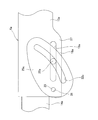
図29~図33は、本発明の実施の形態の第15例を示している。本例の場合、テレスコピック用揺動摩擦板25eを略三角形として、その表面積をより大きくするとともに、テレスコピック用揺動摩擦板25eに、直線状の案内長孔32eを形成している。また、テレスコピック用揺動摩擦板25eの一部で、案内長孔32eの幅方向両側縁のうち、二次衝突時に調節杆22aからの衝撃荷重が加わる片側縁(図29~図32の下側縁)から、この案内長孔32eの幅方向片側に離隔した部分に、この案内長孔32eと平行に強度調節用長孔38を設けている。これにより、これらの案内長孔32eと強度調節用長孔38との間に、二次衝突時に案内長孔32eの片側縁に加わる衝撃荷重に基づいて、この強度調節用長孔38側に向け塑性変形可能な、ブリッジ部39を設けている。
図34~図36は、本発明の実施の形態の第16例を示している。本例の場合、チルト用揺動摩擦板34dの幅方向両側縁のうち、片側縁を円弧として、その表面積をより大きくするとともに、チルト用揺動摩擦板34dに直線状の案内長孔36dを設けている。また、チルト用揺動摩擦板34dの一部で、案内長孔36dの幅方向両側縁のうち、二次衝突時に調節杆22aからの衝撃荷重が加わる片側縁(図34~図36の上側縁)から、この案内長孔36dの幅方向片側に離隔した部分に、この案内長孔36dと並列に強度調節用長孔40を設けている。これにより、これらの案内長孔36dと強度調節用長孔40との間に、この強度調節用長孔40側に向け塑性変形可能な、ブリッジ部41を設けている。
図37は、本発明の実施の形態の第17例を示している。本例は、実施の形態の第15例および第16例を組み合わせた構造を有している。すなわち、テレスコピック用揺動摩擦板25eに強度調節用長孔38を設けることでブリッジ部39を、チルト用揺動摩擦板34dに強度調節用長孔40を設けることでブリッジ部41を、それぞれ設けている。その他の部分の構成および効果は、実施の形態の第15例および第16例と同様である。
図38および図39は、本発明の実施の形態の第18例を示している。本例の場合、テレスコピック用揺動摩擦板25fに、円弧状の案内長孔32fを設けている。また、テレスコピック用揺動摩擦板25fの一部に、案内長孔32fと並列に円弧状の強度調節用長孔38aを設けることにより、二次衝突時に塑性変形可能な円弧状のブリッジ部39aを設けている。さらに、案内長孔32fのうち、二次衝突時に調節杆22aから加わる衝撃荷重に伴って応力が集中する、長さ方向一端縁(図38の下端縁)に、切り欠き部42を設けている。このような切り欠き部42を設けることで、二次衝突時に、ブリッジ部39aを変形しやすくしている。その他の部分の構成および効果は、実施の形態の第15例と同様である。
図40は、本発明の実施の形態の第19例を示している。本例は、実施の形態の第5例および第15例を組み合わせた構造を有する。すなわち、チルト用長孔21bの、ステアリングコラム6aの中心軸に対し直交する仮想平面αに対する傾斜角度βを、ステアリングホイール1(図41参照)の上下位置にかかわらず、ステアリングコラム6aの中心軸の前後方向γに対する傾斜角度δよりも大きくするとともに、テレスコピック用揺動摩擦板25eに強度調節用長孔38を設けることでブリッジ部39を設けている。その他の部分の構造および効果は、実施の形態の第5例および第15例と同様である。
2 ステアリングギヤユニット
3 入力軸
4 タイロッド
5、5a ステアリングシャフト
6、6a ステアリングコラム
7 自在継手
8 中間シャフト
9 自在継手
10 車体
11、11a 枢軸
12、12a 支持ブラケット
13、13a アウタコラム
14、14a インナコラム
15、15a アウタシャフト
16、16a インナシャフト
17 電動モータ
18、18a 変位ブラケット
19、19a テレスコピック用長孔
20、20a 支持板部
21、21a チルト用長孔
22、22a 調節杆
23 調節ハンドル
24 拡縮装置
25、25a~25f テレスコピック用揺動摩擦板
26 枢支ブラケット
27 被挟持板部
28 取付板部
29 調節ナット
30 頭部
31 揺動中心孔
32、32a~32f 案内長孔
33 支持ピン
34、34a~34e チルト用揺動摩擦板
35 揺動中心孔
36、36a~36e 案内長孔
37 支持ピン
38 強度調節用長孔
39 ブリッジ部
40 強度調節用長孔
41 ブリッジ部
42 頭部
Claims (11)
- 後端部にステアリングホイールを固定するステアリングシャフトの周囲に配置されて、このステアリングシャフトを回転自在に支持するステアリングコラムと、
前記ステアリングコラムの軸方向中間部に固設された変位ブラケットと、
前記変位ブラケットに左右方向に形成された第一貫通孔と、
前記変位ブラケットを左右両側から挟む状態で設けられた左右1対の支持板部を有し、車体に支持される支持ブラケットと、
前記1対の支持板部の一部で互いに整合する位置に設けられた第二貫通孔と、
調節杆と、この調節杆の一端部で前記1対の支持板部のうちの一方の外側面から突出した部分に設けられた調節ハンドルと、この調節杆の一部で前記1対の支持板部を左右両側から挟む位置に設けられた1対の押圧部とを備え、前記調節ハンドルの操作に基づいて、これら1対の押圧部同士の間隔を拡縮することが可能になっている拡縮装置と、
それぞれが互いに対向する1対の面同士の間部分である、前記1対の支持板部のそれぞれの内側面と前記変位ブラケットの両側の外側面との間部分、および、前記1対の支持板部のそれぞれの外側面と前記1対の押圧部のそれぞれの内側面との間部分とのうち、少なくとも一方に狭持され、互いに離隔した2箇所位置に、揺動中心孔と案内長孔とを有する揺動摩擦板と、
前記揺動摩擦板を挟持した前記1対の面のうち、前記ステアリングホイールの位置調節を行う際に前記調節杆と相対変位する一方の面の一部あるいはこの一方の面に対して不動である部分に固設され、前記揺動中心孔と係合する支持ピンと、
を備えており、
第一貫通孔および第二貫通孔のうち、少なくとも一方が前記ステアリングホイールの位置調節方向に長い調節用長孔であり、前記調節杆は、第一貫通孔および第二貫通孔、ならびに、前記案内長孔に挿通されており、
前記1対の押圧部同士の間隔を拡げることにより、前記揺動摩擦板の左右両側の面とこの揺動摩擦板を挟持する前記1対の面との当接部の面圧を低下ないしは喪失させた状態で、前記調節杆を前記調節用長孔に沿って変位させた場合に、前記揺動摩擦板は、前記調節杆を前記案内長孔に沿って変位させつつ、前記支持ピンを中心として揺動するものであり、
この揺動の全範囲で、前記案内長孔の長さ方向もしくは前記案内長孔のうちで前記案内ピンが係合している部分の接線方向と、前記調節用長孔の長さ方向もしくは前記調節用長孔のうちで前記調節杆が挿通している部分の接線方向とが、一致しないように構成されている、
ステアリング装置。 - 第一貫通孔が、前記ステアリングコラムの軸方向に長いテレスコピック用長孔であり、前記1対の面同士の間部分のうちの少なくとも一方に挟持した揺動摩擦板は、前記調節杆を前記テレスコピック用長孔に沿って変位させた場合に、前記調節杆を前記案内長孔に沿って変位させつつ、前記支持ピンを中心として揺動するものであり、この揺動の全範囲で、前記案内長孔の長さ方向あるいは前記案内長孔のうちで前記調節杆が係合している部分の接線方向と、前記テレスコピック用長孔の長さ方向とが一致しない、請求項1に記載したステアリング装置。
- 第二貫通孔が、上下方向に長いチルト用長孔であり、前記1対の面同士の間部分のうちの少なくとも一方に挟持した揺動摩擦板は、前記調節杆を前記チルト用長孔に沿って変位させた場合に、前記調節杆を前記案内長孔に沿って変位させつつ、前記支持ピンを中心として揺動するものであり、この揺動の全範囲で、前記案内長孔の長さ方向あるいは前記案内長孔のうちで前記調節杆が係合している部分の接線方向と、前記チルト用長孔の長さ方向あるいは前記チルト用長孔のうちで前記調節杆が挿通している部分の接線方向とが一致しない、請求項1に記載したステアリング装置。
- 前記案内長孔が、前記調節杆と前記支持ピンとを結ぶ直線に沿って形成されている、請求項1に記載したステアリング装置。
- 前記案内長孔が、前記調節杆と前記支持ピンとを結ぶ円弧に沿って形成されている、請求項1に記載したステアリング装置。
- 前記案内長孔が、前記調節杆と前記支持ピンとを結ぶ直線に対して傾斜した状態で直線状に形成されている、請求項1に記載したステアリング装置。
- 前記案内長孔が、前記調節杆と前記支持ピンとを結ぶ円弧に対し傾斜した状態で円弧状に形成されている、請求項1に記載したステアリング装置。
- 前記揺動摩擦板の一部で、前記案内長孔の幅方向両側縁のうち、二次衝突の発生時に前記調節杆から衝撃的な押付力を加えられる片側縁から、前記案内長孔の幅方向片側に離隔した部分に、強度調節用長孔を、この案内長孔と並列に設けることにより、これらの強度調節用長孔と案内長孔の間に、前記衝撃的な押付力に基づき、前記強度調節用長孔の側に向け塑性変形可能なブリッジ部を設けている、請求項1に記載したステアリング装置。
- 前記揺動摩擦板と、この揺動摩擦板を挟持する前記1対の面のうちの一方の面を備えた部材と他方の面を備えた部材とのうちの少なくとも一方の部材とが、硬さの異なる金属素材により造られている、請求項1に記載したステアリング装置。
- 前記揺動摩擦板に、摩擦係数を大きくするための表面加工が施されている、請求項1に記載したステアリング装置。
- 前記揺動摩擦板が、鉄、鉄系合金、アルミニウム、またはアルミニウム合金により形成されている、請求項1に記載したステアリング装置。
Priority Applications (3)
| Application Number | Priority Date | Filing Date | Title |
|---|---|---|---|
| EP12801315.8A EP2722253B1 (en) | 2011-06-15 | 2012-06-13 | Steering device |
| US13/810,805 US9039042B2 (en) | 2011-06-15 | 2012-06-13 | Steering apparatus |
| CN201280000524.XA CN102971198B (zh) | 2011-06-15 | 2012-06-13 | 转向装置 |
Applications Claiming Priority (8)
| Application Number | Priority Date | Filing Date | Title |
|---|---|---|---|
| JP2011-132819 | 2011-06-15 | ||
| JP2011132819 | 2011-06-15 | ||
| JP2011-206810 | 2011-09-22 | ||
| JP2011206810A JP5626165B2 (ja) | 2011-06-15 | 2011-09-22 | ステアリング装置 |
| JP2011208306 | 2011-09-25 | ||
| JP2011-208306 | 2011-09-25 | ||
| JP2012035139A JP5447556B2 (ja) | 2011-06-15 | 2012-02-21 | ステアリング装置 |
| JP2012-035139 | 2012-02-21 |
Publications (1)
| Publication Number | Publication Date |
|---|---|
| WO2012173143A1 true WO2012173143A1 (ja) | 2012-12-20 |
Family
ID=48525800
Family Applications (1)
| Application Number | Title | Priority Date | Filing Date |
|---|---|---|---|
| PCT/JP2012/065126 WO2012173143A1 (ja) | 2011-06-15 | 2012-06-13 | ステアリング装置 |
Country Status (5)
| Country | Link |
|---|---|
| US (1) | US9039042B2 (ja) |
| EP (1) | EP2722253B1 (ja) |
| JP (4) | JP5447556B2 (ja) |
| CN (1) | CN102971198B (ja) |
| WO (1) | WO2012173143A1 (ja) |
Cited By (2)
| Publication number | Priority date | Publication date | Assignee | Title |
|---|---|---|---|---|
| CN107380251A (zh) * | 2016-04-27 | 2017-11-24 | 株式会社捷太格特 | 转向装置 |
| US9956983B2 (en) * | 2014-01-07 | 2018-05-01 | Nsk Ltd. | Steering wheel position adjustment device |
Families Citing this family (33)
| Publication number | Priority date | Publication date | Assignee | Title |
|---|---|---|---|---|
| JP5971097B2 (ja) * | 2012-11-29 | 2016-08-17 | 日本精工株式会社 | ステアリングホイールの位置調節装置 |
| US9616914B2 (en) | 2014-02-20 | 2017-04-11 | Steering Solutions Ip Holding Corporation | Telescope and adaptive energy absorption system |
| US9663136B2 (en) | 2014-02-20 | 2017-05-30 | Steering Solutions Ip Holding Corporation | Steering column having anti-rotation feature |
| US9499190B2 (en) * | 2014-03-06 | 2016-11-22 | Steering Solutions Ip Holding Corporation | Adjustable steering column assembly having self-de-lashing power-rake mechanism |
| JP6353748B2 (ja) * | 2014-08-30 | 2018-07-04 | 株式会社山田製作所 | ステアリング装置 |
| US9522694B2 (en) | 2015-02-27 | 2016-12-20 | Steering Solutions Ip Holding Corporation | Radial telescope bushing for steering column |
| US10351159B2 (en) | 2015-05-01 | 2019-07-16 | Steering Solutions Ip Holding Corporation | Retractable steering column with a radially projecting attachment |
| US10343706B2 (en) * | 2015-06-11 | 2019-07-09 | Steering Solutions Ip Holding Corporation | Retractable steering column system, vehicle having the same, and method |
| US11560169B2 (en) * | 2015-06-11 | 2023-01-24 | Steering Solutions Ip Holding Corporation | Retractable steering column system and method |
| US10577009B2 (en) | 2015-06-16 | 2020-03-03 | Steering Solutions Ip Holding Corporation | Retractable steering column assembly and method |
| DE102016111473A1 (de) | 2015-06-25 | 2016-12-29 | Steering Solutions Ip Holding Corporation | Stationäre lenkradbaugruppe und verfahren |
| DE102015112086B4 (de) * | 2015-07-24 | 2022-10-20 | Robert Bosch Automotive Steering Gmbh | Vorrichtung zum verstellen einer lenksäule eines kraftfahrzeuges und lenksystem |
| CN107848560B (zh) * | 2015-09-29 | 2020-03-27 | 日本精工株式会社 | 方向盘的位置调节装置 |
| CN107521547B (zh) | 2016-06-21 | 2020-03-10 | 操纵技术Ip控股公司 | 转向柱组件的自锁伸缩式致动器 |
| US10457313B2 (en) | 2016-06-28 | 2019-10-29 | Steering Solutions Ip Holding Corporation | ADAS wheel locking device |
| US10363958B2 (en) | 2016-07-26 | 2019-07-30 | Steering Solutions Ip Holding Corporation | Electric power steering mode determination and transitioning |
| US10189496B2 (en) | 2016-08-22 | 2019-01-29 | Steering Solutions Ip Holding Corporation | Steering assembly having a telescope drive lock assembly |
| US10464590B2 (en) | 2016-10-07 | 2019-11-05 | Steering Solutions Ip Holding Corporation | Steering column energy absorbing system |
| US10351160B2 (en) | 2016-11-30 | 2019-07-16 | Steering Solutions Ip Holding Corporation | Steering column assembly having a sensor assembly |
| US10370022B2 (en) | 2017-02-13 | 2019-08-06 | Steering Solutions Ip Holding Corporation | Steering column assembly for autonomous vehicle |
| JP6799782B2 (ja) * | 2017-02-13 | 2020-12-16 | 株式会社ジェイテクト | ステアリング装置 |
| US10385930B2 (en) | 2017-02-21 | 2019-08-20 | Steering Solutions Ip Holding Corporation | Ball coupling assembly for steering column assembly |
| GB2566704A (en) * | 2017-09-21 | 2019-03-27 | Ford Global Tech Llc | A steering assembly |
| US10526003B2 (en) | 2017-09-28 | 2020-01-07 | Steering Solutions Ip Holding Corporation | Shroud guidance mechanism for steering column |
| US10464592B2 (en) | 2017-10-30 | 2019-11-05 | Steering Solutions Ip Holding Corporation | Steering column motion control assembly |
| US10974756B2 (en) | 2018-07-31 | 2021-04-13 | Steering Solutions Ip Holding Corporation | Clutch device latching system and method |
| US11034377B2 (en) * | 2018-07-31 | 2021-06-15 | Steering Solutions Ip Holding Corporation | System and method of automatically stowing and unstowing a steering column assembly |
| KR102575152B1 (ko) * | 2018-08-07 | 2023-09-06 | 현대자동차주식회사 | 차량의 스티어링 컬럼 장치 |
| JP7096740B2 (ja) * | 2018-08-30 | 2022-07-06 | 株式会社山田製作所 | ステアリング装置 |
| US11292504B2 (en) * | 2019-03-20 | 2022-04-05 | Volvo Car Corporation | Vehicle having multiple driving positions |
| JP7351684B2 (ja) * | 2019-09-13 | 2023-09-27 | 株式会社ジェイテクト | ステアリングコラム装置 |
| US11203374B2 (en) | 2020-01-03 | 2021-12-21 | Steering Solutions Ip Holding Corporation | Clamp mechanism with pivoting friction plate for adjustable steering column |
| US11891113B2 (en) * | 2022-04-18 | 2024-02-06 | Steering Solutions Ip Holding Corporation | Externally translating, internally telescoping steering column assembly |
Citations (7)
| Publication number | Priority date | Publication date | Assignee | Title |
|---|---|---|---|---|
| JPH1035511A (ja) | 1996-04-18 | 1998-02-10 | Etab Supervis | 自動車用ステアリングコラム |
| JP2005343331A (ja) * | 2004-06-03 | 2005-12-15 | Nsk Ltd | 車両用ステアリング装置 |
| WO2006118054A1 (ja) * | 2005-04-28 | 2006-11-09 | Nsk Ltd. | ステアリング装置およびその製造方法 |
| JP2010052639A (ja) | 2008-08-29 | 2010-03-11 | Nsk Ltd | ステアリングコラム装置 |
| JP2010173552A (ja) * | 2009-01-30 | 2010-08-12 | Fuji Kiko Co Ltd | ステアリングコラム装置 |
| JP2011052639A (ja) | 2009-09-03 | 2011-03-17 | Teikoku Electric Mfg Co Ltd | 流体分散ポンプ |
| JP2011084133A (ja) * | 2009-10-14 | 2011-04-28 | Nsk Ltd | ステアリング装置 |
Family Cites Families (40)
| Publication number | Priority date | Publication date | Assignee | Title |
|---|---|---|---|---|
| GB2092966A (en) * | 1981-02-13 | 1982-08-25 | Ford Motor Co | Steering column assembly |
| JPH0511105Y2 (ja) * | 1988-01-29 | 1993-03-18 | ||
| JPH02225176A (ja) * | 1989-02-23 | 1990-09-07 | Koyo Seiko Co Ltd | チルトステアリング装置 |
| JPH02249761A (ja) * | 1989-03-24 | 1990-10-05 | Koyo Seiko Co Ltd | チルトステアリング装置 |
| JPH02303971A (ja) * | 1989-05-17 | 1990-12-17 | Koyo Seiko Co Ltd | チルトステアリング装置 |
| JPH0367779A (ja) * | 1989-08-07 | 1991-03-22 | Koyo Seiko Co Ltd | チルトステアリング装置 |
| JPH0367780A (ja) * | 1989-08-08 | 1991-03-22 | Koyo Seiko Co Ltd | チルトステアリング装置 |
| GB2306629A (en) * | 1995-10-28 | 1997-05-07 | Nastech Europ Ltd | Adjustable vehicle steering column assembly |
| JPH114476A (ja) | 1997-06-11 | 1999-01-06 | Nec Corp | 移動通信システム及びそのトラヒック収集制御方法並びにトラヒック収集制御プログラムを記録した記録媒体 |
| US6036228A (en) * | 1998-05-04 | 2000-03-14 | General Motors Corporation | Adjustable steering column for motor vehicle |
| SE521827C2 (sv) * | 1998-11-27 | 2003-12-09 | Volvo Personvagnar Ab | Arrangemang vid styrinrättning |
| JP2000289628A (ja) | 1999-04-12 | 2000-10-17 | Nsk Ltd | チルト・テレスコ式ステアリング装置 |
| JP3727004B2 (ja) | 1999-09-10 | 2005-12-14 | 光洋精工株式会社 | 衝撃吸収式ステアリング装置及びこれに用いる取付部材 |
| WO2001083284A1 (en) * | 2000-05-02 | 2001-11-08 | Douglas Autotech Corporation | Steering column support assembly |
| US6474189B1 (en) * | 2000-10-26 | 2002-11-05 | Trw Inc. | Apparatus for mounting a foot pedal and a steering column to a vehicle |
| US6923086B2 (en) * | 2001-02-06 | 2005-08-02 | Thyssenkrupp Presta Ag | Safety device for a motor vehicle with a steering column arrangement and safety method |
| JP2002362377A (ja) | 2001-06-01 | 2002-12-18 | Nsk Ltd | 車両用ステアリングコラム保持装置 |
| GB2377471A (en) * | 2001-07-13 | 2003-01-15 | Nsk Steering Sys Europ Ltd | Clamping apparatus with zinc coated clutch plates |
| GB2381853B (en) * | 2001-11-12 | 2005-08-17 | Lansing Linde Ltd | Adjusting device for a steering wheel of an industrial truck |
| US6662674B2 (en) * | 2001-11-21 | 2003-12-16 | Trw Inc. | Steering column |
| US6766712B2 (en) * | 2001-11-21 | 2004-07-27 | Trw Inc. | Steering column |
| JP4147579B2 (ja) | 2002-01-17 | 2008-09-10 | 日本精工株式会社 | ステアリング装置 |
| US7047836B2 (en) * | 2002-02-01 | 2006-05-23 | Trw Inc. | Surface treatment for a locking mechanism |
| US6829962B2 (en) * | 2002-04-08 | 2004-12-14 | Trw Inc. | Steering column |
| JP4069362B2 (ja) | 2002-07-05 | 2008-04-02 | 日本精工株式会社 | ステアリングコラム装置 |
| GB2392971A (en) | 2002-09-10 | 2004-03-17 | Nsk Steering Sys Europ Ltd | Clamping apparatus for an adjustable steering column for a vehicle |
| US6863305B2 (en) * | 2002-09-20 | 2005-03-08 | Trw Inc. | Steering column |
| DE10261538A1 (de) * | 2002-12-23 | 2004-07-01 | Thyssenkrupp Presta Ag | Lenksäule |
| DE60308805T2 (de) | 2003-01-06 | 2007-08-23 | Mando Corp., Pyungtaek | Neigungsverstellung für Lenksäulen |
| US7942446B2 (en) * | 2004-04-30 | 2011-05-17 | Nexteer (Beijing) Technology Co., Ltd. | Horizontal hybrid collapsing steering column |
| WO2005118370A1 (ja) * | 2004-06-01 | 2005-12-15 | Nsk Ltd. | 車両用チルト・テレスコピック式ステアリング装置 |
| JP2005343333A (ja) | 2004-06-03 | 2005-12-15 | Asmo Co Ltd | 電動スライド装置 |
| DE202004017086U1 (de) * | 2004-11-03 | 2005-02-03 | Kässbohrer Geländefahrzeug AG | Lenksäulenanordnung für ein Kraftfahrzeug, insbesondere ein Kettenfahrzeug |
| DE602006001334D1 (de) * | 2005-09-08 | 2008-07-10 | Nsk Ltd | Lenkeinrichtung |
| DE102006007553B3 (de) * | 2006-02-16 | 2007-05-16 | Thyssenkrupp Presta Ag | Verstellbare Lenksäule für ein Kraftfahrzeug |
| JP5167633B2 (ja) | 2006-12-12 | 2013-03-21 | 日本精工株式会社 | ステアリング装置 |
| JP2008149969A (ja) * | 2006-12-20 | 2008-07-03 | Fuji Kiko Co Ltd | ステアリングコラム装置 |
| JP5227904B2 (ja) * | 2009-06-24 | 2013-07-03 | 富士機工株式会社 | ステアリングコラム装置 |
| US8523227B2 (en) * | 2010-12-13 | 2013-09-03 | Caterpillar Inc. | Single point friction lock for tilt and telescope adjustment of steering columns |
| JP5991516B2 (ja) * | 2012-06-12 | 2016-09-14 | 株式会社ジェイテクト | ステアリングコラム装置 |
-
2012
- 2012-02-21 JP JP2012035139A patent/JP5447556B2/ja active Active
- 2012-06-13 EP EP12801315.8A patent/EP2722253B1/en active Active
- 2012-06-13 CN CN201280000524.XA patent/CN102971198B/zh active Active
- 2012-06-13 US US13/810,805 patent/US9039042B2/en active Active
- 2012-06-13 WO PCT/JP2012/065126 patent/WO2012173143A1/ja active Application Filing
-
2013
- 2013-12-26 JP JP2013270039A patent/JP5742926B2/ja active Active
- 2013-12-26 JP JP2013270040A patent/JP5742927B2/ja active Active
- 2013-12-26 JP JP2013270038A patent/JP5673793B2/ja active Active
Patent Citations (7)
| Publication number | Priority date | Publication date | Assignee | Title |
|---|---|---|---|---|
| JPH1035511A (ja) | 1996-04-18 | 1998-02-10 | Etab Supervis | 自動車用ステアリングコラム |
| JP2005343331A (ja) * | 2004-06-03 | 2005-12-15 | Nsk Ltd | 車両用ステアリング装置 |
| WO2006118054A1 (ja) * | 2005-04-28 | 2006-11-09 | Nsk Ltd. | ステアリング装置およびその製造方法 |
| JP2010052639A (ja) | 2008-08-29 | 2010-03-11 | Nsk Ltd | ステアリングコラム装置 |
| JP2010173552A (ja) * | 2009-01-30 | 2010-08-12 | Fuji Kiko Co Ltd | ステアリングコラム装置 |
| JP2011052639A (ja) | 2009-09-03 | 2011-03-17 | Teikoku Electric Mfg Co Ltd | 流体分散ポンプ |
| JP2011084133A (ja) * | 2009-10-14 | 2011-04-28 | Nsk Ltd | ステアリング装置 |
Non-Patent Citations (1)
| Title |
|---|
| See also references of EP2722253A4 |
Cited By (2)
| Publication number | Priority date | Publication date | Assignee | Title |
|---|---|---|---|---|
| US9956983B2 (en) * | 2014-01-07 | 2018-05-01 | Nsk Ltd. | Steering wheel position adjustment device |
| CN107380251A (zh) * | 2016-04-27 | 2017-11-24 | 株式会社捷太格特 | 转向装置 |
Also Published As
| Publication number | Publication date |
|---|---|
| JP2014054993A (ja) | 2014-03-27 |
| JP2013079051A (ja) | 2013-05-02 |
| JP2014054995A (ja) | 2014-03-27 |
| JP5673793B2 (ja) | 2015-02-18 |
| JP5447556B2 (ja) | 2014-03-19 |
| CN102971198B (zh) | 2015-05-13 |
| JP2014054994A (ja) | 2014-03-27 |
| JP5742926B2 (ja) | 2015-07-01 |
| US9039042B2 (en) | 2015-05-26 |
| EP2722253B1 (en) | 2017-09-13 |
| EP2722253A4 (en) | 2015-04-29 |
| CN102971198A (zh) | 2013-03-13 |
| EP2722253A1 (en) | 2014-04-23 |
| JP5742927B2 (ja) | 2015-07-01 |
| US20130205933A1 (en) | 2013-08-15 |
Similar Documents
| Publication | Publication Date | Title |
|---|---|---|
| WO2012173143A1 (ja) | ステアリング装置 | |
| JP6380411B2 (ja) | ステアリングホイールの位置調節装置 | |
| US8622427B2 (en) | Steering column support apparatus | |
| US9283982B2 (en) | Steering column | |
| WO2015056538A1 (ja) | 位置調節式ステアリング装置 | |
| US9359002B2 (en) | Steering-column device | |
| EP2915721B1 (en) | Steering column | |
| JP5891876B2 (ja) | ステアリング装置 | |
| JP2009120133A (ja) | ステアリング装置 | |
| JP6098745B2 (ja) | ステアリング装置 | |
| JP6406020B2 (ja) | ステアリングホイールの位置調節装置 | |
| JP6668619B2 (ja) | テレスコピック式ステアリングコラム装置 | |
| JP2017056820A (ja) | ステアリングホイールの位置調節装置 | |
| JP2015229409A (ja) | ステアリング装置 | |
| JP6379863B2 (ja) | ステアリングホイールの位置調節装置及びその製造方法 | |
| JP6561678B2 (ja) | ステアリングホイールの位置調節装置 | |
| JP2015205576A (ja) | チルト式ステアリング装置 | |
| JP6561679B2 (ja) | ステアリングホイールの位置調節装置 | |
| JP6102205B2 (ja) | ステアリングホイールの位置調節装置 | |
| WO2023038013A1 (ja) | ステアリングコラム装置 | |
| JP2017132323A (ja) | ステアリングホイールの位置調節装置 | |
| JP6613820B2 (ja) | ステアリング装置 | |
| JP6187129B2 (ja) | ステアリングホイールの位置調節装置 | |
| JP2017081470A (ja) | ステアリングホイールの位置調節装置 | |
| JP6191389B2 (ja) | ステアリングホイールの位置調節装置 |
Legal Events
| Date | Code | Title | Description |
|---|---|---|---|
| WWE | Wipo information: entry into national phase |
Ref document number: 201280000524.X Country of ref document: CN |
|
| REEP | Request for entry into the european phase |
Ref document number: 2012801315 Country of ref document: EP |
|
| WWE | Wipo information: entry into national phase |
Ref document number: 2012801315 Country of ref document: EP |
|
| 121 | Ep: the epo has been informed by wipo that ep was designated in this application |
Ref document number: 12801315 Country of ref document: EP Kind code of ref document: A1 |
|
| WWE | Wipo information: entry into national phase |
Ref document number: 13810805 Country of ref document: US |
|
| NENP | Non-entry into the national phase |
Ref country code: DE |