WO2012132740A1 - 発進装置 - Google Patents
発進装置 Download PDFInfo
- Publication number
- WO2012132740A1 WO2012132740A1 PCT/JP2012/055139 JP2012055139W WO2012132740A1 WO 2012132740 A1 WO2012132740 A1 WO 2012132740A1 JP 2012055139 W JP2012055139 W JP 2012055139W WO 2012132740 A1 WO2012132740 A1 WO 2012132740A1
- Authority
- WO
- WIPO (PCT)
- Prior art keywords
- oil passage
- shaft
- input
- input shaft
- lubricating oil
- Prior art date
- Legal status (The legal status is an assumption and is not a legal conclusion. Google has not performed a legal analysis and makes no representation as to the accuracy of the status listed.)
- Ceased
Links
Images

Classifications
-
- F—MECHANICAL ENGINEERING; LIGHTING; HEATING; WEAPONS; BLASTING
- F16—ENGINEERING ELEMENTS AND UNITS; GENERAL MEASURES FOR PRODUCING AND MAINTAINING EFFECTIVE FUNCTIONING OF MACHINES OR INSTALLATIONS; THERMAL INSULATION IN GENERAL
- F16D—COUPLINGS FOR TRANSMITTING ROTATION; CLUTCHES; BRAKES
- F16D33/00—Rotary fluid couplings or clutches of the hydrokinetic type
- F16D33/18—Details
-
- F—MECHANICAL ENGINEERING; LIGHTING; HEATING; WEAPONS; BLASTING
- F16—ENGINEERING ELEMENTS AND UNITS; GENERAL MEASURES FOR PRODUCING AND MAINTAINING EFFECTIVE FUNCTIONING OF MACHINES OR INSTALLATIONS; THERMAL INSULATION IN GENERAL
- F16H—GEARING
- F16H45/00—Combinations of fluid gearings for conveying rotary motion with couplings or clutches
- F16H45/02—Combinations of fluid gearings for conveying rotary motion with couplings or clutches with mechanical clutches for bridging a fluid gearing of the hydrokinetic type
-
- F—MECHANICAL ENGINEERING; LIGHTING; HEATING; WEAPONS; BLASTING
- F16—ENGINEERING ELEMENTS AND UNITS; GENERAL MEASURES FOR PRODUCING AND MAINTAINING EFFECTIVE FUNCTIONING OF MACHINES OR INSTALLATIONS; THERMAL INSULATION IN GENERAL
- F16D—COUPLINGS FOR TRANSMITTING ROTATION; CLUTCHES; BRAKES
- F16D13/00—Friction clutches
- F16D13/22—Friction clutches with axially-movable clutching members
- F16D13/38—Friction clutches with axially-movable clutching members with flat clutching surfaces, e.g. discs
-
- F—MECHANICAL ENGINEERING; LIGHTING; HEATING; WEAPONS; BLASTING
- F16—ENGINEERING ELEMENTS AND UNITS; GENERAL MEASURES FOR PRODUCING AND MAINTAINING EFFECTIVE FUNCTIONING OF MACHINES OR INSTALLATIONS; THERMAL INSULATION IN GENERAL
- F16D—COUPLINGS FOR TRANSMITTING ROTATION; CLUTCHES; BRAKES
- F16D13/00—Friction clutches
- F16D13/58—Details
- F16D13/74—Features relating to lubrication
-
- F—MECHANICAL ENGINEERING; LIGHTING; HEATING; WEAPONS; BLASTING
- F16—ENGINEERING ELEMENTS AND UNITS; GENERAL MEASURES FOR PRODUCING AND MAINTAINING EFFECTIVE FUNCTIONING OF MACHINES OR INSTALLATIONS; THERMAL INSULATION IN GENERAL
- F16D—COUPLINGS FOR TRANSMITTING ROTATION; CLUTCHES; BRAKES
- F16D25/00—Fluid-actuated clutches
- F16D25/06—Fluid-actuated clutches in which the fluid actuates a piston incorporated in, i.e. rotating with the clutch
- F16D25/062—Fluid-actuated clutches in which the fluid actuates a piston incorporated in, i.e. rotating with the clutch the clutch having friction surfaces
- F16D25/063—Fluid-actuated clutches in which the fluid actuates a piston incorporated in, i.e. rotating with the clutch the clutch having friction surfaces with clutch members exclusively moving axially
- F16D25/0635—Fluid-actuated clutches in which the fluid actuates a piston incorporated in, i.e. rotating with the clutch the clutch having friction surfaces with clutch members exclusively moving axially with flat friction surfaces, e.g. discs
- F16D25/0638—Fluid-actuated clutches in which the fluid actuates a piston incorporated in, i.e. rotating with the clutch the clutch having friction surfaces with clutch members exclusively moving axially with flat friction surfaces, e.g. discs with more than two discs, e.g. multiple lamellae
-
- F—MECHANICAL ENGINEERING; LIGHTING; HEATING; WEAPONS; BLASTING
- F16—ENGINEERING ELEMENTS AND UNITS; GENERAL MEASURES FOR PRODUCING AND MAINTAINING EFFECTIVE FUNCTIONING OF MACHINES OR INSTALLATIONS; THERMAL INSULATION IN GENERAL
- F16D—COUPLINGS FOR TRANSMITTING ROTATION; CLUTCHES; BRAKES
- F16D25/00—Fluid-actuated clutches
- F16D25/12—Details not specific to one of the before-mentioned types
- F16D25/123—Details not specific to one of the before-mentioned types in view of cooling and lubrication
-
- F—MECHANICAL ENGINEERING; LIGHTING; HEATING; WEAPONS; BLASTING
- F16—ENGINEERING ELEMENTS AND UNITS; GENERAL MEASURES FOR PRODUCING AND MAINTAINING EFFECTIVE FUNCTIONING OF MACHINES OR INSTALLATIONS; THERMAL INSULATION IN GENERAL
- F16H—GEARING
- F16H45/00—Combinations of fluid gearings for conveying rotary motion with couplings or clutches
- F16H45/02—Combinations of fluid gearings for conveying rotary motion with couplings or clutches with mechanical clutches for bridging a fluid gearing of the hydrokinetic type
- F16H2045/0215—Details of oil circulation
Definitions
- the present invention relates to a starting device including a clutch that can transmit power input to an input member to an input shaft of a transmission and can cancel transmission of power between the input member and the input shaft.
- a wet multi-plate clutch device that is arranged between the transmission and the engine to transmit power, it supports a clutch drum that supports a plurality of friction plates (friction plates) and a plurality of friction materials (separator plates). And a cover member that is coupled to a clutch drum so as to cover an opening (see, for example, Patent Document 1). .
- a narrow passage is defined by the hub member and the cover member, and the lubricating oil is guided to spaces around the plurality of friction plates through the passage. The oil that has lubricated the plurality of friction plates stays in the clutch drum and is then discharged.
- a piston that rotates integrally with an input member (front cover) and moves in an axial direction toward the input member to press a plurality of friction plates
- a piston that rotates integrally with an input member (front cover) and moves in an axial direction toward the input member to press a plurality of friction plates
- an annular oil chamber defining member that is disposed behind and defines an engagement-side oil chamber that is supplied with hydraulic oil together with the piston
- hydraulic oil is supplied to an engagement-side oil chamber defined between the piston and the oil chamber defining member via an oil passage formed inside the input shaft of the transmission, and input.
- Hydraulic oil as a lubrication / cooling medium is supplied to the plurality of friction plates via an oil passage formed on the outer periphery of the shaft and an oil passage defined between the input member and the piston.
- JP 2008-163982 A German Patent Application No. 102008060940
- an oil passage for supplying hydraulic oil as a lubricating / cooling medium to a plurality of bearings and the like is branched from an oil passage formed on the outer periphery of the input shaft. If the hydraulic oil leaks out, a sufficient amount of hydraulic oil may not be supplied to the plurality of friction plates constituting the clutch.
- the main object of the present invention is to enable efficient cooling of a plurality of friction plates constituting the clutch in a starting device including a multi-plate clutch.
- the starting device of the present invention adopts the following means in order to achieve the main object.
- the starting device of the present invention is in a starting device including a clutch capable of transmitting power input to an input member to an input shaft of a transmission and releasing transmission of power between the input member and the input shaft.
- the clutch is A first friction plate that rotates integrally with the input member;
- a second friction plate rotatable integrally with the input shaft of the transmission,
- a piston capable of rotating integrally with the input member and axially moving toward the input member to press the first and second friction plates;
- An oil chamber defining member that defines an engagement side oil chamber to which hydraulic oil is supplied together with the piston;
- a first lubricating oil passage for supplying hydraulic oil to the first and second friction plates is defined between the input member and the piston.
- a second lubricating oil passage communicating with the first lubricating oil passage is formed in the input member, A first in-shaft oil passage communicating with the engagement side oil chamber and a second in-shaft oil passage communicating with the second lubricating oil passage are formed inside the input shaft. To do.
- the starting device rotates integrally with the input member and moves in the axial direction toward the input member to press the first and second friction plates, and the engagement side to which hydraulic oil is supplied together with the piston
- An oil chamber defining member that defines an oil chamber is provided, and a first lubricating oil passage for supplying hydraulic oil to the first and second friction plates is provided between the input member and the piston.
- a second lubricating oil passage communicating with the first lubricating oil passage is formed in the input member.
- a first in-shaft oil passage communicating with the engagement side oil chamber, and a second A second in-shaft oil passage communicating with the lubricating oil passage is formed inside the input shaft.
- the first first clutch oil passes from the second in-shaft oil passage of the input shaft through the second lubricating oil passage of the input member and the first lubricating oil passage between the input member and the piston. Then, hydraulic oil is supplied to the second friction plate.
- the second in-shaft oil passage is formed inside the input shaft, and the second in-shaft oil passage and the first lubricating oil passage are communicated with each other via the second lubricating oil passage formed in the input member. As a result, it is possible to reduce the leakage amount of the hydraulic oil in the second in-shaft oil passage as much as possible.
- the clutch is configured to be engaged when the piston is moved in the axial direction toward the input member, and the engagement side oil chamber is formed on the opposite side of the piston from the input member by using the oil chamber defining member.
- the first lubricating oil passage having a sufficient volume on the inner peripheral side of the first and second friction plates can be defined by the input member and the piston. Therefore, in this starting device, it is possible to supply a sufficient amount of hydraulic oil to the first and second friction plates of the clutch and efficiently cool the first and second friction plates.
- a sufficient amount of hydraulic oil is applied to the first and second friction plates via the second in-shaft oil passage, the second lubricating oil passage, the first lubricating oil passage, and the like.
- the pressure bonding of the first and second friction plates can be quickly released. Furthermore, by using the oil chamber defining member to define the engagement side oil chamber on the opposite side of the piston input member, a relatively high hydraulic pressure for engaging the clutch device does not act on the input member. Thus, it is possible to suppress the swelling of the input member.
- a first engagement oil passage communicating with the first in-shaft oil passage is defined between one end of the input shaft and an inner end surface of the input member facing the one end of the input shaft.
- the input member may be provided with a second engagement oil passage communicating with the first engagement oil passage and the engagement side oil chamber.
- the engagement side oil chamber between the piston and the oil chamber defining member is operated from the first in-shaft oil passage of the input shaft via the first engagement oil passage and the second engagement oil passage. Oil is supplied.
- the first in-shaft oil passage and the first engagement oil passage can be provided by merely arranging one seal member that suppresses leakage of hydraulic oil from the first engagement oil passage between the input shaft and the input member.
- the starting device may include an output member that can be coupled to the input member via the clutch and that is rotatably fitted to the input member and rotatable integrally with the input shaft.
- the shaft, the input member, and the output member may define a third lubricating oil passage communicating with the second in-shaft oil passage and the second lubricating oil passage, and the input member, the input shaft,
- a seal member may be disposed between the input member and the output member so as to suppress leakage of hydraulic oil from the third lubricating oil passage. Accordingly, the seal member between the input member and the input shaft suppresses the communication between the first engagement oil passage and the third lubricant oil passage while suppressing the leakage of the hydraulic oil from the first engagement oil passage.
- the leakage of the hydraulic oil from the third lubricating oil passage can be suppressed by the sealing member between the input member and the output member, the number of sealing members in the starting device can be reduced.
- the second shaft oil passage is disposed between the input shaft, a stator shaft disposed on the outer periphery of the input shaft, and the input shaft and the stator shaft to suppress leakage of hydraulic oil.
- the hydraulic oil may be supplied through an oil passage defined by the bushing, and the input shaft and the output member are a fitting seal portion that suppresses leakage of the hydraulic oil from the third lubricating oil passage May be formed. Thereby, it becomes possible to supply hydraulic oil more reliably to the second in-shaft oil passage from between the input shaft and the stator shaft.
- the input member may be formed so as to protrude in the axial direction toward the piston, and may have a protruding portion that contacts either one of the first and second friction plates.
- the protruding portion in contact with any one of the first and second friction plates on the input member, it is possible to further increase the rigidity of the input member while reducing the number of parts.
- the oil chamber defining member may be fitted to the input member and fixed in the axial direction with respect to the input member. Thereby, the number of seal members used for sealing the engagement side oil chamber can be reduced.
- the starting device may include a pump impeller and a turbine runner
- the input member may be a front cover that is joined to a pump shell of the pump impeller and constitutes a fluid transmission chamber together with the pump shell.
- the hydraulic oil may be supplied into the fluid transmission chamber via the first lubricating oil passage.
- a sufficient amount of hydraulic oil can be supplied to the pump impeller and the turbine runner via the first lubricating oil passage.
- a sufficient amount of hydraulic oil is supplied to the first and second friction plates via the first lubricating oil passage to efficiently cool the first and second friction plates. It becomes possible.
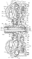
- FIG. 1 It is a fragmentary sectional view showing fluid transmission 1 as a starting device concerning an example of the present invention.
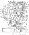
- 2 is a partial cross-sectional view showing a main part of the fluid transmission device 1.
- FIG. It is a principal part expanded partial sectional view which shows the fluid transmission apparatus 1B which concerns on a modification.
- FIG. 1 is a configuration diagram showing a fluid transmission device 1 as a starting device according to an embodiment of the present invention.
- a fluid transmission device 1 shown in the figure is a torque converter mounted as a starting device on a vehicle including an engine (internal combustion engine) as a prime mover, and is a front cover (input member) connected to a crankshaft of the engine (not shown). 3, a pump impeller (input side fluid transmission element) 4 fixed to the front cover 3, a turbine runner (output side fluid transmission element) 5 that can rotate coaxially with the pump impeller 4, and a pump impeller 4 from the turbine runner 5.
- a stator 6 that rectifies the flow of hydraulic fluid (working fluid) to the input shaft 100, and an input shaft 100 fixed to an input shaft 100 of a transmission (not shown) that is an automatic transmission (AT) or a continuously variable transmission (CVT).
- a turbine hub (output member) 7 that can rotate integrally, a multi-plate friction lockup clutch mechanism 8, And a damper device 10 which is connected to the lock-up clutch mechanism 8 is connected to the Binhabu 7.
- the front cover 3 includes a center piece 30, a side wall 34 that is fixed to the center piece 30 by welding and that extends in the radial direction, and an outer cylinder that extends from the outer periphery of the side wall 34 in the axial direction of the fluid transmission device 1.
- a cover body 33 having a portion 35. As shown in FIG. 1, a hole 30 c into which the input shaft 100 is rotatably fitted is formed inside the center piece 30.
- a set block 36 connected to a drive plate (not shown) connected to a crankshaft of an engine (not shown) is fixed to the outer periphery of the side wall 34 of the cover body 33 by welding or the like.
- the pump impeller 4 includes a pump shell 40 that is tightly fixed to the outer cylinder portion 35 of the front cover 3, and a plurality of pump blades 41 that are disposed on the inner surface of the pump shell 40.
- the turbine runner 5 includes a turbine shell 50 and a plurality of turbine blades 51 disposed on the inner surface of the turbine shell 50.
- the turbine shell 50 is fitted to the turbine hub 7 and fixed to the turbine hub 7 through rivets.
- the stator 6 has a plurality of stator blades 60, and the rotation direction of the stator 6 is set in only one direction by the one-way clutch 61.
- the pump impeller 4 and the turbine runner 5 face each other, and the pump impeller 4, the turbine runner 5 and the stator 6 form a torus (annular flow path) for circulating the hydraulic oil.
- the damper device 10 includes a drive member 11 as an input element and a first intermediate member that engages with the drive member 11 via a plurality of first springs (first elastic bodies) SP1.
- first intermediate element 12, a second intermediate member (second intermediate element) 14 that engages with the first intermediate member 12 via a plurality of second springs (second elastic bodies) SP2, and a plurality of third A driven member (output element) 15 that engages with the second intermediate member 14 via a spring (third elastic body) SP3
- the first and second springs SP1 and SP2 are coil springs made of a metal material spirally wound so as to have an axial center extending straight when no load is applied.
- SP3 is an arc spring made of a metal material wound so as to have an axial center extending in an arc shape when no load is applied.
- the drive member 11 includes a plurality of spring contact portions 11a that contact one end of the corresponding first spring SP1, and a plurality of spring support portions 11b.
- the drive member 11 is fixed to the clutch drum 82 of the lockup clutch mechanism 8 via a rivet, and is formed in an outer peripheral side region inside the fluid transmission chamber 9 defined by the front cover 3 and the pump shell 40 of the pump impeller 4. Be placed.
- the first intermediate member 12 is a ring that can slidably support the first and second springs SP1 and SP2 together with the plurality of spring support portions 11b of the drive member 11 adjacent to each other (alternately) on the same circumference.
- the first intermediate member 12 is disposed between the other end of the corresponding first spring SP1 and one end of the second spring SP2 adjacent to the first spring SP1. And a plurality of spring contact portions 12a that contact the both.
- the second intermediate member 14 includes an annular first plate 141 and an annular second plate 142 fixed to the first plate 141 via a rivet.
- the fluid transmission device is driven by the driven member 15. It is supported rotatably around one axis.
- the first plate 141 of the second intermediate member 14 has a plurality of spring contact portions 141a that contact the other ends of the corresponding second springs SP2 on the outer peripheral side, and a plurality of springs for supporting the third springs SP3.
- a spring support is provided on the inner peripheral side.
- the second plate 142 of the second intermediate member 14 has a clutch drum support portion 142 a that rotatably supports the clutch drum 82 of the lockup clutch mechanism 8 on the outer peripheral side, and a spring support portion of the first plate 141. And a spring support portion that supports the third spring SP3.
- the first and second plates 141 and 142 are formed with a plurality of spring abutting portions (not shown) that abut against one end of the corresponding third spring SP3.
- the plurality of first springs SP1 are disposed on the outer peripheral portion of the damper device 10 so as to be positioned between the spring contact portion 11a of the drive member 11 and the spring contact portion 12a of the first intermediate member 12, respectively.
- the plurality of second springs SP2 are positioned between the spring contact portion 12a of the first intermediate member 12 and the second intermediate member 14, that is, the spring contact portion 141a of the first plate 141, respectively. It will be arranged on the outer periphery.
- the plurality of third springs SP3 are arranged to be spaced apart from the first and second springs SP1 and SP2 in the radial direction of the fluid transmission device 1, respectively, and closer to the inner peripheral side than the first and second springs SP1 and SP2. Will be located.
- the driven member 15 is disposed between the first plate 141 and the second plate 142 of the second intermediate member 14 and is fixed to the turbine hub 7.
- the driven member 15 includes a plurality of spring contact portions 15a that contact the other end of the corresponding third spring SP3. Furthermore, the driven member 15 has a plurality of plate support portions 15 c that protrude in the axial direction and rotatably support the inner periphery of the second plate 142 of the second intermediate member 14. Accordingly, the second intermediate member 14 is rotatably supported by the driven member 15 and is arranged around the axis of the fluid transmission device 1.
- the lockup clutch mechanism 8 can perform a lockup that connects the front cover 3 as an input member and the turbine hub 7, that is, the input shaft 100 of the transmission, via the damper device 10 and can release the lockup. As shown in FIGS. 1 and 2, the damper device 10 and the side wall 34 of the front cover 3 are disposed.
- the lockup clutch mechanism 8 is supported by the front cover 3 so as to be slidable in the axial direction and rotates together with the front cover 3, and the front cover 3 (cover An annular clutch hub (first friction plate support member) 81 fixed to the side wall 34 of the main body 33) and the drive member 11 are connected to the input shaft 100 of the transmission via the damper device 10.
- the clutch drum (the friction plate support member or the second friction plate support member) 82 and the spline formed on the outer periphery of the clutch hub 81 are fitted and supported by the clutch hub 81 so as to be slidable in the axial direction.
- a plurality of first friction plates 83 (separator plates) that can rotate integrally with the front cover 3, and a clutch.
- a plurality of second friction plates (friction materials) which are fitted to splines formed on the inner periphery of the drum 82 and supported by the clutch drum 82 so as to be slidable in the axial direction and which can rotate integrally with the input shaft 100.
- an annular flange member (oil chamber defining member) 85 fixed to the center piece 30 of the front cover 3 so as to be positioned closer to the damper device 10 than the lock-up piston 80.
- the lockup piston 80 is fitted to a first cylindrical portion (first support portion) 31 formed in the center piece 30 and is opposed to the inner surface of the front cover 3 (such as the side wall portion 34 of the cover main body 33).
- the inner peripheral portion 80a of the lock-up piston 80 is in sliding contact with the outer peripheral surface of the first cylindrical portion 31 of the center piece 30 via a seal member such as an O-ring.
- the cylindrical portion 80b of the lock-up piston 80 is spline-fitted to the inner peripheral portion of the clutch hub 81 fixed to the front cover 3 (cover body 33) as shown in the figure.
- a part is disposed on the inner peripheral side of the clutch hub 81 and is supported by the front cover 3 so as to be slidable in the axial direction of the fluid transmission device 1.
- the pressing portion 80c of the lock-up piston 80 is one of the plurality of first friction plates 83 supported by the clutch hub 81 and located at the most central portion (the center between the outer periphery and the inner periphery). Part).
- the clutch hub 81 is fixed to the inner surface of the side wall 34 of the cover main body 33 by welding, and the clutch hub 81 and the clutch drum 82 are arranged in a region on the outer peripheral side in the front cover 3 as shown in the figure.
- the side wall 34 of the cover main body 33 is formed by press molding so as to protrude in the axial direction toward the lockup piston 80 and is the most of the plurality of first friction plates 83 supported by the clutch hub 81. It has an annular projecting portion 34a that abuts one generally central portion (the central portion between the outer periphery and the inner periphery) located on the front cover 3 side.
- the flange member 85 is a second cylindrical portion (second support portion) 32 formed on the center piece 30 so as to protrude closer to the damper device 10 side than the first cylindrical portion 31 on the inner peripheral side of the first cylindrical portion 31. And a cylindrical outer periphery that slides in contact with the inner peripheral surface of the cylindrical portion 80b of the lockup piston 80 via a seal member such as an O-ring to guide the movement of the lockup piston 80 in the axial direction. And a piston movement restricting portion 85c having an annular surface extending inward and in the radial direction (direction orthogonal to the axial direction) from the outer edge of the outer peripheral portion 85b on the lockup piston 80 side. As shown in FIG.
- the second cylindrical portion 32 of the center piece 30 is formed so as to overlap the end portion of the first cylindrical portion 31 on the damper device 10 side as viewed from the radial direction, and the base portion 85 a of the flange member 85. Is inserted to the overlapping portion (concave portion) between the first cylindrical portion 31 and the second cylindrical portion 32. Accordingly, the first cylindrical portion 31 and the flange member 85 fitted to the second cylindrical portion 32 overlap when viewed from the radial direction.
- the flange member 85 (base 85a) is fixed in the axial direction with respect to the center piece 30 (front cover 3) using a snap ring 86.
- the 2nd cylindrical part 32 of the centerpiece 30 is rotatably fitted with respect to the turbine hub 7 so that it may show in figure, and seal members 89, such as an O-ring, are arrange
- the flange member 85 guides the movement of the lockup piston 80 in the axial direction, and hydraulic oil is supplied together with the lockup piston 80 to the opposite side of the front cover 3 (side wall portion 34) of the lockup piston 80.
- An engagement side oil chamber 87 is defined. As shown in FIG. 1, the engagement-side oil chamber 87 is formed on the input shaft 100 of the transmission from an oil pressure control device (not shown) connected to an oil pump (not shown) driven by the engine and at one end side.
- the first in-shaft oil passage 101 having an opening 101 a that opens in the axial direction, and the center piece 30 that faces one end of the input shaft 100 fitted in the hole 30 c of the center piece 30 and one end of the input shaft 100.
- a first engagement oil passage 91 defined between the inner end face 30d of the (front cover 3) and communicating with the opening 101a, and a second engagement oil passage 30a formed in the center piece 30 (front cover 3).
- Hydraulic oil (lock-up) for engaging the lock-up clutch mechanism 8 via the valve (to make it a fully engaged state or slip state) ) Is supplied.
- the first in-shaft oil passage 101 is formed so as to extend along the axis of the input shaft 100 without being branched in the middle, and one end thereof (the right end and the inner end face in FIG. 1).
- the first engagement oil passage 91 communicates with each other by opening the end portion on the 30d side.
- a seal member 90 such as an O-ring is disposed between the outer peripheral surface of the input shaft 100 and the inner peripheral surface of the hole 30c of the center piece 30.
- the second engagement oil passage 30 a formed in the center piece 30 opens in the axial direction with respect to the engagement-side oil chamber 87 as shown in FIGS. 1 and 2.
- the front cover 3 and the lock-up piston 80 are fluid transmissions defined by the clutch shell 81, that is, the inner peripheral side of the first and second friction plates 83 and 84, by the front cover 3 and the pump shell 40 of the pump impeller 4.
- a first lubricating oil passage (oil chamber) 88 for supplying hydraulic oil to the inside of the chamber 9, that is, the first and second friction plates 83 and 84, the pump impeller 4, the turbine hub 7, the damper device 10, and the like is defined.
- a second lubricating oil formed in the second shaft oil path 102 (see FIG. 1) formed in the input shaft 100 of the transmission from a hydraulic control device (not shown) and the center piece 30 is provided. Hydraulic fluid (for example, circulating pressure obtained by reducing the line pressure) is supplied through the passage 30b (see FIG. 1) and the like.
- an inner peripheral surface of a hollow stator shaft 62 fixed to the stator blade 60 (spline fitting), an outer peripheral surface of the input shaft 100, a stator shaft 62, and the input shaft 100 are provided in the second shaft oil passage 102.
- the hydraulic oil is supplied through an oil passage 104 defined by a bush 94 disposed between the oil passage 104 and a communication hole 105 formed in the input shaft 100 and extending in the radial direction. The leakage of hydraulic oil to the side is prevented (suppressed) by the bush 94 between the stator shaft 62 and the input shaft 100.
- the second in-shaft oil passage 102 is formed so as to extend along the axis of the input shaft 100 without being branched in the middle, and one end thereof (the right end in FIG. 1, The inner end face 30d side end) is closed (sealed).
- the outer peripheral surface of the input shaft 100, the center piece 30, and the turbine hub 7 define an annular third lubricating oil passage 93 that communicates with the second lubricating oil passage 30b inside the second lubricating oil passage 30b.
- the input shaft 100 is formed with a communication hole 103 that extends in the radial direction and allows the second in-shaft oil passage 102 and the third lubricating oil passage 93 to communicate with each other.
- the seal member 90 disposed between the input shaft 100 and the center piece 30 (front cover 3) is a first defined between one end of the input shaft 100 and the inner end face 30 d.
- the communication between the engagement oil passage 91 and the third lubricating oil passage 93 defined by the outer peripheral surface of the input shaft 100, the center piece 30 and the turbine hub 7 is prevented (suppressed).
- the clutch hub 81 is formed with an opening 81o that allows the first lubricating oil passage 88 and the first and second friction plates 83 and 84, that is, the fluid transmission chamber 9 to communicate with each other.
- the clutch drum 82 is formed with an opening 82o that allows the first lubricating oil passage 88 side and the fluid transmission chamber 9 to communicate with each other.
- the fluid transmission device 1 as a starting device configured as described above will be described.
- the fluid transmission device 1 In a vehicle equipped with the fluid transmission device 1, when the engagement of the lockup clutch mechanism 8 is released before starting and the engine is started and is in an idle state, the fluid transmission device 1 is connected to the front cover 3.
- the impeller 4 rotates at the same rotational speed as that of the engine and the turbine runner 5 stops without rotating.
- the fluid transmission chamber 9 of the fluid transmission device 1 is defined by the second in-shaft oil passage 102 and the communication hole 103 of the input shaft 100, the outer peripheral surface of the input shaft 100, the center piece 30, and the turbine hub 7.
- Hydraulic oil from a hydraulic controller (not shown) is supplied through the third lubricating oil passage 93, the second lubricating oil passage 30 b of the center piece 30, and the first lubricating oil passage 88.
- Hydraulic oil from a hydraulic controller (not shown) is supplied through the third lubricating oil passage 93, the second lubricating oil passage 30 b of the center piece 30, and the first lubricating oil passage 88.
- the fluid transmission device 1 functions as a torque amplifier by the action of the stator 6 when the rotational speed difference between the pump impeller 4 and the turbine runner 5 is large, and functions as a fluid coupling when the rotational speed difference between the two is small. Further, the hydraulic oil supplied into the fluid transmission chamber 9 flows through the fluid transmission chamber 9 and then returns to an oil pan (not shown) through the oil passage 9a and the like.
- the engagement-side oil chamber is set so that the torque capacity of the lockup clutch mechanism 8 gradually increases.
- Slip control is performed in which hydraulic oil is supplied to 87 and the lockup pressure to the engagement side oil chamber 87 is gradually increased from the circulation pressure to the first lubricating oil passage 88.
- the lock-up piston 80 moves in the axial direction toward the side wall portion 34 of the front cover 3 and presses the first and second friction plates 83 and 84 against the protruding portion 34a of the side wall portion 34.
- the power is transmitted to the subsequent transmission via the transmission path of the front cover 3, the lockup clutch mechanism 8, the damper device 10, and the turbine hub 7.
- the lock-up clutch mechanism 8 transmits power from the front cover 3 to the turbine hub 7 while causing a slip between the front cover 3 and the turbine hub 7, and transmits the power to the front cover 3 via the clutch hub 81.
- Torque fluctuations torsional vibration
- damper device 10 absorbs (damped) by the connected damper device 10.
- the lock-up clutch mechanism 8 of the embodiment is a multi-plate friction clutch, the torque capacity when the slip control is executed can be set more appropriately. At this time, since a sufficient amount of hydraulic fluid can be supplied to the first and second friction plates 83 and 84 of the lockup clutch mechanism 8 via the first lubricating oil passage 88, The second friction plates 83 and 84, as well as the damper device 10 and various bearings can be lubricated and cooled satisfactorily.
- the second in-shaft oil passage 102 and the communication hole 103 are formed inside the input shaft 100, and the second in-shaft inside the second shaft through the second lubricating oil passage 30 b formed in the center piece 30 constituting the front cover 3.
- the lockup clutch mechanism 8 is configured to be engaged when the lockup piston 80 is moved in the axial direction toward the front cover 3, and the front cover 3 of the lockup piston 80 is formed using the flange member 85.
- the engagement side oil chamber 87 is defined on the opposite side, the first cover having a sufficient volume on the inner peripheral side of the first and second friction plates 83 and 84 by the front cover 3 and the lockup piston 80.
- a lubricating oil passage 88 can be defined. Therefore, in the fluid transmission device 1, a sufficient amount of hydraulic oil is supplied to the first and second friction plates 83 and 84 of the lockup clutch mechanism 8 to efficiently lubricate the first and second friction plates 83 and 84. ⁇ Cooling is possible. Furthermore, in the lock-up clutch mechanism 8 of the embodiment, the pressing portion 80c of the lock-up piston 80 abuts the substantially central portion of the first friction plate 83 located closest to the damper device 10 and the side wall portion 34 of the cover body 33.
- the lockup pressure is set so that the lockup clutch mechanism 8 is completely engaged, and the lockup piston 80 Further moves in the axial direction toward the side wall portion 34 of the front cover 3 to crimp the first and second friction plates 83 and 84, whereby the lockup clutch mechanism 8 and the front cover 3 are connected via the damper device 10.
- the turbine hub 7 (input shaft 100) is connected (locked up).
- the lockup pressure to the engagement side oil chamber 87 is increased while continuing the supply of the hydraulic oil (circulation pressure) to the first lubricating oil passage 88. Decrease gradually to stop supplying hydraulic oil.
- the lock-up piston 80 moves in the axial direction so as to be separated from the front cover 3 (to the damper device 10 side), and stops when the back surface thereof comes into contact with the piston movement restricting portion 85c of the flange member 85. .
- the first and second friction plates 83 and 84 are passed through the second in-shaft oil passage 102, the communication hole 103, the third lubricating oil passage 93, the second lubricating oil passage 30b, and the first lubricating oil passage 88. Since a sufficient amount of hydraulic oil is supplied, the first and second friction plates 83 and 84 can be quickly released from the pressure in the lock-up clutch mechanism 8 of the embodiment.
- the first in-shaft oil passage 101 formed on the input shaft 100 is formed between one end of the input shaft 100 and the inner end surface 30 d of the center piece 30 facing one end of the input shaft 100.
- a first engaging oil passage 91 that communicates with the first engaging oil passage 91 and the engaging-side oil chamber 87 is formed in the center piece 30.
- the engagement-side oil chamber 87 between the lock-up piston 80 and the flange member 85 is connected to the first engagement oil passage 91 and the second engagement oil passage 30a from the first in-shaft oil passage 101 of the input shaft 100.
- Hydraulic oil is supplied via Therefore, in the fluid transmission device 1, the first shaft is simply disposed between the input shaft 100 and the center piece 30 by disposing only one seal member 90 that suppresses leakage of hydraulic oil from the first engagement oil passage 91. It is possible to reduce the amount of hydraulic fluid leakage in the inner oil passage 101, the first engagement oil passage 91, and the second engagement oil passage 30a as much as possible.
- the fluid transmission device 1 includes a turbine hub 7 that can be coupled to the front cover 3 via a lock-up clutch mechanism 8 and that is rotatably fitted to the center piece 30 and can rotate integrally with the input shaft 100.
- the input shaft 100, the center piece 30, and the turbine hub 7 define a third lubricating oil passage 93 that communicates with the second in-shaft oil passage 102 and the second lubricating oil passage 30b of the input shaft 100.
- a single sealing member 90 is disposed between the center piece 30 and the input shaft 100 so as to suppress leakage of hydraulic oil from the third lubricating oil passage 93, and the center piece 30 and the turbine hub 7 are disposed.
- a single sealing member 89 is disposed between the two.
- the first engaging oil passage 91 and the third lubricating oil passage 93 are suppressed by the seal member 90 between the center piece 30 and the input shaft 100 while suppressing leakage of the hydraulic oil from the first engaging oil passage 91.
- the leakage of hydraulic oil from the third lubricating oil passage 93 to the damper device 10 side can be suppressed by the seal member 89 between the center piece 30 and the turbine hub 7.
- the fluid transmission device 1 can reduce the number of seal members.
- the lock-up clutch mechanism 8 included in the fluid transmission device 1 of the embodiment moves in the axial direction toward the front cover 3 and can lock the first and second friction plates 83 and 84.
- An up piston 80 and a flange member 85 defining an engagement side oil chamber 87 to which hydraulic oil is supplied together with the lock up piston 80 on the opposite side of the front cover 3 of the lock up piston 80;
- the front cover 3 and the lockup piston 80 are a first lubricating oil passage for supplying hydraulic oil to the first and second friction plates 83, 84 on the inner peripheral side of the first and second friction plates 83, 84. 88 is defined.
- the lockup clutch mechanism 8 is configured to be engaged when the lockup piston 80 is moved in the axial direction toward the front cover 3, and the front cover of the lockup piston 80 is formed using the flange member 85. If the engagement side oil chamber 87 is defined on the side opposite to the third side, the front cover 3 and the lock-up piston 80 allow the first and second friction plates 83 and 84 to have a sufficient volume on the inner peripheral side.
- One lubricating oil path 88 can be defined. Therefore, a sufficient amount of hydraulic oil is supplied to the first and second friction plates 83 and 84 via the first lubricating oil passage 88 to efficiently cool the first and second friction plates 83 and 84. Is possible.
- the first and second friction plates 83 and 84 can be released, the return spring can be omitted and the axial length of the lockup clutch mechanism 8 can be shortened.
- a relatively high lockup for engaging the lockup clutch mechanism 8 by defining an engagement side oil chamber 87 on the opposite side of the front cover 3 of the lockup piston 80 using the flange member 85. It is possible to suppress the swelling of the front cover 3 so that the pressure does not act on the front cover 3.
- one of the first and second friction plates 83 and 84 protrudes in the axial direction toward the lockup piston 80 (in the above-described embodiment, the first friction plate 83 closest to the front cover 3 side). ) Is formed on the side wall portion 34 of the front cover 3. Thereby, the rigidity of the front cover 3 can be further increased while reducing the number of parts.
- the cylindrical portion 80b of the lock-up piston 80 is fixed. If a sealing member is provided between the cylindrical outer peripheral portion 85b slidably in contact with the inner peripheral surface and between the second cylindrical portion 32 of the center piece 30 and the turbine hub 7, the engagement-side oil chamber 87 is well sealed. As a result, the number of seal members used for sealing the engagement side oil chamber 87 can be reduced.
- the fluid transmission device 1 of the above embodiment when torque is transmitted by the pump impeller 4 and the turbine runner 5, the fluid transmission chamber 9, that is, the pump impeller 4 and the turbine runner via the first lubricating oil passage 88.
- the lock-up clutch mechanism 8 When the lock-up clutch mechanism 8 is engaged (during slip control or lock-up), the first oil is passed through the first lubricating oil passage 88.
- a sufficient amount of hydraulic oil can be supplied to the second friction plates 83 and 84 to cool the first and second friction plates 83 and 84 efficiently.
- the inner diameter of the cylindrical portion 80b of the lock-up piston 80B is reduced (the inner peripheral surface of the cylindrical portion 80b is moved closer to the device axis), and the lock-up piston 80B.
- the volume of the engagement side oil chamber 87B defined by the flange member 85B may be reduced.
- a return spring 80s may be disposed between the lockup piston 80B and the front cover 3, as shown in FIG.
- the damper device 10 includes a driven member disposed on the outer peripheral side of the fluid transmission chamber defined by the front cover and the pump shell of the pump impeller, and a drive member disposed on the inner peripheral side of the fluid transmission chamber.
- the damper device 10 may be configured as a so-called parallel damper device.
- the above-described damper device 10 may be applied to a fluid coupling that does not include a stator that rectifies the flow of the working fluid from the turbine runner to the pump impeller.
- the fluid includes the lockup clutch mechanism 8 that performs the lockup for directly transmitting the torque input to the front cover 3 as the input member to the input shaft 100 of the transmission and the release of the lockup.
- the transmission device 1 corresponds to a “starting device”
- the first friction plate 83 that rotates integrally with the front cover 3 corresponds to a “first friction plate”
- the friction plate 84 corresponds to a “second friction plate” and is a lock that rotates integrally with the front cover 3 and moves in the axial direction toward the front cover 3 to press the first and second friction plates 83, 84.
- the up piston 80 corresponds to a “piston”, and a flange member 85 defining an engagement side oil chamber 87 to which hydraulic oil is supplied together with the lock up piston 80 is “
- the first lubricating oil path 88 for supplying hydraulic oil to the first and second friction plates 83 and 84 defined by the front cover 3 and the lock-up piston 80 corresponds to the “chamber defining member”.
- the second lubricating oil passage 30b formed in the center piece 30 of the front cover 3 and communicating with the first lubricating oil passage 88 corresponds to the “second lubricating oil passage”, and corresponds to the “second lubricating oil passage”.
- the first in-shaft oil passage 101 that is formed in the interior and communicates with the engagement-side oil chamber 87 corresponds to the “first in-shaft oil passage”, and is formed in the input shaft 100 and is provided in the second lubricating oil passage 30b.
- the second in-shaft oil passage 102 communicating with the first shaft corresponds to a “second in-shaft oil passage”, and communicates with the first in-shaft oil passage 101 between one end of the input shaft 100 and the inner end face 30d of the center piece 30.
- the first engagement oil passage 91 is defined as follows.
- the second engagement oil passage 30a formed in the center piece 30 so as to communicate with the first engagement oil passage 91 and the engagement side oil chamber 87 corresponds to the “first engagement oil passage 91”.
- the turbine hub 7 corresponds to an engagement oil passage 30a, can be connected to the front cover 3 via the lock-up clutch mechanism 8, and is rotatably fitted to the center piece 30 so as to rotate integrally with the input shaft 100.
- the seal member 89 disposed on the side corresponds to a “seal member”, protrudes in the axial direction toward the lock-up piston 80, and contacts the first friction plate 83 so that the side wall 34 of the cover main body 33 of the front cover 3.
- the protruding portion 34a formed in this corresponds to the “projecting portion”.
- the present invention can be used in the field of manufacturing starter devices.
Landscapes
- Engineering & Computer Science (AREA)
- General Engineering & Computer Science (AREA)
- Mechanical Engineering (AREA)
- Hydraulic Clutches, Magnetic Clutches, Fluid Clutches, And Fluid Joints (AREA)
- Mechanical Operated Clutches (AREA)
- General Details Of Gearings (AREA)
Abstract
Description
入力部材に入力された動力を変速装置の入力軸に伝達すると共に前記入力部材と前記入力軸との間の動力の伝達を解除することができるクラッチを含む発進装置において、
前記クラッチは、
前記入力部材と一体に回転な第1摩擦板と、
前記変速装置の前記入力軸と一体に回転可能な第2摩擦板と、
前記入力部材と一体に回転すると共に該入力部材に向けて軸方向に移動して前記第1および第2摩擦板を押圧可能なピストンと、
前記ピストンと共に作動油が供給される係合側油室を画成する油室画成部材とを備え、
前記入力部材と前記ピストンとの間には、前記第1および第2摩擦板に作動油を供給するための第1潤滑油路が画成され、
前記入力部材には、前記第1潤滑油路と連通する第2潤滑油路が形成され、
前記入力軸の内部には、前記係合側油室と連通する第1軸内油路と、前記第2潤滑油路と連通する第2軸内油路とが形成されていることを特徴とする。
Claims (7)
- 入力部材に入力された動力を変速装置の入力軸に伝達すると共に前記入力部材と前記入力軸との間の動力の伝達を解除することができるクラッチを含む発進装置において、
前記クラッチは、
前記入力部材と一体に回転な第1摩擦板と、
前記変速装置の前記入力軸と一体に回転可能な第2摩擦板と、
前記入力部材と一体に回転すると共に該入力部材に向けて軸方向に移動して前記第1および第2摩擦板を押圧可能なピストンと、
前記ピストンと共に作動油が供給される係合側油室を画成する油室画成部材とを備え、
前記入力部材と前記ピストンとの間には、前記第1および第2摩擦板に作動油を供給するための第1潤滑油路が画成され、
前記入力部材には、前記第1潤滑油路と連通する第2潤滑油路が形成され、
前記入力軸の内部には、前記係合側油室と連通する第1軸内油路と、前記第2潤滑油路と連通する第2軸内油路とが形成されていることを特徴とする発進装置。 - 請求項1に記載の発進装置において、
前記入力軸の一端と、該入力軸の一端と対向する前記入力部材の内側端面との間には、前記第1軸内油路と連通する第1係合用油路が画成され、
前記入力部材には、前記第1係合用油路および前記係合側油室と連通する第2係合用油路が形成されていることを特徴とする発進装置。 - 請求項2に記載の発進装置において、
前記クラッチを介して前記入力部材に連結され得ると共に、前記入力部材に回転自在に嵌合されて前記入力軸と一体に回転可能な出力部材を更に含み、
前記入力軸と前記入力部材と前記出力部材とは、前記第2軸内油路および前記第2潤滑油路と連通する第3潤滑油路を画成し、
前記入力部材と前記入力軸との間と、前記入力部材と前記出力部材との間には、前記第3潤滑油路からの作動油の漏出を抑制するように1体ずつシール部材が配置されることを特徴とする発進装置。 - 請求項3に記載の発進装置において、
前記第2軸内油路には、前記入力軸と、該入力軸の外周に配置されるステータシャフトと、前記入力軸と前記ステータシャフトとの間に配置されて作動油の漏出を抑制するブッシュとにより画成される油路を介して作動油が供給され、
前記入力軸と前記出力部材とは前記第3潤滑油路からの作動油の漏出を抑制する嵌め合いシール部を形成することを特徴とする発進装置。 - 請求項1から4の何れか一項に記載の発進装置において、
前記入力部材は、前記ピストンに向けて前記軸方向に突出するように形成されると共に前記第1および第2摩擦板の何れか1つと当接する突出部を有することを特徴とする発進装置。 - 請求項1から5の何れか一項に記載の発進装置において、
前記油室画成部材は、前記入力部材に嵌合されると共に該入力部材に対して軸方向に固定されることを特徴とする発進装置。 - 請求項1から6の何れか一項に記載の発進装置において、
ポンプインペラとタービンランナとを更に含み、
前記入力部材は、前記ポンプインペラのポンプシェルに接合されて該ポンプシェルと共に流体伝動室を構成するフロントカバーであり、
前記流体伝動室内には前記第1潤滑油路を介して作動油が供給されることを特徴とする発進装置。
Priority Applications (4)
| Application Number | Priority Date | Filing Date | Title |
|---|---|---|---|
| DE112012000729.8T DE112012000729B4 (de) | 2011-03-31 | 2012-02-29 | Startervorrichtung |
| CN201280009628.7A CN103380315B (zh) | 2011-03-31 | 2012-02-29 | 起步装置 |
| US13/983,469 US9027724B2 (en) | 2011-03-31 | 2012-02-29 | Starting device |
| JP2013507298A JP5621916B2 (ja) | 2011-03-31 | 2012-02-29 | 発進装置 |
Applications Claiming Priority (2)
| Application Number | Priority Date | Filing Date | Title |
|---|---|---|---|
| JP2011-080208 | 2011-03-31 | ||
| JP2011080208 | 2011-03-31 |
Publications (1)
| Publication Number | Publication Date |
|---|---|
| WO2012132740A1 true WO2012132740A1 (ja) | 2012-10-04 |
Family
ID=46930487
Family Applications (1)
| Application Number | Title | Priority Date | Filing Date |
|---|---|---|---|
| PCT/JP2012/055139 Ceased WO2012132740A1 (ja) | 2011-03-31 | 2012-02-29 | 発進装置 |
Country Status (5)
| Country | Link |
|---|---|
| US (1) | US9027724B2 (ja) |
| JP (2) | JP5621916B2 (ja) |
| CN (1) | CN103380315B (ja) |
| DE (1) | DE112012000729B4 (ja) |
| WO (1) | WO2012132740A1 (ja) |
Cited By (4)
| Publication number | Priority date | Publication date | Assignee | Title |
|---|---|---|---|---|
| CN104100655A (zh) * | 2013-04-11 | 2014-10-15 | 铃木株式会社 | 用于摩托车的离合器装置的润滑结构 |
| JP2015021587A (ja) * | 2013-07-22 | 2015-02-02 | アイシン・エィ・ダブリュ株式会社 | クラッチ |
| US10156271B2 (en) | 2014-03-31 | 2018-12-18 | Aisin Aw Co., Ltd. | Hydraulic structure for clutch device |
| JP2019120300A (ja) * | 2017-12-28 | 2019-07-22 | トヨタ自動車株式会社 | トルクコンバータ |
Families Citing this family (11)
| Publication number | Priority date | Publication date | Assignee | Title |
|---|---|---|---|---|
| DE102015217268A1 (de) * | 2015-09-10 | 2017-03-16 | Zf Friedrichshafen Ag | Getriebe mit einem hydrodynamischen Drehmomentwandler |
| DE112015007089T5 (de) * | 2015-11-04 | 2018-08-09 | Schaeffler Technologies AG & Co. KG | Überbrückungskupplung für einen Drehmomentwandler, die eine axiale Freilaufkupplung enthält |
| JP6725278B2 (ja) * | 2016-03-18 | 2020-07-15 | 株式会社エクセディ | トルクコンバータのロックアップ装置 |
| JP6654072B2 (ja) * | 2016-03-18 | 2020-02-26 | 株式会社エクセディ | トルクコンバータのロックアップ装置 |
| KR101836728B1 (ko) * | 2016-10-24 | 2018-03-08 | 현대자동차주식회사 | 차량용 토크컨버터 |
| US10197105B2 (en) * | 2017-02-18 | 2019-02-05 | Schaeffler Technologies AG & Co. KG | Motor vehicle clutch assembly including stop for limiting liftoff of a clutch plate assembly |
| EP3757421B1 (en) | 2018-02-20 | 2024-08-14 | Unipres Corporation | Torsional vibration reduction device |
| JP6995009B2 (ja) * | 2018-05-08 | 2022-01-14 | 株式会社エクセディ | ダンパ装置 |
| CN112437850B (zh) | 2018-09-03 | 2024-03-29 | 有能沛思株式会社 | 转矩变换器用锁定离合器 |
| WO2020170511A1 (ja) * | 2019-02-22 | 2020-08-27 | ジヤトコ株式会社 | 摩擦締結装置 |
| US11226014B2 (en) | 2019-04-18 | 2022-01-18 | Hamilton Sundstrand Corporation | Hydraulic clutch assemblies |
Citations (3)
| Publication number | Priority date | Publication date | Assignee | Title |
|---|---|---|---|---|
| JP2001116110A (ja) * | 1999-10-19 | 2001-04-27 | Jatco Transtechnology Ltd | 多板式ロックアップクラッチ付きトルクコンバータ |
| JP2009243597A (ja) * | 2008-03-31 | 2009-10-22 | Aisin Aw Co Ltd | 発進装置 |
| JP2010105450A (ja) * | 2008-10-28 | 2010-05-13 | Aisin Aw Co Ltd | 車両用駆動装置 |
Family Cites Families (20)
| Publication number | Priority date | Publication date | Assignee | Title |
|---|---|---|---|---|
| JP4198848B2 (ja) * | 1999-11-11 | 2008-12-17 | 株式会社ユタカ技研 | トルクコンバータのロックアップクラッチ |
| KR100881792B1 (ko) * | 2001-08-14 | 2009-02-03 | 아이신에이더블류 가부시키가이샤 | 발진 클러치 장치 |
| JP2003139240A (ja) * | 2001-08-22 | 2003-05-14 | Yutaka Giken Co Ltd | ロックアップクラッチ付き流体伝動装置 |
| JP4568496B2 (ja) * | 2003-12-18 | 2010-10-27 | 富士重工業株式会社 | トルクコンバータ |
| DE102004060256A1 (de) * | 2004-12-15 | 2006-06-29 | Zf Friedrichshafen Ag | Hydrodynamische Kopplungsvorrichtung |
| DE102007023481A1 (de) | 2006-06-12 | 2008-01-03 | Luk Lamellen Und Kupplungsbau Beteiligungs Kg | Drehmomentwandler mit feststehendem Stator und Verfahren zur Steuerung der Drehung einer Turbine und einer Pumpe in einem Drehmomentwandler |
| US7794358B2 (en) | 2006-06-12 | 2010-09-14 | Luk Lamellen Und Kupplungsbau Beteiligungs Kg | Torque converter with fixed stator and method of controlling rotation of a turbine and pump in a torque converter |
| JP4811215B2 (ja) | 2006-09-25 | 2011-11-09 | マツダ株式会社 | 流体伝動装置 |
| JP5044208B2 (ja) * | 2006-12-27 | 2012-10-10 | Nskワーナー株式会社 | 発進クラッチ |
| JP2008275063A (ja) * | 2007-04-27 | 2008-11-13 | Nsk Warner Kk | 発進クラッチ装置 |
| JP2008309317A (ja) * | 2007-06-18 | 2008-12-25 | Aisin Aw Co Ltd | 発進装置 |
| US8459432B2 (en) * | 2008-02-28 | 2013-06-11 | Magna Powertrain, Inc. | Friction clutch and method to reduce drag loss in friction clutch |
| JP2009243640A (ja) * | 2008-03-31 | 2009-10-22 | Aisin Aw Co Ltd | 発進装置の油圧制御装置 |
| CN102066798B (zh) * | 2008-06-19 | 2014-08-06 | 舍弗勒技术股份两合公司 | 尤其是盘状结构方式的可转换的离合器装置,用于混合动力系统的传动系和车辆 |
| JP4684321B2 (ja) | 2008-08-21 | 2011-05-18 | 株式会社エクセディ | トルクコンバータ |
| DE102008039039A1 (de) * | 2008-08-21 | 2010-02-25 | Zf Friedrichshafen Ag | Kupplungsanordnung, insbesondere nasslaufende Kupplungsanordnung oder Überbrückungskupplungsanordnung einer hydrodynamischen Kopplungseinrichtung |
| JP4773503B2 (ja) * | 2008-11-27 | 2011-09-14 | 本田技研工業株式会社 | ロックアップクラッチ付きトルクコンバータの油圧制御装置 |
| DE102008060940A1 (de) * | 2008-12-06 | 2010-06-10 | Daimler Ag | Wandlervorrichtung |
| JP4684364B2 (ja) | 2010-10-21 | 2011-05-18 | 株式会社エクセディ | トルクコンバータ |
| US9010508B2 (en) * | 2011-03-31 | 2015-04-21 | Aisin Aw Co., Ltd. | Starting apparatus |
-
2012
- 2012-02-29 US US13/983,469 patent/US9027724B2/en active Active
- 2012-02-29 WO PCT/JP2012/055139 patent/WO2012132740A1/ja not_active Ceased
- 2012-02-29 CN CN201280009628.7A patent/CN103380315B/zh active Active
- 2012-02-29 JP JP2013507298A patent/JP5621916B2/ja active Active
- 2012-02-29 DE DE112012000729.8T patent/DE112012000729B4/de active Active
-
2014
- 2014-03-28 JP JP2014069641A patent/JP5835391B2/ja active Active
Patent Citations (3)
| Publication number | Priority date | Publication date | Assignee | Title |
|---|---|---|---|---|
| JP2001116110A (ja) * | 1999-10-19 | 2001-04-27 | Jatco Transtechnology Ltd | 多板式ロックアップクラッチ付きトルクコンバータ |
| JP2009243597A (ja) * | 2008-03-31 | 2009-10-22 | Aisin Aw Co Ltd | 発進装置 |
| JP2010105450A (ja) * | 2008-10-28 | 2010-05-13 | Aisin Aw Co Ltd | 車両用駆動装置 |
Cited By (6)
| Publication number | Priority date | Publication date | Assignee | Title |
|---|---|---|---|---|
| CN104100655A (zh) * | 2013-04-11 | 2014-10-15 | 铃木株式会社 | 用于摩托车的离合器装置的润滑结构 |
| CN104100655B (zh) * | 2013-04-11 | 2017-01-11 | 铃木株式会社 | 用于摩托车的离合器装置的润滑结构 |
| JP2015021587A (ja) * | 2013-07-22 | 2015-02-02 | アイシン・エィ・ダブリュ株式会社 | クラッチ |
| US10156271B2 (en) | 2014-03-31 | 2018-12-18 | Aisin Aw Co., Ltd. | Hydraulic structure for clutch device |
| DE112015000773B4 (de) | 2014-03-31 | 2019-04-04 | Aisin Aw Co., Ltd. | Kupplungsvorrichtung mit einem Kolben, der gegen Reibscheiben drückt |
| JP2019120300A (ja) * | 2017-12-28 | 2019-07-22 | トヨタ自動車株式会社 | トルクコンバータ |
Also Published As
| Publication number | Publication date |
|---|---|
| JP5835391B2 (ja) | 2015-12-24 |
| JPWO2012132740A1 (ja) | 2014-07-24 |
| DE112012000729B4 (de) | 2017-09-14 |
| CN103380315B (zh) | 2016-06-01 |
| US20140027231A1 (en) | 2014-01-30 |
| DE112012000729T5 (de) | 2014-01-02 |
| JP2014122709A (ja) | 2014-07-03 |
| US9027724B2 (en) | 2015-05-12 |
| JP5621916B2 (ja) | 2014-11-12 |
| CN103380315A (zh) | 2013-10-30 |
Similar Documents
| Publication | Publication Date | Title |
|---|---|---|
| JP5621916B2 (ja) | 発進装置 | |
| JP5505558B2 (ja) | 発進装置 | |
| US9267555B2 (en) | Lock-up device for torque converter | |
| US10302150B2 (en) | Clutch | |
| US9200685B2 (en) | Lock-up device for torque converter | |
| US8967349B2 (en) | Lock-up device for torque converter | |
| WO2010125640A1 (ja) | チェーン駆動式オイルポンプの油路構造 | |
| JP6217740B2 (ja) | 動力伝達装置 | |
| KR101897048B1 (ko) | 마찰 부재, 클러치 플레이트, 클러치 장치, 및 토크 컨버터 | |
| JP2012215222A (ja) | クラッチ装置およびそれを備えた流体伝動装置 | |
| JP2014070647A (ja) | 発進装置 | |
| JP2012207777A (ja) | 発進装置 | |
| JP6173814B2 (ja) | クラッチ | |
| JP5505357B2 (ja) | クラッチ装置およびそれを備えた流体伝動装置 | |
| JP6034641B2 (ja) | 発進装置 | |
| JP5871032B2 (ja) | トルクコンバータ | |
| JP5986868B2 (ja) | クラッチ | |
| JP2020076475A (ja) | 発進装置および動力伝達装置 | |
| JP5163477B2 (ja) | 流体伝達装置 | |
| KR20220080993A (ko) | 토크 컨버터 | |
| JP2021071124A (ja) | 発進装置 |
Legal Events
| Date | Code | Title | Description |
|---|---|---|---|
| 121 | Ep: the epo has been informed by wipo that ep was designated in this application |
Ref document number: 12763670 Country of ref document: EP Kind code of ref document: A1 |
|
| ENP | Entry into the national phase |
Ref document number: 2013507298 Country of ref document: JP Kind code of ref document: A |
|
| WWE | Wipo information: entry into national phase |
Ref document number: 112012000729 Country of ref document: DE Ref document number: 1120120007298 Country of ref document: DE |
|
| WWE | Wipo information: entry into national phase |
Ref document number: 13983469 Country of ref document: US |
|
| 122 | Ep: pct application non-entry in european phase |
Ref document number: 12763670 Country of ref document: EP Kind code of ref document: A1 |