WO2012108505A1 - 二次電池用非水系電解液及びそれを用いた非水系電解液二次電池 - Google Patents
二次電池用非水系電解液及びそれを用いた非水系電解液二次電池 Download PDFInfo
- Publication number
- WO2012108505A1 WO2012108505A1 PCT/JP2012/052978 JP2012052978W WO2012108505A1 WO 2012108505 A1 WO2012108505 A1 WO 2012108505A1 JP 2012052978 W JP2012052978 W JP 2012052978W WO 2012108505 A1 WO2012108505 A1 WO 2012108505A1
- Authority
- WO
- WIPO (PCT)
- Prior art keywords
- group
- aqueous electrolyte
- atom
- lithium
- mass
- Prior art date
Links
Classifications
-
- H—ELECTRICITY
- H01—ELECTRIC ELEMENTS
- H01M—PROCESSES OR MEANS, e.g. BATTERIES, FOR THE DIRECT CONVERSION OF CHEMICAL ENERGY INTO ELECTRICAL ENERGY
- H01M10/00—Secondary cells; Manufacture thereof
- H01M10/05—Accumulators with non-aqueous electrolyte
- H01M10/056—Accumulators with non-aqueous electrolyte characterised by the materials used as electrolytes, e.g. mixed inorganic/organic electrolytes
- H01M10/0564—Accumulators with non-aqueous electrolyte characterised by the materials used as electrolytes, e.g. mixed inorganic/organic electrolytes the electrolyte being constituted of organic materials only
- H01M10/0566—Liquid materials
- H01M10/0567—Liquid materials characterised by the additives
-
- H—ELECTRICITY
- H01—ELECTRIC ELEMENTS
- H01M—PROCESSES OR MEANS, e.g. BATTERIES, FOR THE DIRECT CONVERSION OF CHEMICAL ENERGY INTO ELECTRICAL ENERGY
- H01M10/00—Secondary cells; Manufacture thereof
- H01M10/05—Accumulators with non-aqueous electrolyte
- H01M10/052—Li-accumulators
- H01M10/0525—Rocking-chair batteries, i.e. batteries with lithium insertion or intercalation in both electrodes; Lithium-ion batteries
-
- H—ELECTRICITY
- H01—ELECTRIC ELEMENTS
- H01M—PROCESSES OR MEANS, e.g. BATTERIES, FOR THE DIRECT CONVERSION OF CHEMICAL ENERGY INTO ELECTRICAL ENERGY
- H01M10/00—Secondary cells; Manufacture thereof
- H01M10/05—Accumulators with non-aqueous electrolyte
- H01M10/056—Accumulators with non-aqueous electrolyte characterised by the materials used as electrolytes, e.g. mixed inorganic/organic electrolytes
- H01M10/0564—Accumulators with non-aqueous electrolyte characterised by the materials used as electrolytes, e.g. mixed inorganic/organic electrolytes the electrolyte being constituted of organic materials only
- H01M10/0566—Liquid materials
- H01M10/0568—Liquid materials characterised by the solutes
-
- H—ELECTRICITY
- H01—ELECTRIC ELEMENTS
- H01M—PROCESSES OR MEANS, e.g. BATTERIES, FOR THE DIRECT CONVERSION OF CHEMICAL ENERGY INTO ELECTRICAL ENERGY
- H01M10/00—Secondary cells; Manufacture thereof
- H01M10/05—Accumulators with non-aqueous electrolyte
- H01M10/056—Accumulators with non-aqueous electrolyte characterised by the materials used as electrolytes, e.g. mixed inorganic/organic electrolytes
- H01M10/0564—Accumulators with non-aqueous electrolyte characterised by the materials used as electrolytes, e.g. mixed inorganic/organic electrolytes the electrolyte being constituted of organic materials only
- H01M10/0566—Liquid materials
- H01M10/0569—Liquid materials characterised by the solvents
-
- H—ELECTRICITY
- H01—ELECTRIC ELEMENTS
- H01M—PROCESSES OR MEANS, e.g. BATTERIES, FOR THE DIRECT CONVERSION OF CHEMICAL ENERGY INTO ELECTRICAL ENERGY
- H01M4/00—Electrodes
- H01M4/02—Electrodes composed of, or comprising, active material
- H01M4/36—Selection of substances as active materials, active masses, active liquids
- H01M4/58—Selection of substances as active materials, active masses, active liquids of inorganic compounds other than oxides or hydroxides, e.g. sulfides, selenides, tellurides, halogenides or LiCoFy; of polyanionic structures, e.g. phosphates, silicates or borates
- H01M4/583—Carbonaceous material, e.g. graphite-intercalation compounds or CFx
- H01M4/587—Carbonaceous material, e.g. graphite-intercalation compounds or CFx for inserting or intercalating light metals
-
- Y—GENERAL TAGGING OF NEW TECHNOLOGICAL DEVELOPMENTS; GENERAL TAGGING OF CROSS-SECTIONAL TECHNOLOGIES SPANNING OVER SEVERAL SECTIONS OF THE IPC; TECHNICAL SUBJECTS COVERED BY FORMER USPC CROSS-REFERENCE ART COLLECTIONS [XRACs] AND DIGESTS
- Y02—TECHNOLOGIES OR APPLICATIONS FOR MITIGATION OR ADAPTATION AGAINST CLIMATE CHANGE
- Y02E—REDUCTION OF GREENHOUSE GAS [GHG] EMISSIONS, RELATED TO ENERGY GENERATION, TRANSMISSION OR DISTRIBUTION
- Y02E60/00—Enabling technologies; Technologies with a potential or indirect contribution to GHG emissions mitigation
- Y02E60/10—Energy storage using batteries
Definitions
- the present invention relates to a non-aqueous electrolyte for a secondary battery and a secondary battery using the same, and more specifically, a non-aqueous electrolyte for a lithium secondary battery containing a specific component and the use thereof.
- the present invention relates to a lithium secondary battery.
- lithium secondary batteries with higher energy density than nickel-cadmium batteries and nickel-hydrogen batteries have been developed, and up to now, efforts to improve performance have been repeated.
- great expectations have been placed on the application of lithium secondary batteries to large-scale power sources such as in-vehicle power sources and stationary power sources.
- it is indispensable to ensure the stability of such batteries against repeated charging and discharging over a long period of time, and further, they are expected to be used in an environment exposed to the outside air.
- the battery characteristics under a particularly low temperature environment, in particular, the low temperature discharge characteristics are regarded as important.
- electrolytes generally include electrolytes such as LiPF 6 , LiBF 4 , LiClO 4 , LiCF 3 SO 3 , LiAsF 6 , LiN (CF 3 SO 2 ) 2 , LiCF 3 (CF 2 ) 3 SO 3 , Cyclic carbonates such as ethylene carbonate and propylene carbonate, chain carbonates such as dimethyl carbonate, diethyl carbonate and ethyl methyl carbonate; cyclic esters such as ⁇ -butyrolactone and ⁇ -valerolactone; chain esters such as methyl acetate and methyl propionate
- a non-aqueous electrolyte solution dissolved in a non-aqueous solvent such as a liquid is used.
- Patent Document 1 discloses that cycle stability is improved by adding a low-molecular compound having an isocyanate group, a chain isocyanate compound or a diisocyanate compound to the electrolyte solution, respectively. Yes.
- Patent Document 4 proposes that a specific sulfone compound and an isocyanate compound be used in combination with an electrolyte solution for the purpose of improving cycle characteristics.
- further improvements are required to achieve sufficient battery characteristics including low temperature discharge characteristics.
- lithium secondary batteries may be used by immobilizing the electrolytic solution by impregnating the non-aqueous electrolytic solution into the higher order structure formed by the polymer matrix.
- the freedom degree of battery shape design becomes high and it becomes possible to provide the lithium secondary battery with which liquid leakage hardly arises.
- isocyanate compounds are sometimes used.
- Patent Documents 5, 6 and 7 disclose that a polymer matrix is formed by curing in combination with a polymer capable of binding to an isocyanate group such as a polyol.
- the low molecular weight aliphatic diisocyanates and alicyclic diisocyanates as described above, and polyisocyanates produced using them as main raw materials are frequently used as crosslinking agents for forming a polymer matrix.
- resins cured by polyisocyanate have excellent mechanical properties such as flexibility and chemical resistance, and are widely used in paints, adhesives, sealing materials, waterproofing materials, foams, elastomers, etc. For this reason, it is also preferably used in gel electrolyte polymers.
- Polyisocyanates having a skeleton such as carbodiimide, uretdione, oxadiaditrione, biuret, urethane, allophanate and isocyanurate are known.
- the biuret type polyisocyanate is disclosed in Patent Document 8, Patent Document 9, and the like.
- the isocyanurate type polyisocyanate is disclosed in Patent Document 10 and Patent Document 11.
- the allophanate type polyisocyanate is disclosed in Patent Document 12 and the like.
- the polymer matrix hinders ion movement and the resistance of the battery is remarkably increased. Therefore, it is not suitable for a battery that requires a large current, for example. Therefore, depending on the use of the battery, it may not be preferable to coexist an isocyanate compound and a compound that cures with the isocyanate compound in the electrolytic solution, and to cure them to solidify the electrolytic solution.
- the present invention has been made in view of the background art and provides a non-aqueous electrolyte for a secondary battery excellent in long-term durability and load characteristics.
- the present inventor has obtained a non-aqueous electrolyte solution containing a specific amount of a compound having one or more specific partial structures and two or more isocyanate groups in the molecule together with the electrolyte and the non-aqueous solvent.
- aqueous electrolyte secondary battery By using it for an aqueous electrolyte secondary battery, it has been found that the long-term durability and load characteristics are remarkably improved, and the present invention has been completed.
- a non-aqueous electrolyte solution for a non-aqueous electrolyte secondary battery including a positive electrode and a negative electrode capable of inserting and extracting metal ions, and a separator, together with an electrolyte and a non-aqueous solvent, the following general formula (1)
- R is an atom selected from the group consisting of a hydrogen atom, a carbon atom, a nitrogen atom, an oxygen atom, a sulfur atom, a phosphorus atom, and a halogen atom, which may have hydrogen or an isocyanate group. And represents an organic group having 1 to 12 carbon atoms and comprising ⁇ 2> The nonaqueous electrolytic solution according to ⁇ 1>, wherein the compound is a compound having at least one skeleton selected from uretdione, oxadiaditrione, biuret, urethane, allophanate, and isocyanurate.
- ⁇ 3> The nonaqueous electrolytic solution according to ⁇ 1> or ⁇ 2>, wherein the compound is a compound having a number average molecular weight of 300 or more and 5000 or less.
- ⁇ 4> The nonaqueous electrolytic solution according to any one of ⁇ 1> to ⁇ 3>, wherein lithium hexafluorophosphate (LiPF 6 ) is contained in an amount of 0.5 to 3 mol / L in the entire nonaqueous electrolytic solution.
- ⁇ 5> containing at least one selected from the group consisting of monofluorophosphate, difluorophosphate, tetrafluoroborate, and compounds represented by the following general formulas (2) to (5).
- R 1 represents an alkyloxy group having 1 to 11 carbon atoms, a silyloxy group, or having 1 to 11 carbon atoms. Represents an alkylsilyloxy group, n represents the number of R 1 bonded to M 3 , and when n is 2 or more, R 1 may be the same or different, and R 2 to R 4 each independently represents 1 carbon atom.
- At least one selected from the group consisting of the monofluorophosphate, difluorophosphate, tetrafluoroborate, and compounds represented by the general formulas (2) to (5) is a non-aqueous system.
- the nonaqueous electrolytic solution according to any one of ⁇ 5> to ⁇ 8>, which contains at least one selected.
- A is an organic compound having 1 to 10 carbon atoms composed of an atom selected from the group consisting of a hydrogen atom, a carbon atom, a nitrogen atom, an oxygen atom, a sulfur atom, a phosphorus atom, and a halogen atom.
- ⁇ 11> The nonaqueous electrolyte solution according to any one of ⁇ 1> to ⁇ 10>, which is for a nonaqueous electrolyte secondary battery including a separator containing at least one selected from polyethylene and polypropylene.
- ⁇ 12> The non-aqueous electrolyte solution according to any one of ⁇ 1> to ⁇ 11>, which is for a non-aqueous electrolyte secondary battery containing carbon as a negative electrode active material.
- a non-aqueous electrolyte secondary battery comprising a positive electrode and a negative electrode capable of inserting and extracting metal ions, a separator, and the non-aqueous electrolyte solution according to any one of ⁇ 1> to ⁇ 12>.
- a nonaqueous electrolyte secondary battery according to ⁇ 13> comprising carbon as negative electrode active material, as the ratio of the peak intensity of 1360 cm -1 to the peak intensity of 1580 cm -1 in the argon ion laser Raman spectroscopy
- a non-aqueous electrolyte secondary battery comprising a negative electrode active material containing at least one carbonaceous material having a defined Raman R value of 0.1 or more.
- One of the factors that the present invention exerts its excellent effect is that it contains a compound having two or more isocyanate groups.
- a passive film derived from the aforementioned partial structure is formed on the negative electrode surface, and the film is firmly bound on the negative electrode surface.
- reductive decomposition of the solvent can be effectively suppressed and the effect can be maintained for a long time.
- the above-described film becomes a film having a relatively high lithium ion conductivity because the partial structure represented by the formula (1) is included in the molecule, the charge transfer resistance is low, and excellent low-temperature discharge characteristics are obtained. Is possible.
- the isocyanate compound according to the present invention in the electrolytic solution so that the electrolytic solution does not solidify, superior durability and load characteristics can be achieved than using other disclosed isocyanate compounds. It becomes possible.
- a passive film having a low resistance is formed on the electrode surface, the chemical stability of the substance in the battery is improved, and a secondary battery having excellent cycle characteristics and low-temperature discharge characteristics over a long period of time. It is possible to provide a non-aqueous electrolyte solution and a secondary battery for use.
- Non-aqueous electrolyte ⁇ 1-1. Electrolyte>
- the electrolyte used for the non-aqueous electrolyte solution of the present invention is not particularly limited, and any known electrolyte used as an electrolyte of a non-aqueous electrolyte secondary battery can be arbitrarily adopted and contained.
- the electrolyte is preferably a lithium salt.
- LiPF 6 , LiBF 4 , LiCF 3 SO 3 , LiN (CF 3 SO 2 ) 2 , LiN (C 2 F 5 SO 2 ) 2 or lithium bis (oxalato) borate is preferable, and LiPF 6 or LiBF 4 is preferred.
- the electrolyte may be used alone or in combination of two or more in any combination and ratio.
- two types of specific inorganic lithium salts are used in combination, or when an inorganic lithium salt and a fluorine-containing organic lithium salt are used in combination, gas generation during continuous charging is suppressed, or deterioration after high-temperature storage is suppressed. Therefore, it is preferable.
- the concentration of the lithium salt in the final composition of the non-aqueous electrolyte of the present invention is arbitrary as long as the effects of the present invention are not significantly impaired, but usually 0.5 mol / L or more, preferably 0.6 mol / L or more. More preferably, it is 0.8 mol / L or more, usually 3 mol / L or less, preferably 2 mol / L or less, more preferably 1.5 mol / L or less. If it is the said range, lithium which is a charged particle is not too little, and the viscosity of electrolyte solution can be made into a suitable range, and the electrical conductivity of electrolyte solution can fully be ensured.
- Non-aqueous solvent used in the non-aqueous electrolyte of the present invention is not particularly limited as long as it is a solvent that does not adversely affect battery characteristics when used as a battery.
- One or more of the solvents are preferable.
- Examples of commonly used non-aqueous solvents include linear and cyclic carbonates, linear and cyclic carboxylic acid esters, linear and cyclic ethers, phosphorus-containing organic solvents, sulfur-containing organic solvents, and the like.
- the type of chain carbonate is not particularly limited, but an example of a commonly used one is dialkyl carbonate.
- the number of carbon atoms of the alkyl group of the dialkyl carbonate is preferably 1 to 5, and particularly preferably 1 to 4.
- Specific examples include dimethyl carbonate, ethyl methyl carbonate, diethyl carbonate, methyl-n-propyl carbonate, ethyl-n-propyl carbonate, di-n-propyl carbonate and the like.
- dimethyl carbonate, ethyl methyl carbonate, and diethyl carbonate are preferable because of their excellent industrial availability and various characteristics in non-aqueous electrolyte secondary batteries.
- the type of the cyclic carbonate is not particularly limited, but a cyclic carbonate having an alkylene group having 2 to 6 carbon atoms is preferable, and a cyclic carbonate having an alkylene group having 2 to 4 carbon atoms is particularly preferable.
- Specific examples include ethylene carbonate, propylene carbonate, butylene carbonate (2-ethylethylene carbonate, cis and trans-2,3-dimethylethylene carbonate).
- ethylene carbonate and propylene carbonate are preferable because various characteristics in the non-aqueous electrolyte secondary battery are good.
- the type of chain carboxylic acid ester is not particularly limited, but examples of commonly used ones include methyl acetate, ethyl acetate, acetic acid-n-propyl, acetic acid-i-propyl, acetic acid-n-butyl, acetic acid-i- Butyl, tert-butyl acetate, methyl propionate, ethyl propionate, n-propyl propionate, i-propyl propionate, n-butyl propionate, i-butyl propionate, t-butyl propionate Etc.
- methyl acetate, ethyl acetate, methyl propionate, or ethyl propionate are preferable because they have good industrial availability and various characteristics in non-aqueous electrolyte secondary batteries.
- the type of cyclic carboxylic acid ester is not particularly limited, and examples of commonly used ones include ⁇ -butyrolactone, ⁇ -valerolactone, ⁇ -valerolactone, and the like. Among these, ⁇ -butyrolactone is preferable because it has good industrial availability and various characteristics in a non-aqueous electrolyte secondary battery.
- the type of chain ether is not particularly limited, but examples of commonly used ones include dimethoxymethane, dimethoxyethane, diethoxymethane, diethoxyethane, ethoxymethoxymethane, and ethoxymethoxyethane.
- dimethoxyethane or diethoxyethane is preferable because it has good industrial availability and various characteristics in a non-aqueous electrolyte secondary battery.
- the type of cyclic ether is not particularly limited, but examples of commonly used ones include tetrahydrofuran, 2-methyltetrahydrofuran, tetrahydropyran and the like.
- the type of the organic solvent containing phosphorus is not particularly limited.
- Examples of commonly used organic solvents include phosphate esters such as trimethyl phosphate, triethyl phosphate, and triphenyl phosphate; trimethyl phosphite, triethyl phosphite, Phosphites such as triphenyl phosphite; phosphine oxides such as trimethylphosphine oxide, triethylphosphine oxide, triphenylphosphine oxide; and the like.
- the type of sulfur-containing organic solvent is not particularly limited, but examples of commonly used organic solvents include ethylene sulfite, 1,3-propane sultone, 1,4-butane sultone, methyl methanesulfonate, busulfan, sulfolane, sulfolene, dimethyl Examples include sulfone, diphenyl sulfone, methylphenyl sulfone, dibutyl disulfide, dicyclohexyl disulfide, tetramethylthiuram monosulfide, N, N-dimethylmethanesulfonamide, N, N-diethylmethanesulfonamide, and the like.
- a chain and cyclic carbonate or a chain and cyclic carboxylic acid ester is preferable because various properties in a non-aqueous electrolyte secondary battery are good, ethylene carbonate, propylene carbonate, dimethyl carbonate, ethyl methyl carbonate, Diethyl carbonate, ethyl acetate, methyl propionate, ethyl propionate, and ⁇ -butyrolactone are more preferable, and ethylene carbonate, propylene carbonate, dimethyl carbonate, ethyl methyl carbonate, diethyl carbonate, ethyl acetate, methyl propionate, and ⁇ -butyrolactone are particularly preferable. .
- Non-aqueous solvents may be used alone or in combination of two or more, but preferably in combination of two or more.
- a high dielectric constant solvent such as a cyclic carbonate
- a low viscosity solvent such as a chain carbonate or a chain ester.
- One preferable combination of the non-aqueous solvents is a combination mainly composed of cyclic carbonates and chain carbonates.
- the total of the cyclic carbonates and the chain carbonates in the whole non-aqueous solvent is usually 80% by volume or more, preferably 85% by volume or more, more preferably 90% by volume or more, and the cyclic carbonates.
- the volume of cyclic carbonates in the total of the chain carbonates is usually 5% by volume or more, preferably 10% by volume or more, more preferably 15% or more by volume, usually 50% or less, preferably 40% by volume or less. More preferably, it is 35% by volume or less.
- Use of a combination of these non-aqueous solvents is preferable because the balance between the cycle characteristics and high-temperature storage characteristics (particularly, the remaining capacity and high-load discharge capacity after high-temperature storage) of the produced battery is improved.
- cyclic carbonates and chain carbonates include ethylene carbonate and dimethyl carbonate, ethylene carbonate and diethyl carbonate, ethylene carbonate and ethyl methyl carbonate, ethylene carbonate and dimethyl carbonate and diethyl carbonate, ethylene carbonate and dimethyl carbonate
- ethylene carbonate and chain carbonates such as ethylene carbonate, diethyl carbonate and ethyl methyl carbonate, ethylene carbonate, dimethyl carbonate, diethyl carbonate and ethyl methyl carbonate.
- a combination in which propylene carbonate is further added to the combination of ethylene carbonate and chain carbonate is also preferable.
- the volume ratio of ethylene carbonate to propylene carbonate is preferably 99: 1 to 40:60, particularly preferably 95: 5 to 50:50.
- the amount of propylene carbonate in the whole non-aqueous solvent is usually 0.1% by volume or more, preferably 1% by volume, more preferably 2% by volume or more, usually 10% by volume or less, preferably 8% by volume or less, more Preferably, it is preferably 5% by volume or less because the discharge load characteristics are further excellent while maintaining the combination characteristics of ethylene carbonate and chain carbonates.
- those containing asymmetric chain carbonates are more preferable, especially ethylene carbonate, dimethyl carbonate and ethyl methyl carbonate, ethylene carbonate, diethyl carbonate and ethyl methyl carbonate, ethylene carbonate, dimethyl carbonate, diethyl carbonate and ethyl methyl.
- ethylene carbonate such as carbonate, symmetric chain carbonates and asymmetric chain carbonates, or further containing propylene carbonate are preferred because of a good balance between cycle characteristics and discharge load characteristics.
- the asymmetric chain carbonate is ethyl methyl carbonate, and the alkyl group constituting the dialkyl carbonate preferably has 1 to 2 carbon atoms.
- non-aqueous solvents include those containing a chain ester.
- those containing a chain ester in the combination of the above cyclic carbonates and chain carbonates are preferred from the viewpoint of improving the discharge load characteristics of the battery, and as the chain ester, ethyl acetate, methyl propionate, Particularly preferred.
- the volume of the chain ester in the entire non-aqueous solvent is usually 5% or more, preferably 8% or more, more preferably 15% or more, usually 50% or less, preferably 35% or less, more Preferably it is 30 volume% or less, More preferably, it is 25 volume% or less.
- non-aqueous solvents include ethylene carbonate, propylene carbonate and butylene carbonate, one organic solvent selected from the group consisting of ⁇ -butyrolactone and ⁇ -valerolactone, or selected from the group
- the combination which consists of 2 or more organic solvents occupies 60 volume% or more of the whole non-aqueous solvent is mentioned.
- Such a combination preferably has a flash point of 50 ° C or higher, particularly preferably 70 ° C or higher.
- the non-aqueous electrolyte using this non-aqueous solvent reduces evaporation and liquid leakage of the non-aqueous solvent even when used at a high temperature.
- the total of ethylene carbonate and ⁇ -butyrolactone in the entire non-aqueous solvent is usually 80% by volume or more, preferably 90% by volume or more, and the volume ratio of ethylene carbonate to ⁇ -butyrolactone is 5: 95 to 45:55, or the total of ethylene carbonate and propylene carbonate is usually 80% by volume or more, preferably 90% by volume or more, and the volume ratio of ethylene carbonate to propylene carbonate is 30:70 to 80 :
- the balance between cycle characteristics and discharge load characteristics is generally improved.
- the non-aqueous electrolyte of the present invention is a compound having one or more partial structures represented by the following general formula (1) and two or more isocyanate groups in the molecule (hereinafter abbreviated as “isocyanate compound according to the present invention”). Is contained in an amount of 0.01% by mass to less than 3% by mass.
- R is an atom selected from the group consisting of a hydrogen atom, a carbon atom, a nitrogen atom, an oxygen atom, a sulfur atom, a phosphorus atom, and a halogen atom, which may have hydrogen or an isocyanate group. It represents a composed organic group having 1 to 12 carbon atoms. Note that the organic group having 1 to 12 carbon atoms composed of an atom selected from the group consisting of a hydrogen atom, a carbon atom, a nitrogen atom, an oxygen atom, a sulfur atom, a phosphorus atom, and a halogen atom is a carbon atom and a hydrogen atom.
- an organic group composed of: an organic group that may contain a nitrogen atom, an oxygen atom, a sulfur atom, a phosphorus atom, or a halogen atom.
- An organic group which may contain a nitrogen atom, an oxygen atom, a sulfur atom, a phosphorus atom, or a halogen atom is an organic group in which a part of the carbon atoms of the skeleton is substituted with these atoms, or these atoms. It is meant to include an organic group having a configured substituent.
- the above-mentioned isocyanate group which has an isocyanate group, has 1 to 12 carbon atoms composed of an atom selected from the group consisting of a hydrogen atom, a carbon atom, a nitrogen atom, an oxygen atom, a sulfur atom, a phosphorus atom, and a halogen atom.
- the organic group may include an isocyanate group, an alkyl group having 1 to 4 carbon atoms, an alkylene group having 1 to 12 carbon atoms, a cycloalkylene group having 4 to 12 carbon atoms, and an aromatic group having 6 to 12 carbon atoms.
- the organic group is preferably a hydrocarbon or an organic group having 1 to 12 carbon atoms containing one or more elements of F, N, S, and O.
- one of the ends of the structure of the general formula (1) is preferably bonded to a carbon atom, and the other is preferably bonded to a nitrogen atom or an oxygen atom.
- the isocyanate compound according to the present invention more preferably has at least one skeleton selected from uretdione, oxadiaditrione, biuret, urethane, allophanate, and isocyanurate.
- the isocyanate compound according to the present invention has two or more isocyanate groups in the molecule, and the number of isocyanate groups is preferably 3 or more, and usually 15 or less, preferably 10 or less, more preferably 8 It is as follows. By being in the above range, the stability of the film can be improved, and the increase in the charge transfer resistance of the positive electrode due to the increase in the functional group can be prevented.
- the molecular weight of the isocyanate compound according to the present invention is not particularly limited, the number average molecular weight is usually 200 or more, preferably 300 or more, because a higher effect than a conventional isocyanate compound having a simple molecular structure and a low molecular weight appears. Usually, it is 10,000 or less, preferably 5000 or less, more preferably 3000 or less, and still more preferably 2000 or less. When the number average molecular weight is in the above range, the solubility in the electrolytic solution tends to be ensured. For the same reason as above, the average number of functional groups is 2 or more, preferably 3 or more, and usually 12 or less, preferably 10 or less, more preferably 8 or less.
- the isocyanate group at the end of the isocyanate compound according to the present invention is preferably bonded to an alkylene group from the viewpoint of cost of raw materials, ease of production, durability of the bound film, and the like.
- the number of carbon atoms of the alkylene group to which the terminal isocyanate group is bonded is not particularly limited, but is preferably 4 or more, preferably 12 or less, more preferably 8 or less.
- the isocyanate compound according to the present invention has one or more partial structures represented by the general formula (1) and two or more isocyanate groups, other structures and production methods thereof are not particularly limited, but are listed below. Examples thereof include polyisocyanate compounds in which a diisocyanate compound is a dimer or more.
- diisocyanate compound used as a raw material examples include diisocyanatomethane, 1,3-diisocyanatopropane, 1,4-diisocyanatobutane, 1,5-diisocyanatopentane, 1,6-diisocyanatohexane, , 7-diisocyanatoheptane, 1,8-diisocyanatooctane, 1,12-diisocyanatododecane, 1,3-diisocyanato-2-fluoropropane, 1,4-diisocyanato-2-butene, 1,4 -Diisocyanato-2-fluorobutane, 1,4-diisocyanato-2,3-difluorobutane, 1,5-diisocyanato-2-pentene, 1,5-diisocyanato-2-methylpentane, 1,6-diisocyanato-2- Hexene
- isocyanate compound according to the present invention include compounds represented by the following general formulas (1-1) to (1-4).
- Compounds represented by the following general formulas (1-1) to (1-4) correspond to compounds obtained by dimerizing the diisocyanate compound described above, and the following general formulas (1-1) and (
- the compound represented by 1-2) is an aliphatic polyisocyanate trimerized from a diisocyanate compound, and the compounds represented by the following general formulas (1-3) and (1-4) are obtained by adding a polyhydric alcohol to the diisocyanate compound. Added aliphatic polyisocyanate.
- R in the following general formulas (1-1) to (1-4) is derived from a diisocyanate compound as a raw material, and is preferably an alkylene group having 4 to 12 carbon atoms, and R ′ Is derived from a polyhydric alcohol, and is an alkylene group having 2 to 12 carbon atoms, or a group represented by C n H 2n + 1 C (CH 2 ) 3 having 1 to 7 carbon atoms. preferable.
- the isocyanate compound according to the present invention includes so-called blocked isocyanates which are blocked with a blocking agent to enhance storage stability.
- the blocking agent include alcohols, phenols, organic amines, oximes, and lactams. Specific examples include n-butanol, phenol, tributylamine, diethylethanolamine, methyl ethyl ketoxime, and ⁇ -caprolactam. Etc.
- a metal catalyst such as dibutyltin dilaurate or the like, or an amine system such as 1,8-diazabicyclo [5.4.0] undecene-7 It is also preferable to use a catalyst or the like in combination.
- the isocyanate compound according to the present invention may be used alone or in combination of two or more in any combination and ratio. Moreover, the aliphatic unisocyanate etc. which are unreacted raw materials may be contained. Some of these monomer components are undesirable in terms of worker safety and health, and it is preferable to use them by removing them within a range that does not adversely affect the human body. Furthermore, the isocyanate compound according to the present invention may contain a monoisocyanate compound. In particular, the addition of alkyl monoisocyanates has the effect of improving the low-temperature discharge characteristics.
- the non-aqueous electrolyte solution of the present invention is characterized by containing 0.01 mass% or more and less than 3 mass% of the isocyanate compound according to the present invention.
- the content of the isocyanate compound according to the present invention (in the case of two or more types)
- the total content is preferably 0.05% by mass or more, more preferably 0.1% by mass or more, preferably 2.5% by mass or less, more preferably 1.5% by mass or less, Preferably it is 0.8 mass% or less. If it is the said range, while being able to fully improve the chemical and physical stability in a battery, the excessive increase in resistance by film formation can be suppressed.
- the non-aqueous electrolyte solution of the present invention may be abbreviated as a compound having an isocyanate group that does not belong to the isocyanate compound according to the present invention (hereinafter referred to as “other isocyanate compound”) as long as the effects of the present invention are not impaired. ) May be contained.
- other isocyanate compounds include the following.
- An aliphatic diisocyanate compound is preferable because it can effectively enhance resistance to physical deformation of expansion / contraction of the electrode accompanying charge / discharge.
- the total content of the isocyanate compound according to the present invention and the other isocyanate compound in the non-aqueous electrolyte is 0.01% by mass or more, preferably 0.05% by mass or more, more preferably Is 0.1% by mass or more and less than 3% by mass, preferably 2.5% by mass or less, more preferably 1.5% by mass or less, and still more preferably 0.8% by mass or less.
- the non-aqueous electrolyte solution of the present invention may contain an auxiliary agent in addition to the above-described electrolyte, non-aqueous solvent, and isocyanate compound according to the present invention.
- an auxiliary agent a cyclic carbonate having an unsaturated bond described later, a cyclic carbonate having a fluorine atom, an unsaturated cyclic carbonate having a fluorine atom, a dinitrile compound represented by the general formula (6), an overcharge inhibitor, other An auxiliary agent etc. are mentioned.
- a cyclic carbonate having an unsaturated bond (hereinafter sometimes abbreviated as “unsaturated cyclic carbonate”) also has an effect of improving the battery life because a film is formed on the surface of the negative electrode.
- the unsaturated cyclic carbonate is not particularly limited as long as it is a cyclic carbonate having a carbon-carbon double bond and / or a carbon-carbon triple bond, and any unsaturated cyclic carbonate can be used.
- the cyclic carbonate having an aromatic ring is also included in the unsaturated cyclic carbonate.
- Examples of unsaturated cyclic carbonates include vinylene carbonates; ethylene carbonates substituted with a substituent having an aromatic ring, a carbon-carbon double bond or a carbon-carbon triple bond; phenyl carbonates; vinyl carbonates; allyl carbonates; Catechol carbonates; ethynyl carbonates; propargyl carbonate and the like.
- the vinylene carbonates include vinylene carbonate, methyl vinylene carbonate, 4,5-dimethyl vinylene carbonate, phenyl vinylene carbonate, 4,5-diphenyl vinylene carbonate, vinyl vinylene carbonate, 4,5-vinyl vinylene carbonate, allyl vinylene carbonate, 4 , 5-diallyl vinylene carbonate.
- ethylene carbonates substituted with a substituent having an aromatic ring, a carbon-carbon double bond or a carbon-carbon triple bond include vinyl ethylene carbonate, 4,5-divinylethylene carbonate, 4-methyl-5- Vinyl ethylene carbonate, 4-allyl-5-vinyl ethylene carbonate, phenyl ethylene carbonate, 4,5-diphenyl ethylene carbonate, 4-phenyl-5-vinyl ethylene carbonate, 4-allyl-5-phenyl ethylene carbonate, allyl ethylene carbonate, Examples include 4,5-diallylethylene carbonate, 4-methyl-5-allylethylene carbonate, ethynylethylene carbonate, propargylethylene carbonate, and the like.
- preferable unsaturated cyclic carbonates to be used in combination with the isocyanate compound according to the present invention include vinylene carbonate, methyl vinylene carbonate, 4,5-dimethyl vinylene carbonate, vinyl vinylene carbonate, 4,5-vinyl vinylene carbonate. , Allyl vinylene carbonate, 4,5-diallyl vinylene carbonate, vinyl ethylene carbonate, 4,5-divinyl ethylene carbonate, 4-methyl-5-vinyl ethylene carbonate, allyl ethylene carbonate, 4,5-diallyl ethylene carbonate, 4-methyl Examples include -5-allylethylene carbonate, 4-allyl-5-vinylethylene carbonate, and ethynylethylene carbonate. Since these form a stable interface protective film, they can be used more suitably.
- the molecular weight of the unsaturated cyclic carbonate is not particularly limited and may be arbitrary as long as the effects of the present invention are not significantly impaired, but is usually 50 or more, preferably 80 or more, and usually 250 or less, preferably 150 or less. If it is in the said range, it will be easy to ensure the solubility of the unsaturated cyclic carbonate with respect to non-aqueous electrolyte solution, and the effect of this invention will fully be easy to be expressed.
- the production method of the unsaturated cyclic carbonate is not particularly limited, and can be produced by arbitrarily selecting a known method.
- the unsaturated cyclic carbonate may be used alone or in combination of two or more in any combination and ratio. Further, the content of the unsaturated cyclic carbonate in the non-aqueous electrolyte solution (the total content in the case of 2 or more types) is not particularly limited, and is arbitrary as long as the effects of the present invention are not significantly impaired. 01% by mass or more, preferably 0.1% by mass or more, more preferably 0.2% by mass or more, and usually 5% by mass or less, preferably 4% by mass or less, more preferably 3% by mass or less. .
- the cycle characteristics of the non-aqueous electrolyte secondary battery can be improved, and further, the decrease in the discharge capacity retention rate due to the decrease in the high temperature storage characteristics can be suppressed, while the resistance due to excessive film formation is reduced. Increase can be suppressed.
- fluorinated cyclic carbonate having a fluorine atom
- the number of fluorine atoms in the cyclic carbonate having fluorine atoms is not particularly limited, but is usually 6 or less, preferably 4 or less, and 1 or 2. Fluorinated cyclic carbonate is most preferred.
- fluorinated cyclic carbonate examples include fluoroethylene carbonate, 4,4-difluoroethylene carbonate, 4,5-difluoroethylene carbonate, 4-fluoro-4-methylethylene carbonate, 4,5-difluoro-4-methylethylene.
- fluorinated cyclic carbonates particularly preferable for use in combination with the isocyanate compound according to the present invention include fluoroethylene carbonate, 4- (fluoromethyl) -ethylene carbonate, 4,4-difluoroethylene carbonate, 4,5- Difluoroethylene carbonate is mentioned. Since these form an interface protective film, they can be used more suitably.
- the molecular weight of the fluorinated cyclic carbonate is not particularly limited and may be arbitrary as long as the effects of the present invention are not significantly impaired. Usually, it is 50 or more, preferably 100 or more, and usually 250 or less, preferably 200 or less. If it is the said range, it will be easy to ensure the solubility of the fluorinated cyclic carbonate with respect to a non-aqueous electrolyte solution, and the effect of this invention will be easy to be expressed.
- the production method of the fluorinated cyclic carbonate is not particularly limited, and any known method can be selected and produced.
- Fluorinated cyclic carbonates may be used alone or in combination of two or more in any combination and ratio. Further, the content of the fluorinated cyclic carbonate in the non-aqueous electrolyte solution (the total content in the case of 2 or more types) is not particularly limited, and is arbitrary as long as the effects of the present invention are not significantly impaired. 01% by mass or more, preferably 0.1% by mass or more, more preferably 0.2% by mass or more, and usually 90% by mass or less, preferably 85% by mass or less, more preferably 80% by mass or less. .
- the cycle characteristics of the non-aqueous electrolyte secondary battery can be improved, and further, the decrease in the discharge capacity retention rate due to the decrease in the high temperature storage characteristics can be suppressed, while the excessive increase in resistance is suppressed. be able to.
- the content in the nonaqueous electrolytic solution is usually 5% by mass or more, preferably 7% by mass or more, more preferably 10% by mass or more, and usually 90% by mass or less. , Preferably it is 70 mass% or less, More preferably, it is 50 mass% or less.
- fluorinated cyclic carbonate having fluorine atom As the fluorinated cyclic carbonate, it is also preferable to use a cyclic carbonate having both an unsaturated bond and a fluorine atom (hereinafter sometimes abbreviated as “fluorinated unsaturated cyclic carbonate”).
- fluorinated unsaturated cyclic carbonate a cyclic carbonate having both an unsaturated bond and a fluorine atom
- the number of fluorine atoms in the fluorinated unsaturated cyclic carbonate is not particularly limited, but is usually 6 or less, preferably 4 or less, and fluorinated unsaturated cyclic carbonate 1 or 2 is most preferable.
- fluorinated unsaturated cyclic carbonate examples include a fluorinated vinylene carbonate derivative, a fluorinated ethylene carbonate derivative substituted with an aromatic ring or a substituent having a carbon-carbon double bond.
- Fluorinated vinylene carbonate derivatives include 4-fluoro vinylene carbonate, 4-fluoro-5-methyl vinylene carbonate, 4-fluoro-5-phenyl vinylene carbonate, 4-allyl-5-fluoro vinylene carbonate, 4-fluoro-5- And vinyl vinylene carbonate.
- fluorinated ethylene carbonate derivative substituted with a substituent having an aromatic ring or a carbon-carbon double bond examples include 4-fluoro-4-vinylethylene carbonate, 4-fluoro-4-allylethylene carbonate, 4-fluoro-5 -Vinylethylene carbonate, 4-fluoro-5-allylethylene carbonate, 4,4-difluoro-4-vinylethylene carbonate, 4,4-difluoro-4-allylethylene carbonate, 4,5-difluoro-4-vinylethylene carbonate 4,5-difluoro-4-allylethylene carbonate, 4-fluoro-4,5-divinylethylene carbonate, 4-fluoro-4,5-diallylethylene carbonate, 4,5-difluoro-4,5-divinylethylene carbonate , 4,5-Diff Oro-4,5-diallylethylene carbonate, 4-fluoro-4-phenylethylene carbonate, 4-fluoro-5-phenylethylene carbonate, 4,4-difluoro-5-phenyl
- fluorinated unsaturated cyclic carbonates particularly preferred for use in combination with the isocyanate compound according to the present invention include 4-fluorovinylene carbonate, 4-fluoro-5-methylvinylene carbonate, 4-fluoro-5-vinylvinylene.
- the molecular weight of the fluorinated unsaturated cyclic carbonate is not particularly limited, and is arbitrary as long as the effects of the present invention are not significantly impaired, but is usually 50 or more, preferably 100 or more, and usually 250 or less, preferably 200 or less. If it is the said range, it will be easy to ensure the solubility of the fluorinated cyclic carbonate with respect to a non-aqueous electrolyte solution, and the effect of this invention will be easy to be expressed.
- the production method of the fluorinated unsaturated cyclic carbonate is not particularly limited, and can be produced by arbitrarily selecting a known method.
- Fluorinated unsaturated cyclic carbonates may be used alone or in combination of two or more in any combination and ratio.
- the content of the fluorinated unsaturated cyclic carbonate in the non-aqueous electrolyte solution is not particularly limited and is arbitrary as long as the effects of the present invention are not significantly impaired. 0.01% by mass or more, preferably 0.1% by mass or more, more preferably 0.2% by mass or more, and usually 5% by mass or less, preferably 4% by mass or less, more preferably 3% by mass or less. It is.
- the cycle characteristics of the non-aqueous electrolyte secondary battery can be improved, and further, the decrease in the discharge capacity retention rate due to the decrease in the high temperature storage characteristics can be suppressed, while the resistance increase due to excessive film formation Can be suppressed.
- A is an organic compound having 1 to 10 carbon atoms composed of an atom selected from the group consisting of a hydrogen atom, a carbon atom, a nitrogen atom, an oxygen atom, a sulfur atom, a phosphorus atom, and a halogen atom. Group.
- the organic group having 1 to 10 carbon atoms composed of an atom selected from the group consisting of a hydrogen atom, a carbon atom, a nitrogen atom, an oxygen atom, a sulfur atom, a phosphorus atom, and a halogen atom is composed of a carbon atom and a hydrogen atom.
- the organic group which may contain a nitrogen atom, an oxygen atom, a sulfur atom, a phosphorus atom, or a halogen atom in addition to the organic group to be formed is meant.
- the organic group which may contain a nitrogen atom, an oxygen atom, a sulfur atom, a phosphorus atom or a halogen atom is an organic group in which a part of the carbon atoms of the skeleton is substituted with these atoms, or is composed of these atoms It is meant to include an organic group having a substituted group.
- the molecular weight of the dinitrile compound is not particularly limited, and is arbitrary as long as the effects of the present invention are not significantly impaired. As a minimum of molecular weight, Preferably, it is 65 or more, More preferably, it is 80 or more, More preferably, it is 90 or more. Moreover, as an upper limit of molecular weight, it is 200 or less, More preferably, it is 160 or less, More preferably, it is 135 or less. Under these conditions, it is easy to ensure the solubility of the dinitrile compound in the nonaqueous electrolytic solution, and the effects of the present invention are easily exhibited.
- the method for producing the dinitrile compound is not particularly limited, and any known method can be selected and produced.
- a in the general formula (6) include, for example, an alkylene group or a derivative thereof, an alkenylene group or a derivative thereof, a cycloalkylene group or a derivative thereof, an alkynylene group or a derivative thereof, a cycloalkenylene group or a derivative thereof, an arylene group, or Derivatives thereof, carbonyl groups or derivatives thereof, sulfonyl groups or derivatives thereof, sulfinyl groups or derivatives thereof, phosphonyl groups or derivatives thereof, phosphinyl groups or derivatives thereof, amide groups or derivatives thereof, imide groups or derivatives thereof, ether groups or derivatives thereof , A thioether group or a derivative thereof, a borinic acid group or a derivative thereof, a borane group or a derivative thereof, and the like.
- an alkylene group or a derivative thereof an alkenylene group or a derivative thereof, a cycloalkylene group or a derivative thereof, an alkynylene group or a derivative thereof, an arylene group or a derivative thereof is preferable. More preferably, A is an organic group having 3 to 5 carbon atoms which may have a substituent.
- the compound represented by the general formula (6) include, for example, malononitrile, succinonitrile, glutaronitrile, adiponitrile, pimonitrile, suberonitrile, azeronitrile, sebaconitrile, undecandinitrile, dodecandinitrile, methylmalononitrile, Ethylmalononitrile, isopropylmalononitrile, tert-butylmalononitrile, methylsuccinonitrile, 2,2-dimethylsuccinonitrile, 2,3-dimethylsuccinonitrile, 2,3,3-trimethylsuccinonitrile, 2, 2,3,3-tetramethylsuccinonitrile, 2,3-diethyl-2,3-dimethylsuccinonitrile, 2,2-diethyl-3,3-dimethylsuccinonitrile, bicyclohexyl-1,1-di Carbonitrile, Bisik Hexyl-2,2-dicarbonitrile
- malononitrile, succinonitrile, glutaronitrile, adiponitrile, pimeonitrile, suberonitrile, azeronitrile, sebacononitrile, undecandinitrile, dodecandinitrile, and fumaronitrile are preferable from the viewpoint of improving storage characteristics.
- glutaronitrile, adiponitrile, pimelonitrile, and suberonitrile are particularly preferable because they are particularly excellent in the effect of improving storage characteristics and have little deterioration due to side reaction at the electrode.
- the dinitrile compound represented by the general formula (6) may be used alone or in combination of two or more in any combination and ratio.
- the amount of dinitrile compound added to the whole non-aqueous electrolyte of the present invention is no limitation on the amount of dinitrile compound added to the whole non-aqueous electrolyte of the present invention, and it is optional as long as the effects of the present invention are not significantly impaired.
- 0.001% by mass relative to the non-aqueous electrolyte of the present invention preferably 0.1% by mass or more, more preferably 0.3% by mass or more, and usually 10% by mass or less, preferably 5% by mass or less, more preferably 3% by mass or less.
- the non-aqueous electrolyte solution of the present invention may contain an overcharge inhibitor that suppresses battery rupture / ignition when the non-aqueous electrolyte secondary battery is overcharged.
- an overcharge inhibitor aromatic compounds such as biphenyl, alkylbiphenyl, terphenyl, partially hydrogenated terphenyl, cyclohexylbenzene, t-butylbenzene, t-amylbenzene, diphenyl ether, dibenzofuran; 2-fluorobiphenyl, Partially fluorinated products of the above aromatic compounds such as o-cyclohexylfluorobenzene and p-cyclohexylfluorobenzene; 2,4-difluoroanisole, 2,5-difluoroanisole, 2,6-difluoroanisole, 3,5-difluoroanisole and the like And a fluorine-containing anisole compound.
- aromatic compounds such as biphenyl, alkylbiphenyl, terphenyl, terphenyl partially hydrogenated, cyclohexylbenzene, t-butylbenzene, t-amylbenzene, diphenyl ether, and dibenzofuran are preferable. These may be used alone or in combination of two or more.
- a combination of cyclohexylbenzene and t-butylbenzene or t-amylbenzene biphenyl, alkylbiphenyl, terphenyl, a partially hydrogenated terphenyl, cyclohexylbenzene, t-butylbenzene,
- aromatic compounds not containing oxygen such as t-amylbenzene
- oxygen-containing aromatic compounds such as diphenyl ether, dibenzofuran, and the like
- the content of the overcharge inhibitor in the non-aqueous electrolyte solution is not particularly limited, and is arbitrary as long as the effects of the present invention are not significantly impaired, but usually 0.1% by mass or more, preferably 0.2% by mass or more, more Preferably it is 0.3 mass% or more, More preferably, it is 0.5 mass% or more, and is 5 mass% or less normally, Preferably it is 3 mass% or less, More preferably, it is 2 mass% or less. If it is the said range, the overcharge prevention effect can fully be aimed at, On the other hand, battery characteristics, such as a high temperature storage characteristic, can be ensured.
- the non-aqueous electrolyte of the present invention includes the above-described cyclic carbonate having an unsaturated bond, cyclic carbonate having a fluorine atom, unsaturated cyclic carbonate having a fluorine atom, a dinitrile compound represented by the general formula (6), and overcharge.
- An auxiliary agent other than the inhibitor may be contained.
- a compound such as monofluorophosphate forms a high-quality composite film when combined with the isocyanate group compound according to the present invention, and the stability of the entire electrode structure including the film is dramatically increased. Therefore, it is possible to achieve excellent durability and load characteristics that cannot be achieved by just using them.
- the counter cation of monofluorophosphate, difluorophosphate, and tetrafluoroborate is not particularly limited, but in addition to metal elements such as Li, Na, K, Mg, Ca, Fe, and Cu, NR 5 R 6 And R 7 R 8 (wherein R 5 to R 8 each independently represents a hydrogen atom or an organic group having 1 to 12 carbon atoms).
- examples of the organic group having 1 to 12 carbon atoms of R 5 to R 9 include an alkyl group which may be substituted with a halogen atom, a cycloalkyl group which may be substituted with a halogen atom, and a halogen atom.
- R 5 to R 8 are each preferably a hydrogen atom, an alkyl group, a cycloalkyl group, or a nitrogen atom-containing heterocyclic group.
- lithium, sodium, potassium, magnesium, calcium, or NR 5 R 6 R 7 R 8 is preferable, and lithium is particularly preferable from the viewpoint of battery characteristics when used in a lithium secondary battery.
- the compound represented by the general formula (2) can also be preferably used as a compound having an equivalent effect.
- l and m in (2) are integers of 0 to 4, and may be the same value or different.
- the size of the anion of such a salt is too large, the ion mobility may decrease or the film resistance may increase.
- n is an integer of 0 to 4 for the same reason as described above.
- the compound represented by the general formula (4) is a salt having an oxalato complex as an anion, and has the same effect as the monofluorophosphate described above.
- M 1 is an element selected from Group 1, Group 2 and Aluminum (Al) in the Periodic Table. From the viewpoint of battery characteristics when used in a lithium secondary battery, lithium, sodium, potassium, magnesium and calcium are preferable, and lithium is particularly preferable.
- M 2 is an element selected from transition metals, groups 13, 14 and 15 of the periodic table. Among these, boron and phosphorus are used from the viewpoint of electrochemical stability when used in lithium secondary batteries. Is particularly preferred.
- R is a group selected from a halogen atom, an alkyl group having 1 to 11 carbon atoms, and a halogen-substituted alkyl group having 1 to 11 carbon atoms.
- a and b are positive integers
- c is 0 or a positive integer
- d is an integer of 1 to 3.
- R in the general formula (4) include fluorine atom, chlorine atom, methyl group, trifluoromethyl group, ethyl group, pentafluoroethyl group, propyl group, isopropyl group, butyl group, sec-butyl group, Examples thereof include t-butyl group.
- a fluorine atom and a trifluoromethyl group are particularly preferable.
- M 3 represents a metal atom, a phosphorus atom, a boron atom, or P ⁇ O.
- R 1 represents an alkyloxy group having 1 to 11 carbon atoms, a silyloxy group, or an alkylsilyloxy group having 1 to 11 carbon atoms.
- n represents the number of R 1 bonded to M 3 and is determined by the valence of M 3 . When n is 2 or more, R 1 may be the same or different.
- R 2 to R 4 each independently represents an alkyl group having 1 to 11 carbon atoms, an alkenyl group having 1 to 11 carbon atoms, an alkyloxy group having 1 to 11 carbon atoms, or an aryl group having 6 to 11 carbon atoms.
- M 3 in the general formula (5) include magnesium, boron, aluminum, silicon, phosphorus, P ⁇ O, scandium, titanium, vanadium, chromium, manganese, iron, cobalt, nickel, copper, zinc, germanium. , Tin, yttrium, zirconium, niobium and the like.
- aluminum, boron atom, phosphorus atom, P ⁇ O, titanium, and zirconium are particularly preferable.
- R 1 in the general formula (5) include methoxy group, ethoxy group, propoxy group, isopropoxy group, normal butoxy group, sec-butoxy group, tert-butoxy group, bentoxy group, hexyloxy group, phenoxy Group, trimethylsilyloxy group, triethylsilyloxy group, trimethoxysilyloxy group, triethoxysilyloxy group and the like.
- a methoxy group, an ethoxy group, a propoxypropoxy group, an isopropoxy group, a normal butoxy group, and a trimethylsilyloxy group are preferable.
- R 2 , R 3 and R 4 in the general formula (5) include methyl group, ethyl group, vinyl group, propyl group, isopropyl group, 1-propenyl group, 2-propenyl group and 1-propvinyl group.
- the carbon number of R 2 to R 4 is preferably 4 or less.
- methyl, ethyl, propyl, isopropyl, normal butyl, isobutyl, sec-butyl, Methoxy, ethoxy, propoxy, isopropoxy, normal butoxy, isobutoxy and sec-butoxy groups are preferred. Of these, a methyl group is most preferred.
- Specific examples of the compound represented by the general formula (5) include magnesium bis (trimethylsiloxide), tris (trimethylsilyl) borate, tris (trimethoxysilyl) borate, tris (triethylsilyl) borate, boric acid.
- Tris triethoxysilyl, tris borate (dimethylvinylsilyl), tris borate (diethylvinylsilyl), aluminum tris (trimethylsiloxide), dimethoxyaluminoxytrimethylsilane, dimethoxyaluminoxytrimethoxysilane, diethoxyaluminoxy Trimethylsilane, diethoxyaluminoxytriethoxysilane, dipropyloxyaluminoxytrimethylsilane, dibutoxyaluminoxytrimethylsilane, dibutoxyaluminoxytrimethoxysilane, dibutoxyaluminoxy Riethylsilane, Dibutoxyaluminoxytriethoxysilane, Dipropoxyaluminoxytriethoxysilane, Dibutoxyaluminoxytripropylsilane, Dibutoxyaluminoxytrimethoxysilane, Dibutoxyaluminoxytriethoxylane, Dibutoxyaluminoxytriethoxys
- Preferred examples of the compound such as monofluorophosphate include lithium monofluorophosphate, potassium monofluorophosphate, sodium monofluorophosphate, lithium difluorophosphate, potassium difluorophosphate, sodium difluorophosphate, tetrafluoride.
- Compounds such as monofluorophosphate may be used alone or in combination of two or more in any combination and ratio.
- the content of the compound such as monofluorophosphate in the non-aqueous electrolyte solution is not particularly limited, but is usually 0.01% by mass or more, preferably 0.05% by mass. Above, more preferably 0.1% by mass or more, usually 5% by mass or less, preferably 4% by mass or less, more preferably 3% by mass or less. If this content is too low, the chemical and physical stability of the film may be insufficient. If the content is too high, the insulation of the film may increase, and the discharge capacity may decrease due to increased resistance. is there.
- the method for incorporating a compound such as monofluorophosphate into the non-aqueous electrolyte solution is not particularly limited, but in addition to the method of directly adding a compound such as monofluorophosphate synthesized by a known technique to the electrolyte solution, Examples include a method of generating a compound such as monofluorophosphate in a battery or in an electrolytic solution. Examples of the generation method include a method in which a compound other than a compound such as monofluorophosphate is added to generate a battery component such as an electrolytic solution by oxidation or hydrolysis. Furthermore, a method of generating a battery by applying an electrical load such as charge / discharge is also mentioned.
- the content of a compound such as monofluorophosphate in a non-aqueous electrolyte solution or a non-aqueous electrolyte battery can be quantified by ion chromatography, F nuclear magnetic resonance spectroscopy, or the like.
- the weight ratio of the isocyanate compound according to the present invention to a compound such as monofluorophosphate is usually 1: 500 to 300: 1, preferably 1:80 to 40: 1, more preferably 1:30 to 1.5. : 1 range.
- auxiliary agents such as erythritan carbonate, spiro-bis-dimethylene carbonate, and methoxyethyl-methyl carbonate, which can improve capacity retention characteristics and cycle characteristics after high temperature storage; succinic anhydride, anhydrous Carboxylic anhydrides such as glutaric acid, maleic anhydride, citraconic anhydride, glutaconic anhydride, itaconic anhydride, diglycolic anhydride, cyclohexanedicarboxylic anhydride, cyclopentanetetracarboxylic dianhydride, and phenylsuccinic anhydride Spiro compounds such as 2,4,8,10-tetraoxaspiro [5.5] undecane and 3,9-divinyl-2,4,8,10-tetraoxaspiro [5.5] undecane; ethylene sulfite 1,3-propane sultone, 1-fluoro-1,3- Lopan sultone, 2-fluoro-1
- Hydrocarbon compound such as heptane, octane, nonane, decane, cycloheptane, fluo Benzene, difluorobenzene, hexafluorobenzene, fluorinated aromatic compounds such as benzotrifluoride, and the like.
- auxiliaries may be used alone or in combination of two or more.
- the content of the auxiliary agent in the non-aqueous electrolyte solution is not particularly limited, but is usually 0.01% by mass or more, preferably 0.1% by mass or more. Preferably it is 0.2 mass% or more, and is 5 mass% or less normally, Preferably it is 3 mass% or less, More preferably, it is 1 mass% or less. Moreover, if it is the said range, the bad influence to a battery can be suppressed, fully exhibiting the effect of an adjuvant.
- the non-aqueous electrolyte solution described above includes those existing inside the non-aqueous electrolyte battery according to the present invention. Specifically, non-aqueous electrolyte components such as lithium salts, solvents and auxiliaries are separately synthesized, and a non-aqueous electrolyte solution is prepared from the substantially isolated one, and assembled separately by the method described later.
- non-aqueous electrolyte components such as lithium salts, solvents and auxiliaries are separately synthesized, and a non-aqueous electrolyte solution is prepared from the substantially isolated one, and assembled separately by the method described later.
- non-aqueous electrolyte solution in a non-aqueous electrolyte battery obtained by injecting into the battery the components of the non-aqueous electrolyte solution of the present invention are individually placed in the battery,
- a compound constituting the non-aqueous electrolyte of the present invention is further generated in the non-aqueous electrolyte battery, and the non-aqueous electrolysis of the present invention is produced.
- the case where the same composition as the liquid is obtained is also included.
- the non-aqueous electrolyte secondary battery of the present invention includes a positive electrode and a negative electrode that can occlude and release metal ions, a separator described later, and the non-aqueous electrolyte described above.
- the non-aqueous electrolyte secondary battery of the present invention is the same as the conventionally known non-aqueous electrolyte secondary battery except for the non-aqueous electrolyte, and is usually impregnated with the non-aqueous electrolyte of the present invention.
- the positive electrode and the negative electrode are laminated via a porous film (separator), and these are housed in a case (exterior body). Therefore, the shape of the non-aqueous electrolyte secondary battery of the present invention is not particularly limited, and may be any of a cylindrical shape, a square shape, a laminate shape, a coin shape, a large size, and the like.
- Non-aqueous electrolyte As the non-aqueous electrolyte solution in the non-aqueous electrolyte secondary battery of the present invention, the aforementioned non-aqueous electrolyte solution is used. It should be noted that other non-aqueous electrolytes can be mixed with the non-aqueous electrolyte of the present invention without departing from the spirit of the present invention. ⁇ 2-3. Negative electrode> The negative electrode active material used for the negative electrode is described below. The negative electrode active material is not particularly limited as long as it can electrochemically occlude and release metal ions. Specific examples include carbonaceous materials, alloy materials, lithium-containing metal composite oxide materials, and the like. These may be used alone or in combination of two or more.
- the negative electrode active material examples include carbonaceous materials, alloy materials, lithium-containing metal composite oxide materials, and the like.
- a carbonaceous material used as a negative electrode active material (1) natural graphite, (2) a carbonaceous material obtained by heat-treating an artificial carbonaceous material and an artificial graphite material at least once in the range of 400 to 3200 ° C; (3) a carbonaceous material in which the negative electrode active material layer is made of carbonaceous materials having at least two or more different crystallinities and / or has an interface in contact with the different crystalline carbonaceous materials, (4) A carbonaceous material in which the negative electrode active material layer is made of carbonaceous materials having at least two or more different orientations and / or has an interface in contact with the carbonaceous materials having different orientations, Is preferably a good balance between initial irreversible capacity and high current density charge / discharge characteristics.
- the carbonaceous materials (1) to (4) may be used alone or in combination of two or more in any combination and ratio.
- Examples of the artificial carbonaceous material and artificial graphite material of (2) above include natural graphite, coal-based coke, petroleum-based coke, coal-based pitch, petroleum-based pitch, those obtained by oxidizing these pitches, needle coke, pitch coke and Carbon materials that are partially graphitized, furnace black, acetylene black, organic pyrolysis products such as pitch-based carbon fibers, carbonizable organic materials and their carbides, or carbonizable organic materials are benzene, toluene, xylene, quinoline And a solution dissolved in a low-molecular organic solvent such as n-hexane, and carbides thereof.
- the single metal and alloy forming the lithium alloy are preferably materials containing group 13 and group 14 metal / metalloid elements (that is, excluding carbon), more preferably aluminum, silicon and tin (hereinafter referred to as “ Simple metals) and alloys or compounds containing these atoms (sometimes abbreviated as “specific metal elements”). These may be used individually by 1 type and may use 2 or more types together by arbitrary combinations and a ratio.
- a negative electrode active material having at least one kind of atom selected from a specific metal element, a metal simple substance of any one specific metal element, an alloy composed of two or more specific metal elements, one type or two or more specific types Alloys comprising metal elements and one or more other metal elements, as well as compounds containing one or more specific metal elements, and oxides, carbides, nitrides and silicides of the compounds And composite compounds such as sulfides or phosphides.
- these simple metals, alloys or metal compounds as the negative electrode active material, the capacity of the battery can be increased.
- compounds in which these complex compounds are complexly bonded to several elements such as simple metals, alloys or non-metallic elements are also included.
- silicon and tin an alloy of these elements and a metal that does not operate as a negative electrode can be used.
- tin a complex compound containing 5 to 6 kinds of elements in combination with a metal that acts as a negative electrode other than tin and silicon, a metal that does not operate as a negative electrode, and a nonmetallic element may be used. it can.
- any one simple metal of a specific metal element, an alloy of two or more specific metal elements, oxidation of a specific metal element In particular, silicon and / or tin metal simple substance, alloy, oxide, carbide, nitride and the like are preferable from the viewpoint of capacity per unit mass and environmental load.
- the lithium-containing metal composite oxide material used as the negative electrode active material is not particularly limited as long as it can occlude and release lithium, but a material containing titanium and lithium is preferable from the viewpoint of high current density charge / discharge characteristics, A lithium-containing composite metal oxide material containing titanium is more preferable, and a composite oxide of lithium and titanium (hereinafter sometimes abbreviated as “lithium titanium composite oxide”) is more preferable. That is, it is particularly preferable to use a lithium titanium composite oxide having a spinel structure in a negative electrode active material for a non-aqueous electrolyte secondary battery because the output resistance is greatly reduced.
- lithium or titanium of the lithium titanium composite oxide is at least selected from the group consisting of other metal elements such as Na, K, Co, Al, Fe, Ti, Mg, Cr, Ga, Cu, Zn, and Nb. Those substituted with one element are also preferred.
- the metal oxide is a lithium titanium composite oxide represented by the general formula (A). In the general formula (A), 0.7 ⁇ x ⁇ 1.5, 1.5 ⁇ y ⁇ 2.3, It is preferable that 0 ⁇ z ⁇ 1.6 because the structure upon doping and dedoping of lithium ions is stable.
- M represents at least one element selected from the group consisting of Na, K, Co, Al, Fe, Ti, Mg, Cr, Ga, Cu, Zn, and Nb.
- M represents at least one element selected from the group consisting of Na, K, Co, Al, Fe, Ti, Mg, Cr, Ga, Cu, Zn, and Nb.
- (A) 1.2 ⁇ x ⁇ 1.4, 1.5 ⁇ y ⁇ 1.7, z 0
- This structure is particularly preferable because of a good balance of battery performance.
- Particularly preferred representative compositions of the above compounds are Li 4/3 Ti 5/3 O 4 in (a), Li 1 Ti 2 O 4 in (b), Li 4/5 Ti 11/5 O in (c). 4 .
- the d value (interlayer distance) of the lattice plane (002 plane) determined by X-ray diffraction by the Gakushin method of carbonaceous material is preferably 0.335 nm or more, and is usually 0.360 nm or less. 350 nm or less is preferable, and 0.345 nm or less is more preferable. Further, the crystallite size (Lc) of the carbonaceous material obtained by X-ray diffraction by the Gakushin method is preferably 1.0 nm or more, and more preferably 1.5 nm or more.
- the volume-based average particle diameter of the carbonaceous material is a volume-based average particle diameter (median diameter) obtained by a laser diffraction / scattering method, and is usually 1 ⁇ m or more, preferably 3 ⁇ m or more, more preferably 5 ⁇ m or more, and 7 ⁇ m.
- the above is particularly preferable, and is usually 100 ⁇ m or less, preferably 50 ⁇ m or less, more preferably 40 ⁇ m or less, further preferably 30 ⁇ m or less, and particularly preferably 25 ⁇ m or less.
- the volume-based average particle size is measured by dispersing the carbon powder in a 0.2% by mass aqueous solution (about 10 mL) of polyoxyethylene (20) sorbitan monolaurate, which is a surfactant, and laser diffraction / scattering particle size distribution. This can be performed using a meter (LA-700 manufactured by Horiba, Ltd.). The median diameter determined by the measurement is defined as the volume-based average particle diameter of the carbonaceous material of the present invention.
- the Raman R value of the carbonaceous material is a value measured using an argon ion laser Raman spectrum method, and is usually 0.01 or more, preferably 0.03 or more, more preferably 0.1 or more, and usually 1.5 or less, preferably 1.2 or less, more preferably 1 or less, and particularly preferably 0.5 or less.
- the Raman half-width in the vicinity of 1580 cm ⁇ 1 of the carbonaceous material is not particularly limited, but is usually 10 cm ⁇ 1 or more, preferably 15 cm ⁇ 1 or more, and usually 100 cm ⁇ 1 or less, and 80 cm ⁇ 1 or less. Preferably, it is more preferably 60 cm ⁇ 1 or less, particularly preferably 40 cm ⁇ 1 or less.
- the Raman R value and the Raman half-value width are indices indicating the crystallinity of the surface of the carbonaceous material, but the carbonaceous material has an appropriate crystallinity from the viewpoint of chemical stability, while the layer into which Li enters by charge / discharge. It is preferable that the crystallinity is such that it does not disappear. In the case where the density of the negative electrode is increased by press after applying to the current collector, it is preferable to take into account that the crystal is easily oriented in a direction parallel to the electrode plate.
- the Raman R value or the Raman half-value width is in the above range, the reaction between the carbonaceous material and the nonaqueous electrolytic solution can be suppressed, and the deterioration of the load characteristics due to the disappearance of the site can be suppressed.
- the measurement of the Raman spectrum using a Raman spectrometer (manufactured by JASCO Corporation Raman spectrometer), the sample is naturally dropped into the measurement cell and filled, and while irradiating the sample surface in the cell with argon ion laser light, This is done by rotating the cell in a plane perpendicular to the laser beam.
- the Raman R value calculated by the measurement is defined as the Raman R value of the carbonaceous material of the present invention.
- the half width of the peak PA near 1580 cm ⁇ 1 of the obtained Raman spectrum is measured, and this is defined as the Raman half width of the carbonaceous material of the present invention.
- said Raman measurement conditions are as follows. Argon ion laser wavelength: 514.5nm ⁇ Laser power on the sample: 15-25mW ⁇ Resolution: 10-20cm -1 Measurement range: 1100 cm -1 to 1730 cm -1 ⁇ Raman R value, Raman half width analysis: Background processing ⁇ Smoothing processing: Simple average, 5 points of convolution
- BET specific surface area of the carbonaceous material is a value of the measured specific surface area using the BET method is usually 0.1 m 2 ⁇ g-1 or more, 0.7 m 2 ⁇ g -1 or more, 1. 0 m 2 ⁇ g -1 or more, and particularly preferably 1.5 m 2 ⁇ g -1 or more, and it is generally 100m 2 ⁇ g-1 or less, preferably 25 m 2 ⁇ g -1 or less, 15 m 2 ⁇ g ⁇ 1 or less is more preferable, and 10 m 2 ⁇ g ⁇ 1 or less is particularly preferable.
- the specific surface area was measured by the BET method using a surface area meter (a fully automated surface area measuring device manufactured by Okura Riken), preliminarily drying the sample at 350 ° C. for 15 minutes under nitrogen flow, Using a nitrogen helium mixed gas accurately adjusted so that the value of the relative pressure becomes 0.3, the nitrogen adsorption BET one-point method by the gas flow method is used.
- the specific surface area determined by the measurement is defined as the BET specific surface area of the carbonaceous material of the present invention.
- the circularity is measured as the degree of the sphere of the carbonaceous material, it is preferably within the following range.
- the degree of circularity of particles having a particle size of 3 to 40 ⁇ m in the range of the carbonaceous material is desirably close to 1, and is preferably 0.1 or more, more preferably 0.5 or more, and more preferably 0.8 or more. 0.85 or more is more preferable, and 0.9 or more is particularly preferable.
- the degree of circularity of the carbonaceous material is larger, the filling property is improved and the resistance between particles can be suppressed, so that the high current density charge / discharge characteristics are improved. Therefore, it is preferable that the circularity is as high as the above range.
- the circularity is measured using a flow type particle image analyzer (FPIA manufactured by Sysmex Corporation). About 0.2 g of a sample was dispersed in a 0.2% by mass aqueous solution (about 50 mL) of polyoxyethylene (20) sorbitan monolaurate as a surfactant, and irradiated with 28 kHz ultrasonic waves at an output of 60 W for 1 minute.
- the detection range is specified as 0.6 to 400 ⁇ m, and the particle size is measured in the range of 3 to 40 ⁇ m.
- the circularity determined by the measurement is defined as the circularity of the carbonaceous material of the present invention.
- the method for improving the degree of circularity is not particularly limited, but a spheroidized sphere is preferable because the shape of the interparticle void when the electrode body is formed is preferable.
- spheroidizing treatment include a method of mechanically approaching a sphere by applying a shearing force and a compressive force, a mechanical / physical processing method of granulating a plurality of fine particles by the binder or the adhesive force of the particles themselves, etc. Is mentioned.
- the tap density of the carbonaceous material is usually 0.1 g ⁇ cm ⁇ 3 or more, preferably 0.5 g ⁇ cm ⁇ 3 or more, more preferably 0.7 g ⁇ cm ⁇ 3 or more, and 1 g ⁇ cm ⁇ 3 or more. particularly preferred, and is preferably 2 g ⁇ cm -3 or less, more preferably 1.8 g ⁇ cm -3 or less, 1.6 g ⁇ cm -3 or less are particularly preferred.
- the tap density is in the above range, the battery capacity can be ensured and the increase in resistance between particles can be suppressed.
- the tap density is measured by passing a sieve having a mesh opening of 300 ⁇ m, dropping the sample onto a 20 cm 3 tapping cell and filling the sample to the upper end surface of the cell, and then measuring a powder density measuring instrument (for example, a tap manufactured by Seishin Enterprise Co., Ltd.). Using a denser, tapping with a stroke length of 10 mm is performed 1000 times, and the tap density is calculated from the volume at that time and the mass of the sample. The tap density calculated by the measurement is defined as the tap density of the carbonaceous material of the present invention.
- a powder density measuring instrument for example, a tap manufactured by Seishin Enterprise Co., Ltd.
- the orientation ratio of the carbonaceous material is usually 0.005 or more, preferably 0.01 or more, more preferably 0.015 or more, and usually 0.67 or less. When the orientation ratio is in the above range, excellent high-density charge / discharge characteristics can be ensured.
- the upper limit of the above range is the theoretical upper limit value of the orientation ratio of the carbonaceous material.
- the orientation ratio is measured by X-ray diffraction after pressure-molding the sample.
- Set the molded body obtained by filling 0.47 g of the sample into a molding machine with a diameter of 17 mm and compressing it with 58.8 MN ⁇ m -2 so that it is flush with the surface of the sample holder for measurement.
- X-ray diffraction is measured.
- From the (110) diffraction and (004) diffraction peak intensities of the obtained carbon a ratio represented by (110) diffraction peak intensity / (004) diffraction peak intensity is calculated.
- the orientation ratio calculated by the measurement is defined as the orientation ratio of the carbonaceous material of the present invention.
- the X-ray diffraction measurement conditions are as follows. “2 ⁇ ” indicates a diffraction angle.
- ⁇ Target Cu (K ⁇ ray) graphite monochromator
- Light receiving slit 0.15
- Scattering slit 0.5 degree / measurement range and step angle / measurement time: (110) plane: 75 degrees ⁇ 2 ⁇ ⁇ 80 degrees 1 degree / 60 seconds (004) plane: 52 degrees ⁇ 2 ⁇ ⁇ 57 degrees 1 degree / 60 seconds
- the aspect ratio of the carbonaceous material is usually 1 or more and usually 10 or less, preferably 8 or less, and more preferably 5 or less.
- the lower limit of the above range is the theoretical lower limit value of the aspect ratio of the carbonaceous material.
- the aspect ratio by magnifying the carbonaceous material particles with a scanning electron microscope. Carbonaceous material particles when three-dimensional observation is performed by selecting arbitrary 50 graphite particles fixed to the end face of a metal having a thickness of 50 ⁇ m or less and rotating and tilting the stage on which the sample is fixed. The longest diameter A and the shortest diameter B orthogonal thereto are measured, and the average value of A / B is obtained. The aspect ratio (A / B) obtained by the measurement is defined as the aspect ratio of the carbonaceous material of the present invention.
- the properties referred to here are selected from the group consisting of X-ray diffraction parameters, median diameter, aspect ratio, BET specific surface area, orientation ratio, Raman R value, tap density, true density, pore distribution, circularity, and ash content. Shows more than one characteristic.
- the volume-based particle size distribution is not symmetrical when centered on the median diameter, and contains two or more carbonaceous materials having different Raman R values, And different X-ray parameters.
- carbonaceous materials such as graphite, such as natural graphite and artificial graphite, carbon black such as acetylene black, and amorphous carbon such as needle coke are contained as a conductive material. Reducing the electrical resistance.
- conductive materials as a secondary material mixture
- one type may be mixed alone, or two or more types may be mixed in any combination and ratio.
- the mixing ratio of the conductive material to the carbonaceous material is usually 0.1% by mass or more and 0.5% by mass or more, more preferably 0.6% by mass or more, and usually 45% by mass or less. Yes, 40 mass% or less is preferable.
- the mixing ratio is in the above range, the effect of reducing electric resistance can be secured and an increase in initial irreversible capacity can be suppressed.
- any known method can be used for producing the electrode as long as the effects of the present invention are not significantly impaired. For example, it is formed by adding a binder, a solvent, and, if necessary, a thickener, a conductive material, a filler, etc. to a negative electrode active material to form a slurry, which is applied to a current collector, dried and then pressed. Can do.
- a method of forming a thin film layer (negative electrode active material layer) containing the above-described negative electrode active material by a technique such as vapor deposition, sputtering, or plating is also used.
- the current collector for holding the negative electrode active material As the current collector for holding the negative electrode active material, a known material can be arbitrarily used. Examples of the current collector for the negative electrode include metal materials such as aluminum, copper, nickel, stainless steel, and nickel-plated steel. Copper is particularly preferable from the viewpoint of ease of processing and cost.
- the shape of the current collector may be, for example, a metal foil, a metal cylinder, a metal coil, a metal plate, a metal thin film, an expanded metal, a punch metal, a foam metal, etc. when the current collector is a metal material.
- a metal thin film is preferable, a copper foil is more preferable, and a rolled copper foil by a rolling method and an electrolytic copper foil by an electrolytic method are more preferable, and both can be used as a current collector.
- the thickness of the current collector is usually 1 ⁇ m or more, preferably 5 ⁇ m or more, and usually 100 ⁇ m or less, preferably 50 ⁇ m or less, from the viewpoint of securing battery capacity and handling properties.
- the ratio of the thickness of the current collector to the negative electrode active material layer is not particularly limited, but the value of “(the thickness of the negative electrode active material layer on one side immediately before the nonaqueous electrolyte injection) / (thickness of the current collector)”
- 150 or less is preferable, 20 or less is more preferable, 10 or less is particularly preferable, 0.1 or more is preferable, 0.4 or more is more preferable, and 1 or more is particularly preferable.
- the ratio of the thickness of the current collector to the negative electrode active material layer is in the above range, battery capacity can be secured and heat generation of the current collector during high current density charge / discharge can be suppressed.
- the binder for binding the negative electrode active material is not particularly limited as long as it is a material that is stable with respect to the non-aqueous electrolyte solution and the solvent used in manufacturing the electrode.
- resin polymers such as polyethylene, polypropylene, polyethylene terephthalate, polymethyl methacrylate, aromatic polyamide, polyimide, cellulose, nitrocellulose; SBR (styrene-butadiene rubber), isoprene rubber, butadiene rubber, fluororubber, Rubber polymers such as NBR (acrylonitrile / butadiene rubber) and ethylene / propylene rubber; styrene / butadiene / styrene block copolymer or hydrogenated product thereof; EPDM (ethylene / propylene / diene terpolymer), styrene / Thermoplastic elastomeric polymers such as ethylene / butadiene / styrene copoly
- the ratio of the binder to the negative electrode active material is preferably 0.1% by mass or more, more preferably 0.5% by mass or more, particularly preferably 0.6% by mass or more, and preferably 20% by mass or less, 15% by mass. The following is more preferable, 10% by mass or less is further preferable, and 8% by mass or less is particularly preferable.
- the ratio of the binder with respect to a negative electrode active material exceeds the said range, the binder ratio from which the amount of binders does not contribute to battery capacity may increase, and the fall of battery capacity may be caused.
- the strength of the negative electrode may be reduced.
- the ratio of the binder to the negative electrode active material is usually 0.1% by mass or more, preferably 0.5% by mass or more, and 0 .6% by mass or more is more preferable, and is usually 5% by mass or less, preferably 3% by mass or less, and more preferably 2% by mass or less.
- the main component contains a fluorine-based polymer typified by polyvinylidene fluoride
- the ratio to the negative electrode active material is usually 1% by mass or more, preferably 2% by mass or more, and more preferably 3% by mass or more. It is preferably 15% by mass or less, preferably 10% by mass or less, and more preferably 8% by mass or less.
- the solvent for forming the slurry is not particularly limited as long as it is a solvent capable of dissolving or dispersing the negative electrode active material, the binder, and the thickener and conductive material used as necessary. Alternatively, either an aqueous solvent or an organic solvent may be used.
- aqueous solvent examples include water and alcohol
- examples of the organic solvent include N-methylpyrrolidone (NMP), dimethylformamide, dimethylacetamide, methyl ethyl ketone, cyclohexanone, methyl acetate, methyl acrylate, diethyltriamine, N, N—
- examples thereof include dimethylaminopropylamine, tetrahydrofuran (THF), toluene, acetone, diethyl ether, dimethylacetamide, hexamethylphosphalamide, dimethyl sulfoxide, benzene, xylene, quinoline, pyridine, methylnaphthalene, and hexane.
- aqueous solvent when used, it is preferable to add a dispersant or the like in addition to the thickener and slurry it using a latex such as SBR.
- these solvents may be used individually by 1 type, or may use 2 or more types together by arbitrary combinations and a ratio.
- a thickener is usually used to adjust the viscosity of the slurry.
- the thickener is not particularly limited, and specific examples include carboxymethyl cellulose, methyl cellulose, hydroxymethyl cellulose, ethyl cellulose, polyvinyl alcohol, oxidized starch, phosphorylated starch, casein, and salts thereof. These may be used individually by 1 type, or may use 2 or more types together by arbitrary combinations and ratios.
- the ratio of the thickener to the negative electrode active material is usually 0.1% by mass or more, preferably 0.5% by mass or more, more preferably 0.6% by mass or more, Moreover, it is 5 mass% or less normally, 3 mass% or less is preferable, and 2 mass% or less is more preferable.
- the ratio of the thickener to the negative electrode active material is within the above range, it is possible to suppress a decrease in battery capacity and an increase in resistance, and it is possible to ensure appropriate applicability.
- the electrode structure when the negative electrode active material is converted into an electrode is not particularly limited, but the density of the negative electrode active material present on the current collector is preferably 1 g ⁇ cm ⁇ 3 or more, and 1.2 g ⁇ cm ⁇ 3 or more. but more preferably, particularly preferably 1.3 g ⁇ cm -3 or more, preferably 2.2 g ⁇ cm -3 or less, more preferably 2.1 g ⁇ cm -3 or less, 2.0 g ⁇ cm -3 or less Further preferred is 1.9 g ⁇ cm ⁇ 3 or less.
- the density of the negative electrode active material existing on the current collector is within the above range, the negative electrode active material particles are prevented from being destroyed, and an increase in initial irreversible capacity or to the vicinity of the current collector / negative electrode active material interface. While the deterioration of the high current density charge / discharge characteristics due to the reduced permeability of the non-aqueous electrolyte solution can be suppressed, the decrease in battery capacity and the increase in resistance can be suppressed.
- the thickness of the negative electrode plate is designed according to the positive electrode plate to be used, and is not particularly limited.
- the thickness of the composite layer obtained by subtracting the thickness of the metal foil of the core is usually 15 ⁇ m or more, preferably 20 ⁇ m or more. More preferably, it is 30 ⁇ m or more, and usually 300 ⁇ m or less, preferably 280 ⁇ m or less, more preferably 250 ⁇ m or less.
- Surface adhering substances include aluminum oxide, silicon oxide, titanium oxide, zirconium oxide, magnesium oxide, calcium oxide, boron oxide, antimony oxide, bismuth oxide, lithium sulfate, sodium sulfate, potassium sulfate, magnesium sulfate, calcium sulfate And sulfates such as aluminum sulfate and carbonates such as lithium carbonate, calcium carbonate and magnesium carbonate.
- Positive electrode active material is not particularly limited as long as it can electrochemically occlude and release lithium ions.
- a material containing lithium and at least one transition metal is preferable. Specific examples include lithium transition metal composite oxides and lithium-containing transition metal phosphate compounds.
- the transition metal of the lithium transition metal composite oxide is preferably V, Ti, Cr, Mn, Fe, Co, Ni, Cu or the like, and specific examples include lithium-cobalt composite oxide such as LiCoO 2 or LiNiO 2 .
- substituted ones include, for example, LiNi 0.5 Mn 0.5 O 2 , LiNi 0.85 Co 0.10 Al 0.05 O 2 , LiNi 0.33 Co 0.33 Mn 0.33 O 2 , LiMn 1.8 Al 0.2 O 4 , LiMn 1.5 Ni 0.5 O 4, etc. Is mentioned.
- transition metal of the lithium-containing transition metal phosphate compound V, Ti, Cr, Mn, Fe, Co, Ni, Cu and the like are preferable, and specific examples include, for example, LiFePO 4 , Li 3 Fe 2 (PO 4 ). 3 , iron phosphates such as LiFeP 2 O 7 , cobalt phosphates such as LiCoPO 4 , and some of the transition metal atoms that are the main components of these lithium transition metal phosphate compounds are Al, Ti, V, Cr, Mn , Fe, Co, Li, Ni, Cu, Zn, Mg, Ga, Zr, Nb, Si and the like substituted with other metals.
- Surface adhering substances include aluminum oxide, silicon oxide, titanium oxide, zirconium oxide, magnesium oxide, calcium oxide, boron oxide, antimony oxide, bismuth oxide, lithium sulfate, sodium sulfate, potassium sulfate, magnesium sulfate, calcium sulfate And sulfates such as aluminum sulfate, carbonates such as lithium carbonate, calcium carbonate, and magnesium carbonate, and carbon.
- these surface adhering substances are dissolved or suspended in a solvent, impregnated and added to the positive electrode active material, and dried.
- the surface adhering substance precursor is dissolved or suspended in a solvent and impregnated and added to the positive electrode active material, It can be made to adhere to the surface of the positive electrode active material by a method of reacting by heating or the like, a method of adding to the positive electrode active material precursor and firing simultaneously.
- the method of making carbonaceous adhere mechanically later in the form of activated carbon etc. can also be used, for example.
- the amount of the surface adhering substance is by mass with respect to the positive electrode active material, preferably 0.1 ppm or more, more preferably 1 ppm or more, still more preferably 10 ppm or more, and the upper limit, preferably 20% or less, more preferably, as the lower limit. Is used at 10% or less, more preferably 5% or less.
- the surface adhering substance can suppress the oxidation reaction of the electrolytic solution on the surface of the positive electrode active material, and can improve the battery life. Within the above range, the resistance associated with the inhibition of the entry and exit of lithium ions can be suppressed, while the above effect can be sufficiently exhibited.
- a material in which a material having a different composition is attached to the surface of the positive electrode active material is also referred to as “positive electrode active material”.
- positive electrode active material examples include a lump shape, a polyhedron shape, a sphere shape, an oval sphere shape, a plate shape, a needle shape, and a column shape, which are conventionally used. It is preferable that the secondary particles have a spherical shape or an elliptical shape.
- an electrochemical element expands and contracts as the active material in the electrode expands and contracts as it is charged and discharged. Therefore, the active material is easily damaged due to the stress or the conductive path is broken.
- the primary particles are aggregated to form secondary particles, rather than a single particle active material having only primary particles, in order to relieve expansion and contraction stress and prevent deterioration.
- spherical or oval spherical particles are less oriented at the time of molding the electrode than plate-like equiaxially oriented particles, so there is less expansion and contraction of the electrode during charge and discharge, and an electrode is produced.
- the mixing with the conductive material is also preferable because it is easy to mix uniformly.
- the tap density of the positive electrode active material is preferably 0.5 g / cm 3 or more, more preferably 1.0 g / cm 3 or more, still more preferably 1.5 g / cm 3 or more, and most preferably 1.7 g / cm 3 or more. It is.
- the tap density of the positive electrode active material is within the above range, the amount of dispersion medium and the necessary amount of conductive material and binder required for forming the positive electrode active material layer can be suppressed. As a result, the filling rate of the positive electrode active material and the battery Capacity can be secured.
- a complex oxide powder having a high tap density a high-density positive electrode active material layer can be formed.
- the tap density is preferably as large as possible, and there is no particular upper limit, but it is preferably 2.7 g / cm 3 or less, more preferably 2.5 g / cm 3 or less. When it is within the above range, it is possible to suppress a decrease in load characteristics.
- the tap density is defined as the powder packing density (tap density) g / cc when 5 to 10 g of the positive electrode active material powder is put in a 10 ml glass graduated cylinder and tapped 200 times with a stroke of about 20 mm. Ask.
- the median diameter d50 of the positive electrode active material particles is preferably 0.3 ⁇ m or more, more preferably 1.2 ⁇ m or more, and even more preferably. Is 1.5 ⁇ m or more, most preferably 2 ⁇ m or more, and the upper limit is preferably 20 ⁇ m or less, more preferably 18 ⁇ m or less, still more preferably 16 ⁇ m or less, and most preferably 15 ⁇ m or less. Within the above range, a high tap density product can be obtained and the battery performance can be prevented from being lowered.
- the positive electrode of the battery when the positive electrode of the battery is produced, that is, when the active material and the conductive material or binder are slurried with a solvent and applied in a thin film form It is possible to prevent problems such as drawing streaks.
- the filling property at the time of producing the positive electrode can be further improved.
- the median diameter d50 is measured by a known laser diffraction / scattering particle size distribution measuring apparatus.
- LA-920 manufactured by HORIBA is used as a particle size distribution meter
- a 0.1% by mass sodium hexametaphosphate aqueous solution is used as a dispersion medium for measurement, and a measurement refractive index of 1.24 is set after ultrasonic dispersion for 5 minutes. Measured.
- the average primary particle diameter of the positive electrode active material is preferably 0.05 ⁇ m or more, more preferably 0.1 ⁇ m or more, and still more preferably 0.8 ⁇ m.
- the upper limit is preferably 2 ⁇ m or less, more preferably 1.6 ⁇ m or less, still more preferably 1.3 ⁇ m or less, and most preferably 1 ⁇ m or less.
- the primary particle diameter is measured by observation using a scanning electron microscope (SEM). Specifically, in a photograph at a magnification of 10000 times, the longest value of the intercept by the left and right boundary lines of the primary particles with respect to the horizontal straight line is obtained for any 50 primary particles and obtained by taking the average value. It is done.
- SEM scanning electron microscope
- the BET specific surface area of the positive electrode active material is preferably 0.4 m 2 / g or more, more preferably 0.5 m 2 / g or more, still more preferably 0.6 m 2 / g or more, and the upper limit is 50 m 2 / g or less. , Preferably 40 m 2 / g or less, more preferably 30 m 2 / g or less.
- the BET specific surface area is in the above range, the battery performance can be secured and the applicability of the positive electrode active material can be kept good.
- the BET specific surface area is determined by using a surface area meter (for example, a fully automatic surface area measuring device manufactured by Okura Riken), preliminarily drying the sample at 150 ° C. for 30 minutes under nitrogen flow, and then atmospheric pressure.
- a surface area meter for example, a fully automatic surface area measuring device manufactured by Okura Riken
- This is defined as a value measured by a nitrogen adsorption BET one-point method using a gas flow method, using a nitrogen-helium mixed gas accurately adjusted so that the value of the relative pressure of nitrogen to 0.3 is 0.3.
- Method for producing positive electrode active material As a manufacturing method of the positive electrode active material, a general method is used as a manufacturing method of the inorganic compound. In particular, various methods are conceivable for producing a spherical or oval spherical active material. For example, a phosphorus raw material such as phosphoric acid and an M raw material in the composition formula (1) are dissolved in a solvent such as water. Or, pulverize and disperse, adjust the pH while stirring, produce and recover a spherical precursor, dry it as necessary, and then add a Li source such as LiOH, Li 2 CO 3 , LiNO 3, etc. Examples thereof include a method of obtaining an active material by baking at a high temperature.
- the positive electrode active material of the composition formula (1) and / or the positive electrode active material of the composition formula (1) coated with the surface adhesion material may be used alone, or one or more of different compositions May be used in any combination or ratio.
- LiMn 2 O 4 or a combination with a part of this Mn substituted with another transition metal or the like, or LiCoO 2 or a part of this Co with another transition metal or the like is substituted. The combination with what was done is mentioned.
- the positive electrode active material of the composition formula (1) and / or the positive electrode active material of the composition formula (1) coated with the surface adhesion material is preferably 30% by mass or more of the whole positive electrode active material, More preferably, it is at least mass%.
- the battery capacity may be reduced.
- the “positive electrode active material other than the positive electrode active material of the composition formula (1) coated with the material” is collectively referred to as “positive electrode active material”.
- the positive electrode can be produced by forming a positive electrode active material layer containing a positive electrode active material and a binder on a current collector. Manufacture of the positive electrode using a positive electrode active material can be performed by a conventional method.
- a positive electrode can be obtained by forming a positive electrode active material layer on the current collector by applying it to a positive electrode current collector and drying it as a slurry by dissolving or dispersing in a slurry.
- the content of the positive electrode active material in the positive electrode active material layer is preferably 80% by mass or more, more preferably 82% by mass or more, and particularly preferably 84% by mass or more. Moreover, an upper limit becomes like this. Preferably it is 95 mass% or less, More preferably, it is 93 mass% or less. Within the above range, the electric capacity of the positive electrode active material in the positive electrode active material layer can be secured, and the strength of the positive electrode can be maintained.
- the positive electrode active material layer obtained by coating and drying is preferably consolidated by a hand press, a roller press or the like in order to increase the packing density of the positive electrode active material.
- the density of the positive electrode active material layer is preferably 1.5 g / cm 3 or more as a lower limit, more preferably 2 g / cm 3 , still more preferably 2.2 g / cm 3 or more, and the upper limit is preferably 3.5 g. / Cm 3 or less, more preferably 3 g / cm 3 or less, and even more preferably 2.8 g / cm 3 or less. If it exceeds this range, the permeability of the electrolyte solution to the vicinity of the current collector / active material interface decreases, and the charge / discharge characteristics particularly at a high current density decrease, and a high output may not be obtained. On the other hand, if it is lower, the conductivity between the active materials is lowered, the battery resistance is increased, and a high output may not be obtained.
- a known conductive material can be arbitrarily used as the conductive material. Specific examples include metal materials such as copper and nickel; graphite such as natural graphite and artificial graphite (graphite); carbon black such as acetylene black; and carbon materials such as amorphous carbon such as needle coke. In addition, these may be used individually by 1 type and may use 2 or more types together by arbitrary combinations and a ratio.
- the conductive material is usually 0.01% by mass or more, preferably 0.1% by mass or more, more preferably 1% by mass or more in the positive electrode active material layer, and the upper limit is usually 50% by mass or less, preferably It is used so as to contain 30% by mass or less, more preferably 15% by mass or less. Sufficient electrical conductivity and battery capacity can be ensured within the above range.
- the binder used in the production of the positive electrode active material layer is not particularly limited, and in the case of the coating method, any material that can be dissolved or dispersed in the liquid medium used during electrode production may be used.
- Resin polymers such as polyethylene, polypropylene, polyethylene terephthalate, polymethyl methacrylate, polyimide, aromatic polyamide, cellulose, nitrocellulose; SBR (styrene-butadiene rubber), NBR (acrylonitrile-butadiene rubber), fluorine rubber, isoprene rubber , Rubber polymers such as butadiene rubber and ethylene-propylene rubber; styrene / butadiene / styrene block copolymer or hydrogenated product thereof, EPDM (ethylene / propylene / diene terpolymer), styrene / ethylene / butadiene / Ethylene copolymer, styrene Thermoplastic elastomeric
- the ratio of the binder in the positive electrode active material layer is usually 0.1% by mass or more, preferably 1% by mass or more, more preferably 3% by mass or more, and the upper limit is usually 80% by mass or less, preferably 60%. It is not more than mass%, more preferably not more than 40 mass%, most preferably not more than 10 mass%. Within the above range, the mechanical strength of the positive electrode can be ensured, and deterioration of battery performance such as cycle characteristics can be suppressed, while decrease in battery capacity and conductivity can be suppressed.
- the solvent for forming the slurry As the solvent for forming the slurry, the positive electrode active material, the conductive material, the binder, and a solvent capable of dissolving or dispersing the thickener used as necessary may be used. There is no restriction, and either an aqueous solvent or an organic solvent may be used. Examples of the aqueous medium include water, a mixed medium of alcohol and water, and the like.
- organic medium examples include aliphatic hydrocarbons such as hexane; aromatic hydrocarbons such as benzene, toluene, xylene, and methylnaphthalene; heterocyclic compounds such as quinoline and pyridine; ketones such as acetone, methyl ethyl ketone, and cyclohexanone.
- Esters such as methyl acetate and methyl acrylate; amines such as diethylenetriamine and N, N-dimethylaminopropylamine; ethers such as diethyl ether, propylene oxide and tetrahydrofuran (THF); N-methylpyrrolidone (NMP) Amides such as dimethylformamide and dimethylacetamide; and aprotic polar solvents such as hexamethylphosphalamide and dimethylsulfoxide.
- amines such as diethylenetriamine and N, N-dimethylaminopropylamine
- ethers such as diethyl ether, propylene oxide and tetrahydrofuran (THF)
- NMP N-methylpyrrolidone
- Amides such as dimethylformamide and dimethylacetamide
- aprotic polar solvents such as hexamethylphosphalamide and dimethylsulfoxide.
- a thickener is usually used to adjust the viscosity of the slurry.
- the thickener is not particularly limited, and specific examples include carboxymethyl cellulose, methyl cellulose, hydroxymethyl cellulose, ethyl cellulose, polyvinyl alcohol, oxidized starch, phosphorylated starch, casein, and salts thereof. These may be used individually by 1 type, or may use 2 or more types together by arbitrary combinations and ratios.
- the ratio of the thickener to the active material is 0.1% by mass or more, preferably 0.5% by mass or more, more preferably 0.6% by mass or more.
- the upper limit is 5% by mass or less, preferably 3% by mass or less, more preferably 2% by mass or less.
- the material of the positive electrode current collector is not particularly limited, and a known material can be arbitrarily used. Specific examples include metal materials such as aluminum, stainless steel, nickel plating, titanium, and tantalum; and carbon materials such as carbon cloth and carbon paper. Of these, metal materials, particularly aluminum, are preferred.
- the shape of the current collector examples include metal foil, metal cylinder, metal coil, metal plate, metal thin film, expanded metal, punch metal, and foam metal in the case of a metal material.
- a thin film, a carbon cylinder, etc. are mentioned. Of these, metal thin films are preferred.
- the thickness of the thin film is arbitrary, from the viewpoint of strength and handleability as a current collector, it is usually 1 ⁇ m or more, preferably 3 ⁇ m or more, more preferably 5 ⁇ m or more, and the upper limit is usually 1 mm or less, preferably 100 ⁇ m or less. More preferably, it is 50 ⁇ m or less.
- a conductive additive is applied to the surface of the current collector.
- the conductive assistant include noble metals such as carbon, gold, platinum, and silver.
- the ratio of the thickness of the current collector to the positive electrode active material layer is not particularly limited, but the value of (thickness of the positive electrode active material layer on one side immediately before electrolyte injection) / (thickness of the current collector) is 20
- the lower limit is preferably 15 or less, most preferably 10 or less, and the lower limit is preferably 0.5 or more, more preferably 0.8 or more, and most preferably 1 or more.
- the area of the positive electrode active material layer is larger than the outer surface area of the battery outer case from the viewpoint of increasing the stability at high output and high temperature.
- the sum of the electrode areas of the positive electrode with respect to the surface area of the exterior of the secondary battery is preferably 15 times or more, and more preferably 40 times or more.
- the outer surface area of the outer case is the total area obtained by calculation from the vertical, horizontal, and thickness dimensions of the case part filled with the power generation element excluding the protruding part of the terminal in the case of a bottomed square shape. .
- the geometric surface area approximates the case portion filled with the power generation element excluding the protruding portion of the terminal as a cylinder.
- the total electrode area of the positive electrode is the geometric surface area of the positive electrode mixture layer facing the mixture layer containing the negative electrode active material, and in the structure in which the positive electrode mixture layer is formed on both sides via the current collector foil. , The sum of the areas where each surface is calculated separately.
- the thickness of the positive electrode plate is not particularly limited, but from the viewpoint of high capacity and high output, the thickness of the composite layer obtained by subtracting the metal foil thickness of the core material is preferably as a lower limit with respect to one side of the current collector. Is 10 ⁇ m or more, more preferably 20 ⁇ m or more, and the upper limit is preferably 500 ⁇ m or less, more preferably 450 ⁇ m or less.
- Electrode surface coating (Positive electrode surface coating) Moreover, you may use what adhered the substance of the composition different from this to the surface of the said positive electrode plate.
- Surface adhering substances include aluminum oxide, silicon oxide, titanium oxide, zirconium oxide, magnesium oxide, calcium oxide, boron oxide, antimony oxide, bismuth oxide, lithium sulfate, sodium sulfate, potassium sulfate, magnesium sulfate, calcium sulfate And sulfates such as aluminum sulfate, carbonates such as lithium carbonate, calcium carbonate, and magnesium carbonate, and carbon.
- a separator is interposed between the positive electrode and the negative electrode in order to prevent a short circuit.
- the nonaqueous electrolytic solution of the present invention is usually used by impregnating the separator.
- the material and shape of the separator are not particularly limited, and known ones can be arbitrarily adopted as long as the effects of the present invention are not significantly impaired.
- a resin, glass fiber, inorganic material, etc. formed of a material that is stable with respect to the non-aqueous electrolyte solution of the present invention is used, and a porous sheet or a nonwoven fabric-like material having excellent liquid retention properties is used. Is preferred.
- polyolefins such as polyethylene and polypropylene, aromatic polyamides, polytetrafluoroethylene, polyethersulfone, glass filters and the like can be used. Of these, glass filters and polyolefins are preferred, and polyolefins are more preferred. These materials may be used individually by 1 type, and may use 2 or more types together by arbitrary combinations and a ratio.
- the thickness of the separator is arbitrary, but is usually 1 ⁇ m or more, preferably 5 ⁇ m or more, more preferably 8 ⁇ m or more, and usually 50 ⁇ m or less, preferably 40 ⁇ m or less, more preferably 30 ⁇ m or less. If the separator is too thin than the above range, the insulating properties and mechanical strength may decrease. Moreover, when it is the said range, while ensuring insulation and mechanical strength, battery performance and energy density, such as a rate characteristic, can be ensured.
- the porosity of the separator is arbitrary, but is usually 20% or more, preferably 35% or more, more preferably 45% or more, Further, it is usually 90% or less, preferably 8 ⁇ 5% or less, and more preferably 75% or less.
- the porosity is in the above range, insulation and mechanical strength can be secured, while film resistance can be suppressed and good rate characteristics can be obtained.
- the average pore diameter of the separator is also arbitrary, but is usually 0.5 ⁇ m or less, preferably 0.2 ⁇ m or less, and usually 0.05 ⁇ m or more.
- the average pore diameter is in the above range, the film resistance can be suppressed and good rate characteristics can be obtained while preventing a short circuit.
- inorganic materials for example, oxides such as alumina and silicon dioxide, nitrides such as aluminum nitride and silicon nitride, and sulfates such as barium sulfate and calcium sulfate are used. Used.
- a thin film shape such as a nonwoven fabric, a woven fabric, or a microporous film is used.
- the thin film shape those having a pore diameter of 0.01 to 1 ⁇ m and a thickness of 5 to 50 ⁇ m are preferably used.
- a separator formed by forming a composite porous layer containing the inorganic particles on the surface layer of the positive electrode and / or the negative electrode using a resin binder can be used.
- a porous layer may be formed by using alumina particles having a 90% particle size of less than 1 ⁇ m on both surfaces of the positive electrode and using a fluororesin as a binder.
- the electrode group has a laminated structure in which the positive electrode plate and the negative electrode plate are interposed through the separator, and a structure in which the positive electrode plate and the negative electrode plate are wound in a spiral shape through the separator. Either is acceptable.
- the ratio of the volume of the electrode group to the internal volume of the battery (hereinafter referred to as the electrode group occupation ratio) is usually 40% or more, preferably 50% or more, and usually 90% or less, preferably 80% or less. .
- the battery capacity can be secured and the deterioration of characteristics such as charge / discharge repetition performance and high temperature storage accompanying the increase in internal pressure can be suppressed, and further the operation of the gas release valve can be prevented. Can do.
- the current collecting structure is not particularly limited, but in order to more effectively realize the high current density charge / discharge characteristics by the non-aqueous electrolyte solution of the present invention, a structure that reduces the resistance of the wiring part and the joint part is used. It is preferable. Thus, when internal resistance is reduced, the effect of using the non-aqueous electrolyte solution of this invention is exhibited especially favorable.
- the electrode group has the laminated structure described above, a structure formed by bundling the metal core portions of the electrode layers and welding them to the terminals is preferably used.
- the area of one electrode increases, the internal resistance increases. Therefore, it is also preferable to provide a plurality of terminals in the electrode to reduce the resistance.
- the electrode group has the winding structure described above, the internal resistance can be lowered by providing a plurality of lead structures for the positive electrode and the negative electrode, respectively, and bundling the terminals.
- the material of the outer case is not particularly limited as long as it is a substance that is stable with respect to the non-aqueous electrolyte used. Specifically, a nickel-plated steel plate, stainless steel, aluminum, an aluminum alloy, a metal such as a magnesium alloy, or a laminated film (laminate film) of a resin and an aluminum foil is used. From the viewpoint of weight reduction, an aluminum or aluminum alloy metal or a laminate film is preferably used.
- the metal is welded together by laser welding, resistance welding, or ultrasonic welding to form a sealed sealed structure, or a caulking structure using the above metals via a resin gasket. Things.
- the outer case using the laminate film include a case where a resin-sealed structure is formed by heat-sealing resin layers.
- a resin different from the resin used for the laminate film may be interposed between the resin layers.
- a resin layer is heat-sealed through a current collecting terminal to form a sealed structure, a metal and a resin are joined, so that a resin having a polar group or a modified group having a polar group introduced as an intervening resin is used.
- Resins are preferably used.
- Protection elements such as PTC (Positive Temperature Coefficient), thermal fuse, thermistor, which increases resistance when abnormal heat is generated or excessive current flows, shuts off current flowing through the circuit due to sudden increase in battery internal pressure or internal temperature during abnormal heat generation
- a valve current cutoff valve or the like can be used. It is preferable to select a protective element that does not operate under normal use at a high current, and it is more preferable that the protective element is designed so as not to cause abnormal heat generation or thermal runaway even without the protective element.
- the non-aqueous electrolyte secondary battery of the present invention is usually configured by housing the non-aqueous electrolyte, the negative electrode, the positive electrode, the separator, and the like in an exterior body.
- This exterior body is not particularly limited, and any known one can be arbitrarily adopted as long as the effects of the present invention are not significantly impaired.
- the material of the exterior body is arbitrary, but usually, for example, nickel-plated iron, stainless steel, aluminum or an alloy thereof, nickel, titanium, or the like is used.
- the shape of the outer package is also arbitrary, and may be any of a cylindrical shape, a square shape, a laminate shape, a coin shape, a large size, and the like.
- Graphite Raman R value defined as the ratio of the peak intensity of 1360 cm -1 to the peak intensity of 1580 cm -1 in the argon ion laser Raman spectroscopy is 0.33, an aqueous dispersion of sodium carboxymethyl cellulose as a thickening agent ( Sodium carboxymethylcellulose (concentration 1% by mass) and an aqueous dispersion of styrene-butadiene rubber (concentration of styrene-butadiene rubber 50% by mass) as a binder were added and mixed to form a slurry.
- the obtained slurry was uniformly applied to one side of a 12 ⁇ m thick copper foil and dried, and then pressed so that the density of the negative electrode active material layer was 1.4 g ⁇ cm ⁇ 3 to obtain a negative electrode.
- the positive electrode, the negative electrode, and the polyethylene separator (25 ⁇ m) were laminated in the order of the negative electrode, the separator, the positive electrode, the separator, and the negative electrode.
- the battery element thus obtained was wrapped in a cylindrical aluminum laminate film, injected with an electrolyte described later, and then vacuum sealed to produce a sheet-like non-aqueous electrolyte secondary battery. Furthermore, in order to improve the adhesion between the electrodes, the sheet-like battery was sandwiched between glass plates and pressurized.
- the lithium secondary battery was charged with a constant current corresponding to 2C at 60 ° C., and then discharged with a constant current of 2C as one cycle, and 500 cycles were performed.
- the discharge capacity at the 500th cycle of the battery when using the non-aqueous electrolyte solution (reference electrolyte solution) containing no isocyanate compound according to the present invention is set to 1, and the battery capacity when using the non-aqueous electrolyte solution of the present invention is 500.
- the discharge capacity at the cycle was compared.
- Example 1-1 Under a dry argon atmosphere, fully dried LiPF 6 was dissolved in a mixture of ethylene carbonate, dimethyl carbonate and ethyl methyl carbonate (volume ratio 3: 3: 4) so that the total amount of the non-aqueous electrolyte was 1 mol / L. (This electrolyte may be abbreviated as “reference electrolyte” in some cases.) To the standard electrolyte, Duranate TM TPA-100 (manufactured by Asahi Kasei Chemicals) having an isocyanurate skeleton was added to 0.5% by mass to prepare a non-aqueous electrolyte.
- Example 1-2 An electrolyte solution was prepared in the same manner as in Example 1-1, except that Duranate TM 24A-100 (manufactured by Asahi Kasei Chemicals) having a biuret skeleton was used instead of Duranate TM TPA-100.
- Example 1-3 An electrolyte solution was prepared in the same manner as in Example 1-1, except that Duranate TM D101 (manufactured by Asahi Kasei Chemicals) having a urethane skeleton was used instead of Duranate TM TPA-100.
- Example 1-4 An electrolyte solution was prepared in the same manner as in Example 1-3, except that the content of Duranate TM D101 in the total amount of the non-aqueous electrolyte solution was 1.0% by mass.
- Example 1-5 An electrolyte solution was prepared in the same manner as in Example 1-1 except that the content of Duranate TM TPA-100 was 1.0% by mass with respect to the total amount of the nonaqueous electrolyte solution.
- Example 1-6 An electrolyte solution was prepared in the same manner as in Example 1-1 except that the content of Duranate TM TPA-100 was 2.5% by mass with respect to the total amount of the nonaqueous electrolyte solution.
- Example 1-2 An electrolyte solution was prepared in the same manner as in Example 1-1 except that 1,6-diisocyanatohexane (HDI) was used in place of Duranate TM TPA-100.
- HDI 1,6-diisocyanatohexane
- Example 1-4 An electrolyte solution was prepared in the same manner as in Example 1-1 except that the content of Duranate TM TPA-100 was 3.0% by mass with respect to the total amount of the nonaqueous electrolyte solution.
- the isocyanate compound according to the present invention and the comparative example 1,6-diisocyanatohexane (HDI) tend to improve the cycle characteristics as the content increases, but the low-temperature discharge characteristics tend to decrease.
- the lowering of the isocyanate compound according to the present invention was clearly smaller than that of the compound of the comparative example, when the addition amount was increased, the low temperature discharge characteristics were significantly decreased. That is, by using the isocyanate compound according to the present invention, it is possible to design a battery in which both performances of cycle characteristics and low temperature discharge characteristics are distributed in a balanced manner.
- the positive electrode, the negative electrode, and a polyolefin separator (25 ⁇ m) were laminated in the order of the negative electrode, the separator, and the positive electrode.
- the battery element thus obtained was wrapped in an aluminum laminate film, injected with an electrolyte solution described later, and then vacuum sealed to produce a sheet-like non-aqueous electrolyte secondary battery.
- Example 2-1> Under a dry argon atmosphere, fully dried LiPF 6 was dissolved in a mixture of ethylene carbonate and diethyl carbonate (volume ratio 3: 7) so that the total amount of the non-aqueous electrolyte was 1 mol / L (this electrolyte was (It may be abbreviated as “second reference electrolyte”). To the second reference electrolytic solution, Duranate TM TPA-100 and fluoroethylene carbonate (FEC) were added to 0.5% by mass and 2.0% by mass, respectively, to prepare a nonaqueous electrolytic solution.
- FEC fluoroethylene carbonate
- Example 2-2 To the second reference electrolyte solution, Duranate TM TPA-100 and vinylene carbonate (VC) were added so as to be 0.5% by mass and 1.0% by mass, respectively, and the non-aqueous electrolyte solution was added in the same manner as in Example 2-1. Prepared.
- Example 2-3 To the second reference electrolyte solution, Duranate TM TPA-100, FEC and vinylene carbonate (VC) were added so as to be 0.5% by mass, 1.0% by mass and 1.0% by mass, respectively, and Example 2-1 A non-aqueous electrolyte solution was prepared in the same manner as described above.
- Example 2-4 To the second reference electrolyte, Duranate TM TPA-100, FEC and succinic anhydride (SUC) were added to 0.5% by mass, 1.0% by mass and 0.2% by mass, respectively. A non-aqueous electrolyte solution was prepared in the same manner as in 1.
- Example 2-5 To the second reference electrolyte, Duranate TM TPA-100, VC and SUC were added to 0.5 mass%, 1.0 mass% and 0.2 mass%, respectively, and the same as in Example 2-1. An aqueous electrolyte was prepared.
- Example 2-1 An electrolyte solution was prepared in the same manner as in Example 2-1 except that the isocyanate compound according to the present invention and other auxiliary agents were not included, and a battery was manufactured and a cycle test was performed.
- the positive electrode, the negative electrode, and a polyethylene separator (25 ⁇ m) were laminated in the order of the negative electrode, the separator, the positive electrode, the separator, and the negative electrode to prepare a battery element.
- This battery element was inserted into a bag made of a laminate film in which both surfaces of aluminum (thickness 40 ⁇ m) were covered with a resin layer while projecting positive and negative terminals, and a nonaqueous electrolyte solution described later was injected into the bag. Then, vacuum sealing was performed to produce a sheet-like non-aqueous electrolyte battery.
- 1C represents a current value for discharging the reference capacity of the battery in one hour, and for example, 0.2C represents a current value of 1/5 thereof.
- Example 3-1 Under a dry argon atmosphere, fully dried LiPF 6 was dissolved in a mixture of ethylene carbonate, monofluoroethylene carbonate and dimethyl carbonate (volume ratio 15:15:70) so that the total amount of the non-aqueous electrolyte was 1 mol / L.
- This electrolyte may be abbreviated as “third reference electrolyte”.
- Duranate TM TPA-100, VC, and adiponitrile (AdpCN) were added to the third reference electrolyte so that they would be 0.3% by mass, 1.0% by mass, and 1.0% by mass, respectively, to prepare a non-aqueous electrolyte. did.
- Example 3-2 An electrolyte solution was prepared in the same manner as in Example 3-1, except that the content of Duranate TM TPA-100 was 0.5% by mass.
- Example 3-1 An electrolyte solution was prepared in the same manner as in Example 3-1, except that it did not contain Duranate TM TPA-100, and a battery was prepared and evaluated for high-temperature storage characteristics. The results thus obtained are shown in Table 3.
- Example 4-1 To the reference electrolyte used in the first example, Duranate TM D101 and lithium difluorophosphate (LiPO 2 F 2 ) were added to 0.5% by mass and 0.5% by mass, respectively, and a non-aqueous electrolyte was added. Was prepared.
- Example 4-2 An electrolyte solution was prepared in the same manner as in Example 4-1, except that the content of Duranate TM D101 in the total amount of the non-aqueous electrolyte solution was 0.3% by mass.
- Example 4-3 An electrolyte solution was prepared in the same manner as in Example 4-1, except that the content of Duranate TM D101 in the total amount of the non-aqueous electrolyte solution was 1.0% by mass.
- Example 4-4 An electrolyte solution was prepared in the same manner as in Example 4-1, except that Duranate TM TPA-100 was used instead of Duranate TM D101.
- Example 4-5 An electrolyte solution was prepared in the same manner as in Example 4-4 except that lithium bis (fluorosulfonyl) imide (LiFSI) was used instead of LiPO 2 F 2 .
- LiFSI lithium bis (fluorosulfonyl) imide
- Example 4-6 An electrolyte solution was prepared in the same manner as in Example 4-4, except that lithium trifluoromethanesulfonate (LiTFSI) was used instead of LiPO 2 F 2 .
- LiTFSI lithium trifluoromethanesulfonate
- Example 4-7 An electrolytic solution was prepared in the same manner as in Example 4-4 except that lithium fluorosulfonate (LiSO 3 F) was used instead of LiPO 2 F 2 .
- LiSO 3 F lithium fluorosulfonate
- Example 4-8 An electrolyte solution was prepared in the same manner as in Example 4-4 except that lithium bis (oxalato) borate (LiBOB) was used in place of LiPO 2 F 2 .
- LiBOB lithium bis (oxalato) borate
- Example 4-9 An electrolyte solution was prepared in the same manner as in Example 4-4, except that tris (trimethylsilyl) borate (TMSB) was used instead of LiPO 2 F 2 .
- TMSB tris (trimethylsilyl) borate
- the lithium secondary battery was charged at a constant current corresponding to 1 C at 45 ° C., and then discharged at a constant current of 1 C as one cycle, and 300 cycles were performed.
- the discharge capacity at the 300th cycle of the battery when using the non-aqueous electrolyte solution (reference electrolyte solution) containing no isocyanate compound or auxiliary agent according to the present invention is 1, and the non-aqueous electrolyte solution of the present invention is used.
- the discharge capacities at the 300th cycle of the batteries were compared.
- Example 5-1 Under a dry argon atmosphere, a mixture of ethylene carbonate, dimethyl carbonate and ethyl methyl carbonate (volume ratio 3: 3: 4) and LiPF 6 sufficiently dried so that the total amount of the non-aqueous electrolyte solution is 1.2 mol / L.
- This electrolyte solution may be abbreviated as “fifth reference electrolyte solution.”
- Duranate TM TPA-100, VC and LiBOB were added to 0.5% by mass, 0.5% by mass and 0.5% by mass, respectively, to prepare a non-aqueous electrolytic solution.
- Example 5-2> To the fifth reference electrolyte, Duranate TM TPA-100, FEC and LiBOB were added to 0.5% by mass, 0.5% by mass and 0.5% by mass, respectively, and the same as in Example 5-1. An aqueous electrolyte was prepared.
- Example 5-3 To the fifth reference electrolytic solution, Duranate TM TPA-100, FEC and LiBF 4 were added so as to be 0.5% by mass, 0.5% by mass and 0.3% by mass, respectively, and the same as in Example 2-1. A non-aqueous electrolyte solution was prepared.
- Example 5-1 An electrolyte solution was prepared in the same manner as in Example 5-1, except that the fifth reference electrolyte solution containing no isocyanate compound or other auxiliary agent according to the present invention was used, and a battery was prepared and subjected to a cycle test.
- Example 5-2 An electrolyte solution was prepared in the same manner as in Example 5-2 except that it did not contain Duranate TM TPA-100 and LiBOB, and a battery was produced and subjected to a cycle test.
- Example 5-3 An electrolyte solution was prepared in the same manner as in Example 5-1, except that it did not contain Duranate TM TPA-100, and a battery was manufactured and a cycle test was performed.
- Example 5-4 An electrolyte solution was prepared in the same manner as in Example 5-2, except that it did not contain Duranate TM TPA-100, and a battery was produced and a cycle test was performed.
- Example 5-5 An electrolyte solution was prepared in the same manner as in Example 5-3 except that it did not contain Duranate TM TPA-100, and a battery was manufactured and a cycle test was performed.
- non-aqueous electrolyte secondary battery excellent in cycle characteristics and low-temperature discharge characteristics can be produced, so that any electronic device or the like in which the non-aqueous electrolyte secondary battery is used can be manufactured. It can be suitably used in the field.
- the application of the non-aqueous electrolyte solution or the non-aqueous electrolyte secondary battery of the present invention is not particularly limited, and can be used for various known applications. Specific examples include notebook computers, pen input computers, mobile computers, electronic book players, mobile phones, mobile faxes, mobile copy, mobile printers, headphone stereos, video movies, LCD TVs, handy cleaners, portable CDs, minidiscs, and transceivers.
Landscapes
- Chemical & Material Sciences (AREA)
- Engineering & Computer Science (AREA)
- Chemical Kinetics & Catalysis (AREA)
- Electrochemistry (AREA)
- General Chemical & Material Sciences (AREA)
- Inorganic Chemistry (AREA)
- Manufacturing & Machinery (AREA)
- Physics & Mathematics (AREA)
- Condensed Matter Physics & Semiconductors (AREA)
- General Physics & Mathematics (AREA)
- Materials Engineering (AREA)
- Secondary Cells (AREA)
Abstract
Description
一方、近年では環境問題やエネルギー問題などの地球規模の課題を背景に、リチウム二次電池の車載用電源や定置型電源などの大型電源への応用にも大きな期待が集まっている。しかし、このような電池は一般に、長期に及ぶ充放電の繰り返しに対する安定性の確保が不可欠であり、さらには外気に晒される環境下での使用が見込まれているため、開発に当たっては氷点下のような低温環境下における電池特性、特に低温放電特性が重要視されている。
このような化合物の1つとして、分子内にイソシアネート基を含有する化合物が挙げられる。特許文献1、特許文献2及び特許文献3には、それぞれ電解液にイソシアネート基を有する低分子化合物、鎖状のイソシアネート化合物やジイソシアネート化合物を加えることにより、サイクル安定性を向上させることが開示されている。
<1> 金属イオンを吸蔵・放出しうる正極及び負極と、セパレータとを備える非水系電解液二次電池用の非水系電解液であって、電解質及び非水系溶媒とともに、分子内に下記一般式(1)表される部分構造を1以上及びイソシアネート基を2以上有する化合物を0.01質量%以上3質量%未満含有することを特徴とする、非水系電解液。
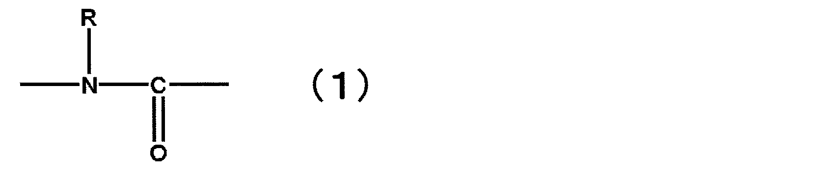
<2> 前記化合物が、ウレトジオン、オキサジアジトリオン、ビウレット、ウレタン、アロファネート、及びイソシアヌレートから選ばれる少なくとも1種以上の骨格を有する化合物である、<1>に記載の非水系電解液。
<3> 前記化合物が、数平均分子量300以上5000以下の化合物である、<1>又は<2>に記載の非水系電解液。
<4> ヘキサフルオロリン酸リチウム(LiPF6)を非水系電解液全体中に0.5~3mol/L含有する、<1>~<3>の何れかに記載の非水系電解液。
<5>モノフルオロリン酸塩、ジフルオロリン酸塩、四フッ化ホウ酸塩、及び下記一般式(2)~(5)で表される化合物からなる群より選ばれる少なくとも1種を含有する、<1>~<4>の何れかに記載の非水系電解液。

<6> M1がリチウムであり、かつM2がリン又はホウ素である一般式(4)で表される化合物を含有する、<5>に記載の非水系電解液。
<7> M3がホウ素原子又はP=Oである一般式(5)で表される化合物を含有する、<5>又は<6>に記載の非水系電解液。
<8> 前記モノフルオロリン酸塩、ジフルオロリン酸塩、四フッ化ホウ酸塩、及び一般式(2)~(5)で表される化合物からなる群より選ばれる少なくとも1種を、非水系電解液全体中に0.01~5質量%含有する、<5>~<7>の何れかに記載の非水系電解液。
<9> モノフルオロリン酸リチウム、ジフルオロリン酸リチウム、テトラフルオロホウ酸リチウム、リチウムビス(フルオロスルホニル)イミド、リチウムビス(トリフルオロメタンスルホニル)イミド、フルオロスルホン酸リチウム、トリフルオロメタンスルホン酸リチウム、リチウムビス(オキサラト)ボレート、リチウムジフルオロオキサラトボレート、リチウムトリス(オキサラト)ホスフェート、リチウムジフルオロビス(オキサラト)ホスフェート、リチウムテトラフルオロオキサラトホスフェート、ホウ酸トリス(トリメチルシリル)、リン酸トリス(トリメチルシリル)からなる群より選ばれる少なくとも1種を含有する、<5>~<8>の何れかに記載の非水系電解液。
<10> 不飽和環状カーボネート、フッ素化環状カーボネート、及び下記一般式(6)で表されるジニトリル化合物からなる群より選ばれる少なくとも1種以上を含有する、<1>~<9>の何れかに記載の非水系電解液。

<11> ポリエチレン及びポリプロピレンから選ばれる少なくとも1種を含有するセパレータを備える非水系電解液二次電池用である、<1>~<10>の何れかに記載の非水系電解液。
<12> 炭素を負極活物質として含む非水系電解液二次電池用である、<1>~<11>の何れかに記載の非水系電解液。
<13> 金属イオンを吸蔵・放出しうる正極及び負極、セパレータ並びに<1>~<12>の何れかに記載の非水系電解液を備えることを特徴とする、非水系電解液二次電池。
<14> 炭素を負極活物質として含む<13>に記載の非水系電解液二次電池であって、アルゴンイオンレーザーラマンスペクトル法における1580cm-1のピーク強度に対する1360cm-1のピーク強度の比として定義されるラマンR値が、0.1以上である炭素質材料を少なくとも1種以上を含有する負極活物質を含むものである、非水系電解液二次電池。
<1-1.電解質>
本発明の非水系電解液に使用する電解質は、特に制限されず、非水系電解液二次電池の電解質として使用される公知のものを任意に採用して含有させることができる。本発明の非水系電解液を非水系電解液二次電池に用いる場合には、電解質はリチウム塩が好ましい。
LiCF3SO3、LiN(CF3SO2)2、LiN(C2F5SO2)2、LiN(CF3SO2)(C4F9SO2)、LiC(CF3SO2)3、LiPF4(CF3)2、LiPF4(C2F5)2、LiPF4(CF3SO2)2、LiPF4(C2F5SO2)2、LiBF3(CF3)、LiBF3(C2F5)、LiBF2(CF3)2、LiBF2(C2F5)2、LiBF2(CF3SO2)2、LiBF2(C2F5SO2)2等の含フッ素有機リチウム塩;
リチウムビス(オキサラト)ボレート、リチウムジフルオロ(オキサラト)ボレート、リチウムトリス(オキサラト)ホスフェート、リチウムジフルオロビス(オキサラト)ホスフェート、リチウムテトラフルオロ(オキサラト)ホスフェート等の含ジカルボン酸錯体リチウム塩;
KPF6、NaPF6、NaBF4、CF3SO3Na等のナトリウム塩又はカリウム塩;
等が挙げられる。
本発明の非水系電解液に使用する非水系溶媒は、電池として利用する際に、電池特性に対して悪影響を及ぼさない溶媒であれば特に制限されないが、非水系電解液に使用される以下の溶媒の内の1種以上であることが好ましい。通常使用される非水系溶媒の例としては、鎖状及び環状カーボネート、鎖状及び環状カルボン酸エステル、鎖状及び環状エーテル、含リン有機溶媒、含硫黄有機溶媒等が挙げられる。
本発明の非水系電解液は、分子内に下記一般式(1)で表される部分構造を1以上及びイソシアネート基を2以上有する化合物(以下、「本発明に係るイソシアネート化合物」と略称する場合がある。)を0.01質量%以上3質量%未満含有することを特徴とする。

また、上記イソシアネート基を有してもよい、水素原子、炭素原子、窒素原子、酸素原子、硫黄原子、リン原子、及びハロゲン原子からなる群より選ばれる原子で構成された炭素数1~12の有機基としては、イソシアネート基を有してもよい、炭素数1~4のアルキル基、炭素数1~12のアルキレン基、炭素数4~12のシクロアルキレン基、炭素数6~12の芳香族炭化水素若しくはF、N、S、Oのいずれかの元素が1以上含まれる炭素数1~12の有機基であることが好ましい。
原料となるジイソシアネート化合物としては、ジイソシアナトメタン、1,3-ジイソシアナトプロパン、1,4-ジイソシアナトブタン、1,5-ジイソシアナトペンタン、1,6-ジイソシアナトヘキサン、1,7-ジイソシアナトヘプタン、1,8-ジイソシアナトオクタン、1,12-ジイソシアナトドデカン、1,3-ジイソシアナト- 2-フルオロプロパン、1,4-ジイソシアナト-2-ブテン、1,4-ジイソシアナト-2-フルオロブタン、1,4-ジイソシアナト-2,3-ジフルオロブタン、1,5-ジイソシアナト-2-ペンテン、1,5-ジイソシアナト-2-メチルペンタン、1,6-ジイソシアナト-2-ヘキセン、1,6-ジイソシアナト-3-ヘキセン、1,6-ジイソシアナト-3-フルオロヘキサン、1,6-ジイソシアナト-3,4-ジフルオロヘキサン、1,3-ビス(イソシアナトメチル)シクロヘキサン、ジシクロヘキシルメタンジイソシアネート、カルボニルジイソシアネート、1,4-ジイソシアナトブタン-1,4-ジオン、1,5-ジイソシアナトペンタン-1,5-ジオン、ジイソシアナトベンゼン、トルエンジイソシアネート、キシレンジイソシアネート、エチルジイソシアナトベンゼン、トリメチルジイソシアナトベンゼン、ジイソシアナトナフタレン、ジイソシアナトビフェニル、ジフェニルメタンジイソシアネート、2,2-ビス(イソシアナトフェニル)ヘキサフルオロプロパン等の化合物が挙げられる。これらの中でも、炭素数4以上12以下のアルキレン構造を有するジイソシアネート化合物が好ましく、炭素数4以上8以下のアルキレン構造を有するジイソシアネート化合物がより好ましい。

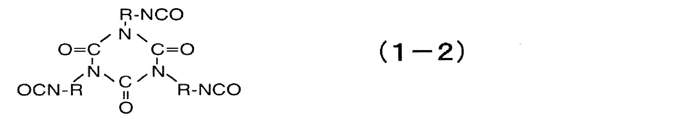

本発明の非水系電解液は、前述の電解質、非水系溶媒、本発明に係るイソシアネート化合物以外に、助剤を含有するものであってもよい。助剤としては、後述する不飽和結合を有する環状カーボネート、フッ素原子を有する環状カーボネート、フッ素原子を有する不飽和環状カーボネート、一般式(6)で表されるジニトリル化合物、過充電防止剤、その他の助剤等が挙げられる。
不飽和結合を有する環状カーボネート(以下、「不飽和環状カーボネート」と略称する場合がある。)も、負極表面に皮膜を形成するため、電池の寿命を向上させる効果を有する。
前記不飽和環状カーボネートとしては、炭素-炭素二重結合及び/又は炭素-炭素三重結合を有する環状カーボネートであれば、特に制限はなく、任意の不飽和環状カーボネートを用いることができる。なお、芳香環を有する環状カーボネートも、不飽和環状カーボネートに包含されることとする。
ビニレンカーボネート類としては、ビニレンカーボネート、メチルビニレンカーボネート、4,5-ジメチルビニレンカーボネート、フェニルビニレンカーボネート、4,5-ジフェニルビニレンカーボネート、ビニルビニレンカーボネート、4,5-ビニルビニレンカーボネート、アリルビニレンカーボネート、4,5-ジアリルビニレンカーボネート等が挙げられる。
フッ素原子を有する環状カーボネート(以下、「フッ素化環状カーボネート」と略称する場合がある。)におけるフッ素原子の数は特に制限されないが、通常6以下、好ましくは4以下であり、1又は2であるフッ素化環状カーボネートが最も好ましい。
前述のフッ素化環状カーボネートとして、不飽和結合とフッ素原子を両方有する環状カーボネート(以下、「フッ素化不飽和環状カーボネート」と略称する場合がある。)を使用することも好ましい。フッ素化不飽和環状カーボネートにおけるフッ素原子の数は特に制限されないが、通常6以下、好ましくは4以下であり、1又は2であるフッ素化不飽和環状カーボネートが最も好ましい。
下記一般式(6)で表されるジニトリル化合物は、電極表面に皮膜を形成するため、電池の寿命を向上させる効果を有する。

本発明の非水系電解液は、非水系電解液二次電池が過充電等の状態になった際に電池の破裂・発火を抑制する過充電防止剤を含有してもよい。過充電防止剤としては、ビフェニル、アルキルビフェニル、ターフェニル、ターフェニルの部分水素化体、シクロヘキシルベンゼン、t-ブチルベンゼン、t-アミルベンゼン、ジフェニルエーテル、ジベンゾフラン等の芳香族化合物;2-フルオロビフェニル、o-シクロヘキシルフルオロベンゼン、p-シクロヘキシルフルオロベンゼン等の上記芳香族化合物の部分フッ素化物;2,4-ジフルオロアニソール、2,5-ジフルオロアニソール、2,6-ジフルオロアニソール、3,5-ジフルオロアニソール等の含フッ素アニソール化合物等が挙げられる。中でも、ビフェニル、アルキルビフェニル、ターフェニル、ターフェニルの部分水素化体、シクロヘキシルベンゼン、t-ブチルベンゼン、t-アミルベンゼン、ジフェニルエーテル、ジベンゾフラン等の芳香族化合物が好ましい。これらは1種を単独で用いても、2種以上を併用してもよい。2種以上併用する場合は、特に、シクロヘキシルベンゼンとt-ブチルベンゼン又はt-アミルベンゼンとの組み合わせ、ビフェニル、アルキルビフェニル、ターフェニル、ターフェニルの部分水素化体、シクロヘキシルベンゼン、t-ブチルベンゼン、t-アミルベンゼン等の酸素を含有しない芳香族化合物から選ばれる少なくとも1種と、ジフェニルエーテル、ジベンゾフラン等の含酸素芳香族化合物から選ばれる少なくとも1種を併用するのが過充電防止特性と高温保存特性のバランスの点から好ましい。
本発明の非水系電解液は、前述の不飽和結合を有する環状カーボネート、フッ素原子を有する環状カーボネート、フッ素原子を有する不飽和環状カーボネート、一般式(6)で表されるジニトリル化合物、及び過充電防止剤以外の助剤を含有するものであってもよい。
例えば、モノフルオロリン酸塩、ジフルオロリン酸塩、四フッ化ホウ酸塩、及び下記一般式(2)~(5)で表される化合物からなる群より選ばれた少なくとも1種(以下、「モノフルオロリン酸塩等の化合物」と略称する場合がある。)を含有するものであってもよい。モノフルオロリン酸塩等の化合物は、本発明に係るイソシアネート基化合物と組み合わせることによって良質な複合皮膜を形成すると共に、その皮膜を含めた電極構造全体の安定性が飛躍的に高まるので、それぞれ単独で用いただけでは到達し得ない優れた耐久性と負荷特性を達成することが可能となる。
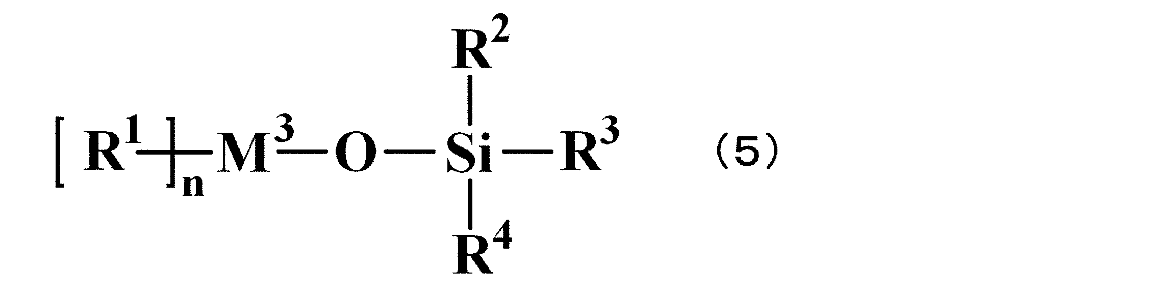

本発明の非水系電解液二次電池は、金属イオンを吸蔵及び放出しうる正極及び負極と、後述するセパレータと、前述した非水系電解液とを備えるものである。
<2-1.電池構成>
本発明の非水系電解液二次電池は、非水系電解液以外の構成については、従来公知の非水系電解液二次電池と同様であり、通常は、本発明の非水系電解液が含浸されている多孔膜(セパレータ)を介して正極と負極とが積層され、これらがケース(外装体)に収納された形態を有する。従って、本発明の非水系電解液二次電池の形状は特に制限されるものではなく、円筒型、角形、ラミネート型、コイン型、大型等の何れであってもよい。
本発明の非水系電解液二次電池における非水系電解液としては、前述の非水系電解液を使用する。なお、本発明の趣旨を逸脱しない範囲において、本発明の非水系電解液に対し、その他の非水系電解液を混合して用いることも可能である。
<2-3.負極>
以下に負極に使用される負極活物質について述べる。負極活物質としては、電気化学的に金属イオンを吸蔵・放出可能なものであれば、特に制限はない。具体例としては、炭素質材料、合金系材料、リチウム含有金属複合酸化物材料等が挙げられる。これらは1種を単独で用いてもよく、また2種以上を任意に組み合わせて併用してもよい。
負極活物質としては、炭素質材料、合金系材料、リチウム含有金属複合酸化物材料等が挙げられる。
負極活物質として用いられる炭素質材料としては、
(1)天然黒鉛、
(2)人造炭素質物質並びに人造黒鉛質物質を400~3200℃の範囲で1回以上熱処理した炭素質材料、
(3)負極活物質層が少なくとも2種以上の異なる結晶性を有する炭素質からなり、かつ/又はその異なる結晶性の炭素質が接する界面を有している炭素質材料、
(4)負極活物質層が少なくとも2種以上の異なる配向性を有する炭素質からなり、かつ/又はその異なる配向性の炭素質が接する界面を有している炭素質材料、
から選ばれるものが、初期不可逆容量、高電流密度充放電特性のバランスがよく好ましい。また、(1)~(4)の炭素質材料は、1種を単独で用いてもよく、2種以上を任意の組み合わせ及び比率で併用してもよい。
[一般式(A)中、Mは、Na、K、Co、Al、Fe、Ti、Mg、Cr、Ga、Cu、Zn及びNbからなる群より選ばれる少なくとも1種の元素を表わす。]
上記の一般式(A)で表される組成の中でも、
(a)1.2≦x≦1.4、1.5≦y≦1.7、z=0
(b)0.9≦x≦1.1、1.9≦y≦2.1、z=0
(c)0.7≦x≦0.9、2.1≦y≦2.3、z=0
の構造が、電池性能のバランスが良好なため特に好ましい。
負極活物質として炭素質材料を用いる場合、以下の物性を有するものであることが望ましい。
(X線パラメータ)
炭素質材料の学振法によるX線回折で求めた格子面(002面)のd値(層間距離)が、0.335nm以上であることが好ましく、また、通常0.360nm以下であり、0.350nm以下が好ましく、0.345nm以下がさらに好ましい。また、学振法によるX線回折で求めた炭素質材料の結晶子サイズ(Lc)は、1.0nm以上であることが好ましく、中でも1.5nm以上であることがさらに好ましい。
炭素質材料の体積基準平均粒径は、レーザー回折・散乱法により求めた体積基準の平均粒径(メジアン径)であり、通常1μm以上であり、3μm以上が好ましく、5μm以上がさらに好ましく、7μm以上が特に好ましく、また、通常100μm以下であり、50μm以下が好ましく、40μm以下がより好ましく、30μm以下がさらに好ましく、25μm以下が特に好ましい。
体積基準平均粒径の測定は、界面活性剤であるポリオキシエチレン(20)ソルビタンモノラウレートの0.2質量%水溶液(約10mL)に炭素粉末を分散させて、レーザー回折・散乱式粒度分布計(堀場製作所社製LA-700)を用いて行なうことができる。該測定で求められるメジアン径を、本発明の炭素質材料の体積基準平均粒径と定義する。
炭素質材料のラマンR値は、アルゴンイオンレーザーラマンスペクトル法を用いて測定した値であり、通常0.01以上であり、0.03以上が好ましく、0.1以上がさらに好ましく、また、通常1.5以下であり、1.2以下が好ましく、1以下がさらに好ましく、0.5以下が特に好ましい。
ラマンR値又はラマン半値幅が上記範囲であると、炭素質材料と非水系電解液との反応を抑制することができるとともに、サイトの消失による負荷特性の低下を抑制することができる。
・アルゴンイオンレーザー波長 :514.5nm
・試料上のレーザーパワー :15~25mW
・分解能 :10~20cm-1
・測定範囲 :1100cm-1~1730cm-1
・ラマンR値、ラマン半値幅解析:バックグラウンド処理
・スムージング処理 :単純平均、コンボリューション5ポイント
炭素質材料のBET比表面積は、BET法を用いて測定した比表面積の値であり、通常0.1m2・g-1以上であり、0.7m2・g-1以上が好ましく、1.0m2・g-1以上がさらに好ましく、1.5m2・g-1以上が特に好ましく、また、通常100m2・g-1以下であり、25m2・g-1以下が好ましく、15m2・g-1以下がさらに好ましく、10m2・g-1以下が特に好ましい。
BET法による比表面積の測定は、表面積計(大倉理研製全自動表面積測定装置)を用いて、試料に対して窒素流通下350℃で15分間、予備乾燥を行なった後、大気圧に対する窒素の相対圧の値が0.3となるように正確に調整した窒素ヘリウム混合ガスを用いて、ガス流動法による窒素吸着BET1点法によって行う。該測定で求められる比表面積を、本発明の炭素質材料のBET比表面積と定義する。
炭素質材料の球形の程度として円形度を測定した場合、以下の範囲に収まることが好ましい。なお、円形度は、「円形度=(粒子投影形状と同じ面積を持つ相当円の周囲長)/(粒子投影形状の実際の周囲長)」で定義され、円形度が1のときに理論的真球となる。炭素質材料の粒径が3~40μmの範囲にある粒子の円形度は1に近いほど望ましく、また、0.1以上が好ましく、中でも0.5以上が好ましく、0.8以上がより好ましく、0.85以上がさらに好ましく、0.9以上が特に好ましい。
炭素質材料の円形度が大きいほど、充填性が向上し、粒子間の抵抗を抑えることができるため、高電流密度充放電特性は向上する。従って、円形度が上記範囲のように高いほど好ましい。
炭素質材料のタップ密度は、通常0.1g・cm-3以上であり、0.5g・cm-3以上が好ましく、0.7g・cm-3以上がさらに好ましく、1g・cm-3以上が特に好ましく、また、2g・cm-3以下が好ましく、1.8g・cm-3以下がさらに好ましく、1.6g・cm-3以下が特に好ましい。タップ密度が上記範囲であると、電池容量を確保することができるとともに、粒子間の抵抗の増大を抑制することができる。
炭素質材料の配向比は、通常0.005以上であり、0.01以上が好ましく、0.015以上がさらに好ましく、また、通常0.67以下である。配向比が、上記範囲であると、優れた高密度充放電特性を確保することができる。なお、上記範囲の上限は、炭素質材料の配向比の理論上限値である。
・ターゲット:Cu(Kα線)グラファイトモノクロメーター
・スリット :
発散スリット=0.5度
受光スリット=0.15mm
散乱スリット=0.5度
・測定範囲及びステップ角度/計測時間:
(110)面:75度≦2θ≦80度 1度/60秒
(004)面:52度≦2θ≦57度 1度/60秒
炭素質材料のアスペクト比は、通常1以上、また、通常10以下であり、8以下が好ましく、5以下がさらに好ましい。アスペクト比が、上記範囲であると、極板化時のスジ引きを抑制し、さらに均一な塗布が可能となるため、優れた高電流密度充放電特性を確保することができる。なお、上記範囲の下限は、炭素質材料のアスペクト比の理論下限値である。
副材混合とは、負極電極中及び/又は負極活物質中に性質の異なる炭素質材料が2種以上含有していることである。ここでいう性質とは、X線回折パラメータ、メジアン径、アスペクト比、BET比表面積、配向比、ラマンR値、タップ密度、真密度、細孔分布、円形度、灰分量の群から選ばれる1つ以上の特性を示す。
副材混合の効果の1例として、天然黒鉛、人造黒鉛等の黒鉛(グラファイト)、アセチレンブラック等のカーボンブラック、ニードルコークス等の無定形炭素等の炭素質材料を導電材として含有されることにより、電気抵抗を低減させることが挙げられる。
電極の製造は、本発明の効果を著しく損なわない限り、公知のいずれの方法を用いることができる。例えば、負極活物質に、バインダー、溶媒、必要に応じて、増粘剤、導電材、充填材等を加えてスラリーとし、これを集電体に塗布、乾燥した後にプレスすることによって形成することができる。
また、合金系材料を用いる場合には、蒸着法、スパッタ法、メッキ法等の手法により、上述の負極活物質を含有する薄膜層(負極活物質層)を形成する方法も用いられる。
負極活物質を保持させる集電体としては、公知のものを任意に用いることができる。負極の集電体としては、例えば、アルミニウム、銅、ニッケル、ステンレス鋼、ニッケルメッキ鋼等の金属材料が挙げられるが、加工し易さとコストの点から特に銅が好ましい。
集電体と負極活物質層の厚さの比は特に制限されないが、「(非水系電解液注液直前の片面の負極活物質層厚さ)/(集電体の厚さ)」の値が、150以下が好ましく、20以下がさらに好ましく、10以下が特に好ましく、また、0.1以上が好ましく、0.4以上がさらに好ましく、1以上が特に好ましい。集電体と負極活物質層の厚さの比が、上記範囲であると、電池容量を確保することができるとともに、高電流密度充放電時における集電体の発熱を抑制することができる。
負極活物質を結着するバインダーとしては、非水系電解液や電極製造時に用いる溶媒に対して安定な材料であれば、特に制限されない。
具体例としては、ポリエチレン、ポリプロピレン、ポリエチレンテレフタレート、ポリメチルメタクリレート、芳香族ポリアミド、ポリイミド、セルロース、ニトロセルロース等の樹脂系高分子;SBR(スチレン・ブタジエンゴム)、イソプレンゴム、ブタジエンゴム、フッ素ゴム、NBR(アクリロニトリル・ブタジエンゴム)、エチレン・プロピレンゴム等のゴム状高分子;スチレン・ブタジエン・スチレンブロック共重合体又はその水素添加物;EPDM(エチレン・プロピレン・ジエン三元共重合体)、スチレン・エチレン・ブタジエン・スチレン共重合体、スチレン・イソプレン・スチレンブロック共重合体又はその水素添加物等の熱可塑性エラストマー状高分子;シンジオタクチック-1,2-ポリブタジエン、ポリ酢酸ビニル、エチレン・酢酸ビニル共重合体、プロピレン・α-オレフィン共重合体等の軟質樹脂状高分子;ポリフッ化ビニリデン、ポリテトラフルオロエチレン、フッ素化ポリフッ化ビニリデン、ポリテトラフルオロエチレン・エチレン共重合体等のフッ素系高分子;アルカリ金属イオン(特にリチウムイオン)のイオン伝導性を有する高分子組成物等が挙げられる。これらは、1種を単独で用いても、2種以上を任意の組み合わせ及び比率で併用してもよい。
スラリーを形成するための溶媒としては、負極活物質、バインダー、並びに必要に応じて使用される増粘剤及び導電材を溶解又は分散することが可能な溶媒であれば、その種類に特に制限はなく、水系溶媒と有機系溶媒のどちらを用いてもよい。
水系溶媒としては、水、アルコール等が挙げられ、有機系溶媒としてはN-メチルピロリドン(NMP)、ジメチルホルムアミド、ジメチルアセトアミド、メチルエチルケトン、シクロヘキサノン、酢酸メチル、アクリル酸メチル、ジエチルトリアミン、N,N-ジメチルアミノプロピルアミン、テトラヒドロフラン(THF)、トルエン、アセトン、ジエチルエーテル、ジメチルアセトアミド、ヘキサメチルホスファルアミド、ジメチルスルホキシド、ベンゼン、キシレン、キノリン、ピリジン、メチルナフタレン、ヘキサン等が挙げられる。
増粘剤は、通常、スラリーの粘度を調製するために使用される。増粘剤としては、特に制限されないが、具体的には、カルボキシメチルセルロース、メチルセルロース、ヒドロキシメチルセルロース、エチルセルロース、ポリビニルアルコール、酸化スターチ、リン酸化スターチ、カゼイン及びこれらの塩等が挙げられる。これらは、1種を単独で用いても、2種以上を任意の組み合わせ及び比率で併用してもよい。
負極活物質を電極化した際の電極構造は特に制限されないが、集電体上に存在している負極活物質の密度は、1g・cm-3以上が好ましく、1.2g・cm-3以上がさらに好ましく、1.3g・cm-3以上が特に好ましく、また、2.2g・cm-3以下が好ましく、2.1g・cm-3以下がより好ましく、2.0g・cm-3以下がさらに好ましく、1.9g・cm-3以下が特に好ましい。集電体上に存在している負極活物質の密度が、上記範囲であると、負極活物質粒子の破壊を防止して、初期不可逆容量の増加や、集電体/負極活物質界面付近への非水系電解液の浸透性低下による高電流密度充放電特性悪化を抑制することができる一方、電池容量の低下や抵抗の増大を抑制することができる。
負極板の厚さは用いられる正極板に合わせて設計されるものであり、特に制限されないが、芯材の金属箔厚さを差し引いた合材層の厚さは通常15μm以上、好ましくは20μm以上、より好ましくは30μm以上、また、通常300μm以下、好ましくは280μm以下、より好ましくは250μm以下が望ましい。
また、上記負極板の表面に、これとは異なる組成の物質が付着したものを用いてもよい。表面付着物質としては酸化アルミニウム、酸化ケイ素、酸化チタン、酸化ジルコニウム、酸化マグネシウム、酸化カルシウム、酸化ホウ素、酸化アンチモン、酸化ビスマス等の酸化物、硫酸リチウム、硫酸ナトリウム、硫酸カリウム、硫酸マグネシウム、硫酸カルシウム、硫酸アルミニウム等の硫酸塩、炭酸リチウム、炭酸カルシウム、炭酸マグネシウム等の炭酸塩等が挙げられる。
(正極活物質)
正極活物質としては、電気化学的にリチウムイオンを吸蔵・放出可能なものであれば特に制限されないが、例えば、リチウムと少なくとも1種の遷移金属を含有する物質が好ましい。具体例としては、リチウム遷移金属複合酸化物、リチウム含有遷移金属リン酸化合物が挙げられる。
また、上記正極活物質の表面に、これとは異なる組成の物質が付着したものを用いてもよい。表面付着物質としては酸化アルミニウム、酸化ケイ素、酸化チタン、酸化ジルコニウム、酸化マグネシウム、酸化カルシウム、酸化ホウ素、酸化アンチモン、酸化ビスマス等の酸化物、硫酸リチウム、硫酸ナトリウム、硫酸カリウム、硫酸マグネシウム、硫酸カルシウム、硫酸アルミニウム等の硫酸塩、炭酸リチウム、炭酸カルシウム、炭酸マグネシウム等の炭酸塩、炭素等が挙げられる。
(形状)
正極活物質の粒子の形状は、従来用いられるような、塊状、多面体状、球状、楕円球状、板状、針状、柱状等が挙げられるが、中でも一次粒子が凝集して、二次粒子を形成して成り、その二次粒子の形状が球状ないし楕円球状であるものが好ましい。通常、電気化学素子はその充放電に伴い、電極中の活物質が膨張収縮をするため、そのストレスによる活物質の破壊や導電パス切れ等の劣化がおきやすい。そのため一次粒子のみの単一粒子活物質であるよりも、一次粒子が凝集して、二次粒子を形成したものである方が膨張収縮のストレスを緩和して、劣化を防ぐため好ましい。また、板状等軸配向性の粒子であるよりも球状ないし楕円球状の粒子の方が、電極の成形時の配向が少ないため、充放電時の電極の膨張収縮も少なく、また電極を作製する際の導電材との混合においても、均一に混合されやすいため好ましい。
正極活物質のタップ密度は、好ましくは0.5g/cm3以上、より好ましくは1.0g/cm3以上、さらに好ましくは1.5g/cm3以上、最も好ましくは1.7g/cm3以上である。該正極活物質のタップ密度が上記範囲であると、正極活物質層形成時に必要な分散媒量及び導電材や結着剤の必要量を抑えることができ、結果正極活物質の充填率及び電池容量を確保することができる。タップ密度の高い複合酸化物粉体を用いることにより、高密度の正極活物質層を形成することができる。タップ密度は一般に大きいほど好ましく、特に上限はないが、好ましくは2.7g/cm3以下、より好ましくは2.5g/cm3以下である。上記範囲であると負荷特性の低下を抑制することができる。
正極活物質の粒子のメジアン径d50(一次粒子が凝集して二次粒子を形成している場合には二次粒子径)は好ましくは0.3μm以上、より好ましくは1.2μm以上、さらに好ましくは1.5μm以上、最も好ましくは2μm以上であり、上限は、好ましくは20μm以下、より好ましくは18μm以下、さらに好ましくは16μm以下、最も好ましくは15μm以下である。上記範囲であると、高タップ密度品が得られ、電池性能の低下を抑制できる一方、電池の正極作製、即ち活物質と導電材やバインダー等を溶媒でスラリー化して、薄膜状に塗布する際に生じるスジを引く等の問題を防止することができる。ここで、異なるメジアン径d50をもつ該正極活物質を2種類以上混合することで、正極作製時の充填性をさらに向上させることができる。
一次粒子が凝集して二次粒子を形成している場合には、該正極活物質の平均一次粒子径としては、好ましくは0.05μm以上、より好ましくは0.1μm以上、さらに好ましくは0.2μm以上であり、上限は、好ましくは2μm以下、より好ましくは1.6μm以下、さらに好ましくは1.3μm以下、最も好ましくは1μm以下である。上記範囲であると、粉体充填性及び比表面積を確保し、電池性能の低下を抑制することができる一方、適度な結晶性が得られることによって、充放電の可逆性を確保することができる。
正極活物質のBET比表面積は、好ましくは0.4m2/g以上、より好ましくは0.5m2/g以上、さらに好ましくは0.6m2/g以上であり、上限は50m2/g以下、好ましくは40m2/g以下、さらに好ましくは30m2/g以下である。BET比表面積が上記範囲であると、電池性能を確保できるとともに、正極活性物質の塗布性を良好に保つことができる。
正極活物質の製造法としては、無機化合物の製造法として一般的な方法が用いられる。特に球状ないし楕円球状の活物質を作製するには種々の方法が考えられるが、例えば、リン酸等のリン原料物質と、組成式(1)におけるMの原料物質を水等の溶媒中に溶解ないし粉砕分散して、攪拌をしながらpHを調節して球状の前駆体を作製回収し、これを必要に応じて乾燥した後、LiOH、Li2CO3、LiNO3等のLi源を加えて高温で焼成して活物質を得る方法等が挙げられる。
以下に、正極の構成について述べる。本発明において、正極は、正極活物質と結着剤とを含有する正極活物質層を、集電体上に形成して作製することができる。正極活物質を用いる正極の製造は、常法により行うことができる。即ち、正極活物質と結着剤、並びに必要に応じて導電材及び増粘剤等を乾式で混合してシート状にしたものを正極集電体に圧着するか、又はこれらの材料を液体媒体に溶解又は分散させてスラリーとして、これを正極集電体に塗布し、乾燥することにより、正極活物質層を集電体上に形成されることにより正極を得ることができる。
塗布、乾燥によって得られた正極活物質層は、正極活物質の充填密度を上げるために、ハンドプレス、ローラープレス等により圧密化することが好ましい。正極活物質層の密度は、下限として好ましくは1.5g/cm3以上、より好ましくは2g/cm3、さらに好ましくは2.2g/cm3以上であり、上限としては、好ましくは3.5g/cm3以下、より好ましくは3g/cm3以下、さらに好ましくは2.8g/cm3以下の範囲である。この範囲を上回ると集電体/活物質界面付近への電解液の浸透性が低下し、特に高電流密度での充放電特性が低下し高出力が得られない場合がある。また下回ると活物質間の導電性が低下し、電池抵抗が増大し高出力が得られない場合がある。
導電材としては、公知の導電材を任意に用いることができる。具体例としては、銅、ニッケル等の金属材料;天然黒鉛、人造黒鉛等の黒鉛(グラファイト);アセチレンブラック等のカーボンブラック;ニードルコークス等の無定形炭素等の炭素材料等が挙げられる。なお、これらは、1種を単独で用いてもよく、2種以上を任意の組み合わせ及び比率で併用してもよい。導電材は、正極活物質層中に、通常0.01質量%以上、好ましくは0.1質量%以上、より好ましくは1質量%以上であり、また上限は、通常50質量%以下、好ましくは30質量%以下、より好ましくは15質量%以下含有するように用いられる。上記範囲であると、十分な導電性と電池容量を確保することができる。
正極活物質層の製造に用いる結着剤としては、特に限定されず、塗布法の場合は、電極製造時に用いる液体媒体に対して溶解又は分散される材料であればよいが、具体例としては、ポリエチレン、ポリプロピレン、ポリエチレンテレフタレート、ポリメチルメタクリレート、ポリイミド、芳香族ポリアミド、セルロース、ニトロセルロース等の樹脂系高分子;SBR(スチレン-ブタジエンゴム)、NBR(アクリロニトリル-ブタジエンゴム)、フッ素ゴム、イソプレンゴム、ブタジエンゴム、エチレン-プロピレンゴム等のゴム状高分子;スチレン・ブタジエン・スチレンブロック共重合体又はその水素添加物、EPDM(エチレン・プロピレン・ジエン三元共重合体)、スチレン・エチレン・ブタジエン・エチレン共重合体、スチレン・イソプレン・スチレンブロック共重合体又はその水素添加物等の熱可塑性エラストマー状高分子;シンジオタクチック-1,2-ポリブタジエン、ポリ酢酸ビニル、エチレン・酢酸ビニル共重合体、プロピレン・α-オレフィン共重合体等の軟質樹脂状高分子;ポリフッ化ビニリデン(PVdF)、ポリテトラフルオロエチレン、フッ素化ポリフッ化ビニリデン、ポリテトラフルオロエチレン・エチレン共重合体等のフッ素系高分子;アルカリ金属イオン(特にリチウムイオン)のイオン伝導性を有する高分子組成物等が挙げられる。なお、これらの物質は、1種を単独で用いてもよく、2種以上を任意の組み合わせ及び比率で併用してもよい。
スラリーを形成するための溶媒としては、正極活物質、導電材、結着剤、並びに必要に応じて使用される増粘剤を溶解又は分散することが可能な溶媒であれば、その種類に特に制限はなく、水系溶媒と有機系溶媒のどちらを用いてもよい。水系媒体としては、例えば、水、アルコールと水との混合媒等が挙げられる。有機系媒体としては、例えば、ヘキサン等の脂肪族炭化水素類;ベンゼン、トルエン、キシレン、メチルナフタレン等の芳香族炭化水素類;キノリン、ピリジン等の複素環化合物;アセトン、メチルエチルケトン、シクロヘキサノン等のケトン類;酢酸メチル、アクリル酸メチル等のエステル類;ジエチレントリアミン、N,N-ジメチルアミノプロピルアミン等のアミン類;ジエチルエーテル、プロピレンオキシド、テトラヒドロフラン(THF)等のエーテル類;N-メチルピロリドン(NMP)、ジメチルホルムアミド、ジメチルアセトアミド等のアミド類;ヘキサメチルホスファルアミド、ジメチルスルホキシド等の非プロトン性極性溶媒等が挙げられ
る。
正極集電体の材質としては特に制限されず、公知のものを任意に用いることができる。具体例としては、アルミニウム、ステンレス鋼、ニッケルメッキ、チタン、タンタル等の金属材料;カーボンクロス、カーボンペーパー等の炭素材料が挙げられる。中でも金属材料、特にアルミニウムが好ましい。
集電体と正極活物質層の厚さの比は特には限定されないが、(電解液注液直前の片面の正極活物質層の厚さ)/(集電体の厚さ)の値が20以下であることが好ましく、より好ましくは15以下、最も好ましくは10以下であり、下限は、0.5以上が好ましく、より好ましくは0.8以上、最も好ましくは1以上の範囲である。上記範囲であると、高電流密度充放電時の集電体の発熱を抑制し、電池容量を確保することができる。
本発明の非水系電解液を用いる場合、高出力かつ高温時の安定性を高める観点から、正極活物質層の面積は、電池外装ケースの外表面積に対して大きくすることが好ましい。具体的には、二次電池の外装の表面積に対する正極の電極面積の総和が面積比で15倍以上とすることが好ましく、さらに40倍以上とすることがより好ましい。外装ケースの外表面積とは、有底角型形状の場合には、端子の突起部分を除いた発電要素が充填されたケース部分の縦と横と厚さの寸法から計算で求める総面積をいう。有底円筒形状の場合には、端子の突起部分を除いた発電要素が充填されたケース部分を円筒として近似する幾何表面積である。正極の電極面積の総和とは、負極活物質を含む合材層に対向する正極合材層の幾何表面積であり、集電体箔を介して両面に正極合材層を形成してなる構造では、それぞれの面を別々に算出する面積の総和をいう。
正極板の厚さは特に限定されないが、高容量かつ高出力の観点から、芯材の金属箔厚さを差し引いた合材層の厚さは、集電体の片面に対して下限として、好ましくは10μm以上、より好ましくは20μm以上で、上限としては、好ましくは500μm以下、より好ましくは450μm以下である。
また、上記正極板の表面に、これとは異なる組成の物質が付着したものを用いてもよい。表面付着物質としては酸化アルミニウム、酸化ケイ素、酸化チタン、酸化ジルコニウム、酸化マグネシウム、酸化カルシウム、酸化ホウ素、酸化アンチモン、酸化ビスマス等の酸化物、硫酸リチウム、硫酸ナトリウム、硫酸カリウム、硫酸マグネシウム、硫酸カルシウム、硫酸アルミニウム等の硫酸塩、炭酸リチウム、炭酸カルシウム、炭酸マグネシウム等の炭酸塩、炭素等が挙げられる。
正極と負極との間には、短絡を防止するために、通常はセパレータを介在させる。この場合、本発明の非水系電解液は、通常はこのセパレータに含浸させて用いる。
セパレータの材料や形状については特に制限されず、本発明の効果を著しく損なわない限り、公知のものを任意に採用することができる。中でも、本発明の非水系電解液に対し安定な材料で形成された、樹脂、ガラス繊維、無機物等が用いられ、保液性に優れた多孔性シート又は不織布状の形態の物等を用いるのが好ましい。
(電極群)
電極群は、上記の正極板と負極板とを上記のセパレータを介してなる積層構造のもの、及び上記の正極板と負極板とを上記のセパレータを介して渦巻き状に捲回した構造のもののいずれでもよい。電極群の体積が電池内容積に占める割合(以下、電極群占有率と称する)は、通常40%以上であり、50%以上が好ましく、また、通常90%以下であり、80%以下が好ましい。
集電構造は、特に制限されないが、本発明の非水系電解液による高電流密度の充放電特性の向上をより効果的に実現するには、配線部分や接合部分の抵抗を低減する構造にすることが好ましい。この様に内部抵抗を低減させた場合、本発明の非水系電解液を使用した効果は特に良好に発揮される。
外装ケースの材質は用いられる非水系電解液に対して安定な物質であれば特に制限されない。具体的には、ニッケルめっき鋼板、ステンレス、アルミニウム又はアルミニウム合金、マグネシウム合金等の金属類、又は、樹脂とアルミ箔との積層フィルム(ラミネートフィルム)が用いられる。軽量化の観点から、アルミニウム又はアルミニウム合金の金属、ラミネートフィルムが好適に用いられる。
保護素子として、異常発熱や過大電流が流れた時に抵抗が増大するPTC(Positive Temperature Coefficient)、温度ヒューズ、サーミスター、異常発熱時に電池内部圧力や内部温度の急激な上昇により回路に流れる電流を遮断する弁(電流遮断弁)等を使用することができる。上記保護素子は高電流の通常使用で作動しない条件のものを選択することが好ましく、保護素子がなくても異常発熱や熱暴走に至らない設計にすることがより好ましい。
本発明の非水系電解液二次電池は、通常、上記の非水系電解液、負極、正極、セパレータ等を外装体内に収納して構成される。この外装体は、特に制限されず、本発明の効果を著しく損なわない限り、公知のものを任意に採用することができる。具体的に、外装体の材質は任意であるが、通常は、例えばニッケルメッキを施した鉄、ステンレス、アルミニウム又はその合金、ニッケル、チタン等が用いられる。
[第1の実施例]
<非水系電解液二次電池の製造>
(正極の作製)
正極活物質としてニッケルマンガンコバルト酸リチウム(LiNi1/3Mn1/3Co1/3O2)90質量部を用い、カーボンブラック7質量部とポリフッ化ビニリデン3質量部を混合し、N-メチル-2-ピロリドンを加えスラリー化し、これを厚さ15μmのアルミニウム箔の両面に均一に塗布、乾燥した後、正極活物質層の密度が2.6g・cm-3になるようにプレスして正極とした。
アルゴンイオンレーザーラマンスペクトル法における1580cm-1のピーク強度に対する1360cm-1のピーク強度の比として定義されるラマンR値が0.33である黒鉛に、増粘剤としてカルボキシメチルセルロースナトリウムの水性ディスパージョン(カルボキシメチルセルロースナトリウムの濃度1質量%)と、バインダーとしてスチレン-ブタジエンゴムの水性ディスパージョン(スチレン-ブタジエンゴムの濃度50質量%)を加え、ディスパーザーで混合してスラリー化した。得られたスラリーを厚さ12μmの銅箔の片面に均一に塗布して乾燥し、その後、負極活物質層の密度が1.4g・cm-3になるようにプレスして負極とした。尚、乾燥後の負極において、黒鉛:カルボキシメチルセルロースナトリウム:スチレン-ブタジエンゴム=98:1:1の質量比となるように作製した。
上記の正極、負極、及びポリエチレン製セパレータ(25μm)を、負極、セパレータ、正極、セパレータ、負極の順に積層した。こうして得られた電池要素を筒状のアルミニウムラミネートフィルムで包み込み、後述する電解液を注入した後で真空封止し、シート状の非水系電解液二次電池を作製した。更に、電極間の密着性を高めるために、ガラス板でシート状電池を挟んで加圧した。
(慣らし運転)
25℃の恒温槽中、シート状の非水系電解液二次電池を0.2Cで4.1Vまで定電流-定電圧充電した後、0.2Cで3.0Vまで放電した。これを5サイクル行って電池を安定させた。なお、1Cとは電池の全容量を1時間で放電させる場合の電流値のことである。
リチウム二次電池を、60℃において2Cに相当する定電流で充電後、2Cの定電流で放電する過程を1サイクルとして、500サイクル実施した。
本発明に係るイソシアネート化合物を含まない非水系電解液(基準電解液)を用いた時の電池の500サイクル目の放電容量を1とし、本発明の非水系電解液を用いた時の電池の500サイクル目の放電容量を比較した。すなわち、
(本発明の非水系電解液の500サイクル目の放電容量)÷(基準電解液の500サイクル目の放電容量)の計算式から求められる値の比較である。結果を表1に示す。
初期容量の50%に相当する電気量だけ充電させた電池に対して、-30℃の環境下で0.3C、0.5C、1.0C、1.5C、2.0C、および2.5Cで各々10秒間放電させ、その10秒目の電圧を測定した。このようにして得られた電流-電圧曲線において、3Vになるときの電流値を算出し、この値を低温放電特性とした。ここでは基準電解液使用時の電流値を1とし、本発明の非水系電解液を用いた時の電池の電流値を比較した。すなわち、
(本発明の非水系電解液の電流値)÷(基準電解液の電流値)の計算式から求められる値の比較である。結果を表1に示す。
乾燥アルゴン雰囲気下、エチレンカーボネートとジメチルカーボネートとエチルメチルカーボネートとの混合物(体積比3:3:4)に、十分に乾燥したLiPF6を非水系電解液全量で1mol/Lとなるように溶解させた(この電解液を「基準電解液」と略称する場合がある。)。基準電解液に、イソシアヌレート体の骨格を有するデュラネートTMTPA-100(旭化成ケミカルズ製)を0.5質量%となるように加え、非水系電解液を調製した。
デュラネートTMTPA-100に替えて、ビウレット体の骨格を有するデュラネートTM24A-100(旭化成ケミカルズ製)を用いたことを除き、実施例1-1と同様に電解液を調製した。
デュラネートTMTPA-100に替えて、ウレタンの骨格を有するデュラネートTMD101(旭化成ケミカルズ製)を用いたことを除き、実施例1-1と同様に電解液を調製した。
デュラネートTMD101の非水系電解液全量における含有量を1.0質量%としたことを除き、実施例1-3と同様に電解液を調製した。
デュラネートTMTPA-100の非水系電解液全量に対する含有量を1.0質量%としたことを除き、実施例1-1と同様に電解液を調製した。
デュラネートTMTPA-100の非水系電解液全量に対する含有量を2.5質量%としたことを除き、実施例1-1と同様に電解液を調製した。
本発明に係るイソシアネート化合物を含まない基準電解液を用いた以外は実施例1-1と同様に電解液を調製し、実施例1と同様の手法で電池の作製、サイクル試験および低温放電試験を行った。このようにして得られた結果を表1に示す。
デュラネートTMTPA-100に替えて、1,6-ジイソシアナトヘキサン(HDI)を用いたことを除き、実施例1-1と同様に電解液を調製した。
HDIの非水系電解液全量に対する含有量を1.0質量%としたことを除き、比較例1-2と同様に電解液を調製した。
デュラネートTMTPA-100の非水系電解液全量に対する含有量を3.0質量%としたことを除き、実施例1-1と同様に電解液を調製した。

本実施例では、第1の実施例とは異なる下記の電池構成及び基準電解液について評価を行った。
<非水系電解液二次電池の製造>
(正極の作製)
第一の正極活物質としてのマンガン酸リチウム(Li1.1Mn1.9Al0.1O4)72質量部、第二の正極活物質としてのリチウムニッケルマンガンコバルト複合酸化物(Li1.15Ni0.45Mn0.45Co0.10O2)18質量部、導電剤としてのカーボンブラックを5質量部、結着剤としてのポリフッ化ビニリデン(PVdF)を5質量部とを、N-メチル-2-ピロリドン中で混合・スラリー化し、これを厚さ15μmのアルミニウム箔に均一に塗布、乾燥した後、ロールプレスを行い正極とした。
グラファイト粉末93質量部に、カーボンブラックを1質量部、結着剤としてのポリフッ化ビニリデン(PVdF)を6質量部とを、N-メチル-2-ピロリドン中で混合・スラリー化し、これを厚さ12μmの銅箔に均一に塗布して乾燥し、ロールプレスして負極とした。
上記の正極、負極、及びポリオレフィン製セパレータ(25μm)を、負極、セパレータ、正極の順に積層した。こうして得られた電池要素をアルミニウムラミネートフィルムで包み込み、後述する電解液を注入した後で真空封止し、シート状の非水系電解液二次電池を作製した。
(初期充放電)
25℃の恒温槽中、シート状の非水系電解液二次電池を0.1C(1時間率の放電容量による定格容量を1時間で放電する電流値を1Cとする。以下同様。)で4.2Vまで定電流-定電圧充電した後、0.1Cで3.0Vまで放電した。続いて0.3Cで4.2Vまで定電流-定電圧充電した後、0.3Cで3.0Vまで放電した。これを2サイクル、合計3サイクル行って非水系電解液二次電池を安定させた。その後電池を60℃に24時間保持しエージングを実施した。その後、0.3Cで充放電を行って、その放電容量を測定し、初期容量とした。
55℃において、1Cに相当する定電流で4.2Vまで定電流-定電圧充電した後、1Cの定電流で3.0Vまで放電する過程を1サイクルとして、30サイクル実施した。ここで、サイクル維持率を次の計算式から算出した。結果を表2に示す。
(30サイクル目の放電容量)÷(1サイクル目の放電容量)
乾燥アルゴン雰囲気下、エチレンカーボネートとジエチルカーボネートとの混合物(体積比3:7)に、十分に乾燥したLiPF6を非水系電解液全量で1mol/Lとなるように溶解させた(この電解液を「第二基準電解液」と略称する場合がある。)。第二基準電解液に、デュラネートTMTPA-100並びにフルオロエチレンカーボネート(FEC)をそれぞれ0.5質量%と2.0質量%となるように加え、非水系電解液を調製した。
第二基準電解液に、デュラネートTMTPA-100並びにビニレンカーボネート(VC)をそれぞれ0.5質量%と1.0質量%となるように加え、実施例2-1と同様に非水系電解液を調製した。
第二基準電解液に、デュラネートTMTPA-100、FEC並びにビニレンカーボネート(VC)をそれぞれ0.5質量%、1.0質量%、1.0質量%となるように加え、実施例2-1と同様に非水系電解液を調製した。
第二基準電解液に、デュラネートTMTPA-100、FEC並びに無水コハク酸(SUC)をそれぞれ0.5質量%、1.0質量%、0.2質量%となるように加え、実施例2-1と同様に非水系電解液を調製した。
第二基準電解液に、デュラネートTMTPA-100、VC並びにSUCをそれぞれ0.5質量%、1.0質量%、0.2質量%となるように加え、実施例2-1と同様に非水系電解液を調製した。
本発明に係るイソシアネート化合物やその他の助剤を含まない以外は実施例2-1と同様に電解液を調製し、電池の作製とサイクル試験を行った。
デュラネートTMTPA-100を含有しないことを除いて、実施例2-3と同様に電解液を調製し、電池の作製とサイクル試験を行った。このようにして得られた結果を表2に示す。
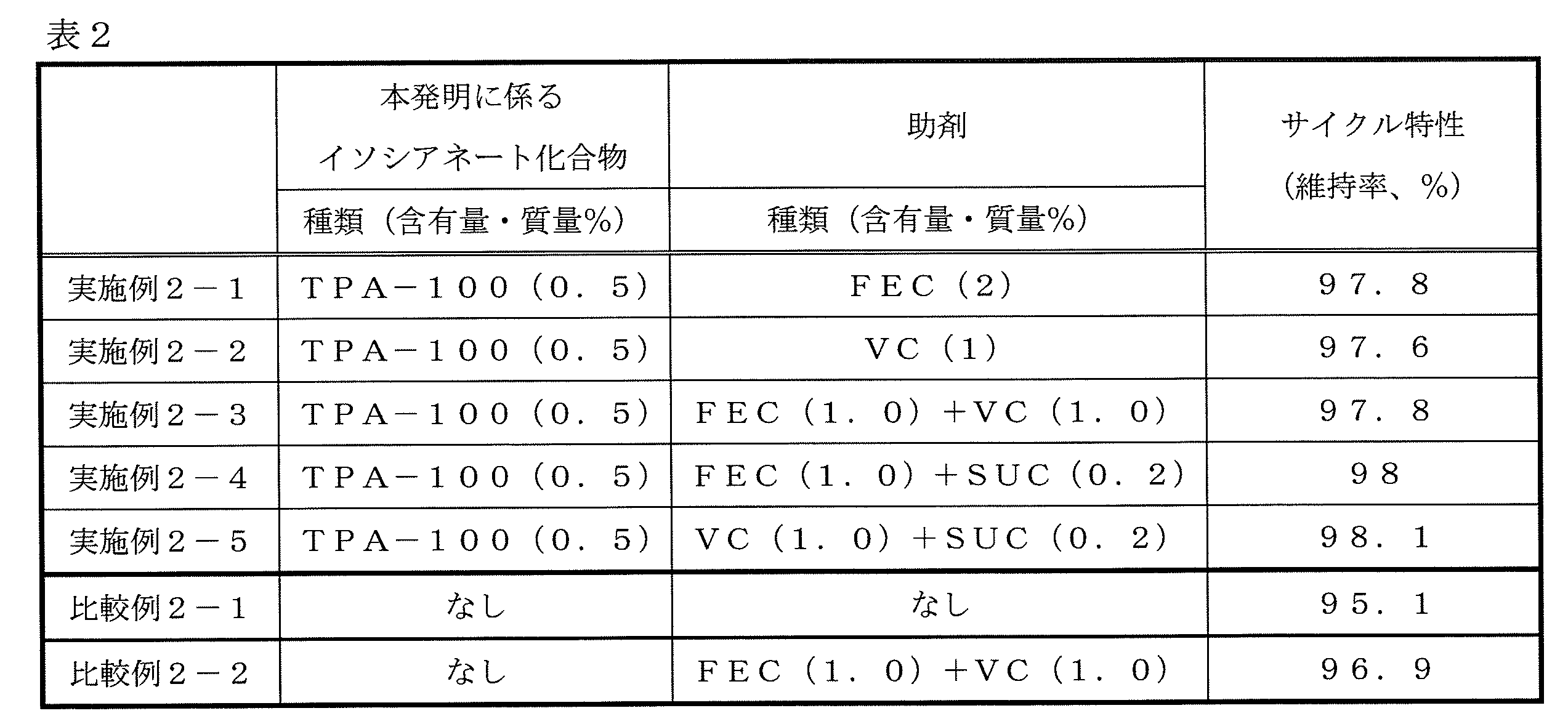
本実施例では、第1の実施例及び第2の実施例とは異なる下記の電池構成及び基準電解液について評価を行った。
(正極の作製)
正極活物質としてのリチウムコバルト酸化物(LiCoO2)94質量%と、導電材としてアセチレンブラック3質量%と、結着剤としてのポリフッ化ビニリデン(PVdF)3質量%とを、N-メチルピロリドン溶媒中で、ディスパーザーで混合してスラリー化した。これを厚さ21μmのアルミニウム箔の両面に均一に塗布、乾燥した後、プレスして正極とした。
負極活物質としてグラファイト粉末100質量部に、増粘剤、バインダーとしてそれぞれ、カルボキシメチルセルロースナトリウムの水性ディスパージョン(カルボキシメチルセルロースナトリウムの濃度1質量%)1質量部、及びスチレン-ブタジエンゴムの水性ディスパージョン(スチレン-ブタジエンゴムの濃度50質量%)1質量部を加え、ディスパーザーで混合してスラリー化した。このスラリーを厚さ12μmの銅箔の片面に均一に塗布、乾燥した後、プレスして負極とした。
上記の正極、負極、及びポリエチレン製のセパレータ(25μm)を、負極、セパレータ、正極、セパレータ、負極の順に積層して電池要素を作製した。この電池要素をアルミニウム(厚さ40μm)の両面を樹脂層で被覆したラミネートフィルムからなる袋内に正・負極の端子を突設させながら挿入した後、後述する非水系電解液を袋内に注入し、真空封止を行ない、シート状の非水系電解液電池を作製した。
(初期容量評価)
非水系電解液電池を、ガラス板で挟んで加圧した状態で、25℃において、0.2Cに相当する電流で4.1Vまで定電流充電した後、0.2Cの定電流で3Vまで放電し、さらに0.2Cに相当する電流で4.33Vまで定電流-定電圧充電(以下適宜、「CCCV充電」という)(0.05Cカット)した後、0.2Cで3Vまで放電して電池を安定させた。次いで、0.2Cで4.33VまでCCCV充電(0.05Cカット)した後、0.2Cで3Vまで再度放電し、初期放電容量を求めた。ここで、1Cとは電池の基準容量を1時間で放電する電流値を表し、例えば、0.2Cとはその1/5の電流値を表す。
再度、4.33VまでCCCV充電(0.05Cカット)を行った後、85℃、24時間の条件で高温保存を行った。電池を十分に冷却させた後、エタノール浴中に浸して体積を測定し、保存前後の体積変化から発生したガス量を求めた。次に、25℃において0.2Cで3Vまで放電させ、高温保存特性試験後の残存容量を測定し、初期放電容量に対する残存容量の割合を求め、これを高温保存後の残存容量(%)とした。再度、4.33VまでCCCV充電(0.05Cカット)を行い、0.2Cで3Vまで放電させ、高温保存特性試験後の0.2C放電容量を測定し、初期放電容量に対する0.2C放電容量の割合を求め、これを高温保存後の回復容量(%)とした。評価結果を表3に示す。なお、表中の数値は、比較例3-1を100%としたときの相対値である。
乾燥アルゴン雰囲気下、エチレンカーボネートとモノフルオロエチレンカーボネートとジメチルカーボネートとの混合物(体積比15:15:70)に、十分に乾燥したLiPF6を非水系電解液全量で1mol/Lとなるように溶解させた(この電解液を「第三基準電解液」と略称する場合がある。)。第三基準電解液に、デュラネートTMTPA-100、VC並びにアジポニトリル(AdpCN)をそれぞれ0.3質量%、1.0質量%、1.0質量%となるように加え、非水系電解液を調製した。
デュラネートTMTPA-100の含有量を0.5質量%としたことを除き、実施例3-1と同様に電解液を調製した。
デュラネートTMTPA-100を含有しないことを除いて実施例3-1と同様に電解液を調製し、電池の作製と高温保存特性評価を行った。このようにして得られた結果を表3に示す。
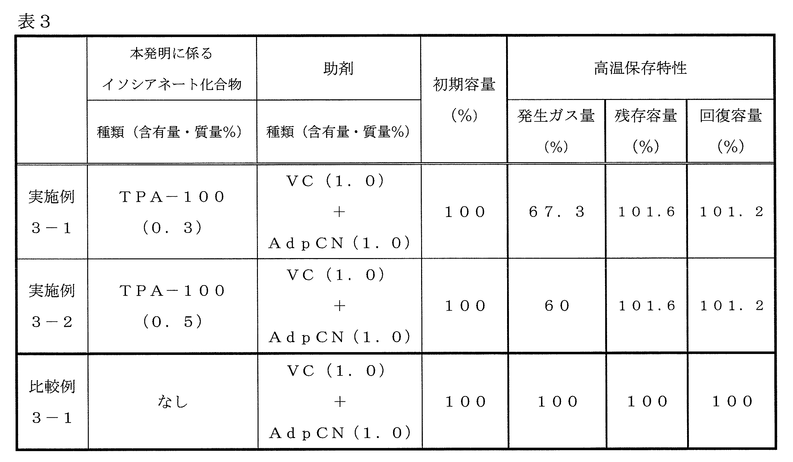
本実施例では、助剤の種類を変えて第1の実施例と同じ電池構成及び基準電解液について、第1の実施例と同じサイクル特性評価を行った。
第1の実施例で用いた基準電解液に、デュラネートTMD101ならびにジフルオロリン酸リチウム(LiPO2F2)をそれぞれ0.5質量%と0.5質量%となるように加え、非水系電解液を調製した。
デュラネートTMD101の非水系電解液全量における含有量を0.3質量%としたことを除き、実施例4-1と同様に電解液を調製した。
デュラネートTMD101の非水系電解液全量における含有量を1.0質量%としたことを除き、実施例4-1と同様に電解液を調製した。
デュラネートTMD101に替えて、デュラネートTMTPA-100を用いたことを除き、実施例4-1と同様に電解液を調製した。
LiPO2F2に替えて、リチウムビス(フルオロスルホニル)イミド(LiFSI)を用いたことを除き、実施例4-4と同様に電解液を調製した。
LiPO2F2に替えて、トリフルオロメタンスルホン酸リチウム(LiTFSI)を用いたことを除き、実施例4-4と同様に電解液を調製した。
LiPO2F2に替えて、フルオロスルホン酸リチウム(LiSO3F)を用いたことを除き、実施例4-4と同様に電解液を調製した。
LiPO2F2に替えて、リチウムビス(オキサラト)ボレート(LiBOB)を用いたことを除き、実施例4-4と同様に電解液を調製した。
LiPO2F2に替えて、ホウ酸トリス(トリメチルシリル)(TMSB)を用いたことを除き、実施例4-4と同様に電解液を調製した。
電解液にデュラネートTMTPA-100を加えなかった以外は実施例4-4と同様に電解液を作製した。
電解液にデュラネートTMTPA-100を加えなかった以外は実施例4-5と同様に電解液を作製した。
電解液にデュラネートTMTPA-100を加えなかった以外は実施例4-6と同様に電解液を作製した。
電解液にデュラネートTMTPA-100を加えなかった以外は実施例4-7と同様に電解液を作製した。
電解液にデュラネートTMTPA-100を加えなかった以外は実施例4-8と同様に電解液を作製した。
電解液にデュラネートTMTPA-100を加えなかった以外は実施例4-9と同様に電解液を作製した。
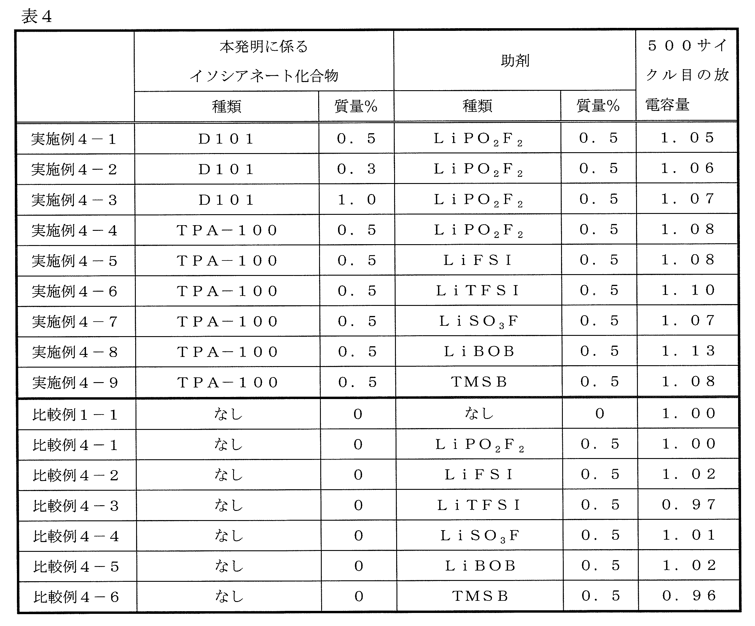
本実施例では、第1の実施例と同じ電池構成で、充放電条件を変更し、第1~4の実施例とは異なる基準電解液及び助剤組み合わせについて以下の評価を行った。
(慣らし運転)
25℃の恒温槽中、シート状の非水系電解液二次電池を0.2Cで4.2Vまで定電流-定電圧充電した後、0.2Cで2.7Vまで放電した。これを5サイクル行って電池を安定させた。なお、1Cとは電池の全容量を1時間で放電させる場合の電流値のことである。
リチウム二次電池を、45℃において1Cに相当する定電流で充電後、1Cの定電流で放電する過程を1サイクルとして、300サイクル実施した。
本発明に係るイソシアネート化合物や助剤を含まない非水系電解液(基準電解液)を用いた時の電池の300サイクル目の放電容量を1とし、本発明の非水系電解液を用いた時の電池の300サイクル目の放電容量を比較した。すなわち、
(本発明の非水系電解液の300サイクル目の放電容量)÷(基準電解液の300サイクル目の放電容量)の計算式から求められる値の比較である。結果を表5に示す。
乾燥アルゴン雰囲気下、エチレンカーボネートとジメチルカーボネートとエチルメチルカーボネートとの混合物(体積比3:3:4)に、十分に乾燥したLiPF6を非水系電解液全量で1.2mol/Lとなるように溶解させた(この電解液を「第五基準電解液」と略称する場合がある。)。第五基準電解液に、デュラネートTMTPA-100、VCならびにLiBOBをそれぞれ0.5質量%、0.5質量%、0.5質量%となるように加え、非水系電解液を調製した。
第五基準電解液に、デュラネートTMTPA-100、FEC並びにLiBOBをそれぞれ0.5質量%、0.5質量%、0.5質量%となるように加え、実施例5-1と同様に非水系電解液を調製した。
第五基準電解液に、デュラネートTMTPA-100、FEC並びにLiBF4をそれぞれ0.5質量%、0.5質量%、0.3質量%となるように加え、実施例2-1と同様に非水系電解液を調製した。
本発明に係るイソシアネート化合物やその他の助剤を含まない第五基準電解液を用いた以外は実施例5-1と同様に電解液を調製し、電池の作製とサイクル試験を行った。
デュラネートTMTPA-100とLiBOBを含有しないことを除いて実施例5-2と同様に電解液を調製し、電池の作製とサイクル試験を行った。
デュラネートTMTPA-100を含有しないことを除いて実施例5-1と同様に電解液を調製し、電池の作製とサイクル試験を行った。
デュラネートTMTPA-100を含有しないことを除いて実施例5-2と同様に電解液を調製し、電池の作製とサイクル試験を行った。
デュラネートTMTPA-100を含有しないことを除いて実施例5-3と同様に電解液を調製し、電池の作製とサイクル試験を行った。
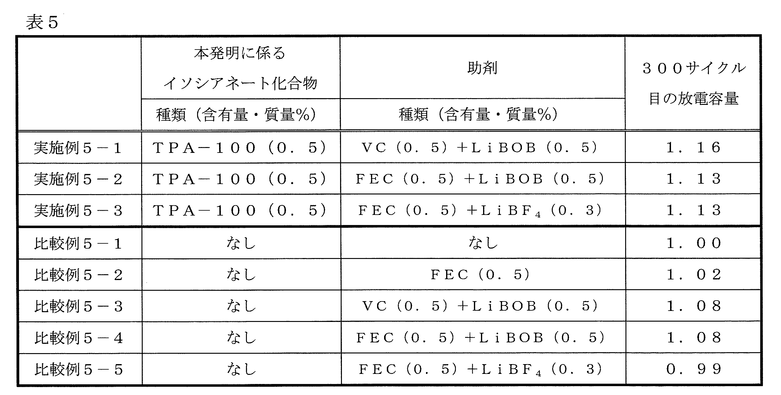
本発明の非水系電解液や非水系電解液二次電池の用途は特に限定されず、公知の各種の用途に用いることが可能である。具体例としては、ノートパソコン、ペン入力パソコン、モバイルパソコン、電子ブックプレーヤー、携帯電話、携帯ファックス、携帯コピー、携帯プリンター、ヘッドフォンステレオ、ビデオムービー、液晶テレビ、ハンディークリーナー、ポータブルCD、ミニディスク、トランシーバー、電子手帳、電卓、メモリーカード、携帯テープレコーダー、ラジオ、バックアップ電源、モーター、自動車、バイク、原動機付自転車、自転車、照明器具、玩具、ゲーム機器、時計、電動工具、ストロボ、カメラ等を挙げることができる。
Claims (14)
- 金属イオンを吸蔵・放出しうる正極及び負極と、セパレータとを備える非水系電解液二次電池用の非水系電解液であって、
電解質及び非水系溶媒とともに、分子内に下記一般式(1)で表される部分構造を1以上及びイソシアネート基を2以上有する化合物を0.01質量%以上3質量%未満含有することを特徴とする、非水系電解液。
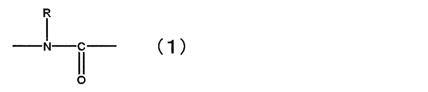
- 前記化合物が、ウレトジオン、オキサジアジトリオン、ビウレット、ウレタン、アロファネート、及びイソシアヌレートから選ばれる少なくとも1種以上の骨格を有する化合物である、請求項1に記載の非水系電解液。
- 前記化合物が、数平均分子量300以上5000以下の化合物である、請求項1又は2に記載の非水系電解液。
- ヘキサフルオロリン酸リチウム(LiPF6)を非水系電解液全体中に0.5~3mol/L含有する、請求項1~3の何れか1項に記載の非水系電解液。
- モノフルオロリン酸塩、ジフルオロリン酸塩、四フッ化ホウ酸塩、及び下記一般式(2)~(5)で表される化合物からなる群より選ばれる少なくとも1種を含有する、請求項1~4の何れか1項に記載の非水系電解液。


- M1がリチウムであり、かつM2がリン又はホウ素である一般式(4)で表される化合物を含有する、請求項5に記載の非水系電解液。
- M3がホウ素原子又はP=Oである一般式(5)で表される化合物を含有する、請求項5又は6に記載の非水系電解液。
- 前記モノフルオロリン酸塩、ジフルオロリン酸塩、四フッ化ホウ酸塩、及び一般式(2)~(5)で表される化合物からなる群より選ばれる少なくとも1種を、非水系電解液全体中に0.01~5質量%含有する、請求項5~7の何れか1項に記載の非水系電解液。
- モノフルオロリン酸リチウム、ジフルオロリン酸リチウム、テトラフルオロホウ酸リチウム、リチウムビス(フルオロスルホニル)イミド、リチウムビス(トリフルオロメタンスルホニル)イミド、フルオロスルホン酸リチウム、トリフルオロメタンスルホン酸リチウム、リチウムビス(オキサラト)ボレート、リチウムジフルオロオキサラトボレート、リチウムトリス(オキサラト)ホスフェート、リチウムジフルオロビス(オキサラト)ホスフェート、リチウムテトラフルオロオキサラトホスフェート、ホウ酸トリス(トリメチルシリル)、リン酸トリス(トリメチルシリル)からなる群より選ばれる少なくとも1種を含有する、請求項5~8の何れか1項に記載の非水系電解液。
- 不飽和環状カーボネート、フッ素化環状カーボネート、及び下記一般式(6)で表されるジニトリル化合物からなる群より選ばれる少なくとも1種以上を含有する、請求項1~9の何れか1項に記載の非水系電解液。

- ポリエチレン及びポリプロピレンから選ばれる少なくとも1種を含有するセパレータを備える非水系電解液二次電池用である、請求項1~10の何れか1項に記載の非水系電解液。
- 炭素を負極活物質として含む非水系電解液二次電池用である、請求項1~11の何れか1項に記載の非水系電解液。
- 金属イオンを吸蔵・放出しうる正極及び負極、セパレータ並びに請求項1~12の何れか1項に記載の非水系電解液を備えることを特徴とする、非水系電解液二次電池。
- 炭素を負極活物質として含む請求項13に記載の非水系電解液二次電池であって、
アルゴンイオンレーザーラマンスペクトル法における1580cm-1のピーク強度に対する1360cm-1のピーク強度の比として定義されるラマンR値が、0.1以上である炭素質材料を少なくとも1種以上を含有する負極活物質を含むものである、非水系電解液二次電池。
Priority Applications (4)
| Application Number | Priority Date | Filing Date | Title |
|---|---|---|---|
| CN201280008548.XA CN103354962B (zh) | 2011-02-10 | 2012-02-09 | 二次电池用非水电解液及使用该非水电解液的非水电解质二次电池 |
| KR1020137023657A KR101929599B1 (ko) | 2011-02-10 | 2012-02-09 | 2 차 전지용 비수계 전해액 및 그것을 사용한 비수계 전해액 2 차 전지 |
| EP12745284.5A EP2675010B1 (en) | 2011-02-10 | 2012-02-09 | Non-aqueous electrolyte solution for secondary battery, and non-aqueous electrolyte secondary battery using same |
| US13/964,511 US8846247B2 (en) | 2011-02-10 | 2013-08-12 | Non-aqueous electrolyte for secondary battery and non-aqueous electrolyte secondary battery employing the same |
Applications Claiming Priority (6)
| Application Number | Priority Date | Filing Date | Title |
|---|---|---|---|
| JP2011027671 | 2011-02-10 | ||
| JP2011-027671 | 2011-02-10 | ||
| JP2011104377 | 2011-05-09 | ||
| JP2011-104377 | 2011-05-09 | ||
| JP2011-168647 | 2011-08-01 | ||
| JP2011168647 | 2011-08-01 |
Related Child Applications (1)
| Application Number | Title | Priority Date | Filing Date |
|---|---|---|---|
| US13/964,511 Continuation US8846247B2 (en) | 2011-02-10 | 2013-08-12 | Non-aqueous electrolyte for secondary battery and non-aqueous electrolyte secondary battery employing the same |
Publications (1)
| Publication Number | Publication Date |
|---|---|
| WO2012108505A1 true WO2012108505A1 (ja) | 2012-08-16 |
Family
ID=46638717
Family Applications (1)
| Application Number | Title | Priority Date | Filing Date |
|---|---|---|---|
| PCT/JP2012/052978 WO2012108505A1 (ja) | 2011-02-10 | 2012-02-09 | 二次電池用非水系電解液及びそれを用いた非水系電解液二次電池 |
Country Status (5)
| Country | Link |
|---|---|
| US (1) | US8846247B2 (ja) |
| EP (1) | EP2675010B1 (ja) |
| KR (1) | KR101929599B1 (ja) |
| CN (1) | CN103354962B (ja) |
| WO (1) | WO2012108505A1 (ja) |
Cited By (13)
| Publication number | Priority date | Publication date | Assignee | Title |
|---|---|---|---|---|
| JP2014194930A (ja) * | 2013-02-27 | 2014-10-09 | Mitsubishi Chemicals Corp | 非水系電解液及びそれを用いた非水系電解液電池 |
| JP2014209479A (ja) * | 2013-03-27 | 2014-11-06 | 三菱化学株式会社 | 非水系電解液、それを用いた電池 |
| WO2015020625A1 (en) * | 2013-08-05 | 2015-02-12 | Empire Technology Development Llc | Gel electrolyte composition for rechargeable batteries |
| WO2015060156A1 (ja) * | 2013-10-22 | 2015-04-30 | 三洋化成工業株式会社 | リチウムイオン二次電池用添加剤、それを用いた電極及び電解液、並びにリチウムイオン二次電池 |
| WO2015098471A1 (ja) * | 2013-12-25 | 2015-07-02 | 旭化成株式会社 | シリル基含有化合物を含む電解液添加用組成物、該組成物を含む非水蓄電デバイス用電解液、及び該電解液を含むリチウムイオン二次電池 |
| KR20150125928A (ko) * | 2013-02-27 | 2015-11-10 | 미쓰비시 가가꾸 가부시키가이샤 | 비수계 전해액 및 그것을 이용한 비수계 전해액 전지 |
| CN105074994A (zh) * | 2013-03-27 | 2015-11-18 | 三菱化学株式会社 | 非水电解液及使用该非水电解液的非水电解质电池 |
| US20160240888A1 (en) | 2013-10-04 | 2016-08-18 | Asahi Kasei Kabushiki Kaisha | Electrolyte and lithium-ion secondary battery |
| JP2016189327A (ja) * | 2015-03-27 | 2016-11-04 | 旭化成株式会社 | 非水蓄電デバイス用電解液の添加剤 |
| KR20170057421A (ko) * | 2014-09-23 | 2017-05-24 | 어플라이드 머티어리얼스, 인코포레이티드 | 보호된 음극을 갖는 전기 화학 전지 |
| JP2017528894A (ja) * | 2014-09-26 | 2017-09-28 | エルジー・ケム・リミテッド | 非水性電解液及びこれを含むリチウム二次電池 |
| WO2022091520A1 (ja) * | 2020-10-28 | 2022-05-05 | パナソニックIpマネジメント株式会社 | 非水系二次電池およびこれに用いる非水電解質 |
| US11437646B2 (en) | 2014-09-26 | 2022-09-06 | Lg Energy Solution, Ltd. | Non-aqueous liquid electrolyte and lithium secondary battery comprising the same |
Families Citing this family (60)
| Publication number | Priority date | Publication date | Assignee | Title |
|---|---|---|---|---|
| KR101537142B1 (ko) * | 2012-04-30 | 2015-07-15 | 주식회사 엘지화학 | 전해액 첨가제, 상기 첨가제를 포함하는 비수성 전해액 및 리튬 이차 전지 |
| JP2014035951A (ja) * | 2012-08-09 | 2014-02-24 | Sanyo Electric Co Ltd | 非水電解質二次電池 |
| EP2958183B1 (en) | 2013-02-18 | 2020-05-06 | Nippon Shokubai Co., Ltd. | Electrolyte solution and lithium ion secondary battery provided with same |
| EP2999030B1 (en) | 2013-07-10 | 2017-09-27 | LG Chem, Ltd. | Electrode improving battery lifespan and lithium secondary battery having same |
| CN104752763B (zh) * | 2013-12-25 | 2017-04-12 | 中国科学院宁波材料技术与工程研究所 | 一种新型锂离子电解液添加剂体系 |
| CN105917515B (zh) * | 2014-01-16 | 2019-05-07 | 株式会社钟化 | 非水电解质二次电池及其组电池 |
| US10343527B2 (en) * | 2014-01-20 | 2019-07-09 | Murata Manufacturing Co., Ltd. | Cell, cell pack, electronic device, electric vehicle, electricity storage apparatus, and power system |
| KR20160113598A (ko) * | 2014-01-24 | 2016-09-30 | 산요가세이고교 가부시키가이샤 | 2 차 전지용 첨가제, 그것을 사용한 전극 및 전해액, 리튬 이온 전지 그리고 리튬 이온 캐패시터 |
| CN103904364B (zh) * | 2014-03-28 | 2017-01-11 | 宁德新能源科技有限公司 | 锂离子二次电池及其电解液 |
| KR102164007B1 (ko) * | 2014-04-07 | 2020-10-12 | 삼성에스디아이 주식회사 | 리튬 이차 전지 |
| EP3149798B1 (en) * | 2014-05-30 | 2018-04-11 | Basf Se | Polymer for use as protective layers and other components in electrochemical cells |
| KR102186402B1 (ko) * | 2014-07-03 | 2020-12-03 | 삼성에스디아이 주식회사 | 리튬 이차 전지용 전해액 및 이를 포함하는 리튬 이차 전지 |
| EP3171445B1 (en) * | 2014-07-15 | 2020-09-02 | UBE Industries, Ltd. | Non-aqueous electrolyte solution and electricity storage device in which same is used |
| KR20160037102A (ko) | 2014-09-26 | 2016-04-05 | 주식회사 엘지화학 | 비수성 전해액 및 이를 포함하는 리튬 이차전지 |
| KR101797271B1 (ko) | 2014-09-26 | 2017-11-13 | 주식회사 엘지화학 | 비수성 전해액 및 이를 포함하는 리튬 이차 전지 |
| CN104269577A (zh) * | 2014-09-29 | 2015-01-07 | 深圳新宙邦科技股份有限公司 | 一种高电压锂离子电池的电解液及高电压锂离子电池 |
| KR101737222B1 (ko) * | 2014-10-02 | 2017-05-17 | 주식회사 엘지화학 | 리튬 이차 전지용 전해액 첨가제, 상기 전해액 첨가제를 포함하는 비수성 전해액 및 리튬 이차 전지 |
| JP6390902B2 (ja) * | 2014-10-10 | 2018-09-19 | トヨタ自動車株式会社 | 非水電解液二次電池 |
| JP6567280B2 (ja) * | 2015-01-29 | 2019-08-28 | 三洋電機株式会社 | 非水電解質二次電池及び製造方法 |
| JP6705119B2 (ja) | 2015-02-20 | 2020-06-03 | 株式会社村田製作所 | 電解質、電池、電池パック、電子機器、電動車両、蓄電装置および電力システム |
| KR20170008475A (ko) * | 2015-07-14 | 2017-01-24 | 주식회사 엘지화학 | 비수성 전해질 및 이를 포함하는 리튬 이차전지 |
| WO2017010255A1 (ja) * | 2015-07-15 | 2017-01-19 | 日本電気株式会社 | リチウムイオン二次電池 |
| PL3352283T3 (pl) | 2015-10-22 | 2021-07-26 | Daikin Industries, Ltd. | Roztwór elektrolityczny, urządzenie elektrochemiczne, litowo-jonowe ogniwo wtórne oraz moduł |
| JP6890956B2 (ja) * | 2015-12-10 | 2021-06-18 | 株式会社半導体エネルギー研究所 | 蓄電装置及び電子機器 |
| EP3389119B1 (en) * | 2015-12-11 | 2024-02-07 | GS Yuasa International Ltd. | Nonaqueous electrolyte energy storage device and method for producing the same |
| CN106941191B (zh) * | 2016-01-04 | 2020-03-24 | 宁德新能源科技有限公司 | 锂离子电池及其非水电解液 |
| DE102016104210A1 (de) * | 2016-03-08 | 2017-09-14 | Westfälische Wilhelms-Universität Münster | Verwendung von Trialkylsiloxy-basierten Metallkomplexen als Additiv in Lithium-Ionen-Batterien |
| WO2017217408A1 (ja) * | 2016-06-13 | 2017-12-21 | 日本電気株式会社 | リチウムイオン二次電池 |
| CN107634265A (zh) * | 2016-07-18 | 2018-01-26 | 万向二三股份公司 | 一种耐高压锂离子电池电解液 |
| CN106450432A (zh) * | 2016-11-04 | 2017-02-22 | 东莞市凯欣电池材料有限公司 | 一种硅碳复合负极高电压锂离子电池 |
| US10991981B2 (en) * | 2016-12-22 | 2021-04-27 | Panasonic Intellectual Property Management Co., Ltd. | Nonaqueous electrolyte secondary battery |
| CN108242567A (zh) * | 2016-12-26 | 2018-07-03 | 宁德时代新能源科技股份有限公司 | 电解液及二次电池 |
| PL3514883T3 (pl) * | 2017-03-17 | 2021-06-14 | Lg Chem, Ltd. | Dodatek do elektrolitu i zawierający go elektrolit dla akumulatora litowego |
| CN108808065B (zh) | 2017-04-28 | 2020-03-27 | 深圳新宙邦科技股份有限公司 | 锂离子电池非水电解液和锂离子电池 |
| CN108808086B (zh) | 2017-04-28 | 2020-03-27 | 深圳新宙邦科技股份有限公司 | 锂离子电池非水电解液和锂离子电池 |
| CN108808084B (zh) | 2017-04-28 | 2020-05-08 | 深圳新宙邦科技股份有限公司 | 锂离子电池非水电解液和锂离子电池 |
| CN108808066B (zh) * | 2017-04-28 | 2020-04-21 | 深圳新宙邦科技股份有限公司 | 锂离子电池非水电解液和锂离子电池 |
| CN108933292B (zh) | 2017-05-27 | 2020-04-21 | 深圳新宙邦科技股份有限公司 | 锂离子电池非水电解液和锂离子电池 |
| PL3656014T3 (pl) * | 2017-07-20 | 2021-11-02 | Basf Se | Dodatki heterocykliczne zawierające grupy fluorku sulfonylu do kompozycji elektrolitu akumulatorów litowych |
| CN109326823B (zh) | 2017-07-31 | 2020-04-21 | 深圳新宙邦科技股份有限公司 | 锂离子电池非水电解液及锂离子电池 |
| CN109326824B (zh) | 2017-07-31 | 2020-04-21 | 深圳新宙邦科技股份有限公司 | 锂离子电池非水电解液及锂离子电池 |
| EP3471191A1 (en) * | 2017-10-11 | 2019-04-17 | Centre National De La Recherche Scientifique | Electrolyte composition including a specific combination of additives, its use as non-aqueous liquid electrolyte in a na-ion battery and na-ion battery including such an electrolyte composition |
| WO2019130958A1 (ja) * | 2017-12-26 | 2019-07-04 | 日立オートモティブシステムズ株式会社 | リチウムイオン二次電池用電解液 |
| PL3761435T3 (pl) * | 2018-03-27 | 2023-02-06 | Daikin Industries, Ltd. | Roztwór elektrolitu, urządzenie elektrochemiczne, litowo-jonowa bateria akumulatorowa, moduł oraz związek |
| CN110400969B (zh) * | 2018-04-25 | 2022-06-10 | 比亚迪股份有限公司 | 一种非水电解液及含有该非水电解液的电池 |
| CN111293364B (zh) * | 2018-12-10 | 2021-03-30 | 张家港市国泰华荣化工新材料有限公司 | 一种非水电解液及锂离子电池 |
| US20220238919A1 (en) * | 2019-05-30 | 2022-07-28 | Panasonic Intellectual Property Management Co., Ltd. | Non-aqueous electrolyte secondary battery |
| WO2021128002A1 (zh) * | 2019-12-24 | 2021-07-01 | 宁德时代新能源科技股份有限公司 | 二次电池及含有该二次电池的装置 |
| CN111613835A (zh) * | 2020-05-12 | 2020-09-01 | 贵州兴锂新能源科技有限公司 | 一种锂离子电池的电解液 |
| CN111934012A (zh) * | 2020-08-19 | 2020-11-13 | 四川虹微技术有限公司 | 一种锂离子电池电解液、制备方法及其应用 |
| CN114447429B (zh) * | 2020-10-30 | 2024-08-09 | 深圳新宙邦科技股份有限公司 | 锂离子电池非水电解液以及锂离子电池 |
| CN114464959B (zh) * | 2020-10-30 | 2023-07-11 | 深圳新宙邦科技股份有限公司 | 锂离子电池 |
| CN114447326B (zh) * | 2020-10-30 | 2024-08-09 | 深圳新宙邦科技股份有限公司 | 锂离子电池负极材料和锂离子电池 |
| CN114447430B (zh) * | 2020-10-30 | 2024-08-09 | 深圳新宙邦科技股份有限公司 | 锂离子电池 |
| CN114447327B (zh) * | 2020-10-30 | 2024-08-09 | 深圳新宙邦科技股份有限公司 | 锂离子电池正极和锂离子电池 |
| CN112615050A (zh) * | 2020-12-11 | 2021-04-06 | 联动天翼新能源有限公司 | 一种低产气长循环高电压电解液、制备方法及锂离子电池 |
| CN112666772B (zh) * | 2020-12-24 | 2023-02-03 | 清华大学深圳国际研究生院 | 一种可自封装的电致变色器件及其制备方法 |
| CN112968157B (zh) * | 2021-02-06 | 2022-11-01 | 苏州精诚智造智能科技有限公司 | 一种动力锂离子电池的制备方法 |
| CN113161617A (zh) * | 2021-03-26 | 2021-07-23 | 天津市捷威动力工业有限公司 | 一种低温型锂离子电池电解液及其锂离子电池 |
| CN113113668B (zh) * | 2021-04-09 | 2022-05-17 | 珠海市赛纬电子材料股份有限公司 | 电解液添加剂和含有该添加剂的非水电解液及锂离子电池 |
Citations (15)
| Publication number | Priority date | Publication date | Assignee | Title |
|---|---|---|---|---|
| JPS5747319A (en) | 1980-09-03 | 1982-03-18 | Nippon Polyurethan Kogyo Kk | Preparation of aliphatic isocyanurate compound |
| JPS6357577A (ja) | 1986-08-29 | 1988-03-12 | Asahi Chem Ind Co Ltd | ポリイソシアネ−トの製造方法 |
| JPS63174961A (ja) | 1987-01-07 | 1988-07-19 | バイエル・アクチエンゲゼルシヤフト | ビウレツト構造を有するポリイソシアネートの製造方法 |
| JPH07304724A (ja) | 1994-05-09 | 1995-11-21 | Bayer Ag | アロファネート基を含有する光安定性ポリイソシアネートの製造方法 |
| JPH08225511A (ja) | 1994-12-09 | 1996-09-03 | Basf Ag | ビウレット含有ポリイソシアネートの製造法 |
| JP2004214041A (ja) | 2003-01-06 | 2004-07-29 | Nitto Denko Corp | ゲル電解質とこれを用いる非水電解質電池 |
| JP2005158703A (ja) | 2003-10-29 | 2005-06-16 | Nippon Synthetic Chem Ind Co Ltd:The | リチウムポリマー電池及びその製造方法 |
| JP2005259641A (ja) | 2004-03-15 | 2005-09-22 | Mitsubishi Heavy Ind Ltd | リチウム二次電池用の電解液、電極、リチウム二次電池およびそれらの製造方法 |
| JP2005294020A (ja) | 2004-03-31 | 2005-10-20 | Sk Kaken Co Ltd | 固体電解質 |
| JP2006164759A (ja) | 2004-12-07 | 2006-06-22 | Tomiyama Pure Chemical Industries Ltd | 電気化学デバイス用非水電解液 |
| JP2007242411A (ja) | 2006-03-08 | 2007-09-20 | Sony Corp | 電池及び電解液組成物 |
| JP2010225522A (ja) | 2009-03-25 | 2010-10-07 | Sony Corp | 電解質および二次電池 |
| JP2011171108A (ja) * | 2010-02-18 | 2011-09-01 | Sanyo Electric Co Ltd | 非水電解質二次電池 |
| JP2011198691A (ja) * | 2010-03-23 | 2011-10-06 | Sekisui Plastics Co Ltd | ゲル状イオン導電体及びその製造方法 |
| JP2011216443A (ja) * | 2010-04-02 | 2011-10-27 | Asahi Kasei Chemicals Corp | リチウムイオン伝導性ゲル及び製造方法 |
Family Cites Families (12)
| Publication number | Priority date | Publication date | Assignee | Title |
|---|---|---|---|---|
| DE19933898A1 (de) * | 1999-07-22 | 2001-02-01 | Chemetall Gmbh | Tris(oxalato)phosphate, Verfahren zu deren Herstellung und deren Verwendung |
| JP4565707B2 (ja) | 2000-06-27 | 2010-10-20 | 三井化学株式会社 | 非水電解液およびそれを使用した二次電池 |
| JP4196398B2 (ja) * | 2002-08-26 | 2008-12-17 | 日本電気株式会社 | 非水電解液二次電池 |
| JP4537736B2 (ja) | 2003-10-28 | 2010-09-08 | 日東電工株式会社 | 電池 |
| JP4578203B2 (ja) * | 2004-10-25 | 2010-11-10 | 旭化成ケミカルズ株式会社 | ゲル状リチウムイオン導電体及びその製法 |
| JP2006310071A (ja) * | 2005-04-28 | 2006-11-09 | Nippon Synthetic Chem Ind Co Ltd:The | 固体電解質及びそれを用いたリチウムポリマー電池 |
| KR20220156102A (ko) * | 2005-10-20 | 2022-11-24 | 미쯔비시 케미컬 주식회사 | 리튬 2 차 전지 및 그것에 사용하는 비수계 전해액 |
| CN101894974A (zh) * | 2005-10-20 | 2010-11-24 | 三菱化学株式会社 | 锂二次电池以及其中使用的非水电解液 |
| CA2552282A1 (fr) * | 2006-07-18 | 2008-01-18 | Hydro Quebec | Materiau multi-couches a base de lithium vif, procedes de preparation et applications dans les generateurs electrochimiques |
| KR20090064583A (ko) * | 2006-10-23 | 2009-06-19 | 아사히 가세이 케미칼즈 가부시키가이샤 | 리튬 이온 2차 전지용 전해액 |
| JP5319899B2 (ja) * | 2007-08-23 | 2013-10-16 | 株式会社東芝 | 非水電解液電池 |
| US20120055668A1 (en) * | 2009-05-11 | 2012-03-08 | Wu Yong K | Solvents and compositions for treating hydrocarbon-bearing formations |
-
2012
- 2012-02-09 EP EP12745284.5A patent/EP2675010B1/en active Active
- 2012-02-09 KR KR1020137023657A patent/KR101929599B1/ko active IP Right Grant
- 2012-02-09 WO PCT/JP2012/052978 patent/WO2012108505A1/ja active Application Filing
- 2012-02-09 CN CN201280008548.XA patent/CN103354962B/zh active Active
-
2013
- 2013-08-12 US US13/964,511 patent/US8846247B2/en active Active
Patent Citations (15)
| Publication number | Priority date | Publication date | Assignee | Title |
|---|---|---|---|---|
| JPS5747319A (en) | 1980-09-03 | 1982-03-18 | Nippon Polyurethan Kogyo Kk | Preparation of aliphatic isocyanurate compound |
| JPS6357577A (ja) | 1986-08-29 | 1988-03-12 | Asahi Chem Ind Co Ltd | ポリイソシアネ−トの製造方法 |
| JPS63174961A (ja) | 1987-01-07 | 1988-07-19 | バイエル・アクチエンゲゼルシヤフト | ビウレツト構造を有するポリイソシアネートの製造方法 |
| JPH07304724A (ja) | 1994-05-09 | 1995-11-21 | Bayer Ag | アロファネート基を含有する光安定性ポリイソシアネートの製造方法 |
| JPH08225511A (ja) | 1994-12-09 | 1996-09-03 | Basf Ag | ビウレット含有ポリイソシアネートの製造法 |
| JP2004214041A (ja) | 2003-01-06 | 2004-07-29 | Nitto Denko Corp | ゲル電解質とこれを用いる非水電解質電池 |
| JP2005158703A (ja) | 2003-10-29 | 2005-06-16 | Nippon Synthetic Chem Ind Co Ltd:The | リチウムポリマー電池及びその製造方法 |
| JP2005259641A (ja) | 2004-03-15 | 2005-09-22 | Mitsubishi Heavy Ind Ltd | リチウム二次電池用の電解液、電極、リチウム二次電池およびそれらの製造方法 |
| JP2005294020A (ja) | 2004-03-31 | 2005-10-20 | Sk Kaken Co Ltd | 固体電解質 |
| JP2006164759A (ja) | 2004-12-07 | 2006-06-22 | Tomiyama Pure Chemical Industries Ltd | 電気化学デバイス用非水電解液 |
| JP2007242411A (ja) | 2006-03-08 | 2007-09-20 | Sony Corp | 電池及び電解液組成物 |
| JP2010225522A (ja) | 2009-03-25 | 2010-10-07 | Sony Corp | 電解質および二次電池 |
| JP2011171108A (ja) * | 2010-02-18 | 2011-09-01 | Sanyo Electric Co Ltd | 非水電解質二次電池 |
| JP2011198691A (ja) * | 2010-03-23 | 2011-10-06 | Sekisui Plastics Co Ltd | ゲル状イオン導電体及びその製造方法 |
| JP2011216443A (ja) * | 2010-04-02 | 2011-10-27 | Asahi Kasei Chemicals Corp | リチウムイオン伝導性ゲル及び製造方法 |
Cited By (25)
| Publication number | Priority date | Publication date | Assignee | Title |
|---|---|---|---|---|
| JP2018142556A (ja) * | 2013-02-27 | 2018-09-13 | 三菱ケミカル株式会社 | 非水系電解液及びそれを用いた非水系電解液電池 |
| US11942601B2 (en) | 2013-02-27 | 2024-03-26 | Mitsubishi Chemical Corporation | Nonaqueous electrolyte solution and nonaqueous electrolyte battery using same |
| US11424482B2 (en) | 2013-02-27 | 2022-08-23 | Mitsubishi Chemical Corporation | Nonaqueous electrolyte solution and nonaqueous electrolyte battery using same |
| KR102167579B1 (ko) * | 2013-02-27 | 2020-10-19 | 미쯔비시 케미컬 주식회사 | 비수계 전해액 및 그것을 이용한 비수계 전해액 전지 |
| CN110010882A (zh) * | 2013-02-27 | 2019-07-12 | 三菱化学株式会社 | 非水电解液及使用该非水电解液的非水电解质电池 |
| KR20150125928A (ko) * | 2013-02-27 | 2015-11-10 | 미쓰비시 가가꾸 가부시키가이샤 | 비수계 전해액 및 그것을 이용한 비수계 전해액 전지 |
| JP2014194930A (ja) * | 2013-02-27 | 2014-10-09 | Mitsubishi Chemicals Corp | 非水系電解液及びそれを用いた非水系電解液電池 |
| CN105074994A (zh) * | 2013-03-27 | 2015-11-18 | 三菱化学株式会社 | 非水电解液及使用该非水电解液的非水电解质电池 |
| US9947965B2 (en) | 2013-03-27 | 2018-04-17 | Mitsubishi Chemical Corporation | Nonaqueous electrolyte solution and nonaqueous electrolyte battery using same |
| JP2014209479A (ja) * | 2013-03-27 | 2014-11-06 | 三菱化学株式会社 | 非水系電解液、それを用いた電池 |
| CN109301162A (zh) * | 2013-03-27 | 2019-02-01 | 三菱化学株式会社 | 非水电解液及使用该非水电解液的非水电解质电池 |
| WO2015020625A1 (en) * | 2013-08-05 | 2015-02-12 | Empire Technology Development Llc | Gel electrolyte composition for rechargeable batteries |
| KR101848189B1 (ko) * | 2013-10-04 | 2018-04-11 | 아사히 가세이 가부시키가이샤 | 전해액 및 리튬 이온 이차전지 |
| US10050306B2 (en) | 2013-10-04 | 2018-08-14 | Asahi Kasei Kabushiki Kaisha | Electrolyte and lithium-ion secondary battery |
| US20160240888A1 (en) | 2013-10-04 | 2016-08-18 | Asahi Kasei Kabushiki Kaisha | Electrolyte and lithium-ion secondary battery |
| WO2015060156A1 (ja) * | 2013-10-22 | 2015-04-30 | 三洋化成工業株式会社 | リチウムイオン二次電池用添加剤、それを用いた電極及び電解液、並びにリチウムイオン二次電池 |
| WO2015098471A1 (ja) * | 2013-12-25 | 2015-07-02 | 旭化成株式会社 | シリル基含有化合物を含む電解液添加用組成物、該組成物を含む非水蓄電デバイス用電解液、及び該電解液を含むリチウムイオン二次電池 |
| JPWO2015098471A1 (ja) * | 2013-12-25 | 2017-03-23 | 旭化成株式会社 | シリル基含有化合物を含む電解液添加用組成物、該組成物を含む非水蓄電デバイス用電解液、及び該電解液を含むリチウムイオン二次電池 |
| KR20170057421A (ko) * | 2014-09-23 | 2017-05-24 | 어플라이드 머티어리얼스, 인코포레이티드 | 보호된 음극을 갖는 전기 화학 전지 |
| KR102570455B1 (ko) | 2014-09-23 | 2023-08-23 | 어플라이드 머티어리얼스, 인코포레이티드 | 보호된 음극을 갖는 전기 화학 전지 |
| JP2017528894A (ja) * | 2014-09-26 | 2017-09-28 | エルジー・ケム・リミテッド | 非水性電解液及びこれを含むリチウム二次電池 |
| US10276894B2 (en) | 2014-09-26 | 2019-04-30 | Lg Chem, Ltd. | Non-aqueous liquid electrolyte and lithium secondary battery comprising the same |
| US11437646B2 (en) | 2014-09-26 | 2022-09-06 | Lg Energy Solution, Ltd. | Non-aqueous liquid electrolyte and lithium secondary battery comprising the same |
| JP2016189327A (ja) * | 2015-03-27 | 2016-11-04 | 旭化成株式会社 | 非水蓄電デバイス用電解液の添加剤 |
| WO2022091520A1 (ja) * | 2020-10-28 | 2022-05-05 | パナソニックIpマネジメント株式会社 | 非水系二次電池およびこれに用いる非水電解質 |
Also Published As
| Publication number | Publication date |
|---|---|
| CN103354962B (zh) | 2016-03-30 |
| EP2675010B1 (en) | 2019-03-27 |
| US20130330610A1 (en) | 2013-12-12 |
| KR101929599B1 (ko) | 2018-12-14 |
| CN103354962A (zh) | 2013-10-16 |
| KR20140051836A (ko) | 2014-05-02 |
| EP2675010A4 (en) | 2017-06-28 |
| US8846247B2 (en) | 2014-09-30 |
| EP2675010A1 (en) | 2013-12-18 |
Similar Documents
| Publication | Publication Date | Title |
|---|---|---|
| JP5962040B2 (ja) | 二次電池用非水系電解液及びそれを用いた非水系電解液二次電池 | |
| US8846247B2 (en) | Non-aqueous electrolyte for secondary battery and non-aqueous electrolyte secondary battery employing the same | |
| JP6485485B2 (ja) | 非水系電解液及び非水系電解液二次電池 | |
| JP6213468B2 (ja) | 非水系電解液及びそれを用いた非水系電解液電池 | |
| JP6187566B2 (ja) | 非水系電解液及び非水系電解液二次電池 | |
| EP3113274B1 (en) | Non-aqueous electrolytic solution and non-aqueous electrolyte secondary battery using same | |
| WO2015046475A1 (ja) | 非水系電解液及びそれを用いた非水系電解液電池 | |
| WO2015111676A1 (ja) | 非水系電解液及びそれを用いた非水系電解液二次電池 | |
| JP2015159109A (ja) | 非水系電解液及びそれを用いた非水系電解液二次電池 | |
| JP6031868B2 (ja) | 非水系電解液及びそれを用いた非水系電解液電池 | |
| JP2014086221A (ja) | 非水系電解液二次電池 | |
| JP6459695B2 (ja) | 非水系電解液二次電池 | |
| JP2017174543A (ja) | 非水系電解液、及びそれを用いた非水系電解液二次電池 | |
| JP5906915B2 (ja) | 二次電池用非水系電解液及びそれを用いた非水系電解液二次電池 | |
| JP6221201B2 (ja) | 非水系電解液、および非水系電解液二次電池 | |
| JP2015195196A (ja) | 非水系電解液及びそれを用いた非水系電解液二次電池 |
Legal Events
| Date | Code | Title | Description |
|---|---|---|---|
| WWE | Wipo information: entry into national phase |
Ref document number: 201280008548.X Country of ref document: CN |
|
| 121 | Ep: the epo has been informed by wipo that ep was designated in this application |
Ref document number: 12745284 Country of ref document: EP Kind code of ref document: A1 |
|
| NENP | Non-entry into the national phase |
Ref country code: DE |
|
| WWE | Wipo information: entry into national phase |
Ref document number: 2012745284 Country of ref document: EP |
|
| ENP | Entry into the national phase |
Ref document number: 20137023657 Country of ref document: KR Kind code of ref document: A |