WO2012102266A1 - Châssis de brochage fixé par résine, son procédé de fabrication, et châssis de brochage - Google Patents
Châssis de brochage fixé par résine, son procédé de fabrication, et châssis de brochage Download PDFInfo
- Publication number
- WO2012102266A1 WO2012102266A1 PCT/JP2012/051432 JP2012051432W WO2012102266A1 WO 2012102266 A1 WO2012102266 A1 WO 2012102266A1 JP 2012051432 W JP2012051432 W JP 2012051432W WO 2012102266 A1 WO2012102266 A1 WO 2012102266A1
- Authority
- WO
- WIPO (PCT)
- Prior art keywords
- lead frame
- led element
- lead
- element mounting
- resin
- Prior art date
Links
Images


Classifications
-
- H—ELECTRICITY
- H01—ELECTRIC ELEMENTS
- H01L—SEMICONDUCTOR DEVICES NOT COVERED BY CLASS H10
- H01L33/00—Semiconductor devices with at least one potential-jump barrier or surface barrier specially adapted for light emission; Processes or apparatus specially adapted for the manufacture or treatment thereof or of parts thereof; Details thereof
- H01L33/48—Semiconductor devices with at least one potential-jump barrier or surface barrier specially adapted for light emission; Processes or apparatus specially adapted for the manufacture or treatment thereof or of parts thereof; Details thereof characterised by the semiconductor body packages
- H01L33/52—Encapsulations
- H01L33/56—Materials, e.g. epoxy or silicone resin
-
- H—ELECTRICITY
- H01—ELECTRIC ELEMENTS
- H01L—SEMICONDUCTOR DEVICES NOT COVERED BY CLASS H10
- H01L33/00—Semiconductor devices with at least one potential-jump barrier or surface barrier specially adapted for light emission; Processes or apparatus specially adapted for the manufacture or treatment thereof or of parts thereof; Details thereof
- H01L33/44—Semiconductor devices with at least one potential-jump barrier or surface barrier specially adapted for light emission; Processes or apparatus specially adapted for the manufacture or treatment thereof or of parts thereof; Details thereof characterised by the coatings, e.g. passivation layer or anti-reflective coating
- H01L33/46—Reflective coating, e.g. dielectric Bragg reflector
-
- H—ELECTRICITY
- H01—ELECTRIC ELEMENTS
- H01L—SEMICONDUCTOR DEVICES NOT COVERED BY CLASS H10
- H01L33/00—Semiconductor devices with at least one potential-jump barrier or surface barrier specially adapted for light emission; Processes or apparatus specially adapted for the manufacture or treatment thereof or of parts thereof; Details thereof
- H01L33/48—Semiconductor devices with at least one potential-jump barrier or surface barrier specially adapted for light emission; Processes or apparatus specially adapted for the manufacture or treatment thereof or of parts thereof; Details thereof characterised by the semiconductor body packages
- H01L33/483—Containers
- H01L33/486—Containers adapted for surface mounting
-
- H—ELECTRICITY
- H01—ELECTRIC ELEMENTS
- H01L—SEMICONDUCTOR DEVICES NOT COVERED BY CLASS H10
- H01L33/00—Semiconductor devices with at least one potential-jump barrier or surface barrier specially adapted for light emission; Processes or apparatus specially adapted for the manufacture or treatment thereof or of parts thereof; Details thereof
- H01L33/48—Semiconductor devices with at least one potential-jump barrier or surface barrier specially adapted for light emission; Processes or apparatus specially adapted for the manufacture or treatment thereof or of parts thereof; Details thereof characterised by the semiconductor body packages
- H01L33/58—Optical field-shaping elements
- H01L33/60—Reflective elements
-
- H—ELECTRICITY
- H01—ELECTRIC ELEMENTS
- H01L—SEMICONDUCTOR DEVICES NOT COVERED BY CLASS H10
- H01L33/00—Semiconductor devices with at least one potential-jump barrier or surface barrier specially adapted for light emission; Processes or apparatus specially adapted for the manufacture or treatment thereof or of parts thereof; Details thereof
- H01L33/48—Semiconductor devices with at least one potential-jump barrier or surface barrier specially adapted for light emission; Processes or apparatus specially adapted for the manufacture or treatment thereof or of parts thereof; Details thereof characterised by the semiconductor body packages
- H01L33/62—Arrangements for conducting electric current to or from the semiconductor body, e.g. lead-frames, wire-bonds or solder balls
-
- H—ELECTRICITY
- H01—ELECTRIC ELEMENTS
- H01L—SEMICONDUCTOR DEVICES NOT COVERED BY CLASS H10
- H01L2224/00—Indexing scheme for arrangements for connecting or disconnecting semiconductor or solid-state bodies and methods related thereto as covered by H01L24/00
- H01L2224/01—Means for bonding being attached to, or being formed on, the surface to be connected, e.g. chip-to-package, die-attach, "first-level" interconnects; Manufacturing methods related thereto
- H01L2224/42—Wire connectors; Manufacturing methods related thereto
- H01L2224/47—Structure, shape, material or disposition of the wire connectors after the connecting process
- H01L2224/48—Structure, shape, material or disposition of the wire connectors after the connecting process of an individual wire connector
- H01L2224/4805—Shape
- H01L2224/4809—Loop shape
- H01L2224/48091—Arched
-
- H—ELECTRICITY
- H01—ELECTRIC ELEMENTS
- H01L—SEMICONDUCTOR DEVICES NOT COVERED BY CLASS H10
- H01L2224/00—Indexing scheme for arrangements for connecting or disconnecting semiconductor or solid-state bodies and methods related thereto as covered by H01L24/00
- H01L2224/01—Means for bonding being attached to, or being formed on, the surface to be connected, e.g. chip-to-package, die-attach, "first-level" interconnects; Manufacturing methods related thereto
- H01L2224/42—Wire connectors; Manufacturing methods related thereto
- H01L2224/47—Structure, shape, material or disposition of the wire connectors after the connecting process
- H01L2224/48—Structure, shape, material or disposition of the wire connectors after the connecting process of an individual wire connector
- H01L2224/481—Disposition
- H01L2224/48151—Connecting between a semiconductor or solid-state body and an item not being a semiconductor or solid-state body, e.g. chip-to-substrate, chip-to-passive
- H01L2224/48221—Connecting between a semiconductor or solid-state body and an item not being a semiconductor or solid-state body, e.g. chip-to-substrate, chip-to-passive the body and the item being stacked
- H01L2224/48245—Connecting between a semiconductor or solid-state body and an item not being a semiconductor or solid-state body, e.g. chip-to-substrate, chip-to-passive the body and the item being stacked the item being metallic
- H01L2224/48247—Connecting between a semiconductor or solid-state body and an item not being a semiconductor or solid-state body, e.g. chip-to-substrate, chip-to-passive the body and the item being stacked the item being metallic connecting the wire to a bond pad of the item
-
- H—ELECTRICITY
- H01—ELECTRIC ELEMENTS
- H01L—SEMICONDUCTOR DEVICES NOT COVERED BY CLASS H10
- H01L23/00—Details of semiconductor or other solid state devices
- H01L23/48—Arrangements for conducting electric current to or from the solid state body in operation, e.g. leads, terminal arrangements ; Selection of materials therefor
- H01L23/488—Arrangements for conducting electric current to or from the solid state body in operation, e.g. leads, terminal arrangements ; Selection of materials therefor consisting of soldered or bonded constructions
- H01L23/498—Leads, i.e. metallisations or lead-frames on insulating substrates, e.g. chip carriers
- H01L23/49861—Lead-frames fixed on or encapsulated in insulating substrates
-
- H—ELECTRICITY
- H01—ELECTRIC ELEMENTS
- H01L—SEMICONDUCTOR DEVICES NOT COVERED BY CLASS H10
- H01L2933/00—Details relating to devices covered by the group H01L33/00 but not provided for in its subgroups
- H01L2933/0008—Processes
- H01L2933/0033—Processes relating to semiconductor body packages
Definitions
- the present invention relates to a lead frame with resin used for mounting an LED element, a method for manufacturing the same, and a lead frame.
- LED devices have expanded their applications as mobile phone lighting and liquid crystal backlights, and recently their applications have expanded to the general lighting field replacing incandescent bulbs.
- LED devices tend to have large variations in light emission efficiency within the same wafer. Further, in order to use an LED device for general illumination, the light emission efficiency is still low, and a plurality of LED elements must be mounted in one LED device.
- LED device packaging there are LED devices mounted on an organic substrate such as glass epoxy, wire bonded, sealed with an epoxy-based transparent resin, and then separated into individual pieces.
- a reflective plate (reflective resin part) made of white resin such as PPA is molded on a ceramic substrate, and then an LED element is mounted on this, wire bonded, sealed with a transparent resin, and separated into individual pieces Is also present.
- a reflector is molded with a white resin such as PPA on a lead frame, and then an LED element is mounted thereon, wire bonded, sealed with a transparent resin, and separated into individual pieces.
- a substrate on which a reflecting plate made of a synthetic resin is molded in advance on a lead frame is used as a substrate on which the LED element is mounted.
- the lead frame has been subjected to silver plating on the entire surface in consideration of its reflection efficiency.
- the synthetic resin constituting the reflecting plate it may be deteriorated and yellowed by ultraviolet rays emitted from the LED element, and the light extraction efficiency may decrease with time.
- the silver plating of the lead frame has a problem that it reacts with hydrogen sulfide in the air and turns brown over time.
- the present invention has been made in consideration of such points, and in a semiconductor device including an LED element, it is possible to increase the light extraction efficiency from the LED element and prevent deterioration of the lead frame over time. It is an object to provide a lead frame with resin, a method for manufacturing the same, and a lead frame.
- the present invention includes a plurality of LED element placement portions and a plurality of lead portions arranged separately from each of the LED element placement portions, and each of the LED element placement portions and the lead portions.
- Each of the LED elements of the lead frame main body includes a lead frame main body having an LED element mounting region formed on a surface thereof, and a reflective resin portion provided surrounding the LED element mounting regions of the lead frame main body.
- the present invention has an LED element placement portion and a lead portion that is spaced apart from the LED element placement portion, and an LED element placement area on the surface of the LED element placement portion and the lead portion.
- a lead frame body formed, and a reflective resin portion provided surrounding the LED element mounting area of the lead frame body, and an aluminum vapor deposition layer or a surface of the LED element mounting area surface of the lead frame body
- the present invention is the lead frame with resin, wherein the aluminum vapor deposition layer or the aluminum sputter layer is further provided on an inner wall of the reflective resin portion.
- the present invention is the lead frame with resin, wherein the plurality of LED element mounting regions of the lead frame main body are arranged vertically and horizontally.
- the lead frame main body is made of copper, a copper alloy, or a 42 alloy, and at least the surface of the LED element mounting area of the lead frame main body is mirror-finished, and the LED element mounting area A lead frame with a resin characterized by having an arithmetic average height Sa of 0.01 ⁇ m to 0.10 ⁇ m and a roughness curve element average length Sm of 2 ⁇ m to 18 ⁇ m.
- the present invention is the lead frame with resin, wherein a silver plating layer is provided on the back surface of the LED element mounting portion and the lead portion of the lead frame main body.
- the present invention is the lead frame with resin, wherein a groove for improving the adhesion between the lead frame main body and the reflective resin portion is formed on the surface of the lead frame main body.
- the present invention is the lead frame with resin, wherein a reflective metal layer is provided on the upper surface of the reflective resin portion.
- the present invention is the lead frame with resin, wherein the reflective resin portion is exposed at a portion cut by dicing in the upper surface of the reflective resin portion.
- the present invention is the lead frame with resin, wherein a concave portion that is recessed inward is formed on the upper surface of the reflective resin portion.
- the present invention includes a plurality of LED element placement portions and a plurality of lead portions arranged separately from each of the LED element placement portions, and each of the LED element placement portions and the lead portions.
- a lead frame comprising a lead frame main body having an LED element mounting area formed on a surface thereof, and an aluminum vapor deposition layer or an aluminum sputter layer provided on each LED element mounting area surface of the lead frame main body. is there.
- the present invention has an LED element placement portion and a lead portion that is spaced apart from the LED element placement portion, and an LED element placement area on the surface of the LED element placement portion and the lead portion.
- a lead frame comprising a formed lead frame main body, wherein an aluminum vapor deposition layer or an aluminum sputter layer is provided on the surface of the LED element mounting region of the lead frame main body.
- the present invention includes a plurality of LED element mounting portions and a plurality of lead portions spaced apart from the LED element mounting portions, respectively, and the LED elements.
- a method of manufacturing a lead frame with a resin comprising: a step of providing a layer; and a step of providing a reflective resin portion so as to surround each LED element mounting region of the lead frame main body.
- the present invention includes a plurality of LED element mounting portions and a plurality of lead portions spaced apart from the LED element mounting portions, respectively, and the LED elements.
- an aluminum vapor deposition layer or an aluminum sputter layer is provided on the surface of each LED element mounting region of the lead frame body.
- FIG. 1 is a cross-sectional view showing a lead frame according to the first embodiment of the present invention (a cross-sectional view taken along the line II in FIG. 2).
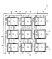
- FIG. 2 is a plan view showing a lead frame according to the first embodiment of the present invention.
- FIG. 3 is a cross-sectional view (cross-sectional view taken along the line III-III in FIG. 4) of the lead frame with resin according to the first embodiment of the present invention.
- FIG. 4 is a plan view showing a lead frame with resin according to the first embodiment of the present invention.
- FIG. 5 is a sectional view showing the semiconductor device according to the first embodiment of the present invention (a sectional view taken along line VV in FIG. 6).
- FIG. 6 is a plan view showing the semiconductor device according to the first embodiment of the present invention.
- 7A to 7G are views showing a lead frame manufacturing method according to the first embodiment of the present invention.
- FIGS. 8A to 8C are views showing a method for manufacturing a lead frame with resin according to the first embodiment of the present invention.
- FIGS. 9A to 9F are cross-sectional views showing a method of manufacturing a semiconductor device according to the first embodiment of the present invention.
- FIG. 10 is a cross-sectional view showing a state where the semiconductor device is arranged on the wiring board.
- FIG. 11 is a cross-sectional view showing a resin-attached lead frame according to the second embodiment of the present invention (cross-sectional view taken along line XI-XI in FIG. 12).
- FIG. 12 is a plan view showing a lead frame with a resin according to the second embodiment of the present invention.
- FIG. 13 is a sectional view showing a semiconductor device according to the second embodiment of the present invention (a sectional view taken along line XIII-XIII in FIG. 14).
- FIG. 14 is a plan view showing a semiconductor device according to the second embodiment of the present invention.
- FIGS. 15A to 15F are views showing a method of manufacturing a lead frame according to the second embodiment of the present invention.
- FIGS. 16A to 16D are views showing a method for manufacturing a lead frame with a resin according to the second embodiment of the present invention.
- FIG. 17 is a sectional view showing a modification of the lead frame with resin according to the second embodiment of the present invention.
- FIG. 18 is a cross-sectional view showing a modified example of the lead frame with resin according to the second embodiment of the present invention.
- FIG. 19 is a cross-sectional view showing a modified example of the lead frame with resin according to the second embodiment of the present invention.
- FIG. 20 is a cross-sectional view showing a modified example of the lead frame with resin according to the second embodiment of the present invention.
- FIGS. 1 and 2 are views showing a lead frame according to the present embodiment.
- the lead frame 15 shown in FIGS. 1 and 2 is provided on the surface of the lead frame main body 11 having a plurality of LED element mounting areas 14 and the LED element mounting areas 14 of the lead frame main body 11. And a metal layer 12 functioning as a reflective layer for reflecting light.
- the lead frame body 11 is made of a metal plate.
- the material of the metal plate constituting the lead frame body 11 include copper, copper alloy, 42 alloy (Ni 42% Fe alloy), and the like.
- the thickness of the lead frame body 11 is preferably 0.1 mm to 0.5 mm, although it depends on the configuration of the semiconductor device.
- the lead frame main body 11 has an outer frame 13, and the plurality of LED element placement regions 14 are arranged vertically and horizontally in the outer frame 13.
- the lead frame main body 11 has a plurality of die pads (LED element mounting portions) 25 and a plurality of lead portions 26 arranged away from each die pad 25.
- Each LED element mounting region 14 has Are formed on the respective die pads 25 and lead portions 26.
- a space 17 filled with the reflective resin portion 23 is formed between the die pad 25 and the lead portion 26.
- Each die pad 25 and each lead portion 26 are connected to another adjacent die pad 25, another adjacent lead portion 26, or the outer frame 13 by a bar-like tie bar 16.
- a first outer lead portion 27 is formed on the back surface of the die pad 25, and a second outer lead portion 28 is formed on the back surface of the lead portion 26.
- Each of the first outer lead portion 27 and the second outer lead portion 28 is provided with a silver plating layer 29 for improving the contact property with the solder.
- the thickness of the plating layer 29 is preferably 2 ⁇ m to 10 ⁇ m.
- the metal layer 12 may be formed, for example, by vapor deposition or sputtering, and examples of the material thereof include aluminum, silver, rhodium, palladium, platinum, and copper.
- the metal layer 12 is formed of an aluminum vapor deposition layer or an aluminum sputter layer will be described as an example (hereinafter also simply referred to as an aluminum vapor deposition layer or an aluminum sputter layer 12).
- This aluminum vapor deposition layer or aluminum sputter layer 12 functions as a reflective layer for reflecting the light from the LED element 21, and is located on the outermost surface side of the lead frame 15.
- This aluminum vapor deposition layer or aluminum sputter layer 12 is formed by vapor deposition or sputtering of aluminum (Al).
- the aluminum vapor deposition layer or the aluminum sputter layer 12 is formed to be extremely thin, and specifically, it is preferably 0.1 ⁇ m to 1 ⁇ m.
- the aluminum vapor deposition layer or the aluminum sputter layer 12 may be formed directly on the lead frame main body 11, but is formed on the lead frame main body 11 via a bonding layer made of, for example, a silver (Ag) plating layer. Also good.
- the aluminum vapor deposition layer or the aluminum sputter layer 12 is provided on the entire surface of the lead frame main body 11 including the outer frame 13 and the tie bar 16, but at least of the surface of the lead frame main body 11. What is necessary is just to be provided in each LED element mounting area
- the LED element placement area 14 is an area that is not covered by the reflective resin portion 23 (described later) in the lead frame body 11 and contributes to reflecting light from the LED element 21.
- the aluminum vapor deposition layer or the aluminum sputter layer 12 may not be provided on the portion of the surface of the lead frame body 11 where wire bonding is performed.
- the aluminum vapor deposition layer or the aluminum sputter layer 12 may not be provided on the portion of the surface of the lead frame body 11 where the LED element 21 is mounted.
- an aluminum vapor deposition layer or an aluminum sputter layer 12 is provided on the surface of the lead frame main body 11 via a bonding layer (not shown) made of a silver plating layer, and wire bonding is performed on the surface of the lead frame main body 11.
- the aluminum vapor deposition layer or the aluminum sputter layer 12 may not be provided in the portion.
- an aluminum vapor deposition layer or an aluminum sputter layer 12 is provided on the surface of the lead frame main body 11 via a bonding layer (not shown) made of a silver plating layer, and the LED element 21 on the surface of the lead frame main body 11. It is not necessary to provide the aluminum vapor deposition layer or the aluminum sputter layer 12 in the portion where the substrate is mounted.
- each LED element mounting region 14 in the lead frame body 11 is preferably mirror-finished in advance before the aluminum vapor deposition layer or the aluminum sputter layer 12 is provided.
- the roughness of the surface of each LED element mounting area 14 is an arithmetic average of the LED element mounting areas 14 measured using Ryoka System Co., Ltd., non-contact surface / layer cross-sectional shape measurement system, VertScan 2.0.
- the height Sa is 0.01 ⁇ m to 0.10 ⁇ m
- the roughness curve element average length Sm is 2 ⁇ m to 18 ⁇ m.
- a groove 18 is formed on the surface of the lead frame main body 11 for improving the adhesion between the lead frame main body 11 and the reflective resin portion 23.
- the groove 18 has a planar rectangular shape (excluding the space 17), and is provided along the outer peripheral edge of the LED element mounting region 14 on the surface of the lead frame main body 11.
- a symbol S indicates a region of the lead frame 15 corresponding to a semiconductor device 20 (FIGS. 5 and 6) described later.
- the lead frame main body 11 includes a plurality of die pads 25 and a plurality of lead portions 26 that are spaced apart from the die pads 25.
- the main body 11 only needs to have at least one die pad 25 and one lead part 26.
- FIG. 3 and 4 are views showing a resin-attached lead frame according to the present embodiment. 3 and 4, the same parts as those in FIGS. 1 and 2 are denoted by the same reference numerals.
- Such a lead frame 10 with resin includes a lead frame 15 and a reflective resin portion 23 provided on the lead frame 15 and surrounding the LED element mounting region 14.
- the lead frame 15 has a lead frame main body 11, and the lead frame main body 11 has a plurality of die pads 25 and a plurality of lead portions 26 arranged away from each die pad 25. Yes. LED element placement regions 14 are formed on the surfaces of the die pads 25 and the lead portions 26. Further, an aluminum vapor deposition layer or an aluminum sputter layer 12 is provided on the surface of each LED element mounting region 14 of the lead frame body 11. In FIG. 4, the aluminum vapor deposition layer or the aluminum sputtered layer 12 is indicated by oblique lines. The configuration of the lead frame 15 is the same as that shown in FIGS. 1 and 2 described above, and detailed description thereof is omitted here.
- the reflective resin portion 23 is integrated with the lead frame 15, and has a concave portion 23 a having a substantially rectangular shape surrounding the LED element 21.
- An inner wall 23b is formed inside the recess 23a.
- the reflective resin portion 23 is also filled in the space 17 between the die pad 25 and the lead portion 26. Details of the reflective resin portion 23 will be described later.
- the lead frame main body 11 includes a plurality of die pads 25 and a plurality of lead portions 26 that are spaced apart from the die pads 25.
- the main body 11 only needs to have at least one die pad 25 and one lead part 26.
- FIGS. 5 and 6 are diagrams showing a semiconductor device (SON type) according to the present embodiment.
- SON type semiconductor device
- FIGS. 5 and 6 the same parts as those in FIGS. 1 to 4 are denoted by the same reference numerals.
- the semiconductor device 20 includes a lead frame 15 (separated) having a lead frame main body 11 and an aluminum vapor deposition layer or an aluminum sputter layer 12, and a die pad 25 on the lead frame 15. And a bonding wire (conductive portion) 22 that electrically connects the lead portion 26 of the lead frame 15 and the LED element 21.
- the aluminum vapor deposition layer or the aluminum sputter layer 12 is indicated by oblique lines.
- a reflective resin portion 23 having a recess 23 a is provided so as to surround the LED element 21. Furthermore, the LED element 21 and the bonding wire 22 are sealed with a translucent sealing resin 24. The sealing resin 24 is filled in the concave portion 23 a of the reflective resin portion 23. In addition, the area
- the lead frame 15 is provided on the lead frame main body 11 having the die pad 25 and the lead portion 26 and the lead frame main body 11 and functions as a reflection layer for reflecting light from the LED element 21.
- An aluminum vapor deposition layer or an aluminum sputter layer 12 is provided.
- the LED element 21 selects an emission wavelength ranging from ultraviolet light to infrared light by appropriately selecting a material made of a compound semiconductor single crystal such as GaP, GaAs, GaAlAs, GaAsP, AlInGaP, or InGaN as a light emitting layer. can do.
- a material made of a compound semiconductor single crystal such as GaP, GaAs, GaAlAs, GaAsP, AlInGaP, or InGaN as a light emitting layer.
- a material made of a compound semiconductor single crystal such as GaP, GaAs, GaAlAs, GaAsP, AlInGaP, or InGaN as a light emitting layer.
- the LED element 21 is fixedly mounted on the die pad 25 (the aluminum vapor deposition layer or the aluminum sputter layer 12) in the recess 23a of the reflective resin portion 23 by solder or die bonding paste.
- solder or die bonding paste it is possible to select a die bonding paste made of an epoxy resin or a silicone resin having light resistance.
- the bonding wire 22 is made of a material having good conductivity such as gold, and one end thereof is connected to the terminal portion 21a of the LED element 21, and the other end is on the surface of the lead portion 26 of the lead frame body 11 (aluminum vapor deposition layer). Or on the aluminum sputter layer 12).
- the reflective resin portion 23 is formed by, for example, injection molding of a thermoplastic resin on the lead frame 10 with resin, or by injection molding or transfer molding of a thermosetting resin, for example.
- the shape of the reflective resin portion 23 can be variously realized by designing a mold used for injection molding or transfer molding.
- the overall shape of the reflective resin portion 23 may be a rectangular parallelepiped as shown in FIGS. 5 and 6, or may be a cylindrical shape or a cone shape.
- the bottom surface of the recess 23a can be rectangular, circular, elliptical, polygonal, or the like.
- the cross-sectional shape of the inner wall 23b of the recessed part 23a may be comprised from the straight line like FIG. 5, or may be comprised from the curve.
- thermoplastic resin or thermosetting resin used for the reflective resin portion 23 it is desirable to select a resin having excellent heat resistance, weather resistance and mechanical strength.
- Thermoplastic resins include polyamide, polyphthalamide (PPA), polyphenylene sulfide, liquid crystal polymer, polyethersulfone, polyetherimide and polybutylene terephthalate, polyolefin, cyclopolyolefin, etc. Epoxy, polyimide, etc. can be used.
- the bottom surface of the recess 23a and the inner wall 23b can be separated from the light emitting element.
- the sealing resin 24 it is desirable to select a material having a high light transmittance and a high refractive index at the emission wavelength of the semiconductor device 20 in order to improve the light extraction efficiency. Therefore, it is possible to select an epoxy resin or a silicone resin as a resin that satisfies the characteristics of high heat resistance, weather resistance, and mechanical strength.
- the sealing resin 24 is preferably made of a silicone resin having high weather resistance because the sealing resin 24 is exposed to strong light.
- a flat metal substrate 31 is prepared.
- a metal substrate made of copper, copper alloy, 42 alloy (Ni 42% Fe alloy) or the like can be used as described above.
- the surface 31a of the metal substrate 31 is previously mirror-finished so that the arithmetic average height Sa is 0.01 ⁇ m to 0.1 ⁇ m, and the roughness curve element average length Sm is 2 ⁇ m to 18 ⁇ m. It is preferable to keep it.
- a mirror surface rolling roller can be used at the time of the final rolling of material, or a double-sided mirror surface copper plating process can be mentioned, for example.
- photosensitive resists 32a and 33a are applied to the entire front and back surfaces of the metal substrate 31, respectively, and dried (FIG. 7B).
- photosensitive resists 32a and 33a conventionally known resists can be used.
- the metal substrate 31 is exposed through a photomask and developed to form etching resist layers 32 and 33 having desired openings 32b and 33b (FIG. 7C).
- etching is performed on the metal substrate 31 with a corrosive solution using the etching resist layers 32 and 33 as corrosion resistant films (FIG. 7D).
- the corrosive liquid can be appropriately selected according to the material of the metal substrate 31 to be used. For example, when copper is used as the metal substrate 31, an aqueous ferric chloride solution is usually used and sprayed from both surfaces of the metal substrate 31. It can be performed by etching.
- the etching resist layers 32 and 33 are peeled off and removed.
- the lead frame main body 11 having the die pad 25 and the lead portion 26 separated from the die pad 25 is obtained (FIG. 7E).
- a groove 18 is formed on the surface of the lead frame body 11 by half etching.
- a plating layer 29 is formed (FIG. 7F).
- the first outer lead portion 27 and the silver degreasing step, the pickling step, the chemical polishing step, the copper strike step, the water washing step, the neutral degreasing step, the cyan washing step, and the silver plating step are sequentially performed.
- a silver plating layer 29 is formed on the second outer lead portion 28.
- the plating solution for electrolytic plating include a silver plating solution mainly composed of silver cyanide. In the actual process, a water washing process is appropriately added between the processes as necessary.
- the lead frame body 11 is deposited on the lead frame body 11 by performing vapor deposition or sputtering on the surface of the lead frame body 11.
- the aluminum vapor deposition layer or the aluminum sputtered layer 12 which functions as a reflective layer is formed on the entire surface of the lead frame main body 11 including the LED element mounting region 14 (FIG. 7G).
- the formation of the aluminum vapor deposition layer or the aluminum sputter layer is not limited to this, but in the case of vapor deposition, the conditions for vacuum attainment 9 ⁇ 10 ⁇ 6 torr and rate 1.5 nm / second are:
- An aluminum vapor deposition layer 12 can be formed on the lead frame body 11. Further, in the case of sputtering, on the lead frame body 11 under the conditions of a vacuum level of 4 ⁇ 10 ⁇ 6 torr, a film formation vacuum level of 5 ⁇ 10 ⁇ 3 torr, and a power of 900 W (target size: 5 inches ⁇ 18 inches).
- An aluminum sputter layer 12 can be formed.
- the lead frame 15 having the lead frame main body 11 and the aluminum vapor deposition layer or the aluminum sputtered layer 12 formed on the lead frame main body 11 is obtained (FIG. 7G).
- the reflective resin portion 23 is formed on the aluminum vapor deposition layer or the aluminum sputter layer 12 of the lead frame 15. Hereinafter, each of these steps will be further described.
- the lead frame 15 obtained by the above-described steps is mounted in a mold 35 of an injection molding machine or a transfer molding machine (not shown) (FIG. 8A).
- a space 35 a corresponding to the shape of the reflective resin portion 23 is formed in the mold 35.
- thermosetting resin is poured into the mold 35 by a resin supply unit (not shown) of an injection molding machine or a transfer molding machine, and then cured to thereby form an LED element mounting region on the surface of the lead frame 15.
- a reflective resin portion 23 is formed in a portion other than 14 (FIG. 8B). At this time, the reflective resin portion 23 is also filled in the space 17 between the die pad 25 and the lead portion 26.
- the lead frame 15 in which the reflective resin portion 23 is formed is taken out from the mold 35.
- the lead frame with resin 10 (FIGS. 3 and 4) in which the reflective resin portion 23 and the lead frame 15 are integrally formed is obtained (FIG. 8C).
- the resin-made lead frame 10 including the lead frame 15 and the reflective resin portion 23 is manufactured (FIG. FIG. 9A).
- the LED element 21 is mounted on the die pad 25 of the lead frame 15.
- the LED element 21 is mounted on the die pad 25 (on the aluminum vapor deposition layer or the aluminum sputter layer 12) of the lead frame 15 and fixed by using solder or die bonding paste (die attach step) (FIG. 9 ( b)).
- the terminal portion 21a of the LED element 21 and the surface of the lead portion 26 of the lead frame 15 are electrically connected to each other by the bonding wire 22 (wire bonding step) (FIG. 9C).
- the sealing resin 24 is filled into the recess 23a of the reflective resin portion 23, and the LED element 21 and the bonding wire 22 are sealed with the sealing resin 24 (FIG. 9D).
- the reflective resin portion 23 between the LED elements 21 is diced to separate the lead frame 15 for each LED element 21 (FIG. 9E).
- the lead frame 15 is first placed and fixed on the dicing tape 37, and then the reflective resin portion 23 between the LED elements 21 is cut in the vertical direction by a blade 38 made of, for example, a diamond grindstone.
- FIG. 10 is a cross-sectional view showing a state where the semiconductor device according to the present embodiment is arranged on a wiring board.
- the semiconductor device 20 is arranged on a wiring board 41.
- a wiring board 41 has a board body 42 and wiring terminal portions 43 and 44 formed on the board body 42.
- one wiring terminal portion 43 is connected to the first outer lead portion 27 via one connection solder portion 45.
- the other wiring terminal portion 44 is connected to the second outer lead portion 28 via the other connecting solder portion 46.
- the light from the LED element 21 passes through the sealing resin 24 and is emitted from the surface of the sealing resin 24, or is reflected by the inner wall 23 b of the recess 23 a of the reflective resin portion 23, thereby causing the sealing resin 24. Released from the surface.
- the light from the LED element 21 is emitted from the surface of the sealing resin 24 by being reflected on the surface of the aluminum vapor deposition layer or the aluminum sputter layer 12.
- an aluminum vapor deposition layer or an aluminum sputter layer 12 is provided on the surface of the LED element mounting region 14 of the lead frame main body 11. Thereby, the light from the LED element 21 can be efficiently reflected, and the light extraction efficiency from the LED element 21 can be increased. Moreover, since the aluminum which comprises the aluminum vapor deposition layer or the aluminum sputter layer 12 does not deteriorate with the hydrogen sulfide in the air, deterioration with time of the lead frame 15 can be prevented.
- the aluminum vapor deposition layer or the aluminum sputter layer 12 is provided on the surface of each LED element mounting region 14 of the lead frame body 11. As a result, the light from the LED element 21 can be efficiently reflected to increase the light extraction efficiency from the LED element 21 and the deterioration of the lead frame 15 with time can be prevented.
- the adhesion between the lead frame 15 and the sealing resin 24 can be improved by providing the aluminum vapor deposition layer or the aluminum sputter layer 12. Moreover, the wire bonding property by the bonding wire 22 and the die attachability of the LED element 21 can be maintained well.
- an aluminum vapor deposition layer or an aluminum sputter layer 12 is provided via a bonding layer made of a silver plating layer, an alloy of the underlying silver (silver plating layer) and the wire is broken by breaking thin aluminum in the portion to be wire bonded. Since it is formed, the bondability is further improved and the wire bonding strength can be further increased.
- the energy for breaking the aluminum oxide film is not required at the time of wire bonding, so the conditions such as bonding temperature and ultrasonic wave can be relaxed. I can do it.
- the heat dissipation path through the die pad 25 is shortened, and as a result, the heat dissipation can be improved.
- the aluminum vapor deposition layer or the aluminum sputter layer 12 is provided via a bonding layer made of a silver plating layer, and the aluminum vapor deposition layer or the aluminum sputter layer 12 is not provided in the portion to be wire-bonded, the silver plating layer as in the conventional case Since the wire bonding can be performed directly on the upper surface, for example, the bonding strength with the gold bonding wire 22 can be kept high.
- the LED element 21 is When joining with solder, since the wetness of the solder of the part is good, a void does not generate
- FIGS. 11 to 16 are views showing a second embodiment of the present invention.
- the second embodiment shown in FIGS. 11 to 16 differs from the second embodiment in that an aluminum vapor deposition layer or an aluminum sputter layer 12 is also provided on the inner wall 23b of the reflective resin portion 23, and the other configurations are the same as those described above.
- This is substantially the same as the first embodiment.
- 11 to 16 the same parts as those of the embodiment shown in FIGS. 1 to 10 are denoted by the same reference numerals, and detailed description thereof is omitted.
- 11 and 12 are diagrams showing a resin-attached lead frame according to the present embodiment.
- the lead frame with resin 10A includes a lead frame 15 and a reflective resin portion.
- the lead frame 15 has a lead frame main body 11, and the lead frame main body 11 has a plurality of die pads 25 and a plurality of lead portions 26 that are arranged apart from the die pads 25. .
- LED element placement regions 14 are formed on the surfaces of the die pads 25 and the lead portions 26.
- the reflective resin portion 23 is provided so as to surround each LED element mounting region 14 of the lead frame main body 11.
- the metal layer (in this case, the aluminum vapor deposition layer or the aluminum sputter layer) 12 is also applied to the inner wall 23b of the reflective resin portion 23 in addition to the surface of each LED element mounting region 14 of the lead frame body 11. Is provided. That is, the aluminum vapor deposition layer or the aluminum sputter layer 12 continuously extends from the surface of the LED element mounting region 14 along the inner wall 23 b of the reflective resin portion 23. In FIG. 12, the aluminum vapor deposition layer or the aluminum sputter layer 12 is indicated by oblique lines.
- the metal layer 12 formed on the surface of the LED element mounting region 14 and the inner wall 23b of the reflective resin portion 23 is not limited to an aluminum vapor deposition layer or an aluminum sputter layer, but silver, rhodium, palladium, platinum, copper, etc. It may consist of layers of
- the aluminum vapor deposition layer or the aluminum sputter layer 12 is not provided between the lead frame main body 11 and the reflective resin portion 23. It is provided only on each LED element placement region 14 on the surface of the main body 11.
- an aluminum vapor deposition layer or an aluminum sputter layer 12 is formed on a portion of the inner wall 23b of the reflective resin portion 23 adjacent to the space 17. Is not provided.
- the lead frame main body 11 includes a plurality of die pads 25 and a plurality of lead portions 26 that are spaced apart from the die pads 25.
- the main body 11 only needs to have at least one die pad 25 and one lead part 26.
- FIG. 17 shows a lead frame with resin 10A according to a modification of the present embodiment.
- a reflective metal layer 51 is provided on the upper surface 23 c of the reflective resin portion 23.
- the reflective metal layer 51 may be made of an aluminum vapor deposition layer or an aluminum sputter layer, and may be made of other types of metal layers (for example, silver, rhodium, palladium, platinum, copper, etc.).
- a part of the light emitted from the LED element 21 may be reflected inside the lighting device and return to the upper part of the semiconductor device 20.
- By providing 51 it is possible to prevent the light returning to the upper part of the semiconductor device 20 from being absorbed by the semiconductor device 20.
- FIG. 18 shows a lead frame with resin 10A according to another modification.
- a reflective metal layer is formed on a portion 23d of the upper surface 23c of the reflective resin portion 23 cut by dicing (see FIG. 9E).
- the reflective resin portion 23 is exposed without 51 being provided.
- a reflective metal layer 51 is provided in a region of the upper surface 23c of the reflective resin portion 23 other than the portion 23d cut by dicing.
- the portion 23d where the reflective resin portion 23 is exposed may be a substantially central portion of the upper surface 23c of the reflective resin portion 23, or may be a position shifted in the horizontal direction from the central portion of the upper surface 23c.
- metal powder such as aluminum having good conductivity is not included in the cutting waste during dicing, it is possible to prevent a short circuit due to metal foreign matter remaining after cutting.
- FIG. 19 shows a lead frame with resin 10A according to another modification.
- a concave portion 52 that is recessed inward is formed at a substantially central portion of the upper surface 23c of the reflective resin portion 23.
- the reflective metal layer 51 is provided over the entire area in the recess 52 (including the bottom surface 52 a).
- this portion has a property of absorbing light.
- the semiconductor device 20 is incorporated in the lighting device, part of the light emitted from the LED element 21 may be reflected inside the lighting device and return to the upper portion of the semiconductor device 20.
- FIG. 19 by reducing the region that absorbs light (the portion cut by dicing), it is possible to prevent the light that has returned to the top of the semiconductor device 20 from being absorbed by the semiconductor device 20.
- FIG. 20 shows a lead frame with resin 10A according to another modification.
- the reflective metal layer 51 is formed on the bottom surface 52a which is a portion cut by dicing (see FIG. 9E) in the recess 52.
- the reflective resin portion 23 is exposed without being provided.
- a reflective metal layer 51 is provided in a region other than the bottom surface 52 a in the recess 52. In this case, the light returning to the upper part of the semiconductor device 20 can be prevented from being absorbed by the semiconductor device 20. Further, since metal powder such as aluminum having good conductivity is not included in the cutting waste during dicing, it is possible to prevent a short circuit due to metal foreign matters remaining after cutting.
- FIG. 13 and 14 are diagrams showing a semiconductor device (SON type).
- the semiconductor device 20 ⁇ / b> A includes a lead frame 15 having a lead frame body 11 and an aluminum vapor deposition layer or an aluminum sputter layer 12 (individualized), and a die pad 25 on the lead frame 15. And a bonding wire (conductive portion) 22 that electrically connects the lead portion 26 of the lead frame 15 and the LED element 21.
- a reflective resin portion 23 is provided so as to surround the LED element 21. Furthermore, the LED element 21 and the bonding wire 22 are sealed with a translucent sealing resin 24.
- the aluminum vapor deposition layer or the aluminum sputter layer 12 is provided on the inner wall 23b of the reflective resin portion 23 in addition to the surface of each LED element mounting region 14 of the lead frame body 11.
- the aluminum vapor deposition layer or the aluminum sputtered layer 12 is indicated by oblique lines.
- FIGS. 11 and 12 a manufacturing method of the lead frame with resin 10A shown in FIGS. 11 and 12 will be described with reference to FIGS. 15 (a)-(f) and FIGS. 16 (a)-(d). To do. The following description will focus on differences from the steps shown in FIGS. 7 (a)-(g) and FIGS. 8 (a)-(c).
- the lead frame main body 11 having the die pad 25 and the lead portion 26 arranged away from the die pad 25 is manufactured (FIG. 15A). -(E)).
- a silver plating layer 29 is formed on each of the first outer lead portion 27 and the second outer lead portion 28 by performing electroplating on the back surface of the lead frame main body 11. Thereby, the lead frame 15 is obtained (FIG. 15F). Alternatively, silver plating may be applied to the entire surface of the lead frame main body 11 at this time.
- the lead frame 15 and the reflection resin portion 23 are integrally formed by forming the reflection resin portion 23 on the surface of the lead frame main body 11 (FIGS. 16A to 16C).
- the steps of forming the reflective resin portion 23 are the same as those described above except that the reflective resin portion 23 is formed before the aluminum vapor deposition layer or the aluminum sputter layer 12 is formed. This is substantially the same as the steps shown in FIGS.
- the aluminum vapor deposition layer or the aluminum sputter layer 12 is formed by performing vapor deposition or sputtering on the LED element placement region 14 of the lead frame main body 11 and the inner wall 23b of the reflective resin portion 23 (FIG. 16D). )). In this way, the lead frame with resin 10A shown in FIGS. 11 and 12 is obtained.
- the aluminum vapor deposition layer or the aluminum sputter layer 12 is also provided on the inner wall 23 b of the reflective resin portion 23. Since aluminum constituting the aluminum vapor deposition layer or the aluminum sputter layer 12 is not deteriorated by the ultraviolet rays from the LED elements 21, the reflective resin portion 23 can be prevented from being deteriorated by ultraviolet rays over time.
Abstract
Priority Applications (5)
| Application Number | Priority Date | Filing Date | Title |
|---|---|---|---|
| US13/980,980 US9461220B2 (en) | 2011-01-27 | 2012-01-24 | Resin-attached lead frame, method for manufacturing the same, and lead frame |
| CN201280005657.6A CN103348499B (zh) | 2011-01-27 | 2012-01-24 | 带树脂的引线框和其制造方法、以及引线框 |
| JP2012554800A JP5861943B2 (ja) | 2011-01-27 | 2012-01-24 | 樹脂付リードフレームおよびその製造方法、ならびにリードフレーム |
| KR1020137016578A KR101760545B1 (ko) | 2011-01-27 | 2012-01-24 | 수지 부착 리드 프레임 및 그 제조 방법, 및 리드 프레임 |
| US15/246,608 US9806241B2 (en) | 2011-01-27 | 2016-08-25 | Resin-attached lead frame and semiconductor device |
Applications Claiming Priority (2)
| Application Number | Priority Date | Filing Date | Title |
|---|---|---|---|
| JP2011-015274 | 2011-01-27 | ||
| JP2011015274 | 2011-01-27 |
Related Child Applications (2)
| Application Number | Title | Priority Date | Filing Date |
|---|---|---|---|
| US13/980,980 A-371-Of-International US9461220B2 (en) | 2011-01-27 | 2012-01-24 | Resin-attached lead frame, method for manufacturing the same, and lead frame |
| US15/246,608 Continuation US9806241B2 (en) | 2011-01-27 | 2016-08-25 | Resin-attached lead frame and semiconductor device |
Publications (1)
| Publication Number | Publication Date |
|---|---|
| WO2012102266A1 true WO2012102266A1 (fr) | 2012-08-02 |
Family
ID=46580832
Family Applications (1)
| Application Number | Title | Priority Date | Filing Date |
|---|---|---|---|
| PCT/JP2012/051432 WO2012102266A1 (fr) | 2011-01-27 | 2012-01-24 | Châssis de brochage fixé par résine, son procédé de fabrication, et châssis de brochage |
Country Status (6)
| Country | Link |
|---|---|
| US (2) | US9461220B2 (fr) |
| JP (1) | JP5861943B2 (fr) |
| KR (1) | KR101760545B1 (fr) |
| CN (1) | CN103348499B (fr) |
| TW (1) | TW201250964A (fr) |
| WO (1) | WO2012102266A1 (fr) |
Cited By (14)
| Publication number | Priority date | Publication date | Assignee | Title |
|---|---|---|---|---|
| JP2014096550A (ja) * | 2012-11-09 | 2014-05-22 | Fusheng Industrial Co Ltd | 発光ダイオードのフレーム構造の製造方法(四) |
| JP2014112614A (ja) * | 2012-12-05 | 2014-06-19 | Dainippon Printing Co Ltd | 光半導体装置用リードフレーム、樹脂付き光半導体装置用リードフレーム、リードフレームの多面付け体、樹脂付きリードフレームの多面付け体、光半導体装置、光半導体装置の多面付け体 |
| JP2014112616A (ja) * | 2012-12-05 | 2014-06-19 | Dainippon Printing Co Ltd | 光半導体装置用リードフレーム、樹脂付き光半導体装置用リードフレーム、リードフレームの多面付け体、樹脂付きリードフレームの多面付け体、光半導体装置、光半導体装置の多面付け体 |
| JP2015056425A (ja) * | 2013-09-10 | 2015-03-23 | 大日本印刷株式会社 | 光半導体装置、光半導体装置用リードフレーム、及びそれらの製造方法 |
| JP2016032082A (ja) * | 2014-07-30 | 2016-03-07 | シチズン電子株式会社 | メッキ膜の剥離防止方法、部品集合体および発光装置 |
| JP2016086059A (ja) * | 2014-10-24 | 2016-05-19 | 日亜化学工業株式会社 | 発光装置、パッケージ及びそれらの製造方法 |
| WO2017056321A1 (fr) * | 2015-10-02 | 2017-04-06 | 大日本印刷株式会社 | Grille de connexion à résine et son procédé de fabrication, conditionnement de diode électroluminescente et son procédé de fabrication |
| JP2017157684A (ja) * | 2016-03-02 | 2017-09-07 | ローム株式会社 | 発光装置およびその製造方法 |
| JP2017183662A (ja) * | 2016-03-31 | 2017-10-05 | 古河電気工業株式会社 | リードフレーム材料およびその製造方法 |
| WO2018147325A1 (fr) * | 2017-02-09 | 2018-08-16 | 株式会社アクアバンク | Unité de stérilisation de boisson et dispositif d'alimentation en eau potable équipé de cette dernière |
| JP2019016620A (ja) * | 2017-07-03 | 2019-01-31 | 株式会社沖データ | 光源用反射体、光源及び光源用反射体の製造方法 |
| JP2019016740A (ja) * | 2017-07-10 | 2019-01-31 | 新光電気工業株式会社 | リードフレーム、半導体装置、及びリードフレームの製造方法 |
| JP2019046938A (ja) * | 2017-08-31 | 2019-03-22 | 日亜化学工業株式会社 | パッケージの製造方法及び発光装置の製造方法 |
| US10777719B2 (en) | 2018-04-10 | 2020-09-15 | Nichia Corporation | Base member, and method of manufacturing light emitting device using same |
Families Citing this family (33)
| Publication number | Priority date | Publication date | Assignee | Title |
|---|---|---|---|---|
| US8878215B2 (en) * | 2011-06-22 | 2014-11-04 | Lg Innotek Co., Ltd. | Light emitting device module |
| DE102012104882B4 (de) * | 2012-06-05 | 2017-06-08 | Osram Opto Semiconductors Gmbh | Verfahren zur Herstellung von optoelektronischen Halbleiterbauteilen und damit hergestelltes optoelektronisches Halbleiterbauteil |
| US9748164B2 (en) * | 2013-03-05 | 2017-08-29 | Nichia Corporation | Semiconductor device |
| US10242934B1 (en) * | 2014-05-07 | 2019-03-26 | Utac Headquarters Pte Ltd. | Semiconductor package with full plating on contact side surfaces and methods thereof |
| TWI553264B (zh) | 2014-05-23 | 2016-10-11 | 億光電子工業股份有限公司 | 承載支架及其製造方法以及從該承載支架所製得之發光裝置及其製造方法 |
| US10177292B2 (en) | 2014-05-23 | 2019-01-08 | Everlight Electronics Co., Ltd. | Carrier, carrier leadframe, and light emitting device |
| JP6493952B2 (ja) * | 2014-08-26 | 2019-04-03 | 大口マテリアル株式会社 | リードフレーム及びその製造方法 |
| US9379087B2 (en) * | 2014-11-07 | 2016-06-28 | Texas Instruments Incorporated | Method of making a QFN package |
| JP6362111B2 (ja) * | 2014-12-01 | 2018-07-25 | 大口マテリアル株式会社 | リードフレームの製造方法 |
| JP6270052B2 (ja) * | 2014-12-05 | 2018-01-31 | Shマテリアル株式会社 | リードフレーム及びその製造方法 |
| US9590158B2 (en) | 2014-12-22 | 2017-03-07 | Nichia Corporation | Light emitting device |
| US9859481B2 (en) * | 2014-12-22 | 2018-01-02 | Nichia Corporation | Light emitting device |
| JP2016207739A (ja) | 2015-04-17 | 2016-12-08 | 株式会社東芝 | 半導体発光装置及びその製造方法 |
| US10312168B2 (en) * | 2015-06-18 | 2019-06-04 | Kyocera Corporation | Electronic element mounting substrate, and electronic device |
| JP6337859B2 (ja) | 2015-09-08 | 2018-06-06 | 日亜化学工業株式会社 | 発光装置 |
| US20170294367A1 (en) * | 2016-04-07 | 2017-10-12 | Microchip Technology Incorporated | Flat No-Leads Package With Improved Contact Pins |
| JP6644978B2 (ja) * | 2016-07-25 | 2020-02-12 | 大口マテリアル株式会社 | 半導体素子搭載用基板及び半導体装置、並びにそれらの製造方法 |
| JP6825780B2 (ja) * | 2016-07-27 | 2021-02-03 | 大口マテリアル株式会社 | 多列型led用配線部材及びその製造方法 |
| US10700252B2 (en) * | 2017-04-18 | 2020-06-30 | Bridgelux Chongqing Co., Ltd. | System and method of manufacture for LED packages |
| CN108933185B (zh) * | 2017-05-26 | 2021-01-05 | 黄国益 | 支撑结构、使用其的发光装置以及其加工方法 |
| US10672954B2 (en) * | 2017-09-01 | 2020-06-02 | Lg Innotek Co., Ltd. | Light emitting device package |
| KR102641336B1 (ko) * | 2017-09-05 | 2024-02-28 | 쑤저우 레킨 세미컨덕터 컴퍼니 리미티드 | 반도체 소자 패키지 |
| KR102379733B1 (ko) * | 2017-09-15 | 2022-03-28 | 쑤저우 레킨 세미컨덕터 컴퍼니 리미티드 | 발광소자 패키지 |
| KR102401826B1 (ko) | 2017-09-15 | 2022-05-25 | 쑤저우 레킨 세미컨덕터 컴퍼니 리미티드 | 발광소자 패키지 및 이를 포함하는 조명장치 |
| KR102359594B1 (ko) * | 2017-09-19 | 2022-02-07 | 엘지디스플레이 주식회사 | 복합 무기 발광 재료, 발광 필름, 이를 포함하는 엘이디 패키지, 발광다이오드 및 발광장치 |
| CN108321283A (zh) * | 2018-04-03 | 2018-07-24 | 江苏鸿利国泽光电科技有限公司 | 一种高光效紫外led的封装支架及其封装方法 |
| JP7174240B2 (ja) * | 2018-11-30 | 2022-11-17 | 日亜化学工業株式会社 | 発光装置の製造方法 |
| JP6947988B2 (ja) * | 2019-01-28 | 2021-10-13 | 日亜化学工業株式会社 | 発光装置の製造方法 |
| CN111724741A (zh) * | 2020-06-09 | 2020-09-29 | 武汉华星光电半导体显示技术有限公司 | 覆晶薄膜及其制备方法 |
| JP2022014288A (ja) * | 2020-07-06 | 2022-01-19 | 日亜化学工業株式会社 | 発光装置及び発光装置の製造方法 |
| TWM606836U (zh) * | 2020-09-18 | 2021-01-21 | 長華科技股份有限公司 | 導線架 |
| US11715678B2 (en) * | 2020-12-31 | 2023-08-01 | Texas Instruments Incorporated | Roughened conductive components |
| CN113113321B (zh) * | 2021-03-26 | 2022-02-11 | 昆山弗莱吉电子科技有限公司 | 半导体高密度引线框架及其制造工艺 |
Citations (7)
| Publication number | Priority date | Publication date | Assignee | Title |
|---|---|---|---|---|
| JP2004165567A (ja) * | 2002-11-15 | 2004-06-10 | Mitsui High Tec Inc | プリモールドパッケージ用リードフレーム及びその製造方法並びにプリモールドパッケージ及びその製造方法 |
| JP2005019688A (ja) * | 2003-06-26 | 2005-01-20 | Kyocera Corp | 発光素子収納用パッケージおよび発光装置 |
| JP2006156747A (ja) * | 2004-11-30 | 2006-06-15 | Ngk Spark Plug Co Ltd | 配線基板 |
| JP2007294631A (ja) * | 2006-04-25 | 2007-11-08 | Matsushita Electric Works Ltd | 樹脂反射鏡及びこれを用いた照明器具 |
| JP2008172125A (ja) * | 2007-01-15 | 2008-07-24 | Citizen Electronics Co Ltd | チップ型led発光装置及びその製造方法 |
| WO2010026716A1 (fr) * | 2008-09-03 | 2010-03-11 | 日亜化学工業株式会社 | Dispositif émetteur de lumière, conditionnement de résine, corps moulé en résine et procédés de fabrication d'un dispositif émetteur de lumière, d'un conditionnement de résine et d'un corps moulé en résine |
| JP2011003853A (ja) * | 2009-06-22 | 2011-01-06 | Stanley Electric Co Ltd | 発光装置の製造方法、発光装置および発光装置搭載用基板 |
Family Cites Families (19)
| Publication number | Priority date | Publication date | Assignee | Title |
|---|---|---|---|---|
| JP2632528B2 (ja) * | 1988-02-08 | 1997-07-23 | 新光電気工業株式会社 | リードフレーム |
| JP2000183407A (ja) * | 1998-12-16 | 2000-06-30 | Rohm Co Ltd | 光半導体装置 |
| JP3940124B2 (ja) * | 2003-01-16 | 2007-07-04 | 松下電器産業株式会社 | 装置 |
| JP4493013B2 (ja) | 2003-10-08 | 2010-06-30 | 日亜化学工業株式会社 | 半導体装置 |
| TWI245437B (en) | 2004-11-16 | 2005-12-11 | Lighthouse Technology Co Ltd | Package structure of a surface mount device light emitting diode |
| JP2006344925A (ja) * | 2005-05-11 | 2006-12-21 | Sharp Corp | 発光素子搭載用フレームおよび発光装置 |
| US7906794B2 (en) * | 2006-07-05 | 2011-03-15 | Koninklijke Philips Electronics N.V. | Light emitting device package with frame and optically transmissive element |
| TW200847478A (en) * | 2007-05-30 | 2008-12-01 | I Chiun Precision Ind Co Ltd | Light-emitting diode lead frame and manufacture method thereof |
| JP4758976B2 (ja) * | 2007-12-03 | 2011-08-31 | 日立ケーブルプレシジョン株式会社 | 半導体発光素子搭載用リードフレーム及びその製造方法並びに発光装置 |
| US8378369B2 (en) * | 2008-09-09 | 2013-02-19 | Showa Denko K.K. | Light emitting unit, light emitting module, and display device |
| WO2010035944A2 (fr) * | 2008-09-29 | 2010-04-01 | 서울반도체 주식회사 | Dispositif électroluminescent |
| US8288785B2 (en) * | 2008-12-03 | 2012-10-16 | Seoul Semiconductor Co., Ltd. | Lead frame having light-reflecting layer, light emitting diode having the lead frame, and backlight unit having the light emitting diode |
| TWI393275B (zh) * | 2009-02-04 | 2013-04-11 | Everlight Electronics Co Ltd | 發光二極體封裝體及其製造方法 |
| TWI485878B (zh) * | 2009-04-01 | 2015-05-21 | Lite On Technology Corp | 形成發光二極體之透鏡結構之方法及其相關架構 |
| WO2011125346A1 (fr) * | 2010-04-07 | 2011-10-13 | シャープ株式会社 | Dispositif électroluminescent et son procédé de fabrication associé |
| TWM400099U (en) * | 2010-09-27 | 2011-03-11 | Silitek Electronic Guangzhou | Lead frame, package structure and lighting device thereof |
| KR101778832B1 (ko) * | 2010-11-02 | 2017-09-14 | 다이니폰 인사츠 가부시키가이샤 | Led 소자 탑재용 리드 프레임, 수지 부착 리드 프레임, 반도체 장치의 제조 방법 및 반도체 소자 탑재용 리드 프레임 |
| US9209373B2 (en) * | 2011-02-23 | 2015-12-08 | Intellectual Discovery Co., Ltd. | High power plastic leaded chip carrier with integrated metal reflector cup and direct heat sink |
| US8846421B2 (en) * | 2011-03-10 | 2014-09-30 | Mds Co. Ltd. | Method of manufacturing lead frame for light-emitting device package and light-emitting device package |
-
2012
- 2012-01-20 TW TW101102701A patent/TW201250964A/zh unknown
- 2012-01-24 JP JP2012554800A patent/JP5861943B2/ja active Active
- 2012-01-24 CN CN201280005657.6A patent/CN103348499B/zh not_active Expired - Fee Related
- 2012-01-24 WO PCT/JP2012/051432 patent/WO2012102266A1/fr active Application Filing
- 2012-01-24 US US13/980,980 patent/US9461220B2/en active Active
- 2012-01-24 KR KR1020137016578A patent/KR101760545B1/ko active IP Right Grant
-
2016
- 2016-08-25 US US15/246,608 patent/US9806241B2/en not_active Expired - Fee Related
Patent Citations (7)
| Publication number | Priority date | Publication date | Assignee | Title |
|---|---|---|---|---|
| JP2004165567A (ja) * | 2002-11-15 | 2004-06-10 | Mitsui High Tec Inc | プリモールドパッケージ用リードフレーム及びその製造方法並びにプリモールドパッケージ及びその製造方法 |
| JP2005019688A (ja) * | 2003-06-26 | 2005-01-20 | Kyocera Corp | 発光素子収納用パッケージおよび発光装置 |
| JP2006156747A (ja) * | 2004-11-30 | 2006-06-15 | Ngk Spark Plug Co Ltd | 配線基板 |
| JP2007294631A (ja) * | 2006-04-25 | 2007-11-08 | Matsushita Electric Works Ltd | 樹脂反射鏡及びこれを用いた照明器具 |
| JP2008172125A (ja) * | 2007-01-15 | 2008-07-24 | Citizen Electronics Co Ltd | チップ型led発光装置及びその製造方法 |
| WO2010026716A1 (fr) * | 2008-09-03 | 2010-03-11 | 日亜化学工業株式会社 | Dispositif émetteur de lumière, conditionnement de résine, corps moulé en résine et procédés de fabrication d'un dispositif émetteur de lumière, d'un conditionnement de résine et d'un corps moulé en résine |
| JP2011003853A (ja) * | 2009-06-22 | 2011-01-06 | Stanley Electric Co Ltd | 発光装置の製造方法、発光装置および発光装置搭載用基板 |
Cited By (16)
| Publication number | Priority date | Publication date | Assignee | Title |
|---|---|---|---|---|
| JP2014096550A (ja) * | 2012-11-09 | 2014-05-22 | Fusheng Industrial Co Ltd | 発光ダイオードのフレーム構造の製造方法(四) |
| JP2014112614A (ja) * | 2012-12-05 | 2014-06-19 | Dainippon Printing Co Ltd | 光半導体装置用リードフレーム、樹脂付き光半導体装置用リードフレーム、リードフレームの多面付け体、樹脂付きリードフレームの多面付け体、光半導体装置、光半導体装置の多面付け体 |
| JP2014112616A (ja) * | 2012-12-05 | 2014-06-19 | Dainippon Printing Co Ltd | 光半導体装置用リードフレーム、樹脂付き光半導体装置用リードフレーム、リードフレームの多面付け体、樹脂付きリードフレームの多面付け体、光半導体装置、光半導体装置の多面付け体 |
| JP2015056425A (ja) * | 2013-09-10 | 2015-03-23 | 大日本印刷株式会社 | 光半導体装置、光半導体装置用リードフレーム、及びそれらの製造方法 |
| JP2016032082A (ja) * | 2014-07-30 | 2016-03-07 | シチズン電子株式会社 | メッキ膜の剥離防止方法、部品集合体および発光装置 |
| JP2016086059A (ja) * | 2014-10-24 | 2016-05-19 | 日亜化学工業株式会社 | 発光装置、パッケージ及びそれらの製造方法 |
| WO2017056321A1 (fr) * | 2015-10-02 | 2017-04-06 | 大日本印刷株式会社 | Grille de connexion à résine et son procédé de fabrication, conditionnement de diode électroluminescente et son procédé de fabrication |
| JP2017157684A (ja) * | 2016-03-02 | 2017-09-07 | ローム株式会社 | 発光装置およびその製造方法 |
| JP2017183662A (ja) * | 2016-03-31 | 2017-10-05 | 古河電気工業株式会社 | リードフレーム材料およびその製造方法 |
| WO2018147325A1 (fr) * | 2017-02-09 | 2018-08-16 | 株式会社アクアバンク | Unité de stérilisation de boisson et dispositif d'alimentation en eau potable équipé de cette dernière |
| JPWO2018147325A1 (ja) * | 2017-02-09 | 2019-11-07 | 株式会社アクアバンク | 飲料殺菌ユニットおよびこれを備えた飲料水供給装置 |
| JP2019016620A (ja) * | 2017-07-03 | 2019-01-31 | 株式会社沖データ | 光源用反射体、光源及び光源用反射体の製造方法 |
| JP2019016740A (ja) * | 2017-07-10 | 2019-01-31 | 新光電気工業株式会社 | リードフレーム、半導体装置、及びリードフレームの製造方法 |
| JP2019046938A (ja) * | 2017-08-31 | 2019-03-22 | 日亜化学工業株式会社 | パッケージの製造方法及び発光装置の製造方法 |
| JP7116881B2 (ja) | 2017-08-31 | 2022-08-12 | 日亜化学工業株式会社 | パッケージの製造方法及び発光装置の製造方法 |
| US10777719B2 (en) | 2018-04-10 | 2020-09-15 | Nichia Corporation | Base member, and method of manufacturing light emitting device using same |
Also Published As
| Publication number | Publication date |
|---|---|
| US20130307000A1 (en) | 2013-11-21 |
| JP5861943B2 (ja) | 2016-02-16 |
| US9806241B2 (en) | 2017-10-31 |
| CN103348499B (zh) | 2016-08-10 |
| KR20130140097A (ko) | 2013-12-23 |
| CN103348499A (zh) | 2013-10-09 |
| TW201250964A (en) | 2012-12-16 |
| JPWO2012102266A1 (ja) | 2014-06-30 |
| US20160365495A1 (en) | 2016-12-15 |
| KR101760545B1 (ko) | 2017-07-21 |
| US9461220B2 (en) | 2016-10-04 |
Similar Documents
| Publication | Publication Date | Title |
|---|---|---|
| JP5861943B2 (ja) | 樹脂付リードフレームおよびその製造方法、ならびにリードフレーム | |
| JP5818149B2 (ja) | 樹脂付リードフレーム、半導体装置、照明装置、樹脂付リードフレームの製造方法および半導体装置の製造方法 | |
| JP5922326B2 (ja) | Led用リードフレームまたは基板およびその製造方法、ならびに半導体装置およびその製造方法 | |
| TWI397193B (zh) | Light emitting diode chip element with heat dissipation substrate and method for making the same | |
| JP5582382B2 (ja) | リードフレームおよびその製造方法、ならびに半導体装置およびその製造方法 | |
| JP2011146524A (ja) | リードフレームおよびその製造方法、ならびに半導体装置およびその製造方法 | |
| JP2012146816A (ja) | 半導体装置およびその製造方法ならびに照明装置 | |
| WO2013121708A1 (fr) | Appareil électroluminescent et son procédé de fabrication | |
| JP5904001B2 (ja) | Led素子搭載用リードフレーム、樹脂付リードフレーム、多面付ledパッケージ、ledパッケージの製造方法および半導体素子搭載用リードフレーム | |
| JP5737605B2 (ja) | Led用リードフレームまたは基板およびその製造方法、ならびに半導体装置およびその製造方法 | |
| JP5970835B2 (ja) | リードフレーム部材、樹脂付リードフレーム部材および半導体装置 | |
| JP5871174B2 (ja) | Led用リードフレームまたは基板、半導体装置、およびled用リードフレームまたは基板の製造方法 | |
| JP2011228687A (ja) | Led用リードフレームまたは基板、半導体装置、およびled用リードフレームまたは基板の製造方法 | |
| JP2014207481A (ja) | リードフレームおよびその製造方法、ならびに半導体装置およびその製造方法 | |
| JP6071034B2 (ja) | Led素子搭載用リードフレーム、樹脂付リードフレーム、多面付ledパッケージ、ledパッケージの製造方法および半導体素子搭載用リードフレーム | |
| JP2016026398A (ja) | リードフレームおよびその製造方法、ならびに半導体装置およびその製造方法 | |
| JP5804369B2 (ja) | 半導体素子用リードフレーム、樹脂付半導体素子用リードフレームおよび半導体装置、並びに、半導体素子用リードフレームの製造方法、樹脂付半導体素子用リードフレームの製造方法および半導体装置の製造方法 | |
| JP5888098B2 (ja) | Led素子搭載用リードフレーム、樹脂付リードフレーム、多面付ledパッケージ、ledパッケージの製造方法および半導体素子搭載用リードフレーム | |
| KR101321887B1 (ko) | 조명용 엘이디모듈의 리드프레임 | |
| JP6697720B2 (ja) | 半導体装置およびその製造方法ならびに照明装置 | |
| JP6350683B2 (ja) | Led素子搭載用リードフレーム、樹脂付リードフレーム、多面付ledパッケージ、ledパッケージの製造方法および半導体素子搭載用リードフレーム | |
| JP5998609B2 (ja) | 光半導体装置 | |
| JP5867261B2 (ja) | 光半導体装置用リードフレーム、光半導体装置、および、それらの製造方法 | |
| JP2015195412A (ja) | 半導体素子用リードフレーム、樹脂付半導体素子用リードフレームおよび半導体装置、並びに、半導体素子用リードフレームの製造方法、樹脂付半導体素子用リードフレームの製造方法および半導体装置の製造方法 | |
| JP2015181203A (ja) | 樹脂付リードフレーム、半導体装置および照明装置 |
Legal Events
| Date | Code | Title | Description |
|---|---|---|---|
| 121 | Ep: the epo has been informed by wipo that ep was designated in this application |
Ref document number: 12738905 Country of ref document: EP Kind code of ref document: A1 |
|
| WWE | Wipo information: entry into national phase |
Ref document number: 2012554800 Country of ref document: JP |
|
| ENP | Entry into the national phase |
Ref document number: 20137016578 Country of ref document: KR Kind code of ref document: A |
|
| WWE | Wipo information: entry into national phase |
Ref document number: 13980980 Country of ref document: US |
|
| NENP | Non-entry into the national phase |
Ref country code: DE |
|
| 122 | Ep: pct application non-entry in european phase |
Ref document number: 12738905 Country of ref document: EP Kind code of ref document: A1 |