WO2011108162A1 - 金属微粒子担持触媒体及びその利用 - Google Patents
金属微粒子担持触媒体及びその利用 Download PDFInfo
- Publication number
- WO2011108162A1 WO2011108162A1 PCT/JP2010/071341 JP2010071341W WO2011108162A1 WO 2011108162 A1 WO2011108162 A1 WO 2011108162A1 JP 2010071341 W JP2010071341 W JP 2010071341W WO 2011108162 A1 WO2011108162 A1 WO 2011108162A1
- Authority
- WO
- WIPO (PCT)
- Prior art keywords
- metal
- fine particles
- catalyst body
- carrier
- compound
- Prior art date
Links
- 229910052751 metal Inorganic materials 0.000 title claims abstract description 120
- 239000002184 metal Substances 0.000 title claims abstract description 119
- 239000003054 catalyst Substances 0.000 title claims abstract description 99
- 239000011859 microparticle Substances 0.000 title abstract 7
- 229910000510 noble metal Inorganic materials 0.000 claims abstract description 99
- 238000006243 chemical reaction Methods 0.000 claims abstract description 43
- 239000000446 fuel Substances 0.000 claims abstract description 24
- 239000010419 fine particle Substances 0.000 claims description 110
- BASFCYQUMIYNBI-UHFFFAOYSA-N platinum Chemical group [Pt] BASFCYQUMIYNBI-UHFFFAOYSA-N 0.000 claims description 102
- 239000010953 base metal Substances 0.000 claims description 81
- PXHVJJICTQNCMI-UHFFFAOYSA-N Nickel Chemical compound [Ni] PXHVJJICTQNCMI-UHFFFAOYSA-N 0.000 claims description 60
- 238000004519 manufacturing process Methods 0.000 claims description 47
- 150000001875 compounds Chemical class 0.000 claims description 46
- 230000009467 reduction Effects 0.000 claims description 34
- 239000002245 particle Substances 0.000 claims description 33
- 239000011258 core-shell material Substances 0.000 claims description 30
- 229910052759 nickel Inorganic materials 0.000 claims description 25
- OKTJSMMVPCPJKN-UHFFFAOYSA-N Carbon Chemical compound [C] OKTJSMMVPCPJKN-UHFFFAOYSA-N 0.000 claims description 20
- 239000002923 metal particle Substances 0.000 claims description 20
- 229910052799 carbon Inorganic materials 0.000 claims description 17
- XEEYBQQBJWHFJM-UHFFFAOYSA-N Iron Chemical group [Fe] XEEYBQQBJWHFJM-UHFFFAOYSA-N 0.000 claims description 16
- 239000003638 chemical reducing agent Substances 0.000 claims description 16
- 150000003839 salts Chemical class 0.000 claims description 10
- 229910001111 Fine metal Inorganic materials 0.000 claims description 6
- 239000004020 conductor Substances 0.000 claims description 4
- 239000003575 carbonaceous material Substances 0.000 claims description 3
- 150000002815 nickel Chemical class 0.000 claims description 3
- 239000010970 precious metal Substances 0.000 claims description 3
- 238000000034 method Methods 0.000 abstract description 25
- 230000003197 catalytic effect Effects 0.000 abstract description 15
- 230000008569 process Effects 0.000 abstract description 11
- 239000005518 polymer electrolyte Substances 0.000 abstract description 7
- 230000015572 biosynthetic process Effects 0.000 abstract description 4
- 229910052697 platinum Inorganic materials 0.000 description 44
- 239000000243 solution Substances 0.000 description 42
- 239000007864 aqueous solution Substances 0.000 description 19
- 150000002736 metal compounds Chemical class 0.000 description 17
- 239000012295 chemical reaction liquid Substances 0.000 description 13
- 239000007771 core particle Substances 0.000 description 11
- HEMHJVSKTPXQMS-UHFFFAOYSA-M Sodium hydroxide Chemical compound [OH-].[Na+] HEMHJVSKTPXQMS-UHFFFAOYSA-M 0.000 description 9
- 239000006185 dispersion Substances 0.000 description 9
- 239000000463 material Substances 0.000 description 9
- 239000006229 carbon black Substances 0.000 description 8
- XLYOFNOQVPJJNP-UHFFFAOYSA-N water Substances O XLYOFNOQVPJJNP-UHFFFAOYSA-N 0.000 description 8
- KDLHZDBZIXYQEI-UHFFFAOYSA-N Palladium Chemical compound [Pd] KDLHZDBZIXYQEI-UHFFFAOYSA-N 0.000 description 7
- 239000002612 dispersion medium Substances 0.000 description 7
- 239000007800 oxidant agent Substances 0.000 description 7
- 230000001590 oxidative effect Effects 0.000 description 7
- LFQSCWFLJHTTHZ-UHFFFAOYSA-N Ethanol Chemical compound CCO LFQSCWFLJHTTHZ-UHFFFAOYSA-N 0.000 description 6
- 239000002253 acid Substances 0.000 description 6
- 238000000265 homogenisation Methods 0.000 description 6
- 238000005259 measurement Methods 0.000 description 6
- 229910021586 Nickel(II) chloride Inorganic materials 0.000 description 5
- 229910045601 alloy Inorganic materials 0.000 description 5
- 239000000956 alloy Substances 0.000 description 5
- 239000002105 nanoparticle Substances 0.000 description 5
- QMMRZOWCJAIUJA-UHFFFAOYSA-L nickel dichloride Chemical compound Cl[Ni]Cl QMMRZOWCJAIUJA-UHFFFAOYSA-L 0.000 description 5
- 239000002904 solvent Substances 0.000 description 5
- 239000008139 complexing agent Substances 0.000 description 4
- 239000003792 electrolyte Substances 0.000 description 4
- 150000004687 hexahydrates Chemical class 0.000 description 4
- IKDUDTNKRLTJSI-UHFFFAOYSA-N hydrazine hydrate Chemical compound O.NN IKDUDTNKRLTJSI-UHFFFAOYSA-N 0.000 description 4
- 239000012528 membrane Substances 0.000 description 4
- 239000010948 rhodium Substances 0.000 description 4
- 239000011734 sodium Substances 0.000 description 4
- 238000003756 stirring Methods 0.000 description 4
- CSCPPACGZOOCGX-UHFFFAOYSA-N Acetone Chemical compound CC(C)=O CSCPPACGZOOCGX-UHFFFAOYSA-N 0.000 description 3
- XEKOWRVHYACXOJ-UHFFFAOYSA-N Ethyl acetate Chemical compound CCOC(C)=O XEKOWRVHYACXOJ-UHFFFAOYSA-N 0.000 description 3
- OKKJLVBELUTLKV-UHFFFAOYSA-N Methanol Chemical compound OC OKKJLVBELUTLKV-UHFFFAOYSA-N 0.000 description 3
- MUBZPKHOEPUJKR-UHFFFAOYSA-N Oxalic acid Chemical compound OC(=O)C(O)=O MUBZPKHOEPUJKR-UHFFFAOYSA-N 0.000 description 3
- 238000002441 X-ray diffraction Methods 0.000 description 3
- 239000003125 aqueous solvent Substances 0.000 description 3
- 230000005540 biological transmission Effects 0.000 description 3
- -1 carbon black) Chemical compound 0.000 description 3
- 229910017052 cobalt Inorganic materials 0.000 description 3
- 239000010941 cobalt Substances 0.000 description 3
- GUTLYIVDDKVIGB-UHFFFAOYSA-N cobalt atom Chemical compound [Co] GUTLYIVDDKVIGB-UHFFFAOYSA-N 0.000 description 3
- 238000006073 displacement reaction Methods 0.000 description 3
- 229910052742 iron Inorganic materials 0.000 description 3
- 239000007788 liquid Substances 0.000 description 3
- LAIZPRYFQUWUBN-UHFFFAOYSA-L nickel chloride hexahydrate Chemical compound O.O.O.O.O.O.[Cl-].[Cl-].[Ni+2] LAIZPRYFQUWUBN-UHFFFAOYSA-L 0.000 description 3
- 239000003002 pH adjusting agent Substances 0.000 description 3
- 229910052763 palladium Inorganic materials 0.000 description 3
- 238000007747 plating Methods 0.000 description 3
- 239000000047 product Substances 0.000 description 3
- 229910052703 rhodium Inorganic materials 0.000 description 3
- MHOVAHRLVXNVSD-UHFFFAOYSA-N rhodium atom Chemical compound [Rh] MHOVAHRLVXNVSD-UHFFFAOYSA-N 0.000 description 3
- 238000004544 sputter deposition Methods 0.000 description 3
- VHUUQVKOLVNVRT-UHFFFAOYSA-N Ammonium hydroxide Chemical compound [NH4+].[OH-] VHUUQVKOLVNVRT-UHFFFAOYSA-N 0.000 description 2
- 229910000990 Ni alloy Inorganic materials 0.000 description 2
- ZLMJMSJWJFRBEC-UHFFFAOYSA-N Potassium Chemical compound [K] ZLMJMSJWJFRBEC-UHFFFAOYSA-N 0.000 description 2
- 229910001260 Pt alloy Inorganic materials 0.000 description 2
- KJTLSVCANCCWHF-UHFFFAOYSA-N Ruthenium Chemical compound [Ru] KJTLSVCANCCWHF-UHFFFAOYSA-N 0.000 description 2
- 239000000654 additive Substances 0.000 description 2
- QGZKDVFQNNGYKY-UHFFFAOYSA-N ammonia Natural products N QGZKDVFQNNGYKY-UHFFFAOYSA-N 0.000 description 2
- 150000001649 bromium compounds Chemical class 0.000 description 2
- 239000002041 carbon nanotube Substances 0.000 description 2
- 229910021393 carbon nanotube Inorganic materials 0.000 description 2
- 150000001805 chlorine compounds Chemical class 0.000 description 2
- 239000011651 chromium Substances 0.000 description 2
- 239000010949 copper Substances 0.000 description 2
- 238000002484 cyclic voltammetry Methods 0.000 description 2
- 238000009826 distribution Methods 0.000 description 2
- 238000005516 engineering process Methods 0.000 description 2
- 239000000706 filtrate Substances 0.000 description 2
- 239000007789 gas Substances 0.000 description 2
- 239000010931 gold Substances 0.000 description 2
- 150000004679 hydroxides Chemical class 0.000 description 2
- 150000004694 iodide salts Chemical class 0.000 description 2
- 229910052741 iridium Inorganic materials 0.000 description 2
- GKOZUEZYRPOHIO-UHFFFAOYSA-N iridium atom Chemical compound [Ir] GKOZUEZYRPOHIO-UHFFFAOYSA-N 0.000 description 2
- 239000011572 manganese Substances 0.000 description 2
- 150000002739 metals Chemical class 0.000 description 2
- 239000011259 mixed solution Substances 0.000 description 2
- 238000002156 mixing Methods 0.000 description 2
- 150000002816 nickel compounds Chemical class 0.000 description 2
- BFDHFSHZJLFAMC-UHFFFAOYSA-L nickel(ii) hydroxide Chemical compound [OH-].[OH-].[Ni+2] BFDHFSHZJLFAMC-UHFFFAOYSA-L 0.000 description 2
- 150000002823 nitrates Chemical class 0.000 description 2
- 239000003960 organic solvent Substances 0.000 description 2
- 229910052762 osmium Inorganic materials 0.000 description 2
- SYQBFIAQOQZEGI-UHFFFAOYSA-N osmium atom Chemical compound [Os] SYQBFIAQOQZEGI-UHFFFAOYSA-N 0.000 description 2
- 150000003058 platinum compounds Chemical class 0.000 description 2
- 229910052700 potassium Inorganic materials 0.000 description 2
- 239000011591 potassium Substances 0.000 description 2
- 230000001376 precipitating effect Effects 0.000 description 2
- 239000002994 raw material Substances 0.000 description 2
- 230000009257 reactivity Effects 0.000 description 2
- 229910052707 ruthenium Inorganic materials 0.000 description 2
- NLJMYIDDQXHKNR-UHFFFAOYSA-K sodium citrate Chemical compound O.O.[Na+].[Na+].[Na+].[O-]C(=O)CC(O)(CC([O-])=O)C([O-])=O NLJMYIDDQXHKNR-UHFFFAOYSA-K 0.000 description 2
- 150000004763 sulfides Chemical class 0.000 description 2
- 150000003467 sulfuric acid derivatives Chemical class 0.000 description 2
- 239000010936 titanium Substances 0.000 description 2
- WFKWXMTUELFFGS-UHFFFAOYSA-N tungsten Chemical compound [W] WFKWXMTUELFFGS-UHFFFAOYSA-N 0.000 description 2
- 229910052721 tungsten Inorganic materials 0.000 description 2
- 239000010937 tungsten Substances 0.000 description 2
- 238000001771 vacuum deposition Methods 0.000 description 2
- VEHXKUNAGOJDJB-UHFFFAOYSA-N (4-formyl-2-methoxyphenyl) 4-methoxybenzoate Chemical compound C1=CC(OC)=CC=C1C(=O)OC1=CC=C(C=O)C=C1OC VEHXKUNAGOJDJB-UHFFFAOYSA-N 0.000 description 1
- KLFRPGNCEJNEKU-FDGPNNRMSA-L (z)-4-oxopent-2-en-2-olate;platinum(2+) Chemical compound [Pt+2].C\C([O-])=C\C(C)=O.C\C([O-])=C\C(C)=O KLFRPGNCEJNEKU-FDGPNNRMSA-L 0.000 description 1
- QGZKDVFQNNGYKY-UHFFFAOYSA-O Ammonium Chemical compound [NH4+] QGZKDVFQNNGYKY-UHFFFAOYSA-O 0.000 description 1
- VYZAMTAEIAYCRO-UHFFFAOYSA-N Chromium Chemical compound [Cr] VYZAMTAEIAYCRO-UHFFFAOYSA-N 0.000 description 1
- 229910020366 ClO 4 Inorganic materials 0.000 description 1
- RYGMFSIKBFXOCR-UHFFFAOYSA-N Copper Chemical compound [Cu] RYGMFSIKBFXOCR-UHFFFAOYSA-N 0.000 description 1
- DGAQECJNVWCQMB-PUAWFVPOSA-M Ilexoside XXIX Chemical compound C[C@@H]1CC[C@@]2(CC[C@@]3(C(=CC[C@H]4[C@]3(CC[C@@H]5[C@@]4(CC[C@@H](C5(C)C)OS(=O)(=O)[O-])C)C)[C@@H]2[C@]1(C)O)C)C(=O)O[C@H]6[C@@H]([C@H]([C@@H]([C@H](O6)CO)O)O)O.[Na+] DGAQECJNVWCQMB-PUAWFVPOSA-M 0.000 description 1
- PWHULOQIROXLJO-UHFFFAOYSA-N Manganese Chemical compound [Mn] PWHULOQIROXLJO-UHFFFAOYSA-N 0.000 description 1
- ZOKXTWBITQBERF-UHFFFAOYSA-N Molybdenum Chemical compound [Mo] ZOKXTWBITQBERF-UHFFFAOYSA-N 0.000 description 1
- 241000080590 Niso Species 0.000 description 1
- 230000010757 Reduction Activity Effects 0.000 description 1
- BQCADISMDOOEFD-UHFFFAOYSA-N Silver Chemical compound [Ag] BQCADISMDOOEFD-UHFFFAOYSA-N 0.000 description 1
- 229910006404 SnO 2 Inorganic materials 0.000 description 1
- VMHLLURERBWHNL-UHFFFAOYSA-M Sodium acetate Chemical compound [Na+].CC([O-])=O VMHLLURERBWHNL-UHFFFAOYSA-M 0.000 description 1
- 229910010413 TiO 2 Inorganic materials 0.000 description 1
- ATJFFYVFTNAWJD-UHFFFAOYSA-N Tin Chemical compound [Sn] ATJFFYVFTNAWJD-UHFFFAOYSA-N 0.000 description 1
- RTAQQCXQSZGOHL-UHFFFAOYSA-N Titanium Chemical compound [Ti] RTAQQCXQSZGOHL-UHFFFAOYSA-N 0.000 description 1
- 230000000996 additive effect Effects 0.000 description 1
- 150000001298 alcohols Chemical class 0.000 description 1
- 229910052782 aluminium Inorganic materials 0.000 description 1
- XAGFODPZIPBFFR-UHFFFAOYSA-N aluminium Chemical compound [Al] XAGFODPZIPBFFR-UHFFFAOYSA-N 0.000 description 1
- 238000000429 assembly Methods 0.000 description 1
- 230000000712 assembly Effects 0.000 description 1
- QVGXLLKOCUKJST-UHFFFAOYSA-N atomic oxygen Chemical compound [O] QVGXLLKOCUKJST-UHFFFAOYSA-N 0.000 description 1
- RKNFJIIYAUSTJA-UHFFFAOYSA-N bis(sulfanylidene)platinum Chemical compound S=[Pt]=S RKNFJIIYAUSTJA-UHFFFAOYSA-N 0.000 description 1
- 229910052797 bismuth Inorganic materials 0.000 description 1
- JCXGWMGPZLAOME-UHFFFAOYSA-N bismuth atom Chemical compound [Bi] JCXGWMGPZLAOME-UHFFFAOYSA-N 0.000 description 1
- 229910052793 cadmium Inorganic materials 0.000 description 1
- BDOSMKKIYDKNTQ-UHFFFAOYSA-N cadmium atom Chemical compound [Cd] BDOSMKKIYDKNTQ-UHFFFAOYSA-N 0.000 description 1
- 238000004364 calculation method Methods 0.000 description 1
- 239000002134 carbon nanofiber Substances 0.000 description 1
- 150000004649 carbonic acid derivatives Chemical class 0.000 description 1
- 239000000919 ceramic Substances 0.000 description 1
- 229910052804 chromium Inorganic materials 0.000 description 1
- 239000002131 composite material Substances 0.000 description 1
- 150000004696 coordination complex Chemical class 0.000 description 1
- 229910052802 copper Inorganic materials 0.000 description 1
- 125000004093 cyano group Chemical group *C#N 0.000 description 1
- 238000013461 design Methods 0.000 description 1
- 238000011161 development Methods 0.000 description 1
- LVOXSMIIOWTHNF-UHFFFAOYSA-L dichloroplatinum hexahydrate Chemical compound O.O.O.O.O.O.Cl[Pt]Cl LVOXSMIIOWTHNF-UHFFFAOYSA-L 0.000 description 1
- ZBFQOIBWJITQRI-UHFFFAOYSA-H disodium;hexachloroplatinum(2-);hexahydrate Chemical compound O.O.O.O.O.O.[Na+].[Na+].[Cl-].[Cl-].[Cl-].[Cl-].[Cl-].[Cl-].[Pt+4] ZBFQOIBWJITQRI-UHFFFAOYSA-H 0.000 description 1
- 238000001035 drying Methods 0.000 description 1
- 150000002148 esters Chemical class 0.000 description 1
- PERLSLNQWLZSLS-UHFFFAOYSA-N ethyl hexanoate;nickel Chemical compound [Ni].CCCCCC(=O)OCC PERLSLNQWLZSLS-UHFFFAOYSA-N 0.000 description 1
- 238000011156 evaluation Methods 0.000 description 1
- 230000001747 exhibiting effect Effects 0.000 description 1
- 238000001914 filtration Methods 0.000 description 1
- PCHJSUWPFVWCPO-UHFFFAOYSA-N gold Chemical compound [Au] PCHJSUWPFVWCPO-UHFFFAOYSA-N 0.000 description 1
- 229910052737 gold Inorganic materials 0.000 description 1
- 150000004820 halides Chemical class 0.000 description 1
- 125000005843 halogen group Chemical group 0.000 description 1
- 125000002887 hydroxy group Chemical group [H]O* 0.000 description 1
- 150000002576 ketones Chemical class 0.000 description 1
- 229910052748 manganese Inorganic materials 0.000 description 1
- 229910021645 metal ion Inorganic materials 0.000 description 1
- VNWKTOKETHGBQD-UHFFFAOYSA-N methane Chemical compound C VNWKTOKETHGBQD-UHFFFAOYSA-N 0.000 description 1
- 239000012046 mixed solvent Substances 0.000 description 1
- 229910052750 molybdenum Inorganic materials 0.000 description 1
- 239000011733 molybdenum Substances 0.000 description 1
- 125000000896 monocarboxylic acid group Chemical group 0.000 description 1
- 239000002116 nanohorn Substances 0.000 description 1
- 229940078487 nickel acetate tetrahydrate Drugs 0.000 description 1
- RRIWRJBSCGCBID-UHFFFAOYSA-L nickel sulfate hexahydrate Chemical compound O.O.O.O.O.O.[Ni+2].[O-]S([O-])(=O)=O RRIWRJBSCGCBID-UHFFFAOYSA-L 0.000 description 1
- 229940116202 nickel sulfate hexahydrate Drugs 0.000 description 1
- OINIXPNQKAZCRL-UHFFFAOYSA-L nickel(2+);diacetate;tetrahydrate Chemical compound O.O.O.O.[Ni+2].CC([O-])=O.CC([O-])=O OINIXPNQKAZCRL-UHFFFAOYSA-L 0.000 description 1
- AOPCKOPZYFFEDA-UHFFFAOYSA-N nickel(2+);dinitrate;hexahydrate Chemical compound O.O.O.O.O.O.[Ni+2].[O-][N+]([O-])=O.[O-][N+]([O-])=O AOPCKOPZYFFEDA-UHFFFAOYSA-N 0.000 description 1
- WHGYCGOFTBFDLW-UHFFFAOYSA-L nickel(2+);diperchlorate;hexahydrate Chemical compound O.O.O.O.O.O.[Ni+2].[O-]Cl(=O)(=O)=O.[O-]Cl(=O)(=O)=O WHGYCGOFTBFDLW-UHFFFAOYSA-L 0.000 description 1
- 150000003891 oxalate salts Chemical class 0.000 description 1
- 235000006408 oxalic acid Nutrition 0.000 description 1
- 229910052760 oxygen Inorganic materials 0.000 description 1
- 239000001301 oxygen Substances 0.000 description 1
- VLTRZXGMWDSKGL-UHFFFAOYSA-N perchloric acid Chemical class OCl(=O)(=O)=O VLTRZXGMWDSKGL-UHFFFAOYSA-N 0.000 description 1
- 150000003057 platinum Chemical class 0.000 description 1
- HRGDZIGMBDGFTC-UHFFFAOYSA-N platinum(2+) Chemical compound [Pt+2] HRGDZIGMBDGFTC-UHFFFAOYSA-N 0.000 description 1
- KGRJUMGAEQQVFK-UHFFFAOYSA-L platinum(2+);dibromide Chemical compound Br[Pt]Br KGRJUMGAEQQVFK-UHFFFAOYSA-L 0.000 description 1
- ZXDJCKVQKCNWEI-UHFFFAOYSA-L platinum(2+);diiodide Chemical compound [I-].[I-].[Pt+2] ZXDJCKVQKCNWEI-UHFFFAOYSA-L 0.000 description 1
- NNFCIKHAZHQZJG-UHFFFAOYSA-N potassium cyanide Chemical compound [K+].N#[C-] NNFCIKHAZHQZJG-UHFFFAOYSA-N 0.000 description 1
- 239000000843 powder Substances 0.000 description 1
- 238000011946 reduction process Methods 0.000 description 1
- 229910052709 silver Inorganic materials 0.000 description 1
- 239000004332 silver Substances 0.000 description 1
- 229910052708 sodium Inorganic materials 0.000 description 1
- 239000001632 sodium acetate Substances 0.000 description 1
- 235000017281 sodium acetate Nutrition 0.000 description 1
- 239000012279 sodium borohydride Substances 0.000 description 1
- 229910000033 sodium borohydride Inorganic materials 0.000 description 1
- AKHNMLFCWUSKQB-UHFFFAOYSA-L sodium thiosulfate Chemical compound [Na+].[Na+].[O-]S([O-])(=O)=S AKHNMLFCWUSKQB-UHFFFAOYSA-L 0.000 description 1
- 235000019345 sodium thiosulphate Nutrition 0.000 description 1
- 238000001694 spray drying Methods 0.000 description 1
- 239000000126 substance Substances 0.000 description 1
- JBQYATWDVHIOAR-UHFFFAOYSA-N tellanylidenegermanium Chemical compound [Te]=[Ge] JBQYATWDVHIOAR-UHFFFAOYSA-N 0.000 description 1
- FBEIPJNQGITEBL-UHFFFAOYSA-J tetrachloroplatinum Chemical compound Cl[Pt](Cl)(Cl)Cl FBEIPJNQGITEBL-UHFFFAOYSA-J 0.000 description 1
- 229910052719 titanium Inorganic materials 0.000 description 1
- LEONUFNNVUYDNQ-UHFFFAOYSA-N vanadium atom Chemical compound [V] LEONUFNNVUYDNQ-UHFFFAOYSA-N 0.000 description 1
- 238000005406 washing Methods 0.000 description 1
- XLOMVQKBTHCTTD-UHFFFAOYSA-N zinc oxide Inorganic materials [Zn]=O XLOMVQKBTHCTTD-UHFFFAOYSA-N 0.000 description 1
Images


Classifications
-
- B—PERFORMING OPERATIONS; TRANSPORTING
- B01—PHYSICAL OR CHEMICAL PROCESSES OR APPARATUS IN GENERAL
- B01J—CHEMICAL OR PHYSICAL PROCESSES, e.g. CATALYSIS OR COLLOID CHEMISTRY; THEIR RELEVANT APPARATUS
- B01J23/00—Catalysts comprising metals or metal oxides or hydroxides, not provided for in group B01J21/00
- B01J23/70—Catalysts comprising metals or metal oxides or hydroxides, not provided for in group B01J21/00 of the iron group metals or copper
- B01J23/89—Catalysts comprising metals or metal oxides or hydroxides, not provided for in group B01J21/00 of the iron group metals or copper combined with noble metals
-
- H—ELECTRICITY
- H01—ELECTRIC ELEMENTS
- H01M—PROCESSES OR MEANS, e.g. BATTERIES, FOR THE DIRECT CONVERSION OF CHEMICAL ENERGY INTO ELECTRICAL ENERGY
- H01M4/00—Electrodes
- H01M4/86—Inert electrodes with catalytic activity, e.g. for fuel cells
- H01M4/90—Selection of catalytic material
- H01M4/92—Metals of platinum group
-
- B—PERFORMING OPERATIONS; TRANSPORTING
- B01—PHYSICAL OR CHEMICAL PROCESSES OR APPARATUS IN GENERAL
- B01J—CHEMICAL OR PHYSICAL PROCESSES, e.g. CATALYSIS OR COLLOID CHEMISTRY; THEIR RELEVANT APPARATUS
- B01J20/00—Solid sorbent compositions or filter aid compositions; Sorbents for chromatography; Processes for preparing, regenerating or reactivating thereof
- B01J20/30—Processes for preparing, regenerating, or reactivating
- B01J20/32—Impregnating or coating ; Solid sorbent compositions obtained from processes involving impregnating or coating
- B01J20/3291—Characterised by the shape of the carrier, the coating or the obtained coated product
- B01J20/3293—Coatings on a core, the core being particle or fiber shaped, e.g. encapsulated particles, coated fibers
-
- B—PERFORMING OPERATIONS; TRANSPORTING
- B01—PHYSICAL OR CHEMICAL PROCESSES OR APPARATUS IN GENERAL
- B01J—CHEMICAL OR PHYSICAL PROCESSES, e.g. CATALYSIS OR COLLOID CHEMISTRY; THEIR RELEVANT APPARATUS
- B01J35/00—Catalysts, in general, characterised by their form or physical properties
- B01J35/50—Catalysts, in general, characterised by their form or physical properties characterised by their shape or configuration
- B01J35/51—Spheres
-
- B—PERFORMING OPERATIONS; TRANSPORTING
- B01—PHYSICAL OR CHEMICAL PROCESSES OR APPARATUS IN GENERAL
- B01J—CHEMICAL OR PHYSICAL PROCESSES, e.g. CATALYSIS OR COLLOID CHEMISTRY; THEIR RELEVANT APPARATUS
- B01J37/00—Processes, in general, for preparing catalysts; Processes, in general, for activation of catalysts
- B01J37/16—Reducing
-
- H—ELECTRICITY
- H01—ELECTRIC ELEMENTS
- H01M—PROCESSES OR MEANS, e.g. BATTERIES, FOR THE DIRECT CONVERSION OF CHEMICAL ENERGY INTO ELECTRICAL ENERGY
- H01M4/00—Electrodes
- H01M4/86—Inert electrodes with catalytic activity, e.g. for fuel cells
- H01M4/8647—Inert electrodes with catalytic activity, e.g. for fuel cells consisting of more than one material, e.g. consisting of composites
- H01M4/8657—Inert electrodes with catalytic activity, e.g. for fuel cells consisting of more than one material, e.g. consisting of composites layered
-
- H—ELECTRICITY
- H01—ELECTRIC ELEMENTS
- H01M—PROCESSES OR MEANS, e.g. BATTERIES, FOR THE DIRECT CONVERSION OF CHEMICAL ENERGY INTO ELECTRICAL ENERGY
- H01M4/00—Electrodes
- H01M4/86—Inert electrodes with catalytic activity, e.g. for fuel cells
- H01M4/90—Selection of catalytic material
- H01M4/92—Metals of platinum group
- H01M4/925—Metals of platinum group supported on carriers, e.g. powder carriers
- H01M4/926—Metals of platinum group supported on carriers, e.g. powder carriers on carbon or graphite
-
- B—PERFORMING OPERATIONS; TRANSPORTING
- B01—PHYSICAL OR CHEMICAL PROCESSES OR APPARATUS IN GENERAL
- B01J—CHEMICAL OR PHYSICAL PROCESSES, e.g. CATALYSIS OR COLLOID CHEMISTRY; THEIR RELEVANT APPARATUS
- B01J2523/00—Constitutive chemical elements of heterogeneous catalysts
- B01J2523/80—Constitutive chemical elements of heterogeneous catalysts of Group VIII of the Periodic Table
- B01J2523/82—Metals of the platinum group
- B01J2523/828—Platinum
-
- Y—GENERAL TAGGING OF NEW TECHNOLOGICAL DEVELOPMENTS; GENERAL TAGGING OF CROSS-SECTIONAL TECHNOLOGIES SPANNING OVER SEVERAL SECTIONS OF THE IPC; TECHNICAL SUBJECTS COVERED BY FORMER USPC CROSS-REFERENCE ART COLLECTIONS [XRACs] AND DIGESTS
- Y02—TECHNOLOGIES OR APPLICATIONS FOR MITIGATION OR ADAPTATION AGAINST CLIMATE CHANGE
- Y02E—REDUCTION OF GREENHOUSE GAS [GHG] EMISSIONS, RELATED TO ENERGY GENERATION, TRANSMISSION OR DISTRIBUTION
- Y02E60/00—Enabling technologies; Technologies with a potential or indirect contribution to GHG emissions mitigation
- Y02E60/30—Hydrogen technology
- Y02E60/50—Fuel cells
Definitions
- the present invention relates to a metal fine particle-supported catalyst body comprising metal fine particles containing a catalytically active noble metal on a carbon carrier and a method for producing the same.
- the present invention also relates to the use of the metal fine particle supported catalyst body.
- the present invention relates to a fuel cell using the metal fine particle supported catalyst body as an electrode catalyst.
- Catalyst bodies in which platinum or other noble metal particles having a catalytic action are supported on the surface of an appropriate carrier are widely used for purifying exhaust gas and as electrodes for fuel cells.
- an appropriate carrier for example, a carbon carrier
- a noble metal typically a platinum group element
- a noble metal-supported catalyst body on which particles are supported is used.
- One of the requirements for the development of such a noble metal-supported catalyst body is to reduce the manufacturing cost. That is, it is to reduce the amount (supported amount) of noble metal such as platinum, which causes high cost, without reducing the catalyst performance.
- One possible measure for realizing this purpose is to make noble metal particles fine, that is, to reduce the average particle size to the order of nm (typically the average particle size based on observation with an electron microscope (eg, TEM)
- the so-called nano-particle size is reduced to about 1 nm to 100 nm. Nano-particle formation increases the exposed surface area of noble metal particles, and the amount of noble metal (such as platinum) used per unit mass can be reduced.
- the catalytic activity is reduced, which is not preferable from the viewpoint of maintaining the performance as a catalyst body.
- platinum Pt
- the oxygen reduction activity per particle may be significantly reduced when the particle size is less than about 2.5 nm. Therefore, even if nanoparticles are promoted, it is considered that the limit of about 3 nm is the limit from the viewpoint of maintaining the catalytic activity.
- Patent Document 1 describes a noble metal-containing catalyst in which a noble metal element such as platinum is attached to the surface of core particles made of cobalt, iron, nickel, or tungsten in order to reduce the amount of noble metal element used.
- Patent Documents 2 to 4 can be cited as related technologies of this type, but the technologies described therein do not directly contribute to the realization of the above object.
- a predetermined noble metal element is formed on the surface of core particles previously supported on a carbon carrier by displacement plating, sputtering or vacuum deposition. Is attached.
- the catalyst particles composed of the core particles obtained by these methods and the noble metal elements present on the surface of the core particles have a particle size that is too large (for example, displacement plating), and the noble metal elements are sufficiently present on the surface of the core particles.
- the present invention was created to achieve the above-described object by a technique different from conventional ones, and the core-shell structured metal fine particles exhibiting excellent catalytic activity while reducing the amount of noble metal used and suppressing cost increase.
- a catalyst body to be supported metal fine particle supported catalyst body.
- this invention provides the manufacturing method which manufactures the catalyst body of this structure suitably.
- the present invention also provides a fuel cell (typically PEFC) constructed using such a catalyst body.
- the present invention provides a method for producing a metal fine particle supported catalyst body having the following constitution. That is, the manufacturing method disclosed herein includes a carrier made of a conductive material (conductive carrier), core-shell structured metal fine particles supported on the carrier, the shell portion being composed of a noble metal, and a core.
- the manufacturing method disclosed herein includes a carrier made of a conductive material (conductive carrier), core-shell structured metal fine particles supported on the carrier, the shell portion being composed of a noble metal, and a core.
- This is a method for producing a metal fine particle-supported catalyst body comprising a metal fine particle having a portion made of a metal that is baser than the shell portion.
- the manufacturing method disclosed here reduces fine particles comprising the base metal by reducing the compound having the base metal element for constituting the core portion in the reaction solution in which the support is present and the noble metal is not present.
- the present inventor has studied a method for forming metal particles having a core-shell structure in place of the displacement plating method and the sputtering method described in Patent Document 1, and created a two-step reduction treatment process having the above-described configuration, thereby completing the present invention. It came to do. That is, according to the production method disclosed herein, a base metal compound having a higher ionization tendency than a noble metal is reduced in a reaction liquid (typically a dispersion liquid) in which a conductive carrier is present and the target noble metal is not present. Thus, core particles made of a base metal are generated in advance. Next, a compound having the target noble metal element is added to the reaction solution, and the compound is reduced.
- a reaction liquid typically a dispersion liquid
- a compound having the target noble metal element is added to the reaction solution, and the compound is reduced.
- a noble metal layer that has been reduced and deposited by the reduction treatment on the surface of core particles made of a base metal that has been formed in advance. That is, by performing the two-step reduction treatment, an extremely thin noble metal layer (typically about 2 to 10 atomic layers) can be formed on the surface of the core portion made of the base metal. Typically, a base metal-noble metal alloy layer is formed between a core portion made of a base metal and the outermost noble metal layer. Therefore, according to the manufacturing method of the present invention having the above-described configuration, the inner surface of the metal fine particles that are difficult to function as a catalyst is deposited with a base metal while precipitating a target noble metal on the surface of the metal fine particles functioning as a catalyst.
- the degree of the reduction treatment (treatment time and concentration of the reducing agent) and the concentration of the raw material compound contained in the reaction solution are adjusted so that the core-shell structured metal fine particles having an average particle diameter of about 3 nm to 15 nm are generated. .
- a metal salt or complex belonging to the platinum group is used as the compound having a noble metal element, and a metal salt or complex belonging to the iron group is used as a compound having a base metal element.
- a two-step reduction treatment can be suitably performed, and metal particles having a preferable core-shell structure can be formed. Therefore, the target metal fine particle supported catalyst body can be manufactured more preferably.
- a nickel salt as the compound having a base metal element.
- fine particles comprising the base metal are generated by adding a reducing agent to a reaction solution containing the compound having the base metal element and the support, and the fine particles are By adding a compound having a noble metal element to the produced reaction solution, a shell portion made of the noble metal is formed on the surface of the base metal fine particles.
- a predetermined reducing agent is added to the reaction solution at the time of the first reduction treatment for forming the core portion (core particle), and after the formation of the core particles, the reaction solution is compared with the base metal.
- a compound having a noble metal element that is easily reduced is added. This makes it possible to efficiently form the desired metal particles having a core-shell structure.
- a carrier made of conductive carbon is used as the carrier.
- a carrier from conductive carbon for example, conductive carbon powder such as carbon black
- a catalyst body excellent in conductivity can be produced.
- Such a catalyst body can be suitably used as an electrode catalyst of, for example, a fuel cell (for example, the above-described polymer electrolyte fuel cell).
- the present invention also provides a catalyst body that can be suitably manufactured by the manufacturing method disclosed herein in order to achieve the above object. That is, the catalyst body disclosed herein includes a support made of a carbonaceous material, core-shell structured metal fine particles supported on the support, the shell portion being made of a noble metal, and the core portion being the shell portion.
- a metal fine particle-supported catalyst body comprising metal fine particles composed of a base metal.
- the metal fine particle-supported catalyst body having such a configuration achieves a reduction in the amount of noble metal used, and is particularly practical in terms of cost.
- the average particle diameter of the metal fine particles based on observation with an electron microscope is 3 nm to 15 nm.
- a catalyst body supporting core-shell structured metal fine particles having a thin noble metal layer of about 2 to 10 atomic layers is preferable.
- the shell portion of the metal fine particle is composed of a metal belonging to the platinum group (platinum, rhodium, palladium, etc.), and the core portion of the metal fine particle Is made of a metal belonging to the iron group (nickel, iron, cobalt, etc.).
- the core-shell structured metal fine particles composed of such a combination of a noble metal and a base metal can exhibit an excellent catalytic activity while realizing a good cost reduction.
- the carrier is composed of conductive carbon (for example, a powder such as carbon black or a microstructure such as carbon nanotube).
- conductive carbon for example, a powder such as carbon black or a microstructure such as carbon nanotube.
- the present invention provides, as another aspect, a fuel cell (for example, a polymer electrolyte fuel cell) provided with such a conductive metal fine particle-supported catalyst body on an electrode.
- FIG. 1 is a view showing a cross-sectional configuration of an electrode assembly of a polymer electrolyte fuel cell according to an embodiment of the present invention.
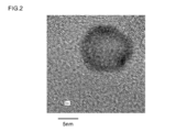
- FIG. 2 is a transmission electron microscope (TEM) photograph of Sample 1.
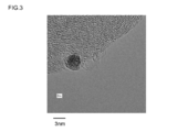
- FIG. 3 is a TEM photograph of Sample 2.
- FIG. 4 is a TEM photograph of Sample 3.
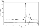
- FIG. 5 is a chart showing the results of X-ray diffraction measurement of Sample 1.
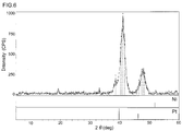
- FIG. 6 is a chart showing the results of X-ray diffraction measurement of Sample 2.
- the manufacturing method disclosed herein includes a carrier made of a conductive material (hereinafter referred to as “conductive carrier”), and core-shell structured metal fine particles supported on the carrier, and the shell portion is made of a noble metal. And a fine metal particle-supported catalyst body comprising a fine metal particle having a core portion made of a base metal lower than the shell portion.
- a manufacturing method includes a step (1) of generating fine particles made of base metal, a step (2) of forming a shell portion made of noble metal on the surface of the base metal fine particles, and a metal fine particle support in which the metal fine particles are supported on a carrier. And (3) a step of recovering the catalyst body.
- the precious metal constituting the shell portion of the core-shell structured metal fine particles will be described.
- a metal element that functions as a catalyst can be preferably used.
- gold (Au), silver (Ag), platinum (Pt), palladium (Pd), rhodium (Rh), iridium (Ir), Ruthenium (Ru), osmium (Os), a compound containing the above metal element, or an alloy thereof can be used.
- metals belonging to the platinum group platinum, palladium, rhodium, iridium, ruthenium, osmium
- platinum group platinum, palladium, rhodium, iridium, ruthenium, osmium
- a metal constituting the core portion of the core-shell structure is a base metal (that is, a metal element excluding the above-described noble metal. In the following description, for the sake of convenience, it is referred to as “base metal”). It is done.
- Such base metals include, for example, aluminum (Al), titanium (Ti), vanadium (V), chromium (Cr), manganese (Mn), iron (Fe), cobalt (Co), nickel (Ni), copper (Cu ), Zinc (Zn), molybdenum (Mo), cadmium (Cd), tin (Sn), lead (Pb), bismuth (Bi), tungsten (W), and compounds containing the above metal elements, or these An alloy or the like can be used. Further, such a base metal does not necessarily need a function as a catalyst, and may be selected from the viewpoints of manufacturing cost and stability of the core portion. In this case, among the base metals described above, metals belonging to the iron group (particularly iron, nickel) can be preferably used.
- the above-described noble metals and base metals are provided to the manufacturing process in the state of compounds.
- the compound used here may be any compound that can produce fine particles of noble metal and base metal by performing a reduction treatment.
- each compound will be described in detail.
- a salt or complex of the noble metal can be preferably used.
- the noble metal salts include halides such as chlorides, bromides, and iodides, hydroxides, sulfides, sulfates, nitrates, and potassium complex oxides, ammonium complex oxides, and sodium complex oxides.
- a composite oxide such as a product can be used.
- an ammine complex, a cyano complex, a halogeno complex, a hydroxy complex, or the like can be used.
- a salt or complex of a metal belonging to the platinum group for example, platinum
- platinum may be used as the compound having a noble metal element.
- platinum chloride hexahydrate H 2 (PtCl 6 ) ⁇ 6H 2 O
- platinum (IV) chloride platinum (II) bromide, platinum (II ) Iodide, platinum (IV) sulfide, potassium tetrachloroplatinate (II), ammonium tetrachloroplatinate (II), sodium hexachloroplatinate (IV) hexahydrate, platinum (II) hexafluoroacetylacetonate Complex, platinum (II) acetylacetonate complex, and the like.
- the base metal salt can be preferably used as the compound having a base metal element.
- the base metal salts include chlorides, hydroxides, borides, bromides, iodides, sulfides; carbonates, sulfates, nitrates, oxalates, perchlorates, and the like.
- a salt of a metal (for example, nickel) belonging to the iron group may be used as the compound having a base metal element.
- Examples of the base metal compound when nickel is used as the base metal include nickel chloride hexahydrate (NiCl 2 .6H 2 O), nickel nitrate hexahydrate (Ni (NO 3 ) 2 .6H 2 O), 2 Nickel ethylhexanoate (Ni (C 8 H 15 O 2 )), nickel sulfate hexahydrate (NiSO 4 .6H 2 O), nickel perchlorate hexahydrate (Ni (ClO 4 ) 2 .6H 2 O), nickel acetate tetrahydrate (Ni (CH 3 COO) 2 .4H 2 O), and the like.
- Such a carrier is made of a conductive material.
- conductive carbon ZnO, SnO 2 , TiO 2 or the like, or perovskite-based conductive ceramics (more preferably conductive carbon) can be used.
- conductive carbon for example, a micro structure such as carbon black, carbon nanotube, carbon nanohorn, carbon nanofiber (typically carbon black) can be preferably used.
- a metal fine particle-supported catalyst body that can be suitably used for, for example, a fuel cell can be produced.
- the average particle diameter of the conductive carrier (here, the average particle diameter measured based on observation with an electron microscope is used. In the following description, “average particle diameter” is calculated by the same method). Is, for example, 10 nm to 100 nm, preferably 20 nm to 70 nm, and more preferably about 30 nm to 50 nm.
- the reaction liquid in the production method disclosed herein may be a solution in which each material described above is dissolved in a solvent, or a dispersion liquid in which each material is dispersed in a dispersion medium (“dispersion liquid” in this specification is a sol, Gel).
- the solvent (dispersion medium) constituting the reaction solution may be an aqueous solvent (aqueous dispersion medium) or an organic solvent (organic dispersion medium).
- water or a mixed solution containing water for example, a mixed solution of water and ethanol
- organic solvents organic dispersion media
- alcohols such as methanol and ethanol
- ketones such as acetone and methyl ketone
- highly polar ones such as esters such as ethyl acetate
- Step of generating fine particles of base metal (1) In the production method disclosed herein, first, fine particles composed of a base metal are generated by reducing a compound having a base metal element for constituting a core portion in a reaction solution in which a conductive carrier is present and no precious metal is present. To do.
- This step (1) can be easily carried out, for example, by adding a reducing agent to a reaction solution containing a compound having a base metal element and a carrier.
- the reaction solution is prepared by mixing a compound having a base metal element for constituting the core portion and the above-described conductive carrier in a solvent (or dispersion medium).
- a solvent or dispersion medium.
- the content of each material is not particularly limited because it can vary depending on the purpose and the type of material.
- the solvent is water or other aqueous solvent (for example, a mixed solvent of water and ethanol)
- the above-described core-shell having an average particle diameter of about 3 nm to 15 nm.
- the reaction solution so that the molar concentration of the base metal compound is 0.5M to 4M (more preferably 0.75M to 2M, for example 1M).
- the conductive carbon is contained in a proportion of 2 to 20 parts by mass (more preferably 5 to 10 parts by mass) with respect to 100 parts by mass of the reaction solution.
- a various additive other than the above-mentioned material can be added. Examples of such additives include complexing agents.
- the complexing agent for example, hydrazine monohydrate (N 2 H 4 .H 2 O), aqueous ammonia, potassium cyanide and the like can be used.
- a complex having the base metal as a central metal ion is formed in the reaction solution.
- base metal fine particles can be easily deposited in the reduction treatment described later.
- the temperature condition at this time is preferably about 20 to 60 ° C. (more preferably 30 to 50 ° C.).
- the rotation speed of stirring is preferably about 100 rpm to 500 rpm (more preferably 200 rpm to 300 rpm).
- Such a reduction treatment can be performed, for example, by adding a reducing agent to the reaction solution.
- the reducing agent to be added here for example, trisodium citrate dihydrate (Na 3 C 6 H 5 O 7 ⁇ 2H 2 O), oxalic acid (C 2 H 2 O 4) , sodium acetate (NaCH 3 COOH), sodium borohydride (NaBH 4 ), sodium thiosulfate (Na 2 S 2 O 3 ), and the like can be used.
- the reducing agent is added in an amount of 0.02 to 0.2 parts by mass (more preferably 0.05 to 0.1 parts by mass) with respect to 100 parts by mass of the reaction liquid (solution or dispersion). (Mass part).
- a pH adjuster to the reaction solution (solution or dispersion) to adjust the pH to 9 to 11 (for example, about pH 9).
- NaOH sodium hydroxide
- aqueous ammonia aqueous ammonia
- other basic substances can be used as the pH adjuster.
- the reaction solution may be kept for a predetermined time (1 to 6 hours, preferably 1 to 4 hours, for example, about 2 hours) after the addition of the reducing agent.
- the temperature of the reaction solution is preferably maintained at 20 ° C. to 60 ° C. (more preferably 20 ° C. to 50 ° C., for example, 40 ° C.). Furthermore, it is more preferable to perform homogenization while holding the reaction solution. Examples of such a homogenization method include ultrasonic homogenization, ultrasonic disperser, ultrasonic cleaner, etc. Among them, ultrasonic homogenization is preferably used. In this case, the ultrasonic homogenization is preferably performed by homogenization at a frequency of about 15 kHz to 50 kHz and an output of about 100 W to 500 W.
- Step (2) ⁇ Step of forming a shell portion made of a noble metal on the surface of the base metal fine particles (2)>
- a compound having a noble metal element for constituting the shell portion is added to the reaction solution in which the base metal fine particles generated by the support and the reduction treatment are present, and the compound is reduced.
- a shell portion made of the noble metal is formed on the surface of the base metal fine particle as a core.
- This step (2) can be easily realized, for example, by adding a compound having a noble metal element to the reaction solution in which fine particles composed of a base metal are generated through the above-described step (1).
- a compound having a noble metal element is added to the reaction solution subjected to the reduction treatment of the base metal compound.
- the amount of the base metal compound added is not particularly limited because it may vary depending on the purpose and the type of material.
- an addition amount in the case where one of the platinum group (for example, platinum) is selected as the noble metal and the above-described 2 to 10 atomic layer shell portion is formed will be described.
- the mixing ratio may be determined so that the molar concentration of the noble metal compound is 0.2 M to 2 M (more preferably 0.3 M to 1 M, for example, about 0.5 M) in the adjusted reaction liquid.
- a noble metal compound added to the reaction solution is then subjected to a reduction treatment to form a shell portion made of the noble metal on the surface of the base metal fine particles (core).
- the reduction treatment of the noble metal compound performed here can be performed by adding the noble metal compound to the reaction solution to which the reducing agent is added. That is, the reduction treatment can utilize the reducing agent added to the reaction solution in the previous step, and can be performed by holding the reaction system after adding the noble metal compound to the reaction solution. Further, a reducing agent may be newly added during the reduction treatment.
- noble metal fine particles are precipitated in the reaction solution.
- a two-stage reduction treatment is performed in which the reduction treatment of the noble metal compound is performed. That is, base metal fine particles having a higher ionization tendency than noble metal fine particles are generated in advance by the reduction treatment in the above-described step (1), and the noble metal fine particles are deposited on the surface of the already generated base metal fine particles.
- metal particles having a core-shell structure in which a base metal fine particle is used as a core and a shell portion made of the noble metal is formed on the surface thereof are produced.
- the produced metal fine particle supported catalyst body is recovered from the reaction solution.
- Various conventionally known methods can be used as a method for recovering the metal fine particle-supported catalyst body.
- a method of filtering a reaction solution (solution or dispersion), washing a residue, and drying the filtrate can be mentioned.
- the filtrate is washed with ion-exchanged water and dried at about 60 ° C. to 120 ° C. for about 1 hour to 8 hours.
- the method for recovering the metal fine particle-supported catalyst body is not limited to the above-described method. For example, a method of collecting the particles in the gas phase by spray drying the reaction solution in which the metal fine particle-supported catalyst body is generated, etc. Is mentioned.
- the production method disclosed herein produces a catalyst body in which metal fine particles having a shell portion made of a noble metal and a core portion made of a base metal are supported on the carrier.
- a base metal compound having a higher ionization tendency than a noble metal is present in a reaction liquid (typically in a reaction liquid such as a dispersion) in which a conductive carrier is present and the target noble metal is not present.
- Reduction treatment is performed to generate core particles made of a base metal in advance.
- a compound having the target noble metal element is added to the reaction solution, and the compound is reduced.
- the catalyst body provided by the production method disclosed herein includes a support made of a carbonaceous material, core-shell structured metal fine particles supported on the support, and the shell portion is made of a noble metal and A metal fine particle-supported catalyst body comprising a metal fine particle having a core portion made of a metal that is baser than the shell portion. Since the base metal is used in the central part of the metal fine particles serving as a catalyst, this metal fine particle-supported catalyst body has a reduced amount of noble metal used, and is particularly practical in terms of cost.
- the metal fine particle-supported catalyst body may have an average particle size of 1 nm to 20 nm (preferably 3 nm to 15 nm, more preferably 3 nm to 10 nm) of the metal fine particles supported on the carrier.
- a catalyst body including such metal particles having a core-shell structure can exhibit high catalytic activity while suppressing an increase in cost.
- the average particle size of the core portion is preferably about 2 nm to 10 nm (typically 4 nm)
- the thickness of the shell portion is 1 to 10 atomic layers (preferably 2 to 10 atomic layers, More preferably, it is about 2 to 5 atomic layers).
- various conditions in the production method can be adjusted in order to produce such a metal fine particle supported catalyst body.
- a base metal-noble metal alloy layer may be formed between a core portion made of a base metal and a shell portion made of a noble metal. This is because a base metal-noble metal alloy may be formed when metal fine particles begin to precipitate on the surface of the base metal fine particles.
- the shell part of the metal fine particle is made of a metal belonging to the platinum group
- the core part of the metal fine particle is made of a metal belonging to the iron group. Good.
- a relatively inexpensive metal belonging to the iron group is used for the core portion and a platinum group having a high catalytic activity is used for the shell portion, it is possible to achieve high catalytic activity while more suitably suppressing cost increase. it can.
- the metal fine particle supported catalyst body disclosed here can be suitably used for PEFC.
- FIG. 1 is a cross-sectional view schematically showing an electrode assembly 100 which is a basic structure of PEFC.
- the electrode assembly (PEFC) 100 includes a sheet-like electrolyte membrane 10, a fuel electrode 20 applied to one surface (left surface in FIG. 1) of the electrolyte membrane 10, and the other surface of the electrolyte membrane 10. It has an oxidant electrode 30 applied to (the right side surface in FIG. 1).
- a fuel circulation layer 40 is laminated on the outer surface of the fuel electrode 20, and an oxidant circulation layer 50 is laminated on the outer surface of the oxidant electrode 30.
- housings 60 are arranged on the outer surfaces of the fuel circulation layer 40 and the oxidant circulation layer 50, respectively.
- the fuel electrode 20 side is a negative electrode
- the oxidant electrode 30 side is a positive electrode.
- the metal fine particle supported catalyst body disclosed here can be suitably used as a catalyst body included in the fuel electrode 20, for example.
- conductive carbon for example, carbon black
- nickel for the core of the metal fine particles
- platinum for the shell portion.
- Nickel was used as the base metal particles, and nickel chloride hexahydrate (NiCl 2 .6H 2 O), which is a nickel salt, was used as the nickel-containing compound.
- NiCl 2 .6H 2 O nickel chloride hexahydrate
- 1.2 g of nickel chloride hexahydrate (NiCl 2 .6H 2 O) was dissolved in 7 ml of pure water to prepare a 1M nickel chloride aqueous solution.
- the nickel chloride aqueous solution was stirred in the environment of temperature 40 degreeC, and stirring speed 250rpm using the hot stirrer.
- nickel chloride which is a base metal compound
- carbon black which is a conductive carrier
- a compound having a noble metal element was added to reduce the compound.
- platinum was used as the noble metal element
- chloroplatinic acid hexahydrate H 2 [PtCl 6 ] .6H 2 O
- 9.9 g of a 10% by mass chloroplatinic acid aqueous solution in which the chloroplatinic acid hexahydrate was dissolved in pure water was added to the aqueous solution. Then, while this aqueous solution was kept at 40 ° C., the chloroplatinic acid was reduced by stirring for 30 minutes.
- the metal fine particle-supported catalyst body obtained by the above-mentioned process is referred to as Sample 1.
- Example 2 an aqueous solution was prepared by the same process as Sample 1 described above, and the precipitated particles were recovered after reducing the compound in the aqueous solution.
- chloroplatinic acid hexahydrate was dissolved in the aqueous solution immediately after adding the reducing agent to the nickel hydroxide aqueous solution (here, about 0 to 20 minutes).
- the metal fine particle supported catalyst body obtained by such a process is referred to as Sample 2.
- Example 3 Also in this example, an aqueous solution was prepared by the same process as Sample 1, and the precipitated particles were recovered after reducing the compound in the aqueous solution. However, here, chloroplatinic acid hexahydrate was dissolved in the aqueous solution 20 hours after the reducing agent was added to the nickel hydroxide aqueous solution.
- the metal fine particle supported catalyst body obtained by this process is referred to as Sample 3.
- FIGS. 2 is a TEM photograph of Sample 1
- FIG. 3 is Sample 2
- FIG. 1 a transmission image of the metal particles supported on the conductive carrier can be observed.
- the darker color is platinum
- the lighter color than platinum is nickel.
- nickel fine particles are formed at the center of particles carried on carbon black (conductive carrier), and the surface of the nickel fine particles is platinum.
- the fine particles were covered. From this, it can be understood that the metal fine particles supported in Sample 1 are metal particles having a Ni-Pt core shell structure in which nickel fine particles are the core and the surface is covered with a shell portion made of platinum fine particles. From this, it was found that when the nickel compound was reduced to precipitate nickel fine particles, and then the platinum compound was reduced to precipitate platinum, it was possible to produce metal particles having a suitable core-shell structure. On the other hand, as shown in FIG. 3, in the fine metal particles supported by Sample 2, platinum fine particles and nickel fine particles were mixed.
- the metal fine particles supported by the sample 2 are an alloy of platinum and nickel. From this, it can be seen that if the reduction treatment of the nickel compound and the reduction treatment of the platinum compound are carried out at almost the same timing, the core-shell metal fine particles cannot be produced, and an alloy of platinum and nickel is produced instead. It was. Moreover, as shown in FIG. 4, in sample 3, nickel particles and platinum particles were separately supported on a conductive carrier. From this, it was found that when the reaction liquid was kept for a long time after the nickel fine particles were deposited, the reactivity of the surface of the nickel fine particles was lowered and the core-shell structure was not formed.
- FIG. 5 shows the XRD result of sample 1
- FIG. 6 shows the XRD result of sample 2. 5 and 6 also show the peak values of nickel and platinum in XRD.
- sample P is a catalyst body in which metal fine particles made of only platinum are supported on a carrier.
- the platinum active specific surface areas of Sample 1 and Sample P were calculated based on the measurement results of cyclic voltammetry measurement (hereinafter referred to as “CV measurement”).
- CV measurement cyclic voltammetry measurement
- the average particle diameter of the metal fine particles carried on Sample 1 and Sample P was measured.
- the platinum utilization factor of a measuring object was computed.
- the platinum utilization rate is a value obtained by dividing the platinum active specific surface area by the surface area of the metal fine particles calculated based on the average particle diameter. Table 1 shows the measurement results of the platinum active specific surface area and the average particle diameter, and the calculation results of the platinum utilization rate.
- the platinum active specific surface area was 34.1 m 2 / g, and the average particle size was 10.58 nm. Based on the measurement result, the platinum utilization of Sample 1 was calculated to be 88.2%. On the other hand, in sample P, the platinum active specific surface area was 71.7 m 2 / g, and the average particle size was 3.36 nm. Based on the measurement result, the platinum utilization rate of Sample P was calculated to be 86.1%.
- Sample 1 can have a catalytic function equivalent to that obtained when pure platinum is used as a catalyst by using metal fine particles having a Ni / Pt core-shell structure as a catalyst. That is, the metal fine particle supported catalyst body using the above-described production method can reduce the production cost while maintaining a good catalytic function.
- the metal fine particle-supported catalyst body produced by the production method disclosed herein can be used as a catalyst in various apparatuses.
- it can be used when forming a catalyst layer in a polymer electrolyte fuel cell (PEFC). In this case, it is possible to reduce the manufacturing cost while maintaining the PEFC function.
- PEFC polymer electrolyte fuel cell
- Electrode assembly 10 Electrolyte membrane 20 Fuel electrode 30 Oxidant electrode 40 Fuel distribution layer 50 Oxidant distribution layer 60 Case 100 Electrode assembly (PEFC)
Landscapes
- Chemical & Material Sciences (AREA)
- Chemical Kinetics & Catalysis (AREA)
- Electrochemistry (AREA)
- General Chemical & Material Sciences (AREA)
- Engineering & Computer Science (AREA)
- Materials Engineering (AREA)
- Organic Chemistry (AREA)
- Composite Materials (AREA)
- Analytical Chemistry (AREA)
- Catalysts (AREA)
- Inert Electrodes (AREA)
Abstract
Description
しかし、ナノ粒子化を過度に進めると触媒活性の低下がみられ、触媒体としての性能維持の観点からは好ましくない。例えば、白金(Pt)をナノ粒子化した場合、1粒当たりの酸素還元活性は、粒径が概ね2.5nmを下回ると顕著に低下する虞がある。従って、ナノ粒子化を進めるとしても触媒活性の維持の観点からは3nm程度が限界であると考えられる。
即ち、ここで開示される製造方法は、導電性材料から成る担体(導電性担体)と、該担体上に担持されたコアシェル構造の金属微粒子であってシェル部分が貴金属で構成されており且つコア部分が該シェル部分よりも卑な金属で構成されている金属微粒子とを備える金属微粒子担持触媒体を製造する方法である。そして、ここで開示される製造方法は、上記担体が存在し且つ上記貴金属が存在しない反応液において上記コア部分を構成するための卑金属元素を有する化合物を還元処理することによって該卑金属から成る微粒子を生成する工程と、上記担体および上記還元処理により生成された卑金属微粒子が存在する反応液に上記シェル部分を構成するための貴金属元素を有する化合物を添加し、該化合物を還元処理することによって上記卑金属微粒子をコアとしてその表面に該貴金属から成るシェル部分を形成する工程と、上記貴金属から成るシェル部分と上記卑金属から成るコア部分とを有する金属微粒子が上記担体に担持された触媒体を上記反応液から回収する工程とを包含する。
即ち、ここで開示される製造方法によると、貴金属よりもイオン化傾向が高い卑金属の化合物を導電性担体が存在し且つ目的の貴金属が存在しない反応液(典型的には分散液等)において還元処理して予め卑金属から成るコア粒子を生成する。次いで、当該反応液に目的の貴金属元素を有する化合物を添加し、該化合物を還元処理する。このことによって、予め形成しておいた卑金属から成るコア粒子の表面に上記還元処理により還元されて析出した貴金属層を形成することができる。即ち、上記2段階の還元処理を行うことにより、卑金属から成るコア部分の表面に極薄い貴金属層(典型的には2~10原子層程度)を形成することができる。典型的には、卑金属から成るコア部分と最表面の貴金属層との間に卑金属-貴金属合金層が形成される。
従って、上記構成の本発明の製造方法によると、触媒として機能する金属微粒子の表面に目的の貴金属を析出させつつ触媒として機能し難い金属微粒子の内面を卑金属で構成することにより、コスト増の要因となる貴金属の使用量を低減した実用性に優れる金属微粒子を担持した触媒体を提供することができる。
好ましくは、平均粒子径が3nm~15nm程度の上記コアシェル構造金属微粒子が生成されるように上記還元処理の程度(処理時間や還元剤の濃度)や反応液に含ませる原料化合物の濃度を調整する。
このような原料化合物の組み合わせによって、2段階の還元処理を好適に行うことができ、好ましいコアシェル構造の金属微粒子を形成することができる。従って、より好ましく目的とする金属微粒子担持触媒体を製造することができる。特に、卑金属元素を有する化合物としてニッケルの塩を使用することが好ましい。
かかる構成の製造方法によると、コア部分(コア粒子)を形成する最初の還元処理の際に所定の還元剤を反応液に添加しておき、コア粒子の形成後に当該反応液に卑金属と比べて容易に還元する貴金属元素を有する化合物を添加する。このことによって、目的とするコアシェル構造の金属微粒子を効率よく形成することができる。
導電性カーボン(例えばカーボンブラック等の導電性カーボン粉体)から担体を使用することにより、導電性に優れる触媒体を製造することができる。かかる触媒体は、例えば燃料電池(例えば上述の高分子電解質型燃料電池)の電極触媒として好適に用いることができる。
かかる構成の金属微粒子担持触媒体は、貴金属の使用量の低減が実現されており、特にコスト面において実用性に優れる。
好ましくは、前記金属微粒子の電子顕微鏡観察に基づく平均粒子径が3nm~15nmであることを特徴とする。このようなコアシェル構造の金属微粒子を備えることにより、コスト増を抑制しつつ高い触媒活性を発揮することができる。特に2~10原子層程度の薄い貴金属層を備えるコアシェル構造金属微粒子を担持する触媒体が好ましい。
従って、本発明は、他の側面として、かかる導電性の金属微粒子担持触媒体を電極に備える燃料電池(例えば高分子電解質型燃料電池)を提供する。
また、本発明を限定するものではないが、貴金属元素を有する化合物としては白金族に属する金属(例えば白金)の塩又は錯体を用いるとよい。上記貴金属として白金を用いた場合の貴金属化合物を例示すると、塩化白金六水和物(H2(PtCl6)・6H2O)、白金(IV)塩化物、白金(II)臭化物、白金(II)ヨウ化物、白金(IV)硫化物、テトラクロロ白金(II)酸カリウム、テトラクロロ白金(II)酸アンモニウム、ヘキサクロロ白金(IV)酸ナトリウム六水和物、白金(II)ヘキサフルオロアセチルアセトナト錯体、白金(II)アセチルアセトナト錯体、などが挙げられる。
また、本発明を限定するものではないが、卑金属元素を有する化合物としては鉄族に属する金属(例えばニッケル)の塩を用いるとよい。上記卑金属としてニッケルを用いた場合の卑金属化合物を例示すると、塩化ニッケル六水和物(NiCl2・6H2O)、硝酸ニッケル六水和物(Ni(NO3)2・6H2O)、2-エチルヘキサン酸ニッケル(Ni(C8H15O2))、硫酸ニッケル六水和物(NiSO4・6H2O)、過塩素酸ニッケル六水和物(Ni(ClO4)2・6H2O)、酢酸ニッケル四水和物(Ni(CH3COO)2・4H2O)などが挙げられる。
また、導電性担体の平均粒子径(ここでは、電子顕微鏡観察に基づいて計測された平均粒子径を指す。以下の説明において「平均粒子径」は同様の方法で算出されたものとする。)は、例えば、10nm~100nmであるとよく、好ましくは20nm~70nm、より好ましくは30nm~50nm程度であるとよい。
ここで開示される製造方法における反応液は、上述した各材料を溶媒に溶かした溶液でもよいし、各材料を分散媒に分散させた分散液(本明細書中における「分散液」はゾル、ゲルを包含するものとする。)でもよい。また、反応液を構成する溶媒(分散媒)は、水系溶媒(水系分散媒)でもよいし、有機系溶媒(有機系分散媒)でもよい。
水系溶媒(水系分散媒)で反応液を構成する場合、溶媒には水や水を含んだ混合液(例えば、水とエタノールの混合溶液)を用いることができる。また、有機系溶媒(有機系分散媒)の場合には、メタノールやエタノールなどのアルコール類や;アセトン、メチルケトンのようなケトン類や;酢酸エチルのようなエステル類などの極性の高いものなどを用いることができる。
ここで開示される製造方法では、先ず、導電性担体が存在し且つ貴金属が存在しない反応液において、コア部分を構成するための卑金属元素を有する化合物を還元処理することによって卑金属から成る微粒子を生成する。この工程(1)は、例えば、卑金属元素を有する化合物と担体とを含む反応液中に還元剤を添加することによって容易に実施できる。
また、上記反応液を構成する際、上述の材料の他に種々の添加剤を加えることができる。かかる添加剤としては、例えば、錯化剤が挙げられる。錯化剤には、例えば、ヒドラジン一水和物(N2H4・H2O)、アンモニア水、シアン化カリウムなどを用いることができる。この錯化剤を反応液に適量加えると、上記卑金属を中心金属イオンとする錯体が反応液中で形成される。これによって、後述する還元処理において卑金属微粒子を容易に析出させることができる。
また、反応液を調整する際に、一定の範囲内に温度条件を維持しながら攪拌するとよい。このときの温度条件としては、20℃~60℃(より好ましくは30℃~50℃)程度であるとよい。また、攪拌の回転速度は、100rpm~500rpm(より好ましくは200rpm~300rpm)程度であるとよい。
また、かかる還元処理において、上記還元剤の添加後から所定の時間(1時間~6時間時間、好ましくは1時間~4時間、例えば2時間程度)、反応液を保持し続けるとよい。なお、長時間に亘って(例えば20時間以上)、反応液を保持し続けると、析出した卑金属微粒子の表面の反応性が低下して、コアシェル構造が形成されづらくなるため、好ましくない。
また、この際、反応液の温度は、20℃~60℃(より好ましくは20℃~50℃、例えば40℃)に維持するとよい。さらに、反応液を保持している間に、均質化を行うとより好ましい。かかる均質化の方法としては、例えば、超音波ホモジナイズ、超音波分散機、超音波洗浄機などが挙げられ、中でも超音波ホモジナイズを用いるとよい。この場合、超音波ホモジナイズは、15kHz~50kHz程度の周波数、100W~500W程度の出力で均質化を行うものであるとよい。
ここで開示される製造方法では、次に、担体および還元処理により生成された卑金属微粒子が存在する反応液にシェル部分を構成するための貴金属元素を有する化合物を添加し、該化合物を還元処理することによって前記卑金属微粒子をコアとしてその表面に該貴金属から成るシェル部分を形成する。この工程(2)は、例えば、上述した工程(1)を経て、卑金属からなる微粒子が生成された反応液中に貴金属元素を有する化合物を添加することによって容易に実現することができる。
ここで開示される製造方法では、次に、生成された金属微粒子担持触媒体を反応液から回収する。金属微粒子担持触媒体を回収する方法としては、従来公知の種々の方法を用いることができる。かかる方法としては、例えば、反応液(溶液又は分散液)を濾過し、濾物を洗浄、乾燥する方法が挙げられる。この場合、濾物は、イオン交換水で洗浄し、60℃~120℃程度、1時間~8時間程度で乾燥させるとよい。また、金属微粒子担持触媒体を回収する方法は、上述の方法に限定されず、例えば、金属微粒子担持触媒体が生成された反応液を噴霧乾燥して気相中の粒子を捕集する方法などが挙げられる。
ここで開示される製造方法によると、貴金属よりもイオン化傾向が高い卑金属の化合物を導電性担体が存在し且つ目的の貴金属が存在しない反応液(典型的には分散液等の反応液中)において還元処理して予め卑金属から成るコア粒子を生成する。次いで、当該反応液に目的の貴金属元素を有する化合物を添加し、該化合物を還元処理する。このことによって、予め形成しておいた卑金属から成るコア粒子の表面に上記還元処理により還元されて析出した貴金属層を形成することができる。即ち、上記2段階の還元処理を行うことにより、卑金属から成るコア部分の表面に極薄い貴金属層(典型的には2~10原子層程度)を形成することができる。
従って、上記構成の本発明の製造方法によると、触媒として機能する金属微粒子の表面に目的の貴金属を析出させつつ触媒として機能し難い金属微粒子の内面を卑金属で構成することにより、コスト増の要因となる貴金属の使用量を低減した実用性に優れる金属微粒子を担持した触媒体を提供することができる。
卑金属粒子としてニッケルを用い、ニッケルを有する化合物として、ニッケルの塩である塩化ニッケル六水和物(NiCl2・6H2O)を用いた。ここでは、1.2gの塩化ニッケル六水和物(NiCl2・6H2O)を7mlの純水に溶解し、1Mの塩化ニッケル水溶液を調製した。そして、ホットスターラーを用いて、塩化ニッケル水溶液を温度40℃、攪拌速度250rpmの環境で攪拌した。次に、攪拌した状態の塩化ニッケル水溶液に、錯化剤としてヒドラジン一水和物(N2H4・H2O)を5.0g、還元剤としてクエン酸三ナトリウム二水和物(Na3C6H5O7・2H2O)を0.015g添加した。さらに、導電性担体として炭素質担体であるカーボンブラック(キャボット社製、品番:Vulcan XC72)を1.5g添加した後に、pH調製剤として50質量%水酸化ナトリウム水溶液を5.0g添加し、水溶液のpHを約9に調整した。
ここでは、上記サンプル1と同様のプロセスで水溶液を調製し、水溶液中の化合物を還元処理した後に、析出した粒子を回収した。ただし、ここでは、還元剤を水酸化ニッケル水溶液に添加した直後(ここでは、0分~20分程度)に塩化白金酸六水和物を水溶液に溶解させた。以下、かかるプロセスで得られた金属微粒子担持触媒体をサンプル2とする。
本例においても、上記サンプル1と同様のプロセスで水溶液を調製し、水溶液中の化合物を還元処理した後に、析出した粒子を回収した。ただし、ここでは、還元剤を水酸化ニッケル水溶液に添加した20時間後に塩化白金酸六水和物を水溶液に溶解させた。以下、かかるプロセスで得られた金属微粒子担持触媒体をサンプル3とする。
上述の製造プロセスを経て得られたサンプル1~3を透過型電子顕微鏡(Transmission Electron Microscope、以下「TEM」と称する。)で観察した。観察結果のTEM写真を図2~4に示す。図2はサンプル1、図3はサンプル2、図4はサンプル3のTEM写真である。なお、かかるTEM写真では、導電性担体に担持されている金属粒子の透過像が観察できる。観察された金属粒子のうち、色が濃いものが白金であり、白金よりも色が薄いものがニッケルである。
一方、図3に示すように、サンプル2で担持されている金属微粒子では、白金微粒子とニッケル微粒子とが混在していた。よって、サンプル2で担持されている金属微粒子は、白金とニッケルとの合金であると解される。このことから、ニッケル化合物の還元処理と白金化合物の還元処理とをほぼ同時のタイミングで行うと、コアシェル構造の金属微粒子は作製できず、代わりに白金とニッケルとの合金が作製されることが分かった。
また、図4に示すように、サンプル3では、ニッケル粒子と白金粒子が別々に導電性担体に担持されていた。このことから、ニッケル微粒子を析出させてから長時間に亘って反応液を保持し続けていると、ニッケル微粒子の表面の反応性が低下し、コアシェル構造が形成されなかったことが分かった。
次に、サンプル1およびサンプル2にXRDを行い、XRDにおける各々のサンプルのピーク値を調べた。図5はサンプル1のXRD結果、図6はサンプル2のXRD結果を示している。また、図5および6にはニッケルと白金のXRDにおけるピーク値も併せて記載している。
次に、上述したサンプル1の白金利用率を、市販の白金微粒子担持触媒体(田中貴金属工業株式会社製、品番:TEC10E70TPM。以下の説明では「サンプルP」と称する。)の白金利用率と比較し、その性能を評価した。ここで、サンプルPは、白金のみからなる金属微粒子を担体に担持させた触媒体である。

20 燃料極
30 酸化剤極
40 燃料流通層
50 酸化剤流通層
60 筐体
100 電極接合体(PEFC)
Claims (11)
- 導電性材料から成る担体と、該担体上に担持されたコアシェル構造の金属微粒子であってシェル部分が貴金属で構成されており且つコア部分が該シェル部分よりも卑な金属で構成されている金属微粒子と、を備える金属微粒子担持触媒体を製造する方法であって、以下の工程:
前記担体が存在し且つ上記貴金属が存在しない反応液において、前記コア部分を構成するための卑金属元素を有する化合物を還元処理することによって該卑金属から成る微粒子を生成する工程;
前記担体および前記還元処理により生成された卑金属微粒子が存在する反応液に前記シェル部分を構成するための貴金属元素を有する化合物を添加し、該化合物を還元処理することによって前記卑金属微粒子をコアとしてその表面に該貴金属から成るシェル部分を形成する工程;および
前記貴金属から成るシェル部分と前記卑金属から成るコア部分とを有する金属微粒子が前記担体に担持された触媒体を前記反応液から回収する工程;
を包含する、金属微粒子担持触媒体の製造方法。 - 前記貴金属元素を有する化合物として白金族に属する金属の塩又は錯体を使用し、且つ、前記卑金属元素を有する化合物として鉄族に属する金属の塩又は錯体を使用する、請求項1に記載の製造方法。
- 前記卑金属元素を有する化合物としてニッケルの塩を使用する、請求項2に記載の製造方法。
- 前記卑金属元素を有する化合物と前記担体とを含む反応液中に還元剤を添加することによって前記卑金属から成る微粒子を生成し、
該微粒子が生成された反応液中に前記貴金属元素を有する化合物を添加することによって前記卑金属微粒子の表面に該貴金属から成るシェル部分を形成する、請求項1~3のいずれかに記載の製造方法。 - 前記担体として導電性カーボンから成る担体を使用する、請求項1~4のいずれかに記載の製造方法。
- 金属微粒子担持触媒体であって、
炭素質材料から成る担体と、
該担体上に担持されたコアシェル構造の金属微粒子であってシェル部分が貴金属で構成されており且つコア部分が該シェル部分よりも卑な金属で構成されている金属微粒子と、
を備え、
請求項1~5のいずれかに記載の製造方法により製造された、触媒体。 - 前記金属微粒子の電子顕微鏡観察に基づく平均粒子径が3nm~15nmである、請求項6に記載の触媒体。
- 前記金属微粒子のシェル部分が白金族に属する金属で構成されており、該金属微粒子のコア部分が鉄族に属する金属で構成されている、請求項6又は7に記載の触媒体。
- 前記金属微粒子のコア部分がニッケルで構成されている、請求項8に記載の触媒体。
- 前記担体は導電性カーボンにより構成されている、請求項6~9のいずれかに記載の触媒体。
- 請求項10に記載の触媒体を電極に備える燃料電池。
Priority Applications (5)
| Application Number | Priority Date | Filing Date | Title |
|---|---|---|---|
| KR1020127024973A KR101770010B1 (ko) | 2010-03-01 | 2010-11-30 | 금속 미립자 담지 촉매체 및 그 이용 |
| DE112010005334T DE112010005334T5 (de) | 2010-03-01 | 2010-11-30 | Katalysator mit geträgerten feinen Metallteilchen und dessen Verwendung |
| JP2012502965A JP5607140B2 (ja) | 2010-03-01 | 2010-11-30 | 金属微粒子担持触媒体及びその利用 |
| CN2010800650527A CN102781576A (zh) | 2010-03-01 | 2010-11-30 | 金属微颗粒载持催化剂体及其应用 |
| US13/581,384 US9425465B2 (en) | 2010-03-01 | 2010-11-30 | Catalyst carrying fine metal particles and use thereof |
Applications Claiming Priority (2)
| Application Number | Priority Date | Filing Date | Title |
|---|---|---|---|
| JP2010-044101 | 2010-03-01 | ||
| JP2010044101 | 2010-03-01 |
Publications (1)
| Publication Number | Publication Date |
|---|---|
| WO2011108162A1 true WO2011108162A1 (ja) | 2011-09-09 |
Family
ID=44541835
Family Applications (1)
| Application Number | Title | Priority Date | Filing Date |
|---|---|---|---|
| PCT/JP2010/071341 WO2011108162A1 (ja) | 2010-03-01 | 2010-11-30 | 金属微粒子担持触媒体及びその利用 |
Country Status (6)
| Country | Link |
|---|---|
| US (1) | US9425465B2 (ja) |
| JP (1) | JP5607140B2 (ja) |
| KR (1) | KR101770010B1 (ja) |
| CN (1) | CN102781576A (ja) |
| DE (1) | DE112010005334T5 (ja) |
| WO (1) | WO2011108162A1 (ja) |
Cited By (10)
| Publication number | Priority date | Publication date | Assignee | Title |
|---|---|---|---|---|
| JP2012005969A (ja) * | 2010-06-25 | 2012-01-12 | Toyota Motor Corp | 触媒担持担体の製造方法および電極触媒の製造方法 |
| JP2013215697A (ja) * | 2012-04-11 | 2013-10-24 | Noritake Co Ltd | コアシェルナノ粒子担持触媒体とその製造方法ならびに該触媒体を用いた燃料電池 |
| JP2014108380A (ja) * | 2012-11-30 | 2014-06-12 | Noritake Co Ltd | 金属微粒子担持触媒体及びその製造方法 |
| WO2014129253A1 (ja) * | 2013-02-25 | 2014-08-28 | 日産自動車株式会社 | 燃料電池用触媒粒子及びその製造方法 |
| JP2015515365A (ja) * | 2012-05-11 | 2015-05-28 | エルジー・ケム・リミテッド | 担体に担持されたコア−シェル粒子の製造方法およびこれによって製造された担体に担持されたコア−シェル粒子 |
| CN104736275A (zh) * | 2012-10-24 | 2015-06-24 | 日本曹达株式会社 | 标准电极电位大于0v的元素的粒子的制造方法 |
| JP2015206102A (ja) * | 2014-04-23 | 2015-11-19 | 株式会社ノリタケカンパニーリミテド | 白金中空ナノ粒子および該粒子担持触媒体ならびに該触媒体の製造方法 |
| WO2017033342A1 (ja) * | 2015-08-27 | 2017-03-02 | 日産自動車株式会社 | 触媒粒子ならびにこれを用いてなる電極触媒、電解質膜-電極接合体および燃料電池 |
| JP2019171331A (ja) * | 2018-03-29 | 2019-10-10 | 堺化学工業株式会社 | 貴金属触媒の製造方法及び貴金属触媒 |
| JP2022540820A (ja) * | 2019-07-10 | 2022-09-20 | ヘレウス ドイチュラント ゲーエムベーハー ウント カンパニー カーゲー | 水電解中の酸素発生反応のための触媒 |
Families Citing this family (14)
| Publication number | Priority date | Publication date | Assignee | Title |
|---|---|---|---|---|
| JP5482095B2 (ja) * | 2008-10-30 | 2014-04-23 | ソニー株式会社 | 白金含有触媒を含有する電極及びその製造方法、並びに、電気化学デバイス |
| US20110275009A1 (en) * | 2008-10-30 | 2011-11-10 | Sony Corporation | Platinum-containing catalyst and method of producing the same, electrode and electrochemical device |
| CN103280588A (zh) * | 2013-06-13 | 2013-09-04 | 苏州诺信创新能源有限公司 | 燃料电池 |
| JP6020506B2 (ja) | 2014-04-11 | 2016-11-02 | トヨタ自動車株式会社 | 触媒微粒子及びカーボン担持触媒の各製造方法 |
| US9950315B2 (en) * | 2014-09-02 | 2018-04-24 | Council Of Scientific & Industrial Research | Ni—MgO—ZnO solid catalysts for syngas preparation and process for the preparation thereof |
| WO2016044595A1 (en) * | 2014-09-17 | 2016-03-24 | Massachusetts Institute Of Technology | Aluminum based electroactive materials |
| JP6096816B2 (ja) * | 2015-01-22 | 2017-03-15 | トヨタ自動車株式会社 | 触媒の製造方法及び製造装置 |
| CN106910907B (zh) * | 2017-04-14 | 2021-02-23 | 中国科学院深圳先进技术研究院 | 一种核壳结构催化剂、其制备方法及用途 |
| JP2019098292A (ja) * | 2017-12-07 | 2019-06-24 | トヨタ自動車株式会社 | 内燃機関の排気浄化触媒 |
| CN109494376B (zh) * | 2018-11-06 | 2021-07-02 | 陕西师范大学 | 壳层组分、厚度可调控的Pd@Pt-Ni核@壳纳米材料及其制备方法与应用 |
| CN112589108A (zh) * | 2020-11-27 | 2021-04-02 | 青岛科技大学 | 一种二元金属壳层结构微米纳米粒子批量制备方法 |
| KR20220103288A (ko) * | 2021-01-15 | 2022-07-22 | 현대자동차주식회사 | 인터메탈릭 촉매 및 이의 제조 방법 |
| JP7468379B2 (ja) * | 2021-01-27 | 2024-04-16 | トヨタ紡織株式会社 | 合金微粒子担持触媒の製造方法、電極、燃料電池、合金微粒子の製造方法、膜電極接合体の製造方法、及び燃料電池の製造方法 |
| CN114807624B (zh) * | 2022-04-07 | 2023-10-13 | 北京电子科技职业学院 | 一种抗氧化耐磨贵金属首饰的制备装置及方法 |
Citations (8)
| Publication number | Priority date | Publication date | Assignee | Title |
|---|---|---|---|---|
| JP2004149847A (ja) * | 2002-10-30 | 2004-05-27 | Toppan Forms Co Ltd | コアシェル型の金属系ナノコロイド微粒子 |
| JP2004332028A (ja) * | 2003-05-06 | 2004-11-25 | Tanaka Kikinzoku Kogyo Kk | 三層コア/シェル構造を有する三元系金属コロイド及び該三元系金属コロイドの製造方法 |
| JP2005034836A (ja) * | 2003-07-02 | 2005-02-10 | Nissan Motor Co Ltd | 電極触媒およびその製造方法 |
| JP2005135900A (ja) * | 2003-10-06 | 2005-05-26 | Nissan Motor Co Ltd | 燃料電池用電極触媒およびその製造方法 |
| JP2005270873A (ja) * | 2004-03-25 | 2005-10-06 | Nissan Motor Co Ltd | 酸化物微粒子担持触媒及びその製造方法 |
| JP2008153192A (ja) * | 2006-11-24 | 2008-07-03 | Hitachi Maxell Ltd | 貴金属含有触媒、その製造方法、膜・電極構造体、燃料電池および燃料電池発電システム |
| JP2008297626A (ja) * | 2007-06-04 | 2008-12-11 | Kri Inc | コアシェル型貴金属ナノコロイド |
| JP2010501344A (ja) * | 2006-08-30 | 2010-01-21 | ユミコア・アクチエンゲゼルシャフト・ウント・コムパニー・コマンディットゲゼルシャフト | コア/シェルタイプの触媒粒子およびそれらの製造方法 |
Family Cites Families (3)
| Publication number | Priority date | Publication date | Assignee | Title |
|---|---|---|---|---|
| US20090117257A1 (en) * | 2005-09-13 | 2009-05-07 | University Of South Carolina | Catalysts for Fuel Cell Applications Using Electroless Deposition |
| JP2010044101A (ja) | 2008-08-08 | 2010-02-25 | Toshiba Corp | パターン予測方法、プログラム及び装置 |
| US8058204B2 (en) | 2008-10-24 | 2011-11-15 | GM Global Technology Operations LLC | Method for generating a shell of noble metal overlaid on a core of non-noble metal, and catalysts made thereby |
-
2010
- 2010-11-30 JP JP2012502965A patent/JP5607140B2/ja active Active
- 2010-11-30 KR KR1020127024973A patent/KR101770010B1/ko active IP Right Grant
- 2010-11-30 US US13/581,384 patent/US9425465B2/en active Active
- 2010-11-30 DE DE112010005334T patent/DE112010005334T5/de active Pending
- 2010-11-30 CN CN2010800650527A patent/CN102781576A/zh active Pending
- 2010-11-30 WO PCT/JP2010/071341 patent/WO2011108162A1/ja active Application Filing
Patent Citations (8)
| Publication number | Priority date | Publication date | Assignee | Title |
|---|---|---|---|---|
| JP2004149847A (ja) * | 2002-10-30 | 2004-05-27 | Toppan Forms Co Ltd | コアシェル型の金属系ナノコロイド微粒子 |
| JP2004332028A (ja) * | 2003-05-06 | 2004-11-25 | Tanaka Kikinzoku Kogyo Kk | 三層コア/シェル構造を有する三元系金属コロイド及び該三元系金属コロイドの製造方法 |
| JP2005034836A (ja) * | 2003-07-02 | 2005-02-10 | Nissan Motor Co Ltd | 電極触媒およびその製造方法 |
| JP2005135900A (ja) * | 2003-10-06 | 2005-05-26 | Nissan Motor Co Ltd | 燃料電池用電極触媒およびその製造方法 |
| JP2005270873A (ja) * | 2004-03-25 | 2005-10-06 | Nissan Motor Co Ltd | 酸化物微粒子担持触媒及びその製造方法 |
| JP2010501344A (ja) * | 2006-08-30 | 2010-01-21 | ユミコア・アクチエンゲゼルシャフト・ウント・コムパニー・コマンディットゲゼルシャフト | コア/シェルタイプの触媒粒子およびそれらの製造方法 |
| JP2008153192A (ja) * | 2006-11-24 | 2008-07-03 | Hitachi Maxell Ltd | 貴金属含有触媒、その製造方法、膜・電極構造体、燃料電池および燃料電池発電システム |
| JP2008297626A (ja) * | 2007-06-04 | 2008-12-11 | Kri Inc | コアシェル型貴金属ナノコロイド |
Cited By (19)
| Publication number | Priority date | Publication date | Assignee | Title |
|---|---|---|---|---|
| JP2012005969A (ja) * | 2010-06-25 | 2012-01-12 | Toyota Motor Corp | 触媒担持担体の製造方法および電極触媒の製造方法 |
| JP2013215697A (ja) * | 2012-04-11 | 2013-10-24 | Noritake Co Ltd | コアシェルナノ粒子担持触媒体とその製造方法ならびに該触媒体を用いた燃料電池 |
| JP2015515365A (ja) * | 2012-05-11 | 2015-05-28 | エルジー・ケム・リミテッド | 担体に担持されたコア−シェル粒子の製造方法およびこれによって製造された担体に担持されたコア−シェル粒子 |
| US9735432B2 (en) | 2012-05-11 | 2017-08-15 | Lg Chem, Ltd. | Method for fabricating core-shell particles supported on carrier and core-shell particles supported on carrier fabricated by the same |
| US9928945B2 (en) | 2012-10-24 | 2018-03-27 | Nippon Soda Co., Ltd. | Production method for particles of element having standard electrode potential greater than 0V |
| CN104736275A (zh) * | 2012-10-24 | 2015-06-24 | 日本曹达株式会社 | 标准电极电位大于0v的元素的粒子的制造方法 |
| JP2014108380A (ja) * | 2012-11-30 | 2014-06-12 | Noritake Co Ltd | 金属微粒子担持触媒体及びその製造方法 |
| JPWO2014129253A1 (ja) * | 2013-02-25 | 2017-02-02 | 日産自動車株式会社 | 燃料電池用触媒粒子及びその製造方法 |
| US20160013494A1 (en) * | 2013-02-25 | 2016-01-14 | Nissan Motor Co., Ltd. | Catalyst particles for fuel cells and method for producing same |
| WO2014129253A1 (ja) * | 2013-02-25 | 2014-08-28 | 日産自動車株式会社 | 燃料電池用触媒粒子及びその製造方法 |
| US9991522B2 (en) | 2013-02-25 | 2018-06-05 | Nissan Motor Co., Ltd. | Catalyst particles for fuel cells and method for producing same |
| JP2015206102A (ja) * | 2014-04-23 | 2015-11-19 | 株式会社ノリタケカンパニーリミテド | 白金中空ナノ粒子および該粒子担持触媒体ならびに該触媒体の製造方法 |
| WO2017033342A1 (ja) * | 2015-08-27 | 2017-03-02 | 日産自動車株式会社 | 触媒粒子ならびにこれを用いてなる電極触媒、電解質膜-電極接合体および燃料電池 |
| JPWO2017033342A1 (ja) * | 2015-08-27 | 2018-05-24 | 日産自動車株式会社 | 触媒粒子ならびにこれを用いてなる電極触媒、電解質膜−電極接合体および燃料電池 |
| US10686196B2 (en) | 2015-08-27 | 2020-06-16 | Nissan Motor Co., Ltd. | Catalyst particles, and electrode catalyst, electrolyte membrane-electrode assembly, and fuel cell using catalyst particles |
| JP2019171331A (ja) * | 2018-03-29 | 2019-10-10 | 堺化学工業株式会社 | 貴金属触媒の製造方法及び貴金属触媒 |
| JP7222179B2 (ja) | 2018-03-29 | 2023-02-15 | 堺化学工業株式会社 | 貴金属触媒の製造方法及び貴金属触媒 |
| JP2022540820A (ja) * | 2019-07-10 | 2022-09-20 | ヘレウス ドイチュラント ゲーエムベーハー ウント カンパニー カーゲー | 水電解中の酸素発生反応のための触媒 |
| JP7316436B2 (ja) | 2019-07-10 | 2023-07-27 | ヘレウス ドイチュラント ゲーエムベーハー ウント カンパニー カーゲー | 水電解中の酸素発生反応のための触媒 |
Also Published As
| Publication number | Publication date |
|---|---|
| JP5607140B2 (ja) | 2014-10-15 |
| US20120321996A1 (en) | 2012-12-20 |
| DE112010005334T5 (de) | 2012-12-13 |
| CN102781576A (zh) | 2012-11-14 |
| KR101770010B1 (ko) | 2017-08-21 |
| JPWO2011108162A1 (ja) | 2013-06-20 |
| US9425465B2 (en) | 2016-08-23 |
| KR20130004582A (ko) | 2013-01-11 |
Similar Documents
| Publication | Publication Date | Title |
|---|---|---|
| JP5607140B2 (ja) | 金属微粒子担持触媒体及びその利用 | |
| JP5140672B2 (ja) | 金属あるいはセラミックコア材料を含むコア/シェルタイプの触媒粒子およびそれらの製造方法 | |
| JP5675255B2 (ja) | 燃料電池用触媒の製造方法 | |
| JP6196579B2 (ja) | 白金中空ナノ粒子および該粒子担持触媒体ならびに該触媒体の製造方法 | |
| JP5730751B2 (ja) | 燃料電池用白金・チタン酸化物・チタンカーバイド複合触媒及びその製造方法、並びに当該複合触媒を用いた燃料電池用膜・電極接合体 | |
| JP5665743B2 (ja) | 触媒の連続的な製造方法 | |
| JP6653875B2 (ja) | 白金触媒の製造方法及びそれを用いた燃料電池 | |
| Huang et al. | A facile approach for preparation of highly dispersed platinum-copper/carbon nanocatalyst toward formic acid electro-oxidation | |
| JP6161239B2 (ja) | コアシェルナノ粒子担持触媒体とその製造方法ならびに該触媒体を用いた燃料電池 | |
| JP5768848B2 (ja) | コアシェル触媒及びコアシェル触媒の製造方法 | |
| JP5961537B2 (ja) | 金属微粒子担持触媒体の製造方法 | |
| JP2012529135A (ja) | 電気化学用途の触媒 | |
| JP5204714B2 (ja) | 合金微粒子およびその製造と利用 | |
| Naresh et al. | Tailoring multi-metallic nanotubes by copper nanowires with platinum and gold via galvanic replacement route for the efficient methanol oxidation reaction | |
| JP2012216292A (ja) | 高耐久性燃料電池触媒とその製造方法 | |
| JP2009054339A (ja) | 燃料電池用複合触媒、燃料電池用複合触媒の製造方法、燃料電池用電極触媒層の製造方法及び燃料電池 | |
| JP2013033701A (ja) | 再酸化防止高分子型燃料電池電極触媒 | |
| Dey et al. | An easy synthesis of carbon-supported silver–cobalt bimetallic nanoparticles to study the electrocatalytic performance in alkaline borohydride fuel cell | |
| JP2020145154A (ja) | 白金コアシェル触媒の製造方法及びそれを用いた燃料電池 | |
| JP6815590B2 (ja) | 白金触媒、その製造方法及び当該白金触媒を用いた燃料電池 | |
| JP2019096624A (ja) | 電極材料 | |
| JP2002248350A (ja) | 合金触媒の調製方法及び固体高分子型燃料電池の製造方法 | |
| JP2014221448A (ja) | コアシェル触媒粒子の製造方法及びコアシェル触媒粒子 | |
| US20220143691A1 (en) | Method for preparation of a supported noble metal-metal alloy composite, and the obtained supported noble metal-metal alloy composite | |
| WO2016143784A1 (ja) | 白金触媒の製造方法及びそれを用いた燃料電池 |
Legal Events
| Date | Code | Title | Description |
|---|---|---|---|
| WWE | Wipo information: entry into national phase |
Ref document number: 201080065052.7 Country of ref document: CN |
|
| 121 | Ep: the epo has been informed by wipo that ep was designated in this application |
Ref document number: 10847058 Country of ref document: EP Kind code of ref document: A1 |
|
| WWE | Wipo information: entry into national phase |
Ref document number: 2012502965 Country of ref document: JP |
|
| WWE | Wipo information: entry into national phase |
Ref document number: 13581384 Country of ref document: US |
|
| WWE | Wipo information: entry into national phase |
Ref document number: 112010005334 Country of ref document: DE Ref document number: 1120100053340 Country of ref document: DE |
|
| ENP | Entry into the national phase |
Ref document number: 20127024973 Country of ref document: KR Kind code of ref document: A |
|
| 122 | Ep: pct application non-entry in european phase |
Ref document number: 10847058 Country of ref document: EP Kind code of ref document: A1 |