WO2014129253A1 - 燃料電池用触媒粒子及びその製造方法 - Google Patents
燃料電池用触媒粒子及びその製造方法 Download PDFInfo
- Publication number
- WO2014129253A1 WO2014129253A1 PCT/JP2014/051199 JP2014051199W WO2014129253A1 WO 2014129253 A1 WO2014129253 A1 WO 2014129253A1 JP 2014051199 W JP2014051199 W JP 2014051199W WO 2014129253 A1 WO2014129253 A1 WO 2014129253A1
- Authority
- WO
- WIPO (PCT)
- Prior art keywords
- metal
- noble metal
- particles
- catalyst
- fuel cell
- Prior art date
Links
Images


Classifications
-
- H—ELECTRICITY
- H01—ELECTRIC ELEMENTS
- H01M—PROCESSES OR MEANS, e.g. BATTERIES, FOR THE DIRECT CONVERSION OF CHEMICAL ENERGY INTO ELECTRICAL ENERGY
- H01M4/00—Electrodes
- H01M4/86—Inert electrodes with catalytic activity, e.g. for fuel cells
- H01M4/90—Selection of catalytic material
- H01M4/92—Metals of platinum group
-
- C—CHEMISTRY; METALLURGY
- C23—COATING METALLIC MATERIAL; COATING MATERIAL WITH METALLIC MATERIAL; CHEMICAL SURFACE TREATMENT; DIFFUSION TREATMENT OF METALLIC MATERIAL; COATING BY VACUUM EVAPORATION, BY SPUTTERING, BY ION IMPLANTATION OR BY CHEMICAL VAPOUR DEPOSITION, IN GENERAL; INHIBITING CORROSION OF METALLIC MATERIAL OR INCRUSTATION IN GENERAL
- C23C—COATING METALLIC MATERIAL; COATING MATERIAL WITH METALLIC MATERIAL; SURFACE TREATMENT OF METALLIC MATERIAL BY DIFFUSION INTO THE SURFACE, BY CHEMICAL CONVERSION OR SUBSTITUTION; COATING BY VACUUM EVAPORATION, BY SPUTTERING, BY ION IMPLANTATION OR BY CHEMICAL VAPOUR DEPOSITION, IN GENERAL
- C23C18/00—Chemical coating by decomposition of either liquid compounds or solutions of the coating forming compounds, without leaving reaction products of surface material in the coating; Contact plating
- C23C18/16—Chemical coating by decomposition of either liquid compounds or solutions of the coating forming compounds, without leaving reaction products of surface material in the coating; Contact plating by reduction or substitution, e.g. electroless plating
- C23C18/1601—Process or apparatus
- C23C18/1633—Process of electroless plating
- C23C18/1635—Composition of the substrate
- C23C18/1637—Composition of the substrate metallic substrate
-
- C—CHEMISTRY; METALLURGY
- C23—COATING METALLIC MATERIAL; COATING MATERIAL WITH METALLIC MATERIAL; CHEMICAL SURFACE TREATMENT; DIFFUSION TREATMENT OF METALLIC MATERIAL; COATING BY VACUUM EVAPORATION, BY SPUTTERING, BY ION IMPLANTATION OR BY CHEMICAL VAPOUR DEPOSITION, IN GENERAL; INHIBITING CORROSION OF METALLIC MATERIAL OR INCRUSTATION IN GENERAL
- C23C—COATING METALLIC MATERIAL; COATING MATERIAL WITH METALLIC MATERIAL; SURFACE TREATMENT OF METALLIC MATERIAL BY DIFFUSION INTO THE SURFACE, BY CHEMICAL CONVERSION OR SUBSTITUTION; COATING BY VACUUM EVAPORATION, BY SPUTTERING, BY ION IMPLANTATION OR BY CHEMICAL VAPOUR DEPOSITION, IN GENERAL
- C23C18/00—Chemical coating by decomposition of either liquid compounds or solutions of the coating forming compounds, without leaving reaction products of surface material in the coating; Contact plating
- C23C18/16—Chemical coating by decomposition of either liquid compounds or solutions of the coating forming compounds, without leaving reaction products of surface material in the coating; Contact plating by reduction or substitution, e.g. electroless plating
- C23C18/31—Coating with metals
- C23C18/42—Coating with noble metals
- C23C18/44—Coating with noble metals using reducing agents
-
- H—ELECTRICITY
- H01—ELECTRIC ELEMENTS
- H01M—PROCESSES OR MEANS, e.g. BATTERIES, FOR THE DIRECT CONVERSION OF CHEMICAL ENERGY INTO ELECTRICAL ENERGY
- H01M4/00—Electrodes
- H01M4/86—Inert electrodes with catalytic activity, e.g. for fuel cells
- H01M4/8647—Inert electrodes with catalytic activity, e.g. for fuel cells consisting of more than one material, e.g. consisting of composites
- H01M4/8657—Inert electrodes with catalytic activity, e.g. for fuel cells consisting of more than one material, e.g. consisting of composites layered
-
- H—ELECTRICITY
- H01—ELECTRIC ELEMENTS
- H01M—PROCESSES OR MEANS, e.g. BATTERIES, FOR THE DIRECT CONVERSION OF CHEMICAL ENERGY INTO ELECTRICAL ENERGY
- H01M4/00—Electrodes
- H01M4/86—Inert electrodes with catalytic activity, e.g. for fuel cells
- H01M4/88—Processes of manufacture
- H01M4/8825—Methods for deposition of the catalytic active composition
- H01M4/8842—Coating using a catalyst salt precursor in solution followed by evaporation and reduction of the precursor
-
- H—ELECTRICITY
- H01—ELECTRIC ELEMENTS
- H01M—PROCESSES OR MEANS, e.g. BATTERIES, FOR THE DIRECT CONVERSION OF CHEMICAL ENERGY INTO ELECTRICAL ENERGY
- H01M4/00—Electrodes
- H01M4/86—Inert electrodes with catalytic activity, e.g. for fuel cells
- H01M4/90—Selection of catalytic material
- H01M4/9041—Metals or alloys
- H01M4/905—Metals or alloys specially used in fuel cell operating at high temperature, e.g. SOFC
- H01M4/9058—Metals or alloys specially used in fuel cell operating at high temperature, e.g. SOFC of noble metals or noble-metal based alloys
-
- H—ELECTRICITY
- H01—ELECTRIC ELEMENTS
- H01M—PROCESSES OR MEANS, e.g. BATTERIES, FOR THE DIRECT CONVERSION OF CHEMICAL ENERGY INTO ELECTRICAL ENERGY
- H01M4/00—Electrodes
- H01M4/86—Inert electrodes with catalytic activity, e.g. for fuel cells
- H01M4/90—Selection of catalytic material
- H01M4/9075—Catalytic material supported on carriers, e.g. powder carriers
-
- H—ELECTRICITY
- H01—ELECTRIC ELEMENTS
- H01M—PROCESSES OR MEANS, e.g. BATTERIES, FOR THE DIRECT CONVERSION OF CHEMICAL ENERGY INTO ELECTRICAL ENERGY
- H01M4/00—Electrodes
- H01M4/86—Inert electrodes with catalytic activity, e.g. for fuel cells
- H01M4/90—Selection of catalytic material
- H01M4/92—Metals of platinum group
- H01M4/925—Metals of platinum group supported on carriers, e.g. powder carriers
- H01M4/926—Metals of platinum group supported on carriers, e.g. powder carriers on carbon or graphite
-
- Y—GENERAL TAGGING OF NEW TECHNOLOGICAL DEVELOPMENTS; GENERAL TAGGING OF CROSS-SECTIONAL TECHNOLOGIES SPANNING OVER SEVERAL SECTIONS OF THE IPC; TECHNICAL SUBJECTS COVERED BY FORMER USPC CROSS-REFERENCE ART COLLECTIONS [XRACs] AND DIGESTS
- Y02—TECHNOLOGIES OR APPLICATIONS FOR MITIGATION OR ADAPTATION AGAINST CLIMATE CHANGE
- Y02E—REDUCTION OF GREENHOUSE GAS [GHG] EMISSIONS, RELATED TO ENERGY GENERATION, TRANSMISSION OR DISTRIBUTION
- Y02E60/00—Enabling technologies; Technologies with a potential or indirect contribution to GHG emissions mitigation
- Y02E60/30—Hydrogen technology
- Y02E60/50—Fuel cells
Definitions
- the present invention relates to fuel cell catalyst particles and a method for producing the same. More specifically, the present invention relates to a fuel cell catalyst particle capable of realizing excellent power generation performance and a method for producing the same.
- a polymer electrolyte fuel cell generally has a structure in which a plurality of single cells that exhibit a power generation function are stacked.
- the single cell usually includes a membrane electrode assembly including a polymer electrolyte membrane and a pair of electrode catalyst layers sandwiching the polymer electrolyte membrane. And the membrane electrode assembly in each single cell is electrically connected with the membrane electrode assembly of the other adjacent single cell through the separator. In this way, the single cells are stacked and connected to form a fuel cell stack.
- the fuel cell stack can function as power generation means that can be used for various applications.
- the power generation mechanism of the polymer electrolyte fuel cell will be briefly explained.
- a fuel gas for example, hydrogen gas
- an oxidant gas for example, air or oxygen
- the present invention has been made in view of such problems of the conventional technology. And the objective of this invention is providing the catalyst particle
- the fuel cell catalyst particles according to the first aspect of the present invention are provided on the surface of the metal particles, metal particles made of any one of metals other than noble metals and alloys of metals other than noble metals and noble metals, A noble metal layer having a thickness of 1 nm to 3.2 nm.
- the method for producing fuel cell catalyst particles according to the second aspect of the present invention comprises preparing a precursor solution by dispersing a metal salt other than a noble metal or a metal complex other than a noble metal in a solvent, A step of preparing a metal particle dispersion by adding a reducing agent to the precursor solution, and a noble metal layer or a noble metal complex is added to the metal particle dispersion to form a noble metal layer on the surface of the metal particles. And a process.
- FIG. 1 is a cross-sectional view schematically showing catalyst particles for a fuel cell according to an embodiment of the present invention.
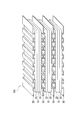
- FIG. 2 is a perspective view schematically showing the stack of the fuel cell according to the embodiment of the present invention.
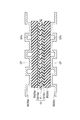
- FIG. 3 is a cross-sectional view schematically showing the basic configuration of the fuel cell.
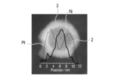
- FIG. 4 is a diagram showing a line analysis result of transmission electron microscope-energy dispersive X-ray spectroscopic analysis (TEM-EDX) in Example 1.
- FIG. 5 is a graph for explaining a method for measuring mass specific activity.
- FIG. 6 is a graph showing the relationship between the thickness of the noble metal layer and the mass specific activity in the examples.
- a fuel cell catalyst particle 1 (hereinafter also simply referred to as catalyst particle) according to an embodiment of the present invention includes a metal particle 2 and a noble metal layer 3 provided on the surface of the metal particle 2. I have.
- the catalyst particles 1 are characterized in that the noble metal layer 3 has a thickness of 1 to 3.2 nm.
- the noble metal layer 3 is formed thicker than in the past. That is, since the electrochemical reaction represented by the reaction formulas (I) and (II) proceeds on the surface of the noble metal layer 3, the catalyst particles are optimized by optimizing the thickness of the noble metal layer 3 in the above range. It becomes possible to improve the activity per unit noble metal mass (mass specific activity).
- the noble metal layer 3 needs to contain at least a noble metal from the viewpoint of promoting the electrochemical reaction.
- the noble metal layer 3 includes at least one selected from the group consisting of platinum (Pt), palladium (Pd), gold (Au), iridium (Ir), ruthenium (Ru), and silver (Ag). It is preferable to contain.
- the noble metal layer 3 more preferably contains at least platinum (Pt). Platinum is particularly preferable as a material for the noble metal layer 3 because it is difficult to dissolve even in an acidic medium and has excellent catalytic activity.
- the precious metal layer 3 preferably contains the precious metal as a main component. That is, the noble metal content in the noble metal layer 3 is preferably 50 mol% or more. However, from the viewpoint of improving the catalytic activity on the surface of the noble metal layer 3, elements other than the noble metal may be contained. Specifically, titanium (Ti), vanadium (V), chromium (Cr), manganese (Mn), iron (Fe), cobalt (Co), nickel (Ni), copper (Cu), zinc (Zn), At least one selected from the group consisting of zirconium (Zr), niobium (Nb), molybdenum (Mo), and tantalum (Ta) may be included.
- the noble metal content in the noble metal layer 3 is more preferably 80 mol% or more, further preferably 90 mol% or more, and particularly preferably 100 mol%.
- the thickness of the noble metal layer 3 needs to be 1 nm to 3.2 nm. By being in this range, it becomes possible to obtain catalyst particles having excellent catalytic activity, as shown in the examples described later. Further, the thickness of the noble metal layer 3 is particularly preferably 1.9 nm to 2.4 nm. By being in this range, it becomes possible to obtain catalyst particles having particularly excellent catalytic activity while reducing the amount of noble metal.
- the thickness of the noble metal layer 3 and the particle diameter of the metal particles 2 described later can be calculated by line analysis of transmission electron microscope-energy dispersive X-ray spectroscopy (TEM-EDX).
- the noble metal layer 3 preferably has a layered structure in which a plurality of noble metal monoatomic layers are stacked. By having such a layered structure, the outermost surface structure of the noble metal layer is optimized, and the mass specific activity can be further improved.
- the metal particles 2 are characterized by comprising any one of metals other than noble metals and alloys of metals other than noble metals and noble metals.
- the metal particles forming the core of the catalyst particles contain a metal other than such a noble metal, it is possible to maintain a high catalytic activity for the reaction gas while reducing the amount of the noble metal used.
- the metal particles 2 include titanium (Ti), vanadium (V), chromium (Cr), manganese (Mn), iron (Fe), cobalt (Co), nickel (Ni), copper (Cu), It is preferable to contain at least one selected from the group consisting of zinc (Zn), zirconium (Zr), niobium (Nb), molybdenum (Mo), and tantalum (Ta).
- a transition metal titanium (Ti), vanadium (V), chromium (Cr), manganese (Mn), iron (Fe), cobalt (Co), nickel (Ni), copper (Cu)
- the metal particles particles made of a metal other than the noble metal can be used, but an alloy of a metal other than the noble metal and the noble metal can also be used.
- an alloy of a metal other than the noble metal and the noble metal can also be used.
- the activity per unit area (area specific activity) of the catalyst particles can be kept high.
- the activity maintenance rate of the catalyst particles ratio of the catalyst activity after a lapse of a certain time to the catalyst activity when the fuel cell using the catalyst particles is driven for the first time
- a transition metal as the metal other than the noble metal for forming the alloy.
- Zr zirconium
- Nb niobium
- Mo molybdenum
- Ta tantalum
- the noble metal for forming the alloy is at least one selected from the group consisting of platinum (Pt), palladium (Pd), gold (Au), iridium (Ir), ruthenium (Ru), and silver (Ag). Is preferably used.
- the metal particle 2 has a metal other than the above-described noble metal as a main component. That is, the content of the metal other than the noble metal in the metal particle 2 is preferably 50 mol% or more. In addition, as for content of metals other than a noble metal in the metal particle 2, 80 mol% or more is more preferable, and 90 mol% or more is further more preferable.
- the particle diameter of the metal particles 2 is preferably 2 nm to 5.5 nm.
- the noble metal layer 3 covers the entire surface of the metal particles 2. However, from the viewpoint of increasing the surface area of the noble metal layer 3 and increasing the three-phase interface (electrolyte-catalyst particles-reaction gas), the noble metal layer 3 preferably covers at least 60% or more of the surface of the metal particles 2. . Further, the noble metal layer 3 preferably covers 80% or more of the surface of the metal particle 2, and more preferably covers 90% or more.
- the catalyst particles of this embodiment include metal particles containing a metal other than a noble metal, and a noble metal layer having a thickness of 1 nm to 3.2 nm provided on the surface of the metal particles.
- the outermost surface structure of the noble metal layer is optimized, and the mass specific activity can be further improved while reducing the amount of noble metal used.
- a precursor solution is prepared by dispersing a salt of a metal other than a noble metal or a complex of a metal other than a noble metal in a solvent.
- a metal particle dispersion is prepared by adding a reducing agent.
- a noble metal layer or a noble metal complex is added to the metal particle dispersion to form a noble metal layer on the surface of the metal particles.
- salts of metals other than noble metals or complexes of metals other than noble metals are titanium (Ti), vanadium (V), chromium (Cr), manganese (Mn), iron (Fe), cobalt (Co), nickel (Ni ), Copper (Cu), zinc (Zn), zirconium (Zr), niobium (Nb), molybdenum (Mo) and tantalum (Ta).
- the salts or complexes of metals other than noble metals include nitrates, sulfates, ammonium salts, amines, carbonates, bicarbonates, bromides and chlorides of metals other than noble metals, nitrites, oxalic acid, etc.
- Inorganic salts such as carboxylic acid salts such as sulfamate and formate, hydroxides, alkoxides, oxides, ammine complexes, cyano complexes, halogeno complexes, and hydroxy complexes can be used. That is, a compound in which a metal other than a noble metal can be converted into a metal ion in a solvent such as pure water is preferable.
- halides particularly chlorides
- sulfates and nitrates are more preferable as the salts or complexes of metals other than noble metals. Note that pure water can be used as the solvent.
- a reducing agent is added to the precursor solution in which a metal other than the noble metal is dissolved, and a metal other than the noble metal is precipitated to prepare a metal particle dispersion in which fine metal particles are dispersed.
- the reducing agent include ethanol, methanol, propanol, formic acid, formate such as sodium formate and potassium formate, citrate such as formaldehyde, sodium thiosulfate, citric acid and sodium citrate, sodium borohydride (NaBH 4 ) and Hydrazine (N 2 H 4 ) or the like can be used.
- the amount of the reducing agent added is not particularly limited as long as the metal can be sufficiently reduced to prepare fine metal particles. It is preferable to add a reducing agent.
- concentration of metals other than a noble metal in the said precursor solution is 2.5 mM or less.
- a noble metal layer or a noble metal complex is added to the metal particle dispersion to form a noble metal layer on the surface of the metal particles. That is, by adding a noble metal salt to the metal particle dispersion, the noble metal salt is dissolved in the dispersion and the generated noble metal ions receive electrons from the metal particles in the dispersion. As a result, noble metal ions are reduced on the surface of the metal particles, and a noble metal layer is deposited.
- the noble metal salt or the noble metal complex preferably contains at least one selected from the group consisting of platinum, palladium, gold, iridium, ruthenium and silver. As described above, since the noble metal layer preferably contains at least platinum, the noble metal salt or the noble metal complex preferably contains at least platinum.
- noble metal salts or noble metal complexes include nitrates, sulfates, ammonium salts, amines, carbonates, bicarbonates, halides such as bromides and chlorides, inorganic salts such as nitrites and oxalic acid, sulfamines, and the like.
- a carboxylate such as an acid salt and a formate, a hydroxide, an alkoxide, an ammine complex, a cyano complex, a halogeno complex, and a hydroxy complex can be used.
- an ammine complex or a halogeno complex is more preferable.
- a substitution reaction of the metal of the metal particle and the noble metal ion of the noble metal complex proceeds.
- noble metal ions penetrate into the metal particles, and as the metal particles, particles made of an alloy of a metal other than the noble metal and the noble metal are generated.
- a reduction reaction of noble metal ions proceeds on the surface of the metal particles, and a noble metal layer is deposited.
- the ratio of the number of moles of a metal other than the noble metal to the number of moles of the noble metal is 3.2 to 11. It is preferable to mix a metal other than the noble metal and a noble metal raw material. With such a mixing ratio, the film thickness of the noble metal layer can be easily controlled to 1 nm to 3.2 nm.
- the catalyst particles When isolating the catalyst particles obtained as described above, the catalyst particles may be filtered and dried.
- the catalyst particles are first adsorbed on the conductive carrier by introducing the conductive carrier into the catalyst particle dispersion and stirring. Let Thereafter, an electrocatalyst in which the catalyst particles are dispersed in the electroconductive carrier can be obtained by filtering and drying the electroconductive carrier on which the catalyst particles are adsorbed.
- the drying of the catalyst particles and the electrode catalyst may be performed in air, may be performed in an inert gas atmosphere, or may be performed under reduced pressure.
- the drying temperature is not particularly limited, but can be performed, for example, in the range of room temperature (25 ° C.) to about 100 ° C.
- FIG. 2 schematically shows a stack of a polymer electrolyte fuel cell, which is a typical example of a fuel cell according to an embodiment of the present invention.
- FIG. 3 schematically shows the basic configuration of the polymer electrolyte fuel cell.
- the fuel cell 100 includes a membrane electrode assembly 10 and a pair of gas diffusion layers (GDL) 20 that sandwich the membrane electrode assembly 10. Further, the fuel cell 100 includes a pair of separators 30 that sandwich the membrane electrode assembly 10 and the gas diffusion layer 20.
- GDL gas diffusion layers
- the membrane electrode assembly exhibits a power generation function, and the gas diffusion layer disperses the supply gas.
- the separator separates the fuel gas and the oxidant gas supplied to the anode and the cathode and electrically connects adjacent membrane electrode assemblies.
- a fuel cell is comprised by laminating
- a gas seal member is disposed around the separator, between the separator and the solid polymer electrolyte membrane described later, or between the membrane electrode assembly and another membrane electrode assembly adjacent thereto. Is done. However, in FIG. 2 and FIG. 3, the description of the gas seal member is omitted.
- a manifold member that functions as a connection means for connecting the cells when the stack is formed is disposed. However, the description of the manifold member is omitted in FIG.
- the membrane electrode assembly 10 includes a polymer electrolyte membrane 11 and a pair of electrode catalyst layers 13 (an anode electrode catalyst layer 13a and a cathode electrode catalyst layer 13c) sandwiching the polymer electrolyte membrane 11.
- the membrane electrode assembly 10 is sandwiched between a pair of gas diffusion layers 20 (an anode gas diffusion layer 20a and a cathode gas diffusion layer 20c).
- the membrane electrode assembly 10 and the gas diffusion layer 20 are sandwiched between a pair of separators 30 (an anode separator 30a and a cathode separator 30c).
- the separator 30 has an uneven shape as shown in FIG.
- the convex portions of the anode separator 30 a and the cathode separator 30 c viewed from the membrane electrode assembly 10 side are in contact with the gas diffusion layer 20. Thereby, the electrical connection with the membrane electrode assembly 10 is ensured.
- a recess is formed as a space between the separator 30 and the gas diffusion layer 20 generated due to the uneven shape of the separator. ing. And this recessed part functions as a gas flow path (GPa, GPc) for distribute
- fuel gas for example, hydrogen
- oxidant gas for example, oxygen, air
- the recess viewed from the side opposite to the membrane electrode assembly 10 side of the anode separator 30a and the cathode separator 30c circulates a coolant (for example, water) for cooling the fuel cell during operation of the fuel cell 100.
- a coolant for example, water
- the polymer electrolyte membrane 11 has a function of selectively transmitting protons generated in the anode electrode catalyst layer 13a during the operation of the fuel cell 100 to the cathode electrode catalyst layer 13c along the film thickness direction.
- the polymer electrolyte membrane 11 also functions as a partition wall for preventing the fuel gas supplied to the anode side and the oxidant gas supplied to the cathode side from being mixed.
- the polymer electrolyte membrane 11 is roughly classified into a fluorine-based polymer electrolyte membrane and a hydrocarbon-based polymer electrolyte membrane depending on the type of ion exchange resin that is a constituent material.
- ion exchange resins constituting the fluorine-based polymer electrolyte membrane include NAFION (registered trademark, manufactured by DuPont), Aciplex (registered trademark, manufactured by Asahi Kasei Chemicals), and Flemion (registered trademark, manufactured by Asahi Glass Co., Ltd.).
- Perfluorocarbon sulfonic acid polymers perfluorocarbon phosphonic acid polymers; trifluorostyrene sulfonic acid polymers; ethylene tetrafluoroethylene-g-styrene sulfonic acid polymers; ethylene-tetrafluoroethylene copolymers; polyvinylidene fluoride Examples thereof include do-perfluorocarbon sulfonic acid polymers.
- these fluorine-based polymer electrolyte membranes are preferably used.
- a fluoropolymer electrolyte membrane composed of a perfluorocarbon sulfonic acid polymer is used.
- Examples of the ion exchange resin constituting the hydrocarbon polymer electrolyte membrane include sulfonated polyethersulfone (S-PES), sulfonated polyaryletherketone, sulfonated polybenzimidazole alkyl, and phosphonated polybenzimidazole. Examples thereof include alkyl, sulfonated polystyrene, sulfonated polyether ether ketone (S-PEEK), and sulfonated polyphenylene (S-PPP).
- S-PES sulfonated polyethersulfone
- S-PEEK sulfonated polyether ether ketone
- S-PPP sulfonated polyphenylene
- These hydrocarbon polymer electrolyte membranes are preferably used from the viewpoint of production such that the raw material is inexpensive, the production process is simple, and the selectivity of the material is high.
- the ion exchange resin mentioned above only 1 type may be used independently
- the thickness of the polymer electrolyte membrane may be appropriately determined in consideration of the characteristics of the obtained fuel cell, and is not particularly limited.
- the thickness of the polymer electrolyte membrane is usually 5 to 300 ⁇ m. When the thickness of the polymer electrolyte membrane is within such a numerical range, it is possible to appropriately control the balance between strength during film formation, durability during use, and output characteristics during use.
- the electrode catalyst layers are layers in which the battery reaction actually proceeds. Specifically, the oxidation reaction of hydrogen proceeds in the anode electrode catalyst layer 13a, and the reduction reaction of oxygen proceeds in the cathode electrode catalyst layer 13c.
- the electrode catalyst layer of this embodiment contains at least the fuel cell catalyst particles described above, and the fuel cell catalyst particles are supported on a carrier. Further, the electrode catalyst layer contains a proton conductive material in order to improve proton conductivity.
- At least one of the anode electrode catalyst layer 13a and the cathode electrode catalyst layer 13c according to the present embodiment contains a fuel cell electrode catalyst in which the above-described fuel cell catalyst particles are supported on a carrier.
- the anode electrode catalyst layer 13a may contain other conventionally known catalyst particles as long as they have a catalytic action in the oxidation reaction of hydrogen.
- the cathode electrode catalyst layer 13c may contain other conventionally known catalyst particles as long as they have a catalytic action in the oxygen reduction reaction.
- catalyst particles include platinum (Pt), ruthenium (Ru), iridium (Ir), rhodium (Rh), palladium (Pd), osmium (Os), tungsten (W), lead (Pb), Selected from the group consisting of iron (Fe), chromium (Cr), cobalt (Co), nickel (Ni), manganese (Mn), vanadium (V), molybdenum (Mo), gallium (Ga) and aluminum (Al) Examples thereof include at least one metal, a mixture or an alloy according to any combination thereof.
- the other catalyst particles contained in the anode electrode catalyst layer and the cathode electrode catalyst layer do not have to be the same, and can be appropriately selected so as to exhibit the desired action as described above.
- the size of the other catalyst particles is not particularly limited, and the same size as a conventionally known catalyst can be adopted.
- the average particle diameter of the other catalyst particles is preferably 1 to 30 nm, more preferably 1 to 20 nm. When the average particle diameter of the other catalyst particles is within such a range, the balance between the catalyst utilization rate related to the effective electrode area where the electrochemical reaction proceeds and the ease of loading can be appropriately controlled.
- the average particle diameter of the other catalyst particles is a crystallite diameter obtained from the half-value width of the diffraction peak of the catalyst particles in X-ray diffraction or an average value of the particle diameters of the catalyst particles examined from a transmission electron microscope image. be able to.
- the carrier for supporting the catalyst particles is preferably a conductive carrier. That is, the carrier preferably functions as an electron conduction path involved in the exchange of electrons between the catalyst particles and other members. Further, by supporting the catalyst particles on a conductive carrier, it is possible to form a thick electrode catalyst layer, and it is possible to use at a high current density.
- the conductive carrier may be any conductive carrier having a specific surface area for supporting the catalyst particles in a desired dispersed state and sufficient electron conductivity, and the main component is preferably carbon.
- carbon black such as acetylene black, channel black, oil furnace black, gas furnace black (eg Vulcan), lamp black, thermal black, ketjen black (registered trademark); black pearl; graphitized acetylene black; Graphitized Channel Black; Graphitized Oil Furnace Black; Graphitized Gas Furnace Black; Graphitized Lamp Black; Graphitized Thermal Black; Graphitized Ketjen Black; Graphitized Black Pearl; Carbon Nanotubes; Carbon Nanofibers; Carbon Nanohorns; Activated carbon; coke; natural graphite; artificial graphite.
- examples of the conductive carrier include zeolite template carbon (ZTC) having a structure in which nano-sized band-shaped graphene is regularly connected in a three-dimensional manner.
- the main component is carbon means that the main component includes a carbon atom, and is a concept including both a carbon atom only and a substantially carbon atom. In some cases, elements other than carbon atoms may be included in order to improve the characteristics of the fuel cell. In addition, “substantially consisting of carbon atoms” means that contamination of 2 to 3 mass% or less of impurities can be allowed.
- the BET specific surface area of the conductive support is preferably a specific surface area sufficient to support the catalyst particles in a highly dispersed state, and is preferably 10 to 5000 m 2 / g.
- the specific surface area of the conductive support is within such a numerical range, the balance between the dispersibility of the catalyst on the conductive support and the effective utilization rate of the catalyst can be appropriately controlled.
- the conductive carrier one having primary vacancies or one having no primary vacancies can be used as appropriate.
- the size of the conductive carrier is not particularly limited. However, from the standpoint of easy loading and controlling the thickness of the electrode catalyst layer within an appropriate range, the average particle size is about 5 to 200 nm, preferably 10 to 100 nm.
- the supported concentration of the fuel cell catalyst particles of the present embodiment in the conductive support is preferably 2 to 70% by mass with respect to the total amount of the electrode catalyst.
- the concentration of catalyst particles supported on the conductive carrier can be measured by inductively coupled plasma emission spectroscopy (ICP).
- Examples of the proton conducting material include a polymer electrolyte material having a proton donating group.
- the polymer electrolyte material is roughly classified into a fluorine-based polymer electrolyte material and a hydrocarbon-based polymer electrolyte material depending on the type of ion exchange resin that is a constituent material.
- Examples of ion exchange resins constituting the fluorine-based polymer electrolyte material include perfluorocarbon sulfonic acid polymers such as NAFION, Aciplex, and Flemion; perfluorocarbon phosphonic acid polymers; trifluorostyrene sulfonic acid polymers; ethylene tetrafluoro And ethylene-g-styrene sulfonic acid polymer; ethylene-tetrafluoroethylene copolymer; polyvinylidene fluoride-perfluorocarbon sulfonic acid polymer. From the viewpoint of improving power generation performance such as heat resistance and chemical stability, these fluorine-based polymer electrolyte materials are preferably used, and perfluorocarbon sulfonic acid polymers are particularly preferably used.
- perfluorocarbon sulfonic acid polymers are particularly preferably used.
- Examples of the ion exchange resin constituting the hydrocarbon-based polymer electrolyte material include sulfonated polyethersulfone (S-PES); sulfonated polyaryletherketone; sulfonated polybenzimidazole alkyl; phosphonated polybenzimidazole. Examples include alkyl; sulfonated polystyrene; sulfonated polyetheretherketone (S-PEEK); sulfonated polyphenylene (S-PPP).
- S-PES sulfonated polyethersulfone
- S-PEEK sulfonated polyetheretherketone
- S-PPP sulfonated polyphenylene
- the gas diffusion layers are configured to convert the gas (fuel gas or oxidant gas) supplied through the gas flow paths (GPa, GPc) of the separator into the electrode catalyst layers (13a, 13c). Further, the gas diffusion layer has a function as an electron conduction path.
- the material constituting the base material of the gas diffusion layer is not particularly limited, and conventionally known knowledge is appropriately referred to. Examples thereof include sheet-like materials having conductivity and porosity, such as carbon woven fabrics and nonwoven fabrics, paper-like paper bodies, wire nets, metal meshes, punching metals, and expanded metals.
- the thickness of the substrate may be appropriately determined in consideration of the characteristics of the obtained gas diffusion layer, but may be about 30 to 500 ⁇ m. If the thickness of the substrate is a value within such a range, the balance between mechanical strength and diffusibility such as gas and water can be appropriately controlled.
- the gas diffusion layer preferably contains a water repellent for the purpose of further improving water repellency and preventing flooding.
- the water repellent is not particularly limited, and examples thereof include fluorine-based polymer materials and olefin-based polymer materials.
- fluorine-based polymer material include polytetrafluoroethylene (PTFE), polyvinylidene fluoride (PVdF), polyhexafluoropropylene (PHFP), and tetrafluoroethylene-hexafluoropropylene copolymer (TFE-HFP). It is done.
- the olefin polymer material include polypropylene (PP) and polyethylene (PE).
- the gas diffusion layer has a carbon particle layer (microporous layer; MPL) made of an aggregate of carbon particles containing a water repellent on the electrode catalyst layer side of the substrate.
- MPL microporous layer
- the carbon particles contained in the carbon particle layer are not particularly limited, and conventionally known materials such as carbon black, graphite, and expanded graphite can be appropriately employed. Among them, carbon black such as oil furnace black, channel black, lamp black, thermal black, acetylene black and the like is preferably used because of excellent electron conductivity and a large specific surface area.
- the average particle diameter of the carbon particles is preferably about 10 to 100 nm. Thereby, while being able to obtain the high drainage property by capillary force, it becomes possible to improve contact property with an electrode catalyst layer.
- Examples of the water repellent used for the carbon particle layer include the same water repellents as described above. Among them, it is preferable to use a fluorine-based polymer material because it is excellent in water repellency, corrosion resistance during electrode reaction, and the like.
- the mixing ratio of the carbon particles to the water repellent in the carbon particle layer is about 90:10 to 40:60 (carbon particles: water repellent) in mass ratio in consideration of the balance between water repellency and electron conductivity. It is good.
- the separator 30 can be obtained, for example, by forming a concavo-convex shape as shown in FIG. 2 by performing a pressing process on a thin plate having a thickness of 0.5 mm or less, but is not limited to such a form. That is, for example, by performing a cutting process on a flat metal plate (metal base material), the uneven shape constituting the gas flow path or the coolant flow path may be formed.
- the material constituting the separator is not particularly limited, and conventionally known materials can be applied. It is preferable that the supplied gas is difficult to permeate, and it is preferable that the current extracted by the battery reaction easily flows.
- metal materials such as iron, titanium, aluminum, and alloys thereof; metal materials whose corrosion resistance has been improved by forming a film such as a carbon material; high conductivity imparted with a metal material or a carbon material, etc. Examples include molecular materials (conductive plastics).
- the iron alloy includes stainless steel. These may be a single layer or a layered structure of two or more layers.
- the catalyst particles of this embodiment are preferably used for electrochemical devices such as solid polymer fuel cells. Further, the catalyst particles of the present embodiment can also be used for electrochemical devices such as phosphoric acid fuel cells.
- NiCl 2 nickel (II) chloride
- a nickel aqueous solution having a concentration of 0.105M nickel aqueous solution having a concentration of 0.105M.
- 1.2 g of trisodium citrate dihydrate and 0.40 g of sodium borohydride were mixed with 100 mL of ultrapure water to prepare a reducing agent aqueous solution.
- a ketjen black dispersion in which 0.2 g of ketjen black was mixed with 100 mL of ultrapure water was prepared.
- the reducing agent aqueous solution is added and stirred at room temperature (25 ° C.) for 30 minutes to prepare a dispersion of nickel metal particles. did.
- a catalyst in which a noble metal layer was formed around the metal particles by adding 0.41 mL of a 1.16M chloroplatinic acid aqueous solution to the metal particle dispersion and stirring at room temperature (25 ° C.) for 30 minutes. Particles were prepared.
- Ketjen black dispersion was mixed with the catalyst particle dispersion, and the mixture was stirred at room temperature (25 ° C.) for 48 hours, thereby supporting the catalyst particles on Ketjen black. Thereafter, ketjen black carrying catalyst particles was filtered, washed with ultrapure water three times, and then dried in air at 60 ° C. for 12 hours or more to prepare the electrode catalyst of this example.
- Example 2 The electrode catalyst of this example was the same as Example 1 except that a reducing agent aqueous solution in which 1.5 g of trisodium citrate dihydrate and 0.40 g of sodium borohydride were mixed in 100 mL of ultrapure water was used. was prepared.
- Example 3 First, 0.78 g of trisodium citrate dihydrate and 0.20 g of sodium borohydride were mixed with 100 mL of ultrapure water to prepare an aqueous reducing agent solution.
- Example 2 After mixing 14.3 mL of the nickel aqueous solution of Example 1 with 1000 mL of ultrapure water, the above reducing agent aqueous solution was added, and the mixture was stirred at room temperature (25 ° C.) for 30 minutes to disperse the metal particles made of nickel. A liquid was prepared.
- a catalyst in which a noble metal layer was formed around the metal particles by adding 0.27 mL of a 1.16M chloroplatinic acid aqueous solution to the metal particle dispersion and stirring at room temperature (25 ° C.) for 30 minutes. Particles were prepared.
- Example 1 the Ketjen black dispersion of Example 1 was mixed with the catalyst particle dispersion and stirred at room temperature (25 ° C.) for 48 hours to support the catalyst particles on Ketjen black. Thereafter, ketjen black carrying catalyst particles was filtered, washed with ultrapure water three times, and then dried in air at 60 ° C. for 12 hours or more to prepare the electrode catalyst of this example.
- nickel (II) sulfamate tetrahydrate was dissolved in ultrapure water to prepare a nickel aqueous solution having a concentration of 0.105M. Furthermore, 0.78 g of trisodium citrate dihydrate and 0.26 g of sodium borohydride were mixed with 100 mL of ultrapure water to prepare a reducing agent aqueous solution.
- Example 1 the Ketjen black dispersion of Example 1 was mixed with the catalyst particle dispersion and stirred at room temperature (25 ° C.) for 48 hours to support the catalyst particles on Ketjen black. Thereafter, ketjen black carrying catalyst particles was filtered, washed with ultrapure water three times, and then dried in air at 60 ° C. for 12 hours or more to prepare the electrode catalyst of this example.
- Example 5 nickel (II) sulfate (NiSO 4 ) was dissolved in ultrapure water to prepare a nickel aqueous solution having a concentration of 0.105M. Furthermore, 1.2 g of trisodium citrate dihydrate and 0.30 g of sodium borohydride were mixed with 100 mL of ultrapure water to prepare a reducing agent aqueous solution.
- the reducing agent aqueous solution is added and stirred at room temperature (25 ° C.) for 30 minutes to prepare a dispersion of nickel metal particles. did.
- Example 1 the Ketjen black dispersion of Example 1 was mixed with the catalyst particle dispersion and stirred at room temperature (25 ° C.) for 48 hours to support the catalyst particles on Ketjen black. Thereafter, ketjen black carrying catalyst particles was filtered, washed with ultrapure water three times, and then dried in air at 60 ° C. for 12 hours or more to prepare the electrode catalyst of this example.
- Nickel (II) sulfamate tetrahydrate was dissolved in ultrapure water to prepare a nickel aqueous solution having a concentration of 0.105M. Furthermore, 1.57 g of trisodium citrate dihydrate and 0.39 g of sodium borohydride were mixed with 100 mL of ultrapure water to prepare a reducing agent aqueous solution.
- a catalyst in which a noble metal layer was formed around the metal particles by adding 0.53 mL of a 1.16M chloroplatinic acid aqueous solution to the metal particle dispersion and stirring at room temperature (25 ° C.) for 30 minutes. Particles were prepared.
- Example 1 the Ketjen black dispersion of Example 1 was mixed with the catalyst particle dispersion and stirred at room temperature (25 ° C.) for 48 hours to support the catalyst particles on Ketjen black. Thereafter, ketjen black carrying catalyst particles was filtered, washed with ultrapure water three times, and then dried in air at 60 ° C. for 12 hours or more to prepare an electrode catalyst of this comparative example.
- FIG. 6 is a graph showing the relationship between the mass specific activity of the electrode catalyst of each Example and Comparative Example and the thickness of the noble metal layer. As shown in FIG. 6, it can be confirmed that the mass specific activity is high when the thickness of the noble metal layer is 1 nm to 3.2 nm, and that the mass specific activity is particularly excellent when the thickness is 1.9 nm to 2.4 nm.
- a noble metal layer having a thickness of 1 nm to 3.2 nm is provided on the surface of the metal particles. Therefore, by optimizing the thickness of the noble metal layer, the electrochemical reaction represented by the above reaction formulas (I) and (II) proceeds on the surface of the noble metal layer. The catalytic activity can be improved while reducing the above. Furthermore, the production method of the present invention can easily prepare the fuel cell catalyst particles.
Landscapes
- Chemical & Material Sciences (AREA)
- Chemical Kinetics & Catalysis (AREA)
- General Chemical & Material Sciences (AREA)
- Engineering & Computer Science (AREA)
- Electrochemistry (AREA)
- Materials Engineering (AREA)
- Organic Chemistry (AREA)
- Mechanical Engineering (AREA)
- Metallurgy (AREA)
- Composite Materials (AREA)
- Manufacturing & Machinery (AREA)
- Inert Electrodes (AREA)
- Fuel Cell (AREA)
- Catalysts (AREA)
Abstract
Description
2H++2e-+(1/2)O2→H2O …(II)
本発明の実施形態に係る燃料電池用触媒粒子1(以下、単に触媒粒子ともいう。)は、図1に示すように、金属粒子2と、金属粒子2の表面に設けられる貴金属層3とを備えている。そして、触媒粒子1は、貴金属層3の厚さが1~3.2nmであることを特徴とする。
次に、本実施形態の燃料電池用触媒粒子の製造方法について説明する。
次に、本実施形態に係る燃料電池用触媒粒子を用いた燃料電池について説明する。図2では、本発明の実施形態に係る燃料電池の代表例である固体高分子形燃料電池のスタックの概略を示している。また、図3は、当該固体高分子形燃料電池の基本構成を模式的に示している。
高分子電解質膜11は、燃料電池100の運転時にアノード電極触媒層13aで生成したプロトンを膜厚方向に沿ってカソード電極触媒層13cへと選択的に透過させる機能を有する。また、高分子電解質膜11は、アノード側に供給される燃料ガスとカソード側に供給される酸化剤ガスとを混合させないための隔壁としての機能をも有する。
電極触媒層(アノード電極触媒層13a、カソード電極触媒層13c)は、実際に電池反応が進行する層である。具体的には、アノード電極触媒層13aでは水素の酸化反応が進行し、カソード電極触媒層13cでは酸素の還元反応が進行する。そして、本実施形態の電極触媒層は少なくとも上述の燃料電池用触媒粒子を含有し、さらに上記燃料電池用触媒粒子は担体に担持されている。また、電極触媒層は、プロトン伝導性を向上させるために、プロトン伝導材を含有している。
本実施形態に係るアノード電極触媒層13a及びカソード電極触媒層13cの少なくとも一方は、上述の燃料電池用触媒粒子を担体に担持させてなる燃料電池用電極触媒を含有している。ただ、アノード電極触媒層13aに関し、水素の酸化反応に触媒作用を有するものであれば、従来公知の他の触媒粒子を含有してもよい。同様に、カソード電極触媒層13cに関し、酸素の還元反応に触媒作用を有するものであれば、従来公知の他の触媒粒子を含有してもよい。
上記触媒粒子を担持するための担体は、導電性担体であることが好ましい。つまり、担体は、触媒粒子と他の部材との間における、電子の授受に関与する電子伝導パスとして機能するものであることが好ましい。また、触媒粒子を導電性の担体上に担持することで、厚みのある電極触媒層を形成することが可能となり、さらに高電流密度での利用が可能となる。
プロトン伝導材としては、例えば、プロトン供与性基を有する高分子電解質材料を挙げることができる。そして、高分子電解質材料は、構成材料であるイオン交換樹脂の種類によって、フッ素系高分子電解質材料と炭化水素系高分子電解質材料とに大別される。
ガス拡散層(アノードガス拡散層20a、カソードガス拡散層20c)は、セパレータのガス流路(GPa、GPc)を介して供給されたガス(燃料ガス又は酸化剤ガス)を電極触媒層(13a、13c)へ拡散させる機能を有する。また、ガス拡散層は、電子伝導パスとしての機能を有する。
セパレータ30は、例えば、厚さ0.5mm以下の薄板にプレス処理を施すことによって図2に示すような凹凸形状に成形することにより得られるが、このような形態に限定されない。すなわち、例えば平板状の金属板(金属基材)に対して切削処理を施すことにより、ガス流路や冷媒流路を構成する凹凸形状を形成してもよい。
まず、塩化ニッケル(II)(NiCl2)を超純水に溶解し、濃度が0.105Mのニッケル水溶液を調製した。さらに、超純水100mLにクエン酸三ナトリウム二水和物1.2gと水素化ホウ素ナトリウム0.40gを混合し、還元剤水溶液を調製した。また、超純水100mLにケッチェンブラック0.2gを混合したケッチェンブラック分散液を調製した。
超純水100mLにクエン酸三ナトリウム二水和物1.5gと水素化ホウ素ナトリウム0.40gを混合した還元剤水溶液を用いたこと以外は実施例1と同様にして、本実施例の電極触媒を調製した。
まず、超純水100mLにクエン酸三ナトリウム二水和物0.78gと水素化ホウ素ナトリウム0.20gを混合し、還元剤水溶液を調製した。
まず、スルファミン酸ニッケル(II)四水和物を超純水に溶解し、濃度が0.105Mのニッケル水溶液を調製した。さらに、超純水100mLにクエン酸三ナトリウム二水和物0.78gと水素化ホウ素ナトリウム0.26gを混合し、還元剤水溶液を調製した。
まず、硫酸ニッケル(II)(NiSO4)を超純水に溶解し、濃度が0.105Mのニッケル水溶液を調製した。さらに、超純水100mLにクエン酸三ナトリウム二水和物1.2gと水素化ホウ素ナトリウム0.30gを混合し、還元剤水溶液を調製した。
まず、スルファミン酸ニッケル(II)四水和物を超純水に溶解し、濃度が0.105Mのニッケル水溶液を調製した。さらに、超純水100mLにクエン酸三ナトリウム二水和物1.57gと水素化ホウ素ナトリウム0.39gを混合し、還元剤水溶液を調製した。
TEM-EDXのライン分析により、各実施例及び比較例の貴金属層の厚さ及び金属粒子の直径を測定した。触媒粒子のライン分析結果の代表例を図4に示す。また、得られた各実施例及び比較例の貴金属層の平均厚さ及び金属粒子の平均直径の結果を表1に示す。
Electrochemistry Vol.79, No.2, p.116-121 (2011) (対流ボルタモグラム(1)酸素還元(RRDE))の「4 Pt/C触媒上での酸素還元反応の解析」に記載の方法に準じて、各実施例及び比較例の電極触媒の質量比活性を測定した。

2 金属粒子
3 貴金属層
Claims (10)
- 貴金属以外の金属、及び貴金属以外の金属と貴金属との合金のいずれか一方からなる金属粒子と、
前記金属粒子の表面に設けられ、厚さが1nm~3.2nmである貴金属層と、
を備えることを特徴とする燃料電池用触媒粒子。 - 前記貴金属層は、少なくとも白金を含有することを特徴とする請求項1に記載の燃料電池用触媒粒子。
- 前記金属粒子の粒子径は、2nm~5.5nmであることを特徴とする請求項1又は2に記載の燃料電池用触媒粒子。
- 前記金属粒子における貴金属は、白金、パラジウム、金、イリジウム、ルテニウム及び銀からなる群から選ばれる少なくとも一つであり、
前記金属粒子における貴金属以外の金属は、チタン、バナジウム、クロム、マンガン、鉄、コバルト、ニッケル、銅、亜鉛、ジルコニウム、ニオブ、モリブデン及びタンタルからなる群から選ばれる少なくとも一つであることを特徴とする請求項1乃至3のいずれか一項に記載の燃料電池用触媒粒子。 - 請求項1乃至4のいずれか一項に記載の燃料電池用触媒粒子と、
前記燃料電池用触媒粒子を担持する導電性担体と、
を備えることを特徴とする燃料電池用電極触媒。 - 貴金属以外の金属の塩又は貴金属以外の金属の錯体を溶媒中に分散させることにより、前駆体溶液を調製した後、前記前駆体溶液に還元剤を添加することにより、金属粒子分散液を調製する工程と、
前記金属粒子分散液に、貴金属塩又は貴金属錯体を添加することにより、金属粒子の表面に貴金属層を形成する工程と、
を有することを特徴とする燃料電池用触媒粒子の製造方法。 - 前記貴金属塩又は貴金属錯体は、少なくとも白金を含有することを特徴とする請求項6に記載の燃料電池用触媒粒子の製造方法。
- 前記貴金属塩又は貴金属錯体は、白金、パラジウム、金、イリジウム、ルテニウム及び銀からなる群から選ばれる少なくとも一つを含有し、
前記貴金属以外の金属の塩又は貴金属以外の金属の錯体は、チタン、バナジウム、クロム、マンガン、鉄、コバルト、ニッケル、銅、亜鉛、ジルコニウム、ニオブ、モリブデン及びタンタルからなる群から選ばれる少なくとも一つを含有することを特徴とする請求項6に記載の燃料電池用触媒粒子の製造方法。 - 前記前駆体溶液における貴金属以外の金属の濃度は、2.5mM以下であることを特徴とする請求項6乃至8のいずれか一項に記載の燃料電池用触媒粒子の製造方法。
- 貴金属のモル数に対する貴金属以外の金属のモル数の比率([貴金属以外の金属のモル数]/[貴金属のモル数])が3.2~11であることを特徴とする請求項6乃至9のいずれか一項に記載の燃料電池用触媒粒子の製造方法。
Priority Applications (5)
| Application Number | Priority Date | Filing Date | Title |
|---|---|---|---|
| CN201480009964.0A CN105073254B (zh) | 2013-02-25 | 2014-01-22 | 燃料电池用催化剂颗粒及其制造方法 |
| CA2902397A CA2902397C (en) | 2013-02-25 | 2014-01-22 | Catalyst particles for fuel cells and method for producing same |
| EP14753958.9A EP2959968B1 (en) | 2013-02-25 | 2014-01-22 | Catalyst particles for fuel cells and method for producing same |
| US14/769,988 US9991522B2 (en) | 2013-02-25 | 2014-01-22 | Catalyst particles for fuel cells and method for producing same |
| JP2015501366A JP6197861B2 (ja) | 2013-02-25 | 2014-01-22 | 燃料電池用触媒粒子及びその製造方法 |
Applications Claiming Priority (2)
| Application Number | Priority Date | Filing Date | Title |
|---|---|---|---|
| JP2013-034297 | 2013-02-25 | ||
| JP2013034297 | 2013-02-25 |
Publications (1)
| Publication Number | Publication Date |
|---|---|
| WO2014129253A1 true WO2014129253A1 (ja) | 2014-08-28 |
Family
ID=51391050
Family Applications (1)
| Application Number | Title | Priority Date | Filing Date |
|---|---|---|---|
| PCT/JP2014/051199 WO2014129253A1 (ja) | 2013-02-25 | 2014-01-22 | 燃料電池用触媒粒子及びその製造方法 |
Country Status (6)
| Country | Link |
|---|---|
| US (1) | US9991522B2 (ja) |
| EP (1) | EP2959968B1 (ja) |
| JP (1) | JP6197861B2 (ja) |
| CN (1) | CN105073254B (ja) |
| CA (1) | CA2902397C (ja) |
| WO (1) | WO2014129253A1 (ja) |
Cited By (3)
| Publication number | Priority date | Publication date | Assignee | Title |
|---|---|---|---|---|
| WO2017033342A1 (ja) * | 2015-08-27 | 2017-03-02 | 日産自動車株式会社 | 触媒粒子ならびにこれを用いてなる電極触媒、電解質膜-電極接合体および燃料電池 |
| JP2017042759A (ja) * | 2015-08-27 | 2017-03-02 | 国立大学法人山梨大学 | 燃料電池のアノード用触媒、アノード及び燃料電池 |
| JP2017144401A (ja) * | 2016-02-18 | 2017-08-24 | 国立大学法人東北大学 | コアシェル触媒の製造方法 |
Families Citing this family (15)
| Publication number | Priority date | Publication date | Assignee | Title |
|---|---|---|---|---|
| US9633957B2 (en) * | 2014-11-28 | 2017-04-25 | Infineon Technologies Ag | Semiconductor device, a power semiconductor device, and a method for processing a semiconductor device |
| CN108232203A (zh) * | 2016-12-09 | 2018-06-29 | 中国科学院大连化学物理研究所 | 一种过氧化氢燃料电池阴极及其制备和应用 |
| CN107342427B (zh) * | 2017-08-22 | 2020-04-28 | 岭南师范学院 | 一种直接乙醇燃料电池用Pd/Ag纳米合金催化剂的制备方法 |
| CN116230960A (zh) * | 2017-12-28 | 2023-06-06 | 松下知识产权经营株式会社 | 燃料电池用催化剂层的制造方法、膜电极接合体的制造方法及燃料电池的制造方法 |
| WO2019193460A1 (en) * | 2018-04-04 | 2019-10-10 | 3M Innovative Properties Company | Catalyst comprising pt, ni, and ru |
| EP3776701A1 (en) | 2018-04-04 | 2021-02-17 | 3M Innovative Properties Company | Catalyst |
| WO2019193461A1 (en) | 2018-04-04 | 2019-10-10 | 3M Innovative Properties Company | Catalyst comprising pt, ni, and cr |
| US11990626B2 (en) | 2018-04-13 | 2024-05-21 | 3M Innovative Properties Company | Catalyst |
| CN111971830B (zh) | 2018-04-13 | 2023-10-27 | 3M创新有限公司 | 催化剂 |
| CN112042023A (zh) * | 2018-04-13 | 2020-12-04 | 3M创新有限公司 | 催化剂 |
| RU2677283C1 (ru) * | 2018-06-18 | 2019-01-16 | Анастасия Анатольевна Алексеенко | Способ получения биметаллических катализаторов с градиентной структурой на основе платины |
| CN109585866A (zh) * | 2018-12-04 | 2019-04-05 | 张红 | 一种硬模板法制备铂碲镍纳米线的方法 |
| CN111841550B (zh) * | 2020-08-18 | 2022-12-30 | 中国科学技术大学 | 双金属合金在抗积碳甲烷水汽重整催化剂中的应用 |
| JP7468379B2 (ja) * | 2021-01-27 | 2024-04-16 | トヨタ紡織株式会社 | 合金微粒子担持触媒の製造方法、電極、燃料電池、合金微粒子の製造方法、膜電極接合体の製造方法、及び燃料電池の製造方法 |
| CN115249820A (zh) * | 2021-04-27 | 2022-10-28 | 哈尔滨工业大学(深圳) | 双功能催化剂及其制备方法、以及燃料电池及其制备方法 |
Citations (6)
| Publication number | Priority date | Publication date | Assignee | Title |
|---|---|---|---|---|
| JP2005251455A (ja) * | 2004-03-02 | 2005-09-15 | Matsushita Electric Ind Co Ltd | 燃料電池用触媒およびその製造方法、電極、ならびに直接メタノール型燃料電池 |
| JP2008153192A (ja) * | 2006-11-24 | 2008-07-03 | Hitachi Maxell Ltd | 貴金属含有触媒、その製造方法、膜・電極構造体、燃料電池および燃料電池発電システム |
| JP2009045583A (ja) | 2007-08-22 | 2009-03-05 | Honda Motor Co Ltd | 触媒 |
| JP2010501344A (ja) * | 2006-08-30 | 2010-01-21 | ユミコア・アクチエンゲゼルシャフト・ウント・コムパニー・コマンディットゲゼルシャフト | コア/シェルタイプの触媒粒子およびそれらの製造方法 |
| WO2011108162A1 (ja) * | 2010-03-01 | 2011-09-09 | 株式会社ノリタケカンパニーリミテド | 金属微粒子担持触媒体及びその利用 |
| JP2012041581A (ja) * | 2010-08-17 | 2012-03-01 | Sony Corp | コアシェル型微粒子及びこれを用いた機能デバイス |
Family Cites Families (4)
| Publication number | Priority date | Publication date | Assignee | Title |
|---|---|---|---|---|
| KR101193163B1 (ko) * | 2005-10-21 | 2012-10-19 | 삼성에스디아이 주식회사 | 일산화탄소 산화 촉매 및 그의 제조 방법 |
| US8288308B2 (en) * | 2006-08-30 | 2012-10-16 | Umicore Ag & Co. Kg | Core/shell-type catalyst particles and methods for their preparation |
| US8168561B2 (en) * | 2008-07-31 | 2012-05-01 | University Of Utah Research Foundation | Core shell catalyst |
| JP5961537B2 (ja) | 2012-11-30 | 2016-08-02 | 株式会社ノリタケカンパニーリミテド | 金属微粒子担持触媒体の製造方法 |
-
2014
- 2014-01-22 WO PCT/JP2014/051199 patent/WO2014129253A1/ja active Application Filing
- 2014-01-22 CA CA2902397A patent/CA2902397C/en active Active
- 2014-01-22 US US14/769,988 patent/US9991522B2/en active Active
- 2014-01-22 EP EP14753958.9A patent/EP2959968B1/en active Active
- 2014-01-22 CN CN201480009964.0A patent/CN105073254B/zh active Active
- 2014-01-22 JP JP2015501366A patent/JP6197861B2/ja active Active
Patent Citations (6)
| Publication number | Priority date | Publication date | Assignee | Title |
|---|---|---|---|---|
| JP2005251455A (ja) * | 2004-03-02 | 2005-09-15 | Matsushita Electric Ind Co Ltd | 燃料電池用触媒およびその製造方法、電極、ならびに直接メタノール型燃料電池 |
| JP2010501344A (ja) * | 2006-08-30 | 2010-01-21 | ユミコア・アクチエンゲゼルシャフト・ウント・コムパニー・コマンディットゲゼルシャフト | コア/シェルタイプの触媒粒子およびそれらの製造方法 |
| JP2008153192A (ja) * | 2006-11-24 | 2008-07-03 | Hitachi Maxell Ltd | 貴金属含有触媒、その製造方法、膜・電極構造体、燃料電池および燃料電池発電システム |
| JP2009045583A (ja) | 2007-08-22 | 2009-03-05 | Honda Motor Co Ltd | 触媒 |
| WO2011108162A1 (ja) * | 2010-03-01 | 2011-09-09 | 株式会社ノリタケカンパニーリミテド | 金属微粒子担持触媒体及びその利用 |
| JP2012041581A (ja) * | 2010-08-17 | 2012-03-01 | Sony Corp | コアシェル型微粒子及びこれを用いた機能デバイス |
Non-Patent Citations (1)
| Title |
|---|
| ELECTROCHEMISTRY, vol. 79, no. 2, 2011, pages 116 - 121 |
Cited By (5)
| Publication number | Priority date | Publication date | Assignee | Title |
|---|---|---|---|---|
| WO2017033342A1 (ja) * | 2015-08-27 | 2017-03-02 | 日産自動車株式会社 | 触媒粒子ならびにこれを用いてなる電極触媒、電解質膜-電極接合体および燃料電池 |
| JP2017042759A (ja) * | 2015-08-27 | 2017-03-02 | 国立大学法人山梨大学 | 燃料電池のアノード用触媒、アノード及び燃料電池 |
| JPWO2017033342A1 (ja) * | 2015-08-27 | 2018-05-24 | 日産自動車株式会社 | 触媒粒子ならびにこれを用いてなる電極触媒、電解質膜−電極接合体および燃料電池 |
| US10686196B2 (en) | 2015-08-27 | 2020-06-16 | Nissan Motor Co., Ltd. | Catalyst particles, and electrode catalyst, electrolyte membrane-electrode assembly, and fuel cell using catalyst particles |
| JP2017144401A (ja) * | 2016-02-18 | 2017-08-24 | 国立大学法人東北大学 | コアシェル触媒の製造方法 |
Also Published As
| Publication number | Publication date |
|---|---|
| US9991522B2 (en) | 2018-06-05 |
| CA2902397C (en) | 2018-07-17 |
| JPWO2014129253A1 (ja) | 2017-02-02 |
| CN105073254B (zh) | 2017-07-18 |
| CA2902397A1 (en) | 2014-08-28 |
| US20160013494A1 (en) | 2016-01-14 |
| EP2959968A4 (en) | 2016-01-20 |
| EP2959968A1 (en) | 2015-12-30 |
| CN105073254A (zh) | 2015-11-18 |
| EP2959968B1 (en) | 2017-07-05 |
| JP6197861B2 (ja) | 2017-09-20 |
Similar Documents
| Publication | Publication Date | Title |
|---|---|---|
| JP6197861B2 (ja) | 燃料電池用触媒粒子及びその製造方法 | |
| KR102076926B1 (ko) | 전극 촉매 그리고 당해 전극 촉매를 사용하는 막 전극 접합체 및 연료 전지 | |
| JP6172281B2 (ja) | 触媒粒子ならびにこれを用いる電極触媒、電解質膜−電極接合体および燃料電池 | |
| JP2019505376A (ja) | 触媒 | |
| JP6583417B2 (ja) | 触媒粒子ならびにこれを用いてなる電極触媒、電解質膜−電極接合体および燃料電池 | |
| JP2016054065A (ja) | 電極触媒の製造方法 | |
| JP5811184B2 (ja) | 燃料電池用電極触媒層、燃料電池用電極、燃料電池用膜電極接合体及び燃料電池 | |
| JP4789179B2 (ja) | 電極触媒、および、その製造方法 | |
| JP6469942B2 (ja) | 燃料電池用触媒粒子及びその製造方法 | |
| JP5803536B2 (ja) | 電極触媒 | |
| JP6759651B2 (ja) | 触媒粒子の製造方法および電極触媒の製造方法 | |
| JP6191326B2 (ja) | 燃料電池用電極触媒粒子、これを用いる燃料電池用電極触媒、電解質−電極接合体、および燃料電池、ならびに触媒粒子および触媒の製造方法 | |
| JP6554954B2 (ja) | 触媒混合物およびその製造方法ならびに当該触媒混合物を用いてなる電極触媒層、膜電極接合体および燃料電池 | |
| KR20190004324A (ko) | 전극 촉매, 그의 제조 방법 및 당해 전극 촉매를 사용한 전극 촉매층 | |
| JP6862792B2 (ja) | 電極触媒の製造方法 | |
| JP6720611B2 (ja) | 電極触媒の製造方法 | |
| WO2019224729A2 (ja) | 触媒層用インク及び燃料電池の製造方法 | |
| JP6950255B2 (ja) | 燃料電池用触媒 | |
| JP6846210B2 (ja) | 電極触媒ならびに当該電極触媒を用いる膜電極接合体および燃料電池 |
Legal Events
| Date | Code | Title | Description |
|---|---|---|---|
| WWE | Wipo information: entry into national phase |
Ref document number: 201480009964.0 Country of ref document: CN |
|
| 121 | Ep: the epo has been informed by wipo that ep was designated in this application |
Ref document number: 14753958 Country of ref document: EP Kind code of ref document: A1 |
|
| ENP | Entry into the national phase |
Ref document number: 2015501366 Country of ref document: JP Kind code of ref document: A |
|
| REEP | Request for entry into the european phase |
Ref document number: 2014753958 Country of ref document: EP |
|
| WWE | Wipo information: entry into national phase |
Ref document number: 2014753958 Country of ref document: EP |
|
| WWE | Wipo information: entry into national phase |
Ref document number: 14769988 Country of ref document: US |
|
| ENP | Entry into the national phase |
Ref document number: 2902397 Country of ref document: CA |
|
| NENP | Non-entry into the national phase |
Ref country code: DE |