WO2011099116A1 - 電動車両の電源システムおよびその制御方法 - Google Patents
電動車両の電源システムおよびその制御方法 Download PDFInfo
- Publication number
- WO2011099116A1 WO2011099116A1 PCT/JP2010/051868 JP2010051868W WO2011099116A1 WO 2011099116 A1 WO2011099116 A1 WO 2011099116A1 JP 2010051868 W JP2010051868 W JP 2010051868W WO 2011099116 A1 WO2011099116 A1 WO 2011099116A1
- Authority
- WO
- WIPO (PCT)
- Prior art keywords
- storage device
- power storage
- power
- state
- power supply
- Prior art date
Links
Images


Classifications
-
- B—PERFORMING OPERATIONS; TRANSPORTING
- B60—VEHICLES IN GENERAL
- B60L—PROPULSION OF ELECTRICALLY-PROPELLED VEHICLES; SUPPLYING ELECTRIC POWER FOR AUXILIARY EQUIPMENT OF ELECTRICALLY-PROPELLED VEHICLES; ELECTRODYNAMIC BRAKE SYSTEMS FOR VEHICLES IN GENERAL; MAGNETIC SUSPENSION OR LEVITATION FOR VEHICLES; MONITORING OPERATING VARIABLES OF ELECTRICALLY-PROPELLED VEHICLES; ELECTRIC SAFETY DEVICES FOR ELECTRICALLY-PROPELLED VEHICLES
- B60L50/00—Electric propulsion with power supplied within the vehicle
- B60L50/50—Electric propulsion with power supplied within the vehicle using propulsion power supplied by batteries or fuel cells
- B60L50/51—Electric propulsion with power supplied within the vehicle using propulsion power supplied by batteries or fuel cells characterised by AC-motors
-
- B—PERFORMING OPERATIONS; TRANSPORTING
- B60—VEHICLES IN GENERAL
- B60L—PROPULSION OF ELECTRICALLY-PROPELLED VEHICLES; SUPPLYING ELECTRIC POWER FOR AUXILIARY EQUIPMENT OF ELECTRICALLY-PROPELLED VEHICLES; ELECTRODYNAMIC BRAKE SYSTEMS FOR VEHICLES IN GENERAL; MAGNETIC SUSPENSION OR LEVITATION FOR VEHICLES; MONITORING OPERATING VARIABLES OF ELECTRICALLY-PROPELLED VEHICLES; ELECTRIC SAFETY DEVICES FOR ELECTRICALLY-PROPELLED VEHICLES
- B60L50/00—Electric propulsion with power supplied within the vehicle
- B60L50/10—Electric propulsion with power supplied within the vehicle using propulsion power supplied by engine-driven generators, e.g. generators driven by combustion engines
- B60L50/16—Electric propulsion with power supplied within the vehicle using propulsion power supplied by engine-driven generators, e.g. generators driven by combustion engines with provision for separate direct mechanical propulsion
-
- B—PERFORMING OPERATIONS; TRANSPORTING
- B60—VEHICLES IN GENERAL
- B60L—PROPULSION OF ELECTRICALLY-PROPELLED VEHICLES; SUPPLYING ELECTRIC POWER FOR AUXILIARY EQUIPMENT OF ELECTRICALLY-PROPELLED VEHICLES; ELECTRODYNAMIC BRAKE SYSTEMS FOR VEHICLES IN GENERAL; MAGNETIC SUSPENSION OR LEVITATION FOR VEHICLES; MONITORING OPERATING VARIABLES OF ELECTRICALLY-PROPELLED VEHICLES; ELECTRIC SAFETY DEVICES FOR ELECTRICALLY-PROPELLED VEHICLES
- B60L50/00—Electric propulsion with power supplied within the vehicle
- B60L50/40—Electric propulsion with power supplied within the vehicle using propulsion power supplied by capacitors
-
- B—PERFORMING OPERATIONS; TRANSPORTING
- B60—VEHICLES IN GENERAL
- B60L—PROPULSION OF ELECTRICALLY-PROPELLED VEHICLES; SUPPLYING ELECTRIC POWER FOR AUXILIARY EQUIPMENT OF ELECTRICALLY-PROPELLED VEHICLES; ELECTRODYNAMIC BRAKE SYSTEMS FOR VEHICLES IN GENERAL; MAGNETIC SUSPENSION OR LEVITATION FOR VEHICLES; MONITORING OPERATING VARIABLES OF ELECTRICALLY-PROPELLED VEHICLES; ELECTRIC SAFETY DEVICES FOR ELECTRICALLY-PROPELLED VEHICLES
- B60L53/00—Methods of charging batteries, specially adapted for electric vehicles; Charging stations or on-board charging equipment therefor; Exchange of energy storage elements in electric vehicles
- B60L53/10—Methods of charging batteries, specially adapted for electric vehicles; Charging stations or on-board charging equipment therefor; Exchange of energy storage elements in electric vehicles characterised by the energy transfer between the charging station and the vehicle
- B60L53/14—Conductive energy transfer
-
- B—PERFORMING OPERATIONS; TRANSPORTING
- B60—VEHICLES IN GENERAL
- B60L—PROPULSION OF ELECTRICALLY-PROPELLED VEHICLES; SUPPLYING ELECTRIC POWER FOR AUXILIARY EQUIPMENT OF ELECTRICALLY-PROPELLED VEHICLES; ELECTRODYNAMIC BRAKE SYSTEMS FOR VEHICLES IN GENERAL; MAGNETIC SUSPENSION OR LEVITATION FOR VEHICLES; MONITORING OPERATING VARIABLES OF ELECTRICALLY-PROPELLED VEHICLES; ELECTRIC SAFETY DEVICES FOR ELECTRICALLY-PROPELLED VEHICLES
- B60L2210/00—Converter types
- B60L2210/10—DC to DC converters
-
- B—PERFORMING OPERATIONS; TRANSPORTING
- B60—VEHICLES IN GENERAL
- B60L—PROPULSION OF ELECTRICALLY-PROPELLED VEHICLES; SUPPLYING ELECTRIC POWER FOR AUXILIARY EQUIPMENT OF ELECTRICALLY-PROPELLED VEHICLES; ELECTRODYNAMIC BRAKE SYSTEMS FOR VEHICLES IN GENERAL; MAGNETIC SUSPENSION OR LEVITATION FOR VEHICLES; MONITORING OPERATING VARIABLES OF ELECTRICALLY-PROPELLED VEHICLES; ELECTRIC SAFETY DEVICES FOR ELECTRICALLY-PROPELLED VEHICLES
- B60L2220/00—Electrical machine types; Structures or applications thereof
- B60L2220/10—Electrical machine types
- B60L2220/14—Synchronous machines
-
- B—PERFORMING OPERATIONS; TRANSPORTING
- B60—VEHICLES IN GENERAL
- B60L—PROPULSION OF ELECTRICALLY-PROPELLED VEHICLES; SUPPLYING ELECTRIC POWER FOR AUXILIARY EQUIPMENT OF ELECTRICALLY-PROPELLED VEHICLES; ELECTRODYNAMIC BRAKE SYSTEMS FOR VEHICLES IN GENERAL; MAGNETIC SUSPENSION OR LEVITATION FOR VEHICLES; MONITORING OPERATING VARIABLES OF ELECTRICALLY-PROPELLED VEHICLES; ELECTRIC SAFETY DEVICES FOR ELECTRICALLY-PROPELLED VEHICLES
- B60L2250/00—Driver interactions
- B60L2250/10—Driver interactions by alarm
-
- Y—GENERAL TAGGING OF NEW TECHNOLOGICAL DEVELOPMENTS; GENERAL TAGGING OF CROSS-SECTIONAL TECHNOLOGIES SPANNING OVER SEVERAL SECTIONS OF THE IPC; TECHNICAL SUBJECTS COVERED BY FORMER USPC CROSS-REFERENCE ART COLLECTIONS [XRACs] AND DIGESTS
- Y02—TECHNOLOGIES OR APPLICATIONS FOR MITIGATION OR ADAPTATION AGAINST CLIMATE CHANGE
- Y02T—CLIMATE CHANGE MITIGATION TECHNOLOGIES RELATED TO TRANSPORTATION
- Y02T10/00—Road transport of goods or passengers
- Y02T10/60—Other road transportation technologies with climate change mitigation effect
- Y02T10/70—Energy storage systems for electromobility, e.g. batteries
-
- Y—GENERAL TAGGING OF NEW TECHNOLOGICAL DEVELOPMENTS; GENERAL TAGGING OF CROSS-SECTIONAL TECHNOLOGIES SPANNING OVER SEVERAL SECTIONS OF THE IPC; TECHNICAL SUBJECTS COVERED BY FORMER USPC CROSS-REFERENCE ART COLLECTIONS [XRACs] AND DIGESTS
- Y02—TECHNOLOGIES OR APPLICATIONS FOR MITIGATION OR ADAPTATION AGAINST CLIMATE CHANGE
- Y02T—CLIMATE CHANGE MITIGATION TECHNOLOGIES RELATED TO TRANSPORTATION
- Y02T10/00—Road transport of goods or passengers
- Y02T10/60—Other road transportation technologies with climate change mitigation effect
- Y02T10/7072—Electromobility specific charging systems or methods for batteries, ultracapacitors, supercapacitors or double-layer capacitors
-
- Y—GENERAL TAGGING OF NEW TECHNOLOGICAL DEVELOPMENTS; GENERAL TAGGING OF CROSS-SECTIONAL TECHNOLOGIES SPANNING OVER SEVERAL SECTIONS OF THE IPC; TECHNICAL SUBJECTS COVERED BY FORMER USPC CROSS-REFERENCE ART COLLECTIONS [XRACs] AND DIGESTS
- Y02—TECHNOLOGIES OR APPLICATIONS FOR MITIGATION OR ADAPTATION AGAINST CLIMATE CHANGE
- Y02T—CLIMATE CHANGE MITIGATION TECHNOLOGIES RELATED TO TRANSPORTATION
- Y02T10/00—Road transport of goods or passengers
- Y02T10/60—Other road transportation technologies with climate change mitigation effect
- Y02T10/72—Electric energy management in electromobility
-
- Y—GENERAL TAGGING OF NEW TECHNOLOGICAL DEVELOPMENTS; GENERAL TAGGING OF CROSS-SECTIONAL TECHNOLOGIES SPANNING OVER SEVERAL SECTIONS OF THE IPC; TECHNICAL SUBJECTS COVERED BY FORMER USPC CROSS-REFERENCE ART COLLECTIONS [XRACs] AND DIGESTS
- Y02—TECHNOLOGIES OR APPLICATIONS FOR MITIGATION OR ADAPTATION AGAINST CLIMATE CHANGE
- Y02T—CLIMATE CHANGE MITIGATION TECHNOLOGIES RELATED TO TRANSPORTATION
- Y02T90/00—Enabling technologies or technologies with a potential or indirect contribution to GHG emissions mitigation
- Y02T90/10—Technologies relating to charging of electric vehicles
- Y02T90/12—Electric charging stations
-
- Y—GENERAL TAGGING OF NEW TECHNOLOGICAL DEVELOPMENTS; GENERAL TAGGING OF CROSS-SECTIONAL TECHNOLOGIES SPANNING OVER SEVERAL SECTIONS OF THE IPC; TECHNICAL SUBJECTS COVERED BY FORMER USPC CROSS-REFERENCE ART COLLECTIONS [XRACs] AND DIGESTS
- Y02—TECHNOLOGIES OR APPLICATIONS FOR MITIGATION OR ADAPTATION AGAINST CLIMATE CHANGE
- Y02T—CLIMATE CHANGE MITIGATION TECHNOLOGIES RELATED TO TRANSPORTATION
- Y02T90/00—Enabling technologies or technologies with a potential or indirect contribution to GHG emissions mitigation
- Y02T90/10—Technologies relating to charging of electric vehicles
- Y02T90/14—Plug-in electric vehicles
Definitions
- the present invention relates to a power supply system for an electric vehicle and a control method therefor, and more specifically, a main power storage device (main battery) for powering a running motor and a sub power storage device (auxiliary power supply for auxiliary power supply including a control device).
- main battery main battery
- sub power storage device auxiliary power supply for auxiliary power supply including a control device.
- the present invention relates to charge control of auxiliary battery in an electric vehicle equipped with a battery.
- Electric vehicles, hybrid vehicles, and fuel cell vehicles are known as electric vehicles configured to be able to drive a traveling motor that generates vehicle driving force using electric power from an in-vehicle power storage device represented by a secondary battery. ing.
- a high-voltage power storage device main battery or high-voltage battery
- a low-voltage power storage device auxiliary battery or low-voltage battery
- a configuration in which the two types of power storage devices are mounted is common.
- Patent Document 1 in a power supply device for an electric vehicle equipped with a low voltage battery and a high voltage battery, when the low voltage battery is insufficiently charged, the low voltage battery is removed from the high voltage battery through a DC / DC converter. It is described to charge.
- Patent Document 2 states that if the remaining capacity of the auxiliary battery is insufficient when charging the main battery in the vehicle stop mode of the electric vehicle, the remaining capacity of the auxiliary battery is increased. , Increasing the output voltage of a DC / DC converter is described.
- Patent Document 3 describes a so-called plug-in hybrid vehicle configured to be able to charge a high voltage battery (main battery) by a power source outside the vehicle.
- Patent Document 4 monitors the state of the main battery in a plug-in hybrid vehicle when the main battery (main power storage device) is charged by a solar cell or a commercial power source. It is described that the start-up frequency of the battery ECU is minimized by driving a battery ECU (Electronic Control Unit) for this purpose at a predetermined interval.
- a battery ECU Electronic Control Unit
- Patent Document 4 it is possible to charge the auxiliary battery by starting the DC / DC converter while the main battery is being charged in the vehicle stop mode.
- the voltage level of the auxiliary battery is not monitored by the battery ECU, but is monitored by a charging ECU that is always activated during charging of the main battery. And it is described that charge ECU will instruct
- the configuration is such that the output voltage (remaining capacity) of the auxiliary battery is constantly monitored when the vehicle operation is stopped for a long period of time, the entire vehicle including the main battery is consumed by the continuous power consumption in the control system. There is a concern that the stored power (remaining capacity) of the vehicle will be reduced, causing trouble in starting the vehicle.
- the present invention has been made to solve these problems, and controls charging of a sub power storage device, which is a power source of a control system, while suppressing power consumption during an operation stop state of an electric vehicle. Therefore, it is to provide a configuration of a power supply system for ensuring normal vehicle startability.
- a power supply system for an electric vehicle equipped with a motor that generates vehicle drive power includes a main power storage device and a sub power storage device, a voltage converter, and a first control device.
- the main power storage device stores electric power input / output to / from the motor.
- the sub power storage device has a lower output voltage than the main power storage device.
- the voltage converter is configured to convert an output voltage of the main power storage device into an output voltage level of the sub power storage device and output the converted voltage to the sub power storage device.
- the first control device operates with electric power from the sub power storage device, monitors the charging state of the main power storage device and the sub power storage device, and controls the operation and stop of the voltage converter.
- the first control device operates constantly in the vehicle operation state and operates the voltage converter constantly to maintain the output voltage of the sub power storage device at the target voltage, while intermittently in the key-off state of the electric vehicle. And when the output voltage of the sub power storage device drops below a predetermined voltage during operation, the sub power storage device is charged by the power of the main power storage device by operating the voltage converter.
- the power system includes the main power storage device and the sub power storage device, the voltage converter, and the first control device.
- the control method acquired the step which operates the 1st control device intermittently in the key-off state of the electric vehicle, the step which acquires the output voltage of the sub power storage device at the time of the intermittent operation of the 1st control device Performing a charging process of the sub power storage device with the power of the main power storage device by operating the voltage converter when the output voltage falls below a predetermined voltage.
- the power supply system further includes a charging connector, a charger, and a second control device.
- the charging connector is provided to make electrical contact with an external power source outside the vehicle.
- the charger is configured to convert power from an external power source supplied to the charging connector into charging power for the main power storage device.
- the second control device operates by supplying power from the sub power storage device, and charges the main power storage device with power from the external power source when transitioning from the key-off state to the external charge state due to establishment of a predetermined external charge condition Configured to control the charger.
- the first control device always operates in the external charging state, and always operates the voltage converter in order to maintain the output voltage of the sub power storage device at the target voltage.
- the first control device performs voltage conversion when the power supply from the external power source is possible when the output voltage of the sub power storage device drops below a predetermined voltage during the intermittent operation in the key-off state. And operating the second controller and requesting the operation of the second controller and the charger to execute the charging process of the sub power storage device with the electric power from the external power source.
- the first control device turns on the voltage converter when power supply from the external power source is impossible.
- the sub power storage device is charged by the power of the main power storage device.
- the step of executing the charging process determines whether or not power supply from an external power supply is possible. And a step of operating the voltage converter and requesting the operation of the second control device and the charger when the power supply from the external power source is possible.
- a step of executing the charging process of the power storage device and a step of executing the charging process of the sub power storage device by the power of the main power storage device by operating the voltage converter when the power supply from the external power source is not possible And further including.
- the power supply system further includes an auxiliary load configured to be supplied with operating power from the sub power storage device.
- the first control device is configured such that the voltage drop amount of the sub power storage device and the discharge current of the sub power storage device can be obtained even when the output voltage of the sub power storage device is higher than a predetermined voltage during the intermittent operation in the key-off state. Is greater than a predetermined level, the sub power storage device is charged with power from an external power source or main power storage device. Alternatively, even when the acquired output voltage is higher than the predetermined voltage, the charging method of the sub power storage device is performed when the voltage drop amount of the sub power storage device and the discharge current of the sub power storage device are larger than the predetermined level. The step of indicating further is provided.
- the first control device in the charging process of the sub power storage device, when the remaining capacity of the main power storage device is lower than a predetermined level, is configured not to execute the charging process using the power of the main power storage device.
- the step of executing the charging process includes a step of not executing the charging process using the power of the main power storage device when the remaining capacity of the main power storage device is lower than a predetermined level.
- the first control device stops the subsequent intermittent operation and maintains the stop during the key-off state. Configured.
- the subsequent intermittent operation of the first control device is stopped and the key-off state is established. Further comprising maintaining the stop of the first control device during the period.
- the first control device is configured to detect the output voltage of the sub power storage device detected at each intermittent operation when the output voltage of the sub power storage device is higher than a predetermined voltage during the intermittent operation in the key-off state.
- the sub power storage device is configured to determine the degree of deterioration based on the transition.
- the control method includes a step of determining a degree of deterioration of the sub power storage device based on a transition of the output voltage of the sub power storage device detected every intermittent operation when the acquired output voltage is higher than a predetermined voltage. Further prepare.
- the first control device is configured to set a cycle of the intermittent operation based on the determined degree of deterioration of the sub power storage device during the intermittent operation in the key-off state.
- the control method further includes a step of setting an intermittent operation cycle of the first control device based on the determined degree of deterioration of the sub power storage device.
- the power supply system further includes a charging connector, a charger, a charging relay, a second control device, a main relay, a power control unit, and a third control device.
- the charging connector is provided to make electrical contact with an external power source outside the vehicle.
- the charger is configured to convert power from an external power source supplied to the charging connector into charging power for the main power storage device.
- the charging relay controls connection and disconnection between the charger and the main power storage device.
- the second control device is operated by electric power from the sub power storage device, and is charged so as to charge the main power storage device by an external power source when transitioning from the key-off state to the external charge state due to establishment of a predetermined external charge condition Configured to control the vessel.
- the main relay controls connection and disconnection between the main power storage device and the main power supply wiring.
- the power control unit is configured to drive and control the motor by power conversion between the main power supply wiring and the motor when the vehicle is operating.
- the third control device is configured to operate with the electric power from the sub power storage device and to control the power control unit to drive the motor according to the running state when the vehicle is running. In the key-off state, the main relay and the charging relay are opened, and the second control device, the third control device, the charger, and the power control unit are stopped.
- normal vehicle startability can be ensured by controlling charging of the sub power storage device, which is a power source of the control system, while suppressing power consumption during the operation stop state of the electric vehicle. .
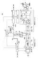
- FIG. 1 is a block diagram showing a configuration of a power supply system for an electric vehicle according to an embodiment of the present invention.
- an electric vehicle 100 includes a main battery 10, a power control unit (PCU) 20, a motor generator 30, a power transmission gear 40, drive wheels 50, and a plurality of ECUs. And a control device configured.
- PCU power control unit
- motor generator a motor generator
- power transmission gear 40 a power transmission gear 40
- drive wheels 50 a plurality of ECUs.
- control device configured.
- FIG. 1 shows an HV-ECU 80 for controlling the operation of the electric vehicle 100 during operation of the vehicle, an MG-ECU 81 for controlling the operation of the PCU 20, and an external charging operation. And a BAT-ECU 85 for managing and controlling the state of charge of the main battery 10 and the auxiliary battery 70.
- Each ECU is composed of a CPU (Central Processing Unit) (not shown) and an electronic control unit with a built-in memory. Based on a map and a program stored in the memory, each ECU performs a calculation process using detection values from each sensor. Configured to do. Alternatively, at least a part of the ECU 80 may be configured to execute predetermined numerical / logical operation processing by hardware such as an electronic circuit.
- CPU Central Processing Unit
- ECU 80 may be configured to execute predetermined numerical / logical operation processing by hardware such as an electronic circuit.
- the main battery 10 corresponds to a “main power storage device”, and typically includes a secondary battery such as a lithium ion battery or a nickel metal hydride battery.
- a secondary battery such as a lithium ion battery or a nickel metal hydride battery.
- the output voltage of the main battery 10 is about 200V.
- the main power storage device may be configured by an electric double layer capacitor or a combination of a secondary battery and a capacitor.
- the PCU 20 converts the stored power of the main battery 10 into power for driving and controlling the motor generator 30.
- motor generator 30 is configured with a permanent magnet type three-phase synchronous motor
- PCU 20 is configured to include inverter 26.
- the output torque of the motor generator 30 is transmitted to the drive wheels via the power transmission gear 40 constituted by a speed reducer and a power split mechanism, thereby causing the electric vehicle 100 to travel.
- the motor generator 30 can generate electric power by the rotational force of the drive wheels 50 during the regenerative braking operation of the electric vehicle 100.
- the generated power is converted into charging power for the main battery 10 by the PCU 20.
- the necessary vehicle driving force of electric vehicle 100 is generated by operating this engine and motor generator 30 in a coordinated manner. . At this time, it is also possible to charge the main battery 10 using the power generated by the rotation of the engine.
- the electric vehicle 100 indicates a vehicle on which an electric motor for generating vehicle driving force is mounted, and includes a hybrid vehicle that generates vehicle driving force by an engine and an electric motor, an electric vehicle that does not have an engine, a fuel cell vehicle, and the like. .
- a “power supply system for an electric vehicle” is configured by a portion excluding the motor generator 30, the power transmission gear 40, and the drive wheels 50 from the configuration of the electric vehicle 100 illustrated.
- the configuration of the power supply system will be described in detail.
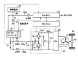
- the power control unit (PCU) 20 includes a converter CNV, a smoothing capacitor C0, and an inverter 26.
- Converter CNV is configured to perform DC voltage conversion between DC voltage VL of power supply wiring 153p and DC voltage VH of power supply wiring 154p.
- the power supply wiring 153p and the ground wiring 153g are electrically connected to the positive terminal and the negative terminal of the main battery 10 through the system main relays SMR1 and SMR2, respectively.
- the smoothing capacitor C0 is connected to the power supply wiring 154p and smoothes the DC voltage.
- the smoothing capacitor C1 is connected to the power supply wiring 153p and smoothes the DC voltage VL.
- the inverter 26 is a general three-phase inverter, the detailed circuit configuration is not shown.
- the inverter 26 is arranged so that the upper arm element and the lower arm element are arranged in each phase, and the connection point of the upper and lower arm elements in each phase is connected to the stator coil winding of the corresponding phase of the motor generator 30. Composed.
- the inverter 26 converts the DC voltage of the power supply wiring 154p into a three-phase AC voltage and supplies it to the motor generator 30 by turning on and off each switching element by the MG-ECU 81.
- inverter 26 is controlled to be turned on / off by MG-ECU 81 so that AC voltage from motor generator 30 is converted into a DC voltage and output to power supply wiring 154p.
- HV-ECU 80 and the MG-ECU 81 are hierarchically configured.
- HV-ECU 80 sets an operation command value for driving motor generator 30 according to the running state
- MG-ECU 81 causes PCU 20 to drive motor generator 30 according to the operation command value from HV-ECU 80. Control.
- the power supply system of the electric vehicle 100 further includes a DC / DC converter 60, an auxiliary battery 70, a power supply wiring 155p, relays HVMR and PIMR, and an auxiliary load 90 as a low voltage system (auxiliary system) configuration. Including.
- the auxiliary battery 70 is connected between the power supply wiring 155p and the ground wiring.
- Auxiliary battery 70 corresponds to the “sub power storage device”, and is constituted by a lead storage battery, for example.
- the output voltage Vs of the auxiliary battery 70 corresponds to a low-voltage power supply voltage.
- the rating of the power supply voltage is lower than the output voltage of the main battery 10 and is, for example, about 12V.
- BAT-ECU 85 monitors the charging state of main battery 10 and auxiliary battery 70.
- the state of charge of the main battery 10 is managed by SOC (State Of Charge) which is a ratio (%) of the remaining capacity with the fully charged state being 100 (%).
- SOC State Of Charge
- the state of charge of the auxiliary battery 70 is generally managed by the output voltage Vs.
- the state of charge of main battery 10 and auxiliary battery 70 can be communicated from BAT-ECU 85 to HV-ECU 80 and PLG-ECU 82. Further, the BAT-ECU 85 controls the operation / stop of the DC / DC converter 60.
- DC / DC converter 60 is configured to step down the output voltage of main battery 10 and convert it to DC voltage Vi at the output voltage level of auxiliary battery 70.
- the rated output voltage Vi of the DC / DC converter 60 is set so that the auxiliary battery 70 can be charged. Therefore, during operation of DC / DC converter 60 by BAT-ECU 85, auxiliary battery 70 is charged by the power of main battery 10 as necessary so that output voltage Vs of auxiliary battery 70 becomes constant.
- the DC / DC converter 60 is typically a switching regulator including a semiconductor switching element (not shown), and any known circuit configuration can be applied.
- the output side of the DC / DC converter 60 is connected to the power supply wiring 155p.
- the input side of the DC / DC converter 60 is electrically connected to the positive terminal and the negative terminal of the main battery 10.
- a low-voltage auxiliary load 90 is connected to the power supply wiring 155p.
- the auxiliary machine load 90 includes, for example, audio equipment, navigation equipment, lighting equipment (hazard lamp, room light, headlamp, etc.) and the like. These auxiliary machine loads consume electric power by operating according to user operations.
- a relay HVMR is electrically connected between the power supply wiring 155p and the HV-ECU 80.
- Relay PIMR is electrically connected between power supply wiring 155p and PLG-ECU 82.
- the minimum circuit elements necessary for the starting process are always supplied from the auxiliary battery 70 without passing through the relays HVMR and PIMR.
- standby power is reduced by adopting a configuration in which power is supplied to the other circuit elements via the relays HVMR and PIMR.
- the power supply system of electric vehicle 100 includes a charging connector 105, a charger 110, and external charging relays CHR1 and CHR2 as an external charging system for external charging of main battery 10.
- PLG-ECU 82 is powered from auxiliary battery 70 via relay PIMR during operation.
- the PLG-ECU 82 controls the components of the external charging system.
- the charging connector 105 is electrically connected to the external power source 400 by being connected to the charging plug 410 of the charging cable that is connected to the external power source 400. It is assumed that the charging cable incorporates a relay 405 for cutting off the charging path of the external power source 400.
- the external power source 400 is a commercial AC power source.
- the external power source 400 and the electric vehicle 100 are electromagnetically coupled in a non-contact manner to supply electric power, specifically, a primary coil is provided on the external power source side, A secondary coil may be provided on the vehicle side, and electric power may be supplied from the external power supply 400 to the electric vehicle 100 using the mutual inductance between the primary coil and the secondary coil. Even when such external charging is performed, the configuration after the charger 110 that converts the power supplied from the external power source 400 can be shared.
- the power supply wiring 151 electrically connects between the charging connector 105 and the charger 110.
- the charger 110 converts the AC voltage from the external power supply 400 transmitted to the power supply wiring 151 into a DC voltage for charging the main battery 10.
- the converted DC voltage is output between the power supply wiring 152p and the ground wiring 152g.
- Charger 110 charges main battery 10 in accordance with a control command from PLG-ECU 82 by feedback control of output voltage and / or output current.
- the charging command is set according to the state of the main battery 10, for example, the SOC and temperature.
- the external charging relay CHR1 is electrically connected between the power supply wiring 152p and the positive electrode of the main battery 10.
- External charging relay CHR2 is electrically connected between ground wiring 152g and the negative electrode of main battery 10.
- Each of external charging relays CHR1, CHR2, system main relays SMR1, SMR2, and relays HVMR, PIMR is typically closed (turned on) when excitation current is supplied by an excitation circuit (not shown), while excitation current of It is composed of an electromagnetic relay that is opened (turned off) when not supplied.
- excitation current of It is composed of an electromagnetic relay that is opened (turned off) when not supplied.
- any circuit element can be used as each relay as long as it is a switch that can control conduction (ON) / interruption (OFF) of the energization path.
- MG-ECU 80 generates control commands SM1 and SM2 for instructing to turn on system main relays SMR1 and SMR2.
- PLG-ECU 82 generates control commands SR1 and SR2 for instructing to turn on external charging relays CHR1 and CHR2.
- excitation current of the corresponding system main relay or external charging relay is generated using auxiliary battery 70 as a power source.
- control commands SM1, SM2, SR1, and SR2 are not generated, the corresponding system main relay or external charging relay is maintained in the off state (opened).
- the on / off of relays HVMR and PIMR is also appropriately controlled in response to a key operation or an external charging instruction by the driver, as will be described later.
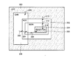
- the vehicle state is classified into three: “vehicle driving state”, “key-off state”, and “external charging state”. Below, the transition between each state is demonstrated.
- power supply state of electrically powered vehicle 100 includes an OFF state 200, an ACC (accessory) state 202, an IG-ON state 204, a READY-ON state 208, and CHR set at the time of external charging.
- State 209 exists.
- the transition between the power states is mainly controlled according to the operation of a power switch and a brake pedal (not shown). That is, the power state changes in response to a user operation.
- OFF state 200 corresponds to an off state of the power supply system (that is, a key-off state of the vehicle).
- this power supply state basically, power supply to each device mounted on the vehicle is cut off.
- power supply from the auxiliary battery 70 is continued to a minimum target such as a part of ECUs or a start control part of the ECUs.
- some devices including a part of lighting devices are configured to be operable by a user operation even in the OFF state 200.
- the ACC In the ACC state 202, the ACC is turned on, and accessories such as audios and air conditioners are supplied with power and can operate.
- the IG-ON state 204 the IG is turned on, and in addition to the power supply target when the ACC is on, power is also supplied to devices necessary for vehicle travel.
- the power state changes from the OFF state 200 to the ACC state 202 (arrow 210), and from the ACC state 202 to the IG-ON state. Transition is made in the order of 204 (arrow 212).
- ⁇ System check is activated when the power switch is operated during brake pedal operation.
- the READY-ON state 208 is selected (arrow 214).
- CHR state 209 the transition to the READY-ON state 208 cannot be made.
- the system main relays SMR1 and SMR2 shown in FIG. 1 are turned on, and the motor generator 30 can be driven by the control of the PCU 20. Thereby, electric vehicle 100 is in a state where it can travel in accordance with the operation of the accelerator pedal.
- the ACC state 202 In the OFF state 200, the ACC state 202, or the IG-ON state 204, by operating a power switch (not shown) while depressing the brake pedal, the ACC and IG can be turned on and the system check can be activated. Is possible.
- the power switch when the power switch is operated in the IG-ON state 204 or the READY-ON state 208, the power supply state transitions to the OFF state 200.
- the charging start condition includes a condition that the charging plug 410 is normally connected to the charging connector 105. Further, in response to a user operation or a predetermined charging start time, a manual or automatic charging start instruction is generated, whereby a transition indicated by an arrow 220 occurs.
- the devices that can be used in the ACC state 202 or the IG-ON state 204 can be operated even during external charging.
- the predetermined driving condition in the system check includes “not in the external charging state (CHR state 209)”. Therefore, as indicated by an arrow 226, transition to the READY-ON state 208 is prohibited in the CHR state 209. That is, the CHR state 209 and the READY-ON state 208 are not selected at the same time. Further, the CHR state 209 can only transition from the OFF state 200, and the transition from the ACC state 202, the IG-ON state 204, and the READY-ON state 208 to the CHR state 209 is prohibited.
- the CHR state 209 ends in response to establishment of a predetermined charging end condition.
- the charging end condition can be determined based on the user operation, the SOC of the main battery 10, the time, or the elapsed charging time. If an abnormality occurs in the connection of the charging plug 410 to the charging connector 105, external charging is forcibly stopped and the CHR state 209 is also ended.
- the power state transitions to the ACC state 202 or the IG-ON state 204 when the CHR state 209 ends.
- the power state transitions to the OFF state 200.
- the OFF state 200 corresponds to the “key-off state (operation stop state)”
- the CHR state 209 corresponds to the “external charging state”.
- the READY-ON state 208 corresponds to the “vehicle driving state”.
- relay HVMR In the vehicle operating state, relay HVMR is turned on, and HV-ECU 80 and MG-ECU 81 operate.
- the BAT-ECU 85 always operates in the vehicle operating state, and monitors the charging state of the auxiliary battery 70 and the main battery 10.
- the BAT-ECU 85 always operates the DC / DC converter 60. For this reason, in the vehicle operating state, the auxiliary battery 70 is charged by the power of the main battery 10 so that the output voltage Vs of the auxiliary battery 70 becomes constant while the auxiliary load 90 operates in response to a user operation. can do.
- the vehicle traveling system is started by turning on the system main relays SMR1 and SMR2.
- the output voltage of main battery 10 is transmitted to power supply wiring 153p and ground wiring 153g via system main relays SMR1 and SMR2 in the on state.
- PCU 20 drives and controls motor generator 30 by power conversion between power supply wiring 153 p electrically connected to main battery 10 and motor generator 30.
- electric vehicle 100 can travel using the power of main battery 10.
- the external charging system is stopped when the vehicle is operating. Therefore, external charging relays CHR1, CHR2 and relay PIMR are turned off, and charger 110 is also stopped. Further, relay PIMR that controls power supply from auxiliary battery 70 to PLG-ECU 82 is also turned off. Therefore, the components of the external charging system can be designed considering only the operation of external charging.
- the relay PIMR is turned on to operate the PLG-ECU 82, and the external charging relays CHR1 and CHR2 are turned on to start the external charging system.
- the main battery 10 is charged by the DC voltage obtained by converting the AC power from the external power source 400 by the charger 110 via the external charging relays CHR1 and CHR2 in the on state.
- the BAT-ECU 85 always operates in the same manner as the vehicle operation state, and monitors the charging state of the auxiliary battery 70 and the main battery 10.
- the BAT-ECU 85 always operates the DC / DC converter 60.
- the auxiliary battery 70 is driven by the electric power from the external power source 400 so that the output voltage Vs of the auxiliary battery 70 becomes constant under the operation of the auxiliary load 90 according to the user operation. Can be charged.
- the vehicle traveling system can be completely stopped by turning off relay HVMR and system main relays SMR1, SMR2.
- the HV-ECU 80 and the MG-ECU 81 can also be stopped.
- power supply wiring 153p and ground wiring 153g are electrically disconnected from charger 110 and main battery 10 by system main relays SMR1 and SMR2 in the off state. Therefore, since the output voltage of the main battery 10 is not applied to the components of the vehicle traveling system, it is possible to prevent the durability and life of the components from changing due to the influence of external charging.
- BAT-ECU 85 corresponds to “first control device”
- PLG-ECU 82 corresponds to “second control device”
- HV-ECU 80 and MG-ECU 81 correspond to “third control device”. Corresponds to "control device”.
- system main relays SMR1 and SMR2 are turned off, and relays HVMR and PIMR are also turned off. That is, both the external charging system and the vehicle traveling system are stopped.
- the BAT-ECU 85 may reduce the accumulated power (remaining capacity) in the main battery 10 and the auxiliary battery 70 as a whole. There is.
- the relay HVMR is turned off in the key-off state (OFF state 200) and the ACC state 202, and turns on in response to the transition to the IG-ON state 204. Further, in the ACC state 202 and the IG-ON state 204, since there is a high possibility that the devices are operated by the power of the auxiliary battery 70, the DC / DC converter 60 and the BAT-ECU 85 are always in the same manner as in the vehicle driving state. It is preferable to operate. Thereby, auxiliary battery 70 can be charged with the electric power of main battery 10 so that output voltage Vs of auxiliary battery 70 becomes constant.
- the BAT-ECU 85 operates intermittently rather than constantly operating in the key-off state. That is, the BAT-ECU 85 is normally in a so-called sleep mode, and waits in a state where power consumption is suppressed without performing a normal control operation.
- the BAT-ECU 85 is configured to perform monitoring and charging control of the charging state (output voltage Vs) of the auxiliary battery 70 by operating intermittently in response to the activation trigger.
- step S100 it is determined whether the activation condition of BAT-ECU 85 is satisfied.
- This activation condition is satisfied, for example, when a predetermined time has elapsed since the last operation of the BAT-ECU 85. For example, if an activation trigger is generated in response to the establishment of the activation condition, YES is determined in step S100 in response to the generation of the activation trigger.
- step S100 When the activation condition is not satisfied (NO determination in S100), the process proceeds to step S500, and the BAT-ECU 85 maintains the stopped state (sleep mode).
- step S110 the process proceeds to step S110 and the BAT-ECU 85 is activated.
- BAT-ECU 85 is in a state in which it is possible to monitor the charging state of auxiliary battery 70 and main battery 10 and to control the operation / stop of DC / DC converter 60.
- BAT-ECU 85 acquires the charging state (output voltage Vs) of auxiliary battery 70 and the charging state (SOC) of main battery 10 in step S120. Further, BAT-ECU 85 advances the process to step S130 to determine whether or not the remaining capacity of auxiliary battery 70 has decreased. Typically, the determination in step S130 is executed based on whether or not the output voltage Vs of the auxiliary battery 70 has decreased below a predetermined reference voltage. This reference voltage is determined so as to have an appropriate margin with respect to a lower limit voltage at which each device such as an ECU can normally operate.
- the BAT-ECU 85 executes the charging process of the auxiliary battery 70 in step S200.
- BAT-ECU 85 advances the process to step S300 to execute the deterioration determination process of auxiliary battery 70 and at step S400.
- the next activation condition is set based on the deterioration process determination in step S300.
- the BAT-ECU 85 is again stopped (sleep mode) in step S500, and a series of intermittent operation is performed. This process ends.
- step S100 is maintained as NO, and the BAT-ECU 85 is maintained in a stopped state.
- step S110 is executed, whereby BAT-ECU 85 is intermittently operated.
- FIG. 4 is a flowchart showing a detailed processing procedure of the auxiliary battery charging process shown in FIG.
- step S210 determines in step S210 whether the SOC of main battery 10 is higher than a predetermined reference value.
- the reference value in step S210 is for determining whether or not the main battery 10 has a margin for charging the auxiliary battery 70. Accordingly, step S210 is NO in the low SOC region where it becomes difficult to drive the vehicle with the power of the main battery 10 if the auxiliary battery 70 is charged, or in the low SOC region where the main battery 10 causes deterioration.
- the reference value is set so that
- the BAT-ECU 85 proceeds to step S220 and activates the DC / DC converter 60. Thereby, auxiliary battery 70 is charged by the power of main battery 10.
- step S230 the BAT-ECU 85 sequentially determines whether or not the charging of the auxiliary battery 70 is completed in step S230.
- the determination in step S230 is executed based on the output voltage Vs of the auxiliary battery 70, for example.
- auxiliary battery 70 Until the auxiliary battery 70 is fully charged (NO in S230), the operations in steps S210 and S220 are repeated. Then, when output voltage Vs of auxiliary battery 70 increases, BAT-ECU 85 determines that charging of auxiliary battery 70 has been completed (YES in S230), and stops DC / DC converter 60 in step S240. To do. Thereby, the charging of the auxiliary battery 70 is completed.
- BAT-ECU 85 skips step S220 and proceeds to step S245.
- DC / DC converter 60 is stopped and auxiliary battery 70 is not charged by main battery 10.
- SOC of the main battery 10 falls below the reference value during charging of the auxiliary battery 70 once started, that is, when S210 becomes NO during the repeated processing of S210 and S220.
- the DC / DC converter 60 is stopped and the charging of the auxiliary battery 70 is forcibly terminated.
- step S100 in FIG. 3 is forcibly determined as NO.
- step S500 is executed every time the flowchart of FIG. 3 is activated, so that the stopped state (sleep mode) of the BAT-ECU 85 is maintained during the key-off state.
- the auxiliary battery charging process (S200) shown in FIG. 3 may be configured as shown in FIG.
- BAT-ECU 85 first determines in step S250 whether external charging is possible.
- the power supply from the external power source 400 can be received when the CHR state 209 is ended while the connection of the charging plug 410 is maintained. Therefore, it is determined that “external charging is possible (YES in S250)”.
- BAT-ECU 85 proceeds to step S260 to instruct activation of DC / DC converter 60 and generate an activation request for the external charging system. To do.
- auxiliary battery 70 can be charged by converting the power supplied from external power supply 400 by charger 110 and DC / DC converter 60.
- BAT-ECU 85 determines whether or not charging of auxiliary battery 70 is completed in step S270 during charging of auxiliary battery 70 in step S260.
- the determination in step S270 is equivalent to the determination in step S230 in FIG.
- BAT-ECU 85 proceeds to step S280 to stop DC / DC converter 60 and generate a request to stop the external charging system. To do. Thereby, the charging of the auxiliary battery 70 is completed and the external charging system is stopped again.
- BAT-ECU 85 charges auxiliary battery 70 with the power of main battery 10 in accordance with the processing in steps S210 to S240 shown in FIG. Execute the process.
- BAT-ECU 85 based on the transition of output voltage Vs of auxiliary battery 70 acquired for each intermittent operation, in step S310.
- the voltage drop amount ⁇ V of the machine battery 70 is calculated.
- the voltage drop amount ⁇ V is preferably calculated with the removal of abnormal values and the filtering process.
- step S320 the BAT-ECU 85 determines whether or not the calculated voltage drop amount ⁇ V is greater than a predetermined level.
- BAT-ECU 85 proceeds to step S330 to acquire current discharge current Ib of auxiliary battery 70.
- the discharge current Ib can be acquired by a current sensor (not shown) provided in the auxiliary battery 70.
- BAT-ECU 85 determines in step S340 whether or not discharge current Ib is larger than a predetermined determination value.
- the discharge current Ib of the auxiliary battery 70 is large (when YES is determined in step S340)
- the remaining capacity of the auxiliary battery 70 is rapidly reduced by the operation of the auxiliary load 90 (for example, a headlight).
- the BAT-ECU 85 instructs the auxiliary battery 70 to be charged in step S345. Thereby, the process jumps to step S200 of FIG.
- BAT-ECU 85 is based on the transition of output voltage Vs of auxiliary battery 70 acquired for each intermittent operation in step S350.
- the voltage drop rate which is the slope of the voltage drop over time, is calculated.
- the voltage decrease rate is obtained based on the decrease history of the output voltage Vs within a period that goes back a certain time.
- step S360 the BAT-ECU 85 determines the degree of deterioration of the auxiliary battery 70 based on the calculated voltage drop rate. For example, a deterioration parameter value obtained by quantifying the deterioration degree is calculated. This determination is based on the characteristic that as the deterioration of the auxiliary battery 70 progresses, the rate of decrease of the output voltage Vs with respect to the continuous consumption of the dark current of the same level increases. That is, it is determined that the degree of deterioration is larger as the voltage drop rate is larger, and the deterioration parameter value is calculated larger.
- step S370 the BAT-ECU 85 determines whether or not the degree of deterioration (deterioration parameter value) determined in step S360 is greater than a predetermined value.
- a predetermined level YES in S370
- BAT-ECU 85 notifies the user that the degree of deterioration of auxiliary battery 70 is large in step S380.
- This user notification is output, for example, as a warning message that prompts maintenance or inspection of the auxiliary battery 70.
- the degree of deterioration is equal to or lower than the predetermined level (NO determination in S370)
- BAT-ECU 85 does not execute the user notification in step S380.
- the BAT-ECU 85 skips the processes in S330 to S380 and advances the process to step S400.
- BAT-ECU 85 sets the next activation condition for BAT-ECU 85 in step S400 upon completion of the auxiliary battery deterioration determination process in step S300.
- the activation condition indicates a period Tc of intermittent activation.
- period Tc is set to a predetermined default value, while voltage drop amount ⁇ V is larger than a predetermined level (YES in S320).
- the period Tc is set shorter than the default value. At this time, it is preferable to set the period Tc to be shorter as the degree of deterioration (deterioration parameter value) determined in step S360 is larger.
- the ECU (BAT-ECU 85) is intermittently operated in a key-off state (operation stop state) corresponding to an off state of a so-called ignition switch.
- a key-off state operation stop state
- the auxiliary battery 70 can be monitored and charged while the power consumption of the auxiliary battery 70 is suppressed.
- it is possible to more reliably prevent the output voltage of auxiliary battery 70 from being lowered while the operation of the electric vehicle is stopped, and to ensure normal vehicle startability even after a long-term operation stop.
- the auxiliary battery 70 In the charging process (S200) of the auxiliary battery 70 whose output voltage has decreased, the auxiliary battery 70 is charged after confirming the SOC margin of the main battery 10, so that the charging power of the auxiliary battery 70 is supplied. Thus, the main battery 10 can be prevented from being overdischarged. Also, in an electrically chargeable vehicle that can be externally charged, the power stored in the entire vehicle in the key-off state can be secured by preferentially charging the auxiliary battery 70 using the power of the external power supply (FIG. 4). Further, when there is no means for charging auxiliary battery 70, intermittent activation of BAT-ECU 85 is stopped and maintained in a stopped state, so that power is unnecessarily consumed for monitoring auxiliary battery 70 and charging control. Can be avoided.
- the deterioration degree of the auxiliary battery 70 can be determined based on the output voltage Vs of the auxiliary battery 70 monitored by the intermittent operation. Furthermore, by setting the intermittent operation cycle of the BAT-ECU 85 variably, it is possible to reduce power consumption while maintaining the monitoring effect of the auxiliary battery 70.
- the auxiliary battery deterioration determination process (S300) can be omitted.
- components (particularly the BAT-ECU 85) relating to the main battery 10, the auxiliary battery 70, and the DC / DC converter 60, which are required to operate even in the key-off state, are connected to the external charging system and It is separated from the vehicle driving system and used in common in each driving state. As a result, since it is not necessary to arrange the constituent elements in duplicate, the cost can be reduced.
- FIG. 1 illustrates a so-called plug-in type electric vehicle that can charge the in-vehicle power storage device with an external power source.
- the present invention is not limited to plug-in type electric vehicles, and can also be applied to electric vehicles that do not include an external charging system.
- FIG. 7 is a block diagram showing a configuration of a power supply system for an electric vehicle according to a first modification of the embodiment of the present invention.
- the external charging system is removed from the configuration of the power supply system of the electric vehicle shown in FIG.
- the CHR state 209 is deleted from the power supply state shown in FIG.
- the BAT-ECU 85 always operates in the vehicle driving state, while in the key-off state (OFF state 200), the BAT-ECU 85 can intermittently operate according to the flowchart shown in FIG.
- the auxiliary battery charging process in step S200 of FIG. 3 can be executed by the processes of steps S210 to S245 shown in FIG. That is, in the configuration of FIG. 7, the HV-ECU 80 constitutes a “first control device”.
- FIG. 8 is compared with FIG. 7, and in the second modified example shown in FIG. 8, the BAT-ECU 85 is not arranged. Then, the control circuit 61 of the DC / DC converter 60 has a function of monitoring the output voltage Vs of the auxiliary battery 70.
- control circuit 61 of the DC / DC converter 60 is configured to be able to communicate with the HV-ECU 80. That is, the HV-ECU 80 can instruct the control circuit 61 to operate / stop the DC / DC converter 60. Further, since the HV-ECU 80 can monitor the output voltage Vs of the auxiliary battery 70 and the SOC of the main battery 10, the monitoring and charging control functions of the main battery 10 and the auxiliary battery 70 are the same as those of the BAT-ECU 85. Have
- the HV-ECU 80 when the electric vehicle is in a key-off state, the HV-ECU 80 is basically in a stopped state, and the control circuit 61 is similar to the BAT-ECU 85 in FIGS. Operate intermittently.
- the control circuit 61 is configured to monitor the output voltage Vs of the auxiliary battery 70 every time an intermittent operation is performed, and to generate an activation request for the HV-ECU 80 when a decrease in the output voltage Vs is detected.
- the HV-ECU 80 that operates in response to the activation request confirms the SOC of the main battery 10 in the same manner as the BAT-ECU 85 in FIGS. 4, a process equivalent to the auxiliary battery charging process of 4 can be realized. That is, in the configuration of FIG. 8, the HV-ECU 80 and the control circuit 61 constitute a “first control device”.
- monitoring and charging control of the auxiliary battery 70 by intermittent operation of the ECU is performed during the key-off state (operation stop state). It can be carried out.
- the control circuit 61 of the DC / DC converter 60 can generate a startup request for the BAT-ECU 85 based on the output voltage Vs of the auxiliary battery 70.
- the BAT-ECU 85 operates intermittently based on the output voltage Vs rather than the operation interval (time).
- the auxiliary battery deterioration determination process (S300) is omitted in the process of FIG. 3, and only the auxiliary battery charging process (S200) is executed.
- the configuration after the power supply wiring 153p is not limited to the illustrated configuration.
- the load of the power supply system can be set to an arbitrary configuration including a configuration for generating vehicle driving force. That is, the present invention includes an electric vehicle and a fuel cell vehicle that are not equipped with an engine, and a hybrid vehicle that is equipped with an engine, a power storage device that can be externally charged, and a wheel that can be driven by the power of the power storage device.
- the present invention can be commonly applied to an electric vehicle equipped with an electric motor for generating a driving force.
- the present invention can be applied to an electric vehicle equipped with a main power storage device (main battery) for power supply for running motors and an auxiliary power storage device (auxiliary battery) for power supply including auxiliary devices including a control device.
- main battery main power storage device
- auxiliary battery auxiliary power storage device
Abstract
Description
これにより、図3のフローチャートが起動される度にステップS500が実行されることになるので、キーオフ状態の間、BAT-ECU85の停止状態(スリープモード)が維持されることになる。
図1では、外部電源によって車載蓄電装置を充電可能な、いわゆるプラグインタイプの電動車両について例示した。しかしながら、本願発明は、プラグインタイプの電動車両に限定されるものではなく、外部充電システムを具備しない電動車両に対しても適用可能である。
Claims (17)
- 車両駆動パワーを発生するモータ(30)を搭載した電動車両の電源システムであって、
前記モータに対して入出力される電力を蓄電するための主蓄電装置(10)と、
前記主蓄電装置よりも出力電圧が低い副蓄電装置(70)と、
前記主蓄電装置の出力電圧を前記副蓄電装置の出力電圧レベルに変換して前記副蓄電装置へ出力するように構成された電圧変換器(60)と、
前記副蓄電装置からの電力によって動作して、前記主蓄電装置および前記副蓄電装置の充電状態を監視するとともに、前記電圧変換器の動作および停止を制御するための第1の制御装置(85)とを備え、
前記第1の制御装置は、車両運転状態では常時動作するとともに前記副蓄電装置の出力電圧を目標電圧に維持するために前記電圧変換器を常時動作させる一方で、前記電動車両のキーオフ状態では、間欠的に動作するとともに、動作時には前記副蓄電装置の出力電圧が所定電圧よりも低下した場合に、前記電圧変換器を動作させることによって前記主蓄電装置の電力による前記副蓄電装置の充電処理を実行するように構成される、電動車両の電源システム。 - 車両外部の外部電源(400)と電気的にコンタクトするための充電コネクタ(105)と、
前記充電コネクタへ供給された前記外部電源からの電力を前記主蓄電装置の充電電力に変換するための充電器(110)と、
前記副蓄電装置からの電力供給によって動作して、所定の外部充電条件の成立によって前記キーオフ状態から外部充電状態へ遷移したときに、前記外部電源からの電力によって前記主蓄電装置を充電するように前記充電器を制御するための第2の制御装置(82)とをさらに備え、
前記第1の制御装置は、前記外部充電状態では常時動作するとともに、前記副蓄電装置の出力電圧を前記目標電圧に維持するために前記電圧変換器を常時動作させる、請求の範囲第1項記載の電動車両の電源システム。 - 前記第1の制御装置は、前記キーオフ状態での間欠動作時において、前記副蓄電装置の出力電圧が前記所定電圧よりも低下した場合に、前記外部電源からの電力供給が可能であるときには、前記電圧変換器を動作させるとともに、前記第2の制御装置および前記充電器の動作を要求することによって、前記外部電源からの電力により前記副蓄電装置の充電処理を実行するように構成される、請求の範囲第2項記載の電動車両の電源システム。
- 前記第1の制御装置は、前記キーオフ状態での間欠動作時において、前記副蓄電装置の出力電圧が前記所定電圧よりも低下した場合に、前記外部電源からの電力供給が不能であるときには、前記電圧変換器を動作させることによって前記主蓄電装置の電力により前記副蓄電装置の充電処理を実行するように構成される、請求の範囲第3項記載の電動車両の電源システム。
- 前記副蓄電装置から動作電力を供給されるように構成された補機負荷(90)をさらに備え、
前記第1の制御装置(85)は、前記キーオフ状態での間欠動作時において、前記副蓄電装置の出力電圧(Vs)が前記所定電圧よりも高い場合であっても、前記副蓄電装置の電圧低下量および前記副蓄電装置の放電電流が所定レベルより大きいときには、前記外部電源からの電力または前記主蓄電装置の電力による前記副蓄電装置の充電処理を実行するように構成される、請求の範囲第1項~第4項のいずれか1項に記載の電動車両の電源システム。 - 前記第1の制御装置(85)は、前記副蓄電装置の充電処理に際して、前記主蓄電装置の残容量(SOC)が所定レベルより低いときには、前記主蓄電装置の電力による前記充電処理を非実行とするように構成される、請求の範囲第1項~第4項のいずれか1項に記載の電動車両の電源システム。
- 前記第1の制御装置(85)は、前記主蓄電装置の残容量(SOC)が前記所定レベルより低いために前記充電処理を非実行としたときには、以降の間欠動作を中止して前記キーオフ状態の間停止を維持するように構成される、請求の範囲第6項記載の電動車両の電源システム。
- 前記第1の制御装置(85)は、前記キーオフ状態での間欠動作時において、前記副蓄電装置の出力電圧(Vs)が前記所定電圧よりも高い場合に、前記間欠動作のたびに検出される前記出力電圧の推移に基づいて、前記副蓄電装置の劣化度合いを判定するように構成される、請求の範囲第1項に記載の電動車両の電源システム。
- 前記第1の制御装置(85)は、前記キーオフ状態での間欠動作時において、判定した前記副蓄電装置の劣化度合いに基づいて、間欠動作の周期を設定するように構成される、請求の範囲第8項に記載の電動車両の電源システム。
- 車両外部の外部電源(400)と電気的にコンタクトするための充電コネクタ(105)と、
前記充電コネクタへ供給された前記外部電源からの電力を前記主蓄電装置の充電電力に変換するための充電器(110)と、
前記充電器と前記主蓄電装置(10)との間の接続および遮断を制御するための充電リレー(CHR1,CHR2)と、
前記副蓄電装置からの電力によって動作して、所定の外部充電条件の成立によって前記キーオフ状態から外部充電状態へ遷移したときに、前記外部電源によって前記主蓄電装置を充電するように前記充電器を制御するための第2の制御装置(82)と、
前記主蓄電装置(10)と主電源配線(153p)との間の接続および遮断を制御するメインリレー(SMR1,SMR2)と、
前記車両運転状態時に、前記主電源配線と前記モータ(30)との間での電力変換によって前記モータを駆動制御するように構成された電力制御ユニット(20)と、
前記副蓄電装置(70)からの電力によって動作して、前記車両運転状態時に走行状態に応じて前記モータ(30)を駆動するために前記電力制御ユニットを制御するための第3の制御装置(80,81)とをさらに備え、
前記キーオフ状態において、前記メインリレーおよび前記充電リレーは開放されるとともに、前記第2の制御装置、前記第3の制御装置、前記充電器および、前記電力制御ユニットは停止される、請求の範囲第1項に記載の電動車両の電源システム。 - 車両駆動パワーを発生するモータ(30)を搭載した電動車両の電源システムの制御方法であって、
前記電源システムは、
前記モータに対して入出力される電力を蓄電するための主蓄電装置(10)と、
前記主蓄電装置よりも出力電圧が低い副蓄電装置(70)と、
前記主蓄電装置の出力電圧を前記副蓄電装置の出力電圧レベルに変換して前記副蓄電装置へ出力するように構成された電圧変換器(60)と、
前記副蓄電装置からの電力によって動作して、前記主蓄電装置および前記副蓄電装置の充電状態を監視するとともに、前記電圧変換器の動作および停止を制御するための第1の制御装置(85)とを含み、
前記制御方法は、
前記電動車両のキーオフ状態において、前記第1の制御装置を間欠的に動作させるステップ(S100,S110)と、
前記第1の制御装置の間欠動作時に前記副蓄電装置の出力電圧(Vs)を取得するステップ(S120)と、
取得した前記出力電圧が所定電圧よりも低下した場合に、前記電圧変換器(60)を動作させることによって前記主蓄電装置の電力による前記副蓄電装置の充電処理を実行するステップ(S200)とを備える、電源システムの制御方法。 - 前記電源システムは、
車両外部の外部電源(400)と電気的にコンタクトするための充電コネクタ(105)と、
前記充電コネクタへ供給された前記外部電源からの電力を前記主蓄電装置の充電電力に変換するための充電器(110)と、
前記副蓄電装置からの電力供給によって動作して、所定の外部充電条件の成立によって前記キーオフ状態から外部充電状態へ遷移したときに、前記外部電源によって前記主蓄電装置を充電するように前記充電器を制御するための第2の制御装置(82)とをさらに備え、
前記充電処理を実行するステップ(S200)は、
前記外部電源からの電力供給が可能な状態であるか否かを判定するステップ(S250)と、
前記外部電源からの電力供給が可能な状態であるときに、前記電圧変換器を動作させるとともに、前記第2の制御装置および前記充電器の動作を要求することによって、前記外部電源からの電力により前記副蓄電装置の充電処理を実行するステップ(S260)と、
前記外部電源からの電力供給が可能な状態ではないときに、前記電圧変換器を動作させることによって前記主蓄電装置の電力により前記副蓄電装置の充電処理を実行するステップ(S210-S240)とをさらに含む、請求の範囲第11項に記載の電源システムの制御方法。 - 前記電源システムは、
前記副蓄電装置から動作電力を供給されるように構成された補機負荷(90)をさらに含み、
前記制御方法は、
取得した前記出力電圧が前記所定電圧よりも高い場合であっても、前記副蓄電装置の電圧低下量および前記副蓄電装置の放電電流が所定レベルより大きいときには、前記副蓄電装置(70)の充電処理を指示するステップ(S345)をさらに備える、請求の範囲第11項または第12項に記載の電動車両の電源システムの制御方法。 - 前記充電処理を実行するステップ(S200)は、
前記主蓄電装置の残容量(SOC)が所定レベルより低いときには、前記主蓄電装置の電力による前記充電処理を非実行とするステップ(S210)を有する、請求の範囲第11項または第12項に記載の電動車両の電源システムの制御方法。 - 前記充電処理を実行するステップ(S200)は、
前記主蓄電装置の残容量(SOC)が前記所定レベルより低いために前記充電処理が非実行とされたときには、前記第1の制御装置(85)の以降の間欠動作を中止して、前記キーオフ状態の間前記第1の制御装置の停止を維持するステップ(S245)をさらに含む、請求の範囲第14項記載の電動車両の電源システムの制御方法。 - 取得した前記出力電圧が前記所定電圧よりも高い場合に、前記間欠動作のたびに検出される前記副蓄電装置の出力電圧の推移に基づいて、前記副蓄電装置の劣化度合いを判定するステップ(S300)をさらに備える、請求の範囲第11項に記載の電動車両の電源システムの制御方法。
- 判定した前記副蓄電装置の劣化度合いに基づいて、前記第1の制御装置の間欠作動の周期を設定するステップ(S400)をさらに備える、請求の範囲第16項に記載の電動車両の電源システムの制御方法。
Priority Applications (5)
| Application Number | Priority Date | Filing Date | Title |
|---|---|---|---|
| US13/519,644 US8736101B2 (en) | 2010-02-09 | 2010-02-09 | Power source system for electric powered vehicle and control method thereof |
| JP2011553672A JP5293841B2 (ja) | 2010-02-09 | 2010-02-09 | 電動車両の電源システムおよびその制御方法 |
| EP10845719.3A EP2535218B1 (en) | 2010-02-09 | 2010-02-09 | Power supply system for electric vehicle, and control method thereof |
| PCT/JP2010/051868 WO2011099116A1 (ja) | 2010-02-09 | 2010-02-09 | 電動車両の電源システムおよびその制御方法 |
| CN201080063487.8A CN102753379B (zh) | 2010-02-09 | 2010-02-09 | 电动车辆的电源系统及其控制方法 |
Applications Claiming Priority (1)
| Application Number | Priority Date | Filing Date | Title |
|---|---|---|---|
| PCT/JP2010/051868 WO2011099116A1 (ja) | 2010-02-09 | 2010-02-09 | 電動車両の電源システムおよびその制御方法 |
Publications (1)
| Publication Number | Publication Date |
|---|---|
| WO2011099116A1 true WO2011099116A1 (ja) | 2011-08-18 |
Family
ID=44367427
Family Applications (1)
| Application Number | Title | Priority Date | Filing Date |
|---|---|---|---|
| PCT/JP2010/051868 WO2011099116A1 (ja) | 2010-02-09 | 2010-02-09 | 電動車両の電源システムおよびその制御方法 |
Country Status (5)
| Country | Link |
|---|---|
| US (1) | US8736101B2 (ja) |
| EP (1) | EP2535218B1 (ja) |
| JP (1) | JP5293841B2 (ja) |
| CN (1) | CN102753379B (ja) |
| WO (1) | WO2011099116A1 (ja) |
Cited By (43)
| Publication number | Priority date | Publication date | Assignee | Title |
|---|---|---|---|---|
| JPH0489772A (ja) * | 1990-07-31 | 1992-03-23 | Fujitsu Ltd | 循環式シート収納箱及び収納方法 |
| CN102963260A (zh) * | 2011-08-29 | 2013-03-13 | 夏普株式会社 | 车辆驱动装置、车辆充电系统以及汽车 |
| JP2013055800A (ja) * | 2011-09-05 | 2013-03-21 | Toyota Industries Corp | 電池監視協調充電システム及び電動車両 |
| JP2013099124A (ja) * | 2011-11-01 | 2013-05-20 | Toyota Motor Corp | バッテリシステムおよびバッテリシステムの制御方法 |
| JP2013150487A (ja) * | 2012-01-21 | 2013-08-01 | Hino Motors Ltd | 電気自動車の制御装置 |
| JP2013182705A (ja) * | 2012-02-29 | 2013-09-12 | Mitsubishi Heavy Ind Ltd | 電池管理装置、電池管理方法およびプログラム |
| JP2013255324A (ja) * | 2012-06-06 | 2013-12-19 | Denso Corp | 車載充電制御装置 |
| JP2014050116A (ja) * | 2012-08-29 | 2014-03-17 | Mitsubishi Electric Corp | 充放電システム |
| JP2014088171A (ja) * | 2012-10-30 | 2014-05-15 | Lsis Co Ltd | 車両の初期始動装置及びその方法 |
| JP2014140268A (ja) * | 2013-01-21 | 2014-07-31 | Toyota Motor Corp | 車両の電源システムおよびそれを備える車両 |
| JP2014143817A (ja) * | 2013-01-23 | 2014-08-07 | Toyota Motor Corp | 車両の電源システム |
| CN103986199A (zh) * | 2013-02-13 | 2014-08-13 | 铃木株式会社 | 电动车辆的充电装置 |
| JP2015048064A (ja) * | 2013-09-04 | 2015-03-16 | トヨタ自動車株式会社 | 車両 |
| JPWO2013042717A1 (ja) * | 2011-09-21 | 2015-03-26 | ダイムラー・アクチェンゲゼルシャフトDaimler AG | ハイブリッド電気自動車の電源制御装置および制御方法 |
| JPWO2013098902A1 (ja) * | 2011-12-28 | 2015-04-30 | 川崎重工業株式会社 | 電動式乗り物及びその制御装置の動作方法 |
| CN104786846A (zh) * | 2015-04-07 | 2015-07-22 | 安徽江淮汽车股份有限公司 | 一种电动汽车的电气安全防护方法、模块及系统 |
| JP2015131565A (ja) * | 2014-01-14 | 2015-07-23 | 株式会社デンソー | ハイブリッド車制御装置 |
| JP2015208225A (ja) * | 2015-07-16 | 2015-11-19 | 三菱電機株式会社 | 充放電システム |
| KR20150130671A (ko) * | 2014-05-14 | 2015-11-24 | 현대자동차주식회사 | 보조 배터리의 자동 충전 장치 및 방법 |
| CN105391108A (zh) * | 2014-09-02 | 2016-03-09 | Ls产电株式会社 | 一种蓄电池组和包含该蓄电池组的混合动力车辆 |
| EP2868517A4 (en) * | 2012-06-28 | 2016-05-11 | Mitsubishi Motors Corp | CHARGING DEVICE FOR ELECTRIC VEHICLES |
| JP2016514443A (ja) * | 2013-02-13 | 2016-05-19 | ジャガー ランド ローバー リミテッドJaguar Land Rover Limited | 充電方法 |
| JP2016150745A (ja) * | 2015-02-19 | 2016-08-22 | ドクター エンジニール ハー ツェー エフ ポルシェ アクチエンゲゼルシャフトDr. Ing. h.c. F. Porsche Aktiengesellschaft | 自動車における休止状態を監視する方法および装置 |
| US9487090B2 (en) * | 2011-11-03 | 2016-11-08 | Johnson Controls Technology Company | Dual energy storage system for micro hybrid vehicles |
| JP2017093070A (ja) * | 2015-11-05 | 2017-05-25 | 株式会社デンソー | 車両の電源システム |
| JP2017128186A (ja) * | 2016-01-19 | 2017-07-27 | 株式会社クボタ | プラグインハイブリッド作業車 |
| US9718366B2 (en) | 2011-12-28 | 2017-08-01 | Kawasaki Jukogyo Kabushiki Kaisha | Electric vehicle and operation method of control device in electric vehicle |
| JP2017163737A (ja) * | 2016-03-10 | 2017-09-14 | 本田技研工業株式会社 | 電動車両の補充電制御装置 |
| JP2017204983A (ja) * | 2016-05-13 | 2017-11-16 | トヨタ自動車株式会社 | 電気自動車 |
| JP2018033256A (ja) * | 2016-08-25 | 2018-03-01 | トヨタ自動車株式会社 | 電動車両 |
| KR101836603B1 (ko) | 2016-03-10 | 2018-03-08 | 현대자동차주식회사 | 친환경차량의 직류변환장치 출력 제어 방법 |
| JP2019088055A (ja) * | 2017-11-02 | 2019-06-06 | トヨタ自動車株式会社 | 電気自動車 |
| US10363796B2 (en) * | 2017-04-19 | 2019-07-30 | Ford Global Technologies, Llc | Control module activation of vehicles in a key-off state |
| US10378919B2 (en) | 2017-04-19 | 2019-08-13 | Ford Global Technologies, Llc | Control module activation of vehicles in a key-off state to determine driving routes |
| CN110154762A (zh) * | 2018-02-11 | 2019-08-23 | 广州小鹏汽车科技有限公司 | 一种下电控制方法、装置、存储介质和设备 |
| JP2019180156A (ja) * | 2018-03-30 | 2019-10-17 | スズキ株式会社 | 車両用電源装置 |
| US10717361B2 (en) | 2016-01-19 | 2020-07-21 | Kubota Corporation | Work vehicle and display device for the work vehicle |
| JP2021090329A (ja) * | 2019-12-06 | 2021-06-10 | トヨタ自動車株式会社 | 車両用制御装置 |
| JP2021090330A (ja) * | 2019-12-06 | 2021-06-10 | トヨタ自動車株式会社 | 車両用制御装置 |
| JP2022075693A (ja) * | 2019-03-13 | 2022-05-18 | 株式会社デンソー | 電池監視装置 |
| JP2023509205A (ja) * | 2020-06-30 | 2023-03-07 | 寧徳時代新能源科技股▲分▼有限公司 | 低電圧送電システム、dcdcコンバータ、制御方法、デバイス及び媒体 |
| WO2023100721A1 (ja) * | 2021-12-03 | 2023-06-08 | 株式会社デンソー | 制御装置 |
| JP7469563B2 (ja) | 2020-09-29 | 2024-04-16 | ビーワイディー カンパニー リミテッド | ハイブリッド自動車の充電制御方法、装置及び自動車 |
Families Citing this family (58)
| Publication number | Priority date | Publication date | Assignee | Title |
|---|---|---|---|---|
| KR101617292B1 (ko) * | 2010-08-02 | 2016-05-18 | 엘지전자 주식회사 | 전기자동차 및 그 보조배터리의 충전제어방법. |
| DE102010041068A1 (de) * | 2010-09-20 | 2012-03-22 | Robert Bosch Gmbh | System zum Laden eines Energiespeichers und Verfahren zum Betrieb des Ladesystems |
| WO2012076730A1 (es) * | 2010-12-10 | 2012-06-14 | General Electric Company | Dispositivo de carga y procedimiento para controlar un dispositivo de carga |
| CN102097849B (zh) * | 2011-02-11 | 2013-11-06 | 蒋小平 | 直流电机电动车用感应器电能量回收装置 |
| CA2746304A1 (fr) * | 2011-07-15 | 2013-01-15 | Hydro-Quebec | Systeme de recharge rapide multi-niveaux avec batteries de puissance imbriquees |
| JP5680569B2 (ja) * | 2012-01-13 | 2015-03-04 | トヨタ自動車株式会社 | インバータ |
| DE102012200804A1 (de) * | 2012-01-20 | 2013-07-25 | Continental Automotive Gmbh | Bordnetz und Verfahren zum Betreiben eines Bordnetzes |
| US9266433B2 (en) * | 2012-07-23 | 2016-02-23 | Ford Global Technologies, Llc | Low cost charger circuit with precharge |
| JP2014057418A (ja) * | 2012-09-12 | 2014-03-27 | Toyota Motor Corp | 車載制御装置 |
| EP2919371B1 (en) * | 2012-11-09 | 2019-10-09 | Volvo Truck Corporation | Power source device |
| CN103841717A (zh) * | 2012-11-21 | 2014-06-04 | 赵元雷 | 利用燃油汽车充电指示灯改制成的纯电动汽车dc-dc系统指示灯 |
| JP5733292B2 (ja) * | 2012-11-28 | 2015-06-10 | トヨタ自動車株式会社 | 車両の電源システム |
| KR101428293B1 (ko) * | 2012-12-18 | 2014-08-07 | 현대자동차주식회사 | 전기자동차용 보조배터리의 주기적 충전 방법 |
| US9376025B2 (en) * | 2013-02-06 | 2016-06-28 | Lg Electronics Inc. | Charging apparatus and electric vehicle including the same |
| KR101568225B1 (ko) * | 2013-02-06 | 2016-07-20 | 엘지전자 주식회사 | 충전 장치, 및 이를 구비하는 전기 차량 |
| JP5741635B2 (ja) * | 2013-06-17 | 2015-07-01 | 三菱自動車工業株式会社 | 補機バッテリ用電力供給装置 |
| KR101500119B1 (ko) * | 2013-08-09 | 2015-03-06 | 현대자동차주식회사 | 하이브리드 차량의 저전압 직류변환장치 제어 방법 |
| EP2842793B1 (en) | 2013-09-02 | 2021-03-03 | Volvo Car Corporation | Method for controlling charging of a hybrid or electric vehicle |
| JP5850017B2 (ja) | 2013-10-15 | 2016-02-03 | 株式会社デンソー | バッテリ監視装置 |
| JP5880582B2 (ja) | 2014-01-10 | 2016-03-09 | トヨタ自動車株式会社 | 車両 |
| GB2528321A (en) * | 2014-07-18 | 2016-01-20 | Airbus Operations Ltd | Determining integrity of braking control system |
| GB2528322B (en) * | 2014-07-18 | 2020-08-05 | Airbus Operations Ltd | Determining integrity of braking control system |
| KR102257902B1 (ko) * | 2014-07-29 | 2021-05-28 | 삼성전자주식회사 | 이종 전원을 공급하는 배터리 팩 및 그 충전 방법 |
| US10052965B2 (en) * | 2014-09-30 | 2018-08-21 | Ford Global Technologies, Llc | Method for charging the starter battery of a vehicle |
| JP6149872B2 (ja) * | 2015-01-16 | 2017-06-21 | トヨタ自動車株式会社 | 蓄電システム |
| KR20160122005A (ko) * | 2015-04-13 | 2016-10-21 | 엘에스산전 주식회사 | 차량 전원 관리 장치 |
| US20160303992A1 (en) * | 2015-04-14 | 2016-10-20 | Ford Global Technologies, Llc | Electrified Vehicle Predictive Low-Voltage Battery Alert |
| CN107710586B (zh) * | 2015-05-18 | 2020-06-09 | 康奈可关精株式会社 | 电力转换装置 |
| US10355586B2 (en) * | 2015-05-18 | 2019-07-16 | Calsonic Kansei Corporation | Power converter |
| US20160352120A1 (en) * | 2015-05-26 | 2016-12-01 | Ford Global Technologies, Llc | Electric vehicle high-voltage system alert |
| KR20170014962A (ko) | 2015-07-31 | 2017-02-08 | 현대자동차주식회사 | 차량용 배터리 관리 시스템 및 그 제어 방법 |
| CN108599553A (zh) * | 2015-08-25 | 2018-09-28 | 漳州龙文区汇洋远软件开发有限公司 | 一种电动车的电气系统 |
| US9923470B2 (en) | 2015-09-18 | 2018-03-20 | Lear Corporation | High voltage pre-charge system |
| WO2017056137A1 (ja) * | 2015-10-02 | 2017-04-06 | 日産自動車株式会社 | 車両用電源制御方法、車両用電源制御装置 |
| CN105680334B (zh) * | 2016-04-05 | 2019-01-18 | 深圳市清友能源技术有限公司 | 一种用于电动汽车高压配电与dc/dc的集成箱 |
| CN105922873B (zh) * | 2016-05-18 | 2018-05-04 | 北京新能源汽车股份有限公司 | 车辆及用于车辆的低压蓄电池的充电控制方法和系统 |
| CN106004446B (zh) * | 2016-05-31 | 2018-07-10 | 北京现代汽车有限公司 | 电动汽车低压蓄电池的充电控制方法、系统及整车控制器 |
| DE102016007088B3 (de) * | 2016-06-10 | 2017-06-22 | Sew-Eurodrive Gmbh & Co Kg | Verfahren zum Betreiben eines elektrischen Fahrzeuges und elektrisches Fahrzeug |
| DE102016214995A1 (de) * | 2016-08-11 | 2018-02-15 | Robert Bosch Gmbh | System zur Batterieüberwachung für ein Fahrzeug |
| US10457155B2 (en) | 2016-09-09 | 2019-10-29 | Ford Global Technologies, Llc | System and method for charging electrified vehicle low-voltage battery |
| KR101866063B1 (ko) * | 2016-10-07 | 2018-06-08 | 현대자동차주식회사 | 보조배터리의 릴레이 제어 시스템 및 그 방법 |
| US10938232B2 (en) * | 2016-11-10 | 2021-03-02 | Ocean Power Technologies, Inc. | High DC voltage to low DC voltage conversion apparatus including rechargeable batteries |
| JP6812771B2 (ja) * | 2016-12-09 | 2021-01-13 | 三菱自動車工業株式会社 | 電源制御装置 |
| US11215156B2 (en) | 2017-03-03 | 2022-01-04 | Gentherm Incorporated | Dual voltage battery system for a vehicle |
| JP6582327B2 (ja) * | 2017-05-31 | 2019-10-02 | 本田技研工業株式会社 | 電動車両 |
| CN107472053A (zh) * | 2017-06-29 | 2017-12-15 | 宝沃汽车(中国)有限公司 | 电动汽车的电力系统、控制方法及车辆 |
| CN110077193B (zh) * | 2018-01-25 | 2021-03-26 | 宝沃汽车(中国)有限公司 | 车辆的控制方法、系统及车辆 |
| JP2019170096A (ja) * | 2018-03-23 | 2019-10-03 | 本田技研工業株式会社 | 電気自動車 |
| JP7091830B2 (ja) * | 2018-05-23 | 2022-06-28 | トヨタ自動車株式会社 | 電源装置 |
| CN109039662B (zh) * | 2018-07-16 | 2021-04-16 | 苏州艾普乐思新能源动力系统科技有限公司 | 一种电动汽车整车能耗控制方法 |
| KR102535954B1 (ko) * | 2018-08-31 | 2023-05-23 | 삼성전자주식회사 | 반도체 장치 및 반도체 장치의 동작 방법 |
| JP7070294B2 (ja) * | 2018-09-27 | 2022-05-18 | トヨタ自動車株式会社 | 車両の制御装置 |
| JP7251170B2 (ja) * | 2019-01-30 | 2023-04-04 | トヨタ自動車株式会社 | 車両の電源システム |
| JP7088096B2 (ja) * | 2019-03-20 | 2022-06-21 | トヨタ自動車株式会社 | 車両用電池制御装置 |
| JP7291513B2 (ja) * | 2019-03-27 | 2023-06-15 | 株式会社Subaru | 車両 |
| CN112140906B (zh) * | 2019-06-28 | 2023-04-07 | 宇通客车股份有限公司 | 一种车辆及其充电状态下供电控制方法、装置 |
| DE102020007350A1 (de) | 2019-12-18 | 2021-06-24 | Sew-Eurodrive Gmbh & Co Kg | Verfahren zum Betreiben eines elektrischen Fahrzeuges und elektrisches Fahrzeug |
| US11929632B2 (en) | 2021-01-27 | 2024-03-12 | Livewire Ev, Llc | On-board charger system with integrated auxiliary power supply |
Citations (3)
| Publication number | Priority date | Publication date | Assignee | Title |
|---|---|---|---|---|
| JP2006197765A (ja) * | 2005-01-17 | 2006-07-27 | Toyota Motor Corp | 移動体の価格設定システムおよび価格設定方法 |
| JP2007209168A (ja) * | 2006-02-03 | 2007-08-16 | Toyota Motor Corp | 電動車両 |
| WO2009011444A1 (ja) * | 2007-07-17 | 2009-01-22 | Toyota Jidosha Kabushiki Kaisha | 車両 |
Family Cites Families (20)
| Publication number | Priority date | Publication date | Assignee | Title |
|---|---|---|---|---|
| JPH07111735A (ja) | 1993-10-07 | 1995-04-25 | Nippondenso Co Ltd | 電気自動車用補機バッテリ充電システム |
| US5869951A (en) | 1994-10-26 | 1999-02-09 | Fuji Jukogyo Kabushiki Kaisha | Battery management system for electric vehicle |
| JP3491714B2 (ja) | 1995-06-14 | 2004-01-26 | 本田技研工業株式会社 | 電動車の電池過放電防止装置 |
| JP3524661B2 (ja) | 1995-12-08 | 2004-05-10 | 本田技研工業株式会社 | 電動車両の電源制御装置 |
| JP3431537B2 (ja) | 1999-05-31 | 2003-07-28 | 株式会社デンソー | 電気自動車用電源装置の充電制御方法 |
| EP1281581B1 (en) * | 1999-06-09 | 2007-12-26 | Lear Automotive (EEDS) Spain, S.L. | Electrical distribution box for vehicles having two networks with different voltage levels and vehicle with such an electrical distribution box |
| WO2000077916A1 (es) * | 1999-06-09 | 2000-12-21 | Lear Automotive (Eeds) Spain, S.L. | Sistema de distribucion electrica de tension dual |
| JP3549806B2 (ja) | 2000-03-01 | 2004-08-04 | 株式会社日立製作所 | 自動車用電源の制御装置 |
| JP3839382B2 (ja) | 2002-09-13 | 2006-11-01 | 本田技研工業株式会社 | 車載蓄電装置の制御装置 |
| WO2005015252A1 (ja) * | 2003-06-27 | 2005-02-17 | The Furukawa Electric Co., Ltd. | 蓄電池の劣化判定方法、二次電池の内部インピーダンス測定方法、二次電池の内部インピーダンス測定装置、二次電池劣化判定装置及び電源システム |
| US7199551B2 (en) | 2003-09-26 | 2007-04-03 | Ford Global Technologies, Llc | Method and system for controllably transferring energy from a high voltage bus to a low voltage bus in a hybrid electric vehicle |
| JP4211715B2 (ja) | 2004-08-23 | 2009-01-21 | 株式会社デンソー | 車載電源システム |
| JP4218634B2 (ja) * | 2004-12-16 | 2009-02-04 | 株式会社デンソー | ハイブリッド型車両の充電制御装置 |
| US7267090B2 (en) | 2005-11-21 | 2007-09-11 | Gm Global Technology Operations, Inc. | Method of starting a hybrid vehicle |
| JP5247001B2 (ja) * | 2006-01-11 | 2013-07-24 | 富士通テン株式会社 | 車両の電源制御装置 |
| JP4245624B2 (ja) * | 2006-09-20 | 2009-03-25 | トヨタ自動車株式会社 | ハイブリッド車両の電源制御装置および電源制御方法 |
| JP4513812B2 (ja) * | 2007-01-04 | 2010-07-28 | トヨタ自動車株式会社 | 車両の電源装置および車両 |
| JP2008195315A (ja) | 2007-02-15 | 2008-08-28 | Toyota Motor Corp | プラグインハイブリッド車両における充電制御装置 |
| JP4586832B2 (ja) * | 2007-08-10 | 2010-11-24 | トヨタ自動車株式会社 | 電動車両 |
| JP4254890B2 (ja) * | 2007-09-20 | 2009-04-15 | トヨタ自動車株式会社 | 車両の制御装置 |
-
2010
- 2010-02-09 US US13/519,644 patent/US8736101B2/en active Active
- 2010-02-09 JP JP2011553672A patent/JP5293841B2/ja active Active
- 2010-02-09 CN CN201080063487.8A patent/CN102753379B/zh not_active Expired - Fee Related
- 2010-02-09 EP EP10845719.3A patent/EP2535218B1/en not_active Not-in-force
- 2010-02-09 WO PCT/JP2010/051868 patent/WO2011099116A1/ja active Application Filing
Patent Citations (3)
| Publication number | Priority date | Publication date | Assignee | Title |
|---|---|---|---|---|
| JP2006197765A (ja) * | 2005-01-17 | 2006-07-27 | Toyota Motor Corp | 移動体の価格設定システムおよび価格設定方法 |
| JP2007209168A (ja) * | 2006-02-03 | 2007-08-16 | Toyota Motor Corp | 電動車両 |
| WO2009011444A1 (ja) * | 2007-07-17 | 2009-01-22 | Toyota Jidosha Kabushiki Kaisha | 車両 |
Non-Patent Citations (1)
| Title |
|---|
| See also references of EP2535218A4 * |
Cited By (60)
| Publication number | Priority date | Publication date | Assignee | Title |
|---|---|---|---|---|
| JPH0489772A (ja) * | 1990-07-31 | 1992-03-23 | Fujitsu Ltd | 循環式シート収納箱及び収納方法 |
| CN102963260A (zh) * | 2011-08-29 | 2013-03-13 | 夏普株式会社 | 车辆驱动装置、车辆充电系统以及汽车 |
| JP2013066365A (ja) * | 2011-08-29 | 2013-04-11 | Sharp Corp | 車両駆動装置、車両充電システム、及び自動車 |
| US9079501B2 (en) | 2011-08-29 | 2015-07-14 | Sharp Kabushiki Kaisha | Vehicle driving device, vehicle charging system, and automobile |
| JP2013055800A (ja) * | 2011-09-05 | 2013-03-21 | Toyota Industries Corp | 電池監視協調充電システム及び電動車両 |
| JPWO2013042717A1 (ja) * | 2011-09-21 | 2015-03-26 | ダイムラー・アクチェンゲゼルシャフトDaimler AG | ハイブリッド電気自動車の電源制御装置および制御方法 |
| JP2013099124A (ja) * | 2011-11-01 | 2013-05-20 | Toyota Motor Corp | バッテリシステムおよびバッテリシステムの制御方法 |
| US9487090B2 (en) * | 2011-11-03 | 2016-11-08 | Johnson Controls Technology Company | Dual energy storage system for micro hybrid vehicles |
| US9718366B2 (en) | 2011-12-28 | 2017-08-01 | Kawasaki Jukogyo Kabushiki Kaisha | Electric vehicle and operation method of control device in electric vehicle |
| JPWO2013098902A1 (ja) * | 2011-12-28 | 2015-04-30 | 川崎重工業株式会社 | 電動式乗り物及びその制御装置の動作方法 |
| JP2013150487A (ja) * | 2012-01-21 | 2013-08-01 | Hino Motors Ltd | 電気自動車の制御装置 |
| JP2013182705A (ja) * | 2012-02-29 | 2013-09-12 | Mitsubishi Heavy Ind Ltd | 電池管理装置、電池管理方法およびプログラム |
| JP2013255324A (ja) * | 2012-06-06 | 2013-12-19 | Denso Corp | 車載充電制御装置 |
| US9834101B2 (en) | 2012-06-28 | 2017-12-05 | Mitsubishi Jidosha Kogyo Kabushiki Kaisha | Charge control device for electrically driven vehicle |
| EP2868517A4 (en) * | 2012-06-28 | 2016-05-11 | Mitsubishi Motors Corp | CHARGING DEVICE FOR ELECTRIC VEHICLES |
| JP2014050116A (ja) * | 2012-08-29 | 2014-03-17 | Mitsubishi Electric Corp | 充放電システム |
| CN103683369A (zh) * | 2012-08-29 | 2014-03-26 | 三菱电机株式会社 | 充放电系统 |
| US9346366B2 (en) | 2012-08-29 | 2016-05-24 | Mitsubishi Electric Corporation | Charge/discharge system |
| JP2014088171A (ja) * | 2012-10-30 | 2014-05-15 | Lsis Co Ltd | 車両の初期始動装置及びその方法 |
| JP2014140268A (ja) * | 2013-01-21 | 2014-07-31 | Toyota Motor Corp | 車両の電源システムおよびそれを備える車両 |
| JP2014143817A (ja) * | 2013-01-23 | 2014-08-07 | Toyota Motor Corp | 車両の電源システム |
| CN103986199B (zh) * | 2013-02-13 | 2017-09-05 | 铃木株式会社 | 电动车辆的充电装置 |
| JP2016514443A (ja) * | 2013-02-13 | 2016-05-19 | ジャガー ランド ローバー リミテッドJaguar Land Rover Limited | 充電方法 |
| CN103986199A (zh) * | 2013-02-13 | 2014-08-13 | 铃木株式会社 | 电动车辆的充电装置 |
| JP2014155411A (ja) * | 2013-02-13 | 2014-08-25 | Suzuki Motor Corp | 電動車両の充電装置 |
| JP2015048064A (ja) * | 2013-09-04 | 2015-03-16 | トヨタ自動車株式会社 | 車両 |
| JP2015131565A (ja) * | 2014-01-14 | 2015-07-23 | 株式会社デンソー | ハイブリッド車制御装置 |
| KR20150130671A (ko) * | 2014-05-14 | 2015-11-24 | 현대자동차주식회사 | 보조 배터리의 자동 충전 장치 및 방법 |
| KR102175393B1 (ko) * | 2014-05-14 | 2020-11-06 | 현대자동차주식회사 | 보조 배터리의 자동 충전 장치 및 방법 |
| JP2016054635A (ja) * | 2014-09-02 | 2016-04-14 | エルエス産電株式会社Lsis Co., Ltd. | バッテリパックと、前記バッテリパックを含むハイブリッド車両 |
| CN105391108A (zh) * | 2014-09-02 | 2016-03-09 | Ls产电株式会社 | 一种蓄电池组和包含该蓄电池组的混合动力车辆 |
| JP2016150745A (ja) * | 2015-02-19 | 2016-08-22 | ドクター エンジニール ハー ツェー エフ ポルシェ アクチエンゲゼルシャフトDr. Ing. h.c. F. Porsche Aktiengesellschaft | 自動車における休止状態を監視する方法および装置 |
| CN104786846A (zh) * | 2015-04-07 | 2015-07-22 | 安徽江淮汽车股份有限公司 | 一种电动汽车的电气安全防护方法、模块及系统 |
| JP2015208225A (ja) * | 2015-07-16 | 2015-11-19 | 三菱電機株式会社 | 充放電システム |
| JP2017093070A (ja) * | 2015-11-05 | 2017-05-25 | 株式会社デンソー | 車両の電源システム |
| US10717361B2 (en) | 2016-01-19 | 2020-07-21 | Kubota Corporation | Work vehicle and display device for the work vehicle |
| JP2017128186A (ja) * | 2016-01-19 | 2017-07-27 | 株式会社クボタ | プラグインハイブリッド作業車 |
| CN107181292A (zh) * | 2016-03-10 | 2017-09-19 | 本田技研工业株式会社 | 电动车辆的补充电控制装置 |
| KR101836603B1 (ko) | 2016-03-10 | 2018-03-08 | 현대자동차주식회사 | 친환경차량의 직류변환장치 출력 제어 방법 |
| JP2017163737A (ja) * | 2016-03-10 | 2017-09-14 | 本田技研工業株式会社 | 電動車両の補充電制御装置 |
| JP2017204983A (ja) * | 2016-05-13 | 2017-11-16 | トヨタ自動車株式会社 | 電気自動車 |
| JP2018033256A (ja) * | 2016-08-25 | 2018-03-01 | トヨタ自動車株式会社 | 電動車両 |
| US10363796B2 (en) * | 2017-04-19 | 2019-07-30 | Ford Global Technologies, Llc | Control module activation of vehicles in a key-off state |
| US10378919B2 (en) | 2017-04-19 | 2019-08-13 | Ford Global Technologies, Llc | Control module activation of vehicles in a key-off state to determine driving routes |
| JP7067020B2 (ja) | 2017-11-02 | 2022-05-16 | トヨタ自動車株式会社 | 電気自動車 |
| JP2019088055A (ja) * | 2017-11-02 | 2019-06-06 | トヨタ自動車株式会社 | 電気自動車 |
| CN110154762A (zh) * | 2018-02-11 | 2019-08-23 | 广州小鹏汽车科技有限公司 | 一种下电控制方法、装置、存储介质和设备 |
| JP2019180156A (ja) * | 2018-03-30 | 2019-10-17 | スズキ株式会社 | 車両用電源装置 |
| JP7020248B2 (ja) | 2018-03-30 | 2022-02-16 | スズキ株式会社 | 車両用電源装置 |
| JP7334811B2 (ja) | 2019-03-13 | 2023-08-29 | 株式会社デンソー | 電池監視装置及び電池ecu |
| JP2022075693A (ja) * | 2019-03-13 | 2022-05-18 | 株式会社デンソー | 電池監視装置 |
| JP2021090329A (ja) * | 2019-12-06 | 2021-06-10 | トヨタ自動車株式会社 | 車両用制御装置 |
| JP7310575B2 (ja) | 2019-12-06 | 2023-07-19 | トヨタ自動車株式会社 | 車両用制御装置 |
| JP7310576B2 (ja) | 2019-12-06 | 2023-07-19 | トヨタ自動車株式会社 | 車両用制御装置 |
| JP2021090330A (ja) * | 2019-12-06 | 2021-06-10 | トヨタ自動車株式会社 | 車両用制御装置 |
| JP2023509205A (ja) * | 2020-06-30 | 2023-03-07 | 寧徳時代新能源科技股▲分▼有限公司 | 低電圧送電システム、dcdcコンバータ、制御方法、デバイス及び媒体 |
| JP7453386B2 (ja) | 2020-06-30 | 2024-03-19 | 寧徳時代新能源科技股▲分▼有限公司 | 低電圧送電システム、dcdcコンバータ、制御方法、デバイス及び媒体 |
| JP7469563B2 (ja) | 2020-09-29 | 2024-04-16 | ビーワイディー カンパニー リミテッド | ハイブリッド自動車の充電制御方法、装置及び自動車 |
| WO2023100721A1 (ja) * | 2021-12-03 | 2023-06-08 | 株式会社デンソー | 制御装置 |
| JP7468497B2 (ja) | 2021-12-03 | 2024-04-16 | 株式会社デンソー | 制御装置 |
Also Published As
| Publication number | Publication date |
|---|---|
| CN102753379A (zh) | 2012-10-24 |
| EP2535218B1 (en) | 2019-01-09 |
| US8736101B2 (en) | 2014-05-27 |
| JPWO2011099116A1 (ja) | 2013-06-13 |
| EP2535218A1 (en) | 2012-12-19 |
| JP5293841B2 (ja) | 2013-09-18 |
| EP2535218A4 (en) | 2014-07-23 |
| CN102753379B (zh) | 2015-12-09 |
| US20120299377A1 (en) | 2012-11-29 |
Similar Documents
| Publication | Publication Date | Title |
|---|---|---|
| JP5293841B2 (ja) | 電動車両の電源システムおよびその制御方法 | |
| JP4993036B2 (ja) | 電動車両の電源システム | |
| JP4957873B2 (ja) | 電動車両の電源システムおよびその制御方法 | |
| US8860363B2 (en) | Power supply system for electric powered vehicle, control method thereof, and electric powered vehicle | |
| KR101863737B1 (ko) | 축전 시스템 | |
| US9618954B2 (en) | Vehicle charging system and vehicle charging method with first and second charging operations | |
| JP4438887B1 (ja) | 電動車両及び電動車両の充電制御方法 | |
| JP5104077B2 (ja) | 電動車両 | |
| JP4306775B2 (ja) | 電動車両 | |
| JP5880582B2 (ja) | 車両 | |
| JP2011234536A (ja) | 車両の電源装置 | |
| CN104584373A (zh) | 车辆电力控制系统和电力控制方法 | |
| JP5454739B2 (ja) | 充電制御装置およびそれを備える車両ならびに充電制御方法 | |
| US20130264867A1 (en) | Vehicle and method for controlling vehicle | |
| JP5625715B2 (ja) | 車両の制御装置および制御方法 | |
| JP5885236B2 (ja) | 車両の電源装置 | |
| JP5136612B2 (ja) | ハイブリッド車の発電制御装置 | |
| JP2008302852A (ja) | ハイブリッド自動車の制御装置 | |
| JP6333161B2 (ja) | 電動車両 |
Legal Events
| Date | Code | Title | Description |
|---|---|---|---|
| WWE | Wipo information: entry into national phase |
Ref document number: 201080063487.8 Country of ref document: CN |
|
| 121 | Ep: the epo has been informed by wipo that ep was designated in this application |
Ref document number: 10845719 Country of ref document: EP Kind code of ref document: A1 |
|
| WWE | Wipo information: entry into national phase |
Ref document number: 13519644 Country of ref document: US |
|
| WWE | Wipo information: entry into national phase |
Ref document number: 2011553672 Country of ref document: JP |
|
| NENP | Non-entry into the national phase |
Ref country code: DE |
|
| WWE | Wipo information: entry into national phase |
Ref document number: 2010845719 Country of ref document: EP |