WO2010095643A1 - 板状体の載置方法及び合紙並びに合紙の供給装置 - Google Patents
板状体の載置方法及び合紙並びに合紙の供給装置 Download PDFInfo
- Publication number
- WO2010095643A1 WO2010095643A1 PCT/JP2010/052343 JP2010052343W WO2010095643A1 WO 2010095643 A1 WO2010095643 A1 WO 2010095643A1 JP 2010052343 W JP2010052343 W JP 2010052343W WO 2010095643 A1 WO2010095643 A1 WO 2010095643A1
- Authority
- WO
- WIPO (PCT)
- Prior art keywords
- plate
- slip sheet
- upper side
- pallet
- slip
- Prior art date
- Legal status (The legal status is an assumption and is not a legal conclusion. Google has not performed a legal analysis and makes no representation as to the accuracy of the status listed.)
- Ceased
Links
Images




Classifications
-
- B—PERFORMING OPERATIONS; TRANSPORTING
- B65—CONVEYING; PACKING; STORING; HANDLING THIN OR FILAMENTARY MATERIAL
- B65B—MACHINES, APPARATUS OR DEVICES FOR, OR METHODS OF, PACKAGING ARTICLES OR MATERIALS; UNPACKING
- B65B23/00—Packaging fragile or shock-sensitive articles other than bottles; Unpacking eggs
- B65B23/20—Packaging plate glass, tiles, or shingles
-
- B—PERFORMING OPERATIONS; TRANSPORTING
- B65—CONVEYING; PACKING; STORING; HANDLING THIN OR FILAMENTARY MATERIAL
- B65D—CONTAINERS FOR STORAGE OR TRANSPORT OF ARTICLES OR MATERIALS, e.g. BAGS, BARRELS, BOTTLES, BOXES, CANS, CARTONS, CRATES, DRUMS, JARS, TANKS, HOPPERS, FORWARDING CONTAINERS; ACCESSORIES, CLOSURES, OR FITTINGS THEREFOR; PACKAGING ELEMENTS; PACKAGES
- B65D57/00—Internal frames or supports for flexible articles, e.g. stiffeners; Separators for articles packaged in stacks or groups, e.g. for preventing adhesion of sticky articles
- B65D57/002—Separators for articles packaged in stacks or groups, e.g. stacked or nested
- B65D57/005—Separators for vertically placed articles
- B65D57/006—Separators for vertically placed articles the articles being substantially flat panels, e.g. wooden planks or photovoltaic panels
-
- B—PERFORMING OPERATIONS; TRANSPORTING
- B65—CONVEYING; PACKING; STORING; HANDLING THIN OR FILAMENTARY MATERIAL
- B65D—CONTAINERS FOR STORAGE OR TRANSPORT OF ARTICLES OR MATERIALS, e.g. BAGS, BARRELS, BOTTLES, BOXES, CANS, CARTONS, CRATES, DRUMS, JARS, TANKS, HOPPERS, FORWARDING CONTAINERS; ACCESSORIES, CLOSURES, OR FITTINGS THEREFOR; PACKAGING ELEMENTS; PACKAGES
- B65D85/00—Containers, packaging elements or packages, specially adapted for particular articles or materials
- B65D85/30—Containers, packaging elements or packages, specially adapted for particular articles or materials for articles particularly sensitive to damage by shock or pressure
- B65D85/48—Containers, packaging elements or packages, specially adapted for particular articles or materials for articles particularly sensitive to damage by shock or pressure for glass sheets
-
- B—PERFORMING OPERATIONS; TRANSPORTING
- B65—CONVEYING; PACKING; STORING; HANDLING THIN OR FILAMENTARY MATERIAL
- B65G—TRANSPORT OR STORAGE DEVICES, e.g. CONVEYORS FOR LOADING OR TIPPING, SHOP CONVEYOR SYSTEMS OR PNEUMATIC TUBE CONVEYORS
- B65G49/00—Conveying systems characterised by their application for specified purposes not otherwise provided for
- B65G49/05—Conveying systems characterised by their application for specified purposes not otherwise provided for for fragile or damageable materials or articles
- B65G49/06—Conveying systems characterised by their application for specified purposes not otherwise provided for for fragile or damageable materials or articles for fragile sheets, e.g. glass
- B65G49/068—Stacking or destacking devices; Means for preventing damage to stacked sheets, e.g. spaces
-
- B—PERFORMING OPERATIONS; TRANSPORTING
- B65—CONVEYING; PACKING; STORING; HANDLING THIN OR FILAMENTARY MATERIAL
- B65G—TRANSPORT OR STORAGE DEVICES, e.g. CONVEYORS FOR LOADING OR TIPPING, SHOP CONVEYOR SYSTEMS OR PNEUMATIC TUBE CONVEYORS
- B65G49/00—Conveying systems characterised by their application for specified purposes not otherwise provided for
- B65G49/05—Conveying systems characterised by their application for specified purposes not otherwise provided for for fragile or damageable materials or articles
- B65G49/06—Conveying systems characterised by their application for specified purposes not otherwise provided for for fragile or damageable materials or articles for fragile sheets, e.g. glass
- B65G49/068—Stacking or destacking devices; Means for preventing damage to stacked sheets, e.g. spaces
- B65G49/069—Means for avoiding damage to stacked plate glass, e.g. by interposing paper or powder spacers in the stack
-
- B—PERFORMING OPERATIONS; TRANSPORTING
- B65—CONVEYING; PACKING; STORING; HANDLING THIN OR FILAMENTARY MATERIAL
- B65H—HANDLING THIN OR FILAMENTARY MATERIAL, e.g. SHEETS, WEBS, CABLES
- B65H35/00—Delivering articles from cutting or line-perforating machines; Article or web delivery apparatus incorporating cutting or line-perforating devices, e.g. adhesive tape dispensers
- B65H35/04—Delivering articles from cutting or line-perforating machines; Article or web delivery apparatus incorporating cutting or line-perforating devices, e.g. adhesive tape dispensers from or with transverse cutters or perforators
-
- B—PERFORMING OPERATIONS; TRANSPORTING
- B65—CONVEYING; PACKING; STORING; HANDLING THIN OR FILAMENTARY MATERIAL
- B65G—TRANSPORT OR STORAGE DEVICES, e.g. CONVEYORS FOR LOADING OR TIPPING, SHOP CONVEYOR SYSTEMS OR PNEUMATIC TUBE CONVEYORS
- B65G2249/00—Aspects relating to conveying systems for the manufacture of fragile sheets
- B65G2249/02—Controlled or contamination-free environments or clean space conditions
-
- B—PERFORMING OPERATIONS; TRANSPORTING
- B65—CONVEYING; PACKING; STORING; HANDLING THIN OR FILAMENTARY MATERIAL
- B65G—TRANSPORT OR STORAGE DEVICES, e.g. CONVEYORS FOR LOADING OR TIPPING, SHOP CONVEYOR SYSTEMS OR PNEUMATIC TUBE CONVEYORS
- B65G2249/00—Aspects relating to conveying systems for the manufacture of fragile sheets
- B65G2249/04—Arrangements of vacuum systems or suction cups
-
- B—PERFORMING OPERATIONS; TRANSPORTING
- B65—CONVEYING; PACKING; STORING; HANDLING THIN OR FILAMENTARY MATERIAL
- B65H—HANDLING THIN OR FILAMENTARY MATERIAL, e.g. SHEETS, WEBS, CABLES
- B65H2301/00—Handling processes for sheets or webs
- B65H2301/50—Auxiliary process performed during handling process
- B65H2301/51—Modifying a characteristic of handled material
- B65H2301/512—Changing form of handled material
- B65H2301/5126—Embossing, crimping or similar processes
-
- B—PERFORMING OPERATIONS; TRANSPORTING
- B65—CONVEYING; PACKING; STORING; HANDLING THIN OR FILAMENTARY MATERIAL
- B65H—HANDLING THIN OR FILAMENTARY MATERIAL, e.g. SHEETS, WEBS, CABLES
- B65H2701/00—Handled material; Storage means
- B65H2701/10—Handled articles or webs
- B65H2701/13—Parts concerned of the handled material
- B65H2701/131—Edges
Definitions
- the present invention relates to a plate-like body placing method, interleaving paper, and a slip sheet manufacturing apparatus, and in particular, placing a plurality of plate-like bodies on a pallet with interleaving paper interposed between the plate-like body and the plate-like body.
- the present invention relates to a plate-like body placing method, interleaving paper interposed between plate-like bodies, and a supply device for supplying the interleaf paper to the plate-like body.
- Patent Document 1 discloses a pallet that accommodates a plurality of glass plates that are plate-like bodies in a stacked manner.
- This pallet is composed of a mounting table on which the bottom of the glass plate is placed, a back support that supports the back of the glass plate at an angle, and the like.
- a slip sheet is interposed between each glass plate accommodated in the pallet, and the slip sheet prevents the glass plates from being damaged due to direct contact between the glass plates.
- the slip sheet is cut to a size slightly larger than the glass plate by a slip sheet supply device, which will be described later, and protrudes a predetermined amount upward from the upper side of the glass plate in the laminated state of the glass plate on the pallet. ing.
- the protruding slip sheet is sucked and held by the slip sheet suction means when the glass plate is taken out from the pallet. That is, after the protruding slip sheet is sucked and held by the slip sheet suction means, the glass plate is sucked by the glass plate suction means. Then, when the glass plate suction means is moved by the robot, the glass plate is peeled off from the interleaf and taken out from the pallet.
- the glass plate suction means By such a movement operation of the glass plate suction means and the suction holding operation of the slip sheet suction means, the glass plates pressed against the pallet during the lamination and adhered to each other are easily separated from the slip sheet. Note that the slip sheet sucked and held by the slip sheet suction means is peeled off from the next glass plate when the slip sheet suction means is moved by the robot.
- Patent Document 2 discloses an apparatus for supplying slip sheets to a glass plate.
- This feeding device is a device that feeds slip sheets onto the upper surface of a continuously moving glass plate, and feeds the slip sheets wound in a roll shape at the same speed as the moving speed of the glass plate.
- the paper is cut to a size slightly longer than the glass plate, and the cut slip sheet is supplied and placed on the upper surface of the glass plate.
- the glass plates on which the slip sheets are placed in this way are sucked together with the slip sheets by the suction means of the robot, and are stacked one by one on the pallet described above by operating the robot.
- the interleaving paper As the interleaving paper interposed between the glass plates, the interleaving paper has a resin content of 0.1% or less (JIS P 8205 (1976)) and a smoothness of 20 seconds or less (JIS P 8119 (1976)).
- a slip sheet containing 50 mg / m 2 or more of sodium tetraborate is disclosed in Patent Document 3.
- a polyhydric alcohol having 2 to 6 carbon atoms and one hydroxyl group of the polyhydric alcohol are disclosed.
- Japanese Unexamined Patent Publication No. 2005-298062 Japanese Unexamined Patent Publication No. 7-89507 Japanese Laid-Open Patent Publication No. 7-101483 Japanese Unexamined Patent Publication No. 7-316998
- the present invention has been made in view of such circumstances, and at the time of taking out the plate-like body from the pallet, the plate-like body placing method and the interleaf paper capable of reliably adsorbing the slip sheet by the slip-sheet suction means, It is an object of the present invention to provide a slip sheet supply device.
- a plate-like body mounting method includes a plurality of plate-like bodies on a pallet including a mounting table on which a bottom portion of the plate-like body is placed and a back support that supports the back surface of the plate-like body.
- the plate-like body placing method for placing the interleaf paper between the plate-like bodies the interleaf paper is placed above the upper side in the state of being placed on the pallet of the plate-like body. And a plurality of folds are formed at predetermined intervals along the upper side portion of the projected interleaving paper.
- a plurality of creases are formed at predetermined intervals along the upper side of the upper side of the slip sheet protruding above the upper side of the plate-like body. Since the folds make it easy to maintain the posture of the upper side portion of the slip sheet, the slip sheet is stacked on the pallet together with the plate-like body without the upper side portion hanging down. Therefore, according to the plate-shaped body mounting method of the present invention, the slip sheet can be reliably sucked by the slip sheet suction means when the plate-shaped body is taken out from the pallet.
- the upper side of the interleaf is protruded by a predetermined amount above the upper side of the plate-like body, It is preferable to interpose the slip sheet between the plate-like bodies.
- the slip sheet of the present invention comprises a plurality of plate-like bodies placed on a pallet including a placing table on which the bottom portion of the plate-like body is placed and a back support that supports the back surface of the plate-like body.
- Interleaving paper interposed between each of the plurality of protrusions protruding a predetermined amount above the upper side of the plate-like body and a plurality of intervals formed along the upper side of the protrusion A fold is provided.
- the slip sheet of the present invention When the slip sheet of the present invention is laminated together with the plate-like body on the pallet, a plurality of folds are formed on the top side of the slip sheet protruding from the top side of the plate-like body. At the time of taking out, it is reliably adsorbed by the slip sheet adsorbing means.
- the slip sheet supply device of the present invention is a slip sheet supply device for supplying slip sheets to the upper surface of a continuously moving plate-like body, and the slip sheet wound in a roll shape is fed into the plate-like body.
- a feeding means for feeding out the paper at a moving speed, a cutting means for cutting the slip sheet fed by the feed means into a length corresponding to the length of the plate-like body, and the slip sheet cut by the cutting means.
- a slip sheet supply means for supplying to the upper surface of the sheet, and a crease forming means for forming a plurality of folds at predetermined intervals along one side of the slip sheet cut by the cutting means.
- the supply means supplies the slip sheet to the plate-like body so that the crease formed in the slip sheet is located outside a predetermined side of the plate-like body.
- the slip sheet wound in a roll shape is sent out by the sending means in accordance with the moving speed of the plate-like body, and the fed slip sheet is sent to the plate-like body by the cutting means.
- the sheet is cut into a length corresponding to the length of the sheet, and a plurality of folds are formed at predetermined intervals along one side of the cut sheet, and the sheet on which the fold is formed is Supply the slip sheet to the top surface of the plate-like body so that the crease formed on the slip-sheet is supplied to the top surface of the plate-like body by the supply means and located outside the predetermined one side of the plate-like body.
- the slip sheet can be reliably sucked by the slip sheet suction means when the plate-shaped body is taken out from the pallet.
- the crease forming unit is provided at a position corresponding to a side of the slip sheet along a transport direction of the slip sheet by the slip sheet feeding unit. .
- the interleaf is reliably removed by the interleaf adsorbing means when the plate is removed from the pallet. Can be adsorbed.
- FIG. 1 shows a side view of a pallet 10 for explaining the plate-like body mounting method of the present invention
- FIG. 2 shows an enlarged top view of the pallet 10.
- the pallet 10 is a pallet that transports a laminated body 16 in which a plurality of glass plates 12 that are plate-like bodies are stacked vertically with interleaf paper 14 interposed therebetween. It is comprised from the mounting base 18 which supports the bottom part of a plate-shaped body, the back surface support body 20 etc. which support the back surface (back surface of a plate-shaped body) of the laminated body 16 at an inclination.
- an inclined mounting plate 22 for fixing the stacked body 16 is fixed on the upper surface of the mounting table 18.
- the inclined mounting plate 22 is mounted on the inclined base 24 and the upper surface of the base 24. It is comprised from the buffer member 26 which consists of affixed rubber
- the interleaf paper 14 interposed between the glass plates 12 may be the interleaf paper disclosed in Patent Documents 1, 3, and 4, but is not particularly limited to the material thereof, and is suitable for conveying the glass plate 12. As long as the slip sheet is made of any material.
- the slip sheet 14 protrudes a predetermined amount above the upper side 12 ⁇ / b> A of the glass plate 12. Further, as shown in FIG. 3, a plurality of creases 28, 28... Are formed along the upper side portion 14A on the upper side portion 14A of the protruding slip sheet 14 as shown in FIG.
- the height (H) of the upper side portion 14A of the slip sheet 14 protruding upward from the upper side portion 12A of the glass plate 12 is preferably 30 to 100 mm, and in this example about 60 mm.
- the pitch (P) of the folds in the width direction of the upper side portion 14A is preferably 50 to 80 mm, and is about 65 mm in this example.
- -Groove depth (d) of crease 28 about 0.05 to 0.2 mm, about 0.1 mm in this example
- the length (h) of the groove of the crease 28 is preferably longer than H, specifically 50 to 120 mm, and in this example about 80 mm.
- the groove width (c) of the crease 28 is preferably 2 to 10 mm, and is about 5 mm in this example.
- the folds 28, 28... are formed on the upper side portion 14 ⁇ / b> A of the interleaving paper 14 and the glass plate 12 is placed on the pallet 10.
- the upper side portion 14A of the interleaf paper 14 can be reliably adsorbed by the interleaf paper suction pad (interleaf paper suction means) 30.
- the formation example of the fold line 28 is not limited to the above-described example, and any fold line may be used as long as the upper side portion 14A of the interleaf paper 14 does not hang down. Further, in a broad sense, it is only necessary to form a sag prevention shape on the upper side portion 14A that prevents the sag of the upper side portion 14A from being formed on the upper side portion 14A. The object of the present invention can be achieved.
- reference numeral 32 denotes a glass plate adsorption device.
- the glass plate suction device 32 is provided with a plurality of suction pads 34, 34... At positions facing the glass plate 12 stacked on the pallet 10, and the suction pads 34, 34. Thus, the glass plate 12 is sucked and held by the glass plate suction device 32.
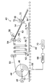
- FIG. 5 is a side view of the slip sheet supply apparatus 40 according to the embodiment of the present invention.
- the glass plates 12, 12... Cut to a predetermined length are conveyed at a predetermined speed and at a predetermined interval by the roller conveyor 42 from the left side of the drawing as indicated by an arrow A.
- a roll-shaped interleaf paper 44 is rotatably arranged on the upstream side of the roller conveyor 42.
- the interleaf paper 50 is supplied to a pair of feed rollers 54, 54 via a plurality of tension adjusting rollers 52, 52.
- the feed rollers 54 and 54 are intermittently rotationally driven by a motor (sending means) 56, and feed a slip sheet 50 having a length corresponding to the length of the glass plate 12 to a cutter (cutting means) 58.
- the feeding speed of the slip sheet 50 by the feeding rollers 54 and 54 is set to the same speed as the conveying speed of the glass plate 12 by the roller conveyor 42.
- the cutter 58 is moved in the vertical direction by an unillustrated elevating drive unit.
- the cutter 58 is waiting at the upper position of the fed slip sheet 50 when the slip sheet 50 is fed, and is moved downward when the slip sheet 50 is cut.
- the slip sheet 50 is cut into a slip sheet 14 having a size to be placed on the glass plate 12.
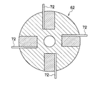
- the cut interleaf paper 14 slides down along the guide member 60 configured in a comb-teeth shape shown in FIG. 6 and passes through a crease forming roller (fold forming means) 62 described later. 4 are formed along one side of the slip sheet 14.
- the interleaf 14 formed with the folds 28, 28... Slides along the guide member (interleaf supply means) 64 similarly configured in a comb-teeth shape.
- the guide member (interleaf supply means) 64 similarly configured in a comb-teeth shape.
- the control unit 68 calculates the time at which the tip of the glass plate 12 reaches the lower position below the lower end of the guide member 64, and when that time is reached.
- 56 drivers 70 are controlled. As a result, the slip sheet 14 is smoothly placed on the glass plate 12 being conveyed by the roller conveyor 42.
- control unit 68 outputs a command to move the cutter 58 downward to the above-described lifting drive unit when the interleaf sheet 50 is fed out substantially the same length as the length of the glass plate 12.
- the slip sheet 50 is cut by the cutter 58 to become the slip sheet 14, which slips along the guide members 60 and 64, and the rear end of the slip sheet 14 is placed on the rear end of the glass plate 12. Is done.
- the glass plate 12 on which the interleaving paper 14 is placed is carried out to the right in FIG. 5 by the roller conveyor 42, and is sequentially stacked in a state where the interleaving paper 14 is placed in a downstream stock section (not shown). The During this time, the next glass plate 12 is continuously conveyed by the roller conveyor 42, and the slip sheet 14 is placed on the upper surface by the above-described operation.
- the control unit 68 outputs a command for stopping the driving of the feed rollers 54, 54 and the like so as to stop the feeding of the slip sheet 50 by an amount corresponding to the space between the glass plates that are sequentially conveyed. Further, in order to cut the slip sheet 50 by the cutter 58 in this stop state, a command for controlling the lowering movement of the cutter 58 and the movement to the upper standby position is output to the lifting drive unit. By repeating this operation, the slip sheet 14 is supplied and placed on the upper surface of the glass plate 12.
- a backup roller 74 is arranged below the fold forming roller 62 as shown in FIG. On the right end of the backup roller 74 facing the teeth 72, 72,... Of the fold forming roller 62, a soft member 76 for forming the fold 28 on the interleaf 14 between the teeth 72, 72,. It is attached in the circumferential direction. In other words, the crease 28 is satisfactorily formed on the interleaf paper 14 by the predetermined amount of the rotated teeth 72 biting into the soft member 76.
- the folds 28, 28... Formed on the slip sheet 14 are placed on the pallet 10 so that the upper side portion is formed. To load. By stacking in this way, the slip sheet 14 can be reliably sucked by the slip sheet suction pad 30 when the glass plate 12 is taken out from the pallet 10.
- the rotational speeds of the crease forming roller 62 and the backup roller 74 are set in accordance with the rotational speeds of the feed rollers 54, 54. Therefore, the interleaf 14 on which the creases 28, 28. Is smoothly placed on the glass plate 12 being conveyed.
- the crease forming roller 62 is provided with teeth 72 for forming the crease 28 in the interleaf 14. However, as described above, when forming irregularities on one side of the interleaf 14, a crease is formed. A portion corresponding to the teeth 72 of the roller 62 may be formed in a concavo-convex shape, and the concavo-convex shape may be transferred to the slip sheet 14.
- the crease forming roller 62 is provided at a position corresponding to the side along the conveyance direction of the interleaf sheet 14.
- the side of the slip sheet is a side that is located on the upper side of the glass plate and protrudes from the upper side when the glass plate is placed on the pallet. That is, when the sides along the conveyance direction of the glass plate are the upper and lower sides when being placed on the pallet, the crease forming rollers are placed on the sides along the conveyance direction of the interleaf 14 as shown in FIG. It is preferable that they are provided correspondingly.
- the crease forming means acts along the side perpendicular to the conveyance direction of the slip sheet,
- the interleaving paper can be placed on the glass plate while being conveyed.
- the length (h) of the crease groove is longer than the height (H) of the upper side of the slip sheet protruding upward from the upper side of the glass plate. This is because the posture maintenance property of the slip sheet can be improved. Therefore, the creases can be formed after interleaving the interleaf sheets between the glass plates, but it is preferable to interpose between the glass plates after providing the creases in the interleaving paper from the viewpoint of higher posture maintenance.
- the glass plate 12 has been illustrated as an example of use of the present invention, not only the glass plate 12 but also a plate-like body such as a resin plate, a metal plate, etc. as long as it is a plate-like body, the pallet 10 with the interleaf 14 interposed therebetween As long as they are stacked, the plate-like body placing method, slip sheet, and slip sheet supply apparatus of the present invention can be applied.
- a plate-like body such as a resin plate, a metal plate, etc.
Landscapes
- Engineering & Computer Science (AREA)
- Mechanical Engineering (AREA)
- Life Sciences & Earth Sciences (AREA)
- Wood Science & Technology (AREA)
- Buffer Packaging (AREA)
- Wrapping Of Specific Fragile Articles (AREA)
- Sheets, Magazines, And Separation Thereof (AREA)
- Packaging Frangible Articles (AREA)
Abstract
Description
・上辺部14Aの幅方向における折り目のピッチ(P):50~80mmが好ましく、本例では約65mm
・折り目28の溝深さ(d):0.05~0.2mm程度、本例では約0.1mm
・折り目28の溝の長さ(h):Hよりも長いことが好ましく、具体的には50~120mmが好ましく、本例では約80mm
・折り目28の溝幅(c):2~10mmが好ましく、本例では約5mm
このような折り目28が、合紙14の上辺部14Aに沿って形成されることにより、合紙14の上辺部14Aの腰が強くなり、上辺部14Aは垂れ下がることなく起立した状態に保持される。
ローラコンベア42の上流側上方には、ロール状合紙44が回転自在に配置されている。
本出願は、2009年2月20日出願の日本特許出願(特願2009-038241)に基づくものであり、その内容はここに参照として取り込まれる。
12…ガラス板
14…合紙
16…積層体
18…載置台
20…背面支持体
22…傾斜載置板
24…基台
26…緩衝部材
28…折り目
30…合紙吸着パッド
32…ガラス板吸着装置
34…吸着パッド
40…合紙の供給装置
42…ローラコンベア
44…ロール状合紙
46…回転軸
48…モータ
50…帯状の合紙
52…張力調整用ローラ
54…送りローラ
58…カッター
60…ガイド部材
62…折り目形成用ローラ
64…ガイド部材
66…センサー
68…制御部
70…ドライバ
72…歯
74…バックアップローラ
76…軟性部材
Claims (9)
- 板状体の底辺部が載置される載置台と板状体の背面を支持する背面支持体とを備えたパレットに、複数枚の板状体を、各々の板状体間に合紙を介在させて載置する板状体の載置方法において、
前記合紙を、前記板状体の前記パレットに載置した状態における上辺部よりも上方に所定量突出させ、
該突出させた合紙の上辺部に、該上辺部に沿って所定の間隔で複数の折り目を形成することを特徴とする板状体の載置方法。 - 前記合紙に前記折り目を形成した後に、前記合紙の上辺部を前記板状体の上辺部よりも上方に所定量突出させて、各々の板状体間に前記合紙を介在させる請求項1に記載の板状体の載置方法。
- 前記板状体の上辺部よりも前記合紙の上辺部が30~100mm突出している請求項1または2に記載の板状体の載置方法。
- 前記複数の折り目が、50~80mmの間隔で形成されている請求項1乃至3のいずれかに1項に記載の板状体の載置方法。
- 板状体の底辺部が載置される載置台と板状体の背面を支持する背面支持体とを備えたパレットに載置される複数の板状体の各々の間に介在される合紙であって、
前記板状体の上辺部よりも上方に所定量突出する突出部と、
該突出部の上辺部に沿って所定の間隔で形成された複数の折り目を備えることを特徴とする合紙。 - 前記複数の折り目が、50~80mmの間隔で形成されている請求項5に記載の合紙。
- 連続して移動する板状体の上面に合紙を供給する合紙の供給装置であって、
ロール状に巻回された合紙を板状体の移動速度にあわせて送り出す送出手段と、
前記送出手段によって送り出された合紙を板状体の長さに対応した長さに切断する切断手段と、
前記切断手段によって切断された合紙を板状体の上面に供給する合紙供給手段とを備え、
前記切断手段によって切断された合紙の一辺部に沿って所定の間隔で複数の折り目を形成する折り目形成手段が設けられ、
前記合紙供給手段は、前記合紙に形成された前記折り目が、板状体の所定の一辺部から外側に位置するように合紙を板状体に供給することを特徴とする合紙の供給装置。 - 前記折り目形成手段は、前記合紙送出手段による合紙の搬送方向に沿った合紙の辺に相当する位置に設けられている請求項7に記載の合紙の供給装置。
- 前記折り目形成手段は、複数の折り目を50~80mmの間隔で形成する請求項7または8に記載の合紙の供給装置。
Priority Applications (2)
| Application Number | Priority Date | Filing Date | Title |
|---|---|---|---|
| JP2011500625A JP5408559B2 (ja) | 2009-02-20 | 2010-02-17 | 板状体の載置方法及び合紙並びに合紙の供給装置 |
| CN2010800061202A CN102300776B (zh) | 2009-02-20 | 2010-02-17 | 板状体的载置方法及夹纸以及夹纸的供给装置 |
Applications Claiming Priority (2)
| Application Number | Priority Date | Filing Date | Title |
|---|---|---|---|
| JP2009038241 | 2009-02-20 | ||
| JP2009-038241 | 2009-02-20 |
Publications (1)
| Publication Number | Publication Date |
|---|---|
| WO2010095643A1 true WO2010095643A1 (ja) | 2010-08-26 |
Family
ID=42633923
Family Applications (1)
| Application Number | Title | Priority Date | Filing Date |
|---|---|---|---|
| PCT/JP2010/052343 Ceased WO2010095643A1 (ja) | 2009-02-20 | 2010-02-17 | 板状体の載置方法及び合紙並びに合紙の供給装置 |
Country Status (5)
| Country | Link |
|---|---|
| JP (1) | JP5408559B2 (ja) |
| KR (1) | KR101598243B1 (ja) |
| CN (1) | CN102300776B (ja) |
| TW (1) | TWI527750B (ja) |
| WO (1) | WO2010095643A1 (ja) |
Cited By (7)
| Publication number | Priority date | Publication date | Assignee | Title |
|---|---|---|---|---|
| JP2013256315A (ja) * | 2012-06-12 | 2013-12-26 | Asahi Glass Co Ltd | ガラス板積層体の積層方法及びガラス板積層体並びにガラス板梱包体 |
| JP2018197123A (ja) * | 2017-05-24 | 2018-12-13 | Agc株式会社 | ガラス合紙、ガラス板梱包体、ガラス合紙積層方法およびガラス合紙積層装置 |
| CN110589087A (zh) * | 2019-08-28 | 2019-12-20 | 广州荣裕智能机械有限公司 | 一种面膜内托盘盒机 |
| JP2020011748A (ja) * | 2018-07-17 | 2020-01-23 | 日本電気硝子株式会社 | 積層体パレット一体品、及びパレット |
| WO2021054034A1 (ja) * | 2019-09-20 | 2021-03-25 | 日本電気硝子株式会社 | ガラス板梱包体 |
| JP2021046239A (ja) * | 2019-09-20 | 2021-03-25 | 日本電気硝子株式会社 | ガラス板梱包体 |
| WO2021054219A1 (ja) * | 2019-09-20 | 2021-03-25 | 日本電気硝子株式会社 | ガラス板梱包体およびガラス板梱包体の作製方法 |
Families Citing this family (2)
| Publication number | Priority date | Publication date | Assignee | Title |
|---|---|---|---|---|
| JP7088180B2 (ja) * | 2017-05-29 | 2022-06-21 | Agc株式会社 | ガラス板梱包体の製造方法 |
| TWI908487B (zh) * | 2024-11-22 | 2025-12-11 | 冠誠國際股份有限公司 | 膨脹螺絲 |
Citations (5)
| Publication number | Priority date | Publication date | Assignee | Title |
|---|---|---|---|---|
| JPS508000B1 (ja) * | 1970-12-18 | 1975-03-31 | ||
| JPH07232781A (ja) * | 1994-02-17 | 1995-09-05 | Mitsubishi Electric Corp | 挿間紙 |
| JP2005239242A (ja) * | 2004-02-27 | 2005-09-08 | Nippon Electric Glass Co Ltd | ガラス板梱包体 |
| JP2008213920A (ja) * | 2007-03-07 | 2008-09-18 | Nippon Electric Glass Co Ltd | 保護シート供給装置 |
| WO2009008413A1 (ja) * | 2007-07-11 | 2009-01-15 | Asahi Glass Co., Ltd. | ガラス板用合紙及びガラス板積層体 |
Family Cites Families (12)
| Publication number | Priority date | Publication date | Assignee | Title |
|---|---|---|---|---|
| JPH0789507A (ja) | 1993-09-16 | 1995-04-04 | Asahi Glass Co Ltd | 板ガラスの合紙挿入方法 |
| JPH07101483A (ja) | 1993-10-01 | 1995-04-18 | Asahi Glass Co Ltd | ガラス用合紙 |
| JP2791640B2 (ja) | 1994-05-24 | 1998-08-27 | 長良製紙株式会社 | ガラス用合紙 |
| CN2450157Y (zh) * | 2000-09-22 | 2001-09-26 | 中国国际海运集装箱(集团)股份有限公司 | 侧开式集装箱 |
| JP2004203436A (ja) * | 2002-12-25 | 2004-07-22 | Kyokuhei Glass Kako Kk | ガラス基板搬送用ボックス |
| JP4775755B2 (ja) | 2003-12-05 | 2011-09-21 | 旭硝子株式会社 | ガラス板梱包箱とガラス板梱包方法及びガラス板開梱方法並びにガラス板開梱装置 |
| JP4535790B2 (ja) * | 2004-06-25 | 2010-09-01 | 大日本印刷株式会社 | 板状物の積載方法及び装置 |
| JP5237792B2 (ja) * | 2006-04-20 | 2013-07-17 | 旭硝子株式会社 | 板状体保持機構及び板状体梱包装置及び板状体保持方法 |
| JP4924982B2 (ja) * | 2006-12-07 | 2012-04-25 | 日本電気硝子株式会社 | ガラス板梱包方法及びガラス板梱包体 |
| CN102336280B (zh) * | 2007-03-07 | 2013-08-28 | 日本电气硝子株式会社 | 保护片装载装置 |
| KR200438921Y1 (ko) * | 2007-06-20 | 2008-03-11 | 삼성코닝정밀유리 주식회사 | 디스플레이용 평판유리 포장 컨테이너 |
| KR101337249B1 (ko) * | 2007-07-03 | 2013-12-05 | (주)포스코엠텍 | 접기 롤러 및 이를 이용한 코일 포장용 방청지 권취장치 |
-
2010
- 2010-02-12 TW TW099104757A patent/TWI527750B/zh not_active IP Right Cessation
- 2010-02-17 WO PCT/JP2010/052343 patent/WO2010095643A1/ja not_active Ceased
- 2010-02-17 JP JP2011500625A patent/JP5408559B2/ja not_active Expired - Fee Related
- 2010-02-17 KR KR1020117017797A patent/KR101598243B1/ko not_active Expired - Fee Related
- 2010-02-17 CN CN2010800061202A patent/CN102300776B/zh not_active Expired - Fee Related
Patent Citations (5)
| Publication number | Priority date | Publication date | Assignee | Title |
|---|---|---|---|---|
| JPS508000B1 (ja) * | 1970-12-18 | 1975-03-31 | ||
| JPH07232781A (ja) * | 1994-02-17 | 1995-09-05 | Mitsubishi Electric Corp | 挿間紙 |
| JP2005239242A (ja) * | 2004-02-27 | 2005-09-08 | Nippon Electric Glass Co Ltd | ガラス板梱包体 |
| JP2008213920A (ja) * | 2007-03-07 | 2008-09-18 | Nippon Electric Glass Co Ltd | 保護シート供給装置 |
| WO2009008413A1 (ja) * | 2007-07-11 | 2009-01-15 | Asahi Glass Co., Ltd. | ガラス板用合紙及びガラス板積層体 |
Cited By (17)
| Publication number | Priority date | Publication date | Assignee | Title |
|---|---|---|---|---|
| JP2013256315A (ja) * | 2012-06-12 | 2013-12-26 | Asahi Glass Co Ltd | ガラス板積層体の積層方法及びガラス板積層体並びにガラス板梱包体 |
| JP2018197123A (ja) * | 2017-05-24 | 2018-12-13 | Agc株式会社 | ガラス合紙、ガラス板梱包体、ガラス合紙積層方法およびガラス合紙積層装置 |
| JP2020011748A (ja) * | 2018-07-17 | 2020-01-23 | 日本電気硝子株式会社 | 積層体パレット一体品、及びパレット |
| WO2020017196A1 (ja) * | 2018-07-17 | 2020-01-23 | 日本電気硝子株式会社 | 積層体パレット一体品、及びパレット |
| JP7012942B2 (ja) | 2018-07-17 | 2022-01-31 | 日本電気硝子株式会社 | 積層体パレット一体品、及びパレット |
| CN110589087A (zh) * | 2019-08-28 | 2019-12-20 | 广州荣裕智能机械有限公司 | 一种面膜内托盘盒机 |
| JP2021046238A (ja) * | 2019-09-20 | 2021-03-25 | 日本電気硝子株式会社 | ガラス板梱包体 |
| WO2021054219A1 (ja) * | 2019-09-20 | 2021-03-25 | 日本電気硝子株式会社 | ガラス板梱包体およびガラス板梱包体の作製方法 |
| JP2021046239A (ja) * | 2019-09-20 | 2021-03-25 | 日本電気硝子株式会社 | ガラス板梱包体 |
| JPWO2021054219A1 (ja) * | 2019-09-20 | 2021-03-25 | ||
| WO2021054034A1 (ja) * | 2019-09-20 | 2021-03-25 | 日本電気硝子株式会社 | ガラス板梱包体 |
| CN114174194A (zh) * | 2019-09-20 | 2022-03-11 | 日本电气硝子株式会社 | 玻璃板捆包体 |
| CN114206740A (zh) * | 2019-09-20 | 2022-03-18 | 日本电气硝子株式会社 | 玻璃板捆包体以及玻璃板捆包体的制作方法 |
| JP7324419B2 (ja) | 2019-09-20 | 2023-08-10 | 日本電気硝子株式会社 | ガラス板梱包体 |
| CN114174194B (zh) * | 2019-09-20 | 2023-08-25 | 日本电气硝子株式会社 | 玻璃板捆包体 |
| JP7453622B2 (ja) | 2019-09-20 | 2024-03-21 | 日本電気硝子株式会社 | ガラス板梱包体およびガラス板梱包体の作製方法 |
| CN114206740B (zh) * | 2019-09-20 | 2024-09-27 | 日本电气硝子株式会社 | 玻璃板捆包体以及玻璃板捆包体的制作方法 |
Also Published As
| Publication number | Publication date |
|---|---|
| JP5408559B2 (ja) | 2014-02-05 |
| TW201040101A (en) | 2010-11-16 |
| CN102300776A (zh) | 2011-12-28 |
| KR101598243B1 (ko) | 2016-02-29 |
| JPWO2010095643A1 (ja) | 2012-08-23 |
| CN102300776B (zh) | 2013-07-31 |
| TWI527750B (zh) | 2016-04-01 |
| KR20110127647A (ko) | 2011-11-25 |
Similar Documents
| Publication | Publication Date | Title |
|---|---|---|
| JP5408559B2 (ja) | 板状体の載置方法及び合紙並びに合紙の供給装置 | |
| CN104955749B (zh) | 片材供给装置 | |
| WO2020237462A1 (zh) | 贴胶条装置 | |
| KR20110046387A (ko) | 광학 필름의 반송 방법 및 이를 이용한 장치 | |
| JP6953795B2 (ja) | ガラス合紙、ガラス板梱包体、ガラス合紙積層方法およびガラス合紙積層装置 | |
| TW201010927A (en) | Conveying apparatus for envelopes and related methods | |
| WO2015178480A1 (ja) | 搬送装置 | |
| CN103562104A (zh) | 光学膜的输送方法和输送装置 | |
| US7971865B2 (en) | Inserting apparatus for discrete objects into envelopes and related methods | |
| JP2009269702A (ja) | 段ボールシートの給送装置及び給送方法 | |
| JP6568123B2 (ja) | 本の中身のための紙分離装置 | |
| JP4364830B2 (ja) | シート材供給裁断装置 | |
| CN112441439B (zh) | 纸张搬送机构以及图像形成装置 | |
| EP1247772A3 (en) | Apparatus for sensing the feeding of sheets of paper | |
| CN101516751A (zh) | 裁压机供料台上片材的传送辅助驱动装置 | |
| JP6980192B2 (ja) | 給紙装置および紙葉体の重送防止方法 | |
| JP2006056675A (ja) | 板材の合紙セット装置 | |
| JPH08217035A (ja) | 貼合機 | |
| JP6111934B2 (ja) | シート載置装置 | |
| JPH05229673A (ja) | コレータ装置 | |
| JP2008143640A (ja) | 給紙ホッパ | |
| JP4595928B2 (ja) | 印刷用記録プレート供給装置 | |
| JP2001039568A (ja) | 合紙取出装置 | |
| JP4484130B2 (ja) | 刷本供給装置 | |
| JP2001151371A5 (ja) |
Legal Events
| Date | Code | Title | Description |
|---|---|---|---|
| WWE | Wipo information: entry into national phase |
Ref document number: 201080006120.2 Country of ref document: CN |
|
| 121 | Ep: the epo has been informed by wipo that ep was designated in this application |
Ref document number: 10743769 Country of ref document: EP Kind code of ref document: A1 |
|
| ENP | Entry into the national phase |
Ref document number: 2011500625 Country of ref document: JP Kind code of ref document: A |
|
| ENP | Entry into the national phase |
Ref document number: 20117017797 Country of ref document: KR Kind code of ref document: A |
|
| NENP | Non-entry into the national phase |
Ref country code: DE |
|
| 122 | Ep: pct application non-entry in european phase |
Ref document number: 10743769 Country of ref document: EP Kind code of ref document: A1 |