WO2008062853A1 - Feuille d'acier électromagnétique à orientation unidirectionnelle de grains, ayant une excellente adhésion de film, et son procédé de fabrication - Google Patents
Feuille d'acier électromagnétique à orientation unidirectionnelle de grains, ayant une excellente adhésion de film, et son procédé de fabrication Download PDFInfo
- Publication number
- WO2008062853A1 WO2008062853A1 PCT/JP2007/072600 JP2007072600W WO2008062853A1 WO 2008062853 A1 WO2008062853 A1 WO 2008062853A1 JP 2007072600 W JP2007072600 W JP 2007072600W WO 2008062853 A1 WO2008062853 A1 WO 2008062853A1
- Authority
- WO
- WIPO (PCT)
- Prior art keywords
- mass
- steel sheet
- electrical steel
- earth metal
- compound
- Prior art date
Links
Classifications
-
- C—CHEMISTRY; METALLURGY
- C22—METALLURGY; FERROUS OR NON-FERROUS ALLOYS; TREATMENT OF ALLOYS OR NON-FERROUS METALS
- C22C—ALLOYS
- C22C38/00—Ferrous alloys, e.g. steel alloys
- C22C38/60—Ferrous alloys, e.g. steel alloys containing lead, selenium, tellurium, or antimony, or more than 0.04% by weight of sulfur
-
- C—CHEMISTRY; METALLURGY
- C22—METALLURGY; FERROUS OR NON-FERROUS ALLOYS; TREATMENT OF ALLOYS OR NON-FERROUS METALS
- C22C—ALLOYS
- C22C38/00—Ferrous alloys, e.g. steel alloys
-
- C—CHEMISTRY; METALLURGY
- C21—METALLURGY OF IRON
- C21D—MODIFYING THE PHYSICAL STRUCTURE OF FERROUS METALS; GENERAL DEVICES FOR HEAT TREATMENT OF FERROUS OR NON-FERROUS METALS OR ALLOYS; MAKING METAL MALLEABLE, e.g. BY DECARBURISATION OR TEMPERING
- C21D8/00—Modifying the physical properties by deformation combined with, or followed by, heat treatment
- C21D8/12—Modifying the physical properties by deformation combined with, or followed by, heat treatment during manufacturing of articles with special electromagnetic properties
- C21D8/1216—Modifying the physical properties by deformation combined with, or followed by, heat treatment during manufacturing of articles with special electromagnetic properties the working step(s) being of interest
- C21D8/1222—Hot rolling
-
- C—CHEMISTRY; METALLURGY
- C21—METALLURGY OF IRON
- C21D—MODIFYING THE PHYSICAL STRUCTURE OF FERROUS METALS; GENERAL DEVICES FOR HEAT TREATMENT OF FERROUS OR NON-FERROUS METALS OR ALLOYS; MAKING METAL MALLEABLE, e.g. BY DECARBURISATION OR TEMPERING
- C21D8/00—Modifying the physical properties by deformation combined with, or followed by, heat treatment
- C21D8/12—Modifying the physical properties by deformation combined with, or followed by, heat treatment during manufacturing of articles with special electromagnetic properties
- C21D8/1216—Modifying the physical properties by deformation combined with, or followed by, heat treatment during manufacturing of articles with special electromagnetic properties the working step(s) being of interest
- C21D8/1233—Cold rolling
-
- C—CHEMISTRY; METALLURGY
- C21—METALLURGY OF IRON
- C21D—MODIFYING THE PHYSICAL STRUCTURE OF FERROUS METALS; GENERAL DEVICES FOR HEAT TREATMENT OF FERROUS OR NON-FERROUS METALS OR ALLOYS; MAKING METAL MALLEABLE, e.g. BY DECARBURISATION OR TEMPERING
- C21D8/00—Modifying the physical properties by deformation combined with, or followed by, heat treatment
- C21D8/12—Modifying the physical properties by deformation combined with, or followed by, heat treatment during manufacturing of articles with special electromagnetic properties
- C21D8/1244—Modifying the physical properties by deformation combined with, or followed by, heat treatment during manufacturing of articles with special electromagnetic properties the heat treatment(s) being of interest
- C21D8/1266—Modifying the physical properties by deformation combined with, or followed by, heat treatment during manufacturing of articles with special electromagnetic properties the heat treatment(s) being of interest between cold rolling steps
-
- C—CHEMISTRY; METALLURGY
- C21—METALLURGY OF IRON
- C21D—MODIFYING THE PHYSICAL STRUCTURE OF FERROUS METALS; GENERAL DEVICES FOR HEAT TREATMENT OF FERROUS OR NON-FERROUS METALS OR ALLOYS; MAKING METAL MALLEABLE, e.g. BY DECARBURISATION OR TEMPERING
- C21D8/00—Modifying the physical properties by deformation combined with, or followed by, heat treatment
- C21D8/12—Modifying the physical properties by deformation combined with, or followed by, heat treatment during manufacturing of articles with special electromagnetic properties
- C21D8/1244—Modifying the physical properties by deformation combined with, or followed by, heat treatment during manufacturing of articles with special electromagnetic properties the heat treatment(s) being of interest
- C21D8/1272—Final recrystallisation annealing
-
- C—CHEMISTRY; METALLURGY
- C21—METALLURGY OF IRON
- C21D—MODIFYING THE PHYSICAL STRUCTURE OF FERROUS METALS; GENERAL DEVICES FOR HEAT TREATMENT OF FERROUS OR NON-FERROUS METALS OR ALLOYS; MAKING METAL MALLEABLE, e.g. BY DECARBURISATION OR TEMPERING
- C21D8/00—Modifying the physical properties by deformation combined with, or followed by, heat treatment
- C21D8/12—Modifying the physical properties by deformation combined with, or followed by, heat treatment during manufacturing of articles with special electromagnetic properties
- C21D8/1277—Modifying the physical properties by deformation combined with, or followed by, heat treatment during manufacturing of articles with special electromagnetic properties involving a particular surface treatment
- C21D8/1283—Application of a separating or insulating coating
-
- C—CHEMISTRY; METALLURGY
- C22—METALLURGY; FERROUS OR NON-FERROUS ALLOYS; TREATMENT OF ALLOYS OR NON-FERROUS METALS
- C22C—ALLOYS
- C22C38/00—Ferrous alloys, e.g. steel alloys
- C22C38/001—Ferrous alloys, e.g. steel alloys containing N
-
- C—CHEMISTRY; METALLURGY
- C22—METALLURGY; FERROUS OR NON-FERROUS ALLOYS; TREATMENT OF ALLOYS OR NON-FERROUS METALS
- C22C—ALLOYS
- C22C38/00—Ferrous alloys, e.g. steel alloys
- C22C38/002—Ferrous alloys, e.g. steel alloys containing In, Mg, or other elements not provided for in one single group C22C38/001 - C22C38/60
-
- C—CHEMISTRY; METALLURGY
- C22—METALLURGY; FERROUS OR NON-FERROUS ALLOYS; TREATMENT OF ALLOYS OR NON-FERROUS METALS
- C22C—ALLOYS
- C22C38/00—Ferrous alloys, e.g. steel alloys
- C22C38/004—Very low carbon steels, i.e. having a carbon content of less than 0,01%
-
- C—CHEMISTRY; METALLURGY
- C22—METALLURGY; FERROUS OR NON-FERROUS ALLOYS; TREATMENT OF ALLOYS OR NON-FERROUS METALS
- C22C—ALLOYS
- C22C38/00—Ferrous alloys, e.g. steel alloys
- C22C38/02—Ferrous alloys, e.g. steel alloys containing silicon
-
- C—CHEMISTRY; METALLURGY
- C22—METALLURGY; FERROUS OR NON-FERROUS ALLOYS; TREATMENT OF ALLOYS OR NON-FERROUS METALS
- C22C—ALLOYS
- C22C38/00—Ferrous alloys, e.g. steel alloys
- C22C38/04—Ferrous alloys, e.g. steel alloys containing manganese
-
- H—ELECTRICITY
- H01—ELECTRIC ELEMENTS
- H01F—MAGNETS; INDUCTANCES; TRANSFORMERS; SELECTION OF MATERIALS FOR THEIR MAGNETIC PROPERTIES
- H01F1/00—Magnets or magnetic bodies characterised by the magnetic materials therefor; Selection of materials for their magnetic properties
- H01F1/01—Magnets or magnetic bodies characterised by the magnetic materials therefor; Selection of materials for their magnetic properties of inorganic materials
- H01F1/03—Magnets or magnetic bodies characterised by the magnetic materials therefor; Selection of materials for their magnetic properties of inorganic materials characterised by their coercivity
- H01F1/12—Magnets or magnetic bodies characterised by the magnetic materials therefor; Selection of materials for their magnetic properties of inorganic materials characterised by their coercivity of soft-magnetic materials
- H01F1/14—Magnets or magnetic bodies characterised by the magnetic materials therefor; Selection of materials for their magnetic properties of inorganic materials characterised by their coercivity of soft-magnetic materials metals or alloys
- H01F1/147—Alloys characterised by their composition
- H01F1/14766—Fe-Si based alloys
- H01F1/14775—Fe-Si based alloys in the form of sheets
Definitions
- the present invention relates to a unidirectional electrical steel sheet used for a static inductor such as a transformer. In particular, by reducing the film peeling rate during strong bending.
- It relates to a unidirectional electrical steel sheet with high magnetic flux density and excellent transformer manufacturing characteristics.
- Unidirectional electrical steel sheets are mainly used for static inductors represented by transformers.
- the characteristics to be satisfied by the unidirectional electrical steel sheet are as follows: (1) Low energy loss, that is, iron loss when excited by alternating current,
- the device has high permeability in the excitation range and can be easily excited.
- One of the typical techniques for improving the magnetic flux density is a manufacturing method disclosed in Japanese Patent Publication No. 4 0-1 5 6 4 4.
- This method is a manufacturing method in which A 1 N and Mn S function as an inhibitor that suppresses crystal grain growth, and the reduction rate in the final cold rolling step is a strong reduction exceeding 80%.
- This method increases the degree of grain orientation in the ⁇ 1 1 0 ⁇ 0 0 1> orientation, and B 8 (magnetic flux density at an excitation force of 80 0 A / m) is 1. 8 7 0 T or more It is now possible to obtain a grain-oriented electrical steel sheet having a high magnetic flux density.
- JP-A-6 8 8 1 7 1 discloses a method of adding a 1 0 0 ⁇ 5 0 0 0 g ZT of B i in the molten steel is disclosed, B s is 1 9 5 T or more products have been obtained.
- methods for reducing the iron loss include a method of applying a laser treatment to a steel plate (Japanese Patent Publication No. 5 7-2 25 2) and a method of introducing mechanical strain into a steel plate (Japanese Patent Publication No. 5-8-). 2 5 6 9) and other methods for subdividing magnetic domains are disclosed, and materials exhibiting excellent iron loss characteristics are also disclosed.
- an annealing separator mainly composed of MgO is selected from La, La compounds, Ce, and Ce compounds.
- 0.1 to 3.0% of Mg or O is added in a total amount of 1 or 2 or more as La and Ce compounds, and S or S compound is S and 0 to Mg O , 0 1 to 1.0% added
- a method for producing a unidirectional silicon steel sheet is disclosed.
- This method uses an annealing separator containing S, which is an inhibitor of the formation of an inhibitor, and suppresses the grain growth of primary recrystallization by allowing S to penetrate into the steel from the annealing separator during finish annealing.
- the orientation of secondary recrystallized grains grown from the surface layer. By coexisting strong La and Ce, the penetration time of S is optimized for secondary recrystallization.
- a rare earth oxide alone or a metal silicate is used in an annealing separator for grain-oriented silicon steel strip based on magnesium oxide.
- An annealing separator characterized by being contained with salt is disclosed. It also discloses that products without small discontinuities (small hole indentations) under the strip's skin can be obtained, resulting in a low magnetostriction rate, good surface resistance and adhesion. Has been. Disclosure of the invention
- the adhesion of the primary coating of the strongly-bending processed portion is the ratio of the area where the coating peels to the area of the processed portion where the steel plate contacts the round bar when the steel plate is wound around a round bar with a diameter of 10 dragons or less.
- the film peeling area ratio corresponding to is evaluated.
- the present inventors added Ce compound or La compound, or both Ce compound and La compound into the annealing separator mainly composed of MgO. It has been proposed that a unidirectional electrical steel sheet containing Ce or La, or both Ce and La is obtained, and that the primary coating of this steel sheet is excellent in film adhesion, particularly frame peeling. However, even the film adhesion is insufficient as the adhesion of the primary film to the strongly bent portion.
- the present invention solves the above-mentioned problems, and when manufacturing a transformer, particularly a wound core transformer, it is possible to prevent peeling of the primary film that occurs at the strongly bent portion on the inner peripheral side of the core, and has excellent film adhesion. Another object is to provide a unidirectional electrical steel sheet and a method for producing the same.
- the present invention provides the following unidirectional electrical steel sheet and a method for producing the same.
- the rare earth metal element is one or more selected from La and Ce (1)
- the unidirectional electrical steel sheet having excellent film adhesion as described in (1) is one or more selected from La and Ce (1).
- C 0.1% or less
- one or two selected from S or Se Total of seeds 0.01 to 0.040% Containing the remaining Fe and unavoidable impurities to make a hot-rolled sheet, hot-rolled sheet annealed, once or twice Or a series of processes in which cold rolling is performed twice or more with intermediate annealing and finished to the final thickness, then decarburized annealing is applied, and then the steel sheet surface is coated with an annealing separator, dried, and finish annealed.
- rare earth metal compounds in the range of 0.1 to 10% by mass in terms of rare earth metals, Ca, Sr or Ba
- One or more selected alkaline earth metal compounds are contained in an amount of 0.1 to 10% by mass in terms of alkaline earth metal, and sulfur compounds are contained in an amount of 0.01 to 5% by mass in terms of S conversion.
- the annealing separator contains 0.5 to 10% by mass of a Ti compound in terms of Ti, (5) The unidirectional electromagnetic wave excellent in film adhesion according to (5) A method of manufacturing a steel sheet.
- the steel is characterized by containing acid-soluble A 1: 0.0 10 to 0.0 65% by mass and N: 0.0 0 30 to 0.0 15 50% by mass%.
- the unidirectional electrical steel with excellent film adhesion described in (5) or (6) A manufacturing method of a board.
- the present invention contains, in a primary coating of a unidirectional electrical steel sheet containing 1 to 7% by mass and A 1 N as an inhibitor, a rare earth metal element, an alkaline earth metal element, and Since it contains a compound containing elemental sulfur, a unidirectional electrical steel sheet having a high coating adhesion that has never been obtained, and particularly having a small coating peeling area ratio during bending is obtained.
- the compound is contained in the primary coating of grain-oriented electrical steel sheets by adding a rare earth metal element compound, an alkaline earth metal element compound, or a sulfur compound to an annealing separator mainly composed of MgO. Can be achieved.
- Figure 1 is a diagram (photo) showing the interface cross section between the primary coating and the steel sheet.
- Figure 2 shows an example of GDS profile analysis of the primary coating.
- Fig. 3 shows a cross-sectional view of the sample with a small peel-off area ratio during strong bending processing observed with FE-EP MA (upper left photo), S mapping (upper right photo), and Sr mapping. The figure shown (lower left picture) and the figure showing the mapping of Ce (lower right picture).
- Figure 4 shows the Sr, Ce and S compounds observed with FE-EPMA ( (Photo shows SrCeS compound that appears white adjacent to spinel (Mg AI 2 0 4 ) that appears black in the backscattered electron image).
- FE-EPMA (Photo shows SrCeS compound that appears white adjacent to spinel (Mg AI 2 0 4 ) that appears black in the backscattered electron image).
- a primary film of grain-oriented electrical steel sheet after applying and drying an annealing separator composed mainly of M g O decarburization annealed sheet by finish annealing, and S i ⁇ 2 in decarboxylation film It means a coating mainly composed of Mg 2 S i 0 4 (forsterite) formed on the surface of the steel plate by the reaction of MgO.
- an insulating film composed mainly of phosphate and colloidal silica coated on the primary film after finish annealing is classified as a secondary film.
- a primary film made of oxide mainly composed of forsterite is usually easily broken when deformed. Therefore, in order to give good workability, a deformable substance is formed in the primary film. Is considered effective.
- the inventors of the present invention have included C a, S r, C 1, S r, in the primary coating of unidirectional electrical steel sheet containing 2 to 7% by mass and containing 1 to 7% of A 1 N.
- One or more alkaline earth metals selected from B a When a compound containing an element, a rare earth metal element, and a sulfur element (hereinafter, this compound is referred to as “compound (A)”) is excellent in film adhesion, and in particular, the strong bending processed part. It has been found that a unidirectional electrical steel sheet having excellent adhesion can be obtained.
- Examples of the compound (A) include composite sulfides (double sulfides), composite sulfates, oxysulfides, and octarogenated sulfides.
- the compound (A) effectively acts as a deformable substance in forsterite and realizes excellent adhesion at the strongly bent portion.
- the compound (A) containing sulfur has a lower Young's modulus or is more easily deformed than an oxide (forsterite) having a rigid structure, workability is imparted to the primary film of Forstery®.
- the composite sulfide is composed of at least one kind of alkaline earth metal element selected from the compounds (A), Ca, Sr, and Ba and a rare earth metal element, the effect is great. .
- the compound (A) Since the compound (A) is different from an ionic bond oxide, it has a direction of bonding due to its close proximity to the covalent bond, so it often takes a layered structure and slips between the layers. It is thought that it will be better due to its deformability.
- composite sulfides such as (C a x, S r y, B a z) e 2 S 4, (C a x, S r y, B a z) R e S 2, (C a x, S r y , B a z ) 2 R e S 4 and the like.
- These may also be non-stoichiometric compounds such as (C a x , S r y , B a z ) n Re 2 + w S 4 .
- the rare earth metal element contained in the compound (A) refers to Sc, Y, and lanthanide in Group 3 of the periodic table. Includes La, Ce, Pr, Nd, etc. One or more of these may be used. From the viewpoint of easy availability, La or Ce is preferred. Therefore, it is more preferable to use one or two selected from La or Ce, and although the reason is not clear, La or Ce tends to develop better characteristics. .
- the total amount of the metal element of the compound (A) and S converted to 100 parts by mass in terms of Mg as Mg Mg in the primary coating is 0.001 part by mass or more It is preferably present at 50 parts by mass or less. If it is less than 0, 0 1 part by mass, the effect on adhesion may be insufficient, and if it exceeds 50 parts by mass, the film properties may deteriorate. More preferably, it is 0.05 to 30 parts by mass, and more preferably 0.0 1 to 10 parts by mass.
- the primary coating of the present invention and the interface layer of the ground iron are as follows. Since the primary coating generally forms roots in a network toward the inner layer of the steel, the iron from the layer mainly composed of the primary coating. It is defined by the position of transition to the main layer. The interface layer can be observed in the cross section of the coating, as shown in FIG.
- the interface layer of the present invention is defined by the following analysis method.
- the peaks of Mg and S i which are the primary elements forming the primary film, decrease, while F e Peaks increase.
- the depth from the surface calculated from the time at which the 1/2 peak intensity is reached is taken as the starting point.
- the interface layer is defined as the depth from the time when the peak intensity becomes constant (this depth also corresponds to the depth at which the Mg intensity is not detected). This is shown in Figure 2. However, the interface layers in Fig. 1 and Fig. 2 are almost the same.
- the presence of the compound (A) in the interface layer between the primary coating and the steel sheet is preferable because the root of the primary coating is strengthened to improve adhesion. It is more preferable that it exists up to 5. If it exists at a position deeper than 5 ⁇ m, the hysteresis loss may increase and the magnetic properties may deteriorate. More preferably, it is up to 3 i m.
- a composite oxide of Mg and A 1 called spinel in addition to forsterite is formed at the interface between the coating and the ground iron (M g A l 2 0 4 ) tends to be formed, and the spinel is present in the primary coating and mainly in the interface layer between the primary coating and the steel sheet.
- M g A l 2 0 4 ground iron
- a compound (A) composed of one or more elements selected from Ca, Sr, and Ba, a rare earth metal element, and a sulfur element is formed inside the steel sheet from the interface between the coating and the steel sheet.
- the total amount of the compound (A) is 1.0 parts by mass in terms of A 1, and the total of the metal element of the compound (A) and S conversion is 0.0. It is preferably present in an amount of 1 to 3 parts by mass. If the amount is less than 1 part by mass, the effect on the spinel is small and the effect of improving the adhesion may not be obtained. As a result, the effect on the spinel does not change and the film properties may deteriorate. More preferably, it is not less than 0.01 parts by mass and not more than 100 parts by mass.
- the adhesion at the time of strong bending is more effectively improved.
- the sulfide is likely to remain as a sulfide in the primary coating and is likely to be formed at the root of the primary coating adjacent to the spinel. Conceivable.
- C a, S r, or B a has a high diffusion rate in the decarbonation film, and reaches the root of the decarbonation film in the inner layer of the steel at a temperature of 100 ° C. or lower during finish annealing.
- a 1 diffuses from the steel to the surface layer and Mg does not exist, it forms a complex oxide with C a, S r or B a, and is decarboxylated. Stays at the membrane root position.
- an annealing separator containing MgO as the main component is usually used, so Mg diffuses to the surface of the steel at a high temperature. It reacts with A 1 diffusing to the surface layer to form spinel.
- Ca, Sr, or Ba coexists here, some of them are taken into the spinel, but many diffuse into the surface layer to form sulfides. That is, Mg preferentially forms A 1 and the spinel oxide at the interface between the coating and the steel plate with respect to C a, S r or B a.
- rare earth metal is easily formed as a sulfide on the surface layer of the coating.
- the rare earth metal diffuses into the inner layer, and Ca, Sr or B
- the composite sulfide is formed at the position where A 1 exists, the composite sulfide finally exists in a form adjacent to the spinel. It is presumed that the direct improvement contributes greatly to the improvement of adhesion.
- the formation of sulfides of rare earth metals and Ca, Sr, or Ba is likely to remain as sulfides in the primary coating, and is also likely to form at the root of the primary coating adjacent to the spinel. In particular, it is thought that it can greatly contribute to the reduction of the film peeling area ratio during the strong bending process.
- the adhesion of the strongly bent portion of the present invention corresponds to the ratio of the area where film peeling occurs to the area of the processed portion where the steel plate contacts the round bar when the steel plate is wound around a round bar having a diameter of 10 or less.
- the film peeling area ratio is evaluated. Specifically, after applying an absolute coating on the primary coating formed on the test piece after the final finish annealing, the test piece is wound around a round bar having a different diameter, Judgment is based on the ratio of the peeled area of the test piece to the diameter.
- the coating peeling area ratio is a ratio obtained by dividing the actually peeled area by the processing part area (the area where the test piece is in contact with the round bar, which corresponds to the test width X round bar diameter X ⁇ ). Even if peeling occurs in the strong bending process, the peeling does not progress, and if the peeling area ratio is low, it is possible to suppress a decrease in transformer characteristics.
- C 0, 10% or less, S i: 2 to 7%, M n: 0.0 2 to 0.3 0%, and selected from S or Se 1 Species or total of two types: Steels containing 0.0 0 1 to 0.0 40%, the balance being Fe and unavoidable impurities can be used.
- the steel further contains acid-soluble A 1: 0.0 1 0 to 0.0 65%, N: 0.0 30 0 to 0.0 1 5 0%, or the steel
- B i steel containing 0.005 to 0.05%, or the steel further contains acid-soluble A 1: 0.00 0 to 0.065%, Steel containing N: 0. 0 0 3 0 to 0. 0 1 5 0%, B i: 0. 0 0 0 5 to 0.0 5% can be used.
- S i is an extremely effective element for increasing the electrical resistance of steel and reducing the eddy current loss that forms part of the iron loss. However, if it is less than 2%, the eddy current loss of the product cannot be suppressed. On the other hand, if it exceeds 7.0%, the additive property is remarkably deteriorated.
- M n is an important element that forms M n S and Z or M n S e, which is called “inhibition”, which affects secondary recrystallization. If less than 0.02%, the absolute amount of Mn S and M n Se necessary for causing secondary recrystallization is insufficient, which is not preferable. On the other hand, if it exceeds 0.3%, not only the solid solution during slab heating becomes difficult, but also the precipitation size during hot rolling tends to become coarse, and the optimum size distribution as an inhibitor is impaired.
- M n S and M n Se are important to form M n S and M n Se as described above. 2600 elements. If the above range is exceeded, a sufficient inhibitory effect cannot be obtained. Therefore, the total of one or two of these must be limited to 0.001 to 0.040%.
- Acid-soluble A 1 is effective as a main inhibitor constituting element for high magnetic flux density unidirectional electrical steel sheets, and a range of 0.0 10 to 0.0 65% is preferable. If it is less than 0.0%, it is not preferable because it is insufficient in quantity and the inhibitor strength is insufficient. On the other hand, if it exceeds 0.065%, A 1 N precipitated as an inhibitor is coarsened, and as a result, the inhibitor strength is lowered, which may be undesirable.
- N is an important element that forms the acid-soluble A 1 and A 1 N described above. If the value deviates from the above range, a sufficient effect may not be obtained, so the range of 0.0 0 30 to 0.0 1 5 0% is preferable.
- B i is an extremely useful element as a secondary inhibitor in the stable production of unidirectional electrical steel sheets with ultra-high magnetic flux density. If the amount is less than 0.05%, the effect cannot be sufficiently obtained.If the amount exceeds 0.05%, the effect of improving the magnetic flux density is saturated, and cracking occurs at the end of the hot-rolled coil. There is a case.
- Other elements that stabilize secondary recrystallization include Sn, Cu, Sb, As, Mo, Cr, P, Ni, B, Te, Pb, V, and Ge. It is also useful to contain 0.03 to 0.5% of seeds or two or more kinds. If the amount of these elements added is less than 0.03%, the effect of stabilizing the secondary recrystallization is not sufficient, and if it exceeds 0.5%, the effect will be saturated, so that from the viewpoint of cost. 5% is desirable.
- the molten steel for producing grain-oriented electrical steel sheets with the components adjusted as described above is produced by a normal method. There is no limitation in particular in the forging method. Then, it is rolled into a hot rolled coil by ordinary hot rolling. Usually Mn S or A 1 N In order to fully dissolve the inhibitor component, slab heating at a high temperature exceeding 1300 ° C. is performed before hot rolling. In order to prioritize productivity and cost, the slabs are heated at a temperature of about 1 250 ° C, assuming that the inhibitor is strengthened in the subsequent process using an external nitriding process in the steel plate state. Even if heating is performed, the idea of the present invention is not impaired.
- decarburization annealing is performed on the strip rolled to the final product thickness.
- decarburization annealing is performed by heat treatment in wet hydrogen to lower C in the steel plate to a region where there is no magnetic aging degradation of the product plate, and at the same time, the cold-stripped strip is subjected to primary recrystallization and secondary recrystallization. Prepare crystals.
- a heating rate of 80 ° C. ZZ sec or more is used as disclosed in Japanese Patent Application Laid-Open No. 8-29. Recrystallization is also preferable in order to improve iron loss.
- finish annealing at 1100 ° C or higher is performed for the purpose of primary film formation, secondary recrystallization, and purification.
- This finish annealing is performed in the form of a coil wound with a strip, but the steel sheet surface is annealed and separated with MgO as the main component for the purpose of preventing seizure of the strip and forming a primary film.
- Agent powder is applied.
- the annealing separator is generally applied to the surface of the steel sheet in a water slurry and dried, but an electrostatic coating method can also be used.
- the slurry In the case where the slurry is applied in the state of the water slurry, it is desirable that the slurry does not contain chlorine ions, or the chlorine ions contained are not more than 500 mg ZL. Chloride ion content of 50 mg If it exceeds ZL, the application of the annealing separator may become uneven and a good effect may not be obtained.
- the rare earth metal compound is 0.1 to 10% by mass in terms of rare earth metal, and at least one alkaline earth metal compound in Ca, Sr or Ba is 0 in terms of alkaline earth metal.
- One of the embodiments of the present invention is to contain 1 to 10% by mass and, further, 0.1 to 5% by mass of a sulfur compound in terms of S.
- the total mass of the annealing separator containing the above-mentioned compound is 100 mass%.
- the addition amount of the rare earth metal compound is preferably 0.2 to 10% by mass, more preferably 0.2 to 5% by mass in terms of rare earth metal. More preferably, it is 0.5 to 3% by mass.
- the rare earth metal compound may be added as any compound, for example, oxide, sulfide, sulfate, carbide, phosphate, hydroxide, carbonate, boronide, chloride, fluoride. And bromide. Any form of the compounds may be used, and any combination thereof may be used. For rare earth metal compounds, it is more desirable to use La and Ce compounds from the viewpoint of availability and cost.
- the amount of addition of the alkaline earth metal compound of Ca, Sr or Ba is preferably 0.5 to 10% by mass in terms of alkaline earth metal, more preferably 1 to 5% in consideration of magnetic properties. %.
- C a, S r or B a may be added as any compound, for example, oxides, sulfides, sulfates, halides, phosphates, hydroxides, carbonates, borides, chlorides, fluorides, bromides and the like. Any form of the above compounds may be used, and any combination thereof may be used.
- the amount of sulfur compound added is less than 0.01% by mass in terms of S, it will be difficult to suppress the effect on secondary recrystallization, and if it exceeds 5% by mass, purification will be adversely affected.
- it is 0.05-3 mass%, More preferably, it is 0.1-; L mass%.
- the sulfur compound may be added in any compound, for example, various metal sulfides, sulfates, etc. may be added, or sulfuric acid may be added to the annealing separator slurry. It is also possible to do.
- the rare earth metal compound or alkaline earth metal compound added at the same time is supplied in the form of a sulfide or sulfate, the number of additives can be suppressed or the formation reaction rate of the composite sulfide can be increased.
- the rare earth metal compound or alkaline earth metal compound to be added simultaneously is supplied in the form of sulfide or sulfate, the amount of sulfur compound including sulfur contained in the compound is calculated in terms of S.
- S in the steel diffuses and is supplied to the steel surface during finish annealing, and sulfides are formed without adding to the annealing separator.
- the rare earth metal or alkali earth metal added to the annealing separator promotes the formation of sulfide by S in the steel, the S in the steel is consumed, resulting in the behavior of secondary recrystallization. May affect the magnetic properties. For this reason, it is desirable to add S to the annealing agent in advance.
- the Ti compound when added to the annealing separator in an amount of 0.5 to 10% by mass in terms of Ti, the film adhesion is further improved. If the addition amount in terms of Ti is less than 0.5% by mass, the effect of reducing the film peeling rate cannot be obtained. In some cases, if it exceeds 10% by mass, the iron loss characteristics of the product plate may be deteriorated. Therefore, the amount of Ti compound added is preferably within the above range.
- the added amount in terms of Ti is preferably 1 to 8% by mass, more preferably 2 to 6% by mass.
- an additional insulating coating is applied over the primary coating.
- an insulating coating obtained by applying a coating solution mainly composed of phosphate and colloidal silica to the surface of the steel sheet and baking it has a large applied tension to the steel sheet and is effective in further improving iron loss.
- the unidirectional electrical steel sheet is subjected to so-called magnetic domain fragmentation treatment such as laser irradiation, plasma irradiation, tooth-shaped roll or groove processing by etching, if necessary.
- the grain-oriented electrical steel sheet obtained in this way is processed into a transformer, in a large-sized wound core transformer, after the sheared sheets are stacked, it is formed into a circular shape, and then the shape is corrected by a mold. At that time, machining with a very small radius of curvature is performed especially on the inner circumference side of the iron core.
- the processing is significantly stronger than the bending adhesion test of several tens of mm ⁇ , which is a general method for evaluating film adhesion.
- the film peeling area ratio is 20% or less, preferably 10% or less, more preferably 5% or less, in a 5 ⁇ strong bending work adhesion test. Is good.
- a method for measuring a compound (A) containing a rare earth metal, one or more of Ca, Sr or Ba and sulfur is described.
- GDS glow discharge emission spectroscopy
- rare earth metals alkaline earth metals
- a non-aqueous solvent system potentiostatic electrolysis method which has the feature of being able to stably extract even an unstable compound
- the electrolyte 10% by volume of cetylacetone 1 mass% tetramethylammonium chloride (TMAC) -methanol mixed solution, 10% by mass maleic anhydride 1 mass% TM AC-methanol mixed solution, 1 0% by volume methyl salicylate to 1% by weight TMAC-methanol mixed solution is generally used.
- a sample piece is processed from a steel plate to a size of 2 Ommx 3 O mmX, and the surface dirt is lightly removed by preliminary electrolysis.
- the size of the sample piece is not limited to this size, but considering the size of a practical electrolytic cell electrode, the size of the sample piece is about 5 Omm or less on each side. The inside is preferable.
- the film from the coating to the iron-iron interface is dissolved by the SPEED method.
- the electrolytic solution used a commonly used one can be used.
- An acid 1% by mass TMAC-methanol mixed solution, 10% by volume methyl salicylate-1% by mass TMAC-methanol mixed solution, 2% by volume trimethanolamine-1% by mass TMAC-methanol mixed solution, or the like can be used.
- TMAC-methanol mixed solution 10% by volume methyl salicylate-1 mass% TMA C -methanol mixed solution because it can be extracted relatively stably.
- Electrolytic coulomb is electrolyzed to 1 mol at 96.000 coulomb. Therefore, electrolysis should be performed by controlling the surface area of the sample and the plate thickness to the amount of coulomb that can electrolyze about 10 to 20 xm. desirable.
- the sample is transferred into a methanol solution filled in a beaker, and ultrasonic shock is applied for several tens of seconds to completely peel off the surface layer portion of the sample. Then, the electrolyte solution and the above-mentioned ultrasonically treated methanol solution are collected by suction filtration with a filter (eg, Newclepore filter 0.2 ⁇ m diameter). If the film component thus obtained is subjected to an X-ray fluorescence analyzer to confirm the presence of metal components and sulfur, or to analyze the crystal structure, it can be analyzed using an X-ray diffractometer.
- a filter eg, Newclepore filter 0.2 ⁇ m diameter
- a steel slab containing the remaining Fe and inevitable impurities is annealed after hot rolling to a thickness of 0.23 mm by cold rolling, and decarburized and annealed.
- Annealing separator with various ratios of various rare earth metal compounds and various alkaline earth metal compounds shown in Table 1 using MgO as a separating agent, After applying to the surface, it was dried.
- the chloride ion content in the water slurry was in the range of 50 to 80 mg / L.
- the sulfur compound was added simultaneously as a rare earth metal compound or an alkaline earth compound. Thereafter, as the final finish annealing, the temperature was reached at a maximum temperature of 1180 ° C for 20 hours in dry hydrogen.
- Table 2 shows the results of adhesion evaluation.
- the film peeling area ratio is the ratio obtained by dividing the actual peeled area by the additional area (the area where the test piece is in contact with the round bar, which corresponds to the test width X round bar diameter X ⁇ ). Even if peeling occurs in the strong bending process, the peeling does not progress, and if the peeling area ratio is low, it is expected to suppress the deterioration of the transformer characteristics.
- peel area ratio is 0%, more than 0% is less than 20%, more than 20% is less than 40% C, more than 40% is less than 60% D, more than 60% is less than 80% E, more than 80% is 100 It is effective if a characteristic of B or higher is obtained by evaluating it in 7 stages, with F being less than% and G being 100%.
- the film peeling area ratio was improved by the addition of rare earth metal compounds and the addition of Ca, Sr, and Ba compounds in the annealing separator.
- rare earth metal and alkaline earth of C a, S r or B a It was confirmed that a compound containing a metal and sulfur, that is, a composite sulfide of a rare earth metal and the above alkaline earth metal was formed.
- FIG. 3 as an example of the present invention, a photograph of the cross-section of the film using FE—EP MA of the sample No. 1-8 of Example 1, a mating photograph of S, a mapping photograph of Sr, and C The mapping photograph of e is shown. It can be seen that there are compounds in which the rare earth metal C e and the alkaline earth metals S r and S coexist. Moreover, this compound is a complex sulfide that Yotsute S r C e 2 S 4 on the X-ray diffraction after extraction, it was confirmed that the composite sulfide is present. Thus, other examples are also sulfided. It was confirmed that the product was formed in the primary film. On the other hand, in the comparative examples of ⁇ 1 to ⁇ 4 and 1-7, the sulfide was not formed.
- Fig. 4 shows a photograph of Sr C e 2 S 4 adjacent to the spinel observed with FE-EPMA for the sample No. 1-8 of Example 1 which is the same as Fig. 3.
- Decarburization annealing was performed in wet hydrogen at 830 ° C for 2 minutes. After that, water slurry prepared by adding the additives shown in Table 3 to the Mg 0 annealing separator containing 5% by mass T i ⁇ 2 was applied. Time was high-temperature annealing in a hydrogen gas atmosphere. The chlorine ion content in the water slurry was in the range of 10 to 30 mg / L. After washing this with water, an insulating film mainly composed of aluminum phosphate and colloidal silica was applied and baked, and after forming grooves at a constant pitch using a gear, strain relief annealing was performed.
- Table 4 shows the properties of the product plate and the peeled area ratio.
- the coil that satisfies the conditions of the present invention has a coating adhesion, It is a unidirectional electrical steel sheet with excellent magnetic properties.
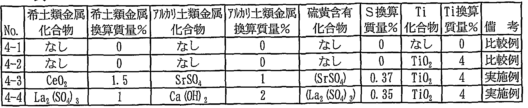
- An annealing separator containing the additives shown in Table 5 was applied to this with a water slurry and subjected to high temperature annealing in a hydrogen gas atmosphere at a maximum temperature of 1180 ° C for 15 hours.
- the chloride ion content in the water slurry was in the range of 40 to 60 mg / L. This was washed with water, and then an insulating film composed mainly of magnesium phosphate and colloidal silica was applied and baked, followed by laser irradiation for magnetic domain fragmentation.
- Table 6 shows the characteristics of the product plate obtained.
- the coil is a grain-oriented electrical steel sheet having a small coating peeling area ratio during strong bending and excellent adhesion.
- Example 1 1 and Example 2 Using the same annealing separator as in Example 6, water slurries with different chloride ion contents were prepared and applied to steel plates as used in Examples 1 and 2. Their applicability was evaluated. Na a C 1 was used to adjust the chloride content. In addition, the chlorine ion content shown in Table 9 means that O mg / L is below the analytical limit. The slurry shown in Table 8 was applied to a test steel plate (10 cm x 30 cm) with a barco overnight, and the coating condition after drying was visually observed. The applicability was judged by the area ratio at which peeling or spots occurred on the entire surface of the test steel plate.
- Table 9 shows the results. As shown in Table 9, when the chlorine content in the slurry was 500 mg ZL or less, better coating properties were exhibited. The better the coating properties, the more effective the annealing separator. Table 9
- the coil is a grain-oriented electrical steel sheet having a small film peeling area ratio during strong bending and excellent adhesion.
- a transformer in particular, a wound core transformer
- the industrial contribution of the present invention is great.
Landscapes
- Chemical & Material Sciences (AREA)
- Engineering & Computer Science (AREA)
- Physics & Mathematics (AREA)
- Materials Engineering (AREA)
- Mechanical Engineering (AREA)
- Metallurgy (AREA)
- Organic Chemistry (AREA)
- Electromagnetism (AREA)
- Manufacturing & Machinery (AREA)
- Thermal Sciences (AREA)
- Crystallography & Structural Chemistry (AREA)
- Dispersion Chemistry (AREA)
- Power Engineering (AREA)
- Manufacturing Of Steel Electrode Plates (AREA)
- Chemical Treatment Of Metals (AREA)
- Soft Magnetic Materials (AREA)
Description


Claims
Priority Applications (6)
| Application Number | Priority Date | Filing Date | Title |
|---|---|---|---|
| JP2008545443A JP5419459B2 (ja) | 2006-11-22 | 2007-11-15 | 被膜密着性に優れた一方向性電磁鋼板およびその製造法 |
| CN2007800431388A CN101541991B (zh) | 2006-11-22 | 2007-11-15 | 被膜密着性优异的单向性电磁钢板及其制造方法 |
| EP07832330.0A EP2096185B1 (en) | 2006-11-22 | 2007-11-15 | Unidirectionally grain oriented electromagnetic steel sheet having excellent film adhesion, and method for manufacturing the same |
| US12/312,427 US7942982B2 (en) | 2006-11-22 | 2007-11-15 | Grain-oriented electrical steel sheet excellent in coating adhesion and method of producing the same |
| BRPI0719586A BRPI0719586B1 (pt) | 2006-11-22 | 2007-11-15 | folha de aço elétrica de grão orientado excelente na adesão de revestimento e método de produção da mesma |
| KR1020097006240A KR101165430B1 (ko) | 2006-11-22 | 2007-11-15 | 피막 밀착성이 우수한 일방향성 전자 강판 및 그 제조법 |
Applications Claiming Priority (2)
| Application Number | Priority Date | Filing Date | Title |
|---|---|---|---|
| JP2006-315527 | 2006-11-22 | ||
| JP2006315527 | 2006-11-22 |
Publications (1)
| Publication Number | Publication Date |
|---|---|
| WO2008062853A1 true WO2008062853A1 (fr) | 2008-05-29 |
Family
ID=39429784
Family Applications (1)
| Application Number | Title | Priority Date | Filing Date |
|---|---|---|---|
| PCT/JP2007/072600 WO2008062853A1 (fr) | 2006-11-22 | 2007-11-15 | Feuille d'acier électromagnétique à orientation unidirectionnelle de grains, ayant une excellente adhésion de film, et son procédé de fabrication |
Country Status (9)
| Country | Link |
|---|---|
| US (1) | US7942982B2 (ja) |
| EP (1) | EP2096185B1 (ja) |
| JP (1) | JP5419459B2 (ja) |
| KR (1) | KR101165430B1 (ja) |
| CN (1) | CN101541991B (ja) |
| BR (1) | BRPI0719586B1 (ja) |
| RU (1) | RU2405842C1 (ja) |
| TW (1) | TW200827453A (ja) |
| WO (1) | WO2008062853A1 (ja) |
Cited By (15)
| Publication number | Priority date | Publication date | Assignee | Title |
|---|---|---|---|---|
| CN102361993A (zh) * | 2009-03-23 | 2012-02-22 | 新日本制铁株式会社 | 方向性电磁钢板的制造方法、卷绕铁芯用方向性电磁钢板及卷绕铁芯 |
| JP2018066062A (ja) * | 2016-10-19 | 2018-04-26 | Jfeスチール株式会社 | 方向性電磁鋼板の製造方法 |
| CN109923223A (zh) * | 2016-10-26 | 2019-06-21 | Posco公司 | 取向电工钢板用退火隔离剂组合物、取向电工钢板及其制造方法 |
| WO2019146697A1 (ja) | 2018-01-25 | 2019-08-01 | 日本製鉄株式会社 | 方向性電磁鋼板 |
| WO2020138069A1 (ja) * | 2018-12-28 | 2020-07-02 | 日本製鉄株式会社 | 方向性電磁鋼板及びその製造方法 |
| WO2020145321A1 (ja) | 2019-01-08 | 2020-07-16 | 日本製鉄株式会社 | 方向性電磁鋼板、方向性電磁鋼板の製造方法、及び、方向性電磁鋼板の製造に利用される焼鈍分離剤 |
| WO2020145315A1 (ja) * | 2019-01-08 | 2020-07-16 | 日本製鉄株式会社 | 方向性電磁鋼板およびその製造方法、ならびに焼鈍分離剤 |
| WO2020145316A1 (ja) | 2019-01-08 | 2020-07-16 | 日本製鉄株式会社 | 方向性電磁鋼板、方向性電磁鋼板の製造方法、及び、方向性電磁鋼板の製造に利用される焼鈍分離剤 |
| WO2020145313A1 (ja) * | 2019-01-08 | 2020-07-16 | 日本製鉄株式会社 | 方向性電磁鋼板、仕上焼鈍用鋼板、焼鈍分離剤、方向性電磁鋼板の製造方法、及び仕上焼鈍用鋼板の製造方法 |
| WO2020145319A1 (ja) * | 2019-01-08 | 2020-07-16 | 日本製鉄株式会社 | 方向性電磁鋼板の製造方法および方向性電磁鋼板 |
| WO2020145314A1 (ja) * | 2019-01-08 | 2020-07-16 | 日本製鉄株式会社 | 方向性電磁鋼板、焼鈍分離剤、及び方向性電磁鋼板の製造方法 |
| WO2020145318A1 (ja) | 2019-01-08 | 2020-07-16 | 日本製鉄株式会社 | 方向性電磁鋼板、方向性電磁鋼板の製造方法、及び、方向性電磁鋼板の製造に利用される焼鈍分離剤 |
| WO2020218607A1 (ja) * | 2019-04-25 | 2020-10-29 | 日本製鉄株式会社 | 巻鉄心、及びその製造方法 |
| JPWO2021054409A1 (ja) * | 2019-09-18 | 2021-03-25 | ||
| RU2772719C1 (ru) * | 2019-01-08 | 2022-05-24 | Ниппон Стил Корпорейшн | Лист анизотропной электротехнической стали, способ производства листа анизотропной электротехнической стали и сепаратор отжига, использующийся для производства листа анизотропной электротехнической стали |
Families Citing this family (46)
| Publication number | Priority date | Publication date | Assignee | Title |
|---|---|---|---|---|
| TWI403592B (zh) * | 2009-02-16 | 2013-08-01 | China Steel Corp | Component width steel sheets cryogenic process |
| EP2548977B1 (en) * | 2010-03-17 | 2015-06-03 | Nippon Steel & Sumitomo Metal Corporation | Method for producing directional electromagnetic steel sheet |
| JP5593942B2 (ja) | 2010-08-06 | 2014-09-24 | Jfeスチール株式会社 | 方向性電磁鋼板およびその製造方法 |
| JP5853352B2 (ja) * | 2010-08-06 | 2016-02-09 | Jfeスチール株式会社 | 方向性電磁鋼板およびその製造方法 |
| PL2664689T3 (pl) * | 2011-01-12 | 2019-09-30 | Nippon Steel & Sumitomo Metal Corporation | Blacha cienka ze stali elektrotechnicznej o ziarnach zorientowanych oraz sposób jej wytwarzania |
| JP5994981B2 (ja) | 2011-08-12 | 2016-09-21 | Jfeスチール株式会社 | 方向性電磁鋼板の製造方法 |
| JP5360272B2 (ja) * | 2011-08-18 | 2013-12-04 | Jfeスチール株式会社 | 方向性電磁鋼板の製造方法 |
| WO2013046716A1 (ja) * | 2011-09-28 | 2013-04-04 | Jfeスチール株式会社 | 方向性電磁鋼板およびその製造方法 |
| WO2013058239A1 (ja) * | 2011-10-20 | 2013-04-25 | Jfeスチール株式会社 | 方向性電磁鋼板およびその製造方法 |
| WO2013099160A1 (ja) * | 2011-12-26 | 2013-07-04 | Jfeスチール株式会社 | 方向性電磁鋼板 |
| KR20140099923A (ko) * | 2011-12-28 | 2014-08-13 | 제이에프이 스틸 가부시키가이샤 | 코팅 부착 방향성 전자 강판 및 그의 제조 방법 |
| CN103517469B (zh) | 2012-06-27 | 2015-03-04 | 比亚迪股份有限公司 | 一种ptc电热元件、电加热装置以及电动车 |
| US9748029B2 (en) * | 2012-07-26 | 2017-08-29 | Ginza Maronie P.C. | Method of producing grain-oriented electrical steel sheet |
| IN2015DN00610A (ja) * | 2012-07-26 | 2015-06-26 | Jfe Steel Corp | |
| JP5672273B2 (ja) * | 2012-07-26 | 2015-02-18 | Jfeスチール株式会社 | 方向性電磁鋼板の製造方法 |
| US20150243419A1 (en) * | 2012-09-27 | 2015-08-27 | Jef Steel Corporation | Method for producing grain-oriented electrical steel sheet |
| JP5871137B2 (ja) * | 2012-12-12 | 2016-03-01 | Jfeスチール株式会社 | 方向性電磁鋼板 |
| KR101482354B1 (ko) | 2012-12-27 | 2015-01-13 | 주식회사 포스코 | 철손이 우수한 방향성 전기강판 및 그 제조방법 |
| WO2014104393A1 (ja) * | 2012-12-28 | 2014-07-03 | Jfeスチール株式会社 | 方向性電磁鋼板の製造方法 |
| MX2015011022A (es) * | 2013-02-28 | 2015-10-22 | Jfe Steel Corp | Metodo para la produccion de lamina de acero electrico de grano orientado. |
| JP5884944B2 (ja) * | 2013-09-19 | 2016-03-15 | Jfeスチール株式会社 | 方向性電磁鋼板およびその製造方法 |
| PL2902509T3 (pl) * | 2014-01-30 | 2019-04-30 | Thyssenkrupp Electrical Steel Gmbh | Płaski produkt z teksturowanej stali elektrotechnicznej, obejmujący powłokę izolacyjną |
| KR101647655B1 (ko) * | 2014-12-15 | 2016-08-11 | 주식회사 포스코 | 방향성 전기강판 및 그 제조방법 |
| WO2016105053A1 (ko) * | 2014-12-24 | 2016-06-30 | 주식회사 포스코 | 방향성 전기강판 및 그 제조방법 |
| KR101693516B1 (ko) | 2014-12-24 | 2017-01-06 | 주식회사 포스코 | 방향성 전기강판 및 그 제조방법 |
| US20180119244A1 (en) | 2015-02-05 | 2018-05-03 | Jfe Steel Corporation | Grain-oriented electrical steel sheet, manufacturing method therefor, and method for predicting transformer noise property |
| JP6354957B2 (ja) | 2015-07-08 | 2018-07-11 | Jfeスチール株式会社 | 方向性電磁鋼板とその製造方法 |
| JP6471807B2 (ja) | 2015-09-28 | 2019-02-20 | 新日鐵住金株式会社 | 方向性電磁鋼板及び方向性電磁鋼板用の熱延鋼板 |
| KR102177523B1 (ko) * | 2015-12-22 | 2020-11-11 | 주식회사 포스코 | 방향성 전기강판 및 그 제조방법 |
| US11091842B2 (en) * | 2016-10-18 | 2021-08-17 | Jfe Steel Corporation | Oriented electromagnetic steel sheet and method for manufacturing oriented electromagnetic steel sheet |
| US11781196B2 (en) * | 2016-11-28 | 2023-10-10 | Jfe Steel Corporation | Grain-oriented electromagnetic steel sheet and method of producing grain-oriented electromagnetic steel sheet |
| KR101869455B1 (ko) * | 2016-12-19 | 2018-06-20 | 주식회사 포스코 | 방향성 전기강판 및 이의 제조방법 |
| EP3534383B1 (en) | 2016-12-21 | 2024-01-24 | JFE Steel Corporation | Grain-oriented electrical steel sheet and production method for grain-oriented electrical steel sheet |
| US10886055B2 (en) * | 2017-01-10 | 2021-01-05 | Nippon Steel Corporation | Wound core and manufacturing method thereof |
| CN110651058B (zh) * | 2017-05-12 | 2021-09-07 | 杰富意钢铁株式会社 | 取向性电磁钢板及其制造方法 |
| US11145446B2 (en) | 2017-07-13 | 2021-10-12 | Nippon Steel Corporation | Grain-oriented electrical steel sheet |
| WO2019106976A1 (ja) * | 2017-11-28 | 2019-06-06 | Jfeスチール株式会社 | 方向性電磁鋼板およびその製造方法 |
| EP3722460A4 (en) | 2018-02-06 | 2020-11-11 | JFE Steel Corporation | INSULATED-COATED ELECTROMAGNETIC STEEL SHEET AND ITS PRODUCTION PROCESS |
| US11697856B2 (en) * | 2018-02-09 | 2023-07-11 | Nippon Steel Corporation | Grain-oriented electrical steel sheet and manufacturing method thereof |
| KR102517647B1 (ko) * | 2018-03-20 | 2023-04-05 | 닛폰세이테츠 가부시키가이샤 | 방향성 전자 강판의 제조 방법 및 방향성 전자 강판 |
| EP3822385A4 (en) * | 2018-07-13 | 2021-12-01 | Nippon Steel Corporation | ALIGNED ELECTROMAGNETIC STEEL PLATE AND METHOD OF MANUFACTURING IT |
| WO2020012667A1 (ja) * | 2018-07-13 | 2020-01-16 | 日本製鉄株式会社 | 方向性電磁鋼板用原板、方向性電磁鋼板用原板の材料となる方向性珪素鋼板、方向性電磁鋼板用原板の製造方法、及び方向性電磁鋼板の製造方法 |
| WO2020149328A1 (ja) * | 2019-01-16 | 2020-07-23 | 日本製鉄株式会社 | 一方向性電磁鋼板およびその製造方法 |
| EP3715480A1 (en) * | 2019-03-26 | 2020-09-30 | Thyssenkrupp Electrical Steel Gmbh | Iron-silicon material suitable for medium frequency applications |
| BR112022004788A2 (pt) | 2019-09-19 | 2022-06-21 | Nippon Steel Corp | Chapa de aço elétrico de grão orientado |
| CN117230290B (zh) * | 2023-11-16 | 2024-02-27 | 内蒙古丰洲材料有限公司 | 一种控制低温Hi-B钢抑制剂析出的方法 |
Citations (10)
| Publication number | Priority date | Publication date | Assignee | Title |
|---|---|---|---|---|
| JPS572252B2 (ja) | 1978-07-26 | 1982-01-14 | ||
| JPS582569B2 (ja) | 1979-11-17 | 1983-01-17 | 新日本製鐵株式会社 | 帯状金属板への局所歪付与装置 |
| JPS60141830A (ja) | 1983-12-29 | 1985-07-26 | Kawasaki Steel Corp | 一方向性珪素鋼板の製造方法 |
| JPS6115152B2 (ja) | 1976-05-24 | 1986-04-22 | Sentoro Superimentare Metaruurujiiko Spa | |
| JPH0688171A (ja) | 1992-09-09 | 1994-03-29 | Nippon Steel Corp | 超高磁束密度一方向性電磁鋼板の製造方法 |
| JPH06192743A (ja) * | 1992-12-28 | 1994-07-12 | Kawasaki Steel Corp | 被膜特性及び磁気特性に優れた一方向性けい素鋼板の製造方法 |
| JPH08295937A (ja) | 1995-04-26 | 1996-11-12 | Nippon Steel Corp | 極めて低い鉄損をもつ一方向性電磁鋼板の製造方法 |
| JPH09118921A (ja) | 1995-10-26 | 1997-05-06 | Nippon Steel Corp | 極めて低い鉄損をもつ一方向性電磁鋼板の製造方法 |
| JP2005264280A (ja) * | 2004-03-22 | 2005-09-29 | Jfe Steel Kk | 打ち抜き性及び耐被膜剥離性に優れた方向性電磁鋼板及びその製造方法 |
| WO2006126660A1 (ja) * | 2005-05-23 | 2006-11-30 | Nippon Steel Corporation | 被膜密着性に優れる方向性電磁鋼板およびその製造方法 |
Family Cites Families (10)
| Publication number | Priority date | Publication date | Assignee | Title |
|---|---|---|---|---|
| IT1116431B (it) * | 1977-04-27 | 1986-02-10 | Centro Speriment Metallurg | Separatore di ricottura |
| GR75219B (ja) | 1980-04-21 | 1984-07-13 | Merck & Co Inc | |
| JPS582569A (ja) | 1981-06-26 | 1983-01-08 | 富士電機株式会社 | 水冷蓄熱式飲料冷却装置 |
| JPS6115152A (ja) | 1984-06-30 | 1986-01-23 | Canon Inc | 電子写真感光体 |
| JPS62156226A (ja) * | 1985-12-27 | 1987-07-11 | Nippon Steel Corp | 均一なグラス皮膜を有し磁気特性が優れた方向性電磁鋼板の製造方法 |
| JP3539028B2 (ja) * | 1996-01-08 | 2004-06-14 | Jfeスチール株式会社 | 高磁束密度一方向性けい素鋼板のフォルステライト被膜とその形成方法 |
| US5885371A (en) * | 1996-10-11 | 1999-03-23 | Kawasaki Steel Corporation | Method of producing grain-oriented magnetic steel sheet |
| KR19990088437A (ko) * | 1998-05-21 | 1999-12-27 | 에모또 간지 | 철손이매우낮은고자속밀도방향성전자강판및그제조방법 |
| JP2002302718A (ja) * | 2001-04-06 | 2002-10-18 | Kawasaki Steel Corp | 方向性電磁鋼板の製造方法及び方向性電磁鋼板用焼鈍分離剤 |
| JP4015644B2 (ja) | 2004-05-31 | 2007-11-28 | 株式会社ソニー・コンピュータエンタテインメント | 画像処理装置及び画像処理方法 |
-
2007
- 2007-11-15 JP JP2008545443A patent/JP5419459B2/ja active Active
- 2007-11-15 CN CN2007800431388A patent/CN101541991B/zh active Active
- 2007-11-15 WO PCT/JP2007/072600 patent/WO2008062853A1/ja active Application Filing
- 2007-11-15 EP EP07832330.0A patent/EP2096185B1/en active Active
- 2007-11-15 RU RU2009123514/02A patent/RU2405842C1/ru active
- 2007-11-15 BR BRPI0719586A patent/BRPI0719586B1/pt active IP Right Grant
- 2007-11-15 KR KR1020097006240A patent/KR101165430B1/ko active IP Right Grant
- 2007-11-15 US US12/312,427 patent/US7942982B2/en active Active
- 2007-11-20 TW TW096143903A patent/TW200827453A/zh unknown
Patent Citations (10)
| Publication number | Priority date | Publication date | Assignee | Title |
|---|---|---|---|---|
| JPS6115152B2 (ja) | 1976-05-24 | 1986-04-22 | Sentoro Superimentare Metaruurujiiko Spa | |
| JPS572252B2 (ja) | 1978-07-26 | 1982-01-14 | ||
| JPS582569B2 (ja) | 1979-11-17 | 1983-01-17 | 新日本製鐵株式会社 | 帯状金属板への局所歪付与装置 |
| JPS60141830A (ja) | 1983-12-29 | 1985-07-26 | Kawasaki Steel Corp | 一方向性珪素鋼板の製造方法 |
| JPH0688171A (ja) | 1992-09-09 | 1994-03-29 | Nippon Steel Corp | 超高磁束密度一方向性電磁鋼板の製造方法 |
| JPH06192743A (ja) * | 1992-12-28 | 1994-07-12 | Kawasaki Steel Corp | 被膜特性及び磁気特性に優れた一方向性けい素鋼板の製造方法 |
| JPH08295937A (ja) | 1995-04-26 | 1996-11-12 | Nippon Steel Corp | 極めて低い鉄損をもつ一方向性電磁鋼板の製造方法 |
| JPH09118921A (ja) | 1995-10-26 | 1997-05-06 | Nippon Steel Corp | 極めて低い鉄損をもつ一方向性電磁鋼板の製造方法 |
| JP2005264280A (ja) * | 2004-03-22 | 2005-09-29 | Jfe Steel Kk | 打ち抜き性及び耐被膜剥離性に優れた方向性電磁鋼板及びその製造方法 |
| WO2006126660A1 (ja) * | 2005-05-23 | 2006-11-30 | Nippon Steel Corporation | 被膜密着性に優れる方向性電磁鋼板およびその製造方法 |
Non-Patent Citations (1)
| Title |
|---|
| See also references of EP2096185A4 * |
Cited By (54)
| Publication number | Priority date | Publication date | Assignee | Title |
|---|---|---|---|---|
| CN104087823A (zh) * | 2009-03-23 | 2014-10-08 | 新日铁住金株式会社 | 卷绕铁芯用方向性电磁钢板及卷绕铁芯 |
| CN102361993A (zh) * | 2009-03-23 | 2012-02-22 | 新日本制铁株式会社 | 方向性电磁钢板的制造方法、卷绕铁芯用方向性电磁钢板及卷绕铁芯 |
| JP2018066062A (ja) * | 2016-10-19 | 2018-04-26 | Jfeスチール株式会社 | 方向性電磁鋼板の製造方法 |
| CN109923223A (zh) * | 2016-10-26 | 2019-06-21 | Posco公司 | 取向电工钢板用退火隔离剂组合物、取向电工钢板及其制造方法 |
| US11946114B2 (en) | 2016-10-26 | 2024-04-02 | Posco Co., Ltd | Annealing separating agent composition for grain-oriented electrical steel sheet, grain-oriented electrical steel sheet, and method for manufacturing grain oriented electrical steel sheet |
| US11225700B2 (en) | 2016-10-26 | 2022-01-18 | Posco | Annealing separating agent composition for grain-oriented electrical steel sheet, grain-oriented electrical steel sheet, and method for manufacturing grain oriented electrical steel sheet |
| KR20200103826A (ko) | 2018-01-25 | 2020-09-02 | 닛폰세이테츠 가부시키가이샤 | 방향성 전자 강판 |
| WO2019146697A1 (ja) | 2018-01-25 | 2019-08-01 | 日本製鉄株式会社 | 方向性電磁鋼板 |
| US11466338B2 (en) | 2018-01-25 | 2022-10-11 | Nippon Steel Corporation | Grain oriented electrical steel sheet |
| WO2020138069A1 (ja) * | 2018-12-28 | 2020-07-02 | 日本製鉄株式会社 | 方向性電磁鋼板及びその製造方法 |
| JP7265186B2 (ja) | 2018-12-28 | 2023-04-26 | 日本製鉄株式会社 | 方向性電磁鋼板及びその製造方法 |
| JPWO2020138069A1 (ja) * | 2018-12-28 | 2021-11-11 | 日本製鉄株式会社 | 方向性電磁鋼板及びその製造方法 |
| JPWO2020145315A1 (ja) * | 2019-01-08 | 2021-10-21 | 日本製鉄株式会社 | 方向性電磁鋼板およびその製造方法、ならびに焼鈍分離剤 |
| WO2020145313A1 (ja) * | 2019-01-08 | 2020-07-16 | 日本製鉄株式会社 | 方向性電磁鋼板、仕上焼鈍用鋼板、焼鈍分離剤、方向性電磁鋼板の製造方法、及び仕上焼鈍用鋼板の製造方法 |
| CN113195753B (zh) * | 2019-01-08 | 2024-04-30 | 日本制铁株式会社 | 方向性电磁钢板的制造方法及方向性电磁钢板 |
| WO2020145321A1 (ja) | 2019-01-08 | 2020-07-16 | 日本製鉄株式会社 | 方向性電磁鋼板、方向性電磁鋼板の製造方法、及び、方向性電磁鋼板の製造に利用される焼鈍分離剤 |
| JPWO2020145319A1 (ja) * | 2019-01-08 | 2021-02-18 | 日本製鉄株式会社 | 方向性電磁鋼板の製造方法および方向性電磁鋼板 |
| JP7295441B2 (ja) | 2019-01-08 | 2023-06-21 | 日本製鉄株式会社 | 方向性電磁鋼板、方向性電磁鋼板の製造方法、及び、方向性電磁鋼板の製造に利用される焼鈍分離剤 |
| JP7288202B2 (ja) | 2019-01-08 | 2023-06-07 | 日本製鉄株式会社 | 方向性電磁鋼板、方向性電磁鋼板の製造方法、及び、方向性電磁鋼板の製造に利用される焼鈍分離剤 |
| CN112771183A (zh) * | 2019-01-08 | 2021-05-07 | 日本制铁株式会社 | 方向性电磁钢板、方向性电磁钢板的制造方法及方向性电磁钢板的制造中利用的退火分离剂 |
| KR20210064336A (ko) | 2019-01-08 | 2021-06-02 | 닛폰세이테츠 가부시키가이샤 | 방향성 전자 강판, 방향성 전자 강판의 제조 방법 및 방향성 전자 강판의 제조에 이용되는 어닐링 분리제 |
| CN113195751A (zh) * | 2019-01-08 | 2021-07-30 | 日本制铁株式会社 | 方向性电磁钢板、成品退火用钢板、退火分离剂、方向性电磁钢板的制造方法及成品退火用钢板的制造方法 |
| CN113195753A (zh) * | 2019-01-08 | 2021-07-30 | 日本制铁株式会社 | 方向性电磁钢板的制造方法及方向性电磁钢板 |
| KR20210096235A (ko) | 2019-01-08 | 2021-08-04 | 닛폰세이테츠 가부시키가이샤 | 방향성 전자 강판, 방향성 전자 강판의 제조 방법, 및, 방향성 전자 강판의 제조에 이용되는 어닐링 분리제 |
| KR20210096237A (ko) | 2019-01-08 | 2021-08-04 | 닛폰세이테츠 가부시키가이샤 | 방향성 전자 강판, 방향성 전자 강판의 제조 방법, 및 방향성 전자 강판의 제조에 이용되는 어닐링 분리제 |
| CN113260718A (zh) * | 2019-01-08 | 2021-08-13 | 日本制铁株式会社 | 方向性电磁钢板、方向性电磁钢板的制造方法及方向性电磁钢板的制造中利用的退火分离剂 |
| WO2020145314A1 (ja) * | 2019-01-08 | 2020-07-16 | 日本製鉄株式会社 | 方向性電磁鋼板、焼鈍分離剤、及び方向性電磁鋼板の製造方法 |
| JPWO2020145314A1 (ja) * | 2019-01-08 | 2021-11-04 | 日本製鉄株式会社 | 方向性電磁鋼板、焼鈍分離剤、及び方向性電磁鋼板の製造方法 |
| WO2020145319A1 (ja) * | 2019-01-08 | 2020-07-16 | 日本製鉄株式会社 | 方向性電磁鋼板の製造方法および方向性電磁鋼板 |
| JPWO2020145321A1 (ja) * | 2019-01-08 | 2021-11-25 | 日本製鉄株式会社 | 方向性電磁鋼板、方向性電磁鋼板の製造方法、及び、方向性電磁鋼板の製造に利用される焼鈍分離剤 |
| JPWO2020145313A1 (ja) * | 2019-01-08 | 2021-11-25 | 日本製鉄株式会社 | 方向性電磁鋼板、仕上焼鈍用鋼板、焼鈍分離剤、方向性電磁鋼板の製造方法、及び仕上焼鈍用鋼板の製造方法 |
| JPWO2020145316A1 (ja) * | 2019-01-08 | 2021-11-25 | 日本製鉄株式会社 | 方向性電磁鋼板、方向性電磁鋼板の製造方法、及び、方向性電磁鋼板の製造に利用される焼鈍分離剤 |
| JPWO2020145318A1 (ja) * | 2019-01-08 | 2021-12-02 | 日本製鉄株式会社 | 方向性電磁鋼板、方向性電磁鋼板の製造方法、及び、方向性電磁鋼板の製造に利用される焼鈍分離剤 |
| WO2020145318A1 (ja) | 2019-01-08 | 2020-07-16 | 日本製鉄株式会社 | 方向性電磁鋼板、方向性電磁鋼板の製造方法、及び、方向性電磁鋼板の製造に利用される焼鈍分離剤 |
| RU2772719C1 (ru) * | 2019-01-08 | 2022-05-24 | Ниппон Стил Корпорейшн | Лист анизотропной электротехнической стали, способ производства листа анизотропной электротехнической стали и сепаратор отжига, использующийся для производства листа анизотропной электротехнической стали |
| RU2772720C1 (ru) * | 2019-01-08 | 2022-05-24 | Ниппон Стил Корпорейшн | Лист анизотропной электротехнической стали, способ производства листа анизотропной электротехнической стали и сепаратор отжига, используемый для производства листа анизотропной электротехнической стали |
| RU2773359C1 (ru) * | 2019-01-08 | 2022-06-02 | Ниппон Стил Корпорейшн | Лист электротехнической стали с ориентированной зеренной структурой, способ изготовления листа электротехнической стали с ориентированной зеренной структурой и отжиговый сепаратор, используемый для изготовления листа электротехнической стали с ориентированной зеренной структурой |
| RU2773479C1 (ru) * | 2019-01-08 | 2022-06-06 | Ниппон Стил Корпорейшн | Лист анизотропной электротехнической стали, способ его изготовления и отжиговый сепаратор |
| WO2020145315A1 (ja) * | 2019-01-08 | 2020-07-16 | 日本製鉄株式会社 | 方向性電磁鋼板およびその製造方法、ならびに焼鈍分離剤 |
| WO2020145316A1 (ja) | 2019-01-08 | 2020-07-16 | 日本製鉄株式会社 | 方向性電磁鋼板、方向性電磁鋼板の製造方法、及び、方向性電磁鋼板の製造に利用される焼鈍分離剤 |
| JP7180691B2 (ja) | 2019-01-08 | 2022-11-30 | 日本製鉄株式会社 | 方向性電磁鋼板、仕上焼鈍用鋼板、焼鈍分離剤、方向性電磁鋼板の製造方法、及び仕上焼鈍用鋼板の製造方法 |
| JP7184098B2 (ja) | 2019-01-08 | 2022-12-06 | 日本製鉄株式会社 | 方向性電磁鋼板、焼鈍分離剤、及び方向性電磁鋼板の製造方法 |
| JP7205555B2 (ja) | 2019-01-08 | 2023-01-17 | 日本製鉄株式会社 | 方向性電磁鋼板およびその製造方法、ならびに焼鈍分離剤 |
| JP7211436B2 (ja) | 2019-01-08 | 2023-01-24 | 日本製鉄株式会社 | 方向性電磁鋼板、方向性電磁鋼板の製造方法、及び、方向性電磁鋼板の製造に利用される焼鈍分離剤 |
| US11591668B2 (en) | 2019-01-08 | 2023-02-28 | Nippon Steel Corporation | Grain-oriented electrical steel sheet and method for manufacturing same and annealing separator |
| CN113260718B (zh) * | 2019-01-08 | 2023-02-17 | 日本制铁株式会社 | 方向性电磁钢板、方向性电磁钢板的制造方法及方向性电磁钢板的制造中利用的退火分离剂 |
| JP7115634B2 (ja) | 2019-04-25 | 2022-08-09 | 日本製鉄株式会社 | 巻鉄心、及びその製造方法 |
| US11742140B2 (en) | 2019-04-25 | 2023-08-29 | Nippon Steel Corporation | Wound core and method for producing same |
| JPWO2020218607A1 (ja) * | 2019-04-25 | 2020-10-29 | ||
| WO2020218607A1 (ja) * | 2019-04-25 | 2020-10-29 | 日本製鉄株式会社 | 巻鉄心、及びその製造方法 |
| RU2790283C1 (ru) * | 2019-09-18 | 2023-02-16 | Ниппон Стил Корпорейшн | Лист электротехнической стали с ориентированной зеренной структурой |
| WO2021054409A1 (ja) * | 2019-09-18 | 2021-03-25 | 日本製鉄株式会社 | 方向性電磁鋼板 |
| JPWO2021054409A1 (ja) * | 2019-09-18 | 2021-03-25 | ||
| JP7352109B2 (ja) | 2019-09-18 | 2023-09-28 | 日本製鉄株式会社 | 方向性電磁鋼板 |
Also Published As
| Publication number | Publication date |
|---|---|
| US7942982B2 (en) | 2011-05-17 |
| TW200827453A (en) | 2008-07-01 |
| KR101165430B1 (ko) | 2012-07-12 |
| EP2096185B1 (en) | 2014-08-13 |
| CN101541991A (zh) | 2009-09-23 |
| RU2405842C1 (ru) | 2010-12-10 |
| BRPI0719586A2 (pt) | 2014-07-08 |
| TWI341868B (ja) | 2011-05-11 |
| EP2096185A4 (en) | 2011-05-25 |
| BRPI0719586B1 (pt) | 2017-04-25 |
| EP2096185A1 (en) | 2009-09-02 |
| KR20090049611A (ko) | 2009-05-18 |
| US20100055481A1 (en) | 2010-03-04 |
| JP5419459B2 (ja) | 2014-02-19 |
| JPWO2008062853A1 (ja) | 2010-03-04 |
| CN101541991B (zh) | 2012-11-28 |
Similar Documents
| Publication | Publication Date | Title |
|---|---|---|
| JP5419459B2 (ja) | 被膜密着性に優れた一方向性電磁鋼板およびその製造法 | |
| JP5230194B2 (ja) | 被膜密着性に優れる方向性電磁鋼板およびその製造方法 | |
| JP6168173B2 (ja) | 方向性電磁鋼板とその製造方法 | |
| KR101620763B1 (ko) | 방향성 전기 강판 및 그 제조 방법 | |
| JP4916847B2 (ja) | 一方向性電磁鋼板の製造方法 | |
| JP5130488B2 (ja) | 磁気特性および被膜密着性に優れた方向性電磁鋼板およびその製造方法 | |
| RU2771318C1 (ru) | Способ производства листа электротехнической стали с ориентированной зеренной структурой | |
| JP2020063510A (ja) | 方向性電磁鋼板およびその製造方法 | |
| JP2009228117A (ja) | 方向性電磁鋼板の製造方法 | |
| JP7269505B2 (ja) | 方向性電磁鋼板の製造方法 | |
| RU2768094C1 (ru) | Способ производства листа электротехнической стали с ориентированной зеренной структурой | |
| RU2771130C1 (ru) | Способ производства листа электротехнической стали с ориентированной зеренной структурой | |
| JP2021123766A (ja) | 方向性電磁鋼板、および方向性電磁鋼板の製造方法、ならびに焼鈍分離剤 | |
| JP7184098B2 (ja) | 方向性電磁鋼板、焼鈍分離剤、及び方向性電磁鋼板の製造方法 | |
| JP7464818B2 (ja) | 方向性電磁鋼板の製造方法および方向性電磁鋼板、ならびに焼鈍分離剤 | |
| RU2773042C1 (ru) | Лист анизотропной электротехнической стали, сепаратор отжига и способ производства листа анизотропной электротехнической стали | |
| RU2792912C2 (ru) | Лист электротехнической стали с ориентированной зеренной структурой, стальной лист, используемый для финишного отжига, отжиговый сепаратор, способ изготовления листа электротехнической стали с ориентированной зеренной структурой и способ изготовления стального листа, используемого для финишного отжига | |
| WO2023204267A1 (ja) | 方向性電磁鋼板およびその製造方法 | |
| RU2777398C1 (ru) | Лист электротехнической стали с ориентированной зеренной структурой, стальной лист, используемый для финишного отжига, отжиговый сепаратор, способ изготовления листа электротехнической стали с ориентированной зеренной структурой и способ изготовления стального листа, используемого для финишного отжига | |
| WO2020145313A1 (ja) | 方向性電磁鋼板、仕上焼鈍用鋼板、焼鈍分離剤、方向性電磁鋼板の製造方法、及び仕上焼鈍用鋼板の製造方法 | |
| JP2002194444A (ja) | 磁気特性及び被膜特性に優れた方向性電磁鋼板の製造方法 | |
| JP2021123768A (ja) | 方向性電磁鋼板の製造方法および方向性電磁鋼板、ならびに焼鈍分離剤 |
Legal Events
| Date | Code | Title | Description |
|---|---|---|---|
| WWE | Wipo information: entry into national phase |
Ref document number: 200780043138.8 Country of ref document: CN |
|
| 121 | Ep: the epo has been informed by wipo that ep was designated in this application |
Ref document number: 07832330 Country of ref document: EP Kind code of ref document: A1 |
|
| WWE | Wipo information: entry into national phase |
Ref document number: 2008545443 Country of ref document: JP |
|
| WWE | Wipo information: entry into national phase |
Ref document number: 1020097006240 Country of ref document: KR |
|
| WWE | Wipo information: entry into national phase |
Ref document number: 2742/DELNP/2009 Country of ref document: IN |
|
| WWE | Wipo information: entry into national phase |
Ref document number: 12312427 Country of ref document: US |
|
| WWE | Wipo information: entry into national phase |
Ref document number: 2007832330 Country of ref document: EP |
|
| NENP | Non-entry into the national phase |
Ref country code: DE |
|
| ENP | Entry into the national phase |
Ref document number: 2009123514 Country of ref document: RU Kind code of ref document: A |
|
| ENP | Entry into the national phase |
Ref document number: PI0719586 Country of ref document: BR Kind code of ref document: A2 Effective date: 20090522 |