WO2020145321A1 - 方向性電磁鋼板、方向性電磁鋼板の製造方法、及び、方向性電磁鋼板の製造に利用される焼鈍分離剤 - Google Patents
方向性電磁鋼板、方向性電磁鋼板の製造方法、及び、方向性電磁鋼板の製造に利用される焼鈍分離剤 Download PDFInfo
- Publication number
- WO2020145321A1 WO2020145321A1 PCT/JP2020/000348 JP2020000348W WO2020145321A1 WO 2020145321 A1 WO2020145321 A1 WO 2020145321A1 JP 2020000348 W JP2020000348 W JP 2020000348W WO 2020145321 A1 WO2020145321 A1 WO 2020145321A1
- Authority
- WO
- WIPO (PCT)
- Prior art keywords
- steel sheet
- group
- grain
- content
- total
- Prior art date
Links
Classifications
-
- C—CHEMISTRY; METALLURGY
- C23—COATING METALLIC MATERIAL; COATING MATERIAL WITH METALLIC MATERIAL; CHEMICAL SURFACE TREATMENT; DIFFUSION TREATMENT OF METALLIC MATERIAL; COATING BY VACUUM EVAPORATION, BY SPUTTERING, BY ION IMPLANTATION OR BY CHEMICAL VAPOUR DEPOSITION, IN GENERAL; INHIBITING CORROSION OF METALLIC MATERIAL OR INCRUSTATION IN GENERAL
- C23C—COATING METALLIC MATERIAL; COATING MATERIAL WITH METALLIC MATERIAL; SURFACE TREATMENT OF METALLIC MATERIAL BY DIFFUSION INTO THE SURFACE, BY CHEMICAL CONVERSION OR SUBSTITUTION; COATING BY VACUUM EVAPORATION, BY SPUTTERING, BY ION IMPLANTATION OR BY CHEMICAL VAPOUR DEPOSITION, IN GENERAL
- C23C22/00—Chemical surface treatment of metallic material by reaction of the surface with a reactive liquid, leaving reaction products of surface material in the coating, e.g. conversion coatings, passivation of metals
- C23C22/82—After-treatment
-
- C—CHEMISTRY; METALLURGY
- C04—CEMENTS; CONCRETE; ARTIFICIAL STONE; CERAMICS; REFRACTORIES
- C04B—LIME, MAGNESIA; SLAG; CEMENTS; COMPOSITIONS THEREOF, e.g. MORTARS, CONCRETE OR LIKE BUILDING MATERIALS; ARTIFICIAL STONE; CERAMICS; REFRACTORIES; TREATMENT OF NATURAL STONE
- C04B35/00—Shaped ceramic products characterised by their composition; Ceramics compositions; Processing powders of inorganic compounds preparatory to the manufacturing of ceramic products
- C04B35/01—Shaped ceramic products characterised by their composition; Ceramics compositions; Processing powders of inorganic compounds preparatory to the manufacturing of ceramic products based on oxide ceramics
- C04B35/16—Shaped ceramic products characterised by their composition; Ceramics compositions; Processing powders of inorganic compounds preparatory to the manufacturing of ceramic products based on oxide ceramics based on silicates other than clay
- C04B35/20—Shaped ceramic products characterised by their composition; Ceramics compositions; Processing powders of inorganic compounds preparatory to the manufacturing of ceramic products based on oxide ceramics based on silicates other than clay rich in magnesium oxide, e.g. forsterite
-
- C—CHEMISTRY; METALLURGY
- C04—CEMENTS; CONCRETE; ARTIFICIAL STONE; CERAMICS; REFRACTORIES
- C04B—LIME, MAGNESIA; SLAG; CEMENTS; COMPOSITIONS THEREOF, e.g. MORTARS, CONCRETE OR LIKE BUILDING MATERIALS; ARTIFICIAL STONE; CERAMICS; REFRACTORIES; TREATMENT OF NATURAL STONE
- C04B35/00—Shaped ceramic products characterised by their composition; Ceramics compositions; Processing powders of inorganic compounds preparatory to the manufacturing of ceramic products
- C04B35/622—Forming processes; Processing powders of inorganic compounds preparatory to the manufacturing of ceramic products
- C04B35/62222—Forming processes; Processing powders of inorganic compounds preparatory to the manufacturing of ceramic products obtaining ceramic coatings
-
- C—CHEMISTRY; METALLURGY
- C21—METALLURGY OF IRON
- C21D—MODIFYING THE PHYSICAL STRUCTURE OF FERROUS METALS; GENERAL DEVICES FOR HEAT TREATMENT OF FERROUS OR NON-FERROUS METALS OR ALLOYS; MAKING METAL MALLEABLE, e.g. BY DECARBURISATION OR TEMPERING
- C21D1/00—General methods or devices for heat treatment, e.g. annealing, hardening, quenching or tempering
- C21D1/68—Temporary coatings or embedding materials applied before or during heat treatment
- C21D1/70—Temporary coatings or embedding materials applied before or during heat treatment while heating or quenching
-
- C—CHEMISTRY; METALLURGY
- C21—METALLURGY OF IRON
- C21D—MODIFYING THE PHYSICAL STRUCTURE OF FERROUS METALS; GENERAL DEVICES FOR HEAT TREATMENT OF FERROUS OR NON-FERROUS METALS OR ALLOYS; MAKING METAL MALLEABLE, e.g. BY DECARBURISATION OR TEMPERING
- C21D6/00—Heat treatment of ferrous alloys
- C21D6/005—Heat treatment of ferrous alloys containing Mn
-
- C—CHEMISTRY; METALLURGY
- C21—METALLURGY OF IRON
- C21D—MODIFYING THE PHYSICAL STRUCTURE OF FERROUS METALS; GENERAL DEVICES FOR HEAT TREATMENT OF FERROUS OR NON-FERROUS METALS OR ALLOYS; MAKING METAL MALLEABLE, e.g. BY DECARBURISATION OR TEMPERING
- C21D6/00—Heat treatment of ferrous alloys
- C21D6/008—Heat treatment of ferrous alloys containing Si
-
- C—CHEMISTRY; METALLURGY
- C21—METALLURGY OF IRON
- C21D—MODIFYING THE PHYSICAL STRUCTURE OF FERROUS METALS; GENERAL DEVICES FOR HEAT TREATMENT OF FERROUS OR NON-FERROUS METALS OR ALLOYS; MAKING METAL MALLEABLE, e.g. BY DECARBURISATION OR TEMPERING
- C21D8/00—Modifying the physical properties by deformation combined with, or followed by, heat treatment
- C21D8/12—Modifying the physical properties by deformation combined with, or followed by, heat treatment during manufacturing of articles with special electromagnetic properties
- C21D8/1216—Modifying the physical properties by deformation combined with, or followed by, heat treatment during manufacturing of articles with special electromagnetic properties the working step(s) being of interest
- C21D8/1222—Hot rolling
-
- C—CHEMISTRY; METALLURGY
- C21—METALLURGY OF IRON
- C21D—MODIFYING THE PHYSICAL STRUCTURE OF FERROUS METALS; GENERAL DEVICES FOR HEAT TREATMENT OF FERROUS OR NON-FERROUS METALS OR ALLOYS; MAKING METAL MALLEABLE, e.g. BY DECARBURISATION OR TEMPERING
- C21D8/00—Modifying the physical properties by deformation combined with, or followed by, heat treatment
- C21D8/12—Modifying the physical properties by deformation combined with, or followed by, heat treatment during manufacturing of articles with special electromagnetic properties
- C21D8/1216—Modifying the physical properties by deformation combined with, or followed by, heat treatment during manufacturing of articles with special electromagnetic properties the working step(s) being of interest
- C21D8/1233—Cold rolling
-
- C—CHEMISTRY; METALLURGY
- C21—METALLURGY OF IRON
- C21D—MODIFYING THE PHYSICAL STRUCTURE OF FERROUS METALS; GENERAL DEVICES FOR HEAT TREATMENT OF FERROUS OR NON-FERROUS METALS OR ALLOYS; MAKING METAL MALLEABLE, e.g. BY DECARBURISATION OR TEMPERING
- C21D8/00—Modifying the physical properties by deformation combined with, or followed by, heat treatment
- C21D8/12—Modifying the physical properties by deformation combined with, or followed by, heat treatment during manufacturing of articles with special electromagnetic properties
- C21D8/1244—Modifying the physical properties by deformation combined with, or followed by, heat treatment during manufacturing of articles with special electromagnetic properties the heat treatment(s) being of interest
- C21D8/1272—Final recrystallisation annealing
-
- C—CHEMISTRY; METALLURGY
- C21—METALLURGY OF IRON
- C21D—MODIFYING THE PHYSICAL STRUCTURE OF FERROUS METALS; GENERAL DEVICES FOR HEAT TREATMENT OF FERROUS OR NON-FERROUS METALS OR ALLOYS; MAKING METAL MALLEABLE, e.g. BY DECARBURISATION OR TEMPERING
- C21D8/00—Modifying the physical properties by deformation combined with, or followed by, heat treatment
- C21D8/12—Modifying the physical properties by deformation combined with, or followed by, heat treatment during manufacturing of articles with special electromagnetic properties
- C21D8/1277—Modifying the physical properties by deformation combined with, or followed by, heat treatment during manufacturing of articles with special electromagnetic properties involving a particular surface treatment
- C21D8/1283—Application of a separating or insulating coating
-
- C—CHEMISTRY; METALLURGY
- C21—METALLURGY OF IRON
- C21D—MODIFYING THE PHYSICAL STRUCTURE OF FERROUS METALS; GENERAL DEVICES FOR HEAT TREATMENT OF FERROUS OR NON-FERROUS METALS OR ALLOYS; MAKING METAL MALLEABLE, e.g. BY DECARBURISATION OR TEMPERING
- C21D9/00—Heat treatment, e.g. annealing, hardening, quenching or tempering, adapted for particular articles; Furnaces therefor
- C21D9/46—Heat treatment, e.g. annealing, hardening, quenching or tempering, adapted for particular articles; Furnaces therefor for sheet metals
-
- C—CHEMISTRY; METALLURGY
- C22—METALLURGY; FERROUS OR NON-FERROUS ALLOYS; TREATMENT OF ALLOYS OR NON-FERROUS METALS
- C22C—ALLOYS
- C22C38/00—Ferrous alloys, e.g. steel alloys
- C22C38/001—Ferrous alloys, e.g. steel alloys containing N
-
- C—CHEMISTRY; METALLURGY
- C22—METALLURGY; FERROUS OR NON-FERROUS ALLOYS; TREATMENT OF ALLOYS OR NON-FERROUS METALS
- C22C—ALLOYS
- C22C38/00—Ferrous alloys, e.g. steel alloys
- C22C38/002—Ferrous alloys, e.g. steel alloys containing In, Mg, or other elements not provided for in one single group C22C38/001 - C22C38/60
-
- C—CHEMISTRY; METALLURGY
- C22—METALLURGY; FERROUS OR NON-FERROUS ALLOYS; TREATMENT OF ALLOYS OR NON-FERROUS METALS
- C22C—ALLOYS
- C22C38/00—Ferrous alloys, e.g. steel alloys
- C22C38/004—Very low carbon steels, i.e. having a carbon content of less than 0,01%
-
- C—CHEMISTRY; METALLURGY
- C22—METALLURGY; FERROUS OR NON-FERROUS ALLOYS; TREATMENT OF ALLOYS OR NON-FERROUS METALS
- C22C—ALLOYS
- C22C38/00—Ferrous alloys, e.g. steel alloys
- C22C38/008—Ferrous alloys, e.g. steel alloys containing tin
-
- C—CHEMISTRY; METALLURGY
- C22—METALLURGY; FERROUS OR NON-FERROUS ALLOYS; TREATMENT OF ALLOYS OR NON-FERROUS METALS
- C22C—ALLOYS
- C22C38/00—Ferrous alloys, e.g. steel alloys
- C22C38/02—Ferrous alloys, e.g. steel alloys containing silicon
-
- C—CHEMISTRY; METALLURGY
- C22—METALLURGY; FERROUS OR NON-FERROUS ALLOYS; TREATMENT OF ALLOYS OR NON-FERROUS METALS
- C22C—ALLOYS
- C22C38/00—Ferrous alloys, e.g. steel alloys
- C22C38/04—Ferrous alloys, e.g. steel alloys containing manganese
-
- C—CHEMISTRY; METALLURGY
- C22—METALLURGY; FERROUS OR NON-FERROUS ALLOYS; TREATMENT OF ALLOYS OR NON-FERROUS METALS
- C22C—ALLOYS
- C22C38/00—Ferrous alloys, e.g. steel alloys
- C22C38/06—Ferrous alloys, e.g. steel alloys containing aluminium
-
- C—CHEMISTRY; METALLURGY
- C22—METALLURGY; FERROUS OR NON-FERROUS ALLOYS; TREATMENT OF ALLOYS OR NON-FERROUS METALS
- C22C—ALLOYS
- C22C38/00—Ferrous alloys, e.g. steel alloys
- C22C38/60—Ferrous alloys, e.g. steel alloys containing lead, selenium, tellurium, or antimony, or more than 0.04% by weight of sulfur
-
- C—CHEMISTRY; METALLURGY
- C23—COATING METALLIC MATERIAL; COATING MATERIAL WITH METALLIC MATERIAL; CHEMICAL SURFACE TREATMENT; DIFFUSION TREATMENT OF METALLIC MATERIAL; COATING BY VACUUM EVAPORATION, BY SPUTTERING, BY ION IMPLANTATION OR BY CHEMICAL VAPOUR DEPOSITION, IN GENERAL; INHIBITING CORROSION OF METALLIC MATERIAL OR INCRUSTATION IN GENERAL
- C23C—COATING METALLIC MATERIAL; COATING MATERIAL WITH METALLIC MATERIAL; SURFACE TREATMENT OF METALLIC MATERIAL BY DIFFUSION INTO THE SURFACE, BY CHEMICAL CONVERSION OR SUBSTITUTION; COATING BY VACUUM EVAPORATION, BY SPUTTERING, BY ION IMPLANTATION OR BY CHEMICAL VAPOUR DEPOSITION, IN GENERAL
- C23C22/00—Chemical surface treatment of metallic material by reaction of the surface with a reactive liquid, leaving reaction products of surface material in the coating, e.g. conversion coatings, passivation of metals
- C23C22/05—Chemical surface treatment of metallic material by reaction of the surface with a reactive liquid, leaving reaction products of surface material in the coating, e.g. conversion coatings, passivation of metals using aqueous solutions
- C23C22/06—Chemical surface treatment of metallic material by reaction of the surface with a reactive liquid, leaving reaction products of surface material in the coating, e.g. conversion coatings, passivation of metals using aqueous solutions using aqueous acidic solutions with pH less than 6
- C23C22/48—Chemical surface treatment of metallic material by reaction of the surface with a reactive liquid, leaving reaction products of surface material in the coating, e.g. conversion coatings, passivation of metals using aqueous solutions using aqueous acidic solutions with pH less than 6 not containing phosphates, hexavalent chromium compounds, fluorides or complex fluorides, molybdates, tungstates, vanadates or oxalates
- C23C22/50—Treatment of iron or alloys based thereon
-
- C—CHEMISTRY; METALLURGY
- C23—COATING METALLIC MATERIAL; COATING MATERIAL WITH METALLIC MATERIAL; CHEMICAL SURFACE TREATMENT; DIFFUSION TREATMENT OF METALLIC MATERIAL; COATING BY VACUUM EVAPORATION, BY SPUTTERING, BY ION IMPLANTATION OR BY CHEMICAL VAPOUR DEPOSITION, IN GENERAL; INHIBITING CORROSION OF METALLIC MATERIAL OR INCRUSTATION IN GENERAL
- C23C—COATING METALLIC MATERIAL; COATING MATERIAL WITH METALLIC MATERIAL; SURFACE TREATMENT OF METALLIC MATERIAL BY DIFFUSION INTO THE SURFACE, BY CHEMICAL CONVERSION OR SUBSTITUTION; COATING BY VACUUM EVAPORATION, BY SPUTTERING, BY ION IMPLANTATION OR BY CHEMICAL VAPOUR DEPOSITION, IN GENERAL
- C23C22/00—Chemical surface treatment of metallic material by reaction of the surface with a reactive liquid, leaving reaction products of surface material in the coating, e.g. conversion coatings, passivation of metals
- C23C22/05—Chemical surface treatment of metallic material by reaction of the surface with a reactive liquid, leaving reaction products of surface material in the coating, e.g. conversion coatings, passivation of metals using aqueous solutions
- C23C22/06—Chemical surface treatment of metallic material by reaction of the surface with a reactive liquid, leaving reaction products of surface material in the coating, e.g. conversion coatings, passivation of metals using aqueous solutions using aqueous acidic solutions with pH less than 6
- C23C22/48—Chemical surface treatment of metallic material by reaction of the surface with a reactive liquid, leaving reaction products of surface material in the coating, e.g. conversion coatings, passivation of metals using aqueous solutions using aqueous acidic solutions with pH less than 6 not containing phosphates, hexavalent chromium compounds, fluorides or complex fluorides, molybdates, tungstates, vanadates or oxalates
- C23C22/57—Treatment of magnesium or alloys based thereon
-
- C—CHEMISTRY; METALLURGY
- C23—COATING METALLIC MATERIAL; COATING MATERIAL WITH METALLIC MATERIAL; CHEMICAL SURFACE TREATMENT; DIFFUSION TREATMENT OF METALLIC MATERIAL; COATING BY VACUUM EVAPORATION, BY SPUTTERING, BY ION IMPLANTATION OR BY CHEMICAL VAPOUR DEPOSITION, IN GENERAL; INHIBITING CORROSION OF METALLIC MATERIAL OR INCRUSTATION IN GENERAL
- C23C—COATING METALLIC MATERIAL; COATING MATERIAL WITH METALLIC MATERIAL; SURFACE TREATMENT OF METALLIC MATERIAL BY DIFFUSION INTO THE SURFACE, BY CHEMICAL CONVERSION OR SUBSTITUTION; COATING BY VACUUM EVAPORATION, BY SPUTTERING, BY ION IMPLANTATION OR BY CHEMICAL VAPOUR DEPOSITION, IN GENERAL
- C23C24/00—Coating starting from inorganic powder
- C23C24/02—Coating starting from inorganic powder by application of pressure only
- C23C24/04—Impact or kinetic deposition of particles
-
- C—CHEMISTRY; METALLURGY
- C23—COATING METALLIC MATERIAL; COATING MATERIAL WITH METALLIC MATERIAL; CHEMICAL SURFACE TREATMENT; DIFFUSION TREATMENT OF METALLIC MATERIAL; COATING BY VACUUM EVAPORATION, BY SPUTTERING, BY ION IMPLANTATION OR BY CHEMICAL VAPOUR DEPOSITION, IN GENERAL; INHIBITING CORROSION OF METALLIC MATERIAL OR INCRUSTATION IN GENERAL
- C23C—COATING METALLIC MATERIAL; COATING MATERIAL WITH METALLIC MATERIAL; SURFACE TREATMENT OF METALLIC MATERIAL BY DIFFUSION INTO THE SURFACE, BY CHEMICAL CONVERSION OR SUBSTITUTION; COATING BY VACUUM EVAPORATION, BY SPUTTERING, BY ION IMPLANTATION OR BY CHEMICAL VAPOUR DEPOSITION, IN GENERAL
- C23C24/00—Coating starting from inorganic powder
- C23C24/08—Coating starting from inorganic powder by application of heat or pressure and heat
-
- C—CHEMISTRY; METALLURGY
- C23—COATING METALLIC MATERIAL; COATING MATERIAL WITH METALLIC MATERIAL; CHEMICAL SURFACE TREATMENT; DIFFUSION TREATMENT OF METALLIC MATERIAL; COATING BY VACUUM EVAPORATION, BY SPUTTERING, BY ION IMPLANTATION OR BY CHEMICAL VAPOUR DEPOSITION, IN GENERAL; INHIBITING CORROSION OF METALLIC MATERIAL OR INCRUSTATION IN GENERAL
- C23C—COATING METALLIC MATERIAL; COATING MATERIAL WITH METALLIC MATERIAL; SURFACE TREATMENT OF METALLIC MATERIAL BY DIFFUSION INTO THE SURFACE, BY CHEMICAL CONVERSION OR SUBSTITUTION; COATING BY VACUUM EVAPORATION, BY SPUTTERING, BY ION IMPLANTATION OR BY CHEMICAL VAPOUR DEPOSITION, IN GENERAL
- C23C26/00—Coating not provided for in groups C23C2/00 - C23C24/00
-
- H—ELECTRICITY
- H01—ELECTRIC ELEMENTS
- H01F—MAGNETS; INDUCTANCES; TRANSFORMERS; SELECTION OF MATERIALS FOR THEIR MAGNETIC PROPERTIES
- H01F1/00—Magnets or magnetic bodies characterised by the magnetic materials therefor; Selection of materials for their magnetic properties
- H01F1/01—Magnets or magnetic bodies characterised by the magnetic materials therefor; Selection of materials for their magnetic properties of inorganic materials
- H01F1/03—Magnets or magnetic bodies characterised by the magnetic materials therefor; Selection of materials for their magnetic properties of inorganic materials characterised by their coercivity
- H01F1/12—Magnets or magnetic bodies characterised by the magnetic materials therefor; Selection of materials for their magnetic properties of inorganic materials characterised by their coercivity of soft-magnetic materials
- H01F1/14—Magnets or magnetic bodies characterised by the magnetic materials therefor; Selection of materials for their magnetic properties of inorganic materials characterised by their coercivity of soft-magnetic materials metals or alloys
- H01F1/147—Alloys characterised by their composition
- H01F1/14766—Fe-Si based alloys
- H01F1/14775—Fe-Si based alloys in the form of sheets
-
- H—ELECTRICITY
- H01—ELECTRIC ELEMENTS
- H01F—MAGNETS; INDUCTANCES; TRANSFORMERS; SELECTION OF MATERIALS FOR THEIR MAGNETIC PROPERTIES
- H01F1/00—Magnets or magnetic bodies characterised by the magnetic materials therefor; Selection of materials for their magnetic properties
- H01F1/01—Magnets or magnetic bodies characterised by the magnetic materials therefor; Selection of materials for their magnetic properties of inorganic materials
- H01F1/03—Magnets or magnetic bodies characterised by the magnetic materials therefor; Selection of materials for their magnetic properties of inorganic materials characterised by their coercivity
- H01F1/12—Magnets or magnetic bodies characterised by the magnetic materials therefor; Selection of materials for their magnetic properties of inorganic materials characterised by their coercivity of soft-magnetic materials
- H01F1/14—Magnets or magnetic bodies characterised by the magnetic materials therefor; Selection of materials for their magnetic properties of inorganic materials characterised by their coercivity of soft-magnetic materials metals or alloys
- H01F1/16—Magnets or magnetic bodies characterised by the magnetic materials therefor; Selection of materials for their magnetic properties of inorganic materials characterised by their coercivity of soft-magnetic materials metals or alloys in the form of sheets
-
- C—CHEMISTRY; METALLURGY
- C04—CEMENTS; CONCRETE; ARTIFICIAL STONE; CERAMICS; REFRACTORIES
- C04B—LIME, MAGNESIA; SLAG; CEMENTS; COMPOSITIONS THEREOF, e.g. MORTARS, CONCRETE OR LIKE BUILDING MATERIALS; ARTIFICIAL STONE; CERAMICS; REFRACTORIES; TREATMENT OF NATURAL STONE
- C04B2235/00—Aspects relating to ceramic starting mixtures or sintered ceramic products
- C04B2235/02—Composition of constituents of the starting material or of secondary phases of the final product
- C04B2235/30—Constituents and secondary phases not being of a fibrous nature
- C04B2235/32—Metal oxides, mixed metal oxides, or oxide-forming salts thereof, e.g. carbonates, nitrates, (oxy)hydroxides, chlorides
- C04B2235/3224—Rare earth oxide or oxide forming salts thereof, e.g. scandium oxide
- C04B2235/3225—Yttrium oxide or oxide-forming salts thereof
-
- C—CHEMISTRY; METALLURGY
- C04—CEMENTS; CONCRETE; ARTIFICIAL STONE; CERAMICS; REFRACTORIES
- C04B—LIME, MAGNESIA; SLAG; CEMENTS; COMPOSITIONS THEREOF, e.g. MORTARS, CONCRETE OR LIKE BUILDING MATERIALS; ARTIFICIAL STONE; CERAMICS; REFRACTORIES; TREATMENT OF NATURAL STONE
- C04B2235/00—Aspects relating to ceramic starting mixtures or sintered ceramic products
- C04B2235/02—Composition of constituents of the starting material or of secondary phases of the final product
- C04B2235/30—Constituents and secondary phases not being of a fibrous nature
- C04B2235/32—Metal oxides, mixed metal oxides, or oxide-forming salts thereof, e.g. carbonates, nitrates, (oxy)hydroxides, chlorides
- C04B2235/3224—Rare earth oxide or oxide forming salts thereof, e.g. scandium oxide
- C04B2235/3227—Lanthanum oxide or oxide-forming salts thereof
-
- C—CHEMISTRY; METALLURGY
- C04—CEMENTS; CONCRETE; ARTIFICIAL STONE; CERAMICS; REFRACTORIES
- C04B—LIME, MAGNESIA; SLAG; CEMENTS; COMPOSITIONS THEREOF, e.g. MORTARS, CONCRETE OR LIKE BUILDING MATERIALS; ARTIFICIAL STONE; CERAMICS; REFRACTORIES; TREATMENT OF NATURAL STONE
- C04B2235/00—Aspects relating to ceramic starting mixtures or sintered ceramic products
- C04B2235/02—Composition of constituents of the starting material or of secondary phases of the final product
- C04B2235/30—Constituents and secondary phases not being of a fibrous nature
- C04B2235/32—Metal oxides, mixed metal oxides, or oxide-forming salts thereof, e.g. carbonates, nitrates, (oxy)hydroxides, chlorides
- C04B2235/3224—Rare earth oxide or oxide forming salts thereof, e.g. scandium oxide
- C04B2235/3229—Cerium oxides or oxide-forming salts thereof
-
- C—CHEMISTRY; METALLURGY
- C04—CEMENTS; CONCRETE; ARTIFICIAL STONE; CERAMICS; REFRACTORIES
- C04B—LIME, MAGNESIA; SLAG; CEMENTS; COMPOSITIONS THEREOF, e.g. MORTARS, CONCRETE OR LIKE BUILDING MATERIALS; ARTIFICIAL STONE; CERAMICS; REFRACTORIES; TREATMENT OF NATURAL STONE
- C04B2235/00—Aspects relating to ceramic starting mixtures or sintered ceramic products
- C04B2235/02—Composition of constituents of the starting material or of secondary phases of the final product
- C04B2235/30—Constituents and secondary phases not being of a fibrous nature
- C04B2235/32—Metal oxides, mixed metal oxides, or oxide-forming salts thereof, e.g. carbonates, nitrates, (oxy)hydroxides, chlorides
- C04B2235/3231—Refractory metal oxides, their mixed metal oxides, or oxide-forming salts thereof
- C04B2235/3232—Titanium oxides or titanates, e.g. rutile or anatase
-
- C—CHEMISTRY; METALLURGY
- C04—CEMENTS; CONCRETE; ARTIFICIAL STONE; CERAMICS; REFRACTORIES
- C04B—LIME, MAGNESIA; SLAG; CEMENTS; COMPOSITIONS THEREOF, e.g. MORTARS, CONCRETE OR LIKE BUILDING MATERIALS; ARTIFICIAL STONE; CERAMICS; REFRACTORIES; TREATMENT OF NATURAL STONE
- C04B2235/00—Aspects relating to ceramic starting mixtures or sintered ceramic products
- C04B2235/02—Composition of constituents of the starting material or of secondary phases of the final product
- C04B2235/30—Constituents and secondary phases not being of a fibrous nature
- C04B2235/32—Metal oxides, mixed metal oxides, or oxide-forming salts thereof, e.g. carbonates, nitrates, (oxy)hydroxides, chlorides
- C04B2235/3231—Refractory metal oxides, their mixed metal oxides, or oxide-forming salts thereof
- C04B2235/3244—Zirconium oxides, zirconates, hafnium oxides, hafnates, or oxide-forming salts thereof
-
- C—CHEMISTRY; METALLURGY
- C04—CEMENTS; CONCRETE; ARTIFICIAL STONE; CERAMICS; REFRACTORIES
- C04B—LIME, MAGNESIA; SLAG; CEMENTS; COMPOSITIONS THEREOF, e.g. MORTARS, CONCRETE OR LIKE BUILDING MATERIALS; ARTIFICIAL STONE; CERAMICS; REFRACTORIES; TREATMENT OF NATURAL STONE
- C04B2235/00—Aspects relating to ceramic starting mixtures or sintered ceramic products
- C04B2235/02—Composition of constituents of the starting material or of secondary phases of the final product
- C04B2235/50—Constituents or additives of the starting mixture chosen for their shape or used because of their shape or their physical appearance
- C04B2235/54—Particle size related information
- C04B2235/5418—Particle size related information expressed by the size of the particles or aggregates thereof
- C04B2235/5436—Particle size related information expressed by the size of the particles or aggregates thereof micrometer sized, i.e. from 1 to 100 micron
-
- C—CHEMISTRY; METALLURGY
- C04—CEMENTS; CONCRETE; ARTIFICIAL STONE; CERAMICS; REFRACTORIES
- C04B—LIME, MAGNESIA; SLAG; CEMENTS; COMPOSITIONS THEREOF, e.g. MORTARS, CONCRETE OR LIKE BUILDING MATERIALS; ARTIFICIAL STONE; CERAMICS; REFRACTORIES; TREATMENT OF NATURAL STONE
- C04B2235/00—Aspects relating to ceramic starting mixtures or sintered ceramic products
- C04B2235/02—Composition of constituents of the starting material or of secondary phases of the final product
- C04B2235/50—Constituents or additives of the starting mixture chosen for their shape or used because of their shape or their physical appearance
- C04B2235/54—Particle size related information
- C04B2235/5418—Particle size related information expressed by the size of the particles or aggregates thereof
- C04B2235/5445—Particle size related information expressed by the size of the particles or aggregates thereof submicron sized, i.e. from 0,1 to 1 micron
-
- C—CHEMISTRY; METALLURGY
- C04—CEMENTS; CONCRETE; ARTIFICIAL STONE; CERAMICS; REFRACTORIES
- C04B—LIME, MAGNESIA; SLAG; CEMENTS; COMPOSITIONS THEREOF, e.g. MORTARS, CONCRETE OR LIKE BUILDING MATERIALS; ARTIFICIAL STONE; CERAMICS; REFRACTORIES; TREATMENT OF NATURAL STONE
- C04B2235/00—Aspects relating to ceramic starting mixtures or sintered ceramic products
- C04B2235/70—Aspects relating to sintered or melt-casted ceramic products
- C04B2235/72—Products characterised by the absence or the low content of specific components, e.g. alkali metal free alumina ceramics
-
- C—CHEMISTRY; METALLURGY
- C21—METALLURGY OF IRON
- C21D—MODIFYING THE PHYSICAL STRUCTURE OF FERROUS METALS; GENERAL DEVICES FOR HEAT TREATMENT OF FERROUS OR NON-FERROUS METALS OR ALLOYS; MAKING METAL MALLEABLE, e.g. BY DECARBURISATION OR TEMPERING
- C21D2201/00—Treatment for obtaining particular effects
- C21D2201/05—Grain orientation
-
- C—CHEMISTRY; METALLURGY
- C22—METALLURGY; FERROUS OR NON-FERROUS ALLOYS; TREATMENT OF ALLOYS OR NON-FERROUS METALS
- C22C—ALLOYS
- C22C2202/00—Physical properties
- C22C2202/02—Magnetic
-
- Y—GENERAL TAGGING OF NEW TECHNOLOGICAL DEVELOPMENTS; GENERAL TAGGING OF CROSS-SECTIONAL TECHNOLOGIES SPANNING OVER SEVERAL SECTIONS OF THE IPC; TECHNICAL SUBJECTS COVERED BY FORMER USPC CROSS-REFERENCE ART COLLECTIONS [XRACs] AND DIGESTS
- Y02—TECHNOLOGIES OR APPLICATIONS FOR MITIGATION OR ADAPTATION AGAINST CLIMATE CHANGE
- Y02P—CLIMATE CHANGE MITIGATION TECHNOLOGIES IN THE PRODUCTION OR PROCESSING OF GOODS
- Y02P10/00—Technologies related to metal processing
- Y02P10/20—Recycling
Definitions
- the present invention relates to a grain-oriented electrical steel sheet, a method for producing a grain-oriented electrical steel sheet, and an annealing separator used in the production of a grain-oriented electrical steel sheet.
- Oriented electrical steel sheet is a steel sheet containing 0.5 to 7% by mass of Si and having crystal orientations accumulated in ⁇ 110 ⁇ 001> orientation (goss orientation). A catastrophic grain growth phenomenon called secondary recrystallization is used to control the crystal orientation.
- the method of manufacturing grain-oriented electrical steel is as follows. A slab is heated and hot rolling is performed to manufacture a hot rolled steel sheet. The hot rolled steel sheet is annealed as necessary. Pickling the hot rolled steel sheet. The hot-rolled steel sheet after pickling is cold-rolled at a cold rolling ratio of 80% or more to produce a cold-rolled steel sheet. Decarburization annealing is performed on the cold rolled steel sheet to develop primary recrystallization. Finish annealing is performed on the cold rolled steel sheet after decarburization annealing to develop secondary recrystallization. Through the above steps, the grain-oriented electrical steel sheet is manufactured.
- an aqueous slurry containing an annealing separating agent containing MgO as a main component is applied onto the surface of the cold rolled steel sheet and dried.
- finish annealing is performed.
- MgO in the annealing separator reacts with SiO 2 in the internal oxide layer formed on the surface of the cold-rolled steel sheet during decarburization annealing, and forsterite (Mg 2 SiO 4 ) is contained as a main component.
- a primary coating is formed on the surface.
- an insulating coating (also referred to as a secondary coating) made of, for example, colloidal silica and phosphate is formed on the primary coating.
- the primary coating and the insulating coating have a coefficient of thermal expansion smaller than that of the steel sheet. Therefore, the primary coating, together with the insulating coating, imparts tension to the steel sheet to reduce iron loss.
- the primary coating further enhances the adhesion of the insulating coating to the steel sheet. Therefore, it is preferable that the adhesion of the primary coating to the steel sheet is high.
- the steel sheet contains a magnetic property improving element (Sn, Sb, Bi, Te, Pb, Se, etc.) that strengthens the action of the inhibitor.
- a magnetic property improving element Sn, Sb, Bi, Te, Pb, Se, etc.
- the magnetic property improving element when contained, a part of the primary coating agglomerates and the interface between the steel sheet and the primary coating tends to be flattened. In this case, the adhesion of the primary coating to the steel plate is reduced.
- Patent Documents 4, 5, 6, and 7 disclose techniques for increasing the adhesion of the primary coating to the steel sheet.
- Patent Document 4 0.001 to 0.1% of Ce is contained in the slab, and a primary coating film containing 0.01 to 1000 mg/m 2 of Ce is formed on the surface of the steel sheet.
- Patent Document 5 in a grain-oriented electrical steel sheet containing Si: 1.8 to 7% and having a primary coating containing forsterite as a main component on the surface thereof, Ce in the primary coating is 0.001 per unit surface area by 0.001%. ⁇ 1000 mg/m 2 is contained.
- Patent Document 6 0.1 to 10% of a rare earth metal element compound and one or more alkaline earth metal compounds selected from Ca, Sr, or Ba are contained in an annealing separator containing MgO as a main component.
- an annealing separator containing MgO as a main component.
- a compound containing 1 to 10% and a sulfur compound of 0.01 to 5% one or more alkaline earth metal compounds selected from Ca, Sr or Ba in the primary coating, A rare earth element and a primary coating film containing the rare earth element are formed.
- Patent Document 7 is characterized by containing a compound containing one or more elements selected from Ca, Sr or Ba, 0.1 to 1.0% of a rare earth metal element compound, and sulfur. Form a primary coating.
- JP-A-6-88171 Japanese Patent Laid-Open No. 8-269552 JP, 2005-290446, A JP, 2008-127634, A JP 2012-214902 A International Publication No. 2008/062853 JP, 2009-270129, A
- the annealing separator contains a rare earth element compound such as Y, La or Ce to form a primary coating containing Y, La or Ce
- the magnetic properties may be deteriorated.
- the primary coating In some cases, the area of underdeveloping may occur, resulting in poor adhesion.
- the film appearance In a grain-oriented electrical steel sheet, it is preferable that the coating film has an excellent appearance.
- the object of the present invention is excellent in magnetic properties, excellent adhesion to the mother steel sheet of the primary coating, and a grain-oriented electrical steel sheet having an excellent coating appearance, a method for producing a grain-oriented electrical steel sheet, and the production of a grain-oriented electrical steel sheet.
- the purpose of the present invention is to provide an annealing separator for use in.
- the grain-oriented electrical steel sheet according to the present invention is, in mass %, C: 0.005% or less, Si: 2.5 to 4.5%, Mn: 0.02 to 0.2%, from the group consisting of S and Se.
- One or more selected elements 0.005% or less in total, sol. Al: 0.01% or less, and N: to 0.01% or less, the balance being a base steel sheet having a chemical composition consisting of Fe and impurities, is formed on the surface of the base steel sheet, Mg 2 A primary coating containing SiO 4 as a main component, and the peak position of Al emission intensity obtained when elemental analysis by glow discharge emission spectrometry is carried out from the surface of the primary coating in the thickness direction of the grain-oriented electrical steel sheet.
- An Al oxide which is arranged within a range of 2.0 to 10.0 ⁇ m in the plate thickness direction from the surface of the primary coating and is at a peak position of Al emission intensity, and has an area equivalent circle equivalent diameter of 0.2 ⁇ m.
- the number density of the above Al oxide is 0.032 to 0.20/ ⁇ m 2 , and the distribution of 100 ⁇ m ⁇ 100 ⁇ m Al oxide at the peak position of Al emission intensity obtained by glow discharge emission spectrometry In the figure, when divided by a lattice of 10 ⁇ m ⁇ 10 ⁇ m, the ratio of the number of lattices not containing Al oxide to the total number of lattices in the distribution chart is less than 5%.
- the production method of the grain-oriented electrical steel sheet according to the present invention comprises, in mass%, C: 0.1% or less, Si: 2.5 to 4.5%, Mn: 0.02 to 0.2%, S and Se.
- the annealing separator is MgO, at least one compound of a metal selected from the group consisting of Y, La, and Ce, and at least one compound of a metal selected from the group consisting of Ti, Zr, and Hf.
- the total content of oxides of the compounds of metals selected from the group consisting of Y, La, and Ce is 0.5 to 6.0%
- the total content of oxides of the compounds of the metals selected from the group consisting of Ti, Zr, and Hf is 0.8 to 10.0%
- Y The average particle size of the metal compound selected from the group consisting of La and Ce is 10 ⁇ m or less
- the average particle size of the metal compound selected from the group consisting of Ti, Zr, and Hf is Y, La, and Ce.
- the ratio of the metal compound selected from the group consisting of Y to La is 0.1 to 3.0, and the total of the metal compounds selected from the group consisting of Y, La, and Ce in terms of the oxide.
- the total of the content and the total content of the compounds of the metal selected from the group consisting of Ti, Zr, and Hf in terms of oxide is 2.0 to 12.5%, and the annealing separator is used for the annealing.
- the ratio of the total number of Ti, Zr, and Hf atoms contained in the separating agent to the total number of Y, La, and Ce atoms is 0.15 to 3.6, and further, Y, La, A particle of a metal compound selected from the group consisting of Ce, having a volume-based sphere-equivalent diameter of 0.1 ⁇ m or more and having a number density of 2 billion particles/g or more. Particles of a metal compound selected from the group consisting of Zr and Hf, having a volume-based equivalent spherical diameter of 0.1 ⁇ m or more, have a number density of 2 billion particles/g or more.
- the annealing separator used in the production of the grain-oriented electrical steel sheet according to the present invention is MgO, at least one metal compound selected from the group consisting of Y, La, and Ce, and a group consisting of Ti, Zr, and Hf.
- the content of the MgO in the annealing separator is 100% by mass, the compound is selected from the group consisting of Y, La and Ce.
- the total oxide equivalent content of the metal compound is 0.5 to 6.0%, and the total oxide equivalent content of the metal compound selected from the group consisting of Ti, Zr, and Hf is 0.
- the average particle size of the compound of the metal selected from the group consisting of Y, La and Ce is 10 ⁇ m or less
- the average particle size of the compound of the metal selected from the group consisting of Ti, Zr and Hf is The ratio of the average particle size of the compound to the average particle size of the compound of the metal selected from the group consisting of Y, La and Ce is 0.1 to 3.0, and the ratio is selected from the group consisting of Y, La and Ce.
- the total content of the metal compound in terms of oxide and the total content of the compound of metal selected from the group consisting of Ti, Zr, and Hf in terms of oxide is 2.0 to 12. 5%.
- the ratio of the total number of Ti, Zr, and Hf atoms contained in the annealing separator to the total number of Y, La, and Ce atoms is 0.15 to 3.6, and further, the above Y, La , Ce, which are particles of a metal compound selected from the group consisting of Ce and Ce, and have a volume-based sphere-equivalent diameter of 0.1 ⁇ m or more and a number density of 2 billion particles/g or more. , Zr, Hf, which are particles of a metal compound selected from the group consisting of Zr, Hf, and having a volume-based sphere-equivalent diameter of 0.1 ⁇ m or more, the number density of particles is 2 billion particles/g or more.
- the grain-oriented electrical steel sheet according to the present invention has excellent magnetic properties and excellent adhesion of the primary coating to the base material steel sheet.
- the manufacturing method according to the present invention can manufacture the grain-oriented electrical steel sheet described above.
- the annealing separator according to the present invention is applied to the above-mentioned manufacturing method, whereby a grain-oriented electrical steel sheet can be manufactured.
- the present inventors have investigated and examined the magnetic properties of grain-oriented electrical steel sheets containing magnetic property improving elements, and the adhesion of primary coatings formed by containing Y, La, and Ce compounds in the annealing separator. went. As a result, the present inventors have obtained the following findings.
- the interface between the primary coating of grain-oriented electrical steel and the steel sheet has a fitting structure. Specifically, in the vicinity of the interface between the primary coating and the steel sheet, the root of the primary coating is stretched inside the steel sheet. The closer the root of the primary coating is to the inside of the steel sheet, the higher the adhesion of the primary coating to the steel sheet. Furthermore, the more the roots of the primary coating are dispersed inside the steel sheet (the tighter it is stretched), the higher the adhesion of the primary coating to the steel sheet.
- the root of the primary coating if the root of the primary coating penetrates too deep into the steel sheet, the root of the primary coating will prevent secondary recrystallization in the Goss orientation. Therefore, the crystal grains of random orientation increase in the surface layer. Furthermore, the root of the primary coating becomes a factor that hinders the domain wall movement, deteriorating the magnetic characteristics. Similarly, if the roots of the primary coating are excessively dispersed inside the steel sheet, the roots of the primary coating impede secondary recrystallization in the Goss orientation, so that crystal grains in random orientation increase in the surface layer. Furthermore, the root of the primary coating becomes a factor that hinders the domain wall movement, deteriorating the magnetic characteristics.
- the inventors further investigated the root state of the primary coating, the magnetic properties of the grain-oriented electrical steel sheet, and the adhesion of the primary coating.
- the annealing separator contains Y, La, and Ce compounds to form the primary coating
- the magnetic properties deteriorate as described above. It is considered that this is because the root of the primary coating penetrates too deeply inside the steel sheet and hinders domain wall movement. If the particle size of the Y, La and Ce compounds is large, Y, La and Ce are localized in the annealing separator. As a result, the roots of the primary coating do not grow uniformly, and there is a portion where the primary coating becomes thin.
- the present inventors lower the content of Y, La, and Ce compounds in the annealing separator mainly composed of MgO, and instead contain Ti, Zr, and Hf compounds to form a primary coating.
- the magnetic properties of the grain-oriented electrical steel sheet may be improved, and the adhesion of the primary coating may be improved.
- the present inventors further adjusted the contents of Y, La, and Ce compounds and the contents of Ti, Zr, and Hf compounds in the annealing separator mainly composed of MgO to obtain the root depth of the formed primary coating. And the dispersion state was investigated.
- the main component of the root of the primary coating is an Al oxide represented by spinel (MgAl 2 O 4 ).
- the depth position from the surface of the peak of the Al emission intensity obtained by performing the elemental analysis based on the glow discharge emission analysis method (GDS method) in the plate thickness direction from the surface of the grain-oriented electrical steel sheet (hereinafter referred to as Al peak) indicates the position where the spinel exists, that is, the position of the root of the primary film.
- the number density of Al oxides represented by spinels having a size corresponding to an area-based circle at the Al peak position D Al of 0.2 ⁇ m or more (hereinafter referred to as Al oxide number density ND) is It is considered to indicate the dispersion state of roots.
- the root of the primary coating has an appropriate length, and since it is in an appropriate dispersed state, excellent magnetic properties and adhesion of the primary coating are obtained, Further, they have found that the appearance of the coating does not deteriorate.
- Al peak position D Al is 2.0 to 10.0 ⁇ m.
- the number density ND of Al oxides is 0.032 to 0.20 pieces/ ⁇ m 2 .
- lattice ratio RA Al The ratio of the number of lattices containing no Al oxide to the number of lattices
- the above-mentioned appropriate ranges of the Al peak position D Al , the Al oxide number density ND, and the lattice ratio RA Al are the average particle diameters of Y, La, and Ce compounds in the annealing separator, and those of Y, La, and Ce compounds.
- Content, average particle size of Ti, Zr, Hf compounds, and content of Ti, Zr, Hf compounds and Y, La, Ce in raw material powder before adjusting annealing separator into aqueous slurry It can be obtained by adjusting the number density of the particles of the compound of the selected metal and the number density of the particles of the compound of the metal selected from the group consisting of Ti, Zr and Hf within an appropriate range.
- the ratio of the oxide-equivalent content C RE (described later) of Y, La, and Ce compounds and the oxide-equivalent content C G4 (described later) of Ti, Zr, and Hf compounds and An image showing the distribution of Al obtained by EDS analysis in the glow discharge scar region of the Al peak position D Al and the Al oxide number density ND (number/ ⁇ m 2 ) in each image were investigated.
- the Al oxide number density ND is changed by adjusting the oxide equivalent contents of Y, La and Ce compounds and the oxide equivalent contents of Ti, Zr and Hf compounds in the annealing separator. I found out.
- Y, La, and Ce were obtained.
- the total oxide equivalent content of the compound is 0.5 to 6.0%
- the total oxide equivalent content of the Ti, Zr, and Hf compounds is 0.8 to 10.0%
- Y, La , Ce compounds have an average particle diameter of 10 ⁇ m or less
- the ratio of the average particle diameter of Ti, Zr, and Hf compounds to the average particle diameter of Y, La, and Ce compounds is 0.1 to 3.0.
- the total oxide content of Ce compounds and the total oxide content of Ti, Zr, and Hf compounds is 2.0 to 12.5%
- Ti contained in the annealing separator is The ratio of the total number of Zr, Hf atoms to the total number of Y, La, Ce atoms is 0.15 to 3.6, and in the raw material powder before adjusting the annealing separator into an aqueous slurry.
- the metal compound powder selected from the group consisting of Y, La and Ce and having a number density of particles of 0.1 ⁇ m or more of 2 billion particles/g or more and the group consisting of Ti, Zr and Hf.
- the annealing separator applied with the selected metal compound powder is used, it is a grain-oriented electrical steel sheet manufactured from a hot rolled steel sheet containing a magnetic flux density improving element (Sn, Sb, Bi, Te, Pb, etc.).
- the Al peak position D Al is 2.0 to 10.0 ⁇ m
- the number density ND of Al oxides having an area-based circle equivalent diameter of 0.2 ⁇ m or more is 0.032 to 0.20/ [mu] m 2
- the further obtained by glow discharge optical emission spectrometry in the distribution diagram of the Al oxide 100 [mu] m ⁇ 100 [mu] m at the peak position of Al luminous intensity, when the distribution map, separated by 10 [mu] m ⁇ 10 [mu] m grid, distribution map It has been found that the ratio of the number of lattices not containing Al oxide to the total number of lattices (lattice ratio RA Al ) is less than 5%, and excellent magnetic properties, adhesion of the primary
- the grain-oriented electrical steel sheet according to the present invention completed based on the above findings is, in mass %, C: 0.005% or less, Si: 2.5 to 4.5%, Mn: 0.02 to 0.2%. , One or more elements selected from the group consisting of S and Se: 0.005% or less in total, sol. Al: 0.01% or less, and N: to 0.01% or less, the balance being a base steel sheet having a chemical composition consisting of Fe and impurities, is formed on the surface of the base steel sheet, Mg 2 And a primary coating containing SiO 4 as a main component.
- the peak position of Al emission intensity obtained when elemental analysis by glow discharge emission spectrometry was carried out from the surface of the primary coating in the thickness direction of the grain-oriented electrical steel sheet was 2.0 to 10 in the thickness direction from the surface of the primary coating.
- the ratio of the number of lattices not including Al oxide to the total number of lattices in the distribution diagram is It is less than 5%.
- the production method of the grain-oriented electrical steel sheet according to the present invention comprises, in mass%, C: 0.1% or less, Si: 2.5 to 4.5%, Mn: 0.02 to 0.2%, S and Se.
- the annealing separator is MgO, at least one compound of a metal selected from the group consisting of Y, La, and Ce, and at least one compound of a metal selected from the group consisting of Ti, Zr, and Hf.
- the total content of oxides of compounds of metals selected from the group consisting of Ti, Zr, and Hf is 0.8 to 10.0%.
- the average particle size of the metal compound selected from the group is 10 ⁇ m or less, and the average particle size of the metal compound selected from the group consisting of Ti, Zr, and Hf is selected from the group consisting of Y, La, and Ce.
- the ratio of the metal compound to the average particle size of the metal compound is 0.1 to 3.0, the total oxide content of the metal compound selected from the group consisting of Y, La, and Ce, and Ti, Zr, and Hf.
- the total content of the metal compounds selected from the group consisting of oxides is 2.0 to 12.5%, and Ti, Zr,
- the ratio of the total number of Hf atoms to the total number of Y, La, and Ce atoms is 0.15 to 3.6, and further, in the raw material powder before adjusting the annealing separator into an aqueous slurry.
- the number density of each is 2 billion pieces/g or more.
- the particle size is a volume-based equivalent spherical diameter.
- the annealing separator further contains at least one metal compound selected from the group consisting of Ca, Sr and Ba, and when the MgO content in the annealing separator is 100% by mass, Ca,
- the total content of the metal compounds selected from the group consisting of Sr and Ba in terms of sulfate may be 10% or less.
- the chemical composition of the hot-rolled steel sheet further includes one or more elements selected from the group consisting of Cu, Sb, and Sn instead of a part of Fe in a total amount of 0. You may contain 6% or less.
- the chemical composition of the hot-rolled steel sheet further includes one or more elements selected from the group consisting of Bi, Te, and Pb in total of 0. You may contain up to 03%.
- the annealing separator according to the present invention is used for producing grain-oriented electrical steel sheets.
- the annealing separator is MgO, at least one compound of a metal selected from the group consisting of Y, La, and Ce, and at least one compound of a metal selected from the group consisting of Ti, Zr, and Hf.
- the content of MgO in the annealing separator is 100% by mass, the total content of oxides of the compounds of the metals selected from the group consisting of Y, La and Ce is 0.5.
- the total content of oxides of compounds of metals selected from the group consisting of Ti, Zr, and Hf is 0.8 to 10.0%, and it is composed of Y, La, and Ce.
- the average particle diameter of the metal compound selected from the group is 10 ⁇ m or less, and the average particle diameter of the metal compound selected from the group consisting of Ti, Zr, and Hf is selected from the group consisting of Y, La, and Ce.
- the ratio of the metal compound to the average particle size is 0.1 to 3.0, and the total oxide equivalent content of the metal compound selected from the group consisting of Y, La and Ce and Ti, Zr and Hf are used.
- the total content of oxides of the compounds of the metals selected from the group is 2.0 to 12.5%, and the total number of Ti, Zr, and Hf atoms contained in the annealing separator is , Y, La, Ce and the total number of atoms are 0.15 to 3.6, and further, Y, La, and Ce are contained in the raw material powder before the annealing separator is adjusted to an aqueous slurry.
- the number density of particles of a metal compound selected from the group having a particle size of 0.1 ⁇ m or more and the number density of particles of a metal compound selected from the group consisting of Ti, Zr, and Hf of 0.1 ⁇ m or more are 2 billion. /G or more. However, the particle size is a volume-based equivalent spherical diameter.
- the annealing separator further contains at least one metal compound selected from the group consisting of Ca, Sr and Ba, and when the MgO content in the annealing separator is 100% by mass, Ca,
- the total content of metals selected from the group consisting of Sr and Ba in terms of sulfate may be 10% or less.
- the grain-oriented electrical steel sheet according to the present invention the method for producing the grain-oriented electrical steel sheet, and the annealing separator used for producing the grain-oriented electrical steel sheet will be described in detail.
- % relating to the content of an element means mass% unless otherwise specified.
- the notation “A to B” means “above A and below B”. When a unit is attached only to the numerical value B in this notation, the unit is also applied to the numerical value A.
- the grain-oriented electrical steel sheet according to the present invention includes a base material steel sheet and a primary coating formed on the surface of the base material steel sheet.
- the chemical composition of the base steel sheet forming the grain-oriented electrical steel sheet described above contains the following elements. As described in the manufacturing method described below, the base steel sheet is manufactured by cold rolling using a hot rolled steel sheet having a chemical composition described below.
- Carbon (C) is an element effective in controlling the structure until the completion of the decarburization annealing step in the manufacturing process, but if the C content exceeds 0.005%, it is a product plate. The magnetic properties of the grain-oriented electrical steel sheet deteriorate. Therefore, the C content is 0.005% or less. It is preferable that the C content is as low as possible. However, even if the C content is reduced to less than 0.0001%, only the manufacturing cost is required, and the above effect does not change so much. Therefore, the preferable lower limit of the C content is 0.0001%.
- Si 2.5-4.5%
- Si increases the electrical resistance of steel and reduces eddy current loss. If the Si content is less than 2.5%, the above effect cannot be sufficiently obtained. On the other hand, if the Si content exceeds 4.5%, the cold workability of the steel deteriorates. Therefore, the Si content is 2.5 to 4.5%.
- the lower limit of the Si content is preferably 2.6%, and more preferably 2.8%.
- the upper limit of the Si content is preferably 4.0%, and more preferably 3.8%.
- Mn 0.02 to 0.20%
- Manganese (Mn) combines with S and Se described later to form MnS and MnSe during the manufacturing process. These precipitates function as inhibitors (inhibitors of normal grain growth) and cause secondary recrystallization in steel. Mn further enhances the hot workability of steel. If the Mn content is less than 0.02%, the above effect cannot be sufficiently obtained. On the other hand, if the Mn content exceeds 0.20%, secondary recrystallization does not occur and the magnetic properties of the steel deteriorate. Therefore, the Mn content is 0.02 to 0.20%.
- the preferable lower limit of the Mn content is 0.03%, more preferably 0.04%.
- the preferable upper limit of the Mn content is 0.13%, more preferably 0.10%.
- S sulfur
- Se selenium
- MnS metal-oxide-semiconductor
- the total content of these elements exceeds 0.005% the magnetic properties deteriorate due to the remaining inhibitors.
- segregation of S and Se may cause surface defects in the grain-oriented electrical steel sheet. Therefore, in the grain-oriented electrical steel sheet, the total content of at least one selected from the group consisting of S and Se is 0.005% or less.
- the total content of S and Se in the grain-oriented electrical steel sheet is preferably as low as possible.
- the preferable lower limit of the total content of at least one selected from the group consisting of S and Se in the grain-oriented electrical steel sheet is 0.0005%.
- sol. Al 0.01% or less
- Aluminum (Al) combines with N to form AlN during the manufacturing process of the grain-oriented electrical steel sheet, and functions as an inhibitor. However, the sol. When the Al content exceeds 0.01%, the above-mentioned inhibitor excessively remains in the steel sheet, so that the magnetic properties deteriorate. Therefore, sol.
- the Al content is 0.01% or less. sol.
- the preferable upper limit of the Al content is 0.004%, and more preferably 0.003%. sol.
- the Al content is preferably as low as possible. However, the sol. Even if the Al content is reduced to less than 0.0001%, the manufacturing cost is increased and the above effect is not so changed. Therefore, the sol.
- the preferable lower limit of the Al content is 0.0001%.
- sol. Al means acid-soluble Al. Therefore, sol.
- the Al content is the content of acid-soluble Al.
- N 0.01% or less Nitrogen (N) forms AlN by combining with Al during the manufacturing process of the grain-oriented electrical steel sheet, and functions as an inhibitor.
- N content in the grain-oriented electrical steel sheet exceeds 0.01%, the above-mentioned inhibitor excessively remains in the grain-oriented electrical steel sheet, and the magnetic properties deteriorate. Therefore, the N content is 0.01% or less.
- the preferable upper limit of the N content is 0.004%, and more preferably 0.003%.
- the N content is preferably as low as possible. However, even if the total content of N in the grain-oriented electrical steel sheet is reduced to less than 0.0001%, the manufacturing cost only increases and the above effect does not change so much. Therefore, the preferable lower limit of the N content in the grain-oriented electrical steel sheet is 0.0001%.
- the balance of the chemical composition of the base steel sheet of the grain-oriented electrical steel sheet according to the present invention consists of Fe and impurities.
- the impurities when industrially producing the base steel sheet, ore as a raw material, scrap, or those mixed from the production environment, or in the steel without being completely purified in the purification annealing.
- the following remaining elements and the like are meant as long as they are permitted within a range that does not adversely affect the grain-oriented electrical steel sheet of the present invention.
- the total content of one or more elements selected from the group consisting of Cu, Sn, Sb, Bi, Te and Pb is 0.30% or less. is there.
- the total content of one or more elements selected from the group consisting of Cu, Sn, Sb, Bi, Te and Pb is 0.30% or less. Since these elements are impurities as described above, the total content of these elements is preferably as low as possible.
- the grain-oriented electrical steel sheet according to the present invention further comprises a primary coating as described above.
- the primary coating is formed on the surface of the base steel sheet.
- the main component of the primary coating is forsterite (Mg 2 SiO 4 ). More specifically, the primary coating contains 50-90 wt% Mg 2 SiO 4 .
- the main component of the primary coating is Mg 2 SiO 4 as described above, but the primary coating also contains Y, La, Ce and Ti, Zr, Hf.
- the total content of Y, La and Ce in the primary coating is 0.001 to 6.0%.
- the total content of Ti, Zr, and Hf in the primary coating is 0.0005 to 4.0%.
- the annealing separator containing the Ti, Zr, and Hf compounds together with the above Y, La, and Ce compounds is used in the method for producing a grain-oriented electrical steel sheet.
- the magnetic properties of the grain-oriented electrical steel sheet can be enhanced and the coating adhesion of the primary coating can be enhanced.
- the annealing separator contains Y, La, Ce and Ti, Zr, Hf
- the primary coating also contains the above-mentioned contents of Y, La, Ce and Ti, Zr, Hf.
- the Mg 2 SiO 4 content in the primary coating can be measured by the following method.
- the grain-oriented electrical steel sheet is electrolyzed to separate the primary coating film from the surface of the base steel sheet.
- Mg in the separated primary film is quantitatively analyzed by inductively coupled plasma mass spectrometry (ICP-MS).
- ICP-MS inductively coupled plasma mass spectrometry
- the product of the obtained quantitative value (mass %) and the molecular weight of Mg 2 SiO 4 is divided by the atomic weight of Mg to obtain the content of Mg 2 SiO 4 equivalent.
- the total content of Y, La and Ce and the total content of Ti, Zr and Hf in the primary coating can be measured by the following method.
- the grain-oriented electrical steel sheet is electrolyzed to separate the primary coating film from the surface of the base steel sheet.
- Mass %) is quantitatively analyzed by ICP-MS to obtain the total of Y content, La content, Ce content and the total of Ti content, Zr content, and Hf content.
- the peak position of the Al emission intensity obtained when performing elemental analysis by glow discharge emission spectrometry from the surface of the primary coating in the thickness direction of the grain-oriented electrical steel sheet is It is arranged in the range of 2.0 to 10.0 ⁇ m in the plate thickness direction from the surface.
- the interface between the primary coating and the steel sheet has a fitting structure. Specifically, a part of the primary coating penetrates into the inside of the steel sheet from the surface of the steel sheet. A part of the primary coating that penetrates into the steel sheet from the surface of the steel sheet exhibits a so-called anchor effect to enhance the adhesion of the primary coating to the steel sheet.
- a part of the primary coating that has entered from the surface of the steel sheet into the inside of the steel sheet is defined as the “root of the primary coating”.
- the main component of the root of the primary coating is spinel (MgAl 2 O 4 ) which is a type of Al oxide.
- the peak of the Al emission intensity obtained when the elemental analysis by the glow discharge emission analysis method is performed indicates the existence position of the spinel.
- the depth position from the surface of the primary coating of the above Al emission intensity peak is defined as the Al peak position D Al ( ⁇ m).
- the Al peak position D Al is less than 2.0 ⁇ m, it means that the spinel is formed at a shallow (low) position from the steel sheet surface. That is, it means that the root of the primary film is shallow. In this case, the adhesion of the primary coating is low.
- the Al peak position D Al exceeds 10.0 ⁇ m, the root of the primary coating is overdeveloped, and the root of the primary coating penetrates deep inside the steel sheet. In this case, the root of the primary coating hinders domain wall movement. As a result, the magnetic characteristics deteriorate.
- the Al peak position D Al is 2.0 to 10.0 ⁇ m, it is possible to improve the adhesion of the film while maintaining excellent magnetic properties.
- the lower limit of the Al peak position D Al is preferably 3.0 ⁇ m, more preferably 4.0 ⁇ m.
- the preferable upper limit of the Al peak position D Al is 9.0 ⁇ m, and more preferably 8.0 ⁇ m.
- the Al peak position D Al can be measured by the following method. Elemental analysis is carried out using the well-known glow discharge emission spectrometry (GDS method). Specifically, an Ar atmosphere is set on the surface of the grain-oriented electrical steel sheet. A voltage is applied to the grain-oriented electrical steel sheet to generate glow plasma, and the surface of the steel sheet is sputtered and analyzed in the sheet thickness direction.
- GDS method glow discharge emission spectrometry
- Al contained in the surface layer of the steel sheet is identified on the basis of the emission spectrum wavelength peculiar to the element generated when atoms are excited in glow plasma. Further, the emission intensity of the identified Al is plotted in the depth direction. The Al peak position D Al is obtained based on the plotted Al emission intensity.
- the depth position from the surface of the primary coating in elemental analysis can be calculated based on the sputtering time. Specifically, the relationship between the sputtering time and the sputtering depth (hereinafter referred to as the sample result) is obtained in advance for the standard sample. Using the sample results, the sputter time is converted to sputter depth. The converted sputter depth is defined as a depth position (depth position from the surface of the primary coating) obtained by elemental analysis (Al analysis). In the GDS method of the present invention, a commercially available high frequency glow discharge emission spectrometer can be used.
- the number density ND of the Al oxides having an area-based circle equivalent diameter of 0.2 ⁇ m or more at the Al peak position D Al is 0.032 to 0.20 pieces/ ⁇ m 2.
- the Al peak position D Al corresponds to the root portion of the primary coating.
- the number density ND of Al oxides is 0.032 to 0.20 pieces/ ⁇ m 2 .
- a preferable lower limit of the Al oxide number density ND is 0.035 pieces/ ⁇ m 2 , and more preferably 0.04 pieces/ ⁇ m 2 .
- the preferable upper limit of the number density ND is 0.12 pieces/ ⁇ m 2 , and more preferably 0.08 pieces/ ⁇ m 2 .
- the Al oxide number density ND can be obtained by the following method.
- a glow discharge emission analyzer is used to perform glow discharge up to the Al peak position D Al .
- Al peak position D Among the discharge traces at Al , an elemental analysis by an energy dispersive X-ray spectrometer (EDS) was performed on an arbitrary area (observation area) of 30 ⁇ m ⁇ 50 ⁇ m or more, and the characteristics of the observation area A map showing the distribution of the X-ray intensity is created and the Al oxide is specified. Specifically, with respect to the maximum intensity of the characteristic X-ray of O in the observation region, a region in which 50% or more of the characteristic X-ray intensity of O is analyzed is specified as an oxide.
- EDS energy dispersive X-ray spectrometer
- the Al oxide region a region in which 30% or more of the intensity of the specific X-ray of Al is analyzed with respect to the maximum intensity of the specific X-ray of Al is specified as the Al oxide.
- the specified Al oxide is mainly spinel, and may be a silicate containing Mg, Ca, Sr, Ba, etc. and Al at a high concentration.
- the number of Al oxides having an area-based circle equivalent diameter of 0.2 ⁇ m or more is counted, and the Al oxide number density ND (pieces/ ⁇ m 2 ) is calculated by the following formula. ..
- Equivalent circle diameter ⁇ (4/ ⁇ (Area of the region specified as Al oxide (area per analysis point in the map showing the distribution of the characteristic X-ray intensity ⁇ corresponding to the region specified as Al oxide Analysis points))
- Area per analysis point area of observation area/number of analysis points
- ND number of specified Al oxides having a circle equivalent diameter of 0.2 ⁇ m or more/area of observation area in a map showing the distribution of characteristic X-ray intensity
- the Al peak position is D Al is 2.0 to 10.0 ⁇ m
- the number density ND of Al oxides at the Al peak position D Al is 0.032 to 0.20/ ⁇ m 2 .
- the distribution chart of the Al oxide at the Al peak position D Al obtained by the glow discharge emission analysis method the distribution chart of 100 ⁇ m ⁇ 100 ⁇ m is divided by a grid of 10 ⁇ m ⁇ 10 ⁇ m, and distributed.
- the ratio of the number of lattices not containing Al oxide (the lattice ratio RA Al ) to the total number of lattices in the figure is 5% or less.
- the Al peak position D Al corresponds to the root portion of the primary coating.
- the lattice ratio RA Al exceeds 5%, the roots of the primary coating are not formed uniformly. Therefore, color unevenness occurs depending on the degree of development of the coating, and the appearance of the coating deteriorates. Therefore, the lattice ratio RA Al is 5% or less.
- the preferable upper limit of the lattice ratio RA is 3%, and more preferably 2%.
- the lattice ratio RA Al can be obtained by the following method.
- a glow discharge emission analyzer is used to perform glow discharge up to the Al peak position D Al .
- Al peak position D Among the discharge traces at Al , an elemental analysis by an energy dispersive X-ray spectroscope (EDS) was performed on an arbitrary area (observation area) of 100 ⁇ m ⁇ 100 ⁇ m, and Al in the observation area was observed. Identify oxides. Specifically, with respect to the maximum intensity of the characteristic X-ray of O in the observation region, a region in which 50% or more of the characteristic X-ray intensity of O is analyzed is specified as an oxide.
- EDS energy dispersive X-ray spectroscope
- the specified oxide region a region in which 30% or more of the intensity of the specific X-ray of Al is analyzed with respect to the maximum intensity of the specific X-ray of Al is specified as the Al oxide.
- the specified Al oxide is mainly spinel, and may be a silicate containing Mg, Ca, Sr, Ba, etc. and Al at a high concentration.
- a distribution diagram of Al oxide in the observation region is created based on the measurement result.
- An example of the method for manufacturing the grain-oriented electrical steel sheet according to the present invention will be described.
- An example of a method for manufacturing a grain-oriented electrical steel sheet includes a cold rolling step, a decarburizing annealing step, and a finish annealing step. Hereinafter, each step will be described.
- Cold rolling process In the cold rolling step, cold rolling is performed on the hot rolled steel sheet to produce a cold rolled steel sheet.
- the hot rolled steel sheet contains the following chemical composition.
- the C content of the hot rolled steel sheet is 0.1% or less.
- the preferable upper limit of the C content of the hot-rolled steel sheet is 0.092%, more preferably 0.085%.
- the lower limit of the C content of the rolled steel sheet is 0.005%, preferably 0.02%, more preferably 0.04%.
- Si 2.5-4.5%
- Si increases the electric resistance of steel, but if it is contained in excess, the cold workability deteriorates.
- the Si content of the hot rolled steel sheet is 2.5 to 4.5%
- the Si content of the grain-oriented electrical steel sheet after the finish annealing step will be 2.5 to 4.5%.
- the upper limit of the Si content of the hot-rolled steel sheet is preferably 4.0%, more preferably 3.8%.
- the lower limit of the Si content of the hot-rolled steel sheet is preferably 2.6%, more preferably 2.8%.
- Mn 0.02 to 0.20%
- Mn combines with S and Se to form a precipitate during the manufacturing process, and functions as an inhibitor. Mn further enhances the hot workability of steel. If the Mn content of the hot rolled steel sheet is 0.02 to 0.20%, the Mn content of the grain-oriented electrical steel sheet after the finish annealing step will be 0.02 to 0.20%.
- the upper limit of the Mn content of the hot rolled steel sheet is preferably 0.13%, more preferably 0.1%.
- the lower limit of the Mn content of the hot-rolled steel sheet is preferably 0.03%, more preferably 0.04%.
- One or more elements selected from the group consisting of S and Se 0.005 to 0.07% in total
- sulfur (S) and selenium (Se) combine with Mn to form MnS and MnSe. Both MnS and MnSe function as inhibitors necessary for suppressing grain growth during secondary recrystallization. If the total content of one or more elements selected from the group consisting of S and Se is less than 0.005%, it is difficult to obtain the above effects. On the other hand, if the total content of one or more elements selected from the group consisting of S and Se exceeds 0.07%, secondary recrystallization does not occur during the manufacturing process and the magnetic properties of the steel deteriorate. ..
- the total content of one or more elements selected from the group consisting of S and Se in the hot rolled steel sheet is 0.005 to 0.07%.
- the preferable lower limit of the total content of one or more elements selected from the group consisting of S and Se is 0.008%, and more preferably 0.016%.
- the preferable upper limit of the total content of one or more elements selected from the group consisting of S and Se is 0.06%, more preferably 0.05%.
- sol. Al 0.005-0.05%
- AlN functions as an inhibitor.
- the Al content is 0.005 to 0.05%.
- the preferable upper limit of the Al content is 0.04%, more preferably 0.035%.
- the sol. The preferable lower limit of the Al content is 0.01%, and more preferably 0.015%.
- N 0.001 to 0.030%
- nitrogen (N) combines with Al to form AlN that functions as an inhibitor. If the N content in the hot rolled steel sheet is less than 0.001%, the above effect cannot be obtained. On the other hand, if the N content in the hot rolled steel sheet exceeds 0.030%, AlN becomes coarse. In this case, AlN becomes difficult to function as an inhibitor, and secondary recrystallization may not occur. Therefore, the N content in the hot rolled steel sheet is 0.001 to 0.030%.
- the preferable upper limit of the N content in the hot-rolled steel sheet is 0.012%, more preferably 0.010%.
- the preferable lower limit of the N content in the hot-rolled steel sheet is 0.005%, more preferably 0.006%.
- the balance of the chemical composition of the hot-rolled steel sheet of the present invention consists of Fe and impurities.
- the impurities are those that are mixed from ore as a raw material, scrap, or the manufacturing environment when industrially manufacturing the hot rolled steel sheet, and have an adverse effect on the hot rolled steel sheet of the present embodiment. It means something that is acceptable within the range.
- the hot-rolled steel sheet according to the present invention may further contain, in place of a part of Fe, one or more elements selected from the group consisting of Cu, Sn and Sb in a total amount of 0.6% or less. All of these elements are arbitrary elements.
- One or more elements selected from the group consisting of Cu, Sn and Sb: 0 to 0.6% in total Copper (Cu), tin (Sn) and antimony (Sb) are all optional elements and may not be contained.
- Cu, Sn and Sb all increase the magnetic flux density of the grain-oriented electrical steel sheet. If Cu, Sn, and Sb are contained in any amount, the above effect can be obtained to some extent. However, if the total content of Cu, Sn and Sb exceeds 0.6%, it becomes difficult to form the internal oxide layer during decarburization annealing. In this case, during the finish annealing, the MgO of the annealing separator and the SiO 2 of the internal oxide layer react with each other to delay the formation of the primary coating.
- the total content of one or more elements selected from the group consisting of Cu, Sn and Sb is 0 to 0.6%.
- the preferable lower limit of the total content of one or more elements selected from the group consisting of Cu, Sn and Sb is 0.005%, and more preferably 0.007%.
- the preferable upper limit of the total content of one or more elements selected from the group consisting of Cu, Sn, and Sb is 0.5%, and more preferably 0.45%.
- the hot-rolled steel sheet according to the present invention may further contain one or more elements selected from the group consisting of Bi, Te and Pb in a total amount of 0.03% or less instead of part of Fe. All of these elements are arbitrary elements.
- One or more elements selected from the group consisting of Bi, Te and Pb: 0 to 0.03% in total Bismuth (Bi), tellurium (Te), and lead (Pb) are all optional elements and may not be contained.
- Bi, Te and Pb all increase the magnetic flux density of the grain-oriented electrical steel sheet. If any of these elements is contained, this effect can be obtained to some extent. However, if the total content of these elements exceeds 0.03%, these elements segregate on the surface during finish annealing, and the interface between the primary coating and the steel sheet becomes flat. In this case, the film adhesion of the primary film decreases. Therefore, the total content of one or more elements selected from the group consisting of Bi, Te and Pb is 0 to 0.03%.
- a preferred lower limit value of the total content of one or more elements selected from the group consisting of Bi, Te and Pb is 0.0005%, more preferably 0.001%.
- the preferable upper limit of the total content of one or more selected from the group consisting of Bi, Te and Pb is 0.02%, more preferably 0.015%.
- the hot-rolled steel sheet having the above chemical composition is manufactured by a well-known method.
- An example of the method for manufacturing the hot rolled steel sheet is as follows. A slab having the same chemical composition as the hot rolled steel sheet described above is prepared. Slabs are manufactured by performing well known refining and casting processes. Heat the slab. The heating temperature of the slab is, for example, more than 1280°C to 1350°C. Hot rolling is performed on the heated slab to produce a hot rolled steel sheet.
- Cold rolling is performed on the prepared hot-rolled steel sheet to produce a cold-rolled steel sheet which is the base steel sheet.
- Cold rolling may be carried out only once, or may be carried out plural times.
- intermediate annealing for the purpose of softening is carried out, and then cold rolling is carried out.
- Cold rolling is performed once or a plurality of times to manufacture a cold rolled steel sheet having a product sheet thickness (sheet thickness as a product).
- the cold rolling rate in cold rolling once or a plurality of times is 80% or more.
- the cold rolling rate (%) is defined as follows.
- Cold rolling ratio (%) (1-plate thickness of cold rolled steel plate after last cold rolling/plate thickness of hot rolled steel plate before start of first cold rolling) ⁇ 100
- the preferable upper limit of the cold rolling rate is 95%. Further, before performing cold rolling on the hot rolled steel sheet, heat treatment may be performed on the hot rolled steel sheet, or pickling may be performed.
- Decarburization annealing is performed on the steel sheet manufactured by the cold rolling process, and nitriding annealing is performed as necessary.
- the decarburization annealing is performed in a well-known wet atmosphere containing hydrogen and nitrogen.
- the decarburization annealing reduces the C concentration of the grain-oriented electrical steel sheet to 50 ppm or less, which can suppress the magnetic aging deterioration.
- Decarburization annealing further causes primary recrystallization in the steel sheet to release the processing strain introduced in the cold rolling step. Further, in the decarburization annealing step, an internal oxide layer containing SiO 2 as a main component is formed on the surface layer of the steel sheet.
- the annealing temperature in decarburization annealing is well known and is, for example, 750 to 950°C.
- the holding time at the annealing temperature is, for example, 1 to 5 minutes.
- a finishing annealing process is performed on the steel sheet after the decarburizing annealing process.
- an aqueous slurry containing an annealing separator is applied to the surface of the steel sheet.
- the coating amount for example, be applied at 4 ⁇ 15g / m 2 approximately per side in the steel plate of 1 m 2.
- annealing finish annealing
- the aqueous slurry is refined by adding industrial pure water to an annealing separator described later and stirring.
- the ratio of the annealing separator and the pure water for industrial use may be determined so that the required coating amount can be obtained when coated with a roll coater. For example, it is preferably 2 times or more and 20 times or less. If the ratio of water to the annealing separator is less than twice, the viscosity of the water slurry becomes too high and the annealing separator cannot be uniformly applied to the surface of the steel sheet, which is not preferable.
- the ratio of water to the annealing separator is more than 20 times, the water slurry is not sufficiently dried in the subsequent drying step, and the moisture remaining in the finish annealing additionally oxidizes the steel sheet, which deteriorates the appearance of the primary coating. It is not preferable.
- the annealing separating agent used in the finish annealing step contains magnesium oxide (MgO) and an additive.
- MgO is the main component of the annealing separator, and the "main component" means a component contained in a certain substance in an amount of 50% by mass or more, preferably 70% by mass or more, more preferably 90% by mass or more. .. Adhesion amount of the steel sheet in the annealing separating agent, per side, for example, preferably 2 g / m 2 or more 10 g / m 2 or less.
- the application of the annealing separator may be electrostatic coating instead of coating with the aqueous slurry.
- the additive contains at least one compound of a metal selected from the group consisting of Y, La, and Ce, and at least one compound of a metal selected from the group consisting of Ti, Zr, and Hf.
- the total content of metal compounds selected from the group consisting of Y, La, and Ce in terms of oxide is 0.5 to 6.0. %
- the total content of metal compounds selected from the group consisting of Ti, Zr, and Hf in terms of oxide is 0.8 to 10.0%.
- the ratio of the total number of Ti, Zr, and Hf atoms contained in the annealing separator to the total number of Y, La, and Ce atoms is 0.15 to 3.6. ..
- the total with the converted total content is 2.0 to 12.5%.
- the additive contains at least one metal compound selected from the group consisting of Y, La, and Ce and at least one metal compound selected from the group consisting of Ti, Zr, and Hf.
- the oxide conversion content of the metal compound selected from the group consisting of Y, La, and Ce and the oxide conversion content of the metal compound selected from the group consisting of Ti, Zr, and Hf are as follows. is there.
- a compound of a metal selected from the group consisting of Y, La and Ce (referred to as Y, La, and Ce compound) has a total of 0. 0 in terms of oxide when the MgO content in the annealing separator is 100% by mass. 5 to 6.0% is contained.
- M RE one kind of Y, La, and Ce compound contained in the annealing separator
- W RE % by mass
- W RE (Amount of M RE added (mass %))/(Molecular weight of M RE ) ⁇ ((Molecular weight of Y 2 O 3 ) ⁇ (Number of Y atoms per M RE molecule/2)+(La 2 O 3 Molecular weight) ⁇ (number of La atoms per M RE molecule/2)+(molecular weight of CeO 2 ) ⁇ (number of Ce atoms per M RE molecule))
- the ratio x RE of the total number of Y, La, and Ce atoms to the number of Mg atoms contained in the annealing separator is as follows.
- x RE ((number of Y atoms per M RE molecule)+(number of La atoms per M RE molecule)+(number of Ce atoms per M RE molecule)) ⁇ (amount of added M RE (Mass %)/ MRE molecular weight) ⁇ (MgO molecular weight/100) Therefore, the total content of Y, La, and Ce compounds in terms of oxides when the MgO content is 100% by mass% in the annealing separator to which one or more Y, La, and Ce compounds are added.
- C RE oxide conversion content C RE of Y, La, and Ce compounds
- X RE ratio of total number of Y, La, and Ce atoms to the number of Mg atoms in the annealing separator
- Y, La and Ce atom abundance ratios X RE are respectively the sum of W RE and the sum of x RE of the metal compound species selected from the group consisting of Y, La and Ce contained in the annealing separator. Is.
- the Y, La, and Ce compounds are, for example, oxides and hydroxides, carbonates, sulfates, etc., which are partially or wholly converted to oxides by the drying treatment and finish annealing treatment described below.
- the Y, La and Ce compounds suppress the aggregation of the primary coating.
- the Y, La, and Ce compounds also function as oxygen release sources. Therefore, the root growth of the primary coating formed by finish annealing is promoted. As a result, the adhesion of the primary coating to the steel sheet is enhanced. If the oxide conversion content C RE of the Y, La, and Ce compounds is less than 0.5%, the above effects cannot be sufficiently obtained.
- the oxide conversion content C RE of the Y, La, and Ce compounds exceeds 6.0%, the roots of the primary coating film excessively develop. In this case, the root of the primary coating hinders the domain wall movement, so that the magnetic characteristics are deteriorated. If the oxide-equivalent content C RE of the Y, La, and Ce compounds exceeds 6.0%, the MgO content in the annealing separator further decreases, so that the formation of forsterite is suppressed. That is, the reactivity decreases. Therefore, the oxide conversion content C RE of the Y, La and Ce compounds is 0.5 to 6.0%.
- the preferable lower limit of the oxide equivalent content C RE of the Y, La and Ce compounds is 1.0%, more preferably 2.0%.
- the preferable upper limit of the oxide equivalent content C RE of the Y, La, and Ce compounds is 5.0%, and more preferably 4.0%.
- the average particle diameter PS RE of the Y, La and Ce compounds is 10 ⁇ m or less. If the average particle size PS RE of Y, La, and Ce compounds exceeds 10 ⁇ m, the amount of Y, La, and Ce compounds that react with Ti, Zr, and Hf decreases with respect to the added amount, so that the root growth of the primary film grows. Is suppressed, and the adhesion of the primary coating to the steel sheet is reduced. Furthermore, the roots of the primary coating do not grow uniformly, and there is a portion where the primary coating becomes thin. As a result, the appearance of the coating is deteriorated due to unevenness in the degree of development of the primary coating, uneven brightness and darkness due to the formation of compounds containing Y, La, and Ce.
- the average particle size PS RE is 10 ⁇ m or less.
- the preferable upper limit of the average particle size PS RE is 8 ⁇ m, more preferably 4 ⁇ m.
- the lower limit of the average particle diameter PS RE is not particularly limited, but is, for example, 0.003 ⁇ m or more in industrial production.
- the average particle size PS RE can be measured by the following method.
- the Y, La and Ce compound powders are measured by a laser diffraction/scattering method according to JIS Z8825 (2013) using a laser diffraction/scattering type particle size distribution measuring device. Thereby, the average particle size PS RE can be obtained.
- Metal compound selected from the group consisting of Ti, Zr, and Hf A compound of a metal selected from the group consisting of Ti, Zr, and Hf (referred to as Ti, Zr, and Hf compound) has a total amount of 0.8 to 10 in terms of oxide when MgO in the annealing separator is 100% by mass. Contains 10.0%.
- a certain kind of Ti contained in the annealing separator, Zr, and Hf compound is defined as M G4, the content of the oxide in terms of M G4 in the annealing separator W G4 (wt%) The following It is as follows.
- W G4 (MG G addition amount (mass %))/(M G4 molecular weight) ⁇ ((TiO 2 molecular weight) ⁇ (M G4 number of Ti atoms per molecule)+(ZrO 2 molecular weight) ⁇ (M G4 number of Zr atoms per molecule)+(molecular weight of HfO 2 ) ⁇ (M G4 number of Hf atoms per molecule))
- the ratio x G4 of the total sum of Ti, Zr, and Hf atoms to the number of Mg atoms contained in the annealing separator for M G4 is as follows.
- x G4 ((M G4 atoms Ti per molecule) + (M G4 atoms Zr per molecule) + (M G4 atoms Hf per molecule)) ⁇ (amount of M G4 (Mass %)/M G4 molecular weight) ⁇ (MgO molecular weight/100) Therefore, the total content of Ti, Zr, and Hf compounds in terms of oxides when the MgO content is 100% by mass% in the annealing separator containing one or more kinds of Ti, Zr, and Hf compounds added.
- oxide conversion content C G4 of Ti, Zr, and Hf compounds oxide conversion content C G4 of Ti, Zr, and Hf compounds
- ratio X G4 of total sum of Ti, Zr, and Hf atoms to the number of Mg atoms in the annealing separator hereinafter, Ti and Zr.
- Hf atom abundance ratio X G4 is the sum of W G4 and the sum of x G4 of the respective compounds of the metals selected from the group consisting of Ti, Zr, and Hf contained in the annealing separator.
- the Ti, Zr, and Hf compounds are, for example, oxides and hydroxides, carbonates, sulfates, etc., which are partially or wholly converted to oxides by the drying treatment and finish annealing treatment described later.
- the Ti, Zr and Hf compounds are contained in the annealing separator together with the Y, La and Ce compounds, they react with a part of the Y, La and Ce compounds during the final annealing to form a composite oxide.
- the oxygen releasing ability of the annealing separator can be increased as compared with the case where the Y, La and Ce compounds are contained alone.
- the oxide-equivalent content C G4 of the Ti, Zr, and Hf compounds exceeds 10.0%, the MgO content in the annealing separator is further reduced, so that the formation of forsterite is suppressed. That is, the reactivity decreases.
- the oxide conversion content C G4 of Ti, Zr, and Hf compounds is 0.8 to 10.0%, adhesion of the primary coating to the base material steel sheet is suppressed while suppressing deterioration of magnetic properties and reactivity. You can improve your sex.
- the preferable lower limit of the oxide equivalent content C G4 of the Ti, Zr, and Hf compounds is 1.5%, and more preferably 2.0%.
- the preferable upper limit of the oxide equivalent content C G4 of Ti, Zr, and Hf compounds is 8.5%, and more preferably 8.0%.
- Total content of oxide conversion contents C RE of Y, La and Ce compounds and oxide conversion content C G4 of Ti, Zr and Hf compounds The total content of the oxide equivalent contents C RE of the Y, La and Ce compounds and the oxide equivalent contents C G4 of the Ti, Zr and Hf compounds is 2.0 to 12.5%. If the total content is less than 2.0%, the roots of the primary coating will not grow sufficiently and the adhesion of the temporary coating to the steel sheet will decrease. On the other hand, if the total content exceeds 12.5%, the roots of the primary coating will be excessively developed and the magnetic properties will be deteriorated.
- the total content of the oxide equivalent content C RE of the Y, La and Ce compounds and the oxide equivalent content C G4 of the Ti, Zr and Hf compounds is 2.0 to 12.5%.
- the preferable lower limit of the total content is 3.0% and the preferable upper limit is 11.0%.
- Ratio (average particle size ratio) RA G4/RE ( PS G4 /PS RE ) of the average particle size PS G4 of Ti, Zr, and Hf compounds to the average particle size PS RE of Y, La, and Ce compounds in the annealing separator. ) Is 0.1 to 3.0.
- the average particle diameter ratio RA G4/RE is less than 0.1, the particle diameters of Ti, Zr, and Hf with respect to Y, La, and Ce are too small. In this case, the number of isolated Ti, Zr, and Hf compounds increases, and the development of the primary coating becomes nonuniform. As a result, the appearance of the coating deteriorates.
- the average particle size ratio RAG4 /RE exceeds 3.0, the amount of reaction of the Y, La, and Ce compounds with the Ti, Zr, and Hf compounds does not increase, and the development of the primary coating becomes nonuniform. As a result, the appearance of the coating deteriorates.
- the average particle size ratio RA G4/RE When the average particle size ratio RA G4/RE is 0.1 to 3.0, the appearance of the coating film is improved.
- the preferable lower limit of the average particle size ratio RA G4/RE is 0.2, and more preferably 0.3.
- the preferable upper limit of the average particle size ratio RA G4/RE is 0.8, and more preferably 0.6.
- the average particle size ratio RA G4/RE is obtained by the following method.
- the average particle size PS RE is determined by the above-mentioned measuring method.
- the average particle size PS G4 of Ti, Zr, and Hf compounds is obtained by the same measurement method as the average particle size PS RE .
- the average particle diameter ratio RA G4/RE is calculated by the following equation.
- Average particle size ratio RA G4/RE average particle size PS G4 / average particle size PS RE
- X RE /X G4 exceeds 3.6, the development of the primary coating becomes non-uniform and the coating appearance deteriorates.
- X RE /X G4 is 0.15 to 3.6, the adhesion of the primary coating to the steel sheet is enhanced.
- the preferable lower limit of X RE /X G4 is 0.5, and more preferably 0.8.
- the preferable upper limit of X RE /X G4 is 3.2, and more preferably 3.0.
- N RE and N G4 in Annealing Separator If the number density of the particles of the rare earth element compound such as Y, La and Ce and the additive particles such as Ti, Zr and Hf is insufficient in the raw material powder of the annealing separator before adjusting to an aqueous slurry, the primary coating film Areas of insufficient development may occur, resulting in poor adhesion and coating appearance. Therefore, the number density N RE of particles of the compound of the metal selected from the group consisting of Y, La and Ce contained in the annealing separator and having a particle size of 0.1 ⁇ m or more and the group consisting of Ti, Zr and Hf.
- the number density N G4 of the particles of the selected metal compound having a particle diameter of 0.1 ⁇ m or more is 2 billion particles/g or more.
- the particle size of these metal compounds is determined as a sphere-equivalent diameter on a volume basis, and is determined from a particle number-based particle size distribution obtained by measuring a raw material powder with a laser diffraction particle size distribution measuring device.
- the particle size distribution based on the number of particles refers to a particle size range in which an arbitrary value in the range of 0.1 to 0.15 ⁇ m is the minimum diameter and an arbitrary value in 2000 to 4000 ⁇ m is the maximum diameter.
- N RE the number density of particles of a metal compound selected from the group consisting of Y, La, and Ce having a particle size of 0.1 ⁇ m or more, the number n of particles in 1 g of each metal compound powder in the raw material powder is n.
- N RE ⁇ (n ⁇ c/C) Is required as.
- the number density N G4 of particles of a metal compound selected from the group consisting of Ti, Zr, and Hf and having a particle size of 0.1 ⁇ m or more can be similarly obtained. If N RE or N G4 is less than 2 billion pieces/g, the root growth effect of the primary coating is biased during finish annealing, and a region in which root growth is not sufficiently promoted occurs. As a result, sufficient adhesion of the primary coating to the steel sheet cannot be obtained. When N RE and N G4 are 2 billion pieces/g or more, the adhesion of the primary coating is enhanced.
- Y, La, Ce and Ti, Zr, Hf, etc. have an effect of releasing oxygen during finish annealing, and Y, La, Ce release oxygen slowly from a low temperature to a high temperature.
- Ti, Zr, and Hf are considered to have a relatively short oxygen release period, they have the effect of enhancing the oxygen release effect of Y, La, and Ce, and continuously agglomerate the internal oxide layer necessary for film development. It is thought that it can be suppressed to. Therefore, it is considered that this interaction can be effectively obtained by increasing the number densities N RE and N G4 to enhance the dispersed state in the separating agent layer.
- N RE or N G4 is insufficient (less than 2 billion pieces/g)
- a region where the primary film is not sufficiently developed occurs.
- the appearance of the coating film deteriorates even if RA G4/RE is satisfied.
- the above-mentioned annealing separator further contains, if necessary, at least one compound of a metal selected from the group consisting of Ca, Sr, and Ba (referred to as Ca, Sr, and Ba compound), and the annealing separator is mass%.
- the content of MgO is 100%
- the total content of the Ca, Sr, and Ba compounds in terms of sulfate may be 10% or less.
- the total content of Ca, Sr, and Ba compounds is 10% or less in terms of sulfate when the MgO content in the annealing separator is 100% by mass.
- the Sr, and Ba compounds is defined as M MX, when taken as 100% by mass% of MgO content in the annealing separator, the M MX
- the content W MX in terms of sulfate can be calculated by the following formula.
- W MX M MX wt% / M MX molecular weight ⁇ of ((M MX Ca number of atoms per molecule) ⁇ (CaSO 4 molecular weight) + (M MX atoms Sr per molecule) ⁇ (SrSO 4 (Molecular weight)+(Number of Ba atoms per M MX molecule) ⁇ (BaSO 4 molecular weight)) Therefore, the total content of the Ca, Sr, and Ba compounds in terms of sulfate when the MgO content is 100% by mass% in the annealing separator containing one or more Ca, Sr, and Ba compounds.
- C MX hereinafter, referred to as oxide-containing content C MX of Ca, Sr, and Ba compounds
- C MX is the sum of W MX .
- the Ca, Sr, and Ba compounds lower the reaction temperature between MgO in the annealing separator and SiO 2 on the surface layer of the steel sheet during finish annealing, and promote the production of forsterite. If at least one of Ca, Sr, and Ba compounds is contained at least, the above effect can be obtained to some extent.
- the sulfate equivalent content C MX of the Ca, Sr, and Ba compounds exceeds 10%, the reaction between MgO and SiO 2 becomes rather dull and the production of forsterite is suppressed. That is, the reactivity decreases.
- the sulfate equivalent content C MX of the Ca, Sr, and Ba compounds is 10% or less, the production of forsterite is promoted in the finish annealing.
- the finish annealing step is performed, for example, under the following conditions.
- a drying treatment is carried out before the finish annealing.
- the annealing separator of an aqueous slurry is applied to the surface of the steel sheet.
- a steel sheet having an annealing separator applied on its surface is placed in a furnace kept at 400 to 1000° C. and held (drying treatment).
- the holding time is, for example, 10 to 90 seconds.
- finish annealing is performed.
- the annealing temperature is set to 1150 to 1250° C. and the base steel sheet (cold rolled steel sheet) is soaked.
- the soaking time is, for example, 15 to 30 hours.
- the atmosphere in the furnace during finish annealing is a known atmosphere.
- a primary coating film containing Mg 2 SiO 4 as a main component is formed. Further, the Al peak position D Al is located within the range of 2.0 to 10.0 ⁇ m from the surface of the primary coating. Further, the number density ND of Al oxides becomes 0.032 to 0.20 pieces/ ⁇ m 2 . Further, the lattice ratio RA Al becomes 5% or less.
- each element of the chemical composition of the hot rolled steel sheet is removed to some extent from the components in the steel by the decarburization annealing step and the finish annealing step.
- the composition change (and process) in the finish annealing step is sometimes referred to as “purification (annealing)”, and in addition to Sn, Sb, Bi, Te and Pb utilized for controlling the crystal orientation, particularly as an inhibitor. Functional S, Al, N etc. are largely removed. Therefore, as compared with the chemical composition of the hot rolled steel sheet, the element content in the chemical composition of the base steel sheet of the grain-oriented electrical steel sheet is low as described above. If the above-mentioned manufacturing method is carried out using a hot rolled steel sheet having the above-mentioned chemical composition, a grain-oriented electrical steel sheet having the base material steel sheet having the above-mentioned chemical composition can be produced.
- a secondary coating forming step may be further performed after the finish annealing step.
- an insulating coating agent mainly composed of colloidal silica and phosphate is applied to the surface of the grain-oriented electrical steel sheet after the temperature is reduced by finish annealing, and then baking is performed.
- a secondary coating which is a tension insulating coating, is formed on the primary coating.
- the grain-oriented electrical steel sheet according to the present invention may be further subjected to a magnetic domain refining treatment step after the finish annealing step or the secondary coating forming step.
- the magnetic domain subdivision processing step the surface of the grain-oriented electrical steel sheet is irradiated with laser light having a magnetic domain subdivision effect, or a groove is formed on the surface. In this case, a grain-oriented electrical steel sheet having further excellent magnetic properties can be manufactured.
- Example 1 [Production of grain-oriented electrical steel sheet] Molten steel having the chemical composition shown in Table 1 was manufactured in a vacuum melting furnace. A slab was manufactured by a continuous casting method using the manufactured molten steel.
- the slab was heated at 1350°C. Hot rolling was performed on the heated slab to produce a hot rolled steel sheet having a plate thickness of 2.3 mm.
- the chemical composition of the hot-rolled steel sheet was the same as that of molten steel and was as shown in Table 1.
- Anneal treatment was performed on the hot rolled steel sheet, and then pickling was performed on the hot rolled steel sheet.
- the annealing conditions for the hot rolled steel sheet and the pickling conditions for the hot rolled steel sheet were the same for all test numbers.
- the hot-rolled steel sheet after pickling was cold-rolled to produce a cold-rolled steel sheet having a thickness of 0.22 mm.
- the cold rolling rate was 90.4%.
- aqueous slurry was applied to the cold-rolled steel sheet after the primary recrystallization annealing, dried, and the annealing separator was applied at a rate of 5 g/m 2 per one surface.
- the aqueous slurry was prepared by mixing the annealing separator (raw material powder) and industrial pure water at a mixing ratio of 1:4.
- the annealing separator contained MgO, the additives shown in Table 2, and 2.0% CaSO 4 when the content of MgO in the annealing separator was 100% by mass.
- the content C RE (% by mass) of Y, La, and Ce compounds in the annealing separator shown in Table 2 is Y in terms of oxide when MgO in the annealing separator is 100% by mass.
- Y, La and Ce abundance ratio X RE shown in Table 2 means the ratio of the total number of Y, La and Ce atoms to the number of Mg atoms contained in the annealing separator.
- the content C G4 (% by mass) of Ti, Zr, and Hf compounds in the annealing separator shown in Table 2 is Ti in terms of oxide when MgO in the annealing separator is 100% by mass %.
- Zr, and the total content of Hf compounds (the content of Ti, Zr, and Hf compounds in terms of oxide C G4 ) are meant.
- Ti, Zr, Hf abundance ratio X G4 shown in Table 2 means the ratio of the total number of Ti, Zr, and Hf atoms to the number of Mg atoms contained in the annealing separator.
- the number density N RE of Y, La, and Ce shown in Table 2 is 0.1 ⁇ m of the particle size of the metal compound selected from the group consisting of Y, La, and Ce in the annealing separator before being adjusted to the aqueous slurry. It means the number density of the above particles in the raw material powder.
- the Ti, Zr, and Hf number density N G4 shown in Table 2 is 0.1 ⁇ m in particle diameter of the metal compound selected from the group consisting of Ti, Zr, and Hf in the annealing separator before being adjusted to the aqueous slurry. It means the number density of the above particles in the raw material powder.
- the average particle size PS RE ( ⁇ m) in Table 2 means the average particle size of the Y, La, and Ce compounds measured by the above-described measuring method.
- PS G4 in Table 2 means the average particle size of the Ti, Zr, and Hf compounds measured by the above-mentioned measuring method.
- RA G4/RE in Table 2 means the average particle size ratio measured by the above-mentioned measuring method.
- the cold-rolled steel sheet having the surface coated with the aqueous slurry was charged into a 900° C. furnace for 10 seconds in any test number, and a drying treatment was performed to dry the aqueous slurry. After drying, finish annealing treatment was performed. In the finish annealing treatment, each test number was held at 1200° C. for 20 hours.
- Al peak position D Al measurement test For the grain-oriented electrical steel sheet of each test number, the Al peak position D Al was obtained by the following measuring method. Specifically, elemental analysis using the GDS method is performed on the surface layer of the grain-oriented electrical steel sheet, and elemental analysis is performed in the range of 100 ⁇ m from the surface of the grain-oriented electrical steel sheet in the depth direction (surface layer). Al contained in each depth position inside was identified. The emission intensity of the identified Al was plotted in the depth direction from the surface. The Al peak position D Al was determined based on the plotted graph of Al emission intensity. Table 4 shows the obtained Al peak position D Al .
- the Al oxide number density ND (number/ ⁇ m 2 ) at the Al peak position D Al was determined by the following method.
- a glow discharge emission analyzer was used to perform glow discharge up to the Al peak position D Al .
- Al peak position D Among the discharge traces at Al , an arbitrary 36 ⁇ m ⁇ 50 ⁇ m region (observation region) was subjected to elemental analysis by an energy dispersive X-ray spectrometer (EDS), and Al in the observation region was observed. The oxide was specified. Among the precipitates in the observation region, the one containing Al and O was specified as the Al oxide.
- the lattice ratio RA Al was obtained by the following method.
- a glow discharge emission analyzer was used to perform glow discharge up to the Al peak position D Al .
- Al peak position D Among the discharge traces at Al , an arbitrary 100 ⁇ m ⁇ 100 ⁇ m region (observation region) that does not overlap is subjected to elemental analysis by an energy dispersive X-ray spectrometer (EDS) and observed.
- EDS energy dispersive X-ray spectrometer
- the Al oxide in the region was specified. Specifically, a region in which 50% or more of the characteristic X-ray intensity of O was analyzed with respect to the maximum intensity of the characteristic O-ray of the observation region was specified as an oxide.
- the Al oxide region a region in which 30% or more of the intensity of the specific X-ray of Al was analyzed with respect to the maximum intensity of the specific X-ray of Al was identified as the Al oxide. Based on the measurement results, a distribution diagram of Al oxide in the observation region was created.
- the total content of Y, La and Ce and the total content of Ti, Zr and Hf in the primary coating were measured by the following methods. Specifically, the grain-oriented electrical steel sheet was electrolyzed to separate the primary coating simple substance from the surface of the base steel sheet. Mg in the separated primary film was quantitatively analyzed by ICP-MS. The product of the obtained quantitative value (mass %) and the molecular weight of Mg 2 SiO 4 was divided by the atomic weight of Mg to obtain the content of Mg 2 SiO 4 equivalent.
- the total Y, La and Ce contents and the total Ti, Zr and Hf contents in the primary coating were measured by the following method.
- the grain-oriented electrical steel sheet was electrolyzed to separate the primary coating simple substance from the surface of the base steel sheet.
- the total content (% by mass) of Y, La, and Ce in the separated primary coating and the total content (% by mass) of Ti, Zr, and Hf contents were determined by ICP-MS quantitative analysis.
- Table 4 shows the total Y, La, and Ce contents and the total Ti, Zr, and Hf contents obtained by the measurement.
- Magnetic property evaluation test The magnetic properties of the grain-oriented electrical steel sheets of each test number were evaluated by the following method. Specifically, a sample having a length of 300 mm in the rolling direction and a width of 60 mm was taken from the grain-oriented electrical steel sheet of each test number. A magnetic field of 800 A/m was applied to the sample to determine the magnetic flux density B8. Table 4 shows the test results.
- Table 4 shows the test results.
- the chemical composition is appropriate and Conditions (Y, La, Ce compound oxide equivalent content C RE , Ti, Zr, Hf compound oxide equivalent content C G4 , total content C RE +C G4 , Y, La, average particle size of Ce compound
- the PS RE , the average particle size ratio AR G4/RE , and the atom number ratio X RE /X G4 ) were appropriate.
- the Al peak position D Al was in the range of 2.0 to 10.0 ⁇ m
- the number density ND of Al oxides was in the range of 0.032 to 0.20 pieces/ ⁇ m 2 .
- the lattice ratio RA Al of the Al oxide was 5% or less.
- the Y, La and Ce contents in the primary coating were in the range of 0.001 to 6.0%, and the Ti, Zr and Hf contents were in the range of 0.0005 to 4.0%. ..
- the magnetic flux density B8 was 1.92 T or more, and excellent magnetic characteristics were obtained.
- the residual rate of the primary coating was 90% or more, which showed excellent adhesion. Furthermore, the appearance of the primary coating was also good.
- Test Nos. 21, 24, and 35 contain at least two kinds of metal compounds selected from the group consisting of Ti, Zr, and Hf, and the primary coating film shows extremely excellent adhesion, It showed extremely excellent magnetic properties.
- test number 21 the atomic number ratio X RE /X G4 was too high. Therefore, the Al peak position D Al exceeded 10.0. As a result, in this test number, the lattice ratio RA Al exceeded 5%, and the appearance of the primary coating deteriorated.
- test number 29 the atomic ratio X RE /X G4 was too low.
- the Al peak position D Al was less than 2.0.
- the residual rate of the primary coating was less than 90%, and the adhesion was low.
- the total content C RE +C G4 was too low.
- the Al peak position D Al was less than 2.0 and the number density ND of Al oxides was less than 0.032/ ⁇ m 2 .
- the residual rate of the primary coating was less than 90%, and the adhesion was low.
- the lattice ratio RA Al exceeded 5%, and the appearance of the primary coating deteriorated.
- the average particle size ratio RA G4/RE was too small, and the average particle size PS RE was too large. Therefore, the lattice ratio RA Al exceeded 5%, and the appearance of the primary coating deteriorated.
- the average particle size PS RE of the Y, La and Ce compounds was too large. Furthermore, the average particle size ratio RA G4/RE was too small. Therefore, the lattice ratio RA Al exceeded 5%, and the appearance of the primary coating deteriorated.
- Example 2 [Production of grain-oriented electrical steel sheet] Similar to Example 1, cold-rolled steel sheets after primary recrystallization annealing of test numbers 64 to 79 produced from molten steel having the chemical composition shown in Table 1 were coated with an aqueous slurry and dried to obtain an annealing separator. Was applied at a rate of 5 g/m 2 on one surface.
- the aqueous slurry was prepared by mixing an annealing separator and pure water for industrial use in a mixing ratio of 1:6.
- the annealing separator is MgO, the additives shown in Table 5, 2.5% CeO 2 when the content of MgO is 100% by mass, 2.0% ZrO 2 , 4.0%. It contained TiO 2 .
- the Y, La and Ce contents C RE in the annealing separator shown in Table 5 are the oxide conversions of Y, La and Ce compounds when the MgO content in the annealing separator is 100% by mass. Means the total content of Similarly, Y, La, and Ce abundance ratio X RE shown in Table 5 means the ratio of the total number of Y, La, and Ce atoms to the number of Mg atoms contained in the annealing separator. Similarly, the Ti, Zr, and Hf contents C G4 in the annealing separator shown in Table 5 are oxides of Ti, Zr, and Hf compounds when the MgO content in the annealing separator is 100% by mass. It means the converted total content.
- the Ti, Zr, and Hf abundance ratio X G4 shown in Table 5 means the ratio of the total number of Ti, Zr, and Hf atoms to the number of Mg atoms contained in the annealing separator.
- the Ca, Sr, Ba content C MX shown in Table 5 is the total of Ca, Sr, Ba compound sulfate conversion when the MgO content in the annealing separator is 100% by mass. Means the content.
- PS RE shown in Table 5 means the average particle size of all Y, La, and Ce compounds contained in the annealing separator.
- PS G4 shown in Table 5 means the average particle size of all the Ti, Zr, and Hf compounds contained in the annealing separator.
- RA RE/G4 shown in Table 5 means the ratio of PS G4 to PS RE .
- the cold-rolled steel sheet having the surface coated with the aqueous slurry was placed in a furnace at 900° C. for 10 seconds in any test number to dry the aqueous slurry. After drying, finish annealing treatment was performed. In the finish annealing treatment, each test number was held at 1200° C. for 20 hours.
- Table 7 shows the test results.
- the chemical compositions are appropriate and the conditions (Y, La, Ce compound oxide equivalent contents C RE , Ti) in the annealing separator are suitable.
- Zr, Hf compound oxide conversion content C G4 total content C RE +C G4 , Y, La, Ce compound average particle size PS RE , average particle size ratio AR G4/RE , atomic number ratio X RE / X G4 ) was suitable.
- the content C MX of Ca, Mg, and Ba compounds in terms of sulfates was appropriate.
- the Al peak position D Al was in the range of 2.0 to 10.0 ⁇ m, and the number density ND of Al oxides was in the range of 0.032 to 0.15 pieces/ ⁇ m 2 .
- the lattice ratio RA Al of the Al oxide was 5% or less.
- the Y, La and Ce contents in the primary coating were in the range of 0.001 to 6.0%, and the Ti, Zr and Hf contents were in the range of 0.0005 to 4.0%. ..
- the magnetic flux density B8 was 1.92 T or more, and excellent magnetic characteristics were obtained.
- the residual rate of the primary coating was 90% or more, which showed excellent adhesion.
- the appearance of the primary coating was also good.
Abstract
Description
(1)Alピーク位置DAlが2.0~10.0μmである。
(2)Al酸化物個数密度NDが0.032~0.20個/μm2である。
(3)グロー放電発光分析法により得られた、Al発光強度のピーク位置における100μm×100μmのAl酸化物の分布図において、分布図を10μm×10μmの格子で区切った場合、分布図内の総格子数に対するAl酸化物を含まない格子数の比率(以下、格子比率RAAlという)が5%未満である。
本発明による方向性電磁鋼板は、母材鋼板と、母材鋼板表面に形成されている一次被膜とを備える。
上述の方向性電磁鋼板を構成する母材鋼板の化学組成は、次の元素を含有する。なお、後述の製造方法で説明するとおり、母材鋼板は、後述する化学組成を有する熱延鋼板を用いて、冷間圧延を実施することにより製造される。
炭素(C)は、製造工程中における脱炭焼鈍工程完了までの組織制御に有効な元素であるが、C含有量が0.005%を超えれば、製品板である方向性電磁鋼板の磁気特性が低下する。したがって、C含有量は0.005%以下である。C含有量はなるべく低い方が好ましい。しかしながら、C含有量を0.0001%未満に低減しても、製造コストが掛るだけで、上記効果はそれほど変化しない。したがって、C含有量の好ましい下限は0.0001%である。
シリコン(Si)は鋼の電気抵抗を高めて、渦電流損を低減する。Si含有量が2.5%未満であれば、上記効果が十分に得られない。一方、Si含有量が4.5%を超えれば、鋼の冷間加工性が低下する。したがって、Si含有量は2.5~4.5%である。Si含有量の好ましい下限は2.6%であり、さらに好ましくは2.8%である。Si含有量の好ましい上限は4.0%であり、さらに好ましくは3.8%である。
マンガン(Mn)は、製造工程中において、後述のS及びSeと結合してMnS及びMnSeを形成する。これらの析出物は、インヒビター(正常結晶粒成長の抑制剤)として機能し、鋼において、二次再結晶を起こさせる。Mnはさらに、鋼の熱間加工性を高める。Mn含有量が0.02%未満であれば、上記効果が十分に得られない。一方、Mn含有量が0.20%を超えれば、二次再結晶が発現せず、鋼の磁気特性が低下する。したがって、Mn含有量は0.02~0.20%である。Mn含有量の好ましい下限は0.03%であり、さらに好ましくは0.04%である。Mn含有量の好ましい上限は0.13%であり、さらに好ましくは0.10%である。
硫黄(S)及びセレン(Se)は、製造工程中において、Mnと結合して、インヒビターとして機能するMnS及びMnSeを形成する。しかしながら、これらの元素の含有量が合計で0.005%を超えれば、残存するインヒビターにより、磁気特性が低下する。さらに、S及びSeの偏析により、方向性電磁鋼板において、表面欠陥が発生する場合がある。したがって、方向性電磁鋼板において、S及びSeからなる群から選択される1種以上の合計含有量は0.005%以下である。方向性電磁鋼板におけるS及びSe含有量の合計はなるべく低い方が好ましい。しかしながら、方向性電磁鋼板中のS含有量及びSe含有量の合計を0.0005%未満に低減しても、製造コストが高くなるだけで、上記効果はそれほど変化しない。したがって、方向性電磁鋼板中のS及びSeからなる群から選択される1種以上の合計含有量の好ましい下限は0.0005%である。
アルミニウム(Al)は、方向性電磁鋼板の製造工程中において、Nと結合してAlNを形成し、インヒビターとして機能する。しかしながら、方向性電磁鋼板中のsol.Al含有量が0.01%を超えれば、鋼板中に上記インヒビターが過剰に残存するため、磁気特性が低下する。したがって、sol.Al含有量は0.01%以下である。sol.Al含有量の好ましい上限は0.004%であり、さらに好ましくは0.003%である。sol.Al含有量はなるべく低い方が好ましい。しかしながら、方向性電磁鋼板中のsol.Al含有量を0.0001%未満に低減しても、製造コストが高くなるだけで、上記効果はそれほど変化しない。したがって、方向性電磁鋼板中のsol.Al含有量の好ましい下限は0.0001%である。なお、本明細書において、sol.Alは酸可溶Alを意味する。したがって、sol.Al含有量は、酸可溶Alの含有量である。
窒素(N)は、方向性電磁鋼板の製造工程中において、Alと結合してAlNを形成し、インヒビターとして機能する。しかしながら、方向性電磁鋼板中のN含有量が0.01%を超えれば、方向性電磁鋼板中に上記インヒビターが過剰に残存するため、磁気特性が低下する。したがって、N含有量は0.01%以下である。N含有量の好ましい上限は0.004%であり、さらに好ましくは0.003%である。N含有量はなるべく低い方が好ましい。しかしながら、方向性電磁鋼板中のN含有量の合計を0.0001%未満に低減しても、製造コストが高くなるだけで、上記効果はそれほど変化しない。したがって、方向性電磁鋼板中のN含有量の好ましい下限は0.0001%である。
本発明による方向性電磁鋼板の母材鋼板中の不純物において、Cu、Sn、Sb、Bi、Te及びPbからなる群から選択される1種以上の元素の合計含有量は0.30%以下である。
本発明による方向性電磁鋼板はさらに、上述のとおり、一次被膜を備える。一次被膜は、母材鋼板の表面上に形成されている。一次被膜の主成分はフォルステライト(Mg2SiO4)である。より具体的には、一次被膜は50~90質量%のMg2SiO4を含有する。
本発明による方向性電磁鋼板ではさらに、一次被膜の表面から方向性電磁鋼板の板厚方向にグロー放電発光分析法による元素分析を実施したときに得られるAl発光強度のピーク位置が、一次被膜の表面から板厚方向に2.0~10.0μmの範囲内に配置される。
本発明による方向性電磁鋼板ではさらに、Alピーク位置DAlでの面積基準の円相当径で0.2μm以上のサイズのAl酸化物の個数密度NDが0.032~0.20個/μm2である。
円相当径=√(4/π・(Al酸化物と特定された領域の面積(特性X線強度の分布を示すマップにおける1分析点あたりの面積×Al酸化物と特定された領域に相当する分析点数))
特性X線強度の分布を示すマップにおける、1分析点あたりの面積=観察領域面積÷分析点数
ND=円相当径0.2μm以上の特定されたAl酸化物の個数/観察領域の面積
本発明による方向性電磁鋼板ではさらに、グロー放電発光分析法により得られた、Alピーク位置DAlにおけるAl酸化物の分布図において、100μm×100μmの分布図を10μm×10μmの格子で区切り、分布図内の総格子数に対するAl酸化物を含まない格子数の比率(格子比率RAAl)が5%以下である。
格子比率RAAl=Al酸化物を含まない格子数/分布図中の総格子数×100
本発明による方向性電磁鋼板の製造方法の一例を説明する。方向性電磁鋼板の製造方法の一例は、冷延工程と、脱炭焼鈍工程と、仕上げ焼鈍工程とを備える。以下、各工程について説明する。
冷延工程では、熱延鋼板に対して冷間圧延を実施して、冷延鋼板を製造する。熱延鋼板は次の化学組成を含有する。
熱延鋼板中のC含有量が0.1%を超えれば、脱炭焼鈍に必要となる時間が長くなる。この場合、製造コストが高くなり、かつ、生産性も低下する。したがって、熱延鋼板のC含有量は0.1%以下である。熱延鋼板のC含有量の好ましい上限は0.092%であり、さらに好ましくは0.085%である。延鋼板のC含有量の下限は0.005%であり、好ましくは0.02%であり、さらに好ましくは0.04%である。
製品である方向性電磁鋼板の化学組成の項目で説明したとおり、Siは鋼の電気抵抗を高めるが、過剰に含有されれば、冷間加工性が低下する。熱延鋼板のSi含有量が2.5~4.5%であれば、仕上げ焼鈍工程後の方向性電磁鋼板のSi含有量が2.5~4.5%となる。熱延鋼板のSi含有量の上限は、好ましくは4.0%であり、さらに好ましくは3.8%である。熱延鋼板のSi含有量の下限は、好ましくは2.6%であり、さらに好ましくは2.8%である。
製品である方向性電磁鋼板の化学組成の項目で説明したとおり、製造工程中において、MnはS及びSeと結合して析出物を形成し、インヒビターとして機能する。Mnはさらに、鋼の熱間加工性を高める。熱延鋼板のMn含有量が0.02~0.20%であれば、仕上げ焼鈍工程後の方向性電磁鋼板のMn含有量が0.02~0.20%となる。熱延鋼板のMn含有量の上限は、好ましくは0.13%であり、さらに好ましくは0.1%である。熱延鋼板のMn含有量の下限は、好ましくは0.03%であり、さらに好ましくは0.04%である。
製造工程中において、硫黄(S)及びセレン(Se)はMnと結合して、MnS及びMnSeを形成する。MnS及びMnSeはいずれも、二次再結晶中の結晶粒成長を抑制するために必要なインヒビターとして機能する。S及びSeからなる群から選択される1種以上の元素の合計含有量が0.005%未満であれば、上記効果が得られにくい。一方、S及びSeからなる群から選択される1種以上の元素の合計含有量が0.07%を超えれば、製造工程中において二次再結晶が発現せず、鋼の磁気特性が低下する。したがって、熱延鋼板中において、S及びSeからなる群から選択される1種以上の元素の合計含有量は0.005~0.07%である。S及びSeからなる群から選択される1種以上の元素の合計含有量の好ましい下限は0.008%であり、さらに好ましくは0.016%である。S及びSeからなる群から選択される1種以上の元素の合計含有量の好ましい上限は0.06%であり、さらに好ましくは0.05%である。
製造工程中において、アルミニウム(Al)は、Nと結合してAlNを形成する。AlNはインヒビターとして機能する。熱延鋼板中のsol.Al含有量が0.005%未満であれば、上記効果が得られない。一方、熱延鋼板中のsol.Al含有量が0.05%を超えれば、AlNが粗大化する。この場合、AlNがインヒビターとして機能しにくくなり、二次再結晶が発現しない場合がある。したがって、熱延鋼板中のsol.Al含有量は0.005~0.05%である。熱延鋼板中のsol.Al含有量の好ましい上限は0.04%であり、さらに好ましくは0.035%である。熱延鋼板中のsol.Al含有量の好ましい下限は0.01%であり、さらに好ましくは0.015%である。
製造工程中において、窒素(N)はAlと結合して、インヒビターとして機能するAlNを形成する。熱延鋼板中のN含有量が0.001%未満であれば、上記効果が得られない。一方、熱延鋼板中のN含有量が0.030%を超えれば、AlNが粗大化する。この場合、AlNがインヒビターとして機能しにくくなり、二次再結晶が発現しない場合がある。したがって、熱延鋼板中のN含有量は0.001~0.030%である。熱延鋼板中のN含有量の好ましい上限は0.012%であり、さらに好ましくは0.010%である。熱延鋼板中のN含有量の好ましい下限は0.005%であり、さらに好ましくは0.006%である。
本発明による熱延鋼板はさらに、Feの一部に代えて、Cu、Sn及びSbからなる群から選択される1種以上の元素を合計で0.6%以下含有してもよい。これらの元素はいずれも任意元素である。
銅(Cu)、スズ(Sn)及びアンチモン(Sb)はいずれも任意元素であり、含有されなくてもよい。含有される場合、Cu、Sn及びSbはいずれも、方向性電磁鋼板の磁束密度を高める。Cu、Sn及びSbが少しでも含有されれば、上記効果がある程度得られる。しかしながら、Cu、Sn及びSb含有量が合計で0.6%を超えれば、脱炭焼鈍時に内部酸化層が形成しにくくなる。この場合、仕上げ焼鈍時に、焼鈍分離剤のMgO及び内部酸化層のSiO2が反応して進行する一次被膜形成が遅延する。その結果、一次皮膜の密着性が低下する。また、純化焼鈍後にCu、Sn、Sbが不純物元素として残存しやすくなる。その結果、磁気特性が劣化する。したがって、Cu、Sn及びSbからなる群から選択される1種以上の元素の含有量は合計で0~0.6%である。Cu、Sn及びSbからなる群から選択される1種以上の元素の合計含有量の好ましい下限は0.005%であり、さらに好ましくは、0.007%である。Cu、Sn及びSbからなる群から選択される1種以上の元素の合計含有量の好ましい上限は0.5%であり、さらに好ましくは、0.45%である。
ビスマス(Bi)、テルル(Te)及び鉛(Pb)はいずれも任意元素であり、含有されなくてもよい。含有される場合、Bi、Te及びPbはいずれも、方向性電磁鋼板の磁束密度を高める。これらの元素が少しでも含有されれば、この効果がある程度得られる。しかしながら、これらの元素の合計含有量が0.03%を超えれば、仕上げ焼鈍時にこれらの元素が表面に偏析して、一次被膜と鋼板の界面が平たん化する。この場合、一次被膜の被膜密着性が低下する。したがって、Bi、Te及びPbからなる群から選択される1種以上の元素の合計含有量は0~0.03%である。Bi、Te及びPbからなる群から選択される1種以上の元素の合計含有量の好ましい下限値は、0.0005%であり、さらに好ましくは、0.001%である。Bi、Te及びPbからなる群から選択される1種以上の合計含有量の好ましい上限は0.02%であり、さらに好ましくは0.015%である。
冷延率(%)=(1-最後の冷間圧延後の冷延鋼板の板厚/最初の冷間圧延開始前の熱延鋼板の板厚)×100
冷延工程により製造された鋼板に対して、脱炭焼鈍を実施し、必要に応じて窒化焼鈍を行う。脱炭焼鈍は、周知の水素-窒素含有湿潤雰囲気中で実施される。脱炭焼鈍により、方向性電磁鋼板のC濃度を、磁気時効劣化を抑制可能な50ppm以下に低減する。脱炭焼鈍ではさらに、鋼板において、一次再結晶が発現して、冷延工程により導入された加工ひずみが解放される。さらに、脱炭焼鈍工程では、鋼板の表層部にSiO2を主成分とする内部酸化層が形成される。脱炭焼鈍での焼鈍温度は周知であり、たとえば750~950℃である。焼鈍温度での保持時間はたとえば、1~5分である。
[仕上焼鈍工程]
脱炭焼鈍工程後の鋼板に対して、仕上焼鈍工程を実施する。仕上焼鈍工程では、はじめに、鋼板の表面に焼鈍分離剤を含有する水性スラリーを塗布する。塗布量は、たとえば、1m2の鋼板に片面あたり4~15g/m2程度で塗布する。そして、水性スラリーを塗布された鋼板に対して400~1000℃の炉に挿入して乾燥した後、焼鈍(仕上焼鈍)を実施する。
水性スラリーは、後述する焼鈍分離剤に工業用純水を加え、攪拌して精製する。焼鈍分離剤と工業用純水の比率は、ロールコーターで塗布した時に、所要の塗布量となるように決定すればよく、例えば、2倍以上20倍以下が好ましい。焼鈍分離剤に対する水の比率が2倍未満である場合、水スラリーの粘度が高くなり過ぎて、焼鈍分離剤を鋼板表面に均一に塗布できないので好ましくない。焼鈍分離剤に対する水の比率が20倍超である場合、引き続く乾燥工程で水スラリーの乾燥が不十分となり、仕上焼鈍において残存した水分が鋼板を追加酸化させることで、一次被膜の外観が劣化するので好ましくない。
本発明において、仕上焼鈍工程で使用される焼鈍分離剤は、酸化マグネシウム(MgO)と、添加剤とを含有する。MgOは焼鈍分離剤の主成分であり、「主成分」とはある物質に50質量%以上含まれている成分のことを言い、好ましくは70質量%以上、より好ましくは90質量%以上である。焼鈍分離剤の鋼板への付着量は、片面あたり、例えば、2g/m2以上10g/m2以下が好ましい。焼鈍分離剤の鋼板への付着量が2g/m2未満である場合、仕上焼鈍において、鋼板同士が焼き付いてしまうので好ましくない。焼鈍分離剤の鋼板への付着量が10g/m2超である場合、製造コストが増大するので好ましくない。焼鈍分離剤の塗布は、水性スラリーによる塗布の代わりに、静電塗布などでも構わない。
添加剤は、Y、La、Ceからなる群から選択される金属の化合物を少なくとも1種以上と、Ti、Zr、Hfからなる群から選択される金属の化合物を少なくとも1種以上とを含有し、焼鈍分離剤中のMgO含有量を質量%で100%としたとき、Y、La、Ceからなる群から選択される金属の化合物の酸化物換算の合計含有量が0.5~6.0%であり、Ti、Zr、Hfからなる群から選択される金属の化合物の酸化物換算の合計含有量が0.8~10.0%である。さらに、焼鈍分離剤において、前記焼鈍分離剤に含有されるTi、Zr、Hf原子の数の総和と、Y、La、Ce原子の数の総和との比が0.15~3.6である。さらに、焼鈍分離剤において、前記Y、La、Ceからなる群から選択される金属の化合物の酸化物換算の合計含有量とTi、Zr、Hfからなる群から選択される金属の化合物の酸化物換算の合計含有量との合計が、2.0~12.5%である。以下、焼鈍分離剤中の添加剤について詳述する。
添加剤は、Y、La、Ceからなる群から選択される金属の化合物を少なくとも1種以上及びTi、Zr、Hfからなる群から選択される金属の化合物を少なくとも1種以上を含有する。Y、La、Ceからなる群から選択される金属の化合物の酸化物換算の含有量及びTi、Zr、Hfからなる群から選択される金属の化合物の酸化物換算の含有量は次のとおりである。
Y、La、Ceからなる群から選択される金属の化合物(Y、La、Ce化合物という)は、焼鈍分離剤中のMgO含有量を質量%で100%としたとき酸化物換算で合計0.5~6.0%含有される。ここで、焼鈍分離剤中に含有されるある1種のY、La、Ce化合物をMREと定義し、前記焼鈍分離剤におけるMREの酸化物換算の含有量WRE(質量%)は次のとおりである。
WRE=(MRE添加量(質量%))/(MREの分子量)×((Y2O3の分子量)×(MRE1分子あたりのY原子数/2)+(La2O3の分子量)×(MRE1分子あたりのLa原子数/2)+(CeO2の分子量)×(MRE1分子あたりのCe原子数))
また、前記MREについて、前記焼鈍分離剤に含まれるMg原子の数に対する、Y、La、Ce原子の数の総和の比xREは次のとおりである。
xRE=((MRE1分子あたりのYの原子数)+(MRE1分子あたりのLaの原子数)+(MRE1分子あたりのCeの原子数))×(MREの添加量(質量%)/MREの分子量)×(MgOの分子量/100)
したがって、1種または2種以上のY、La、Ce化合物を添加した焼鈍分離剤における、MgO含有量を質量%で100%としたときのY、La、Ce化合物の酸化物換算の合計含有量CRE(以下、Y、La、Ce化合物の酸化物換算含有量CREという)および焼鈍分離剤におけるMg原子の数に対するY、La、Ce原子の数の総和の比XRE(以下、Y、La、Ce原子の存在比XREという)は、それぞれ、焼鈍分離剤中に含有されるY、La、Ceからなる群から選択される金属の化合物種それぞれのWREの総和、xREの総和である。
Ti、Zr、Hfからなる群から選択される金属の化合物(Ti、Zr、Hf化合物という)は、焼鈍分離剤中のMgOを質量%で100%としたとき酸化物換算で合計0.8~10.0%含有される。ここで、焼鈍分離剤中に含有されるある1種のTi、Zr、Hf化合物をMG4と定義し、前記焼鈍分離剤におけるMG4の酸化物換算の含有量WG4(質量%)は次のとおりである。
WG4=(MG4添加量(質量%))/(MG4の分子量)×((TiO2の分子量)×(MG41分子あたりのTi原子数)+(ZrO2の分子量)×(MG41分子あたりのZr原子数)+(HfO2の分子量)×(MG41分子あたりのHf原子数))
また、前記MG4について、前記焼鈍分離剤に含まれるMg原子の数に対する、Ti、Zr、Hf原子の総和の比xG4は次のとおりである。
xG4=((MG41分子あたりのTiの原子数)+(MG41分子あたりのZrの原子数)+(MG41分子あたりのHfの原子数))×(MG4の添加量(質量%)/MG4の分子量)×(MgOの分子量/100)
したがって、1種または2種以上のTi、Zr、Hf化合物を添加した焼鈍分離剤における、MgO含有量を質量%で100%としたときのTi、Zr、Hf化合物の酸化物換算の合計含有量CG4(以下、Ti、Zr、Hf化合物の酸化物換算含有量CG4という)および、焼鈍分離剤におけるMg原子の数に対するTi、Zr、Hf原子の総和の比XG4(以下、Ti、Zr、Hf原子の存在比XG4という)は、それぞれ、焼鈍分離剤中に含有されるTi、Zr、Hfからなる群から選択される金属の各化合物のWG4の総和、xG4総和である。
Y、La、Ce化合物の酸化物換算含有量CRE及びTi、Zr、Hf化合物の酸化物換算含有量CG4の合計含有量は2.0~12.5%である。上記合計含有量が2.0%未満であれば、一次被膜の根が十分に成長せず、一時皮膜の鋼板に対する密着性が低下する。一方、上記合計含有量が12.5%を超えれば、一次被膜の根が過剰に発達して、磁気特性が低下する。したがって、Y、La、Ce化合物の酸化物換算含有量CRE及びTi、Zr、Hf化合物の酸化物換算含有量CG4の合計含有量は2.0~12.5%である。この合計含有量の好ましい下限は3.0%であり、好ましい上限は11.0%である。
焼鈍分離剤中において、Ti、Zr、Hf化合物の平均粒径PSG4のY、La、Ce化合物の平均粒径PSREに対する比(平均粒径比)RAG4/RE(=PSG4/PSRE)は0.1~3.0である。
平均粒径比RAG4/RE=平均粒径PSG4/平均粒径PSRE
焼鈍分離剤中において、前記焼鈍分離剤に含有されるTi、Zr、Hf原子の数の総和と、Y、La、Ce原子の数の総和との比(XRE/XG4)が0.15~3.6である。XRE/XG4が0.15未満であれば、仕上げ焼鈍中において、一次被膜の根の成長が抑制される。その結果、一次被膜の鋼板に対する密着性が低下する。一方、XRE/XG4が3.6を超えても、一次被膜の発達が不均一となり、被膜外観が低下する。XRE/XG4が0.15~3.6であれば、一次被膜の鋼板に対する密着性が高まる。XRE/XG4の好ましい下限は0.5であり、さらに好ましくは0.8である。XRE/XG4の好ましい上限は3.2であり、さらに好ましくは3.0である。
水性スラリーに調整する前の焼鈍分離剤原料粉末中において、Y,La,Ceなどの希土類元素化合物やTi,Zr,Hfなどの添加剤の粒子の個数密度が不十分であると、一次被膜の発達が不十分な領域が生じ、密着性及び被膜外観が低下する場合がある。このため、前記焼鈍分離剤に含有されるY,La,Ceからなる群から選択される金属の化合物の粒径0.1μm以上の粒子の個数密度NREおよびTi,Zr,Hfからなる群から選択される金属の化合物の粒径0.1μm以上の粒子の個数密度NG4は、それぞれ20億個/g以上である。これらの金属化合物の粒径は、体積基準の球相当径として求められ、レーザー回折式粒度分布測定装置にて原料粉末を測定して得られる粒子数基準の粒度分布から求められる。
ここで、前記粒子数基準の粒度分布とは、0.1~0.15μmの範囲の任意の値を最小径、2000~4000μmの中の任意の値を最大径とする粒径範囲を、30以上の区間となるよう、対数スケールにおける等しい幅で分割したのち、各区間の粒子の全粒子に対する存在頻度(%)を示すものである。ここで、各区間の代表粒径Dは、それぞれの区間の上限値DMAX[μm]と下限値DMIN[μm]を用いて、
D=10^((LogDMAX+LogDMIN)/2)
として求められる。
さらに、各区間の粒子が、原料粉末100個の粒子に占める重量w[g]は、全粒子に対する存在頻度f、代表粒径D[μm]および金属化合物の比重d[g/μm3]を用いて、
w=f・d・(D^3・π)/6
として求められる。
全区間の重量wの総和W[g]は原料粉末粒子100個の平均重量であるため、1gの金属化合物粉体中の粒子数n[個/g]は
n=100/W
として求められる。
Y,La,Ceからなる群から選択される金属の化合物の粒径0.1μm以上の粒子の個数密度NREを求める場合、原料粉末中のそれぞれの金属化合物粉体の1g中の粒子数nを算出し、それぞれの金属化合物のスラリー中の含有量c(%)とすべての含有量cの総和C(%)を用いて、
NRE=Σ(n・c/C)
として求められる。Ti,Zr,Hfからなる群から選択される金属の化合物の粒径0.1μm以上の粒子の個数密度NG4も同様にして求められる。
NREまたはNG4が20億個/g未満であれば、仕上げ焼鈍中において、一次被膜の根の成長効果が偏り、根の成長が十分促進されない領域が生じる。その結果、一次被膜の鋼板に対する密着性が十分に得られない。NREおよびNG4が20億個/g以上であれば、一次被膜の密着性が高まる。Y,La,CeやTi,Zr,Hfなどは仕上げ焼鈍中に酸素を放出する効果があり、Y,La,Ceが低温から高温にかけて緩やかに酸素を放出する。一方、Ti,Zr,Hfは酸素の放出期間は比較的短いと考えられるが、Y,La,Ceの酸素放出効果を高める効果があり、被膜の発達に必要な内部酸化層の凝集を持続的に抑えることができると考えられる。そのため、個数密度NREおよびNG4を高くして分離剤層中での分散状態を高めることで、この相互作用が効果的に得られると考えられる。
上記焼鈍分離剤はさらに、必要に応じて、Ca、Sr、Baからなる群から選択される金属の化合物(Ca、Sr、Ba化合物という)を少なくとも1種以上含有し、質量%で焼鈍分離剤中のMgOを100%としたとき、Ca、Sr、Ba化合物の硫酸塩換算の合計含有量を10%以下としてもよい。
WMX=MMXの質量%/MMXの分子量×((MMX1分子あたりのCaの原子数)×(CaSO4分子量)+(MMX1分子あたりのSrの原子数)×(SrSO4分子量)+(MMX1分子あたりのBaの原子数)×(BaSO4分子量))
したがって、1種または2種以上のCa、Sr、Ba化合物を添加した焼鈍分離剤における、MgO含有量を質量%で100%としたときのCa、Sr、Ba化合物の硫酸塩換算の合計含有量CMX(以下、Ca、Sr、Ba化合物の酸化物換算含有量CMXという)はWMXの総和である。
仕上げ焼鈍工程はたとえば、次の条件で実施する。仕上げ焼鈍の前に、乾燥処理を実施する。初めに、鋼板の表面に水性スラリーの焼鈍分離剤を塗布する。表面に焼鈍分離剤が塗布された鋼板を400~1000℃に保持した炉内に装入し、保持する(乾燥処理)。これにより、鋼板表面に塗布された焼鈍分離剤が乾燥する。保持時間はたとえば10~90秒である。
本発明による方向性電磁鋼板の製造方法の一例ではさらに、仕上げ焼鈍工程後に二次被膜形成工程を実施してもよい。二次被膜形成工程では、仕上げ焼鈍の降温後の方向性電磁鋼板の表面に、コロイド状シリカ及びリン酸塩を主体とする絶縁コーティング剤を塗布した後、焼付けを実施する。これにより、一次被膜上に、張力絶縁被膜である二次被膜が形成される。
本発明による方向性電磁鋼板はさらに、仕上げ焼鈍工程又は二次被膜形成工程後に、磁区細分化処理工程を実施してもよい。磁区細分化処理工程では、方向性電磁鋼板の表面に、磁区細分化効果のあるレーザ光を照射したり、表面に溝を形成したりする。この場合、さらに磁気特性に優れる方向性電磁鋼板が製造できる。
[方向性電磁鋼板の製造]
表1に示す化学組成の溶鋼を、真空溶解炉にて製造した。製造された溶鋼を用いて、連続鋳造法によりスラブを製造した。

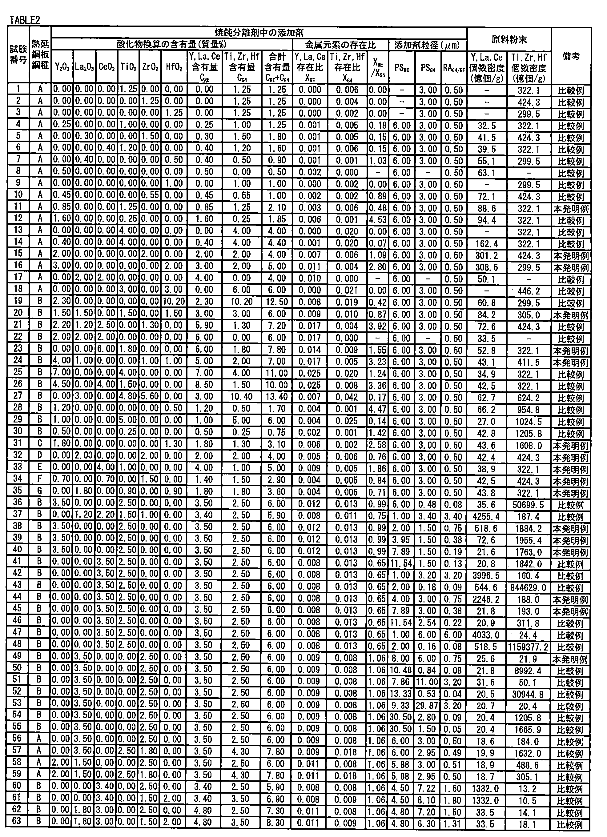
原料粉末をレーザー回折式粒度分布測定装置(型式:LA950,堀場製作所)で個数基準の粒度分布データを測定し、1g中の粒子数を計算した。
製造された試験番号1~63の方向性電磁鋼板の母材鋼板に対して、スパーク放電発光析法および、原子吸光分析法により、母材鋼板の化学組成を求めた。求めた化学組成を表3に示す。

[Alピーク位置DAl測定試験]
各試験番号の方向性電磁鋼板に対して、次の測定方法によりAlピーク位置DAlを求めた。具体的には、方向性電磁鋼板の表層に対してGDS法を用いた元素分析を実施し、方向性電磁鋼板の表面から深さ方向に100μmの範囲(表層)で元素分析を実施し、表層中の各深さ位置に含まれるAlを同定した。同定されたAlの発光強度を表面から深さ方向にプロットした。プロットされたAl発光強度のグラフに基づいて、Alピーク位置DAlを求めた。求めたAlピーク位置DAlを表4に示す。
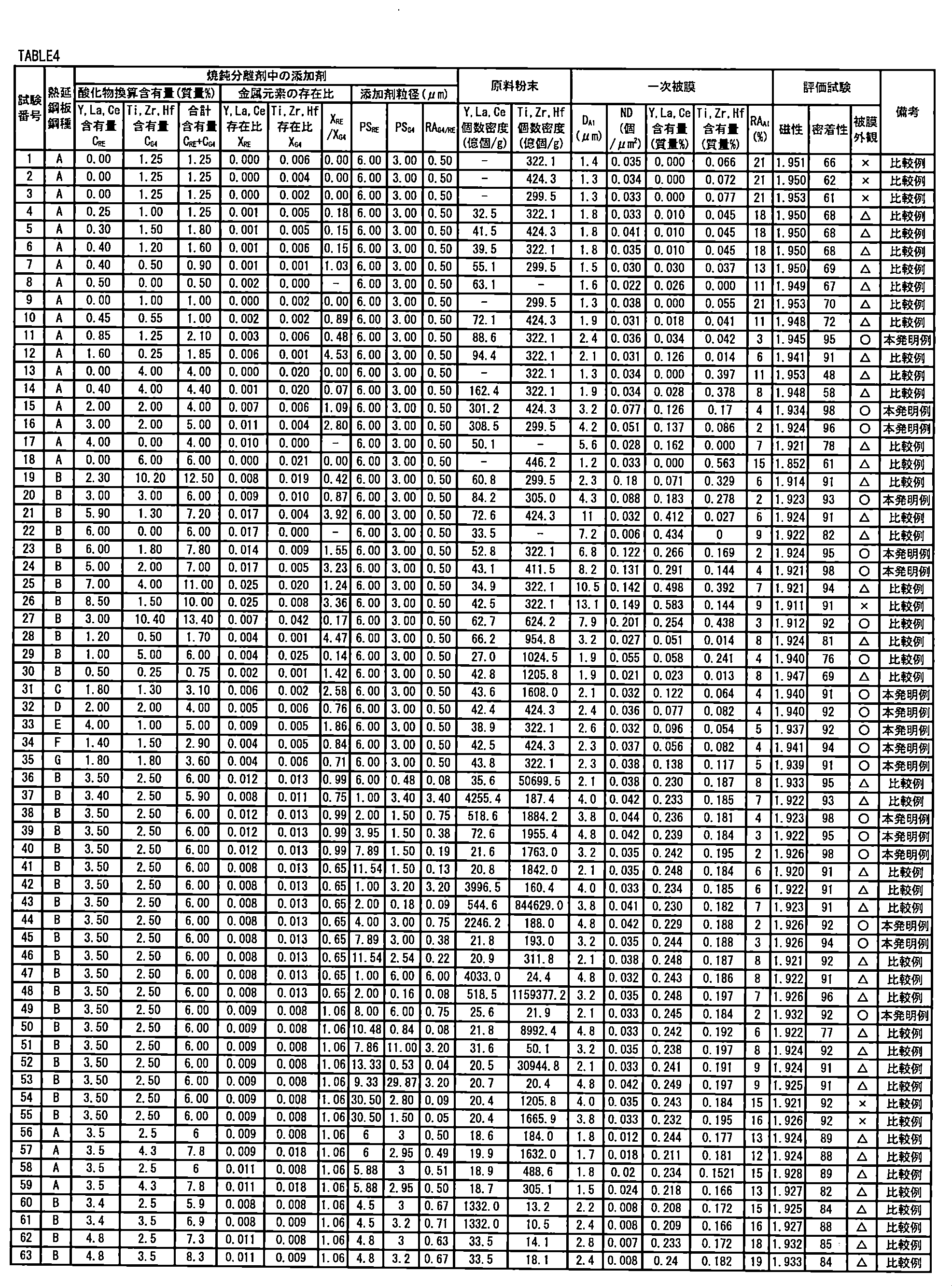
各試験番号の方向性電磁鋼板に対して、Alピーク位置DAlでのAl酸化物個数密度ND(個/μm2)を次の方法で求めた。グロー放電発光分析装置により、Alピーク位置DAlまでグロー放電を実施した。Alピーク位置DAlでの放電痕のうち、任意の36μm×50μmの領域(観察領域)に対して、エネルギー分散型X線分光器(EDS)による元素分析を実施して、観察領域中のAl酸化物を特定した。観察領域中の析出物のうち、AlとOとを含有したものをAl酸化物と特定した。特定されたAl酸化物の個数をカウントし、次の式でAl酸化物個数密度ND(個/μm2)を求めた。
ND=特定されたAl酸化物の個数/観察領域の面積
求めたAl酸化物個数密度NDを表4に示す。
格子比率RAAlは次の方法で求めた。グロー放電発光分析装置により、Alピーク位置DAlまでグロー放電を実施した。Alピーク位置DAlでの放電痕のうち、重複のない、任意の100μm×100μmの領域(観察領域)に対して、エネルギー分散型X線分光器(EDS)による元素分析を実施して、観察領域中のAl酸化物を特定した。具体的には、観察領域におけるOの特性X線の最大強度に対して、50%以上のOの特性X線の強度が分析される領域を酸化物と特定した。特定された酸化物領域において、Alの特定X線の最大強度に対して、30%以上のAlの特定X線の強度が分析される領域をAl酸化物と特定した。測定結果に基づいて、観察領域におけるAl酸化物の分布図を作成した。
格子比率RAAl=Al酸化物を含まない格子数/分布図中の総格子数×100
各試験番号の方向性電磁鋼板に対して、次の方法で一次被膜中のY、La、Ce含有量(質量%)及びTi、Zr、Hf含有量(質量%)を測定した。具体的には、方向性電磁鋼板を電解して一次被膜単体を母材鋼板表面から分離した。分離された一次皮膜中のMgをICP―MSで定量分析した。得られた定量値(質量%)とMg2SiO4の分子量との積を、Mgの原子量で除して、Mg2SiO4当量の含有量を求めた。一次被膜中のY、La、Ce含有量の合計及びTi、Zr、Hf含有量の合計は次の方法で測定した。方向性電磁鋼板を電解して一次被膜単体を母材鋼板表面から分離した。分離された一次皮膜中のY、La、Ce含有量の合計(質量%)及びTi、Zr、Hf含有量の合計含有量(質量%)を、ICP―MSで定量分析して求めた。測定により得られたY、La、Ce含有量の合計及びTi、Zr、Hf含有量の合計を表4に示す。
次の方法により、各試験番号の方向性電磁鋼板の磁気特性を評価した。具体的には、各試験番号の方向性電磁鋼板から圧延方向長さ300mm×幅60mmのサンプルを採取した。サンプルに対して、800A/mの磁場を付与して、磁束密度B8を求めた。表4に試験結果を示す。
次の方法により、各試験番号の方向性電磁鋼板の一次被膜の密着性を評価した。具体的には、各試験番号の方向性電磁鋼板から圧延方向長さ60mm×幅15mmのサンプルを採取した。サンプルに対して10mmの曲率で曲げ試験を実施した。曲げ試験は、耐屈曲性試験器(TP技研株式会社製)を用いて、円筒の軸方向がサンプルの幅方向と一致するようにサンプルに設置して実施した。曲げ試験後のサンプルの表面を観察し、一次被膜が剥離せずに残存している領域の総面積を求めた。次の式により、一次被膜残存率を求めた。
一次被膜残存率=一次被膜が剥離せず残存している領域の総面積/サンプル表面の面積×100
次の方法により、各試験番号の方向性電磁鋼板の一次被膜の外観を評価した。各試験番号の方向性電磁鋼板から圧延方向長さ15mm×幅60mmのサンプルを採取した。サンプルの外観を目視し、幅方向に対して一様に無彩色であり、色味、明度のムラが視認されない場合、被膜外観が良好と判断した。色ムラが生じている面積が5%未満であれば「○」、5%以上10%未満であれば「△」、10%以上であれば「×」とした。
表4に試験結果を示す。表4を参照して、試験番号11、15、16、20、23、24、31~35、38~40、44、45及び49では、化学組成が適切であり、かつ、焼鈍分離剤中の条件(Y、La、Ce化合物の酸化物換算含有量CRE、Ti、Zr、Hf化合物の酸化物換算含有量CG4、合計含有量CRE+CG4、Y、La、Ce化合物の平均粒径PSRE、平均粒径比ARG4/RE、原子数比XRE/XG4)が適切であった。その結果、Alピーク位置DAlは2.0~10.0μmの範囲内であり、Al酸化物の個数密度NDは0.032~0.20個/μm2の範囲内であった。さらに、Al酸化物の格子比率RAAlは5%以下であった。なお、一次被膜中のY、La、Ce含有量は0.001~6.0%の範囲内であり、Ti、Zr、Hf含有量は0.0005~4.0%の範囲内であった。その結果、これらの試験番号の方向性電磁鋼板において、磁束密度B8が1.92T以上であり、優れた磁気特性が得られた。さらに、一次被膜残存率が90%以上であり、優れた密着性を示した。さらに、一次被膜の外観も良好であった。
[方向性電磁鋼板の製造]
実施例1と同様にして、表1に示す化学成分の溶鋼から製造した試験番号64~79の一次再結晶焼鈍後の冷延鋼板に対して、水性スラリーを塗布、乾燥させて、焼鈍分離剤を片面あたり、5g/m2の割合で塗布した。なお、水性スラリーは、焼鈍分離剤と工業用純水と1:6の配合比で混合して調整した。焼鈍分離剤は、MgOと、表5に示す添加剤と、MgO含有量を質量%で100%としたとき2.5%のCeO2と、2.0%のZrO2、4.0%のTiO2を含有した。なお、表5に示す焼鈍分離剤中のY、La、Ce含有量CREは、焼鈍分離剤中のMgO含有量を質量%で100%としたときのY、La、Ce化合物の酸化物換算の合計含有量を意味する。同様に、表5に示すY、La、Ce存在比XREは焼鈍分離剤中に含まれるMg原子の数に対するY、La、Ce原子の数の総和の比を意味する。同様に、表5に示す焼鈍分離剤中のTi、Zr、Hf含有量CG4は、焼鈍分離剤中のMgO含有量を質量%で100%としたときのTi、Zr、Hf化合物の酸化物換算の合計含有量を意味する。同様に、表5に示すTi、Zr、Hf存在比XG4は、焼鈍分離剤中に含まれるMg原子の数に対する、Ti、Zr、Hf原子の数の総和の比を意味する。また、同様に、表5に示すCa、Sr、Ba含有量CMXは、焼鈍分離剤中のMgO含有量を質量%で100%としたときのCa、Sr、Ba化合物の硫酸塩換算の合計含有量を意味する。また同様に、表5に示すPSREは、焼鈍分離剤に含まれるY、La、Ce化合物全体の平均粒径を意味する。また同様に、表5に示すPSG4は、焼鈍分離剤に含まれるTi、Zr、Hf化合物全体の平均粒径を意味する。また、同様に、表5に示すRARE/G4は、前記PSREに対するPSG4の比を意味する。
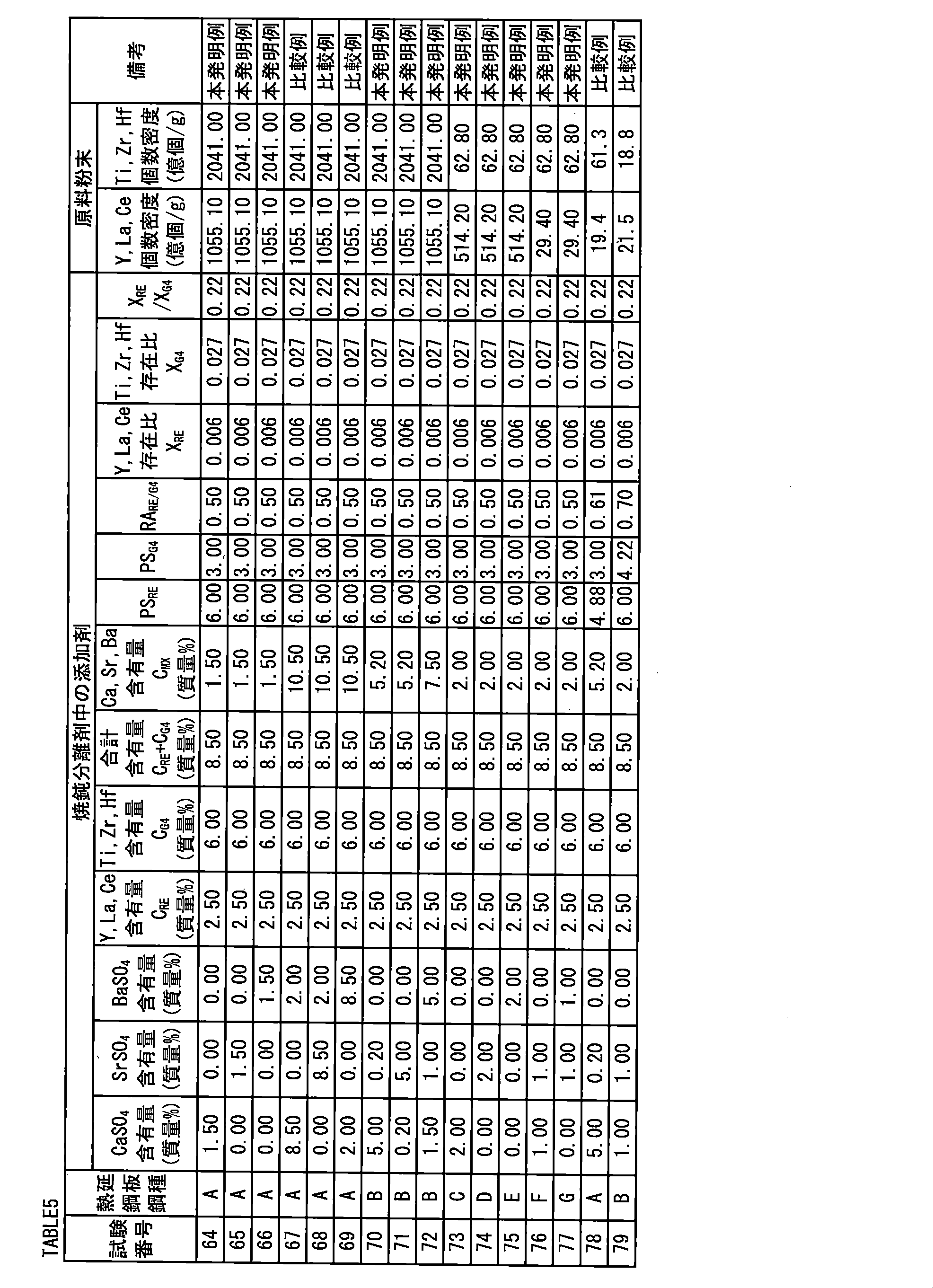
製造された試験番号64~79の方向性電磁鋼板の母材鋼板に対して、スパーク放電発光析法および、原子吸光分析法により、母材鋼板の化学組成を求めた。求めた化学組成を表6に示す。

各試験番号の方向性電磁鋼板に対して、実施例1と同様にして、Alピーク位置DAl、Alピーク位置DAlでのAl酸化物個数密度ND(個/μm2)、一次被膜中のY、La、Ce含有量及びTi、Zr、Hf含有量および格子比率RAAlを求めた。測定により求められたDAl、Al酸化物個数密度ND、一次被膜中のY、La、Ce含有量及びTi、Zr、Hf含有量およびRAAlを表7に示す。
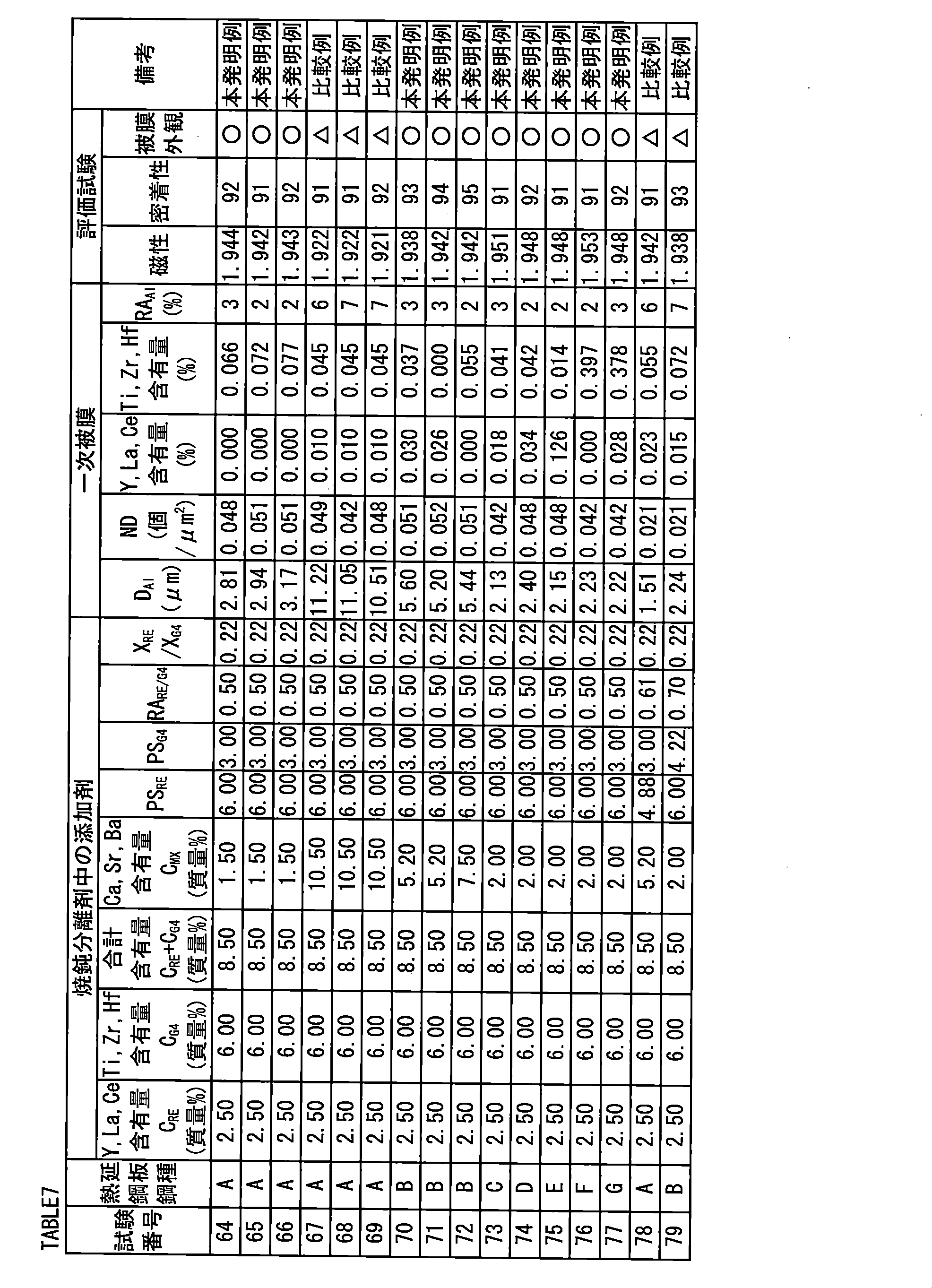
実施例1と同様の方法により、各試験番号の方向性電磁鋼板の磁気特性を評価した。表7に試験結果を示す。
実施例1と同様の方法により、各試験番号の方向性電磁鋼板の一次被膜の密着性を評価した。
実施例1と同様の方法により、各試験番号の方向性電磁鋼板の一次被膜の外観を評価した。実施例1と同様に、表7において、色ムラが生じている面積が5%未満であれば「○」、5%以上10%未満であれば「△」、10%以上であれば「×」とした。
表7に試験結果を示す。表7を参照して、試験番号64~66および70~77では、化学組成が適切であり、かつ、焼鈍分離剤中の条件(Y、La、Ce化合物の酸化物換算含有量CRE、Ti、Zr、Hf化合物の酸化物換算含有量CG4、合計含有量CRE+CG4、Y、La、Ce化合物の平均粒径PSRE、平均粒径比ARG4/RE、原子数比XRE/XG4)が適切であった。またさらに、Ca、Mg、Ba化合物の硫酸塩換算の含有量CMXが適切であった。その結果、Alピーク位置DAlは2.0~10.0μmの範囲内であり、Al酸化物の個数密度NDは0.032~0.15個/μm2の範囲内であった。さらに、Al酸化物の格子比率RAAlは5%以下であった。なお、一次被膜中のY、La、Ce含有量は0.001~6.0%の範囲内であり、Ti、Zr、Hf含有量は0.0005~4.0%の範囲内であった。その結果、これらの試験番号の方向性電磁鋼板において、磁束密度B8が1.92T以上であり、優れた磁気特性が得られた。さらに、一次被膜残存率が90%以上であり、優れた密着性を示した。さらに、一次被膜の外観も良好であった。
Claims (7)
- 方向性電磁鋼板であって、
質量%で、
C:0.005%以下、
Si:2.5~4.5%、
Mn:0.02~0.2%、
S及びSeからなる群から選択される1種以上の元素:合計で0.005%以下、
sol.Al:0.01%以下、及び
N:0.01%以下
を含有し、残部はFe及び不純物からなる化学組成を有する母材鋼板と、
前記母材鋼板の表面上に形成されており、Mg2SiO4を主成分として含有する一次被膜とを備え、
前記一次被膜の表面から前記方向性電磁鋼板の板厚方向にグロー放電発光分析法による元素分析を実施したときに得られるAl発光強度のピーク位置が、前記一次被膜の表面から前記板厚方向に2.0~10.0μmの範囲内に配置され、
前記Al発光強度のピーク位置でのAl酸化物であって、面積基準の円相当径で、0.2μm以上の前記Al酸化物の個数密度が0.032~0.20個/μm2であり、
前記グロー放電発光分析法により得られた、前記Al発光強度のピーク位置における、100μm×100μmの前記Al酸化物の分布図において、前記分布図を10μm×10μmの格子で区切った場合、前記分布図内の総格子数に対する前記Al酸化物を含まない格子数の比率が5%以下である、方向性電磁鋼板。 - 質量%で、
C:0.1%以下、
Si:2.5~4.5%、
Mn:0.02~0.2%、
S及びSeからなる群から選択される1種以上の元素:合計で0.005~0.07%、
sol.Al:0.005~0.05%、及び、
N:0.001~0.030%
を含有し、残部がFe及び不純物からなる熱延鋼板に対して80%以上の冷延率で冷間圧延を実施して冷延鋼板を製造する工程と、
前記冷延鋼板に対して脱炭焼鈍を実施する工程と、
前記脱炭焼鈍後の前記冷延鋼板の表面に、焼鈍分離剤を含有する水性スラリーを塗布し、400~1000℃の炉で前記冷延鋼板の表面上の水性スラリーを乾燥する工程と、
前記水性スラリーが乾燥された後の前記冷延鋼板に対して仕上げ焼鈍を実施する工程とを備え、
前記焼鈍分離剤は、
MgOと、
Y、La、Ceからなる群から選択される金属の化合物を少なくとも1種以上と、
Ti、Zr、Hfからなる群から選択される金属の化合物を少なくとも1種以上とを含有し、
前記焼鈍分離剤中の前記MgO含有量を質量%で100%としたとき、前記Y、La、Ceからなる群から選択される金属の化合物の酸化物換算の合計含有量が0.5~6.0%であり、前記Ti、Zr、Hfからなる群から選択される金属の化合物の酸化物換算の合計含有量が0.8~10.0%であり、
前記Y、La、Ceからなる群から選択される金属の化合物の平均粒径は10μm以下であり、
前記Ti、Zr、Hfからなる群から選択される金属の化合物の平均粒径の前記Y、La、Ceからなる群から選択される金属の化合物の平均粒径に対する比が0.1~3.0であり、
前記Y、La、Ceからなる群から選択される金属の化合物の前記酸化物換算の合計含有量と前記Ti、Zr、Hfからなる群から選択される金属の化合物の前記酸化物換算の合計含有量との合計が2.0~12.5%であり、
前記焼鈍分離剤に含有されるTi、Zr、Hf原子の数の総和と、Y、La、Ce原子の数の総和との比が0.15~3.6であり、
またさらに、前記Y,La,Ceからなる群から選択される金属の化合物の粒子であって、体積基準の球相当径で、0.1μm以上の粒子の個数密度が20億個/g以上であり、
またさらに、前記Ti,Zr,Hfからなる群から選択される金属の化合物の粒子であって、体積基準の球相当径で、0.1μm以上の粒子の個数密度が20億個/g以上である、方向性電磁鋼板の製造方法。 - 請求項2に記載の方向性電磁鋼板の製造方法であって、
前記焼鈍分離剤はさらに、Ca、Sr、Baからなる群から選択される金属の化合物を少なくとも1種以上含有し、
前記焼鈍分離剤中のMgO含有量を質量%で100%としたとき、前記Ca、Sr、Baからなる群から選択される金属の化合物の硫酸塩換算の合計含有量が10%以下である、方向性電磁鋼板の製造方法。 - 請求項2又は請求項3に記載の方向性電磁鋼板の製造方法であって、
前記熱延鋼板の化学組成はさらに、Feの一部に代えて、
Cu、Sb及びSnからなる群から選択される1種以上の元素を合計で0.6%以下含有する、方向性電磁鋼板の製造方法。 - 請求項2~請求項4のいずれか1項に記載の方向性電磁鋼板の製造方法であって、
前記熱延鋼板の化学組成はさらに、Feの一部に代えて、
Bi、Te及びPbからなる群から選択される1種以上の元素を合計で0.03%以下含有する、方向性電磁鋼板の製造方法。 - 方向性電磁鋼板の製造に用いられる焼鈍分離剤であって、
MgOと、
Y、La、Ceからなる群から選択される金属の化合物を少なくとも1種以上と、
Ti、Zr、Hfからなる群から選択される金属の化合物を少なくとも1種以上とを含有し、
前記焼鈍分離剤中の前記MgO含有量を質量%で100%としたとき、前記Y、La、Ceからなる群から選択される金属の化合物の酸化物換算の合計含有量が0.5~6.0%であり、前記Ti、Zr、Hfからなる群から選択される金属の化合物の酸化物換算の合計含有量が0.8~10.0%であり、
前記Y、La、Ceからなる群から選択される金属の化合物の平均粒径は10μm以下であり、
前記Ti、Zr、Hfからなる群から選択される金属の化合物の平均粒径の前記Y、La、Ceからなる群から選択される金属の化合物の平均粒径に対する比が0.1~3.0であり、
前記Y、La、Ceからなる群から選択される金属の化合物の前記酸化物換算の合計含有量と前記Ti、Zr、Hfからなる群から選択される金属の化合物の前記酸化物換算の合計含有量との合計が2.0~12.5%であり、
前記焼鈍分離剤に含有されるTi、Zr、Hf原子の数の総和と、Y、La、Ce原子の数の総和との比が0.15~3.6であり、
またさらに、前記Y,La,Ceからなる群から選択される金属の化合物の粒子であって、体積基準の球相当径で、0.1μm以上の粒子の個数密度が20億個/g以上であり、
またさらに、前記Ti,Zr,Hfからなる群から選択される金属の化合物の粒子であって、体積基準の球相当径で、0.1μm以上の粒子の個数密度が20億個/g以上である、焼鈍分離剤。 - 請求項6に記載の焼鈍分離剤であってさらに、Ca、Sr、Baからなる群から選択される金属の化合物を少なくとも1種以上含有し、
前記焼鈍分離剤中のMgO含有量を質量%で100%としたとき、前記Ca、Sr、Baからなる群から選択される金属の化合物の硫酸塩換算の合計含有量が10%以下である、焼鈍分離剤。
Priority Applications (6)
| Application Number | Priority Date | Filing Date | Title |
|---|---|---|---|
| EP20738049.4A EP3910078A4 (en) | 2019-01-08 | 2020-01-08 | ORIENTED ELECTROMAGNETIC STEEL SHEET AND METHOD FOR MAKING THE SAME, AND ANNEALING RELEASE AGENT IMPLEMENTED IN MAKING SUCH STEEL SHEET |
| BR112021012872-7A BR112021012872A2 (pt) | 2019-01-08 | 2020-01-08 | Chapa de aço elétrico com grão orientado, método para fabricar chapa de aço elétrico com grão orientado, e, separador de recozimento |
| CN202080007026.2A CN113195752B (zh) | 2019-01-08 | 2020-01-08 | 方向性电磁钢板、方向性电磁钢板的制造方法及方向性电磁钢板的制造中利用的退火分离剂 |
| US17/421,332 US20220056551A1 (en) | 2019-01-08 | 2020-01-08 | Grain-oriented electrical steel sheet, method for manufacturing grain-oriented electrical steel sheet, and annealing separator utilized for manufacture of grain-oriented electrical steel sheet |
| KR1020217020602A KR102554127B1 (ko) | 2019-01-08 | 2020-01-08 | 방향성 전자 강판, 방향성 전자 강판의 제조 방법, 및, 방향성 전자 강판의 제조에 이용되는 어닐링 분리제 |
| JP2020565188A JP7295441B2 (ja) | 2019-01-08 | 2020-01-08 | 方向性電磁鋼板、方向性電磁鋼板の製造方法、及び、方向性電磁鋼板の製造に利用される焼鈍分離剤 |
Applications Claiming Priority (2)
| Application Number | Priority Date | Filing Date | Title |
|---|---|---|---|
| JP2019-001206 | 2019-01-08 | ||
| JP2019001206 | 2019-01-08 |
Publications (1)
| Publication Number | Publication Date |
|---|---|
| WO2020145321A1 true WO2020145321A1 (ja) | 2020-07-16 |
Family
ID=71520520
Family Applications (1)
| Application Number | Title | Priority Date | Filing Date |
|---|---|---|---|
| PCT/JP2020/000348 WO2020145321A1 (ja) | 2019-01-08 | 2020-01-08 | 方向性電磁鋼板、方向性電磁鋼板の製造方法、及び、方向性電磁鋼板の製造に利用される焼鈍分離剤 |
Country Status (7)
| Country | Link |
|---|---|
| US (1) | US20220056551A1 (ja) |
| EP (1) | EP3910078A4 (ja) |
| JP (1) | JP7295441B2 (ja) |
| KR (1) | KR102554127B1 (ja) |
| CN (1) | CN113195752B (ja) |
| BR (1) | BR112021012872A2 (ja) |
| WO (1) | WO2020145321A1 (ja) |
Citations (10)
| Publication number | Priority date | Publication date | Assignee | Title |
|---|---|---|---|---|
| JPH0617261A (ja) * | 1991-07-10 | 1994-01-25 | Nippon Steel Corp | 被膜特性と磁気特性に優れた一方向性珪素鋼板 |
| JPH0688171A (ja) | 1992-09-09 | 1994-03-29 | Nippon Steel Corp | 超高磁束密度一方向性電磁鋼板の製造方法 |
| JPH08269552A (ja) | 1995-03-28 | 1996-10-15 | Nippon Steel Corp | 超高磁束密度一方向性電磁鋼板の製造方法 |
| JP2000063950A (ja) * | 1998-08-19 | 2000-02-29 | Kawasaki Steel Corp | 磁気特性および被膜特性に優れた方向性電磁鋼板およびその製造方法 |
| JP2005290446A (ja) | 2004-03-31 | 2005-10-20 | Jfe Steel Kk | 磁気特性および被膜特性に優れる方向性電磁鋼板の製造方法 |
| WO2006126660A1 (ja) * | 2005-05-23 | 2006-11-30 | Nippon Steel Corporation | 被膜密着性に優れる方向性電磁鋼板およびその製造方法 |
| WO2008062853A1 (fr) | 2006-11-22 | 2008-05-29 | Nippon Steel Corporation | Feuille d'acier électromagnétique à orientation unidirectionnelle de grains, ayant une excellente adhésion de film, et son procédé de fabrication |
| JP2008127634A (ja) | 2006-11-21 | 2008-06-05 | Nippon Steel Corp | 一方向性電磁鋼板の製造方法 |
| JP2009270129A (ja) | 2008-04-30 | 2009-11-19 | Nippon Steel Corp | 磁気特性および被膜密着性に優れた方向性電磁鋼板およびその製造方法 |
| JP2011246770A (ja) * | 2010-05-27 | 2011-12-08 | Nippon Steel Corp | 方向性電磁鋼板及び張力絶縁膜被覆方向性電磁鋼板 |
Family Cites Families (8)
| Publication number | Priority date | Publication date | Assignee | Title |
|---|---|---|---|---|
| JPS59215488A (ja) * | 1983-05-20 | 1984-12-05 | Nippon Steel Corp | 方向性電磁鋼板の焼鈍分離剤 |
| JPS6017261A (ja) * | 1983-07-11 | 1985-01-29 | Nissan Motor Co Ltd | ペ−パライザ |
| JP2006144042A (ja) * | 2004-11-17 | 2006-06-08 | Jfe Steel Kk | 磁気特性および被膜特性に優れた方向性電磁鋼板の製造方法 |
| RU2562182C2 (ru) * | 2011-01-12 | 2015-09-10 | Ниппон Стил Энд Сумитомо Метал Корпорейшн | Лист из электротехнической стали с ориентированной зеренной структурой и способ его получения |
| WO2016105053A1 (ko) * | 2014-12-24 | 2016-06-30 | 주식회사 포스코 | 방향성 전기강판 및 그 제조방법 |
| KR101693516B1 (ko) * | 2014-12-24 | 2017-01-06 | 주식회사 포스코 | 방향성 전기강판 및 그 제조방법 |
| JP6579078B2 (ja) * | 2016-10-18 | 2019-09-25 | Jfeスチール株式会社 | 方向性電磁鋼板の製造方法 |
| US10968521B2 (en) * | 2016-12-21 | 2021-04-06 | Jfe Steel Corporation | Grain-oriented electrical steel sheet and production method for grain-oriented electrical steel sheet |
-
2020
- 2020-01-08 WO PCT/JP2020/000348 patent/WO2020145321A1/ja active Application Filing
- 2020-01-08 US US17/421,332 patent/US20220056551A1/en active Pending
- 2020-01-08 KR KR1020217020602A patent/KR102554127B1/ko active IP Right Grant
- 2020-01-08 BR BR112021012872-7A patent/BR112021012872A2/pt unknown
- 2020-01-08 EP EP20738049.4A patent/EP3910078A4/en active Pending
- 2020-01-08 JP JP2020565188A patent/JP7295441B2/ja active Active
- 2020-01-08 CN CN202080007026.2A patent/CN113195752B/zh active Active
Patent Citations (11)
| Publication number | Priority date | Publication date | Assignee | Title |
|---|---|---|---|---|
| JPH0617261A (ja) * | 1991-07-10 | 1994-01-25 | Nippon Steel Corp | 被膜特性と磁気特性に優れた一方向性珪素鋼板 |
| JPH0688171A (ja) | 1992-09-09 | 1994-03-29 | Nippon Steel Corp | 超高磁束密度一方向性電磁鋼板の製造方法 |
| JPH08269552A (ja) | 1995-03-28 | 1996-10-15 | Nippon Steel Corp | 超高磁束密度一方向性電磁鋼板の製造方法 |
| JP2000063950A (ja) * | 1998-08-19 | 2000-02-29 | Kawasaki Steel Corp | 磁気特性および被膜特性に優れた方向性電磁鋼板およびその製造方法 |
| JP2005290446A (ja) | 2004-03-31 | 2005-10-20 | Jfe Steel Kk | 磁気特性および被膜特性に優れる方向性電磁鋼板の製造方法 |
| WO2006126660A1 (ja) * | 2005-05-23 | 2006-11-30 | Nippon Steel Corporation | 被膜密着性に優れる方向性電磁鋼板およびその製造方法 |
| JP2012214902A (ja) | 2005-05-23 | 2012-11-08 | Nippon Steel Corp | 被膜密着性に優れる方向性電磁鋼板およびその製造方法 |
| JP2008127634A (ja) | 2006-11-21 | 2008-06-05 | Nippon Steel Corp | 一方向性電磁鋼板の製造方法 |
| WO2008062853A1 (fr) | 2006-11-22 | 2008-05-29 | Nippon Steel Corporation | Feuille d'acier électromagnétique à orientation unidirectionnelle de grains, ayant une excellente adhésion de film, et son procédé de fabrication |
| JP2009270129A (ja) | 2008-04-30 | 2009-11-19 | Nippon Steel Corp | 磁気特性および被膜密着性に優れた方向性電磁鋼板およびその製造方法 |
| JP2011246770A (ja) * | 2010-05-27 | 2011-12-08 | Nippon Steel Corp | 方向性電磁鋼板及び張力絶縁膜被覆方向性電磁鋼板 |
Non-Patent Citations (1)
| Title |
|---|
| See also references of EP3910078A4 |
Also Published As
| Publication number | Publication date |
|---|---|
| JPWO2020145321A1 (ja) | 2021-11-25 |
| US20220056551A1 (en) | 2022-02-24 |
| EP3910078A4 (en) | 2022-10-05 |
| KR102554127B1 (ko) | 2023-07-12 |
| CN113195752A (zh) | 2021-07-30 |
| KR20210096235A (ko) | 2021-08-04 |
| BR112021012872A2 (pt) | 2021-09-21 |
| EP3910078A1 (en) | 2021-11-17 |
| CN113195752B (zh) | 2022-09-13 |
| JP7295441B2 (ja) | 2023-06-21 |
Similar Documents
| Publication | Publication Date | Title |
|---|---|---|
| KR102493707B1 (ko) | 방향성 전자 강판의 제조 방법 및 방향성 전자 강판 | |
| KR102554127B1 (ko) | 방향성 전자 강판, 방향성 전자 강판의 제조 방법, 및, 방향성 전자 강판의 제조에 이용되는 어닐링 분리제 | |
| KR102541760B1 (ko) | 방향성 전자 강판, 방향성 전자 강판의 제조 방법 및 방향성 전자 강판의 제조에 이용되는 어닐링 분리제 | |
| JP7211436B2 (ja) | 方向性電磁鋼板、方向性電磁鋼板の製造方法、及び、方向性電磁鋼板の製造に利用される焼鈍分離剤 | |
| JP7205555B2 (ja) | 方向性電磁鋼板およびその製造方法、ならびに焼鈍分離剤 | |
| JP2021123766A (ja) | 方向性電磁鋼板、および方向性電磁鋼板の製造方法、ならびに焼鈍分離剤 | |
| RU2772719C1 (ru) | Лист анизотропной электротехнической стали, способ производства листа анизотропной электротехнической стали и сепаратор отжига, использующийся для производства листа анизотропной электротехнической стали | |
| RU2772720C1 (ru) | Лист анизотропной электротехнической стали, способ производства листа анизотропной электротехнической стали и сепаратор отжига, используемый для производства листа анизотропной электротехнической стали | |
| RU2773479C1 (ru) | Лист анизотропной электротехнической стали, способ его изготовления и отжиговый сепаратор | |
| JP7184098B2 (ja) | 方向性電磁鋼板、焼鈍分離剤、及び方向性電磁鋼板の製造方法 | |
| JP7464818B2 (ja) | 方向性電磁鋼板の製造方法および方向性電磁鋼板、ならびに焼鈍分離剤 | |
| JP7180691B2 (ja) | 方向性電磁鋼板、仕上焼鈍用鋼板、焼鈍分離剤、方向性電磁鋼板の製造方法、及び仕上焼鈍用鋼板の製造方法 |
Legal Events
| Date | Code | Title | Description |
|---|---|---|---|
| 121 | Ep: the epo has been informed by wipo that ep was designated in this application |
Ref document number: 20738049 Country of ref document: EP Kind code of ref document: A1 |
|
| ENP | Entry into the national phase |
Ref document number: 2020565188 Country of ref document: JP Kind code of ref document: A |
|
| ENP | Entry into the national phase |
Ref document number: 20217020602 Country of ref document: KR Kind code of ref document: A |
|
| REG | Reference to national code |
Ref country code: BR Ref legal event code: B01A Ref document number: 112021012872 Country of ref document: BR |
|
| NENP | Non-entry into the national phase |
Ref country code: DE |
|
| WWE | Wipo information: entry into national phase |
Ref document number: 2021122414 Country of ref document: RU |
|
| ENP | Entry into the national phase |
Ref document number: 2020738049 Country of ref document: EP Effective date: 20210809 |
|
| ENP | Entry into the national phase |
Ref document number: 112021012872 Country of ref document: BR Kind code of ref document: A2 Effective date: 20210629 |