WO2007105631A1 - 蛍光体および発光装置 - Google Patents
蛍光体および発光装置 Download PDFInfo
- Publication number
- WO2007105631A1 WO2007105631A1 PCT/JP2007/054676 JP2007054676W WO2007105631A1 WO 2007105631 A1 WO2007105631 A1 WO 2007105631A1 JP 2007054676 W JP2007054676 W JP 2007054676W WO 2007105631 A1 WO2007105631 A1 WO 2007105631A1
- Authority
- WO
- WIPO (PCT)
- Prior art keywords
- powder
- phosphor
- red
- light
- reference example
- Prior art date
Links
Classifications
-
- C—CHEMISTRY; METALLURGY
- C09—DYES; PAINTS; POLISHES; NATURAL RESINS; ADHESIVES; COMPOSITIONS NOT OTHERWISE PROVIDED FOR; APPLICATIONS OF MATERIALS NOT OTHERWISE PROVIDED FOR
- C09K—MATERIALS FOR MISCELLANEOUS APPLICATIONS, NOT PROVIDED FOR ELSEWHERE
- C09K11/00—Luminescent, e.g. electroluminescent, chemiluminescent materials
- C09K11/08—Luminescent, e.g. electroluminescent, chemiluminescent materials containing inorganic luminescent materials
- C09K11/0883—Arsenides; Nitrides; Phosphides
-
- C—CHEMISTRY; METALLURGY
- C09—DYES; PAINTS; POLISHES; NATURAL RESINS; ADHESIVES; COMPOSITIONS NOT OTHERWISE PROVIDED FOR; APPLICATIONS OF MATERIALS NOT OTHERWISE PROVIDED FOR
- C09K—MATERIALS FOR MISCELLANEOUS APPLICATIONS, NOT PROVIDED FOR ELSEWHERE
- C09K11/00—Luminescent, e.g. electroluminescent, chemiluminescent materials
- C09K11/08—Luminescent, e.g. electroluminescent, chemiluminescent materials containing inorganic luminescent materials
- C09K11/77—Luminescent, e.g. electroluminescent, chemiluminescent materials containing inorganic luminescent materials containing rare earth metals
- C09K11/7728—Luminescent, e.g. electroluminescent, chemiluminescent materials containing inorganic luminescent materials containing rare earth metals containing europium
- C09K11/77348—Silicon Aluminium Nitrides or Silicon Aluminium Oxynitrides
-
- H—ELECTRICITY
- H01—ELECTRIC ELEMENTS
- H01L—SEMICONDUCTOR DEVICES NOT COVERED BY CLASS H10
- H01L2224/00—Indexing scheme for arrangements for connecting or disconnecting semiconductor or solid-state bodies and methods related thereto as covered by H01L24/00
- H01L2224/01—Means for bonding being attached to, or being formed on, the surface to be connected, e.g. chip-to-package, die-attach, "first-level" interconnects; Manufacturing methods related thereto
- H01L2224/42—Wire connectors; Manufacturing methods related thereto
- H01L2224/47—Structure, shape, material or disposition of the wire connectors after the connecting process
- H01L2224/48—Structure, shape, material or disposition of the wire connectors after the connecting process of an individual wire connector
- H01L2224/4805—Shape
- H01L2224/4809—Loop shape
- H01L2224/48091—Arched
-
- H—ELECTRICITY
- H01—ELECTRIC ELEMENTS
- H01L—SEMICONDUCTOR DEVICES NOT COVERED BY CLASS H10
- H01L33/00—Semiconductor devices with at least one potential-jump barrier or surface barrier specially adapted for light emission; Processes or apparatus specially adapted for the manufacture or treatment thereof or of parts thereof; Details thereof
- H01L33/48—Semiconductor devices with at least one potential-jump barrier or surface barrier specially adapted for light emission; Processes or apparatus specially adapted for the manufacture or treatment thereof or of parts thereof; Details thereof characterised by the semiconductor body packages
- H01L33/50—Wavelength conversion elements
- H01L33/501—Wavelength conversion elements characterised by the materials, e.g. binder
- H01L33/502—Wavelength conversion materials
Definitions
- the present invention relates to a phosphor used for a light emitting device and the light emitting device.
- LED lamps using light emitting diodes are used in various display devices such as portable devices, PC peripheral devices, OA devices, various switches, light sources for knocklights, and display boards.
- High-load LEDs generate heat when driven, and the temperature of the phosphor rises by about 100 to 200 ° C. This causes the emission intensity of the phosphor to decrease.
- the phosphor is desired to have a small decrease in emission intensity when the temperature rises.
- a phosphor used in a powerful LED lamp that emits green light when excited by blue is Eu-activated
- This phosphor is said to be efficient at 450 nm excitation, and has an absorption rate of 65%, internal quantum efficiency of 53%, and emission efficiency of 35% at 450 nm excitation.
- a field emission display includes a screen in which red, green, and blue phosphors are arranged, and a force sword that is opposed to the screen at a smaller interval than the CRT.
- a force sword a plurality of electron sources are arranged as emitter elements, and electrons are emitted in accordance with a potential difference with a gate electrode arranged in the vicinity thereof.
- the emitted electrons are accelerated by the anode voltage (acceleration voltage) on the phosphor side and collide with the phosphor, which causes the phosphor to emit light.
- a phosphor used in a field emission display having a powerful structure it has a sufficiently high light emission efficiency and exhibits a sufficiently high light emission efficiency even when saturation is reached in excitation at a high current density. Is required.
- the sulfur-based phosphors (ZnS: Cu, ZnS: Ag) that have been used for CRT phosphors so far can be candidates for this.
- Low energy cathode It has been reported that sulfate-based phosphors such as ZnS decompose under the excitation conditions of a line display screen. This decomposition product significantly deteriorates the hot filament that emits the electron beam.
- ZnS-based blue phosphors that have been used in the past have a problem in that the display color of the color screen changes with time because the heritagence degradation is significant compared to red phosphors and green phosphors. .
- An object of the present invention is to provide a phosphor having good temperature characteristics.
- the phosphor according to one embodiment of the present invention has a composition represented by the following general formula (2), which exhibits an emission peak between wavelengths 490 nm and 580 nm when excited with light having a wavelength of 250 nm to 500 nm. It is characterized by that.
- M is at least one metal element excluding Si and A1, and R is a light emitting central element.
- X, a2, b2, c2, and d2 satisfy the following relationship.
- the phosphor according to another embodiment of the present invention has a composition represented by the following general formula (2), which exhibits an emission peak between wavelengths 490 nm and 580 nm when excited with light having a wavelength of 250 nm to 500 nm. It is characterized by that.
- M is at least one metal element excluding Si and A1, and R is a light emitting central element.
- X, a2, b2, c2, and d2 satisfy the following relationship.
- FIG. 1 is an XRD profile of a phosphor according to one embodiment.
- FIG. 2 is a schematic diagram showing a configuration of a light emitting device that works according to one embodiment.
- FIG. 3 is an emission spectrum of the phosphors of Reference Examples 1 to 4 at 457 nm excitation.
- FIG. 4 is an emission spectrum of the phosphors of Reference Examples 5 to 8 when excited with light at 457 nm.
- FIG. 5 shows XRD profiles of the phosphors of Reference Examples 1 to 4, 7, and 8.
- Fig. 6 is an emission spectrum of the phosphor of Reference Example 9: L 1 at 457 nm excitation.
- FIG. 7 is an emission spectrum of the phosphors of Reference Examples 12 to 16 when excited with 457 nm light.
- FIG. 8 is an emission spectrum of the phosphors of Reference Examples 17 to 20 when excited with 457 nm light.
- FIG. 9 is an emission spectrum of the phosphors of Reference Examples 21 to 23 when excited with light at 457 nm.
- FIG. 10 is an emission spectrum of the phosphors of Reference Examples 24 to 26 when excited with 457 nm light.
- FIG. 11 is an emission spectrum of the phosphors of Reference Examples 27 to 29 when excited with 457 nm light.
- FIG. 12 is an emission spectrum of the phosphor of Reference Example 30 when excited with light at 457 nm.
- FIG. 13 is an emission spectrum of the phosphors of Examples 1 to 4 when excited with light at 457 nm.
- FIG. 14 is an emission spectrum of the phosphor of Example 5 when excited with light at 461 nm.
- FIG. 15 is an emission spectrum of the phosphors of Examples 6 and 7 when excited with light at 461 nm.
- FIG. 16 is an emission spectrum of the phosphor of Example 8 to: L 1 when excited with light at 461 nm.
- FIG. 17 is an XRD profile of the phosphors of Examples 12-14.
- FIG. 18 is an emission spectrum of the phosphors of Reference Examples 31 to 34 when excited with light at 457 nm.
- Figure 19 shows the emission spectrum of the phosphors of Reference Examples 35 to 38 under 457 nm excitation. It is.
- FIG. 20 is an emission spectrum of the phosphor of Reference Example 39 when excited with light at 457 nm.
- FIG. 21 is an XRD profile of the phosphors of Comparative Examples 3 to 5, Reference Example 20, and Example 2.
- FIG. 22 is an emission spectrum of the phosphors of Comparative Examples 3 to 5, and Reference Example 20 and Example 2 at 390 nm photoexcitation.
- FIG. 23 is a graph showing the temperature characteristics of the light emission intensity of the phosphors of Reference Examples 20 and 39 and Comparative Examples 1 and 2 when excited with light at 461 nm.
- FIG. 24 is a graph showing the temperature characteristics of the emission intensity of the phosphors of Example 1 and Comparative Example 6 when excited with light at 461 nm.
- the present inventors have found that a phosphor having good temperature characteristics can be obtained by adding a luminescent center element to a sialon-based compound with a limited composition.
- the sialon compound in the present specification is represented by the following composition formula (A).
- M is at least one metal element excluding Si and Si.
- the metal element M include alkaline earth metals such as Mg, Ca, Sr and Ba; rare earths such as Y, Gd, La, Lu and Sc; alkali metals such as Li, Na and K It is done.
- B, Ga, In, Ge, etc. may be contained as the metal element M.
- a phosphor that is effective in the present embodiment can be obtained. It can be said that the phosphor according to this embodiment is obtained by defining the composition of each constituent element within a predetermined range in the following composition formula (B).
- luminescent center element R for example, Eu, Ce, Mn, Tb, Yb, Dy, Sm, Tm, Pr, Nd , Pm, Ho, Er, Gd, Cr, Sn, Cu, Zn, Ga, Ge, As, Ag, Cd, In, Sb, Au, Hg,
- Examples include Tl, Pb, Bi, and Fe. Considering the tunability of the emission wavelength, it is preferable to use at least one of Eu and Mn! /.
- the luminescent center element R is desired to replace at least 0.1 mol% of the metal element M.
- the luminescent center element R may replace the entire amount of the metal element M. However, when the replacement amount is less than 50 mol%, a decrease in the light emission probability (concentration quenching) can be suppressed as much as possible.
- the phosphor according to one embodiment exhibits an emission peak between wavelengths 490 nm and 580 nm when excited with light having a wavelength of 250 nm to 500 nm, and has a composition represented by the following general formula (2).
- M is at least one metal element excluding Si and A1, and R is a light emitting element.
- X, a2, b2, c2, and d2 are numerical values that satisfy the following relationship: It is.
- the phosphor having the composition represented by the general formula (2) exhibits light emission in a region ranging from green to yellowish green when excited with light having a wavelength of 250 nm to 500 nm.
- the obtained phosphor is X-ray diffraction using CuKa characteristic X-rays (wavelength 1.54056 A).
- the obtained phosphor has an X-ray diffraction profile as schematically shown in FIG.
- phosphors having the composition represented by the general formula (2) are 11.81-: L 1.85 °, 15.34-15.38 °, 20.40-20. 47. , 23.74 to 23.86 Containing a single component exhibiting a diffraction peak at the same diffraction angle (2 ⁇ ).
- This phosphor exhibits good temperature characteristics because the composition of each element is defined within a predetermined range.
- the phosphor according to the embodiment includes, for example, carbonates, nitrides, oxides, and other carbides such as cyanamide, nitrides, oxides, or carbides of A1 and Si, and light emission of metal element M Synthesis is performed using an acid oxide, nitride, or carbonate of the central element R as a starting material.
- a phosphor containing Sr as the metal element M and Eu as the emission center element R is intended, SrCO, A1N, Si N and Eu O
- 3 3 4 2 3 can be used as a starting material. These are weighed and mixed so as to have a desired composition, and the obtained mixed powder is fired to obtain the target phosphor.
- a ball mill mixing in dehydrated isopropanol (IPA) for 2 to 72 hours can be mentioned.
- IPA dehydrated isopropanol
- other organic solvents such as ethanol and aqueous solutions can be used.
- mixing may be performed by dry mixing in a mortar or other wet mixing methods.
- the IPA is volatilized and removed by drying at room temperature or by heating with a mantle heater. This is dried in the atmosphere at 0 to 40 ° C. overnight, crushed in a mortar and then filled into a carbon crucible. For drying, a hot plate or the like can be used as appropriate.
- the material of the crucible may be boron nitride, silicon nitride, silicon carbide, aluminum nitride, sialon, aluminum oxide, molybdenum or tungsten.
- a phosphor having a target composition is obtained. It is desirable to perform firing at a pressure higher than atmospheric pressure. In order to suppress decomposition of the silicon nitride at a high temperature, 5 atmospheres or more is more preferable.
- the firing temperature is preferably in the range of 1500 to 2000 ° C, more preferably 1800 to 2000 ° C. When the firing temperature is less than 1500 ° C, it is difficult to form sialon. On the other hand, if the temperature exceeds 2000 ° C, the material or product may be sublimated. In addition, since the raw material A1N is easily oxidized, it is fired in an N atmosphere.
- a mixed atmosphere of nitrogen and hydrogen may be used.
- the phosphor according to the embodiment can be obtained by appropriately performing post-treatment such as washing on the powder after firing. Cleaning can be performed by pure water cleaning or acid cleaning, for example.
- a conventional nitride phosphor CaAlSiN: Eu is known, and CaN is used as a raw material.
- the phosphor according to the embodiment is manufactured by an extremely simple process. And manufacturing costs can be significantly reduced.
- the phosphor according to the embodiment can be applied to a white LED.
- white light can be obtained by using a combination of a plurality of phosphors.
- a plurality of phosphors that emit red, yellow (or green), and blue light by ultraviolet light can be used in combination.
- a plurality of types of phosphors that emit yellow and red light (blue may be omitted if necessary) by blue light may be used in combination.
- the resin stem 200 has a lead 201 and a lead 202 formed by molding a lead frame, and a resin part 203 formed integrally therewith.
- the resin part 203 has a concave part 205 whose upper opening is wider than the bottom part, and a reflective surface 204 is provided on the side surface of the concave part.
- a light emitting chip 206 is mounted with Ag paste or the like at the center of the substantially circular bottom of the recess 205.
- the light emitting chip 206 for example, a light emitting diode, a laser diode, or the like can be used.
- what emits ultraviolet light can be used, and it is not particularly limited.
- chips capable of emitting wavelengths such as blue, blue-violet, and near ultraviolet light can also be used.
- a GaN-based semiconductor light emitting element or the like can be used.
- the electrodes (not shown) of the light-emitting chip 206 are connected to the leads 201 and 202 by bonding wires 207 and 208 having a force such as Au, respectively.
- the arrangement of the leads 201 and 202 can be changed as appropriate.
- a fluorescent layer 209 is disposed in the recess 205 of the resin portion 203.
- the phosphor layer 209 can be formed by dispersing or precipitating a phosphor 210 that is effective in the embodiment in a ratio of 5% to 50% by weight in a resin layer 211 made of, for example, silicone resin. it can .
- a resin layer 211 made of, for example, silicone resin. it can .
- a nitride having a high covalent bond is used as a base material. For this reason, the phosphor is hydrophobic and is very well adapted to rosin. Therefore, scattering at the interface between the resin and the phosphor is remarkably suppressed, and the light extraction efficiency is improved.
- the light-emitting chip 206 a flip-chip chip having an n-type electrode and a p-type electrode on the same surface may be used.
- the problems caused by the wire such as the disconnection and peeling of the wire and the light absorption by the wire are solved, and a highly reliable and high-brightness semiconductor light emitting device can be obtained.
- an n-type substrate is used for the light-emitting chip 206, and the following configuration is used. You can also Specifically, an n-type electrode is formed on the back surface of the n-type substrate, a p-type electrode is formed on the upper surface of the semiconductor layer on the substrate, and the n-type electrode or the p-type electrode is mounted on the lead. The p-type electrode or n-type electrode can be connected to the other lead by a wire.
- the size of the light emitting chip 206 and the size and shape of the recess 205 can be changed as appropriate.
- the type of the light-emitting device can be changed as appropriate. Specifically, in the case of a bullet-type LED or a surface-mounted LED, the same effect can be obtained by applying the phosphor of the embodiment.
- 87g, 8.198g, 46.770g and 4.575g were weighed and ball milled in dehydrated isopronool V (IPA) for 24h.
- IPA isopronool V
- the IPA was volatilized off by drying at room temperature. After drying overnight at 120 ° C in the atmosphere, it was crushed in a mortar and filled into a carbon crucible. This was fired in N atmosphere at 7.5 atmospheres at 1900 ° C for 8 hours to synthesize the phosphor of this reference example.
- the fired phosphor was a mixture of two kinds of sintered powders having different body colors, and a white sintered powder and a red sintered powder were confirmed. As a result of excitation with black light, blue light emission was observed from the white powder, and red light emission was observed from the red powder.
- the amount of SrCO was changed to 25.097g and the amount of Eu O was changed to 5.279g.
- the fired phosphor was a mixture of two types of sintered powders having different body colors, and a white sintered powder and a red sintered powder were confirmed. As a result of excitation with black light, blue light emission was observed from the white powder, and red light emission was observed from the red powder.
- the amount of SrCO was changed to 24.506 g and the amount of Eu O was changed to 5.983 g.
- the phosphor of this reference example was synthesized in the same manner as in Reference Example 1.
- the fired phosphor was a mixture of two types of sintered powders having different body colors, and a white sintered powder and a red sintered powder were confirmed. As a result of excitation with black light, blue light emission was observed from the white powder, and red light emission was observed from the red powder.
- the fired phosphor was a mixture of two kinds of sintered powders having different body colors, and a white sintered powder and a red sintered powder were confirmed. As a result of excitation with black light, blue light emission was observed from the white powder, and red light emission was observed from the red powder.
- the red powder of Reference Example 1 was fractionated in crucible force and crushed in a mortar. This was excited by a light emitting diode having a peak wavelength of 457 nm, and an emission spectrum was observed.
- the red powders of Reference Examples 2 to 4 were similarly fractionated and crushed, and then excited with 457 nm light to observe the emission spectrum.
- the bands each having a peak at 457 nm are due to reflection of excitation light.
- single band emission having a peak wavelength in the range of 620 to 640 nm was obtained.
- a single band refers to light emission that has only one peak wavelength at which the light emission intensity takes a maximum value.
- the phosphor of this reference example was synthesized under the same conditions as in Reference Example 1 except that the firing temperature was changed to 1950 ° C.
- the phosphor after firing was a mixture of two kinds of sintered powders having different body colors, and a white sintered powder and a red sintered powder were confirmed. As a result of excitation with black light, blue light emission was observed from the white powder, and red light emission was observed from the red powder.
- the phosphor of this reference example was synthesized under the same conditions as in Reference Example 2 except that the firing temperature was changed to 1950 ° C.
- the fired phosphor was a mixture of two kinds of sintered powders having different body colors, and a white sintered powder and a red sintered powder were confirmed. As a result of excitation with black light, white powder Blue light emission was observed, and red light emission was observed from the red powder.
- the phosphor of this reference example was synthesized under the same conditions as in Reference Example 3 except that the firing temperature was changed to 1950 ° C.
- the phosphor after firing was a mixture of two types of sintered powders having different body colors, and a white sintered powder and a red sintered powder were confirmed. As a result of excitation with black light, blue light emission was observed from the white powder, and red light emission was observed from the red powder.
- the phosphor of this reference example was synthesized under the same conditions as in Reference Example 4 except that the firing temperature was changed to 1950 ° C.
- the fired phosphor was a mixture of two kinds of sintered powders having different body colors, and a white sintered powder and a red sintered powder were confirmed. As a result of excitation with black light, blue light emission was observed from the white powder, and red light emission was observed from the red powder.
- Figure 4 shows the emission spectrum obtained.
- the band having a peak at 457 nm is due to reflection of excitation light.
- single band emission having a peak wavelength in the range of 620 to 640 nm was obtained.
- (2 ⁇ ) has a peak at the same time.
- the peak on the low angle side suggests that the unit cell is relatively large.
- the JCPDS card is a collection of data that summarizes peak profiles of various substances by X-ray diffraction.
- the space size Pnma, Pnc2 (orthorhombic), etc. with a lattice size of 11.7 X 4. 96 X 21.4 A Matched well.
- the phosphor of this reference example was synthesized under the same conditions as in Reference Example 2 except that the firing temperature was changed to 1850 ° C.
- the phosphor after firing was a mixture of three kinds of sintered powders having different body colors, and white powder, red powder and yellow-green powder were confirmed. As a result of excitation with black light, blue light emission, red light emission, and yellow-green light emission were observed from the white powder, red powder, and yellow-green powder, respectively.
- the phosphor of this reference example was synthesized under the same conditions as in Reference Example 3 except that the firing temperature was changed to 1850 ° C.
- the phosphor after firing was a mixture of three kinds of sintered powders having different body colors, and white powder, red powder, and yellow-green powder were confirmed. As a result of excitation with black light, blue light emission, red light emission, and yellow-green light emission were observed from the white powder, red powder, and yellow-green powder, respectively.
- the phosphor of this reference example was synthesized under the same conditions as in Reference Example 4 except that the firing temperature was changed to 1850 ° C.
- the phosphor after firing was a mixture of three kinds of sintered powders having different body colors, and white powder, red powder, and yellow-green powder were confirmed. As a result of excitation with black light, blue light emission, red light emission, and yellow-green light emission were observed from the white powder, red powder, and yellow-green powder, respectively.
- the fired phosphor was a mixture of two types of sintered powders having different body colors, and a white sintered powder and a red sintered powder were confirmed. As a result of excitation with black light, blue light emission was observed from the white powder, and red light emission was observed from the red powder.
- the phosphor of this reference example was synthesized under the same conditions as in Reference Example 12 except that the firing temperature was changed to 1800 ° C.
- the fired phosphor was a mixture of three kinds of sintered powders having different body colors, and white powder, red powder and yellow-green powder were confirmed. As a result of excitation with black light, blue light emission, red light emission, and yellow-green light emission were observed from the white powder, red powder, and yellow-green powder, respectively.
- the phosphor of this reference example was synthesized under the same conditions as in Reference Example 2 except that the firing temperature was changed to 1800 ° C.
- the phosphor after firing was a mixture of three kinds of sintered powders having different body colors, and white powder, red powder, and yellow-green powder were confirmed. As a result of excitation with black light, blue light emission, red light emission, and yellow-green light emission were observed from the white powder, red powder, and yellow-green powder, respectively.
- the phosphor of this reference example was synthesized under the same conditions as in Reference Example 4 except that the firing temperature was changed to 1800 ° C.
- the phosphor after firing is a mixture of three kinds of sintered powders having different body colors. A red powder and a yellow-green powder were confirmed. As a result of excitation with black light, blue light emission, red light emission, and yellow-green light emission were observed from the white powder, red powder, and yellow-green powder, respectively.
- the phosphor of this reference example was synthesized under the same conditions as in Reference Example 14 except that the crucible was changed to a boron nitride crucible.
- the phosphor after firing was a mixture of two kinds of sintered powders having different body colors, and a red sintered powder and a yellow-green sintered powder were confirmed. As a result of excitation with black light, red luminescence was observed from the red powder, and yellow-green luminescence was observed from the yellow-green powder.
- the red powders of Reference Examples 12 to 16 were separated and pulverized by the same method as described above, and then excited by a light emitting diode having a peak wavelength of 457 nm.
- the obtained light emission spectrum is shown in FIG. In FIG. 7, the band having a peak at 457 nm is due to reflection of excitation light. From any of the red powders, emission of a single band having a peak wavelength at 600 to 630 nm was obtained.
- the phosphor of this reference example was synthesized under the same conditions as in Reference Example 2 except that the firing time was changed to 16 hours.
- the phosphor after firing was a mixture of two kinds of sintered powders having different body colors, and a white sintered powder and a red sintered powder were confirmed. As a result of excitation with black light, blue light emission was observed for the white powder force and red light emission was observed for the red powder force.
- the phosphor of this reference example was synthesized in the same manner as in Reference Example 1 except that.
- the phosphor after firing was a mixture of two kinds of sintered powders having different body colors, and a red sintered powder and a yellow-green sintered powder were confirmed. As a result of excitation with black light, red luminescence was observed from the red powder, and yellow-green luminescence was observed from the yellow-green powder. [0081] (Reference Example 19)
- the phosphor of this reference example was synthesized in the same manner as Reference Example 1 except that the firing conditions were changed to 16 hours at 1850 ° C.
- the phosphor after firing was a mixture of two kinds of sintered powders having different body colors, and a red sintered powder and a yellow-green sintered powder were confirmed. As a result of excitation with black light, red luminescence was observed from the red powder, and yellow-green luminescence was observed from the yellow-green powder.
- the phosphor of this reference example was synthesized in the same manner as in Reference Example 2 except that the firing conditions were changed to 1850 ° C for 16 hours.
- the phosphor after firing was a mixture of three kinds of sintered powders having different body colors, and white powder, red powder and yellow-green powder were confirmed. As a result of excitation with black light, blue light emission, red light emission, and yellow-green light emission were observed from the white powder, red powder, and yellow-green powder, respectively.
- the phosphor of this reference example was synthesized in the same manner as in Reference Example 12 except that the firing conditions were changed to 1800 ° C for 16 hours.
- the phosphor after firing was a mixture of two kinds of sintered powders having different body colors, and a red sintered powder and a yellow-green sintered powder were confirmed. As a result of excitation with black light, red luminescence was observed from the red powder, and yellow-green luminescence was observed from the yellow-green powder.
- the phosphor of this reference example was synthesized in the same manner as in Reference Example 1 except that the firing conditions were changed to 1800 ° C for 16 hours.
- the phosphor after firing was a mixture of two kinds of sintered powders having different body colors, and a red sintered powder and a yellow-green sintered powder were confirmed. As a result of excitation with black light, red luminescence was observed from the red powder, and yellow-green luminescence was observed from the yellow-green powder.
- the phosphor of this reference example was synthesized in the same manner as Reference Example 3 except that the firing conditions were changed to 1800 ° C for 16 hours.
- the phosphor after firing was a mixture of two kinds of sintered powders having different body colors, and a red sintered powder and a yellow-green sintered powder were confirmed. As a result of excitation with black light, red luminescence was observed from the red powder, and yellow-green luminescence was observed from the yellow-green powder.
- the phosphor of this reference example was synthesized by baking for 64 hours.
- the phosphor after firing is a mixture of two kinds of sintered powders having different body colors, and is sintered in red. A powder and a yellow-green sintered powder were confirmed. As a result of excitation with black light, red luminescence was observed from the red powder, and yellow-green luminescence was observed from the yellow-green powder.
- the raw material powder mixed, dried and crushed in the same manner as in Reference Example 2 was filled in a boron nitride crucible. This was baked for 24 hours at 1900 ° C in N atmosphere of 7.5 atm, then 1800 ° C
- the phosphor of this reference example was synthesized by baking for 64 hours.
- the phosphor after firing was a mixture of three kinds of sintered powders having different body colors, and white powder, red powder and yellow-green powder were confirmed. As a result of excitation with black light, blue light emission, red light emission, and yellow-green light emission were observed from the white powder, red powder, and yellow-green powder, respectively.
- the phosphor of this reference example was synthesized by baking for 64 hours.
- the fired phosphor was a mixture of three kinds of sintered powders having different body colors, and white powder, red powder and yellow-green powder were confirmed. As a result of excitation with black light, blue light emission, red light emission, and yellow-green light emission were observed from the white powder, red powder, and yellow-green powder, respectively.
- a phosphor was synthesized.
- the phosphor after firing is a mixture of three types of sintered powders with different body colors. Yes, white powder, red powder and orange powder were confirmed. As a result of excitation with black light, blue light emission, red light emission, and orange light emission were observed from the white powder, the red powder, and the orange powder, respectively.
- Samples of 7 g, 0.820 g, 1.403 g and 0.070 g were mixed well in a jar L and filled into a carbon crucible. This is baked at 1800 ° C for 10 hours in N atmosphere of 7.5 atm.
- Example phosphors were synthesized.
- the phosphor after firing was a mixture of three kinds of sintered powders having different body colors, and a white powder, a red powder and an orange powder were confirmed. As a result of excitation with black light, blue light emission, red light emission, and orange light emission were observed from the white powder, red powder, and orange powder, respectively.
- This reference example was the same as Reference Example 18 except that the firing conditions were changed to 1800 ° C for 16 hours.
- the phosphors were synthesized.
- the fired phosphor was a mixture of three kinds of sintered powders having different body colors, and white powder, red powder and orange powder were confirmed. As a result of excitation with black light, blue light emission, red light emission, and orange light emission were observed from the white powder, red powder, and orange powder, respectively.
- the red powder of Reference Example 30 was fractionated and crushed in the same manner as described above, and then excited by a light emitting diode having a peak wavelength of 457 nm.
- the obtained emission spectrum is shown in FIG. In FIG. 12, the band having a peak at 457 nm is due to reflection of excitation light. It is clearly shown that single band emission with a peak wavelength of 6 l lnm can be obtained.
- the red powders of Reference Examples 1 to 26, the orange powders of Reference Examples 27 to 29, and the red powder of Reference Example 30 were all excited with light having a wavelength of 250 nm to 500 nm.
- the phosphor has an emission wavelength between 580 nm and 700 nm.
- the absorption rate, quantum efficiency, and luminous efficiency of these phosphors are, for example, those of conventional Sr Si N: Eu
- the excitation wavelength is preferably from 380 nm to 460 nm.
- the peak wavelength of light emission is desired to be 670 nm or less.
- compositions of the red powders of Reference Examples 1 to 4, 7, 8, and 17 are as already shown in Table 1.
- the red and orange powders of the remaining reference examples were also subjected to chemical analysis, and the values of a, b, c and d in the composition formula (B) were examined.
- the upper limit of the value of a was 0.948.
- the lower limit was 0.605.
- the upper and lower limits for the value of b were 3.88 and 2.10, respectively, and the upper and lower limits for the value of c were 0.446 and 0.253, respectively.
- the upper and lower limits of d were 5.68 and 4.05, respectively.
- compositions of the red powders of Reference Examples 1 to 26, the orange powders of Reference Examples 27 to 29, and the red powder of Reference Example 30 were defined by the following general formula (1). .
- M is at least one metal element excluding Si and Al, and R is a light emitting central element.
- X, al, bl, cl, dl satisfy the following relationship: It is a numerical value.
- the red powder of Reference Examples 1 to 26, the orange powder of Reference Examples 27 to 29, and the red powder of Reference Example 30 are all X-rays with CuK o; characteristic X-rays (wavelength 1. 54056 A).
- characteristic X-rays wavelength 1. 54056 A.
- diffraction peaks were simultaneously shown at diffraction angles (2 ⁇ ) of at least 8.60 to 8.64 °, 11.16 to: L 1.20 ° and 18.26 to 18.30 °.
- the phosphor of this example was synthesized in the same manner as Reference Example 21 except that the firing conditions were changed to 1800 ° C. for 72 hours.
- the fired phosphor is a mixture of two types of sintered powders with different body colors, and is a yellow-green fired powder. A sintered powder and an orange sintered powder were confirmed. As a result of excitation with black light, yellow-green light emission was observed from the yellow-green powder, and orange light emission was observed from the orange powder.
- the phosphor of this example was synthesized in the same manner as in Reference Example 22 except that the firing conditions were changed to 1800 ° C. for 72 hours.
- the phosphor after firing was a mixture of two kinds of sintered powders having different body colors, and a yellow-green sintered powder and an orange sintered powder were confirmed. As a result of excitation with black light, yellow-green light emission was observed from the yellow-green powder, and orange light emission was observed from the orange powder.
- the phosphor of this example was synthesized in the same manner as in Reference Example 23 except that the firing conditions were changed to 1800 ° C. for 72 hours.
- the phosphor after firing was a mixture of two kinds of sintered powders having different body colors, and a yellow-green sintered powder and an orange sintered powder were confirmed. As a result of excitation with black light, yellow-green light emission was observed from the yellow-green powder, and orange light emission was observed from the orange powder.
- This yellow-green powder was subjected to X-ray diffraction by CuK o; characteristic X-ray (wavelength: 1.54056A). As a result, diffraction peaks were simultaneously shown at the diffraction angles (2 ⁇ ) of 11.831 °, 15.361 °, 20.451 ° and 23.840 °.
- the phosphor of this example was synthesized in the same manner as in Reference Example 24 except that the firing conditions were changed to 1800 ° C. for 72 hours.
- the fired phosphor was a mixture of two kinds of sintered powders having different body colors, and a yellow-green sintered powder and an orange sintered powder were confirmed. As a result of excitation with black light, yellow-green light emission was observed from the yellow-green powder, and orange light emission was observed from the orange powder.
- the yellow-green powders of Examples 1 to 4 were separated and pulverized by the same method as described above, and then excited by a light emitting diode having a peak wavelength of 457 nm.
- the resulting light emission spectrum is shown in FIG. In FIG. 13, the band having a peak at 457 nm is due to reflection of excitation light. From any of the yellowish green powders, single band emission having a peak wavelength at 522 to 524 nm was obtained.
- Table 3 below shows the results of selecting the yellow-green powder of Example 3 from the crucible and conducting chemical analysis. Table 3 below shows the values of a, b, c and d in the general formula (B).
- the yellow-green powders of Examples 1 to 4 are all phosphors having an emission wavelength of 490 nm to 580 nm when excited with light having a wavelength of 250 nm to 500 nm. is there.
- the absorption rate, quantum efficiency, and light emission efficiency of these phosphors are comparable to conventional yellow-green phosphors such as (Ba, Sr) SiO 2: Eu, for example.
- the emission characteristics when the phosphor of Example 2 was excited at 450 nm were as high as 87% absorption, 48% internal quantum efficiency, and 42% emission efficiency. This result suggests that the yellow-green phosphor of the present embodiment has a characteristic that the emission efficiency is higher at 450 nm than at 460 nm.
- the excitation wavelength is preferably from 380 nm to 460 nm.
- the peak wavelength of light emission is desired to be 560 nm or less.
- the peak wavelength of light emission is desired to be 500 nm or more.
- the phosphor of this example was synthesized.
- the fired phosphor was a mixture of two types of sintered powders having different body colors, and a white sintered powder and a yellow-green sintered powder were confirmed. As a result of excitation with black light, blue light emission was observed from the white powder, and yellow green light emission was observed from the yellow-green powder.
- a raw material powder was produced in the same manner as in Example 5 except that the amount was changed to 689 g.
- the obtained raw material powder was baked at 1850 ° C. for 6 hours to synthesize the phosphor of this example.
- the phosphor after firing is a mixture of three kinds of sintered powders with different body colors, and white sintered powder, red sintered powder, and yellow-green sintered powder are observed. It was done. As a result of excitation with black light, blue, red, and yellow-green light emission was observed from the white powder, red powder, and yellow-green powder, respectively.
- Example 7 Except that the amount of Si N was changed to 26.659 g, the same procedure as in Example 6 was performed.
- Example phosphors were synthesized.
- the fired phosphor is a mixture of three kinds of sintered powders with different body colors, and white sintered powder, red sintered powder, and yellow-green sintered powder are observed. It was done. As a result of excitation with black light, blue, red, and yellow-green light emission was observed from the white powder, red powder, and yellow-green powder, respectively.
- the phosphor of this example was synthesized in the same manner as in Example 7 except that the firing conditions were changed to 1800 ° C. for 16 hours.
- the phosphor is a mixture of three types of sintered powders with different body colors, confirming white sintered powder, red sintered powder, and yellow-green sintered powder. It was done. As a result of excitation with black light, blue, red, and yellow-green light emission was observed from the white powder, red powder, and yellow-green powder, respectively.
- the phosphor of this example was synthesized in the same manner as in Example 5 except that the firing time was changed to 16 hours.
- the phosphor after firing is a mixture of three types of sintered powders with different body colors, and confirmed to be white sintered powder, red sintered powder, and yellow-green sintered powder. It was done. As a result of excitation with black light, blue, red, and yellow-green light emission was observed from the white powder, red powder, and yellow-green powder, respectively.
- Example phosphors were synthesized.
- the phosphor after firing was a mixture of two kinds of sintered powders having different body colors, and a white sintered powder and a yellow-green sintered powder were confirmed. As a result of excitation with black light, blue light emission was observed from the white powder, and yellow green light emission was observed from the yellow-green powder.
- This yellow-green powder was subjected to X-ray diffraction by CuK o; characteristic X-ray (wavelength: 1.54056A). As a result, diffraction angles of 11.870 °, 15.39 °, 20.47 ° and 23.79 ° A diffraction peak was simultaneously shown at a degree (2 ⁇ ).
- Example phosphors were synthesized.
- the phosphor after firing was a mixture of two kinds of sintered powders having different body colors, and a white sintered powder and a yellow-green sintered powder were confirmed. As a result of excitation with black light, blue light emission was observed from the white powder, and yellow green light emission was observed from the yellow-green powder.
- the phosphor of this example was synthesized by the same method as in Example 6.
- the fired phosphor was a sintered powder with a yellowish green color, and yellow-green light emission was observed by excitation with black light.
- the amount of SrCO was changed to 16. 550 g, and the amount of Eu O was changed to 1.038 g.
- the phosphor of this example was synthesized in the same manner as in Example 5.
- the phosphor after firing was sintered powder with a yellowish green color, and yellow-green light emission was observed by excitation with black light.
- the phosphor of this example was synthesized in the same manner as in Example 12.
- the fired phosphor was a sintered powder with a yellowish green color, and yellow-green light emission was observed by excitation with black light.
- This yellow-green powder was subjected to X-ray diffraction by CuK o; characteristic X-ray (wavelength: 1.54056A). As a result, diffraction peaks were simultaneously observed at diffraction angles (2 ⁇ ) of 11.87 °, 15.39 °, 20.47 ° and 23.85 °.
- the yellow-green powder of Example 5 was excited by a light-emitting diode having a peak wavelength of 461 nm.
- the obtained emission spectrum is shown in FIG. In FIG. 14, the band having a peak at 461 nm is due to reflection of excitation light.
- Single band emission having a peak wavelength in the range of 514 to 518 nm was obtained.
- the yellow-green powders of Examples 6 and 7 were each excited by a light-emitting diode having a peak wavelength of 46 lnm.
- the obtained emission spectrum is shown in FIG. In FIG. 15, each band having a peak at 46 lnm is due to reflection of excitation light.
- a single band emission having a peak wavelength at 517 nm was obtained.
- Example 8 ⁇ The yellow green powder of L 1 was respectively excited by a light emitting diode having a peak wavelength of 46 lnm. The obtained emission spectrum is shown in FIG. In FIG. 16, the bands each having a peak at 4 61 nm are due to reflection of excitation light. Single band emission having a peak wavelength in the range of 517 to 520 nm was obtained.
- the yellow-green powders of Examples 12 to 14 were each excited by a light emitting diode having a peak wavelength of 46 lnm.
- the obtained emission spectrum is shown in FIG. In FIG. 17, each band having a peak at 46 lnm is due to reflection of excitation light.
- a single band emission having a peak wavelength at 517 to 520 nm was obtained.
- Table 5 shows the values of a, b, c, and d in the general formula (B).
- Table 6 summarizes the values of the absorptivity, quantum efficiency, and luminous efficiency of the yellow-green powders of Examples 5 to 14.
- compositions of the yellow-green powders of Examples 3, 5, 7, and 10 to 14 are as already shown.
- the yellow-green powder in the remaining examples was also subjected to chemical analysis, and the values of a, b, c, and d in the composition formula (B) were examined.
- the upper limit of the value of a was 1.30, and the lower limit was 0.940.
- the upper and lower limits for the value of b were 5.73 and 4.12, respectively, and the upper and lower limits for the value of c were 0.85 and 0.63, respectively.
- the upper and lower limits of d are 11 and 6.3, respectively.
- compositions of the yellow-green powders of Examples 1 to 14 were defined by the following general formula (2).
- M is at least one metal element excluding Si and A1, and R is a light emitting element.
- X, a2, b2, c2, and d2 are numerical values that satisfy the following relationship: It is.
- the yellow-green phosphors 5 to 8 and 14 have a luminous efficiency of 45% or more. Especially excellent.
- a2, b2, c2, and d2 are numerical values that satisfy the following relationship.
- the phosphor after firing was a mixture of a sintered powder having a white body color, a small amount of an orange sintered powder, and a red sintered powder. As a result of excitation with black light, blue light emission was observed from the white powder, and orange light emission and red light emission were observed from the trace amount of orange powder and trace amount of red powder, respectively.
- Red powder was fractionated and subjected to X-ray diffraction by CuKa characteristic X-ray (wavelength: 1.54056 A). As a result, 13.10 °, 18.62 °, 20.22 °, 26.40 °, and 28.04 ° showed diffraction peaks simultaneously at diffraction angles (2 ⁇ ).
- the red powder of this reference example has the general formula (
- the amount of SrCO was changed to 29.231g and the amount of EuO was changed to 0.352g.
- the phosphor of this reference example was synthesized under the same conditions as in Reference Example 31.
- the phosphor after firing was a mixture of a sintered powder with a white body color, a small amount of an orange sintered powder and a red sintered powder. Blue light was observed from the body, and orange light and red light were observed from a small amount of orange powder and a small amount of red powder, respectively.
- the amount of SrCO was changed to 28.935 g, and the amount of Eu O was changed to 0.704 g.
- the phosphor of this reference example was synthesized under the same conditions as in Reference Example 31.
- the phosphor after firing was a mixture of a white sintered powder, a small amount of orange sintered powder, and a red sintered powder. Blue light was observed from the body, and orange light and red light were observed from a small amount of orange powder and a small amount of red powder, respectively.
- Red powder was fractionated and subjected to X-ray diffraction by CuKa characteristic X-rays (wavelength: 1.54056 A). As a result, diffraction peaks were simultaneously shown at diffraction angles (2 ⁇ ) of 13.08 °, 18.62 °, 20.18 °, 26.38 °, and 28.02 °.
- the amount of SrCO was changed to 28.640g and the amount of Eu O was changed to 1.056g.
- the phosphor of this reference example was synthesized under the same conditions as in Reference Example 31.
- the phosphor after firing was a mixture of white sintered powder, a small amount of orange sintered powder, and red sintered powder. Blue light was observed from the body, and orange light and red light were observed from a small amount of orange powder and a small amount of red powder, respectively.
- the red powder was fractionated and subjected to X-ray diffraction by CuKa characteristic X-ray (wavelength: 1.54056 A). As a result, 13.10 °, 18.60 °, 20.20 °, 26.38 ° and 28.03 ° showed diffraction peaks at the same time (2 ⁇ ).
- the phosphor of this reference example was synthesized by baking at 1800 ° C for 60 hours.
- the phosphor after firing was a mixture of two kinds of sintered powders having different body colors, and a white sintered powder and a red sintered powder were confirmed. As a result of excitation with black light, blue light emission was observed from the white powder, and red light emission was observed from the red powder.
- This red powder was subjected to X-ray diffraction by CuKo; characteristic X-ray (wavelength: 1.54056A). As a result, diffraction peaks were simultaneously shown at diffraction angles (2 ⁇ ) of 13.12 °, 18.64 °, 20.22 °, 26.40 °, and 28.04 °.
- the phosphor of this reference example was synthesized by baking at 1800 ° C for 60 hours.
- the fired phosphor was a mixture of two kinds of sintered powders having different body colors, and a white sintered powder and a red sintered powder were confirmed. As a result of excitation with black light, blue light emission was observed from the white powder, and red light emission was observed from the red powder.
- the phosphor of this reference example was synthesized by baking at 1800 ° C for 60 hours.
- the phosphor after firing was a mixture of two kinds of sintered powders having different body colors, and a white sintered powder and a red sintered powder were confirmed. As a result of excitation with black light, blue light emission was observed from the white powder, and red light emission was observed from the red powder.
- the phosphor of this reference example was synthesized by baking at 1800 ° C for 60 hours.
- the phosphor after firing was a mixture of two kinds of sintered powders having different body colors, and a white sintered powder and a red sintered powder were confirmed. As a result of excitation with black light, white powder Blue light emission was observed, and red light emission was observed from the red powder.
- the red powders of Reference Examples 35 to 38 were separated and pulverized by the same method as described above, and then excited by a light emitting diode having a peak wavelength of 457 nm.
- the obtained light emission spectrum is shown in FIG. In FIG. 19, the band having a peak at 457 nm is due to reflection of excitation light. From any of the red powders, single band emission having a peak wavelength at 610 to 640 nm was obtained.
- Samples of 3g, 1.640g, 2.806g and 0.035g were weighed, mixed for 20 minutes in an L bowl, and filled into a carbon crucible. This was calcined at 1800 ° C for 4 hours in a 7.5 atmosphere N atmosphere. More
- the phosphor of this reference example was synthesized by baking at 1800 ° C for 20 hours.
- the phosphor after firing was a mixture of a white sintered powder, a small amount of orange sintered powder, and a red sintered powder. Blue light was observed from the body, and orange light and red light were observed from a small amount of orange powder and a small amount of red powder, respectively.
- the red powder of Reference Example 39 was fractionated and crushed in the same manner as described above, and then excited by a light emitting diode having a peak wavelength of 457 nm.
- the obtained emission spectrum is shown in FIG. In FIG. 20, the band having a peak at 457 nm is due to reflection of excitation light.
- Single band emission having a peak wavelength in the range of 610 to 640 nm was obtained.
- the red powders of Reference Examples 31 to 39 are all phosphors having an emission wavelength of 580 nm to 700 nm when excited with light having a wavelength of 250 nm to 500 nm. .
- the absorption rate, quantum efficiency, and emission efficiency of these phosphors are, for example, Sr Si
- N Compared to conventional red phosphors such as Eu, nothing is inferior.
- the excitation wavelength was changed to 254 nm, 365 nm, 390 nm, and 460 nm, light emission having a peak in the same wavelength range was confirmed. If the excitation wavelength is too short, the loss due to Stokes shift increases, and if the excitation wavelength is too long, the excitation efficiency decreases. Therefore, the excitation wavelength is preferably from 380 nm to 460 nm. Also, the peak wavelength of light emission is desired to be 670 nm or less.
- the composition of the red powder of Reference Example 31 is as already described.
- the red powder of the remaining reference examples was also subjected to chemical analysis, and the values of a, b, c, and d in the composition formula (B) were examined.
- the lower limit and upper limit of the value of (l + b) Za were 2.41 and 2.58, respectively.
- the lower and upper limits of the (c + d) / a value were 3.48 and 4.17, respectively.
- compositions of the yellow-green powders of Reference Examples 31 to 39 were defined by the following general formula (3).
- M is at least one metal element excluding A1 and Si, and R is a light emitting element.
- X, a3, b3, c3, and d3 are numerical values that satisfy the following relationship: It is. [0197] 0 ⁇ 1, 2. 4 ⁇ (l + b3) / a3 ⁇ 2.6
- red powders of Reference Examples 31 to 39 are CuCo; X-ray diffraction by characteristic X-ray (wavelength: 1.54056A). As a result of S'J determination, at least 13. 06-13. 16 °, 18. Diffraction peaks were simultaneously shown at diffraction angles (20) of 58-18.68 °, 20.14-20.24 °, 26.32-26.46 °, 27.98-28.10 °.
- the phosphor of this comparative example was synthesized by baking at 1650 ° C. for 8 hours in a 7 atmosphere N atmosphere.
- the phosphor of this comparative example has a composition represented by (Sr Eu) SiN.
- the phosphor obtained was a vermilion sintered body, and as a result of excitation with black light, red light emission was observed.
- the obtained mixed powder was filled in a quartz crucible and placed in a 1 H atmosphere of 1 atm 1100
- the phosphor of this comparative example has the composition represented by (Sr Eu) S.
- the obtained phosphor was a pink sintered body. As a result of excitation with black light, red light emission with a peak of 620 nm was observed.
- the pressure is 350MPa and 180 atmosphere in N atmosphere of 3.5atm.
- the phosphor of this comparative example was synthesized in the same manner as Comparative Example 3 except that 722gEuO was used.
- the sample after firing is a sintered body with a body color of grey-yellowish green, and the result of excitation with black light
- the raw material that was weighed and mixed in the same manner as in Reference Example 1 was filled in a carbon crucible and fired in the same manner as in Comparative Example 3 to synthesize the phosphor of this Comparative Example.
- the fired sample was a sintered body with a body color of grey-yellowish green, and a faint yellow-green luminescence was observed by blacklight excitation.
- Comparative phosphor Sr Ba SiO 2 Eu phosphor was prepared. The obtained phosphor is yellow baked.
- the phosphors of Comparative Examples 3 to 5 are based on sialon compounds, they do not satisfy any of the general formulas (1), (2), and (3). Therefore, it can be seen that the phosphor composition is outside the range of the embodiment.
- the phosphors of Comparative Examples 1, 2, and 6 are not based on sialon compounds.
- the phosphors of Comparative Examples 3 to 5 were subjected to X-ray diffraction using CuKa characteristic X-rays (wavelength: 1.54056A), and the results are shown in FIG.
- FIG. 21 also shows the X-ray diffraction results for the phosphors of Reference Example 20 and Example 2. As shown in FIG.
- the phosphors of Comparative Examples 3 to 5 show XRD profiles different from those of Reference Example 20 or Example 2. From this, it is presumed that the phosphor of the comparative example has a structure different from that of the phosphor of the example.
- the structure of the phosphors of Comparative Examples 3 to 5 almost coincided with the pattern of S 11 & 56 (1? 03 card # 53-0636) shown in FIG.
- the phosphors of Comparative Examples 3 to 5 were excited by a light emitting diode having a peak wavelength of 390 nm.
- the obtained emission spectrum is shown in FIG. FIG. 22 also shows the results for the red powder of Reference Example 20 and the yellow-green powder of Example 2.
- each band having a peak at 390 nm is due to reflection of excitation light.
- All of the phosphors of the comparative examples had extremely low emission intensity.
- the temperature dependence of the peak emission intensity is also shown in FIG.
- the y-axis in Fig. 23 is a value obtained by standardizing the emission intensity at room temperature of each phosphor as 1.
- the graph of Fig. 23 shows that the phosphors of Reference Example 20 and Reference Example 39 have a small decrease in emission intensity even under a high temperature condition of 200 ° C. From this result, the phosphor according to the embodiment has a temperature characteristic compared to CaS: Eu and Sr Si N: Eu, which is the same nitride matrix.
- Example 1 The yellow-green powder of Example 1 was excited while the sample temperature was raised from room temperature to 200 ° C with a heater, and the change in the emission spectrum was measured. A light-emitting diode having a peak wavelength of 458 nm was used for excitation. Figure 24 shows the temperature dependence of the peak intensity of the emission spectrum at each temperature.
- the y-axis in FIG. 24 is a value obtained by standardizing the emission intensity of each phosphor at room temperature as 1.
- the graph of Fig. 24 shows that the phosphor of Example 1 shows a small decrease in emission intensity even under a high temperature condition of 200 ° C. From this result, the phosphor according to the embodiment is Sr Ba
- the light emitting device shown in Fig. 2 was manufactured using the phosphor of Example 1.
- the obtained light emitting device was operated in the temperature range from room temperature to 150 ° C, and the temperature change in efficiency was measured. As a result, the efficiency was hardly reduced in this temperature range. For this reason, it was confirmed that the light emitting device according to the embodiment had good temperature characteristics.
- a phosphor having good temperature characteristics and a light emitting device using a powerful phosphor there are provided a phosphor having good temperature characteristics and a light emitting device using a powerful phosphor.
Abstract
波長250nm乃至500nmの光で励起した際に波長490nm乃至580nmの間に発光ピークを示し、下記一般式(2)で表わされる組成を有することを特徴とする蛍光体。
(M1-xRx)a2AlSib2Oc2Nd2 (2)
(上記一般式(2)中、MはSiおよびAlを除く少なくとも一種の金属元素であり、Rは発光中心元素である。x、a2、b2、c2、d2は、次の関係を満たす。
0<x≦1, 0.93<a2<1.3, 4.0<b2<5.8
0.6<c2<1, 6<d2<11)
Description
明 細 書
蛍光体および発光装置
技術分野
[0001] 本発明は、発光装置に使用される蛍光体および発光装置に関する。
背景技術
[0002] 発光ダイオードを用いた LEDランプは、携帯機器、 PC周辺機器、 OA機器、各種 スィッチ、ノ ックライト用光源、および表示板などの各種表示装置に用いられている。 高負荷 LEDは駆動により発熱して、蛍光体の温度は 100〜200°C程度上昇し、これ に起因して蛍光体の発光強度が低下する。蛍光体は、温度上昇時の発光強度低下 が少ないことが望まれる。
[0003] 力かる LEDランプに用いられる、青色で励起され緑色の発光を示す蛍光体として は Eu付活 |8サイアロン蛍光体がある。この蛍光体は 450nm励起で効率力 いとされ 、 450nm励起では、吸収率 65%、内部量子効率 53%、発光効率 35%である。
[0004] また、フラットパネルディスプレイ装置に関する開発は、 PDP (プラズマディスプレイ )、 LCD (液晶ディスプレイ)において精力的に行なわれている。電界放出型ディスプ レイは、鮮明な画像を提供するという点で PDP、 LCDを凌駕するものとして期待され ている。
[0005] 電界放出型ディスプレイは、赤色、緑色、および青色の蛍光体が配列されたスクリ ーンと、このスクリーンに対して CRTよりも狭い間隔で対向する力ソードを備えている 。力ソードには電子源がェミッタ素子として複数配置され、その近傍に配置されたゲ ート電極との電位差に応じて電子を放出する。放出された電子は蛍光体側のァノー ド電圧 (加速電圧)により加速されて蛍光体に衝突して、これにより蛍光体が発光する
[0006] 力かる構成の電界放出型ディスプレイに使用する蛍光体としては、十分に高い発 光効率を有し、高電流密度の励起において飽和に至った際にも、十分に高い発光 効率を示すことが要求される。これまで CRT用蛍光体に用いられてきた硫ィ匕物系蛍 光体 (ZnS : Cu、 ZnS :Ag)は、この候補となり得る。し力しながら、低エネルギー陰極
線ディスプレイスクリーンの励起条件下では、 ZnSのような硫ィ匕物系蛍光体は分解す ることが報告されている。この分解物が、電子線を放出する熱フィラメントを著しく劣化 させてしまう。特に、従来用いられている ZnS系青色蛍光体は、赤色蛍光体および緑 色蛍光体に比して輝度劣化が著しいため、カラー画面の表示色が経時変化してしま うという問題が生じている。
発明の開示
[0007] 本発明は、温度特性の良好な蛍光体を提供することを目的とする。
[0008] 本発明の一態様に力かる蛍光体は、波長 250nm乃至 500nmの光で励起した際 に波長 490nm乃至 580nmの間に発光ピークを示し、下記一般式(2)で表わされる 組成を有することを特徴とする。
[0009] (M R ) AlSi O N (2)
1 -x X a2 b2 c2 d2
(上記一般式(2)中、 Mは Siおよび A1を除く少なくとも一種の金属元素であり、 Rは発 光中心元素である。 x、 a2、 b2、 c2、 d2は、次の関係を満たす。
[0010] 0< χ≤1, 0. 93く a2く 1. 3, 4. 0<b2< 5. 8
0. 6< c2< l, 6< d2< l l)
本発明の他の態様に力かる蛍光体は、波長 250nm乃至 500nmの光で励起した 際に波長 490nm乃至 580nmの間に発光ピークを示し、下記一般式(2)で表わされ る組成を有することを特徴とする。
[0011] (M R ) AlSi O N (2)
1 -x x a2 b2 c2 d2
(上記一般式(2)中、 Mは Siおよび A1を除く少なくとも一種の金属元素であり、 Rは発 光中心元素である。 x、 a2、 b2、 c2、 d2は、次の関係を満たす。
[0012] 0< χ≤1, 0. 94< a2< l. 1, 4. Kb2<4. 7
0. 7< c2< 0. 85, 7< d2< 9)
図面の簡単な説明
[0013] [図 1]図 1は、一実施形態に力かる蛍光体の XRDプロファイルである。
[図 2]図 2は、一実施形態に力かる発光装置の構成を表わす概略図である。
[図 3]図 3は、参考例 1〜4の蛍光体の 457nm光励起における発光スペクトルである
[図 4]図 4は、参考例 5〜8の蛍光体の 457nm光励起における発光スペクトルである
[図 5]図 5は、参考例 1〜4, 7, 8の蛍光体の XRDプロファイルである。
[図 6]図 6は、参考例 9〜: L 1の蛍光体の 457nm光励起における発光スペクトルである
[図 7]図 7は、参考例 12〜16の蛍光体の 457nm光励起における発光スペクトルであ る。
[図 8]図 8は、参考例 17〜20の蛍光体の 457nm光励起における発光スペクトルであ る。
[図 9]図 9は、参考例 21〜23の蛍光体の 457nm光励起における発光スペクトルであ る。
[図 10]図 10は、参考例 24〜26の蛍光体の 457nm光励起における発光スペクトル である。
[図 11]図 11は、参考例 27〜29の蛍光体の 457nm光励起における発光スペクトル である。
[図 12]図 12は、参考例 30の蛍光体の 457nm光励起における発光スペクトルである
[図 13]図 13は、 、実施例 1〜4の蛍光体の 457nm光励起における発光スペクトルであ る。
[図 14]図 14は、 、実施例 5の蛍光体の 461nm光励起における発光スペクトルである。
[図 15]図 15は、、実施例 6, 7の蛍光体の 461nm光励起における発光スペクトルであ る。
[図 16]図 16は、 、実施例 8〜: L 1の蛍光体の 461nm光励起における発光スペクトルで ある。
[図 17]図 17は、 、実施例 12〜 14の蛍光体の XRDプロファイルである。
[図 18]図 18は、、参考例 31〜34の蛍光体の 457nm光励起における発光スペクトル である。
[図 19]図 19は 、参考例 35〜38の蛍光体の 457nm光励起における発光スペクトル
である。
[図 20]図 20は、参考例 39の蛍光体の 457nm光励起における発光スペクトルである
[図 21]図 21は、比較例 3〜5、および参考例 20、実施例 2の蛍光体の XRDプロファ ィルである。
[図 22]図 22は、比較例 3〜5、および参考例 20、実施例 2の蛍光体の 390nm光励 起における発光スペクトルである。
[図 23]図 23は、参考例 20, 39、比較例 1, 2の蛍光体の 461nm光励起における発 光強度の温度特性を表わすグラフ図である。
[図 24]図 24は、実施例 1、比較例 6の蛍光体の 461nm光励起における発光強度の 温度特性を表わすグラフ図である。
発明を実施するための最良の形態
[0014] 以下、本発明の実施形態を説明する。
[0015] 本発明者らは、組成を限定したサイアロン系化合物に発光中心元素を添加すること によって、温度特性の良好な蛍光体が得られることを見出した。本明細書におけるサ ィァロン系化合物は、下記組成式 (A)で表わされる。
[0016] MAlSiON (A)
上記組成式 (A)中、 Mは、 Siおよび Siを除く少なくとも 1種の金属元素である。具体 的には、金属元素 Mとしては、 Mg, Ca, Sr, Ba等のアルカリ土類金属; Y, Gd, La, Lu, Sc等の希土類; Li, Na, K等のアルカリ金属などが挙げられる。また、 B, Ga, I n, Ge等が金属元素 Mとして含有されてもよい。
[0017] サイアロン系化合物におけるこうした金属元素 Mの少なくとも一部を発光中心元素 Rで置き換えるとともに、各構成元素の組成を所定範囲に規定することによって、本 実施形態に力かる蛍光体が得られる。本実施形態にかかる蛍光体は、下記組成式( B)において、各構成元素の組成を所定の範囲内に規定したものであるということが できる。
[0018] (M R ) AlSi O N (B)
l -x X a b e d
発光中心元素 Rとしては、例えば、 Eu, Ce, Mn, Tb, Yb, Dy, Sm, Tm, Pr, Nd
, Pm, Ho, Er, Gd, Cr, Sn, Cu, Zn, Ga, Ge, As, Ag, Cd, In, Sb, Au, Hg,
Tl, Pb, Bi,および Feなどが挙げられる。発光波長の可変性等を考慮すると、 Euお よび Mnの少なくとも 1種を用いることが好まし!/、。
[0019] 発光中心元素 Rは、金属元素 Mの少なくとも 0. 1モル%を置換することが望まれる
。置換量が 0. 1モル%未満の場合には、十分な発光効果を得ることが困難となる。 発光中心元素 Rは、金属元素 Mの全量を置き換えてもよいが、置換量が 50モル% 未満の場合には、発光確率の低下 (濃度消光)を極力抑制することができる。
[0020] 一実施形態にかかる蛍光体は、波長 250nm乃至 500nmの光で励起した際に波 長 490nm乃至 580nmの間に発光ピークを示し、下記一般式(2)で表わされる組成 を有する。
[0021] (M R ) AlSi O N (2)
1 a2 b2 c2 d2
(上記一般式(2)中、 Mは Siおよび A1を除く少なくとも一種の金属元素であり、 Rは発 光中心元素である。 x、 a2、 b2、 c2、 d2は、次の関係を満たす数値である。
[0022] 0< χ≤1 , 0. 93く a2く 1. 3, 4. 0< b2 < 5. 8
0. 6 < c2 < l , 6 < d2 < l l)
前記一般式(2)で表わされる組成を有する蛍光体は、波長 250nm乃至 500nmの 光で励起した際、緑色力 黄緑色にわたる領域の発光を示すということができる。
[0023] 前記一般式(2)における金属元素 Mとしてアルカリ土類金属元素が含有された場 合、得られる蛍光体は、 CuK a特性 X線 (波長 1. 54056 A)を用いた X線回折にお いて、例えば図 1に模式的に示されるような X線回折プロファイルを有する。図 1に示 すように、前記一般式(2)で表わされる組成を有する蛍光体は、 11. 81〜: L 1. 85° 、 15. 34〜15. 38° 、 20. 40〜20. 47。 、 23. 74〜23. 86° の回折角度(2 Θ ) に同時に回折ピークを示す一成分を含有する。
[0024] この蛍光体は、各元素の組成が所定の範囲内に規定されていることによって、良好 な温度特性を示す。
[0025] 実施形態にかかる蛍光体は、例えば、金属元素 Mの炭酸塩、窒化物、酸化物、ま たはその他シァナミド等の炭化物、 A1や Siの窒化物、酸化物、または炭化物、および 発光中心元素 Rの酸ィ匕物、窒化物、または炭酸塩を出発原料として用いて、合成す
ることができる。より具体的には、金属元素 Mとして Srを含有し、発光中心元素 Rとし て Euを含有する蛍光体を目的とする場合には、 SrCO , A1N, Si Nおよび Eu O
3 3 4 2 3 を出発原料として用いることができる。これらを所望の組成になるように秤量混合し、 得られた混合粉末を焼成することによって、目的の蛍光体が得られる。混合に当たつ ては、例えば、脱水イソプロパノール (IPA)中で 2〜72時間ボールミル混合するとい つた手法が挙げられる。 IPA以外に、エタノール等他の有機溶媒や水溶液を用いる ことも可能である。あるいは、乳鉢中の乾式混合や他の湿式混合法により混合を行な つてもよい。
[0026] 室温あるいはマントルヒーターによる加熱乾燥を行なって、 IPAを揮発 '除去させる 。これを、大気中 0〜40°Cで一晩乾燥させた後、乳鉢で解砕後にカーボンるつぼに 充填する。乾燥には、適宜ホットプレート等を用いることもできる。また、るつぼの材質 は、窒化ホウ素、窒化ケィ素、炭化ケィ素、窒化アルミニウム、サイアロン、酸ィ匕アルミ 、モリブデンあるいはタングステン等としてもよい。
[0027] これらを所定時間焼成して、目的の組成を有する蛍光体が得られる。焼成は、大気 圧以上の圧力で行なうことが望ま 、。窒化ケィ素の高温での分解を抑制するため には、 5気圧以上がより好ましい。焼成温度は 1500〜2000°Cの範囲が好ましぐよ り好ましくは 1800〜2000°Cである。焼成温度が 1500°C未満の場合には、サイァロ ンの形成が困難となる。一方、 2000°Cを越えると、材料あるいは生成物の昇華のお それがある。また、原料の A1Nが酸ィ匕されやすいことから、 N雰囲気中で焼成するこ
2
とが望まれるが、窒素 ·水素混合雰囲気でもよい。
[0028] 焼成後の粉体に洗浄等の後処理を適宜施して、実施形態にかかる蛍光体が得ら れる。洗浄は、例えば純水洗浄、酸洗浄により行なうことができる。なお、従来の窒化 物の蛍光体としては CaAlSiN: Eu等が知られており、 Ca N等を原料として用いて
3 3 2
合成される。こうした原料粉末は嫌気性であるため、合成の際には、秤量'混合にグ ローブボックス等の大気を遮断した環境が要求される。これに対して、実施形態にか 力る蛍光体を合成する際には、原料粉末は大気中で秤量 ·混合が可能である。実施 形態に力かる蛍光体の原料は、上述した Ca N等に比べて大気中での反応性が低
3 2
いためである。したがって、実施形態にかかる蛍光体は、極めて簡便なプロセスで製
造することができ、製造コストを著しく削減することが可能である。
[0029] 実施形態にかかる蛍光体は、白色 LEDに適用することができる。具体的には、複 数種の蛍光体を組み合わせて用いることにより、白色光が得られる。例えば、紫外光 によりそれぞれ赤色、黄色 (または緑色)、青色に発光する複数種の蛍光体を組み合 わせて用いることができる。あるいは、青色光により黄色、赤色 (必要に応じて赤色は 省略可能。 )にそれぞれ発光する複数種の蛍光体を組み合わせて用いてもよい。
[0030] 図 2に示す発光装置においては、榭脂ステム 200はリードフレームを成形してなるリ ード 201およびリード 202と、これに一体成形されてなる榭脂部 203とを有する。榭脂 部 203は、上部開口部が底面部より広い凹部 205を有しており、この凹部の側面に は反射面 204が設けられる。
[0031] 凹部 205の略円形底面中央部には、発光チップ 206が Agペースト等によりマウント されている。発光チップ 206としては、例えば発光ダイオード、レーザダイオード等を 用いることができる。さらには、紫外発光を行なうものを用いることができ、特に限定さ れるものではない。紫外光以外にも、青色や青紫、近紫外光などの波長を発光可能 なチップも使用可能である。例えば、 GaN系等の半導体発光素子等を用いることが できる。発光チップ 206の電極(図示せず)は、 Auなど力もなるボンディングワイヤー 207および 208によって、リード 201およびリード 202にそれぞれ接続されている。な お、リード 201および 202の配置は、適宜変更することができる。
[0032] 榭脂部 203の凹部 205内には、蛍光層 209が配置される。この蛍光層 209は、実 施形態に力かる蛍光体 210を、例えばシリコーン榭脂からなる榭脂層 211中に 5重量 %から 50重量%の割合で分散、もしくは沈降させることによって形成することができる 。実施形態に力かる蛍光体には、共有結合性の高い窒化物が母体として用いられる 。このため、蛍光体は疎水性であり、榭脂との馴染みが極めて良好である。したがつ て、榭脂と蛍光体との界面での散乱が著しく抑制されて、光取出し効率が向上する。
[0033] 発光チップ 206としては、 n型電極と p型電極とを同一面上に有するフリップチップ 型のものを用いることも可能である。この場合には、ワイヤーの断線や剥離、ワイヤー による光吸収等のワイヤーに起因した問題を解消して、信頼性の高い高輝度な半導 体発光装置が得られる。また、発光チップ 206に n型基板を用いて、次のような構成と
することもできる。具体的には、 n型基板の裏面に n型電極を形成し、基板上の半導 体層上面には p型電極を形成して、 n型電極または p型電極をリードにマウントする。 p 型電極または n型電極は、ワイヤーにより他方のリードに接続することができる。発光 チップ 206のサイズ、凹部 205の寸法および形状は、適宜変更することができる。
[0034] なお、発光装置の種類は適宜変更することができる。具体的には、砲弾型 LEDや 表面実装型 LEDの場合も、実施形態の蛍光体を適用して同様の効果を得ることが できる。
[0035] 以下、実施例および比較例を示して本発明をさらに詳細に説明するが、本発明は 実施例のみに限定されるものではない。
[0036] (参考例 1)
出発原料として SrCO , A1N, Si Nおよび Eu Oを準備した。これらを各々 25. 6
3 3 4 2 3
87g、 8. 198g、 46. 770gおよび 4. 575g秤量し、脱水イソプロノ V—ル(IPA)中で 24hボールミル混合した。室温で乾燥することによって、 IPAを揮発'除去させた。大 気中 120°Cで一晩乾燥させた後、乳鉢で解砕して、カーボンるつぼに充填した。これ を 7. 5気圧の N雰囲気中、 1900°Cで 8時間焼成して本参考例の蛍光体を合成した
2
[0037] 焼成後の蛍光体は、体色の異なる 2種類の焼結粉体の混合物であり、白色の焼結 粉体と赤色の焼結粉体とが確認された。ブラックライトで励起した結果、白色粉体から は青色発光が観察され、赤色粉体からは赤色発光が観察された。
[0038] (参考例 2)
SrCOの配合量を 25. 097g〖こ変更し、 Eu Oの配合量を 5. 279g〖こ変更した以
3 2 3
外は、参考例 1と同様の手法により本参考例の蛍光体を合成した。
[0039] 焼成後の蛍光体は、体色の異なる 2種類の焼結粉体の混合物であり、白色の焼結 粉体と赤色の焼結粉体とが確認された。ブラックライトで励起した結果、白色粉体から は青色発光が観察され、赤色粉体からは赤色発光が観察された。
[0040] (参考例 3)
SrCOの配合量を 24. 506gに変更し、 Eu Oの配合量を 5. 983gに変更した以
3 2 3
外は、参考例 1と同様の手法により本参考例の蛍光体を合成した。
[0041] 焼成後の蛍光体は、体色の異なる 2種類の焼結粉体の混合物であり、白色の焼結 粉体と赤色の焼結粉体とが確認された。ブラックライトで励起した結果、白色粉体から は青色発光が観察され、赤色粉体からは赤色発光が観察された。
[0042] (参考例 4)
SrCOの配合量を 7. 012gに変更し、 Eu Oの配合量を 0. 440gに変更した以外
3 2 3
は、参考例 1と同様の手法により本参考例の蛍光体を合成した。
[0043] 焼成後の蛍光体は、体色の異なる 2種類の焼結粉体の混合物であり、白色の焼結 粉体と赤色の焼結粉体とが確認された。ブラックライトで励起した結果、白色粉体から は青色発光が観察され、赤色粉体からは赤色発光が観察された。
[0044] 参考例 1の赤色粉体をるつぼ力も分取し、乳鉢で解砕した。これを、 457nmのピー ク波長を有する発光ダイオードにより励起して、発光スペクトルを観察した。参考例 2 乃至 4の赤色粉体についても、同様に分取して解砕した後、 457nmの光で励起して 発光スペクトルを観察した。
[0045] 得られた結果を図 3に示す。図 3において、各々 457nmにピークを示すバンドは、 励起光の反射によるものである。いずれの赤色粉体力もも、 620〜640nmにピーク 波長を有する単一バンドの発光が得られた。単一バンドとは、発光強度が極大値を 取るピーク波長が一つのみであるような発光をさす。
[0046] (参考例 5)
焼成温度を 1950°Cに変更した以外は参考例 1と同様の条件で、本参考例の蛍光 体を合成した。
[0047] 焼成後の蛍光体は、体色の異なる 2種類の焼結粉体の混合物であり、白色の焼結 粉体と赤色の焼結粉体とが確認された。ブラックライトで励起した結果、白色粉体から は青色発光が観察され、赤色粉体からは赤色発光が観察された。
[0048] (参考例 6)
焼成温度を 1950°Cに変更した以外は参考例 2と同様の条件で、本参考例の蛍光 体を合成した。
[0049] 焼成後の蛍光体は、体色の異なる 2種類の焼結粉体の混合物であり、白色の焼結 粉体と赤色の焼結粉体とが確認された。ブラックライトで励起した結果、白色粉体から
は青色発光が観察され、赤色粉体からは赤色発光が観察された。
[0050] (参考例 7)
焼成温度を 1950°Cに変更した以外は参考例 3と同様の条件で、本参考例の蛍光 体を合成した。
[0051] 焼成後の蛍光体は、体色の異なる 2種類の焼結粉体の混合物であり、白色の焼結 粉体と赤色の焼結粉体とが確認された。ブラックライトで励起した結果、白色粉体から は青色発光が観察され、赤色粉体からは赤色発光が観察された。
[0052] (参考例 8)
焼成温度を 1950°Cに変更した以外は参考例 4と同様の条件で、本参考例の蛍光 体を合成した。
[0053] 焼成後の蛍光体は、体色の異なる 2種類の焼結粉体の混合物であり、白色の焼結 粉体と赤色の焼結粉体とが確認された。ブラックライトで励起した結果、白色粉体から は青色発光が観察され、赤色粉体からは赤色発光が観察された。
[0054] 参考例 5乃至 8の赤色粉体について、前述と同様の手法により分取して解砕した後
、 457nmのピーク波長を有する発光ダイオードにより励起した。得られた発光スぺク トルを、図 4に示す。図 4において、 457nmにピークを示すバンドは、励起光の反射 によるものである。いずれの赤色粉体からも、 620〜640nmにピーク波長を有する単 一バンドの発光が得られた。
[0055] 参考例 1乃至 4および 7および 8の赤色粉体について、 CuK o;特性 X線 (波長 1. 5
4056 A)による X線回折測定を行なった。得られたプロファイルを図 5に示す。図 5に 示されるようにピークの多いプロファイルが示されたことから、これらの赤色粉体は、比 較的複雑な構造を有して ヽるものと推測される。
[0056] いずれも、 8. 60〜8. 64° 、 11. 16〜: L 1. 20° 、 18. 26〜18. 30° の回折角度
(2 Θ )に同時にピークを有することがわかる。低角側でのピークは、単位格子が比較 的大き 、ことを示唆して 、る。
[0057] このプロファイルを JPCDSカードと照合したところ、既存物質の JPCDSカードデー タとは一致しなかった。なお、 JCPDSカードとは、各種物質の X線回折法によるピー クプロファイルをまとめたデータ集である。
[0058] 参考例 1の赤色粉体についてのプロファイルのピークを指数付けした結果、格子サ ィズが 11. 7 X 4. 96 X 21. 4Aの空間群 Pnma、 Pnc2 (斜方晶)などと良く一致した 。また、参考例 2の赤色粉体についてのプロファイルのピークを指数付けした結果、 格子サイズが 11. 7 X 4. 97 X 21. 4 の空間群1¾111&(斜方晶)?217じ(単斜晶) などと良く一致した。このことから、少なくともこれらの蛍光体が斜方晶であり、格子サ ィズが 12 X 5 X 21 A程度であることがわかる。
[0059] (参考例 9)
焼成温度を 1850°Cに変更した以外は参考例 2と同様の条件で、本参考例の蛍光 体を合成した。
[0060] 焼成後の蛍光体は、体色の異なる 3種類の焼結粉体の混合物であり、白色粉体と 赤色粉体と黄緑色粉体とが確認された。ブラックライトで励起した結果、白色粉体、赤 色粉体、および黄緑色粉体からは、それぞれ青色発光、赤色発光、および黄緑色発 光が観察された。
[0061] (参考例 10)
焼成温度を 1850°Cに変更した以外は参考例 3と同様の条件で、本参考例の蛍光 体を合成した。
[0062] 焼成後の蛍光体は、体色の異なる 3種類の焼結粉体の混合物であり、白色粉体と 赤色粉体と黄緑色粉体とが確認された。ブラックライトで励起した結果、白色粉体、赤 色粉体、および黄緑色粉体からは、それぞれ青色発光、赤色発光、および黄緑色発 光が観察された。
[0063] (参考例 11)
焼成温度を 1850°Cに変更した以外は参考例 4と同様の条件で、本参考例の蛍光 体を合成した。
[0064] 焼成後の蛍光体は、体色の異なる 3種類の焼結粉体の混合物であり、白色粉体と 赤色粉体と黄緑色粉体とが確認された。ブラックライトで励起した結果、白色粉体、赤 色粉体、および黄緑色粉体からは、それぞれ青色発光、赤色発光、および黄緑色発 光が観察された。
[0065] 参考例 9乃至 11の赤色粉体について、前述と同様の手法により分取して解砕した
後、 457nmのピーク波長を有する発光ダイオードにより励起した。得られた発光スぺ タトルを、図 6に示す。図 6において、 457nmにピークを示すバンドは、励起光の反 射によるものである。いずれの赤色粉体からも、 610〜620nmにピーク波長を有する 単一バンドの発光が得られた。
[0066] (参考例 12)
SrCOの配合量を 13. 287gに変更し、 Eu Oの配合量を 1. 760gに変更した以
3 2 3
外は、参考例 1と同様の条件で本参考例の蛍光体を合成した。
[0067] 焼成後の蛍光体は、体色の異なる 2種類の焼結粉体の混合物であり、白色の焼結 粉体と赤色の焼結粉体とが確認された。ブラックライトで励起した結果、白色粉体から は青色発光が観察され、赤色粉体からは赤色発光が観察された。
[0068] (参考例 13)
焼成温度を 1800°Cに変更した以外は参考例 12と同様の条件で、本参考例の蛍 光体を合成した。
[0069] 焼成後の蛍光体は、体色の異なる 3種類の焼結粉体の混合物であり、白色粉体と 赤色粉体と黄緑色粉体とが確認された。ブラックライトで励起した結果、白色粉体、赤 色粉体、および黄緑色粉体からは、それぞれ青色発光、赤色発光、および黄緑色発 光が観察された。
[0070] (参考例 14)
焼成温度を 1800°Cに変更した以外は参考例 2と同様の条件で、本参考例の蛍光 体を合成した。
[0071] 焼成後の蛍光体は、体色の異なる 3種類の焼結粉体の混合物であり、白色粉体と 赤色粉体と黄緑色粉体とが確認された。ブラックライトで励起した結果、白色粉体、赤 色粉体、および黄緑色粉体からは、それぞれ青色発光、赤色発光、および黄緑色発 光が観察された。
[0072] (参考例 15)
焼成温度を 1800°Cに変更した以外は参考例 4と同様の条件で、本参考例の蛍光 体を合成した。
[0073] 焼成後の蛍光体は、体色の異なる 3種類の焼結粉体の混合物であり、白色粉体と
赤色粉体と黄緑色粉体とが確認された。ブラックライトで励起した結果、白色粉体、赤 色粉体、および黄緑色粉体からは、それぞれ青色発光、赤色発光、および黄緑色発 光が観察された。
[0074] (参考例 16)
るつぼを窒化ホウ素るつぼに変更した以外は参考例 14と同様の条件で、本参考例 の蛍光体を合成した。
[0075] 焼成後の蛍光体は、体色の異なる 2種類の焼結粉体の混合物であり、赤色の焼結 粉体と黄緑色の焼結粉体とが確認された。ブラックライトで励起した結果、赤色粉体 からは赤色発光が観察され、黄緑色粉体からは黄緑色発光が観察された。
[0076] 参考例 12乃至 16の赤色粉体について、前述と同様の手法により分取して解砕した 後、 457nmのピーク波長を有する発光ダイオードにより励起した。得られた発光スぺ タトルを、図 7に示す。図 7において、 457nmにピークを示すバンドは、励起光の反 射によるものである。いずれの赤色粉体からも、 600〜630nmにピーク波長を有する 単一バンドの発光が得られた。
[0077] (参考例 17)
焼成時間を 16時間に変更した以外は参考例 2と同様の条件で、本参考例の蛍光 体を合成した。
[0078] 焼成後の蛍光体は、体色の異なる 2種類の焼結粉体の混合物であり、白色の焼結 粉体と赤色の焼結粉体とが確認された。ブラックライトで励起した結果、ブラックライト 励起で白色粉体力 は青色発光が観察され、赤色粉体力 は赤色発光が観察され た。
[0079] (参考例 18)
出発原料として 31. 371gの SrCO , 12. 296gの A1N, 46. 770gの Si Nおよび
3 3 4
6. 599gの Eu Oを用意した。これらを用い、焼成条件を 1750°Cで 20時間に変更
2 3
した以外は参考例 1と同様にして、本参考例の蛍光体を合成した。
[0080] 焼成後の蛍光体は、体色の異なる 2種類の焼結粉体の混合物であり、赤色の焼結 粉体と黄緑色の焼結粉体とが確認された。ブラックライトで励起した結果、赤色粉体 からは赤色発光が観察され、黄緑色粉体からは黄緑色発光が観察された。
[0081] (参考例 19)
焼成条件を 1850°Cで 16時間に変更した以外は参考例 1にして、本参考例の蛍光 体を合成した。
[0082] 焼成後の蛍光体は、体色の異なる 2種類の焼結粉体の混合物であり、赤色の焼結 粉体と黄緑色の焼結粉体とが確認された。ブラックライトで励起した結果、赤色粉体 からは赤色発光が観察され、黄緑色粉体からは黄緑色発光が観察された。
[0083] (参考例 20)
焼成条件を 1850°Cで 16時間に変更した以外は参考例 2と同様にして、本参考例 の蛍光体を合成した。
[0084] 焼成後の蛍光体は、体色の異なる 3種類の焼結粉体の混合物であり、白色粉体と 赤色粉体と黄緑色粉体とが確認された。ブラックライトで励起した結果、白色粉体、赤 色粉体、および黄緑色粉体からは、それぞれ青色発光、赤色発光、および黄緑色発 光が観察された。
[0085] 参考例 17乃至 20の赤色粉体について、前述と同様の手法により分取して解砕した 後、 457nmのピーク波長を有する発光ダイオードにより励起した。得られた発光スぺ タトルを、図 8に示す。図 8において、各々 457nmにピークを示すバンドは、励起光 の反射によるものである。いずれの赤色粉体力もも、 616〜618nmにピーク波長を 有する単一バンドの発光が得られた。
[0086] 参考例 1乃至 4、 7乃至 8、 17の赤色粉体を選り分けて、化学分析を行なった結果 を、下記表 1にまとめて示す。下記表 1には、前記一般式 (B)における a, b, cおよび dの値を示した。
[表 1] 表 1
a b c d
参考例 1 0.858 3.34 0.350 4.92
参考例 2 0.935 3.41 0.418 5.18
参考例 3 0.868 3.58 0.270 5.42
参考例 4 0.911 3.70 0.272 5.63
参考例 7 0.839 3.37 0.283 5.18
参考例 8 0.845 3.34 0.281 5.14
参考例 17 0.680 2.54 0.332 4.29
[0087] (参考例 21)
焼成条件を 1800°Cで 16時間に変更した以外は参考例 12と同様にして、本参考 例の蛍光体を合成した。
[0088] 焼成後の蛍光体は、体色の異なる 2種類の焼結粉体の混合物であり、赤色の焼結 粉体と黄緑色の焼結粉体とが確認された。ブラックライトで励起した結果、赤色粉体 からは赤色発光が観察され、黄緑色粉体からは黄緑色発光が観察された。
[0089] (参考例 22)
焼成条件を 1800°Cで 16時間に変更した以外は参考例 1と同様にして、本参考例 の蛍光体を合成した。
[0090] 焼成後の蛍光体は、体色の異なる 2種類の焼結粉体の混合物であり、赤色の焼結 粉体と黄緑色の焼結粉体とが確認された。ブラックライトで励起した結果、赤色粉体 からは赤色発光が観察され、黄緑色粉体からは黄緑色発光が観察された。
[0091] (参考例 23)
焼成条件を 1800°Cで 16時間に変更した以外は参考例 3と同様にして、本参考例 の蛍光体を合成した。
[0092] 焼成後の蛍光体は、体色の異なる 2種類の焼結粉体の混合物であり、赤色の焼結 粉体と黄緑色の焼結粉体とが確認された。ブラックライトで励起した結果、赤色粉体 からは赤色発光が観察され、黄緑色粉体からは黄緑色発光が観察された。
[0093] 参考例 21乃至 23の赤色粉体について、前述と同様の手法により分取して解砕した 後、 457nmのピーク波長を有する発光ダイオードにより励起した。得られた発光スぺ タトルを、図 9に示す。図 9において、各々 457nmにピークを示すバンドは、励起光 の反射によるものである。いずれの赤色粉体力もも、 615〜645nmにピーク波長を 有する単一バンドの発光が得られた。
[0094] (参考例 24)
参考例 1と同様に混合、乾燥、解砕を行なった原料粉末を、窒化ホウ素るつぼに充 填した。これを、 7. 5気圧の N雰囲気中、 1900°Cで 24時間焼成、引き続き 1800°C
2
で 64時間焼成して本参考例の蛍光体を合成した。
[0095] 焼成後の蛍光体は、体色の異なる 2種類の焼結粉体の混合物であり、赤色の焼結
粉体と黄緑色の焼結粉体とが確認された。ブラックライトで励起した結果、赤色粉体 からは赤色発光が観察され、黄緑色粉体からは黄緑色発光が観察された。
[0096] (参考例 25)
参考例 2と同様に混合、乾燥、解砕を行なった原料粉末を、窒化ホウ素るつぼに充 填した。これを、 7. 5気圧の N雰囲気中、 1900°Cで 24時間焼成、引き続き 1800°C
2
で 64時間焼成して本参考例の蛍光体を合成した。
[0097] 焼成後の蛍光体は、体色の異なる 3種類の焼結粉体の混合物であり、白色粉体と 赤色粉体と黄緑色粉体とが確認された。ブラックライトで励起した結果、白色粉体、赤 色粉体、および黄緑色粉体からは、それぞれ青色発光、赤色発光、および黄緑色発 光が観察された。
[0098] (参考例 26)
参考例 3と同様に混合、乾燥、解砕を行なった原料粉末を、窒化ホウ素るつぼに充 填した。これを、 7. 5気圧の N雰囲気中、 1900°Cで 24時間焼成、引き続き 1800°C
2
で 64時間焼成して本参考例の蛍光体を合成した。
[0099] 焼成後の蛍光体は、体色の異なる 3種類の焼結粉体の混合物であり、白色粉体と 赤色粉体と黄緑色粉体とが確認された。ブラックライトで励起した結果、白色粉体、赤 色粉体、および黄緑色粉体からは、それぞれ青色発光、赤色発光、および黄緑色発 光が観察された。
[0100] 参考例 24乃至 26の赤色粉体について、前述と同様の手法により分取して解砕した 後、 457nmのピーク波長を有する発光ダイオードにより励起した。得られた発光スぺ タトルを、図 10に示す。図 10において、各々 457nmにピークを示すバンドは、励起 光の反射によるものである。いずれの赤色粉体も、 580〜610nmにピーク波長を有 する単一バンドの発光が得られた。
[0101] (参考例 27)
出発原料として SrCO , A1N, Si Nおよび Eu Oを用い、これらを各々 0. 664g、
3 3 4 2 3
0. 410g、 0. 702gおよび 0. 088g#SL,孚 L鉢で十分に混合し、カーボンるつぼに 充填した。これらを 7. 5気圧の N雰囲気中、 1800°Cで 4時間焼成して本参考例の
2
蛍光体を合成した。焼成後の蛍光体は、体色の異なる 3種類の焼結粉体の混合物で
あり、白色粉体と赤色粉体と橙色粉体とが確認された。ブラックライトで励起した結果 、白色粉体、赤色粉体、および橙色粉体からは、それぞれ青色発光、赤色発光、お よび橙色発光が観察された。
[0102] (参考例 28)
出発原料として SrCO , A1N, Si Nおよび Eu Oを準備した。これらを各々 1. 41
3 3 4 2 3
7g、 0. 820g、 1. 403gおよび 0. 070g样量し、孚 L鉢で十分に混合し、カーボンるつ ぼに充填した。これを、 7. 5気圧の N雰囲気中、 1800°Cで 10時間焼成して本参考
2
例の蛍光体を合成した。
[0103] 焼成後の蛍光体は、体色の異なる 3種類の焼結粉体の混合物であり、白色粉体と 赤色粉体と橙色粉体とが確認された。ブラックライトで励起した結果、白色粉体、赤色 粉体、および橙色粉体からは、それぞれ青色発光、赤色発光、および橙色発光が観 察された。
[0104] (参考例 29)
出発原料として SrCO , A1N, Si Nおよび Eu Oを準備した。これらを各々 1. 40
3 3 4 2 3
2g、 0. 820g、 1. 403gおよび 0. 088g样量し、孚 L鉢で十分に混合し、カーボンるつ ぼに充填した。これを、 7. 5気圧の N雰囲気中、 1800°Cで 10時間焼成して本参考
2
例の蛍光体を合成した。
[0105] 焼成後の蛍光体は、体色の異なる 3種類の焼結粉体の混合物であり、白色粉体と 赤色粉体と橙色粉体とが確認された。ブラックライトで励起した結果、白色粉体、赤色 粉体、および橙色粉体からは、それぞれ青色発光、赤色発光、および橙色発光が観 察された。
[0106] 参考例 27乃至 29の橙色粉体について、前述と同様の手法により分取して解砕した 後、 457nmのピーク波長を有する発光ダイオードにより励起した。得られた発光スぺ タトルを、図 11に示す。図 11において、 457nmにピークを示すバンドは、励起光の 反射によるものである。いずれの橙色粉体からも、 587〜606nmにピーク波長を有 する単一バンドの発光が得られた。
[0107] (参考例 30)
焼成条件を 1800°Cで 16時間に変更した以外は参考例 18と同様にして、本参考例
の蛍光体を合成した。
[0108] 焼成後の蛍光体は、体色の異なる 3種類の焼結粉体の混合物であり、白色粉体と 赤色粉体と橙色粉体とが確認された。ブラックライトで励起した結果、白色粉体、赤色 粉体、および橙色粉体からは、それぞれ青色発光、赤色発光、および橙色発光が観 察された。
[0109] 参考例 30の赤色粉体について、前述と同様の手法により分取して解砕した後、 45 7nmのピーク波長を有する発光ダイオードにより励起した。得られた発光スペクトル を、図 12に示す。図 12において、 457nmにピークを示すバンドは、励起光の反射に よるものである。 6 l lnmにピーク波長を有する単一バンドの発光が得られることが、 明確に示されている。
[0110] 参考例 1乃至 26の赤色粉体、参考例 27乃至 29の橙色粉体、および参考例 30の 赤色粉体の吸収率、量子効率、および発光効率の値を、下記表 2にまとめて示す。
[表 2]
表 2

上記表 2に示されるように、参考例 1乃至 26の赤色粉体、参考例 27乃至 29の橙色 粉体、および参考例 30の赤色粉体は、いずれも波長 250nm乃至 500nmの光で励 起した際、 580nm乃至 700nmの間に発光波長を有する蛍光体である。これらの蛍 光体の吸収率、量子効率、および発光効率は、例えば、 Sr Si N : Eu等の従来の
2 5 8
赤色系蛍光体と比較して、何等遜色ないものである。
[0112] なお、励起波長を 254nm、 365nm、 390nm、および 460nmに変更した場合も、 同様の波長範囲にピークを有する発光が確認された。励起波長が短すぎるとストーク スシフトによる損失が大きくなり、励気波長が長過ぎると励起効率が低下することから 、励起波長は 380nm以上 460nm以下であることが好ましい。また、発光のピーク波 長は、 670nm以下であることが望まれる。
[0113] 参考例 1乃至 4、 7、 8および 17の赤色粉体の組成は、表 1にすでに示したとおりで ある。残りの参考例の赤色粉体および橙色粉体についても化学分析を行なって、組 成式(B)における a, b, cおよび dの値を調べた。
[0114] その結果、参考例 1乃至 26の赤色粉体、参考例 27乃至 29の橙色粉体、および参 考例 30の赤色粉体においては、 aの値の上限は 0. 948であり、下限は 0. 605であ つた。 bの値の上限および下限は、それぞれ 3. 88および 2. 10であり、 cの値の上限 および下限は、それぞれ 0. 446および 0. 253であった。また、 dの値の上限および 下限は、それぞれ 5. 68および 4. 05であった。
[0115] こうした結果に基づいて、参考例 1乃至 26の赤色粉体、参考例 27乃至 29の橙色 粉体、および参考例 30の赤色粉体の組成を、下記一般式(1)で規定した。
[0116] (M R ) AlSi O N (1)
l -x X al bl cl dl
(上記一般式(1)中、 Mは Siおよび Alを除く少なくとも 1種の金属元素であり、 Rは発 光中心元素である。 x、 al、 bl、 cl、 dlは、次の関係を満たす数値である。
[0117] 0< χ≤1, 0. 6< al < 0. 95, 2< bl < 3. 9
0. 25く cl < 0. 45, 4< dl < 5. 7)
また、参考例 1乃至 26の赤色粉体、参考例 27乃至 29の橙色粉体、および参考例 30の赤色粉体のいずれも、 CuK o;特性 X線 (波長 1. 54056 A)による X線回折測 定の結果、少なくとも 8. 60〜8. 64° 、 11. 16〜: L 1. 20° 、 18. 26〜18. 30° の 回折角度(2 Θ )に同時に回折ピークを示した。
[0118] (実施例 1)
焼成条件を 1800°Cで 72時間に変更した以外は参考例 21と同様にして、本実施 例の蛍光体を合成した。
[0119] 焼成後の蛍光体は、体色の異なる 2種類の焼結粉体の混合物であり、黄緑色の焼
結粉体と橙色の焼結粉体とが確認された。ブラックライトで励起した結果、黄緑色粉 体からは黄緑色発光が観察され、橙色粉体からは橙色発光が観察された。
[0120] (実施例 2)
焼成条件を 1800°Cで 72時間に変更した以外は参考例 22と同様にして、本実施 例の蛍光体を合成した。
[0121] 焼成後の蛍光体は、体色の異なる 2種類の焼結粉体の混合物であり、黄緑色の焼 結粉体と橙色の焼結粉体とが確認された。ブラックライトで励起した結果、黄緑色粉 体からは黄緑色発光が観察され、橙色粉体からは橙色発光が観察された。
[0122] (実施例 3)
焼成条件を 1800°Cで 72時間に変更した以外は参考例 23と同様にして、本実施 例の蛍光体を合成した。
[0123] 焼成後の蛍光体は、体色の異なる 2種類の焼結粉体の混合物であり、黄緑色の焼 結粉体と橙色の焼結粉体とが確認された。ブラックライトで励起した結果、黄緑色粉 体からは黄緑色発光が観察され、橙色粉体からは橙色発光が観察された。
[0124] この黄緑色粉体について、 CuK o;特性 X線 (波長 1. 54056A)による X線回折を 行なった。その結果、 11. 831° 、 15. 361° 、 20. 451° および 23. 840° の回 折角度(2 Θ )に同時に回折ピークを示した。
[0125] (実施例 4)
焼成条件を 1800°Cで 72時間に変更した以外は参考例 24と同様にして、本実施 例の蛍光体を合成した。
[0126] 焼成後の蛍光体は、体色の異なる 2種類の焼結粉体の混合物であり、黄緑色の焼 結粉体と橙色の焼結粉体とが確認された。ブラックライトで励起した結果、黄緑色粉 体からは黄緑色発光が観察され、橙色粉体からは橙色発光が観察された。
[0127] 実施例 1乃至 4の黄緑色粉体について、前述と同様の手法により分取して解砕した 後、 457nmのピーク波長を有する発光ダイオードにより励起した。得られた発光スぺ タトルを、図 13に示す。図 13において、 457nmにピークを示すバンドは、励起光の 反射によるものである。いずれの黄緑色粉体からも、 522乃至 524nmにピーク波長 を有する単一バンドの発光が得られた。
実施例 3の黄緑色粉体を坩堝より選り分け、化学分析を行なった結果を、下記表 3 に示す。下記表 3には、前記一般式 (B)における a, b, cおよび dの値を示した。
[表 3]

[0129] 実施例 1乃至 4の黄緑色粉体の 457nm励起における吸収率、量子効率、および発 光効率の値を、下記表 4にまとめて示す。
[表 4] 表 4
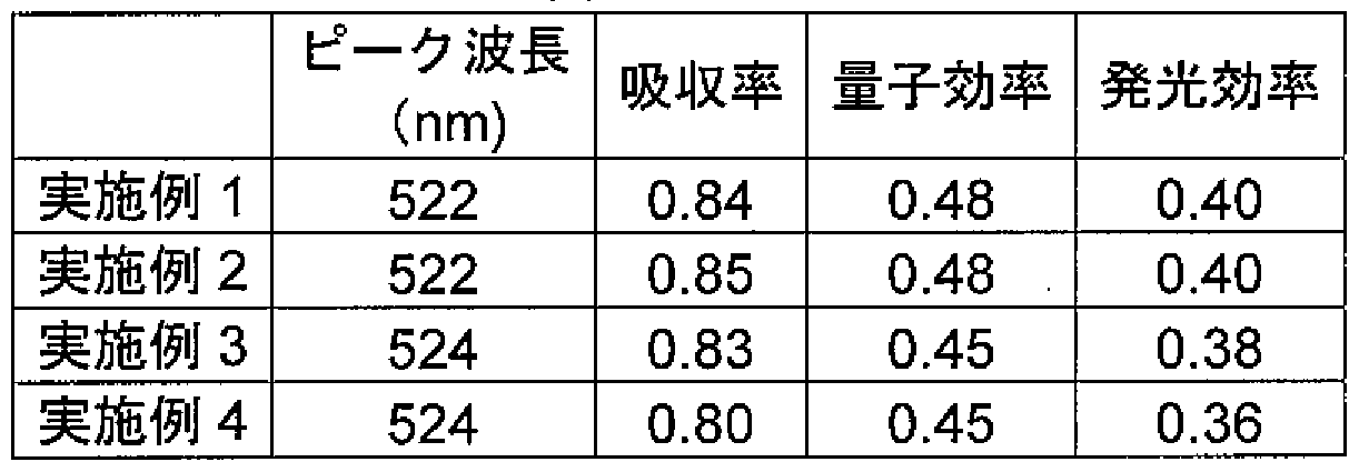
[0130] 上記表 4に示されるように、実施例 1乃至 4の黄緑色粉体は、いずれも波長 250nm 乃至 500nmの光で励起した際、 490nm乃至 580nmの間に発光波長を有する蛍光 体である。これらの蛍光体の吸収率、量子効率、および発光効率は、例えば (Ba, Sr ) SiO : Eu等の従来の黄緑色蛍光体と比較して、何等遜色ないものである。
2 4
[0131] また、実施例 2の蛍光体を 450nmで励起した際の発光特性は、吸収率 87%、内部 量子効率 48%、発光効率 42%とさらに高い効率が得られた。この結果は、本実施形 態の黄緑色蛍光体にお!、ては、 460nm励起より 450nm励起の方が高 、発光効率 を示す特性を有することを示唆する。
[0132] なお、 N. Hirosaki et.al.; Extended Abstracts (The 53th Spring Meeting); The Japa n Society of Applied Physics and Related Societies, 25p— ZR— 11(2006)には、 Eu付活 サイアロンの発光効率は、 450nm励起で吸収率 65%、内部量子効率 53%、発光 効率 35%であることが記載されている。特開 2005— 255895号公報は、上記 Eu付 活 サイアロンに係わる特許公報である。こうした従来の蛍光体の発光効率と本実施
形態の蛍光体の発光効率とを同一条件の励起波長で比較すると、本実施形態の黄 緑色蛍光体の方が優れた特性を示すことがわ力る。
[0133] 励起波長を 254nm、 365nm、および 390nm、および 460nmに変更した場合も、 同様の波長範囲にピークを有する発光が確認された。励起波長が短すぎるとストーク スシフトによる損失が大きくなり、励気波長が長過ぎると励起効率が低下することから 、励起波長は、 380nm以上 460nm以下であること力 S好ましい。また、発光のピーク 波長は 560nm以下であることが望まれる。さらに、発光のピーク波長は 500nm以上 であることが望まれる。
[0134] (実施例 5)
出発原料として SrCO , A1N, Si Nおよび Eu Oを準備した。これらを各々 16. 0
3 3 4 2 3
27g、 4. 837g、 27. 594gおよび 1. 661g秤量し、脱水イソプロノ V—ル(IPA)中で 2hボールミル混合した。マントルヒーターで乾燥を行なうことにより、 IPAを揮発'除去 させた。その後、目開き 300 mの篩を通して、原料粉を作製した。得られた原料粉 を、目開き 500〜: L000 mの篩より自然落下させて、窒化ホウ素るつぼに充填した 。るつぼに充填された原料粉は、 7気圧の N雰囲気中、 1800°Cで 12時間焼成して
2
本実施例の蛍光体を合成した。
[0135] 焼成後の蛍光体は、体色の異なる 2種類の焼結粉体の混合物であり、白色の焼結 粉体と黄緑色の焼結粉体とが確認された。ブラックライトで励起した結果、白色粉体 からは青色発光が観察され、黄緑色粉体からは黄緑色発光が観察された。
[0136] (実施例 6)
SrCO , A1N, Si Nおよび Eu Oの配合量を 16. 298g, 4. 919g, 25. 256gお
3 3 4 2 3
よび 1. 689gに変更した以外は、実施例 5と同様の手法により、原料粉を作製した。 得られた原料粉を 1850°Cで 6時間焼成して、本実施例の蛍光体を合成した。
[0137] 焼成後の蛍光体は、体色の異なる 3種類の焼結粉体の混合物であり、白色の焼結 粉体、赤色の焼結粉体、および黄緑色の焼結粉体が観察された。ブラックライトで励 起した結果、白色粉体、赤色粉体、および黄緑色粉体からは、それぞれ青色発光、 赤色発光、および黄緑色発光が観察された。
[0138] (実施例 7)
Si Nの配合量を 26. 659gに変更した以外は、実施例 6と同様の手法により本実
3 4
施例の蛍光体を合成した。
[0139] 焼成後の蛍光体は、体色の異なる 3種類の焼結粉体の混合物であり、白色の焼結 粉体、赤色の焼結粉体、および黄緑色の焼結粉体が観察された。ブラックライトで励 起した結果、白色粉体、赤色粉体、および黄緑色粉体からは、それぞれ青色発光、 赤色発光、および黄緑色発光が観察された。
[0140] (実施例 8)
焼成条件を 1800°C16時間に変更した以外は実施例 7と同様の手法により、本実 施例の蛍光体を合成した。
[0141] 焼成後の蛍光体は、体色の異なる 3種類の焼結粉体の混合物であり、白色の焼結 粉体、赤色の焼結粉体、および黄緑色の焼結粉体が確認された。ブラックライトで励 起した結果、白色粉体、赤色粉体、および黄緑色粉体からは、それぞれ青色発光、 赤色発光、および黄緑色発光が観察された。
[0142] (実施例 9)
焼成時間を 16時間に変更した以外は実施例 5と同様の手法により、本実施例の蛍 光体を合成した。
[0143] 焼成後の蛍光体は、体色の異なる 3種類の焼結粉体の混合物であり、白色の焼結 粉体、赤色の焼結粉体、および黄緑色の焼結粉体が確認された。ブラックライトで励 起した結果、白色粉体、赤色粉体、および黄緑色粉体からは、それぞれ青色発光、 赤色発光、および黄緑色発光が観察された。
[0144] (実施例 10)
Si Nの配合量を 29. 465gに変更した以外は実施例 9と同様の手法により、本実
3 4
施例の蛍光体を合成した。
[0145] 焼成後の蛍光体は、体色の異なる 2種類の焼結粉体の混合物であり、白色の焼結 粉体と黄緑色の焼結粉体とが確認された。ブラックライトで励起した結果、白色粉体 からは青色発光が観察され、黄緑色粉体からは黄緑色発光が観察された。
[0146] この黄緑色粉体について、 CuK o;特性 X線 (波長 1. 54056A)による X線回折を 行なった。その結果、 11. 870° 、 15. 39° 、 20. 47° および 23. 79° の回折角
度(2 θ )に同時に回折ピークを示した。
[0147] (実施例 11)
Si Nの配合量を 30. 868gに変更した以外は実施例 9と同様の手法により、本実
3 4
施例の蛍光体を合成した。
[0148] 焼成後の蛍光体は、体色の異なる 2種類の焼結粉体の混合物であり、白色の焼結 粉体と黄緑色の焼結粉体とが確認された。ブラックライトで励起した結果、白色粉体 からは青色発光が観察され、黄緑色粉体からは黄緑色発光が観察された。
[0149] (実施例 12)
Si Nの配合量を 29. 465gに変更し、焼成時間を 10時間に変更した以外は実施
3 4
例 6と同様の手法により、本実施例の蛍光体を合成した。焼成後の蛍光体は、体色 が黄緑色の焼結粉体であり、ブラックライトでの励起によって黄緑色発光が観察され た。
[0150] (実施例 13)
SrCOの配合量を 16. 550gに変更し、 Eu Oの配合量を 1. 038gに変更した以
3 2 3
外は実施例 5と同様の手法により、本実施例の蛍光体を合成した。焼成後の蛍光体 は体色が黄緑色の焼結粉体であり、ブラックライトでの励起によって黄緑色発光が観 察された。
[0151] (実施例 14)
実施例 12と同様の手法により、本実施例の蛍光体を合成した。焼成後の蛍光体は 体色が黄緑色の焼結粉体であり、ブラックライトでの励起によって黄緑色発光が観察 された。
[0152] この黄緑色粉体について、 CuK o;特性 X線 (波長 1. 54056A)による X線回折を 行なった。その結果、 11. 87° 、 15. 39° 、 20. 47° および 23. 85° の回折角度 (2 Θ )に同時に回折ピークを示した。
[0153] 実施例 5の黄緑色粉体を、 461nmのピーク波長を有する発光ダイオードにより励 起した。得られた発光スペクトルを、図 14に示す。図 14において、 461nmにピーク を示すバンドは、励起光の反射によるものである。 514〜518nmにピーク波長を有 する単一バンドの発光が得られた。
[0154] 実施例 6, 7の黄緑色粉体を、 46 lnmのピーク波長を有する発光ダイオードにより それぞれ励起した。得られた発光スペクトルを図 15に示す。図 15において、各々 46 lnmにピークを示すバンドは、励起光の反射によるものである。 517nmにピーク波 長を有する単一バンドの発光が得られた。
[0155] 実施例 8〜: L 1の黄緑色粉体を、 46 lnmのピーク波長を有する発光ダイオードによ りそれぞれ励起した。得られた発光スペクトルを図 16に示す。図 16において、各々 4 61nmにピークを示すバンドは、励起光の反射によるものである。 517〜520nmにピ ーク波長を有する単一バンドの発光が得られた。
[0156] 実施例 12〜 14の黄緑色粉体を、 46 lnmのピーク波長を有する発光ダイオードに よりそれぞれ励起した。得られた発光スペクトルを図 17に示す。図 17において、各々 46 lnmにピークを示すバンドは、励起光の反射によるものである。 517〜520nmに ピーク波長を有する単一バンドの発光が得られた。
[0157] 実施例 5、 7、 10〜14の黄緑色蛍光体を坩堝より選り分け、化学分析を行なった。
その結果を表 5にまとめて示す。下記表 5には、前記一般式 (B)における a, b, c,お よび dの値を示した。
[表 5] 表 5

[0158] 実施例 5乃至 14の黄緑色粉体の吸収率、量子効率、および発光効率の値を表 6に まとめて示す。
[表 6]
表 6

[0159] 上記表 6に示されるように、実施例 5乃至 14の黄緑色粉体は、いずれも波長 250η m乃至 500nmの光で励起した際、 490nm乃至 580nmの間に発光波長を有する蛍 光体である。これらの蛍光体の吸収率、量子効率、および発光効率は、例えば (Ba, Sr) SiO : Eu等の従来の黄緑色蛍光体と比較して、何等遜色ないものである。
2 4
[0160] 実施例 3, 5, 7, 10〜 14の黄緑色粉体の組成は、すでに示したとおりである。残り の実施例における黄緑色粉体についても化学分析を行なって、組成式 (B)における a, b, cおよび dの値を調べた。その結果、実施例 1乃至 14の黄緑色粉体においては 、 aの値の上限は 1. 30であり、下限は 0. 940であった。 bの値の上限および下限は 、それぞれ 5. 73および 4. 12であり、 cの値の上限および下限は、それぞれ 0. 85お よび 0. 63であった。また、 dの値の上限および下限は、それぞれ 11および 6. 3であ つた o
[0161] こうした結果に基づいて、実施例 1乃至 14の黄緑色粉体の組成を、下記一般式(2 )で規定した。
[0162] (M R ) AlSi O N (2)
1 a2 b2 c2 d2
(上記一般式(2)中、 Mは Siおよび A1を除く少なくとも一種の金属元素であり、 Rは発 光中心元素である。 x、 a2、 b2、 c2、 d2は、次の関係を満たす数値である。
[0163] 0< χ≤1, 0. 93< a2< l. 3, 4. 0<b2< 5. 8
0. 6< c2< l, 6< d2< l l)
実施例は 5〜8、 14の黄緑色蛍光体は、発光効率が 45%以上であり、発光効率に
特に優れる。実施例 1乃至 14の黄緑色粉体の組成を一般式(2)で規定すると、 a2、 b2、 c2、 d2は、次の関係を満たす数値となる。
[0164] 0. 94< a2 < l . 1 , 4. K b2 < 4. 7
0. 7< c2 < 0. 85, 7< d2 < 9
また、実施例 1乃至 14の全ての黄緑色粉体は、 CuK o;特性 X線 (波長 1. 54056
A)による X線回折柳』定の結果、少なくとも 11. 81- 11. 85° 、 15. 34- 15. 38°
、 20. 40〜20. 47。 、 23. 74〜23. 86° の回折角度(2 0 )【こ同時【こ回折ピークを 示した。
[0165] (参考例 31)
出発原料として SrCO , A1N, Si Nおよび Eu Oを準備した。これらを各々 29. 3
3 3 4 2 3
78g、 16. 395g、 28. 062gおよび 0. 176g秤量し、脱水イソプロノ V—ル(IPA)中 で 24hボールミル混合した。室温乾燥により IPAを揮発'除去させた後、大気中 120 °Cで一晩乾燥させた。これを乳鉢で解砕した後、うち 15gをカーボンるつぼに充填し た。最後に、 7. 5気圧の N雰囲気中、 1800°Cで 60時間焼成を 2回行なって蛍光体
2
を合成した。
[0166] 焼成後の蛍光体は、体色が白色の焼結粉体、微量の橙色の焼結粉体および赤色 の焼結粉体の混合物であった。ブラックライトで励起した結果、白色粉体からは青色 発光が観察され、微量の橙色粉体および微量の赤色粉体からは、それぞれ橙色発 光および赤色発光が観察された。
[0167] 赤色粉体を分取して、 CuK a特性 X線 (波長 1. 54056 A)による X線回折を行な つた。その結果、 13. 10° 、 18. 62° 、 20. 22° 、 26. 40° 、および 28. 04° の 回折角度(2 Θ )に同時に回折ピークを示した。
[0168] この赤色粉体をィ匕学分析に供したところ、 (Sr Eu ) AlSi O N
0. 991 0. 009 2. 23 4. 75 0. 80 7. 88 で表わされる組成を有することが確認された。本参考例の赤色粉体は、前記一般式 (
B)における a, b, c, dの値を用いると、(l+b)Zaの値が 2. 58となり、(c + d)Zaの 値力 S3. 93となる。
[0169] (参考例 32)
SrCOの配合量を 29. 231gに変更し、 Eu Oの配合量を 0. 352gに変更した以
外は参考例 31と同様の条件で、本参考例の蛍光体を合成した。
[0170] 焼成後の蛍光体は、体色が白色の焼結粉体、微量の橙色の焼結粉体および赤色 の焼結粉体の混合物であった、ブラックライトで励起した結果、白色粉体からは青色 発光が観察され、微量の橙色粉体および微量の赤色粉体からは、それぞれ橙色発 光および赤色発光が観察された。
[0171] (参考例 33)
SrCOの配合量を 28. 935gに変更し、 Eu Oの配合量を 0. 704gに変更した以
3 2 3
外は参考例 31と同様の条件で、本参考例の蛍光体を合成した。
[0172] 焼成後の蛍光体は、体色が白色の焼結粉体、微量の橙色の焼結粉体および赤色 の焼結粉体の混合物であった、ブラックライトで励起した結果、白色粉体からは青色 発光が観察され、微量の橙色粉体および微量の赤色粉体からは、それぞれ橙色発 光および赤色発光が観察された。
[0173] 赤色粉体を分取して、 CuK a特性 X線 (波長 1. 54056 A)による X線回折を行な つた。その結果、 13. 08° 、 18. 62° 、 20. 18° 、 26. 38° 、および 28. 02° の 回折角度(2 Θ )に同時に回折ピークを示した。
[0174] (参考例 34)
SrCOの配合量を 28. 640gに変更し、 Eu Oの配合量を 1. 056gに変更した以
3 2 3
外は参考例 31と同様の条件で、本参考例の蛍光体を合成した。
[0175] 焼成後の蛍光体は、体色が白色の焼結粉体、微量の橙色の焼結粉体および赤色 の焼結粉体の混合物であった、ブラックライトで励起した結果、白色粉体からは青色 発光が観察され、微量の橙色粉体および微量の赤色粉体からは、それぞれ橙色発 光および赤色発光が観察された。
[0176] 赤色粉体を分取して、 CuK a特性 X線 (波長 1. 54056 A)による X線回折を行な つた。その結果、 13. 10° 、 18. 60° 、 20. 20° 、 26. 38° および 28. 03° の回 折角度(2 Θ )に同時に回折ピークを示した。
[0177] 参考例 31乃至 34の赤色粉体について、前述と同様の手法により分取して解砕した 後、 457nmのピーク波長を有する発光ダイオードにより励起した。得られた発光スぺ タトルを、図 18に示す。図 18において、 457nmにピークを示すバンドは、励起光の
反射によるものである。いずれの赤色粉体からも、 620〜640nmにピーク波長を有 する単一バンドの発光が得られた。
[0178] (参考例 35)
参考例 31と同様の出発原料をカーボンるつぼに充填し、 7. 5気圧の N雰囲気中、
2
1800°Cで 60時間焼成して本参考例の蛍光体を合成した。
[0179] 焼成後の蛍光体は、体色の異なる 2種類の焼結粉体の混合物であり、白色の焼結 粉体と赤色の焼結粉体とが確認された。ブラックライトで励起した結果、白色粉体から は青色発光が観察され、赤色粉体からは赤色発光が観察された。
[0180] この赤色粉体について、 CuK o;特性 X線 (波長 1. 54056A)により X線回折を行 なった。その結果、 13. 12° 、 18. 64° 、 20. 22° 、 26. 40° 、および 28. 04° の回折角度(2 Θ )に同時に回折ピークを示した。
[0181] (参考例 36)
参考例 32と同様の出発原料をカーボンるつぼに充填し、 7. 5気圧の N雰囲気中、
2
1800°Cで 60時間焼成して本参考例の蛍光体を合成した。
[0182] 焼成後の蛍光体は、体色の異なる 2種類の焼結粉体の混合物であり、白色の焼結 粉体と赤色の焼結粉体とが確認された。ブラックライトで励起した結果、白色粉体から は青色発光が観察され、赤色粉体からは赤色発光が観察された。
[0183] (参考例 37)
参考例 33と同様の出発原料をカーボンるつぼに充填し、 7. 5気圧の N雰囲気中、
2
1800°Cで 60時間焼成して本参考例の蛍光体を合成した。
[0184] 焼成後の蛍光体は、体色の異なる 2種類の焼結粉体の混合物であり、白色の焼結 粉体と赤色の焼結粉体とが確認された。ブラックライトで励起した結果、白色粉体から は青色発光が観察され、赤色粉体からは赤色発光が観察された。
[0185] (参考例 38)
参考例 34と同様の出発原料をカーボンるつぼに充填し、 7. 5気圧の N雰囲気中、
2
1800°Cで 60時間焼成して本参考例の蛍光体を合成した。
[0186] 焼成後の蛍光体は、体色の異なる 2種類の焼結粉体の混合物であり、白色の焼結 粉体と赤色の焼結粉体とが確認された。ブラックライトで励起した結果、白色粉体から
は青色発光が観察され、赤色粉体からは赤色発光が観察された。
[0187] 参考例 35乃至 38の赤色粉体について、前述と同様の手法により分取して解砕した 後、 457nmのピーク波長を有する発光ダイオードにより励起した。得られた発光スぺ タトルを、図 19に示す。図 19において、 457nmにピークを示すバンドは、励起光の 反射によるものである。いずれの赤色粉体からも、 610〜640nmにピーク波長を有 する単一バンドの発光が得られた。
[0188] (参考例 39)
出発原料として SrCO , A1N, Si Nおよび Eu Oを準備した。これらを各々 2. 92
3 3 4 2 3
3g、 1. 640g、 2. 806gおよび 0. 035g样量し、 20分孚 L鉢混合した後に、カーボンる つぼに充填した。これを 7. 5気圧の N雰囲気中、 1800°Cで 4時間焼成した。さらに
2
、 1800°Cで 20時間焼成して、本参考例の蛍光体を合成した。
[0189] 焼成後の蛍光体は、体色が白色の焼結粉体、微量の橙色の焼結粉体および赤色 の焼結粉体の混合物であった、ブラックライトで励起した結果、白色粉体からは青色 発光が観察され、微量の橙色粉体および微量の赤色粉体からは、それぞれ橙色発 光および赤色発光が観察された。
[0190] 参考例 39の赤色粉体を、前述と同様の手法により分取して解砕した後、 457nmの ピーク波長を有する発光ダイオードにより励起した。得られた発光スペクトルを、図 20 に示す。図 20において、 457nmにピークを示すバンドは、励起光の反射によるもの である。 610〜640nmにピーク波長を有する単一バンドの発光が得られた。
[0191] 参考例 31乃至 39の赤色粉体の吸収率、量子効率、および発光効率の値を、下記 表 7にまとめて示す。
[表 7]
表

[0192] 上記表 7に示されるように、参考例 31乃至 39の赤色粉体は、いずれも波長 250nm 乃至 500nmの光で励起した際、 580nm乃至 700nmの間に発光波長を有する蛍光 体である。これらの蛍光体の吸収率、量子効率、および発光効率は、例えば Sr Si
2 5
N : Eu等の従来の赤色蛍光体と比較して、何等遜色ないものである。
8
[0193] なお、励起波長を 254nm、 365nm、 390nm、および 460nmに変更した場合も、 同様の波長範囲にピークを有する発光が確認された。励起波長が短すぎるとストーク スシフトによる損失が大きくなり、励気波長が長過ぎると励起効率が低下することから 、励起波長は、 380nm以上 460nm以下であること力 S好ましい。また、発光のピーク 波長は 670nm以下であることが望まれる。
[0194] 参考例 31の赤色粉体の組成はすでに説明したとおりである。残りの参考例の赤色 粉体についても、化学分析を行なって組成式 (B)における a, b, cおよび dの値を調 ベた。その結果、参考例 31乃至 39の赤色粉体においては、(l +b) Zaの値の下限 および上限は、それぞれ 2. 41および 2. 58であった。また、(c + d) /aの値の下限 および上限は、それぞれ 3. 48および 4. 17であった。
[0195] こうした結果に基づいて、参考例 31乃至 39の黄緑色粉体の組成を、下記一般式( 3)で規定した。
[0196] (M R ) AlSi O N (3)
1 a3 b3 c3 d3
(上記一般式(3)中、 Mは A1および Siを除く少なくとも一種の金属元素であり、 Rは発 光中心元素である。 x、 a3、 b3、 c3、 d3は、次の関係を満たす数値である。
[0197] 0<χ≤1, 2. 4< (l +b3) /a3< 2. 6
3. 4く (c3 + d3) /a3<4. 2)
また、参考例 31乃至 39の全ての赤色粉体は、 CuK o;特性 X線 (波長 1. 54056A )による X線回折 S'J定の結果、少なくとも 13. 06-13. 16° 、 18. 58-18. 68° 、 2 0. 14〜20. 24° 、 26. 32〜26. 46° 、 27. 98〜28. 10° の回折角度(2 0 )に 同時に回折ピークを示した。
[0198] (比較例 1)
出発原料として、 26. 573g( SrCO , 23. 385g( Si N ,および 3. 519gの Eu
3 3 4 2 oを秤量し、ボールミルで混合した。得られた混合粉末をカーボンるつぼに充填し、
3
7気圧の N雰囲気中、 1650°Cで 8時間焼成して本比較例の蛍光体を合成した。
2
[0199] 化学分析の結果、本比較例の蛍光体は、 (Sr Eu ) Si Nで表わされる組成を
0. 9 0. 1 2 5 8
有することが確認された。得られた蛍光体は朱色の焼結体であり、ブラックライトで励 起した結果、赤色発光が観察された。
[0200] (比較例 2)
出発原料として、 148gの SrCO ,および 0. 176gの Eu Oを秤量し、乳鉢中で混
3 2 3
合した。得られた混合粉末を石英るつぼ中に充填し、 1気圧の H S雰囲気中 1100
2
°Cで 1時間焼成した。さらに粉砕して、 2gの NH C1をカ卩えて乳鉢混合した。これを、
4
石英管中に封じ 1気圧の N雰囲気中 1100°Cで 1時間焼成して、本比較例の蛍光体
2
を合成した。
[0201] 化学分析の結果、本比較例の蛍光体は、 (Sr Eu ) Sで表わされる組成を
0. 999 0. 001 2
有することが確認された。得られた蛍光体は桃色の焼結体であり、ブラックライトで励 起した結果、 620nmピークの赤色発光が観察された。
[0202] (比較例 3)
出発原料として、 17. 066gSrCO , 8. 198gの A1N, 23. 759gSi Nおよび 3. 5
3 3 4
90gの Eu Oを用意した。これを、実施例 1と同様に混合、乾燥および解砕を行なつ
2 3
てカーボンるつぼに充填した後、 3. 5気圧の N雰囲気中、プレス圧 350MPaで 180
2
0°C2時間のホットプレス焼成を行なった。焼成後の試料は体色が灰黄緑色の焼結 体であり、ブラックライトで励起した結果、微弱な黄緑色発光が観察された。
[0203] (比較例 4)
出発原料として、 17. 693g( SrCO , 6. 148gの A1N, 29. 114gの Si Nおよび
3 3 4
3. 722gEu Oを用いた以外は比較例 3と同様にして、本比較例の蛍光体を合成し
2 3
た。焼成後の試料は体色が灰黄緑色の焼結体であり、ブラックライトで励起した結果
、微弱な黄緑色発光が観察された。
[0204] (比較例 5)
参考例 1と同様に秤量 ·混合を行なった原料をカーボンるつぼに充填し、比較例 3と 同様に焼成して本比較例の蛍光体を合成した。焼成後の試料は体色が灰黄緑色の 焼結体であり、ブラックライト励起で微弱な黄緑色発光が観察された。
[0205] (比較例 6)
(SrCO )粉末 94. 27g、 (BaCO )粉末 7. 12g、 (SiO )粉末 22. 835g、および(
3 3 2
Eu O )粉末 4. 460gを用意した。さらに、結晶成長剤として、 1. 8gの NH C1を添加
2 3 4 して、ボールミルで均一に混合した。
[0206] 得られた混合原料を焼成容器に仕込み、以下の焼成条件で焼成した。まず、 N /
2
Hの還元性雰囲気において、 1000〜1600°Cの温度で 3〜7時間焼成して、本比
2
較例の蛍光体 Sr Ba SiO :Eu蛍光体を調製した。得られた蛍光体は黄色の焼
1. 9 0. 1 4
結体であり、ブラックライトで励起した結果、黄色発光が観察された。
[0207] 比較例 3乃至 5の蛍光体に関し、化学分析を行なった結果を、下記表 8にまとめて 示す。下記表 6には、前記一般式 (B)における a, b, cおよび dの値を示した。
[表 8] 表 8

比較例 3乃至 5の蛍光体は、サイアロン系化合物を母体とするものであるものの、一 般式(1)、 (2)、および(3)のいずれの条件も満たさない。したがって、実施形態にか 力る蛍光体の組成の範囲外であることがわかる。なお、比較例 1、 2および 6の蛍光体 は、 、ずれもサイアロン系化合物を母体とするものではな 、。
[0209] 比較例 3乃至 5の蛍光体について、 CuK a特性 X線(波長 1. 54056A)を用いて X線回折を行ない、その結果を図 21に示す。図 21には、参考例 20および実施例 2 の蛍光体についての X線回折の結果も併せて示した。図 21に示されるように、組成 が所定の範囲から外れているので、比較例 3乃至 5の蛍光体は、参考例 20もしくは 実施例 2とは異なる XRDプロファイルを示す。このことから、比較例の蛍光体におい ては、実施例の蛍光体とは異なる構造が生成していることが推測される。比較例 3乃 至 5の蛍光体の構造は、図 21中に示す S 11&56 (1じ?03カード# 53— 0636)のパ ターンと概ね一致した。
[0210] 比較例 3乃至 5の蛍光体を、 390nmのピーク波長を有する発光ダイオードにより励 起した。得られた発光スペクトルを図 22に示す。図 22には、参考例 20の赤色粉体お よび実施例 2の黄緑色粉体についての結果も併せて示した。図 22において、各々 3 90nmにピークを示すバンドは、励起光の反射によるものである。比較例の蛍光体は 、いずれも発光強度が著しく低力つた。
[0211] 以上の結果に示されるように、実施形態に力かる蛍光体組成範囲外の組成におい ては、実施形態にかかる蛍光体と構造が異なって、所望の発光特性が得られないこ とがわかる。
[0212] 参考例 20および参考例 39の赤色粉体を、室温から 200°Cまでヒーターにより試料 温度を上昇させながら励起して、発光スペクトル変化を測定した。励起には、 458nm のピーク波長を有する発光ダイオードを用いた。各温度における発光スペクトルのピ ーク強度の温度依存性を図 23に示す。
[0213] 比較のため、比較例 1に力力る Sr Si N: Euおよび比較例 2に力かる CaS :Euのピ
2 5 8
ーク発光強度の温度依存性も、図 23に併せて示した。図 23の y軸は、各蛍光体の室 温における発光強度を 1として規格ィ匕した値である。
[0214] 参考例 20および参考例 39の蛍光体は、 200°Cの高温条件下でも、発光強度の低 下が小さいことが図 23のグラフに示されている。この結果から、実施形態にかかる蛍 光体は、 CaS :Euおよび同じ窒化物母体である Sr Si N: Euに比べて、温度特性が
2 5 8
良好なことがわかる。図 23のグラフには、参考例 20および参考例 39の蛍光体につ いての結果を示した力 他の実施例に力かる蛍光体においても、同様に比較例を上
回る良好な温度特性が得られた。
[0215] 比較例 3乃至 5の蛍光体も、前述と同様に試料温度を上昇させながら励起して、発 光スペクトル変化を測定した。その結果、 200°Cの高温条件下では、いずれの蛍光 体も発光強度が低下し、比較例 1もしくは 2と同様の傾向がみられた。
[0216] また、実施例 1の黄緑色粉体を、室温から 200°Cまでヒーターにより試料温度を上 昇させながら励起して、発光スペクトル変化を測定した。励起には、 458nmのピーク 波長を有する発光ダイオードを用いた。各温度における発光スペクトルのピーク強度 の温度依存性を図 24に示す。
[0217] 比較のため、比較例 6にかかる Sr Ba SiO :Euのピーク発光強度の温度依存性
1.9 0.1 4
も、図 24に併せて示した。図 24の y軸は、各蛍光体の室温における発光強度を 1とし て規格ィ匕した値である。
[0218] 実施例 1の蛍光体は、 200°Cの高温条件下でも、発光強度の低下が小さいことが 図 24のグラフに示されている。この結果から、実施形態にかかる蛍光体は、 Sr Ba
1. 9 0
SiO: Euに比べて、温度特性が良好なことがわかる。
. 1 4
[0219] また、実施例 1の蛍光体を用いて、図 2に示した発光装置を製造した。得られた発 光装置を、室温から 150°Cの温度範囲で動作させ、効率の温度変化を測定したとこ ろ、この温度範囲で効率の低下が殆ど起こらな力つた。このこと力 、実施形態にか かる発光装置は、良好な温度特性を有することが確認された。
[0220] 比較例 3の蛍光体を用いて同様の発光装置を製造し、同様に試験したところ、この 温度範囲で顕著な効率低下が見られた。比較例 4, 5の蛍光体を用いた場合も同様 の結果であった。発光中心元素を含有するサイアロン系化合物であっても、所定の 組成範囲でなければ、良好な温度特性が得られな ヽことが確認された。
[0221] 本発明によれば、温度特性の良好な蛍光体、および力かる蛍光体を用いた発光装 置が提供される。
Claims
[1] 波長 250nm乃至 500nmの光で励起した際に波長 490nm乃至 580nmの間に発 光ピークを示し、下記一般式(2)で表わされる組成を有することを特徴とする蛍光体
(M R ) AlSi O N (2)
1-x X a2 b2 c2 d2
(上記一般式(2)中、 Mは Siおよび A1を除く少なくとも一種の金属元素であり、 Rは発 光中心元素である。 x、 a2、 b2、 c2、 d2は、次の関係を満たす。
0<χ≤1, 0. 93く a2く 1. 3, 4.0<b2<5.8
0.6<c2<l, 6<d2<ll)
[2] 波長 250nm乃至 500nmの光で励起した際に波長 490nm乃至 580nmの間に発 光ピークを示し、下記一般式(2)で表わされる組成を有することを特徴とする蛍光体
(M R ) AlSi O N (2)
1-x x a2 b2 c2 d2
(上記一般式(2)中、 Mは Siおよび A1を除く少なくとも一種の金属元素であり、 Rは発 光中心元素である。 x、 a2、 b2、 c2、 d2は、次の関係を満たす。
0<χ≤1, 0. 94<a2<l. 1, 4. Kb2<4. 7
0. 7<c2<0.85, 7<d2<9)
[3] 前記一般式(2)における Mはアルカリ土類金属元素であり、 CuKa特性 X線 (波長 1. 54056 A)による X線回折柳』定にお!/、て、少なくとも 11.81〜: L1.85° 、 15. 34 〜15. 38° 、 20.40〜20.47。 、 23. 74〜23.86° の回折角度(20 )【こ同時【こ 回折ピークを示す一成分を含有することを特徴とする請求項 1に記載の蛍光体。
[4] 前記一般式(2)における Mは、 Mg, Ca, Sr, Ba, Y, Gd, La, Lu, Sc, Li, Na, K, B, Ga, In,および Geからなる群力も選択される少なくとも 1種であることを特徴と する請求項 1に記載の蛍光体。
[5] 前記一般式(2)における Rは、 Eu, Ce, Mn, Tb, Yb, Dy, Sm, Tm, Pr, Nd, P m, Ho, Er, Gd, Cr, Sn, Cu, Zn, Ga, Ge, As, Ag, Cd, In, Sb, Au, Hg, Tl, Pb, Bi,および Feからなる群力 選択される少なくとも 1種であることを特徴とする請 求項 1に記載の蛍光体。
[6] 前記一般式(2)における xは 0. 001以上であることを特徴とする請求項 1に記載の 蛍光体。
[7] 前記一般式(2)における Xは 0. 5以下であることを特徴とする請求項 1に記載の蛍 光体。
[8] 250nm乃至 500nmの波長の光を発光する発光素子と、
前記発光素子上に配置された蛍光体層とを具備し、
前記蛍光体層は、請求項 1に記載の蛍光体を含むことを特徴とする発光装置。
Priority Applications (6)
| Application Number | Priority Date | Filing Date | Title |
|---|---|---|---|
| EP07738161A EP2003183B1 (en) | 2006-03-10 | 2007-03-09 | Phosphor and light-emitting device |
| JP2007541548A JP4762248B2 (ja) | 2006-03-10 | 2007-03-09 | 蛍光体 |
| US12/207,771 US8475680B2 (en) | 2006-03-10 | 2008-09-10 | Luminescent material and light-emitting device |
| US12/944,938 US8450923B2 (en) | 2006-03-10 | 2010-11-12 | Luminescent material and light-emitting device |
| US12/944,926 US8491817B2 (en) | 2006-03-10 | 2010-11-12 | Luminescent material and light-emitting device |
| US12/944,947 US8482192B2 (en) | 2006-03-10 | 2010-11-12 | Luminescent material and light-emitting device |
Applications Claiming Priority (2)
| Application Number | Priority Date | Filing Date | Title |
|---|---|---|---|
| JP2006065603 | 2006-03-10 | ||
| JP2006-065603 | 2006-03-10 |
Related Child Applications (1)
| Application Number | Title | Priority Date | Filing Date |
|---|---|---|---|
| US12/207,771 Continuation US8475680B2 (en) | 2006-03-10 | 2008-09-10 | Luminescent material and light-emitting device |
Publications (1)
| Publication Number | Publication Date |
|---|---|
| WO2007105631A1 true WO2007105631A1 (ja) | 2007-09-20 |
Family
ID=38509454
Family Applications (1)
| Application Number | Title | Priority Date | Filing Date |
|---|---|---|---|
| PCT/JP2007/054676 WO2007105631A1 (ja) | 2006-03-10 | 2007-03-09 | 蛍光体および発光装置 |
Country Status (4)
| Country | Link |
|---|---|
| US (4) | US8475680B2 (ja) |
| EP (3) | EP2308946B1 (ja) |
| JP (9) | JP4762248B2 (ja) |
| WO (1) | WO2007105631A1 (ja) |
Cited By (37)
| Publication number | Priority date | Publication date | Assignee | Title |
|---|---|---|---|---|
| JP2008050462A (ja) * | 2006-08-24 | 2008-03-06 | Stanley Electric Co Ltd | 蛍光体、その製造方法およびそれを用いた発光装置 |
| JP2008189811A (ja) * | 2007-02-05 | 2008-08-21 | Osaka Univ | 窒化物又は酸窒化物を母体とする蛍光体、及びその製造方法、並びにそれを使用した蛍光体含有組成物、発光装置、照明装置、及び画像表示装置 |
| JP2009073870A (ja) * | 2007-09-18 | 2009-04-09 | Toshiba Corp | 蛍光体および発光装置 |
| JP2010538102A (ja) * | 2007-09-04 | 2010-12-09 | コーニンクレッカ フィリップス エレクトロニクス エヌ ヴィ | 複合材料SiAlONをベースにしたセラミック材料を有する発光装置 |
| JP2011500880A (ja) * | 2007-10-15 | 2011-01-06 | コーニンクレッカ フィリップス エレクトロニクス エヌ ヴィ | 多相SiAlONに基づくセラミック材料を有する発光装置 |
| JP2011505451A (ja) * | 2007-12-03 | 2011-02-24 | コーニンクレッカ フィリップス エレクトロニクス エヌ ヴィ | 緑色光放出SiAlONをベースにする材料を含有する光放出デバイス |
| WO2011024882A1 (ja) | 2009-08-31 | 2011-03-03 | シャープ株式会社 | 液晶表示装置 |
| WO2011024818A1 (ja) | 2009-08-26 | 2011-03-03 | 三菱化学株式会社 | 白色半導体発光装置 |
| JP2011054659A (ja) * | 2009-08-31 | 2011-03-17 | Sharp Corp | 発光装置及びそれを用いた液晶表示装置 |
| WO2011105571A1 (ja) | 2010-02-26 | 2011-09-01 | 三菱化学株式会社 | ハロリン酸塩蛍光体、及び白色発光装置 |
| JP2011184577A (ja) * | 2010-03-09 | 2011-09-22 | Toshiba Corp | 蛍光体、蛍光体の製造方法、発光装置及び発光モジュール |
| JP2011195688A (ja) * | 2010-03-18 | 2011-10-06 | Toshiba Corp | 赤色蛍光体およびその製造方法、ならびに発光装置 |
| WO2011122655A1 (ja) | 2010-03-30 | 2011-10-06 | 三菱化学株式会社 | 発光装置 |
| WO2011122576A1 (ja) | 2010-03-30 | 2011-10-06 | 三菱化学株式会社 | 発光装置 |
| JP2011199193A (ja) * | 2010-03-23 | 2011-10-06 | Toshiba Corp | 発光装置及びその製造方法 |
| JP2011256340A (ja) * | 2010-06-11 | 2011-12-22 | Tohoku Univ | 蛍光体と、この蛍光体を用いた蛍光体含有組成物及び発光装置、並びに画像表示装置及び照明装置 |
| JP2012003073A (ja) * | 2010-06-17 | 2012-01-05 | Sharp Corp | 液晶表示装置 |
| EP2423293A2 (en) | 2010-08-31 | 2012-02-29 | Kabushiki Kaisha Toshiba | Process for production of SiAlON oxynitride phosphors |
| WO2012036016A1 (ja) * | 2010-09-17 | 2012-03-22 | 株式会社東芝 | 蛍光体および発光装置 |
| WO2012105688A1 (ja) | 2011-02-06 | 2012-08-09 | 独立行政法人物質・材料研究機構 | 蛍光体、その製造方法及び発光装置 |
| WO2012105689A1 (ja) | 2011-02-06 | 2012-08-09 | 独立行政法人物質・材料研究機構 | 蛍光体、その製造方法及び発光装置 |
| WO2012105687A1 (ja) | 2011-02-06 | 2012-08-09 | 独立行政法人物質・材料研究機構 | 蛍光体、その製造方法及び発光装置 |
| WO2012114640A1 (ja) | 2011-02-25 | 2012-08-30 | 三菱化学株式会社 | ハロリン酸塩蛍光体、及び白色発光装置 |
| US8414795B2 (en) | 2010-09-09 | 2013-04-09 | Kabushiki Kaisha Toshiba | Red light-emitting fluorescent substance and light-emitting device employing the same |
| WO2013069696A1 (ja) * | 2011-11-07 | 2013-05-16 | 独立行政法人物質・材料研究機構 | 蛍光体および製造方法、蛍光体を用いる発光装置および画像表示装置 |
| JP2013127055A (ja) * | 2011-11-15 | 2013-06-27 | National Institute For Materials Science | 蛍光体、その製造方法、発光装置および画像表示装置 |
| US8475682B2 (en) | 2005-09-27 | 2013-07-02 | Mitsubishi Chemical Corporation | Phosphor and manufacturing method therefore, and light emission device using the phosphor |
| US8501039B2 (en) | 2010-02-19 | 2013-08-06 | Kabushiki Kaisha Toshiba | Fluorescent material and light-emitting device employing the same |
| WO2013137434A1 (ja) | 2012-03-16 | 2013-09-19 | 株式会社東芝 | 蛍光体、蛍光体の製造方法および発光装置 |
| WO2013137436A1 (ja) | 2012-03-16 | 2013-09-19 | 株式会社東芝 | 蛍光体、蛍光体の製造方法および発光装置 |
| WO2013137435A1 (ja) * | 2012-03-16 | 2013-09-19 | 株式会社東芝 | 蛍光体、蛍光体の製造方法および発光装置 |
| WO2013147195A1 (ja) | 2012-03-30 | 2013-10-03 | 三菱化学株式会社 | 半導体発光装置、及び照明装置 |
| JP2013216909A (ja) * | 2013-06-28 | 2013-10-24 | Toshiba Corp | 蛍光体 |
| US8829780B2 (en) | 2010-06-25 | 2014-09-09 | Mitsubishi Chemical Corporation | White semiconductor light emitting device |
| US9399731B2 (en) | 2012-12-14 | 2016-07-26 | Denka Company Limited | Phosphor, method for producing the same, and luminescent device using the same |
| KR101907617B1 (ko) | 2011-12-13 | 2018-10-15 | 엘지이노텍 주식회사 | 산질화물 형광체 및 그를 포함한 발광소자 패키지 |
| US10214689B2 (en) | 2016-12-15 | 2019-02-26 | National Institute For Materials Science | Fluorescent material and light emitting device |
Families Citing this family (30)
| Publication number | Priority date | Publication date | Assignee | Title |
|---|---|---|---|---|
| EP2308946B1 (en) | 2006-03-10 | 2013-07-24 | Kabushiki Kaisha Toshiba | Luminescent material and light-emitting device |
| JP5592602B2 (ja) | 2008-07-31 | 2014-09-17 | 株式会社東芝 | 蛍光体およびそれを用いた発光装置 |
| JP4869317B2 (ja) * | 2008-10-29 | 2012-02-08 | 株式会社東芝 | 赤色蛍光体およびそれを用いた発光装置 |
| JP5101650B2 (ja) * | 2010-03-25 | 2012-12-19 | 株式会社東芝 | 半導体発光装置及びその製造方法 |
| US20120043569A1 (en) * | 2010-08-23 | 2012-02-23 | Kabushiki Kaisha Toshiba | Light emitting device and manufacturing method thereof |
| JP5076017B2 (ja) | 2010-08-23 | 2012-11-21 | 株式会社東芝 | 発光装置 |
| JP5127965B2 (ja) | 2010-09-02 | 2013-01-23 | 株式会社東芝 | 蛍光体およびそれを用いた発光装置 |
| US20120057338A1 (en) * | 2010-09-06 | 2012-03-08 | Kabushiki Kaisha Toshiba | Light emitting device |
| JP4991958B2 (ja) * | 2010-09-06 | 2012-08-08 | 株式会社東芝 | 発光装置 |
| US8414145B2 (en) | 2010-09-06 | 2013-04-09 | Kabushiki Kaisha Toshiba | Light emitting device |
| JP5127964B2 (ja) | 2010-09-06 | 2013-01-23 | 株式会社東芝 | 発光装置 |
| JP4929413B2 (ja) | 2010-09-07 | 2012-05-09 | 株式会社東芝 | 発光装置 |
| US8436527B2 (en) * | 2010-09-07 | 2013-05-07 | Kabushiki Kaisha Toshiba | Light emitting device |
| JP5319743B2 (ja) | 2010-09-08 | 2013-10-16 | 株式会社東芝 | 発光装置 |
| EP2428543B1 (en) | 2010-09-08 | 2013-05-08 | Kabushiki Kaisha Toshiba | Light emitting device |
| JP5185421B2 (ja) | 2010-09-09 | 2013-04-17 | 株式会社東芝 | 赤色発光蛍光体およびそれを用いた発光装置 |
| TWI447207B (zh) * | 2010-12-08 | 2014-08-01 | Univ Nat Chiao Tung | 螢光材料及使用其之發光裝置 |
| JP5634352B2 (ja) | 2011-08-24 | 2014-12-03 | 株式会社東芝 | 蛍光体、発光装置および蛍光体の製造方法 |
| JP5762929B2 (ja) | 2011-11-16 | 2015-08-12 | 株式会社東芝 | 蛍光体、発光装置、および蛍光体の製造方法 |
| JP5851214B2 (ja) * | 2011-11-16 | 2016-02-03 | 株式会社東芝 | 蛍光体、発光装置、および蛍光体の製造方法 |
| JP5865688B2 (ja) | 2011-12-07 | 2016-02-17 | 株式会社東芝 | 蛍光体およびそれを用いた発光装置 |
| JP5727955B2 (ja) | 2012-03-08 | 2015-06-03 | 株式会社東芝 | 蛍光体およびその製造方法 |
| US8679367B2 (en) * | 2012-08-09 | 2014-03-25 | Intematix Corporation | Green-emitting (oxy)nitride-based phosphors and light-emitting device using the same |
| JP5746672B2 (ja) * | 2012-09-25 | 2015-07-08 | 株式会社東芝 | 蛍光体、発光装置、および蛍光体の製造方法 |
| KR102019501B1 (ko) * | 2012-11-05 | 2019-09-06 | 엘지이노텍 주식회사 | 형광체 및 이를 구비한 발광 소자 |
| JP2014224184A (ja) * | 2013-05-15 | 2014-12-04 | 株式会社東芝 | 蛍光体および発光装置 |
| EP3015530B1 (en) * | 2013-06-24 | 2019-05-08 | General Research Institute For Nonferrous Metals | Fluorescent powder and light emitting apparatus comprising same |
| KR102295679B1 (ko) | 2013-12-26 | 2021-08-30 | 덴카 주식회사 | 형광체 및 발광 장치 |
| KR102331836B1 (ko) | 2014-02-26 | 2021-11-26 | 덴카 주식회사 | 형광체, 발광 소자 및 발광 장치 |
| KR102331842B1 (ko) | 2014-02-26 | 2021-11-26 | 덴카 주식회사 | 형광체, 발광 소자 및 발광 장치 |
Citations (4)
| Publication number | Priority date | Publication date | Assignee | Title |
|---|---|---|---|---|
| JPS60206889A (ja) * | 1984-03-01 | 1985-10-18 | エヌ・ベー・フイリツプス・フルーイランペンフアブリケン | 発光窒化物からなる発光スクリーン |
| JP2004067837A (ja) * | 2002-08-06 | 2004-03-04 | Toyota Central Res & Dev Lab Inc | α−サイアロン蛍光体 |
| JP2005036038A (ja) * | 2003-07-16 | 2005-02-10 | Ube Ind Ltd | サイアロン系蛍光体およびその製造方法 |
| JP2006008721A (ja) * | 2003-11-26 | 2006-01-12 | National Institute For Materials Science | 蛍光体と蛍光体を用いた発光器具 |
Family Cites Families (31)
| Publication number | Priority date | Publication date | Assignee | Title |
|---|---|---|---|---|
| US2006A (en) * | 1841-03-16 | Clamp for crimping leather | ||
| US79058A (en) * | 1868-06-23 | Henry l | ||
| US303409A (en) * | 1884-08-12 | wilson | ||
| US6252254B1 (en) * | 1998-02-06 | 2001-06-26 | General Electric Company | Light emitting device with phosphor composition |
| DE10147040A1 (de) * | 2001-09-25 | 2003-04-24 | Patent Treuhand Ges Fuer Elektrische Gluehlampen Mbh | Beleuchtungseinheit mit mindestens einer LED als Lichtquelle |
| ATE357746T1 (de) * | 2002-12-13 | 2007-04-15 | Koninkl Philips Electronics Nv | Beleuchtungsvorrichtung mit strahlungsquelle und fluoreszenzmaterial |
| US7088038B2 (en) * | 2003-07-02 | 2006-08-08 | Gelcore Llc | Green phosphor for general illumination applications |
| JP2005048105A (ja) | 2003-07-30 | 2005-02-24 | Matsushita Electric Ind Co Ltd | 蛍光体組成物およびそれを用いた発光装置 |
| TWI359187B (en) * | 2003-11-19 | 2012-03-01 | Panasonic Corp | Method for preparing nitridosilicate-based compoun |
| JP3921545B2 (ja) | 2004-03-12 | 2007-05-30 | 独立行政法人物質・材料研究機構 | 蛍光体とその製造方法 |
| US7229573B2 (en) * | 2004-04-20 | 2007-06-12 | Gelcore, Llc | Ce3+ and Eu2+ doped phosphors for light generation |
| JP4565141B2 (ja) * | 2004-06-30 | 2010-10-20 | 独立行政法人物質・材料研究機構 | 蛍光体と発光器具 |
| JP4521227B2 (ja) | 2004-07-14 | 2010-08-11 | 株式会社東芝 | 窒素を含有する蛍光体の製造方法 |
| JP4524470B2 (ja) * | 2004-08-20 | 2010-08-18 | Dowaエレクトロニクス株式会社 | 蛍光体およびその製造方法、並びに当該蛍光体を用いた光源 |
| EP2360225B1 (en) * | 2004-09-22 | 2013-06-26 | National Institute for Materials Science | Phosphor, production method thereof and light emitting instrument |
| JP4674348B2 (ja) * | 2004-09-22 | 2011-04-20 | 独立行政法人物質・材料研究機構 | 蛍光体とその製造方法および発光器具 |
| US7321191B2 (en) * | 2004-11-02 | 2008-01-22 | Lumination Llc | Phosphor blends for green traffic signals |
| WO2006061778A1 (en) * | 2004-12-06 | 2006-06-15 | Philips Intellectual Property & Standards Gmbh | Illumination system comprising a radiation source and a blue-emitting phospor |
| JP2006213910A (ja) * | 2005-01-06 | 2006-08-17 | Matsushita Electric Ind Co Ltd | 酸窒化物蛍光体及び発光装置 |
| WO2006072918A1 (en) * | 2005-01-10 | 2006-07-13 | Philips Intellectual Property & Standards Gmbh | Illumination system comprising ceramic luminescence converter |
| JP4756261B2 (ja) * | 2005-01-27 | 2011-08-24 | 独立行政法人物質・材料研究機構 | 蛍光体とその製造方法および発光器具 |
| CN102827603A (zh) * | 2005-03-04 | 2012-12-19 | 三菱化学株式会社 | 荧光体及其制备方法、和使用该荧光体的发光装置 |
| US7524437B2 (en) * | 2005-03-04 | 2009-04-28 | Dowa Electronics Materials Co., Ltd. | Phosphor and manufacturing method of the same, and light emitting device using the phosphor |
| US7276183B2 (en) * | 2005-03-25 | 2007-10-02 | Sarnoff Corporation | Metal silicate-silica-based polymorphous phosphors and lighting devices |
| US7443094B2 (en) * | 2005-03-31 | 2008-10-28 | Dowa Electronics Materials Co., Ltd. | Phosphor and manufacturing method of the same, and light emitting device using the phosphor |
| JP5066786B2 (ja) * | 2005-04-27 | 2012-11-07 | 日亜化学工業株式会社 | 窒化物蛍光体及びそれを用いた発光装置 |
| JP4975269B2 (ja) * | 2005-04-28 | 2012-07-11 | Dowaホールディングス株式会社 | 蛍光体およびその製造方法、並びに当該蛍光体を用いた発光装置 |
| CN101175835B (zh) * | 2005-05-24 | 2012-10-10 | 三菱化学株式会社 | 荧光体及其应用 |
| JP4836229B2 (ja) | 2005-05-31 | 2011-12-14 | 株式会社東芝 | 蛍光体および発光装置 |
| WO2007004138A2 (en) * | 2005-06-30 | 2007-01-11 | Philips Intellectual Property & Standards Gmbh | Illumination system comprising a yellow green-emitting luminescent material |
| EP2308946B1 (en) * | 2006-03-10 | 2013-07-24 | Kabushiki Kaisha Toshiba | Luminescent material and light-emitting device |
-
2007
- 2007-03-09 EP EP10014287.6A patent/EP2308946B1/en active Active
- 2007-03-09 WO PCT/JP2007/054676 patent/WO2007105631A1/ja active Application Filing
- 2007-03-09 JP JP2007541548A patent/JP4762248B2/ja active Active
- 2007-03-09 EP EP07738161A patent/EP2003183B1/en active Active
- 2007-03-09 EP EP12178121.5A patent/EP2518129B1/en active Active
-
2008
- 2008-09-10 US US12/207,771 patent/US8475680B2/en active Active
-
2010
- 2010-11-02 JP JP2010246179A patent/JP5337130B2/ja active Active
- 2010-11-02 JP JP2010246178A patent/JP5319645B2/ja active Active
- 2010-11-02 JP JP2010246177A patent/JP4719309B2/ja active Active
- 2010-11-12 US US12/944,926 patent/US8491817B2/en active Active
- 2010-11-12 US US12/944,947 patent/US8482192B2/en active Active
- 2010-11-12 US US12/944,938 patent/US8450923B2/en active Active
-
2011
- 2011-02-14 JP JP2011028594A patent/JP5586499B2/ja active Active
- 2011-08-11 JP JP2011176115A patent/JP5058365B2/ja active Active
- 2011-09-14 JP JP2011201161A patent/JP5696013B2/ja active Active
-
2012
- 2012-01-11 JP JP2012003275A patent/JP5323216B2/ja active Active
- 2012-01-11 JP JP2012003276A patent/JP5454965B2/ja active Active
Patent Citations (4)
| Publication number | Priority date | Publication date | Assignee | Title |
|---|---|---|---|---|
| JPS60206889A (ja) * | 1984-03-01 | 1985-10-18 | エヌ・ベー・フイリツプス・フルーイランペンフアブリケン | 発光窒化物からなる発光スクリーン |
| JP2004067837A (ja) * | 2002-08-06 | 2004-03-04 | Toyota Central Res & Dev Lab Inc | α−サイアロン蛍光体 |
| JP2005036038A (ja) * | 2003-07-16 | 2005-02-10 | Ube Ind Ltd | サイアロン系蛍光体およびその製造方法 |
| JP2006008721A (ja) * | 2003-11-26 | 2006-01-12 | National Institute For Materials Science | 蛍光体と蛍光体を用いた発光器具 |
Non-Patent Citations (1)
| Title |
|---|
| See also references of EP2003183A4 * |
Cited By (64)
| Publication number | Priority date | Publication date | Assignee | Title |
|---|---|---|---|---|
| US8475682B2 (en) | 2005-09-27 | 2013-07-02 | Mitsubishi Chemical Corporation | Phosphor and manufacturing method therefore, and light emission device using the phosphor |
| JP2008050462A (ja) * | 2006-08-24 | 2008-03-06 | Stanley Electric Co Ltd | 蛍光体、その製造方法およびそれを用いた発光装置 |
| JP2008189811A (ja) * | 2007-02-05 | 2008-08-21 | Osaka Univ | 窒化物又は酸窒化物を母体とする蛍光体、及びその製造方法、並びにそれを使用した蛍光体含有組成物、発光装置、照明装置、及び画像表示装置 |
| JP2010538102A (ja) * | 2007-09-04 | 2010-12-09 | コーニンクレッカ フィリップス エレクトロニクス エヌ ヴィ | 複合材料SiAlONをベースにしたセラミック材料を有する発光装置 |
| JP2009073870A (ja) * | 2007-09-18 | 2009-04-09 | Toshiba Corp | 蛍光体および発光装置 |
| JP2011500880A (ja) * | 2007-10-15 | 2011-01-06 | コーニンクレッカ フィリップス エレクトロニクス エヌ ヴィ | 多相SiAlONに基づくセラミック材料を有する発光装置 |
| US8680547B2 (en) | 2007-10-15 | 2014-03-25 | Koninklijke Philips Electronics N.V. | Light emitting device comprising a multiphase ceramic material |
| JP2011505451A (ja) * | 2007-12-03 | 2011-02-24 | コーニンクレッカ フィリップス エレクトロニクス エヌ ヴィ | 緑色光放出SiAlONをベースにする材料を含有する光放出デバイス |
| WO2011024818A1 (ja) | 2009-08-26 | 2011-03-03 | 三菱化学株式会社 | 白色半導体発光装置 |
| US8581488B2 (en) | 2009-08-26 | 2013-11-12 | Mitsubishi Chemical Corporation | White light-emitting semiconductor devices |
| US8829778B2 (en) | 2009-08-26 | 2014-09-09 | Mitsubishi Chemical Corporation | White light-emitting semiconductor devices |
| WO2011024882A1 (ja) | 2009-08-31 | 2011-03-03 | シャープ株式会社 | 液晶表示装置 |
| JP2011054659A (ja) * | 2009-08-31 | 2011-03-17 | Sharp Corp | 発光装置及びそれを用いた液晶表示装置 |
| KR101434713B1 (ko) | 2010-02-19 | 2014-08-26 | 가부시끼가이샤 도시바 | 형광 물질 및 이를 사용한 발광 장치 |
| US8501039B2 (en) | 2010-02-19 | 2013-08-06 | Kabushiki Kaisha Toshiba | Fluorescent material and light-emitting device employing the same |
| WO2011105571A1 (ja) | 2010-02-26 | 2011-09-01 | 三菱化学株式会社 | ハロリン酸塩蛍光体、及び白色発光装置 |
| EP2368965A2 (en) | 2010-03-09 | 2011-09-28 | Kabushiki Kaisha Toshiba | Fluorescent substance, process for production and light-emitting device using the substance |
| JP2011184577A (ja) * | 2010-03-09 | 2011-09-22 | Toshiba Corp | 蛍光体、蛍光体の製造方法、発光装置及び発光モジュール |
| US8552437B2 (en) | 2010-03-09 | 2013-10-08 | Kabushiki Kaisha Toshiba | Fluorescent substance, process for production of fluorescent substance, light-emitting device and light-emitting module |
| JP2011195688A (ja) * | 2010-03-18 | 2011-10-06 | Toshiba Corp | 赤色蛍光体およびその製造方法、ならびに発光装置 |
| JP2011199193A (ja) * | 2010-03-23 | 2011-10-06 | Toshiba Corp | 発光装置及びその製造方法 |
| US8377726B2 (en) | 2010-03-23 | 2013-02-19 | Kabushiki Kaisha Toshiba | Method for manufacturing light emitting device and light emitting device |
| WO2011122576A1 (ja) | 2010-03-30 | 2011-10-06 | 三菱化学株式会社 | 発光装置 |
| WO2011122655A1 (ja) | 2010-03-30 | 2011-10-06 | 三菱化学株式会社 | 発光装置 |
| JP2011256340A (ja) * | 2010-06-11 | 2011-12-22 | Tohoku Univ | 蛍光体と、この蛍光体を用いた蛍光体含有組成物及び発光装置、並びに画像表示装置及び照明装置 |
| JP2012003073A (ja) * | 2010-06-17 | 2012-01-05 | Sharp Corp | 液晶表示装置 |
| US8829780B2 (en) | 2010-06-25 | 2014-09-09 | Mitsubishi Chemical Corporation | White semiconductor light emitting device |
| US8628686B2 (en) | 2010-08-31 | 2014-01-14 | Kabushiki Kaisha Toshiba | Process for production of fluorescent substance |
| EP2423293A2 (en) | 2010-08-31 | 2012-02-29 | Kabushiki Kaisha Toshiba | Process for production of SiAlON oxynitride phosphors |
| US8877095B2 (en) | 2010-08-31 | 2014-11-04 | Kabushiki Kaisha Toshiba | Process for production of fluorescent substance |
| JP2012072346A (ja) * | 2010-08-31 | 2012-04-12 | Toshiba Corp | 蛍光体の製造方法 |
| US8414795B2 (en) | 2010-09-09 | 2013-04-09 | Kabushiki Kaisha Toshiba | Red light-emitting fluorescent substance and light-emitting device employing the same |
| US8652359B2 (en) | 2010-09-09 | 2014-02-18 | Kabushiki Kaisha Toshiba | Red light-emitting fluorescent substance and light-emitting device employing the same |
| CN103119126A (zh) * | 2010-09-17 | 2013-05-22 | 株式会社东芝 | 荧光体以及发光装置 |
| WO2012036016A1 (ja) * | 2010-09-17 | 2012-03-22 | 株式会社東芝 | 蛍光体および発光装置 |
| JPWO2012036016A1 (ja) * | 2010-09-17 | 2014-02-03 | 株式会社東芝 | 蛍光体および発光装置 |
| KR101476561B1 (ko) * | 2010-09-17 | 2014-12-24 | 가부시끼가이샤 도시바 | 형광체 및 발광 장치 |
| WO2012105689A1 (ja) | 2011-02-06 | 2012-08-09 | 独立行政法人物質・材料研究機構 | 蛍光体、その製造方法及び発光装置 |
| WO2012105688A1 (ja) | 2011-02-06 | 2012-08-09 | 独立行政法人物質・材料研究機構 | 蛍光体、その製造方法及び発光装置 |
| US9624428B2 (en) | 2011-02-06 | 2017-04-18 | National Institute For Materials Science | Phosphor, production method for the same, and light-emitting device |
| US9512979B2 (en) | 2011-02-06 | 2016-12-06 | Denka Company Limited | Phosphor, production method for the same, and light-emitting device |
| WO2012105687A1 (ja) | 2011-02-06 | 2012-08-09 | 独立行政法人物質・材料研究機構 | 蛍光体、その製造方法及び発光装置 |
| US9512358B2 (en) | 2011-02-06 | 2016-12-06 | National Institute For Materials Science | Phosphor, production method for the same, and light-emitting device |
| WO2012114640A1 (ja) | 2011-02-25 | 2012-08-30 | 三菱化学株式会社 | ハロリン酸塩蛍光体、及び白色発光装置 |
| EP2703469A1 (en) | 2011-02-25 | 2014-03-05 | Mitsubishi Chemical Corporation | Halophosphate phosphor and white light-emitting device |
| JPWO2013069696A1 (ja) * | 2011-11-07 | 2015-04-02 | 独立行政法人物質・材料研究機構 | 蛍光体および製造方法、蛍光体を用いる発光装置および画像表示装置 |
| KR101610565B1 (ko) | 2011-11-07 | 2016-04-07 | 코쿠리츠켄큐카이하츠호징 붓시쯔 자이료 켄큐키코 | 형광체 및 제조 방법, 형광체를 사용하는 발광 장치 및 화상 표시 장치 |
| WO2013069696A1 (ja) * | 2011-11-07 | 2013-05-16 | 独立行政法人物質・材料研究機構 | 蛍光体および製造方法、蛍光体を用いる発光装置および画像表示装置 |
| WO2013069693A1 (ja) * | 2011-11-07 | 2013-05-16 | 独立行政法人物質・材料研究機構 | 蛍光体、その製造方法、発光装置および画像表示装置 |
| JPWO2013069693A1 (ja) * | 2011-11-07 | 2015-04-02 | 独立行政法人物質・材料研究機構 | 蛍光体、その製造方法、発光装置および画像表示装置 |
| KR101626229B1 (ko) | 2011-11-07 | 2016-05-31 | 코쿠리츠켄큐카이하츠호징 붓시쯔 자이료 켄큐키코 | 형광체, 그 제조 방법, 발광 장치 및 화상 표시 장치 |
| JP2013127055A (ja) * | 2011-11-15 | 2013-06-27 | National Institute For Materials Science | 蛍光体、その製造方法、発光装置および画像表示装置 |
| KR101907617B1 (ko) | 2011-12-13 | 2018-10-15 | 엘지이노텍 주식회사 | 산질화물 형광체 및 그를 포함한 발광소자 패키지 |
| WO2013137436A1 (ja) | 2012-03-16 | 2013-09-19 | 株式会社東芝 | 蛍光体、蛍光体の製造方法および発光装置 |
| JPWO2013137434A1 (ja) * | 2012-03-16 | 2015-08-03 | 株式会社東芝 | 蛍光体、蛍光体の製造方法および発光装置 |
| WO2013137434A1 (ja) | 2012-03-16 | 2013-09-19 | 株式会社東芝 | 蛍光体、蛍光体の製造方法および発光装置 |
| US9487696B2 (en) | 2012-03-16 | 2016-11-08 | Kabushiki Kaisha Toshiba | Phosphor of SiAlON crystal, method for producing phosphor and light emitting device |
| US9512359B2 (en) | 2012-03-16 | 2016-12-06 | Kabushiki Kaisha Toshiba | Phosphor, method for producing phosphor and light emitting device |
| KR20140054305A (ko) | 2012-03-16 | 2014-05-08 | 가부시끼가이샤 도시바 | 형광체, 형광체의 제조 방법 및 발광 장치 |
| WO2013137435A1 (ja) * | 2012-03-16 | 2013-09-19 | 株式会社東芝 | 蛍光体、蛍光体の製造方法および発光装置 |
| WO2013147195A1 (ja) | 2012-03-30 | 2013-10-03 | 三菱化学株式会社 | 半導体発光装置、及び照明装置 |
| US9399731B2 (en) | 2012-12-14 | 2016-07-26 | Denka Company Limited | Phosphor, method for producing the same, and luminescent device using the same |
| JP2013216909A (ja) * | 2013-06-28 | 2013-10-24 | Toshiba Corp | 蛍光体 |
| US10214689B2 (en) | 2016-12-15 | 2019-02-26 | National Institute For Materials Science | Fluorescent material and light emitting device |
Also Published As
Similar Documents
| Publication | Publication Date | Title |
|---|---|---|
| JP5058365B2 (ja) | 蛍光体 | |
| JP5592602B2 (ja) | 蛍光体およびそれを用いた発光装置 | |
| JP5540322B2 (ja) | 蛍光体、その製造方法、発光器具および画像表示装置 | |
| US8471459B2 (en) | Fluorescent substance and light-emitting device employing the same | |
| JP5269163B2 (ja) | 精密に制御された元素組成物を有する蛍光体を提供する方法、同方法で提供された蛍光体、蛍光体、及び該蛍光体を含む発光デバイス | |
| JP5129392B2 (ja) | 蛍光体の製造方法およびそれにより製造された蛍光体 | |
| US9515231B2 (en) | Phosphor and light emitting device using the same | |
| JPWO2007004493A1 (ja) | 蛍光体とその製造方法および照明器具 | |
| JP6057213B2 (ja) | 蛍光体、その製造方法、発光装置および画像表示装置 | |
| WO2006101096A1 (ja) | 蛍光体とその製造方法および発光器具 | |
| WO2007004492A1 (ja) | 蛍光体とその製造方法および照明器具 | |
| JPWO2006033418A1 (ja) | 蛍光体とその製造方法および発光器具 | |
| JP6684412B1 (ja) | 蛍光体、その製造方法および発光装置 | |
| JP5592729B2 (ja) | 蛍光体およびそれを用いた発光装置 | |
| JP5325959B2 (ja) | 蛍光体およびそれを用いた発光装置 | |
| JP2008208238A (ja) | 蛍光体及びその製造方法、並びにそれを備えた照明器具と画像表示装置 | |
| TW201504391A (zh) | 磷光體及使用彼之發光裝置 | |
| JP5170640B2 (ja) | 蛍光体とその製造方法および発光器具 | |
| JP5398778B2 (ja) | 蛍光体の製造方法 | |
| JP2013216909A (ja) | 蛍光体 |
Legal Events
| Date | Code | Title | Description |
|---|---|---|---|
| WWE | Wipo information: entry into national phase |
Ref document number: 2007541548 Country of ref document: JP |
|
| WWE | Wipo information: entry into national phase |
Ref document number: 2007738161 Country of ref document: EP |
|
| NENP | Non-entry into the national phase |
Ref country code: DE |