EP3703489B1 - Automatisierter zitzentauchflüssigkeitsverteiler - Google Patents
Automatisierter zitzentauchflüssigkeitsverteiler Download PDFInfo
- Publication number
- EP3703489B1 EP3703489B1 EP18804853.2A EP18804853A EP3703489B1 EP 3703489 B1 EP3703489 B1 EP 3703489B1 EP 18804853 A EP18804853 A EP 18804853A EP 3703489 B1 EP3703489 B1 EP 3703489B1
- Authority
- EP
- European Patent Office
- Prior art keywords
- valve
- dip
- teat
- conduit
- teat dip
- Prior art date
- Legal status (The legal status is an assumption and is not a legal conclusion. Google has not performed a legal analysis and makes no representation as to the accuracy of the status listed.)
- Active
Links
Images


Classifications
-
- A—HUMAN NECESSITIES
- A01—AGRICULTURE; FORESTRY; ANIMAL HUSBANDRY; HUNTING; TRAPPING; FISHING
- A01J—MANUFACTURE OF DAIRY PRODUCTS
- A01J7/00—Accessories for milking machines or devices
- A01J7/04—Accessories for milking machines or devices for treatment of udders or teats, e.g. for cleaning
-
- A—HUMAN NECESSITIES
- A01—AGRICULTURE; FORESTRY; ANIMAL HUSBANDRY; HUNTING; TRAPPING; FISHING
- A01J—MANUFACTURE OF DAIRY PRODUCTS
- A01J5/00—Milking machines or devices
- A01J5/007—Monitoring milking processes; Control or regulation of milking machines
-
- A—HUMAN NECESSITIES
- A01—AGRICULTURE; FORESTRY; ANIMAL HUSBANDRY; HUNTING; TRAPPING; FISHING
- A01J—MANUFACTURE OF DAIRY PRODUCTS
- A01J5/00—Milking machines or devices
- A01J5/04—Milking machines or devices with pneumatic manipulation of teats
- A01J5/044—Milk lines or coupling devices for milk conduits
-
- A—HUMAN NECESSITIES
- A01—AGRICULTURE; FORESTRY; ANIMAL HUSBANDRY; HUNTING; TRAPPING; FISHING
- A01J—MANUFACTURE OF DAIRY PRODUCTS
- A01J7/00—Accessories for milking machines or devices
- A01J7/02—Accessories for milking machines or devices for cleaning or sanitising milking machines or devices
- A01J7/022—Clean-in-Place Systems, i.e. CIP, for cleaning the complete milking installation in place
-
- A—HUMAN NECESSITIES
- A61—MEDICAL OR VETERINARY SCIENCE; HYGIENE
- A61K—PREPARATIONS FOR MEDICAL, DENTAL OR TOILETRY PURPOSES
- A61K9/00—Medicinal preparations characterised by special physical form
- A61K9/0012—Galenical forms characterised by the site of application
- A61K9/0041—Mammary glands, e.g. breasts, udder; Intramammary administration
-
- F—MECHANICAL ENGINEERING; LIGHTING; HEATING; WEAPONS; BLASTING
- F16—ENGINEERING ELEMENTS AND UNITS; GENERAL MEASURES FOR PRODUCING AND MAINTAINING EFFECTIVE FUNCTIONING OF MACHINES OR INSTALLATIONS; THERMAL INSULATION IN GENERAL
- F16L—PIPES; JOINTS OR FITTINGS FOR PIPES; SUPPORTS FOR PIPES, CABLES OR PROTECTIVE TUBING; MEANS FOR THERMAL INSULATION IN GENERAL
- F16L55/00—Devices or appurtenances for use in, or in connection with, pipes or pipe systems
- F16L55/07—Arrangement or mounting of devices, e.g. valves, for venting or aerating or draining
-
- F—MECHANICAL ENGINEERING; LIGHTING; HEATING; WEAPONS; BLASTING
- F16—ENGINEERING ELEMENTS AND UNITS; GENERAL MEASURES FOR PRODUCING AND MAINTAINING EFFECTIVE FUNCTIONING OF MACHINES OR INSTALLATIONS; THERMAL INSULATION IN GENERAL
- F16L—PIPES; JOINTS OR FITTINGS FOR PIPES; SUPPORTS FOR PIPES, CABLES OR PROTECTIVE TUBING; MEANS FOR THERMAL INSULATION IN GENERAL
- F16L2201/00—Special arrangements for pipe couplings
- F16L2201/20—Safety or protective couplings
-
- F—MECHANICAL ENGINEERING; LIGHTING; HEATING; WEAPONS; BLASTING
- F16—ENGINEERING ELEMENTS AND UNITS; GENERAL MEASURES FOR PRODUCING AND MAINTAINING EFFECTIVE FUNCTIONING OF MACHINES OR INSTALLATIONS; THERMAL INSULATION IN GENERAL
- F16L—PIPES; JOINTS OR FITTINGS FOR PIPES; SUPPORTS FOR PIPES, CABLES OR PROTECTIVE TUBING; MEANS FOR THERMAL INSULATION IN GENERAL
- F16L2201/00—Special arrangements for pipe couplings
- F16L2201/30—Detecting leaks
Definitions
- the invention relates to an automated milking stall unit with a teat dip delivery system.
- Dairy milking systems as they relate to the present invention include a cluster of teat cups, each of which is matched with a flexible teat cup liner that is attached to a teat of a dairy animal with a vacuum. Vacuum is applied in pulses between the shell and liner to facilitate movement of the flexible liner to milk the dairy animals. Milk flows from the dairy animal through each flexible liner and then through a milk tube to a milker unit collecting assembly, which collects milk from all of the animal's teats.
- This combination of elements is known as a milker unit and can be used to milk cows, sheep, goats and other dairy animals. Each milker unit is used to milk multiple animals so it must be sanitized, at least periodically, to prevent transmission of dirt and germs into the milk, and to help prevent transmission of diseases from animal to animal.
- Milk from individual animals flows from each milker unit collecting assembly through milk tubes and into a milk line that receives milk from all of the milker units in the dairy.
- the milk is then chilled and stored in a milk tank.
- the milk lines and storage systems must not be contaminated with dirt, debris, chemicals, pathogens, or contaminated milk. In the event that milk being collected is from a sick dairy animal, or a monitoring system determines the milk is unsellable, the milk would be diverted to a "bad milk” line or a "calf milk” line for feeding to calves.
- dairy animal teats have been prepared for milking by cleaning the teats before milking using sanitizing teat dips, and protecting teats after milking by applying protective teat dips. These dips are broadly categorized as “pre-dips” and “post-dips.” Before automated systems were used, the pre-dips and post-dips were applied by dairy operators manually, with cloth wipes or specialized teat dip applicators. The teat dips were effective in cleaning and protecting teats from infection, but as automated milking systems came into commercial use, automated teat dip applicators were developed to realize the full benefit of automated milking.
- block-bleed-block To protect milk lines in the United States, they should be separated from potentially contaminating fluids using at least two automatically controlled valves or a double seat mixproof valve, with a drainable opening to the atmosphere between the valves or valve seats (PMO Item 14r).
- This arrangement is referred to as "block-bleed-block,” and protects milk lines from contamination even when the valves or valve seats fail by draining fluid through the opening (bleed) rather than allowing it to pass through both valves or valve seats.
- Various embodiments of block-bleed-block valves and valve arrangements are known and operate effectively. See for example: U.S. Patent 8,342,125 ; U.S. Patent 9,510,556 ; and U.S. Patent 9,686,958 .
- Milk line protection systems can be complicated because pre-dipping and post-dipping require that teat dipping fluids be delivered in precise dosages and in a timely fashion to provide proper teat treatment, system cleaning, system timing, and milk line protection.
- Dosage valves for teat dips measure proper dosage quantities of teat dips and ensure that the doses are delivered under pressure and in proper sequence. Air can be used to "chase" the teat dip through the lines to overcome sluggishness due to friction in the lines and viscosity of the teat dip. Following teat dip application, the delivery system must be sufficiently cleaned and rinsed with water or other rinsing fluid, to sanitize equipment before subsequent milkings.
- teat dip delivery systems Further complicating teat dip delivery systems is the requirement that the teat dip, air, and rinsing fluids provided from main source lines must be accurately divided and delivered to each teat of the dairy animal.
- dividing dosages of teat dip fluids is performed through a teat dip fluid manifold that receives the fluids from one or more main supply lines and then divides the fluids into individual delivery lines. Given the short time durations in which teat dip must pass through the teat dip fluid manifold, providing adequate milk line protections can be challenging.
- teat dip fluid delivery systems Further complicating teat dip fluid delivery systems is a desire to prevent cross-contamination of the various teat dip fluids. For example, water should not be allowed to contaminate teat dip before it is delivered to a teat because the dip can be diluted and possibly less effective. Conversely, teat dip should not be allowed to contaminate water and air lines, which could foul the system and require additional maintenance. Also, pre-dips should not be contaminated by post-dips, which could contain iodine or other antimicrobial composition that would then enter the milk lines during milking.
- An automated milking stall unit comprises a teat dip delivery system comprising an automated teat dip manifold, which comprises at a conduit fluidically coupled to a rinsing fluid supply line via a rinsing fluid valve and fluidically coupled to an air supply line via an air valve. It further comprises an upstream valve having a closed position and an open position, wherein the upstream valve is a two-position, three-way valve and has a first inlet configured to receive teat dip, a second inlet coupled to said conduit, and an outlet, wherein the second inlet and the outlet are open to each other when the upstream valve is in the closed position.
- the automated teat dip manifold further comprises a downstream valve in fluid communication with said conduit having a closed position and an open position, wherein the downstream valve has an inlet coupled to the outlet of the upstream valve and an outlet coupled to a delivery line and a vent disposed between the inlet and the outlet to create a block-bleed-block arrangement; and a pressure monitor in communication with said conduit to sense pressure in the conduit when the upstream valve is in the closed position and the downstream valve is in the closed position;
- the automated milking stall unit further comprises a controller coupled to the upstream valve, the downstream valve, and the pressure monitor, wherein the controller is configured to control the upstream and downstream valves into the closed position, receive the sensed pressure in the conduit from the pressure monitor while the upstream valve is closed to teat dip at inlet and the downstream valve is closed for all fluids except at the vent, and to deactivate all or any portions of the teat dip delivery system depending on the received sensed pressure in the conduit.
- the upstream valve defines a vent when the upstream valve is in the closed position.
- the automated milking stall unit further comprises a pre-charge container that defines a fluid compartment disposed upstream from and in fluid communication with the upstream valve.
- the automated milking stall unit further comprises a fluid drain in communication with the conduit.
- the conduit defines an air vent and/or the pressure monitor is a pressure switch.
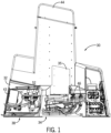
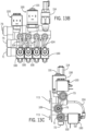
- Fig. 1 Illustrated generally in Fig. 1 is an automated dairy animal milking stall unit 30 used in a dairy harvesting facility.
- the dairy animal milking stall unit 30 can be used in any type of dairy arrangement, including those with stationary or rotary milking stalls, and the present invention is not limited for use in the particular type of milking stall unit 30 depicted herein.
- the automated dairy animal milking stall unit 30 includes: a frame 32 for mounting in or adjacent to a milking stall; a milker unit 34 mounted in the frame 32; milk lines 36 as part of the milker unit 34; milker arm controls 35 used to control movement of the milker unit 34 between a parked position (shown) and a milking position (not shown); and a teat dip fluid supply system 38.
- the frame 32 carries a milking module 42 for determining whether to direct milk to a "good milk" path, a "bad milk” path, or a "calf milk” path, for example.
- a dipping module controller 43 that is programmed to monitor and control teat dipping, rinsing, and backflushing.
- the milking module 42 and the dipping module 43 are in communication with each other and coordinated by a programmable stall control 44, preferably concealed in an upper portion of the frame 32. It is preferred that all of the components described above be disposed in a single frame 32, but multiple frames or mounting systems can be used, so long as the teat dip fluid supply system 38 is in fluid communication with the milker unit 34 or at least a teat dip delivery unit for delivering pre-dip, post-dip, or both types of dip to a dairy animal's teats that will be milked using the milker unit 34.
- the frame 32 can be open or enclosed or at least partially enclosed to protect the teat dip supply system 38, the milker unit control module 42, and the programmable stall control 44 from the harsh dairy environment and from being damaged by dairy animals.
- the milker unit 34 can be of any suitable design and preferably includes teat cups and liner combinations 46, each of which receives an animal teat for milking. Generally, milk travels from the liner through the milk lines 36 and downstream to suitable chilling and storage systems.
- the milker unit 34 also carries one or more hoses and teat dip delivery nozzles or openings to direct teat dip toward each animal teat.
- the teat dip delivery nozzles or openings are formed in a teat cup liner, examples of such liners are disclosed in Torgerson et al., U.S. Patent 8,991,335 , but other types of dispensers and/or liners can be used with the present invention.
- the present invention includes at least one teat dip fluid manifold 50, and the embodiment depicted in Figs. 1 and 2 , includes a second teat dip fluid manifold 52.
- the first teat dip fluid manifold 50 delivers pre-dip fluids
- the second teat dip fluid manifold 52 delivers post-dip fluids.
- other embodiments of teat dip fluid manifolds can dispense both pre-dip fluids and post-dip fluids.
- teat dip fluids can include teat dip for being applied before (“pre”) or after ("post") milking, as well as, air to force teat dip through delivery lines, and rinsing fluids, such as water, for rinsing the teat dip fluid manifold, valves, delivery lines, and teat dip openings or nozzles. It is not necessary that all of these teat dip fluids be utilized in a single manifold 50, 52, but the present invention can be used to deliver one or more of these fluids effectively, efficiently, and reliably.
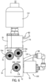
- the teat dip fluid manifold 50 includes a housing 54, a teat dip supply line 56, an air supply line 60, and a rinsing fluid supply line 62.
- Other fluids can also be supplied to the teat dip fluid manifold 50, if desired.
- the teat dip supply line 56 could be divided into two teat dip inlets, so that one receives pre-dip 56 and the other receives post-dip 58.
- the teat dip fluids are then delivered to individual dairy animal teats through a number of delivery lines 68 ( Fig. 7 ) that communicate from the teat dip fluid manifold 50 to a corresponding teat cup and liner combination 46.
- the housing 54 preferably includes inlets 70 ( Figs. 3 , 4 , 5 ), outlets 72 ( Figs. 4 and 5 ), and control valves 76 ( Figs. 3 , 4 , and 5 , and described in more detail below).
- the housing inlets 70 and outlets 72 can be formed in the housing 54 using any appropriate method, and preferably include associated connectors or couplings 78 for connecting to supply lines 56, 58, 60, and 62, and delivery lines 68.
- Supply lines 56 and 58 can also serve as "pre-charge containers" for storing dip prior to being dispensed through the manifold 50.
- the housing 54 is formed of any suitable material that can withstand the dairy environment as well as teat dips and rinsing fluids that pass through the housing 54.
- the housing 54 can be singular for containing most of the valve and seal components for use in either pre-dipping or post-dipping operations as described below in relation to Fig. 10 , for example, or the housing 54 can be separated into multiple housings 54 in fluid communication with one another using any suitable device such as tubes, hoses, conduits, for example, or in direct fluid communication with the individual conduits 88 ( Fig. 7 ) in which teat dip fluids pass to the teat cup and liner combinations 46.
- Housing vents 79 can be provided for access to internal components during manufacturing, for example.
- An electrical power source 80 is also provided for powering valves and actuators within the teat dip fluid manifold 50, and computer controls may also be directly wired to the valves or power source for controlling valve operation. Wireless controls and interfaces can also be used.
- Main supplies for teat dip, air, and water are preferably disposed at a central source location for convenience in supplying a number of teat dip fluid manifolds 50.
- supplies can be disposed at various stations in the dairy harvesting facility or even at individual milking stalls.
- Teat dips for example, can also be mixed on site or even as they are passing in the teat dip supply lines, 56, 58 with various ingredients, such as concentrates, water, or ingredients with short shelf lives.
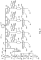
- Fig. 7 is a schematic illustration of a first embodiment of a teat dip fluid manifold 50 in accordance with the present invention.
- the teat dip supply line 56 (or 58 for a post-dip), the air supply line 60, and the rinsing fluid supply line 62 are illustrated in the upper left hand portion of the figure.
- the teat dip supply line 56 connects to an inlet 71 protected by an optional mesh filter screen 71A ( Fig. 6 ) and enters a main dip conduit 85, which is illustrated as a tube, but serves as a pre-charge container inside the housing 54, which includes branches of individual conduits 88 corresponding to each teat.
- Each individual conduit 88 preferably includes the same arrangement of valves, so only one set will be described.
- Teat dip fluid flow through each individual conduit 88 is controlled by an upstream valve 100 and a downstream valve 102.
- the individual conduits 88 are part of the main dip conduit 85 and terminate at the downstream valve 102 in the illustrated example.
- the upstream valve 100 in this embodiment is preferably a 2 position-3 way valve. As seen in Fig.
- each 2 position-3 way valve includes a first inlet 106, a second inlet 108, and an outlet 110.
- the first inlet 106 receives teat dip
- the second inlet 108 can receive other teat dip fluids such as air and rinsing fluids, as described in more detail below.
- the quantity of teat dip supplied to the teat dip fluid manifold 50 can be determined at an upstream location via a suitable dosage valve or it can be provided at a suitable back pressure, so that the upstream valve 100 can be opened for a predetermined interval to provide a desired quantity of teat dip while the upstream valve 100 is open.
- Each downstream valve 102 is preferably a safety valve to provide added protection for milk lines in the dairy, but other types of valves can be used as well.
- the example of a downstream valve 102 illustrated is a safety valve and includes an inlet 111, an outlet 112, and a vent 113 disposed between the inlet 111 and the outlet 113 to create a block-bleed-bock arrangement.
- the upstream valve 100 and the downstream valve 102 provide redundancy in protecting the milk lines from contamination from teat dip fluids.
- a conduit 86 is provided from an air check valve 126 and a rinse fluid check valve 134, into and including individual conduits 124 extending to the downstream valve 102. Included in this example of the conduit 86, is the passage through the upstream valve 100 from the second inlet 108 to the outlet 110.
- the conduit 86 is monitored for pressure by a pressure monitor 114, which in conjunction with a controller 43, monitors pressure in the conduit 86 when the upstream valve 100 is closed to teat dip at inlet 106, and the downstream safety valve 102 is closed to all fluids, except at the vent 113.
- the individual conduits 124 of the conduit 86 extend through the upstream valve 100 second inlet 108 down to the downstream valve 102.
- the positions of the upstream valve 100 and the downstream valve 102 are controlled by actuators 115 of any desired type including the solenoid valves illustrated in the figures. If the pressure rises or falls outside of a predetermined range, the pressure monitor 114 generates an appropriate signal that can send an alarm or other notice to a controller or a dairy operator indicating the abnormality. In such a case, the milking stall unit 30 can be taken out of service or the milk can be directed to a "bad milk" line, for example.
- the pressure monitor 114 senses pressures of about 103,4 kPa (15 psi), but any desirable pressure range can be selected.
- the pressure monitor 114 is preferably a pressure switch that flips when it senses a certain pressure. Also preferably, the pressure switch is adjustable. Pressure sensors can also be used that monitor pressures at varying levels and rates.
- This arrangement of a conduit 86 and a pressure monitor 114 can monitor for valve leakage as described above, but it can also be used to check for unsatisfactory air or rinsing fluid supplies. This procedure preferably takes place when there is no milking operation occurring.
- the downstream valve 102 is closed and air or rinsing fluid are introduced into the conduit 86 through their respective valves 120 or 130. If the air pressure or rinsing fluid pressure is insufficient to reach a pressure at which the pressure monitor 114 is set, then this is an indication that supply pumps or anything affecting fluid pressures require attention.
- the failure of air or rinsing fluid pressure to meet predetermined standards can raise an alarm or even be used by the controller 44 to cease operations at that milking stall unit 30 or cause milk obtained at that stall unit 30 to be redirected to a "bad milk" line, for example.
- the air supply line 60 connects to the housing 54 at a port 73, and only requires controlling with an air valve 120, which is preferably, a 2 position-2 way pneumatic valve that is in fluid communication with the individual air conduits 124, which each communicate with a corresponding upstream valve 100.
- an air check valve 126 is provided downstream from the air valve 120. Air (or any other suitable gas or gas mixture) provided to the teat dip fluid manifold 50 is preferably delivered immediately after a teat dip is sent from the teat dip fluid manifold 50.
- the air provides a back pressure to force ("chase") the teat dip through delivery lines to ensure delivery of a complete dose of teat dip, as well as a timely delivery of teat dip in the precisely-timed operation of an automated dairy-milking system.
- a port mesh filter 73A is preferably used to prevent debris from entering.
- a rinsing fluid such as water
- a rinsing fluid valve 130 which is preferably a 2 position-3 way hydraulic valve to provide a block-bleed-block arrangement between the rinsing fluid supply line 62 and the rest of the teat dip fluid manifold 50 using a vent 131.
- the rinsing fluid valve 130 preferably shares the individual air conduits 124 to delivery rinsing fluid through the rest of the teat dip fluid manifold 50 and the delivery lines 68. Nonetheless, separate individual rinsing fluid conduits could be used.
- a rinsing fluid check valve 134 is provided downstream from the rinsing fluid valve 130 to prevent teat dip or air from cross-contaminating the rinsing fluid supply line 62.
- the controller 43 activates the upstream valve 100 inlet 106 to open and the downstream safety valves 102 to open to allow pressurized teat dip to flow from the teat dip supply 56, 58 through the conduits 88 and to the delivery lines 68.
- the upstream valve 100 will be actuated to close to stop the teat dip supply 56, 58.
- the upstream valve 100 inlet 108 will then be opened to the individual conduits 124 and the air valve 120 will be activated to open to supply pressurized air (or other gas) through each individual conduit 124, the upstream valves 100, the downstream valves 102 (which remain open from teat dip flow or are re-opened), and into the delivery lines 68 to "chase" the teat dip through the delivery lines 68 to the teats.
- the air valve 120 closes, and the rinsing fluid valve 130 is activated to open to release rinsing fluid through the same path as the air traveled until a desired quantity of rinsing fluid has entered the system.
- Another activation of the air valve 120 could be used to "chase" the rinsing fluid through the system, if desired.
- the rinsing fluid valve 130 and the air valve 120 are activated to be closed and the upstream valve 100 and the downstream safety valve 102 are activated to be closed.
- the teat dip fluid manifold 50 is in essentially a milking position because none of the teat dip fluids can reach the milk lines.
- the pressure monitor 114 monitors pressure levels in the conduit 86 (heavy lines in Fig. 7 ), which includes individual conduits 124 and, as described above, generates data and/or warning signals if line pressure is outside of a desired or predetermined range, which might indicate that valve maintenance and/or replacement is necessary.
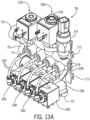
- Figs. 13A through 13E illustrate a teat dip manifold substantially as illustrated in Figs. 3 through 7 , except that many of the conduits are formed from tubes that are part of the housing 54.
- the teat dip fluid manifold 50 is depicted, (a second teat dip fluid manifold 52 would be substantially identical and can be used if separate manifolds were used for pre-and post-dips), including a housing 54 defining a teat dip inlet 71, an air inlet 73, a rinsing fluid inlet 75, which feed into the housing 54 conduits to a respective outlet 72, which in turn is connected to a delivery line 68.
- Flow through the air inlet 73 is controlled by an air valve 120, and rinse fluid through the rinse fluid inlet 75 is controlled by a rinse fluid valve 130. Both air and rinse fluid flow through the conduit 86 and the individual conduits 124 illustrated in Fig. 7 , for example. Flow through each of the individual conduits 124 is controlled by an upstream valve 100 and a downstream valve 102.
- a pressure monitor 114 is used to monitor pressure in the conduit 86 and the individual conduits 124, and will send an appropriate signal to a controller, as described above, in the event pressure in the conduit 86 is outside of a predetermined range. Such a signal would indicate the need for valve or system maintenance.
- the housing 54 can in the form of a frame and include a hanger feature 109 with hooks 113 for attaching to corresponding receivers in a mounting panel, such as seen in Figs. 1 and 2 .
- a single teat dip fluid manifold 250 receives both pre-dip and post-dip, as well as air and rinsing fluid.
- pre-dip teat dip is provided through the teat dip supply line 56, through a pre-dip valve 200, which is preferably a 2 position-2 way valve, but other valves could be used. Downstream from the pre-dip valve 200, is a pre-dip check valve 202 to prevent the pre-dip teat dip supply line 56 from being cross-contaminated by post-dip teat dip, rinsing fluids, and air. Pressurized teat dip is sufficient to open the check valve 202.
- the pre-dip teat dip supply line 56 is in fluid communication with the conduit 86 (bold lines) before splitting into the individual conduits 124.
- Each individual conduit 124 is provided with a pre-charging vessel 208 to provide a premeasured dose of teat dip immediately upstream of a set of teat dip fluid manifold valves described below.
- This arrangement provides an immediate and accurately measured dose of teat dip or other teat dip fluid for delivery to a dairy animal teat or for rinsing the teat dip fluid manifold 250 and the delivery lines 68.
- the pre-charging vessel 208 is sized to receive and store a pressurized volume of between four and eight milliliters (ml) of teat dip fluid, but other volumes or masses can be measured or metered to provide a desired quantity of teat dip.
- ml milliliters
- the drain valve 214 is preferably a 2-position-2 way valve with a drain 218, so that teat dip can be drained from the related pre-charging vessel 208 in the event it is not needed for any reason. For example, all of the charging vessels 208 must be charged simultaneously. If one of the teats is re-dipped for some reason and only one vessel 208 is emptied for that re-dipping, then the other vessels 208 must be emptied through the drain valves 214. Although slightly wasteful, it provides a reliable means for re-dipping one or more teats, if necessary.
- Each downstream safety valve 216 is preferably a suitable safety valve providing a block-bleed-block arrangement or a "block-monitor-block” arrangement as disclosed in patent application serial number 62/581,514 entitled “Automated Milking System Safety Valve Arrangement,” filed on November 3, 2017, and naming inventors Matthew J. Stuessel, Wolfgang Schulze-Wilmert, and Thomas Orban .
- a post-dip dip supply 58 is controlled by a post-dip valve 226 arranged in series with the air supply line 60 and the rinsing fluid supply line 62.
- the post-dip valve is a 2-position-3 way valve for receiving post-dip, as well as, air and rinsing fluid through a separate valve inlet 228.
- other valve configurations can be used.
- the air supply line 60 is controlled by an air valve 230, and the rinsing fluid supply line 62 is controlled by a rinsing fluid valve 232, each of which is preferably a 2-position-2 way valve.
- An air check valve 236 is provided downstream from the air valve 230 to prevent cross-contamination by teat dip and rinsing fluid.
- a safety valve 240 is disposed downstream from the post-dip valve 226.
- This safety valve 240 can be any desired configuration, including a block-bleed-block or a block-monitor-block, as mentioned above.
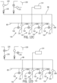
- Fig. 8 illustrates an example of a teat dip fluid manifold valve arrangement that is not n accordance with the present invention.
- Fig. 8 shows a vent valve 244 in the upper right portion that includes an air vent 246 for releasing pressure from the conduit 86 while other fluids are entering. Venting the conduit 86 lowers conduit pressure to enable easier ingress of teat dip fluids into the manifold 50, 52.
- the conduit 86 can be simply vented to atmosphere, or a vacuum could be applied to evacuate the conduit 86 and even draw in teat dipping fluids, if desired.
- air and rinsing fluid are supplied in series to the post-dip valve 226 and pass through the post-dip valve 226 when that valve is activated to open to the water and an air line 235.
- This arrangement is efficient in terms of operation and space conservation.
- an air pressure monitor 114 senses pressure in the conduit 86, including the portions between the pre-charging vessel 208 and the downstream valve 216 for the purposes described above.
- the pre-dip valve 200 is activated and pre-dip passes through the check valve 202 and the conduit 86, and then is divided into each of the individual conduits 124 of the conduit 86 to charge the pre-charging vessels 208.
- the downstream valve 216 opens and back pressure and air from the air valve 230 urge the pre-dip to pass through the delivery lines 68 to a teat cup and liner combination 46.
- the dip valves 200 or 226 can be activated to refill all of the pre-charging vessels 208, and only the teat or teats that did not receive dip can be re-dipped.
- the pre-charging vessels 208 having unused teat dip therein can be dumped through a corresponding drain valve 214, so that all of the charging vessels 208 can receive the next teat dip fluid.
- an air "chase” passes through the air valve 230, the air check valve 236, the air line 235, the post-dip valve 226, the safety valve 240, the conduit 86, and the rest of the path described above for the pre-dip.
- Rinsing fluid can then be used, if desired, so that the rinsing fluid valve 232 will be activated to open and allow pressurized rinsing fluid to follow the same path as the "chase" air traveled, as described above.
- post-dip can be released through an activated post-dip valve 226 and the valve 240, through the conduit 86 and into the pre-charge vessels 208. This part of the process preferably can take place during milking or immediately following milking, but before the teat cup and liner combination 46 is detached from the dairy animal.
- the downstream safety valve 216 is activated to open and permit the post-dip to flow toward the teat cup and liner combination 46. Chase air and optional rinsing fluid can follow, as described above. Again, if post-dip fails to complete the delivery path, another dose can be provided, as described above in relation to the pre-dip teat dip. As illustrated, the valves include actuators 215.
- FIG. 9 A further example that is not in accordance with the present invention is illustrated in Fig. 9 . It is similar to the example of Fig. 8 , because it includes a manifold 350 with a similar arrangement of a pre-dip valve 300, and a pre-dip check valve 302.
- the pre-charging vessel 308 can be refilled if for some reason it fails to fill completely, or the teat dip is delivered at a time when a teat is not located in a corresponding teat cup and liner combination 46. This refiling capability is less wasteful of teat dip compared to the Fig. 9 example, but requires more valves.
- the ability to refill individual (versus all) charging vessels 308 results from the use of an upstream valve 314, and a second upstream valve 320 having an air vent 346, which vents the pre-charging vessel 308 and related lines to allow the pre-charging vessel 308 to be re-charged and applied to an animal teat:
- This process can be performed manually or automatically based on other sensors or observation made downstream from the manifold 350.
- the valves include actuators 315.
- downstream valve 316 Downstream from the pre-charging vessel 308, is a downstream valve 316, which is preferably a safety valve such as a 2 position-5 way valve or a block-monitor-block valve.
- a post-dip valve 326 In addition, as described above in relation to the second embodiment of Fig. 8 , is a post-dip valve 326, an air valve 330, an air check valve 336, a rinsing fluid valve 332, and a safety valve 340, which all operate as described above.
- the Fig. 9 example wastes less teat dip, but requires more valves and results in the conduit 86 not extending all the way to the downstream valves 316.
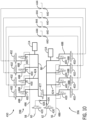
- Fig. 10 a further example not in accordance with the present invention is depicted, which is similar to the Fig. 7 embodiment, except that the teat dip fluid manifold 450 includes elements for dispensing both pre-dip teat dip fluids and post-dip teat dip fluids through a single housing 54.
- a pre-dipping portion 396 and a post-dipping portion 398 are provided, and they are both in communication with a single air supply line 60 and a single rinsing fluid supply line 62.
- the pre-dipping portion 396 and the post-dipping portion 398 each include a conduit 486 with individual conduits 488.
- each individual conduit 488 there is an upstream valve 400 and a downstream valve 402.
- the upstream valves 400 are preferably 2 position- 3 way valves for receiving teat dip through one inlet, and air and rinsing fluid through another inlet.
- a pre-dip supply line 56 a post-dip supply line 58; an air supply line 60; a rinsing fluid supply line 62; an air valve 420; an air check valve 426; a rinsing fluid valve 430; and a rinsing fluid check valve 434.
- a pre-dip/post-dip selection valve 477 is provided to direct air and rinsing fluid to the pre-dip portion 396, when pre-dipping or to the post-dip portion 398, when post-dipping.
- a simple 2 position-2 way valve can be used for the selection valve 477. Again, actuators and valve position sensors are used in relation to any or all of the valves described above.
- the individual conduits 488 of the pre-dip portion 396 are protected from cross-contamination from the post-dip portion 398, by a check valve 440 and the opposite is true because of the check valve 444.
- Other types of protective valves could be used as well to prevent cross contamination.
- a pressure sensor 414 is in fluid communication with each conduit 486 to detect abnormal pressures in each conduit 486, which could indicate leakage in any of the various valves, as described above.
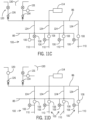
- Figs. 11A to 11D illustrate a progression of valve positions that dispense pre-dip teat dipping fluids through a manifold 50, in accordance with the present invention.
- the upstream valves are closed and the downstream valves 102 (not illustrated in these figures) are also closed.
- the air valve 120 and rinsing fluid valve 130 are also closed.
- the conduit 86, including the individual conduits 124 is monitored by the pressure monitor 114 for leaks.
- the individual conduits 124 are in communication with the rest of the conduit 86 because the second inlet 108 and the outlet 110 in the upstream valve 100 are open to one another. (see: Fig. 7 , for example.)
- Fig. 11B illustrates the next step, "pre-cleaning," taking place by releasing rinsing fluid into the manifold 50.
- the rinsing fluid vent 131 is closed and the rinsing fluid valve 130 is opened to permit rinsing fluid to pass through the rinsing fluid check valve 134 and into the conduit 86, including the conduits 124.
- the pressure monitor 114 can be used to check adequacy of the rinsing fluid supply, if desired.
- Fig. 11C illustrates the next step, "pre-dipping," during which the air valve 120 and the rinsing fluid valve 130 are closed.
- Pre-dip is provided through the pre-dip line 85, and in the illustrated example, only the first inlet 106 of the first upstream valve 100 and its corresponding downstream valve 102 ( Fig. 7 ) are opened, and only an associated teat will receive pre-dip. This can occur while the other teats are being connected to the milking unit 34. Therefore, the first inlet 106 of the other upstream valves 100 remain closed until the other teats are attached.
- Fig. 11D illustrates the "dip chase” step in which the first inlet 106 of the upstream valves 100 are closed, but air and then rinsing fluid are allowed via the air valve 120 and the rinsing fluid valve 130, respectively, to enter the conduit 86 and pass through the upstream valve second inlet 108 to 110 and through the downstream valves (again, not illustrated in this figure) and through the remaining flow path.
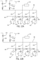
- Figs. 12A to 12D illustrate a progression of valve positions that dispense post-dip teat dipping fluids through a manifold 50, in accordance with the present invention.
- the upstream valves are closed and the downstream valves 102 (not illustrated in these figures) are also closed.
- the air valve 120 and rinsing fluid valve 130 are also closed.
- the conduit 86, including the individual conduits 124 is monitored by the pressure monitor 114 for leaks.
- the individual conduits 124 are in communication with the rest of the conduit 86 because the second inlet 108 and the outlet 110 in the upstream valve 100 are open to one another.
- Fig. 12B illustrates the next step, "post-dipping," during which the air valve 120 and the rinsing fluid valve 130 are closed.
- Post-dip is provided through the post-dip line 85, and in the illustrated example, only the upstream valve 100 and its corresponding downstream valve 102 ( Fig. 7 ) are opened, and only an associated teat will receive post-dip.
- Fig. 12C illustrates the "dip chase” step in which the first inlet 106 of the upstream valves 100 are closed, but air and then rinsing fluid are allowed via the air valve 120 and the rinsing fluid valve 130, respectively, to enter the conduit 86 and pass through the second upstream valve inlet 108 to the outlet 110 and through the downstream valves (again, not illustrated in this figure) and through the remaining flow path.
- Fig. 12D illustrates the next step, "backflushing," taking place by releasing rinsing fluid into the manifold 50.
- the rinsing fluid vent 131 is closed and the rinsing fluid valve 130 is opened to permit rinsing fluid to pass through the rinsing fluid check valve 134 and into the conduit 86, including the conduits 124.
- the pressure monitor 114 can be used to check adequacy of the rinsing fluid supply, if desired.
Landscapes
- Life Sciences & Earth Sciences (AREA)
- Animal Husbandry (AREA)
- Environmental Sciences (AREA)
- Health & Medical Sciences (AREA)
- Engineering & Computer Science (AREA)
- General Engineering & Computer Science (AREA)
- Medicinal Chemistry (AREA)
- Pharmacology & Pharmacy (AREA)
- Public Health (AREA)
- Animal Behavior & Ethology (AREA)
- Veterinary Medicine (AREA)
- Chemical & Material Sciences (AREA)
- Epidemiology (AREA)
- General Health & Medical Sciences (AREA)
- Mechanical Engineering (AREA)
- Indication Of The Valve Opening Or Closing Status (AREA)
- Pipeline Systems (AREA)
- Cleaning In General (AREA)
- Coating Apparatus (AREA)
- Details Of Valves (AREA)
- Safety Valves (AREA)
Claims (6)
- Automatisierte Melkstandeinheit (30), umfassend:ein Zitzentauchmittelfördersystem, das einen automatisierten Zitzentauchmittelverteiler (50) umfasst, der eine Leitung (86, 124) umfasst, die fluidisch an eine Spülfluidzufuhrleitung (62) über ein Spülfluidventil (130) gekoppelt ist und fluidisch an eine Luftzufuhrleitung (60) über ein Luftventil (120) gekoppelt ist;ein stromaufwärts gelegenes Ventil (100), das eine geschlossene Position und eine offene Position aufweist, wobei es sich bei dem stromaufwärts gelegenen Ventil (100) um ein Zwei-Positionen-Drei-Wege-Ventil handelt und dieses einen ersten Einlass (106) aufweist, der dazu konfiguriert ist, Zitzentauchmittel zu empfangen, einen zweiten Einlass (108), der an die Leitung (86, 124) gekoppelt ist, und einen Auslass (110) aufweist, wobei der zweite Einlass (108) und der Auslass (110) zueinander offen sind, wenn sich das stromaufwärts gelegene Ventil (100) in der geschlossenen Position befindet;ein stromabwärts gelegenes Ventil (102) in Fluidkommunikation mit der Leitung (86, 124), die eine geschlossene Position und eine offene Position aufweist, wobei das stromabwärts gelegene Ventil (102) einen Einlass (111), der an den Auslass (110) des stromaufwärts gelegenen Ventils (100) gekoppelt ist, und einen Auslass (112), der an eine Förderleitung (68) gekoppelt ist, und eine Entlüftung (113) aufweist, die zwischen dem Einlass (111) und dem Auslass (112) angeordnet ist, um eine Block-Bleed-Block-Anordnung zu schaffen; undeinen Druckwächter (114) in Kommunikation mit der Leitung (86, 124), um Druck in der Leitung (86, 124) wahrzunehmen, wenn sich das stromaufwärts gelegene Ventil (100) in der geschlossenen Position befindet und sich das stromabwärts gelegene Ventil (102) in der geschlossenen Position befindet; unddie automatisierte Melkstandeinheit eine Steuerung (43) umfasst, die an das stromaufwärts gelegene Ventil (100), das stromabwärts gelegene Ventil (102) und den Druckwächter (114) gekoppelt ist, wobei die Steuerung (43) dazu konfiguriert ist, das stromaufwärts gelegene und das stromabwärts gelegene Ventil (100, 102) in die geschlossene Position zu steuern, den wahrgenommenen Druck in der Leitung (86, 124) von dem Druckwächter (114) zu empfangen, während das stromaufwärts gelegene Ventil (100) für das Zitzentauchmittel an dem Einlass (106) geschlossen ist und das stromabwärts gelegene Ventil (102) für sämtliche Fluide außer der Entlüftung (113) geschlossen ist, und sämtliche oder beliebige Abschnitte des Zitzentauchmittelfördersystems in Abhängigkeit von dem empfangenen wahrgenommenen Druck in der Leitung (86, 124) zu deaktivieren.
- Automatisierte Melkstandeinheit (30) nach Anspruch 1, wobei das stromaufwärts gelegene Ventil (100) eine Entlüftung definiert, wenn sich das stromaufwärts gelegene Ventil (100) in der geschlossenen Position befindet.
- Automatisierte Melkstandeinheit (30) nach Anspruch 1 und ferner umfassend:
einen Vorladebehälter (85), der stromaufwärts von und in Fluidkommunikation mit dem stromaufwärts gelegenen Ventil (100) angeordnet ist, und wobei der Vorladebehälter (85) einen Fluidraum definiert. - Automatisierte Melkstandeinheit (30) nach Anspruch 1 und ferner umfassend:
einen Fluidablass in Kommunikation mit der Leitung (86, 124). - Automatisierte Melkstandeinheit (30) nach Anspruch 1, wobei die Leitung (86, 124) eine Luftentlüftung definiert.
- Automatisierte Melkstandeinheit (30) nach Anspruch 1, wobei es sich bei dem Druckwächter (114) um einen Druckschalter handelt.
Applications Claiming Priority (3)
| Application Number | Priority Date | Filing Date | Title |
|---|---|---|---|
| US201762581514P | 2017-11-03 | 2017-11-03 | |
| US201762581526P | 2017-11-03 | 2017-11-03 | |
| PCT/US2018/058897 WO2019090044A1 (en) | 2017-11-03 | 2018-11-02 | Automated teat dip fluid manifold |
Publications (2)
| Publication Number | Publication Date |
|---|---|
| EP3703489A1 EP3703489A1 (de) | 2020-09-09 |
| EP3703489B1 true EP3703489B1 (de) | 2025-02-12 |
Family
ID=64362729
Family Applications (2)
| Application Number | Title | Priority Date | Filing Date |
|---|---|---|---|
| EP18804875.5A Pending EP3703490A1 (de) | 2017-11-03 | 2018-11-02 | Sicherheitsventilanordnung für ein automatisches melksystem |
| EP18804853.2A Active EP3703489B1 (de) | 2017-11-03 | 2018-11-02 | Automatisierter zitzentauchflüssigkeitsverteiler |
Family Applications Before (1)
| Application Number | Title | Priority Date | Filing Date |
|---|---|---|---|
| EP18804875.5A Pending EP3703490A1 (de) | 2017-11-03 | 2018-11-02 | Sicherheitsventilanordnung für ein automatisches melksystem |
Country Status (3)
| Country | Link |
|---|---|
| US (4) | US11206805B2 (de) |
| EP (2) | EP3703490A1 (de) |
| WO (2) | WO2019090136A1 (de) |
Families Citing this family (12)
| Publication number | Priority date | Publication date | Assignee | Title |
|---|---|---|---|---|
| US10874084B2 (en) | 2004-06-12 | 2020-12-29 | Gea Farm Technologies, Inc. | Safety valve for a dairy system component |
| US8117989B2 (en) | 2008-06-27 | 2012-02-21 | Gea Farm Technologies, Inc. | Milk tube dome with flow controller |
| US11723341B2 (en) | 2009-09-04 | 2023-08-15 | Gea Farm Technologies, Inc. | Safety valve for an automated milker unit backflushing and teat dip applicator system |
| US20120097107A1 (en) | 2010-02-22 | 2012-04-26 | Gea Farm Technologies, Inc. | Dairy animal milking preparation system and methods |
| USD818215S1 (en) * | 2013-12-19 | 2018-05-15 | Gea Farm Technologies Gmbh | Milking machine |
| DE102016108300A1 (de) | 2016-05-04 | 2017-11-09 | Gea Farm Technologies Gmbh | Sicherheitsventil |
| EP3703490A1 (de) | 2017-11-03 | 2020-09-09 | GEA Farm Technologies, Inc. | Sicherheitsventilanordnung für ein automatisches melksystem |
| NL2020053B1 (nl) * | 2017-12-11 | 2019-06-19 | N V Nederlandsche Apparatenfabriek Nedap | Melkmeter |
| US11864530B2 (en) * | 2020-01-14 | 2024-01-09 | Roy L. Rard | Teat preparation system |
| US12396432B2 (en) * | 2021-05-19 | 2025-08-26 | Robovine, LLC | Teat preparation system |
| NL2026979B1 (nl) * | 2020-11-25 | 2022-07-04 | Lely Patent Nv | Automatische melkklep |
| AU2022338067A1 (en) * | 2021-08-31 | 2024-03-07 | Gea Farm Technologies, Inc. | Milking system and methods with pre- and post-dip in the teat liner |
Family Cites Families (224)
| Publication number | Priority date | Publication date | Assignee | Title |
|---|---|---|---|---|
| DE261300C (de) | ||||
| US1365665A (en) | 1920-05-05 | 1921-01-18 | John H Davies | Teat-cup of milking-machines |
| US2012031A (en) | 1932-11-25 | 1935-08-20 | Joseph W Woodruff | High pressure greasing control valve |
| US2532088A (en) | 1947-11-01 | 1950-11-28 | Cordis Nat | Cleansing apparatus |
| US2747544A (en) | 1948-08-18 | 1956-05-29 | Babson Bros Co | Teat cup support assembly |
| GB918766A (en) | 1959-02-03 | 1963-02-20 | Edward David Dyke | Milking equipment |
| US3014455A (en) | 1959-10-22 | 1961-12-26 | Olander Karl Erik | Claw pieces for milking machines |
| US3099246A (en) | 1960-05-19 | 1963-07-30 | Separator Ab | Teat cup for milking machines |
| US3119401A (en) | 1961-02-02 | 1964-01-28 | Babson Bros Co | Milk pipeline washing system |
| US3285297A (en) | 1964-08-31 | 1966-11-15 | Milk Line Corp | Milk transfer system and apparatus |
| DE1299165B (de) | 1966-06-06 | 1969-07-10 | Maier Jakob | Melkbecher fuer Melkmaschinen |
| GB1160900A (en) | 1966-09-13 | 1969-08-06 | Gascoignes Res & Dev Ltd | Improvements in or relating to Teat Cups for Milking Equipment |
| US3417763A (en) | 1966-12-27 | 1968-12-24 | Universal Milking Machine Divi | Milk line washing system |
| US3461845A (en) | 1967-01-23 | 1969-08-19 | Research Corp | Sanitizing apparatus for milking machines |
| DE1582939A1 (de) | 1967-02-03 | 1970-07-09 | Alfa Laval Ab | Anordnung bei Melkmaschinen |
| US3474760A (en) | 1967-11-03 | 1969-10-28 | Norton Co | Milking inflation |
| US3500839A (en) | 1968-05-07 | 1970-03-17 | Lloyd F Bender | Automated washing system for cleaning,sanitizing and drying flexible tubing or the like |
| DE1801758A1 (de) | 1968-10-08 | 1970-06-11 | Otto Tuchenhagen | Verfahren zum Durchspuelen hauptsaechlich von Milchleitungen |
| GB1314326A (en) | 1969-06-30 | 1973-04-18 | Nat Res Dev | Methods and apparatus for the detection of mastitis in milk animals |
| NL7014273A (de) | 1969-10-06 | 1971-04-08 | ||
| US3630081A (en) | 1970-01-06 | 1971-12-28 | Lavel Separator Co The De | Milk metering apparatus |
| US3696790A (en) | 1970-01-08 | 1972-10-10 | Zero Manufacturing Co | Teat cup assembly |
| US3648696A (en) | 1970-03-20 | 1972-03-14 | Robert H Keith | Teat spraying apparatus for aiding in the prevention of mastitis in dairy cows |
| US3688783A (en) | 1970-08-17 | 1972-09-05 | William E Owens | Sanitizing apparatus |
| US3713423A (en) | 1971-01-08 | 1973-01-30 | A Sparr | Udder and teat cleansing apparatus and sanitizer |
| US3797525A (en) | 1972-04-10 | 1974-03-19 | Stanray Corp | Pilot valve |
| US3789798A (en) | 1972-08-10 | 1974-02-05 | Sta Rite Industries | Automatic milking unit |
| GB1435604A (en) | 1974-04-26 | 1976-05-12 | Duncan D R | Spraying apparatus |
| US3861335A (en) | 1973-08-20 | 1975-01-21 | Progressive Trade Corp | Incineration system |
| IE39314B1 (en) | 1973-09-20 | 1978-09-13 | Mullinahone Co Operative Dairy | Improvements in milking apparatus |
| DE2363125C2 (de) | 1973-12-19 | 1981-07-23 | Westfalia Separator Ag, 4740 Oelde | Den Betriebsunterdruck für Melkanlagen automatisch regelndes Ventil |
| US3861355A (en) | 1974-02-25 | 1975-01-21 | Universal Cooperatives Inc | Automatic milker take off assembly |
| US3973520A (en) | 1974-09-30 | 1976-08-10 | Flocchini Andrew J | Automated milking assembly |
| CA1003900A (en) | 1975-01-16 | 1977-01-18 | Sed Systems Ltd. | Fluid conductivity measurement apparatus |
| US4034714A (en) | 1975-11-04 | 1977-07-12 | Raymond E. Umbaugh | Stimulating and valving system for milking |
| DE2622794A1 (de) | 1976-05-21 | 1977-12-08 | Alfa Laval Agrar Gmbh | Verfahren und vorrichtung zur automatisierten anwendung von sanitisern an strichen und melkzeug |
| US4061504A (en) | 1976-05-21 | 1977-12-06 | Cornell Research Foundation, Inc. | Apparatus for cleaning automatic milking machines |
| FR7805940A (de) | 1977-02-11 | |||
| US4175514A (en) | 1977-05-19 | 1979-11-27 | Frank F. Souza, Inc. | Automatic milking machine control and cleansing |
| FR2419012A1 (fr) | 1978-03-08 | 1979-10-05 | Happel Fritz | Procede et dispositif de traite mecanique |
| US4333387A (en) | 1978-03-21 | 1982-06-08 | Bertea Corporation | Anti-jam hydraulic servo valve |
| US4168677A (en) | 1978-04-20 | 1979-09-25 | Brown Michael J | Sanitary backwashing system for automatic milking machines |
| US4344385A (en) | 1978-05-03 | 1982-08-17 | Babson Bros. Co. | Milker |
| US4295490A (en) | 1978-05-16 | 1981-10-20 | Boudreau Archie E | Milking apparatus |
| JPS54173138U (de) | 1978-05-26 | 1979-12-07 | ||
| CA1138805A (en) | 1978-07-05 | 1983-01-04 | Paul Slater | Liquid flow sensing device |
| US4222346A (en) | 1978-11-29 | 1980-09-16 | Reisgies Rolf W | Milk line back flushing method and apparatus |
| DE3020758A1 (de) | 1980-05-31 | 1981-12-10 | Jörn Dr. 2300 Kiel Hamann | Verfahren und vorrichtung zur verhinderung der benetzung von zitzenspitzen durch einen rueckstrom |
| US4333421A (en) | 1980-06-18 | 1982-06-08 | Dec International, Inc. | Milking unit support and detacher mechanism |
| US4305346A (en) | 1980-09-26 | 1981-12-15 | Sparr Sr Anders V | Teat washing cup with milk let-down stimulating blades |
| US4332215A (en) | 1980-10-01 | 1982-06-01 | Hi-Life Rubber, Inc. | Milking inflation |
| JPS5935574B2 (ja) | 1980-12-24 | 1984-08-29 | エーザイ株式会社 | 分房乳の検査装置を具えたミルククロ− |
| US4393811A (en) | 1981-03-24 | 1983-07-19 | Mae Lois Moore | Weighted teat cup shell and assembly |
| US4462425A (en) | 1981-07-13 | 1984-07-31 | Economics Laboratory, Inc. | Backflushing system |
| US4372345A (en) | 1981-07-13 | 1983-02-08 | Economics Laboratory, Inc. | Fail-safe valve |
| US4403569A (en) | 1981-12-29 | 1983-09-13 | Bennett Arthur J R | Milking machine |
| US4459938A (en) | 1982-06-23 | 1984-07-17 | Noorlander Daniel O | Teat cup assembly |
| US4498419A (en) | 1982-10-18 | 1985-02-12 | Flocchini Andrew J | Backwash valve and system for teat cup assembly |
| US4485762A (en) | 1982-12-21 | 1984-12-04 | Alfa-Laval, Inc. | Milk metering method and apparatus |
| SU1076036A1 (ru) | 1982-12-29 | 1984-02-29 | Белорусский научно-исследовательский институт животноводства | Доильный аппарат |
| US4516530A (en) | 1983-10-14 | 1985-05-14 | Germania Dairy Automation, Inc. | Milk sweep method and apparatus for automated milking systems |
| US4593649A (en) | 1984-02-14 | 1986-06-10 | Britten Allan M | Milk monitoring apparatus and method |
| DE3406878C1 (de) | 1984-02-25 | 1985-06-20 | Westfalia Separator Ag, 4740 Oelde | Trag- und Abziehmechanismus fuer Melkzeuge |
| US4572105A (en) | 1984-09-20 | 1986-02-25 | Alfa-Laval, Inc. | Backflushing system |
| EP0319523B2 (de) | 1985-01-16 | 1995-10-25 | C. van der Lely N.V. | Gerät zum automatischen Melken von Tieren |
| SU1273143A1 (ru) | 1985-02-14 | 1986-11-30 | Научно-исследовательский и экспериментальный институт автомобильного электрооборудования и автоприборов | Устройство дл очистки сжатого газа от влаги |
| EP0194729B1 (de) | 1985-03-12 | 1989-12-20 | C. van der Lely N.V. | Gerät zum Melken von Tieren |
| EP0332235B2 (de) | 1985-07-01 | 1998-12-30 | C. van der Lely N.V. | Gerät zum automatischen Melken von Tieren |
| AU598762B2 (en) | 1985-11-01 | 1990-07-05 | Agresearch Limited | Improvements in milking machinery |
| DE3540058A1 (de) | 1985-11-12 | 1987-05-14 | Schletter Peter | Melkmaschine |
| US4936254A (en) | 1986-05-10 | 1990-06-26 | Ambic Equipment Limited | Automatic milking apparatus |
| US4903639A (en) | 1986-10-14 | 1990-02-27 | Kessel Dan W | Teat disinfecting method |
| NL8700249A (nl) | 1987-02-02 | 1988-09-01 | Multinorm Bv | Werkwijze voor het reinigen van een tepel van een vrouwelijk dier, melkwerkwijze en beker ten gebruike bij bovengenoemde werkwijzen. |
| US4907535A (en) | 1988-06-01 | 1990-03-13 | Orion Machinery Co. Ltd. | Milk-claw for milking machines |
| NL8802332A (nl) | 1988-09-21 | 1990-04-17 | Lely Nv C Van Der | Inrichting voor het melken van een dier. |
| DE4006785A1 (de) | 1989-03-03 | 1990-09-06 | Passavant Werke | Dehnkoerperverschluss |
| SU1676538A1 (ru) | 1989-07-18 | 1991-09-15 | Центральный Научно-Исследовательский И Проектно-Технологический Институт Механизации И Электрификации Животноводства | Устройство дл обмывани сосков вымени |
| GB8926950D0 (en) | 1989-11-29 | 1990-01-17 | Ambic Equip Ltd | Automatic milking apparatus |
| US5568788A (en) | 1990-02-27 | 1996-10-29 | C. Van Der Lely N.V. | Implement for and a method of milking animals automatically |
| AU641229B2 (en) | 1990-04-05 | 1993-09-16 | Douglas Harold Emmins | A diaphragm valve |
| IL94341A (en) | 1990-05-09 | 1992-09-06 | Afikim S A E | System for disinfecting milking apparatus |
| SE466780B (sv) | 1990-05-31 | 1992-04-06 | Alfa Laval Agri Int | Mjoelkningspulsator |
| DE69102588T2 (de) | 1990-06-01 | 1994-12-08 | British Tech Group | Automatische Melkanlage. |
| US5101770A (en) | 1990-11-05 | 1992-04-07 | Stevenson Dale V | Post-milking and pre-milking udder care |
| US5166313A (en) | 1991-04-29 | 1992-11-24 | Fluorochem, Inc. | Diamantane modified rigid-rod poly benzazole and method of manufacture |
| NL9200051A (nl) | 1992-01-13 | 1993-08-02 | Prolion Bv | Automatische melkinrichting. |
| US5178095A (en) | 1991-06-13 | 1993-01-12 | Dec International, Inc. | Milking system with positive pressure on thin liner |
| NL9200258A (nl) | 1991-10-04 | 1993-05-03 | Lely Nv C Van Der | Werkwijze voor het reinigen van melkbekers en/of het nabehandelen van de spenen van een gemolken dier, inrichting voor het melken van dieren voor het toepassen van deze werkwijze(n), en spoelwerktuig toegepast in een dergelijke inrichting. |
| ES2157894T3 (es) | 1991-11-22 | 2001-09-01 | Berthold Johannes The Dietrich | Dispositivo para el ordeño neumatico y pezonera para este dispositivo. |
| US5218924A (en) | 1992-03-19 | 1993-06-15 | Dec International, Inc. | Milking system with variable pressure source |
| US5305788A (en) | 1992-08-13 | 1994-04-26 | Whitey Co. | Stream selector for process analyzer |
| GB9224405D0 (en) | 1992-11-20 | 1993-01-13 | Silsoe Research Inst | Cleaning of milking animal teats |
| NL9300143A (nl) | 1993-01-26 | 1994-08-16 | Lely Nv C Van Der | Melkinrichting. |
| NL9301099A (nl) | 1993-06-24 | 1995-01-16 | Texas Industries Inc | Inrichting voor het automatisch melken van dieren. |
| US5403005A (en) | 1993-08-09 | 1995-04-04 | Avila-Valdez; Jesus | Game and puzzle board |
| US5379722A (en) | 1993-12-30 | 1995-01-10 | Babson Bros. Co. | Control for a milker unit support |
| NL9400241A (nl) | 1994-02-17 | 1995-10-02 | Prolion Bv | Besturingswijze voor een melkbehandelingssysteem en op deze wijze bestuurde melkinrichting. |
| NL9401937A (nl) | 1994-04-27 | 1995-12-01 | Maasland Nv | Werkwijze voor het automatisch melken van dieren en inrichting waarin deze werkwijze kan worden toegepast. |
| US5493995A (en) | 1994-05-16 | 1996-02-27 | Alfa Laval Agri, Inc. | Collapsing teat cup liner with tapering barrel wall |
| NL9401113A (nl) | 1994-07-04 | 1996-02-01 | Maasland Nv | Constructie met een inrichting voor het automatisch melken van dieren. |
| NL9401801A (nl) | 1994-08-23 | 1996-04-01 | Maasland Nv | Constructie met een inrichting voor het melken van dieren. |
| NL9401451A (nl) | 1994-09-07 | 1996-04-01 | Maasland Nv | Inrichting en werkwijze voor het melken van dieren. |
| RU2084137C1 (ru) | 1995-02-03 | 1997-07-20 | Оренбургская государственная сельскохозяйственная академия | Тренажер для обучения приемам преддоильного массажа вымени животного |
| US5697325A (en) | 1995-02-13 | 1997-12-16 | Gehm; Lanny | Milking system |
| NL9500364A (nl) | 1995-02-24 | 1996-10-01 | Maasland Nv | Inrichting voor het melken van dieren. |
| US5572947A (en) | 1995-03-29 | 1996-11-12 | Hi-Life Rubber Inc. | Milking inflation |
| SE504427C2 (sv) | 1995-05-17 | 1997-02-10 | Tetra Laval Holdings & Finance | Sätt och anordning att mjölka ett djur genom bestämning av pulseringsvakuumets nivå när spengummit öppnar eller stänger abrupt |
| SE9503792D0 (sv) | 1995-10-27 | 1995-10-27 | Tetra Laval Holdings & Finance | Teat location for milking |
| EP1208743B1 (de) | 1996-04-17 | 2009-06-17 | Maasland N.V. | Gerät zum Melken von Tieren, sowie Kühen |
| US6249710B1 (en) | 1996-05-14 | 2001-06-19 | Microwave Science, Llc | Method and apparatus for managing the thermal activity of a microwave oven |
| DE19635719A1 (de) | 1996-09-03 | 1998-03-05 | Jakob Maier | Zitzengummi |
| US5850845A (en) | 1996-10-17 | 1998-12-22 | Pereira Construction, Inc. | Backflush valve for milking machine system |
| NL1004921C2 (nl) | 1996-12-31 | 1998-07-01 | Prolion Bv | Inrichting en werkwijze voor het melken van dieren. |
| NL1004922C2 (nl) | 1996-12-31 | 1998-07-01 | Prolion Bv | Inrichting en werkwijze voor het melken van dieren. |
| US5960736A (en) | 1997-04-17 | 1999-10-05 | Cornell Research Foundation, Inc. | Vacuum level control system using variable frequency drive |
| US5896828A (en) | 1997-05-22 | 1999-04-27 | Alfa Laval Agri Inc. | Method and apparatus for cleaning milking pipelines and milking equipment |
| NL1006473C2 (nl) | 1997-07-04 | 1999-01-05 | Maasland Nv | Inrichting voor het automatisch melken van dieren. |
| NL1007727C2 (nl) * | 1997-12-08 | 1999-06-09 | Maasland Nv | Spoelvloeistofreinigingsinrichting voor het reinigen van althans een deel van een melkmachine. |
| US6089242A (en) | 1998-02-10 | 2000-07-18 | Babson Bros. Co. | Dairy harvesting facility wash system |
| SE9704515D0 (sv) | 1997-12-04 | 1997-12-04 | Alfa Laval Agri Ab | Combined cleaning and pre-milking device |
| SE9704514D0 (sv) | 1997-12-04 | 1997-12-04 | Alfa Laval Agri Ab | Internal wings |
| SE9704781D0 (sv) | 1997-12-19 | 1997-12-19 | Alfa Laval Agri Ab | A method and an apparatus for separation of foremilk |
| SE511990C2 (sv) | 1998-03-19 | 2000-01-10 | Alfa Laval Agri Ab | Anordning och förfaringssätt för sprutande av en desinficerande vätska på ett djurs spenar |
| NL1008673C2 (nl) | 1998-03-23 | 1999-09-24 | Maasland Nv | Inrichting en werkwijze voor het reinigen en/of desinfecteren van een speen van een dier. |
| US20070070803A1 (en) | 1998-04-16 | 2007-03-29 | Urquhart Karl J | Point-of-use process control blender systems and corresponding methods |
| DE69906288T2 (de) | 1998-06-22 | 2003-12-04 | Rieberjo B.V., Gorssel | Melkvorrichtung mit reinigungsmitteln |
| NL1009663C2 (nl) | 1998-07-06 | 2000-01-10 | Maasland Nv | Werkwijze en inrichting voor het desinfecteren van een melkinstallatie en/of een reinigingsinrichting voor de spenen van een dier. |
| SE514037C2 (sv) | 1998-08-31 | 2000-12-18 | Delaval Holding Ab | Förfarande och anordning för rengöring av spenarna hos ett mjölkdjurs juver |
| DE59908528D1 (de) | 1998-09-07 | 2004-03-18 | Werner Happel | Melkbecher |
| NL1010323C2 (nl) | 1998-10-15 | 2000-04-18 | Maasland Nv | Werkwijze voor het automatisch melken van dieren en volautomatische melkmachine met een melkrobot geschikt voor het uitvoeren van de werkwijze. |
| DE19852349A1 (de) | 1998-11-13 | 2000-05-18 | Wabco Gmbh & Co Ohg | Ventileinrichtung |
| NL1012529C2 (nl) | 1999-07-07 | 2001-01-09 | Lely Res Holding | Inrichting voor het melken van dieren, zoals koeien. |
| SE518094C2 (sv) | 1999-09-09 | 2002-08-27 | Delaval Holding Ab | Förfarande och anordning för spenbehandling |
| SE515440C2 (sv) | 1999-09-09 | 2001-08-06 | Delaval Holding Ab | Förfarande och anordning för att tvätta spenar hos ett djur |
| SE515114C2 (sv) | 1999-09-15 | 2001-06-11 | Delaval Holding Ab | Metod och arrangemang för tvättning av en spentvättningsanordning |
| US6752102B2 (en) | 1999-09-27 | 2004-06-22 | Pro Chemicals, Llc | Apparatus for producing a foam bovine teat dip |
| SE515443C3 (sv) | 1999-12-15 | 2001-08-14 | Delaval Holding Ab | Förfarande och anordning för spenkoppstvättning |
| US6435132B1 (en) | 1999-12-23 | 2002-08-20 | Constance J. Milbrath | Teat cup assembly |
| DE10006548A1 (de) * | 2000-02-15 | 2001-08-23 | Westfalia Landtechnik Gmbh | Verfahren zur Erzeugung und Stabilisierung des Arbeitsdrucks durch Volumenstromanpassung beim Verdichten von kompressiblen Fluiden |
| ATE310382T1 (de) | 2000-06-22 | 2005-12-15 | Delaval Holding Ab | Verfahren und vorrichtung zur behandlung der zitze eines tieres |
| NL1015803C2 (nl) | 2000-07-25 | 2002-01-28 | Nedap Nv | Inrichting bestemd voor het injecteren van een flu´dum in een systeem dat een melkbeker en een melkleiding omvat. |
| US7290497B2 (en) | 2001-09-21 | 2007-11-06 | Westfaliasurge, Inc. | Milking device provided with cleansing means |
| US20080022932A1 (en) | 2001-09-21 | 2008-01-31 | Westfaliasurge, Inc. | Milking device provided with cleansing means |
| NL1016237C2 (nl) | 2000-09-22 | 2002-03-25 | Rieberjo B V | Melkinrichting voorzien van reinigingsmiddelen. |
| DE10100840C2 (de) | 2001-01-10 | 2003-01-30 | Westfalia Landtechnik Gmbh | Verfahren und Vorrichtung zum Melken |
| DE10110473B4 (de) | 2001-03-05 | 2005-02-03 | Maier Jun., Jakob | Automatische Melkvorrichtung mit steuerbarer Stimulationsvorrichtung und System zur Stimulation |
| JP2002345955A (ja) | 2001-05-23 | 2002-12-03 | Kazuaki Yamaoka | 安全キャップ付注射針 |
| JP4565210B2 (ja) | 2001-05-31 | 2010-10-20 | 独立行政法人農業・食品産業技術総合研究機構 | 円筒型乳頭清拭装置 |
| US20020185071A1 (en) | 2001-06-08 | 2002-12-12 | Fangjiang Guo | Apparatus for cleaning a teat of a dairy animal |
| SE520278C2 (sv) | 2001-09-20 | 2003-06-17 | Delaval Holding Ab | Arrangemang och förfarande för mjölkning av djur |
| SE0103367D0 (sv) | 2001-10-10 | 2001-10-10 | Delaval Holding Ab | A device and a method for treatment of a teat of an animal |
| DE10160161B4 (de) | 2001-12-07 | 2016-01-07 | Werner Happel | Melksystem, System für Belüftung, Desinfektion von Zitze und Zitzengummi |
| US6755153B1 (en) | 2002-02-08 | 2004-06-29 | Mofazzal H. Chowdhury | Teatcup liner mouthpiece lip with controlled deflection and slip reduction |
| SE0202988D0 (sv) | 2002-03-15 | 2002-10-10 | Delaval Holding Ab | A method and an arrangement at a dairy farm |
| US6619227B1 (en) | 2002-04-04 | 2003-09-16 | Danaher Controls | Milking equipment wash monitoring system and method |
| SE0201596D0 (sv) | 2002-05-29 | 2002-05-29 | Delaval Holding Ab | A device for cleaning the teats of an animal |
| NL1021430C1 (nl) | 2002-08-06 | 2004-02-10 | Lely Entpr Ag | Inrichting voor het bewaken van een melktank, samenstel van een melkrobot met automatische opstartinrichting en een dergelijke inrichting. |
| US6895892B2 (en) | 2002-10-01 | 2005-05-24 | Westfaliasurge, Inc. | Short milk tube |
| SE0203006D0 (sv) | 2002-10-11 | 2002-10-11 | Delaval Holding Ab | A milking plant |
| NL1021950C1 (nl) | 2002-11-19 | 2004-05-24 | Rieberjo B V | Tepeldesinfecteerinrichting. |
| US6990924B2 (en) | 2003-02-07 | 2006-01-31 | Global Tech Systems Inc | Controller for monitoring and controlling pulsators in a milking system |
| US6997136B1 (en) | 2003-03-21 | 2006-02-14 | Avon Hi-Life, Inc. | Teat cup assembly |
| US7575022B2 (en) | 2003-08-25 | 2009-08-18 | Falcon Waterfree Technologie | Diverter, liquid-level indicator and chemical pre-treatment and post-treatment implementations useful in waterless urinals |
| US6935270B2 (en) | 2003-08-29 | 2005-08-30 | Delaval, Inc. | Milking and application teat cup, system, and method |
| NL1024402C2 (nl) | 2003-09-30 | 2005-03-31 | Lely Entpr Ag | Inrichting en werkwijze voor het aanbrengen van een fluïdum op een speen van een melkdier. |
| US6997135B1 (en) | 2003-10-08 | 2006-02-14 | Dewaard Dave | Valve for a milking apparatus |
| NL1024518C2 (nl) | 2003-10-13 | 2005-04-14 | Lely Entpr Ag | Samenstel en werkwijze voor het voederen en melken van dieren, voederplatform, melksysteem, voedersysteem, melkvoorbehandelingsinrichting, melknabehandelingsinrichting, reinigingsinrichting en separatie-inrichting, alle geschikt voor gebruik in een dergelijk samenstel. |
| GB0408968D0 (en) | 2004-04-22 | 2004-05-26 | Duke James R J | Milking equipment |
| EP1795069A3 (de) | 2003-10-22 | 2009-07-29 | James Richard John Duke | Melkvorrichtung |
| JP4696310B2 (ja) | 2003-12-26 | 2011-06-08 | 独立行政法人農業・食品産業技術総合研究機構 | 突起状物の洗浄装置 |
| WO2005072516A1 (en) | 2004-01-30 | 2005-08-11 | James Richard John Duke | Milking equipment |
| DE102004033637B4 (de) | 2004-03-23 | 2012-07-26 | Wilfried Hatzack | Haltevorrichtung für Melkbecher mit einem Antrieb zur Erzeugung einer Bewegung |
| US7401573B2 (en) | 2004-06-12 | 2008-07-22 | Westfaliasurge, Inc. | Liner contact automatic teat dip applicator |
| US8033247B2 (en) | 2004-06-12 | 2011-10-11 | Gea Farm Technologies, Inc. | Automatic dairy animal milker unit backflusher and teat dip applicator system and method |
| US10874084B2 (en) | 2004-06-12 | 2020-12-29 | Gea Farm Technologies, Inc. | Safety valve for a dairy system component |
| US8342125B2 (en) | 2004-06-12 | 2013-01-01 | Gea Farm Technologies, Inc. | Safety valve for an automatic dairy animal milker unit backflusher and teat dip applicator |
| US8117989B2 (en) | 2008-06-27 | 2012-02-21 | Gea Farm Technologies, Inc. | Milk tube dome with flow controller |
| US8025029B2 (en) | 2004-06-12 | 2011-09-27 | Gea Farm Technologies, Inc. | Automatic dairy animal milker unit backflusher and teat dip applicator system and method |
| CA2570327C (en) | 2004-06-29 | 2013-11-26 | Lauren Agrisystems, Ltd. | Milking liner |
| US7536975B2 (en) | 2004-08-18 | 2009-05-26 | Wisconsin Alumni Research Foundation | Plasma-assisted disinfection of milking machines |
| US7237694B2 (en) | 2004-09-08 | 2007-07-03 | Quantum Technical Services, Inc. | Food metering and dispensing device |
| US20090165724A1 (en) | 2004-09-14 | 2009-07-02 | Westfaliasurge Gmbh | Teat Cup and Method for Bringing a Fluid into Contact with the Teat of an Animal |
| CA2598905C (en) | 2005-02-22 | 2014-07-08 | Swagelok Company | Valve and actuator assemblies |
| SE529121C2 (sv) | 2005-04-14 | 2007-05-02 | Delaval Holding Ab | Arrangemang för att tillföra ett vätskeformigt medium till en spene hos ett djur |
| DE102005020457A1 (de) | 2005-04-29 | 2006-11-02 | Westfaliasurge Gmbh | Verwendung nicht-pathogener, sporenbildender Bakterien |
| GB0518976D0 (en) | 2005-09-16 | 2005-10-26 | Duke James R J | Teat cup |
| DE102005055973B4 (de) | 2005-11-22 | 2010-02-04 | Gea Westfaliasurge Gmbh | Melkbecher und Melkverfahren |
| DE602006004291D1 (de) | 2006-01-06 | 2009-01-29 | Bou Matic Technologies Corp | Melkbecher |
| NL1031749C2 (nl) | 2006-05-04 | 2007-11-06 | Jacob Hendrik Berthold Dietric | Melkklauwinrichting. |
| NL1031764C2 (nl) | 2006-05-08 | 2007-11-13 | Jacob Hendrik Berthold Dietric | Melkklauwinrichting eventueel met reinigingsfunctie. |
| SE0700274L (sv) * | 2007-02-05 | 2008-08-06 | Delaval Holding Ab | Automatic monitoring of milking plant valve means |
| JP4914242B2 (ja) | 2007-02-23 | 2012-04-11 | オリオン機械株式会社 | 洗浄装置 |
| DE102007022802A1 (de) | 2007-05-11 | 2008-11-13 | Westfaliasurge Gmbh | Milchschlauch für eine Melkeinrichtung |
| DE102007022800A1 (de) | 2007-05-11 | 2008-11-13 | Westfaliasurge Gmbh | Verbindung von Zitzengummi und Melkbecherhülse |
| DE102008023011A1 (de) | 2007-05-11 | 2008-11-27 | Westfaliasurge Gmbh | Melkeinheit zum Melken eines Tieres |
| US7926449B2 (en) | 2007-06-25 | 2011-04-19 | Delaval Holding Ab | Fluid application systems and methods and milking systems and methods |
| CN101932230B (zh) | 2007-12-19 | 2013-04-17 | Gea农业技术有限公司 | 具有可封闭腔室的奶采集件 |
| WO2009093966A2 (en) * | 2008-01-24 | 2009-07-30 | Delaval Holding Ab | Method and arrangement for controlling the milking by a milking machine |
| EP2271373B1 (de) | 2008-03-10 | 2018-10-31 | The Medical College Of Wisconsin, Inc. | 99mtc-markiertes 19 aminosäuren enthaltendes peptid zur verwendung als phosphatidylethanolamin-bindungs-molekularsonde und radiopharmazeutikum |
| EP2355652B2 (de) | 2008-11-10 | 2021-03-17 | GEA Farm Technologies GmbH | Verfahren und Vorrichtung zum automatischen inkontaktbringen eines Fluids mit den Zitzen eines Tieres |
| CA2746088A1 (en) * | 2008-12-18 | 2010-06-24 | Delaval Holding Ab | Cleaning arrangement |
| CA2752441A1 (en) | 2009-02-19 | 2010-08-26 | Delaval Holding Ab | Independent cleaning of interfaces between separable fluid systems |
| NZ605225A (en) | 2009-09-04 | 2014-06-27 | Gea Farm Technologies Inc | Automatic dairy animal milker unit backflusher and teat dip applicator system and method |
| AU2015227478B2 (en) | 2009-09-04 | 2018-03-01 | Gea Farm Technologies, Inc. | Automatic dairy animal milker unit backflusher and teat dip applicator system and method |
| US8770146B2 (en) | 2009-09-04 | 2014-07-08 | Gea Farm Technologies, Inc. | Methods and apparatus for applying teat dip to a dairy animal |
| GB2475249A (en) * | 2009-11-10 | 2011-05-18 | Delaval Holding Ab | Method and apparatus for cleaning a milking system |
| RU2583697C2 (ru) | 2010-02-22 | 2016-05-10 | Геа Фарм Технолоджис, Инк. | Аппарат для доения и сбора молока с системой защиты молокопровода |
| US20120097107A1 (en) | 2010-02-22 | 2012-04-26 | Gea Farm Technologies, Inc. | Dairy animal milking preparation system and methods |
| EP2632247B1 (de) | 2010-10-26 | 2017-04-26 | DeLaval Holding AB | Steuersystem und verfahren für melkeinheiten eines melkstandes |
| EP2640184B2 (de) | 2010-11-16 | 2020-07-01 | DeLaval Holding AB | Melksystem und verfahren für den betrieb eines melksystems |
| US8752504B2 (en) | 2011-05-25 | 2014-06-17 | Technologies Holdings Corp. | Milking system shut-off and sensors |
| GB201213232D0 (en) | 2012-07-25 | 2012-09-05 | An Udder Company Ltd | Milking cluster |
| GB201213231D0 (en) | 2012-07-25 | 2012-09-05 | An Udder Company Ltd | Milking equipment |
| WO2014209203A1 (en) | 2013-06-26 | 2014-12-31 | Delaval Holding Ab | Arrangement for milking animals |
| DE102013114595A1 (de) | 2013-12-20 | 2015-06-25 | Gea Farm Technologies Gmbh | Sicherheitsventil |
| US9526224B2 (en) | 2013-12-20 | 2016-12-27 | Gea Farm Technologies Gmbh | Safety valve device |
| GB201402188D0 (en) | 2014-02-07 | 2014-03-26 | An Udder Ip Company Ltd | Milking equipment |
| US9404599B2 (en) | 2014-03-12 | 2016-08-02 | Flextronics Automotive Inc. | Dual/variable gain oil pump control valve |
| GB201405611D0 (en) | 2014-03-28 | 2014-05-14 | An Udder Ip Company Ltd | A teat cup |
| GB201406145D0 (en) | 2014-04-04 | 2014-05-21 | An Udder Ip Company Ltd | A clawbowl for a milking cluster |
| EP2939532A1 (de) * | 2014-04-17 | 2015-11-04 | MILKLINE S.r.l. | Durch einen computer implementiertes verfahren für die steuerung von melkvorgängen in automatisierten systemen |
| WO2017061932A1 (en) | 2015-10-08 | 2017-04-13 | Delaval Holding Ab | Diagnostic apparatus and testing method |
| DE102016108300A1 (de) | 2016-05-04 | 2017-11-09 | Gea Farm Technologies Gmbh | Sicherheitsventil |
| EP3703490A1 (de) | 2017-11-03 | 2020-09-09 | GEA Farm Technologies, Inc. | Sicherheitsventilanordnung für ein automatisches melksystem |
-
2018
- 2018-11-02 EP EP18804875.5A patent/EP3703490A1/de active Pending
- 2018-11-02 US US16/179,660 patent/US11206805B2/en active Active
- 2018-11-02 EP EP18804853.2A patent/EP3703489B1/de active Active
- 2018-11-02 WO PCT/US2018/059041 patent/WO2019090136A1/en not_active Ceased
- 2018-11-02 WO PCT/US2018/058897 patent/WO2019090044A1/en not_active Ceased
- 2018-11-02 US US16/178,996 patent/US11617343B2/en active Active
-
2021
- 2021-11-23 US US17/533,291 patent/US11930782B2/en active Active
-
2023
- 2023-03-01 US US18/115,848 patent/US12329122B2/en active Active
Also Published As
| Publication number | Publication date |
|---|---|
| RU2020115226A3 (de) | 2022-01-18 |
| EP3703489A1 (de) | 2020-09-09 |
| WO2019090136A1 (en) | 2019-05-09 |
| US20230200345A1 (en) | 2023-06-29 |
| RU2020115267A3 (de) | 2022-01-18 |
| RU2020115267A (ru) | 2021-11-01 |
| US11206805B2 (en) | 2021-12-28 |
| EP3703490A1 (de) | 2020-09-09 |
| US20190133067A1 (en) | 2019-05-09 |
| US20220079108A1 (en) | 2022-03-17 |
| US20190133069A1 (en) | 2019-05-09 |
| WO2019090044A1 (en) | 2019-05-09 |
| WO2019090136A9 (en) | 2019-06-13 |
| US12329122B2 (en) | 2025-06-17 |
| US11930782B2 (en) | 2024-03-19 |
| RU2020115226A (ru) | 2021-11-01 |
| US11617343B2 (en) | 2023-04-04 |
Similar Documents
| Publication | Publication Date | Title |
|---|---|---|
| US12329122B2 (en) | Automated teat dip fluid manifold | |
| US11627718B2 (en) | Dairy animal milking preparation system and methods | |
| RU2676917C2 (ru) | Аппарат для доения и сбора молока с системой защиты молокопровода | |
| CN102811607B (zh) | 自动奶品动物挤奶器单元反冲器和乳头浸液施加器系统 | |
| US11540484B2 (en) | Safety valve for a dairy system component | |
| US8528500B2 (en) | Automatic dairy animal milker unit backflusher and teat dip applicator system and method | |
| US12096743B2 (en) | Safety valve for a dairy system component | |
| RU2776452C2 (ru) | Автоматизированный распределитель текучей среды для обработки сосков | |
| AU2021202216B2 (en) | Safety valve for an automatic dairy animal milker unit backflusher and teat dip applicator | |
| RU2776699C2 (ru) | Конструкция автоматизированного предохранительного клапана для системы доения | |
| US20250127137A1 (en) | Milking system and methods with pre- and post-dip in the teat liner |
Legal Events
| Date | Code | Title | Description |
|---|---|---|---|
| STAA | Information on the status of an ep patent application or granted ep patent |
Free format text: STATUS: UNKNOWN |
|
| STAA | Information on the status of an ep patent application or granted ep patent |
Free format text: STATUS: THE INTERNATIONAL PUBLICATION HAS BEEN MADE |
|
| PUAI | Public reference made under article 153(3) epc to a published international application that has entered the european phase |
Free format text: ORIGINAL CODE: 0009012 |
|
| STAA | Information on the status of an ep patent application or granted ep patent |
Free format text: STATUS: REQUEST FOR EXAMINATION WAS MADE |
|
| 17P | Request for examination filed |
Effective date: 20200512 |
|
| AK | Designated contracting states |
Kind code of ref document: A1 Designated state(s): AL AT BE BG CH CY CZ DE DK EE ES FI FR GB GR HR HU IE IS IT LI LT LU LV MC MK MT NL NO PL PT RO RS SE SI SK SM TR |
|
| AX | Request for extension of the european patent |
Extension state: BA ME |
|
| DAV | Request for validation of the european patent (deleted) | ||
| DAX | Request for extension of the european patent (deleted) | ||
| RIN1 | Information on inventor provided before grant (corrected) |
Inventor name: STUESSEL, MATTHEW J. Inventor name: SCHULZE-WILMERT, WOLFGANG Inventor name: ORBAN, THOMAS |
|
| STAA | Information on the status of an ep patent application or granted ep patent |
Free format text: STATUS: EXAMINATION IS IN PROGRESS |
|
| 17Q | First examination report despatched |
Effective date: 20230519 |
|
| REG | Reference to a national code |
Ref country code: DE Ref legal event code: R079 Free format text: PREVIOUS MAIN CLASS: A01J0007040000 Ipc: A01J0005007000 Ref country code: DE Ref legal event code: R079 Ref document number: 602018079111 Country of ref document: DE Free format text: PREVIOUS MAIN CLASS: A01J0007040000 Ipc: A01J0005007000 |
|
| GRAP | Despatch of communication of intention to grant a patent |
Free format text: ORIGINAL CODE: EPIDOSNIGR1 |
|
| STAA | Information on the status of an ep patent application or granted ep patent |
Free format text: STATUS: GRANT OF PATENT IS INTENDED |
|
| RIC1 | Information provided on ipc code assigned before grant |
Ipc: A01J 7/04 20060101ALI20240917BHEP Ipc: A01J 5/04 20060101ALI20240917BHEP Ipc: A01J 5/007 20060101AFI20240917BHEP |
|
| INTG | Intention to grant announced |
Effective date: 20240925 |
|
| P01 | Opt-out of the competence of the unified patent court (upc) registered |
Free format text: CASE NUMBER: APP_61834/2024 Effective date: 20241119 |
|
| GRAS | Grant fee paid |
Free format text: ORIGINAL CODE: EPIDOSNIGR3 |
|
| GRAA | (expected) grant |
Free format text: ORIGINAL CODE: 0009210 |
|
| STAA | Information on the status of an ep patent application or granted ep patent |
Free format text: STATUS: THE PATENT HAS BEEN GRANTED |
|
| AK | Designated contracting states |
Kind code of ref document: B1 Designated state(s): AL AT BE BG CH CY CZ DE DK EE ES FI FR GB GR HR HU IE IS IT LI LT LU LV MC MK MT NL NO PL PT RO RS SE SI SK SM TR |
|
| REG | Reference to a national code |
Ref country code: GB Ref legal event code: FG4D |
|
| REG | Reference to a national code |
Ref country code: CH Ref legal event code: EP |
|
| REG | Reference to a national code |
Ref country code: DE Ref legal event code: R096 Ref document number: 602018079111 Country of ref document: DE |
|
| REG | Reference to a national code |
Ref country code: IE Ref legal event code: FG4D Ref country code: NL Ref legal event code: FP |
|
| PG25 | Lapsed in a contracting state [announced via postgrant information from national office to epo] |
Ref country code: RS Free format text: LAPSE BECAUSE OF FAILURE TO SUBMIT A TRANSLATION OF THE DESCRIPTION OR TO PAY THE FEE WITHIN THE PRESCRIBED TIME-LIMIT Effective date: 20250512 |
|
| PG25 | Lapsed in a contracting state [announced via postgrant information from national office to epo] |
Ref country code: FI Free format text: LAPSE BECAUSE OF FAILURE TO SUBMIT A TRANSLATION OF THE DESCRIPTION OR TO PAY THE FEE WITHIN THE PRESCRIBED TIME-LIMIT Effective date: 20250212 |
|
| PG25 | Lapsed in a contracting state [announced via postgrant information from national office to epo] |
Ref country code: PL Free format text: LAPSE BECAUSE OF FAILURE TO SUBMIT A TRANSLATION OF THE DESCRIPTION OR TO PAY THE FEE WITHIN THE PRESCRIBED TIME-LIMIT Effective date: 20250212 |
|
| PG25 | Lapsed in a contracting state [announced via postgrant information from national office to epo] |
Ref country code: ES Free format text: LAPSE BECAUSE OF FAILURE TO SUBMIT A TRANSLATION OF THE DESCRIPTION OR TO PAY THE FEE WITHIN THE PRESCRIBED TIME-LIMIT Effective date: 20250212 |
|
| REG | Reference to a national code |
Ref country code: LT Ref legal event code: MG9D |
|
| PG25 | Lapsed in a contracting state [announced via postgrant information from national office to epo] |
Ref country code: IS Free format text: LAPSE BECAUSE OF FAILURE TO SUBMIT A TRANSLATION OF THE DESCRIPTION OR TO PAY THE FEE WITHIN THE PRESCRIBED TIME-LIMIT Effective date: 20250612 Ref country code: NO Free format text: LAPSE BECAUSE OF FAILURE TO SUBMIT A TRANSLATION OF THE DESCRIPTION OR TO PAY THE FEE WITHIN THE PRESCRIBED TIME-LIMIT Effective date: 20250512 |
|
| PG25 | Lapsed in a contracting state [announced via postgrant information from national office to epo] |
Ref country code: HR Free format text: LAPSE BECAUSE OF FAILURE TO SUBMIT A TRANSLATION OF THE DESCRIPTION OR TO PAY THE FEE WITHIN THE PRESCRIBED TIME-LIMIT Effective date: 20250212 |
|
| PG25 | Lapsed in a contracting state [announced via postgrant information from national office to epo] |
Ref country code: PT Free format text: LAPSE BECAUSE OF FAILURE TO SUBMIT A TRANSLATION OF THE DESCRIPTION OR TO PAY THE FEE WITHIN THE PRESCRIBED TIME-LIMIT Effective date: 20250612 Ref country code: LV Free format text: LAPSE BECAUSE OF FAILURE TO SUBMIT A TRANSLATION OF THE DESCRIPTION OR TO PAY THE FEE WITHIN THE PRESCRIBED TIME-LIMIT Effective date: 20250212 |
|
| PG25 | Lapsed in a contracting state [announced via postgrant information from national office to epo] |
Ref country code: BG Free format text: LAPSE BECAUSE OF FAILURE TO SUBMIT A TRANSLATION OF THE DESCRIPTION OR TO PAY THE FEE WITHIN THE PRESCRIBED TIME-LIMIT Effective date: 20250212 Ref country code: GR Free format text: LAPSE BECAUSE OF FAILURE TO SUBMIT A TRANSLATION OF THE DESCRIPTION OR TO PAY THE FEE WITHIN THE PRESCRIBED TIME-LIMIT Effective date: 20250513 |
|
| REG | Reference to a national code |
Ref country code: AT Ref legal event code: MK05 Ref document number: 1765133 Country of ref document: AT Kind code of ref document: T Effective date: 20250212 |
|
| PG25 | Lapsed in a contracting state [announced via postgrant information from national office to epo] |
Ref country code: SE Free format text: LAPSE BECAUSE OF FAILURE TO SUBMIT A TRANSLATION OF THE DESCRIPTION OR TO PAY THE FEE WITHIN THE PRESCRIBED TIME-LIMIT Effective date: 20250212 |
|
| PG25 | Lapsed in a contracting state [announced via postgrant information from national office to epo] |
Ref country code: SM Free format text: LAPSE BECAUSE OF FAILURE TO SUBMIT A TRANSLATION OF THE DESCRIPTION OR TO PAY THE FEE WITHIN THE PRESCRIBED TIME-LIMIT Effective date: 20250212 |
|
| PG25 | Lapsed in a contracting state [announced via postgrant information from national office to epo] |
Ref country code: DK Free format text: LAPSE BECAUSE OF FAILURE TO SUBMIT A TRANSLATION OF THE DESCRIPTION OR TO PAY THE FEE WITHIN THE PRESCRIBED TIME-LIMIT Effective date: 20250212 |
|
| PG25 | Lapsed in a contracting state [announced via postgrant information from national office to epo] |
Ref country code: IT Free format text: LAPSE BECAUSE OF FAILURE TO SUBMIT A TRANSLATION OF THE DESCRIPTION OR TO PAY THE FEE WITHIN THE PRESCRIBED TIME-LIMIT Effective date: 20250212 |
|
| PG25 | Lapsed in a contracting state [announced via postgrant information from national office to epo] |
Ref country code: AT Free format text: LAPSE BECAUSE OF FAILURE TO SUBMIT A TRANSLATION OF THE DESCRIPTION OR TO PAY THE FEE WITHIN THE PRESCRIBED TIME-LIMIT Effective date: 20250212 |
|
| PG25 | Lapsed in a contracting state [announced via postgrant information from national office to epo] |
Ref country code: CZ Free format text: LAPSE BECAUSE OF FAILURE TO SUBMIT A TRANSLATION OF THE DESCRIPTION OR TO PAY THE FEE WITHIN THE PRESCRIBED TIME-LIMIT Effective date: 20250212 Ref country code: EE Free format text: LAPSE BECAUSE OF FAILURE TO SUBMIT A TRANSLATION OF THE DESCRIPTION OR TO PAY THE FEE WITHIN THE PRESCRIBED TIME-LIMIT Effective date: 20250212 |
|
| PG25 | Lapsed in a contracting state [announced via postgrant information from national office to epo] |
Ref country code: RO Free format text: LAPSE BECAUSE OF FAILURE TO SUBMIT A TRANSLATION OF THE DESCRIPTION OR TO PAY THE FEE WITHIN THE PRESCRIBED TIME-LIMIT Effective date: 20250212 |
|
| PG25 | Lapsed in a contracting state [announced via postgrant information from national office to epo] |
Ref country code: SK Free format text: LAPSE BECAUSE OF FAILURE TO SUBMIT A TRANSLATION OF THE DESCRIPTION OR TO PAY THE FEE WITHIN THE PRESCRIBED TIME-LIMIT Effective date: 20250212 |
|
| PGFP | Annual fee paid to national office [announced via postgrant information from national office to epo] |
Ref country code: NL Payment date: 20251127 Year of fee payment: 8 |