EP2640184B2 - Melksystem und verfahren für den betrieb eines melksystems - Google Patents
Melksystem und verfahren für den betrieb eines melksystems Download PDFInfo
- Publication number
- EP2640184B2 EP2640184B2 EP11794872.9A EP11794872A EP2640184B2 EP 2640184 B2 EP2640184 B2 EP 2640184B2 EP 11794872 A EP11794872 A EP 11794872A EP 2640184 B2 EP2640184 B2 EP 2640184B2
- Authority
- EP
- European Patent Office
- Prior art keywords
- filter
- filter element
- indication
- milk
- filter device
- Prior art date
- Legal status (The legal status is an assumption and is not a legal conclusion. Google has not performed a legal analysis and makes no representation as to the accuracy of the status listed.)
- Not-in-force
Links
- 238000000034 method Methods 0.000 title claims description 23
- 238000004140 cleaning Methods 0.000 claims description 85
- 239000008267 milk Substances 0.000 claims description 68
- 210000004080 milk Anatomy 0.000 claims description 68
- 235000013336 milk Nutrition 0.000 claims description 68
- 239000007788 liquid Substances 0.000 claims description 52
- 230000031700 light absorption Effects 0.000 claims description 4
- 241001465754 Metazoa Species 0.000 claims description 3
- 238000001914 filtration Methods 0.000 claims description 3
- 238000011144 upstream manufacturing Methods 0.000 description 10
- 244000005700 microbiome Species 0.000 description 3
- 238000011109 contamination Methods 0.000 description 2
- 239000000203 mixture Substances 0.000 description 2
- 230000003287 optical effect Effects 0.000 description 2
- 239000002245 particle Substances 0.000 description 2
- 239000013049 sediment Substances 0.000 description 2
- 241000894006 Bacteria Species 0.000 description 1
- 241000700605 Viruses Species 0.000 description 1
- 210000000078 claw Anatomy 0.000 description 1
- 230000003247 decreasing effect Effects 0.000 description 1
- 210000003608 fece Anatomy 0.000 description 1
- 210000004209 hair Anatomy 0.000 description 1
- 239000000463 material Substances 0.000 description 1
- 238000009736 wetting Methods 0.000 description 1
Images

Classifications
-
- A—HUMAN NECESSITIES
- A01—AGRICULTURE; FORESTRY; ANIMAL HUSBANDRY; HUNTING; TRAPPING; FISHING
- A01J—MANUFACTURE OF DAIRY PRODUCTS
- A01J11/00—Apparatus for treating milk
- A01J11/06—Strainers or filters for milk
-
- A—HUMAN NECESSITIES
- A01—AGRICULTURE; FORESTRY; ANIMAL HUSBANDRY; HUNTING; TRAPPING; FISHING
- A01J—MANUFACTURE OF DAIRY PRODUCTS
- A01J5/00—Milking machines or devices
- A01J5/013—On-site detection of mastitis in milk
- A01J5/0134—On-site detection of mastitis in milk by using filters or decanters
-
- A—HUMAN NECESSITIES
- A01—AGRICULTURE; FORESTRY; ANIMAL HUSBANDRY; HUNTING; TRAPPING; FISHING
- A01J—MANUFACTURE OF DAIRY PRODUCTS
- A01J7/00—Accessories for milking machines or devices
- A01J7/02—Accessories for milking machines or devices for cleaning or sanitising milking machines or devices
- A01J7/022—Clean-in-Place Systems, i.e. CIP, for cleaning the complete milking installation in place
Definitions
- the present invention refers generally to a milking system for extracting milk from animals that have been milked. Specifically, the invention refers to a milking system according to the preamble of claim 1, see EP-A-1 559 314 . The present invention further relates to a method for operating a milking system according to the preamble of claim 11.
- a large number of milking members are connected to the same milk tank for receiving and storing the milk from the different milking members.
- the milk from the different milking members is conveyed to the milk tank via a transport line. All milk passes through a milk filter unit before reaching the milk tank.
- the filter element or elements of the milk filter unit has to be replaced regularly, typically three times a day. It is preferred to replace the filter element just before the cleaning operation so that the cleaning operation can be performed with a clean filter element not influencing the cleaning liquid in a negative way.
- EP-A-1 559 314 discloses a milk filter unit for a milking system.
- a cleaning equipment provides a rinsing liquid and a cleaning liquid during a cleaning operation via a transport line connected to the cleaning equipment.
- the milk filter unit is provided on the transport line and comprises a first filter device and a second filter device, each comprising a filter container and a filter element.
- a valve arrangement is configured to convey the rinsing liquid and the cleaning liquid through at least one of the first filter device and the second filter device.
- a control unit is provided for controlling the cleaning equipment and the valve arrangement.
- the control unit supplies, during the cleaning operation, the rinsing liquid through the milk filter unit and the first filter device during a pre-rinsing phase, the cleaning liquid through the milk filter unit during a cleaning phase, and the rinsing liquid through the milk filter unit and the first filter device during an after-rinsing phase.
- the filter element must not be replaced when the milk is passing through the filter element. It is also not possible to replace the filter element during the cleaning operation when the cleaning liquid is circulating in the transport line and thus through the filter element.
- the object of the present invention is to overcome the problems discussed above. More specifically the present invention aims at providing a reliable means to the user to know when a filter element needs to be replaced, and which filter element needs to be replaced.
- the milking system initially defined, which is characterised in that the milking system comprises an indication device configured to generate an indication to a user when any one of the filter element of the first filter device and the second filter device needs to be replaced and which filter element of the first filter device and the second filter device needs to be replaced, wherein said indication also indicates to the user when the filter element to be replaced is accessible for replacement.
- the milking system comprises a mechanical lock configured to permit or prevent opening of the filter container, in order to control access to the filter element contained in the filter container.
- the indication device communicates with the mechanical lock to permit opening of the filter container when said indication indicates that the filter element is accessible for replacement.
- said indication also indicates to the user that the filter element has been replaced.
- the user is better informed about the status of the filter element.
- the indication device increase the convenience and efficiency for the user. Undue filter replacement can be prevented.
- the indication device may also help to prevent the filter device from being opened during milking or during the cleaning phase.
- the indication device comprises a sensor device configured to sense the value of at least one parameter related to the condition of the filter element.
- the parameter is at least one of time of use of the filter element, light absorption characteristics of the filter element, pressure difference over the filter element or amount of milk that has passed through the filter element.
- Such a parameter will indicate the amount of dirt or sediment present in the filter element and can thus be used as a measure for when the filter element needs to be replaced.
- the indication device is configured to generate said indication in response to a threshold level of the value sensed by the sensor.
- One advantage of the sensor device is that it helps to prevent unnecessary replacement of the filter element. First at a threshold level of the mentioned value, an indication will be generated to inform the user that a filter needs to be replaced. This improves the efficiency in operating the milking system. The operational costs are also decreased.
- the indication device comprises a user panel in the proximity of the filter unit.
- the user panel may comprise a display, lamps and/or switches.
- One advantage of the user panel is a further improvement in convenience, efficiency and safety in operating the milking system.
- the mechanical lock can be an additional security measure to prevent accidental opening of the filter container.
- the indication device communicates with the control unit to generate said indication in response to a valve position of the valve arrangement.
- the valve arrangement may comprise a number of valves for conveying the milk through at least one of the filter devices. The communication of the position of these valves may be an additional or alternative measure to prevent the filter elements from being replaced during milking or during the cleaning phase.
- the object of the present invention is also achieved by the method for operating a milking system initially defined, which method is characterised in that the method comprises the steps of filtering milk by conveying the milk through the first filter device and/or the second filter device, and generating an indication to a user when any one of the filter element of the first filter device and the second filter device needs to be replaced and which filter element of the first filter device and the second filter device needs to be replaced, wherein said indication also indicates to the user when the filter element to be replaced is accessible for replacement.
- said indication also indicates to the user that the filter element has been replaced.
- the method comprises the further steps of sensing a value of at least one parameter related to the condition of the filter element, and generating said indication in response to at least the value sensed by the sensor.
- the milking system also comprises a cleaning equipment connected to the transport line and configured to provide a rinsing liquid and a cleaning liquid during a cleaning operation through the transport line, and wherein the valve arrangement is also configured to convey the rinsing liquid and the cleaning liquid through at least one of the first filter device and the second filter device, wherein the method comprises the further steps of:
- Effective cleaning of the milking system is important to prevent contamination by microorganisms. Efficient cleaning is also important to save time and costs on resources and materials.
- One advantage of the method described above is that the risk for contamination by microorganisms such as viruses and bacteria in the filter container are minimised.
- the method also enables the advantage that any remaining cleaning liquid present in the filter container of the first filter device will be rinsed during the after-rinsing phase.
- Another advantage is that wetting the filter element of the first filter device prevents microorganisms from growing in the filter device.
- Fig 1 discloses a milking system with a milking member M comprising a claw and a number of teatcups T, such as four teatcups T.
- a large number of milking members M may be provided for milking of animals several times a day.
- the milk from the milking members M is conveyed via a transport line 1 to a milk tank 2.
- All the milk passes a milk filter unit 3 provided to filter milk residues, dirt particles such as fibres, hairs and dung particles from the milk.
- the milk filter unit 3 is provided on the transport line 1 and comprises at least a first filter device 4 and a second filter device 5 as shown in Fig 1 .
- the first and second filter devices 4, 5 are preferably arranged in parallel to each other.
- Each filter device 4 comprises a filter container 6 and a filter element 7.
- the milk filter unit 3 may also comprise more than two filter devices, see for instance WO02/0174070 .
- the milking system also comprises a cleaning equipment 8, which is connected to the transport line 1.
- the cleaning equipment 8 provides rinsing and cleaning liquids that are used for cleaning the milking system, i.e. the milking members M, the transport line 1, the filter devices 4, 5, and possible other components of the milking system.
- a control unit 9 is connected to, or forms a part of, the milking system to control the flow of the milk and the rinsing and cleaning liquids.
- the control unit 9 preferably automatically controls a valve arrangement. With help of the valve arrangement, the control unit 9 controls the conveying of the milk and the rinsing and cleaning liquids via the transport line 1.
- the valve arrangement comprises individual valves arranged to open and close depending on the instructions given through the control unit 9.
- the valve arrangement thus ensures that the milk and liquids flow in the desired direction through the transport line 1.
- the pressure in the transport line 1 can be maintained.
- the pressure may be maintained such that the milk and liquids flow towards the milk tank 2.
- the valve arrangement further prevents the milk and liquids from flowing in the wrong direction, e.g. away from the milk tank 2.
- the valve arrangement comprises at least four individual valves 20, 21, 22 and 23.
- a first upstream valve 20 of the valve arrangement may be placed on the transport line 1 before the filter container 6 of the first filter device 4.
- a first downstream valve 21 of the valve arrangement may be placed on the transport line 1 behind the filter container 6 of the first filter device 4.
- a second upstream valve 22 of the valve arrangement may be placed on the transport line 1 before the filter container 6 of the second filter device 5, and a second downstream valve 23 of the valve arrangement may be placed on the transport line 1 behind the filter container 6 of the second filter device 5.
- the first upstream valve 20 and first downstream valve 21 associated to the first filter device 4 may be open.
- the second upstream valve 22 and the second downstream valve 23 associated to the second filter device 5 may be closed.
- valves 20, 21, 22, 23 associated with each individual filter device 4, 5 will be controlled by the control unit 9 individually and in relation to the other filter devices 4, 5 in the milk filter unit 3.
- the valves 20, 21, 22, 23 are preferably of a sanitary design. Any valves 20, 21, 22, 23 known to the skilled artisan may be used. For example, a three way valve or a diverted valve or an equivalent valve device can be used.
- the milking system comprises an indication device 10.
- the indication device 10 may generate an indication to the user related to the status of the filter element 7 for example when any of filter elements 7 in filter devices 4, 5 needs to be replaced.
- the indication device 10 may also generate an indication to inform the user which filter element 7 needs to be replaced.
- the indication device 10 may even indicate to the user when the filter element 7 to be replaced is accessible for replacement. Or the indication device 10 may indicate to the user that the filter element 7 has been replaced.
- the indication device 10 may comprise a sensor device 11.
- the sensor device 11 may be any device that is able to sense the condition of the filter element 7.
- Each of the filter devices 4, 5 may have a sensor device 11, or a single sensor device 11 may be movable between the filter devices 4, 5.
- This sensor device 11 is configured to sense the condition of the filter element 7 such as a value of one or more parameters related to the condition of the filter element 7.
- the sensor device 11 is also configured to generate an indication in response to the value of one or more parameter related to the condition of the filter element 7. The value may for example indicate the level of clogging of the filter element 7.
- An example of a parameter may be light absorption characteristics of the filter element 7.
- the light absorption characteristics may be related to colour, transparency, reflected or scattered light.
- the sensor device 11 may comprise a light source 18 that transmits a light beam towards the filter element 7.
- the light reflected by the filter element 7 can be sensed by a light sensor 19.
- the light reflected by a dirty filter will differ from the light reflected by a clean filter, for instance with respect to the colour composition.
- the values of the colour composition can be determined by RGB-analysis and used to communicate the value of the parameter to the indication device 10.
- a parameter may be time of use of the filter element 7. This parameter may be sensed with help of a sensor comprising or being a timer (not shown). Such a timer may be included in e.g. the control unit 9.
- a further parameter may be the amount of milk that has passed through the filter element 7. This parameter may be sensed with help of a sensor comprising or being a flow meter (not shown).
- An alternative parameter may be pressure difference over the filter element 7.
- the pressure difference over the filter element increases during use of the filter element due to increased clogging of dirt in the filter element 7. This clogging obstructs the milk flow through the filter element 7, whereby a pressure develops on the receiving side of the filter element 7.
- the pressure may be sensed by a sensor comprising pressure gauges on each side of the filter element 7.
- Threshold levels of the value for the different parameters or even different threshold levels per parameter can be determined and programmed.
- the indication device 10 may for example generate a signal to the user when a first threshold level has been reached to warn the user that a filter element 7 will be due for replacement within a certain period of time, e.g. 1 hour.
- a second threshold level will indicate that the filter element 7 needs to be replaced and yet another threshold level may indicate that a filter element 7 has been replaced.
- the sensor device 11 may be configured to measure one or more parameters at the same time.
- the indication device 10 may generate the indication in the form of an acoustic, optical or radio signal such as for example a short message service (SMS).
- SMS short message service
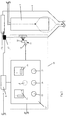
- the indication device 10 may comprise a user panel 12, shown more closely in Fig 2 , in the proximity of the filter unit 3.
- the user panel 12 may be configured to indicate the condition of the filter element 7 to a user.
- the user panel 12 is configured to communicate with the sensor device 11.
- the user panel 12 may be configured to indicate when the filter element 7 needs to be replaced and which filter element 7 needs to be replaced.
- the user panel 12 may be configured to indicate that the filter element 7 is accessible for replacement.
- the user panel 12 may be configured to indicate that the filter element 7 has been replaced.
- the user panel 12 may comprise a display 12A, see Fig 1 , with text informing the user about the value of one or more parameter related to the condition of the filter element 7 or when the filter element 7 was last replaced or explaining to the user what to do, etc..
- the user panel 12 may also comprise at least one lamp 13 generating an optical signal.
- the lamp 13 can indicate to the user when the filter element 7 needs to be replaced.
- the user panel 12 may have more then one lamp, such as for instance a primary lamp 13 and a secondary lamp 14.
- the user panel 12 may have a primary lamp 13 and/or a secondary lamp 14 for each individual filter device 4, 5.
- the primary lamp 13, which may be a green lamp, can be switched on to indicate that the filter element 7 is in order.
- the primary lamp 13 may slowly flash to indicate that the filter element 7 is ready to be replaced. Further, the primary lamp 13 may flash faster to indicate that the filter element 7 is being replaced.
- the secondary lamp which may be a red lamp, could indicate that the filter device 4 is not accessible at that moment, e.g.
- the primary lamp 13 can be turned off.
- the secondary lamp 14 may also be integrated into the primary lamp 13 or it may be a separate lamp.
- the user panel 12 may comprise one or two green lamps 13 and one red lamp 14. The red lamp 14 is lit during cleaning, while the green lamps 13 are turned off. The red lamp 14 may also be integrated into the green lamps 13. This way, both lamps 13, 14 will turn red during cleaning and milking. In another embodiment, the user panel 12 only has one red lamp 14.
- the user panel 12 may further comprise one or two switches 15 in the form of turning switches, push buttons (not shown), etc..
- the switch or switches 15 may also be connected to the lamp 13, 14 configured to indicate to the user whether and if a filter container 6 can be opened or whether and if a filter element 7 can be replaced.
- the switch 15 can be turned when the primary lamp 13 is slowly flashing, so that the filter element 7 can be replaced.
- the switch 15 can then be reset when the primary lamp 13 is flashing fast to indicate that the filter element 7 has been replaced.
- the user panel 12 may for example have one switch 15 and one primary lamp 13 for the first filter device 4 and another switch 15 and primary lamp 13 for the second filter device 5.
- the primary lamp 13 will indicate that the filter element 7 is accessible for replacement.
- the user panel 12 may in addition have one or two secondary lamps 14 to indicate that the filter element 7 is not accessible.
- the user panel 12 may further comprise a yellow or orange lamp 16 that can be activated when a failure is discovered such as a broken lamp 13, 14, or a problem with a connection in the system or when the milking system is not working.
- the other lamps 13, 14 may be turned off when the yellow lamp 16 is lit, but if something hinders this, the yellow lamp 16 indicates that the signal for the other lamps 13, 14 are false.
- a further timer may be connected to the user panel 12. If one of the switches 15 is turned to replace the filter element 7, the timer may start running, which creates a reminder after a predetermined time, e.g. one hour, and a stop alarm at the start of the cleaning. The stop alarm may be a signal postponing the cleaning. Cleaning will be postponed until the switch 15 is back in the normal position.
- a predetermined time e.g. one hour
- the filter device 4, 6 comprises a mechanical lock 17 configured to permit or prevent opening of the filter container 6.
- Each filter container 6 may comprise a cover 17A or any similar closing member, which is opened when the filter element 7 is to be replaced.
- the indication device 10 communicates with the mechanical lock 17.
- the filter container 6 will be allowed to be opened when said indication indicates that the filter element 7 is accessible for replacement.
- the mechanical lock 17 may also be connected to the control unit 9 and the user panel 12, and configured to prevent opening of the filter container 6 during cleaning or milking. For example, when the secondary lamp 14 is lit, the filter container 6 is mechanically locked, thereby preventing accidental opening of the filter container 6. When the primary lamp 13 is flashing, the lock 17 can be opened and the cover 17A removed so that the filter container 6 may be opened and the filter element 7 replaced.
- Any filter element 7 known to the skilled artisan may be used.
- suitable filter elements 7 are cylindrical mesh elements or disc-shaped mesh elements, possibly rotating and possibly combined with a scraper. Liquids such as milk or cleaning liquid, may flow from inside of a bag-shaped filter element 7 through the filter element 7 towards the outside of the filter element 7, while dirt or sediment remains in the filter element 7. This is illustrated with the dotted lines in the filter container 6 in Fig 2 .
- the indication device 10 may also communicate with the control unit 9 to generate an indication in response to a valve position of the valve arrangement.
- the valve arrangement may communicate with the control unit 9, which is configured to control the cleaning equipment 8 and the valve arrangement.
- the control unit 9 may be configured to supply the rinsing and cleaning liquids during the cleaning operation.
- the liquids may be supplied in various ways to the milk filter unit 3.
- the rinsing liquid is first supplied through the milk filter unit 3 and the first filter device 4 during a pre-rinsing phase. Then, the cleaning liquid is supplied through the milk filter unit 3 during a cleaning phase, and subsequently the rinsing liquid is supplied through the milk filter unit 3 and the second filter device 5 during an after-rinsing phase.
- control unit 9 may be configured to supply during the cleaning phase the cleaning liquid through the first filter device 4 during a minor time period of the cleaning phase and through the second filter device 5 during a major time period of the cleaning phase.
- the minor time period may be defined as at the most 25% of the time used for the cleaning phase and the major time period may be defined as at least 75% of the time used for the cleaning phase.
- the total time needed for the cleaning phase may vary depending on for example the amount of milking members M used since the last cleaning.
- the minor time period is at the most 20% or 15% or 10% or 5% or 2% of the time used for the cleaning phase and the major time period is at least 80% or 85% or 90% or 95% or 98% of the time used for the cleaning phase.
- the minor time period during which the cleaning liquid is conveyed through the first device 4 may be set at the beginning of the cleaning phase, at the end of the cleaning phase or in the middle of the cleaning phase.
- control unit 9 may be configured to supply the rinsing liquid, during the after-rinsing phase, through only the second filter device including the new filter element 7.
- control unit 9 may also be configured to supply the rinsing liquid, during the after-rinsing phase, through the first filter device 4, including the old filter element 7, during an initial minor part of the after-rinsing phase, and through the second filter device 5 for a major part of the after-rinsing phase.
- a milking system may be cleaned with respect to the milk filter unit 3 in many different ways.
- One example of a method for cleaning the milk filter unit 3 will be described, whereby, as indicated above, the filter element 7 of the first filter device 4 is old and to be replaced, and the filter element 7 of the second filter device 5 is new and to be used during the following transport of the milk to the milk tank 2.
- Such a method comprises the following steps of:
- the first filter element 7 may be replaced before supplying the cleaning liquid through the milk filter unit 3 during a minor time period in the method described above.
- the filter element 7 in the first filter device 4 may also be replaced, while the filter element 7 in the second filter device 5 is in use during cleaning or milking.
Landscapes
- Life Sciences & Earth Sciences (AREA)
- Animal Husbandry (AREA)
- Environmental Sciences (AREA)
- External Artificial Organs (AREA)
Claims (13)
- Melksystem, umfassend
ein Melkelement (M) zum Absaugen von Milch von einem Tier,
eine Transportleitung (1), die mit dem Melkelement (M) verbunden ist,
einen mit der Transportleitung (1) verbundenen Milchbehälter (2), der so angeordnet ist, dass er die Milch von dem Melkelement (M) über die Transportleitung (1) aufnimmt,
eine Milchfiltereinheit (3) zum Filtern der Milch, die einen Teil der Transportleitung (1) bildet und die mindestens eine erste Filtervorrichtung (4) und eine zweite Filtervorrichtung (5) umfasst, die jeweils einen Filterbehälter (6) und ein Filterelement (7) umfassen, und
eine Ventilanordnung, die so ausgelegt ist, dass sie die Milch durch die erste Filtervorrichtung (4) und/oder die zweite Filtervorrichtung (5) befördert, wobei die Ventilanordnung mit einer Steuereinheit (9) in Verbindung steht, die so ausgelegt ist, dass sie die Ventilanordnung steuert,
dadurch gekennzeichnet, dass das Melksystem eine Meldevorrichtung (10) umfasst, die so ausgelegt ist, dass sie für einen Benutzer eine Meldung erzeugt, wann das Filterelement (7) der ersten Filtervorrichtung (4) oder der zweiten Filtervorrichtung (5) ausgetauscht werden muss und welches Filterelement (7) der ersten Filtervorrichtung (4) und der zweiten Filtervorrichtung (5) ausgetauscht werden muss,
wobei die Meldung dem Benutzer auch anzeigt, wann das zu ersetzende Filterelement (7) für den Austausch zugänglich ist, wobei das Melksystem ferner eine mechanische Verriegelung (17) umfasst, die so ausgelegt ist, dass sie ein Öffnen des Filterbehälters (6) ermöglicht oder verhindert, damit der Zugang zu dem Filterelement (7), das in dem Filterbehälter (6) enthalten ist, gesteuert wird, wobei die Meldevorrichtung (10) mit der mechanischen Verriegelung (17) in Verbindung steht, um das Öffnen des Filterbehälters (6) zu ermöglichen, wenn die Meldung anzeigt, dass das Filterelement (7) für den Austausch zugänglich ist. - Melksystem nach Anspruch 1, wobei die Meldung dem Benutzer auch anzeigt, dass das Filterelement (7) ersetzt worden ist.
- Melksystem nach Anspruch 1 oder 2, wobei die Meldevorrichtung (10) eine Sensorvorrichtung (11) umfasst, die so ausgelegt ist, dass sie den Wert von mindestens einem Parameter bezüglich des Zustands des Filterelements (7) erfasst.
- Melksystem nach Anspruch 3, wobei der Parameter die Nutzungsdauer des Filterelements (7), Lichtabsorptionseigenschaften des Filterelements (7), die Druckdifferenz über das Filterelement (7) und/oder die durch das Filterelement (7) geflossene Milchmenge ist.
- Melksystem nach Anspruch 3 oder 4, wobei die Meldevorrichtung (10) so ausgelegt ist, dass sie die Meldung als Reaktion auf einen Schwellwert des vom Sensor erfassten Werts erzeugt.
- Melksystem nach einem der Ansprüche 1 bis 5, wobei die Meldevorrichtung (10) ein Bedienteil (12) in der Nähe der Filtereinheit (3) umfasst.
- Melksystem nach einem der Ansprüche 1 bis 6, wobei die Meldevorrichtung (10) mit der Steuereinheit (9) in Verbindung steht, um die Meldung als Reaktion auf eine Ventilposition der Ventilanordnung zu erzeugen.
- Verfahren zum Betreiben des Melksystems nach Anspruch 1, dadurch gekennzeichnet, dass das Verfahren die Schritte des Filterns von Milch durch Befördern der Milch durch die erste Filtervorrichtung (4) und/oder die zweite Filtervorrichtung (5) und des Erzeugens einer Meldung für einen Benutzer umfasst, wann das Filterelement (7) der ersten Filtervorrichtung (4) oder der zweiten Filtervorrichtung (5) ausgetauscht werden muss und welches Filterelement (7) der ersten Filtervorrichtung (4) und der zweiten Filtervorrichtung (5) ausgetauscht werden muss,
wobei die Meldung dem Benutzer auch anzeigt, wann das zu ersetzende Filterelement (7) für den Austausch zugänglich ist. - Verfahren nach Anspruch 8, wobei die Meldung dem Benutzer auch anzeigt, dass das Filterelement (7) ersetzt worden ist.
- Verfahren nach Anspruch 8 oder 9, wobei das Verfahren die weiteren Schritte des Erfassens eines Werts von mindestens einem Parameter bezüglich des Zustands des Filterelements (7) und des Erzeugens der Meldung als Reaktion auf zumindest den vom Sensor erfassten Wert umfasst.
- Verfahren nach einem der Ansprüche 8 bis 10, wobei das Melksystem auch eine Reinigungsausrüstung (8) umfasst, die mit der Transportleitung (1) verbunden und so ausgelegt ist, dass sie eine Spülflüssigkeit und eine Reinigungsflüssigkeit während eines Reinigungsvorgangs durch die Transportleitung (1) hindurch bereitstellt, und wobei die Ventilanordnung auch so ausgelegt ist, dass sie die Spülflüssigkeit und die Reinigungsflüssigkeit durch die erste Filtervorrichtung (4) und/oder die zweite Filtervorrichtung (5) befördert,
wobei das Verfahren die weiteren folgenden Schritte umfasst:- Leiten der Spülflüssigkeit durch die Milchfiltereinheit (3) und die erste Filtervorrichtung (4) während einer Vorspülphase,- Leiten der Reinigungsflüssigkeit durch die Milchfiltereinheit (3) während einer Reinigungsphase, und- Leiten der Spülflüssigkeit durch die Milchfiltereinheit (3) während einer Nachspülphase,wobei die Reinigungsflüssigkeit während der Reinigungsphase während eines kürzeren Zeitraums der Reinigungsphase durch die erste Filtervorrichtung (4) und während eines überwiegenden Zeitraums der Reinigungsphase durch die zweite Filtervorrichtung (5) geleitet wird. - Verfahren nach Anspruch 11, wobei die Spülflüssigkeit während der Nachspülphase durch zumindest die zweite Filtervorrichtung (5) geleitet wird.
- Verfahren nach Anspruch 12, wobei die Spülflüssigkeit während der Nachspülphase während eines anfänglichen kürzeren Teils der Nachspülphase durch die erste Filtervorrichtung (4) und während eines überwiegenden Teils der Nachspülphase durch die zweite Filtervorrichtung (5) geleitet wird.
Applications Claiming Priority (3)
| Application Number | Priority Date | Filing Date | Title |
|---|---|---|---|
| US41410510P | 2010-11-16 | 2010-11-16 | |
| SE1051197 | 2010-11-16 | ||
| PCT/SE2011/051358 WO2012067569A1 (en) | 2010-11-16 | 2011-11-11 | A milking system, and a method for operating a milking system |
Publications (3)
| Publication Number | Publication Date |
|---|---|
| EP2640184A1 EP2640184A1 (de) | 2013-09-25 |
| EP2640184B1 EP2640184B1 (de) | 2017-05-17 |
| EP2640184B2 true EP2640184B2 (de) | 2020-07-01 |
Family
ID=45346534
Family Applications (1)
| Application Number | Title | Priority Date | Filing Date |
|---|---|---|---|
| EP11794872.9A Not-in-force EP2640184B2 (de) | 2010-11-16 | 2011-11-11 | Melksystem und verfahren für den betrieb eines melksystems |
Country Status (3)
| Country | Link |
|---|---|
| US (1) | US9332726B2 (de) |
| EP (1) | EP2640184B2 (de) |
| WO (1) | WO2012067569A1 (de) |
Families Citing this family (9)
| Publication number | Priority date | Publication date | Assignee | Title |
|---|---|---|---|---|
| US10874084B2 (en) | 2004-06-12 | 2020-12-29 | Gea Farm Technologies, Inc. | Safety valve for a dairy system component |
| US11723341B2 (en) | 2009-09-04 | 2023-08-15 | Gea Farm Technologies, Inc. | Safety valve for an automated milker unit backflushing and teat dip applicator system |
| US20120097107A1 (en) | 2010-02-22 | 2012-04-26 | Gea Farm Technologies, Inc. | Dairy animal milking preparation system and methods |
| US8800486B2 (en) * | 2010-10-26 | 2014-08-12 | Delaval Holding Ab | Control system and a method for milking members in a milking parlour |
| WO2019090136A1 (en) * | 2017-11-03 | 2019-05-09 | Gea Farm Technologies, Inc. | Automated milking system safety valve arrangement |
| RU185329U1 (ru) * | 2018-05-17 | 2018-11-30 | Общество с ограниченной ответственностью "ПРОФИТМИЛК" | Устройство фильтрации жидких смесей |
| KR102430520B1 (ko) * | 2020-08-28 | 2022-08-10 | 주식회사 다운 | 착유기용 우유필터 |
| CN116018063A (zh) | 2020-09-03 | 2023-04-25 | 莱利专利股份有限公司 | 具有奶过滤器的挤奶设备 |
| NL2026404B1 (nl) * | 2020-09-03 | 2022-05-04 | Lely Patent Nv | Melkinrichting |
Citations (2)
| Publication number | Priority date | Publication date | Assignee | Title |
|---|---|---|---|---|
| US5769025A (en) † | 1993-01-26 | 1998-06-23 | Maasland, N.V. | Milking apparatus |
| WO2002074070A1 (en) † | 2001-03-16 | 2002-09-26 | Delaval Holding Ab | A method and an arrangement for filtering milk |
Family Cites Families (21)
| Publication number | Priority date | Publication date | Assignee | Title |
|---|---|---|---|---|
| US3618781A (en) | 1969-08-22 | 1971-11-09 | Parker Hannifin Corp | Duplex filtering device |
| US3915866A (en) | 1973-10-11 | 1975-10-28 | Parker Hannifin Corp | High pressure filtering device |
| US4385590A (en) | 1981-12-11 | 1983-05-31 | Bruce Mortensen | Apparatus for on-site detection of mastitis in milk animals |
| AU4514285A (en) | 1984-07-27 | 1986-01-30 | Dowty Mining Equipment Ltd. | Fluid filtering systems |
| US4873943A (en) * | 1987-12-28 | 1989-10-17 | Dairy Equipment Co. | Milk flow indicator |
| RU2015665C1 (ru) * | 1991-06-18 | 1994-07-15 | Всероссийский научно-исследовательский институт электрификации сельского хозяйства | Устройство для первичной обработки молока на доильных установках |
| NL9301985A (nl) | 1993-11-17 | 1995-06-16 | Texas Industries Inc | Melkmachine. |
| US5743209A (en) * | 1994-08-01 | 1998-04-28 | La Federation Francaise De Controle Laitier (F.F.C.L.) | System and method for monitoring and controlling milk production at dairy farms |
| NL9402010A (nl) * | 1994-11-30 | 1996-07-01 | Maasland Nv | Inrichting voor het melken van dieren. |
| NL1010829C2 (nl) | 1998-12-16 | 2000-06-19 | Prolion Bv | Inrichting en werkwijze voor het melken van dieren en een vervuilingsmeter. |
| SE0003226D0 (sv) * | 2000-09-12 | 2000-09-12 | Delaval Holding Ab | Milk filtration and filter regeneration |
| DE10046277B4 (de) | 2000-09-19 | 2005-02-10 | Westfaliasurge Gmbh | Verfahren zum Wechseln von Milchfiltern und Wechselvorrichtung für Milchfilter |
| DE20023879U1 (de) | 2000-09-19 | 2007-02-01 | Westfaliasurge Gmbh | Wechselvorrichtung für Milchfilter |
| NL1016817C2 (nl) | 2000-12-06 | 2002-06-07 | Prolion Bv | Melkinrichting en werkwijze voor het reinigen van de melkinrichting. |
| NL1017749C2 (nl) * | 2001-03-30 | 2002-10-01 | Lely Entpr Ag | Inrichting voor het automatisch melken van dieren. |
| US20030168389A1 (en) | 2002-02-15 | 2003-09-11 | Astle Robert E. | System for monitoring the performance of fluid treatment cartridges |
| US6619227B1 (en) * | 2002-04-04 | 2003-09-16 | Danaher Controls | Milking equipment wash monitoring system and method |
| NL1027439C1 (nl) | 2004-01-29 | 2005-08-01 | Lely Entpr Ag | Inrichting en werkwijze voor het reinigen van een melkinstallatie. |
| US7481919B1 (en) | 2004-03-26 | 2009-01-27 | Keenan Andrew D | Multiple filter controller |
| IL184410A (en) * | 2007-07-04 | 2012-06-28 | Water Works Ass | Clogging rate monitor |
| DE102008039667A1 (de) | 2008-08-26 | 2010-04-08 | Lufthansa Technik Ag | Wasseraufbereitungsvorrichtung und -verfahren für eine Trinkwasseranlage insbesondere in einem Passagierflugzeug |
-
2011
- 2011-11-11 EP EP11794872.9A patent/EP2640184B2/de not_active Not-in-force
- 2011-11-11 US US13/881,740 patent/US9332726B2/en not_active Expired - Fee Related
- 2011-11-11 WO PCT/SE2011/051358 patent/WO2012067569A1/en not_active Ceased
Patent Citations (2)
| Publication number | Priority date | Publication date | Assignee | Title |
|---|---|---|---|---|
| US5769025A (en) † | 1993-01-26 | 1998-06-23 | Maasland, N.V. | Milking apparatus |
| WO2002074070A1 (en) † | 2001-03-16 | 2002-09-26 | Delaval Holding Ab | A method and an arrangement for filtering milk |
Also Published As
| Publication number | Publication date |
|---|---|
| US9332726B2 (en) | 2016-05-10 |
| EP2640184A1 (de) | 2013-09-25 |
| EP2640184B1 (de) | 2017-05-17 |
| US20130213304A1 (en) | 2013-08-22 |
| WO2012067569A1 (en) | 2012-05-24 |
Similar Documents
| Publication | Publication Date | Title |
|---|---|---|
| EP2640184B1 (de) | Melksystem und verfahren für den betrieb eines melksystems | |
| KR20170059001A (ko) | 음료 자판기, 특히 커피 머신 및 음료 자판기의 작동방법 | |
| US7670485B2 (en) | Water treatment assembly | |
| CN110337419B (zh) | 用于饮料分配机的自动化清洁系统 | |
| KR101185212B1 (ko) | 세정시스템이 구비된 정수기 | |
| JP5536055B2 (ja) | 液体供給システム、液体供給切換装置、及び液体流路調整装置 | |
| EP1852131A1 (de) | Wasserspender mit Desinfektionskreislauf | |
| JP7693660B2 (ja) | 真空廃水デバイス及び方法 | |
| US7718054B2 (en) | Water treatment system | |
| CA2719873A1 (en) | System and method for conveying status information regarding an electronic faucet | |
| SK4532000A3 (en) | Water purifying and dispensing apparatus | |
| US12065363B2 (en) | Antimicrobial capture system with carbon container | |
| US7776209B2 (en) | Control method and apparatus for a water treatment system | |
| US20140158219A1 (en) | System for pipe treatment | |
| KR101916526B1 (ko) | 급이기의 센서 오동작을 감지하는 방법 | |
| JP4011313B2 (ja) | 電池式浄水装置 | |
| EP1559314B1 (de) | Vorrichtung und Verfahren zur Reinigung einer Melkanlage | |
| JP7605983B2 (ja) | 洗濯処理組成物の供給システム | |
| JP6532787B2 (ja) | 水質計保護システム及び水質測定システム | |
| JP2005245330A (ja) | スープ製造装置 | |
| KR100366882B1 (ko) | 정수기의 정수량 제어장치 | |
| JP2002159967A (ja) | 浄水装置 | |
| CN118000116A (zh) | 一种宠物饮水机的出水构件 | |
| KR20110094173A (ko) | 세정시스템이 구비된 정수기 | |
| HK40068373A (en) | Urinal system, water consumer system having a urinal system, and method for operating a urinal system |
Legal Events
| Date | Code | Title | Description |
|---|---|---|---|
| PUAI | Public reference made under article 153(3) epc to a published international application that has entered the european phase |
Free format text: ORIGINAL CODE: 0009012 |
|
| 17P | Request for examination filed |
Effective date: 20130517 |
|
| AK | Designated contracting states |
Kind code of ref document: A1 Designated state(s): AL AT BE BG CH CY CZ DE DK EE ES FI FR GB GR HR HU IE IS IT LI LT LU LV MC MK MT NL NO PL PT RO RS SE SI SK SM TR |
|
| DAX | Request for extension of the european patent (deleted) | ||
| GRAP | Despatch of communication of intention to grant a patent |
Free format text: ORIGINAL CODE: EPIDOSNIGR1 |
|
| RIC1 | Information provided on ipc code assigned before grant |
Ipc: A01J 7/02 20060101AFI20161114BHEP Ipc: A01J 11/06 20060101ALI20161114BHEP Ipc: A01J 5/013 20060101ALI20161114BHEP |
|
| INTG | Intention to grant announced |
Effective date: 20161213 |
|
| RIN1 | Information on inventor provided before grant (corrected) |
Inventor name: PERSSON, STAFFAN Inventor name: BOSMA, EPKE |
|
| GRAS | Grant fee paid |
Free format text: ORIGINAL CODE: EPIDOSNIGR3 |
|
| GRAA | (expected) grant |
Free format text: ORIGINAL CODE: 0009210 |
|
| AK | Designated contracting states |
Kind code of ref document: B1 Designated state(s): AL AT BE BG CH CY CZ DE DK EE ES FI FR GB GR HR HU IE IS IT LI LT LU LV MC MK MT NL NO PL PT RO RS SE SI SK SM TR |
|
| REG | Reference to a national code |
Ref country code: GB Ref legal event code: FG4D |
|
| REG | Reference to a national code |
Ref country code: CH Ref legal event code: EP |
|
| REG | Reference to a national code |
Ref country code: IE Ref legal event code: FG4D Ref country code: NL Ref legal event code: FP |
|
| REG | Reference to a national code |
Ref country code: AT Ref legal event code: REF Ref document number: 893593 Country of ref document: AT Kind code of ref document: T Effective date: 20170615 |
|
| REG | Reference to a national code |
Ref country code: DE Ref legal event code: R096 Ref document number: 602011038088 Country of ref document: DE |
|
| REG | Reference to a national code |
Ref country code: LT Ref legal event code: MG4D |
|
| REG | Reference to a national code |
Ref country code: AT Ref legal event code: MK05 Ref document number: 893593 Country of ref document: AT Kind code of ref document: T Effective date: 20170517 |
|
| PG25 | Lapsed in a contracting state [announced via postgrant information from national office to epo] |
Ref country code: AT Free format text: LAPSE BECAUSE OF FAILURE TO SUBMIT A TRANSLATION OF THE DESCRIPTION OR TO PAY THE FEE WITHIN THE PRESCRIBED TIME-LIMIT Effective date: 20170517 Ref country code: NO Free format text: LAPSE BECAUSE OF FAILURE TO SUBMIT A TRANSLATION OF THE DESCRIPTION OR TO PAY THE FEE WITHIN THE PRESCRIBED TIME-LIMIT Effective date: 20170817 Ref country code: ES Free format text: LAPSE BECAUSE OF FAILURE TO SUBMIT A TRANSLATION OF THE DESCRIPTION OR TO PAY THE FEE WITHIN THE PRESCRIBED TIME-LIMIT Effective date: 20170517 Ref country code: FI Free format text: LAPSE BECAUSE OF FAILURE TO SUBMIT A TRANSLATION OF THE DESCRIPTION OR TO PAY THE FEE WITHIN THE PRESCRIBED TIME-LIMIT Effective date: 20170517 Ref country code: GR Free format text: LAPSE BECAUSE OF FAILURE TO SUBMIT A TRANSLATION OF THE DESCRIPTION OR TO PAY THE FEE WITHIN THE PRESCRIBED TIME-LIMIT Effective date: 20170818 Ref country code: LT Free format text: LAPSE BECAUSE OF FAILURE TO SUBMIT A TRANSLATION OF THE DESCRIPTION OR TO PAY THE FEE WITHIN THE PRESCRIBED TIME-LIMIT Effective date: 20170517 Ref country code: HR Free format text: LAPSE BECAUSE OF FAILURE TO SUBMIT A TRANSLATION OF THE DESCRIPTION OR TO PAY THE FEE WITHIN THE PRESCRIBED TIME-LIMIT Effective date: 20170517 |
|
| PG25 | Lapsed in a contracting state [announced via postgrant information from national office to epo] |
Ref country code: IS Free format text: LAPSE BECAUSE OF FAILURE TO SUBMIT A TRANSLATION OF THE DESCRIPTION OR TO PAY THE FEE WITHIN THE PRESCRIBED TIME-LIMIT Effective date: 20170917 Ref country code: RS Free format text: LAPSE BECAUSE OF FAILURE TO SUBMIT A TRANSLATION OF THE DESCRIPTION OR TO PAY THE FEE WITHIN THE PRESCRIBED TIME-LIMIT Effective date: 20170517 Ref country code: BG Free format text: LAPSE BECAUSE OF FAILURE TO SUBMIT A TRANSLATION OF THE DESCRIPTION OR TO PAY THE FEE WITHIN THE PRESCRIBED TIME-LIMIT Effective date: 20170817 Ref country code: SE Free format text: LAPSE BECAUSE OF FAILURE TO SUBMIT A TRANSLATION OF THE DESCRIPTION OR TO PAY THE FEE WITHIN THE PRESCRIBED TIME-LIMIT Effective date: 20170517 Ref country code: PL Free format text: LAPSE BECAUSE OF FAILURE TO SUBMIT A TRANSLATION OF THE DESCRIPTION OR TO PAY THE FEE WITHIN THE PRESCRIBED TIME-LIMIT Effective date: 20170517 Ref country code: LV Free format text: LAPSE BECAUSE OF FAILURE TO SUBMIT A TRANSLATION OF THE DESCRIPTION OR TO PAY THE FEE WITHIN THE PRESCRIBED TIME-LIMIT Effective date: 20170517 |
|
| PG25 | Lapsed in a contracting state [announced via postgrant information from national office to epo] |
Ref country code: EE Free format text: LAPSE BECAUSE OF FAILURE TO SUBMIT A TRANSLATION OF THE DESCRIPTION OR TO PAY THE FEE WITHIN THE PRESCRIBED TIME-LIMIT Effective date: 20170517 Ref country code: RO Free format text: LAPSE BECAUSE OF FAILURE TO SUBMIT A TRANSLATION OF THE DESCRIPTION OR TO PAY THE FEE WITHIN THE PRESCRIBED TIME-LIMIT Effective date: 20170517 Ref country code: CZ Free format text: LAPSE BECAUSE OF FAILURE TO SUBMIT A TRANSLATION OF THE DESCRIPTION OR TO PAY THE FEE WITHIN THE PRESCRIBED TIME-LIMIT Effective date: 20170517 Ref country code: DK Free format text: LAPSE BECAUSE OF FAILURE TO SUBMIT A TRANSLATION OF THE DESCRIPTION OR TO PAY THE FEE WITHIN THE PRESCRIBED TIME-LIMIT Effective date: 20170517 Ref country code: SK Free format text: LAPSE BECAUSE OF FAILURE TO SUBMIT A TRANSLATION OF THE DESCRIPTION OR TO PAY THE FEE WITHIN THE PRESCRIBED TIME-LIMIT Effective date: 20170517 |
|
| REG | Reference to a national code |
Ref country code: DE Ref legal event code: R026 Ref document number: 602011038088 Country of ref document: DE |
|
| PLBI | Opposition filed |
Free format text: ORIGINAL CODE: 0009260 |
|
| PG25 | Lapsed in a contracting state [announced via postgrant information from national office to epo] |
Ref country code: SM Free format text: LAPSE BECAUSE OF FAILURE TO SUBMIT A TRANSLATION OF THE DESCRIPTION OR TO PAY THE FEE WITHIN THE PRESCRIBED TIME-LIMIT Effective date: 20170517 Ref country code: IT Free format text: LAPSE BECAUSE OF FAILURE TO SUBMIT A TRANSLATION OF THE DESCRIPTION OR TO PAY THE FEE WITHIN THE PRESCRIBED TIME-LIMIT Effective date: 20170517 |
|
| PLAX | Notice of opposition and request to file observation + time limit sent |
Free format text: ORIGINAL CODE: EPIDOSNOBS2 |
|
| 26 | Opposition filed |
Opponent name: OCTROOIBUREAU VAN DER LELY N.V. Effective date: 20180219 |
|
| PG25 | Lapsed in a contracting state [announced via postgrant information from national office to epo] |
Ref country code: SI Free format text: LAPSE BECAUSE OF FAILURE TO SUBMIT A TRANSLATION OF THE DESCRIPTION OR TO PAY THE FEE WITHIN THE PRESCRIBED TIME-LIMIT Effective date: 20170517 |
|
| PG25 | Lapsed in a contracting state [announced via postgrant information from national office to epo] |
Ref country code: MC Free format text: LAPSE BECAUSE OF FAILURE TO SUBMIT A TRANSLATION OF THE DESCRIPTION OR TO PAY THE FEE WITHIN THE PRESCRIBED TIME-LIMIT Effective date: 20170517 |
|
| PLBB | Reply of patent proprietor to notice(s) of opposition received |
Free format text: ORIGINAL CODE: EPIDOSNOBS3 |
|
| GBPC | Gb: european patent ceased through non-payment of renewal fee |
Effective date: 20171111 |
|
| PG25 | Lapsed in a contracting state [announced via postgrant information from national office to epo] |
Ref country code: CH Free format text: LAPSE BECAUSE OF NON-PAYMENT OF DUE FEES Effective date: 20171130 Ref country code: LI Free format text: LAPSE BECAUSE OF NON-PAYMENT OF DUE FEES Effective date: 20171130 |
|
| PG25 | Lapsed in a contracting state [announced via postgrant information from national office to epo] |
Ref country code: LU Free format text: LAPSE BECAUSE OF NON-PAYMENT OF DUE FEES Effective date: 20171111 |
|
| REG | Reference to a national code |
Ref country code: FR Ref legal event code: ST Effective date: 20180731 Ref country code: BE Ref legal event code: MM Effective date: 20171130 |
|
| REG | Reference to a national code |
Ref country code: IE Ref legal event code: MM4A |
|
| PG25 | Lapsed in a contracting state [announced via postgrant information from national office to epo] |
Ref country code: MT Free format text: LAPSE BECAUSE OF NON-PAYMENT OF DUE FEES Effective date: 20171111 |
|
| PG25 | Lapsed in a contracting state [announced via postgrant information from national office to epo] |
Ref country code: IE Free format text: LAPSE BECAUSE OF NON-PAYMENT OF DUE FEES Effective date: 20171111 Ref country code: FR Free format text: LAPSE BECAUSE OF NON-PAYMENT OF DUE FEES Effective date: 20171130 |
|
| PG25 | Lapsed in a contracting state [announced via postgrant information from national office to epo] |
Ref country code: BE Free format text: LAPSE BECAUSE OF NON-PAYMENT OF DUE FEES Effective date: 20171130 Ref country code: GB Free format text: LAPSE BECAUSE OF NON-PAYMENT OF DUE FEES Effective date: 20171111 |
|
| PG25 | Lapsed in a contracting state [announced via postgrant information from national office to epo] |
Ref country code: HU Free format text: LAPSE BECAUSE OF FAILURE TO SUBMIT A TRANSLATION OF THE DESCRIPTION OR TO PAY THE FEE WITHIN THE PRESCRIBED TIME-LIMIT; INVALID AB INITIO Effective date: 20111111 |
|
| PG25 | Lapsed in a contracting state [announced via postgrant information from national office to epo] |
Ref country code: CY Free format text: LAPSE BECAUSE OF NON-PAYMENT OF DUE FEES Effective date: 20170517 |
|
| PG25 | Lapsed in a contracting state [announced via postgrant information from national office to epo] |
Ref country code: MK Free format text: LAPSE BECAUSE OF FAILURE TO SUBMIT A TRANSLATION OF THE DESCRIPTION OR TO PAY THE FEE WITHIN THE PRESCRIBED TIME-LIMIT Effective date: 20170517 |
|
| PG25 | Lapsed in a contracting state [announced via postgrant information from national office to epo] |
Ref country code: TR Free format text: LAPSE BECAUSE OF FAILURE TO SUBMIT A TRANSLATION OF THE DESCRIPTION OR TO PAY THE FEE WITHIN THE PRESCRIBED TIME-LIMIT Effective date: 20170517 |
|
| PG25 | Lapsed in a contracting state [announced via postgrant information from national office to epo] |
Ref country code: PT Free format text: LAPSE BECAUSE OF FAILURE TO SUBMIT A TRANSLATION OF THE DESCRIPTION OR TO PAY THE FEE WITHIN THE PRESCRIBED TIME-LIMIT Effective date: 20170517 |
|
| PUAH | Patent maintained in amended form |
Free format text: ORIGINAL CODE: 0009272 |
|
| STAA | Information on the status of an ep patent application or granted ep patent |
Free format text: STATUS: PATENT MAINTAINED AS AMENDED |
|
| 27A | Patent maintained in amended form |
Effective date: 20200701 |
|
| AK | Designated contracting states |
Kind code of ref document: B2 Designated state(s): AL AT BE BG CH CY CZ DE DK EE ES FI FR GB GR HR HU IE IS IT LI LT LU LV MC MK MT NL NO PL PT RO RS SE SI SK SM TR |
|
| REG | Reference to a national code |
Ref country code: DE Ref legal event code: R102 Ref document number: 602011038088 Country of ref document: DE |
|
| PG25 | Lapsed in a contracting state [announced via postgrant information from national office to epo] |
Ref country code: AL Free format text: LAPSE BECAUSE OF FAILURE TO SUBMIT A TRANSLATION OF THE DESCRIPTION OR TO PAY THE FEE WITHIN THE PRESCRIBED TIME-LIMIT Effective date: 20170517 |
|
| REG | Reference to a national code |
Ref country code: NL Ref legal event code: FP |
|
| PGFP | Annual fee paid to national office [announced via postgrant information from national office to epo] |
Ref country code: NL Payment date: 20221019 Year of fee payment: 12 |
|
| PGFP | Annual fee paid to national office [announced via postgrant information from national office to epo] |
Ref country code: DE Payment date: 20221004 Year of fee payment: 12 |
|
| REG | Reference to a national code |
Ref country code: DE Ref legal event code: R119 Ref document number: 602011038088 Country of ref document: DE |
|
| REG | Reference to a national code |
Ref country code: NL Ref legal event code: MM Effective date: 20231201 |
|
| PG25 | Lapsed in a contracting state [announced via postgrant information from national office to epo] |
Ref country code: NL Free format text: LAPSE BECAUSE OF NON-PAYMENT OF DUE FEES Effective date: 20231201 |
|
| PG25 | Lapsed in a contracting state [announced via postgrant information from national office to epo] |
Ref country code: NL Free format text: LAPSE BECAUSE OF NON-PAYMENT OF DUE FEES Effective date: 20231201 |
|
| PG25 | Lapsed in a contracting state [announced via postgrant information from national office to epo] |
Ref country code: DE Free format text: LAPSE BECAUSE OF NON-PAYMENT OF DUE FEES Effective date: 20240601 |
|
| PG25 | Lapsed in a contracting state [announced via postgrant information from national office to epo] |
Ref country code: DE Free format text: LAPSE BECAUSE OF NON-PAYMENT OF DUE FEES Effective date: 20240601 |