EP3700076A1 - Multi-level inverter - Google Patents
Multi-level inverter Download PDFInfo
- Publication number
- EP3700076A1 EP3700076A1 EP20163235.3A EP20163235A EP3700076A1 EP 3700076 A1 EP3700076 A1 EP 3700076A1 EP 20163235 A EP20163235 A EP 20163235A EP 3700076 A1 EP3700076 A1 EP 3700076A1
- Authority
- EP
- European Patent Office
- Prior art keywords
- switches
- switch
- voltage
- bank
- input
- Prior art date
- Legal status (The legal status is an assumption and is not a legal conclusion. Google has not performed a legal analysis and makes no representation as to the accuracy of the status listed.)
- Pending
Links
- 239000003990 capacitor Substances 0.000 claims description 167
- 238000000034 method Methods 0.000 claims description 23
- 230000000295 complement effect Effects 0.000 claims description 6
- 230000016507 interphase Effects 0.000 description 33
- 230000008901 benefit Effects 0.000 description 18
- 230000009467 reduction Effects 0.000 description 16
- 238000010586 diagram Methods 0.000 description 9
- 238000005516 engineering process Methods 0.000 description 6
- 238000001816 cooling Methods 0.000 description 4
- 238000013461 design Methods 0.000 description 4
- 230000005291 magnetic effect Effects 0.000 description 4
- 230000004048 modification Effects 0.000 description 4
- 238000012986 modification Methods 0.000 description 4
- 238000011160 research Methods 0.000 description 4
- 230000007704 transition Effects 0.000 description 4
- 230000008859 change Effects 0.000 description 3
- 230000006872 improvement Effects 0.000 description 3
- 230000007246 mechanism Effects 0.000 description 3
- 239000000243 solution Substances 0.000 description 3
- 238000003860 storage Methods 0.000 description 3
- 230000004075 alteration Effects 0.000 description 2
- 238000004364 calculation method Methods 0.000 description 2
- 238000006243 chemical reaction Methods 0.000 description 2
- 230000004044 response Effects 0.000 description 2
- 102220281055 rs759653160 Human genes 0.000 description 2
- 102220059229 rs786203745 Human genes 0.000 description 2
- 102220106769 rs879255496 Human genes 0.000 description 2
- 241001101998 Galium Species 0.000 description 1
- 102220499859 Neuronal acetylcholine receptor subunit beta-3_T83D_mutation Human genes 0.000 description 1
- 102220546262 Ras-related protein Rab-43_T82E_mutation Human genes 0.000 description 1
- XAGFODPZIPBFFR-UHFFFAOYSA-N aluminium Chemical compound [Al] XAGFODPZIPBFFR-UHFFFAOYSA-N 0.000 description 1
- 229910052782 aluminium Inorganic materials 0.000 description 1
- 238000013459 approach Methods 0.000 description 1
- 230000003190 augmentative effect Effects 0.000 description 1
- 102220358029 c.232A>G Human genes 0.000 description 1
- 230000008878 coupling Effects 0.000 description 1
- 238000010168 coupling process Methods 0.000 description 1
- 238000005859 coupling reaction Methods 0.000 description 1
- 230000003111 delayed effect Effects 0.000 description 1
- 238000001914 filtration Methods 0.000 description 1
- 238000004519 manufacturing process Methods 0.000 description 1
- 230000007935 neutral effect Effects 0.000 description 1
- 150000004767 nitrides Chemical class 0.000 description 1
- 230000008569 process Effects 0.000 description 1
- 230000010349 pulsation Effects 0.000 description 1
- 238000009877 rendering Methods 0.000 description 1
- 102220325588 rs1184817036 Human genes 0.000 description 1
- 102200017208 rs1555451582 Human genes 0.000 description 1
- 102220061725 rs200018296 Human genes 0.000 description 1
- 102220012483 rs2069540 Human genes 0.000 description 1
- 102200022326 rs28936416 Human genes 0.000 description 1
- 102220026959 rs587778998 Human genes 0.000 description 1
- 102220221032 rs61729796 Human genes 0.000 description 1
- 102200153443 rs768834663 Human genes 0.000 description 1
- 238000007493 shaping process Methods 0.000 description 1
- 230000007480 spreading Effects 0.000 description 1
- 238000003892 spreading Methods 0.000 description 1
- 239000012086 standard solution Substances 0.000 description 1
- 238000012360 testing method Methods 0.000 description 1
- 238000012546 transfer Methods 0.000 description 1
Images


Classifications
-
- H—ELECTRICITY
- H02—GENERATION; CONVERSION OR DISTRIBUTION OF ELECTRIC POWER
- H02M—APPARATUS FOR CONVERSION BETWEEN AC AND AC, BETWEEN AC AND DC, OR BETWEEN DC AND DC, AND FOR USE WITH MAINS OR SIMILAR POWER SUPPLY SYSTEMS; CONVERSION OF DC OR AC INPUT POWER INTO SURGE OUTPUT POWER; CONTROL OR REGULATION THEREOF
- H02M7/00—Conversion of ac power input into dc power output; Conversion of dc power input into ac power output
- H02M7/42—Conversion of dc power input into ac power output without possibility of reversal
- H02M7/44—Conversion of dc power input into ac power output without possibility of reversal by static converters
- H02M7/48—Conversion of dc power input into ac power output without possibility of reversal by static converters using discharge tubes with control electrode or semiconductor devices with control electrode
- H02M7/483—Converters with outputs that each can have more than two voltages levels
-
- H—ELECTRICITY
- H02—GENERATION; CONVERSION OR DISTRIBUTION OF ELECTRIC POWER
- H02M—APPARATUS FOR CONVERSION BETWEEN AC AND AC, BETWEEN AC AND DC, OR BETWEEN DC AND DC, AND FOR USE WITH MAINS OR SIMILAR POWER SUPPLY SYSTEMS; CONVERSION OF DC OR AC INPUT POWER INTO SURGE OUTPUT POWER; CONTROL OR REGULATION THEREOF
- H02M1/00—Details of apparatus for conversion
- H02M1/0095—Hybrid converter topologies, e.g. NPC mixed with flying capacitor, thyristor converter mixed with MMC or charge pump mixed with buck
-
- H—ELECTRICITY
- H02—GENERATION; CONVERSION OR DISTRIBUTION OF ELECTRIC POWER
- H02M—APPARATUS FOR CONVERSION BETWEEN AC AND AC, BETWEEN AC AND DC, OR BETWEEN DC AND DC, AND FOR USE WITH MAINS OR SIMILAR POWER SUPPLY SYSTEMS; CONVERSION OF DC OR AC INPUT POWER INTO SURGE OUTPUT POWER; CONTROL OR REGULATION THEREOF
- H02M1/00—Details of apparatus for conversion
- H02M1/08—Circuits specially adapted for the generation of control voltages for semiconductor devices incorporated in static converters
-
- H—ELECTRICITY
- H02—GENERATION; CONVERSION OR DISTRIBUTION OF ELECTRIC POWER
- H02M—APPARATUS FOR CONVERSION BETWEEN AC AND AC, BETWEEN AC AND DC, OR BETWEEN DC AND DC, AND FOR USE WITH MAINS OR SIMILAR POWER SUPPLY SYSTEMS; CONVERSION OF DC OR AC INPUT POWER INTO SURGE OUTPUT POWER; CONTROL OR REGULATION THEREOF
- H02M1/00—Details of apparatus for conversion
- H02M1/12—Arrangements for reducing harmonics from ac input or output
- H02M1/126—Arrangements for reducing harmonics from ac input or output using passive filters
-
- H—ELECTRICITY
- H02—GENERATION; CONVERSION OR DISTRIBUTION OF ELECTRIC POWER
- H02M—APPARATUS FOR CONVERSION BETWEEN AC AND AC, BETWEEN AC AND DC, OR BETWEEN DC AND DC, AND FOR USE WITH MAINS OR SIMILAR POWER SUPPLY SYSTEMS; CONVERSION OF DC OR AC INPUT POWER INTO SURGE OUTPUT POWER; CONTROL OR REGULATION THEREOF
- H02M1/00—Details of apparatus for conversion
- H02M1/14—Arrangements for reducing ripples from dc input or output
- H02M1/143—Arrangements for reducing ripples from dc input or output using compensating arrangements
-
- H—ELECTRICITY
- H02—GENERATION; CONVERSION OR DISTRIBUTION OF ELECTRIC POWER
- H02M—APPARATUS FOR CONVERSION BETWEEN AC AND AC, BETWEEN AC AND DC, OR BETWEEN DC AND DC, AND FOR USE WITH MAINS OR SIMILAR POWER SUPPLY SYSTEMS; CONVERSION OF DC OR AC INPUT POWER INTO SURGE OUTPUT POWER; CONTROL OR REGULATION THEREOF
- H02M7/00—Conversion of ac power input into dc power output; Conversion of dc power input into ac power output
- H02M7/42—Conversion of dc power input into ac power output without possibility of reversal
- H02M7/44—Conversion of dc power input into ac power output without possibility of reversal by static converters
- H02M7/48—Conversion of dc power input into ac power output without possibility of reversal by static converters using discharge tubes with control electrode or semiconductor devices with control electrode
- H02M7/483—Converters with outputs that each can have more than two voltages levels
- H02M7/4833—Capacitor voltage balancing
-
- H—ELECTRICITY
- H02—GENERATION; CONVERSION OR DISTRIBUTION OF ELECTRIC POWER
- H02M—APPARATUS FOR CONVERSION BETWEEN AC AND AC, BETWEEN AC AND DC, OR BETWEEN DC AND DC, AND FOR USE WITH MAINS OR SIMILAR POWER SUPPLY SYSTEMS; CONVERSION OF DC OR AC INPUT POWER INTO SURGE OUTPUT POWER; CONTROL OR REGULATION THEREOF
- H02M7/00—Conversion of ac power input into dc power output; Conversion of dc power input into ac power output
- H02M7/42—Conversion of dc power input into ac power output without possibility of reversal
- H02M7/44—Conversion of dc power input into ac power output without possibility of reversal by static converters
- H02M7/48—Conversion of dc power input into ac power output without possibility of reversal by static converters using discharge tubes with control electrode or semiconductor devices with control electrode
- H02M7/483—Converters with outputs that each can have more than two voltages levels
- H02M7/4837—Flying capacitor converters
-
- H—ELECTRICITY
- H02—GENERATION; CONVERSION OR DISTRIBUTION OF ELECTRIC POWER
- H02M—APPARATUS FOR CONVERSION BETWEEN AC AND AC, BETWEEN AC AND DC, OR BETWEEN DC AND DC, AND FOR USE WITH MAINS OR SIMILAR POWER SUPPLY SYSTEMS; CONVERSION OF DC OR AC INPUT POWER INTO SURGE OUTPUT POWER; CONTROL OR REGULATION THEREOF
- H02M7/00—Conversion of ac power input into dc power output; Conversion of dc power input into ac power output
- H02M7/42—Conversion of dc power input into ac power output without possibility of reversal
- H02M7/44—Conversion of dc power input into ac power output without possibility of reversal by static converters
- H02M7/48—Conversion of dc power input into ac power output without possibility of reversal by static converters using discharge tubes with control electrode or semiconductor devices with control electrode
- H02M7/53—Conversion of dc power input into ac power output without possibility of reversal by static converters using discharge tubes with control electrode or semiconductor devices with control electrode using devices of a triode or transistor type requiring continuous application of a control signal
- H02M7/537—Conversion of dc power input into ac power output without possibility of reversal by static converters using discharge tubes with control electrode or semiconductor devices with control electrode using devices of a triode or transistor type requiring continuous application of a control signal using semiconductor devices only, e.g. single switched pulse inverters
-
- H—ELECTRICITY
- H02—GENERATION; CONVERSION OR DISTRIBUTION OF ELECTRIC POWER
- H02M—APPARATUS FOR CONVERSION BETWEEN AC AND AC, BETWEEN AC AND DC, OR BETWEEN DC AND DC, AND FOR USE WITH MAINS OR SIMILAR POWER SUPPLY SYSTEMS; CONVERSION OF DC OR AC INPUT POWER INTO SURGE OUTPUT POWER; CONTROL OR REGULATION THEREOF
- H02M1/00—Details of apparatus for conversion
- H02M1/0048—Circuits or arrangements for reducing losses
- H02M1/0054—Transistor switching losses
-
- H—ELECTRICITY
- H02—GENERATION; CONVERSION OR DISTRIBUTION OF ELECTRIC POWER
- H02M—APPARATUS FOR CONVERSION BETWEEN AC AND AC, BETWEEN AC AND DC, OR BETWEEN DC AND DC, AND FOR USE WITH MAINS OR SIMILAR POWER SUPPLY SYSTEMS; CONVERSION OF DC OR AC INPUT POWER INTO SURGE OUTPUT POWER; CONTROL OR REGULATION THEREOF
- H02M7/00—Conversion of ac power input into dc power output; Conversion of dc power input into ac power output
- H02M7/42—Conversion of dc power input into ac power output without possibility of reversal
- H02M7/44—Conversion of dc power input into ac power output without possibility of reversal by static converters
- H02M7/48—Conversion of dc power input into ac power output without possibility of reversal by static converters using discharge tubes with control electrode or semiconductor devices with control electrode
- H02M7/483—Converters with outputs that each can have more than two voltages levels
- H02M7/4835—Converters with outputs that each can have more than two voltages levels comprising two or more cells, each including a switchable capacitor, the capacitors having a nominal charge voltage which corresponds to a given fraction of the input voltage, and the capacitors being selectively connected in series to determine the instantaneous output voltage
Definitions
- the low frequency switching causes the choke to approach or exceed 20% of the overall cost of the inverter.
- Alternative research has sought to use even more advanced switch technology (e.g., Silcon Carbide and/or Galium Nitride) in order to increase frequency and reduce the size of passive components. This research can reduce switching losses to some extent as well but only at the high cost of the advanced switch technology.
- these inverter topologies offer only limited improvements and cannot achieve the cost reduction and efficiencies needed for efficient inverter technologies.
- Embodiments herein may employ a multi-level inverter (e.g., a single phase and/or three phase inverters) with a specialized control system which enables low cost inverters with a high efficiency.
- a multi-level inverter may be utilized where the output of the inverter (before filtering) has several voltage steps thereby reducing the stress on the magnetics of the inverter and improving the output voltage shaping which allows further reduction in switching frequency.
- the control system allows the use of low-voltage MOSFETs (e.g. 80V) in order to form an equivalent switch of higher voltage (e.g. using six 80V MOSFETs resulting in an equivalent 480V switch).
- low-voltage MOSFETs e.g. 80V
- the conduction and switching characteristics of the low voltage switching multi-level inverter are substantially and unexpectedly improved over other multi-level inverter implementations.
- a lower frequency modulation may be utilized for each of the multi-level switches, e.g., each of the MOSFETs may be switched at a moderate frequency (e.g.
- the MOSFETs may be switched in at staggered times according to a duty cycle ratio (which may or may not change according to the sine-wave), where each MOSFET is shifted by, for example, 1/6 of the switching period (for examples with 6 MOSFETs in a series).
- these examples offer other major benefits such as the reduction of passive components (e.g., in the main choke magnetics and/or output filter).
- a reduction in size and/or cost by a factor of N e.g. 6 in the example
- exemplary embodiments discussed herein can achieve an effective frequency within the main choke which may be N times the switching frequency (e.g. 6 ⁇ 200kHz in this example).
- the main choke can be smaller by a factor of N ⁇ 2 (e.g. 36) relative to a standard design.
- a similar calculation can be made for the output filter showing even greater advantage in reduction in cost and increases in efficiencies.
- an exemplary multi-level inverter includes one, two, or more parallel connections each comprising a plurality of different switches disposed across a DC voltage.
- the switches may be coupled to a number of capacitors and/or inductors which may be utilized to smooth a sine-wave of an AC output of the inverter.
- a plurality of switch banks S1A-S6A, S6B-S1B, S1C-S6C, and/or S6D-S1D may be disposed in any suitable configuration such as that shown in Fig. 1A .
- Each of the banks of MOSFET transistors may be variously configured to include two, three, four, five, six, seven, eight, nine, ten, eleven, twelve or more transistors.
- Fig. 1B illustrates half of the circuit illustrated in Fig. 1A .
- the capacitor voltages (C1, C2, C3, C4, and C5) average at 5/6 ⁇ Vdc, 4/6 ⁇ Vdc, 3/6 ⁇ Vdc, 2/6 ⁇ Vdc, 1/6 ⁇ Vdc respectively (e.g. multiples of 1/N, where N is the number capacitors or the number switches in a bank, assuming the capacitors are of equal value).
- steady-state average voltage across each capacitor will scale accordingly.
- some embodiments may pre-charge the capacitors to their steady-state operating voltages.
- One embodiment for pre-charging capacitor voltage during non-steady-state operation of the inverter includes switching series zener diodes and resistors in parallel to each of the MOSFETs as shown in Figure 1C .
- the capacitors are charged according to these resistor dividers, with the zener diodes protecting the MOSFETs from over-voltage.
- the zener diodes and resistors can be switched off once the capacitors are charged to their voltages for steady state operation of the inverter.
- switches Q1 and Q2 may be added, each with a parallel bypass resistor path that can be optionally switched.
- Q1 and Q2 can be switched OFF and the parallel bypass switched ON (if a switch is present), such that the resistors in the parallel bypass path to Q1 and Q2 can limit the charging current from Vdc. Once charged, Q1 and Q2 can be switched ON, for normal operation of the inverter.
- the parallel path to Q1 and Q2 may optionally include series zener diodes.
- Q1 and Q2 are added in this implementation for operation in the pre-charge process as described with respect to Fig. 1C .
- the zener diodes are eliminated from each parallel resistor path.
- voltages of Vdc/2 and Vdc/4 are generated with no current draw from the output (as is the case prior to steady-state operation).
- each of the switches may be controlled by an output from a processor 10 (e.g., logic, one or more processor(s), controls, state machine, controller, microprocessor, software driven control, gate array, and/or other controller).
- a processor 10 e.g., logic, one or more processor(s), controls, state machine, controller, microprocessor, software driven control, gate array, and/or other controller.
- switch bank A comprises a series of FET transistors S1A-S6A (e.g., 20v, 40v, 60v, 80v, 100v, 120v MOSFET transistors) connected together in, for example, a source to drain configuration to form a first switching bank;
- switch bank B comprises a series of FET transistors S1B-S6B (e.g., 20v, 40v, 60v, 80v, 100v, 120v MOSFET transistors) connected together in, for example, a source to drain configuration to form a second switching bank;
- switch bank C comprises a series of FET transistors S1C-S6C (e.g., 20v, 40v, 60v, 80v, 100v, 120v MOSFET transistors) connected together in, for example, a source to drain configuration to form a third switching bank;
- switch bank D comprises a series of FET transistors S1D-S6D (e.g., 20v, 40v, 60v, 80v, 100v, 120
- each of the MOSFETs may be controlled to switch using a high frequency (e.g. around 200kHz in this example) while still having low switching losses compared to other switch technologies.
- the MOSFETs are switched according to the duty cycle ratio (which changes according to the sine-wave) in the following simple manner (shown for six MOSFETs in series), where each MOSFET in series is shifted sequentially by 1/6 of the switching period.
- the specific timing shown in Fig. 2A is an example of the required duty cycles and a variety of different timings may be used that may have similar or different switching performance.
- the duty cycle of the control signals may be varied according to required conversion ratio of the inverter, which may include a full range of duty cycles starting from 0 and ending up at 1 throughout, for example, a 50/60Hz sine wave.
- required conversion ratio of the inverter may include a full range of duty cycles starting from 0 and ending up at 1 throughout, for example, a 50/60Hz sine wave.
- the switch timing does not have any overlap as shown in Fig. 2A .
- the control signals start to overlap up to point where there is a full overlap between all control signals at the duty cycle of 1 (all switches are ON constantly).
- Fig. 2B illustrates a more detailed diagram of low duty cycles where there is no overlap.
- the figure includes both control signals S1 through S6 respectively for switches S1AS6A and signals S1 ⁇ through S6 ⁇ respectively for switches S1B - S6B.
- Fig. IE When there is no overlap of the control signals, only one out of six MOSFET is ON (i.e., closed) on the high-side while only one out of six MOSFETS is OFF (i.e., open) on the low side as shown in Fig. IE.
- Fig. IE is illustrated with the MOSFETS represented as switches, with switch states corresponding to signal S1 On in Fig. 2B .
- the current flow is from Vdc+ towards the output (Grid phase #1) while passing through the MOSFETs that are ON and passing through capacitor C1, resulting in C1 charging with some ripple current.
- any voltage between 0 to 1/6 ⁇ Vdc can be generated with PWM. This occurs for any case where the duty cycles are below 1/6, resulting in no overlap in ON signals between the MOSFETs.
- Figure 2C illustrates another example of a timing diagram with a high duty cycle where there is an overlap between all the MOSFETs besides one (when the duty cycle is higher than 5/6).
- Fig. IF shows the switch states and current flow when there is an overlap between S1 and S2 (due to a duty cycle between 1/6 and 2/6 in this specific example.
- the dotted line again shows the path from Vdc towards the output, and in this case capacitor C2 is used.
- the PWM multiplexing will be between 1/6 ⁇ Vdc (as in the previous case of a single MOSFET in the ON state) and 2/6 ⁇ Vdc, corresponding to a duty cycle that is between 1/6 and 2/6.
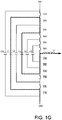
- FIG. 1G Another example of a duty cycle between 1/6 and 2/6 is shown in Fig. 1G where two capacitors are used in the same path towards the output. This is a case of overlap between S2 and S3, again for duty cycles between 1/6 and 2/6.
- capacitor C3 gets charged with ripple current and capacitor C1 gets discharged with ripple current. It is noted that capacitor C1 was charged in the previous case now gets discharged and eventually can ripple about the same value (5/6Vdc).
- the basic timing diagram that was presented is built such that the same duty cycle is used for all six MOSFETs and there is a phase delay of T/N between these MOSFETs which will eventually yield the required voltages according to the duty cycles while keeping all of the capacitors charged and discharged to the same average value.
- states 00 S1 and S2 OFF
- 11 S1 and S2 ON
- current flows directly from Vdc or GND, without going through the capacitor C2 (also identified as the flying capacitor).
- states 01 and 10 flow current into the capacitor where each of these states is opposite in the current direction as shown in Figs 1H and 1I .
- the dwell time in state 01 and state 10 is the same and therefore the capacitor C2 gets charged and discharged by the same portion and eventually stays balanced.
- due to possible mismatches and drifts there is a need to actively tune the capacitor voltage.
- Fig 2D illustrates a timing diagram that has a 20% duty cycle for each S1 and S2 signals.
- Fig. 2F the timing of S1 and S2 are illustrated, with the timing of S1 being changed to a 30% duty cycle and the timing of S2 being changed to 10% such that the average is 20% as required but a drift of the capacitor C2 voltage is towards its required steady state value.
- Another method for balancing capacitors is to change the timing diagram such that the state 01 is switched to more times than state 10.
- This type of balancing solution is more generic and can be used more easily in cases of more than two states (e.g., in the case of more MOSFETs in series) where a particular state is chosen in any time in order to drift the flying capacitors to their pre-charged steady-state value.
- another major benefit of the embodiment shown herein is the reduction of passive components (e.g., main choke and output filter sizes). Due to the multi-level voltages, a factor of N (e.g. 6 in the example) can be reduced in size/cost.
- the effective frequency within the main choke is N times the switching frequency (e.g. 6 ⁇ 200kHz in this case).
- the result of embodiments in accordance with this example is that the main choke can be smaller by a factor of N ⁇ 2 (e.g. 36) relative to a standard design using 200kHz. Since usual inverters use much smaller switching frequencies (e.g.
- a similar calculation can be made for the output filter showing even greater advantage.
- Embodiments of the present invention switch at a higher frequency such as 16KHz or 33KHz or preferably 50kHz, 100kHz, 150kHz, 200kHz, 250kHz, 300kHz or even higher), and the manner in which the switches are modified in accordance with, for example, Figs. 2A-2F .
- the gain in accordance with inverters of the present examples gain a factor of n squared. This unusual result is achieved in part by switching only one component at a time instead of switching all of them in one cycle. Using low voltage MOSFETs, it is possible to switch all of the switches in the same output voltage cycle while still achieving comparatively low switching losses which allows further gains and efficiencies.
- the main choke usually about 20% of both size and cost of an inverter are related to the main choke.
- increasing the frequency to, for example, 6 ⁇ 16 kHz and increasing the number of switches to 6 can result in an additional gain factor of 36 relative to the original 16KHz because of the multi-level components.
- the cost of the main choke can be as little as one percent or even less than that of the overall inverter cost.
- the inverter will be much more efficient and also the production of the output voltage will be much better which gains substantial efficiency. It means that the enclosure and the inverter can be dimensionally much lower and therefore a much smaller and cheaper enclosure can be used. The size and cost of the enclosure is reduced both because of reduction of the main choke, reduction in the filter, and because of improved efficiency, which provides a smaller and more compact enclosure.
- the control shown in Figs. 2A-2F has been demonstrated to have substantial efficiencies over conventional control circuits.
- the control illustrated in Fig. 2A allows the switches S1A-S6A, S6B-S1B, S1C-S6C, and S6D-S1D to be switched all within one period, in this embodiment with the switching of switches in one bank to be offset as shown in Fig. 2A .
- the switches operate six times higher than other control mechanisms.
- an inverter is may comprise two halves with symmetry on each side of the inverter.
- the higher frequency switching allows staggered switching of each switch in each bank (e.g., all six switches) in one cycle, which is six times faster than conventional modulators.
- this voltage may be utilized to produce an AC voltage of, for example, 230V.
- the switching elements in each bank when coupled with the capacitors C1-C5 and C6-C10 may be switched such that the voltages across switching banks A and B and switching banks C and D may sum to a voltage of approximately 350V in this example. Because the voltage across any one switch can be much lower than 350V because the voltage is spread over each of the switch/capacitor combinations, the voltage of the switches can be much smaller (e.g., 350 divided by 6 which or around 60V). This voltage can be made lower and/or higher depending upon the number of switches in each bank.
- the switches may be configured to switch all during the same cycle.
- the switches may each be switched at, for example, 200 kHz. This allows each switch to turn "on" for a predetermined period such as 1/200kHz or around 5 microseconds, during which time each switch turns on and off.
- a conventional multi-level inverter only one switch will switch at one cycle of one of the 16 kHz.
- the low voltage MOSFETs may be switched at a much higher rate (e.g., 200 kHz) and additionally all of the switches in one bank may be switched during the same period. This example effectively increases the speed to 6 times the switching period, without actually increasing the switching frequency.
- the design is scalable in that it can be increased more and more by adding more transistors to the switching banks; the multi-level switching in each bank allows the switching to increase in frequency without driving the MOSFET faster (e.g., six times faster).
- the capacitors between the switches will be smaller. This is part of the size and cost reduction. Additionally, the inductors L1 and L2 are also made smaller. In general, there are many components that shrink by going to a higher frequency, which is being increased, also by the factor of 36.
- the control into S1A-S6A is inverted from the control input into switches S1B-S6B (e.g., when S1A is closed, S1B is open).
- switches S1C-S6C the control inputs to these switches are inverted from the control inputs to switches S1A-S6A (e.g., when S1A is closed, SIC is open).
- switches S1D-S6D these switches have the same control input as those of switches S1A-S6A (e.g., when S1A is closed, SID is closed).
- S1C-S6C are inverted and S1D-S6D are not inverted with respect to the control input signal. Further, S1A-S6A are not inverted and S1B-S6B are inverted.
- 24 switches may be controlled with only six different control outputs from the processor. See, for example, the exemplary control structure shown in Fig. 3 .
- FIG. 4 an alternate embodiment is shown which includes a single leg of multi-level MOSFETs that may be configured to generate a rectified sine-wave by performing DC/DC operation (buck) during a sine-wave cycle.
- the output of the leg may be inverted by a low-frequency full-bridge operated at AC line frequency (e.g., 50Hz).
- the switching losses at the high-frequency are reduced by a factor of two relative to a full-bridge implementation and the conduction losses are a combination of the single multi-level leg and the slow-switching full-bridge. It is possible to reduce the conduction losses of the slow-switching full-bridge by using improved components (e.g Super-junction MOSFETs or a series-stack of low-voltage MOSFETs) while not increasing switching losses due to low switching frequency.
- improved components e.g Super-junction MOSFETs or a series-stack of low-voltage MOSFETs
- Another benefit of this variation is that the component cost may be further reduced since there is only one multi-level leg with all the drivers and balancing capacitors and the full-bridge components can be made much cheaper than the cost of another multi-level leg.
- the output of the high frequency stage is a rectified sine-wave (e.g., whenever the sine-wave is positive, it is the same, whenever the sine-wave is negative, it's still positive).
- the high frequency stage may be configured to generate a sine-wave but it is always positive.
- the low frequency stage inverts the rectified sine-wave to positive and negative, to create a true sine-wave.
- the low-frequency stage may be configured to invert the signal whenever it is needed.
- the low frequency stage has a number of switches such as four switches S10, S11, S12, S13.
- the positive cycle of the sine-wave can be achieved by having the top-left S10 and bottom right S11, switching to on.
- control can switch on the other diagonal, e.g., the upper right switch S12 and the bottom left switch S13 to invert the signal completing a sine-wave.
- These switches may be controlled via a processor such as processor 10 shown in Fig. 3 .
- FIG. 5 Still another embodiment is shown in Fig. 5 .
- S1G-S6G and S6H-S1H and C17-C22 operate above as discussed with respect to Figs 1A-1I , 2A- 2F , and any of the other embodiments discussed below.
- a single phase inverter adds an additional multi-level leg at the input of the inverter.
- the circuit of Fig. 5 may in Fig. 1A (or any of the other embodiments) be connected across the Vdc (e.g., 350v) input (e.g., C17 of Fig. 5 is connected across the 350v input bus).
- this architecture may be referred to as the active capacitor concept.
- the additional leg may be configured to act to transfer capacitive charge between the DC link capacitor (C17) and the storage capacitor (C23) in order to compensate for the low frequency pulsation, such as a low frequency pulse of around 100Hz. Since the storage capacitor C23 may be configured to fluctuate with full voltage swing, its size can be reduced considerably relative to the original size of the input bus capacitance. The size of C17 can be very small.
- the capacitor C17 on the input takes the difference between the output power and the input power.
- the input power is DC and the output power is AC.
- the output power is fluctuating and the DC power does not fluctuate because it is DC.
- Some capacitors absorb over/under power in view of sine-wave fluctuations.
- the input capacitor, on such an inverter is very big and can be 10 percent of the cost of the inverter.
- C17 instead of having a very big capacitor which is C17, using this embodiment, C17 can be very small and actually performing DC to DC conversion between C17 and C23 due to the low power MOSFETs and control switching topology discussed herein.
- the capacitor C11 of Fig. 4 can be replaced with the circuit shown in Fig. 5 (e.g., e.g., connected to C17 of Fig. 5 ).
- the modified Fig. 1A would now have 36 MOSFETs as opposed to 24 MOSFETs.
- the circuit would have 24 MOSFETs as opposed to 12 MOSFETs, but the large capacitor C11 is no longer present.
- the circuit shown in Fig. 5 can serve as replacement for the capacitor on the left-hand side of Fig. 1A (not shown) and/or for a replacement for the capacitor shown on the left-hand side of Fig. 4 (C11).
- MOSFET transistors S1E-S6E and S1F-S6F and associated capacitors there may be additional banks of MOSFET transistors S1E-S6E and S1F-S6F and associated capacitors. These MOSFET transistors would be controlled in the same manner as the other legs and transistor banks discussed herein. In this example, instead of just two legs shown in Fig. 1A , one on the left and one leg on the right, you may have three legs similarly configured.
- Fig. 6 shows another embodiment similar to the flying capacitor topology or the capacitor-clamped multi-level inverter topology shown in, for example, Figs. 1B or 5 .
- two banks G, H of series connected switches are connected to each other between a high voltage and a low voltage and capacitors C17-C22 are nested within each other between the two banks.
- the capacitors are nested within each other by connecting the ends between corresponding switches in each bank.
- capacitor C18 is connected at a first end between S1G and S2G and at a second end between S1H and S2H.
- capacitor C19 is connected at a first end between S2G and S3G and at a second end between S2H and S3H.
- the circuit shown in Fig. 6 reduces the number of capacitors used in the circuit compared to the embodiment shown in Fig. 5 .
- capacitors C18, C20, and C22 from the circuit of Fig. 5 are absent in the circuit shown in Fig. 6 .
- Each two MOSFET transistors in series may be considered as one switch with only one mutual PWM control signal.
- switches S1I and S2I may be considered as one switch and be controlled by a single PWM control signal.
- switches S3I and S4I, S5I and S6I, S6J andS5J, S4J and S3J, and S2J and S1J may be paired.
- Capacitor C25 is connected at a first end between S2I and S3I and at a second end between S2J and S3J.
- the series connection of these two MOSFET transistors allows spreading of the voltage stress between the two MOSFET transistors assuming they are balanced at OFF state and transition times. This balancing may be accomplished with either by biasing the drives of any two adjacent MOSFETs or by still keeping C18, C20, and C22 from Fig.
- FIG. 6 may be applied to any of the embodiments herein.
- Fig. 7 shows another embodiment that is able to reduce the capacitance of one of the flying capacitors.
- standard multi-phase techniques are used by having parallel switches in the middle of the phase leg such that each parallel switch leg is switched in a time-shifted manner versus the other switch leg in order to provide multi-phasing (e.g. 180° in the shown case of two parallel phase legs).
- the parallel switch legs may be a first leg of switches T1B, T1C, T2B, T2C and a second leg of switches T3A, T3B, T4A, T4B.
- Multi-phasing enables reduction of the ripple voltage in the flying capacitor C29 by a factor of four, which allows the reduction of the capacitance of the flying capacitor C29 by the same factor.
- the phase inductor L6 as shown in Fig. 6 can be split into two inductors L8, L9 where mutual coupling eventually allows the reduction of the inductors' size below the original required inductor L6 in the case where multi-phasing is not used.
- Multi-phasing may be used between parallel phase legs in order to achieve benefits in the input capacitance and output inductance.
- the multi-phase technique is employed on a sub-set of the phase leg in order to reduce the flying capacitors and not just the main capacitance of the whole phase leg.
- multi-phasing can be applied to each of the flying capacitors separately and then also applied to the whole leg thereby achieving a hierarchical structure of multi-phasing.
- Fig. 8 shows another embodiment that may be applied on a high voltage boost converter (e.g. as a front-end sub-system of a photovoltaic panel inverter or not necessarily related to an inverter) utilizing the multi-level inverter topology and using low-voltage MOSFET transistors at high switching speeds with staggered timing in the same manner as described herein.
- a high voltage boost converter e.g. as a front-end sub-system of a photovoltaic panel inverter or not necessarily related to an inverter
- This structure is split into two halves where each half of the structure handles half of the input voltage by using multi-level techniques (in the case of Fig. 8 , three-level). It can be of course extended to higher numbers of switches in series thereby increasing the number of levels in each half.
- the switches T5A, T5B, T6A, T6B may form the first half, and the switches T7A, T7B, T8A, T8B may form the second half.
- the control signals to switches T6A-B may an inverted version of the control signal to switches T5A-B, respectively.
- control signal to switch T6A may be inverted from the control signal to switch T5A, and the control signal to switch T6B may be the inverted version of the control signal to switch T5B.
- the timing of the control signals to the A switches (T5A, T6A) may be the delayed version or the same as the controls signals to the B switches (T5B, T6B).
- Control signals similar to the first half may be applied to the second half.
- the control signals to the A switches (T7A, T8A) may be inverted versions of each other, and the control signals to the B switches (T7B, T8B) may be inverted versions of each other.
- the control signals to the T7 switches may be the same or different than the control signals to the T5 switches.
- the control signals to the T8 switches may be the same or different than the T6 switches.
- Fig. 9 shows another embodiment reducing the number of capacitors used in the circuit.
- capacitors C18 and C19 from Fig. 5 or C1 and C2 from Fig. 1B may be removed or used as a small capacitance for balancing purposes such that the three switches S1K-S3K above capacitor C38 in Fig.
- Fig. 10 shows another version of a multi-level inverter circuit including an inter-phase balancing block.
- the circuit of Fig. 10 is similar to the circuit of Fig. 9 with the addition of the inter-phase balancing block B1. Similar to Fig. 9 , the three switches S1M-S3M above capacitor C42 and the three switches S1N-S3N below capacitor C42 may be low frequency switches. Switches S4M-S6M, S4N-S6N may be fast switches using a flying capacitor control method described herein.
- the inter-phase balancing block B1 may be connected in parallel to capacitor C42 which is connected at each end between a low frequency switch S3M, S3N and a high frequency switch S4M, S4N.
- the inter-phase balancing block can share current over capacitor C42 to remove a low frequency (e.g., 50Hz) ripple over capacitor C42 from the switches S1M-S3M and S1N-S3N being switched at 50Hz.
- the circuit shown in Fig. 10 maintains seven levels since, in each 50Hz half cycle, the circuit shown in Fig. 10 provides three different levels resulting in six levels in addition to the zero level.
- the circuit shown in Fig. 10 may comprise a leg of an inverter.
- An inverter may contain several legs.
- a single phase inverter may have two legs with the legs connected via the interphase balancing block B1.
- capacitor C42 of each phase may be connected in parallel to the same interphase balancing block B1 or an inter-phase balancing block B1 shared with another phase.
- a three phase inverter may include three legs connected to each other via inter-phase balancing block B1.
- the addition of the interphase balancing block mechanism connected to capacitor C42 of each phase and sharing the currents can remove the 50Hz ripple over capacitors C42 of each phase.
- the addition of the interphase balancing block allows a topology that uses only capacitors C42-C44 while maintaining the original seven levels.
- Fig. 11 shows an example of an interphase balancing block B1 for a single phase inverter circuit which can have two legs.
- the interphase balancing block B1 shown in Fig. 11 allows the current that was supposed to flow downwards through capacitor C42 and the current that was supposed to flow upwards through capacitor C42 to cancel one another such that no current will flow through these capacitors.
- This block B1 enables the 50Hz ripple to be negated when switch T7 is ON and switch T8 is OFF.
- Switches T7 and T8 are complementary (e.g., receive inverted control signals of each other) and follow the same polarity as the low frequency switches S1M-S3M, S1N-S3N in Fig. 10 .
- switch T7 may follow switches S1N-S3N
- switch T8 may follow switches S1M-S3M
- Switches T7 and T8 may represent any number of switches in series that support the voltage of 6 switches (e.g., MOSFET transistors).
- the inductors L14 andL15 may be included in the circuit to slow the transition between the two legs or to filter high frequency PWM currents flowing between the legs.
- Fig. 12 shows another example of an inter-phase balancing block B1 for a single phase inverter.
- two control signals with mutual dead-time may be used.
- One control signal may be used for the switches of T7A and T7B and another control signal can be used for the switches of T8A and T8B.
- Fig. 13 shows another example of an inter-phase balancing block B1 which may be used with different PWM control signals. An even number of switches between the capacitors may be used. Control signals with dead time between the switches of T7A and T8A, the switches of T7A and T7B, and the switches of T7A and T8B may be used.
- Fig. 14 shows an exemplary circuit incorporating an inter-phase balancing block B1 in a single phase inverter between the two legs of the single phase inverter.
- a single switch T14A as shown in Fig. 14 may be used in place of multiple slow switching (e.g., low frequency) series-connected switches (e.g., MOSFET transistors) such as switches S1M-S3M as shown in Fig. 10 .
- slow switching e.g., low frequency
- series-connected switches e.g., MOSFET transistors
- Fig. 15 shows an exemplary balancing block B1 for a three phase inverter similar to the balancing block B1 shown in Fig. 12 for the single phase inverter.
- Each capacitorC42 may be connected to the next capacitor C42 or the capacitor C42 of another phase by two switches to cancel out the three ripple currents through the capacitor C42 of each of the three phases such that current does not flow through any of the capacitors C42.
- Fig. 16 shows a variation of a balancing block B1 for a three phase inverter.
- the balancing block shown in Fig. 16 includes an intersection point. This variation of the balancing block may be used with an even number of switches in series with dead time controlled signals.
- Fig. 17 shows an example of a three phase inverter including the balancing block shown in Fig. 15 .
- a single switch may be used in place of several slow switching (e.g., low frequency) switches (e.g., MOSFET transistors) in series.
- the interphase balancing block B1 can be extended to any number of phases such that the balancing blocks in each phase are connected together by a balancing block in each of the phases. In order to maintain balance, the phases should complement to 360 degrees.
- Fig. 18 shows an example of a six phase balancing block which may include three phases in a first position and three phases in a position opposite of the first position, where each two phases pair is 180 degrees apart.
- a balancing block per phase instead of having a balancing block per phase and connecting all six balancing blocks together in a similar manner to the three phase case, it is possible to connect each two phases together via their balancing blocks regardless of the other four phases.
- Each structure contains two phases (having one capacitor C42 for each phase).
- any even number of phases can be used such that each pair of phases are 180 degrees shifted such that they can be balanced one against the other without relation to other phases.
- twelve phases can be used such that there are six phases spaced at 60 degrees apart at the AC line frequency and each pair is spaced at 180 degrees apart at the AC line frequency to allow balancing within each pair.
- Fig. 19 shows an overall structure of another embodiment of the multi-level inverter.
- the example structure of Fig. 19 includes three phases having three phase blocks P1 and a balancing block B2 connected to all three phase blocks P1 via the capacitor Cin of each phase block P1. While Fig. 19 shows three phase blocks PI, any number of phase blocks may be used. For example, a single phase having two phase blocks or a six phase having six phase blocks may be used.
- a phase block may be formed of a half-bridge structure or a flying capacitor structure.
- phase blocks P1 are shown in Figs. 20 and 21 .
- a phase block may be a half-bridge structure as shown in Fig. 20 or a flying capacitor structure as shown in Fig. 21 .
- the half-bridge structure shown in Fig. 20 includes two series connected switches T18, T19 in parallel with capacitor Cin.
- each phase block can be a DC/DC converter that is able to output a smoothed PWM output between a high voltage Vh and a low voltage Vl.
- the DC/DC converter can use the half voltage capacitor to provide the output voltage relative to the half voltage in order to be able to use half of the switches relative to a DC/DC converter spanning the full voltage from Vh to Vl.
- the input capacitor Cin of each phase block can provide the half voltage since the switches to Vh and Vl may slowly switch according to the polarity of the 50Hz sine-wave of each phase. Each phase may transition polarity at a different time. Since the input capacitors Cin will be charged and discharged at a slow rate, a high capacitance may be needed.
- the multi-phase system described herein is advantageous in that a sum of currents in all phase blocks is zero such that by using the balancing blocks as described herein the currents in the capacitors can be balanced without the need for capacitance to compensate for low frequencies.
- Fig. 22 shows another aspect of the multi-phase inverters.
- Fig. 22 shows an example of an inverter including a transformer TF1 that transforms six legs or phases into a three phase system.
- Each phase of the three phase system may include the dual-legs or full-bridges as shown in Fig. 22 .
- Each leg H1, H3 of the multi-level, multi-phase inverter may include switches or transistors (e.g., MOSFET transistors) with capacitors (e.g., capacitors C63, C64, C65) in a flying capacitor configuration.
- An output AC voltage is produced at the input of the transformer TF1 which is part of circuit of a first grid phase.
- Fig. 23 shows another embodiment of the three phase system in the form of a circuit of a half-bridge leg H5 without a transformer.
- the leg H5 includes two banks of switches T57A-H, T58A-H with capacitors C67-C73 in a flying capacitor arrangement.
- the output of the leg H5 is located at the node between the two banks of switches, specifically, the node between switch T57H and switch T58H.
- the AC output of the H5 may be connected to a grid phase.
- the circuit shown in Fig. 22 produces an AC output voltage at the input of the transformer that is the same as the AC output voltage generated by the half-bridge leg H5 shown in Fig. 23 .
- the circuit of Fig. 22 can use half the input DC voltage of the circuit of Fig. 23 and use the same number of MOSFETs as that of Fig. 23 .
- Fig. 24 shows another variation of the multi-phase inverter including six phases.
- the inverter of Fig. 24 is similar to the embodiment shown in Fig. 22 and uses three dual-leg or full bridge configurations including inter-phase balancing blocks B3.
- the inter-phase balancing blocks B3 are located between and connect pairs of phases.
- the inter-phase balancing block B3 advantageously avoids triple AC line frequency harmonics (e.g. 3 ⁇ 50Hz) on the middle voltage capacitors (e.g., capacitors C64) that are usually present when balancing these capacitors between three phases (e.g.
- Fig. 25 shows another variation of the multi-phase inverter including six phases (or in more general, any even number of phases such that each two phases are a pair of phases spaced at 180° from each other).
- the variation shown in Fig. 25 uses balancing between the pairs of phases similar to Fig. 24 .
- the switches T63 and T63 are present at both slow switching legs H11, H17.
- the middle capacitors C69 of both fast switching phase legs are balanced between the two phases by a balancing block B8 (one example of a balancing block is shown in the main circuit) without the need to connect to legs of other phases, and the balancing block B8 also removes the 150Hz harmonics (e.g., 3 ⁇ 50Hz ripple) as described herein.
- the advantages are that the slow switching phase legs can be formed of ultra low resistance switches regardless of their switching characteristics and that the total output AC voltage Vac is multiplied by four relative to a regular leg, thus enabling higher total power.
- balancing blocks B9 are connected between the fast switching phase legs of all three phases (or more phases in a more generic case). The balancing blocks B9 are able to reduce the ripple on the middle capacitors C71, though not able to balance them completely.
- multi-phase inverter includes six phases using a single leg or full bridge for each phase as shown in Fig. 27 . Similar to other embodiments, the legs are connected to other legs via the inter-phase balancing block B10.
- Fig. 28 shows a general multi-phase inverter including a balancing block B4 and two phase blocks P2.
- Fig. 28 shows an example of two phase blocks, but any number of phase blocks may be used.
- Each phase block may have an input DC voltage and current paths to Vh and Vl.
- Vh may be Vdc+
- Vl may be Vdc-.
- Each phase block P2 may be formed by any DC/DC converter which uses multiple capacitors to form partial DC voltages.
- Fig. 29 shows an illustrative general multi-phase inverter including a balancing block B5 and three phase blocks P3.
- Each phase block P3 may have two input capacitors which each form a voltage equal to Vdc/3. When the two input capacitors are connected in series, the voltage may be 2 ⁇ Vdc/3.
- Figs. 30-32 show examples of phase blocks that may be used in the general multi-phase inverter shown in Fig. 29 .
- the phase block illustrated in Fig. 30 enables the forming of a voltage between a high voltage Vh and low voltage Vl.
- the two capacitors which each have a voltage of Vdc/3 may be used to form a portion of the amplitude of the voltage.
- the voltage below Vdc/3 may be provided by using smoothed PWM switching.
- an additional flying capacitor C86 may be used to form a voltage of Vdc/6 by splitting the switches (e.g., MOSFET transistors) in the phase block shown in P3 into two switches (e.g., MOSFET transistors) in series.
- switches e.g., MOSFET transistors
- switch T77A is replaced with switches T81A and T81B which are connected in series.
- the phase block of Fig. 32 shows the example of using a single switch in place of two switches connected in series from the phase block illustrated in Fig. 31 .
- switches e.g., MOSFET transistors
- T77A, T81A, T81B, T83A, T77C, T81E, T81F, T83C, T83D, T78A, T82A, T82B, T84A, and T78C, T78C, T82E, T82F, T84C, T84D may be fast switching while the remaining switches are switched slowly according to the polarity of a 50Hz sine wave.
- the balancing block B5 may be used to balance the current flowing between the capacitors between different legs or phases.
- the balancing block B5 also enables the use of lower capacitance capacitors.
- Fig. 33 provides an example of a single phase inverter having two legs that require balancing between the legs.
- An interphase balancing block B6 located between the legs may be used to balance the two legs.
- Fig. 34 shows an example of an interphase balancing block B6 that can be used in the single phase inverter of Fig. 33 .
- Fig. 35 shows another example of an interphase balancing block B6 that may be used in the single phase inverter of Fig. 33 .
- the three center capacitors C89-C91 may be used in addition to or in place of the two pairs of capacitors C87, C88 illustrated with dotted lines.
- Fig. 36 shows an example inter-phase balancing block B6 where there are no intersection points between the two legs. While Fig. 36 shows the use of two switches in each leg forming a series connection of four switches between the two legs, any number of switches may be used including a single switch.
- phase blocks having multiple capacitors in each phase block forming partial voltage as shown in Fig. 37 Phase blocks similar to those used for the two capacitor phase blocks shown in Figs. 30-32 may be used with the modification of including 4 capacitors. A balancing block similar to those shown in Figs. 34-36 may also be used.
- Fig. 38 shows another embodiment of a single phase inverter with reduced capacitance similar to Fig. 5 .
- the reduced capacitance may be accomplished by using a DC/DC converter between the input voltage (Vdc+ to Vdc- (e.g., GND)) and a rippled voltage Vripple over a capacitor Cdc on the rippled voltage V ripple .
- Fig. 39 shows a variation of the single phase inverter with reduced capacitance.
- a boost DC/DC- may be used.
- the variation shown in Fig. 39 is advantageous in that a higher voltage ripple capacitor may be used, so the size may be reduced. More switches or higher rating switches are used in this variation to reach the higher voltage. For example, to boost the ripple voltage up to twice the DC average voltage requires total withstand voltage of twice the DC voltage on each half-leg.
- Fig. 40 shows a variation including a buck-boost aspect centered around the input DC voltage by two switches.
- the ripple capacitance is spread over two ripple capacitors Cdc_H and Cdc_L. Since this variation requires less switches than other buck or boost embodiments, this variation is cheaper and has less losses.
- Cdc_L enables the circuit to achieve a full voltage rating (Vdc+ to Vdc-) without placing all of the switches in series.
- the circuit can boost voltages to twice the DC voltage while having withstand voltage of the DC voltage in each half-leg.
- the gain boost of this variation may be up to twice the DC voltage.
- Fig. 41 shows another variation including a buck-boost aspect with two switches implemented as flying capacitor switches.
- low-voltage MOSFET transistors may be used as the switches with a capacitance reduction.
- Cdc_L enables the circuit to achieve a full voltage rating (Vdc+ to Vdc-) without placing all of the switches in series.
- the circuit can boost voltages to twice the DC voltage while having withstand voltage of the DC voltage in each half-leg.
- three or four switches in series may be used while using small capacitance values for Cdc_H and Cdc_L.
- Fig. 42 illustrates a further embodiment including, for example, a DC voltage (400V in the diagram) divided into 200V capacitors and 100V flying capacitors.
- the balancing block concept previously presented e.g., Figs. 11-14
- the output voltages at any of the two phase outputs can be 0, 100, 200, 300, 400V utilizing all the states of the flying capacitor structure.
- the 100V capacitor is a flying capacitor that is balanced by a proper timing diagram as described previously (e.g., by an adjustment of each of the 01 and 10 states relative timing (while keeping the average duty cycle fixed).
- 150V low-voltage MOSFETs are used for the switches (e.g., BSB165N15 from Infineon with very low Rds on of 13mohm).
- 50KHz for each MOSFET
- 100KHz total inductor frequency is 6 times higher than prior inverter switching frequencies, and the utilization of low-voltage MOSFETs at this high frequency enables several inverter benefits, including:
- the current through the inductor is shown in the test results illustrated in Fig. 43 . It can be seen that throughout the 50Hz sine wave current, there are four stages where each one of them is composed of fluctuating current from zero current to a maximum peak-to-peak ripple current. These four stages relate to the levels of the multi-level implementation (according to 0v, 100v, 200v, 300v) as was previously described with respect to the circuit in Fig. 42 .
- Fig. 44 shows a picture of an electronic circuit board of the circuit in Fig. 42 .
- the board includes various options (number of MOSFETs in series), several types of capacitors etc. to implement the circuit configuration of the Fig. 42 circuit and other circuits described herein.
- the image is annotated with a dotted circle that identifies the MOSFETS in the Fig. 42 circuit.
- the Fig. 42 circuit includes the active capacitor concept that was described with respect to Fig.5 .
- the circuit of Fig. 45 is connected to Vdc of Fig. 42 .
- the Vdc ripple is redirected to other capacitors that may have a very high ripple (e.g. between 0 to their rated voltage), and therefore, can use much smaller capacitance (about 1/10 of the original capacitance).
- 150V BSB165N15 MOSFETS from Infineon are used and the previously described flying capacitor topology is utilized such that Cfly is balanced to Vdc/2.
- 575V capacitors (3 ⁇ 80uF) and 700V capacitors (3 ⁇ 55uF) are used, with a total of about 400uF at 575-700V range instead of having about 4000-5000uF rated for 500V, as is conventional prior systems.
- up to 200V of ripple voltage is possible on the capacitors, which allows for a considerable reduction of the required capacitance.
- the capacitor voltages are shown for the active capacitor input circuit of Fig. 45 .
- the middle line is the average Vdc input
- the top line is the voltage of the capacitor that fluctuates above Vdc (3 ⁇ 55uF)
- the bottom line is the voltage of the capacitor that fluctuates below Vdc (3 ⁇ 80uF).
Abstract
Description
- The present application claims priority to
U.S. Provisional Application No. 61/970,788 U.S. Patent Application serial no. 13/826,556 - Despite many years of research, the search for a more cost-effective inverter implementation (either single phase or three phases) has thus far has been elusive. Some attempts utilize high voltage switches (e.g. 600V IGBTs) in a topology that is aimed at reducing switching losses and/or the size of passive components (mainly magnetics). See, for example, "Multilevel inverters: A survey of Topologies, Control and Applications". These inverters, which are aimed at reducing switching losses typically include high voltage switches (e.g. 600V IGBTs) that switch at a frequency around x10 of the line frequency (50Hz) or up to 16kHz. The IGBT switching losses are considerable at this range of frequencies and even at the low end of these frequencies. Further, the low frequency switching causes the choke to approach or exceed 20% of the overall cost of the inverter. Alternative research has sought to use even more advanced switch technology (e.g., Silcon Carbide and/or Galium Nitride) in order to increase frequency and reduce the size of passive components. This research can reduce switching losses to some extent as well but only at the high cost of the advanced switch technology. Despite extensive research, these inverter topologies offer only limited improvements and cannot achieve the cost reduction and efficiencies needed for efficient inverter technologies.
- There remains a need for a low cost, high efficiency inverter technology.
- The following summary is for illustrative purposes only, and is not intended to limit or constrain the detailed description.
- Embodiments herein may employ a multi-level inverter (e.g., a single phase and/or three phase inverters) with a specialized control system which enables low cost inverters with a high efficiency. In some embodiments discussed herein, a multi-level inverter may be utilized where the output of the inverter (before filtering) has several voltage steps thereby reducing the stress on the magnetics of the inverter and improving the output voltage shaping which allows further reduction in switching frequency.
- In exemplary multi-level inverters (either single phase or three phase) described herein, the control system allows the use of low-voltage MOSFETs (e.g. 80V) in order to form an equivalent switch of higher voltage (e.g. using six 80V MOSFETs resulting in an equivalent 480V switch). The conduction and switching characteristics of the low voltage switching multi-level inverter are substantially and unexpectedly improved over other multi-level inverter implementations. In these embodiments, by staggering the turning on and off of the low voltage MOSFETs, a lower frequency modulation may be utilized for each of the multi-level switches, e.g., each of the MOSFETs may be switched at a moderate frequency (e.g. 200kHz) while maintaining low switching losses compared to other switch technologies and gaining the benefits of an effective frequency of 200kHz∗N where N is the number of switches in series that are staggered in time, thereby reducing the size requirements of the passive parts according to the effective extended frequency. In some embodiments, the MOSFETs may be switched in at staggered times according to a duty cycle ratio (which may or may not change according to the sine-wave), where each MOSFET is shifted by, for example, 1/6 of the switching period (for examples with 6 MOSFETs in a series).
- In accordance with embodiments discussed herein, in addition to the advantages with respect to conduction and switching losses discussed herein, these examples offer other major benefits such as the reduction of passive components (e.g., in the main choke magnetics and/or output filter). For example, due to the multi-level voltages and low cost MOSFET switches, a reduction in size and/or cost by a factor of N (e.g. 6 in the example) can be achieved. In addition, exemplary embodiments discussed herein can achieve an effective frequency within the main choke which may be N times the switching frequency (e.g. 6∗200kHz in this example). As a result, in these embodiments, the main choke can be smaller by a factor of N^2 (e.g. 36) relative to a standard design. In embodiments described herein, the overall gain factor in the main choke size relative to a standard IGBT-based inverter system utilizing 16kHz switching frequency may be, for example, 200kHz/16kHz∗36=450, rendering the cost of the choke to be so small that it becomes almost negligible in multi-level inverter examples described herein. A similar calculation can be made for the output filter showing even greater advantage in reduction in cost and increases in efficiencies.
- As noted above, this summary is merely a summary of some of the features described herein. It is not exhaustive, and it is not to be a limitation on the claims.
- These and other features, aspects, and advantages of the present disclosure will become better understood with regard to the following description, claims, and drawings. The present disclosure is illustrated by way of example, and not limited by, the accompanying figures in which like numerals indicate similar elements.
-
Fig. 1A - 1I illustrate various examples multi-level inverter circuits in accordance with embodiments herein. -
Figs. 2A - 2F illustrate algorithms for controlling multi-level inverter in accordance with embodiments herein. -
Fig. 3 illustrates an exemplary control for embodiments herein. -
Fig. 4 illustrates another example of a multi-level inverter in accordance with embodiments herein. -
Fig. 5 illustrates aspects of the multi-level inverter in accordance with embodiments herein. -
Fig. 6 illustrates aspects of the multi-level inverter in accordance with embodiments described herein. -
Fig. 7 illustrates aspects of the multi-level inverter in accordance with embodiments described herein. -
Fig. 8 illustrates aspects of the multi-level inverter in accordance with embodiments described herein. -
Fig. 9 illustrates aspects of the multi-level inverter in accordance with embodiments described herein. -
Fig. 10 illustrates aspects of the multi-level inverter including an interphase balancing block in accordance with embodiments described herein. -
Fig. 11 illustrates an example of an inter-phase balancing block in accordance with embodiments described herein. -
Fig. 12 illustrates another example of an inter-phase balancing block in accordance with embodiments described herein. -
Fig. 13 illustrates an example of an inter-phase balancing block in accordance with embodiments described herein. -
Fig. 14 illustrates an example inverter incorporating an inter-phase balancing block with embodiments described herein. -
Fig. 15 illustrates an example of an inter-phase balancing block for a three phase inverter in accordance with embodiments described herein. -
Fig. 16 illustrates an example of an inter-phase balancing block for a three phase inverter in accordance with embodiments described herein. -
Fig. 17 illustrates an example of a three phase inverter including the balancing block ofFig. 15 in accordance with embodiments described herein. -
Fig. 18 illustrates an example of a six phase balancing block in accordance with embodiments described herein. -
Fig. 19 illustrates another embodiment of a multi-level inverter in accordance with embodiments described herein. -
Fig. 20 illustrates an example of a phase block in accordance with embodiments described herein. -
Fig. 21 illustrates another example of a phase block in accordance with embodiments described herein. -
Fig. 22 illustrates another embodiment of a multi-phase multi-level inverter in accordance with embodiments described herein. -
Fig. 23 illustrates another embodiment of a multi-phase multi-level inverter in accordance with embodiments described herein -
Fig. 24 illustrates an embodiment of a phase of an inverter in accordance with embodiments described herein. -
Fig. 25 illustrates another embodiment of a phase of an inverter in accordance with embodiments described herein. -
Fig. 26 illustrates yet another embodiment of a phase of an inverter in accordance with embodiments described herein. -
Fig. 27 illustrates another embodiment of a phase of an inverter in accordance with embodiments described herein. -
Fig. 28 illustrates an example of a general multi-phase multi-level inverter including a balancing block in accordance with embodiments described herein. -
Fig. 29 illustrates another example of a general multi-phase multi-level inverter including a balancing block in accordance with embodiments described herein. -
Fig. 30 illustrates an example of a phase block that may be used with the example inverter ofFig. 29 in accordance with embodiments described herein. -
Fig. 31 illustrates an example of a phase block that may be used with the example inverter ofFig. 29 in accordance with embodiments described herein. -
Fig. 32 illustrates an example of a phase block that may be used with the example inverter ofFig. 29 in accordance with embodiments described herein. -
Fig. 33 illustrates an example of a single phase inverter in accordance with embodiments described herein. -
Fig. 34 illustrates another example of a single phase inverter in accordance with embodiments described herein. -
Fig. 35 illustrates another example of a single phase inverter in accordance with embodiments described herein. -
Fig. 36 illustrates another example of a single phase inverter in accordance with embodiments described herein. -
Fig. 37 illustrates another example of a general multi-phase multi-level inverter including a balancing block in accordance with embodiments described herein. -
Fig. 38 illustrates an embodiment of a single phase inverter with reduced capacitance in accordance with embodiments described herein. -
Fig. 39 illustrates another embodiment of a single phase inverter with reduced capacitance in accordance with embodiments described herein. -
Fig. 40 illustrates an embodiment of an inverter including a buck-boost aspect in accordance with embodiments described herein. -
Fig. 41 illustrates another embodiment of an inverter including a buck-boost aspect in in accordance with embodiments described herein. -
Fig. 42 illustrates another embodiment of an inverter topology in accordance with embodiments described herein. -
Fig. 43 illustrates operational results of the inverter topology shown inFig 42 in accordance with embodiments described herein. -
Fig. 44 illustrates an example circuit board in accordance with embodiments described herein. -
Fig. 45 illustrates aspects of a multi-level inverter in accordance with embodiments described herein. -
Fig. 46 illustrates operational results of the inverter topology shown inFig 45 in accordance with embodiments described herein. - In the following description of various illustrative embodiments, reference is made to the accompanying drawings, which form a part hereof, and in which is shown, by way of illustration, various embodiments in which aspects of the disclosure may be practiced. It is to be understood that other embodiments may be utilized and structural and functional modifications may be made, without departing from the scope of the present disclosure.
- Referring to
Fig. 1A , an exemplary multi-level inverter includes one, two, or more parallel connections each comprising a plurality of different switches disposed across a DC voltage. The switches may be coupled to a number of capacitors and/or inductors which may be utilized to smooth a sine-wave of an AC output of the inverter. For example, a plurality of switch banks S1A-S6A, S6B-S1B, S1C-S6C, and/or S6D-S1D may be disposed in any suitable configuration such as that shown inFig. 1A . Each of the banks of MOSFET transistors may be variously configured to include two, three, four, five, six, seven, eight, nine, ten, eleven, twelve or more transistors. -
Fig. 1B illustrates half of the circuit illustrated inFig. 1A . In various embodiments, during steady-state operation the capacitor voltages (C1, C2, C3, C4, and C5) average at 5/6∗Vdc, 4/6∗Vdc, 3/6∗Vdc, 2/6∗Vdc, 1/6∗Vdc respectively (e.g. multiples of 1/N, where N is the number capacitors or the number switches in a bank, assuming the capacitors are of equal value). For embodiments where the capacitors are not of the same value, steady-state average voltage across each capacitor will scale accordingly. - During periods when the inverter is not operating at steady-state, such as during start-up of the inverter or during standby of the inverter, some embodiments may pre-charge the capacitors to their steady-state operating voltages.
- One embodiment for pre-charging capacitor voltage during non-steady-state operation of the inverter includes switching series zener diodes and resistors in parallel to each of the MOSFETs as shown in
Figure 1C . The capacitors are charged according to these resistor dividers, with the zener diodes protecting the MOSFETs from over-voltage. The zener diodes and resistors can be switched off once the capacitors are charged to their voltages for steady state operation of the inverter. In some embodiments, switches Q1 and Q2 may be added, each with a parallel bypass resistor path that can be optionally switched. During charging, Q1 and Q2 can be switched OFF and the parallel bypass switched ON (if a switch is present), such that the resistors in the parallel bypass path to Q1 and Q2 can limit the charging current from Vdc. Once charged, Q1 and Q2 can be switched ON, for normal operation of the inverter. When this option of Q1/Q2 is used, the parallel path to Q1 and Q2 may optionally include series zener diodes. -
Fig. 1D illustrates another embodiment where N=2 (e.g., two MOSFETs in series). Q1 and Q2 are added in this implementation for operation in the pre-charge process as described with respect toFig. 1C . In this embodiment, the zener diodes are eliminated from each parallel resistor path. In one example, with the resistance across Q1 and Q2 equaling 2R and the resistance across each inverter switch S1A, S2A, SIB, and S2B equaling R, voltages of Vdc/2 and Vdc/4 are generated with no current draw from the output (as is the case prior to steady-state operation). - Once the capacitors are pre-charged, the inverter may operate in steady-state with the timing shown in
Fig. 2A , for example, or with other various timings. Referring toFigs. 3 , each of the switches may be controlled by an output from a processor 10 (e.g., logic, one or more processor(s), controls, state machine, controller, microprocessor, software driven control, gate array, and/or other controller). In this embodiment, switch bank A comprises a series of FET transistors S1A-S6A (e.g., 20v, 40v, 60v, 80v, 100v, 120v MOSFET transistors) connected together in, for example, a source to drain configuration to form a first switching bank; switch bank B comprises a series of FET transistors S1B-S6B (e.g., 20v, 40v, 60v, 80v, 100v, 120v MOSFET transistors) connected together in, for example, a source to drain configuration to form a second switching bank; switch bank C comprises a series of FET transistors S1C-S6C (e.g., 20v, 40v, 60v, 80v, 100v, 120v MOSFET transistors) connected together in, for example, a source to drain configuration to form a third switching bank; switch bank D comprises a series of FET transistors S1D-S6D (e.g., 20v, 40v, 60v, 80v, 100v, 120v MOSFET transistors) connected together in, for example, a source to drain configuration to form a fourth switching bank. While six 80 volt FET transistors are used for each switch bank in this example, either more and/or less transistors can be utilized with different voltages e.g., 20v, 40v, 60v, 80v, 100v, 120v. For example, where 12 transistors are utilized in each switching bank, the voltages across those transistors may be adjusted to a suitable voltage such as 40 volts and the switching frequency of the transistors within one cycle may be increased from the example where only 6 transistors are utilized (e.g., switching each transistor at twice the rate). - Referring to
Fig. 2A , each of the MOSFETs may be controlled to switch using a high frequency (e.g. around 200kHz in this example) while still having low switching losses compared to other switch technologies. As shown inFig. 2A , for this example, the MOSFETs are switched according to the duty cycle ratio (which changes according to the sine-wave) in the following simple manner (shown for six MOSFETs in series), where each MOSFET in series is shifted sequentially by 1/6 of the switching period. The specific timing shown inFig. 2A is an example of the required duty cycles and a variety of different timings may be used that may have similar or different switching performance. - The duty cycle of the control signals may be varied according to required conversion ratio of the inverter, which may include a full range of duty cycles starting from 0 and ending up at 1 throughout, for example, a 50/60Hz sine wave. When the required duty cycle D is smaller than T/N, the switch timing does not have any overlap as shown in
Fig. 2A . When the required duty cycle is higher than T/N, the control signals start to overlap up to point where there is a full overlap between all control signals at the duty cycle of 1 (all switches are ON constantly). -
Fig. 2B illustrates a more detailed diagram of low duty cycles where there is no overlap. The figure includes both control signals S1 through S6 respectively for switches S1AS6A and signals S1∼ through S6∼ respectively for switches S1B - S6B. - When there is no overlap of the control signals, only one out of six MOSFET is ON (i.e., closed) on the high-side while only one out of six MOSFETS is OFF (i.e., open) on the low side as shown in Fig. IE. Fig. IE is illustrated with the MOSFETS represented as switches, with switch states corresponding to signal S1 On in
Fig. 2B . As shown by the dotted line, the current flow is from Vdc+ towards the output (Grid phase #1) while passing through the MOSFETs that are ON and passing through capacitor C1, resulting in C1 charging with some ripple current. Since C1 is charged with 5/6∗Vdc the total output voltage in this case, the output voltage is Vdc-5/6∗Vdc=1/6∗Vdc. When S1 goes off inFig. 2B , S1=S2=S3=S4=S5=S6=0 which yields an output voltage of 0. Subsequently S2 will be on resulting in an output being the voltage difference between C1 and C2 (5/6∗Vdc - 4/6∗Vdc= 1/6∗Vdc). The pattern continues with 1/6∗Vdc at the output occurring when each switch is turned on. Therefore, during the multiplexing between the on state of one switch and the off states, any voltage between 0 to 1/6∗Vdc can be generated with PWM. This occurs for any case where the duty cycles are below 1/6, resulting in no overlap in ON signals between the MOSFETs. -
Figure 2C illustrates another example of a timing diagram with a high duty cycle where there is an overlap between all the MOSFETs besides one (when the duty cycle is higher than 5/6). - As another example, Fig. IF shows the switch states and current flow when there is an overlap between S1 and S2 (due to a duty cycle between 1/6 and 2/6 in this specific example. The dotted line again shows the path from Vdc towards the output, and in this case capacitor C2 is used. C2 is charged to a voltage of 4/6∗Vdc, and therefore the output is Vdc-4/6∗Vdc=2/6∗Vdc. In this specific case the PWM multiplexing will be between 1/6∗Vdc (as in the previous case of a single MOSFET in the ON state) and 2/6∗Vdc, corresponding to a duty cycle that is between 1/6 and 2/6.
- Another example of a duty cycle between 1/6 and 2/6 is shown in
Fig. 1G where two capacitors are used in the same path towards the output. This is a case of overlap between S2 and S3, again for duty cycles between 1/6 and 2/6. The path goes through capacitor C1 (Vdc ∗5/6) and capacitor C3 (Vdc ∗3/6) but in different directions, such that the output voltage isVdc ∗5/6-Vdc ∗3/6=Vdc ∗2/6, which is the same as the previous case. Now, however, capacitor C3 gets charged with ripple current and capacitor C1 gets discharged with ripple current. It is noted that capacitor C1 was charged in the previous case now gets discharged and eventually can ripple about the same value (5/6Vdc). - In various embodiments, the basic timing diagram that was presented is built such that the same duty cycle is used for all six MOSFETs and there is a phase delay of T/N between these MOSFETs which will eventually yield the required voltages according to the duty cycles while keeping all of the capacitors charged and discharged to the same average value.
- As further examples,
Figs. 2D and 2E illustrate timing diagrams for low duty cycles and high duty cycles, respectively for the circuit implementation ofFig. 1D based on N=2 (two MOSFETs in series). For each of these cases (low duty cycle, high duty cycle), there are several states (00, 01, 10, 11) where 0 and 1 denote which of the switches [S1,S2] are ON or OFF (and S1∼ and S2∼ follow them as complementary signals). - For states 00 (S1 and S2 OFF) and 11 (S1 and S2 ON), current flows directly from Vdc or GND, without going through the capacitor C2 (also identified as the flying capacitor). However, states 01 and 10 flow current into the capacitor where each of these states is opposite in the current direction as shown in
Figs 1H and 1I . In the timing diagrams shownFigs 2D and 2E , the dwell time instate 01 andstate 10 is the same and therefore the capacitor C2 gets charged and discharged by the same portion and eventually stays balanced. However, due to possible mismatches and drifts there is a need to actively tune the capacitor voltage. - One method for balancing the flying capacitor drifts is by changing the dwell time of each of the
states Fig 2D illustrates a timing diagram that has a 20% duty cycle for each S1 and S2 signals. InFig. 2F , the timing of S1 and S2 are illustrated, with the timing of S1 being changed to a 30% duty cycle and the timing of S2 being changed to 10% such that the average is 20% as required but a drift of the capacitor C2 voltage is towards its required steady state value. - Another method for balancing capacitors is to change the timing diagram such that the
state 01 is switched to more times thanstate 10. This type of balancing solution is more generic and can be used more easily in cases of more than two states (e.g., in the case of more MOSFETs in series) where a particular state is chosen in any time in order to drift the flying capacitors to their pre-charged steady-state value. - In addition to the conduction and switching losses advantages discussed above, another major benefit of the embodiment shown herein is the reduction of passive components (e.g., main choke and output filter sizes). Due to the multi-level voltages, a factor of N (e.g. 6 in the example) can be reduced in size/cost. In addition, the effective frequency within the main choke is N times the switching frequency (e.g. 6∗200kHz in this case). The result of embodiments in accordance with this example is that the main choke can be smaller by a factor of N^2 (e.g. 36) relative to a standard design using 200kHz. Since usual inverters use much smaller switching frequencies (e.g. 16kHz) due to limitations of the 600V switches, the overall gain in the main choke size is 200kHz/16kHz∗36=450 which makes it negligible while in a standard inverter it is about 20% of the size and cost of the inverter. A similar calculation can be made for the output filter showing even greater advantage.
- Embodiments of the present invention switch at a higher frequency such as 16KHz or 33KHz or preferably 50kHz, 100kHz, 150kHz, 200kHz, 250kHz, 300kHz or even higher), and the manner in which the switches are modified in accordance with, for example,
Figs. 2A-2F . The gain in accordance with inverters of the present examples gain a factor of n squared. This unusual result is achieved in part by switching only one component at a time instead of switching all of them in one cycle. Using low voltage MOSFETs, it is possible to switch all of the switches in the same output voltage cycle while still achieving comparatively low switching losses which allows further gains and efficiencies. - Usually about 20% of both size and cost of an inverter are related to the main choke. In embodiments described herein, increasing the frequency to, for example, 6∗16 kHz and increasing the number of switches to 6 can result in an additional gain factor of 36 relative to the original 16KHz because of the multi-level components. In these embodiments, the cost of the main choke can be as little as one percent or even less than that of the overall inverter cost. In addition, because of switching method described herein, the inverter will be much more efficient and also the production of the output voltage will be much better which gains substantial efficiency. It means that the enclosure and the inverter can be dimensionally much lower and therefore a much smaller and cheaper enclosure can be used. The size and cost of the enclosure is reduced both because of reduction of the main choke, reduction in the filter, and because of improved efficiency, which provides a smaller and more compact enclosure.
- The control shown in
Figs. 2A-2F has been demonstrated to have substantial efficiencies over conventional control circuits. For example, the control illustrated inFig. 2A allows the switches S1A-S6A, S6B-S1B, S1C-S6C, and S6D-S1D to be switched all within one period, in this embodiment with the switching of switches in one bank to be offset as shown inFig. 2A . In these embodiments, the switches operate six times higher than other control mechanisms. - Referring again to
Fig. 1A , an inverter is may comprise two halves with symmetry on each side of the inverter. In the embodiment ofFig. 1A , there are 4 banks of six switches each for 24 switches which operate at a lower voltage (e.g., 80V) and a higher frequency (e.g., 200 kHz). The higher frequency switching allows staggered switching of each switch in each bank (e.g., all six switches) in one cycle, which is six times faster than conventional modulators. - For voltage, where the absolute voltage is around 350V (which may be a voltage received from a DC source such as a bank of solar panels), this voltage may be utilized to produce an AC voltage of, for example, 230V. The switching elements in each bank when coupled with the capacitors C1-C5 and C6-C10 may be switched such that the voltages across switching banks A and B and switching banks C and D may sum to a voltage of approximately 350V in this example. Because the voltage across any one switch can be much lower than 350V because the voltage is spread over each of the switch/capacitor combinations, the voltage of the switches can be much smaller (e.g., 350 divided by 6 which or around 60V). This voltage can be made lower and/or higher depending upon the number of switches in each bank.
- Referring to
Fig. 2A-2F , the switches may be configured to switch all during the same cycle. For example, the switches may each be switched at, for example, 200 kHz. This allows each switch to turn "on" for a predetermined period such as 1/200kHz or around 5 microseconds, during which time each switch turns on and off. In a conventional multi-level inverter, only one switch will switch at one cycle of one of the 16 kHz. However, in embodiments described herein, the low voltage MOSFETs may be switched at a much higher rate (e.g., 200 kHz) and additionally all of the switches in one bank may be switched during the same period. This example effectively increases the speed to 6 times the switching period, without actually increasing the switching frequency. Further, the design is scalable in that it can be increased more and more by adding more transistors to the switching banks; the multi-level switching in each bank allows the switching to increase in frequency without driving the MOSFET faster (e.g., six times faster). - This is an advantage of multi-level inverters in the examples herein in that you can switch six, eight, ten, twelve, or more times faster depending on the number MOSFETs in a series in each switching bank. One advantage associated with certain embodiments, is that it is possible to switch 6, 8, 10, 12, or more times faster by switching all of the MOSFETs during the same period, without actually switching any one of the MOSFETs faster than the original speed. This is a structural advantage cannot be achieved in inverters today because the switching ability of conventional designs cannot achieve this result. By controlling the control switches to operate in accordance with
Figs. 2A-2F , for example, it is possible to super charge a multi-level inverter to switch all the switches during the same cycle time and thus achieve an effective frequency of, for example, six times higher without actually switching any of the switches (e.g., MOSFETs) at a higher frequency. - Because of the higher switching frequency in accordance with the present embodiments, in addition to a smaller choke, the capacitors between the switches will be smaller. This is part of the size and cost reduction. Additionally, the inductors L1 and L2 are also made smaller. In general, there are many components that shrink by going to a higher frequency, which is being increased, also by the factor of 36.
- Again referring to
Figs. 2A and3, the control into S1A-S6A is inverted from the control input into switches S1B-S6B (e.g., when S1A is closed, S1B is open). With respect to switches S1C-S6C, the control inputs to these switches are inverted from the control inputs to switches S1A-S6A (e.g., when S1A is closed, SIC is open). With respect to switches S1D-S6D, these switches have the same control input as those of switches S1A-S6A (e.g., when S1A is closed, SID is closed). While the processor needs to control 24 switches, because banks A and D receive the same six control signals and banks B and C receive the opposite six control signals, it is possible to have only six output control signals input respectively to each of S1A-S6A and S1D-S6D and the inverse of these six control signals sent to S1B-S6B and S1C-S6C. - In these embodiments, S1C-S6C are inverted and S1D-S6D are not inverted with respect to the control input signal. Further, S1A-S6A are not inverted and S1B-S6B are inverted. Thus, 24 switches may be controlled with only six different control outputs from the processor. See, for example, the exemplary control structure shown in
Fig. 3 . - Various alternate embodiments may also be employed. For example, referring to
Fig. 4 , an alternate embodiment is shown which includes a single leg of multi-level MOSFETs that may be configured to generate a rectified sine-wave by performing DC/DC operation (buck) during a sine-wave cycle. In this embodiment, the output of the leg may be inverted by a low-frequency full-bridge operated at AC line frequency (e.g., 50Hz). - With this variation, the switching losses at the high-frequency are reduced by a factor of two relative to a full-bridge implementation and the conduction losses are a combination of the single multi-level leg and the slow-switching full-bridge. It is possible to reduce the conduction losses of the slow-switching full-bridge by using improved components (e.g Super-junction MOSFETs or a series-stack of low-voltage MOSFETs) while not increasing switching losses due to low switching frequency.
- Another benefit of this variation is that the component cost may be further reduced since there is only one multi-level leg with all the drivers and balancing capacitors and the full-bridge components can be made much cheaper than the cost of another multi-level leg.
- Again referring to
Fig. 4 , the output of the high frequency stage is a rectified sine-wave (e.g., whenever the sine-wave is positive, it is the same, whenever the sine-wave is negative, it's still positive). The high frequency stage may be configured to generate a sine-wave but it is always positive. The low frequency stage inverts the rectified sine-wave to positive and negative, to create a true sine-wave. The low-frequency stage may be configured to invert the signal whenever it is needed. In this embodiment, the low frequency stage has a number of switches such as four switches S10, S11, S12, S13. In this example, the positive cycle of the sine-wave can be achieved by having the top-left S10 and bottom right S11, switching to on. When the other half of the signal is processed, the control can switch on the other diagonal, e.g., the upper right switch S12 and the bottom left switch S13 to invert the signal completing a sine-wave. These switches may be controlled via a processor such asprocessor 10 shown inFig. 3 . - The use of MOSFETs for the first high frequency stage controlled as discussed herein in order to shape the rectified sine-wave is another example of the invention. The advantages discussed above with respect to
Figs. 1A-1I ,2A- 2F , and3 can be achieved in the embodiment ofFig. 4 with only 16 switches as opposed to the 24 switches ofFigs. 1A . Thus, substantial advantages can be achieved and further reduced costs and components. - Still another embodiment is shown in
Fig. 5 . In the embodiment ofFig. 5 , S1G-S6G and S6H-S1H and C17-C22 operate above as discussed with respect toFigs 1A-1I ,2A- 2F , and any of the other embodiments discussed below. In this embodiment, a single phase inverter adds an additional multi-level leg at the input of the inverter. In other words, the circuit ofFig. 5 may inFig. 1A (or any of the other embodiments) be connected across the Vdc (e.g., 350v) input (e.g., C17 ofFig. 5 is connected across the 350v input bus). As further discussed herein, this architecture may be referred to as the active capacitor concept. The additional leg may be configured to act to transfer capacitive charge between the DC link capacitor (C17) and the storage capacitor (C23) in order to compensate for the low frequency pulsation, such as a low frequency pulse of around 100Hz. Since the storage capacitor C23 may be configured to fluctuate with full voltage swing, its size can be reduced considerably relative to the original size of the input bus capacitance. The size of C17 can be very small. - This type of solution for reducing the DC link capacitor C17 when implemented using multi-level topology with low-voltage MOSFETs as shown can be very efficient (0.2% losses) and therefore reduce both size and cost without a high impact on the performance.
- In
Fig. 5 , the capacitor C17 on the input takes the difference between the output power and the input power. The input power is DC and the output power is AC. The output power is fluctuating and the DC power does not fluctuate because it is DC. Some capacitors absorb over/under power in view of sine-wave fluctuations. Usually, the input capacitor, on such an inverter is very big and can be 10 percent of the cost of the inverter. With respect to the embodiment shown inFig. 5 , instead of having a very big capacitor which is C17, using this embodiment, C17 can be very small and actually performing DC to DC conversion between C17 and C23 due to the low power MOSFETs and control switching topology discussed herein. For example, whenever there is too much power on the AC side, then C17 needs to provide more power, then it takes it from C23 and whenever there is too much power on the DC side, then C17 gives that redundant power to C23. So, everything is going back and forth between C17 and C23. But eventually it compensates for the difference between the DC power and the AC power. By using the techniques described herein of low-voltage multi-level component with the associated control, embodiments gain the ability to reduce the capacitances of the input of the inverter. - In still further embodiments, the capacitor C11 of
Fig. 4 can be replaced with the circuit shown inFig. 5 (e.g., e.g., connected to C17 ofFig. 5 ). With these examples, the modifiedFig. 1A would now have 36 MOSFETs as opposed to 24 MOSFETs. Similarly, for the example whereFig. 4 is modified, the circuit would have 24 MOSFETs as opposed to 12 MOSFETs, but the large capacitor C11 is no longer present. Thus, the circuit shown inFig. 5 can serve as replacement for the capacitor on the left-hand side ofFig. 1A (not shown) and/or for a replacement for the capacitor shown on the left-hand side ofFig. 4 (C11). - In still further embodiments, such as three phase embodiments, there may be more banks of MOSFET transistors. For example, referring to
Fig. 1A , there may be additional banks of MOSFET transistors S1E-S6E and S1F-S6F and associated capacitors. These MOSFET transistors would be controlled in the same manner as the other legs and transistor banks discussed herein. In this example, instead of just two legs shown inFig. 1A , one on the left and one leg on the right, you may have three legs similarly configured. -
Fig. 6 shows another embodiment similar to the flying capacitor topology or the capacitor-clamped multi-level inverter topology shown in, for example,Figs. 1B or5 . In the configuration shown inFig. 5 , two banks G, H of series connected switches are connected to each other between a high voltage and a low voltage and capacitors C17-C22 are nested within each other between the two banks. The capacitors are nested within each other by connecting the ends between corresponding switches in each bank. For example, capacitor C18 is connected at a first end between S1G and S2G and at a second end between S1H and S2H. Similarly, capacitor C19 is connected at a first end between S2G and S3G and at a second end between S2H and S3H. - The circuit shown in
Fig. 6 reduces the number of capacitors used in the circuit compared to the embodiment shown inFig. 5 . For example, capacitors C18, C20, and C22 from the circuit ofFig. 5 are absent in the circuit shown inFig. 6 . Each two MOSFET transistors in series may be considered as one switch with only one mutual PWM control signal. For example, switches S1I and S2I may be considered as one switch and be controlled by a single PWM control signal. Similarly, switches S3I and S4I, S5I and S6I, S6J andS5J, S4J and S3J, and S2J and S1J may be paired. Capacitor C25 is connected at a first end between S2I and S3I and at a second end between S2J and S3J. The series connection of these two MOSFET transistors allows spreading of the voltage stress between the two MOSFET transistors assuming they are balanced at OFF state and transition times. This balancing may be accomplished with either by biasing the drives of any two adjacent MOSFETs or by still keeping C18, C20, and C22 fromFig. 5 with small capacitance and driving the two adjacent MOSFETs (e.g., S1I and S2I, S3I and S4I, S5I and S6I, S6J and S5J, S4J and S3J, S2J and S1J) at similar timing such that C18, C20, and C22 will be kept balanced for the transition period only. The implementation ofFIG. 6 may be applied to any of the embodiments herein. -
Fig. 7 shows another embodiment that is able to reduce the capacitance of one of the flying capacitors. In this embodiment, standard multi-phase techniques are used by having parallel switches in the middle of the phase leg such that each parallel switch leg is switched in a time-shifted manner versus the other switch leg in order to provide multi-phasing (e.g. 180° in the shown case of two parallel phase legs). InFig. 7 , the parallel switch legs may be a first leg of switches T1B, T1C, T2B, T2C and a second leg of switches T3A, T3B, T4A, T4B. Multi-phasing enables reduction of the ripple voltage in the flying capacitor C29 by a factor of four, which allows the reduction of the capacitance of the flying capacitor C29 by the same factor. Additionally, the phase inductor L6 as shown inFig. 6 can be split into two inductors L8, L9 where mutual coupling eventually allows the reduction of the inductors' size below the original required inductor L6 in the case where multi-phasing is not used. - Multi-phasing may be used between parallel phase legs in order to achieve benefits in the input capacitance and output inductance. In the embodiment shown in
Fig. 7 , the multi-phase technique is employed on a sub-set of the phase leg in order to reduce the flying capacitors and not just the main capacitance of the whole phase leg. - More generally, multi-phasing can be applied to each of the flying capacitors separately and then also applied to the whole leg thereby achieving a hierarchical structure of multi-phasing.
-
Fig. 8 shows another embodiment that may be applied on a high voltage boost converter (e.g. as a front-end sub-system of a photovoltaic panel inverter or not necessarily related to an inverter) utilizing the multi-level inverter topology and using low-voltage MOSFET transistors at high switching speeds with staggered timing in the same manner as described herein. - This structure is split into two halves where each half of the structure handles half of the input voltage by using multi-level techniques (in the case of
Fig. 8 , three-level). It can be of course extended to higher numbers of switches in series thereby increasing the number of levels in each half. For example, inFig. 8 , the switches T5A, T5B, T6A, T6B may form the first half, and the switches T7A, T7B, T8A, T8B may form the second half. The control signals to switches T6A-B may an inverted version of the control signal to switches T5A-B, respectively. For example, the control signal to switch T6A may be inverted from the control signal to switch T5A, and the control signal to switch T6B may be the inverted version of the control signal to switch T5B. The timing of the control signals to the A switches (T5A, T6A) may be the delayed version or the same as the controls signals to the B switches (T5B, T6B). Control signals similar to the first half may be applied to the second half. For example, the control signals to the A switches (T7A, T8A) may be inverted versions of each other, and the control signals to the B switches (T7B, T8B) may be inverted versions of each other. The control signals to the T7 switches may be the same or different than the control signals to the T5 switches. Similarly, the control signals to the T8 switches may be the same or different than the T6 switches. -
Fig. 9 shows another embodiment reducing the number of capacitors used in the circuit. For example, capacitors C18 and C19 fromFig. 5 or C1 and C2 fromFig. 1B may be removed or used as a small capacitance for balancing purposes such that the three switches S1K-S3K above capacitor C38 inFig. 9 and the three switches S1L-S3L below capacitor C38 become low frequency switches that can operate at, for example, 50Hz complementarily while the other 6 switches S4K-S6K, S4L-S6L connected to capacitors C38-40 act as fast switches (e.g., high frequency switches) using a flying capacitor control method as described herein where the control signals to the switches S4L-S6L are inverted versions of the control signals to the switches S4K-S6K. -
Fig. 10 shows another version of a multi-level inverter circuit including an inter-phase balancing block. The circuit ofFig. 10 is similar to the circuit ofFig. 9 with the addition of the inter-phase balancing block B1. Similar toFig. 9 , the three switches S1M-S3M above capacitor C42 and the three switches S1N-S3N below capacitor C42 may be low frequency switches. Switches S4M-S6M, S4N-S6N may be fast switches using a flying capacitor control method described herein. The inter-phase balancing block B1 may be connected in parallel to capacitor C42 which is connected at each end between a low frequency switch S3M, S3N and a high frequency switch S4M, S4N. The inter-phase balancing block can share current over capacitor C42 to remove a low frequency (e.g., 50Hz) ripple over capacitor C42 from the switches S1M-S3M and S1N-S3N being switched at 50Hz. The circuit shown inFig. 10 maintains seven levels since, in each 50Hz half cycle, the circuit shown inFig. 10 provides three different levels resulting in six levels in addition to the zero level. - The circuit shown in
Fig. 10 may comprise a leg of an inverter. An inverter may contain several legs. For example, a single phase inverter may have two legs with the legs connected via the interphase balancing block B1. Specifically, capacitor C42 of each phase may be connected in parallel to the same interphase balancing block B1 or an inter-phase balancing block B1 shared with another phase. As another example, a three phase inverter may include three legs connected to each other via inter-phase balancing block B1. The addition of the interphase balancing block mechanism connected to capacitor C42 of each phase and sharing the currents can remove the 50Hz ripple over capacitors C42 of each phase. The addition of the interphase balancing block allows a topology that uses only capacitors C42-C44 while maintaining the original seven levels. -
Fig. 11 shows an example of an interphase balancing block B1 for a single phase inverter circuit which can have two legs. The interphase balancing block B1 shown inFig. 11 allows the current that was supposed to flow downwards through capacitor C42 and the current that was supposed to flow upwards through capacitor C42 to cancel one another such that no current will flow through these capacitors. This block B1 enables the 50Hz ripple to be negated when switch T7 is ON and switch T8 is OFF. Switches T7 and T8 are complementary (e.g., receive inverted control signals of each other) and follow the same polarity as the low frequency switches S1M-S3M, S1N-S3N inFig. 10 . For example, switch T7 may follow switches S1N-S3N, and switch T8 may follow switches S1M-S3M. Switches T7 and T8 may represent any number of switches in series that support the voltage of 6 switches (e.g., MOSFET transistors). The inductors L14 andL15 may be included in the circuit to slow the transition between the two legs or to filter high frequency PWM currents flowing between the legs. -
Fig. 12 shows another example of an inter-phase balancing block B1 for a single phase inverter. In the circuit shown inFig. 12 , two control signals with mutual dead-time may be used. One control signal may be used for the switches of T7A and T7B and another control signal can be used for the switches of T8A and T8B. -
Fig. 13 shows another example of an inter-phase balancing block B1 which may be used with different PWM control signals. An even number of switches between the capacitors may be used. Control signals with dead time between the switches of T7A and T8A, the switches of T7A and T7B, and the switches of T7A and T8B may be used. -
Fig. 14 shows an exemplary circuit incorporating an inter-phase balancing block B1 in a single phase inverter between the two legs of the single phase inverter. A single switch T14A as shown inFig. 14 may be used in place of multiple slow switching (e.g., low frequency) series-connected switches (e.g., MOSFET transistors) such as switches S1M-S3M as shown inFig. 10 . -
Fig. 15 shows an exemplary balancing block B1 for a three phase inverter similar to the balancing block B1 shown inFig. 12 for the single phase inverter. Each capacitorC42 may be connected to the next capacitor C42 or the capacitor C42 of another phase by two switches to cancel out the three ripple currents through the capacitor C42 of each of the three phases such that current does not flow through any of the capacitors C42. -
Fig. 16 shows a variation of a balancing block B1 for a three phase inverter. The balancing block shown inFig. 16 includes an intersection point. This variation of the balancing block may be used with an even number of switches in series with dead time controlled signals. -
Fig. 17 shows an example of a three phase inverter including the balancing block shown inFig. 15 . A single switch may be used in place of several slow switching (e.g., low frequency) switches (e.g., MOSFET transistors) in series. - Although the previous examples were directed mainly to either single phase or three phase inverters, the interphase balancing block B1 can be extended to any number of phases such that the balancing blocks in each phase are connected together by a balancing block in each of the phases. In order to maintain balance, the phases should complement to 360 degrees.
-
Fig. 18 shows an example of a six phase balancing block which may include three phases in a first position and three phases in a position opposite of the first position, where each two phases pair is 180 degrees apart. Instead of having a balancing block per phase and connecting all six balancing blocks together in a similar manner to the three phase case, it is possible to connect each two phases together via their balancing blocks regardless of the other four phases. Each structure contains two phases (having one capacitor C42 for each phase). - As a more generic case, any even number of phases can be used such that each pair of phases are 180 degrees shifted such that they can be balanced one against the other without relation to other phases. For examples, twelve phases can be used such that there are six phases spaced at 60 degrees apart at the AC line frequency and each pair is spaced at 180 degrees apart at the AC line frequency to allow balancing within each pair.
-
Fig. 19 shows an overall structure of another embodiment of the multi-level inverter. The example structure ofFig. 19 includes three phases having three phase blocks P1 and a balancing block B2 connected to all three phase blocks P1 via the capacitor Cin of each phase block P1. WhileFig. 19 shows three phase blocks PI, any number of phase blocks may be used. For example, a single phase having two phase blocks or a six phase having six phase blocks may be used. A phase block may be formed of a half-bridge structure or a flying capacitor structure. - Examples of phase blocks P1 are shown in
Figs. 20 and 21 . A phase block may be a half-bridge structure as shown inFig. 20 or a flying capacitor structure as shown inFig. 21 . The half-bridge structure shown inFig. 20 includes two series connected switches T18, T19 in parallel with capacitor Cin. - In general, each phase block can be a DC/DC converter that is able to output a smoothed PWM output between a high voltage Vh and a low voltage Vl. The DC/DC converter can use the half voltage capacitor to provide the output voltage relative to the half voltage in order to be able to use half of the switches relative to a DC/DC converter spanning the full voltage from Vh to Vl.
- The input capacitor Cin of each phase block can provide the half voltage since the switches to Vh and Vl may slowly switch according to the polarity of the 50Hz sine-wave of each phase. Each phase may transition polarity at a different time. Since the input capacitors Cin will be charged and discharged at a slow rate, a high capacitance may be needed.
- The multi-phase system described herein is advantageous in that a sum of currents in all phase blocks is zero such that by using the balancing blocks as described herein the currents in the capacitors can be balanced without the need for capacitance to compensate for low frequencies.
-
Fig. 22 shows another aspect of the multi-phase inverters.Fig. 22 shows an example of an inverter including a transformer TF1 that transforms six legs or phases into a three phase system. Each phase of the three phase system may include the dual-legs or full-bridges as shown inFig. 22 . Each leg H1, H3 of the multi-level, multi-phase inverter may include switches or transistors (e.g., MOSFET transistors) with capacitors (e.g., capacitors C63, C64, C65) in a flying capacitor configuration. An output AC voltage is produced at the input of the transformer TF1 which is part of circuit of a first grid phase. -
Fig. 23 shows another embodiment of the three phase system in the form of a circuit of a half-bridge leg H5 without a transformer. The leg H5 includes two banks of switches T57A-H, T58A-H with capacitors C67-C73 in a flying capacitor arrangement. The output of the leg H5 is located at the node between the two banks of switches, specifically, the node between switch T57H and switch T58H. The AC output of the H5 may be connected to a grid phase. The circuit shown inFig. 22 produces an AC output voltage at the input of the transformer that is the same as the AC output voltage generated by the half-bridge leg H5 shown inFig. 23 . The circuit ofFig. 22 can use half the input DC voltage of the circuit ofFig. 23 and use the same number of MOSFETs as that ofFig. 23 . -
Fig. 24 shows another variation of the multi-phase inverter including six phases. The inverter ofFig. 24 is similar to the embodiment shown inFig. 22 and uses three dual-leg or full bridge configurations including inter-phase balancing blocks B3. In this case, the inter-phase balancing blocks B3 are located between and connect pairs of phases. The inter-phase balancing block B3 advantageously avoids triple AC line frequency harmonics (e.g. 3∗50Hz) on the middle voltage capacitors (e.g., capacitors C64) that are usually present when balancing these capacitors between three phases (e.g. like in standard Neutral Point Clamped (NPC) topologies) instead of balancing these capacitors between each leg of a phase pair as in the case of the six phase topology. It can be of course generalized to more phases such that the middle voltage capacitor (e.g., capacitor C64) is balanced internally within each pair regardless of the number of pairs in the circuit, which can be standard the three phases (each phase has a pair and therefore a total of 6 phases), six phases (where each phase has a pair and therefore a total of 12 phases), or a higher number of phases. In general, the multi-phase inverter can be extended to any 2∗N number of phases, where N=3 is one preferable implementation. -
Fig. 25 shows another variation of the multi-phase inverter including six phases (or in more general, any even number of phases such that each two phases are a pair of phases spaced at 180° from each other). The variation shown inFig. 25 uses balancing between the pairs of phases similar toFig. 24 . In the variation shown inFig. 25 , there are four legs H11, H13, H15, H17 for each AC phase (which means 12 legs in the case of a three-phase inverter), and it can be extended to any 4∗N phases, where N=3 is one preferable implementation. The switches T63 andT63 are present at both slow switching legs H11, H17. The switches T63 andT63 switch at 50Hz and form either a negative or positive Vac output whereas T64 andT64 switch at 100Hz and divide the half-sine waveform into two halves (e.g. in case of T63=1, we get Vac of 0.5-0.75 or 0.75-1 depending on T64). The middle capacitors C69 of both fast switching phase legs are balanced between the two phases by a balancing block B8 (one example of a balancing block is shown in the main circuit) without the need to connect to legs of other phases, and the balancing block B8 also removes the 150Hz harmonics (e.g., 3∗50Hz ripple) as described herein. The advantages are that the slow switching phase legs can be formed of ultra low resistance switches regardless of their switching characteristics and that the total output AC voltage Vac is multiplied by four relative to a regular leg, thus enabling higher total power. - Another variation is shown in
Fig. 26 . In this case, balancing cannot be achieved between the pair of fast switching phase legs. Instead, balancing blocks B9 are connected between the fast switching phase legs of all three phases (or more phases in a more generic case). The balancing blocks B9 are able to reduce the ripple on the middle capacitors C71, though not able to balance them completely. - Another variation of the multi-phase inverter includes six phases using a single leg or full bridge for each phase as shown in
Fig. 27 . Similar to other embodiments, the legs are connected to other legs via the inter-phase balancing block B10. -
Fig. 28 shows a general multi-phase inverter including a balancing block B4 and two phase blocks P2.Fig. 28 shows an example of two phase blocks, but any number of phase blocks may be used. Each phase block may have an input DC voltage and current paths to Vh and Vl. For example, Vh may be Vdc+, and Vl may be Vdc-. Each phase block P2 may be formed by any DC/DC converter which uses multiple capacitors to form partial DC voltages. For example, the partial DC voltages may be Vdc/N where Vdc = Vdc+ minus Vdc- and N is the number of capacitors in the phase block P2 plus 1. -
Fig. 29 shows an illustrative general multi-phase inverter including a balancing block B5 and three phase blocks P3. Each phase block P3 may have two input capacitors which each form a voltage equal to Vdc/3. When the two input capacitors are connected in series, the voltage may be 2∗Vdc/3. -
Figs. 30-32 show examples of phase blocks that may be used in the general multi-phase inverter shown inFig. 29 . - The phase block illustrated in
Fig. 30 enables the forming of a voltage between a high voltage Vh and low voltage Vl. The two capacitors which each have a voltage of Vdc/3 may be used to form a portion of the amplitude of the voltage. The voltage below Vdc/3 may be provided by using smoothed PWM switching. - In the phase block illustrated in
Fig. 31 , an additional flying capacitor C86 may be used to form a voltage of Vdc/6 by splitting the switches (e.g., MOSFET transistors) in the phase block shown in P3 into two switches (e.g., MOSFET transistors) in series. For example, switch T77A is replaced with switches T81A and T81B which are connected in series. - The phase block of
Fig. 32 shows the example of using a single switch in place of two switches connected in series from the phase block illustrated inFig. 31 . - In the phase blocks P3 of
Figs. 30-32 , switches (e.g., MOSFET transistors) T77A, T81A, T81B, T83A, T77C, T81E, T81F, T83C, T83D, T78A, T82A, T82B, T84A, and T78C, T78C, T82E, T82F, T84C, T84D may be fast switching while the remaining switches are switched slowly according to the polarity of a 50Hz sine wave. - To compensate for the slow switching where two capacitors will either be charged or discharged in a low frequency, the balancing block B5 may be used to balance the current flowing between the capacitors between different legs or phases. The balancing block B5 also enables the use of lower capacitance capacitors.
-
Fig. 33 provides an example of a single phase inverter having two legs that require balancing between the legs. An interphase balancing block B6 located between the legs may be used to balance the two legs. -
Fig. 34 shows an example of an interphase balancing block B6 that can be used in the single phase inverter ofFig. 33 . -
Fig. 35 shows another example of an interphase balancing block B6 that may be used in the single phase inverter ofFig. 33 . The three center capacitors C89-C91 may be used in addition to or in place of the two pairs of capacitors C87, C88 illustrated with dotted lines. -
Fig. 36 shows an example inter-phase balancing block B6 where there are no intersection points between the two legs. WhileFig. 36 shows the use of two switches in each leg forming a series connection of four switches between the two legs, any number of switches may be used including a single switch. - Similarly, the variations described herein may be used for phase blocks having multiple capacitors in each phase block forming partial voltage as shown in
Fig. 37 . Phase blocks similar to those used for the two capacitor phase blocks shown inFigs. 30-32 may be used with the modification of including 4 capacitors. A balancing block similar to those shown inFigs. 34-36 may also be used. -
Fig. 38 shows another embodiment of a single phase inverter with reduced capacitance similar toFig. 5 . The reduced capacitance may be accomplished by using a DC/DC converter between the input voltage (Vdc+ to Vdc- (e.g., GND)) and a rippled voltage Vripple over a capacitor Cdc on the rippled voltage Vripple. -
Fig. 39 shows a variation of the single phase inverter with reduced capacitance. A boost DC/DC- may be used. The variation shown inFig. 39 is advantageous in that a higher voltage ripple capacitor may be used, so the size may be reduced. More switches or higher rating switches are used in this variation to reach the higher voltage. For example, to boost the ripple voltage up to twice the DC average voltage requires total withstand voltage of twice the DC voltage on each half-leg. -
Fig. 40 shows a variation including a buck-boost aspect centered around the input DC voltage by two switches. The ripple capacitance is spread over two ripple capacitors Cdc_H and Cdc_L. Since this variation requires less switches than other buck or boost embodiments, this variation is cheaper and has less losses. The addition of Cdc_L enables the circuit to achieve a full voltage rating (Vdc+ to Vdc-) without placing all of the switches in series. The circuit can boost voltages to twice the DC voltage while having withstand voltage of the DC voltage in each half-leg. The gain boost of this variation may be up to twice the DC voltage. -
Fig. 41 shows another variation including a buck-boost aspect with two switches implemented as flying capacitor switches. Using this variation, low-voltage MOSFET transistors may be used as the switches with a capacitance reduction. Similar to the previous variation, the addition of Cdc_L enables the circuit to achieve a full voltage rating (Vdc+ to Vdc-) without placing all of the switches in series. The circuit can boost voltages to twice the DC voltage while having withstand voltage of the DC voltage in each half-leg. In another variation, three or four switches in series may be used while using small capacitance values for Cdc_H and Cdc_L. This enables the reduction of conduction switching losses considerably while still being able to reduce the total capacitance of Cdc_H and Cdc_L lower than the DC capacitance usually required without a swing mechanism of swinging the ripple between the capacitors Cdc_H and Cdc_L. -
Fig. 42 illustrates a further embodiment including, for example, a DC voltage (400V in the diagram) divided into 200V capacitors and 100V flying capacitors. The balancing block concept previously presented (e.g.,Figs. 11-14 ) is implemented by the two cross MOSFETs to balance the 200V capacitor between the two phases. The output voltages at any of the two phase outputs can be 0, 100, 200, 300, 400V utilizing all the states of the flying capacitor structure. The 100V capacitor is a flying capacitor that is balanced by a proper timing diagram as described previously (e.g., by an adjustment of each of the 01 and 10 states relative timing (while keeping the average duty cycle fixed). In certain variations, 150V low-voltage MOSFETs are used for the switches (e.g., BSB165N15 from Infineon with very low Rds on of 13mohm). - The switching frequency for the circuit in
Fig. 42 may include as one example, 50KHz for each MOSFET, such that the switching losses are still low enough and yet the total output inductor ripple is at 2∗50KHz=100KHz, thereby allowing a very small inductor (e.g., a PQ40 core). At 100KHz total inductor frequency is 6 times higher than prior inverter switching frequencies, and the utilization of low-voltage MOSFETs at this high frequency enables several inverter benefits, including: - 1. Much smaller passive components (reduced by 6 due to frequency and by 4 due to the use of 150V rated parts instead of 600V rated parts required for typical inverters). This is a gain of x24 of the passive components size and cost (which is mostly magnetics).
- 2. Much lower power losses and therefore superb efficiency (above 99%) which allows passive cooling (without fans) even for high power levels (such as 15KW, 20KW, 50KW, 80KW, 100KW, etc.).
- 3. Much smaller inverter size due to the above mentioned benefits, including reduced passives size and reduced cooling requirements.
- For the circuit in
Fig. 42 , the current through the inductor is shown in the test results illustrated inFig. 43 . It can be seen that throughout the 50Hz sine wave current, there are four stages where each one of them is composed of fluctuating current from zero current to a maximum peak-to-peak ripple current. These four stages relate to the levels of the multi-level implementation (according to 0v, 100v, 200v, 300v) as was previously described with respect to the circuit inFig. 42 . -
Fig. 44 shows a picture of an electronic circuit board of the circuit inFig. 42 . The board includes various options (number of MOSFETs in series), several types of capacitors etc. to implement the circuit configuration of theFig. 42 circuit and other circuits described herein. The image is annotated with a dotted circle that identifies the MOSFETS in theFig. 42 circuit. - In various embodiments, the
Fig. 42 circuit includes the active capacitor concept that was described with respect toFig.5 . According to these embodiments, instead of having the line frequency (50/60Hz) ripple on the input capacitor (not shown inFig. 42 ) of Vdc (labeled 400V), which previously limited its ripple to about 10%, the circuit ofFig. 45 is connected to Vdc ofFig. 42 . In this case, the Vdc ripple is redirected to other capacitors that may have a very high ripple (e.g. between 0 to their rated voltage), and therefore, can use much smaller capacitance (about 1/10 of the original capacitance). - In one embodiment 150V BSB165N15 MOSFETS from Infineon are used and the previously described flying capacitor topology is utilized such that Cfly is balanced to Vdc/2. In an embodiment, 575V capacitors (3∗80uF) and 700V capacitors (3∗55uF) are used, with a total of about 400uF at 575-700V range instead of having about 4000-5000uF rated for 500V, as is conventional prior systems. With this embodiment, up to 200V of ripple voltage is possible on the capacitors, which allows for a considerable reduction of the required capacitance.
- In the signal plot illustrated in
Fig. 46 , the capacitor voltages are shown for the active capacitor input circuit ofFig. 45 . The middle line is the average Vdc input, the top line is the voltage of the capacitor that fluctuates above Vdc (3∗55uF), and the bottom line is the voltage of the capacitor that fluctuates below Vdc (3∗80uF). - This reduced capacitance of the various embodiments disclosed herein allows for the use film capacitors instead of aluminum electrolytic capacitors. Film capacitors are less dense and less cost effective for the same capacitance level, but due to the reduction in capacitance, the same level of cost and volume is obtained while gaining much higher reliability and lifetime due to the properties of film capacitors (typically 20-25 years lifetime instead of 5-12 years for an electrolytic capacitor).
- Further, by leverage the flying capacitor topology with low-voltage MOSFETs at high frequency, very low losses, high efficiency and much smaller converters with passive cooling can be achieved, which is not possible with current standard solutions. Prior solutions required the use of high-voltage IGBTs/IGCTs operating at very low frequencies, resulting in high losses that necessitated the use of fans or other active cooling resources that reduced efficiency further.
- Although example embodiments are described above, the various features and steps may be combined, divided, omitted, and/or augmented in any desired manner, depending on the specific outcome and/or application. Various alterations, modifications, and improvements will readily occur to those skilled in art. Such alterations, modifications, and improvements as are made obvious by this disclosure are intended to be part of this description though not expressly stated herein, and are intended to be within the spirit and scope of the disclosure. Accordingly, the foregoing description is by way of example only, and not limiting. This patent is limited only as defined in the following claims and equivalents thereto.
- Hereinafter, various characteristics of various embodiments of the invention will be highlighted in a set of numbered clauses or paragraphs. These characteristics are not to be interpreted as being limiting on the invention or inventive concept, but are provided merely as a highlighting of some characteristics of the invention as described in the description, without suggesting a particular order of importance or relevancy of such characteristics. The invention is only limited by the appended claims presented in the correspondingly named section. The number clauses include:
-
Clause 1. A method comprising:
switching at different times each of a plurality of low voltage MOSFET transistors connected in series in a first bank of a multi-level inverter comprising at least one bank of MOSFET transistors. -
Clause 2. The method ofclause 1, wherein switching of the first bank includes switching at different times more than two low voltage MOSFET transistors. -
Clause 3. The method ofclause 1, wherein switching at different times each of the plurality of low voltage MOSFET transistors comprises:
turning on any one low voltage MOSFET transistor in the bank with a time delay between turning off the one low voltage MOSFET transistor and turning on another low voltage MOSFET transistor in the first bank. -
Clause 4. The method ofclause 1, wherein the switching occurs at a cycle time of about 50kHz or about 200 kHz for each transistor. -
Clause 5. The method ofclause 1, further comprising
switching at the different times each of a second plurality of low voltage MOSFET transistors connected in a second bank of the multi-level inverter, each of the second plurality of low voltage MOSFET transistors being switched at a common time as a respective one of the plurality of low voltage MOSFET transistors. -
Clause 6. The method ofclause 5, further comprising:
adjusting switching duty cycles of one of the second plurality of low voltage MOSFET transistors and the respective one of the plurality of low voltage MOSFET transistors switched at the common time to different values such that voltage across one of a plurality of switching capacitors in the multi-level inverter is compensated in response to switch mismatches. - Clause 7. The method of
clause 1, further comprising
switching at the different times each of a second plurality of low voltage MOSFET transistors connected in a second bank of the multi-level inverter, each of the second plurality of low voltage MOSFET transistors being switched at a common time and in an opposite state as a respective one of the plurality of low voltage MOSFET transistors. - Clause 8. The method of
clause 1, further comprising:
switching the first bank, a second bank, a third bank, and a fourth bank of low voltage MOSFET transistors in the multi-level inverter, the first bank being connected in series with the second bank, the third bank being connected in series with the fourth bank, and the first and the second banks being connected to a first phase of an output of the multi-level inverter, and the third and the fourth banks being connected in a second phase of the output of the multi-level inverter. -
Clause 9. The method of clause 8, further comprising:- providing a first control signal to switch one of the MOSFET transistors of the first bank and one of the MOSFET transistors of the fourth bank; and
- providing an inverted first control signal comprising an inverted version of the first control signal to switch one of the MOSFET transistors of the second bank and one of the MOSFET transistors of the third bank.
-
Clause 10. The method ofclause 9, further comprising,
connecting a resistor across each of the low voltage MOSFET transistors such that switching capacitors in the multi-level inverter are pre-charged to respective voltages. -
Clause 11. The method ofclause 1, the different times being separated by 1/N of a switching frequency of the transistors and N being a number of transistors in the plurality of low voltage MOSFET transistors. -
Clause 12. The method ofclause 1, further comprising:
changing a switching duty cycle of each of the plurality of the low voltage MOSFET transistors such that voltage at an output of the multi-level inverter is varied between two predetermined values. -
Clause 13. A multi-level inverter comprising:- a first bank and a second bank of series connected switches, the first bank and the second bank connected in series between an input voltage terminal and a reference voltage terminal;
- a plurality of capacitors, each of the capacitors having a first capacitor terminal connected between two adjacent ones of switches of the first bank and a second capacitor terminal connected between two adjacent ones of the switches of the second bank; and
- a controller configured to control a plurality of switch pairs, each pair being switched at different times during a switching cycle, and each switch pair comprising a switch in the first bank and a respective switch in the second bank.
- Clause 14. The multi-level inverter of
clause 13, further comprising:- a third bank and a fourth bank of series connected switches, the third bank and the fourth bank connected in series between the input voltage terminal and the reference voltage terminal;
- a first phase output terminal and a second phase output terminal;
- a first inductor connected between the first phase output terminal and a first node connecting the first bank to the second bank; and
- a second inductor connected between the second phase output terminal and a second node connecting the third bank to the fourth bank.
- Clause 15. The multi-level inverter of clause 14, wherein the controller is configured to:
control a plurality of second switch pairs, each of the second switch pairs comprising a switch in the third bank and a respective switch in the fourth bank, each of the second switch pairs being switched simultaneously with a respective one of the switch pairs. - Clause 16. The multi-level inverter of
clause 13, further comprising
an inductor and a storage capacitor connected in series between a node connecting the first bank to the second bank and either the input voltage terminal and the reference voltage terminal. - Clause 17. The multi-level inverter of
clause 13, wherein each of the series connected switches of the first bank and the second bank comprise a low voltage MOSFET transistor. Clause 18. The multi-level inverter of clause 17, wherein each of series connected switches of the first bank and the second bank comprise a switched resistor bypassing the low voltage MOSFET transistor. -
Clause 19. The multi-level inverter of clause 17, wherein the low voltage MOSFET transistors operate at 80V or at 150V. -
Clause 20. The multi-level inverter ofclause 13, wherein the controller is configured to switch each of the switches at a cycle frequency of about 50kHz or about 200 kHz. - Clause 21. The multi-level inverter of
clause 13, wherein the controller is configured to change a switching duty cycle of each of the plurality of switch pairs such that voltage at an output of the multi-level inverter is changed between predetermined values. -
Clause 22. The multi-level inverter of clause 21, wherein the controller is configured to adjust the switching duty cycle of each switch within one of the plurality of switch pairs to different values such that voltage across one of the plurality of capacitors is compensated in response to mismatches between the switches within the one of the plurality of pairs. - Clause 23. An apparatus comprising:
- a multi-level inverter comprising a first phase circuit and a second phase circuit, each of the first and second phase circuits comprising a flying capacitor circuit balanced by a controller;
- a first set of low-frequency switches connecting the first phase circuit between voltage input terminals and a second set of low-frequency switches connecting the second phase circuit between the voltage input terminals; and
- an interphase balancing circuit comprising a first pair of terminals connected in parallel across the first phase circuit and a second pair of terminals connected in parallel across the second phase circuit.
- Clause 24. The apparatus of clause 23, wherein the first phase circuit and the second phase circuit each comprise a phase output, an inductor, first and second pairs of switches and first and second capacitors, wherein:
- a first terminal of the inductor is connected to the phase output;
- a second terminal of the inductor is connected to first terminals of the first pair of switches;
- the first capacitor is connected across second terminals of the first pair of switches and across first terminals of the second pair of switches;
- the second capacitor is connected across second terminals of the second pair of switches; and
- the controller is configured to balance a voltage across the first capacitor.
-
Clause 25. The apparatus of clause 23, wherein:- the first set of low-frequency switches comprises at least one high switch connecting a first input terminal of the first phase circuit to a first one of the voltage input terminals and least one low switch connecting a second input terminal of the first phase circuit to a second one of the voltage input terminal;
- the second set of low-frequency switches comprises at least one second high switch connecting a first input terminal of the second phase circuit to the first one of the voltage input terminals and least one second low switch connecting a second input terminal of the second phase circuit to the second one of the voltage input terminals; and
- the controller is configured to switch the first set and the second set of low frequency switches at a lower frequency than switches in first and second phase circuits.
- Clause 26. The apparatus of clause 23, wherein the interphase balancing circuit comprises:
- a first switch connecting a high input terminal of the first phase circuit to a low input terminal of the second phase circuit; and
- a second switch connecting a high input terminal of the second phase circuit to a low input terminal of the first phase circuit.
- Clause 27. The apparatus of clause 23, wherein the controller is configured to control the first and second sets of low-frequency switches at a lower frequency than the multi-level inverter. Clause 28. The apparatus of clause 23, wherein the controller is configured to operate the apparatus to convert greater than 15KW of power at greater than 99% efficiency.
- Clause 29. An apparatus comprising:
voltage input terminals, an inductor, first and second pairs of switches, first and second capacitors, and a controller circuit, wherein:- a first terminal of the inductor is connected to the voltage input terminals;
- a second terminal of the inductor is connected to first terminals of the first pair of switches;
- the first capacitor is connected across second terminals of the first pair of switches and across first terminals of the second pair of switches;
- the second capacitor is connected across second terminals of the second pair of switches; and
- the controller is configured to toggle the first pair of switches in a different phase of a switching cycle than the second pair of switches, toggle each switch in the first pair in opposite positions, and toggle each switch in the second pair in opposite positions.
- Clause 30. The apparatus of clause 29, further comprising and inverter connected across the voltage input terminals.
Claims (23)
- A single phase multilevel inverter comprising:first and second DC inputs (Vdc+, Vdc-) configured to receive a DC voltage;first and second AC outputs configured to output an AC voltage having a first frequency;a first circuit comprising first and second input terminals, a first flying capacitor (C44) and a first voltage output terminal coupled to the first AC output;a second circuit comprising third and fourth input terminals, a second flying capacitor (C44) and a second voltage output terminal coupled to the second AC output; anda first plurality of switches (T14A, T17A, T19) configured to operate at the first frequency and a second plurality of switches (T15A, T16A, T18) configured to operate at the first frequency; wherein:during a first half cycle of the AC voltage, the first plurality of switches (T14A, T17A, T19) is configured to connect the first DC input (Vdc+) to the first input terminal, the second DC input (Vdc-) to the fourth voltage input, and the second input terminal to the third input terminal; andduring a second half cycle of the AC voltage, the second plurality of switches (T15A, T16A, T18) is configured to connect the first DC input (Vdc+) to the third input terminal, the second DC input (Vdc-) to the second input terminal, and the fourth input terminal to the first input terminal.
- The single phase multilevel inverter of claim 1, further configured to switch the first plurality of switches (T14A, T17A, T19) complementary to the second plurality of switches (T15A, T16A, T18).
- The single phase multilevel inverter of claim 1 or 2, wherein the first plurality of switches (T15A, T16A, T18) is configured to connect and disconnect the second input terminal to the third input terminal with mutual dead time to the second plurality of switches (T15A, T16A, T18) being configured to connect and disconnect the fourth voltage input to the first voltage input.
- The single phase multilevel inverter of any of the preceding claims, wherein:the second plurality of switches comprises a first switch (T7A, T26) connected between an intersection point and the first input terminal, and a fourth switch (T7B, T29) connected between the intersection point and the fourth voltage input; andthe first plurality of switches comprises a second switch (T8A, T28) connected between the intersection point and the second input terminal, and a third switch (T8B, T27) connected between the intersection point and the third input terminal.
- The single phase multilevel inverter of any of the preceding claims 1 to 3, wherein:the first plurality of switches comprises at least one first switch (T19; T8; T8A-T8B) connected between the second input terminal and the third input terminal; andthe second plurality of switches comprises at least one second switch (T18; T7; T7A-T7B) connected between the fourth input terminal and the first input terminal.
- The single phase multilevel inverter of any of the preceding claims, wherein:the first plurality of switches comprises a first high switch (T14A) connected between the first DC input and the first input terminal, and a first low switch (T15A) connected between the second DC input and the second input terminal;the second plurality of switches comprises a second high switch (T16A) connected between the first DC input and the third input terminal, and a second low switch (T17A) connected between the second DC input and the fourth input terminal; and whereinthe single phase multilevel inverter further comprises a controller configured to control the first high switch (T14A) and the second low switch (T17A) to be on during the first half cycle and to be off during the second half cycle, and the first low switch (T15A) and the second high switch (T16A) to be off during the first half cycle and to be on during the second half cycle.
- The single phase multilevel inverter of any of claims the preceding claims, further comprising:a first inductor (L16) connected between the first voltage output terminal and the first AC output; anda second inductor (L17) connected between the second voltage output terminal and the second AC output.
- The single phase multilevel inverter of any of claims the preceding claims, wherein:the single phase multilevel inverter is configured to generate a first sine wave voltage on the first AC output and a second sine wave voltage on the second AC output;the first sine wave voltage is 180 degrees phase shifted from the second sine wave voltage; andthe AC voltage is output as a voltage difference between the first and the second sine wave voltages.
- The single phase multilevel inverter of any of the preceding claims, wherein the first plurality of switches and the second plurality of switches are configured to share current between the first circuit and the second circuit such that ripple voltage is removed across the first and the second input terminals and removed across the third and the fourth input terminals.
- The single phase multilevel inverter of any of the preceding claims, wherein:
the first circuit comprises a third plurality of switches (T14B-T14D, T15B-T15D), the second circuit comprises a fourth plurality of switches (T16B-T16D, T17B-T17D), and the third plurality of switches and the fourth plurality of switches are configured to switch at a second frequency that is greater than the first frequency. - The single phase multilevel inverter of claim 10, wherein each switch of the third plurality of switches (T14B-T14D, T15B-T15D) and the fourth plurality of switches (T16B-T16D, T17B-T17D) is switched according to a duty-cycle ratio.
- The single phase multilevel inverter of claim 11 or 12, wherein the third plurality of switches (T14B-T14D, T15B-T15D) comprises a first bank of series connected switches (T14B-T14D) and a second bank of series connected switches (T15B-T15D);
wherein the fourth plurality of switches (T16B-T16D, T17B-T17D) comprises a third bank of series connected switches (T16B-T16D) and a fourth bank of series connected switches (T17B-T17D); and wherein
each switch of the first bank (T14B-T14D) and a respective switch of the fourth bank (T17B-T17D) receive a first control input, and
each switch of the second bank (T15B-T15D) and a respective switch of the third bank (T16B-T17D) receive a second control input. - The single phase multilevel inverter of claim 12, wherein the second control input is an inverted version of the first control input.
- The single phase multilevel inverter of claim 10, wherein the third plurality of switches (T14B-T14D, T15B-T15D) comprises a first bank of series connected switches (T14B-T14D) and, a second bank of series connected switches (T15B-T15D);
wherein the fourth plurality of switches (T16B-T16D, T17B-T17D) comprises a third bank of series connected switches (T16B-T16D) and, a fourth bank of series connected switches (T17B-T17D); and wherein
each switch of the first bank (T14B-T14D) and a corresponding switch of the fourth bank (T17B-T17D), both switched at a first common duty-cycle and at the second frequency, and
each switch of the second bank (T15B-T15D) and a corresponding switch of the third bank (T16B-T16D), both switched at a second common duty-cycle and at the second frequency. - The single phase multilevel inverter of claim 14, wherein the second common duty-cycle is complementary with respect to the first common duty-cycle.
- The single phase multilevel inverter of claim 10, wherein the third plurality of switches comprises a first bank of two series connected switches and, a second bank of two series connected switches; and
wherein the fourth plurality of switches comprises a third bank of two series connected switches and, a fourth bank of two series connected switches; wherein in each of the first, second, third and fourth banks, each switch of the two series connected switches is switched by a control signal shifted by 180 degrees. - The single phase multilevel inverter of claim 10, wherein the third plurality of switches (T14B-T14D, T15B-T15D) comprises a first bank of series connected switches (T14B-T14D) and a second bank of series connected switches (T15B-T15D);
wherein the fourth plurality of switches (T16B-T16D, T17B-T17D) comprises a third bank of series connected switches (T16B-T16D) and a fourth bank of series connected switches (T17B-T17D); and wherein
in each of the first, second, third and fourth banks, each switch of the series connected switches is switched at a common duty-cycle. - The single phase multilevel inverter of any of the preceding claims 12 to 17, wherein N is a number of the series connected switches of the first bank (T14B-T14D); and each switch of the series connected switches of the first bank (T14B-T14D) is switched by a control signal shifted sequentially by 1/N of a switching period.
- The single phase multilevel inverter of any of the preceding claims, wherein
a first connection established by the first plurality of switches between the second and the third input terminals includes a first filter inductor, and
a second connection established by the second plurality of switches between the fourth and the first input terminals includes a second filter inductor, said filter inductors being configured to filter current at the second frequency from flowing between the first and the second circuits. - The single phase multilevel inverter of claim 1, further comprising a controller, wherein:the first circuit comprises a third plurality of switches (T14B-T14D, T15B-T15D), the second circuit comprises a fourth plurality of switches (T16B-T16D, T17B-T17D), the third plurality of switches corresponding one-to-one with the fourth plurality of switches; andthe controller is configured to switch the third plurality of switches and the fourth plurality of switches at a second frequency that is greater than the first frequency such that, during each cycle of the second frequency, each switch of the third plurality of switches turns on and off substantially in a complementary manner to its corresponding switch of the fourth plurality of switches.
- The single phase multilevel inverter of claim 1, further comprising a controller, wherein:the first circuit comprises a third plurality of switches (T14B-T14D, T15B-T15D), and the second circuit comprises a fourth plurality of switches (T16B-T16D, T17B-T17D); andduring the first and the second half cycles of the AC voltage, the controller is configured to switch the third plurality of switches and the fourth plurality of switches at a second frequency that is greater than the first frequency and that is greater than 16kHz.
- The inverter single phase multilevel of any of claims the preceding claims, wherein the first frequency is 50 Hz or 60 Hz.
- A method comprising:
generating an AC voltage having a first frequency with a single phase multilevel inverter comprising first and second DC inputs (Vdc+, Vdc-), first and second AC outputs, a first plurality of switches (T14A, T17A, T19) and a second plurality of switches (T15A, T16A, T18), a first circuit having first and second input terminals and a first voltage output terminal coupled to the first AC output, and a second circuit having third and fourth input terminals and a second voltage output terminal coupled to the second AC output; wherein the generating comprises:receiving a DC voltage across the first and the second DC inputs (Vdc+, Vdc-); andswitching the first plurality of switches and the second plurality of switches at the first frequency, including:a) closing, during first half cycles of the AC voltage, the first plurality of switches to connect the first DC input to the first input terminal, the second DC input to the fourth input terminal, and the second input terminal to the third input terminal; andb) closing, during second half cycles of the AC voltage, the second plurality of switches to connect the first DC input to the third input terminal, the second DC input to the second input terminal, and the fourth input terminal to the first input terminal.
Applications Claiming Priority (4)
| Application Number | Priority Date | Filing Date | Title |
|---|---|---|---|
| US201461970788P | 2014-03-26 | 2014-03-26 | |
| US14/485,682 US9318974B2 (en) | 2014-03-26 | 2014-09-13 | Multi-level inverter with flying capacitor topology |
| EP17203127.0A EP3301803B1 (en) | 2014-03-26 | 2015-03-25 | Multi-level inverter |
| EP15160896.5A EP2930839B1 (en) | 2014-03-26 | 2015-03-25 | Multi-level inverter |
Related Parent Applications (3)
| Application Number | Title | Priority Date | Filing Date |
|---|---|---|---|
| EP15160896.5A Division EP2930839B1 (en) | 2014-03-26 | 2015-03-25 | Multi-level inverter |
| EP17203127.0A Division-Into EP3301803B1 (en) | 2014-03-26 | 2015-03-25 | Multi-level inverter |
| EP17203127.0A Division EP3301803B1 (en) | 2014-03-26 | 2015-03-25 | Multi-level inverter |
Publications (1)
| Publication Number | Publication Date |
|---|---|
| EP3700076A1 true EP3700076A1 (en) | 2020-08-26 |
Family
ID=52727026
Family Applications (4)
| Application Number | Title | Priority Date | Filing Date |
|---|---|---|---|
| EP20163235.3A Pending EP3700076A1 (en) | 2014-03-26 | 2015-03-25 | Multi-level inverter |
| EP15160896.5A Revoked EP2930839B1 (en) | 2014-03-26 | 2015-03-25 | Multi-level inverter |
| EP20163237.9A Active EP3700077B1 (en) | 2014-03-26 | 2015-03-25 | Multi-level inverter |
| EP17203127.0A Active EP3301803B1 (en) | 2014-03-26 | 2015-03-25 | Multi-level inverter |
Family Applications After (3)
| Application Number | Title | Priority Date | Filing Date |
|---|---|---|---|
| EP15160896.5A Revoked EP2930839B1 (en) | 2014-03-26 | 2015-03-25 | Multi-level inverter |
| EP20163237.9A Active EP3700077B1 (en) | 2014-03-26 | 2015-03-25 | Multi-level inverter |
| EP17203127.0A Active EP3301803B1 (en) | 2014-03-26 | 2015-03-25 | Multi-level inverter |
Country Status (3)
| Country | Link |
|---|---|
| US (11) | US9318974B2 (en) |
| EP (4) | EP3700076A1 (en) |
| CN (3) | CN105024572B (en) |
Families Citing this family (82)
| Publication number | Priority date | Publication date | Assignee | Title |
|---|---|---|---|---|
| US8982593B2 (en) | 2012-04-27 | 2015-03-17 | Rockwell Automation Technologies, Inc. | Cascaded H-Bridge (CHB) inverter level shift PWM with rotation |
| WO2014011706A1 (en) * | 2012-07-09 | 2014-01-16 | Inertech Ip Llc | Transformerless multi-level medium-voltage uninterruptible power supply (ups) systems and methods |
| US9425705B2 (en) | 2012-08-13 | 2016-08-23 | Rockwell Automation Technologies, Inc. | Method and apparatus for bypassing cascaded H-bridge (CHB) power cells and power sub cell for multilevel inverter |
| US9941813B2 (en) | 2013-03-14 | 2018-04-10 | Solaredge Technologies Ltd. | High frequency multi-level inverter |
| US9653986B2 (en) * | 2013-03-15 | 2017-05-16 | Maxim Integrated Products, Inc. | Multi-level step-up converter topologies, control and soft start systems and methods |
| US9240731B2 (en) | 2013-03-18 | 2016-01-19 | Rockwell Automation Technologies, Inc. | Power cell bypass method and apparatus for multilevel inverter |
| JP6206118B2 (en) * | 2013-08-02 | 2017-10-04 | 株式会社明電舎 | Multi-level power converter |
| US9520800B2 (en) | 2014-01-09 | 2016-12-13 | Rockwell Automation Technologies, Inc. | Multilevel converter systems and methods with reduced common mode voltage |
| WO2015120023A1 (en) * | 2014-02-04 | 2015-08-13 | The Trustees Of Dartmouth College | System and method for reducing power loss in switched-capacitor power converters |
| US9318974B2 (en) | 2014-03-26 | 2016-04-19 | Solaredge Technologies Ltd. | Multi-level inverter with flying capacitor topology |
| US10141866B2 (en) * | 2014-09-11 | 2018-11-27 | The University Of North Carolina At Charlotte | Multi-level inverter with first and second switch banks |
| EP3002866B1 (en) * | 2014-09-30 | 2021-09-08 | Siemens Aktiengesellschaft | Intermediate power circuit converter in five point topology |
| US9559541B2 (en) * | 2015-01-15 | 2017-01-31 | Rockwell Automation Technologies, Inc. | Modular multilevel converter and charging circuit therefor |
| US9843258B2 (en) * | 2015-02-23 | 2017-12-12 | Empower Semiconductor, Inc. | Buck power stage with multiple MOSFET types |
| US10389240B2 (en) * | 2015-02-23 | 2019-08-20 | Empower Semiconductor | Switching regulator with multiple MOSFET types |
| US9300210B1 (en) * | 2015-03-02 | 2016-03-29 | Empower Semiconductor | Resonant rectified discontinuous switching regulator |
| US9780663B2 (en) | 2015-03-02 | 2017-10-03 | Empower Semiconductor, Inc. | Resonant rectified discontinuous switching regulator with inductor preflux |
| US9748862B2 (en) | 2015-05-13 | 2017-08-29 | Rockwell Automation Technologies, Inc. | Sparse matrix multilevel actively clamped power converter |
| CN106329975B (en) * | 2015-07-10 | 2019-02-12 | 台达电子企业管理(上海)有限公司 | Five LCU level conversion units |
| CN106559004B (en) * | 2015-09-29 | 2019-04-12 | 华为技术有限公司 | Multi-electrical level inverter |
| JP6455793B2 (en) * | 2015-10-13 | 2019-01-23 | パナソニックIpマネジメント株式会社 | Power converter and power conditioner using the same |
| US10833584B2 (en) | 2015-11-12 | 2020-11-10 | Empower Semiconductor, Inc. | Boot-strapping systems and techniques for circuits |
| US9800132B2 (en) * | 2015-12-29 | 2017-10-24 | General Electric Company | Systems and methods for controlling a plurality of power semiconductor devices |
| CN109070745B (en) | 2016-03-25 | 2021-09-03 | 康明斯有限公司 | System and method for adjusting vehicle operating parameters based on vehicle duty cycle |
| US9813008B2 (en) * | 2016-04-06 | 2017-11-07 | Lcdrives Corp | Half-bridge switching circuit system |
| JP6238257B1 (en) * | 2016-06-28 | 2017-11-29 | 三菱電機株式会社 | Power converter |
| US10447158B2 (en) * | 2016-07-01 | 2019-10-15 | Texas Instruments Incorporated | Reducing voltage rating of devices in a multilevel converter |
| DE102016218304B3 (en) * | 2016-09-23 | 2018-02-01 | Volkswagen Aktiengesellschaft | Device for voltage conversion, traction network and method for charging a battery |
| US9812990B1 (en) | 2016-09-26 | 2017-11-07 | Rockwell Automation Technologies, Inc. | Spare on demand power cells for modular multilevel power converter |
| US10361630B1 (en) * | 2016-12-23 | 2019-07-23 | Verily Life Sciences Llc | Systems and methods for a reconfigurable switched capacitor DC-DC converter |
| EP3373407B1 (en) * | 2017-03-10 | 2020-02-12 | VARTA Microbattery GmbH | Method for operating a modular battery storage system, modular battery storage system and battery management system therefor |
| CN109120171B (en) * | 2017-06-22 | 2021-10-29 | 丰郅(上海)新能源科技有限公司 | Multi-level inverter system for generating power frequency alternating current under control of high-frequency switch |
| US9985526B1 (en) * | 2017-06-30 | 2018-05-29 | Empower Semiconductor | Switching regulator with self biasing high voltage swing switch stack |
| US10075080B1 (en) | 2017-07-18 | 2018-09-11 | Texas Instruments Incorporated | Three-level converter using an auxiliary switched capacitor circuit |
| US10425260B2 (en) | 2017-08-07 | 2019-09-24 | Micron Technology, Inc. | Multi-level signaling in memory with wide system interface |
| US10277441B2 (en) * | 2017-08-07 | 2019-04-30 | Micron Technology, Inc. | Uniformity between levels of a multi-level signal |
| US10447512B2 (en) | 2017-08-07 | 2019-10-15 | Micron Technology, Inc. | Channel equalization for multi-level signaling |
| US10403337B2 (en) | 2017-08-07 | 2019-09-03 | Micron Technology, Inc. | Output driver for multi-level signaling |
| US10277435B2 (en) | 2017-08-07 | 2019-04-30 | Micron Technology, Inc. | Method to vertically align multi-level cells |
| US10530617B2 (en) | 2017-08-07 | 2020-01-07 | Micron Technology, Inc. | Programmable channel equalization for multi-level signaling |
| CN109412439B (en) * | 2017-08-18 | 2020-11-06 | 丰郅(上海)新能源科技有限公司 | Flying capacitor multi-level inverter system and method for inhibiting oscillation caused by switch switching |
| CN107317500B (en) * | 2017-08-28 | 2019-05-21 | 清华大学 | A kind of bus capacitor voltage balancing control method of four level converter of neutral point clamp |
| JP6895643B2 (en) * | 2017-09-29 | 2021-06-30 | パナソニックIpマネジメント株式会社 | Power converter |
| US20190190373A1 (en) * | 2017-12-19 | 2019-06-20 | Apple Inc. | Multi Output Three Level Buck Converter |
| US10404175B2 (en) * | 2017-12-29 | 2019-09-03 | Texas Instruments Incorporated | Converter topology with adaptive power path architecture |
| US10128842B1 (en) | 2018-03-23 | 2018-11-13 | Micron Technology, Inc. | Output impedance calibration for signaling |
| US10158299B1 (en) | 2018-04-18 | 2018-12-18 | Rockwell Automation Technologies, Inc. | Common voltage reduction for active front end drives |
| KR102634472B1 (en) * | 2018-04-25 | 2024-02-06 | 주식회사 엘엑스세미콘 | Step-up converter |
| CN108667327B (en) * | 2018-05-03 | 2020-03-20 | 华为数字技术(苏州)有限公司 | Multi-level inverter |
| US10284092B1 (en) * | 2018-05-15 | 2019-05-07 | The Florida International University Board Of Trustees | Power electronic building block using series-stacked gallium-nitride HEMTs |
| US10924031B2 (en) * | 2018-05-22 | 2021-02-16 | The Governors Of The University Of Alberta | Internal paralleled active neutral point clamped converter with logic-based flying capacitor voltage balancing |
| DK180754B1 (en) | 2018-05-25 | 2022-02-24 | Kk Wind Solutions As | Wind turbine converter with integrated battery storage |
| CN109004832B (en) * | 2018-08-03 | 2020-11-13 | 广东工业大学 | Five-stage single-phase buck DC/DC converter and five-stage two-phase buck converter |
| TWI683522B (en) * | 2018-10-24 | 2020-01-21 | 林景源 | High frequency time-division multi-phase power converter |
| CN113273073B (en) * | 2018-11-08 | 2023-01-31 | 广东锐顶电力技术有限公司 | Novel full-wave switch DC-AC grid-connected inverter |
| US10686370B1 (en) * | 2018-12-13 | 2020-06-16 | Infineon Technologies Ag | Flying capacitor balancing in a multi-level voltage converter |
| EP3912263A1 (en) | 2019-01-16 | 2021-11-24 | pSemi Corporation | Multi-level dc-dc converter |
| US10720842B1 (en) | 2019-01-16 | 2020-07-21 | Psemi Corporation | Multi-level DC-DC converter with boundary transition control |
| US10770974B2 (en) | 2019-01-16 | 2020-09-08 | Psemi Corporation | Multi-level DC-DC converter with lossless voltage balancing |
| US10720843B1 (en) | 2019-01-16 | 2020-07-21 | Psemi Corporation | Multi-level DC-DC converter with lossy voltage balancing |
| US10651731B1 (en) * | 2019-01-31 | 2020-05-12 | Infineon Technologies Austria Ag | Zero voltage switching of interleaved switched-capacitor converters |
| US10491138B1 (en) | 2019-02-07 | 2019-11-26 | Hamilton Sundstrand Corporation | Multilevel inverters and methods of controlling multilevel inverters |
| CN110011327A (en) * | 2019-03-29 | 2019-07-12 | 浙江大学 | A kind of modular multilevel circuit based on Active Power Filter-APF |
| JP2022541632A (en) * | 2019-07-22 | 2022-09-26 | ブレイク エレクトロニクス インコーポレイテッド | High density interleaved inverter |
| US11211879B2 (en) | 2019-09-23 | 2021-12-28 | Rockwell Automation Technologies, Inc. | Capacitor size reduction and lifetime extension for cascaded H-bridge drives |
| TWI721621B (en) | 2019-10-29 | 2021-03-11 | 財團法人工業技術研究院 | Three-phase expandable ac system based on battery reconfiguration and control method thereof |
| KR20220093328A (en) | 2019-11-06 | 2022-07-05 | 이피션트 파워 컨버젼 코퍼레이션 | Multi-level converter with voltage divider for precharging flying capacitors |
| CN112994494B (en) * | 2019-12-13 | 2022-04-19 | 台达电子企业管理(上海)有限公司 | Voltage balance control method suitable for flying capacitor multi-level conversion circuit |
| CN111030489B (en) * | 2019-12-17 | 2021-01-19 | 华南理工大学 | Flying capacitor type sub-module circuit for modular multilevel converter |
| WO2021138912A1 (en) * | 2020-01-10 | 2021-07-15 | 西门子股份公司 | Direct current-direct current converter |
| US11581820B1 (en) * | 2020-02-12 | 2023-02-14 | Imagen Energy, LLC | Multi-level inverter with mixed device types |
| EP3876409A1 (en) | 2020-03-05 | 2021-09-08 | ABB Schweiz AG | Flying capacitor switching cell-system |
| FR3108991B1 (en) * | 2020-04-06 | 2022-02-25 | Vitesco Technologies | Control of an electronic switching unit for the electrical supply of an inductive power load. |
| EP4229736A1 (en) * | 2020-10-19 | 2023-08-23 | Cummins Inc. | System and method for discharging a capacitor using an auxiliary leg in an inverter |
| US11682983B2 (en) | 2021-01-13 | 2023-06-20 | University Of Central Florida Research Foundation, Inc. | GaN-based multiport multilevel converter/inverter |
| US11342878B1 (en) | 2021-04-09 | 2022-05-24 | Rockwell Automation Technologies, Inc. | Regenerative medium voltage drive (Cascaded H Bridge) with reduced number of sensors |
| CN113271012B (en) * | 2021-05-07 | 2022-04-19 | 清华大学 | Indirect series topology of power electronic device and control method |
| EP4106176A1 (en) | 2021-06-18 | 2022-12-21 | B&R Industrial Automation GmbH | Method of operating a flying capacitor multi-level converter |
| EP4164099A1 (en) * | 2021-10-05 | 2023-04-12 | Goodrich Control Systems | Switching bridge for wide gain converter |
| US11936291B2 (en) * | 2021-11-08 | 2024-03-19 | Psemi Corporation | Controlling charge-balance and transients in a multi-level power converter |
| WO2023122828A1 (en) * | 2021-12-30 | 2023-07-06 | Vermillion Power Technologies Inc. | Multi-stage power converters and power converter control methods |
| FR3132997A1 (en) * | 2022-02-24 | 2023-08-25 | Renault S.A.S | Device with floating capacitors and method for precharging the capacitors of such a device. |
Citations (1)
| Publication number | Priority date | Publication date | Assignee | Title |
|---|---|---|---|---|
| DE102012005974A1 (en) * | 2012-03-23 | 2013-09-26 | Tq-Systems Gmbh | Electric circuit and method for its operation |
Family Cites Families (1448)
| Publication number | Priority date | Publication date | Assignee | Title |
|---|---|---|---|---|
| DE425436C (en) | 1924-07-12 | 1926-02-23 | Siemens Schuckertwerke G M B H | Arrangement for the operation of induction machines with only electrically coupled collector rear machine |
| US2367925A (en) | 1942-05-15 | 1945-01-23 | Westinghouse Electric & Mfg Co | Power line synchronizing and control system |
| US2852721A (en) | 1954-06-16 | 1958-09-16 | Dortmund Harder Huttenunion Ag | Glow discharge circuits |
| US2758219A (en) | 1955-05-25 | 1956-08-07 | Frank N Miller | Single-control variable phase-shift network |
| US3369210A (en) | 1965-07-28 | 1968-02-13 | Electro Nite | Electrical connector |
| US3392326A (en) | 1966-09-28 | 1968-07-09 | Gen Electric | Coil winding buffer conductors having impedance means |
| US3496029A (en) | 1966-10-12 | 1970-02-17 | Ion Physics Corp | Process of doping semiconductor with analyzing magnet |
| US3528046A (en) | 1966-11-22 | 1970-09-08 | Gen Electric | Interlaced disk winding with improved impulse voltage gradient |
| US3517300A (en) | 1968-04-16 | 1970-06-23 | Gen Electric | Power converter circuits having a high frequency link |
| US3566143A (en) | 1969-03-11 | 1971-02-23 | Nasa | Maximum power point tracker |
| US3596229A (en) | 1969-04-28 | 1971-07-27 | Wago Kontakttechnik Gmbh | Electrical connector |
| US3581212A (en) | 1969-07-31 | 1971-05-25 | Gen Electric | Fast response stepped-wave switching power converter circuit |
| US3657657A (en) | 1970-08-03 | 1972-04-18 | William T Jefferson | Digital sine wave generator |
| US3696286A (en) | 1970-08-06 | 1972-10-03 | North American Rockwell | System for detecting and utilizing the maximum available power from solar cells |
| US3867643A (en) | 1974-01-14 | 1975-02-18 | Massachusetts Inst Technology | Electric power converter |
| US3958136A (en) | 1974-08-09 | 1976-05-18 | Bell Telephone Laboratories, Incorporated | Level shifter circuit |
| GB1554411A (en) | 1975-08-09 | 1979-10-17 | Communications Patents Ltd | Control systems |
| FR2393448A1 (en) | 1976-08-18 | 1978-12-29 | Wago Kontakttechnik Gmbh | ELECTRICAL CONNECTION OR CONNECTION DEVICE |
| US4060757A (en) | 1976-09-17 | 1977-11-29 | General Electric Co. | Inverters having a transformer-coupled commutating circuit |
| US4101816A (en) | 1976-11-03 | 1978-07-18 | Vibra-Metrics, Inc. | Switch control system |
| US4104687A (en) | 1976-11-24 | 1978-08-01 | S&C Electric Company | Device for detecting unbalanced conditions in a polyphase equipment bank |
| DE2658456C2 (en) | 1976-12-23 | 1984-02-16 | Licentia Patent-Verwaltungs-Gmbh, 6000 Frankfurt | Two-part magnet |
| US4129788A (en) | 1977-04-26 | 1978-12-12 | Dracon Industries | High efficiency DC to DC converter |
| US4336613A (en) | 1977-06-30 | 1982-06-22 | Texas Instruments Incorporated | Charge coupled device filters and modems incorporating such filters |
| JPS6011545B2 (en) | 1977-07-05 | 1985-03-26 | ソニー株式会社 | Oscillation transformer for self-excited DC-DC converter |
| US4170735A (en) | 1977-07-21 | 1979-10-09 | General X-Ray Corporation | Portable X-ray unit |
| US4161771A (en) | 1977-07-25 | 1979-07-17 | Gulton Industries, Inc. | Inverter ripple regulator |
| US4146785A (en) | 1978-02-13 | 1979-03-27 | Sunpower Systems Corporation | Sun-tracking control system for solar collector |
| DE2810534C2 (en) | 1978-03-10 | 1983-10-20 | Siemens AG, 1000 Berlin und 8000 München | Ripple control system |
| GB1571681A (en) | 1978-04-25 | 1980-07-16 | Itt Creed Ltd Dc Ac | Inverter |
| CA1143787A (en) | 1978-09-21 | 1983-03-29 | Richard H. Baker | Bridge converter circuit |
| EP0010811A1 (en) | 1978-10-28 | 1980-05-14 | Westinghouse Brake And Signal Company Limited | Switching transistor over-voltage protection means |
| US4296461A (en) | 1979-01-29 | 1981-10-20 | Duracell International Inc. | Battery package with DC to DC converter |
| US4257087A (en) | 1979-04-02 | 1981-03-17 | California Institute Of Technology | DC-to-DC switching converter with zero input and output current ripple and integrated magnetics circuits |
| JPS563421A (en) | 1979-06-21 | 1981-01-14 | Canon Inc | Signal converting device |
| FR2467508A1 (en) | 1979-10-10 | 1981-04-17 | Commissariat Energie Atomique | DEVICE FOR CONTROLLING, AT MAXIMUM POWER, A PHOTOVOLTAIC CONVERTER |
| US4382382A (en) | 1979-11-01 | 1983-05-10 | General Electric Company | Multilevel liquid sensing system |
| US4375662A (en) | 1979-11-26 | 1983-03-01 | Exxon Research And Engineering Co. | Method of and apparatus for enabling output power of solar panel to be maximized |
| US4384321A (en) | 1980-04-29 | 1983-05-17 | California Institute Of Technology | Unity power factor switching regulator |
| USRE33057E (en) | 1980-06-23 | 1989-09-12 | Brigham Young University | High frequency supply system for gas discharge lamps and electronic ballast therefor |
| CA1151239A (en) | 1980-09-25 | 1983-08-02 | Pradeep M. Bhagwat | Commutation circuits for thyristor inverters |
| US4327318A (en) | 1980-10-31 | 1982-04-27 | Exxon Research & Engineering Co. | Source shedding regulator |
| SE426761B (en) | 1980-12-09 | 1983-02-07 | Ellemtel Utvecklings Ab | Pulse-width modulated voltage converter for converting a DC voltage to a low frequency and preferably sinusoidal AC voltage |
| US4412142A (en) | 1980-12-24 | 1983-10-25 | General Electric Company | Integrated circuit incorporating low voltage and high voltage semiconductor devices |
| US4346341A (en) | 1981-03-02 | 1982-08-24 | General Electric Company | Method and apparatus for automatic voltage reduction control |
| US4356542A (en) | 1981-03-11 | 1982-10-26 | Ncr Corporation | Digital controller |
| US4394607A (en) | 1981-05-08 | 1983-07-19 | Stanley Automatic Openers | Control systems for gates and the like including a motor overload monitoring circuit |
| US4488136A (en) | 1981-05-18 | 1984-12-11 | Westinghouse Electric Corp. | Combination transformer with common core portions |
| US4458204A (en) | 1981-09-10 | 1984-07-03 | Weber Harold J | Frequency dependent pulsed gain modulated concealed structure locator |
| US4468792A (en) | 1981-09-14 | 1984-08-28 | General Electric Company | Method and apparatus for data transmission using chirped frequency-shift-keying modulation |
| US4574250A (en) | 1981-10-13 | 1986-03-04 | Intel Corporation | Switched capacitor filter utilizing a differential input and output circuit and method |
| US4404472A (en) | 1981-12-28 | 1983-09-13 | General Electric Company | Maximum power control for a solar array connected to a load |
| CA1175964A (en) | 1982-02-22 | 1984-10-09 | John A. Barsellotti | Two wire voice and data subscriber loop |
| US4453207A (en) | 1982-03-31 | 1984-06-05 | Best Energy Systems For Tomorrow, Inc. | DC To AC power inverter |
| US4460232A (en) | 1982-05-24 | 1984-07-17 | Amp, Incorporated | Junction box for solar modules |
| DE3236071A1 (en) | 1982-07-09 | 1984-01-12 | Siemens AG, 1000 Berlin und 8000 München | Device for parallel supply into an AC or three-phase network |
| US4479175A (en) | 1982-08-13 | 1984-10-23 | Honeywell Inc. | Phase modulated switchmode power amplifier and waveform generator |
| US4481654A (en) | 1982-09-09 | 1984-11-06 | General Electric Company | X-Ray tube bias supply |
| US4639844A (en) | 1982-09-13 | 1987-01-27 | Venus Scientific Inc. | Resonant current driven power source for low input voltages |
| US4470213A (en) | 1983-01-14 | 1984-09-11 | Thompson Marion E | Load bearing solar powered displays |
| DE3301648A1 (en) | 1983-01-19 | 1984-07-19 | Siemens AG, 1000 Berlin und 8000 München | MISFET WITH INPUT AMPLIFIER |
| US4549254A (en) | 1983-02-03 | 1985-10-22 | Chrysler Corporation | Buck-boost regulated D.C. to D.C. power supply |
| CH660543A5 (en) | 1983-02-21 | 1987-04-30 | Jaeger Walter | METHOD FOR GENERATING AN AC DIRECT CURRENT. |
| US4452867A (en) | 1983-02-28 | 1984-06-05 | Pittway Corporation | Storage battery containing voltage reducing means |
| US4545997A (en) | 1983-03-21 | 1985-10-08 | Hershey Foods Corporation | Process of manufacturing candy bars containing wafers and wafer bars manufactured thereby |
| US4526553A (en) | 1983-04-11 | 1985-07-02 | Mattel, Inc. | Floppy limbed water immersible figure toy |
| US4554502A (en) | 1983-05-06 | 1985-11-19 | Frederick Rohatyn | Power factor correction system |
| US4564895A (en) | 1983-09-12 | 1986-01-14 | Sundstrand Corporation | Neutrally clamped PWM half-bridge inverter |
| US4580090A (en) | 1983-09-16 | 1986-04-01 | Motorola, Inc. | Maximum power tracker |
| JPS6079417A (en) | 1983-10-06 | 1985-05-07 | Nishimu Denshi Kogyo Kk | Power converter for solar battery |
| US4604567A (en) | 1983-10-11 | 1986-08-05 | Sundstrand Corporation | Maximum power transfer system for a solar cell array |
| US4623753A (en) | 1983-10-31 | 1986-11-18 | Amp Incorporated | Watertight junction box |
| JPH0710149B2 (en) | 1984-02-20 | 1995-02-01 | 日本電装株式会社 | Vehicle charge control device |
| US4644458A (en) | 1984-03-19 | 1987-02-17 | Nec Corporation | Electric power supply circuit capable of reducing a loss of electric power |
| US4602322A (en) | 1984-04-02 | 1986-07-22 | Hewlett-Packard Company | Transistor rectifier |
| JPS60249832A (en) | 1984-05-25 | 1985-12-10 | 株式会社東芝 | Method of protecting inverter |
| GB8416153D0 (en) | 1984-06-25 | 1984-08-01 | Transtar Ltd | Power supply |
| US4554515A (en) | 1984-07-06 | 1985-11-19 | At&T Laboratories | CMOS Operational amplifier |
| JPH0823781B2 (en) | 1984-09-06 | 1996-03-06 | 株式会社東芝 | Solar power system |
| EP0178757A3 (en) | 1984-10-15 | 1987-10-14 | Trw Inc. | Solar array regulator |
| US4649334A (en) | 1984-10-18 | 1987-03-10 | Kabushiki Kaisha Toshiba | Method of and system for controlling a photovoltaic power system |
| US4591965A (en) | 1984-10-19 | 1986-05-27 | Dickerson Arthur F | Inverter for use with solar arrays |
| US4598330A (en) | 1984-10-31 | 1986-07-01 | International Business Machines Corporation | High power direct current switching circuit |
| US4637677A (en) | 1984-12-18 | 1987-01-20 | Amp Incorporated | Electrical connector |
| JPS61173636A (en) | 1984-12-18 | 1986-08-05 | 三菱電機株式会社 | Power source unit |
| CA1256942A (en) | 1985-06-20 | 1989-07-04 | Gunther Mieth | Circuit arrangement for feeding an electrical load from a solar generator |
| WO1987000312A1 (en) | 1985-07-11 | 1987-01-15 | Allan Russell Jones | Electronic control circuit |
| DE3525630A1 (en) | 1985-07-18 | 1987-01-29 | Licentia Gmbh | Method for optimum matching of the voltage from a solar generator to a parallel-connected battery |
| JPH0638696B2 (en) | 1985-09-20 | 1994-05-18 | 株式会社東芝 | Power converter |
| US4888063A (en) | 1985-11-21 | 1989-12-19 | Powell Roger A | Variable aperture, variable flux density, aerospace solar collector |
| US4685040A (en) | 1985-12-06 | 1987-08-04 | General Electric Company | Integrated circuit for controlling power converter by frequency modulation and pulse width modulation |
| US4670828A (en) | 1986-02-25 | 1987-06-02 | Sundstrand Corporation | Bi-directional switch for neutral point clamped PWM inverter |
| US4799059A (en) | 1986-03-14 | 1989-01-17 | Enscan, Inc. | Automatic/remote RF instrument monitoring system |
| US4783728A (en) | 1986-04-29 | 1988-11-08 | Modular Power Corp. | Modular power supply with PLL control |
| US4686617A (en) | 1986-06-06 | 1987-08-11 | Rca Corporation | Current limited constant frequency dc converter |
| US4720667A (en) | 1986-06-20 | 1988-01-19 | Lee Fred C | Zero-current switching quasi-resonant converters operating in a full-wave mode |
| US4720668A (en) | 1986-06-20 | 1988-01-19 | Lee Fred C | Zero-voltage switching quasi-resonant converters |
| US4683529A (en) | 1986-11-12 | 1987-07-28 | Zytec Corporation | Switching power supply with automatic power factor correction |
| WO1988004801A1 (en) | 1986-12-19 | 1988-06-30 | Stuart Maxwell Watkinson | Electrical power transfer apparatus |
| US4736151A (en) | 1986-12-23 | 1988-04-05 | Sundstrand Corporation | Bi-directional buck/boost DC/DC converter |
| US4706181A (en) | 1987-02-02 | 1987-11-10 | Unisys Corporation | Switching converter with enhanced voltage clamping and energy recovery |
| US4816736A (en) | 1987-03-12 | 1989-03-28 | Globe-Union Inc. | Polyphase alternator and dual voltage battery charging system for multiple voltage loads |
| US4719553A (en) | 1987-05-07 | 1988-01-12 | Unisys Corporation | Inrush-current limiter for switching regulator power supply |
| JPH0746898B2 (en) | 1987-05-28 | 1995-05-17 | 株式会社東芝 | Power converter |
| US4910518A (en) | 1987-07-16 | 1990-03-20 | Samsun Semiconductor and Telecommunications Co., Ltd. | Comparator unit for a flash analog-to-digital converter |
| US4888702A (en) | 1987-08-20 | 1989-12-19 | Integrated Power Corporation | Photovoltaic system controller |
| JPS6450554A (en) | 1987-08-21 | 1989-02-27 | Nec Corp | Manufacture of complementary semiconductor device |
| DE3729000A1 (en) | 1987-08-31 | 1989-03-09 | Rudolf Kiesslinger | Universal regulator for maximising the power of photovoltaic electrical power supplies and for high-efficiency DC/DC voltage converters |
| US4772994A (en) | 1987-09-10 | 1988-09-20 | Nishimu Electronics Industries, Co., Ltd. | Power source using high-frequency phase control |
| US5138422A (en) | 1987-10-27 | 1992-08-11 | Nippondenso Co., Ltd. | Semiconductor device which includes multiple isolated semiconductor segments on one chip |
| JPH01144606A (en) | 1987-11-30 | 1989-06-06 | Nec Corp | Autotransformer |
| CA1295670C (en) | 1987-12-11 | 1992-02-11 | Tooru Kido | Dc supply having low and high constant voltages for powering an inverter controller |
| FR2634293B2 (en) | 1988-01-29 | 1990-10-19 | Centre Nat Etd Spatiales | SYSTEM FOR REGULATING THE OPERATING POINT OF A DIRECT CURRENT SUPPLY IN A VOLTAGE OR CURRENT GENERATOR CHARACTERISTIC AREA |
| JP2676789B2 (en) | 1988-06-09 | 1997-11-17 | 松下電器産業株式会社 | AC power supply |
| US4947312A (en) | 1988-04-28 | 1990-08-07 | Matsushita Electric Industrial Co., Ltd. | Non-resonance type AC power source apparatus |
| US4868379A (en) | 1988-06-20 | 1989-09-19 | Utility Power Group | Photovoltaic array with two-axis power maximization tracking |
| US4903851A (en) | 1988-07-07 | 1990-02-27 | Slough Donovan L | Molded plastic stud box support and box |
| US4873480A (en) | 1988-08-03 | 1989-10-10 | Lafferty Donald L | Coupling network for improving conversion efficiency of photovoltaic power source |
| US4928056A (en) | 1988-10-06 | 1990-05-22 | National Semiconductor Corporation | Stabilized low dropout voltage regulator circuit |
| CA2003191A1 (en) | 1988-11-21 | 1990-05-21 | Shigeki Tezuka | Electric power supply system for automobile |
| US4987360A (en) | 1988-12-27 | 1991-01-22 | Bill's Ice Cream, Inc. | Self-contained rechargeable battery power source with voltage reducer |
| US5143556A (en) | 1989-03-13 | 1992-09-01 | Matlin Ronald W | Support for photovoltaic arrays |
| US5171660A (en) | 1989-04-26 | 1992-12-15 | Cryolife, Inc. | Process of revitalizing cells and tissue prior to cryopreservation |
| US4978870A (en) | 1989-07-19 | 1990-12-18 | Industrial Technology Research Institute | CMOS digital level shifter circuit |
| US5027059A (en) | 1989-08-24 | 1991-06-25 | Schlumberger Industries, Inc. | Differential current shunt |
| JPH079442B2 (en) | 1989-09-20 | 1995-02-01 | 株式会社東芝 | Current detection circuit |
| US4947100A (en) | 1989-10-16 | 1990-08-07 | Sundstrand Corporation | Power conversion system with stepped waveform inverter having prime mover start capability |
| US5013990A (en) | 1989-10-16 | 1991-05-07 | Weber Harold J | Energy conserving electric motor power control method and apparatus |
| JPH0834709B2 (en) | 1990-01-31 | 1996-03-29 | 株式会社日立製作所 | Semiconductor integrated circuit and electric motor control device using the same |
| US5081558A (en) | 1990-02-02 | 1992-01-14 | Northrop Corporation | High voltage DC relays |
| US5027051A (en) | 1990-02-20 | 1991-06-25 | Donald Lafferty | Photovoltaic source switching regulator with maximum power transfer efficiency without voltage change |
| US5237194A (en) | 1990-04-27 | 1993-08-17 | Nec Corporation | Power semiconductor device |
| DE4017860A1 (en) | 1990-06-02 | 1991-12-05 | Schottel Werft | ENERGY RECOVERY SYSTEM, IN PARTICULAR PROPELLER SHIP DRIVE, WITH POWER FROM A SOLAR GENERATOR |
| US5235266A (en) | 1990-06-02 | 1993-08-10 | Schottel-Werft Josef Becker Gmbh & Co. Kg | Energy-generating plant, particularly propeller-type ship's propulsion plant, including a solar generator |
| DE4019710A1 (en) | 1990-06-21 | 1992-01-02 | Telefunken Systemtechnik | Energy source and load adaptor control method - involving iterative comparison of actual and pre-established source power levels until max. power point is attained |
| US5045988A (en) | 1990-07-31 | 1991-09-03 | Eaton Corporation | Isolated adjustable frequency AC inverter control |
| US5196781A (en) | 1990-09-14 | 1993-03-23 | Weiss Instruments, Inc. | Method and apparatus for power control of solar powered display devices |
| DE4032569A1 (en) | 1990-10-13 | 1992-04-16 | Flachglas Solartechnik Gmbh | Photovoltaic system coupled to mains network - has individual modules incorporating respective DC-AC converter for direct supply of mains network |
| IT1244799B (en) | 1990-10-19 | 1994-09-05 | Italtel Spa | DC-AC CONVERTER |
| US5159255A (en) | 1990-11-07 | 1992-10-27 | Savvy Frontiers Patent Trust | Energy conserving electric induction motor field control method and apparatus |
| DE4038225A1 (en) | 1990-11-30 | 1992-06-04 | Bosch Gmbh Robert | METHOD AND DEVICE FOR VOLTAGE REGULATION DEPENDING ON THE BATTERY CHARGE STATE |
| JPH04219982A (en) | 1990-12-20 | 1992-08-11 | Sanyo Electric Co Ltd | Solar battery panel and its connection |
| US5144222A (en) | 1991-01-07 | 1992-09-01 | Edward Herbert | Apparatus for controlling the input impedance of a power converter |
| US6933627B2 (en) | 1991-01-08 | 2005-08-23 | Nextek Power Systems Inc. | High efficiency lighting system |
| DE4100444A1 (en) | 1991-01-09 | 1992-07-16 | Fraunhofer Ges Forschung | INTEGRATED CIRCUIT BREAKER STRUCTURE |
| US5289361A (en) | 1991-01-16 | 1994-02-22 | Vlt Corporation | Adaptive boost switching preregulator and method |
| JPH04299027A (en) | 1991-03-27 | 1992-10-22 | Toshiba Corp | Inverter device |
| DE69131786T2 (en) | 1991-05-06 | 2000-06-21 | Koninkl Philips Electronics Nv | Building control system |
| JP2892183B2 (en) | 1991-06-12 | 1999-05-17 | 三菱電機株式会社 | Power converter for photovoltaic power generation |
| JP3015512B2 (en) | 1991-06-25 | 2000-03-06 | 東芝エフエーシステムエンジニアリング株式会社 | DC / AC power supply |
| JPH0513562A (en) | 1991-07-05 | 1993-01-22 | Hitachi Ltd | Driving control device |
| US5172309A (en) | 1991-08-07 | 1992-12-15 | General Electric Company | Auxiliary quasi-resonant dc link converter |
| US5442358A (en) | 1991-08-16 | 1995-08-15 | Kaman Aerospace Corporation | Imaging lidar transmitter downlink for command guidance of underwater vehicle |
| JP2766407B2 (en) | 1991-08-20 | 1998-06-18 | 株式会社東芝 | Inverter control device for photovoltaic power generation |
| US5155670A (en) | 1991-09-24 | 1992-10-13 | Brian Matley J | Bootstrap modified topologies for wide-input range switchmode DC to DC converters |
| US5289998A (en) | 1991-10-15 | 1994-03-01 | General Electric Co. | Solar array output regulator using variable light transmission |
| US5408171A (en) | 1991-10-21 | 1995-04-18 | Electric Power Research Institute, Inc. | Combined solid-state and mechanically-switched transformer tap-changer |
| US5327071A (en) | 1991-11-05 | 1994-07-05 | The United States Of America As Represented By The Administrator Of The National Aeronautics & Space Administration | Microprocessor control of multiple peak power tracking DC/DC converters for use with solar cell arrays |
| US5280133A (en) | 1991-12-13 | 1994-01-18 | United Solar Systems Corporation | Junction box for a solar panel |
| US5345375A (en) | 1991-12-16 | 1994-09-06 | Regents Of The University Of Minnesota | System and method for reducing harmonic currents by current injection |
| US5245527A (en) | 1991-12-24 | 1993-09-14 | Siemens Electric Limited | Modular ac drive controller |
| IT1250558B (en) | 1991-12-30 | 1995-04-20 | Hospal Dasco Spa | DIALYSIS MACHINE WITH SAFETY CONTROL AND RELATED SAFETY CONTROL METHOD. |
| GB2264403B (en) | 1992-02-18 | 1996-09-04 | Hitachi Ltd | An apparatus for controlling parallel running of inverters |
| US5475818A (en) | 1992-03-18 | 1995-12-12 | Aeg Transportation Systems, Inc. | Communications controller central processing unit board |
| DE4208894A1 (en) | 1992-03-19 | 1993-09-23 | Abb Patent Gmbh | CIRCUIT FOR CONTROLLING A VOLTAGE-CONTROLLED SEMICONDUCTOR SWITCH |
| GB9206022D0 (en) | 1992-03-19 | 1992-04-29 | Astec Int Ltd | Push-pull inverter |
| US5233509A (en) | 1992-04-03 | 1993-08-03 | International Business Machines Corporation | Switch-mode AC-to-DC converter |
| US5504449A (en) | 1992-04-09 | 1996-04-02 | Harris Corporation | Power driver circuit |
| AU651034B2 (en) | 1992-04-24 | 1994-07-07 | Hitachi Limited | Power converter for converting DC voltage into AC phase voltage having three levels of positive, zero and negative voltage |
| US5373433A (en) | 1992-05-05 | 1994-12-13 | Trace Engineering | Power inverter for generating voltage regulated sine wave replica |
| US5513075A (en) | 1992-05-08 | 1996-04-30 | The Whitaker Corporation | Module for electrically connecting conductor wires to circuits of flat surfaces such as solar panels |
| US5287261A (en) | 1992-06-23 | 1994-02-15 | The Texas A&M University System | Power conversion using zero current soft switching |
| AU655889B2 (en) | 1992-06-24 | 1995-01-12 | Kabushiki Kaisha Toshiba | Inverter protection device |
| CA2096358A1 (en) | 1992-07-02 | 1994-01-03 | Apurba Roy | Partial gap magnetic core apparatus |
| US5555287A (en) | 1992-07-21 | 1996-09-10 | Advanced Micro Devices, Inc. | Integrated circuit and cordless telephone using the integrated circuit |
| US5539238A (en) | 1992-09-02 | 1996-07-23 | Texas Instruments Incorporated | Area efficient high voltage Mosfets with vertical resurf drift regions |
| DE4232356C2 (en) | 1992-09-26 | 1997-01-09 | Inst Solare Energieversorgungstechnik Iset | Power supply device with at least two power sources |
| JP2809026B2 (en) | 1992-09-30 | 1998-10-08 | 三菱電機株式会社 | INVERTER DEVICE AND METHOD OF USING INVERTER DEVICE |
| JP2882952B2 (en) | 1992-10-19 | 1999-04-19 | キヤノン株式会社 | Power generator |
| WO1994012690A1 (en) | 1992-11-25 | 1994-06-09 | John Beavis Lasich | The production of hydrogen from solar radiation at high efficiency |
| US5329222A (en) | 1992-11-30 | 1994-07-12 | Westinghouse Electric Corporation | Apparatus and method for dynamic voltage restoration of utility distribution networks |
| EP0604777A1 (en) | 1992-12-28 | 1994-07-06 | Motorola, Inc. | Data transmission device system and method |
| US5379209A (en) | 1993-02-09 | 1995-01-03 | Performance Controls, Inc. | Electronic switching circuit |
| JP2626868B2 (en) | 1993-03-08 | 1997-07-02 | モレックス インコーポレーテッド | Terminal of electrical connector and method of manufacturing the same |
| US5493154A (en) | 1993-04-21 | 1996-02-20 | Astec International, Ltd. | Temperature share scheme |
| US5530335A (en) | 1993-05-11 | 1996-06-25 | Trw Inc. | Battery regulated bus spacecraft power control system |
| US5402060A (en) | 1993-05-13 | 1995-03-28 | Toko America, Inc. | Controller for two-switch buck-boost converter |
| US6862349B1 (en) | 1993-05-28 | 2005-03-01 | Mediaone Group, Inc. | Method and apparatus for delivering secured telephony service in a hybrid coaxial cable network |
| IL105990A (en) | 1993-06-11 | 1997-04-15 | Uri Segev And Benjamin Machnes | Infra-red communication system |
| JP2771096B2 (en) | 1993-06-11 | 1998-07-02 | キヤノン株式会社 | Power control device, power control method, and power generation device |
| US5428268A (en) | 1993-07-12 | 1995-06-27 | Led Corporation N.V. | Low frequency square wave electronic ballast for gas discharge |
| DE4325436C2 (en) | 1993-07-29 | 2000-06-29 | Inst Luft & Kaeltetechnik Ggmbh | Circuit arrangement for MPP control of photovoltaic solar systems and circuit arrangement for carrying out the method |
| DE4328511C2 (en) | 1993-08-25 | 1995-06-22 | Zsw | Switch-on control method and control circuit for an inverter coupling a solar generator to the power grid |
| DE4330381A1 (en) | 1993-09-08 | 1995-03-09 | Abb Management Ag | Protection circuit for a circuit with a capacitor circuit |
| US5530638A (en) | 1993-09-24 | 1996-06-25 | At&T Corp. | Multi-resonant electronic power converter with a wide dynamic range |
| FR2710848B1 (en) | 1993-10-08 | 1995-12-01 | Ela Medical Sa | Implantable defibrillator with optically isolated shock generator. |
| US5504418A (en) | 1993-11-26 | 1996-04-02 | Hughes Aircraft Company | Full shunt boost switching voltage limiter for solar panel array |
| US5479337A (en) | 1993-11-30 | 1995-12-26 | Kaiser Aerospace And Electronics Corporation | Very low power loss amplifier for analog signals utilizing constant-frequency zero-voltage-switching multi-resonant converter |
| US5504415A (en) | 1993-12-03 | 1996-04-02 | Electronic Power Technology, Inc. | Method and apparatus for automatic equalization of series-connected batteries |
| US5563780A (en) | 1993-12-08 | 1996-10-08 | International Power Systems, Inc. | Power conversion array applying small sequentially switched converters in parallel |
| SE514827C2 (en) | 1993-12-09 | 2001-04-30 | Abb Ab | DC switch for high power |
| DE69509459T2 (en) | 1994-02-10 | 1999-10-28 | Koninkl Philips Electronics Nv | HIGH-FREQUENCY AC CONVERTER WITH PERFORMANCE FACTOR CORRECTION |
| US5625545A (en) | 1994-03-01 | 1997-04-29 | Halmar Robicon Group | Medium voltage PWM drive and method |
| US5638263A (en) | 1994-03-01 | 1997-06-10 | Halmar Robicon Group | Low and medium voltage PWM AC/DC power conversion method and apparatus |
| US5726615A (en) | 1994-03-24 | 1998-03-10 | Bloom; Gordon E. | Integrated-magnetic apparatus |
| JP3029185B2 (en) | 1994-04-12 | 2000-04-04 | キヤノン株式会社 | Islanding prevention device, distributed power generation device and power generation system using the same |
| US5793184A (en) | 1994-04-20 | 1998-08-11 | Opcon, Ltd. | Solar power supply unit for battery operated devices |
| US5508658A (en) * | 1994-04-27 | 1996-04-16 | Rohm Co., Ltd. | Power amplifier circuit for audio signal and audio device using the same |
| US5644219A (en) | 1994-04-28 | 1997-07-01 | Kyocera Corporation | Solar energy system |
| DE69505966T2 (en) | 1994-05-11 | 1999-04-08 | B & W Loudspeakers | CONTROLLED COMMUTING CIRCUIT |
| JP3298738B2 (en) | 1994-05-19 | 2002-07-08 | 富士通株式会社 | Communication device |
| US5625539A (en) | 1994-05-30 | 1997-04-29 | Sharp Kabushiki Kaisha | Method and apparatus for controlling a DC to AC inverter system by a plurality of pulse-width modulated pulse trains |
| JPH089557A (en) | 1994-06-20 | 1996-01-12 | Toshiba Corp | Inverter for photovoltaic power generation |
| JP3202536B2 (en) | 1994-07-19 | 2001-08-27 | シャープ株式会社 | Solar cell with bypass function |
| DE4427077C1 (en) | 1994-07-30 | 1996-03-21 | Fraunhofer Ges Forschung | Device for the exchange of charges between a plurality of energy stores or converters connected in pure |
| US5576941A (en) | 1994-08-10 | 1996-11-19 | York Technologies, Inc. | Modular power supply system |
| DE69532041T2 (en) | 1994-09-16 | 2004-07-01 | Kraft Foods North America, Inc., Northfield | FOAMING COFFEE CREAM AND HOT INSTANT CAPPUCCINO |
| JPH0897460A (en) | 1994-09-22 | 1996-04-12 | Nissin Electric Co Ltd | Solar cell power generator |
| US5659465A (en) | 1994-09-23 | 1997-08-19 | Aeroviroment, Inc. | Peak electrical power conversion system |
| US5604430A (en) | 1994-10-11 | 1997-02-18 | Trw Inc. | Solar array maximum power tracker with arcjet load |
| JPH08116628A (en) | 1994-10-14 | 1996-05-07 | Nitto Kogyo Kk | Solar disconnecting switch |
| WO1996013093A1 (en) | 1994-10-24 | 1996-05-02 | Hitachi, Ltd. | Inverter device |
| JP2715941B2 (en) | 1994-10-31 | 1998-02-18 | 日本電気株式会社 | Method for manufacturing semiconductor device |
| JPH08140209A (en) | 1994-11-11 | 1996-05-31 | Fuji Heavy Ind Ltd | Battery managing system for electric motor vehicle |
| DE4441280C2 (en) | 1994-11-19 | 1998-08-27 | Asea Brown Boveri | PTC thermistor and device for current limitation with at least one PTC thermistor |
| DE4446303C2 (en) | 1994-12-23 | 1997-01-23 | Deutsche Forsch Luft Raumfahrt | Device for concentrating solar radiation |
| JP3165606B2 (en) | 1994-12-27 | 2001-05-14 | シャープ株式会社 | Interconnected solar power generation system with solar cell module abnormality check function |
| US5585749A (en) | 1994-12-27 | 1996-12-17 | Motorola, Inc. | High current driver providing battery overload protection |
| DE19502762C2 (en) | 1995-01-30 | 2000-05-31 | Inst Luft Kaeltetech Gem Gmbh | Process and circuit arrangement for MPP control of photovoltaic solar systems |
| JP3516101B2 (en) | 1995-02-20 | 2004-04-05 | オムロン株式会社 | Solar power generator |
| FR2732170B1 (en) | 1995-03-24 | 1997-05-09 | Guyonneau Claude | HIGH VOLTAGE PHOTOVOLTAIC ENERGY STATION WITH PERSONALIZED STORAGE |
| US5903138A (en) | 1995-03-30 | 1999-05-11 | Micro Linear Corporation | Two-stage switching regulator having low power modes responsive to load power consumption |
| US5777515A (en) | 1995-05-11 | 1998-07-07 | Matsushita Electric Industrial Co., Ltd. | Operational amplifier apparatus |
| US5677833A (en) | 1995-05-16 | 1997-10-14 | Raytheon Company | Power conditioning system for a four quadrant photovoltaic array with an inverter for each array quadrant |
| JP3316336B2 (en) | 1995-05-17 | 2002-08-19 | 三洋電機株式会社 | Solar cell device |
| JP3541982B2 (en) | 1995-05-17 | 2004-07-14 | 株式会社安川電機 | System overvoltage protection method and device for photovoltaic power converter |
| WO1996037063A1 (en) | 1995-05-17 | 1996-11-21 | The Chamberlain Group, Inc. | Rolling code security system |
| US6980655B2 (en) | 2000-01-21 | 2005-12-27 | The Chamberlain Group, Inc. | Rolling code security system |
| US6690796B1 (en) | 1995-05-17 | 2004-02-10 | The Chamberlain Group, Inc. | Rolling code security system |
| US5644483A (en) | 1995-05-22 | 1997-07-01 | Lockheed Martin Energy Systems, Inc. | Voltage balanced multilevel voltage source converter system |
| CN1086259C (en) | 1995-06-07 | 2002-06-12 | 哈里公司 | Monolithic class D amplifier |
| US5635864A (en) | 1995-06-07 | 1997-06-03 | Discovision Associates | Comparator circuit |
| JPH094692A (en) | 1995-06-20 | 1997-01-07 | Akira Konishi | Transmission for transport |
| US5751138A (en) | 1995-06-22 | 1998-05-12 | University Of Washington | Active power conditioner for reactive and harmonic compensation having PWM and stepped-wave inverters |
| JP3651972B2 (en) | 1995-07-26 | 2005-05-25 | キヤノン株式会社 | Control device for grid-connected inverter and photovoltaic power generation system using the same |
| JP3270303B2 (en) | 1995-07-26 | 2002-04-02 | キヤノン株式会社 | Battery power supply device characteristic measuring device and measuring method |
| US5751120A (en) | 1995-08-18 | 1998-05-12 | Siemens Stromberg-Carlson | DC operated electronic ballast for fluorescent light |
| GB9516913D0 (en) | 1995-08-18 | 1995-10-18 | Advanced Power Conversion Ltd | A transformer assembly |
| US5631534A (en) | 1995-08-21 | 1997-05-20 | Delco Electronics Corp. | Bidirectional current pump for battery charge balancing |
| US6064086A (en) | 1995-08-24 | 2000-05-16 | Kabushiki Kaisha Toshiba | Semiconductor device having lateral IGBT |
| US5731603A (en) | 1995-08-24 | 1998-03-24 | Kabushiki Kaisha Toshiba | Lateral IGBT |
| US6026286A (en) | 1995-08-24 | 2000-02-15 | Nortel Networks Corporation | RF amplifier, RF mixer and RF receiver |
| JPH0962387A (en) | 1995-08-29 | 1997-03-07 | Canon Inc | Method and device for power control of battery power source and battery power source system |
| US5642275A (en) | 1995-09-14 | 1997-06-24 | Lockheed Martin Energy System, Inc. | Multilevel cascade voltage source inverter with seperate DC sources |
| JP3382434B2 (en) | 1995-09-22 | 2003-03-04 | キヤノン株式会社 | Battery power supply voltage control device and voltage control method |
| WO1997013279A1 (en) | 1995-10-02 | 1997-04-10 | Siliconix Incorporated | Trench-gated mosfet including integral temperature detection diode |
| US5798631A (en) | 1995-10-02 | 1998-08-25 | The State Of Oregon Acting By And Through The State Board Of Higher Education On Behalf Of Oregon State University | Performance optimization controller and control method for doubly-fed machines |
| DE19538946C1 (en) | 1995-10-19 | 1997-04-03 | Webasto Karosseriesysteme | Electronically commutated electric motor e.g. for application with motor vehicle roof-mounted panel for fan drive |
| US5646501A (en) | 1995-11-02 | 1997-07-08 | Lucent Technologies Inc. | Flexible power architecture which supports multiple battery technologies for use with a portable device |
| US5636107A (en) | 1995-11-15 | 1997-06-03 | International Power Devices, Inc. | DC-DC converters |
| JPH09148611A (en) | 1995-11-24 | 1997-06-06 | Sanyo Electric Co Ltd | Solar battery device |
| JPH09167708A (en) | 1995-12-15 | 1997-06-24 | Toko Inc | Inverter transformer |
| US5790396A (en) | 1995-12-19 | 1998-08-04 | Kabushiki Kaisha Toshiba | Neutral point clamped (NPC) inverter control system |
| DE69620124T2 (en) | 1995-12-20 | 2002-10-31 | Sharp Kk | Inverter control method and device |
| KR970048612A (en) | 1995-12-29 | 1997-07-29 | 김주용 | Solar Tracking System and Method Using Solar Array |
| US5747967A (en) | 1996-02-22 | 1998-05-05 | Midwest Research Institute | Apparatus and method for maximizing power delivered by a photovoltaic array |
| US5822186A (en) | 1996-02-23 | 1998-10-13 | Apple Computer, Inc. | Auxiliary electrical component utilized on the exterior of an electrical device that can be removed when the electrical device is powered |
| DE19609189A1 (en) | 1996-03-09 | 1997-09-11 | Webasto Karosseriesysteme | Solar power generator for mounting on vehicle roof and including adaptive voltage converter e.g. for driving fan motor |
| US5844439A (en) | 1996-03-13 | 1998-12-01 | Integrated Circuit Systems, Inc. | DC restoration circuit for multi-level transmission signals |
| JP3575908B2 (en) | 1996-03-28 | 2004-10-13 | 株式会社東芝 | Semiconductor device |
| JPH09275644A (en) | 1996-04-01 | 1997-10-21 | Omron Corp | Solar battery module and solar power generation system using it |
| JP3591978B2 (en) | 1996-04-12 | 2004-11-24 | キヤノン株式会社 | Fluid supply device powered by unstable power supply |
| DE19618882A1 (en) | 1996-05-10 | 1997-11-13 | Webasto Karosseriesysteme | Circuit for supplying electric load such as fan or storage battery of vehicle from solar generator |
| KR100205229B1 (en) | 1996-05-15 | 1999-07-01 | 윤종용 | The source for solar cells |
| EP0809293B1 (en) | 1996-05-21 | 2001-08-29 | Co.Ri.M.Me. Consorzio Per La Ricerca Sulla Microelettronica Nel Mezzogiorno | Power semiconductor structure with lateral transistor driven by vertical transistor |
| US5973368A (en) | 1996-06-05 | 1999-10-26 | Pearce; Lawrence G. | Monolithic class D amplifier |
| US5886882A (en) | 1996-06-11 | 1999-03-23 | Advanced Power Conversion Ltd. | Push-pull DC-DC converter with transformer having multiple primary and secondary windings with diodes connected between them with MOSFET switching |
| US5801519A (en) | 1996-06-21 | 1998-09-01 | The Board Of Trustees Of The University Of Illinois | Self-excited power minimizer/maximizer for switching power converters and switching motor drive applications |
| GB2314474B (en) | 1996-06-21 | 2001-03-07 | Univ Bristol | Low power audio device |
| EP0817350B1 (en) | 1996-06-24 | 2008-03-26 | SANYO ELECTRIC Co., Ltd. | Power-supply system involving system interconnection |
| JPH1017445A (en) | 1996-06-27 | 1998-01-20 | Lion Corp | Composition for oral cavity and its production |
| US5708576A (en) | 1996-07-10 | 1998-01-13 | Sundstrand Corporation | Fault tolerant power converter |
| US5734565A (en) | 1996-08-16 | 1998-03-31 | American Superconductor Corporation | Reducing switching losses in series connected bridge inverters and amplifiers |
| US5804894A (en) | 1996-08-16 | 1998-09-08 | Telxon Corporation | Low voltage battery pack monitoring circuit with adjustable set points |
| JP3571860B2 (en) | 1996-08-23 | 2004-09-29 | キヤノン株式会社 | Motor driving device using an unstable power supply |
| JP3663455B2 (en) | 1996-08-29 | 2005-06-22 | 株式会社安川電機 | Solar power converter |
| US5773963A (en) | 1996-08-29 | 1998-06-30 | Apple Computer Inc. | Method and apparatus for programmably adjusting output voltage of a battery charger |
| JP3352334B2 (en) | 1996-08-30 | 2002-12-03 | キヤノン株式会社 | Solar cell power controller |
| JP3554116B2 (en) | 1996-09-06 | 2004-08-18 | キヤノン株式会社 | Power control device and solar power generation system using the same |
| EP0928509A1 (en) | 1996-09-24 | 1999-07-14 | Siemens Aktiengesellschaft | Circuit arrangement to provide electronic tripping devices with an electricity supply |
| DE19639279C2 (en) | 1996-09-25 | 2002-01-17 | Daimlerchrysler Rail Systems | Converter circuit |
| JPH10136574A (en) | 1996-10-31 | 1998-05-22 | Hitachi Ltd | Battery control device |
| US5847549A (en) | 1996-11-19 | 1998-12-08 | Pairgain Technologies, Inc. | Power converter stabilization loop |
| SE515366C2 (en) | 1996-11-20 | 2001-07-23 | Ericsson Telefon Ab L M | Battery pack for a portable electrical appliance and way of charging the same |
| US5905645A (en) | 1996-12-02 | 1999-05-18 | Astec International Limited | Thermally aided power sharing of power supplies with or without an external current share line |
| GB2320814B (en) | 1996-12-31 | 2000-11-29 | Redcliffe Magtronics Ltd | An apparatus for altering the magnetic state of a permanent magnet |
| JPH10201086A (en) | 1997-01-14 | 1998-07-31 | Nissin Electric Co Ltd | Solar beam power generation system |
| DE19701897A1 (en) | 1997-01-21 | 1998-07-23 | Peter Schwarz | Solar power supply for small electronic device |
| JP3630967B2 (en) | 1997-01-21 | 2005-03-23 | キヤノン株式会社 | Solar cell array and solar power generation device |
| US6104209A (en) | 1998-08-27 | 2000-08-15 | Micron Technology, Inc. | Low skew differential receiver with disable feature |
| JP3644615B2 (en) | 1997-02-17 | 2005-05-11 | Tdk株式会社 | Switching power supply |
| JPH10284591A (en) | 1997-02-28 | 1998-10-23 | Internatl Rectifier Corp | Semiconductor device and its manufacture |
| CN2305016Y (en) | 1997-03-06 | 1999-01-20 | 深圳众大实业股份有限公司 | D/A convertor for pump driven by photocell |
| DE19709766C1 (en) | 1997-03-10 | 1998-09-03 | Siemens Ag | Controlling several coupled end stages esp. with gradient amplifier of nuclear resonance tomography e.g. Project 039 |
| JP3393191B2 (en) | 1997-03-28 | 2003-04-07 | 日本電池株式会社 | Control method of snow melting device using solar cell |
| US5923100A (en) | 1997-03-31 | 1999-07-13 | Lockheed Martin Corporation | Apparatus for controlling a solar array power system |
| DE19718046A1 (en) | 1997-04-29 | 1998-11-12 | Sun Power Solartechnik Gmbh | Contactless current transfer from photovoltaic solar module to busbar |
| US5898585A (en) | 1997-05-29 | 1999-04-27 | Premier Global Corporation, Ltd. | Apparatus and method for providing supplemental alternating current from a solar cell array |
| US5892677A (en) | 1997-06-02 | 1999-04-06 | Reliance Electric Industrial Company | Adaptive overlapping communication control of modular AC-AC converter and integration with device module of multiple AC-AC switches |
| JP3565470B2 (en) | 1997-06-13 | 2004-09-15 | キヤノン株式会社 | Ground fault protection device and operation method thereof, photovoltaic power generation system having the same, and inverter for photovoltaic power generation system having the same |
| US5929614A (en) | 1997-06-13 | 1999-07-27 | Northrop Grumman Corporation | High efficiency DC step-up voltage converter |
| US6353929B1 (en) | 1997-06-23 | 2002-03-05 | One River Worldtrek, Inc. | Cooperative system for measuring electronic media |
| JPH1110353A (en) | 1997-06-23 | 1999-01-19 | Mazda Motor Corp | Spot welding method and its device |
| US6083164A (en) | 1997-06-27 | 2000-07-04 | Siemens Medical Systems, Inc. | Ultrasound front-end circuit combining the transmitter and automatic transmit/receiver switch |
| GB2327208B (en) | 1997-07-15 | 1999-09-29 | Chin Wen Lin | Waterproof keyboard assembly |
| JPH1141832A (en) | 1997-07-17 | 1999-02-12 | Nippon Telegr & Teleph Corp <Ntt> | System and method for solar cell generation |
| JPH1146457A (en) | 1997-07-25 | 1999-02-16 | Tdk Corp | Charging device utilizing solar cell |
| DE19732218C1 (en) | 1997-07-26 | 1999-03-18 | Dirk Schekulin | Transformerless ac. inverter circuit, for coupling photovoltaic systems or wind generator systems, esp. in the low power range, to current networks |
| FR2766589B1 (en) | 1997-07-28 | 1999-09-24 | Centre Nat Etd Spatiales | DEVICE FOR CONTROLLING THE OPERATION POINT OF AN ELECTRIC POWER GENERATOR, PARTICULARLY A SOLAR GENERATOR |
| US5961739A (en) | 1997-08-19 | 1999-10-05 | Osborne; Michael J. | Hemispheric moving focus power plant apparatus and method |
| NL1006838C2 (en) | 1997-08-25 | 1999-03-04 | Univ Eindhoven Tech | Panel-shaped hybrid photovoltaic / thermal device. |
| DE19737286C2 (en) | 1997-08-27 | 2000-05-31 | Webasto Karosseriesysteme | Solar panel |
| US5945806A (en) | 1997-08-29 | 1999-08-31 | Compaq Computer Corporation | Variable-voltage programmable battery module |
| US5821734A (en) | 1997-08-29 | 1998-10-13 | Compaq Computer Corporation | Converting battery module with resistor programmation of default output voltage |
| US6021052A (en) | 1997-09-22 | 2000-02-01 | Statpower Technologies Partnership | DC/AC power converter |
| US6105317A (en) | 1997-09-24 | 2000-08-22 | Matsushita Electric Works, Ltd. | Mounting system for installing an array of solar battery modules of a panel-like configuration on a roof |
| JPH11103538A (en) | 1997-09-27 | 1999-04-13 | My Way Giken Kk | Optical power generating system |
| JPH11113283A (en) | 1997-09-30 | 1999-04-23 | Toshiba Corp | Motor driver |
| US5990659A (en) | 1997-10-01 | 1999-11-23 | Telefonaktiebolaget Lm Ericsson | Battery pack that communicates intrinsic information over battery voltage terminals |
| US6058031A (en) | 1997-10-23 | 2000-05-02 | General Electric Company | Five level high power motor drive converter and control system |
| US5910892A (en) | 1997-10-23 | 1999-06-08 | General Electric Company | High power motor drive converter system and modulation control |
| AUPP021697A0 (en) | 1997-11-06 | 1997-11-27 | Rocktek Limited | Radio detonation system |
| IL136235A0 (en) | 1997-11-17 | 2001-05-20 | Lifestyle Technologies | Universal power supply |
| JP4076721B2 (en) | 1997-11-24 | 2008-04-16 | エイチ. ウィルス、ロバート | Isolated power-proof method and apparatus for distributed generation |
| GB9725128D0 (en) | 1997-11-27 | 1998-01-28 | Weinberg Alan H | Solar array system |
| JPH11159090A (en) | 1997-11-27 | 1999-06-15 | Canon Inc | Solar battery roof and its execution method |
| US6088205A (en) | 1997-12-19 | 2000-07-11 | Leviton Manufacturing Co., Inc. | Arc fault detector with circuit interrupter |
| US6002290A (en) | 1997-12-23 | 1999-12-14 | Sarnoff Corporation | Crisscross voltage level shifter |
| US6346451B1 (en) | 1997-12-24 | 2002-02-12 | Philips Electronics North America Corporation | Laterial thin-film silicon-on-insulator (SOI) device having a gate electrode and a field plate electrode |
| JPH11206038A (en) | 1998-01-20 | 1999-07-30 | Sharp Corp | Network system connected to solar power generation system |
| US5963078A (en) | 1998-01-26 | 1999-10-05 | Peco Ii, Inc. | Transformer coupled FET drive circuit |
| SE511219C2 (en) * | 1998-01-27 | 1999-08-23 | Asea Brown Boveri | Inverter where the clamping diodes are replaced by an active clamping circuit |
| US6005788A (en) | 1998-02-13 | 1999-12-21 | Wisconsin Alumni Research Foundation | Hybrid topology for multilevel power conversion |
| US5936856A (en) | 1998-02-13 | 1999-08-10 | Baldor Electric Companh | Method and apparatus for active common-mode voltage compensation in induction motor systems |
| US6031399A (en) | 1998-02-13 | 2000-02-29 | National Semiconductor Corporation | Selectively configurable analog signal sampler |
| US6876181B1 (en) | 1998-02-27 | 2005-04-05 | Power Integrations, Inc. | Off-line converter with digital control |
| JPH11251615A (en) | 1998-03-03 | 1999-09-17 | Canon Inc | Photovoltaic power generation system with snow melting function |
| US6556330B2 (en) | 1998-03-10 | 2003-04-29 | Integration Associates, Inc. | Apparatus and method for an integrated photodiode in an infrared receiver |
| JPH11330521A (en) | 1998-03-13 | 1999-11-30 | Canon Inc | Solar battery module, solar battery array, photovolatic power plant, and method of specifying fault of solar battery module |
| JPH11266545A (en) | 1998-03-17 | 1999-09-28 | Nippon Telegr & Teleph Corp <Ntt> | Portable noncontact power-feeding device |
| US5933339A (en) | 1998-03-23 | 1999-08-03 | Electric Boat Corporation | Modular static power converter connected in a multi-level, multi-phase, multi-circuit configuration |
| US6340851B1 (en) | 1998-03-23 | 2002-01-22 | Electric Boat Corporation | Modular transformer arrangement for use with multi-level power converter |
| CN1161678C (en) | 1998-03-30 | 2004-08-11 | 三洋电机株式会社 | Solar generating device |
| JP3744679B2 (en) | 1998-03-30 | 2006-02-15 | 三洋電機株式会社 | Solar power plant |
| JPH11282557A (en) | 1998-03-31 | 1999-10-15 | Sanyo Electric Co Ltd | Method for calibrating detecting part and solar power generator |
| US5930128A (en) | 1998-04-02 | 1999-07-27 | Ericsson Inc. | Power waveform synthesis using bilateral devices |
| US5933327A (en) | 1998-04-03 | 1999-08-03 | Ericsson, Inc. | Wire bond attachment of a integrated circuit package to a heat sink |
| JP3662108B2 (en) | 1998-04-13 | 2005-06-22 | 株式会社荏原製作所 | Solar cell driven automatic irrigation system |
| FR2777715B1 (en) | 1998-04-15 | 2000-06-09 | Agence Spatiale Europeenne | POWER SUPPLY CONVERTER MODULE AND INCLUDING SYSTEM |
| US6075350A (en) | 1998-04-24 | 2000-06-13 | Lockheed Martin Energy Research Corporation | Power line conditioner using cascade multilevel inverters for voltage regulation, reactive power correction, and harmonic filtering |
| KR100281528B1 (en) | 1998-04-29 | 2001-02-15 | 윤종용 | Power supply circuit |
| JP3568023B2 (en) | 1998-05-07 | 2004-09-22 | シャープ株式会社 | Power converter for photovoltaic power generation |
| JP3545203B2 (en) | 1998-05-22 | 2004-07-21 | 三洋電機株式会社 | Inverter operation method and power supply system |
| US5930131A (en) | 1998-05-28 | 1999-07-27 | Long Well Electronics Corp. | Controlling device for conversion of DC power to sine wave AC power |
| US5943229A (en) | 1998-06-02 | 1999-08-24 | Abb Power T&D Company Inc. | Solid state transformer |
| US6031738A (en) | 1998-06-16 | 2000-02-29 | Wisconsin Alumni Research Foundation | DC bus voltage balancing and control in multilevel inverters |
| US6111767A (en) | 1998-06-22 | 2000-08-29 | Heliotronics, Inc. | Inverter integrated instrumentation having a current-voltage curve tracer |
| US6891838B1 (en) | 1998-06-22 | 2005-05-10 | Statsignal Ipc, Llc | System and method for monitoring and controlling residential devices |
| DE19828560C2 (en) | 1998-06-26 | 2000-05-25 | Fraunhofer Ges Forschung | Device for checking autonomous solar systems |
| DE19828669C2 (en) | 1998-06-26 | 2003-08-21 | Infineon Technologies Ag | Lateral IGBT in SOI construction and manufacturing process |
| US5982646A (en) | 1998-06-30 | 1999-11-09 | General Electric Company | Voltage clamp snubbers for three level converter |
| JP2000020150A (en) | 1998-06-30 | 2000-01-21 | Toshiba Fa Syst Eng Corp | Solar power generation inverter device |
| DE19831010C2 (en) | 1998-07-10 | 2000-07-06 | Gkn Loebro Gmbh | Drive arrangement with at least one constant velocity fixed joint and with a rolling element guide |
| US6087738A (en) | 1998-08-20 | 2000-07-11 | Robicon Corporation | Variable output three-phase transformer |
| DE19838230A1 (en) | 1998-08-22 | 2000-02-24 | Gfe Ges Fuer Energieelektronik | Operating point optimization for photo-voltaic or thermo-voltaic energy converter with variable internal resistance, changing load current periodically around operating point at high frequency |
| US6072302A (en) | 1998-08-26 | 2000-06-06 | Northrop Grumman Corporation | Integrated control system and method for controlling mode, synchronization, power factor, and utility outage ride-through for micropower generation systems |
| JP4010060B2 (en) | 1998-08-27 | 2007-11-21 | ソニー株式会社 | Boost converter device |
| US6111391A (en) | 1998-09-11 | 2000-08-29 | Cullen; Richard A. | Controller for solar electric generator for recreational vehicles |
| US6057665A (en) | 1998-09-18 | 2000-05-02 | Fire Wind & Rain Technologies Llc | Battery charger with maximum power tracking |
| DE19844977A1 (en) | 1998-09-30 | 2000-04-13 | Siemens Solar Gmbh | Protection system for a solar module |
| US6262555B1 (en) | 1998-10-02 | 2001-07-17 | Robicon Corporation | Apparatus and method to generate braking torque in an AC drive |
| GB9821434D0 (en) | 1998-10-03 | 1998-11-25 | Grant Duncan | A battery management system |
| DE19846818A1 (en) | 1998-10-10 | 2000-04-13 | Karl Swiontek | Maximum regulator e.g. for regulating electrical power of solar cells, uses control value produced by conventional regulator, or another value derived from it, to influence demand value generation in demand value generator |
| US6218043B1 (en) | 1998-10-20 | 2001-04-17 | The United States Of America As Represented By The Secretary Of The Army | Dual voltage multiple configuration battery and adapter |
| US6037720A (en) | 1998-10-23 | 2000-03-14 | Philips Electronics North America Corporation | Level shifter |
| US20030212440A1 (en) | 2002-05-09 | 2003-11-13 | Boveja Birinder R. | Method and system for modulating the vagus nerve (10th cranial nerve) using modulated electrical pulses with an inductively coupled stimulation system |
| US6081104A (en) | 1998-11-20 | 2000-06-27 | Applied Power Corporation | Method and apparatus for providing energy to a lighting system |
| US6429546B1 (en) | 1998-11-20 | 2002-08-06 | Georgia Tech Research Corporation | Systems and methods for preventing islanding of grid-connected electrical power systems |
| JP2000166097A (en) | 1998-11-25 | 2000-06-16 | Daiwa House Ind Co Ltd | Parallel operation system of solar-generating inverter |
| JP2000228529A (en) | 1998-11-30 | 2000-08-15 | Canon Inc | Solar cell module having overvoltage preventing element and solar light power generating system using the same |
| JP2000160789A (en) | 1998-11-30 | 2000-06-13 | Toshiba Corp | Generator device using roof building material mounted with solar battery |
| US6078511A (en) | 1998-12-01 | 2000-06-20 | Lucent Technologies, Inc. | Temperature protection circuit for power converter and method of operation thereof |
| JP2000174307A (en) | 1998-12-01 | 2000-06-23 | Toshiba Corp | Solar battery power generation module and device for diagnosing number of connected modules |
| US6038148A (en) | 1998-12-11 | 2000-03-14 | Ericsson, Inc. | Self-driven synchronous rectification scheme |
| US6198178B1 (en) | 1999-12-21 | 2001-03-06 | International Power Systems, Inc. | Step wave power converter |
| JP2000269531A (en) | 1999-01-14 | 2000-09-29 | Canon Inc | Solar battery module, building material therewith envelope thereof and photovoltaic power generation device |
| US6166455A (en) | 1999-01-14 | 2000-12-26 | Micro Linear Corporation | Load current sharing and cascaded power supply modules |
| JP2000284006A (en) | 1999-01-27 | 2000-10-13 | Canon Inc | Information-displaying device used for generation system, solar light generation system, information relay device, information display method, information relay method, computer product, and information transmission method |
| JP3809316B2 (en) | 1999-01-28 | 2006-08-16 | キヤノン株式会社 | Solar power plant |
| DE19904561C1 (en) | 1999-02-04 | 2000-08-24 | Rossendorf Forschzent | Maximum power point control method for solar generator uses current characteristic for sensor of similar type and charge for calculation of power characteristic used for providing setting parameter for solar generator |
| JP3398912B2 (en) | 1999-02-12 | 2003-04-21 | 日本電信電話株式会社 | Multi-phase charge recycling step power supply circuit |
| JP2000232793A (en) | 1999-02-12 | 2000-08-22 | Toyota Autom Loom Works Ltd | Inverter |
| NL1011483C2 (en) | 1999-03-08 | 2000-09-12 | Hendrik Oldenkamp | Device for converting a direct current into an alternating current. |
| EP1039620A3 (en) | 1999-03-19 | 2002-01-30 | Winz Corporation | Energy conversion apparatus |
| JP3796095B2 (en) | 1999-03-24 | 2006-07-12 | 三洋電機株式会社 | Solar power plant |
| US6291764B1 (en) | 1999-03-24 | 2001-09-18 | Sanyo Electronics Co., Ltd. | Photovoltaic power generation device |
| SE513846C2 (en) | 1999-03-29 | 2000-11-13 | Abb Ab | VSCconverter |
| US6236580B1 (en) | 1999-04-09 | 2001-05-22 | Robicon Corporation | Modular multi-level adjustable supply with series connected active inputs |
| DE19916742C1 (en) | 1999-04-13 | 2000-08-24 | Angew Solarenergie Ase Gmbh | Solar cell current generation circuit has bypass diodes across each solar cell chain connected in series and bridged in groups by further diodes |
| US6285572B1 (en) | 1999-04-20 | 2001-09-04 | Sanyo Electric Co., Ltd. | Method of operating a power supply system having parallel-connected inverters, and power converting system |
| JP2000316282A (en) | 1999-04-28 | 2000-11-14 | Toshiba Fa Syst Eng Corp | Power conditioner device for solar power generation |
| DE19921545A1 (en) | 1999-05-11 | 2000-11-23 | Angew Solarenergie Ase Gmbh | Solar cell and method for producing such |
| JP2000324852A (en) | 1999-05-14 | 2000-11-24 | Sanyo Electric Co Ltd | Current type inverter for photovoltaic power generation |
| FI991135A (en) | 1999-05-18 | 2000-11-19 | Nokia Networks Oy | Integrated DC converter |
| DE19924318A1 (en) | 1999-05-27 | 2000-11-30 | Bosch Gmbh Robert | Circuit arrangement of a control device for monitoring a voltage |
| JP2000341974A (en) | 1999-05-28 | 2000-12-08 | Mitsubishi Electric Corp | Power converter for mounting on vehicle |
| FR2794890B1 (en) | 1999-06-08 | 2001-08-10 | Crouzet Automatismes | ELECTROMECHANICAL RELAY ASSISTED SWITCHING BY SEMICONDUCTOR |
| JP3930999B2 (en) | 1999-06-08 | 2007-06-13 | 三菱電機株式会社 | Solar cell control device and solar power generation device |
| US7090509B1 (en) | 1999-06-11 | 2006-08-15 | Stratos International, Inc. | Multi-port pluggable transceiver (MPPT) with multiple LC duplex optical receptacles |
| JP2000358330A (en) | 1999-06-14 | 2000-12-26 | Nissin Electric Co Ltd | Photovoltaic power generating apparatus |
| WO2000077522A1 (en) | 1999-06-15 | 2000-12-21 | Biosensor Systems Design, Inc. | Analytic sensor apparatus and method |
| DE19928809B4 (en) | 1999-06-17 | 2008-05-08 | Solarc Innovative Solarprodukte Gmbh | Universal power supply unit for various small electrical appliances |
| US6509712B1 (en) | 1999-06-24 | 2003-01-21 | David M. Landis | Voltage bus regulation circuit |
| CA2277343A1 (en) | 1999-07-06 | 2001-01-06 | Jean-Marc Boutet | Electrical energy storage system |
| US6469919B1 (en) | 1999-07-22 | 2002-10-22 | Eni Technology, Inc. | Power supplies having protection circuits |
| DE19961382A1 (en) | 1999-07-31 | 2001-02-01 | Alstom Anlagen Und Antriebssys | Electrical circuit, in particular for a medium-voltage converter |
| DE19937410A1 (en) | 1999-08-07 | 2001-02-15 | Elektro & Automatisierungstech | Three-phase solar converter for mains and island power operations adapts voltage levels from DC voltage generated by solar cells to the public mains power supply by raising and converting power. |
| US6160722A (en) | 1999-08-13 | 2000-12-12 | Powerware Corporation | Uninterruptible power supplies with dual-sourcing capability and methods of operation thereof |
| JP3567808B2 (en) | 1999-08-20 | 2004-09-22 | 松下電工株式会社 | Maximum power control method for solar cells |
| JP3422954B2 (en) | 1999-08-31 | 2003-07-07 | 日本電信電話株式会社 | Maximum power follow-up control method of solar cell and recording medium storing the control program |
| US6310785B1 (en) | 1999-09-01 | 2001-10-30 | Regents Of The University Of Minnesota | Zero voltage switching DC-DC converter |
| US6301130B1 (en) | 1999-09-01 | 2001-10-09 | Robicon Corporation | Modular multi-level adjustable supply with parallel connected active inputs |
| US6650371B1 (en) | 1999-09-09 | 2003-11-18 | National Semiconductor Corporation | Multiplexed video signal interface signal, system and method |
| US6272025B1 (en) | 1999-10-01 | 2001-08-07 | Online Power Supply, Inc. | Individual for distributed non-saturated magnetic element(s) (referenced herein as NSME) power converters |
| GB9924299D0 (en) | 1999-10-15 | 1999-12-15 | Siemens Ag | Apparatus and method for measuring current |
| US6205042B1 (en) | 1999-10-27 | 2001-03-20 | General Electric Company | Indirect calculation of bus voltage for voltage source inverter |
| US6556661B1 (en) | 1999-11-16 | 2003-04-29 | Independent Technologies, Inc. | In-line telephony data protector with line condition announce |
| JP2001161032A (en) | 1999-12-01 | 2001-06-12 | Canon Inc | System interconnection power conditioner and power generating system using the same |
| US6404655B1 (en) | 1999-12-07 | 2002-06-11 | Semikron, Inc. | Transformerless 3 phase power inverter |
| JP2001178145A (en) | 1999-12-20 | 2001-06-29 | Akihiko Yonetani | Maximum power operating inverter system |
| DE19961705B4 (en) | 1999-12-21 | 2005-12-01 | Sma Technologie Ag | Device for the decentralized supply of regenerative energy |
| BR9907351A (en) | 1999-12-22 | 2001-08-07 | Ericsson Telecomunicacoees S A | Control method and circuit for three-level three-level elevator rectifier |
| JP2001189476A (en) | 1999-12-27 | 2001-07-10 | Kyocera Corp | Solar battery |
| JP3547355B2 (en) | 1999-12-28 | 2004-07-28 | 株式会社日立製作所 | Power conversion system |
| JP3687464B2 (en) | 2000-02-08 | 2005-08-24 | 日新電機株式会社 | Solar power plant |
| US6301128B1 (en) | 2000-02-09 | 2001-10-09 | Delta Electronics, Inc. | Contactless electrical energy transmission system |
| EP1258070A2 (en) | 2000-02-18 | 2002-11-20 | Liebert Corporation | Modular uninterruptible power supply |
| US6269010B1 (en) | 2000-02-29 | 2001-07-31 | Rockwell Technologies, Llc | CSI based drive having feedforward control of inverter input voltage |
| US6593520B2 (en) | 2000-02-29 | 2003-07-15 | Canon Kabushiki Kaisha | Solar power generation apparatus and control method therefor |
| JP2001250964A (en) | 2000-03-03 | 2001-09-14 | Fuji Electric Co Ltd | Method for coducting light irradiation test of solar battery |
| DE20024002U1 (en) | 2000-03-17 | 2009-03-26 | Tridonicatco Gmbh & Co. Kg | Power supply of light emitting diodes (LEDs) |
| US6166527A (en) | 2000-03-27 | 2000-12-26 | Linear Technology Corporation | Control circuit and method for maintaining high efficiency in a buck-boost switching regulator |
| US6396170B1 (en) | 2000-03-29 | 2002-05-28 | Powerware Corporation | Method and apparatus for coordinating uninterruptible power supply modules to provide scalable, redundant power |
| US6292379B1 (en) | 2000-03-29 | 2001-09-18 | Powerware Corporation | Distributed internal fault bypass in a modular uninterruptible power supply |
| JP2001275259A (en) | 2000-03-29 | 2001-10-05 | Canon Inc | Linked system inverter and distributed power generation system |
| US6503649B1 (en) | 2000-04-03 | 2003-01-07 | Convergence, Llc | Variable fuel cell power system for generating electrical power |
| US20020002040A1 (en) | 2000-04-19 | 2002-01-03 | Kline Paul A. | Method and apparatus for interfacing RF signals to medium voltage power lines |
| US20050257827A1 (en) | 2000-04-27 | 2005-11-24 | Russell Gaudiana | Rotational photovoltaic cells, systems and methods |
| DE10120595B4 (en) | 2000-04-28 | 2004-08-05 | Sharp K.K. | Solar Energy System |
| US6255360B1 (en) | 2000-05-15 | 2001-07-03 | Novartis Ag | Process for the manufacture of moldings |
| US7327095B2 (en) | 2000-05-24 | 2008-02-05 | Mitsubishi Denki Kabushiki Kaisha | Discharge lamp lighting apparatus |
| US6531848B1 (en) | 2000-05-26 | 2003-03-11 | Arris International, Inc. | Battery voltage regulation circuit |
| US6350944B1 (en) | 2000-05-30 | 2002-02-26 | Hughes Electronics Corporation | Solar module array with reconfigurable tile |
| US6894911B2 (en) | 2000-06-02 | 2005-05-17 | Iwatt, Inc. | Method of driving a power converter by using a power pulse and a sense pulse |
| JP3605032B2 (en) | 2000-06-07 | 2004-12-22 | 三洋電機株式会社 | Solar cell module, solar cell module connection method, solar cell module installation method, and solar cell module ground connection method |
| US6483203B1 (en) | 2000-06-08 | 2002-11-19 | 3Com Corporation | Single unit integrated transformer assembly |
| US6709291B1 (en) | 2000-06-22 | 2004-03-23 | Trw Inc. | Apparatus and method for shielding a circuit from electromagnetic interference |
| US6384579B2 (en) | 2000-06-27 | 2002-05-07 | Origin Electric Company, Limited | Capacitor charging method and charging apparatus |
| AUPQ865900A0 (en) | 2000-07-07 | 2000-08-03 | Cleansun Pty Ltd | Power line communications method |
| US6653549B2 (en) | 2000-07-10 | 2003-11-25 | Canon Kabushiki Kaisha | Photovoltaic power generation systems and methods of controlling photovoltaic power generation systems |
| US7319763B2 (en) | 2001-07-11 | 2008-01-15 | American Technology Corporation | Power amplification for parametric loudspeakers |
| US6366483B1 (en) | 2000-07-24 | 2002-04-02 | Rockwell Automation Technologies, Inc. | PWM rectifier having de-coupled power factor and output current control loops |
| WO2002011267A2 (en) | 2000-07-28 | 2002-02-07 | International Power Systems, Inc. | Dc to dc converter and power management system |
| WO2002013361A1 (en) | 2000-08-04 | 2002-02-14 | American Superconductor Corporation | Exciter assembly for superconducting machine |
| SE517063C2 (en) | 2000-08-10 | 2002-04-09 | Abb Ab | Procedure and device for voltage setting of a VSC converter |
| MY129760A (en) | 2000-08-14 | 2007-04-30 | Prysmian Kabel Und Systeme Gmbh | Water monitoring system and water monitoring method for high voltage cables |
| US6697271B2 (en) | 2000-08-16 | 2004-02-24 | Northrop Grumman Corporation | Cascaded multi-level H-bridge drive |
| US6459596B1 (en) | 2000-08-18 | 2002-10-01 | The United States Of America As Represented By The Secretary Of The Navy | Method and apparatus for a Reduced parts-counts multilevel rectifier |
| JP3656531B2 (en) | 2000-08-31 | 2005-06-08 | 松下電工株式会社 | Solar power system |
| US6369461B1 (en) | 2000-09-01 | 2002-04-09 | Abb Inc. | High efficiency power conditioner employing low voltage DC bus and buck and boost converters |
| US6239997B1 (en) | 2000-09-01 | 2001-05-29 | Ford Motor Company | System for connecting and synchronizing a supplemental power source to a power grid |
| DE10044096A1 (en) | 2000-09-07 | 2002-04-04 | Aloys Wobben | Off-grid and method for operating an off-grid |
| JP3634731B2 (en) | 2000-09-21 | 2005-03-30 | シャープ株式会社 | Photovoltaic power generation management system, solar power generation management server and solar power generation apparatus used in the system |
| JP3743704B2 (en) | 2000-09-25 | 2006-02-08 | Necトーキン栃木株式会社 | Battery pack |
| US6281485B1 (en) | 2000-09-27 | 2001-08-28 | The Aerospace Corporation | Maximum power tracking solar power system |
| JP2002112459A (en) | 2000-09-29 | 2002-04-12 | Canon Inc | Solar battery module and power generation device |
| JP2002112553A (en) | 2000-09-29 | 2002-04-12 | Canon Inc | Power converter, its control method, and generator |
| US7733069B2 (en) | 2000-09-29 | 2010-06-08 | Canon Kabushiki Kaisha | Power converting apparatus and power generating apparatus |
| WO2002031517A2 (en) | 2000-10-13 | 2002-04-18 | Primarion, Inc. | System and method for current sensing |
| US6307749B1 (en) | 2000-10-23 | 2001-10-23 | Delphi Technologies, Inc. | Overmolded electronic module with underfilled surface-mount components |
| JP2002142462A (en) | 2000-10-30 | 2002-05-17 | Canon Inc | Power converter and method of preventing its burglary |
| JP2002141541A (en) | 2000-10-31 | 2002-05-17 | Canon Inc | Solarlight power generator and construction |
| JP2002141540A (en) | 2000-10-31 | 2002-05-17 | Canon Inc | Solar cell module integrated with power converter |
| US6603672B1 (en) | 2000-11-10 | 2003-08-05 | Ballard Power Systems Corporation | Power converter system |
| DE10060108B4 (en) | 2000-11-27 | 2006-05-11 | Technische Universität Dresden | Method for setting the point of maximum power of a solar generator of a photovoltaic solar system |
| JP2002165357A (en) | 2000-11-27 | 2002-06-07 | Canon Inc | Power converter and its control method, and power generating system |
| US6501362B1 (en) | 2000-11-28 | 2002-12-31 | Umec Usa, Inc. | Ferrite core |
| JP4119081B2 (en) | 2000-11-29 | 2008-07-16 | 本田技研工業株式会社 | Power supply system with solar cell |
| US20030066555A1 (en) | 2000-12-04 | 2003-04-10 | Hui Ron Shu Yuen | Maximum power tracking technique for solar panels |
| JP3391384B2 (en) | 2000-12-04 | 2003-03-31 | サンケン電気株式会社 | DC-DC converter |
| US6538568B2 (en) | 2000-12-21 | 2003-03-25 | Iota Engineering Co. | Emergency lighting remote monitoring and control system |
| JP2002199614A (en) | 2000-12-28 | 2002-07-12 | Nec Corp | Photovoltaic power charger |
| FR2819653B1 (en) | 2001-01-16 | 2003-04-11 | Centre Nat Rech Scient | CONTROL OF A POWER CONVERTER FOR AN AUTOMATIC SEARCH FOR THE MAXIMUM POINT OF POWER |
| DE10103031B4 (en) | 2001-01-24 | 2011-12-01 | Siemens Ag | Converter circuit with distributed energy storage and method for controlling such a converter circuit |
| DE10103431C2 (en) | 2001-01-26 | 2003-03-06 | Fraunhofer Ges Forschung | Power supply device |
| US6930473B2 (en) | 2001-08-23 | 2005-08-16 | Fairchild Semiconductor Corporation | Method and circuit for reducing losses in DC-DC converters |
| DE10106359C1 (en) | 2001-02-12 | 2002-09-05 | Hanning Elektro Werke | Lateral semiconductor device using thin-film SOI technology |
| US6465910B2 (en) | 2001-02-13 | 2002-10-15 | Utc Fuel Cells, Llc | System for providing assured power to a critical load |
| US6560131B1 (en) | 2001-02-13 | 2003-05-06 | Vonbrethorst William F. | Stored energy power system |
| JP3655831B2 (en) | 2001-02-14 | 2005-06-02 | シャープ株式会社 | Booster unit, power conditioner, and solar power generation system using them |
| US6275016B1 (en) | 2001-02-15 | 2001-08-14 | Texas Instruments Incorporated | Buck-boost switching regulator |
| DE10107600C1 (en) | 2001-02-17 | 2002-08-22 | Saint Gobain | Method for operating a photovoltaic solar module and photovoltaic solar module |
| US7072408B2 (en) | 2001-02-20 | 2006-07-04 | Lucent Technologies Inc. | Method and system for using power lines for signaling, telephony and data communications |
| JP2002252986A (en) | 2001-02-26 | 2002-09-06 | Canon Inc | Inverter, power supply system and method for reducing leakage current in power supply system |
| KR20010044490A (en) | 2001-02-27 | 2001-06-05 | 이종관 | Apparatus for Generating of Electric Power by Solar Energy |
| US6653552B2 (en) | 2001-02-28 | 2003-11-25 | Kyocera Corporation | Photoelectric conversion device and method of manufacturing the same |
| US6907283B2 (en) | 2001-03-02 | 2005-06-14 | Ge Medical Systems Information Technologies, Inc. | Patient telemetry device with auto-compensation for impedance changes in leadset antenna |
| US7277853B1 (en) | 2001-03-02 | 2007-10-02 | Mindspeed Technologies, Inc. | System and method for a endpoint detection of speech for improved speech recognition in noisy environments |
| US6304065B1 (en) | 2001-03-02 | 2001-10-16 | Technical Witts, Inc. | Power electronic circuits with all terminal currents non-pulsating |
| JP4651832B2 (en) | 2001-03-05 | 2011-03-16 | 富士通セミコンダクター株式会社 | Overvoltage protection device for power system |
| JP3394996B2 (en) | 2001-03-09 | 2003-04-07 | 独立行政法人産業技術総合研究所 | Maximum power operating point tracking method and device |
| AT411946B (en) | 2001-03-09 | 2004-07-26 | Fronius Schweissmasch Prod | METHOD FOR REGULATING A INVERTER SYSTEM |
| US6765315B2 (en) | 2001-03-14 | 2004-07-20 | International Power Systems, Inc. | Bi-directional regulator/converter with buck/boost by fuzzy logic control |
| JP2002270876A (en) | 2001-03-14 | 2002-09-20 | Nissin Electric Co Ltd | Solarlight power generator |
| JP2003102134A (en) | 2001-03-26 | 2003-04-04 | Hino Jushi:Kk | Electric power data transaction system |
| US6633824B2 (en) | 2001-03-29 | 2003-10-14 | Siemens Energy & Automation, Inc. | Direct current electrical system arc detection apparatus and method |
| US6445599B1 (en) | 2001-03-29 | 2002-09-03 | Maxim Integrated Products, Inc. | Ripple canceling, soft switching isolated DC/DC converters with reduced voltage stress synchronous rectification |
| US7150938B2 (en) | 2001-03-30 | 2006-12-19 | Lithium Power Technologies, Inc. | Structurally embedded intelligent power unit |
| JP2002300735A (en) | 2001-03-30 | 2002-10-11 | Fuji Electric Co Ltd | Power cable data collecting device |
| US6396239B1 (en) | 2001-04-06 | 2002-05-28 | William M. Benn | Portable solar generator |
| TW550878B (en) | 2001-04-06 | 2003-09-01 | Delta Electronics Inc | Zero-voltage zero-current switching power factor correction converter |
| JP3772096B2 (en) | 2001-04-13 | 2006-05-10 | シャープ株式会社 | Power conditioner for photovoltaic system |
| US6424207B1 (en) * | 2001-04-18 | 2002-07-23 | Northrop Grumman Corporation | PWM active filter for DC power systems |
| EP1253706B1 (en) | 2001-04-25 | 2013-08-07 | ABB Schweiz AG | Power electronic circuit and process to transfer active power |
| US6369462B1 (en) | 2001-05-02 | 2002-04-09 | The Aerospace Corporation | Maximum power tracking solar power system |
| US6433522B1 (en) | 2001-05-02 | 2002-08-13 | The Aerospace Corporation | Fault tolerant maximum power tracking solar power system |
| US6577087B2 (en) | 2001-05-10 | 2003-06-10 | Ut-Battelle, Llc | Multilevel DC link inverter |
| NL1018067C2 (en) | 2001-05-14 | 2002-11-15 | Stichting Energie | Device for generating photovoltaic energy. |
| JP3884627B2 (en) | 2001-05-18 | 2007-02-21 | ミサワホーム株式会社 | Snow melting apparatus for roof with solar cell and snow melting control method |
| US7027770B2 (en) | 2001-05-22 | 2006-04-11 | Andrew Corporation | Repeater for customer premises |
| WO2002095929A1 (en) | 2001-05-23 | 2002-11-28 | Ebara Corporation | Gas turbine generator |
| US6650552B2 (en) | 2001-05-25 | 2003-11-18 | Tdk Corporation | Switching power supply unit with series connected converter circuits |
| JP2002354677A (en) | 2001-05-28 | 2002-12-06 | Japan Storage Battery Co Ltd | Power conditioner for solar energy generation |
| JP2002354678A (en) | 2001-05-29 | 2002-12-06 | Canon Inc | Power generating device, and its control method |
| JP2003052185A (en) | 2001-05-30 | 2003-02-21 | Canon Inc | Power converter, and photovoltaic element module using the same and power generator |
| US6700358B2 (en) | 2001-06-05 | 2004-03-02 | Mcdaniel William D. | Automatic power factor correction system |
| US7002321B2 (en) | 2001-06-05 | 2006-02-21 | Mcdaniel William D | Automatic power factor correction using power measurement chip |
| GB2376801B (en) | 2001-06-22 | 2005-10-19 | * Motorola Israel Limited | R F Radiators and Transmitters |
| US6738692B2 (en) | 2001-06-25 | 2004-05-18 | Sustainable Energy Technologies | Modular, integrated power conversion and energy management system |
| US6809942B2 (en) | 2001-06-29 | 2004-10-26 | Sanyo Electric Co., Ltd. | System interconnection electric power generator and control method therefor |
| DE10131961A1 (en) | 2001-07-02 | 2003-01-23 | Siemens Ag | N-point converter circuit |
| ITVA20010022A1 (en) | 2001-07-11 | 2003-01-11 | Chemieco Srl | STATIC VOLTAGE INVERTER FOR BATTERY SYSTEM |
| DE10136147B4 (en) | 2001-07-25 | 2004-11-04 | Kolm, Hendrik, Dipl.-Ing. | Photovoltaic alternator |
| NL1020893C2 (en) | 2001-07-29 | 2003-01-30 | Stichting Energie | Maximum power follower circuit. |
| FR2832870B1 (en) | 2001-08-14 | 2006-08-04 | Somfy | IMPROVEMENT FOR PHOTOVOLTAIC TYPE CHARGER |
| US6664762B2 (en) | 2001-08-21 | 2003-12-16 | Power Designers, Llc | High voltage battery charger |
| US20050242795A1 (en) | 2001-08-22 | 2005-11-03 | Shihab Al-Kuran | MMIC DC-to-DC converter |
| JP2003158282A (en) | 2001-08-30 | 2003-05-30 | Canon Inc | Solar photovoltaic power-generation system |
| EP1288060A1 (en) | 2001-08-31 | 2003-03-05 | Alstom Belgium S.A. | Multiple voltage power supply for railway vehicles |
| US7208674B2 (en) | 2001-09-11 | 2007-04-24 | Eric Aylaian | Solar cell having photovoltaic cells inclined at acute angle to each other |
| US6452814B1 (en) | 2001-09-19 | 2002-09-17 | Technical Witts, Inc. | Zero voltage switching cells for power converters |
| DE10146581C1 (en) | 2001-09-21 | 2003-04-24 | Infineon Technologies Ag | Circuit arrangement with a semiconductor switch and a protective circuit |
| DE10146527A1 (en) | 2001-09-21 | 2003-04-24 | Siemens Ag | Converter with a line and load side self-commutated pulse converter |
| JP2003098215A (en) | 2001-09-26 | 2003-04-03 | Canon Inc | Earth detection method and device in power conversion system |
| US6781357B2 (en) | 2001-09-27 | 2004-08-24 | Power Integrations, Inc. | Method and apparatus for maintaining a constant load current with line voltage in a switch mode power supply |
| US20030066076A1 (en) | 2001-09-28 | 2003-04-03 | Minahan Michael R. | Method of distribution of digital media having durational limits for digital media usage |
| JP2003180036A (en) | 2001-10-01 | 2003-06-27 | Canon Inc | Power converter, power conversion system, and method of detecting single operation |
| WO2003032477A2 (en) | 2001-10-12 | 2003-04-17 | Northeastern University | Integrated magnetics for a dc-dc converter with flexible output inductor |
| US6672018B2 (en) | 2001-10-12 | 2004-01-06 | Jefferson Shingleton | Solar module mounting method and clip |
| JP2003134667A (en) | 2001-10-17 | 2003-05-09 | Mitsubishi Heavy Ind Ltd | Photovoltaic power generation device |
| JP2003134661A (en) | 2001-10-17 | 2003-05-09 | Mitsubishi Heavy Ind Ltd | Load interruption detecting device and photovoltaic power generator |
| JP2003124492A (en) | 2001-10-18 | 2003-04-25 | Tdk Corp | Solar cell module |
| AU2002348084A1 (en) | 2001-10-25 | 2003-05-06 | Sandia Corporation | Alternating current photovoltaic building block |
| WO2003038970A2 (en) | 2001-10-26 | 2003-05-08 | Youtility, Inc. | Anti-islanding techniques for distributed power generation |
| US6650560B2 (en) | 2001-12-03 | 2003-11-18 | Mobility Electronics, Inc. | Dual input AC and DC power supply having a programmable DC output utilizing single-loop optical feedback |
| US6441597B1 (en) | 2001-10-31 | 2002-08-27 | Semtech Corporation | Method and apparatus for sensing output inductor current in a DC-to-DC power converter |
| US6731136B2 (en) | 2001-11-01 | 2004-05-04 | Hewlett-Packard Development Company, L.P. | Differential CMOS logic with dynamic bias |
| CN2514538Y (en) | 2001-11-12 | 2002-10-02 | 武汉加伟光电科技有限公司 | Automatic power servo unit for solar battery |
| US20030090233A1 (en) | 2001-11-13 | 2003-05-15 | Browe David S. | Renewable stored energy power generating apparatus |
| US6996741B1 (en) | 2001-11-15 | 2006-02-07 | Xiotech Corporation | System and method for redundant communication between redundant controllers |
| US6657419B2 (en) | 2001-11-19 | 2003-12-02 | Solarmate Corporation | Micro-solar insolation circuit |
| US6556461B1 (en) | 2001-11-19 | 2003-04-29 | Power Paragon, Inc. | Step switched PWM sine generator |
| US6683441B2 (en) | 2001-11-26 | 2004-01-27 | Analog Devices, Inc. | Multi-phase switching regulator |
| DE10161178A1 (en) | 2001-12-13 | 2003-07-10 | Aloys Wobben | inverter |
| SE0104401D0 (en) | 2001-12-21 | 2001-12-21 | Bang & Olufsen Powerhouse As | Syncronized controlled oscillation modulator |
| US6690590B2 (en) | 2001-12-26 | 2004-02-10 | Ljubisav S. Stamenic | Apparatus for regulating the delivery of power from a DC power source to an active or passive load |
| ITRM20020027A1 (en) | 2002-01-22 | 2003-07-22 | Telecom Italia Mobile Spa | RADIO BASE STATION FOR MOBILE MOBILE TELEPHONE WITH ELECTRICITY POWER STATION FROM PHOTOVOLTAIC-WIND ENERGY WITH CONTINUOUS OPERATION |
| US6724593B1 (en) | 2002-01-30 | 2004-04-20 | National Semiconductor Corporation | Reverse charger protection |
| US7126294B2 (en) | 2002-01-31 | 2006-10-24 | Ebara Corporation | Method and device for controlling photovoltaic inverter, and feed water device |
| JP2003244966A (en) | 2002-02-18 | 2003-08-29 | Mitsubishi Electric Corp | Drive circuit |
| US6933714B2 (en) | 2002-02-19 | 2005-08-23 | Institut Fuer Solare Energieversorgungs-Technik (Iset) Verein An Der Universitaet Gesamthochschule Kassel E.V. | Method and apparatus for measuring the impedance of an electrical energy supply system |
| DE10207560A1 (en) | 2002-02-22 | 2003-09-04 | Kolm Hendrik | Process for monitoring decentralized energy generation plants |
| US6751107B2 (en) | 2002-03-27 | 2004-06-15 | Shindengen Electric Manufacturing Co., Ltd. | DC power supply device with constant power output level |
| JP2003289674A (en) | 2002-03-27 | 2003-10-10 | Tama Tlo Kk | Inverter circuit and photovoltaic generator |
| AUPS143902A0 (en) | 2002-03-28 | 2002-05-09 | Curtin University Of Technology | Power conversion system and method of converting power |
| US6768180B2 (en) | 2002-04-04 | 2004-07-27 | C. Andre T. Salama | Superjunction LDMOST using an insulator substrate for power integrated circuits |
| US20030193821A1 (en) | 2002-04-10 | 2003-10-16 | Michael Krieger | Inverter for producing a true sine wave |
| US7435897B2 (en) | 2002-04-11 | 2008-10-14 | Schott Solar, Inc. | Apparatus and method for mounting photovoltaic power generating systems on buildings |
| US6972972B2 (en) | 2002-04-15 | 2005-12-06 | Airak, Inc. | Power inverter with optical isolation |
| US20030214274A1 (en) | 2002-05-14 | 2003-11-20 | Lethellier Patrice R. | Multiple-phase power converter having current sharing and high frequency filtering |
| DE10222621A1 (en) | 2002-05-17 | 2003-11-27 | Josef Steger | Process and circuit to control and regulated a photovoltaic device assembly for solar energy has controlled bypass for each cell to ensure maximum power operation |
| CA2388434A1 (en) | 2002-05-31 | 2003-11-30 | Catena Networks Canada Inc. | Method of controlling low frequency load currents drawn from a dc source |
| US6900998B2 (en) | 2002-05-31 | 2005-05-31 | Midwest Research Institute | Variable-speed wind power system with improved energy capture via multilevel conversion |
| JP4162523B2 (en) | 2002-06-03 | 2008-10-08 | シャープ株式会社 | Inverter |
| WO2003105542A1 (en) | 2002-06-07 | 2003-12-18 | 松下電器産業株式会社 | Electrodeless discharge lamp lighting device, light bulb type electrodeless fluorescent lamp and discharge lamp lighting device |
| US6800964B2 (en) | 2002-06-10 | 2004-10-05 | Bernhard Beck | Plural configurable DC sources to provide optimal power to plural configurable inverters |
| US6768047B2 (en) | 2002-06-13 | 2004-07-27 | Koninklijke Philips Electronics N.V. | Autonomous solid state lighting system |
| JP2004079997A (en) | 2002-06-19 | 2004-03-11 | Canon Inc | Power generation system and power generating device |
| AU2003240440A1 (en) | 2002-06-23 | 2004-01-06 | Powerlynx A/S | Power converter |
| US8116889B2 (en) | 2002-06-27 | 2012-02-14 | Openpeak Inc. | Method, system, and computer program product for managing controlled residential or non-residential environments |
| US6833635B2 (en) | 2002-07-08 | 2004-12-21 | Artesyn Technologies, Inc. | Dual input DC-to-DC power converter |
| US7612283B2 (en) | 2002-07-09 | 2009-11-03 | Canon Kabushiki Kaisha | Solar power generation apparatus and its manufacturing method |
| WO2004006342A1 (en) | 2002-07-09 | 2004-01-15 | Canon Kabushiki Kaisha | Solar power generation apparatus and its manufacturing method |
| AU2003238635A1 (en) | 2002-07-15 | 2004-02-02 | Koninklijke Philips Electronics N.V. | Inverter |
| JP2004055603A (en) | 2002-07-16 | 2004-02-19 | Canon Inc | Solar cell module, solar cell array, and photovoltaic power generation system |
| US7087332B2 (en) | 2002-07-31 | 2006-08-08 | Sustainable Energy Systems, Inc. | Power slope targeting for DC generators |
| JP2005535277A (en) | 2002-07-31 | 2005-11-17 | エス エム シー エレクトリカル プロダクツ インコーポレーテッド | Medium to high voltage, 3 level or higher AC drive Inverter bridge driving low voltage, 2 level, 6 pulse induction motor controller |
| US7371963B2 (en) | 2002-07-31 | 2008-05-13 | Kyocera Corporation | Photovoltaic power generation system |
| DE10235162A1 (en) | 2002-08-01 | 2004-02-19 | Robert Bosch Gmbh | Controller in vehicle, especially for airbag, has converter with electrical isolation for supplying energy to components with earth connections, and data transfer coupling elements with isolation |
| US6850074B2 (en) | 2002-08-05 | 2005-02-01 | Encorp, Inc. | System and method for island detection |
| US6788033B2 (en) | 2002-08-08 | 2004-09-07 | Vlt, Inc. | Buck-boost DC-DC switching power conversion |
| FR2843464B1 (en) | 2002-08-09 | 2006-09-08 | Cit Alcatel | CIRCUIT FOR CONDITIONING A SOURCE AT THE MAXIMUM POWER POINT |
| US6768658B2 (en) | 2002-09-04 | 2004-07-27 | Artesyn Technologies, Inc. | DC-DC power supply with at least two paralleled converters and current share method for same |
| US6744643B2 (en) | 2002-09-06 | 2004-06-01 | Phoenixtec Power Co., Ltd. | Push-pull booster circuit with a pair of inductors for coupling |
| US7024568B2 (en) | 2002-09-06 | 2006-04-04 | National Semiconductor Corporation | Method and system for providing self-calibration for adaptively adjusting a power supply voltage in a digital processing system |
| JP2004111528A (en) | 2002-09-17 | 2004-04-08 | Matsushita Electric Ind Co Ltd | Step-up transformer for magnetron drive |
| FR2844890B1 (en) | 2002-09-19 | 2005-01-14 | Cit Alcatel | CONDITIONING CIRCUIT FOR POWER SOURCE AT MAXIMUM POINT OF POWER, SOLAR GENERATOR, AND CONDITIONING METHOD |
| JP2004111754A (en) | 2002-09-19 | 2004-04-08 | Sumitomo Special Metals Co Ltd | Inductor |
| US6838856B2 (en) | 2002-10-04 | 2005-01-04 | Spx Corporation | Apparatus and method for high-frequency operation in a battery charger |
| DE10248447A1 (en) | 2002-10-17 | 2004-04-29 | Badische Stahl-Engineering Gmbh | Process and device for impedance matching especially for solar modules has differentiating unit and amplifier to maximize power at the load |
| JP3705259B2 (en) | 2002-10-22 | 2005-10-12 | 株式会社デンソー | Power controller |
| US7456510B2 (en) | 2002-11-15 | 2008-11-25 | Zephyr Corporation | Wind power generator |
| US6813168B2 (en) | 2002-11-18 | 2004-11-02 | Power Integrations, Inc. | Method and apparatus for providing input EMI filtering in power supplies |
| US7138730B2 (en) | 2002-11-22 | 2006-11-21 | Virginia Tech Intellectual Properties, Inc. | Topologies for multiple energy sources |
| US6966184B2 (en) | 2002-11-25 | 2005-11-22 | Canon Kabushiki Kaisha | Photovoltaic power generating apparatus, method of producing same and photovoltaic power generating system |
| WO2004051850A2 (en) | 2002-11-27 | 2004-06-17 | Ionwerks, Inc. | A time-of-flight mass spectrometer with improved data acquisition system |
| US6795318B2 (en) | 2002-11-27 | 2004-09-21 | Hewlett-Packard Development Company, Lp. | Portable modular electronic system |
| AU2003288446A1 (en) | 2002-12-10 | 2004-06-30 | Power Electronics Design Centre | Power integrated circuits |
| JP2004208494A (en) | 2002-12-11 | 2004-07-22 | Canon Inc | Method for controlling signal generator |
| JP2004241753A (en) | 2002-12-13 | 2004-08-26 | Canon Inc | Solar cell module |
| US6788146B2 (en) | 2002-12-16 | 2004-09-07 | Texas Instruments Incorporated | Capacitor compensation in miller compensated circuits |
| US20040125618A1 (en) | 2002-12-26 | 2004-07-01 | Michael De Rooij | Multiple energy-source power converter system |
| US7088015B2 (en) | 2003-01-17 | 2006-08-08 | Intersil Americas Inc. | Smooth voltage regulation transition circuit having fast recovery |
| US7342171B2 (en) | 2003-01-23 | 2008-03-11 | Solar Intergrated Technologies, Inc. | Integrated photovoltaic roofing component and panel |
| AU2003200316B2 (en) | 2003-01-31 | 2009-10-01 | Mono Pumps Limited | Solar-powered pumping device |
| US6837739B2 (en) | 2003-01-31 | 2005-01-04 | Hewlett-Packard Development Company, L.P. | Battery connection interrupter |
| IES20030065A2 (en) | 2003-02-03 | 2004-03-10 | John Blake | An electrical box |
| US7046532B2 (en) | 2003-02-06 | 2006-05-16 | Matsushita Electric Industrial Co., Ltd. | Switching power supply |
| KR100468127B1 (en) | 2003-02-13 | 2005-01-27 | 넥스콘 테크놀러지 주식회사 | Uniform Charging Device of Battery Cell |
| US7099169B2 (en) | 2003-02-21 | 2006-08-29 | Distributed Power, Inc. | DC to AC inverter with single-switch bipolar boost circuit |
| US7463500B2 (en) | 2003-02-21 | 2008-12-09 | Xantrex Technology, Inc. | Monopolar DC to bipolar DC to AC converter |
| US6936995B2 (en) | 2003-02-25 | 2005-08-30 | General Motors Corporation | Battery voltage reduction |
| US7600349B2 (en) | 2003-02-26 | 2009-10-13 | Unirac, Inc. | Low profile mounting system |
| JP2004260944A (en) | 2003-02-26 | 2004-09-16 | Sharp Corp | Power generation equipment, method and apparatus for controlling the same, communication apparatus, its program, and control system of power generation equipment |
| US6894466B2 (en) | 2003-02-28 | 2005-05-17 | Astec International Limited | Active current sharing circuit |
| JP2004265671A (en) | 2003-02-28 | 2004-09-24 | Hitachi Ltd | Operation control method and device for fuel cell |
| JP4585774B2 (en) | 2003-03-07 | 2010-11-24 | キヤノン株式会社 | Power conversion device and power supply device |
| JP3548765B1 (en) | 2003-03-11 | 2004-07-28 | オムロン株式会社 | Maximum power tracking controller |
| GB2399465A (en) | 2003-03-13 | 2004-09-15 | Bombardier Transp | A protection arrangement for transferring electric power to a power consumer |
| DE10312921A1 (en) | 2003-03-22 | 2004-10-14 | Sma Regelsysteme Gmbh | Circuit arrangement, additional module and solar system |
| JP2004312994A (en) | 2003-03-27 | 2004-11-04 | Tokyo Rika Daigaku Kagaku Gijutsu Koryu Center | Power conditioner for passive generator output system |
| EP1471661A1 (en) | 2003-03-31 | 2004-10-27 | Magnetek S.p.A. | Packet communication between a collecting unit and a plurality of control devices over the power supply line |
| FR2853469B1 (en) | 2003-04-02 | 2008-08-22 | Electricite De France | SAFETY PHOTOVOLTAIC PANEL AGAINST FLIGHT |
| US7259474B2 (en) | 2003-04-09 | 2007-08-21 | Utstarcom, Inc. | Method and apparatus for aggregating power from multiple sources |
| US7506179B2 (en) | 2003-04-11 | 2009-03-17 | Zilker Labs, Inc. | Method and apparatus for improved DC power delivery management and configuration |
| US6914418B2 (en) | 2003-04-21 | 2005-07-05 | Phoenixtec Power Co., Ltd. | Multi-mode renewable power converter system |
| US20040211458A1 (en) | 2003-04-28 | 2004-10-28 | General Electric Company | Tandem photovoltaic cell stacks |
| CA2518074C (en) | 2003-05-02 | 2011-07-26 | Xantrex Technology Inc. | Control system for doubly fed induction generator |
| WO2004100344A2 (en) | 2003-05-02 | 2004-11-18 | Ballard Power Systems Corporation | Method and apparatus for tracking maximum power point for inverters in photovoltaic applications |
| US8067855B2 (en) | 2003-05-06 | 2011-11-29 | Enecsys Limited | Power supply circuits |
| DE602004023497D1 (en) | 2003-05-06 | 2009-11-19 | Enecsys Ltd | POWER SUPPLY CIRCUITS |
| US7054173B2 (en) | 2003-05-07 | 2006-05-30 | Toshiba International Corporation | Circuit with DC filter having a link fuse serially connected between a pair of capacitors |
| JP2004336944A (en) | 2003-05-09 | 2004-11-25 | Canon Inc | Power converter and phtovolatic generation system |
| JP2004334704A (en) | 2003-05-09 | 2004-11-25 | Canon Inc | Power converter, its control method, and photovoltaic generator |
| US7446750B2 (en) | 2003-05-23 | 2008-11-04 | Samsung Electronics Co., Ltd. | Inverter and liquid crystal display including inverter |
| US8102144B2 (en) | 2003-05-28 | 2012-01-24 | Beacon Power Corporation | Power converter for a solar panel |
| ATE507060T1 (en) | 2003-06-09 | 2011-05-15 | Big Belly Solar Inc | COMPACTION DEVICE POWERED BY SOLAR ENERGY |
| CN1771641A (en) | 2003-06-09 | 2006-05-10 | 京半导体股份有限公司 | Generator system |
| US6995658B2 (en) | 2003-06-11 | 2006-02-07 | The Boeing Company | Digital communication over 28VDC power line |
| US6949843B2 (en) | 2003-07-11 | 2005-09-27 | Morningstar, Inc. | Grid-connected power systems having back-up power sources and methods of providing back-up power in grid-connected power systems |
| DE20311183U1 (en) | 2003-07-21 | 2004-07-08 | Tyco Electronics Amp Gmbh | Junction box for a solar panel and solar panel |
| TWM240729U (en) | 2003-07-21 | 2004-08-11 | Richtek Techohnology Corp | Voltage transformer with enhanced efficiency |
| EP1503490B1 (en) | 2003-08-01 | 2006-10-18 | Infineon Technologies AG | Current sensing circuit |
| EP1652200B1 (en) | 2003-08-06 | 2013-03-06 | Biosource, Inc. | Power efficient flow through capacitor system |
| US7061212B2 (en) | 2003-08-08 | 2006-06-13 | Astec International Limited | Circuit for maintaining hold-up time while reducing bulk capacitor size and improving efficiency in a power supply |
| US6842354B1 (en) | 2003-08-08 | 2005-01-11 | Rockwell Automation Technologies, Inc. | Capacitor charge balancing technique for a three-level PWM power converter |
| KR100512128B1 (en) | 2003-08-14 | 2005-09-05 | 한국에너지기술연구원 | Automatic arraying machine of solar cells |
| US7872454B2 (en) | 2003-08-21 | 2011-01-18 | Marvell World Trade Ltd. | Digital low dropout regulator |
| JP2005073362A (en) | 2003-08-22 | 2005-03-17 | Rikogaku Shinkokai | Power converter, motor drive arrangement, btb system, and grid-connected inverter system |
| WO2005022737A1 (en) | 2003-08-29 | 2005-03-10 | Koninklijke Philips Electronics, N.V. | Power delivery system having cascaded buck stages |
| US7068017B2 (en) | 2003-09-05 | 2006-06-27 | Daimlerchrysler Corporation | Optimization arrangement for direct electrical energy converters |
| JP2005086021A (en) | 2003-09-09 | 2005-03-31 | Mitsubishi Electric Corp | Shielding case |
| US7372709B2 (en) | 2003-09-11 | 2008-05-13 | The Board Of Trustees Of The University Of Illinois | Power conditioning system for energy sources |
| US20050141248A1 (en) | 2003-09-11 | 2005-06-30 | Mazumder Sudip K. | Novel efficient and reliable DC/AC converter for fuel cell power conditioning |
| US20050057215A1 (en) | 2003-09-15 | 2005-03-17 | Stefan Matan | Systems and methods for charging a battery |
| US20050057214A1 (en) | 2003-09-15 | 2005-03-17 | Stefan Matan | Systems and methods for generating renewable energy |
| SE0302453D0 (en) | 2003-09-16 | 2003-09-16 | Solarit Ab | A module, a converter, a node, and a system |
| US7091707B2 (en) | 2003-09-29 | 2006-08-15 | Xantrex Technology, Inc. | Method and apparatus for controlling power drawn from an energy converter |
| DE10345302A1 (en) | 2003-09-30 | 2005-04-21 | Hella Kgaa Hueck & Co | Electronic device manufacturing method has electronic component enclosed by plastics housing with applied metallized layer for providing electromagnetic screening |
| DE10394311T5 (en) | 2003-09-30 | 2006-08-03 | Mitsubishi Denki K.K. | power converters |
| US7358442B2 (en) | 2003-09-30 | 2008-04-15 | Rockwell Automation Technologies, Inc. | Bus structure for power switching circuits |
| JP4791689B2 (en) | 2003-10-06 | 2011-10-12 | パナソニック株式会社 | Power supply |
| DE20316088U1 (en) | 2003-10-21 | 2003-12-18 | Aeg Svs Power Supply Systems Gmbh | Device for setting alternating current |
| FR2861179B1 (en) | 2003-10-21 | 2006-01-20 | Thales Sa | DEVICE FOR NON-DISSIPATING CURRENT MEASUREMENT IN INDUCTANCE |
| US6984967B2 (en) | 2003-10-29 | 2006-01-10 | Allegro Microsystems, Inc. | Multi-mode switching regulator |
| US7420815B2 (en) | 2003-11-06 | 2008-09-02 | Gateway Inc. | System for assembling computers to provide a favorable import classification |
| US20050109386A1 (en) | 2003-11-10 | 2005-05-26 | Practical Technology, Inc. | System and method for enhanced thermophotovoltaic generation |
| US7074659B2 (en) | 2003-11-13 | 2006-07-11 | Volterra Semiconductor Corporation | Method of fabricating a lateral double-diffused MOSFET (LDMOS) transistor |
| JP2005151662A (en) | 2003-11-13 | 2005-06-09 | Sharp Corp | Inverter device and distributed power supply system |
| JP2005150318A (en) | 2003-11-14 | 2005-06-09 | Canon Inc | Solar cell module and its manufacturing method |
| JP4231769B2 (en) | 2003-11-14 | 2009-03-04 | 株式会社日立産機システム | Filter device and power conversion device to which the filter device is connected |
| US6940735B2 (en) | 2003-11-14 | 2005-09-06 | Ballard Power Systems Corporation | Power converter system |
| US7050311B2 (en) | 2003-11-25 | 2006-05-23 | Electric Power Research Institute, Inc. | Multilevel converter based intelligent universal transformer |
| US6954366B2 (en) | 2003-11-25 | 2005-10-11 | Electric Power Research Institute | Multifunction hybrid intelligent universal transformer |
| TWI232361B (en) | 2003-11-25 | 2005-05-11 | Delta Electronics Inc | Maximum-power tracking method and device of solar power generation system |
| US7061214B2 (en) | 2003-11-25 | 2006-06-13 | Texas Instruments Incorporated | Single inductor dual output buck converter with frequency and time varying offset control |
| US7376389B2 (en) | 2003-11-28 | 2008-05-20 | Consistel Pte Ltd. | Wireless communication system and lift system having the same |
| US6969967B2 (en) | 2003-12-12 | 2005-11-29 | Ut-Battelle Llc | Multi-level dc bus inverter for providing sinusoidal and PWM electrical machine voltages |
| US7183667B2 (en) | 2003-12-19 | 2007-02-27 | Square D Company | Method and apparatus for power inverter synchronization |
| JP2005192314A (en) | 2003-12-25 | 2005-07-14 | Kyocera Corp | Power converter |
| CN2672938Y (en) | 2003-12-29 | 2005-01-19 | 中国科学院电工研究所 | Independently operating solar energy photovoltaic power station controller |
| US20050139258A1 (en) | 2003-12-29 | 2005-06-30 | Yung-Hsiang Liu | Solar cell array control device |
| US20050139259A1 (en) | 2003-12-30 | 2005-06-30 | Robert Steigerwald | Transformerless power conversion in an inverter for a photovoltaic system |
| TWI260807B (en) | 2003-12-31 | 2006-08-21 | Ind Tech Res Inst | Equalizer for series of connected battery strings |
| CN1902808B (en) | 2004-01-09 | 2011-10-05 | 皇家飞利浦电子股份有限公司 | Decentralized power generation system |
| US7443052B2 (en) | 2004-01-09 | 2008-10-28 | Koninklijke Philips Electronics N.V. | DC/DC converter and decentralized power generation system comprising a DC/DC converter |
| WO2005069096A1 (en) | 2004-01-12 | 2005-07-28 | Koninklijke Philips Electronics, N.V. | Solar power source with maximum power-point tracking |
| US7352154B2 (en) | 2004-01-14 | 2008-04-01 | Vanner, Inc. | Electrical system control for a vehicle |
| US7227278B2 (en) | 2004-01-21 | 2007-06-05 | Nextek Power Systems Inc. | Multiple bi-directional input/output power control system |
| DE202004001246U1 (en) | 2004-01-27 | 2004-04-08 | Institut für Solare Energieversorgungstechnik Verein an der Universität Kassel e.V. | Solar radiation monitor for power installation planning and evaluation has solar cell sensor with self powered supply and radio data transmission |
| US7148669B2 (en) | 2004-02-02 | 2006-12-12 | The Regents Of The University Of Colorado, A Body Corporate | Predictive digital current controllers for switching power converters |
| US7510640B2 (en) | 2004-02-18 | 2009-03-31 | General Motors Corporation | Method and apparatus for hydrogen generation |
| JP3916163B2 (en) | 2004-02-19 | 2007-05-16 | ローム株式会社 | Current direction detection circuit and switching regulator provided with the same |
| US7231773B2 (en) | 2004-04-12 | 2007-06-19 | York International Corporation | Startup control system and method for a multiple compressor chiller system |
| US7193826B2 (en) | 2004-02-27 | 2007-03-20 | York International Corporation | Motor disconnect arrangement for a variable speed drive |
| TWI342659B (en) | 2004-03-05 | 2011-05-21 | Rohm Co Ltd | Dc-ac converter, controller ic thereof, and electronic device using such dc-ac converter |
| JP2005251039A (en) | 2004-03-05 | 2005-09-15 | Japan Science & Technology Agency | Maximum power control method for solar battery and its controller |
| WO2005089030A1 (en) | 2004-03-05 | 2005-09-22 | Koninklijke Philips Electronics N.V. | Lamp driver using solar cells |
| US7282814B2 (en) | 2004-03-08 | 2007-10-16 | Electrovaya Inc. | Battery controller and method for controlling a battery |
| JP4217644B2 (en) | 2004-03-23 | 2009-02-04 | キヤノン株式会社 | Power generation system, power generation system management apparatus and management method |
| JP2004194500A (en) | 2004-03-25 | 2004-07-08 | Sharp Corp | Power conversion apparatus for solar power generation |
| TWI234339B (en) | 2004-03-25 | 2005-06-11 | Richtek Techohnology Corp | High-efficiency voltage transformer |
| US20060044018A1 (en) | 2004-04-02 | 2006-03-02 | Chang Augustine W | Variable threshold transistor for the Schottky FPGA and multilevel storage cell flash arrays |
| US7078883B2 (en) | 2004-04-07 | 2006-07-18 | The Board Of Trustees Of The University Of Illinois | Method and apparatus for starting power converters |
| JP2005312138A (en) | 2004-04-19 | 2005-11-04 | Canon Inc | Power controller, power generation system and power system |
| US7248946B2 (en) | 2004-05-11 | 2007-07-24 | Advanced Energy Conversion, Llc | Inverter control methodology for distributed generation sources connected to a utility grid |
| US7398012B2 (en) | 2004-05-12 | 2008-07-08 | Siemens Energy & Automation, Inc. | Method for powering mining equipment |
| US6856102B1 (en) | 2004-05-14 | 2005-02-15 | Hitech Electronics Co., Ltd. | Three-stage electronic ballast for metal halide lamps |
| JP4704099B2 (en) | 2004-05-21 | 2011-06-15 | ローム株式会社 | Power supply device and electronic device using the same |
| WO2005112551A2 (en) | 2004-05-21 | 2005-12-01 | Hansung Engineering Co. Ltd | Method for compensating for partial shade in photovoltaic power system |
| CA2566606A1 (en) | 2004-05-27 | 2005-12-15 | Lawrence Kates | Wireless sensor system |
| US7042352B2 (en) | 2004-05-27 | 2006-05-09 | Lawrence Kates | Wireless repeater for sensor system |
| US7595616B2 (en) | 2004-05-28 | 2009-09-29 | Texas Instruments Deutschland Gmbh | Control circuit for a polarity inverting buck-boost DC-DC converter |
| US8169108B2 (en) | 2004-06-03 | 2012-05-01 | Silicon Laboratories Inc. | Capacitive isolator |
| US20050269988A1 (en) | 2004-06-04 | 2005-12-08 | Maxwell Technologies, Inc. | Voltage balancing circuit for multi-cell modules |
| US20050269989A1 (en) | 2004-06-05 | 2005-12-08 | Geren Michael D | Cell balancing circuit |
| US7330762B2 (en) | 2004-06-07 | 2008-02-12 | Neuro And Cardiac Technologies, Llc | Method and system for providing pulsed electrical stimulation to provide therapy for erectile/sexual dysfunction, prostatitis, prostatitis pain, and chronic pelvic pain |
| US7262979B2 (en) | 2004-06-09 | 2007-08-28 | Yuan Ze University | Current source wave voltage inverter voltage-clamping and soft-switching techniques, and fuel cell system using the same |
| JP4367251B2 (en) | 2004-06-15 | 2009-11-18 | ソニー株式会社 | Power supply device and electronic device |
| US7348802B2 (en) | 2004-06-15 | 2008-03-25 | Stmicroelectronics Pvt. Ltd. | Differential receiver |
| US7248490B2 (en) | 2004-06-17 | 2007-07-24 | Gaia Power Technologies, Inc. | Battery and inverter configuration with increased efficiency |
| ES2374270T3 (en) | 2004-06-21 | 2012-02-15 | Xantrex Technology Inc. | CONTROL OF THE OUTPUT POWER FACTOR OF A MODULATED PULSE WIDTH INVERTER. |
| US7174973B1 (en) | 2004-06-24 | 2007-02-13 | C.E. Electronics, Inc. | Power tool interface |
| WO2006002380A2 (en) | 2004-06-24 | 2006-01-05 | Ambient Control Systems, Inc. | Systems and methods for providing maximum photovoltaic peak power tracking |
| US7288921B2 (en) | 2004-06-25 | 2007-10-30 | Emerson Process Management Power & Water Solutions, Inc. | Method and apparatus for providing economic analysis of power generation and distribution |
| US20050286274A1 (en) | 2004-06-29 | 2005-12-29 | Hans-Erik Pfitzer | Self-testing power supply apparatus, methods and computer program products |
| US20060001406A1 (en) | 2004-07-01 | 2006-01-05 | Stefan Matan | Power extractor circuit |
| ES2249147B1 (en) | 2004-07-01 | 2007-05-01 | Fundacion Robotiker | SMART PHOTOVOLTAIC MODULE. |
| US8013583B2 (en) | 2004-07-01 | 2011-09-06 | Xslent Energy Technologies, Llc | Dynamic switch power converter |
| ES2249149B1 (en) | 2004-07-08 | 2007-04-16 | Electronic Intelligent Controls, S.L. | CAMAREROS NOTICE SYSTEM. |
| AU2005262278B2 (en) | 2004-07-13 | 2009-03-26 | Tigo Energy, Inc. | A device for distributed maximum power tracking for solar arrays |
| WO2006005125A1 (en) | 2004-07-13 | 2006-01-19 | Central Queensland University | A device for distributed maximum power tracking for solar arrays |
| WO2006011071A2 (en) | 2004-07-20 | 2006-02-02 | Koninklijke Philips Electronics N.V. | 3-phase solar converter circuit and method |
| US7564149B2 (en) | 2004-07-21 | 2009-07-21 | Kasemsan Siri | Sequentially-controlled solar array power system with maximum power tracking |
| US7218541B2 (en) | 2004-07-21 | 2007-05-15 | Dell Products L.P. | High efficiency two stage inverter |
| JP2006041440A (en) | 2004-07-30 | 2006-02-09 | Canon Inc | Ac module, its manufacturing method, and solar energy power generating system |
| WO2006011359A1 (en) | 2004-07-30 | 2006-02-02 | Honda Motor Co., Ltd. | Power source device |
| ITRM20040396A1 (en) | 2004-08-04 | 2004-11-04 | Univ Roma | SYSTEM DISTRIBUTED FOR THE POWER SUPPLY OF THE POWER BUS AND METHOD OF CONTROL OF THE POWER USING SUCH SYSTEM. |
| US7280377B2 (en) | 2004-08-16 | 2007-10-09 | Caterpillar Inc. | Power converter in a utility interactive system |
| US7538684B2 (en) | 2004-08-18 | 2009-05-26 | Hamilton Sundstrand Corporation | Circuit health monitoring system and method |
| US7219673B2 (en) | 2004-08-25 | 2007-05-22 | Curtiss-Wright Electro-Mechanical Corporation | Transformerless multi-level power converter |
| US7456518B2 (en) | 2004-08-31 | 2008-11-25 | American Power Conversion Corporation | Method and apparatus for providing uninterruptible power |
| WO2006027744A2 (en) | 2004-09-08 | 2006-03-16 | Eaton Corporation | Primary paralleled three-phase full-bridge dc-dc converter |
| JP4606935B2 (en) | 2004-09-13 | 2011-01-05 | 株式会社ダイヘン | Control method of photovoltaic power generation system |
| US7445178B2 (en) | 2004-09-28 | 2008-11-04 | The Boeing Company | Powered nose aircraft wheel system |
| JP4502767B2 (en) | 2004-09-29 | 2010-07-14 | 株式会社リコー | Level shift circuit |
| US20060068239A1 (en) | 2004-09-30 | 2006-03-30 | Yasuaki Norimatsu | Electric power source apparatus using fuel cell and method of controlling the same |
| WO2006043658A1 (en) | 2004-10-22 | 2006-04-27 | Kyocera Corporation | Solar battery module device and method of installing the same |
| US7701083B2 (en) | 2004-10-27 | 2010-04-20 | Nextek Power Systems, Inc. | Portable hybrid applications for AC/DC load sharing |
| JP2006136086A (en) | 2004-11-04 | 2006-05-25 | Hitachi Ltd | Current detection method, current detector, power converter using current detector and vehicle using power converter |
| GB2415841B (en) | 2004-11-08 | 2006-05-10 | Enecsys Ltd | Power conditioning unit |
| WO2006048689A2 (en) | 2004-11-08 | 2006-05-11 | Encesys Limited | Integrated circuits and power supplies |
| GB2419968B (en) | 2004-11-08 | 2010-02-03 | Enecsys Ltd | Power supply circuits |
| GB2421847B (en) | 2004-11-08 | 2006-12-27 | Enecsys Ltd | Integrated circuits |
| US20060132102A1 (en) | 2004-11-10 | 2006-06-22 | Harvey Troy A | Maximum power point tracking charge controller for double layer capacitors |
| DE102004054933B3 (en) | 2004-11-13 | 2006-05-04 | Sma Technologie Ag | Protection device for a load current leading device |
| JP4841829B2 (en) | 2004-11-17 | 2011-12-21 | ルネサスエレクトロニクス株式会社 | Semiconductor device and manufacturing method thereof |
| US7304461B2 (en) | 2004-11-18 | 2007-12-04 | Honda Motor Co., Ltd. | DC/DC converter |
| GB2420659B (en) | 2004-11-25 | 2006-10-11 | Simon Richard Daniel | Collapsible rechargeable battery assembly with integral connector |
| JP2006158067A (en) | 2004-11-29 | 2006-06-15 | Renesas Technology Corp | Power supply driver circuit |
| JP2006186344A (en) * | 2004-12-02 | 2006-07-13 | Toshiba Corp | Optical coupling device |
| JP4945077B2 (en) | 2004-12-03 | 2012-06-06 | シャープ株式会社 | Power storage equipment management system |
| US20060118162A1 (en) | 2004-12-06 | 2006-06-08 | Florida Atlantic University | Powering a vehicle and providing excess energy to an external device using photovoltaic cells |
| US7142997B1 (en) | 2004-12-08 | 2006-11-28 | Tripac Systems, Inc. | Automatic power factor corrector |
| CN1625037A (en) | 2004-12-10 | 2005-06-08 | 华中科技大学 | Cascad multi-level inverter |
| US20060174939A1 (en) | 2004-12-29 | 2006-08-10 | Isg Technologies Llc | Efficiency booster circuit and technique for maximizing power point tracking |
| WO2006071436A2 (en) | 2004-12-29 | 2006-07-06 | Atira Technologies, Llc | A converter circuit and technique for increasing the output efficiency of a variable power source |
| US20060185727A1 (en) | 2004-12-29 | 2006-08-24 | Isg Technologies Llc | Converter circuit and technique for increasing the output efficiency of a variable power source |
| KR100618775B1 (en) | 2004-12-31 | 2006-08-31 | 동부일렉트로닉스 주식회사 | semiconductor device |
| JP4556677B2 (en) | 2005-01-18 | 2010-10-06 | オムロン株式会社 | Power conditioner with built-in curve tracer |
| US8204709B2 (en) | 2005-01-18 | 2012-06-19 | Solar Sentry Corporation | System and method for monitoring photovoltaic power generation systems |
| US20070055151A1 (en) | 2005-01-20 | 2007-03-08 | Shertukde Hemchandra M | Apparatus and methods for acoustic diagnosis |
| US7714550B2 (en) | 2005-01-24 | 2010-05-11 | Linear Technology Corporation | System and method for tracking a variable characteristic through a range of operation |
| EP1849189B9 (en) | 2005-01-26 | 2012-12-26 | Günther Spelsberg GmbH & Co. KG | Protective circuit with current bypass for solar cell module |
| US7193872B2 (en) | 2005-01-28 | 2007-03-20 | Kasemsan Siri | Solar array inverter with maximum power tracking |
| US7281141B2 (en) | 2005-01-31 | 2007-10-09 | Powersdsine, Ltd.-Microsemi Corporation | Bypass discharge path for a power sourcing equipment |
| JP5379948B2 (en) | 2005-02-02 | 2013-12-25 | シャープ株式会社 | Server for distributed power generation management system and power generation management system using the same |
| US20060176031A1 (en) | 2005-02-04 | 2006-08-10 | Ess Technology, Inc. | Dual output switching regulator and method of operation |
| US7126314B2 (en) | 2005-02-04 | 2006-10-24 | Micrel, Incorporated | Non-synchronous boost converter including switched schottky diode for true disconnect |
| US7466112B2 (en) | 2005-02-08 | 2008-12-16 | Linear Technology Corporation | Variable frequency current-mode control for switched step up-step down regulators |
| US7689195B2 (en) | 2005-02-22 | 2010-03-30 | Broadcom Corporation | Multi-protocol radio frequency identification transponder tranceiver |
| DE102005008809A1 (en) | 2005-02-26 | 2006-10-12 | Kostal Industrie Elektrik Gmbh | inverter |
| WO2006094106A2 (en) | 2005-02-28 | 2006-09-08 | Sangamo Biosciences, Inc. | Anti-angiogenic methods and compositions |
| TWI274454B (en) | 2005-03-04 | 2007-02-21 | Ind Tech Res Inst | A power management method and system of a hybrid power supply |
| US7633284B2 (en) | 2005-03-08 | 2009-12-15 | Tennessee Valley Authority | Method and apparatus for managing ultracapacitor energy storage systems for a power transmission system |
| JP2006262665A (en) | 2005-03-18 | 2006-09-28 | Toyota Motor Corp | Inverter unit for vehicle |
| US7919952B1 (en) | 2005-03-21 | 2011-04-05 | Microsemi Corporation | Automatic gain control technique for current monitoring in current-mode switching regulators |
| US7359223B2 (en) | 2005-03-30 | 2008-04-15 | General Electric Company | Power converter system and method |
| JP4794189B2 (en) | 2005-03-30 | 2011-10-19 | 三洋電機株式会社 | Solar power plant |
| JP2006286408A (en) | 2005-03-31 | 2006-10-19 | Hitachi Ltd | Maximum power point voltage specifying method for fuel cell, fuel cell control system, and power control device used for fuel cell control system |
| US20060225781A1 (en) | 2005-04-07 | 2006-10-12 | Steve Locher | Portable solar panel with attachment points |
| WO2006110613A2 (en) | 2005-04-11 | 2006-10-19 | The University Of Toledo | Integrated photovoltaic-electrolysis cell |
| US7221107B2 (en) | 2005-04-13 | 2007-05-22 | Ballastronic, Inc. | Low frequency electronic ballast for gas discharge lamps |
| US7495938B2 (en) | 2005-04-15 | 2009-02-24 | Rockwell Automation Technologies, Inc. | DC voltage balance control for three-level NPC power converters with even-order harmonic elimination scheme |
| DE102005017835B3 (en) | 2005-04-18 | 2006-11-23 | Beck Energy Gmbh | Photovoltaic generator with thermal switch element |
| DE102005018173B4 (en) | 2005-04-19 | 2009-05-14 | Swiontek, Karl, Dipl.-Ing. | Switching device for safe interruption of operation of photovoltaic systems |
| US20060237058A1 (en) | 2005-04-25 | 2006-10-26 | Mcclintock Ronald B | Direct current combiner box with power monitoring, ground fault detection and communications interface |
| JP4628172B2 (en) | 2005-04-28 | 2011-02-09 | セイコーインスツル株式会社 | Boost DC-DC and semiconductor device having boost DC-DC |
| FR2885237B1 (en) | 2005-05-02 | 2007-06-29 | Agence Spatiale Europeenne | DEVICE FOR CONTROLLING CONTINUOUS VOLTAGE SWITCH CONVERTER AND USE THEREOF FOR MAXIMIZING THE POWER SUPPLIED BY A PHOTOVOLTAIC GENERATOR |
| DE102005020937B4 (en) | 2005-05-03 | 2008-06-19 | Cool Mountain Collection Ag | Portable temperature control tank |
| JP4584024B2 (en) | 2005-05-17 | 2010-11-17 | 日本電気株式会社 | Discharge prevention circuit and electronic device provided with the discharge prevention circuit |
| DE102005023291A1 (en) | 2005-05-20 | 2006-11-23 | Sma Technologie Ag | inverter |
| DE102005036153B4 (en) | 2005-05-24 | 2007-03-22 | Fraunhofer-Gesellschaft zur Förderung der angewandten Forschung e.V. | Protection switching device for a solar module |
| US7190143B2 (en) | 2005-05-27 | 2007-03-13 | Rockwell Automation Technologies, Inc. | Pulse width modulation (PWM) rectifier with variable switching frequency |
| US7385833B2 (en) | 2005-06-03 | 2008-06-10 | Astec International Limited | Snubber circuit for a power converter |
| JP5148073B2 (en) | 2005-06-17 | 2013-02-20 | 日清紡ホールディングス株式会社 | Measurement method using solar simulator |
| US7148650B1 (en) | 2005-06-22 | 2006-12-12 | World Water & Power Corp. | Maximum power point motor control |
| DE102005030907B4 (en) | 2005-06-30 | 2012-01-12 | Pairan Gmbh | Solar generator system, multi-rank inverter for solar generator systems and method for checking the insulation resistance of the solar generator strings |
| US7932693B2 (en) | 2005-07-07 | 2011-04-26 | Eaton Corporation | System and method of controlling power to a non-motor load |
| DE202005020161U1 (en) | 2005-07-12 | 2006-11-23 | REV Renewable Energy Ventures, Inc., Aloha | module monitoring |
| ITSA20050014A1 (en) | 2005-07-13 | 2007-01-14 | Univ Degli Studi Salerno | SINGLE STAGE INVERTER DEVICE, AND ITS CONTROL METHOD, FOR POWER CONVERTERS FROM ENERGY SOURCES, IN PARTICULAR PHOTOVOLTAIC SOURCES. |
| DE102005032864B4 (en) | 2005-07-14 | 2011-04-14 | Sma Solar Technology Ag | Method for finding a maximum power of a photovoltaic generator |
| US7388348B2 (en) | 2005-07-15 | 2008-06-17 | Mattichak Alan D | Portable solar energy system |
| US20070013349A1 (en) | 2005-07-18 | 2007-01-18 | Bassett John A | Zero voltage switching buck converter |
| DE602005027910D1 (en) | 2005-07-20 | 2011-06-16 | Ecosol Solar Technologies Inc | PHOTOVOLTAIC ELECTRICITY OUTPUT DEVICE |
| JP2007058845A (en) | 2005-07-27 | 2007-03-08 | Gunma Prefecture | Photovoltaic power generator |
| EP1750363A1 (en) | 2005-08-03 | 2007-02-07 | Abb Research Ltd. | Multilevel AC/DC converter for traction applications |
| US7309850B2 (en) | 2005-08-05 | 2007-12-18 | Sinton Consulting, Inc. | Measurement of current-voltage characteristic curves of solar cells and solar modules |
| JP4188954B2 (en) | 2005-08-08 | 2008-12-03 | 三菱電機株式会社 | Non-feedback load current device |
| US7319313B2 (en) | 2005-08-10 | 2008-01-15 | Xantrex Technology, Inc. | Photovoltaic DC-to-AC power converter and control method |
| US7786716B2 (en) | 2005-08-29 | 2010-08-31 | The Aerospace Corporation | Nanosatellite solar cell regulator |
| KR200402282Y1 (en) | 2005-09-13 | 2005-11-28 | 주식회사 에스에너지 | Monitering apparatus of solar photo condensing array |
| US7277304B2 (en) | 2005-09-23 | 2007-10-02 | Gm Global Technology Operations, Inc. | Multiple inverter system with single controller and related operating method |
| WO2007084196A2 (en) | 2005-09-26 | 2007-07-26 | Atira Technologies, Llc | Dynamic switch power converter |
| JP2007095617A (en) | 2005-09-30 | 2007-04-12 | Hitachi Ltd | Fuel cell apparatus and method of controlling same |
| US7276886B2 (en) | 2005-10-03 | 2007-10-02 | Texas Instruments Incorporated | Dual buck-boost converter with single inductor |
| JP2009531000A (en) | 2005-10-04 | 2009-08-27 | トンプソン テクノロジー インダストリーズ,インコーポレイテッド | Array level and string level monitoring system and method for grid connected photovoltaic system |
| US7375994B2 (en) | 2005-10-11 | 2008-05-20 | Texas Instruments Incorporated | Highly efficient isolated AC/DC power conversion technique |
| US7944191B2 (en) | 2005-10-14 | 2011-05-17 | Monolithic Power Systems, Inc. | Switching regulator with automatic multi mode conversion |
| JP4591304B2 (en) | 2005-10-17 | 2010-12-01 | 株式会社豊田自動織機 | Bidirectional DC / AC inverter |
| EP1946418A2 (en) | 2005-10-24 | 2008-07-23 | Conergy AG | Switch-fuse with control management for solar cells |
| JP4575272B2 (en) | 2005-10-27 | 2010-11-04 | 株式会社日立製作所 | Distributed power system and system stabilization method |
| EP1785800A1 (en) | 2005-11-11 | 2007-05-16 | Monodraught Limited | Ventilation control |
| US20070107767A1 (en) | 2005-11-16 | 2007-05-17 | Arizona Public Service Company | DC power-generation system and integral control apparatus therefor |
| CN100553398C (en) | 2005-11-18 | 2009-10-21 | 清华大学 | Solar energy high voltage sodium lamp controller based on single-stage inverter |
| US20070121648A1 (en) | 2005-11-28 | 2007-05-31 | Philip Hahn | Wireless communication system |
| US10693415B2 (en) | 2007-12-05 | 2020-06-23 | Solaredge Technologies Ltd. | Testing of a photovoltaic panel |
| US8324921B2 (en) | 2007-12-05 | 2012-12-04 | Solaredge Technologies Ltd. | Testing of a photovoltaic panel |
| CN100431253C (en) | 2005-12-12 | 2008-11-05 | 上海艾帕电力电子有限公司 | Power unit and high-voltage frequency converter with contactor bypass function |
| US7656811B2 (en) | 2005-12-12 | 2010-02-02 | At&T Intellectual Property I, L.P. | Digital subscriber line access multiplexer wiring validation |
| DE102005061532B4 (en) | 2005-12-22 | 2008-05-29 | Siemens Ag Österreich | Load disconnecting circuit for the currentless connection and disconnection of electrical contacts |
| WO2007072517A1 (en) | 2005-12-22 | 2007-06-28 | Power-One Italy S.P.A. | A system for producing electric power from renewable sources and a control method thereof |
| CN1328591C (en) | 2005-12-26 | 2007-07-25 | 通领科技集团有限公司 | Earth-fault circuit breaker life termination detecting-protecting method and its circuit |
| KR101212210B1 (en) | 2005-12-26 | 2012-12-13 | 엘지디스플레이 주식회사 | Backlight and liquid crystal display having the same |
| US7375503B2 (en) | 2006-01-11 | 2008-05-20 | Atmel Corporation | System for current sensing in switched DC-to-DC converters |
| JP4585454B2 (en) | 2006-01-11 | 2010-11-24 | ルネサスエレクトロニクス株式会社 | Switching power supply |
| US8405367B2 (en) | 2006-01-13 | 2013-03-26 | Enecsys Limited | Power conditioning units |
| GB2454389B (en) | 2006-01-13 | 2009-08-26 | Enecsys Ltd | Power conditioning unit |
| EP1811643A1 (en) | 2006-01-18 | 2007-07-25 | Harman Becker Automotive Systems GmbH | Power converter |
| US20080012724A1 (en) | 2006-01-30 | 2008-01-17 | Corcoran Kevin F | Power line communications module and method |
| US7649434B2 (en) | 2006-01-31 | 2010-01-19 | Virginia Tech Intellectual Properties, Inc. | Multiphase voltage regulator having coupled inductors with reduced winding resistance |
| DE102006005853A1 (en) | 2006-02-09 | 2007-08-23 | Robert Bosch Gmbh | Switching power supply with adaptive and lossless switching operations |
| US7336085B2 (en) | 2006-02-17 | 2008-02-26 | Infineon Technologies Ag | Current sensing circuit |
| KR100727017B1 (en) | 2006-02-20 | 2007-06-13 | 이원기 | Cooking device by steam |
| US7315052B2 (en) | 2006-03-02 | 2008-01-01 | Micrel, Inc. | Power FET with embedded body pickup |
| US7518346B2 (en) | 2006-03-03 | 2009-04-14 | Texas Instruments Deutschland Gmbh | Buck-boost DC/DC converter with overlap control using ramp shift signal |
| CN102067389B (en) | 2006-03-09 | 2014-10-22 | 尚能系统有限公司 | Photovoltaic module mounting clip with integral grounding |
| EP1994568A2 (en) | 2006-03-13 | 2008-11-26 | Green Volts, Inc. | Tracking solar power system |
| JP4674722B2 (en) | 2006-03-17 | 2011-04-20 | 国立大学法人静岡大学 | Electric vehicle power supply device |
| JP4094649B2 (en) | 2006-03-22 | 2008-06-04 | 三菱電機株式会社 | Bidirectional buck-boost DCDC converter device, railway vehicle drive control system, electric railway feeding system |
| US7230837B1 (en) | 2006-03-27 | 2007-06-12 | North Carolina State University | Method and circuit for cascaded pulse width modulation |
| WO2007110913A1 (en) | 2006-03-27 | 2007-10-04 | Mitsubishi Denki Kabushiki Kaisha | System linkage inverter apparatus |
| EP2023227A1 (en) | 2006-03-31 | 2009-02-11 | Antoine Capel | Circuit and method for monitoring the point of maximum power for solar energy sources and solar generator incorporating said circuit |
| US7495419B1 (en) | 2006-04-03 | 2009-02-24 | National Semiconductor Corporation | Apparatus and method for PFM buck-or-boost converter with smooth transition between modes |
| CN101050770B (en) | 2006-04-05 | 2010-05-12 | 上海万德风力发电股份有限公司 | Multiple fan parallel type wind-light complementary water pumping system |
| US8563845B2 (en) | 2006-04-06 | 2013-10-22 | Carmanah Technologies Corp. | Adaptive solar powered system |
| US7479774B2 (en) | 2006-04-07 | 2009-01-20 | Yuan Ze University | High-performance solar photovoltaic (PV) energy conversion system |
| KR100772658B1 (en) | 2006-04-19 | 2007-11-01 | 학교법인 포항공과대학교 | Active-clamp current-source push-pull dc-dc converter |
| WO2007124059A2 (en) | 2006-04-21 | 2007-11-01 | University Of South Carolina | Apparatus and method for enhanced solar power generation and maximum power point tracking |
| AT503542B1 (en) | 2006-04-27 | 2009-07-15 | Fronius Int Gmbh | METHOD AND INVERTER FOR CONVERTING AN EQUIVALENT VOLTAGE INTO AN ALTERNATING VOLTAGE |
| US8103389B2 (en) | 2006-05-18 | 2012-01-24 | Gridpoint, Inc. | Modular energy control system |
| DE102006023563B4 (en) | 2006-05-19 | 2020-09-10 | Kostal Industrie Elektrik Gmbh | Photovoltaic system |
| US20070273342A1 (en) | 2006-05-25 | 2007-11-29 | Ebara Corporation | Electric power supply apparatus and method of synchronously operating power converter |
| US7471524B1 (en) | 2006-05-26 | 2008-12-30 | University Of Central Florida Research Foundation, Inc. | Isolated DC-DC converters with high current capability |
| DE102006026073A1 (en) | 2006-06-03 | 2007-12-13 | Adensis Gmbh | Solar panel plant with electromagnetic energy conversion |
| US7375984B2 (en) | 2006-06-16 | 2008-05-20 | Astec Custom Power (Hk) Ltd. | Zero voltage zero current switching converter |
| TWI328730B (en) | 2006-06-16 | 2010-08-11 | Ablerex Electronics Co Ltd | Maximum power point tracking method and tracker thereof for a solar power system |
| WO2007148745A1 (en) | 2006-06-22 | 2007-12-27 | Fdk Corporation | Multi-series accumulation cell, series accumulation cell device, and series cell voltage balance correction circuit |
| US7746041B2 (en) | 2006-06-27 | 2010-06-29 | Virginia Tech Intellectual Properties, Inc. | Non-isolated bus converters with voltage divider topology |
| WO2008002226A1 (en) | 2006-06-28 | 2008-01-03 | Abb Technology Ltd. | Modular hvdc converter |
| US7626834B2 (en) | 2006-06-29 | 2009-12-01 | Enecsys Limited | Double ended converter with output synchronous rectifier and auxiliary input regulator |
| KR100795752B1 (en) | 2006-07-06 | 2008-01-21 | 명지대학교 산학협력단 | Voltage source converter system with pulse-interleaving auxiliary circuit for HVDC application |
| US7598714B2 (en) | 2006-07-12 | 2009-10-06 | Harman International Industries, Incorporated | Amplifier employing interleaved signals for PWM ripple suppression |
| US20080012640A1 (en) | 2006-07-14 | 2008-01-17 | Cascade Microtech, Inc. | Unilateralized amplifier |
| US7808125B1 (en) | 2006-07-31 | 2010-10-05 | Sustainable Energy Technologies | Scheme for operation of step wave power converter |
| GB0615562D0 (en) | 2006-08-04 | 2006-09-13 | Ceres Power Ltd | Power supply control for power |
| DE102006037043B3 (en) | 2006-08-08 | 2008-02-07 | Siemens Ag Österreich | Photovoltaic system for generating current, has inverters, where each inverter has bypass lines for bypassing service sections, and high impedance resistors arranged at bypass lines |
| CN100433525C (en) | 2006-08-09 | 2008-11-12 | 哈尔滨工业大学 | Soft switch back exciting converter used for solar energy photovoltaic generation incorporate in power network |
| WO2008026207A2 (en) | 2006-08-29 | 2008-03-06 | Ilan Yoscovich | Media handling architecture for digital content |
| US7663268B2 (en) | 2006-08-30 | 2010-02-16 | The Regents of the University of Cailfornia | Converters for high power applications |
| US7471014B2 (en) | 2006-09-01 | 2008-12-30 | Cisco Technology, Inc. | Method and apparatus distributing power to a load in a powered device |
| US7961817B2 (en) | 2006-09-08 | 2011-06-14 | Lsi Corporation | AC coupling circuit integrated with receiver with hybrid stable common-mode voltage generation and baseline wander compensation |
| CN100426175C (en) | 2006-09-25 | 2008-10-15 | 清华大学深圳研究生院 | Mixed maximum power point-tracing control method of photovoltaic water-raising system |
| US7893346B2 (en) | 2006-09-28 | 2011-02-22 | Jack Nachamkin | Integrated voltaic energy system |
| CN101153992A (en) | 2006-09-29 | 2008-04-02 | 鸿富锦精密工业(深圳)有限公司 | Back light source and its light emitting diode module group |
| US8578757B2 (en) | 2006-10-05 | 2013-11-12 | University Of Florida Research Foundation, Inc. | System for hydrogen sensing |
| US8004113B2 (en) | 2006-10-06 | 2011-08-23 | Apple Inc. | Methods and apparatuses for operating devices with solar power |
| US7906870B2 (en) | 2006-10-13 | 2011-03-15 | Pv Powered, Inc. | System and method for anti-islanding, such as anti-islanding for a grid-connected photovoltaic inverter |
| ITPD20060382A1 (en) | 2006-10-13 | 2008-04-14 | Elettronica Santerno S P A | SOLAR INVERTER AND SOLAR ENERGY CONVERSION PLANT IN ELECTRICITY |
| WO2008048933A2 (en) | 2006-10-16 | 2008-04-24 | Assa Abloy Hospitality, Inc. | Centralized wireless network for multi-room large properties |
| TW200820538A (en) | 2006-10-17 | 2008-05-01 | Syspotek Corp | Power supply apparatus |
| US8751053B2 (en) | 2006-10-19 | 2014-06-10 | Tigo Energy, Inc. | Method and system to provide a distributed local energy production system with high-voltage DC bus |
| DE102006052295B3 (en) | 2006-11-03 | 2008-06-12 | Sma Technologie Ag | Method and circuit arrangement for monitoring a photovoltaic generator |
| US7291036B1 (en) | 2006-11-08 | 2007-11-06 | Tyco Electronics Corporation | Photovoltaic connection system |
| US20080111529A1 (en) | 2006-11-10 | 2008-05-15 | Dell Products L.P. | Methods, apparatus and media for control scheme for parallel high-side switching mosfets |
| US20100266875A1 (en) | 2006-11-13 | 2010-10-21 | Ryan Somogye | Fuel Cell Power Management Module |
| KR100725755B1 (en) | 2006-11-17 | 2007-06-08 | 주식회사 텐코리아 | Photovoltaic power generation apparatus |
| US20080115823A1 (en) | 2006-11-21 | 2008-05-22 | Kinsey Geoffrey S | Curved focal plane receiver for concentrating light in a photovoltaic system |
| EP1926199B1 (en) | 2006-11-21 | 2019-07-31 | Dialog Semiconductor GmbH | Buck converter with inductor pre-energizing |
| US8212399B2 (en) | 2006-11-27 | 2012-07-03 | Xslent Energy Technologies, Llc | Power extractor with control loop |
| US7960870B2 (en) | 2006-11-27 | 2011-06-14 | Xslent Energy Technologies, Llc | Power extractor for impedance matching |
| US8013474B2 (en) | 2006-11-27 | 2011-09-06 | Xslent Energy Technologies, Llc | System and apparatuses with multiple power extractors coupled to different power sources |
| US9431828B2 (en) | 2006-11-27 | 2016-08-30 | Xslent Energy Technologies | Multi-source, multi-load systems with a power extractor |
| JP2008141871A (en) | 2006-12-01 | 2008-06-19 | Honda Motor Co Ltd | Power converter |
| US8473250B2 (en) | 2006-12-06 | 2013-06-25 | Solaredge, Ltd. | Monitoring of distributed power harvesting systems using DC power sources |
| US8013472B2 (en) | 2006-12-06 | 2011-09-06 | Solaredge, Ltd. | Method for distributed power harvesting using DC power sources |
| US8816535B2 (en) | 2007-10-10 | 2014-08-26 | Solaredge Technologies, Ltd. | System and method for protection during inverter shutdown in distributed power installations |
| US9088178B2 (en) | 2006-12-06 | 2015-07-21 | Solaredge Technologies Ltd | Distributed power harvesting systems using DC power sources |
| EP2135348B1 (en) | 2006-12-06 | 2015-11-04 | Solaredge Technologies | Distributed power harvesting systems using dc power sources |
| US8963369B2 (en) | 2007-12-04 | 2015-02-24 | Solaredge Technologies Ltd. | Distributed power harvesting systems using DC power sources |
| US7900361B2 (en) | 2006-12-06 | 2011-03-08 | Solaredge, Ltd. | Current bypass for distributed power harvesting systems using DC power sources |
| US9112379B2 (en) | 2006-12-06 | 2015-08-18 | Solaredge Technologies Ltd. | Pairing of components in a direct current distributed power generation system |
| US8319471B2 (en) | 2006-12-06 | 2012-11-27 | Solaredge, Ltd. | Battery power delivery module |
| US8319483B2 (en) | 2007-08-06 | 2012-11-27 | Solaredge Technologies Ltd. | Digital average input current control in power converter |
| US8384243B2 (en) | 2007-12-04 | 2013-02-26 | Solaredge Technologies Ltd. | Distributed power harvesting systems using DC power sources |
| US8618692B2 (en) | 2007-12-04 | 2013-12-31 | Solaredge Technologies Ltd. | Distributed power system using direct current power sources |
| WO2008125915A2 (en) | 2006-12-06 | 2008-10-23 | Solaredge, Ltd. | Monitoring of distributed power harvesting systems using dc power sources |
| US9130401B2 (en) | 2006-12-06 | 2015-09-08 | Solaredge Technologies Ltd. | Distributed power harvesting systems using DC power sources |
| US20080144294A1 (en) | 2006-12-06 | 2008-06-19 | Meir Adest | Removal component cartridge for increasing reliability in power harvesting systems |
| US8947194B2 (en) | 2009-05-26 | 2015-02-03 | Solaredge Technologies Ltd. | Theft detection and prevention in a power generation system |
| US7538990B2 (en) | 2006-12-14 | 2009-05-26 | Hamilton Sundstrand Corporation | High voltage DC contactor hybrid without a DC arc break |
| EP2054944A2 (en) | 2006-12-21 | 2009-05-06 | SP Solarprojekt Gmbh | Solar power generation plant |
| US7994657B2 (en) | 2006-12-22 | 2011-08-09 | Solarbridge Technologies, Inc. | Modular system for unattended energy generation and storage |
| CN100561846C (en) | 2006-12-22 | 2009-11-18 | 群康科技(深圳)有限公司 | converter circuit |
| TWI331264B (en) | 2006-12-26 | 2010-10-01 | Richtek Technology Corp | Analog photovoltaic power circuit |
| US7336056B1 (en) | 2007-01-04 | 2008-02-26 | Rf Micro Devices, Inc. | Switching power converter that supports both a boost mode of operation and a buck mode of operation using a common duty-cycle timing signal |
| US7782031B2 (en) | 2007-01-05 | 2010-08-24 | Intersil Americas Inc. | Power supply control |
| JP5247723B2 (en) | 2007-01-17 | 2013-07-24 | シーメンス アクチエンゲゼルシヤフト | Control method of phase module arm of multi-level power converter |
| CA2680561C (en) | 2007-02-06 | 2020-07-14 | Xslent Energy Technologies, Llc | Multi-source, multi-load systems with a power extractor |
| JP5317413B2 (en) | 2007-02-06 | 2013-10-16 | 株式会社東芝 | Semiconductor switch and power converter using the semiconductor switch |
| FR2912848B1 (en) | 2007-02-20 | 2010-09-17 | Commissariat Energie Atomique | VOLTAGE LIMITER AND PROTECTION OF A PHOTOVOLTAIC MODULE |
| US7688048B2 (en) | 2007-02-21 | 2010-03-30 | American Power Conversion Corporation | 3-phase high power UPS |
| EP2122816A4 (en) | 2007-02-22 | 2011-11-30 | Virginia Tech Intell Prop | Control method for a universal power condition system |
| KR100825323B1 (en) | 2007-03-05 | 2008-04-28 | 엘에스산전 주식회사 | A multi level inverter using a cascade configuration with a controller capable of making power factors of cells be same and control method thereof |
| EP1971018A1 (en) | 2007-03-13 | 2008-09-17 | SMA Solar Technology AG | Switching device for transformerless conversion of a direct voltage into an alternating voltage with two DC/DC converters and a DC/AC converter |
| US8115454B2 (en) | 2007-03-26 | 2012-02-14 | The Gillette Company | Battery with an integrated voltage converter having a bypass circuit |
| US7772716B2 (en) | 2007-03-27 | 2010-08-10 | Newdoll Enterprises Llc | Distributed maximum power point tracking system, structure and process |
| US7645931B2 (en) | 2007-03-27 | 2010-01-12 | Gm Global Technology Operations, Inc. | Apparatus to reduce the cost of renewable hydrogen fuel generation by electrolysis using combined solar and grid power |
| US8158877B2 (en) | 2007-03-30 | 2012-04-17 | Sunpower Corporation | Localized power point optimizer for solar cell installations |
| US7772818B2 (en) | 2007-04-03 | 2010-08-10 | Apple Inc. | Method and apparatus for measuring an average output current of a switching regulator using current-sensing-circuitry |
| KR100912945B1 (en) | 2007-04-16 | 2009-08-20 | (주)제이디에이테크놀로지 | Dc/dc converter |
| JP5888578B2 (en) | 2007-05-04 | 2016-03-30 | インプレンディトール ピーティーワイ リミテッド | Monitoring system |
| RU2475923C2 (en) | 2007-05-08 | 2013-02-20 | Американ Пауэр Конвершн Корпорейшн | Alternative source energy control |
| US20090000654A1 (en) | 2007-05-17 | 2009-01-01 | Larankelo, Inc. | Distributed inverter and intelligent gateway |
| CN101312016B (en) | 2007-05-22 | 2010-05-26 | 北京京东方光电科技有限公司 | Multilevel electrical level drive apparatus |
| US7660135B2 (en) | 2007-05-23 | 2010-02-09 | Hamilton Sundstrand Corporation | Universal AC high power inveter with galvanic isolation for linear and non-linear loads |
| US7573732B2 (en) | 2007-05-25 | 2009-08-11 | General Electric Company | Protective circuit and method for multi-level converter |
| EP2160828B1 (en) | 2007-06-01 | 2016-05-04 | DRS Power & Control Technologies, Inc. | Four pole neutral-point clamped three phase converter with zero common mode voltage output |
| WO2009044293A2 (en) | 2007-06-04 | 2009-04-09 | Sustainable Energy Technologies | Prediction scheme for step wave power converter and inductive inverter topology |
| US7758011B2 (en) | 2007-06-06 | 2010-07-20 | Robert M. M. Haddock | Adjustable mounting assembly for standing seam panels |
| US7679941B2 (en) | 2007-06-06 | 2010-03-16 | General Electric Company | Power conversion system with galvanically isolated high frequency link |
| US7787270B2 (en) | 2007-06-06 | 2010-08-31 | General Electric Company | DC-DC and DC-AC power conversion system |
| DE102007028077B4 (en) | 2007-06-15 | 2009-04-16 | Sma Solar Technology Ag | Device for feeding electrical energy into a power supply network and DC-DC converter for such a device |
| DE102007032605A1 (en) | 2007-07-11 | 2009-02-05 | Robert Maier | Fotovoltaikanlage |
| US20090014050A1 (en) | 2007-07-13 | 2009-01-15 | Peter Haaf | Solar module system and method using transistors for bypass |
| US7899632B2 (en) | 2007-07-16 | 2011-03-01 | Enphase Energy, Inc. | Method and apparatus for anti-islanding of distributed power generation systems |
| US20090020151A1 (en) | 2007-07-16 | 2009-01-22 | Pvi Solutions, Inc. | Method and apparatus for converting a direct current to alternating current utilizing a plurality of inverters |
| US7986535B2 (en) | 2007-07-17 | 2011-07-26 | Raytheon Company | Methods and apparatus for a cascade converter using series resonant cells with zero voltage switching |
| US7839023B2 (en) | 2007-07-18 | 2010-11-23 | Raytheon Company | Methods and apparatus for three-phase inverter with reduced energy storage |
| US8294296B2 (en) | 2007-08-03 | 2012-10-23 | Advanced Energy Industries, Inc. | System, method, and apparatus for remotely coupling photovoltaic arrays |
| US7768751B2 (en) | 2008-01-29 | 2010-08-03 | Advanced Energy Industries, Inc. | System and method for ground fault detection and interruption |
| US8203069B2 (en) | 2007-08-03 | 2012-06-19 | Advanced Energy Industries, Inc | System, method, and apparatus for coupling photovoltaic arrays |
| AT505731B1 (en) | 2007-08-29 | 2013-03-15 | Fronius Int Gmbh | METHOD FOR THE ALARM DETECTION OF A PHOTOVOLTAIC SYSTEM AND INVERTERS FOR A PHOTOVOLTAIC SYSTEM |
| US7945413B2 (en) | 2007-09-04 | 2011-05-17 | Solarbridge Technologies, Inc. | Voltage-sensed system and method for anti-islanding protection of grid-connected inverters |
| US9048693B2 (en) | 2007-09-06 | 2015-06-02 | Enphase Energy, Inc. | Method and apparatus for detecting impairment of a solar array |
| TW200913491A (en) | 2007-09-11 | 2009-03-16 | Richtek Technology Corp | Level shift electric circuit |
| CN101919150B (en) | 2007-09-18 | 2013-12-18 | 菲莱贝克能源公司 | Current waveform construction to generate AC power with low harmonic distortion from localized energy sources |
| CN101136129A (en) | 2007-09-18 | 2008-03-05 | 北京意科通信技术有限责任公司 | Solar panel theft preventing installation and anti-theft method thereof |
| US7986539B2 (en) | 2007-09-26 | 2011-07-26 | Enphase Energy, Inc. | Method and apparatus for maximum power point tracking in power conversion based on dual feedback loops and power ripples |
| US8222533B2 (en) | 2007-10-02 | 2012-07-17 | Tyco Electronics Corporation | Low profile photovoltaic (LPPV) box |
| WO2009046533A1 (en) | 2007-10-11 | 2009-04-16 | Icp Global Technologies Inc. | Autonomous hybrid renewable energy controller |
| EP2048679B1 (en) | 2007-10-12 | 2010-04-07 | SMA Solar Technology AG | Circuit breaker assembly |
| EP3324505B1 (en) | 2007-10-15 | 2023-06-07 | Ampt, Llc | Systems for highly efficient solar power |
| WO2009055474A1 (en) | 2007-10-23 | 2009-04-30 | And, Llc | High reliability power systems and solar power converters |
| DE102007050031B3 (en) | 2007-10-17 | 2009-04-16 | Hanning Elektro-Werke Gmbh & Co. Kg | Control system for solar systems |
| US7710082B2 (en) | 2007-10-18 | 2010-05-04 | Instituto Potosino De Investigacion Cientifica Y Technologica (Ipicyt) | Controller for the three-phase cascade multilevel converter used as shunt active filter in unbalanced operation with guaranteed capacitors voltages balance |
| KR101010174B1 (en) | 2007-10-18 | 2011-01-20 | 가부시키가이샤 시세이도 | Recording medium recording method of evaluation of UV protection effect, evaluation device and evaluation program |
| JP4987661B2 (en) | 2007-10-19 | 2012-07-25 | 東洋製罐株式会社 | Extraction material |
| DE102007050554B4 (en) | 2007-10-23 | 2011-07-14 | Adensis GmbH, 01129 | photovoltaic system |
| US20090102440A1 (en) | 2007-10-23 | 2009-04-23 | Advanced Analogic Technologies, Inc. | Buck-Boost Switching Voltage Regulator |
| US7733178B1 (en) | 2007-10-24 | 2010-06-08 | Fairchild Semiconductor Corporation | High efficiency audio amplifier |
| FR2923020B1 (en) | 2007-10-30 | 2009-11-13 | Mge Ups Systems | METHOD AND DEVICE FOR PREDICTING ELECTROLYTIC CAPACITOR FAILURES, CONVERTER AND NON-INTERRUPTION POWER EQUIPPED WITH SUCH A DEVICE |
| ITMI20072094A1 (en) | 2007-10-30 | 2009-04-30 | Tonali Spa | ANTI-THEFT SYSTEM FOR SOLAR PANELS |
| US7884278B2 (en) | 2007-11-02 | 2011-02-08 | Tigo Energy, Inc. | Apparatuses and methods to reduce safety risks associated with photovoltaic systems |
| US8933321B2 (en) | 2009-02-05 | 2015-01-13 | Tigo Energy, Inc. | Systems and methods for an enhanced watchdog in solar module installations |
| US7602080B1 (en) | 2008-11-26 | 2009-10-13 | Tigo Energy, Inc. | Systems and methods to balance solar panels in a multi-panel system |
| DE102007052653B4 (en) | 2007-11-05 | 2016-08-18 | Erhard Dumps | Theft monitoring device and method for monitoring an electrical device, in particular a solar module |
| US8018748B2 (en) | 2007-11-14 | 2011-09-13 | General Electric Company | Method and system to convert direct current (DC) to alternating current (AC) using a photovoltaic inverter |
| US9218013B2 (en) | 2007-11-14 | 2015-12-22 | Tigo Energy, Inc. | Method and system for connecting solar cells or slices in a panel system |
| ITMO20070344A1 (en) | 2007-11-16 | 2009-05-17 | Meta System Spa | PERFECT PHOTOVOLTAIC PLANT |
| US7800348B2 (en) | 2007-11-21 | 2010-09-21 | Rockwell Automation Technologies, Inc. | Motor drive with VAR compensation |
| DE102007056600B4 (en) | 2007-11-21 | 2011-05-05 | Solon Se | Photovoltaic system with a matrix of frameless solar modules |
| US7868599B2 (en) | 2007-11-26 | 2011-01-11 | Texas Instruments Incorporated | Method of optimum current blanking time implementation in current sense circuit |
| DE102007057021B3 (en) | 2007-11-27 | 2009-06-18 | Lumberg Connect Gmbh | Junction box for photovoltaic panels |
| EP2232690B1 (en) | 2007-12-05 | 2016-08-31 | Solaredge Technologies Ltd. | Parallel connected inverters |
| WO2009072075A2 (en) | 2007-12-05 | 2009-06-11 | Solaredge Technologies Ltd. | Photovoltaic system power tracking method |
| US8049523B2 (en) | 2007-12-05 | 2011-11-01 | Solaredge Technologies Ltd. | Current sensing on a MOSFET |
| JP2011507465A (en) | 2007-12-05 | 2011-03-03 | ソラレッジ テクノロジーズ リミテッド | Safety mechanism, wake-up method and shutdown method in distributed power installation |
| US7898112B2 (en) | 2007-12-06 | 2011-03-01 | Tigo Energy, Inc. | Apparatuses and methods to connect power sources to an electric power system |
| WO2009073995A1 (en) | 2007-12-10 | 2009-06-18 | Pasan Sa | Lighting device for checking photovoltaic panels |
| US8310101B2 (en) | 2007-12-20 | 2012-11-13 | Enecsys Limited | Grid synchronisation |
| US8138631B2 (en) | 2007-12-21 | 2012-03-20 | Eiq Energy, Inc. | Advanced renewable energy harvesting |
| US8004866B2 (en) | 2008-01-03 | 2011-08-23 | Teknic, Inc. | Method and apparatus to remove energy from DC loads |
| DE102008003272A1 (en) | 2008-01-05 | 2009-07-09 | Hans-Hermann Hunfeld | Monitoring unit for photovoltaic modules |
| CN101911463B (en) | 2008-01-08 | 2013-09-04 | Abb技术有限公司 | A method for controlling a voltage source converter and a voltage converting apparatus |
| US7812701B2 (en) | 2008-01-08 | 2010-10-12 | Samsung Electro-Mechanics | Compact multiple transformers |
| US20090179662A1 (en) | 2008-01-10 | 2009-07-16 | Moulton Thomas A | System for Monitoring Individual Photovoltaic Modules |
| CN101488271B (en) | 2008-01-16 | 2011-02-16 | 福建三元达通讯股份有限公司 | Method for alarming by anti-theft system of electric power source equipment |
| US20090184746A1 (en) | 2008-01-22 | 2009-07-23 | Microsemi Corporation | Low Voltage Drop Unidirectional Electronic Valve |
| US7612466B2 (en) | 2008-01-28 | 2009-11-03 | VPT Energy Systems | System and method for coordinated control and utilization of local storage and generation, with a power grid |
| US20090196764A1 (en) | 2008-02-04 | 2009-08-06 | Fogarty James M | High frequency electric-drive with multi-pole motor for gas pipeline and storage compression applications |
| US20090207543A1 (en) | 2008-02-14 | 2009-08-20 | Independent Power Systems, Inc. | System and method for fault detection and hazard prevention in photovoltaic source and output circuits |
| FR2927733B1 (en) | 2008-02-19 | 2011-05-06 | Photowatt Internat | INSTALLATION OF REMOTE CONTROLLED PHOTOVOLTAIC MODULES |
| JP4607976B2 (en) | 2008-03-07 | 2011-01-05 | 株式会社東芝 | Semiconductor integrated device |
| US20090234692A1 (en) | 2008-03-13 | 2009-09-17 | Tigo Energy, Inc. | Method and System for Configuring Solar Energy Systems |
| US7925552B2 (en) | 2008-03-13 | 2011-04-12 | Solarcity Corporation | Renewable energy system monitor |
| EP2104200B1 (en) | 2008-03-22 | 2019-02-27 | SMA Solar Technology AG | Method for controlling a multi-string inverter for photovoltaic systems |
| EP2269290B1 (en) | 2008-03-24 | 2018-12-19 | Solaredge Technologies Ltd. | Switch mode converter including active clamp for achieving zero voltage switching |
| US7719864B2 (en) | 2008-04-02 | 2010-05-18 | Array Converter, Inc. | Pulse amplitude modulated current converter |
| US7872528B2 (en) | 2008-04-10 | 2011-01-18 | Javelin Semiconductor, Inc. | Providing pre-distortion to an input signal |
| EP2110939A1 (en) | 2008-04-18 | 2009-10-21 | ABB Research LTD | Inverter and method for controlling an inverter with flying capacitors |
| KR100912892B1 (en) | 2008-04-21 | 2009-08-20 | 서울마린 (주) | Remote self test monitoring and remote control system of solar power apparatus |
| CN101488668A (en) | 2008-04-30 | 2009-07-22 | 江苏南自通华新能源电力有限公司 | Reconfigurable distributed access grid-connected inverter |
| ITTO20080324A1 (en) | 2008-04-30 | 2009-11-01 | Trevi Energy S P A | MODULAR ELECTRICAL POWER CONVERTER PRODUCED BY WIND GENERATORS AND WIND POWER PLANT EMPLOYING THE SAME. |
| CN201203438Y (en) | 2008-04-30 | 2009-03-04 | 上海绿色环保能源有限公司 | Solar photovoltaic set tester |
| DE102008022050B3 (en) | 2008-05-03 | 2009-02-26 | Lumberg Connect Gmbh | Connection box for solar module, has base part with two holders, where one holder for contacting section of supply cable maintains contacting section in parallel plane at position displaced by angle, and holders form bracket cross |
| DE102008022049B4 (en) | 2008-05-03 | 2010-07-15 | Lumberg Connect Gmbh | Connection box for connecting a solar module |
| EP2294669B8 (en) | 2008-05-05 | 2016-12-07 | Solaredge Technologies Ltd. | Direct current power combiner |
| US7991511B2 (en) | 2008-05-14 | 2011-08-02 | National Semiconductor Corporation | Method and system for selecting between centralized and distributed maximum power point tracking in an energy generating system |
| US7969133B2 (en) | 2008-05-14 | 2011-06-28 | National Semiconductor Corporation | Method and system for providing local converters to provide maximum power point tracking in an energy generating system |
| US8279644B2 (en) | 2008-05-14 | 2012-10-02 | National Semiconductor Corporation | Method and system for providing maximum power point tracking in an energy generating system |
| CN102067429A (en) | 2008-05-14 | 2011-05-18 | 国家半导体公司 | System and method for an array of intelligent inverters |
| US8176693B2 (en) | 2008-05-19 | 2012-05-15 | Robert W. Mitchell | Photovoltaic mounting system with locking connectors, adjustable rail height and hinge lock |
| US7646116B2 (en) | 2008-05-22 | 2010-01-12 | Petra Solar Inc. | Method and system for balancing power distribution in DC to DC power conversion |
| US8630098B2 (en) | 2008-06-12 | 2014-01-14 | Solaredge Technologies Ltd. | Switching circuit layout with heatsink |
| CN101291129B (en) | 2008-06-18 | 2011-05-25 | 梁之龙 | Wind power electricity generating apparatus |
| US7759575B2 (en) | 2008-06-20 | 2010-07-20 | Tyco Electronics Corporation | Expandable power distribution unit |
| US8046385B2 (en) | 2008-06-20 | 2011-10-25 | Ab Initio Technology Llc | Data quality tracking |
| TW201001107A (en) | 2008-06-30 | 2010-01-01 | Delta Electronics Inc | Controlling device and system |
| IT1390778B1 (en) | 2008-07-01 | 2011-09-23 | St Microelectronics Srl | ARCHITECTURE FOR CELL BY-PASS DIODE IN SERIES OF A PHOTOVOLTAIC PANEL |
| WO2010002960A1 (en) | 2008-07-01 | 2010-01-07 | Satcon Technology Corporation | Photovoltaic dc/dc micro-converter |
| US8207720B2 (en) | 2008-07-18 | 2012-06-26 | Infineon Technologies Austria Ag | Methods and apparatus for power supply load dump compensation |
| US8098055B2 (en) | 2008-08-01 | 2012-01-17 | Tigo Energy, Inc. | Step-up converter systems and methods |
| CA2699636A1 (en) | 2008-08-01 | 2010-02-04 | Petra Solar Inc. | System and method for utility pole distributed solar power generation |
| US8711593B2 (en) | 2008-08-20 | 2014-04-29 | ConvenientPower HK Ltd. | Generalized AC-DC synchronous rectification techniques for single- and multi-phase systems |
| US8901411B2 (en) | 2008-08-27 | 2014-12-02 | General Electric Company | System and method for controlling ramp rate of solar photovoltaic system |
| US7679420B1 (en) | 2008-08-28 | 2010-03-16 | Micrel, Incorporated | Slew rate controlled level shifter with reduced quiescent current |
| US8188610B2 (en) | 2008-09-08 | 2012-05-29 | General Electric Company | Wind turbine having a main power converter and an auxiliary power converter and a method for the control thereof |
| US8670255B2 (en) | 2008-09-12 | 2014-03-11 | Infineon Technologies Austria Ag | Utilization of a multifunctional pin combining voltage sensing and zero current detection to control a switched-mode power converter |
| US20100181957A1 (en) | 2008-09-19 | 2010-07-22 | Christoph Goeltner | Solar powered, grid independent EV charging system |
| US7830681B2 (en) | 2008-09-24 | 2010-11-09 | Teco-Westinghouse Motor Company | Modular multi-pulse transformer rectifier for use in asymmetric multi-level power converter |
| US8279640B2 (en) | 2008-09-24 | 2012-10-02 | Teco-Westinghouse Motor Company | Modular multi-pulse transformer rectifier for use in symmetric multi-level power converter |
| US8854019B1 (en) | 2008-09-25 | 2014-10-07 | Rf Micro Devices, Inc. | Hybrid DC/DC power converter with charge-pump and buck converter |
| CN102224472A (en) | 2008-10-01 | 2011-10-19 | 松西尔公司 | Power generation system and method of operating a power generation system |
| WO2010042643A2 (en) | 2008-10-07 | 2010-04-15 | Solaratek | Photovoltaic module monitoring system |
| US20110210611A1 (en) | 2008-10-10 | 2011-09-01 | Ampt, Llc | Novel Solar Power Circuits |
| EP2178200B1 (en) | 2008-10-14 | 2012-05-30 | ABB Research Ltd. | Voltage source converter with multi-level voltage output |
| JP2010114150A (en) | 2008-11-04 | 2010-05-20 | Sharp Corp | Photovoltaic generation system |
| CA2743085C (en) * | 2008-11-10 | 2018-02-13 | Socovar S.E.C. | Multilevel electric power converter |
| US8026763B2 (en) | 2008-11-11 | 2011-09-27 | Massachusetts Institute Of Technology | Asymmetric multilevel outphasing architecture for RF amplifiers |
| US8653689B2 (en) | 2008-11-12 | 2014-02-18 | Tigo Energy, Inc. | Method and system for current-mode power line communications |
| US8325059B2 (en) | 2008-11-12 | 2012-12-04 | Tigo Energy, Inc. | Method and system for cost-effective power line communications for sensor data collection |
| DE102008057874A1 (en) | 2008-11-18 | 2010-05-20 | Adensis Gmbh | Switch circuit for a photo-voltaic assembly, at a current circuit, has a mechanical switch and a second electronic switch |
| NO332673B1 (en) | 2008-11-24 | 2012-12-03 | Aker Engineering & Technology | Inverter |
| US8860241B2 (en) | 2008-11-26 | 2014-10-14 | Tigo Energy, Inc. | Systems and methods for using a power converter for transmission of data over the power feed |
| WO2010062662A2 (en) | 2008-11-26 | 2010-06-03 | Tigo Energy, Inc. | Systems and methods for using a power converter for transmission of data over the power feed |
| US20100132757A1 (en) | 2008-12-01 | 2010-06-03 | Chung Yuan Christian University | Solar energy system |
| US8362644B2 (en) | 2008-12-02 | 2013-01-29 | Advanced Energy Industries, Inc. | Device, system, and method for managing an application of power from photovoltaic arrays |
| US8053929B2 (en) | 2008-12-03 | 2011-11-08 | Solar Power Technologies, Inc. | Solar power array with maximized panel power extraction |
| JP2010146047A (en) | 2008-12-16 | 2010-07-01 | Renesas Electronics Corp | Buffer circuit insertion method, buffer circuit insertion device, and buffer circuit insertion program |
| JP4725641B2 (en) | 2008-12-17 | 2011-07-13 | 日本テキサス・インスツルメンツ株式会社 | Buck-boost switching regulator |
| FR2940459B1 (en) | 2008-12-22 | 2012-11-30 | Commissariat Energie Atomique | METHOD FOR DETECTING ELECTRIC ARC IN A PHOTOVOLTAIC INSTALLATION |
| US8476689B2 (en) | 2008-12-23 | 2013-07-02 | Augustine Wei-Chun Chang | Super CMOS devices on a microelectronics system |
| US8212408B2 (en) | 2008-12-24 | 2012-07-03 | Alencon Acquisition Co., Llc. | Collection of electric power from renewable energy sources via high voltage, direct current systems with conversion and supply to an alternating current transmission network |
| WO2010078303A2 (en) | 2008-12-29 | 2010-07-08 | Atonometrics, Inc. | Electrical safety shutoff system and devices for photovoltaic modules |
| US7768350B2 (en) | 2008-12-30 | 2010-08-03 | Javelin Semiconductor, Inc. | Output gain stage for a power amplifier |
| CN201332382Y (en) | 2008-12-30 | 2009-10-21 | 上海发电设备成套设计研究院 | Back-to-back type unit series connection multilevel structure high-voltage transformer |
| US7940537B2 (en) | 2008-12-31 | 2011-05-10 | Teco-Westinghouse Motor Company | Partial regeneration in a multi-level power inverter |
| US8144491B2 (en) | 2008-12-31 | 2012-03-27 | Drs Power & Control Technologies, Inc. | Cascaded flying capacitor modular high voltage inverters |
| ITMC20090002U1 (en) | 2009-01-19 | 2010-07-20 | Gen Building Srl | UNIVERSAL BRACKET FOR FASTENING OF PHOTOVOLTAIC PANELS. |
| US20100191383A1 (en) | 2009-01-28 | 2010-07-29 | Intersil Americas, Inc. | Connection systems and methods for solar cells |
| DE102009006999A1 (en) | 2009-01-30 | 2010-08-12 | Schott Solar Ag | Alarm system for photovoltaic modules and method for protecting a photovoltaic system from theft |
| US20100197051A1 (en) | 2009-02-04 | 2010-08-05 | Applied Materials, Inc. | Metrology and inspection suite for a solar production line |
| WO2010094012A1 (en) | 2009-02-13 | 2010-08-19 | First Solar, Inc. | Photovoltaic power plant output |
| US8058752B2 (en) | 2009-02-13 | 2011-11-15 | Miasole | Thin-film photovoltaic power element with integrated low-profile high-efficiency DC-DC converter |
| US8693228B2 (en) | 2009-02-19 | 2014-04-08 | Stefan Matan | Power transfer management for local power sources of a grid-tied load |
| US8223515B2 (en) | 2009-02-26 | 2012-07-17 | TECO—Westinghouse Motor Company | Pre-charging an inverter using an auxiliary winding |
| JP5483231B2 (en) | 2009-03-16 | 2014-05-07 | 国立大学法人東京工業大学 | Voltage uniform circuit |
| US8344548B2 (en) | 2009-03-17 | 2013-01-01 | Renewable Power Conversion, Inc. | Photovoltaic power plant with minimized power collection losses |
| US8918124B2 (en) | 2009-03-20 | 2014-12-23 | Kenneth Bland | Communications platform |
| CN101527504B (en) | 2009-03-24 | 2011-04-20 | 北京交通大学 | Multilevel T-type converter power factor control method |
| US9401439B2 (en) | 2009-03-25 | 2016-07-26 | Tigo Energy, Inc. | Enhanced systems and methods for using a power converter for balancing modules in single-string and multi-string configurations |
| EP2234237A1 (en) | 2009-03-26 | 2010-09-29 | ABB Research Ltd. | Method for controlling single-phase DC/AC converters and converter arrangement |
| JP2010245532A (en) | 2009-04-06 | 2010-10-28 | Savio Spa | Antitheft and monitoring system for photovoltaic panel |
| CN102484364B (en) | 2009-04-17 | 2016-04-13 | 美国国家半导体公司 | By distributed MPPT maximum power point tracking, photovoltaic system is carried out to the system and method for overvoltage protection |
| WO2010120315A1 (en) | 2009-04-17 | 2010-10-21 | Ampt, Llc | Methods and apparatus for adaptive operation of solar power systems |
| US8138914B2 (en) | 2009-05-08 | 2012-03-20 | Man Kit Wong | Method and apparatus for implementing enhanced signature checking security measures for solar energy systems |
| CN101546964B (en) | 2009-05-12 | 2011-07-20 | 北京交通大学 | Module combined multi-level converter |
| US20100288327A1 (en) | 2009-05-13 | 2010-11-18 | National Semiconductor Corporation | System and method for over-Voltage protection of a photovoltaic string with distributed maximum power point tracking |
| US8303349B2 (en) | 2009-05-22 | 2012-11-06 | Solaredge Technologies Ltd. | Dual compressive connector |
| EP2427915B1 (en) | 2009-05-22 | 2013-09-11 | Solaredge Technologies Ltd. | Electrically isolated heat dissipating junction box |
| DE102009022508A1 (en) | 2009-05-25 | 2010-12-09 | Eaton Industries Gmbh | Safety switchgear for solar systems |
| US8690110B2 (en) | 2009-05-25 | 2014-04-08 | Solaredge Technologies Ltd. | Bracket for connection of a junction box to photovoltaic panels |
| US8184460B2 (en) | 2009-05-28 | 2012-05-22 | General Electric Company | Solar inverter and control method |
| US8427010B2 (en) | 2009-05-29 | 2013-04-23 | General Electric Company | DC-to-AC power conversion system and method |
| US8569956B2 (en) | 2009-06-04 | 2013-10-29 | Point Somee Limited Liability Company | Apparatus, method and system for providing AC line power to lighting devices |
| US20100321148A1 (en) | 2009-06-18 | 2010-12-23 | Peter Gevorkian | Wireless intelligent solar power reader (wispr) structure and process |
| US8039730B2 (en) | 2009-06-18 | 2011-10-18 | Tigo Energy, Inc. | System and method for prevention of open loop damage during or immediately after manufacturing |
| US8954203B2 (en) | 2009-06-24 | 2015-02-10 | Tigo Energy, Inc. | Systems and methods for distributed power factor correction and phase balancing |
| US8405349B2 (en) | 2009-06-25 | 2013-03-26 | Tigo Energy, Inc. | Enhanced battery storage and recovery energy systems |
| US8230257B2 (en) | 2009-06-26 | 2012-07-24 | Seagate Technology Llc | Systems, methods and devices for controlling backup power provided to memory devices and used for storing of sensitive data |
| US8130501B2 (en) | 2009-06-30 | 2012-03-06 | Teco-Westinghouse Motor Company | Pluggable power cell for an inverter |
| WO2011008514A2 (en) | 2009-06-30 | 2011-01-20 | Teco-Westinghouse Motor Company | Pluggable power cell for an inverter and providing modular power conversion |
| US9467053B2 (en) | 2009-07-09 | 2016-10-11 | Infineon Technologies Ag | Controlling a multi-mode switching converter |
| CN102549873B (en) | 2009-07-16 | 2015-11-11 | 美国通控集团公司 | Intelligence expandable type power converter |
| DE102009034354A1 (en) | 2009-07-17 | 2011-01-27 | Siemens Aktiengesellschaft | Neutral point reactor |
| US8582331B2 (en) | 2009-07-20 | 2013-11-12 | Vincotech Holdings S.à.r.l. | Inverter topologies usable with reactive power |
| US8358033B2 (en) | 2009-07-20 | 2013-01-22 | General Electric Company | Systems, methods, and apparatus for converting DC power to AC power |
| AU2010275466B2 (en) | 2009-07-23 | 2015-11-26 | Enphase Energy, Inc. | Method and apparatus for detection and control of DC arc faults |
| US9312697B2 (en) | 2009-07-30 | 2016-04-12 | Tigo Energy, Inc. | System and method for addressing solar energy production capacity loss due to field buildup between cells and glass and frame assembly |
| US8102074B2 (en) | 2009-07-30 | 2012-01-24 | Tigo Energy, Inc. | Systems and method for limiting maximum voltage in solar photovoltaic power generation systems |
| US8040115B2 (en) | 2009-08-04 | 2011-10-18 | International Business Machines Corporation | Multiple branch alternative element power regulation |
| AT509251A1 (en) | 2009-08-14 | 2011-07-15 | Fronius Int Gmbh | 4 EXPERTS IN THE FIELD OF ARC FLASH IN PHOTOVOLTAIC PLANTS AND ONE SUCH PHOTOVOLTAIC PLANT |
| US8410950B2 (en) | 2009-08-17 | 2013-04-02 | Paceco Corp. | Photovoltaic panel monitoring apparatus |
| US8385091B2 (en) | 2009-08-20 | 2013-02-26 | Electric IT Corporation | 3-phase high-power UPS |
| US8314375B2 (en) | 2009-08-21 | 2012-11-20 | Tigo Energy, Inc. | System and method for local string management unit |
| US8436591B2 (en) | 2009-08-24 | 2013-05-07 | Micrel, Inc. | Buck-boost converter with smooth transitions between modes |
| PT2457258E (en) | 2009-08-26 | 2016-02-26 | Fraunhofer Ges Zur Fã Rderung Der Angewandten Forschung E V | Bypass and protection circuit for a solar module and method for controlling a solar module |
| WO2011023237A1 (en) | 2009-08-28 | 2011-03-03 | Abb Technology Ag | Converter cell module, voltage source converter system comprising such a module and a method for controlling such a system |
| JP4590520B1 (en) | 2009-09-02 | 2010-12-01 | 日本蓄電器工業株式会社 | AC output power storage device |
| US9143036B2 (en) | 2009-09-02 | 2015-09-22 | Tigo Energy, Inc. | Systems and methods for enhanced efficiency auxiliary power supply module |
| US8482156B2 (en) | 2009-09-09 | 2013-07-09 | Array Power, Inc. | Three phase power generation from a plurality of direct current sources |
| TWI390817B (en) | 2009-09-10 | 2013-03-21 | Inergy Technology Inc | Series solar system with current-matching function |
| US8558102B2 (en) | 2009-09-11 | 2013-10-15 | Miasole | Rotatable junction box for a solar module |
| US20110065161A1 (en) | 2009-09-14 | 2011-03-17 | Board Of Regents, The University Of Texas System | Bipolar solid state marx generator |
| US9325173B2 (en) | 2009-09-15 | 2016-04-26 | The University Of Western Ontario | Utilization of distributed generator inverters as STATCOM |
| JP5593660B2 (en) | 2009-09-25 | 2014-09-24 | 富士電機株式会社 | 5 level inverter |
| CN101692579B (en) | 2009-09-27 | 2011-07-20 | 荣信电力电子股份有限公司 | Full-controlled variable current device based sub-synchronous oscillation suppression method for generating set |
| EP2312739B1 (en) | 2009-09-29 | 2013-07-31 | Weg S.A. | Optimal pulse width modulation for multi-level inverter systems |
| US9324885B2 (en) | 2009-10-02 | 2016-04-26 | Tigo Energy, Inc. | Systems and methods to provide enhanced diode bypass paths |
| US8462518B2 (en) | 2009-10-12 | 2013-06-11 | Solarbridge Technologies, Inc. | Power inverter docking system for photovoltaic modules |
| US20110090607A1 (en) | 2009-10-20 | 2011-04-21 | Luebke Charles J | String and system employing direct current electrical generating modules and a number of string protectors |
| FR2952482B1 (en) | 2009-11-06 | 2011-11-18 | Mge Ups Systems | CONVERTER DEVICE COMPRISING AT LEAST FIVE LEVELS OF CONTINUOUS VOLTAGE AND NON - INTERRUPTION POWER SUPPLY PROVIDED WITH SAID DEVICE. |
| US8144490B2 (en) | 2009-11-10 | 2012-03-27 | General Electric Company | Operation of a three level converter |
| US9035491B2 (en) | 2009-11-16 | 2015-05-19 | Omron Corporation | Voltage setting device, photovoltaic power generation system, and control method of voltage setting device |
| EP2325970A3 (en) | 2009-11-19 | 2015-01-21 | Samsung SDI Co., Ltd. | Energy management system and grid-connected energy storage system including the energy management system |
| US20110017267A1 (en) | 2009-11-19 | 2011-01-27 | Joseph Isaac Lichy | Receiver for concentrating photovoltaic-thermal system |
| US8710699B2 (en) | 2009-12-01 | 2014-04-29 | Solaredge Technologies Ltd. | Dual use photovoltaic system |
| US8509032B2 (en) | 2009-12-09 | 2013-08-13 | Selim Shlomo Rakib | Vibration mediated networks for photovoltaic arrays |
| US20110139213A1 (en) | 2009-12-11 | 2011-06-16 | Du Pont Apollo Limited | Photovoltaic system and boost converter thereof |
| US8498137B2 (en) | 2009-12-11 | 2013-07-30 | Magna International, Inc. | Boost multilevel inverter system |
| IT1397463B1 (en) | 2009-12-14 | 2013-01-16 | Sacchetti | ANTI-BURNING AND ANTI-THEFT SYSTEMS FOR PHOTOVOLTAIC PANELS. |
| JP5397203B2 (en) | 2009-12-15 | 2014-01-22 | 富士電機株式会社 | Power converter |
| GB2476508B (en) | 2009-12-23 | 2013-08-21 | Control Tech Ltd | Voltage compensation for photovoltaic generator systems |
| US8854193B2 (en) | 2009-12-29 | 2014-10-07 | Tigo Energy, Inc. | Systems and methods for remote or local shut-off of a photovoltaic system |
| US8773236B2 (en) | 2009-12-29 | 2014-07-08 | Tigo Energy, Inc. | Systems and methods for a communication protocol between a local controller and a master controller |
| US8271599B2 (en) | 2010-01-08 | 2012-09-18 | Tigo Energy, Inc. | Systems and methods for an identification protocol between a local controller and a master controller in a photovoltaic power generation system |
| US8559193B2 (en) | 2010-01-22 | 2013-10-15 | The Board Of Trustees Of The University Of Illinois | Zero-voltage-switching scheme for high-frequency converter |
| WO2011093269A1 (en) | 2010-01-26 | 2011-08-04 | 三菱電機株式会社 | Power conversion device |
| US8766696B2 (en) | 2010-01-27 | 2014-07-01 | Solaredge Technologies Ltd. | Fast voltage level shifter circuit |
| IN2012DN06603A (en) | 2010-02-15 | 2015-10-23 | Siemens Corp | |
| US8836162B2 (en) | 2010-02-26 | 2014-09-16 | Ziehl-Abegg Ag | Inverter for photovoltaic systems |
| DE102010010782A1 (en) | 2010-03-09 | 2011-09-15 | Ferdinand Lutz | Rectifier and electric machine i.e. alternator, arrangement for use in switchgear in e.g. industrial plant, has B6-bridge circuits connected in series over direct voltage-side terminals in direct and electrically inductive manner |
| US9425783B2 (en) | 2010-03-15 | 2016-08-23 | Tigo Energy, Inc. | Systems and methods to provide enhanced diode bypass paths |
| JP5378274B2 (en) | 2010-03-15 | 2013-12-25 | 株式会社日立製作所 | Power converter |
| US8294306B2 (en) | 2010-03-16 | 2012-10-23 | Indian Institute Of Technology Madras | DC capacitor balancing |
| US8922061B2 (en) | 2010-03-22 | 2014-12-30 | Tigo Energy, Inc. | Systems and methods for detecting and correcting a suboptimal operation of one or more inverters in a multi-inverter system |
| US9502904B2 (en) | 2010-03-23 | 2016-11-22 | Eaton Corporation | Power conversion system and method providing maximum efficiency of power conversion for a photovoltaic system, and photovoltaic system employing a photovoltaic array and an energy storage device |
| US8374009B2 (en) | 2010-03-25 | 2013-02-12 | Hamilton Sundstrand Corporation | Multi-level parallel phase converter |
| EP2372893B1 (en) | 2010-03-31 | 2012-06-27 | Ce+T | Multilevel inverter |
| JP2013529324A (en) | 2010-04-01 | 2013-07-18 | エンフェイズ エナジー インコーポレイテッド | Method and apparatus for managing installation information |
| US9312399B2 (en) | 2010-04-02 | 2016-04-12 | Tigo Energy, Inc. | Systems and methods for mapping the connectivity topology of local management units in photovoltaic arrays |
| CN101795057B (en) | 2010-04-07 | 2012-06-27 | 浙江大学 | Method for starting three-phase modular multilevel inverter without auxiliary DC power supply |
| KR101727778B1 (en) | 2010-04-08 | 2017-04-17 | 제네럴 일렉트릭 테크놀러지 게엠베하 | Hybrid hvdc converter |
| EP2556586A1 (en) | 2010-04-08 | 2013-02-13 | Alstom Technology Ltd. | Modularised converter for hvdc and statcom |
| WO2011127980A1 (en) | 2010-04-15 | 2011-10-20 | Areva T&D Uk Limited | Hybrid 2-level and multilevel hvdc converter |
| WO2011130733A1 (en) | 2010-04-16 | 2011-10-20 | Enphase Energy, Inc. | Method and apparatus for indicating a disconnection within a distributed generator |
| WO2011132597A1 (en) | 2010-04-19 | 2011-10-27 | 独立行政法人物質・材料研究機構 | Inductor composed of capacitor array |
| CN102918759B (en) | 2010-04-19 | 2015-12-09 | 宝威电源意大利股份公司 | Many level DC/AC transducer and DC/AC voltage conversion method |
| US9007210B2 (en) | 2010-04-22 | 2015-04-14 | Tigo Energy, Inc. | Enhanced system and method for theft prevention in a solar power array during nonoperative periods |
| EP2561596B1 (en) | 2010-04-22 | 2019-05-22 | Tigo Energy, Inc. | System and method for enhanced watch dog in solar panel installations |
| US8411474B2 (en) | 2010-04-30 | 2013-04-02 | General Electric Company | System and method for protection of a multilevel converter |
| US8472221B1 (en) | 2010-05-07 | 2013-06-25 | Alfred E. Mann Foundation For Scientific Research | High voltage rectifier using low voltage CMOS process transistors |
| JP2013528241A (en) | 2010-05-26 | 2013-07-08 | ダウ グローバル テクノロジーズ エルエルシー | Electronic device module comprising polyolefin copolymer with low unsaturation and optional vinyl silane |
| US8547717B2 (en) | 2010-05-26 | 2013-10-01 | Hamilton Sundstrand Corporation | Multilevel unidirectional rectifier with N-2 switches per phase leg |
| WO2011151672A1 (en) | 2010-05-31 | 2011-12-08 | Solaredge Technologies Ltd. | Theft detection and prevention in a power generation system |
| GB2482653B (en) | 2010-06-07 | 2012-08-29 | Enecsys Ltd | Solar photovoltaic systems |
| US8837097B2 (en) | 2010-06-07 | 2014-09-16 | Eaton Corporation | Protection, monitoring or indication apparatus for a direct current electrical generating apparatus or a plurality of strings |
| US9225261B2 (en) | 2010-06-09 | 2015-12-29 | Tigo Energy, Inc. | Method for use of static inverters in variable energy generation environments |
| DE102010023601A1 (en) * | 2010-06-12 | 2011-12-15 | Kostal Industrie Elektrik Gmbh | Circuit topology for a phase connection of an inverter |
| BR112012031569A2 (en) | 2010-06-18 | 2016-11-08 | Alstom Technology Ltd | electronic converter and power for use in high voltage direct current power transmission and reactive power compensation and method of operation of the electronic power converter |
| JP5189620B2 (en) * | 2010-06-29 | 2013-04-24 | 三菱電機株式会社 | DC / DC power converter |
| EP2408081A1 (en) | 2010-07-16 | 2012-01-18 | ABB Technology AG | Modular multi-level converter |
| US8717720B2 (en) | 2010-07-20 | 2014-05-06 | Siemens Industry, Inc. | Systems and methods for providing arc fault and/or ground fault protection for distributed generation sources |
| CN101917016B (en) | 2010-07-21 | 2012-10-31 | 北京交通大学 | Energy-saving type cascade multilevel photovoltaic grid-connected generating control system |
| CN102013691A (en) | 2010-07-22 | 2011-04-13 | 荣信电力电子股份有限公司 | Battery energy storage topology structure without transformer based on MMC modularized multi-level inverter |
| CN102013823A (en) | 2010-07-22 | 2011-04-13 | 荣信电力电子股份有限公司 | Transformer-free solar inverter topological structure based on MMC |
| CN102013685A (en) | 2010-07-22 | 2011-04-13 | 荣信电力电子股份有限公司 | Transformerless STATCOM (Static Compensator) topological structure based on MMC (Modular Multilevel Converter) |
| CN101902143B (en) * | 2010-07-26 | 2012-05-23 | 南京航空航天大学 | Capacitor-clamped three-level dual-buck half-bridge inverter |
| BR112013001600A2 (en) | 2010-07-30 | 2016-05-17 | Alstom Technology Ltd | '' electronic power converter '' |
| US9035626B2 (en) | 2010-08-18 | 2015-05-19 | Volterra Semiconductor Corporation | Switching circuits for extracting power from an electric power source and associated methods |
| US8461716B2 (en) | 2010-08-24 | 2013-06-11 | Sanyo Electric Co., Ltd. | Photovoltaic power generating device, and controlling method |
| US8415937B2 (en) | 2010-08-31 | 2013-04-09 | Texas Instruments Incorporated | Switching method to improve the efficiency of switched-mode power converters employing a bridge topology |
| JP2012060735A (en) | 2010-09-07 | 2012-03-22 | Sharp Corp | Multilevel inverter |
| KR101776984B1 (en) | 2010-09-09 | 2017-09-08 | 벤쇼, 인코포레이티드 | System and method for controlling a m2lc system |
| JP2012065428A (en) | 2010-09-15 | 2012-03-29 | Tabuchi Electric Co Ltd | Multilevel inverter |
| CN101944839B (en) * | 2010-09-28 | 2012-11-07 | 中国科学院电工研究所 | Single-phase five-level power inverter |
| US8441820B2 (en) | 2010-09-29 | 2013-05-14 | General Electric Company | DC-link voltage balancing system and method for multilevel converters |
| IT1402433B1 (en) | 2010-09-29 | 2013-09-04 | St Microelectronics Srl | SYNCHRONOUS AUTOMATIC SYSTEM FOR ENABLING / DISABLING PHOTOVOLTAIC PANELS OF A DISTRIBUTED DC / DC CONVERSION SYSTEM |
| US8471514B2 (en) | 2010-09-30 | 2013-06-25 | Rockwell Automation Technologies, Inc. | Adaptive harmonic reduction apparatus and methods |
| US8493754B1 (en) | 2010-09-30 | 2013-07-23 | Rockwell Collins, Inc. | Method of and apparatus for power factor correction in a power supply |
| US8810182B2 (en) | 2010-09-30 | 2014-08-19 | Rockwell Automation Technologies, Inc. | Adaptive harmonic reduction apparatus and methods |
| US8503200B2 (en) | 2010-10-11 | 2013-08-06 | Solarbridge Technologies, Inc. | Quadrature-corrected feedforward control apparatus and method for DC-AC power conversion |
| GB2485335B (en) | 2010-10-25 | 2012-10-03 | Enecsys Ltd | Renewable energy monitoring system |
| US9515617B2 (en) | 2010-10-27 | 2016-12-06 | Merus Audio Aps | Audio amplifier using multi-level pulse width modulation |
| US8653931B2 (en) | 2010-10-27 | 2014-02-18 | Rockwell Automation Technologies, Inc. | Multi-phase power converters and integrated choke therfor |
| US8848401B2 (en) | 2010-10-27 | 2014-09-30 | Alstom Technology Ltd. | Modular multilevel power electronic converter having selectively definable circulation path |
| US20120112545A1 (en) | 2010-11-04 | 2012-05-10 | Curtiss-Wright Electro-Mechanical Corporation | M2LC System Coupled to a Rectifier System |
| GB2485527B (en) | 2010-11-09 | 2012-12-19 | Solaredge Technologies Ltd | Arc detection and prevention in a power generation system |
| US8508896B2 (en) | 2010-11-09 | 2013-08-13 | Eaton Corporation | DC feeder protection system |
| CN102594192B (en) | 2010-11-30 | 2014-12-10 | 中国南方电网有限责任公司电网技术研究中心 | Step wave pulse width modulation method based on nonlinear programming |
| EP2647119B1 (en) | 2010-11-30 | 2018-07-25 | Technische Universität München | Novel multi-level converter topology with the possibility of dynamically connecting individual modules in series and in parallel |
| GB2486408A (en) | 2010-12-09 | 2012-06-20 | Solaredge Technologies Ltd | Disconnection of a string carrying direct current |
| WO2012087895A1 (en) | 2010-12-22 | 2012-06-28 | Converteam Technology Ltd. | Capacitor balancing circuit and control method for an electronic device such as a multilevel power inverter |
| CN103493351B (en) | 2010-12-22 | 2017-10-24 | 通用电气能源能量变换技术有限公司 | The mechanical device of many level power converter circuits |
| GB2496140B (en) | 2011-11-01 | 2016-05-04 | Solarcity Corp | Photovoltaic power conditioning units |
| GB2483317B (en) | 2011-01-12 | 2012-08-22 | Solaredge Technologies Ltd | Serially connected inverters |
| US8547669B2 (en) | 2011-01-12 | 2013-10-01 | Schneider Electric USA, Inc. | Arc fault mitigation for photovoltaic systems |
| GB2485423B (en) | 2011-01-18 | 2014-06-04 | Enecsys Ltd | Solar photovoltaic systems |
| GB2487368B (en) | 2011-01-18 | 2012-12-05 | Enecsys Ltd | Inverters |
| JP5800154B2 (en) | 2011-01-18 | 2015-10-28 | 国立大学法人東京工業大学 | Power converter and control method thereof |
| US9366714B2 (en) | 2011-01-21 | 2016-06-14 | Ampt, Llc | Abnormality detection architecture and methods for photovoltaic systems |
| EP2495766A1 (en) | 2011-02-13 | 2012-09-05 | Fabio Brucchi | Safety system to reduce risk of electrocution at photovoltaic panels level |
| US9043039B2 (en) | 2011-02-24 | 2015-05-26 | Tigo Energy, Inc. | System and method for arc detection and intervention in solar energy systems |
| US8929114B2 (en) | 2011-02-24 | 2015-01-06 | Virginia Tech Intellectual Properties, Inc. | Three-level active neutral point clamped zero voltage switching converter |
| US20120218795A1 (en) | 2011-02-28 | 2012-08-30 | Siemens Corporation | Pulse width modulated control for hybrid inverters |
| EP2493062B1 (en) | 2011-02-28 | 2015-04-15 | SEMIKRON Elektronik GmbH & Co. KG | DC-DC converter cell, regenerative DC-DC converter circuit comprising same and method for operating same |
| US8841916B2 (en) | 2011-02-28 | 2014-09-23 | Tigo Energy, Inc. | System and method for flash bypass |
| EP2495858A1 (en) | 2011-03-01 | 2012-09-05 | Rheinisch-Westfälisch-Technische Hochschule Aachen | Bidirectional direct current converter |
| US9024478B2 (en) | 2011-03-03 | 2015-05-05 | Massachusetts Institute Of Technology | Photovoltaic energy extraction with multilevel output DC-DC switched capacitor converters |
| US20120229264A1 (en) | 2011-03-09 | 2012-09-13 | Analog Devices, Inc. | Smart linear resonant actuator control |
| CN102185306B (en) | 2011-03-16 | 2015-02-18 | 中国电力科学研究院 | Modularized multilevel flexible DC (direct current) transmission valve base control equipment |
| CN102215004B (en) | 2011-03-16 | 2014-07-30 | 中国电力科学研究院 | Valve current control method based on modular multi-level converter |
| CN102130619B (en) | 2011-03-21 | 2014-07-02 | 中国电力科学研究院 | Voltage balancing control method for multi-level modular converter |
| GB2486032B (en) | 2011-03-22 | 2013-06-19 | Enecsys Ltd | Solar photovoltaic inverters |
| GB2486509B (en) | 2011-03-22 | 2013-01-09 | Enecsys Ltd | Solar photovoltaic power conditioning units |
| US20120240490A1 (en) | 2011-03-25 | 2012-09-27 | Gangemi Ronald J | Roof mounted photovoltaic system with accessible panel electronics |
| DE102011006988B4 (en) | 2011-04-07 | 2021-09-30 | Siemens Aktiengesellschaft | Two-part converter cell |
| DE102011006987A1 (en) | 2011-04-07 | 2012-10-11 | Siemens Aktiengesellschaft | Modular power converter cabinet system |
| WO2012140008A2 (en) | 2011-04-15 | 2012-10-18 | Siemens Aktiengesellschaft | Multilevel converter and method of starting up a multilevel converter |
| US9112445B2 (en) | 2011-04-18 | 2015-08-18 | Snu R&Db Foundation | Winding synchronous machine having a moving object including an inverter circuit, and method for controlling same |
| CA2833017A1 (en) | 2011-04-21 | 2012-10-26 | Converteam Technology Ltd. | Gate drive circuit and associated method |
| US8193788B2 (en) | 2011-04-27 | 2012-06-05 | Solarbridge Technologies, Inc. | Method and device for controlling a configurable power supply to provide AC and/or DC power output |
| US10090777B2 (en) | 2011-05-08 | 2018-10-02 | Koolbridge Solar, Inc. | Inverter with independent current and voltage controlled outputs |
| US8937822B2 (en) | 2011-05-08 | 2015-01-20 | Paul Wilkinson Dent | Solar energy conversion and utilization system |
| US8558405B2 (en) | 2011-05-26 | 2013-10-15 | Siemens Aktiengesellschaft | Method and system for operating and controlling a wind turbine to prevent excitation of subsynchronous oscillations within the wind turbine |
| US8570776B2 (en) | 2011-05-27 | 2013-10-29 | Alstom Technology Ltd | Method and device for determining a control scheme for an active power filter |
| KR101906895B1 (en) | 2011-06-08 | 2018-10-11 | 엘에스산전 주식회사 | Photovoltaic power conversion apparatus |
| JP6480184B2 (en) * | 2011-06-14 | 2019-03-06 | インフィネオン テクノロジーズ オーストリア アクチエンゲゼルシャフト | Power transistor gate driver |
| CN102223099B (en) | 2011-06-15 | 2013-02-27 | 重庆大学 | Adaptive three-phase balanced control cascaded three-phase bridge converter |
| EP2721726B1 (en) | 2011-06-17 | 2018-03-28 | Philips Lighting Holding B.V. | Dc-dc driver device having input and output filters, for driving a load, in particular an led unit |
| EP2731250B1 (en) | 2011-07-05 | 2019-04-03 | Fuji Electric Co., Ltd. | Multilevel converter circuit |
| EP2549635B1 (en) | 2011-07-20 | 2018-12-05 | Solaredge Technologies Ltd. | Distributed power harvesting systems using DC power sources |
| US9142965B2 (en) | 2011-07-28 | 2015-09-22 | Tigo Energy, Inc. | Systems and methods to combine strings of solar panels |
| US9368965B2 (en) | 2011-07-28 | 2016-06-14 | Tigo Energy, Inc. | Enhanced system and method for string-balancing |
| US9431825B2 (en) | 2011-07-28 | 2016-08-30 | Tigo Energy, Inc. | Systems and methods to reduce the number and cost of management units of distributed power generators |
| CA2842498A1 (en) | 2011-08-04 | 2013-02-07 | Abb Technology Ag | Transformerless multilevel converter |
| EP2560276B1 (en) | 2011-08-17 | 2017-05-31 | DET International Holding Limited | Power conversion system |
| FR2979493B1 (en) * | 2011-08-25 | 2013-09-13 | Converteam Technology Ltd | REACTIVE ENERGY COMPENSATOR COMPRISING N IN PARALLEL INVERTERS, N CAPACITOR BENCHES (S) AND CONNECTIONS FOR BENCHES THROUGH PASSIVE ELECTRICAL COMPONENTS |
| CN102983002A (en) | 2011-09-03 | 2013-03-20 | 阳光电源股份有限公司 | An assembling capacitor, a multilevel inverter and applications of the assembling capacitor |
| JP5927640B2 (en) | 2011-09-05 | 2016-06-01 | 国立大学法人 千葉大学 | Multi-level inverter circuit |
| EP2568589B1 (en) | 2011-09-08 | 2013-11-13 | ABB Technology AG | Multilevel converter comprising an active AC-DC converter and a resonant DC-DC converter and a control method for operating a multilevel converter |
| US8570005B2 (en) | 2011-09-12 | 2013-10-29 | Solaredge Technologies Ltd. | Direct current link circuit |
| EP2568591A1 (en) | 2011-09-12 | 2013-03-13 | Green Power Technologies, S.L. | Multilevel-clamped multilevel converters (MLC2) |
| CN102355152B (en) * | 2011-10-09 | 2014-03-12 | 西安爱科赛博电气股份有限公司 | Control method of flying capacitor hybrid three-level DC-AC (Direct Current-Alternating Current) inverter |
| JP6123219B2 (en) * | 2011-10-14 | 2017-05-10 | 株式会社明電舎 | Multi-level power converter |
| US8982591B2 (en) | 2011-10-18 | 2015-03-17 | Tigo Energy, Inc. | System and method for exchangeable capacitor modules for high power inverters and converters |
| GB2496139B (en) | 2011-11-01 | 2016-05-04 | Solarcity Corp | Photovoltaic power conditioning units |
| GB2496163B (en) | 2011-11-03 | 2015-11-11 | Enecsys Ltd | Transformer construction |
| EP2590312A1 (en) | 2011-11-04 | 2013-05-08 | Alstom Technology Ltd | Voltage source converter (VSC) with neutral-point-clamped (NPC) topology and method for operating such voltage source converter |
| CN202333835U (en) | 2011-11-18 | 2012-07-11 | 湖南大学 | High-frequency photovoltaic grid-connected power generation system |
| GB2497275A (en) | 2011-11-25 | 2013-06-12 | Enecsys Ltd | Modular adjustable power factor renewable energy inverter system |
| DE102011087151A1 (en) | 2011-11-25 | 2013-05-29 | Ge Energy Power Conversion Gmbh | Multipoint power converter with brake chopper |
| WO2013086445A1 (en) | 2011-12-09 | 2013-06-13 | The Regents Of The University Of California | Switched-capacitor isolated led driver |
| KR101251166B1 (en) | 2011-12-12 | 2013-04-04 | 주식회사 효성 | Unit and method for controlling module switching of power transform system |
| CN104137404B (en) | 2011-12-19 | 2017-12-01 | Abb瑞士股份有限公司 | The black starting-up of modular multilevel voltage source converter |
| US8867248B2 (en) | 2011-12-20 | 2014-10-21 | Kohler Co. | High-efficiency, three-level, single-phase inverter |
| US20130163292A1 (en) | 2011-12-22 | 2013-06-27 | General Electric Company | Mid-point voltage control |
| GB2498365A (en) | 2012-01-11 | 2013-07-17 | Solaredge Technologies Ltd | Photovoltaic module |
| CN102545681B (en) | 2012-01-18 | 2014-04-23 | 南京航空航天大学 | Step wave synthesis three-phase inverter capable of eliminating low frequency harmonic waves and control method |
| EP2621076B1 (en) | 2012-01-24 | 2018-11-28 | Ingeteam Power Technology, S.A. | Multicell AC/DC power converter with isolated DC/DC converter stages |
| EP2621073A1 (en) | 2012-01-26 | 2013-07-31 | Siemens Aktiengesellschaft | Multilevel converter |
| GB2498790A (en) | 2012-01-30 | 2013-07-31 | Solaredge Technologies Ltd | Maximising power in a photovoltaic distributed power system |
| GB2498791A (en) | 2012-01-30 | 2013-07-31 | Solaredge Technologies Ltd | Photovoltaic panel circuitry |
| US8891261B2 (en) | 2012-01-31 | 2014-11-18 | Delta Electronics, Inc. | Three-phase three-level soft-switched PFC rectifiers |
| US20130192657A1 (en) | 2012-02-01 | 2013-08-01 | Tigo Energy, Inc. | Enhanced System and Method for Matrix Panel Ties for Large Installations |
| DE102012202173B4 (en) | 2012-02-14 | 2013-08-29 | Siemens Aktiengesellschaft | Method for operating a multiphase, modular multilevel converter |
| DE102012202187B4 (en) | 2012-02-14 | 2016-06-09 | Siemens Aktiengesellschaft | Distribution network for electrical energy |
| WO2013126660A2 (en) | 2012-02-24 | 2013-08-29 | Board Of Trustees Of Michigan State University | Transformer-less unified power flow controller |
| CN102594191A (en) * | 2012-02-24 | 2012-07-18 | 西安交通大学 | Active clamping three-level zero-voltage soft-switching converter using coupled inductor |
| CN202444420U (en) | 2012-02-24 | 2012-09-19 | 山东德佑电气有限公司 | High insulation voltage resisting isolating power supply |
| US9000919B2 (en) | 2012-02-27 | 2015-04-07 | Tigo Energy, Inc. | Anti-theft system and method using a multiple radio frequency signal for solar panel systems |
| US8817504B2 (en) | 2012-02-29 | 2014-08-26 | General Electric Company | Multilevel converter and topology method thereof |
| GB2499991A (en) | 2012-03-05 | 2013-09-11 | Solaredge Technologies Ltd | DC link circuit for photovoltaic array |
| WO2013137749A1 (en) | 2012-03-16 | 2013-09-19 | Auckland Uniservices Limited | Electrical systems with inductive power transfer-based energy balancing |
| JP5624577B2 (en) | 2012-03-16 | 2014-11-12 | 株式会社東芝 | Power converter for vehicle |
| US8885374B2 (en) | 2012-03-26 | 2014-11-11 | General Electric Company | Multilevel converter and topology method thereof |
| CN102624267B (en) | 2012-03-27 | 2014-07-16 | 阳光电源股份有限公司 | Inverter and application circuit in three-phase system |
| CN102611345A (en) | 2012-03-31 | 2012-07-25 | 华北电力大学 | Topological method of modular multilevel converter structure based on loop nesting mechanism |
| EP2651025A1 (en) | 2012-04-10 | 2013-10-16 | ABB Oy | 3-level fullbridge NPC inverter assembly for connection to a single phase grid and photovoltaic power plant comprising the same |
| JP2013223274A (en) | 2012-04-13 | 2013-10-28 | Fuji Electric Co Ltd | Multilevel power conversion device |
| CN102664514B (en) | 2012-04-13 | 2015-01-07 | 阳光电源股份有限公司 | Switch tube unit, five-level inverters and power generation system with same |
| US20130278183A1 (en) | 2012-04-19 | 2013-10-24 | Schlumberger Technology Corporation | Load filters for medium voltage variable speed drives in electrical submersible pump systems |
| CN102629836B (en) | 2012-04-23 | 2014-09-17 | 山东大学 | Novel two-stage alternating-current photovoltaic module |
| CN102684204B (en) | 2012-04-26 | 2014-05-21 | 国家电网公司 | Cascading-type STATCOM DC side capacitor voltage balance control method |
| US8619446B2 (en) | 2012-04-27 | 2013-12-31 | Rockwell Automation Technologies, Inc. | Cascaded H-bridge (CHB) inverter level shift PWM with rotation |
| WO2013167189A1 (en) | 2012-05-10 | 2013-11-14 | Abb Research Ltd | Battery energy storage and power system |
| CN102709941B (en) | 2012-05-22 | 2014-07-30 | 北京交通大学 | Control method of quasi-Z source cascade multi-level single-phase photovoltaic grid generation system |
| US9148069B2 (en) | 2012-05-25 | 2015-09-29 | General Electric Company | High voltage high power multi-level drive structure |
| US20130322142A1 (en) | 2012-05-31 | 2013-12-05 | General Electric Company | Multilevel power converter |
| JP5910333B2 (en) | 2012-06-11 | 2016-04-27 | 株式会社明電舎 | 5 level power converter |
| WO2013185825A1 (en) | 2012-06-14 | 2013-12-19 | Abb Technology Ltd | Multiline hvdc station with mmc and csc inputs |
| JP6009833B2 (en) | 2012-06-19 | 2016-10-19 | 株式会社東芝 | Power converter |
| EP2677653A1 (en) | 2012-06-19 | 2013-12-25 | Siemens Aktiengesellschaft | Modular multilevel converter |
| CN102739080B (en) | 2012-06-21 | 2015-04-22 | 北京四方继保自动化股份有限公司 | Direct current de-icing device based on full-bridge modular multilevel converter |
| CN202798507U (en) | 2012-06-21 | 2013-03-13 | 北京四方继保自动化股份有限公司 | DC ice melting device based on full-bridge modular multi-level converter |
| US8830710B2 (en) | 2012-06-25 | 2014-09-09 | Eta Devices, Inc. | RF energy recovery system |
| US20130343089A1 (en) | 2012-06-25 | 2013-12-26 | General Electric Company | Scalable-voltage current-link power electronic system for multi-phase ac or dc loads |
| CN102723734B (en) | 2012-06-29 | 2014-08-06 | 西安交通大学 | Voltage control method of Y-type connected direct-current bus of serially-connected H bridge multi-level grid-connected inverter |
| KR101297320B1 (en) | 2012-07-02 | 2013-08-16 | 전남대학교산학협력단 | Single phase full-bridge inverter for providing enhanced power quality |
| EP2870689B1 (en) | 2012-07-06 | 2016-09-21 | ABB Schweiz AG | Controlling a modular converter |
| CN103123664B (en) | 2012-07-13 | 2016-12-21 | 中电普瑞科技有限公司 | A kind of dynamic model of modular multi-level convector modeling method |
| EP2693622A1 (en) | 2012-08-02 | 2014-02-05 | ABB Technology AG | Modular power electronics device |
| US10014823B2 (en) | 2012-08-05 | 2018-07-03 | Ben-Gurion University Of The Negev Research & Development Authority | High efficiency resonant switched capacitor converter with continuous conversion ratio |
| US9436200B2 (en) | 2012-08-09 | 2016-09-06 | Rajiv Kumar Varma | Use of distributed generator (DG) inverters as statcoms for decreasing line losses |
| WO2014030202A1 (en) | 2012-08-20 | 2014-02-27 | 東芝三菱電機産業システム株式会社 | Power converter |
| JP5598513B2 (en) | 2012-08-29 | 2014-10-01 | 株式会社村田製作所 | Power system interconnection inverter device |
| CN103107720B (en) | 2012-09-05 | 2016-04-20 | 南京航空航天大学 | A kind of three inductance dual Buck inverters |
| CN102856881B (en) | 2012-09-05 | 2015-01-21 | 华北电力大学 | Full-bridge MMC (multi-media card)-HVDC (high-voltage direct current) fault classification detection and protection method |
| CN102868290B (en) | 2012-09-05 | 2015-04-15 | 华北电力大学 | Total bridge type MMC (Microsoft Management Console)-HVDC (High Voltage Direct Current Transmission) sub-module fault in-situ diagnosing and protecting method |
| JP6025128B2 (en) | 2012-09-13 | 2016-11-16 | 国立研究開発法人産業技術総合研究所 | Multilevel power conversion circuit and apparatus |
| IN2015DN02455A (en) | 2012-09-27 | 2015-09-04 | Rajiv Kumar Varma | |
| CN102891602A (en) * | 2012-09-28 | 2013-01-23 | 江苏银佳企业集团有限公司 | Three-level DC converter |
| US8937469B2 (en) | 2012-10-09 | 2015-01-20 | Delta-Q Technologies Corp. | Digital controller based detection methods for adaptive mixed conduction mode power factor correction circuit |
| US9939379B2 (en) | 2012-10-15 | 2018-04-10 | Pharmaseq, Inc. | Compact analyzer for acquiring characteristics of small tabs placed in a vessel |
| SG2012079117A (en) * | 2012-10-24 | 2014-05-29 | Pratt & Whitney Services Pte Ltd | Casting funnel |
| US9206684B2 (en) | 2012-11-01 | 2015-12-08 | Schlumberger Technology Corporation | Artificial lift equipment power line communication |
| US9276493B2 (en) | 2012-11-27 | 2016-03-01 | Abb Technology Ltd | Multilevel converter with cells being selected based on phase arm current |
| CN104904109B (en) | 2012-11-27 | 2017-11-28 | Abb技术有限公司 | Voltage source converter based on IGCT |
| WO2014082221A1 (en) | 2012-11-28 | 2014-06-05 | Eaton Corporation | Multi-level converter apparatus with efficiency improving current bypass |
| CN103855913A (en) | 2012-11-30 | 2014-06-11 | 通用电气公司 | Energy transformation system and control method |
| CN103001519B (en) | 2012-12-01 | 2014-11-26 | 中国科学院电工研究所 | Method for controlling low-frequency operation of modular multilevel converter |
| CN103116665B (en) | 2012-12-11 | 2016-01-20 | 国网智能电网研究院 | A kind of MMC topological transformation device high-efficiency electromagnetic transient emulation method |
| CN103066573B (en) | 2012-12-13 | 2015-01-21 | 国网智能电网研究院 | Modular multi-level multi-terminal flexible direct current system direct current fault handling method |
| US9337731B2 (en) | 2012-12-13 | 2016-05-10 | Linear Technology Corporation | Power converter for generating both positive and negative output signals |
| CN202997660U (en) | 2012-12-21 | 2013-06-12 | 山东大学 | Capacitive pre-charging system for modular multi-level matrix converter |
| KR20140087450A (en) | 2012-12-31 | 2014-07-09 | 주식회사 효성 | Converter having decrease function of fault current |
| US9257837B2 (en) | 2013-01-04 | 2016-02-09 | Solarcity Corporation | Power balancing in a multi-phase system |
| US9379639B2 (en) | 2013-01-04 | 2016-06-28 | Solarcity Corporation | Inverter system enabling self-configuration |
| US9099935B2 (en) | 2013-01-14 | 2015-08-04 | Yaskawa America, Inc. | Single-phase active front end rectifier system for use with three-phase variable frequency drives |
| KR101462750B1 (en) | 2013-01-16 | 2014-11-17 | 삼성전기주식회사 | Multi level inverter |
| CN103929045B (en) * | 2013-01-16 | 2019-06-07 | 通用电气能源电能变换科技有限公司 | Convertor device, driving unit and correlation technique |
| CN103066878B (en) | 2013-01-27 | 2015-01-21 | 中国科学院电工研究所 | Control method for modularized multilevel converter |
| US9160232B2 (en) * | 2013-02-15 | 2015-10-13 | St-Ericsson Sa | Efficient regulation of capacitance voltage(s) in a switched mode multilevel power converter |
| CN103176470B (en) | 2013-02-26 | 2015-09-02 | 南京南瑞继保电气有限公司 | The experimental system of MMC flexible direct-current transmission of electricity Control protection equipment and method |
| US9941813B2 (en) * | 2013-03-14 | 2018-04-10 | Solaredge Technologies Ltd. | High frequency multi-level inverter |
| EP3506370B1 (en) | 2013-03-15 | 2023-12-20 | Solaredge Technologies Ltd. | Bypass mechanism |
| US9246407B2 (en) * | 2013-03-29 | 2016-01-26 | General Electric Company | Voltage balancing system and method for multilevel converters |
| CN103219738B (en) | 2013-03-29 | 2015-05-20 | 浙江大学 | Direct current transmission system based on three-pole type structure |
| CN103219896B (en) | 2013-04-09 | 2015-01-07 | 湖南大学 | Three-phase high-voltage cascade type AC (Alternating Current) -DC (Direct Current) -AC bidirectional converter and control method thereof |
| CN103248112B (en) | 2013-04-12 | 2015-03-18 | 株洲变流技术国家工程研究中心有限公司 | Control and switch method for redundant submodules of modular multilevel converter |
| US9882507B2 (en) | 2013-04-16 | 2018-01-30 | Solarcity Corporation | Power factor adjustment in multi-phase power system |
| CN203399000U (en) | 2013-04-22 | 2014-01-15 | 广东电网公司电力科学研究院 | MMC-based electronic power transformer |
| CN203398807U (en) | 2013-04-22 | 2014-01-15 | 广东电网公司电力科学研究院 | Power mixed conversion system |
| CN103208929B (en) | 2013-04-22 | 2016-06-08 | 广东电网公司电力科学研究院 | Based on the electronic power transformer of MMC |
| CN103280952B (en) | 2013-04-23 | 2016-01-27 | 浙江大学 | A kind of control system of modularization multi-level converter and application process thereof |
| CN103199681B (en) | 2013-04-27 | 2016-01-13 | 东南大学 | A kind of MMC loop current suppression technology based on second harmonic trap |
| US9543455B2 (en) | 2013-05-01 | 2017-01-10 | Tigo Energy, Inc. | System and method for low-cost, high-efficiency solar panel power feed |
| CN103236800B (en) | 2013-05-14 | 2015-04-15 | 武汉大学 | Novel topological structure voltage source type inverter and adjusting method |
| CN103731035A (en) | 2013-06-13 | 2014-04-16 | 华北电力大学 | DC-DC converter based on modular multi-level converter topological structure |
| CN103312209B (en) | 2013-06-18 | 2016-09-14 | 哈尔滨工业大学 | The space vector modulating method of three level outputs is realized based on three-level voltage source inverter |
| CN103296885B (en) | 2013-06-19 | 2015-07-01 | 山东大学 | Pulse width modulation (PWM) power converter analog simulation circuit and simulation method |
| CN103312246A (en) | 2013-06-28 | 2013-09-18 | 哈尔滨工业大学 | Control system and control method of permanent magnet synchronous motor of series-connected cascade-type multi-level converter |
| CN103311947B (en) | 2013-07-02 | 2016-01-20 | 南京南瑞继保电气有限公司 | A kind of three pole DC transmission system topological structures based on modularization multi-level converter |
| CN103412528B (en) | 2013-07-25 | 2016-03-30 | 北京融汇科艺科技有限公司 | A kind of electric-controlled light-regulating material control system |
| CN103441512B (en) | 2013-08-13 | 2016-08-17 | 上海交通大学 | Reactive-load compensation (MMC-STATCOM) method based on modular multi-level converter |
| CN103457501B (en) | 2013-08-23 | 2016-08-17 | 上海交通大学 | SVG modulator approach based on PAM+PWM cascaded multilevel inverter |
| CN103633870A (en) | 2013-11-19 | 2014-03-12 | 国家电网公司 | Sub module capacitance and voltage balancing and optimizing method for modularized multi-level converter |
| CN103595284B (en) | 2013-11-27 | 2015-09-02 | 电子科技大学 | Modularization multi-level converter passivity modeling and control method |
| CN103607107B (en) * | 2013-11-29 | 2016-03-30 | 河北工业大学 | Boosting and voltage reducing hybrid power decoupling circuit for photovoltaic grid-connected inverter |
| US9564794B2 (en) | 2013-12-04 | 2017-02-07 | Broadcom Corporation | System, apparatus, and method for a ping-pong charge pump |
| CN103701145B (en) | 2014-01-02 | 2015-07-08 | 浙江大学 | Mixed MMC-based mixed direct current power transmission system |
| CN103701350B (en) | 2014-01-13 | 2016-01-20 | 清华大学 | Low frequency operating mode counterdie blocking Multilevel Inverters voltage fluctuation of capacitor suppressing method |
| CN103762873B (en) | 2014-01-24 | 2016-04-20 | 南京理工大学 | Based on the high frequency isolation type three-level inverter of Boost |
| CN103762881B (en) | 2014-01-28 | 2016-06-22 | 华南理工大学 | Single-phase three switches set MMC inverter and the control methods thereof of dual output |
| WO2015120023A1 (en) | 2014-02-04 | 2015-08-13 | The Trustees Of Dartmouth College | System and method for reducing power loss in switched-capacitor power converters |
| US9318974B2 (en) * | 2014-03-26 | 2016-04-19 | Solaredge Technologies Ltd. | Multi-level inverter with flying capacitor topology |
| JP6454939B2 (en) * | 2014-10-29 | 2019-01-23 | パナソニックIpマネジメント株式会社 | Power converter and power conditioner using the same |
-
2014
- 2014-09-13 US US14/485,682 patent/US9318974B2/en active Active
-
2015
- 2015-03-25 EP EP20163235.3A patent/EP3700076A1/en active Pending
- 2015-03-25 EP EP15160896.5A patent/EP2930839B1/en not_active Revoked
- 2015-03-25 CN CN201510133812.8A patent/CN105024572B/en not_active Ceased
- 2015-03-25 EP EP20163237.9A patent/EP3700077B1/en active Active
- 2015-03-25 CN CN201811175971.4A patent/CN109245581B9/en active Active
- 2015-03-25 EP EP17203127.0A patent/EP3301803B1/en active Active
- 2015-03-25 CN CN202111392572.5A patent/CN114244168A/en active Pending
-
2016
- 2016-02-26 US US15/054,647 patent/US10404154B2/en active Active
-
2017
- 2017-04-07 US US15/482,037 patent/US10153685B2/en active Active
-
2019
- 2019-06-14 US US16/442,161 patent/US10680505B2/en active Active
- 2019-06-14 US US16/442,214 patent/US10700588B2/en active Active
- 2019-06-24 US US16/450,635 patent/US10680506B2/en active Active
-
2020
- 2020-05-08 US US16/870,025 patent/US10886832B2/en active Active
- 2020-05-08 US US16/869,994 patent/US10886831B2/en active Active
- 2020-12-01 US US17/108,678 patent/US11296590B2/en active Active
-
2022
- 2022-02-01 US US17/590,199 patent/US11632058B2/en active Active
-
2023
- 2023-01-26 US US18/160,095 patent/US11855552B2/en active Active
Patent Citations (2)
| Publication number | Priority date | Publication date | Assignee | Title |
|---|---|---|---|---|
| DE102012005974A1 (en) * | 2012-03-23 | 2013-09-26 | Tq-Systems Gmbh | Electric circuit and method for its operation |
| US20150009734A1 (en) * | 2012-03-23 | 2015-01-08 | Tq-Systems Gmbh | Electrical circuit and method for operation thereof |
Non-Patent Citations (2)
| Title |
|---|
| JUN LI ET AL: "An optimum PWM Strategy for 5-level active NPC (ANPC) converter based on real-time solution for THD minimization", ENERGY CONVERSION CONGRESS AND EXPOSITION, 2009. ECCE. IEEE, IEEE, PISCATAWAY, NJ, USA, 20 September 2009 (2009-09-20), pages 1976 - 1982, XP031887708, ISBN: 978-1-4244-2893-9, DOI: 10.1109/ECCE.2009.5316229 * |
| MANFRED WINKELNKEMPER ET AL: "Control of a 6MVA hybrid converter for a permanent magnet synchronous generator for windpower", ELECTRICAL MACHINES, 2008. ICEM 2008. 18TH INTERNATIONAL CONFERENCE ON, IEEE, PISCATAWAY, NJ, USA, 6 September 2008 (2008-09-06), pages 1 - 6, XP031436314, ISBN: 978-1-4244-1735-3 * |
Also Published As
Similar Documents
| Publication | Publication Date | Title |
|---|---|---|
| EP2930839B1 (en) | Multi-level inverter | |
| EP3629466B1 (en) | Multi-level inverter | |
| JP2015122913A (en) | Zero current switching electric power conversion device |
Legal Events
| Date | Code | Title | Description |
|---|---|---|---|
| PUAI | Public reference made under article 153(3) epc to a published international application that has entered the european phase |
Free format text: ORIGINAL CODE: 0009012 |
|
| STAA | Information on the status of an ep patent application or granted ep patent |
Free format text: STATUS: THE APPLICATION HAS BEEN PUBLISHED |
|
| AC | Divisional application: reference to earlier application |
Ref document number: 2930839 Country of ref document: EP Kind code of ref document: P Ref document number: 3301803 Country of ref document: EP Kind code of ref document: P |
|
| AK | Designated contracting states |
Kind code of ref document: A1 Designated state(s): AL AT BE BG CH CY CZ DE DK EE ES FI FR GB GR HR HU IE IS IT LI LT LU LV MC MK MT NL NO PL PT RO RS SE SI SK SM TR |
|
| STAA | Information on the status of an ep patent application or granted ep patent |
Free format text: STATUS: REQUEST FOR EXAMINATION WAS MADE |
|
| 17P | Request for examination filed |
Effective date: 20210226 |
|
| RBV | Designated contracting states (corrected) |
Designated state(s): AL AT BE BG CH CY CZ DE DK EE ES FI FR GB GR HR HU IE IS IT LI LT LU LV MC MK MT NL NO PL PT RO RS SE SI SK SM TR |
|
| STAA | Information on the status of an ep patent application or granted ep patent |
Free format text: STATUS: EXAMINATION IS IN PROGRESS |
|
| 17Q | First examination report despatched |
Effective date: 20210609 |
|
| P01 | Opt-out of the competence of the unified patent court (upc) registered |
Effective date: 20230504 |
|
| APBK | Appeal reference recorded |
Free format text: ORIGINAL CODE: EPIDOSNREFNE |
|
| APBN | Date of receipt of notice of appeal recorded |
Free format text: ORIGINAL CODE: EPIDOSNNOA2E |
|
| APBR | Date of receipt of statement of grounds of appeal recorded |
Free format text: ORIGINAL CODE: EPIDOSNNOA3E |
|
| APAF | Appeal reference modified |
Free format text: ORIGINAL CODE: EPIDOSCREFNE |