EP3554716B1 - Applikationsvorrichtung und verfahren zum applizieren eines beschichtungsmittels - Google Patents
Applikationsvorrichtung und verfahren zum applizieren eines beschichtungsmittels Download PDFInfo
- Publication number
- EP3554716B1 EP3554716B1 EP17808874.6A EP17808874A EP3554716B1 EP 3554716 B1 EP3554716 B1 EP 3554716B1 EP 17808874 A EP17808874 A EP 17808874A EP 3554716 B1 EP3554716 B1 EP 3554716B1
- Authority
- EP
- European Patent Office
- Prior art keywords
- nozzle
- components
- nozzles
- flushing
- coating agent
- Prior art date
- Legal status (The legal status is an assumption and is not a legal conclusion. Google has not performed a legal analysis and makes no representation as to the accuracy of the status listed.)
- Active
Links
- 239000011248 coating agent Substances 0.000 title claims description 93
- 238000000576 coating method Methods 0.000 title claims description 45
- 238000000034 method Methods 0.000 title claims description 13
- 238000011010 flushing procedure Methods 0.000 claims description 38
- 238000002156 mixing Methods 0.000 claims description 18
- 239000004922 lacquer Substances 0.000 claims description 13
- 239000003795 chemical substances by application Substances 0.000 claims description 11
- 239000000463 material Substances 0.000 claims description 11
- 239000000203 mixture Substances 0.000 claims description 10
- 239000012530 fluid Substances 0.000 claims description 6
- 238000006243 chemical reaction Methods 0.000 claims description 5
- 238000004140 cleaning Methods 0.000 claims description 5
- 239000002904 solvent Substances 0.000 claims description 5
- 239000000443 aerosol Substances 0.000 claims description 4
- 239000000853 adhesive Substances 0.000 claims description 3
- 230000001070 adhesive effect Effects 0.000 claims description 3
- 238000003825 pressing Methods 0.000 claims description 3
- 239000000565 sealant Substances 0.000 claims description 3
- 239000003086 colorant Substances 0.000 claims description 2
- 239000003755 preservative agent Substances 0.000 claims description 2
- 230000003068 static effect Effects 0.000 claims description 2
- 239000007788 liquid Substances 0.000 claims 1
- 238000007493 shaping process Methods 0.000 claims 1
- 238000009736 wetting Methods 0.000 claims 1
- 238000010422 painting Methods 0.000 description 22
- 239000003973 paint Substances 0.000 description 21
- 239000003599 detergent Substances 0.000 description 12
- 239000004848 polyfunctional curative Substances 0.000 description 5
- 238000000151 deposition Methods 0.000 description 3
- 239000013615 primer Substances 0.000 description 3
- 239000002987 primer (paints) Substances 0.000 description 3
- 239000012855 volatile organic compound Substances 0.000 description 3
- 230000015572 biosynthetic process Effects 0.000 description 2
- 230000000694 effects Effects 0.000 description 2
- XLYOFNOQVPJJNP-UHFFFAOYSA-N water Substances O XLYOFNOQVPJJNP-UHFFFAOYSA-N 0.000 description 2
- LFQSCWFLJHTTHZ-UHFFFAOYSA-N Ethanol Chemical compound CCO LFQSCWFLJHTTHZ-UHFFFAOYSA-N 0.000 description 1
- 229920006169 Perfluoroelastomer Polymers 0.000 description 1
- 239000002318 adhesion promoter Substances 0.000 description 1
- 238000011001 backwashing Methods 0.000 description 1
- 238000005422 blasting Methods 0.000 description 1
- 238000006073 displacement reaction Methods 0.000 description 1
- 229920001971 elastomer Polymers 0.000 description 1
- 238000000605 extraction Methods 0.000 description 1
- 238000004519 manufacturing process Methods 0.000 description 1
- 239000011159 matrix material Substances 0.000 description 1
- 238000012806 monitoring device Methods 0.000 description 1
- 239000003960 organic solvent Substances 0.000 description 1
- 230000002335 preservative effect Effects 0.000 description 1
- 230000001105 regulatory effect Effects 0.000 description 1
- 239000007921 spray Substances 0.000 description 1
- 239000000126 substance Substances 0.000 description 1
Images

Classifications
-
- B—PERFORMING OPERATIONS; TRANSPORTING
- B05—SPRAYING OR ATOMISING IN GENERAL; APPLYING FLUENT MATERIALS TO SURFACES, IN GENERAL
- B05B—SPRAYING APPARATUS; ATOMISING APPARATUS; NOZZLES
- B05B7/00—Spraying apparatus for discharge of liquids or other fluent materials from two or more sources, e.g. of liquid and air, of powder and gas
- B05B7/02—Spray pistols; Apparatus for discharge
- B05B7/08—Spray pistols; Apparatus for discharge with separate outlet orifices, e.g. to form parallel jets, i.e. the axis of the jets being parallel, to form intersecting jets, i.e. the axis of the jets converging but not necessarily intersecting at a point
- B05B7/0807—Spray pistols; Apparatus for discharge with separate outlet orifices, e.g. to form parallel jets, i.e. the axis of the jets being parallel, to form intersecting jets, i.e. the axis of the jets converging but not necessarily intersecting at a point to form intersecting jets
- B05B7/0846—Spray pistols; Apparatus for discharge with separate outlet orifices, e.g. to form parallel jets, i.e. the axis of the jets being parallel, to form intersecting jets, i.e. the axis of the jets converging but not necessarily intersecting at a point to form intersecting jets with jets being only jets constituted by a liquid or a mixture containing a liquid
-
- B—PERFORMING OPERATIONS; TRANSPORTING
- B05—SPRAYING OR ATOMISING IN GENERAL; APPLYING FLUENT MATERIALS TO SURFACES, IN GENERAL
- B05B—SPRAYING APPARATUS; ATOMISING APPARATUS; NOZZLES
- B05B12/00—Arrangements for controlling delivery; Arrangements for controlling the spray area
- B05B12/02—Arrangements for controlling delivery; Arrangements for controlling the spray area for controlling time, or sequence, of delivery
- B05B12/04—Arrangements for controlling delivery; Arrangements for controlling the spray area for controlling time, or sequence, of delivery for sequential operation or multiple outlets
-
- B—PERFORMING OPERATIONS; TRANSPORTING
- B05—SPRAYING OR ATOMISING IN GENERAL; APPLYING FLUENT MATERIALS TO SURFACES, IN GENERAL
- B05B—SPRAYING APPARATUS; ATOMISING APPARATUS; NOZZLES
- B05B13/00—Machines or plants for applying liquids or other fluent materials to surfaces of objects or other work by spraying, not covered by groups B05B1/00 - B05B11/00
- B05B13/02—Means for supporting work; Arrangement or mounting of spray heads; Adaptation or arrangement of means for feeding work
- B05B13/04—Means for supporting work; Arrangement or mounting of spray heads; Adaptation or arrangement of means for feeding work the spray heads being moved during spraying operation
- B05B13/0431—Means for supporting work; Arrangement or mounting of spray heads; Adaptation or arrangement of means for feeding work the spray heads being moved during spraying operation with spray heads moved by robots or articulated arms, e.g. for applying liquid or other fluent material to 3D-surfaces
-
- B—PERFORMING OPERATIONS; TRANSPORTING
- B05—SPRAYING OR ATOMISING IN GENERAL; APPLYING FLUENT MATERIALS TO SURFACES, IN GENERAL
- B05B—SPRAYING APPARATUS; ATOMISING APPARATUS; NOZZLES
- B05B15/00—Details of spraying plant or spraying apparatus not otherwise provided for; Accessories
- B05B15/50—Arrangements for cleaning; Arrangements for preventing deposits, drying-out or blockage; Arrangements for detecting improper discharge caused by the presence of foreign matter
- B05B15/55—Arrangements for cleaning; Arrangements for preventing deposits, drying-out or blockage; Arrangements for detecting improper discharge caused by the presence of foreign matter using cleaning fluids
-
- B—PERFORMING OPERATIONS; TRANSPORTING
- B05—SPRAYING OR ATOMISING IN GENERAL; APPLYING FLUENT MATERIALS TO SURFACES, IN GENERAL
- B05B—SPRAYING APPARATUS; ATOMISING APPARATUS; NOZZLES
- B05B16/00—Spray booths
-
- B—PERFORMING OPERATIONS; TRANSPORTING
- B05—SPRAYING OR ATOMISING IN GENERAL; APPLYING FLUENT MATERIALS TO SURFACES, IN GENERAL
- B05B—SPRAYING APPARATUS; ATOMISING APPARATUS; NOZZLES
- B05B16/00—Spray booths
- B05B16/20—Arrangements for spraying in combination with other operations, e.g. drying; Arrangements enabling a combination of spraying operations
-
- B—PERFORMING OPERATIONS; TRANSPORTING
- B05—SPRAYING OR ATOMISING IN GENERAL; APPLYING FLUENT MATERIALS TO SURFACES, IN GENERAL
- B05B—SPRAYING APPARATUS; ATOMISING APPARATUS; NOZZLES
- B05B7/00—Spraying apparatus for discharge of liquids or other fluent materials from two or more sources, e.g. of liquid and air, of powder and gas
- B05B7/02—Spray pistols; Apparatus for discharge
- B05B7/06—Spray pistols; Apparatus for discharge with at least one outlet orifice surrounding another approximately in the same plane
- B05B7/061—Spray pistols; Apparatus for discharge with at least one outlet orifice surrounding another approximately in the same plane with several liquid outlets discharging one or several liquids
-
- B—PERFORMING OPERATIONS; TRANSPORTING
- B05—SPRAYING OR ATOMISING IN GENERAL; APPLYING FLUENT MATERIALS TO SURFACES, IN GENERAL
- B05D—PROCESSES FOR APPLYING FLUENT MATERIALS TO SURFACES, IN GENERAL
- B05D1/00—Processes for applying liquids or other fluent materials
- B05D1/02—Processes for applying liquids or other fluent materials performed by spraying
-
- B—PERFORMING OPERATIONS; TRANSPORTING
- B41—PRINTING; LINING MACHINES; TYPEWRITERS; STAMPS
- B41J—TYPEWRITERS; SELECTIVE PRINTING MECHANISMS, i.e. MECHANISMS PRINTING OTHERWISE THAN FROM A FORME; CORRECTION OF TYPOGRAPHICAL ERRORS
- B41J2/00—Typewriters or selective printing mechanisms characterised by the printing or marking process for which they are designed
- B41J2/005—Typewriters or selective printing mechanisms characterised by the printing or marking process for which they are designed characterised by bringing liquid or particles selectively into contact with a printing material
- B41J2/01—Ink jet
- B41J2/135—Nozzles
- B41J2/14—Structure thereof only for on-demand ink jet heads
- B41J2/1433—Structure of nozzle plates
-
- B—PERFORMING OPERATIONS; TRANSPORTING
- B41—PRINTING; LINING MACHINES; TYPEWRITERS; STAMPS
- B41J—TYPEWRITERS; SELECTIVE PRINTING MECHANISMS, i.e. MECHANISMS PRINTING OTHERWISE THAN FROM A FORME; CORRECTION OF TYPOGRAPHICAL ERRORS
- B41J3/00—Typewriters or selective printing or marking mechanisms characterised by the purpose for which they are constructed
- B41J3/407—Typewriters or selective printing or marking mechanisms characterised by the purpose for which they are constructed for marking on special material
- B41J3/4073—Printing on three-dimensional objects not being in sheet or web form, e.g. spherical or cubic objects
-
- B—PERFORMING OPERATIONS; TRANSPORTING
- B05—SPRAYING OR ATOMISING IN GENERAL; APPLYING FLUENT MATERIALS TO SURFACES, IN GENERAL
- B05B—SPRAYING APPARATUS; ATOMISING APPARATUS; NOZZLES
- B05B13/00—Machines or plants for applying liquids or other fluent materials to surfaces of objects or other work by spraying, not covered by groups B05B1/00 - B05B11/00
- B05B13/02—Means for supporting work; Arrangement or mounting of spray heads; Adaptation or arrangement of means for feeding work
- B05B13/04—Means for supporting work; Arrangement or mounting of spray heads; Adaptation or arrangement of means for feeding work the spray heads being moved during spraying operation
- B05B13/0447—Installation or apparatus for applying liquid or other fluent material to conveyed separate articles
- B05B13/0452—Installation or apparatus for applying liquid or other fluent material to conveyed separate articles the conveyed articles being vehicle bodies
-
- B—PERFORMING OPERATIONS; TRANSPORTING
- B41—PRINTING; LINING MACHINES; TYPEWRITERS; STAMPS
- B41J—TYPEWRITERS; SELECTIVE PRINTING MECHANISMS, i.e. MECHANISMS PRINTING OTHERWISE THAN FROM A FORME; CORRECTION OF TYPOGRAPHICAL ERRORS
- B41J2/00—Typewriters or selective printing mechanisms characterised by the printing or marking process for which they are designed
- B41J2/005—Typewriters or selective printing mechanisms characterised by the printing or marking process for which they are designed characterised by bringing liquid or particles selectively into contact with a printing material
- B41J2/01—Ink jet
- B41J2/21—Ink jet for multi-colour printing
- B41J2/2107—Ink jet for multi-colour printing characterised by the ink properties
- B41J2/211—Mixing of inks, solvent or air prior to paper contact
Definitions
- the invention relates to an application device for the serial application of a coating agent on surfaces of workpieces, in particular motor vehicle bodies and / or their add-on parts, with a nozzle applicator, referred to below as a nozzle print head, which contains at least one nozzle or preferably a plurality of nozzles arranged next to one another that contains the coating agent Apply as continuous jets or individual drops to the surface to be coated.
- a nozzle applicator referred to below as a nozzle print head, which contains at least one nozzle or preferably a plurality of nozzles arranged next to one another that contains the coating agent Apply as continuous jets or individual drops to the surface to be coated.
- Application device means a device to which, in addition to the nozzle print head moved by a coating robot, other units such as the supply unit containing the coating agent and possibly a mixer, color changer and / or a rinsing device can belong.
- the invention also relates to a corresponding application and / or cleaning method.
- z. B. be referred to the GB 2,367,771 A , the DE 10 2013 002 412 A1 , the DE 198 52 079 A1 , the WO 2011/044491 A1 , the DE 200 17 629 U1 , the DE 694 29 354 T2 and the DE 601 25 369 T2 .
- EP 2 799 150 A1 and EP 2 433 716 A1 disclose application systems with nozzle arrangements for generating image patterns similar to known inkjet printers.
- WO 2010/046064 A1 for continuous paint blasting
- WO 2011/138048 A1 for the generation of paint drops by applying vibrations of the coating agent
- nozzle print heads are known, which enable the coating, namely painting of motor vehicle bodies with practically no overspray, because the jets or drops can be aimed precisely at the desired surface areas.
- the coating without overspray has that mentioned, for example WO 2010/046064 A1
- Such print heads can operate with a surface coating capacity of at least 1 m 2 / min, 2 m 2 / min, 3 m 2 / min, 4 m 2 / min or even 5 m 2 / min.
- the application efficiency of the printhead can be more than 80%, 90% or even 99%, and in the coating booth the air descent speed during operation can be less than 0.3 m / s, 0.2 m / s, 0.1 m / s , 0.07 m / s or even 0.05 m / s.
- a nozzle plate with openings formed in a plate plane, which serve as nozzles, can be an essential component of the nozzle print head.
- US 2010/321448 A1 describes print heads with electro-pneumatically controlled ejectors in a modular plate unit with respective fluid outlets.
- the above-mentioned application devices and other known nozzle print heads all have the disadvantage that they do not have multi-component coating agents such as. B. can apply the 2K or 3K paints, adhesives, sealants, adhesion promoters, primers, etc. that are customary in the painting of motor vehicle bodies.
- the DE 10 2010 019 612 A1 however, already discloses a nozzle print head for the application of 2K paint, which is fed to the nozzle print head from a mixer via an input of a color changer, and also mentions a flushing system.
- the invention is based on the object of enabling the coating, in particular, of structural or add-on parts of motor vehicle bodies and, in particular, their total surfaces in the manner already proposed, practically without overspray, but with any multicomponent coating agents.
- the application device initially has, in accordance with the prior art, a nozzle applicator or nozzle print head for applying the coating agent to the component to be coated.
- nozzle pressure head used in the context of the invention is to be understood in general terms and serves only to distinguish this nozzle applicator from all atomizers (e.g. rotary atomizers, air atomizers, airless atomizers, etc.) which emit a spray of the coating agent to be applied.
- the nozzle print head produces radially narrow jets of coating agent or drops, the jet being continuous, i.e. H. is generated coherently in its longitudinal direction, while the drops fly in one and the same direction and should be separated from one another in the direction of flight.
- the nozzle print head contains a plurality of juxtaposed nozzles to which the already mixed coating agent is fed, or a plurality of nozzle units designed as double nozzles, of which one nozzle emits a first component and the other nozzle emits a second component.
- print heads with a multiplicity of, for example, one or more parallel rows of nozzles are preferred.
- the invention can also be implemented with all types of print heads or other nozzle applicators which differ from conventional atomizers in the manner explained above.
- the components are at least one material component (e.g. base lacquer) and at least one hardener component which reacts in a manner known per se with the material component for its hardening. In the case of the invention, the components remain separate at least as far as the nozzle print head.
- material component e.g. base lacquer
- hardener component which reacts in a manner known per se with the material component for its hardening. In the case of the invention, the components remain separate at least as far as the nozzle print head.
- An essential advantage of the invention is that the series-wise fully automatic surface coating, namely painting of complete motor vehicle bodies with any multicomponent coating agents (including effect paints) is made possible with practically no overspray.
- the nozzles of the print head are intended to direct the jets or drops of the coating agent or its components specifically onto individual points of the surface to be coated in order to avoid overspray.
- the points of impact applied here can adjoin one another or overlap one another, as will be described in more detail below.
- the nozzle print head on a multi-axis coating robot which moves the nozzle print head over the surface to be coated.
- this can generally be referred to from the prior art per se known 6 or multi-axis painting robots with or without a linear travel axis are referred to.
- the invention is suitable for any multicomponent coating agent such as 2K or 3K paint (including basecoat and clearcoat), primer or primer, adhesive or sealant or preservative, etc., each at least one Base component and a hardener component that reacts with it.
- a multicomponent coating agent such as 2K or 3K paint (including basecoat and clearcoat), primer or primer, adhesive or sealant or preservative, etc., each at least one Base component and a hardener component that reacts with it.
- the components can be mixed in different ways and at different points in the application system.
- the nozzle print head can direct the at least two components separately from one another onto the surface to be coated in such a way that they mix on this.
- the mixing of the components takes place here through the impact of the drops or jets.
- the printhead will eject the components to be mixed at the same time.
- the print head ejects the components to be mixed one after the other, that is to say first one and then the other component (for example first the base lacquer and then the hardener, or vice versa). In both cases, the jets or drops impinge at essentially the same point.
- the mixing can also take place in flight, ie the nozzles of the print head are positioned in relation to one another in such a way that the components meet on the way to the surface to be coated.
- a corresponding distance between the nozzle print head and the one to be coated must be maintained Area are respected.
- the drops of the components of the coating agent it is possible for the drops of the components of the coating agent to be ejected at different speeds and with a time offset from one another in such a way that the later ejected drop hits the first ejected drop in flight and mixes with it.
- z. B electrically valve-controlled nozzles produce drops of different sizes.
- the invention by means of different droplet sizes, inter alia. set the mixing ratio if the components are only mixed after leaving the nozzles.
- the mixing can also take place in the nozzle print head, for example with a mixer, which can be designed in a manner known per se as a static or dynamic mixer.
- the mixer can be arranged on the nozzle print head, for example integrated within the print head in a respective inflow channel of the nozzles, where it is connected to the at least two separate feed lines of the application device.
- the individual nozzles of the nozzle print head can each be designed to mix the components.
- the respective nozzles can contain at least two channels leading to a nozzle outlet, which in this embodiment can run concentrically to one another, wherein the nozzle outlet can be formed by at least one annular gap and a central opening.
- each nozzle of the nozzle print head is involved actually a unit with at least two nozzle elements, namely the outlet openings of this nozzle unit.
- the mixing ratio can be determined by the volume of the drops, e.g. B. can be controlled by means of different opening times of the nozzles.
- a mixer If a mixer is to be provided, it has corresponding inputs at which it is connected to the at least two separate supply lines, while its output is connected to the nozzles via a common line.
- Controlled color change valve arrangements for selecting a particular desired color lacquer from a large number of supplied different colors are generally known per se.
- at least one color changer can be provided which is connected to at least one of the supply lines of the application device or the nozzle print head z. B. is connected for a base paint component.
- the color changer can expediently be arranged movably, in particular on the coating robot that moves the nozzle pressure head, for example on a its arms or on a robot axis. The closer the color changer is to the nozzle print head, the lower the unavoidable loss of color and detergent during a color change.
- the color changer can also be arranged in a stationary manner, for example on an inner or outer wall of the coating booth of the coating system under consideration here.
- the nozzle print head can expediently be formed by a nozzle plate which, as nozzles, contains openings arranged next to one another in a plane of the plate.
- the nozzles can preferably be arranged in one or more parallel rows, for example also as columns and rows of a matrix.
- the longitudinal axes of the nozzles can run perpendicular to the plane of the plate.
- the longitudinal axes of adjacent nozzles are inclined at different or identical, for example opposite, identical angles with respect to the plane of the plate.
- the nozzles can be connected, for example within the framework of the usual program control for coating systems, to electrical or pneumatically controlled valves arranged in or on the nozzle print head, possibly for example on the nozzle plate.
- the control valves can, for example, have a piston which can be displaced electrically by a coil or pneumatically and which, depending on its position, closes or opens the nozzle.
- the nozzle print head can be rinsed after a specified time or operating time, for example hourly or after several hours or at certain times of the day (end of shift or production, weekend) etc. or after reaching a certain number of coated workpieces or after reaching a certain ejected amount of paint . It can also be useful to rinse the nozzle print head after certain events in the coating operation, for example after each standstill of a belt or other conveyor device conveying the vehicle bodies or other workpieces to be coated through a coating booth as usual, or after a predetermined number of conveyor stoppages.
- the flushing can be signal-controlled after a predetermined period of time has elapsed, for example on the basis of an alarm or fault signal signal after a period of time after which the reaction of two components has progressed so far that the application system has to be flushed to avoid damage.
- rinsing can also take place in the so-called body gaps, i.e. when the robot waits for the next body to be conveyed through the coating booth during the breaks after coating a body.
- the flushing processes can be controlled automatically as a function of time monitoring devices.
- Different detergents can be used for cleaning, depending on the application.
- other rinsing agents may be appropriate, with a separating agent such as. B. an alcohol can be used.
- detergents with different cleaning effects can be used (cascading), for example for Reduction of VOC emissions (i.e. volatile organic compounds) when the organic solvent content of an aqueous detergent increases.
- VOC-free detergent is preferably used.
- different wash programs which differ in their program sequence and / or their duration, can be used for different paints.
- a reaction generally means a chemical and / or curing reaction
- detergent and pulsed air can be supplied alternately in a manner known per se.
- the flushing device provided for the flushing processes described can be formed by at least one flushing agent line running parallel to the component feed lines into the application device, which can optionally be connected or connectable to all nozzles via a mixer or directly. If a color changer is available, a detergent line can be connected to an input of the color changer, for example, so that the detergent can be fed to the nozzle print head through the supply line, for example. B. can be supplied for the base paint component. A rinsing agent line leading separately into the nozzle print head is also conceivable.
- an external rinsing device can also be provided in the coating system, for example a separate rinsing device arranged in the vicinity of the coating robot that can be reached by the latter. If there is a depositing device in the coating system for depositing the nozzle print head during coating breaks, the flushing device can also be integrated into the depositing device.
- the flushing device should preferably be designed in such a way that the nozzle channels and also the outer surface of the nozzle print head, that is to say the nozzle plate, if applicable, can be flushed. Furthermore, backwashing of the nozzle plate or nozzle channels can be expedient, the flushing agent being pressed from the outside inwards through the nozzle channel, for example in order to clean a clogged nozzle. This eliminates the need to change the nozzle print head or the nozzle plate, thus saving material and working time.
- the rinsing device can be equipped with an appropriate to collect all fluids emerging during rinsing (from the nozzles), that is to say coating and rinsing agents and / or aerosols Be provided collecting device from which they can then be separated and disposed of.
- paint or coating losses caused by a rinsing process should be limited to less than 10 1, but preferably to less than 5 1, 200 ml, 20 ml, 10 ml, 5 ml or even 2 ml, and the The amount of detergent required should be limited to less than 10 1, but preferably less than 5 1, 2 1, 200 ml, 100 ml, 50 ml, 20 ml or even 10 ml.
- the nozzle print heads known from the prior art which are only suitable for one-component paint, have to be adapted to the requirements for two-component coating agents.
- the size that is, the hydraulic cross-sections of the nozzles and their channels, must be dimensioned in accordance with the respective mixing ratio.
- materials that are as solvent-resistant as possible should be used, such as seals made of FFKM (i.e. perfluorinated rubber).
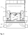
- the components to be painted are transported on a conveyor 1 at right angles to the plane of the drawing through a painting booth 2, in which the components are then painted by painting robots in a manner known per se.
- the painting robots 3, 4 have two swiveling robot arms and each guide an application device via a multi-axis robot hand axis.
- it can be a robot with six or more rotary axes and possibly a linear travel axis along the conveying path.
- Painting robots with at least seven rotary axes have the advantage of painting bodywork that in many cases there is no need for an additional axis.
- the painting robots 3, 4, as application devices carry nozzle print heads 8, 9 for two-component or multi-component paint.
- These nozzle print heads have a much higher application efficiency than atomizers of more than 95% to 99% and thus produce practically no overspray.
- this offers the advantage that the washout below the booth, which is required in conventional painting systems with atomizers, can be dispensed with.
- an air suction device 10 can be located under the painting booth 2, which sucks the booth air downwards out of the booth through a filter ceiling 11 if necessary, without any other effort required to collect and separate overspray. In many cases, the air extraction works without a filter. This can also take place via channels arranged near the floor.
- Fig. 2 explains an embodiment of the invention in which two components of the coating agent are mixed with one another only when they strike the surface to be coated by the impact of the drops or jets.
- These drops or jets are generated by two schematically illustrated nozzles D1 and D2, which are in a common plane of the nozzle print head are arranged next to each other, with one nozzle ejecting a first component (e.g. base paint) and the other nozzle ejecting a second component (hardener).
- a first component e.g. base paint
- hardener hardener
- the ejection can take place one after the other or simultaneously at a point in time 1, and according to the painting distance L of the nozzles D1 and D2 from the surface F to be coated and the flight speeds of the components, the two components hit the surface F a little later at a point in time 2 , at least approximately at one and the same point P, where they mix with one another.
- the ejection directions of the two nozzles D1 and D2 are inclined at, for example, opposite flight angles ⁇ and ⁇ to the other nozzle in relation to the painting distance L perpendicular to the surface F.
- the size of the chosen flight angle depends not only on the painting distance L, but also on the distance between the nozzles D1 and D2, measured parallel to the surface F, and can be, for example, between approximately 0 and 90 °.
- the flight speeds and / or the flight angles of the two components can also be different from one another. If the nozzles D1 and D2 are opened at different times, a displacement movement of the nozzles relative to the surface F during the application of the two components can also be taken into account.
- Fig. 3 explains schematically the overlapping application of coating dots on the surface F to be coated, whereby it is usually a matter of drops of already mixed components, which in turn mix with one another on the surface F by flowing together. However, these could also be components that only mix on the surface F to be coated.
- the Nozzles are moved by the coating robot at the given travel speed along the surface F, they generate a coating point, for example one drop each, with a defined size a at predetermined successive evenly spaced times t1 to t5 etc.
- the respective nozzle is time-controlled in such a way that defined drop spacings b along the surface F and consequently the respectively desired overlap of the applied drops result.
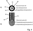
- a nozzle unit 40 designed as a double nozzle for mixing two components of a coating agent (e.g. 2K paint) in or on the nozzle pressure head is shown schematically.
- the nozzle unit 40 consists essentially of an outer tubular body 41, in the interior of which, for example, is cylindrical, and an inner tube 42, which is also cylindrical, for example, is arranged concentrically. While Figure 4B ) shows a longitudinal section through this tubular nozzle unit 40 is shown in FIG Figure 4A ) a top view of the in Figure 4B ) lower nozzle face shown.
- the outer pipe body 41 can, as shown, protrude axially outward on the nozzle end face 43 beyond the inner tube 42.
- one component of the coating agent e.g. base paint
- the second component e.g. hardener
- the first-mentioned component could also be passed through the annular gap and consequently the second component could be passed through the inner tube.
- the components are mixed at the end face 43 of the double nozzle or nozzle unit 40 shown, that is to say at its outlet, where the droplets formed there mix with one another as shown.
- the respective droplet formation does not begin at the same time, but rather the two nozzle elements, i.e. the inner tube 42 and the outlet 46 designed as an annular gap nozzle with valves (not shown), are timed so that first the drop at the inner tube nozzle and only then the drop is formed at the annular gap nozzle.
- the reverse order can also be useful. Instead, however, a simultaneous opening of the two nozzle elements is also conceivable.
- the nozzle print head according to the invention preferably holds a multiplicity of such nozzle units, which can in particular be arranged in one or more rows.
- a double nozzle unit is explained using the example of droplet formation, such or similar double nozzles are also conceivable for the generation of component jets which can be mixed at the nozzle outlets.
- the two nozzle elements can be controlled jointly and / or individually with regard to their opening times by assigned controllable valves.
Landscapes
- Engineering & Computer Science (AREA)
- Manufacturing & Machinery (AREA)
- Robotics (AREA)
- Coating Apparatus (AREA)
- Application Of Or Painting With Fluid Materials (AREA)
- Spray Control Apparatus (AREA)
- Nozzles (AREA)
Applications Claiming Priority (2)
| Application Number | Priority Date | Filing Date | Title |
|---|---|---|---|
| DE102016014919.1A DE102016014919A1 (de) | 2016-12-14 | 2016-12-14 | Applikationsvorrichtung und Verfahren zum Applizieren eines Beschichtungsmittels |
| PCT/EP2017/081123 WO2018108573A1 (de) | 2016-12-14 | 2017-12-01 | Applikationsvorrichtung und verfahren zum applizieren eines beschichtungsmittels |
Publications (2)
| Publication Number | Publication Date |
|---|---|
| EP3554716A1 EP3554716A1 (de) | 2019-10-23 |
| EP3554716B1 true EP3554716B1 (de) | 2021-08-18 |
Family
ID=60574584
Family Applications (1)
| Application Number | Title | Priority Date | Filing Date |
|---|---|---|---|
| EP17808874.6A Active EP3554716B1 (de) | 2016-12-14 | 2017-12-01 | Applikationsvorrichtung und verfahren zum applizieren eines beschichtungsmittels |
Country Status (9)
| Country | Link |
|---|---|
| US (1) | US11440035B2 (zh) |
| EP (1) | EP3554716B1 (zh) |
| JP (1) | JP6991218B2 (zh) |
| CN (1) | CN110087779B (zh) |
| DE (1) | DE102016014919A1 (zh) |
| ES (1) | ES2896964T3 (zh) |
| HU (1) | HUE056762T2 (zh) |
| MX (1) | MX2019006979A (zh) |
| WO (1) | WO2018108573A1 (zh) |
Families Citing this family (16)
| Publication number | Priority date | Publication date | Assignee | Title |
|---|---|---|---|---|
| US10799905B2 (en) * | 2018-01-30 | 2020-10-13 | Ford Motor Company | Ultrasonic material applicators and methods of use thereof |
| DE102019001423B4 (de) * | 2019-02-11 | 2022-05-25 | Kastriot Merlaku | Vorrichtung, die ein Objekt aus Knetmasse oder Modelliermasse durch Beschichten verfestigen kann |
| DE102019119613A1 (de) * | 2019-07-19 | 2021-01-21 | Bayerische Motoren Werke Aktiengesellschaft | Verfahren zum Lackieren eines Außenhautbauteils eines Kraftfahrzeugs sowie Lackierstation für ein Außenhautbauteil eines Kraftfahrzeugs |
| CN110355037B (zh) * | 2019-07-25 | 2021-01-01 | 浙江奥年家居有限公司 | 一种零件快速无尘喷漆装置 |
| CN110420782B (zh) * | 2019-07-26 | 2020-12-22 | 瑞润化工(南通)有限公司 | 一种涂料配比调试设备 |
| CN111530704A (zh) * | 2020-04-22 | 2020-08-14 | 山东惟德再制造科技有限公司 | 一种大型换热器内管防腐灌涂装置及方法 |
| CN112108321A (zh) * | 2020-04-30 | 2020-12-22 | 中国电子产品可靠性与环境试验研究所((工业和信息化部电子第五研究所)(中国赛宝实验室)) | 一种无固化双组份胶水压电喷涂装置 |
| DE102020127852A1 (de) | 2020-10-22 | 2022-04-28 | Dürr Systems Ag | Betriebsverfahren für eine Beschichtungsanlage und entsprechend angepasste Beschichtungsanlage |
| CN113262943A (zh) * | 2021-05-25 | 2021-08-17 | 延锋伟世通汽车电子有限公司 | 自动涂覆装置 |
| DE102021124196A1 (de) | 2021-09-20 | 2023-03-23 | Dürr Systems Ag | Applikationsverfahren zur Beschichtung eines Objekts, vorzugsweise eines oder mehrerer Kraftfahrzeugkaroserie-Teile |
| CN114682464B (zh) * | 2022-04-24 | 2023-09-26 | 许艳青 | 木质家具的漆饰方法、漆饰装置及其家具 |
| DE102022114673A1 (de) | 2022-06-10 | 2023-12-21 | FPT Robotik GmbH & Co. KG | Verfahren und Vorrichtung zur prozessoptimierten Beschichtung dreidimensionaler Oberflächen mittels aushärtenden Flüssigkeiten |
| US20240109095A1 (en) * | 2022-09-30 | 2024-04-04 | The Boeing Company | Inkjet printing vehicle livery |
| US20240109349A1 (en) * | 2022-09-30 | 2024-04-04 | The Boeing Company | Robotics for inkjet printing vehicle livery |
| JP7241955B1 (ja) * | 2022-12-20 | 2023-03-17 | アーベーベー・シュバイツ・アーゲー | 塗装機 |
| CN116174219A (zh) * | 2022-12-29 | 2023-05-30 | 中国科学院福建物质结构研究所 | 一种复合涂层喷涂设备 |
Citations (1)
| Publication number | Priority date | Publication date | Assignee | Title |
|---|---|---|---|---|
| DE102010019612A1 (de) * | 2010-05-06 | 2011-11-10 | Dürr Systems GmbH | Beschichtungseinrichtung, insbesondere mit einem Applikationsgerät, und zugehöriges Beschichtungsverfahren, das einen zertropfenden Beschichtungsmittelstrahl ausgibt |
Family Cites Families (232)
| Publication number | Priority date | Publication date | Assignee | Title |
|---|---|---|---|---|
| DE1284250B (de) | 1965-10-30 | 1968-11-28 | Kaercher Fa Alfred | Spruehgeraet zum Verspruehen eines Fluessigkeits-Gemisches |
| US3717306A (en) * | 1971-03-10 | 1973-02-20 | Hushon R | Nozzle for spraying foaming materials |
| US3981320A (en) | 1974-05-10 | 1976-09-21 | The Gyromat Corporation | Recovery system for spray painting installation with automatic color change |
| AT349415B (de) | 1975-07-28 | 1979-04-10 | Zimmer Peter Ag | Spritzdruckeinrichtung zum bemustern einer ware |
| CH613387A5 (en) | 1975-07-28 | 1979-09-28 | Zimmer Peter Maschinenfabrik A | Process and device for applying patterns to a material, in particular to a web material |
| US4383264A (en) | 1980-06-18 | 1983-05-10 | Exxon Research And Engineering Co. | Demand drop forming device with interacting transducer and orifice combination |
| JPS5722070A (en) | 1980-07-15 | 1982-02-04 | Oki Electric Ind Co Ltd | Cooling device for printer |
| US4375865A (en) | 1980-08-12 | 1983-03-08 | Binks Manufacturing Company | Color change system for spray coating apparatus |
| DE3045401A1 (de) | 1980-12-02 | 1982-07-01 | Robert Bosch Gmbh, 7000 Stuttgart | Verfahren zum pruefen von einspritzduesen |
| MX152277A (es) | 1980-12-16 | 1985-06-19 | Vitro Tec Fideicomiso | Mejoras en bloque de valvulas neumaticas de solenoide para maquinas de fabricacion de articulos de vidrio |
| US4423999A (en) | 1981-09-14 | 1984-01-03 | General Motors Corporation | Mechanical hand for a door-opener |
| US4435719A (en) | 1982-03-30 | 1984-03-06 | Snaper Alvin A | Fluidic matrix printer |
| DE3221327A1 (de) | 1982-06-05 | 1983-09-15 | Daimler-Benz Ag, 7000 Stuttgart | Anlage zum farbspritzen von serienteilen wechselnder farbe |
| DE3225554A1 (de) | 1982-07-08 | 1984-01-12 | Robert Bosch Gmbh, 7000 Stuttgart | Messeinrichtung fuer fluidstrahlen |
| US4668948A (en) | 1983-03-10 | 1987-05-26 | Nordson Corporation | Dispenser malfunction detector |
| US4555719A (en) | 1983-08-19 | 1985-11-26 | Videojet Systems International, Inc. | Ink valve for marking systems |
| US4593360A (en) | 1983-12-16 | 1986-06-03 | Cocks Eric H | Fluid spray control system |
| WO1986001775A1 (en) | 1984-09-19 | 1986-03-27 | Ronald Douglas Drysdale | Method of and apparatus for applying images to a surface |
| JPS624464A (ja) | 1985-07-02 | 1987-01-10 | Honda Motor Co Ltd | 車体塗装装置 |
| JPS62116442A (ja) | 1985-11-12 | 1987-05-28 | Toppan Printing Co Ltd | 二枚差し検知装置 |
| DD245400A1 (de) | 1986-02-05 | 1987-05-06 | Robotron Bueromasch | Farbstrahldruckkopf |
| US4875058A (en) | 1986-12-12 | 1989-10-17 | Markpoint System Ab | Valve device for a matrix printer |
| US4734711A (en) | 1986-12-22 | 1988-03-29 | Eastman Kodak Company | Pressure regulation system for multi-head ink jet printing apparatus |
| SE456597B (sv) | 1987-02-12 | 1988-10-17 | Scandot System Ab | Anordning vid ett ventilarrangemang for utmatning av vetska hos en vetskestralskrivare |
| DE3721875A1 (de) | 1987-07-02 | 1989-01-12 | Gema Ransburg Ag | Verfahren und einrichtung fuer eine pulverspruehbeschichtungsanlage |
| JPH0798171B2 (ja) | 1988-04-19 | 1995-10-25 | トキコ株式会社 | 工業用ロボット装置 |
| US4974780A (en) | 1988-06-22 | 1990-12-04 | Toa Nenryo Kogyo K.K. | Ultrasonic fuel injection nozzle |
| US5050533A (en) | 1988-07-25 | 1991-09-24 | Technadyne Engineering Corporation | Application of thermal-cure materials |
| US5602575A (en) | 1988-11-05 | 1997-02-11 | Rea Elektronik Gmbh | Ink jet writing head |
| US4894252A (en) | 1988-11-30 | 1990-01-16 | Ransburg Corporation | Coating material orifice clogging indication method and apparatus |
| US4985715A (en) | 1990-03-22 | 1991-01-15 | Telesis Controls Corporation | Marker assembly for spray marking dot matrix characters and method of fabrication thereof |
| DE4013322A1 (de) | 1990-04-26 | 1991-10-31 | Heino Kaiser | Mehrfach-auftragskopf |
| JP3144566B2 (ja) | 1990-05-08 | 2001-03-12 | マツダ株式会社 | 塗装方法および塗装装置 |
| US5072881A (en) | 1990-06-04 | 1991-12-17 | Systems Specialties | Method of cleaning automated paint spraying equipment |
| JPH04106669U (ja) | 1991-02-21 | 1992-09-14 | セントラル自動車株式会社 | 水性塗装用ブース |
| DE4138491C2 (de) | 1991-11-23 | 1995-07-20 | Juergen Dipl Ing Joswig | Mikromechanisches Ventil für mikromechanische Dosiereinrichtungen |
| US5429682A (en) | 1993-08-19 | 1995-07-04 | Advanced Robotics Technologies | Automated three-dimensional precision coatings application apparatus |
| DE9422327U1 (de) | 1993-09-01 | 2000-03-23 | Duerr Systems Gmbh | Beschichtungsanlage |
| DE4329384C2 (de) | 1993-09-01 | 2001-08-09 | Duerr Systems Gmbh | Fördervorrichtung |
| US5435884A (en) | 1993-09-30 | 1995-07-25 | Parker-Hannifin Corporation | Spray nozzle and method of manufacturing same |
| GB2286157B (en) | 1994-01-31 | 1998-01-14 | Neopost Ltd | Ink jet printing device |
| DE9405600U1 (de) | 1994-04-02 | 1994-06-16 | Itw Dynatec Klebetechnik Holdi | Auftragskopf zur dosierten Abgabe von strömenden Medien |
| CN2287527Y (zh) | 1994-04-20 | 1998-08-12 | 徐连宽 | 燃油式汽车喷漆烤漆房 |
| US5718767A (en) | 1994-10-05 | 1998-02-17 | Nordson Corporation | Distributed control system for powder coating system |
| US5659347A (en) | 1994-11-14 | 1997-08-19 | Xerox Corporation | Ink supply apparatus |
| US5647542A (en) | 1995-01-24 | 1997-07-15 | Binks Manufacturing Company | System for electrostatic application of conductive coating liquid |
| US5636795A (en) | 1995-05-11 | 1997-06-10 | First Pioneer Industries Inc. | Cyclonic spray nozzle |
| SE504472C2 (sv) | 1995-06-22 | 1997-02-17 | Abb Flexible Automation As | Färgmatningssystem för sprutmålningsrobot |
| JPH09192583A (ja) | 1996-01-17 | 1997-07-29 | Fuji Heavy Ind Ltd | ローラ式塗布装置保管用ボックス |
| DE19606716C1 (de) | 1996-02-23 | 1997-08-14 | Herberts Gmbh | Verfahren zur Mehrschichtlackierung |
| SE507821C2 (sv) | 1996-04-15 | 1998-07-20 | Jetline Ab | Ventilkonstruktion vid bläckstråleskrivare |
| DE19630290C2 (de) | 1996-07-26 | 2000-08-10 | Audi Ag | Anlage zur Oberflächenbehandlung von Gegenständen, insbesondere von Fahrzeugkarosserien |
| JP2978459B2 (ja) | 1996-09-30 | 1999-11-15 | キヤノン株式会社 | カラーフィルタの製造方法及び製造装置及びカラーフィルタ及び表示装置及び表示装置を備えた装置 |
| DE19731829A1 (de) | 1997-07-24 | 1999-01-28 | Tietz Patrick | Einrichtung zur gesteuerten Farbmischung und Dosierung von Lacken und Farben |
| DE19743804A1 (de) | 1997-10-02 | 1999-04-08 | Politrust Ag | Druckvorrichtung |
| ES2273444T3 (es) | 1998-01-13 | 2007-05-01 | Abb K.K. | Metodo de recubrimiento para un dispositivo de recubrimiento del tipo de cabezal atomizador rotativo. |
| ID28206A (id) | 1998-08-13 | 2001-05-10 | Ppg Ind Ohio Inc | Komposisi, peralatan dan metode pembentukan lapisan dengan warna pilihan pada substrat dan barang-barang yang dihasilkannya |
| DE19852079A1 (de) * | 1998-11-11 | 2000-05-18 | Thomas Kovarovsky | Bildgebende Lackiervorrichtung |
| JP2000158670A (ja) | 1998-11-26 | 2000-06-13 | Fuji Electric Co Ltd | インクジェット記録装置 |
| JP4358352B2 (ja) | 1999-05-11 | 2009-11-04 | トリニティ工業株式会社 | 塗装装置とそれに用いる塗装機とそれを用いた塗装方法 |
| DE19936790A1 (de) | 1999-08-10 | 2001-02-15 | Nordson Corp Westlake | Verfahren und Vorrichtung zum Herstellen einer abziehbaren Schutzschicht für Oberflächen, insbesondere für lackierte Oberflächen von Kraftfahrzeugkarosserien |
| JP2001157863A (ja) | 1999-09-21 | 2001-06-12 | Tokyo Electron Ltd | 塗布装置 |
| JP2001129456A (ja) | 1999-11-04 | 2001-05-15 | Sekisui Chem Co Ltd | スプレイ塗装装置におけるノズルの洗浄方法及びスプレイ塗装装置 |
| IT1311388B1 (it) | 1999-11-10 | 2002-03-12 | Gd Spa | Unita' di gommatura a spruzzo. |
| US6325302B1 (en) | 1999-11-29 | 2001-12-04 | Fanuc Robotics North America, Inc. | Airless spray tool |
| DE10050875B4 (de) * | 1999-12-20 | 2006-11-02 | Tevkür, Talip | Anlage zum Farbspritzen |
| KR100335955B1 (ko) | 1999-12-30 | 2002-05-10 | 이계안 | 도장막 보호용 코팅 시스템 |
| DE20122653U1 (de) | 2000-01-21 | 2007-02-22 | Seiko Epson Corp. | Tintenkartusche und diese verwendende Tintenstrahlaufzeichnungseinrichtung |
| US6360656B2 (en) | 2000-02-28 | 2002-03-26 | Minolta Co., Ltd. | Apparatus for and method of printing on three-dimensional object |
| JP2001239652A (ja) | 2000-02-28 | 2001-09-04 | Minolta Co Ltd | 印刷装置及び印刷方法 |
| US6460958B2 (en) | 2000-02-29 | 2002-10-08 | Minolta Co., Ltd. | Three-dimensional object printing apparatus and method |
| US6401976B1 (en) | 2000-03-23 | 2002-06-11 | Nordson Corporation | Electrically operated viscous fluid dispensing apparatus and method |
| DE10031030B4 (de) | 2000-06-26 | 2005-08-04 | Bauer, Jörg R. | Verfahren und Vorrichtung zum Herstellen flächiger Bauteile mit vorbestimmtem Oberflächenaussehen und flächiges Bauteil, insbesondere Frontplatte eines Küchenelements |
| FR2811917B1 (fr) | 2000-07-24 | 2002-12-20 | Sames Sa | Procede et station de changement de produit dans une installation de projection de produit de revetement |
| US6641667B2 (en) | 2000-08-29 | 2003-11-04 | Honda Giken Kogyo Kabushiki Kaisha | Robot-mounted two-package-mixing coating device and internal pressure explosion-proof robot |
| EP1324829B1 (en) | 2000-08-30 | 2007-12-26 | Biodot, Inc. | Method for high-speed microfluidic dispensing |
| US6523921B2 (en) | 2000-08-30 | 2003-02-25 | L&P Property Management | Method and apparatus for printing on rigid panels and other contoured or textured surfaces |
| DE10048749A1 (de) | 2000-09-29 | 2002-04-11 | Josef Schucker | Anordnung zum Aufbringen von Klebstoff auf ein Werkstück |
| US6849684B2 (en) | 2000-10-20 | 2005-02-01 | E. I. Du Pont De Nemours And Company | Molded soft elastomer/hard polyester composition with noise damping properties |
| JP3953776B2 (ja) | 2001-01-15 | 2007-08-08 | セイコーエプソン株式会社 | 材料の吐出装置、及び吐出方法、カラーフィルタの製造装置及び製造方法、液晶装置の製造装置及び製造方法、el装置の製造装置及び製造方法 |
| WO2002098576A1 (en) | 2001-06-01 | 2002-12-12 | Litrex Corporation | Industrial microdeposition system for polymer light emitting diode displays, printed circuit boards and the like |
| US7160105B2 (en) | 2001-06-01 | 2007-01-09 | Litrex Corporation | Temperature controlled vacuum chuck |
| US7244310B2 (en) | 2001-06-01 | 2007-07-17 | Litrex Corporation | Over-clocking in a microdeposition control system to improve resolution |
| US20050016451A1 (en) | 2001-06-01 | 2005-01-27 | Edwards Charles O. | Interchangeable microdesition head apparatus and method |
| US7449070B2 (en) | 2001-06-01 | 2008-11-11 | Ulvac, Inc. | Waveform generator for microdeposition control system |
| US20040231594A1 (en) | 2001-06-01 | 2004-11-25 | Edwards Charles O. | Microdeposition apparatus |
| JP4158357B2 (ja) | 2001-06-05 | 2008-10-01 | セイコーエプソン株式会社 | インクジェット式記録装置 |
| DE10130499A1 (de) | 2001-06-25 | 2003-01-02 | Duerr Systems Gmbh | Beschichtungsanlage und Verfahren zum Steuern einer Beschichtungsvorrichtung mit unterschiedlichen Düsen |
| US6755512B2 (en) | 2001-07-30 | 2004-06-29 | Fuji Photo Film Co. Ltd | Liquid droplet ejection apparatus and inkjet recording head |
| JP3487301B2 (ja) | 2001-08-06 | 2004-01-19 | マツダ株式会社 | 自動車車体の塗装方法および塗装装置 |
| DE10140216B4 (de) | 2001-08-17 | 2006-02-09 | ITW Oberflächentechnik GmbH & Co. KG | Verfahren und Vorrichtung an einer Lackiereinrichtung zum Reinigen einer Lack-Förderleitung |
| US6757586B2 (en) | 2001-09-05 | 2004-06-29 | Abb Automation Inc. | Multiple arm robot arrangement |
| JP3961820B2 (ja) | 2001-11-30 | 2007-08-22 | 株式会社不二越 | 産業用ロボットの制御装置 |
| JP4060275B2 (ja) | 2002-01-22 | 2008-03-12 | ノードソン コーポレーション | 液体噴出パターンを検出するための方法及び装置 |
| DE10307719A1 (de) | 2002-03-01 | 2003-09-11 | Vmt Bildverarbeitungssysteme G | Verfahren zur Qualitätssicherung eines als Zielauftrag auf ein Zielobjekt aufzubringenden Auftrags eines Mediums |
| DE10224128A1 (de) | 2002-05-29 | 2003-12-18 | Schmid Rhyner Ag Adliswil | Verfahren zum Auftrag von Beschichtungen auf Oberflächen |
| US20040173144A1 (en) | 2002-05-31 | 2004-09-09 | Edwards Charles O. | Formation of printed circuit board structures using piezo microdeposition |
| DE60311519T2 (de) | 2002-10-23 | 2007-11-29 | Fanuc Robotics America, Inc., Rochester Hills | Modulare beschichtungsvorrichtung |
| JP4123897B2 (ja) | 2002-10-28 | 2008-07-23 | 株式会社エルエーシー | インクジェットノズル |
| WO2004041444A1 (en) | 2002-11-06 | 2004-05-21 | Advanced Flow Control Afc Ab | System for spraying a fluid material |
| SE0203515L (sv) | 2002-11-27 | 2004-05-28 | Texdot Ab | Ventilenhet i en vätskestrålskrivare samt metod vid en sådan enhet |
| US7454785B2 (en) | 2002-12-19 | 2008-11-18 | Avocent Huntsville Corporation | Proxy method and system for secure wireless administration of managed entities |
| JP3885036B2 (ja) | 2003-03-14 | 2007-02-21 | 本田技研工業株式会社 | 保護層形成材の塗布方法および塗布装置 |
| GB0306788D0 (en) | 2003-03-25 | 2003-04-30 | Willett Int Ltd | Method |
| US7178742B2 (en) | 2003-05-06 | 2007-02-20 | Lear Corporation | Fluid delivery system for spray applicator |
| JP2004337710A (ja) | 2003-05-14 | 2004-12-02 | Trinity Ind Corp | 塗装ロボットの制御装置及び制御方法 |
| US20050001869A1 (en) | 2003-05-23 | 2005-01-06 | Nordson Corporation | Viscous material noncontact jetting system |
| DE10331206A1 (de) | 2003-07-10 | 2005-01-27 | Daimlerchrysler Ag | Verfahren zum Auftragen von Sprühstoffen |
| US20050015050A1 (en) | 2003-07-15 | 2005-01-20 | Kimberly-Clark Worldwide, Inc. | Apparatus for depositing fluid material onto a substrate |
| ZA200407781B (en) | 2003-10-03 | 2005-09-28 | Int Tech Llc | Blasting and blastiing accessory |
| FR2862563B1 (fr) | 2003-11-24 | 2007-01-19 | Centre Nat Rech Scient | Robot d'impression numerique grand format en trois dimensions sur une surface fixe et procede d'impression mettant en oeuvre au moins un tel robot |
| KR100848162B1 (ko) | 2004-01-19 | 2008-07-23 | 삼성전자주식회사 | 잉크젯 프린팅 장치 및 헤드위치 조절방법 |
| WO2005075170A1 (en) | 2004-02-03 | 2005-08-18 | Linde Aktiengesellschaft | Surface coating device |
| JP4419015B2 (ja) | 2004-03-04 | 2010-02-24 | リコープリンティングシステムズ株式会社 | インクジェット塗布方法及び装置 |
| DE102004034270B4 (de) | 2004-07-15 | 2016-08-18 | Wolfgang Schmidt | Anlage zum Austragen fließfähiger Fluide, insbesondere von Farben und Lacken und Verfahren zum Betrieb der Anlage |
| WO2006022217A1 (ja) | 2004-08-23 | 2006-03-02 | Kabushiki Kaisha Ishiihyoki | インクジェットプリンタの吐出量制御方法、及びインク滴広がり検査方法、並びに配向膜形成方法。 |
| DE102004044655B4 (de) | 2004-09-15 | 2009-06-10 | Airbus Deutschland Gmbh | Lackier-Vorrichtung, Lackier-Anordnung, Verfahren zum Lackieren einer gekrümmten Oberfläche eines Flugzeugs und Verwendung einer Inkjet-Einrichtung zum Lackieren eines Flugzeugs |
| US20060068109A1 (en) | 2004-09-15 | 2006-03-30 | Airbus Deutschland Gmbh | Painting device, painting arrangement, method for painting a curved surface of an object, and use of an inkjet device for painting an aircraft |
| US7824001B2 (en) | 2004-09-21 | 2010-11-02 | Z Corporation | Apparatus and methods for servicing 3D printers |
| DE102004049471A1 (de) | 2004-10-11 | 2006-04-20 | Bayerische Motoren Werke Ag | Vorrichtung zum Auftragen einer Konservierungsschicht und Verfahren zum Auftragen derselben |
| JP2007021760A (ja) | 2005-07-12 | 2007-02-01 | Nissha Printing Co Ltd | 薄膜形成装置 |
| DK1764226T3 (da) | 2005-09-20 | 2009-10-12 | Agfa Graphics Nv | Fremgangsmåde og indretning til automatisk at stille arrays af printelementer på linie |
| CN101309755A (zh) * | 2005-12-01 | 2008-11-19 | 3M创新有限公司 | 多组分液体喷雾系统 |
| JP2007152666A (ja) | 2005-12-02 | 2007-06-21 | Seiko Epson Corp | 液滴観測装置 |
| JP4432922B2 (ja) | 2006-03-17 | 2010-03-17 | セイコーエプソン株式会社 | 液滴吐出装置 |
| DE102006017956B4 (de) | 2006-04-18 | 2016-01-07 | OuISS Qualitäts-Inspektionssysteme und Service AG | Verfahren zum Aufbringen und Überwachen einer Auftragsstruktur mit Reparaturfunktion sowie Vorrichtung hierfür |
| JP4705877B2 (ja) | 2006-04-25 | 2011-06-22 | トリニティ工業株式会社 | 上塗り塗装設備及びそれを用いた塗装方法 |
| DE102006021623A1 (de) | 2006-05-09 | 2007-11-15 | Dürr Systems GmbH | Dosiersystem für eine Beschichtungsanlage |
| US8794174B2 (en) | 2006-05-12 | 2014-08-05 | Durr Systems Gmbh | Coating installation and associated operating method |
| EP1884365A1 (en) | 2006-07-28 | 2008-02-06 | Abb Research Ltd. | Paint applicator and coating method |
| KR100729553B1 (ko) | 2006-10-27 | 2007-06-18 | 주식회사 탑 엔지니어링 | 디스펜싱 장치 |
| KR100833679B1 (ko) * | 2006-11-07 | 2008-05-29 | 포항공과대학교 산학협력단 | 극소량 액체의 혼합 장치 및 그 혼합 방법 |
| DE102006056051B4 (de) | 2006-11-28 | 2018-09-20 | Robert Bosch Gmbh | Roboter mit Steuerung für Zusatzachsen |
| US8707976B2 (en) | 2006-11-29 | 2014-04-29 | Daryl Bauer | Portable painting apparatus |
| DE102007002980A1 (de) | 2007-01-19 | 2008-07-24 | Voith Patent Gmbh | Klebstoffauftrageinrichtung für eine papier- oder kartonverarbeitende Maschine |
| CA2680034C (en) | 2007-03-08 | 2018-01-02 | Kabushiki Kaisha Yaskawa Denki | Painting system |
| DE102007018877B4 (de) | 2007-04-19 | 2010-03-04 | Hönig, Thomas | Verfahren und Materialauftragseinrichtung mit einer Prüfvorrichtung zur Gütemessung des Auftragsbildes einer Sprühdüse sowie Verwendung eines Testfelds |
| EP2151282B1 (en) | 2007-05-18 | 2021-04-21 | Musashi Engineering, Inc. | Method and apparatus for discharging liquid material |
| EP2002898A1 (de) | 2007-06-14 | 2008-12-17 | J. Zimmer Maschinenbau Gesellschaft m.b.H. | Auftragungseinrichtung zum Auftragen von Fluid auf ein Substrat mit Ventileinrichtungen, Verfahren zum Reinigen des Auftragungseinrichtung und Ventileinrichtung für die Auftragungseinrichtung |
| GB0712860D0 (en) | 2007-07-03 | 2007-08-08 | Eastman Kodak Co | continuous inkjet drop generation device |
| DE102007037663A1 (de) | 2007-08-09 | 2009-02-19 | Dürr Systems GmbH | Nadelventilanordnung |
| EP2207951B1 (en) | 2007-09-25 | 2014-03-12 | Airbus SAS | Method for operating a gas turbine engine and aircraft using such method |
| CN103909743B (zh) | 2007-12-31 | 2017-01-11 | 埃克阿泰克有限责任公司 | 用于打印三维物品的装置和方法 |
| US20090181182A1 (en) * | 2008-01-10 | 2009-07-16 | Sloan Donald D | Multipurpose digital ink |
| DE102008018881B4 (de) | 2008-03-11 | 2020-10-01 | Atlas Copco Ias Gmbh | Verfahren und Vorrichtung zum Auftragen eines viskosen Materials auf ein Werkstück sowie Verwendung eines Nadelventils für eine Vorrichtung zum Auftragen eines viskosen Materials auf ein Werkstück |
| EP2268415B1 (de) * | 2008-03-20 | 2015-05-06 | Dürr Systems GmbH | Lackierroboter und zugehöriges betriebsverfahren |
| DE102008045553A1 (de) | 2008-09-03 | 2010-03-04 | Dürr Systems GmbH | Lackiereinrichtung und zugehöriges Verfahren |
| DE102008053178A1 (de) | 2008-10-24 | 2010-05-12 | Dürr Systems GmbH | Beschichtungseinrichtung und zugehöriges Beschichtungsverfahren |
| DE102008061203A1 (de) | 2008-12-09 | 2010-06-10 | Rehau Ag + Co | Verfahren zum Lackieren einer dreidimensionalen Oberfläche eines Bauteils |
| JP2010241003A (ja) | 2009-04-07 | 2010-10-28 | Seiko Epson Corp | 液滴吐出ヘッド |
| DE102009020064A1 (de) | 2009-05-06 | 2010-11-11 | Dürr Systems GmbH | Fluidventil, insbesondere Rückführventil für eine Lackieranlage |
| DE102009029946A1 (de) | 2009-06-19 | 2010-12-30 | Epainters GbR (vertretungsberechtigte Gesellschafter Burkhard Büstgens, 79194 Gundelfingen und Suheel Roland Georges, 79102 Freiburg) | Druckkopf oder Dosierkopf |
| US8556373B2 (en) * | 2009-06-19 | 2013-10-15 | Burkhard Buestgens | Multichannel-printhead or dosing head |
| DE102009038462A1 (de) | 2009-08-21 | 2011-03-03 | Dürr Systems GmbH | Taumelkolbenpumpe zur Dosierung eines Beschichtungsmittels |
| US8652581B2 (en) * | 2009-10-09 | 2014-02-18 | Matthew Merchant | Method of using a spray gun and material produced thereby |
| DE102009052654A1 (de) * | 2009-11-11 | 2011-05-12 | Dürr Systems GmbH | Vorrichtung und Verfahren zur Konservierung von Bauteilen |
| US8757511B2 (en) | 2010-01-11 | 2014-06-24 | AdvanJet | Viscous non-contact jetting method and apparatus |
| DE102010004496B4 (de) | 2010-01-12 | 2020-06-18 | Hermann Müller | Verfahren zum Betrieb einer Vorrichtung zum Beschichten und/oder Bedrucken eines Werkstückes |
| JP2011206958A (ja) | 2010-03-29 | 2011-10-20 | Seiko Epson Corp | 液体噴射装置、液体噴射ヘッドおよびノズル抜け検出方法 |
| US8534574B2 (en) | 2010-04-08 | 2013-09-17 | Intel Corporation | Underfill material dispenser |
| DE202010005211U1 (de) | 2010-04-15 | 2011-10-21 | Planatol System Gmbh | Auftragsystem für flüssige Medien |
| JP5769384B2 (ja) | 2010-04-20 | 2015-08-26 | キヤノン株式会社 | インクカートリッジおよびインクジェット記録装置 |
| JP5489887B2 (ja) | 2010-06-30 | 2014-05-14 | 富士フイルム株式会社 | 液体塗布装置及び液体塗布方法並びにナノインプリントシステム |
| EP2799150B1 (en) | 2013-05-02 | 2016-04-27 | Hexagon Technology Center GmbH | Graphical application system |
| EP2433716A1 (en) | 2010-09-22 | 2012-03-28 | Hexagon Technology Center GmbH | Surface spraying device with a nozzle control mechanism and a corresponding method |
| EP2632730B1 (en) | 2010-10-27 | 2019-08-07 | Matthews International Corporation | Valve jet printer with inert plunger tip |
| JP5215376B2 (ja) | 2010-12-27 | 2013-06-19 | 富士ゼロックス株式会社 | 液体循環装置、液体循環制御プログラム、液体吐出装置 |
| CN102198434A (zh) | 2010-12-29 | 2011-09-28 | 东莞市冠辉五金有限公司 | 一种精密五金件自动喷涂工艺及喷涂控制系统 |
| DE102012005087A1 (de) | 2011-03-28 | 2012-10-04 | Heidelberger Druckmaschinen Aktiengesellschaft | Vorrichtung zum Bedrucken von Oberflächen mit mehreren, bewegbaren Druckköpfen |
| JP5647940B2 (ja) | 2011-04-26 | 2015-01-07 | タクボエンジニアリング株式会社 | 携帯端末用筐体の塗装装置及びそれを用いた携帯端末用筐体の塗装方法 |
| JP2012228643A (ja) | 2011-04-26 | 2012-11-22 | Takubo Engineering Co Ltd | 携帯端末用筐体の塗装システム及びそれを用いた携帯端末用筐体の塗装方法 |
| JP2013158968A (ja) | 2012-02-02 | 2013-08-19 | Seiko Epson Corp | 印刷装置及び印刷ヘッドユニットの昇温抑制方法 |
| JP5055512B1 (ja) | 2012-02-16 | 2012-10-24 | 繁 中島 | 塗料供給印字装置 |
| CN102582260A (zh) | 2012-02-17 | 2012-07-18 | 上海美杰彩喷材料有限公司 | 水性树脂墨喷墨打印机 |
| JP5906841B2 (ja) | 2012-03-14 | 2016-04-20 | マツダ株式会社 | 塗料循環装置及び塗料循環方法 |
| EP2641661B1 (en) | 2012-03-20 | 2016-05-11 | Hexagon Technology Center GmbH | Graphical application system |
| DE102012005650A1 (de) | 2012-03-22 | 2013-09-26 | Burkhard Büstgens | Beschichtung von Flächen im Druckverfahren |
| DE102012006371A1 (de) | 2012-03-29 | 2012-07-05 | Heidelberger Druckmaschinen Aktiengesellschaft | Verfahren zum Bedrucken eines Objekts |
| DE102012006370A1 (de) | 2012-03-29 | 2013-10-02 | Heidelberger Druckmaschinen Aktiengesellschaft | System zum Bedrucken eines Objekts |
| DE102012212469B4 (de) | 2012-07-17 | 2022-10-06 | Peter Fornoff | Verfahren zum Bedrucken einer Oberfläche und Vorrichtung zum Bedrucken einer Oberfläche |
| JP2014019140A (ja) | 2012-07-23 | 2014-02-03 | Ricoh Co Ltd | 吐出状態検査方法、及び液滴吐出装置 |
| DE102012017538A1 (de) | 2012-09-05 | 2014-03-06 | Heidelberger Druckmaschinen Ag | Verfahren zum Bebildern und/oder Lackieren der Oberfläche von Gegenständen |
| DE102012109123A1 (de) | 2012-09-27 | 2014-03-27 | Vermes Microdispensing GmbH | Dosiersystem, Dosierverfahren und Herstellungsverfahren |
| GB2507069A (en) | 2012-10-17 | 2014-04-23 | Siemens Plc | Monitoring the quality of an electrostatic coating by measuring light reflected from a spray |
| KR101733904B1 (ko) | 2012-12-27 | 2017-05-08 | 카티바, 인크. | 정밀 공차 내로 유체를 증착하기 위한 인쇄 잉크 부피 제어를 위한 기법 |
| JP5494846B2 (ja) | 2013-01-23 | 2014-05-21 | セイコーエプソン株式会社 | インクジェットヘッドユニットおよび印刷装置 |
| DE102013002412A1 (de) | 2013-02-11 | 2014-08-14 | Dürr Systems GmbH | Applikationsverfahren und Applikationsanlage |
| ITMO20130069A1 (it) | 2013-03-15 | 2014-09-16 | Tecno Italia S R L | Testina per la decorazione digitale di manufatti ceramici |
| DE202013101134U1 (de) | 2013-03-15 | 2014-06-17 | Vermes Microdispensing GmbH | Dosierventil |
| DE102013205171A1 (de) | 2013-03-22 | 2014-09-25 | Krautzberger Gmbh | Spritzsystem, Spritzvorrichtung, Schnellwechseladapter und Wechselvorrichtung, Beschichtungsanlage sowie Verfahren zum Beschichten |
| DE102013006219A1 (de) | 2013-04-11 | 2014-10-16 | Eisenmann Ag | Wechseleinrichtung für Beschichtungsmedien und Beschichtungssystem zum Beschichten von Gegenständen |
| KR101467404B1 (ko) | 2013-05-02 | 2014-12-03 | 희성촉매 주식회사 | 촉매 정량 공급장치 |
| US9808820B2 (en) | 2013-05-03 | 2017-11-07 | Abb Schweiz Ag | Automatic painting and maintaining wet-surface of artifacts |
| DE102014006991A1 (de) | 2013-06-06 | 2014-12-11 | Heidelberger Druckmaschinen Ag | Vorrichtung zum Drucken mit einem Tintenstrahl-Druckkopf auf eine gekrümmte Oberfläche eines Obiekts |
| JP5805147B2 (ja) | 2013-07-01 | 2015-11-04 | 本田技研工業株式会社 | 塗装方法 |
| DE102013011107A1 (de) | 2013-07-03 | 2014-08-07 | Eisenmann Ag | Verfahren zum Betreiben einer Oberflächenbehandlungsanlage und Vorrichtung zum Abscheiden von Overspray |
| JP6198499B2 (ja) | 2013-07-04 | 2017-09-20 | 株式会社エルエーシー | プリント装置 |
| US9901945B2 (en) | 2013-07-19 | 2018-02-27 | Graco Minnesota Inc. | Spray system pump wash sequence |
| BR112016002149A2 (pt) * | 2013-07-31 | 2017-08-01 | Organovo Inc | métodos, sistemas e dispositivos automatizados para a fabricação de tecido |
| ES2861950T3 (es) | 2013-08-29 | 2021-10-06 | In Te Sa S P A | Cabezal de impresión para decorar sustratos cerámicos |
| FR3010918B1 (fr) | 2013-09-23 | 2019-07-26 | Airbus Operations | Dispositif pour l'application de revetements projetes sur des pieces et procede associe |
| JP2015096322A (ja) | 2013-10-07 | 2015-05-21 | 株式会社ミマキエンジニアリング | 印刷装置、インクジェットヘッド、及び印刷方法 |
| DE102013223250A1 (de) | 2013-11-14 | 2015-05-21 | Fraunhofer-Gesellschaft zur Förderung der angewandten Forschung e.V. | Druckkopf, Druckvorrichtung und Verfahren zum Aufbringen eines Druckmediums auf ein Substrat, insbesondere eine photovoltaische Solarzelle |
| WO2015083722A1 (ja) | 2013-12-06 | 2015-06-11 | 武蔵エンジニアリング株式会社 | 液体材料塗布装置 |
| CN104734940A (zh) | 2013-12-23 | 2015-06-24 | 华为技术有限公司 | 一种用于即时通讯工具的信息显示方法和用户终端 |
| JP2015193129A (ja) | 2014-03-31 | 2015-11-05 | セーレン株式会社 | インクジェット記録装置 |
| DE102014007048A1 (de) | 2014-05-14 | 2015-11-19 | Eisenmann Ag | Beschichtungssystem zum Beschichten von Gegenständen |
| DE102014007523A1 (de) | 2014-05-23 | 2015-11-26 | Burkhard Büstgens | Verfahren und Vorrichtungen für die Beschichtung von Flächen mit Farben |
| ES2811824T3 (es) | 2014-06-04 | 2021-03-15 | System Ceramics S P A | Un dispositivo para la impresión por inyección de tinta de fluidos, en particular esmaltes, sobre azulejos |
| DE102014008183A1 (de) | 2014-06-10 | 2015-12-17 | Burkhard Büstgens | Reinigen von Düsen von eingetrockneten Beschichtungsstoffen |
| DE102014012395A1 (de) | 2014-08-21 | 2016-02-25 | Heidelberger Druckmaschinen Ag | Verfahren und Vorrichtung zum Bedrucken einer gekrümmten Oberfläche eines Objekts mit einem Tintenstrahlkopf |
| DE102014012705A1 (de) | 2014-08-27 | 2016-03-17 | Eisenmann Se | Ventil |
| DE102014217892A1 (de) | 2014-09-08 | 2016-03-10 | Volkswagen Aktiengesellschaft | Verfahren zum automatisierten Auftragen eines viskosen oder flüssigen Mediums auf Bauteile und Dosiervorrichtung zur Durchführung des Verfahrens |
| DE102014013158A1 (de) | 2014-09-11 | 2016-03-17 | Burkhard Büstgens | Freistrahl-Einrichtung |
| DE102014017707A1 (de) | 2014-12-01 | 2016-06-02 | Dürr Systems GmbH | Beschichtigungsverfahren und entsprechende Beschichtungsanlage |
| WO2016145000A1 (en) | 2015-03-09 | 2016-09-15 | Isp Investments Inc. | Spray characterization by optical image analysis |
| FR3033506B1 (fr) | 2015-03-11 | 2020-02-21 | Reydel Automotive B.V. | Procede et installation de revetement d'un corps avec formation d'une surface structuree |
| JP6712840B2 (ja) | 2015-03-19 | 2020-06-24 | Dicグラフィックス株式会社 | 充填ノズル装置 |
| ITUB20151903A1 (it) | 2015-07-08 | 2017-01-08 | System Spa | Dispositivo attuatore, in particolare per una testina di stampa a getto di inchiostro, con sistema di raffreddamento |
| ITUB20151950A1 (it) | 2015-07-08 | 2017-01-08 | System Spa | Dispositivo attuatore, in particolare per una testina di stampa a getto di inchiostro, con isolamento elettromagnetico |
| CN205042649U (zh) | 2015-10-15 | 2016-02-24 | 湖北燕加隆九方圆板材有限责任公司 | 一种多种颜色油漆导流装置 |
| US10556249B2 (en) | 2015-10-16 | 2020-02-11 | The Boeing Company | Robotic end effector and method for maskless painting |
| FR3048368A1 (fr) | 2016-03-04 | 2017-09-08 | Exel Ind | Applicateur de produit de revetement, robot multiaxes comprenant un tel applicateur et procede d'application d'un produit de revetement |
| DE102016206272A1 (de) | 2016-04-14 | 2017-10-19 | Robert Bosch Gmbh | Bypassventil und Expandereinheit mit einem Bypassventil |
| EP3257590A1 (en) * | 2016-06-16 | 2017-12-20 | Airbus Operations GmbH | Maskless painting and printing |
| JP6776685B2 (ja) | 2016-07-21 | 2020-10-28 | セイコーエプソン株式会社 | 流体吐出装置 |
| US10226944B2 (en) | 2016-08-30 | 2019-03-12 | The Boeing Company | Adaptable surface treatment repair system |
| JP6844183B2 (ja) | 2016-10-04 | 2021-03-17 | セイコーエプソン株式会社 | 液体噴射装置 |
| DE102016123731B4 (de) | 2016-12-07 | 2019-03-21 | Pixelrunner GmbH | Roboter zum Drucken von Bildern auf Bodenflächen |
| DE102016014951A1 (de) | 2016-12-14 | 2018-06-14 | Dürr Systems Ag | Beschichtungseinrichtung und zugehöriges Betriebsverfahren |
| DE102016014953A1 (de) | 2016-12-14 | 2018-06-14 | Dürr Systems Ag | Lackieranlage und entsprechendes Lackierverfahren |
| DE102016014952A1 (de) | 2016-12-14 | 2018-06-14 | Dürr Systems Ag | Beschichtungseinrichtung zur Beschichtung von Bauteilen |
-
2016
- 2016-12-14 DE DE102016014919.1A patent/DE102016014919A1/de not_active Withdrawn
-
2017
- 2017-12-01 EP EP17808874.6A patent/EP3554716B1/de active Active
- 2017-12-01 CN CN201780077476.7A patent/CN110087779B/zh active Active
- 2017-12-01 ES ES17808874T patent/ES2896964T3/es active Active
- 2017-12-01 JP JP2019531967A patent/JP6991218B2/ja active Active
- 2017-12-01 MX MX2019006979A patent/MX2019006979A/es unknown
- 2017-12-01 WO PCT/EP2017/081123 patent/WO2018108573A1/de unknown
- 2017-12-01 US US16/468,701 patent/US11440035B2/en active Active
- 2017-12-01 HU HUE17808874A patent/HUE056762T2/hu unknown
Patent Citations (1)
| Publication number | Priority date | Publication date | Assignee | Title |
|---|---|---|---|---|
| DE102010019612A1 (de) * | 2010-05-06 | 2011-11-10 | Dürr Systems GmbH | Beschichtungseinrichtung, insbesondere mit einem Applikationsgerät, und zugehöriges Beschichtungsverfahren, das einen zertropfenden Beschichtungsmittelstrahl ausgibt |
Also Published As
| Publication number | Publication date |
|---|---|
| HUE056762T2 (hu) | 2022-03-28 |
| ES2896964T3 (es) | 2022-02-28 |
| CN110087779A (zh) | 2019-08-02 |
| US11440035B2 (en) | 2022-09-13 |
| EP3554716A1 (de) | 2019-10-23 |
| WO2018108573A1 (de) | 2018-06-21 |
| CN110087779B (zh) | 2022-02-22 |
| DE102016014919A1 (de) | 2018-06-14 |
| JP6991218B2 (ja) | 2022-01-12 |
| US20190299231A1 (en) | 2019-10-03 |
| MX2019006979A (es) | 2019-08-16 |
| JP2020501887A (ja) | 2020-01-23 |
Similar Documents
| Publication | Publication Date | Title |
|---|---|---|
| EP3554716B1 (de) | Applikationsvorrichtung und verfahren zum applizieren eines beschichtungsmittels | |
| EP3523052B1 (de) | Beschichtungseinrichtung und entsprechendes beschichtungsverfahren | |
| EP3115216B1 (de) | Beschichtungseinrichtung und zugehöriges beschichtungsverfahren | |
| EP3535062B1 (de) | Beschichtungseinrichtung | |
| EP3523053B1 (de) | Beschichtungseinrichtung und zugehöriges betriebsverfahren | |
| EP2076336B1 (de) | Fluidversorgungsvorrichtung für eine spritzanlage | |
| EP1733799B1 (de) | Applikationsroboter mit mehreren Beschichtungsvorrichtungen | |
| DE102007012878B3 (de) | Zerstäuber zum Zerstäuben eines Beschichtungsmittels | |
| EP2566627A1 (de) | Beschichtungseinrichtung mit zertropfendem beschichtungsmittelstrahl | |
| EP3034175B1 (de) | Düsenkopf und rotationszerstäuber mit einem solchen | |
| EP1245294B1 (de) | Zerstäuber für eine Beschichtungsanlage und Verfahren zu seiner Materialversorgung | |
| EP1992465A2 (de) | Sprühkopf | |
| EP3702045B1 (de) | Druckkopf und zugehöriges betriebsverfahren | |
| DE69827611T2 (de) | Beschichtungsvorrichtung mit einem drehenden sprühkopf | |
| WO2021094278A1 (de) | Zerstäuber und zugehöriges betriebsverfahren | |
| EP0541745B1 (de) | Sprühbeschichtungsvorrichtung | |
| EP1543883A1 (de) | Ventilanordnung zum Mischen eines Mehrkomponenten-Lacks und zugehöriges Betriebsverfahren |
Legal Events
| Date | Code | Title | Description |
|---|---|---|---|
| STAA | Information on the status of an ep patent application or granted ep patent |
Free format text: STATUS: UNKNOWN |
|
| STAA | Information on the status of an ep patent application or granted ep patent |
Free format text: STATUS: THE INTERNATIONAL PUBLICATION HAS BEEN MADE |
|
| PUAI | Public reference made under article 153(3) epc to a published international application that has entered the european phase |
Free format text: ORIGINAL CODE: 0009012 |
|
| STAA | Information on the status of an ep patent application or granted ep patent |
Free format text: STATUS: REQUEST FOR EXAMINATION WAS MADE |
|
| 17P | Request for examination filed |
Effective date: 20190508 |
|
| AK | Designated contracting states |
Kind code of ref document: A1 Designated state(s): AL AT BE BG CH CY CZ DE DK EE ES FI FR GB GR HR HU IE IS IT LI LT LU LV MC MK MT NL NO PL PT RO RS SE SI SK SM TR |
|
| AX | Request for extension of the european patent |
Extension state: BA ME |
|
| DAV | Request for validation of the european patent (deleted) | ||
| DAX | Request for extension of the european patent (deleted) | ||
| STAA | Information on the status of an ep patent application or granted ep patent |
Free format text: STATUS: EXAMINATION IS IN PROGRESS |
|
| 17Q | First examination report despatched |
Effective date: 20200918 |
|
| STAA | Information on the status of an ep patent application or granted ep patent |
Free format text: STATUS: EXAMINATION IS IN PROGRESS |
|
| GRAP | Despatch of communication of intention to grant a patent |
Free format text: ORIGINAL CODE: EPIDOSNIGR1 |
|
| STAA | Information on the status of an ep patent application or granted ep patent |
Free format text: STATUS: GRANT OF PATENT IS INTENDED |
|
| RIC1 | Information provided on ipc code assigned before grant |
Ipc: B05B 13/04 20060101ALN20210406BHEP Ipc: B41J 3/407 20060101ALI20210406BHEP Ipc: B05B 12/04 20060101ALI20210406BHEP Ipc: B05B 7/08 20060101ALI20210406BHEP Ipc: B05B 7/06 20060101AFI20210406BHEP |
|
| RIC1 | Information provided on ipc code assigned before grant |
Ipc: B05B 13/04 20060101ALN20210412BHEP Ipc: B41J 3/407 20060101ALI20210412BHEP Ipc: B05B 12/04 20060101ALI20210412BHEP Ipc: B05B 7/08 20060101ALI20210412BHEP Ipc: B05B 7/06 20060101AFI20210412BHEP |
|
| INTG | Intention to grant announced |
Effective date: 20210503 |
|
| GRAS | Grant fee paid |
Free format text: ORIGINAL CODE: EPIDOSNIGR3 |
|
| GRAA | (expected) grant |
Free format text: ORIGINAL CODE: 0009210 |
|
| STAA | Information on the status of an ep patent application or granted ep patent |
Free format text: STATUS: THE PATENT HAS BEEN GRANTED |
|
| AK | Designated contracting states |
Kind code of ref document: B1 Designated state(s): AL AT BE BG CH CY CZ DE DK EE ES FI FR GB GR HR HU IE IS IT LI LT LU LV MC MK MT NL NO PL PT RO RS SE SI SK SM TR |
|
| REG | Reference to a national code |
Ref country code: GB Ref legal event code: FG4D Free format text: NOT ENGLISH |
|
| REG | Reference to a national code |
Ref country code: CH Ref legal event code: EP |
|
| REG | Reference to a national code |
Ref country code: DE Ref legal event code: R096 Ref document number: 502017011247 Country of ref document: DE |
|
| REG | Reference to a national code |
Ref country code: IE Ref legal event code: FG4D Free format text: LANGUAGE OF EP DOCUMENT: GERMAN Ref country code: AT Ref legal event code: REF Ref document number: 1421137 Country of ref document: AT Kind code of ref document: T Effective date: 20210915 |
|
| REG | Reference to a national code |
Ref country code: LT Ref legal event code: MG9D |
|
| REG | Reference to a national code |
Ref country code: NL Ref legal event code: MP Effective date: 20210818 |
|
| REG | Reference to a national code |
Ref country code: SK Ref legal event code: T3 Ref document number: E 38731 Country of ref document: SK |
|
| PG25 | Lapsed in a contracting state [announced via postgrant information from national office to epo] |
Ref country code: PT Free format text: LAPSE BECAUSE OF FAILURE TO SUBMIT A TRANSLATION OF THE DESCRIPTION OR TO PAY THE FEE WITHIN THE PRESCRIBED TIME-LIMIT Effective date: 20211220 Ref country code: NO Free format text: LAPSE BECAUSE OF FAILURE TO SUBMIT A TRANSLATION OF THE DESCRIPTION OR TO PAY THE FEE WITHIN THE PRESCRIBED TIME-LIMIT Effective date: 20211118 Ref country code: BG Free format text: LAPSE BECAUSE OF FAILURE TO SUBMIT A TRANSLATION OF THE DESCRIPTION OR TO PAY THE FEE WITHIN THE PRESCRIBED TIME-LIMIT Effective date: 20211118 Ref country code: LT Free format text: LAPSE BECAUSE OF FAILURE TO SUBMIT A TRANSLATION OF THE DESCRIPTION OR TO PAY THE FEE WITHIN THE PRESCRIBED TIME-LIMIT Effective date: 20210818 Ref country code: RS Free format text: LAPSE BECAUSE OF FAILURE TO SUBMIT A TRANSLATION OF THE DESCRIPTION OR TO PAY THE FEE WITHIN THE PRESCRIBED TIME-LIMIT Effective date: 20210818 Ref country code: SE Free format text: LAPSE BECAUSE OF FAILURE TO SUBMIT A TRANSLATION OF THE DESCRIPTION OR TO PAY THE FEE WITHIN THE PRESCRIBED TIME-LIMIT Effective date: 20210818 Ref country code: HR Free format text: LAPSE BECAUSE OF FAILURE TO SUBMIT A TRANSLATION OF THE DESCRIPTION OR TO PAY THE FEE WITHIN THE PRESCRIBED TIME-LIMIT Effective date: 20210818 Ref country code: FI Free format text: LAPSE BECAUSE OF FAILURE TO SUBMIT A TRANSLATION OF THE DESCRIPTION OR TO PAY THE FEE WITHIN THE PRESCRIBED TIME-LIMIT Effective date: 20210818 |
|
| PG25 | Lapsed in a contracting state [announced via postgrant information from national office to epo] |
Ref country code: PL Free format text: LAPSE BECAUSE OF FAILURE TO SUBMIT A TRANSLATION OF THE DESCRIPTION OR TO PAY THE FEE WITHIN THE PRESCRIBED TIME-LIMIT Effective date: 20210818 Ref country code: LV Free format text: LAPSE BECAUSE OF FAILURE TO SUBMIT A TRANSLATION OF THE DESCRIPTION OR TO PAY THE FEE WITHIN THE PRESCRIBED TIME-LIMIT Effective date: 20210818 Ref country code: GR Free format text: LAPSE BECAUSE OF FAILURE TO SUBMIT A TRANSLATION OF THE DESCRIPTION OR TO PAY THE FEE WITHIN THE PRESCRIBED TIME-LIMIT Effective date: 20211119 |
|
| REG | Reference to a national code |
Ref country code: ES Ref legal event code: FG2A Ref document number: 2896964 Country of ref document: ES Kind code of ref document: T3 Effective date: 20220228 |
|
| REG | Reference to a national code |
Ref country code: HU Ref legal event code: AG4A Ref document number: E056762 Country of ref document: HU |
|
| PG25 | Lapsed in a contracting state [announced via postgrant information from national office to epo] |
Ref country code: NL Free format text: LAPSE BECAUSE OF FAILURE TO SUBMIT A TRANSLATION OF THE DESCRIPTION OR TO PAY THE FEE WITHIN THE PRESCRIBED TIME-LIMIT Effective date: 20210818 |
|
| PG25 | Lapsed in a contracting state [announced via postgrant information from national office to epo] |
Ref country code: DK Free format text: LAPSE BECAUSE OF FAILURE TO SUBMIT A TRANSLATION OF THE DESCRIPTION OR TO PAY THE FEE WITHIN THE PRESCRIBED TIME-LIMIT Effective date: 20210818 |
|
| REG | Reference to a national code |
Ref country code: DE Ref legal event code: R097 Ref document number: 502017011247 Country of ref document: DE |
|
| PG25 | Lapsed in a contracting state [announced via postgrant information from national office to epo] |
Ref country code: SM Free format text: LAPSE BECAUSE OF FAILURE TO SUBMIT A TRANSLATION OF THE DESCRIPTION OR TO PAY THE FEE WITHIN THE PRESCRIBED TIME-LIMIT Effective date: 20210818 Ref country code: RO Free format text: LAPSE BECAUSE OF FAILURE TO SUBMIT A TRANSLATION OF THE DESCRIPTION OR TO PAY THE FEE WITHIN THE PRESCRIBED TIME-LIMIT Effective date: 20210818 Ref country code: EE Free format text: LAPSE BECAUSE OF FAILURE TO SUBMIT A TRANSLATION OF THE DESCRIPTION OR TO PAY THE FEE WITHIN THE PRESCRIBED TIME-LIMIT Effective date: 20210818 Ref country code: AL Free format text: LAPSE BECAUSE OF FAILURE TO SUBMIT A TRANSLATION OF THE DESCRIPTION OR TO PAY THE FEE WITHIN THE PRESCRIBED TIME-LIMIT Effective date: 20210818 |
|
| PLBE | No opposition filed within time limit |
Free format text: ORIGINAL CODE: 0009261 |
|
| STAA | Information on the status of an ep patent application or granted ep patent |
Free format text: STATUS: NO OPPOSITION FILED WITHIN TIME LIMIT |
|
| 26N | No opposition filed |
Effective date: 20220519 |
|
| PG25 | Lapsed in a contracting state [announced via postgrant information from national office to epo] |
Ref country code: MC Free format text: LAPSE BECAUSE OF FAILURE TO SUBMIT A TRANSLATION OF THE DESCRIPTION OR TO PAY THE FEE WITHIN THE PRESCRIBED TIME-LIMIT Effective date: 20210818 |
|
| REG | Reference to a national code |
Ref country code: CH Ref legal event code: PL |
|
| PG25 | Lapsed in a contracting state [announced via postgrant information from national office to epo] |
Ref country code: SI Free format text: LAPSE BECAUSE OF FAILURE TO SUBMIT A TRANSLATION OF THE DESCRIPTION OR TO PAY THE FEE WITHIN THE PRESCRIBED TIME-LIMIT Effective date: 20210818 |
|
| REG | Reference to a national code |
Ref country code: BE Ref legal event code: MM Effective date: 20211231 |
|
| PG25 | Lapsed in a contracting state [announced via postgrant information from national office to epo] |
Ref country code: LU Free format text: LAPSE BECAUSE OF NON-PAYMENT OF DUE FEES Effective date: 20211201 Ref country code: IE Free format text: LAPSE BECAUSE OF NON-PAYMENT OF DUE FEES Effective date: 20211201 |
|
| PG25 | Lapsed in a contracting state [announced via postgrant information from national office to epo] |
Ref country code: BE Free format text: LAPSE BECAUSE OF NON-PAYMENT OF DUE FEES Effective date: 20211231 |
|
| PG25 | Lapsed in a contracting state [announced via postgrant information from national office to epo] |
Ref country code: LI Free format text: LAPSE BECAUSE OF NON-PAYMENT OF DUE FEES Effective date: 20211231 Ref country code: CH Free format text: LAPSE BECAUSE OF NON-PAYMENT OF DUE FEES Effective date: 20211231 |
|
| P01 | Opt-out of the competence of the unified patent court (upc) registered |
Effective date: 20230512 |
|
| PG25 | Lapsed in a contracting state [announced via postgrant information from national office to epo] |
Ref country code: CY Free format text: LAPSE BECAUSE OF FAILURE TO SUBMIT A TRANSLATION OF THE DESCRIPTION OR TO PAY THE FEE WITHIN THE PRESCRIBED TIME-LIMIT Effective date: 20210818 |
|
| PGFP | Annual fee paid to national office [announced via postgrant information from national office to epo] |
Ref country code: SK Payment date: 20231129 Year of fee payment: 7 |
|
| PGFP | Annual fee paid to national office [announced via postgrant information from national office to epo] |
Ref country code: GB Payment date: 20231220 Year of fee payment: 7 |
|
| PGFP | Annual fee paid to national office [announced via postgrant information from national office to epo] |
Ref country code: TR Payment date: 20231130 Year of fee payment: 7 Ref country code: IT Payment date: 20231221 Year of fee payment: 7 Ref country code: HU Payment date: 20231222 Year of fee payment: 7 Ref country code: FR Payment date: 20231222 Year of fee payment: 7 Ref country code: DE Payment date: 20231214 Year of fee payment: 7 Ref country code: CZ Payment date: 20231123 Year of fee payment: 7 |
|
| REG | Reference to a national code |
Ref country code: AT Ref legal event code: MM01 Ref document number: 1421137 Country of ref document: AT Kind code of ref document: T Effective date: 20221201 |
|
| PGFP | Annual fee paid to national office [announced via postgrant information from national office to epo] |
Ref country code: ES Payment date: 20240130 Year of fee payment: 7 |
|
| PG25 | Lapsed in a contracting state [announced via postgrant information from national office to epo] |
Ref country code: AT Free format text: LAPSE BECAUSE OF NON-PAYMENT OF DUE FEES Effective date: 20221201 |
|
| PG25 | Lapsed in a contracting state [announced via postgrant information from national office to epo] |
Ref country code: MK Free format text: LAPSE BECAUSE OF FAILURE TO SUBMIT A TRANSLATION OF THE DESCRIPTION OR TO PAY THE FEE WITHIN THE PRESCRIBED TIME-LIMIT Effective date: 20210818 Ref country code: AT Free format text: LAPSE BECAUSE OF NON-PAYMENT OF DUE FEES Effective date: 20221201 |