EP3554716B1 - Application device and method for applying a coating product - Google Patents
Application device and method for applying a coating product Download PDFInfo
- Publication number
- EP3554716B1 EP3554716B1 EP17808874.6A EP17808874A EP3554716B1 EP 3554716 B1 EP3554716 B1 EP 3554716B1 EP 17808874 A EP17808874 A EP 17808874A EP 3554716 B1 EP3554716 B1 EP 3554716B1
- Authority
- EP
- European Patent Office
- Prior art keywords
- nozzle
- components
- nozzles
- flushing
- coating agent
- Prior art date
- Legal status (The legal status is an assumption and is not a legal conclusion. Google has not performed a legal analysis and makes no representation as to the accuracy of the status listed.)
- Active
Links
- 239000011248 coating agent Substances 0.000 title claims description 93
- 238000000576 coating method Methods 0.000 title claims description 45
- 238000000034 method Methods 0.000 title claims description 13
- 238000011010 flushing procedure Methods 0.000 claims description 38
- 238000002156 mixing Methods 0.000 claims description 18
- 239000004922 lacquer Substances 0.000 claims description 13
- 239000003795 chemical substances by application Substances 0.000 claims description 11
- 239000000463 material Substances 0.000 claims description 11
- 239000000203 mixture Substances 0.000 claims description 10
- 239000012530 fluid Substances 0.000 claims description 6
- 238000006243 chemical reaction Methods 0.000 claims description 5
- 238000004140 cleaning Methods 0.000 claims description 5
- 239000002904 solvent Substances 0.000 claims description 5
- 239000000443 aerosol Substances 0.000 claims description 4
- 239000000853 adhesive Substances 0.000 claims description 3
- 230000001070 adhesive effect Effects 0.000 claims description 3
- 238000003825 pressing Methods 0.000 claims description 3
- 239000000565 sealant Substances 0.000 claims description 3
- 239000003086 colorant Substances 0.000 claims description 2
- 239000003755 preservative agent Substances 0.000 claims description 2
- 230000003068 static effect Effects 0.000 claims description 2
- 239000007788 liquid Substances 0.000 claims 1
- 238000007493 shaping process Methods 0.000 claims 1
- 238000009736 wetting Methods 0.000 claims 1
- 238000010422 painting Methods 0.000 description 22
- 239000003973 paint Substances 0.000 description 21
- 239000003599 detergent Substances 0.000 description 12
- 239000004848 polyfunctional curative Substances 0.000 description 5
- 238000000151 deposition Methods 0.000 description 3
- 239000013615 primer Substances 0.000 description 3
- 239000002987 primer (paints) Substances 0.000 description 3
- 239000012855 volatile organic compound Substances 0.000 description 3
- 230000015572 biosynthetic process Effects 0.000 description 2
- 230000000694 effects Effects 0.000 description 2
- XLYOFNOQVPJJNP-UHFFFAOYSA-N water Substances O XLYOFNOQVPJJNP-UHFFFAOYSA-N 0.000 description 2
- LFQSCWFLJHTTHZ-UHFFFAOYSA-N Ethanol Chemical compound CCO LFQSCWFLJHTTHZ-UHFFFAOYSA-N 0.000 description 1
- 229920006169 Perfluoroelastomer Polymers 0.000 description 1
- 239000002318 adhesion promoter Substances 0.000 description 1
- 238000011001 backwashing Methods 0.000 description 1
- 238000005422 blasting Methods 0.000 description 1
- 238000006073 displacement reaction Methods 0.000 description 1
- 229920001971 elastomer Polymers 0.000 description 1
- 238000000605 extraction Methods 0.000 description 1
- 238000004519 manufacturing process Methods 0.000 description 1
- 239000011159 matrix material Substances 0.000 description 1
- 238000012806 monitoring device Methods 0.000 description 1
- 239000003960 organic solvent Substances 0.000 description 1
- 230000002335 preservative effect Effects 0.000 description 1
- 230000001105 regulatory effect Effects 0.000 description 1
- 239000007921 spray Substances 0.000 description 1
- 239000000126 substance Substances 0.000 description 1
Images

Classifications
-
- B—PERFORMING OPERATIONS; TRANSPORTING
- B05—SPRAYING OR ATOMISING IN GENERAL; APPLYING FLUENT MATERIALS TO SURFACES, IN GENERAL
- B05B—SPRAYING APPARATUS; ATOMISING APPARATUS; NOZZLES
- B05B7/00—Spraying apparatus for discharge of liquids or other fluent materials from two or more sources, e.g. of liquid and air, of powder and gas
- B05B7/02—Spray pistols; Apparatus for discharge
- B05B7/08—Spray pistols; Apparatus for discharge with separate outlet orifices, e.g. to form parallel jets, i.e. the axis of the jets being parallel, to form intersecting jets, i.e. the axis of the jets converging but not necessarily intersecting at a point
- B05B7/0807—Spray pistols; Apparatus for discharge with separate outlet orifices, e.g. to form parallel jets, i.e. the axis of the jets being parallel, to form intersecting jets, i.e. the axis of the jets converging but not necessarily intersecting at a point to form intersecting jets
- B05B7/0846—Spray pistols; Apparatus for discharge with separate outlet orifices, e.g. to form parallel jets, i.e. the axis of the jets being parallel, to form intersecting jets, i.e. the axis of the jets converging but not necessarily intersecting at a point to form intersecting jets with jets being only jets constituted by a liquid or a mixture containing a liquid
-
- B—PERFORMING OPERATIONS; TRANSPORTING
- B05—SPRAYING OR ATOMISING IN GENERAL; APPLYING FLUENT MATERIALS TO SURFACES, IN GENERAL
- B05B—SPRAYING APPARATUS; ATOMISING APPARATUS; NOZZLES
- B05B12/00—Arrangements for controlling delivery; Arrangements for controlling the spray area
- B05B12/02—Arrangements for controlling delivery; Arrangements for controlling the spray area for controlling time, or sequence, of delivery
- B05B12/04—Arrangements for controlling delivery; Arrangements for controlling the spray area for controlling time, or sequence, of delivery for sequential operation or multiple outlets
-
- B—PERFORMING OPERATIONS; TRANSPORTING
- B05—SPRAYING OR ATOMISING IN GENERAL; APPLYING FLUENT MATERIALS TO SURFACES, IN GENERAL
- B05B—SPRAYING APPARATUS; ATOMISING APPARATUS; NOZZLES
- B05B13/00—Machines or plants for applying liquids or other fluent materials to surfaces of objects or other work by spraying, not covered by groups B05B1/00 - B05B11/00
- B05B13/02—Means for supporting work; Arrangement or mounting of spray heads; Adaptation or arrangement of means for feeding work
- B05B13/04—Means for supporting work; Arrangement or mounting of spray heads; Adaptation or arrangement of means for feeding work the spray heads being moved during spraying operation
- B05B13/0431—Means for supporting work; Arrangement or mounting of spray heads; Adaptation or arrangement of means for feeding work the spray heads being moved during spraying operation with spray heads moved by robots or articulated arms, e.g. for applying liquid or other fluent material to 3D-surfaces
-
- B—PERFORMING OPERATIONS; TRANSPORTING
- B05—SPRAYING OR ATOMISING IN GENERAL; APPLYING FLUENT MATERIALS TO SURFACES, IN GENERAL
- B05B—SPRAYING APPARATUS; ATOMISING APPARATUS; NOZZLES
- B05B15/00—Details of spraying plant or spraying apparatus not otherwise provided for; Accessories
- B05B15/50—Arrangements for cleaning; Arrangements for preventing deposits, drying-out or blockage; Arrangements for detecting improper discharge caused by the presence of foreign matter
- B05B15/55—Arrangements for cleaning; Arrangements for preventing deposits, drying-out or blockage; Arrangements for detecting improper discharge caused by the presence of foreign matter using cleaning fluids
-
- B—PERFORMING OPERATIONS; TRANSPORTING
- B05—SPRAYING OR ATOMISING IN GENERAL; APPLYING FLUENT MATERIALS TO SURFACES, IN GENERAL
- B05B—SPRAYING APPARATUS; ATOMISING APPARATUS; NOZZLES
- B05B16/00—Spray booths
-
- B—PERFORMING OPERATIONS; TRANSPORTING
- B05—SPRAYING OR ATOMISING IN GENERAL; APPLYING FLUENT MATERIALS TO SURFACES, IN GENERAL
- B05B—SPRAYING APPARATUS; ATOMISING APPARATUS; NOZZLES
- B05B16/00—Spray booths
- B05B16/20—Arrangements for spraying in combination with other operations, e.g. drying; Arrangements enabling a combination of spraying operations
-
- B—PERFORMING OPERATIONS; TRANSPORTING
- B05—SPRAYING OR ATOMISING IN GENERAL; APPLYING FLUENT MATERIALS TO SURFACES, IN GENERAL
- B05B—SPRAYING APPARATUS; ATOMISING APPARATUS; NOZZLES
- B05B7/00—Spraying apparatus for discharge of liquids or other fluent materials from two or more sources, e.g. of liquid and air, of powder and gas
- B05B7/02—Spray pistols; Apparatus for discharge
- B05B7/06—Spray pistols; Apparatus for discharge with at least one outlet orifice surrounding another approximately in the same plane
- B05B7/061—Spray pistols; Apparatus for discharge with at least one outlet orifice surrounding another approximately in the same plane with several liquid outlets discharging one or several liquids
-
- B—PERFORMING OPERATIONS; TRANSPORTING
- B05—SPRAYING OR ATOMISING IN GENERAL; APPLYING FLUENT MATERIALS TO SURFACES, IN GENERAL
- B05D—PROCESSES FOR APPLYING FLUENT MATERIALS TO SURFACES, IN GENERAL
- B05D1/00—Processes for applying liquids or other fluent materials
- B05D1/02—Processes for applying liquids or other fluent materials performed by spraying
-
- B—PERFORMING OPERATIONS; TRANSPORTING
- B41—PRINTING; LINING MACHINES; TYPEWRITERS; STAMPS
- B41J—TYPEWRITERS; SELECTIVE PRINTING MECHANISMS, i.e. MECHANISMS PRINTING OTHERWISE THAN FROM A FORME; CORRECTION OF TYPOGRAPHICAL ERRORS
- B41J2/00—Typewriters or selective printing mechanisms characterised by the printing or marking process for which they are designed
- B41J2/005—Typewriters or selective printing mechanisms characterised by the printing or marking process for which they are designed characterised by bringing liquid or particles selectively into contact with a printing material
- B41J2/01—Ink jet
- B41J2/135—Nozzles
- B41J2/14—Structure thereof only for on-demand ink jet heads
- B41J2/1433—Structure of nozzle plates
-
- B—PERFORMING OPERATIONS; TRANSPORTING
- B41—PRINTING; LINING MACHINES; TYPEWRITERS; STAMPS
- B41J—TYPEWRITERS; SELECTIVE PRINTING MECHANISMS, i.e. MECHANISMS PRINTING OTHERWISE THAN FROM A FORME; CORRECTION OF TYPOGRAPHICAL ERRORS
- B41J3/00—Typewriters or selective printing or marking mechanisms characterised by the purpose for which they are constructed
- B41J3/407—Typewriters or selective printing or marking mechanisms characterised by the purpose for which they are constructed for marking on special material
- B41J3/4073—Printing on three-dimensional objects not being in sheet or web form, e.g. spherical or cubic objects
-
- B—PERFORMING OPERATIONS; TRANSPORTING
- B05—SPRAYING OR ATOMISING IN GENERAL; APPLYING FLUENT MATERIALS TO SURFACES, IN GENERAL
- B05B—SPRAYING APPARATUS; ATOMISING APPARATUS; NOZZLES
- B05B13/00—Machines or plants for applying liquids or other fluent materials to surfaces of objects or other work by spraying, not covered by groups B05B1/00 - B05B11/00
- B05B13/02—Means for supporting work; Arrangement or mounting of spray heads; Adaptation or arrangement of means for feeding work
- B05B13/04—Means for supporting work; Arrangement or mounting of spray heads; Adaptation or arrangement of means for feeding work the spray heads being moved during spraying operation
- B05B13/0447—Installation or apparatus for applying liquid or other fluent material to conveyed separate articles
- B05B13/0452—Installation or apparatus for applying liquid or other fluent material to conveyed separate articles the conveyed articles being vehicle bodies
-
- B—PERFORMING OPERATIONS; TRANSPORTING
- B41—PRINTING; LINING MACHINES; TYPEWRITERS; STAMPS
- B41J—TYPEWRITERS; SELECTIVE PRINTING MECHANISMS, i.e. MECHANISMS PRINTING OTHERWISE THAN FROM A FORME; CORRECTION OF TYPOGRAPHICAL ERRORS
- B41J2/00—Typewriters or selective printing mechanisms characterised by the printing or marking process for which they are designed
- B41J2/005—Typewriters or selective printing mechanisms characterised by the printing or marking process for which they are designed characterised by bringing liquid or particles selectively into contact with a printing material
- B41J2/01—Ink jet
- B41J2/21—Ink jet for multi-colour printing
- B41J2/2107—Ink jet for multi-colour printing characterised by the ink properties
- B41J2/211—Mixing of inks, solvent or air prior to paper contact
Definitions
- the invention relates to an application device for the serial application of a coating agent on surfaces of workpieces, in particular motor vehicle bodies and / or their add-on parts, with a nozzle applicator, referred to below as a nozzle print head, which contains at least one nozzle or preferably a plurality of nozzles arranged next to one another that contains the coating agent Apply as continuous jets or individual drops to the surface to be coated.
- a nozzle applicator referred to below as a nozzle print head, which contains at least one nozzle or preferably a plurality of nozzles arranged next to one another that contains the coating agent Apply as continuous jets or individual drops to the surface to be coated.
- Application device means a device to which, in addition to the nozzle print head moved by a coating robot, other units such as the supply unit containing the coating agent and possibly a mixer, color changer and / or a rinsing device can belong.
- the invention also relates to a corresponding application and / or cleaning method.
- z. B. be referred to the GB 2,367,771 A , the DE 10 2013 002 412 A1 , the DE 198 52 079 A1 , the WO 2011/044491 A1 , the DE 200 17 629 U1 , the DE 694 29 354 T2 and the DE 601 25 369 T2 .
- EP 2 799 150 A1 and EP 2 433 716 A1 disclose application systems with nozzle arrangements for generating image patterns similar to known inkjet printers.
- WO 2010/046064 A1 for continuous paint blasting
- WO 2011/138048 A1 for the generation of paint drops by applying vibrations of the coating agent
- nozzle print heads are known, which enable the coating, namely painting of motor vehicle bodies with practically no overspray, because the jets or drops can be aimed precisely at the desired surface areas.
- the coating without overspray has that mentioned, for example WO 2010/046064 A1
- Such print heads can operate with a surface coating capacity of at least 1 m 2 / min, 2 m 2 / min, 3 m 2 / min, 4 m 2 / min or even 5 m 2 / min.
- the application efficiency of the printhead can be more than 80%, 90% or even 99%, and in the coating booth the air descent speed during operation can be less than 0.3 m / s, 0.2 m / s, 0.1 m / s , 0.07 m / s or even 0.05 m / s.
- a nozzle plate with openings formed in a plate plane, which serve as nozzles, can be an essential component of the nozzle print head.
- US 2010/321448 A1 describes print heads with electro-pneumatically controlled ejectors in a modular plate unit with respective fluid outlets.
- the above-mentioned application devices and other known nozzle print heads all have the disadvantage that they do not have multi-component coating agents such as. B. can apply the 2K or 3K paints, adhesives, sealants, adhesion promoters, primers, etc. that are customary in the painting of motor vehicle bodies.
- the DE 10 2010 019 612 A1 however, already discloses a nozzle print head for the application of 2K paint, which is fed to the nozzle print head from a mixer via an input of a color changer, and also mentions a flushing system.
- the invention is based on the object of enabling the coating, in particular, of structural or add-on parts of motor vehicle bodies and, in particular, their total surfaces in the manner already proposed, practically without overspray, but with any multicomponent coating agents.
- the application device initially has, in accordance with the prior art, a nozzle applicator or nozzle print head for applying the coating agent to the component to be coated.
- nozzle pressure head used in the context of the invention is to be understood in general terms and serves only to distinguish this nozzle applicator from all atomizers (e.g. rotary atomizers, air atomizers, airless atomizers, etc.) which emit a spray of the coating agent to be applied.
- the nozzle print head produces radially narrow jets of coating agent or drops, the jet being continuous, i.e. H. is generated coherently in its longitudinal direction, while the drops fly in one and the same direction and should be separated from one another in the direction of flight.
- the nozzle print head contains a plurality of juxtaposed nozzles to which the already mixed coating agent is fed, or a plurality of nozzle units designed as double nozzles, of which one nozzle emits a first component and the other nozzle emits a second component.
- print heads with a multiplicity of, for example, one or more parallel rows of nozzles are preferred.
- the invention can also be implemented with all types of print heads or other nozzle applicators which differ from conventional atomizers in the manner explained above.
- the components are at least one material component (e.g. base lacquer) and at least one hardener component which reacts in a manner known per se with the material component for its hardening. In the case of the invention, the components remain separate at least as far as the nozzle print head.
- material component e.g. base lacquer
- hardener component which reacts in a manner known per se with the material component for its hardening. In the case of the invention, the components remain separate at least as far as the nozzle print head.
- An essential advantage of the invention is that the series-wise fully automatic surface coating, namely painting of complete motor vehicle bodies with any multicomponent coating agents (including effect paints) is made possible with practically no overspray.
- the nozzles of the print head are intended to direct the jets or drops of the coating agent or its components specifically onto individual points of the surface to be coated in order to avoid overspray.
- the points of impact applied here can adjoin one another or overlap one another, as will be described in more detail below.
- the nozzle print head on a multi-axis coating robot which moves the nozzle print head over the surface to be coated.
- this can generally be referred to from the prior art per se known 6 or multi-axis painting robots with or without a linear travel axis are referred to.
- the invention is suitable for any multicomponent coating agent such as 2K or 3K paint (including basecoat and clearcoat), primer or primer, adhesive or sealant or preservative, etc., each at least one Base component and a hardener component that reacts with it.
- a multicomponent coating agent such as 2K or 3K paint (including basecoat and clearcoat), primer or primer, adhesive or sealant or preservative, etc., each at least one Base component and a hardener component that reacts with it.
- the components can be mixed in different ways and at different points in the application system.
- the nozzle print head can direct the at least two components separately from one another onto the surface to be coated in such a way that they mix on this.
- the mixing of the components takes place here through the impact of the drops or jets.
- the printhead will eject the components to be mixed at the same time.
- the print head ejects the components to be mixed one after the other, that is to say first one and then the other component (for example first the base lacquer and then the hardener, or vice versa). In both cases, the jets or drops impinge at essentially the same point.
- the mixing can also take place in flight, ie the nozzles of the print head are positioned in relation to one another in such a way that the components meet on the way to the surface to be coated.
- a corresponding distance between the nozzle print head and the one to be coated must be maintained Area are respected.
- the drops of the components of the coating agent it is possible for the drops of the components of the coating agent to be ejected at different speeds and with a time offset from one another in such a way that the later ejected drop hits the first ejected drop in flight and mixes with it.
- z. B electrically valve-controlled nozzles produce drops of different sizes.
- the invention by means of different droplet sizes, inter alia. set the mixing ratio if the components are only mixed after leaving the nozzles.
- the mixing can also take place in the nozzle print head, for example with a mixer, which can be designed in a manner known per se as a static or dynamic mixer.
- the mixer can be arranged on the nozzle print head, for example integrated within the print head in a respective inflow channel of the nozzles, where it is connected to the at least two separate feed lines of the application device.
- the individual nozzles of the nozzle print head can each be designed to mix the components.
- the respective nozzles can contain at least two channels leading to a nozzle outlet, which in this embodiment can run concentrically to one another, wherein the nozzle outlet can be formed by at least one annular gap and a central opening.
- each nozzle of the nozzle print head is involved actually a unit with at least two nozzle elements, namely the outlet openings of this nozzle unit.
- the mixing ratio can be determined by the volume of the drops, e.g. B. can be controlled by means of different opening times of the nozzles.
- a mixer If a mixer is to be provided, it has corresponding inputs at which it is connected to the at least two separate supply lines, while its output is connected to the nozzles via a common line.
- Controlled color change valve arrangements for selecting a particular desired color lacquer from a large number of supplied different colors are generally known per se.
- at least one color changer can be provided which is connected to at least one of the supply lines of the application device or the nozzle print head z. B. is connected for a base paint component.
- the color changer can expediently be arranged movably, in particular on the coating robot that moves the nozzle pressure head, for example on a its arms or on a robot axis. The closer the color changer is to the nozzle print head, the lower the unavoidable loss of color and detergent during a color change.
- the color changer can also be arranged in a stationary manner, for example on an inner or outer wall of the coating booth of the coating system under consideration here.
- the nozzle print head can expediently be formed by a nozzle plate which, as nozzles, contains openings arranged next to one another in a plane of the plate.
- the nozzles can preferably be arranged in one or more parallel rows, for example also as columns and rows of a matrix.
- the longitudinal axes of the nozzles can run perpendicular to the plane of the plate.
- the longitudinal axes of adjacent nozzles are inclined at different or identical, for example opposite, identical angles with respect to the plane of the plate.
- the nozzles can be connected, for example within the framework of the usual program control for coating systems, to electrical or pneumatically controlled valves arranged in or on the nozzle print head, possibly for example on the nozzle plate.
- the control valves can, for example, have a piston which can be displaced electrically by a coil or pneumatically and which, depending on its position, closes or opens the nozzle.
- the nozzle print head can be rinsed after a specified time or operating time, for example hourly or after several hours or at certain times of the day (end of shift or production, weekend) etc. or after reaching a certain number of coated workpieces or after reaching a certain ejected amount of paint . It can also be useful to rinse the nozzle print head after certain events in the coating operation, for example after each standstill of a belt or other conveyor device conveying the vehicle bodies or other workpieces to be coated through a coating booth as usual, or after a predetermined number of conveyor stoppages.
- the flushing can be signal-controlled after a predetermined period of time has elapsed, for example on the basis of an alarm or fault signal signal after a period of time after which the reaction of two components has progressed so far that the application system has to be flushed to avoid damage.
- rinsing can also take place in the so-called body gaps, i.e. when the robot waits for the next body to be conveyed through the coating booth during the breaks after coating a body.
- the flushing processes can be controlled automatically as a function of time monitoring devices.
- Different detergents can be used for cleaning, depending on the application.
- other rinsing agents may be appropriate, with a separating agent such as. B. an alcohol can be used.
- detergents with different cleaning effects can be used (cascading), for example for Reduction of VOC emissions (i.e. volatile organic compounds) when the organic solvent content of an aqueous detergent increases.
- VOC-free detergent is preferably used.
- different wash programs which differ in their program sequence and / or their duration, can be used for different paints.
- a reaction generally means a chemical and / or curing reaction
- detergent and pulsed air can be supplied alternately in a manner known per se.
- the flushing device provided for the flushing processes described can be formed by at least one flushing agent line running parallel to the component feed lines into the application device, which can optionally be connected or connectable to all nozzles via a mixer or directly. If a color changer is available, a detergent line can be connected to an input of the color changer, for example, so that the detergent can be fed to the nozzle print head through the supply line, for example. B. can be supplied for the base paint component. A rinsing agent line leading separately into the nozzle print head is also conceivable.
- an external rinsing device can also be provided in the coating system, for example a separate rinsing device arranged in the vicinity of the coating robot that can be reached by the latter. If there is a depositing device in the coating system for depositing the nozzle print head during coating breaks, the flushing device can also be integrated into the depositing device.
- the flushing device should preferably be designed in such a way that the nozzle channels and also the outer surface of the nozzle print head, that is to say the nozzle plate, if applicable, can be flushed. Furthermore, backwashing of the nozzle plate or nozzle channels can be expedient, the flushing agent being pressed from the outside inwards through the nozzle channel, for example in order to clean a clogged nozzle. This eliminates the need to change the nozzle print head or the nozzle plate, thus saving material and working time.
- the rinsing device can be equipped with an appropriate to collect all fluids emerging during rinsing (from the nozzles), that is to say coating and rinsing agents and / or aerosols Be provided collecting device from which they can then be separated and disposed of.
- paint or coating losses caused by a rinsing process should be limited to less than 10 1, but preferably to less than 5 1, 200 ml, 20 ml, 10 ml, 5 ml or even 2 ml, and the The amount of detergent required should be limited to less than 10 1, but preferably less than 5 1, 2 1, 200 ml, 100 ml, 50 ml, 20 ml or even 10 ml.
- the nozzle print heads known from the prior art which are only suitable for one-component paint, have to be adapted to the requirements for two-component coating agents.
- the size that is, the hydraulic cross-sections of the nozzles and their channels, must be dimensioned in accordance with the respective mixing ratio.
- materials that are as solvent-resistant as possible should be used, such as seals made of FFKM (i.e. perfluorinated rubber).
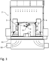
- the components to be painted are transported on a conveyor 1 at right angles to the plane of the drawing through a painting booth 2, in which the components are then painted by painting robots in a manner known per se.
- the painting robots 3, 4 have two swiveling robot arms and each guide an application device via a multi-axis robot hand axis.
- it can be a robot with six or more rotary axes and possibly a linear travel axis along the conveying path.
- Painting robots with at least seven rotary axes have the advantage of painting bodywork that in many cases there is no need for an additional axis.
- the painting robots 3, 4, as application devices carry nozzle print heads 8, 9 for two-component or multi-component paint.
- These nozzle print heads have a much higher application efficiency than atomizers of more than 95% to 99% and thus produce practically no overspray.
- this offers the advantage that the washout below the booth, which is required in conventional painting systems with atomizers, can be dispensed with.
- an air suction device 10 can be located under the painting booth 2, which sucks the booth air downwards out of the booth through a filter ceiling 11 if necessary, without any other effort required to collect and separate overspray. In many cases, the air extraction works without a filter. This can also take place via channels arranged near the floor.
- Fig. 2 explains an embodiment of the invention in which two components of the coating agent are mixed with one another only when they strike the surface to be coated by the impact of the drops or jets.
- These drops or jets are generated by two schematically illustrated nozzles D1 and D2, which are in a common plane of the nozzle print head are arranged next to each other, with one nozzle ejecting a first component (e.g. base paint) and the other nozzle ejecting a second component (hardener).
- a first component e.g. base paint
- hardener hardener
- the ejection can take place one after the other or simultaneously at a point in time 1, and according to the painting distance L of the nozzles D1 and D2 from the surface F to be coated and the flight speeds of the components, the two components hit the surface F a little later at a point in time 2 , at least approximately at one and the same point P, where they mix with one another.
- the ejection directions of the two nozzles D1 and D2 are inclined at, for example, opposite flight angles ⁇ and ⁇ to the other nozzle in relation to the painting distance L perpendicular to the surface F.
- the size of the chosen flight angle depends not only on the painting distance L, but also on the distance between the nozzles D1 and D2, measured parallel to the surface F, and can be, for example, between approximately 0 and 90 °.
- the flight speeds and / or the flight angles of the two components can also be different from one another. If the nozzles D1 and D2 are opened at different times, a displacement movement of the nozzles relative to the surface F during the application of the two components can also be taken into account.
- Fig. 3 explains schematically the overlapping application of coating dots on the surface F to be coated, whereby it is usually a matter of drops of already mixed components, which in turn mix with one another on the surface F by flowing together. However, these could also be components that only mix on the surface F to be coated.
- the Nozzles are moved by the coating robot at the given travel speed along the surface F, they generate a coating point, for example one drop each, with a defined size a at predetermined successive evenly spaced times t1 to t5 etc.
- the respective nozzle is time-controlled in such a way that defined drop spacings b along the surface F and consequently the respectively desired overlap of the applied drops result.
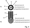
- a nozzle unit 40 designed as a double nozzle for mixing two components of a coating agent (e.g. 2K paint) in or on the nozzle pressure head is shown schematically.
- the nozzle unit 40 consists essentially of an outer tubular body 41, in the interior of which, for example, is cylindrical, and an inner tube 42, which is also cylindrical, for example, is arranged concentrically. While Figure 4B ) shows a longitudinal section through this tubular nozzle unit 40 is shown in FIG Figure 4A ) a top view of the in Figure 4B ) lower nozzle face shown.
- the outer pipe body 41 can, as shown, protrude axially outward on the nozzle end face 43 beyond the inner tube 42.
- one component of the coating agent e.g. base paint
- the second component e.g. hardener
- the first-mentioned component could also be passed through the annular gap and consequently the second component could be passed through the inner tube.
- the components are mixed at the end face 43 of the double nozzle or nozzle unit 40 shown, that is to say at its outlet, where the droplets formed there mix with one another as shown.
- the respective droplet formation does not begin at the same time, but rather the two nozzle elements, i.e. the inner tube 42 and the outlet 46 designed as an annular gap nozzle with valves (not shown), are timed so that first the drop at the inner tube nozzle and only then the drop is formed at the annular gap nozzle.
- the reverse order can also be useful. Instead, however, a simultaneous opening of the two nozzle elements is also conceivable.
- the nozzle print head according to the invention preferably holds a multiplicity of such nozzle units, which can in particular be arranged in one or more rows.
- a double nozzle unit is explained using the example of droplet formation, such or similar double nozzles are also conceivable for the generation of component jets which can be mixed at the nozzle outlets.
- the two nozzle elements can be controlled jointly and / or individually with regard to their opening times by assigned controllable valves.
Description
Die Erfindung betrifft eine Applikationsvorrichtung zum serienweisen Applizieren eines Beschichtungsmittels auf Flächen von Werkstücken, insbesondere von Kraftfahrzeugkarossen und/oder deren Anbauteilen, mit einem im Folgenden als Düsendruckkopf bezeichneten Düsenapplikator, der mindestens eine Düse oder vorzugsweise eine Mehrzahl von nebeneinander angeordneten Düsen enthält, die das Beschichtungsmittel als kontinuierliche Strahlen oder einzelne Tropfen auf die zu beschichtende Fläche applizieren. Mit "Applikationsvorrichtung" ist eine Vorrichtung gemeint, zu welcher außer dem von einem Beschichtungsroboter bewegten Düsendruckkopf weitere Einheiten wie die das Beschichtungsmittel enthaltende Versorgungseinheit und ggf. Mischer, Farbwechsler und/oder eine Spüleinrichtung gehören können. Ferner betrifft die Erfindung ein entsprechendes Applikations- und/oder Reinigungsverfahren.The invention relates to an application device for the serial application of a coating agent on surfaces of workpieces, in particular motor vehicle bodies and / or their add-on parts, with a nozzle applicator, referred to below as a nozzle print head, which contains at least one nozzle or preferably a plurality of nozzles arranged next to one another that contains the coating agent Apply as continuous jets or individual drops to the surface to be coated. "Application device" means a device to which, in addition to the nozzle print head moved by a coating robot, other units such as the supply unit containing the coating agent and possibly a mixer, color changer and / or a rinsing device can belong. The invention also relates to a corresponding application and / or cleaning method.
Zum allgemeinen Stand der Technik kann zunächst z. B. verwiesen werden auf die
Ferner sind u. a. aus
Dennoch können derartige Druckköpfe mit einer Flächenbeschichtungsleistung von mindestens 1 m2/min, 2 m2/min, 3 m2/min, 4 m2/min oder gar 5 m2/min arbeiten. Der Auftragungswirkungsgrad des Druckkopfes kann mehr als 80 %, 90 % oder sogar 99 % betragen, und in der Beschichtungskabine kann die Luftsinkgeschwindigkeit im Betrieb kleiner sein als 0,3 m/s, 0,2 m/s, 0,1 m/s, 0,07 m/s oder sogar 0,05 m/s.Nevertheless, such print heads can operate with a surface coating capacity of at least 1 m 2 / min, 2 m 2 / min, 3 m 2 / min, 4 m 2 / min or even 5 m 2 / min. The application efficiency of the printhead can be more than 80%, 90% or even 99%, and in the coating booth the air descent speed during operation can be less than 0.3 m / s, 0.2 m / s, 0.1 m / s , 0.07 m / s or even 0.05 m / s.
Wesentlicher Bestandteil des Düsendruckkopfes kann eine Düsenplatte mit in einer Plattenebene ausgebildeten Öffnungen sein, die als Düsen dienen.A nozzle plate with openings formed in a plate plane, which serve as nozzles, can be an essential component of the nozzle print head.
Alle oben erwähnten Merkmale und Vorteile der erwähnten bekannten Düsendruckköpfe gelten auch für die hier beschriebene Erfindung.All of the above-mentioned features and advantages of the known nozzle print heads mentioned also apply to the invention described here.
Ferner ist beispielsweise aus
Die oben erwähnten Applikationsvorrichtungen und sonstige bereits bekannte Düsendruckköpfe haben alle den Nachteil, dass sie keine Mehrkomponenten-Beschichtungsmittel wie z. B. die bei der Lackierung von Kraftfahrzeugkarossen an sich üblichen 2K- oder 3K-Lacke, Kleber, Dichtmittel, Haftvermittler, Primer usw. applizieren können.The above-mentioned application devices and other known nozzle print heads all have the disadvantage that they do not have multi-component coating agents such as. B. can apply the 2K or 3K paints, adhesives, sealants, adhesion promoters, primers, etc. that are customary in the painting of motor vehicle bodies.
Die
Der Erfindung liegt die Aufgabe zugrunde, die Beschichtung insbesondere von Bau- oder Anbauteilen von Kraftfahrzeugkarossen und insbesondere auch deren Gesamtflächen in der bereits vorgeschlagenen Weise praktisch ohne Overspray, jedoch mit beliebigen Mehrkomponenten-Beschichtungsmitteln zu ermöglichen.The invention is based on the object of enabling the coating, in particular, of structural or add-on parts of motor vehicle bodies and, in particular, their total surfaces in the manner already proposed, practically without overspray, but with any multicomponent coating agents.
Dieser Aufgabe wird durch eine erfindungsgemäße Applikationsvorrichtung bzw. ein entsprechendes Applikationsverfahren gemäß den unabhängigen Ansprüchen gelöst.This object is achieved by an application device according to the invention or a corresponding application method according to the independent claims.
Die erfindungsgemäße Applikationsvorrichtung weist zunächst in Übereinstimmung mit dem Stand der Technik einen Düsenapplikator oder Düsendruckkopf zur Applikation des Beschichtungsmittels auf das zu beschichtende Bauteil auf. Der im Rahmen der Erfindung verwendete Begriff eines "Düsendrucckopfs" ist allgemein zu verstehen und dient lediglich zur Abgrenzung dieses Düsenapplikators von allen Zerstäubern (z. B. Rotationszerstäuber, Luftzerstäuber, Airless-Zerstäuber usw.), die einen Sprühnebel des zu applizierenden Beschichtungsmittels abgeben. Im Gegensatz dazu erzeugt der Düsendruckkopf radial eng begrenzte Beschichtungsmittelstrahlen oder Tropfen, wobei der Strahl kontinuierlich, d. h. in seiner Längsrichtung zusammenhängend erzeugt wird, während die Tropfen in ein und dieselbe Richtung fliegen und in der Flugrichtung voneinander getrennt sein sollen. Erfindungsgemäß enthält der Düsendruckkopf eine Mehrzahl von nebeneinander angeordneten Düsen, denen das bereits gemischte Beschichtungsmittel zugeführt wird, oder eine Mehrzahl von als Doppeldüsen ausgebildeten Düseneinheiten, von denen die eine Düse eine erste Komponente und die andere Düse eine zweite Komponente ausgibt. Zu bevorzugen sind aber Druckköpfe mit einer Vielzahl von beispielsweise einer oder mehreren parallelen Reihen von Düsen.The application device according to the invention initially has, in accordance with the prior art, a nozzle applicator or nozzle print head for applying the coating agent to the component to be coated. The term "nozzle pressure head" used in the context of the invention is to be understood in general terms and serves only to distinguish this nozzle applicator from all atomizers (e.g. rotary atomizers, air atomizers, airless atomizers, etc.) which emit a spray of the coating agent to be applied. In contrast, the nozzle print head produces radially narrow jets of coating agent or drops, the jet being continuous, i.e. H. is generated coherently in its longitudinal direction, while the drops fly in one and the same direction and should be separated from one another in the direction of flight. According to the invention, the nozzle print head contains a plurality of juxtaposed nozzles to which the already mixed coating agent is fed, or a plurality of nozzle units designed as double nozzles, of which one nozzle emits a first component and the other nozzle emits a second component. However, print heads with a multiplicity of, for example, one or more parallel rows of nozzles are preferred.
Die Erfindung ist im Übrigen mit allen Arten von Druckköpfen oder sonstigen Düsenapplikatoren realisierbar, die sich in der oben erläuterten Weise von üblichen Zerstäubern unterscheiden.The invention can also be implemented with all types of print heads or other nozzle applicators which differ from conventional atomizers in the manner explained above.
Darüber hinaus sind erfindungsgemäß mindestens zwei getrennte Zuleitungen für miteinander zu mischende Komponenten des Beschichtungsmittels vorgesehen, die zur gemeinsamen Versorgung aller Düsen des Druckkopfes mit ein und demselben Beschichtungsmittel oder dessen Komponenten vorgesehen sind. Mindestens zwei getrennte Zuleitungen führen zu dem oder in den Düsendruckkopf, da die Komponenten dort oder erst nach Verlassen des Düsendruckkopfes gemischt werden sollen. Bei den Komponenten handelt es sich bei typischen Ausführungsbeispielen um mindestens eine Materialkomponente (z. B. Stammlack) und mindestens eine in an sich bekannter Weise mit der Materialkomponente für deren Aushärtung reagierende Härterkomponente. Bei der Erfindung bleiben die Komponenten mindestens bis in den Düsendruckkopf hinein getrennt.In addition, according to the invention, there are at least two separate feed lines for components of the coating agent that are to be mixed with one another provided, which are provided for the common supply of all nozzles of the print head with one and the same coating agent or its components. At least two separate supply lines lead to or into the nozzle print head, since the components are to be mixed there or only after leaving the nozzle print head. In typical exemplary embodiments, the components are at least one material component (e.g. base lacquer) and at least one hardener component which reacts in a manner known per se with the material component for its hardening. In the case of the invention, the components remain separate at least as far as the nozzle print head.
Ein wesentlicher Vorteil der Erfindung ist darin zu sehen, dass die serienweise vollautomatische Flächenbeschichtung, namentlich Lackierung von vollständigen Kraftfahrzeugkarossen mit beliebigen Mehrkomponenten-Beschichtungsmitteln (einschließlich Effektlacken) praktisch ohne Overspray ermöglicht wird.An essential advantage of the invention is that the series-wise fully automatic surface coating, namely painting of complete motor vehicle bodies with any multicomponent coating agents (including effect paints) is made possible with practically no overspray.
Wie schon erläutert wurde, sollen die Düsen des Druckkopfes die Strahlen oder Tropfen des Beschichtungsmittels oder seiner Komponenten zur Vermeidung von Overspray gezielt auf einzelne Punkte der zu beschichtenden Fläche lenken. Die hierbei applizierten Auftreffpunkte können aneinander angrenzen oder einander überlappen, wie noch genauer beschrieben wird.As has already been explained, the nozzles of the print head are intended to direct the jets or drops of the coating agent or its components specifically onto individual points of the surface to be coated in order to avoid overspray. The points of impact applied here can adjoin one another or overlap one another, as will be described in more detail below.
In Übereinstimmung mit dem Stand der Technik ist es auch bei der Erfindung zweckmäßig, den Düsendruckkopf an einem mehrachsigen Beschichtungsroboter anzuordnen, der den Düsendrucckopf über die zu beschichtende Fläche bewegt. Beispielsweise kann hierzu auf die aus dem Stand der Technik an sich allgemein bekannten 6- oder mehrachsigen Lackierroboter mit oder ohne lineare Mitfahrachse verwiesen werden.In accordance with the prior art, it is also expedient in the invention to arrange the nozzle print head on a multi-axis coating robot which moves the nozzle print head over the surface to be coated. For example, this can generally be referred to from the prior art per se known 6 or multi-axis painting robots with or without a linear travel axis are referred to.
Wie ebenfalls schon erläutert wurde, eignet sich die Erfindung für beliebige Mehrkomponenten-Beschichtungsmittel wie etwa 2K- oder 3K-Lack (einschließlich Basislack und Klarlack), Grundierungs- oder Primer-Mittel, Kleb- oder Dichtungsmittel oder Konservierungsmittel usw., die jeweils mindestens eine Stammkomponente und eine mit diesem reagierende Härterkomponente haben.As has also already been explained, the invention is suitable for any multicomponent coating agent such as 2K or 3K paint (including basecoat and clearcoat), primer or primer, adhesive or sealant or preservative, etc., each at least one Base component and a hardener component that reacts with it.
Die Mischung der Komponenten kann auf verschiedene Art und Weise und an unterschiedlichen Stellen des Applikationssystems durchgeführt werden.The components can be mixed in different ways and at different points in the application system.
So kann der Düsendruckkopf die mindestens zwei Komponenten voneinander getrennt so auf die zu beschichtende Fläche lenken, dass sie sich auf dieser vermischen. Das Vermischen der Komponenten erfolgt hierbei also durch den Impact der Tropfen oder Strahlen. Es besteht die Möglichkeit, dass der Druckkopf die zu mischenden Komponenten gleichzeitig ausstößt. Bei anderen Ausführungsformen der Erfindung stößt der Druckkopf die zu mischenden Komponenten aber zeitlich nacheinander aus, also zuerst die eine und dann die andere Komponente (beispielsweise zuerst den Stammlack und dann den Härter, oder umgekehrt). In beiden Fällen treffen die Strahlen bzw. Tropfen an im Wesentlichen derselben Stelle auf.Thus, the nozzle print head can direct the at least two components separately from one another onto the surface to be coated in such a way that they mix on this. The mixing of the components takes place here through the impact of the drops or jets. There is a possibility that the printhead will eject the components to be mixed at the same time. In other embodiments of the invention, however, the print head ejects the components to be mixed one after the other, that is to say first one and then the other component (for example first the base lacquer and then the hardener, or vice versa). In both cases, the jets or drops impinge at essentially the same point.
Gemäß einer anderen Möglichkeit der Erfindung kann das Mischen auch im Flug erfolgen, d. h. die Düsen des Druckkopfes sind so zueinander angestellt, dass die Komponenten sich auf dem Weg der zu beschichtenden Fläche treffen. Hierbei muss beispielsweise mittels des Beschichtungsroboters ein entsprechender Abstand zwischen dem Düsendruckkopf und der zu beschichtenden Fläche eingehalten werden. Weiterhin ist es möglich, dass die Tropfen der Komponenten des Beschichtungsmittels so mit unterschiedlichen Geschwindigkeiten und zeitlich versetzt zueinander ausgestoßen werden, dass der später ausgestoßene Tropfen im Flug auf den zuerst ausgestoßenen Tropfen trifft und sich mit ihm vermischt.According to another possibility of the invention, the mixing can also take place in flight, ie the nozzles of the print head are positioned in relation to one another in such a way that the components meet on the way to the surface to be coated. In this case, for example, by means of the coating robot, a corresponding distance between the nozzle print head and the one to be coated must be maintained Area are respected. Furthermore, it is possible for the drops of the components of the coating agent to be ejected at different speeds and with a time offset from one another in such a way that the later ejected drop hits the first ejected drop in flight and mixes with it.
Wie schon erwähnt wurde, lassen sich mit z. B. elektrisch ventilgesteuerten Düsen Tropfen unterschiedlicher Größe erzeugen. Durch unterschiedliche Tropfengrößen lässt sich erfindungsgemäß u. a. das Mischungsverhältnis einstellen, wenn die Komponenten erst nach Verlassen der Düsen gemischt werden.As already mentioned, z. B. electrically valve-controlled nozzles produce drops of different sizes. According to the invention, by means of different droplet sizes, inter alia. set the mixing ratio if the components are only mixed after leaving the nozzles.
Gemäß einer weiteren Möglichkeit der Erfindung kann das Mischen aber auch in dem Düsendruckkopf erfolgen, beispielsweise mit einem Mischer, der in an sich bekannter Weise als statischer oder dynamischer Mischer ausgebildet sein kann. Der Mischer kann an dem Düsendruckkopf angeordnet sein, beispielsweise innerhalb des Druckkopfes integriert in einen jeweiligen Zuflusskanal der Düsen, wo er mit den mindestens zwei getrennten Zuleitungen der Applikationsvorrichtung verbunden ist.According to a further possibility of the invention, however, the mixing can also take place in the nozzle print head, for example with a mixer, which can be designed in a manner known per se as a static or dynamic mixer. The mixer can be arranged on the nozzle print head, for example integrated within the print head in a respective inflow channel of the nozzles, where it is connected to the at least two separate feed lines of the application device.
Gemäß einer anderen Möglichkeit, die Komponenten im Druckkopf zu mischen, können auch die einzelnen Düsen des Düsendrucckopfes jeweils zum Vermischen der Komponenten ausgebildet sein. Gemäß einem entsprechenden Ausführungsbeispiel der Erfindung können die jeweiligen Düsen mindestens zwei zu einem Düsenauslass führende Kanäle enthalten, die bei diesem Ausführungsbeispiel konzentrisch zueinander verlaufen können, wobei der Düsenauslass durch mindestens einen Ringspalt und eine zentrale Öffnung gebildet sein kann. Bei diesem Ausführungsbeispiel handelt es sich also bei jeder Düse des Düsendruckkopfes eigentlich um eine Einheit mit mindestens zwei Düsenelementen, nämlich den Auslassöffnungen dieser Düseneinheit.According to another possibility of mixing the components in the print head, the individual nozzles of the nozzle print head can each be designed to mix the components. According to a corresponding embodiment of the invention, the respective nozzles can contain at least two channels leading to a nozzle outlet, which in this embodiment can run concentrically to one another, wherein the nozzle outlet can be formed by at least one annular gap and a central opening. In this exemplary embodiment, each nozzle of the nozzle print head is involved actually a unit with at least two nozzle elements, namely the outlet openings of this nozzle unit.
Insbesondere bei jeder der erwähnten Möglichkeiten des Vermischens ohne Mischer kann es zweckmäßig sein, mindestens einer der Komponenten, vorzugsweise aber beiden oder allen Komponenten einen Drall zu erteilen, wodurch sie sich besser vermischen. Konstruktive Möglichkeiten hierfür stehen dem Fachmann ohne weiteres zur Verfügung.In particular with each of the mentioned possibilities of mixing without a mixer, it can be expedient to impart a twist to at least one of the components, but preferably to both or all of the components, as a result of which they mix better. Design options for this are readily available to the person skilled in the art.
Werden die Komponenten nicht über einen Mischer gemischt, kann es bei der Applikation von zusammenhängenden Strahlen notwendig sein, über eine Volumenstromregelung der Einzelkomponenten das Mischungsverhältnis der beiden Komponenten sicherzustellen. Bei der Applikation von Tropfen kann das Mischungsverhältnis über das Volumen der Tropfen z. B. mittels unterschiedlicher Öffnungszeiten der Düsen gesteuert werden.If the components are not mixed using a mixer, it may be necessary when applying continuous jets to ensure the mixing ratio of the two components by regulating the volume flow of the individual components. When applying drops, the mixing ratio can be determined by the volume of the drops, e.g. B. can be controlled by means of different opening times of the nozzles.
Wenn ein Mischer vorgesehen sein soll, hat er entsprechende Eingänge, an denen er mit den mindestens zwei getrennten Zuleitungen verbunden ist, während sein Ausgang über eine gemeinsame Leitung mit den Düsen verbunden ist.If a mixer is to be provided, it has corresponding inputs at which it is connected to the at least two separate supply lines, while its output is connected to the nozzles via a common line.
Üblicherweise als Farbwechsler bezeichnete gesteuerte Farbwechselventilanordnungen zur Auswahl eines jeweils gewünschten Farblacks aus einer Vielzahl zugeführter unterschiedlicher Farben sind an sich allgemein bekannt. Auch bei der Erfindung kann mindestens ein Farbwechsler vorgesehen sein, der an mindestens eine der Zuleitungen der Applikationsvorrichtung oder des Düsendruckkopfes z. B. für eine Stammlackkomponente angeschlossen ist. Der Farbwechsler kann zweckmäßig bewegbar angeordnet sein, insbesondere an dem den Düsendrucckopf bewegenden Beschichtungsroboter, beispielsweise auf einem seiner Arme oder auch auf einer Mitfahrachse des Roboters. Je näher der Farbwechsler dem Düsendruckkopf ist, umso geringer sind die unvermeidbaren Farb- und Spülmittelverluste bei einem Farbwechsel. Stattdessen kann der Farbwechsler aber auch stationär beispielsweise an einer Innen- oder Außenwand der Beschichtungskabine der hier betrachteten Beschichtungsanlage angeordnet sein.Controlled color change valve arrangements, usually referred to as color changers, for selecting a particular desired color lacquer from a large number of supplied different colors are generally known per se. Also in the invention, at least one color changer can be provided which is connected to at least one of the supply lines of the application device or the nozzle print head z. B. is connected for a base paint component. The color changer can expediently be arranged movably, in particular on the coating robot that moves the nozzle pressure head, for example on a its arms or on a robot axis. The closer the color changer is to the nozzle print head, the lower the unavoidable loss of color and detergent during a color change. Instead, however, the color changer can also be arranged in a stationary manner, for example on an inner or outer wall of the coating booth of the coating system under consideration here.
Der Düsendruckkopf kann zweckmäßig durch eine Düsenplatte gebildet sein, die als Düsen in einer Plattenebene nebeneinander angeordnete Öffnungen enthält. Die Düsen können vorzugsweise in einer oder mehreren parallelen Reihen angeordnet sein, beispielsweise auch als Spalten und Zeilen einer Matrix. Die Längsachsen der Düsen können bei entsprechenden Ausführungsformen der Erfindung senkrecht zu der Plattenebene verlaufen. Bei anderen Ausführungsformen sind die Längsachsen benachbarter Düsen dagegen um unterschiedliche oder gleiche, beispielsweise entgegengesetzte gleiche Winkel gegen die Plattenebene geneigt.The nozzle print head can expediently be formed by a nozzle plate which, as nozzles, contains openings arranged next to one another in a plane of the plate. The nozzles can preferably be arranged in one or more parallel rows, for example also as columns and rows of a matrix. In corresponding embodiments of the invention, the longitudinal axes of the nozzles can run perpendicular to the plane of the plate. In other embodiments, on the other hand, the longitudinal axes of adjacent nozzles are inclined at different or identical, for example opposite, identical angles with respect to the plane of the plate.
Zur automatischen Steuerung ihrer Öffnungszeiten können die Düsen beispielsweise im Rahmen der für Beschichtungsanlagen üblichen Programmsteuerung mit in oder an dem Düsendruckkopf, ggf. beispielsweise an der Düsenplatte angeordneten elektrischen oder pneumatisch gesteuerten Ventilen verbunden sein.For automatic control of their opening times, the nozzles can be connected, for example within the framework of the usual program control for coating systems, to electrical or pneumatically controlled valves arranged in or on the nozzle print head, possibly for example on the nozzle plate.
Die Steuerventile können beispielsweise einen elektrisch von einer Spule oder pneumatisch verschiebbaren Kolben haben, der in Abhängigkeit von seiner Stellung die Düse verschließt oder öffnet.The control valves can, for example, have a piston which can be displaced electrically by a coil or pneumatically and which, depending on its position, closes or opens the nozzle.
Gemäß einem speziell für Mehrkomponenten-Beschichtungsmittel wichtigen Aspekt der erfindungsgemäßen Applikationsvorrichtung ist deren Reinigung vor und nach Beschichtungsvorgängen. Beispielsweise kann der Düsendruckkopf jeweils nach einer vorgegebenen Zeit oder Betriebsdauer gespült werden, etwa stündlich oder nach jeweils mehreren Stunden oder zu bestimmten Tageszeiten (Schicht- oder Produktionsende, Wochenende) usw. oder nach Erreichen einer bestimmten Anzahl beschichteter Werkstücke oder nach Erreichen einer bestimmten ausgestoßenen Lackmenge. Ebenso kann es sinnvoll sein, den Düsendruckkopf nach bestimmten Ereignissen des Beschichtungsbetriebs zu spülen, beispielsweise nach jedem Stillstand einer wie üblich die Fahrzeugkarossen oder sonstigen zu beschichtenden Werkstücke durch eine Beschichtungskabine fördernden Band- oder sonstigen Fördereinrichtung oder auch nach einer vorbestimmten Anzahl von Förderstillständen. Ferner kann das Spülen signalgesteuert nach Ablauf einer vorgegebenen Zeitdauer erfolgen, beispielsweise aufgrund eines Alarm- oder Störungsmeldesignals nach Ablauf einer Zeitdauer, nach der die Reaktion von zwei Komponenten so weit fortgeschritten ist, dass das Applikationssystem zur Schadensvermeidung gespült werden muss. Bei der Karossenbeschichtung kann das Spülen auch in den sogenannten Karossenlücken erfolgen, also wenn in den Pausen nach dem Beschichten einer Karosse der Roboter auf die nächste durch die Beschichtungskabine geförderte Karosse wartet. Die Spülvorgänge können automatisch in Abhängigkeit von Zeitüberwachungseinrichtungen gesteuert werden.According to an aspect of the application device according to the invention that is particularly important for multicomponent coating agents, its cleaning before and after coating processes. For example, the nozzle print head can be rinsed after a specified time or operating time, for example hourly or after several hours or at certain times of the day (end of shift or production, weekend) etc. or after reaching a certain number of coated workpieces or after reaching a certain ejected amount of paint . It can also be useful to rinse the nozzle print head after certain events in the coating operation, for example after each standstill of a belt or other conveyor device conveying the vehicle bodies or other workpieces to be coated through a coating booth as usual, or after a predetermined number of conveyor stoppages. Furthermore, the flushing can be signal-controlled after a predetermined period of time has elapsed, for example on the basis of an alarm or fault signal signal after a period of time after which the reaction of two components has progressed so far that the application system has to be flushed to avoid damage. With car body coating, rinsing can also take place in the so-called body gaps, i.e. when the robot waits for the next body to be conveyed through the coating booth during the breaks after coating a body. The flushing processes can be controlled automatically as a function of time monitoring devices.
Zum Reinigen können je nach Anwendungsfall unterschiedliche Spülmittel verwendet werden. So können beispielsweise bei einem Wechsel des Beschichtungsbetriebs zwischen lösemittelbasiertem (2K-)Lack und Wasserlack jeweils andere Spülmittel zweckmäßig sein, wobei zwischen den beiden Spülmitteln auch zusätzlich ein Trennmittel wie z. B. ein Alkohol zum Einsatz kommen kann. Ferner können Spülmittel mit unterschiedlicher Reinigungswirkung verwendet werden (Kaskadierung), etwa zur Reduzierung von VOC-Emissionen (also flüchtiger organischer Verbindungen), wenn bei einem wässrigen Spülmittel der Gehalt an organischem Lösemittel ansteigt. Es sind aber auch Universal-Spülmittel für Wasserlack und Lösemittellack bekannt. Vorzugsweise wird VOC-freies Spülmittel verwendet. Hierzu können für unterschiedliche Lacke unterschiedliche Spülprogramme, die sich in ihrer Programmabfolge und/oder ihrer Dauer unterscheiden, angewendet werden.Different detergents can be used for cleaning, depending on the application. For example, when changing the coating operation between solvent-based (2K) paint and water-based paint, other rinsing agents may be appropriate, with a separating agent such as. B. an alcohol can be used. In addition, detergents with different cleaning effects can be used (cascading), for example for Reduction of VOC emissions (i.e. volatile organic compounds) when the organic solvent content of an aqueous detergent increases. But there are also known universal detergents for water-based paints and solvent-based paints. VOC-free detergent is preferably used. For this purpose, different wash programs, which differ in their program sequence and / or their duration, can be used for different paints.
Ferner kann es zweckmäßig sein, die von einer oder mehr Komponenten des Beschichtungsmittels berührten Innen- oder Außenflächen des Düsendruckkopfes insbesondere vor einer geplanten Arbeitsunterbrechung mit einem Fluid zu befüllen oder zu benetzen, das Ablagerungen des Beschichtungsmittels und/oder die Reaktion von zwei Komponenten des Beschichtungsmittels mindestens im Wesentlichen verhindert (mit Reaktion ist im Rahmen der Erfindung in der Regel eine chemische und/oder Aushärtungsreaktion gemeint).Furthermore, it can be useful to fill or wet the inner or outer surfaces of the nozzle print head that are touched by one or more components of the coating agent, especially before a planned work interruption, with a fluid that at least causes deposits of the coating agent and / or the reaction of two components of the coating agent essentially prevented (in the context of the invention, a reaction generally means a chemical and / or curing reaction).
Zum Spülen kann in an sich bekannter Weise abwechselnd Spülmittel und Pulsluft zugeführt werden. Zusätzlich oder stattdessen kann auch mit einem Aerosol gespült werde. Wenn es sich nach dem Spülen als erforderlich erweist, können die gespülten Wege anschließend mit Druckluft entleert bzw. getrocknet werden.For rinsing, detergent and pulsed air can be supplied alternately in a manner known per se. In addition or instead, it is also possible to rinse with an aerosol. If it proves necessary after flushing, the flushed paths can then be emptied or dried with compressed air.
Nach dem Spülen ist zweckmäßig, die betreffenden Wege vor Beschichtungsbeginn wieder mit dem Beschichtungsmittel oder dessen Komponenten zu befüllen, was in Beschichtungsanlagen üblicherweise als Andrücken bezeichnet wird. Optional kann es hierbei sinnvoll sein, mindestens einen Tropfen oder eine definierte Menge des neuen Beschichtungsmittels oder seiner Komponenten durch die Düse auszubringen.After rinsing, it is expedient to fill the path in question with the coating agent or its components again before the start of coating, which is usually referred to as pressing in coating systems. Optionally, it can be useful here to apply at least one drop or a defined amount of the new coating agent or its components through the nozzle.
Die für die beschriebenen Spülvorgänge vorgesehene Spüleinrichtung kann durch mindestens eine parallel zu den Komponentenzuleitungen in die Applikationsvorrichtung führende Spülmittelleitung gebildet sein, die ggf. über einen Mischer oder unmittelbar mit allen Düsen verbunden oder verbindbar sein kann. Wenn ein Farbwechsler vorhanden ist, kann eine Spülmittelleitung beispielsweise an einen Eingang des Farbwechslers angeschlossen sein, so dass das Spülmittel dem Düsendruckkopf durch die Zuleitung z. B. für die Stammlackkomponente zugeführt werden kann. Denkbar ist auch eine separat in den Düsendruckkopf führende Spülmittelleitung.The flushing device provided for the flushing processes described can be formed by at least one flushing agent line running parallel to the component feed lines into the application device, which can optionally be connected or connectable to all nozzles via a mixer or directly. If a color changer is available, a detergent line can be connected to an input of the color changer, for example, so that the detergent can be fed to the nozzle print head through the supply line, for example. B. can be supplied for the base paint component. A rinsing agent line leading separately into the nozzle print head is also conceivable.
Bei zweckmäßigen Ausführungsformen der Erfindung kann ferner in der Beschichtungsanlage eine externe Spüleinrichtung vorgesehen sein, beispielsweise eine in der Nähe des Beschichtungsroboters von diesem erreichbar angeordnete gesonderte Spülvorrichtung. Wenn in der Beschichtungsanlage eine Ablagevorrichtung zum Ablegen des Düsendruckkopfes in Beschichtungspausen vorhanden ist, kann die Spülvorrichtung auch in die Ablagevorrichtung integriert sein.In expedient embodiments of the invention, an external rinsing device can also be provided in the coating system, for example a separate rinsing device arranged in the vicinity of the coating robot that can be reached by the latter. If there is a depositing device in the coating system for depositing the nozzle print head during coating breaks, the flushing device can also be integrated into the depositing device.
In jedem Fall soll die Spüleinrichtung vorzugsweise so ausgebildet sein, dass die Düsenkanäle und auch die Außenfläche des Düsendruckkopfes, also ggf. der Düsenplatte gespült werden können. Ferner kann ein Rückspülen der Düsenplatte oder Düsenkanäle zweckmäßig sein, wobei das Spülmittel von außen nach innen durch den Düsenkanal gedrückt wird, beispielsweise um eine verstopfte Düse zu reinigen. Dadurch kann ein sonst erforderlicher Wechsel des Düsendruckkopfes bzw. der Düsenplatte entfallen und somit Material und Arbeitszeit eingespart werden. Zum Auffangen aller beim Spülen (aus den Düsen) austretender Fluide, also Beschichtungs- und Spülmittel und/oder Aerosole kann die Spülvorrichtung mit einer entsprechenden Auffangeinrichtung versehen sein, aus der sie dann abgeschieden und entsorgt werden können.In any case, the flushing device should preferably be designed in such a way that the nozzle channels and also the outer surface of the nozzle print head, that is to say the nozzle plate, if applicable, can be flushed. Furthermore, backwashing of the nozzle plate or nozzle channels can be expedient, the flushing agent being pressed from the outside inwards through the nozzle channel, for example in order to clean a clogged nozzle. This eliminates the need to change the nozzle print head or the nozzle plate, thus saving material and working time. The rinsing device can be equipped with an appropriate to collect all fluids emerging during rinsing (from the nozzles), that is to say coating and rinsing agents and / or aerosols Be provided collecting device from which they can then be separated and disposed of.
Generell sollen möglichst geringe Verluste an Beschichtungsmittel und Spülmittel auftreten und VOC-Emissionen vermieden werden. Bei den hier beschriebenen Applikationsverfahren sollen durch einen Spülvorgang verursachte Farb- bzw. Beschichtungsmittelverluste beschränkt werden auf jedenfalls weniger als 10 1, vorzugsweise aber auf weniger als 5 1, 200 ml, 20 ml, 10 ml, 5 ml oder sogar 2 ml, und der Spülmittelbedarf soll hierbei auf weniger als 10 1, vorzugsweise aber weniger als 5 1, 2 1, 200 ml, 100 ml, 50 ml, 20 ml oder sogar 10 ml beschränkt werden.In general, the lowest possible losses of coating agent and rinsing agent should occur and VOC emissions should be avoided. In the application methods described here, paint or coating losses caused by a rinsing process should be limited to less than 10 1, but preferably to less than 5 1, 200 ml, 20 ml, 10 ml, 5 ml or even 2 ml, and the The amount of detergent required should be limited to less than 10 1, but preferably less than 5 1, 2 1, 200 ml, 100 ml, 50 ml, 20 ml or even 10 ml.
Um den Farbverlust und den Spülmittelverbrauch bei einem Farbwechsel zu reduzieren, kann es bei der Verarbeitung von Mehrkomponentenlacken auch genügen, dass nur die von der farbgebenden Komponente z. B. eines 2K-Basislacks oder 2K-Klarlacks und die von dem Gemisch beider Komponenten berührten Bereiche gespült werden.In order to reduce the loss of color and the consumption of detergent when changing color, it can also be sufficient when processing multi-component paints that only the B. a 2K basecoat or 2K clearcoat and the areas touched by the mixture of both components are rinsed.
In diesem Zusammenhang ist zu erwähnen, dass speziell dann, wenn die Mischung der Komponenten erst bei oder nach Verlassen der Düsen erfolgt und in dem Düsendruckkopf somit kein bereits gemischtes Beschichtungsmaterial fließt, sonst erforderliche Spülmittel- und Zeitverluste vermieden werden können, insbesondere weil dann keine besonderen Mischelemente gespült werden müssen.In this context it should be mentioned that especially when the components are mixed only when or after leaving the nozzles and therefore no already mixed coating material flows in the nozzle print head, the otherwise necessary detergent and time losses can be avoided, in particular because then there are no special losses Mixing elements need to be flushed.
Wenn die Mischung erst bei oder nach Verlassen der Düse erfolgt, hat dies außerdem den Vorteil, dass jeweils gewünschte Mischungsverhältnisse besonders einfach und problemlos eingestellt werden können.If the mixing takes place only when or after leaving the nozzle, this also has the advantage that the mixing ratios required in each case can be set particularly easily and without problems.
Schließlich ist noch zu erwähnen, dass die aus dem Stand der Technik bekannten, nur für Einkomponentenlack geeigneten Düsendruckköpfe an die Erfordernisse für Zweikomponenten-Beschichtungsmittel angepasst werden müssen. Insbesondere sind die Größe, also hydraulischen Querschnitte der Düsen und ihrer Kanäle entsprechend dem jeweiligen Mischungsverhältnis zu bemessen. Im Übrigen sollen möglichst lösemittelbeständige Werkstoffe verwendet werden, wie beispielsweise Dichtungen aus FFKM (also Perfluorkautschuk).Finally, it should also be mentioned that the nozzle print heads known from the prior art, which are only suitable for one-component paint, have to be adapted to the requirements for two-component coating agents. In particular, the size, that is, the hydraulic cross-sections of the nozzles and their channels, must be dimensioned in accordance with the respective mixing ratio. In addition, materials that are as solvent-resistant as possible should be used, such as seals made of FFKM (i.e. perfluorinated rubber).
Anhand der Zeichnungen wird die Erfindung näher erläutert. Es zeigen
- Fig. 1
- eine Querschnittsansicht durch eine erfindungsgemäße Lackieranlage zur Lackierung von Kraftfahrzeugkarosseriebauteilen mit Druckköpfen als Applikationsgeräte,
- Fig. 2
- die schematische Darstellung von aus zwei Düsen ausgestoßenen Komponenten gemäß einer Ausführungsform der Erfindung,
- Fig. 3
- die schematische Darstellung der Erzeugung einander überlappender Beschichtungspunkte, und
- Fig. 4
- eine bei einer Ausführungsform der Erfindung zu verwendenden Düseneinheit.
- Fig. 1
- a cross-sectional view through a painting system according to the invention for painting motor vehicle body components with print heads as application devices,
- Fig. 2
- the schematic representation of components ejected from two nozzles according to an embodiment of the invention,
- Fig. 3
- the schematic representation of the generation of overlapping coating points, and
- Fig. 4
- a nozzle unit to be used in one embodiment of the invention.
In der in
Im Gegensatz zu konventionellen Lackieranlagen mit den üblichen Rotationszerstäubern oder sonstigen Zerstäubern führen die Lackierroboter 3, 4 als Applikationsvorrichtung Düsendruckköpfe 8, 9 für 2K- oder Mehrkomponentenlack. Diese Düsendruckköpfe haben einen wesentlich größeren Auftragungswirkungsgrad als Zerstäuber von mehr als 95 % bis 99 % und erzeugen somit praktisch keinen Overspray. Zum einen bietet dies den Vorteil, dass auf die bei herkömmlichen Lackieranlagen mit Zerstäubern benötigte Auswaschung unterhalb der Kabine verzichtet werden kann. Stattdessen kann sich bei der erfindungsgemäßen Lackieranlage unter der Lackierkabine 2 eine Luftabsaugung 10 befinden, welche die Kabinenluft bei Bedarf durch eine Filterdecke 11 hindurch nach unten aus der Kabine absaugt, ohne dass sonstiger Aufwand zum Auffangen und Abscheiden von Overspray erforderlich ist. In vielen Fällen kommt die Luftabsaugung auch ohne Filter aus. Diese kann auch über in Bodennähe angeordnete Kanäle erfolgen.In contrast to conventional painting systems with the usual rotary atomizers or other atomizers, the
Bei dem dargestellten Beispiel sind darstellungsgemäß (gestrichelt dargestellte) Ausstoßrichtungen der beiden Düsen D1 und D2 um beispielsweise entgegengesetzt gleiche Flugwinkel α bzw. β zu der jeweils anderen Düse hin gegen den zu der Fläche F senkrechten Lackierabstand L geneigt. Die Größe der gewählten Flugwinkel hängt außer von dem Lackierabstand L ersichtlich auch von dem parallel zu der Fläche F gemessenen Abstand zwischen den Düsen D1 und D2 ab und kann beispielsweise zwischen annähernd 0 und 90° betragen. Die Fluggeschwindigkeiten und/oder die Flugwinkel der beiden Komponenten können auch unterschiedlich voneinander sein. Wenn die Düsen D1 und D2 zu unterschiedlichen Zeitpunkten geöffnet werden, kann auch eine Verschiebungsbewegung der Düsen relativ zu der Fläche F während der Applikation der beiden Komponenten berücksichtigt werden.In the example shown, the ejection directions of the two nozzles D1 and D2 (shown in dashed lines) are inclined at, for example, opposite flight angles α and β to the other nozzle in relation to the painting distance L perpendicular to the surface F. The size of the chosen flight angle depends not only on the painting distance L, but also on the distance between the nozzles D1 and D2, measured parallel to the surface F, and can be, for example, between approximately 0 and 90 °. The flight speeds and / or the flight angles of the two components can also be different from one another. If the nozzles D1 and D2 are opened at different times, a displacement movement of the nozzles relative to the surface F during the application of the two components can also be taken into account.
Prinzipiell ist eine derartige Applikation mit oder ohne Überlappung dann möglich, wenn die Komponenten schon vor oder in dem Düsendruckkopf oder nach Verlassen der Düse, aber vor Erreichen der zu beschichtenden Fläche gemischt werden. Auch wenn keine einzelnen Tropfen appliziert werden, sondern kontinuierliche Strahlen, ist eine überlappende Applikation zweckmäßig.In principle, such an application with or without an overlap is possible if the components are mixed before or in the nozzle print head or after leaving the nozzle, but before reaching the surface to be coated. Even if no individual drops are applied, but rather continuous jets, an overlapping application is advisable.
In
Die Vermischung der Komponenten erfolgt bei dem hier betrachteten Beispiel an der Stirnseite 43 der dargestellten Doppeldüse oder Düseneinheit 40, also an deren Auslass, wo sich die dort darstellunsgemäß jeweils gebildeten Tropfen miteinander mischen. Hierbei kann es zweckmäßig sein, wenn die jeweilige Tropfenbildung nicht gleichzeitig beginnt, sondern die beiden Düsenelemente, also das Innenrohr 42 und der als Ringspaltdüse ausgebildete Auslass 46 mit (nicht dargestellten) Ventilen zeitlich so gesteuert werden, dass zuerst der Tropfen an der Innenrohrdüse und erst danach der Tropfen an der Ringspaltendüse gebildet wird. Auch die umgekehrte Reihenfolge kann zweckmäßig sein. Stattdessen ist aber auch eine gleichzeitige Öffnung der beiden Düsenelemente denkbar.In the example considered here, the components are mixed at the end face 43 of the double nozzle or
Wie eingangs erläutert wurde, hält der erfindungsgemäße Düsendruckkopf vorzugsweise eine Vielzahl derartiger Düseneinheiten, die insbesondere in einer oder mehreren Reihen angeordnet sein können.As explained at the outset, the nozzle print head according to the invention preferably holds a multiplicity of such nozzle units, which can in particular be arranged in one or more rows.
Während die Erfindung in
Wie schon erwähnt wurde, kann es zweckmäßig sein, die zu mischenden Komponenten mit einem Drall zu versehen. Dies kann beispielsweise mittels einer Spiralnut an der Innenseite eines Düsenkanals realisiert werden (im Prinzip ähnlich wie bei einem gezogenen Gewehrlauf).As already mentioned, it can be useful to provide the components to be mixed with a twist. This can be achieved, for example, by means of a spiral groove on the inside of a nozzle channel (in principle similar to a rifle barrel).
Claims (22)
- Application device for the application in series of a coating agent to surfaces of workpieces, in particular of motor vehicle bodies and/or add-on parts thereof,
having a nozzle printhead (8, 9) which contains a plurality of nozzles (D1, D2; 40) arranged side by side which apply the coating agent to the surface (F) to be coated as continuous jets or individual drops,
wherein the nozzle printhead is arranged on a multi-axis coating robot (3, 4) having six or more rotary axes which moves the nozzle printhead (8, 9) over the surface to be coated,
and having a supply unit containing the coating agent,
wherein the coating agent consists of at least two components which are to be mixed together, which components comprise at least one material component and at least one curing agent component which reacts with the material component for the curing thereof,
and wherein there is provided a flushing apparatus for the nozzle printhead, which(a) is formed by at least one flushing medium line which leads into the application device and/or into the nozzle printhead and to which the nozzles are connected or can be connected, and/or(b) is formed by an apparatus arranged externally in the vicinity of the multi-axis coating robot (3, 4) which moves the nozzle printhead,characterised in that the nozzle printhead (8, 9) has at least two separate supply lines for the components to be mixed, which supply lines are provided to jointly supply the nozzles (D1, D2; 40) with the coating agent or the components thereof, and
the components remain separate at least until they enter the nozzle printhead (8, 9). - Application device according to claim 1, characterised in that the nozzles of the nozzle printhead purposively direct the jets or drops of the coating agent or the components thereof at individual points of the surface to be coated in order to avoid overspray, wherein the applied impact points in particular adjoin one another or overlap with one another.
- Application device according to any one of the preceding claims, characterised in that the coating agent is(a) a liquid multicomponent lacquer,(b) a primer,(c) an adhesive or sealant or(d) a preserving agent,and in each case has at least one parent component and at least one curing agent component that reacts therewith.
- Application device according to any one of the preceding claims, characterised in that(a) the nozzle printhead directs the at least two components separately from one another onto the surface to be coated in such a manner that they mix together on the surface, and/or(b) the nozzles of the nozzle printhead are so adjusted relative to one another that the components meet on the path to the surface to be coated, or(c) the components are mixed in the nozzle printhead, and/or(d) the nozzles of the nozzle printhead are each configured for mixing the at least two components.
- Application device according to any one of the preceding claims, characterised in that the nozzle printhead ejects the components to be mixed simultaneously or in succession in time.
- Application device according to any one of the preceding claims, characterised in that a mixer for mixing the components of the coating material(a) is arranged in the nozzle printhead, and/or(b) is integrated into an inflow channel of the nozzles inside the nozzle printhead and is there connected on the inlet side to the at least two separate supply lines.
- Application device according to claim 6, characterised in that the mixer is in the form of a static mixer or in the form of a dynamic mixer.
- Application device according to any one of the preceding claims, characterised in that there is provided at least one colour changer which(a) is connected to at least one of the supply lines of the application device or of the nozzle printhead and supplies selectable lacquer components of different colours to the at least one supply line in a controlled manner, and(b) is movably arranged relative to the surface to be coated, in particular on a lacquering robot which moves the nozzle printhead, or(c) is fixedly arranged in a lacquering booth.
- Application device according to any one of the preceding claims, characterised in that the nozzles (40) each contain at least two passages which lead to a nozzle outlet (45, 46) and which preferably extend concentrically to one another, wherein the nozzle outlet (45, 46) is preferably formed by at least one annular gap and a central opening.
- Application device according to any one of the preceding claims, characterised in that the nozzle printhead imparts a swirling motion to the ejected components by constructive shaping of the nozzles or the supply channels thereof, for the purpose of better mixing.
- Application device according to any one of the preceding claims, characterised in that the nozzles of the nozzle printhead are controllable in respect of their respective opening and closing times, in particular by program control signals for actuating valves of the nozzles.
- Application device according to any one of the preceding claims, characterised in that the longitudinal axes of the nozzles of the nozzle printhead, with respect to a plane of the nozzle printhead, in particular of a nozzle plate,(a) extend perpendicularly to the plane, or(b) extend at an angle to the plane, in particular at different, equal or opposite equal angles of adjacent nozzles.
- Nozzle printhead of the application device according to any one of the preceding claims, in particular having a nozzle plate which contains, in a plate plane, openings serving as nozzles and preferably arranged in one or more parallel rows.
- Application device according to claim 1, characterised in that the flushing apparatus is configured(a) for flushing the nozzle passages and/or(b) for flushing an outside surface of the nozzle printhead and/or a nozzle plate containing the nozzles.
- Application device according to claim 1 or 14, characterised in that the flushing apparatus has a collecting device for collecting coating agent and/or flushing medium ejected from the nozzles during flushing.
- Coating system having an application device according to any one of the preceding claims having one or more application robots inside a coating booth.
- Method for the application in series of a coating agent to surfaces of workpieces, in particular of motor vehicle bodies and/or add-on parts thereof,
wherein the coating agent is applied to the surface (F) to be coated as continuous jets or individual drops by an application device having a nozzle printhead (8, 9) which is arranged on a multi-axis coating robot (3, 4) having six or more rotary axes and which contains a plurality of nozzles (D1, D2, 40) arranged side by side,
wherein the coating agent consists of at least two components which are to be mixed together, which components comprise at least one material component and at least one curing agent component which reacts with the material component for the curing thereof,
and wherein there is used a flushing apparatus which is formed by at least one flushing medium line which leads into the application device and/or into the nozzle printhead and to which the nozzle or nozzles are connected or can be connected, and/or by an apparatus arranged externally in the vicinity of the multi-axis coating robot (3, 4) which moves the nozzle printhead,
characterised in that the components are fed to the nozzle printhead (8, 9) via at least two separate supply lines by which the nozzles are jointly supplied with the coating agent or the components thereof, and the components remain separate at least until they enter the nozzle printhead (8, 9),
wherein mixing of the at least two components takes place(a) on the surface to be coated,(b) in mid-air on the path to the surface to be coated,(c) in or at the nozzle printhead, or(d) in each case in or at the outlet of a nozzle. - Method according to claim 17, characterised in that the at least two components are ejected(a) simultaneously or(b) in succession in time in a controlled mannerfrom separate nozzles or from at least two outlet openings of one nozzle.
- Method according to claim 17 or 18, characterised in that the components to be mixed are ejected with a swirling motion.
- Method according to any one of claims 17 to 19, in particular when mixing the components on the surface to be coated, characterised in that the jets or drops of the coating agent or the components thereof strike the surface to be coated as points with a defined diameter in succession in time in such a manner that they(a) adjoin one another or(b) overlap with one another, wherein the overlap is between more than 0 % and preferably approximately 75 % of the point diameter.
- Method according to any one of claims 17 to 20, characterised by at least one of the following steps:(a) flushing the nozzle printhead after a specified operating period or other period of time or at fixed specified times or after at least one specified event of the coating operation;(b) flushing the passages of the nozzles;(c) flushing an outside surface of the nozzle printhead and/or of a nozzle plate containing the nozzles;(d) back flushing the nozzle printhead and/or a nozzle plate containing the nozzles by pressing the flushing medium into the nozzle passages from the outside inwards;(e) alternately supplying flushing medium and pulsed air;(f) flushing with an aerosol;(g) collecting the fluids ejected during flushing and/or an aerosol and separating it off for disposal;(h) pressing on the coating agent or the components thereof by re-filling the nozzle printhead after flushing;(i) ejecting at least one drop or a defined amount of the coating agent or of a component through the nozzle after flushing;(k) using different flushing media in the case of a change between solvent-based lacquer and water-borne lacquer as the parent lacquer component of the coating agent and optionally using a separating agent between the two types of lacquer;(1) using different flushing media with different cleaning actions;(m) using a universal flushing medium, in particular in the case of a change between solvent-based lacquer and water-borne lacquer as the parent lacquer component of the coating agent;(n) using a VOC-free flushing medium;(o) flushing only the paths of the application device with which only one of the components and/or the mixture of two components comes into contact, in particular only the paths with which a colour-giving component of the coating agent and the mixture of the two components comes into contact;(p) filling or wetting the inside or outside surfaces of the nozzle printhead which come into contact with coating agent with a fluid which prevents coating agent deposits and/or the reaction of two coating agent components.
- Method according to any one of claims 17 to 21, characterised in that, during flushing of the nozzle printhead,(a) the losses of coating agent or at least one parent lacquer component caused by the flushing are limited to less than 5 1, 2 1, 200 ml, 20 ml, 10 ml, 5 ml or 2 ml, and/or(b) the flushing medium consumption is limited to less than 10 1, 5 1, 2 1, 200 ml, 100 ml, 50 ml, 20 ml or 10 ml.
Applications Claiming Priority (2)
| Application Number | Priority Date | Filing Date | Title |
|---|---|---|---|
| DE102016014919.1A DE102016014919A1 (en) | 2016-12-14 | 2016-12-14 | Application device and method for applying a coating agent |
| PCT/EP2017/081123 WO2018108573A1 (en) | 2016-12-14 | 2017-12-01 | Application device and method for applying a coating medium |
Publications (2)
| Publication Number | Publication Date |
|---|---|
| EP3554716A1 EP3554716A1 (en) | 2019-10-23 |
| EP3554716B1 true EP3554716B1 (en) | 2021-08-18 |
Family
ID=60574584
Family Applications (1)
| Application Number | Title | Priority Date | Filing Date |
|---|---|---|---|
| EP17808874.6A Active EP3554716B1 (en) | 2016-12-14 | 2017-12-01 | Application device and method for applying a coating product |
Country Status (9)
| Country | Link |
|---|---|
| US (1) | US11440035B2 (en) |
| EP (1) | EP3554716B1 (en) |
| JP (1) | JP6991218B2 (en) |
| CN (1) | CN110087779B (en) |
| DE (1) | DE102016014919A1 (en) |
| ES (1) | ES2896964T3 (en) |
| HU (1) | HUE056762T2 (en) |
| MX (1) | MX2019006979A (en) |
| WO (1) | WO2018108573A1 (en) |
Families Citing this family (15)
| Publication number | Priority date | Publication date | Assignee | Title |
|---|---|---|---|---|
| US10792693B2 (en) * | 2018-01-30 | 2020-10-06 | Ford Motor Company | Ultrasonic applicators with UV light sources and methods of use thereof |
| DE102019001423B4 (en) * | 2019-02-11 | 2022-05-25 | Kastriot Merlaku | Device that can solidify an object made of playdough or modeling clay by coating |
| DE102019119613A1 (en) * | 2019-07-19 | 2021-01-21 | Bayerische Motoren Werke Aktiengesellschaft | Method for painting an outer skin component of a motor vehicle and painting station for an outer skin component of a motor vehicle |
| CN110355037B (en) * | 2019-07-25 | 2021-01-01 | 浙江奥年家居有限公司 | Quick dustless paint spraying apparatus of part |
| CN110420782B (en) * | 2019-07-26 | 2020-12-22 | 瑞润化工(南通)有限公司 | Coating ratio debugging equipment |
| CN112108321A (en) * | 2020-04-30 | 2020-12-22 | 中国电子产品可靠性与环境试验研究所((工业和信息化部电子第五研究所)(中国赛宝实验室)) | Piezoelectric spraying device for non-curing double-component glue |
| DE102020127852A1 (en) | 2020-10-22 | 2022-04-28 | Dürr Systems Ag | Operating procedure for a coating plant and correspondingly adapted coating plant |
| CN113262943A (en) * | 2021-05-25 | 2021-08-17 | 延锋伟世通汽车电子有限公司 | Automatic coating device |
| DE102021124196A1 (en) | 2021-09-20 | 2023-03-23 | Dürr Systems Ag | Application method for coating an object, preferably one or more motor vehicle body parts |
| CN114682464B (en) * | 2022-04-24 | 2023-09-26 | 许艳青 | Paint decoration method and device for wooden furniture and furniture |
| DE102022114673A1 (en) | 2022-06-10 | 2023-12-21 | FPT Robotik GmbH & Co. KG | Method and device for process-optimized coating of three-dimensional surfaces using hardening liquids |
| US20240109349A1 (en) * | 2022-09-30 | 2024-04-04 | The Boeing Company | Robotics for inkjet printing vehicle livery |
| US20240109095A1 (en) * | 2022-09-30 | 2024-04-04 | The Boeing Company | Inkjet printing vehicle livery |
| JP7241955B1 (en) * | 2022-12-20 | 2023-03-17 | アーベーベー・シュバイツ・アーゲー | painting machine |
| CN116174219A (en) * | 2022-12-29 | 2023-05-30 | 中国科学院福建物质结构研究所 | Composite coating spraying equipment |
Citations (1)
| Publication number | Priority date | Publication date | Assignee | Title |
|---|---|---|---|---|
| DE102010019612A1 (en) * | 2010-05-06 | 2011-11-10 | Dürr Systems GmbH | Coating device, in particular with an application device, and associated coating method that emits a droplets of coating agent droplet |
Family Cites Families (232)
| Publication number | Priority date | Publication date | Assignee | Title |
|---|---|---|---|---|
| DE1284250B (en) | 1965-10-30 | 1968-11-28 | Kaercher Fa Alfred | Sprayer for spraying a liquid mixture |
| US3717306A (en) * | 1971-03-10 | 1973-02-20 | Hushon R | Nozzle for spraying foaming materials |
| US3981320A (en) | 1974-05-10 | 1976-09-21 | The Gyromat Corporation | Recovery system for spray painting installation with automatic color change |
| AT349415B (en) | 1975-07-28 | 1979-04-10 | Zimmer Peter Ag | INJECTION PRESSURE DEVICE FOR SAMPLING OF A GOODS |
| CH613387A5 (en) | 1975-07-28 | 1979-09-28 | Zimmer Peter Maschinenfabrik A | Process and device for applying patterns to a material, in particular to a web material |
| US4383264A (en) | 1980-06-18 | 1983-05-10 | Exxon Research And Engineering Co. | Demand drop forming device with interacting transducer and orifice combination |
| JPS5722070A (en) | 1980-07-15 | 1982-02-04 | Oki Electric Ind Co Ltd | Cooling device for printer |
| US4375865A (en) | 1980-08-12 | 1983-03-08 | Binks Manufacturing Company | Color change system for spray coating apparatus |
| DE3045401A1 (en) | 1980-12-02 | 1982-07-01 | Robert Bosch Gmbh, 7000 Stuttgart | PROCESS FOR INJECTING INJECTORS |
| MX152277A (en) | 1980-12-16 | 1985-06-19 | Vitro Tec Fideicomiso | IMPROVEMENTS IN SOLENOID PNEUMATIC VALVE BLOCKS FOR GLASS ARTICLE MANUFACTURING MACHINES |
| US4423999A (en) | 1981-09-14 | 1984-01-03 | General Motors Corporation | Mechanical hand for a door-opener |
| US4435719A (en) | 1982-03-30 | 1984-03-06 | Snaper Alvin A | Fluidic matrix printer |
| DE3221327A1 (en) | 1982-06-05 | 1983-09-15 | Daimler-Benz Ag, 7000 Stuttgart | Plant for colour spraying of series-production parts of changing colour |
| DE3225554A1 (en) | 1982-07-08 | 1984-01-12 | Robert Bosch Gmbh, 7000 Stuttgart | Measuring device for fluid jets |
| US4668948A (en) | 1983-03-10 | 1987-05-26 | Nordson Corporation | Dispenser malfunction detector |
| US4555719A (en) | 1983-08-19 | 1985-11-26 | Videojet Systems International, Inc. | Ink valve for marking systems |
| US4593360A (en) | 1983-12-16 | 1986-06-03 | Cocks Eric H | Fluid spray control system |
| WO1986001775A1 (en) | 1984-09-19 | 1986-03-27 | Ronald Douglas Drysdale | Method of and apparatus for applying images to a surface |
| JPS624464A (en) | 1985-07-02 | 1987-01-10 | Honda Motor Co Ltd | Device for painting automobile body |
| JPS62116442A (en) | 1985-11-12 | 1987-05-28 | Toppan Printing Co Ltd | Double feed sensing device |
| DD245400A1 (en) | 1986-02-05 | 1987-05-06 | Robotron Bueromasch | COLOR JET HEAD |
| FR2608097B1 (en) | 1986-12-12 | 1994-04-08 | Markpoint System Ab | VALVE DEVICE FOR MATRIX PRINTERS |
| US4734711A (en) | 1986-12-22 | 1988-03-29 | Eastman Kodak Company | Pressure regulation system for multi-head ink jet printing apparatus |
| SE456597B (en) | 1987-02-12 | 1988-10-17 | Scandot System Ab | DEVICE FOR A VALVE ARRANGEMENT FOR THE EXHAUST OF LIQUID BY A SCRIPLINE PRINTER |
| DE3721875A1 (en) | 1987-07-02 | 1989-01-12 | Gema Ransburg Ag | METHOD AND DEVICE FOR A POWDER SPRAY COATING SYSTEM |
| JPH0798171B2 (en) | 1988-04-19 | 1995-10-25 | トキコ株式会社 | Industrial robot equipment |
| US4974780A (en) | 1988-06-22 | 1990-12-04 | Toa Nenryo Kogyo K.K. | Ultrasonic fuel injection nozzle |
| US5050533A (en) | 1988-07-25 | 1991-09-24 | Technadyne Engineering Corporation | Application of thermal-cure materials |
| US5602575A (en) | 1988-11-05 | 1997-02-11 | Rea Elektronik Gmbh | Ink jet writing head |
| US4894252A (en) | 1988-11-30 | 1990-01-16 | Ransburg Corporation | Coating material orifice clogging indication method and apparatus |
| US4985715A (en) | 1990-03-22 | 1991-01-15 | Telesis Controls Corporation | Marker assembly for spray marking dot matrix characters and method of fabrication thereof |
| DE4013322A1 (en) | 1990-04-26 | 1991-10-31 | Heino Kaiser | Multiple applicator head for flowing medium - has several controlled feed valves fitted in modular structure in frame-type head |
| JP3144566B2 (en) | 1990-05-08 | 2001-03-12 | マツダ株式会社 | Painting method and painting equipment |
| US5072881A (en) | 1990-06-04 | 1991-12-17 | Systems Specialties | Method of cleaning automated paint spraying equipment |
| JPH04106669U (en) | 1991-02-21 | 1992-09-14 | セントラル自動車株式会社 | Water-based painting booth |
| DE4138491C2 (en) | 1991-11-23 | 1995-07-20 | Juergen Dipl Ing Joswig | Micromechanical valve for micromechanical dosing devices |
| US5429682A (en) | 1993-08-19 | 1995-07-04 | Advanced Robotics Technologies | Automated three-dimensional precision coatings application apparatus |
| DE4329384C2 (en) | 1993-09-01 | 2001-08-09 | Duerr Systems Gmbh | Conveyor |
| DE9422327U1 (en) | 1993-09-01 | 2000-03-23 | Duerr Systems Gmbh | Coating system |
| US5435884A (en) | 1993-09-30 | 1995-07-25 | Parker-Hannifin Corporation | Spray nozzle and method of manufacturing same |
| GB2286157B (en) | 1994-01-31 | 1998-01-14 | Neopost Ltd | Ink jet printing device |
| DE9405600U1 (en) | 1994-04-02 | 1994-06-16 | Itw Dynatec Klebetechnik Holdi | Application head for the metered delivery of flowing media |
| CN2287527Y (en) | 1994-04-20 | 1998-08-12 | 徐连宽 | Fuel burning type paint spray and baking vanish booth |
| US5718767A (en) | 1994-10-05 | 1998-02-17 | Nordson Corporation | Distributed control system for powder coating system |
| US5659347A (en) | 1994-11-14 | 1997-08-19 | Xerox Corporation | Ink supply apparatus |
| US5647542A (en) | 1995-01-24 | 1997-07-15 | Binks Manufacturing Company | System for electrostatic application of conductive coating liquid |
| US5636795A (en) | 1995-05-11 | 1997-06-10 | First Pioneer Industries Inc. | Cyclonic spray nozzle |
| SE504472C2 (en) | 1995-06-22 | 1997-02-17 | Abb Flexible Automation As | Color feeding system for spray painting robot |
| JPH09192583A (en) | 1996-01-17 | 1997-07-29 | Fuji Heavy Ind Ltd | Box for keeping roller type coating device |
| DE19606716C1 (en) | 1996-02-23 | 1997-08-14 | Herberts Gmbh | Process for multi-layer painting |
| SE507821C2 (en) | 1996-04-15 | 1998-07-20 | Jetline Ab | Valve construction with ink jet printers |
| DE19630290C2 (en) | 1996-07-26 | 2000-08-10 | Audi Ag | System for the surface treatment of objects, in particular vehicle bodies |
| JP2978459B2 (en) | 1996-09-30 | 1999-11-15 | キヤノン株式会社 | Method and apparatus for manufacturing color filter, color filter, display apparatus, and apparatus having display apparatus |
| DE19731829A1 (en) | 1997-07-24 | 1999-01-28 | Tietz Patrick | Colour mixing and dosing unit for enamels, paints etc.using paint delivery unit atomising paint |
| DE19743804A1 (en) | 1997-10-02 | 1999-04-08 | Politrust Ag | Large format printing using ink-jet printer |
| US6179217B1 (en) | 1998-01-13 | 2001-01-30 | Abb K.K. | Coating method for rotary atomizing head type coating device |
| AU748247B2 (en) * | 1998-08-13 | 2002-05-30 | Ppg Industries Ohio, Inc. | Compositions, apparatus and methods for forming coatings of selected color on a substrate and articles produced thereby |
| DE19852079A1 (en) * | 1998-11-11 | 2000-05-18 | Thomas Kovarovsky | Image generating painting arrangement has controller with device that reacts to image information by actuating robot arm, dosing device to reproduce image on painted surface |
| JP2000158670A (en) | 1998-11-26 | 2000-06-13 | Fuji Electric Co Ltd | Ink-jet recording apparatus |
| JP4358352B2 (en) | 1999-05-11 | 2009-11-04 | トリニティ工業株式会社 | Coating device, coating machine used therefor, and coating method using the same |
| DE19936790A1 (en) | 1999-08-10 | 2001-02-15 | Nordson Corp Westlake | Method and device for producing a removable protective layer for surfaces, in particular for painted surfaces of motor vehicle bodies |
| JP2001157863A (en) | 1999-09-21 | 2001-06-12 | Tokyo Electron Ltd | Coater |
| JP2001129456A (en) | 1999-11-04 | 2001-05-15 | Sekisui Chem Co Ltd | Cleaning method of nozzle in spray coating device and spray coating device |
| IT1311388B1 (en) | 1999-11-10 | 2002-03-12 | Gd Spa | SPRAY RUBBER UNIT. |
| US6325302B1 (en) | 1999-11-29 | 2001-12-04 | Fanuc Robotics North America, Inc. | Airless spray tool |
| DE20017630U1 (en) * | 1999-12-20 | 2001-03-22 | Tevkuer Talip | Paint spray gun |
| KR100335955B1 (en) | 1999-12-30 | 2002-05-10 | 이계안 | Coating system for protecting film |
| CN101372177A (en) | 2000-01-21 | 2009-02-25 | 精工爱普生株式会社 | Ink cartridge for use with recording apparatus and ink jet recording apparatus |
| JP2001239652A (en) | 2000-02-28 | 2001-09-04 | Minolta Co Ltd | Printer and printing method |
| US6360656B2 (en) | 2000-02-28 | 2002-03-26 | Minolta Co., Ltd. | Apparatus for and method of printing on three-dimensional object |
| US6460958B2 (en) | 2000-02-29 | 2002-10-08 | Minolta Co., Ltd. | Three-dimensional object printing apparatus and method |
| US6401976B1 (en) | 2000-03-23 | 2002-06-11 | Nordson Corporation | Electrically operated viscous fluid dispensing apparatus and method |
| DE10031030B4 (en) | 2000-06-26 | 2005-08-04 | Bauer, Jörg R. | Method and device for producing flat components with a predetermined surface appearance and planar component, in particular front panel of a kitchen element |
| FR2811917B1 (en) | 2000-07-24 | 2002-12-20 | Sames Sa | PRODUCT CHANGE METHOD AND STATION IN A COATING PRODUCT SPRAYING SYSTEM |
| US6641667B2 (en) | 2000-08-29 | 2003-11-04 | Honda Giken Kogyo Kabushiki Kaisha | Robot-mounted two-package-mixing coating device and internal pressure explosion-proof robot |
| WO2002018053A1 (en) | 2000-08-30 | 2002-03-07 | Cartesian Technologies, Inc. | Method and apparatus for high-speed microfluidic dispensing using text file control |
| US6523921B2 (en) | 2000-08-30 | 2003-02-25 | L&P Property Management | Method and apparatus for printing on rigid panels and other contoured or textured surfaces |
| DE10048749A1 (en) | 2000-09-29 | 2002-04-11 | Josef Schucker | Arrangement for applying adhesive to a workpiece |
| US6849684B2 (en) | 2000-10-20 | 2005-02-01 | E. I. Du Pont De Nemours And Company | Molded soft elastomer/hard polyester composition with noise damping properties |
| JP3953776B2 (en) | 2001-01-15 | 2007-08-08 | セイコーエプソン株式会社 | Material discharging apparatus and method, color filter manufacturing apparatus and manufacturing method, liquid crystal device manufacturing apparatus and manufacturing method, EL apparatus manufacturing apparatus and manufacturing method |
| US7244310B2 (en) | 2001-06-01 | 2007-07-17 | Litrex Corporation | Over-clocking in a microdeposition control system to improve resolution |
| US20050016451A1 (en) | 2001-06-01 | 2005-01-27 | Edwards Charles O. | Interchangeable microdesition head apparatus and method |
| US7449070B2 (en) | 2001-06-01 | 2008-11-11 | Ulvac, Inc. | Waveform generator for microdeposition control system |
| US20040231594A1 (en) | 2001-06-01 | 2004-11-25 | Edwards Charles O. | Microdeposition apparatus |
| KR20040024558A (en) | 2001-06-01 | 2004-03-20 | 리트렉스 코오포레이션 | Formation of printed circuit board structures using piezo microdeposition |
| US7160105B2 (en) | 2001-06-01 | 2007-01-09 | Litrex Corporation | Temperature controlled vacuum chuck |
| JP4158357B2 (en) | 2001-06-05 | 2008-10-01 | セイコーエプソン株式会社 | Inkjet recording device |
| DE10130499A1 (en) | 2001-06-25 | 2003-01-02 | Duerr Systems Gmbh | Coating system and method for controlling a coating device with different nozzles |
| US6755512B2 (en) | 2001-07-30 | 2004-06-29 | Fuji Photo Film Co. Ltd | Liquid droplet ejection apparatus and inkjet recording head |
| JP3487301B2 (en) | 2001-08-06 | 2004-01-19 | マツダ株式会社 | Painting method and painting equipment for automobile body |
| DE10140216B4 (en) | 2001-08-17 | 2006-02-09 | ITW Oberflächentechnik GmbH & Co. KG | Method and device on a painting device for cleaning a paint delivery line |
| US6757586B2 (en) | 2001-09-05 | 2004-06-29 | Abb Automation Inc. | Multiple arm robot arrangement |
| JP3961820B2 (en) | 2001-11-30 | 2007-08-22 | 株式会社不二越 | Industrial robot controller |
| JP4060275B2 (en) | 2002-01-22 | 2008-03-12 | ノードソン コーポレーション | Method and apparatus for detecting a liquid ejection pattern |
| DE10307719A1 (en) | 2002-03-01 | 2003-09-11 | Vmt Bildverarbeitungssysteme G | Quality assurance for application of medium to object involves allowing coating of target object depending on comparison of result of coating test object with stored desired properties |
| DE10224128A1 (en) | 2002-05-29 | 2003-12-18 | Schmid Rhyner Ag Adliswil | Method of applying coatings to surfaces |
| US20040173144A1 (en) | 2002-05-31 | 2004-09-09 | Edwards Charles O. | Formation of printed circuit board structures using piezo microdeposition |
| WO2004037430A1 (en) | 2002-10-23 | 2004-05-06 | Fanuc Robotics America, Inc. | Modular painting apparatus |
| JP4123897B2 (en) | 2002-10-28 | 2008-07-23 | 株式会社エルエーシー | Inkjet nozzle |
| US20040089234A1 (en) | 2002-11-06 | 2004-05-13 | Soren Hagglund | System for spraying a fluid material |
| SE0203515L (en) | 2002-11-27 | 2004-05-28 | Texdot Ab | Valve unit in a liquid jet printer and method at such a unit |
| US7454785B2 (en) | 2002-12-19 | 2008-11-18 | Avocent Huntsville Corporation | Proxy method and system for secure wireless administration of managed entities |
| JP3885036B2 (en) | 2003-03-14 | 2007-02-21 | 本田技研工業株式会社 | Method and apparatus for applying protective layer forming material |
| GB0306788D0 (en) | 2003-03-25 | 2003-04-30 | Willett Int Ltd | Method |
| US7178742B2 (en) | 2003-05-06 | 2007-02-20 | Lear Corporation | Fluid delivery system for spray applicator |
| JP2004337710A (en) | 2003-05-14 | 2004-12-02 | Trinity Ind Corp | Controller and controlling method of coating robot |
| US20050001869A1 (en) | 2003-05-23 | 2005-01-06 | Nordson Corporation | Viscous material noncontact jetting system |
| DE10331206A1 (en) | 2003-07-10 | 2005-01-27 | Daimlerchrysler Ag | Spray material is applied to a workpiece by directing a spray jet of an applicator, monitoring the jet geometry, and comparing it with a predetermined geometry |
| US20050015050A1 (en) | 2003-07-15 | 2005-01-20 | Kimberly-Clark Worldwide, Inc. | Apparatus for depositing fluid material onto a substrate |
| ZA200407781B (en) | 2003-10-03 | 2005-09-28 | Int Tech Llc | Blasting and blastiing accessory |
| FR2862563B1 (en) | 2003-11-24 | 2007-01-19 | Centre Nat Rech Scient | A LARGE-SIZE DIGITAL DIGITAL PRINTING ROBOT ON A FIXED SURFACE AND A PRINTING METHOD USING AT LEAST ONE SUCH ROBOT |
| KR100848162B1 (en) | 2004-01-19 | 2008-07-23 | 삼성전자주식회사 | A ink-jet printing apparatus and head position adjustment method thereof |
| RU2350463C2 (en) | 2004-02-03 | 2009-03-27 | Линде Акциенгезельшафт | Device to apply coatings on product surfaces |
| JP4419015B2 (en) | 2004-03-04 | 2010-02-24 | リコープリンティングシステムズ株式会社 | Inkjet coating method and apparatus |
| DE102004034270B4 (en) | 2004-07-15 | 2016-08-18 | Wolfgang Schmidt | Plant for discharging flowable fluids, in particular paints and varnishes and method for operating the system |
| KR101256424B1 (en) | 2004-08-23 | 2013-04-19 | 이시이 효키 가부시키가이샤 | Ink jet printer discharge amount control method, ink droplet spread check method, and orientation film formation method |
| DE102004044655B4 (en) | 2004-09-15 | 2009-06-10 | Airbus Deutschland Gmbh | Painting device, painting arrangement, method for painting a curved surface of an aircraft and use of an inkjet device for painting an aircraft |
| US20060068109A1 (en) | 2004-09-15 | 2006-03-30 | Airbus Deutschland Gmbh | Painting device, painting arrangement, method for painting a curved surface of an object, and use of an inkjet device for painting an aircraft |
| US7824001B2 (en) | 2004-09-21 | 2010-11-02 | Z Corporation | Apparatus and methods for servicing 3D printers |
| DE102004049471A1 (en) | 2004-10-11 | 2006-04-20 | Bayerische Motoren Werke Ag | Device for applying preserving coating to vehicle comprises nozzle strip with controllable spray nozzles arranged to also only spray in partial areas |
| JP2007021760A (en) * | 2005-07-12 | 2007-02-01 | Nissha Printing Co Ltd | Forming apparatus of thin film |
| ATE439985T1 (en) | 2005-09-20 | 2009-09-15 | Agfa Graphics Nv | APPARATUS AND METHOD FOR AUTOMATICALLY ALIGNING SERIES OF PRESSURE ELEMENTS |
| JP2009517213A (en) * | 2005-12-01 | 2009-04-30 | スリーエム イノベイティブ プロパティズ カンパニー | Multi-component liquid spray system |
| JP2007152666A (en) | 2005-12-02 | 2007-06-21 | Seiko Epson Corp | Liquid droplet observing device |
| JP4432922B2 (en) | 2006-03-17 | 2010-03-17 | セイコーエプソン株式会社 | Droplet discharge device |
| DE102006017956B4 (en) | 2006-04-18 | 2016-01-07 | OuISS Qualitäts-Inspektionssysteme und Service AG | Method for applying and monitoring a job structure with repair function and device therefor |
| JP4705877B2 (en) | 2006-04-25 | 2011-06-22 | トリニティ工業株式会社 | Top coating equipment and coating method using the same |
| DE102006021623A1 (en) | 2006-05-09 | 2007-11-15 | Dürr Systems GmbH | Dosing system for a coating system |
| ES2556171T3 (en) | 2006-05-12 | 2016-01-13 | Dürr Systems GmbH | Coating installation and corresponding operating procedure |
| EP1884365A1 (en) | 2006-07-28 | 2008-02-06 | Abb Research Ltd. | Paint applicator and coating method |
| KR100729553B1 (en) | 2006-10-27 | 2007-06-18 | 주식회사 탑 엔지니어링 | Dispensing apparatus |
| KR100833679B1 (en) * | 2006-11-07 | 2008-05-29 | 포항공과대학교 산학협력단 | Droplet Mixing Apparatus and Droplet Mixing Method |
| DE102006056051B4 (en) | 2006-11-28 | 2018-09-20 | Robert Bosch Gmbh | Robot with control for additional axes |
| US8707976B2 (en) | 2006-11-29 | 2014-04-29 | Daryl Bauer | Portable painting apparatus |
| DE102007002980A1 (en) | 2007-01-19 | 2008-07-24 | Voith Patent Gmbh | Adhesive applicator for a paper or cardboard processing machine |
| CN101657264B (en) | 2007-03-08 | 2013-05-01 | 株式会社安川电机 | Painting system |
| DE102007018877B4 (en) | 2007-04-19 | 2010-03-04 | Hönig, Thomas | Method and material application device with a test device for the quality measurement of the application image of a spray nozzle and use of a test field |
| TWI610824B (en) | 2007-05-18 | 2018-01-11 | Musashi Engineering Inc | Liquid material discharging method and device |
| EP2002898A1 (en) | 2007-06-14 | 2008-12-17 | J. Zimmer Maschinenbau Gesellschaft m.b.H. | Application device for applying a fluid onto a substrate with valve devices, method for cleaning the application device and valve device for application device |
| GB0712860D0 (en) * | 2007-07-03 | 2007-08-08 | Eastman Kodak Co | continuous inkjet drop generation device |
| DE102007037663A1 (en) | 2007-08-09 | 2009-02-19 | Dürr Systems GmbH | Needle valve assembly |
| EP2207951B1 (en) | 2007-09-25 | 2014-03-12 | Airbus SAS | Method for operating a gas turbine engine and aircraft using such method |
| US20090167817A1 (en) | 2007-12-31 | 2009-07-02 | Exatec Llc | Apparatus and method for printing three dimensional articles |
| US20090181182A1 (en) * | 2008-01-10 | 2009-07-16 | Sloan Donald D | Multipurpose digital ink |
| DE102008018881B4 (en) | 2008-03-11 | 2020-10-01 | Atlas Copco Ias Gmbh | Method and device for applying a viscous material to a workpiece and use of a needle valve for a device for applying a viscous material to a workpiece |
| EP2268415B1 (en) * | 2008-03-20 | 2015-05-06 | Dürr Systems GmbH | Painting robot and associated operating method |
| DE102008045553A1 (en) | 2008-09-03 | 2010-03-04 | Dürr Systems GmbH | Painting device and associated method |
| DE102008053178A1 (en) | 2008-10-24 | 2010-05-12 | Dürr Systems GmbH | Coating device and associated coating method |
| DE102008061203A1 (en) | 2008-12-09 | 2010-06-10 | Rehau Ag + Co | Method for painting a three-dimensional surface of a component |
| JP2010241003A (en) | 2009-04-07 | 2010-10-28 | Seiko Epson Corp | Liquid droplet delivering head |
| DE102009020064A1 (en) | 2009-05-06 | 2010-11-11 | Dürr Systems GmbH | Fluid valve, in particular recirculation valve for a paint shop |
| DE102009029946A1 (en) | 2009-06-19 | 2010-12-30 | Epainters GbR (vertretungsberechtigte Gesellschafter Burkhard Büstgens, 79194 Gundelfingen und Suheel Roland Georges, 79102 Freiburg) | Print head or dosing head |
| US8556373B2 (en) * | 2009-06-19 | 2013-10-15 | Burkhard Buestgens | Multichannel-printhead or dosing head |
| DE102009038462A1 (en) | 2009-08-21 | 2011-03-03 | Dürr Systems GmbH | Tumbling piston pump for metering a coating agent |
| US8652581B2 (en) | 2009-10-09 | 2014-02-18 | Matthew Merchant | Method of using a spray gun and material produced thereby |
| DE102009052654A1 (en) * | 2009-11-11 | 2011-05-12 | Dürr Systems GmbH | Device and method for the preservation of components |
| US8757511B2 (en) | 2010-01-11 | 2014-06-24 | AdvanJet | Viscous non-contact jetting method and apparatus |
| DE102010004496B4 (en) | 2010-01-12 | 2020-06-18 | Hermann Müller | Method for operating a device for coating and / or printing a workpiece |
| JP2011206958A (en) | 2010-03-29 | 2011-10-20 | Seiko Epson Corp | Liquid injection device, liquid injection head and method of detecting coming-out of nozzle |
| US8534574B2 (en) | 2010-04-08 | 2013-09-17 | Intel Corporation | Underfill material dispenser |
| DE202010005211U1 (en) | 2010-04-15 | 2011-10-21 | Planatol System Gmbh | Application system for liquid media |
| JP5769384B2 (en) | 2010-04-20 | 2015-08-26 | キヤノン株式会社 | Ink cartridge and ink jet recording apparatus |
| JP5489887B2 (en) | 2010-06-30 | 2014-05-14 | 富士フイルム株式会社 | Liquid coating apparatus, liquid coating method, and nanoimprint system |
| EP2433716A1 (en) | 2010-09-22 | 2012-03-28 | Hexagon Technology Center GmbH | Surface spraying device with a nozzle control mechanism and a corresponding method |
| EP2799150B1 (en) | 2013-05-02 | 2016-04-27 | Hexagon Technology Center GmbH | Graphical application system |
| US8820871B2 (en) | 2010-10-27 | 2014-09-02 | Matthews Resources, Inc. | Valve jet printer with inert plunger tip |
| JP5215376B2 (en) | 2010-12-27 | 2013-06-19 | 富士ゼロックス株式会社 | Liquid circulation device, liquid circulation control program, liquid ejection device |
| CN102198434A (en) | 2010-12-29 | 2011-09-28 | 东莞市冠辉五金有限公司 | Automatic spraying process for precision hardware and spraying control method |
| DE102012005087A1 (en) | 2011-03-28 | 2012-10-04 | Heidelberger Druckmaschinen Aktiengesellschaft | Device for printing surfaces with multiple, movable print heads |
| JP2012228643A (en) | 2011-04-26 | 2012-11-22 | Takubo Engineering Co Ltd | Coating system for casing of mobile terminal and coating method for casing of mobile terminal using the same |
| JP5647940B2 (en) | 2011-04-26 | 2015-01-07 | タクボエンジニアリング株式会社 | Mobile terminal casing coating apparatus and mobile terminal casing coating method using the same |
| JP2013158968A (en) | 2012-02-02 | 2013-08-19 | Seiko Epson Corp | Printing apparatus, and method of suppressing rise of temperature of print head unit |
| WO2013121565A1 (en) | 2012-02-16 | 2013-08-22 | 株式会社伊万里鉄鋼センター | Coating supplying printing device |
| CN102582260A (en) | 2012-02-17 | 2012-07-18 | 上海美杰彩喷材料有限公司 | Water-base resin ink-jet printer |
| JP5906841B2 (en) | 2012-03-14 | 2016-04-20 | マツダ株式会社 | Paint circulation device and paint circulation method |
| EP2641661B1 (en) | 2012-03-20 | 2016-05-11 | Hexagon Technology Center GmbH | Graphical application system |
| DE102012005650A1 (en) | 2012-03-22 | 2013-09-26 | Burkhard Büstgens | Coating of surfaces in the printing process |
| DE102012006370A1 (en) | 2012-03-29 | 2013-10-02 | Heidelberger Druckmaschinen Aktiengesellschaft | System for printing on an object |
| DE102012006371A1 (en) | 2012-03-29 | 2012-07-05 | Heidelberger Druckmaschinen Aktiengesellschaft | Method for printing image on body i.e. tank of e.g. passenger car, involves generating three or higher-dimension raster matrix data to control inkjet printhead, and printing image with inkjet printhead using raster data |
| DE102012212469B4 (en) | 2012-07-17 | 2022-10-06 | Peter Fornoff | Method for printing on a surface and device for printing on a surface |
| JP2014019140A (en) | 2012-07-23 | 2014-02-03 | Ricoh Co Ltd | Ejection state inspecting method, and droplet ejecting apparatus |
| DE102012017538A1 (en) | 2012-09-05 | 2014-03-06 | Heidelberger Druckmaschinen Ag | Process for imaging and / or varnishing the surface of objects |
| DE102012109123A1 (en) | 2012-09-27 | 2014-03-27 | Vermes Microdispensing GmbH | Dosing system, dosing process and manufacturing process |
| GB2507069A (en) | 2012-10-17 | 2014-04-23 | Siemens Plc | Monitoring the quality of an electrostatic coating by measuring light reflected from a spray |
| CN107891668B (en) | 2012-12-27 | 2020-04-21 | 科迪华公司 | Apparatus and method for printing ink volume control to deposit fluid within precise tolerances |
| JP5494846B2 (en) | 2013-01-23 | 2014-05-21 | セイコーエプソン株式会社 | Inkjet head unit and printing apparatus |
| DE102013002412A1 (en) | 2013-02-11 | 2014-08-14 | Dürr Systems GmbH | Application method and application system |
| DE202013101134U1 (en) | 2013-03-15 | 2014-06-17 | Vermes Microdispensing GmbH | metering valve |
| ITMO20130069A1 (en) | 2013-03-15 | 2014-09-16 | Tecno Italia S R L | HEAD FOR THE DIGITAL DECORATION OF CERAMIC MANUFACTURES |
| DE102013205171A1 (en) | 2013-03-22 | 2014-09-25 | Krautzberger Gmbh | Spraying system, spraying device, quick-change adapter and changing device, coating system and method for coating |
| DE102013006219A1 (en) | 2013-04-11 | 2014-10-16 | Eisenmann Ag | Changing device for coating media and coating system for coating objects |
| KR101467404B1 (en) | 2013-05-02 | 2014-12-03 | 희성촉매 주식회사 | A device for dosing a fixed catalyst amount |
| US9808820B2 (en) | 2013-05-03 | 2017-11-07 | Abb Schweiz Ag | Automatic painting and maintaining wet-surface of artifacts |
| DE102014006991A1 (en) | 2013-06-06 | 2014-12-11 | Heidelberger Druckmaschinen Ag | Apparatus for printing with an ink jet printhead on a curved surface of an obiect |
| JP5805147B2 (en) | 2013-07-01 | 2015-11-04 | 本田技研工業株式会社 | Painting method |
| DE102013011107A1 (en) | 2013-07-03 | 2014-08-07 | Eisenmann Ag | Method for operating a surface treatment system and device for separating overspray |
| JP6198499B2 (en) | 2013-07-04 | 2017-09-20 | 株式会社エルエーシー | Printing device |
| CN105358257B (en) | 2013-07-19 | 2019-07-09 | 固瑞克明尼苏达有限公司 | Spraying system pumps cleaning method |
| BR112016002149A2 (en) | 2013-07-31 | 2017-08-01 | Organovo Inc | automated fabric manufacturing methods, systems and devices |
| ES2861950T3 (en) | 2013-08-29 | 2021-10-06 | In Te Sa S P A | Print head for decorating ceramic substrates |
| FR3010918B1 (en) | 2013-09-23 | 2019-07-26 | Airbus Operations | DEVICE FOR APPLYING PROJECTED COATINGS ON PARTS AND ASSOCIATED METHOD |
| JP2015096322A (en) | 2013-10-07 | 2015-05-21 | 株式会社ミマキエンジニアリング | Printing device, inkjet head, and printing method |
| DE102013223250A1 (en) | 2013-11-14 | 2015-05-21 | Fraunhofer-Gesellschaft zur Förderung der angewandten Forschung e.V. | Printhead, printing device and method for applying a printing medium to a substrate, in particular a photovoltaic solar cell |
| EP3825013A1 (en) | 2013-12-06 | 2021-05-26 | Musashi Engineering, Inc. | Liquid material application device |
| CN104734940A (en) | 2013-12-23 | 2015-06-24 | 华为技术有限公司 | Message display method for instant messaging tool and user terminals |
| JP2015193129A (en) | 2014-03-31 | 2015-11-05 | セーレン株式会社 | Inkjet recording device |
| DE102014007048A1 (en) | 2014-05-14 | 2015-11-19 | Eisenmann Ag | Coating system for coating objects |
| DE102014007523A1 (en) | 2014-05-23 | 2015-11-26 | Burkhard Büstgens | Methods and devices for coating surfaces with colors |
| CN106414081B (en) | 2014-06-04 | 2018-11-27 | 系统股份公司 | For by the device on fluid especially glaze inkjet printing to ceramic tile |
| DE102014008183A1 (en) | 2014-06-10 | 2015-12-17 | Burkhard Büstgens | Cleaning nozzles of dried coating materials |
| DE102014012395A1 (en) | 2014-08-21 | 2016-02-25 | Heidelberger Druckmaschinen Ag | Method and apparatus for printing a curved surface of an object with an ink jet head |
| DE102014012705A1 (en) | 2014-08-27 | 2016-03-17 | Eisenmann Se | Valve |
| DE102014217892A1 (en) | 2014-09-08 | 2016-03-10 | Volkswagen Aktiengesellschaft | Method for the automated application of a viscous or liquid medium to components and metering device for carrying out the method |
| DE102014013158A1 (en) | 2014-09-11 | 2016-03-17 | Burkhard Büstgens | Free jet facility |
| DE102014017707A1 (en) | 2014-12-01 | 2016-06-02 | Dürr Systems GmbH | Coating method and corresponding coating system |
| US10656066B2 (en) | 2015-03-09 | 2020-05-19 | Isp Investments Llc | Spray characterization by optical image analysis |
| FR3033506B1 (en) | 2015-03-11 | 2020-02-21 | Reydel Automotive B.V. | METHOD AND INSTALLATION FOR COATING A BODY WITH THE FORMATION OF A STRUCTURED SURFACE |
| JP6712840B2 (en) | 2015-03-19 | 2020-06-24 | Dicグラフィックス株式会社 | Filling nozzle device |
| ITUB20151903A1 (en) | 2015-07-08 | 2017-01-08 | System Spa | Actuator device, in particular for an ink jet printing head, with cooling system |
| ITUB20151950A1 (en) | 2015-07-08 | 2017-01-08 | System Spa | Actuator device, in particular for an ink jet print head, with electromagnetic isolation |
| CN205042649U (en) | 2015-10-15 | 2016-02-24 | 湖北燕加隆九方圆板材有限责任公司 | A variety of colors paints guiding device |
| US10556249B2 (en) | 2015-10-16 | 2020-02-11 | The Boeing Company | Robotic end effector and method for maskless painting |
| FR3048368A1 (en) | 2016-03-04 | 2017-09-08 | Exel Ind | COATING PRODUCT APPLICATOR, MULTIAXIS ROBOT COMPRISING SUCH APPLICATOR AND METHOD FOR APPLYING COATING PRODUCT |
| DE102016206272A1 (en) | 2016-04-14 | 2017-10-19 | Robert Bosch Gmbh | Bypass valve and expander unit with a bypass valve |
| EP3257590A1 (en) * | 2016-06-16 | 2017-12-20 | Airbus Operations GmbH | Maskless painting and printing |
| JP6776685B2 (en) | 2016-07-21 | 2020-10-28 | セイコーエプソン株式会社 | Fluid discharge device |
| US10226944B2 (en) | 2016-08-30 | 2019-03-12 | The Boeing Company | Adaptable surface treatment repair system |
| JP6844183B2 (en) | 2016-10-04 | 2021-03-17 | セイコーエプソン株式会社 | Liquid injection device |
| DE102016123731B4 (en) | 2016-12-07 | 2019-03-21 | Pixelrunner GmbH | Robot for printing images on floor surfaces |
| DE102016014951A1 (en) | 2016-12-14 | 2018-06-14 | Dürr Systems Ag | Coating device and associated operating method |
| DE102016014953A1 (en) | 2016-12-14 | 2018-06-14 | Dürr Systems Ag | Painting plant and corresponding painting process |
| DE102016014952A1 (en) | 2016-12-14 | 2018-06-14 | Dürr Systems Ag | Coating device for coating components |
-
2016
- 2016-12-14 DE DE102016014919.1A patent/DE102016014919A1/en not_active Withdrawn
-
2017
- 2017-12-01 MX MX2019006979A patent/MX2019006979A/en unknown
- 2017-12-01 US US16/468,701 patent/US11440035B2/en active Active
- 2017-12-01 JP JP2019531967A patent/JP6991218B2/en active Active
- 2017-12-01 CN CN201780077476.7A patent/CN110087779B/en active Active
- 2017-12-01 HU HUE17808874A patent/HUE056762T2/en unknown
- 2017-12-01 WO PCT/EP2017/081123 patent/WO2018108573A1/en unknown
- 2017-12-01 EP EP17808874.6A patent/EP3554716B1/en active Active
- 2017-12-01 ES ES17808874T patent/ES2896964T3/en active Active
Patent Citations (1)
| Publication number | Priority date | Publication date | Assignee | Title |
|---|---|---|---|---|
| DE102010019612A1 (en) * | 2010-05-06 | 2011-11-10 | Dürr Systems GmbH | Coating device, in particular with an application device, and associated coating method that emits a droplets of coating agent droplet |
Also Published As
| Publication number | Publication date |
|---|---|
| DE102016014919A1 (en) | 2018-06-14 |
| US20190299231A1 (en) | 2019-10-03 |
| JP2020501887A (en) | 2020-01-23 |
| ES2896964T3 (en) | 2022-02-28 |
| WO2018108573A1 (en) | 2018-06-21 |
| CN110087779A (en) | 2019-08-02 |
| CN110087779B (en) | 2022-02-22 |
| JP6991218B2 (en) | 2022-01-12 |
| EP3554716A1 (en) | 2019-10-23 |
| US11440035B2 (en) | 2022-09-13 |
| HUE056762T2 (en) | 2022-03-28 |
| MX2019006979A (en) | 2019-08-16 |
Similar Documents
| Publication | Publication Date | Title |
|---|---|---|
| EP3554716B1 (en) | Application device and method for applying a coating product | |
| EP3523052B1 (en) | Coating device and corresponding coating method | |
| EP3115216B1 (en) | Coating device and associated coating method | |
| EP3535062B1 (en) | Coating device | |
| EP3523053B1 (en) | Coating device and corresponding coating method | |
| EP2076336B1 (en) | Fluid supply device for spraying system | |
| EP1733799B1 (en) | Robot with several coating devices | |
| DE102007012878B3 (en) | Sprayer e.g. electrostatic rotation sprayer, for spraying e.g. dye, has air nozzles formed inside central opening of sprayer cap for compressed air atomization, and channel supplying coating agent to sprayer head | |
| EP2566627A1 (en) | Coating device comprising a jet of coating medium which is broken down into drops | |
| EP3034175B1 (en) | Rotary nozzle for an atomiser head | |
| EP1245294B1 (en) | Sprayer for a coating installation and process for feeding coating material to the sprayer | |
| EP1992465A2 (en) | Spray head | |
| EP3702045B1 (en) | Printing head and corresponding operational method | |
| DE69827611T2 (en) | COATING DEVICE WITH A TURNING SPRAY HEAD | |
| WO2021094278A1 (en) | Nebuliser and associated operating method | |
| EP0541745B1 (en) | Spray coating device | |
| EP1543883A1 (en) | Valve arrangement for mixing of a multi-component paint and corresponding proceeding |
Legal Events
| Date | Code | Title | Description |
|---|---|---|---|
| STAA | Information on the status of an ep patent application or granted ep patent |
Free format text: STATUS: UNKNOWN |
|
| STAA | Information on the status of an ep patent application or granted ep patent |
Free format text: STATUS: THE INTERNATIONAL PUBLICATION HAS BEEN MADE |
|
| PUAI | Public reference made under article 153(3) epc to a published international application that has entered the european phase |
Free format text: ORIGINAL CODE: 0009012 |
|
| STAA | Information on the status of an ep patent application or granted ep patent |
Free format text: STATUS: REQUEST FOR EXAMINATION WAS MADE |
|
| 17P | Request for examination filed |
Effective date: 20190508 |
|
| AK | Designated contracting states |
Kind code of ref document: A1 Designated state(s): AL AT BE BG CH CY CZ DE DK EE ES FI FR GB GR HR HU IE IS IT LI LT LU LV MC MK MT NL NO PL PT RO RS SE SI SK SM TR |
|
| AX | Request for extension of the european patent |
Extension state: BA ME |
|
| DAV | Request for validation of the european patent (deleted) | ||
| DAX | Request for extension of the european patent (deleted) | ||
| STAA | Information on the status of an ep patent application or granted ep patent |
Free format text: STATUS: EXAMINATION IS IN PROGRESS |
|
| 17Q | First examination report despatched |
Effective date: 20200918 |
|
| STAA | Information on the status of an ep patent application or granted ep patent |
Free format text: STATUS: EXAMINATION IS IN PROGRESS |
|
| GRAP | Despatch of communication of intention to grant a patent |
Free format text: ORIGINAL CODE: EPIDOSNIGR1 |
|
| STAA | Information on the status of an ep patent application or granted ep patent |
Free format text: STATUS: GRANT OF PATENT IS INTENDED |
|
| RIC1 | Information provided on ipc code assigned before grant |
Ipc: B05B 13/04 20060101ALN20210406BHEP Ipc: B41J 3/407 20060101ALI20210406BHEP Ipc: B05B 12/04 20060101ALI20210406BHEP Ipc: B05B 7/08 20060101ALI20210406BHEP Ipc: B05B 7/06 20060101AFI20210406BHEP |
|
| RIC1 | Information provided on ipc code assigned before grant |
Ipc: B05B 13/04 20060101ALN20210412BHEP Ipc: B41J 3/407 20060101ALI20210412BHEP Ipc: B05B 12/04 20060101ALI20210412BHEP Ipc: B05B 7/08 20060101ALI20210412BHEP Ipc: B05B 7/06 20060101AFI20210412BHEP |
|
| INTG | Intention to grant announced |
Effective date: 20210503 |
|
| GRAS | Grant fee paid |
Free format text: ORIGINAL CODE: EPIDOSNIGR3 |
|
| GRAA | (expected) grant |
Free format text: ORIGINAL CODE: 0009210 |
|
| STAA | Information on the status of an ep patent application or granted ep patent |
Free format text: STATUS: THE PATENT HAS BEEN GRANTED |
|
| AK | Designated contracting states |
Kind code of ref document: B1 Designated state(s): AL AT BE BG CH CY CZ DE DK EE ES FI FR GB GR HR HU IE IS IT LI LT LU LV MC MK MT NL NO PL PT RO RS SE SI SK SM TR |
|
| REG | Reference to a national code |
Ref country code: GB Ref legal event code: FG4D Free format text: NOT ENGLISH |
|
| REG | Reference to a national code |
Ref country code: CH Ref legal event code: EP |
|
| REG | Reference to a national code |
Ref country code: DE Ref legal event code: R096 Ref document number: 502017011247 Country of ref document: DE |
|
| REG | Reference to a national code |
Ref country code: IE Ref legal event code: FG4D Free format text: LANGUAGE OF EP DOCUMENT: GERMAN Ref country code: AT Ref legal event code: REF Ref document number: 1421137 Country of ref document: AT Kind code of ref document: T Effective date: 20210915 |
|
| REG | Reference to a national code |
Ref country code: LT Ref legal event code: MG9D |
|
| REG | Reference to a national code |
Ref country code: NL Ref legal event code: MP Effective date: 20210818 |
|
| REG | Reference to a national code |
Ref country code: SK Ref legal event code: T3 Ref document number: E 38731 Country of ref document: SK |
|
| PG25 | Lapsed in a contracting state [announced via postgrant information from national office to epo] |
Ref country code: PT Free format text: LAPSE BECAUSE OF FAILURE TO SUBMIT A TRANSLATION OF THE DESCRIPTION OR TO PAY THE FEE WITHIN THE PRESCRIBED TIME-LIMIT Effective date: 20211220 Ref country code: NO Free format text: LAPSE BECAUSE OF FAILURE TO SUBMIT A TRANSLATION OF THE DESCRIPTION OR TO PAY THE FEE WITHIN THE PRESCRIBED TIME-LIMIT Effective date: 20211118 Ref country code: BG Free format text: LAPSE BECAUSE OF FAILURE TO SUBMIT A TRANSLATION OF THE DESCRIPTION OR TO PAY THE FEE WITHIN THE PRESCRIBED TIME-LIMIT Effective date: 20211118 Ref country code: LT Free format text: LAPSE BECAUSE OF FAILURE TO SUBMIT A TRANSLATION OF THE DESCRIPTION OR TO PAY THE FEE WITHIN THE PRESCRIBED TIME-LIMIT Effective date: 20210818 Ref country code: RS Free format text: LAPSE BECAUSE OF FAILURE TO SUBMIT A TRANSLATION OF THE DESCRIPTION OR TO PAY THE FEE WITHIN THE PRESCRIBED TIME-LIMIT Effective date: 20210818 Ref country code: SE Free format text: LAPSE BECAUSE OF FAILURE TO SUBMIT A TRANSLATION OF THE DESCRIPTION OR TO PAY THE FEE WITHIN THE PRESCRIBED TIME-LIMIT Effective date: 20210818 Ref country code: HR Free format text: LAPSE BECAUSE OF FAILURE TO SUBMIT A TRANSLATION OF THE DESCRIPTION OR TO PAY THE FEE WITHIN THE PRESCRIBED TIME-LIMIT Effective date: 20210818 Ref country code: FI Free format text: LAPSE BECAUSE OF FAILURE TO SUBMIT A TRANSLATION OF THE DESCRIPTION OR TO PAY THE FEE WITHIN THE PRESCRIBED TIME-LIMIT Effective date: 20210818 |
|
| PG25 | Lapsed in a contracting state [announced via postgrant information from national office to epo] |
Ref country code: PL Free format text: LAPSE BECAUSE OF FAILURE TO SUBMIT A TRANSLATION OF THE DESCRIPTION OR TO PAY THE FEE WITHIN THE PRESCRIBED TIME-LIMIT Effective date: 20210818 Ref country code: LV Free format text: LAPSE BECAUSE OF FAILURE TO SUBMIT A TRANSLATION OF THE DESCRIPTION OR TO PAY THE FEE WITHIN THE PRESCRIBED TIME-LIMIT Effective date: 20210818 Ref country code: GR Free format text: LAPSE BECAUSE OF FAILURE TO SUBMIT A TRANSLATION OF THE DESCRIPTION OR TO PAY THE FEE WITHIN THE PRESCRIBED TIME-LIMIT Effective date: 20211119 |
|
| REG | Reference to a national code |
Ref country code: ES Ref legal event code: FG2A Ref document number: 2896964 Country of ref document: ES Kind code of ref document: T3 Effective date: 20220228 |
|
| REG | Reference to a national code |
Ref country code: HU Ref legal event code: AG4A Ref document number: E056762 Country of ref document: HU |
|
| PG25 | Lapsed in a contracting state [announced via postgrant information from national office to epo] |
Ref country code: NL Free format text: LAPSE BECAUSE OF FAILURE TO SUBMIT A TRANSLATION OF THE DESCRIPTION OR TO PAY THE FEE WITHIN THE PRESCRIBED TIME-LIMIT Effective date: 20210818 |
|
| PG25 | Lapsed in a contracting state [announced via postgrant information from national office to epo] |
Ref country code: DK Free format text: LAPSE BECAUSE OF FAILURE TO SUBMIT A TRANSLATION OF THE DESCRIPTION OR TO PAY THE FEE WITHIN THE PRESCRIBED TIME-LIMIT Effective date: 20210818 |
|
| REG | Reference to a national code |
Ref country code: DE Ref legal event code: R097 Ref document number: 502017011247 Country of ref document: DE |
|
| PG25 | Lapsed in a contracting state [announced via postgrant information from national office to epo] |
Ref country code: SM Free format text: LAPSE BECAUSE OF FAILURE TO SUBMIT A TRANSLATION OF THE DESCRIPTION OR TO PAY THE FEE WITHIN THE PRESCRIBED TIME-LIMIT Effective date: 20210818 Ref country code: RO Free format text: LAPSE BECAUSE OF FAILURE TO SUBMIT A TRANSLATION OF THE DESCRIPTION OR TO PAY THE FEE WITHIN THE PRESCRIBED TIME-LIMIT Effective date: 20210818 Ref country code: EE Free format text: LAPSE BECAUSE OF FAILURE TO SUBMIT A TRANSLATION OF THE DESCRIPTION OR TO PAY THE FEE WITHIN THE PRESCRIBED TIME-LIMIT Effective date: 20210818 Ref country code: AL Free format text: LAPSE BECAUSE OF FAILURE TO SUBMIT A TRANSLATION OF THE DESCRIPTION OR TO PAY THE FEE WITHIN THE PRESCRIBED TIME-LIMIT Effective date: 20210818 |
|
| PLBE | No opposition filed within time limit |
Free format text: ORIGINAL CODE: 0009261 |
|
| STAA | Information on the status of an ep patent application or granted ep patent |
Free format text: STATUS: NO OPPOSITION FILED WITHIN TIME LIMIT |
|
| 26N | No opposition filed |
Effective date: 20220519 |
|
| PG25 | Lapsed in a contracting state [announced via postgrant information from national office to epo] |
Ref country code: MC Free format text: LAPSE BECAUSE OF FAILURE TO SUBMIT A TRANSLATION OF THE DESCRIPTION OR TO PAY THE FEE WITHIN THE PRESCRIBED TIME-LIMIT Effective date: 20210818 |
|
| REG | Reference to a national code |
Ref country code: CH Ref legal event code: PL |
|
| PG25 | Lapsed in a contracting state [announced via postgrant information from national office to epo] |
Ref country code: SI Free format text: LAPSE BECAUSE OF FAILURE TO SUBMIT A TRANSLATION OF THE DESCRIPTION OR TO PAY THE FEE WITHIN THE PRESCRIBED TIME-LIMIT Effective date: 20210818 |
|
| REG | Reference to a national code |
Ref country code: BE Ref legal event code: MM Effective date: 20211231 |
|
| PG25 | Lapsed in a contracting state [announced via postgrant information from national office to epo] |
Ref country code: LU Free format text: LAPSE BECAUSE OF NON-PAYMENT OF DUE FEES Effective date: 20211201 Ref country code: IE Free format text: LAPSE BECAUSE OF NON-PAYMENT OF DUE FEES Effective date: 20211201 |
|
| PG25 | Lapsed in a contracting state [announced via postgrant information from national office to epo] |
Ref country code: BE Free format text: LAPSE BECAUSE OF NON-PAYMENT OF DUE FEES Effective date: 20211231 |
|
| PG25 | Lapsed in a contracting state [announced via postgrant information from national office to epo] |
Ref country code: LI Free format text: LAPSE BECAUSE OF NON-PAYMENT OF DUE FEES Effective date: 20211231 Ref country code: CH Free format text: LAPSE BECAUSE OF NON-PAYMENT OF DUE FEES Effective date: 20211231 |
|
| PGFP | Annual fee paid to national office [announced via postgrant information from national office to epo] |
Ref country code: ES Payment date: 20230228 Year of fee payment: 6 |
|
| P01 | Opt-out of the competence of the unified patent court (upc) registered |
Effective date: 20230512 |
|
| PG25 | Lapsed in a contracting state [announced via postgrant information from national office to epo] |
Ref country code: CY Free format text: LAPSE BECAUSE OF FAILURE TO SUBMIT A TRANSLATION OF THE DESCRIPTION OR TO PAY THE FEE WITHIN THE PRESCRIBED TIME-LIMIT Effective date: 20210818 |
|
| PGFP | Annual fee paid to national office [announced via postgrant information from national office to epo] |
Ref country code: SK Payment date: 20231129 Year of fee payment: 7 |
|
| PGFP | Annual fee paid to national office [announced via postgrant information from national office to epo] |
Ref country code: GB Payment date: 20231220 Year of fee payment: 7 |
|
| PGFP | Annual fee paid to national office [announced via postgrant information from national office to epo] |
Ref country code: TR Payment date: 20231130 Year of fee payment: 7 Ref country code: IT Payment date: 20231221 Year of fee payment: 7 Ref country code: HU Payment date: 20231222 Year of fee payment: 7 Ref country code: FR Payment date: 20231222 Year of fee payment: 7 Ref country code: DE Payment date: 20231214 Year of fee payment: 7 Ref country code: CZ Payment date: 20231123 Year of fee payment: 7 |
|
| REG | Reference to a national code |
Ref country code: AT Ref legal event code: MM01 Ref document number: 1421137 Country of ref document: AT Kind code of ref document: T Effective date: 20221201 |
|
| PGFP | Annual fee paid to national office [announced via postgrant information from national office to epo] |
Ref country code: ES Payment date: 20240130 Year of fee payment: 7 |