CN110087779B - Application device and method for applying a coating composition - Google Patents
Application device and method for applying a coating composition Download PDFInfo
- Publication number
- CN110087779B CN110087779B CN201780077476.7A CN201780077476A CN110087779B CN 110087779 B CN110087779 B CN 110087779B CN 201780077476 A CN201780077476 A CN 201780077476A CN 110087779 B CN110087779 B CN 110087779B
- Authority
- CN
- China
- Prior art keywords
- nozzle
- print head
- components
- coating composition
- nozzles
- Prior art date
- Legal status (The legal status is an assumption and is not a legal conclusion. Google has not performed a legal analysis and makes no representation as to the accuracy of the status listed.)
- Active
Links
Images


Classifications
-
- B—PERFORMING OPERATIONS; TRANSPORTING
- B05—SPRAYING OR ATOMISING IN GENERAL; APPLYING FLUENT MATERIALS TO SURFACES, IN GENERAL
- B05B—SPRAYING APPARATUS; ATOMISING APPARATUS; NOZZLES
- B05B7/00—Spraying apparatus for discharge of liquids or other fluent materials from two or more sources, e.g. of liquid and air, of powder and gas
- B05B7/02—Spray pistols; Apparatus for discharge
- B05B7/08—Spray pistols; Apparatus for discharge with separate outlet orifices, e.g. to form parallel jets, i.e. the axis of the jets being parallel, to form intersecting jets, i.e. the axis of the jets converging but not necessarily intersecting at a point
- B05B7/0807—Spray pistols; Apparatus for discharge with separate outlet orifices, e.g. to form parallel jets, i.e. the axis of the jets being parallel, to form intersecting jets, i.e. the axis of the jets converging but not necessarily intersecting at a point to form intersecting jets
- B05B7/0846—Spray pistols; Apparatus for discharge with separate outlet orifices, e.g. to form parallel jets, i.e. the axis of the jets being parallel, to form intersecting jets, i.e. the axis of the jets converging but not necessarily intersecting at a point to form intersecting jets with jets being only jets constituted by a liquid or a mixture containing a liquid
-
- B—PERFORMING OPERATIONS; TRANSPORTING
- B05—SPRAYING OR ATOMISING IN GENERAL; APPLYING FLUENT MATERIALS TO SURFACES, IN GENERAL
- B05B—SPRAYING APPARATUS; ATOMISING APPARATUS; NOZZLES
- B05B12/00—Arrangements for controlling delivery; Arrangements for controlling the spray area
- B05B12/02—Arrangements for controlling delivery; Arrangements for controlling the spray area for controlling time, or sequence, of delivery
- B05B12/04—Arrangements for controlling delivery; Arrangements for controlling the spray area for controlling time, or sequence, of delivery for sequential operation or multiple outlets
-
- B—PERFORMING OPERATIONS; TRANSPORTING
- B05—SPRAYING OR ATOMISING IN GENERAL; APPLYING FLUENT MATERIALS TO SURFACES, IN GENERAL
- B05B—SPRAYING APPARATUS; ATOMISING APPARATUS; NOZZLES
- B05B13/00—Machines or plants for applying liquids or other fluent materials to surfaces of objects or other work by spraying, not covered by groups B05B1/00 - B05B11/00
- B05B13/02—Means for supporting work; Arrangement or mounting of spray heads; Adaptation or arrangement of means for feeding work
- B05B13/04—Means for supporting work; Arrangement or mounting of spray heads; Adaptation or arrangement of means for feeding work the spray heads being moved during spraying operation
- B05B13/0431—Means for supporting work; Arrangement or mounting of spray heads; Adaptation or arrangement of means for feeding work the spray heads being moved during spraying operation with spray heads moved by robots or articulated arms, e.g. for applying liquid or other fluent material to 3D-surfaces
-
- B—PERFORMING OPERATIONS; TRANSPORTING
- B05—SPRAYING OR ATOMISING IN GENERAL; APPLYING FLUENT MATERIALS TO SURFACES, IN GENERAL
- B05B—SPRAYING APPARATUS; ATOMISING APPARATUS; NOZZLES
- B05B13/00—Machines or plants for applying liquids or other fluent materials to surfaces of objects or other work by spraying, not covered by groups B05B1/00 - B05B11/00
- B05B13/02—Means for supporting work; Arrangement or mounting of spray heads; Adaptation or arrangement of means for feeding work
- B05B13/04—Means for supporting work; Arrangement or mounting of spray heads; Adaptation or arrangement of means for feeding work the spray heads being moved during spraying operation
- B05B13/0447—Installation or apparatus for applying liquid or other fluent material to conveyed separate articles
- B05B13/0452—Installation or apparatus for applying liquid or other fluent material to conveyed separate articles the conveyed articles being vehicle bodies
-
- B—PERFORMING OPERATIONS; TRANSPORTING
- B05—SPRAYING OR ATOMISING IN GENERAL; APPLYING FLUENT MATERIALS TO SURFACES, IN GENERAL
- B05B—SPRAYING APPARATUS; ATOMISING APPARATUS; NOZZLES
- B05B15/00—Details of spraying plant or spraying apparatus not otherwise provided for; Accessories
- B05B15/50—Arrangements for cleaning; Arrangements for preventing deposits, drying-out or blockage; Arrangements for detecting improper discharge caused by the presence of foreign matter
- B05B15/55—Arrangements for cleaning; Arrangements for preventing deposits, drying-out or blockage; Arrangements for detecting improper discharge caused by the presence of foreign matter using cleaning fluids
-
- B—PERFORMING OPERATIONS; TRANSPORTING
- B05—SPRAYING OR ATOMISING IN GENERAL; APPLYING FLUENT MATERIALS TO SURFACES, IN GENERAL
- B05B—SPRAYING APPARATUS; ATOMISING APPARATUS; NOZZLES
- B05B16/00—Spray booths
-
- B—PERFORMING OPERATIONS; TRANSPORTING
- B05—SPRAYING OR ATOMISING IN GENERAL; APPLYING FLUENT MATERIALS TO SURFACES, IN GENERAL
- B05B—SPRAYING APPARATUS; ATOMISING APPARATUS; NOZZLES
- B05B16/00—Spray booths
- B05B16/20—Arrangements for spraying in combination with other operations, e.g. drying; Arrangements enabling a combination of spraying operations
-
- B—PERFORMING OPERATIONS; TRANSPORTING
- B05—SPRAYING OR ATOMISING IN GENERAL; APPLYING FLUENT MATERIALS TO SURFACES, IN GENERAL
- B05B—SPRAYING APPARATUS; ATOMISING APPARATUS; NOZZLES
- B05B7/00—Spraying apparatus for discharge of liquids or other fluent materials from two or more sources, e.g. of liquid and air, of powder and gas
- B05B7/02—Spray pistols; Apparatus for discharge
- B05B7/06—Spray pistols; Apparatus for discharge with at least one outlet orifice surrounding another approximately in the same plane
- B05B7/061—Spray pistols; Apparatus for discharge with at least one outlet orifice surrounding another approximately in the same plane with several liquid outlets discharging one or several liquids
-
- B—PERFORMING OPERATIONS; TRANSPORTING
- B05—SPRAYING OR ATOMISING IN GENERAL; APPLYING FLUENT MATERIALS TO SURFACES, IN GENERAL
- B05D—PROCESSES FOR APPLYING FLUENT MATERIALS TO SURFACES, IN GENERAL
- B05D1/00—Processes for applying liquids or other fluent materials
- B05D1/02—Processes for applying liquids or other fluent materials performed by spraying
-
- B—PERFORMING OPERATIONS; TRANSPORTING
- B41—PRINTING; LINING MACHINES; TYPEWRITERS; STAMPS
- B41J—TYPEWRITERS; SELECTIVE PRINTING MECHANISMS, i.e. MECHANISMS PRINTING OTHERWISE THAN FROM A FORME; CORRECTION OF TYPOGRAPHICAL ERRORS
- B41J2/00—Typewriters or selective printing mechanisms characterised by the printing or marking process for which they are designed
- B41J2/005—Typewriters or selective printing mechanisms characterised by the printing or marking process for which they are designed characterised by bringing liquid or particles selectively into contact with a printing material
- B41J2/01—Ink jet
- B41J2/135—Nozzles
- B41J2/14—Structure thereof only for on-demand ink jet heads
- B41J2/1433—Structure of nozzle plates
-
- B—PERFORMING OPERATIONS; TRANSPORTING
- B41—PRINTING; LINING MACHINES; TYPEWRITERS; STAMPS
- B41J—TYPEWRITERS; SELECTIVE PRINTING MECHANISMS, i.e. MECHANISMS PRINTING OTHERWISE THAN FROM A FORME; CORRECTION OF TYPOGRAPHICAL ERRORS
- B41J3/00—Typewriters or selective printing or marking mechanisms characterised by the purpose for which they are constructed
- B41J3/407—Typewriters or selective printing or marking mechanisms characterised by the purpose for which they are constructed for marking on special material
- B41J3/4073—Printing on three-dimensional objects not being in sheet or web form, e.g. spherical or cubic objects
-
- B—PERFORMING OPERATIONS; TRANSPORTING
- B41—PRINTING; LINING MACHINES; TYPEWRITERS; STAMPS
- B41J—TYPEWRITERS; SELECTIVE PRINTING MECHANISMS, i.e. MECHANISMS PRINTING OTHERWISE THAN FROM A FORME; CORRECTION OF TYPOGRAPHICAL ERRORS
- B41J2/00—Typewriters or selective printing mechanisms characterised by the printing or marking process for which they are designed
- B41J2/005—Typewriters or selective printing mechanisms characterised by the printing or marking process for which they are designed characterised by bringing liquid or particles selectively into contact with a printing material
- B41J2/01—Ink jet
- B41J2/21—Ink jet for multi-colour printing
- B41J2/2107—Ink jet for multi-colour printing characterised by the ink properties
- B41J2/211—Mixing of inks, solvent or air prior to paper contact
Landscapes
- Engineering & Computer Science (AREA)
- Manufacturing & Machinery (AREA)
- Robotics (AREA)
- Coating Apparatus (AREA)
- Application Of Or Painting With Fluid Materials (AREA)
- Spray Control Apparatus (AREA)
- Nozzles (AREA)
Abstract
The invention relates to an application device for the serial application of paint or other coating media to motor vehicle bodies and/or to additional components of motor vehicle bodies, having a nozzle printing head (8, 9) which comprises a plurality of nozzles, for example arranged in one or more rows, which apply the coating medium as continuous jets or individual drops to the area to be coated. The nozzle print heads are arranged on a multi-axis coating robot (3, 4). In contrast to previously known application devices of this type, the coating medium consists of at least two components to be mixed together, for example two-component paints, which are supplied to the nozzle print heads (8, 9) via separate supply lines for the common supply of a plurality of nozzles.
Description
Technical Field
The invention relates to an application device for the serial application of a coating composition to a workpiece surface, in particular to the surface of a motor vehicle body and/or additional components thereof, having a nozzle applicator (which is referred to below as a nozzle print head) which comprises at least one nozzle or preferably a plurality of adjacently arranged nozzles which apply the coating composition as a continuous jet or individual droplets onto the surface to be coated. "application device" refers to such devices as: it may comprise, in addition to the nozzle print head, which is moved in particular by the coating robot, further units, such as a supply unit containing the coating composition and optionally a mixer, a color changer and/or a flushing device. The invention also relates to a corresponding application and/or cleaning method.
Background
For general prior art reference may be made first to, for example, DE 102010019612 a1, GB 2367771A, DE 102013002412 a1, DE 19852079 a1, WO 2011/044491a1, DE 20017629U 1, DE 69429354T 2 and DE 60125369T 2.
So-called nozzle print heads are available in particular from WO2010/046064a1 (for continuous paint jets) and WO2011/138048a1 (for generating paint drops by applying vibrations to a coating composition) and allow motor vehicle bodies to be coated, in particular to be painted, with little overspray, since the jets or drops can be directed at the desired surface regions with point accuracy. Coating without overspray has significant advantages, such as the minimal loss of coating material and the simplification of the coating cabin achieved by omitting the measures hitherto required for removing overspray from the paint cabin and/or from the exhaust gas stream, as described, for example, in the cited WO2010/046064a 1.
However, such a print head may be used at least 1m2/min、2m2/min、3m2/min、4m2Min or even 5m2Surface coating ability/minAnd (5) operating. The application efficiency of the print head may exceed 80%, exceed 90% or even exceed 99%, and the rate of air descent during operation in the paint booth may be less than 0.3m/s, less than 0.2m/s, less than 0.1m/s, less than 0.07m/s or even less than 0.05 m/s.
An important component of a nozzle print head may be a nozzle plate having openings formed in the plane of the plate that serve as nozzles.
All of the above-described features and advantages of the known nozzle print heads mentioned also apply to the invention described herein.
Furthermore, a nozzle print head with an array of inkjet nozzles for printing a surface in a predetermined pattern is also known, for example from US 9,108,424B 2, which print head operates according to the so-called drop-on-demand principle. This principle is based on the use of an electric valve, in which a magnetic valve needle is guided as a plunger in a coil and is pulled into the coil by supplying an electric current. The valve opening is thereby released so that the fluid concerned (in this case ink) can be ejected in the form of droplets of different sizes depending on the opening time. This principle can also be used in the invention described herein, but unlike the prior art, it is not used for inks.
The above-described known application devices and other nozzle print heads have the disadvantage that they cannot apply multi-component coating compositions which are conventionally used in the painting of motor vehicle bodies, such as 2K or 3K paints, adhesives, sealants, adhesion promoters, primers, etc.
Disclosure of Invention
It is therefore an object of the present invention to be able to coat, in particular, the entire surface of a component or an add-on part of a motor vehicle body, in particular a component or an add-on part of a motor vehicle body, in the manner already proposed, with little overspray, but with any desired multi-component coating composition.
This object is achieved by an application device according to the invention or a corresponding application method according to the independent claims.
The application device according to the invention has firstly according to the prior art a nozzle applicator or a nozzle print head for applying a coating composition to the component to be coated. The term "nozzle print head" as used in the context of the present invention is to be interpreted broadly and merely serves to distinguish the nozzle applicator from all atomizers (e.g. rotary atomizers, air atomizers, airless atomizers, etc.) which deliver a spray of the coating composition to be applied. In contrast to this, nozzle printing heads produce coating agent jets or drops which are narrowly delimited in the radial direction, wherein the jets are produced continuously, i.e. cohesively in their longitudinal direction, and the drops each run in the same direction and are separated from one another in the running direction. In principle, it is conceivable that the nozzle print head comprises only a single nozzle which is supplied with the already mixed coating composition, or only two nozzles, wherein one nozzle delivers the first component and the other nozzle delivers the second component. However, the print head preferably has a plurality of nozzles, for example a row of nozzles or a plurality of parallel rows of nozzles.
Furthermore, the invention can be implemented in the above-mentioned manner with all types of print heads or other nozzle applicators than conventional atomizers.
Furthermore, according to the invention, at least one or at least two separate supply lines for the components of the coating composition to be mixed together are provided, which in a typical embodiment of the invention are provided for supplying all nozzles of the print head together with one and the same coating composition or component thereof. If the components are to be mixed in the nozzle print head or if the components are not to be mixed until they have left the nozzle print head, at least two separate supply lines lead to or lead into the nozzle print head. On the other hand, if the mixing is to be carried out in a mixer arranged outside the nozzle print head, it is sufficient to have one line leading from the outlet of the mixer to the nozzle print head. In typical exemplary embodiments, the components are at least one material component (e.g., a masterbatch) and at least one curative component that reacts with the material component in a known manner to cure the material component. In a preferred exemplary embodiment of the invention, the components are kept separate at least until they enter the nozzle print head.
An important advantage of the present invention is that: it is firstly possible to carry out a continuous, fully automatic surface coating, in particular painting, of the entire motor vehicle body with any desired multi-component coating agent, including special-effect paints, with virtually no overspray.
As already mentioned, the nozzles of the print head are used to direct jets or droplets of the coating composition or of its components at various points of the surface to be coated in a targeted manner, in order to avoid overspray. The impact points thus applied may abut each other or overlap each other, as will be described in more detail.
According to the prior art, it is also advantageous in the present invention to arrange the nozzle print heads on a multi-axis coating robot which moves the nozzle print heads over the surface to be coated. For example, reference may be made to 6-or more-axis coating robots with or without axes of linear motion, which are generally known in the art.
However, the present invention is not limited to the conventional robot having 6 or more rotation axes. Instead, the nozzle applicators may be arranged, for example, on a linear unit which essentially only has a linear axis for moving the nozzle print head advantageously under program control over the surface to be coated. Such a linear unit can be placed, for example, temporarily on the workpiece to be coated, for example, on a vehicle roof, or also on a transport device for the workpiece (for example, a conventional skid) and thus has the following advantages: problems with the accuracy of conventional robot and transport systems with respect to the position of the nozzle print head relative to the workpiece can be avoided.
As already discussed, the present invention is applicable to any desired multi-component coating composition, such as 2K or 3K paints (including basecoats and clearcoats), primers, adhesives or sealants or preservatives (German: Konservierungsmittel), and the like, each of which has at least one masterbatch component and a curative component reactive with the masterbatch component.
The mixing of the components can be performed in different ways, at different locations of the application system.
For example, the nozzle print head may direct at least two components independently of each other onto the surface to be coated, such that the at least two components mix together on the surface. The mixing of the components thus takes place on the basis of the impact of the droplets or jets. The print heads may simultaneously eject the components to be mixed. However, in other embodiments of the invention, the print head sprays the components to be mixed sequentially in time, i.e., first sprays one component and then the other (e.g., first sprays the masterbatch and then the curative, or first sprays the curative and then sprays the masterbatch). In both cases, the jets or droplets impinge at substantially the same point of location.
According to another possibility of the invention, the mixing can also take place in mid-stream air, that is to say the nozzles of the print heads are arranged relative to one another such that the components meet on their way to the surface to be coated. In this case the appropriate distance between the nozzle print head and the surface to be coated must be maintained, for example by means of a coating robot. In addition, the droplets of the components of the coating composition may be ejected at different speeds and at different times so that the later ejected droplets encounter and mix with the earlier ejected droplets in mid-stream air.
As already mentioned, nozzles controlled e.g. by electro-valve control can be used to generate droplets of different sizes. According to the invention, the mixing ratio can be adjusted by different droplet sizes if the components are not mixed until they have left the nozzle.
However, according to a further possibility of the invention, the mixing can also be carried out at or in the nozzle print head, for example by means of a mixer, which, as is known, can be in the form of a static mixer or a dynamic mixer. The mixer may be arranged in or at the nozzle print head, for example integrated in the print head in the respective inflow channel of the nozzle, wherein the mixer is connected to at least two separate supply lines of the application device.
According to another possibility of mixing the components in the print head, the individual nozzles of the nozzle print head can also each be configured for mixing the components. According to a corresponding exemplary embodiment of the present invention, the respective nozzle may comprise at least two channels leading to the nozzle outlet, which channels may in this embodiment extend concentrically to each other, so that the nozzle outlet may be formed by at least one annular gap and one central opening. In this exemplary embodiment, each nozzle of the nozzle print head is thus effectively a unit having at least two nozzle elements, i.e. the output openings of the nozzle units.
In particular, in each of the mentioned possibilities of mixing without a mixer, it is advantageous to apply a swirling motion to at least one of the components, preferably to both of the two components or to all of the components, whereby they can be mixed better. The person skilled in the art can thus easily imagine a number of construction possibilities.
If the components are not mixed by means of a mixer, it is necessary in the case of application of a continuous jet to ensure the mixing ratio of the two components by adjusting the volume flow rate of the two components. In the case of application of droplets, the mixing ratio can be controlled by the volume of the droplets, for example by means of different opening times of the nozzles.
If a mixer is provided, the mixer can also be integrated into the supply line according to another possibility of the invention outside the print head, preferably as close as possible to the nozzle print head or in the vicinity of the color changer. The mixers have respective inlets where they are connected to at least two separate supply lines, while the outlets of the mixers are connected to the nozzles by a common line.
Controlled color changing valve devices (commonly referred to as color changers) for selecting a desired colored paint from a plurality of different paints supplied are generally known. In the case of the present invention, it is also possible to provide at least one color changer which is connected to at least one of the supply lines of the application device or the nozzle print head, for example to the supply line for the masterbatch component. The color changer can advantageously be movably arranged on a coating robot, in particular for moving the nozzle print head, for example on one arm of the robot or on a linear movement axis of the robot. The closer the color changer is to the nozzle print head, the smaller the inevitable paint and flushing medium losses during color changes. Alternatively, however, the color changer may also be arranged fixedly, for example on an inner or outer wall of the coating chamber of the coating system discussed herein.
The nozzle print head can advantageously be formed by a nozzle plate containing openings as nozzles arranged adjacently in the plane of the plate. The nozzles may preferably be arranged in one or more parallel rows, for example may be arranged as columns and rows of a matrix. In a corresponding embodiment of the invention, the longitudinal axis of the nozzle may extend perpendicular to the plate plane. On the other hand, in other embodiments, the longitudinal axes of adjacent nozzles are inclined at different or the same angle, e.g., at opposite, equal angles, with respect to the plane of the plate.
For automatic control of the opening times of the nozzles, the nozzles can be connected, for example within the scope of a conventional program control in coating systems, to electrically or pneumatically controllable valves which are arranged in or on the nozzle print head, optionally for example on the nozzle plate.
The control valve may have, for example, a plunger which can be displaced electrically or pneumatically by a coil and which closes or opens the nozzle depending on its position.
In accordance with one aspect of the application device of the present invention, it is important, especially for multi-component coating compositions, to clean the application device before and after the coating operation. For example, the nozzle print heads may be flushed after a certain period of time or after an operating time, for example after every hour or several hours or at a certain time of day (shift or end of production, weekend) etc. or after the coating of a certain number of workpieces has been completed or after a certain amount of paint has been sprayed. It is also advantageous that the nozzle print heads can also be flushed after a specific event of the coating operation, for example after each stop of a belt or other conveyor for conveying the vehicle bodies or other workpieces to be coated through the coating booth in a conventional manner, or after a predetermined number of stops of the conveyor. Flushing may also be performed under signal control after a predetermined period of time, for example due to an alarm or malfunction warning signal after a period of time has elapsed after which the reaction of the two components has progressed to the point where the application system must be flushed to avoid damage. In the case of coating the bodies, the rinsing can also take place during a so-called body gap, i.e. in the interval when one body is coated and the robot is waiting for the next body to be conveyed through the coating booth. The flushing operation can be automatically controlled according to the time monitoring device.
Depending on the application, different rinsing media can be used for cleaning. For example, in the case of a change of the coating operation between solvent-borne (2K) paints and water-borne paints, it may be advantageous to use different flushing media in each case, wherein a separating agent, for example an alcohol, may additionally also be used between the two flushing media. Furthermore, flushing media (cascaded) with different cleaning actions may be used, for example for reducing VOC (i.e. volatile organic compounds) emissions when the content of organic solvents in the aqueous flushing medium is increased. However, universal flushing media for water-borne and solvent-borne paints are also known. Preferably, a VOC-free rinse medium is used. For this purpose, different rinsing programs in terms of program sequence and/or duration can be used for different paints.
It is also advantageous, in particular before the intended intermission of operation, to fill or wet the inner or outer surface of the nozzle print head in contact with one or more components of the coating composition with a fluid which at least substantially prevents deposition of the coating composition and/or reaction of the two components of the coating composition (within the scope of the present invention reaction is usually referred to as chemical reaction and/or curing reaction).
For flushing, the flushing medium and the pulsed air can be supplied alternately in a known manner. Additionally or alternatively, an aerosol may also be used for rinsing. If necessary after flushing, the flushed path can then be emptied or dried with compressed air.
After rinsing, it is advantageous to fill the relevant path with the coating composition or its components before the coating begins, which is generally referred to as prepressing in coating systems (German: Andru cken). Alternatively, at least one drop or defined amount of a new coating agent or a component thereof can be sprayed through the nozzle.
The flushing device provided for the described flushing operation can be formed by at least one flushing medium line which runs in parallel with the component supply line into the application device and is optionally connected or connectable to all nozzles by means of a mixer or directly. If a color changer is present, a flushing medium line may be connected to, for example, the inlet of the color changer, so that flushing medium may be fed to the nozzle print head through, for example, a supply line for the masterbatch component. Flushing medium lines leading independently to the nozzle print head are also conceivable.
In an advantageous embodiment of the invention, an external flushing device can additionally be provided in the coating system, for example a separate flushing device is provided in the vicinity of the coating robot and is thus accessible to the coating robot. The flushing device can also be integrated in the storage device if a storage device for storing the nozzle print heads during the coating pause is provided in the coating system.
In any case, the flushing device should preferably have the following form: so that the outer surfaces of the nozzle channels and the nozzle print head, i.e. optionally the nozzle plate, can be rinsed. Furthermore, a back flushing of the nozzle plate or nozzle channels can be advantageous, in which back flushing the flushing medium is pressed through the nozzle channels from the outside inwards, for example in order to clean clogged nozzles. Thus, no nozzle print head or nozzle plate changes (which would otherwise be required) are required and thus material and working time can be saved. In order to capture all the fluid, i.e. the coating composition and the flushing medium and/or aerosol, ejected during flushing (from the nozzle), the flushing device may be provided with corresponding collecting means, from which the fluid may then be separated and disposed of.
In general, the losses of coating composition and flushing medium should be as small as possible and VOC emissions should also be avoided. In the application methods described herein, the loss of paint or coating composition due to the rinsing operation should be limited to less than 10 liters, but preferably less than 5 liters, 200 milliliters, 20 milliliters, 10 milliliters, 5 milliliters, or even 2 milliliters, and the need for a rinse should be limited to less than 10 liters, but preferably less than 5 liters, 2 liters, 200 milliliters, 100 milliliters, 50 milliliters, 20 milliliters, or even 10 milliliters.
In order to reduce the paint loss and the consumption of rinsing medium during the color change, it is also sufficient to rinse only the areas which come into contact with the pigmented component (for example the pigmented component of a 2K lacquer or 2K varnish) and with the mixture of the two components during the multi-component paint.
It should be mentioned in this connection that, in particular in the case of components which are not mixed until they leave the nozzle or coating materials which have left the nozzle and have thus been mixed do not flow in the nozzle print head, the flushing medium losses and flushing times which would otherwise be required can be avoided, in particular because flushing of special mixing elements is not required.
If no mixing takes place until the components leave the nozzle or have left the nozzle, there is the additional advantage that: the desired mixing ratio can be established in a particularly simple manner and without problems.
Finally, it should also be mentioned that nozzle print heads known from the prior art which are suitable only for one-component paints must be adapted to the requirements of the two-component coating composition. In particular, the dimensions of the nozzle, i.e. the hydraulic cross-section and the dimensions of the channels of the nozzle, should be set according to a specific mixing ratio. Furthermore, as solvent-resistant materials as possible should be used, for example seals made of FFKM (i.e. perfluorinated rubbers).
Drawings
The invention is explained in more detail below with the aid of the drawings, which show:
FIG. 1 is a cross-sectional view of a coating system for coating automotive body parts having a print head as an application device in accordance with the present invention;
FIG. 2 is a schematic illustration of components ejected from two nozzles according to an embodiment of the present invention;
FIG. 3 is a schematic illustration of the generation of coating spots overlapping each other; and is
Fig. 4 shows a nozzle unit for use in an embodiment of the invention.
Detailed Description
In the painting system according to the invention shown in fig. 1 for the sequential complete painting of motor vehicle bodies, the components to be painted are transported on a conveyor 1 at right angles to the plane of the drawing through a painting booth 2, in which painting booth 2 the components are painted by a painting robot in a partially known manner. In the illustrated example, the painting robots 3, 4 have two pivotable robot arms and each painting robot guides the application device by means of a multi-axis robot hand axis. For example, the robot may have six or more axes of rotation, and optionally have a linear axis of movement along the conveyor path. A painting robot having at least seven axes of rotation has the following advantages in painting a vehicle body: the expense of a linear axis of motion can be eliminated in many cases.
In contrast to conventional painting systems with conventional rotary atomizers or other atomizers, the painting robots 3, 4 guide nozzle print heads 8, 9 for 2K or multi-component paints as application devices. These nozzle print heads have a much greater application efficiency than atomizers, ranging from 95% to 99% and thus produce little overspray. On the one hand, this has the following advantages: the need for under-cabin purging, which is required in conventional coating systems with atomizers, can be eliminated. Furthermore, in the painting system according to the invention, it is possible to evacuate air 10 under the painting cabin 2, which, if required, evacuates the cabin air downwards out of the cabin via the filter cover 11, without any further expenditure for collecting and separating overspray. In many cases, the air can also be evacuated without a filter. This can also be done by a channel arranged in the bottom region.
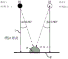
Fig. 2 illustrates an embodiment of the invention in which the two components of the coating composition are not mixed together until they impinge upon the surface to be coated by the impact of a droplet or jet. These droplets or jets are produced by two schematically shown nozzles D1 and D2 arranged side by side in a common plane of the nozzle print head, wherein one nozzle ejects a first component (e.g. masterbatch) and the other nozzle ejects a second component (hardener). These components can be sprayed one after the other in time or else simultaneously at time point 1 and, corresponding to the spray distance L of the nozzles D1 and D2 from the surface F to be coated and the speed of travel of the components, they strike the surface F at a slightly later point in time 2, i.e. at least approximately at the same point in time P, at which they mix with one another.
In the illustrated example, according to the illustration, the ejection directions (shown by the dashed lines) of the two nozzles D1 and D2 are inclined with respect to the spraying distance L perpendicular to the surface F and, for example, towards the respective other nozzle at opposite, equal travel angles α and β. The magnitude of the chosen travel angle is not only related to the spraying distance L but obviously also to the distance between the nozzles D1 and D2 measured in a direction parallel to the surface F, and may for example be about 0 ° to 90 °. The speed of travel and/or angle of travel of the two components may also be different from one another. If the nozzles D1 and D2 are opened at different points in time, the translational movement of the nozzles relative to the surface F during the application of the two components can also be taken into account.
Fig. 3 schematically illustrates the overlapping application of coating dots, typically applied droplets consisting of already mixed components, on the surface F to be coated, which droplets are then mixed with each other by flowing together on the surface F. However, the coating point may also be a component which is not mixed until it comes to the surface F to be coated. The nozzles each produce a coating spot, for example a droplet, of defined size a at predetermined successive equidistant times t1 to t5 etc., when the nozzles are moved along the surface F at a specific movement speed, for example by means of a coating robot. The respective nozzles are controlled in time to obtain a defined drop distance b along the surface F and thus a desired overlap of the applied drops. The degree of overlap may be between greater than 0% and about 75% (triple overlap), that is to say about 10%, 20%, 30% or 50% (double overlap, b-1/2 a) or b-1/3 a or 2/3 a. Alternatively, however, the application points can be applied adjacent to one another, that is to say without overlapping (b ═ a).
In principle, such application with or without overlap is possible if the components have been mixed either before or in the nozzle print head or after they leave the nozzle but before they reach the surface to be coated. Even if a continuous jet is applied instead of individual droplets, an overlapping application is advantageous.
Fig. 4 schematically shows a nozzle unit 40 in the form of a double nozzle, the nozzle unit 40 being used for mixing two components of a coating composition (e.g. a 2K lacquer) in or at a nozzle print head. The nozzle unit 40 is mainly constituted by an outer tubular body 41, inside the outer tubular body 41, for example, concentrically inside a cylinder, an inner tube 42, for example, also cylindrical, is arranged. Fig. 4B) shows a longitudinal section through the tubular nozzle unit 40, while fig. 4A) is a plan view of the lower nozzle end face in fig. 4B. According to this illustration, the outer tubular body 41 may project axially outward beyond the inner tube 42 at the nozzle end face 43. One component of the coating composition, e.g. the masterbatch, is forced through the inner tube 42 to an outlet 45, said outlet 45 being circular in this example, while a second component, e.g. the hardener, is forced towards an outlet 46, said outlet 46 being in the form of an annular gap between the inner tube 42 and the outer tubular body 41. Conversely, it is also possible to guide the former component mentioned through the annular gap and the latter component through the inner tube.
In the example discussed here, the mixing of the components takes place at the end face 43, i.e. the outlet, of the illustrated double nozzle or nozzle unit 40, wherein, at said end face 43, the individual droplets formed here are mixed with one another according to the explanation. Advantageously, the formation of the respective droplets does not start simultaneously, but rather the two nozzle elements, i.e. the inner tube 42 and the outlet 46 in the form of an annular gap nozzle, are controlled in terms of time by means of valves (not shown) such that droplets are formed first at the inner tubular nozzle and only then at the annular gap nozzle. The reverse order is also advantageous. Alternatively, however, it is also conceivable for the two nozzle elements to be opened simultaneously.
As mentioned at the outset, the nozzle printing head according to the invention preferably carries a plurality of such nozzle units, which may in particular be arranged in one or more rows.
Although the invention in fig. 4 explains the dual nozzle unit with an example of droplet formation, such or similar dual nozzles for generating component jets that can be mixed at the nozzle outlet are also conceivable. In both cases, the two nozzle elements can be controlled jointly and/or individually with respect to their opening time by means of associated controllable valves.
As already mentioned, it may be advantageous to provide a swirling motion to the components to be mixed. This can be achieved, for example, by means of a helical groove (similar in principle to a barrel of a string-bore gun) on the inside of the nozzle channel.
Claims (36)
1. An application device for applying a coating composition to a surface of a workpiece in succession,
the application device has a nozzle print head (8, 9) comprising a plurality of nozzles (D1, D2; 40) arranged next to one another, which apply the coating composition as continuous jets or individual droplets to the surface (F) to be coated,
wherein the nozzle print heads are arranged on a multi-axis coating robot (3, 4) having six or more axes of rotation, which moves the nozzle print heads (8, 9) over the surface to be coated, and
the applicator device has a supply unit containing a coating composition,
wherein the coating composition consists of at least two components to be mixed together, said components comprising at least one material component and at least one curing agent component which reacts with the material component to cure the material component, and wherein a flushing device for a nozzle print head is provided, said flushing device being provided
(a) Formed by at least one flushing medium line leading to the application device and/or the nozzle printing head, to which flushing medium line the nozzles are or can be connected, and/or
(b) Formed by a device arranged externally in the vicinity of a multi-axis coating robot (3, 4) for moving the nozzle print heads,
it is characterized in that the preparation method is characterized in that,
the nozzle print head (8, 9) has at least two separate supply lines for these components to be mixed, which supply lines are arranged to supply the coating composition jointly to the nozzles (D1, D2; 40) and the components are kept separate at least until they enter the nozzle print head (8, 9).
2. An application device according to claim 1, characterised in that the nozzles of the nozzle print head direct jets or droplets of the coating composition or of the components of the coating composition specifically at various points of the surface to be coated in order to avoid overspray.
3. An applicator according to claim 1 or 2, wherein the coating composition is:
(a) a liquid multi-component paint vehicle,
(b) a primer,
(c) an adhesive or sealant, or
(d) A preservative agent, a preservative agent and a preservative agent,
also, the coating composition has at least one masterbatch component and at least one curative component reactive with the masterbatch component.
4. The applicator according to claim 1 or 2,
(a) the nozzle print head directs the at least two components independently of each other onto the surface to be coated, such that the at least two components mix together on the surface, and/or
(b) The nozzles of the nozzle print head are adjusted relative to each other such that the components meet on their way to the surface to be coated, or
(c) The components are mixed in a nozzle print head, and/or
(d) Each of the nozzles of the nozzle print head is configured for mixing the at least two components.
5. An application device according to claim 1 or 2, characterised in that the nozzle print head ejects the components to be mixed simultaneously or sequentially in time.
6. An applicator device according to claim 1 or 2, characterised by a mixer for mixing the components of the coating material
(a) Arranged in a nozzle print head, and/or
(b) Are integrated in the respective inflow path of the nozzles in the nozzle print head and are connected at their inlet side to the at least two separate supply lines.
7. The applicator of claim 6 wherein the mixer is in the form of a static mixer or in the form of a dynamic mixer.
8. The applicator device according to any one of claims 1, 2 and 7, wherein at least one color changer is provided, said color changer being
(a) Is connected to at least one of the supply lines of the application device or of the nozzle print head and is supplied with optional paint components of different colors in a controlled manner, and
(b) arranged in a movable manner relative to the surface to be coated, or
(c) Is fixedly arranged in the coating cabin.
9. The application device according to any one of claims 1, 2 and 7, characterized in that each of the nozzles (40) comprises at least two channels, respectively, which lead to a nozzle outlet (45, 46).
10. The application device as claimed in one of claims 1, 2 and 7, characterized in that the nozzle print head imparts a swirling motion to the sprayed components by means of the structural shape of the nozzle or the structural shape of the supply channel of the nozzle in order to achieve better mixing.
11. An applicator according to any one of claims 1, 2 and 7, wherein the nozzles of the nozzle print head are controllable at respective open and close times.
12. Application device according to one of claims 1, 2 and 7, characterized in that the longitudinal axis of the nozzles of the nozzle print head is relative to the plane of the nozzle print head
(a) Extending perpendicularly to said plane, or
(b) Extending at an angle to said plane.
13. The applicator of claim 1 wherein the flushing device
(a) Configured for flushing the nozzle channel, and/or
(b) For rinsing the outer surface of the nozzle print head and/or the nozzle plate containing the nozzles.
14. An applicator device according to claim 1 or 13, wherein the flushing device has a collecting device for collecting the coating composition and/or the flushing medium ejected from the nozzle during flushing.
15. The application device according to claim 1, wherein the workpiece is an automotive body and/or an additional part of an automotive body.
16. The applicator of claim 2 wherein the impact points of application abut one another or overlap one another.
17. The application device according to claim 8, characterized in that the color changer is arranged on a painting robot moving a nozzle print head.
18. The applicator of claim 9 wherein the channels extend concentrically with respect to one another.
19. The applicator according to claim 9, wherein the nozzle outlet (45, 46) is formed by at least one annular gap and a central opening.
20. An applicator according to claim 11, wherein the nozzles of the nozzle print head are controlled by a programmed control signal for actuating the valves of the nozzles.
21. An applicator according to claim 12, wherein the longitudinal axis of the nozzles of the nozzle print head is relative to the plane of the nozzle plate
(a) Extending perpendicularly to said plane, or
(b) Extending at an angle to said plane.
22. The applicator of claim 12 wherein adjacent nozzles extend at different, the same, or opposite, equal angles relative to the plane.
23. A nozzle print head for an applicator according to any one of the preceding claims, having a nozzle plate which contains openings in the plane of the plate which serve as nozzles.
24. The nozzle print head of claim 23, wherein the openings are arranged in one or more side-by-side rows.
25. A coating system having an application device according to any one of the preceding claims.
26. The coating system of claim 25 having one or more application robots located within a coating booth.
27. A method for the serial application of a coating composition to the surface of a workpiece,
wherein a coating composition supplied by a supply unit is applied as a continuous jet or as individual droplets to a surface (F) to be coated by means of an application device having nozzle print heads (8, 9) which are arranged on a multi-axis coating robot (3, 4) having six or more axes of rotation and which comprise a plurality of nozzles (D1, D2; 40) arranged adjacently, wherein the coating composition consists of at least two components to be mixed together, said components comprising at least one material component and at least one curing agent component which reacts with the material component and thereby cures the material component, and wherein a flushing device is used which is formed by at least one flushing medium line which leads to the application device and/or to the nozzle print heads, to which flushing medium line the nozzles are connected or can be connected, and/or the flushing medium line is formed by a device arranged externally in the vicinity of a multi-axis coating robot for moving the nozzle print head,
it is characterized in that the preparation method is characterized in that,
these components are fed to the nozzle print heads (8, 9) via at least two separate supply lines, the coating compositions are supplied jointly to the nozzles via the supply lines, and the components are kept separate at least until they enter the nozzle print heads (8, 9),
wherein the mixing of the at least two components is performed at the following locations:
(a) on the surface to be coated,
(b) in air midway on the way to the surface to be coated,
(c) in or at the nozzle print head, or
(d) In or at the outlet of the nozzle.
28. The method of claim 27, wherein the at least two components
(a) Simultaneously, or
(b) In a controlled manner, one after the other in time
By means of a single nozzle or by means of at least two outlet openings of one nozzle.
29. Method according to claim 27 or 28, characterized in that the components to be mixed are injected in a swirling motion.
30. Method according to claim 27 or 28, characterized in that the jet or droplet of the coating composition or the components of the coating composition impacts the surface to be coated successively in time as a point with a defined diameter, so that said point
(a) Are adjacent to each other, or
(b) Overlap each other, wherein the degree of overlap is between greater than 0% and 75% of the dot diameter.
31. The method according to claim 27 or 28, characterized in that it has at least one of the following steps alone or in combination with at least one other step:
(a) flushing the nozzle print head after a specific operation period or other time period, or at a fixed specific time, or after at least one specific event of a coating operation;
(b) a channel for flushing the nozzle;
(c) flushing the outer surface of the nozzle print head and/or the outer surface of the nozzle plate containing the nozzles;
(d) backwashing the nozzle print head and/or the nozzle plate containing the nozzles by pressing flushing medium from the outside inwards into the nozzle channels;
(e) alternately supplying a flushing medium and pulsed air;
(f) flushing with aerosol;
(g) collecting the liquid and/or aerosol ejected during the rinsing process and separating the collected liquid and/or aerosol for disposal;
(h) pre-pressing the coating composition or components of the coating composition after rinsing by refilling the nozzle print head;
(i) spraying at least one drop or a defined amount of the coating composition or components of the coating composition through the nozzle after rinsing;
(k) in the case of a masterbatch component used as a coating composition that is changed between a solvent-borne paint and a water-borne paint, different flushing media are used and optionally a release agent is used between the two paints;
(l) Using different rinsing media with different cleaning actions;
(m) use of a universal flushing medium;
(n) use of a VOC free rinse medium;
(o) flushing only the following paths of the applicator: only one of the components and/or the two-component mixture is contacted with the pathway;
(p) filling or wetting the inner or outer surface of the nozzle print head in contact with the coating composition with a fluid that prevents deposition of the coating composition and/or prevents reaction of the two components in the coating composition.
32. The method of claim 27 or 28, wherein during flushing of the nozzle print head,
(a) the loss of the coating composition or the loss of the at least one masterbatch component caused by rinsing is limited to less than 5 liters, less than 2 liters, less than 200 milliliters, less than 20 milliliters, less than 10 milliliters, less than 5 milliliters, or less than 2 milliliters, and/or
(b) The consumption of the flushing medium is limited to less than 10 liters, less than 5 liters, less than 2 liters, less than 200 milliliters, less than 100 milliliters, less than 50 milliliters, less than 20 milliliters, or less than 10 milliliters.
33. The method according to claim 27, wherein the workpiece is a motor vehicle body and/or an additional part of a motor vehicle body.
34. The method of claim 30, wherein the method is performed while mixing the components on the surface to be coated.
35. The method according to claim 31, characterized in that a universal flushing medium is used in case the masterbatch component used as coating composition is changed between solvent-borne and water-borne paints.
36. The method of claim 31, wherein the following paths of the applicator are flushed: the tinting component of the coating composition and the two-component mixture are contacted with the pathway.
Applications Claiming Priority (3)
| Application Number | Priority Date | Filing Date | Title |
|---|---|---|---|
| DE102016014919.1A DE102016014919A1 (en) | 2016-12-14 | 2016-12-14 | Application device and method for applying a coating agent |
| DE102016014919.1 | 2016-12-14 | ||
| PCT/EP2017/081123 WO2018108573A1 (en) | 2016-12-14 | 2017-12-01 | Application device and method for applying a coating medium |
Publications (2)
| Publication Number | Publication Date |
|---|---|
| CN110087779A CN110087779A (en) | 2019-08-02 |
| CN110087779B true CN110087779B (en) | 2022-02-22 |
Family
ID=60574584
Family Applications (1)
| Application Number | Title | Priority Date | Filing Date |
|---|---|---|---|
| CN201780077476.7A Active CN110087779B (en) | 2016-12-14 | 2017-12-01 | Application device and method for applying a coating composition |
Country Status (9)
| Country | Link |
|---|---|
| US (1) | US11440035B2 (en) |
| EP (1) | EP3554716B1 (en) |
| JP (1) | JP6991218B2 (en) |
| CN (1) | CN110087779B (en) |
| DE (1) | DE102016014919A1 (en) |
| ES (1) | ES2896964T3 (en) |
| HU (1) | HUE056762T2 (en) |
| MX (1) | MX2019006979A (en) |
| WO (1) | WO2018108573A1 (en) |
Families Citing this family (15)
| Publication number | Priority date | Publication date | Assignee | Title |
|---|---|---|---|---|
| US10864541B2 (en) * | 2018-01-30 | 2020-12-15 | Ford Motor Company | Ultrasonic atomizer with quick-connect mechanism |
| DE102019001423B4 (en) * | 2019-02-11 | 2022-05-25 | Kastriot Merlaku | Device that can solidify an object made of playdough or modeling clay by coating |
| DE102019119613A1 (en) * | 2019-07-19 | 2021-01-21 | Bayerische Motoren Werke Aktiengesellschaft | Method for painting an outer skin component of a motor vehicle and painting station for an outer skin component of a motor vehicle |
| CN110355037B (en) * | 2019-07-25 | 2021-01-01 | 浙江奥年家居有限公司 | Quick dustless paint spraying apparatus of part |
| CN110420782B (en) * | 2019-07-26 | 2020-12-22 | 瑞润化工(南通)有限公司 | Coating ratio debugging equipment |
| CN112108321A (en) * | 2020-04-30 | 2020-12-22 | 中国电子产品可靠性与环境试验研究所((工业和信息化部电子第五研究所)(中国赛宝实验室)) | Piezoelectric spraying device for non-curing double-component glue |
| DE102020127852A1 (en) | 2020-10-22 | 2022-04-28 | Dürr Systems Ag | Operating procedure for a coating plant and correspondingly adapted coating plant |
| CN113262943A (en) * | 2021-05-25 | 2021-08-17 | 延锋伟世通汽车电子有限公司 | Automatic coating device |
| DE102021124196A1 (en) | 2021-09-20 | 2023-03-23 | Dürr Systems Ag | Application method for coating an object, preferably one or more motor vehicle body parts |
| CN114682464B (en) * | 2022-04-24 | 2023-09-26 | 许艳青 | Paint decoration method and device for wooden furniture and furniture |
| DE102022114673A1 (en) | 2022-06-10 | 2023-12-21 | FPT Robotik GmbH & Co. KG | Method and device for process-optimized coating of three-dimensional surfaces using hardening liquids |
| US20240109349A1 (en) * | 2022-09-30 | 2024-04-04 | The Boeing Company | Robotics for inkjet printing vehicle livery |
| US20240109095A1 (en) * | 2022-09-30 | 2024-04-04 | The Boeing Company | Inkjet printing vehicle livery |
| JP7241955B1 (en) * | 2022-12-20 | 2023-03-17 | アーベーベー・シュバイツ・アーゲー | painting machine |
| CN116174219A (en) * | 2022-12-29 | 2023-05-30 | 中国科学院福建物质结构研究所 | Composite coating spraying equipment |
Citations (4)
| Publication number | Priority date | Publication date | Assignee | Title |
|---|---|---|---|---|
| CN1331661A (en) * | 1998-08-13 | 2002-01-16 | Ppg工业俄亥俄公司 | Compsns. appts. and methods for forming coatings of selected color on substrate and articles produced thereby |
| CN101309755A (en) * | 2005-12-01 | 2008-11-19 | 3M创新有限公司 | Multi-component liquid spray systems |
| CN102198434A (en) * | 2010-12-29 | 2011-09-28 | 东莞市冠辉五金有限公司 | Automatic spraying process for precision hardware and spraying control method |
| EP2433716A1 (en) * | 2010-09-22 | 2012-03-28 | Hexagon Technology Center GmbH | Surface spraying device with a nozzle control mechanism and a corresponding method |
Family Cites Families (229)
| Publication number | Priority date | Publication date | Assignee | Title |
|---|---|---|---|---|
| DE1284250B (en) | 1965-10-30 | 1968-11-28 | Kaercher Fa Alfred | Sprayer for spraying a liquid mixture |
| US3717306A (en) * | 1971-03-10 | 1973-02-20 | Hushon R | Nozzle for spraying foaming materials |
| US3981320A (en) | 1974-05-10 | 1976-09-21 | The Gyromat Corporation | Recovery system for spray painting installation with automatic color change |
| AT349415B (en) | 1975-07-28 | 1979-04-10 | Zimmer Peter Ag | INJECTION PRESSURE DEVICE FOR SAMPLING OF A GOODS |
| CH613387A5 (en) | 1975-07-28 | 1979-09-28 | Zimmer Peter Maschinenfabrik A | Process and device for applying patterns to a material, in particular to a web material |
| US4383264A (en) | 1980-06-18 | 1983-05-10 | Exxon Research And Engineering Co. | Demand drop forming device with interacting transducer and orifice combination |
| JPS5722070A (en) | 1980-07-15 | 1982-02-04 | Oki Electric Ind Co Ltd | Cooling device for printer |
| US4375865A (en) | 1980-08-12 | 1983-03-08 | Binks Manufacturing Company | Color change system for spray coating apparatus |
| DE3045401A1 (en) | 1980-12-02 | 1982-07-01 | Robert Bosch Gmbh, 7000 Stuttgart | PROCESS FOR INJECTING INJECTORS |
| MX152277A (en) | 1980-12-16 | 1985-06-19 | Vitro Tec Fideicomiso | IMPROVEMENTS IN SOLENOID PNEUMATIC VALVE BLOCKS FOR GLASS ARTICLE MANUFACTURING MACHINES |
| US4423999A (en) | 1981-09-14 | 1984-01-03 | General Motors Corporation | Mechanical hand for a door-opener |
| US4435719A (en) | 1982-03-30 | 1984-03-06 | Snaper Alvin A | Fluidic matrix printer |
| DE3221327A1 (en) | 1982-06-05 | 1983-09-15 | Daimler-Benz Ag, 7000 Stuttgart | Plant for colour spraying of series-production parts of changing colour |
| DE3225554A1 (en) | 1982-07-08 | 1984-01-12 | Robert Bosch Gmbh, 7000 Stuttgart | Measuring device for fluid jets |
| US4668948A (en) | 1983-03-10 | 1987-05-26 | Nordson Corporation | Dispenser malfunction detector |
| US4555719A (en) | 1983-08-19 | 1985-11-26 | Videojet Systems International, Inc. | Ink valve for marking systems |
| US4593360A (en) | 1983-12-16 | 1986-06-03 | Cocks Eric H | Fluid spray control system |
| JPS62500230A (en) | 1984-09-19 | 1987-01-29 | ドライスデイル,ロナルド・ダグラス | Method and apparatus for drawing an image on a surface |
| JPS624464A (en) | 1985-07-02 | 1987-01-10 | Honda Motor Co Ltd | Device for painting automobile body |
| JPS62116442A (en) | 1985-11-12 | 1987-05-28 | Toppan Printing Co Ltd | Double feed sensing device |
| DD245400A1 (en) | 1986-02-05 | 1987-05-06 | Robotron Bueromasch | COLOR JET HEAD |
| US4875058A (en) | 1986-12-12 | 1989-10-17 | Markpoint System Ab | Valve device for a matrix printer |
| US4734711A (en) | 1986-12-22 | 1988-03-29 | Eastman Kodak Company | Pressure regulation system for multi-head ink jet printing apparatus |
| SE456597B (en) | 1987-02-12 | 1988-10-17 | Scandot System Ab | DEVICE FOR A VALVE ARRANGEMENT FOR THE EXHAUST OF LIQUID BY A SCRIPLINE PRINTER |
| DE3721875A1 (en) | 1987-07-02 | 1989-01-12 | Gema Ransburg Ag | METHOD AND DEVICE FOR A POWDER SPRAY COATING SYSTEM |
| JPH0798171B2 (en) | 1988-04-19 | 1995-10-25 | トキコ株式会社 | Industrial robot equipment |
| US4974780A (en) | 1988-06-22 | 1990-12-04 | Toa Nenryo Kogyo K.K. | Ultrasonic fuel injection nozzle |
| US5050533A (en) | 1988-07-25 | 1991-09-24 | Technadyne Engineering Corporation | Application of thermal-cure materials |
| US5602575A (en) | 1988-11-05 | 1997-02-11 | Rea Elektronik Gmbh | Ink jet writing head |
| US4894252A (en) | 1988-11-30 | 1990-01-16 | Ransburg Corporation | Coating material orifice clogging indication method and apparatus |
| US4985715A (en) | 1990-03-22 | 1991-01-15 | Telesis Controls Corporation | Marker assembly for spray marking dot matrix characters and method of fabrication thereof |
| DE4013322A1 (en) | 1990-04-26 | 1991-10-31 | Heino Kaiser | Multiple applicator head for flowing medium - has several controlled feed valves fitted in modular structure in frame-type head |
| JP3144566B2 (en) | 1990-05-08 | 2001-03-12 | マツダ株式会社 | Painting method and painting equipment |
| US5072881A (en) | 1990-06-04 | 1991-12-17 | Systems Specialties | Method of cleaning automated paint spraying equipment |
| JPH04106669U (en) | 1991-02-21 | 1992-09-14 | セントラル自動車株式会社 | Water-based painting booth |
| DE4138491C2 (en) | 1991-11-23 | 1995-07-20 | Juergen Dipl Ing Joswig | Micromechanical valve for micromechanical dosing devices |
| US5429682A (en) | 1993-08-19 | 1995-07-04 | Advanced Robotics Technologies | Automated three-dimensional precision coatings application apparatus |
| DE9422327U1 (en) | 1993-09-01 | 2000-03-23 | Duerr Systems Gmbh | Coating system |
| DE4329384C2 (en) | 1993-09-01 | 2001-08-09 | Duerr Systems Gmbh | Conveyor |
| US5435884A (en) | 1993-09-30 | 1995-07-25 | Parker-Hannifin Corporation | Spray nozzle and method of manufacturing same |
| GB2286157B (en) | 1994-01-31 | 1998-01-14 | Neopost Ltd | Ink jet printing device |
| DE9405600U1 (en) | 1994-04-02 | 1994-06-16 | Itw Dynatec Klebetechnik Holdi | Application head for the metered delivery of flowing media |
| CN2287527Y (en) | 1994-04-20 | 1998-08-12 | 徐连宽 | Fuel burning type paint spray and baking vanish booth |
| US5718767A (en) | 1994-10-05 | 1998-02-17 | Nordson Corporation | Distributed control system for powder coating system |
| US5659347A (en) | 1994-11-14 | 1997-08-19 | Xerox Corporation | Ink supply apparatus |
| US5647542A (en) | 1995-01-24 | 1997-07-15 | Binks Manufacturing Company | System for electrostatic application of conductive coating liquid |
| US5636795A (en) | 1995-05-11 | 1997-06-10 | First Pioneer Industries Inc. | Cyclonic spray nozzle |
| SE504472C2 (en) | 1995-06-22 | 1997-02-17 | Abb Flexible Automation As | Color feeding system for spray painting robot |
| JPH09192583A (en) | 1996-01-17 | 1997-07-29 | Fuji Heavy Ind Ltd | Box for keeping roller type coating device |
| DE19606716C1 (en) | 1996-02-23 | 1997-08-14 | Herberts Gmbh | Process for multi-layer painting |
| SE507821C2 (en) | 1996-04-15 | 1998-07-20 | Jetline Ab | Valve construction with ink jet printers |
| DE19630290C2 (en) | 1996-07-26 | 2000-08-10 | Audi Ag | System for the surface treatment of objects, in particular vehicle bodies |
| JP2978459B2 (en) | 1996-09-30 | 1999-11-15 | キヤノン株式会社 | Method and apparatus for manufacturing color filter, color filter, display apparatus, and apparatus having display apparatus |
| DE19731829A1 (en) | 1997-07-24 | 1999-01-28 | Tietz Patrick | Colour mixing and dosing unit for enamels, paints etc.using paint delivery unit atomising paint |
| DE19743804A1 (en) | 1997-10-02 | 1999-04-08 | Politrust Ag | Large format printing using ink-jet printer |
| DE69836128T2 (en) | 1998-01-13 | 2007-08-16 | Abb K.K. | COATING METHOD FOR A COATING DEVICE WITH A ROTATING SPRAY HEAD |
| DE19852079A1 (en) * | 1998-11-11 | 2000-05-18 | Thomas Kovarovsky | Image generating painting arrangement has controller with device that reacts to image information by actuating robot arm, dosing device to reproduce image on painted surface |
| JP2000158670A (en) | 1998-11-26 | 2000-06-13 | Fuji Electric Co Ltd | Ink-jet recording apparatus |
| JP4358352B2 (en) | 1999-05-11 | 2009-11-04 | トリニティ工業株式会社 | Coating device, coating machine used therefor, and coating method using the same |
| DE19936790A1 (en) | 1999-08-10 | 2001-02-15 | Nordson Corp Westlake | Method and device for producing a removable protective layer for surfaces, in particular for painted surfaces of motor vehicle bodies |
| JP2001157863A (en) | 1999-09-21 | 2001-06-12 | Tokyo Electron Ltd | Coater |
| JP2001129456A (en) | 1999-11-04 | 2001-05-15 | Sekisui Chem Co Ltd | Cleaning method of nozzle in spray coating device and spray coating device |
| IT1311388B1 (en) | 1999-11-10 | 2002-03-12 | Gd Spa | SPRAY RUBBER UNIT. |
| US6325302B1 (en) | 1999-11-29 | 2001-12-04 | Fanuc Robotics North America, Inc. | Airless spray tool |
| DE20017630U1 (en) * | 1999-12-20 | 2001-03-22 | Tevkuer Talip | Paint spray gun |
| KR100335955B1 (en) | 1999-12-30 | 2002-05-10 | 이계안 | Coating system for protecting film |
| DK1120258T3 (en) | 2000-01-21 | 2006-08-28 | Seiko Epson Corp | Cartridge and ink-jet recording apparatus using the same |
| JP2001239652A (en) | 2000-02-28 | 2001-09-04 | Minolta Co Ltd | Printer and printing method |
| US6360656B2 (en) | 2000-02-28 | 2002-03-26 | Minolta Co., Ltd. | Apparatus for and method of printing on three-dimensional object |
| US6460958B2 (en) | 2000-02-29 | 2002-10-08 | Minolta Co., Ltd. | Three-dimensional object printing apparatus and method |
| US6401976B1 (en) | 2000-03-23 | 2002-06-11 | Nordson Corporation | Electrically operated viscous fluid dispensing apparatus and method |
| DE10031030B4 (en) | 2000-06-26 | 2005-08-04 | Bauer, Jörg R. | Method and device for producing flat components with a predetermined surface appearance and planar component, in particular front panel of a kitchen element |
| FR2811917B1 (en) | 2000-07-24 | 2002-12-20 | Sames Sa | PRODUCT CHANGE METHOD AND STATION IN A COATING PRODUCT SPRAYING SYSTEM |
| US6641667B2 (en) * | 2000-08-29 | 2003-11-04 | Honda Giken Kogyo Kabushiki Kaisha | Robot-mounted two-package-mixing coating device and internal pressure explosion-proof robot |
| US6523921B2 (en) | 2000-08-30 | 2003-02-25 | L&P Property Management | Method and apparatus for printing on rigid panels and other contoured or textured surfaces |
| WO2002018053A1 (en) | 2000-08-30 | 2002-03-07 | Cartesian Technologies, Inc. | Method and apparatus for high-speed microfluidic dispensing using text file control |
| DE10048749A1 (en) | 2000-09-29 | 2002-04-11 | Josef Schucker | Arrangement for applying adhesive to a workpiece |
| US6849684B2 (en) | 2000-10-20 | 2005-02-01 | E. I. Du Pont De Nemours And Company | Molded soft elastomer/hard polyester composition with noise damping properties |
| JP3953776B2 (en) | 2001-01-15 | 2007-08-08 | セイコーエプソン株式会社 | Material discharging apparatus and method, color filter manufacturing apparatus and manufacturing method, liquid crystal device manufacturing apparatus and manufacturing method, EL apparatus manufacturing apparatus and manufacturing method |
| US7244310B2 (en) | 2001-06-01 | 2007-07-17 | Litrex Corporation | Over-clocking in a microdeposition control system to improve resolution |
| EP1399269B1 (en) | 2001-06-01 | 2010-11-03 | Ulvac, Inc. | Waveform generator for microdeposition control system |
| US20040231594A1 (en) | 2001-06-01 | 2004-11-25 | Edwards Charles O. | Microdeposition apparatus |
| US7160105B2 (en) | 2001-06-01 | 2007-01-09 | Litrex Corporation | Temperature controlled vacuum chuck |
| US20050016451A1 (en) | 2001-06-01 | 2005-01-27 | Edwards Charles O. | Interchangeable microdesition head apparatus and method |
| US7449070B2 (en) | 2001-06-01 | 2008-11-11 | Ulvac, Inc. | Waveform generator for microdeposition control system |
| JP4158357B2 (en) | 2001-06-05 | 2008-10-01 | セイコーエプソン株式会社 | Inkjet recording device |
| DE10130499A1 (en) | 2001-06-25 | 2003-01-02 | Duerr Systems Gmbh | Coating system and method for controlling a coating device with different nozzles |
| US6755512B2 (en) | 2001-07-30 | 2004-06-29 | Fuji Photo Film Co. Ltd | Liquid droplet ejection apparatus and inkjet recording head |
| JP3487301B2 (en) | 2001-08-06 | 2004-01-19 | マツダ株式会社 | Painting method and painting equipment for automobile body |
| DE10140216B4 (en) | 2001-08-17 | 2006-02-09 | ITW Oberflächentechnik GmbH & Co. KG | Method and device on a painting device for cleaning a paint delivery line |
| US6757586B2 (en) | 2001-09-05 | 2004-06-29 | Abb Automation Inc. | Multiple arm robot arrangement |
| JP3961820B2 (en) | 2001-11-30 | 2007-08-22 | 株式会社不二越 | Industrial robot controller |
| WO2003062129A2 (en) | 2002-01-22 | 2003-07-31 | Nordson Corporation | Method and apparatus for detecting a liquid spray pattern |
| DE10307719A1 (en) | 2002-03-01 | 2003-09-11 | Vmt Bildverarbeitungssysteme G | Quality assurance for application of medium to object involves allowing coating of target object depending on comparison of result of coating test object with stored desired properties |
| DE10224128A1 (en) | 2002-05-29 | 2003-12-18 | Schmid Rhyner Ag Adliswil | Method of applying coatings to surfaces |
| US20040173144A1 (en) | 2002-05-31 | 2004-09-09 | Edwards Charles O. | Formation of printed circuit board structures using piezo microdeposition |
| DE60311519T2 (en) | 2002-10-23 | 2007-11-29 | Fanuc Robotics America, Inc., Rochester Hills | MODULAR COATING DEVICE |
| JP4123897B2 (en) | 2002-10-28 | 2008-07-23 | 株式会社エルエーシー | Inkjet nozzle |
| WO2004041444A1 (en) | 2002-11-06 | 2004-05-21 | Advanced Flow Control Afc Ab | System for spraying a fluid material |
| SE0203515L (en) | 2002-11-27 | 2004-05-28 | Texdot Ab | Valve unit in a liquid jet printer and method at such a unit |
| US7454785B2 (en) | 2002-12-19 | 2008-11-18 | Avocent Huntsville Corporation | Proxy method and system for secure wireless administration of managed entities |
| JP3885036B2 (en) | 2003-03-14 | 2007-02-21 | 本田技研工業株式会社 | Method and apparatus for applying protective layer forming material |
| GB0306788D0 (en) | 2003-03-25 | 2003-04-30 | Willett Int Ltd | Method |
| US7178742B2 (en) | 2003-05-06 | 2007-02-20 | Lear Corporation | Fluid delivery system for spray applicator |
| JP2004337710A (en) | 2003-05-14 | 2004-12-02 | Trinity Ind Corp | Controller and controlling method of coating robot |
| US20050001869A1 (en) | 2003-05-23 | 2005-01-06 | Nordson Corporation | Viscous material noncontact jetting system |
| DE10331206A1 (en) | 2003-07-10 | 2005-01-27 | Daimlerchrysler Ag | Spray material is applied to a workpiece by directing a spray jet of an applicator, monitoring the jet geometry, and comparing it with a predetermined geometry |
| US20050015050A1 (en) | 2003-07-15 | 2005-01-20 | Kimberly-Clark Worldwide, Inc. | Apparatus for depositing fluid material onto a substrate |
| ZA200407781B (en) | 2003-10-03 | 2005-09-28 | Int Tech Llc | Blasting and blastiing accessory |
| FR2862563B1 (en) | 2003-11-24 | 2007-01-19 | Centre Nat Rech Scient | A LARGE-SIZE DIGITAL DIGITAL PRINTING ROBOT ON A FIXED SURFACE AND A PRINTING METHOD USING AT LEAST ONE SUCH ROBOT |
| KR100848162B1 (en) | 2004-01-19 | 2008-07-23 | 삼성전자주식회사 | A ink-jet printing apparatus and head position adjustment method thereof |
| BRPI0507377A (en) | 2004-02-03 | 2007-07-10 | Linde Ag | surface coating device |
| JP4419015B2 (en) | 2004-03-04 | 2010-02-24 | リコープリンティングシステムズ株式会社 | Inkjet coating method and apparatus |
| DE102004034270B4 (en) | 2004-07-15 | 2016-08-18 | Wolfgang Schmidt | Plant for discharging flowable fluids, in particular paints and varnishes and method for operating the system |
| KR101256424B1 (en) | 2004-08-23 | 2013-04-19 | 이시이 효키 가부시키가이샤 | Ink jet printer discharge amount control method, ink droplet spread check method, and orientation film formation method |
| DE102004044655B4 (en) | 2004-09-15 | 2009-06-10 | Airbus Deutschland Gmbh | Painting device, painting arrangement, method for painting a curved surface of an aircraft and use of an inkjet device for painting an aircraft |
| US20060068109A1 (en) | 2004-09-15 | 2006-03-30 | Airbus Deutschland Gmbh | Painting device, painting arrangement, method for painting a curved surface of an object, and use of an inkjet device for painting an aircraft |
| US7824001B2 (en) | 2004-09-21 | 2010-11-02 | Z Corporation | Apparatus and methods for servicing 3D printers |
| DE102004049471A1 (en) | 2004-10-11 | 2006-04-20 | Bayerische Motoren Werke Ag | Device for applying preserving coating to vehicle comprises nozzle strip with controllable spray nozzles arranged to also only spray in partial areas |
| JP2007021760A (en) | 2005-07-12 | 2007-02-01 | Nissha Printing Co Ltd | Forming apparatus of thin film |
| ES2329806T3 (en) | 2005-09-20 | 2009-12-01 | Agfa Graphics N.V. | METHOD AND APPARATUS FOR AUTOMATIC ALIGNMENT OF PRINT ELEMENT SETS. |
| JP2007152666A (en) | 2005-12-02 | 2007-06-21 | Seiko Epson Corp | Liquid droplet observing device |
| JP4432922B2 (en) | 2006-03-17 | 2010-03-17 | セイコーエプソン株式会社 | Droplet discharge device |
| DE102006017956B4 (en) | 2006-04-18 | 2016-01-07 | OuISS Qualitäts-Inspektionssysteme und Service AG | Method for applying and monitoring a job structure with repair function and device therefor |
| JP4705877B2 (en) | 2006-04-25 | 2011-06-22 | トリニティ工業株式会社 | Top coating equipment and coating method using the same |
| DE102006021623A1 (en) | 2006-05-09 | 2007-11-15 | Dürr Systems GmbH | Dosing system for a coating system |
| EP2018230B1 (en) | 2006-05-12 | 2015-09-16 | Dürr Systems GmbH | Coating plant and associated operating method |
| EP1884365A1 (en) | 2006-07-28 | 2008-02-06 | Abb Research Ltd. | Paint applicator and coating method |
| KR100729553B1 (en) | 2006-10-27 | 2007-06-18 | 주식회사 탑 엔지니어링 | Dispensing apparatus |
| KR100833679B1 (en) * | 2006-11-07 | 2008-05-29 | 포항공과대학교 산학협력단 | Droplet Mixing Apparatus and Droplet Mixing Method |
| DE102006056051B4 (en) | 2006-11-28 | 2018-09-20 | Robert Bosch Gmbh | Robot with control for additional axes |
| US8707976B2 (en) | 2006-11-29 | 2014-04-29 | Daryl Bauer | Portable painting apparatus |
| DE102007002980A1 (en) | 2007-01-19 | 2008-07-24 | Voith Patent Gmbh | Adhesive applicator for a paper or cardboard processing machine |
| EP2359939B1 (en) | 2007-03-08 | 2014-02-26 | Kabushiki Kaisha Yaskawa Denki | Painting system |
| DE102007018877B4 (en) | 2007-04-19 | 2010-03-04 | Hönig, Thomas | Method and material application device with a test device for the quality measurement of the application image of a spray nozzle and use of a test field |
| KR101592443B1 (en) | 2007-05-18 | 2016-02-18 | 무사시 엔지니어링 가부시키가이샤 | Method and apparatus for discharging liquid material |
| EP2002898A1 (en) | 2007-06-14 | 2008-12-17 | J. Zimmer Maschinenbau Gesellschaft m.b.H. | Application device for applying a fluid onto a substrate with valve devices, method for cleaning the application device and valve device for application device |
| GB0712860D0 (en) | 2007-07-03 | 2007-08-08 | Eastman Kodak Co | continuous inkjet drop generation device |
| DE102007037663A1 (en) | 2007-08-09 | 2009-02-19 | Dürr Systems GmbH | Needle valve assembly |
| US9464573B2 (en) | 2007-09-25 | 2016-10-11 | Airbus Sas | Method for operating a gas turbine engine, power supplying device for conducting such method and aircraft using such method |
| CN103909743B (en) | 2007-12-31 | 2017-01-11 | 埃克阿泰克有限责任公司 | Apparatus and method for printing three dimensional articles |
| US20090181182A1 (en) * | 2008-01-10 | 2009-07-16 | Sloan Donald D | Multipurpose digital ink |
| DE102008018881B4 (en) | 2008-03-11 | 2020-10-01 | Atlas Copco Ias Gmbh | Method and device for applying a viscous material to a workpiece and use of a needle valve for a device for applying a viscous material to a workpiece |
| ES2544431T3 (en) * | 2008-03-20 | 2015-08-31 | Dürr Systems GmbH | Paint robot and corresponding operating procedure |
| DE102008045553A1 (en) | 2008-09-03 | 2010-03-04 | Dürr Systems GmbH | Painting device and associated method |
| DE102008053178A1 (en) | 2008-10-24 | 2010-05-12 | Dürr Systems GmbH | Coating device and associated coating method |
| DE102008061203A1 (en) | 2008-12-09 | 2010-06-10 | Rehau Ag + Co | Method for painting a three-dimensional surface of a component |
| JP2010241003A (en) | 2009-04-07 | 2010-10-28 | Seiko Epson Corp | Liquid droplet delivering head |
| DE102009020064A1 (en) | 2009-05-06 | 2010-11-11 | Dürr Systems GmbH | Fluid valve, in particular recirculation valve for a paint shop |
| DE102009029946A1 (en) | 2009-06-19 | 2010-12-30 | Epainters GbR (vertretungsberechtigte Gesellschafter Burkhard Büstgens, 79194 Gundelfingen und Suheel Roland Georges, 79102 Freiburg) | Print head or dosing head |
| US8556373B2 (en) | 2009-06-19 | 2013-10-15 | Burkhard Buestgens | Multichannel-printhead or dosing head |
| DE102009038462A1 (en) | 2009-08-21 | 2011-03-03 | Dürr Systems GmbH | Tumbling piston pump for metering a coating agent |
| US8652581B2 (en) | 2009-10-09 | 2014-02-18 | Matthew Merchant | Method of using a spray gun and material produced thereby |
| DE102009052654A1 (en) * | 2009-11-11 | 2011-05-12 | Dürr Systems GmbH | Device and method for the preservation of components |
| US8757511B2 (en) | 2010-01-11 | 2014-06-24 | AdvanJet | Viscous non-contact jetting method and apparatus |
| DE102010004496B4 (en) | 2010-01-12 | 2020-06-18 | Hermann Müller | Method for operating a device for coating and / or printing a workpiece |
| JP2011206958A (en) | 2010-03-29 | 2011-10-20 | Seiko Epson Corp | Liquid injection device, liquid injection head and method of detecting coming-out of nozzle |
| US8534574B2 (en) | 2010-04-08 | 2013-09-17 | Intel Corporation | Underfill material dispenser |
| DE202010005211U1 (en) | 2010-04-15 | 2011-10-21 | Planatol System Gmbh | Application system for liquid media |
| JP5769384B2 (en) | 2010-04-20 | 2015-08-26 | キヤノン株式会社 | Ink cartridge and ink jet recording apparatus |
| DE102010019612A1 (en) * | 2010-05-06 | 2011-11-10 | Dürr Systems GmbH | Coating device, in particular with an application device, and associated coating method that emits a droplets of coating agent droplet |
| JP5489887B2 (en) | 2010-06-30 | 2014-05-14 | 富士フイルム株式会社 | Liquid coating apparatus, liquid coating method, and nanoimprint system |
| EP2799150B1 (en) | 2013-05-02 | 2016-04-27 | Hexagon Technology Center GmbH | Graphical application system |
| EP2632730B1 (en) | 2010-10-27 | 2019-08-07 | Matthews International Corporation | Valve jet printer with inert plunger tip |
| JP5215376B2 (en) | 2010-12-27 | 2013-06-19 | 富士ゼロックス株式会社 | Liquid circulation device, liquid circulation control program, liquid ejection device |
| DE102012005087A1 (en) | 2011-03-28 | 2012-10-04 | Heidelberger Druckmaschinen Aktiengesellschaft | Device for printing surfaces with multiple, movable print heads |
| JP5647940B2 (en) | 2011-04-26 | 2015-01-07 | タクボエンジニアリング株式会社 | Mobile terminal casing coating apparatus and mobile terminal casing coating method using the same |
| JP2012228643A (en) | 2011-04-26 | 2012-11-22 | Takubo Engineering Co Ltd | Coating system for casing of mobile terminal and coating method for casing of mobile terminal using the same |
| JP2013158968A (en) | 2012-02-02 | 2013-08-19 | Seiko Epson Corp | Printing apparatus, and method of suppressing rise of temperature of print head unit |
| JP5055512B1 (en) | 2012-02-16 | 2012-10-24 | 繁 中島 | Paint supply printing device |
| CN102582260A (en) | 2012-02-17 | 2012-07-18 | 上海美杰彩喷材料有限公司 | Water-base resin ink-jet printer |
| JP5906841B2 (en) | 2012-03-14 | 2016-04-20 | マツダ株式会社 | Paint circulation device and paint circulation method |
| EP2641661B1 (en) | 2012-03-20 | 2016-05-11 | Hexagon Technology Center GmbH | Graphical application system |
| DE102012005650A1 (en) | 2012-03-22 | 2013-09-26 | Burkhard Büstgens | Coating of surfaces in the printing process |
| DE102012006370A1 (en) | 2012-03-29 | 2013-10-02 | Heidelberger Druckmaschinen Aktiengesellschaft | System for printing on an object |
| DE102012006371A1 (en) | 2012-03-29 | 2012-07-05 | Heidelberger Druckmaschinen Aktiengesellschaft | Method for printing image on body i.e. tank of e.g. passenger car, involves generating three or higher-dimension raster matrix data to control inkjet printhead, and printing image with inkjet printhead using raster data |
| DE102012212469B4 (en) | 2012-07-17 | 2022-10-06 | Peter Fornoff | Method for printing on a surface and device for printing on a surface |
| JP2014019140A (en) | 2012-07-23 | 2014-02-03 | Ricoh Co Ltd | Ejection state inspecting method, and droplet ejecting apparatus |
| DE102012017538A1 (en) | 2012-09-05 | 2014-03-06 | Heidelberger Druckmaschinen Ag | Process for imaging and / or varnishing the surface of objects |
| DE102012109123A1 (en) | 2012-09-27 | 2014-03-27 | Vermes Microdispensing GmbH | Dosing system, dosing process and manufacturing process |
| GB2507069A (en) | 2012-10-17 | 2014-04-23 | Siemens Plc | Monitoring the quality of an electrostatic coating by measuring light reflected from a spray |
| JP5936294B2 (en) | 2012-12-27 | 2016-06-22 | カティーバ, インコーポレイテッド | Techniques for controlling the amount of printing ink that deposits fluid within close tolerances |
| JP5494846B2 (en) | 2013-01-23 | 2014-05-21 | セイコーエプソン株式会社 | Inkjet head unit and printing apparatus |
| DE102013002412A1 (en) | 2013-02-11 | 2014-08-14 | Dürr Systems GmbH | Application method and application system |
| DE202013101134U1 (en) | 2013-03-15 | 2014-06-17 | Vermes Microdispensing GmbH | metering valve |
| ITMO20130069A1 (en) | 2013-03-15 | 2014-09-16 | Tecno Italia S R L | HEAD FOR THE DIGITAL DECORATION OF CERAMIC MANUFACTURES |
| DE102013205171A1 (en) | 2013-03-22 | 2014-09-25 | Krautzberger Gmbh | Spraying system, spraying device, quick-change adapter and changing device, coating system and method for coating |
| DE102013006219A1 (en) | 2013-04-11 | 2014-10-16 | Eisenmann Ag | Changing device for coating media and coating system for coating objects |
| KR101467404B1 (en) | 2013-05-02 | 2014-12-03 | 희성촉매 주식회사 | A device for dosing a fixed catalyst amount |
| US9808820B2 (en) | 2013-05-03 | 2017-11-07 | Abb Schweiz Ag | Automatic painting and maintaining wet-surface of artifacts |
| DE102014006991A1 (en) | 2013-06-06 | 2014-12-11 | Heidelberger Druckmaschinen Ag | Apparatus for printing with an ink jet printhead on a curved surface of an obiect |
| JP5805147B2 (en) | 2013-07-01 | 2015-11-04 | 本田技研工業株式会社 | Painting method |
| DE102013011107A1 (en) | 2013-07-03 | 2014-08-07 | Eisenmann Ag | Method for operating a surface treatment system and device for separating overspray |
| JP6198499B2 (en) | 2013-07-04 | 2017-09-20 | 株式会社エルエーシー | Printing device |
| EP3021980B1 (en) | 2013-07-19 | 2018-05-02 | Graco Minnesota Inc. | Spray system pump wash sequence |
| WO2015017579A1 (en) | 2013-07-31 | 2015-02-05 | Organovo, Inc. | Automated devices, systems, and methods for the fabrication of tissue |
| ES2861950T3 (en) | 2013-08-29 | 2021-10-06 | In Te Sa S P A | Print head for decorating ceramic substrates |
| FR3010918B1 (en) | 2013-09-23 | 2019-07-26 | Airbus Operations | DEVICE FOR APPLYING PROJECTED COATINGS ON PARTS AND ASSOCIATED METHOD |
| JP2015096322A (en) | 2013-10-07 | 2015-05-21 | 株式会社ミマキエンジニアリング | Printing device, inkjet head, and printing method |
| DE102013223250A1 (en) | 2013-11-14 | 2015-05-21 | Fraunhofer-Gesellschaft zur Förderung der angewandten Forschung e.V. | Printhead, printing device and method for applying a printing medium to a substrate, in particular a photovoltaic solar cell |
| CN105792946B (en) | 2013-12-06 | 2019-03-22 | 武藏工业株式会社 | Liquid material application device |
| CN104734940A (en) | 2013-12-23 | 2015-06-24 | 华为技术有限公司 | Message display method for instant messaging tool and user terminals |
| JP2015193129A (en) | 2014-03-31 | 2015-11-05 | セーレン株式会社 | Inkjet recording device |
| DE102014007048A1 (en) | 2014-05-14 | 2015-11-19 | Eisenmann Ag | Coating system for coating objects |
| DE102014007523A1 (en) | 2014-05-23 | 2015-11-26 | Burkhard Büstgens | Methods and devices for coating surfaces with colors |
| CN106414081B (en) | 2014-06-04 | 2018-11-27 | 系统股份公司 | For by the device on fluid especially glaze inkjet printing to ceramic tile |
| DE102014008183A1 (en) | 2014-06-10 | 2015-12-17 | Burkhard Büstgens | Cleaning nozzles of dried coating materials |
| DE102014012395A1 (en) | 2014-08-21 | 2016-02-25 | Heidelberger Druckmaschinen Ag | Method and apparatus for printing a curved surface of an object with an ink jet head |
| DE102014012705A1 (en) | 2014-08-27 | 2016-03-17 | Eisenmann Se | Valve |
| DE102014217892A1 (en) | 2014-09-08 | 2016-03-10 | Volkswagen Aktiengesellschaft | Method for the automated application of a viscous or liquid medium to components and metering device for carrying out the method |
| DE102014013158A1 (en) | 2014-09-11 | 2016-03-17 | Burkhard Büstgens | Free jet facility |
| DE102014017707A1 (en) | 2014-12-01 | 2016-06-02 | Dürr Systems GmbH | Coating method and corresponding coating system |
| US10656066B2 (en) | 2015-03-09 | 2020-05-19 | Isp Investments Llc | Spray characterization by optical image analysis |
| FR3033506B1 (en) | 2015-03-11 | 2020-02-21 | Reydel Automotive B.V. | METHOD AND INSTALLATION FOR COATING A BODY WITH THE FORMATION OF A STRUCTURED SURFACE |
| JP6712840B2 (en) | 2015-03-19 | 2020-06-24 | Dicグラフィックス株式会社 | Filling nozzle device |
| ITUB20151903A1 (en) | 2015-07-08 | 2017-01-08 | System Spa | Actuator device, in particular for an ink jet printing head, with cooling system |
| ITUB20151950A1 (en) | 2015-07-08 | 2017-01-08 | System Spa | Actuator device, in particular for an ink jet print head, with electromagnetic isolation |
| CN205042649U (en) | 2015-10-15 | 2016-02-24 | 湖北燕加隆九方圆板材有限责任公司 | A variety of colors paints guiding device |
| US10556249B2 (en) | 2015-10-16 | 2020-02-11 | The Boeing Company | Robotic end effector and method for maskless painting |
| FR3048368A1 (en) | 2016-03-04 | 2017-09-08 | Exel Ind | COATING PRODUCT APPLICATOR, MULTIAXIS ROBOT COMPRISING SUCH APPLICATOR AND METHOD FOR APPLYING COATING PRODUCT |
| DE102016206272A1 (en) | 2016-04-14 | 2017-10-19 | Robert Bosch Gmbh | Bypass valve and expander unit with a bypass valve |
| EP3257590A1 (en) * | 2016-06-16 | 2017-12-20 | Airbus Operations GmbH | Maskless painting and printing |
| JP6776685B2 (en) | 2016-07-21 | 2020-10-28 | セイコーエプソン株式会社 | Fluid discharge device |
| US10226944B2 (en) | 2016-08-30 | 2019-03-12 | The Boeing Company | Adaptable surface treatment repair system |
| JP6844183B2 (en) | 2016-10-04 | 2021-03-17 | セイコーエプソン株式会社 | Liquid injection device |
| DE102016123731B4 (en) | 2016-12-07 | 2019-03-21 | Pixelrunner GmbH | Robot for printing images on floor surfaces |
| DE102016014953A1 (en) | 2016-12-14 | 2018-06-14 | Dürr Systems Ag | Painting plant and corresponding painting process |
| DE102016014952A1 (en) | 2016-12-14 | 2018-06-14 | Dürr Systems Ag | Coating device for coating components |
| DE102016014951A1 (en) | 2016-12-14 | 2018-06-14 | Dürr Systems Ag | Coating device and associated operating method |
-
2016
- 2016-12-14 DE DE102016014919.1A patent/DE102016014919A1/en not_active Withdrawn
-
2017
- 2017-12-01 MX MX2019006979A patent/MX2019006979A/en unknown
- 2017-12-01 WO PCT/EP2017/081123 patent/WO2018108573A1/en unknown
- 2017-12-01 CN CN201780077476.7A patent/CN110087779B/en active Active
- 2017-12-01 US US16/468,701 patent/US11440035B2/en active Active
- 2017-12-01 EP EP17808874.6A patent/EP3554716B1/en active Active
- 2017-12-01 HU HUE17808874A patent/HUE056762T2/en unknown
- 2017-12-01 ES ES17808874T patent/ES2896964T3/en active Active
- 2017-12-01 JP JP2019531967A patent/JP6991218B2/en active Active
Patent Citations (5)
| Publication number | Priority date | Publication date | Assignee | Title |
|---|---|---|---|---|
| CN1331661A (en) * | 1998-08-13 | 2002-01-16 | Ppg工业俄亥俄公司 | Compsns. appts. and methods for forming coatings of selected color on substrate and articles produced thereby |
| CN101309755A (en) * | 2005-12-01 | 2008-11-19 | 3M创新有限公司 | Multi-component liquid spray systems |
| EP2433716A1 (en) * | 2010-09-22 | 2012-03-28 | Hexagon Technology Center GmbH | Surface spraying device with a nozzle control mechanism and a corresponding method |
| CN103153483A (en) * | 2010-09-22 | 2013-06-12 | 赫克斯冈技术中心 | Surface spattering device |
| CN102198434A (en) * | 2010-12-29 | 2011-09-28 | 东莞市冠辉五金有限公司 | Automatic spraying process for precision hardware and spraying control method |
Also Published As
| Publication number | Publication date |
|---|---|
| US20190299231A1 (en) | 2019-10-03 |
| EP3554716A1 (en) | 2019-10-23 |
| WO2018108573A1 (en) | 2018-06-21 |
| MX2019006979A (en) | 2019-08-16 |
| JP2020501887A (en) | 2020-01-23 |
| JP6991218B2 (en) | 2022-01-12 |
| HUE056762T2 (en) | 2022-03-28 |
| EP3554716B1 (en) | 2021-08-18 |
| CN110087779A (en) | 2019-08-02 |
| US11440035B2 (en) | 2022-09-13 |
| ES2896964T3 (en) | 2022-02-28 |
| DE102016014919A1 (en) | 2018-06-14 |
Similar Documents
| Publication | Publication Date | Title |
|---|---|---|
| CN110087779B (en) | Application device and method for applying a coating composition | |
| JP6335991B2 (en) | Painting equipment and painting method | |
| US11878317B2 (en) | Coating device with printhead storage | |
| JP7036824B2 (en) | Coating method and corresponding coating equipment | |
| US11154892B2 (en) | Coating device for applying coating agent in a controlled manner | |
| JP4428973B2 (en) | Rotating atomizing coating apparatus and coating method | |
| CN111822233A (en) | Coating product applicator, method of using same and coating device comprising same | |
| KR20220097390A (en) | Nebulizers and related methods of operation | |
| KR20220140891A (en) | Rinsing device for connection of the applicator changeover unit to the applicator main channel | |
| JPH0340388Y2 (en) | ||
| JP6871429B2 (en) | Painting equipment | |
| JP2009006266A (en) | Water paint atomizing coating system | |
| JP2002066439A (en) | Two-liquid mixing and coating method | |
| JP2008126173A (en) | Coating apparatus |
Legal Events
| Date | Code | Title | Description |
|---|---|---|---|
| PB01 | Publication | ||
| PB01 | Publication | ||
| SE01 | Entry into force of request for substantive examination | ||
| SE01 | Entry into force of request for substantive examination | ||
| GR01 | Patent grant | ||
| GR01 | Patent grant |