EP3554714B1 - Druckkopf mit temperiereinrichtung - Google Patents
Druckkopf mit temperiereinrichtung Download PDFInfo
- Publication number
- EP3554714B1 EP3554714B1 EP17818069.1A EP17818069A EP3554714B1 EP 3554714 B1 EP3554714 B1 EP 3554714B1 EP 17818069 A EP17818069 A EP 17818069A EP 3554714 B1 EP3554714 B1 EP 3554714B1
- Authority
- EP
- European Patent Office
- Prior art keywords
- application
- temperature control
- print head
- drive
- heat
- Prior art date
- Legal status (The legal status is an assumption and is not a legal conclusion. Google has not performed a legal analysis and makes no representation as to the accuracy of the status listed.)
- Active
Links
Images



Classifications
-
- B—PERFORMING OPERATIONS; TRANSPORTING
- B05—SPRAYING OR ATOMISING IN GENERAL; APPLYING FLUENT MATERIALS TO SURFACES, IN GENERAL
- B05B—SPRAYING APPARATUS; ATOMISING APPARATUS; NOZZLES
- B05B13/00—Machines or plants for applying liquids or other fluent materials to surfaces of objects or other work by spraying, not covered by groups B05B1/00 - B05B11/00
- B05B13/02—Means for supporting work; Arrangement or mounting of spray heads; Adaptation or arrangement of means for feeding work
- B05B13/04—Means for supporting work; Arrangement or mounting of spray heads; Adaptation or arrangement of means for feeding work the spray heads being moved during spraying operation
- B05B13/0447—Installation or apparatus for applying liquid or other fluent material to conveyed separate articles
- B05B13/0452—Installation or apparatus for applying liquid or other fluent material to conveyed separate articles the objects being vehicle components, e.g. vehicle bodies
-
- B—PERFORMING OPERATIONS; TRANSPORTING
- B05—SPRAYING OR ATOMISING IN GENERAL; APPLYING FLUENT MATERIALS TO SURFACES, IN GENERAL
- B05B—SPRAYING APPARATUS; ATOMISING APPARATUS; NOZZLES
- B05B1/00—Nozzles, spray heads or other outlets, with or without auxiliary devices such as valves, heating means
- B05B1/02—Nozzles, spray heads or other outlets, with or without auxiliary devices such as valves, heating means designed to produce a jet, spray, or other discharge of particular shape or nature, e.g. in single drops, or having an outlet of particular shape
-
- B—PERFORMING OPERATIONS; TRANSPORTING
- B05—SPRAYING OR ATOMISING IN GENERAL; APPLYING FLUENT MATERIALS TO SURFACES, IN GENERAL
- B05B—SPRAYING APPARATUS; ATOMISING APPARATUS; NOZZLES
- B05B1/00—Nozzles, spray heads or other outlets, with or without auxiliary devices such as valves, heating means
- B05B1/24—Nozzles, spray heads or other outlets, with or without auxiliary devices such as valves, heating means incorporating means for heating the liquid or other fluent material, e.g. electrically
-
- B—PERFORMING OPERATIONS; TRANSPORTING
- B05—SPRAYING OR ATOMISING IN GENERAL; APPLYING FLUENT MATERIALS TO SURFACES, IN GENERAL
- B05B—SPRAYING APPARATUS; ATOMISING APPARATUS; NOZZLES
- B05B1/00—Nozzles, spray heads or other outlets, with or without auxiliary devices such as valves, heating means
- B05B1/30—Nozzles, spray heads or other outlets, with or without auxiliary devices such as valves, heating means designed to control volume of flow, e.g. with adjustable passages
- B05B1/3033—Nozzles, spray heads or other outlets, with or without auxiliary devices such as valves, heating means designed to control volume of flow, e.g. with adjustable passages the control being effected by relative coaxial longitudinal movement of the controlling element and the spray head
- B05B1/304—Nozzles, spray heads or other outlets, with or without auxiliary devices such as valves, heating means designed to control volume of flow, e.g. with adjustable passages the control being effected by relative coaxial longitudinal movement of the controlling element and the spray head the controlling element being a lift valve
- B05B1/3046—Nozzles, spray heads or other outlets, with or without auxiliary devices such as valves, heating means designed to control volume of flow, e.g. with adjustable passages the control being effected by relative coaxial longitudinal movement of the controlling element and the spray head the controlling element being a lift valve the valve element, e.g. a needle, co-operating with a valve seat located downstream of the valve element and its actuating means, generally in the proximity of the outlet orifice
- B05B1/3053—Nozzles, spray heads or other outlets, with or without auxiliary devices such as valves, heating means designed to control volume of flow, e.g. with adjustable passages the control being effected by relative coaxial longitudinal movement of the controlling element and the spray head the controlling element being a lift valve the valve element, e.g. a needle, co-operating with a valve seat located downstream of the valve element and its actuating means, generally in the proximity of the outlet orifice the actuating means being a solenoid
-
- B—PERFORMING OPERATIONS; TRANSPORTING
- B05—SPRAYING OR ATOMISING IN GENERAL; APPLYING FLUENT MATERIALS TO SURFACES, IN GENERAL
- B05B—SPRAYING APPARATUS; ATOMISING APPARATUS; NOZZLES
- B05B12/00—Arrangements for controlling delivery; Arrangements for controlling the spray area
- B05B12/08—Arrangements for controlling delivery; Arrangements for controlling the spray area responsive to condition of liquid or other fluent material to be discharged, of ambient medium or of target ; responsive to condition of spray devices or of supply means, e.g. pipes, pumps or their drive means
- B05B12/10—Arrangements for controlling delivery; Arrangements for controlling the spray area responsive to condition of liquid or other fluent material to be discharged, of ambient medium or of target ; responsive to condition of spray devices or of supply means, e.g. pipes, pumps or their drive means responsive to temperature or viscosity of liquid or other fluent material discharged
-
- B—PERFORMING OPERATIONS; TRANSPORTING
- B05—SPRAYING OR ATOMISING IN GENERAL; APPLYING FLUENT MATERIALS TO SURFACES, IN GENERAL
- B05B—SPRAYING APPARATUS; ATOMISING APPARATUS; NOZZLES
- B05B12/00—Arrangements for controlling delivery; Arrangements for controlling the spray area
- B05B12/14—Arrangements for controlling delivery; Arrangements for controlling the spray area for supplying a selected one of a plurality of liquids or other fluent materials or several in selected proportions to a spray apparatus, e.g. to a single spray outlet
- B05B12/149—Arrangements for controlling delivery; Arrangements for controlling the spray area for supplying a selected one of a plurality of liquids or other fluent materials or several in selected proportions to a spray apparatus, e.g. to a single spray outlet characterised by colour change manifolds or valves therefor
-
- B—PERFORMING OPERATIONS; TRANSPORTING
- B05—SPRAYING OR ATOMISING IN GENERAL; APPLYING FLUENT MATERIALS TO SURFACES, IN GENERAL
- B05B—SPRAYING APPARATUS; ATOMISING APPARATUS; NOZZLES
- B05B13/00—Machines or plants for applying liquids or other fluent materials to surfaces of objects or other work by spraying, not covered by groups B05B1/00 - B05B11/00
- B05B13/002—Machines or plants for applying coating liquids or other fluent materials by inkjet
-
- B—PERFORMING OPERATIONS; TRANSPORTING
- B05—SPRAYING OR ATOMISING IN GENERAL; APPLYING FLUENT MATERIALS TO SURFACES, IN GENERAL
- B05B—SPRAYING APPARATUS; ATOMISING APPARATUS; NOZZLES
- B05B13/00—Machines or plants for applying liquids or other fluent materials to surfaces of objects or other work by spraying, not covered by groups B05B1/00 - B05B11/00
- B05B13/02—Means for supporting work; Arrangement or mounting of spray heads; Adaptation or arrangement of means for feeding work
- B05B13/04—Means for supporting work; Arrangement or mounting of spray heads; Adaptation or arrangement of means for feeding work the spray heads being moved during spraying operation
- B05B13/0431—Means for supporting work; Arrangement or mounting of spray heads; Adaptation or arrangement of means for feeding work the spray heads being moved during spraying operation with spray heads moved by robots or articulated arms, e.g. for applying liquid or other fluent material to three-dimensional [3D] surfaces
-
- B—PERFORMING OPERATIONS; TRANSPORTING
- B05—SPRAYING OR ATOMISING IN GENERAL; APPLYING FLUENT MATERIALS TO SURFACES, IN GENERAL
- B05B—SPRAYING APPARATUS; ATOMISING APPARATUS; NOZZLES
- B05B13/00—Machines or plants for applying liquids or other fluent materials to surfaces of objects or other work by spraying, not covered by groups B05B1/00 - B05B11/00
- B05B13/02—Means for supporting work; Arrangement or mounting of spray heads; Adaptation or arrangement of means for feeding work
- B05B13/04—Means for supporting work; Arrangement or mounting of spray heads; Adaptation or arrangement of means for feeding work the spray heads being moved during spraying operation
- B05B13/0431—Means for supporting work; Arrangement or mounting of spray heads; Adaptation or arrangement of means for feeding work the spray heads being moved during spraying operation with spray heads moved by robots or articulated arms, e.g. for applying liquid or other fluent material to three-dimensional [3D] surfaces
- B05B13/0433—Means for supporting work; Arrangement or mounting of spray heads; Adaptation or arrangement of means for feeding work the spray heads being moved during spraying operation with spray heads moved by robots or articulated arms, e.g. for applying liquid or other fluent material to three-dimensional [3D] surfaces the work being vehicle components, e.g. vehicle bodies
-
- B—PERFORMING OPERATIONS; TRANSPORTING
- B05—SPRAYING OR ATOMISING IN GENERAL; APPLYING FLUENT MATERIALS TO SURFACES, IN GENERAL
- B05C—APPARATUS FOR APPLYING FLUENT MATERIALS TO SURFACES, IN GENERAL
- B05C11/00—Component parts, details or accessories not specifically provided for in groups B05C1/00 - B05C9/00
- B05C11/10—Storage, supply or control of liquid or other fluent material; Recovery of excess liquid or other fluent material
- B05C11/1042—Storage, supply or control of liquid or other fluent material; Recovery of excess liquid or other fluent material provided with means for heating or cooling the liquid or other fluent material in the supplying means upstream of the applying apparatus
-
- B—PERFORMING OPERATIONS; TRANSPORTING
- B05—SPRAYING OR ATOMISING IN GENERAL; APPLYING FLUENT MATERIALS TO SURFACES, IN GENERAL
- B05C—APPARATUS FOR APPLYING FLUENT MATERIALS TO SURFACES, IN GENERAL
- B05C5/00—Apparatus in which liquid or other fluent material is projected, poured or allowed to flow on to the surface of the work
- B05C5/001—Apparatus in which liquid or other fluent material is projected, poured or allowed to flow on to the surface of the work incorporating means for heating or cooling the liquid or other fluent material
-
- B—PERFORMING OPERATIONS; TRANSPORTING
- B05—SPRAYING OR ATOMISING IN GENERAL; APPLYING FLUENT MATERIALS TO SURFACES, IN GENERAL
- B05C—APPARATUS FOR APPLYING FLUENT MATERIALS TO SURFACES, IN GENERAL
- B05C5/00—Apparatus in which liquid or other fluent material is projected, poured or allowed to flow on to the surface of the work
- B05C5/02—Apparatus in which liquid or other fluent material is projected, poured or allowed to flow on to the surface of the work the liquid or other fluent material being discharged through an outlet orifice by pressure, e.g. from an outlet device in contact or almost in contact, with the work
- B05C5/0225—Apparatus in which liquid or other fluent material is projected, poured or allowed to flow on to the surface of the work the liquid or other fluent material being discharged through an outlet orifice by pressure, e.g. from an outlet device in contact or almost in contact, with the work characterised by flow controlling means, e.g. valves, located proximate the outlet
-
- B—PERFORMING OPERATIONS; TRANSPORTING
- B05—SPRAYING OR ATOMISING IN GENERAL; APPLYING FLUENT MATERIALS TO SURFACES, IN GENERAL
- B05C—APPARATUS FOR APPLYING FLUENT MATERIALS TO SURFACES, IN GENERAL
- B05C5/00—Apparatus in which liquid or other fluent material is projected, poured or allowed to flow on to the surface of the work
- B05C5/02—Apparatus in which liquid or other fluent material is projected, poured or allowed to flow on to the surface of the work the liquid or other fluent material being discharged through an outlet orifice by pressure, e.g. from an outlet device in contact or almost in contact, with the work
- B05C5/0291—Apparatus in which liquid or other fluent material is projected, poured or allowed to flow on to the surface of the work the liquid or other fluent material being discharged through an outlet orifice by pressure, e.g. from an outlet device in contact or almost in contact, with the work the material being discharged on the work through discrete orifices as discrete droplets, beads or strips that coalesce on the work or are spread on the work so as to form a continuous coating
-
- B—PERFORMING OPERATIONS; TRANSPORTING
- B25—HAND TOOLS; PORTABLE POWER-DRIVEN TOOLS; MANIPULATORS
- B25J—MANIPULATORS; CHAMBERS PROVIDED WITH MANIPULATION DEVICES
- B25J11/00—Manipulators not otherwise provided for
- B25J11/0075—Manipulators for painting or coating
-
- B—PERFORMING OPERATIONS; TRANSPORTING
- B41—PRINTING; LINING MACHINES; TYPEWRITERS; STAMPS
- B41J—TYPEWRITERS; SELECTIVE PRINTING MECHANISMS, i.e. MECHANISMS PRINTING OTHERWISE THAN FROM A FORME; CORRECTION OF TYPOGRAPHICAL ERRORS
- B41J2/00—Typewriters or selective printing mechanisms characterised by the printing or marking process for which they are designed
- B41J2/005—Typewriters or selective printing mechanisms characterised by the printing or marking process for which they are designed characterised by bringing liquid or particles selectively into contact with a printing material
- B41J2/01—Ink jet
- B41J2/015—Ink jet characterised by the jet generation process
- B41J2/04—Ink jet characterised by the jet generation process generating single droplets or particles on demand
- B41J2/06—Ink jet characterised by the jet generation process generating single droplets or particles on demand by electric or magnetic field
-
- F—MECHANICAL ENGINEERING; LIGHTING; HEATING; WEAPONS; BLASTING
- F16—ENGINEERING ELEMENTS AND UNITS; GENERAL MEASURES FOR PRODUCING AND MAINTAINING EFFECTIVE FUNCTIONING OF MACHINES OR INSTALLATIONS; THERMAL INSULATION IN GENERAL
- F16K—VALVES; TAPS; COCKS; ACTUATING-FLOATS; DEVICES FOR VENTING OR AERATING
- F16K31/00—Actuating devices; Operating means; Releasing devices
- F16K31/004—Actuating devices; Operating means; Releasing devices actuated by piezoelectric means
-
- F—MECHANICAL ENGINEERING; LIGHTING; HEATING; WEAPONS; BLASTING
- F16—ENGINEERING ELEMENTS AND UNITS; GENERAL MEASURES FOR PRODUCING AND MAINTAINING EFFECTIVE FUNCTIONING OF MACHINES OR INSTALLATIONS; THERMAL INSULATION IN GENERAL
- F16K—VALVES; TAPS; COCKS; ACTUATING-FLOATS; DEVICES FOR VENTING OR AERATING
- F16K49/00—Means in or on valves for heating or cooling
- F16K49/005—Circulation means for a separate heat transfer fluid
-
- B—PERFORMING OPERATIONS; TRANSPORTING
- B41—PRINTING; LINING MACHINES; TYPEWRITERS; STAMPS
- B41J—TYPEWRITERS; SELECTIVE PRINTING MECHANISMS, i.e. MECHANISMS PRINTING OTHERWISE THAN FROM A FORME; CORRECTION OF TYPOGRAPHICAL ERRORS
- B41J2202/00—Embodiments of or processes related to ink-jet or thermal heads
- B41J2202/01—Embodiments of or processes related to ink-jet heads
- B41J2202/08—Embodiments of or processes related to ink-jet heads dealing with thermal variations, e.g. cooling
-
- B—PERFORMING OPERATIONS; TRANSPORTING
- B41—PRINTING; LINING MACHINES; TYPEWRITERS; STAMPS
- B41J—TYPEWRITERS; SELECTIVE PRINTING MECHANISMS, i.e. MECHANISMS PRINTING OTHERWISE THAN FROM A FORME; CORRECTION OF TYPOGRAPHICAL ERRORS
- B41J3/00—Typewriters or selective printing or marking mechanisms characterised by the purpose for which they are constructed
- B41J3/407—Typewriters or selective printing or marking mechanisms characterised by the purpose for which they are constructed for marking on special material
- B41J3/4073—Printing on three-dimensional objects not being in sheet or web form, e.g. spherical or cubic objects
Definitions
- the invention relates to an application device for applying an application agent to a component, preferably for applying a paint to a motor vehicle body component, with a print head for preferably serial and / or overspray-free application of the application agent.
- atomizers e.g. rotary atomizers, airmix atomizers, airless atomizers, etc.
- atomizers e.g. rotary atomizers, airmix atomizers, airless atomizers, etc.
- these have the disadvantage of limited application efficiency, so that only part of the applied paint is deposited on the components to be coated , while the rest of the applied paint must be disposed of as so-called overspray.
- the general state of the art can first be referred to DE 20 2013 101 134 U1 , the DE 10 2010 019 612 A1 , the EP 2 002 898 A1 and the DE 197 43 804 A1 to get expelled.
- the US 9,108,424 B2 discloses a drop-on-demand valve jet printer whose operating principle is based on the use of electric valves. A magnetic piston is guided in a coil and lifted into the coil by the supply of current. This releases a valve opening so that ink can be dispensed.
- a particular disadvantage of this is that such valve jet printers are not designed for continuous operation and are therefore not used for surface coating, such as. B. at the serial painting of motor vehicle bodies common, are suitable. In continuous operation, the valve openings must either be opened and closed with maximum frequency or else be kept in the open position permanently.
- Both of these can lead to overheating of the coils or at least to severe heating of the coils, since the valves are designed to be closed by spring force and voltage is applied to the coil to open the valve. Overheating can destroy the coils. Strong heating can have negative effects on the application agent.
- the application agent can be damaged by the absorbed heat or energy.
- the viscosity of the application agent can be influenced by the heat or energy absorbed, so that the coating results fluctuate in different operating situations.
- B. would be fundamentally unacceptable in the series painting of motor vehicle components. A high opening-closing frequency or a permanent opening can, for. B.
- An object of the invention is to create a print head which is suitable for serial and / or permanent application of the application agent.
- the invention relates to an application device for applying an application agent to a component, preferably for applying a paint to a motor vehicle body component.
- the application device comprises at least one print head for preferably serial and / or permanent application of the application agent.
- the print head comprises: a nozzle plate, at least one nozzle (e.g. opening) in the nozzle plate for dispensing the application agent, at least one valve element movable relative to the nozzle plate (e.g. anchor or valve needle) for controlling the application agent discharge by the at least one Nozzle, wherein the at least one movable valve element closes the at least one nozzle in a closed position and releases it in an open position, and at least one drive (in particular valve drive) for moving the at least one valve element.
- the application device comprises at least one temperature control device for reducing heating of the at least one drive expediently during the application of the application agent.
- the at least one temperature control device enables in particular a serial and / or permanent application of the application agent by means of the print head and, alternatively or additionally, a substantially constant keeping of the temperature and thus the boundary conditions in the print head, whereby z. B. temperature-dependent fluctuating application results can be avoided or at least reduced.
- a high opening-closing frequency can be made possible.
- the temperature control device is used to cool the drive. By cooling the drive, heating of the drive can be reduced or almost completely prevented.
- the temperature control device serves to heat the application agent (preferably at least at the start of operation). By heating the application agent, the viscosity of the application agent can be reduced, so that the amount of the ejected coating agent can be kept constant or a certain volume flow is made possible in the first place. Furthermore, the heating also makes it possible to reduce the pressure of the coating agent while keeping the application rate constant.
- the reduction of the excessive heating of the drive can thus expediently be made possible in the context of the invention by targeted heating below a critical temperature and / or targeted cooling.
- the temperature control in the context of the invention thus expediently includes heating and / or cooling.
- the temperature control fluid volume flow and / or its temperature is controlled in such a way that, for example, the service life of the drive is increased and / or that the temperature in the print head is below the ignition temperature (e.g. ⁇ + 100 ° C) of the solvents used in the coating agents.
- the ignition temperature e.g. ⁇ + 100 ° C
- the at least one temperature control device expediently for reducing the heating of the at least one drive, comprises a heating device for heating the application agent and thus for reducing the viscosity of the application agent.
- the at least one temperature control device expediently to reduce the heating of the at least one drive, comprises a heat exchanger device for cooling the at least one drive.
- the heating device serves to heat a temperature control fluid, the temperature control fluid thus representing a heating fluid for heating the application agent.
- the cooling device is used to cool a temperature control fluid, the temperature control fluid thus representing a cooling fluid for cooling the at least one drive.
- the at least one temperature control device comprises at least one temperature control fluid line (e.g. a channel, a hole, a hose, etc.) for a temperature control fluid, the temperature control fluid line running inside the print head and / or extending along the outside of the print head around the To cool the printhead (100) from the outside.
- at least one temperature control fluid line e.g. a channel, a hole, a hose, etc.
- the application medium is preferably not used as a temperature control fluid, in particular not as a cooling temperature control fluid.
- the temperature control fluid can, for. B. air, water or a coolant, preferably free of volatile organic compounds (VOC-free refrigerant - VOC: v olatile o rganic c ompounds) be.
- an application agent feed to run in the print head for feeding the application agent to the at least one nozzle.
- the application agent supply can, for. B. at least partially tempered by at least one temperature control device (appropriately cooled and / or heated).
- At least one temperature control fluid line z. B. to heat the application agent along the application agent feed, preferably so that the application agent feed can be flowed around by the temperature control fluid.
- the temperature control fluid line z. B. in the circumferential direction of the application agent supply, in particular in a spiral or ring shape, to extend around the application agent supply.
- the nozzle plate can preferably limit the application agent feed in its longitudinal direction.
- At least one temperature control fluid line for cooling the drive in particular an electrical coil of the drive, extends along the drive, in particular the coil, and / or extends so that the temperature control fluid flows around the at least one drive, in particular the coil.
- the at least one temperature control device can in particular comprise a pump for conveying the temperature control fluid.
- the at least one temperature control device can, for. B. provide passive temperature control.
- the at least one temperature control device comprises a heat-conducting structure made of a heat-conducting material.
- the thermally conductive structure can, for. B. serve to effectively dissipate heat generated by the at least one drive to the outside.
- the heat-conducting structure, for. B. serve to effectively conduct heat generated by at least one temperature control device (z. B. a temperature control fluid line) to the application means.
- the heat-conducting structure, for. B. serve to direct the cold generated by the at least one temperature control device (z. B. a temperature control fluid line) to the at least one drive.
- the heat-conducting structure can thus in particular serve to effectively transfer heat for heating the application agent and / or effectively transfer cold for cooling the at least one drive and / or effectively dissipate heat from the at least one drive.
- the thermally conductive structure can, for. B. include heat conducting plates and / or heat conducting fins.
- the thermally conductive structure can also, for. B. comprise a thermally conductive function block, wherein the at least one drive can be positioned in the thermally conductive function block. All drives, in particular coils, of the print head are preferably accommodated in the heat-conducting function block.
- the thermal structure can be, for. B. extend at least in sections on the outside of the print head and / or at least in sections within the print head. This allows z. B. an effective heat / cold transfer from within the print head to the outside or vice versa can be guaranteed.
- the thermally conductive structure can, for. B. be arranged on the at least one drive, preferably the coil, preferably so that it spans the at least one drive in its circumferential direction, which allows effective heat dissipation and / or cold supply to the at least one drive.
- the heat-conducting structure can e.g. B. be arranged in the form of a sleeve or socket around the at least one drive.
- the thermal structure can be, for. B. extend along the application agent feed.
- the nozzle plate itself can be designed as a heat conducting structure.
- the thermally conductive material can, for. B. comprise a metallic material, copper or aluminum.
- the at least one temperature control device comprises a cooling pad arrangement (for example a cooling pad or cooling lacquer arrangement, expediently in a sandwich construction) for packing the print head at least in sections.
- a cooling pad arrangement for example a cooling pad or cooling lacquer arrangement, expediently in a sandwich construction
- the cooling pad arrangement can, for. B. be designed for at least temporarily continuous flow with a cooling fluid and thus bring about an active temperature control.
- a cooling pad arrangement can also be mounted on the printhead in a pre-cooled state and, after heating, replaced by another pre-cooled cooling pad arrangement. so that the cooling pad arrangement can also be used for passive temperature control.
- At least one of the following e.g. B. is mounted on the outside of the print head and / or or at least partially arranged in the print head: the heating device, the cooler and / or heat exchanger device, at least one temperature control fluid line and / or the pump.
- the at least one drive preferably works electromechanically (e.g. electromagnetic or piezoelectric).
- the at least one drive includes, in particular, an electrical coil for actuating the valve element.
- the coil is preferably that part of the at least one drive whose heating is to be reduced.
- the at least one temperature control device thus serves in particular to reduce heating of the coil during the application of the application agent.
- the at least one drive comprises a preferably elastic restoring element for actuating the valve element.
- valve element is shifted as a function of the energization of the coil.
- the coil and a z. B. elastic return element ensure that the valve element is moved back and forth between the open position and the closed position.
- the drop jet can, for. B. comprise a plurality of substantially spherical or elongated drops.
- the jet of drops lies expediently between the at least one nozzle and the component.
- the coil can hold the valve element permanently in the open position.
- a preferably elastic return element can, for. B. move the valve element in the rest phase into the closed position, the valve element being expediently permanently held in the open position during the application of the application agent.
- the coherent application medium jet is expediently between the at least one nozzle and the component.
- the application agent can, for. B. be viscous, highly viscous or pseudoplastic, preferably with a viscosity of over 15mPas, over 60mPas, over 100mPas or over 130mPas and / or preferably with a viscosity of less than 400mPas or less than 200mPas or less than 1500mPas (measured at a shear rate of 1000s -1 ) and / or a lacquer.
- the at least one temperature control device (in particular the heating device, the cooler and / or heat exchanger device, at least one temperature control fluid line and / or the pump) is part of a ring line.
- the at least one temperature control device can temper the at least one drive to a temperature of below 80 ° C., below 60 ° C., below 50 ° C. or below 40 ° C. during the application of the application agent.
- the printhead preferably has a large number of nozzles (e.g. over 5, over 10 or even over 15 nozzles) and may include a corresponding number of associated valve elements and associated drives.
- the nozzles are preferably arranged in at least one row of nozzles in the nozzle plate.
- print head used in the context of the invention is to be understood in general terms and is only used in particular to differentiate between atomizers (e.g. rotary atomizers, disc atomizers, airless atomizers, airmix atomizers and / or ultrasonic atomizers), which use a spray mist of the Generate application means to be applied.
- atomizers e.g. rotary atomizers, disc atomizers, airless atomizers, airmix atomizers and / or ultrasonic atomizers
- the print head according to the invention preferably generates at least one, in particular a large number of spatially narrowly limited application medium jets.
- the pressure head according to the invention is preferably used to apply a lacquer (e.g. basecoat, clear lacquer, water-based lacquer and / or solvent-based lacquer).
- a lacquer e.g. basecoat, clear lacquer, water-based lacquer and / or solvent-based lacquer.
- the print head according to the invention can, however, alternatively also be designed for the application of other application means, in particular coating means, such as for example for the application of sealant, insulating material, adhesive, primer, etc., to name just a few examples.
- At least one temperature control fluid line can be designed at least in sections as an expediently flexible hose, alternatively or additionally but also at least in sections as a channel which z. B. can be incorporated into a component arranged in the printhead.
- the application distance between the at least one nozzle and the component surface is preferably at least 4 mm, 10 mm, 20 mm or 40 mm and / or at most 200 mm or 100 mm.
- the temperature control can, for. B. comprise only certain sections of the printhead, e.g. B. the application means-guiding areas and / or the individual drives, or the substantially entire inner area of the print head.
- the invention also includes an application robot, preferably a coating or painting robot, with at least one application device as disclosed herein.
- the application robot is useful for guiding one or more print heads and can, for. B. have at least five or at least six movable robot axes.
- At least one of the following is mounted at least in sections on or in the application robot, e.g. B. on or in a robot housing, a robot arm and / or a robot base: the heating device, the cooler and / or heat exchanger device, a section of at least one temperature control fluid line and / or the pump.
- At least one of the following is provided at a distance from the application robot: the heating device, the cooler and / or heat exchanger device, a section of at least one temperature control fluid line, and / or the pump.
- Air is preferably used as the temperature control medium. This has advantages since compressed air is usually readily available and it can be cooled or heated with simple means. The viscosity of air is low to allow it to flow through gaps and small ducts. The air flowing through the printhead can be diverted, for example, by hoses at any point inside or outside the paint booth. The disadvantage of poor heat transfer is largely offset by the aforementioned advantages.
- Figure 1 shows a schematic view of an application device V with a print head 100 according to an embodiment of the invention, wherein Figure 3 shows a principle / detailed view of a part of the print head 100.
- the application device V and in particular the print head 100 are described below with common reference to FIG Figures 1 and 3 described.
- the application device V is used to apply an application agent to a component, in particular for application of a paint on an automobile body component.
- the application device V comprises in particular a print head 100 for serial, permanent and essentially atom-free and spray-mist-free application of the application agent.
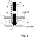
- Figure 3 shows a principle / detailed view of part of the print head 100, with a nozzle plate 1 and a nozzle 2 in the nozzle plate 1.
- a preferably magnetic valve element 9 e.g. armature or valve needle
- An electromechanical drive (expediently valve drive) A is used to move the valve element 9.
- the print head 100 has a multiplicity of such nozzles 2, each with an associated valve element 9 and an associated drive A, with FIG Figure 1 For the sake of clarity, only one nozzle is provided with a reference number 2.
- the drive A comprises an electrical coil 6 for actuating the valve element 9 as a function of the energization of the coil 6, in particular for actuating the valve element 9 in the open position.
- the drive A further comprises an elastic return element 10, for. B. a coil spring for actuating the valve element 9 in the closed position.
- the application agent to be applied is fed to the nozzles 2 via an application agent feeder 3 in the print head 100.
- the application agent supply 3 is (in Figure 3 below) through the nozzle plate 1 and (in Figure 3 above) by a further plate 4, wherein the nozzle plate 1 and the plate 4 can be separate components or part of a z.
- the plate 4 has an opening coaxially to the nozzle 2, onto which a coil tube 5 is placed coaxially, the coil tube 5 being wound with the coil 6.
- the coil tube 5 there is a magnetic coil core 7, which is in Figure 3
- the upper end of the coil tube 5 can be sealed off from the coil tube 5 by a seal 8.
- the coil tube 5 contains sections of the valve element 9, which can be displaced in the direction of the double arrow, the movement of the valve element 9, as already mentioned, being dependent on the energization of the coil 6.
- Figure 3 shows the valve element 9 in a closed position in order to close the nozzle 2.
- the coil 6 is energized so that the valve element 9 in Figure 3 pulled up to reveal nozzle 2.
- the return spring 10 presses the valve element 9 into the closed position when the coil 6 is de-energized.
- the printhead 100 and the in Figure 3 serve for serial and permanent application of the application agent and can optionally be operated in a first operating mode and a second operating mode.
- the coil 6 holds the valve element 9 permanently in the open position in order to generate a coherent application medium jet (e.g. Figure 7 ).
- the restoring element 10 is expediently used to move the valve element 9 into the closed position in the rest phases.
- the coil 6 and the restoring element 10 ensure that the valve element 9 is moved back and forth between the open position and the closed position at a high frequency, in order to generate a jet of droplets S1 (e.g. Figures 1, 2 , 5, 6 and 8th ).
- the coil 6 In both operating modes, the coil 6 is heavily used and therefore tends to overheat or at least overheat. Overheating can destroy the coil 6. Strong heating can have negative effects on the application agent and / or the application result, with strong fluctuations in the application result, for example. B. are unacceptable in the series painting of motor vehicle components. Paint, especially water-based paint, can be damaged at temperatures above 30 ° C.
- the application device V therefore includes a temperature control device T1, T2 and T3.
- the temperature control device T1, T2, T3 serves to reduce the heating of the drive A, in particular to reduce the heating of the coil 6 during the application of the application agent. Cooling is more important than warming. Heating only works to a limited extent, i.e. in narrow temperature ranges.
- the printhead can have the option of heating and cooling at the same time.
- the processes can be carried out at different points at the same time, eg cooling the coil and heating the coating agent.
- the processes can also run one after the other, especially at the same point, in the print head. For example, it would be conceivable that when the printhead is started, a low temperature prevails, which is increased by activating the heating process to a temperature that is set during the ongoing process by heat generation, for example from the coils.
- the temperature control device T1, T2, T3 can expediently comprise a heating device (heater) T1.
- the heating device T1 is used in particular to heat a heating fluid, a temperature control fluid line T2 for the heating fluid leading through the print head 100, and a pump T3 being provided for conveying the heating fluid.
- the temperature control fluid line T2 forms a ring line, so that the heating device T1, the pump T3 and the print head 100 are connected to one another via the ring line.
- the temperature control fluid line T2 extends through the pressure head 100, expediently along the application medium supply 3, so as to heat the nozzle plate 1 and / or the plate 4 and thereby the application medium in the application medium supply 3, which is shown in Figure 3 is indicated schematically by the hatched areas and the note "heated".
- the temperature control fluid line T2 z. B. as a channel within the The nozzle plate 1 and / or the plate 4 extend.
- a temperature control fluid line T2 can of course also extend on the outside and / or inside along the nozzle plate 1 and / or the plate 4.
- the nozzle plate 1 and / or the plate 4 made of thermally conductive material, for. B. a metal such as aluminum or copper.
- the heating of the application agent leads to the viscosity of the application agent being reduced.
- the print head 100 can additionally be enabled to process higher-viscosity and / or (highly) structurally-viscous application agents, e.g. B. with a viscosity of over 15mPas, over 30Pas or even over 60Pas.
- Ink z. B. has a viscosity of less than 15 mPas as a comparison.
- the temperature control also enables the viscosity of the application agent to be kept essentially constant and thus essentially constant application results regardless of the heating of the coils 6.
- Figure 2 shows a schematic view of an application device V with a print head 100 according to another embodiment of the invention, wherein Figure 4 shows a principle / detailed view of a part of the print head 100.
- Figure 4 The construction shown essentially corresponds to that in Figure 3 shown construction, reducing the However, the heating of the coil 6 is based on a different operating principle, as described below.
- the application device V and in particular the print head 100 are described below with common reference to FIG Figures 2 and 4th described.
- the application device V comprises a temperature control device T3, T4, T5 and T6.
- the temperature control device T3, T4, T5, T6 serves to reduce the heating of the drive A, specifically in particular to reduce the heating of the coil 6 during the application of the application agent.
- the temperature control device T3, T4, T5, T6 expediently comprises a cooler and / or heat exchanger device T4 for cooling the coil 6.
- the cooler / heat exchanger device T4 is used in particular to cool a cooling fluid, with a temperature control fluid line T5, T6 for the cooling fluid with a section T5 leading through the print head 100 and optionally with a section T6 extending along the outside of the print head 100, and a pump T3 is provided for conveying the cooling fluid.
- the temperature control fluid line T5, T6 forms a ring line, so that the cooler / heat exchanger device T4, the pump T3 and the print head 100 are connected to one another via the ring line.
- the temperature control fluid line T5 extends through the pressure head 100, specifically along the coil 6, for. B. around the coil 6 so as to cool the coil 6, which is shown in Figure 4 schematically by the hatched areas and the note “chilled” is indicated.
- the temperature control fluid line T5 and / or a heat conducting structure made of thermally conductive material can extend in the circumferential direction of the coil 6 around the coil 6.
- Figure 5 shows a schematic view of an application device V with a print head 100 according to another embodiment of the invention.
- the print head 100 can e.g. B as in the Figures 3 and 4th be constructed with or without a cooling or heating function.
- a temperature control device T7 comprises a cooling pad arrangement T7 for packing the print head 100 at least in sections.
- the cooling pad arrangement T7 can, for. B. be provided in the form of one or more cooling pads or cooling packs.
- a cooling pad arrangement T7 heated by the operation of the print head 100 can expediently be removed from the print head 100 in predetermined cycles, with a cooled cooling pad arrangement T7 subsequently being able to be applied to the print head 100.
- the cooling pad arrangement T7 acts in the form of passive cooling.
- the cooling pad arrangement T7 can also be designed for at least temporarily continuous flow with a cooling fluid and for this purpose, similar to z. B. shown in Figure 2, are connected to a cooling and / or heat exchanger device T4 and a pump T3 by means of a ring line.
- the cooling pad arrangement T7 acts here in the form of active cooling.
- Figure 6 shows a schematic view of an application device V with a print head 100 according to another embodiment of the invention.
- the print head 100 and the temperature control device of Figure 6 can like in the Figures 1 and 3 be constructed so that to reduce the heating of the drive A during the application of the application agent, the application agent is heated.
- the print head 100 can also be provided with a cooling pad arrangement T7, as in FIG Figure 6 shown, so that the drive A is cooled to reduce heating of the drive A during the application of the application agent.
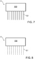
- Figure 7 shows a schematic view of a printhead 100 according to an embodiment of the invention.
- the print head 100 is used to generate a coherent application medium jet S2, for which purpose the coil 6 holds the valve element 9 permanently in the open position.
- Figure 8 Figure 3 shows a schematic view of a printhead 100 according to another embodiment of the invention.
- the print head 100 is used to generate a jet of droplets S1, for which purpose the coil 6 and the restoring element 10 ensure that the valve element 9 is moved back and forth between the open position and the closed position at a high frequency.
- droplet jets S1 shown have essentially spherical droplets, whereas those in FIGS characters 1, 2 , 5 and 6 shown drop jets S1 have drops that can initially be elongated.
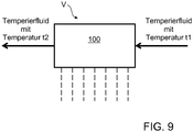
- Figure 9 serves to illustrate possible operating principles of the active, cooling-fluid-based temperature control (cooling and / or heating) for the purpose of reducing the heating of the drive A during the application of the application agent.
- the temperature control fluid (heating fluid) upstream of the print head 100 is warmer than downstream of the print head 100 (t1 greater than t2).
- the temperature control fluid (cooling fluid) upstream of print head 100 is colder than downstream of print head 100 (t1 less than t2).
- the pressure head 100 can be specifically equipped with a heat-conducting structure (not shown) made of highly thermally conductive material, e.g. B. aluminum or copper, trained temperature control device, for the purpose of reducing heating of the drive A during the application of the application agent.
- a heat-conducting structure made of highly thermally conductive material, e.g. B. aluminum or copper, trained temperature control device, for the purpose of reducing heating of the drive A during the application of the application agent.
- the heat-conducting structure can be designed and arranged in order to dissipate heat generated by the drive A.
- the heat-conducting structure can alternatively or additionally be designed and arranged in order to effectively transfer the heat generated by the temperature control device T1, T2, T3 to the application means to direct.
- the nozzle plate 1 and / or the plate 4 can be designed as a heat conducting structure.
- the heat-conducting structure can alternatively or additionally be designed and arranged in order to effectively conduct the cold generated by the temperature control device T3, T4, T5, T6 to drive A and / or around drive A.
- the heat-conducting structure can comprise heat-conducting plates and / or heat-conducting ribs.
- the heat-conducting structure can also comprise a heat-conducting function block in which preferably all drives A, in particular preferably all coils 6, of the print head 100 can be accommodated.
- the thermal structure can be, for. B. extend in sections on the outside of the print head 100 and in sections within the print head 100, so that heat / cold can be conducted from the inside of the print head 100 to the outside or vice versa.
- the heat-conducting structure can, however, also extend essentially holistically in the interior of the print head 100, e.g. B. in the case in which the heat conduction structure is to pass on heat / cold of the temperature control fluid.
- the nozzle plate 1 and / or the plate 4 can be formed from thermally conductive material and thus form a thermally conductive structure.
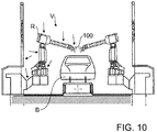
- Figure 10 shows a view of two application robots R for applying an application agent to a component B in the form of a motor vehicle body, with an application device V according to an embodiment of the invention.
- an application device V for applying an application agent to a component B in the form of a motor vehicle body, with an application device V according to an embodiment of the invention.
- Figure 10 only the left application robot is provided with a reference number.
- the application robot R serves to guide at least one print head 100 and expediently has at least five or at least six movable robot axes.
- the dashed arrows show examples of assembly points for the arrangement of individual components of the temperature control devices described here, in particular the heating device T1, the pump T3, the cooler and / or heat exchanger device T4 and / or one or more of the temperature control fluid lines T2, T5, T6.
- the individual components can be arranged at least in sections inside or outside the assembly locations shown (e.g. robot housing, robot base, robot arm and / or print head 100).
- Several print heads can be supplied with at least one central temperature control device.
- the temperature control fluid can be fed directly to each print head and flow directly back to the temperature control device. However, it can also flow through several printheads connected in series.
- the heating device T1, the pump T3, and / or the cooler and / or heat exchanger device T4 can also be arranged at a distance from the application robot R, e.g. B. on a painting booth wall or a robot support structure (e.g. support bracket or support frame), whereby the connection to the pressure head 100 can be made via one or more of the temperature control fluid lines T2, T5, T6, which in turn can run in or along the application robot R.
- the application robot R e.g. B. on a painting booth wall or a robot support structure (e.g. support bracket or support frame)
Landscapes
- Engineering & Computer Science (AREA)
- General Engineering & Computer Science (AREA)
- Mechanical Engineering (AREA)
- Robotics (AREA)
- Physics & Mathematics (AREA)
- Thermal Sciences (AREA)
- Coating Apparatus (AREA)
- Ink Jet (AREA)
Description
- Die Erfindung betrifft eine Applikationsvorrichtung zum Applizieren eines Applikationsmittels auf ein Bauteil, vorzugsweise zur Applikation eines Lacks auf ein Kraftfahrzeugkarosseriebauteil, mit einem Druckkopf zum vorzugsweise serienweisen und/oder oversprayfreien Applizieren des Applikationsmittels.
- Zur Serienlackierung von Kraftfahrzeugkarosseriebauteilen werden als Applikationsgerät üblicherweise Zerstäuber (z.B. Rotationszerstäuber, Airmix-Zerstäuber, Airless-Zerstäuber, etc.) eingesetzt, die jedoch den Nachteil eines beschränkten Auftragswirkungsgrades haben, so dass sich nur ein Teil des applizierten Lacks auf den zu beschichtenden Bauteilen ablagert, während der Rest des applizierten Lacks als sogenannter Overspray entsorgt werden muss.
- Zum allgemeinen Stand der Technik kann zunächst auf die
DE 20 2013 101 134 U1 , dieDE 10 2010 019 612 A1 , dieEP 2 002 898 A1 und dieDE 197 43 804 A1 verwiesen werden. - Die
US 9,108,424 B2 - Eine Aufgabe der Erfindung ist es, einen Druckkopf zu schaffen, der sich zum serienweisen und/oder dauerhaften Applizieren des Applikationsmittels eignet.
- Diese Aufgabe kann mit den Merkmalen des Hauptanspruchs gelöst werden. Vorteilhafte Weiterbildungen der Erfindung können den Unteransprüchen und der folgenden Beschreibung entnommen werden.
- Die Erfindung betrifft eine Applikationsvorrichtung zum Applizieren eines Applikationsmittels auf ein Bauteil, vorzugsweise zur Applikation eines Lacks auf ein Kraftfahrzeugkarosseriebauteil.
- Die Applikationsvorrichtung umfasst zumindest einen Druckkopf zum vorzugsweise serienweisen und/oder dauerhaften Applizieren des Applikationsmittels. Der Druckkopf umfasst: eine Düsenplatte, zumindest eine Düse (z. B. Öffnung) in der Düsenplatte zur Abgabe des Applikationsmittels, zumindest ein relativ zu der Düsenplatte bewegliches Ventilelement (z. B. Anker oder Ventilnadel) zur Steuerung der Applikationsmittelabgabe durch die zumindest eine Düse, wobei das zumindest eine bewegliche Ventilelement die zumindest eine Düse in einer Schließstellung verschließt und in einer Öffnungsstellung freigibt, und zumindest einen Antrieb (insbesondere Ventilantrieb) zum Bewegen des zumindest eines Ventilelements.
- Die Applikationsvorrichtung umfasst zumindest eine Temperiereinrichtung zur Reduzierung einer Erwärmung des zumindest einen Antriebs zweckmäßig während der Applikation des Applikationsmittels .
- Die zumindest eine Temperiereinrichtung ermöglicht insbesondere ein serienweises und/oder dauerhaftes Applizieren des Applikationsmittels mittels des Druckkopfs und alternativ oder ergänzend ein im Wesentlichen Konstant-halten der Temperatur und damit der Randbedingungen im Druckkopf, wodurch z. B. temperaturabhängig schwankende Applikationsergebnisse vermieden oder zumindest reduziert werden können. Darüber hinaus kann eine hohe Öffnungs-Schließ-Frequenz ermöglicht werden.
- Im Kontext der Erfindung dient die Temperiereinrichtung zum Kühlen des Antriebs. Durch das Kühlen des Antriebs kann eine Erwärmung des Antriebs reduziert oder nahezu verhindert werden. Im Kontext der Erfindung dient die Temperiereinrichtung zum Erwärmen des Applikationsmittels (vorzugsweise zumindest zu Betriebsbeginn). Durch das Erwärmen des Applikationsmittels kann die Viskosität des Applikationsmittels reduziert werden, so dass die Menge des ausgestoßenen Beschichtungsmittels konstant gehalten werden kann oder überhaupt erst ein bestimmter Volumenstrom ermöglicht wird. Weiterhin ermöglicht das Erwärmen auch, den Beschichtungsmitteldruck bei gleichzeitig konstanter Ausbringmenge zu verringern.
- Die Reduzierung der übermäßigen Erwärmung des Antriebs kann somit im Kontext der Erfindung zweckmäßig durch eine gezielte Erwärmung unter eine kritische Temperatur und/oder eine gezielte Kühlung ermöglicht werden. Das Temperieren im Kontext der Erfindung umfasst somit zweckmäßig ein Erwärmen und/oder Kühlen.
- Dazu wird der Temperierfluidvolumenstrom und/oder die Temperatur desselben so gesteuert, dass z.B. die Standzeit des Antriebs erhöht wird und/oder dass die Temperatur im Druckkopf unterhalb der Zündtemperatur (z.B. < +100°C) der in den Beschichtungsmitteln verwendeten Lösemittel liegt.
- Erfindungsgemäß umfasst die zumindest eine Temperiereinrichtung, zweckmäßig zur Reduzierung der Erwärmung des zumindest einen Antriebs, eine Erwärmungseinrichtung zum Erwärmen des Applikationsmittels und somit zum Erniedrigen der Viskosität des Applikationsmittels. Alternativ oder ergänzend ist es möglich, dass die zumindest eine Temperiereinrichtung, zweckmäßig zur Reduzierung der Erwärmung des zumindest einen Antriebs, eine Wärmetauschereinrichtung zur Kühlung des zumindest einen Antriebs umfasst.
- Die Erwärmungseinrichtung dient zum Erwärmen eines Temperierfluids, wobei das Temperierfluid somit ein Erwärmungsfluid zum Erwärmen des Applikationsmittels darstellt.
- Die Kühlereinrichtung dient zum Kühlen eines Temperierfluids, wobei das Temperierfluid somit ein Kühlfluid zum Kühlen des zumindest einen Antriebs darstellt.
- Die zumindest eine Temperiereinrichtunc umfasst zumindest eine Temperierfluidleitung (z. B. einen Kanal, einen, eine Bohrung, einen Schlauch etc.) für ein Temperierfluid, wobei die Temperierfluidleitung innerhalb des Druckkopfs verläuft und/ oder sich entlang der Außenseite des Druckkopfs erstreckt, um den Druckkopf (100) von außen zu kühlen.
- Vorzugsweise wird nicht das Applikationsmittel als Temperierfluid genutzt, insbesondere nicht als kühlendes Temperierfluid.
- Das Temperierfluid kann z. B. Luft, Wasser oder ein Kühlmittel, vorzugsweise frei von flüchtigen organischen Verbindungen (VOC-freies Kühlmittel - VOC: volatile organic compounds) sein.
- Es ist möglich, dass im Druckkopf eine Applikationsmittelzuführung zur Zuführung des Applikationsmittels zu der zumindest einen Düse verläuft.
- Die Applikationsmittelzuführung kann z. B. zumindest abschnittsweise von zumindest einer Temperiereinrichtung temperiert (zweckmäßig gekühlt und/oder erwärmt) werden.
- Insbesondere kann sich zumindest eine Temperierfluidleitung z. B. zur Erwärmung des Applikationsmittels entlang der Applikationsmittelzuführung erstrecken, vorzugsweise so, dass die Applikationsmittelzuführung durch das Temperierfluid umströmt werden kann. Zu diesem Zweck kann sich die Temperierfluidleitung z. B. in Umfangsrichtung der Applikationsmittelzuführung insbesondere spiral- oder ringförmig, um die Applikationsmittelzuführung herum erstrecken.
- Die Düsenplatte kann vorzugsweise die Applikationsmittelzuführung in deren Längsrichtung begrenzen.
- Es ist möglich, dass sich zumindest eine Temperierfluidleitung zur Kühlung des Antriebs, insbesondere einer elektrischen Spule des Antriebs, entlang des Antriebs, insbesondere der Spule, erstreckt und/oder so erstreckt, dass das Temperierfluid den zumindest einen Antrieb, insbesondere die Spule, umströmt.
- Die zumindest eine Temperiereinrichtung kann insbesondere eine Pumpe zum Befördern des Temperierfluids umfassen.
- Die zumindest eine Temperiereinrichtung kann z. B. eine passive Temperierung zur Verfügung stellen.
- Es ist möglich, dass die zumindest eine Temperiereinrichtung eine Wärmeleitkonstruktion aus wärmeleitfähigem Material umfasst.
- Die Wärmeleitkonstruktion kann z. B. dazu dienen, um von dem zumindest einen Antrieb erzeugte Wärme zweckmäßig nach außen effektiv abzuleiten. Alternativ oder ergänzend kann die Wärmeleitkonstruktion z. B. dazu dienen, durch zumindest eine Temperiereinrichtung (z. B. eine Temperierfluidleitung) erzeugte Wärme effektiv zum Applikationsmittel zu leiten. Alternativ oder ergänzend kann die Wärmeleitkonstruktion z. B. dazu dienen, durch die zumindest eine Temperiereinrichtung (z. B. eine Temperierfluidleitung) erzeugte Kälte zum zumindest einen Antrieb zu leiten.
- Die Wärmeleitkonstruktion kann somit im Kontext der Erfindung insbesondere dazu dienen, Wärme zur Erwärmung des Applikationsmittels effektiv zu übertragen und/oder Kälte zur Kühlung des zumindest einen Antriebs effektiv zu übertragen und/oder Wärme des zumindest einen Antriebs effektiv abzuleiten.
- Die Wärmeleitkonstruktion kann z. B. Wärmeleitbleche und/oder Wärmeleitrippen umfassen.
- Die Wärmeleitkonstruktion kann auch z. B. einen Wärmeleitfunktionsblock umfassen, wobei der zumindest eine Antrieb in dem Wärmeleitfunktionsblock positioniert sein kann. Vorzugsweise sind alle Antriebe, insbesondere Spulen, des Druckkopfs im Wärmeleitfunktionsblock untergebracht.
- Die Wärmeleitkonstruktion kann sich z. B. zumindest abschnittsweise an der Außenseite des Druckkopfes erstrecken und/oder zumindest abschnittsweise innerhalb des Druckkopfes. Dadurch kann z. B. eine effektive Wärme-/Kälte-Übertragung von innerhalb des Druckkopfs nach außen oder umgekehrt gewährleistet werden.
- Die Wärmeleitkonstruktion kann z. B. an dem zumindest einen Antrieb, vorzugsweise der Spule, angeordnet sein, vorzugsweise so, dass sie den zumindest einen Antrieb in dessen Umfangsrichtung umspannt, was eine effektive Wärmeableitung und/oder Kältezuführung hin zum zumindest einen Antrieb ermöglicht. Zu diesem Zweck kann die Wärmeleitkonstruktion z. B. in Form einer Hülse oder Buchse um den zumindest einen Antrieb herum angeordnet sein.
- Die Wärmeleitkonstruktion kann sich z. B. auch entlang der Applikationsmittelzuführung erstrecken. Z. B. kann die Düsenplatte selbst als Wärmeleitkonstruktion ausgeführt sein.
- Das wärmeleitfähige Material kann z. B. ein metallisches Material, Kupfer oder Aluminium umfassen.
- Es ist möglich, dass die zumindest eine Temperiereinrichtung eine Kühl-Pad-Anordnung (z. B. eine Kühlkissen- oder Kühlacku-Anordnung, zweckmäßig in Sandwichbauweise) zum zumindest abschnittsweisen Einpacken des Druckkopfes umfasst.
- Die Kühl-Pad-Anordnung kann z. B. zur zumindest zeitweise kontinuierlichen Durchströmung mit einem Kühlfluid ausgeführt sein und somit eine aktive Temperierung bewirken. Allerdings kann im Austauschbetrieb eine Kühl-Pad-Anordnung auch vorgekühlt an den Druckkopf montiert werden und nach Erwärmung durch eine andere vorgekühlte Kühl-Pad-Anordnung ersetzt werden, so dass die Kühl-Pad-Anordnung auch zur passiven Temperierung genutzt werden kann.
- Es ist möglich, dass zumindest eines von folgenden z. B. außen an den Druckkopf montiert ist und/oder oder zumindest abschnittsweise im Druckkopf angeordnet ist: die Erwärmungseinrichtung, die Kühler- und/oder Wärmetauschereinrichtung, zumindest eine Temperierfluidleitung und/oder die Pumpe.
- Der zumindest eine Antrieb arbeitet vorzugsweise elektromechanisch (z. B elektromagnetisch oder piezoelektrisch).
- Der zumindest eine Antrieb umfasst insbesondere eine elektrische Spule zur Betätigung des Ventilelements. Die Spule ist vorzugsweise der Teil des zumindest einen Antriebs, dessen Erwärmung zu reduzieren ist. Die zumindest eine Temperiereinrichtung dient somit insbesondere zur Reduzierung einer Erwärmung der Spule während der Applikation des Applikationsmittels.
- Es ist möglich, dass der zumindest eine Antrieb ein vorzugsweise elastisches Rückstellelement zur Betätigung des Ventilelements umfasst.
- Es ist möglich, dass das Ventilelement in Abhängigkeit von der Bestromung der Spule verschoben wird.
- Zur Erzeugung eines Tropfenstrahls können die Spule und ein z. B. elastisches Rückstellelement (z. B. eine Feder) dafür sorgen, dass das Ventilelement zwischen der Öffnungsstellung und der Schließstellung hin- und her bewegt wird. Der Tropfenstrahl kann z. B. mehrere im Wesentlichen kugelförmige oder längliche Tropfen umfassen. Der Tropfenstrahl liegt zweckmäßig zwischen der zumindest einen Düse und dem Bauteil vor.
- Zur Erzeugung eines zusammenhängenden Applikationsmittelstrahls kann die Spule das Ventilelement dauerhaft in der Öffnungsstellung halten. Ein vorzugsweise elastisches Rückstellelement kann z. B. das Ventilelement in Ruhephasen in die Schließstellung bewegen, wobei während der Applikation des Applikationsmittels das Ventilelement zweckmäßig dauerhaft in der Öffnungsstellung gehalten wird. Der zusammenhängende Applikationsmittelstrahl liegt zweckmäßig zwischen der zumindest einen Düse und dem Bauteil vor.
- Das Applikationsmittel kann z. B. viskos, hochviskos oder strukturviskos sein, vorzugsweise mit einer Viskosität von über 15mPas, über 60mPas, über 100mPas oder über 130mPas und/oder vorzugsweise mit einer Viskosität kleiner 400mPas oder kleiner 200mPas oder kleiner 1500mPas (gemessen bei einer Schergeschwindigkeit von 1000s-1) und/oder ein Lack sein.
- Es ist möglich, dass die zumindest eine Temperiereinrichtung (insbesondere die Erwärmungseinrichtung, die Kühler- und/oder Wärmetauschereinrichtung, zumindest eine Temperierfluidleitung und/oder die Pumpe) Teil einer Ringleitung ist.
- Die zumindest eine Temperiereinrichtung kann den zumindest einen Antrieb während der Applikation des Applikationsmittels auf eine Temperatur von unter 80°C, unter 60°C, unter 50C° oder unter 40°C temperieren.
- Der Druckkopf kann vorzugsweise zumindest eines der folgenden Merkmale aufweisen:
- der Druckkopf ist zum im Wesentlichen zerstäubungs- oder sprühnebelfreien Applizieren des Applikationsmittels ausgeführt, und/oder
- der Druckkopf ist auf Dauerbetrieb ausgelegt und dient zur Flächenbeschichtung des Bauteils, und/oder
- der Druckkopf gibt einen eng begrenzten Applikationsmittelstrahl ab im Gegensatz zu einem (wie z. B. durch einen Zerstäuber erzeugten, zerstäubten) Sprühnebel, und/oder
- der Druckkopf gibt einen Tropfenstrahl ab, z. B. im Gegensatz zu einem in Strahllängsrichtung zusammen hängenden Applikationsmittelstrahl, und/oder
- der Druckkopf gibt einen in Strahllängsrichtung zusammen hängenden Applikationsmittelstrahl ab, z. B. im Gegensatz zu einem Tropfenstrahl, und/oder
- der Druckkopf weist einen Auftragswirkungsgrad von mindestens 80%, 90%, 95% oder 99% auf, so dass vorzugsweise im Wesentlichen das gesamte applizierte Applikationsmittel vollständig auf dem Bauteil abgelagert wird, im Wesentlichen ohne Oversprayerzeugung, und/oder
- der Druckkopf weist eine Flächenbeschichtungsleistung von mindestens 0,5 m2/min, 1m2/min, 2m2/min oder mindestens 3m2/min auf, und/oder
- der Druckkopf weist mindestens einen elektrisch ansteuerbaren Aktor aufweist, um das Applikationsmittel aus dem Druckkopf auszustoßen, insbesondere einen Magnetaktor oder einen Piezoaktor.
- Zu erwähnen ist, dass der Druckkopf vorzugsweise eine Vielzahl an Düsen (z. B. über 5, über 10 oder sogar über 15 Düsen) und eine dementsprechende Anzahl an zugehörigen Ventilelementen und zugehörigen Antrieben umfassen kann.
- Die Düsen sind vorzugsweise in zumindest einer Düsenreihe in der Düsenplatte angeordnet.
- Zu erwähnen ist außerdem, dass der im Rahmen der Erfindung verwendete Begriff eines Druckkopfs allgemein zu verstehen ist und lediglich insbesondere zur Abgrenzung von Zerstäubern (z.B. Rotationszerstäuber, Scheibenzerstäuber, Airless-Zerstäuber, Airmix-Zerstäuber und/oder Ultraschallzerstäuber) dient, die einen Sprühnebel des zu applizierenden Applikationsmittels erzeugen. Im Gegensatz dazu erzeugt der erfindungsgemäße Druckkopf vorzugsweise zumindest einen, insbesondere eine Vielzahl räumlich eng begrenzter Applikationsmittelstrahlen.
- Weiterhin ist zu erwähnen, dass der erfindungsgemäße Drucckopf vorzugsweise zur Applikation eines Lacks (z.B. Basislack, Klarlack, Wasserlack und/oder lösemittelbasierter Lack) dient. Der erfindungsgemäße Druckkopf kann jedoch alternativ auch zur Applikation anderer Applikationsmittel, insbesondere Beschichtungsmittel, ausgelegt sein, wie beispielsweise zur Applikation von Dichtstoff, Dämmstoff, Klebstoff, Primer etc., um nur einige Beispiele zu nennen.
- Darüber hinaus ist zu erwähnen, dass zumindest eine Temperierfluidleitung zumindest abschnittweise als zweckmäßig flexibler Schlauch ausgeführt sein kann, alternativ oder ergänzend aber auch zumindest abschnittsweise als ein Kanal, der z. B. in eine im Druckkopf angeordnete Komponente eingearbeitet sein kann.
- Der Applikationsabstand zwischen der zumindest einen Düse und der Bauteiloberfläche beträgt vorzugsweise mindestens 4mm, 10 mm, 20mm oder 40 mm und/oder höchstens 200mm oder 100 mm.
- Die Temperierung kann z. B. nur bestimmte Teilabschnitte des Druckkopfes umfassen, z. B. die Applikationsmittel-führenden Bereiche und/oder die einzelnen Antriebe, oder den im Wesentlichen gesamten Innenbereich des Druckkopfs umfassen.
- Die Erfindung umfasst auch einen Applikationsroboter, vorzugsweise einen Beschichtungs- oder Lackierroboter, mit zumindest einer Applikationsvorrichtung wie hierin offenbart. Der Applikationsroboter dient zweckmäßig zur Führung eines oder mehrerer Druckköpfe und kann z. B. zumindest fünf oder zumindest sechs bewegliche Roboterachsen aufweisen.
- Es ist möglich, dass zumindest eines von folgenden zumindest abschnittsweise an oder in den Applikationsroboter montiert ist, z. B. an oder in ein Robotergehäuse, einen Roboterarm und/oder eine Roboterbasis: die Erwärmungseinrichtung, die Kühler- und/oder Wärmetauschereinrichtung, ein Teilabschnitt zumindest einer Temperierfluidleitung und/oder die Pumpe.
- Allerdings ist es auch möglich, dass zumindest eines von folgenden beabstandet zum Applikationsroboter zur Verfügung gestellt ist: die Erwärmungseinrichtung, die Kühler- und/oder Wärmetauschereinrichtung, ein Teilabschnitt zumindest einer Temperierfluidleitung, und/oder die Pumpe.
- Vorzugsweise wird als Temperiermedium Luft eingesetzt. Dies hat Vorteile, da Druckluft üblicherweise leicht verfügbar ist und diese mit einfachen Mitteln gekühlt oder erwärmt werden kann. Die Viskosität von Luft ist gering, um auch durch Spalte und kleine Durchführungen zu strömen. Die Ableitung der durch den Druckkopf geströmten Luft kann z.B. durch Schläuche an jede Stelle innerhalb oder außerhalb der Lackierkabine erfolgen. Der Nachteil der schlechteren Wärmeübertragung wird durch die vorgenannten Vorteile bei weitem aufgehoben.
- Die oben beschriebenen bevorzugten Ausführungsformen der Erfindung sind miteinander kombinierbar. Andere vorteilhafte Weiterbildungen der Erfindung sind in den Unteransprüchen offenbart oder ergeben sich aus der folgenden Beschreibung bevorzugter Ausführungsformen der Erfindung in Verbindung mit den beigefügten Figuren.
- Figur 1
- zeigt eine schematische Ansicht einer Applikationsvorrichtung gemäß einer Ausführungsform der Erfindung,
- Figur 2
- zeigt eine schematische Ansicht einer Applikationsvorrichtung gemäß einer anderen Ausführungsform der Erfindung,
- Figur 3
- zeigt eine Prinzip-/Detaildarstellung eines Teils eines Druckkopfes gemäß einer Ausführungsform der Erfindung,
- Figur 4
- zeigt eine Prinzip-/Detaildarstellung eines Teils eines Druckkopfes gemäß einer anderen Ausführungsform der Erfindung,
- Figur 5
- zeigt eine schematische Ansicht einer Applikationsvorrichtung gemäß einer Ausführungsform der Erfindung,
- Figur 6
- zeigt eine schematische Ansicht einer Applikationsvorrichtung gemäß einer anderen Ausführungsform der Erfindung,
- Figur 7
- zeigt eine schematische Ansicht eines Druckkopfs zum Erzeugen eines zusammenhängenden Applikationsmittelstrahls gemäß einer Ausführungsform der Erfindung,
- Figur 8
- zeigt eine schematische Ansicht eines Druckkopfs zum Erzeugen eines Tropfenstrahls gemäß einer Ausführungsform der Erfindung,
- Figur 9
- zeigt eine Prinzipdarstellung einer Temperierung gemäß einer Ausführungsform der Erfindung, und
- Figur 10
- zeigt eine Ansicht zweier Applikationsroboter mit einer Applikationsvorrichtung gemäß einer Ausführungsform der Erfindung.
- Die unter Bezugnahme auf die Figuren beschriebenen bevorzugten Ausführungsformen der Erfindung stimmen teilweise überein, wobei ähnliche oder identische Teile mit den gleichen Bezugszeichen versehen sind, und zu deren Erläuterung auch auf die Beschreibung anderer Ausführungsformen oder Figuren verwiesen wird, um Wiederholungen zu vermeiden.
-
Figur 1 zeigt eine schematische Ansicht einer Applikationsvorrichtung V mit einem Druckkopf 100 gemäß einer Ausführungsform der Erfindung, wobeiFigur 3 eine Prinzip-/Detailansicht eines Teils des Druckkopfes 100 zeigt. Die Applikationsvorrichtung V und insbesondere der Druckkopf 100 werden nachfolgend unter gemeinsamer Bezugnahme auf dieFiguren 1 und3 beschrieben. - Die Applikationsvorrichtung V dient zum Applizieren eines Applikationsmittels auf ein Bauteil, insbesondere zur Applikation eines Lacks auf ein Kraftfahrzeugkarosseriebauteil. Hierfür umfasst die Applikationsvorrichtung V insbesondere einen Druckkopf 100 zum serienweisen, dauerhaften sowie im Wesentlichen zerstäubungs- und sprühnebelfreien Applizieren des Applikationsmittels.
-
Figur 3 zeigt eine Prinzip-/Detailansicht eines Teils des Druckkopfs 100, mit einer Düsenplatte 1 und einer Düse 2 in der Düsenplatte 1. Ein relativ zu der Düsenplatte 1 bewegliches, vorzugsweise magnetisches, Ventilelement 9 (z. B. Anker oder Ventilnadel) dient zur Steuerung der Applikationsmittelabgabe durch die Düse 2, wobei das bewegliche Ventilelement 9 die Düse 2 in einer Schließstellung verschließt und in einer Öffnungsstellung freigibt. Ein elektromechanischer Antrieb (zweckmäßig Ventilantrieb) A dient zum Bewegen des Ventilelements 9. Der Druckkopf 100 weist eine Vielzahl solcher Düsen 2 auf, mit jeweils zugehörigem Ventilelement 9 und zugehörigem Antrieb A, wobei inFigur 1 der Übersichtlichkeit halber nur eine Düse mit einem Bezugszeichen 2 versehen ist. - Der Antrieb A umfasst eine elektrische Spule 6 zur Betätigung des Ventilelements 9 in Abhängigkeit von der Bestromung der Spule 6, insbesondere zur Betätigung des Ventilelements 9 in die Öffnungsstellung. Der Antrieb A umfasst ferner ein elastisches Rückstellelement 10, z. B. eine Spiralfeder, zur Betätigung des Ventilelements 9 in die Schließstellung.
- Das zu applizierende Applikationsmittel wird über eine Applikationsmittelzuführung 3 im Druckkopf 100 den Düsen 2 zugeführt. Die Applikationsmittelzuführung 3 wird (in
Figur 3 unten) durch die Düsenplatte 1 und (inFigur 3 oben) durch eine weitere Platte 4 begrenzt, wobei die Düsenplatte 1 und die Platte 4 separate Bauteile sein können oder Teil einer z. B. einstückig-integralen (z. B. runden oder rechteckförmigen) rohrförmigen Applikationsmittelzuführung 3. - Die Platte 4 weist koaxial zu der Düse 2 eine Öffnung auf, auf die ein Spulenrohr 5 koaxial aufgesetzt ist, wobei das Spulenrohr 5 mit der Spule 6 bewickelt ist.
- In dem Spulenrohr 5 befindet sich ein magnetischer Spulenkern 7, der am in
Figur 3 oberen Ende des Spulenrohrs 5 durch eine Dichtung 8 gegenüber dem Spulenrohr 5 abgedichtet sein kann. - Darüber hinaus befindet sich in dem Spulenrohr 5 abschnittsweise das Ventilelement 9, das in Richtung des Doppelpfeils verschiebbar ist, wobei die Bewegung des Ventilelements 9, wie schon erwähnt, von der Bestromung der Spule 6 abhängt.
-
Figur 3 zeigt das Ventilelement 9 hierbei in einer Schließstellung, um die Düse 2 zu schließen. Für eine Applikation des Applikationsmittels wird die Spule 6 dagegen so bestromt, dass das Ventilelement 9 inFigur 3 nach oben gezogen wird, um die Düse 2 freizugeben. - Die Rückstellfeder 10 drückt das Ventilelement 9 in die Schließstellung, wenn die Spule 6 unbestromt ist.
- Der Druckkopf 100 und die in
Figur 3 gezeigte Konstruktion dienen zum serienweisen und dauerhaften Applizieren des Applikationsmittels und können wahlweise in einem ersten Betriebsmodus und einem zweiten Betriebsmodus betrieben werden. - In dem ersten Betriebsmodus hält die Spule 6 das Ventilelement 9 dauerhaft in der Öffnungsstellung, zur Erzeugung eines zusammenhängenden Applikationsmittelstrahls (z. B.
Figur 7 ). - Das Rückstellelement 10 dient zweckmäßig dazu, das Ventilelement 9 in Ruhephasen in die Schließstellung zu bewegen.
- In dem zweiten Betriebsmodus sorgen die Spule 6 und das Rückstellelement 10 dafür, dass das Ventilelement 9 zwischen der Öffnungsstellung und der Schließstellung mit hoher Frequenz hin- und her bewegt wird, zur Erzeugung eines mehrere Tropfen aufweisenden Tropfenstrahls S1 (z. B.
Figuren 1, 2 ,5, 6 und8 ). - In beiden Betriebsmodi wird die Spule 6 stark beansprucht und neigt deshalb zur Überhitzung oder zumindest starker Erhitzung. Eine Überhitzung kann zur Zerstörung der Spule 6 führen. Eine starke Erhitzung kann negative Auswirkungen auf das Applikationsmittel und/oder das Applikationsergebnis haben, wobei starke Schwankungen im Applikationsergebnis z. B. bei der serienweisen Lackierung von Kraftfahrzeugbauteilen inakzeptabel sind. Lack, insbesondere wasserbasierter Lack, kann bereits bei Temperaturen von über 30°C geschädigt werden.
- Die Applikationsvorrichtung V umfasst deshalb eine Temperiereinrichtung T1, T2 und T3.
- Die Temperiereinrichtung T1, T2, T3 dient zur Reduzierung einer Erwärmung des Antriebs A und zwar insbesondere zur Reduzierung einer Erwärmung der Spule 6 während der Applikation des Applikationsmittels. Kühlen ist wichtiger als Erwärmen. Erwärmen funktioniert nur bedingt, also in engen Temperaturbereichen.
- In einer besonderen Ausführungsform kann der Druckkopf gleichzeitig über die Möglichkeit zum Erwärmen und zum Kühlen verfügen. Dabei können die Prozesse (Kühlen und Erwärmen) gleichzeitig an verschiedenen Stellen durchgeführt werden, z.B. Kühlen der Spule und Erwärmen des Beschichtungsmittels. Die Prozesse können aber auch nacheinander, im Speziellen an derselben Stelle, im Druckkopf ablaufen. So wäre es beispielsweise denkbar, dass beim Start des Druckkopfs zunächst eine niedrige Temperatur vorherrscht, die durch Aktivierung des Erwärmungsprozesses auf eine Temperatur erhöht wird, die sich während des laufenden Prozesses durch Wärmeentwicklung z.B. der Spulen einstellt.
- Zum Erwärmen des Applikationsmittels und somit zum Erniedrigen der Viskosität des Applikationsmittels kann die Temperiereinrichtung T1, T2, T3 zweckmäßig eine Erwärmungseinrichtung (Heizer) T1 umfassen.
- Die Erwärmungseinrichtung T1 dient insbesondere zum Erwärmen eines Erwärmungsfluids, wobei eine Temperierfluidleitung T2 für das Erwärmungsfluid durch den Druckkopf 100 führt, und eine Pumpe T3 zum Befördern des Erwärmungsfluids vorgesehen ist. Die Temperierfluidleitung T2 bildet eine Ringleitung, so dass die Erwärmungseinrichtung T1, die Pumpe T3 und der Druckkopf 100 über die Ringleitung miteinander in Verbindung stehen.
- Die Temperierfluidleitung T2 erstreckt sich durch den Drucckopf 100 und zwar zweckmäßig entlang der Applikationsmittelzuführung 3, um so die Düsenplatte 1 und/oder die Platte 4 und dadurch das Applikationsmittel in der Applikationsmittelzuführung 3 zu erwärmen, was in
Figur 3 schematisch durch die schraffierten Bereiche und den Hinweis "erwärmt" angedeutet ist. - Um eine effektive Wärmeübertragung auf das Applikationsmittel in der Applikationsmittelzuführung 3 zu bewirken, kann sich die Temperierfluidleitung T2 z. B. als Kanal innerhalb der Düsenplatte 1 und/oder der Platte 4 erstrecken. Alternativ oder ergänzend kann sich eine Temperierfluidleitung T2 natürlich auch an der Außen- und/oder Innenseite entlang der Düsenplatte 1 und/oder der Platte 4 erstrecken. Außerdem kann die Düsenplatte 1 und/oder die Platte 4 aus wärmeleitfähigem Material, z. B. einem Metall wie Aluminium oder Kupfer hergestellt sein.
- Die Erwärmung des Applikationsmittel führt dazu, dass die Viskosität des Applikationsmittels reduziert wird.
- Die Reduzierung der Viskosität des Applikationsmittels führt dazu, dass die Spule 6 in ihrer Öffnungsarbeit entlastet wird, was zu einer Reduzierung der Erwärmung der Spule 6 führt.
- Vorteilhafterweise kann der Druckkopf 100 durch die Erwärmung des Applikationsmittels zusätzlich in die Lage versetzt werden, höherviskose und/oder (stark) strukturviskose Applikationsmittel zu verarbeiten, z. B. mit einer Viskosität von über 15mPas, über 30Pas oder sogar über 60Pas. Tinte z. B. weist als Vergleich eine Viskosität von unter 15mPas auf. Ebenfalls ermöglicht die Temperierung ein im Wesentlichen Konstant-halten der Viskosität des Applikationsmittels und somit im Wesentlichen gleichbleibende Applikationsergebnisse unabhängig von der Erwärmung der Spulen 6.
-
Figur 2 zeigt eine schematische Ansicht einer Applikationsvorrichtung V mit einem Druckkopf 100 gemäß einer anderen Ausführungsform der Erfindung, wobeiFigur 4 eine Prinzip-/Detailansicht eines Teils des Druckkopfes 100 zeigt. Die inFigur 4 gezeigte Konstruktion entspricht im Wesentlichen der inFigur 3 gezeigten Konstruktion, wobei die Reduzierung der Erwärmung der Spule 6 allerdings auf einem anderen Wirkprinzip beruht, wie weiter unten beschrieben. - Die Applikationsvorrichtung V und insbesondere der Druckkopf 100 werden nachfolgend unter gemeinsamer Bezugnahme auf die
Figuren 2 und4 beschrieben. - Die Applikationsvorrichtung V umfasst eine Temperiereinrichtung T3, T4, T5 und T6.
- Die Temperiereinrichtung T3, T4, T5, T6 dient zur Reduzierung einer Erwärmung des Antriebs A und zwar insbesondere zur Reduzierung einer Erwärmung der Spule 6 während der Applikation des Applikationsmittels.
- Zu diesem Zweck umfasst die Temperiereinrichtung T3, T4, T5, T6 zweckmäßig eine Kühler- und/oder Wärmetauschereinrichtung T4 zur Kühlung der Spule 6.
- Die Kühler-/Wärmetauschereinrichtung T4 dient insbesondere zum Kühlen eines Kühlfluids, wobei eine Temperierfluidleitung T5, T6 für das Kühlfluid mit einem Teilabschnitt T5 durch den Druckkopf 100 führt und optional mit einem Teilabschnitt T6 sich entlang der Außenseite des Druckkopfs 100 erstreckt, und eine Pumpe T3 zum Befördern des Kühlfluids vorgesehen ist. Die Temperierfluidleitung T5, T6 bildet eine Ringleitung, so dass die Kühler-/Wärmetauschereinrichtung T4, die Pumpe T3 und der Druckkopf 100 über die Ringleitung miteinander in Verbindung stehen.
- Die Temperierfluidleitung T5 erstreckt sich durch den Drucckopf 100 und zwar zweckmäßig entlang der Spule 6, z. B. um die Spule 6, um so die Spule 6 zu kühlen, was in
Figur 4 schematisch durch die schraffierten Bereiche und den Hinweis "gekühlt" angedeutet ist. Um eine effektive Kühlung zu bewirken, kann sich die Temperierfluidleitung T5 und/oder eine Wärmeleitkonstruktion aus wärmeleitfähigem Material in Umfangsrichtung der Spule 6 um die Spule 6 herum erstrecken. -
Figur 5 zeigt eine schematische Ansicht einer Applikationsvorrichtung V mit einem Druckkopf 100 gemäß einer anderen Ausführungsform der Erfindung. Der Druckkopf 100 kann z. B wie in denFiguren 3 und4 gezeigt aufgebaut sein, mit oder ohne Kühlungs- oder Erwärmungsfunktion. - Eine Besonderheit der in
Figur 5 gezeigten Ausführungsform ist, dass eine Temperiereinrichtung T7 eine Kühl-Pad-Anordnung T7 zum zumindest abschnittsweisen Einpacken des Druckkopfes 100 umfasst. Die Kühl-Pad-Anordnung T7 kann z. B. in Form eines oder mehrerer Kühlkissen oder Kühlakkus vorgesehen sein. - Eine durch den Betrieb des Druckkopfes 100 erwärmte Kühl-Pad-Anordnung T7 kann zweckmäßig in vorbestimmten Zyklen vom Druckkopf 100 entfernt werden, wobei in der Folge eine gekühlte Kühl-Pad-Anordnung T7 auf den Druckkopf 100 aufgebracht werden kann. Die Kühl-Pad-Anordnung T7 wirkt hierbei in Form einer passiven Kühlung.
- Allerdings kann die Kühl-Pad-Anordnung T7 auch zur zumindest zeitweise kontinuierlichen Durchströmung mit einem Kühlfluid ausgeführt sein und zu diesem Zweck, ähnlich wie z. B. in Figur 2 gezeigt, mit einer Kühl- und/oder Wärmetauschereinrichtung T4 und einer Pumpe T3 mittels einer Ringleitung in Verbindung stehen. Die Kühl-Pad-Anordnung T7 wirkt hierbei in Form einer aktiven Kühlung.
-
Figur 6 zeigt eine schematische Ansicht einer Applikationsvorrichtung V mit einem Druckkopf 100 gemäß einer anderen Ausführungsform der Erfindung. - Der Druckkopf 100 und die Temperiereinrichtung der
Figur 6 können wie in denFiguren 1 und3 gezeigt aufgebaut sein, so dass zur Reduzierung einer Erwärmung des Antriebs A während der Applikation des Applikationsmittels eine Erwärmung des Applikationsmittels bewirkt wird. - Der Druckkopf 100 kann darüber hinaus mit einer Kühl-Pad-Anordnung T7 versehen sein, wie in
Figur 6 gezeigt, so dass zur Reduzierung einer Erwärmung des Antriebs A während der Applikation des Applikationsmittels eine Kühlung des Antriebs A bewirkt wird. -
Figur 7 zeigt eine schematische Ansicht eines Druckkopfs 100 gemäß einer Ausführungsform der Erfindung. - Der Druckkopf 100 dient zur Erzeugung eines zusammenhängenden Applikationsmittelstrahls S2, wozu die Spule 6 das Ventilelement 9 dauerhaft in der Öffnungsstellung hält.
-
Figur 8 zeigt eine schematische Ansicht eines Druckkopfs 100 gemäß einer anderen Ausführungsform der Erfindung. - Der Druckkopf 100 dient zur Erzeugung eines Tropfenstrahls S1, wozu die Spule 6 und das Rückstellelement 10 dafür sorgen, dass das Ventilelement 9 zwischen der Öffnungsstellung und der Schließstellung mit hoher Frequenz hin- und her bewegt wird.
- Die in
Figur 8 gezeigten Tropfenstrahlen S1 weisen im Wesentlichen kugelförmige Tropfen auf, wohingegen die in denFiguren 1, 2 ,5 und 6 gezeigten Tropfenstrahlen S1 Tropfen aufweisen, die anfangs länglich sein können. -
Figur 9 dient zur Veranschaulichung möglicher Wirkprinzipien der aktiven, Kühlfluid-basierten Temperierung (Kühlung und/oder Erwärmung) zum Zweck der Reduzierung einer Erwärmung des Antriebs A während der Applikation des Applikationsmittels. - Bei der Erwärmungs-basierten Variante (z. B.
Figuren 1 und3 ) ist das Temperierfluid (Erwärmungsfluid) stromaufwärts des Druckkopfs 100 wärmer als stromabwärts des Druckkopfs 100 (t1 größer t2). - Bei der Kühlungs-basierten Variante (z. B.
Figuren 2 und4 ) ist das Temperierfluid (Kühlungsfluid) stromaufwärts des Druckkopfs 100 kälter als stromabwärts des Druckkopfs 100 (t1 kleiner t2). - Alternativ oder ergänzend zu den unter Bezugnahme auf die Figuren 1 bis 9 beschriebenen Ausführungsformen kann der Drucckopf 100 gezielt mit einer (nicht gezeigten) als Wärmeleitkonstruktion aus stark wärmeleitfähigem Material, z. B. Aluminium oder Kupfer, ausgebildeten Temperiereinrichtung versehen sein, zum Zwecke der Reduzierung einer Erwärmung des Antriebs A während der Applikation des Applikationsmittels.
- Die Wärmeleitkonstruktion kann ausgebildet und angeordnet sein, um von dem Antrieb A erzeugte Wärme abzuleiten.
- Die Wärmeleitkonstruktion kann alternativ oder ergänzend ausgebildet und angeordnet sein, um durch die Temperiereinrichtung T1, T2, T3 erzeugte Wärme effektiv zum Applikationsmittel zu leiten. So kann z. B. die Düsenplatte 1 und/oder die Platte 4 als Wärmeleitkonstruktion ausgebildet sein.
- Die Wärmeleitkonstruktion kann alternativ oder ergänzend ausgebildet und angeordnet sein, um durch die Temperiereinrichtung T3, T4, T5, T6 erzeugte Kälte effektiv zum Antrieb A und/oder um den Antrieb A herum zu leiten.
- Die Wärmeleitkonstruktion kann Wärmeleitbleche und/oder Wärmeleitrippen umfassen. Auch kann die Wärmeleitkonstruktion einen Wärmeleitfunktionsblock umfassen, in dem vorzugsweise alle Antriebe A, insbesondere vorzugsweise alle Spulen 6, des Druckkopfes 100 aufgenommen sein können.
- Die Wärmeleitkonstruktion kann sich z. B. abschnittsweise an der Außenseite des Druckkopfes 100 erstrecken und abschnittsweise innerhalb des Druckkopfes 100, so dass Wärme/Kälte vom Innern des Druckkopfs 100 nach außen geleitet werden kann oder umgekehrt. Die Wärmeleitkonstruktion kann sich allerdings auch im Wesentlich ganzheitlich im Innern des Druckkopfs 100 erstrecken, z. B. in dem Fall, in dem die Wärmeleitkonstruktion Wärme/Kälte des Temperierfluids weiterleiten soll. Hierbei kann, wie schon zuvor erwähnt, insbesondere die Düsenplatte 1 und/oder die Platte 4 aus wärmeleitfähigem Material ausgebildet sein und somit eine Wärmeleitkonstruktion bilden.
-
Figur 10 zeigt eine Ansicht zweier Applikationsroboter R zur Applikation eines Applikationsmittels auf ein Bauteil B in Form einer Kraftfahrzeugkarosserie, mit einer Applikationsvorrichtung V gemäß einer Ausführungsform der Erfindung. Der Übersichtlichkeit halber ist inFigur 10 nur der linke Applikationsroboter mit Bezugszeichen versehen. - Der Applikationsroboter R dient zur Führung zumindest eines Druckkopfes 100 und weist zweckmäßig zumindest fünf oder zumindest sechs bewegliche Roboterachsen auf.
- Die gestrichelten Pfeile zeigen beispielhaft auf Montagestellen zur Anordnung einzelner Komponenten der hierin beschriebenen Temperiereinrichtungen, insbesondere der Erwärmungseinrichtung T1, der Pumpe T3, der Kühler- und/oder Wärmetauschereinrichtung T4 und/oder einer oder mehrerer der Temperierfluidleitungen T2, T5, T6. Hierbei können die einzelnen Komponenten zumindest abschnittsweise innerhalb oder außerhalb der gezeigten Montagestellen (z. B. Robotergehäuse, Roboterbasis, Roboterarm und/oder Druckkopf 100) angeordnet sein. Mehrere Druckköpfe können mit mindestens einer zentralen Temperiereinrichtung versorgt werden. Das Temperierfluid kann jedem Druckkopf direkt zugeführt werden und direkt zurück zur Temperiereinrichtung fließen. Es kann aber auch durch mehrere in Reihe geschaltete Druckköpfe fließen.
- Ebenfalls können die Erwärmungseinrichtung T1, die Pumpe T3, und/oder die Kühler- und/oder Wärmetauschereinrichtung T4 beabstandet zum Applikationsroboter R angeordnet sein, z. B. an einer Lackierkabinenwand oder eine Robotertragstruktur (z. B. Tragkonsole oder Tragrahmen), wobei die Verbindung zum Drucckopf 100 über eine oder mehrere der Temperierfluidleitungen T2, T5, T6 erfolgen kann, die wiederum im oder entlang des Applikationsroboters R verlaufen können.
- Die Erfindung ist nicht auf die vorstehend beschriebenen bevorzugten Ausführungsbeispiele beschränkt, sondern durch die beigefügten Ansprüche definiert.
-
- 1
- Düsenplatte
- 2
- Zumindest eine Düse
- 3
- Applikationsmittelzuführung
- 4
- Platte
- 5
- Spulenrohr
- 6
- Spule
- 7
- Spulenkern
- 8
- Dichtung zwischen Spulenkern und Spulenrohr
- 9
- Ventilelement, vorzugsweise Anker und/oder Ventilnadel
- 10
- Rückstellelement
- A
- Antrieb, insbesondere Ventilantrieb
- T1
- Erwärmungseinrichtung, insbesondere Heizer
- T2
- Temperierfluidleitung
- T3
- Pumpe
- T4
- Kühler- und/oder Wärmetauschereinrichtung
- T5
- Temperierfluidleitung
- T6
- Temperierfluidleitung
- T7
- Kühl-Pad-Anordnung
- 100
- Druckkopf
- V
- Applikationsvorrichtung
- R
- Applikationsroboter
- B
- Bauteil, vorzugsweise Kraftfahrzeugkarosserie
Claims (20)
- Applikationsvorrichtung (V) zum Applizieren eines Applikationsmittels auf ein Bauteil (B), vorzugsweise zur Applikation eines Lacks auf ein Kraftfahrzeugkarosseriebauteil (B), umfassend:- einen Druckkopf (100) zum vorzugsweise serienweisen und/oder dauerhaften Applizieren des Applikationsmittels, wobei der Druckkopf (100) aufweist:- eine Düsenplatte (1),- zumindest eine Düse (2) in der Düsenplatte (1) zur Abgabe des Applikationsmittels,- zumindest ein relativ zu der Düsenplatte (1) bewegliches Ventilelement (9) zur Steuerung der Applikationsmittelabgabe durch die zumindest eine Düse (2), wobei das zumindest eine bewegliche Ventilelement (9) die zumindest eine Düse (2) in einer Schließstellung verschließt und in einer Öffnungsstellung freigibt, und- zumindest einen Antrieb (A) zum Bewegen des zumindest einen Ventilelements (9),wobei- die Applikationsvorrichtung (V) zumindest eine Temperiereinrichtung (T1-T8) mit einer Kühleinrichtung zum Kühlen eines Temperierfluids als Kühlfluid zur Reduzierung einer Erwärmung des zumindest einen Antriebs (A) während der Applikation des Applikationsmittels umfasst dadurch gekennzeichnet, dass- die zumindest eine Temperiereinrichtung (T1-T8) ferner eine Erwärmungseinrichtung (T1) zum Erwärmen eines Temperierfluids als Erwärmungsfluid zum Erwärmen des Applikationsmittels und somit zum Erniedrigen der Viskosität des Applikationsmittels umfasst,- und wobei die zumindest eine Temperiereinrichtung (T1-T8) zumindest eine Temperierfluidleitung (T2, T5, T6) für ein Temperierfluid umfasst, die innerhalb des Druckkopfs (100) verläuft und/oder die sich entlang der Außenseite des Druckkopfs (100) erstreckt, um den Druckkopf (100) von außen zu kühlen.
- Applikationsvorrichtung (V) nach Anspruch 1, dadurch gekennzeichnet, dass die zumindest eine Temperiereinrichtung (T1-T8) eine Wärmetauschereinrichtung (T4) zur Kühlung des zumindest einen Antriebs (A) umfasst.
- Applikationsvorrichtung (V) nach einem der vorhergehenden Ansprüche, dadurch gekennzeichnet,a) dass nicht das Applikationsmittel als Temperierfluid dient, und/oderb) dass das Temperierfluid ausgewählt ist aus:b1) einem Gas, insbesondere Stickstoff, Luft, Druckluft,b2) einer Flüssigkeit, insbesondere Wasser, insbesondere deionisiertem Wasser oder destilliertem Wasser,b3) einem Kühlmittel, vorzugsweise frei von flüchtigen organischen Verbindungen,b4) einem Spülmittel, Reinigungsmittel oder Lösemittel, insbesondere gewärmt, und/oder c) dass als Temperierfluid dienende Druckluft direkt aus einer zentralen Versorgungsleitung entnommen wird.
- Applikationsvorrichtung (V) nach einem der vorhergehenden Ansprüche, dadurch gekennzeichnet, dass im Druckkopf (100) eine Applikationsmittelzuführung (3) zur Zuführung des Applikationsmittels zu der zumindest einen Düse (2) verläuft und die Applikationsmittelzuführung (3) zumindest abschnittsweise von der zumindest einen Temperiereinrichtung (T1-T8) temperiert wird.
- Applikationsvorrichtung (V) nach Anspruch 4, dadurch gekennzeichnet, dass- die zumindest eine Temperierfluidleitung (T2) zur Erwärmung des Applikationsmittels sich entlang der Applikationsmittelzuführung (3) erstreckt, und/oder- zumindest eine Temperierfluidleitung (T2) sich so erstreckt, dass das Temperierfluid die Applikationsmittelzuführung (3) umströmt, und/oder- die Düsenplatte (1) die Applikationsmittelzuführung (3) in deren Längsrichtung begrenzt.
- Applikationsvorrichtung (V) nach einem der vorhergehenden Ansprüche, dadurch gekennzeichnet, dass die zumindest eine Temperierfluidleitung (T5)- zur Kühlung des Antriebs (A), vorzugsweise einer elektrischen Spule (6) des Antriebs (A), sich an dem Antrieb (A) entlang erstreckt, und/oder- sich so erstreckt, dass das Temperierfluid den zumindest einen Antrieb (A) umströmt.
- Applikationsvorrichtung (V) nach einem der vorhergehenden Ansprüche, dadurch gekennzeichnet, dass der Temperierfluidvolumenstrom und/oder die Temperatur desselben so gesteuert wird, dass- die Standzeit des Antriebs erhöht wird,- die Temperatur im Druckkopf unterhalb der Zündtemperatur der in Beschichtungsmitteln verwendeten Lösemittel liegt.
- Applikationsvorrichtung (V) nach einem der vorhergehenden Ansprüche, dadurch gekennzeichnet, dass die zumindest eine Temperiereinrichtung (T1-T8) eine Pumpe (T3) zum Befördern des Temperierfluids umfasst.
- Applikationsvorrichtung (V) nach einem der vorhergehenden Ansprüche, dadurch gekennzeichnet, dass die zumindest eine Temperiereinrichtung (T1-T8) eine passive Temperierung zur Verfügung stellt und/oder eine Wärmeleitkonstruktion aus wärmeleitfähigem Material umfasst und vorzugsweise die Wärmeleitkonstruktion zumindest eine der folgenden Funktionen erfüllt:- durch den zumindest einen Antrieb (A) erzeugte Wärme ableiten,- durch die zumindest eine Temperiereinrichtung (T1, T2, T3) erzeugte Wärme zum Applikationsmittel leiten,- durch die zumindest eine Temperiereinrichtung (T3, T4, T5, T6) erzeugte Kälte zum Antrieb (A) leiten.
- Applikationsvorrichtung (V) nach Anspruch 9, dadurch gekennzeichnet, dass eine Wärmeleitkonstruktion der Temperiereinrichtung (T1-T8) Wärmeleitbleche und/oder Wärmeleitrippen umfasst und/oder dass eine Wärmeleitkonstruktion der Temperiereinrichtung (T1-T8) einen Wärmeleitfunktionsblock umfasst und der zumindest eine Antrieb (A) in dem Wärmeleitfunktionsblock positioniert ist.
- Applikationsvorrichtung (V) nach Anspruch 9 oder 10, dadurch gekennzeichnet, dass eine Wärmeleitkonstruktion der Temperiereinrichtung (T1-T8)- sich zumindest abschnittsweise an der Außenseite des Druckkopfes (100) erstreckt, und/oder- zumindest abschnittsweise innerhalb des Druckkopfes (100) angeordnet ist, und/oder- an dem zumindest einen Antrieb (A)angeordnet ist, vorzugsweise so, dass sie den zumindest einen Antrieb (A) in dessen Umfangsrichtung umspannt, und/oder- sich entlang einer Applikationsmittelzuführung (3) im Druckkopf (100) erstreckt.
- Applikationsvorrichtung (V) nach einem der Ansprüche 9 bis 11, dadurch gekennzeichnet, dass die Temperiereinrichtung (T1-T8) eine Wärmeleitkonstruktion aus wärmeleitfähigem Material umfasst, das ausgewählt ist aus:- einem metallischen Material,- Kupfer,- Aluminium.
- Applikationsvorrichtung (V) nach einem der vorhergehenden Ansprüche, dadurch gekennzeichnet, dass die zumindest eine Temperiereinrichtung (T1-T8) eine Kühl-Pad-Anordnung (T7) zum zumindest abschnittsweisen Einpacken des Druckkopfes (100) umfasst, wobei die Kühl-Pad-Anordnung (T7) vorzugsweise zur zumindest zeitweise kontinuierlichen Durchströmung mit einem Kühlfluid ausgeführt ist.
- Applikationsvorrichtung (V) nach einem der vorhergehenden Ansprüche, dadurch gekennzeichnet, dass zumindest eines von folgenden am Druckkopf (100) montiert oder zumindest abschnittsweise im Druckkopf (100) angeordnet ist:- die Erwärmungseinrichtung (T1),- eine Kühler- und/oder Wärmetauschereinrichtung (T4),- zumindest eine Temperierfluidleitung (T2, T5, T6),- eine Pumpe (T3).
- Applikationsvorrichtung (V) nach einem der vorhergehenden Ansprüche, dadurch gekennzeichnet, dass der zumindest eine Antrieb (A)- elektromechanisch arbeitet, und/oder- eine elektrische Spule (6) zur Betätigung des Ventilelements (9) umfasst, wobei das Ventilelement (9) in Abhängigkeit von der Bestromung der Spule (6) verschoben wird und die zumindest eine Temperiereinrichtung (T1-T8) zur Reduzierung einer Erwärmung der Spule (6) während der Applikation des Applikationsmittels dient, und/oder- ein Rückstellelement (10) zur Betätigung des Ventilelements (9) umfasst.
- Applikationsvorrichtung (V) nach Anspruch 15, dadurch gekennzeichnet, dass zur Erzeugung eines Tropfenstrahls (S1) eine elektrische Spule (6) und ein vorzugsweise elastisches Rückstellelement (10) dafür sorgen, dass das Ventilelement (9) zwischen der Öffnungsstellung und der Schließstellung hin- und her bewegt wird,
oder dass zur Erzeugung eines zusammenhängenden Applikationsmittelstrahls (S2) eine elektrische Spule (6) des Antriebs (A) das Ventilelement (9) dauerhaft in der Öffnungsstellung hält und vorzugsweise ein insbesondere elastisches Rückstellelement (10) das Ventilelement (9) in Ruhephasen in die Schließstellung bewegt. - Applikationsvorrichtung (V) nach einem der vorhergehenden Ansprüche dadurch gekennzeichnet, dass das Applikationsmittel viskos, hochviskos oder strukturviskos ist, mit einer Viskosität von über 15mPas, über 60mPas, über 100mPas oder über 130mPas und/oder vorzugsweise mit einer Viskosität kleiner als 400mPas oder kleiner als 200mPas oder kleiner als 150mPas gemessen bei einer Schergeschwindigkeit von 1000s-1 und/oder ein Lack ist.
- Applikationsvorrichtung (V) nach einem der vorhergehenden Ansprüche, dadurch gekennzeichnet, dass- die zumindest eine Temperiereinrichtung (T1-T8) Teil einer Ringleitung ist, und/oder- die zumindest eine Temperiereinrichtung (T1-T8) den zumindest einen Antrieb (A), insbesondere eine Spule (6) des Antriebs (A), während der Applikation des Applikationsmittels auf eine Temperatur von unter 80°C, unter 60°C, unter 50C° oder unter 40°C temperiert.
- Applikationsvorrichtung (V) nach einem der vorhergehenden Ansprüche, dadurch gekennzeichnet, dass der Druckkopf (100) zumindest eines der folgenden Merkmale aufweist:- der Druckkopf (100) ist zum zerstäubungs- oder sprühnebelfreien Applizieren des Applikationsmittels ausgeführt,- der Druckkopf (100) ist auf Dauerbetrieb ausgelegt und dient zur Flächenbeschichtung des Bauteils,- der Druckkopf (100) gibt einen eng begrenzten Applikationsmittelstrahl (T1, T2) ab im Gegensatz zu einem Sprühnebel,- der Druckkopf (100) gibt einen Tropfenstrahl (T1) ab im Gegensatz zu einem in Strahllängsrichtung zusammen hängenden Applikationsmittelstrahl (T2),- der Druckkopf (100) gibt einen in Strahllängsrichtung zusammen hängenden Applikationsmittelstrahl (T2) ab im Gegensatz zu einem Tropfenstrahl (T1),- der Druckkopf (100) weist einen Auftragswirkungsgrad von mindestens 80%, 90%, 95% oder 99% auf, so dass im Wesentlichen das gesamte applizierte Applikationsmittel vollständig auf dem Bauteil abgelagert wird,- der Druckkopf (100) weist eine Flächenbeschichtungsleistung von mindestens 0,5 m2/min, 1m2/min, 2m2/min oder mindestens 3m2/min auf,- der Druckkopf (100) weist mindestens einen elektrisch ansteuerbaren Aktor auf, um ein Ventil zu öffnen und/oder zu schließen und dadurch das Applikationsmittel aus dem Druckkopf (100) ausfließen zu lassen, vorzugsweise einen Magnetaktor oder einen Piezoaktor.
- Applikationsroboter (R), vorzugsweise Beschichtungs- oder Lackierroboter, mit zumindest einer Applikationsvorrichtung (V) nach einem der vorhergehenden Ansprüche, wobei der Applikationsroboter (R) zur Führung zumindest eines Druckkopfes (100) dient und vorzugsweise zumindest fünf oder zumindest sechs bewegliche Roboterachsen aufweist und wobei vorzugsweise zumindest eines von folgenden zumindest abschnittsweise an oder in den Applikationsroboter (R) montiert oder beabstandet zum Applikationsroboter (R) angeordnet ist:- die Erwärmungseinrichtung (T1),- die Kühler- und/oder Wärmetauschereinrichtung (T4),- ein Teilabschnitt der zumindest einen Temperierfluidleitung (T2, T5, T6),- die Pumpe (T3).
Applications Claiming Priority (2)
| Application Number | Priority Date | Filing Date | Title |
|---|---|---|---|
| DE102016014943.4A DE102016014943A1 (de) | 2016-12-14 | 2016-12-14 | Druckkopf mit Temperiereinrichtung |
| PCT/EP2017/081117 WO2018108571A1 (de) | 2016-12-14 | 2017-12-01 | Druckkopf mit temperiereinrichtung |
Publications (2)
| Publication Number | Publication Date |
|---|---|
| EP3554714A1 EP3554714A1 (de) | 2019-10-23 |
| EP3554714B1 true EP3554714B1 (de) | 2021-02-03 |
Family
ID=60782177
Family Applications (1)
| Application Number | Title | Priority Date | Filing Date |
|---|---|---|---|
| EP17818069.1A Active EP3554714B1 (de) | 2016-12-14 | 2017-12-01 | Druckkopf mit temperiereinrichtung |
Country Status (8)
| Country | Link |
|---|---|
| US (1) | US11298717B2 (de) |
| EP (1) | EP3554714B1 (de) |
| JP (1) | JP7021222B2 (de) |
| CN (1) | CN110099750B (de) |
| DE (1) | DE102016014943A1 (de) |
| ES (1) | ES2865437T3 (de) |
| MX (1) | MX2019006960A (de) |
| WO (1) | WO2018108571A1 (de) |
Families Citing this family (12)
| Publication number | Priority date | Publication date | Assignee | Title |
|---|---|---|---|---|
| DE102018124662A1 (de) * | 2018-10-05 | 2020-04-09 | Vermes Microdispensing GmbH | Dosiersystem mit Kühleinrichtung |
| US11684947B2 (en) * | 2018-11-09 | 2023-06-27 | Illinois Tool Works Inc. | Modular fluid application device for varying fluid coat weight |
| CH715861A1 (de) * | 2019-02-15 | 2020-08-31 | Soudronic Ag | Verfahren und Vorrichtung zur Nahtbeschichtung von Dosenzargen. |
| CN111045458B (zh) * | 2019-12-25 | 2021-07-20 | 华南理工大学 | 一种非牛顿流体微涂覆系统及控制方法 |
| WO2022003759A1 (ja) * | 2020-06-29 | 2022-01-06 | アーベーベー・シュバイツ・アーゲー | 塗装ロボット |
| DE102020127852A1 (de) | 2020-10-22 | 2022-04-28 | Dürr Systems Ag | Betriebsverfahren für eine Beschichtungsanlage und entsprechend angepasste Beschichtungsanlage |
| CN113275149B (zh) * | 2021-06-01 | 2022-01-18 | 丰县通亚电子科技有限公司 | 环保型电动车喷漆装置 |
| CN117836143A (zh) * | 2021-08-20 | 2024-04-05 | 株式会社理光 | 头驱动装置、液体排出装置、液体排出设备及液体排出方法 |
| DE102021133410A1 (de) | 2021-12-16 | 2023-06-22 | Dürr Systems Ag | Beschichtungseinrichtung und entsprechendes Betriebsverfahren |
| US11853629B1 (en) | 2022-10-27 | 2023-12-26 | Xerox Corporation | System and method for feed forward control of printhead temperature in an inkjet printer to improve ink image quality |
| CN116328987B (zh) * | 2022-12-30 | 2023-11-24 | 浙江嘉顿木业有限公司 | 一种防蛀防水实木门板的表面处理装置及工艺 |
| CN118950293B (zh) * | 2024-10-15 | 2024-12-13 | 江苏道金智能制造科技股份有限公司 | 锂电池负极材料液相包覆装置用喷嘴及其工作方法 |
Family Cites Families (221)
| Publication number | Priority date | Publication date | Assignee | Title |
|---|---|---|---|---|
| DE1284250B (de) | 1965-10-30 | 1968-11-28 | Kaercher Fa Alfred | Spruehgeraet zum Verspruehen eines Fluessigkeits-Gemisches |
| US3717306A (en) | 1971-03-10 | 1973-02-20 | Hushon R | Nozzle for spraying foaming materials |
| US3981320A (en) | 1974-05-10 | 1976-09-21 | The Gyromat Corporation | Recovery system for spray painting installation with automatic color change |
| AT349415B (de) * | 1975-07-28 | 1979-04-10 | Zimmer Peter Ag | Spritzdruckeinrichtung zum bemustern einer ware |
| CH613387A5 (en) | 1975-07-28 | 1979-09-28 | Zimmer Peter Maschinenfabrik A | Process and device for applying patterns to a material, in particular to a web material |
| US4383264A (en) | 1980-06-18 | 1983-05-10 | Exxon Research And Engineering Co. | Demand drop forming device with interacting transducer and orifice combination |
| JPS5722070A (en) * | 1980-07-15 | 1982-02-04 | Oki Electric Ind Co Ltd | Cooling device for printer |
| US4375865A (en) | 1980-08-12 | 1983-03-08 | Binks Manufacturing Company | Color change system for spray coating apparatus |
| DE3045401A1 (de) | 1980-12-02 | 1982-07-01 | Robert Bosch Gmbh, 7000 Stuttgart | Verfahren zum pruefen von einspritzduesen |
| MX152277A (es) * | 1980-12-16 | 1985-06-19 | Vitro Tec Fideicomiso | Mejoras en bloque de valvulas neumaticas de solenoide para maquinas de fabricacion de articulos de vidrio |
| US4423999A (en) | 1981-09-14 | 1984-01-03 | General Motors Corporation | Mechanical hand for a door-opener |
| US4435719A (en) | 1982-03-30 | 1984-03-06 | Snaper Alvin A | Fluidic matrix printer |
| DE3221327A1 (de) | 1982-06-05 | 1983-09-15 | Daimler-Benz Ag, 7000 Stuttgart | Anlage zum farbspritzen von serienteilen wechselnder farbe |
| DE3225554A1 (de) | 1982-07-08 | 1984-01-12 | Robert Bosch Gmbh, 7000 Stuttgart | Messeinrichtung fuer fluidstrahlen |
| US4668948A (en) | 1983-03-10 | 1987-05-26 | Nordson Corporation | Dispenser malfunction detector |
| US4555719A (en) | 1983-08-19 | 1985-11-26 | Videojet Systems International, Inc. | Ink valve for marking systems |
| EP0231177A1 (de) * | 1984-09-19 | 1987-08-12 | DRYSDALE, Ronald Douglas | Verfahren und vorrichtung zum aufbringen von bildern auf einer oberfläche |
| JPS62116442A (ja) | 1985-11-12 | 1987-05-28 | Toppan Printing Co Ltd | 二枚差し検知装置 |
| DD245400A1 (de) | 1986-02-05 | 1987-05-06 | Robotron Bueromasch | Farbstrahldruckkopf |
| FR2608097B1 (fr) | 1986-12-12 | 1994-04-08 | Markpoint System Ab | Dispositif a clapet pour imprimantes matricielles |
| US4734711A (en) | 1986-12-22 | 1988-03-29 | Eastman Kodak Company | Pressure regulation system for multi-head ink jet printing apparatus |
| SE456597B (sv) | 1987-02-12 | 1988-10-17 | Scandot System Ab | Anordning vid ett ventilarrangemang for utmatning av vetska hos en vetskestralskrivare |
| DE3721875A1 (de) | 1987-07-02 | 1989-01-12 | Gema Ransburg Ag | Verfahren und einrichtung fuer eine pulverspruehbeschichtungsanlage |
| JPH0798171B2 (ja) | 1988-04-19 | 1995-10-25 | トキコ株式会社 | 工業用ロボット装置 |
| US4974780A (en) | 1988-06-22 | 1990-12-04 | Toa Nenryo Kogyo K.K. | Ultrasonic fuel injection nozzle |
| US5050533A (en) * | 1988-07-25 | 1991-09-24 | Technadyne Engineering Corporation | Application of thermal-cure materials |
| US5602575A (en) | 1988-11-05 | 1997-02-11 | Rea Elektronik Gmbh | Ink jet writing head |
| US4894252A (en) | 1988-11-30 | 1990-01-16 | Ransburg Corporation | Coating material orifice clogging indication method and apparatus |
| US4985715A (en) | 1990-03-22 | 1991-01-15 | Telesis Controls Corporation | Marker assembly for spray marking dot matrix characters and method of fabrication thereof |
| JP3144566B2 (ja) | 1990-05-08 | 2001-03-12 | マツダ株式会社 | 塗装方法および塗装装置 |
| US5072881A (en) | 1990-06-04 | 1991-12-17 | Systems Specialties | Method of cleaning automated paint spraying equipment |
| JPH04106669U (ja) | 1991-02-21 | 1992-09-14 | セントラル自動車株式会社 | 水性塗装用ブース |
| DE4138491C2 (de) | 1991-11-23 | 1995-07-20 | Juergen Dipl Ing Joswig | Mikromechanisches Ventil für mikromechanische Dosiereinrichtungen |
| US5429682A (en) | 1993-08-19 | 1995-07-04 | Advanced Robotics Technologies | Automated three-dimensional precision coatings application apparatus |
| DE4329384C2 (de) | 1993-09-01 | 2001-08-09 | Duerr Systems Gmbh | Fördervorrichtung |
| DE9422327U1 (de) | 1993-09-01 | 2000-03-23 | Dürr Systems GmbH, 70435 Stuttgart | Beschichtungsanlage |
| US5435884A (en) | 1993-09-30 | 1995-07-25 | Parker-Hannifin Corporation | Spray nozzle and method of manufacturing same |
| GB2286157B (en) * | 1994-01-31 | 1998-01-14 | Neopost Ltd | Ink jet printing device |
| DE9405600U1 (de) | 1994-04-02 | 1994-06-16 | ITW Dynatec Klebetechnik Holding GmbH, 40699 Erkrath | Auftragskopf zur dosierten Abgabe von strömenden Medien |
| CN2287527Y (zh) | 1994-04-20 | 1998-08-12 | 徐连宽 | 燃油式汽车喷漆烤漆房 |
| US5718767A (en) | 1994-10-05 | 1998-02-17 | Nordson Corporation | Distributed control system for powder coating system |
| US5659347A (en) | 1994-11-14 | 1997-08-19 | Xerox Corporation | Ink supply apparatus |
| US5647542A (en) | 1995-01-24 | 1997-07-15 | Binks Manufacturing Company | System for electrostatic application of conductive coating liquid |
| US5636795A (en) | 1995-05-11 | 1997-06-10 | First Pioneer Industries Inc. | Cyclonic spray nozzle |
| SE504472C2 (sv) | 1995-06-22 | 1997-02-17 | Abb Flexible Automation As | Färgmatningssystem för sprutmålningsrobot |
| JPH09192583A (ja) | 1996-01-17 | 1997-07-29 | Fuji Heavy Ind Ltd | ローラ式塗布装置保管用ボックス |
| DE19606716C1 (de) | 1996-02-23 | 1997-08-14 | Herberts Gmbh | Verfahren zur Mehrschichtlackierung |
| SE507821C2 (sv) | 1996-04-15 | 1998-07-20 | Jetline Ab | Ventilkonstruktion vid bläckstråleskrivare |
| DE19630290C2 (de) | 1996-07-26 | 2000-08-10 | Audi Ag | Anlage zur Oberflächenbehandlung von Gegenständen, insbesondere von Fahrzeugkarosserien |
| DE19731829A1 (de) | 1997-07-24 | 1999-01-28 | Tietz Patrick | Einrichtung zur gesteuerten Farbmischung und Dosierung von Lacken und Farben |
| DE19743804A1 (de) * | 1997-10-02 | 1999-04-08 | Politrust Ag | Druckvorrichtung |
| DE69836128T2 (de) | 1998-01-13 | 2007-08-16 | Abb K.K. | Beschichtungsverfahren für eine beschichtungsvorrichtung mit einem rotierenden sprühkopf |
| CZ2001554A3 (cs) | 1998-08-13 | 2001-12-12 | Ppg Industries Ohio, Inc. | Povlakové směsi, způsoby a zařízení pro vytváření povlaků zvolené barvy na substrátu a výrobky takto zhotovené |
| DE19852079A1 (de) | 1998-11-11 | 2000-05-18 | Thomas Kovarovsky | Bildgebende Lackiervorrichtung |
| JP2000158670A (ja) | 1998-11-26 | 2000-06-13 | Fuji Electric Co Ltd | インクジェット記録装置 |
| JP4358352B2 (ja) | 1999-05-11 | 2009-11-04 | トリニティ工業株式会社 | 塗装装置とそれに用いる塗装機とそれを用いた塗装方法 |
| DE19936790A1 (de) | 1999-08-10 | 2001-02-15 | Nordson Corp Westlake | Verfahren und Vorrichtung zum Herstellen einer abziehbaren Schutzschicht für Oberflächen, insbesondere für lackierte Oberflächen von Kraftfahrzeugkarosserien |
| JP2001157863A (ja) | 1999-09-21 | 2001-06-12 | Tokyo Electron Ltd | 塗布装置 |
| US7152965B2 (en) | 2000-01-21 | 2006-12-26 | Seiko Epson Corporation | Ink cartridge, and ink-jet recording apparatus using the same |
| JP2001129456A (ja) | 1999-11-04 | 2001-05-15 | Sekisui Chem Co Ltd | スプレイ塗装装置におけるノズルの洗浄方法及びスプレイ塗装装置 |
| IT1311388B1 (it) | 1999-11-10 | 2002-03-12 | Gd Spa | Unita' di gommatura a spruzzo. |
| US6325302B1 (en) | 1999-11-29 | 2001-12-04 | Fanuc Robotics North America, Inc. | Airless spray tool |
| DE20017630U1 (de) | 1999-12-20 | 2001-03-22 | Tevkür, Talip, 13585 Berlin | Farbspritzpistole |
| KR100335955B1 (ko) | 1999-12-30 | 2002-05-10 | 이계안 | 도장막 보호용 코팅 시스템 |
| US6360656B2 (en) | 2000-02-28 | 2002-03-26 | Minolta Co., Ltd. | Apparatus for and method of printing on three-dimensional object |
| JP2001239652A (ja) | 2000-02-28 | 2001-09-04 | Minolta Co Ltd | 印刷装置及び印刷方法 |
| US6460958B2 (en) | 2000-02-29 | 2002-10-08 | Minolta Co., Ltd. | Three-dimensional object printing apparatus and method |
| US6401976B1 (en) * | 2000-03-23 | 2002-06-11 | Nordson Corporation | Electrically operated viscous fluid dispensing apparatus and method |
| DE10031030B4 (de) | 2000-06-26 | 2005-08-04 | Bauer, Jörg R. | Verfahren und Vorrichtung zum Herstellen flächiger Bauteile mit vorbestimmtem Oberflächenaussehen und flächiges Bauteil, insbesondere Frontplatte eines Küchenelements |
| FR2811917B1 (fr) | 2000-07-24 | 2002-12-20 | Sames Sa | Procede et station de changement de produit dans une installation de projection de produit de revetement |
| US6641667B2 (en) | 2000-08-29 | 2003-11-04 | Honda Giken Kogyo Kabushiki Kaisha | Robot-mounted two-package-mixing coating device and internal pressure explosion-proof robot |
| US6523921B2 (en) | 2000-08-30 | 2003-02-25 | L&P Property Management | Method and apparatus for printing on rigid panels and other contoured or textured surfaces |
| DE10048749A1 (de) | 2000-09-29 | 2002-04-11 | Josef Schucker | Anordnung zum Aufbringen von Klebstoff auf ein Werkstück |
| US6849684B2 (en) | 2000-10-20 | 2005-02-01 | E. I. Du Pont De Nemours And Company | Molded soft elastomer/hard polyester composition with noise damping properties |
| JP3953776B2 (ja) | 2001-01-15 | 2007-08-08 | セイコーエプソン株式会社 | 材料の吐出装置、及び吐出方法、カラーフィルタの製造装置及び製造方法、液晶装置の製造装置及び製造方法、el装置の製造装置及び製造方法 |
| US7244310B2 (en) | 2001-06-01 | 2007-07-17 | Litrex Corporation | Over-clocking in a microdeposition control system to improve resolution |
| US20040231594A1 (en) | 2001-06-01 | 2004-11-25 | Edwards Charles O. | Microdeposition apparatus |
| US20050016451A1 (en) | 2001-06-01 | 2005-01-27 | Edwards Charles O. | Interchangeable microdesition head apparatus and method |
| US7160105B2 (en) | 2001-06-01 | 2007-01-09 | Litrex Corporation | Temperature controlled vacuum chuck |
| US7449070B2 (en) | 2001-06-01 | 2008-11-11 | Ulvac, Inc. | Waveform generator for microdeposition control system |
| WO2002099849A2 (en) | 2001-06-01 | 2002-12-12 | Litrex Corporation | Apparatus for microdeposition of multiple fluid materials |
| JP4158357B2 (ja) | 2001-06-05 | 2008-10-01 | セイコーエプソン株式会社 | インクジェット式記録装置 |
| US6755512B2 (en) | 2001-07-30 | 2004-06-29 | Fuji Photo Film Co. Ltd | Liquid droplet ejection apparatus and inkjet recording head |
| JP3487301B2 (ja) | 2001-08-06 | 2004-01-19 | マツダ株式会社 | 自動車車体の塗装方法および塗装装置 |
| DE10140216B4 (de) | 2001-08-17 | 2006-02-09 | ITW Oberflächentechnik GmbH & Co. KG | Verfahren und Vorrichtung an einer Lackiereinrichtung zum Reinigen einer Lack-Förderleitung |
| US6757586B2 (en) | 2001-09-05 | 2004-06-29 | Abb Automation Inc. | Multiple arm robot arrangement |
| JP3961820B2 (ja) | 2001-11-30 | 2007-08-22 | 株式会社不二越 | 産業用ロボットの制御装置 |
| KR100761235B1 (ko) | 2002-01-22 | 2007-10-04 | 노드슨 코포레이션 | 액체 스프레이 패턴 검출을 위한 방법 및 장치 |
| EP1340974B1 (de) | 2002-03-01 | 2008-09-17 | VMT Bildverarbeitungssysteme GmbH | Verfahren zur Qualitätssicherung des Auftrags eines Mediums auf ein Objekt |
| DE10224128A1 (de) | 2002-05-29 | 2003-12-18 | Schmid Rhyner Ag Adliswil | Verfahren zum Auftrag von Beschichtungen auf Oberflächen |
| US20040173144A1 (en) | 2002-05-31 | 2004-09-09 | Edwards Charles O. | Formation of printed circuit board structures using piezo microdeposition |
| US7650852B2 (en) | 2002-10-23 | 2010-01-26 | Fanuc Robotics America, Inc. | Modular painting apparatus |
| JP4123897B2 (ja) | 2002-10-28 | 2008-07-23 | 株式会社エルエーシー | インクジェットノズル |
| AU2003283896A1 (en) | 2002-11-06 | 2004-06-07 | Advanced Flow Control Afc Ab | System for spraying a fluid material |
| SE0203515L (sv) * | 2002-11-27 | 2004-05-28 | Texdot Ab | Ventilenhet i en vätskestrålskrivare samt metod vid en sådan enhet |
| US7454785B2 (en) | 2002-12-19 | 2008-11-18 | Avocent Huntsville Corporation | Proxy method and system for secure wireless administration of managed entities |
| JP3885036B2 (ja) | 2003-03-14 | 2007-02-21 | 本田技研工業株式会社 | 保護層形成材の塗布方法および塗布装置 |
| GB0306788D0 (en) | 2003-03-25 | 2003-04-30 | Willett Int Ltd | Method |
| US7178742B2 (en) | 2003-05-06 | 2007-02-20 | Lear Corporation | Fluid delivery system for spray applicator |
| US20050001869A1 (en) | 2003-05-23 | 2005-01-06 | Nordson Corporation | Viscous material noncontact jetting system |
| DE10331206A1 (de) | 2003-07-10 | 2005-01-27 | Daimlerchrysler Ag | Verfahren zum Auftragen von Sprühstoffen |
| US20050015050A1 (en) | 2003-07-15 | 2005-01-20 | Kimberly-Clark Worldwide, Inc. | Apparatus for depositing fluid material onto a substrate |
| ZA200407781B (en) | 2003-10-03 | 2005-09-28 | Int Tech Llc | Blasting and blastiing accessory |
| FR2862563B1 (fr) | 2003-11-24 | 2007-01-19 | Centre Nat Rech Scient | Robot d'impression numerique grand format en trois dimensions sur une surface fixe et procede d'impression mettant en oeuvre au moins un tel robot |
| US20070292626A1 (en) | 2004-02-03 | 2007-12-20 | Linde Aktiengesellschaft | Apparatus and Method for Manufacturing and Surface Coating an Object |
| JP4419015B2 (ja) | 2004-03-04 | 2010-02-24 | リコープリンティングシステムズ株式会社 | インクジェット塗布方法及び装置 |
| DE102004034270B4 (de) | 2004-07-15 | 2016-08-18 | Wolfgang Schmidt | Anlage zum Austragen fließfähiger Fluide, insbesondere von Farben und Lacken und Verfahren zum Betrieb der Anlage |
| WO2006022217A1 (ja) | 2004-08-23 | 2006-03-02 | Kabushiki Kaisha Ishiihyoki | インクジェットプリンタの吐出量制御方法、及びインク滴広がり検査方法、並びに配向膜形成方法。 |
| DE102004044655B4 (de) | 2004-09-15 | 2009-06-10 | Airbus Deutschland Gmbh | Lackier-Vorrichtung, Lackier-Anordnung, Verfahren zum Lackieren einer gekrümmten Oberfläche eines Flugzeugs und Verwendung einer Inkjet-Einrichtung zum Lackieren eines Flugzeugs |
| US20060068109A1 (en) | 2004-09-15 | 2006-03-30 | Airbus Deutschland Gmbh | Painting device, painting arrangement, method for painting a curved surface of an object, and use of an inkjet device for painting an aircraft |
| US7824001B2 (en) | 2004-09-21 | 2010-11-02 | Z Corporation | Apparatus and methods for servicing 3D printers |
| DE102004049471A1 (de) | 2004-10-11 | 2006-04-20 | Bayerische Motoren Werke Ag | Vorrichtung zum Auftragen einer Konservierungsschicht und Verfahren zum Auftragen derselben |
| JP2007021760A (ja) | 2005-07-12 | 2007-02-01 | Nissha Printing Co Ltd | 薄膜形成装置 |
| EP1764226B1 (de) | 2005-09-20 | 2009-08-19 | Agfa Graphics N.V. | Apparat und Verfahren zum automatischen Ausrichten von Druckelementreihe |
| EP1954399A4 (de) | 2005-12-01 | 2008-11-26 | 3M Innovative Properties Co | Multikomponenten-flüssigkeitssprühsysteme |
| JP2007152666A (ja) | 2005-12-02 | 2007-06-21 | Seiko Epson Corp | 液滴観測装置 |
| JP4432922B2 (ja) | 2006-03-17 | 2010-03-17 | セイコーエプソン株式会社 | 液滴吐出装置 |
| DE102006017956B4 (de) | 2006-04-18 | 2016-01-07 | OuISS Qualitäts-Inspektionssysteme und Service AG | Verfahren zum Aufbringen und Überwachen einer Auftragsstruktur mit Reparaturfunktion sowie Vorrichtung hierfür |
| JP4705877B2 (ja) | 2006-04-25 | 2011-06-22 | トリニティ工業株式会社 | 上塗り塗装設備及びそれを用いた塗装方法 |
| DE102006021623A1 (de) | 2006-05-09 | 2007-11-15 | Dürr Systems GmbH | Dosiersystem für eine Beschichtungsanlage |
| EP1884365A1 (de) | 2006-07-28 | 2008-02-06 | Abb Research Ltd. | Farbauftragegerät und Beschichtungsverfahren |
| KR100729553B1 (ko) * | 2006-10-27 | 2007-06-18 | 주식회사 탑 엔지니어링 | 디스펜싱 장치 |
| KR100833679B1 (ko) | 2006-11-07 | 2008-05-29 | 포항공과대학교 산학협력단 | 극소량 액체의 혼합 장치 및 그 혼합 방법 |
| DE102006056051B4 (de) | 2006-11-28 | 2018-09-20 | Robert Bosch Gmbh | Roboter mit Steuerung für Zusatzachsen |
| US8707976B2 (en) | 2006-11-29 | 2014-04-29 | Daryl Bauer | Portable painting apparatus |
| DE102007002980A1 (de) | 2007-01-19 | 2008-07-24 | Voith Patent Gmbh | Klebstoffauftrageinrichtung für eine papier- oder kartonverarbeitende Maschine |
| CN101657264B (zh) | 2007-03-08 | 2013-05-01 | 株式会社安川电机 | 涂装系统 |
| DE102007018877B4 (de) | 2007-04-19 | 2010-03-04 | Hönig, Thomas | Verfahren und Materialauftragseinrichtung mit einer Prüfvorrichtung zur Gütemessung des Auftragsbildes einer Sprühdüse sowie Verwendung eines Testfelds |
| TWI610824B (zh) | 2007-05-18 | 2018-01-11 | Musashi Engineering Inc | 液體材料之吐出方法及裝置 |
| EP2002898A1 (de) | 2007-06-14 | 2008-12-17 | J. Zimmer Maschinenbau Gesellschaft m.b.H. | Auftragungseinrichtung zum Auftragen von Fluid auf ein Substrat mit Ventileinrichtungen, Verfahren zum Reinigen des Auftragungseinrichtung und Ventileinrichtung für die Auftragungseinrichtung |
| GB0712860D0 (en) | 2007-07-03 | 2007-08-08 | Eastman Kodak Co | continuous inkjet drop generation device |
| DE102007037663A1 (de) | 2007-08-09 | 2009-02-19 | Dürr Systems GmbH | Nadelventilanordnung |
| WO2009040112A2 (en) | 2007-09-25 | 2009-04-02 | Eads Deutschland Gmbh | Method for operating a gas turbine engine, power supplying device for conducting such method and aircraft using such method |
| EP2229282A1 (de) | 2007-12-31 | 2010-09-22 | Exatec, LLC. | Vorrichtung und verfahren zum drucken dreidimensionaler artikel |
| US20090181182A1 (en) | 2008-01-10 | 2009-07-16 | Sloan Donald D | Multipurpose digital ink |
| DE102008018881B4 (de) | 2008-03-11 | 2020-10-01 | Atlas Copco Ias Gmbh | Verfahren und Vorrichtung zum Auftragen eines viskosen Materials auf ein Werkstück sowie Verwendung eines Nadelventils für eine Vorrichtung zum Auftragen eines viskosen Materials auf ein Werkstück |
| WO2009115201A2 (de) | 2008-03-20 | 2009-09-24 | Dürr Systems GmbH | Lackierroboter und zugehöriges betriebsverfahren |
| DE102008045553A1 (de) | 2008-09-03 | 2010-03-04 | Dürr Systems GmbH | Lackiereinrichtung und zugehöriges Verfahren |
| DE102008053178A1 (de) | 2008-10-24 | 2010-05-12 | Dürr Systems GmbH | Beschichtungseinrichtung und zugehöriges Beschichtungsverfahren |
| DE102008061203A1 (de) | 2008-12-09 | 2010-06-10 | Rehau Ag + Co | Verfahren zum Lackieren einer dreidimensionalen Oberfläche eines Bauteils |
| JP2010241003A (ja) | 2009-04-07 | 2010-10-28 | Seiko Epson Corp | 液滴吐出ヘッド |
| DE102009020064A1 (de) | 2009-05-06 | 2010-11-11 | Dürr Systems GmbH | Fluidventil, insbesondere Rückführventil für eine Lackieranlage |
| US8556373B2 (en) | 2009-06-19 | 2013-10-15 | Burkhard Buestgens | Multichannel-printhead or dosing head |
| DE102009029946A1 (de) | 2009-06-19 | 2010-12-30 | Epainters GbR (vertretungsberechtigte Gesellschafter Burkhard Büstgens, 79194 Gundelfingen und Suheel Roland Georges, 79102 Freiburg) | Druckkopf oder Dosierkopf |
| DE102009038462A1 (de) | 2009-08-21 | 2011-03-03 | Dürr Systems GmbH | Taumelkolbenpumpe zur Dosierung eines Beschichtungsmittels |
| US8652581B2 (en) | 2009-10-09 | 2014-02-18 | Matthew Merchant | Method of using a spray gun and material produced thereby |
| DE102009052654A1 (de) | 2009-11-11 | 2011-05-12 | Dürr Systems GmbH | Vorrichtung und Verfahren zur Konservierung von Bauteilen |
| US8757511B2 (en) | 2010-01-11 | 2014-06-24 | AdvanJet | Viscous non-contact jetting method and apparatus |
| DE102010004496B4 (de) | 2010-01-12 | 2020-06-18 | Hermann Müller | Verfahren zum Betrieb einer Vorrichtung zum Beschichten und/oder Bedrucken eines Werkstückes |
| JP2011206958A (ja) | 2010-03-29 | 2011-10-20 | Seiko Epson Corp | 液体噴射装置、液体噴射ヘッドおよびノズル抜け検出方法 |
| US8534574B2 (en) * | 2010-04-08 | 2013-09-17 | Intel Corporation | Underfill material dispenser |
| DE202010005211U1 (de) | 2010-04-15 | 2011-10-21 | Planatol System Gmbh | Auftragsystem für flüssige Medien |
| JP5769384B2 (ja) | 2010-04-20 | 2015-08-26 | キヤノン株式会社 | インクカートリッジおよびインクジェット記録装置 |
| DE102010019612A1 (de) | 2010-05-06 | 2011-11-10 | Dürr Systems GmbH | Beschichtungseinrichtung, insbesondere mit einem Applikationsgerät, und zugehöriges Beschichtungsverfahren, das einen zertropfenden Beschichtungsmittelstrahl ausgibt |
| JP5489887B2 (ja) | 2010-06-30 | 2014-05-14 | 富士フイルム株式会社 | 液体塗布装置及び液体塗布方法並びにナノインプリントシステム |
| EP2799150B1 (de) | 2013-05-02 | 2016-04-27 | Hexagon Technology Center GmbH | Graphisches Auftragssystem |
| EP2433716A1 (de) | 2010-09-22 | 2012-03-28 | Hexagon Technology Center GmbH | Oberflächenspritzvorrichtung mit einem Kontrollmechanismus für die Düse und einer entsprechenden Methode |
| US8820871B2 (en) * | 2010-10-27 | 2014-09-02 | Matthews Resources, Inc. | Valve jet printer with inert plunger tip |
| JP5215376B2 (ja) | 2010-12-27 | 2013-06-19 | 富士ゼロックス株式会社 | 液体循環装置、液体循環制御プログラム、液体吐出装置 |
| CN102198434A (zh) | 2010-12-29 | 2011-09-28 | 东莞市冠辉五金有限公司 | 一种精密五金件自动喷涂工艺及喷涂控制系统 |
| DE102012005087A1 (de) | 2011-03-28 | 2012-10-04 | Heidelberger Druckmaschinen Aktiengesellschaft | Vorrichtung zum Bedrucken von Oberflächen mit mehreren, bewegbaren Druckköpfen |
| JP2012228643A (ja) | 2011-04-26 | 2012-11-22 | Takubo Engineering Co Ltd | 携帯端末用筐体の塗装システム及びそれを用いた携帯端末用筐体の塗装方法 |
| JP5647940B2 (ja) | 2011-04-26 | 2015-01-07 | タクボエンジニアリング株式会社 | 携帯端末用筐体の塗装装置及びそれを用いた携帯端末用筐体の塗装方法 |
| JP2013158968A (ja) * | 2012-02-02 | 2013-08-19 | Seiko Epson Corp | 印刷装置及び印刷ヘッドユニットの昇温抑制方法 |
| WO2013121565A1 (ja) | 2012-02-16 | 2013-08-22 | 株式会社伊万里鉄鋼センター | 塗料供給印字装置 |
| CN102582260A (zh) * | 2012-02-17 | 2012-07-18 | 上海美杰彩喷材料有限公司 | 水性树脂墨喷墨打印机 |
| JP5906841B2 (ja) | 2012-03-14 | 2016-04-20 | マツダ株式会社 | 塗料循環装置及び塗料循環方法 |
| EP2641661B1 (de) | 2012-03-20 | 2016-05-11 | Hexagon Technology Center GmbH | Graphisches Auftragssystem |
| DE102012005650A1 (de) | 2012-03-22 | 2013-09-26 | Burkhard Büstgens | Beschichtung von Flächen im Druckverfahren |
| DE102012006370A1 (de) | 2012-03-29 | 2013-10-02 | Heidelberger Druckmaschinen Aktiengesellschaft | System zum Bedrucken eines Objekts |
| DE102012006371A1 (de) | 2012-03-29 | 2012-07-05 | Heidelberger Druckmaschinen Aktiengesellschaft | Verfahren zum Bedrucken eines Objekts |
| DE102012212469B4 (de) | 2012-07-17 | 2022-10-06 | Peter Fornoff | Verfahren zum Bedrucken einer Oberfläche und Vorrichtung zum Bedrucken einer Oberfläche |
| JP2014019140A (ja) | 2012-07-23 | 2014-02-03 | Ricoh Co Ltd | 吐出状態検査方法、及び液滴吐出装置 |
| DE102012017538A1 (de) | 2012-09-05 | 2014-03-06 | Heidelberger Druckmaschinen Ag | Verfahren zum Bebildern und/oder Lackieren der Oberfläche von Gegenständen |
| DE102012109123A1 (de) | 2012-09-27 | 2014-03-27 | Vermes Microdispensing GmbH | Dosiersystem, Dosierverfahren und Herstellungsverfahren |
| GB2507069A (en) | 2012-10-17 | 2014-04-23 | Siemens Plc | Monitoring the quality of an electrostatic coating by measuring light reflected from a spray |
| JP5494846B2 (ja) | 2013-01-23 | 2014-05-21 | セイコーエプソン株式会社 | インクジェットヘッドユニットおよび印刷装置 |
| DE102013002412A1 (de) | 2013-02-11 | 2014-08-14 | Dürr Systems GmbH | Applikationsverfahren und Applikationsanlage |
| ITMO20130069A1 (it) * | 2013-03-15 | 2014-09-16 | Tecno Italia S R L | Testina per la decorazione digitale di manufatti ceramici |
| DE202013101134U1 (de) * | 2013-03-15 | 2014-06-17 | Vermes Microdispensing GmbH | Dosierventil |
| DE102013205171A1 (de) | 2013-03-22 | 2014-09-25 | Krautzberger Gmbh | Spritzsystem, Spritzvorrichtung, Schnellwechseladapter und Wechselvorrichtung, Beschichtungsanlage sowie Verfahren zum Beschichten |
| DE102013006219A1 (de) | 2013-04-11 | 2014-10-16 | Eisenmann Ag | Wechseleinrichtung für Beschichtungsmedien und Beschichtungssystem zum Beschichten von Gegenständen |
| KR101467404B1 (ko) | 2013-05-02 | 2014-12-03 | 희성촉매 주식회사 | 촉매 정량 공급장치 |
| US9808820B2 (en) | 2013-05-03 | 2017-11-07 | Abb Schweiz Ag | Automatic painting and maintaining wet-surface of artifacts |
| DE102014006991A1 (de) | 2013-06-06 | 2014-12-11 | Heidelberger Druckmaschinen Ag | Vorrichtung zum Drucken mit einem Tintenstrahl-Druckkopf auf eine gekrümmte Oberfläche eines Obiekts |
| JP5805147B2 (ja) | 2013-07-01 | 2015-11-04 | 本田技研工業株式会社 | 塗装方法 |
| DE102013011107A1 (de) | 2013-07-03 | 2014-08-07 | Eisenmann Ag | Verfahren zum Betreiben einer Oberflächenbehandlungsanlage und Vorrichtung zum Abscheiden von Overspray |
| JP6198499B2 (ja) | 2013-07-04 | 2017-09-20 | 株式会社エルエーシー | プリント装置 |
| JP6470280B2 (ja) | 2013-07-19 | 2019-02-13 | グラコ ミネソタ インコーポレーテッド | スプレーシステム用ポンプの洗浄方法及び装置 |
| KR20160036619A (ko) | 2013-07-31 | 2016-04-04 | 오가노보, 인크. | 조직을 제작하기 위한 자동화 장치, 시스템 및 방법 |
| ES2861950T3 (es) | 2013-08-29 | 2021-10-06 | In Te Sa S P A | Cabezal de impresión para decorar sustratos cerámicos |
| FR3010918B1 (fr) | 2013-09-23 | 2019-07-26 | Airbus Operations | Dispositif pour l'application de revetements projetes sur des pieces et procede associe |
| JP2015096322A (ja) | 2013-10-07 | 2015-05-21 | 株式会社ミマキエンジニアリング | 印刷装置、インクジェットヘッド、及び印刷方法 |
| DE102013223250A1 (de) | 2013-11-14 | 2015-05-21 | Fraunhofer-Gesellschaft zur Förderung der angewandten Forschung e.V. | Druckkopf, Druckvorrichtung und Verfahren zum Aufbringen eines Druckmediums auf ein Substrat, insbesondere eine photovoltaische Solarzelle |
| HUE054627T2 (hu) | 2013-12-06 | 2021-09-28 | Musashi Eng Inc | Folyékonyanyag-felhordó eszköz |
| CN104734940A (zh) | 2013-12-23 | 2015-06-24 | 华为技术有限公司 | 一种用于即时通讯工具的信息显示方法和用户终端 |
| JP2015193129A (ja) | 2014-03-31 | 2015-11-05 | セーレン株式会社 | インクジェット記録装置 |
| DE102014007048A1 (de) * | 2014-05-14 | 2015-11-19 | Eisenmann Ag | Beschichtungssystem zum Beschichten von Gegenständen |
| DE102014007523A1 (de) | 2014-05-23 | 2015-11-26 | Burkhard Büstgens | Verfahren und Vorrichtungen für die Beschichtung von Flächen mit Farben |
| CN106414081B (zh) | 2014-06-04 | 2018-11-27 | 系统股份公司 | 用于将流体特别是釉料喷墨打印到瓷砖上的装置 |
| DE102014008183A1 (de) | 2014-06-10 | 2015-12-17 | Burkhard Büstgens | Reinigen von Düsen von eingetrockneten Beschichtungsstoffen |
| DE102014012395A1 (de) | 2014-08-21 | 2016-02-25 | Heidelberger Druckmaschinen Ag | Verfahren und Vorrichtung zum Bedrucken einer gekrümmten Oberfläche eines Objekts mit einem Tintenstrahlkopf |
| DE102014012705A1 (de) | 2014-08-27 | 2016-03-17 | Eisenmann Se | Ventil |
| DE102014013158A1 (de) | 2014-09-11 | 2016-03-17 | Burkhard Büstgens | Freistrahl-Einrichtung |
| DE102014017707A1 (de) | 2014-12-01 | 2016-06-02 | Dürr Systems GmbH | Beschichtigungsverfahren und entsprechende Beschichtungsanlage |
| WO2016145000A1 (en) | 2015-03-09 | 2016-09-15 | Isp Investments Inc. | Spray characterization by optical image analysis |
| FR3033506B1 (fr) | 2015-03-11 | 2020-02-21 | Reydel Automotive B.V. | Procede et installation de revetement d'un corps avec formation d'une surface structuree |
| JP6712840B2 (ja) | 2015-03-19 | 2020-06-24 | Dicグラフィックス株式会社 | 充填ノズル装置 |
| ITUB20151950A1 (it) | 2015-07-08 | 2017-01-08 | System Spa | Dispositivo attuatore, in particolare per una testina di stampa a getto di inchiostro, con isolamento elettromagnetico |
| ITUB20151903A1 (it) * | 2015-07-08 | 2017-01-08 | System Spa | Dispositivo attuatore, in particolare per una testina di stampa a getto di inchiostro, con sistema di raffreddamento |
| CN205042649U (zh) | 2015-10-15 | 2016-02-24 | 湖北燕加隆九方圆板材有限责任公司 | 一种多种颜色油漆导流装置 |
| US10556249B2 (en) | 2015-10-16 | 2020-02-11 | The Boeing Company | Robotic end effector and method for maskless painting |
| FR3048368A1 (fr) | 2016-03-04 | 2017-09-08 | Exel Ind | Applicateur de produit de revetement, robot multiaxes comprenant un tel applicateur et procede d'application d'un produit de revetement |
| DE102016206272A1 (de) * | 2016-04-14 | 2017-10-19 | Robert Bosch Gmbh | Bypassventil und Expandereinheit mit einem Bypassventil |
| EP3257590A1 (de) | 2016-06-16 | 2017-12-20 | Airbus Operations GmbH | Maskenloses lackieren und drucken |
| JP6776685B2 (ja) | 2016-07-21 | 2020-10-28 | セイコーエプソン株式会社 | 流体吐出装置 |
| US10226944B2 (en) | 2016-08-30 | 2019-03-12 | The Boeing Company | Adaptable surface treatment repair system |
| JP6844183B2 (ja) | 2016-10-04 | 2021-03-17 | セイコーエプソン株式会社 | 液体噴射装置 |
| DE102016123731B4 (de) | 2016-12-07 | 2019-03-21 | Pixelrunner GmbH | Roboter zum Drucken von Bildern auf Bodenflächen |
| DE102016014951A1 (de) | 2016-12-14 | 2018-06-14 | Dürr Systems Ag | Beschichtungseinrichtung und zugehöriges Betriebsverfahren |
| DE102016014953A1 (de) | 2016-12-14 | 2018-06-14 | Dürr Systems Ag | Lackieranlage und entsprechendes Lackierverfahren |
-
2016
- 2016-12-14 DE DE102016014943.4A patent/DE102016014943A1/de not_active Withdrawn
-
2017
- 2017-12-01 ES ES17818069T patent/ES2865437T3/es active Active
- 2017-12-01 JP JP2019532012A patent/JP7021222B2/ja active Active
- 2017-12-01 US US16/468,700 patent/US11298717B2/en active Active
- 2017-12-01 EP EP17818069.1A patent/EP3554714B1/de active Active
- 2017-12-01 MX MX2019006960A patent/MX2019006960A/es unknown
- 2017-12-01 CN CN201780077477.1A patent/CN110099750B/zh active Active
- 2017-12-01 WO PCT/EP2017/081117 patent/WO2018108571A1/de not_active Ceased
Non-Patent Citations (1)
| Title |
|---|
| None * |
Also Published As
| Publication number | Publication date |
|---|---|
| EP3554714A1 (de) | 2019-10-23 |
| CN110099750B (zh) | 2022-06-28 |
| ES2865437T3 (es) | 2021-10-15 |
| MX2019006960A (es) | 2019-08-01 |
| WO2018108571A1 (de) | 2018-06-21 |
| US11298717B2 (en) | 2022-04-12 |
| US20190314847A1 (en) | 2019-10-17 |
| JP7021222B2 (ja) | 2022-02-16 |
| DE102016014943A1 (de) | 2018-06-14 |
| JP2020501888A (ja) | 2020-01-23 |
| CN110099750A (zh) | 2019-08-06 |
Similar Documents
| Publication | Publication Date | Title |
|---|---|---|
| DE102016014943A1 (de) | Druckkopf mit Temperiereinrichtung | |
| EP2906410B1 (de) | Vorrichtung zum herstellen dreidimensionaler modelle mit temperierbarem druckkopf | |
| EP3554713B1 (de) | Druckkopf mit verschiebe- und/oder drehmechanik für zumindest eine düsenreihe | |
| EP3698880B1 (de) | Druckkopf zur applikation eines beschichtungsmittels | |
| DE3047586C2 (de) | Tintenversorgung für die Düsenkammer eines Farbstrahldruckers | |
| EP3270981B1 (de) | System und verfahren zur ausgabe eines materials | |
| WO2018167209A1 (de) | Druckkopf für den 3d-druck von metallen | |
| EP3860771A1 (de) | Dosiersystem mit kühleinrichtung | |
| EP3860770A1 (de) | Dosiersystem mit dosierstoff-kühleinrichtung | |
| WO2020120317A1 (de) | Druckkopf für den 3d-druck von metallen, vorrichtung zur additiven fertigung von dreidimensionalen werkstücken, umfassend einen druckkopf und verfahren zum betreiben einer vorrichtung | |
| EP0597240B1 (de) | Vorrichtung und Verfahren zum Einspritzen | |
| EP3698883A1 (de) | Druckkopf zur applikation eines beschichtungsmittels auf ein bauteil | |
| DE102015218375A1 (de) | Druckkopf für den 3D-Druck von Metallen | |
| DE102007030724A1 (de) | Beschichtungseinrichtung und Beschichtungsverfahren mit konstanter Lenklufttemperatur | |
| EP3717151B1 (de) | Druckkopf für einen 3d-drucker | |
| DE102019219867A1 (de) | Druckkopf für einen 3D-Drucker | |
| EP4076797B1 (de) | Druckkopf für den 3d-druck von metallen | |
| EP3322538B1 (de) | Beschichtungsanlage und entsprechendes betriebsverfahren | |
| DE102019102101A1 (de) | Vorrichtung und Verfahren zum Versorgen eines Druckkopfes mit Tinte bei einem Tintendruckgerät | |
| DE60316497T2 (de) | Tintenstrahldrucker mit kontinuierlichem Tintenstrom mit einem Mechanismus zum umlenken durch asymmetriche Erwärmung bei reduzierter Tintentemperatur und Verfahren zum betreiben Desselben | |
| DE102019209643A1 (de) | Druckkopf für den 3D-Druck von Metallen | |
| DE10129093B4 (de) | Druckkopf mit zumindest einer geradlinigen oder mehreren zueinander versetzten Düsenreihen | |
| DE102017111845A1 (de) | Verbesserungen bei Tintenstrahl-Druckverfahren sowie bei hierzu eingesetzten Vorrichtungen | |
| DE3519990A1 (de) | Thermodruckkopf | |
| DE2537147A1 (de) | Vorrichtung zum erwaermen von piezoxiden |
Legal Events
| Date | Code | Title | Description |
|---|---|---|---|
| STAA | Information on the status of an ep patent application or granted ep patent |
Free format text: STATUS: UNKNOWN |
|
| STAA | Information on the status of an ep patent application or granted ep patent |
Free format text: STATUS: THE INTERNATIONAL PUBLICATION HAS BEEN MADE |
|
| PUAI | Public reference made under article 153(3) epc to a published international application that has entered the european phase |
Free format text: ORIGINAL CODE: 0009012 |
|
| STAA | Information on the status of an ep patent application or granted ep patent |
Free format text: STATUS: REQUEST FOR EXAMINATION WAS MADE |
|
| 17P | Request for examination filed |
Effective date: 20190506 |
|
| AK | Designated contracting states |
Kind code of ref document: A1 Designated state(s): AL AT BE BG CH CY CZ DE DK EE ES FI FR GB GR HR HU IE IS IT LI LT LU LV MC MK MT NL NO PL PT RO RS SE SI SK SM TR |
|
| AX | Request for extension of the european patent |
Extension state: BA ME |
|
| DAV | Request for validation of the european patent (deleted) | ||
| DAX | Request for extension of the european patent (deleted) | ||
| GRAP | Despatch of communication of intention to grant a patent |
Free format text: ORIGINAL CODE: EPIDOSNIGR1 |
|
| STAA | Information on the status of an ep patent application or granted ep patent |
Free format text: STATUS: GRANT OF PATENT IS INTENDED |
|
| RIC1 | Information provided on ipc code assigned before grant |
Ipc: F16K 49/00 20060101ALI20200914BHEP Ipc: B05B 1/24 20060101AFI20200914BHEP Ipc: F16K 31/00 20060101ALI20200914BHEP Ipc: B05B 12/10 20060101ALN20200914BHEP Ipc: B05B 13/04 20060101ALN20200914BHEP Ipc: B05B 1/30 20060101ALI20200914BHEP |
|
| INTG | Intention to grant announced |
Effective date: 20201021 |
|
| GRAS | Grant fee paid |
Free format text: ORIGINAL CODE: EPIDOSNIGR3 |
|
| GRAA | (expected) grant |
Free format text: ORIGINAL CODE: 0009210 |
|
| STAA | Information on the status of an ep patent application or granted ep patent |
Free format text: STATUS: THE PATENT HAS BEEN GRANTED |
|
| AK | Designated contracting states |
Kind code of ref document: B1 Designated state(s): AL AT BE BG CH CY CZ DE DK EE ES FI FR GB GR HR HU IE IS IT LI LT LU LV MC MK MT NL NO PL PT RO RS SE SI SK SM TR |
|
| REG | Reference to a national code |
Ref country code: GB Ref legal event code: FG4D Free format text: NOT ENGLISH |
|
| REG | Reference to a national code |
Ref country code: AT Ref legal event code: REF Ref document number: 1359572 Country of ref document: AT Kind code of ref document: T Effective date: 20210215 Ref country code: CH Ref legal event code: EP |
|
| REG | Reference to a national code |
Ref country code: DE Ref legal event code: R096 Ref document number: 502017009291 Country of ref document: DE |
|
| REG | Reference to a national code |
Ref country code: IE Ref legal event code: FG4D Free format text: LANGUAGE OF EP DOCUMENT: GERMAN |
|
| REG | Reference to a national code |
Ref country code: NL Ref legal event code: MP Effective date: 20210203 |
|
| REG | Reference to a national code |
Ref country code: LT Ref legal event code: MG9D |
|
| PG25 | Lapsed in a contracting state [announced via postgrant information from national office to epo] |
Ref country code: LT Free format text: LAPSE BECAUSE OF FAILURE TO SUBMIT A TRANSLATION OF THE DESCRIPTION OR TO PAY THE FEE WITHIN THE PRESCRIBED TIME-LIMIT Effective date: 20210203 Ref country code: BG Free format text: LAPSE BECAUSE OF FAILURE TO SUBMIT A TRANSLATION OF THE DESCRIPTION OR TO PAY THE FEE WITHIN THE PRESCRIBED TIME-LIMIT Effective date: 20210503 Ref country code: PT Free format text: LAPSE BECAUSE OF FAILURE TO SUBMIT A TRANSLATION OF THE DESCRIPTION OR TO PAY THE FEE WITHIN THE PRESCRIBED TIME-LIMIT Effective date: 20210604 Ref country code: NO Free format text: LAPSE BECAUSE OF FAILURE TO SUBMIT A TRANSLATION OF THE DESCRIPTION OR TO PAY THE FEE WITHIN THE PRESCRIBED TIME-LIMIT Effective date: 20210503 Ref country code: FI Free format text: LAPSE BECAUSE OF FAILURE TO SUBMIT A TRANSLATION OF THE DESCRIPTION OR TO PAY THE FEE WITHIN THE PRESCRIBED TIME-LIMIT Effective date: 20210203 Ref country code: HR Free format text: LAPSE BECAUSE OF FAILURE TO SUBMIT A TRANSLATION OF THE DESCRIPTION OR TO PAY THE FEE WITHIN THE PRESCRIBED TIME-LIMIT Effective date: 20210203 Ref country code: GR Free format text: LAPSE BECAUSE OF FAILURE TO SUBMIT A TRANSLATION OF THE DESCRIPTION OR TO PAY THE FEE WITHIN THE PRESCRIBED TIME-LIMIT Effective date: 20210504 |
|
| PG25 | Lapsed in a contracting state [announced via postgrant information from national office to epo] |
Ref country code: SE Free format text: LAPSE BECAUSE OF FAILURE TO SUBMIT A TRANSLATION OF THE DESCRIPTION OR TO PAY THE FEE WITHIN THE PRESCRIBED TIME-LIMIT Effective date: 20210203 Ref country code: LV Free format text: LAPSE BECAUSE OF FAILURE TO SUBMIT A TRANSLATION OF THE DESCRIPTION OR TO PAY THE FEE WITHIN THE PRESCRIBED TIME-LIMIT Effective date: 20210203 Ref country code: NL Free format text: LAPSE BECAUSE OF FAILURE TO SUBMIT A TRANSLATION OF THE DESCRIPTION OR TO PAY THE FEE WITHIN THE PRESCRIBED TIME-LIMIT Effective date: 20210203 Ref country code: RS Free format text: LAPSE BECAUSE OF FAILURE TO SUBMIT A TRANSLATION OF THE DESCRIPTION OR TO PAY THE FEE WITHIN THE PRESCRIBED TIME-LIMIT Effective date: 20210203 Ref country code: PL Free format text: LAPSE BECAUSE OF FAILURE TO SUBMIT A TRANSLATION OF THE DESCRIPTION OR TO PAY THE FEE WITHIN THE PRESCRIBED TIME-LIMIT Effective date: 20210203 |
|
| PG25 | Lapsed in a contracting state [announced via postgrant information from national office to epo] |
Ref country code: IS Free format text: LAPSE BECAUSE OF FAILURE TO SUBMIT A TRANSLATION OF THE DESCRIPTION OR TO PAY THE FEE WITHIN THE PRESCRIBED TIME-LIMIT Effective date: 20210603 |
|
| REG | Reference to a national code |
Ref country code: ES Ref legal event code: FG2A Ref document number: 2865437 Country of ref document: ES Kind code of ref document: T3 Effective date: 20211015 |
|
| PG25 | Lapsed in a contracting state [announced via postgrant information from national office to epo] |
Ref country code: SM Free format text: LAPSE BECAUSE OF FAILURE TO SUBMIT A TRANSLATION OF THE DESCRIPTION OR TO PAY THE FEE WITHIN THE PRESCRIBED TIME-LIMIT Effective date: 20210203 Ref country code: EE Free format text: LAPSE BECAUSE OF FAILURE TO SUBMIT A TRANSLATION OF THE DESCRIPTION OR TO PAY THE FEE WITHIN THE PRESCRIBED TIME-LIMIT Effective date: 20210203 Ref country code: CZ Free format text: LAPSE BECAUSE OF FAILURE TO SUBMIT A TRANSLATION OF THE DESCRIPTION OR TO PAY THE FEE WITHIN THE PRESCRIBED TIME-LIMIT Effective date: 20210203 |
|
| REG | Reference to a national code |
Ref country code: DE Ref legal event code: R097 Ref document number: 502017009291 Country of ref document: DE |
|
| PG25 | Lapsed in a contracting state [announced via postgrant information from national office to epo] |
Ref country code: DK Free format text: LAPSE BECAUSE OF FAILURE TO SUBMIT A TRANSLATION OF THE DESCRIPTION OR TO PAY THE FEE WITHIN THE PRESCRIBED TIME-LIMIT Effective date: 20210203 Ref country code: SK Free format text: LAPSE BECAUSE OF FAILURE TO SUBMIT A TRANSLATION OF THE DESCRIPTION OR TO PAY THE FEE WITHIN THE PRESCRIBED TIME-LIMIT Effective date: 20210203 Ref country code: RO Free format text: LAPSE BECAUSE OF FAILURE TO SUBMIT A TRANSLATION OF THE DESCRIPTION OR TO PAY THE FEE WITHIN THE PRESCRIBED TIME-LIMIT Effective date: 20210203 |
|
| PLBE | No opposition filed within time limit |
Free format text: ORIGINAL CODE: 0009261 |
|
| STAA | Information on the status of an ep patent application or granted ep patent |
Free format text: STATUS: NO OPPOSITION FILED WITHIN TIME LIMIT |
|
| 26N | No opposition filed |
Effective date: 20211104 |
|
| PG25 | Lapsed in a contracting state [announced via postgrant information from national office to epo] |
Ref country code: AL Free format text: LAPSE BECAUSE OF FAILURE TO SUBMIT A TRANSLATION OF THE DESCRIPTION OR TO PAY THE FEE WITHIN THE PRESCRIBED TIME-LIMIT Effective date: 20210203 |
|
| PG25 | Lapsed in a contracting state [announced via postgrant information from national office to epo] |
Ref country code: SI Free format text: LAPSE BECAUSE OF FAILURE TO SUBMIT A TRANSLATION OF THE DESCRIPTION OR TO PAY THE FEE WITHIN THE PRESCRIBED TIME-LIMIT Effective date: 20210203 |
|
| PG25 | Lapsed in a contracting state [announced via postgrant information from national office to epo] |
Ref country code: IS Free format text: LAPSE BECAUSE OF FAILURE TO SUBMIT A TRANSLATION OF THE DESCRIPTION OR TO PAY THE FEE WITHIN THE PRESCRIBED TIME-LIMIT Effective date: 20210603 |
|
| PG25 | Lapsed in a contracting state [announced via postgrant information from national office to epo] |
Ref country code: MC Free format text: LAPSE BECAUSE OF FAILURE TO SUBMIT A TRANSLATION OF THE DESCRIPTION OR TO PAY THE FEE WITHIN THE PRESCRIBED TIME-LIMIT Effective date: 20210203 |
|
| REG | Reference to a national code |
Ref country code: CH Ref legal event code: PL |
|
| REG | Reference to a national code |
Ref country code: BE Ref legal event code: MM Effective date: 20211231 |
|
| PG25 | Lapsed in a contracting state [announced via postgrant information from national office to epo] |
Ref country code: LU Free format text: LAPSE BECAUSE OF NON-PAYMENT OF DUE FEES Effective date: 20211201 Ref country code: IE Free format text: LAPSE BECAUSE OF NON-PAYMENT OF DUE FEES Effective date: 20211201 |
|
| PG25 | Lapsed in a contracting state [announced via postgrant information from national office to epo] |
Ref country code: BE Free format text: LAPSE BECAUSE OF NON-PAYMENT OF DUE FEES Effective date: 20211231 |
|
| PG25 | Lapsed in a contracting state [announced via postgrant information from national office to epo] |
Ref country code: LI Free format text: LAPSE BECAUSE OF NON-PAYMENT OF DUE FEES Effective date: 20211231 Ref country code: CH Free format text: LAPSE BECAUSE OF NON-PAYMENT OF DUE FEES Effective date: 20211231 |
|
| P01 | Opt-out of the competence of the unified patent court (upc) registered |
Effective date: 20230512 |
|
| PG25 | Lapsed in a contracting state [announced via postgrant information from national office to epo] |
Ref country code: CY Free format text: LAPSE BECAUSE OF FAILURE TO SUBMIT A TRANSLATION OF THE DESCRIPTION OR TO PAY THE FEE WITHIN THE PRESCRIBED TIME-LIMIT Effective date: 20210203 |
|
| PG25 | Lapsed in a contracting state [announced via postgrant information from national office to epo] |
Ref country code: HU Free format text: LAPSE BECAUSE OF FAILURE TO SUBMIT A TRANSLATION OF THE DESCRIPTION OR TO PAY THE FEE WITHIN THE PRESCRIBED TIME-LIMIT; INVALID AB INITIO Effective date: 20171201 |
|
| REG | Reference to a national code |
Ref country code: AT Ref legal event code: MM01 Ref document number: 1359572 Country of ref document: AT Kind code of ref document: T Effective date: 20221201 |
|
| PG25 | Lapsed in a contracting state [announced via postgrant information from national office to epo] |
Ref country code: AT Free format text: LAPSE BECAUSE OF NON-PAYMENT OF DUE FEES Effective date: 20221201 |
|
| PG25 | Lapsed in a contracting state [announced via postgrant information from national office to epo] |
Ref country code: MK Free format text: LAPSE BECAUSE OF FAILURE TO SUBMIT A TRANSLATION OF THE DESCRIPTION OR TO PAY THE FEE WITHIN THE PRESCRIBED TIME-LIMIT Effective date: 20210203 Ref country code: AT Free format text: LAPSE BECAUSE OF NON-PAYMENT OF DUE FEES Effective date: 20221201 |
|
| PG25 | Lapsed in a contracting state [announced via postgrant information from national office to epo] |
Ref country code: MT Free format text: LAPSE BECAUSE OF FAILURE TO SUBMIT A TRANSLATION OF THE DESCRIPTION OR TO PAY THE FEE WITHIN THE PRESCRIBED TIME-LIMIT Effective date: 20210203 |
|
| PG25 | Lapsed in a contracting state [announced via postgrant information from national office to epo] |
Ref country code: TR Free format text: LAPSE BECAUSE OF FAILURE TO SUBMIT A TRANSLATION OF THE DESCRIPTION OR TO PAY THE FEE WITHIN THE PRESCRIBED TIME-LIMIT Effective date: 20210203 |
|
| PGFP | Annual fee paid to national office [announced via postgrant information from national office to epo] |
Ref country code: DE Payment date: 20251211 Year of fee payment: 9 |
|
| PGFP | Annual fee paid to national office [announced via postgrant information from national office to epo] |
Ref country code: GB Payment date: 20251219 Year of fee payment: 9 |
|
| PGFP | Annual fee paid to national office [announced via postgrant information from national office to epo] |
Ref country code: IT Payment date: 20251222 Year of fee payment: 9 |
|
| PGFP | Annual fee paid to national office [announced via postgrant information from national office to epo] |
Ref country code: FR Payment date: 20251229 Year of fee payment: 9 |
|
| PGFP | Annual fee paid to national office [announced via postgrant information from national office to epo] |
Ref country code: ES Payment date: 20260130 Year of fee payment: 9 |
|
| PGFP | Annual fee paid to national office [announced via postgrant information from national office to epo] |
Ref country code: AT Payment date: 20260410 Year of fee payment: 5 |