EP3535801B1 - Indicateur de batterie réutilisable double face - Google Patents
Indicateur de batterie réutilisable double face Download PDFInfo
- Publication number
- EP3535801B1 EP3535801B1 EP17800664.9A EP17800664A EP3535801B1 EP 3535801 B1 EP3535801 B1 EP 3535801B1 EP 17800664 A EP17800664 A EP 17800664A EP 3535801 B1 EP3535801 B1 EP 3535801B1
- Authority
- EP
- European Patent Office
- Prior art keywords
- battery
- connector
- reusable
- indicator
- housing
- Prior art date
- Legal status (The legal status is an assumption and is not a legal conclusion. Google has not performed a legal analysis and makes no representation as to the accuracy of the status listed.)
- Active
Links
- 230000009977 dual effect Effects 0.000 title 1
- 239000002184 metal Substances 0.000 claims description 6
- 229910052751 metal Inorganic materials 0.000 claims description 6
- 239000012212 insulator Substances 0.000 claims description 4
- 230000007246 mechanism Effects 0.000 claims description 3
- RUEIBQJFGMERJD-UHFFFAOYSA-N 1,2,3,4,5-pentachloro-6-(2-chlorophenyl)benzene Chemical compound ClC1=CC=CC=C1C1=C(Cl)C(Cl)=C(Cl)C(Cl)=C1Cl RUEIBQJFGMERJD-UHFFFAOYSA-N 0.000 description 15
- 230000014759 maintenance of location Effects 0.000 description 11
- ALFHIHDQSYXSGP-UHFFFAOYSA-N 1,2-dichloro-3-(2,4-dichlorophenyl)benzene Chemical compound ClC1=CC(Cl)=CC=C1C1=CC=CC(Cl)=C1Cl ALFHIHDQSYXSGP-UHFFFAOYSA-N 0.000 description 7
- 230000037361 pathway Effects 0.000 description 7
- 239000010960 cold rolled steel Substances 0.000 description 5
- 239000000463 material Substances 0.000 description 5
- CWYNVVGOOAEACU-UHFFFAOYSA-N Fe2+ Chemical compound [Fe+2] CWYNVVGOOAEACU-UHFFFAOYSA-N 0.000 description 4
- PXHVJJICTQNCMI-UHFFFAOYSA-N Nickel Chemical compound [Ni] PXHVJJICTQNCMI-UHFFFAOYSA-N 0.000 description 4
- 238000010586 diagram Methods 0.000 description 3
- 239000003792 electrolyte Substances 0.000 description 3
- OKTJSMMVPCPJKN-UHFFFAOYSA-N Carbon Chemical compound [C] OKTJSMMVPCPJKN-UHFFFAOYSA-N 0.000 description 2
- 229910000640 Fe alloy Inorganic materials 0.000 description 2
- 229910045601 alloy Inorganic materials 0.000 description 2
- 239000000956 alloy Substances 0.000 description 2
- 239000010405 anode material Substances 0.000 description 2
- 229910052799 carbon Inorganic materials 0.000 description 2
- 239000006182 cathode active material Substances 0.000 description 2
- QVFWZNCVPCJQOP-UHFFFAOYSA-N chloralodol Chemical compound CC(O)(C)CC(C)OC(O)C(Cl)(Cl)Cl QVFWZNCVPCJQOP-UHFFFAOYSA-N 0.000 description 2
- 239000000696 magnetic material Substances 0.000 description 2
- 229910001092 metal group alloy Inorganic materials 0.000 description 2
- 238000012986 modification Methods 0.000 description 2
- 230000004048 modification Effects 0.000 description 2
- 229910052759 nickel Inorganic materials 0.000 description 2
- 229910021652 non-ferrous alloy Inorganic materials 0.000 description 2
- 229920000642 polymer Polymers 0.000 description 2
- 239000011800 void material Substances 0.000 description 2
- 239000004593 Epoxy Substances 0.000 description 1
- 229910000677 High-carbon steel Inorganic materials 0.000 description 1
- 229910001209 Low-carbon steel Inorganic materials 0.000 description 1
- 229910000831 Steel Inorganic materials 0.000 description 1
- 230000008901 benefit Effects 0.000 description 1
- 239000011248 coating agent Substances 0.000 description 1
- 238000000576 coating method Methods 0.000 description 1
- 229910017052 cobalt Inorganic materials 0.000 description 1
- 239000010941 cobalt Substances 0.000 description 1
- GUTLYIVDDKVIGB-UHFFFAOYSA-N cobalt atom Chemical compound [Co] GUTLYIVDDKVIGB-UHFFFAOYSA-N 0.000 description 1
- 230000007797 corrosion Effects 0.000 description 1
- 238000005260 corrosion Methods 0.000 description 1
- 230000000994 depressogenic effect Effects 0.000 description 1
- 239000008151 electrolyte solution Substances 0.000 description 1
- 238000003780 insertion Methods 0.000 description 1
- 230000037431 insertion Effects 0.000 description 1
- 230000002452 interceptive effect Effects 0.000 description 1
- 239000002608 ionic liquid Substances 0.000 description 1
- 150000002500 ions Chemical class 0.000 description 1
- 238000004519 manufacturing process Methods 0.000 description 1
- 230000003647 oxidation Effects 0.000 description 1
- 238000007254 oxidation reaction Methods 0.000 description 1
- 239000003973 paint Substances 0.000 description 1
- 230000002093 peripheral effect Effects 0.000 description 1
- ISWSIDIOOBJBQZ-UHFFFAOYSA-N phenol group Chemical group C1(=CC=CC=C1)O ISWSIDIOOBJBQZ-UHFFFAOYSA-N 0.000 description 1
- 238000007747 plating Methods 0.000 description 1
- 238000006722 reduction reaction Methods 0.000 description 1
- 239000007787 solid Substances 0.000 description 1
- 239000010959 steel Substances 0.000 description 1
Images


Classifications
-
- H—ELECTRICITY
- H01—ELECTRIC ELEMENTS
- H01M—PROCESSES OR MEANS, e.g. BATTERIES, FOR THE DIRECT CONVERSION OF CHEMICAL ENERGY INTO ELECTRICAL ENERGY
- H01M10/00—Secondary cells; Manufacture thereof
- H01M10/42—Methods or arrangements for servicing or maintenance of secondary cells or secondary half-cells
- H01M10/425—Structural combination with electronic components, e.g. electronic circuits integrated to the outside of the casing
-
- G—PHYSICS
- G01—MEASURING; TESTING
- G01R—MEASURING ELECTRIC VARIABLES; MEASURING MAGNETIC VARIABLES
- G01R31/00—Arrangements for testing electric properties; Arrangements for locating electric faults; Arrangements for electrical testing characterised by what is being tested not provided for elsewhere
- G01R31/36—Arrangements for testing, measuring or monitoring the electrical condition of accumulators or electric batteries, e.g. capacity or state of charge [SoC]
- G01R31/371—Arrangements for testing, measuring or monitoring the electrical condition of accumulators or electric batteries, e.g. capacity or state of charge [SoC] with remote indication, e.g. on external chargers
-
- G—PHYSICS
- G01—MEASURING; TESTING
- G01R—MEASURING ELECTRIC VARIABLES; MEASURING MAGNETIC VARIABLES
- G01R31/00—Arrangements for testing electric properties; Arrangements for locating electric faults; Arrangements for electrical testing characterised by what is being tested not provided for elsewhere
- G01R31/36—Arrangements for testing, measuring or monitoring the electrical condition of accumulators or electric batteries, e.g. capacity or state of charge [SoC]
- G01R31/382—Arrangements for monitoring battery or accumulator variables, e.g. SoC
- G01R31/3835—Arrangements for monitoring battery or accumulator variables, e.g. SoC involving only voltage measurements
-
- H—ELECTRICITY
- H01—ELECTRIC ELEMENTS
- H01M—PROCESSES OR MEANS, e.g. BATTERIES, FOR THE DIRECT CONVERSION OF CHEMICAL ENERGY INTO ELECTRICAL ENERGY
- H01M10/00—Secondary cells; Manufacture thereof
- H01M10/42—Methods or arrangements for servicing or maintenance of secondary cells or secondary half-cells
- H01M10/4285—Testing apparatus
-
- H—ELECTRICITY
- H01—ELECTRIC ELEMENTS
- H01M—PROCESSES OR MEANS, e.g. BATTERIES, FOR THE DIRECT CONVERSION OF CHEMICAL ENERGY INTO ELECTRICAL ENERGY
- H01M10/00—Secondary cells; Manufacture thereof
- H01M10/42—Methods or arrangements for servicing or maintenance of secondary cells or secondary half-cells
- H01M10/48—Accumulators combined with arrangements for measuring, testing or indicating the condition of cells, e.g. the level or density of the electrolyte
-
- H—ELECTRICITY
- H04—ELECTRIC COMMUNICATION TECHNIQUE
- H04L—TRANSMISSION OF DIGITAL INFORMATION, e.g. TELEGRAPHIC COMMUNICATION
- H04L67/00—Network arrangements or protocols for supporting network services or applications
- H04L67/01—Protocols
- H04L67/12—Protocols specially adapted for proprietary or special-purpose networking environments, e.g. medical networks, sensor networks, networks in vehicles or remote metering networks
- H04L67/125—Protocols specially adapted for proprietary or special-purpose networking environments, e.g. medical networks, sensor networks, networks in vehicles or remote metering networks involving control of end-device applications over a network
-
- H—ELECTRICITY
- H04—ELECTRIC COMMUNICATION TECHNIQUE
- H04W—WIRELESS COMMUNICATION NETWORKS
- H04W4/00—Services specially adapted for wireless communication networks; Facilities therefor
- H04W4/70—Services for machine-to-machine communication [M2M] or machine type communication [MTC]
-
- H—ELECTRICITY
- H01—ELECTRIC ELEMENTS
- H01M—PROCESSES OR MEANS, e.g. BATTERIES, FOR THE DIRECT CONVERSION OF CHEMICAL ENERGY INTO ELECTRICAL ENERGY
- H01M10/00—Secondary cells; Manufacture thereof
- H01M10/42—Methods or arrangements for servicing or maintenance of secondary cells or secondary half-cells
- H01M10/48—Accumulators combined with arrangements for measuring, testing or indicating the condition of cells, e.g. the level or density of the electrolyte
- H01M10/486—Accumulators combined with arrangements for measuring, testing or indicating the condition of cells, e.g. the level or density of the electrolyte for measuring temperature
-
- H—ELECTRICITY
- H01—ELECTRIC ELEMENTS
- H01M—PROCESSES OR MEANS, e.g. BATTERIES, FOR THE DIRECT CONVERSION OF CHEMICAL ENERGY INTO ELECTRICAL ENERGY
- H01M10/00—Secondary cells; Manufacture thereof
- H01M10/42—Methods or arrangements for servicing or maintenance of secondary cells or secondary half-cells
- H01M10/425—Structural combination with electronic components, e.g. electronic circuits integrated to the outside of the casing
- H01M2010/4278—Systems for data transfer from batteries, e.g. transfer of battery parameters to a controller, data transferred between battery controller and main controller
-
- Y—GENERAL TAGGING OF NEW TECHNOLOGICAL DEVELOPMENTS; GENERAL TAGGING OF CROSS-SECTIONAL TECHNOLOGIES SPANNING OVER SEVERAL SECTIONS OF THE IPC; TECHNICAL SUBJECTS COVERED BY FORMER USPC CROSS-REFERENCE ART COLLECTIONS [XRACs] AND DIGESTS
- Y02—TECHNOLOGIES OR APPLICATIONS FOR MITIGATION OR ADAPTATION AGAINST CLIMATE CHANGE
- Y02E—REDUCTION OF GREENHOUSE GAS [GHG] EMISSIONS, RELATED TO ENERGY GENERATION, TRANSMISSION OR DISTRIBUTION
- Y02E60/00—Enabling technologies; Technologies with a potential or indirect contribution to GHG emissions mitigation
- Y02E60/10—Energy storage using batteries
Definitions
- the disclosure relates generally to battery indicators and, more specifically, relates to a two sided reusable battery characteristic indicator.
- Electrochemical cells, or batteries, are commonly used as electrical energy sources.
- a battery contains a negative electrode, typically called the anode, and a positive electrode, typically called the cathode.
- the anode contains an electrochemically active anode material that can be oxidized.
- the cathode contains an electrochemically active cathode material that can be reduced.
- the electrochemically active anode material is capable of reducing the electrochemically active cathode material.
- a separator is disposed between the anode and the cathode.
- the battery components are disposed in a can, or housing, that is typically made from metal.
- a battery When a battery is used as an electrical energy source in an electronic device, electrical contact is made to the anode and the cathode, thereby completing a circuit that allows electrons to flow through the device, and which results in respective oxidation and reduction reactions that produce electrical power to the electronic device.
- An electrolyte is in contact with the anode, the cathode, and the separator. The electrolyte contains ions that flow through the separator between the anode and cathode to maintain charge balance throughout the battery during discharge.
- on-cell battery charge indicators to help a consumer determine when a battery is nearly depleted and in need of replacement.
- these current on-cell battery charge indicators are single use (i.e., attached to a single battery cell) and cumbersome (because typically two contact buttons must be simultaneously depressed to activate the indicator). Additionally, these on-cell battery indicators require removal of the battery from an electronic device (or package) in order to use the indicator.
- US 2015/349391 A1 discloses an indicator circuit that is attached to both ends of a battery.
- the battery includes a positive terminal and a negative terminal.
- An integrated circuit is electrically coupled to the positive terminal and to the negative terminal, which are at opposite ends of the battery.
- US 2016/064781 A1 discloses a battery pack having an indicator circuit.
- the indicator circuit is affixed to a terminal plate of a case.
- the indicator circuit is not removable and does not include end connectors.
- US 2016/277879 A1 discloses a battery beacon combination having a PCB in contact with poles of a battery. A radiobeacon chip and an antenna are disposed on the PCB. The PCB is inserted inside a front face of a battery housing.
- the present invention relates to a reusable battery indicator comprising the features of claim 1.
- the present invention also relates to an electronic device comprising the features of claim 11.
- the present invention also relates to a remote battery indication system comprising the features of claim 12.
- any one or more of the foregoing aspects of a reusable battery indicator or a remote battery indication system may further include any one or more of the following optional forms.
- a voltage booster may be electrically connected to or incorporated in the voltage sensor.
- At least one of the first connector and the second connector comprises at least one of a magnet, a cup, a sleeve, a tab, a socket, a pin, a washer, a spring connector, or any combination thereof.
- At least one of the first connector and the second connector comprises at least one metal and at least one insulator.
- At least one of the first connector and the second connector comprises at least one of a metal, a metal alloy, cold-rolled steel, carbon, or any combination thereof.
- the communication circuit may comprise at least one of radio-frequency identification circuitry, Bluetooth® circuitry, Bluetooth® low energy circuitry, Wi-Fi circuitry, Zigbee® circuitry, LORA circuitry, and Z-wave circuitry.
- the voltage sensor is capable of reading an open circuit voltage of less than 1.8 Volts.
- the voltage sensor, and the communication circuit are formed on a printed circuit board that is adapted to be inserted between the first connector and the second connector.
- first connector and the second connector may comprise flexible wires with conductive magnets.
- the voltage sensor, and the communication circuit are mounted within a housing, and the housing is sized and shaped to fit between two cylindrical batteries that are arranged longitudinally side-by-side.
- the housing has a cross-section that is in the shape of a triangular prism.
- the housing has one side that is concave or two sides that are concave.
- the voltage sensor is disc-shaped and the voltage sensor is arranged to fit one end of a cylindrical battery cell.
- the voltage sensor is one of a thin disc BLE, UHF, or RF module.
- a housing of the reusable battery indicator is mounted within a battery receptacle of an electronic device.
- a computing device is communicatively connected to the communication circuit, and the computing device receives information from the communication circuit through the antenna.
- the computing device includes a processor and a memory, the memory storing a software routine that causes the processor to detect a wireless communication signal from the reusable battery indicator, to remotely control battery circuitry through the reusable battery indicator to determine battery characteristic data; and to send the battery characteristic data to a user interface.
- the battery characteristic data comprises at least one of an electrical capacity, a voltage, an impedance, a temperature, a current, an age, a charge/discharge cycle count, and a coulomb count.
- the software routine when executed by the processor, causes the processor to determine at least one of a battery type, a physical location of the battery, and an electrical device that the battery is powering.
- Electrochemical cells, or batteries may be primary or secondary.
- Primary batteries are meant to be discharged, e.g., to exhaustion, only once and then discarded.
- Primary batteries or disposable batteries
- Secondary batteries or rechargeable batteries
- Secondary batteries are intended to be recharged and used over and over again.
- Secondary batteries may be discharged and recharged many times, e.g ., more than fifty times, a hundred times, or more.
- Secondary batteries are described, for example, in David Linden, Handbook of Batteries (4th ed. 2011 ). Accordingly, batteries may include various electrochemical couples and electrolyte combinations.
- a primary alkaline electrochemical cell, or battery cell 10 that includes a cathode 12, an anode 14, and a housing 18.
- the battery cell 10 also includes an end cap 24.
- the end cap 24 serves as a negative terminal of the battery cell 10.
- a positive pip 26 is located at the opposite end of the battery cell 10 from the end cap 24.
- the positive pip 26 serves as a positive terminal of the battery cell 10.
- An electrolytic solution is dispersed throughout the battery cell 10.
- the battery cell 10 can be, for example, a AA, AAA, AAAA, C, or D alkaline battery. Additionally, in other embodiments, the battery cell 10 can be a 9V battery, a camera battery, a watch battery, or any other type of primary or secondary battery.
- the housing 18 can be made of any suitable type of housing base material, for example cold-rolled steel or nickel-plated cold-rolled steel.
- the housing 18 may have a cylindrical shape.
- the housing 18 may have any other suitable, non-cylindrical shape.
- the housing 18, for example, may have a shape comprising at least two parallel plates, such as a rectangular, square, or prismatic shape.
- the housing 18 may be, for example, deep-drawn from a sheet of the base material, such as cold-rolled steel or nickel-plated steel.
- the housing 18 may be, for example, drawn into a cylindrical shape.
- the housing 18 may have a sidewall.
- the interior surface of the sidewall of the housing 18 may be treated with a material that provides a low electrical-contact resistance between the interior surface of the sidewall of the housing 18 and an electrode, such as the cathode 12.
- the interior surface of the sidewall of the housing 18 may be plated, e.g., with nickel, cobalt, and/or painted with a carbon-loaded paint to decrease contact resistance between, for example, the internal surface of the sidewall of the housing 18 and the cathode 12.
- the reusable battery indicator 40 includes an integrated circuit, which may be incorporated into a printed circuit board (PCB) 42, a first connector 44 that is electrically connected to the PCB 42, and a second connector 46 that is electrically connected to the PCB 42.
- the first connector 44 may be removably and electrically connected to the positive pip 26 to form a positive electrical connection and the second connector 46 may be removably and electrically connected to the end cap 24 to form a negative electrical connection, as illustrated in FIG. 2 .
- the first connector 44 and the second connector 46 may take virtually any physical form that allows the first connector 44 and the second connector 46 to form electrical connections with the battery cell 10 and the PCB 42.
- the first connector 44 and the second connector 46 may take any one or more of the following forms, a magnet, a cup, a sleeve, a tab, a socket, a pin, a washer, a spring connector, a wire loop, or any combination thereof.
- the first connector 44 and the second connector 46 may be formed from virtually any material that transmits analog information, such as electrical information, from the battery cell to the PCB 42.
- the first connector 44 and the second connector 46 may be formed from one or more of the following materials, a metal, a metal alloy, cold-rolled steel, hard drawn ferrous and non-ferrous alloys, high and low carbon steel alloys, post or pre-plated ferrous and non-ferrous alloys, or any combination thereof.
- at least one of the first connector 44 and the second connector 46 may comprise a metal and an insulator.
- an inner surface of the first and second connectors 44, 46 may include a non-conductive coating (such as a polymer layer, epoxy, or passivate) or an additional insulator ring (e.g., paper, phenolic, or polymer) in areas other than contact areas for the terminals to guard against shorting to the battery housing or crimp.
- a non-conductive coating such as a polymer layer, epoxy, or passivate
- an additional insulator ring e.g., paper, phenolic, or polymer
- the integrated circuit receives electrical information, such as amperes or volts from the first connector 44 and from the second connector 46, and the electrical information is used by the integrated circuit to calculate battery characteristic information, such as power or charge level, and the integrated circuit then transmits the battery characteristic information to a receiver, such as a computer, a smart phone, or a personal digital assistant, for use by the consumer.
- a receiver such as a computer, a smart phone, or a personal digital assistant
- the reusable battery indicator 40 allows a consumer to acquire the battery characteristic information without removing the battery cell from an electronic device (or from a package).
- the first connector 44 and the second connector 46 deliver the electrical information to the integrated circuit without interfering with electrical contacts between the battery cell and the electronic device.
- the reusable battery indicator 40 is movable from one battery cell to another battery cell so as to be reused over and over again, thereby reducing the overall cost to a consumer.
- an integrated circuit 48 that includes an embedded voltage sensor 50 within the integrated circuit 48 that is communicatively connected to the first connector 44 and to the second connector 46.
- the embedded voltage sensor 50 senses analog characteristics of the battery cell, such as amperes and voltage and converts the sensed analog characteristics to digital information.
- the PCB 42 also includes a communication circuit 52.
- An antenna 54 is operatively coupled to the communication circuit 52.
- the communication circuit 52 may comprise one or more of a radio-frequency identification circuit, a Bluetooth® circuit, a Bluetooth® low energy circuit, a Wi-Fi circuit, a Zigbee® circuit, a LORA circuit, and a Z-wave circuit.
- an integrated circuit such as a wireless Bluetooth Low-Energy voltage sensor, may incorporate the analog to digital converter, a microcontroller, a Bluetooth radio, a memory device, and a DC/DC voltage converter.
- a voltage booster 56 is electrically connected to the integrated circuit 48 and the embedded voltage sensor 50.
- the embedded voltage sensor 50 and the voltage booster 56 are capable of reading the open circuit voltage of the battery that may be, for example, less than 1.8 volts.
- the communication circuit 52 may comprise one or more of a thin disc BLE module, a UHF module, or a RF module.
- the integrated circuit 48, the voltage sensor 50, and the communication circuit 52 are all formed on the PCB 42, which is connected to the first connector 44 and the second connector 46.
- the integrated circuit 48, the voltage sensor 50, and the communication circuit 52 may be formed as separate components that are communicatively and operatively connected to one another.
- FIGS. 5A and 5B similar elements are numbered exactly 100 greater than elements numbered in FIGS. 1-4 .
- the battery cell is numbered 10 in FIGS. 1-4 and the battery cell is numbered 110 in FIGS. 5A and 5B .
- any element from any illustrated embodiment may be incorporated into any other illustrated embodiment.
- FIGS. 5A and 5B a second embodiment of the reusable battery indicator 140 is attached to a battery cell 110.
- the reusable battery indicator 140 includes a PCB 142, a first connector 144, and a second connector 146. While the battery cell 110 in FIGS. 5A and 5B is illustrated as a AA size battery, the illustration is not intended to limit the reusable battery indicator 140 to the illustrated battery cell 110. Rather, the reusable battery indicator 140 may be sized and shaped to fit virtually any battery cell, especially those battery cell sizes listed elsewhere in the specification.
- the first connector 144 and the second connector 146 comprise flexible wires 160, 162, respectively.
- the flexible wires 160, 162 may be formed as spring wires (from hard drawn ferrous and non-ferrous spring alloys) that capture the positive battery terminal 126 and the negative battery terminal 124, respectively, to transmit electrical characteristics, such as voltage and amperes, to the integrated circuit formed on the PCB 142.
- the flexible wires 160, 162 are formed of ASTM A228 music wire with pre or post nickel plating to enhance conductivity, to reduce contact resistance, and to provide corrosion resistance.
- the flexible wire 160 includes a first end 166, which is connected to a positive terminal 168 on the PCB 142 and a second end 170, which is also connected to the positive terminal 168 on the PCB 142.
- the flexible wire 160 includes a first leg 172, extending from the first end 166 and a second leg 174 extending from the second end 170.
- the first leg 172 and the second leg 174 are oriented substantially parallel to a longitudinal axis A of the battery cell 110.
- the first leg 172 and the second leg 174 are connected to one another at an end loop 176.
- the end loop 176 lies in a plane that is substantially perpendicular to the longitudinal axis of the battery cell 110.
- the end loop 176 is sized and shaped to fit around the positive terminal 126 of the battery cell 110.
- the flexible wire 160 forms a positive electrical pathway from the positive battery terminal 126 to the positive terminal 168 on the PCB 142.
- the flexible wire 160 may be formed to produce a spring force that biases the flexible wire 160 into the attached position illustrated in FIGS. 5A and 5B , while allowing the flexible wire 160 to be temporarily deformed by a user to remove the reusable battery indicator 140 from the battery cell 110 when desired.
- the flexible wire 162 includes a first end 178, which is connected to a negative terminal 180 on the PCB 142 and a second end 182, which is also connected to the negative terminal 180 on the PCB 142.
- the flexible wire 162 includes a first leg 184, extending from the first end 178 and a second leg 186 extending from the second end 182.
- the first leg 184 and the second leg 186 are oriented substantially parallel to the longitudinal axis A of the battery cell 110.
- the first leg 184 and the second leg 186 are connected to one another at an end loop 188.
- the end loop 188 lies in a plane that is substantially perpendicular to the longitudinal axis of the battery cell 110.
- the end loop 186 is sized and shaped to fit around the negative terminal 124 of the battery cell 110.
- the flexible wire 162 forms a negative electrical pathway from the negative battery terminal 124 to the negative terminal 180 on the PCB 142.
- the flexible wire 162 may be formed to produce a spring force that biases the flexible wire 162 into the attached position illustrated in FIGS. 5A and 5B , while allowing the flexible wire 162 to be temporarily deformed by a user to remove the reusable battery indicator 140 from the battery cell 110 when desired.
- the bends may be more than 90° to mate to a tapered positive terminal.
- one or more of the first flexible wire 160 and the second flexible wire 162 may include a conductive magnet, or the one or more of the first flexible wire 160 and the second flexible wire 162 may be formed from conductive magnetic material, to provide additional retention force between the first flexible wire 160 and the positive terminal 126 and between the second flexible wire 162 and the negative terminal 124.
- first flexible wire 160 and the second flexible wire 162 may be formed as a Kelvin connection, including separate power and sensing terminals, to measure impedance. Additionally, in alternate embodiments, the first flexible wire 160 and the second flexible wire 162 need not be formed as a single continuous wire, but may be formed as multiple wire pieces, for example, two wire pieces that are separated by a small distance in the end loop.
- FIGS. 5A and 5B in the embodiment of FIG. 6 , similar elements are numbered exactly 100 greater than elements numbered in FIGS. 1-4 .
- the battery cell is numbered 10 in FIGS. 1-4 and the battery cell is numbered 110 in FIG. 6 .
- any element from any illustrated embodiment may be incorporated into any other illustrated embodiment.
- a third embodiment of the reusable battery indicator 140 is attached to a battery cell 110.
- the reusable battery indicator 140 includes a PCB 142, a first connector 144, and a second connector 146. While the battery cell 110 in FIG. 6 is illustrated as a AA size battery, the illustration is not intended to limit the reusable battery indicator 140 to the illustrated battery cell 110. Rather, the reusable battery indicator 140 may be sized and shaped to fit virtually any battery cell, especially those battery cell sizes listed elsewhere in the specification.
- the first connector 144 and the second connector 146 comprise flexible wires 160, 162, respectively.
- the flexible wires 160, 162 may be formed as spring wires that capture the positive battery terminal 126 and the negative battery terminal 124, respectively, to transmit electrical characteristics, such as voltage and amperes, to the integrated circuit formed on the PCB 142.
- the flexible wires 160, 162 in FIG. 6 are similar to the flexible wires of FIGS. 5A and 5B , except that the flexible wires 160, 162 in FIG. 6 have only a single leg. More specifically, the flexible wire 160 includes a first end 166, which is connected to a positive terminal 168 on the PCB 142. The flexible wire 160 includes a single leg 172, extending from the first end 166. The single leg 172 is oriented substantially parallel to a longitudinal axis A of the battery cell 110. The single leg 172 forms an end loop 176 at a second end. The end loop 176 lies in a plane that is substantially perpendicular to the longitudinal axis of the battery cell 110.
- the end loop also lies below the plane of the contact surface of the positive terminal 126. In this manner, the end loop 176 does not interfere with an electronic device making contact with the positive terminal 126.
- the end loop 176 is sized and shaped to fit around the positive terminal 126 of the battery cell 110.
- the flexible wire 160 forms a positive electrical pathway from the positive battery terminal 126 to the positive terminal 168 on the PCB 142.
- the flexible wire 160 may be formed to produce a spring force that biases the flexible wire 160 into the attached position illustrated in FIG. 6 , while allowing the flexible wire 160 to be temporarily deformed by a user to remove the reusable battery indicator 140 from the battery cell 110 when desired.
- the flexible wire 162 includes a first end 178, which is connected to a negative terminal 180 on the PCB 142.
- the flexible wire 162 includes a single leg 184, extending from the first end 178.
- the single leg 184 is oriented substantially parallel to the longitudinal axis A of the battery cell 110.
- the single leg 184 forms an end loop 188 at a second end.
- the end loop 188 lies in a plane that is substantially perpendicular to the longitudinal axis of the battery cell 110.
- the end loop 188 also lies below the plane of the contact surface of the negative terminal 124. In this manner, the end loop 188 does not interfere with an electronic device making contact with the negative terminal 124.
- the end loop 188 is sized and shaped to fit around the negative terminal 124 of the battery cell 110.
- the flexible wire 162 forms a negative electrical pathway from the negative battery terminal 124 to the negative terminal 180 on the PCB 142.
- the flexible wire 162 may be formed to produce a spring force that biases the flexible wire 162 into the attached position illustrated in FIG. 6 , while allowing the flexible wire 162 to be temporarily deformed by a user to remove the reusable battery indicator 140 from the battery cell 110 when desired.
- one or more of the first flexible wire 160 and the second flexible wire 162 may include a conductive magnet, or the one or more of the first flexible wire 160 and the second flexible wire 162 may be formed from conductive magnetic material, to provide additional retention force between the first flexible wire 160 and the positive terminal 126 and between the second flexible wire 162 and the negative terminal 124.
- one or more of the first flexible wire 160 and the second flexible wire 162 may be formed as a Kelvin connection, including separate power and sensing terminals, to measure impedance.
- FIGS. 7A and 7B similar elements are numbered exactly 200 greater than elements numbered in FIGS. 1-4 .
- the battery cell is numbered 10 in FIGS. 1-4 and the battery cell is numbered 210 in FIGS. 7A and 7B .
- any element from any illustrated embodiment may be incorporated into any other illustrated embodiment.
- FIGS. 7A and 7B a fourth embodiment of the reusable battery indicator 240 is attached to a battery cell 210.
- the reusable battery indicator 240 includes a PCB 242, a first connector 244, and a second connector 246. While the battery cell 210 in FIGS. 6A and 6B is illustrated as a AA size battery, the illustration is not intended to limit the reusable battery indicator 240 to the illustrated battery cell 210. Rather, the reusable battery indicator 240 may be sized and shaped to fit virtually any battery cell, especially those battery cell sizes listed elsewhere in the specification.
- the first connector 244 and the second connector 246 comprise leaf springs 260, 262, respectively.
- the leaf springs 260, 262 may be formed as planar legs that capture the positive battery terminal 226 and the negative battery terminal 224, respectively, to transmit electrical characteristics, such as voltage and amperes, to the integrated circuit formed on the PCB 142.
- the leaf spring 260 includes a first end 266, which is connected to a positive terminal 268 on the PCB 242.
- the leaf spring 260 includes a first leg 272, extending from the first end 266.
- the first leg 272 is substantially planar (or very slightly curved to mirror the curvature of the outer surface of the battery cell 210) and is oriented substantially parallel to the longitudinal axis of the battery cell 210.
- the first leg 272 turns approximately 90° near a second end 273, forming an end clip 276.
- the end clip 276 lies in a plane that is substantially perpendicular to the longitudinal axis of the battery cell 210.
- the end clip 276 includes a concave end that is curved to mirror an outer cylindrical surface of the positive terminal 226 of the battery cell 210.
- the leaf spring 260 forms a positive electrical pathway from the positive battery terminal 226 to the positive terminal 268 on the PCB 242.
- the leaf spring 260 may be formed to produce a spring force that biases the leaf spring 260 into the attached position illustrated in FIGS. 7A and 7B , while allowing the leaf spring 260 to be temporarily deformed by a user to remove the reusable battery indicator 240 from the battery cell 210 when desired.
- the leaf spring 262 includes a first end 278, which is connected to a negative terminal 280 on the PCB 242.
- the leaf spring 262 includes a first leg 284, extending from the first end 278.
- the first leg 284 is substantially planar (or very slightly curved to mirror the curvature of the outer surface of the battery cell 210) and is oriented substantially parallel to a longitudinal axis of the battery cell 210.
- the first leg 284 turns approximately 90° near a second end 285, forming an end clip 288.
- the end clip 288 lies in a plane that is substantially perpendicular to the longitudinal axis of the battery cell 210.
- the end clip 288 includes a concave end that is curved to mirror an outer cylindrical surface of the negative terminal 224 of the battery cell 210.
- the leaf spring 262 forms a negative electrical pathway from the negative battery terminal 224 to the negative terminal 280 on the PCB 242.
- the leaf spring 262 may be formed to produce a spring force that biases the leaf spring 262 into the attached position illustrated in FIGS. 7A and 7B , while allowing the leaf spring 262 to be temporarily deformed by a user to remove the reusable battery indicator 240 from the battery cell 210 when desired.
- one or more of the first leaf spring 260 and the second leaf spring 262 may be integrated into the positive terminal 268 and the negative terminal 280, respectively, of the PCB 242 as one layer of a multi-layered PCB 242.
- the reusable battery indicator 240 may also include a retention clip 291 that extends from the reusuable battery indicator 240 in a plane substantially perpendicular to the longitudinal axis of the battery cell 210.
- the retention clip 291 may include two opposing legs that are curved to mirror the curvature of the outer surface of the battery cell 210. The retention clip 291 provides additional retention force to retain the reusable battery indicator 240 on the battery cell 210.
- FIGS. 8A, 8B , and 9 similar elements are numbered exactly 300 greater than elements numbered in FIGS. 1-4 .
- the battery cell is numbered 10 in FIGS. 1-4 and the battery cell is numbered 310 in FIGS. 8A, 8B , and 9 .
- any element from any illustrated embodiment may be incorporated into any other illustrated embodiment.
- the reusable battery indicator 340 includes a PCB 342, a first connector 344, and a second connector 346. While the battery cell 210 in FIGS. 8A and 8B is illustrated as a AA size battery, the illustration is not intended to limit the reusable battery indicator 340 to the illustrated battery cell 310. Rather, the reusable battery indicator 340 may be sized and shaped to fit virtually any battery cell, especially those battery cell sizes listed elsewhere in the specification.
- the first connector 344 and the second connector 346 comprise first and second leaf springs 360, 362, respectively.
- the first and second leaf springs 360, 362 are similar to the first and second leaf springs 260, 262 of FIGS. 7A and 7B , with the following exceptions.
- the first leaf spring 360 includes a retention clip 391 that extends in a plane that is substantially perpendicular to the longitudinal axis of the battery cell 310.
- the second leaf spring 362 may include a similar retention clip.
- the retention clip 391 may include two opposing legs that are curved to mirror the curvature of the outer surface of the battery cell 310. The retention clip 391 provides additional retention force to retain the reusable battery indicator 340 on the battery cell 310.
- the second leaf spring 346 includes an end loop 388.
- the end loop 388 lies in a plane that is substantially perpendicular to the longitudinal axis of the battery cell 310.
- the end loop 388 includes an inner opening 392 that is sized and shaped to mirror an outer cylindrical surface of the negative battery terminal 324.
- the second leaf spring 362 forms a negative electrical pathway from the negative battery terminal 324 to the negative terminal on the PCB 342.
- the end loop 388 may include a disc-shaped voltage sensor that is arranged to fit one end of the cylindrical battery cell 310.
- the end loop 388 may include a radial collar 394 that extends away from the end loop 388, towards the PCB 342.
- the radial collar 394 is sized and shaped to fit within a negative cap recess 396.
- the radial collar 394 provides negative terminal location and contact force, in addition to the end loop 388.
- a similar end loop with a radial collar may be formed in the first leaf spring for contact at the positive battery terminal.
- the radial collar may provide additional clearance at the positive battery terminal where a reverse polarity insertion guard exists.
- the end loop 388 and radial collar 394 cooperate with battery cells having a negative cap/positive crimp groove.
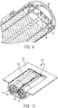
- the reusable battery indicator includes a housing 498, the integrated circuit, the voltage sensor, and the communication circuit being mounted within the housing 498.
- the housing 498 is sized and shaped to fit between two cylindrical battery cells 410 that are arranged longitudinally side-by-side.
- the housing 498 has a cross-section that is in the shape of a triangular prism. More specifically, the housing 498 has a first side 497 that is concave and a second side 499 that is concave.
- the housing 498 may have a shape such as rectangular, trapezoid, elliptical, semi-circular, and variable, that fits within the void described by the triangular prism.
- the reusable battery indicator 440 is mounted between the battery cells 410 and within a battery receptacle 495 of an electronic device 500.
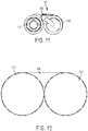
- FIG. 11 a seventh embodiment of a reusable battery indicator 540 is illustrated and located between two battery cells 510.
- the reusable battery indicator 540 includes a housing 598 that has only a single concave side.
- FIG. 12 illustrates an alternative housing shape.
- the housing 698 is arranged to fit in the void formed by two cylindrical battery cells 610 that are arranged side by side and oriented such that the respective longitudinal axes of the battery cells 610 are parallel to one another.
- a housing having a cross-sectional shape defined by the preceding equation maximizes the usable space between the battery cells.
- a housing having the cross-sectional shape defined above would result in the following housing volumes for the given battery sizes (assuming that the housing length was equal to the battery cell length).
- the housing would have a volume of 526 mm 3 ; and for a AA battery, the housing would have a volume of 1140 mm 3 .
- a computing device 800 is communicatively connected to the communication circuit in the reusable battery indicator 740.
- the computing device receives information from the communication circuit through wireless signals sent by the antenna in the reusable battery indicator 740.
- the wireless signal may be one or more of a wifi signal, a Bluetooth® signal, a RFID signal, or any other wireless signal.
- the computing device 800 and the reusable battery indicator 740 may communicatively connected by a wired connection.
- the computing device 800 includes a processor 802 and a memory 804.
- the memory 804 may store processor executable instructions that when executed by the processor 802 cause the processor 802 to detect a wireless communication signal from the reusable battery indicator 740.
- the memory 804 may comprise a non-transitory computer readable medium with the processor executable instructions embedded thereon as an article of manufacture.
- the processor executable instructions may also cause the processor 802 to send wireless signals back to the reusable battery indicator 740 to remotely control battery circuitry through the reusable battery indicator 740. In this manner, the processor 802 may cause the reusable battery indicator 740 to determine battery characteristic data; and to send the battery characteristic data to a user interface, such as a display 806 on the computing device 800.
- the battery characteristic data may comprise at least one of an electrical capacity; a voltage; an impedance, a temperature, a current; an age, a charge/discharge cycle count, and a coulomb count.
- the processor executable instructions when executed by the processor 802, causes the processor 802 to determine at least one of a battery type, a physical location of the battery, and an electrical device that the battery is powering by communicating with the reusuable battery indicator 740.
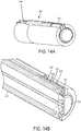
- the reusable battery indicator 940 includes a first connector 944 and a second connector 946.
- the first connector 944 connects to the negative terminal 924 of the battery 910 and the second connector 946 connects to the positive terminal of the battery 910.
- the first connector 944 includes an insulated leg 905 with an embedded wire 907.
- the insulated leg 905 includes an inner portion 909 that prevents the embedded wirer 907 from making contact with the crimped wall 961 of the battery housing 918.
- the embedded wire 907 is exposed at a radially inward end of the insulated leg 905 so that the embedded wire 907 may make electrical contact with the negative terminal 924, thus completing the electrical connection.
Landscapes
- Engineering & Computer Science (AREA)
- Manufacturing & Machinery (AREA)
- General Chemical & Material Sciences (AREA)
- Electrochemistry (AREA)
- Chemical Kinetics & Catalysis (AREA)
- Chemical & Material Sciences (AREA)
- Signal Processing (AREA)
- Physics & Mathematics (AREA)
- Computer Networks & Wireless Communication (AREA)
- General Physics & Mathematics (AREA)
- Microelectronics & Electronic Packaging (AREA)
- General Health & Medical Sciences (AREA)
- Medical Informatics (AREA)
- Computing Systems (AREA)
- Health & Medical Sciences (AREA)
- Battery Mounting, Suspending (AREA)
- Secondary Cells (AREA)
- Tests Of Electric Status Of Batteries (AREA)
Claims (15)
- Indicateur de batterie réutilisable (40) pour indiquer une caractéristique d'une batterie, l'indicateur de batterie réutilisable comprenant :un capteur de tension (50) configuré pour convertir les caractéristiques analogiques détectées d'une batterie en des informations numériques ;un circuit de communication (52) connecté de manière communicante au capteur de tension (50) ;une antenne (54) couplée fonctionnellement au circuit de communication (52) ; etun mécanisme de connexion comportant au moins un premier connecteur (44) comprenant un fil souple et un deuxième connecteur (46) comprenant un fil souple, chacun du premier connecteur (44) et du deuxième connecteur (46) étant connecté électriquement au capteur de tension (50), le premier connecteur (44) comprenant une première boucle d'extrémité (176) qui est dimensionnée et formée pour être connectée de manière amovible à une première borne de batterie et le deuxième connecteur (46) comprenant une boucle d'extrémité (182) qui est dimensionnée et formée pour être connectée de manière amovible à une deuxième borne de batterie, réalisant de ce fait un circuit électrique entre le capteur de tension (50) et les première et deuxième bornes de batterie lorsque le mécanisme de connexion est couplé à la première borne de batterie et à la deuxième borne de batterie.
- Indicateur de batterie réutilisable (40) selon la revendication 1, comprenant en outre un suramplificateur de tension (56) connecté électriquement au capteur de tension (50) .
- Indicateur de batterie réutilisable (40) selon la revendication 1, dans lequel au moins l'un du premier connecteur (44) et du deuxième connecteur (46) comprend au moins un métal et au moins un isolant.
- Indicateur de batterie réutilisable (40) selon la revendication 1, comprenant en outre une carte de circuit imprimé (42), dans lequel le capteur de tension (50) et le circuit de communication (52) sont formés sur la carte de circuit imprimé (42), et la carte de circuit imprimé (42) est disposée entre le premier connecteur (44) et le deuxième connecteur (46).
- Indicateur de batterie réutilisable (40) selon la revendication 1, dans lequel le premier connecteur (44) et le deuxième connecteur (46) comprennent l'un de fils élastiques souples ou d'aimants conducteurs.
- Indicateur de batterie réutilisable (40) selon la revendication 1, comprenant en outre un logement (498), le capteur de tension (50), et le circuit de communication (52) étant montés dans le logement (498), le logement (498) étant dimensionné et formé pour s'insérer entre deux batteries cylindriques qui sont agencées longitudinalement côte-à-côte.
- Indicateur de batterie réutilisable (40) selon la revendication 6, dans lequel le logement (498) a une section transversale qui a la forme d'un prisme triangulaire.
- Indicateur de batterie réutilisable (40) selon la revendication 6, dans lequel le logement (498) a un côté qui est concave.
- Indicateur de batterie réutilisable (40) selon la revendication 6, dans lequel le logement (498) a deux côtés qui sont concaves.
- Indicateur de batterie réutilisable (40) selon la revendication 1, dans lequel le capteur de tension (50) a la forme d'un disque et le capteur de tension (50) est agencé pour correspondre à une extrémité d'un élément de batterie cylindrique.
- Dispositif électronique comprenant l'indicateur de batterie réutilisable (40) selon la revendication 1, dans lequel un logement (498) de l'indicateur de batterie réutilisable (40) est monté dans un réceptacle de batterie d'un dispositif électronique.
- Système d'indication de batterie à distance, le système comprenant :une batterie (10) ; etl'indicateur de batterie réutilisable (40) selon la revendication 1,dans lequel le premier connecteur (44) et le deuxième connecteur (46) sont attachés électriquement à une première borne de batterie (24) et à une deuxième borne de batterie (26), respectivement, de la batterie (10), de sorte que le capteur de tension (50) détecte une caractéristique de la batterie (10).
- Système selon la revendication 12, comprenant en outre un dispositif informatique (800) qui est connecté de manière communicante au circuit de communication (52), le dispositif informatique (800) recevant des informations du circuit de communication (52) par l'intermédiaire de l'antenne (54).
- Système selon la revendication 13, dans lequel le dispositif informatique (800) comprend un processeur (802) et une mémoire (804), la mémoire (804) mémorisant un sous-programme logiciel qui amène le processeur (802) à détecter un signal de communication sans fil provenant de l'indicateur de batterie réutilisable (40), pour commander à distance des éléments de circuit de batterie par l'intermédiaire de l'indicateur de batterie réutilisable (40) pour déterminer des données de caractéristiques de batterie, et pour envoyer les données de caractéristiques de batterie à une interface utilisateur.
- Système selon la revendication 14, dans lequel le sous-programme logiciel, lorsqu'il est exécuté par le processeur (802), amène le processeur (802) à déterminer au moins l'un d'un type de batterie, d'un emplacement physique de la batterie, et d'un dispositif électrique que la batterie alimente.
Applications Claiming Priority (2)
| Application Number | Priority Date | Filing Date | Title |
|---|---|---|---|
| US15/340,757 US10608293B2 (en) | 2016-11-01 | 2016-11-01 | Dual sided reusable battery indicator |
| PCT/US2017/059472 WO2018085350A1 (fr) | 2016-11-01 | 2017-11-01 | Indicateur de batterie réutilisable double face |
Publications (2)
| Publication Number | Publication Date |
|---|---|
| EP3535801A1 EP3535801A1 (fr) | 2019-09-11 |
| EP3535801B1 true EP3535801B1 (fr) | 2020-09-09 |
Family
ID=60382611
Family Applications (1)
| Application Number | Title | Priority Date | Filing Date |
|---|---|---|---|
| EP17800664.9A Active EP3535801B1 (fr) | 2016-11-01 | 2017-11-01 | Indicateur de batterie réutilisable double face |
Country Status (6)
| Country | Link |
|---|---|
| US (3) | US10608293B2 (fr) |
| EP (1) | EP3535801B1 (fr) |
| JP (1) | JP7134954B2 (fr) |
| CN (1) | CN109891664B (fr) |
| AU (1) | AU2017355393B2 (fr) |
| WO (1) | WO2018085350A1 (fr) |
Families Citing this family (21)
| Publication number | Priority date | Publication date | Assignee | Title |
|---|---|---|---|---|
| US9551758B2 (en) | 2012-12-27 | 2017-01-24 | Duracell U.S. Operations, Inc. | Remote sensing of remaining battery capacity using on-battery circuitry |
| US9478850B2 (en) | 2013-05-23 | 2016-10-25 | Duracell U.S. Operations, Inc. | Omni-directional antenna for a cylindrical body |
| US9726763B2 (en) | 2013-06-21 | 2017-08-08 | Duracell U.S. Operations, Inc. | Systems and methods for remotely determining a battery characteristic |
| US9882250B2 (en) | 2014-05-30 | 2018-01-30 | Duracell U.S. Operations, Inc. | Indicator circuit decoupled from a ground plane |
| US10297875B2 (en) | 2015-09-01 | 2019-05-21 | Duracell U.S. Operations, Inc. | Battery including an on-cell indicator |
| US10483634B2 (en) | 2016-11-01 | 2019-11-19 | Duracell U.S. Operations, Inc. | Positive battery terminal antenna ground plane |
| US10151802B2 (en) | 2016-11-01 | 2018-12-11 | Duracell U.S. Operations, Inc. | Reusable battery indicator with electrical lock and key |
| US10608293B2 (en) * | 2016-11-01 | 2020-03-31 | Duracell U.S. Operations, Inc. | Dual sided reusable battery indicator |
| US10818979B2 (en) | 2016-11-01 | 2020-10-27 | Duracell U.S. Operations, Inc. | Single sided reusable battery indicator |
| US11024891B2 (en) | 2016-11-01 | 2021-06-01 | Duracell U.S. Operations, Inc. | Reusable battery indicator with lock and key mechanism |
| CN110896315A (zh) * | 2018-09-12 | 2020-03-20 | 宁德时代新能源科技股份有限公司 | 无线射频通信系统 |
| KR102274412B1 (ko) * | 2019-01-24 | 2021-07-07 | 주식회사 엘지에너지솔루션 | 배터리 특성 측정 장치 |
| CN110116623B (zh) * | 2019-04-30 | 2022-06-24 | 蜂巢能源科技有限公司 | 动力电池包的连接失效检测方法及电池管理系统 |
| US11265828B2 (en) * | 2019-08-21 | 2022-03-01 | Qualcomm Incorporated | Power allocation for sidelink feedback transmission |
| USD936568S1 (en) * | 2020-01-07 | 2021-11-23 | ShenZhen Mobai Technology Limited | Battery |
| USD941751S1 (en) * | 2020-01-16 | 2022-01-25 | Streamlight, Inc. | Battery with charging port and key way |
| USD949095S1 (en) * | 2020-08-14 | 2022-04-19 | Streamlight, Inc. | Battery with charging port and key way |
| US11837754B2 (en) * | 2020-12-30 | 2023-12-05 | Duracell U.S. Operations, Inc. | Magnetic battery cell connection mechanism |
| US11639789B2 (en) | 2021-01-13 | 2023-05-02 | Streamlight, Inc. | Portable light and keyed rechargeable USB battery |
| JP7333803B2 (ja) * | 2021-06-29 | 2023-08-25 | ソフトバンク株式会社 | 電源装置及び電源システム |
| WO2024020916A1 (fr) * | 2022-07-28 | 2024-02-01 | 宁德时代新能源科技股份有限公司 | Appareil d'échantillonnage, batterie, et dispositif électrique |
Family Cites Families (384)
| Publication number | Priority date | Publication date | Assignee | Title |
|---|---|---|---|---|
| US3354565A (en) | 1966-02-01 | 1967-11-28 | Texas Instruments Inc | Passive information displays |
| CH662773A4 (fr) | 1973-05-10 | 1976-02-27 | ||
| FR2290047A1 (fr) | 1974-10-31 | 1976-05-28 | Accumulateurs Fixes | Pile electrique comportant un indicateur visuel de son etat de charge |
| JPS525581A (en) | 1975-07-02 | 1977-01-17 | Hitachi Ltd | Voltage detector circuit |
| JPS5911911B2 (ja) | 1975-12-01 | 1984-03-19 | シチズン時計株式会社 | デンシコウガクテキヒヨウジタイノクドウホウホウ |
| JPS59107B2 (ja) | 1976-02-09 | 1984-01-05 | シチズン時計株式会社 | エレクトロクロミズム表示装置を備えた携帯用電子装置 |
| JPS5324798A (en) | 1976-08-20 | 1978-03-07 | Sharp Corp | Driving circuit of electrochromic display device |
| US4238554A (en) | 1979-09-04 | 1980-12-09 | Duracell International Inc. | Abuse resistant active metal anode/fluid cathode depolarized cells |
| US4460870A (en) | 1981-07-23 | 1984-07-17 | Curtis Instruments, Inc. | Quiescent voltage sampling battery state of charge meter |
| US4482615A (en) | 1982-09-30 | 1984-11-13 | Power Conversion, Inc. | Lithium anode comprising copper strip in contact with lithium body and lithium-sulfur dioxide battery utilizing same |
| JPS60121931A (ja) | 1983-12-06 | 1985-06-29 | 富士写真フイルム株式会社 | 直流電源装置 |
| US4808497A (en) | 1983-12-28 | 1989-02-28 | Eveready Battery Company | Organic electrolyte for nonaqueous cells |
| US4654280A (en) | 1984-12-27 | 1987-03-31 | Eveready Battery Company | Nonaqueous cell employing a cathode-electrolyte solution containing a boron-containing additive |
| JPS61169781A (ja) | 1985-01-23 | 1986-07-31 | Canon Inc | 画像形成装置 |
| US4759765A (en) | 1986-03-17 | 1988-07-26 | Minnesota Mining And Manufacturing Company | Tissue augmentation device |
| US4723656A (en) | 1987-06-04 | 1988-02-09 | Duracell Inc. | Battery package with battery condition indicator means |
| US4860185A (en) | 1987-08-21 | 1989-08-22 | Electronic Research Group, Inc. | Integrated uninterruptible power supply for personal computers |
| JPH02142324A (ja) | 1988-11-19 | 1990-05-31 | Fukuda Denshi Co Ltd | 電池残量表示装置 |
| US5015544A (en) | 1989-02-08 | 1991-05-14 | Strategic Energy Ltd. | Battery with strength indicator |
| US4952330A (en) | 1989-05-25 | 1990-08-28 | Eveready Battery Company, Inc. | Nonaqueous electrolyte |
| JP2667993B2 (ja) | 1989-10-17 | 1997-10-27 | セイコープレシジョン株式会社 | 電池電圧検出装置 |
| US5032825A (en) | 1990-03-02 | 1991-07-16 | Motorola, Inc. | Battery capacity indicator |
| US5219683A (en) | 1990-08-02 | 1993-06-15 | Eveready Battery Company, Inc. | Diol diesters and alkoxyalkylesters as solvents for nonaqueous battery electrolytes |
| JPH0625888Y2 (ja) * | 1990-08-15 | 1994-07-06 | 中村理科工業株式会社 | 乾電池コネクタ |
| US5654640A (en) | 1991-01-31 | 1997-08-05 | Eveready Battery Company | Cell tester device employing a printed transparent electrically conductive electrode |
| CA2056139C (fr) | 1991-01-31 | 2000-08-01 | John C. Bailey | Detecteur d'etat de charge a couche mince electrochromique a placer directement sur une pile |
| US5737114A (en) | 1991-01-31 | 1998-04-07 | Eveready Battery Company, Inc. | Label having an incorporated electrochromic state-of-charge indicator for an electrochemical cell |
| CA2054008A1 (fr) | 1991-01-31 | 1992-08-01 | Harry R. Huhndorff | Verificateur d'epuisement des batteries |
| JPH04334874A (ja) | 1991-05-13 | 1992-11-20 | Sony Corp | 電池式受信機 |
| US5188231A (en) | 1991-05-31 | 1993-02-23 | Duracell Inc. | Battery package with removable voltage indicator means |
| SG66286A1 (en) | 1991-07-16 | 1999-07-20 | Duracell Inc | Battery with integral condition tester |
| CA2072488C (fr) | 1991-08-13 | 2002-10-01 | Andrew Webber | Electrolytes non aqueux |
| IL102794A (en) * | 1991-09-24 | 1995-06-29 | Duracell Inc | Battery with electrochemical tester |
| US5355089A (en) | 1992-07-22 | 1994-10-11 | Duracell Inc. | Moisture barrier for battery with electrochemical tester |
| US5250905A (en) | 1991-09-24 | 1993-10-05 | Duracell Inc. | Battery with electrochemical tester |
| US5200686A (en) * | 1991-10-10 | 1993-04-06 | Motorola, Inc. | Method and apparatus for determining battery type |
| US5290414A (en) | 1992-05-15 | 1994-03-01 | Eveready Battery Company, Inc. | Separator/electrolyte combination for a nonaqueous cell |
| AU662822B2 (en) | 1992-06-01 | 1995-09-14 | Kuraray Co., Ltd. | Separator for alkaline batteries |
| US5231356A (en) | 1992-06-16 | 1993-07-27 | Robert Parker | Flexible battery tester with a variable length resistive heater |
| JP2727149B2 (ja) | 1992-09-14 | 1998-03-11 | エムアンドシー 株式会社 | バッテリー検査方法 |
| US5434396A (en) | 1992-11-10 | 1995-07-18 | Xicor Inc. | Wireless powering and communication system for communicating data between a host system and a stand-alone device |
| US5438607A (en) | 1992-11-25 | 1995-08-01 | U.S. Monitors, Ltd. | Programmable monitoring system and method |
| DE4241975C1 (de) | 1992-12-12 | 1994-04-21 | Braun Ag | Schaltungsanordnung zur Anzeige des Ladezustands einer Batterie |
| JPH06284170A (ja) | 1993-03-30 | 1994-10-07 | Fujitsu Ten Ltd | 相手先電源の監視機能付き通信装置、および相手先装置 |
| US5389458A (en) | 1993-05-03 | 1995-02-14 | Eveready Battery Company, Inc. | Battery with tester label and method for producing it |
| US5389470A (en) | 1993-05-07 | 1995-02-14 | Parker; Robert | Temperature responsive battery tester |
| WO1995001062A1 (fr) | 1993-06-28 | 1995-01-05 | Troyk Philip R | Systeme d'identification a distance pour contenants |
| US5418086A (en) | 1993-08-09 | 1995-05-23 | Eveready Battery Company, Inc. | Battery with coulometric state of charge indicator |
| CA2131358A1 (fr) | 1993-09-02 | 1995-03-03 | Jack S. Treger | Systeme de collage pour controleur de batterie |
| JPH07113855A (ja) | 1993-10-14 | 1995-05-02 | Oki Electric Ind Co Ltd | 電池種別検出装置 |
| US5514491A (en) | 1993-12-02 | 1996-05-07 | Eveready Battery Company, Inc. | Nonaqueous cell having a lithium iodide-ether electrolyte |
| US5458997A (en) | 1994-08-19 | 1995-10-17 | Medtronic, Inc. | Rebalancing of lithium/silver vandium oxide (Li/SVO) cells for improved performance |
| US5491038A (en) | 1994-08-24 | 1996-02-13 | Duracell Inc. | Contact ring for on-cell battery tester |
| US5578390A (en) | 1994-09-29 | 1996-11-26 | Duracell Inc. | Electrochemical cell label with integrated tester |
| US5449570A (en) | 1994-09-30 | 1995-09-12 | Globe-Union Inc. | Connection arrangement for battery monitoring circuits |
| CN1163020A (zh) | 1994-10-04 | 1997-10-22 | 杜拉塞奥公司 | 用于向外部设备报告电池参数的智能电池算法 |
| US5569556A (en) | 1994-12-30 | 1996-10-29 | Display Matrix Corporation | Battery charge indicator |
| US5593794A (en) | 1995-01-23 | 1997-01-14 | Duracell Inc. | Moisture barrier composite film of silicon nitride and fluorocarbon polymer and its use with an on-cell tester for an electrochemical cell |
| US5627472A (en) | 1995-01-26 | 1997-05-06 | Duracell Inc. | Condition tester for a battery |
| US5691083A (en) | 1995-06-07 | 1997-11-25 | Eveready Battery Company, Inc. | Potassium ion additives for voltage control and performance improvement in nonaqueous cells |
| FR2735870B1 (fr) | 1995-06-21 | 1997-09-05 | Sgs Thomson Microelectronics | Mesure numerique relative de haute precision d'une tension |
| US6184656B1 (en) * | 1995-06-28 | 2001-02-06 | Aevt, Inc. | Radio frequency energy management system |
| JP3384653B2 (ja) | 1995-07-28 | 2003-03-10 | 三洋電機株式会社 | パック電池 |
| US5640150A (en) | 1995-08-17 | 1997-06-17 | The United States Of America As Represented By The Secretary Of The Army | Resettable state-of-charge indicator for rechargeable batteries |
| US5596278A (en) | 1995-09-08 | 1997-01-21 | Duracell Inc. | Condition tester for a battery |
| US5626984A (en) * | 1995-11-16 | 1997-05-06 | Albini; Salvatore | Battery terminal system |
| US6774685B2 (en) | 1996-05-13 | 2004-08-10 | Micron Technology, Inc. | Radio frequency data communications device |
| JP3351682B2 (ja) | 1996-06-17 | 2002-12-03 | 日野自動車株式会社 | 車載電池の情報伝達装置 |
| US5786106A (en) | 1996-06-24 | 1998-07-28 | Armani; Shane | Battery pack with interchangeable tag-along supplemental feature cartridge particularly for cellular telephones |
| US5959568A (en) | 1996-06-26 | 1999-09-28 | Par Goverment Systems Corporation | Measuring distance |
| US6208235B1 (en) | 1997-03-24 | 2001-03-27 | Checkpoint Systems, Inc. | Apparatus for magnetically decoupling an RFID tag |
| KR100281538B1 (ko) | 1997-12-26 | 2001-02-15 | 윤종용 | 밧데리 사용가능시간 표시기능을 갖는 컴퓨터 |
| US5962158A (en) | 1997-07-21 | 1999-10-05 | Duracell Inc. | End cap assembly for electrochemical cell |
| US6156450A (en) | 1997-07-24 | 2000-12-05 | Eveready Battery Company, Inc. | Battery tester having printed electronic components |
| US6169397B1 (en) | 1997-08-13 | 2001-01-02 | University Technology Corp. | Damped superconducting coil system having a multiturn, planar geometry superconducting coil and shunt resistors electrically connecting successive coil turns |
| US6018326A (en) | 1997-09-29 | 2000-01-25 | Ericsson Inc. | Antennas with integrated windings |
| US7012504B2 (en) | 2002-04-01 | 2006-03-14 | Micron Technology, Inc. | Wireless identification device, RFID device with push-on/push off switch, and method of manufacturing wireless identification device |
| US6171729B1 (en) | 1998-01-02 | 2001-01-09 | Wilson Greatbatch Ltd | Control of swelling in alkali metal electrochemical cells |
| US6127062A (en) | 1998-03-24 | 2000-10-03 | Duracell Inc | End cap seal assembly for an electrochemical cell |
| US6835491B2 (en) | 1998-04-02 | 2004-12-28 | The Board Of Trustees Of The University Of Illinois | Battery having a built-in controller |
| US5963012A (en) | 1998-07-13 | 1999-10-05 | Motorola, Inc. | Wireless battery charging system having adaptive parameter sensing |
| US6084523A (en) | 1998-07-13 | 2000-07-04 | The United States Of America As Represented By The Secretary Of The Army | Non-intrusive battery status indicator and inventory system |
| USRE38518E1 (en) | 1998-08-21 | 2004-05-18 | Eveready Battery Company, Inc. | Battery constructions having increased internal volume for active components |
| US6265101B1 (en) | 1998-08-21 | 2001-07-24 | Eveready Battery Company, Inc. | Battery constructions having increased internal volume for active components |
| US6300004B1 (en) | 1998-08-21 | 2001-10-09 | Eveready Battery Company, Inc. | Battery constructions having reduced collector assembly volume |
| JP4168486B2 (ja) * | 1998-08-25 | 2008-10-22 | 日産自動車株式会社 | 電気自動車のバッテリコントローラ格納構造および格納方法 |
| EP1116315A4 (fr) | 1998-08-28 | 2002-08-07 | Invensys Energy Systems Nz Ltd | Technique et appareil permettant de mesurer la charge d'une batterie et de predire le temps restant avant dechargement |
| JP2000077928A (ja) | 1998-09-03 | 2000-03-14 | Lintec Corp | ループアンテナ及びデータキャリア |
| GB9820132D0 (en) | 1998-09-16 | 1998-11-11 | Raychem Ltd | Battery over-discharge protection |
| GB9820271D0 (en) | 1998-09-17 | 1998-11-11 | Simoco Int Ltd | A method of and apparatus for monitoring the condition of batteries used by a mobile radio telecommunications fleet |
| DE19944517A1 (de) | 1998-09-18 | 2000-05-25 | C K Electronics Sdn Bhd | Verfahren und Vorrichtung für die Zustandsbestimmung von Automobilbatterien |
| US6014014A (en) | 1998-10-28 | 2000-01-11 | Hewlett-Packard Company | State-of-charge-measurable batteries |
| JP3607105B2 (ja) | 1999-01-26 | 2005-01-05 | 本田技研工業株式会社 | バッテリ残容量検出装置 |
| US7039533B2 (en) | 1999-04-08 | 2006-05-02 | Midtronics, Inc. | Battery test module |
| US7058525B2 (en) | 1999-04-08 | 2006-06-06 | Midtronics, Inc. | Battery test module |
| US6483275B1 (en) | 1999-04-23 | 2002-11-19 | The Board Of Trustees Of The Univesity Of Illinois | Consumer battery having a built-in indicator |
| US6979502B1 (en) | 1999-06-21 | 2005-12-27 | Board Of Trustees Of The University Of Illinois | Battery having a housing for electronic circuitry |
| JP2001022905A (ja) | 1999-07-08 | 2001-01-26 | Hitachi Maxell Ltd | Icカード装置 |
| US6208114B1 (en) | 1999-07-22 | 2001-03-27 | Dallas Semiconductor Corporation | Battery monitoring system with integrated battery holder |
| JP2001093510A (ja) | 1999-09-28 | 2001-04-06 | Yazaki Corp | バッテリの電源線接続構造 |
| JP2004085580A (ja) | 1999-11-24 | 2004-03-18 | Seiko Epson Corp | 電圧検出装置 |
| GB2359203B (en) | 2000-02-09 | 2004-09-01 | Mitel Semiconductor Ab | CMOS Low battery voltage detector |
| US6775562B1 (en) | 2000-04-17 | 2004-08-10 | Sbc Properties, Lp | Remote battery replacement notification system and method |
| GB2363899A (en) | 2000-06-19 | 2002-01-09 | Ever Ready Ltd | Alkaline electrochemical cells |
| US6627353B1 (en) | 2000-11-08 | 2003-09-30 | Lithium Power Technologies, Inc. | Disposable lithium batteries |
| US7045250B2 (en) | 2000-11-13 | 2006-05-16 | Sanyo Electric Co., Ltd. | Non-aqueous electrolyte battery |
| US6407534B1 (en) | 2001-02-06 | 2002-06-18 | Quallion Llc | Detecting a microcurrent and a microcurrent detecting circuit |
| DE60214833T2 (de) | 2001-03-07 | 2007-09-06 | Acreo Ab | Elektrochromische einrichtung |
| EP1693807A1 (fr) | 2001-03-19 | 2006-08-23 | Escort Memory Systems | Procédé et système de suivi de RFID |
| EP1377945A4 (fr) | 2001-03-19 | 2005-10-26 | Escort Memory Systems | Procede et systeme de poursuite par identification radiofrequence |
| DE10118027B4 (de) | 2001-04-11 | 2005-11-10 | Daimlerchrysler Ag | Batteriemessklemme mit Fremdstartstützpunkt und integrierter Meßsensorik |
| DE10118051B4 (de) | 2001-04-11 | 2005-09-29 | Daimlerchrysler Ag | Batterienmessklemme mit Fremdstartstützpunkt |
| US6730136B2 (en) | 2001-10-01 | 2004-05-04 | Eveready Battery Company, Inc. | Direct addition of beta-aminoenones in organic electrolytes of nonaqueous cells employing solid cathodes |
| EP1461629A4 (fr) | 2001-11-27 | 2006-03-22 | Xsilogy Inc | Systeme et capteurs de telesurveillance de batteries |
| US6617072B2 (en) | 2001-11-27 | 2003-09-09 | Ovonic Battery Company, Inc. | Positive active electrode composition with graphite additive |
| US20050112462A1 (en) | 2003-11-21 | 2005-05-26 | Marple Jack W. | High discharge capacity lithium battery |
| JP2003264009A (ja) | 2001-12-19 | 2003-09-19 | Midtronics Inc | バッテリテストモジュール |
| US6690171B2 (en) | 2002-03-05 | 2004-02-10 | Chicony Electronics Co., Ltd. | Battery capacity detection device and method |
| FR2837985B1 (fr) | 2002-04-02 | 2004-05-21 | Commissariat Energie Atomique | Antenne receptrice morcelee |
| US7123204B2 (en) | 2002-04-24 | 2006-10-17 | Forster Ian J | Energy source communication employing slot antenna |
| US6849360B2 (en) | 2002-06-05 | 2005-02-01 | Eveready Battery Company, Inc. | Nonaqueous electrochemical cell with improved energy density |
| US20040048512A1 (en) | 2002-09-11 | 2004-03-11 | Carl Chen | Quick coupler for cylindrical battery terminal |
| AU2003274571A1 (en) | 2002-11-15 | 2004-06-15 | Koninklijke Philips Electronics N.V. | Wireless battery management system |
| US20040189256A1 (en) | 2003-02-14 | 2004-09-30 | Alcatel | Reusable state of charge indicator |
| JP2004253858A (ja) | 2003-02-18 | 2004-09-09 | Minerva:Kk | Icタグ用のブースタアンテナ装置 |
| JP4215538B2 (ja) | 2003-02-28 | 2009-01-28 | 三洋電機株式会社 | 二次電池 |
| US8310201B1 (en) * | 2003-05-06 | 2012-11-13 | Cypress Semiconductor Corporation | Battery with electronic compartment |
| US7388350B1 (en) | 2003-05-06 | 2008-06-17 | Cypress Semiconductor Corporation | Battery with electronic compartment |
| WO2004107251A2 (fr) | 2003-05-23 | 2004-12-09 | Symbol Technologies, Inc. | Relais d'identification par radiofrequence (rfid) et procedes de retransmission d'un signal rfid |
| EP1652199A2 (fr) | 2003-07-23 | 2006-05-03 | Koninklijke Philips Electronics N.V. | Elements inductifs et capacitifs pour technologies de dispositifs semi-conducteurs a exigences minimales en matiere de densite de circuits |
| US7067882B2 (en) | 2003-08-28 | 2006-06-27 | Lsi Logic Corporation | High quality factor spiral inductor that utilizes active negative capacitance |
| CN1529182A (zh) | 2003-10-01 | 2004-09-15 | 复旦大学 | 有源射频识别标签卡电池的电量识别与充电方法 |
| US20050073282A1 (en) | 2003-10-03 | 2005-04-07 | Carrier David A. | Methods of discharge control for a battery pack of a cordless power tool system, a cordless power tool system and battery pack adapted to provide over-discharge protection and discharge control |
| US6990171B2 (en) | 2003-10-27 | 2006-01-24 | General Electric Company | System and method of determining a user-defined region-of-interest of an imaging subject for x-ray flux management control |
| JP2005141998A (ja) | 2003-11-05 | 2005-06-02 | Sony Corp | リチウム/二硫化鉄一次電池 |
| US8283071B2 (en) | 2003-11-21 | 2012-10-09 | Eveready Battery Company, Inc. | High discharge capacity lithium battery |
| US8124274B2 (en) | 2003-11-21 | 2012-02-28 | Eveready Battery Company, Inc. | High discharge capacity lithium battery |
| US20050233214A1 (en) | 2003-11-21 | 2005-10-20 | Marple Jack W | High discharge capacity lithium battery |
| US7612472B2 (en) | 2004-01-23 | 2009-11-03 | American Power Conversion Corporation | Method and apparatus for monitoring energy storage devices |
| JP4206348B2 (ja) | 2004-01-27 | 2009-01-07 | 株式会社マキタ | 電池パック及び電動工具 |
| WO2005078673A1 (fr) | 2004-02-03 | 2005-08-25 | Sys Technologies, Inc. | Systeme de surveillance de batteries a distance comprenant des telecapteurs integres |
| US7417599B2 (en) | 2004-02-20 | 2008-08-26 | 3M Innovative Properties Company | Multi-loop antenna for radio frequency identification (RFID) communication |
| US7928059B2 (en) | 2004-02-24 | 2011-04-19 | Wisconsin Alumni Research Foundation | Use of neuropeptides for traumatic cartilage injury |
| US8427109B2 (en) | 2004-04-06 | 2013-04-23 | Chevron Technology Ventures Llc | Battery state of charge reset |
| JP3851639B2 (ja) | 2004-05-14 | 2006-11-29 | 東芝テック株式会社 | 無線タグ読取装置 |
| US7199555B2 (en) | 2004-05-19 | 2007-04-03 | Chien Hung Taiwan Ltd. | Portable emergency vehicle battery charger with microprocessor |
| KR100599795B1 (ko) | 2004-06-29 | 2006-07-12 | 삼성에스디아이 주식회사 | 이차 전지 |
| US7079079B2 (en) | 2004-06-30 | 2006-07-18 | Skycross, Inc. | Low profile compact multi-band meanderline loaded antenna |
| US7772850B2 (en) | 2004-07-12 | 2010-08-10 | Midtronics, Inc. | Wireless battery tester with information encryption means |
| US7521896B2 (en) * | 2004-07-20 | 2009-04-21 | Panasonic Ev Energy Co., Ltd. | Abnormal voltage detector apparatus for detecting voltage abnormality in assembled battery |
| US7746242B2 (en) | 2004-07-21 | 2010-06-29 | Honeywell International Inc. | Low battery indicator |
| US8344685B2 (en) | 2004-08-20 | 2013-01-01 | Midtronics, Inc. | System for automatically gathering battery information |
| US20060046154A1 (en) | 2004-08-27 | 2006-03-02 | Eveready Battery Company, Inc. | Low temperature Li/FeS2 battery |
| US7510808B2 (en) | 2004-08-27 | 2009-03-31 | Eveready Battery Company, Inc. | Low temperature Li/FeS2 battery |
| US20060046153A1 (en) | 2004-08-27 | 2006-03-02 | Andrew Webber | Low temperature Li/FeS2 battery |
| US20060047576A1 (en) | 2004-08-30 | 2006-03-02 | Nokia Corporation | Automated memory and accessory purchasing agent for use in a mobile terminal |
| US20060043933A1 (en) | 2004-08-31 | 2006-03-02 | Latinis Gary R | Battery voltage monitor |
| WO2006030332A2 (fr) | 2004-09-16 | 2006-03-23 | Koninklijke Philips Electronics N.V. | Bobines de reception de signaux de resonance magnetique avec composants inductifs compacts |
| KR100657381B1 (ko) * | 2004-10-21 | 2006-12-14 | 주식회사 서비전자 | 무선 단거리 통신 기술을 이용한 배터리 모뎀 |
| EP1828794B1 (fr) | 2004-11-08 | 2018-08-22 | Koninklijke Philips N.V. | Gestion de l'etat d'une batterie sans fil pour dispositifs medicaux |
| JP2006139544A (ja) | 2004-11-12 | 2006-06-01 | Seiko Epson Corp | アクティブrfid−tag |
| US7576517B1 (en) | 2004-11-29 | 2009-08-18 | Data Power Monitoring Corporation | System and method for remote monitoring of battery condition |
| JP5019031B2 (ja) | 2004-11-30 | 2012-09-05 | 新神戸電機株式会社 | 蓄電池ユニット |
| US7554294B2 (en) | 2005-01-28 | 2009-06-30 | The Johns Hopkins University | Battery health monitor |
| JP2008530682A (ja) | 2005-02-14 | 2008-08-07 | ビジブル アセッツ,インク. | 低周波数タグおよびシステム |
| US20060208898A1 (en) | 2005-03-04 | 2006-09-21 | Intelleflex Corporation | Compact omnidirectional RF system |
| JP3838258B2 (ja) | 2005-03-10 | 2006-10-25 | ソニー株式会社 | バッテリー残量表示方法 |
| US7598880B2 (en) | 2005-03-14 | 2009-10-06 | Liebert Corporation | Wireless battery monitoring system and method |
| JP2006284431A (ja) | 2005-04-01 | 2006-10-19 | Nissan Motor Co Ltd | 二次電池の充電率推定装置 |
| DE102005017682A1 (de) | 2005-04-08 | 2006-10-12 | Varta Microbattery Gmbh | Galvanisches Element |
| JP2006324074A (ja) | 2005-05-18 | 2006-11-30 | Matsushita Electric Ind Co Ltd | 電池に対する情報記録方法及びその装置 |
| US7386404B2 (en) | 2005-05-27 | 2008-06-10 | Savi Technology, Inc. | Method and apparatus for monitoring battery discharge state |
| US7911182B2 (en) | 2005-05-27 | 2011-03-22 | Savi Technology, Inc. | Method and apparatus for detecting a battery voltage |
| US20070045018A1 (en) | 2005-08-25 | 2007-03-01 | Carter Scott J | Systems and methods for controlling powered vehicles near a restricted region |
| JPWO2007023933A1 (ja) | 2005-08-26 | 2009-03-26 | パナソニック株式会社 | アルカリ乾電池 |
| CN2828963Y (zh) | 2005-09-22 | 2006-10-18 | 中达电通股份有限公司 | 无线式电池监控系统 |
| FR2891091B1 (fr) | 2005-09-22 | 2008-01-11 | Commissariat Energie Atomique | Antenne plane omnidirectionnelle et procede de fabrication |
| US20070080804A1 (en) | 2005-10-07 | 2007-04-12 | Edwin Hirahara | Systems and methods for enhanced RFID tag performance |
| US7715884B2 (en) | 2005-10-14 | 2010-05-11 | Research In Motion Limited | Mobile device with a smart battery having a battery information profile corresponding to a communication standard |
| US7531989B2 (en) | 2005-11-02 | 2009-05-12 | 02Micro International Ltd. | Battery fuel gauge circuit |
| JP5039980B2 (ja) | 2005-11-14 | 2012-10-03 | 日立ビークルエナジー株式会社 | 二次電池モジュール |
| JP2007171045A (ja) | 2005-12-22 | 2007-07-05 | Panasonic Ev Energy Co Ltd | 電池用制御装置及び二次電池の分極電圧推定方法 |
| JP4892962B2 (ja) | 2005-12-22 | 2012-03-07 | オムロン株式会社 | Rfid用の交信中継装置および交信処理装置 |
| US20070182576A1 (en) | 2006-02-09 | 2007-08-09 | 1673892 Ontario, Inc. | Remote battery monitoring |
| US8026698B2 (en) | 2006-02-09 | 2011-09-27 | Scheucher Karl F | Scalable intelligent power supply system and method |
| JP5041395B2 (ja) * | 2006-02-13 | 2012-10-03 | 古河電気工業株式会社 | 電流センサ付バッテリーターミナル |
| EP2690586B1 (fr) | 2006-02-22 | 2017-07-19 | Toyo Seikan Kaisha, Ltd. | Substrat d'étiquette RFID pour composant métallique |
| US7331708B2 (en) | 2006-02-23 | 2008-02-19 | National Semiconductor Corporation | Frequency ratio digitizing temperature sensor with linearity correction |
| US20070210924A1 (en) | 2006-03-10 | 2007-09-13 | Wavezero, Inc. | RFID Smart Label with Reduced Layers and Method of Production |
| US7606530B1 (en) | 2006-03-11 | 2009-10-20 | Rockwell Collins, Inc. | RFID system for allowing access to remotely positioned RFID tags |
| US7561050B2 (en) | 2006-06-28 | 2009-07-14 | International Business Machines Corporation | System and method to automate placement of RFID repeaters |
| US20080076029A1 (en) | 2006-07-27 | 2008-03-27 | Bowden William L | Battery |
| US7768236B2 (en) | 2006-07-28 | 2010-08-03 | Panasonic Corporation | Electrical device and battery pack for preventing polarity reversal of battery |
| JP4890993B2 (ja) | 2006-08-02 | 2012-03-07 | 株式会社東海理化電機製作所 | 電動車両の蓄電池装置 |
| CN101126795A (zh) | 2006-08-14 | 2008-02-20 | 英业达股份有限公司 | 电池性能测试系统 |
| US7741806B2 (en) * | 2006-08-25 | 2010-06-22 | Meridian Design, Inc. | Magnetically attachable battery recharging |
| EP1906506B1 (fr) | 2006-09-29 | 2009-04-22 | W & H Dentalwerk Bürmoos GmbH | Dispositif pour charger des accumulateurs |
| US8162230B2 (en) | 2006-10-17 | 2012-04-24 | Powerid Ltd. | Method and circuit for providing RF isolation of a power source from an antenna and an RFID device employing such a circuit |
| KR100982852B1 (ko) | 2006-10-20 | 2010-09-16 | 주식회사 케이티 | Rfid를 이용한 이동체 실시간 위치 결정 시스템 및 그방법과, 그를 위한 무선중계장치 설치 방법 |
| EP1921496A1 (fr) | 2006-11-08 | 2008-05-14 | Acreo AB | Dispositif électrochromique |
| GB0623108D0 (en) | 2006-11-20 | 2006-12-27 | Sericol Ltd | A printable composition |
| US20100030592A1 (en) | 2006-11-30 | 2010-02-04 | Mobilocity Solutions LLC | Transmitting information from a mobile device to a point of sale or point of use |
| JP5164491B2 (ja) | 2006-12-29 | 2013-03-21 | 三洋電機株式会社 | 筒形電池 |
| US20080160392A1 (en) | 2006-12-29 | 2008-07-03 | Shoichi Toya | Cylindrical battery |
| US7741970B2 (en) | 2006-12-31 | 2010-06-22 | At&T Intellectual Property Ii, L.P. | Method and apparatus for a radio frequency identification repeater |
| US8941496B2 (en) | 2007-01-03 | 2015-01-27 | Intelleflex Corporation | Long range RFID device for battery monitoring and systems implementing same |
| US8054160B2 (en) | 2007-03-09 | 2011-11-08 | Innovation Law Group, Ltd. | RFID tag power conservation system and method |
| US8493187B2 (en) | 2007-03-15 | 2013-07-23 | Endotronix, Inc. | Wireless sensor reader |
| US8031054B2 (en) | 2007-03-27 | 2011-10-04 | Round Rock Research, Llc | Multi-antenna element systems and related methods |
| JP4839257B2 (ja) | 2007-04-11 | 2011-12-21 | 株式会社日立製作所 | Rfidタグ |
| US8147280B2 (en) | 2007-06-04 | 2012-04-03 | Lear Corporation | Battery post connector |
| US20080312782A1 (en) | 2007-06-15 | 2008-12-18 | Gene Berdichevsky | Electric vehicle communication interface |
| US20080311795A1 (en) | 2007-06-15 | 2008-12-18 | Brotto Daniele C | Adapter for cordless power tools |
| US20090009177A1 (en) | 2007-07-02 | 2009-01-08 | Nesscap Co., Ltd. | Voltage monitoring method and circuit for electrical energy storage device |
| US9076331B2 (en) | 2007-07-16 | 2015-07-07 | Crucs Holdings, Llc | System and method to monitor vehicles on a roadway and to control driving restrictions of vehicle drivers |
| JP2009037374A (ja) | 2007-08-01 | 2009-02-19 | Nec Personal Products Co Ltd | 電子タグを備えた電子機器 |
| US8900731B2 (en) | 2007-08-24 | 2014-12-02 | Motorola Solutions, Inc. | Charger system for communication devices using a charger circuit to communicate a charge status to a portable host device |
| WO2009070663A1 (fr) | 2007-11-26 | 2009-06-04 | Gwacs Defense, Inc. | Système de batterie intelligente et procédés d'utilisation |
| JP5179851B2 (ja) | 2007-11-30 | 2013-04-10 | オーツー マイクロ, インコーポレーテッド | 埋め込まれたセルモニタを備えるバッテリパック、電子システム、およびバッテリパックを監視するための方法 |
| US8131486B2 (en) | 2007-11-30 | 2012-03-06 | Btech, Inc. | Networked battery monitors |
| US8617743B2 (en) | 2007-12-05 | 2013-12-31 | The Gillette Company | Anode balanced lithium-iron disulfide primary cell |
| US20090155673A1 (en) | 2007-12-12 | 2009-06-18 | Daniel Ross Northcott | Battery Management System |
| JP2009151953A (ja) | 2007-12-18 | 2009-07-09 | Mitsumi Electric Co Ltd | 電池パック及び電子機器 |
| CN201142022Y (zh) | 2007-12-18 | 2008-10-29 | 瑞德电能股份有限公司 | 电动车辆的电池模块的远程控制系统 |
| TW200933180A (en) | 2008-01-16 | 2009-08-01 | Dhc Specialty Corp | Detachable battery status alarm and its miniature battery status detector |
| US20090214950A1 (en) | 2008-02-22 | 2009-08-27 | Bowden William L | Lithium cell |
| WO2009107597A1 (fr) | 2008-02-29 | 2009-09-03 | 日産自動車株式会社 | Dispositif de surveillance d'ensemble de cellules |
| US8164528B2 (en) | 2008-03-26 | 2012-04-24 | Dockon Ag | Self-contained counterpoise compound loop antenna |
| CN201233435Y (zh) | 2008-03-27 | 2009-05-06 | 兰州太格维尔电子有限公司 | 蓄电池剩余容量测试仪 |
| GB0805596D0 (en) | 2008-03-27 | 2008-04-30 | British Telecomm | Tagged cable |
| US8076028B2 (en) | 2008-04-16 | 2011-12-13 | The Gillette Company | Lithium cell with cathode including iron disulfide and iron sulfide |
| US7456606B1 (en) | 2008-04-23 | 2008-11-25 | International Business Machines Corporation | Battery label with wireless battery charging circuit |
| US8400297B2 (en) | 2008-05-05 | 2013-03-19 | Round Rock Research, Llc | Power conserving active RFID label |
| US7642942B2 (en) | 2008-05-21 | 2010-01-05 | Honeywell International Inc. | Systems and methods for synthesis of a signal |
| US20090297949A1 (en) | 2008-05-29 | 2009-12-03 | Berkowitz Fred J | Lithium Primary Cells |
| JP5549121B2 (ja) | 2008-06-17 | 2014-07-16 | 三洋電機株式会社 | 組電池の電圧検出装置及びこれを具えたバッテリシステム |
| US8305034B2 (en) | 2008-07-23 | 2012-11-06 | Lear Corporation | Battery monitoring system |
| JP2010081716A (ja) | 2008-09-25 | 2010-04-08 | Toshiba Corp | 電池情報取得装置 |
| US8529345B2 (en) | 2008-10-02 | 2013-09-10 | Igt | Gaming system including a gaming table with mobile user input devices |
| CN101714647B (zh) | 2008-10-08 | 2012-11-28 | 株式会社牧田 | 电动工具用蓄电池匣以及电动工具 |
| JP4843658B2 (ja) | 2008-10-09 | 2011-12-21 | フェリカネットワークス株式会社 | バッテリパック及び情報処理装置 |
| JP5195263B2 (ja) | 2008-10-14 | 2013-05-08 | 凸版印刷株式会社 | 情報伝達媒体管理システム |
| DE202008017318U1 (de) | 2008-12-08 | 2009-06-18 | Auto-Kabel Managementgesellschaft Mbh | Batteriemessklemme |
| KR101009526B1 (ko) | 2008-12-10 | 2011-01-18 | 삼성에스디아이 주식회사 | 배터리 팩 |
| US8417472B2 (en) | 2008-12-19 | 2013-04-09 | 02Micro Inc. | Synchronized data sampling systems and methods |
| JP2010154012A (ja) | 2008-12-24 | 2010-07-08 | Nec Corp | Rfidタグ用識別システム |
| JP5560290B2 (ja) | 2009-02-05 | 2014-07-23 | マグナ−ラスティック ディヴァイシーズ、インコーポレイテッド | 充電状態をモニタリングするための装置及び方法、バッテリ充電状態センサを含むlfpバッテリ |
| KR101023884B1 (ko) | 2009-02-18 | 2011-03-22 | 삼성에스디아이 주식회사 | 배터리팩 |
| PT104482A (pt) | 2009-04-01 | 2010-10-01 | Univ Nova De Lisboa | Método de fabrico e criação de transístores de filme fino electrocrómicos de estrutura lateral ou vertical utilizando substratos vitrocerâmicos, poliméricos, metálicos ou de papel celulósico natural, sintético ou misto funcionalizados ou não funciona |
| KR100928563B1 (ko) | 2009-04-08 | 2009-11-25 | 태성전장주식회사 | 자동차용 배터리 전류 검출장치 |
| CN101552363A (zh) | 2009-05-07 | 2009-10-07 | 许皓程 | 一种具有电压显示功能的电池装置 |
| WO2010127509A1 (fr) | 2009-05-08 | 2010-11-11 | Confidex Ltd. | Transpondeur rfid |
| EP2285068B1 (fr) | 2009-08-07 | 2014-06-25 | BlackBerry Limited | Procédé, dispositif mobile et support lisible par ordinateur pour téléprésence mobile |
| KR20110018488A (ko) | 2009-08-18 | 2011-02-24 | 김창식 | Rfid를 이용한 차량용 배터리 이력관리 시스템 및 그 방법 |
| US8374507B2 (en) * | 2009-09-18 | 2013-02-12 | Fluke Corporation | Digital multimeter having remote display with automatic communication binding |
| CN101702792B (zh) | 2009-10-27 | 2011-01-19 | 北京交通大学 | 纯电动公交车电池参数传输装置 |
| US20110104520A1 (en) | 2009-11-02 | 2011-05-05 | Changbum Ahn | Secondary battery and battery pack using the same |
| US20130183568A1 (en) | 2009-11-18 | 2013-07-18 | Susan J. Babinec | Composite separator for electrochemical cell and method for its manufacture |
| US8119286B2 (en) | 2009-11-24 | 2012-02-21 | The Gillette Company | Electrochemical cells with improved separator and electrolyte |
| CN102074722A (zh) | 2009-11-24 | 2011-05-25 | 中兴通讯股份有限公司 | 手持设备电池及手持设备 |
| JP2011113759A (ja) | 2009-11-25 | 2011-06-09 | Diamond Electric Mfg Co Ltd | バッテリー管理装置とバッテリー管理方法 |
| EP2328173B1 (fr) | 2009-11-26 | 2016-03-30 | Nxp B.V. | Batterie intégrée et circuit intégré |
| US8390249B2 (en) | 2009-11-30 | 2013-03-05 | Broadcom Corporation | Battery with integrated wireless power receiver and/or RFID |
| US8575939B2 (en) | 2010-01-07 | 2013-11-05 | Paul JANOUSEK | Apparatuses and methods for determining potential energy stored in an electrochemical cell |
| JP5448865B2 (ja) | 2010-01-18 | 2014-03-19 | 三菱重工業株式会社 | 電池システム |
| US20120308849A1 (en) | 2010-02-05 | 2012-12-06 | Alelion Batteries Ab | Battery assembly |
| US9425487B2 (en) * | 2010-03-03 | 2016-08-23 | Midtronics, Inc. | Monitor for front terminal batteries |
| JP2011203595A (ja) | 2010-03-26 | 2011-10-13 | Fujifilm Corp | 無線通信型カセッテのバッテリ管理装置およびシステム、並びに方法 |
| JP5686555B2 (ja) | 2010-09-08 | 2015-03-18 | 富士機械製造株式会社 | 製造システム構築方法 |
| JP5303528B2 (ja) | 2010-09-16 | 2013-10-02 | カルソニックカンセイ株式会社 | フィルタによるパラメータ推定装置 |
| CA2811802A1 (fr) | 2010-09-20 | 2012-03-29 | Fariborz Frankie Roohparvar | Structure et procede d'augmentation de la duree de vie d'une pile |
| US20120086615A1 (en) | 2010-10-12 | 2012-04-12 | John Peter Norair | Method and Apparatus for an Integrated Antenna |
| JP4929389B2 (ja) | 2010-10-14 | 2012-05-09 | 三菱重工業株式会社 | 電池システム |
| US20120183862A1 (en) | 2010-10-21 | 2012-07-19 | Eastman Chemical Company | Battery separator |
| JP6147668B2 (ja) | 2010-11-02 | 2017-06-14 | ナビタス ソリューションズ,インコーポレイテッド | スマート電池管理システムのための無線電池エリアネットワーク |
| JP5757111B2 (ja) | 2010-11-19 | 2015-07-29 | ソニー株式会社 | 二次電池セル、電池パック及び電力消費機器 |
| JP2012129183A (ja) | 2010-11-26 | 2012-07-05 | Sony Corp | 二次電池セル、電池パック及び電力消費機器 |
| JP5796289B2 (ja) | 2010-11-26 | 2015-10-21 | ソニー株式会社 | 二次電池セル、電池パック及び電力消費機器 |
| CN201927640U (zh) | 2010-12-22 | 2011-08-10 | 中兴通讯股份有限公司 | 一种集成天线的电池和移动终端 |
| JP2012146447A (ja) | 2011-01-11 | 2012-08-02 | Toyota Industries Corp | 電池異常検出システム及び電池異常検出方法 |
| CN102097844B (zh) | 2011-01-17 | 2015-08-19 | 余维 | 一种智能电池管理系统 |
| FR2970832B1 (fr) | 2011-01-21 | 2013-08-23 | St Microelectronics Rousset | Indicateur de niveau de batterie par telephone portable |
| US8648752B2 (en) | 2011-02-11 | 2014-02-11 | Pulse Finland Oy | Chassis-excited antenna apparatus and methods |
| JP5633745B2 (ja) | 2011-02-15 | 2014-12-03 | ソニー株式会社 | 電池、電池パック、充電器、および充電システム |
| JP5620302B2 (ja) | 2011-02-17 | 2014-11-05 | 株式会社富士通ソーシアルサイエンスラボラトリ | 二次電池劣化検出システム、電源接続機器、情報処理装置、二次電池劣化検出方法及びプログラム |
| US9178570B2 (en) | 2011-02-28 | 2015-11-03 | Blackberry Limited | NFC system providing battery power level measurement features and related methods |
| CN102142186B (zh) | 2011-03-01 | 2013-01-09 | 合肥国轩高科动力能源有限公司 | 锂电池组远程监控系统 |
| CN103392133A (zh) | 2011-03-07 | 2013-11-13 | 株式会社日立制作所 | 电池状态推定方法和电池管理系统 |
| US8917214B2 (en) | 2011-03-16 | 2014-12-23 | Avery Dennison Corporation | Dual band RFID device and method of formulation |
| US8761885B2 (en) | 2011-04-29 | 2014-06-24 | Cyberonics, Inc. | Battery life estimation based on voltage depletion rate |
| US9037426B2 (en) | 2011-05-13 | 2015-05-19 | GM Global Technology Operations LLC | Systems and methods for determining cell capacity values in a multi-cell battery |
| US9060213B2 (en) | 2011-05-24 | 2015-06-16 | Spireon, Inc. | Battery monitoring system |
| JP5739244B2 (ja) | 2011-06-14 | 2015-06-24 | 矢崎総業株式会社 | 電池状態通知ユニット、バスバモジュール、組電池、及び、電池状態監視システム |
| US9167317B2 (en) | 2011-06-23 | 2015-10-20 | Edward DeMar | Battery monitoring system |
| US20130164567A1 (en) | 2011-06-24 | 2013-06-27 | Seektech, Inc. | Modular battery pack apparatus, systems, and methods |
| US20130069768A1 (en) | 2011-07-20 | 2013-03-21 | Maitreya Visweswara Madhyastha | Systems, devices, methods and computer-readable storage media that facilitate control of battery-powered devices |
| US9146595B2 (en) | 2011-08-05 | 2015-09-29 | Qualcomm Incorporated | Systems and methods for remotely monitoring or controlling a battery |
| JP2013038961A (ja) | 2011-08-09 | 2013-02-21 | Panasonic Corp | 電子機器、バッテリおよびバッテリ特定方法 |
| JP5798407B2 (ja) | 2011-08-09 | 2015-10-21 | Fdk株式会社 | 非接触充電対応型二次電池 |
| WO2013024341A1 (fr) | 2011-08-17 | 2013-02-21 | King Abdullah University Of Science And Technology | Composants passifs à base de pcl miniaturisés, de haute qualité |
| JP5641006B2 (ja) | 2011-08-31 | 2014-12-17 | ソニー株式会社 | 蓄電装置 |
| US9015513B2 (en) | 2011-11-03 | 2015-04-21 | Vocollect, Inc. | Receiving application specific individual battery adjusted battery use profile data upon loading of work application for managing remaining power of a mobile device |
| CN202308203U (zh) | 2011-11-04 | 2012-07-04 | 广州明美电子有限公司 | 一种轻型电动车的串联锂电池组 |
| EP2778699A4 (fr) | 2011-11-08 | 2015-07-29 | Shin Kobe Electric Machinery | Système de surveillance d'état de batterie |
| US20130127611A1 (en) | 2011-11-20 | 2013-05-23 | Battery Marvel, Llc. | Battery marvel 1.0 |
| JP5247874B2 (ja) | 2011-12-06 | 2013-07-24 | パナソニック株式会社 | 蓄電池移転支援装置および蓄電池移転支援方法 |
| CN102544709B (zh) | 2011-12-21 | 2014-07-30 | 上海坤锐电子科技有限公司 | 一种移动支付转接桥的通信距离均衡的转接桥天线 |
| US20130162402A1 (en) | 2011-12-27 | 2013-06-27 | Mathias Amann | Apparatus and Method for Providing Product Information |
| CN102709494A (zh) | 2012-01-04 | 2012-10-03 | 瑞声声学科技(深圳)有限公司 | 电池组件 |
| EP2807699A2 (fr) | 2012-01-23 | 2014-12-03 | Avery Dennison Corporation | Étiquettes et accessoires pour cellules électrochimiques |
| JP2013158148A (ja) * | 2012-01-30 | 2013-08-15 | Sharp Corp | 充電装置 |
| US9869726B2 (en) | 2012-05-22 | 2018-01-16 | Lawrence Livermore National Security, Llc | Wireless battery management control and monitoring system |
| US9331378B2 (en) | 2012-05-29 | 2016-05-03 | Nxp B.V. | Active load modulation antenna |
| US8905317B1 (en) | 2012-06-07 | 2014-12-09 | Amazon Technologies, Inc. | Co-located passive UHF RFID tag and NFC antenna in compact electronic devices |
| CN202720320U (zh) | 2012-06-08 | 2013-02-06 | 低碳动能开发股份有限公司 | 二次电池主动式监控装置 |
| US20140107853A1 (en) | 2012-06-26 | 2014-04-17 | Black & Decker Inc. | System for enhancing power tools |
| US9619612B2 (en) | 2012-10-15 | 2017-04-11 | Battery Technology Holdings, Llc | Tester for equipment, apparatus, or component with distributed processing function |
| TWI580153B (zh) | 2012-11-13 | 2017-04-21 | 電池監控系統 | |
| US9793616B2 (en) | 2012-11-19 | 2017-10-17 | Apple Inc. | Shared antenna structures for near-field communications and non-near-field communications circuitry |
| JP5766683B2 (ja) | 2012-12-21 | 2015-08-19 | 三菱重工業株式会社 | 電池状態監視装置及びこれを備えた電池モジュール |
| US9551758B2 (en) | 2012-12-27 | 2017-01-24 | Duracell U.S. Operations, Inc. | Remote sensing of remaining battery capacity using on-battery circuitry |
| CN104919642B (zh) | 2013-01-11 | 2018-03-20 | 株式会社半导体能源研究所 | 电子设备充电方法 |
| US10870360B2 (en) | 2013-02-12 | 2020-12-22 | Cps Technology Holdings Llc | Battery monitoring network |
| US9013323B2 (en) | 2013-03-15 | 2015-04-21 | Crown Equipment Corporation | Pairing of a battery monitor to a communication device |
| US8901888B1 (en) * | 2013-07-16 | 2014-12-02 | Christopher V. Beckman | Batteries for optimizing output and charge balance with adjustable, exportable and addressable characteristics |
| JP2014197805A (ja) | 2013-03-29 | 2014-10-16 | 日立オートモティブシステムズ株式会社 | 電池システム |
| JP2014203584A (ja) | 2013-04-02 | 2014-10-27 | 株式会社Gsユアサ | 蓄電装置 |
| US9083063B2 (en) | 2013-04-03 | 2015-07-14 | The Gillette Company | Electrochemical cell including an integrated circuit |
| US20140302348A1 (en) * | 2013-04-03 | 2014-10-09 | The Gillette Company | Electrochemical cell including an integrated circuit |
| US20140302347A1 (en) * | 2013-04-03 | 2014-10-09 | The Gillette Company | Electrochemical cell including an integrated circuit |
| US9312575B2 (en) | 2013-05-16 | 2016-04-12 | Midtronics, Inc. | Battery testing system and method |
| US20140342193A1 (en) | 2013-05-17 | 2014-11-20 | Tenergy Corporation | Smart battery system |
| US9478850B2 (en) | 2013-05-23 | 2016-10-25 | Duracell U.S. Operations, Inc. | Omni-directional antenna for a cylindrical body |
| US9673621B2 (en) | 2013-05-23 | 2017-06-06 | Powerful Battery Solutions LLC | Enhanced battery system and method |
| US9726763B2 (en) | 2013-06-21 | 2017-08-08 | Duracell U.S. Operations, Inc. | Systems and methods for remotely determining a battery characteristic |
| US9285430B2 (en) | 2013-08-29 | 2016-03-15 | Ford Global Technologies, Llc | Monitor system and method for stored battery |
| KR101720614B1 (ko) | 2013-08-30 | 2017-03-28 | 삼성에스디아이 주식회사 | 배터리 팩 |
| CN104427037A (zh) | 2013-09-06 | 2015-03-18 | 中兴通讯股份有限公司 | 一种终端 |
| KR102105170B1 (ko) | 2013-10-24 | 2020-04-24 | 삼성전자주식회사 | 전자장치, 입력장치 및 그 배터리 잔량 결정방법 |
| WO2015066626A1 (fr) * | 2013-11-01 | 2015-05-07 | Batteroo, Inc. | Procédés destinés à prolonger la durée de vie d'une batterie |
| CN103682482A (zh) | 2013-11-22 | 2014-03-26 | 超威电源有限公司 | 一种无线智能电池 |
| US9543623B2 (en) | 2013-12-11 | 2017-01-10 | Duracell U.S. Operations, Inc. | Battery condition indicator |
| US9235044B2 (en) | 2014-01-29 | 2016-01-12 | The Gillette Company | Light activated power indicator |
| TWM510009U (zh) | 2014-03-14 | 2015-10-01 | zhi-hong Wu | 無線電池管理系統 |
| KR101493829B1 (ko) | 2014-03-27 | 2015-02-16 | 삼성에스디아이 주식회사 | 전지 팩 |
| JP6353070B2 (ja) | 2014-04-01 | 2018-07-04 | 深▲せん▼市智輪電動車駆動技術有限公司 | 動力電池及びその電池セル状態収集装置 |
| US9882250B2 (en) | 2014-05-30 | 2018-01-30 | Duracell U.S. Operations, Inc. | Indicator circuit decoupled from a ground plane |
| US20160277879A1 (en) | 2014-06-10 | 2016-09-22 | Pb Inc | Battery beacon systems and methods of use |
| JP6351393B2 (ja) * | 2014-06-13 | 2018-07-04 | セイコーインスツル株式会社 | 電池モジュールの製造方法および携帯電子機器の製造方法 |
| CN204011808U (zh) * | 2014-07-03 | 2014-12-10 | 钟明 | 一种接线端子 |
| US9823310B2 (en) | 2014-07-25 | 2017-11-21 | Duracell U.S. Operations, Inc. | Battery state of charge indicator with an indicator circuit |
| US9568556B2 (en) | 2014-07-25 | 2017-02-14 | Duracell U.S. Operations, Inc. | Battery state of charge indicator with an auxiliary cell |
| KR101679913B1 (ko) | 2014-08-12 | 2016-11-25 | 현대자동차주식회사 | 배터리 모듈 |
| US9893390B2 (en) * | 2014-08-27 | 2018-02-13 | Duracell U.S. Operations, Inc. | Battery pack including an indicator circuit |
| US9746524B2 (en) | 2014-09-12 | 2017-08-29 | Measurement Ltd. | System and method for monitoring battery status |
| US10102507B2 (en) | 2014-09-25 | 2018-10-16 | Google Llc | Systems and methods to faciliate replacement of depleted batteries |
| KR102229824B1 (ko) | 2014-11-19 | 2021-03-22 | 현대모비스 주식회사 | Ibs 장치 |
| KR20160065613A (ko) | 2014-12-01 | 2016-06-09 | 삼성전자주식회사 | 전압 측정 장치 및 전압 센서 |
| EP3235266B1 (fr) | 2014-12-18 | 2020-10-14 | Widex A/S | Système et procédé pour gérer des pièces de remplacement pour une aide auditive |
| US9843220B2 (en) | 2015-01-28 | 2017-12-12 | Motorola Solutions, Inc. | Method and apparatus for operating an internal charger system of a portable electronic device |
| CN104635169A (zh) | 2015-03-04 | 2015-05-20 | 姚锋 | 一种采用蓝牙技术联接智能手机的蓄电池能量监测装置 |
| JP6444223B2 (ja) | 2015-03-04 | 2018-12-26 | ルネサスエレクトロニクス株式会社 | 無線送信装置及び無線受信装置 |
| CN106033803B (zh) | 2015-03-18 | 2019-06-14 | 阿里巴巴集团控股有限公司 | 电池套筒、待寻找设备定位方法及装置 |
| WO2016166735A1 (fr) | 2015-04-17 | 2016-10-20 | Gp Batteries International Limited | Batteries intelligentes |
| WO2016172542A1 (fr) | 2015-04-24 | 2016-10-27 | Prong, Inc. | Système de charge électronique |
| CN204538140U (zh) * | 2015-04-30 | 2015-08-05 | 贾建国 | 一种正极为集成式结构的锂电池 |
| US10297875B2 (en) | 2015-09-01 | 2019-05-21 | Duracell U.S. Operations, Inc. | Battery including an on-cell indicator |
| US20170062841A1 (en) | 2015-09-01 | 2017-03-02 | Duracell U.S. Operations, Inc. | Battery including an on-cell indicator |
| US20170092994A1 (en) | 2015-09-25 | 2017-03-30 | Intel Corporation | Smart battery with integrated sensing and electronics |
| CN105337367A (zh) | 2015-11-28 | 2016-02-17 | 惠州市蓝微新源技术有限公司 | 一种基于移动终端监控电池包的系统 |
| CN205160145U (zh) | 2015-11-28 | 2016-04-13 | 惠州市蓝微新源技术有限公司 | 一种基于移动终端监控电池包的系统 |
| US20170176539A1 (en) | 2015-12-16 | 2017-06-22 | Centurylink Intellectual Property Llc | Wireless Capable Battery |
| US10411306B2 (en) | 2016-04-19 | 2019-09-10 | GM Global Technology Operations LLC | Battery module with integrated RF communication and cell sensing board |
| US20170315183A1 (en) | 2016-04-29 | 2017-11-02 | Global Technology Systems, Inc. | Battery pack tester and connected app for bluetooth connected smart device |
| AU2017263851B2 (en) | 2016-05-13 | 2023-03-30 | Schumacher Electric Corporation | Battery state detection system and method |
| CN106405241A (zh) | 2016-08-31 | 2017-02-15 | 天津市畅和科技有限公司 | 一种蓄电池内阻远程检测app监测系统 |
| US10608293B2 (en) | 2016-11-01 | 2020-03-31 | Duracell U.S. Operations, Inc. | Dual sided reusable battery indicator |
| US10151802B2 (en) | 2016-11-01 | 2018-12-11 | Duracell U.S. Operations, Inc. | Reusable battery indicator with electrical lock and key |
| US11024891B2 (en) | 2016-11-01 | 2021-06-01 | Duracell U.S. Operations, Inc. | Reusable battery indicator with lock and key mechanism |
| US10818979B2 (en) | 2016-11-01 | 2020-10-27 | Duracell U.S. Operations, Inc. | Single sided reusable battery indicator |
| US10483634B2 (en) | 2016-11-01 | 2019-11-19 | Duracell U.S. Operations, Inc. | Positive battery terminal antenna ground plane |
| CN106848448A (zh) | 2017-01-12 | 2017-06-13 | 深圳市信宇人科技有限公司 | 基于无线传输方式的锂离子动力电池在线监测方法及其动力电池 |
| CN206804833U (zh) | 2017-04-18 | 2017-12-26 | 巫协森 | 智能电池管理装置 |
| CN107284272A (zh) | 2017-07-10 | 2017-10-24 | 刘玲玲 | 一种动力电池监测装置及方法 |
-
2016
- 2016-11-01 US US15/340,757 patent/US10608293B2/en active Active
-
2017
- 2017-11-01 WO PCT/US2017/059472 patent/WO2018085350A1/fr active Search and Examination
- 2017-11-01 AU AU2017355393A patent/AU2017355393B2/en active Active
- 2017-11-01 CN CN201780068058.1A patent/CN109891664B/zh active Active
- 2017-11-01 JP JP2019522300A patent/JP7134954B2/ja active Active
- 2017-11-01 EP EP17800664.9A patent/EP3535801B1/fr active Active
-
2020
- 2020-03-30 US US16/834,827 patent/US11024892B2/en active Active
- 2020-12-28 US US17/135,759 patent/US11664539B2/en active Active
Non-Patent Citations (1)
| Title |
|---|
| None * |
Also Published As
| Publication number | Publication date |
|---|---|
| CN109891664B (zh) | 2022-10-18 |
| JP7134954B2 (ja) | 2022-09-12 |
| US11664539B2 (en) | 2023-05-30 |
| AU2017355393B2 (en) | 2023-02-23 |
| US20180123175A1 (en) | 2018-05-03 |
| US11024892B2 (en) | 2021-06-01 |
| WO2018085350A1 (fr) | 2018-05-11 |
| CN109891664A (zh) | 2019-06-14 |
| US20200227790A1 (en) | 2020-07-16 |
| EP3535801A1 (fr) | 2019-09-11 |
| US10608293B2 (en) | 2020-03-31 |
| JP2020517042A (ja) | 2020-06-11 |
| US20210119270A1 (en) | 2021-04-22 |
| AU2017355393A1 (en) | 2019-05-23 |
Similar Documents
| Publication | Publication Date | Title |
|---|---|---|
| US11664539B2 (en) | Dual sided reusable battery indicator | |
| EP3535798B1 (fr) | Indicateur de batterie réutilisable avec mécanisme de verrouillage et de touche | |
| EP3535800B1 (fr) | Indicateur de batterie réutilisable à serrure électrique et clé | |
| EP3535799B1 (fr) | Indicateur de batterie réutilisable à un seul côté |
Legal Events
| Date | Code | Title | Description |
|---|---|---|---|
| STAA | Information on the status of an ep patent application or granted ep patent |
Free format text: STATUS: UNKNOWN |
|
| STAA | Information on the status of an ep patent application or granted ep patent |
Free format text: STATUS: THE INTERNATIONAL PUBLICATION HAS BEEN MADE |
|
| PUAI | Public reference made under article 153(3) epc to a published international application that has entered the european phase |
Free format text: ORIGINAL CODE: 0009012 |
|
| STAA | Information on the status of an ep patent application or granted ep patent |
Free format text: STATUS: REQUEST FOR EXAMINATION WAS MADE |
|
| 17P | Request for examination filed |
Effective date: 20190528 |
|
| AK | Designated contracting states |
Kind code of ref document: A1 Designated state(s): AL AT BE BG CH CY CZ DE DK EE ES FI FR GB GR HR HU IE IS IT LI LT LU LV MC MK MT NL NO PL PT RO RS SE SI SK SM TR |
|
| AX | Request for extension of the european patent |
Extension state: BA ME |
|
| DAV | Request for validation of the european patent (deleted) | ||
| DAX | Request for extension of the european patent (deleted) | ||
| GRAP | Despatch of communication of intention to grant a patent |
Free format text: ORIGINAL CODE: EPIDOSNIGR1 |
|
| STAA | Information on the status of an ep patent application or granted ep patent |
Free format text: STATUS: GRANT OF PATENT IS INTENDED |
|
| INTG | Intention to grant announced |
Effective date: 20200331 |
|
| GRAS | Grant fee paid |
Free format text: ORIGINAL CODE: EPIDOSNIGR3 |
|
| GRAA | (expected) grant |
Free format text: ORIGINAL CODE: 0009210 |
|
| STAA | Information on the status of an ep patent application or granted ep patent |
Free format text: STATUS: THE PATENT HAS BEEN GRANTED |
|
| AK | Designated contracting states |
Kind code of ref document: B1 Designated state(s): AL AT BE BG CH CY CZ DE DK EE ES FI FR GB GR HR HU IE IS IT LI LT LU LV MC MK MT NL NO PL PT RO RS SE SI SK SM TR |
|
| REG | Reference to a national code |
Ref country code: GB Ref legal event code: FG4D |
|
| REG | Reference to a national code |
Ref country code: AT Ref legal event code: REF Ref document number: 1312702 Country of ref document: AT Kind code of ref document: T Effective date: 20200915 Ref country code: CH Ref legal event code: EP |
|
| REG | Reference to a national code |
Ref country code: IE Ref legal event code: FG4D |
|
| REG | Reference to a national code |
Ref country code: DE Ref legal event code: R096 Ref document number: 602017023457 Country of ref document: DE |
|
| REG | Reference to a national code |
Ref country code: LT Ref legal event code: MG4D |
|
| PG25 | Lapsed in a contracting state [announced via postgrant information from national office to epo] |
Ref country code: FI Free format text: LAPSE BECAUSE OF FAILURE TO SUBMIT A TRANSLATION OF THE DESCRIPTION OR TO PAY THE FEE WITHIN THE PRESCRIBED TIME-LIMIT Effective date: 20200909 Ref country code: GR Free format text: LAPSE BECAUSE OF FAILURE TO SUBMIT A TRANSLATION OF THE DESCRIPTION OR TO PAY THE FEE WITHIN THE PRESCRIBED TIME-LIMIT Effective date: 20201210 Ref country code: LT Free format text: LAPSE BECAUSE OF FAILURE TO SUBMIT A TRANSLATION OF THE DESCRIPTION OR TO PAY THE FEE WITHIN THE PRESCRIBED TIME-LIMIT Effective date: 20200909 Ref country code: BG Free format text: LAPSE BECAUSE OF FAILURE TO SUBMIT A TRANSLATION OF THE DESCRIPTION OR TO PAY THE FEE WITHIN THE PRESCRIBED TIME-LIMIT Effective date: 20201209 Ref country code: NO Free format text: LAPSE BECAUSE OF FAILURE TO SUBMIT A TRANSLATION OF THE DESCRIPTION OR TO PAY THE FEE WITHIN THE PRESCRIBED TIME-LIMIT Effective date: 20201209 Ref country code: HR Free format text: LAPSE BECAUSE OF FAILURE TO SUBMIT A TRANSLATION OF THE DESCRIPTION OR TO PAY THE FEE WITHIN THE PRESCRIBED TIME-LIMIT Effective date: 20200909 Ref country code: SE Free format text: LAPSE BECAUSE OF FAILURE TO SUBMIT A TRANSLATION OF THE DESCRIPTION OR TO PAY THE FEE WITHIN THE PRESCRIBED TIME-LIMIT Effective date: 20200909 |
|
| REG | Reference to a national code |
Ref country code: AT Ref legal event code: MK05 Ref document number: 1312702 Country of ref document: AT Kind code of ref document: T Effective date: 20200909 |
|
| REG | Reference to a national code |
Ref country code: NL Ref legal event code: MP Effective date: 20200909 |
|
| PG25 | Lapsed in a contracting state [announced via postgrant information from national office to epo] |
Ref country code: PL Free format text: LAPSE BECAUSE OF FAILURE TO SUBMIT A TRANSLATION OF THE DESCRIPTION OR TO PAY THE FEE WITHIN THE PRESCRIBED TIME-LIMIT Effective date: 20200909 Ref country code: RS Free format text: LAPSE BECAUSE OF FAILURE TO SUBMIT A TRANSLATION OF THE DESCRIPTION OR TO PAY THE FEE WITHIN THE PRESCRIBED TIME-LIMIT Effective date: 20200909 Ref country code: LV Free format text: LAPSE BECAUSE OF FAILURE TO SUBMIT A TRANSLATION OF THE DESCRIPTION OR TO PAY THE FEE WITHIN THE PRESCRIBED TIME-LIMIT Effective date: 20200909 |
|
| PG25 | Lapsed in a contracting state [announced via postgrant information from national office to epo] |
Ref country code: SM Free format text: LAPSE BECAUSE OF FAILURE TO SUBMIT A TRANSLATION OF THE DESCRIPTION OR TO PAY THE FEE WITHIN THE PRESCRIBED TIME-LIMIT Effective date: 20200909 Ref country code: CZ Free format text: LAPSE BECAUSE OF FAILURE TO SUBMIT A TRANSLATION OF THE DESCRIPTION OR TO PAY THE FEE WITHIN THE PRESCRIBED TIME-LIMIT Effective date: 20200909 Ref country code: RO Free format text: LAPSE BECAUSE OF FAILURE TO SUBMIT A TRANSLATION OF THE DESCRIPTION OR TO PAY THE FEE WITHIN THE PRESCRIBED TIME-LIMIT Effective date: 20200909 Ref country code: PT Free format text: LAPSE BECAUSE OF FAILURE TO SUBMIT A TRANSLATION OF THE DESCRIPTION OR TO PAY THE FEE WITHIN THE PRESCRIBED TIME-LIMIT Effective date: 20210111 Ref country code: EE Free format text: LAPSE BECAUSE OF FAILURE TO SUBMIT A TRANSLATION OF THE DESCRIPTION OR TO PAY THE FEE WITHIN THE PRESCRIBED TIME-LIMIT Effective date: 20200909 |
|
| PG25 | Lapsed in a contracting state [announced via postgrant information from national office to epo] |
Ref country code: IS Free format text: LAPSE BECAUSE OF FAILURE TO SUBMIT A TRANSLATION OF THE DESCRIPTION OR TO PAY THE FEE WITHIN THE PRESCRIBED TIME-LIMIT Effective date: 20210109 Ref country code: AT Free format text: LAPSE BECAUSE OF FAILURE TO SUBMIT A TRANSLATION OF THE DESCRIPTION OR TO PAY THE FEE WITHIN THE PRESCRIBED TIME-LIMIT Effective date: 20200909 Ref country code: AL Free format text: LAPSE BECAUSE OF FAILURE TO SUBMIT A TRANSLATION OF THE DESCRIPTION OR TO PAY THE FEE WITHIN THE PRESCRIBED TIME-LIMIT Effective date: 20200909 Ref country code: ES Free format text: LAPSE BECAUSE OF FAILURE TO SUBMIT A TRANSLATION OF THE DESCRIPTION OR TO PAY THE FEE WITHIN THE PRESCRIBED TIME-LIMIT Effective date: 20200909 |
|
| REG | Reference to a national code |
Ref country code: DE Ref legal event code: R097 Ref document number: 602017023457 Country of ref document: DE |
|
| PG25 | Lapsed in a contracting state [announced via postgrant information from national office to epo] |
Ref country code: MC Free format text: LAPSE BECAUSE OF FAILURE TO SUBMIT A TRANSLATION OF THE DESCRIPTION OR TO PAY THE FEE WITHIN THE PRESCRIBED TIME-LIMIT Effective date: 20200909 Ref country code: SK Free format text: LAPSE BECAUSE OF FAILURE TO SUBMIT A TRANSLATION OF THE DESCRIPTION OR TO PAY THE FEE WITHIN THE PRESCRIBED TIME-LIMIT Effective date: 20200909 |
|
| REG | Reference to a national code |
Ref country code: CH Ref legal event code: PL |
|
| PLBE | No opposition filed within time limit |
Free format text: ORIGINAL CODE: 0009261 |
|
| STAA | Information on the status of an ep patent application or granted ep patent |
Free format text: STATUS: NO OPPOSITION FILED WITHIN TIME LIMIT |
|
| PG25 | Lapsed in a contracting state [announced via postgrant information from national office to epo] |
Ref country code: LU Free format text: LAPSE BECAUSE OF NON-PAYMENT OF DUE FEES Effective date: 20201101 |
|
| 26N | No opposition filed |
Effective date: 20210610 |
|
| PG25 | Lapsed in a contracting state [announced via postgrant information from national office to epo] |
Ref country code: CH Free format text: LAPSE BECAUSE OF NON-PAYMENT OF DUE FEES Effective date: 20201130 Ref country code: SI Free format text: LAPSE BECAUSE OF FAILURE TO SUBMIT A TRANSLATION OF THE DESCRIPTION OR TO PAY THE FEE WITHIN THE PRESCRIBED TIME-LIMIT Effective date: 20200909 Ref country code: DK Free format text: LAPSE BECAUSE OF FAILURE TO SUBMIT A TRANSLATION OF THE DESCRIPTION OR TO PAY THE FEE WITHIN THE PRESCRIBED TIME-LIMIT Effective date: 20200909 Ref country code: LI Free format text: LAPSE BECAUSE OF NON-PAYMENT OF DUE FEES Effective date: 20201130 |
|
| PG25 | Lapsed in a contracting state [announced via postgrant information from national office to epo] |
Ref country code: IE Free format text: LAPSE BECAUSE OF NON-PAYMENT OF DUE FEES Effective date: 20201101 Ref country code: IT Free format text: LAPSE BECAUSE OF FAILURE TO SUBMIT A TRANSLATION OF THE DESCRIPTION OR TO PAY THE FEE WITHIN THE PRESCRIBED TIME-LIMIT Effective date: 20200909 |
|
| PG25 | Lapsed in a contracting state [announced via postgrant information from national office to epo] |
Ref country code: TR Free format text: LAPSE BECAUSE OF FAILURE TO SUBMIT A TRANSLATION OF THE DESCRIPTION OR TO PAY THE FEE WITHIN THE PRESCRIBED TIME-LIMIT Effective date: 20200909 Ref country code: MT Free format text: LAPSE BECAUSE OF FAILURE TO SUBMIT A TRANSLATION OF THE DESCRIPTION OR TO PAY THE FEE WITHIN THE PRESCRIBED TIME-LIMIT Effective date: 20200909 Ref country code: CY Free format text: LAPSE BECAUSE OF FAILURE TO SUBMIT A TRANSLATION OF THE DESCRIPTION OR TO PAY THE FEE WITHIN THE PRESCRIBED TIME-LIMIT Effective date: 20200909 |
|
| PG25 | Lapsed in a contracting state [announced via postgrant information from national office to epo] |
Ref country code: MK Free format text: LAPSE BECAUSE OF FAILURE TO SUBMIT A TRANSLATION OF THE DESCRIPTION OR TO PAY THE FEE WITHIN THE PRESCRIBED TIME-LIMIT Effective date: 20200909 |
|
| P01 | Opt-out of the competence of the unified patent court (upc) registered |
Effective date: 20230524 |
|
| PG25 | Lapsed in a contracting state [announced via postgrant information from national office to epo] |
Ref country code: NL Free format text: LAPSE BECAUSE OF NON-PAYMENT OF DUE FEES Effective date: 20200923 |
|
| PGFP | Annual fee paid to national office [announced via postgrant information from national office to epo] |
Ref country code: GB Payment date: 20230907 Year of fee payment: 7 |
|
| PGFP | Annual fee paid to national office [announced via postgrant information from national office to epo] |
Ref country code: FR Payment date: 20230911 Year of fee payment: 7 |
|
| PGFP | Annual fee paid to national office [announced via postgrant information from national office to epo] |
Ref country code: DE Payment date: 20230912 Year of fee payment: 7 |
|
| PGFP | Annual fee paid to national office [announced via postgrant information from national office to epo] |
Ref country code: BE Payment date: 20231016 Year of fee payment: 7 |