EP3421066B1 - Injector and method of assembly - Google Patents
Injector and method of assembly Download PDFInfo
- Publication number
- EP3421066B1 EP3421066B1 EP18186736.7A EP18186736A EP3421066B1 EP 3421066 B1 EP3421066 B1 EP 3421066B1 EP 18186736 A EP18186736 A EP 18186736A EP 3421066 B1 EP3421066 B1 EP 3421066B1
- Authority
- EP
- European Patent Office
- Prior art keywords
- container
- needle
- sterile
- wall
- injector
- Prior art date
- Legal status (The legal status is an assumption and is not a legal conclusion. Google has not performed a legal analysis and makes no representation as to the accuracy of the status listed.)
- Active
Links
Images


Classifications
-
- A—HUMAN NECESSITIES
- A61—MEDICAL OR VETERINARY SCIENCE; HYGIENE
- A61M—DEVICES FOR INTRODUCING MEDIA INTO, OR ONTO, THE BODY; DEVICES FOR TRANSDUCING BODY MEDIA OR FOR TAKING MEDIA FROM THE BODY; DEVICES FOR PRODUCING OR ENDING SLEEP OR STUPOR
- A61M5/00—Devices for bringing media into the body in a subcutaneous, intra-vascular or intramuscular way; Accessories therefor, e.g. filling or cleaning devices, arm-rests
- A61M5/178—Syringes
- A61M5/24—Ampoule syringes, i.e. syringes with needle for use in combination with replaceable ampoules or carpules, e.g. automatic
- A61M5/2455—Ampoule syringes, i.e. syringes with needle for use in combination with replaceable ampoules or carpules, e.g. automatic with sealing means to be broken or opened
- A61M5/2466—Ampoule syringes, i.e. syringes with needle for use in combination with replaceable ampoules or carpules, e.g. automatic with sealing means to be broken or opened by piercing without internal pressure increase
-
- A—HUMAN NECESSITIES
- A61—MEDICAL OR VETERINARY SCIENCE; HYGIENE
- A61M—DEVICES FOR INTRODUCING MEDIA INTO, OR ONTO, THE BODY; DEVICES FOR TRANSDUCING BODY MEDIA OR FOR TAKING MEDIA FROM THE BODY; DEVICES FOR PRODUCING OR ENDING SLEEP OR STUPOR
- A61M5/00—Devices for bringing media into the body in a subcutaneous, intra-vascular or intramuscular way; Accessories therefor, e.g. filling or cleaning devices, arm-rests
- A61M5/178—Syringes
- A61M5/1782—Devices aiding filling of syringes in situ
-
- A—HUMAN NECESSITIES
- A61—MEDICAL OR VETERINARY SCIENCE; HYGIENE
- A61M—DEVICES FOR INTRODUCING MEDIA INTO, OR ONTO, THE BODY; DEVICES FOR TRANSDUCING BODY MEDIA OR FOR TAKING MEDIA FROM THE BODY; DEVICES FOR PRODUCING OR ENDING SLEEP OR STUPOR
- A61M5/00—Devices for bringing media into the body in a subcutaneous, intra-vascular or intramuscular way; Accessories therefor, e.g. filling or cleaning devices, arm-rests
- A61M5/178—Syringes
- A61M5/28—Syringe ampoules or carpules, i.e. ampoules or carpules provided with a needle
- A61M5/285—Syringe ampoules or carpules, i.e. ampoules or carpules provided with a needle with sealing means to be broken or opened
- A61M5/288—Syringe ampoules or carpules, i.e. ampoules or carpules provided with a needle with sealing means to be broken or opened by piercing without internal pressure increase
-
- A—HUMAN NECESSITIES
- A61—MEDICAL OR VETERINARY SCIENCE; HYGIENE
- A61M—DEVICES FOR INTRODUCING MEDIA INTO, OR ONTO, THE BODY; DEVICES FOR TRANSDUCING BODY MEDIA OR FOR TAKING MEDIA FROM THE BODY; DEVICES FOR PRODUCING OR ENDING SLEEP OR STUPOR
- A61M5/00—Devices for bringing media into the body in a subcutaneous, intra-vascular or intramuscular way; Accessories therefor, e.g. filling or cleaning devices, arm-rests
- A61M5/178—Syringes
- A61M5/31—Details
- A61M5/315—Pistons; Piston-rods; Guiding, blocking or restricting the movement of the rod or piston; Appliances on the rod for facilitating dosing ; Dosing mechanisms
-
- A—HUMAN NECESSITIES
- A61—MEDICAL OR VETERINARY SCIENCE; HYGIENE
- A61M—DEVICES FOR INTRODUCING MEDIA INTO, OR ONTO, THE BODY; DEVICES FOR TRANSDUCING BODY MEDIA OR FOR TAKING MEDIA FROM THE BODY; DEVICES FOR PRODUCING OR ENDING SLEEP OR STUPOR
- A61M5/00—Devices for bringing media into the body in a subcutaneous, intra-vascular or intramuscular way; Accessories therefor, e.g. filling or cleaning devices, arm-rests
- A61M5/178—Syringes
- A61M5/24—Ampoule syringes, i.e. syringes with needle for use in combination with replaceable ampoules or carpules, e.g. automatic
- A61M5/2455—Ampoule syringes, i.e. syringes with needle for use in combination with replaceable ampoules or carpules, e.g. automatic with sealing means to be broken or opened
- A61M5/2466—Ampoule syringes, i.e. syringes with needle for use in combination with replaceable ampoules or carpules, e.g. automatic with sealing means to be broken or opened by piercing without internal pressure increase
- A61M2005/247—Ampoule syringes, i.e. syringes with needle for use in combination with replaceable ampoules or carpules, e.g. automatic with sealing means to be broken or opened by piercing without internal pressure increase with fixed or steady piercing means, e.g. piercing under movement of ampoule
-
- A—HUMAN NECESSITIES
- A61—MEDICAL OR VETERINARY SCIENCE; HYGIENE
- A61M—DEVICES FOR INTRODUCING MEDIA INTO, OR ONTO, THE BODY; DEVICES FOR TRANSDUCING BODY MEDIA OR FOR TAKING MEDIA FROM THE BODY; DEVICES FOR PRODUCING OR ENDING SLEEP OR STUPOR
- A61M5/00—Devices for bringing media into the body in a subcutaneous, intra-vascular or intramuscular way; Accessories therefor, e.g. filling or cleaning devices, arm-rests
- A61M5/178—Syringes
- A61M5/31—Details
- A61M5/315—Pistons; Piston-rods; Guiding, blocking or restricting the movement of the rod or piston; Appliances on the rod for facilitating dosing ; Dosing mechanisms
- A61M5/31565—Administration mechanisms, i.e. constructional features, modes of administering a dose
- A61M5/31576—Constructional features or modes of drive mechanisms for piston rods
- A61M2005/31588—Constructional features or modes of drive mechanisms for piston rods electrically driven
-
- A—HUMAN NECESSITIES
- A61—MEDICAL OR VETERINARY SCIENCE; HYGIENE
- A61M—DEVICES FOR INTRODUCING MEDIA INTO, OR ONTO, THE BODY; DEVICES FOR TRANSDUCING BODY MEDIA OR FOR TAKING MEDIA FROM THE BODY; DEVICES FOR PRODUCING OR ENDING SLEEP OR STUPOR
- A61M2202/00—Special media to be introduced, removed or treated
- A61M2202/04—Liquids
-
- A—HUMAN NECESSITIES
- A61—MEDICAL OR VETERINARY SCIENCE; HYGIENE
- A61M—DEVICES FOR INTRODUCING MEDIA INTO, OR ONTO, THE BODY; DEVICES FOR TRANSDUCING BODY MEDIA OR FOR TAKING MEDIA FROM THE BODY; DEVICES FOR PRODUCING OR ENDING SLEEP OR STUPOR
- A61M2207/00—Methods of manufacture, assembly or production
Definitions
- This patent is directed to an injector.
- Injectors are used to deliver medical fluids or drug products, such as liquid drugs, to a patient.
- the injector will provide the fluid to the patient through a needle, cannula or catheter that defines a flow path into the patient.
- Certain injectors have a reservoir that is assembled by the manufacturer already connected to the flow path. These reservoirs are typically provided empty by the manufacturer to the patient or healthcare provider (e.g., doctor, nurse, healthcare assistant, etc.), and then the reservoir is filled at the time of use.
- the injector may be used in combination with a reservoir that is provided to the patient or healthcare provider prefilled.
- the injector must be prepared prior to use. For example, if the reservoir is provided empty, then the reservoir must be filled. To do this, a syringe is filled with the medical fluid or drug product to be delivered, and then the medical fluid or drug product is injected into the reservoir through an inlet port. Prior to the injection, the inlet port must be sterilized by swabbing the outer surface with an alcohol wipe, for example. Similarly, before the prefilled reservoir is connected to the flow path in the alternative injector, the mating connectors must be sterilized, by swabbing the surface with an alcohol wipe.
- WO 01/54755 A1 discloses a drug delivery system comprising self-contained storage means adapted to sealingly retain a substance of predetermined volume comprising a pre-determined dosage of a drug or drugs for transport from a first location to a second location; said storage means having actuator means engagement means at a first end thereof; said storage means having delivery means engagement means at a second end thereof.
- US 2012/296307 A discloses a vial adapter that includes a base having first and second opposing sides, a spike depending from the first side of the base, the spike having a spike passageway, and a connector disposed on the second side of the base, the connector having a connector passageway that is in fluid communication with the spike passageway.
- the vial adapter may be combined with a vial.
- the present disclosure provides an improved injector embodying advantageous alternatives to the conventional devices and methods discussed above.
- an injector includes a container, a seal assembly, a fluid delivery system, and an actuator.
- the seal assembly includes a flexible seal assembly wall with an interior surface, the interior surfaces of a container wall and the seal assembly wall defining a closed sterile reservoir filled with a medical fluid or drug product, and a barrier disposed exterior of the seal assembly wall to define an enclosed space between the flexible wall and the barrier.
- the fluid delivery system includes a sterile container needle having a point disposed only through the barrier in a storage state, and disposed through the flexible wall into the sterile reservoir in a delivery state.
- the sterile container needle is attached to a connector, the connector mechanically coupled to the container to secure the sterile container needle to the container with the needle in the storage state.
- the actuator is adapted to move the container needle from the storage state to the delivery state.
- an injector in general terms, includes a container, a fluid delivery system and an actuator. While reference is made to an injector, which in some instances may refer to a delivery device that ensures that a set volume of medical fluid or drug product is delivered, it will be understood that this disclosure also encompasses infusion devices, which in some instances may refer to a delivery device that ensures that a particular rate of delivery is achieved.
- the terms medical fluid and drug product may have the same or different meanings.
- the term medical fluids may encompass drug products, as well as other patient deliverable substances. It should also be understood that the terms injector and infuser may be used interchangeably when referring to embodiments in the specification.
- subassembly of the container and the fluid delivery system may be addressed separately from the remainder of the injector, whether such subassembly is filled or unfilled with a medical fluid or drug product; for example, such subassembly may be transported as a unit during the assembly process in manufacturing the injector.
- the container may include a wall with an interior surface and a seal assembly with an interior surface, the interior surfaces of the wall and the seal assembly defining a closed sterile reservoir filled with a medical fluid or drug product.
- the fluid delivery system illustrated in these embodiments may include a sterile container needle, which may also be unsheathed, having a point disposed only partially through the seal assembly in a storage state, and disposed through the interior surface of the seal assembly into the sterile reservoir in a delivery state.
- the needle is in fluid communication with the container in the delivery state, but not the storage state.
- the injector may include an actuator that is adapted to move the container needle from the storage state to the delivery state, which may involve movement of the needle relative to the container or the container relative to the needle.
- the seal assembly may be a flexible unitary wall having an interior surface that defines the interior surface of the seal assembly, and the point of the container needle may be disposed partially into the unitary wall.
- the seal assembly may include a flexible wall with an interior surface that defines the interior surface of the seal assembly, and a barrier disposed exterior of the flexible wall to define an enclosed space between the flexible wall and the barrier. According to such embodiments, the point of the container needle is disposed through the barrier into the space in the storage state.
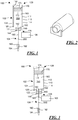
- the injector 100 includes a container 102, a fluid delivery system 104, and an actuator 106.
- the container 102 (which also may be referred to as a cartridge) includes a wall 110 with an interior surface 112 and an exterior surface 114. While a unitary (i.e., one-piece) wall 110 that defines both the interior and exterior surfaces 112, 114 is shown in Fig. 1 , in other embodiments, the wall 110 may include a plurality of layers with different layers defining the interior and exterior surfaces 112, 114.
- the wall 110 is rigid. In other embodiments, the wall 110 is flexible, because of the material that defines the wall or the structure of wall (e.g., a bellows construction).
- the wall 110 may be made of glass, metal or polymer, for example.
- polymer versions may be made of polycarbonate, polypropylene, polyethylene (such as high density polyethylene), polytetrafluoroethylene, cyclic olefin polymer, cyclic olefin copolymer, Crystal Zenith® olefinic polymer (available from Daikyo Seiko, Ltd., Japan), nylon or engineering resins, for example.
- the wall 110 may have a generally cylindrical shape, with a shoulder 120 separating a first cylindrical section 122 having a first cross-sectional diameter from a second cylindrical section 124 having a second cross-sectional diameter, the first cross-sectional diameter being smaller than the second cross-sectional diameter.
- the wall 110 may also define two opposed, open ends 126, 128.
- the wall 110, or more particularly the interior surface 112 of the wall 110, may also define a bore 130.
- the container 102 may include a flexible unitary wall 140 (which may also be referred to as a seal or septum) having an interior surface 142 and an exterior surface 144.
- the wall 140 may be disposed in the first open end 126 defined by the wall 110 and fixedly attached to the wall 110 of the container 102 such that there is limited relative movement between the wall 140 and the wall 110, for example at the points of attachment of the wall 140 to the wall 110 across the open end or opening 126.
- the interior surfaces 112, 142 of the wall 110 and the flexible wall 140 may define, at least in part, a closed sterile reservoir 150 that is filled with a medical fluid or drug product 160, described in greater detail below.
- the wall 140 may be made of bromobutyl, chlorobutyl or chlorobromobutyl rubber, fluoropolymer rubber, natural rubber, silicon-based rubber, silicon or santoprene, for example.
- the container 102 may also include a stopper or piston 170 with interior and exterior surfaces 172, 174.
- the piston 170 may be received within the end 128 defined by the wall 110, and may be moveable along the bore 130 between the ends 126, 128 of the container 102.
- the reservoir 150 within which the medical fluid or drug product 160 is disposed may be defined by the interior surfaces 112, 142, 172 of the walls 110, 140 and piston 170.
- the container 102 may be used in conjunction with the fluid delivery system 104, the relevant portions of which are illustrated in Fig. 1 .
- the fluid delivery system 104 may include a container needle 180 having a point 182.
- the point 182 is disposed only partially into the flexible wall 140 in a storage state.
- the penetration of the point 182 of the needle 180 into the wall 140 may be controlled through a number of methods and/or mechanisms.
- Fig. 2 illustrates a jig that may be used in combination with the container 102 to control the depth at which the point 182 penetrates the wall 140.
- the fluid delivery system 104 may also include an injection needle 190 with a point 192.
- the point 192 of the injection needle 190 may be covered with a needle shield 194 to prevent contact with and contamination of the point 192.
- the container needle 180 and the injection needle 190 may be connected by a cannula or tube 200, which may be a flexible cannula according to certain embodiments of the present disclosure.
- the needle 190 similarly to the needle 180, may be made of stainless steel, for example.
- the container needle 180 and the injection needle 190 may be formed integrally (i.e., as one piece).
- Fluid delivery system 104 may be used in conjunction with the actuator 106, illustrated in Fig. 1 .
- the actuator 106 may be adapted to move the container needle 180 between the storage state illustrated in Fig. 1 and a delivery state illustrated in Fig. 3 , and thus move the fluid delivery system 104 between the storage and delivery states.
- the container needle 180 In the delivery state, the container needle 180 is disposed through the interior surface 142 of the flexible wall 140 into the sterile reservoir 150 and is in fluid communication with the reservoir 150.
- the movement of the needle 180 between the states may occur in a variety of ways.
- the needle 180 may be held fixed relative to the housing of the injector 100, and the container 102 may move relative to the needle 180 and the housing.
- the container 102 may be held fixed relative to the housing, and the needle 180 may be moved relative to the container 102 and the housing.
- both the container 102 and the needle 180 move relative to the housing of the injector 100. It will be understood that all of these actions are embraced within the statement that the actuator 106 is adapted to move the container needle 180 between the storage and delivery states.
- the actuator 106 may be mechanical, electro-mechanical or electrical.
- the actuator 106 may include a solenoid, motor-driven lever, motor with associated gearing, etc.
- a tab or button attached to the container 102 or the needle 180 permits the user to achieve the relative motion between the container 102 and the needle 180 manually.
- the container 102 may be received within a tab or button that is depressed into the housing when the injector 100 is activated to move the container 102 relative to the (fixed) needle 180.
- the actuator 106 may move the container needle 180 between storage and delivery states by moving the needle 180 from the storage state to the delivery state, or by moving the needle 180 from the delivery state to the storage state. In some embodiments, the actuator may move the container needle 180 between the storage and delivery states repeatedly (i.e., multiple times or repetitions). The actuator 106 may move the container needle 180 immediately upon receipt of an input or signal (e.g., as generated through the depression or manipulation of a button, switch or other input device, which may be mechanical, electro-mechanical or electrical in nature, coupled to the actuator 106), or may delay movement of the container needle 180 between storage and delivery states some period of time after an input is received. According to a particular embodiment, the actuator 106 may delay movement of the needle 180 from the storage state to the delivery state until after such a time delay.
- an input or signal e.g., as generated through the depression or manipulation of a button, switch or other input device, which may be mechanical, electro-mechanical or electrical in nature, coupled to the actuator 106
- the actuator 106 may delay movement
- both the reservoir 150 and the container needle 180 are described as sterile, while the remainder of the delivery device/injector 100 (e.g., actuator 106) is described as clean.
- These terms describe the condition of the reservoir 150, the needle 180 or remainder of the delivery device as a consequence of their assembly under conditions that will ensure a specified level of freedom from contamination, wherein a sterile object or device is understood to have a relatively higher level of freedom from contamination than a clean object or device.
- the concepts of sterility and cleanliness may be discussed with reference to Fig. 4 , which discussion applies to all of the embodiments described herein.
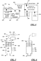
- Fig. 4 illustrates a manufacturing facility 250, and may be used to discuss a manufacturing process that is conducted within the facility 250.
- the facility 250 is divided into a plurality of spaces 252, 254, 256, 258, 260, 262, 264, 266, 268, which divisions may be maintained through the use of permanent or semi-permanent walls or other barriers.
- certain spaces or regions may be divided without barriers or walls, but may simply be separated on an organizational level instead.
- a greater or lesser number of spaces or an alternative arrangement of the spaces may be used, such differing numbers or arrangements of spaces being readily determinable by one of ordinary skill in the art.
- the components of the container 102 enter the facility 250 through space 252, wherein the components are sterilized using e-beam technology, for example.
- the container 102 and the fluid delivery system 104 are defined as separate structures with reference to the embodiments of Figs. 1 and 3 , it would be known to use the manufacturing process described herein with a product where the container 102 is attached to the fluid delivery system 104 prior to introduction into the space 254 (e.g., the container 102/fluid delivery system 104 is a syringe), and to sterilize the product.
- the components may be sterilized through other currently-known (e.g., treatment with chlorine dioxide or vapor phase hydrogen peroxide) or later-developed sterilization procedures as the components enter the facility 250 at entry points 252, 264, 266.
- the container 102 and fluid delivery system 104 then pass into space 254 for filing with the medical fluid or drug product.
- the space 254 may be operated as an aseptic Class 100 clean room.
- a Class 100 clean room is one in which the number of particles of size 0.5 ⁇ m or larger permitted per cubic foot of air is less than 100.
- the reservoir 150 and the medical fluid or drug product 160 remains sterile (i.e., at the higher level of cleanliness). Moreover, because the fluid delivery system 104 is sterile and is assembled to the container 102 under sterile conditions, the fluid delivery system 104 is believed to remain sterile, in part because of the partial insertion of the container needle 180 and in part because of the shield 194.
- the prefilled containers 102 in combination with the associated fluid delivery systems 104 (which combination may be referred to as a prefilled, sterile container combination, or in those embodiments wherein the fluid delivery system 104 and containers 102 are attached or formed integrally with each other (e.g., a syringe), the container 102 and the fluid delivery system 104 may also be referred to as prefilled sterile syringes) are moved through transfer space 256 (also operated as a Class 100 clean room, wherein certain embodiments are also aseptic) before being received within storage space 258.
- transfer space 256 also operated as a Class 100 clean room, wherein certain embodiments are also aseptic
- the prefilled, sterile container combinations are moved from the storage space 258 into inspection area 260 (aseptic in certain embodiments), wherein the prefilled, sterile container combinations are inspected prior to assembly with the actuator 106 and other elements of the injector 100. Because the medical fluid or drug product 160 is contained within the sealed container 102 and the sterility of the fluid delivery system 104 is preserved at this point (i.e., the container needle 180 is inserted into the wall 140 and the injector needle 190 is capped with the shield 194), the inspection area may be operated as a Class 10,000 clean room. Once inspected, the prefilled, sterile container combinations may be passed from inspection space 260 to assembly space 262.
- the assembly space 262 may be operated as an aseptic Class 10,000 clean room, or in some embodiments a Class 100,000 clean room. Materials passed into the clean room from spaces 264, 266 may be in a sterile condition, or may be sterilized using e-beam technology, for example.
- the remainder of the injector 100 e.g., the actuator 106
- the fluid delivery system 104 may be disposed in the remainder of the injector 100 prior to the injector 100 passing into the packaging space 268.
- the fluid delivery system 104 may be arranged in one configuration prior to assembly with the remainder of the injector 100, for ease of transport for example, but to have the fluid delivery system 104 assume a different arrangement once assembled in the injector 100.
- the spacing between the prefilled, sterile container combinations in a tray or other holder used to transport the prefilled, sterile container combinations may be maximized in that the additional room required to accommodate a curved, bent or other non-straight configuration may be avoided.
- This may also have an effect on the costs of filling the containers 102, in that each tray can accommodate a larger number of container 102/fluid delivery system 104 combinations, and thus the number of trays passing through the space 254 may be limited.
- the change in configuration may be performed in the assembly space 262, for example, so as to minimize the need to accommodate the curved, bent or otherwise non-straight fluid delivery systems 104 elsewhere in the facility 250.
- FIG. 1 and 3 The embodiment of the injector 100 illustrated in Figs. 1 and 3 is exemplary.
- Figs. 5 and 6 illustrate variants of the injector illustrated in Figs. 1 and 3 .
- the injector 300 includes a container 302, a fluid delivery device 304, and an actuator 306. Similar to the embodiment of Figs. 1 and 3 , the container 302 includes a wall 310 with interior and exterior surfaces 312, 314. The wall 310 may have two opposed ends 320, 322 with the interior surface 312 of the wall 310 defining a bore 324 between the opposing ends 320, 322.
- the container 302 has a fixed plug 326 that closes the end 320.
- the container 302 has a flexible unitary wall 330 with interior and exterior surfaces 332, 334, the wall 330 is disposed within the end 322 of the container 302, and thus performs the role of the stopper/piston 170 in the container 102. Consequently, the wall 330 is moveable along the bore 324 between the opposing ends 320, 322.
- the interior surfaces 312, 332 of the walls 310, 330 define a sterile reservoir 340 in which a medical fluid or drug product 350 is disposed.
- the fluid delivery device 304 may include a sterile container needle 360 having a point 362.
- the point 362 of the needle 360 like the point 182 of the needle 180, is disposed only partially into the flexible wall 330 in a storage state, with the actuator 306 causing the point 362 to move between the storage state and a delivery state wherein the point 362 is disposed through the interior surface 332 of the flexible wall 330 into the sterile reservoir 340.
- the container needle 360 may be in fluid communication with a injection needle 370 having a point 372 covered with a shield 374 through a cannula 380 received within a piston rod 382, for example, which rod 382 may be used to move the stopper/piston 330 between the ends 320, 322 of the container 302.
- a container has a wall 390 with interior and exterior surfaces 392, 394. Unlike the containers discussed previously, the wall 390 defines a closed end 396 and an open end 398.
- the container also includes a flexible wall 400, like the wall 330 of the embodiment of Fig. 5 , which wall 400 is moveable within the container between the open end 398 and the closed end 396.
- a separate structure is not required to close off one of the ends 396, 398 because the wall 390 defines the closed end 396 itself.
- the closed end 396 may be resized so that it is radially larger than illustrated in Fig. 6 .
- a further plurality of embodiments will be discussed with reference to Figs. 7-11 wherein the seal assembly includes a plurality of walls and/or seals.
- This structure may be referred to as a compartmentalized seal (or septum with reference to Fig. 7 , or stopper with reference to Figs. 8-11 ). While these walls and/or seals may be illustrated and referred to as a wall and a barrier, it will be recognized that these structures may be defined as part of a single structure (e.g., a single septum with a space formed in the center).
- an injector 450 includes a container 452, a fluid delivery system 454, and an actuator 456.
- the container 452 includes a wall 460 with an interior surface 462 and an exterior surface 464. Similar to the container of Figs. 1 and 2 , the wall 460 may have a generally cylindrical shape, with a shoulder 470 separating a first cylindrical section 472 having a first cross-sectional diameter from a second cylindrical section 474 having a second cross-sectional diameter, the first cross-sectional diameter being smaller than the second cross-sectional diameter.
- the wall 460 may also define two opposed, open ends 476, 478.
- the wall 460, or more particularly, the interior surface 462 of the wall 460 may also define a bore 480.
- the container 452 of Fig. 7 has a seal assembly that includes more than a single, unitary wall.
- the seal assembly of the container 452 includes a flexible wall 490 and a barrier 492.
- the flexible wall 490 has an interior surface 494 and an exterior surface 496, while the barrier 492 has an interior surface 498 and an exterior surface 500.
- the interior surfaces 462, 494 of the wall 460 and the flexible wall 490 define a closed sterile reservoir 510 to be filled with a medical fluid or drug product 520.
- the barrier 492 is disposed exterior of the flexible wall 490 to define an enclosed space 530 between the flexible wall 490 and the barrier 492.
- the space 530 may be defined by the interior surface 462 of the wall 460, the exterior surface 496 of the flexible wall 490, and the interior surface 498 of the barrier 492.
- the container 452 may also include a stopper or piston 540 with interior and exterior surfaces 542, 544.
- the piston 540 may be received within the end 478 defined by the wall 460, and may be moveable along the bore 480 between the ends 476, 478 of the container 452.
- the reservoir 510 within which the medical fluid or drug product 520 is disposed may be defined by the interior surfaces 462, 494, 542 of the walls 460, 490 and piston 540.
- the embodiment of Fig. 7 also includes the fluid delivery system 454 comprising a sterile container needle 550 having a point 552 disposed through the barrier 492 into the space 530 in a storage state, and disposed through the interior surface 494 of the flexible wall 490 into the sterile reservoir 510 in a delivery state.
- the container needle 550 only partially penetrates the seal assembly.
- the fluid delivery system 454 may also include an injection needle 560 with a point 562 covered at least initially with a needle shield 564 to prevent contact with and contamination of the point 562.
- the container needle 550 and the injection needle 560 may be connected by a cannula or tube 570, which may be a flexible cannula according to certain embodiments of the present disclosure.
- the seal assembly of an injector 600 is disposed in a container 602 in place of the stopper/piston 540 illustrated relative to the container 452. That is, the container 602 includes a wall 604 that defines a bore 606, and a flexible wall 608 and a barrier 610 each define a stopper that is moveable along the bore 606. While the wall 604 of the container 602 does not define opposing open and closed ends in the embodiment illustrated, such an alternative is possible.
- Figs. 9-11 illustrate variants to the embodiment illustrated in Fig. 8 , which variants include additional features to permit the space or region between the flexible wall and the barrier to be evacuated or exhausted. These additional features may be referred to as vents, valves or bypasses, but all of these structures permit gases to escape from the space or region between the flexible wall and the barrier when an actuator moves the associated container needle from a storage state to a delivery state. This is not to suggest that the inner wall and exterior barrier cannot remain separated, for example through the use of a spacer or spacers, according to other embodiments of the present disclosure.
- the embodiments shown in Figs. 9-11 illustrate options for evacuating the space where the inner wall and exterior barrier come together. It would be understood that the vents, valves, and bypasses would preserve a sterile condition within the space until the space is evacuated or exhausted.
- a container 650 is illustrated in Fig. 9 including a wall 652 and a seal assembly, the assembly including a flexible wall 654 and a barrier 656.
- the flexible wall 654 has an interior surface 658 and an exterior surface 660, while the barrier 654 has an interior surface 662 and an exterior surface 664.
- An interior surface 668 of the wall 652 and the interior surface 658 of the flexible wall 654 define a closed sterile reservoir 670 to be filled with a medical fluid or drug product 680.
- the barrier 656 is disposed exterior of the flexible wall 654 to define an enclosed space 690 between the flexible wall 654 and the barrier 656.
- the space 690 may be defined by the interior surface 668 of the wall 652, the exterior surface 660 of the flexible wall 652, and the interior surface 662 of the barrier 656.
- a fluid delivery system 700 including a container needle 702 is used in conjunction with the seal assembly.
- the container needle 702 is shown in the storage state.
- the container needle 702 is disposed through the barrier 656 so that a point 704 of the needle 702 is disposed in the space 690.
- the point 704 will penetrate the flexible wall 654 and depend into the reservoir 670 in a delivery state (not shown).
- the needle 702 is not drawn to scale particularly as to its length.
- the container 650 illustrated in Fig. 9 includes at least one vent 710.
- the vents 710 are in fluid communication with the space 690 between the barrier 656 and the flexible wall 654.
- the vents 710 are selectively actuated to permit gas trapped between the barrier 656 and the flexible wall 654 to escape through the vents 710 when the seal assembly is moved between the illustrated storage state and the delivery state, wherein the barrier 656 is advanced in the direction of the flexible wall 654 to permit the point 704 of the container needle 702 to penetrate through the wall 654.
- the vents 710 may be in a sealed condition relative to the environment until actuated, for example, by a change in the pressure within the space 690.
- vents 710 are disposed within the barrier 656, and extend between the interior surface 662 and the exterior surface 664 of the barrier 656.
- a flap 712 covers the end of the vent 710 proximate to the exterior surface 664, and thereby seals the end of the vent 710 until the vent is actuated, preserving the sterility of the space 690 between the barrier 656 and the flexible wall 654.
- the vents 710 may be arranged, for example, in the wall 652 of the container 650.
- Figs. 10 and 11 illustrate a further variant on the system of Fig. 8 , wherein a container 720 includes a wall 722 and a seal assembly, the assembly including a flexible wall 724 and a barrier 726.
- the flexible wall 724 has an interior surface 728 and an exterior surface 730, while the barrier 726 has an interior surface 732 and an exterior surface 734.
- An interior surface 738 of the wall 722 and the interior surface 728 of the flexible wall 724 define a closed sterile reservoir 740 to be filled with a medical fluid or drug product 750.
- the barrier 726 is disposed exterior of the flexible wall 724 to define an enclosed space 760 between the flexible wall 724 and the barrier 726.
- the space 760 may be defined by the interior surface 738 of the wall 722, the exterior surface 730 of the flexible wall 722, and the interior surface 732 of the barrier 726.
- a fluid delivery system 770 including a container needle 772 is used in conjunction with the seal assembly.
- the container needle 772 is illustrated in the storage state, wherein the container needle 772 is disposed through the barrier 726 so that a point 774 of the needle 772 is disposed in the space 760.
- the point 774 will penetrate the flexible wall 724 and depend into the reservoir 740 in a delivery state, not shown.
- the container 720 illustrated in Fig. 10 includes at least one bypass or vent 780.
- the bypasses 780 are in fluid communication with the reservoir 740.
- the bypasses 780 are selectively actuated to permit gas trapped between the barrier 726 and the flexible wall 724 to escape through the bypasses 780 into the reservoir 740 when the seal assembly is moved between the illustrated storage state and the delivery state, wherein the barrier 726 is advanced in the direction of the flexible wall 724 to permit the point 774 of the container needle 772 to penetrate through the wall 724.
- bypasses 780 are not in fluid communication with the space 760 until the flexible wall 724 has moved from the storage state illustrated in Fig. 10 to an intermediate state illustrated in Fig. 11 .
- the bypasses 780 may be defined in the interior surface 738 of the wall 722, and may take the form of a groove 782 formed in the wall 722.
- the groove 782 may have a distal end 784 and a proximal end 786. As will be recognized, until the exterior surface 730 of the flexible wall 724 moves past the distal end 784 of the grooves 782, the reservoir 740 is in a sealed condition relative to the space 760.
- the gases trapped between the barrier 726 and the flexible wall 724 may exhaust into the reservoir 740. This may facilitate the movement of the barrier 726 and needle 770 toward the flexible wall 724.
- Figs. 12 and 13 illustrate embodiments wherein the container needle is disposed through the flexible wall (defining the stopper or septum) and a valve is used to seal the reservoir off from the injection needle.
- the valve may also be used to control the flow of medical fluid or drug product from the reservoir in the container. In this fashion, the valve may be used to meter an amount of medical fluid or drug product from the reservoir, or to delay the flow of the medical fluid or drug product until a time delay has elapsed relative to receipt of an input from an input device (e.g., button or switch), for example.
- an input device e.g., button or switch
- Fig. 12 illustrates an injector 850 with a container 852, a fluid delivery system 854, and an actuator 856.
- the container 852 includes a flexible wall 860, which may be in the form of a septum.
- the flexible wall 860 has an interior surface 862 and an exterior surface 864.
- the fluid delivery system 854 includes a container needle 866, an injection needle 868, and a flexible cannula or tubing 870 connecting the container needle 866 and the injection needle 868.
- the injection needle 868 may be received within a cover 872 that preserves the sterility of the needle 868.
- the container needle 866 (and in particular a point 874 of the container needle 866) is disposed through the flexible wall 860 and through the interior surface 862.
- the needle 866 is thus in fluid communication with a sterile reservoir 880 and a medical fluid or drug product 890 disposed within the reservoir 880.
- Fluid communication between the container needle 866 and the injection needle 868 is interrupted by valve 900 disposed in or along the flexible tubing 870. Unlike the other embodiments discussed above relative to Figs.
- the actuator 856 of the injector 850 is not used to move the container needle 866 relative to the flexible wall 860, but instead to manipulate the valve between a closed state wherein fluid communication is interrupted between the needles 866, 868 and an open state wherein the container needle 866 is in fluid communication with the injection needle 868.
- the valve 900 may take a variety of shapes and forms, two of which are illustrated in Figs. 12 and 13 .
- Fig. 12 illustrates an embodiment of the injector 850 wherein a rotatable valve 900 is disposed in the flexible tubing 870, or has an internal valve member that is in fluid communication with the fluid flow path defined between the container needle 866 and the injection needle 868.
- Fig. 13 illustrates an embodiment of the injector wherein a pinch valve 902 is disposed along the flexible tubing 870, and thus cooperates with an exterior surface of the tubing 870 to interrupt the fluid communication between the container needle 866 and the injection needle 868.
- Embodiments such as those illustrated in Figs. 12 and 13 could also be used with a container that has a permanently attached needle, such that the container is in the form of a syringe, for example.
- the method described relative to Fig. 4 could be used with any of the embodiments mentioned heretofore, as well as with an embodiment like those illustrated in Figs. 12 and 13 wherein no valve is used, but the syringe (i.e., a container with permanently attached needle) has an injection needle that is covered by a shield to maintain its sterility.
- Figs. 12 and 13 may be further modified to incorporate a seal assembly including a plurality of walls and/or seals, such as is illustrated in Fig. 7 , for example.
- Fig. 14 illustrates such an embodiment.
- Fig. 14 illustrates an injector 920 with a container 922, a fluid delivery system 924, an actuator 926, and a seal assembly 928.
- the fluid delivery system 924 may include a container needle 930, an injection needle 932, and a flexible cannula or tubing 934 connecting the container needle 930 and the injection needle 932.
- the injection needle 932 may be received within a cover 936 that preserves the sterility of the needle 932.
- the needle 932 may also be in selective fluid communication with a sterile reservoir 940 and a medical fluid or drug product 942 disposed within the reservoir 940 via a valve 944 disposed in or along the flexible tubing 934.
- the injector 920 is similar to those injector embodiments illustrated in Figs. 12 and 13 .
- the seal assembly 928 of the injector 920 also has a flexible wall 950 and a barrier 952.
- the flexible wall 950 and the barrier 952 each have interior and exterior surfaces, with the interior surface of the flexible wall 950 defining, in part, the closed sterile reservoir 940.
- the barrier 952 is disposed exterior of the flexible wall 950 to define an enclosed space 954 between the flexible wall 950 and the barrier 952 in which a point 956 of the container needle 930 may be disposed.
- Fig. 14 has two potential barriers: one in the form of the valve 944 and a second in the form of the placement of the point 956 within the space 954.
- the valve 944 may be controlled to provide a delay in the injection of the medical fluid or drug product 942 after the container needle 930 has been caused to penetrate trough the flexible wall 950 into the reservoir 940.
- the devices according to the present disclosure may have one or more advantages relative to conventional technology, any one or more of which may be present in a particular embodiment in accordance with the features of the present disclosure included in that embodiment.
- these embodiments maintain the sterility of the medical fluid or drug product until the time of use.
- the potential for mixing of the medical fluid or drug product is limited or eliminated prior to the time of use.
- unintended delivery of the medical fluid or drug product is limited or prevented prior to the time of use.
- Fig. 15 provides a further method 1000 for assembling delivery devices according to any of the embodiments disclosed above.
- the method 1000 follows the general processing flow outlined above relative to Fig. 4 .
- the method 1000 provides additional optional paths (represented as a left or right branch) that may be followed in the assembly of the delivery device. Consequently, the method 1000 of Fig. 15 may be viewed as supplementary to the discussion above relative to Fig. 4 .
- the method 1000 for assembling delivery devices begins at block 1002.
- the containers used in the device are initially stored in sealed tubs. These containers may be sterilized.
- the tubs are debagged, for example using an automated debagger in a Grade C cleanroom.
- the Tyvek seal is peeled off (e.g., by a robot) and removed, for example, in a space operated as a Grade A cleanroom, perhaps within an isolator in a space otherwise operated a Grade C cleanroom.
- the containers are filled, and the stoppers and the fluid systems are attached, and then the containers are re-nested in open tubs, at block 1006, in a space operated as a Grade A cleanroom, perhaps within an isolator in a space otherwise operated a Grade C cleanroom. From this point, two different alternative paths, or branches, are possible.
- the filled containers may be left in the open tubs at block 1008.
- the tubs may be conveyed and carted to a storage space (e.g., cold room) at block 1010.
- a storage space e.g., cold room
- the method 1000 may continue with the tubs being transferred for processing to an inspection room at block 1012.
- the filled containers are then denested from the open tubs at block 1014, and supplied to an automated inspection machine at block 1016.
- Automated inspection of the filled containers occurs at block 1016, followed by optional, additional semi-automated or manual inspection at block 1018.
- the tubs may be resealed, rebagged, and labeled, at block 1020.
- the tubs may be resealed with Tyvek (e.g., using a Bausch + Strobel tub sealer), rebagged, and then labeled in a Grade C cleanroom at block 1020.
- Tyvek e.g., using a Bausch + Strobel tub sealer
- the tubs may then be stored, or even shipped, if necessary, at blocks 1022, 1024.
- the tubs are debagged, for example using an automated debagger at block 1026.
- the Tyvek seal is peeled off and removed.
- the filled containers may then be denested for inspection, at block 1030.
- the actions at blocks 1026, 1028, 1030 are performed in a Grade C cleanroom.
- An automated inspection may then be carried out using a visual inspection machine designed for operation in a Grade C cleanroom at block 1032.
- the filled, inspected containers may then be transferred to rondo trays at block 1034.
- the rondo trays may be sent directly to storage at block 1036. If the route of block 1036 is followed, then the rondo trays are transferred for processing to the device assembly room at block 1038.
- the containers are denested at block 1040, and assembled with the other elements of the delivery device at block 1042 to define an assembled delivery device (e.g., an injector or an infuser).
- the containers may be moved into tubs, which are sealed, bagged, and labeled, at block 1044.
- the tubs may be resealed with Tyvek, bagged, and then labeled in a Grade C cleanroom.
- the tubs may then be stored, or even shipped for further processing, if necessary, at blocks 1046, 1048.
- the tubs are debagged, for example using an automated debagger at block 1050.
- the Tyvek seal is peeled off and removed, and the containers are denested.
- the filled containers may then be assembled with the other elements of the delivery device at block 1054.
- the actions at blocks 1050, 1052, 1054 may all occur in a Grade C cleanroom.
- the assembled devices are packaged at block 1056, and the packaged, assembled devices are stored at block 1058. Finally, the packaged, assembled devices are transported to the distributor, and/or for other distribution actions at block 1060.
- an injector 1100 includes a container 1102, a seal assembly 1104 and a fluid delivery system 1106, which fluid delivery system 1106 includes a sterile container needle 1108.
- the fluid delivery system 1106 may include sterile flexible tubing connected at a first end to the container needle 1108 and a second end to a sterile injection needle received within a sterile cover that closes off the sterile injection needle, as discussed above.
- the sterile container needle 1108 is attached to a connector 1110, the connector 1110 being mechanically connected or coupled to the container 1102 to secure the sterile container needle 1108 to the container 1102.
- the container 1102 has a container wall 1120 with an interior surface 1122.
- the container 1102 may include a rigid wall formed using, for example, any of the materials discussed above relative to the other containers discussed herein.
- the container 1102, and more particularly the container wall 1120, defines a bore 1124, and the container 1102 includes a stopper (or plunger) 1126 that is moveable along the bore 1124 between opposite ends 1128, 1130.
- the seal assembly 1104 includes a flexible seal assembly wall 1140 and a barrier 1142.
- the flexible seal assembly wall 1140 has an interior surface 1144, the interior surfaces 1122, 1144 of the container wall 1120 and the seal assembly wall 1140 defining a closed sterile reservoir 1146 that may be filled with a medical fluid or drug product.
- the container 1102 has an opening 1148 at the first end 1128 of the bore 1124, which opening 1148 is in fluid communication with the reservoir 1146, and the flexible seal assembly wall 1140 defines a septum disposed across the opening 1148.
- the flexible seal assembly wall 1140 is fixedly attached to the container wall 1120 as described in detail below relative to an exemplary embodiment.
- the barrier 1142 is disposed exterior of the seal assembly wall 1140 (relative to the reservoir 1146) to define an enclosed space 1150 between the flexible wall 1140 and the barrier 1142.
- the barrier 1142 may have a cup-like shape defined by a plate 1152 with exterior and interior surfaces 1154, 1156 and a rim 1158 depending axially from the interior surface 1156 of the plate 1152.
- a surface 1160 of the rim 1158 is disposed on an exterior surface 1162 of the seal assembly wall 1140, the enclosed space 1150 being disposed between interior surface 1156 of the plate 1152, the exterior surface 1162 of the seal assembly wall 1140 and the rim 1158.
- the barrier 1142 and the flexible seal assembly wall 1140 may be formed as a single structure with a space defined therebetween.
- the fluid delivery system 1100 includes the sterile container needle 1108.
- This needle 1108 has a point 1170 that is disposed only through the barrier 1142 in a storage state (see Fig. 17 ), and that is disposed through the flexible wall 1140 into the sterile reservoir 1146 in a delivery state (see Fig. 18 ).
- the sterile container needle 1108 is attached to a connector 1110 that is mechanically attached to the container 1102 to secure the sterile container needle 1108 to the container 1102 with the needle 1108 in the storage state.
- An actuator 1180 (see Fig.
- the actuator 1180 is adapted to delay movement of the container needle 1108 from the storage state to the delivery state to some predetermined time after an input is received.
- the connector 1110 may be mechanically connected or coupled to the container 1102 using a variety of different mechanisms.
- the connector may simply be press fit onto the container.
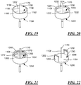
- Fig. 19 illustrates such an embodiment of the connector, which connector is formed of a cup-shaped collar 1190 through which the sterile container needle 1108 depends.
- the collar 1190 has a plate 1192 with exterior and interior surfaces 1194, 1196, and a rim 1198 depending axially from the interior surface 1196 of the plate 1192.
- the end of the container would be received within a space 1200 defined by the interior surface 1196 of the plate 1192 and the rim 1198, and an inner surface 1202 of the rim 1198 would frictionally engage the container to limit or prevent separation.
- the connector 1110 may be a first connector of a pair of connectors, and a second connector 1210 of the pair of connectors may be attached to the container 1102. See, e.g., Figs. 16-18 .
- the first and second connectors 1110, 1210 may be mechanically coupled to secure the sterile container needle 1108 to the container 1102 in the storage state as illustrated in Fig. 17 .
- a family of connectors useful according embodiments of the disclosure may include first and second connectors each of which include one of a pair of facing surfaces. The facing surfaces abut to limit movement of the first and second connectors axially along a longitudinal axis of the sterile container needle, and thus limit or prevent separation of the sterile container needle from the container and the seal assembly.
- Figs. 16-18 and 20 illustrate an embodiment of such a connector pair.
- the first and second connectors 1110, 1210 engage to rotatably couple the pair of connectors 1110, 1210 to secure the sterile container needle 1108 to the container 1102 in the storage state. That is, the illustrated first and second connectors 1110, 1210 limit or prevent separation of the sterile container needle 1108 from the container 1102 in the axial direction, but do not work to limit or prevent the needle 1108 and associated connector 1110 from rotating relative to the container/seal assembly 1102/1104.
- the connector includes a cup-shaped collar 1220 through which the sterile container needle 1108 depends.
- the collar 1220 has a plate 1222 with exterior and interior surfaces 1224, 1226, and a rim 1228 depending axially from the interior surface 1126 of the plate 1222.
- the rim 1228 defines an opening 1230 through which an end of the container 1102 is disposed when the sterile container needle 1108 is secured to the container 1102.
- Disposed about the opening 1230 is an inwardly directed flange 1232 that defines one surface 1234 of a pair of facing surfaces, an outwardly directed flange 1236 attached to the container 1102 defining the other surface 1238. See also Figs. 16 and 17 .
- the abutment of the facing surfaces 1234, 1238 limits or prevents separation once the needle 1108 and connector 1110 have been advanced in the direction of the container 1102 such that the flange 1232 is moved axially past the flange 1236 in the direction of the container 1102.
- the container 1102 comprises a rim 1240 disposed about the opening 1148.
- the seal assembly 1104 is disposed over the opening 1148 of the container 1102, with a portion of the seal assembly wall 1140 disposed through the opening 1148.
- the second connector 1210 includes an outwardly-directed flange 1246 that defines a rim, at least the portion of the second connector 1210 defined by the rim 1246 disposed over the seal assembly 1104.
- the container 1102 further includes a crimp ring 1250, the ring 1250 being formed about the rim 1240 of the container 1102 and the rim 1246 of the second connector 1210 with the seal assembly 1104 disposed between the rims 1240, 1246 to secure the seal assembly 1104 between the rim 1240 of the container 1102 and the rim 1246 of the second connector 1210.
- the second connector 1210 also has an passage 1252 therethrough.
- the sterile container needle 1108 is disposed through the passage 1252 in the second connector 1210 and through the barrier 1142 in the storage state, and through the passage 1252, the barrier 1142 and the seal assembly wall 1140 in the delivery state.
- such an embodiment has been included by way of illustration, and not by way of limitation.
- the container needle 1108 and the connector 1110 is advanced in the direction of the container 1102.
- the inwardly-directed flange 1232 of the connector 1110 moves past the outwardly directed flange 1236 of the connector 1210 attached to the container 1102.
- the flange 1232 has moved past the flange 1236, the movement of the container needle 1108 and the associated connector 1110 is prevented by abutting surfaces 1234, 1238.
- the material selected for the flange 1232 and/or the flange 1236 may be selected to resist a significant force applied to the container needle 1108 and the connector 1110 to separate the needle 1108 from the container 1102.
- the material is also selected, however, to permit the flanges 1232, 1236 to move past each other so that the mechanical coupling can be formed, and/or the collar 1220 of the connector 1110 may have features (e.g., axial slots) that permit the collar 1220 or sections of the collar 1220 to flex to permit the motion of the flange 1232 past the flange 1236.
- features e.g., axial slots
- Fig. 21 illustrates a connector that may be used with a different embodiment of the connector pair.
- the first and second connectors of the connector pair would threadingly engage to couple the connector pair to secure the sterile container needle to the container in the storage state. Accordingly, relative rotational motion between the first and second connector would cause the connectors to either be securely coupled to each other or to decouple from each other, and thus relative rotational motion is to be limited (unlike the embodiment of Figs. 16-18 and 20 , wherein relative rotation motion is permitted).
- Fig. 16-18 and 20 wherein relative rotation motion is permitted
- the first connector of such a connector paid may have a collar 1260 with a plate 1262 having exterior and interior surfaces 1264, 1266, and a rim 1268 depending axially from the interior surface 1266 of the plate 1262.
- the rim 1268 defines an opening 1270 through which an end of the container is disposed when the sterile container needle is secured to the container.
- a thread 1272 is formed, which thread 1272 would be matched with a mating thread formed on the second connector.
- the first connector of a connector pair may include a collar that is disposed continuously about the sterile container needle.
- the first connector may include a collar that is disposed discontinuously about the sterile container needle.
- the connector includes a collar 1280 that is significantly discontinuous, to the point where the collar 1280 defines only a pair of arms 1282 disposed opposite from each other relative to the container needle 1108 that is disposed between the two arms 1282.
- the arms 1282 are connected to a plate 1284 having exterior and interior surfaces 1286, 1288.
- the arms 1282 may have an end 1290 that is attached to the plate 1284 and that defines a living hinge, permitting the arms 1282 to pivot relative to the plate 1284 and the end 1290.
- the arms 1282 may also have an inwardly-directed flange or finger 1292 that will mate with a corresponding structure of the container, such as the flange 1236 of the container 1102 illustrated in Figs. 16 and 17 , to limit or prevent axial motion between the container 1102 and the needle 1108 such that the container needle 1108 would separate from the container 1102.
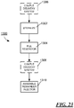
- a method 1300 of assembling an injector such as the injector 1100 illustrated in Figs. 16-18 and 19 , is illustrated in Fig. 23 .
- the method 1300 may include sterilizing a reservoir 1146 at block 1302 and filling a sterile reservoir 1146 of a container 1102 with a medical fluid or drug product under sterile conditions at block 1304, the reservoir 1146 defined by an interior surface 1122 of a wall 1120 of the container 1102.
- a sterile fluid delivery system 1106 may be mechanically connected or coupled to the container 1102 under sterile conditions, the fluid delivery system 1106 not in fluid communication with the reservoir 1146 in a storage state and in fluid communication with the reservoir 1146 in a delivery state, and assembling the remainder of the injector 1100 under clean room conditions.
- the steps of sterilizing and filling the sterile reservoir 1146 may follow the step of mechanically connecting or coupling the sterile fluid delivery system 1106 to the container 1102, as illustrated at block 1306.
- the step of mechanically connecting or coupling the sterile fluid delivery system 1106 to the container 1102 may follow the step of filling the sterile reservoir 1146, as illustrated at block 1308.
- the step of mechanically connecting or coupling the sterile fluid delivery system 1106 may occur within a fill/finish suite, for example.
- Assembly of the remainder of the injector 1100 may also include attaching the fluid delivery system 1106 to an actuator 1180 under clean room conditions at block 1310, the actuator 1180 adapted to change the state of the fluid delivery system 1106 from the storage state to a delivery state.
- connection of the needle to the container (and specifically to the flexible seal assembly wall/barrier) prior to the sterilization and filing of the container is not limited to the embodiments of Figs. 16-22 . It will be recognized that the method 1000 described in regard to the Fig. 15 may be performed in accordance with the method described in Fig. 23 . In particular, rather than assembling the container needle with the reservoir at block 1006 of the method 1000 of Fig. 15 , the container needle (and associated tubing/delivery needle) may be assembled with the reservoir even prior to block 1002, such that the container needle/container assembly may be filled and renested in the tub at block 1006. The method 1000 may then continue as described above.
- FIG. 24 an additional embodiment according to the present disclosure is provided in Fig. 24 with an injector 1330 including a container 1332, a seal assembly 1334 and a fluid delivery system 1336, which fluid delivery system 1336 includes a sterile container needle 1338.
- the fluid delivery system 1336 may include sterile flexible tubing connected at a first end to the container needle 1338 and a second end to a sterile injection needle received within a sterile cover that closes off the sterile injection needle, as discussed above.
- the sterile container needle 1338 is attached to a connector 1340, the connector 1340 being mechanically connected or coupled to the container 1332 to secure the sterile container needle 1338 to the container 1332.
- the container 1332 may have a container wall 1342 with an interior surface 1344, and a stopper (or plunger) 1346 that is moveable between opposite ends 1348, 1350. While the plunger 1346 closes one end 1350 of the container 1332, the other end 1348 of the container 1332 is closed by the seal assembly 1334. As illustrated, the seal assembly 1334 includes a flexible seal assembly wall 1352.
- the flexible seal assembly wall 1352 has an interior surface 1354, the interior surfaces 1344, 1354 of the container wall 1342 and the seal assembly wall 1352 defining a closed sterile reservoir 1356.
- the container 1332 has an opening 1358 at the first end 1348 in fluid communication with the reservoir 1356, and the flexible seal assembly wall 1352 defines a septum disposed across the opening 1358.
- the needle 1338 has a point 1360 that is disposed only partially through the wall 1352 in a storage state, as illustrated in Fig. 24 , and that is disposed through the flexible wall 1352 into the sterile reservoir 1356 in a delivery state.
- the sterile container needle 1338 is attached to a connector 1340 that is mechanically attached to the container 1332 to secure the sterile container needle 1338 to the container 1332 with the needle 1338 in the storage state.
- a second connector 1362 is connected to the container 1332.
- the connector 1340 has an inwardly directed flange 1364 that defines one surface 1366 of a pair of facing surfaces, an outwardly directed flange 1368 attached to the container 1332 defining the other surface 1370.
- a dose of medical fluid or drug product is to be delivered that is less than the volume of the reservoir (such as may be the case wherein the injector is designed to be programmed to deliver an adjustable dose according to the needs of the patient (e.g., pediatric vs. adult patient))
- the actuator may move the container needle from the storage state to the delivery state prior to delivery of the dose, and from the delivery state to the storage state after delivery of the dose.
- the movement from the delivery state to the storage state will in effect reseal the container and close the fluid path to the patient.
- This sequence of movement between the storage state and the delivery state may be repeated.
- maintaining a closed fluid path until delivery is initiated is advantageous in that the opportunity for unintended delivery of the medical fluid or drug product to the patient and/or mixing of the medical fluid or drug product with the patient's bodily fluids is reduced.
- the injectors according to the present disclosure may be used with a variety of medical fluids or drug products, including colony stimulating factors, such as granulocyte colouny-stimulating factor (G-CSF).
- G-CSF agents include, but are not limited to, Neupogen® (filgrastim) and Neulasta® (pegfilgrastim).
- the drug delivery device may be used with various pharmaceutical products, such as an erythropoiesis stimulating agent (ESA), which may be in a liquid or a lyophilized form.
- ESA erythropoiesis stimulating agent
- An ESA is any molecule that stimulates erythropoiesis, such as Epogen® (epoetin alfa), Aranesp® (darbepoetin alfa), Dynepo® (epoetin delta), Mircera® (methyoxy polyethylene glycol-epoetin beta), Hematide®, MRK-2578, INS-22, Retacrit® (epoetin zeta), Neorecormon® (epoetin beta), Silapo® (epoetin zeta), Binocrit® (epoetin alfa), epoetin alfa Hexal, Abseamed® (epoetin alfa), Ratioepo® (epoetin theta), Eporatio® (epoetin theta), Biopoin® (epoetin theta), epoetin alfa
- An ESA can be an erythropoiesis stimulating protein.
- erythropoiesis stimulating protein means any protein that directly or indirectly causes activation of the erythropoietin receptor, for example, by binding to and causing dimerization of the receptor.
- Erythropoiesis stimulating proteins include erythropoietin and variants, analogs, or derivatives thereof that bind to and activate erythropoietin receptor; antibodies that bind to erythropoietin receptor and activate the receptor; or peptides that bind to and activate erythropoietin receptor.
- Erythropoiesis stimulating proteins include, but are not limited to, epoetin alfa, epoetin beta, epoetin delta, epoetin omega, epoetin iota, epoetin zeta, and analogs thereof, pegylated erythropoietin, carbamylated erythropoietin, mimetic peptides (including EMP1/hematide), and mimetic antibodies.
- Exemplary erythropoiesis stimulating proteins include erythropoietin, darbepoetin, erythropoietin agonist variants, and peptides or antibodies that bind and activate erythropoietin receptor (and include compounds reported in U.S. Publ. Nos. 2003/0215444 and 2006/0040858 ) as well as erythropoietin molecules or variants or analogs thereof as disclosed in the following patents or patent applications: U.S. Pat. Nos.
- Examples of other pharmaceutical products for use with the device may include, but are not limited to, antibodies such as Vectibix® (panitumumab), XgevaTM (denosumab) and ProliaTM (denosamab); other biological agents such as Enbrel® (etanercept, TNF-receptor /Fc fusion protein, TNF blocker), Neulasta® (pegfilgrastim, pegylated filgastrim, pegylated G-CSF, pegylated hu-Met-G-CSF), Neupogen® (filgrastim , G-CSF, hu-MetG-CSF), and Nplate® (romiplostim); small molecule drugs such as Sensipar® (cinacalcet).
- antibodies such as Vectibix® (panitumumab), XgevaTM (denosumab) and ProliaTM (denosamab); other biological agents such as Enbrel® (e
- the device may also be used with a therapeutic antibody, a polypeptide, a protein or other chemical, such as an iron, for example, ferumoxytol, iron dextrans, ferric glyconate, and iron sucrose.
- a therapeutic antibody for example, ferumoxytol, iron dextrans, ferric glyconate, and iron sucrose.
- the pharmaceutical product may be in liquid form, or reconstituted from lyophilized form.
- proteins are the specific proteins set forth below, including fusions, fragments, analogs, variants or derivatives thereof:
- sclerostin antibody such as but not limited to romosozumab, blosozumab, or BPS 804 (Novartis).
- therapeutics such as rilotumumab, bixalomer, trebananib, ganitumab, conatumumab, motesanib diphosphate, brodalumab, vidupiprant, panitumumab, denosumab, NPLATE, PROLIA, VECTIBIX or XGEVA.
- a monoclonal antibody that binds human Proprotein Convertase Subtilisin/Kexin Type 9 (PCSK9), e.g. US 8,030,547 , US13/469,032 , WO2008/057457 , WO2008/057458 , WO2008/057459 , WO2008/063382 , WO2008/133647 , WO2009/100297 , WO2009/100318 , WO2011/037791 , WO2011/053759 , WO2011/053783 , WO2008/125623 , WO2011/072263 , WO2009/055783 , WO2012/0544438 , WO2010/029513 , WO2011/111007 , WO2010/077854 , WO2012/088313 , WO2012/101251 , WO2012/101252 , WO2012/101253 ,
- talimogene laherparepvec or another oncolytic HSV for the treatment of melanoma or other cancers.
- oncolytic HSV include, but are not limited to talimogene laherparepvec ( US 7,223,593 and US 7,537,924 ); OncoVEXGALV/CD ( US 7,981,669 ); OrienX010 ( Lei et al., 2013, World Journal of Gastroenterology, 19:5138-5143 ); G207, 1716; NV1020,;NV12023; NV1034 and NV1042 ( Vargehes et al. 2002, Cancer Gene Ther, 2002, 9 (12): 967-978 ).
- TIMPs are endogenous tissue inhibitors of metalloproteinases (TIMPs) and are important in many natural process.
- TIMP-3 is expressed by various cells or and is present in the extracellular matrix; it inhibits all the major cartilage-degrading metalloproteases, and may play a role in role in many degradative diseases of connective tissue, including rheumatoid arthritis and osteoarthritis, as well as in cancer and cardiovascular conditions.
- the amino acid sequence of TIMP-3, and the nucleic acid sequence of a DNA that encodes TIMP-3 are disclosed in US Patent 6,562,596, issued May 13, 2003 . Description of TIMP mutations can be found in US 61/782,613 , US 61/798,160 , US 61/802,988 , and US 61/940,67 .
- CGRP human calcitonin gene-related peptide
- a bispecific T cell engager antibody e.g. Blinotumomab
- Blinotumomab can be used in the device.
- included can be an APJ large molecule agonist e.g., apelin or analogues thereof in the device. Information relating to such molecules can be found in PCT/2013/075773 , particularly in parts pertinent to proteins that bind PCSK9.
Landscapes
- Health & Medical Sciences (AREA)
- Vascular Medicine (AREA)
- Engineering & Computer Science (AREA)
- Anesthesiology (AREA)
- Biomedical Technology (AREA)
- Heart & Thoracic Surgery (AREA)
- Hematology (AREA)
- Life Sciences & Earth Sciences (AREA)
- Animal Behavior & Ethology (AREA)
- General Health & Medical Sciences (AREA)
- Public Health (AREA)
- Veterinary Medicine (AREA)
- Infusion, Injection, And Reservoir Apparatuses (AREA)
Priority Applications (1)
| Application Number | Priority Date | Filing Date | Title |
|---|---|---|---|
| EP20202187.9A EP3789064B1 (en) | 2013-10-24 | 2014-10-22 | Injector and method of assembly |
Applications Claiming Priority (3)
| Application Number | Priority Date | Filing Date | Title |
|---|---|---|---|
| US201361895390P | 2013-10-24 | 2013-10-24 | |
| PCT/US2014/061675 WO2015061386A1 (en) | 2013-10-24 | 2014-10-22 | Injector and method of assembly |
| EP14792707.3A EP3060275B1 (en) | 2013-10-24 | 2014-10-22 | Injector and method of assembly |
Related Parent Applications (2)
| Application Number | Title | Priority Date | Filing Date |
|---|---|---|---|
| EP14792707.3A Division EP3060275B1 (en) | 2013-10-24 | 2014-10-22 | Injector and method of assembly |
| EP14792707.3A Division-Into EP3060275B1 (en) | 2013-10-24 | 2014-10-22 | Injector and method of assembly |
Related Child Applications (2)
| Application Number | Title | Priority Date | Filing Date |
|---|---|---|---|
| EP20202187.9A Division-Into EP3789064B1 (en) | 2013-10-24 | 2014-10-22 | Injector and method of assembly |
| EP20202187.9A Division EP3789064B1 (en) | 2013-10-24 | 2014-10-22 | Injector and method of assembly |
Publications (2)
| Publication Number | Publication Date |
|---|---|
| EP3421066A1 EP3421066A1 (en) | 2019-01-02 |
| EP3421066B1 true EP3421066B1 (en) | 2021-03-03 |
Family
ID=51844895
Family Applications (3)
| Application Number | Title | Priority Date | Filing Date |
|---|---|---|---|
| EP18186736.7A Active EP3421066B1 (en) | 2013-10-24 | 2014-10-22 | Injector and method of assembly |
| EP14792707.3A Active EP3060275B1 (en) | 2013-10-24 | 2014-10-22 | Injector and method of assembly |
| EP20202187.9A Active EP3789064B1 (en) | 2013-10-24 | 2014-10-22 | Injector and method of assembly |
Family Applications After (2)
| Application Number | Title | Priority Date | Filing Date |
|---|---|---|---|
| EP14792707.3A Active EP3060275B1 (en) | 2013-10-24 | 2014-10-22 | Injector and method of assembly |
| EP20202187.9A Active EP3789064B1 (en) | 2013-10-24 | 2014-10-22 | Injector and method of assembly |
Country Status (14)
| Country | Link |
|---|---|
| US (2) | US11097055B2 (enExample) |
| EP (3) | EP3421066B1 (enExample) |
| JP (2) | JP7086520B2 (enExample) |
| KR (1) | KR102458637B1 (enExample) |
| CN (1) | CN105873626A (enExample) |
| AU (2) | AU2014340171B2 (enExample) |
| BR (1) | BR112016008946B1 (enExample) |
| CA (1) | CA2920894C (enExample) |
| ES (2) | ES3010716T3 (enExample) |
| IL (2) | IL243979B (enExample) |
| MX (2) | MX373358B (enExample) |
| PL (1) | PL3060275T3 (enExample) |
| SG (1) | SG11201602876WA (enExample) |
| WO (1) | WO2015061386A1 (enExample) |
Families Citing this family (32)
| Publication number | Priority date | Publication date | Assignee | Title |
|---|---|---|---|---|
| LT3045187T (lt) | 2011-10-14 | 2019-07-10 | Amgen Inc. | Injekcijų įrenginys ir surinkimo būdas |
| SG11201507878SA (en) | 2013-03-22 | 2015-10-29 | Amgen Inc | Injector and method of assembly |
| EP3421066B1 (en) | 2013-10-24 | 2021-03-03 | Amgen Inc. | Injector and method of assembly |
| JOP20170042B1 (ar) | 2016-02-12 | 2022-09-15 | Amgen Inc | وسيلة توصيل عقار، طريقة تصنيعه وطريقة استخدامه |
| EP3834864A1 (en) | 2016-04-08 | 2021-06-16 | Amgen Inc. | Drug delivery device, method of manufacture, and method of use |
| US11238150B2 (en) | 2016-05-16 | 2022-02-01 | Amgen Inc. | Data encryption in medical devices with limited computational capability |
| MA49677A (fr) | 2017-07-25 | 2021-04-21 | Amgen Inc | Dispositif d'administration de médicament avec module d'engrenage et procédé d'assemblage associé |
| EP3697475B1 (en) * | 2017-10-16 | 2025-08-27 | Becton, Dickinson and Company | Connector for aseptic transfer of fluid |
| WO2019090086A1 (en) | 2017-11-03 | 2019-05-09 | Amgen Inc. | Systems and approaches for sterilizing a drug delivery device |
| US10869961B2 (en) | 2017-11-06 | 2020-12-22 | Sorrel Medical Ltd. | Local disinfection for drug delivery system |
| US10869960B2 (en) | 2017-11-06 | 2020-12-22 | Sorrel Medical Ltd | Local disinfection for prefilled drug delivery system |
| US20220016409A1 (en) * | 2018-11-14 | 2022-01-20 | The Johns Hopkins University | Sterilizable peritoneal dialysis connection device |
| EP4034203A1 (en) | 2019-09-25 | 2022-08-03 | Janssen Pharmaceuticals, Inc. | Interconnection of drug administration systems |
| GB201918663D0 (en) | 2019-12-17 | 2020-01-29 | Oribiotech Ltd | A connector |
| CA3201843A1 (en) | 2020-12-23 | 2022-06-30 | Tejasvi DESAI | System and method for injection and retraction of fluid |
| US11311666B1 (en) | 2021-02-18 | 2022-04-26 | Fresenius Kabi Deutschland Gmbh | Modular wearable medicament delivery device and method of use thereof |
| US11464902B1 (en) | 2021-02-18 | 2022-10-11 | Fresenius Kabi Deutschland Gmbh | Wearable medicament delivery device with compressible reservoir and method of use thereof |
| US11872369B1 (en) | 2021-02-18 | 2024-01-16 | Fresenius Kabi Deutschland Gmbh | Wearable medicament delivery device with leakage and skin contact sensing and method of use thereof |
| US11426523B1 (en) | 2021-02-19 | 2022-08-30 | Fresenius Kabi Deutschland Gmbh | Drug delivery assembly including a removable cartridge |
| US11497847B1 (en) | 2021-02-19 | 2022-11-15 | Fresenius Kabi Deutschland Gmbh | Wearable injector with adhesive substrate |
| US11607505B1 (en) | 2021-02-19 | 2023-03-21 | Fresenius Kabi Deutschland Gmbh | Wearable injector with sterility sensors |
| US11633537B1 (en) | 2021-02-19 | 2023-04-25 | Fresenius Kabi Deutschland Gmbh | Drug delivery assembly including a pre-filled cartridge |
| US11413394B1 (en) | 2021-02-19 | 2022-08-16 | Fresenius Kabi Deutschland Gmbh | Display for wearable drug delivery device |
| US11344682B1 (en) | 2021-02-19 | 2022-05-31 | Fresenius Kabi Deutschland Gmbh | Drug supply cartridge with visual use indicator and delivery devices that use the same |
| US11406755B1 (en) | 2021-02-19 | 2022-08-09 | Fresenius Kabi Deutschland Gmbh | Sensing fluid flow irregularities in an on-body injector |
| US11419976B1 (en) | 2021-04-30 | 2022-08-23 | Fresenius Kabi Deutschland Gmbh | Wearable drug delivery device with pressurized fluid dispensing |
| US11529459B1 (en) | 2021-04-30 | 2022-12-20 | Fresenius Kabi Deutschland Gmbh | Wearable injector with adhesive module |
| US11504470B1 (en) | 2021-04-30 | 2022-11-22 | Fresenius Kabi Deutschland Gmbh | Deformable drug reservoir for wearable drug delivery device |
| US11351300B1 (en) | 2021-04-30 | 2022-06-07 | Fresenius Kabl Deutschland GmbH | Drug dispensing system with replaceable drug supply cartridges |
| US11717608B1 (en) | 2021-05-03 | 2023-08-08 | Fresenius Kabi Deutschland Gmbh | Drug delivery assembly including an adhesive pad |
| US11484646B1 (en) | 2021-05-04 | 2022-11-01 | Fresenius Kabi Deutschland Gmbh | Sealing systems for a reservoir of an on-body injector |
| WO2024026282A1 (en) * | 2022-07-29 | 2024-02-01 | L'oreal | Device autocleaning system based on multi canal and smart formula cartridge |
Citations (1)
| Publication number | Priority date | Publication date | Assignee | Title |
|---|---|---|---|---|
| US20120296307A1 (en) * | 2009-10-23 | 2012-11-22 | Amgen Inc. | Vial Adapter and System |
Family Cites Families (444)
| Publication number | Priority date | Publication date | Assignee | Title |
|---|---|---|---|---|
| US2371086A (en) | 1940-11-14 | 1945-03-06 | Watson | Hypodermic injector |
| US2591706A (en) * | 1950-09-29 | 1952-04-08 | Compule Corp | Plural-compartment admixing hypodermic syringe ampoule for segregated storage of ingredients of liquid medicinal solutions and therapeutic preparations |
| GB718837A (en) | 1951-07-18 | 1954-11-24 | Cook Waite Lab Inc | Improvements in or relating to hypodermic syringe |
| GB722166A (en) | 1951-10-25 | 1955-01-19 | Pfizer & Co C | Improvements in or relating to disposable cartridge for hypodermic syringe |
| BE515202A (enExample) | 1951-11-01 | |||
| US2677373A (en) | 1952-05-19 | 1954-05-04 | P M Ind Inc | Plastic injection device |
| US2688967A (en) * | 1953-06-02 | 1954-09-14 | Huber Jennie | Metal aspirating syringe |
| US2842126A (en) | 1954-03-16 | 1958-07-08 | Frederick M Turnbull | Syringe assembly |
| GB989185A (en) | 1961-08-25 | 1965-04-14 | Glaxo Group Ltd | Improvements in or relating to hypodermic syringes |
| US3187749A (en) | 1962-01-04 | 1965-06-08 | Stanley J Sarnoff | Hypodermic cartridge |
| US3336924A (en) | 1964-02-20 | 1967-08-22 | Sarnoff | Two compartment syringe package |
| US3342180A (en) | 1964-04-24 | 1967-09-19 | American Cyanamid Co | Disposable liquid-powder package and hypodermic syringe |
| DK108590C (da) | 1964-05-28 | 1968-01-08 | Novo Terapeutisk Labor As | Sprøjteampul. |
| US3368558A (en) | 1964-08-21 | 1968-02-13 | Sarnoff | Two compartment cartridge |
| US3378008A (en) | 1965-07-23 | 1968-04-16 | Min I Jet Corp | Hypodermic syringe with vial |
| GB1159665A (en) | 1965-07-23 | 1969-07-30 | Robert Walter Ogle | Improvements in or relating to Component Parts for Medicament Injectors |
| US3557787A (en) | 1968-05-28 | 1971-01-26 | Milton J Cohen | Disposable syringe |
| US3605744A (en) * | 1969-04-22 | 1971-09-20 | Edward M Dwyer | Injection apparatus and method of injecting |
| AT318132B (de) * | 1969-08-01 | 1974-09-25 | Dentaire Ivoclar Ets | Mischbehälter für die Aufnahme von miteinander reagierenden Substanzen für die Herstellung von gebrauchsfertigen pastenförmigen Dentalpräparaten |
| BE757195A (fr) | 1969-10-07 | 1971-03-16 | Century Disposable Devices | Seringue servant a injecter un melange fraichement prepare de poudre etde liquide |
| US3640278A (en) | 1969-10-13 | 1972-02-08 | Benjamin Friedman | Hypodermic syringe device which maintains sterile condition of needle |
| US3739779A (en) | 1970-04-28 | 1973-06-19 | Medical Electroscience & Pharm | Hypodermic syringe and needle construction |
| US3662753A (en) * | 1970-05-25 | 1972-05-16 | Kitchener B Tassell | Syringe |
| US3757779A (en) * | 1971-05-24 | 1973-09-11 | Century Labor Inc | Filter syringe |
| US3872867A (en) | 1971-06-02 | 1975-03-25 | Upjohn Co | Wet-dry additive assembly |
| US3785379A (en) | 1971-08-12 | 1974-01-15 | M Cohen | Syringe for injection of freshly mixed liquid-powder |
| US3835855A (en) * | 1972-10-10 | 1974-09-17 | C Barr | Multi-chambered syringe |
| US3825003A (en) * | 1972-12-26 | 1974-07-23 | Vca Metal Fab Inc | Sealed-hypodermic syringe |
| DE2315367A1 (de) | 1973-03-28 | 1974-10-17 | Hoechst Ag | Injektionsspritze zur einmaligen verwendung |
| US3872864A (en) * | 1973-07-06 | 1975-03-25 | Jr Robert E Allen | Double syringe |
| DE2434046C3 (de) | 1974-07-16 | 1979-10-18 | Lothar 7500 Karlsruhe Schwarz | Nadelhalterung für medizinische Spritzen |
| NL173477C (nl) * | 1974-09-12 | 1984-02-01 | Duphar Int Res | Injektiespuit met teleskopisch orgaan tussen patroon en medicamentflesje. |
| US4055177A (en) | 1976-05-28 | 1977-10-25 | Cohen Milton J | Hypodermic syringe |
| US4188949A (en) * | 1977-07-05 | 1980-02-19 | Becton, Dickinson & Company | Sequential injection syringe |
| US4215689A (en) | 1977-07-27 | 1980-08-05 | Koken Co., Ltd. | Injecting apparatus for medical liquid |
| US4178930A (en) | 1977-10-31 | 1979-12-18 | Fisher Frank R Jr | Combined cap and needle structure |
| AT360139B (de) * | 1978-10-16 | 1980-12-29 | Immuno Ag | Kombinierte ampullen-einweg-injektionsspritze |
| US4196732A (en) | 1978-12-26 | 1980-04-08 | Wardlaw Stephen C | Automatic disposable syringe and method of filling the same |
| US4296786A (en) | 1979-09-28 | 1981-10-27 | The West Company | Transfer device for use in mixing a primary solution and a secondary or additive substance |
| US4411163A (en) * | 1981-07-27 | 1983-10-25 | American Hospital Supply Corporation | Ventable sample collection device |
| US4703008A (en) | 1983-12-13 | 1987-10-27 | Kiren-Amgen, Inc. | DNA sequences encoding erythropoietin |
| NZ210501A (en) | 1983-12-13 | 1991-08-27 | Kirin Amgen Inc | Erythropoietin produced by procaryotic or eucaryotic expression of an exogenous dna sequence |
| KR850004274A (ko) | 1983-12-13 | 1985-07-11 | 원본미기재 | 에리트로포이에틴의 제조방법 |
| IT1173370B (it) | 1984-02-24 | 1987-06-24 | Erba Farmitalia | Dispositivo di sicurezza per collegare una siringa alla imboccatura di un flacone contenente un farmaco o di un tubicino per l'erogazione del farmaco della siringa |
| US4523679A (en) | 1984-03-05 | 1985-06-18 | Sterling Drug Inc. | Pre-sterilized medical procedure kit packages |
| US4619651A (en) * | 1984-04-16 | 1986-10-28 | Kopfer Rudolph J | Anti-aerosoling drug reconstitution device |
| US4626244A (en) | 1985-02-01 | 1986-12-02 | Consolidated Controls Corporation | Implantable medication infusion device |
| GB8509301D0 (en) | 1985-04-11 | 1985-05-15 | Clinical Products Dev Ltd | Device for surgical procedures |
| US4838857A (en) | 1985-05-29 | 1989-06-13 | Becton, Dickinson And Company | Medical infusion device |
| US4632672A (en) | 1985-10-07 | 1986-12-30 | Minnesota Mining And Manufacturing Company | Self venting syringe plunger |
| FR2589738A1 (fr) * | 1985-11-14 | 1987-05-15 | Lascar Marcel | Seringue a double chambre |
| US4655747A (en) * | 1986-01-30 | 1987-04-07 | Allen Jr Robert E | Dual chambered syringe |
| FR2604363A1 (fr) * | 1986-09-30 | 1988-04-01 | Merieux Inst | Dispositif d'injection de substances, notamment medicamenteuses |
| US4883473A (en) | 1987-04-29 | 1989-11-28 | Path | Single use injection device |
| ES1002629Y (es) * | 1987-06-05 | 1989-01-16 | Badia Marcelo Segura | Conexion para cateteres, equipos de perfusion y frascos de liquidos a perfundir |
| US5364369A (en) | 1987-07-08 | 1994-11-15 | Reynolds David L | Syringe |
| CH673775A5 (enExample) | 1987-07-10 | 1990-04-12 | Jacques Verlier | |
| US4784156A (en) * | 1987-09-16 | 1988-11-15 | Garg Rakesh K | Cannula including a valve structure and associated instrument elements and method for using same |
| US5135489A (en) | 1988-01-25 | 1992-08-04 | Baxter International Inc. | Pre-slit injection site and tapered cannula |
| US4915690A (en) | 1988-02-02 | 1990-04-10 | C. R. Bard, Inc. | Micro-injection port |
| IE65903B1 (en) | 1989-06-02 | 1995-11-29 | Becton Dickinson Co | Syringe assembly |
| US4927019A (en) * | 1989-06-12 | 1990-05-22 | Habley Medical Technology Corporation | Combination needle sheath and sterility package |
| US5716343A (en) | 1989-06-16 | 1998-02-10 | Science Incorporated | Fluid delivery apparatus |
| US5205820A (en) | 1989-06-16 | 1993-04-27 | Science, Incorporated | Fluid delivery apparatus |
| US5019047A (en) | 1989-06-16 | 1991-05-28 | Science Incorporated | Fluid delivery apparatus |
| US7217689B1 (en) | 1989-10-13 | 2007-05-15 | Amgen Inc. | Glycosylation analogs of erythropoietin |
| AU646822B2 (en) | 1989-10-13 | 1994-03-10 | Kirin-Amgen Inc. | Erythropoietin isoforms |
| US5856298A (en) | 1989-10-13 | 1999-01-05 | Amgen Inc. | Erythropoietin isoforms |
| JPH03168154A (ja) | 1989-11-29 | 1991-07-19 | Ajinomoto Takara Corp:Kk | 注射器 |
| US5078691A (en) * | 1990-03-01 | 1992-01-07 | Hamacher Edward N | Multiple-dose fluid delivery system and method |
| US5334197A (en) | 1990-09-25 | 1994-08-02 | Science Incorporated | Flexible base fluid delivery apparatus |
| SE9101022D0 (sv) | 1991-01-09 | 1991-04-08 | Paal Svedman | Medicinsk suganordning |
| US5593391A (en) * | 1992-02-13 | 1997-01-14 | Stanners; Sydney D. | Ampule safety syringe |
| US5267974A (en) * | 1992-06-04 | 1993-12-07 | Lambert William S | Hypodermic syringe with foam sponge reservoir |
| US5807323A (en) * | 1992-08-13 | 1998-09-15 | Science Incorporated | Mixing and delivery syringe assembly |
| CH689443A5 (fr) | 1992-09-16 | 1999-04-30 | Debiotech Sa | Ensemble constituant une pompe à usage médical. |
| US5250037A (en) | 1992-12-18 | 1993-10-05 | Becton, Dickinson And Company | Syringe having needle isolation features |
| US5312336A (en) * | 1993-04-14 | 1994-05-17 | Habley Medical Technology Corporation | Component mixing syringe |
| IL192290A0 (en) | 1993-08-17 | 2008-12-29 | Kirin Amgen Inc | Erythropoietin analogs |
| US5665066A (en) * | 1993-09-03 | 1997-09-09 | Ultradent Products, Inc. | Methods and apparatus for mixing and dispensing multi-part compositions |
| US5358491A (en) * | 1993-09-13 | 1994-10-25 | Sterling Winthrop Inc. | Cartridge-needle unit having retractable needle |
| US6562596B1 (en) | 1993-10-06 | 2003-05-13 | Amgen Inc. | Tissue inhibitor of metalloproteinase type three (TIMP-3) composition and methods |
| JPH07124256A (ja) | 1993-10-29 | 1995-05-16 | Ajinomoto Takara Corp:Kk | 注射器 |
| US5620425A (en) | 1993-11-03 | 1997-04-15 | Bracco International B.V. | Method for the preparation of pre-filled plastic syringes |
| US5830851A (en) | 1993-11-19 | 1998-11-03 | Affymax Technologies N.V. | Methods of administering peptides that bind to the erythropoietin receptor |
| US5773569A (en) | 1993-11-19 | 1998-06-30 | Affymax Technologies N.V. | Compounds and peptides that bind to the erythropoietin receptor |
| US5885574A (en) | 1994-07-26 | 1999-03-23 | Amgen Inc. | Antibodies which activate an erythropoietin receptor |
| CA2154853C (en) | 1994-07-27 | 2007-01-16 | John Glyndwr Wilmot | Nipple plunger |
| AU3272695A (en) | 1994-08-12 | 1996-03-07 | Immunomedics Inc. | Immunoconjugates and humanized antibodies specific for b-cell lymphoma and leukemia cells |
| US5496284A (en) * | 1994-09-27 | 1996-03-05 | Waldenburg; Ottfried | Dual-chamber syringe & method |
| US5624402A (en) * | 1994-12-12 | 1997-04-29 | Becton, Dickinson And Company | Syringe tip cap |
| CA2214120A1 (en) * | 1995-03-02 | 1996-09-06 | Sanofi Winthrop, Inc. | Low friction coating for cartridge seal cap |
| US5962794A (en) | 1995-05-01 | 1999-10-05 | Science Incorporated | Fluid delivery apparatus with reservior fill assembly |
| US5618269A (en) | 1995-05-04 | 1997-04-08 | Sarcos, Inc. | Pressure-driven attachable topical fluid delivery system |
| US5686292A (en) | 1995-06-02 | 1997-11-11 | Genentech, Inc. | Hepatocyte growth factor receptor antagonist antibodies and uses thereof |
| US5767078A (en) | 1995-06-07 | 1998-06-16 | Johnson; Dana L. | Agonist peptide dimers |
| US5921962A (en) | 1995-10-11 | 1999-07-13 | Science Incorporated | Fluid delivery device with flow indicator and rate control |
| US5735818A (en) | 1995-10-11 | 1998-04-07 | Science Incorporated | Fluid delivery device with conformable ullage |
| US5957891A (en) | 1995-10-11 | 1999-09-28 | Science Incorporated | Fluid delivery device with fill adapter |
| US5693018A (en) | 1995-10-11 | 1997-12-02 | Science Incorporated | Subdermal delivery device |
| AT404556B (de) * | 1995-11-23 | 1998-12-28 | Pharma Consult Gmbh | Einrichtung zum dichten verschliessen eines glas- oder kunststoffbehälters zur aufnahme flüssiger pharmazeutischer produkte |
| US5749857A (en) * | 1996-04-25 | 1998-05-12 | Cuppy; Michael J. | Catheter system |
| US5865744A (en) | 1996-09-16 | 1999-02-02 | Lemelson; Jerome H. | Method and system for delivering therapeutic agents |
| US5840071A (en) | 1996-12-18 | 1998-11-24 | Science Incorporated | Fluid delivery apparatus with flow indicator and vial fill |
| US6355019B1 (en) | 1996-12-18 | 2002-03-12 | Science Incorporated | Variable rate infusion apparatus with indicator and adjustable rate control |
| DE19652708C2 (de) | 1996-12-18 | 1999-08-12 | Schott Glas | Verfahren zum Herstellen eines befüllten Kunststoff-Spritzenkorpus für medizinische Zwecke |
| EP0989871B1 (en) | 1997-06-16 | 2004-09-01 | ELAN CORPORATION, Plc | Pre-filled drug-delivery device |
| US6500150B1 (en) | 1997-06-16 | 2002-12-31 | Elan Pharma International Limited | Pre-filled drug-delivery device and method of manufacture and assembly of same |
| JPH1121116A (ja) | 1997-06-30 | 1999-01-26 | Nippon Steel Corp | 窒化ホウ素で被覆された炭素質粉末および炭素質繊維 |
| US6753165B1 (en) | 1999-01-14 | 2004-06-22 | Bolder Biotechnology, Inc. | Methods for making proteins containing free cysteine residues |
| CN1269805A (zh) | 1997-07-14 | 2000-10-11 | 博尔德生物技术公司 | 生长激素和相关蛋白的衍生物 |
| US6391633B1 (en) | 1997-07-23 | 2002-05-21 | Roche Diagnostics Gmbh | Production of erythropoietin by endogenous gene activation |
| US5921966A (en) | 1997-08-11 | 1999-07-13 | Becton Dickinson And Company | Medication delivery pen having an improved clutch assembly |
| US6482176B1 (en) | 1997-11-27 | 2002-11-19 | Disetronic Licensing Ag | Method and device for controlling the introduction depth of an injection needle |
| US5957895A (en) | 1998-02-20 | 1999-09-28 | Becton Dickinson And Company | Low-profile automatic injection device with self-emptying reservoir |
| US6248095B1 (en) * | 1998-02-23 | 2001-06-19 | Becton, Dickinson And Company | Low-cost medication delivery pen |
| US6030086A (en) | 1998-03-02 | 2000-02-29 | Becton, Dickinson And Company | Flash tube reflector with arc guide |
| US6221055B1 (en) | 1998-03-04 | 2001-04-24 | Retractable Technologies, Inc. | Retractable dental syringe |
| JP4216467B2 (ja) | 1998-03-13 | 2009-01-28 | ベクトン・ディキンソン・アンド・カンパニー | 医療装置の組立ておよび包装方法 |
| ATE254938T1 (de) | 1998-03-23 | 2003-12-15 | Elan Corp Plc | Vorrichtung zur arzneimittelverarbreichung |
| US6310078B1 (en) | 1998-04-20 | 2001-10-30 | Ortho-Mcneil Pharmaceutical, Inc. | Substituted amino acids as erythropoietin mimetics |
| US20050181482A1 (en) | 2004-02-12 | 2005-08-18 | Meade Harry M. | Method for the production of an erythropoietin analog-human IgG fusion proteins in transgenic mammal milk |
| DE69933216T2 (de) | 1998-06-15 | 2007-09-20 | GTC Biotherapeutics, Inc., Framingham | Erythropoietin-analog-menschliches serum-albumin fusionsprotein |
| ATE355303T1 (de) | 1998-10-23 | 2006-03-15 | Amgen Inc | Methoden und zusammensetzungen zur prävention und behandlung der anämie |
| HK1042114B (zh) | 1998-10-23 | 2006-09-29 | Amgen K-A, Inc. | 与mp1受体结合并具有血小板生成活性的模拟二聚体血小板生成素肽 |
| DE69928827T2 (de) | 1998-10-29 | 2006-08-31 | Medtronic MiniMed, Inc., Northridge | Reservoiranschluss |
| JP4813660B2 (ja) | 1998-11-27 | 2011-11-09 | ダーウィン ディスカバリー リミテッド | 骨鉱化作用を増加するための組成物および方法 |
| EP1006184A1 (en) | 1998-12-03 | 2000-06-07 | F. Hoffmann-La Roche Ag | IGF-1 receptor interacting proteins (IIPs) genes coding therefor and uses thereof |
| DE19909824A1 (de) * | 1999-03-05 | 2000-09-07 | Vetter & Co Apotheker | Spritze für medizinische Zwecke und Verfahren zu ihrer Montage |
| JP2002544123A (ja) | 1999-04-14 | 2002-12-24 | スミスクライン・ビーチャム・コーポレイション | エリトロポイエチン受容体抗体 |
| US7297680B2 (en) | 1999-04-15 | 2007-11-20 | Crucell Holland B.V. | Compositions of erythropoietin isoforms comprising Lewis-X structures and high sialic acid content |
| JP4326704B2 (ja) * | 1999-04-16 | 2009-09-09 | ベクトン・ディキンソン・アンド・カンパニー | 自動物質化合機能を備えるペン型注射器 |
| CZ299516B6 (cs) | 1999-07-02 | 2008-08-20 | F. Hoffmann-La Roche Ag | Konjugát erythropoetinového glykoproteinu, zpusobjeho výroby a použití a farmaceutická kompozice sjeho obsahem |
| US6491667B1 (en) * | 1999-08-31 | 2002-12-10 | Becton, Dickinson And Company | Syringe tip cap |
| US6840291B2 (en) | 1999-10-15 | 2005-01-11 | Becton Dickinson And Company | Attachment for a medical device |
| AU1099601A (en) | 1999-10-22 | 2001-05-08 | Millennium Pharmaceuticals, Inc. | Nucleic acid molecules derived from rat brain and programmed cell death models |
| JP2003527159A (ja) | 1999-10-22 | 2003-09-16 | アンタレス・ファーマ・インコーポレーテッド | 薬剤カートリッジ及び注射装置 |
| US7063684B2 (en) | 1999-10-28 | 2006-06-20 | Medtronic Minimed, Inc. | Drive system seal |
| US20050202538A1 (en) | 1999-11-12 | 2005-09-15 | Merck Patent Gmbh | Fc-erythropoietin fusion protein with improved pharmacokinetics |
| EP1228214A2 (en) | 1999-11-12 | 2002-08-07 | MERCK PATENT GmbH | Erythropoietin forms with improved properties |
| ATE312189T1 (de) | 2000-01-21 | 2005-12-15 | Biovex Ltd | Virusstämme für die onkolytische behandlung von krebs |
| AUPQ526100A0 (en) * | 2000-01-25 | 2000-02-17 | Ferrier International Limited | Improvements in single use syringes |
| US7243689B2 (en) | 2000-02-11 | 2007-07-17 | Medical Instill Technologies, Inc. | Device with needle penetrable and laser resealable portion and related method |
| AUPQ599700A0 (en) | 2000-03-03 | 2000-03-23 | Super Internet Site System Pty Ltd | On-line geographical directory |
| US6586398B1 (en) | 2000-04-07 | 2003-07-01 | Amgen, Inc. | Chemically modified novel erythropoietin stimulating protein compositions and methods |
| WO2001081405A2 (en) | 2000-04-21 | 2001-11-01 | Amgen Inc. | Methods and compositions for the prevention and treatment of anemia |
| US6756480B2 (en) | 2000-04-27 | 2004-06-29 | Amgen Inc. | Modulators of receptors for parathyroid hormone and parathyroid hormone-related protein |
| US6589229B1 (en) | 2000-07-31 | 2003-07-08 | Becton, Dickinson And Company | Wearable, self-contained drug infusion device |
| US7078376B1 (en) | 2000-08-11 | 2006-07-18 | Baxter Healthcare S.A. | Therapeutic methods for treating subjects with a recombinant erythropoietin having high activity and reduced side effects |
| ATE500838T1 (de) | 2000-09-08 | 2011-03-15 | Amylin Pharmaceuticals Inc | ßPSEUDOß-NATIVE CHEMISCHE LIGATION |
| US7621887B2 (en) | 2000-10-10 | 2009-11-24 | Meridian Medical Technologies, Inc. | Wet/dry automatic injector assembly |
| US7271689B1 (en) | 2000-11-22 | 2007-09-18 | Fonar Corporation | Magnet structure |
| US6537249B2 (en) | 2000-12-18 | 2003-03-25 | Science, Incorporated | Multiple canopy |
| DE60144439D1 (de) | 2000-12-20 | 2011-05-26 | Hoffmann La Roche | Konjugate von erythropoietin (epo) mit polyethylenglykol (peg) |
| PA8535501A1 (es) | 2001-01-05 | 2003-07-28 | Pfizer | Anticuerpos contra el receptor del factor de crecimiento similar a insulina |
| US20020139088A1 (en) | 2001-03-08 | 2002-10-03 | Archie Woodworth | Polymeric syringe body and stopper |
| PT1241432E (pt) | 2001-03-15 | 2006-12-29 | Teijin Twaron Gmbh | Material resistente a penetração compreendo um tecido com elevada razão de densidade linearde dois conjuntos de fios |
| BR0208102A (pt) | 2001-03-15 | 2004-08-24 | Mdc Invest Holdings Inc | Dispositivo médico, e, processo para injetar medicamento |
| FR2822710B1 (fr) | 2001-03-27 | 2004-04-02 | Lab Contactologie Appl Lca | Seringue pour solutions viscoleastiques |
| WO2002085940A2 (en) | 2001-04-04 | 2002-10-31 | Genodyssee | New polynucleotides and polypeptides of the erythropoietin gene |
| HU229910B1 (hu) | 2001-05-11 | 2014-12-29 | Amgen Inc Thousand Oaks | A TALL-1-hez kötõdõ peptidek és rokon molekulák |
| US20120209197A1 (en) | 2002-01-04 | 2012-08-16 | Lanigan Richard J | Infusion pump assembly |
| US8034026B2 (en) | 2001-05-18 | 2011-10-11 | Deka Products Limited Partnership | Infusion pump assembly |
| CA2451955C (en) | 2001-06-26 | 2015-09-29 | Abgenix, Inc. | Antibodies to opgl |
| US6900292B2 (en) | 2001-08-17 | 2005-05-31 | Lee-Hwei K. Sun | Fc fusion proteins of human erythropoietin with increased biological activities |
| JP4838955B2 (ja) * | 2001-08-21 | 2011-12-14 | 武田薬品工業株式会社 | 2室型プレフィルドシリンジ |
| IL160358A0 (en) | 2001-08-23 | 2004-07-25 | Genmab As | Human antibodies specific for interleukin 15 (il-15) |
| US7247304B2 (en) | 2001-08-23 | 2007-07-24 | Genmab A/S | Methods of treating using anti-IL-15 antibodies |
| US20030055380A1 (en) | 2001-09-19 | 2003-03-20 | Flaherty J. Christopher | Plunger for patient infusion device |
| US7112188B2 (en) * | 2001-09-25 | 2006-09-26 | Ottfried Waldenburg | Medication capsule, syringe used with medication capsule and method of administrating medication |
| US6930086B2 (en) | 2001-09-25 | 2005-08-16 | Hoffmann-La Roche Inc. | Diglycosylated erythropoietin |
| US7214660B2 (en) | 2001-10-10 | 2007-05-08 | Neose Technologies, Inc. | Erythropoietin: remodeling and glycoconjugation of erythropoietin |
| US7138370B2 (en) | 2001-10-11 | 2006-11-21 | Amgen Inc. | Specific binding agents of human angiopoietin-2 |
| US7521053B2 (en) | 2001-10-11 | 2009-04-21 | Amgen Inc. | Angiopoietin-2 specific binding agents |
| US20040078028A1 (en) | 2001-11-09 | 2004-04-22 | Flaherty J. Christopher | Plunger assembly for patient infusion device |
| US6802828B2 (en) | 2001-11-23 | 2004-10-12 | Duoject Medical Systems, Inc. | System for filling and assembling pharmaceutical delivery devices |
| AU2002351746A1 (en) | 2001-12-21 | 2003-07-15 | Maxygen Aps | Erythropoietin conjugates |
| CA2473039C (fr) | 2002-01-18 | 2014-09-23 | Pierre Fabre Medicament | Nouveaux anticorps anti-igf-ir et leurs applications |
| US7241444B2 (en) | 2002-01-18 | 2007-07-10 | Pierre Fabre Medicament | Anti-IGF-IR antibodies and uses thereof |
| WO2003064664A1 (en) | 2002-01-31 | 2003-08-07 | Oxford Biomedica (Uk) Limited | Physiologically regulated erythropoietin- exprressing vector for the treatment of anaemia |
| GB0202252D0 (en) | 2002-01-31 | 2002-03-20 | Oxford Biomedica Ltd | Anemia |
| KR100507593B1 (ko) | 2002-02-08 | 2005-08-10 | 주식회사 이화양행 | 액체공급장치 |
| ATE363541T1 (de) | 2002-03-26 | 2007-06-15 | Lek Tovarna Farmacevtskih | Verfahren für die herstellung eines gewünschten profils von erythropoietin glyko-isoformen |
| CN101565708B (zh) | 2002-03-29 | 2011-09-21 | 组合化学工业株式会社 | 编码乙酰乳酸合酶的基因 |
| EP1572079A4 (en) | 2002-03-29 | 2006-09-06 | Centocor Inc | MAMMAL-CDR MIMETIC BODIES, COMPOSITIONS, PROCESSES AND APPLICATION PURPOSES |
| US6808507B2 (en) | 2002-05-10 | 2004-10-26 | Cambridge Biostability Ltd. | Safety injectors |
| WO2003094858A2 (en) | 2002-05-13 | 2003-11-20 | Modigenetech Ltd. | Ctp-extended erythropoietin |
| NZ536475A (en) | 2002-05-24 | 2008-06-30 | Schering Corp | Neutralizing human anti-igfr antibody |
| US7538195B2 (en) | 2002-06-14 | 2009-05-26 | Immunogen Inc. | Anti-IGF-I receptor antibody |
| US8034904B2 (en) | 2002-06-14 | 2011-10-11 | Immunogen Inc. | Anti-IGF-I receptor antibody |
| BR0312276A (pt) | 2002-06-28 | 2005-04-26 | Centocor Inc | Mimeticorpos ch1-removidos miméticos de epo de mamìfero, composições, métodos e usos |
| CA2490409A1 (en) | 2002-06-28 | 2004-01-08 | Centocor, Inc. | Mammalian ch1 deleted mimetibodies, compositions, methods and uses |
| US7338465B2 (en) | 2002-07-02 | 2008-03-04 | Patton Medical Devices, Lp | Infusion device and method thereof |
| US20040010207A1 (en) | 2002-07-15 | 2004-01-15 | Flaherty J. Christopher | Self-contained, automatic transcutaneous physiologic sensing system |
| AU2003246486A1 (en) | 2002-07-19 | 2004-02-09 | Cangene Corporation | Pegylated erythropoietic compounds |
| US6811547B2 (en) | 2002-07-22 | 2004-11-02 | Becton, Dickinson & Company | Needle shielding assembly |
| ES2720098T3 (es) | 2002-07-22 | 2019-07-17 | Becton Dickinson Co | Dispositivo de infusión similar a un parche |
| AU2003254950A1 (en) | 2002-08-26 | 2004-03-11 | Kirin Beer Kabushiki Kaisha | Peptides and drugs containing the same |
| CN104178491B (zh) | 2002-09-06 | 2018-07-03 | 安姆根有限公司 | 治疗性人抗-il-1r1单克隆抗体 |
| WO2005025606A1 (en) | 2003-09-09 | 2005-03-24 | Warren Pharmaceuticals, Inc. | Long acting erythropoietins that maintain tissue protective activity of endogenous erythropoietin |
| MXPA05002594A (es) | 2002-09-11 | 2005-05-27 | Fresenius Kabi Gmbh | Derivados de polipeptidos con hidroxialquilalmidon, especialmente derivados de eritropoyetina con hidroxialquilalmidon. |
| US6919426B2 (en) | 2002-09-19 | 2005-07-19 | Amgen Inc. | Peptides and related molecules that modulate nerve growth factor activity |
| EP1545663B1 (en) * | 2002-10-01 | 2006-08-30 | Becton Dickinson and Company | Medication delivery pen |
| US20040071694A1 (en) | 2002-10-14 | 2004-04-15 | Devries Peter J. | Erythropoietin receptor binding antibodies |
| TWI320716B (en) | 2002-10-14 | 2010-02-21 | Abbott Lab | Erythropoietin receptor binding antibodies |
| US7396913B2 (en) | 2002-10-14 | 2008-07-08 | Abbott Laboratories | Erythropoietin receptor binding antibodies |
| US6883222B2 (en) | 2002-10-16 | 2005-04-26 | Bioject Inc. | Drug cartridge assembly and method of manufacture |
| WO2004034988A2 (en) | 2002-10-16 | 2004-04-29 | Amgen Inc. | Human anti-ifn-ϝ neutralizing antibodies as selective ifn-ϝ pathway inhibitors |
| US20040091961A1 (en) | 2002-11-08 | 2004-05-13 | Evans Glen A. | Enhanced variants of erythropoietin and methods of use |
| KR20110086881A (ko) | 2002-12-20 | 2011-08-01 | 암겐 인코포레이티드 | 미오스타틴을 저해하는 결합제 |
| US7252651B2 (en) | 2003-01-07 | 2007-08-07 | Becton, Dickinson And Company | Disposable injection device |
| MXPA05009837A (es) | 2003-03-14 | 2005-12-05 | Pharmacia Corp | Anticuerpos para el receptor del factor de crecimiento tipo insulina-i, para el tratamiento de canceres. |
| AR043668A1 (es) * | 2003-03-20 | 2005-08-03 | Unitract Syringe Pty Ltd | Reten de resorte para jeringa |
| ES2383014T3 (es) | 2003-04-02 | 2012-06-15 | F. Hoffmann-La Roche Ag | Anticuerpos contra el factor I de crecimiento similar a insulina y usos de los mismos |
| JP2004305621A (ja) | 2003-04-10 | 2004-11-04 | Jms Co Ltd | 針アダプタ |
| US7220410B2 (en) | 2003-04-18 | 2007-05-22 | Galaxy Biotech, Llc | Monoclonal antibodies to hepatocyte growth factor |
| US7963956B2 (en) | 2003-04-22 | 2011-06-21 | Antisense Pharma Gmbh | Portable equipment for administration of fluids into tissues and tumors by convection enhanced delivery technique |
| WO2004096113A2 (en) | 2003-04-28 | 2004-11-11 | Medical Instill Technologies, Inc. | Container with valve assembly for filling and dispensing substances, and apparatus and method for filling |
| CA2524305C (en) | 2003-05-01 | 2015-12-08 | Imclone Systems Incorporated | Fully human antibodies directed against the human insulin-like growth factor-1 receptor |
| TWI353991B (en) | 2003-05-06 | 2011-12-11 | Syntonix Pharmaceuticals Inc | Immunoglobulin chimeric monomer-dimer hybrids |
| EP1626983B8 (en) | 2003-05-12 | 2010-12-22 | Affymax, Inc. | Novel poly (ethylene glycol) modified erythropoietin agonists and uses thereof |
| DE602004020610D1 (de) | 2003-05-12 | 2009-05-28 | Affymax Inc | Neue, an den erythropoietinrezeptor bindende peptide |
| ES2395413T3 (es) | 2003-05-12 | 2013-02-12 | Affymax, Inc. | Péptidos que se unen al receptor de eritropoyetina |
| US7074755B2 (en) | 2003-05-17 | 2006-07-11 | Centocor, Inc. | Erythropoietin conjugate compounds with extended half-lives |
| EP1641481A4 (en) | 2003-05-30 | 2008-10-15 | Centocor Inc | TRAINING OF NEW ERYTHROPOIETIN CONJUGATES USING TRANSGLUTAMINASE |
| WO2005001136A1 (en) | 2003-06-04 | 2005-01-06 | Irm Llc | Methods and compositions for modulating erythropoietin expression |
| GB0315953D0 (en) | 2003-07-08 | 2003-08-13 | Glaxosmithkline Biolog Sa | Process |
| US7579157B2 (en) | 2003-07-10 | 2009-08-25 | Hoffmann-La Roche Inc. | Antibody selection method against IGF-IR |
| MEP31508A (hr) | 2003-07-15 | 2010-10-10 | Amgen Inc | Humana anti-ngf neutrališuća antitijela kao selektivni ihibitori ngf signalne kaskade |
| NZ544797A (en) | 2003-07-18 | 2011-04-29 | Amgen Fremont Inc | Specific antibodies that bind HGF and neutralise binding of HGF to met |
| US20050019914A1 (en) | 2003-07-24 | 2005-01-27 | Aventis Pharma Deutschland Gmbh | Perfusion process for producing erythropoietin |
| GB0317511D0 (en) | 2003-07-25 | 2003-08-27 | Biovex Ltd | Viral vectors |
| US7220244B2 (en) | 2003-08-04 | 2007-05-22 | Bioquiddity, Inc. | Infusion apparatus with constant force spring energy source |
| WO2005021579A2 (en) | 2003-08-28 | 2005-03-10 | Biorexis Pharmaceutical Corporation | Epo mimetic peptides and fusion proteins |
| UA89481C2 (uk) | 2003-09-30 | 2010-02-10 | Центокор, Инк. | Еритропоетинові міметичні шарнірно-серцевинні міметитіла людини, композиції, способи та застосування |
| JP4767857B2 (ja) | 2003-09-30 | 2011-09-07 | ジヤンセン・フアーマシユーチカ・ナームローゼ・フエンノートシヤツプ | ベンゾイミダゾール化合物 |
| KR20060099520A (ko) | 2003-10-21 | 2006-09-19 | 노보 노르디스크 에이/에스 | 의료용 피부 장착 장치 |
| NZ547588A (en) | 2003-11-07 | 2009-05-31 | Immunex Corp | Antibodies that bind interleukin-4 receptor |
| TWM261223U (en) | 2003-11-14 | 2005-04-11 | Life Shueld Products Inc | Retractable safety syringe |
| PE20050928A1 (es) | 2003-11-21 | 2005-11-08 | Schering Corp | Combinaciones terapeuticas de anticuerpo anti-igfr1 |
| US7405198B2 (en) | 2003-11-24 | 2008-07-29 | Neose Technologies, Inc. | Glycopegylated erythropoietin |
| US8633157B2 (en) | 2003-11-24 | 2014-01-21 | Novo Nordisk A/S | Glycopegylated erythropoietin |
| WO2005058967A2 (en) | 2003-12-16 | 2005-06-30 | Pierre Fabre Medicament | Novel anti-insulin/igf-i hybrid receptor or anti-insulin/igf-i hybrid receptor and igf-ir antibodies and uses thereof |
| EP1548031A1 (en) | 2003-12-22 | 2005-06-29 | Dubai Genetics FZ-LLC | Nature-identical erythropoietin |
| BRPI0417916A (pt) | 2003-12-31 | 2007-04-10 | Merck Patent Gmbh | proteìna de fusão de fc-eritropoietina com farmacocinética melhorada |
| JP2008500275A (ja) | 2003-12-31 | 2008-01-10 | セントカー・インコーポレーテツド | N末端の遊離チオールを有する新規な組み換えタンパク質 |
| US7794436B2 (en) * | 2004-01-13 | 2010-09-14 | Lloyd Jay Pinel | Controlled gastric bolus feeding device |
| US7423139B2 (en) | 2004-01-20 | 2008-09-09 | Insight Biopharmaceuticals Ltd. | High level expression of recombinant human erythropoietin having a modified 5′-UTR |
| US20050187158A1 (en) | 2004-01-22 | 2005-08-25 | Ranby Mats G. | Pharmaceutical composition |
| US20050177108A1 (en) | 2004-02-10 | 2005-08-11 | Animas Corporation | External infusion device having a casing with multiple cross-vented hermetically-sealed housings |
| WO2005084711A1 (en) | 2004-03-02 | 2005-09-15 | Chengdu Institute Of Biological Products | A pegylated recombinant erythropoietin that has in vivo activity |
| WO2005092369A2 (en) | 2004-03-11 | 2005-10-06 | Fresenius Kabi Deutschland Gmbh | Conjugates of hydroxyethyl starch and erythropoietin |
| US20050227289A1 (en) | 2004-04-09 | 2005-10-13 | Reilly Edward B | Antibodies to erythropoietin receptor and uses thereof |
| CA2563874A1 (en) | 2004-04-23 | 2005-11-03 | Cambridge Antibody Technology Limited | Erythropoietin protein variants |
| US20050277883A1 (en) | 2004-05-26 | 2005-12-15 | Kriesel Marshall S | Fluid delivery device |
| US7220245B2 (en) | 2004-05-26 | 2007-05-22 | Kriesel Marshall S | Infusion apparatus |
| US20050267422A1 (en) | 2004-05-26 | 2005-12-01 | Kriesel Marshall S | Fluid delivery apparatus |
| DK1781697T3 (da) | 2004-07-07 | 2009-07-06 | Lundbeck & Co As H | Nyt carbamyleret erythropoietinprotein samt fremstillingsmetode |
| CN101052430B (zh) * | 2004-07-16 | 2010-10-13 | 尤尼特拉克特注射器公司 | 注射器针头鞘 |
| FR2873699B1 (fr) | 2004-07-29 | 2009-08-21 | Pierre Fabre Medicament Sa | Nouveaux anticorps anti igf ir rt leurs utilisations |
| US20060073563A1 (en) | 2004-09-02 | 2006-04-06 | Xencor, Inc. | Erythropoietin derivatives with altered immunogenicity |
| JP4473312B2 (ja) | 2004-10-28 | 2010-06-02 | ヒューレット−パッカード デベロップメント カンパニー エル.ピー. | 印刷のための定着剤コーティング |
| CA2586915A1 (en) | 2004-11-10 | 2006-05-18 | Aplagen Gmbh | Molecules which promote hematopoiesis |
| GB0426479D0 (en) | 2004-12-02 | 2005-01-05 | Glaxosmithkline Biolog Sa | Novel device |
| WO2006058435A2 (en) | 2004-12-03 | 2006-06-08 | Duoject Medical Systems Inc. | Cartridge, device and method for pharmaceutical storage, mixing and delivery |
| MY146381A (en) | 2004-12-22 | 2012-08-15 | Amgen Inc | Compositions and methods relating relating to anti-igf-1 receptor antibodies |
| CN101312759B (zh) * | 2004-12-24 | 2013-04-10 | 科林专利控股有限公司 | 安全注射器 |
| CA2589860A1 (en) | 2005-01-24 | 2006-08-03 | Amgen Inc. | Humanized anti-amyloid antibody |
| US8029468B2 (en) | 2005-02-15 | 2011-10-04 | Bioquiddity, Inc. | Fluid delivery and mixing apparatus with flow rate control |
| US20080009835A1 (en) | 2005-02-17 | 2008-01-10 | Kriesel Marshall S | Fluid dispensing apparatus with flow rate control |
| US7837653B2 (en) | 2005-02-18 | 2010-11-23 | Bioquiddity, Inc. | Fluid delivery apparatus with vial fill |
| US7592429B2 (en) | 2005-05-03 | 2009-09-22 | Ucb Sa | Sclerostin-binding antibody |
| US7569050B2 (en) | 2005-05-06 | 2009-08-04 | Medtronic Minimed, Inc. | Infusion device and method with drive device in infusion device and method with drive device in separable durable housing portion |
| US8277415B2 (en) | 2006-08-23 | 2012-10-02 | Medtronic Minimed, Inc. | Infusion medium delivery device and method with drive device for driving plunger in reservoir |
| US7905868B2 (en) | 2006-08-23 | 2011-03-15 | Medtronic Minimed, Inc. | Infusion medium delivery device and method with drive device for driving plunger in reservoir |
| JP4001606B2 (ja) | 2005-05-31 | 2007-10-31 | パウダーテック株式会社 | 樹脂充填型キャリア及び該キャリアを用いた電子写真現像剤 |
| KR101246504B1 (ko) | 2005-06-17 | 2013-03-26 | 임클론 엘엘씨 | 항-PDGFRα 항체 |
| WO2007000328A1 (en) | 2005-06-27 | 2007-01-04 | Istituto Di Ricerche Di Biologia Molecolare P Angeletti Spa | Antibodies that bind to an epitope on insulin-like growth factor 1 receptor and uses thereof |
| US8603034B2 (en) | 2005-07-12 | 2013-12-10 | Applied Diabetes Research, Inc. | One piece sealing reservoir for an insulin infusion pump |
| DK1915398T3 (en) | 2005-07-18 | 2016-07-04 | Amgen Inc | Humane anti-B7RP1 neutraliserende antistoffer |
| FR2888850B1 (fr) | 2005-07-22 | 2013-01-11 | Pf Medicament | Nouveaux anticorps anti-igf-ir et leurs applications |
| DE102005038368A1 (de) * | 2005-08-13 | 2007-02-15 | Boehringer Ingelheim Pharma Gmbh & Co. Kg | Doppelkammer-Behälter zur Lyophilisation, Verfahren zu dessen Befüllung und dessen Verwendung |
| PE20071101A1 (es) | 2005-08-31 | 2007-12-21 | Amgen Inc | Polipeptidos y anticuerpos |
| JP4150389B2 (ja) * | 2005-09-05 | 2008-09-17 | 日本ケミカルリサーチ株式会社 | 注射装置 |
| US7794427B2 (en) | 2005-09-26 | 2010-09-14 | Asante Solutions, Inc. | Operating an infusion pump system |
| US8409142B2 (en) | 2005-09-26 | 2013-04-02 | Asante Solutions, Inc. | Operating an infusion pump system |
| US8105279B2 (en) | 2005-09-26 | 2012-01-31 | M2 Group Holdings, Inc. | Dispensing fluid from an infusion pump system |
| US8133202B2 (en) | 2005-10-13 | 2012-03-13 | Becton, Dickinson And Company | Disposable needle and hub assembly |
| JP4943690B2 (ja) | 2005-10-27 | 2012-05-30 | 前田産業株式会社 | シリンジホルダー及び注射器 |
| US20150057615A1 (en) | 2005-11-08 | 2015-02-26 | Asante Solutions | Infusion Pump System |
| US9839743B2 (en) | 2006-02-09 | 2017-12-12 | Deka Products Limited Partnership | Apparatus, system and method for fluid delivery |
| JP2007209675A (ja) | 2006-02-13 | 2007-08-23 | Chemo Sero Therapeut Res Inst | プレフィルドシリンジの製造方法 |
| ATE406926T1 (de) | 2006-02-14 | 2008-09-15 | Gerresheimer Buende Gmbh | Verfahren zum herstellen von vorfüllbaren spritzen |
| US7828772B2 (en) | 2006-03-15 | 2010-11-09 | Bioquiddity, Inc. | Fluid dispensing device |
| TWI395754B (zh) | 2006-04-24 | 2013-05-11 | Amgen Inc | 人類化之c-kit抗體 |
| US20080097306A1 (en) | 2006-08-29 | 2008-04-24 | Jeffrey Smith | Sterilized syringe |
| AU2007254141B2 (en) | 2006-05-19 | 2012-10-11 | Glycofi, Inc. | Erythropoietin compositions |
| TW200743500A (en) | 2006-05-26 | 2007-12-01 | ming-zheng Xu | Disposable syringe |
| US20070282269A1 (en) | 2006-05-31 | 2007-12-06 | Seattle Medical Technologies | Cannula delivery apparatus and method for a disposable infusion device |
| US8292848B2 (en) | 2006-07-31 | 2012-10-23 | Bio Quiddity, Inc. | Fluid dispensing device with additive |
| US7682338B2 (en) | 2006-08-23 | 2010-03-23 | Medtronic Minimed, Inc. | Infusion medium delivery system, device and method with needle inserter and needle inserter device and method |
| CL2007002567A1 (es) | 2006-09-08 | 2008-02-01 | Amgen Inc | Proteinas aisladas de enlace a activina a humana. |
| US8337483B2 (en) | 2006-11-02 | 2012-12-25 | Becton, Dickinson And Company | Vascular access device chamber replacement |
| WO2008057457A2 (en) | 2006-11-07 | 2008-05-15 | Merck & Co., Inc. | Antagonists of pcsk9 |
| WO2008057459A2 (en) | 2006-11-07 | 2008-05-15 | Merck & Co., Inc. | Antagonists of pcsk9 |
| EP2083860A4 (en) | 2006-11-07 | 2010-05-26 | Merck Sharp & Dohme | PCSK9 ANTAGONISTS |
| EP2106261A4 (en) | 2006-11-07 | 2010-05-26 | Merck Sharp & Dohme | ANTAGONISTS OF PCSK9 |
| US7938801B2 (en) | 2006-11-22 | 2011-05-10 | Calibra Medical, Inc. | Disposable infusion device filling apparatus and method |
| EP2125572A2 (en) | 2006-11-29 | 2009-12-02 | West Pharmaceutical Services, Inc. | Syringe cartridge system |
| EP1927372B1 (en) | 2006-11-29 | 2009-06-03 | Ming-Jeng Shue | Disposable syringe with built-in carpule |
| US20080154243A1 (en) | 2006-12-20 | 2008-06-26 | Beta Micropump Partners Llc | Delivery device for a fluid |
| LT3632488T (lt) | 2006-12-22 | 2023-07-25 | Roche Diabetes Care Gmbh | Terapinio skysčio nuolatinio tiekimo prietaisas |
| WO2008083209A2 (en) | 2006-12-29 | 2008-07-10 | Amir Genosar | Hypodermic drug delivery reservoir and apparatus |
| WO2008092782A1 (en) | 2007-02-02 | 2008-08-07 | Unomedical A/S | Injection site for injecting medication |
| US8251960B2 (en) | 2007-03-24 | 2012-08-28 | The Alfred E. Mann Foundation For Scientific Research | Valves, valved fluid transfer devices and ambulatory infusion devices including the same |
| US20080243084A1 (en) | 2007-03-30 | 2008-10-02 | Animas Corporation | User-releasable side-attach rotary infusion set |
| US20080243085A1 (en) | 2007-03-30 | 2008-10-02 | Animas Corporation | Method for mounting a user releasable side-attach rotary infusion set to an infusion site |
| BRPI0810551A2 (pt) | 2007-04-13 | 2019-09-03 | Novartis Ag | moléculas e métodos para modulação da pró-proteína convertase subtilisina/quexina tipo 9 (pcsk9) |
| EP2146760B1 (en) | 2007-04-30 | 2018-10-10 | Medtronic MiniMed, Inc. | Reservoir filling, bubble management, and infusion medium delivery systems and methods with same |
| US7794426B2 (en) | 2007-05-21 | 2010-09-14 | Asante Solutions, Inc. | Infusion pump system with contamination-resistant features |
| US20080319385A1 (en) | 2007-06-25 | 2008-12-25 | Kriesel Marshall S | Fluid dispenser with additive sub-system |
| US8226609B2 (en) | 2007-06-25 | 2012-07-24 | Bioquiddity, Inc. | Fluid dispenser with additive sub-system |
| US8211059B2 (en) | 2007-06-25 | 2012-07-03 | Kriesel Marshall S | Fluid dispenser with additive sub-system |
| US8330579B2 (en) * | 2007-07-05 | 2012-12-11 | Baxter International Inc. | Radio-frequency auto-identification system for dialysis systems |
| WO2009013733A2 (en) | 2007-07-20 | 2009-01-29 | Medingo Ltd. | Collapsible reservoir for use with a delivery device |
| DE102007034871A1 (de) | 2007-07-24 | 2009-01-29 | Lts Lohmann Therapie-Systeme Ag | Einweginjektor mit handbetätigbarem Kolben |
| JOP20080381B1 (ar) | 2007-08-23 | 2023-03-28 | Amgen Inc | بروتينات مرتبطة بمولدات مضادات تتفاعل مع بروبروتين كونفيرتاز سيتيليزين ككسين من النوع 9 (pcsk9) |
| WO2009029572A1 (en) | 2007-08-24 | 2009-03-05 | Deka Products Limited Partnership | Microneedle systems and apparatus |
| ES2542039T3 (es) | 2007-08-30 | 2015-07-29 | Carmel Pharma Ab | Dispositivo, elemento de sellado y recipiente para fluidos |
| MX2010002249A (es) | 2007-08-31 | 2010-03-17 | Amgen Inc | Formulacion de proteina de estado solido. |
| US7717903B2 (en) | 2007-09-06 | 2010-05-18 | M2 Group Holdings, Inc. | Operating an infusion pump system |
| US7935105B2 (en) | 2007-09-07 | 2011-05-03 | Asante Solutions, Inc. | Data storage for an infusion pump system |
| US7879026B2 (en) | 2007-09-07 | 2011-02-01 | Asante Solutions, Inc. | Controlled adjustment of medicine dispensation from an infusion pump device |
| KR20100091191A (ko) | 2007-10-26 | 2010-08-18 | 쉐링 코포레이션 | 항-pcsk9, 및 지질 및 콜레스테롤 질환의 치료 방법 |
| US10188787B2 (en) | 2007-12-31 | 2019-01-29 | Deka Products Limited Partnership | Apparatus, system and method for fluid delivery |
| WO2009088956A2 (en) | 2007-12-31 | 2009-07-16 | Deka Products Limited Partnership | Infusion pump assembly |
| WO2009098648A2 (en) | 2008-02-04 | 2009-08-13 | Nilimedix Ltd. | Drug delivery system with wireless monitor |
| AR070316A1 (es) | 2008-02-07 | 2010-03-31 | Merck & Co Inc | Antagonistas de pcsk9 (proproteina subtilisina-kexina tipo 9) |
| AR070315A1 (es) | 2008-02-07 | 2010-03-31 | Merck & Co Inc | Anticuerpos 1b20 antagonistas de pcsk9 |
| JP5225393B2 (ja) | 2008-02-18 | 2013-07-03 | ジエンス ヘンルイ メデイシンカンパニー リミテッド | 水溶性高分子修飾g−csf複合体 |
| JP2009207619A (ja) | 2008-03-03 | 2009-09-17 | Terumo Corp | 医療用容器 |
| CN101983083B (zh) | 2008-04-01 | 2012-09-26 | 甘布罗伦迪亚股份公司 | 医用连接件 |
| US8597269B2 (en) | 2008-04-11 | 2013-12-03 | Medtronic Minimed, Inc. | Reservoir seal retainer systems and methods |
| AU2009246225B2 (en) | 2008-05-14 | 2012-07-19 | J&J Solutions, Inc. | Systems and methods for safe medicament transport |
| CA2930329A1 (en) | 2008-08-18 | 2010-02-25 | Calibra Medical, Inc. | Drug infusion system with reusable and disposable components |
| US7772006B2 (en) * | 2008-08-21 | 2010-08-10 | Paul Tornambe | Agent detection and/or quantitation in a biological fluid |
| EP2346551B1 (en) | 2008-08-30 | 2020-12-16 | Sanofi-Aventis Deutschland GmbH | Cartridge and needle system therefor |
| US8303535B2 (en) * | 2008-09-10 | 2012-11-06 | Hoffman-La Roche Inc. | Delivery device for use with a therapeutic drug |
| US8353866B2 (en) | 2008-09-10 | 2013-01-15 | Thomasevans, LLC | Multi-chambered mixing syringe device and methods of use |
| TWI516501B (zh) | 2008-09-12 | 2016-01-11 | 禮納特神經系統科學公司 | Pcsk9拮抗劑類 |
| US8728024B2 (en) | 2008-10-10 | 2014-05-20 | Deka Products Limited Partnership | Infusion pump methods, systems and apparatus |
| EP2370086A2 (en) | 2008-12-01 | 2011-10-05 | Lifespan Extension Llc | Methods and compositions for altering health, wellbeing, and lifespan |
| JO3672B1 (ar) | 2008-12-15 | 2020-08-27 | Regeneron Pharma | أجسام مضادة بشرية عالية التفاعل الكيماوي بالنسبة لإنزيم سبتيليسين كنفرتيز بروبروتين / كيكسين نوع 9 (pcsk9). |
| US9370621B2 (en) | 2008-12-16 | 2016-06-21 | Medtronic Minimed, Inc. | Needle insertion systems and methods |
| JO3382B1 (ar) | 2008-12-23 | 2019-03-13 | Amgen Inc | أجسام مضادة ترتبط مع مستقبل cgrp بشري |
| EP2201976A1 (en) | 2008-12-23 | 2010-06-30 | Sanofi-Aventis Deutschland GmbH | Apparatus for holding a cover of a needle unit and method |
| US9375529B2 (en) | 2009-09-02 | 2016-06-28 | Becton, Dickinson And Company | Extended use medical device |
| EP2601934A1 (en) | 2009-01-22 | 2013-06-12 | Ludwig-Maximilians-Universität München | Vesicular phospholipid gels comprising proteinaceous substances |
| US9370619B2 (en) | 2009-02-21 | 2016-06-21 | Incumed, Llc | Partially implantable medical devices and delivery/manifold tube for use with same |
| US9125981B2 (en) | 2009-02-21 | 2015-09-08 | Incumed, Llc | Fluid cartridges including a power source and partially implantable medical devices for use with same |
| WO2010098323A1 (ja) | 2009-02-25 | 2010-09-02 | テルモ株式会社 | プレフィルドシリンジの製造方法およびプレフィルドシリンジ |
| US20100249753A1 (en) * | 2009-02-25 | 2010-09-30 | Gaisser David M | Vented syringe system and method for the containment, mixing and ejection of wetted particulate material |
| CA2753960A1 (en) | 2009-03-06 | 2010-09-10 | Sanofi-Aventis Deutschland Gmbh | Seal member for syringe with retractable needle |
| US8894608B2 (en) * | 2009-05-22 | 2014-11-25 | Michael P. Connair | Steroid delivery system |
| AR076719A1 (es) | 2009-06-02 | 2011-06-29 | Sanofi Aventis Deutschland | Modulo medicinal con derivacion y protector de aguja |
| AR076716A1 (es) | 2009-06-02 | 2011-06-29 | Sanofi Aventis Deutschland | Modulo medicado con medicamento de premezcla |
| TW201100135A (en) | 2009-06-19 | 2011-01-01 | Addino B V | Hypodermic syringe with retractable needle |
| GB2471304B (en) * | 2009-06-24 | 2013-12-11 | Oval Medical Technologies Ltd | A pre-filled syringe or autoinjector |
| GB2471726B (en) | 2009-07-10 | 2013-09-11 | Oval Medical Technologies Ltd | A pre-filled syringe including an oxygen absorber |
| US9238102B2 (en) | 2009-09-10 | 2016-01-19 | Medipacs, Inc. | Low profile actuator and improved method of caregiver controlled administration of therapeutics |
| WO2011037791A1 (en) | 2009-09-25 | 2011-03-31 | Merck Sharp & Dohme Corp. | Antagonists of pcsk9 |
| EP2488236B1 (en) * | 2009-10-16 | 2015-05-06 | Sanofi-Aventis Deutschland GmbH | Arrangement for use in a drug delivery device |
| CN102596249A (zh) | 2009-10-30 | 2012-07-18 | 默沙东公司 | Ax1和ax189 pcsk9拮抗剂和变体 |
| IN2012DN03824A (enExample) | 2009-10-30 | 2015-08-28 | Merck Sharp & Dohme | |
| BR112012009612A2 (pt) | 2009-11-03 | 2016-05-17 | Homann La Roche Ag F | método para remover um meio de fluido de um recipiente e dispositivo para proporcionar um meio de fluido |
| US8449504B2 (en) | 2009-11-11 | 2013-05-28 | Calibra Medical, Inc. | Wearable infusion device and system |
| IL202071A0 (en) * | 2009-11-12 | 2010-06-16 | Medimop Medical Projects Ltd | Module for screw threading syringe onto syringe port |
| AR079336A1 (es) | 2009-12-11 | 2012-01-18 | Irm Llc | Antagonistas de la pro-proteina convertasa-subtilisina/quexina tipo 9 (pcsk9) |
| WO2011082272A2 (en) | 2009-12-31 | 2011-07-07 | Deka Products Limited Partnership | Infusion pump assembley |
| WO2011082370A1 (en) | 2009-12-31 | 2011-07-07 | Abbott Diabetes Care Inc. | Injection port device adapted for use with insulin pump |
| US20120179109A1 (en) * | 2010-03-05 | 2012-07-12 | Masafumi Takemoto | Medical device |
| BR112012022917A2 (pt) | 2010-03-11 | 2017-01-10 | Pfizer | anticorpos com ligação a antígeno dependente de ph |
| WO2011117287A1 (en) | 2010-03-25 | 2011-09-29 | Sanofi-Aventis Deutschland Gmbh | Medicated module with automatic reservoir engagement |
| DK2371408T3 (da) | 2010-03-31 | 2013-11-04 | Hoffmann La Roche | Apparat til afgasning af flydende lægemidler og ambulant infusionssystem, som indeholder et afgasningsapparat |
| EP2554207A4 (en) | 2010-03-31 | 2014-08-06 | Terumo Corp | PRE-FILLED SYRINGE |
| KR101850687B1 (ko) | 2010-04-21 | 2018-04-20 | 애브비 바이오테크놀로지 리미티드 | 치료제의 제어된 전달을 위한 착용형 자동 주사 디바이스 |
| US8821454B2 (en) | 2010-05-12 | 2014-09-02 | Bioquiddity, Inc. | Apparatus for dispensing medicinal fluids and method of making same |
| ES2545411T5 (es) | 2010-06-07 | 2024-04-05 | Amgen Inc | Dispositivo de administración de fármaco |
| JP2012010930A (ja) * | 2010-06-30 | 2012-01-19 | Terumo Corp | 薬剤投与具 |
| CN103167887B (zh) | 2010-08-27 | 2015-07-15 | 诺沃—诺迪斯克有限公司 | 医用注射装置 |
| WO2012039276A1 (ja) | 2010-09-24 | 2012-03-29 | テルモ株式会社 | 薬剤注射装置の組立方法 |
| US8142398B1 (en) | 2010-10-12 | 2012-03-27 | Bioquiddity, Inc. | Fluid dispenser |
| US9616178B2 (en) | 2010-10-13 | 2017-04-11 | Sanofi-Aventis Deutschland Gmbh | Dose setting mechanism and method of using the same |
| WO2012054438A1 (en) | 2010-10-22 | 2012-04-26 | Schering Corporation | Anti-pcsk9 |
| WO2012059449A1 (en) * | 2010-11-03 | 2012-05-10 | Sanofi-Aventis Deutschland Gmbh | Method and system for preventing leakage of a medicament |
| TWI503137B (zh) | 2010-11-19 | 2015-10-11 | Msd Consumer Care Inc | 按壓筆式施用器裝置 |
| EP2468342A1 (en) * | 2010-12-21 | 2012-06-27 | Sanofi-Aventis Deutschland GmbH | Front end for an auto-injector |
| BR112013015687A2 (pt) | 2010-12-22 | 2016-10-11 | Genentech Inc | anticorpo anti-pcsk9 ou um fragmento de anticorpo que se liga a pcsk9, ácido nucleico isolado, vetor, célula hospedeira, método para fabricar um anticorpo anti-pcsk9, composição farmacêutica, método de redução do nível de colesterol ldl em um sujeito e método de tratamento de hipercolesterolemia em um sujeito |
| US20120191074A1 (en) | 2011-01-21 | 2012-07-26 | Palyon Medical (Bvi) Limited | Reduced sized programmable pump |
| MX385311B (es) | 2011-01-28 | 2025-03-18 | Sanofi Biotechnology | Anticuerpos humanos frente a pcsk9 para su uso en métodos de tratamiento de grupos concretos de pacientes. |
| US10130761B2 (en) | 2011-02-09 | 2018-11-20 | Becton, Dickinson And Company | Infusion systems |
| JP6084932B2 (ja) | 2011-02-09 | 2017-02-22 | ベクトン・ディキンソン・アンド・カンパニーBecton, Dickinson And Company | 夜間基礎投薬デバイス |
| KR20140006022A (ko) | 2011-02-11 | 2014-01-15 | 아이알엠 엘엘씨 | Pcsk9 길항제 |
| US8945068B2 (en) | 2011-02-22 | 2015-02-03 | Medtronic Minimed, Inc. | Fluid reservoir having a fluid delivery needle for a fluid infusion device |
| US20120215183A1 (en) | 2011-02-22 | 2012-08-23 | Medtronic Minimed, Inc. | Fluid infusion device having a sealing assembly for a fluid reservoir |
| CA2831100C (en) * | 2011-03-31 | 2020-02-18 | Mark Dominis Holt | Vial adapter and system |
| CA3021845C (en) * | 2011-04-20 | 2022-03-29 | Amgen Inc. | Autoinjector apparatus |
| CN103619378B (zh) | 2011-04-21 | 2017-03-01 | 艾伯维公司 | 可佩戴式自动注射装置 |
| US8795231B2 (en) | 2011-05-10 | 2014-08-05 | Medtronic Minimed, Inc. | Automated reservoir fill system |
| CA3037381C (en) | 2011-05-18 | 2020-07-21 | Becton, Dickinson And Company | Injection device |
| WO2012176171A1 (en) | 2011-06-23 | 2012-12-27 | Debiotech S.A. | Vented reservoir for medical pump |
| EP2736565B1 (en) | 2011-07-25 | 2017-07-05 | Preciflex SA | Fluid dispenser |
| EP2739328B1 (en) * | 2011-08-05 | 2018-04-04 | UNL Holdings LLC | Dual chamber mixing device for a syringe |
| KR101541662B1 (ko) | 2011-08-26 | 2015-08-03 | 일라이 릴리 앤드 캄파니 | 주사 장치용 재충전 모듈 |
| US20150258273A1 (en) | 2011-08-31 | 2015-09-17 | Forrest W. Payne | Electrochemically-Actuated Microfluidic Devices |
| US9821118B2 (en) * | 2011-09-02 | 2017-11-21 | Unl Holdings Llc | Automatic reconstitution for dual chamber syringe |
| JP6411888B2 (ja) | 2011-09-07 | 2018-10-24 | スリーエム イノベイティブ プロパティズ カンパニー | 中空マイクロニードルアレイのための送達システム |
| LT3045187T (lt) * | 2011-10-14 | 2019-07-10 | Amgen Inc. | Injekcijų įrenginys ir surinkimo būdas |
| CN103127579B (zh) | 2011-11-21 | 2017-06-16 | 上海泽生科技开发股份有限公司 | 便携式注射泵的驱动系统 |
| WO2013089105A1 (ja) | 2011-12-15 | 2013-06-20 | テルモ株式会社 | プレフィルドシリンジ用筒状体、プレフィルドシリンジ用穿刺具、プレフィルドシリンジ用注射器およびプレフィルドシリンジ |
| CN104245022A (zh) | 2012-01-31 | 2014-12-24 | 普雷斯弗雷克斯股份公司 | 使用干燥载体的注射设备 |
| WO2013127428A1 (en) | 2012-02-27 | 2013-09-06 | F. Hoffmann-La Roche Ag | Spring force assembly for biasing or actuating stoppers of syringes, injection pen cartridges and the like |
| CN104470559B (zh) * | 2012-03-12 | 2018-02-06 | 尤尼特拉克特注射器控股有限公司 | 用于无菌流体路径组件的填充匣及包含填充匣的药物输送装置 |
| US9155866B2 (en) | 2012-09-13 | 2015-10-13 | Becton, Dickinson And Company | Luer securement device |
| US9463280B2 (en) | 2012-03-26 | 2016-10-11 | Medimop Medical Projects Ltd. | Motion activated septum puncturing drug delivery device |
| US10780228B2 (en) * | 2012-05-07 | 2020-09-22 | Medline Industries, Inc. | Prefilled container systems |
| CN202723859U (zh) | 2012-06-28 | 2013-02-13 | 河南曙光健士医疗器械集团股份有限公司 | 安全采血器 |
| CN104470566B (zh) | 2012-07-11 | 2018-02-09 | 尤尼特拉克特注射器控股有限公司 | 用于药物输送泵的具有排气式流体通道的插入机构 |
| US8454562B1 (en) | 2012-07-20 | 2013-06-04 | Asante Solutions, Inc. | Infusion pump system and method |
| CN104684597A (zh) | 2012-08-20 | 2015-06-03 | 霍夫曼-拉罗奇有限公司 | 带有用于输液器的适配器的治疗系统 |
| EP2712651A1 (en) | 2012-09-27 | 2014-04-02 | F. Hoffmann-La Roche AG | Venting device for use in ambulatory infusion system |
| BR112015008224A2 (pt) | 2012-10-16 | 2017-07-04 | Swissinnov Product Sarl | dispositivo de liberação de fluido para liberar pequenas quantidades de um fluido a um paciente, sistema para liberar pequenas quantidades de um fluido a um paciente, conector bifuncional ajustável de maneira removível no dispositivo de liberação de fluido e método para instalar o dispositivo de liberação de fluido em um paciente |
| JP2014087449A (ja) | 2012-10-30 | 2014-05-15 | Seiko Epson Corp | 液体輸送装置及びカテーテルの抜け判定方法 |
| US9802030B2 (en) | 2013-01-25 | 2017-10-31 | Unl Holdings Llc | Integrated sliding seal fluid pathway connection and drug containers for drug delivery pumps |
| US10080839B2 (en) | 2013-03-14 | 2018-09-25 | Becton, Dickinson And Company | Angled inserter for drug infusion |
| US9821113B2 (en) | 2013-03-15 | 2017-11-21 | Becton, Dickinson And Company | Automatic angled infusion set assembly |
| SG11201507878SA (en) | 2013-03-22 | 2015-10-29 | Amgen Inc | Injector and method of assembly |
| US20140323989A1 (en) | 2013-04-24 | 2014-10-30 | Calibra Medical, Inc. | Wearable infusion device with low profile handle |
| DK2815778T3 (da) | 2013-06-21 | 2017-11-20 | Hoffmann La Roche | Bærbar infusionsindretning til børn med genopfyldelig doseringsenhed med lille volumen |
| CN110115787A (zh) | 2013-08-23 | 2019-08-13 | 尤尼特拉克特注射器公司 | 用于药物输送泵的集成的可刺破密封流体通路连接件和药物容器 |
| US9375537B2 (en) | 2013-10-14 | 2016-06-28 | Medtronic Minimed, Inc. | Therapeutic agent injection device |
| EP3421066B1 (en) * | 2013-10-24 | 2021-03-03 | Amgen Inc. | Injector and method of assembly |
| US9463889B2 (en) | 2013-10-25 | 2016-10-11 | Medtronic, Inc. | Prefilled reservoir apparatus for ambulatory infusion device |
| EP3320319A1 (de) | 2015-07-07 | 2018-05-16 | Brit Hacke | Vorrichtung zur zustandsüberwachung |
-
2014
- 2014-10-22 EP EP18186736.7A patent/EP3421066B1/en active Active
- 2014-10-22 WO PCT/US2014/061675 patent/WO2015061386A1/en not_active Ceased
- 2014-10-22 SG SG11201602876WA patent/SG11201602876WA/en unknown
- 2014-10-22 MX MX2016005312A patent/MX373358B/es active IP Right Grant
- 2014-10-22 PL PL14792707T patent/PL3060275T3/pl unknown
- 2014-10-22 EP EP14792707.3A patent/EP3060275B1/en active Active
- 2014-10-22 CA CA2920894A patent/CA2920894C/en active Active
- 2014-10-22 JP JP2016550467A patent/JP7086520B2/ja active Active
- 2014-10-22 BR BR112016008946-4A patent/BR112016008946B1/pt active IP Right Grant
- 2014-10-22 US US14/916,208 patent/US11097055B2/en active Active
- 2014-10-22 CN CN201480058204.9A patent/CN105873626A/zh active Pending
- 2014-10-22 KR KR1020167004842A patent/KR102458637B1/ko active Active
- 2014-10-22 ES ES20202187T patent/ES3010716T3/es active Active
- 2014-10-22 AU AU2014340171A patent/AU2014340171B2/en active Active
- 2014-10-22 EP EP20202187.9A patent/EP3789064B1/en active Active
- 2014-10-22 ES ES14792707T patent/ES2744837T3/es active Active
-
2016
- 2016-02-07 IL IL243979A patent/IL243979B/en active IP Right Grant
- 2016-04-22 MX MX2020003329A patent/MX2020003329A/es unknown
-
2019
- 2019-08-26 AU AU2019222798A patent/AU2019222798B2/en active Active
-
2020
- 2020-06-02 IL IL275057A patent/IL275057B/en unknown
-
2021
- 2021-01-25 JP JP2021009323A patent/JP2021072917A/ja not_active Withdrawn
- 2021-07-20 US US17/380,749 patent/US12427260B2/en active Active
Patent Citations (1)
| Publication number | Priority date | Publication date | Assignee | Title |
|---|---|---|---|---|
| US20120296307A1 (en) * | 2009-10-23 | 2012-11-22 | Amgen Inc. | Vial Adapter and System |
Also Published As
Similar Documents
| Publication | Publication Date | Title |
|---|---|---|
| US12427260B2 (en) | Injector and method of assembly | |
| AU2022201696B2 (en) | Injector and method of assembly | |
| US11273260B2 (en) | Injector and method of assembly | |
| HK1196956A (en) | Injector and method of assembly | |
| HK1196956B (en) | Injector and method of assembly |
Legal Events
| Date | Code | Title | Description |
|---|---|---|---|
| PUAI | Public reference made under article 153(3) epc to a published international application that has entered the european phase |
Free format text: ORIGINAL CODE: 0009012 |
|
| STAA | Information on the status of an ep patent application or granted ep patent |
Free format text: STATUS: THE APPLICATION HAS BEEN PUBLISHED |
|
| AC | Divisional application: reference to earlier application |
Ref document number: 3060275 Country of ref document: EP Kind code of ref document: P |
|
| AK | Designated contracting states |
Kind code of ref document: A1 Designated state(s): AL AT BE BG CH CY CZ DE DK EE ES FI FR GB GR HR HU IE IS IT LI LT LU LV MC MK MT NL NO PL PT RO RS SE SI SK SM TR |
|
| STAA | Information on the status of an ep patent application or granted ep patent |
Free format text: STATUS: REQUEST FOR EXAMINATION WAS MADE |
|
| 17P | Request for examination filed |
Effective date: 20190702 |
|
| RBV | Designated contracting states (corrected) |
Designated state(s): AL AT BE BG CH CY CZ DE DK EE ES FI FR GB GR HR HU IE IS IT LI LT LU LV MC MK MT NL NO PL PT RO RS SE SI SK SM TR |
|
| STAA | Information on the status of an ep patent application or granted ep patent |
Free format text: STATUS: EXAMINATION IS IN PROGRESS |
|
| 17Q | First examination report despatched |
Effective date: 20190909 |
|
| GRAP | Despatch of communication of intention to grant a patent |
Free format text: ORIGINAL CODE: EPIDOSNIGR1 |
|
| STAA | Information on the status of an ep patent application or granted ep patent |
Free format text: STATUS: GRANT OF PATENT IS INTENDED |
|
| INTG | Intention to grant announced |
Effective date: 20200605 |
|
| RAP1 | Party data changed (applicant data changed or rights of an application transferred) |
Owner name: AMGEN INC. |
|
| GRAJ | Information related to disapproval of communication of intention to grant by the applicant or resumption of examination proceedings by the epo deleted |
Free format text: ORIGINAL CODE: EPIDOSDIGR1 |
|
| STAA | Information on the status of an ep patent application or granted ep patent |
Free format text: STATUS: EXAMINATION IS IN PROGRESS |
|
| INTC | Intention to grant announced (deleted) | ||
| GRAP | Despatch of communication of intention to grant a patent |
Free format text: ORIGINAL CODE: EPIDOSNIGR1 |
|
| STAA | Information on the status of an ep patent application or granted ep patent |
Free format text: STATUS: GRANT OF PATENT IS INTENDED |
|
| INTG | Intention to grant announced |
Effective date: 20201007 |
|
| GRAS | Grant fee paid |
Free format text: ORIGINAL CODE: EPIDOSNIGR3 |
|
| GRAA | (expected) grant |
Free format text: ORIGINAL CODE: 0009210 |
|
| STAA | Information on the status of an ep patent application or granted ep patent |
Free format text: STATUS: THE PATENT HAS BEEN GRANTED |
|
| AC | Divisional application: reference to earlier application |
Ref document number: 3060275 Country of ref document: EP Kind code of ref document: P |
|
| AK | Designated contracting states |
Kind code of ref document: B1 Designated state(s): AL AT BE BG CH CY CZ DE DK EE ES FI FR GB GR HR HU IE IS IT LI LT LU LV MC MK MT NL NO PL PT RO RS SE SI SK SM TR |
|
| REG | Reference to a national code |
Ref country code: GB Ref legal event code: FG4D |
|
| REG | Reference to a national code |
Ref country code: AT Ref legal event code: REF Ref document number: 1366521 Country of ref document: AT Kind code of ref document: T Effective date: 20210315 Ref country code: CH Ref legal event code: EP |
|
| REG | Reference to a national code |
Ref country code: DE Ref legal event code: R096 Ref document number: 602014075477 Country of ref document: DE |
|
| REG | Reference to a national code |
Ref country code: IE Ref legal event code: FG4D |
|
| REG | Reference to a national code |
Ref country code: LT Ref legal event code: MG9D |
|
| PG25 | Lapsed in a contracting state [announced via postgrant information from national office to epo] |
Ref country code: LT Free format text: LAPSE BECAUSE OF FAILURE TO SUBMIT A TRANSLATION OF THE DESCRIPTION OR TO PAY THE FEE WITHIN THE PRESCRIBED TIME-LIMIT Effective date: 20210303 Ref country code: NO Free format text: LAPSE BECAUSE OF FAILURE TO SUBMIT A TRANSLATION OF THE DESCRIPTION OR TO PAY THE FEE WITHIN THE PRESCRIBED TIME-LIMIT Effective date: 20210603 Ref country code: GR Free format text: LAPSE BECAUSE OF FAILURE TO SUBMIT A TRANSLATION OF THE DESCRIPTION OR TO PAY THE FEE WITHIN THE PRESCRIBED TIME-LIMIT Effective date: 20210604 Ref country code: FI Free format text: LAPSE BECAUSE OF FAILURE TO SUBMIT A TRANSLATION OF THE DESCRIPTION OR TO PAY THE FEE WITHIN THE PRESCRIBED TIME-LIMIT Effective date: 20210303 Ref country code: HR Free format text: LAPSE BECAUSE OF FAILURE TO SUBMIT A TRANSLATION OF THE DESCRIPTION OR TO PAY THE FEE WITHIN THE PRESCRIBED TIME-LIMIT Effective date: 20210303 Ref country code: BG Free format text: LAPSE BECAUSE OF FAILURE TO SUBMIT A TRANSLATION OF THE DESCRIPTION OR TO PAY THE FEE WITHIN THE PRESCRIBED TIME-LIMIT Effective date: 20210603 |
|
| REG | Reference to a national code |
Ref country code: NL Ref legal event code: MP Effective date: 20210303 |
|
| REG | Reference to a national code |
Ref country code: AT Ref legal event code: MK05 Ref document number: 1366521 Country of ref document: AT Kind code of ref document: T Effective date: 20210303 |
|
| PG25 | Lapsed in a contracting state [announced via postgrant information from national office to epo] |
Ref country code: SE Free format text: LAPSE BECAUSE OF FAILURE TO SUBMIT A TRANSLATION OF THE DESCRIPTION OR TO PAY THE FEE WITHIN THE PRESCRIBED TIME-LIMIT Effective date: 20210303 Ref country code: RS Free format text: LAPSE BECAUSE OF FAILURE TO SUBMIT A TRANSLATION OF THE DESCRIPTION OR TO PAY THE FEE WITHIN THE PRESCRIBED TIME-LIMIT Effective date: 20210303 Ref country code: LV Free format text: LAPSE BECAUSE OF FAILURE TO SUBMIT A TRANSLATION OF THE DESCRIPTION OR TO PAY THE FEE WITHIN THE PRESCRIBED TIME-LIMIT Effective date: 20210303 Ref country code: PL Free format text: LAPSE BECAUSE OF FAILURE TO SUBMIT A TRANSLATION OF THE DESCRIPTION OR TO PAY THE FEE WITHIN THE PRESCRIBED TIME-LIMIT Effective date: 20210303 |
|
| PG25 | Lapsed in a contracting state [announced via postgrant information from national office to epo] |
Ref country code: NL Free format text: LAPSE BECAUSE OF FAILURE TO SUBMIT A TRANSLATION OF THE DESCRIPTION OR TO PAY THE FEE WITHIN THE PRESCRIBED TIME-LIMIT Effective date: 20210303 |
|
| PG25 | Lapsed in a contracting state [announced via postgrant information from national office to epo] |
Ref country code: SM Free format text: LAPSE BECAUSE OF FAILURE TO SUBMIT A TRANSLATION OF THE DESCRIPTION OR TO PAY THE FEE WITHIN THE PRESCRIBED TIME-LIMIT Effective date: 20210303 Ref country code: AT Free format text: LAPSE BECAUSE OF FAILURE TO SUBMIT A TRANSLATION OF THE DESCRIPTION OR TO PAY THE FEE WITHIN THE PRESCRIBED TIME-LIMIT Effective date: 20210303 Ref country code: CZ Free format text: LAPSE BECAUSE OF FAILURE TO SUBMIT A TRANSLATION OF THE DESCRIPTION OR TO PAY THE FEE WITHIN THE PRESCRIBED TIME-LIMIT Effective date: 20210303 Ref country code: EE Free format text: LAPSE BECAUSE OF FAILURE TO SUBMIT A TRANSLATION OF THE DESCRIPTION OR TO PAY THE FEE WITHIN THE PRESCRIBED TIME-LIMIT Effective date: 20210303 |
|
| PG25 | Lapsed in a contracting state [announced via postgrant information from national office to epo] |
Ref country code: IS Free format text: LAPSE BECAUSE OF FAILURE TO SUBMIT A TRANSLATION OF THE DESCRIPTION OR TO PAY THE FEE WITHIN THE PRESCRIBED TIME-LIMIT Effective date: 20210703 Ref country code: SK Free format text: LAPSE BECAUSE OF FAILURE TO SUBMIT A TRANSLATION OF THE DESCRIPTION OR TO PAY THE FEE WITHIN THE PRESCRIBED TIME-LIMIT Effective date: 20210303 Ref country code: RO Free format text: LAPSE BECAUSE OF FAILURE TO SUBMIT A TRANSLATION OF THE DESCRIPTION OR TO PAY THE FEE WITHIN THE PRESCRIBED TIME-LIMIT Effective date: 20210303 Ref country code: PT Free format text: LAPSE BECAUSE OF FAILURE TO SUBMIT A TRANSLATION OF THE DESCRIPTION OR TO PAY THE FEE WITHIN THE PRESCRIBED TIME-LIMIT Effective date: 20210705 |
|
| REG | Reference to a national code |
Ref country code: DE Ref legal event code: R097 Ref document number: 602014075477 Country of ref document: DE |
|
| PLBE | No opposition filed within time limit |
Free format text: ORIGINAL CODE: 0009261 |
|
| STAA | Information on the status of an ep patent application or granted ep patent |
Free format text: STATUS: NO OPPOSITION FILED WITHIN TIME LIMIT |
|
| PG25 | Lapsed in a contracting state [announced via postgrant information from national office to epo] |
Ref country code: ES Free format text: LAPSE BECAUSE OF FAILURE TO SUBMIT A TRANSLATION OF THE DESCRIPTION OR TO PAY THE FEE WITHIN THE PRESCRIBED TIME-LIMIT Effective date: 20210303 Ref country code: AL Free format text: LAPSE BECAUSE OF FAILURE TO SUBMIT A TRANSLATION OF THE DESCRIPTION OR TO PAY THE FEE WITHIN THE PRESCRIBED TIME-LIMIT Effective date: 20210303 Ref country code: DK Free format text: LAPSE BECAUSE OF FAILURE TO SUBMIT A TRANSLATION OF THE DESCRIPTION OR TO PAY THE FEE WITHIN THE PRESCRIBED TIME-LIMIT Effective date: 20210303 |
|
| 26N | No opposition filed |
Effective date: 20211206 |
|
| PG25 | Lapsed in a contracting state [announced via postgrant information from national office to epo] |
Ref country code: SI Free format text: LAPSE BECAUSE OF FAILURE TO SUBMIT A TRANSLATION OF THE DESCRIPTION OR TO PAY THE FEE WITHIN THE PRESCRIBED TIME-LIMIT Effective date: 20210303 |
|
| PG25 | Lapsed in a contracting state [announced via postgrant information from national office to epo] |
Ref country code: IT Free format text: LAPSE BECAUSE OF FAILURE TO SUBMIT A TRANSLATION OF THE DESCRIPTION OR TO PAY THE FEE WITHIN THE PRESCRIBED TIME-LIMIT Effective date: 20210303 |
|
| REG | Reference to a national code |
Ref country code: CH Ref legal event code: PL |
|
| PG25 | Lapsed in a contracting state [announced via postgrant information from national office to epo] |
Ref country code: IS Free format text: LAPSE BECAUSE OF FAILURE TO SUBMIT A TRANSLATION OF THE DESCRIPTION OR TO PAY THE FEE WITHIN THE PRESCRIBED TIME-LIMIT Effective date: 20210703 |
|
| REG | Reference to a national code |
Ref country code: BE Ref legal event code: MM Effective date: 20211031 |
|
| PG25 | Lapsed in a contracting state [announced via postgrant information from national office to epo] |
Ref country code: MC Free format text: LAPSE BECAUSE OF FAILURE TO SUBMIT A TRANSLATION OF THE DESCRIPTION OR TO PAY THE FEE WITHIN THE PRESCRIBED TIME-LIMIT Effective date: 20210303 |
|
| PG25 | Lapsed in a contracting state [announced via postgrant information from national office to epo] |
Ref country code: LU Free format text: LAPSE BECAUSE OF NON-PAYMENT OF DUE FEES Effective date: 20211022 Ref country code: BE Free format text: LAPSE BECAUSE OF NON-PAYMENT OF DUE FEES Effective date: 20211031 |
|
| PG25 | Lapsed in a contracting state [announced via postgrant information from national office to epo] |
Ref country code: LI Free format text: LAPSE BECAUSE OF NON-PAYMENT OF DUE FEES Effective date: 20211031 Ref country code: CH Free format text: LAPSE BECAUSE OF NON-PAYMENT OF DUE FEES Effective date: 20211031 |
|
| PG25 | Lapsed in a contracting state [announced via postgrant information from national office to epo] |
Ref country code: IE Free format text: LAPSE BECAUSE OF NON-PAYMENT OF DUE FEES Effective date: 20211022 |
|
| P01 | Opt-out of the competence of the unified patent court (upc) registered |
Effective date: 20230516 |
|
| PG25 | Lapsed in a contracting state [announced via postgrant information from national office to epo] |
Ref country code: CY Free format text: LAPSE BECAUSE OF FAILURE TO SUBMIT A TRANSLATION OF THE DESCRIPTION OR TO PAY THE FEE WITHIN THE PRESCRIBED TIME-LIMIT Effective date: 20210303 |
|
| PG25 | Lapsed in a contracting state [announced via postgrant information from national office to epo] |
Ref country code: HU Free format text: LAPSE BECAUSE OF FAILURE TO SUBMIT A TRANSLATION OF THE DESCRIPTION OR TO PAY THE FEE WITHIN THE PRESCRIBED TIME-LIMIT; INVALID AB INITIO Effective date: 20141022 |
|
| PG25 | Lapsed in a contracting state [announced via postgrant information from national office to epo] |
Ref country code: MK Free format text: LAPSE BECAUSE OF FAILURE TO SUBMIT A TRANSLATION OF THE DESCRIPTION OR TO PAY THE FEE WITHIN THE PRESCRIBED TIME-LIMIT Effective date: 20210303 |
|
| PG25 | Lapsed in a contracting state [announced via postgrant information from national office to epo] |
Ref country code: MT Free format text: LAPSE BECAUSE OF FAILURE TO SUBMIT A TRANSLATION OF THE DESCRIPTION OR TO PAY THE FEE WITHIN THE PRESCRIBED TIME-LIMIT Effective date: 20210303 |
|
| PGFP | Annual fee paid to national office [announced via postgrant information from national office to epo] |
Ref country code: GB Payment date: 20250923 Year of fee payment: 12 |
|
| PGFP | Annual fee paid to national office [announced via postgrant information from national office to epo] |
Ref country code: FR Payment date: 20250924 Year of fee payment: 12 |
|
| PG25 | Lapsed in a contracting state [announced via postgrant information from national office to epo] |
Ref country code: TR Free format text: LAPSE BECAUSE OF FAILURE TO SUBMIT A TRANSLATION OF THE DESCRIPTION OR TO PAY THE FEE WITHIN THE PRESCRIBED TIME-LIMIT Effective date: 20210303 |
|
| PGFP | Annual fee paid to national office [announced via postgrant information from national office to epo] |
Ref country code: DE Payment date: 20250923 Year of fee payment: 12 |