EP3416792B1 - Verfahren zur herstellung eines paneels für ein möbelstück - Google Patents
Verfahren zur herstellung eines paneels für ein möbelstück Download PDFInfo
- Publication number
- EP3416792B1 EP3416792B1 EP17753574.7A EP17753574A EP3416792B1 EP 3416792 B1 EP3416792 B1 EP 3416792B1 EP 17753574 A EP17753574 A EP 17753574A EP 3416792 B1 EP3416792 B1 EP 3416792B1
- Authority
- EP
- European Patent Office
- Prior art keywords
- edge
- tool
- panel
- machine
- groove
- Prior art date
- Legal status (The legal status is an assumption and is not a legal conclusion. Google has not performed a legal analysis and makes no representation as to the accuracy of the status listed.)
- Active
Links
- 238000000034 method Methods 0.000 title claims description 42
- 239000000463 material Substances 0.000 claims description 30
- 229920001169 thermoplastic Polymers 0.000 claims description 8
- 239000004416 thermosoftening plastic Substances 0.000 claims description 8
- 238000004519 manufacturing process Methods 0.000 description 14
- 238000003780 insertion Methods 0.000 description 5
- 230000037431 insertion Effects 0.000 description 5
- 238000005520 cutting process Methods 0.000 description 3
- 238000003801 milling Methods 0.000 description 3
- 229920002522 Wood fibre Polymers 0.000 description 2
- 239000011162 core material Substances 0.000 description 2
- 238000004026 adhesive bonding Methods 0.000 description 1
- 239000002131 composite material Substances 0.000 description 1
- 230000007812 deficiency Effects 0.000 description 1
- 239000011120 plywood Substances 0.000 description 1
- 239000002990 reinforced plastic Substances 0.000 description 1
- 239000007787 solid Substances 0.000 description 1
- 239000002023 wood Substances 0.000 description 1
Images
Classifications
-
- F—MECHANICAL ENGINEERING; LIGHTING; HEATING; WEAPONS; BLASTING
- F16—ENGINEERING ELEMENTS AND UNITS; GENERAL MEASURES FOR PRODUCING AND MAINTAINING EFFECTIVE FUNCTIONING OF MACHINES OR INSTALLATIONS; THERMAL INSULATION IN GENERAL
- F16B—DEVICES FOR FASTENING OR SECURING CONSTRUCTIONAL ELEMENTS OR MACHINE PARTS TOGETHER, e.g. NAILS, BOLTS, CIRCLIPS, CLAMPS, CLIPS OR WEDGES; JOINTS OR JOINTING
- F16B5/00—Joining sheets or plates, e.g. panels, to one another or to strips or bars parallel to them
- F16B5/0004—Joining sheets, plates or panels in abutting relationship
- F16B5/0008—Joining sheets, plates or panels in abutting relationship by moving the sheets, plates or panels substantially in their own plane, perpendicular to the abutting edge
- F16B5/0012—Joining sheets, plates or panels in abutting relationship by moving the sheets, plates or panels substantially in their own plane, perpendicular to the abutting edge a tongue on the edge of one sheet, plate or panel co-operating with a groove in the edge of another sheet, plate or panel
- F16B5/0016—Joining sheets, plates or panels in abutting relationship by moving the sheets, plates or panels substantially in their own plane, perpendicular to the abutting edge a tongue on the edge of one sheet, plate or panel co-operating with a groove in the edge of another sheet, plate or panel with snap action
-
- A—HUMAN NECESSITIES
- A47—FURNITURE; DOMESTIC ARTICLES OR APPLIANCES; COFFEE MILLS; SPICE MILLS; SUCTION CLEANERS IN GENERAL
- A47B—TABLES; DESKS; OFFICE FURNITURE; CABINETS; DRAWERS; GENERAL DETAILS OF FURNITURE
- A47B96/00—Details of cabinets, racks or shelf units not covered by a single one of groups A47B43/00 - A47B95/00; General details of furniture
- A47B96/20—Furniture panels or like furniture elements
- A47B96/201—Edge features
-
- B—PERFORMING OPERATIONS; TRANSPORTING
- B27—WORKING OR PRESERVING WOOD OR SIMILAR MATERIAL; NAILING OR STAPLING MACHINES IN GENERAL
- B27M—WORKING OF WOOD NOT PROVIDED FOR IN SUBCLASSES B27B - B27L; MANUFACTURE OF SPECIFIC WOODEN ARTICLES
- B27M1/00—Working of wood not provided for in subclasses B27B - B27L, e.g. by stretching
- B27M1/08—Working of wood not provided for in subclasses B27B - B27L, e.g. by stretching by multi-step processes
-
- B—PERFORMING OPERATIONS; TRANSPORTING
- B27—WORKING OR PRESERVING WOOD OR SIMILAR MATERIAL; NAILING OR STAPLING MACHINES IN GENERAL
- B27M—WORKING OF WOOD NOT PROVIDED FOR IN SUBCLASSES B27B - B27L; MANUFACTURE OF SPECIFIC WOODEN ARTICLES
- B27M3/00—Manufacture or reconditioning of specific semi-finished or finished articles
- B27M3/18—Manufacture or reconditioning of specific semi-finished or finished articles of furniture or of doors
-
- F—MECHANICAL ENGINEERING; LIGHTING; HEATING; WEAPONS; BLASTING
- F16—ENGINEERING ELEMENTS AND UNITS; GENERAL MEASURES FOR PRODUCING AND MAINTAINING EFFECTIVE FUNCTIONING OF MACHINES OR INSTALLATIONS; THERMAL INSULATION IN GENERAL
- F16B—DEVICES FOR FASTENING OR SECURING CONSTRUCTIONAL ELEMENTS OR MACHINE PARTS TOGETHER, e.g. NAILS, BOLTS, CIRCLIPS, CLAMPS, CLIPS OR WEDGES; JOINTS OR JOINTING
- F16B12/00—Jointing of furniture or the like, e.g. hidden from exterior
- F16B12/10—Jointing of furniture or the like, e.g. hidden from exterior using pegs, bolts, tenons, clamps, clips, or the like
- F16B12/12—Jointing of furniture or the like, e.g. hidden from exterior using pegs, bolts, tenons, clamps, clips, or the like for non-metal furniture parts, e.g. made of wood, of plastics
- F16B12/24—Jointing of furniture or the like, e.g. hidden from exterior using pegs, bolts, tenons, clamps, clips, or the like for non-metal furniture parts, e.g. made of wood, of plastics using separate pins, dowels, or the like
-
- F—MECHANICAL ENGINEERING; LIGHTING; HEATING; WEAPONS; BLASTING
- F16—ENGINEERING ELEMENTS AND UNITS; GENERAL MEASURES FOR PRODUCING AND MAINTAINING EFFECTIVE FUNCTIONING OF MACHINES OR INSTALLATIONS; THERMAL INSULATION IN GENERAL
- F16B—DEVICES FOR FASTENING OR SECURING CONSTRUCTIONAL ELEMENTS OR MACHINE PARTS TOGETHER, e.g. NAILS, BOLTS, CIRCLIPS, CLAMPS, CLIPS OR WEDGES; JOINTS OR JOINTING
- F16B12/00—Jointing of furniture or the like, e.g. hidden from exterior
- F16B12/10—Jointing of furniture or the like, e.g. hidden from exterior using pegs, bolts, tenons, clamps, clips, or the like
- F16B12/12—Jointing of furniture or the like, e.g. hidden from exterior using pegs, bolts, tenons, clamps, clips, or the like for non-metal furniture parts, e.g. made of wood, of plastics
- F16B12/26—Jointing of furniture or the like, e.g. hidden from exterior using pegs, bolts, tenons, clamps, clips, or the like for non-metal furniture parts, e.g. made of wood, of plastics using snap-action elements
Definitions
- the present invention relates to a method for forming a first panel for a product that can be assembled according to the preamble of claim 1. Such a method is disclosed by document DE 10 2013 008 595 .
- Embodiments of the present invention relates to panels that are configured to be arranged perpendicular to each other and locked together.
- the panels may be assembled and locked together to obtain a furniture product, such as a bookshelf, a cupboard, a wardrobe, a box, a drawer or a furniture component.
- the locking may comprise a flexible tongue.
- a conventional furniture product may be assembled by a plurality of elements or panels.
- the panels may be assembled with a mechanical locking system, such as disclosed in, for example, WO 2012/154113 A1 .
- the product comprises a first panel connected perpendicularly to a second panel by a mechanical locking system comprising, an edge tongue at the first panel, an edge groove at the second panel and a flexible tongue in an insertion groove.
- WO2010/070605 discloses a product assembled by a plurality of panels that are locked by a mechanical locking system. A strip covers some of the edges of the panels.
- embodiments of the present invention preferably seek to mitigate or eliminate one or more deficiencies, disadvantages or issues in the art.
- a further object of embodiments of the invention is to provide a method for producing a panel for a furniture product that may have the advantage that the locking system is formed and the edges are covered by a covering material in the same production line, and with a continuous flow. Panels may be provided that may be locked together with a mechanical locking system with improved precision.
- the first edge groove is preferably configured to cooperate with an edge tongue of a second panel for locking the first panel to the second panel, wherein a second main surface of the second panel is essentially perpendicular to the first main surface of the first panel.
- the method may provide the advantage that the edge groove may be positioned with improved precision relative an outer surface of the covering material.
- the positioning device may be a part protruding from the conveyor.
- the conveyor may comprise a lower chain track and an upper belt.
- the positioning device may protrude from the lower chain track.
- the method may comprise forming, by a fourth tool of the machine, an inserting groove in the first edge groove.
- the method may comprise inserting a tongue, by a fifth tool of the machine, in the inserting groove.
- the method may comprise displacing the third tool in a direction with an angle to the first main surface of the first panel, the angle is preferably an essentially right angle, such that the first edge groove may end at a distance from a third edge, which is adjacent to the first edge.
- the method may comprise:
- the second edge groove is preferably configured to cooperate with an edge tongue of a second panel for locking the first panel to the second panel, wherein a second main surface of the second panel is essentially perpendicular to the first main surface of the first panel.
- the method comprises positioning of the first panel by a positioning device, such that the first panel is at a same position relative the conveyor at least between said attaching of the covering material by seventh tool and said forming of the second edge groove by the eighth tool.
- the working by the sixth tool is preferably performed before the attaching of the covering material by the seventh tool, and the attaching of the covering material by the seventh tool is performed before the forming the second edge groove by the eighth tool.
- the method may comprise forming, by a ninth tool of the first edge machine, an inserting groove in the second edge groove.
- the method may comprise inserting a tongue, by a tenth tool of the first edge machine, in the inserting groove.
- the method comprises may comprise displacing the eighth tool in a direction with an angle to the first main surface of the first, the angle is preferably an essentially right angle, such that the first edge groove ends at a distance from a third edge, which is adjacent to the first edge.
- the method may comprise:
- the third edge groove is preferably configured to cooperate with an edge tongue of a second panel for locking the first panel to the second panel, wherein a second main surface of the second panel is essentially perpendicular to the first main surface of the first panel.
- the method may comprises displacing the 13th tool in a direction with an angle to the first main surface of the first panel, the angle is preferably an essentially right angle, such that the third edge groove ends at a distance from the first edge and at a distance from a second edge which is adjacent to the fourth edge.
- the method may comprise:
- a core material of the first and/or the second panel may comprise a wood fibre based board, such as a HDF, MDF, plywood, solid wood or particleboard, or a reinforced plastic board or a wood fibre composite board.
- a wood fibre based board such as a HDF, MDF, plywood, solid wood or particleboard, or a reinforced plastic board or a wood fibre composite board.
- the core may be provided with a decorative layer.
- the furniture product may be a cabinet, such as a kitchen cabinet, bookshelves, a drawer, a table, a wardrobe or similar.
- a second aspect of the invention is a furniture product comprising the first panel produced according to the first aspect.
- the set of panels may be a part of a frame of the furniture product.
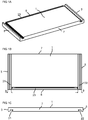
- Embodiments of the first panel are shown in FIGS 1A-1C and FIGS 2A-2D that may be produced according to embodiments of the invention.
- FIG 1A shows an embodiment of the first panel 1 in a 3D-view.
- FIG 1B shows a top view and
- FIG 1C shows a side view.
- the first panel comprises a first edge 3 comprising a first edge groove 21 and a second edge 5 comprising a second edge groove 22.
- the first edge groove extends along the whole first edge and comprises an opening at an adjacent third edge 7 and an opening at an adjacent fourth edge 6.
- the second edge groove extends along the whole second edge 5 and comprises an opening at the adjacent third edge 7 and an opening at the adjacent fourth edge 6.
- the first and the second edges are covered by a covering material.
- the first and the second edges 3,5 may be side edges of a furniture product and the fourth edge 6 may be a back edge.
- the third edge 7 may be a front edge that may be covered with a covering material (not shown) that covers the openings of the first edge groove and the second edge groove, respectively.
- the fourth edge 6 may comprise a third edge groove 23, which preferably ends at a distance 9 from the first edge and the second edge, respectively.
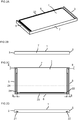
- FIG 2A shows an embodiment of the first panel 1 in a 3D-view.
- FIG 2C shows a top view and
- FIG 2B shows a side view.
- FIG 2D shows a cross cut at the dotted line 24 shown in FIG 2C .
- the first panel comprises a first edge 3 comprising a first edge groove 21 and a second edge 5 comprising a second edge groove 22.
- the first edge groove extends along the first edge and comprises an opening at an adjacent fourth edge 6.
- the second edge groove extends along the second edge 5 and comprises an opening at the adjacent fourth edge 6.
- the first and the second edges are covered by a covering material.
- the first and the second edges 3,5 may be side edges of a furniture product and the fourth 6 edge may be a back edge.
- the first and the second edge groove may end at a distance 8 from the third edge 7.
- the fourth edge may comprise a third edge groove 23, which preferably ends at a distance 9 from the first edge and the second edge, respectively.
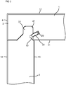
- FIG 3 shows an end piece of an embodiment of the first panel.
- the first panel 1 is locked together by a locking device to a second panel 2.
- a second main surface 13 of the second panel 2 is essentially perpendicular to a first main surface 11 of the first panel 1 in the shown locked position.
- the first edge groove 21 is configured to cooperate with an edge tongue 32 of the second panel 2 for locking the first panel 1 to the second panel 2 in a first direction, which is perpendicular to the second main surface 13 of the second panel.
- the locking device may comprise a flexible tongue 30, which may be arranged in an insertion groove 20 formed in the first edge groove 21, and a tongue groove 10 that may be formed in the edge tongue 32.
- the flexible tongue is configured to cooperate with the tongue groove for locking the first panel to the second panel in second direction which is perpendicular to the first main surface 11 of the first panel.
- the first panel 1 comprises a second main surface 12, which is opposite to the first main surface of the first panel.
- the second panel 2 comprises a first main surface 14, which opposite to the second main surface 13 of the second panel.
- the first edge 3 is covered by a covering material 4.
- the first and the second main surfaces of the first and the second panels may each be covered by a decorative layer.
- An outer surface of the covering material may be in line with an outer surface of the first main surface 14 of the second panel.
- Another panel may be locked to the second edge groove of the first panel 1 in the same way as shown in FIG 3 .
- Another panel may be locked also to the third edge groove of the first panel in the same way as shown in FIG 3 .
- three panels may be locked to the first panel.
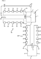
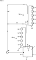
- FIG 4 shows an embodiment of a production line for producing embodiments of the first panel 1.
- the production line comprises a first edge machine 99.
- the first panel is formed by:
- the first panel is positioned by a positioning device, such that the first panel is at a same position relative the conveyor at least between said attaching of the covering material by the second tool 52 and said forming of the first edge groove by the third tool 53.
- the positioning device may be a part protruding from the conveyor.
- the conveyor may comprise a lower chain track and an upper belt.
- the positioning device may protrude from the lower chain track.
- the first panel may be arranged with the first main surface facing the lower chain track. This may have the advantage that thickness variations of the first panel may not affect a location of the first edge groove relative the first main surface.
- the working by the first tool 51 is performed before the attaching of the covering material 4 by the second tool 52, and the attaching of the covering material 4 by the second tool 52 is performed before the forming the first edge groove 21 by the third tool 53.
- the forming of the first edge groove 21, by the third tool 53 may comprise mechanical cutting, such as milling.
- the third tool may be displaced in a direction with an angle to the first main surface, the angle is may be an essentially right angle, e.g., about 90 degrees, such that the first edge groove ends at a distance 8 from a third edge 7, which is adjacent to the first edge 3.
- the direction is preferably perpendicular to an axis of rotation of the third tool.
- An insertion groove 20 is formed, by a fourth tool 54 of the first edge machine 99, in the first edge groove 21.
- the forming may comprise displacing the fourth tool in a direction, which is preferably essentially perpendicular to an axis of rotation of the fourth tool, such that the insertion groove 20 ends at a distance from the third edge.
- a tongue 30 is inserted, by a fifth tool 55 of the first machine, in the insertion groove 20.
- a first tool setup comprising the first, second, third, fourth and fifth tools of the first edge machine are arranged on a first side 91 of the first edge machine 99.
- the shown first edge machine may comprise the same tool setup on a second side 92, which is opposite to the first side, for forming a second edge of the first panel.
- Forming of a second edge at a second side 92 of the first edge machine may comprise:
- the forming may further comprise positioning of the first panel by a positioning device, such that the first panel is at a same position relative the conveyor at least between said attaching of the covering material by seventh tool 72 and said forming of the second edge groove by the eighth tool 73.
- the positioning device on the second side may be configured as on the first side.
- the working by the sixth tool 71 is performed before the attaching of the covering material 4 by the seventh tool 72, and the attaching of the covering material 4 by the seventh tool 72 is performed before the forming the second edge groove 22 by the eighth tool 73.
- the eighth tool may be displaced in a direction with an angle to the first main surface of the first panel, the angle is preferably an essentially right angle, e.g., about 90 degrees, such that the first edge groove ends at a distance 8 from a third edge 7, which is adjacent to the first edge 3.
- the direction is preferably perpendicular to an axis of rotation of the eighth tool.
- the forming may comprise forming, by a ninth tool 74 of the first edge machine 99, an inserting groove 20 in the second edge groove 22.
- the forming may comprise displacing the ninth tool in a direction, which is preferably essentially perpendicular to an axis of rotation of the ninth tool, such that the inserting groove 20 ends at a distance from the third edge.
- the forming may comprise inserting a tongue 30, by a tenth tool 75 of the first edge machine 99, in the inserting groove 20.
- a second tool setup comprising the sixth, seventh, eighth, ninth and tenth tools of the first edge machine is arranged on the second side 92, which is opposite the first side, of the first edge machine 99.
- the embodiment of the production line shown in FIG 4 comprises a fourth edge machine 98 for forming a third and/or fourth edge 7, 6 of the first panel 1.
- An alternative embodiment of the production is lacking the fourth edge machine 98.
- the method for forming a third and/or fourth edge 7, 6 may for the alternative production line comprise the step of a feeding 84 the first panel from the outlet of the first edge machine, rotating the first panel 90 degrees, a feeding 86 into the inlet of the first edge machine and using the first and/or second tool setup for forming the third and/or fourth edge of the first panel.
- the width of the first edge machine may have to be adjusted before a forming of the third and/or fourth edge.
- the tools may have to be adjusted to another shape of the third and or fourth edge. In order to avoid adjustment it is therefore preferred to have the fourth edge machine 98 in the production line.
- the forming of the first panel 1 may comprise:
- the forming may further comprise displacing the 13th tool in a direction with an angle to the first main surface of the first panel, the angle is preferably an essentially right angle, e.g., about 90 degrees, such that the third edge groove ends at a distance 9 from the first edge 3 and at a distance from a second edge which is adjacent to the fourth edge 6.
- the direction is preferably perpendicular to an axis of rotation of the 13th tool.
- the forming may further comprise:
- the fourth edge machine 98 may comprise a third tool setup, comprising the 11th tool and the 13th tool, that is arranged on a first side 93 of the fourth edge machine 98.
- the third tool set up may also comprise one or more of a 12th tool 42, a 14th tool 44 and a 15th tool 45, which corresponds to the second tool 52, the fourth tool 54 and a fifth tool 55, respectively, of the first tool setup.
- One or more of the tools of the third tool setup may be used for the forming of the fourth edge of the first panel.
- the fourth edge machine 98 may comprise a fourth tool setup, comprising the 16th tool and the 17th tool, that is arranged on a second side 94, which is opposite the first side, of the fourth edge machine 98.
- the third tool set up may also comprise one or more of a 18th tool 63, a 19th tool 64 and a 20th tool 65, which corresponds to the eighth tool 73, the ninth tool 74 and a tenth tool 75, respectively, of the second tool setup.
- One or more of the tools of the fourth tool setup may be used for the forming of the third edge of the first panel.
- the fourth edge machine 98 may comprise a positioning device on the first and the second side, such that the first panel is at a same position relative the conveyor during the forming.
- the positioning device may be a part protruding from the conveyor.
- the conveyor may comprise a lower chain track and an upper belt.
- the positioning device may protrude from the lower chain track.
- the fourth edge machine 98 may comprise a guiding device along the first and/or the second side, such that the third edge and the fourth edge are formed parallel.
- FIG 5 An alternative production line shown in FIG 5 which comprises a first machine 95, which comprises a tool set up that corresponds to the first tool setup of the first edge machine 99, and/or a second machine 96 with a tool setup that corresponds to second tool setup of the first edge machine 99.
- the first and the second machine may have a conveyor of the same type as the first edge machine.
- the first panel 1 may be formed on the first edge 3 and the second edge 5 by displacing 81 the first panel through the first machine 9 and the second machine.
- the third edge and the fourth edge may be formed by displacing 87 the first panel from the outlet of the second machine to the inlet of the first machine and rotating 88 the first panel 90 degrees before beginning a forming of the third and the fourth edges.
- the first edge may be formed by displacing 86 the first panel 1 through the first machine 95.
- the second edge may be formed by displacing 87 the first panel from the outlet of the first machine to the inlet of the first machine and rotating 88 the first panel 180 degrees before beginning a forming of the second edge.
- the third edge may be formed by displacing 89 the first panel from the outlet of the first machine to the inlet of the first machine and rotating 88 the first panel 90 degrees before beginning a forming of the third edge.
- the fourth edge may be formed by displacing 89 the first panel from the outlet of the first machine to the inlet of the first machine and rotating 88 the first panel 180 degrees before beginning a forming of the fourth edge.
- An advantage with this alternative production line may be that an adjustment of the first and/or the second machine due to different widths of the first panel may not be needed.
- a disadvantage may be that the first panel may have to be displaced two or more times through the first and/or second machine.
- One or more of the first tool, the fifth tool, 11th tool and the 16th tool may each comprise a mechanical cutting unit, such as a milling unit, and/or preferably a sanding unit.
- One or more of the second tool, the seventh tool, the 12th tool and the 17th tool may each comprise a gluing section.
- One or more of the third tool, the eighth tool, the 13th tool, the 18th tool and the 23th may each comprise a mechanical cutting unit, such as a milling unit, and/or preferably
- any of the tools, and number of tools, in any of the toll setups may differ from each other, depending of the desired shapes of the first panel.
- Forming of the first panel in any of the production lines described above may result in a same final shape of the first panel.
- the furniture product may be a cabinet, such as a kitchen cabinet, bookshelves, a drawer, a table, a wardrobe or similar
- the set of panels described above may be a part of a furniture product, such as a frame.
Claims (13)
- Verfahren zum Ausbilden einer ersten Platte (1) für ein zusammengesetztes Erzeugnis, wie beispielsweise ein Möbelerzeugnis, wobei das Verfahren umfasst:Verschieben der ersten Platte (1) in Vorschubrichtung (82) durch eine Fördereinrichtung durch eine erste Kantenmaschine (99),Bearbeiten der ersten Kante (3) der ersten Platte mit einem ersten Werkzeug (51) der ersten Kantenmaschine (99), um eine bestimmte Position der ersten Kante (3) zu erhalten;Anbringen eines Abdeckmaterials (4), beispielsweise eines Laminatstreifens, eines thermoplastischen Streifens oder eines Furnierstreifens, an der ersten Kante (3) durch ein zweites Werkzeug (52) der ersten Kantenmaschine (99);Ausbilden einer ersten Kantennut (21) durch ein drittes Werkzeug (53) der ersten Kantenmaschine (99) entlang der ersten Kante (3) und auf einer ersten Hauptfläche (11) der ersten Platte (1), wobei die erste Kantennut als Teil einer Verriegelungsvorrichtung konfiguriert ist, undPositionieren der ersten Platte durch eine Positionierungsvorrichtung, so dass sich die erste Platte an derselben Position relativ zu der Fördereinrichtung befindet, wenigstens zwischen dem Anbringen des Abdeckmaterials durch das zweite Werkzeug (52) und dem Ausbilden der ersten Kantennut durch das dritte Werkzeug (53) undwobei das Bearbeiten durch das erste Werkzeug (51) vor dem Anbringen des Abdeckmaterials (4) durch das zweite Werkzeug (52) ausgeführt wird und das Anbringen des Abdeckmaterials (4) durch das zweite Werkzeug (52) vor dem Ausbilden der ersten Kantennut (21) durch das dritte Werkzeug (53) ausgeführt wird.
- Verfahren nach Anspruch 1, wobei das Verfahren das Ausbilden einer Einführnut (20) in der ersten Kantennut (21) durch ein viertes Werkzeug (54) der ersten Kantenmaschine (99) umfasst.
- Verfahren nach Anspruch 2, wobei das Verfahren das Einführen einer Feder (30) durch ein fünftes Werkzeug (55) der ersten Kantenmaschine (99) in die Einführnut (20) umfasst.
- Verfahren nach einem der Ansprüche 1 bis 3, wobei das Verfahren das Verschieben des dritten Werkzeugs in einer Richtung mit einem Winkel zur ersten Hauptfläche der ersten Platte umfasst, wobei der Winkel vorzugsweise ein im wesentlichen rechter Winkel ist, so dass die erste Kantennut in einem Abstand (8) von einer dritten Kante (7) endet, die an die erste Kante (3) angrenzt.
- Verfahren nach einem der Ansprüche 1 bis 4, wobei das Verfahren umfasst:Bearbeiten einer zweiten Kante (5) der ersten Platte mit einem sechsten Werkzeug (71) der ersten Kantenmaschine (99), um eine bestimmte Position der zweiten Kante (5) zu erhalten, die der ersten Kante gegenüberliegt,Anbringen eines Abdeckmaterials (4), beispielsweise eines Laminatstreifens, eines thermoplastischen Streifens oder eines Furnierstreifens, an der zweiten Kante (5) mit einem siebten Werkzeug (72) der ersten Kantenmaschine (99),Ausbilden einer zweiten Kantennut (22) durch ein achtes Werkzeug (73) der ersten Kantenmaschine (99) entlang der zweiten Kante (5) und auf der ersten Hauptfläche (11) der ersten Platte (1), wobei die zweite Kantennut als Teil einer Verriegelungsvorrichtung konfiguriert wird.
- Verfahren nach Anspruch 5, wobei das Verfahren das Positionieren der ersten Platte durch eine Positionierungsvorrichtung umfasst, so dass sich die erste Platte wenigstens zwischen dem Anbringen des Abdeckmaterials mit dem siebten Werkzeug (72) und dem Ausbilden der zweiten Kantennut durch das achte Werkzeug (73) an derselben Position relativ zu der Fördereinrichtung befindet.
- Verfahren nach Anspruch 5 oder 6, bei dem das Bearbeiten mit dem sechsten Werkzeug (71) vor dem Anbringen des Abdeckmaterials (4) durch das siebte Werkzeug (72) und das Anbringen des Abdeckmaterials (4) durch das siebte Werkzeug (72) vor dem Ausbilden der zweiten Kantennut (22) durch das achte Werkzeug (73) ausgeführt wird.
- Verfahren nach einem der Ansprüche 5 bis 6, wobei das Verfahren das Ausbilden einer Einführnut (20) in der zweiten Kantennut (22) durch ein neuntes Werkzeug (74) der ersten Kantenmaschine (99) umfasst.
- Verfahren nach Anspruch 8, wobei das Verfahren das Einführen einer Feder (30) durch ein zehntes Werkzeug (75) der ersten Kantenmaschine (99) in die Einführnut (20) umfasst.
- Verfahren nach einem der Ansprüche 5 bis 9, wobei das Verfahren das Verschieben des achten Werkzeugs in einer Richtung mit einem Winkel zur ersten Hauptfläche der ersten Platte umfasst, wobei der Winkel vorzugsweise ein im wesentlichen rechter Winkel ist, so dass die zweite Kantennut in einem Abstand (8) von einer dritten Kante (7) endet, die an die erste Kante (3) angrenzt.
- Verfahren nach einem der Ansprüche 1 bis 10, wobei das Verfahren umfasst:Verschieben der ersten Platte (1) in Vorschubrichtung (81) durch eine Fördereinrichtung durch eine vierte Kantenmaschine (98),Bearbeiten mit einem elften Werkzeug (41) der vierten Kantenmaschine (98) einer vierten Kante (6) der ersten Platte, um eine bestimmte Position der vierten Kante (6) zu erhalten, wobei die vierte Kante neben der ersten Kante (3) liegt, undAusbilden einer dritten Kantennut (23) durch ein 13. Werkzeug (43) der vierten Kantenmaschine (98) entlang der vierten Kante (6) und auf einer ersten Hauptfläche (11) der ersten Platte (1), wobei die dritte Kantennut als Teil einer Verriegelungsvorrichtung konfiguriert ist.
- Verfahren nach einem der Ansprüche 11, wobei das Verfahren das Verschieben des 13. Werkzeugs in einer Richtung mit einem Winkel zur ersten Hauptfläche der ersten Platte umfasst, wobei der Winkel vorzugsweise ein im wesentlichen rechter Winkel ist, so dass die dritte Kantennut in einem Abstand (9) von der ersten Kante (3) und in einem Abstand von einer zweiten Kante endet, die an die vierte Kante (6) angrenzt.
- Verfahren nach einem der Ansprüche 1 bis 12, wobei das Verfahren umfasst:Bearbeiten einer dritten Kante (7) der ersten Platte mit einem 16. Werkzeug (61) einer vierten Kantenmaschine (98), um eine bestimmte Position der dritten Kante (7) zu erhalten, die neben der ersten Kante (3) liegt, undBefestigen eines Abdeckmaterials (4), beispielsweise eines Laminatstreifens, eines thermoplastischen Streifens oder eines Furnierstreifens, mit einem 17. Werkzeug (62) der vierten Kantenmaschine (98) an der dritten Kante (7).
Priority Applications (3)
| Application Number | Priority Date | Filing Date | Title |
|---|---|---|---|
| PL17753574T PL3416792T3 (pl) | 2016-02-15 | 2017-02-14 | Sposób formowania panelu do wyrobu meblowego |
| SI201730608T SI3416792T1 (sl) | 2016-02-15 | 2017-02-14 | Metoda izdelave panela za pohištveni izdelek |
| HRP20210109TT HRP20210109T1 (hr) | 2016-02-15 | 2021-01-21 | Postupak oblikovanja ploče za proizvod namještaja |
Applications Claiming Priority (2)
| Application Number | Priority Date | Filing Date | Title |
|---|---|---|---|
| SE1650196 | 2016-02-15 | ||
| PCT/SE2017/050135 WO2017142459A1 (en) | 2016-02-15 | 2017-02-14 | A method for forming a panel for a furniture product |
Publications (3)
| Publication Number | Publication Date |
|---|---|
| EP3416792A1 EP3416792A1 (de) | 2018-12-26 |
| EP3416792A4 EP3416792A4 (de) | 2019-09-25 |
| EP3416792B1 true EP3416792B1 (de) | 2020-11-11 |
Family
ID=59559592
Family Applications (1)
| Application Number | Title | Priority Date | Filing Date |
|---|---|---|---|
| EP17753574.7A Active EP3416792B1 (de) | 2016-02-15 | 2017-02-14 | Verfahren zur herstellung eines paneels für ein möbelstück |
Country Status (20)
| Country | Link |
|---|---|
| US (1) | US10830266B2 (de) |
| EP (1) | EP3416792B1 (de) |
| JP (1) | JP6921834B2 (de) |
| KR (1) | KR20180111955A (de) |
| CN (1) | CN108602198B (de) |
| AU (1) | AU2017219521B2 (de) |
| BR (1) | BR112018014155A2 (de) |
| CA (1) | CA3011421C (de) |
| DK (1) | DK3416792T3 (de) |
| EA (1) | EA037625B1 (de) |
| ES (1) | ES2847205T3 (de) |
| HR (1) | HRP20210109T1 (de) |
| HU (1) | HUE053138T2 (de) |
| LT (1) | LT3416792T (de) |
| MX (1) | MX2018009631A (de) |
| MY (1) | MY189424A (de) |
| PL (1) | PL3416792T3 (de) |
| PT (1) | PT3416792T (de) |
| SI (1) | SI3416792T1 (de) |
| WO (1) | WO2017142459A1 (de) |
Families Citing this family (36)
| Publication number | Priority date | Publication date | Assignee | Title |
|---|---|---|---|---|
| UA109938C2 (uk) | 2011-05-06 | 2015-10-26 | Механічна фіксуюча система для будівельних панелей | |
| US9726210B2 (en) | 2013-09-16 | 2017-08-08 | Valinge Innovation Ab | Assembled product and a method of assembling the product |
| MY175374A (en) | 2013-09-16 | 2020-06-23 | Valinge Innovation Ab | An assembled product and a method of assembling the assembled product |
| UA119454C2 (uk) | 2014-01-10 | 2019-06-25 | Велінге Інновейшн Аб | Меблева панель |
| US9714672B2 (en) | 2014-01-10 | 2017-07-25 | Valinge Innovation Ab | Panels comprising a mechanical locking device and an assembled product comprising the panels |
| KR102475315B1 (ko) | 2014-05-09 | 2022-12-06 | 뵈린게 이노베이션 에이비이 | 빌딩 패널용 기계적 잠금 시스템 |
| CN107002732B (zh) | 2014-12-19 | 2020-06-05 | 瓦林格创新股份有限公司 | 包括机械锁定装置的镶板和包括所述镶板的组合产品 |
| WO2016171607A1 (en) | 2015-04-21 | 2016-10-27 | Välinge Innovation AB | Panel with a slider |
| MX2017013753A (es) | 2015-04-30 | 2018-03-01 | Vaelinge Innovation Ab | Panel con dispositivo de sujecion. |
| US9930959B2 (en) * | 2015-08-07 | 2018-04-03 | Comsero, Inc. | Modular furniture and structures |
| AU2016327703B2 (en) | 2015-09-22 | 2020-09-03 | Välinge Innovation AB | Panels comprising a mechanical locking device and an assembled product comprising the panels |
| PL3384165T3 (pl) | 2015-12-03 | 2022-01-03 | Välinge Innovation AB | Zestaw paneli zawierający mechaniczne urządzenie blokujące |
| UA126556C2 (uk) | 2016-01-26 | 2022-11-02 | Велінге Інновейшн Аб | Панелі, що містять механічний блокувальний пристрій, і складений виріб, що містить панелі |
| EP3411599B1 (de) | 2016-02-04 | 2021-03-31 | Välinge Innovation AB | Set aus platten für eine montiertes produkt |
| WO2017138874A1 (en) | 2016-02-09 | 2017-08-17 | Välinge Innovation AB | Element and method for providing dismantling groove |
| US10415613B2 (en) | 2016-02-09 | 2019-09-17 | Valinge Innovation Ab | Set of panel-shaped elements for a composed element |
| CA3040653A1 (en) | 2016-10-27 | 2018-05-03 | Valinge Innovation Ab | Set of panels with a mechanical locking device |
| CN110621889A (zh) | 2017-05-15 | 2019-12-27 | 瓦林格创新股份有限公司 | 用于组合产品的元件和锁定装置 |
| WO2019125291A1 (en) | 2017-12-22 | 2019-06-27 | Välinge Innovation AB | A set of panels, a method for assembly of the same and a locking device for a furniture product |
| LT3728869T (lt) | 2017-12-22 | 2023-04-25 | Välinge Innovation AB | Plokščių rinkinys, jų surinkimo būdas ir baldų gaminio fiksatorius |
| MX2020009767A (es) | 2018-03-23 | 2020-10-08 | Vaelinge Innovation Ab | Paneles que comprenden un dispositivo de bloqueo mecanico y un producto ensamblado que comprende los paneles. |
| EA202092389A1 (ru) * | 2018-04-18 | 2021-01-27 | Велинге Инновейшн Аб | Набор панелей с механическим блокирующим устройством |
| US11703072B2 (en) | 2018-04-18 | 2023-07-18 | Valinge Innovation Ab | Set of panels with a mechanical locking device |
| KR20200141076A (ko) | 2018-04-18 | 2020-12-17 | 뵈린게 이노베이션 에이비이 | 대칭 설형부 및 티-크로스 |
| EP3781823B1 (de) | 2018-04-18 | 2024-04-10 | Välinge Innovation AB | Satz aus platten mit mechanischer verriegelungsvorrichtung |
| US11614114B2 (en) | 2018-04-19 | 2023-03-28 | Valinge Innovation Ab | Panels for an assembled product |
| US11445819B2 (en) | 2018-08-30 | 2022-09-20 | Valinge Innovation Ab | Set of panels with a mechanical locking device |
| EP3718437A1 (de) * | 2019-04-05 | 2020-10-07 | Välinge Innovation AB | Verfahren zur montage eines möbelstücks |
| US11425996B2 (en) * | 2019-09-17 | 2022-08-30 | 902A Llc | Customizable modular shelving system |
| EP3834661A1 (de) | 2019-12-11 | 2021-06-16 | Välinge Innovation AB | Mechanisches arretierungssystem für platten |
| WO2021126070A1 (en) | 2019-12-19 | 2021-06-24 | Välinge Innovation AB | Set of panels with a mechanical locking device |
| WO2021150162A1 (en) | 2020-01-22 | 2021-07-29 | Välinge Innovation AB | Set of panels with a mechanical locking device |
| US11702844B2 (en) | 2020-06-05 | 2023-07-18 | Valinge Innovation Ab | Building panels comprising a locking device |
| US20220018373A1 (en) * | 2020-07-17 | 2022-01-20 | Välinge Innovation AB | Mechanical locking system for panels |
| WO2022124974A1 (en) | 2020-12-11 | 2022-06-16 | Välinge Innovation AB | Rail for cabinets |
| AU2021417720A1 (en) | 2021-01-07 | 2023-07-27 | Välinge Innovation AB | Wedge-shaped tongue insertion groove |
Family Cites Families (305)
| Publication number | Priority date | Publication date | Assignee | Title |
|---|---|---|---|---|
| DE228872C (de) | ||||
| US291032A (en) | 1884-01-01 | Isaac g- | ||
| US634581A (en) | 1898-11-21 | 1899-10-10 | Robert H Miller | Carpenter's square. |
| US701000A (en) | 1901-07-31 | 1902-05-27 | Carl F W Ahrens | File-cabinet. |
| US861911A (en) | 1905-11-04 | 1907-07-30 | William Stewart | Joint for articles of furniture or woodwork. |
| US881673A (en) | 1907-03-11 | 1908-03-10 | Arthur L Ellison | Wardrobe or safe. |
| US1534468A (en) | 1922-10-30 | 1925-04-21 | Jr John J Shea | Joint structure |
| US1533099A (en) | 1924-07-14 | 1925-04-14 | Robert E Carroll | Square-corner glue joint |
| GB245332A (en) | 1925-05-04 | 1926-01-07 | George Hugh Foster | An improved dowelled joint for woodwork and the like |
| US1800386A (en) | 1926-08-28 | 1931-04-14 | Andrew Hoffman Mfg Company | Display rail |
| US1800387A (en) | 1926-12-30 | 1931-04-14 | Andrew Hoffman Mfg Company | Article-supporting device |
| US1802245A (en) | 1930-08-26 | 1931-04-21 | Clarence L Foretich | Display stand and shelving |
| US1954242A (en) | 1932-07-28 | 1934-04-10 | Thomas E Heppenstall | Dovetail spring joint |
| US2360451A (en) | 1942-06-02 | 1944-10-17 | Stone Abraham | Collapsible clothing container |
| US2362904A (en) | 1943-01-20 | 1944-11-14 | Allied Purchasing Corp | Joint for demountable furniture |
| US2496184A (en) | 1946-06-11 | 1950-01-31 | Canon Paul L Von | Furniture drawer construction and method |
| US2681483A (en) | 1948-10-14 | 1954-06-22 | Morawetz Hugo | Dowel connection |
| DE1107910B (de) | 1957-03-26 | 1961-05-31 | Curt Weinert | Biegsamer Duebel |
| CH365507A (de) | 1958-11-17 | 1962-11-15 | Antonius Bus Johannes | Einrichtung zur Verbindung von senkrecht aufeinanderstehenden Wänden mit selbsttätiger Sperrung, insbesondere Möbelwänden |
| US3002630A (en) | 1960-05-24 | 1961-10-03 | Robert E Heisser | Toothbrush rack |
| US3195968A (en) | 1962-12-06 | 1965-07-20 | Lok Trim Corp | Knock-down furniture |
| DE1240638B (de) | 1963-03-07 | 1967-05-18 | Kueche | Zerlegbares Moebelstueck |
| AT260460B (de) | 1963-08-19 | 1968-03-11 | Trepatent As | Führung für Schubladen, Regalplatten od. dgl. |
| US3313054A (en) | 1965-06-09 | 1967-04-11 | Poster Products Inc | Display devices |
| IS831B6 (is) | 1965-10-28 | 1973-04-12 | Nordischer Maschinenbau Rud. BaaderNordischer Maschinenbau, Rud. Baader | Aðferð til þess að fjarlægja lifur úr fiskiTæki til að hausa hásskorinn fisk, þannig að vætubeinið verði eftir á fiskinum |
| US3410441A (en) | 1966-06-29 | 1968-11-12 | Jeff S. Rhyne | Container |
| US3347610A (en) | 1966-07-28 | 1967-10-17 | Pilliod Cabinet Company | Cabinet construction |
| DE1955922C3 (de) | 1969-11-06 | 1974-01-10 | Hefendehl, Hansfriedrich, 5893 Kierspe | Kastenmöbel aus Kunststoff |
| US3722704A (en) | 1970-07-23 | 1973-03-27 | Castelli Sas Anonima | Structural components for the composition of disassemblable pieces offurniture |
| US3765465A (en) | 1972-01-05 | 1973-10-16 | Deutsch Fastener Corp | Retractable captive fastener |
| US3742807A (en) | 1972-02-03 | 1973-07-03 | D Manning | Leveling and locking pin |
| GB1398187A (en) | 1972-06-22 | 1975-06-18 | Schreiber Furniture | Kitchen cabinets |
| US3884002A (en) | 1973-03-15 | 1975-05-20 | American Store Equip | Partition system |
| DE2414104A1 (de) | 1974-03-23 | 1975-10-09 | Alfer Alu Fertigbau | Holzregal |
| DE2514357C3 (de) | 1974-04-02 | 1979-03-22 | Takeshi Tokio Shimizu | Beschlag zum verschwenkbaren Verbinden einer Möbelplatte mit einem feststehenden Möbelteil |
| US3885845A (en) | 1974-06-27 | 1975-05-27 | Hans Krieks | Knock-down furniture system |
| US3981118A (en) | 1974-10-17 | 1976-09-21 | The Goodyear Tire & Rubber Company | Clamping insert |
| ATA882576A (de) | 1975-12-02 | 1983-01-15 | Heinze Fa R | Moebelscharnier mit einem in einer bohrung eines moebelteils verankerbaren scharniertopf |
| CA1062321A (en) | 1976-05-12 | 1979-09-11 | I. T. W. Ltd. | Grommets for furniture connectors |
| DE2635237A1 (de) | 1976-08-05 | 1978-02-09 | Heinze Fa R | Moebelscharnier |
| JPS53113160U (de) | 1977-02-16 | 1978-09-08 | ||
| US4116510A (en) | 1977-03-03 | 1978-09-26 | Gte Automatic Electric Laboratories Incorporated | Chassis formed of sheet stock |
| US4099887A (en) | 1977-07-18 | 1978-07-11 | Einhard Mackenroth | Structural joints |
| US4222544A (en) | 1977-08-10 | 1980-09-16 | Kenneth Crowder | Picture rail apparatus |
| SE409603B (sv) | 1977-12-20 | 1979-08-27 | Stockum Design Ab | Forbindning |
| SE7809081L (sv) | 1978-08-29 | 1980-03-01 | Hafa Fabriks Ab | Anordning for uppberning av skap, speglar, hyllor och andra detaljer |
| US4211379A (en) | 1978-11-20 | 1980-07-08 | Morgan Myron B | Panelboard and mounting fixture combination |
| US4299067A (en) | 1979-10-30 | 1981-11-10 | J. C. Penney Company, Inc. | Partition connector system |
| US4308961A (en) | 1980-05-05 | 1982-01-05 | Kunce Thomas M | Article supporting structure |
| US4324517A (en) | 1980-06-16 | 1982-04-13 | Sps Technologies, Inc. | Panel fastener assembly with retainer ring |
| DE3047642A1 (de) | 1980-12-17 | 1982-10-28 | Arturo Salice S.p.A., 22060 Novedrate, Como | Verbindungsbeschlag |
| DE3103281C2 (de) | 1981-01-31 | 1984-05-10 | C + A Dick GmbH, 5275 Bergneustadt | Materialschrank |
| FR2501805A1 (fr) | 1981-03-10 | 1982-09-17 | Haeusler Roland | Nouveau systeme d'assemblage du genre a tenon et mortaise et articles mobiliers incorporant ledit systeme |
| FR2517187A1 (fr) | 1981-12-01 | 1983-06-03 | Beaux Dominique | Caisson demontable a usage de meuble |
| US4509648A (en) | 1982-07-26 | 1985-04-09 | The Stanley Works | Merchandising display system and components therefor |
| US4593734A (en) | 1983-09-26 | 1986-06-10 | M. Bosley Wright | Frame routing apparatus |
| US4629076A (en) | 1984-05-10 | 1986-12-16 | Amstore Corporation | Slatboard |
| GB2163825B (en) | 1984-08-30 | 1988-03-02 | Hettich Paul Gmbh & Co | Furniture connector |
| US4595105A (en) | 1984-09-12 | 1986-06-17 | Gold Kenneth S | Interlocking bookrack |
| US4750794A (en) | 1984-11-21 | 1988-06-14 | Bass Cabinet Manufacturing, Inc. | Slide-fitted article of furniture |
| US4597122A (en) | 1985-06-10 | 1986-07-01 | Hirsh Company | Free-standing drawer |
| US4615448A (en) | 1985-09-27 | 1986-10-07 | Masonite Corporation | Display panel |
| US4891897A (en) | 1985-12-12 | 1990-01-09 | Gieske Detlef J | Display panel |
| FR2597173B1 (fr) | 1986-04-10 | 1988-10-07 | Forschle Andre | Dispositif pour assembler et modifier facilement la composition d'un meuble en kit |
| GB8612597D0 (en) | 1986-05-23 | 1986-07-02 | George W R | Joint between members |
| FR2602013B1 (fr) | 1986-07-25 | 1988-12-30 | Kapikian Jean Claude | Systeme d'assemblage du type a tenon et mortaise aisement montable et demontable |
| US4815908A (en) | 1986-10-14 | 1989-03-28 | Avibank Mfg., Inc. | Captive panel fastener assembly |
| DE3702154A1 (de) * | 1987-01-26 | 1988-08-04 | Klessmann Ima Norte Maschfab | Kantenanleimmaschine |
| US4844266A (en) | 1987-07-16 | 1989-07-04 | Intercraft Industries Corporation | Display system |
| CA1297934C (en) | 1987-07-24 | 1992-03-24 | Craig Mengel | Method of and structure for the joining of substantially rigidparts together |
| US4886326A (en) | 1988-01-29 | 1989-12-12 | Tetrad Marketing/Sales Ltd. | Interlock system for ready to assemble furniture, and furniture incorporating such system |
| US4961295A (en) | 1988-03-14 | 1990-10-09 | Kosch Sr Paul | Metal slat and wall system utilizing same |
| US4817900A (en) | 1988-05-09 | 1989-04-04 | Gorrie Advertising Management Limited | Support device for use on a display wall |
| JPH0266308A (ja) | 1988-08-30 | 1990-03-06 | Kazuhiro Matsui | 組立具 |
| IT215989Z2 (it) | 1988-09-02 | 1991-03-26 | Cattarozzi Andrea | Contenitore modulare componibile e trasportabile manualmente, per la conservazione di sostanze, in special modo per uso alimentare |
| NL8802459A (nl) | 1988-10-07 | 1990-05-01 | Homburg Interieuren B V | Uitstalwand. |
| US4944416A (en) | 1988-11-21 | 1990-07-31 | Petersen Robert J | Light-weight slot-wall display panel |
| US5471804A (en) | 1988-11-21 | 1995-12-05 | Winter, Iv; Amos G. | Building system using prefabricated building panels and fastening components used therewith |
| US4909581A (en) | 1988-12-12 | 1990-03-20 | American Moulding & Millwork Company | Drawer construction |
| EP0400124A1 (de) | 1988-12-13 | 1990-12-05 | TANNER, Rudolf | Verbindungselement zum formschlüssigen verbinden |
| US5018323A (en) | 1989-05-12 | 1991-05-28 | Knud Clausen | Wall panel system |
| US5109993A (en) | 1989-10-31 | 1992-05-05 | Hutchison V James | Merchandise display system and merchandise holder therefor |
| US5138803A (en) | 1991-01-11 | 1992-08-18 | Commercial And Architectural Products, Inc. | Display panel assembly |
| US5121578A (en) | 1991-01-28 | 1992-06-16 | Holz Plastics, Inc. | Slat wall decorating system |
| US5209556A (en) | 1991-04-01 | 1993-05-11 | Anderson Robert F | Drawer assembly |
| GB2269839B (en) | 1991-04-01 | 1995-06-07 | Walter Lindal | Wooden frame building construction |
| US5114265A (en) | 1991-04-15 | 1992-05-19 | Grisley Kenneth M | Interlocking routed joint |
| US5299509A (en) | 1991-07-29 | 1994-04-05 | Ballard Donald M | Connectors for shelves and bins |
| US5125518A (en) | 1991-08-12 | 1992-06-30 | Innovative Accessories | Interlocking hanging system |
| CH684284A5 (de) | 1991-09-03 | 1994-08-15 | Edgar Probst | Rückwandbeschlag. |
| US5212925A (en) | 1991-11-21 | 1993-05-25 | Mcclinton John | Wall corner composite, mold and method for producing glazed unit for such |
| US5360121A (en) | 1992-08-07 | 1994-11-01 | Commerical And Architectural Products, Inc. | Slotted display wall panel |
| JP2530326Y2 (ja) | 1992-08-24 | 1997-03-26 | 株式会社イトーキクレビオ | 家具等における部材の連結装置 |
| CH685276A5 (de) | 1992-11-25 | 1995-05-31 | Werner Schmidt | Bausatz zur Herstellung von Regalen, Schränken und Wohnwänden und Regale, Schränke und Wohnwände hergestellt mit diesem Bausatz. |
| ZA94676B (en) | 1993-02-03 | 1994-08-03 | Rohm & Haas | Reduction of microfoam in spray-applied waterborne composition. |
| US5423155A (en) | 1993-06-02 | 1995-06-13 | Darko Company, Inc. | Panel for resurfacing slat walls |
| US5499667A (en) | 1994-06-21 | 1996-03-19 | Nakanishi Construction Company | Drill/cutting bit, and method of making structural joint |
| US5527103A (en) | 1993-10-01 | 1996-06-18 | Pittman; Charles | Cabinet of improved design and construction |
| US5375802A (en) | 1993-11-17 | 1994-12-27 | Bill Branham Designs, Ltd. | Structure for fastening facing structural units |
| US5451102A (en) | 1994-01-13 | 1995-09-19 | Chuan; Yuan-Jung | Cabinet with connecting mechanism for two adjacent wall plate |
| US5499886A (en) | 1994-03-02 | 1996-03-19 | Sauder Woodworking Co. | Coupling assembly for furniture components |
| DE4410901A1 (de) | 1994-03-29 | 1995-10-05 | Licentia Gmbh | Kühlschrank mit Kühlgutablagen |
| US5507331A (en) | 1994-06-21 | 1996-04-16 | Nakanishi Construction Company | Drilling/cutting bit, and method of making joint |
| DE9417168U1 (de) | 1994-10-26 | 1995-02-09 | Seeland Peter | Bausatz für ein Möbelstück |
| SE9500810D0 (sv) | 1995-03-07 | 1995-03-07 | Perstorp Flooring Ab | Golvplatta |
| DK9500332U3 (da) | 1995-08-29 | 1996-12-27 | Ikea Of Sweden Ab | Hjørnesamling mellem endepartierne af to bræddeagtige emner |
| US5658086A (en) | 1995-11-24 | 1997-08-19 | Brokaw; Paul E. | Furniture connector |
| US5775521A (en) | 1996-03-22 | 1998-07-07 | Custom Plastics, Inc. | Office organizer |
| CA2207533A1 (en) | 1996-06-12 | 1997-12-12 | David P. Thurston | Adjustable hanger system |
| US5950389A (en) | 1996-07-02 | 1999-09-14 | Porter; William H. | Splines for joining panels |
| US5810505A (en) | 1996-07-26 | 1998-09-22 | Kimball International, Inc. | Double threaded fastener system |
| GB2315988A (en) | 1996-08-07 | 1998-02-18 | Ultimate Systems Limited | Furniture with adjustable size panels |
| US5711115A (en) | 1996-10-30 | 1998-01-27 | Design Components, Inc. | Fireplace shelf and mantel support system |
| CA2200422C (en) | 1997-03-19 | 2002-05-07 | Jan B. Leurdijk | Storage track system |
| US5857304A (en) | 1997-04-07 | 1999-01-12 | Abex Display Systems | Slidable locking system for disengageable panels |
| CA2204301C (en) | 1997-05-02 | 2000-04-18 | Shang-Ming Lee | A connecting assembly for horizontal boards and wall boards of a cabinet |
| DE29714096U1 (de) | 1997-08-07 | 1998-12-03 | Dorth Ursel | Verbindersystem |
| NO974666L (no) | 1997-10-09 | 1999-04-12 | New Ideas | Sammenf°yningsanordning for plateformete konstruksjonsdeler, samt m°belkonstruksjon |
| US5941026A (en) | 1998-01-20 | 1999-08-24 | Storewall Llc | Slatwall display system |
| DE19805538A1 (de) | 1998-02-03 | 1999-08-12 | Montana Innovations Corp | Verbindungsanordnung für in einem Winkel zueinander stehende flächige Körper oder Bauteile |
| AT406181B (de) | 1998-02-09 | 2000-03-27 | Blum Gmbh Julius | Befestigungsvorrichtung für die befestigung mehrerer möbelbeschläge an einem möbelteil |
| DE29924630U1 (de) | 1998-02-11 | 2004-05-13 | Ipeg Gmbh - Ingenieurdienstleistungen | Verbindungsvorrichtung für flächige Körper oder sonstige Bauteile |
| DE19980228D2 (de) | 1998-02-11 | 2001-07-12 | Ipeg Unabhaengige Immobilienbe | Verbindungsvorrichtung für flächige Körper oder sonstige Bauteile |
| US6363645B1 (en) | 1998-02-25 | 2002-04-02 | Bruce A Hunter | Insert for display panels |
| US5944294A (en) | 1998-07-06 | 1999-08-31 | Baer; Thomas C. | Mounting device in form of C-clamp mounted space from a wall |
| DE29820031U1 (de) | 1998-11-10 | 1999-02-25 | Grant Alasdair E | Formschlüsselige Verbindungseinrichtung für Möbel bzw. Plattenelemente |
| US6349507B1 (en) | 1999-03-15 | 2002-02-26 | Spectra Products Corporation | Slat wall structure with profile for different shelf support brackets and the like |
| US6547086B1 (en) | 1999-03-25 | 2003-04-15 | Russell-William, Ltd. | Display wall panel |
| IT1307424B1 (it) | 1999-04-29 | 2001-11-06 | Costa S P A A | Metodo per la profilatura di listelli per parquet e macchinasquadratrice atta a realizzare tale metodo. |
| SE517478C2 (sv) | 1999-04-30 | 2002-06-11 | Valinge Aluminium Ab | Låssystem för mekanisk hofogning av golvskivor, golvskiva försedd med låssystemet samt metod för framställning av mekaniskt hopfogningsbara golvskivor |
| EP1190149B1 (de) | 1999-06-30 | 2004-01-21 | Akzenta Paneele + Profile GmbH | Paneel sowie befestigungssystem für paneele |
| DE29911462U1 (de) | 1999-07-02 | 1999-11-18 | Akzenta Paneele & Profile Gmbh | Befestigungssystem für Paneele |
| DE10001076C1 (de) | 2000-01-13 | 2001-10-04 | Huelsta Werke Huels Kg | Paneelelement |
| SE517183C2 (sv) | 2000-01-24 | 2002-04-23 | Valinge Aluminium Ab | Låssystem för mekanisk hopfogning av golvskivor, golvskiva försedd med låssystemet och metod för framställning av sådana golvskivor |
| WO2001072181A1 (en) | 2000-03-24 | 2001-10-04 | Commercial And Architectural Products, Inc. | Merchandising panel display system |
| US6413007B1 (en) | 2000-05-01 | 2002-07-02 | Sauder Woodworking Co. | Joint assembly |
| US6578498B1 (en) | 2000-06-06 | 2003-06-17 | Steelcase Development Corporation | Furniture accessory kit for portable computers and the like |
| EP2275616A3 (de) | 2001-01-12 | 2014-10-01 | Välinge Innovation AB | Verfahren zum Fügen von Fussbodenplatten |
| US6675979B2 (en) | 2001-05-21 | 2004-01-13 | Gregory Albert Taylor | Furniture assembly system |
| DE20122778U1 (de) | 2001-08-10 | 2007-10-25 | Akzenta Paneele + Profile Gmbh | Paneel sowie Befestigungssystem für Paneele |
| DE10142508A1 (de) | 2001-08-30 | 2003-03-27 | Bsh Bosch Siemens Hausgeraete | Rastvorrichtung und mit dieser ausgestattete Küchenmaschine |
| SE525558C2 (sv) | 2001-09-20 | 2005-03-08 | Vaelinge Innovation Ab | System för bildande av en golvbeläggning, sats av golvskivor samt förfarande för tillverkning av två olika typer av golvskivor |
| US7223045B2 (en) | 2001-09-26 | 2007-05-29 | Agostino Ferrari S.P.A. | Device and method for detachably connecting abutting structural parts and tie member for use to form said device |
| JP2003239921A (ja) | 2002-02-20 | 2003-08-27 | Takagaki Mokuzai Kogei Kk | ほぞとほぞ穴による接合構造 |
| US6772890B2 (en) | 2002-04-03 | 2004-08-10 | Commercial And Architectural Products, Inc. | Narrow groove display panel |
| USD482552S1 (en) | 2002-04-03 | 2003-11-25 | Commercial And Architectural Products, Inc. | Insert for a display panel |
| JP4472355B2 (ja) | 2002-04-03 | 2010-06-02 | ベーリンゲ、イノベイション、アクチボラグ | フロアボード用機械式係止システム |
| AUPS265502A0 (en) | 2002-05-30 | 2002-06-20 | Ibj Resources Pty Ltd | Mounting system |
| AU2003251423A1 (en) | 2002-07-17 | 2004-02-09 | Device Works Company | Cable organization and hardware shelving system |
| US6827028B1 (en) | 2002-12-11 | 2004-12-07 | E. Pryor Callaway | Collapsible support |
| US7228977B2 (en) | 2003-06-16 | 2007-06-12 | Whirlpool Corporation | Workroom storage system |
| BRPI0407664B1 (pt) | 2003-03-06 | 2014-12-09 | Vaelinge Innovation Ab | "sistema de piso e método de instalação". |
| US7306299B2 (en) | 2003-03-07 | 2007-12-11 | Masterbrand Cabinets, Inc. | Semi-frameless cabinet and method for making the same |
| DE20304761U1 (de) | 2003-03-24 | 2004-04-08 | Kronotec Ag | Einrichtung zum Verbinden von Bauplatten, insbesondere Bodenpaneele |
| US6971614B2 (en) | 2003-07-11 | 2005-12-06 | Jifram Extrusions, Inc. | Slatwall hanger stabilizing chip |
| KR100975937B1 (ko) | 2003-09-30 | 2010-08-16 | 엘지전자 주식회사 | 냉장고용 도어바스켓 장착장치 |
| US20050166516A1 (en) | 2004-01-13 | 2005-08-04 | Valinge Aluminium Ab | Floor covering and locking systems |
| SE526596C2 (sv) | 2004-01-13 | 2005-10-11 | Vaelinge Innovation Ab | Flytande golv med mekanisk låssystem som möjliggör rörelse mellan golvskivorna |
| CH696889A5 (de) | 2004-03-23 | 2008-01-15 | Vifian Moebelwerkstaette Ag | Verriegelungselement und Verfahren zur Verriegelung von zwei Platten. |
| US20050247653A1 (en) | 2004-05-06 | 2005-11-10 | Dr. Brooks Innovations, L.L.C. | System for holding implements |
| US7641414B1 (en) | 2004-09-04 | 2010-01-05 | Joyce Jared L | Furniture and joint systems |
| US7841144B2 (en) | 2005-03-30 | 2010-11-30 | Valinge Innovation Ab | Mechanical locking system for panels and method of installing same |
| US7454875B2 (en) | 2004-10-22 | 2008-11-25 | Valinge Aluminium Ab | Mechanical locking system for floor panels |
| DK1650375T4 (da) | 2004-10-22 | 2011-02-28 | Vaelinge Innovation Ab | Sæt af gulvpaneler |
| DE202004017486U1 (de) | 2004-11-11 | 2006-04-13 | Vietmeyer, Adolf | Rahmen eines Schrankes, eines Regales o.dgl. |
| GB0426634D0 (en) | 2004-12-03 | 2005-01-05 | Abbott Ooo | Display panel and display system |
| DE202004019882U1 (de) | 2004-12-20 | 2006-04-27 | Fritz Egger Gmbh & Co. | Möbelteile mit Verbindungsmitteln |
| US7686172B2 (en) | 2005-02-14 | 2010-03-30 | Whirlpool Corporation | Storage bin |
| GB2423332B (en) | 2005-02-17 | 2009-05-27 | Arctium As | Connecting device |
| WO2006103500A1 (en) | 2005-03-29 | 2006-10-05 | Pieter Martin Henderson | Fastener for connecting components and assemblies embodying same |
| US20060273085A1 (en) | 2005-05-18 | 2006-12-07 | Casto Daniel A | Joint for connecting workpieces |
| US20090014401A1 (en) | 2005-05-24 | 2009-01-15 | Windquest Companies, Inc. | Slotwall mounting assembly |
| SE529076C2 (sv) | 2005-07-11 | 2007-04-24 | Pergo Europ Ab | En fog till paneler |
| US20080216435A1 (en) | 2005-07-28 | 2008-09-11 | Granbay Holdings Pty Ltd. | Interlocking Member |
| CH698988B1 (de) | 2005-08-27 | 2009-12-31 | Lindauer Gmbh | Plattenförmiges Vollholzelement und Abdeckung |
| DE202005019986U1 (de) | 2005-12-20 | 2006-02-23 | fif Möbel Vertriebs GmbH | Bausatz für ein Kastenmöbel |
| SE530653C2 (sv) | 2006-01-12 | 2008-07-29 | Vaelinge Innovation Ab | Fuktsäker golvskiva samt golv med ett elastiskt ytskikt omfattande ett dekorativt spår |
| DE102006011887A1 (de) | 2006-01-13 | 2007-07-19 | Akzenta Paneele + Profile Gmbh | Sperrelement, Paneel mit separatem Sperrelement, Verfahren zur Installation eines Paneelbelags aus Paneelen mit Sperrelementen sowie Verfahren und Vorrichtung zur Vormontage eines Sperrelements an einem Paneel |
| DE102006006124A1 (de) | 2006-02-10 | 2007-08-23 | Flooring Technologies Ltd. | Einrichtung zum Verriegeln zweier Bauplatten |
| SE533410C2 (sv) | 2006-07-11 | 2010-09-14 | Vaelinge Innovation Ab | Golvpaneler med mekaniska låssystem med en flexibel och förskjutbar tunga samt tunga därför |
| US7861482B2 (en) | 2006-07-14 | 2011-01-04 | Valinge Innovation Ab | Locking system comprising a combination lock for panels |
| DE102006035648A1 (de) * | 2006-07-31 | 2008-02-07 | Kaindl Flooring Gmbh | Vorrichtung zum Herstellen oder/und Bearbeiten von Paneelen |
| DE102006037614B3 (de) | 2006-08-10 | 2007-12-20 | Guido Schulte | Fußbodenbelag und Verlegeverfahren |
| US20080042532A1 (en) | 2006-08-16 | 2008-02-21 | Crabtree Phillip C | Cabinet system and method of assembling the same |
| US7614350B2 (en) | 2006-10-05 | 2009-11-10 | Haworth, Inc. | Wall-mounted shelf unit |
| EP1922954B1 (de) | 2006-11-14 | 2009-07-15 | Spichtig AG | Ablage- und Sortiervorrichtung |
| SE531111C2 (sv) | 2006-12-08 | 2008-12-23 | Vaelinge Innovation Ab | Mekanisk låsning av golvpaneler |
| GB2445954A (en) | 2007-01-23 | 2008-07-30 | Touac Internat Ltd | A panel joining fastener |
| ES2317821T3 (es) | 2007-05-08 | 2015-10-15 | Franz Baur | Medios y método de unión para establecer una unión de un primer componente a un segundo componente |
| US7818939B2 (en) | 2007-06-05 | 2010-10-26 | Irvin Bearinger | Snap lock joint |
| SE533028C2 (sv) | 2007-06-05 | 2010-06-15 | Rickard Olsson | Lådkonstruktion och monteringsmetod |
| US7726088B2 (en) | 2007-07-20 | 2010-06-01 | Moritz Andre Muehlebach | Flooring system |
| US8220217B2 (en) | 2007-07-20 | 2012-07-17 | Innovaris Ag | Flooring system |
| CN101099618A (zh) | 2007-07-26 | 2008-01-09 | 刘瑞东 | 榫卯式家具 |
| DE102007043308B4 (de) | 2007-09-11 | 2009-12-03 | Flooring Technologies Ltd. | Einrichtung zur Verbindung und Verriegelung zweier Bauplatten, insbesondere Fussbodenpaneele |
| US8146754B2 (en) | 2007-12-07 | 2012-04-03 | Red Star Traders, Llc | Storage and organization system |
| DE102007062430B3 (de) * | 2007-12-20 | 2009-07-02 | Flooring Technologies Ltd. | Verfahren zum spanabhebenden Bearbeiten einer Seitenkante eines Paneels und Vorrichtung zum Durchführen des Verfahrens |
| US8505257B2 (en) | 2008-01-31 | 2013-08-13 | Valinge Innovation Ab | Mechanical locking of floor panels |
| CA2623707A1 (en) | 2008-03-07 | 2009-09-07 | Pierre Trudel | Tongue and groove profile to ease desassembly of floorboards |
| GB0808252D0 (en) | 2008-05-07 | 2008-06-11 | Self Energising Coupling Compa | Latch mechanism |
| US7717278B2 (en) | 2008-07-07 | 2010-05-18 | Jui-Chien Kao | Tool suspension device |
| DE102008035293A1 (de) | 2008-07-29 | 2010-02-04 | Gronbach Forschungs- Und Entwicklungs Gmbh & Co. Kg | Einrichtungsgegenstand für Wohnungen oder Möbel |
| US8220648B2 (en) | 2008-08-01 | 2012-07-17 | Southern Imperial, Inc. | Folded slatwall inserts |
| DE202008011589U1 (de) | 2008-09-01 | 2008-11-27 | Akzenta Paneele + Profile Gmbh | Fußbodenpaneel aus Kunststoff mit mechanischen Verriegelungskanten |
| US20100083603A1 (en) | 2008-10-08 | 2010-04-08 | Goodwin Milton W | Flooring panel with first and second decorative surfaces |
| US20100104354A1 (en) | 2008-10-29 | 2010-04-29 | Lamar Spalding | Pinned Lock Joint |
| BE1018389A3 (nl) | 2008-12-17 | 2010-10-05 | Unilin Bvba | Samengesteld element, meerlagige plaat en paneelvormig element voor het vormen van zulk samengesteld element. |
| US7998549B2 (en) | 2009-01-08 | 2011-08-16 | Thermwood Corporation | Structure and method of assembly thereof |
| BE1018627A5 (nl) | 2009-01-16 | 2011-05-03 | Flooring Ind Ltd Sarl | Vloerpaneel. |
| US8713886B2 (en) * | 2009-01-30 | 2014-05-06 | Valinge Innovation Ab | Mechanical lockings of floor panels and a tongue blank |
| US8464408B2 (en) | 2009-06-03 | 2013-06-18 | Tracy Leigh Hazzard | Hardware for furniture assembly |
| NL2003019C2 (nl) | 2009-06-12 | 2010-12-15 | 4Sight Innovation Bv | Vloerpaneel en vloerbedekking bestaande uit meerdere van dergelijke vloerpanelen. |
| DE102009034902B4 (de) | 2009-07-27 | 2015-10-01 | Guido Schulte | Belag aus mechanisch miteinander verbindbaren Paneelen |
| BR112012001979B1 (pt) * | 2009-07-31 | 2020-12-22 | Välinge Innovation AB | método para produção de sistemas de travamento mecânico em um painel de piso |
| US8365499B2 (en) | 2009-09-04 | 2013-02-05 | Valinge Innovation Ab | Resilient floor |
| DE102009041142B4 (de) | 2009-09-14 | 2015-11-05 | System 180 Gmbh | Anordnung mit Wandelementen, Bausatz für eine Anordnung sowie Wandelement für ein Möbel |
| DE202009012917U1 (de) | 2009-09-26 | 2011-02-10 | Fehre, Jürgen | Schubkasten |
| EP2333353A3 (de) | 2009-12-02 | 2012-07-25 | Lolli, Paride | Längsverschiebbare Verbindung |
| CA3042373C (en) | 2010-01-11 | 2021-07-06 | Valinge Innovation Ab | Floor covering with interlocking design |
| CN102695838B (zh) | 2010-01-12 | 2016-01-20 | 瓦林格创新股份有限公司 | 地板镶板的机械锁定系统 |
| EP2523577B1 (de) | 2010-01-13 | 2014-08-20 | Fehre Design GmbH | Schubkasten, zerlegbar und stapelbar |
| DE102010004717A1 (de) | 2010-01-15 | 2011-07-21 | Pergo (Europe) Ab | Set aus Paneelen umfassend Halteprofile mit einem separaten Clip sowie Verfahren zum Einbringen des Clips |
| CN102725464B (zh) | 2010-02-04 | 2015-01-07 | 瓦林格创新股份有限公司 | 用于地板镶板的机械锁定系统及其榫舌 |
| US8234830B2 (en) | 2010-02-04 | 2012-08-07 | Välinge Innovations AB | Mechanical locking system for floor panels |
| GB201002535D0 (en) | 2010-02-15 | 2010-03-31 | Fgb Ltd | Improvements relating to cabinets |
| BE1019361A5 (nl) | 2010-06-03 | 2012-06-05 | Unilin Bvba | Samengesteld element. |
| WO2011151758A2 (en) | 2010-06-03 | 2011-12-08 | Unilin, Bvba | Composed element and corner connection applied herewith |
| MX2012014870A (es) | 2010-06-22 | 2013-01-25 | Joinlock Pty Ltd | Conectores de llave y chavetero. |
| US20120009383A1 (en) | 2010-07-09 | 2012-01-12 | Michael Hardesty | Method for Joining Workpieces Together and Product Made Thereby |
| US8911037B2 (en) | 2010-12-14 | 2014-12-16 | Tenn-Tex Plastics, Inc. | Brackets and associated components for drawer and tray slides in cabinetry |
| GB201100622D0 (en) | 2011-01-14 | 2011-03-02 | Phillips Sean | Article of furniture |
| IT1403925B1 (it) | 2011-02-09 | 2013-11-08 | O M M S A S Dell Ing Roberto Mariani & C | Dispositivo di giunzione di pannelli di un mobile. |
| US8864407B1 (en) | 2011-03-17 | 2014-10-21 | Petter Sorum | Locking joint for joining structural members |
| UA109938C2 (uk) | 2011-05-06 | 2015-10-26 | Механічна фіксуюча система для будівельних панелей | |
| EP2526819A1 (de) | 2011-05-25 | 2012-11-28 | Steen Sauer | Zusammenbau einer Schublade |
| US8602227B1 (en) | 2011-06-08 | 2013-12-10 | Megawall, Inc. | Slatwall panel |
| CH705082A2 (de) | 2011-06-14 | 2012-12-14 | Denz Ag | Verriegelungselement für Schränke und Tablare und eine Verriegelungsanordnung an Schränken und Tablaren. |
| BE1020044A5 (nl) | 2011-06-29 | 2013-04-02 | Unilin Bvba | Lade, ladeconstructie en werkwijze voor het vervaardigen van een lade. |
| EP3567185B1 (de) | 2011-07-11 | 2023-06-14 | Ceraloc Innovation AB | Mechanisches arretierungssystem für bodenplatten |
| US9725912B2 (en) | 2011-07-11 | 2017-08-08 | Ceraloc Innovation Ab | Mechanical locking system for floor panels |
| UA114483C2 (uk) | 2011-08-15 | 2017-06-26 | Сералок Інновейшн Аб | Механічна блокувальна система для панелей підлоги |
| US20130048632A1 (en) | 2011-08-29 | 2013-02-28 | Yi Hsiang Chen | Quick-disconnect storage box modular structure |
| KR101147274B1 (ko) * | 2011-11-09 | 2012-05-18 | 주식회사 한샘 | 가구용 패널의 제조방법 |
| BE1020453A3 (nl) | 2011-12-01 | 2013-10-01 | Unilin Bvba | Meubel en werkwijze voor het vervaardigen van meubels. |
| DE102012105219A1 (de) | 2011-12-23 | 2013-06-27 | Guido Schulte | Leimloser Korpus |
| DE102011057018B4 (de) | 2011-12-23 | 2017-11-02 | Guido Schulte | Leimloser Korpus |
| EP2808367A4 (de) | 2012-01-27 | 2015-08-19 | Dainippon Ink & Chemicals | Beschichtungszusammensetzung, dosenbeschichtung damit sowie mit dieser beschichtungszusammensetzung beschichtetes doseninnenbeschichtungsmetallmaterial |
| BE1020495A4 (nl) | 2012-02-08 | 2013-11-05 | Unilin Bvba | Samengesteld element en hoekverbinding hierbij toegepast. |
| US8596013B2 (en) | 2012-04-04 | 2013-12-03 | Valinge Innovation Ab | Building panel with a mechanical locking system |
| DE102012008520A1 (de) * | 2012-04-04 | 2013-10-10 | Fritz Egger Gmbh & Co. Og | Leichtbauplatte, Verbindungsanordnung und Verfahren zum Herstellen einer Verbindungsanordnung |
| US9216541B2 (en) | 2012-04-04 | 2015-12-22 | Valinge Innovation Ab | Method for producing a mechanical locking system for building panels |
| ITBO20120281A1 (it) | 2012-05-23 | 2013-11-24 | Biesse Spa | Macchina per la bordatura di pannelli di legno o simili |
| BE1020722A3 (nl) | 2012-06-01 | 2014-04-01 | Unilin Bvba | Paneel voor het vormen van een vloerbekleding en werkwijze voor het vervaardigen van dergelijke panelen. |
| US9510518B2 (en) | 2012-07-11 | 2016-12-06 | Dimitri Shein | Sheet metal structure |
| DE102012013807A1 (de) * | 2012-07-12 | 2014-05-15 | Kolbus Gmbh & Co. Kg | Vorrichtung zum Nuten von Pappenzuschnitten |
| DE112012006949T5 (de) | 2012-09-27 | 2015-06-11 | Whirlpool Corporation | Schiene für ein Schlitzwandsystem |
| KR101423546B1 (ko) * | 2012-09-28 | 2014-07-25 | 주식회사 한샘 | 엣지시트가 접착된 가구용 패널 및 그 제조방법 |
| RU2633259C2 (ru) | 2012-11-06 | 2017-10-11 | Интер Икеа Системз Б.В. | Крепежное приспособление, крепежная система и блок мебели |
| DE102013100352A1 (de) | 2013-01-14 | 2014-07-17 | Guido Schulte | Leimloser Plattenverbund sowie Verfahren zum leimlosen Verbinden zweier Plattenelemente |
| WO2014121410A1 (es) | 2013-02-05 | 2014-08-14 | Luis Antonio Lira Campino | Celda de construcción modular prefabricada |
| US20140294498A1 (en) | 2013-04-02 | 2014-10-02 | William Robert Logan | Furniture component joining system |
| PL3613919T3 (pl) * | 2013-06-27 | 2023-01-30 | Välinge Innovation AB | Panel budowlany z mechanicznym układem blokującym |
| WO2015015603A1 (ja) | 2013-07-31 | 2015-02-05 | 株式会社白井産業 | 部材の結合構造及びこれを備えた組立構造物 |
| CN203424576U (zh) | 2013-08-21 | 2014-02-12 | 陈世威 | 板材组合自动锁及组合式柜体 |
| RU2639100C2 (ru) | 2013-08-30 | 2017-12-19 | Икеа Сапплай Аг | Мебельный модуль |
| MY175374A (en) | 2013-09-16 | 2020-06-23 | Valinge Innovation Ab | An assembled product and a method of assembling the assembled product |
| US9726210B2 (en) | 2013-09-16 | 2017-08-08 | Valinge Innovation Ab | Assembled product and a method of assembling the product |
| GB2520927A (en) | 2013-11-13 | 2015-06-10 | Hassan Fouladi | Panel for building a structure |
| US9700157B2 (en) | 2013-12-20 | 2017-07-11 | Andreas Gesswein | Suspension device |
| JP6505719B2 (ja) | 2014-01-10 | 2019-04-24 | ベーリンゲ、イノベイション、アクチボラグVaelinge Innovation Ab | 機械式係止デバイスを含むパネル及びこれらのパネルでできた組立品 |
| UA119454C2 (uk) | 2014-01-10 | 2019-06-25 | Велінге Інновейшн Аб | Меблева панель |
| US9714672B2 (en) | 2014-01-10 | 2017-07-25 | Valinge Innovation Ab | Panels comprising a mechanical locking device and an assembled product comprising the panels |
| ES2726897T3 (es) | 2014-01-10 | 2019-10-10 | Vaelinge Innovation Ab | Método para ensamblar un producto |
| FR3019862B1 (fr) | 2014-04-11 | 2017-07-21 | Elsa Profil | Systeme d'assemblage de panneaux suivant un diedre pour realiser un meuble et meuble ainsi realise |
| KR102475315B1 (ko) | 2014-05-09 | 2022-12-06 | 뵈린게 이노베이션 에이비이 | 빌딩 패널용 기계적 잠금 시스템 |
| UA119565C2 (uk) | 2014-07-11 | 2019-07-10 | Велінге Інновейшн Аб | Панель з напрямною |
| DE102014110124A1 (de) | 2014-07-18 | 2016-01-21 | Guido Schulte | Nut- und Federeckverbindung von zwei Bauelementen unter Eingliederung einer zusätzlichen Nut- und Federsteckverbindung |
| US9938066B2 (en) | 2014-09-12 | 2018-04-10 | Sonoco Development, Inc. | Temperature controlled pallet shipper |
| SI3031998T1 (en) | 2014-12-08 | 2018-04-30 | Innovations4Flooring Holding N.V. | Panel with hook-up locking system |
| CN107002732B (zh) | 2014-12-19 | 2020-06-05 | 瓦林格创新股份有限公司 | 包括机械锁定装置的镶板和包括所述镶板的组合产品 |
| CA2876325A1 (en) | 2014-12-31 | 2016-06-30 | Fitneff Inc. | Clip and rail attachment system |
| US10378570B2 (en) | 2015-01-07 | 2019-08-13 | Fyrn | Securing pin for securing structural members |
| WO2016171607A1 (en) | 2015-04-21 | 2016-10-27 | Välinge Innovation AB | Panel with a slider |
| MX2017013753A (es) | 2015-04-30 | 2018-03-01 | Vaelinge Innovation Ab | Panel con dispositivo de sujecion. |
| CA2986912A1 (en) | 2015-05-20 | 2016-11-24 | Richard Stack | Modular cabinet with hidden clamping system |
| AU2016327703B2 (en) | 2015-09-22 | 2020-09-03 | Välinge Innovation AB | Panels comprising a mechanical locking device and an assembled product comprising the panels |
| PL3384165T3 (pl) | 2015-12-03 | 2022-01-03 | Välinge Innovation AB | Zestaw paneli zawierający mechaniczne urządzenie blokujące |
| UA126556C2 (uk) | 2016-01-26 | 2022-11-02 | Велінге Інновейшн Аб | Панелі, що містять механічний блокувальний пристрій, і складений виріб, що містить панелі |
| EP3411599B1 (de) | 2016-02-04 | 2021-03-31 | Välinge Innovation AB | Set aus platten für eine montiertes produkt |
| US10415613B2 (en) | 2016-02-09 | 2019-09-17 | Valinge Innovation Ab | Set of panel-shaped elements for a composed element |
| WO2017138874A1 (en) | 2016-02-09 | 2017-08-17 | Välinge Innovation AB | Element and method for providing dismantling groove |
| CN109311179B (zh) | 2016-06-30 | 2021-09-17 | 瓦林格创新股份有限公司 | 用于插入榫舌的设备 |
| CA3040653A1 (en) | 2016-10-27 | 2018-05-03 | Valinge Innovation Ab | Set of panels with a mechanical locking device |
| DE202017101856U1 (de) | 2017-03-30 | 2017-04-27 | Häfele Berlin Gmbh & Co Kg | Rückwand-Einsteckkeil |
| CN110621889A (zh) | 2017-05-15 | 2019-12-27 | 瓦林格创新股份有限公司 | 用于组合产品的元件和锁定装置 |
| LT3728869T (lt) | 2017-12-22 | 2023-04-25 | Välinge Innovation AB | Plokščių rinkinys, jų surinkimo būdas ir baldų gaminio fiksatorius |
| WO2019125291A1 (en) | 2017-12-22 | 2019-06-27 | Välinge Innovation AB | A set of panels, a method for assembly of the same and a locking device for a furniture product |
| MX2020009767A (es) | 2018-03-23 | 2020-10-08 | Vaelinge Innovation Ab | Paneles que comprenden un dispositivo de bloqueo mecanico y un producto ensamblado que comprende los paneles. |
| EP3781823B1 (de) | 2018-04-18 | 2024-04-10 | Välinge Innovation AB | Satz aus platten mit mechanischer verriegelungsvorrichtung |
| KR20200141076A (ko) | 2018-04-18 | 2020-12-17 | 뵈린게 이노베이션 에이비이 | 대칭 설형부 및 티-크로스 |
| EA202092389A1 (ru) | 2018-04-18 | 2021-01-27 | Велинге Инновейшн Аб | Набор панелей с механическим блокирующим устройством |
| US11703072B2 (en) | 2018-04-18 | 2023-07-18 | Valinge Innovation Ab | Set of panels with a mechanical locking device |
| US11614114B2 (en) | 2018-04-19 | 2023-03-28 | Valinge Innovation Ab | Panels for an assembled product |
| JP2021535329A (ja) | 2018-08-30 | 2021-12-16 | ベーリンゲ、イノベイション、アクチボラグVaelinge Innovation Ab | 機械的係止装置を有するパネルのセット |
| US11445819B2 (en) | 2018-08-30 | 2022-09-20 | Valinge Innovation Ab | Set of panels with a mechanical locking device |
-
2017
- 2017-02-14 LT LTEP17753574.7T patent/LT3416792T/lt unknown
- 2017-02-14 EA EA201891786A patent/EA037625B1/ru unknown
- 2017-02-14 CA CA3011421A patent/CA3011421C/en active Active
- 2017-02-14 KR KR1020187025896A patent/KR20180111955A/ko not_active Application Discontinuation
- 2017-02-14 EP EP17753574.7A patent/EP3416792B1/de active Active
- 2017-02-14 JP JP2018541315A patent/JP6921834B2/ja active Active
- 2017-02-14 DK DK17753574.7T patent/DK3416792T3/da active
- 2017-02-14 PT PT177535747T patent/PT3416792T/pt unknown
- 2017-02-14 WO PCT/SE2017/050135 patent/WO2017142459A1/en active Application Filing
- 2017-02-14 MX MX2018009631A patent/MX2018009631A/es unknown
- 2017-02-14 ES ES17753574T patent/ES2847205T3/es active Active
- 2017-02-14 AU AU2017219521A patent/AU2017219521B2/en active Active
- 2017-02-14 BR BR112018014155A patent/BR112018014155A2/pt unknown
- 2017-02-14 CN CN201780010448.3A patent/CN108602198B/zh active Active
- 2017-02-14 US US15/432,190 patent/US10830266B2/en active Active
- 2017-02-14 MY MYPI2018001243A patent/MY189424A/en unknown
- 2017-02-14 PL PL17753574T patent/PL3416792T3/pl unknown
- 2017-02-14 SI SI201730608T patent/SI3416792T1/sl unknown
- 2017-02-14 HU HUE17753574A patent/HUE053138T2/hu unknown
-
2021
- 2021-01-21 HR HRP20210109TT patent/HRP20210109T1/hr unknown
Non-Patent Citations (1)
| Title |
|---|
| None * |
Also Published As
| Publication number | Publication date |
|---|---|
| EA037625B1 (ru) | 2021-04-22 |
| US10830266B2 (en) | 2020-11-10 |
| HRP20210109T1 (hr) | 2021-03-19 |
| JP2019506314A (ja) | 2019-03-07 |
| DK3416792T3 (da) | 2021-01-25 |
| AU2017219521B2 (en) | 2021-12-16 |
| ES2847205T3 (es) | 2021-08-02 |
| EP3416792A1 (de) | 2018-12-26 |
| LT3416792T (lt) | 2021-02-25 |
| EP3416792A4 (de) | 2019-09-25 |
| CN108602198A (zh) | 2018-09-28 |
| EA201891786A1 (ru) | 2019-01-31 |
| MX2018009631A (es) | 2018-12-17 |
| BR112018014155A2 (pt) | 2018-12-11 |
| CA3011421C (en) | 2024-01-16 |
| PT3416792T (pt) | 2021-01-28 |
| CA3011421A1 (en) | 2017-08-24 |
| SI3416792T1 (sl) | 2021-03-31 |
| PL3416792T3 (pl) | 2021-05-04 |
| US20170234346A1 (en) | 2017-08-17 |
| CN108602198B (zh) | 2021-06-01 |
| AU2017219521A1 (en) | 2018-07-19 |
| HUE053138T2 (hu) | 2021-06-28 |
| MY189424A (en) | 2022-02-10 |
| KR20180111955A (ko) | 2018-10-11 |
| JP6921834B2 (ja) | 2021-08-18 |
| WO2017142459A1 (en) | 2017-08-24 |
Similar Documents
| Publication | Publication Date | Title |
|---|---|---|
| EP3416792B1 (de) | Verfahren zur herstellung eines paneels für ein möbelstück | |
| US11098484B2 (en) | Panels comprising a mechanical locking device and an assembled product comprising the panels | |
| US11246415B2 (en) | Panels comprising a mechanical locking device and an assembled product comprising the panels | |
| EP3411599B1 (de) | Set aus platten für eine montiertes produkt | |
| US10486245B2 (en) | Element and method for providing dismantling groove | |
| KR102196359B1 (ko) | 보드를 제 1 패널과 제 2 패널로 분할하기 위한 방법, 제 1 및 제 2 패널의 잠금을 위한 기계적 잠금 시스템의 형성 방법, 및 빌딩 패널 | |
| EP3594514A1 (de) | Platten mit mechanischer verriegelungsvorrichtung und montiertes produkt mit den platten | |
| US11821446B2 (en) | Wedge-shaped tongue groove | |
| EP2814357B1 (de) | Verfahren zur herstellung einer schublade |
Legal Events
| Date | Code | Title | Description |
|---|---|---|---|
| STAA | Information on the status of an ep patent application or granted ep patent |
Free format text: STATUS: THE INTERNATIONAL PUBLICATION HAS BEEN MADE |
|
| PUAI | Public reference made under article 153(3) epc to a published international application that has entered the european phase |
Free format text: ORIGINAL CODE: 0009012 |
|
| STAA | Information on the status of an ep patent application or granted ep patent |
Free format text: STATUS: REQUEST FOR EXAMINATION WAS MADE |
|
| 17P | Request for examination filed |
Effective date: 20180709 |
|
| AK | Designated contracting states |
Kind code of ref document: A1 Designated state(s): AL AT BE BG CH CY CZ DE DK EE ES FI FR GB GR HR HU IE IS IT LI LT LU LV MC MK MT NL NO PL PT RO RS SE SI SK SM TR |
|
| AX | Request for extension of the european patent |
Extension state: BA ME |
|
| DAV | Request for validation of the european patent (deleted) | ||
| DAX | Request for extension of the european patent (deleted) | ||
| A4 | Supplementary search report drawn up and despatched |
Effective date: 20190822 |
|
| RIC1 | Information provided on ipc code assigned before grant |
Ipc: B27M 3/18 20060101AFI20190816BHEP Ipc: F16B 5/00 20060101ALI20190816BHEP Ipc: B27C 5/00 20060101ALI20190816BHEP Ipc: F16B 12/24 20060101ALI20190816BHEP Ipc: B27M 1/08 20060101ALI20190816BHEP Ipc: A47B 47/00 20060101ALI20190816BHEP Ipc: B27F 1/02 20060101ALI20190816BHEP Ipc: F16B 12/26 20060101ALI20190816BHEP Ipc: A47B 96/20 20060101ALI20190816BHEP Ipc: B27D 5/00 20060101ALI20190816BHEP |
|
| STAA | Information on the status of an ep patent application or granted ep patent |
Free format text: STATUS: EXAMINATION IS IN PROGRESS |
|
| STAA | Information on the status of an ep patent application or granted ep patent |
Free format text: STATUS: REQUEST FOR EXAMINATION WAS MADE |
|
| 17Q | First examination report despatched |
Effective date: 20200428 |
|
| GRAP | Despatch of communication of intention to grant a patent |
Free format text: ORIGINAL CODE: EPIDOSNIGR1 |
|
| STAA | Information on the status of an ep patent application or granted ep patent |
Free format text: STATUS: GRANT OF PATENT IS INTENDED |
|
| INTG | Intention to grant announced |
Effective date: 20200608 |
|
| GRAS | Grant fee paid |
Free format text: ORIGINAL CODE: EPIDOSNIGR3 |
|
| GRAA | (expected) grant |
Free format text: ORIGINAL CODE: 0009210 |
|
| STAA | Information on the status of an ep patent application or granted ep patent |
Free format text: STATUS: THE PATENT HAS BEEN GRANTED |
|
| AK | Designated contracting states |
Kind code of ref document: B1 Designated state(s): AL AT BE BG CH CY CZ DE DK EE ES FI FR GB GR HR HU IE IS IT LI LT LU LV MC MK MT NL NO PL PT RO RS SE SI SK SM TR |
|
| REG | Reference to a national code |
Ref country code: GB Ref legal event code: FG4D |
|
| REG | Reference to a national code |
Ref country code: CH Ref legal event code: EP |
|
| REG | Reference to a national code |
Ref country code: AT Ref legal event code: REF Ref document number: 1333018 Country of ref document: AT Kind code of ref document: T Effective date: 20201115 |
|
| REG | Reference to a national code |
Ref country code: DE Ref legal event code: R096 Ref document number: 602017027392 Country of ref document: DE |
|
| REG | Reference to a national code |
Ref country code: IE Ref legal event code: FG4D |
|
| REG | Reference to a national code |
Ref country code: HR Ref legal event code: TUEP Ref document number: P20210109T Country of ref document: HR |
|
| REG | Reference to a national code |
Ref country code: DK Ref legal event code: T3 Effective date: 20210122 |
|
| REG | Reference to a national code |
Ref country code: PT Ref legal event code: SC4A Ref document number: 3416792 Country of ref document: PT Date of ref document: 20210128 Kind code of ref document: T Free format text: AVAILABILITY OF NATIONAL TRANSLATION Effective date: 20210121 |
|
| REG | Reference to a national code |
Ref country code: NL Ref legal event code: FP |
|
| REG | Reference to a national code |
Ref country code: SE Ref legal event code: TRGR |
|
| REG | Reference to a national code |
Ref country code: SK Ref legal event code: T3 Ref document number: E 36226 Country of ref document: SK |
|
| REG | Reference to a national code |
Ref country code: HR Ref legal event code: ODRP Ref document number: P20210109T Country of ref document: HR Payment date: 20210208 Year of fee payment: 5 |
|
| REG | Reference to a national code |
Ref country code: EE Ref legal event code: FG4A Ref document number: E020279 Country of ref document: EE Effective date: 20210112 |
|
| REG | Reference to a national code |
Ref country code: HR Ref legal event code: T1PR Ref document number: P20210109 Country of ref document: HR |
|
| PG25 | Lapsed in a contracting state [announced via postgrant information from national office to epo] |
Ref country code: GR Free format text: LAPSE BECAUSE OF FAILURE TO SUBMIT A TRANSLATION OF THE DESCRIPTION OR TO PAY THE FEE WITHIN THE PRESCRIBED TIME-LIMIT Effective date: 20210212 Ref country code: FI Free format text: LAPSE BECAUSE OF FAILURE TO SUBMIT A TRANSLATION OF THE DESCRIPTION OR TO PAY THE FEE WITHIN THE PRESCRIBED TIME-LIMIT Effective date: 20201111 Ref country code: RS Free format text: LAPSE BECAUSE OF FAILURE TO SUBMIT A TRANSLATION OF THE DESCRIPTION OR TO PAY THE FEE WITHIN THE PRESCRIBED TIME-LIMIT Effective date: 20201111 Ref country code: NO Free format text: LAPSE BECAUSE OF FAILURE TO SUBMIT A TRANSLATION OF THE DESCRIPTION OR TO PAY THE FEE WITHIN THE PRESCRIBED TIME-LIMIT Effective date: 20210211 |
|
| PG25 | Lapsed in a contracting state [announced via postgrant information from national office to epo] |
Ref country code: BG Free format text: LAPSE BECAUSE OF FAILURE TO SUBMIT A TRANSLATION OF THE DESCRIPTION OR TO PAY THE FEE WITHIN THE PRESCRIBED TIME-LIMIT Effective date: 20210211 Ref country code: IS Free format text: LAPSE BECAUSE OF FAILURE TO SUBMIT A TRANSLATION OF THE DESCRIPTION OR TO PAY THE FEE WITHIN THE PRESCRIBED TIME-LIMIT Effective date: 20210311 |
|
| REG | Reference to a national code |
Ref country code: HU Ref legal event code: AG4A Ref document number: E053138 Country of ref document: HU |
|
| PG25 | Lapsed in a contracting state [announced via postgrant information from national office to epo] |
Ref country code: SM Free format text: LAPSE BECAUSE OF FAILURE TO SUBMIT A TRANSLATION OF THE DESCRIPTION OR TO PAY THE FEE WITHIN THE PRESCRIBED TIME-LIMIT Effective date: 20201111 Ref country code: RO Free format text: LAPSE BECAUSE OF FAILURE TO SUBMIT A TRANSLATION OF THE DESCRIPTION OR TO PAY THE FEE WITHIN THE PRESCRIBED TIME-LIMIT Effective date: 20201111 |
|
| REG | Reference to a national code |
Ref country code: ES Ref legal event code: FG2A Ref document number: 2847205 Country of ref document: ES Kind code of ref document: T3 Effective date: 20210802 |
|
| REG | Reference to a national code |
Ref country code: DE Ref legal event code: R097 Ref document number: 602017027392 Country of ref document: DE |
|
| PLBE | No opposition filed within time limit |
Free format text: ORIGINAL CODE: 0009261 |
|
| STAA | Information on the status of an ep patent application or granted ep patent |
Free format text: STATUS: NO OPPOSITION FILED WITHIN TIME LIMIT |
|
| PG25 | Lapsed in a contracting state [announced via postgrant information from national office to epo] |
Ref country code: MC Free format text: LAPSE BECAUSE OF FAILURE TO SUBMIT A TRANSLATION OF THE DESCRIPTION OR TO PAY THE FEE WITHIN THE PRESCRIBED TIME-LIMIT Effective date: 20201111 |
|
| 26N | No opposition filed |
Effective date: 20210812 |
|
| PG25 | Lapsed in a contracting state [announced via postgrant information from national office to epo] |
Ref country code: LU Free format text: LAPSE BECAUSE OF NON-PAYMENT OF DUE FEES Effective date: 20210214 Ref country code: AL Free format text: LAPSE BECAUSE OF FAILURE TO SUBMIT A TRANSLATION OF THE DESCRIPTION OR TO PAY THE FEE WITHIN THE PRESCRIBED TIME-LIMIT Effective date: 20201111 |
|
| PG25 | Lapsed in a contracting state [announced via postgrant information from national office to epo] |
Ref country code: IE Free format text: LAPSE BECAUSE OF NON-PAYMENT OF DUE FEES Effective date: 20210214 |
|
| REG | Reference to a national code |
Ref country code: HR Ref legal event code: ODRP Ref document number: P20210109 Country of ref document: HR Payment date: 20220211 Year of fee payment: 6 |
|
| REG | Reference to a national code |
Ref country code: AT Ref legal event code: UEP Ref document number: 1333018 Country of ref document: AT Kind code of ref document: T Effective date: 20201111 |
|
| REG | Reference to a national code |
Ref country code: HR Ref legal event code: ODRP Ref document number: P20210109 Country of ref document: HR Payment date: 20230127 Year of fee payment: 7 |
|
| PGFP | Annual fee paid to national office [announced via postgrant information from national office to epo] |
Ref country code: LT Payment date: 20230119 Year of fee payment: 7 Ref country code: FR Payment date: 20230119 Year of fee payment: 7 Ref country code: ES Payment date: 20230301 Year of fee payment: 7 Ref country code: DK Payment date: 20230119 Year of fee payment: 7 Ref country code: CZ Payment date: 20230124 Year of fee payment: 7 Ref country code: CH Payment date: 20230307 Year of fee payment: 7 Ref country code: AT Payment date: 20230120 Year of fee payment: 7 |
|
| PGFP | Annual fee paid to national office [announced via postgrant information from national office to epo] |
Ref country code: TR Payment date: 20230126 Year of fee payment: 7 Ref country code: SK Payment date: 20230123 Year of fee payment: 7 Ref country code: SI Payment date: 20230126 Year of fee payment: 7 Ref country code: SE Payment date: 20230119 Year of fee payment: 7 Ref country code: PT Payment date: 20230123 Year of fee payment: 7 Ref country code: PL Payment date: 20230120 Year of fee payment: 7 Ref country code: LV Payment date: 20230123 Year of fee payment: 7 Ref country code: IT Payment date: 20230120 Year of fee payment: 7 Ref country code: HU Payment date: 20230130 Year of fee payment: 7 Ref country code: HR Payment date: 20230127 Year of fee payment: 7 Ref country code: GB Payment date: 20230121 Year of fee payment: 7 Ref country code: EE Payment date: 20230120 Year of fee payment: 7 Ref country code: DE Payment date: 20230119 Year of fee payment: 7 Ref country code: BE Payment date: 20230119 Year of fee payment: 7 |
|
| P01 | Opt-out of the competence of the unified patent court (upc) registered |
Effective date: 20230522 |
|
| PG25 | Lapsed in a contracting state [announced via postgrant information from national office to epo] |
Ref country code: CY Free format text: LAPSE BECAUSE OF FAILURE TO SUBMIT A TRANSLATION OF THE DESCRIPTION OR TO PAY THE FEE WITHIN THE PRESCRIBED TIME-LIMIT Effective date: 20201111 |
|
| PGFP | Annual fee paid to national office [announced via postgrant information from national office to epo] |
Ref country code: NL Payment date: 20230119 Year of fee payment: 7 |
|
| REG | Reference to a national code |
Ref country code: HR Ref legal event code: ODRP Ref document number: P20210109 Country of ref document: HR Payment date: 20240130 Year of fee payment: 8 |
|
| PGFP | Annual fee paid to national office [announced via postgrant information from national office to epo] |
Ref country code: NL Payment date: 20240123 Year of fee payment: 8 |