EP3344113B1 - Dispositif pour progression endoscopique à travers l'intestin grêle - Google Patents
Dispositif pour progression endoscopique à travers l'intestin grêle Download PDFInfo
- Publication number
- EP3344113B1 EP3344113B1 EP16843153.4A EP16843153A EP3344113B1 EP 3344113 B1 EP3344113 B1 EP 3344113B1 EP 16843153 A EP16843153 A EP 16843153A EP 3344113 B1 EP3344113 B1 EP 3344113B1
- Authority
- EP
- European Patent Office
- Prior art keywords
- vacuum
- vacuum port
- distal
- proximal
- blocking element
- Prior art date
- Legal status (The legal status is an assumption and is not a legal conclusion. Google has not performed a legal analysis and makes no representation as to the accuracy of the status listed.)
- Active
Links
- 210000000813 small intestine Anatomy 0.000 title description 50
- 230000000903 blocking effect Effects 0.000 claims description 124
- 230000007246 mechanism Effects 0.000 claims description 52
- 239000012530 fluid Substances 0.000 claims description 5
- 210000001035 gastrointestinal tract Anatomy 0.000 claims description 5
- 239000000463 material Substances 0.000 description 13
- 238000000034 method Methods 0.000 description 11
- 238000003780 insertion Methods 0.000 description 7
- 230000037431 insertion Effects 0.000 description 7
- 239000004033 plastic Substances 0.000 description 6
- 229920003023 plastic Polymers 0.000 description 6
- 230000004913 activation Effects 0.000 description 5
- 238000005096 rolling process Methods 0.000 description 5
- 238000007789 sealing Methods 0.000 description 5
- 238000009423 ventilation Methods 0.000 description 5
- 230000000007 visual effect Effects 0.000 description 5
- 238000005452 bending Methods 0.000 description 4
- 238000013461 design Methods 0.000 description 4
- 238000001125 extrusion Methods 0.000 description 4
- 238000003032 molecular docking Methods 0.000 description 4
- -1 polypropylene Polymers 0.000 description 4
- JOYRKODLDBILNP-UHFFFAOYSA-N Ethyl urethane Chemical compound CCOC(N)=O JOYRKODLDBILNP-UHFFFAOYSA-N 0.000 description 3
- 239000004743 Polypropylene Substances 0.000 description 3
- 238000003491 array Methods 0.000 description 3
- 229920001971 elastomer Polymers 0.000 description 3
- 239000004816 latex Substances 0.000 description 3
- 229920000126 latex Polymers 0.000 description 3
- HLXZNVUGXRDIFK-UHFFFAOYSA-N nickel titanium Chemical compound [Ti].[Ti].[Ti].[Ti].[Ti].[Ti].[Ti].[Ti].[Ti].[Ti].[Ti].[Ni].[Ni].[Ni].[Ni].[Ni].[Ni].[Ni].[Ni].[Ni].[Ni].[Ni].[Ni].[Ni].[Ni] HLXZNVUGXRDIFK-UHFFFAOYSA-N 0.000 description 3
- 229910001000 nickel titanium Inorganic materials 0.000 description 3
- 229920001155 polypropylene Polymers 0.000 description 3
- 238000012546 transfer Methods 0.000 description 3
- 238000013022 venting Methods 0.000 description 3
- 239000004809 Teflon Substances 0.000 description 2
- 229920006362 Teflon® Polymers 0.000 description 2
- 239000004433 Thermoplastic polyurethane Substances 0.000 description 2
- 230000003213 activating effect Effects 0.000 description 2
- 210000003484 anatomy Anatomy 0.000 description 2
- 230000006835 compression Effects 0.000 description 2
- 238000007906 compression Methods 0.000 description 2
- 230000009977 dual effect Effects 0.000 description 2
- 238000002347 injection Methods 0.000 description 2
- 239000007924 injection Substances 0.000 description 2
- 210000000936 intestine Anatomy 0.000 description 2
- 239000007788 liquid Substances 0.000 description 2
- 230000013011 mating Effects 0.000 description 2
- 230000008569 process Effects 0.000 description 2
- 230000002787 reinforcement Effects 0.000 description 2
- 239000007787 solid Substances 0.000 description 2
- 229910001220 stainless steel Inorganic materials 0.000 description 2
- 239000010935 stainless steel Substances 0.000 description 2
- 229920002803 thermoplastic polyurethane Polymers 0.000 description 2
- 208000003200 Adenoma Diseases 0.000 description 1
- 208000022211 Arteriovenous Malformations Diseases 0.000 description 1
- 239000004812 Fluorinated ethylene propylene Substances 0.000 description 1
- 208000005016 Intestinal Neoplasms Diseases 0.000 description 1
- 208000032177 Intestinal Polyps Diseases 0.000 description 1
- 239000004696 Poly ether ether ketone Substances 0.000 description 1
- 229910000831 Steel Inorganic materials 0.000 description 1
- 229920004738 ULTEM® Polymers 0.000 description 1
- 208000025865 Ulcer Diseases 0.000 description 1
- 239000004676 acrylonitrile butadiene styrene Substances 0.000 description 1
- 239000000853 adhesive Substances 0.000 description 1
- 230000001070 adhesive effect Effects 0.000 description 1
- 230000005744 arteriovenous malformation Effects 0.000 description 1
- 230000004323 axial length Effects 0.000 description 1
- JUPQTSLXMOCDHR-UHFFFAOYSA-N benzene-1,4-diol;bis(4-fluorophenyl)methanone Chemical compound OC1=CC=C(O)C=C1.C1=CC(F)=CC=C1C(=O)C1=CC=C(F)C=C1 JUPQTSLXMOCDHR-UHFFFAOYSA-N 0.000 description 1
- 238000001574 biopsy Methods 0.000 description 1
- 230000000740 bleeding effect Effects 0.000 description 1
- 230000008859 change Effects 0.000 description 1
- 239000011248 coating agent Substances 0.000 description 1
- 238000000576 coating method Methods 0.000 description 1
- 239000002131 composite material Substances 0.000 description 1
- 230000001419 dependent effect Effects 0.000 description 1
- 238000000151 deposition Methods 0.000 description 1
- 201000010099 disease Diseases 0.000 description 1
- 208000037265 diseases, disorders, signs and symptoms Diseases 0.000 description 1
- 239000000806 elastomer Substances 0.000 description 1
- 239000013536 elastomeric material Substances 0.000 description 1
- 229920001903 high density polyethylene Polymers 0.000 description 1
- 239000004700 high-density polyethylene Substances 0.000 description 1
- 229910052500 inorganic mineral Inorganic materials 0.000 description 1
- 201000009019 intestinal benign neoplasm Diseases 0.000 description 1
- 230000001788 irregular Effects 0.000 description 1
- 238000003698 laser cutting Methods 0.000 description 1
- 239000000314 lubricant Substances 0.000 description 1
- 238000004519 manufacturing process Methods 0.000 description 1
- 239000002184 metal Substances 0.000 description 1
- 239000011707 mineral Substances 0.000 description 1
- 238000000465 moulding Methods 0.000 description 1
- 230000007935 neutral effect Effects 0.000 description 1
- 229920009441 perflouroethylene propylene Polymers 0.000 description 1
- 239000004417 polycarbonate Substances 0.000 description 1
- 229920000515 polycarbonate Polymers 0.000 description 1
- 229920002530 polyetherether ketone Polymers 0.000 description 1
- 229920001296 polysiloxane Polymers 0.000 description 1
- 230000003014 reinforcing effect Effects 0.000 description 1
- 230000004044 response Effects 0.000 description 1
- 125000006850 spacer group Chemical group 0.000 description 1
- 239000010959 steel Substances 0.000 description 1
- 238000003860 storage Methods 0.000 description 1
- 238000001356 surgical procedure Methods 0.000 description 1
- 230000007704 transition Effects 0.000 description 1
- 231100000397 ulcer Toxicity 0.000 description 1
- XLYOFNOQVPJJNP-UHFFFAOYSA-N water Substances O XLYOFNOQVPJJNP-UHFFFAOYSA-N 0.000 description 1
Images


Classifications
-
- A—HUMAN NECESSITIES
- A61—MEDICAL OR VETERINARY SCIENCE; HYGIENE
- A61B—DIAGNOSIS; SURGERY; IDENTIFICATION
- A61B1/00—Instruments for performing medical examinations of the interior of cavities or tubes of the body by visual or photographical inspection, e.g. endoscopes; Illuminating arrangements therefor
- A61B1/00064—Constructional details of the endoscope body
- A61B1/00071—Insertion part of the endoscope body
- A61B1/0008—Insertion part of the endoscope body characterised by distal tip features
- A61B1/00094—Suction openings
-
- A—HUMAN NECESSITIES
- A61—MEDICAL OR VETERINARY SCIENCE; HYGIENE
- A61B—DIAGNOSIS; SURGERY; IDENTIFICATION
- A61B1/00—Instruments for performing medical examinations of the interior of cavities or tubes of the body by visual or photographical inspection, e.g. endoscopes; Illuminating arrangements therefor
- A61B1/00064—Constructional details of the endoscope body
- A61B1/00071—Insertion part of the endoscope body
- A61B1/0008—Insertion part of the endoscope body characterised by distal tip features
- A61B1/00082—Balloons
-
- A—HUMAN NECESSITIES
- A61—MEDICAL OR VETERINARY SCIENCE; HYGIENE
- A61B—DIAGNOSIS; SURGERY; IDENTIFICATION
- A61B1/00—Instruments for performing medical examinations of the interior of cavities or tubes of the body by visual or photographical inspection, e.g. endoscopes; Illuminating arrangements therefor
- A61B1/00131—Accessories for endoscopes
- A61B1/00135—Oversleeves mounted on the endoscope prior to insertion
-
- A—HUMAN NECESSITIES
- A61—MEDICAL OR VETERINARY SCIENCE; HYGIENE
- A61B—DIAGNOSIS; SURGERY; IDENTIFICATION
- A61B1/00—Instruments for performing medical examinations of the interior of cavities or tubes of the body by visual or photographical inspection, e.g. endoscopes; Illuminating arrangements therefor
- A61B1/00142—Instruments for performing medical examinations of the interior of cavities or tubes of the body by visual or photographical inspection, e.g. endoscopes; Illuminating arrangements therefor with means for preventing contamination, e.g. by using a sanitary sheath
-
- A—HUMAN NECESSITIES
- A61—MEDICAL OR VETERINARY SCIENCE; HYGIENE
- A61B—DIAGNOSIS; SURGERY; IDENTIFICATION
- A61B1/00—Instruments for performing medical examinations of the interior of cavities or tubes of the body by visual or photographical inspection, e.g. endoscopes; Illuminating arrangements therefor
- A61B1/00147—Holding or positioning arrangements
- A61B1/00148—Holding or positioning arrangements using anchoring means
-
- A—HUMAN NECESSITIES
- A61—MEDICAL OR VETERINARY SCIENCE; HYGIENE
- A61B—DIAGNOSIS; SURGERY; IDENTIFICATION
- A61B1/00—Instruments for performing medical examinations of the interior of cavities or tubes of the body by visual or photographical inspection, e.g. endoscopes; Illuminating arrangements therefor
- A61B1/00147—Holding or positioning arrangements
- A61B1/00151—Holding or positioning arrangements using everted tubes
-
- A—HUMAN NECESSITIES
- A61—MEDICAL OR VETERINARY SCIENCE; HYGIENE
- A61B—DIAGNOSIS; SURGERY; IDENTIFICATION
- A61B1/00—Instruments for performing medical examinations of the interior of cavities or tubes of the body by visual or photographical inspection, e.g. endoscopes; Illuminating arrangements therefor
- A61B1/00147—Holding or positioning arrangements
- A61B1/00154—Holding or positioning arrangements using guiding arrangements for insertion
-
- A—HUMAN NECESSITIES
- A61—MEDICAL OR VETERINARY SCIENCE; HYGIENE
- A61B—DIAGNOSIS; SURGERY; IDENTIFICATION
- A61B1/00—Instruments for performing medical examinations of the interior of cavities or tubes of the body by visual or photographical inspection, e.g. endoscopes; Illuminating arrangements therefor
- A61B1/12—Instruments for performing medical examinations of the interior of cavities or tubes of the body by visual or photographical inspection, e.g. endoscopes; Illuminating arrangements therefor with cooling or rinsing arrangements
- A61B1/126—Instruments for performing medical examinations of the interior of cavities or tubes of the body by visual or photographical inspection, e.g. endoscopes; Illuminating arrangements therefor with cooling or rinsing arrangements provided with means for cleaning in-use
-
- A—HUMAN NECESSITIES
- A61—MEDICAL OR VETERINARY SCIENCE; HYGIENE
- A61M—DEVICES FOR INTRODUCING MEDIA INTO, OR ONTO, THE BODY; DEVICES FOR TRANSDUCING BODY MEDIA OR FOR TAKING MEDIA FROM THE BODY; DEVICES FOR PRODUCING OR ENDING SLEEP OR STUPOR
- A61M25/00—Catheters; Hollow probes
- A61M25/01—Introducing, guiding, advancing, emplacing or holding catheters
- A61M25/0105—Steering means as part of the catheter or advancing means; Markers for positioning
- A61M25/0113—Mechanical advancing means, e.g. catheter dispensers
Definitions
- Endoscopic insertion into the small intestine is important, for example, for retrieving foreign bodies, obtaining biopsies, removing small intestinal tumors or polyps, diagnosing Chrohn's Disease, performing hemostatis of ulcers, adenomas, arteriovenous malformations, or other GI bleeding, marking for surgeries of the small intestine.
- current endoscopic procedures cannot quickly and reliably advance through the small intestine.
- the DB system consists of a first latex balloon that is attached to a scope tip and a second latex balloon that is attached to an overtube.
- the DB system By sequentially inflating the tip balloon to grab the inside of the small intestine, advancing the deflated overtube balloon, inflating the overtube balloon once it has been full advanced, pulling back on both the overtube and the scope to pleat the intestine, deflating the tip balloon, re-advancing the scope tip, and repeating the cycle, the small intestine can be moved over the endoscope, allowing the small intestine to be explored with the scope.
- the DB system has numerous drawbacks, resulting in long procedure times, sub-optimal procedural clinical efficacy, and low professional adoption.
- US 2004/092960 A1 discloses an apparatus for moving a diseased portion of an anatomical structure with respect to a healthy portion of an anatomical structure.
- the apparatus includes a first vacuum section adapted to apply vacuum force to and hold the healthy portion, and a second vacuum section adapted to apply vacuum force to and hold the diseased portion.
- the second vacuum section is adapted to withdraw within the first vacuum section.
- EP 2 016 914 A2 discloses an endoscope apparatus comprising an endoscope and an insertion assisting device.
- the insertion assisting device has a substantially tubular shape, and comprises: an insertion path into which an insertion portion of an endoscope is inserted; a ventilation hole that is formed on a distal-end surface or outer circumferential surface of the insertion assisting device; a ventilation duct that communicates with the ventilation hole and is different from the insertion path; and a liquid storage unit that is connected to a base-end side of the ventilation duct and stores liquid flowing out of the ventilation duct.
- the devices described herein are configured to allow an endoscope or other device to travel through the small intestine.
- the devices include first and second grabbing mechanisms, such as vacuum ports, that are slideable relative to one another and can be sequentially activated to grab and release tissue of the small intestine.
- the devices can further include a blocking element that pushes grabbed tissue proximally, plicating the tissue, and ensuring efficient movement of the device and endoscope through the small intestine.
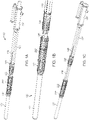
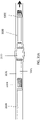
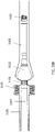
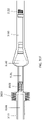
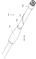
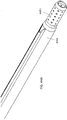
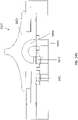
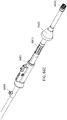
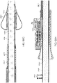
- an exemplary device 100 is configured to ride over an interior element, such as endoscope 101.
- Other interior elements may be used with the advancement apparatus of this invention, such as sheaths, tools, etc.
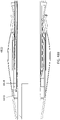
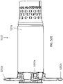
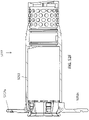
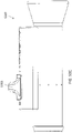
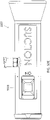
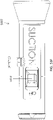
- the device 100 includes a distal vacuum port 102 and a proximal vacuum port 103.
- the distal vacuum port 102 is configured to attach to the endoscope 101 while the proximal vacuum port 103 is attached to an overtube 104 that extends over the endoscope 101.
- the vacuum ports 102/103 are configured to be axially slideable relative to one another (see, e.g., the transition from Figure 1A to Figure 1C ).
- a telescoping vacuum line 105 extends from the distal vacuum port 102 and through the overtube 104. Further, another vacuum line 106 extends to the proximal vacuum port 103.
- the device 100 further includes a blocking element 222 axially movable with, and proximal to, the distal vacuum port 102 that is configured to expand upon activation by axial movement of the proximal vacuum port 103.
- a handle 107 controls the relative movement of the ports 102, 103, the blocking element 222, as well as the vacuum applied thereto through the vacuum lines 105, 106.
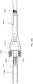
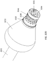
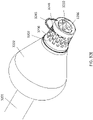
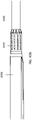
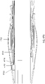
- another exemplary device 3100 is configured to ride over an endoscope 3100 for advancement of the scope through a lumen 3131, such as the small intestine.
- the device 3100 is similar to device 100 and includes a distal vacuum port 3102 and a proximal vacuum port 3103.
- the distal vacuum port 3102 in this configuration is attached to the very tip of the endoscope 3101 while the proximal vacuum port 3103 is attached to an overtube 3104 that extends over the endoscope 3101.
- the vacuum ports 3102/3103 are configured to be axially slideable relative to one another, as described with respect to device 100.
- the device 3100 further includes a support 3110 extending connected to, and proximally from, the distal vacuum port 3102 and a blocking element 3122 connected to support 3110 proximal to the distal vacuum port 3102 so that blocking element 3122 and distal vacuum port 3102 move together with the endoscope 3101.
- the blocking element 3222 in this embodiment is an inflatable balloon, and the proximal vacuum port 3103 is configured to slide thereunder when the endoscope 3101 is drawn proximally with respect to the overtube 3104.
- the devices described herein can include a distal grabbing mechanism configured to grab tissue, such as a distal vacuum port, and a proximal grabbing mechanism configured to grab tissue, such as a proximal vacuum port.
- the proximal and distal grabbing mechanisms can be movable relative to one another.
- Many of the embodiments described herein include vacuum grabbing mechanisms.
- the proximal and/or distal vacuum grabbing mechanism can be replaced with an inflatable element, such as a balloon.
- the devices can be used with only one grabbing mechanism, such as only the proximal grabbing mechanism.
- the distal vacuum port can be configured to connect to the scope and/or remain fixed axially relative to the scope.
- the distal vacuum port 102 can be configured to attach to the endoscope 101 just proximal to the steerable section of the scope, such as just proximal to the bump created at the connection between the steerable and flexible sections. In this embodiment, the port 102 leaves the steerable section substantially uncovered.
- the distal vacuum port 3202 can be configured to attach over the distal-most tip of the endoscope 3201 (see also device 3100 in Figures 31 ).
- a connecting mechanism 123 such as a split collet, can allow the distal vacuum port 102 to clamp around the endoscope.
- the connecting mechanism 123 can further include mating threads 145, 147 that, when rotated relative to one another, tighten the distal vacuum port 102 around the endoscope.
- Alternative attachment mechanisms include set screws or interference fit parts.
- the distal vacuum port 3202 can be attached with a shear clip 3245 (see Figure 32E ), which can be placed within a feature 3246 (see Figures 32D-E ) that prevents the clip from coming dislodged.
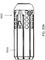
- Other mechanisms of attachment are possible, such as a split clamp or set screws (see Figures 33A-33C ) or an elastomeric band.
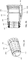
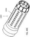
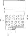
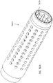
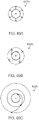
- the distal vacuum port can include a double walled port, where vacuum is created between the walls.
- the distal vacuum port 102 includes an inner cylindrical portion 202b and an outer cylindrical portion 202a and a sealed space 220 therebetween.
- a plurality of holes 230 extend through the outer cylindrical portion 202a into the sealed space 220.
- the vacuum line 105 extends into the sealed space 220 to provide vacuum thereto.
- the holes 230 can be arranged along the outer circumference of the outer cylindrical portion 202a.
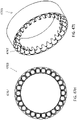
- the holes 230 which can be circular, can further be arranged as an array around the circumference of the outer cylindrical portion 202a. In one embodiment, there can be five circumferential rows of holes 230.
- the distal vacuum port can include a singled walled port, where vacuum is created between the single wall and the scope.
- the distal vacuum port 3202 can be sealed to the scope 3201 with an end cap 3296 and an o-ring 3271a or sealing cartridge so as to provide a sealed vacuum chamber between the single wall of the distal vacuum port 3202 and the scope 3201. Holes 3230 extending through the wall of the port 3202 allow for suction of the tissue thereto.
- the distal vacuum port can include linkages therein to ensure that the distal tip of the endoscope can still flex or move without hindrance from the distal vacuum port.
- the linkages can thus go over the steering section of the endoscope without impeding its native ability to articulate, thereby allowing the distal vacuum port to be placed at the end of the scope (as shown in Figures 32A-32C ).
- the linkages can also be useful if the distal vacuum port is placed at a more proximal location by allowing the scope to more easily flex as, for example, it bends within a tight radius inside of the patient.
- the articulating sections can withstand and/or accommodate torsion, tension, and compression and can have low bending force.
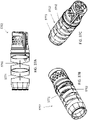
- the distal vacuum port 3302 can include axially extending arms 333 having a vacuum passage therethrough, which can enhance the flexibility of the distal tip 3302.
- Figures 34A-34C show another distal vacuum port 3402 includes long axially extending arms 3434.
- the port 3402 includes a single wall vacuum design, allows for sealing around the inflation port of the scope for inflation of a blocking element, and attaches with a shear clip rather than set screws.
- the distal vacuum port 3502 includes laser-cut coils 3535 extending therearound to enhance flexibility.
- the distal tip 3602 can include annular plastic links 3661 connected together with wire joints 3663.
- the wire joints 3663 can be part of a single wire (or two) that is wrapped and bonded around all of the links 3661.
- the links 3661 can be made, for example, of a high stiffness plastic, such as acrylonitrile butadiene styrene (ABS), polycarbonate, thermoplastic polyurethane, high density polyethylene, PEEK, Ultem, or a mineral filled plastic.
- the wire can be made, for example, of stainless steel or nitinol and can be a solid wire, a spring wire, or a multi-filament cable.
- the distal tip 3702 can include annular plastic links 3771 connected together with wire joints 3762.
- the wire joints 3762 are short studded segments present at each junction (i.e., not part of a continuous wire).
- the distal tip 3802 includes living hinges 3881 cut therein to allow bending or flexing.
- the tip 3802 can thus be made, for example, of a cylindrical material that is laser cut or by depositing different materials with rapid prototyping.
- the tip 2802 can be made of injection molded polypropylene or from nitinol.
- the distal tip can include a coil reinforced elastomer, a braid over an angled coil cut, links made such that they can angle relative to one another while being captured, or steel metal that is cut, bent, and welded with joints.
- the device distal vacuum port can include a braid overlay with a thin elastomeric or plastic sealing tube thereof. The sealing tube can be coated or plated to deliver enhanced features, such as stiffness.
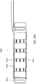
- the holes of the distal vacuum port can be circular, as shown in Figures 3A-3D and 5-6 or non-circular (e.g., square, oval, rectangular, hexagonal, or hexagonal with radiused corners), as shown in Figure 4 .
- the distal vacuum port can have raised ridges around the edges of the holes, as shown in Figure 6 , to help increase the suction force.
- the ridges can be made of a single material or of multiple materials and can include flexible elastomeric and/or highly conformable flanges.
- the distal vacuum port can be slideable relative to the endoscope rather than attached to the endoscope.
- studs can connect the inner cylindrical portion and the outer cylindrical portion of the distal vacuum port to provide structural support therebetween.
- the holes of the proximal and/or distal vacuum ports can be between 0.02 inches and 0.16 inches.
- the hole size can be chosen to optimize redundancy, manufacturability, vacuum strength, and ability to resist clogging from debris both externally and internally.
- the distal vacuum port can include a distal tip.
- the distal vacuum port 102 can include a rounded, atraumatic distal end 112.
- the proximal vacuum port can be attached to an overtube and can be configured to slide relative to the endoscope.
- the proximal vacuum port can include a double wall and vacuum chamber therebetween.
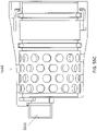
- the proximal vacuum port 103 can include an inner cylindrical portion 302b and an outer cylindrical portion 302a and a sealed space 320 therebetween.
- a plurality of holes 330 extend through the outer cylindrical portion 302a and into the sealed space 320.
- the vacuum line 106 extends into the sealed space 320 to provide vacuum thereto.
- a channel 335 can extend axially therethrough for passage of the vacuum line for the distal port.
- the proximal vacuum port can include a single wall, and creation of vacuum can occur between the wall and the scope.
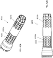
- Figures 40A-40C show a single walled port 4003 configured to form a vacuum chamber with the outer wall of the scope 4001.
- the proximal vacuum port 4003 can include a seal 4040.
- the seal 4040 can be a cone-shaped seal, which can advantageously be fault tolerant to an irregular surface.
- the seal 4040 can have the taper facing in the distal direction.
- the seal 4140 can have a taper that faces in the proximal direction.
- the seal can be made of a material, such as silicone, or thermoplastic polyurethane, that provides low drag when moved along the scope.
- the seal can be installed in a rigid cartridge to maintain dimensional integrity. Further, the seal can help maintain the vacuum (i.e. avoid vacuum leaks) while allowing areas of tissue distal to the seal to be insufflated, as described further below.
- a device 4600 can include a distal seal 4640 and a proximal seal 4646.
- the two seals can create a captured volume therebetween and between the inner surface of the overtube 4604 and the outer surface of the endoscope 4601. This volume can be filled with water and/or other fluid to provide a lubricious layer between the overtube 6404 and the scope 4601.
- the two seals 4604, 4646 can keep the lubricant from leaking out during the procedure.
- the holes of the proximal vacuum port can be between 0.02 inches and 0.16 inches.
- the hole size can be chosen to optimize redundancy, manufacturability, vacuum strength, and ability to resist clogging from debris both externally and internally.
- the holes can be of a variety of shapes, such as circular, square, oval, rectangular, hexagonal, or hexagonal with radiused corners.
- the holes of the vacuum port can be arranged in a variety of different patterns.
- the holes 330 can be arranged along the outer circumference of the outer cylindrical portion 302a.
- the holes 330 which can be circular, can further be arranged as an array around the circumference of the outer cylindrical portion 302a.
- the axial length across which the holes 330 extend can be longer for the proximal vacuum port 103 than the distal vacuum port 102.
- the increased length of the area covered by holes 330 can advantageously increase the grabbing force of the proximal vacuum port 103.
- the holes 4030 can be part of a single array or, as shown in Figures 42A-42B , the holes 4230 can be arranged a plurality of different arrays 4224a,b separated axially from one another.
- the different arrays 4224a,b can be activated independently of one another.
- the distal-most array 4224b can be released when pushed underneath the blocking element to prevent suctioning portion of the blocking element thereto and/or getting tissue stuck between the blocking element and the distal part of the port 4203.
- the proximal vacuum port can further include a tapered distal end.
- the tapered distal end of the proximal vacuum port can be longer than the tapered distal end of the distal port.
- the tapered distal end 312 can include a plurality of flexures 313 therein configured to allow the end 312 to ride closely over the outer diameter of the endoscope (e.g., to prevent tissue from getting caught between the scope and the port 103) while providing flexion at points where the outer diameter of the endoscope increases (such as at the ridge between the steerable end and the flexible portion).
- the tapered end 4312 can be made of an elastomeric material so that it stays against the scope, limits pinching, goes under the blocking element, does not bend up, and does not have any cracks or crevasses that things can get caught in.
- the proximal vacuum port 4403 can be formed as an extension of the overtube itself (i.e., rather than being bonded or otherwise attached thereto). Further, as shown in Figure 45 , in embodiments where the proximal vacuum port is formed as an extension of the overtube and/or in embodiments where the proximal vacuum port is a separate piece, a reinforcement coil 4554 or spring can be placed around the distal vacuum port 4503 to prevent the port 4503 from collapsing under vacuum.
- the proximal vacuum port can include ribs along the inner circumference thereof to help keep the port from collapsing under vacuum.
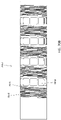
- Figures 56A-D show a proximal vacuum port 5603 including longitudinal ribs 5616 extending therein. The ribs 5616 are rounded so as to allow the proximal vacuum port 5603 to slide freely along the scope 5601.
- Figures 57A-D show a similar proximal vacuum port 5703 with ribs 5716, but the holes 5730 in this embodiment are square rather than round.
- the proximal vacuum port 7003 can include flexible sections 7070 and rigid sections 7071 along the length thereof.
- the flexible sections 7070 and rigid sections 7071 can be in an alternative pattern along the length.
- the rigid sections 7071 can include the vacuum holes 7030 therein.
- the flexible sections 7071 can include spiraled material (as shown in Figure 70B ).
- the vacuum port 7003 can be made, for example, by laser cutting the vacuum holes 7030 and the spiral design into a tube.
- the vacuum port 7003 can further include a tapered distal tip 7012.
- the distal tip 7012 can include a separate piece of material that is attached to the rest of the port 7003.
- the tip 7012 and/or the entire port 7003 can be encased and/or coated with a material, such as urethane and/or a hydrophilic material, to help make the tip smooth and atraumatic.
- the flexible sections 7070 can advantageously ensure that the proximal vacuum port 7003 flexes with the endoscope during advancement through the small intestine.
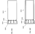
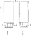
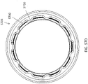
- the blocking elements described herein can be configured to expand radially (i.e., such that the overall radial dimension of the blocking element increases from the collapsed to the expanded configuration).
- the increased radial dimension of the blocking element can prevent pleated tissue from moving distally past the blocking element, thereby ensuring that the tissue is properly transferred to the proximal vacuum port.
- the proximal vacuum port extends between .5 inches and 2 inches, such as approximately 1 inch, underneath the blocking element.
- the blocking element moves with the distal grabbing mechanism and in various embodiments is attached to the distal grabbing mechanism or is attached to the endoscope (or other device) to the which the distal grabbing mechanism is attached.
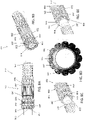
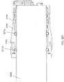
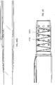
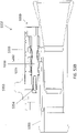
- the blocking element 222 of the device 100 can include a flexure 842, a return spring 844, and a rolling seal 846.
- the flexure 842 can be configured to attach to the distal vacuum port 102.
- the flexure 842 can include a plurality of rigid struts 882, each with two hinges 884, 886 therein. There can be a circumferential array of struts 882, such as between 6 and 12 struts, such as 9 struts.
- the flexure 842 can be configured to bend at the hinges 884, 886 to allow the struts to extend radially outwards such that the blocking element 222 can expand to a larger overall diameter.
- the proximal hinge 884 can be configured to bend inward while the distal hinge 886 can be configured to bend outward such that a proximal wall is formed by the proximal ends 892 of the struts 882 when the hinges 884, 886 are bent.
- the flexure 842 can be configured to expand when axially compressed by the proximal vacuum port 103, as described further below.
- the flexure 842 can be injection molded from polypropylene.
- the hinges 884, 886 are living hinges.
- the return spring 844 can be configured to return the flexure to its unexapanded neutral position.
- the spring 844 can sit within a groove 832 (see Figures 8B and 8C ) of the flexure 842.
- the spring 844 can be, for example, an elastic band or ring surrounding the struts 882.
- return spring functionality can be obtained by making flexure 886 of a high stiffness.
- the rolling seal 846 can be attached to the proximal end of the flexure 842 and can be configured to slide snugly along the outer diameter of the proximal vacuum port 103 when moved relative thereto.
- the seal 846 can thus include an elastic annular member 863 and a plurality of attachment mechanisms 865 configured to attach to attachment mechanisms 887 on the flexure 842.
- the attachment mechanisms 887 on the flexure 842 can be radially extending posts or pins while the attachment mechanisms 865 on the rolling seal 846 can be small annular elastic rings configured to fit over the posts or pins to attach the seal 846 to the flexure 842.
- the elastic annular member 863 can be configured to stretch radially as it slides along the tapered distal surface 312 of the proximal vacuum port 103.
- the rolling seal 846 can be cast from urethane. Alternatively, the rolling seal 846 can be attached to the flexure 842 by insert molding them together.
- the position of blocking element 222 is fixed with respect to the position of distal vacuum port 102.
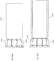
- the blocking element 222 can be activated (i.e., radially expanded) through axial relative movement between the proximal vacuum port 103 and distal vacuum port 102.
- the proximal vacuum port 103 can be in a retracted position relative to the blocking element 222 and distal vacuum port 102.
- the proximal vacuum port 103 and distal vacuum port 102 can then be moved axially toward each other to place proximal vacuum port 103 into contact with the blocking element 222, as shown in Figure 12B .
- proximal vacuum port 103 As the proximal vacuum port 103 is pushed against the seal 846, it causes the flexure 222 to bend at hinges 884, 886 such that the distal portions 892 extend radially outwards.
- the proximal vacuum port 103 and distal vacuum port 102 can continue to be moved axially toward each other, forcing the tapered end 312 to slide underneath the seal 846.
- the flexure 222 can thus continue to expand as the seal 846 moves along the taper 312 and over the holes 330 of the proximal vacuum port 103.
- Relative axial movement of the proximal vacuum port 103 with respect to distal vacuum port 102 can continue until the proximal vacuum port 103 hits the proximal end of the distal vacuum port 102 and/or until the holes 330 of the proximal vacuum port 103 are fully covered by blocking element 222.
- the diameter of the blocking element 222 will decrease due to the radially inward force provided by the return spring 844.
- the proximal vacuum port 103 can then be fully retracted, as shown in Figures 12F-12G .
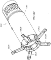
- a blocking element 1322 includes rigid linkages 1313 configured to pivot.
- An o-ring 1314 keeps the blocking element 1322 in the constrained configuration.
- the linkages 1313 can be configured to pivot out and increase their diameter upon activation by axial movement of the proximal vacuum port.
- the blocking element 1422 can be similar to Figure 1322, but can be entirely elastomeric.
- the blocking element 1422 can flex or stretch.
- the blocking element 1522 can include linkages 1513 that can be directly integrated into the distal vacuum port.
- the blocking element 1622 can include both rigid regions and flexing regions.
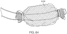
- the blocking element 1722 can include an inflatable cuff 1717.
- the blocking element 1822 can include a sheath, such as a braided sheath, that is configured to compress to create radial expansion when activated by axial movement of the proximal vacuum port.
- the braids can be configured to move relative to one another and/or can be welded or attached at some or all crossover points.
- the blocking element 1822 can advantageously be flexible, smooth, small, and simple.
- the braids and linkages can be created with continuous outer skin such that there are no pinch points.
- the blocking element and distal vacuum port are combined into a single integrated structure. As shown, in such an embodiment, the vacuum holes can be positioned along the struts of the blocking element.
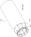
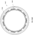
- FIG. 52A-52F Another exemplary blocking element 5222 is shown in Figures 52A-52F .
- the blocking element 5222 is activated with contact from the proximal vacuum port, as described with reference to blocking element 222 and includes a plurality of links 5252a-e at a proximal end of a tube 5253.
- the linkages 5252a-e can be configured to pivot such that the tips of the linkages 5252a-e rotate from a distal position that is flush with the tube 5253 ( Figures 52A-C ) to a proximal position that extends radially outward from the tube 5253 ( Figures 52D-F ).
- a spring mechanism can be configured to hold the links 5252a-c down when in the collapsed position.
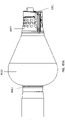
- the blocking element can be an inflatable element, such as a balloon.
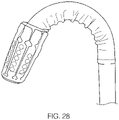
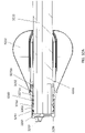
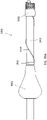
- Figures 39A-D show a balloon blocking element 3922 ( FIGS. 39C-D show a balloon blocking element 3922 deflated while FIGS. 39A-B show the balloon blocking element 3922 inflated).
- the balloon 3922 is advantageously soft and atraumatic so as to avoid damaging tissue as the device travels therethrough.
- the balloon 3922 can be a compliant balloon.
- the balloon can be non-compliant.
- the balloon blocking element 3922 when inflated, can have a larger radius than the scope 3901.
- the radius of the proximal portion of the balloon can be greater than the radius of the distal portion of the balloon.
- the balloon can have a conical shape.
- the balloon can be symmetrical about the scope 3901 so as to help center the scope during transfer through the lumen.
- the blocking element is separate from the distal vacuum port (i.e., not integral therewith).
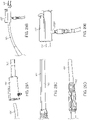
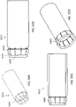
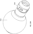
- the device 3900 can include a balloon blocking element 3922 that is separated from the distal port 3902. Separating the blocking element 3922 from the distal port 3902 advantageously allows the blocking element 3922 to be placed proximal to the steering section of the scope 3901, thereby improving docking of the proximal port within the blocking element 3922.
- the balloon blocking element 3922 can be configured to sit directly proximal to the bump 3992 on the scope 3901.
- any of the blocking elements described herein can include a wiping element on a proximal end thereof configured to facilitate movement of pleated tissue over the proximal vacuum port while ensuring that none of the tissue gets pinched thereunder during relative movement between the proximal vacuum port and the blocking element.
- the balloon blocking element 3222 is attached over a wiper element 3250 that includes a rigid sleeve 3261 and a plurality of flexures 3293 at a proximal end thereof.
- the flexures 3293 expand outward when the proximal port is moved thereagainst such that the proximal port can move within the space 3265 to dock within the blocking element 3222.
- the blocking element 3222 can be attached to the scope with a friction fit.
- the balloon blocking element 5822 is attached over a wiper element 5850 (see Figure 58C ) that includes an elastomeric sleeve 5891 reinforced with coil.
- the coil reinforced sleeve 5891 advantageously prevents collapse under vacuum while allowing some flexibility without buckling when bent.
- the wiper element also includes flexures 5893 that extend outwards, similar to flexures 3293.
- a bayonet fitting 5882 on the distal end twists into the rest of the unit and compresses the conical piece thereunder to keep the unit in place proximal to the bump in the scope.
- the blocking element 5022 (the radially expandable elements of the blocking element 5022, such as the balloon, are not shown for clarity) includes wiping element 5050.
- Wiping element 5050 includes a plurality of flexures 5093 configured to expand ( Figures 50D-E ) or contract ( Figure 50A-C ) when extending over the proximal vacuum port when it extends thereunder.
- An elastomeric o-ring 5095 at the proximal end holds the proximal ends of the flexures 5093 together and expands and contracts with the flexures.
- Figures 51A-51F show another embodiment of a blocking element 5122 (again, radially expandable elements, such as the balloon, are not shown for clarity) with wiping element 5150.
- Wiping element 5150 includes flexures 5193 that are similarly configured to expand and contract. In this embodiment, flexures 5193 are hinged.
- Figures 51A-51C show the flexures 4193 expanded while Figures 51D-F show the flexures contracted.
- the wiping elements can include Teflon segments, coated o-rings, hinged up segments, coil springs, or iris style.
- the wiping elements can further include a low friction coating or be made of a material that is inherently low friction (such as polypropylene, Teflon, or FEP).
- the wiping elements can be configured such that there is minimal contact with the proximal vacuum port so as to reduce friction. For example, only the o-ring and/or only the tips of the flexures can touch the proximal vacuum port as it passes thereunder.
- inflation of the balloon blocking element can occur by inflation through an already existing inflation port on the scope.
- an inflation port 3292 from the endoscope 3201 can be sealed off using o-rings 3271a,b to provide inflation to the balloon blocking element 3222.
- a close-up of the inflation port 3292 with surrounding o-rings 3271a,b can be seen in Figure 32F .
- a line can be run from the inflation port to the blocking element for inflation.
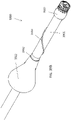
- Figures 39A-D show an inflation line 3939 extending from the distal end of the scope's inflation port back to the balloon blocking element 3922.
- the balloon blocking element can be inflated through an inflation line (e.g., a telescoping inflation line) that runs down the working channel of the scope or through an inflation line extending through an overtube or alongside the outer circumference of the scope.
- an inflation line e.g., a telescoping inflation line
- an extendable tube or needle 4774 can be attached to the proximal port 4703 to aid with inflation of the balloon blocking element 4722.
- the needle 4774 can be stored within the wall of the proximal port 4703 ( Figure 47C ).
- the needle 4774 can extend outwards to provide access to the inflation port 4792 ( Figure 47D ), and fluid can be supplied through the needle 4774 and port 4792 to inflate the balloon blocking element 4722 ( Figure 47E ).
- the needle can then be withdrawn back into the proximal port 4703 ( Figure 47F ).
- Figures 47H-I show a cross-section of the distal end of the proximal port 4703, which can include a plurality of self-sealing holes 4747 for transfer of a plurality of needles therethrough.
- FIG. 48A-D A similar embodiment is shown in Figures 48A-D .
- the distal end of the proximal port 4803 can include a solid rubber element rather than an array of holes.
- the needle 4874 can be used to pierce through the rubber element to inflate the blocking element 4822.
- a device 6600 can include a balloon blocking element 6622 attached to an additional overtube 6666 that extends through the handle 6607 to the balloon blocking element 6622.
- An annular space or lumen 6667 is created between the overtube 6666 and the scope 6601 through which a fluid or gas can be supplied to the balloon blocking element 6622 (e.g., through balloon inflation entry port 6669).
- An insufflation supply port 6668 communicating with annular space or lumen 6667 can be positioned on the overtube 6666 and/or be configured as part of the handle 6607.
- This embodiment also has tissue grabbing mechanisms (distal vacuum ports 6602 and proximal vacuum ports 6603) as discussed above with respect to other embodiments.
- the blocking elements herein are described as expanding radially. Such radial expansion includes any increase in overall radius from the collapsed configuration to the expanded configuration, regardless of the process or direction of expansion.
- a blocking element 6922a might extend purely in the radial direction.
- a blocking element 6922b might extend in a tangential direction while still resulting in an overall radially expansion.
- a blocking element 6922c might extend in a rotational direction while resulting in an overall radial expansion.
- the overtube 104 can be configured to ride over an endoscope 101 and can attach to the proximal vacuum port 103. Further, referring to Figures 19A-19D , the overtube can be designed to include a plurality of lumens configured to hold the endoscope and the vacuum lines 105, 106 therein.
- an overtube 1904 can be a multi-lumen extrusion with a large central lumen 1921 for the endoscope, a side lumen 1923 for one of the vacuum lines 105, 106, and a separate tube 1925 attached thereto for the other vacuum line 105, 106.
- the overtube 1904 can advantageously allow for the union of different structures made of different materials, thereby potentially providing an effective composite structure (for example, one that has very high push stiffness, but very low bending stiffness).
- an overtube 2004 can include a single lumen extrusion with a lumen 2021 for the endoscope and two separate tubes 2035, 2033 attached for the vacuum lines 105, 106.
- the two separate tubes 2035, 2033 can be inside of the lumen 2021, as shown, or outside.
- the shape of the lumen 2021 or the outer diameter of the tube 2004 can be modified to include grooves or channels/indents for the separate tubes 2035, 2033.
- the overtube 2104 can be a multi-lumen extrusion with a large central lumen 2121 for the endoscope and two lumens 2145, 2145 for the vacuum lines 105, 106.
- the overtube 2204 can include a large central lumen 2221 for the endoscope and redundant smaller lumens 2245a-d in the wall thereof for the vacuum lines. Redundant lumens can advantageously ensure a working vacuum even if one of the lumens becomes clogged.
- the distal vacuum port can be connected to vacuum through vacuum lines running down the side of the scope (such as a telescoping line), through a tube extending down the working channel, or through vacuum applied to the working channel itself.
- the vacuum tube 105 connected to the distal vacuum port can be a telescoping tube that telescopes within the overtube 104 to allow for movement of the distal vacuum port 102 and endoscope 101 relative to the handle 107 and/or vacuum supply.
- the telescoping vacuum tube 105 can be attached to the endoscope 101 to ensure that the proximal vacuum port can move easily thereover.
- the attachment mechanism can be configured to: (1) hold the tube 105 against the endoscope 101; (2) slide freely relative to the proximal vacuum structure and small intestine; (3) prevent lateral movement of the vacuum tube 105; and/or (4) be easy to install. Exemplary methods of attachment are shown in Figures 20A-23 .
- the vacuum tube 105 can be attached to the endoscope 101 with an adhesive, such as tape (e.g., bonded or heat-sealed).
- the tube 105 can be attached to the endoscope 101 with a coil 2072.
- the coil 2072 can extend all the way around the endoscope 101 or partially around the endoscope 101.
- the coil 2072 can be made, for example, of stainless steel (e.g., .007"), Nitinol or plastic.
- the vacuum tube 105 can be shrunk onto the endoscope 101, such as activated by heat, chemistry, or UV light.
- the tube 105 can be sealed via a stretchable material 2372 that rolls over the endoscope 101 and tube 105, such as made of urethane or latex.
- the vacuum line 105 can extend from the distal vacuum port 102 for entry into the working channel of the endoscope 101.
- the vacuum line 105 can coil around the tip of the endoscope 101 so as to not disturb the tip flexure.
- the vacuum line can directly enter the working channel.
- the working channel can be used to provide vacuum to the vacuum line 105.
- there can be a flapper valve that is normally closed to maintain a vacuum path, but can be pushed open by an instrument so that the working channel can still function as an instrument working channel.
- the vacuum line 105 can extend from the distal vacuum port 102 proximally towards the handle.
- the working channel 3233 itself can be used to provide vacuum through channel 3297.
- a valve 3232 in an opening in end cap 3296 such as a duckbill valve, prevents the vacuum from pulling out the distal end of the channel 3233, but still allows a working element to travel therethrough.
- FIGs 55A-55C Another embodiment of a distal tip 5502 with a duckbill valve 5532 is shown in Figures 55A-55C .
- the devices described herein can have handles, actuators or controls for activating the grabbing mechanisms and/or blocking elements.
- a handle 107 can include a handle body 2510 having a distal opening 2505 configured to mount to the overtube.
- the handle 107 can further include a large central lumen 2504 configured to ride over the endoscope and a vacuum attachment 2502.
- the handle 107 can further include a spool valve assembly 2508 configured to control the release of vacuum to either the proximal vacuum line or the distal vacuum line, respectively, through vacuum lumen connections 2507a,b.
- User-activated buttons 2503a,b can be configured to interface with the spool valve assembly 2508 to manually control the release of vacuum.
- Vents 2509a,b can also be positioned within the system to release vacuum pressure substantially instantly when the vacuum is released.
- the handle 107 can be configured to fit easily in the user's hand. Further, the handle 107 can be designed to allow the user to both hold the handle and activate the buttons 2503a,b with a single hand.
- the vacuum input 2502 can be removed to provide flush-through.
- the handle 107 can include a separate flush port with a valve for the vacuum line.
- the spool valve assembly 2508 is shown in more detail in Figures 27A-27B .
- the spool valve housing 2648 includes annular or toroidal grooves or rings 2601, 2602, 2603, 2604, 2605. Further, annular grooves 2610, 2612, 2614 can extend along the spool 2638. Each ring can be connected to a different component of the system. For example, ring 2601 can be connected to a first vent 2509a, ring 2602 can be connected to the vacuum lumen 2507a for the distal vacuum port, ring 2603 can be connected to the vacuum input 2502, ring 2604 can be connected to the vacuum lumen 2507b for the proximal vacuum port, and ring 2605 can be connected to a second vent 2509b.
- a first connection can be made between ring 2602 (connected to the vacuum lumen 2507a for the distal vacuum port) and ring 2603 (connected to vacuum input 2502) and via groove 2612 a second connection can be made between 2604 (connected to the vacuum lumen 2508b for the proximal vacuum port) and 2605 (connected to second vent 2509b) via groove 2614.
- the vacuum can be applied to the distal vacuum port while the proximal vacuum port is vented.
- the handle 5307 can include a spool mechanism 5359 configured to connect the proximal vacuum port to the vacuum source.
- the spool mechanism 5359 can include a vacuum input chamber 5331, a proximal vacuum chamber 5332 connected to a second vacuum port, and a third chamber 5333 configured to vent to atmosphere.
- a spool 5336 can be moved proximally and distally using button 5353 (through connection 5354).
- Figure 53A thus shows the spool 5356 configured such that chambers 5331 and 5332 are connected together, thereby allowing vacuum to be applied to the proximal vacuum port through line 5355.
- Figure 53B shows that chambers 5332 and 5333 are connected together, thereby placing deactivating the proximal vacuum port (and venting to atmosphere).
- vacuum to the distal port is supplied through the working channel of the endoscope.
- control of vacuum through the distal vacuum port can be performed through a button or vacuum activation mechanism on the scope itself.
- Figures 54A-D show an alternative embodiment of a handle 5407 that can be used to control vacuum to the proximal vacuum port.
- the handle 5407 includes three chambers 5431 (for the vacuum input), 5432 (for the proximal vacuum port), and 5433 (for venting to atmosphere).
- a u-channel 5455 moves back and forth with the button 5453 to connect the chambers as desired.
- Figure 54C thus shows the suction off (chamber 5432 for vacuum port connected to chamber 4333 for venting to the atmosphere).
- Figure 54D shows suction/vacuum on (chamber 5431 for vacuum input connected to 5432 for proximal vacuum port).
- the devices described herein can be used to quickly and efficiently move an endoscope through the small intestine.
- the device 100 can first be connected to an inner element the use wishes to advance through the gastrointestinal tract (or other lumen), such as endoscope 101.
- the endoscope 101 can be placed through the handle 107.
- the endoscope 101 can be advanced through the overtube 104 until the endoscope 101 exits the overtube 104, and the handle 107 is near the endoscope 101 proximal end.
- the telescoping line 105 can then be attached to the endoscope 101 (e.g., to avoid tangling during use).
- the distal tip 102 can then be attached to the endoscope 101.
- vacuum can be attached to the vacuum input 2502 on the handle 107.
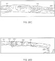
- the endoscope 101 and attached device 100 can be inserted into the small intestine, such as orally or anally (as shown in Figures 30A-30H ).
- the endoscope 101 and device 100 can be advanced to the start of the small intestine 3001.
- the distal vacuum port 102 of the device 100 and endoscope 101 can then be advanced further into the small intestine 3001, such as about 18 to 24 inches, by pushing forward on the endoscope.
- the distal vacuum port 102 can then be activated to suction tissue of the small intestine 3001 thereto, as shown in Figure 30C .
- the space between the distal vacuum port 102 and the proximal vacuum port 103 can be reduced until the the proximal vacuum port hits the blocking element 222 by pulling on the proximal end of the endoscope.
- tissue of the small intestine 3001 is pleated.
- the distal vacuum port 102 can continue to be pulled proximally over the proximal vacuum port 103, causing the blocking element 222 to radially expand. As the blocking element 222 expands, a wall is created that blocks the tissue pleats from moving distally over the distal vacuum port 102.
- the proximal vacuum port 103 moves fully inside of the blocking element 222, causing the pleats to move proximal of the proximal vacuum port 103.
- the proximal vacuum port 103 can then be activated and the distal vacuum port 102 released.
- the distal vacuum port 102 can then be pushed distally through the tissue of the small intestine 3001 about 18 to 24 inches as the proximal vacuum port 103 holds the tissue.
- the distal vacuum 102 can be activated and the proximal vacuum 103 released, and the steps can be performed again until the endoscope 101 has reached the desired location, such as until the endoscope has traveled the entire length of the small intestine.
- the proximal vacuum port 103 can also be moved proximally or distally to obtain the same relative motion between the two port 102, 103 and provide advancement of the scope through the small intestine.
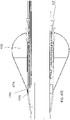
- the device 3100 works similarly to device 100 for advancement of the scope 3100 through the lumen 3131.
- the device 3100 is inserted into the lumen 3131 in the distal direction (indicated by the arrow) while the balloon blocking element 3122 is deflated and the vacuum ports 3102, 3104 are deactivated.
- the balloon blocking element 3122 is inflated (and can remain inflated throughout the entire procedure).
- the distal vacuum 3102 is then activated, thereby suctioning tissue of the lumen 3101 against the distal port 3102 (and pulling vacuum on the lumen 3131 distal to the distal port 3102).
- the proximal vacuum port 3103 and distal vacuum port 3102 are moved towards one another while the distal vacuum port 3102 is activated.
- the expanded blocking element 3122 prevents the tissue of the lumen 3131 from traveling distally past the blocking element 3122 and/or the distal vacuum 3102, thereby creating pleats 3133 of tissue in the lumen.
- the blocking element 3122 is slid over the proximal vacuum port 3103 so as to transfer the pleats 3133 proximal of the proximal vacuum port 3103.
- the vacuum on the distal vacuum port 3102 is released, and the vacuum on the proximal vacuum port 3103 is activated, thereby suctioning tissue of the lumen 3131 thereto (distal to the pleats 3133).
- the distal vacuum port 3102 can then be moved further distally through the lumen 3131. The process can then be repeated so as to incrementally move the device scope 3101 and device 3101 distally through the lumen 3131.
- the device can include a visual indicator thereon to indicate a state of the device (e.g., vacuums on/off, balloon inflated/deflated, proximal vacuum port fully docked inside of the balloon blocking element, etc.).
- a visual indicator thereon to indicate a state of the device (e.g., vacuums on/off, balloon inflated/deflated, proximal vacuum port fully docked inside of the balloon blocking element, etc.).
- a "red out" in the scope viewer can indicate that the distal tip vacuum port is on (i.e., causing the tissue to suction to the scope lens).
- an indicator element 4991 on the distal vacuum port 4902 can be configured to be pushed distally when the proximal vacuum port 4903 is fully docked or positioned within the balloon blocking element 4922 (thus indicating that all of the pleated tissue had been pushed proximal to the proximal vacuum port 4903, similar to as shown in Figure 31D ).
- a spring such as a coil spring, wave spring, local compression spring, or "hit plate” can push the element 4991 distally when acted upon by the proximal vacuum port 4903.
- the indicator element 4991 acts as a visual indicator that docking is complete by being positioned over the camera of the scope so as to be viable in the resulting image. In some embodiments, the indicator element 4991 acts as a visual indicator that docking is complete by moving the tissue off of the end of the scope, thereby locally lifting off red-out tissue.
- Figure 49A thus shows that the proximal vacuum port 4903 is not fully docked while Figure 49B shows that the proximal vacuum port 4903 is fully docked.
- Another example of an indicator includes an electronic indicator, such as an LED that light up when sensors (e.g., magnetic sensors or hall sensors) on the proximal vacuum port and the distal vacuum port are in proximity.
- an indicator includes a magnetic indicator arranged such that a magnet on the proximal vacuum port and a magnet on the distal vacuum port, when in proximity, repel or attract to create a change in the image seen distal to the camera.
- the visual indicator can be a reciprocating cable that is flexible, extending through a tube that is coiled around the scope's shaft and extending to its exit at the distal end of element 4902.
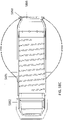
- Figure 59 shows a device 5900 that includes just a single vacuum port 5902 attached to an overtube 5904.
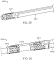
- Figure 60 shows a device including two overtubes that slide relative to one another.
- the distal vacuum port 6002 is attached to an inner overtube 6004a while the proximal vacuum port 6003 is attached to an outer overtube 6004b.
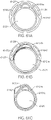
- FIG. 61A Various set-ups for a dual overtube system (as shown in Figure 60 ) can be used, as shown in Figures 61A-C .
- the inner and outer overtubes 3204a,b can be multi-lumen extrusions.
- the inner overtube 6104a includes a central lumen 6121 for the endoscope and a side lumen 6123 for one of the vacuum lines 105, 106.
- the outer overtube 6104b can extend therearound and have lumens 3343a,b that extend on either side of the lumen 6123 for redundant vacuum lines.
- Figure 61B is similar to the set-up of Figure 61A , but includes an in-laid reinforcing coil 6133 in the inner tube 6104a.
- Figure 61C is likewise similar, but includes only a single outer overtube lumen 6143.
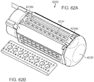
- a device 6200 can include one or more movable planar vacuum belt 6234.
- the movable planar vacuum belt 6234 can roll over a cylindrical feature 6236a,b at either end, e.g., similar to a tank tread or conveyor belt, to create a perforated belt through which vacuum is drawn.
- tissue that is suctioned to the belt can be moved along with the belt 6234, thereby moving tissue along the device (and/or the device through the tissue).
- the scope can be configured to go through a central lumen 6230.
- the device 6200 can include a plurality of vacuum belts arranged circumferentially therearound. For example, as shown in Figures 62A-B , there can be four different vacuum belts.
- a device 6300 can include a distal vacuum port that has a plurality of sections 6302a,b,c,d that can move relative to one another. For example, a first set (sections 6302a,c) can move axially relative to a second set (sections 6302b,d). Likewise, vacuum can be applied to each set alternatively to move through the tissue.
- one or more balloons 6406 can be used in place of the vacuum ports.
- the balloons can act as gripping mechanisms on their own rather than using vacuum.
- the balloons can include an inner wall to hold pressure, an outer wall that is perforated, and an intermediate space therebetween that can be maintained by spacers. As the balloon is inflated, it can expand to contact the tissue of the intestine. At that point, the vacuum can be turned on, pulling vacuum into the intermediate space and out the perforations. As a result, tissue can be suctioned to the outside of the balloon, enabling subsequent manipulation.
- the inner wall of the balloon can include an outward force created by springs, including wire that is pre-set to an outward geometry. As the springs are released, the diameter increased, the surface is brought out to the tissue, and then the vacuum can be turned on to suction the tissue onto the outside surface.
- Figure 68 shows another device 6800 wherein the proximal vacuum port has been replaced with a balloon 6886. The balloon 6886 is still configured to fit radially within the blocking element 6822.
- the devices herein have been described as being used over an endoscope, the devices can also be configured as a discrete unit that functions independently without having to utilize a pre-existing endoscope.
- the discrete unit can function untethered (i.e., with on-board elements) or tethered (with an umbilical).
- the umbilical can have a feature that allows it to unspool as it is advanced, such that the umbilical is not dragged nor subject to notable capstan drag forces relative to the small intestine that the unit weaves through as it advances through the small intestine.
- grabbing mechanisms of the devices described herein have been described as moving relative to one another by manual activation, other activation mechanisms are possible, such as with bellows, a motor, or a pneumatic/hydraulic actuator.
- vacuum lines can extend from the port(s) back to a vacuum source.
- vacuum pressure and flow rate can be modulated.
- the system can operate at or near full vacuum (760 mm Hg) or at partial vacuum (600, 500, 300, 250, 120, 50 mmHg). Vacuum can be applied continuously or intermittently. Flow rates can be varied, for example, from 10 to 40 to 100 liters per minute.
- the balloon can be configured to stay inflated throughout the entire procedure. Doing so can advantageously create two zones - a proximal zone proximal to the inflated balloon and a distal balloon that is distal to the inflated balloon.
- the proximal zone can be under vacuum (by the vacuum ports) while the distal zone can be insufflated (such as with an insufflator). Having the proximal zone under vacuum can advantageously help with pleating of the tissue while having the distal zone insufflated can advantageously increase visibility through the lens of the scope within the lumen.
- a device 6700 with a balloon blocking element 6722 can further include an inflatable element or balloon 6776 attached to the distal end of the proximal vacuum port 6703, thereby preventing vacuum from moving distal to the balloon 6776.
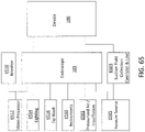
- the devices described herein can be connected to a variety of different control components.
- the device 100 (or any other device described herein) can be positioned over the endoscope 101, which can be attached to a monitor 10, a video processor 6512, a tip wash 6516, instruments 6518 for use therewith, a pressurized air or insufflation source 6501, and a vacuum source 6505.
- the device 100 can likewise be connected to the vacuum source through a suction fluid collection canister and line 6503.
- references to a structure or feature that is disposed "adjacent" another feature may have portions that overlap or underlie the adjacent feature.
- the device may be otherwise oriented (rotated 90 degrees or at other orientations) and the spatially relative descriptors used herein interpreted accordingly.
- the terms “upwardly”, “downwardly”, “vertical”, “horizontal” and the like are used herein for the purpose of explanation only unless specifically indicated otherwise.
- first and second may be used herein to describe various features/elements, these features/elements should not be limited by these terms, unless the context indicates otherwise. These terms may be used to distinguish one feature/element from another feature/element. Thus, a first feature/element discussed below could be termed a second feature/element, and similarly, a second feature/element discussed below could be termed a first feature/element without departing from the teachings of the present invention.
- a numeric value may have a value that is +/- 0.1% of the stated value (or range of values), +/- 1% of the stated value (or range of values), +/- 2% of the stated value (or range of values), +/- 5% of the stated value (or range of values), +/- 10% of the stated value (or range of values), etc. Any numerical range recited herein is intended to include all sub-ranges subsumed therein.
Landscapes
- Health & Medical Sciences (AREA)
- Life Sciences & Earth Sciences (AREA)
- Surgery (AREA)
- General Health & Medical Sciences (AREA)
- Public Health (AREA)
- Veterinary Medicine (AREA)
- Animal Behavior & Ethology (AREA)
- Heart & Thoracic Surgery (AREA)
- Biophysics (AREA)
- Engineering & Computer Science (AREA)
- Biomedical Technology (AREA)
- Radiology & Medical Imaging (AREA)
- Medical Informatics (AREA)
- Molecular Biology (AREA)
- Pathology (AREA)
- Physics & Mathematics (AREA)
- Nuclear Medicine, Radiotherapy & Molecular Imaging (AREA)
- Optics & Photonics (AREA)
- Pulmonology (AREA)
- Anesthesiology (AREA)
- Hematology (AREA)
- Endoscopes (AREA)
- Instruments For Viewing The Inside Of Hollow Bodies (AREA)
Claims (14)
- Appareil pour avancer dans un tractus gastro-intestinal, l'appareil comprenant :des premier et second mécanismes de saisie (3102, 3103) adaptés pour saisir et libérer un tissu du tractus gastro-intestinal, les premier et second mécanismes de saisie étant mobiles axialement l'un par rapport à l'autre le long du tractus gastro-intestinal ; etun élément de blocage expansible radialement (3122) disposé à proximité du premier mécanisme de saisie (3102) et mobile avec le premier mécanisme de saisie, dans lequel l'élément de blocage est adapté pour permettre au tissu du tractus intestinal de se déplacer par rapport au second mécanisme de saisie, caractérisé en ce que l'élément de blocage est configuré pour coulisser sur au moins une partie du second mécanisme de saisie (3103).
- Appareil selon la revendication 1, comprenant en outre des actionneurs adaptés pour actionner les premier et second mécanismes de saisie pour saisir et libérer le tissu.
- Appareil selon la revendication 1, comprenant en outre un élément extérieur configuré pour entourer au moins partiellement un élément intérieur, dans lequel le premier mécanisme de saisie peut être fixé à l'élément intérieur et le second mécanisme de saisie est fixé à l'élément extérieur.
- Appareil selon la revendication 3, comprenant en outre un mécanisme de connexion configuré pour fixer de manière mobile le premier mécanisme de saisie à l'élément intérieur.
- Appareil selon la revendication 3, dans lequel l'élément intérieur comprend un endoscope.
- Appareil selon la revendication 3, dans lequel l'élément extérieur comprend un surtube.
- Appareil selon la revendication 6, dans lequel le surtube supporte des lignes d'actionnement s'étendant jusqu'aux premier et second mécanismes de saisie.
- Appareil selon la revendication 1, dans lequel au moins l'un parmi le premier mécanisme de saisie (3102) et le second mécanisme de saisie (3103) comprend un orifice d'aspiration.
- Appareil selon la revendication 5, dans lequel le second mécanisme de saisie comprend un orifice d'aspiration, l'appareil comprenant en outre un capuchon distal adapté pour recouvrir une extrémité distale de l'endoscope et un joint adapté pour assurer l'étanchéité contre une surface extérieure de l'endoscope à proximité du capuchon pour former une chambre à vide en communication fluidique avec un canal de travail de l'endoscope et avec l'orifice d'aspiration.
- Appareil selon la revendication 9, comprenant en outre une ouverture dans le capuchon adaptée pour s'aligner avec le canal de travail de l'endoscope et une soupape disposée dans l'ouverture.
- Appareil selon la revendication 1, dans lequel l'élément de blocage (3122) comprend un ballon.
- Appareil selon la revendication 11, comprenant en outre un surtube fixé au ballon et définissant un canal de gonflage du ballon communiquant avec un intérieur du ballon.
- Appareil selon la revendication 1, dans lequel l'élément de blocage comprend une pluralité d'éléments radialement mobiles.
- Appareil selon la revendication 1, dans lequel le mécanisme de blocage comprend un élément d'essuyage.
Applications Claiming Priority (3)
| Application Number | Priority Date | Filing Date | Title |
|---|---|---|---|
| US201562213908P | 2015-09-03 | 2015-09-03 | |
| US201662339593P | 2016-05-20 | 2016-05-20 | |
| PCT/US2016/050290 WO2017041052A1 (fr) | 2015-09-03 | 2016-09-02 | Dispositif pour progression endoscopique à travers l'intestin grêle |
Publications (3)
| Publication Number | Publication Date |
|---|---|
| EP3344113A1 EP3344113A1 (fr) | 2018-07-11 |
| EP3344113A4 EP3344113A4 (fr) | 2019-04-03 |
| EP3344113B1 true EP3344113B1 (fr) | 2023-01-18 |
Family
ID=58188612
Family Applications (1)
| Application Number | Title | Priority Date | Filing Date |
|---|---|---|---|
| EP16843153.4A Active EP3344113B1 (fr) | 2015-09-03 | 2016-09-02 | Dispositif pour progression endoscopique à travers l'intestin grêle |
Country Status (5)
| Country | Link |
|---|---|
| US (2) | US11219351B2 (fr) |
| EP (1) | EP3344113B1 (fr) |
| JP (1) | JP7082052B2 (fr) |
| CN (1) | CN108495582B (fr) |
| WO (1) | WO2017041052A1 (fr) |
Families Citing this family (17)
| Publication number | Priority date | Publication date | Assignee | Title |
|---|---|---|---|---|
| US11986150B2 (en) | 2009-12-15 | 2024-05-21 | Lumendi Ltd. | Method and apparatus for manipulating the side wall of a body lumen or body cavity so as to provide increased visualization of the same and/or increased access to the same, and/or for stabilizing instruments relative to the same |
| JP7082052B2 (ja) | 2015-09-03 | 2022-06-07 | ネプチューン メディカル インク. | 小腸内での内視鏡前進の為の器具 |
| WO2018035452A1 (fr) | 2016-08-18 | 2018-02-22 | Neptune Medical | Dispositif et procédé de visualisation améliorée de l'intestin grêle |
| US20200146530A1 (en) * | 2016-09-28 | 2020-05-14 | Lumendi LLC | Method and apparatus for manipulating the side wall of a body lumen or body cavity so as to provide increased visualization of the same and/or increased access to the same, and/or for stabilizing instruments relative to the same |
| CN115251802A (zh) | 2017-04-19 | 2022-11-01 | Hoya株式会社 | 内窥镜顶部的安装装置 |
| CN111065311B (zh) * | 2017-07-20 | 2022-06-10 | 海王星医疗公司 | 动态刚性化外套管 |
| US20190254733A1 (en) | 2018-02-21 | 2019-08-22 | Csa Medical, Inc. | Systems and methods to enhance radial spray from a catheter |
| EP3801187B1 (fr) | 2018-05-31 | 2024-02-07 | Neptune Medical Inc. | Dispositif de visualisation améliorée de l'intestin grêle |
| JP2021531111A (ja) | 2018-07-19 | 2021-11-18 | ネプチューン メディカル インク. | 動的硬化医療用複合構造 |
| WO2020031293A1 (fr) * | 2018-08-08 | 2020-02-13 | オリンパス株式会社 | Dispositif médical et système de traitement |
| US11793392B2 (en) | 2019-04-17 | 2023-10-24 | Neptune Medical Inc. | External working channels |
| CN110867249A (zh) * | 2019-09-01 | 2020-03-06 | 厦门影诺医疗科技有限公司 | 一种下消化道隆起型病变实时检测智能平台 |
| CN110974141A (zh) * | 2019-12-20 | 2020-04-10 | 杨豪 | 一次性纤维支气管内窥镜保护套及其免消毒方法 |
| US11547782B2 (en) * | 2020-01-31 | 2023-01-10 | Covidien Lp | Fluid collecting sheaths for endoscopic devices and systems |
| CN115666676A (zh) | 2020-03-30 | 2023-01-31 | 海王星医疗公司 | 用于刚性化装置的层状壁 |
| EP4243910A1 (fr) | 2020-11-16 | 2023-09-20 | Lumendi Ltd. | Procédés et appareil pour inverser un manchon creux puis remettre un manchon creux inversé à son état d'origine |
| US11937778B2 (en) | 2022-04-27 | 2024-03-26 | Neptune Medical Inc. | Apparatuses and methods for determining if an endoscope is contaminated |
Family Cites Families (421)
| Publication number | Priority date | Publication date | Assignee | Title |
|---|---|---|---|---|
| US2268321A (en) | 1940-11-20 | 1941-12-30 | Wardlyn Corp | Catheter |
| US2767705A (en) * | 1954-10-08 | 1956-10-23 | Technical Oil Tool Corp | Sigmoidoscope with suction attachment for immobilizing adjacent tissue |
| US3859986A (en) | 1973-06-20 | 1975-01-14 | Jiro Okada | Surgical device |
| JPS5061890A (fr) | 1973-10-04 | 1975-05-27 | ||
| US4066071A (en) | 1975-08-15 | 1978-01-03 | Nagel John G | Extension pull through device to allow for easier passage of flexible fiber endoscope |
| US4141364A (en) | 1977-03-18 | 1979-02-27 | Jorge Schultze | Expandable endotracheal or urethral tube |
| US4151800A (en) | 1977-04-15 | 1979-05-01 | The United States Of America As Represented By The Administrator Of The National Aeronautics And Space Administration | Thermal insulation protection means |
| US4176662A (en) | 1977-06-17 | 1979-12-04 | The United States Of America As Represented By The Administrator Of The National Aeronautics And Space Administration | Apparatus for endoscopic examination |
| US4425919A (en) | 1981-07-27 | 1984-01-17 | Raychem Corporation | Torque transmitting catheter apparatus |
| JPS58173558A (ja) | 1982-04-01 | 1983-10-12 | テルモ株式会社 | 医療器具用チユ−ブ |
| SE442377B (sv) | 1984-06-29 | 1985-12-23 | Mediplast Ab | Kateter, sond eller liknande anordning |
| US4690131A (en) | 1985-05-31 | 1987-09-01 | The United States Of America As Represented By The Department Of Health And Human Services | Medical apparatus |
| US4696544A (en) | 1985-11-18 | 1987-09-29 | Olympus Corporation | Fiberscopic device for inspection of internal sections of construction, and method for using same |
| US4961738A (en) | 1987-01-28 | 1990-10-09 | Mackin Robert A | Angioplasty catheter with illumination and visualization within angioplasty balloon |
| US4817613A (en) | 1987-07-13 | 1989-04-04 | Devices For Vascular Intervention, Inc. | Guiding catheter |
| US4794912A (en) | 1987-08-17 | 1989-01-03 | Welch Allyn, Inc. | Borescope or endoscope with fluid dynamic muscle |
| US4893613A (en) | 1987-11-25 | 1990-01-16 | Hake Lawrence W | Endoscope construction with means for controlling rigidity and curvature of flexible endoscope tube |
| US4815450A (en) | 1988-02-01 | 1989-03-28 | Patel Jayendra I | Endoscope having variable flexibility |
| US4794412A (en) | 1988-05-16 | 1988-12-27 | Xerox Corporation | Vertical line width control ionographic system |
| DE3829603A1 (de) | 1988-09-01 | 1990-03-15 | Kontron Holding Ag | Ultraschallendoskopeinrichtung |
| GB2226245A (en) | 1988-11-18 | 1990-06-27 | Alan Crockard | Endoscope, remote actuator and aneurysm clip applicator. |
| US4959058A (en) * | 1989-03-17 | 1990-09-25 | Michelson Gary K | Cannula having side opening |
| JPH0724086Y2 (ja) | 1989-05-01 | 1995-06-05 | 株式会社町田製作所 | 内視鏡用チャンネルチューブ |
| US4962751A (en) | 1989-05-30 | 1990-10-16 | Welch Allyn, Inc. | Hydraulic muscle pump |
| US4913369A (en) | 1989-06-02 | 1990-04-03 | Welch Allyn, Inc. | Reel for borescope insertion tube |
| JP2756706B2 (ja) | 1989-07-19 | 1998-05-25 | 旭光学工業株式会社 | 内視鏡の湾曲管部外皮チューブの固定方法及び固定具 |
| DE3935256C1 (fr) | 1989-10-23 | 1991-01-03 | Bauerfeind, Peter, Dr., 8264 Waldkraiburg, De | |
| US5037386A (en) | 1989-11-17 | 1991-08-06 | Minnesota Mining And Manufacturing Company | Pressure sensing scope cannula |
| US5019121A (en) | 1990-05-25 | 1991-05-28 | Welch Allyn, Inc. | Helical fluid-actuated torsional motor |
| US5018436A (en) | 1990-07-31 | 1991-05-28 | Welch Allyn, Inc. | Folded bladder for fluid dynamic muscle |
| US5123421A (en) | 1991-01-16 | 1992-06-23 | C. R. Bard, Inc. | Liquid activated steerable catheter guidewire |
| US5244619A (en) | 1991-05-03 | 1993-09-14 | Burnham Warren R | Method of making catheter with irregular inner and/or outer surfaces to reduce travelling friction |
| US5251611A (en) | 1991-05-07 | 1993-10-12 | Zehel Wendell E | Method and apparatus for conducting exploratory procedures |
| US5201908A (en) | 1991-06-10 | 1993-04-13 | Endomedical Technologies, Inc. | Sheath for protecting endoscope from contamination |
| US5188595A (en) | 1991-06-28 | 1993-02-23 | Laserscope | Method for enhanced retention of balloon catheter in body cavity |
| US5360440A (en) | 1992-03-09 | 1994-11-01 | Boston Scientific Corporation | In situ apparatus for generating an electrical current in a biological environment |
| JPH05293077A (ja) | 1992-04-20 | 1993-11-09 | Olympus Optical Co Ltd | 管内挿入装置 |
| US6449006B1 (en) | 1992-06-26 | 2002-09-10 | Apollo Camera, Llc | LED illumination system for endoscopic cameras |
| US5662587A (en) | 1992-09-16 | 1997-09-02 | Cedars Sinai Medical Center | Robotic endoscopy |
| US5431676A (en) | 1993-03-05 | 1995-07-11 | Innerdyne Medical, Inc. | Trocar system having expandable port |
| US5823961A (en) | 1993-05-12 | 1998-10-20 | Hdc Corporation | Catheter guidewire and flushing apparatus and method of insertion |
| US5531685A (en) | 1993-06-11 | 1996-07-02 | Catheter Research, Inc. | Steerable variable stiffness device |
| JP3383009B2 (ja) | 1993-06-29 | 2003-03-04 | テルモ株式会社 | 血管カテーテル |
| US5577992A (en) | 1993-10-05 | 1996-11-26 | Asahi Kogaku Kogyo Kabushiki Kaisha | Bendable portion of endoscope |
| US5746692A (en) | 1994-05-05 | 1998-05-05 | Imagen Medical, Inc. | Catheter and endoscope system with distal protruding ball tip and method |
| US5607435A (en) | 1994-05-23 | 1997-03-04 | Memory Medical Systems, Inc. | Instrument for endoscopic-type procedures |
| US5624381A (en) | 1994-08-09 | 1997-04-29 | Kieturakis; Maciej J. | Surgical instrument and method for retraction of an anatomic structure defining an interior lumen |
| JP3614943B2 (ja) | 1994-09-29 | 2005-01-26 | オリンパス株式会社 | 内視鏡用穿刺針 |
| US5891112A (en) | 1995-04-28 | 1999-04-06 | Target Therapeutics, Inc. | High performance superelastic alloy braid reinforced catheter |
| US5759151A (en) | 1995-06-07 | 1998-06-02 | Carnegie Mellon University | Flexible steerable device for conducting exploratory procedures |
| US5662621A (en) | 1995-07-06 | 1997-09-02 | Scimed Life Systems, Inc. | Guide catheter with shape memory retention |
| US5632734A (en) | 1995-10-10 | 1997-05-27 | Guided Medical Systems, Inc. | Catheter shape control by collapsible inner tubular member |
| US5603991A (en) | 1995-09-29 | 1997-02-18 | Target Therapeutics, Inc. | Method for coating catheter lumens |
| US5810715A (en) | 1995-09-29 | 1998-09-22 | Olympus Optical Co., Ltd. | Endoscope provided with function of being locked to flexibility of insertion part which is set by flexibility modifying operation member |
| US6726677B1 (en) | 1995-10-13 | 2004-04-27 | Transvascular, Inc. | Stabilized tissue penetrating catheters |
| US5749828A (en) | 1995-12-22 | 1998-05-12 | Hewlett-Packard Company | Bending neck for use with invasive medical devices |
| GB9610765D0 (en) | 1996-05-23 | 1996-07-31 | Axon Anthony T R | Improvements in or relating to endoscopes |
| US6090099A (en) | 1996-05-24 | 2000-07-18 | Target Therapeutics, Inc. | Multi-layer distal catheter section |
| US5782811A (en) * | 1996-05-30 | 1998-07-21 | Target Therapeutics, Inc. | Kink-resistant braided catheter with distal side holes |
| NL1003984C2 (nl) | 1996-09-09 | 1998-03-10 | Cordis Europ | Katheter met inwendige verstijvingsbruggen. |
| IT1285533B1 (it) * | 1996-10-22 | 1998-06-08 | Scuola Superiore Di Studi Universitari E Di Perfezionamento Sant Anna | Robot endoscopico |
| US6599316B2 (en) | 1996-11-04 | 2003-07-29 | Advanced Stent Technologies, Inc. | Extendible stent apparatus |
| US5779624A (en) | 1996-12-05 | 1998-07-14 | Boston Scientific Corporation | Sigmoid splint device for endoscopy |
| US6159187A (en) | 1996-12-06 | 2000-12-12 | Target Therapeutics, Inc. | Reinforced catheter with a formable distal tip |
| US5951539A (en) | 1997-06-10 | 1999-09-14 | Target Therpeutics, Inc. | Optimized high performance multiple coil spiral-wound vascular catheter |
| US5916147A (en) | 1997-09-22 | 1999-06-29 | Boury; Harb N. | Selectively manipulable catheter |
| US5891114A (en) | 1997-09-30 | 1999-04-06 | Target Therapeutics, Inc. | Soft-tip high performance braided catheter |
| EP1042029B1 (fr) * | 1997-12-22 | 2015-09-16 | Celgard, LLC | Dispositif d'élimination de bulles de gaz et de gaz dissous dans des liquides |
| US20020087148A1 (en) | 1998-02-24 | 2002-07-04 | Brock David L. | Flexible instrument |
| US5989240A (en) | 1998-02-27 | 1999-11-23 | Becton, Dickson And Company | Adaptor for mounting a fluid handling device on a catheter tubing |
| US6190357B1 (en) | 1998-04-21 | 2001-02-20 | Cardiothoracic Systems, Inc. | Expandable cannula for performing cardiopulmonary bypass and method for using same |
| GB9808426D0 (en) * | 1998-04-21 | 1998-06-17 | Univ London | Device with means for propelling it along a passage |
| US6217565B1 (en) | 1998-07-16 | 2001-04-17 | Mark Cohen | Reinforced variable stiffness tubing |
| US6352503B1 (en) | 1998-07-17 | 2002-03-05 | Olympus Optical Co., Ltd. | Endoscopic surgery apparatus |
| US5916145A (en) | 1998-08-07 | 1999-06-29 | Scimed Life Systems, Inc. | Device and method of using a surgical assembly with mesh sheath |
| US6296644B1 (en) | 1998-08-26 | 2001-10-02 | Jean Saurat | Spinal instrumentation system with articulated modules |
| US6162171A (en) | 1998-12-07 | 2000-12-19 | Wan Sing Ng | Robotic endoscope and an autonomous pipe robot for performing endoscopic procedures |
| IL128286A (en) * | 1999-01-29 | 2004-01-04 | Sightline Techn Ltd | Movement gracefully inside the bowel using a flexible sleeve |
| US6179776B1 (en) | 1999-03-12 | 2001-01-30 | Scimed Life Systems, Inc. | Controllable endoscopic sheath apparatus and related method of use |
| US20040044350A1 (en) | 1999-04-09 | 2004-03-04 | Evalve, Inc. | Steerable access sheath and methods of use |
| US6685632B1 (en) | 1999-05-04 | 2004-02-03 | Cardiothoracic Systems, Inc. | Surgical instruments for accessing and stabilizing a localized portion of a beating heart |
| DE60040221D1 (de) | 1999-05-26 | 2008-10-23 | Boston Scient Ltd | Hülse für ein medizinisches Endoskop |
| JP3793368B2 (ja) | 1999-06-07 | 2006-07-05 | ペンタックス株式会社 | 飲み込み型内視鏡装置 |
| US6368315B1 (en) | 1999-06-23 | 2002-04-09 | Durect Corporation | Composite drug delivery catheter |
| US7128708B2 (en) | 2002-06-13 | 2006-10-31 | Usgi Medical Inc. | Shape lockable apparatus and method for advancing an instrument through unsupported anatomy |
| US7637905B2 (en) | 2003-01-15 | 2009-12-29 | Usgi Medical, Inc. | Endoluminal tool deployment system |
| US6364878B1 (en) | 1999-07-07 | 2002-04-02 | Cardiac Pacemakers, Inc. | Percutaneous transluminal ablation catheter manipulation tool |
| US6508804B2 (en) | 1999-07-28 | 2003-01-21 | Scimed Life Systems, Inc. | Catheter having continuous lattice and coil reinforcement |
| AU7641000A (en) | 1999-08-27 | 2001-03-26 | Helmut Wollschlager | Device for handling a catheter |
| US6506149B2 (en) | 1999-09-07 | 2003-01-14 | Origin Medsystems, Inc. | Organ manipulator having suction member supported with freedom to move relative to its support |
| EP1214109A1 (fr) | 1999-09-24 | 2002-06-19 | Omnisonics Medical Technologies, Inc. | Instrument medical a rigidite variable |
| US6780151B2 (en) | 1999-10-26 | 2004-08-24 | Acmi Corporation | Flexible ureteropyeloscope |
| US6533752B1 (en) | 2000-01-05 | 2003-03-18 | Thomas C Waram | Variable shape guide apparatus |
| US6517477B1 (en) * | 2000-01-27 | 2003-02-11 | Scimed Life Systems, Inc. | Catheter introducer system for exploration of body cavities |
| US6699179B2 (en) * | 2000-01-27 | 2004-03-02 | Scimed Life Systems, Inc. | Catheter introducer system for exploration of body cavities |
| EP1267702A1 (fr) | 2000-03-23 | 2003-01-02 | Atropos Limited | Dispositif d'insertion pour endoscope |
| US8888688B2 (en) | 2000-04-03 | 2014-11-18 | Intuitive Surgical Operations, Inc. | Connector device for a controllable instrument |
| EP1662972A4 (fr) | 2000-04-03 | 2010-08-25 | Intuitive Surgical Inc | Instruments articules a polymere active, et methodes d'introduction |
| US6800056B2 (en) | 2000-04-03 | 2004-10-05 | Neoguide Systems, Inc. | Endoscope with guiding apparatus |
| US6984203B2 (en) | 2000-04-03 | 2006-01-10 | Neoguide Systems, Inc. | Endoscope with adjacently positioned guiding apparatus |
| US6837846B2 (en) | 2000-04-03 | 2005-01-04 | Neo Guide Systems, Inc. | Endoscope having a guide tube |
| US6974411B2 (en) | 2000-04-03 | 2005-12-13 | Neoguide Systems, Inc. | Endoscope with single step guiding apparatus |
| US8517923B2 (en) * | 2000-04-03 | 2013-08-27 | Intuitive Surgical Operations, Inc. | Apparatus and methods for facilitating treatment of tissue via improved delivery of energy based and non-energy based modalities |
| US6468203B2 (en) | 2000-04-03 | 2002-10-22 | Neoguide Systems, Inc. | Steerable endoscope and improved method of insertion |
| US6610007B2 (en) | 2000-04-03 | 2003-08-26 | Neoguide Systems, Inc. | Steerable segmented endoscope and method of insertion |
| US6858005B2 (en) | 2000-04-03 | 2005-02-22 | Neo Guide Systems, Inc. | Tendon-driven endoscope and methods of insertion |
| WO2001087399A2 (fr) | 2000-05-18 | 2001-11-22 | Wilson-Cook Medical Inc. | Dispositif medical dote d'un meilleur acces au guide fil |
| US6309346B1 (en) | 2000-06-29 | 2001-10-30 | Ashkan Farhadi | Creeping colonoscope |
| US6572590B1 (en) | 2000-07-13 | 2003-06-03 | Merit Medical Systems, Inc. | Adjustable quick-release valve with toggle capability |
| JP4429495B2 (ja) | 2000-07-28 | 2010-03-10 | オリンパス株式会社 | 内視鏡 |
| JP3927764B2 (ja) | 2000-09-01 | 2007-06-13 | ペンタックス株式会社 | 内視鏡用可撓管 |
| DE10049175A1 (de) | 2000-09-22 | 2002-04-25 | Tea Gmbh | Biologisch abbaubare Funktionsflüssigkeit für mechanische Antriebe |
| JP3600194B2 (ja) | 2000-10-02 | 2004-12-08 | オリンパス株式会社 | 内視鏡 |
| JP2002125921A (ja) | 2000-10-20 | 2002-05-08 | Norikazu Hattori | 内視鏡の付属品及び内視鏡 |
| US6793661B2 (en) | 2000-10-30 | 2004-09-21 | Vision Sciences, Inc. | Endoscopic sheath assemblies having longitudinal expansion inhibiting mechanisms |
| US6684433B2 (en) | 2001-03-07 | 2004-02-03 | Gualtiero G. Giori | Pressure adjustable foam support apparatus |
| US6793621B2 (en) | 2001-03-08 | 2004-09-21 | Atropos Limited | Colonic overtube |
| US6558400B2 (en) * | 2001-05-30 | 2003-05-06 | Satiety, Inc. | Obesity treatment tools and methods |
| JP4744026B2 (ja) | 2001-07-30 | 2011-08-10 | オリンパス株式会社 | カプセル内視鏡およびカプセル内視鏡システム |
| WO2003013348A1 (fr) * | 2001-08-02 | 2003-02-20 | Tadanori Munemoto | Dispositif a endoscope |
| US6712832B2 (en) | 2001-10-15 | 2004-03-30 | Tilak M. Shah | Low-pressure medical balloons and method of making same |
| WO2003039354A1 (fr) * | 2001-10-18 | 2003-05-15 | Atropos Limited | Dispositif destiné à faciliter l'introduction d'un colonoscope |
| US20030153866A1 (en) | 2001-11-09 | 2003-08-14 | Long Gary L. | Self-propelled, intraluminal device with hollow, cylindrical head and method of use |
| US6616628B2 (en) | 2001-11-16 | 2003-09-09 | Cardiac Pacemakers, Inc. | Steerable catheter with a longitudinally adjustable curved core |
| US6860516B2 (en) | 2001-12-07 | 2005-03-01 | Pentax Corporation | Channel tube coupling structure for anti-pollution type endoscope |
| US7493156B2 (en) | 2002-01-07 | 2009-02-17 | Cardiac Pacemakers, Inc. | Steerable guide catheter with pre-shaped rotatable shaft |
| JP2005514145A (ja) * | 2002-01-09 | 2005-05-19 | ネオガイド システムズ, インコーポレイテッド | 内視鏡結腸切除のための装置および方法 |
| US7717899B2 (en) | 2002-01-28 | 2010-05-18 | Cardiac Pacemakers, Inc. | Inner and outer telescoping catheter delivery system |
| US20030225379A1 (en) | 2002-02-19 | 2003-12-04 | Medamicus, Inc. | Composite stasis valve |
| JP2005518855A (ja) | 2002-03-06 | 2005-06-30 | アトロポス・リミテッド | こわさを変更できる操縦可能な結腸内視鏡プローブ |
| AU2003234239A1 (en) * | 2002-04-24 | 2003-11-10 | Surgical Connections, Inc. | Resection and anastomosis devices and methods |
| US20030216622A1 (en) | 2002-04-25 | 2003-11-20 | Gavriel Meron | Device and method for orienting a device in vivo |
| US7384422B2 (en) | 2002-05-06 | 2008-06-10 | Pressure Products Medical Supplies, Inc. | Telescopic, separable introducer and method of using the same |
| US20050085829A1 (en) * | 2002-05-17 | 2005-04-21 | Esophyx, Inc. | Transoral endoscopic gastroesophageal flap valve restoration device, assembly, system and method |
| US20030216691A1 (en) | 2002-05-17 | 2003-11-20 | Endo-Aid, Inc. | Laproscopic pump |
| US20060058582A1 (en) | 2002-06-13 | 2006-03-16 | Usgi Medical Inc. | Disposable shapelocking system |
| US20040243227A1 (en) | 2002-06-13 | 2004-12-02 | Guided Delivery Systems, Inc. | Delivery devices and methods for heart valve repair |
| US20050107811A1 (en) | 2002-06-13 | 2005-05-19 | Guided Delivery Systems, Inc. | Delivery devices and methods for heart valve repair |
| US7591781B2 (en) | 2002-07-15 | 2009-09-22 | Olympus Corporation | Endoscope system with insertion direction changing guides |
| KR100482275B1 (ko) | 2002-08-09 | 2005-04-13 | 한국과학기술연구원 | 마이크로 캡슐형 로봇 |
| US9808597B2 (en) | 2002-09-12 | 2017-11-07 | Intuitive Surgical Operations, Inc. | Shape-transferring cannula system and method of use |
| US7947000B2 (en) | 2003-09-12 | 2011-05-24 | Intuitive Surgical Operations, Inc. | Cannula system for free-space navigation and method of use |
| US8298161B2 (en) | 2002-09-12 | 2012-10-30 | Intuitive Surgical Operations, Inc. | Shape-transferring cannula system and method of use |
| CH696424A5 (de) | 2002-10-15 | 2007-06-15 | Alexander Von Weymarn Schaerli | Führungseinrichtung insbesondere zum Positionieren von Kathetern in einem Körpergang. |
| US6936003B2 (en) | 2002-10-29 | 2005-08-30 | Given Imaging Ltd | In-vivo extendable element device and system, and method of use |
| US6923754B2 (en) | 2002-11-06 | 2005-08-02 | Senorx, Inc. | Vacuum device and method for treating tissue adjacent a body cavity |
| WO2004045672A2 (fr) | 2002-11-15 | 2004-06-03 | The Government Of The United States As Represented By The Secretary Of The Department Of Health And Human Services | Catheter a courbure variable |
| JP3965108B2 (ja) | 2002-11-29 | 2007-08-29 | オリンパス株式会社 | 内視鏡の可撓管 |
| US20040186349A1 (en) | 2002-12-24 | 2004-09-23 | Usgi Medical Corp. | Apparatus and methods for achieving endoluminal access |
| US20040186350A1 (en) | 2003-01-13 | 2004-09-23 | Usgi Medical Corp. | Apparatus and methods for guiding an endoscope via a rigidizable wire guide |
| JP2004258629A (ja) | 2003-02-05 | 2004-09-16 | Olympus Corp | 内視鏡装置 |
| US7438712B2 (en) | 2003-03-05 | 2008-10-21 | Scimed Life Systems, Inc. | Multi-braid exterior tube |
| US20060041188A1 (en) | 2003-03-25 | 2006-02-23 | Dirusso Carlo A | Flexible endoscope |
| CN2613655Y (zh) | 2003-03-27 | 2004-04-28 | 刘堂贵 | 可快速拆装的调压阀组 |
| US20050010237A1 (en) | 2003-06-09 | 2005-01-13 | Niazi Imran K. | Catheter to cannulate coronary sinus branches |
| DE602004025366D1 (de) | 2003-07-02 | 2010-03-18 | Cook Inc | Koaxialen Katheter |
| US7291127B2 (en) | 2003-07-28 | 2007-11-06 | Boston Scientific Scimed, Inc. | Variable manipulative strength catheter |
| EP2258322A3 (fr) | 2003-09-02 | 2011-05-18 | Aesculap Implant Systems, Inc. | Disque intervertébral artificiel |
| US20050124875A1 (en) | 2003-10-01 | 2005-06-09 | Olympus Corporation | Vivo observation device |
| US20080234546A1 (en) | 2003-10-01 | 2008-09-25 | Olympus Corporation | In vivo observation device |
| US20050245899A1 (en) | 2003-10-28 | 2005-11-03 | Swisher David R | Dual purpose adapter |
| US20070088367A1 (en) | 2004-10-22 | 2007-04-19 | Alexander Von Weymarn-Scharli | Device, especially tube or catheter, for at least partially introducing into a body passage |
| JP4217587B2 (ja) * | 2003-11-26 | 2009-02-04 | オリンパス株式会社 | 内視鏡用キャップ |
| JP3791011B2 (ja) | 2003-12-08 | 2006-06-28 | 有限会社エスアールジェイ | バルーン取付治具 |
| DE102004001461A1 (de) | 2004-01-08 | 2005-08-11 | Wollschläger, Helmut, Prof. Dr.med. | Vorrichtung zur Handhabung eines Katheters |
| DE102004003166B4 (de) | 2004-01-21 | 2011-09-15 | Siemens Ag | Katheter |
| US20050165275A1 (en) | 2004-01-22 | 2005-07-28 | Kenneth Von Felten | Inspection device insertion tube |
| AU2013207571B2 (en) | 2004-01-28 | 2015-08-27 | Applied Medical Resources Corporation | Medical tubing |
| JP3877075B2 (ja) | 2004-01-28 | 2007-02-07 | 有限会社エスアールジェイ | 内視鏡装置 |
| EP1943939B1 (fr) | 2004-01-30 | 2019-02-27 | FUJIFILM Corporation | Applicateur d'endoscope et appareil d'endoscope |
| EP1737564B1 (fr) | 2004-03-12 | 2019-09-11 | SRI International | Meta-materiaux mecaniques |
| JP4756851B2 (ja) * | 2004-03-19 | 2011-08-24 | オリンパス株式会社 | 内視鏡バルーン制御装置 |
| JP3981364B2 (ja) | 2004-03-19 | 2007-09-26 | オリンパス株式会社 | ダブルバルーン式内視鏡システム |
| US7727228B2 (en) | 2004-03-23 | 2010-06-01 | Medtronic Cryocath Lp | Method and apparatus for inflating and deflating balloon catheters |
| JP3962999B2 (ja) | 2004-03-29 | 2007-08-22 | 有限会社エスアールジェイ | 内視鏡装置 |
| US8512219B2 (en) | 2004-04-19 | 2013-08-20 | The Invention Science Fund I, Llc | Bioelectromagnetic interface system |
| US7837615B2 (en) | 2004-05-10 | 2010-11-23 | Usgi Medical, Inc. | Shape lockable apparatus and method for advancing an instrument through unsupported anatomy |
| WO2005110200A1 (fr) | 2004-05-13 | 2005-11-24 | Stryker Gi Ltd. | Raccord pour tubulure a passages multiples |
| JP2007536979A (ja) | 2004-05-13 | 2007-12-20 | ストライカー・ジーアイ・リミテッド | 使い捨てマルチルーメン型配管の切断及び密封のための方法 |
| JP2005323778A (ja) | 2004-05-13 | 2005-11-24 | Olympus Corp | 内視鏡装置 |
| US7970455B2 (en) | 2004-05-20 | 2011-06-28 | Spectrum Dynamics Llc | Ingestible device platform for the colon |
| US7708751B2 (en) | 2004-05-21 | 2010-05-04 | Ethicon Endo-Surgery, Inc. | MRI biopsy device |
| US7736379B2 (en) | 2004-06-09 | 2010-06-15 | Usgi Medical, Inc. | Compressible tissue anchor assemblies |
| US7931661B2 (en) | 2004-06-14 | 2011-04-26 | Usgi Medical, Inc. | Apparatus and methods for performing transluminal gastrointestinal procedures |
| EP1778054B1 (fr) | 2004-06-25 | 2013-08-07 | Carnegie Mellon University | Dispositif de guidage orientable |
| US8075476B2 (en) | 2004-07-27 | 2011-12-13 | Intuitive Surgical Operations, Inc. | Cannula system and method of use |
| US7143925B2 (en) | 2004-07-28 | 2006-12-05 | Ethicon Endo-Surgery, Inc. | Surgical instrument incorporating EAP blocking lockout mechanism |
| WO2006028763A2 (fr) | 2004-09-01 | 2006-03-16 | Chul Hi Park | Dispositif de guidage gonflable |
| EP1796529B1 (fr) | 2004-09-08 | 2016-02-03 | Olympus Corporation | Dispositif medical de type capsule |
| US7771411B2 (en) | 2004-09-24 | 2010-08-10 | Syntheon, Llc | Methods for operating a selective stiffening catheter |
| US7559916B2 (en) | 2004-09-24 | 2009-07-14 | Syntheon, Llc | Catheter with controllable stiffness and method for operating a selective stiffening catheter |
| US7938307B2 (en) * | 2004-10-18 | 2011-05-10 | Tyco Healthcare Group Lp | Support structures and methods of using the same |
| JP3834820B2 (ja) | 2004-11-04 | 2006-10-18 | フジノン株式会社 | 内視鏡装置用のバルーン制御装置 |
| JP3874298B2 (ja) | 2004-11-05 | 2007-01-31 | フジノン株式会社 | 内視鏡装置用のバルーン制御装置 |
| US20060129130A1 (en) | 2004-11-18 | 2006-06-15 | Tal Michael G | Sheath/catheter system with controlled hardness and flexibility |
| US8409111B2 (en) | 2004-11-22 | 2013-04-02 | Bard Peripheral Vascular, Inc. | Removable localizing wire |
| US7399291B2 (en) | 2004-12-02 | 2008-07-15 | Syntheon, Llc. | Catheter for treatment of total occlusions and methods for manufacture and use of the catheter |
| WO2006063491A1 (fr) | 2004-12-14 | 2006-06-22 | Kerang Jiang | Systeme d’endoscopie avec etui jetable et mode d’emploi |
| US8206287B2 (en) | 2005-02-14 | 2012-06-26 | Olympus Corporation | Endoscope having flexible tube |
| JP4000485B2 (ja) | 2005-02-28 | 2007-10-31 | フジノン株式会社 | 内視鏡装置 |
| US20070255101A1 (en) | 2005-03-04 | 2007-11-01 | Sightline Technologies Ltd. | Endoscope with Protective Sleeve |
| KR100702155B1 (ko) | 2005-05-12 | 2007-04-02 | 한국과학기술연구원 | 캡슐형 마이크로 로봇 구동 시스템 |
| US7857754B2 (en) | 2005-05-13 | 2010-12-28 | Ethicon Endo-Surgery, Inc. | Apparatus useful for positioning a device on an endoscope |
| EP1881781A2 (fr) | 2005-05-16 | 2008-01-30 | Kenneth Binmoeller | Systemes et procedes facilitant les interventions endoscopiques |
| US20060264707A1 (en) * | 2005-05-20 | 2006-11-23 | Kinney Timothy P | Endoscope sheath |
| US20060287666A1 (en) | 2005-06-15 | 2006-12-21 | Usgi Medical Inc. | Apparatus and methods for endoluminal advancement |
| EP1909633B1 (fr) | 2005-06-24 | 2011-11-23 | GE Inspection Technologies, LP | Carrousel de rangement pour tube d'insertion |
| US20070015965A1 (en) * | 2005-07-13 | 2007-01-18 | Usgi Medical Inc. | Methods and apparatus for colonic cleaning |
| WO2007019811A1 (fr) * | 2005-08-17 | 2007-02-22 | Axenic Medical Inc. | Protection hygienique destinee a des endoscopes, endoscope comportant une protection hygienique et procede d'application d'une protection hygienique sur un endoscope |
| DE102005039601A1 (de) | 2005-08-19 | 2007-02-22 | Karl Storz Gmbh & Co. Kg | Endoskop, insbesondere Duodenoskop für die Mutter-Baby Cholangioskopie |
| JP2007054125A (ja) | 2005-08-22 | 2007-03-08 | Olympus Medical Systems Corp | 内視鏡 |
| US7998132B2 (en) | 2005-09-02 | 2011-08-16 | Boston Scientific Scimed, Inc. | Adjustable stiffness catheter |
| EP1931237A2 (fr) | 2005-09-14 | 2008-06-18 | Neoguide Systems, Inc. | Procédés et appareil pour effectuer des procédures transluminales et autres |
| US20080188928A1 (en) | 2005-09-16 | 2008-08-07 | Amr Salahieh | Medical device delivery sheath |
| US20070100414A1 (en) | 2005-11-02 | 2007-05-03 | Cardiomind, Inc. | Indirect-release electrolytic implant delivery systems |
| US7798992B2 (en) | 2005-11-04 | 2010-09-21 | Ethicon Endo-Surgery, Inc. | Lumen traversing device |
| DE102005057479A1 (de) | 2005-11-30 | 2007-05-31 | Philipps-Universität Marburg | Anordnung zur Führung von Instrumenten in Hohlräumen |
| US20070219411A1 (en) | 2006-01-13 | 2007-09-20 | Olympus Medical Systems Corp. | Overtube and endoscopic treatment system |
| DE102006018489A1 (de) | 2006-02-15 | 2007-10-25 | Epflex Feinwerktechnik Gmbh | Gesteuert versteifbarer Schlauch |
| US9155451B2 (en) | 2006-03-02 | 2015-10-13 | Syntheon, Llc | Variably flexible insertion device and method for variably flexing an insertion device |
| US8556804B2 (en) | 2006-05-22 | 2013-10-15 | Syntheon, Llc | Torque-transmitting, variably flexible insertion device and method for transmitting torque and variably flexing an insertion device |
| US8092374B2 (en) | 2006-03-02 | 2012-01-10 | Kevin Smith | Variably flexible insertion device and method for variably flexing an insertion device |
| US9814372B2 (en) * | 2007-06-27 | 2017-11-14 | Syntheon, Llc | Torque-transmitting, variably-flexible, locking insertion device and method for operating the insertion device |
| US7988621B2 (en) | 2006-08-10 | 2011-08-02 | Syntheon, Llc | Torque-transmitting, variably-flexible, corrugated insertion device and method for transmitting torque and variably flexing a corrugated insertion device |
| US20070239252A1 (en) | 2006-04-10 | 2007-10-11 | Medtronic Vascular, Inc. | A Mechanism to Ensure Placement of Ostial Renal Stents |
| US20120035437A1 (en) | 2006-04-12 | 2012-02-09 | Searete Llc, A Limited Liability Corporation Of The State Of Delaware | Navigation of a lumen traveling device toward a target |
| JP4981344B2 (ja) | 2006-04-13 | 2012-07-18 | 富士フイルム株式会社 | 内視鏡装置用バルーンユニット |
| US7993303B2 (en) | 2006-04-21 | 2011-08-09 | Abbott Laboratories | Stiffening support catheter and methods for using the same |
| US20070250149A1 (en) | 2006-04-21 | 2007-10-25 | Abbott Laboratories | Stiffening Support Catheters and Methods for Using the Same |
| US20070260121A1 (en) | 2006-05-08 | 2007-11-08 | Ethicon Endo-Surgery, Inc. | Endoscopic Translumenal Surgical Systems |
| US7905877B1 (en) | 2006-05-12 | 2011-03-15 | Micrus Design Technology, Inc. | Double helix reinforced catheter |
| DE102006024094A1 (de) | 2006-05-17 | 2007-11-22 | Epflex Feinwerktechnik Gmbh | Gesteuert versteifbare Führungsdrahteinheit |
| JP4716922B2 (ja) | 2006-05-23 | 2011-07-06 | オリンパスメディカルシステムズ株式会社 | カプセル型医療装置およびこれを用いた薬剤導入システム |
| CN104688327B (zh) | 2006-06-13 | 2017-06-09 | 直观外科手术操作公司 | 微创手术系统 |
| CN101528111B (zh) | 2006-08-14 | 2012-04-04 | 卡迪欧机器人技术股份有限公司 | 具有多个工作口的可操纵多节设备 |
| US8109953B1 (en) | 2006-08-14 | 2012-02-07 | Volcano Corporation | Catheter device, hub assembly and method for traversing total occlusions |
| JP5006596B2 (ja) | 2006-08-21 | 2012-08-22 | オリンパスメディカルシステムズ株式会社 | カプセル内視鏡 |
| US9067041B2 (en) | 2006-09-13 | 2015-06-30 | Kawasumi Laboratories, Inc. | Microcatheter |
| WO2008041809A1 (fr) | 2006-10-02 | 2008-04-10 | University Industry Cooperation Foundation Korea Aerospace University | Endoscope du type à capsule |
| US20080091073A1 (en) | 2006-10-16 | 2008-04-17 | Chul Hi Park | Inflatable actuation device |
| US20080103360A1 (en) | 2006-11-01 | 2008-05-01 | Boris Shtul | Endoscopic device insertable into a body cavity and movable in a predetermined direction, and method of moving the endoscopic device in the body cavity |
| US20080172037A1 (en) | 2006-11-01 | 2008-07-17 | Percutaneous Systems, Inc. | Catheter with adjustable column stability and methods for its use |
| US20080139887A1 (en) | 2006-12-07 | 2008-06-12 | International Polymer Engineering, Inc. | Endoscopic working channel and method of making same |
| US10278682B2 (en) | 2007-01-30 | 2019-05-07 | Loma Vista Medical, Inc. | Sheaths for medical devices |
| SE0700313L (sv) | 2007-02-09 | 2008-07-29 | Danielsson Innovation Ab | Fiskerulle |
| US20080200762A1 (en) | 2007-02-16 | 2008-08-21 | Stokes Michael J | Flexible endoscope shapelock |
| US20100113874A1 (en) | 2007-04-04 | 2010-05-06 | Marco Quirini | Teleoperated endoscopic capsule |
| WO2008122969A1 (fr) | 2007-04-10 | 2008-10-16 | Stryker Gi Ltd. | Système de contrôle polyvalent permettant l'approvisionnement d'un milieu fluide à un endoscope |
| US20080262300A1 (en) | 2007-04-20 | 2008-10-23 | Usgi Medical, Inc. | Endoscopic system with disposable sheath |
| US20080275299A1 (en) | 2007-05-01 | 2008-11-06 | Chul Hi Park | Actuation device |
| US8398540B2 (en) * | 2007-05-10 | 2013-03-19 | Technion Research & Development Foundation Ltd. | Semi disposable endoscope |
| US8870755B2 (en) | 2007-05-18 | 2014-10-28 | Olympus Endo Technology America Inc. | Rotate-to-advance catheterization system |
| US8226548B2 (en) | 2007-07-07 | 2012-07-24 | Cannuflow, Inc. | Rigid arthroscope system |
| US8157727B2 (en) | 2007-07-16 | 2012-04-17 | Ethicon Endo-Surgery, Inc. | Surgical methods and devices with movement assistance |
| JP5001082B2 (ja) | 2007-07-18 | 2012-08-15 | 富士フイルム株式会社 | 内視鏡装置 |
| US8388519B2 (en) | 2007-07-26 | 2013-03-05 | Sri International | Controllable dexterous endoscopic device |
| JP2009045141A (ja) | 2007-08-16 | 2009-03-05 | Fujifilm Corp | 内視鏡用挿入補助具及び内視鏡 |
| US8287447B2 (en) | 2007-08-29 | 2012-10-16 | Minos Medical | Outer tube for natural orifice surgery |
| JP2009055955A (ja) * | 2007-08-29 | 2009-03-19 | Olympus Medical Systems Corp | 内視鏡装置 |
| JP5096084B2 (ja) | 2007-09-07 | 2012-12-12 | オリンパス株式会社 | 内視鏡装置 |
| US8382785B2 (en) | 2007-09-27 | 2013-02-26 | Swan Valley Medical Incorporated | Apparatus and method for performing cystotomy procedures |
| US20090157068A1 (en) * | 2007-10-01 | 2009-06-18 | Faouzi Kallel | Intraoperative electrical conduction mapping system |
| US9220398B2 (en) | 2007-10-11 | 2015-12-29 | Intuitive Surgical Operations, Inc. | System for managing Bowden cables in articulating instruments |
| EP2211966A4 (fr) * | 2007-10-16 | 2011-02-23 | Inmotion Medical Ltd | Dispositifs de sonde intra-luminale et leurs méthodes d'utilisation |
| CN101888872A (zh) | 2007-10-17 | 2010-11-17 | 泰尔哈绍梅尔医学研究基础设施和服务有限公司 | 用于引导胃肠设备通过胃肠道的系统和方法 |
| US20090112063A1 (en) | 2007-10-31 | 2009-04-30 | Bakos Gregory J | Endoscopic overtubes |
| WO2009060460A2 (fr) | 2007-11-09 | 2009-05-14 | Given Imaging Ltd. | Appareil et procédés pour une endoscopie par capsule de l'œsophage |
| US8663096B2 (en) | 2007-11-13 | 2014-03-04 | Covidien Lp | System and method for rigidizing flexible medical implements |
| US20090131752A1 (en) | 2007-11-19 | 2009-05-21 | Chul Hi Park | Inflatable artificial muscle for elongated instrument |
| US9066655B2 (en) | 2007-12-07 | 2015-06-30 | Ethicon Endo-Surgery, Inc. | Selective stiffening devices and methods |
| WO2009094434A2 (fr) | 2008-01-22 | 2009-07-30 | University Of South Florida | Surtube endoscopique |
| ES2334303A1 (es) * | 2008-02-04 | 2010-03-08 | Universidad Politecnica De Valencia | Procedimiento y dispositivo de traslacion automatizado de un endoscopio a traves del tubo digestivo. |
| US8246575B2 (en) | 2008-02-26 | 2012-08-21 | Tyco Healthcare Group Lp | Flexible hollow spine with locking feature and manipulation structure |
| EP2248483A4 (fr) | 2008-02-29 | 2014-03-19 | Univ Tokyo | Dispositif ayant une rigidité qui peut être changée entre des niveaux élevé et faible |
| US20090240202A1 (en) | 2008-03-21 | 2009-09-24 | William Joseph Drasler | Expandable introducer sheath |
| US7938809B2 (en) | 2008-04-14 | 2011-05-10 | Merit Medical Systems, Inc. | Quick release hemostasis valve |
| US8496648B2 (en) | 2008-05-27 | 2013-07-30 | Intuitive Surgical Operations, Inc. | Stiffening assembly |
| WO2009149421A1 (fr) | 2008-06-05 | 2009-12-10 | Cardiorobotics, Inc. | Dispositif de sonde articulée extensible |
| JP5224298B2 (ja) | 2008-06-19 | 2013-07-03 | 国立大学法人大阪大学 | 管腔壁穿刺用オーバーチューブ |
| US20100010437A1 (en) | 2008-07-11 | 2010-01-14 | Miles Robin R | Steerable catheter with distending lumen-actuated curling catheter tip |
| US8771170B2 (en) | 2008-08-01 | 2014-07-08 | Microaccess, Inc. | Methods and apparatus for transesophageal microaccess surgery |
| US8123739B2 (en) | 2008-08-19 | 2012-02-28 | Cook Medical Technologies Llc | Drainage catheter and method for catheterizing a patient |
| CA2734995A1 (fr) | 2008-08-28 | 2010-03-04 | Synthes Usa, Llc | Entretoise interepineuse derivee d'os |
| US20100069716A1 (en) | 2008-09-12 | 2010-03-18 | Yem Chin | Flexible guide conduit |
| JP5297732B2 (ja) | 2008-09-12 | 2013-09-25 | オリンパスメディカルシステムズ株式会社 | 親子式内視鏡 |
| US8047236B2 (en) | 2008-09-12 | 2011-11-01 | Boston Scientific Scimed, Inc. | Flexible conduit with locking element |
| US20100076451A1 (en) | 2008-09-19 | 2010-03-25 | Ethicon Endo-Surgery, Inc. | Rigidizable surgical instrument |
| US8663196B2 (en) * | 2008-09-23 | 2014-03-04 | Kassab Kughn Endovascular Devices Llc | Endovascular sheath with gradable stiffness device and method |
| US20100087711A1 (en) | 2008-10-06 | 2010-04-08 | Gyrus Ent, L.L.C. | Repeatably flexible surgical instrument |
| US8894643B2 (en) | 2008-10-10 | 2014-11-25 | Intuitive Surgical Operations, Inc. | Integral electrode placement and connection systems |
| JP2010136834A (ja) | 2008-12-10 | 2010-06-24 | Fujifilm Corp | 内視鏡軟性部及び内視鏡 |
| US8348834B2 (en) | 2008-12-18 | 2013-01-08 | Ethicon Endo-Surgery, Inc. | Steerable surgical access devices and methods |
| US8468637B2 (en) | 2009-02-06 | 2013-06-25 | Endoclear Llc | Mechanically-actuated endotracheal tube cleaning device |
| US8870752B2 (en) | 2009-03-25 | 2014-10-28 | The Cleveland Clinic Foundation | Medical device sheath |
| JP5568629B2 (ja) | 2009-04-01 | 2014-08-06 | ユニバーシティ オブ フロリダ リサーチ ファンデーション インコーポレーティッド | 管路内で内視鏡を前進させる装置 |
| US9254123B2 (en) | 2009-04-29 | 2016-02-09 | Hansen Medical, Inc. | Flexible and steerable elongate instruments with shape control and support elements |
| DE102009042490A1 (de) | 2009-05-29 | 2010-12-09 | Aesculap Ag | Steuerungsvorrichtung |
| US10080482B2 (en) | 2009-06-30 | 2018-09-25 | Intuitive Surgical Operations, Inc. | Compliant surgical device |
| US8475522B2 (en) | 2009-07-14 | 2013-07-02 | Edwards Lifesciences Corporation | Transapical delivery system for heart valves |
| US20110306950A1 (en) | 2010-06-10 | 2011-12-15 | Cucin Robert L | Coaxially-Driven Tissue Aspiration Instruments |
| DE102009037046A1 (de) | 2009-08-13 | 2011-02-17 | Olympus Winter & Ibe Gmbh | Rohrförmiger Schaft eines chirurgischen Instruments sowie chirurgisches Instrument |
| DE102009037047A1 (de) | 2009-08-13 | 2011-02-17 | Olympus Winter & Ibe Gmbh | Rohrförmiger Schaft eines chirurgischen Instruments |
| JP5448637B2 (ja) | 2009-08-18 | 2014-03-19 | 富士フイルム株式会社 | 挿入経路確保装置 |
| DE102009049143B3 (de) | 2009-10-12 | 2010-12-30 | Sopro-Comeg Gmbh | Endoskop |
| WO2011047339A2 (fr) | 2009-10-15 | 2011-04-21 | Inventio Llc | Endoscope transparent de forme complexe jetable et réutilisable |
| US8241299B2 (en) | 2009-10-22 | 2012-08-14 | Devicor Medical Products, Inc. | Biopsy marker delivery configured to retain marker prior to intended deployment |
| AU2010313314B2 (en) | 2009-11-02 | 2015-06-11 | Boston Scientific Scimed, Inc. | Flexible endoscope with modifiable stiffness |
| CN101732082B (zh) | 2009-11-06 | 2011-06-22 | 广州宝胆医疗器械科技有限公司 | 软、硬子母胆囊、胆管镜系统 |
| US10595711B2 (en) | 2009-12-16 | 2020-03-24 | Boston Scientific Scimed, Inc. | System for a minimally-invasive, operative gastrointestinal treatment |
| US9565998B2 (en) | 2009-12-16 | 2017-02-14 | Boston Scientific Scimed, Inc. | Multi-lumen-catheter retractor system for a minimally-invasive, operative gastrointestinal treatment |
| EP3659666A1 (fr) | 2009-12-16 | 2020-06-03 | Boston Scientific Scimed Inc. | Agencements et procédés pour effectuer une structure anatomique endoluminale |
| CN101797147B (zh) | 2010-01-21 | 2011-09-14 | 广州宝胆医疗器械科技有限公司 | 软硬子母宫腔镜、输卵管镜系统 |
| CN102711985B (zh) | 2010-02-05 | 2016-02-03 | 埃克森美孚化学专利公司 | 脱氢方法 |
| JP5563852B2 (ja) * | 2010-03-12 | 2014-07-30 | 富士フイルム株式会社 | バルーン付きオーバーチューブ、および内視鏡システム |
| JP2011194126A (ja) | 2010-03-23 | 2011-10-06 | Fujifilm Corp | 内視鏡若しくは処置具のガイド管 |
| JP2011200356A (ja) | 2010-03-25 | 2011-10-13 | Fujifilm Corp | 内視鏡挿入補助具 |
| JP2011200358A (ja) | 2010-03-25 | 2011-10-13 | Fujifilm Corp | 内視鏡挿入補助具 |
| EP2552350A1 (fr) | 2010-03-26 | 2013-02-06 | Ibis Medical Inc. | Dispositifs de type implant intragastrique |
| US20110245611A1 (en) | 2010-03-30 | 2011-10-06 | Chuen-Tai Yeh | Expandable capsule endoscope and expandable capsule endoscopy system |
| WO2011136115A1 (fr) | 2010-04-26 | 2011-11-03 | オリンパスメディカルシステムズ株式会社 | Endoscope |
| EP2575590B2 (fr) | 2010-05-25 | 2018-12-26 | Arc Medical Design Limited | Gaine pour dispositif de scopie médicale |
| US20110301414A1 (en) | 2010-06-04 | 2011-12-08 | Robert Hotto | Intelligent endoscopy systems and methods |
| US8672837B2 (en) | 2010-06-24 | 2014-03-18 | Hansen Medical, Inc. | Methods and devices for controlling a shapeable medical device |
| GB2477587A (en) | 2010-07-28 | 2011-08-10 | Architectural Facades And Soffit Systems Ltd | Cladding panels made to resemble tiling |
| RU2586247C2 (ru) | 2010-09-30 | 2016-06-10 | Этикон Эндо-Серджери, Инк. | Хирургический сшивающий инструмент с заменяемыми кассетами со скобками |
| US9358073B2 (en) | 2010-10-04 | 2016-06-07 | George Piligian | Expandable devices, rail systems, and motorized devices |
| EP2629810A1 (fr) | 2010-10-18 | 2013-08-28 | Boston Scientific Scimed, Inc. | Implant médical comprenant une couche de liaison à base de magnésium |
| US8968213B2 (en) * | 2010-10-19 | 2015-03-03 | United States Endoscopy Group, Inc. | Cytology brush apparatus with improvements |
| WO2012054829A2 (fr) | 2010-10-22 | 2012-04-26 | Medrobotics Corporation | Sondes robotisées hautement articulées et procédés de production et d'utilisation de ces sondes |
| US20120108992A1 (en) | 2010-10-29 | 2012-05-03 | Patel Amisha S | Morphology change detection for cardiac signal analysis |
| CN201899767U (zh) | 2010-11-23 | 2011-07-20 | 天津捷希医疗设备有限公司 | 照明型肛肠内张器 |
| US9211140B2 (en) | 2010-11-24 | 2015-12-15 | Kyphon Sarl | Dynamically expandable cannulae and systems and methods for performing percutaneous surgical procedures employing same |
| TW201223493A (en) | 2010-12-02 | 2012-06-16 | Chung Shan Inst Of Science | Expandable capsule endoscope |
| IT1402844B1 (it) | 2010-12-13 | 2013-09-27 | Scuola Superiore Di Studi Universitari E Di Perfez | Dispositivo robotico a guida magnetica per procedure di endoscopia |
| US20120165792A1 (en) | 2010-12-22 | 2012-06-28 | Ethicon Endo-Surgery, Inc. | Pill Catchers |
| JP5174140B2 (ja) | 2010-12-24 | 2013-04-03 | 富士フイルム株式会社 | 内視鏡挿入補助具 |
| US9283402B2 (en) | 2011-01-03 | 2016-03-15 | Best Medical International, Inc. | Apparatus and method for providing a double balloon breast brachytherapy device |
| US20120179097A1 (en) | 2011-01-06 | 2012-07-12 | Cully Edward H | Methods and apparatus for an adjustable stiffness catheter |
| US10092291B2 (en) | 2011-01-25 | 2018-10-09 | Ethicon Endo-Surgery, Inc. | Surgical instrument with selectively rigidizable features |
| EP2675515B1 (fr) | 2011-02-18 | 2020-07-15 | Ancora Heart, Inc. | Systèmes et procédés pour attaches à rigidité variable |
| WO2012122288A2 (fr) | 2011-03-08 | 2012-09-13 | The Johns Hopkins University | Ballonnet de visualisation et son procédé d'utilisation |
| US9833126B2 (en) | 2011-04-05 | 2017-12-05 | Visualization Balloons, Llc | Balloon access device with features for engaging an endoscope |
| EP2693931A1 (fr) | 2011-04-05 | 2014-02-12 | Reydel, Boris | Dispositif d'accès à ballonnet pour endoscope |
| US9623206B2 (en) | 2011-04-29 | 2017-04-18 | Cook Medical Technologies Llc | Catheter having a selectively variable degree of flexibility |
| US20150094656A1 (en) | 2011-05-03 | 2015-04-02 | Amr Salahieh | Steerable medical devices, systems, and methods of use |
| EP2704786B1 (fr) | 2011-05-03 | 2024-08-14 | Kalila Medical, Inc. | Gaines de pose orientables |
| JP5788239B2 (ja) | 2011-06-23 | 2015-09-30 | オリンパス株式会社 | 軌道形成装置 |
| US20130018306A1 (en) | 2011-07-13 | 2013-01-17 | Doron Moshe Ludwin | System for indicating catheter deflection |
| KR20140065418A (ko) | 2011-09-13 | 2014-05-29 | 메드로보틱스 코포레이션 | 안티-트위스트 링크 배열을 가지는 고관절 프로브, 그 형성 방법 및 의료 절차 수행 방법 |
| CN103042777B (zh) | 2011-10-14 | 2016-09-14 | 杜邦公司 | 具有改进的抗冲击强度的复合层合物及其制备方法和用途 |
| US9585546B2 (en) | 2011-11-21 | 2017-03-07 | Cook Medical Technologies Llc | Endoscope stabilization system |
| GB2497544A (en) | 2011-12-13 | 2013-06-19 | Staffordshire University Entpr And Commercial Dev | Travelling capsule with two drive mechanisms |
| EP3659491A1 (fr) | 2011-12-13 | 2020-06-03 | EndoChoice Innovation Center Ltd. | Endoscope à extrémité amovible |
| CN108262741A (zh) | 2011-12-21 | 2018-07-10 | 美的洛博迪克斯公司 | 用于具有链节装置的高度铰接探针的稳固装置,该装置的形成方法,以及该装置的使用方法 |
| US20130190565A1 (en) | 2012-01-20 | 2013-07-25 | The General Hospital Corporation | System, method and apparatus for optical imaging of luminal organs, and for centering within and contacting a luminal organ |
| JP6034573B2 (ja) | 2012-02-28 | 2016-11-30 | テルモ株式会社 | 医療器具用可撓管および医療器具 |
| JP2015109887A (ja) | 2012-03-28 | 2015-06-18 | テルモ株式会社 | 医療用処置具 |
| KR101941569B1 (ko) | 2012-03-30 | 2019-04-15 | 삼성전자주식회사 | 가변 유연관 및 이를 갖춘 매니퓰레이터 |
| US9192284B2 (en) | 2012-04-03 | 2015-11-24 | Easynotes Ltd. | Endoscopic accessory for endoscopic device |
| US8777844B1 (en) | 2012-05-08 | 2014-07-15 | Siddharth Sadanand | Modifiable endoscope device |
| US9011513B2 (en) | 2012-05-09 | 2015-04-21 | Abbott Cardiovascular Systems Inc. | Catheter having hydraulic actuator |
| US9386910B2 (en) | 2012-07-18 | 2016-07-12 | Apollo Endosurgery, Inc. | Endoscope overtube for insertion through a natural body orifice |
| US9125653B2 (en) | 2012-08-02 | 2015-09-08 | St. Jude Medical, Cardiology Division, Inc. | Flexible nosecone for percutaneous device |
| US9610068B2 (en) | 2012-08-29 | 2017-04-04 | Boston Scientific Scimed, Inc. | Articulation joint with bending member |
| US9198835B2 (en) | 2012-09-07 | 2015-12-01 | Covidien Lp | Catheter with imaging assembly with placement aid and related methods therefor |
| US20140081169A1 (en) | 2012-09-17 | 2014-03-20 | Vanderbilt University | System and method of tetherless insufflation in colon capsule endoscopy |
| US9604339B2 (en) | 2012-10-29 | 2017-03-28 | Wayne O. Duescher | Vacuum-grooved membrane wafer polishing workholder |
| TWI693059B (zh) | 2012-12-21 | 2020-05-11 | 法商消化道腫瘤治療研究中心 | 用於模組化磁性接合裝置之施加器之用途 |
| US9526862B2 (en) | 2012-12-27 | 2016-12-27 | Samsung Electronics Co., Ltd | Medical tube and flexibility-variable mechanism with the same |
| JP6133594B2 (ja) | 2012-12-27 | 2017-05-24 | 三星電子株式会社Samsung Electronics Co.,Ltd. | 医療用チューブ及び可撓性可変機構 |
| US10299662B2 (en) | 2013-02-07 | 2019-05-28 | Endoaid Ltd. | Endoscopic sleeve |
| WO2014130563A1 (fr) | 2013-02-19 | 2014-08-28 | Beth Israel Deaconess Medical Center | Cathéter à rigidité ajustable |
| US9474882B2 (en) | 2013-02-26 | 2016-10-25 | Prytime Medical Devices, Inc. | Fluoroscopy-independent balloon guided occlusion catheter and methods |
| US20140276601A1 (en) | 2013-03-13 | 2014-09-18 | DePuy Synthes Products, LLC | Catheter stiffness adjustment system and method |
| US10206588B2 (en) | 2013-03-15 | 2019-02-19 | Given Imaging Ltd. | Device and system for sensing within in-vivo fluids |
| ES2574603T3 (es) | 2013-03-15 | 2016-06-21 | Textia Innovative Solutions, S.L. | Elemento con rigidez variable controlada por presión negativa |
| US9993142B2 (en) | 2013-03-28 | 2018-06-12 | Endochoice, Inc. | Fluid distribution device for a multiple viewing elements endoscope |
| JP6438460B2 (ja) | 2013-05-17 | 2018-12-12 | アヴァンティス メディカル システムズ, インコーポレイテッド | 二次撮像内視鏡デバイス |
| US10463495B2 (en) | 2013-06-12 | 2019-11-05 | The United States Of America, As Represented By The Secretary, Department Of Health And Human Services | Encircling implant delivery systems and methods |
| WO2014203641A1 (fr) | 2013-06-19 | 2014-12-24 | オリンパスメディカルシステムズ株式会社 | Endoscope |
| US9675792B2 (en) | 2013-08-05 | 2017-06-13 | Cook Medical Technologies Llc | Hemostasis mechanism and method |
| WO2015035354A1 (fr) | 2013-09-09 | 2015-03-12 | The Cleveland Clinic Foundation | Endoscope utilisé pour la dissection et la visualisation d'un tissu |
| EP3060096A4 (fr) | 2013-10-22 | 2017-11-15 | Lu, Ganyu | Système et procédé pour dispositif de capsules avec multiples phases de densité |
| CN110833455B (zh) | 2013-10-25 | 2023-02-28 | 直观外科手术操作公司 | 带有嵌入式致动导管的柔性器械 |
| KR101523598B1 (ko) * | 2013-11-04 | 2015-05-29 | 최재홍 | 내시경 검사 시 장을 고정하고 단축시키는 기구 및 방법 |
| US9949618B2 (en) * | 2013-11-21 | 2018-04-24 | Motus Gi Medical Technologies Ltd. | Apparatus and method for coupling between a colonoscope and add-on tubes |
| US10688284B2 (en) | 2013-11-22 | 2020-06-23 | Massachusetts Institute Of Technology | Steering techniques for surgical instruments |
| US20150164314A1 (en) | 2013-12-16 | 2015-06-18 | Medical Instrument Development Laboratories, Inc. | Steerable laser probe |
| US9730755B2 (en) | 2014-01-31 | 2017-08-15 | Medtronic Cryocath Lp | Medical device with adjustable flexibility |
| KR101584542B1 (ko) | 2014-05-15 | 2016-01-13 | 주식회사 인트로메딕 | 캡슐 내시경 |
| CN106455929B (zh) | 2014-07-07 | 2018-06-26 | 奥林巴斯株式会社 | 线保护套的连接构造、连结部件、线保护套构造体以及线保护套的连接方法 |
| WO2016017534A1 (fr) | 2014-07-28 | 2016-02-04 | 株式会社日立メディコ | Dispositif de capture d'images par rayons x et procédé de reconstruction d'image |
| EP3188783B1 (fr) | 2014-09-02 | 2019-07-10 | Koninklijke Philips N.V. | Fil-guide de détection de forme optique |
| EP3195784A4 (fr) | 2014-09-17 | 2018-07-04 | Olympus Corporation | Tube flexible et dispositif d'endoscope pourvu d'un tube flexible |
| US10363398B2 (en) | 2014-10-06 | 2019-07-30 | Sanovas Intellectual Property, Llc | Steerable catheter with flexing tip member |
| CN104287684B (zh) | 2014-10-08 | 2016-03-02 | 南京航空航天大学 | 棘爪复位式胶囊內镜机器人驻停及位姿调整装置与方法 |
| US10588491B2 (en) | 2014-12-19 | 2020-03-17 | University Hospitals Health System, Inc. | Accessory medical device introduction apparatus for endoscopes |
| CN105759418B (zh) | 2014-12-19 | 2019-06-28 | 深圳市锐丽视科技有限公司 | 挠性数码内窥镜 |
| CN107614048A (zh) | 2015-01-20 | 2018-01-19 | 乔佩尔医疗有限责任公司 | 具有可变支承件的管状结构 |
| US9931026B2 (en) * | 2015-03-30 | 2018-04-03 | Acclarent, Inc. | Balloon catheter with image capture and light emission features |
| US10307042B2 (en) | 2015-04-28 | 2019-06-04 | Opportunity/Discovery Llc | Disposable sheath device |
| US9498108B1 (en) | 2015-04-28 | 2016-11-22 | Opportunity/Discovery Llc | Disposable sheath device |
| EP3305165B1 (fr) | 2015-05-25 | 2019-08-14 | Olympus Corporation | Tube médical et système médical |
| JP6588994B2 (ja) | 2015-06-29 | 2019-10-09 | ジャイラス・エイシーエムアイ・インコーポレイテッド | 内視鏡用シース |
| US9913570B2 (en) | 2015-08-07 | 2018-03-13 | Enlightenvue Llc | Endoscope with variable profile tip |
| JP7082052B2 (ja) | 2015-09-03 | 2022-06-07 | ネプチューン メディカル インク. | 小腸内での内視鏡前進の為の器具 |
| US10765304B2 (en) | 2015-09-28 | 2020-09-08 | Bio-Medical Engineering (HK) Limited | Endoscopic systems, devices, and methods for performing in vivo procedures |
| US10448805B2 (en) * | 2015-09-28 | 2019-10-22 | Bio-Medical Engineering (HK) Limited | Endoscopic systems, devices and methods |
| CN108366710B (zh) | 2015-11-20 | 2020-08-11 | 奥林巴斯株式会社 | 内窥镜系统 |
| WO2017096362A1 (fr) | 2015-12-04 | 2017-06-08 | Barrish Mark D | Ancrages à articulation latérale pour cathéters et autres utilisations |
| JP2018537229A (ja) | 2015-12-18 | 2018-12-20 | イナリ メディカル, インコーポレイテッド | カテーテルシャフト並びに関連する装置、システム、及び方法 |
| WO2018035452A1 (fr) | 2016-08-18 | 2018-02-22 | Neptune Medical | Dispositif et procédé de visualisation améliorée de l'intestin grêle |
| US10271764B2 (en) | 2016-09-02 | 2019-04-30 | Elwha Llc | Intraluminal devices with deployable elements |
| US11241560B2 (en) | 2017-03-18 | 2022-02-08 | Boston Scientific Scimed, Inc. | System for a minimally-invasive treatment within a body lumen |
| WO2018237086A1 (fr) | 2017-06-21 | 2018-12-27 | Acs Industries, Inc. | Gaine tubulaire en grillage tricoté tout en câble à continuité électrique améliorée |
| CN111065311B (zh) | 2017-07-20 | 2022-06-10 | 海王星医疗公司 | 动态刚性化外套管 |
| EP3801187B1 (fr) | 2018-05-31 | 2024-02-07 | Neptune Medical Inc. | Dispositif de visualisation améliorée de l'intestin grêle |
| JP2021531111A (ja) | 2018-07-19 | 2021-11-18 | ネプチューン メディカル インク. | 動的硬化医療用複合構造 |
| US11793392B2 (en) | 2019-04-17 | 2023-10-24 | Neptune Medical Inc. | External working channels |
| US20240033484A1 (en) | 2021-01-29 | 2024-02-01 | Neptune Medical Inc. | Devices and methods to prevent inadvertent motion of dynamically rigidizing apparatuses |
| US11937778B2 (en) | 2022-04-27 | 2024-03-26 | Neptune Medical Inc. | Apparatuses and methods for determining if an endoscope is contaminated |
-
2016
- 2016-09-02 JP JP2018531302A patent/JP7082052B2/ja active Active
- 2016-09-02 CN CN201680062772.5A patent/CN108495582B/zh active Active
- 2016-09-02 US US15/757,230 patent/US11219351B2/en active Active
- 2016-09-02 WO PCT/US2016/050290 patent/WO2017041052A1/fr active Application Filing
- 2016-09-02 EP EP16843153.4A patent/EP3344113B1/fr active Active
-
2021
- 2021-12-16 US US17/644,758 patent/US12082776B2/en active Active
Also Published As
| Publication number | Publication date |
|---|---|
| JP7082052B2 (ja) | 2022-06-07 |
| US11219351B2 (en) | 2022-01-11 |
| EP3344113A4 (fr) | 2019-04-03 |
| CN108495582B (zh) | 2020-10-02 |
| WO2017041052A1 (fr) | 2017-03-09 |
| JP2018535064A (ja) | 2018-11-29 |
| CN108495582A (zh) | 2018-09-04 |
| US20180271354A1 (en) | 2018-09-27 |
| US12082776B2 (en) | 2024-09-10 |
| US20220104690A1 (en) | 2022-04-07 |
| EP3344113A1 (fr) | 2018-07-11 |
Similar Documents
| Publication | Publication Date | Title |
|---|---|---|
| US20220104690A1 (en) | Device for endoscopic advancement through the small intestine | |
| AU2001220504B2 (en) | Catheter introducer system for exploration of body cavities | |
| AU2020202360B2 (en) | Method and apparatus for manipulating the side wall of a body lumen or body cavity so as to provide increased visualization of the same and/or increased access to the same, and/or for stabilizing instruments relative to the same | |
| AU2002351327B2 (en) | Catheter introducer system with everted tube | |
| CN111248840B (zh) | 用于操纵体管腔或体腔的侧壁的设备 | |
| AU2001220504A1 (en) | Catheter introducer system for exploration of body cavities | |
| CN113056225A (zh) | 用于体腔的设备和系统以及使用的方法 | |
| JP2020513936A (ja) | 体腔または身体空洞の側壁を操作するための方法及び装置 | |
| CN115334951A (zh) | 用于体腔的设备和系统以及使用方法 | |
| CN117677335A (zh) | 用于操纵身体管腔或身体空腔的侧壁的方法和设备 |
Legal Events
| Date | Code | Title | Description |
|---|---|---|---|
| STAA | Information on the status of an ep patent application or granted ep patent |
Free format text: STATUS: THE INTERNATIONAL PUBLICATION HAS BEEN MADE |
|
| PUAI | Public reference made under article 153(3) epc to a published international application that has entered the european phase |
Free format text: ORIGINAL CODE: 0009012 |
|
| STAA | Information on the status of an ep patent application or granted ep patent |
Free format text: STATUS: REQUEST FOR EXAMINATION WAS MADE |
|
| 17P | Request for examination filed |
Effective date: 20180308 |
|
| AK | Designated contracting states |
Kind code of ref document: A1 Designated state(s): AL AT BE BG CH CY CZ DE DK EE ES FI FR GB GR HR HU IE IS IT LI LT LU LV MC MK MT NL NO PL PT RO RS SE SI SK SM TR |
|
| AX | Request for extension of the european patent |
Extension state: BA ME |
|
| RAP1 | Party data changed (applicant data changed or rights of an application transferred) |
Owner name: NEPTUNE MEDICAL INC. |
|
| DAV | Request for validation of the european patent (deleted) | ||
| DAX | Request for extension of the european patent (deleted) | ||
| REG | Reference to a national code |
Ref country code: DE Ref legal event code: R079 Ref document number: 602016077547 Country of ref document: DE Free format text: PREVIOUS MAIN CLASS: A61B0001005000 Ipc: A61B0001000000 |
|
| A4 | Supplementary search report drawn up and despatched |
Effective date: 20190304 |
|
| RIC1 | Information provided on ipc code assigned before grant |
Ipc: A61M 25/01 20060101ALI20190226BHEP Ipc: A61B 1/00 20060101AFI20190226BHEP |
|
| RAP1 | Party data changed (applicant data changed or rights of an application transferred) |
Owner name: NEPTUNE MEDICAL INC. |
|
| GRAP | Despatch of communication of intention to grant a patent |
Free format text: ORIGINAL CODE: EPIDOSNIGR1 |
|
| STAA | Information on the status of an ep patent application or granted ep patent |
Free format text: STATUS: GRANT OF PATENT IS INTENDED |
|
| INTG | Intention to grant announced |
Effective date: 20220310 |
|
| GRAJ | Information related to disapproval of communication of intention to grant by the applicant or resumption of examination proceedings by the epo deleted |
Free format text: ORIGINAL CODE: EPIDOSDIGR1 |
|
| STAA | Information on the status of an ep patent application or granted ep patent |
Free format text: STATUS: REQUEST FOR EXAMINATION WAS MADE |
|
| GRAP | Despatch of communication of intention to grant a patent |
Free format text: ORIGINAL CODE: EPIDOSNIGR1 |
|
| STAA | Information on the status of an ep patent application or granted ep patent |
Free format text: STATUS: GRANT OF PATENT IS INTENDED |
|
| INTC | Intention to grant announced (deleted) | ||
| INTG | Intention to grant announced |
Effective date: 20220810 |
|
| GRAS | Grant fee paid |
Free format text: ORIGINAL CODE: EPIDOSNIGR3 |
|
| GRAA | (expected) grant |
Free format text: ORIGINAL CODE: 0009210 |
|
| STAA | Information on the status of an ep patent application or granted ep patent |
Free format text: STATUS: THE PATENT HAS BEEN GRANTED |
|
| AK | Designated contracting states |
Kind code of ref document: B1 Designated state(s): AL AT BE BG CH CY CZ DE DK EE ES FI FR GB GR HR HU IE IS IT LI LT LU LV MC MK MT NL NO PL PT RO RS SE SI SK SM TR |
|
| REG | Reference to a national code |
Ref country code: GB Ref legal event code: FG4D |
|
| REG | Reference to a national code |
Ref country code: DE Ref legal event code: R096 Ref document number: 602016077547 Country of ref document: DE |
|
| REG | Reference to a national code |
Ref country code: CH Ref legal event code: EP |
|
| REG | Reference to a national code |
Ref country code: AT Ref legal event code: REF Ref document number: 1544234 Country of ref document: AT Kind code of ref document: T Effective date: 20230215 Ref country code: IE Ref legal event code: FG4D |
|
| REG | Reference to a national code |
Ref country code: NL Ref legal event code: FP |
|
| REG | Reference to a national code |
Ref country code: LT Ref legal event code: MG9D |
|
| REG | Reference to a national code |
Ref country code: AT Ref legal event code: MK05 Ref document number: 1544234 Country of ref document: AT Kind code of ref document: T Effective date: 20230118 |
|
| PG25 | Lapsed in a contracting state [announced via postgrant information from national office to epo] |
Ref country code: RS Free format text: LAPSE BECAUSE OF FAILURE TO SUBMIT A TRANSLATION OF THE DESCRIPTION OR TO PAY THE FEE WITHIN THE PRESCRIBED TIME-LIMIT Effective date: 20230118 Ref country code: PT Free format text: LAPSE BECAUSE OF FAILURE TO SUBMIT A TRANSLATION OF THE DESCRIPTION OR TO PAY THE FEE WITHIN THE PRESCRIBED TIME-LIMIT Effective date: 20230518 Ref country code: NO Free format text: LAPSE BECAUSE OF FAILURE TO SUBMIT A TRANSLATION OF THE DESCRIPTION OR TO PAY THE FEE WITHIN THE PRESCRIBED TIME-LIMIT Effective date: 20230418 Ref country code: LV Free format text: LAPSE BECAUSE OF FAILURE TO SUBMIT A TRANSLATION OF THE DESCRIPTION OR TO PAY THE FEE WITHIN THE PRESCRIBED TIME-LIMIT Effective date: 20230118 Ref country code: LT Free format text: LAPSE BECAUSE OF FAILURE TO SUBMIT A TRANSLATION OF THE DESCRIPTION OR TO PAY THE FEE WITHIN THE PRESCRIBED TIME-LIMIT Effective date: 20230118 Ref country code: HR Free format text: LAPSE BECAUSE OF FAILURE TO SUBMIT A TRANSLATION OF THE DESCRIPTION OR TO PAY THE FEE WITHIN THE PRESCRIBED TIME-LIMIT Effective date: 20230118 Ref country code: ES Free format text: LAPSE BECAUSE OF FAILURE TO SUBMIT A TRANSLATION OF THE DESCRIPTION OR TO PAY THE FEE WITHIN THE PRESCRIBED TIME-LIMIT Effective date: 20230118 Ref country code: AT Free format text: LAPSE BECAUSE OF FAILURE TO SUBMIT A TRANSLATION OF THE DESCRIPTION OR TO PAY THE FEE WITHIN THE PRESCRIBED TIME-LIMIT Effective date: 20230118 |
|
| PG25 | Lapsed in a contracting state [announced via postgrant information from national office to epo] |
Ref country code: SE Free format text: LAPSE BECAUSE OF FAILURE TO SUBMIT A TRANSLATION OF THE DESCRIPTION OR TO PAY THE FEE WITHIN THE PRESCRIBED TIME-LIMIT Effective date: 20230118 Ref country code: PL Free format text: LAPSE BECAUSE OF FAILURE TO SUBMIT A TRANSLATION OF THE DESCRIPTION OR TO PAY THE FEE WITHIN THE PRESCRIBED TIME-LIMIT Effective date: 20230118 Ref country code: IS Free format text: LAPSE BECAUSE OF FAILURE TO SUBMIT A TRANSLATION OF THE DESCRIPTION OR TO PAY THE FEE WITHIN THE PRESCRIBED TIME-LIMIT Effective date: 20230518 Ref country code: GR Free format text: LAPSE BECAUSE OF FAILURE TO SUBMIT A TRANSLATION OF THE DESCRIPTION OR TO PAY THE FEE WITHIN THE PRESCRIBED TIME-LIMIT Effective date: 20230419 Ref country code: FI Free format text: LAPSE BECAUSE OF FAILURE TO SUBMIT A TRANSLATION OF THE DESCRIPTION OR TO PAY THE FEE WITHIN THE PRESCRIBED TIME-LIMIT Effective date: 20230118 |
|
| REG | Reference to a national code |
Ref country code: DE Ref legal event code: R097 Ref document number: 602016077547 Country of ref document: DE |
|
| PG25 | Lapsed in a contracting state [announced via postgrant information from national office to epo] |
Ref country code: SM Free format text: LAPSE BECAUSE OF FAILURE TO SUBMIT A TRANSLATION OF THE DESCRIPTION OR TO PAY THE FEE WITHIN THE PRESCRIBED TIME-LIMIT Effective date: 20230118 Ref country code: RO Free format text: LAPSE BECAUSE OF FAILURE TO SUBMIT A TRANSLATION OF THE DESCRIPTION OR TO PAY THE FEE WITHIN THE PRESCRIBED TIME-LIMIT Effective date: 20230118 Ref country code: EE Free format text: LAPSE BECAUSE OF FAILURE TO SUBMIT A TRANSLATION OF THE DESCRIPTION OR TO PAY THE FEE WITHIN THE PRESCRIBED TIME-LIMIT Effective date: 20230118 Ref country code: DK Free format text: LAPSE BECAUSE OF FAILURE TO SUBMIT A TRANSLATION OF THE DESCRIPTION OR TO PAY THE FEE WITHIN THE PRESCRIBED TIME-LIMIT Effective date: 20230118 Ref country code: CZ Free format text: LAPSE BECAUSE OF FAILURE TO SUBMIT A TRANSLATION OF THE DESCRIPTION OR TO PAY THE FEE WITHIN THE PRESCRIBED TIME-LIMIT Effective date: 20230118 |
|
| PGFP | Annual fee paid to national office [announced via postgrant information from national office to epo] |
Ref country code: GB Payment date: 20230720 Year of fee payment: 8 |
|
| PLBE | No opposition filed within time limit |
Free format text: ORIGINAL CODE: 0009261 |
|
| STAA | Information on the status of an ep patent application or granted ep patent |
Free format text: STATUS: NO OPPOSITION FILED WITHIN TIME LIMIT |
|
| PG25 | Lapsed in a contracting state [announced via postgrant information from national office to epo] |
Ref country code: SK Free format text: LAPSE BECAUSE OF FAILURE TO SUBMIT A TRANSLATION OF THE DESCRIPTION OR TO PAY THE FEE WITHIN THE PRESCRIBED TIME-LIMIT Effective date: 20230118 |
|
| PGFP | Annual fee paid to national office [announced via postgrant information from national office to epo] |
Ref country code: FR Payment date: 20230721 Year of fee payment: 8 Ref country code: DE Payment date: 20230718 Year of fee payment: 8 |
|
| 26N | No opposition filed |
Effective date: 20231019 |
|
| PG25 | Lapsed in a contracting state [announced via postgrant information from national office to epo] |
Ref country code: SI Free format text: LAPSE BECAUSE OF FAILURE TO SUBMIT A TRANSLATION OF THE DESCRIPTION OR TO PAY THE FEE WITHIN THE PRESCRIBED TIME-LIMIT Effective date: 20230118 |
|
| REG | Reference to a national code |
Ref country code: CH Ref legal event code: PL |
|
| PG25 | Lapsed in a contracting state [announced via postgrant information from national office to epo] |
Ref country code: LU Free format text: LAPSE BECAUSE OF NON-PAYMENT OF DUE FEES Effective date: 20230902 |
|
| REG | Reference to a national code |
Ref country code: BE Ref legal event code: MM Effective date: 20230930 |
|
| PG25 | Lapsed in a contracting state [announced via postgrant information from national office to epo] |
Ref country code: LU Free format text: LAPSE BECAUSE OF NON-PAYMENT OF DUE FEES Effective date: 20230902 Ref country code: IT Free format text: LAPSE BECAUSE OF FAILURE TO SUBMIT A TRANSLATION OF THE DESCRIPTION OR TO PAY THE FEE WITHIN THE PRESCRIBED TIME-LIMIT Effective date: 20230118 Ref country code: MC Free format text: LAPSE BECAUSE OF FAILURE TO SUBMIT A TRANSLATION OF THE DESCRIPTION OR TO PAY THE FEE WITHIN THE PRESCRIBED TIME-LIMIT Effective date: 20230118 |
|
| REG | Reference to a national code |
Ref country code: IE Ref legal event code: MM4A |
|
| PG25 | Lapsed in a contracting state [announced via postgrant information from national office to epo] |
Ref country code: IE Free format text: LAPSE BECAUSE OF NON-PAYMENT OF DUE FEES Effective date: 20230902 |
|
| PG25 | Lapsed in a contracting state [announced via postgrant information from national office to epo] |
Ref country code: CH Free format text: LAPSE BECAUSE OF NON-PAYMENT OF DUE FEES Effective date: 20230930 |
|
| PG25 | Lapsed in a contracting state [announced via postgrant information from national office to epo] |
Ref country code: IE Free format text: LAPSE BECAUSE OF NON-PAYMENT OF DUE FEES Effective date: 20230902 Ref country code: CH Free format text: LAPSE BECAUSE OF NON-PAYMENT OF DUE FEES Effective date: 20230930 |
|
| PG25 | Lapsed in a contracting state [announced via postgrant information from national office to epo] |
Ref country code: BE Free format text: LAPSE BECAUSE OF NON-PAYMENT OF DUE FEES Effective date: 20230930 |
|
| PGFP | Annual fee paid to national office [announced via postgrant information from national office to epo] |
Ref country code: NL Payment date: 20240725 Year of fee payment: 9 |