EP3338694A1 - Stepped staple cartridge with asymmetrical staples - Google Patents
Stepped staple cartridge with asymmetrical staples Download PDFInfo
- Publication number
- EP3338694A1 EP3338694A1 EP17209496.3A EP17209496A EP3338694A1 EP 3338694 A1 EP3338694 A1 EP 3338694A1 EP 17209496 A EP17209496 A EP 17209496A EP 3338694 A1 EP3338694 A1 EP 3338694A1
- Authority
- EP
- European Patent Office
- Prior art keywords
- staple
- staples
- row
- deck
- cartridge
- Prior art date
- Legal status (The legal status is an assumption and is not a legal conclusion. Google has not performed a legal analysis and makes no representation as to the accuracy of the status listed.)
- Granted
Links
- 239000000463 material Substances 0.000 abstract description 52
- 238000010304 firing Methods 0.000 description 204
- 239000012636 effector Substances 0.000 description 124
- 230000014759 maintenance of location Effects 0.000 description 111
- 238000005520 cutting process Methods 0.000 description 39
- 230000002787 reinforcement Effects 0.000 description 35
- 238000000034 method Methods 0.000 description 31
- 230000008878 coupling Effects 0.000 description 23
- 238000010168 coupling process Methods 0.000 description 23
- 238000005859 coupling reaction Methods 0.000 description 23
- 230000007704 transition Effects 0.000 description 20
- 230000033001 locomotion Effects 0.000 description 17
- 230000007246 mechanism Effects 0.000 description 17
- 239000000203 mixture Substances 0.000 description 14
- 238000006243 chemical reaction Methods 0.000 description 11
- 239000004033 plastic Substances 0.000 description 11
- 239000000945 filler Substances 0.000 description 8
- 238000003466 welding Methods 0.000 description 7
- 230000006835 compression Effects 0.000 description 6
- 238000007906 compression Methods 0.000 description 6
- 238000013461 design Methods 0.000 description 6
- 230000036961 partial effect Effects 0.000 description 6
- 229910001220 stainless steel Inorganic materials 0.000 description 6
- 239000010935 stainless steel Substances 0.000 description 6
- RTAQQCXQSZGOHL-UHFFFAOYSA-N Titanium Chemical compound [Ti] RTAQQCXQSZGOHL-UHFFFAOYSA-N 0.000 description 5
- 230000006870 function Effects 0.000 description 5
- 230000005855 radiation Effects 0.000 description 5
- 239000010936 titanium Substances 0.000 description 5
- 229910052719 titanium Inorganic materials 0.000 description 5
- 230000002452 interceptive effect Effects 0.000 description 4
- 230000008569 process Effects 0.000 description 4
- 230000000712 assembly Effects 0.000 description 3
- 238000000429 assembly Methods 0.000 description 3
- 230000008901 benefit Effects 0.000 description 3
- 230000015572 biosynthetic process Effects 0.000 description 3
- 238000004140 cleaning Methods 0.000 description 3
- 230000009977 dual effect Effects 0.000 description 3
- 229920001971 elastomer Polymers 0.000 description 3
- 239000000806 elastomer Substances 0.000 description 3
- 239000012530 fluid Substances 0.000 description 3
- 238000003780 insertion Methods 0.000 description 3
- 238000004519 manufacturing process Methods 0.000 description 3
- 238000002844 melting Methods 0.000 description 3
- 230000008018 melting Effects 0.000 description 3
- 229910052751 metal Inorganic materials 0.000 description 3
- 239000002184 metal Substances 0.000 description 3
- 230000004048 modification Effects 0.000 description 3
- 238000012986 modification Methods 0.000 description 3
- 238000011084 recovery Methods 0.000 description 3
- 230000009467 reduction Effects 0.000 description 3
- 230000004044 response Effects 0.000 description 3
- 238000011282 treatment Methods 0.000 description 3
- KVCQTKNUUQOELD-UHFFFAOYSA-N 4-amino-n-[1-(3-chloro-2-fluoroanilino)-6-methylisoquinolin-5-yl]thieno[3,2-d]pyrimidine-7-carboxamide Chemical compound N=1C=CC2=C(NC(=O)C=3C4=NC=NC(N)=C4SC=3)C(C)=CC=C2C=1NC1=CC=CC(Cl)=C1F KVCQTKNUUQOELD-UHFFFAOYSA-N 0.000 description 2
- 230000006978 adaptation Effects 0.000 description 2
- 239000000853 adhesive Substances 0.000 description 2
- 230000001070 adhesive effect Effects 0.000 description 2
- 230000005540 biological transmission Effects 0.000 description 2
- 229910010293 ceramic material Inorganic materials 0.000 description 2
- 238000004891 communication Methods 0.000 description 2
- 238000011156 evaluation Methods 0.000 description 2
- 208000014674 injury Diseases 0.000 description 2
- 230000037431 insertion Effects 0.000 description 2
- 230000003993 interaction Effects 0.000 description 2
- 230000000670 limiting effect Effects 0.000 description 2
- 238000012544 monitoring process Methods 0.000 description 2
- 229920000642 polymer Polymers 0.000 description 2
- 238000012545 processing Methods 0.000 description 2
- 239000012858 resilient material Substances 0.000 description 2
- 230000001954 sterilising effect Effects 0.000 description 2
- 238000004659 sterilization and disinfection Methods 0.000 description 2
- 238000001356 surgical procedure Methods 0.000 description 2
- 230000008733 trauma Effects 0.000 description 2
- 238000012795 verification Methods 0.000 description 2
- 239000011800 void material Substances 0.000 description 2
- VCGRFBXVSFAGGA-UHFFFAOYSA-N (1,1-dioxo-1,4-thiazinan-4-yl)-[6-[[3-(4-fluorophenyl)-5-methyl-1,2-oxazol-4-yl]methoxy]pyridin-3-yl]methanone Chemical compound CC=1ON=C(C=2C=CC(F)=CC=2)C=1COC(N=C1)=CC=C1C(=O)N1CCS(=O)(=O)CC1 VCGRFBXVSFAGGA-UHFFFAOYSA-N 0.000 description 1
- CYJRNFFLTBEQSQ-UHFFFAOYSA-N 8-(3-methyl-1-benzothiophen-5-yl)-N-(4-methylsulfonylpyridin-3-yl)quinoxalin-6-amine Chemical compound CS(=O)(=O)C1=C(C=NC=C1)NC=1C=C2N=CC=NC2=C(C=1)C=1C=CC2=C(C(=CS2)C)C=1 CYJRNFFLTBEQSQ-UHFFFAOYSA-N 0.000 description 1
- 241000894006 Bacteria Species 0.000 description 1
- 206010011906 Death Diseases 0.000 description 1
- IAYPIBMASNFSPL-UHFFFAOYSA-N Ethylene oxide Chemical compound C1CO1 IAYPIBMASNFSPL-UHFFFAOYSA-N 0.000 description 1
- AYCPARAPKDAOEN-LJQANCHMSA-N N-[(1S)-2-(dimethylamino)-1-phenylethyl]-6,6-dimethyl-3-[(2-methyl-4-thieno[3,2-d]pyrimidinyl)amino]-1,4-dihydropyrrolo[3,4-c]pyrazole-5-carboxamide Chemical compound C1([C@H](NC(=O)N2C(C=3NN=C(NC=4C=5SC=CC=5N=C(C)N=4)C=3C2)(C)C)CN(C)C)=CC=CC=C1 AYCPARAPKDAOEN-LJQANCHMSA-N 0.000 description 1
- 239000004775 Tyvek Substances 0.000 description 1
- 229920000690 Tyvek Polymers 0.000 description 1
- 230000003044 adaptive effect Effects 0.000 description 1
- 230000003321 amplification Effects 0.000 description 1
- 230000004888 barrier function Effects 0.000 description 1
- 238000005452 bending Methods 0.000 description 1
- 238000005219 brazing Methods 0.000 description 1
- 230000015556 catabolic process Effects 0.000 description 1
- 230000008859 change Effects 0.000 description 1
- 239000011248 coating agent Substances 0.000 description 1
- 238000000576 coating method Methods 0.000 description 1
- 239000002131 composite material Substances 0.000 description 1
- 239000004020 conductor Substances 0.000 description 1
- 238000013270 controlled release Methods 0.000 description 1
- 238000001816 cooling Methods 0.000 description 1
- 238000006731 degradation reaction Methods 0.000 description 1
- 239000011521 glass Substances 0.000 description 1
- 230000002439 hemostatic effect Effects 0.000 description 1
- 238000007373 indentation Methods 0.000 description 1
- 238000007689 inspection Methods 0.000 description 1
- 238000010030 laminating Methods 0.000 description 1
- 238000012830 laparoscopic surgical procedure Methods 0.000 description 1
- 230000013011 mating Effects 0.000 description 1
- 230000003278 mimic effect Effects 0.000 description 1
- 238000012978 minimally invasive surgical procedure Methods 0.000 description 1
- 238000012806 monitoring device Methods 0.000 description 1
- 230000007935 neutral effect Effects 0.000 description 1
- 238000003199 nucleic acid amplification method Methods 0.000 description 1
- 238000002355 open surgical procedure Methods 0.000 description 1
- 230000008520 organization Effects 0.000 description 1
- 230000037361 pathway Effects 0.000 description 1
- 230000002093 peripheral effect Effects 0.000 description 1
- 150000002978 peroxides Chemical class 0.000 description 1
- 239000004417 polycarbonate Substances 0.000 description 1
- 230000003449 preventive effect Effects 0.000 description 1
- 230000001681 protective effect Effects 0.000 description 1
- 238000004353 relayed correlation spectroscopy Methods 0.000 description 1
- 230000003252 repetitive effect Effects 0.000 description 1
- 230000000717 retained effect Effects 0.000 description 1
- 238000007789 sealing Methods 0.000 description 1
- XGVXKJKTISMIOW-ZDUSSCGKSA-N simurosertib Chemical compound N1N=CC(C=2SC=3C(=O)NC(=NC=3C=2)[C@H]2N3CCC(CC3)C2)=C1C XGVXKJKTISMIOW-ZDUSSCGKSA-N 0.000 description 1
- 230000006641 stabilisation Effects 0.000 description 1
- 238000011105 stabilization Methods 0.000 description 1
- 238000009628 steelmaking Methods 0.000 description 1
- 238000005482 strain hardening Methods 0.000 description 1
- 238000005728 strengthening Methods 0.000 description 1
- 239000000126 substance Substances 0.000 description 1
- 230000002459 sustained effect Effects 0.000 description 1
- 230000036962 time dependent Effects 0.000 description 1
- 238000013519 translation Methods 0.000 description 1
- 210000003462 vein Anatomy 0.000 description 1
Images


Classifications
-
- A—HUMAN NECESSITIES
- A61—MEDICAL OR VETERINARY SCIENCE; HYGIENE
- A61B—DIAGNOSIS; SURGERY; IDENTIFICATION
- A61B17/00—Surgical instruments, devices or methods, e.g. tourniquets
- A61B17/068—Surgical staplers, e.g. containing multiple staples or clamps
- A61B17/072—Surgical staplers, e.g. containing multiple staples or clamps for applying a row of staples in a single action, e.g. the staples being applied simultaneously
- A61B17/07207—Surgical staplers, e.g. containing multiple staples or clamps for applying a row of staples in a single action, e.g. the staples being applied simultaneously the staples being applied sequentially
-
- A—HUMAN NECESSITIES
- A61—MEDICAL OR VETERINARY SCIENCE; HYGIENE
- A61B—DIAGNOSIS; SURGERY; IDENTIFICATION
- A61B17/00—Surgical instruments, devices or methods, e.g. tourniquets
- A61B17/064—Surgical staples, i.e. penetrating the tissue
-
- A—HUMAN NECESSITIES
- A61—MEDICAL OR VETERINARY SCIENCE; HYGIENE
- A61B—DIAGNOSIS; SURGERY; IDENTIFICATION
- A61B17/00—Surgical instruments, devices or methods, e.g. tourniquets
- A61B17/064—Surgical staples, i.e. penetrating the tissue
- A61B17/0644—Surgical staples, i.e. penetrating the tissue penetrating the tissue, deformable to closed position
-
- A—HUMAN NECESSITIES
- A61—MEDICAL OR VETERINARY SCIENCE; HYGIENE
- A61B—DIAGNOSIS; SURGERY; IDENTIFICATION
- A61B17/00—Surgical instruments, devices or methods, e.g. tourniquets
- A61B17/068—Surgical staplers, e.g. containing multiple staples or clamps
- A61B17/0682—Surgical staplers, e.g. containing multiple staples or clamps for applying U-shaped staples or clamps, e.g. without a forming anvil
-
- A—HUMAN NECESSITIES
- A61—MEDICAL OR VETERINARY SCIENCE; HYGIENE
- A61B—DIAGNOSIS; SURGERY; IDENTIFICATION
- A61B17/00—Surgical instruments, devices or methods, e.g. tourniquets
- A61B17/068—Surgical staplers, e.g. containing multiple staples or clamps
- A61B17/072—Surgical staplers, e.g. containing multiple staples or clamps for applying a row of staples in a single action, e.g. the staples being applied simultaneously
-
- A—HUMAN NECESSITIES
- A61—MEDICAL OR VETERINARY SCIENCE; HYGIENE
- A61B—DIAGNOSIS; SURGERY; IDENTIFICATION
- A61B34/00—Computer-aided surgery; Manipulators or robots specially adapted for use in surgery
- A61B34/30—Surgical robots
-
- A—HUMAN NECESSITIES
- A61—MEDICAL OR VETERINARY SCIENCE; HYGIENE
- A61B—DIAGNOSIS; SURGERY; IDENTIFICATION
- A61B17/00—Surgical instruments, devices or methods, e.g. tourniquets
- A61B2017/00017—Electrical control of surgical instruments
-
- A—HUMAN NECESSITIES
- A61—MEDICAL OR VETERINARY SCIENCE; HYGIENE
- A61B—DIAGNOSIS; SURGERY; IDENTIFICATION
- A61B17/00—Surgical instruments, devices or methods, e.g. tourniquets
- A61B2017/0023—Surgical instruments, devices or methods, e.g. tourniquets disposable
-
- A—HUMAN NECESSITIES
- A61—MEDICAL OR VETERINARY SCIENCE; HYGIENE
- A61B—DIAGNOSIS; SURGERY; IDENTIFICATION
- A61B17/00—Surgical instruments, devices or methods, e.g. tourniquets
- A61B2017/00367—Details of actuation of instruments, e.g. relations between pushing buttons, or the like, and activation of the tool, working tip, or the like
- A61B2017/00398—Details of actuation of instruments, e.g. relations between pushing buttons, or the like, and activation of the tool, working tip, or the like using powered actuators, e.g. stepper motors, solenoids
-
- A—HUMAN NECESSITIES
- A61—MEDICAL OR VETERINARY SCIENCE; HYGIENE
- A61B—DIAGNOSIS; SURGERY; IDENTIFICATION
- A61B17/00—Surgical instruments, devices or methods, e.g. tourniquets
- A61B2017/0046—Surgical instruments, devices or methods, e.g. tourniquets with a releasable handle; with handle and operating part separable
- A61B2017/00473—Distal part, e.g. tip or head
-
- A—HUMAN NECESSITIES
- A61—MEDICAL OR VETERINARY SCIENCE; HYGIENE
- A61B—DIAGNOSIS; SURGERY; IDENTIFICATION
- A61B17/00—Surgical instruments, devices or methods, e.g. tourniquets
- A61B2017/00477—Coupling
-
- A—HUMAN NECESSITIES
- A61—MEDICAL OR VETERINARY SCIENCE; HYGIENE
- A61B—DIAGNOSIS; SURGERY; IDENTIFICATION
- A61B17/00—Surgical instruments, devices or methods, e.g. tourniquets
- A61B2017/00526—Methods of manufacturing
-
- A—HUMAN NECESSITIES
- A61—MEDICAL OR VETERINARY SCIENCE; HYGIENE
- A61B—DIAGNOSIS; SURGERY; IDENTIFICATION
- A61B17/00—Surgical instruments, devices or methods, e.g. tourniquets
- A61B2017/00831—Material properties
- A61B2017/00862—Material properties elastic or resilient
-
- A—HUMAN NECESSITIES
- A61—MEDICAL OR VETERINARY SCIENCE; HYGIENE
- A61B—DIAGNOSIS; SURGERY; IDENTIFICATION
- A61B17/00—Surgical instruments, devices or methods, e.g. tourniquets
- A61B2017/00831—Material properties
- A61B2017/00964—Material properties composite
-
- A—HUMAN NECESSITIES
- A61—MEDICAL OR VETERINARY SCIENCE; HYGIENE
- A61B—DIAGNOSIS; SURGERY; IDENTIFICATION
- A61B17/00—Surgical instruments, devices or methods, e.g. tourniquets
- A61B17/068—Surgical staplers, e.g. containing multiple staples or clamps
- A61B17/072—Surgical staplers, e.g. containing multiple staples or clamps for applying a row of staples in a single action, e.g. the staples being applied simultaneously
- A61B2017/07214—Stapler heads
- A61B2017/07221—Stapler heads curved
-
- A—HUMAN NECESSITIES
- A61—MEDICAL OR VETERINARY SCIENCE; HYGIENE
- A61B—DIAGNOSIS; SURGERY; IDENTIFICATION
- A61B17/00—Surgical instruments, devices or methods, e.g. tourniquets
- A61B17/068—Surgical staplers, e.g. containing multiple staples or clamps
- A61B17/072—Surgical staplers, e.g. containing multiple staples or clamps for applying a row of staples in a single action, e.g. the staples being applied simultaneously
- A61B2017/07214—Stapler heads
- A61B2017/07228—Arrangement of the staples
-
- A—HUMAN NECESSITIES
- A61—MEDICAL OR VETERINARY SCIENCE; HYGIENE
- A61B—DIAGNOSIS; SURGERY; IDENTIFICATION
- A61B17/00—Surgical instruments, devices or methods, e.g. tourniquets
- A61B17/068—Surgical staplers, e.g. containing multiple staples or clamps
- A61B17/072—Surgical staplers, e.g. containing multiple staples or clamps for applying a row of staples in a single action, e.g. the staples being applied simultaneously
- A61B2017/07214—Stapler heads
- A61B2017/07235—Stapler heads containing different staples, e.g. staples of different shapes, sizes or materials
-
- A—HUMAN NECESSITIES
- A61—MEDICAL OR VETERINARY SCIENCE; HYGIENE
- A61B—DIAGNOSIS; SURGERY; IDENTIFICATION
- A61B17/00—Surgical instruments, devices or methods, e.g. tourniquets
- A61B17/068—Surgical staplers, e.g. containing multiple staples or clamps
- A61B17/072—Surgical staplers, e.g. containing multiple staples or clamps for applying a row of staples in a single action, e.g. the staples being applied simultaneously
- A61B2017/07214—Stapler heads
- A61B2017/07242—Stapler heads achieving different staple heights during the same shot, e.g. using an anvil anvil having different heights or staples of different sizes
-
- A—HUMAN NECESSITIES
- A61—MEDICAL OR VETERINARY SCIENCE; HYGIENE
- A61B—DIAGNOSIS; SURGERY; IDENTIFICATION
- A61B17/00—Surgical instruments, devices or methods, e.g. tourniquets
- A61B17/068—Surgical staplers, e.g. containing multiple staples or clamps
- A61B17/072—Surgical staplers, e.g. containing multiple staples or clamps for applying a row of staples in a single action, e.g. the staples being applied simultaneously
- A61B2017/07214—Stapler heads
- A61B2017/0725—Stapler heads with settable gap between anvil and cartridge, e.g. for different staple heights at different shots
-
- A—HUMAN NECESSITIES
- A61—MEDICAL OR VETERINARY SCIENCE; HYGIENE
- A61B—DIAGNOSIS; SURGERY; IDENTIFICATION
- A61B17/00—Surgical instruments, devices or methods, e.g. tourniquets
- A61B17/068—Surgical staplers, e.g. containing multiple staples or clamps
- A61B17/072—Surgical staplers, e.g. containing multiple staples or clamps for applying a row of staples in a single action, e.g. the staples being applied simultaneously
- A61B2017/07214—Stapler heads
- A61B2017/07257—Stapler heads characterised by its anvil
- A61B2017/07264—Stapler heads characterised by its anvil characterised by its staple forming cavities, e.g. geometry or material
-
- A—HUMAN NECESSITIES
- A61—MEDICAL OR VETERINARY SCIENCE; HYGIENE
- A61B—DIAGNOSIS; SURGERY; IDENTIFICATION
- A61B17/00—Surgical instruments, devices or methods, e.g. tourniquets
- A61B17/068—Surgical staplers, e.g. containing multiple staples or clamps
- A61B17/072—Surgical staplers, e.g. containing multiple staples or clamps for applying a row of staples in a single action, e.g. the staples being applied simultaneously
- A61B2017/07214—Stapler heads
- A61B2017/07271—Stapler heads characterised by its cartridge
-
- A—HUMAN NECESSITIES
- A61—MEDICAL OR VETERINARY SCIENCE; HYGIENE
- A61B—DIAGNOSIS; SURGERY; IDENTIFICATION
- A61B17/00—Surgical instruments, devices or methods, e.g. tourniquets
- A61B17/068—Surgical staplers, e.g. containing multiple staples or clamps
- A61B17/072—Surgical staplers, e.g. containing multiple staples or clamps for applying a row of staples in a single action, e.g. the staples being applied simultaneously
- A61B2017/07214—Stapler heads
- A61B2017/07278—Stapler heads characterised by its sled or its staple holder
-
- A—HUMAN NECESSITIES
- A61—MEDICAL OR VETERINARY SCIENCE; HYGIENE
- A61B—DIAGNOSIS; SURGERY; IDENTIFICATION
- A61B17/00—Surgical instruments, devices or methods, e.g. tourniquets
- A61B17/068—Surgical staplers, e.g. containing multiple staples or clamps
- A61B17/072—Surgical staplers, e.g. containing multiple staples or clamps for applying a row of staples in a single action, e.g. the staples being applied simultaneously
- A61B2017/07214—Stapler heads
- A61B2017/07285—Stapler heads characterised by its cutter
-
- A—HUMAN NECESSITIES
- A61—MEDICAL OR VETERINARY SCIENCE; HYGIENE
- A61B—DIAGNOSIS; SURGERY; IDENTIFICATION
- A61B17/00—Surgical instruments, devices or methods, e.g. tourniquets
- A61B17/28—Surgical forceps
- A61B17/29—Forceps for use in minimally invasive surgery
- A61B2017/2926—Details of heads or jaws
- A61B2017/2927—Details of heads or jaws the angular position of the head being adjustable with respect to the shaft
-
- A—HUMAN NECESSITIES
- A61—MEDICAL OR VETERINARY SCIENCE; HYGIENE
- A61B—DIAGNOSIS; SURGERY; IDENTIFICATION
- A61B17/00—Surgical instruments, devices or methods, e.g. tourniquets
- A61B17/28—Surgical forceps
- A61B17/29—Forceps for use in minimally invasive surgery
- A61B2017/2926—Details of heads or jaws
- A61B2017/2932—Transmission of forces to jaw members
- A61B2017/2933—Transmission of forces to jaw members camming or guiding means
-
- A—HUMAN NECESSITIES
- A61—MEDICAL OR VETERINARY SCIENCE; HYGIENE
- A61B—DIAGNOSIS; SURGERY; IDENTIFICATION
- A61B17/00—Surgical instruments, devices or methods, e.g. tourniquets
- A61B17/28—Surgical forceps
- A61B17/29—Forceps for use in minimally invasive surgery
- A61B2017/2947—Pivots
-
- A—HUMAN NECESSITIES
- A61—MEDICAL OR VETERINARY SCIENCE; HYGIENE
- A61B—DIAGNOSIS; SURGERY; IDENTIFICATION
- A61B90/00—Instruments, implements or accessories specially adapted for surgery or diagnosis and not covered by any of the groups A61B1/00 - A61B50/00, e.g. for luxation treatment or for protecting wound edges
- A61B90/03—Automatic limiting or abutting means, e.g. for safety
- A61B2090/038—Automatic limiting or abutting means, e.g. for safety during shipment
Definitions
- the present invention relates to surgical instruments and, in various arrangements, to surgical stapling and cutting instruments and staple cartridges for use therewith that are designed to staple and cut tissue.
- a staple cartridge assembly for use with a surgical stapling instrument including an anvil, wherein the staple cartridge comprises:
- a staple cartridge assembly for use with a surgical stapling instrument including an anvil, wherein the staple cartridge comprises:
- a surgical stapling instrument comprising:
- One way in which this may be achieved is by providing a sled having ramps that differ in height so that they can effectively engage, deploy and form staples of different heights.
- proximal and distal are used herein with reference to a clinician manipulating the handle portion of the surgical instrument.
- proximal refers to the portion closest to the clinician and the term “distal” refers to the portion located away from the clinician.
- distal refers to the portion located away from the clinician.
- spatial terms such as “vertical”, “horizontal”, “up”, and “down” may be used herein with respect to the drawings.
- surgical instruments are used in many orientations and positions, and these terms are not intended to be limiting and/or absolute.
- Various exemplary devices and methods are provided for performing laparoscopic and minimally invasive surgical procedures.
- the various methods and devices disclosed herein can be used in numerous surgical procedures and applications including, for example, in connection with open surgical procedures.
- the various instruments disclosed herein can be inserted into a body in any way, such as through a natural orifice, through an incision or puncture hole formed in tissue, etc.
- the working portions or end effector portions of the instruments can be inserted directly into a patient's body or can be inserted through an access device that has a working channel through which the end effector and elongate shaft of a surgical instrument can be advanced.
- a surgical stapling system can comprise a shaft and an end effector extending from the shaft.
- the end effector comprises a first jaw and a second jaw.
- the first jaw comprises a staple cartridge.
- the staple cartridge is insertable into and removable from the first jaw; however, other embodiments are envisioned in which a staple cartridge is not removable from, or at least readily replaceable from, the first jaw.
- the second jaw comprises an anvil configured to deform staples ejected from the staple cartridge.
- the second jaw is pivotable relative to the first jaw about a closure axis; however, other embodiments are envisioned in which the first jaw is pivotable relative to the second jaw.
- the surgical stapling system further comprises an articulation joint configured to permit the end effector to be rotated, or articulated, relative to the shaft.
- the end effector is rotatable about an articulation axis extending through the articulation joint. Other embodiments are envisioned which do not include an articulation joint.
- the staple cartridge comprises a cartridge body.
- the cartridge body includes a proximal end, a distal end, and a deck extending between the proximal end and the distal end.
- the staple cartridge is positioned on a first side of the tissue to be stapled and the anvil is positioned on a second side of the tissue.
- the anvil is moved toward the staple cartridge to compress and clamp the tissue against the deck.
- staples removably stored in the cartridge body can be deployed into the tissue.
- the cartridge body includes staple cavities defined therein wherein staples are removably stored in the staple cavities.
- the staple cavities are arranged in six longitudinal rows. Three rows of staple cavities are positioned on a first side of a longitudinal slot and three rows of staple cavities are positioned on a second side of the longitudinal slot. Other arrangements of staple cavities and staples may be possible.
- the staples are supported by staple drivers in the cartridge body.
- the drivers are movable between a first, or unfired position, and a second, or fired, position to eject the staples from the staple cavities.
- the drivers are retained in the cartridge body by a retainer which extends around the bottom of the cartridge body and includes resilient members configured to grip the cartridge body and hold the retainer to the cartridge body.
- the drivers are movable between their unfired positions and their fired positions by a sled.
- the sled is movable between a proximal position adjacent the proximal end and a distal position adjacent the distal end.
- the sled comprises a plurality of ramped surfaces configured to slide under the drivers and lift the drivers, and the staples supported thereon, toward the anvil.
- the sled is moved distally by a firing member.
- the firing member is configured to contact the sled and push the sled toward the distal end.
- the longitudinal slot defined in the cartridge body is configured to receive the firing member.
- the anvil also includes a slot configured to receive the firing member.
- the firing member further comprises a first cam which engages the first jaw and a second cam which engages the second jaw. As the firing member is advanced distally, the first cam and the second cam can control the distance, or tissue gap, between the deck of the staple cartridge and the anvil.
- the firing member also comprises a knife configured to incise the tissue captured intermediate the staple cartridge and the anvil. It is desirable for the knife to be positioned at least partially proximal to the ramped surfaces such that the staples are ejected ahead of the knife.
- Various staples disclosed herein comprise a flat-formed staple which can be cut and/or stamped from a sheet of material, for example.
- the sheet of material can be metallic and can comprise stainless steel and/or titanium, for example.
- outlines can be traced, etched, and/or cut into the sheet of material which are machined and/or laser cut to form the staples into a manufactured shape.
- the staples comprise a pair of staple legs and a staple base portion, or crown, from which the staple legs extend.
- Each staple leg comprises a staple tip, or piercing portion, which is configured to pierce the tissue and contact a corresponding forming pocket of the anvil of the surgical stapling instrument.
- the staple legs are configured to change shape to achieve a formed configuration to fasten the tissue.
- the staple base portion defines a first plane and the staple legs define a second plane which is laterally offset from but at least substantially parallel to the first plane. Embodiments are envisioned where the first and second planes are not parallel.
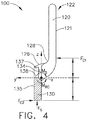
- the flat-formed staple 100 depicted in FIGS. 1-4 comprises a proximal staple leg 110, a distal staple leg 120, and a staple base portion 130.
- the staple 100 further comprises vertical transition portions, or bends, 118, 128 and lateral transition portions, or bends, 116, 126.
- the vertical transition portions 118, 128 bend, or extend, the legs 110, 120 vertically, or upward, from the staple base portion 130.
- the lateral transition portions 116, 126 extend the staple legs 110, 120 laterally outward, or at least substantially perpendicularly with respect to the staple base portion 130.
- the staple legs 110, 120 define a first plane and the staple base portion 130 defines a second plane.
- the vertical transition portions 118, 128 and the lateral transition portions 116, 126 permit the staple legs 110, 120 to be laterally offset and parallel with respect to the staple base portion 130.
- the first plane is offset from and at least substantially parallel to the second plane. In FIGS. 1-4 , the first plane is offset in the negative Y direction.
- Other staples may be used in conjunction with a plurality of staples 100 where the other staples comprise a first plane which is offset in the positive Y direction.
- the use of both types of staples permits staple rows to be nested, or interwoven, where staple legs of neighboring rows may be at least substantially aligned and/or share a common longitudinal axis. In various instances, the staple rows can be nested to provide denser staple rows.
- the proximal staple leg 110 and the distal staple leg 120 comprise staple tips 112, 122 and corners 114, 124, respectively.
- the tips 112, 122 are configured to pierce tissue and contact a forming pocket of an anvil of a surgical stapling instrument.
- the tips 112, 122 contact the anvil when the staple 100 receives a driving force to eject the staple 100 from a corresponding staple cavity in the staple cartridge.
- the tips 112, 122 and/or legs 110, 120 of the staple 100 will then begin forming from an unfired configuration to a fired configuration.
- the proximal staple leg 120 further comprises a leading engagement foot 117 comprising a chamfered surface, or edge, 119.
- a feature of the sled can engage the leading engagement foot 117 to aid in preventing longitudinal staple roll, or rotation, for example.
- the engagement foot 117 can comprise a push point that is configured to be pushed on to load the staple 100 into a staple cartridge.
- the staple 100 is a flat-formed staple
- the staple legs 110, 120, tips 112, 122, and/or other portions of the staple 100 can be further developed, or worked, after being stamped from a flat, or at least substantially flat, stock. Further developing the staple 100 can provide specific properties creating and/or altering preferential bending planes, toughness, and/or elasticity, for example.
- Traditional wire-formed staples comprise desirable properties advantageous for surgical fastening and can be implemented with the staple 100.
- Methods for constructing the corners 114, 124 and/or tips 112, 122, for example, may include any suitable process including cold working, for example.
- a specific process may include coining by working the corners 114, 124 into a rounded, angled, oblique, and/or parabolic profile, for example.
- the staple tips 112, 122 can also be worked using similar methods to provide an adequate tip configured to pierce tissue and form against a corresponding forming pocket of the anvil.
- the staple base portion 130 comprises an inclined drive surface 132, a final drive surface 131, and a distal wall 133.
- the staple 100 is supported in a staple cartridge by a pan where the final drive surface 131 is configured to rest on the pan.
- the final drive surface does not rest on a pan; rather, the final drive surface comprises an initial position residing above a bottom surface of the pan-less staple cartridge. This would allow a bottom surface of the sled and the bottom surface of the pan-less staple cartridge to be at least substantially flush as the sled translates through the cartridge.
- the drive surface 132 of each staple base portion 130 is configured to receive the driving force F s from the sled of the surgical stapling instrument. When the sled translates distally through the staple cartridge, the sled contacts the drive surface 132 to lift the staple 100 out of the cartridge and, in addition, contact the final drive surface 131 to form the staple 100 into its fired configuration.
- the distal wall 133 acts as a distal-most wall of the staple base portion 130 and is positioned proximal of the distal staple leg 120 resulting in a lack of any portion of the staple base portion 130 underneath the distal staple leg 120.
- Having a greater amount of mass in the base portion 130 of the staple 100 increases the ability of the staple 100 to resist rotational motion caused by the moment Ms applied by the sled.
- Increasing the moment of inertia of the staple base portion 130 increases the ability to resist rotational motion. As a result, a greater torque, or larger moment, would be required to cause longitudinal staple roll.
- the staple base portion 130 further comprises a top surface, or compression surface, 136 comprising a proximal surface 139, an intermediate surface 138, and a distal surface 137.
- the proximal surface 139 is angled, or slanted, upward toward the proximal leg 110.
- the distal surface 137 is angled, or slanted, upward toward the distal leg 120.
- the intermediate surface 138 is at least substantially parallel to the final drive surface 131. This valley-like configuration limits the stress concentration of tissue captured near the transition portions 118, 128, 116, 126 where the legs 110, 120 extend from the staple base portion 130. In various instances, these surfaces 137, 138, 139 can be curved to create a concave surface.
- the connections where the legs meet the staple base produce locations responsible for highly localized tissue stress. This is especially true in the event that such a traditional staple buckles, or is crushed, or flattened, rather than formed into a true "B" configuration.
- the dynamics of the staple 100 are predictable when ejected from a staple cartridge. As the staple 100 is ejected from its corresponding staple cavity, a driving force Fs from the sled generates a moment M s .
- One preventive measure for preventing staple roll includes increasing the moment of inertia of the staple 100, discussed above, which is configured to prevent, as illustrated in FIG. 2 , longitudinal roll, or rotation of the staple.
- reaction force F C1 which acts upon the staple leg 120 above the center of mass.
- Both reaction forces, F C1 and F C2 contribute to a reactional moment M RC to counteract, or balance, the applied moment Ms acting on the staple 100.
- the reaction forces discussed herein may be distributed loads acting upon a surface area of each of the staple legs 110, 120. In certain instances, the reaction force F C2 can be about 0.
- the moment of inertia of the staple 100 is also configured to prevent, as illustrated in FIG. 4 , lateral roll, or rotation of the staple 100.
- the staple base portion 130 comprises a notch 134 defined in the top surface 136 on a side of the staple base portion 130 closest to the legs 110, 120.
- the notch 134 contributes to the predictability of the dynamics of the staple 100 before formation and upon formation when ejected from the staple cartridge.
- the notch 134 is configured to induce rotation of the staple 100 toward a particular cavity sidewall.
- An outer lateral wall 135 of the staple base portion 130 contacts another corresponding sidewall of the staple cartridge producing a reaction force F C2 which acts upon the staple base portion 130 below the center of mass.
- Reaction forces F C1 and F C2 produce a reactional moment M RC to counteract, or balance, the applied moment Ms acting on the staple 100 from the sled.
- the reaction forces discussed herein may be distributed loads acting upon a surface area of each of the staple legs 110, 120 and the staple base portion 130.
- the staple 100 is encouraged to roll laterally in the direction of the applied moment Ms to control which walls of the staple cavity are going to be contacted for staple guidance as the staple 100 is ejected from the staple's 100 corresponding staple cavity.
- a staple cartridge assembly 240 is illustrated in FIGS. 5-6 .
- the staple cartridge assembly 240 comprises a cartridge body 242.
- the cartridge body 242 is positionable in and removable from a jaw of a surgical stapling instrument. As a result, the staple cartridge 240 is replaceable; however, other instances are envisioned in which the staple cartridge 240 is not replaceable.
- the cartridge body 242 comprises a proximal end 246, a distal end 247, and a deck 245 extending between the proximal end 246 and the distal end 247.
- the deck 245 is configured to support the tissue of a patient when the tissue is compressed against the deck 245.
- the cartridge body 242 further comprises a plurality of staple cavities 244 defined therein.
- the staple cavities 244 are arranged in six longitudinal rows extending between the proximal end 246 and the distal end 247; however, any suitable arrangement of staple cavities 244 can be utilized.
- a staple such as staple 100 ( FIG. 1 ), for example, can be removably stored in each staple cavity 244.
- the staples are ejected from the staple cavities 244 by a firing member when the firing member is moved from the proximal end 246 of the cartridge body 242 toward the distal end 247.
- the staples are moved from an unfired position to a fired position by the firing member.
- the firing member lifts the staples toward an anvil, such as anvil 250 ( FIG. 7 ), for example, to deform the staples between an unfired, undeformed configuration and a fired, deformed configuration.
- the cartridge body 242 further comprises a elongate slot 243 defined therein.
- the elongate slot 243 is configured to receive the staple firing member and/or a tissue cutting member therein when the staples are ejected from the staple cavities 244.
- the cartridge body 2010 comprises steps 245' and 245" which extend upwardly from the deck 245. More specifically, the steps 245' extend upwardly from the deck 245 and the steps 245" extend upwardly from the steps 245'.
- three discrete deck surfaces 245a, 245b, 245c are defined in the deck 245, wherein the deck surface 245a may apply a larger compressive pressure to the tissue than the deck surface 245b, and wherein the deck surface 245b may apply a larger compressive pressure to the tissue than the deck surface 245c.
- the deck surface 245c is shorter than the deck surfaces 245a and 245b.
- the deck surface 245b is shorter than the deck surface 245a.
- the deck surfaces 245a, 245b, 245c comprise first, second, and third heights, respectively, relative to a plane define by a bottom surface 248 ( FIG. 7 ) of the staple cartridge 240, wherein the first height is greater than the second height, and wherein the second height is greater than the third height.
- the deck surfaces 245a, 245b, 245c are laterally offset from one another relative to the elongate slot 243.
- the deck surface 245a is positioned closer to the elongate slot 243 than the deck surface 245b.
- the deck surface 245b is positioned closer to the elongate slot 243 than the deck surface 245c. That said, any suitable arrangement of the deck surfaces 245a, 245b, 245c can be utilized.
- the staple cavities 244 comprise an inner row of staple cavities 244a defined in the deck surface 245a, an intermediate row of staple cavities 244b defined in the deck surface 245b, and an outer row of staple cavities 244c defined in the deck surface 245c.
- the inner row of staple cavities 244a is positioned closer to the elongate slot 243 than the intermediate row of staple cavities 244b
- the intermediate row of staple cavities 244b is positioned closer to the elongate slot 243 than the outer row of staple cavities 244c.
- the staple cavities 244c are similar to the staple cavities 244a, 244b in many respects.
- the staple cavities, 244a, 244b, 244c each comprise a central slot 249 having a proximal end and a distal end, a proximal staple leg guide 249' extending laterally from the proximal end of the central slot 249, and a distal staple leg guide 249" extending laterally from the distal end of the central slot 249.
- the staple cavities 244b and the staple cavities 244c are oriented in different directions.
- the staple leg guides 249', 249" of the staple cavities 244b extend toward the staple cavities 244a, while the staple leg guides 249', 249" of the staple cavities 100c extend away from the staple cavities 100a; however, any suitable arrangement can be utilized.
- each staple 100 comprises an unformed, or unfired, overall height H1 defined between the bottom of the base 130 and the tips of the staple legs 112, 122.
- each staple 100 comprises a tissue capture area defined between the top of the base 130 and the tips of the staple legs 112, 122 which have the same height H2 when the staple 100 is in its unformed height.
- a first group of staples stored in the staple cartridge 240 can have a first unformed height H1 and a second group of staples can have a second unformed height H2 which is different than the first unformed height H1. Also in contrast to the above, a first group of staples stored in the staple cartridge 240 can have a first tissue capture height H1 and a second group of staples can have a second tissue capture height H2 which is different than the first tissue capture height H2.
- the staples 100 comprise a first row of staples 100a removably stored in the inner row of staple cavities 244a, a second row of staples 100b removably stored in the intermediate row of staple cavities 244b, and a third row of staples 100c removably stored in the outer row of staple cavities 244c.
- the rows of staples 100a, 100b, 100c comprise different unformed heights; however, in other arrangements, the rows of staples 100a, 100b, 100c may comprise the same unformed height H1.
- the rows of staples 100a, 100b, 100c comprise different tissue capturing heights; however, in other arrangements, the rows of staples 100a, 100b, 100c may comprise the same tissue capturing height H2.
- the staples 100c comprise an unformed height 103 which is greater than an unformed height 102 of the staple 100b. Also, the unformed height 102 of the staples 100b is greater than an unformed height 101 of the staples 100a. In addition, the staples 100c comprise a tissue capturing height 106 which is greater than a tissue capturing height 105 of the staple 100b in an unformed configuration. Also, the tissue capturing height 105 of the staples 100b is greater than a tissue capturing height 104 of the staples 100a in the unformed configuration. As a result, the staples 100c comprise a tissue capturing area which is greater than a tissue capturing area of the staple 100b in an unformed configuration. In addition, the tissue capturing area of the staples 100b is greater than the tissue capturing area of the staples 100a in the unformed configuration.
- the staples 100 are driven between unfired positions and fired positions by a firing member, such as sled 290 ( FIG. 8 ), for example.
- the sled 290 comprises ramps or wedges 291 a, 291b, 291c which are configured to directly engage the staples 100a, 100b, 100c, respectively, and lift the staples 100a, 100b, 100c toward an anvil, such as anvil 250, for example, as illustrated in FIG. 7 .
- the sled 290 utilizes a wedge for each longitudinal row of staples 100a, 100b, 100c; however, the sled 290 may have any suitable number of wedges.
- Each of the wedges 291a, 291b, 291c comprises an angled drive surface which slides under the staples 100a, 100b, 100c as the sled 290 is advanced from the proximal end 246 of the staple cartridge 240 toward the distal end 247 of the staple cartridge 240.
- the base 130 of each staple 100a, 100b, 100c comprises an angled drive surface 132 which is directly contacted by the drive surface of the wedges 291 a, 291b, 291 c.
- each staple 100a, 100b, 100c comprises its own integrally-formed driver having a drive surface 132.
- the staples 100a, 100b, 100c are comprised of metal and, as a result, the integrally-formed driver is also comprised of metal. That said, the staples disclosed herein can be comprised of any suitable material.
- the drive surfaces of the wedges 291a, 291b, 291c comprise apex portions defining peak drive surfaces 292a, 292b, 292c.
- the wedges 291a, 291b, 291c comprise different heights.
- the wedge 291c is shorter than the wedge 291b, and the wedge 291b is shorter than the wedge 291a.
- the wedge 291a comprises a first height 294 defined between a bottom surface 293 of the sled 290 and the peak drive surface 292a.
- the wedge 291b comprises a second height 295 defined between the bottom surface 293 of the sled 290 and the peak drive surface 292b.
- the wedge 291c comprises a third height 296 defined between the bottom surface 293 of the sled 290 and the peak drive surface 292c. As illustrated in FIG. 8 , the heights 294, 295, 296 are different. The first height 294 is shorter than the second height 295, and the second height 295 is shorter than the third height 296. In other instances, however, the heights 294, 295, 296 can be the same, or at least substantially the same, size.
- an end effector 220 is depicted in a closed configuration.
- a forming gap is defined between the cartridge deck 245 and the anvil 250.
- a first gap height (A) is defined between the deck surface 245a and anvil pockets 254a which are configured to deform the staples 100a.
- a second gap height (B) is defined between the deck surface 245b and anvil pockets 254b which are configured to deform the staples 100b.
- a third gap height (C) is defined between the deck surface 245c and anvil pockets 254c which are configured to deform the staples 100c.
- the gap height (A) is shorter than the gap height (B), and the gap height (B) is shorter than the gap height (C).
- the forming gap may comprise a constant, or at least substantially constant, height between the cartridge deck 245 and the anvil 250.
- the sled 290 and the anvil 250 cooperate to form the staples 100a, 100b, 100c to different formed heights 107, 108, 109, respectively.
- the staples 100a, 100b, 100c can be proportionally formed by the sled 290 and the anvil 250.
- the staples 100a, 100b, 100c comprise different unformed heights, and are fully or completely formed to a standard "B" shaped formation. The difference in unformed height between the staples 100a, 100b, 100c causes the staples 100a, 100b, 100c to comprise different tissue capturing areas in the formed configuration even though the staples 100a, 100b, 100c are proportionally formed.
- a formed staple 100a comprises a smaller tissue capturing area than a formed staple 100b
- a formed staple 100b comprises a smaller tissue capturing area than a formed staple 100c.
- the formed staple 100a exerts more pressure on tissue captured by the formed staple 100a than the pressure exerted by the formed staple 100b on tissue captured by the formed staple 100b.
- the pressure exerted by the formed staple 100b on the tissue captured by the formed staple 100b is greater than the pressure exerted by the staple 100c on tissue captured by the formed staple 100c.
- a first group of staples, a second group of staples, and/or a third group of staples may comprise the same unformed height but are deformed to different deformed heights by utilizing a sled that comprises wedges with different heights such as, for example, the sled 290.
- the sled 290 may cause the first group of staples to be fully formed, the second group of staples to be partially formed, and the third group of staples to be partially formed to a lesser degree than the second group of staples.
- the first group of staples can apply a larger pressure to the tissue than the second group of staples and, similarly, the second group of staples can apply a larger pressure to the tissue than the third group of staples.
- the staples 100d, 100e, 100f comprise the same unformed height. Yet the staples 100d, 100e, 100f can be formed to different formed heights by causing the staples 100d, 100e, 100f to formed to different degrees. For example, the staples 100d are more tightly formed than the staples 100e, and the staples 100e are more tightly formed than the staples 100f. In result, the formed staples 100d comprise a smaller tissue capturing area than the formed staples 100e, and the formed staples 100e comprise a smaller tissue capturing area than a formed staple 100f.
- the formed staple 100d exerts more pressure on tissue captured by the formed staple 100d than the pressure exerted by the formed staple 100e on tissue captured by the formed staple 100e.
- the pressure exerted by the formed staple 100e on the tissue captured by the formed staple 100e is greater than the pressure exerted by the staple 100f on tissue captured by the formed staple 100f.
- the height of the base 130 can be varied such that a first group of staples, a second group of staples, and/or a third group of staples may comprise different base heights.
- the row of staples 100a may comprise a first base height greater than a corresponding base height of the row of staples 100b
- the row of staples 100b may comprise a base height greater than a corresponding base height of the row of staples 100c.
- various staple cartridges 340 ( FIG. 12 ), 340' ( FIG. 14 ), 340" ( FIG. 15 ) are depicted.
- the staple cartridges 340, 340', 340" are similar in many respects to the staple cartridge 240.
- the staple cartridges 340, 340', 340" comprise a cartridge body 342, staple cavities 344, a cartridge deck 345, a proximal portion 346, a distal portion 347, and an elongate slot 343 extending longitudinally from the proximal portion 346 to the distal portion 347.
- the cartridge deck 345 includes steps 345', 345" that define stepped deck surfaces 345a, 345b, 345c, which comprise rows of staple cavities 344a, 344b, 344c, respectively.
- the staple cartridges 340, 340' are provided with stepped deck surfaces that are equipped tissue retention features or cleats 348.
- the stepped deck surfaces provide several advantages such as facilitating fluid outflow during a tissue stapling procedure; however, the stepped nature of the deck surfaces reduces traction against the tissue gripped between a staple cartridge and an anvil.
- stepped deck surfaces of staple cartridges 340 ( FIG. 12 ), 340' ( FIG. 14 ) are equipped with tissue retention features or cleats 348 that are strategically placed in various arrangements that improve traction against the tissue without significantly interfering with or reducing the functionality of the stepped deck surfaces.
- the cartridge deck 345 includes pyramid-shaped cleats 348.
- the pyramid-shaped cleats 348 may include square and/or triangular bases and sloping sides that may extend generally away from cartridge deck 345.
- the cleats 348 generally comprise a base 351 defined in the cartridge deck 345, and a peak 341 narrower than the base 351.
- the cartridge deck 345 may include pillar-shaped cleats which may include square and/or rectangle bases and substantially perpendicular sides extending generally away from the deck surfaces 345a, 345b, 345c.
- the cartridge deck 345 may include cone-shaped cleats and/or dome-shaped cleats 1042. Cleats with other suitable shapes and sizes can also be utilized.
- the cleats 348 can be made, or at least partially made, from the same material or materials as the cartridge deck 345. Alternatively, the cleats 348 may comprise a different material composition than the cartridge deck 345. In various instances, the cleats 348 can be made from a plastic or a ceramic material. In certain instances, the cleats 348 may comprise one or more biocompatible elastomeric polymers. In certain instances, the cleats are made, or at least partially made, from a medical grade plastic material such as, for example, a glass filled poly-carbonate material. In certain instances, the cleats 348 are made, or at least partially made, from one or more resilient materials. In certain instances, the cleats 348 are more flexible than the cartridge deck 345 to ensure an atraumatic interaction with the tissue.
- Cleats 348 can be spatially arranged onto the cartridge deck 345 in a predetermined pattern or array.
- cleats 348 can be spatially arranged onto the cartridge deck 345 in multiple rows which may extend longitudinally along a length of the cartridge deck 345, which can be in parallel with one another.
- the cleats 348 are spatially arranged in a cleat pattern 350 configured to define a perimeter around the staple cavities 344.
- the cleats 348 of the cleat pattern 350 are positioned outside the area of the cartridge deck 345 occupied by the staple cavities 344.
- the cleats 348 on one side of a plane defined by the elongate slot 343 are mirror images of corresponding cleats 348 on an opposite side of the plane. More of the cleats 348 of the cleat pattern 350 are positioned on the external deck surfaces 345c than the internal deck surfaces 345b, 345a. This creates a barrier against tissue slippage while minimizing interference with the fluid outflow functionality of the stepped cartridge deck 345.
- the cleats 348 that are positioned on the deck surfaces 345c are limited to external area of the deck surfaces 345c, as illustrated in FIG. 12 .
- the cleat pattern 350 is more tightly formed at the distal portion 347 and/or the proximal portion 346 than an intermediate portion 349 that includes the staple cavities 344.
- the distance between adjacent cleats 348 of the intermediate portion 349 is greater than the distance between adjacent cleats 348 of the distal portion 347.
- the distance between adjacent cleats 348 of the intermediate portion 349 is greater than the distance between adjacent cleats 348 of the proximal portion 346.
- the cleats 348 in the deck surfaces 345a, 345b are positioned proximal and/or distal to the rows of staple cavities 344a, 344b.
- This arrangement of the cleat pattern 350 is designed to improve tissue traction without significantly interfering with or reducing the functionality of the stepped deck surfaces, as described above.
- a cleat pattern 360 is utilized with the staple cartridge 340'.
- the cleats 348 of the cleat pattern 360 are limited to the proximal portion 346 and distal portion 347 of the staple cartridge 340 that are void of the staple cavities 344.
- the cleats 348 of the cleat pattern 360 are positioned outside the intermediate portion 349 that includes the staple cavities 344.
- the cleats 348 of the cleat pattern 360 are distributed on the cartridge deck 345 in areas that are void of the staple cavities 344 which are proximal and distal to the intermediate portion 349.
- the cleats 348 of the cleat pattern 360 are arranged in rows 348a, 348b, 348c which extend or protrude from deck surfaces 345a, 345b, 345c, respectively.
- the rows 348a, 348b, 348c are aligned with the rows of the staple cavities 344a, 344b, 344c, respectively, to provide appropriate traction against tissue slippage that is caused by the stepped nature of the stepped cartridge deck 345.
- the cleats of the cleat rows 348a, 348b, 348c are spatially arranged on the deck surfaces 345a, 345b, 345c, respectively, at positions that are proximal and distal to the rows of staple cavities 344a, 344b, 344c, respectively.
- the number, size, and/or shape of the cleats in each of the cleat rows 348a, 348b, 348c can be adjusted to provide an appropriate amount of traction against the tissue slippage at each of the deck surfaces 345a, 345b, 345c, for example.
- the cleats of the deck surfaces 345a, 345b, 345c include different cleat heights.
- the cleats of the cleat row 348a may comprise a first cleat height H1 smaller than a second cleat height H2 of corresponding cleats of the cleat row 348b, which is smaller than a third cleat height H3 of corresponding cleats of the cleat row 348c. That said, cleats with other cleat height arrangements can be utilized.
- the cleat heights of the cleat rows 348a, 348b, 348c can be selected to compensate for the difference in height between the deck surfaces 345a, 345b, 345c.
- the peaks 341 of the cleat rows 348a, 348b, 348c can define a plane extending in parallel, or substantially in parallel, with the deck surfaces 345a, 345b, 345c.
- the combined height of the deck surfaces 345a, 345b, 345c and corresponding cleats from the cleat rows 348a, 348b, 348c, respectively may amount to the same, or substantially the same, height, for example.
- external cleats may comprise greater heights than internal cleats to provide a greater traction at peripheral portions of the cartridge deck 345.
- the tissue traction provided by cleats of the cleat row 348c at the external deck surface 345c is greater than the tissue traction provided by cleats of the cleat row 348b at the intermediate deck surface 345b, which is greater than the tissue traction provided by cleats of the cleat row 348a at the internal deck surface 345a.
- the cleat pattern 350 creates a tissue-traction gradient where tissue closer to the elongate slot 343 experiences a greater traction than tissue further away from the elongate slot 343.
- an end effector 220' includes a staple cartridge 340' and an anvil 250.
- the end effector 220' is similar in many respects to the end effector 220 ( FIG. 7 ).
- the end effector 220' is depicted in a closed configuration.
- a forming gap is defined between the cartridge deck 345 and the anvil 250.
- the cleat rows 348a, 348b, 348c protrude from the deck surfaces 345a, 345b, 345c, respectively, toward the forming gap between the cartridge deck 345 and the anvil 250.
- the cleat rows 348a, 348b, 348c are configured to provide appropriate traction for tissue captured between the anvil 250 and the cartridge deck 340 to resist slippage of the captured tissue.
- the peaks 341 of corresponding cleats of the cleat rows 348a, 348b, 348c are the same or, at least substantially the same, distance from a datum in the anvil 250.
- one or more of the cleats 348 can function as gap setting members configured to set a minimum forming gap between a cartridge deck of a staple cartridge and anvil in a closed configuration.
- FIGS. 15 and 17 illustrate a staple cartridge 340" which is similar in many respects to other staple cartridges described herein such as, for example, the staple cartridge 340.
- the staple cartridge 340" comprises gap setting members 370 configured to set a minimum forming gap between the staple cartridge 340" and an anvil 250. In a fully closed configuration, the anvil 250 is configured to rest against the gap setting members 370. A predetermined minimum gap is set between the anvil 250 and the cartridge deck 340" by the transverse gap setting members 370 in the fully closed configuration.
- the number, height, size, arrangement, and/or shape of the gap setting members 370 can be selected to set a suitable minimum gap between the anvil 250 and the cartridge deck 340.
- the gap setting members 370 comprise a proximal gap setting member 370a extending transversely in a proximal portion 346 of the staple cartridge 340", an intermediate gap setting member 370b extending transversely in an intermediate portion 349 of the staple cartridge 340", and a distal gap setting member 370c extending transversely in a distal portion 347 of the staple cartridge 340".
- the gap setting members 370a, 370b, 370c comprise different heights. In other instances, however, the gap setting members 370a, 370b, 370c may comprise the same, or substantially the same, height.
- the distal gap setting member 370c is greater in height than the intermediate gap setting member 370b, which is greater in height than the proximal gap setting member 370a.
- a minimum forming gap 372 that comprises a size gradient is formed between the cartridge deck 340 and the anvil 250 in the fully closed configuration.
- the minimum forming gap 372 comprises a first volume at the proximal portion 346 of the staple cartridge 340", a second volume at the intermediate portion 349 of the staple cartridge 340", and a third volume at the distal portion 347 of the staple cartridge 340", wherein the first volume is greater than the second volume, and wherein the second volume is greater than the third volume.
- the distal gap setting member 370c can be smaller in height than the intermediate gap setting member 370b, which can be smaller in height than the proximal gap setting member 370a.
- the first volume can be smaller than the second volume, and the second volume can be smaller than the first volume.
- the gap setting members 370a, 370b, 370c are spaced apart. As illustrated in FIG. 15 , the gap setting member 370a is positioned proximal to the staple cavities 344 and the gap setting member 370c is positioned distal to the staple cavities 344 while the gap setting member 370b is positioned between adjacent staple cavities 344.
- Each of the gap setting members 370a, 370b, 370c extends across the elongate slot 343 in a direction perpendicular, or substantially perpendicular, to a longitudinal axis extending along the elongate slot 343. In other instances, one or more of the gap setting members 370a, 370b, 370c may not extend across the elongate slot 343.
- the staple cartridge 340" may comprise more or less than three gap setting members, for example.
- staple cartridges 440 and 440' are depicted.
- the staple cartridges 440 and 440' are similar in many respects to other staple cartridge disclosed herein such as, for example, the staple cartridge 240.
- the staple cartridges 440 and 440' comprise a cartridge body 442, a cartridge deck 445, staple cavities 444, a proximal portion 346, a distal portion 347, and an elongate slot 343 extending longitudinally from the proximal portion 346 to the distal portion 347.
- the cartridge deck 445 includes steps 445', 445" that define stepped deck surfaces 445a, 445b, 445c.
- the staple cavities 444 are arranged in rows 444a, 444b, 44c which are defined in deck surfaces 445a, 445b, 445c, respectively.
- the staple cartridge 440 comprises gap setting pins 470 configured to set a minimum forming gap between the staple cartridge 440 and an anvil 250.
- the anvil 250 In a fully closed configuration, the anvil 250 is configured to rest against the gap setting pins 470.
- a predetermined minimum gap is set between the anvil 250 and the cartridge deck 445 by the gap setting pins 470 in the fully closed configuration.
- the gap setting pins 470 are positioned at a distal portion 347 of the staple cartridge 440. Said another way, the gap setting pins 470 are positioned distal to the staple cavities 444. As illustrated in FIG. 18 , the gap setting pins 470 comprise a cylindrical, or at least substantially cylindrical, shape, and are positioned on opposite sides of a plane defined by the elongate slot 343. The gap setting pins 470 are equidistant from the elongate slot 343 to balance the anvil 250 in the closed configuration and resist any tilting that may occur in the anvil 250 as the anvil 250 is pressed against tissue captured between the anvil 250 and the staple cartridge 440. The number, height, size, arrangement, and/or shape of the gap setting pins 470 can be selected to set a suitable minimum gap between the anvil 250 and the cartridge deck 445.
- the gap setting members 370 and or the gap setting pins 470 can be made from a plastic or a ceramic material. In certain instances, the gap setting members 370 and or the gap setting pins 470 may comprise one or more biocompatible elastomeric polymers. In certain instances, the gap setting members 370 and or the gap setting pins 470 are made, or at least partially made, from a medical grade plastic material. In certain instances, the gap setting members 370 and or the gap setting pins 470 are made, or at least partially made, from one or more resilient materials. In certain instances, the gap setting members 370 and or the gap setting pins 470 are more flexible than the cartridge deck 345 to ensure an atraumatic interaction with the tissue.
- the staple cartridge 440' comprises a shell 402 configured to receive a cartridge body 442.
- Retention features 403 and 405 secure the cartridge body 442 to the shell 402.
- the cartridge body 442 is inserted into the shell 402 until the retention features 403 and 405 snap into engagement with corresponding openings 404 and 406 in the shell 402.
- the shell 402 includes elevated portions 480 that extend above the cartridge deck 445 to set a minimum gap between the cartridge deck 445 and an anvil 250 in a fully closed configuration.
- the elevated portions 480 comprise distal flanges 480a and intermediate flanges 480b that protrude through corresponding openings 481 a, 481b in the cartridge deck 445.
- the distal flanges 480a and intermediate flanges 480b are bent away from the elongate slot 343.
- the elevated portions 480 further include proximal flanges 482 that are bent toward the elongated slot 343.
- Other elevated portions suitable for maintaining a minimum gap between the cartridge deck 445 and the anvil 250 in a fully closed configuration can be utilized.
- a staple retainer 502 is affixed to a cartridge deck 545 of a staple cartridge 540.
- the staple retainer 502 extends between a proximal end 546 and a distal end 547 of the staple cartridge 540.
- the staple retainer 502 may be configured to mimic the surface of the cartridge deck 545.
- the staple cartridge 540 comprises an elongate slot 543 centered among rows of staple cavities 544.
- the elongate slot 543 may be configured to receive a cutting member.
- the staple retainer 502 may be labeled with various information to assist the surgeon in selecting the appropriate cartridge for use with the surgical instrument. Such information can also include descriptions regarding the orientation of the staple cartridge 540 or instructions for attachment or removal of the staple retainer 502.
- the staple retainer 502 may be secured to the staple cartridge 540 through various means including a biasing member in the form of a spring latch 501.
- the spring latch 501 includes two eject arms 506 and a hairpin retainer 507.
- the hairpin retainer 507 can be configured to pass through an aperture 508 on the proximal end 546 of the staple retainer 502 that is aligned with the elongate slot 543 of the staple cartridge 540. Thus, the hairpin retainer 507 passes into the elongate slot 543 when the staple retainer 502 is attached to the staple cartridge 540.
- the two eject arms 506 of the spring latch 501 may engage with a pair of wire cleats 505, configured to secure and retain the eject arms 506.
- the spring latch 501 may be located on the proximal end 546 of the staple retainer 502.
- a spring latch 501 can be located on the distal end 547 of the staple retainer 502.
- Other suitable positions for the spring latch 501 are contemplated by the present disclosure.
- Additional attachment features including side wings or flanges 510, are utilized to strengthen the retention connection of the staple retainer 502 to the staple cartridge 540.
- Such flanges 510 may contact corresponding indentations on the cartridge body 542 of the staple cartridge 540.
- Flanges 510 may engage with the cartridge body 542 in various ways, including but not limited to snap-fit or pressure-fit connections, for example.
- the staple retainer 502 further comprises a handle portion 520 for facilitating removal of the staple retainer 502 from the staple cartridge 540.
- the handle portion 520 extends past the end of the staple cartridge 540 to facilitate grasping the handle portion 520.
- the upward forces can overcome the retention forces holding the spring latch 501 in place.
- Such upward forces are also capable of overcoming any additional retention forces from the side wings or flanges 510.
- the elongate slot 543 of the staple cartridge 540 comprises inner sidewalls 550 with channel detents 551 to facilitate the retention of the hairpin retainer 507 of the spring latch 501.
- the hairpin retainer 507 has outward-extending curves that fit within the channel detents 551 on the inner sidewalls 550 of the elongate slot 543.
- the hairpin retainer 507 when holding the staple retainer 502 in place, the hairpin retainer 507 is configured to enter the elongate slot 543 to a degree where the staple retainer 502 lies flush against the cartridge deck 545 of the staple cartridge 540. In this position, a portion of the hairpin retainer 507 extends beyond the channel detents 551 of the sidewalls 550, while the eject arms 506 rest in the wire cleats 505 of the staple retainer 502.
- the staple retainer 502 presses up against the eject arms 506 of the spring latch 501.
- the eject arms 506 are subjected to such an upward ejection force, they begin to buckle inwardly, disengaging the hairpin retainer 507 from its connection with the channel detents 551 of the elongate slot 543.
- the spring latch 501 may remain attached to the staple retainer 502 throughout attachment and detachment because of the retention of the eject arms 506 within the wire cleats 505. This ensures that the spring latch 501 is removed with the staple retainer 502.
- a staple cartridge 640 is similar in many respects to other staple cartridges disclosed herein such as, for example, the staple cartridges 240, 440.
- the staple cartridge 640 comprises a cartridge body 642, a cartridge deck 645, staple cavities 644, staples 600, a proximal portion 346, a distal portion 347, and an elongate slot 343 extending longitudinally from the proximal portion 346 to the distal portion 347.
- the cartridge deck 645 includes steps 645', 645" that define stepped deck surfaces 645a, 645b, 645c.
- the staple cavities 444 are arranged in rows 444a, 444b, 44c which are defined in the stepped deck surfaces 445a, 445b, 445c, respectively.
- the staple cartridge 640 further comprises a plurality of staple drivers 602, 603, 604 which can each be configured to support one or more staples 600 ( FIG. 27 ) within the staple cavities 444 when the staples 600 and the staple drivers 602, 603, 604 are in their predetermined starting positions.
- Each of the staple drivers 602, 603, 604 comprises cradles, or troughs, 607, for example, which are configured to support the staples 600.
- a staple-firing sled can be moved from a proximal portion 346 to a distal portion 347 of the staple cartridge 640 in order to sequentially lift the staple drivers 602, 603, 604 and the staples 100 from their predetermined starting positions toward an anvil 250 positioned opposite the staple cartridge 640.
- a proximal region 646 includes the staple drivers 602 which comprise each two pushers 602a, 602b supporting two staples 600 in the inner and intermediate cavity rows 644a, 644b.
- an intermediate region 649 includes the staple drivers 603 which comprise each three pushers 603a, 603b, 603c supporting three staples 600 in the inner, intermediate, and outer cavity rows 644a, 644b, 644c.
- a distal region 647 includes the staple drivers 604 which comprise each four pushers 604a, 604b, 604c supporting four staples 600 in the inner, intermediate, and outer cavity rows 644a, 644b, 644c.
- the staple cartridge 640 comprises an outer shell that defines a bottom surface of the staple cartridge 640.
- staple drivers 602, 603, 604 are inserted into predetermined starting positions within the cartridge body 642.
- the cartridge body 642 is assembled with the outer shell of the staple cartridge 640.
- the present disclosure provides various retention features that are configured to maintain the assembled staple drivers 602, 603, 604 at their predetermined starting positions. This is especially useful in staple cartridges such as the staple cartridge 640 where multiple staples from different deck surfaces are configured to be simultaneously driven by the same staple driver. Minor shifting motion of such staple drivers from their predetermined starting positions may compromise the alignment of the staples with the staple driver which can compromise the successful deployment of the staples.
- FIG. 25 illustrates the staple cartridge 640 with the outer shell being removed exposing the staple drivers 602, 603, 604.
- the cartridge body 642 comprises deformable or crushable retention features 610 that maintain the staple drivers 602, 603, 604 in their predetermined starting positions, as illustrated in FIG. 25 .
- the deformable retention features 610 project or protrude from the staple drivers 602, 603, 604 and/or in the cartridge body 642 providing a friction fit between the staple drivers 602, 603, 604 and the cartridge body 642.
- the deformable retention features 610 extend along a predefined direction of motion of the staple drivers 602, 603, 604 within the staple cavities 644.
- the deformable retention features 610 can be in the form of ribs or columns extending in a direction transverse to a plane defined by the cartridge deck 645.
- a deformable retention feature 610 may comprise a dome-shaped or triangular cross-sectional area. Other suitable shapes and sizes of the deformable retention features 610 can be utilized.
- the deformable retention features 610 may comprise the same material composition as the cartridge body 642 and/or the staple drivers 602, 603, 604. Alternatively, the deformable retention features 610 may comprise a different material composition than the cartridge body 642 and/or the staple drivers 602, 603, 604.
- the deformable retention features 610 are sized and positioned such that they are partially deformed to create the friction fit needed to maintain the staple drivers 602, 603, 604 in their predetermined starting positions. When the staple drivers 602, 603, 604 are in their predetermined starting positions, an interference 611 between the deformable retention features 610 and corresponding staple drivers 602, 603, 604 is about 0.001" to about 0.002".
- any suitable interference between the deformable retention features 610 and corresponding staple drivers 602, 603, 604 can be implemented.
- a suitable interference is one that maintains the staple drivers 602, 603, 604 in their predetermined starting positions but can be overcome by a staple deployment force or a firing force transmitted by a sled as the sled is advanced to motivate the staple drivers 602, 603, 604 to deploy the staples 600.
- the deformable retention features 610 are slightly plastically deformed between the staple drivers 602, 603, 604 and the cartridge body 642. Elastic recovery of deformable retention features 610 around the edges of the staple drivers 602, 603, 604 maintain the staple drivers 602, 603, 604 at the predetermined starting position.
- the plastic deformation of the deformable retention features 610 is selected from a range of about 1% to about 40%. In certain instances, the plastic deformation of the deformable retention features 610 is selected from a range of about 5% to about 35%. In certain instances, the plastic deformation of the deformable retention features 610 is selected from a range of about 10% to about 30%.
- a suitable interference can be selected from a range of about 0.0015" to about 0.003", for example. In certain instances, a suitable interference can be selected from a range of about 0.0013" to about 0.0017", for example. In certain instances, a suitable interference can be selected from a range of about 0.0014" to about 0.0016", for example.
- the deformable retention features 610 are molded on the staple drivers 602, 603, 604 and/or in the cartridge body 642. In certain instances, the deformable retention features 610 are attached to the staple drivers 602, 603, 604 and/or the cartridge body 642, for example. Any suitable manufacturing techniques can be utilized to prepare staple drivers 602, 603, 604 and/or cartridge bodies 642 that include the deformable retention features 610.
- the external pushers 602c, 603c, 604c, 604d that support staples 600 in the outer row of staple cavities 644c comprise clearance tracks, recesses, or slots 605 that are configured to receive the deformable retention features 610.
- the outer pan or shell is removed, and the staple drivers 602, 603, 604 are inserted into their predetermined starting positions.
- the clearance slots 605 are slid against the deformable retention features 610 extending or protruding from side walls 608 of the staple cavities 644c. This causes deformation of the deformable retention features 610 as the staple drivers 604 are moved toward their predetermined starting positions.
- the elastic recovery of deformed portions 610a, 610b of the deformable retention features 610 that are below a bottom surface 612 of the clearance slots 605 and above a top surface 612 of the clearance slots ensures that the staple drivers 602, 603, 604 remain at their predetermined starting positions in the absence of a firing force.
- the portions 610a, 610b partially wrap around the surfaces 606 and 612 of the staple drivers 602, 603, 604 at their predetermined starting positions resisting exposure of the staple drivers 602, 603, 604 to shifting motions that may occur during and/or after assembly of the staple cartridge 640.
- the clearance slots 605 cooperate with corresponding deformable retention features 610 to define a track that facilitates guiding the staple drivers 602, 603, 604 within the cartridge body 642 to their predetermined starting positions.
- the staple drivers 602, 603, 604 may lack the clearance slots 605.
- the deformable retention features 610 can provide an interference 611 against other portions of the staple drivers 602, 603, 604.
- clearance slots 605 need not be limited to external pushers 602b, 603c, 604c, 604d.
- Other pushers such as, for example, pushers 602a, 603a, 603b, 604a, 604b may comprise clearance slots 605 which can be pressed against corresponding deformable retention features 610 in the cartridge body 642, for example.
- the clearance slots 605 extend along the entire height of the pushers 602c, 603c, 604c, 604d terminating at top surfaces 612 and bottom surfaces 606. In other instances, a clearance slot 605 can extend along a portion of the height of a pusher, for example.
- the deformable retention features 610 extend along the entire height of corresponding staple cavities 644. Alternatively, a deformable retention feature 610 may extend along a portion of the height of a staple cavity 644.
- the clearance slots 605 and corresponding deformable retention features 610 comprise complimenting shapes to facilitate a mating engagement therebetween.
- a cartridge body may include a retention feature sized such that a friction fit is defined between the retention feature and a corresponding clearance slot of a staple driver without visible deformation of the retention feature.
- the retention feature may gradually increase in size from an initial portion at point of first engagement between the retention feature and the clearance slot to an end portion at a point of last engagement between the retention feature and the clearance slot.
- the end portion comprises a larger cross-sectional area than the initial portion to provide an appropriate friction fit to maintain the staple driver at a predetermined starting position.
- the size gradient allows the clearance slot 605 to easily slide against a relatively narrow initial portion of the retention feature. A greater friction is realized between the clearance slot and the retention feature as the size of the retention feature increases on the way toward the predetermined starting position at the end portion.
- the staple drivers comprise the deformable retention features while the cartridge body comprises the corresponding clearance slots.
- a staple driver such as, for example, the staple driver 604' comprises deformable retention features 610 disposed on side walls of the pushers 604c, 604d in place of the clearance slots.
- a cartridge body may include corresponding clearance slots configured to receive the deformable retention features 610 of the staple driver 604'.
- a staple cartridge 740 is similar in many respects to other staple cartridges disclosed herein such as, for example, the staple cartridges 240, 440, 640.
- the staple cartridge 640 comprises a cartridge body 742, a cartridge deck 745, staple cavities 744, a proximal portion 346, a distal portion 347, and an elongate slot 343 extending longitudinally from the proximal portion 346 to the distal portion 347.
- the cartridge deck 745 includes steps 745', 745" that define stepped deck surfaces 745a, 745b, 745c.
- the staple cavities 744 are arranged in rows 744a, 744b, 744c which are defined in the stepped deck surfaces 745a, 745b, 745c, respectively.
- the staple cartridge 740 comprises staples 100 ( FIG. 30 ) that are removably stored in staple cavities 744.
- the staples 100 of the staple cartridge 740 are ejected from the staple cavities 744 by a firing member or sled 709 ( FIG. 31 ) when the sled 709 is moved from the proximal portion 746 of the cartridge body 642 toward the distal portion 747.
- the sled 709 directly engages a base portion 130 of the staples 100 to sequentially lift the staples 100 from their predetermined starting positions in the staple cavities 744 toward an anvil 250 positioned opposite the staple cartridge 740.
- the cartridge body 742 comprises deformable or crushable retention features 710, which are similar in many respects to the deformable retention features 610.
- the deformable retention features 710 are configured to maintain the staples 100 in their predetermined starting positions in the absence of a firing force.
- the deformable retention features 710 project or protrude from the staples 100 and/or the cartridge body 742 providing a friction fit between the staples 100 and the cartridge body 742.
- the deformable retention features 710 extend along a predefined direction of motion of the staples within the staple cavities 744.
- the deformable retention features 710 can be in the form of ribs or columns extending in a direction transverse to a plane defined by the cartridge deck 745.
- a deformable retention feature 710 may comprise a dome-shaped or triangular cross-sectional area. Other suitable shapes and sizes of the deformable retention features 610 can be utilized. As illustrated in FIG. 31 , the deformable retention features 710 protrude from side walls 708 of the staple cavities 744 providing a friction fit between the base portions 130 of the staples 100 and the cartridge body 742 at the predetermined starting positions of the staples 100.
- the deformable retention features 710 may comprise the same material composition as the cartridge body 742 and/or base portions 130. Alternatively, the deformable retention features 710 may comprise a different material composition than the cartridge body 742 and/or the base portions 130.
- the deformable retention features 710 are sized and positioned such that they are partially deformed to create the friction fit needed to maintain the staples 100 in their predetermined starting positions. When the staples 100 are at their predetermined starting positions, an interference 711 is defined between the deformable retention features 710 and corresponding base portions 130, and is measured at about 0.001" to about 0.002". That said, any suitable interference between the deformable retention features 710 and corresponding base portions 130 can be implemented.
- a suitable interference is one that maintains the staples 100 in their predetermined starting positions but can be overcome by a staple deployment force or a firing force transmitted by the sled 709 ( FIG. 31 ) as the sled 709 is advanced against the base portions 130 to deploy the staples 100.
- the deformable retention features 710 are slightly plastically deformed between the base portions 130 of the staples 100 and the cartridge body 742 at the predetermined starting positions. Elastic recovery of deformable retention features 710 around the edges of the base portions 130 maintains the staples 100 at the predetermined starting positions.
- the plastic deformation of the deformable retention features 710 is selected from a range of about 1% to about 40%. In certain instances, the plastic deformation of the deformable retention features 710 is selected from a range of about 5% to about 35%. In certain instances, the plastic deformation of the deformable retention features 710 is selected from a range of about 10% to about 30%.
- a suitable interference between the deformable retention features 710 and corresponding base portions 130 can be selected from a range of about 0.0015" to about 0.003", for example. In certain instances, a suitable interference between the deformable retention features 710 and corresponding base portions 130 can be selected from a range of about 0.0013" to about 0.0017", for example. In certain instances, a suitable interference between the deformable retention features 710 and corresponding base portions 130 can be selected from a range of about 0.0014" to about 0.0016", for example.
- a surgical stapling and cutting instrument can include a pair of cooperating elongate jaw members, wherein each jaw member can be adapted to be inserted into a patient and positioned relative to tissue that is to be stapled and/or incised.
- One of the jaw members can support a staple cartridge with at least two laterally spaced rows of staples contained therein.
- suitable staple cartridges include but are not limited to the staple cartridges 240 ( FIG. 5 ), 340 ( FIG. 12 ), 440 ( FIG. 18 ), 640 ( FIG. 24 ).
- the other jaw member can support an anvil 850 ( FIG. 33 ) with staple-forming pockets 856 ( FIG. 33 ) aligned with the rows of staples in the staple cartridge.
- the surgical stapling and cutting instrument can further include a firing assembly 800 ( FIG. 35 ) which is slidable relative to the jaw members to sequentially eject the staples from the staple cartridge.
- the firing assembly 800 is configured to activate a plurality of staple drivers carried by the cartridge and associated with the staples in order to push the staples against the staple-forming pockets 856 of the anvil 850 and form laterally spaced rows of deformed staples in the tissue gripped between the jaw members.
- a limitation to the repeated use of a surgical stapling and cutting instrument arises from damage sustained by the anvil from interfacing a firing assembly 800 during a firing stroke.
- Anvils are typically manufactured from materials that can be easily stamped to create staple forming pockets. The material properties that allow anvils to be easily stamped reduce an anvil's resistance to the forces transmitted by the firing assembly 800 during the firing stroke.
- the present disclosure provides an anvil 850 that is designed to resist damage caused by repeated firing of a surgical stapling and cutting instrument. As illustrated in FIG. 33 , the anvil 850 is assembled from a plurality of discrete pieces that are designed to provide a localized reinforcement to portions of the anvil 850 that interface with the firing assembly 800 during a firing stroke.
- the reinforcement can be in the form of localized, strengthening, hardening, coating, and/or laminating of specific portions of the anvil 850, as described below in greater detail.
- the anvil 850 includes a first forming portion 854, a second forming portion 855, and a cover portion 851 interconnecting the first forming portion 854 and the second forming portion 855.
- the anvil 850 includes an anvil channel 857.
- the firing assembly 800 slidingly travels along the anvil channel 857 during a firing stroke.
- the anvil channel 857 includes an elongate slot 866 extending between the first forming portion 854 and the second forming portion 855.
- the elongate slot 866 inwardly opens along a longitudinal axis of the anvil 850.
- the anvil channel 857 includes a first recess 867 defined between the cover portion 851 and the first forming portion 854.
- a second recess 868 of the anvil channel 857 is defined between the cover portion 851 and the second forming portion 855.
- the first recess 867 and the second recess 868 are sized to receive a first engagement portion 811 ( FIG. 35 ) and a second engagement portion 812 ( FIG. 35 ), respectively, of an engagement member 810 ( FIG. 35 ) of the firing assembly 800.
- a first reinforcement member 860 is attached to the first inner interface 858 of the first forming portion 854, and the second reinforcement member 861 is attached to a second inner interface 859 of the second forming portion 855.
- staple-forming pockets 856 are stamped into a first outer interface 858 of the first forming portion 854 and a second outer interface 859 of the second forming portion 855.
- the first engagement portion 811 and the second engagement portion 812 slidingly engage the first reinforcement member 860 and the second reinforcement member 861, respectively, as the firing assembly 800 is advanced along the anvil channel 857.
- the advancement of the firing assembly 800 causes the plurality of staples to be deployed into the tissue and to be deformed against the staple-forming pockets 856.
- the reinforcement members 860, 861 protect the inner interfaces 858, 859 from deformation that may be caused by the engagement portions 811, 812 during a firing stroke. To do so, the reinforcement members 860, 861 are more able to resist deformation than the forming portions 854, 855. In certain instances, the reinforcement members 860, 861 are harder than the forming portions 854, 855. In certain instances, the reinforcement members 860, 861 are made from a material composition that is different from the material composition of the forming portions 854, 855. For example, the reinforcement members 860, 861 from titanium while the forming portions 854, 855 are made or at least partially made from stainless steel. Other suitable material compositions for the reinforcement members 860, 861 and the forming portions 854, 855 can be utilized.
- the reinforcement members 860, 861 can be in the form of flat plates that are welded or mechanically bonded to the inner interfaces 858, 859, respectively.
- the flat plates comprise a thickness selected from a range of about 0.003" to about 0.007". In certain instances, the flat plates comprise a thickness selected from a range of about 0.00" to about 0.006". In certain instances, the flat plates comprise a thickness of about 0.005", for example.
- the anvil 850 is assembled in a manner that permits inclusion of the reinforcement members 860, 861.
- the anvil 850 is manufactured in separate portions 854, 855, 851 which are assembled after attachment of the reinforcement members 860, 861 to the forming portions 854, 855, respectively.
- the first reinforcement member 860 is attached to the first inner interface 858 of the first forming portion 854, and the second reinforcement member 861 is attached to the second inner interface 859 of the second forming portion 854.
- the cover portion 851 is attached to the first forming portion 854 and the second forming portion 855 at outer edges 852, 853, respectively.
- Various attachment mechanisms can be utilized in assembly of the anvil 850 including but not limited to various welding and/or mechanical bonding techniques.
- laser welding is utilized in assembly of the anvil 850.
- spot laser welding 863 is utilized in attachment of the reinforcement members 860, 861 to the forming portions 854, 855. Due to size limitations, the spot laser welding 863 is performed prior to attachment of the cover portion 851 to the forming portions 854, 855, which can be achieved by continuous laser welding, for example, along the edges 852, 853.
- the reinforcement members 860, 861 and/or the inner interfaces 858, 859 can be treated to increase hardness and resistance to deformation. Various suitable treatments can be utilized to increase hardness of the reinforcement members 860, 861 and/or the inner interfaces 858, 859. In certain instances, the reinforcement members 860, 861 and/or the inner interfaces 858, 859 can be plasma coated, for example.
- the cover portion 851 may experience deflective forces during a firing stroke.
- reinforcement members can be attached to an inner interface 862 of the cover portion 851 to protect against such deflective forces.
- an anvil 850' can be equipped with a cover portion 851' designed to resist the deflective forces that are experienced during the firing stroke.
- the cover portion 851 comprises an atraumatic semi-circular outer interface 869 that facilitates insertion into a treatment site.
- the cover portion 851 comprises a flat, or at least substantially flat, inner interface 862' which give the cover portion 851 a generally dome-shaped cross-sectional area that provides sufficient strength to resist the deflective forces that are experienced during the firing stroke.
- the firing assembly 800 includes an I-beam 802 extending distally from a laminated firing bar 804.
- the I-beam 802 facilitates closure and firing of the surgical stapling and cutting instrument during a firing stroke.
- the I-beam 802 and laminated firing bar 804 are formed of a female vertical attachment aperture 806 distally formed in the laminated firing bar 804 that receives a corresponding male attachment member 807 proximally presented by the I-beam 802, allowing each portion to be formed of a selected material and process suitable for their disparate functions (e.g., strength, flexibility, friction).
- the I-beam 802 may be advantageously formed of a material having suitable material properties for forming a pair of top engagement portions or pins 811, 812 and a bottom pin or foot 113, as well as a sharp cutting edge 814.
- the laminated firing bar 804 is formed of a plurality of layers or plates comprising different material compositions. As illustrated in FIG. 35 , a laminated firing bar 804 includes a first outer layer 820, a second outer layer 822, and an intermediate layer 821 sandwiched between the outer layers 820, 822.
- the intermediate layer 821 comprises a thickness T2 that is greater than a thickness T1 of the first outer layer 820, and greater than a thickness T3 of the second outer layer 822.
- the thinner outer layers 820, 822 could be stainless steel making them more flexible and less capable of buckling resistance with the intermediate layer 821 being made of titanium and therefore more buckle resistant.
- the layers 820, 821, 822 can be made from other suitable materials. This design is particularly useful in resisting fatigue failure with repetitive firing of the surgical stapling and cutting instrument.
- the ratio of the thickness T2 of the intermediate layer 821 to the thickness T1 of the first outer layer 820 is selected from a range of about 95% to about 5%. In certain instances, the ratio of the thickness T2 of the intermediate layer 821 to the thickness T1 of the first outer layer 820 is selected from a range of about 80% to about 30%. In certain instances, the ratio of the thickness T2 of the intermediate layer 821 to the thickness T1 of the first outer layer 820 is selected from a range of about 60% to about 40%. Other values for the ratio of the thickness T2 of the intermediate layer 821 to the thickness T1 of the first outer layer 820 are contemplated by the present disclosure.
- an aperture 824 can be created in a laminated firing bar 804.
- the aperture 824 can be created through each of the layers 820, 821, 822 thus defining a through hole.
- the aperture 824 can be filled with melted portions of at least one of the outer layers 821, 822 to bond the layers 820, 821, 822 of the laminated firing bar 804.
- the aperture 824 is created by any suitable technique.
- the intermediate layer 821 is sandwiched between the outer layers 820, 822.
- portions of one or both of the outer layers 820, 822 are melted and permitted to flow through the aperture 824 to bridge the aperture 824 creating a bond between the layers 820, 821, 822 as the melted material is actively cooled, or permitted to cool down, to a temperature below a melting point.
- the outer layers 820, 822 are comprised of stainless steel that is melted to bridge the aperture 824.
- a filler material 826 can be utilized to bridge the aperture 824 and bond layers 820, 821, 822 of a laminated firing bar 804", as illustrated in FIG. 38 .
- the filler material 826 can be inserted into the aperture 824 either in a melted form or in an unmelted form that is then melted within the aperture 824.
- the filler material 826 is then actively cooled, or allowed to cool down, to a temperature below the melting point of the filler material 826 to bond the layers 820, 821, 822.
- an attachment member 827 can be utilized to join layers or plates of a laminated firing bar 804' comprised of different materials.
- the laminated firing bar 804' comprises a layer 820 made, or at least partially made, from stainless steel and a layer 821 made, or at least partially made, from titanium.
- Other suitable materials can be utilized.
- the attachment member 827 comprises a first portion 827a greater in size than the aperture 824, and a second portion 827b sized to be received within the aperture 824, as illustrated in FIG. 37 .
- the attachment member 827 can be made, or at least partially made, from the same material as the layer 820.
- the laminated firing bar 804' is assembled by inserting the second portion 827b into the aperture 824 such that the first portion 827a abuts against the layer 821. Heat can then be introduced to partially melt at least a portion of the second portion 827b and/or a portion of the layer 820. Upon cooling to a temperature below the melting point, the resulting bond between the layer 820 and the attachment member 827 provides an attachment between the layers 820, 821.
- an end effector 900 of a surgical stapling and cutting instrument includes a shaft portion 901, an anvil 902 extending distally from the shaft portion 901, and an elongate channel 911 movably coupled to the shaft portion 901.
- a staple cartridge 940 is removably attached to the elongate channel 911.
- the staple cartridge 940 is similar in many respects to other staple cartridges disclosed herein such as, for example, the staple cartridge 240.
- an unfired staple cartridge 940 is loaded by insertion into the elongate channel 911.
- the end effector 900 is then positioned around tissue.
- a firing bar 906 is then moved, during a firing stroke, to advance a firing assembly 904 distally to transition the end effector 900 to a closed configuration to capture the tissue.
- the firing assembly 904 also causes staples from the staple cartridge 940 to be deployed into the captured tissue.
- the firing assembly 904 further includes a distal cutting edge 908 extending distally from a body 905, and configured to cut the stapled tissue. In certain instances, however, the firing assembly 904 may not include a cutting edge 908.
- the firing bar 906 extends proximally from the firing assembly 904 in a direction opposite the cutting edge 908.
- the anvil 902 is fixedly attached to the shaft portion 901. In certain instances, however, the anvil 902 can be movable relative to the shaft portion 901.
- the elongate channel 911 is rotatable about a channel pivot 912 to transition the staple cartridge 940 and the anvil 902 between an open configuration, as illustrated in FIG. 40 , and a closed configuration, as illustrated in FIG. 39 .
- the firing assembly 904 further includes an anvil camming member 907 and a channel camming member 909 which cooperate to transition the end effector 900 to a closed configuration.
- the anvil camming member 907 and the channel camming member 909 are configured to slidingly engage the anvil 902 and the elongate channel 911, respectively, as the firing assembly 904 is advanced distally during a firing stroke.
- the firing assembly 904 may distally translate a sled that facilitates the deployment of the staples into the captured tissue.
- the firing bar 906 Upon completion of the firing stroke, the firing bar 906 is moved proximally to retract the firing assembly 904 to a neutral or dwell position where the anvil camming member 907 and the channel camming member 909 are no longer able to apply camming forces to the anvil 902 and the elongate channel 911.
- the elongate channel 911 is free to open in order to release the stapled tissue.
- the end effector 900 can also be pulled away from the stapled tissue in order to free the stapled tissue.
- the spacing between the anvil 902 and the staple cartridge 940 at the dwell position may not be sufficiently wide to facilitate an atraumatic release of the stapled tissue by pulling the end effector 904 away from the stapled tissue.
- the present disclosure provided various mechanisms for positively opening the end effector 900 to increase the spacing between the anvil 902 and the staple cartridge 940 to facilitate an atraumatic release of the stapled tissue from the end effector 900.
- the firing assembly 904 further comprises an engagement portion 910 which is sized and positioned to engage a camming member 914 during retraction of the firing assembly 904 by the firing bar 906.
- the engagement portion 910 is configured to motivate the camming member 914 to positively open the elongate channel 911 as the firing assembly 904 is moved proximally from the dwell position by the firing bar 906.
- Positive opening of the elongate channel 911 entails applying an external force to the elongate channel 911 that can gradually open the end effector 900 to a fully open configuration defined by a maximum spacing between the anvil 902 and a staple cartridge 940 attached to the elongate channel 911.
- the gradual opening of the elongate channel 911 facilitates a gradual and/or controlled release of the stapled tissue from the end effector 900 which can reduce the tissue trauma.
- Such gradual opening of the elongate channel 911 is achieved by gradually retracting the firing bar 906 to move the firing assembly 904 proximally so that the engagement portion 910 gradually motivates the camming member 914 to gradually open the elongate channel 911.
- the engagement portion 910 is configured to engage a first portion 916 of the camming member 914 which causes rotation of the camming member 914 about a pivot 915.
- the rotation of the camming member 914 causes a second portion 917 of the camming member 914 to slidingly engage a sloped surface 918 of an end portion 913 of the elongate channel 911.
- the end portion 913 is positioned proximal to the channel pivot 912.
- the firing assembly 904 is movable proximally from the dwell position to a first proximal position where the engagement portion 910 contacts the first portion 916 of the camming member 914.
- the firing assembly 904 is also movable proximally from the first proximal position to a second proximal position, further away from the dwell position than the first proximal position.
- the movement of the firing assembly 904 toward the second proximal position causes the camming member 914 to rotate about the pivot 915 until the second portion 917 of the camming member 914 is brought into contact with the end portion 18 of the elongate channel 911.
- the firing assembly 904 is also movable proximally from the second proximal position to a third proximal position, further away from the dwell position than the second proximal position.
- the movement of the firing assembly 904 toward the second proximal position causes the camming member 914 to exert a camming force against the end portion 913 to positively open the elongate channel 911 which gradually transitions the end effector 900 to a fully open configuration, as illustrated in FIG. 40 .
- a first angle is defined between the second portion 917 and the end portion 913 in the closed configuration.
- a second angle is defined between the second portion 917 and the end portion 913 in the open configuration, wherein the second angle is greater than the first angle.
- the end portion 913 is partially wrapped around the channel pivot 912 which cooperates with the second portion 917 to define a maximum open configuration, as illustrated in FIG. 40 .
- the firing assembly 904 is movable distally from the dwell position to a first distal position and a second distal position further away from the dwell position than the first distal position.
- the movement of the firing assembly 904 toward the first distal position causes the end effector 900 to be transitioned to a closed configuration to capture tissue without deploying the staples from the staple cartridge 940.
- the movement of the firing assembly 904 from the first distal position toward the second distal position causes the staples to be deployed from the staple cartridge 940.
- a user of the surgical stapling a cutting instrument can capture and release tissue multiple times until an optimal tissue portion is captured by advancing and retracting the firing assembly 904 between the first distal position and the third proximal position.
- the engagement portion 910 is manufactured as one seamless piece with the firing assembly 904. In other instances, the engagement portion 910 can be coupled to the firing assembly 904 post manufacturing. Various suitable techniques can be employed to attach the engagement portion 910 to the firing assembly 904 including but not limited to welding, adhesives, and other mechanical, thermal, and/or chemical bonding techniques.
- the engagement portion 910 is coupled to the channel camming member 909, and extends proximally in parallel, or substantially in parallel, with the firing bar 906.
- the engagement portion 910 comprises a blunt end-portion 903 oriented to engage the first portion 916 of the camming member 914 as the firing assembly 904 is retracted proximally.
- the camming member 914 comprises a triangular, or substantially triangular, cross-section.
- the first portion 916 extends in a first direction and the second portion 917 extends in a second direction defining an obtuse angle with the first direction.
- the first portion 916 of the camming member 914 protrudes through a horizontal plane defined by the elongate channel 911, wherein the first portion 916 and the engagement portion 910 are on the same side of the horizontal plane.
- the engagement portion 910 rotates the first portion 916 causing the second portion 917 to apply a camming force against the end portion 913 of the elongate channel 911 to positively open the elongate channel 911.
- an end effector 900' is similar in many respects to the end effector 900.
- the end effector 900' includes a shaft portion 901, an anvil 902 extending distally from the shaft portion 901, and an elongate channel 911' movably coupled to the shaft portion 901.
- the end effector 900' comprises a mechanism for positively opening the elongate channel 911' that similar in many respects to the positive opening mechanism of the end effector 900.
- the end effector 900' comprises a firing assembly 904' comprising an engagement portion 910' extending proximally in parallel, or at least substantially in parallel, with the firing bar 906.
- the engagement portion 910' comprises a sloped end-portion 903' sized and oriented to engage a head piece 921 of a lever arm 920.
- the sloped end-portion 903' is configured to slide under the head piece 921 to lift the head piece 921 toward a bottom surface 918' of the end portion 913' of the elongate channel 911'.
- the firing assembly 904' is retracted proximally by the firing bar 906 from the dwell position to a first proximal position where the sloped end-portion 903' establishes first contact with the head piece 921 of the lever arm 920.
- An additional proximal retraction of the firing assembly 904 to a third proximal position, further away from the dwell position than the second proximal position, causes the sloped end-portion 903' to motivate the head piece 921 to exert an opening force that rotates the end portion 913' about the channel pivot 912.
- This causes the elongate channel 911' to open to a maximum open configuration that corresponds the head piece 921 reaching, or at least substantially reaching, the peak of the sloped end-portion 903'.
- the above-described positive opening mechanism protects the end effector 900' from excessive actuation forces that may be applied to the firing bar 906. Once a maximum open configuration is achieved, as illustrated in FIG. 42 , an additional retraction of the firing assembly 904' does not result in an additional lifting of the head piece 921 once the head piece 921 reaches the peak of the slope end portion 903'.
- the sloped end-portion 903' permits a gradual lifting of the head piece 921 as the sloped end-portion 903' slidingly moves with respect to head piece 921. This results in a gradual opening of the elongate channel 911' minimizing the tissue trauma to the stapled tissue captured between the staple cartridge 940 and the anvil 902 as the stapled tissue is released from the end effector 900'.
- the slope of the sloped end-portion 903' can be adjusted to optimize the rate of opening of the end effector 900'. A greater slope of the sloped end-portion 903' generally corresponds to a greater rate of opening of the end effector 900'.
- the head piece 921 is positioned below a horizontal plane defined by the elongate channel 911' at a default or starting position.
- the engagement portion 910' lifts the head piece 921 into a sliding engagement with the bottom surface 918' of the end portion 913' of the elongate channel 911'.
- the head piece 921 is lifted in a direction perpendicular, or at least substantially perpendicular, to a longitudinal axis 922, as illustrated in FIG. 42 .
- the lever arm 920 is spring biased to return the head piece to the default or starting position when the head piece 921 is released from the sloped end-portion 903'.
- a disposable loading unit (DLU) for a surgical stapling instrument can include an anvil, a staple cartridge, a staple cartridge channel for operably supporting the staple cartridge, and a connector portion for removably attaching the DLU to the surgical stapling instrument.
- a spent, or at least partially spent, staple cartridge can be replaced with a new staple cartridge facilitating use of the DLU in multiple firings.
- the repeated firing of the surgical stapling instrument may subject the DLU to excessive forces.
- the present disclosure provides DLU connector portions that are designed to withstand such forces. Examples of surgical stapling instruments suitable for use with the DLUs of the present disclosure are described in U.S. Patent Application Publication No. 2016/0249921 entitled SURGICAL APPARATUS WITH CONDUCTOR STRAIN RELIEF, and published September 1, 2016, which is hereby incorporated herein by reference in its entirety.
- DLUs 1010, 1030, 1050 comprise connector portions 1021, 1041, 1061, respectively, for releasable attachment to a surgical stapling instrument.
- the connector portions 1021, 1041, 1061 are designed to withstand the forces transmitted during multiple firings of a surgical stapling instrument.
- the connector portions 1021, 1041, 1061 comprise hollow bodies 1015, 1035, 1055, respectively, extending proximally from the DLUs 1010, 1030, 1050, respectively, along a longitudinal axis 1016.
- the hollow bodies 1015, 1035, 1055 are configured to accommodate actuation members that transmit actuation motions to the end effectors of the DLUs 1010, 1030, 1050.
- the connector portion 1021 comprises pins or connectors 1017, 1018, 1019, 1020 which protrude radially from the hollow body 1015.
- the pins or connectors 1017, 1018, 1019, 1020 are configured to establish a bayonet connection with the surgical stapling instrument.
- the connector 1017 and the connector 1018 extend from the hollow body 1015 in opposite directions.
- the connector 1019 and the connector 1020 extend from the hollow body 1015 in opposite directions.
- the hollow body 1015 comprises a first body portion 1012 and a second body portion 1014 on opposite sides of a plane that transects the hollow body 1015 and encompasses the longitudinal axis 1016.
- the plane is further defined by an articulation link 1013 that is slidably positioned between the first body portion 1012 and a second body portion 1014 and is adapted to engage an articulation mechanism of the surgical stapling instrument.
- the connectors 1018, 1020 are spaced apart by a first distance, and protrude from the first body portion 1012.
- the connectors 1017, 1019 are spaced apart by a second distance, and protrude from the second body portion 1014.
- the first distance is equal, or substantially equal, to the second distance.
- the connectors 1017, 1019 are positioned distally relative to the connectors 1019, 1020.
- the first distance is different than the second distance.
- the first distance can be greater than the second distance.
- the first distance can be less than the second distance.
- the connectors 1017, 1018, 1019, 1020 protrude from the hollow body 1015 in directions that are perpendicular, or at least substantially perpendicular, to the longitudinal axis 1016. As illustrated in FIG. 43 , the connectors 1017, 1018 are aligned with each other defining a first axis 1022 intersecting the longitudinal axis 1016. In addition, the connectors 1019, 1020 are aligned with each other defining a second axis 1023 that also intersects the longitudinal axis 1016.
- a first angle is defined between the longitudinal axis 1016 and the first axis 1022, and a second angle is defined between the longitudinal axis 1016 and the second axis 1023, wherein the first angle is equal, or substantially equal, to the second angle.
- the first angle and/or the second angle can be about 90°, for example.
- the connectors 1017, 1018, 1019, 1020 are symmetrical in shape and size. As illustrated in FIG. 43 , the connectors 1017, 1018, 1019, 1020 each comprises a rectangular cross-section. However, connectors with other suitable shapes and sizes can be employed.
- the connector portion 1041 comprises pins or connectors 1037, 1038, 1039, 1040 which protrude radially from the hollow body 1035.
- the connector 1037 and the connector 1038 extend from the hollow body 1035 in opposite directions.
- the connector 1039 and the connector 1040 extend from the hollow body 1035 in opposite directions.
- the connectors 1037, 1038, 1039, 1040 protrude from the hollow body 1035 in directions that are perpendicular, or at least substantially perpendicular, to the longitudinal axis 1016.
- the connectors 1037, 1038 are aligned with each other defining a first axis 1042 intersecting the longitudinal axis 1016.
- the connectors 1039, 1040 are aligned with each other defining a second axis 1043 that also intersects the longitudinal axis 1016.
- the first axis 1042 and the longitudinal axis 1016 define a plane intersected by the second axis 1043 at an angle of about 90°, for example. In certain instances, the angle is selected from a range of about 0° to about 90°, for example.
- the connectors 1037, 1038 define a first engagement portion 1032
- the connectors 1039, 1040 define a second engagement portion 1034.
- the engagement portions 1032, 1034 are spaced apart, wherein the first engagement portion 1032 is distal to the second engagement portion 1034.
- the first engagement portion 1032 can be radially offset with respect to the second engagement portion 1034.
- the first engagement portion 1032 is oriented at a 90° angle with respect to the second engagement portion 1034 which provides a robust connection between the DLU 1030 and the surgical stapling instrument.
- Other suitable orientations of the first engagement portion 1032 with respect to the second engagement portion 1034 can be implemented.
- the connectors 1037, 1038, 1039, 1040 are symmetrical in shape and size. As illustrated in FIG. 44 , the connectors 1037, 1038, 1039, 1040 each comprises a rectangular cross-section. However, connectors with other suitable shapes and sizes can be employed.
- the connector portion 1061 comprises coupling flanges 1052 and 1054 disposed radially about an outer wall 1053 of the hollow body 1055.
- the outer wall 1053 includes a first portion 1056 and a second portion 1057 that is radially offset from the first portion 1056.
- the coupling flange 1052 protrudes from the first portion 1056 while the coupling flange 1054 protrudes from the second portion 1057.
- the coupling flanges 1052, 1054 are spaced apart from each other and define distal end portions that are different distances away from the end effector of the DLU 1050.
- the coupling flanges 1052, 1054 are combined into one seamless structure.
- a distal end portion of the coupling flange 1052 is positioned distally with respect to a distal end portion of the coupling flange 1054. In other instances, the distal end portion of the coupling flange 1052 is positioned proximally with respect to the distal end portion of the coupling flange 1054.
- the coupling flanges 1052, 1054 are configured to establish a bayonet connection with corresponding features of a surgical stapling instrument.
- the coupling flanges 1052, 1054 cooperate with the corresponding features to drive the DLU 1050 into a final position where a proper connection is established between the DLU 1050 and the surgical stapling instrument.
- one or more of the connector portions 1010, 1030, 1050 can be manufactured by attaching a suitable ring around a corresponding hollow body.
- the ring can be manipulated to include the corresponding connectors. Then, the ring can be secured around the hollow body.
- the ring can be heat staked in place, overmolded, or fixed in place through other suitable means.
- the ring can be a metal ring to improve the robustness of the connections portions 1010, 1030, 1050, for example.
- an intermediate shaft assembly 1100 is releasably attachable to a handle assembly and a DLU of a surgical stapling instrument.
- handle assemblies and DLUs that are suitable for use with the intermediate shaft assembly 1100 are disclosed in U.S. Patent Application Publication No. 2016/0095585 , titled HANDHELD ELECTROMECHANICAL SURGICAL SYSTEM, and filed September 24, 2015, which is hereby incorporated by reference herein in its entirety.
- FIG. 46 also depicts portions of proximal portions of a suitable DLU 1110 that are attachable to corresponding distal portions of the intermediate shaft assembly 1100 as described below in greater detail.
- the intermediate shaft assembly 1100 comprises a clutch assembly 1104 configured to switch between an articulation output and a firing output.
- the clutch assembly 1104 comprises a shifter 1105 movable between a first position, where a drive input yields the articulation output, and a second position, where the drive input yields the firing output.
- the drive input is applied to a proximal portion 1106 of a firing rod 1107.
- the proximal portion 1106 of the firing rod 1107 is operably coupled to a drive assembly of the handle assembly that includes a motor configured to generate at least one rotational motion that is converted by the drive assembly into at least one axial motion that provides the drive input to the proximal portion 1106 of the firing rod.
- a camming slot 1109 defined in an outer housing 1111 of the intermediate shaft assembly 1100 is configured to motivate the shifter 1105 to move between the first position and the second position.
- the outer housing 1111 is moved between a proximal position and a distal position to transition a jaw assembly of the DLU 1110 between an open configuration and a closed configuration. While the jaw assembly is in in the open configuration, the shifter 1105 is at the first position, where an articulation mechanism 1112 is engaged with the firing rod 1107 such that the drive input yields an articulation output.
- the articulation mechanism 1112 includes an articulation rod 1114 and an articulation engagement portion 1115 releasably coupled to a corresponding articulation engagement portion 1116 of the DLU 1110.
- the articulation rod 1114 is movable with the firing rod 1107 in response to the drive input.
- the movement of the firing rod 1107 in this stage is not sufficient to yield a firing output.
- the movement of the firing rod 1107 is sufficient to yield an articulation output by motivating the articulation engagement portion 1115 to cause articulation engagement portion 1116 of the DLU 1110 to be advanced distally, which causes articulation of the DLU 1110 about a longitudinal axis 1103 of the intermediate shaft assembly 1100.
- the shifter 1105 is transition to the second position which causes rotation of a clutch 1117.
- the rotation of the clutch 1117 disengages the firing rod 1107 from the articulation mechanism 1112 such that the drive input yields the firing output.
- the firing rod 1107 includes a distal portion 1108 releasably couplable to a firing mechanism 1120 of the DLU 1110. As illustrated in FIG.
- the firing mechanism 1120 comprises an inner housing 1122 and a flexible drive beam 1119 having a proximal engagement section 1121 that includes diametrically opposed inwardly extending fingers that are configured to secure the distal portion 1108 of the firing rod 1107 to the flexible drive beam 1119. While the shifter 1105 is in the second position, the articulation mechanism 1112 is disengaged from the firing rod 1107, and advancement of the firing rod 1107 causes the firing mechanism 1120 to deploy a plurality of staples from a staple cartridge of the jaw assembly of the DLU 1110.
- an end effector in accordance with various embodiments can comprise electrodes configured to heat and seal the tissue.
- an end effector in accordance with certain embodiments can apply vibrational energy to seal the tissue.
- the devices disclosed herein can be designed to be disposed of after a single use, or they can be designed to be used multiple times. In either case, however, a device can be reconditioned for reuse after at least one use. Reconditioning can include any combination of the steps including, but not limited to, the disassembly of the device, followed by cleaning or replacement of particular pieces of the device, and subsequent reassembly of the device. In particular, a reconditioning facility and/or surgical team can disassemble a device and, after cleaning and/or replacing particular parts of the device, the device can be reassembled for subsequent use.
- reconditioning of a device can utilize a variety of techniques for disassembly, cleaning/replacement, and reassembly. Use of such techniques, and the resulting reconditioned device, are all within the scope of the present application.
- the devices disclosed herein may be processed before surgery.
- a new or used instrument may be obtained and, when necessary, cleaned.
- the instrument may then be sterilized.
- the instrument is placed in a closed and sealed container, such as a plastic or TYVEK bag.
- the container and instrument may then be placed in a field of radiation that can penetrate the container, such as gamma radiation, x-rays, and/or high-energy electrons.
- the radiation may kill bacteria on the instrument and in the container.
- the sterilized instrument may then be stored in the sterile container.
- the sealed container may keep the instrument sterile until it is opened in a medical facility.
- a device may also be sterilized using any other technique known in the art, including but not limited to beta radiation, gamma radiation, ethylene oxide, plasma peroxide, and/or steam.
Abstract
Description
- The present invention relates to surgical instruments and, in various arrangements, to surgical stapling and cutting instruments and staple cartridges for use therewith that are designed to staple and cut tissue.
- In accordance with the present invention, there is provided a staple cartridge assembly for use with a surgical stapling instrument including an anvil, wherein the staple cartridge comprises:
- a cartridge body, comprising:
- a proximal portion;
- a distal portion;
- an elongate slot extending between the proximal portion and the distal portion;
- a bottom surface; and
- a cartridge deck on an opposite side of the cartridge body from the bottom surface, the cartridge deck comprising:
- a first deck surface; and
- a second deck surface laterally offset from the first deck surface in a direction away from the elongate slot, wherein the first deck surface is stepped up from the second deck surface relative to the bottom surface;
- a plurality of staple cavities, comprising:
- a first row of staple cavities defined in the first deck surface; and
- a second row of staple cavities defined in the second deck surface, wherein the first row of staple cavities is closer to the elongate slot than the second row of staple cavities;
- a plurality of staples housed in the cartridge body, the plurality of staples comprising:
- first staples deployable from the first row of staple cavities; and
- second staples deployable from the second row of staple cavities, wherein each of the plurality of staples comprises:
- a base comprising an inclined drive surface;
- a first leg extending from the base; and
- a second leg extending from the base, wherein the base, the first leg and the second leg define a seamless unitary piece, wherein the first legs of the first staples and the first legs of the second staples comprise different unformed heights; and
- a sled, comprising:
- a first ramp configured to directly engage the inclined drive surface of the first staples to deploy the first staples from the first row of staple cavities, wherein the first ramp is configured to cooperate with the anvil to form the first staples to a first formed height; and
- a second ramp configured to directly engage the inclined drive surface of the second staples to deploy the second staples from the second row of staple cavities, wherein the second ramp is configured to cooperate with the anvil to form the second staples to a second formed height greater than the first formed height.
- There is also provided a staple cartridge assembly for use with a surgical stapling instrument including an anvil, wherein the staple cartridge comprises:
- a cartridge body, comprising:
- a proximal portion;
- a distal portion;
- an elongate slot extending between the proximal portion and the distal portion; and
- a cartridge deck, comprising:
- a first deck surface defining a first deck height; and
- a second deck surface defining a second deck height, wherein the second deck height is shorter than the first deck height;
- a plurality of staple cavities, comprising:
- a first row of staple cavities defined in the first deck surface; and
- a second row of staple cavities defined in the second deck surface, wherein the first row of staple cavities is closer to the elongate slot than the second row of staple cavities;
- a plurality of staples housed in the cartridge body, the plurality of staples comprising:
- first staples deployable from the first row of staple cavities, wherein each of the first staples comprise an unformed height; and
- second staples deployable from the second row of staple cavities, wherein the each of the second staples comprise the unformed height, and wherein each of the plurality of staples comprises:
- a base comprising a sloping drive surface;
- a first leg extending from the base; and
- a second leg extending from the base, wherein the first leg and the second leg define a first plane, wherein the drive surface extends along a portion of the base in a direction parallel to the first plane, wherein the sloping drive surface is laterally offset from the first plane; and
- a sled, comprising:
- a first ramp configured to directly engage the sloping drive surface of the first staples to deploy the first staples from the first row of staple cavities, wherein the first ramp is configured to cooperate with the anvil to form the first staples to a first formed height; and
- a second ramp configured to directly engage the sloping drive surface of the second staples to deploy the second staples from the second row of staple cavities, wherein the second ramp is configured to cooperate with the anvil to form the second staples to a second formed height greater than the first formed height.
- There is also provided a surgical stapling instrument, comprising:
- an anvil, comprising:
- a first row of pockets; and
- a second row of pockets;
- a staple cartridge, wherein at least one of the anvil and the staple cartridge is movable relative to the other between an open configuration and a closed configuration to capture tissue, and wherein the staple cartridge comprises:
- a cartridge body, comprising:
- a proximal portion;
- a distal portion;
- an elongate slot extending between the proximal portion and the distal portion; and
- a cartridge deck, the cartridge deck comprising:
- a first deck surface; and
- a second deck surface positioned further away from the elongate slot than the first deck surface;
- a plurality of staple cavities, comprising:
- a first row of staple cavities defined in the first deck surface, wherein a first gap is defined between the first row of pockets and the first row of staple cavities in the closed configuration; and
- a second row of staple cavities defined in the second deck surface, wherein the first row of staple cavities is closer to the elongate slot than the second row of staple cavities, wherein a second gap is defined between the second row of pockets and the second row of staple cavities in the closed configuration, and wherein the second gap is greater than the first gap; and
- a plurality of staples housed in the cartridge body, the plurality of staples comprising:
- first staples deployable from the first row of staple cavities, wherein the first staples comprise a first unformed height; and
- second staples deployable from the second row of staple cavities, wherein the second staples comprise a second unformed height greater than the first unformed height, and wherein each of the plurality of staples comprises:
- a leg; and
- an integral drive surface; and
- a cartridge body, comprising:
- a sled, comprising:
- a first ramp configured to directly engage the integral drive surface of the first staples to deploy the first staples from the first row of staple cavities, wherein the first ramp is configured to form the first staples against the first row of pockets to a first formed height; and
- a second ramp configured to directly engage the integral drive surface of the second staples to deploy the second staples from the second row of staple cavities, wherein the second ramp is configured to form the second staples against the second row of staple pockets to a second formed height different than the first formed height.
- It is an aim of the invention to achieve effective use and deployment of staples having different unformed heights and/or different formed heights and/or different tissue compression properties. One way in which this may be achieved is by providing a sled having ramps that differ in height so that they can effectively engage, deploy and form staples of different heights.
- Various features of the embodiments described herein are set forth with particularity in the appended claims. The various embodiments, however, both as to organization and methods of operation, together with advantages thereof, may be understood in accordance with the following description taken in conjunction with the accompanying drawings as follows:
-
FIG. 1 is a perspective view of a staple for use with a surgical stapling instrument in accordance with at least one embodiment; -
FIG. 2 is a side elevation view of the staple ofFIG. 1 ; -
FIG. 3 is a top view of the staple ofFIG. 1 ; -
FIG. 4 is a cross-sectional view of the staple ofFIG. 1 taken along line 4-4 inFIG. 3 ; -
FIG. 5 is a perspective view of a staple cartridge assembly in accordance with at least one embodiment; -
FIG. 6 is a plan view of the staple cartridge assembly ofFIG. 5 without a bottom pan; -
FIG. 7 is a cross-sectional view of an end effector including a staple cartridge assembly and an anvil in accordance with at least one embodiment; -
FIG. 8 is a cross-sectional view of a sled of the end effector ofFIG. 7 ; -
FIG. 9 is an elevational view of staples with different unformed heights in accordance with at least one embodiment; -
FIG. 10 is an elevational view of staples with different formed heights in accordance with at least one embodiment; -
FIG. 11 is an elevational view of staples with different formed heights in accordance with at least one embodiment; -
FIG. 12 is a perspective view of a staple cartridge assembly including tissue retention features in accordance with at least one embodiment; -
FIG. 13 is a top view of the staple cartridge assembly ofFIG. 12 ; -
FIG. 14 is a top view of a staple cartridge assembly including tissue retention features in accordance with at least one embodiment; -
FIG. 15 is a top view of a staple cartridge assembly including gap setting members in accordance with at least one embodiment; -
FIG. 16 is a cross-sectional view of an end effector including a staple cartridge assembly and an anvil in accordance with at least one embodiment; -
FIG. 17 is a longitudinal cross-sectional view of an end effector including a staple cartridge assembly and an anvil in accordance with at least one embodiment; -
FIG. 18 is a perspective view of a staple cartridge assembly including gap setting pins in accordance with at least one embodiment; -
FIG. 19 is a perspective view of a staple cartridge assembly including gap setting features in accordance with at least one embodiment; -
FIG. 20 is a perspective view of a staple cartridge assembly including a staple cartridge and a staple retainer held against a cartridge deck of the staple cartridge by a hairpin retainer; -
FIG. 21 is an exploded view of the staple cartridge assembly ofFIG. 20 ; -
FIG. 22 is a cross-sectional view of the staple cartridge assembly ofFIG. 20 where the hairpin retainer is fully inserted into an elongate slot of the staple cartridge; -
FIG. 23 is a cross-sectional view of the staple cartridge assembly ofFIG. 20 where the hairpin retainer is partially inserted into the elongate slot of the staple cartridge; -
FIG. 24 is a perspective view of a staple cartridge assembly including stepped deck surfaces in accordance with at least one embodiment; -
FIG. 25 is a plan view of the staple cartridge assembly ofFIG. 24 without a bottom pan; -
FIG. 26 is a perspective view of a quadruple staple driver of the staple cartridge assembly ofFIG. 25 ; -
FIG. 27 is a partial perspective view of the staple cartridge assembly ofFIG. 24 ; -
FIG. 28 is a cross-sectional view as taken along the lines 28-28, ofFIG. 27 ; -
FIG. 29 is a perspective view of a quadruple staple driver including deformable retention features in accordance with at least one embodiment; -
FIG. 30 is a partial perspective view of a staple cartridge assembly including deformable retention features in accordance with at least one embodiment; -
FIG. 31 is a cross-sectional view as taken along the lines 31-31, ofFIG. 30 ; -
FIG. 32 is a plan view of a staple cavity of the staple cartridge assembly ofFIG. 30 ; -
FIG. 33 is a partial perspective view of an anvil of a surgical stapling and cutting instrument in accordance with at least one embodiment; -
FIG. 34 is a partial perspective view of an anvil of a surgical stapling and cutting instrument in accordance with at least one embodiment; -
FIG. 35 is a partial perspective view of a firing assembly and a firing bar of a surgical stapling and cutting instrument in accordance with the at least one embodiment; -
FIG. 36 is a partial perspective view of the firing bar ofFIG. 35 ; -
FIG. 37 is a cross-sectional view of a firing bar of a surgical stapling and cutting instrument in accordance with at least one embodiment; -
FIG. 38 is a cross-sectional view of a firing bar of a surgical stapling and cutting instrument in accordance with at least one embodiment; -
FIG. 39 is a cross-sectional view of an end effector of a surgical stapling and cutting instrument in a closed configuration; -
FIG. 40 is a cross-sectional view of the end effector ofFIG. 39 in an open configuration; -
FIG. 41 is a cross-sectional view of an end effector of a surgical stapling and cutting instrument in a closed configuration; -
FIG. 42 is a cross-sectional view of the end effector ofFIG. 41 in an open configuration; -
FIG. 43 is an elevational view of a disposable loading unit in accordance with at least one embodiment; -
FIG. 44 is an elevational view of a disposable loading unit in accordance with at least one embodiment; -
FIG. 45 is an elevational view of a disposable loading unit in accordance with at least one embodiment; and -
FIG. 46 is an exploded view of an intermediate shaft assembly in accordance with at least one embodiment. - Applicant of the present application owns the following U.S. Patent Applications that were filed on December 21, 2016 and which are each herein incorporated by reference in their respective entireties:
-
U.S. Patent Application Serial No. 15/386,185 , entitled SURGICAL STAPLING INSTRUMENTS AND REPLACEABLE TOOL ASSEMBLIES THEREOF; -
U.S. Patent Application Serial No. 15/386,230 , entitled ARTICULATABLE SURGICAL STAPLING INSTRUMENTS; -
U.S. Patent Application Serial No. 15/386,221 , entitled LOCKOUT ARRANGEMENTS FOR SURGICAL END EFFECTORS; -
U.S. Patent Application Serial No. 15/386,209 , entitled SURGICAL END EFFECTORS AND FIRING MEMBERS THEREOF; -
U.S. Patent Application Serial No. 15/386,198 , entitled LOCKOUT ARRANGEMENTS FOR SURGICAL END EFFECTORS AND REPLACEABLE TOOL ASSEMBLIES; and -
U.S. Patent Application Serial No. 15/386,240 , entitled SURGICAL END EFFECTORS AND ADAPTABLE FIRING MEMBERS THEREFOR. - Applicant of the present application owns the following U.S. Patent Applications that were filed on December 21, 2016 and which are each herein incorporated by reference in their respective entireties:
-
U.S. Patent Application Serial No. 15/385,939 , entitled STAPLE CARTRIDGES AND ARRANGEMENTS OF STAPLES AND STAPLE CAVITIES THEREIN; -
U.S. Patent Application Serial No. 15/385,941 , entitled SURGICAL TOOL ASSEMBLIES WITH CLUTCHING ARRANGEMENTS FOR SHIFTING BETWEEN CLOSURE SYSTEMS WITH CLOSURE STROKE REDUCTION FEATURES AND ARTICULATION AND FIRING SYSTEMS; -
U.S. Patent Application Serial No. 15/385,943 , entitled SURGICAL STAPLING INSTRUMENTS AND STAPLE-FORMING ANVILS; -
U.S. Patent Application Serial No. 15/385,950 , entitled SURGICAL TOOL ASSEMBLIES WITH CLOSURE STROKE REDUCTION FEATURES; -
U.S. Patent Application Serial No. 15/385,945 , entitled STAPLE CARTRIDGES AND ARRANGEMENTS OF STAPLES AND STAPLE CAVITIES THEREIN; -
U.S. Patent Application Serial No. 15/385,946 , entitled SURGICAL STAPLING INSTRUMENTS AND STAPLE-FORMING ANVILS; -
U.S. Patent Application Serial No. 15/385,951 , entitled SURGICAL INSTRUMENTS WITH JAW OPENING FEATURES FOR INCREASING A JAW OPENING DISTANCE; -
U.S. Patent Application Serial No. 15/385,953 , entitled METHODS OF STAPLING TISSUE; -
U.S. Patent Application Serial No. 15/385,954 , entitled FIRING MEMBERS WITH NON-PARALLEL JAW ENGAGEMENT FEATURES FOR SURGICAL END EFFECTORS; -
U.S. Patent Application Serial No. 15/385,955 , entitled SURGICAL END EFFECTORS WITH EXPANDABLE TISSUE STOP ARRANGEMENTS; -
U.S. Patent Application Serial No. 15/385,948 , entitled SURGICAL STAPLING INSTRUMENTS AND STAPLE-FORMING ANVILS; -
U.S. Patent Application Serial No. 15/385,956 , entitled SURGICAL INSTRUMENTS WITH POSITIVE JAW OPENING FEATURES; -
U.S. Patent Application Serial No. 15/385,958 , entitled SURGICAL INSTRUMENTS WITH LOCKOUT ARRANGEMENTS FOR PREVENTING FIRING SYSTEM ACTUATION UNLESS AN UNSPENT STAPLE CARTRIDGE IS PRESENT; and -
U.S. Patent Application Serial No. 15/385,947 , entitled STAPLE CARTRIDGES AND ARRANGEMENTS OF STAPLES AND STAPLE CAVITIES THEREIN. - Applicant of the present application owns the following U.S. Patent Applications that were filed on December 21, 2016 and which are each herein incorporated by reference in their respective entireties:
-
U.S. Patent Application Serial No. 15/385,896 , entitled METHOD FOR RESETTING A FUSE OF A SURGICAL INSTRUMENT SHAFT; -
U.S. Patent Application Serial No. 15/385,898 , entitled STAPLE FORMING POCKET ARRANGEMENT TO ACCOMMODATE DIFFERENT TYPES OF STAPLES; -
U.S. Patent Application Serial No. 15/385,899 , entitled SURGICAL INSTRUMENT COMPRISING IMPROVED JAW CONTROL; -
U.S. Patent Application Serial No. 15/385,901 , entitled STAPLE CARTRIDGE AND STAPLE CARTRIDGE CHANNEL COMPRISING WINDOWS DEFINED THEREIN; -
U.S. Patent Application Serial No. 15/385,902 , entitled SURGICAL INSTRUMENT COMPRISING A CUTTING MEMBER; -
U.S. Patent Application Serial No. 15/385,904 , entitled STAPLE FIRING MEMBER COMPRISING A MISSING CARTRIDGE AND/OR SPENT CARTRIDGE LOCKOUT; -
U.S. Patent Application Serial No. 15/385,905 , entitled FIRING ASSEMBLY COMPRISING A LOCKOUT; -
U.S. Patent Application Serial No. 15/385,907 , entitled SURGICAL INSTRUMENT SYSTEM COMPRISING AN END EFFECTOR LOCKOUT AND A FIRING ASSEMBLY LOCKOUT; -
U.S. Patent Application Serial No. 15/385,908 , entitled FIRING ASSEMBLY COMPRISING A FUSE; and -
U.S. Patent Application Serial No. 15/385,909 , entitled FIRING ASSEMBLY COMPRISING A MULTIPLE FAILED-STATE FUSE. - Applicant of the present application owns the following U.S. Patent Applications that were filed on December 21, 2016 and which are each herein incorporated by reference in their respective entireties:
-
U.S. Patent Application Serial No. 15/385,920 , entitled STAPLE FORMING POCKET ARRANGEMENTS; -
U.S. Patent Application Serial No. 15/385,913 , entitled ANVIL ARRANGEMENTS FOR SURGICAL STAPLERS; -
U.S. Patent Application Serial No. 15/385,914 , entitled METHOD OF DEFORMING STAPLES FROM TWO DIFFERENT TYPES OF STAPLE CARTRIDGES WITH THE SAME SURGICAL STAPLING INSTRUMENT; -
U.S. Patent Application Serial No. 15/385,893 , entitled BILATERALLY ASYMMETRIC STAPLE FORMING POCKET PAIRS; -
U.S. Patent Application Serial No. 15/385,929 , entitled CLOSURE MEMBERS WITH CAM SURFACE ARRANGEMENTS FOR SURGICAL INSTRUMENTS WITH SEPARATE AND DISTINCT CLOSURE AND FIRING SYSTEMS; -
U.S. Patent Application Serial No. 15/385,911 , entitled SURGICAL STAPLERS WITH INDEPENDENTLY ACTUATABLE CLOSING AND FIRING SYSTEMS; -
U.S. Patent Application Serial No. 15/385,927 , entitled SURGICAL STAPLING INSTRUMENTS WITH SMART STAPLE CARTRIDGES; -
U.S. Patent Application Serial No. 15/385,917 , entitled STAPLE CARTRIDGE COMPRISING STAPLES WITH DIFFERENT CLAMPING BREADTHS; -
U.S. Patent Application Serial No. 15/385,900 , entitled STAPLE FORMING POCKET ARRANGEMENTS COMPRISING PRIMARY SIDEWALLS AND POCKET SIDEWALLS; -
U.S. Patent Application Serial No. 15/385,931 , entitled NO-CARTRIDGE AND SPENT CARTRIDGE LOCKOUT ARRANGEMENTS FOR SURGICAL STAPLERS; -
U.S. Patent Application Serial No. 15/385,915 , entitled FIRING MEMBER PIN ANGLE; -
U.S. Patent Application Serial No. 15/385,897 , entitled STAPLE FORMING POCKET ARRANGEMENTS COMPRISING ZONED FORMING SURFACE GROOVES; -
U.S. Patent Application Serial No. 15/385,922 , entitled SURGICAL INSTRUMENT WITH MULTIPLE FAILURE RESPONSE MODES; -
U.S. Patent Application Serial No. 15/385,924 , entitled SURGICAL INSTRUMENT WITH PRIMARY AND SAFETY PROCESSORS; -
U.S. Patent Application Serial No. 15/385,912 , entitled SURGICAL INSTRUMENTS WITH JAWS THAT ARE PIVOTABLE ABOUT A FIXED AXIS AND INCLUDE SEPARATE AND DISTINCT CLOSURE AND FIRING SYSTEMS; -
U.S. Patent Application Serial No. 15/385,910 entitled ANVIL HAVING A KNIFE SLOT WIDTH; -
U.S. Patent Application Serial No. 15/385,903 , entitled CLOSURE MEMBER ARRANGEMENTS FOR SURGICAL INSTRUMENTS; and -
U.S. Patent Application Serial No. 15/385,906 , entitled FIRING MEMBER PIN CONFIGURATIONS. - Applicant of the present application owns the following U.S. Patent Applications that were filed on December 21, 2016 and which are each herein incorporated by reference in their respective entireties:
-
U.S. Patent Application Serial No. 15/386,192 , entitled STEPPED STAPLE CARTRIDGE WITH TISSUE RETENTION AND GAP SETTING FEATURES; -
U.S. Patent Application Serial No. 15/386,206 , entitled STAPLE CARTRIDGE WITH DEFORMABLE DRIVER RETENTION FEATURES; -
U.S. Patent Application Serial No. 15/386,226 , entitled DURABILITY FEATURES FOR END EFFECTORS AND FIRING ASSEMBLIES OF SURGICAL STAPLING INSTRUMENTS; -
U.S. Patent Application Serial No. 15/386,222 , entitled SURGICAL STAPLING INSTRUMENTS HAVING END EFFECTORS WITH POSITIVE OPENING FEATURES; and -
U.S. Patent Application Serial No. 15/386,236 , entitled CONNECTION PORTIONS FOR DISPOSABLE LOADING UNITS FOR SURGICAL STAPLING INSTRUMENTS. - Applicant of the present application owns the following U.S. Patent Applications that were filed on December 21, 2016 and which are each herein incorporated by reference in their respective entireties:
-
U.S. Patent Application Serial No. 15/385,887 , entitled METHOD FOR ATTACHING A SHAFT ASSEMBLY TO A SURGICAL INSTRUMENT AND, ALTERNATIVELY, TO A SURGICAL ROBOT; -
U.S. Patent Application Serial No. 15/385,889 , entitled SHAFT ASSEMBLY COMPRISING A MANUALLY-OPERABLE RETRACTION SYSTEM FOR USE WITH A MOTORIZED SURGICAL INSTRUMENT SYSTEM; -
U.S. Patent Application Serial No. 15/385,890 , entitled SHAFT ASSEMBLY COMPRISING SEPARATELY ACTUATABLE AND RETRACTABLE SYSTEMS; -
U.S. Patent Application Serial No. 15/385,891 , entitled SHAFT ASSEMBLY COMPRISING A CLUTCH CONFIGURED TO ADAPT THE OUTPUT OF A ROTARY FIRING MEMBER TO TWO DIFFERENT SYSTEMS; -
U.S. Patent Application Serial No. 15/385,892 , entitled SURGICAL SYSTEM COMPRISING A FIRING MEMBER ROTATABLE INTO AN ARTICULATION STATE TO ARTICULATE AN END EFFECTOR OF THE SURGICAL SYSTEM; -
U.S. Patent Application Serial No. 15/385,894 , entitled SHAFT ASSEMBLY COMPRISING A LOCKOUT; and -
U.S. Patent Application Serial No. 15/385,895 , entitled SHAFT ASSEMBLY COMPRISING FIRST AND SECOND ARTICULATION LOCKOUTS. - Applicant of the present application owns the following U.S. Patent Applications that were filed on December 21, 2016 and which are each herein incorporated by reference in their respective entireties:
-
U.S. Patent Application Serial No. 15/385,916 , entitled SURGICAL STAPLING SYSTEMS; -
U.S. Patent Application Serial No. 15/385,918 , entitled SURGICAL STAPLING SYSTEMS; -
U.S. Patent Application Serial No. 15/385,919 , entitled SURGICAL STAPLING SYSTEMS; -
U.S. Patent Application Serial No. 15/385,921 , entitled SURGICAL STAPLE CARTRIDGE WITH MOVABLE CAMMING MEMBER CONFIGURED TO DISENGAGE FIRING MEMBER LOCKOUT FEATURES; -
U.S. Patent Application Serial No. 15/385,923 , entitled SURGICAL STAPLING SYSTEMS; -
U.S. Patent Application Serial No. 15/385,925 , entitled JAW ACTUATED LOCK ARRANGEMENTS FOR PREVENTING ADVANCEMENT OF A FIRING MEMBER IN A SURGICAL END EFFECTOR UNLESS AN UNFIRED CARTRIDGE IS INSTALLED IN THE END EFFECTOR; -
U.S. Patent Application Serial No. 15/385,926 , entitled AXIALLY MOVABLE CLOSURE SYSTEM ARRANGEMENTS FOR APPLYING CLOSURE MOTIONS TO JAWS OF SURGICAL INSTRUMENTS; -
U.S. Patent Application Serial No. 15/385,928 , entitled PROTECTIVE COVER ARRANGEMENTS FOR A JOINT INTERFACE BETWEEN A MOVABLE JAW AND ACTUATOR SHAFT OF A SURGICAL INSTRUMENT; -
U.S. Patent Application Serial No. 15/385,930 , entitled SURGICAL END EFFECTOR WITH TWO SEPARATE COOPERATING OPENING FEATURES FOR OPENING AND CLOSING END EFFECTOR JAWS; -
U.S. Patent Application Serial No. 15/385,932 , entitled ARTICULATABLE SURGICAL END EFFECTOR WITH ASYMMETRIC SHAFT ARRANGEMENT; -
U.S. Patent Application Serial No. 15/385,933 , entitled ARTICULATABLE SURGICAL INSTRUMENT WITH INDEPENDENT PIVOTABLE LINKAGE DISTAL OF AN ARTICULATION LOCK; -
U.S. Patent Application Serial No. 15/385,934 , entitled ARTICULATION LOCK ARRANGEMENTS FOR LOCKING AN END EFFECTOR IN AN ARTICULATED POSITION IN RESPONSE TO ACTUATION OF A JAW CLOSURE SYSTEM; -
U.S. Patent Application Serial No. 15/385,935 , entitled LATERALLY ACTUATABLE ARTICULATION LOCK ARRANGEMENTS FOR LOCKING AN END EFFECTOR OF A SURGICAL INSTRUMENT IN AN ARTICULATED CONFIGURATION; and -
U.S. Patent Application Serial No. 15/385,936 , entitled ARTICULATABLE SURGICAL INSTRUMENTS WITH ARTICULATION STROKE AMPLIFICATION FEATURES. - Applicant of the present application owns the following U.S. Patent Applications that were filed on June 24, 2016 and which are each herein incorporated by reference in their respective entireties:
-
U.S. Patent Application Serial No. 15/191,775 , entitled STAPLE CARTRIDGE COMPRISING WIRE STAPLES AND STAMPED STAPLES; -
U.S. Patent Application Serial No. 15/191,807 , entitled STAPLING SYSTEM FOR USE WITH WIRE STAPLES AND STAMPED STAPLES; -
U.S. Patent Application Serial No. 15/191,834 , entitled STAMPED STAPLES AND STAPLE CARTRIDGES USING THE SAME; -
U.S. Patent Application Serial No. 15/191,788 , entitled STAPLE CARTRIDGE COMPRISING OVERDRIVEN STAPLES; and -
U.S. Patent Application Serial No. 15/191,818 , entitled STAPLE CARTRIDGE COMPRISING OFFSET LONGITUDINAL STAPLE ROWS. - Applicant of the present application owns the following U.S. Patent Applications that were filed on June 24, 2016 and which are each herein incorporated by reference in their respective entireties:
-
U.S. Design Patent Application Serial No. 29/569,218 , entitled SURGICAL FASTENER; -
U.S. Design Patent Application Serial No. 29/569,227 , entitled SURGICAL FASTENER; -
U.S. Design Patent Application Serial No. 29/569,259 , entitled SURGICAL FASTENER CARTRIDGE; and -
U.S. Design Patent Application Serial No. 29/569,264 , entitled SURGICAL FASTENER CARTRIDGE. - Applicant of the present application owns the following patent applications that were filed on April 1, 2016 and which are each herein incorporated by reference in their respective entireties:
-
U.S. Patent Application Serial No. 15/089,325 , entitled METHOD FOR OPERATING A SURGICAL STAPLING SYSTEM; -
U.S. Patent Application Serial No. 15/089,321 , entitled MODULAR SURGICAL STAPLING SYSTEM COMPRISING A DISPLAY; -
U.S. Patent Application Serial No. 15/089,326 , entitled SURGICAL STAPLING SYSTEM COMPRISING A DISPLAY INCLUDING A RE-ORIENTABLE DISPLAY FIELD; -
U.S. Patent Application Serial No. 15/089,263 , entitled SURGICAL INSTRUMENT HANDLE ASSEMBLY WITH RECONFIGURABLE GRIP PORTION; -
U.S. Patent Application Serial No. 15/089,262 , entitled ROTARY POWERED SURGICAL INSTRUMENT WITH MANUALLY ACTUATABLE BAILOUT SYSTEM; -
U.S. Patent Application Serial No. 15/089,277 , entitled SURGICAL CUTTING AND STAPLING END EFFECTOR WITH ANVIL CONCENTRIC DRIVE MEMBER; -
U.S. Patent Application Serial No. 15/089,296 , entitled INTERCHANGEABLE SURGICAL TOOL ASSEMBLY WITH A SURGICAL END EFFECTOR THAT IS SELECTIVELY ROTATABLE ABOUT A SHAFT AXIS; -
U.S. Patent Application Serial No. 15/089,258 , entitled SURGICAL STAPLING SYSTEM COMPRISING A SHIFTABLE TRANSMISSION; -
U.S. Patent Application Serial No. 15/089,278 , entitled SURGICAL STAPLING SYSTEM CONFIGURED TO PROVIDE SELECTIVE CUTTING OF TISSUE; -
U.S. Patent Application Serial No. 15/089,284 , entitled SURGICAL STAPLING SYSTEM COMPRISING A CONTOURABLE SHAFT; -
U.S. Patent Application Serial No. 15/089,295 , entitled SURGICAL STAPLING SYSTEM COMPRISING A TISSUE COMPRESSION LOCKOUT; -
U.S. Patent Application Serial No. 15/089,300 , entitled SURGICAL STAPLING SYSTEM COMPRISING AN UNCLAMPING LOCKOUT; -
U.S. Patent Application Serial No. 15/089,196 , entitled SURGICAL STAPLING SYSTEM COMPRISING A JAW CLOSURE LOCKOUT; -
U.S. Patent Application Serial No. 15/089,203 , entitled SURGICAL STAPLING SYSTEM COMPRISING A JAW ATTACHMENT LOCKOUT; -
U.S. Patent Application Serial No. 15/089,210 , entitled SURGICAL STAPLING SYSTEM COMPRISING A SPENT CARTRIDGE LOCKOUT; -
U.S. Patent Application Serial No. 15/089,324 , entitled SURGICAL INSTRUMENT COMPRISING A SHIFTING MECHANISM; -
U.S. Patent Application Serial No. 15/089,335 , entitled SURGICAL STAPLING INSTRUMENT COMPRISING MULTIPLE LOCKOUTS; -
U.S. Patent Application Serial No. 15/089,339 , entitled SURGICAL STAPLING INSTRUMENT; -
U.S. Patent Application Serial No. 15/089,253 , entitled SURGICAL STAPLING SYSTEM CONFIGURED TO APPLY ANNULAR ROWS OF STAPLES HAVING DIFFERENT HEIGHTS; -
U.S. Patent Application Serial No. 15/089,304 , entitled SURGICAL STAPLING SYSTEM COMPRISING A GROOVED FORMING POCKET; -
U.S. Patent Application Serial No. 15/089,331 , entitled ANVIL MODIFICATION MEMBERS FOR SURGICAL STAPLERS; -
U.S. Patent Application Serial No. 15/089,336 , entitled STAPLE CARTRIDGES WITH ATRAUMATIC FEATURES; -
U.S. Patent Application Serial No. 15/089,312 , entitled CIRCULAR STAPLING SYSTEM COMPRISING AN INCISABLE TISSUE SUPPORT; -
U.S. Patent Application Serial No. 15/089,309 , entitled CIRCULAR STAPLING SYSTEM COMPRISING ROTARY FIRING SYSTEM; and -
U.S. Patent Application Serial No. 15/089,349 , entitled CIRCULAR STAPLING SYSTEM COMPRISING LOAD CONTROL. - Applicant of the present application also owns the U.S. Patent Applications identified below which were filed on December 31, 2015 which are each herein incorporated by reference in their respective entireties:
-
U.S. Patent Application Serial No. 14/984,488 , entitled MECHANISMS FOR COMPENSATING FOR BATTERY PACK FAILURE IN POWERED SURGICAL INSTRUMENTS; -
U.S. Patent Application Serial No. 14/984,525 , entitled MECHANISMS FOR COMPENSATING FOR DRIVETRAIN FAILURE IN POWERED SURGICAL INSTRUMENTS; and -
U.S. Patent Application Serial No. 14/984,552 , entitled SURGICAL INSTRUMENTS WITH SEPARABLE MOTORS AND MOTOR CONTROL CIRCUITS. - Applicant of the present application also owns the U.S. Patent Applications identified below which were filed on February 9, 2016 which are each herein incorporated by reference in their respective entireties:
-
U.S. Patent Application Serial No. 15/019,220 , entitled SURGICAL INSTRUMENT WITH ARTICULATING AND AXIALLY TRANSLATABLE END EFFECTOR; -
U.S. Patent Application Serial No. 15/019,228 , entitled SURGICAL INSTRUMENTS WITH MULTIPLE LINK ARTICULATION ARRANGEMENTS; -
U.S. Patent Application Serial No. 15/019,196 , entitled SURGICAL INSTRUMENT ARTICULATION MECHANISM WITH SLOTTED SECONDARY CONSTRAINT; -
U.S. Patent Application Serial No. 15/019,206 , entitled SURGICAL INSTRUMENTS WITH AN END EFFECTOR THAT IS HIGHLY ARTICULATABLE RELATIVE TO AN ELONGATE SHAFT ASSEMBLY; -
U.S. Patent Application Serial No. 15/019,215 , entitled SURGICAL INSTRUMENTS WITH NON-SYMMETRICAL ARTICULATION ARRANGEMENTS; -
U.S. Patent Application Serial No. 15/019,227 , entitled ARTICULATABLE SURGICAL INSTRUMENTS WITH SINGLE ARTICULATION LINK ARRANGEMENTS; -
U.S. Patent Application Serial No. 15/019,235 , entitled SURGICAL INSTRUMENTS WITH TENSIONING ARRANGEMENTS FOR CABLE DRIVEN ARTICULATION SYSTEMS; -
U.S. Patent Application Serial No. 15/019,230 , entitled ARTICULATABLE SURGICAL INSTRUMENTS WITH OFF-AXIS FIRING BEAM ARRANGEMENTS; and -
U.S. Patent Application Serial No. 15/019,245 , entitled SURGICAL INSTRUMENTS WITH CLOSURE STROKE REDUCTION ARRANGEMENTS. - Applicant of the present application also owns the U.S. Patent Applications identified below which were filed on February 12, 2016 which are each herein incorporated by reference in their respective entireties:
-
U.S. Patent Application Serial No. 15/043,254 , entitled MECHANISMS FOR COMPENSATING FOR DRIVETRAIN FAILURE IN POWERED SURGICAL INSTRUMENTS; -
U.S. Patent Application Serial No. 15/043,259 , entitled MECHANISMS FOR COMPENSATING FOR DRIVETRAIN FAILURE IN POWERED SURGICAL INSTRUMENTS; -
U.S. Patent Application Serial No. 15/043,275 , entitled MECHANISMS FOR COMPENSATING FOR DRIVETRAIN FAILURE IN POWERED SURGICAL INSTRUMENTS; and -
U.S. Patent Application Serial No. 15/043,289 , entitled MECHANISMS FOR COMPENSATING FOR DRIVETRAIN FAILURE IN POWERED SURGICAL INSTRUMENTS. - Applicant of the present application owns the following patent applications that were filed on June 18, 2015 and which are each herein incorporated by reference in their respective entireties:
-
U.S. Patent Application Serial No. 14/742,925 , entitled SURGICAL END EFFECTORS WITH POSITIVE JAW OPENING ARRANGEMENTS; -
U.S. Patent Application Serial No. 14/742,941 , entitled SURGICAL END EFFECTORS WITH DUAL CAM ACTUATED JAW CLOSING FEATURES; -
U.S. Patent Application Serial No. 14/742,914 , entitled MOVABLE FIRING BEAM SUPPORT ARRANGEMENTS FOR ARTICULATABLE SURGICAL INSTRUMENTS; -
U.S. Patent Application Serial No. 14/742,900 , entitled ARTICULATABLE SURGICAL INSTRUMENTS WITH COMPOSITE FIRING BEAM STRUCTURES WITH CENTER FIRING SUPPORT MEMBER FOR ARTICULATION SUPPORT; -
U.S. Patent Application Serial No. 14/742,885 , entitled DUAL ARTICULATION DRIVE SYSTEM ARRANGEMENTS FOR ARTICULATABLE SURGICAL INSTRUMENTS; and -
U.S. Patent Application Serial No. 14/742,876 , entitled PUSH/PULL ARTICULATION DRIVE SYSTEMS FOR ARTICULATABLE SURGICAL INSTRUMENTS. - Applicant of the present application owns the following patent applications that were filed on March 6, 2015 and which are each herein incorporated by reference in their respective entireties:
-
U.S. Patent Application Serial No. 14/640,746 , entitled POWERED SURGICAL INSTRUMENT, nowU.S. Patent Application Publication No. 2016/0256184 ; -
U.S. Patent Application Serial No. 14/640,795 , entitled MULTIPLE LEVEL THRESHOLDS TO MODIFY OPERATION OF POWERED SURGICAL INSTRUMENTS, nowU.S. Patent Application Publication No. 2016/02561185 -
U.S. Patent Application Serial No. 14/640,832 , entitled ADAPTIVE TISSUE COMPRESSION TECHNIQUES TO ADJUST CLOSURE RATES FOR MULTIPLE TISSUE TYPES, nowU.S. Patent Application Publication No. 2016/0256154 ; -
U.S. Patent Application Serial No. 14/640,935 , entitled OVERLAID MULTI SENSOR RADIO FREQUENCY (RF) ELECTRODE SYSTEM TO MEASURE TISSUE COMPRESSION, nowU.S. Patent Application Publication No. 2016/0256071 ; -
U.S. Patent Application Serial No. 14/640,831 , entitled MONITORING SPEED CONTROL AND PRECISION INCREMENTING OF MOTOR FOR POWERED SURGICAL INSTRUMENTS, nowU.S. Patent Application Publication No. 2016/0256153 ; -
U.S. Patent Application Serial No. 14/640,859 , entitled TIME DEPENDENT EVALUATION OF SENSOR DATA TO DETERMINE STABILITY, CREEP, AND VISCOELASTIC ELEMENTS OF MEASURES, nowU.S. Patent Application Publication No. 2016/0256187 ; -
U.S. Patent Application Serial No. 14/640,817 , entitled INTERACTIVE FEEDBACK SYSTEM FOR POWERED SURGICAL INSTRUMENTS, nowU.S. Patent Application Publication No. 2016/0256186 ; -
U.S. Patent Application Serial No. 14/640,844 , entitled CONTROL TECHNIQUES AND SUB-PROCESSOR CONTAINED WITHIN MODULAR SHAFT WITH SELECT CONTROL PROCESSING FROM HANDLE, nowU.S. Patent Application Publication No. 2016/0256155 ; -
U.S. Patent Application Serial No. 14/640,837 , entitled SMART SENSORS WITH LOCAL SIGNAL PROCESSING, nowU.S. Patent Application Publication No. 2016/0256163 ; -
U.S. Patent Application Serial No. 14/640,765 , entitled SYSTEM FOR DETECTING THE MIS-INSERTION OF A STAPLE CARTRIDGE INTO A SURGICAL STAPLER, nowU.S. Patent Application Publication No. 2016/0256160 ; -
U.S. Patent Application Serial No. 14/640,799 , entitled SIGNAL AND POWER COMMUNICATION SYSTEM POSITIONED ON A ROTATABLE SHAFT, nowU.S. Patent Application Publication No. 2016/0256162 ; and -
U.S. Patent Application Serial No. 14/640,780 , entitled SURGICAL INSTRUMENT COMPRISING A LOCKABLE BATTERY HOUSING, nowU.S. Patent Application Publication No. 2016/0256161 . - Applicant of the present application owns the following patent applications that were filed on February 27, 2015, and which are each herein incorporated by reference in their respective entireties:
-
U.S. Patent Application Serial No. 14/633,576 , entitled SURGICAL INSTRUMENT SYSTEM COMPRISING AN INSPECTION STATION, nowU.S. Patent Application Publication No. 2016/0249919 ; -
U.S. Patent Application Serial No. 14/633,546 , entitled SURGICAL APPARATUS CONFIGURED TO ASSESS WHETHER A PERFORMANCE PARAMETER OF THE SURGICAL APPARATUS IS WITHIN AN ACCEPTABLE PERFORMANCE BAND, nowU.S. Patent Application Publication No. 2016/0249915 ; -
U.S. Patent Application Serial No. 14/633,560 , entitled SURGICAL CHARGING SYSTEM THAT CHARGES AND/OR CONDITIONS ONE OR MORE BATTERIES, nowU.S. Patent Application Publication No. 2016/0249910 ; -
U.S. Patent Application Serial No. 14/633,566 , entitled CHARGING SYSTEM THAT ENABLES EMERGENCY RESOLUTIONS FOR CHARGING A BATTERY, nowU.S. Patent Application Publication No. 2016/0249918 ; -
U.S. Patent Application Serial No. 14/633,555 , entitled SYSTEM FOR MONITORING WHETHER A SURGICAL INSTRUMENT NEEDS TO BE SERVICED, nowU.S. Patent Application Publication No. 2016/0249916 ; -
U.S. Patent Application Serial No. 14/633,542 , entitled REINFORCED BATTERY FOR A SURGICAL INSTRUMENT, nowU.S. Patent Application Publication No. 2016/0249908 ; -
U.S. Patent Application Serial No. 14/633,548 , entitled POWER ADAPTER FOR A SURGICAL INSTRUMENT, nowU.S. Patent Application Publication No. 2016/0249909 ; -
U.S. Patent Application Serial No. 14/633,526 , entitled ADAPTABLE SURGICAL INSTRUMENT HANDLE, nowU.S. Patent Application Publication No. 2016/0249945 ; -
U.S. Patent Application Serial No. 14/633,541 , entitled MODULAR STAPLING ASSEMBLY, nowU.S. Patent Application Publication No. 2016/0249927 ; and -
U.S. Patent Application Serial No. 14/633,562 , entitled SURGICAL APPARATUS CONFIGURED TO TRACK AN END-OF-LIFE PARAMETER, nowU.S. Patent Application Publication No. 2016/0249917 . - Applicant of the present application owns the following patent applications that were filed on December 18, 2014 and which are each herein incorporated by reference in their respective entireties:
-
U.S. Patent Application Serial No. 14/574,478 , entitled SURGICAL INSTRUMENT SYSTEMS COMPRISING AN ARTICULATABLE END EFFECTOR AND MEANS FOR ADJUSTING THE FIRING STROKE OF A FIRING MEMBER, nowU.S. Patent Application Publication No. 2016/0174977 ; -
U.S. Patent Application Serial No. 14/574,483 , entitled SURGICAL INSTRUMENT ASSEMBLY COMPRISING LOCKABLE SYSTEMS, nowU.S. Patent Application Publication No. 2016/0174969 ; -
U.S. Patent Application Serial No. 14/575,139 , entitled DRIVE ARRANGEMENTS FOR ARTICULATABLE SURGICAL INSTRUMENTS, nowU.S. Patent Application Publication No. 2016/0174978 ; -
U.S. Patent Application Serial No. 14/575,148 , entitled LOCKING ARRANGEMENTS FOR DETACHABLE SHAFT ASSEMBLIES WITH ARTICULATABLE SURGICAL END EFFECTORS, nowU.S. Patent Application Publication No. 2016/0174976 ; -
U.S. Patent Application Serial No. 14/575,130 , entitled SURGICAL INSTRUMENT WITH AN ANVIL THAT IS SELECTIVELY MOVABLE ABOUT A DISCRETE NON-MOVABLE AXIS RELATIVE TO A STAPLE CARTRIDGE, nowU.S. Patent Application Publication No. 2016/0174972 ; -
U.S. Patent Application Serial No. 14/575,143 , entitled SURGICAL INSTRUMENTS WITH IMPROVED CLOSURE ARRANGEMENTS, nowU.S. Patent Application Publication No. 2016/0174983 ; -
U.S. Patent Application Serial No. 14/575,117 , entitled SURGICAL INSTRUMENTS WITH ARTICULATABLE END EFFECTORS AND MOVABLE FIRING BEAM SUPPORT ARRANGEMENTS, nowU.S. Patent Application Publication No. 2016/0174975 ; -
U.S. Patent Application Serial No. 14/575,154 , entitled SURGICAL INSTRUMENTS WITH ARTICULATABLE END EFFECTORS AND IMPROVED FIRING BEAM SUPPORT ARRANGEMENTS, nowU.S. Patent Application Publication No. 2016/0174973 ; -
U.S. Patent Application Serial No. 14/574,493 , entitled SURGICAL INSTRUMENT ASSEMBLY COMPRISING A FLEXIBLE ARTICULATION SYSTEM, nowU.S. Patent Application Publication No. 2016/0174970 ; and -
U.S. Patent Application Serial No. 14/574,500 , entitled SURGICAL INSTRUMENT ASSEMBLY COMPRISING A LOCKABLE ARTICULATION SYSTEM, nowU.S. Patent Application Publication No. 2016/0174971 . - Applicant of the present application owns the following patent applications that were filed on March 1, 2013 and which are each herein incorporated by reference in their respective entireties:
-
U.S. Patent Application Serial No. 13/782,295 , entitled ARTICULATABLE SURGICAL INSTRUMENTS WITH CONDUCTIVE PATHWAYS FOR SIGNAL COMMUNICATION, nowU.S. Patent Application Publication No. 2014/0246471 ; -
U.S. Patent Application Serial No. 13/782,323 , entitled ROTARY POWERED ARTICULATION JOINTS FOR SURGICAL INSTRUMENTS, nowU.S. Patent Application Publication No. 2014/0246472 ; -
U.S. Patent Application Serial No. 13/782,338 , entitled THUMBWHEEL SWITCH ARRANGEMENTS FOR SURGICAL INSTRUMENTS, nowU.S. Patent Application Publication No. 2014/0249557 ; -
U.S. Patent Application Serial No. 13/782,499 , entitled ELECTROMECHANICAL SURGICAL DEVICE WITH SIGNAL RELAY ARRANGEMENT, nowU.S. Patent No. 9,358,003 -
U.S. Patent Application Serial No. 13/782,460 , entitled MULTIPLE PROCESSOR MOTOR CONTROL FOR MODULAR SURGICAL INSTRUMENTS, nowU.S. Patent Application Publication No. 2014/0246478 ; -
U.S. Patent Application Serial No. 13/782,358 , entitled JOYSTICK SWITCH ASSEMBLIES FOR SURGICAL INSTRUMENTS, nowU.S. Patent No. 9,326,767 -
U.S. Patent Application Serial No. 13/782,481 , entitled SENSOR STRAIGHTENED END EFFECTOR DURING REMOVAL THROUGH TROCAR, nowU.S. Patent No. 9,468,438 -
U.S. Patent Application Serial No. 13/782,518 , entitled CONTROL METHODS FOR SURGICAL INSTRUMENTS WITH REMOVABLE IMPLEMENT PORTIONS, nowU.S. Patent Application Publication No. 2014/0246475 ; -
U.S. Patent Application Serial No. 13/782,375 , entitled ROTARY POWERED SURGICAL INSTRUMENTS WITH MULTIPLE DEGREES OF FREEDOM, nowU.S. Patent No. 9,398,911 -
U.S. Patent Application Serial No. 13/782,536 , entitled SURGICAL INSTRUMENT SOFT STOP, nowU.S. Patent No. 9,307,986 - Applicant of the present application also owns the following patent applications that were filed on March 14, 2013 and which are each herein incorporated by reference in their respective entireties:
-
U.S. Patent Application Serial No. 13/803,097 , entitled ARTICULATABLE SURGICAL INSTRUMENT COMPRISING A FIRING DRIVE, nowU.S. Patent Application Publication No. 2014/0263542 ; -
U.S. Patent Application Serial No. 13/803,193 , entitled CONTROL ARRANGEMENTS FOR A DRIVE MEMBER OF A SURGICAL INSTRUMENT, nowU.S. Patent No. 9,332,987 -
U.S. Patent Application Serial No. 13/803,053 , entitled INTERCHANGEABLE SHAFT ASSEMBLIES FOR USE WITH A SURGICAL INSTRUMENT, nowU.S. Patent Application Publication No. 2014/0263564 ; -
U.S. Patent Application Serial No. 13/803,086 , entitled ARTICULATABLE SURGICAL INSTRUMENT COMPRISING AN ARTICULATION LOCK, nowU.S. Patent Application Publication No. 2014/0263541 ; -
U.S. Patent Application Serial No. 13/803,210 , entitled SENSOR ARRANGEMENTS FOR ABSOLUTE POSITIONING SYSTEM FOR SURGICAL INSTRUMENTS, nowU.S. Patent Application Publication No. 2014/0263538 ; -
U.S. Patent Application Serial No. 13/803,148 , entitled MULTI-FUNCTION MOTOR FOR A SURGICAL INSTRUMENT, nowU.S. Patent Application Publication No. 2014/0263554 ; -
U.S. Patent Application Serial No. 13/803,066 , entitled DRIVE SYSTEM LOCKOUT ARRANGEMENTS FOR MODULAR SURGICAL INSTRUMENTS, nowU.S. Patent Application Publication No. 2014/0263565 ; -
U.S. Patent Application Serial No. 13/803,117 , entitled ARTICULATION CONTROL SYSTEM FOR ARTICULATABLE SURGICAL INSTRUMENTS, nowU.S. Patent No. 9,351,726 -
U.S. Patent Application Serial No. 13/803,130 , entitled DRIVE TRAIN CONTROL ARRANGEMENTS FOR MODULAR SURGICAL INSTRUMENTS, nowU.S. Patent No. 9,351,727 -
U.S. Patent Application Serial No. 13/803,159 , entitled METHOD AND SYSTEM FOR OPERATING A SURGICAL INSTRUMENT, nowU.S. Patent Application Publication No. 2014/0277017 . - Applicant of the present application also owns the following patent application that was filed on March 7, 2014 and is herein incorporated by reference in its entirety:
-
U.S. Patent Application Serial No. 14/200,111 , entitled CONTROL SYSTEMS FOR SURGICAL INSTRUMENTS, nowU.S. Patent Application Publication No. 2014/0263539 . - Applicant of the present application also owns the following patent applications that were filed on March 26, 2014 and are each herein incorporated by reference in their respective entireties:
-
U.S. Patent Application Serial No. 14/226,106 , entitled POWER MANAGEMENT CONTROL SYSTEMS FOR SURGICAL INSTRUMENTS, nowU.S. Patent Application Publication No. 2015/0272582 ; -
U.S. Patent Application Serial No. 14/226,099 , entitled STERILIZATION VERIFICATION CIRCUIT, nowU.S. Patent Application Publication No. 2015/0272581 ; -
U.S. Patent Application Serial No. 14/226,094 , entitled VERIFICATION OF NUMBER OF BATTERY EXCHANGES/PROCEDURE COUNT, nowU.S. Patent Application Publication No. 2015/0272580 ; -
U.S. Patent Application Serial No. 14/226,117 , entitled POWER MANAGEMENT THROUGH SLEEP OPTIONS OF SEGMENTED CIRCUIT AND WAKE UP CONTROL, nowU.S. Patent Application Publication No. 2015/0272574 ; -
U.S. Patent Application Serial No. 14/226,075 , entitled MODULAR POWERED SURGICAL INSTRUMENT WITH DETACHABLE SHAFT ASSEMBLIES, nowU.S. Patent Application Publication No. 2015/0272579 ; -
U.S. Patent Application Serial No. 14/226,093 , entitled FEEDBACK ALGORITHMS FOR MANUAL BAILOUT SYSTEMS FOR SURGICAL INSTRUMENTS, nowU.S. Patent Application Publication No. 2015/0272569 ; -
U.S. Patent Application Serial No. 14/226,116 , entitled SURGICAL INSTRUMENT UTILIZING SENSOR ADAPTATION, nowU.S. Patent Application Publication No. 2015/0272571 ; -
U.S. Patent Application Serial No. 14/226,071 , entitled SURGICAL INSTRUMENT CONTROL CIRCUIT HAVING A SAFETY PROCESSOR, nowU.S. Patent Application Publication No. 2015/0272578 ; -
U.S. Patent Application Serial No. 14/226,097 , entitled SURGICAL INSTRUMENT COMPRISING INTERACTIVE SYSTEMS, nowU.S. Patent Application Publication No. 2015/0272570 ; -
U.S. Patent Application Serial No. 14/226,126 , entitled INTERFACE SYSTEMS FOR USE WITH SURGICAL INSTRUMENTS, nowU.S. Patent Application Publication No. 2015/0272572 ; -
U.S. Patent Application Serial No. 14/226,133 , entitled MODULAR SURGICAL INSTRUMENT SYSTEM, nowU.S. Patent Application Publication No. 2015/0272557 ; -
U.S. Patent Application Serial No. 14/226,081 , entitled SYSTEMS AND METHODS FOR CONTROLLING A SEGMENTED CIRCUIT, nowU.S. Patent Application Publication No. 2015/0277471 ; -
U.S. Patent Application Serial No. 14/226,076 , entitled POWER MANAGEMENT THROUGH SEGMENTED CIRCUIT AND VARIABLE VOLTAGE PROTECTION, nowU.S. Patent Application Publication No. 2015/0280424 ; -
U.S. Patent Application Serial No. 14/226,111 , entitled SURGICAL STAPLING INSTRUMENT SYSTEM, nowU.S. Patent Application Publication No. 2015/0272583 ; and -
U.S. Patent Application Serial No. 14/226,125 , entitled SURGICAL INSTRUMENT COMPRISING A ROTATABLE SHAFT, nowU.S. Patent Application Publication No. 2015/0280384 . - Applicant of the present application also owns the following patent applications that were filed on September 5, 2014 and which are each herein incorporated by reference in their respective entireties:
-
U.S. Patent Application Serial No. 14/479,103 , entitled CIRCUITRY AND SENSORS FOR POWERED MEDICAL DEVICE, nowU.S. Patent Application Publication No. 2016/0066912 ; -
U.S. Patent Application Serial No. 14/479,119 , entitled ADJUNCT WITH INTEGRATED SENSORS TO QUANTIFY TISSUE COMPRESSION, nowU.S. Patent Application Publication No. 2016/0066914 ; -
U.S. Patent Application Serial No. 14/478,908 , entitled MONITORING DEVICE DEGRADATION BASED ON COMPONENT EVALUATION, nowU.S. Patent Application Publication No. 2016/0066910 ; -
U.S. Patent Application Serial No. 14/478,895 , entitled MULTIPLE SENSORS WITH ONE SENSOR AFFECTING A SECOND SENSOR'S OUTPUT OR INTERPRETATION, nowU.S. Patent Application Publication No. 2016/0066909 ; -
U.S. Patent Application Serial No. 14/479,110 , entitled POLARITY OF HALL MAGNET TO DETECT MISLOADED CARTRIDGE, nowU.S. Patent Application Publication No. 2016/0066915 ; -
U.S. Patent Application Serial No. 14/479,098 , entitled SMART CARTRIDGE WAKE UP OPERATION AND DATA RETENTION, nowU.S. Patent Application Publication No. 2016/0066911 ; -
U.S. Patent Application Serial No. 14/479,115 , entitled MULTIPLE MOTOR CONTROL FOR POWERED MEDICAL DEVICE, nowU.S. Patent Application Publication No. 2016/0066916 ; and -
U.S. Patent Application Serial No. 14/479,108 , entitled LOCAL DISPLAY OF TISSUE PARAMETER STABILIZATION, nowU.S. Patent Application Publication No. 2016/0066913 . - Applicant of the present application also owns the following patent applications that were filed on April 9, 2014 and which are each herein incorporated by reference in their respective entireties:
-
U.S. Patent Application Serial No. 14/248,590 , entitled MOTOR DRIVEN SURGICAL INSTRUMENTS WITH LOCKABLE DUAL DRIVE SHAFTS, nowU.S. Patent Application Publication No. 2014/0305987 ; -
U.S. Patent Application Serial No. 14/248,581 , entitled SURGICAL INSTRUMENT COMPRISING A CLOSING DRIVE AND A FIRING DRIVE OPERATED FROM THE SAME ROTATABLE OUTPUT, nowU.S. Patent Application Publication No. 2014/0305989 ; -
U.S. Patent Application Serial No. 14/248,595 , entitled SURGICAL INSTRUMENT SHAFT INCLUDING SWITCHES FOR CONTROLLING THE OPERATION OF THE SURGICAL INSTRUMENT, nowU.S. Patent Application Publication No. 2014/0305988 ; -
U.S. Patent Application Serial No. 14/248,588 , entitled POWERED LINEAR SURGICAL STAPLER, nowU.S. Patent Application Publication No. 2014/0309666 ; -
U.S. Patent Application Serial No. 14/248,591 , entitled TRANSMISSION ARRANGEMENT FOR A SURGICAL INSTRUMENT, nowU.S. Patent Application Publication No. 2014/0305991 ; -
U.S. Patent Application Serial No. 14/248,584 , entitled MODULAR MOTOR DRIVEN SURGICAL INSTRUMENTS WITH ALIGNMENT FEATURES FOR ALIGNING ROTARY DRIVE SHAFTS WITH SURGICAL END EFFECTOR SHAFTS, nowU.S. Patent Application Publication No. 2014/0305994 ; -
U.S. Patent Application Serial No. 14/248,587 , entitled POWERED SURGICAL STAPLER, nowU.S. Patent Application Publication No. 2014/0309665 ; -
U.S. Patent Application Serial No. 14/248,586 , entitled DRIVE SYSTEM DECOUPLING ARRANGEMENT FOR A SURGICAL INSTRUMENT, nowU.S. Patent Application Publication No. 2014/0305990 ; and -
U.S. Patent Application Serial No. 14/248,607 , entitled MODULAR MOTOR DRIVEN SURGICAL INSTRUMENTS WITH STATUS INDICATION ARRANGEMENTS, nowU.S. Patent Application Publication No. 2014/0305992 . - Applicant of the present application also owns the following patent applications that were filed on April 16, 2013 and which are each herein incorporated by reference in their respective entireties:
-
U.S. Provisional Patent Application Serial No. 61/812,365 -
U.S. Provisional Patent Application Serial No. 61/812,376 -
U.S. Provisional Patent Application Serial No. 61/812,382 -
U.S. Provisional Patent Application Serial No. 61/812,385 -
U.S. Provisional Patent Application Serial No. 61/812,372 - Numerous specific details are set forth to provide a thorough understanding of the overall structure, function, manufacture, and use of the embodiments as described in the specification and illustrated in the accompanying drawings. Well-known operations, components, and elements have not been described in detail so as not to obscure the embodiments described in the specification. The reader will understand that the embodiments described and illustrated herein are non-limiting examples, and thus it can be appreciated that the specific structural and functional details disclosed herein may be representative and illustrative. Variations and changes thereto may be made without departing from the scope of the claims.
- The terms "comprise" (and any form of comprise, such as "comprises" and "comprising"), "have" (and any form of have, such as "has" and "having"), "include" (and any form of include, such as "includes" and "including") and "contain" (and any form of contain, such as "contains" and "containing") are open-ended linking verbs. As a result, a surgical system, device, or apparatus that "comprises," "has," "includes" or "contains" one or more elements possesses those one or more elements, but is not limited to possessing only those one or more elements. Likewise, an element of a system, device, or apparatus that "comprises," "has," "includes" or "contains" one or more features possesses those one or more features, but is not limited to possessing only those one or more features.
- The terms "proximal" and "distal" are used herein with reference to a clinician manipulating the handle portion of the surgical instrument. The term "proximal" refers to the portion closest to the clinician and the term "distal" refers to the portion located away from the clinician. It will be further appreciated that, for convenience and clarity, spatial terms such as "vertical", "horizontal", "up", and "down" may be used herein with respect to the drawings. However, surgical instruments are used in many orientations and positions, and these terms are not intended to be limiting and/or absolute.
- Various exemplary devices and methods are provided for performing laparoscopic and minimally invasive surgical procedures. However, the reader will readily appreciate that the various methods and devices disclosed herein can be used in numerous surgical procedures and applications including, for example, in connection with open surgical procedures. As the present Detailed Description proceeds, the reader will further appreciate that the various instruments disclosed herein can be inserted into a body in any way, such as through a natural orifice, through an incision or puncture hole formed in tissue, etc. The working portions or end effector portions of the instruments can be inserted directly into a patient's body or can be inserted through an access device that has a working channel through which the end effector and elongate shaft of a surgical instrument can be advanced.
- A surgical stapling system can comprise a shaft and an end effector extending from the shaft. The end effector comprises a first jaw and a second jaw. The first jaw comprises a staple cartridge. The staple cartridge is insertable into and removable from the first jaw; however, other embodiments are envisioned in which a staple cartridge is not removable from, or at least readily replaceable from, the first jaw. The second jaw comprises an anvil configured to deform staples ejected from the staple cartridge. The second jaw is pivotable relative to the first jaw about a closure axis; however, other embodiments are envisioned in which the first jaw is pivotable relative to the second jaw. The surgical stapling system further comprises an articulation joint configured to permit the end effector to be rotated, or articulated, relative to the shaft. The end effector is rotatable about an articulation axis extending through the articulation joint. Other embodiments are envisioned which do not include an articulation joint.
- The staple cartridge comprises a cartridge body. The cartridge body includes a proximal end, a distal end, and a deck extending between the proximal end and the distal end. In use, the staple cartridge is positioned on a first side of the tissue to be stapled and the anvil is positioned on a second side of the tissue. The anvil is moved toward the staple cartridge to compress and clamp the tissue against the deck. Thereafter, staples removably stored in the cartridge body can be deployed into the tissue. The cartridge body includes staple cavities defined therein wherein staples are removably stored in the staple cavities. The staple cavities are arranged in six longitudinal rows. Three rows of staple cavities are positioned on a first side of a longitudinal slot and three rows of staple cavities are positioned on a second side of the longitudinal slot. Other arrangements of staple cavities and staples may be possible.
- The staples are supported by staple drivers in the cartridge body. The drivers are movable between a first, or unfired position, and a second, or fired, position to eject the staples from the staple cavities. The drivers are retained in the cartridge body by a retainer which extends around the bottom of the cartridge body and includes resilient members configured to grip the cartridge body and hold the retainer to the cartridge body. The drivers are movable between their unfired positions and their fired positions by a sled. The sled is movable between a proximal position adjacent the proximal end and a distal position adjacent the distal end. The sled comprises a plurality of ramped surfaces configured to slide under the drivers and lift the drivers, and the staples supported thereon, toward the anvil.
- Further to the above, the sled is moved distally by a firing member. The firing member is configured to contact the sled and push the sled toward the distal end. The longitudinal slot defined in the cartridge body is configured to receive the firing member. The anvil also includes a slot configured to receive the firing member. The firing member further comprises a first cam which engages the first jaw and a second cam which engages the second jaw. As the firing member is advanced distally, the first cam and the second cam can control the distance, or tissue gap, between the deck of the staple cartridge and the anvil. The firing member also comprises a knife configured to incise the tissue captured intermediate the staple cartridge and the anvil. It is desirable for the knife to be positioned at least partially proximal to the ramped surfaces such that the staples are ejected ahead of the knife.
- Various staples disclosed herein comprise a flat-formed staple which can be cut and/or stamped from a sheet of material, for example. The sheet of material can be metallic and can comprise stainless steel and/or titanium, for example. In at least one instance, outlines can be traced, etched, and/or cut into the sheet of material which are machined and/or laser cut to form the staples into a manufactured shape.
- The staples comprise a pair of staple legs and a staple base portion, or crown, from which the staple legs extend. Each staple leg comprises a staple tip, or piercing portion, which is configured to pierce the tissue and contact a corresponding forming pocket of the anvil of the surgical stapling instrument. The staple legs are configured to change shape to achieve a formed configuration to fasten the tissue. The staple base portion defines a first plane and the staple legs define a second plane which is laterally offset from but at least substantially parallel to the first plane. Embodiments are envisioned where the first and second planes are not parallel.
- The flat-formed
staple 100 depicted inFIGS. 1-4 comprises a proximalstaple leg 110, a distalstaple leg 120, and astaple base portion 130. The staple 100 further comprises vertical transition portions, or bends, 118, 128 and lateral transition portions, or bends, 116, 126. Thevertical transition portions legs staple base portion 130. Thelateral transition portions staple legs staple base portion 130. Thestaple legs staple base portion 130 defines a second plane. Together, thevertical transition portions lateral transition portions staple legs FIGS. 1-4 , the first plane is offset in the negative Y direction. Other staples may be used in conjunction with a plurality ofstaples 100 where the other staples comprise a first plane which is offset in the positive Y direction. The use of both types of staples permits staple rows to be nested, or interwoven, where staple legs of neighboring rows may be at least substantially aligned and/or share a common longitudinal axis. In various instances, the staple rows can be nested to provide denser staple rows. - The proximal
staple leg 110 and the distalstaple leg 120 comprisestaple tips corners tips tips staple 100 receives a driving force to eject the staple 100 from a corresponding staple cavity in the staple cartridge. Thetips legs staple leg 120 further comprises a leadingengagement foot 117 comprising a chamfered surface, or edge, 119. As the sled contacts the staple 100 upon the sled's distal translation, a feature of the sled can engage the leadingengagement foot 117 to aid in preventing longitudinal staple roll, or rotation, for example. Theengagement foot 117 can comprise a push point that is configured to be pushed on to load the staple 100 into a staple cartridge. - Since the
staple 100 is a flat-formed staple, thestaple legs tips staple 100. Methods for constructing thecorners tips corners staple tips - The
staple base portion 130 comprises aninclined drive surface 132, afinal drive surface 131, and adistal wall 133. In various instances, thestaple 100 is supported in a staple cartridge by a pan where thefinal drive surface 131 is configured to rest on the pan. In various other instances where a staple cartridge is pan-less, the final drive surface does not rest on a pan; rather, the final drive surface comprises an initial position residing above a bottom surface of the pan-less staple cartridge. This would allow a bottom surface of the sled and the bottom surface of the pan-less staple cartridge to be at least substantially flush as the sled translates through the cartridge. Thedrive surface 132 of eachstaple base portion 130 is configured to receive the driving force Fs from the sled of the surgical stapling instrument. When the sled translates distally through the staple cartridge, the sled contacts thedrive surface 132 to lift the staple 100 out of the cartridge and, in addition, contact thefinal drive surface 131 to form the staple 100 into its fired configuration. - The
distal wall 133 acts as a distal-most wall of thestaple base portion 130 and is positioned proximal of the distalstaple leg 120 resulting in a lack of any portion of thestaple base portion 130 underneath the distal staple leg 120.Having a greater amount of mass in thebase portion 130 of the staple 100 increases the ability of the staple 100 to resist rotational motion caused by the moment Ms applied by the sled. Increasing the moment of inertia of thestaple base portion 130 increases the ability to resist rotational motion. As a result, a greater torque, or larger moment, would be required to cause longitudinal staple roll. - The
staple base portion 130 further comprises a top surface, or compression surface, 136 comprising aproximal surface 139, anintermediate surface 138, and adistal surface 137. Theproximal surface 139 is angled, or slanted, upward toward theproximal leg 110. Thedistal surface 137 is angled, or slanted, upward toward thedistal leg 120. Theintermediate surface 138 is at least substantially parallel to thefinal drive surface 131. This valley-like configuration limits the stress concentration of tissue captured near thetransition portions legs staple base portion 130. In various instances, thesesurfaces
In various instances, the dynamics of the staple 100 are predictable when ejected from a staple cartridge. As thestaple 100 is ejected from its corresponding staple cavity, a driving force Fs from the sled generates a moment Ms. One preventive measure for preventing staple roll includes increasing the moment of inertia of thestaple 100, discussed above, which is configured to prevent, as illustrated inFIG. 2 , longitudinal roll, or rotation of the staple. In the event that the staple 100 rolls longitudinally in the distal direction, or, in other words, rotates counterclockwise about the Y axis, outer, longitudinal staple leg surfaces 115, 125 of the staple 100 will contact the guide surfaces, or sidewalls, of the staple cartridge. This contact produces corresponding reaction forces FC1 and FC2.More particularly, as thestaple 100 is driven out of the staple cavity and rotated about the Y axis, thewall 115 of the proximalstaple leg 110 contacts a proximal sidewall of the staple cartridge producing a reaction force FC2 which acts upon thestaple leg 110 below the center of mass. Thewall 125 of the distalstaple leg 120 contacts a distal sidewall of the staple cartridge producing a reaction force FC1 which acts upon thestaple leg 120 above the center of mass. Both reaction forces, FC1 and FC2, contribute to a reactional moment MRC to counteract, or balance, the applied moment Ms acting on the staple 100.The reaction forces discussed herein may be distributed loads acting upon a surface area of each of thestaple legs - The moment of inertia of the
staple 100 is also configured to prevent, as illustrated inFIG. 4 , lateral roll, or rotation of thestaple 100. Thestaple base portion 130 comprises anotch 134 defined in thetop surface 136 on a side of thestaple base portion 130 closest to thelegs 110, 120.Thenotch 134 contributes to the predictability of the dynamics of the staple 100 before formation and upon formation when ejected from the staple cartridge. For example, referring primarily toFIG. 4 , thenotch 134 is configured to induce rotation of the staple 100 toward a particular cavity sidewall. In the event that the staple 100 rolls laterally, or, in other words, rotates in the direction of the applied moment Ms, outer, lateralstaple leg walls staple 100 is driven out of the staple cavity and rotated in the direction of the applied moment Ms, thewalls staple legs staple legs lateral wall 135 of thestaple base portion 130 contacts another corresponding sidewall of the staple cartridge producing a reaction force FC2 which acts upon thestaple base portion 130 below the center of mass. Reaction forces FC1 and FC2 produce a reactional moment MRC to counteract, or balance, the applied moment Ms acting on the staple 100 from the sled. The reaction forces discussed herein may be distributed loads acting upon a surface area of each of thestaple legs staple 100 is encouraged to roll laterally in the direction of the applied moment Ms to control which walls of the staple cavity are going to be contacted for staple guidance as thestaple 100 is ejected from the staple's 100 corresponding staple cavity. - A
staple cartridge assembly 240 is illustrated inFIGS. 5-6 . Thestaple cartridge assembly 240 comprises acartridge body 242. Thecartridge body 242 is positionable in and removable from a jaw of a surgical stapling instrument. As a result, thestaple cartridge 240 is replaceable; however, other instances are envisioned in which thestaple cartridge 240 is not replaceable. Thecartridge body 242 comprises aproximal end 246, adistal end 247, and adeck 245 extending between theproximal end 246 and the distal end 247.Thedeck 245 is configured to support the tissue of a patient when the tissue is compressed against thedeck 245. - The
cartridge body 242 further comprises a plurality ofstaple cavities 244 defined therein. Thestaple cavities 244 are arranged in six longitudinal rows extending between theproximal end 246 and thedistal end 247; however, any suitable arrangement ofstaple cavities 244 can be utilized. A staple, such as staple 100 (FIG. 1 ), for example, can be removably stored in eachstaple cavity 244. As discussed in greater detail below, the staples are ejected from thestaple cavities 244 by a firing member when the firing member is moved from theproximal end 246 of thecartridge body 242 toward thedistal end 247. - Further to the above, the staples are moved from an unfired position to a fired position by the firing member. The firing member lifts the staples toward an anvil, such as anvil 250 (
FIG. 7 ), for example, to deform the staples between an unfired, undeformed configuration and a fired, deformed configuration. Thecartridge body 242 further comprises aelongate slot 243 defined therein. Theelongate slot 243 is configured to receive the staple firing member and/or a tissue cutting member therein when the staples are ejected from thestaple cavities 244. - As illustrated in
FIGS. 5-6 , the cartridge body 2010 comprisessteps 245' and 245" which extend upwardly from thedeck 245. More specifically, the steps 245' extend upwardly from thedeck 245 and thesteps 245" extend upwardly from the steps 245'. As a result, threediscrete deck surfaces deck 245, wherein thedeck surface 245a may apply a larger compressive pressure to the tissue than thedeck surface 245b, and wherein thedeck surface 245b may apply a larger compressive pressure to the tissue than thedeck surface 245c. As illustrated inFIGS. 5-6 , thedeck surface 245c is shorter than thedeck surfaces deck surface 245b is shorter than the deck surface 245a. Said another way, thedeck surfaces FIG. 7 ) of thestaple cartridge 240, wherein the first height is greater than the second height, and wherein the second height is greater than the third height. Furthermore, thedeck surfaces elongate slot 243. Thedeck surface 245a is positioned closer to theelongate slot 243 than thedeck surface 245b. In addition, thedeck surface 245b is positioned closer to theelongate slot 243 than thedeck surface 245c. That said, any suitable arrangement of thedeck surfaces - Further to the above, as illustrated in
FIGS. 5-6 , thestaple cavities 244 comprise an inner row ofstaple cavities 244a defined in thedeck surface 245a, an intermediate row ofstaple cavities 244b defined in thedeck surface 245b, and an outer row ofstaple cavities 244c defined in thedeck surface 245c. As a result, the inner row ofstaple cavities 244a is positioned closer to theelongate slot 243 than the intermediate row ofstaple cavities 244b, and the intermediate row ofstaple cavities 244b is positioned closer to theelongate slot 243 than the outer row ofstaple cavities 244c. - The
staple cavities 244c are similar to thestaple cavities staple cavities 244b and thestaple cavities 244c are oriented in different directions. More particularly, the staple leg guides 249', 249" of thestaple cavities 244b extend toward thestaple cavities 244a, while the staple leg guides 249', 249" of thestaple cavities 100c extend away from the staple cavities 100a; however, any suitable arrangement can be utilized. - The various instances of the staple cartridge assemblies disclosed herein can have any suitable number of staples and/or any suitable size of staples. In certain instances, all of the staples stored in the staple cartridge assembly 240 (
FIG. 5 ) have the same, or at least substantially the same, size. Referring toFIG. 1 , each staple 100 comprises an unformed, or unfired, overall height H1 defined between the bottom of thebase 130 and the tips of thestaple legs base 130 and the tips of thestaple legs staple 100 is in its unformed height. - In contrast to the above, a first group of staples stored in the
staple cartridge 240 can have a first unformed height H1 and a second group of staples can have a second unformed height H2 which is different than the first unformed height H1. Also in contrast to the above, a first group of staples stored in thestaple cartridge 240 can have a first tissue capture height H1 and a second group of staples can have a second tissue capture height H2 which is different than the first tissue capture height H2. - Referring to
FIGS. 7-11 , thestaples 100 comprise a first row ofstaples 100a removably stored in the inner row of staple cavities 244a, a second row ofstaples 100b removably stored in the intermediate row ofstaple cavities 244b, and a third row ofstaples 100c removably stored in the outer row ofstaple cavities 244c. The rows ofstaples staples staples staples - As illustrated in
FIG. 9 , thestaples 100c comprise anunformed height 103 which is greater than anunformed height 102 of the staple 100b. Also, theunformed height 102 of thestaples 100b is greater than anunformed height 101 of thestaples 100a. In addition, thestaples 100c comprise a tissue capturing height 106 which is greater than atissue capturing height 105 of the staple 100b in an unformed configuration. Also, thetissue capturing height 105 of thestaples 100b is greater than atissue capturing height 104 of thestaples 100a in the unformed configuration. As a result, thestaples 100c comprise a tissue capturing area which is greater than a tissue capturing area of the staple 100b in an unformed configuration. In addition, the tissue capturing area of thestaples 100b is greater than the tissue capturing area of thestaples 100a in the unformed configuration. - The
staples 100 are driven between unfired positions and fired positions by a firing member, such as sled 290 (FIG. 8 ), for example. Thesled 290 comprises ramps orwedges staples staples anvil 250, for example, as illustrated inFIG. 7 . Thesled 290 utilizes a wedge for each longitudinal row ofstaples sled 290 may have any suitable number of wedges. Each of thewedges staples sled 290 is advanced from theproximal end 246 of thestaple cartridge 240 toward thedistal end 247 of the staple cartridge 240.Thebase 130 of each staple 100a, 100b, 100c comprises anangled drive surface 132 which is directly contacted by the drive surface of thewedges staples - Further to the above, the drive surfaces of the
wedges peak drive surfaces FIG. 8 , thewedges wedge 291c is shorter than thewedge 291b, and thewedge 291b is shorter than thewedge 291a. Thewedge 291a comprises afirst height 294 defined between abottom surface 293 of thesled 290 and thepeak drive surface 292a. Likewise, thewedge 291b comprises asecond height 295 defined between thebottom surface 293 of thesled 290 and thepeak drive surface 292b. Also, thewedge 291c comprises athird height 296 defined between thebottom surface 293 of thesled 290 and thepeak drive surface 292c. As illustrated inFIG. 8 , theheights first height 294 is shorter than thesecond height 295, and thesecond height 295 is shorter than thethird height 296. In other instances, however, theheights - Referring to
FIG. 7 , anend effector 220 is depicted in a closed configuration. A forming gap is defined between thecartridge deck 245 and theanvil 250. A first gap height (A) is defined between thedeck surface 245a andanvil pockets 254a which are configured to deform thestaples 100a. A second gap height (B) is defined between thedeck surface 245b andanvil pockets 254b which are configured to deform thestaples 100b. A third gap height (C) is defined between thedeck surface 245c andanvil pockets 254c which are configured to deform thestaples 100c. The gap height (A) is shorter than the gap height (B), and the gap height (B) is shorter than the gap height (C). This arrangement improves fluid flow through tissue captured by theend effector 220 in a direction away from theelongate slot 243 by creating a pressure gradient where more pressure is applied to the tissue closer to the cut-line or theelongate slot 243. In other instances, however, the forming gap may comprise a constant, or at least substantially constant, height between thecartridge deck 245 and theanvil 250. - Referring to
FIGS. 7-11 , thesled 290 and theanvil 250 cooperate to form thestaples FIG. 10 , thestaples sled 290 and theanvil 250. As illustrated inFIG. 10 , thestaples staples staples staples - As illustrated in
FIG. 10 , a formedstaple 100a comprises a smaller tissue capturing area than a formedstaple 100b, and a formedstaple 100b comprises a smaller tissue capturing area than a formedstaple 100c. In such instances, the formedstaple 100a exerts more pressure on tissue captured by the formedstaple 100a than the pressure exerted by the formed staple 100b on tissue captured by the formedstaple 100b. In addition, the pressure exerted by the formed staple 100b on the tissue captured by the formedstaple 100b is greater than the pressure exerted by the staple 100c on tissue captured by the formedstaple 100c. - In certain instances, a first group of staples, a second group of staples, and/or a third group of staples may comprise the same unformed height but are deformed to different deformed heights by utilizing a sled that comprises wedges with different heights such as, for example, the
sled 290. Thesled 290 may cause the first group of staples to be fully formed, the second group of staples to be partially formed, and the third group of staples to be partially formed to a lesser degree than the second group of staples. This is the result of thewedges sled 290 havingdifferent heights - Referring to
FIG. 11 , the staples 100d, 100e, 100f comprise the same unformed height. Yet the staples 100d, 100e, 100f can be formed to different formed heights by causing the staples 100d, 100e, 100f to formed to different degrees. For example, the staples 100d are more tightly formed than the staples 100e, and the staples 100e are more tightly formed than the staples 100f. In result, the formed staples 100d comprise a smaller tissue capturing area than the formed staples 100e, and the formed staples 100e comprise a smaller tissue capturing area than a formed staple 100f. In such instances, the formed staple 100d exerts more pressure on tissue captured by the formed staple 100d than the pressure exerted by the formed staple 100e on tissue captured by the formed staple 100e. In addition, the pressure exerted by the formed staple 100e on the tissue captured by the formed staple 100e is greater than the pressure exerted by the staple 100f on tissue captured by the formed staple 100f. - In various instances, the height of the base 130 (
FIG. 1 ) can be varied such that a first group of staples, a second group of staples, and/or a third group of staples may comprise different base heights. For example, the row ofstaples 100a may comprise a first base height greater than a corresponding base height of the row ofstaples 100b, and the row ofstaples 100b may comprise a base height greater than a corresponding base height of the row ofstaples 100c. - Various other suitable staples, staple cartridge, and end effectors for use with the present disclosure can be found in
U.S. Patent Application Serial No. 14/836,036 - Referring now to
FIGS. 12-17 , various staple cartridges 340 (FIG. 12 ), 340' (FIG. 14 ), 340" (FIG. 15 ) are depicted. Thestaple cartridges staple cartridge 240. For example, thestaple cartridges cartridge body 342,staple cavities 344, acartridge deck 345, aproximal portion 346, adistal portion 347, and anelongate slot 343 extending longitudinally from theproximal portion 346 to thedistal portion 347. Thecartridge deck 345 includessteps 345', 345" that define steppeddeck surfaces staple cavities - Referring to
FIGS. 12-14 , thestaple cartridges 340, 340' are provided with stepped deck surfaces that are equipped tissue retention features orcleats 348. The stepped deck surfaces provide several advantages such as facilitating fluid outflow during a tissue stapling procedure; however, the stepped nature of the deck surfaces reduces traction against the tissue gripped between a staple cartridge and an anvil. To resist tissue slippage, stepped deck surfaces of staple cartridges 340 (FIG. 12 ), 340' (FIG. 14 ) are equipped with tissue retention features orcleats 348 that are strategically placed in various arrangements that improve traction against the tissue without significantly interfering with or reducing the functionality of the stepped deck surfaces. - As illustrated in
FIG. 12 , thecartridge deck 345 includes pyramid-shapedcleats 348. The pyramid-shapedcleats 348 may include square and/or triangular bases and sloping sides that may extend generally away fromcartridge deck 345. As illustrated inFIG. 12 , thecleats 348 generally comprise a base 351 defined in thecartridge deck 345, and apeak 341 narrower than thebase 351. In certain instances, thecartridge deck 345 may include pillar-shaped cleats which may include square and/or rectangle bases and substantially perpendicular sides extending generally away from thedeck surfaces cartridge deck 345 may include cone-shaped cleats and/or dome-shapedcleats 1042. Cleats with other suitable shapes and sizes can also be utilized. - The
cleats 348 can be made, or at least partially made, from the same material or materials as thecartridge deck 345. Alternatively, thecleats 348 may comprise a different material composition than thecartridge deck 345. In various instances, thecleats 348 can be made from a plastic or a ceramic material. In certain instances, thecleats 348 may comprise one or more biocompatible elastomeric polymers. In certain instances, the cleats are made, or at least partially made, from a medical grade plastic material such as, for example, a glass filled poly-carbonate material. In certain instances, thecleats 348 are made, or at least partially made, from one or more resilient materials. In certain instances, thecleats 348 are more flexible than thecartridge deck 345 to ensure an atraumatic interaction with the tissue. -
Cleats 348 can be spatially arranged onto thecartridge deck 345 in a predetermined pattern or array. For example,cleats 348 can be spatially arranged onto thecartridge deck 345 in multiple rows which may extend longitudinally along a length of thecartridge deck 345, which can be in parallel with one another. - As illustrated in
FIG. 12 , thecleats 348 are spatially arranged in acleat pattern 350 configured to define a perimeter around thestaple cavities 344. Thecleats 348 of thecleat pattern 350 are positioned outside the area of thecartridge deck 345 occupied by thestaple cavities 344. Thecleats 348 on one side of a plane defined by theelongate slot 343 are mirror images of correspondingcleats 348 on an opposite side of the plane. More of thecleats 348 of thecleat pattern 350 are positioned on the external deck surfaces 345c than the internal deck surfaces 345b, 345a. This creates a barrier against tissue slippage while minimizing interference with the fluid outflow functionality of the steppedcartridge deck 345. In the same vein, thecleats 348 that are positioned on the deck surfaces 345c are limited to external area of the deck surfaces 345c, as illustrated inFIG. 12 . - Further to the above, as illustrated in
FIG. 13 , thecleat pattern 350 is more tightly formed at thedistal portion 347 and/or theproximal portion 346 than anintermediate portion 349 that includes thestaple cavities 344. The distance betweenadjacent cleats 348 of theintermediate portion 349 is greater than the distance betweenadjacent cleats 348 of thedistal portion 347. Likewise, the distance betweenadjacent cleats 348 of theintermediate portion 349 is greater than the distance betweenadjacent cleats 348 of theproximal portion 346. Furthermore, thecleats 348 in thedeck surfaces cleat pattern 350 is designed to improve tissue traction without significantly interfering with or reducing the functionality of the stepped deck surfaces, as described above. - Referring to
FIG. 14 , acleat pattern 360 is utilized with the staple cartridge 340'. Thecleats 348 of thecleat pattern 360 are limited to theproximal portion 346 anddistal portion 347 of thestaple cartridge 340 that are void of thestaple cavities 344. In other words, thecleats 348 of thecleat pattern 360 are positioned outside theintermediate portion 349 that includes thestaple cavities 344. Thecleats 348 of thecleat pattern 360 are distributed on thecartridge deck 345 in areas that are void of thestaple cavities 344 which are proximal and distal to theintermediate portion 349. - Referring again to
FIG. 14 , thecleats 348 of thecleat pattern 360 are arranged inrows deck surfaces rows staple cavities cartridge deck 345. The cleats of thecleat rows deck surfaces staple cavities cleat rows deck surfaces - In various instances, the cleats of the
deck surfaces FIG. 16 , the cleats of thecleat row 348a may comprise a first cleat height H1 smaller than a second cleat height H2 of corresponding cleats of thecleat row 348b, which is smaller than a third cleat height H3 of corresponding cleats of thecleat row 348c. That said, cleats with other cleat height arrangements can be utilized. - Referring again to
FIG. 16 , the cleat heights of thecleat rows deck surfaces peaks 341 of thecleat rows deck surfaces deck surfaces cleat rows cartridge deck 345. As illustrated inFIG. 16 , the tissue traction provided by cleats of thecleat row 348c at theexternal deck surface 345c is greater than the tissue traction provided by cleats of thecleat row 348b at theintermediate deck surface 345b, which is greater than the tissue traction provided by cleats of thecleat row 348a at theinternal deck surface 345a. As a result, thecleat pattern 350 creates a tissue-traction gradient where tissue closer to theelongate slot 343 experiences a greater traction than tissue further away from theelongate slot 343. - Referring again to
FIG. 16 , an end effector 220' includes a staple cartridge 340' and ananvil 250. The end effector 220' is similar in many respects to the end effector 220 (FIG. 7 ). The end effector 220' is depicted in a closed configuration. A forming gap is defined between thecartridge deck 345 and theanvil 250. Thecleat rows deck surfaces cartridge deck 345 and theanvil 250. Thecleat rows anvil 250 and thecartridge deck 340 to resist slippage of the captured tissue. In various instances, thepeaks 341 of corresponding cleats of thecleat rows anvil 250. In various instances, one or more of thecleats 348 can function as gap setting members configured to set a minimum forming gap between a cartridge deck of a staple cartridge and anvil in a closed configuration. -
FIGS. 15 and17 illustrate astaple cartridge 340" which is similar in many respects to other staple cartridges described herein such as, for example, thestaple cartridge 340. Thestaple cartridge 340" comprisesgap setting members 370 configured to set a minimum forming gap between thestaple cartridge 340" and ananvil 250. In a fully closed configuration, theanvil 250 is configured to rest against thegap setting members 370. A predetermined minimum gap is set between theanvil 250 and thecartridge deck 340" by the transversegap setting members 370 in the fully closed configuration. - The number, height, size, arrangement, and/or shape of the
gap setting members 370 can be selected to set a suitable minimum gap between theanvil 250 and thecartridge deck 340. As illustrated inFIGS. 15 and17 , thegap setting members 370 comprise a proximalgap setting member 370a extending transversely in aproximal portion 346 of thestaple cartridge 340", an intermediategap setting member 370b extending transversely in anintermediate portion 349 of thestaple cartridge 340", and a distalgap setting member 370c extending transversely in adistal portion 347 of thestaple cartridge 340". As illustrated inFIG. 17 , thegap setting members gap setting members - As illustrated in
FIG. 17 , the distalgap setting member 370c is greater in height than the intermediategap setting member 370b, which is greater in height than the proximalgap setting member 370a. As a result, a minimum forming gap 372 that comprises a size gradient is formed between thecartridge deck 340 and theanvil 250 in the fully closed configuration. The minimum forming gap 372 comprises a first volume at theproximal portion 346 of thestaple cartridge 340", a second volume at theintermediate portion 349 of thestaple cartridge 340", and a third volume at thedistal portion 347 of thestaple cartridge 340", wherein the first volume is greater than the second volume, and wherein the second volume is greater than the third volume. In certain instances, however, the distalgap setting member 370c can be smaller in height than the intermediategap setting member 370b, which can be smaller in height than the proximalgap setting member 370a. In such instances, the first volume can be smaller than the second volume, and the second volume can be smaller than the first volume. - The
gap setting members FIG. 15 , thegap setting member 370a is positioned proximal to thestaple cavities 344 and thegap setting member 370c is positioned distal to thestaple cavities 344 while thegap setting member 370b is positioned between adjacentstaple cavities 344. Each of thegap setting members elongate slot 343 in a direction perpendicular, or substantially perpendicular, to a longitudinal axis extending along theelongate slot 343. In other instances, one or more of thegap setting members elongate slot 343. In various instances, thestaple cartridge 340" may comprise more or less than three gap setting members, for example. - Referring now to
FIGS. 18 and 19 ,staple cartridges 440 and 440' are depicted. Thestaple cartridges 440 and 440' are similar in many respects to other staple cartridge disclosed herein such as, for example, thestaple cartridge 240. For example, thestaple cartridges 440 and 440' comprise acartridge body 442, acartridge deck 445,staple cavities 444, aproximal portion 346, adistal portion 347, and anelongate slot 343 extending longitudinally from theproximal portion 346 to thedistal portion 347. Thecartridge deck 445 includessteps 445', 445" that define steppeddeck surfaces staple cavities 444 are arranged in rows 444a, 444b, 44c which are defined indeck surfaces - Referring to
FIG. 18 , thestaple cartridge 440 comprises gap setting pins 470 configured to set a minimum forming gap between thestaple cartridge 440 and ananvil 250. In a fully closed configuration, theanvil 250 is configured to rest against the gap setting pins 470. A predetermined minimum gap is set between theanvil 250 and thecartridge deck 445 by the gap setting pins 470 in the fully closed configuration. - The gap setting pins 470 are positioned at a
distal portion 347 of thestaple cartridge 440. Said another way, the gap setting pins 470 are positioned distal to thestaple cavities 444. As illustrated inFIG. 18 , the gap setting pins 470 comprise a cylindrical, or at least substantially cylindrical, shape, and are positioned on opposite sides of a plane defined by theelongate slot 343. The gap setting pins 470 are equidistant from theelongate slot 343 to balance theanvil 250 in the closed configuration and resist any tilting that may occur in theanvil 250 as theanvil 250 is pressed against tissue captured between theanvil 250 and thestaple cartridge 440. The number, height, size, arrangement, and/or shape of the gap setting pins 470 can be selected to set a suitable minimum gap between theanvil 250 and thecartridge deck 445. - The
gap setting members 370 and or the gap setting pins 470 can be made from a plastic or a ceramic material. In certain instances, thegap setting members 370 and or the gap setting pins 470 may comprise one or more biocompatible elastomeric polymers. In certain instances, thegap setting members 370 and or the gap setting pins 470 are made, or at least partially made, from a medical grade plastic material. In certain instances, thegap setting members 370 and or the gap setting pins 470 are made, or at least partially made, from one or more resilient materials. In certain instances, thegap setting members 370 and or the gap setting pins 470 are more flexible than thecartridge deck 345 to ensure an atraumatic interaction with the tissue. - Referring to
FIG. 19 , the staple cartridge 440' comprises ashell 402 configured to receive acartridge body 442. Retention features 403 and 405 secure thecartridge body 442 to theshell 402. To assemble thecartridge body 442 with theshell 402, thecartridge body 442 is inserted into theshell 402 until the retention features 403 and 405 snap into engagement withcorresponding openings shell 402. Furthermore, theshell 402 includeselevated portions 480 that extend above thecartridge deck 445 to set a minimum gap between thecartridge deck 445 and ananvil 250 in a fully closed configuration. Theelevated portions 480 comprisedistal flanges 480a andintermediate flanges 480b that protrude through correspondingopenings cartridge deck 445. Thedistal flanges 480a andintermediate flanges 480b are bent away from theelongate slot 343. Theelevated portions 480 further includeproximal flanges 482 that are bent toward theelongated slot 343. Other elevated portions suitable for maintaining a minimum gap between thecartridge deck 445 and theanvil 250 in a fully closed configuration can be utilized. - Referring now to
FIGS. 20-21 , astaple retainer 502 is affixed to acartridge deck 545 of astaple cartridge 540. Thestaple retainer 502 extends between aproximal end 546 and adistal end 547 of thestaple cartridge 540. Thestaple retainer 502 may be configured to mimic the surface of thecartridge deck 545. Thestaple cartridge 540 comprises anelongate slot 543 centered among rows ofstaple cavities 544. Theelongate slot 543 may be configured to receive a cutting member. Thestaple retainer 502 may be labeled with various information to assist the surgeon in selecting the appropriate cartridge for use with the surgical instrument. Such information can also include descriptions regarding the orientation of thestaple cartridge 540 or instructions for attachment or removal of thestaple retainer 502. - It is desirable to secure the
staple retainer 502 to thestaple cartridge 540 to ensure that the staples of thestaple cartridge 540 remain within theirrespective staple cavities 544. Thestaple retainer 502 may be secured to thestaple cartridge 540 through various means including a biasing member in the form of aspring latch 501. Thespring latch 501 includes twoeject arms 506 and ahairpin retainer 507. Thehairpin retainer 507 can be configured to pass through anaperture 508 on theproximal end 546 of thestaple retainer 502 that is aligned with theelongate slot 543 of thestaple cartridge 540. Thus, thehairpin retainer 507 passes into theelongate slot 543 when thestaple retainer 502 is attached to thestaple cartridge 540. The twoeject arms 506 of thespring latch 501 may engage with a pair ofwire cleats 505, configured to secure and retain theeject arms 506. As illustrated, thespring latch 501 may be located on theproximal end 546 of thestaple retainer 502. However, aspring latch 501 can be located on thedistal end 547 of thestaple retainer 502. Other suitable positions for thespring latch 501 are contemplated by the present disclosure. - Additional attachment features, including side wings or
flanges 510, are utilized to strengthen the retention connection of thestaple retainer 502 to thestaple cartridge 540.Such flanges 510 may contact corresponding indentations on thecartridge body 542 of thestaple cartridge 540.Flanges 510 may engage with thecartridge body 542 in various ways, including but not limited to snap-fit or pressure-fit connections, for example. - The
staple retainer 502 further comprises ahandle portion 520 for facilitating removal of thestaple retainer 502 from thestaple cartridge 540. Thehandle portion 520 extends past the end of thestaple cartridge 540 to facilitate grasping thehandle portion 520. As a lifting motion is applied to thehandle 520, the upward forces can overcome the retention forces holding thespring latch 501 in place. Such upward forces are also capable of overcoming any additional retention forces from the side wings orflanges 510. - Referring now to
FIGS. 22-23 , theelongate slot 543 of thestaple cartridge 540 comprisesinner sidewalls 550 withchannel detents 551 to facilitate the retention of thehairpin retainer 507 of thespring latch 501. Thehairpin retainer 507 has outward-extending curves that fit within thechannel detents 551 on theinner sidewalls 550 of theelongate slot 543. As illustrated inFIG. 22 , when holding thestaple retainer 502 in place, thehairpin retainer 507 is configured to enter theelongate slot 543 to a degree where thestaple retainer 502 lies flush against thecartridge deck 545 of thestaple cartridge 540. In this position, a portion of thehairpin retainer 507 extends beyond thechannel detents 551 of thesidewalls 550, while theeject arms 506 rest in thewire cleats 505 of thestaple retainer 502. - As illustrated in
FIG. 23 , when the surgeon begins to lift up on thehandle 520 of thestaple retainer 502, thestaple retainer 502 presses up against theeject arms 506 of thespring latch 501. When theeject arms 506 are subjected to such an upward ejection force, they begin to buckle inwardly, disengaging thehairpin retainer 507 from its connection with thechannel detents 551 of theelongate slot 543. Thespring latch 501 may remain attached to thestaple retainer 502 throughout attachment and detachment because of the retention of theeject arms 506 within thewire cleats 505. This ensures that thespring latch 501 is removed with thestaple retainer 502. - Referring now to
FIGS. 24-28 , astaple cartridge 640 is similar in many respects to other staple cartridges disclosed herein such as, for example, thestaple cartridges staple cartridge 640 comprises acartridge body 642, acartridge deck 645,staple cavities 644,staples 600, aproximal portion 346, adistal portion 347, and anelongate slot 343 extending longitudinally from theproximal portion 346 to thedistal portion 347. Thecartridge deck 645 includessteps 645', 645" that define steppeddeck surfaces staple cavities 444 are arranged in rows 444a, 444b, 44c which are defined in the steppeddeck surfaces - As illustrated in
FIG. 24 , thestaple cartridge 640 further comprises a plurality ofstaple drivers FIG. 27 ) within thestaple cavities 444 when thestaples 600 and thestaple drivers staple drivers staples 600. A staple-firing sled can be moved from aproximal portion 346 to adistal portion 347 of thestaple cartridge 640 in order to sequentially lift thestaple drivers staples 100 from their predetermined starting positions toward ananvil 250 positioned opposite thestaple cartridge 640. - As illustrated in
FIG. 25 , thestaple drivers cartridge body 642. Aproximal region 646 includes thestaple drivers 602 which comprise each twopushers staples 600 in the inner andintermediate cavity rows intermediate region 649 includes thestaple drivers 603 which comprise each threepushers 603a, 603b, 603c supporting threestaples 600 in the inner, intermediate, andouter cavity rows distal region 647 includes thestaple drivers 604 which comprise each fourpushers staples 600 in the inner, intermediate, andouter cavity rows - Like the
staple cartridge 440, thestaple cartridge 640 comprises an outer shell that defines a bottom surface of thestaple cartridge 640. During assembly,staple drivers cartridge body 642. Then, thecartridge body 642 is assembled with the outer shell of thestaple cartridge 640. To minimize shifting of thestaple drivers staple drivers staple cartridge 640 where multiple staples from different deck surfaces are configured to be simultaneously driven by the same staple driver. Minor shifting motion of such staple drivers from their predetermined starting positions may compromise the alignment of the staples with the staple driver which can compromise the successful deployment of the staples. -
FIG. 25 illustrates thestaple cartridge 640 with the outer shell being removed exposing thestaple drivers cartridge body 642 comprises deformable or crushable retention features 610 that maintain thestaple drivers FIG. 25 . The deformable retention features 610 project or protrude from thestaple drivers cartridge body 642 providing a friction fit between thestaple drivers cartridge body 642. In addition, the deformable retention features 610 extend along a predefined direction of motion of thestaple drivers staple cavities 644. In various instances, the deformable retention features 610 can be in the form of ribs or columns extending in a direction transverse to a plane defined by thecartridge deck 645. Adeformable retention feature 610 may comprise a dome-shaped or triangular cross-sectional area. Other suitable shapes and sizes of the deformable retention features 610 can be utilized. - The deformable retention features 610 may comprise the same material composition as the
cartridge body 642 and/or thestaple drivers cartridge body 642 and/or thestaple drivers staple drivers staple drivers interference 611 between the deformable retention features 610 andcorresponding staple drivers corresponding staple drivers staple drivers staple drivers staples 600. - The deformable retention features 610 are slightly plastically deformed between the
staple drivers cartridge body 642. Elastic recovery of deformable retention features 610 around the edges of thestaple drivers staple drivers - In certain instances, a suitable interference can be selected from a range of about 0.0015" to about 0.003", for example. In certain instances, a suitable interference can be selected from a range of about 0.0013" to about 0.0017", for example. In certain instances, a suitable interference can be selected from a range of about 0.0014" to about 0.0016", for example. In certain instances, the deformable retention features 610 are molded on the
staple drivers cartridge body 642. In certain instances, the deformable retention features 610 are attached to thestaple drivers cartridge body 642, for example. Any suitable manufacturing techniques can be utilized to preparestaple drivers cartridge bodies 642 that include the deformable retention features 610. - Referring to
FIG. 24 , theexternal pushers staples 600 in the outer row ofstaple cavities 644c comprise clearance tracks, recesses, orslots 605 that are configured to receive the deformable retention features 610. To assemble thestaple cartridge 640, the outer pan or shell is removed, and thestaple drivers clearance slots 605 are slid against the deformable retention features 610 extending or protruding fromside walls 608 of thestaple cavities 644c. This causes deformation of the deformable retention features 610 as thestaple drivers 604 are moved toward their predetermined starting positions. When a pusher such as, for example, thepusher 604c is at its predetermined starting position, the elastic recovery ofdeformed portions bottom surface 612 of theclearance slots 605 and above atop surface 612 of the clearance slots ensures that thestaple drivers portions surfaces staple drivers staple drivers staple cartridge 640. - In addition to the retention benefits, the
clearance slots 605 cooperate with corresponding deformable retention features 610 to define a track that facilitates guiding thestaple drivers cartridge body 642 to their predetermined starting positions. In certain instances, however, thestaple drivers clearance slots 605. In such instances, the deformable retention features 610 can provide aninterference 611 against other portions of thestaple drivers - Further to the above, the
clearance slots 605 need not be limited toexternal pushers pushers clearance slots 605 which can be pressed against corresponding deformable retention features 610 in thecartridge body 642, for example. - As illustrated in
FIGS. 24 and26 , theclearance slots 605 extend along the entire height of thepushers top surfaces 612 and bottom surfaces 606. In other instances, aclearance slot 605 can extend along a portion of the height of a pusher, for example. Furthermore, as illustrated inFIGS. 27 ,28 , the deformable retention features 610 extend along the entire height of correspondingstaple cavities 644. Alternatively, adeformable retention feature 610 may extend along a portion of the height of astaple cavity 644. In various instances, theclearance slots 605 and corresponding deformable retention features 610 comprise complimenting shapes to facilitate a mating engagement therebetween. - In various instances, a cartridge body may include a retention feature sized such that a friction fit is defined between the retention feature and a corresponding clearance slot of a staple driver without visible deformation of the retention feature. The retention feature may gradually increase in size from an initial portion at point of first engagement between the retention feature and the clearance slot to an end portion at a point of last engagement between the retention feature and the clearance slot. The end portion comprises a larger cross-sectional area than the initial portion to provide an appropriate friction fit to maintain the staple driver at a predetermined starting position. The size gradient allows the
clearance slot 605 to easily slide against a relatively narrow initial portion of the retention feature. A greater friction is realized between the clearance slot and the retention feature as the size of the retention feature increases on the way toward the predetermined starting position at the end portion. - In various instances, the staple drivers comprise the deformable retention features while the cartridge body comprises the corresponding clearance slots. As illustrated in
FIG. 29 , a staple driver such as, for example, the staple driver 604' comprises deformable retention features 610 disposed on side walls of thepushers - Referring now to
FIGS. 30-32 , astaple cartridge 740 is similar in many respects to other staple cartridges disclosed herein such as, for example, thestaple cartridges staple cartridge 640 comprises a cartridge body 742, acartridge deck 745, staple cavities 744, aproximal portion 346, adistal portion 347, and anelongate slot 343 extending longitudinally from theproximal portion 346 to thedistal portion 347. Thecartridge deck 745 includessteps 745', 745" that define steppeddeck surfaces rows deck surfaces - Like the
staple cartridge 240, thestaple cartridge 740 comprises staples 100 (FIG. 30 ) that are removably stored in staple cavities 744. Thestaples 100 of thestaple cartridge 740 are ejected from the staple cavities 744 by a firing member or sled 709 (FIG. 31 ) when thesled 709 is moved from the proximal portion 746 of thecartridge body 642 toward the distal portion 747. Thesled 709 directly engages abase portion 130 of thestaples 100 to sequentially lift thestaples 100 from their predetermined starting positions in the staple cavities 744 toward ananvil 250 positioned opposite thestaple cartridge 740. - As illustrated in
FIG. 30 , the cartridge body 742 comprises deformable or crushable retention features 710, which are similar in many respects to the deformable retention features 610. The deformable retention features 710 are configured to maintain thestaples 100 in their predetermined starting positions in the absence of a firing force. The deformable retention features 710 project or protrude from thestaples 100 and/or the cartridge body 742 providing a friction fit between thestaples 100 and the cartridge body 742. In addition, the deformable retention features 710 extend along a predefined direction of motion of the staples within the staple cavities 744. In various instances, the deformable retention features 710 can be in the form of ribs or columns extending in a direction transverse to a plane defined by thecartridge deck 745. Adeformable retention feature 710 may comprise a dome-shaped or triangular cross-sectional area. Other suitable shapes and sizes of the deformable retention features 610 can be utilized. As illustrated inFIG. 31 , the deformable retention features 710 protrude fromside walls 708 of the staple cavities 744 providing a friction fit between thebase portions 130 of thestaples 100 and the cartridge body 742 at the predetermined starting positions of thestaples 100. - The deformable retention features 710 may comprise the same material composition as the cartridge body 742 and/or
base portions 130. Alternatively, the deformable retention features 710 may comprise a different material composition than the cartridge body 742 and/or thebase portions 130. The deformable retention features 710 are sized and positioned such that they are partially deformed to create the friction fit needed to maintain thestaples 100 in their predetermined starting positions. When thestaples 100 are at their predetermined starting positions, aninterference 711 is defined between the deformable retention features 710 andcorresponding base portions 130, and is measured at about 0.001" to about 0.002". That said, any suitable interference between the deformable retention features 710 andcorresponding base portions 130 can be implemented. A suitable interference is one that maintains thestaples 100 in their predetermined starting positions but can be overcome by a staple deployment force or a firing force transmitted by the sled 709 (FIG. 31 ) as thesled 709 is advanced against thebase portions 130 to deploy thestaples 100. - The deformable retention features 710 are slightly plastically deformed between the
base portions 130 of thestaples 100 and the cartridge body 742 at the predetermined starting positions. Elastic recovery of deformable retention features 710 around the edges of thebase portions 130 maintains thestaples 100 at the predetermined starting positions. In certain instances, the plastic deformation of the deformable retention features 710 is selected from a range of about 1% to about 40%. In certain instances, the plastic deformation of the deformable retention features 710 is selected from a range of about 5% to about 35%. In certain instances, the plastic deformation of the deformable retention features 710 is selected from a range of about 10% to about 30%. - In certain instances, a suitable interference between the deformable retention features 710 and
corresponding base portions 130 can be selected from a range of about 0.0015" to about 0.003", for example. In certain instances, a suitable interference between the deformable retention features 710 andcorresponding base portions 130 can be selected from a range of about 0.0013" to about 0.0017", for example. In certain instances, a suitable interference between the deformable retention features 710 andcorresponding base portions 130 can be selected from a range of about 0.0014" to about 0.0016", for example. - In various instances, a surgical stapling and cutting instrument can include a pair of cooperating elongate jaw members, wherein each jaw member can be adapted to be inserted into a patient and positioned relative to tissue that is to be stapled and/or incised. One of the jaw members can support a staple cartridge with at least two laterally spaced rows of staples contained therein. Examples of suitable staple cartridges include but are not limited to the staple cartridges 240 (
FIG. 5 ), 340 (FIG. 12 ), 440 (FIG. 18 ), 640 (FIG. 24 ). In addition, the other jaw member can support an anvil 850 (FIG. 33 ) with staple-forming pockets 856 (FIG. 33 ) aligned with the rows of staples in the staple cartridge. - Further to the above, the surgical stapling and cutting instrument can further include a firing assembly 800 (
FIG. 35 ) which is slidable relative to the jaw members to sequentially eject the staples from the staple cartridge. During a firing stroke, the firingassembly 800 is configured to activate a plurality of staple drivers carried by the cartridge and associated with the staples in order to push the staples against the staple-formingpockets 856 of theanvil 850 and form laterally spaced rows of deformed staples in the tissue gripped between the jaw members. - A spent staple cartridge, which has been fired, can be removed and replaced with an unspent or unfired staple cartridge to allow the surgical stapling and cutting instrument to be reused. A limitation to the repeated use of a surgical stapling and cutting instrument arises from damage sustained by the anvil from interfacing a firing
assembly 800 during a firing stroke. Anvils are typically manufactured from materials that can be easily stamped to create staple forming pockets. The material properties that allow anvils to be easily stamped reduce an anvil's resistance to the forces transmitted by the firingassembly 800 during the firing stroke. - The present disclosure provides an
anvil 850 that is designed to resist damage caused by repeated firing of a surgical stapling and cutting instrument. As illustrated inFIG. 33 , theanvil 850 is assembled from a plurality of discrete pieces that are designed to provide a localized reinforcement to portions of theanvil 850 that interface with the firingassembly 800 during a firing stroke. The reinforcement can be in the form of localized, strengthening, hardening, coating, and/or laminating of specific portions of theanvil 850, as described below in greater detail. - Referring to
FIG. 33 , theanvil 850 includes a first formingportion 854, a second formingportion 855, and acover portion 851 interconnecting the first formingportion 854 and the second formingportion 855. Theanvil 850 includes an anvil channel 857. The firingassembly 800 slidingly travels along the anvil channel 857 during a firing stroke. The anvil channel 857 includes anelongate slot 866 extending between the first formingportion 854 and the second formingportion 855. Theelongate slot 866 inwardly opens along a longitudinal axis of theanvil 850. - Further to the above, the anvil channel 857 includes a
first recess 867 defined between thecover portion 851 and the first formingportion 854. In addition, asecond recess 868 of the anvil channel 857 is defined between thecover portion 851 and the second formingportion 855. Thefirst recess 867 and thesecond recess 868 are sized to receive a first engagement portion 811 (FIG. 35 ) and a second engagement portion 812 (FIG. 35 ), respectively, of an engagement member 810 (FIG. 35 ) of the firingassembly 800. - Referring again to
FIG. 33 , afirst reinforcement member 860 is attached to the firstinner interface 858 of the first formingportion 854, and thesecond reinforcement member 861 is attached to a secondinner interface 859 of the second formingportion 855. In addition, staple-formingpockets 856 are stamped into a firstouter interface 858 of the first formingportion 854 and a secondouter interface 859 of the second formingportion 855. During a firing stroke, thefirst engagement portion 811 and thesecond engagement portion 812 slidingly engage thefirst reinforcement member 860 and thesecond reinforcement member 861, respectively, as the firingassembly 800 is advanced along the anvil channel 857. The advancement of the firingassembly 800 causes the plurality of staples to be deployed into the tissue and to be deformed against the staple-formingpockets 856. - The
reinforcement members inner interfaces engagement portions reinforcement members portions reinforcement members portions reinforcement members portions reinforcement members portions reinforcement members portions - Further to the above, the
reinforcement members inner interfaces - Due to size limitations, the
anvil 850 is assembled in a manner that permits inclusion of thereinforcement members anvil 850 is manufactured inseparate portions reinforcement members portions first reinforcement member 860 is attached to the firstinner interface 858 of the first formingportion 854, and thesecond reinforcement member 861 is attached to the secondinner interface 859 of the second formingportion 854. In a second step of assembly, thecover portion 851 is attached to the first formingportion 854 and the second formingportion 855 atouter edges - Various attachment mechanisms can be utilized in assembly of the
anvil 850 including but not limited to various welding and/or mechanical bonding techniques. In certain instances, laser welding is utilized in assembly of theanvil 850. For example, as illustrated inFIG. 33 , spot laser welding 863 is utilized in attachment of thereinforcement members portions cover portion 851 to the formingportions edges - In various instances, the
reinforcement members inner interfaces reinforcement members inner interfaces reinforcement members inner interfaces - Referring to
FIGS. 33 and 34 , thecover portion 851 may experience deflective forces during a firing stroke. In certain instances, reinforcement members can be attached to aninner interface 862 of thecover portion 851 to protect against such deflective forces. Alternatively, as illustrated inFIG. 34 , an anvil 850' can be equipped with a cover portion 851' designed to resist the deflective forces that are experienced during the firing stroke. Thecover portion 851 comprises an atraumatic semi-circularouter interface 869 that facilitates insertion into a treatment site. In addition, thecover portion 851 comprises a flat, or at least substantially flat, inner interface 862' which give the cover portion 851 a generally dome-shaped cross-sectional area that provides sufficient strength to resist the deflective forces that are experienced during the firing stroke. - Referring to
FIG. 35 , the firingassembly 800 includes an I-beam 802 extending distally from alaminated firing bar 804. The I-beam 802 facilitates closure and firing of the surgical stapling and cutting instrument during a firing stroke. In addition to any attachment treatment such as brazing or an adhesive, the I-beam 802 and laminated firingbar 804 are formed of a femalevertical attachment aperture 806 distally formed in thelaminated firing bar 804 that receives a correspondingmale attachment member 807 proximally presented by the I-beam 802, allowing each portion to be formed of a selected material and process suitable for their disparate functions (e.g., strength, flexibility, friction). - The I-
beam 802 may be advantageously formed of a material having suitable material properties for forming a pair of top engagement portions or pins 811, 812 and a bottom pin or foot 113, as well as asharp cutting edge 814. Thelaminated firing bar 804 is formed of a plurality of layers or plates comprising different material compositions. As illustrated inFIG. 35 , alaminated firing bar 804 includes a firstouter layer 820, a secondouter layer 822, and anintermediate layer 821 sandwiched between theouter layers intermediate layer 821 comprises a thickness T2 that is greater than a thickness T1 of the firstouter layer 820, and greater than a thickness T3 of the secondouter layer 822. Furthermore, the thinnerouter layers intermediate layer 821 being made of titanium and therefore more buckle resistant. Thelayers - In certain instances, the ratio of the thickness T2 of the
intermediate layer 821 to the thickness T1 of the firstouter layer 820 is selected from a range of about 95% to about 5%. In certain instances, the ratio of the thickness T2 of theintermediate layer 821 to the thickness T1 of the firstouter layer 820 is selected from a range of about 80% to about 30%. In certain instances, the ratio of the thickness T2 of theintermediate layer 821 to the thickness T1 of the firstouter layer 820 is selected from a range of about 60% to about 40%. Other values for the ratio of the thickness T2 of theintermediate layer 821 to the thickness T1 of the firstouter layer 820 are contemplated by the present disclosure. - Referring to
FIGS. 36-38 , various attachment mechanisms are utilized to attach theintermediate layer 821 to theouter layers layers FIG. 36 , anaperture 824 can be created in alaminated firing bar 804. Theaperture 824 can be created through each of thelayers aperture 824 can be filled with melted portions of at least one of theouter layers layers laminated firing bar 804. Theaperture 824 is created by any suitable technique. - During assembly, the
intermediate layer 821 is sandwiched between theouter layers outer layers aperture 824 to bridge theaperture 824 creating a bond between thelayers outer layers aperture 824. - In other instances, a
filler material 826 can be utilized to bridge theaperture 824 andbond layers laminated firing bar 804", as illustrated inFIG. 38 . Thefiller material 826 can be inserted into theaperture 824 either in a melted form or in an unmelted form that is then melted within theaperture 824. Thefiller material 826 is then actively cooled, or allowed to cool down, to a temperature below the melting point of thefiller material 826 to bond thelayers - Referring to
FIG. 37 , anattachment member 827 can be utilized to join layers or plates of a laminated firing bar 804' comprised of different materials. For example, the laminated firing bar 804' comprises alayer 820 made, or at least partially made, from stainless steel and alayer 821 made, or at least partially made, from titanium. Other suitable materials can be utilized. Theattachment member 827 comprises afirst portion 827a greater in size than theaperture 824, and asecond portion 827b sized to be received within theaperture 824, as illustrated inFIG. 37 . Theattachment member 827 can be made, or at least partially made, from the same material as thelayer 820. The laminated firing bar 804' is assembled by inserting thesecond portion 827b into theaperture 824 such that thefirst portion 827a abuts against thelayer 821. Heat can then be introduced to partially melt at least a portion of thesecond portion 827b and/or a portion of thelayer 820. Upon cooling to a temperature below the melting point, the resulting bond between thelayer 820 and theattachment member 827 provides an attachment between thelayers - Referring now to
FIGS. 39 and 40 , anend effector 900 of a surgical stapling and cutting instrument includes ashaft portion 901, ananvil 902 extending distally from theshaft portion 901, and anelongate channel 911 movably coupled to theshaft portion 901. Astaple cartridge 940 is removably attached to theelongate channel 911. Thestaple cartridge 940 is similar in many respects to other staple cartridges disclosed herein such as, for example, thestaple cartridge 240. - To operate the surgical stapling and cutting instrument, an
unfired staple cartridge 940 is loaded by insertion into theelongate channel 911. Theend effector 900 is then positioned around tissue. A firingbar 906 is then moved, during a firing stroke, to advance a firingassembly 904 distally to transition theend effector 900 to a closed configuration to capture the tissue. In addition the firingassembly 904 also causes staples from thestaple cartridge 940 to be deployed into the captured tissue. The firingassembly 904 further includes adistal cutting edge 908 extending distally from abody 905, and configured to cut the stapled tissue. In certain instances, however, the firingassembly 904 may not include acutting edge 908. The firingbar 906 extends proximally from the firingassembly 904 in a direction opposite thecutting edge 908. - As illustrated in
FIG. 39 , theanvil 902 is fixedly attached to theshaft portion 901. In certain instances, however, theanvil 902 can be movable relative to theshaft portion 901. In addition, theelongate channel 911 is rotatable about achannel pivot 912 to transition thestaple cartridge 940 and theanvil 902 between an open configuration, as illustrated inFIG. 40 , and a closed configuration, as illustrated inFIG. 39 . - Further to the above, the firing
assembly 904 further includes ananvil camming member 907 and achannel camming member 909 which cooperate to transition theend effector 900 to a closed configuration. As illustrated inFIG. 39 , theanvil camming member 907 and thechannel camming member 909 are configured to slidingly engage theanvil 902 and theelongate channel 911, respectively, as the firingassembly 904 is advanced distally during a firing stroke. The firingassembly 904 may distally translate a sled that facilitates the deployment of the staples into the captured tissue. - Upon completion of the firing stroke, the firing
bar 906 is moved proximally to retract the firingassembly 904 to a neutral or dwell position where theanvil camming member 907 and thechannel camming member 909 are no longer able to apply camming forces to theanvil 902 and theelongate channel 911. In other words, at the dwell position, theelongate channel 911 is free to open in order to release the stapled tissue. Theend effector 900 can also be pulled away from the stapled tissue in order to free the stapled tissue. Yet, the spacing between theanvil 902 and thestaple cartridge 940 at the dwell position may not be sufficiently wide to facilitate an atraumatic release of the stapled tissue by pulling theend effector 904 away from the stapled tissue. The present disclosure provided various mechanisms for positively opening theend effector 900 to increase the spacing between theanvil 902 and thestaple cartridge 940 to facilitate an atraumatic release of the stapled tissue from theend effector 900. - Referring to
FIGS. 39 and 40 , the firingassembly 904 further comprises anengagement portion 910 which is sized and positioned to engage acamming member 914 during retraction of the firingassembly 904 by the firingbar 906. Theengagement portion 910 is configured to motivate thecamming member 914 to positively open theelongate channel 911 as the firingassembly 904 is moved proximally from the dwell position by the firingbar 906. Positive opening of theelongate channel 911 entails applying an external force to theelongate channel 911 that can gradually open theend effector 900 to a fully open configuration defined by a maximum spacing between theanvil 902 and astaple cartridge 940 attached to theelongate channel 911. - The gradual opening of the
elongate channel 911 facilitates a gradual and/or controlled release of the stapled tissue from theend effector 900 which can reduce the tissue trauma. Such gradual opening of theelongate channel 911 is achieved by gradually retracting the firingbar 906 to move the firingassembly 904 proximally so that theengagement portion 910 gradually motivates thecamming member 914 to gradually open theelongate channel 911. - As illustrated in
FIGS. 39 and 40 , theengagement portion 910 is configured to engage afirst portion 916 of thecamming member 914 which causes rotation of thecamming member 914 about apivot 915. The rotation of thecamming member 914 causes asecond portion 917 of thecamming member 914 to slidingly engage asloped surface 918 of anend portion 913 of theelongate channel 911. Theend portion 913 is positioned proximal to thechannel pivot 912. Once theengagement portion 910 is in contact with thefirst portion 916 and thesecond portion 917 is in contact with theend portion 913 of theelongate channel 911, any further retraction of the firingassembly 904 by the firingbar 906 results in a positive opening of theelongate channel 911. - Accordingly, the firing
assembly 904 is movable proximally from the dwell position to a first proximal position where theengagement portion 910 contacts thefirst portion 916 of thecamming member 914. The firingassembly 904 is also movable proximally from the first proximal position to a second proximal position, further away from the dwell position than the first proximal position. The movement of the firingassembly 904 toward the second proximal position causes thecamming member 914 to rotate about thepivot 915 until thesecond portion 917 of thecamming member 914 is brought into contact with the end portion 18 of theelongate channel 911. The firingassembly 904 is also movable proximally from the second proximal position to a third proximal position, further away from the dwell position than the second proximal position. The movement of the firingassembly 904 toward the second proximal position causes thecamming member 914 to exert a camming force against theend portion 913 to positively open theelongate channel 911 which gradually transitions theend effector 900 to a fully open configuration, as illustrated inFIG. 40 . - As illustrated in
FIG. 39 , a first angle is defined between thesecond portion 917 and theend portion 913 in the closed configuration. In addition, as illustrated inFIG. 40 , a second angle is defined between thesecond portion 917 and theend portion 913 in the open configuration, wherein the second angle is greater than the first angle. Furthermore, theend portion 913 is partially wrapped around thechannel pivot 912 which cooperates with thesecond portion 917 to define a maximum open configuration, as illustrated inFIG. 40 . - In certain instances, the firing
assembly 904 is movable distally from the dwell position to a first distal position and a second distal position further away from the dwell position than the first distal position. The movement of the firingassembly 904 toward the first distal position causes theend effector 900 to be transitioned to a closed configuration to capture tissue without deploying the staples from thestaple cartridge 940. In addition, the movement of the firingassembly 904 from the first distal position toward the second distal position causes the staples to be deployed from thestaple cartridge 940. A user of the surgical stapling a cutting instrument can capture and release tissue multiple times until an optimal tissue portion is captured by advancing and retracting the firingassembly 904 between the first distal position and the third proximal position. - In various instances, the
engagement portion 910 is manufactured as one seamless piece with the firingassembly 904. In other instances, theengagement portion 910 can be coupled to the firingassembly 904 post manufacturing. Various suitable techniques can be employed to attach theengagement portion 910 to the firingassembly 904 including but not limited to welding, adhesives, and other mechanical, thermal, and/or chemical bonding techniques. - As illustrated in
FIG. 39 , theengagement portion 910 is coupled to thechannel camming member 909, and extends proximally in parallel, or substantially in parallel, with the firingbar 906. Theengagement portion 910 comprises a blunt end-portion 903 oriented to engage thefirst portion 916 of thecamming member 914 as the firingassembly 904 is retracted proximally. - Further to the above, the
camming member 914 comprises a triangular, or substantially triangular, cross-section. Thefirst portion 916 extends in a first direction and thesecond portion 917 extends in a second direction defining an obtuse angle with the first direction. In a closed configuration of theend effector 900, as illustrated inFIG. 39 , thefirst portion 916 of thecamming member 914 protrudes through a horizontal plane defined by theelongate channel 911, wherein thefirst portion 916 and theengagement portion 910 are on the same side of the horizontal plane. In a fully open configuration of theend effector 900, as illustrated inFIG. 40 , theengagement portion 910 rotates thefirst portion 916 causing thesecond portion 917 to apply a camming force against theend portion 913 of theelongate channel 911 to positively open theelongate channel 911. - Referring now to
FIGS. 41 and 42 , an end effector 900' is similar in many respects to theend effector 900. For example, the end effector 900' includes ashaft portion 901, ananvil 902 extending distally from theshaft portion 901, and an elongate channel 911' movably coupled to theshaft portion 901. The end effector 900' comprises a mechanism for positively opening the elongate channel 911' that similar in many respects to the positive opening mechanism of theend effector 900. The end effector 900' comprises a firing assembly 904' comprising an engagement portion 910' extending proximally in parallel, or at least substantially in parallel, with the firingbar 906. The engagement portion 910' comprises a sloped end-portion 903' sized and oriented to engage ahead piece 921 of alever arm 920. The sloped end-portion 903' is configured to slide under thehead piece 921 to lift thehead piece 921 toward a bottom surface 918' of the end portion 913' of the elongate channel 911'. - In operation, the firing assembly 904' is retracted proximally by the firing
bar 906 from the dwell position to a first proximal position where the sloped end-portion 903' establishes first contact with thehead piece 921 of thelever arm 920. An additional proximal retraction of the firingassembly 904 to a second proximal position, further away from the dwell position than the first proximal position, causes the sloped end-portion 903' to slide under the head piece lifting 921 thehead piece 921 toward an initial contact with a bottom surface 918' of the end portion 913' of the elongate channel 911'. An additional proximal retraction of the firingassembly 904 to a third proximal position, further away from the dwell position than the second proximal position, causes the sloped end-portion 903' to motivate thehead piece 921 to exert an opening force that rotates the end portion 913' about thechannel pivot 912. This causes the elongate channel 911' to open to a maximum open configuration that corresponds thehead piece 921 reaching, or at least substantially reaching, the peak of the sloped end-portion 903'. - The above-described positive opening mechanism protects the end effector 900' from excessive actuation forces that may be applied to the firing
bar 906. Once a maximum open configuration is achieved, as illustrated inFIG. 42 , an additional retraction of the firing assembly 904' does not result in an additional lifting of thehead piece 921 once thehead piece 921 reaches the peak of the slope end portion 903'. - Further to the above, the sloped end-portion 903' permits a gradual lifting of the
head piece 921 as the sloped end-portion 903' slidingly moves with respect tohead piece 921. This results in a gradual opening of the elongate channel 911' minimizing the tissue trauma to the stapled tissue captured between thestaple cartridge 940 and theanvil 902 as the stapled tissue is released from the end effector 900'. The slope of the sloped end-portion 903' can be adjusted to optimize the rate of opening of the end effector 900'. A greater slope of the sloped end-portion 903' generally corresponds to a greater rate of opening of the end effector 900'. - As illustrated in
FIG. 41 , thehead piece 921 is positioned below a horizontal plane defined by the elongate channel 911' at a default or starting position. As the firing assembly 904' is retracted, the engagement portion 910' lifts thehead piece 921 into a sliding engagement with the bottom surface 918' of the end portion 913' of the elongate channel 911'. Thehead piece 921 is lifted in a direction perpendicular, or at least substantially perpendicular, to alongitudinal axis 922, as illustrated inFIG. 42 . In various instances, thelever arm 920 is spring biased to return the head piece to the default or starting position when thehead piece 921 is released from the sloped end-portion 903'. - In various instances, a disposable loading unit (DLU) for a surgical stapling instrument can include an anvil, a staple cartridge, a staple cartridge channel for operably supporting the staple cartridge, and a connector portion for removably attaching the DLU to the surgical stapling instrument. A spent, or at least partially spent, staple cartridge can be replaced with a new staple cartridge facilitating use of the DLU in multiple firings. The repeated firing of the surgical stapling instrument may subject the DLU to excessive forces. The present disclosure provides DLU connector portions that are designed to withstand such forces. Examples of surgical stapling instruments suitable for use with the DLUs of the present disclosure are described in
U.S. Patent Application Publication No. 2016/0249921 entitled SURGICAL APPARATUS WITH CONDUCTOR STRAIN RELIEF, and published September 1, 2016, which is hereby incorporated herein by reference in its entirety. - Referring to
FIGS. 43-45 ,DLUs connector portions connector portions connector portions hollow bodies DLUs longitudinal axis 1016. Thehollow bodies DLUs - Referring to
FIG. 43 , theconnector portion 1021 comprises pins orconnectors hollow body 1015. The pins orconnectors connector 1017 and theconnector 1018 extend from thehollow body 1015 in opposite directions. Likewise, theconnector 1019 and theconnector 1020 extend from thehollow body 1015 in opposite directions. Thehollow body 1015 comprises afirst body portion 1012 and asecond body portion 1014 on opposite sides of a plane that transects thehollow body 1015 and encompasses thelongitudinal axis 1016. The plane is further defined by anarticulation link 1013 that is slidably positioned between thefirst body portion 1012 and asecond body portion 1014 and is adapted to engage an articulation mechanism of the surgical stapling instrument. - Further to the above, the
connectors first body portion 1012. In addition, theconnectors second body portion 1014. The first distance is equal, or substantially equal, to the second distance. As illustrated inFIG. 43 , theconnectors connectors - Further to the above, the
connectors hollow body 1015 in directions that are perpendicular, or at least substantially perpendicular, to thelongitudinal axis 1016. As illustrated inFIG. 43 , theconnectors first axis 1022 intersecting thelongitudinal axis 1016. In addition, theconnectors second axis 1023 that also intersects thelongitudinal axis 1016. A first angle is defined between thelongitudinal axis 1016 and thefirst axis 1022, and a second angle is defined between thelongitudinal axis 1016 and thesecond axis 1023, wherein the first angle is equal, or substantially equal, to the second angle. In certain instances, the first angle and/or the second angle can be about 90°, for example. - Furthermore, the
connectors FIG. 43 , theconnectors - Referring now to
FIG. 44 , theconnector portion 1041 comprises pins orconnectors hollow body 1035. Theconnector 1037 and theconnector 1038 extend from thehollow body 1035 in opposite directions. Likewise, theconnector 1039 and theconnector 1040 extend from thehollow body 1035 in opposite directions. - Further to the above, the
connectors hollow body 1035 in directions that are perpendicular, or at least substantially perpendicular, to thelongitudinal axis 1016. As illustrated inFIG. 44 , theconnectors first axis 1042 intersecting thelongitudinal axis 1016. In addition, theconnectors second axis 1043 that also intersects thelongitudinal axis 1016. Thefirst axis 1042 and thelongitudinal axis 1016 define a plane intersected by thesecond axis 1043 at an angle of about 90°, for example. In certain instances, the angle is selected from a range of about 0° to about 90°, for example. - As illustrated in
FIG. 44 , theconnectors first engagement portion 1032, and theconnectors second engagement portion 1034. Theengagement portions first engagement portion 1032 is distal to thesecond engagement portion 1034. In addition, thefirst engagement portion 1032 can be radially offset with respect to thesecond engagement portion 1034. For example, as illustrated inFIG. 44 , thefirst engagement portion 1032 is oriented at a 90° angle with respect to thesecond engagement portion 1034 which provides a robust connection between theDLU 1030 and the surgical stapling instrument. Other suitable orientations of thefirst engagement portion 1032 with respect to thesecond engagement portion 1034 can be implemented. - Furthermore, the
connectors FIG. 44 , theconnectors - Referring to
FIG. 45 , theconnector portion 1061 comprisescoupling flanges outer wall 1053 of thehollow body 1055. Theouter wall 1053 includes afirst portion 1056 and asecond portion 1057 that is radially offset from thefirst portion 1056. Thecoupling flange 1052 protrudes from thefirst portion 1056 while thecoupling flange 1054 protrudes from thesecond portion 1057. Thecoupling flanges DLU 1050. Alternatively, in certain instances, thecoupling flanges coupling flange 1052 is positioned distally with respect to a distal end portion of thecoupling flange 1054. In other instances, the distal end portion of thecoupling flange 1052 is positioned proximally with respect to the distal end portion of thecoupling flange 1054. - The
coupling flanges coupling flanges DLU 1050 into a final position where a proper connection is established between theDLU 1050 and the surgical stapling instrument. - In various instances, one or more of the
connector portions connections portions - Referring now to
FIG. 46 , anintermediate shaft assembly 1100 is releasably attachable to a handle assembly and a DLU of a surgical stapling instrument. Examples of handle assemblies and DLUs that are suitable for use with theintermediate shaft assembly 1100 are disclosed inU.S. Patent Application Publication No. 2016/0095585 , titled HANDHELD ELECTROMECHANICAL SURGICAL SYSTEM, and filed September 24, 2015, which is hereby incorporated by reference herein in its entirety.FIG. 46 also depicts portions of proximal portions of asuitable DLU 1110 that are attachable to corresponding distal portions of theintermediate shaft assembly 1100 as described below in greater detail. - The
intermediate shaft assembly 1100 comprises aclutch assembly 1104 configured to switch between an articulation output and a firing output. Theclutch assembly 1104 comprises ashifter 1105 movable between a first position, where a drive input yields the articulation output, and a second position, where the drive input yields the firing output. The drive input is applied to aproximal portion 1106 of afiring rod 1107. When theintermediate shaft assembly 1100 is coupled to a hand assembly, theproximal portion 1106 of thefiring rod 1107 is operably coupled to a drive assembly of the handle assembly that includes a motor configured to generate at least one rotational motion that is converted by the drive assembly into at least one axial motion that provides the drive input to theproximal portion 1106 of the firing rod. - Further to the above, a
camming slot 1109 defined in anouter housing 1111 of theintermediate shaft assembly 1100 is configured to motivate theshifter 1105 to move between the first position and the second position. Theouter housing 1111 is moved between a proximal position and a distal position to transition a jaw assembly of theDLU 1110 between an open configuration and a closed configuration. While the jaw assembly is in in the open configuration, theshifter 1105 is at the first position, where anarticulation mechanism 1112 is engaged with thefiring rod 1107 such that the drive input yields an articulation output. Thearticulation mechanism 1112 includes anarticulation rod 1114 and an articulation engagement portion 1115 releasably coupled to a correspondingarticulation engagement portion 1116 of theDLU 1110. - While the
shifter 1105 is in the first position, thearticulation rod 1114 is movable with thefiring rod 1107 in response to the drive input. The movement of thefiring rod 1107 in this stage is not sufficient to yield a firing output. However, the movement of thefiring rod 1107 is sufficient to yield an articulation output by motivating the articulation engagement portion 1115 to causearticulation engagement portion 1116 of theDLU 1110 to be advanced distally, which causes articulation of theDLU 1110 about alongitudinal axis 1103 of theintermediate shaft assembly 1100. - Further to the above, as the outer housing is advanced distally to transition the jaw assembly of the
DLU 1110 to a closed configuration, theshifter 1105 is transition to the second position which causes rotation of a clutch 1117. The rotation of the clutch 1117 disengages thefiring rod 1107 from thearticulation mechanism 1112 such that the drive input yields the firing output. Thefiring rod 1107 includes adistal portion 1108 releasably couplable to afiring mechanism 1120 of theDLU 1110. As illustrated inFIG. 46 , thefiring mechanism 1120 comprises aninner housing 1122 and a flexible drive beam 1119 having aproximal engagement section 1121 that includes diametrically opposed inwardly extending fingers that are configured to secure thedistal portion 1108 of thefiring rod 1107 to the flexible drive beam 1119. While theshifter 1105 is in the second position, thearticulation mechanism 1112 is disengaged from thefiring rod 1107, and advancement of thefiring rod 1107 causes thefiring mechanism 1120 to deploy a plurality of staples from a staple cartridge of the jaw assembly of theDLU 1110. -
- Example 1 - A staple cartridge assembly for use with a surgical stapling instrument including an anvil, wherein the staple cartridge comprises a cartridge body, a plurality of staple cavities, a plurality of staples housed in the cartridge body, and a sled. The cartridge body comprises a proximal portion, a distal portion, and an elongate slot extending between the proximal portion and the distal portion, and a bottom surface. The cartridge body further comprises a cartridge deck on an opposite side of the cartridge body from the bottom surface. The cartridge deck comprises a first deck surface, and a second deck surface laterally offset from the first deck surface in a direction away from the elongate slot, wherein the first deck surface is stepped up from the second deck surface relative to the bottom surface. The plurality of staple cavities comprise a first row of staple cavities defined in the first deck surface, and a second row of staple cavities defined in the second deck surface, wherein the first row of staple cavities is closer to the elongate slot than the second row of staple cavities. The plurality of staples comprise first staples deployable from the first row of staple cavities, and second staples deployable from the second row of staple cavities. Each of the plurality of staples comprises a base comprising an inclined drive surface, a first leg extending from the base, and a second leg extending from the base, wherein the base, the first leg and the second leg define a seamless unitary piece, and wherein the first legs of the first staples and the first legs of the second staples comprise different unformed heights. The sled comprises a first ramp configured to directly engage the inclined drive surface of the first staples to deploy the first staples from the first row of staple cavities, wherein the first ramp is configured to cooperate with the anvil to form the first staples to a first formed height, and a second ramp configured to directly engage the inclined drive surface of the second staples to deploy the second staples from the second row of staple cavities, wherein the second ramp is configured to cooperate with the anvil to form the second staples to a second formed height greater than the first formed height.
- Example 2 - The staple cartridge assembly of Example 1, wherein the inclined drive surface is positioned intermediate the first leg and the second leg.
- Example 3 - The staple cartridge assembly of Examples 1 or 2, wherein the first leg and the second leg define a leg plane, wherein the inclined drive surface defines a drive plane, and wherein the drive plane is offset from the leg plane.
- Example 4 - The staple cartridge assembly of Examples 1, 2, or 3, wherein the base is asymmetrical. Example 5 - The staple cartridge assembly of Examples 1, 2, 3, or 4, wherein the first ramp and the second ramp comprise different heights.
- Example 6 - The staple cartridge assembly of Examples 1, 2, 3, 4, or 5, wherein the first ramp comprises a first peak surface, wherein the second ramp comprises a second peak surface, and wherein the first peak surface is higher than the second peak surface.
- Example 7 - A staple cartridge assembly for use with a surgical stapling instrument including an anvil, wherein the staple cartridge comprises a cartridge body, a plurality of staple cavities, a plurality of staples housed in the cartridge body, and a sled. The cartridge body comprises a proximal portion, a distal portion, and an elongate slot extending between the proximal portion and the distal portion. The cartridge body further comprises a cartridge deck. The cartridge deck comprises a first deck surface defining a first deck height, and a second deck surface defining a second deck height, wherein the second deck height is shorter than the first deck height. The plurality of staple cavities comprise a first row of staple cavities defined in the first deck surface; and a second row of staple cavities defined in the second deck surface, wherein the first row of staple cavities is closer to the elongate slot than the second row of staple cavities. The plurality of staples comprise first staples deployable from the first row of staple cavities, wherein each of the first staples comprise an unformed height, and second staples deployable from the second row of staple cavities, wherein each of the second staples comprise the unformed height. Each of the plurality of staples comprises a base comprising a sloping drive surface, a first leg extending from the base, and a second leg extending from the base, wherein the first leg and the second leg define a first plane, wherein the drive surface extends along a portion of the base in a direction parallel to the first plane, wherein the sloping drive surface is laterally offset from the first plane. The sled comprises a first ramp configured to directly engage the sloping drive surface of the first staples to deploy the first staples from the first row of staple cavities, wherein the first ramp is configured to cooperate with the anvil to form the first staples to a first formed height, and a second ramp configured to directly engage the sloping drive surface of the second staples to deploy the second staples from the second row of staple cavities, wherein the second ramp is configured to cooperate with the anvil to form the second staples to a second formed height greater than the first formed height.
- Example 8 - The staple cartridge assembly of Example 7, wherein the sloping drive surface is positioned intermediate the first leg and the second leg.
- Example 9 - The staple cartridge assembly of Examples 7 or 8, wherein the first leg and the second leg define a leg plane, wherein the sloping drive surface defines a drive plane, and wherein the drive plane is offset from the leg plane.
- Example 10 - The staple cartridge assembly of Examples 7, 8, or 9, wherein the base is asymmetrical.
- Example 11 - The staple cartridge assembly of Examples 7, 8, 9, or 10, wherein the first ramp and the second ramp comprise different heights.
- Example 12 - The staple cartridge assembly of Examples 7, 8, 9, 10, or 11, wherein the first ramp comprises a first peak surface, wherein the second ramp comprises a second peak surface, and wherein the first peak surface is higher than the second peak surface.
- Example 13 - The staple cartridge assembly of Examples 7, 8, 9, 10, 11, or 12, wherein the base, the first leg, and the second leg define a unitary piece.
- Example 14 - A surgical stapling instrument comprising an anvil, a staple cartridge, and a sled. The anvil comprises a first row of pockets, and a second row of pockets, and at least one of the anvil and the staple cartridge is movable relative to the other between an open configuration and a closed configuration to capture tissue. The staple cartridge comprises a cartridge body, wherein the cartridge body comprises a proximal portion, a distal portion, and an elongate slot extending between the proximal portion and the distal portion. The cartridge body further comprises a cartridge deck, wherein the cartridge deck comprises a first deck surface, and a second deck surface positioned further away from the elongate slot than the first deck surface. The plurality of staple cavities comprise a first row of staple cavities defined in the first deck surface, wherein a first gap is defined between the first row of pockets and the first row of staple cavities in the closed configuration, and a second row of staple cavities defined in the second deck surface, wherein the first row of staple cavities is closer to the elongate slot than the second row of staple cavities, wherein a second gap is defined between the second row of pockets and the second row of staple cavities in the closed configuration, and wherein the second gap is greater than the first gap. The plurality of staples comprise first staples deployable from the first row of staple cavities, wherein the first staples comprise a first unformed height, and second staples deployable from the second row of staple cavities, wherein the second staples comprise a second unformed height greater than the first unformed height. Each of the plurality of staples comprises a leg, and an integral drive surface. The sled comprises a first ramp configured to directly engage the integral drive surface of the first staples to deploy the first staples from the first row of staple cavities. The first ramp is configured to form the first staples against the first row of pockets to a first formed height. The sled further comprises a second ramp configured to directly engage the integral drive surface of the second staples to deploy the second staples from the second row of staple cavities. The second ramp is configured to form the second staples against the second row of staple pockets to a second formed height different than the first formed height.
- Example 15 - The surgical instrument of Example 14, wherein the second formed height is greater than the first formed height.
- Example 16 - The surgical instrument of Examples 14 or 15, wherein the integral drive surface is positioned intermediate the first leg and the second leg.
- Example 17 - The surgical instrument of Examples 14, 15, or 16, wherein the first leg and the second leg define a leg plane, wherein the integral drive surface defines a drive plane, and wherein the drive plane is offset from the leg plane.
- Example 18 - The surgical instrument of Examples 14, 15, 16, or 17, wherein the base is asymmetrical.
- Example 19 - The surgical instrument of Examples 14, 15, 16, 17, or 18, wherein the first ramp and the second ramp comprise different heights.
- Example 20 - The surgical instrument of Examples 14, 15, 16, 17, 18, or 19, wherein the first ramp comprises a first peak surface, wherein the second ramp comprises a second peak surface, and wherein the first peak surface is higher than the second peak surface.
- Example 21 - A staple cartridge assembly for use with a surgical stapling instrument including an anvil, wherein the staple cartridge comprises a cartridge body. The cartridge body comprises a proximal portion, a distal portion, and an elongate slot extending between the proximal portion and the distal portion. The cartridge body also comprises a bottom surface, and a cartridge deck on an opposite side of the cartridge body from the bottom surface. The cartridge deck comprises a first deck surface, a second deck surface laterally offset from the first deck surface in a direction away from the elongate slot, wherein the first deck surface is stepped up from the second deck surface relative to the bottom surface. The cartridge deck also comprises a third deck surface laterally offset from the second deck surface in a direction away from the elongate slot, wherein the second deck surface is stepped up from the third deck surface relative to the bottom surface. The staple cartridge also comprises a plurality of staple cavities. The plurality of staple cavities comprise a first row of staple cavities defined in the first deck surface, and a second row of staple cavities defined in the second deck surface, wherein the first row of staple cavities is closer to the elongate slot than the second row of staple cavities. The plurality of staple cavities further comprise a third row of staple cavities defined in the third deck surface, wherein the second row of staple cavities is closer to the elongate slot than the third row of staple cavities. The staple cartridge also comprises a plurality of staples housed in the cartridge body, wherein the plurality of staples comprises first staples deployable from the first row of staple cavities, second staples deployable from the second row of staple cavities, and third staples deployable from the third row of staple cavities. The staple cartridge further comprises tissue retention features defining a perimeter around the plurality of staple cavities, wherein the tissue retention features protrude from at least two of the first deck surface, the second deck surface, and the third deck surface.
- Example 22 - The staple cartridge assembly of Example 21, wherein the tissue retention features protrude from the first deck surface, the second deck surface, and the third deck surface.
- Example 23 - The staple cartridge assembly of Example 21, wherein the cartridge deck is free from the tissue retention features in areas between the plurality of staple cavities.
- Example 24 - The staple cartridge assembly of Examples 21 or 22, wherein each of the tissue retention features comprises a base defined in the cartridge deck, and a peak narrower than the base.
- Example 25 - The staple cartridge assembly of Examples 21, 22, or 24, wherein the third deck surface comprises more of the retention features than the second deck surface.
- Example 26 - The staple cartridge assembly of Examples 21, 22, or 24 wherein the first deck surface comprises more of the retention features than the second deck surface.
- Example 27 - The staple cartridge assembly of Examples 21, 22, 24, 25, or 26, wherein the tissue retention members are comprised of an elastomer.
- Example 28 - A staple cartridge assembly for use with a surgical stapling instrument including an anvil, wherein the staple cartridge comprises a cartridge body comprising a proximal portion, a distal portion, and an elongate slot extending between the proximal portion and the distal portion. The cartridge body further comprises a cartridge deck comprising a first deck surface defining a first deck height, and a second deck surface defining a second deck height, wherein the second deck surface is laterally offset from the first deck surface in a direction away from the elongate slot, and wherein the second deck height is shorter than the first deck height. The staple cartridge also comprises a plurality of staple cavities comprising a first row of staple cavities defined in the first deck surface, and a second row of staple cavities defined in the second deck surface, wherein the first row of staple cavities is closer to the elongate slot than the second row of staple cavities. The staple cartridge also comprises a plurality of staples housed in the cartridge body, the plurality of staples comprising first staples deployable from the first row of staple cavities into tissue, and second staples deployable from the second row of staple cavities into the tissue. The staple cartridge further comprises cleats configured to resist movement of the tissue relative to the cartridge deck, wherein the cleats comprise first cleats extending from the first deck surface, wherein each of the first cleats comprises a first cleat height, and second cleats extending from the second deck surface. The second cleats are laterally offset from the first cleats in a direction away from the elongate slot, wherein each of the second cleats comprises a second cleat height, and wherein the first cleat height is different than the second cleat height.
- Example 29 - The staple cartridge assembly of Example 28, wherein the cartridge deck comprises a third deck surface defining a third deck height, wherein the third deck surface is laterally offset from the second deck surface in a direction away from the elongate slot, and wherein the third deck height is shorter than the second deck height.
- Example 30 - The staple cartridge assembly of Examples 28 or 29, wherein the cleats comprise third cleats extending from the third deck surface, and wherein each of the third cleats comprises a third cleat height, and wherein the second cleat height is shorter than the third cleat height.
- Example 31 - The staple cartridge assembly of Example 30, wherein the first cleat height is shorter than the second cleat height.
- Example 32 - The staple cartridge assembly of Examples 28, 29, 30, or 31, wherein the second deck surface comprises more of the cleats than the first deck surface.
- Example 33 - The staple cartridge assembly of Examples 28, 29, 30, 31, or 32, wherein each of the cleats comprises a base defined in the cartridge deck, and a peak narrower than the base.
- Example 34 - The staple cartridge assembly of Example 33, wherein the peaks define a plane substantially parallel to the cartridge deck.
- Example 35 - The staple cartridge assembly of Examples 28, 29, 30, 31, 32, 33, or 34, wherein the cleats are comprised of an elastomer.
- Example 36 - A surgical stapling instrument, comprising an anvil and a staple cartridge. The anvil comprises a first row of pockets, and a second row of pockets, and at least one of the anvil and the staple cartridge is movable relative to the other between an open configuration and a closed configuration to capture tissue. The staple cartridge comprises a cartridge body, a plurality of staple cavities, a plurality of staples, and transverse gap-setting members. The cartridge body comprises a proximal portion, a distal portion, an intermediate portion between the proximal portion and the distal portion, and an elongate slot extending between the proximal portion and the distal portion. The cartridge body further comprises a cartridge deck comprising a first deck surface, and a second deck surface positioned further away from the elongate slot than the first deck surface. The plurality of staple cavities comprises a first row of staple cavities defined in the first deck surface, wherein a first gap is defined between the first row of pockets and the first row of staple cavities in the closed configuration. The plurality of staple cavities further comprises a second row of staple cavities defined in the second deck surface, wherein the first row of staple cavities is closer to the elongate slot than the second row of staple cavities, wherein a second gap is defined between the second row of pockets and the second row of staple cavities in the closed configuration, and wherein the second gap is greater than the first gap. The plurality of staples is housed in the cartridge body, and comprises first staples deployable from the first row of staple cavities into the tissue, and second staples deployable from the second row of staple cavities into the tissue. The transverse gap-setting members comprise a first transverse gap-setting member at the proximal portion, wherein the first transverse gap-setting member comprises a first height. The transverse gap-setting members also comprise a second transverse gap-setting member at the intermediate portion, wherein the second transverse gap-setting member comprises a second height greater than the first height. The transverse gap-setting members further comprise a third transverse gap-setting member at the distal portion, wherein the third transverse gap-setting member comprises a third height greater than the second height.
- Example 37 - The surgical instrument of Example 36, wherein the transverse gap-setting members extend across the elongate slot.
- Example 38 - The surgical instrument of Examples 36 or 37, wherein each of the transverse gap-setting members comprises a base defined in the cartridge deck, and a peak narrower than the base.
- Example 39 - The surgical instrument of Examples 36, 37, or 38, wherein the transverse gap-setting members are comprised of an elastomer.
- Example 40 - The surgical instrument of Examples 36, 37, 38, or 39, wherein the first transverse gap-setting member is positioned proximal to the plurality of staple cavities, and wherein the third transverse gap-setting member is positioned distal to the plurality of staple cavities.
- Example 41 - A staple cartridge assembly for use with a surgical stapling instrument including an anvil, wherein the staple cartridge comprises a cartridge body. The cartridge body comprises a proximal portion, a distal portion, an elongate slot extending between the proximal portion and the distal portion, and a bottom surface. The cartridge body also comprises a cartridge deck on an opposite side of the cartridge body from the bottom surface. The cartridge deck comprises a first deck surface, and a second deck surface laterally offset from the first deck surface in a direction away from the elongate slot, wherein the first deck surface is stepped up from the second deck surface relative to the bottom surface. The cartridge body also comprises staple pockets on opposite sides of the elongate slot, wherein the staple pockets comprise deformable retention features. The staple cartridge also comprises staples deployable from the staple pockets into tissue captured between the cartridge deck and the anvil. The staple cartridge further comprises staple drivers movable from a starting position to deploy the staples into the tissue, wherein the deformable retention features are configured to maintain the staple drivers at the starting positions.
- Example 42 - The staple cartridge assembly of Example 41, wherein the deformable retention features are deformable retention ribs.
- Example 43 - The staple cartridge assembly of Examples 41 or 42, wherein the deformable retention ribs comprise interference portions.
- Example 44 - The staple cartridge assembly of Examples 41, 42, or 43, wherein the staple drivers comprise clearance slots configured to receive the deformable retention features.
- Example 45 - The staple cartridge assembly of Examples 41, 42, 43, or 44, further comprising a sled configured to move the staple drivers from the starting position by applying a deployment force to the staple drivers sufficient to deform the deformable retention features.
- Example 46 - The staple cartridge assembly of Examples 41, 42, 43, 44, or 45, wherein the staples are integral with the staple drivers.
- Example 47 - The staple cartridge assembly of Examples 41, 42, 43, 44, 45, or 46, wherein the deformable retention features are configured to maintain the staple drivers at the starting position in absence of the bottom surface.
- Example 48 - The staple cartridge assembly of Examples 41, 42, 43, 44, 45, 46, or 47, wherein the staple pockets comprise side walls, and wherein the deformable retention features protrude from the side walls.
- Example 49 - The staple cartridge assembly of Example 48, wherein the deformable retention features are more flexible than the side walls.
- Example 50 -The staple cartridge assembly of Examples 48 or 49, wherein the deformable retention features comprise a different material composition that the side walls.
- Example 51 - A staple cartridge assembly for use with a surgical stapling instrument including an anvil, wherein the staple cartridge comprises a cartridge body. The cartridge body comprises a proximal portion, a distal portion, an elongate slot extending between the proximal portion and the distal portion, and a bottom surface. The cartridge body also comprises a cartridge deck on an opposite side of the cartridge body from the bottom surface. The cartridge deck comprises a first deck surface, and a second deck surface laterally offset from the first deck surface in a direction away from the elongate slot, wherein the first deck surface is further away from the second deck surface relative to the bottom surface. The cartridge body further comprises staple pockets on opposite sides of the elongate slot. The staple cartridge also comprises staples deployable from the staple pockets into tissue captured between the cartridge deck and the anvil. The staple cartridge further comprises staple drivers movable from a starting position to deploy the staples into the tissue, wherein the staple drivers comprise deformable retention features configured to maintain the staple drivers at the starting positions.
- Example 52 - The staple cartridge assembly of Example 51, wherein the deformable retention features are deformable retention ribs.
- Example 53 - The staple cartridge assembly of Examples 51 or 52, further comprising a sled configured to move the staple drivers from the starting position by applying a deployment force to the staple drivers sufficient to deform the deformable retention features.
- Example 54 - The staple cartridge assembly of Examples 51, 52, or 53, wherein the deformable retention features are integral with the staple drivers.
- Example 55 - The staple cartridge assembly of Examples 51, 52, 53, or 54, wherein the staples are integral with the staple drivers.
- Example 56 - The staple cartridge assembly of Examples 51, 52, 53, 54, or 55, wherein the deformable retention features are configured to maintain the staple drivers at the starting position in absence of the bottom surface.
- Example 57 - The staple cartridge assembly of Examples 51, 52, 53, 54, 55, or 56, wherein the staple drivers comprise side walls, and wherein the deformable retention features protrude from the side walls.
- Example 58 - The staple cartridge assembly of Example 57, wherein the deformable retention features are more flexible than the side walls.
- Example 59 - The staple cartridge assembly of Examples 57 or 58, wherein the deformable retention features comprise a different material composition that the side walls.
- Example 60 - A staple cartridge assembly for use with a surgical stapling instrument including an anvil, wherein the staple cartridge comprises a cartridge body. The cartridge body comprises a proximal portion, a distal portion, and an elongate slot extending between the proximal portion and the distal portion. The cartridge body also comprises a bottom surface, a cartridge deck on an opposite side of the cartridge body from the bottom surface, and staple pockets on opposite sides of the elongate slot. The staple cartridge also comprises staples deployable from the staple pockets into tissue captured between the cartridge deck and the anvil. The staple cartridge further comprises staple drivers movable from a starting position to deploy the staples into the tissue, wherein the staple drivers comprise a quadruple staple driver. The quadruple staple driver comprises pushers configured to simultaneously deploy four of the staples into the tissue, wherein the pushers comprise side walls, and deformable retention features protruding from the side walls, wherein the deformable retention features cooperate to maintain the quadruple staple driver at the starting position.
- Example 61 - A surgical instrument comprising a staple firing member and an end effector. The staple firing member comprises a cutting member and an engagement member. The engagement member comprises a first engagement portion protruding in a first direction and a second engagement portion protruding in a second direction opposite the first direction. The end effector comprises a staple cartridge comprising a plurality of staples and an anvil, wherein at least one of the staple cartridge and the anvil is movable to capture tissue between the staple cartridge and the anvil. The anvil comprises a first forming portion, comprising a first outer interface comprising first staple forming pockets and a first inner interface and a second forming portion spaced apart from the first forming portion. The second forming portion comprises a second outer interface comprising second staple forming pockets and a second inner interface. The anvil further comprises an anvil channel, wherein the staple firing member is advanced along the anvil channel to cause the plurality of staples to be deployed into the tissue and to be deformed against the first staple forming pockets and the second staple forming pockets. The anvil channel comprises an elongate slot inwardly open along a longitudinal axis of the anvil, wherein the elongate slot extends longitudinally between the first forming portion and the second forming portion. The anvil channel further comprises a first recess extending longitudinally adjacent the first inner interface, wherein the first recess is sized to receive the first engagement portion and a second recess extending longitudinally adjacent the second inner interface, wherein the second recess is sized to receive the second engagement portion. The anvil further comprises a first reinforcement member attached to the first inner interface, wherein the first engagement portion is configured to slidingly engage the first reinforcement member during the advancement of the staple firing member and a second reinforcement member attached to the second inner interface, wherein the elongate slot extends longitudinally between the first reinforcement member and the second reinforcement member. The second reinforcement member is configured to engage the second reinforcement member during the advancement of the staple firing member.
- Example 62 - The surgical instrument of Example 61, wherein the first reinforcement member has a different material composition than the first forming portion.
- Example 63 - The surgical instrument of Examples 61 or 62, wherein the first reinforcement member is harder than the first forming portion.
- Example 64 - The surgical instrument of Examples 61, 62, or 63, wherein the second reinforcement member has a different material composition than the second forming portion.
- Example 65 - The surgical instrument of Examples 61, 62, 63, or 64, wherein the second reinforcement member is harder than the second forming portion.
- Example 66 - The surgical instrument of Examples 61, 62, 63, 64, or 65, wherein the first reinforcement member is welded to the first inner interface, and wherein the second reinforcement member is welded to the second inner surface.
- Example 67 - The surgical instrument of Examples 61, 62, 63, 64, 65, or 66, wherein the anvil further comprises an anvil cover welded to the first forming portion and the second forming portion.
- Example 68 - A surgical instrument comprising an end effector transitionable between an open configuration and a closed configuration and a firing assembly. The end effector comprises a staple cartridge comprising a plurality of staples and an anvil comprising a plurality of staple forming pockets, wherein at least one of the staple cartridge and the anvil is movable to capture tissue between the staple cartridge and the anvil. The firing assembly is movable to cause the plurality of staples to be deployed into the tissue and to be deformed against the plurality of staple forming pockets. The firing assembly comprises a firing member and a laminated firing bar extending proximally from the firing member. The firing member comprises a cutting edge, a first engagement member configured to movably engage the anvil, and a second engagement member configured to movably engage the staple cartridge, wherein the first engagement member and the second engagement member cooperate to transition the end effector to the closed configuration. The laminated firing bar comprises a first outer layer, a second outer layer, and an intermediate layer sandwiched between the first outer layer and the second outer layer, wherein the intermediate layer is thicker than the first outer layer, and wherein the intermediate layer is thicker than the second outer layer.
- Example 69 - The surgical instrument of Example 68, wherein the intermediate layer comprises a different material composition than at least one of the first outer layer and the second.
- Example 70 - The surgical instrument of Examples 68 or 69, wherein the intermediate layer is at least partially made from titanium.
- Example 71 - The surgical instrument of Examples 68, 69, or 70, wherein at least one of the first outer layer and the second outer layer is at least partially made from stainless steel.
- Example 72 - The surgical instrument of Examples 68, 69, 70, or 71, wherein the laminated firing bar comprises a transverse aperture extending through the first outer layer, the intermediate layer, and the second outer layer, wherein the transverse aperture is at least partially filled with melted portions of at least one of the first outer layer and the second outer layer.
- Example 73 - The surgical instrument of Example 72, wherein the melted portions extend through the intermediate layer.
- Example 74 - The surgical instrument of Examples 68, 69, 70, or 71, wherein the laminated firing bar comprises a transverse aperture extending through the first outer layer, the intermediate layer, and the second outer layer, wherein the transverse aperture is at least partially filled with a filler material configured to weld the intermediate layer to the first outer layer and the second outer layer.
- Example 75 - The surgical instrument of Example 74, wherein at least one of the first outer layer and the second outer layer is at least partially made from the filler material.
- Example 76 - A surgical instrument comprising an end effector transitionable between an open configuration and a closed configuration and a firing assembly. The end effector comprises a staple cartridge comprising a plurality of staples and an anvil comprising a plurality of staple forming pockets, wherein at least one of the staple cartridge and the anvil is movable to capture tissue between the staple cartridge and the anvil. The firing assembly is a firing assembly movable to cause the plurality of staples to be deployed into the tissue and to be deformed against the plurality of staple forming pockets. The firing assembly comprises a firing member and a laminated firing bar extending proximally from the firing member. The firing member comprises a cutting edge, a first engagement member configured to movably engage the anvil, and a second engagement member configured to movable engage the staple cartridge, wherein the first engagement member and the second engagement member cooperate to transition the end effector to the closed configuration. The laminated firing bar comprises a first outer layer, a second outer layer, and an intermediate layer sandwiched between the first outer layer and the second outer layer, wherein the intermediate layer is harder than the first outer layer, and wherein the intermediate layer is harder than the second outer layer.
- Example 77 - The surgical instrument of Example 76, wherein the laminated firing bar comprises a transverse aperture extending through the first outer layer, the intermediate layer, and the second outer layer, wherein the transverse aperture is at least partially filled with melted portions of at least one of the first outer layer and the second outer layer.
- Example 78 - The surgical instrument of Example 77, wherein the melted portions extend through the intermediate layer.
- Example 79 - The surgical instrument of Example 76, wherein the laminated firing bar comprises a transverse aperture extending through the first outer layer, the intermediate layer, and the second outer layer, wherein the transverse aperture is at least partially filled with a filler material configured to weld the intermediate layer to the first outer layer and the second outer layer.
- Example 80 - The surgical instrument of Example 79, wherein at least one of the first outer layer and the second outer layer is at least partially made from the filler material.
- Example 81 - An end effector for use with a surgical instrument, wherein the end effector comprises a shaft portion, an anvil extending distally from the shaft portion, a staple cartridge comprising a plurality of staples, an elongate channel, and a firing member. The elongate channel is configured to receive the staple cartridge, wherein the elongate channel is movable relative to the anvil between an open configuration and a closed configuration to capture tissue between the anvil and the staple cartridge. The firing member is configured to cause the plurality of staples to be deployed into the tissue, wherein the firing member is movable distally to positively transition the elongate channel to a closed configuration, and wherein the firing member is movable proximally to positively transition the elongate channel to the open configuration.
- Example 82 - The end effector of Example 81, wherein the anvil is fixedly attached to the shaft portion.
- Example 83 - The end effector of Examples 81 or 82, further comprising a pivot, wherein the elongate channel is rotatable about the pivot.
- Example 84 - The end effector of Example 83, wherein the elongate channel comprises a channel hook movably coupled to the pivot.
- Example 85 - The end effector of Examples 81, 82, 83, or 84, wherein the staple cartridge is removably attached to the elongate channel.
- Example 86 - The end effector of Examples 81, 82, 83, 84, or 85, wherein the staple cartridge comprises a stepped deck.
- Example 87 - The end effector of Examples 81, 82, 83, 84, 85, or 86, wherein the firing member comprises a cutting edge.
- Example 88 - An end effector for use with a surgical instrument, wherein the end effector comprises a shaft portion, an anvil extending distally from the shaft portion, a staple cartridge comprising a plurality of staples, an elongate channel, and a firing member. The elongate channel is configured to receive the staple cartridge, wherein the elongate channel is movable relative to the anvil between an open configuration and a closed configuration to capture tissue between the anvil and the staple cartridge. The firing member is movable relative to the elongate channel to cause the plurality of staples to be deployed into the tissue, wherein the firing member is configured to apply a closing force that transitions the elongate channel to the closed configuration, and wherein the firing member is configured to apply an opening force that transitions the elongate channel to the open configuration.
- Example 89 - The end effector of Example 88, wherein the anvil is fixedly attached to the shaft portion.
- Example 90 - The end effector of Examples 88 or 89, further comprising a pivot, wherein the elongate channel is rotatable about the pivot.
- Example 91 - The end effector of Example 90, wherein the elongate channel comprises a channel hook movably coupled to the pivot.
- Example 92 - The end effector of Examples 88, 89, 90, or 91, wherein the staple cartridge is removably attached to the elongate channel.
- Example 93 - The end effector of Examples 88, 89, 90, 91, or 92, wherein the staple cartridge comprises a stepped deck.
- Example 94 - The end effector of Examples 88, 89, 90, 91, 92, or 93, wherein the firing member comprises a cutting edge.
- Example 95 - An end effector for use with a surgical instrument, wherein the end effector comprises a shaft portion, an anvil extending distally from the shaft portion, a staple cartridge comprising a plurality of staples, and an elongate channel. The end effector further comprises an opening cam movably engaged with the elongate channel, a firing member, and a firing bar. The elongate channel is configured to receive the staple cartridge, wherein the elongate channel is movable relative to the anvil between an open configuration and a closed configuration to capture tissue between the anvil and the staple cartridge. The firing member is movable relative to the elongate channel to cause the plurality of staples to be deployed into the tissue. The firing bar extends proximally from the firing member, wherein a retraction of the firing bar moves the opening cam to positively open the elongate channel.
- Example 96 - The end effector of Example 95, wherein the anvil is fixedly attached to the shaft portion.
- Example 97 - The end effector of Examples 95 or 96, further comprising a channel pivot, wherein the elongate channel is rotatable about the channel pivot.
- Example 98 - The end effector of Example 97, wherein the opening cam is positioned proximal to the channel pivot.
- Example 99 - The end effector of Examples 95, 96, 97, or 98, further comprising a cam pivot, wherein the opening cam is rotatable about the cam pivot.
- Example 100 - The end effector of Example 99, wherein the cam pivot is positioned proximal to the channel pivot.
- Example 101 - A disposable loading unit for use with a surgical instrument, wherein the disposable loading unit comprises an end effector and a connector portion extending proximally from the end effector. The end effector comprises an anvil, an elongate channel, and a staple cartridge removably coupled to the elongate channel, wherein at least one of the anvil and the elongate channel is movable to capture tissue between the anvil and the staple cartridge. The connector portion comprises a hollow body defining a longitudinal axis therethrough. The hollow body comprises a first body portion on a first side of a plane transecting the hollow body, wherein the plane encompasses the longitudinal axis, a second body portion on a second side of the plane, and a plurality of connectors. The plurality of connectors comprise a first connector protruding from the first body portion, a second connector protruding from the first body portion, a third connector protruding from the second body portion, and a fourth connector protruding from the second body portion, wherein the plurality of connectors cooperate to releasably connect the disposable loading unit to the surgical instrument.
- Example 102 - The disposable loading unit of Example 101, wherein the first connector and the third connector define a first axis transecting the longitudinal axis.
- Example 103 - The disposable loading unit of Example 102, wherein the first axis is perpendicular to the longitudinal axis.
- Example 104 - The disposable loading unit of Examples 102 or 103, wherein the second connector and the fourth connector define a second axis transecting the longitudinal axis.
- Example 105 - The disposable loading unit of Example 104, wherein the second axis is parallel to the first axis.
- Example 106 - The disposable loading unit of Example 104, wherein the second axis is perpendicular to the longitudinal axis.
- Example 107 - The disposable loading unit of Example 101, 102, 103, 104, 105, or 106, wherein the first connector is spaced apart from the second connector by a first distance, and wherein the third connector is spaced apart from the fourth connector by a second distance.
- Example 108 - The disposable loading unit of Example 107, wherein the first distance is equal to the second distance.
- Example 109 - A disposable loading unit for use with a surgical instrument, wherein the disposable loading unit comprises an end effector and a connector portion extending proximally from the end effector. The end effector comprises an anvil, an elongate channel, and a staple cartridge removably coupled to the elongate channel, wherein at least one of the anvil and the elongate channel is movable to capture tissue between the anvil and the staple cartridge. The connector portion extends proximally from the end effector. The connector portion comprises a hollow body defining a longitudinal axis therethrough. The hollow body comprises a first engagement portion and a second engagement portion. The first engagement portion comprises a first connector protruding from the hollow body and a second connector protruding from the hollow body in a direction away from the first connector. The second engagement portion comprises a third connector protruding from the hollow body and a fourth connector protruding from the hollow body in a direction away from the third connector, wherein the first engagement portion is radially offset from the second engagement portion, and wherein the first engagement portion and the second engagement portion cooperate to releasably connect the disposable loading unit to the surgical instrument.
- Example 110 - The disposable loading unit of Example 109, wherein the first engagement portion is oriented at a 90° angle with respect to the second engagement portion.
- Example 111 - The disposable loading unit of Examples 109 or 110, wherein the first engagement portion defines a first axis transecting the longitudinal axis.
- Example 112 - The disposable loading unit of Example 111, wherein the first axis is perpendicular to the longitudinal axis.
- Example 113 - The disposable loading unit of Examples 111 or 112, wherein the second engagement portion defines a second axis transecting the longitudinal axis.
- Example 114 - The disposable loading unit of Example 113, wherein the second axis is perpendicular to the longitudinal axis.
- Example 115 - The disposable loading unit of Examples 109, 110, 111, 112, 113, or 114, wherein the first engagement portion is spaced apart from the second engagement portion.
- Example 116 - A disposable loading unit for use with a surgical instrument, wherein the disposable loading unit comprises an end effector and a connector portion extending proximally from the end effector. The end effector comprises an anvil, an elongate channel, and a staple cartridge removably coupled to the elongate channel, wherein at least one of the anvil and the elongate channel is movable to capture tissue between the anvil and the staple cartridge. The connector portion comprises a tubular member, wherein the tubular member comprises an outer wall, a first coupling flange, and a second coupling flange. The outer wall comprises a first portion and a second portion radially offset from the first portion. The first coupling flange is radially disposed on the first portion of the outer wall. The second coupling flange is radially disposed on the second portion of the outer wall, wherein the first coupling flange and the second coupling flange cooperate to releasably connect the disposable loading unit to the surgical instrument.
- Example 117 - The disposable loading unit of Example 116, wherein the first coupling flange comprises a first distal portion, wherein the second coupling flange comprises a second distal portion, and wherein the first distal portion is positioned distally with respect to the second distal portion.
- Example 118 - The disposable loading unit of Examples 116 or 117, wherein the first coupling flange comprises a first proximal portion, wherein the second coupling flange comprises a second proximal portion, and wherein the first proximal portion is positioned proximally with respect to the second proximal portion.
- Example 119 - The disposable loading unit of Examples 116, 117, or 118, wherein the first coupling flange is spaced apart from the second coupling flange.
- Many of the surgical instrument systems described herein are motivated by an electric motor; however, the surgical instrument systems described herein can be motivated in any suitable manner. In various instances, the surgical instrument systems described herein can be motivated by a manually-operated trigger, for example. In certain instances, the motors disclosed herein may comprise a portion or portions of a robotically controlled system. Moreover, any of the end effectors and/or tool assemblies disclosed herein can be utilized with a robotic surgical instrument system.
U.S. Patent Application Serial No. 13/118,241 , entitled SURGICAL STAPLING INSTRUMENTS WITH ROTATABLE STAPLE DEPLOYMENT ARRANGEMENTS, nowU.S. Patent No. 9,072,535 - The surgical instrument systems described herein have been described in connection with the deployment and deformation of staples; however, the embodiments described herein are not so limited. Various embodiments are envisioned which deploy fasteners other than staples, such as clamps or tacks, for example. Moreover, various embodiments are envisioned which utilize any suitable means for sealing tissue. For instance, an end effector in accordance with various embodiments can comprise electrodes configured to heat and seal the tissue. Also, for instance, an end effector in accordance with certain embodiments can apply vibrational energy to seal the tissue.
- The entire disclosures of:
-
U.S. Patent No. 5,403,312 , entitled ELECTROSURGICAL HEMOSTATIC DEVICE, which issued on April 4, 1995; -
U.S. Patent No. 7,000,818 , entitled SURGICAL STAPLING INSTRUMENT HAVING SEPARATE DISTINCT CLOSING AND FIRING SYSTEMS, which issued on February 21, 2006; -
U.S. Patent No. 7,422,139 , entitled MOTOR-DRIVEN SURGICAL CUTTING AND FASTENING INSTRUMENT WITH TACTILE POSITION FEEDBACK, which issued on September 9, 2008; -
U.S. Patent No. 7,464,849 , entitled ELECTRO-MECHANICAL SURGICAL INSTRUMENT WITH CLOSURE SYSTEM AND ANVIL ALIGNMENT COMPONENTS, which issued on December 16, 2008; -
U.S. Patent No. 7,670,334 , entitled SURGICAL INSTRUMENT HAVING AN ARTICULATING END EFFECTOR, which issued on March 2, 2010; -
U.S. Patent No. 7,753,245 , entitled SURGICAL STAPLING INSTRUMENTS, which issued on July 13, 2010; -
U.S. Patent No. 8,393,514 , entitled SELECTIVELY ORIENTABLE IMPLANTABLE FASTENER CARTRIDGE, which issued on March 12, 2013; -
U.S. Patent Application Serial No. 11/343,803 , entitled SURGICAL INSTRUMENT HAVING RECORDING CAPABILITIES; nowU.S. Patent No. 7,845,537 ; -
U.S. Patent Application Serial No. 12/031,573 , entitled SURGICAL CUTTING AND FASTENING INSTRUMENT HAVING RF ELECTRODES, filed February 14, 2008; -
U.S. Patent Application Serial No. 12/031,873 , entitled END EFFECTORS FOR A SURGICAL CUTTING AND STAPLING INSTRUMENT, filed February 15, 2008, nowU.S. Patent No. 7,980,443 ; -
U.S. Patent Application Serial No. 12/235,782 , entitled MOTOR-DRIVEN SURGICAL CUTTING INSTRUMENT, nowU.S. Patent No. 8,210,411 ; -
U.S. Patent Application Serial No. 12/249,117 , entitled POWERED SURGICAL CUTTING AND STAPLING APPARATUS WITH MANUALLY RETRACTABLE FIRING SYSTEM, now U.S. Patent No. 8,608,045; -
U.S. Patent Application Serial No. 12/647,100 U.S. Patent No. 8,220,688 ; -
U.S. Patent Application Serial No. 12/893,461 U.S. Patent No. 8,733,613 ; -
U.S. Patent Application Serial No. 13/036,647 , entitled SURGICAL STAPLING INSTRUMENT, filed February 28, 2011, nowU.S. Patent No. 8,561,870 ; -
U.S. Patent Application Serial No. 13/118,241 , entitled SURGICAL STAPLING INSTRUMENTS WITH ROTATABLE STAPLE DEPLOYMENT ARRANGEMENTS, nowU.S. Patent No. 9,072,535 -
U.S. Patent Application Serial No. 13/524,049 U.S. Patent No. 9,101,358 -
U.S. Patent Application Serial No. 13/800,025 U.S. Patent No. 9,345,481
U.S. Patent Application Serial No. 13/800,067 U.S. Patent Application Publication No. 2014/0263552 ; -
U.S. Patent Application Publication No. 2007/0175955 , entitled SURGICAL CUTTING AND FASTENING INSTRUMENT WITH CLOSURE TRIGGER LOCKING MECHANISM, filed January 31, 2006; and -
U.S. Patent Application Publication No. 2010/0264194 , entitled SURGICAL STAPLING INSTRUMENT WITH AN ARTICULATABLE END EFFECTOR, filed April 22, 2010, nowU.S. Patent No. 8,308,040 , are hereby incorporated by reference herein. - Although various devices have been described herein in connection with certain embodiments, modifications and variations to those embodiments may be implemented. Particular features, structures, or characteristics may be combined in any suitable manner in one or more embodiments. Thus, the particular features, structures, or characteristics illustrated or described in connection with one embodiment may be combined in whole or in part, with the features, structures or characteristics of one ore more other embodiments without limitation. Also, where materials are disclosed for certain components, other materials may be used. Furthermore, according to various embodiments, a single component may be replaced by multiple components, and multiple components may be replaced by a single component, to perform a given function or functions. The foregoing description and following claims are intended to cover all such modification and variations.
- The devices disclosed herein can be designed to be disposed of after a single use, or they can be designed to be used multiple times. In either case, however, a device can be reconditioned for reuse after at least one use. Reconditioning can include any combination of the steps including, but not limited to, the disassembly of the device, followed by cleaning or replacement of particular pieces of the device, and subsequent reassembly of the device. In particular, a reconditioning facility and/or surgical team can disassemble a device and, after cleaning and/or replacing particular parts of the device, the device can be reassembled for subsequent use. Those skilled in the art will appreciate that reconditioning of a device can utilize a variety of techniques for disassembly, cleaning/replacement, and reassembly. Use of such techniques, and the resulting reconditioned device, are all within the scope of the present application.
- The devices disclosed herein may be processed before surgery. First, a new or used instrument may be obtained and, when necessary, cleaned. The instrument may then be sterilized. In one sterilization technique, the instrument is placed in a closed and sealed container, such as a plastic or TYVEK bag. The container and instrument may then be placed in a field of radiation that can penetrate the container, such as gamma radiation, x-rays, and/or high-energy electrons. The radiation may kill bacteria on the instrument and in the container. The sterilized instrument may then be stored in the sterile container. The sealed container may keep the instrument sterile until it is opened in a medical facility. A device may also be sterilized using any other technique known in the art, including but not limited to beta radiation, gamma radiation, ethylene oxide, plasma peroxide, and/or steam.
- While this invention has been described as having exemplary designs, the present invention may be further modified within the spirit and scope of the disclosure. This application is therefore intended to cover any variations, uses, or adaptations of the invention using its general principles.
- Any patent, publication, or other disclosure material, in whole or in part, that is said to be incorporated by reference herein is incorporated herein only to the extent that the incorporated materials do not conflict with existing definitions, statements, or other disclosure material set forth in this disclosure. As such, and to the extent necessary, the disclosure as explicitly set forth herein supersedes any conflicting material incorporated herein by reference. Any material, or portion thereof, that is said to be incorporated by reference herein, but which conflicts with existing definitions, statements, or other disclosure material set forth herein will only be incorporated to the extent that no conflict arises between that incorporated material and the existing disclosure material.
Claims (14)
- A staple cartridge assembly for use with a surgical stapling instrument including an anvil, wherein the staple cartridge comprises:a cartridge body, comprising:a proximal portion;a distal portion;an elongate slot extending between the proximal portion and the distal portion;a bottom surface; anda cartridge deck on an opposite side of the cartridge body from the bottom surface, the cartridge deck comprising:a first deck surface; anda second deck surface laterally offset from the first deck surface in a direction away from the elongate slot, wherein the first deck surface is stepped up from the second deck surface relative to the bottom surface;a plurality of staple cavities, comprising:a first row of staple cavities defined in the first deck surface; anda second row of staple cavities defined in the second deck surface, wherein the first row of staple cavities is closer to the elongate slot than the second row of staple cavities;a plurality of staples housed in the cartridge body, the plurality of staples comprising:first staples deployable from the first row of staple cavities; andsecond staples deployable from the second row of staple cavities, wherein each of the plurality of staples comprises:a base comprising an inclined drive surface;a first leg extending from the base; anda second leg extending from the base, wherein the base, the first leg and the second leg define a seamless unitary piece, wherein the first legs of the first staples and the first legs of the second staples comprise different unformed heights; anda sled, comprising:a first ramp configured to directly engage the inclined drive surface of the first staples to deploy the first staples from the first row of staple cavities, wherein the first ramp is configured to cooperate with the anvil to form the first staples to a first formed height; anda second ramp configured to directly engage the inclined drive surface of the second staples to deploy the second staples from the second row of staple cavities, wherein the second ramp is configured to cooperate with the anvil to form the second staples to a second formed height greater than the first formed height.
- The staple cartridge assembly of Claim 1, wherein the inclined drive surface is positioned intermediate the first leg and the second leg.
- The staple cartridge assembly of Claim 1 or Claim 2, wherein the first leg and the second leg define a leg plane, wherein the inclined drive surface defines a drive plane, and wherein the drive plane is offset from the leg plane.
- A staple cartridge assembly for use with a surgical stapling instrument including an anvil, wherein the staple cartridge comprises:a cartridge body, comprising:a proximal portion;a distal portion;an elongate slot extending between the proximal portion and the distal portion; anda cartridge deck, comprising:a first deck surface defining a first deck height; anda second deck surface defining a second deck height, wherein the second deck height is shorter than the first deck height;a plurality of staple cavities, comprising:a first row of staple cavities defined in the first deck surface; anda second row of staple cavities defined in the second deck surface, wherein the first row of staple cavities is closer to the elongate slot than the second row of staple cavities;a plurality of staples housed in the cartridge body, the plurality of staples comprising:first staples deployable from the first row of staple cavities, wherein each of the first staples comprise an unformed height; andsecond staples deployable from the second row of staple cavities, wherein the each of the second staples comprise the unformed height, and wherein each of the plurality of staples comprises:a base comprising a sloping drive surface;a first leg extending from the base; anda second leg extending from the base, wherein the first leg and the second leg define a first plane, wherein the drive surface extends along a portion of the base in a direction parallel to the first plane, wherein the sloping drive surface is laterally offset from the first plane; anda sled, comprising:a first ramp configured to directly engage the sloping drive surface of the first staples to deploy the first staples from the first row of staple cavities, wherein the first ramp is configured to cooperate with the anvil to form the first staples to a first formed height; anda second ramp configured to directly engage the sloping drive surface of the second staples to deploy the second staples from the second row of staple cavities, wherein the second ramp is configured to cooperate with the anvil to form the second staples to a second formed height greater than the first formed height.
- The staple cartridge assembly of Claim 4, wherein the sloping drive surface is positioned intermediate the first leg and the second leg.
- The staple cartridge assembly of Claim 4 or Claim 5, wherein the first leg and the second leg define a leg plane, wherein the sloping drive surface defines a drive plane, and wherein the drive plane is offset from the leg plane.
- The staple cartridge assembly of any one of Claims 4 to 6, wherein the base, the first leg, and the second leg define a unitary piece.
- A surgical stapling instrument, comprising:an anvil, comprising:a first row of pockets; anda second row of pockets;a staple cartridge, wherein at least one of the anvil and the staple cartridge is movable relative to the other between an open configuration and a closed configuration to capture tissue, and wherein the staple cartridge comprises:a cartridge body, comprising:a proximal portion;a distal portion;an elongate slot extending between the proximal portion and the distal portion; anda cartridge deck, the cartridge deck comprising:a first deck surface; anda second deck surface positioned further away from the elongate slot than the first deck surface;a plurality of staple cavities, comprising:a first row of staple cavities defined in the first deck surface, wherein a first gap is defined between the first row of pockets and the first row of staple cavities in the closed configuration; anda second row of staple cavities defined in the second deck surface, wherein the first row of staple cavities is closer to the elongate slot than the second row of staple cavities, wherein a second gap is defined between the second row of pockets and the second row of staple cavities in the closed configuration, and wherein the second gap is greater than the first gap; anda plurality of staples housed in the cartridge body, the plurality of staples comprising:first staples deployable from the first row of staple cavities, wherein the first staples comprise a first unformed height; andsecond staples deployable from the second row of staple cavities, wherein the second staples comprise a second unformed height greater than the first unformed height, and wherein each of the plurality of staples comprises:a leg; andan integral drive surface; anda sled, comprising:a first ramp configured to directly engage the integral drive surface of the first staples to deploy the first staples from the first row of staple cavities, wherein the first ramp is configured to form the first staples against the first row of pockets to a first formed height; anda second ramp configured to directly engage the integral drive surface of the second staples to deploy the second staples from the second row of staple cavities, wherein the second ramp is configured to form the second staples against the second row of staple pockets to a second formed height different than the first formed height.
- The surgical instrument of Claim 8, wherein the second formed height is greater than the first formed height.
- The surgical instrument of Claim 8 or Claim 9, wherein the integral drive surface is positioned intermediate the first leg and the second leg.
- The surgical instrument of any one of Claims 8 to 10, wherein the first leg and the second leg define a leg plane, wherein the integral drive surface defines a drive plane, and wherein the drive plane is offset from the leg plane.
- The surgical instrument of any one of the preceding Claims, wherein the base is asymmetrical.
- The surgical instrument of any one of the preceding Claims, wherein the first ramp and the second ramp comprise different heights.
- The surgical instrument of any one of the preceding Claims, wherein the first ramp comprises a first peak surface, wherein the second ramp comprises a second peak surface, and wherein the first peak surface is higher than the second peak surface.
Applications Claiming Priority (4)
| Application Number | Priority Date | Filing Date | Title |
|---|---|---|---|
| US15/386,236 US20180168650A1 (en) | 2016-12-21 | 2016-12-21 | Connection portions for disposable loading units for surgical stapling instruments |
| US15/386,188 US10537324B2 (en) | 2016-12-21 | 2016-12-21 | Stepped staple cartridge with asymmetrical staples |
| US15/386,226 US20180168648A1 (en) | 2016-12-21 | 2016-12-21 | Durability features for end effectors and firing assemblies of surgical stapling instruments |
| US15/386,222 US20180168647A1 (en) | 2016-12-21 | 2016-12-21 | Surgical stapling instruments having end effectors with positive opening features |
Publications (2)
| Publication Number | Publication Date |
|---|---|
| EP3338694A1 true EP3338694A1 (en) | 2018-06-27 |
| EP3338694B1 EP3338694B1 (en) | 2021-09-08 |
Family
ID=74557390
Family Applications (4)
| Application Number | Title | Priority Date | Filing Date |
|---|---|---|---|
| EP17209303.1A Active EP3338654B1 (en) | 2016-12-21 | 2017-12-21 | Durability features for end effectors and firing assemblies of surgical stapling instruments |
| EP17209608.3A Active EP3339711B1 (en) | 2016-12-21 | 2017-12-21 | Connection portions for disposable loading units for surgical stapling instruments |
| EP17209496.3A Active EP3338694B1 (en) | 2016-12-21 | 2017-12-21 | Stepped staple cartridge with asymmetrical staples |
| EP17209299.1A Active EP3338653B1 (en) | 2016-12-21 | 2017-12-21 | Surgical stapling instruments having end effectors with positive opening features |
Family Applications Before (2)
| Application Number | Title | Priority Date | Filing Date |
|---|---|---|---|
| EP17209303.1A Active EP3338654B1 (en) | 2016-12-21 | 2017-12-21 | Durability features for end effectors and firing assemblies of surgical stapling instruments |
| EP17209608.3A Active EP3339711B1 (en) | 2016-12-21 | 2017-12-21 | Connection portions for disposable loading units for surgical stapling instruments |
Family Applications After (1)
| Application Number | Title | Priority Date | Filing Date |
|---|---|---|---|
| EP17209299.1A Active EP3338653B1 (en) | 2016-12-21 | 2017-12-21 | Surgical stapling instruments having end effectors with positive opening features |
Country Status (3)
| Country | Link |
|---|---|
| US (6) | US20180168648A1 (en) |
| EP (4) | EP3338654B1 (en) |
| WO (4) | WO2018115995A1 (en) |
Cited By (1)
| Publication number | Priority date | Publication date | Assignee | Title |
|---|---|---|---|---|
| EP3756563A1 (en) * | 2019-06-25 | 2020-12-30 | Ethicon LLC | Surgical stapling assembly with cartridge based retainer configured to unlock a firing lockout |
Families Citing this family (626)
| Publication number | Priority date | Publication date | Assignee | Title |
|---|---|---|---|---|
| US20070084897A1 (en) | 2003-05-20 | 2007-04-19 | Shelton Frederick E Iv | Articulating surgical stapling instrument incorporating a two-piece e-beam firing mechanism |
| US9060770B2 (en) | 2003-05-20 | 2015-06-23 | Ethicon Endo-Surgery, Inc. | Robotically-driven surgical instrument with E-beam driver |
| US8215531B2 (en) | 2004-07-28 | 2012-07-10 | Ethicon Endo-Surgery, Inc. | Surgical stapling instrument having a medical substance dispenser |
| US11890012B2 (en) | 2004-07-28 | 2024-02-06 | Cilag Gmbh International | Staple cartridge comprising cartridge body and attached support |
| US7669746B2 (en) | 2005-08-31 | 2010-03-02 | Ethicon Endo-Surgery, Inc. | Staple cartridges for forming staples having differing formed staple heights |
| US11484312B2 (en) | 2005-08-31 | 2022-11-01 | Cilag Gmbh International | Staple cartridge comprising a staple driver arrangement |
| US11246590B2 (en) | 2005-08-31 | 2022-02-15 | Cilag Gmbh International | Staple cartridge including staple drivers having different unfired heights |
| US7934630B2 (en) | 2005-08-31 | 2011-05-03 | Ethicon Endo-Surgery, Inc. | Staple cartridges for forming staples having differing formed staple heights |
| US10159482B2 (en) | 2005-08-31 | 2018-12-25 | Ethicon Llc | Fastener cartridge assembly comprising a fixed anvil and different staple heights |
| US9237891B2 (en) | 2005-08-31 | 2016-01-19 | Ethicon Endo-Surgery, Inc. | Robotically-controlled surgical stapling devices that produce formed staples having different lengths |
| US20070106317A1 (en) | 2005-11-09 | 2007-05-10 | Shelton Frederick E Iv | Hydraulically and electrically actuated articulation joints for surgical instruments |
| US11278279B2 (en) | 2006-01-31 | 2022-03-22 | Cilag Gmbh International | Surgical instrument assembly |
| US20120292367A1 (en) | 2006-01-31 | 2012-11-22 | Ethicon Endo-Surgery, Inc. | Robotically-controlled end effector |
| US11224427B2 (en) | 2006-01-31 | 2022-01-18 | Cilag Gmbh International | Surgical stapling system including a console and retraction assembly |
| US7845537B2 (en) | 2006-01-31 | 2010-12-07 | Ethicon Endo-Surgery, Inc. | Surgical instrument having recording capabilities |
| US20110290856A1 (en) | 2006-01-31 | 2011-12-01 | Ethicon Endo-Surgery, Inc. | Robotically-controlled surgical instrument with force-feedback capabilities |
| US8186555B2 (en) | 2006-01-31 | 2012-05-29 | Ethicon Endo-Surgery, Inc. | Motor-driven surgical cutting and fastening instrument with mechanical closure system |
| US7753904B2 (en) | 2006-01-31 | 2010-07-13 | Ethicon Endo-Surgery, Inc. | Endoscopic surgical instrument with a handle that can articulate with respect to the shaft |
| US8708213B2 (en) | 2006-01-31 | 2014-04-29 | Ethicon Endo-Surgery, Inc. | Surgical instrument having a feedback system |
| US8820603B2 (en) | 2006-01-31 | 2014-09-02 | Ethicon Endo-Surgery, Inc. | Accessing data stored in a memory of a surgical instrument |
| US20110024477A1 (en) | 2009-02-06 | 2011-02-03 | Hall Steven G | Driven Surgical Stapler Improvements |
| US11793518B2 (en) | 2006-01-31 | 2023-10-24 | Cilag Gmbh International | Powered surgical instruments with firing system lockout arrangements |
| US8992422B2 (en) | 2006-03-23 | 2015-03-31 | Ethicon Endo-Surgery, Inc. | Robotically-controlled endoscopic accessory channel |
| US7552854B2 (en) | 2006-05-19 | 2009-06-30 | Applied Medical Resources Corporation | Surgical stapler with firing lock mechanism |
| US8322455B2 (en) | 2006-06-27 | 2012-12-04 | Ethicon Endo-Surgery, Inc. | Manually driven surgical cutting and fastening instrument |
| US10568652B2 (en) | 2006-09-29 | 2020-02-25 | Ethicon Llc | Surgical staples having attached drivers of different heights and stapling instruments for deploying the same |
| US7506791B2 (en) | 2006-09-29 | 2009-03-24 | Ethicon Endo-Surgery, Inc. | Surgical stapling instrument with mechanical mechanism for limiting maximum tissue compression |
| US8684253B2 (en) | 2007-01-10 | 2014-04-01 | Ethicon Endo-Surgery, Inc. | Surgical instrument with wireless communication between a control unit of a robotic system and remote sensor |
| US8652120B2 (en) | 2007-01-10 | 2014-02-18 | Ethicon Endo-Surgery, Inc. | Surgical instrument with wireless communication between control unit and sensor transponders |
| US11291441B2 (en) | 2007-01-10 | 2022-04-05 | Cilag Gmbh International | Surgical instrument with wireless communication between control unit and remote sensor |
| US11039836B2 (en) | 2007-01-11 | 2021-06-22 | Cilag Gmbh International | Staple cartridge for use with a surgical stapling instrument |
| US8540128B2 (en) | 2007-01-11 | 2013-09-24 | Ethicon Endo-Surgery, Inc. | Surgical stapling device with a curved end effector |
| US8727197B2 (en) | 2007-03-15 | 2014-05-20 | Ethicon Endo-Surgery, Inc. | Staple cartridge cavity configuration with cooperative surgical staple |
| US8931682B2 (en) | 2007-06-04 | 2015-01-13 | Ethicon Endo-Surgery, Inc. | Robotically-controlled shaft based rotary drive systems for surgical instruments |
| US11857181B2 (en) | 2007-06-04 | 2024-01-02 | Cilag Gmbh International | Robotically-controlled shaft based rotary drive systems for surgical instruments |
| US7753245B2 (en) | 2007-06-22 | 2010-07-13 | Ethicon Endo-Surgery, Inc. | Surgical stapling instruments |
| US11849941B2 (en) | 2007-06-29 | 2023-12-26 | Cilag Gmbh International | Staple cartridge having staple cavities extending at a transverse angle relative to a longitudinal cartridge axis |
| US9179912B2 (en) | 2008-02-14 | 2015-11-10 | Ethicon Endo-Surgery, Inc. | Robotically-controlled motorized surgical cutting and fastening instrument |
| US7866527B2 (en) | 2008-02-14 | 2011-01-11 | Ethicon Endo-Surgery, Inc. | Surgical stapling apparatus with interlockable firing system |
| US8758391B2 (en) | 2008-02-14 | 2014-06-24 | Ethicon Endo-Surgery, Inc. | Interchangeable tools for surgical instruments |
| BRPI0901282A2 (en) | 2008-02-14 | 2009-11-17 | Ethicon Endo Surgery Inc | surgical cutting and fixation instrument with rf electrodes |
| US8636736B2 (en) | 2008-02-14 | 2014-01-28 | Ethicon Endo-Surgery, Inc. | Motorized surgical cutting and fastening instrument |
| US7819298B2 (en) | 2008-02-14 | 2010-10-26 | Ethicon Endo-Surgery, Inc. | Surgical stapling apparatus with control features operable with one hand |
| US8573465B2 (en) | 2008-02-14 | 2013-11-05 | Ethicon Endo-Surgery, Inc. | Robotically-controlled surgical end effector system with rotary actuated closure systems |
| US9770245B2 (en) | 2008-02-15 | 2017-09-26 | Ethicon Llc | Layer arrangements for surgical staple cartridges |
| US9386983B2 (en) | 2008-09-23 | 2016-07-12 | Ethicon Endo-Surgery, Llc | Robotically-controlled motorized surgical instrument |
| US8210411B2 (en) | 2008-09-23 | 2012-07-03 | Ethicon Endo-Surgery, Inc. | Motor-driven surgical cutting instrument |
| US9005230B2 (en) | 2008-09-23 | 2015-04-14 | Ethicon Endo-Surgery, Inc. | Motorized surgical instrument |
| US11648005B2 (en) | 2008-09-23 | 2023-05-16 | Cilag Gmbh International | Robotically-controlled motorized surgical instrument with an end effector |
| US8608045B2 (en) | 2008-10-10 | 2013-12-17 | Ethicon Endo-Sugery, Inc. | Powered surgical cutting and stapling apparatus with manually retractable firing system |
| US8517239B2 (en) | 2009-02-05 | 2013-08-27 | Ethicon Endo-Surgery, Inc. | Surgical stapling instrument comprising a magnetic element driver |
| US8444036B2 (en) | 2009-02-06 | 2013-05-21 | Ethicon Endo-Surgery, Inc. | Motor driven surgical fastener device with mechanisms for adjusting a tissue gap within the end effector |
| CN102341048A (en) | 2009-02-06 | 2012-02-01 | 伊西康内外科公司 | Driven surgical stapler improvements |
| US8663220B2 (en) | 2009-07-15 | 2014-03-04 | Ethicon Endo-Surgery, Inc. | Ultrasonic surgical instruments |
| US11090104B2 (en) | 2009-10-09 | 2021-08-17 | Cilag Gmbh International | Surgical generator for ultrasonic and electrosurgical devices |
| US8851354B2 (en) | 2009-12-24 | 2014-10-07 | Ethicon Endo-Surgery, Inc. | Surgical cutting instrument that analyzes tissue thickness |
| US8220688B2 (en) | 2009-12-24 | 2012-07-17 | Ethicon Endo-Surgery, Inc. | Motor-driven surgical cutting instrument with electric actuator directional control assembly |
| US8783543B2 (en) | 2010-07-30 | 2014-07-22 | Ethicon Endo-Surgery, Inc. | Tissue acquisition arrangements and methods for surgical stapling devices |
| US9386988B2 (en) | 2010-09-30 | 2016-07-12 | Ethicon End-Surgery, LLC | Retainer assembly including a tissue thickness compensator |
| US10945731B2 (en) | 2010-09-30 | 2021-03-16 | Ethicon Llc | Tissue thickness compensator comprising controlled release and expansion |
| US9211120B2 (en) | 2011-04-29 | 2015-12-15 | Ethicon Endo-Surgery, Inc. | Tissue thickness compensator comprising a plurality of medicaments |
| US11849952B2 (en) | 2010-09-30 | 2023-12-26 | Cilag Gmbh International | Staple cartridge comprising staples positioned within a compressible portion thereof |
| US11298125B2 (en) | 2010-09-30 | 2022-04-12 | Cilag Gmbh International | Tissue stapler having a thickness compensator |
| US11812965B2 (en) | 2010-09-30 | 2023-11-14 | Cilag Gmbh International | Layer of material for a surgical end effector |
| US9282962B2 (en) | 2010-09-30 | 2016-03-15 | Ethicon Endo-Surgery, Llc | Adhesive film laminate |
| US9629814B2 (en) | 2010-09-30 | 2017-04-25 | Ethicon Endo-Surgery, Llc | Tissue thickness compensator configured to redistribute compressive forces |
| US9016542B2 (en) | 2010-09-30 | 2015-04-28 | Ethicon Endo-Surgery, Inc. | Staple cartridge comprising compressible distortion resistant components |
| US8695866B2 (en) | 2010-10-01 | 2014-04-15 | Ethicon Endo-Surgery, Inc. | Surgical instrument having a power control circuit |
| CA2834649C (en) | 2011-04-29 | 2021-02-16 | Ethicon Endo-Surgery, Inc. | Staple cartridge comprising staples positioned within a compressible portion thereof |
| US11207064B2 (en) | 2011-05-27 | 2021-12-28 | Cilag Gmbh International | Automated end effector component reloading system for use with a robotic system |
| US9072535B2 (en) | 2011-05-27 | 2015-07-07 | Ethicon Endo-Surgery, Inc. | Surgical stapling instruments with rotatable staple deployment arrangements |
| US9044230B2 (en) | 2012-02-13 | 2015-06-02 | Ethicon Endo-Surgery, Inc. | Surgical cutting and fastening instrument with apparatus for determining cartridge and firing motion status |
| CN104379068B (en) | 2012-03-28 | 2017-09-22 | 伊西康内外科公司 | Holding device assembly including tissue thickness compensation part |
| BR112014024098B1 (en) | 2012-03-28 | 2021-05-25 | Ethicon Endo-Surgery, Inc. | staple cartridge |
| BR112014024102B1 (en) | 2012-03-28 | 2022-03-03 | Ethicon Endo-Surgery, Inc | CLAMP CARTRIDGE ASSEMBLY FOR A SURGICAL INSTRUMENT AND END ACTUATOR ASSEMBLY FOR A SURGICAL INSTRUMENT |
| US11871901B2 (en) | 2012-05-20 | 2024-01-16 | Cilag Gmbh International | Method for situational awareness for surgical network or surgical network connected device capable of adjusting function based on a sensed situation or usage |
| US9101358B2 (en) | 2012-06-15 | 2015-08-11 | Ethicon Endo-Surgery, Inc. | Articulatable surgical instrument comprising a firing drive |
| US9289256B2 (en) | 2012-06-28 | 2016-03-22 | Ethicon Endo-Surgery, Llc | Surgical end effectors having angled tissue-contacting surfaces |
| BR112014032776B1 (en) | 2012-06-28 | 2021-09-08 | Ethicon Endo-Surgery, Inc | SURGICAL INSTRUMENT SYSTEM AND SURGICAL KIT FOR USE WITH A SURGICAL INSTRUMENT SYSTEM |
| US9204879B2 (en) | 2012-06-28 | 2015-12-08 | Ethicon Endo-Surgery, Inc. | Flexible drive member |
| JP6290201B2 (en) | 2012-06-28 | 2018-03-07 | エシコン・エンド−サージェリィ・インコーポレイテッドEthicon Endo−Surgery,Inc. | Lockout for empty clip cartridge |
| US20140001231A1 (en) | 2012-06-28 | 2014-01-02 | Ethicon Endo-Surgery, Inc. | Firing system lockout arrangements for surgical instruments |
| US9226751B2 (en) | 2012-06-28 | 2016-01-05 | Ethicon Endo-Surgery, Inc. | Surgical instrument system including replaceable end effectors |
| US20140005705A1 (en) | 2012-06-29 | 2014-01-02 | Ethicon Endo-Surgery, Inc. | Surgical instruments with articulating shafts |
| US11278284B2 (en) | 2012-06-28 | 2022-03-22 | Cilag Gmbh International | Rotary drive arrangements for surgical instruments |
| US9282974B2 (en) | 2012-06-28 | 2016-03-15 | Ethicon Endo-Surgery, Llc | Empty clip cartridge lockout |
| US9393037B2 (en) | 2012-06-29 | 2016-07-19 | Ethicon Endo-Surgery, Llc | Surgical instruments with articulating shafts |
| US9408622B2 (en) | 2012-06-29 | 2016-08-09 | Ethicon Endo-Surgery, Llc | Surgical instruments with articulating shafts |
| JP6345707B2 (en) | 2013-03-01 | 2018-06-20 | エシコン・エンド−サージェリィ・インコーポレイテッドEthicon Endo−Surgery,Inc. | Surgical instrument with soft stop |
| JP6382235B2 (en) | 2013-03-01 | 2018-08-29 | エシコン・エンド−サージェリィ・インコーポレイテッドEthicon Endo−Surgery,Inc. | Articulatable surgical instrument with a conductive path for signal communication |
| US9332987B2 (en) | 2013-03-14 | 2016-05-10 | Ethicon Endo-Surgery, Llc | Control arrangements for a drive member of a surgical instrument |
| US9629629B2 (en) | 2013-03-14 | 2017-04-25 | Ethicon Endo-Surgey, LLC | Control systems for surgical instruments |
| EP3412222B1 (en) | 2013-03-14 | 2023-06-07 | Applied Medical Resources Corporation | Surgical stapler with partial pockets |
| EP3824819B1 (en) | 2013-03-15 | 2023-08-30 | Applied Medical Resources Corporation | Surgical stapler having actuation mechanism with rotatable shaft |
| US9820742B2 (en) | 2013-03-15 | 2017-11-21 | Applied Medical Resources Corporation | Surgical stapler with expandable jaw |
| BR112015026109B1 (en) | 2013-04-16 | 2022-02-22 | Ethicon Endo-Surgery, Inc | surgical instrument |
| US9844368B2 (en) | 2013-04-16 | 2017-12-19 | Ethicon Llc | Surgical system comprising first and second drive systems |
| US20150053746A1 (en) | 2013-08-23 | 2015-02-26 | Ethicon Endo-Surgery, Inc. | Torque optimization for surgical instruments |
| JP6416260B2 (en) | 2013-08-23 | 2018-10-31 | エシコン エルエルシー | Firing member retractor for a powered surgical instrument |
| US9867613B2 (en) * | 2013-12-19 | 2018-01-16 | Covidien Lp | Surgical staples and end effectors for deploying the same |
| US9839428B2 (en) | 2013-12-23 | 2017-12-12 | Ethicon Llc | Surgical cutting and stapling instruments with independent jaw control features |
| US20150173756A1 (en) | 2013-12-23 | 2015-06-25 | Ethicon Endo-Surgery, Inc. | Surgical cutting and stapling methods |
| US9724092B2 (en) | 2013-12-23 | 2017-08-08 | Ethicon Llc | Modular surgical instruments |
| US9968354B2 (en) | 2013-12-23 | 2018-05-15 | Ethicon Llc | Surgical staples and methods for making the same |
| US9962161B2 (en) | 2014-02-12 | 2018-05-08 | Ethicon Llc | Deliverable surgical instrument |
| US10004497B2 (en) | 2014-03-26 | 2018-06-26 | Ethicon Llc | Interface systems for use with surgical instruments |
| US9733663B2 (en) | 2014-03-26 | 2017-08-15 | Ethicon Llc | Power management through segmented circuit and variable voltage protection |
| BR112016021943B1 (en) | 2014-03-26 | 2022-06-14 | Ethicon Endo-Surgery, Llc | SURGICAL INSTRUMENT FOR USE BY AN OPERATOR IN A SURGICAL PROCEDURE |
| US9737355B2 (en) | 2014-03-31 | 2017-08-22 | Ethicon Llc | Controlling impedance rise in electrosurgical medical devices |
| US10561422B2 (en) | 2014-04-16 | 2020-02-18 | Ethicon Llc | Fastener cartridge comprising deployable tissue engaging members |
| BR112016023825B1 (en) | 2014-04-16 | 2022-08-02 | Ethicon Endo-Surgery, Llc | STAPLE CARTRIDGE FOR USE WITH A SURGICAL STAPLER AND STAPLE CARTRIDGE FOR USE WITH A SURGICAL INSTRUMENT |
| JP6532889B2 (en) | 2014-04-16 | 2019-06-19 | エシコン エルエルシーEthicon LLC | Fastener cartridge assembly and staple holder cover arrangement |
| US10327764B2 (en) | 2014-09-26 | 2019-06-25 | Ethicon Llc | Method for creating a flexible staple line |
| JP6636452B2 (en) | 2014-04-16 | 2020-01-29 | エシコン エルエルシーEthicon LLC | Fastener cartridge including extension having different configurations |
| US20150297223A1 (en) | 2014-04-16 | 2015-10-22 | Ethicon Endo-Surgery, Inc. | Fastener cartridges including extensions having different configurations |
| JP6674908B2 (en) | 2014-06-11 | 2020-04-01 | アプライド メディカル リソーシーズ コーポレイション | Surgical stapler with circumferential firing |
| US10111679B2 (en) | 2014-09-05 | 2018-10-30 | Ethicon Llc | Circuitry and sensors for powered medical device |
| BR112017004361B1 (en) | 2014-09-05 | 2023-04-11 | Ethicon Llc | ELECTRONIC SYSTEM FOR A SURGICAL INSTRUMENT |
| US11311294B2 (en) | 2014-09-05 | 2022-04-26 | Cilag Gmbh International | Powered medical device including measurement of closure state of jaws |
| ES2797755T3 (en) | 2014-09-15 | 2020-12-03 | Applied Med Resources | Surgical stapler with self-adjusting staple height |
| US10105142B2 (en) | 2014-09-18 | 2018-10-23 | Ethicon Llc | Surgical stapler with plurality of cutting elements |
| JP6648119B2 (en) | 2014-09-26 | 2020-02-14 | エシコン エルエルシーEthicon LLC | Surgical stapling buttress and accessory materials |
| US11523821B2 (en) | 2014-09-26 | 2022-12-13 | Cilag Gmbh International | Method for creating a flexible staple line |
| US10076325B2 (en) | 2014-10-13 | 2018-09-18 | Ethicon Llc | Surgical stapling apparatus comprising a tissue stop |
| US9924944B2 (en) | 2014-10-16 | 2018-03-27 | Ethicon Llc | Staple cartridge comprising an adjunct material |
| US11141153B2 (en) | 2014-10-29 | 2021-10-12 | Cilag Gmbh International | Staple cartridges comprising driver arrangements |
| US10517594B2 (en) | 2014-10-29 | 2019-12-31 | Ethicon Llc | Cartridge assemblies for surgical staplers |
| US11504192B2 (en) | 2014-10-30 | 2022-11-22 | Cilag Gmbh International | Method of hub communication with surgical instrument systems |
| US9844376B2 (en) | 2014-11-06 | 2017-12-19 | Ethicon Llc | Staple cartridge comprising a releasable adjunct material |
| US10736636B2 (en) | 2014-12-10 | 2020-08-11 | Ethicon Llc | Articulatable surgical instrument system |
| US9844375B2 (en) | 2014-12-18 | 2017-12-19 | Ethicon Llc | Drive arrangements for articulatable surgical instruments |
| US9987000B2 (en) | 2014-12-18 | 2018-06-05 | Ethicon Llc | Surgical instrument assembly comprising a flexible articulation system |
| US10085748B2 (en) | 2014-12-18 | 2018-10-02 | Ethicon Llc | Locking arrangements for detachable shaft assemblies with articulatable surgical end effectors |
| MX2017008108A (en) | 2014-12-18 | 2018-03-06 | Ethicon Llc | Surgical instrument with an anvil that is selectively movable about a discrete non-movable axis relative to a staple cartridge. |
| US9844374B2 (en) | 2014-12-18 | 2017-12-19 | Ethicon Llc | Surgical instrument systems comprising an articulatable end effector and means for adjusting the firing stroke of a firing member |
| US10004501B2 (en) | 2014-12-18 | 2018-06-26 | Ethicon Llc | Surgical instruments with improved closure arrangements |
| US11154301B2 (en) | 2015-02-27 | 2021-10-26 | Cilag Gmbh International | Modular stapling assembly |
| US10687806B2 (en) | 2015-03-06 | 2020-06-23 | Ethicon Llc | Adaptive tissue compression techniques to adjust closure rates for multiple tissue types |
| US9808246B2 (en) | 2015-03-06 | 2017-11-07 | Ethicon Endo-Surgery, Llc | Method of operating a powered surgical instrument |
| US9924961B2 (en) | 2015-03-06 | 2018-03-27 | Ethicon Endo-Surgery, Llc | Interactive feedback system for powered surgical instruments |
| US10245033B2 (en) | 2015-03-06 | 2019-04-02 | Ethicon Llc | Surgical instrument comprising a lockable battery housing |
| US9993248B2 (en) | 2015-03-06 | 2018-06-12 | Ethicon Endo-Surgery, Llc | Smart sensors with local signal processing |
| US10617412B2 (en) | 2015-03-06 | 2020-04-14 | Ethicon Llc | System for detecting the mis-insertion of a staple cartridge into a surgical stapler |
| US9901342B2 (en) | 2015-03-06 | 2018-02-27 | Ethicon Endo-Surgery, Llc | Signal and power communication system positioned on a rotatable shaft |
| US10548504B2 (en) | 2015-03-06 | 2020-02-04 | Ethicon Llc | Overlaid multi sensor radio frequency (RF) electrode system to measure tissue compression |
| JP2020121162A (en) | 2015-03-06 | 2020-08-13 | エシコン エルエルシーEthicon LLC | Time dependent evaluation of sensor data to determine stability element, creep element and viscoelastic element of measurement |
| US10441279B2 (en) | 2015-03-06 | 2019-10-15 | Ethicon Llc | Multiple level thresholds to modify operation of powered surgical instruments |
| US10213201B2 (en) | 2015-03-31 | 2019-02-26 | Ethicon Llc | Stapling end effector configured to compensate for an uneven gap between a first jaw and a second jaw |
| KR20240027156A (en) | 2015-08-06 | 2024-02-29 | 어플라이드 메디컬 리소시스 코포레이션 | Surgical stapler having locking articulation joint |
| US11058425B2 (en) | 2015-08-17 | 2021-07-13 | Ethicon Llc | Implantable layers for a surgical instrument |
| JP6828018B2 (en) | 2015-08-26 | 2021-02-10 | エシコン エルエルシーEthicon LLC | Surgical staple strips that allow you to change the characteristics of staples and facilitate filling into cartridges |
| US10357251B2 (en) | 2015-08-26 | 2019-07-23 | Ethicon Llc | Surgical staples comprising hardness variations for improved fastening of tissue |
| US10238390B2 (en) | 2015-09-02 | 2019-03-26 | Ethicon Llc | Surgical staple cartridges with driver arrangements for establishing herringbone staple patterns |
| MX2022006192A (en) | 2015-09-02 | 2022-06-16 | Ethicon Llc | Surgical staple configurations with camming surfaces located between portions supporting surgical staples. |
| US10238386B2 (en) | 2015-09-23 | 2019-03-26 | Ethicon Llc | Surgical stapler having motor control based on an electrical parameter related to a motor current |
| US10105139B2 (en) | 2015-09-23 | 2018-10-23 | Ethicon Llc | Surgical stapler having downstream current-based motor control |
| US10299878B2 (en) | 2015-09-25 | 2019-05-28 | Ethicon Llc | Implantable adjunct systems for determining adjunct skew |
| US10327777B2 (en) | 2015-09-30 | 2019-06-25 | Ethicon Llc | Implantable layer comprising plastically deformed fibers |
| US11890015B2 (en) | 2015-09-30 | 2024-02-06 | Cilag Gmbh International | Compressible adjunct with crossing spacer fibers |
| US10980539B2 (en) | 2015-09-30 | 2021-04-20 | Ethicon Llc | Implantable adjunct comprising bonded layers |
| US11033322B2 (en) | 2015-09-30 | 2021-06-15 | Ethicon Llc | Circuit topologies for combined generator |
| US10285699B2 (en) | 2015-09-30 | 2019-05-14 | Ethicon Llc | Compressible adjunct |
| US10548655B2 (en) | 2015-10-16 | 2020-02-04 | Ethicon Llc | Control and electrical connections for electrode endocutter device |
| US10595930B2 (en) | 2015-10-16 | 2020-03-24 | Ethicon Llc | Electrode wiping surgical device |
| US10368865B2 (en) | 2015-12-30 | 2019-08-06 | Ethicon Llc | Mechanisms for compensating for drivetrain failure in powered surgical instruments |
| US10292704B2 (en) | 2015-12-30 | 2019-05-21 | Ethicon Llc | Mechanisms for compensating for battery pack failure in powered surgical instruments |
| US10265068B2 (en) | 2015-12-30 | 2019-04-23 | Ethicon Llc | Surgical instruments with separable motors and motor control circuits |
| US11229471B2 (en) | 2016-01-15 | 2022-01-25 | Cilag Gmbh International | Modular battery powered handheld surgical instrument with selective application of energy based on tissue characterization |
| US11213293B2 (en) | 2016-02-09 | 2022-01-04 | Cilag Gmbh International | Articulatable surgical instruments with single articulation link arrangements |
| BR112018016098B1 (en) | 2016-02-09 | 2023-02-23 | Ethicon Llc | SURGICAL INSTRUMENT |
| US20170224332A1 (en) | 2016-02-09 | 2017-08-10 | Ethicon Endo-Surgery, Llc | Surgical instruments with non-symmetrical articulation arrangements |
| US11224426B2 (en) | 2016-02-12 | 2022-01-18 | Cilag Gmbh International | Mechanisms for compensating for drivetrain failure in powered surgical instruments |
| US10448948B2 (en) | 2016-02-12 | 2019-10-22 | Ethicon Llc | Mechanisms for compensating for drivetrain failure in powered surgical instruments |
| US10617413B2 (en) | 2016-04-01 | 2020-04-14 | Ethicon Llc | Closure system arrangements for surgical cutting and stapling devices with separate and distinct firing shafts |
| JP7015246B2 (en) | 2016-04-12 | 2022-02-02 | アプライド メディカル リソーシーズ コーポレイション | Surgical stapler with range of motion |
| EP4144304A1 (en) | 2016-04-12 | 2023-03-08 | Applied Medical Resources Corporation | Surgical stapler having a powered handle |
| AU2017250264B2 (en) | 2016-04-12 | 2021-12-02 | Applied Medical Resources Corporation | Reload shaft assembly for surgical stapler |
| US10357247B2 (en) | 2016-04-15 | 2019-07-23 | Ethicon Llc | Surgical instrument with multiple program responses during a firing motion |
| US10456137B2 (en) | 2016-04-15 | 2019-10-29 | Ethicon Llc | Staple formation detection mechanisms |
| US10828028B2 (en) | 2016-04-15 | 2020-11-10 | Ethicon Llc | Surgical instrument with multiple program responses during a firing motion |
| US10335145B2 (en) | 2016-04-15 | 2019-07-02 | Ethicon Llc | Modular surgical instrument with configurable operating mode |
| US11607239B2 (en) | 2016-04-15 | 2023-03-21 | Cilag Gmbh International | Systems and methods for controlling a surgical stapling and cutting instrument |
| US11179150B2 (en) | 2016-04-15 | 2021-11-23 | Cilag Gmbh International | Systems and methods for controlling a surgical stapling and cutting instrument |
| US10492783B2 (en) | 2016-04-15 | 2019-12-03 | Ethicon, Llc | Surgical instrument with improved stop/start control during a firing motion |
| US10426467B2 (en) | 2016-04-15 | 2019-10-01 | Ethicon Llc | Surgical instrument with detection sensors |
| US11317917B2 (en) | 2016-04-18 | 2022-05-03 | Cilag Gmbh International | Surgical stapling system comprising a lockable firing assembly |
| US10368867B2 (en) | 2016-04-18 | 2019-08-06 | Ethicon Llc | Surgical instrument comprising a lockout |
| US20170296173A1 (en) | 2016-04-18 | 2017-10-19 | Ethicon Endo-Surgery, Llc | Method for operating a surgical instrument |
| US10456193B2 (en) | 2016-05-03 | 2019-10-29 | Ethicon Llc | Medical device with a bilateral jaw configuration for nerve stimulation |
| USD850617S1 (en) * | 2016-06-24 | 2019-06-04 | Ethicon Llc | Surgical fastener cartridge |
| USD847989S1 (en) | 2016-06-24 | 2019-05-07 | Ethicon Llc | Surgical fastener cartridge |
| JP6957532B2 (en) | 2016-06-24 | 2021-11-02 | エシコン エルエルシーEthicon LLC | Staple cartridges including wire staples and punched staples |
| USD826405S1 (en) * | 2016-06-24 | 2018-08-21 | Ethicon Llc | Surgical fastener |
| US10702270B2 (en) | 2016-06-24 | 2020-07-07 | Ethicon Llc | Stapling system for use with wire staples and stamped staples |
| US10945727B2 (en) | 2016-12-21 | 2021-03-16 | Ethicon Llc | Staple cartridge with deformable driver retention features |
| US10888322B2 (en) | 2016-12-21 | 2021-01-12 | Ethicon Llc | Surgical instrument comprising a cutting member |
| US10993715B2 (en) | 2016-12-21 | 2021-05-04 | Ethicon Llc | Staple cartridge comprising staples with different clamping breadths |
| US10426471B2 (en) | 2016-12-21 | 2019-10-01 | Ethicon Llc | Surgical instrument with multiple failure response modes |
| US10918385B2 (en) | 2016-12-21 | 2021-02-16 | Ethicon Llc | Surgical system comprising a firing member rotatable into an articulation state to articulate an end effector of the surgical system |
| US20180168633A1 (en) | 2016-12-21 | 2018-06-21 | Ethicon Endo-Surgery, Llc | Surgical stapling instruments and staple-forming anvils |
| US11684367B2 (en) * | 2016-12-21 | 2023-06-27 | Cilag Gmbh International | Stepped assembly having and end-of-life indicator |
| US10568624B2 (en) | 2016-12-21 | 2020-02-25 | Ethicon Llc | Surgical instruments with jaws that are pivotable about a fixed axis and include separate and distinct closure and firing systems |
| US10588631B2 (en) | 2016-12-21 | 2020-03-17 | Ethicon Llc | Surgical instruments with positive jaw opening features |
| CN110099619B (en) | 2016-12-21 | 2022-07-15 | 爱惜康有限责任公司 | Lockout device for surgical end effector and replaceable tool assembly |
| US10959727B2 (en) | 2016-12-21 | 2021-03-30 | Ethicon Llc | Articulatable surgical end effector with asymmetric shaft arrangement |
| US11419606B2 (en) | 2016-12-21 | 2022-08-23 | Cilag Gmbh International | Shaft assembly comprising a clutch configured to adapt the output of a rotary firing member to two different systems |
| US10973516B2 (en) | 2016-12-21 | 2021-04-13 | Ethicon Llc | Surgical end effectors and adaptable firing members therefor |
| US10856868B2 (en) | 2016-12-21 | 2020-12-08 | Ethicon Llc | Firing member pin configurations |
| US20180168615A1 (en) | 2016-12-21 | 2018-06-21 | Ethicon Endo-Surgery, Llc | Method of deforming staples from two different types of staple cartridges with the same surgical stapling instrument |
| US11090048B2 (en) | 2016-12-21 | 2021-08-17 | Cilag Gmbh International | Method for resetting a fuse of a surgical instrument shaft |
| MX2019007311A (en) | 2016-12-21 | 2019-11-18 | Ethicon Llc | Surgical stapling systems. |
| US10682138B2 (en) | 2016-12-21 | 2020-06-16 | Ethicon Llc | Bilaterally asymmetric staple forming pocket pairs |
| US10687810B2 (en) | 2016-12-21 | 2020-06-23 | Ethicon Llc | Stepped staple cartridge with tissue retention and gap setting features |
| US10695055B2 (en) | 2016-12-21 | 2020-06-30 | Ethicon Llc | Firing assembly comprising a lockout |
| US11134942B2 (en) | 2016-12-21 | 2021-10-05 | Cilag Gmbh International | Surgical stapling instruments and staple-forming anvils |
| US20180168648A1 (en) | 2016-12-21 | 2018-06-21 | Ethicon Endo-Surgery, Llc | Durability features for end effectors and firing assemblies of surgical stapling instruments |
| US20180168625A1 (en) | 2016-12-21 | 2018-06-21 | Ethicon Endo-Surgery, Llc | Surgical stapling instruments with smart staple cartridges |
| JP7010956B2 (en) | 2016-12-21 | 2022-01-26 | エシコン エルエルシー | How to staple tissue |
| US20180235618A1 (en) | 2017-02-22 | 2018-08-23 | Covidien Lp | Loading unit for surgical instruments with low profile pushers |
| US10478185B2 (en) * | 2017-06-02 | 2019-11-19 | Covidien Lp | Tool assembly with minimal dead space |
| US10888321B2 (en) | 2017-06-20 | 2021-01-12 | Ethicon Llc | Systems and methods for controlling velocity of a displacement member of a surgical stapling and cutting instrument |
| US11090046B2 (en) | 2017-06-20 | 2021-08-17 | Cilag Gmbh International | Systems and methods for controlling displacement member motion of a surgical stapling and cutting instrument |
| US10779820B2 (en) | 2017-06-20 | 2020-09-22 | Ethicon Llc | Systems and methods for controlling motor speed according to user input for a surgical instrument |
| US11517325B2 (en) | 2017-06-20 | 2022-12-06 | Cilag Gmbh International | Closed loop feedback control of motor velocity of a surgical stapling and cutting instrument based on measured displacement distance traveled over a specified time interval |
| US10624633B2 (en) | 2017-06-20 | 2020-04-21 | Ethicon Llc | Systems and methods for controlling motor velocity of a surgical stapling and cutting instrument |
| US10307170B2 (en) | 2017-06-20 | 2019-06-04 | Ethicon Llc | Method for closed loop control of motor velocity of a surgical stapling and cutting instrument |
| US10980537B2 (en) | 2017-06-20 | 2021-04-20 | Ethicon Llc | Closed loop feedback control of motor velocity of a surgical stapling and cutting instrument based on measured time over a specified number of shaft rotations |
| US11653914B2 (en) | 2017-06-20 | 2023-05-23 | Cilag Gmbh International | Systems and methods for controlling motor velocity of a surgical stapling and cutting instrument according to articulation angle of end effector |
| US11071554B2 (en) | 2017-06-20 | 2021-07-27 | Cilag Gmbh International | Closed loop feedback control of motor velocity of a surgical stapling and cutting instrument based on magnitude of velocity error measurements |
| US10881399B2 (en) | 2017-06-20 | 2021-01-05 | Ethicon Llc | Techniques for adaptive control of motor velocity of a surgical stapling and cutting instrument |
| USD879808S1 (en) | 2017-06-20 | 2020-03-31 | Ethicon Llc | Display panel with graphical user interface |
| USD890784S1 (en) | 2017-06-20 | 2020-07-21 | Ethicon Llc | Display panel with changeable graphical user interface |
| USD879809S1 (en) | 2017-06-20 | 2020-03-31 | Ethicon Llc | Display panel with changeable graphical user interface |
| US11382638B2 (en) | 2017-06-20 | 2022-07-12 | Cilag Gmbh International | Closed loop feedback control of motor velocity of a surgical stapling and cutting instrument based on measured time over a specified displacement distance |
| US10881396B2 (en) | 2017-06-20 | 2021-01-05 | Ethicon Llc | Surgical instrument with variable duration trigger arrangement |
| US10646220B2 (en) | 2017-06-20 | 2020-05-12 | Ethicon Llc | Systems and methods for controlling displacement member velocity for a surgical instrument |
| US10813639B2 (en) | 2017-06-20 | 2020-10-27 | Ethicon Llc | Closed loop feedback control of motor velocity of a surgical stapling and cutting instrument based on system conditions |
| US10772629B2 (en) | 2017-06-27 | 2020-09-15 | Ethicon Llc | Surgical anvil arrangements |
| US10993716B2 (en) | 2017-06-27 | 2021-05-04 | Ethicon Llc | Surgical anvil arrangements |
| US10856869B2 (en) | 2017-06-27 | 2020-12-08 | Ethicon Llc | Surgical anvil arrangements |
| US11324503B2 (en) | 2017-06-27 | 2022-05-10 | Cilag Gmbh International | Surgical firing member arrangements |
| US11266405B2 (en) | 2017-06-27 | 2022-03-08 | Cilag Gmbh International | Surgical anvil manufacturing methods |
| US20180368844A1 (en) | 2017-06-27 | 2018-12-27 | Ethicon Llc | Staple forming pocket arrangements |
| US11065048B2 (en) | 2017-06-28 | 2021-07-20 | Cilag Gmbh International | Flexible circuit arrangement for surgical fastening instruments |
| USD908216S1 (en) | 2017-06-28 | 2021-01-19 | Ethicon Llc | Surgical instrument |
| US11246592B2 (en) | 2017-06-28 | 2022-02-15 | Cilag Gmbh International | Surgical instrument comprising an articulation system lockable to a frame |
| US10813640B2 (en) | 2017-06-28 | 2020-10-27 | Ethicon Llc | Method of coating slip rings |
| USD893717S1 (en) * | 2017-06-28 | 2020-08-18 | Ethicon Llc | Staple cartridge for surgical instrument |
| US11298128B2 (en) | 2017-06-28 | 2022-04-12 | Cilag Gmbh International | Surgical system couplable with staple cartridge and radio frequency cartridge, and method of using same |
| US11478242B2 (en) | 2017-06-28 | 2022-10-25 | Cilag Gmbh International | Jaw retainer arrangement for retaining a pivotable surgical instrument jaw in pivotable retaining engagement with a second surgical instrument jaw |
| USD865175S1 (en) | 2017-06-28 | 2019-10-29 | Ethicon Llc | Staple cartridge for surgical instrument |
| US11484310B2 (en) | 2017-06-28 | 2022-11-01 | Cilag Gmbh International | Surgical instrument comprising a shaft including a closure tube profile |
| US10765427B2 (en) | 2017-06-28 | 2020-09-08 | Ethicon Llc | Method for articulating a surgical instrument |
| US10888325B2 (en) | 2017-06-28 | 2021-01-12 | Ethicon Llc | Cartridge arrangements for surgical cutting and fastening instruments with lockout disablement features |
| US11278346B2 (en) | 2017-06-28 | 2022-03-22 | Cilag Gmbh International | Systems and methods of displaying surgical instrument status |
| US11103301B2 (en) | 2017-06-28 | 2021-08-31 | Cilag Gmbh International | Surgical system coupleable with staple cartridge and radio frequency cartridge, and having a plurality of radio-frequency energy return paths |
| US11129666B2 (en) | 2017-06-28 | 2021-09-28 | Cilag Gmbh International | Shaft module circuitry arrangements |
| US11013552B2 (en) | 2017-06-28 | 2021-05-25 | Cilag Gmbh International | Electrosurgical cartridge for use in thin profile surgical cutting and stapling instrument |
| US11058477B2 (en) | 2017-06-28 | 2021-07-13 | Cilag Gmbh International | Surgical cutting and fastening instruments with dual power sources |
| US11259805B2 (en) | 2017-06-28 | 2022-03-01 | Cilag Gmbh International | Surgical instrument comprising firing member supports |
| US10888369B2 (en) | 2017-06-28 | 2021-01-12 | Ethicon Llc | Systems and methods for controlling control circuits for independent energy delivery over segmented sections |
| US10716614B2 (en) | 2017-06-28 | 2020-07-21 | Ethicon Llc | Surgical shaft assemblies with slip ring assemblies with increased contact pressure |
| US11564686B2 (en) | 2017-06-28 | 2023-01-31 | Cilag Gmbh International | Surgical shaft assemblies with flexible interfaces |
| US10903685B2 (en) | 2017-06-28 | 2021-01-26 | Ethicon Llc | Surgical shaft assemblies with slip ring assemblies forming capacitive channels |
| US11160604B2 (en) | 2017-06-28 | 2021-11-02 | Cilag Gmbh International | Surgical end effector to adjust jaw compression |
| US11272976B2 (en) | 2017-06-28 | 2022-03-15 | Cilag Gmbh International | Surgical end effector for applying electrosurgical energy to different electrodes on different time periods |
| USD906355S1 (en) | 2017-06-28 | 2020-12-29 | Ethicon Llc | Display screen or portion thereof with a graphical user interface for a surgical instrument |
| EP3420947B1 (en) | 2017-06-28 | 2022-05-25 | Cilag GmbH International | Surgical instrument comprising selectively actuatable rotatable couplers |
| USD869655S1 (en) | 2017-06-28 | 2019-12-10 | Ethicon Llc | Surgical fastener cartridge |
| US10898183B2 (en) | 2017-06-29 | 2021-01-26 | Ethicon Llc | Robotic surgical instrument with closed loop feedback techniques for advancement of closure member during firing |
| US11007022B2 (en) | 2017-06-29 | 2021-05-18 | Ethicon Llc | Closed loop velocity control techniques based on sensed tissue parameters for robotic surgical instrument |
| US10932772B2 (en) | 2017-06-29 | 2021-03-02 | Ethicon Llc | Methods for closed loop velocity control for robotic surgical instrument |
| US11304695B2 (en) | 2017-08-03 | 2022-04-19 | Cilag Gmbh International | Surgical system shaft interconnection |
| US11944300B2 (en) | 2017-08-03 | 2024-04-02 | Cilag Gmbh International | Method for operating a surgical system bailout |
| US11471155B2 (en) | 2017-08-03 | 2022-10-18 | Cilag Gmbh International | Surgical system bailout |
| USD917500S1 (en) | 2017-09-29 | 2021-04-27 | Ethicon Llc | Display screen or portion thereof with graphical user interface |
| USD907647S1 (en) | 2017-09-29 | 2021-01-12 | Ethicon Llc | Display screen or portion thereof with animated graphical user interface |
| US11399829B2 (en) | 2017-09-29 | 2022-08-02 | Cilag Gmbh International | Systems and methods of initiating a power shutdown mode for a surgical instrument |
| US10743872B2 (en) | 2017-09-29 | 2020-08-18 | Ethicon Llc | System and methods for controlling a display of a surgical instrument |
| US10729501B2 (en) | 2017-09-29 | 2020-08-04 | Ethicon Llc | Systems and methods for language selection of a surgical instrument |
| US10765429B2 (en) | 2017-09-29 | 2020-09-08 | Ethicon Llc | Systems and methods for providing alerts according to the operational state of a surgical instrument |
| USD907648S1 (en) | 2017-09-29 | 2021-01-12 | Ethicon Llc | Display screen or portion thereof with animated graphical user interface |
| US11134944B2 (en) | 2017-10-30 | 2021-10-05 | Cilag Gmbh International | Surgical stapler knife motion controls |
| US11129636B2 (en) | 2017-10-30 | 2021-09-28 | Cilag Gmbh International | Surgical instruments comprising an articulation drive that provides for high articulation angles |
| US11090075B2 (en) | 2017-10-30 | 2021-08-17 | Cilag Gmbh International | Articulation features for surgical end effector |
| US11801098B2 (en) | 2017-10-30 | 2023-10-31 | Cilag Gmbh International | Method of hub communication with surgical instrument systems |
| US11026687B2 (en) | 2017-10-30 | 2021-06-08 | Cilag Gmbh International | Clip applier comprising clip advancing systems |
| US11911045B2 (en) | 2017-10-30 | 2024-02-27 | Cllag GmbH International | Method for operating a powered articulating multi-clip applier |
| US11510741B2 (en) | 2017-10-30 | 2022-11-29 | Cilag Gmbh International | Method for producing a surgical instrument comprising a smart electrical system |
| US11317919B2 (en) | 2017-10-30 | 2022-05-03 | Cilag Gmbh International | Clip applier comprising a clip crimping system |
| US11229436B2 (en) | 2017-10-30 | 2022-01-25 | Cilag Gmbh International | Surgical system comprising a surgical tool and a surgical hub |
| US11291510B2 (en) | 2017-10-30 | 2022-04-05 | Cilag Gmbh International | Method of hub communication with surgical instrument systems |
| US11564756B2 (en) | 2017-10-30 | 2023-01-31 | Cilag Gmbh International | Method of hub communication with surgical instrument systems |
| US11311342B2 (en) | 2017-10-30 | 2022-04-26 | Cilag Gmbh International | Method for communicating with surgical instrument systems |
| US10842490B2 (en) | 2017-10-31 | 2020-11-24 | Ethicon Llc | Cartridge body design with force reduction based on firing completion |
| US10779903B2 (en) | 2017-10-31 | 2020-09-22 | Ethicon Llc | Positive shaft rotation lock activated by jaw closure |
| US10687813B2 (en) | 2017-12-15 | 2020-06-23 | Ethicon Llc | Adapters with firing stroke sensing arrangements for use in connection with electromechanical surgical instruments |
| US10743875B2 (en) | 2017-12-15 | 2020-08-18 | Ethicon Llc | Surgical end effectors with jaw stiffener arrangements configured to permit monitoring of firing member |
| US11006955B2 (en) | 2017-12-15 | 2021-05-18 | Ethicon Llc | End effectors with positive jaw opening features for use with adapters for electromechanical surgical instruments |
| US10869666B2 (en) | 2017-12-15 | 2020-12-22 | Ethicon Llc | Adapters with control systems for controlling multiple motors of an electromechanical surgical instrument |
| US10779826B2 (en) | 2017-12-15 | 2020-09-22 | Ethicon Llc | Methods of operating surgical end effectors |
| US11071543B2 (en) | 2017-12-15 | 2021-07-27 | Cilag Gmbh International | Surgical end effectors with clamping assemblies configured to increase jaw aperture ranges |
| US11197670B2 (en) | 2017-12-15 | 2021-12-14 | Cilag Gmbh International | Surgical end effectors with pivotal jaws configured to touch at their respective distal ends when fully closed |
| US10966718B2 (en) | 2017-12-15 | 2021-04-06 | Ethicon Llc | Dynamic clamping assemblies with improved wear characteristics for use in connection with electromechanical surgical instruments |
| US10743874B2 (en) | 2017-12-15 | 2020-08-18 | Ethicon Llc | Sealed adapters for use with electromechanical surgical instruments |
| US11033267B2 (en) | 2017-12-15 | 2021-06-15 | Ethicon Llc | Systems and methods of controlling a clamping member firing rate of a surgical instrument |
| US10828033B2 (en) | 2017-12-15 | 2020-11-10 | Ethicon Llc | Handheld electromechanical surgical instruments with improved motor control arrangements for positioning components of an adapter coupled thereto |
| US10779825B2 (en) | 2017-12-15 | 2020-09-22 | Ethicon Llc | Adapters with end effector position sensing and control arrangements for use in connection with electromechanical surgical instruments |
| US11045270B2 (en) | 2017-12-19 | 2021-06-29 | Cilag Gmbh International | Robotic attachment comprising exterior drive actuator |
| USD910847S1 (en) | 2017-12-19 | 2021-02-16 | Ethicon Llc | Surgical instrument assembly |
| US10716565B2 (en) | 2017-12-19 | 2020-07-21 | Ethicon Llc | Surgical instruments with dual articulation drivers |
| US10729509B2 (en) | 2017-12-19 | 2020-08-04 | Ethicon Llc | Surgical instrument comprising closure and firing locking mechanism |
| US11020112B2 (en) | 2017-12-19 | 2021-06-01 | Ethicon Llc | Surgical tools configured for interchangeable use with different controller interfaces |
| US10835330B2 (en) | 2017-12-19 | 2020-11-17 | Ethicon Llc | Method for determining the position of a rotatable jaw of a surgical instrument attachment assembly |
| US11179152B2 (en) | 2017-12-21 | 2021-11-23 | Cilag Gmbh International | Surgical instrument comprising a tissue grasping system |
| US11311290B2 (en) | 2017-12-21 | 2022-04-26 | Cilag Gmbh International | Surgical instrument comprising an end effector dampener |
| US11076853B2 (en) | 2017-12-21 | 2021-08-03 | Cilag Gmbh International | Systems and methods of displaying a knife position during transection for a surgical instrument |
| US11129680B2 (en) | 2017-12-21 | 2021-09-28 | Cilag Gmbh International | Surgical instrument comprising a projector |
| US11678881B2 (en) | 2017-12-28 | 2023-06-20 | Cilag Gmbh International | Spatial awareness of surgical hubs in operating rooms |
| US11317937B2 (en) | 2018-03-08 | 2022-05-03 | Cilag Gmbh International | Determining the state of an ultrasonic end effector |
| US10892995B2 (en) | 2017-12-28 | 2021-01-12 | Ethicon Llc | Surgical network determination of prioritization of communication, interaction, or processing based on system or device needs |
| US11818052B2 (en) | 2017-12-28 | 2023-11-14 | Cilag Gmbh International | Surgical network determination of prioritization of communication, interaction, or processing based on system or device needs |
| US11896322B2 (en) | 2017-12-28 | 2024-02-13 | Cilag Gmbh International | Sensing the patient position and contact utilizing the mono-polar return pad electrode to provide situational awareness to the hub |
| US11410259B2 (en) | 2017-12-28 | 2022-08-09 | Cilag Gmbh International | Adaptive control program updates for surgical devices |
| US11423007B2 (en) | 2017-12-28 | 2022-08-23 | Cilag Gmbh International | Adjustment of device control programs based on stratified contextual data in addition to the data |
| US11051876B2 (en) | 2017-12-28 | 2021-07-06 | Cilag Gmbh International | Surgical evacuation flow paths |
| US11432885B2 (en) | 2017-12-28 | 2022-09-06 | Cilag Gmbh International | Sensing arrangements for robot-assisted surgical platforms |
| US11896443B2 (en) | 2017-12-28 | 2024-02-13 | Cilag Gmbh International | Control of a surgical system through a surgical barrier |
| US11076921B2 (en) | 2017-12-28 | 2021-08-03 | Cilag Gmbh International | Adaptive control program updates for surgical hubs |
| US11559307B2 (en) | 2017-12-28 | 2023-01-24 | Cilag Gmbh International | Method of robotic hub communication, detection, and control |
| US11864728B2 (en) | 2017-12-28 | 2024-01-09 | Cilag Gmbh International | Characterization of tissue irregularities through the use of mono-chromatic light refractivity |
| US11304699B2 (en) | 2017-12-28 | 2022-04-19 | Cilag Gmbh International | Method for adaptive control schemes for surgical network control and interaction |
| US11179175B2 (en) | 2017-12-28 | 2021-11-23 | Cilag Gmbh International | Controlling an ultrasonic surgical instrument according to tissue location |
| US11832840B2 (en) | 2017-12-28 | 2023-12-05 | Cilag Gmbh International | Surgical instrument having a flexible circuit |
| US11132462B2 (en) | 2017-12-28 | 2021-09-28 | Cilag Gmbh International | Data stripping method to interrogate patient records and create anonymized record |
| US11324557B2 (en) | 2017-12-28 | 2022-05-10 | Cilag Gmbh International | Surgical instrument with a sensing array |
| US20190201139A1 (en) | 2017-12-28 | 2019-07-04 | Ethicon Llc | Communication arrangements for robot-assisted surgical platforms |
| US11424027B2 (en) | 2017-12-28 | 2022-08-23 | Cilag Gmbh International | Method for operating surgical instrument systems |
| US10932872B2 (en) | 2017-12-28 | 2021-03-02 | Ethicon Llc | Cloud-based medical analytics for linking of local usage trends with the resource acquisition behaviors of larger data set |
| US11045591B2 (en) | 2017-12-28 | 2021-06-29 | Cilag Gmbh International | Dual in-series large and small droplet filters |
| US11304763B2 (en) | 2017-12-28 | 2022-04-19 | Cilag Gmbh International | Image capturing of the areas outside the abdomen to improve placement and control of a surgical device in use |
| US11100631B2 (en) | 2017-12-28 | 2021-08-24 | Cilag Gmbh International | Use of laser light and red-green-blue coloration to determine properties of back scattered light |
| US11589888B2 (en) | 2017-12-28 | 2023-02-28 | Cilag Gmbh International | Method for controlling smart energy devices |
| US20190201146A1 (en) | 2017-12-28 | 2019-07-04 | Ethicon Llc | Safety systems for smart powered surgical stapling |
| US11540855B2 (en) | 2017-12-28 | 2023-01-03 | Cilag Gmbh International | Controlling activation of an ultrasonic surgical instrument according to the presence of tissue |
| US10758310B2 (en) | 2017-12-28 | 2020-09-01 | Ethicon Llc | Wireless pairing of a surgical device with another device within a sterile surgical field based on the usage and situational awareness of devices |
| US11419630B2 (en) | 2017-12-28 | 2022-08-23 | Cilag Gmbh International | Surgical system distributed processing |
| US11659023B2 (en) | 2017-12-28 | 2023-05-23 | Cilag Gmbh International | Method of hub communication |
| US11559308B2 (en) | 2017-12-28 | 2023-01-24 | Cilag Gmbh International | Method for smart energy device infrastructure |
| US11026751B2 (en) | 2017-12-28 | 2021-06-08 | Cilag Gmbh International | Display of alignment of staple cartridge to prior linear staple line |
| US11291495B2 (en) | 2017-12-28 | 2022-04-05 | Cilag Gmbh International | Interruption of energy due to inadvertent capacitive coupling |
| US10695081B2 (en) | 2017-12-28 | 2020-06-30 | Ethicon Llc | Controlling a surgical instrument according to sensed closure parameters |
| US11311306B2 (en) | 2017-12-28 | 2022-04-26 | Cilag Gmbh International | Surgical systems for detecting end effector tissue distribution irregularities |
| US11529187B2 (en) | 2017-12-28 | 2022-12-20 | Cilag Gmbh International | Surgical evacuation sensor arrangements |
| US20190201118A1 (en) | 2017-12-28 | 2019-07-04 | Ethicon Llc | Display arrangements for robot-assisted surgical platforms |
| US11179208B2 (en) | 2017-12-28 | 2021-11-23 | Cilag Gmbh International | Cloud-based medical analytics for security and authentication trends and reactive measures |
| US11602393B2 (en) | 2017-12-28 | 2023-03-14 | Cilag Gmbh International | Surgical evacuation sensing and generator control |
| US10944728B2 (en) | 2017-12-28 | 2021-03-09 | Ethicon Llc | Interactive surgical systems with encrypted communication capabilities |
| US11109866B2 (en) | 2017-12-28 | 2021-09-07 | Cilag Gmbh International | Method for circular stapler control algorithm adjustment based on situational awareness |
| US11069012B2 (en) | 2017-12-28 | 2021-07-20 | Cilag Gmbh International | Interactive surgical systems with condition handling of devices and data capabilities |
| US11786245B2 (en) | 2017-12-28 | 2023-10-17 | Cilag Gmbh International | Surgical systems with prioritized data transmission capabilities |
| US11786251B2 (en) | 2017-12-28 | 2023-10-17 | Cilag Gmbh International | Method for adaptive control schemes for surgical network control and interaction |
| US11364075B2 (en) | 2017-12-28 | 2022-06-21 | Cilag Gmbh International | Radio frequency energy device for delivering combined electrical signals |
| US11266468B2 (en) | 2017-12-28 | 2022-03-08 | Cilag Gmbh International | Cooperative utilization of data derived from secondary sources by intelligent surgical hubs |
| US11284936B2 (en) | 2017-12-28 | 2022-03-29 | Cilag Gmbh International | Surgical instrument having a flexible electrode |
| US11166772B2 (en) | 2017-12-28 | 2021-11-09 | Cilag Gmbh International | Surgical hub coordination of control and communication of operating room devices |
| US11389164B2 (en) | 2017-12-28 | 2022-07-19 | Cilag Gmbh International | Method of using reinforced flexible circuits with multiple sensors to optimize performance of radio frequency devices |
| US11147607B2 (en) | 2017-12-28 | 2021-10-19 | Cilag Gmbh International | Bipolar combination device that automatically adjusts pressure based on energy modality |
| US11744604B2 (en) | 2017-12-28 | 2023-09-05 | Cilag Gmbh International | Surgical instrument with a hardware-only control circuit |
| US11633237B2 (en) | 2017-12-28 | 2023-04-25 | Cilag Gmbh International | Usage and technique analysis of surgeon / staff performance against a baseline to optimize device utilization and performance for both current and future procedures |
| US11056244B2 (en) | 2017-12-28 | 2021-07-06 | Cilag Gmbh International | Automated data scaling, alignment, and organizing based on predefined parameters within surgical networks |
| US11903601B2 (en) | 2017-12-28 | 2024-02-20 | Cilag Gmbh International | Surgical instrument comprising a plurality of drive systems |
| US11857152B2 (en) | 2017-12-28 | 2024-01-02 | Cilag Gmbh International | Surgical hub spatial awareness to determine devices in operating theater |
| US11832899B2 (en) | 2017-12-28 | 2023-12-05 | Cilag Gmbh International | Surgical systems with autonomously adjustable control programs |
| US11304745B2 (en) | 2017-12-28 | 2022-04-19 | Cilag Gmbh International | Surgical evacuation sensing and display |
| US10892899B2 (en) | 2017-12-28 | 2021-01-12 | Ethicon Llc | Self describing data packets generated at an issuing instrument |
| US11612444B2 (en) | 2017-12-28 | 2023-03-28 | Cilag Gmbh International | Adjustment of a surgical device function based on situational awareness |
| US11308075B2 (en) | 2017-12-28 | 2022-04-19 | Cilag Gmbh International | Surgical network, instrument, and cloud responses based on validation of received dataset and authentication of its source and integrity |
| US11202570B2 (en) | 2017-12-28 | 2021-12-21 | Cilag Gmbh International | Communication hub and storage device for storing parameters and status of a surgical device to be shared with cloud based analytics systems |
| US10849697B2 (en) | 2017-12-28 | 2020-12-01 | Ethicon Llc | Cloud interface for coupled surgical devices |
| US20190201039A1 (en) | 2017-12-28 | 2019-07-04 | Ethicon Llc | Situational awareness of electrosurgical systems |
| US11376002B2 (en) | 2017-12-28 | 2022-07-05 | Cilag Gmbh International | Surgical instrument cartridge sensor assemblies |
| US11464535B2 (en) | 2017-12-28 | 2022-10-11 | Cilag Gmbh International | Detection of end effector emersion in liquid |
| US11304720B2 (en) | 2017-12-28 | 2022-04-19 | Cilag Gmbh International | Activation of energy devices |
| US11937769B2 (en) | 2017-12-28 | 2024-03-26 | Cilag Gmbh International | Method of hub communication, processing, storage and display |
| US11576677B2 (en) | 2017-12-28 | 2023-02-14 | Cilag Gmbh International | Method of hub communication, processing, display, and cloud analytics |
| US10966791B2 (en) | 2017-12-28 | 2021-04-06 | Ethicon Llc | Cloud-based medical analytics for medical facility segmented individualization of instrument function |
| US11257589B2 (en) | 2017-12-28 | 2022-02-22 | Cilag Gmbh International | Real-time analysis of comprehensive cost of all instrumentation used in surgery utilizing data fluidity to track instruments through stocking and in-house processes |
| US11273001B2 (en) | 2017-12-28 | 2022-03-15 | Cilag Gmbh International | Surgical hub and modular device response adjustment based on situational awareness |
| US11446052B2 (en) | 2017-12-28 | 2022-09-20 | Cilag Gmbh International | Variation of radio frequency and ultrasonic power level in cooperation with varying clamp arm pressure to achieve predefined heat flux or power applied to tissue |
| US10755813B2 (en) | 2017-12-28 | 2020-08-25 | Ethicon Llc | Communication of smoke evacuation system parameters to hub or cloud in smoke evacuation module for interactive surgical platform |
| US11464559B2 (en) | 2017-12-28 | 2022-10-11 | Cilag Gmbh International | Estimating state of ultrasonic end effector and control system therefor |
| US11666331B2 (en) | 2017-12-28 | 2023-06-06 | Cilag Gmbh International | Systems for detecting proximity of surgical end effector to cancerous tissue |
| US11096693B2 (en) | 2017-12-28 | 2021-08-24 | Cilag Gmbh International | Adjustment of staple height of at least one row of staples based on the sensed tissue thickness or force in closing |
| US11234756B2 (en) | 2017-12-28 | 2022-02-01 | Cilag Gmbh International | Powered surgical tool with predefined adjustable control algorithm for controlling end effector parameter |
| US11253315B2 (en) | 2017-12-28 | 2022-02-22 | Cilag Gmbh International | Increasing radio frequency to create pad-less monopolar loop |
| US10943454B2 (en) | 2017-12-28 | 2021-03-09 | Ethicon Llc | Detection and escalation of security responses of surgical instruments to increasing severity threats |
| US11160605B2 (en) | 2017-12-28 | 2021-11-02 | Cilag Gmbh International | Surgical evacuation sensing and motor control |
| US20190200981A1 (en) | 2017-12-28 | 2019-07-04 | Ethicon Llc | Method of compressing tissue within a stapling device and simultaneously displaying the location of the tissue within the jaws |
| US10987178B2 (en) | 2017-12-28 | 2021-04-27 | Ethicon Llc | Surgical hub control arrangements |
| US11278281B2 (en) | 2017-12-28 | 2022-03-22 | Cilag Gmbh International | Interactive surgical system |
| US11571234B2 (en) | 2017-12-28 | 2023-02-07 | Cilag Gmbh International | Temperature control of ultrasonic end effector and control system therefor |
| US11419667B2 (en) | 2017-12-28 | 2022-08-23 | Cilag Gmbh International | Ultrasonic energy device which varies pressure applied by clamp arm to provide threshold control pressure at a cut progression location |
| US11517312B2 (en) | 2018-02-12 | 2022-12-06 | Intuitive Surgical Operations, Inc. | Surgical instrument with lockout mechanism |
| JP7423538B2 (en) | 2018-02-27 | 2024-01-29 | アプライド メディカル リソーシーズ コーポレイション | surgical stapler with electric handle |
| US11259830B2 (en) | 2018-03-08 | 2022-03-01 | Cilag Gmbh International | Methods for controlling temperature in ultrasonic device |
| US11589915B2 (en) | 2018-03-08 | 2023-02-28 | Cilag Gmbh International | In-the-jaw classifier based on a model |
| US11389188B2 (en) | 2018-03-08 | 2022-07-19 | Cilag Gmbh International | Start temperature of blade |
| US11096688B2 (en) | 2018-03-28 | 2021-08-24 | Cilag Gmbh International | Rotary driven firing members with different anvil and channel engagement features |
| US10973520B2 (en) | 2018-03-28 | 2021-04-13 | Ethicon Llc | Surgical staple cartridge with firing member driven camming assembly that has an onboard tissue cutting feature |
| US11278280B2 (en) | 2018-03-28 | 2022-03-22 | Cilag Gmbh International | Surgical instrument comprising a jaw closure lockout |
| US11259806B2 (en) | 2018-03-28 | 2022-03-01 | Cilag Gmbh International | Surgical stapling devices with features for blocking advancement of a camming assembly of an incompatible cartridge installed therein |
| US20190298353A1 (en) | 2018-03-28 | 2019-10-03 | Ethicon Llc | Surgical stapling devices with asymmetric closure features |
| US11090047B2 (en) | 2018-03-28 | 2021-08-17 | Cilag Gmbh International | Surgical instrument comprising an adaptive control system |
| US11471156B2 (en) | 2018-03-28 | 2022-10-18 | Cilag Gmbh International | Surgical stapling devices with improved rotary driven closure systems |
| US11219453B2 (en) | 2018-03-28 | 2022-01-11 | Cilag Gmbh International | Surgical stapling devices with cartridge compatible closure and firing lockout arrangements |
| US11213294B2 (en) | 2018-03-28 | 2022-01-04 | Cilag Gmbh International | Surgical instrument comprising co-operating lockout features |
| US11207067B2 (en) | 2018-03-28 | 2021-12-28 | Cilag Gmbh International | Surgical stapling device with separate rotary driven closure and firing systems and firing member that engages both jaws while firing |
| US11253256B2 (en) | 2018-08-20 | 2022-02-22 | Cilag Gmbh International | Articulatable motor powered surgical instruments with dedicated articulation motor arrangements |
| US11207065B2 (en) | 2018-08-20 | 2021-12-28 | Cilag Gmbh International | Method for fabricating surgical stapler anvils |
| US11291440B2 (en) | 2018-08-20 | 2022-04-05 | Cilag Gmbh International | Method for operating a powered articulatable surgical instrument |
| US11083458B2 (en) | 2018-08-20 | 2021-08-10 | Cilag Gmbh International | Powered surgical instruments with clutching arrangements to convert linear drive motions to rotary drive motions |
| US10779821B2 (en) | 2018-08-20 | 2020-09-22 | Ethicon Llc | Surgical stapler anvils with tissue stop features configured to avoid tissue pinch |
| US10856870B2 (en) | 2018-08-20 | 2020-12-08 | Ethicon Llc | Switching arrangements for motor powered articulatable surgical instruments |
| US10842492B2 (en) | 2018-08-20 | 2020-11-24 | Ethicon Llc | Powered articulatable surgical instruments with clutching and locking arrangements for linking an articulation drive system to a firing drive system |
| US11039834B2 (en) | 2018-08-20 | 2021-06-22 | Cilag Gmbh International | Surgical stapler anvils with staple directing protrusions and tissue stability features |
| US10912559B2 (en) | 2018-08-20 | 2021-02-09 | Ethicon Llc | Reinforced deformable anvil tip for surgical stapler anvil |
| US20200054321A1 (en) | 2018-08-20 | 2020-02-20 | Ethicon Llc | Surgical instruments with progressive jaw closure arrangements |
| US11324501B2 (en) | 2018-08-20 | 2022-05-10 | Cilag Gmbh International | Surgical stapling devices with improved closure members |
| USD914878S1 (en) | 2018-08-20 | 2021-03-30 | Ethicon Llc | Surgical instrument anvil |
| US11045192B2 (en) | 2018-08-20 | 2021-06-29 | Cilag Gmbh International | Fabricating techniques for surgical stapler anvils |
| US11197673B2 (en) | 2018-10-30 | 2021-12-14 | Covidien Lp | Surgical stapling instruments and end effector assemblies thereof |
| US11723661B2 (en) | 2018-12-21 | 2023-08-15 | Intuitive Surgical Operations, Inc. | Surgical instruments with switches for deactivating and/or identifying stapler cartridges |
| WO2020131290A1 (en) | 2018-12-21 | 2020-06-25 | Intuitive Surgical Operations, Inc. | Articulation assemblies for surgical instruments |
| CN113194846A (en) | 2018-12-21 | 2021-07-30 | 直观外科手术操作公司 | Surgical instrument with reinforced staple cartridge |
| US11291450B2 (en) * | 2018-12-31 | 2022-04-05 | Cilag Gmbh International | Anvil for circular surgical stapler and associated method of manufacture with MIM |
| US11051809B2 (en) | 2018-12-31 | 2021-07-06 | Cilag Gmbh International | Cartridge receiving jaw for surgical stapler and associated method of manufacture with MIM |
| US11103245B2 (en) * | 2018-12-31 | 2021-08-31 | Cilag Gmbh International | Knife for surgical stapler and associated method of manufacture with MIM and hip |
| US11317915B2 (en) | 2019-02-19 | 2022-05-03 | Cilag Gmbh International | Universal cartridge based key feature that unlocks multiple lockout arrangements in different surgical staplers |
| US11369377B2 (en) | 2019-02-19 | 2022-06-28 | Cilag Gmbh International | Surgical stapling assembly with cartridge based retainer configured to unlock a firing lockout |
| US11357503B2 (en) | 2019-02-19 | 2022-06-14 | Cilag Gmbh International | Staple cartridge retainers with frangible retention features and methods of using same |
| US11291444B2 (en) | 2019-02-19 | 2022-04-05 | Cilag Gmbh International | Surgical stapling assembly with cartridge based retainer configured to unlock a closure lockout |
| CA3131187A1 (en) | 2019-02-27 | 2020-09-03 | Applied Medical Resources Corporation | Surgical stapling instrument having a two-position lockout mechanism |
| US11147551B2 (en) | 2019-03-25 | 2021-10-19 | Cilag Gmbh International | Firing drive arrangements for surgical systems |
| US11696761B2 (en) | 2019-03-25 | 2023-07-11 | Cilag Gmbh International | Firing drive arrangements for surgical systems |
| US11172929B2 (en) | 2019-03-25 | 2021-11-16 | Cilag Gmbh International | Articulation drive arrangements for surgical systems |
| US11147553B2 (en) | 2019-03-25 | 2021-10-19 | Cilag Gmbh International | Firing drive arrangements for surgical systems |
| AU2020253285A1 (en) * | 2019-03-29 | 2021-09-30 | Applied Medical Resources Corporation | Reload cover for surgical stapling system |
| US11284892B2 (en) * | 2019-04-01 | 2022-03-29 | Covidien Lp | Loading unit and adapter with modified coupling assembly |
| CN113710170A (en) * | 2019-04-15 | 2021-11-26 | 直观外科手术操作公司 | Staple cartridge for surgical instrument |
| US11166721B2 (en) * | 2019-04-26 | 2021-11-09 | Cilag Gmbh International | Staple retainer for surgical stapler cartridge |
| US11426251B2 (en) | 2019-04-30 | 2022-08-30 | Cilag Gmbh International | Articulation directional lights on a surgical instrument |
| US20200345359A1 (en) | 2019-04-30 | 2020-11-05 | Ethicon Llc | Tissue stop for a surgical instrument |
| US11452528B2 (en) | 2019-04-30 | 2022-09-27 | Cilag Gmbh International | Articulation actuators for a surgical instrument |
| US11648009B2 (en) | 2019-04-30 | 2023-05-16 | Cilag Gmbh International | Rotatable jaw tip for a surgical instrument |
| US20200345356A1 (en) | 2019-04-30 | 2020-11-05 | Ethicon Llc | Intelligent firing associated with a surgical instrument |
| US11903581B2 (en) | 2019-04-30 | 2024-02-20 | Cilag Gmbh International | Methods for stapling tissue using a surgical instrument |
| US11471157B2 (en) | 2019-04-30 | 2022-10-18 | Cilag Gmbh International | Articulation control mapping for a surgical instrument |
| US11253254B2 (en) | 2019-04-30 | 2022-02-22 | Cilag Gmbh International | Shaft rotation actuator on a surgical instrument |
| US20200345357A1 (en) | 2019-04-30 | 2020-11-05 | Ethicon Llc | Intelligent firing associated with a surgical instrument |
| US11432816B2 (en) | 2019-04-30 | 2022-09-06 | Cilag Gmbh International | Articulation pin for a surgical instrument |
| CN113905675A (en) * | 2019-05-31 | 2022-01-07 | 直观外科手术操作公司 | Staple cartridge for surgical instruments |
| USD950728S1 (en) | 2019-06-25 | 2022-05-03 | Cilag Gmbh International | Surgical staple cartridge |
| USD964564S1 (en) | 2019-06-25 | 2022-09-20 | Cilag Gmbh International | Surgical staple cartridge retainer with a closure system authentication key |
| USD952144S1 (en) | 2019-06-25 | 2022-05-17 | Cilag Gmbh International | Surgical staple cartridge retainer with firing system authentication key |
| US11660163B2 (en) | 2019-06-28 | 2023-05-30 | Cilag Gmbh International | Surgical system with RFID tags for updating motor assembly parameters |
| US11497492B2 (en) | 2019-06-28 | 2022-11-15 | Cilag Gmbh International | Surgical instrument including an articulation lock |
| US11627959B2 (en) | 2019-06-28 | 2023-04-18 | Cilag Gmbh International | Surgical instruments including manual and powered system lockouts |
| US11224497B2 (en) | 2019-06-28 | 2022-01-18 | Cilag Gmbh International | Surgical systems with multiple RFID tags |
| US11553971B2 (en) | 2019-06-28 | 2023-01-17 | Cilag Gmbh International | Surgical RFID assemblies for display and communication |
| US11298127B2 (en) | 2019-06-28 | 2022-04-12 | Cilag GmbH Interational | Surgical stapling system having a lockout mechanism for an incompatible cartridge |
| US11464601B2 (en) | 2019-06-28 | 2022-10-11 | Cilag Gmbh International | Surgical instrument comprising an RFID system for tracking a movable component |
| US11684434B2 (en) | 2019-06-28 | 2023-06-27 | Cilag Gmbh International | Surgical RFID assemblies for instrument operational setting control |
| US11478241B2 (en) | 2019-06-28 | 2022-10-25 | Cilag Gmbh International | Staple cartridge including projections |
| US11376098B2 (en) | 2019-06-28 | 2022-07-05 | Cilag Gmbh International | Surgical instrument system comprising an RFID system |
| US11219455B2 (en) | 2019-06-28 | 2022-01-11 | Cilag Gmbh International | Surgical instrument including a lockout key |
| US11426167B2 (en) | 2019-06-28 | 2022-08-30 | Cilag Gmbh International | Mechanisms for proper anvil attachment surgical stapling head assembly |
| US11350938B2 (en) | 2019-06-28 | 2022-06-07 | Cilag Gmbh International | Surgical instrument comprising an aligned rfid sensor |
| US11638587B2 (en) | 2019-06-28 | 2023-05-02 | Cilag Gmbh International | RFID identification systems for surgical instruments |
| US11291451B2 (en) | 2019-06-28 | 2022-04-05 | Cilag Gmbh International | Surgical instrument with battery compatibility verification functionality |
| US11051807B2 (en) | 2019-06-28 | 2021-07-06 | Cilag Gmbh International | Packaging assembly including a particulate trap |
| US11246678B2 (en) | 2019-06-28 | 2022-02-15 | Cilag Gmbh International | Surgical stapling system having a frangible RFID tag |
| US11523822B2 (en) | 2019-06-28 | 2022-12-13 | Cilag Gmbh International | Battery pack including a circuit interrupter |
| US11298132B2 (en) | 2019-06-28 | 2022-04-12 | Cilag GmbH Inlernational | Staple cartridge including a honeycomb extension |
| US11399837B2 (en) | 2019-06-28 | 2022-08-02 | Cilag Gmbh International | Mechanisms for motor control adjustments of a motorized surgical instrument |
| US11259803B2 (en) | 2019-06-28 | 2022-03-01 | Cilag Gmbh International | Surgical stapling system having an information encryption protocol |
| US11771419B2 (en) | 2019-06-28 | 2023-10-03 | Cilag Gmbh International | Packaging for a replaceable component of a surgical stapling system |
| US11786325B2 (en) | 2019-07-02 | 2023-10-17 | Intuitive Surgical Operations, Inc. | Remotely controlling a system using video |
| US11291447B2 (en) | 2019-12-19 | 2022-04-05 | Cilag Gmbh International | Stapling instrument comprising independent jaw closing and staple firing systems |
| US11931033B2 (en) | 2019-12-19 | 2024-03-19 | Cilag Gmbh International | Staple cartridge comprising a latch lockout |
| US11234698B2 (en) | 2019-12-19 | 2022-02-01 | Cilag Gmbh International | Stapling system comprising a clamp lockout and a firing lockout |
| US11504122B2 (en) | 2019-12-19 | 2022-11-22 | Cilag Gmbh International | Surgical instrument comprising a nested firing member |
| US11911032B2 (en) | 2019-12-19 | 2024-02-27 | Cilag Gmbh International | Staple cartridge comprising a seating cam |
| US20210186501A1 (en) | 2019-12-19 | 2021-06-24 | Ethicon Llc | Staple cartridge comprising a deployable knife |
| US11844520B2 (en) * | 2019-12-19 | 2023-12-19 | Cilag Gmbh International | Staple cartridge comprising driver retention members |
| US11607219B2 (en) | 2019-12-19 | 2023-03-21 | Cilag Gmbh International | Staple cartridge comprising a detachable tissue cutting knife |
| US11576672B2 (en) | 2019-12-19 | 2023-02-14 | Cilag Gmbh International | Surgical instrument comprising a closure system including a closure member and an opening member driven by a drive screw |
| US11529139B2 (en) | 2019-12-19 | 2022-12-20 | Cilag Gmbh International | Motor driven surgical instrument |
| US11701111B2 (en) | 2019-12-19 | 2023-07-18 | Cilag Gmbh International | Method for operating a surgical stapling instrument |
| US11464512B2 (en) | 2019-12-19 | 2022-10-11 | Cilag Gmbh International | Staple cartridge comprising a curved deck surface |
| US11529137B2 (en) | 2019-12-19 | 2022-12-20 | Cilag Gmbh International | Staple cartridge comprising driver retention members |
| US11446029B2 (en) | 2019-12-19 | 2022-09-20 | Cilag Gmbh International | Staple cartridge comprising projections extending from a curved deck surface |
| US11304696B2 (en) | 2019-12-19 | 2022-04-19 | Cilag Gmbh International | Surgical instrument comprising a powered articulation system |
| US11559304B2 (en) | 2019-12-19 | 2023-01-24 | Cilag Gmbh International | Surgical instrument comprising a rapid closure mechanism |
| US11944366B2 (en) | 2019-12-30 | 2024-04-02 | Cilag Gmbh International | Asymmetric segmented ultrasonic support pad for cooperative engagement with a movable RF electrode |
| US11911063B2 (en) | 2019-12-30 | 2024-02-27 | Cilag Gmbh International | Techniques for detecting ultrasonic blade to electrode contact and reducing power to ultrasonic blade |
| US11950797B2 (en) | 2019-12-30 | 2024-04-09 | Cilag Gmbh International | Deflectable electrode with higher distal bias relative to proximal bias |
| US11812957B2 (en) | 2019-12-30 | 2023-11-14 | Cilag Gmbh International | Surgical instrument comprising a signal interference resolution system |
| US11786291B2 (en) | 2019-12-30 | 2023-10-17 | Cilag Gmbh International | Deflectable support of RF energy electrode with respect to opposing ultrasonic blade |
| US20210196361A1 (en) | 2019-12-30 | 2021-07-01 | Ethicon Llc | Electrosurgical instrument with monopolar and bipolar energy capabilities |
| US11452525B2 (en) | 2019-12-30 | 2022-09-27 | Cilag Gmbh International | Surgical instrument comprising an adjustment system |
| US11660089B2 (en) | 2019-12-30 | 2023-05-30 | Cilag Gmbh International | Surgical instrument comprising a sensing system |
| US11786294B2 (en) | 2019-12-30 | 2023-10-17 | Cilag Gmbh International | Control program for modular combination energy device |
| US11684412B2 (en) | 2019-12-30 | 2023-06-27 | Cilag Gmbh International | Surgical instrument with rotatable and articulatable surgical end effector |
| US11779387B2 (en) | 2019-12-30 | 2023-10-10 | Cilag Gmbh International | Clamp arm jaw to minimize tissue sticking and improve tissue control |
| US11744636B2 (en) | 2019-12-30 | 2023-09-05 | Cilag Gmbh International | Electrosurgical systems with integrated and external power sources |
| US11937866B2 (en) | 2019-12-30 | 2024-03-26 | Cilag Gmbh International | Method for an electrosurgical procedure |
| US11779329B2 (en) | 2019-12-30 | 2023-10-10 | Cilag Gmbh International | Surgical instrument comprising a flex circuit including a sensor system |
| US11696776B2 (en) | 2019-12-30 | 2023-07-11 | Cilag Gmbh International | Articulatable surgical instrument |
| US11937863B2 (en) | 2019-12-30 | 2024-03-26 | Cilag Gmbh International | Deflectable electrode with variable compression bias along the length of the deflectable electrode |
| USD975278S1 (en) | 2020-06-02 | 2023-01-10 | Cilag Gmbh International | Staple cartridge |
| USD975850S1 (en) | 2020-06-02 | 2023-01-17 | Cilag Gmbh International | Staple cartridge |
| USD974560S1 (en) | 2020-06-02 | 2023-01-03 | Cilag Gmbh International | Staple cartridge |
| USD976401S1 (en) | 2020-06-02 | 2023-01-24 | Cilag Gmbh International | Staple cartridge |
| USD966512S1 (en) | 2020-06-02 | 2022-10-11 | Cilag Gmbh International | Staple cartridge |
| USD975851S1 (en) | 2020-06-02 | 2023-01-17 | Cilag Gmbh International | Staple cartridge |
| USD967421S1 (en) | 2020-06-02 | 2022-10-18 | Cilag Gmbh International | Staple cartridge |
| US20220031320A1 (en) | 2020-07-28 | 2022-02-03 | Cilag Gmbh International | Surgical instruments with flexible firing member actuator constraint arrangements |
| USD1013170S1 (en) | 2020-10-29 | 2024-01-30 | Cilag Gmbh International | Surgical instrument assembly |
| US11534259B2 (en) | 2020-10-29 | 2022-12-27 | Cilag Gmbh International | Surgical instrument comprising an articulation indicator |
| US11896217B2 (en) | 2020-10-29 | 2024-02-13 | Cilag Gmbh International | Surgical instrument comprising an articulation lock |
| US11517390B2 (en) | 2020-10-29 | 2022-12-06 | Cilag Gmbh International | Surgical instrument comprising a limited travel switch |
| CA3195757A1 (en) | 2020-10-29 | 2022-05-05 | Jonathan VON STEIN | Actuation shaft retention mechanism for surgical stapler |
| US11617577B2 (en) | 2020-10-29 | 2023-04-04 | Cilag Gmbh International | Surgical instrument comprising a sensor configured to sense whether an articulation drive of the surgical instrument is actuatable |
| JP2023548141A (en) | 2020-10-29 | 2023-11-15 | アプライド メディカル リソーシーズ コーポレイション | surgical stapler with electric handle |
| US11844518B2 (en) | 2020-10-29 | 2023-12-19 | Cilag Gmbh International | Method for operating a surgical instrument |
| US20220133300A1 (en) | 2020-10-29 | 2022-05-05 | Ethicon Llc | Surgical instrument comprising a stowed closure actuator stop |
| USD980425S1 (en) | 2020-10-29 | 2023-03-07 | Cilag Gmbh International | Surgical instrument assembly |
| US20220133303A1 (en) | 2020-10-29 | 2022-05-05 | Ethicon Llc | Surgical instrument comprising sealable interface |
| US11452526B2 (en) | 2020-10-29 | 2022-09-27 | Cilag Gmbh International | Surgical instrument comprising a staged voltage regulation start-up system |
| US11717289B2 (en) | 2020-10-29 | 2023-08-08 | Cilag Gmbh International | Surgical instrument comprising an indicator which indicates that an articulation drive is actuatable |
| US11779330B2 (en) | 2020-10-29 | 2023-10-10 | Cilag Gmbh International | Surgical instrument comprising a jaw alignment system |
| US11931025B2 (en) | 2020-10-29 | 2024-03-19 | Cilag Gmbh International | Surgical instrument comprising a releasable closure drive lock |
| US11627960B2 (en) | 2020-12-02 | 2023-04-18 | Cilag Gmbh International | Powered surgical instruments with smart reload with separately attachable exteriorly mounted wiring connections |
| US11944296B2 (en) | 2020-12-02 | 2024-04-02 | Cilag Gmbh International | Powered surgical instruments with external connectors |
| US11737751B2 (en) | 2020-12-02 | 2023-08-29 | Cilag Gmbh International | Devices and methods of managing energy dissipated within sterile barriers of surgical instrument housings |
| US11653920B2 (en) | 2020-12-02 | 2023-05-23 | Cilag Gmbh International | Powered surgical instruments with communication interfaces through sterile barrier |
| US11849943B2 (en) | 2020-12-02 | 2023-12-26 | Cilag Gmbh International | Surgical instrument with cartridge release mechanisms |
| US11653915B2 (en) | 2020-12-02 | 2023-05-23 | Cilag Gmbh International | Surgical instruments with sled location detection and adjustment features |
| US11678882B2 (en) | 2020-12-02 | 2023-06-20 | Cilag Gmbh International | Surgical instruments with interactive features to remedy incidental sled movements |
| US11744581B2 (en) | 2020-12-02 | 2023-09-05 | Cilag Gmbh International | Powered surgical instruments with multi-phase tissue treatment |
| US11890010B2 (en) | 2020-12-02 | 2024-02-06 | Cllag GmbH International | Dual-sided reinforced reload for surgical instruments |
| US11517313B2 (en) * | 2021-01-27 | 2022-12-06 | Covidien Lp | Surgical stapling device with laminated drive member |
| US11793514B2 (en) | 2021-02-26 | 2023-10-24 | Cilag Gmbh International | Staple cartridge comprising sensor array which may be embedded in cartridge body |
| US11751869B2 (en) | 2021-02-26 | 2023-09-12 | Cilag Gmbh International | Monitoring of multiple sensors over time to detect moving characteristics of tissue |
| US11696757B2 (en) | 2021-02-26 | 2023-07-11 | Cilag Gmbh International | Monitoring of internal systems to detect and track cartridge motion status |
| US11812964B2 (en) | 2021-02-26 | 2023-11-14 | Cilag Gmbh International | Staple cartridge comprising a power management circuit |
| US20220273303A1 (en) | 2021-02-26 | 2022-09-01 | Ethicon Llc | Staple cartridge comrising a sensing array and a temperature control system |
| US11925349B2 (en) | 2021-02-26 | 2024-03-12 | Cilag Gmbh International | Adjustment to transfer parameters to improve available power |
| US11744583B2 (en) | 2021-02-26 | 2023-09-05 | Cilag Gmbh International | Distal communication array to tune frequency of RF systems |
| US11730473B2 (en) | 2021-02-26 | 2023-08-22 | Cilag Gmbh International | Monitoring of manufacturing life-cycle |
| US20220273294A1 (en) | 2021-02-26 | 2022-09-01 | Cilag Gmbh International | Surgical instrument system comprising a power transfer coil |
| US11723657B2 (en) | 2021-02-26 | 2023-08-15 | Cilag Gmbh International | Adjustable communication based on available bandwidth and power capacity |
| US11950777B2 (en) | 2021-02-26 | 2024-04-09 | Cilag Gmbh International | Staple cartridge comprising an information access control system |
| US11749877B2 (en) | 2021-02-26 | 2023-09-05 | Cilag Gmbh International | Stapling instrument comprising a signal antenna |
| US11950779B2 (en) | 2021-02-26 | 2024-04-09 | Cilag Gmbh International | Method of powering and communicating with a staple cartridge |
| US11701113B2 (en) | 2021-02-26 | 2023-07-18 | Cilag Gmbh International | Stapling instrument comprising a separate power antenna and a data transfer antenna |
| US20220287716A1 (en) * | 2021-03-11 | 2022-09-15 | Covidien Lp | Circular stapling device for end-to-end anastomosis |
| US11737749B2 (en) | 2021-03-22 | 2023-08-29 | Cilag Gmbh International | Surgical stapling instrument comprising a retraction system |
| US11806011B2 (en) | 2021-03-22 | 2023-11-07 | Cilag Gmbh International | Stapling instrument comprising tissue compression systems |
| US11723658B2 (en) | 2021-03-22 | 2023-08-15 | Cilag Gmbh International | Staple cartridge comprising a firing lockout |
| US11759202B2 (en) | 2021-03-22 | 2023-09-19 | Cilag Gmbh International | Staple cartridge comprising an implantable layer |
| US11826012B2 (en) | 2021-03-22 | 2023-11-28 | Cilag Gmbh International | Stapling instrument comprising a pulsed motor-driven firing rack |
| US11717291B2 (en) | 2021-03-22 | 2023-08-08 | Cilag Gmbh International | Staple cartridge comprising staples configured to apply different tissue compression |
| US11826042B2 (en) | 2021-03-22 | 2023-11-28 | Cilag Gmbh International | Surgical instrument comprising a firing drive including a selectable leverage mechanism |
| US11896219B2 (en) | 2021-03-24 | 2024-02-13 | Cilag Gmbh International | Mating features between drivers and underside of a cartridge deck |
| US11832816B2 (en) | 2021-03-24 | 2023-12-05 | Cilag Gmbh International | Surgical stapling assembly comprising nonplanar staples and planar staples |
| US11903582B2 (en) | 2021-03-24 | 2024-02-20 | Cilag Gmbh International | Leveraging surfaces for cartridge installation |
| US11786243B2 (en) | 2021-03-24 | 2023-10-17 | Cilag Gmbh International | Firing members having flexible portions for adapting to a load during a surgical firing stroke |
| US11793516B2 (en) | 2021-03-24 | 2023-10-24 | Cilag Gmbh International | Surgical staple cartridge comprising longitudinal support beam |
| US11849945B2 (en) | 2021-03-24 | 2023-12-26 | Cilag Gmbh International | Rotary-driven surgical stapling assembly comprising eccentrically driven firing member |
| US11896218B2 (en) | 2021-03-24 | 2024-02-13 | Cilag Gmbh International | Method of using a powered stapling device |
| US11944336B2 (en) | 2021-03-24 | 2024-04-02 | Cilag Gmbh International | Joint arrangements for multi-planar alignment and support of operational drive shafts in articulatable surgical instruments |
| US11857183B2 (en) | 2021-03-24 | 2024-01-02 | Cilag Gmbh International | Stapling assembly components having metal substrates and plastic bodies |
| US11849944B2 (en) | 2021-03-24 | 2023-12-26 | Cilag Gmbh International | Drivers for fastener cartridge assemblies having rotary drive screws |
| US11786239B2 (en) | 2021-03-24 | 2023-10-17 | Cilag Gmbh International | Surgical instrument articulation joint arrangements comprising multiple moving linkage features |
| US11744603B2 (en) | 2021-03-24 | 2023-09-05 | Cilag Gmbh International | Multi-axis pivot joints for surgical instruments and methods for manufacturing same |
| US11826043B2 (en) | 2021-04-30 | 2023-11-28 | Cilag Gmbh International | Staple cartridge comprising formation support features |
| US11857184B2 (en) | 2021-04-30 | 2024-01-02 | Cilag Gmbh International | Surgical instrument comprising a rotation-driven and translation-driven tissue cutting knife |
| US11944295B2 (en) | 2021-04-30 | 2024-04-02 | Cilag Gmbh International | Surgical instrument comprising end effector with longitudinal sealing step |
| US20220346853A1 (en) | 2021-04-30 | 2022-11-03 | Cilag Gmbh International | Electrosurgical techniques for sealing, short circuit detection, and system determination of power level |
| US20220346860A1 (en) | 2021-04-30 | 2022-11-03 | Cilag Gmbh International | Surgical systems configured to control therapeutic energy application to tissue based on cartridge and tissue parameters |
| US20220346781A1 (en) | 2021-04-30 | 2022-11-03 | Cilag Gmbh International | Staple cartridge comprising staple drivers and stability supports |
| US20220346784A1 (en) | 2021-04-30 | 2022-11-03 | Cilag Gmbh International | Surgical instrument comprising a closure bar and a firing bar |
| US20220346786A1 (en) | 2021-04-30 | 2022-11-03 | Cilag Gmbh International | Shaft system for surgical instrument |
| US20220346773A1 (en) | 2021-04-30 | 2022-11-03 | Cilag Gmbh International | Surgical staple for use with combination electrosurgical instruments |
| US20220346787A1 (en) | 2021-04-30 | 2022-11-03 | Cilag Gmbh International | Interchangeable end effector reloads |
| US11918275B2 (en) | 2021-04-30 | 2024-03-05 | Cilag Gmbh International | Electrosurgical adaptation techniques of energy modality for combination electrosurgical instruments based on shorting or tissue impedance irregularity |
| US11931035B2 (en) | 2021-04-30 | 2024-03-19 | Cilag Gmbh International | Articulation system for surgical instrument |
| US20220346861A1 (en) | 2021-04-30 | 2022-11-03 | Cilag Gmbh International | Surgical systems configured to cooperatively control end effector function and application of therapeutic energy |
| US20220346859A1 (en) | 2021-04-30 | 2022-11-03 | Cilag Gmbh International | Surgical instrument comprising independently activatable segmented electrodes |
| US20220346785A1 (en) | 2021-04-30 | 2022-11-03 | Cilag Gmbh International | Surgical instrument comprising end effector with energy sensitive resistance elements |
| WO2022238841A2 (en) | 2021-05-10 | 2022-11-17 | Cilag Gmbh International | Packaging assemblies for surgical staple cartridges containing bioabsorbable staples |
| US20220354999A1 (en) | 2021-05-10 | 2022-11-10 | Cilag Gmbh International | Bioabsorbable staple comprising mechanisms for slowing the absorption of the staple |
| WO2022238836A1 (en) | 2021-05-10 | 2022-11-17 | Cilag Gmbh International | Bioabsorbable staple comprising mechanisms for slowing the absorption of the staple |
| US20220370065A1 (en) | 2021-05-10 | 2022-11-24 | Cilag Gmbh International | Dissimilar staple cartridges with different bioabsorbable components |
| EP4178458A1 (en) | 2021-05-10 | 2023-05-17 | Cilag GmbH International | System of surgical staple cartridges comprising absorbable staples |
| WO2022238844A1 (en) | 2021-05-10 | 2022-11-17 | Cilag Gmbh International | Absorbable surgical staple comprising a coating |
| WO2022249094A1 (en) | 2021-05-28 | 2022-12-01 | Cilag Gmbh International | Stapling instrument comprising a control system that controls a firiing stroke length |
| US11826047B2 (en) | 2021-05-28 | 2023-11-28 | Cilag Gmbh International | Stapling instrument comprising jaw mounts |
| EP4167872A1 (en) | 2021-05-28 | 2023-04-26 | Cilag GmbH International | Stapling instrument comprising jaw mounts |
| WO2022249099A1 (en) | 2021-05-28 | 2022-12-01 | Cilag Gmbh International | Stapling instrument comprising a firing lockout |
| WO2022249088A1 (en) | 2021-05-28 | 2022-12-01 | Cilag Gmbh International | Stapling instrument comprising a staple cartridge insertion stop |
| EP4178461A1 (en) | 2021-05-28 | 2023-05-17 | Cilag GmbH International | Stapling instrument comprising a mounted shaft orientation sensor |
| BR112023023121A2 (en) | 2021-05-28 | 2024-02-06 | Cilag Gmbh Int | CLAMPING INSTRUMENT COMPRISING A JOINT CONTROL DISPLAY |
| US20230119119A1 (en) | 2021-10-18 | 2023-04-20 | Cilag Gmbh International | Cable-driven actuation system for robotic surgical tool attachment |
| US11877745B2 (en) | 2021-10-18 | 2024-01-23 | Cilag Gmbh International | Surgical stapling assembly having longitudinally-repeating staple leg clusters |
| US20230121835A1 (en) | 2021-10-18 | 2023-04-20 | Cilag Gmbh International | Anvil comprising an arrangement of forming pockets proximal to tissue stop |
| WO2023067463A1 (en) | 2021-10-18 | 2023-04-27 | Cilag Gmbh International | Surgical stapling assembly with offset ramped drive surfaces |
| US20230121658A1 (en) | 2021-10-18 | 2023-04-20 | Cilag Gmbh International | Row-to-row staple array variations |
| US20230135811A1 (en) | 2021-10-28 | 2023-05-04 | Cilag Gmbh International | Surgical instrument cartridge with unique resistor for surgical instrument identification |
| US20230135282A1 (en) | 2021-10-28 | 2023-05-04 | Cilag Gmbh International | Staple cartridge identification systems |
| US20230138743A1 (en) | 2021-10-28 | 2023-05-04 | Cilag Gmbh International | Method and device for transmitting uart communications over a security short range wireless communication |
| US20230134883A1 (en) | 2021-10-28 | 2023-05-04 | Cilag Gmbh International | Alternate means to establish resistive load force |
| US11937816B2 (en) | 2021-10-28 | 2024-03-26 | Cilag Gmbh International | Electrical lead arrangements for surgical instruments |
| US20230138314A1 (en) | 2021-10-28 | 2023-05-04 | Cilag Gmbh International | Surgical device with internal communication that combines multiple signals per wire |
Citations (57)
| Publication number | Priority date | Publication date | Assignee | Title |
|---|---|---|---|---|
| US3157308A (en) | 1961-09-05 | 1964-11-17 | Clark Mfg Co J L | Canister type container and method of making the same |
| US3187308A (en) | 1961-07-03 | 1965-06-01 | Gen Electric | Information storage system for microwave computer |
| US5403312A (en) | 1993-07-22 | 1995-04-04 | Ethicon, Inc. | Electrosurgical hemostatic device |
| US7000818B2 (en) | 2003-05-20 | 2006-02-21 | Ethicon, Endo-Surger, Inc. | Surgical stapling instrument having separate distinct closing and firing systems |
| US20070175955A1 (en) | 2006-01-31 | 2007-08-02 | Shelton Frederick E Iv | Surgical cutting and fastening instrument with closure trigger locking mechanism |
| US7422139B2 (en) | 2006-01-31 | 2008-09-09 | Ethicon Endo-Surgery, Inc. | Motor-driven surgical cutting fastening instrument with tactile position feedback |
| US7464849B2 (en) | 2006-01-31 | 2008-12-16 | Ethicon Endo-Surgery, Inc. | Electro-mechanical surgical instrument with closure system and anvil alignment components |
| US7670334B2 (en) | 2006-01-10 | 2010-03-02 | Ethicon Endo-Surgery, Inc. | Surgical instrument having an articulating end effector |
| US7753245B2 (en) | 2007-06-22 | 2010-07-13 | Ethicon Endo-Surgery, Inc. | Surgical stapling instruments |
| US20100264194A1 (en) | 2007-06-22 | 2010-10-21 | Ethicon Endo-Surgery, Inc. | Surgical stapling instrument with an articulatable end effector |
| US7845537B2 (en) | 2006-01-31 | 2010-12-07 | Ethicon Endo-Surgery, Inc. | Surgical instrument having recording capabilities |
| US7980443B2 (en) | 2008-02-15 | 2011-07-19 | Ethicon Endo-Surgery, Inc. | End effectors for a surgical cutting and stapling instrument |
| US8210411B2 (en) | 2008-09-23 | 2012-07-03 | Ethicon Endo-Surgery, Inc. | Motor-driven surgical cutting instrument |
| US8220688B2 (en) | 2009-12-24 | 2012-07-17 | Ethicon Endo-Surgery, Inc. | Motor-driven surgical cutting instrument with electric actuator directional control assembly |
| US8393514B2 (en) | 2010-09-30 | 2013-03-12 | Ethicon Endo-Surgery, Inc. | Selectively orientable implantable fastener cartridge |
| US20130146642A1 (en) * | 2010-09-30 | 2013-06-13 | Ethicon Endo-Surgery, Inc. | Multiple thickness implantable layers for surgical stapling devices |
| US8561870B2 (en) | 2008-02-13 | 2013-10-22 | Ethicon Endo-Surgery, Inc. | Surgical stapling instrument |
| US8608045B2 (en) | 2008-10-10 | 2013-12-17 | Ethicon Endo-Sugery, Inc. | Powered surgical cutting and stapling apparatus with manually retractable firing system |
| US8733613B2 (en) | 2010-09-29 | 2014-05-27 | Ethicon Endo-Surgery, Inc. | Staple cartridge |
| US20140246478A1 (en) | 2013-03-01 | 2014-09-04 | Ethicon Endo-Surgery, Inc. | Multiple processor motor control for modular surgical instruments |
| US20140263542A1 (en) | 2013-03-14 | 2014-09-18 | Ethicon Endo-Surgery, Inc. | Articulatable surgical instrument comprising a firing drive |
| US20140263552A1 (en) | 2013-03-13 | 2014-09-18 | Ethicon Endo-Surgery, Inc. | Staple cartridge tissue thickness sensor system |
| US20140263539A1 (en) | 2013-03-14 | 2014-09-18 | Ethicon Endo-Surgery, Inc. | Control systems for surgical instruments |
| US20140305989A1 (en) | 2013-04-16 | 2014-10-16 | Ethicon Endo-Surgery, Inc. | Surgical instrument comprising a closing drive and a firing drive operated from the same rotatable output |
| EP2886061A2 (en) * | 2013-12-23 | 2015-06-24 | Ethicon Endo-Surgery, Inc. | Surgical staples, staple cartridges and surgical end effectors |
| US9072535B2 (en) | 2011-05-27 | 2015-07-07 | Ethicon Endo-Surgery, Inc. | Surgical stapling instruments with rotatable staple deployment arrangements |
| US9101358B2 (en) | 2012-06-15 | 2015-08-11 | Ethicon Endo-Surgery, Inc. | Articulatable surgical instrument comprising a firing drive |
| US20150280424A1 (en) | 2014-03-26 | 2015-10-01 | Ethicon Endo-Surgery, Inc. | Power management through segmented circuit and variable voltage protection |
| US20150272580A1 (en) | 2014-03-26 | 2015-10-01 | Ethicon Endo-Surgery, Inc. | Verification of number of battery exchanges/procedure count |
| US20150272557A1 (en) | 2014-03-26 | 2015-10-01 | Ethicon Endo-Surgery, Inc. | Modular surgical instrument system |
| US20160066915A1 (en) | 2014-09-05 | 2016-03-10 | Ethicon Endo-Surgery, Inc. | Polarity of hall magnet to detect misloaded cartridge |
| EP3000414A1 (en) * | 2014-09-26 | 2016-03-30 | Ethicon Endo-Surgery, Inc. | Circular fastener cartridges for applying radially expandable fastener line |
| US20160095585A1 (en) | 2014-10-07 | 2016-04-07 | Covidien Lp | Handheld electromechanical surgical system |
| EP3015079A2 (en) * | 2014-10-29 | 2016-05-04 | Ethicon Endo-Surgery, Inc. | Cartridge assemblies for surgical staplers |
| US20160174972A1 (en) | 2014-12-18 | 2016-06-23 | Ethicon Endo-Surgery, Inc. | Surgical instrument with an anvil that is selectively movable about a discrete non-movable axis relative to a staple cartridge |
| US20160174971A1 (en) | 2014-12-18 | 2016-06-23 | Ethicon Endo-Surgery, Inc. | Surgical instrument assembly comprising a lockable articulation system |
| US20160174978A1 (en) | 2014-12-18 | 2016-06-23 | Ethicon Endo-Surgery, Inc. | Drive arrangements for articulatable surgical instruments |
| US20160174977A1 (en) | 2014-12-18 | 2016-06-23 | Ethicon Endo-Surgery, Inc. | Surgical instrument systems comprising an articulatable end effector and means for adjusting the firing stroke of a firing member |
| US20160174969A1 (en) | 2014-12-18 | 2016-06-23 | Ethicon Endo-Surgery, Inc. | Surgical instrument assembly comprising lockable systems |
| US20160174970A1 (en) | 2014-12-18 | 2016-06-23 | Ethicon Endo-Surgery, Inc. | Surgical instrument assembly comprising a flexible articulation system |
| US20160174976A1 (en) | 2014-12-18 | 2016-06-23 | Ethicon Endo-Surgery, Inc. | Locking arrangements for detachable shaft assemblies with articulatable surgical end effectors |
| US20160249916A1 (en) | 2015-02-27 | 2016-09-01 | Ethicon Endo-Surgery, Llc | System for monitoring whether a surgical instrument needs to be serviced |
| US20160249945A1 (en) | 2015-02-27 | 2016-09-01 | Ethicon Endo-Surgery, Llc | Adaptable surgical instrument handle |
| US20160249915A1 (en) | 2015-02-27 | 2016-09-01 | Ethicon Endo-Surgery, Llc | Surgical apparatus configured to assess whether a performance parameter of the surgical apparatus is within an acceptable performance band |
| US20160249921A1 (en) | 2015-02-26 | 2016-09-01 | Covidien Lp | Surgical apparatus with conductor strain relief |
| US20160256153A1 (en) | 2015-03-06 | 2016-09-08 | Ethicon Endo-Surgery, Llc | Monitoring speed control and precision incrementing of motor for powered surgical instruments |
| US20160256154A1 (en) | 2015-03-06 | 2016-09-08 | Ethicon Endo-Surgery, Llc | Adaptive tissue compression techniques to adjust closure rates for multiple tissue types |
| US20160256186A1 (en) | 2015-03-06 | 2016-09-08 | Ethicon Endo-Surgery, Llc | Interactive feedback system for powered surgical instruments |
| US20160256155A1 (en) | 2015-03-06 | 2016-09-08 | Ethicon Endo-Surgery, Llc | Control techniques and sub-processor contained within modular shaft with select control processing from handle |
| US20160256163A1 (en) | 2015-03-06 | 2016-09-08 | Ethicon Endo-Surgery, Llc | Smart sensors with local signal processing |
| US20160256187A1 (en) | 2015-03-06 | 2016-09-08 | Ethicon Endo-Surgery, Llc | Time dependent evaluation of sensor data to determine stability, creep, and viscoelastic elements of measures |
| US20160256185A1 (en) | 2015-03-06 | 2016-09-08 | Ethicon Endo-Surgery, Llc | Multiple level thresholds to modify operation of powered surgical instruments |
| US20160256161A1 (en) | 2015-03-06 | 2016-09-08 | Ethicon Endo-Surgery, Llc | Surgical instrument comprising a lockable battery housing |
| US20160256160A1 (en) | 2015-03-06 | 2016-09-08 | Ethicon Endo-Surgery, Llc | System for detecting the mis-insertion of a staple cartridge into a surgical stapler |
| US20160256184A1 (en) | 2015-03-06 | 2016-09-08 | Ethicon Endo-Surgery, Llc | Powered surgical instrument |
| US20160256162A1 (en) | 2015-03-06 | 2016-09-08 | Ethicon Endo-Surgery, Llc | Signal and power communication system positioned on a rotatable shaft |
| EP3141194A1 (en) * | 2015-08-26 | 2017-03-15 | Ethicon Endo-Surgery, LLC | Staple cartridge assembly comprising various tissue compression gaps and staple forming gaps |
Family Cites Families (2859)
| Publication number | Priority date | Publication date | Assignee | Title |
|---|---|---|---|---|
| US1314601A (en) | 1919-09-02 | Flexible shaft | ||
| US1306107A (en) | 1919-06-10 | Assigotob to amebxcak | ||
| DE273689C (en) | 1913-08-07 | 1914-05-08 | ||
| US66052A (en) | 1867-06-25 | smith | ||
| US662587A (en) | 1900-05-18 | 1900-11-27 | Charles Chandler Blake | Insulated support for electric conductors. |
| US670748A (en) | 1900-10-25 | 1901-03-26 | Paul Weddeler | Flexible shafting. |
| US951393A (en) | 1909-04-06 | 1910-03-08 | John N Hahn | Staple. |
| FR459743A (en) | 1912-09-14 | 1913-11-12 | Bariquant Et Marre Des Atel | Flexible transmission |
| US1677337A (en) | 1924-09-27 | 1928-07-17 | Thomas E Grove | Antrum drill |
| US1794907A (en) | 1929-07-19 | 1931-03-03 | Joseph N Kelly | Worm and gear |
| US2037727A (en) | 1934-12-27 | 1936-04-21 | United Shoe Machinery Corp | Fastening |
| US2132295A (en) | 1937-05-05 | 1938-10-04 | Hawkins Earl | Stapling device |
| US2211117A (en) | 1937-09-06 | 1940-08-13 | Rieter Joh Jacob & Cie Ag | Device for drawing rovings in speeders and spinning machines |
| US2161632A (en) | 1937-12-20 | 1939-06-06 | Martin L Nattenheimer | Fastening device |
| US2214870A (en) | 1938-08-10 | 1940-09-17 | William J West | Siding cutter |
| US2318379A (en) | 1941-04-17 | 1943-05-04 | Walter S Davis | Suture package |
| US2441096A (en) | 1944-09-04 | 1948-05-04 | Singer Mfg Co | Control means for portable electric tools |
| US2578686A (en) | 1945-04-27 | 1951-12-18 | Tubing Appliance Co Inc | Open-sided-socket ratchet wrench |
| US2475322A (en) | 1946-05-10 | 1949-07-05 | Richard J Horton | Coupling device for flexible conduits |
| US2526902A (en) | 1947-07-31 | 1950-10-24 | Norman C Rublee | Insulating staple |
| FR999646A (en) | 1949-11-16 | 1952-02-04 | Cable clamp device | |
| US2674149A (en) | 1952-03-01 | 1954-04-06 | Jerry S Benson | Multiple pronged fastener device with spreading means |
| DE1026134B (en) | 1953-01-12 | 1958-03-13 | Fritz Ungerer Dipl Ing | Device for releasable securing of wheels against axial displacement |
| US2711461A (en) | 1953-12-24 | 1955-06-21 | Singer Mfg Co | Portable electric tool handle assemblies |
| US2804848A (en) | 1954-09-30 | 1957-09-03 | Chicago Pneumatic Tool Co | Drilling apparatus |
| FR1112936A (en) | 1954-10-20 | 1956-03-20 | Electric motor and three-speed control enclosed in a sheath | |
| US2808482A (en) | 1956-04-12 | 1957-10-01 | Miniature Switch Corp | Toggle switch construction |
| US2853074A (en) | 1956-06-15 | 1958-09-23 | Edward A Olson | Stapling instrument for surgical purposes |
| US3060972A (en) | 1957-08-22 | 1962-10-30 | Bausch & Lomb | Flexible tube structures |
| US2959974A (en) | 1958-05-28 | 1960-11-15 | Melvin H Emrick | Forward and reverse friction drive tapping attachment |
| US3032769A (en) | 1959-08-18 | 1962-05-08 | John R Palmer | Method of making a bracket |
| US3078465A (en) | 1959-09-09 | 1963-02-26 | Bobrov Boris Sergueevitch | Instrument for stitching gastric stump |
| GB939929A (en) | 1959-10-30 | 1963-10-16 | Vasilii Fedotovich Goodov | Instrument for stitching blood vessels, intestines, bronchi and other soft tissues |
| US3079606A (en) | 1960-01-04 | 1963-03-05 | Bobrov Boris Sergeevich | Instrument for placing lateral gastrointestinal anastomoses |
| US3075062A (en) | 1960-02-02 | 1963-01-22 | J B T Instr Inc | Toggle switch |
| SU143738A1 (en) | 1960-06-15 | 1960-11-30 | А.А. Стрекопытов | Method of suturing lung tissue by double-sided immersion sutures |
| US3204731A (en) | 1961-05-26 | 1965-09-07 | Gardner Denver Co | Positive engaging jaw clutch or brake |
| US3196869A (en) | 1962-06-13 | 1965-07-27 | William M Scholl | Buttress pad and method of making the same |
| US3166072A (en) | 1962-10-22 | 1965-01-19 | Jr John T Sullivan | Barbed clips |
| US3266494A (en) | 1963-08-26 | 1966-08-16 | Possis Machine Corp | Powered forceps |
| US3269630A (en) | 1964-04-30 | 1966-08-30 | Fleischer Harry | Stapling instrument |
| US3317103A (en) | 1965-05-03 | 1967-05-02 | Cullen | Apparatus for handling hose or similar elongate members |
| US3275211A (en) | 1965-05-10 | 1966-09-27 | United States Surgical Corp | Surgical stapler with replaceable cartridge |
| GB1210522A (en) | 1966-10-10 | 1970-10-28 | United States Surgical Corp | Instrument for placing lateral gastro-intestinal anastomoses |
| US3499591A (en) | 1967-06-23 | 1970-03-10 | United States Surgical Corp | Instrument for placing lateral gastro-intestinal anastomoses |
| GB1217159A (en) | 1967-12-05 | 1970-12-31 | Coventry Gauge & Tool Co Ltd | Torque limiting device |
| US3583393A (en) | 1967-12-26 | 1971-06-08 | Olympus Optical Co | Bendable tube assembly |
| JPS4711908Y1 (en) | 1968-01-18 | 1972-05-02 | ||
| DE1775926A1 (en) | 1968-08-28 | 1972-01-27 | Ver Deutsche Metallwerke Ag | Verfaerkungen for plastic Bowden cable guide hoses without wire reinforcement |
| US3551987A (en) | 1968-09-12 | 1971-01-05 | Jack E Wilkinson | Stapling clamp for gastrointestinal surgery |
| US3662939A (en) | 1970-02-26 | 1972-05-16 | United States Surgical Corp | Surgical stapler for skin and fascia |
| US3717294A (en) | 1970-12-14 | 1973-02-20 | Surgical Corp | Cartridge and powering instrument for stapling skin and fascia |
| US3799151A (en) | 1970-12-21 | 1974-03-26 | Olympus Optical Co | Controllably bendable tube of an endoscope |
| US3940844A (en) | 1972-02-22 | 1976-03-02 | Pci Group, Inc. | Method of installing an insulating sleeve on a staple |
| US4198734A (en) | 1972-04-04 | 1980-04-22 | Brumlik George C | Self-gripping devices with flexible self-gripping means and method |
| GB1339394A (en) | 1972-04-06 | 1973-12-05 | Vnii Khirurgicheskoi Apparatur | Dies for surgical stapling instruments |
| USRE28932E (en) | 1972-09-29 | 1976-08-17 | United States Surgical Corporation | Surgical stapling instrument |
| JPS5033988U (en) | 1973-07-21 | 1975-04-11 | ||
| JPS543B2 (en) | 1974-02-28 | 1979-01-05 | ||
| US4169990A (en) | 1974-06-24 | 1979-10-02 | General Electric Company | Electronically commutated motor |
| US4129059A (en) | 1974-11-07 | 1978-12-12 | Eck William F Van | Staple-type fastener |
| US4108211A (en) | 1975-04-28 | 1978-08-22 | Fuji Photo Optical Co., Ltd. | Articulated, four-way bendable tube structure |
| SU566574A1 (en) | 1975-05-04 | 1977-07-30 | Всесоюзный научно-исследовательский и испытательный институт медицинской техники | Apparatus for applying linear agraffe suture on organs and tissue |
| US4060089A (en) | 1975-09-03 | 1977-11-29 | United States Surgical Corporation | Surgical fastening method and device therefor |
| US4014244A (en) | 1975-10-22 | 1977-03-29 | Charles O. Larson Co. | Flattened round end staple |
| US4226242A (en) | 1977-09-13 | 1980-10-07 | United States Surgical Corporation | Repeating hemostatic clip applying instruments and multi-clip cartridges therefor |
| SU674747A1 (en) | 1976-11-24 | 1979-07-25 | Всесоюзный научно-исследовательский и испытательный институт медицинской техники | Apparatus for mechanical suturing of tissues |
| FR2446509A1 (en) | 1977-04-29 | 1980-08-08 | Garret Roger | PROGRAMMER |
| US4573468A (en) | 1977-05-26 | 1986-03-04 | United States Surgical Corporation | Hollow body organ stapling instrument and disposable cartridge employing relief vents |
| US4304236A (en) | 1977-05-26 | 1981-12-08 | United States Surgical Corporation | Stapling instrument having an anvil-carrying part of particular geometric shape |
| CA1124605A (en) | 1977-08-05 | 1982-06-01 | Charles H. Klieman | Surgical stapler |
| US4241861A (en) | 1977-12-20 | 1980-12-30 | Fleischer Harry N | Scissor-type surgical stapler |
| US4900303A (en) | 1978-03-10 | 1990-02-13 | Lemelson Jerome H | Dispensing catheter and method |
| US4321002A (en) | 1978-03-27 | 1982-03-23 | Minnesota Mining And Manufacturing Company | Medical stapling device |
| US4207898A (en) | 1978-03-27 | 1980-06-17 | Senco Products, Inc. | Intralumenal anastomosis surgical stapling instrument |
| US4274304A (en) | 1978-03-29 | 1981-06-23 | Cooper Industries, Inc. | In-line reversing mechanism |
| SU1036324A1 (en) | 1978-03-31 | 1983-08-23 | Всесоюзный научно-исследовательский и испытательный институт медицинской техники | Surgical suturing device |
| US4198982A (en) | 1978-03-31 | 1980-04-22 | Memorial Hospital For Cancer And Allied Diseases | Surgical stapling instrument and method |
| GB2024012B (en) | 1978-04-10 | 1982-07-28 | Johnson & Johnson | Oxygen-generating surgical dressing |
| US4180285A (en) | 1978-05-11 | 1979-12-25 | Reneau Bobby J | Articulated ball connector for use with pipeline |
| DE2839990C2 (en) | 1978-09-14 | 1980-05-14 | Audi Nsu Auto Union Ag, 7107 Neckarsulm | Method for remelt hardening the surface of a workpiece rotating about its axis of rotation, which surface is at a different distance from the axis of rotation |
| SE419421B (en) | 1979-03-16 | 1981-08-03 | Ove Larson | RESIDENTIAL ARM IN SPECIAL ROBOT ARM |
| US4340331A (en) | 1979-03-26 | 1982-07-20 | Savino Dominick J | Staple and anviless stapling apparatus therefor |
| SU886900A1 (en) | 1979-03-26 | 1981-12-07 | Всесоюзный научно-исследовательский и испытательный институт медицинской техники | Surgical apparatus for applying line sutures |
| US4261244A (en) | 1979-05-14 | 1981-04-14 | Senco Products, Inc. | Surgical staple |
| US4272662A (en) | 1979-05-21 | 1981-06-09 | C & K Components, Inc. | Toggle switch with shaped wire spring contact |
| US4275813A (en) | 1979-06-04 | 1981-06-30 | United States Surgical Corporation | Coherent surgical staple array |
| US4272002A (en) | 1979-07-23 | 1981-06-09 | Lawrence M. Smith | Internal surgical stapler |
| US4296654A (en) | 1979-08-20 | 1981-10-27 | Mercer Albert E | Adjustable angled socket wrench extension |
| US4250436A (en) | 1979-09-24 | 1981-02-10 | The Singer Company | Motor braking arrangement and method |
| SU1022703A1 (en) | 1979-12-20 | 1983-06-15 | Всесоюзный научно-исследовательский и испытательный институт медицинской техники | Device for correcting and fixing vertebral column of patients ill with scoliosis surgical apparatus for applying compression sutures |
| AU534210B2 (en) | 1980-02-05 | 1984-01-12 | United States Surgical Corporation | Surgical staples |
| US4429695A (en) | 1980-02-05 | 1984-02-07 | United States Surgical Corporation | Surgical instruments |
| JPS56112235A (en) | 1980-02-07 | 1981-09-04 | Vnii Ispytatel Med Tech | Surgical suturing implement for suturing staple |
| US4396139A (en) | 1980-02-15 | 1983-08-02 | Technalytics, Inc. | Surgical stapling system, apparatus and staple |
| US4317451A (en) | 1980-02-19 | 1982-03-02 | Ethicon, Inc. | Plastic surgical staple |
| US4319576A (en) | 1980-02-26 | 1982-03-16 | Senco Products, Inc. | Intralumenal anastomosis surgical stapling instrument |
| US4289133A (en) | 1980-02-28 | 1981-09-15 | Senco Products, Inc. | Cut-through backup washer for the scalpel of an intraluminal surgical stapling instrument |
| US4428376A (en) | 1980-05-02 | 1984-01-31 | Ethicon Inc. | Plastic surgical staple |
| US4331277A (en) | 1980-05-23 | 1982-05-25 | United States Surgical Corporation | Self-contained gas powered surgical stapler |
| US4380312A (en) | 1980-07-17 | 1983-04-19 | Minnesota Mining And Manufacturing Company | Stapling tool |
| US4606343A (en) | 1980-08-18 | 1986-08-19 | United States Surgical Corporation | Self-powered surgical fastening instrument |
| US4328839A (en) | 1980-09-19 | 1982-05-11 | Drilling Development, Inc. | Flexible drill pipe |
| US4353371A (en) | 1980-09-24 | 1982-10-12 | Cosman Eric R | Longitudinally, side-biting, bipolar coagulating, surgical instrument |
| DE3036217C2 (en) | 1980-09-25 | 1986-12-18 | Siemens AG, 1000 Berlin und 8000 München | Remote-controlled medical device |
| US4349028A (en) | 1980-10-03 | 1982-09-14 | United States Surgical Corporation | Surgical stapling apparatus having self-contained pneumatic system for completing manually initiated motion sequence |
| AU542936B2 (en) | 1980-10-17 | 1985-03-28 | United States Surgical Corporation | Self centering staple |
| US4500024A (en) | 1980-11-19 | 1985-02-19 | Ethicon, Inc. | Multiple clip applier |
| US4347450A (en) | 1980-12-10 | 1982-08-31 | Colligan Wallace M | Portable power tool |
| US4451743A (en) | 1980-12-29 | 1984-05-29 | Citizen Watch Company Limited | DC-to-DC Voltage converter |
| US4409057A (en) | 1981-01-19 | 1983-10-11 | Minnesota Mining & Manufacturing Company | Staple supporting and removing strip |
| US4382326A (en) | 1981-01-19 | 1983-05-10 | Minnesota Mining & Manufacturing Company | Staple supporting and staple removing strip |
| US4379457A (en) | 1981-02-17 | 1983-04-12 | United States Surgical Corporation | Indicator for surgical stapler |
| SU1009439A1 (en) | 1981-03-24 | 1983-04-07 | Предприятие П/Я Р-6094 | Surgical suturing device for application of anastomosis on digestive tract |
| US4526174A (en) | 1981-03-27 | 1985-07-02 | Minnesota Mining And Manufacturing Company | Staple and cartridge for use in a tissue stapling device and a tissue closing method |
| SU982676A1 (en) | 1981-04-07 | 1982-12-23 | Всесоюзный научно-исследовательский и испытательный институт медицинской техники | Surgical cramp |
| DE3115192C2 (en) | 1981-04-15 | 1983-05-19 | Christian Prof. Dr.med. 2400 Lübeck Krüger | Medical instrument |
| US4383634A (en) | 1981-05-26 | 1983-05-17 | United States Surgical Corporation | Surgical stapler apparatus with pivotally mounted actuator assemblies |
| US4485816A (en) | 1981-06-25 | 1984-12-04 | Alchemia | Shape-memory surgical staple apparatus and method for use in surgical suturing |
| FR2509490B1 (en) | 1981-07-09 | 1985-02-22 | Tractel Sa | RELEASE MECHANISM FOR TRACTION EQUIPMENT ACTING ON A CABLE THROUGH IT |
| US4486928A (en) | 1981-07-09 | 1984-12-11 | Magnavox Government And Industrial Electronics Company | Apparatus for tool storage and selection |
| US4475679A (en) | 1981-08-07 | 1984-10-09 | Fleury Jr George J | Multi-staple cartridge for surgical staplers |
| US4632290A (en) | 1981-08-17 | 1986-12-30 | United States Surgical Corporation | Surgical stapler apparatus |
| US4576167A (en) | 1981-09-03 | 1986-03-18 | United States Surgical Corporation | Surgical stapler apparatus with curved shaft |
| JPS5844033A (en) | 1981-09-11 | 1983-03-14 | 富士写真光機株式会社 | Adaptor type treating tool introducing apparatus for endoscope |
| JPS5861747A (en) | 1981-10-08 | 1983-04-12 | 馬渕 健一 | Beauty tool |
| AU548370B2 (en) | 1981-10-08 | 1985-12-05 | United States Surgical Corporation | Surgical fastener |
| EP0077526B1 (en) | 1981-10-15 | 1987-09-16 | Olympus Optical Co., Ltd. | Endoscope system with an electric bending mechanism |
| US4809695A (en) | 1981-10-21 | 1989-03-07 | Owen M. Gwathmey | Suturing assembly and method |
| US4416276A (en) | 1981-10-26 | 1983-11-22 | Valleylab, Inc. | Adaptive, return electrode monitoring system |
| US4415112A (en) | 1981-10-27 | 1983-11-15 | United States Surgical Corporation | Surgical stapling assembly having resiliently mounted anvil |
| US4442964A (en) | 1981-12-07 | 1984-04-17 | Senco Products, Inc. | Pressure sensitive and working-gap controlled surgical stapling instrument |
| US4448194A (en) | 1982-02-03 | 1984-05-15 | Ethicon, Inc. | Full stroke compelling mechanism for surgical instrument with drum drive |
| DE3204532C2 (en) | 1982-02-10 | 1983-12-08 | B. Braun Melsungen Ag, 3508 Melsungen | Surgical skin staple |
| SU1114405A1 (en) | 1982-02-23 | 1984-09-23 | Всесоюзный научно-исследовательский и испытательный институт медицинской техники | Surgical suturing apparatus for placing compression anastomoses on the organs of digestive tract |
| US4802478A (en) | 1982-03-04 | 1989-02-07 | Minnesota Mining And Manufacturing Company | Medical staple and removal method |
| DE3210466A1 (en) | 1982-03-22 | 1983-09-29 | Peter Dipl.-Kfm. Dr. 6230 Frankfurt Gschaider | Method and device for carrying out handling processes |
| US4408692A (en) | 1982-04-12 | 1983-10-11 | The Kendall Company | Sterile cover for instrument |
| US4664305A (en) | 1982-05-04 | 1987-05-12 | Blake Joseph W Iii | Surgical stapler |
| US4473077A (en) | 1982-05-28 | 1984-09-25 | United States Surgical Corporation | Surgical stapler apparatus with flexible shaft |
| US4467805A (en) | 1982-08-25 | 1984-08-28 | Mamoru Fukuda | Skin closure stapling device for surgical procedures |
| US4488523A (en) | 1982-09-24 | 1984-12-18 | United States Surgical Corporation | Flexible, hydraulically actuated device for applying surgical fasteners |
| US4604786A (en) | 1982-11-05 | 1986-08-12 | The Grigoleit Company | Method of making a composite article including a body having a decorative metal plate attached thereto |
| US4790225A (en) | 1982-11-24 | 1988-12-13 | Panduit Corp. | Dispenser of discrete cable ties provided on a continuous ribbon of cable ties |
| US4676245A (en) | 1983-02-09 | 1987-06-30 | Mamoru Fukuda | Interlocking surgical staple assembly |
| JPS59163608A (en) | 1983-03-08 | 1984-09-14 | Hitachi Koki Co Ltd | Jigsaw |
| JPS59168848A (en) | 1983-03-11 | 1984-09-22 | エチコン・インコ−ポレ−テツド | Antiseptic surgical apparatus made of nonmetal having affinity to organism |
| US4652820A (en) | 1983-03-23 | 1987-03-24 | North American Philips Corporation | Combined position sensor and magnetic motor or bearing |
| US4506671A (en) | 1983-03-30 | 1985-03-26 | United States Surgical Corporation | Apparatus for applying two-part surgical fasteners |
| GB2138298B (en) | 1983-04-21 | 1986-11-05 | Hundon Forge Ltd | Pellet implanter |
| US4522327A (en) | 1983-05-18 | 1985-06-11 | United States Surgical Corporation | Surgical fastener applying apparatus |
| US4527724A (en) | 1983-06-10 | 1985-07-09 | Senmed, Inc. | Disposable linear surgical stapling instrument |
| US4573469A (en) | 1983-06-20 | 1986-03-04 | Ethicon, Inc. | Two-piece tissue fastener with coinable leg staple and retaining receiver and method and instrument for applying same |
| US4531522A (en) | 1983-06-20 | 1985-07-30 | Ethicon, Inc. | Two-piece tissue fastener with locking top and method for applying same |
| US4693248A (en) | 1983-06-20 | 1987-09-15 | Ethicon, Inc. | Two-piece tissue fastener with deformable retaining receiver |
| GR81919B (en) | 1983-06-20 | 1984-12-12 | Ethicon Inc | |
| US4532927A (en) | 1983-06-20 | 1985-08-06 | Ethicon, Inc. | Two-piece tissue fastener with non-reentry bent leg staple and retaining receiver |
| US4548202A (en) | 1983-06-20 | 1985-10-22 | Ethicon, Inc. | Mesh tissue fasteners |
| SU1175891A1 (en) | 1983-08-16 | 1985-08-30 | Предприятие П/Я А-7840 | Device for moulding articles |
| US4944443A (en) | 1988-04-22 | 1990-07-31 | Innovative Surgical Devices, Inc. | Surgical suturing instrument and method |
| US4669647A (en) | 1983-08-26 | 1987-06-02 | Technalytics, Inc. | Surgical stapler |
| US4530453A (en) | 1983-10-04 | 1985-07-23 | United States Surgical Corporation | Surgical fastener applying apparatus |
| US4667674A (en) | 1983-10-04 | 1987-05-26 | United States Surgical Corporation | Surgical fastener exhibiting improved hemostasis |
| US4589416A (en) | 1983-10-04 | 1986-05-20 | United States Surgical Corporation | Surgical fastener retainer member assembly |
| US4505414A (en) | 1983-10-12 | 1985-03-19 | Filipi Charles J | Expandable anvil surgical stapler |
| US4610383A (en) | 1983-10-14 | 1986-09-09 | Senmed, Inc. | Disposable linear surgical stapler |
| US4571213A (en) | 1983-11-17 | 1986-02-18 | Nikko Co., Ltd. | Direction-converting device for a toy car |
| US4565109A (en) | 1983-12-27 | 1986-01-21 | Tsay Chi Chour | Instantaneous direction changing rotation mechanism |
| JPS60137406U (en) | 1984-02-24 | 1985-09-11 | シ−アイ化成株式会社 | magnetic sheet |
| US4600037A (en) | 1984-03-19 | 1986-07-15 | Texas Eastern Drilling Systems, Inc. | Flexible drill pipe |
| US4612933A (en) | 1984-03-30 | 1986-09-23 | Senmed, Inc. | Multiple-load cartridge assembly for a linear surgical stapling instrument |
| US4619391A (en) | 1984-04-18 | 1986-10-28 | Acme United Corporation | Surgical stapling instrument |
| US4607638A (en) | 1984-04-20 | 1986-08-26 | Design Standards Corporation | Surgical staples |
| WO1985005025A1 (en) | 1984-05-07 | 1985-11-21 | Puchy David P W | Surgical stapler providing variable degree of staple closure |
| US4894051A (en) | 1984-05-14 | 1990-01-16 | Surgical Systems & Instruments, Inc. | Atherectomy system with a biasing sleeve and method of using the same |
| US5002553A (en) | 1984-05-14 | 1991-03-26 | Surgical Systems & Instruments, Inc. | Atherectomy system with a clutch |
| US5464013A (en) | 1984-05-25 | 1995-11-07 | Lemelson; Jerome H. | Medical scanning and treatment system and method |
| US4781186A (en) | 1984-05-30 | 1988-11-01 | Devices For Vascular Intervention, Inc. | Atherectomy device having a flexible housing |
| GB8417562D0 (en) | 1984-07-10 | 1984-08-15 | Surgical Design Services | Fasteners |
| US4585153A (en) | 1984-07-16 | 1986-04-29 | Ethicon, Inc. | Surgical instrument for applying two-piece fasteners comprising frictionally held U-shaped staples and receivers (Case III) |
| US4591085A (en) | 1984-07-16 | 1986-05-27 | Ethicon, Inc. | Surgical instrument for applying fasteners, said instrument having an improved trigger interlocking mechanism (Case VI) |
| US4605004A (en) | 1984-07-16 | 1986-08-12 | Ethicon, Inc. | Surgical instrument for applying fasteners said instrument including force supporting means (case IV) |
| IN165375B (en) | 1984-07-16 | 1989-10-07 | Ethicon Inc | |
| US4741336A (en) | 1984-07-16 | 1988-05-03 | Ethicon, Inc. | Shaped staples and slotted receivers (case VII) |
| US4655222A (en) | 1984-07-30 | 1987-04-07 | Ethicon, Inc. | Coated surgical staple |
| US4754909A (en) | 1984-08-09 | 1988-07-05 | Barker John M | Flexible stapler |
| US4671445A (en) | 1984-08-09 | 1987-06-09 | Baxter Travenol Laboratories, Inc. | Flexible surgical stapler assembly |
| IL73079A (en) | 1984-09-26 | 1989-01-31 | Porat Michael | Gripper means for medical instruments |
| USD286441S (en) | 1984-10-16 | 1986-10-28 | United States Surgical Corporation | Surgical fastener |
| USD286180S (en) | 1984-10-16 | 1986-10-14 | United States Surgical Corporation | Surgical fastener |
| US4633874A (en) | 1984-10-19 | 1987-01-06 | Senmed, Inc. | Surgical stapling instrument with jaw latching mechanism and disposable staple cartridge |
| US4605001A (en) | 1984-10-19 | 1986-08-12 | Senmed, Inc. | Surgical stapling instrument with dual staple height mechanism |
| US4767044A (en) | 1984-10-19 | 1988-08-30 | United States Surgical Corporation | Surgical fastener applying apparatus |
| US4573622A (en) | 1984-10-19 | 1986-03-04 | United States Surgical Corporation | Surgical fastener applying apparatus with variable fastener arrays |
| US4608981A (en) | 1984-10-19 | 1986-09-02 | Senmed, Inc. | Surgical stapling instrument with staple height adjusting mechanism |
| US4566620A (en) | 1984-10-19 | 1986-01-28 | United States Surgical Corporation | Articulated surgical fastener applying apparatus |
| US4580712A (en) | 1984-10-19 | 1986-04-08 | United States Surgical Corporation | Surgical fastener applying apparatus with progressive application of fastener |
| US4787387A (en) | 1984-11-08 | 1988-11-29 | American Cyanamid Company | Surgical closure element |
| US4646722A (en) | 1984-12-10 | 1987-03-03 | Opielab, Inc. | Protective endoscope sheath and method of installing same |
| US4641076A (en) | 1985-01-23 | 1987-02-03 | Hall Surgical-Division Of Zimmer, Inc. | Method and apparatus for sterilizing and charging batteries |
| US4569469A (en) | 1985-02-15 | 1986-02-11 | Minnesota Mining And Manufacturing Company | Bone stapler cartridge |
| JPS635697Y2 (en) | 1985-04-04 | 1988-02-17 | ||
| US4665916A (en) | 1985-08-09 | 1987-05-19 | United States Surgical Corporation | Surgical stapler apparatus |
| US4643731A (en) | 1985-08-16 | 1987-02-17 | Alza Corporation | Means for providing instant agent from agent dispensing system |
| US4750902A (en) | 1985-08-28 | 1988-06-14 | Sonomed Technology, Inc. | Endoscopic ultrasonic aspirators |
| US4750488A (en) | 1986-05-19 | 1988-06-14 | Sonomed Technology, Inc. | Vibration apparatus preferably for endoscopic ultrasonic aspirator |
| US4728020A (en) | 1985-08-30 | 1988-03-01 | United States Surgical Corporation | Articulated surgical fastener applying apparatus |
| CH670753A5 (en) | 1985-09-10 | 1989-07-14 | Vnii Ispytatel Med Tech | |
| SU1377053A1 (en) | 1985-10-02 | 1988-02-28 | В. Г. Сахаутдинов, Р. А. Талипов, Р. М. Халиков и 3. X. Гарифуллин | Surgical suturing apparatus |
| US4610250A (en) | 1985-10-08 | 1986-09-09 | United States Surgical Corporation | Two-part surgical fastener for fascia wound approximation |
| US4715520A (en) | 1985-10-10 | 1987-12-29 | United States Surgical Corporation | Surgical fastener applying apparatus with tissue edge control |
| US4729260A (en) | 1985-12-06 | 1988-03-08 | Desoutter Limited | Two speed gearbox |
| SU1333319A2 (en) | 1985-12-10 | 1987-08-30 | Петрозаводский государственный университет им.О.В.Куусинена | Suture appliance for hollow organs |
| US4634419A (en) | 1985-12-13 | 1987-01-06 | Cooper Lasersonics, Inc. | Angulated ultrasonic surgical handpieces and method for their production |
| USD297764S (en) | 1985-12-18 | 1988-09-20 | Ethicon, Inc. | Surgical staple cartridge |
| USD286442S (en) | 1985-12-31 | 1986-10-28 | United States Surgical Corporation | Surgical fastener |
| US4728876A (en) | 1986-02-19 | 1988-03-01 | Minnesota Mining And Manufacturing Company | Orthopedic drive assembly |
| US4662555A (en) | 1986-03-11 | 1987-05-05 | Edward Weck & Company, Inc. | Surgical stapler |
| US4700703A (en) | 1986-03-27 | 1987-10-20 | Semion Resnick | Cartridge assembly for a surgical stapling instrument |
| US4903697A (en) | 1986-03-27 | 1990-02-27 | Semion Resnick | Cartridge assembly for a surgical stapling instrument |
| US4827911A (en) | 1986-04-02 | 1989-05-09 | Cooper Lasersonics, Inc. | Method and apparatus for ultrasonic surgical fragmentation and removal of tissue |
| US4988334A (en) | 1986-04-09 | 1991-01-29 | Valleylab, Inc. | Ultrasonic surgical system with aspiration tubulation connector |
| US4747820A (en) | 1986-04-09 | 1988-05-31 | Cooper Lasersonics, Inc. | Irrigation/aspiration manifold and fittings for ultrasonic surgical aspiration system |
| JPS62170011U (en) | 1986-04-16 | 1987-10-28 | ||
| AU7286587A (en) | 1986-04-21 | 1987-11-24 | Globe Control Finanzaktiengesellschaft | Anastomosis process and device |
| SU1561964A1 (en) | 1986-04-24 | 1990-05-07 | Благовещенский государственный медицинский институт | Surgical suturing apparatus |
| FR2598905B1 (en) | 1986-05-22 | 1993-08-13 | Chevalier Jean Michel | DEVICE FOR INTERRUPTING THE CIRCULATION OF A FLUID IN A FLEXIBLE WALL CONDUIT, IN PARTICULAR A HOLLOW VISCERE AND CLIP ASSEMBLY COMPRISING THIS DEVICE |
| US4709120A (en) | 1986-06-06 | 1987-11-24 | Pearson Dean C | Underground utility equipment vault |
| US5190544A (en) | 1986-06-23 | 1993-03-02 | Pfizer Hospital Products Group, Inc. | Modular femoral fixation system |
| US4874122A (en) | 1986-07-14 | 1989-10-17 | Minnesota Mining And Manufacturing Company | Bent back box staple and staple closing mechanism with split actuator |
| US4727308A (en) | 1986-08-28 | 1988-02-23 | International Business Machines Corporation | FET power converter with reduced switching loss |
| US4743214A (en) | 1986-09-03 | 1988-05-10 | Tai Cheng Yang | Steering control for toy electric vehicles |
| US4890613A (en) | 1986-09-19 | 1990-01-02 | Ethicon, Inc. | Two piece internal organ fastener |
| US4893622A (en) | 1986-10-17 | 1990-01-16 | United States Surgical Corporation | Method of stapling tubular body organs |
| US4752024A (en) | 1986-10-17 | 1988-06-21 | Green David T | Surgical fastener and surgical stapling apparatus |
| JPH0755222B2 (en) | 1986-12-12 | 1995-06-14 | オリンパス光学工業株式会社 | Treatment tool |
| US4865030A (en) | 1987-01-21 | 1989-09-12 | American Medical Systems, Inc. | Apparatus for removal of objects from body passages |
| CA1322314C (en) | 1987-02-10 | 1993-09-21 | Paul Mulhauser | Venous cuff applicator |
| US4873977A (en) | 1987-02-11 | 1989-10-17 | Odis L. Avant | Stapling method and apparatus for vesicle-urethral re-anastomosis following retropubic prostatectomy and other tubular anastomosis |
| US4719917A (en) | 1987-02-17 | 1988-01-19 | Minnesota Mining And Manufacturing Company | Surgical staple |
| US5217478A (en) | 1987-02-18 | 1993-06-08 | Linvatec Corporation | Arthroscopic surgical instrument drive system |
| DE3709067A1 (en) | 1987-03-19 | 1988-09-29 | Ewald Hensler | Medical, especially surgical, instrument |
| US4730726A (en) | 1987-04-21 | 1988-03-15 | United States Surgical Corporation | Sealed sterile package |
| US4777780A (en) | 1987-04-21 | 1988-10-18 | United States Surgical Corporation | Method for forming a sealed sterile package |
| US4941623A (en) | 1987-05-12 | 1990-07-17 | United States Surgical Corporation | Stapling process and device for use on the mesentery of the abdomen |
| US5542949A (en) | 1987-05-14 | 1996-08-06 | Yoon; Inbae | Multifunctional clip applier instrument |
| US5285944A (en) | 1987-05-26 | 1994-02-15 | United States Surgical Corporation | Surgical stapler apparatus |
| US4844068A (en) | 1987-06-05 | 1989-07-04 | Ethicon, Inc. | Bariatric surgical instrument |
| US5027834A (en) | 1987-06-11 | 1991-07-02 | United States Surgical Corporation | Stapling process for use on the mesenteries of the abdomen |
| US4848637A (en) | 1987-06-11 | 1989-07-18 | Pruitt J Crayton | Staple device for use on the mesenteries of the abdomen |
| US4930503A (en) | 1987-06-11 | 1990-06-05 | Pruitt J Crayton | Stapling process and device for use on the mesenteries of the abdomen |
| US4773420A (en) | 1987-06-22 | 1988-09-27 | U.S. Surgical Corporation | Purse string applicator |
| DE3723310A1 (en) | 1987-07-15 | 1989-01-26 | John Urquhart | PHARMACEUTICAL PREPARATION AND METHOD FOR THE PRODUCTION THEREOF |
| US4821939A (en) | 1987-09-02 | 1989-04-18 | United States Surgical Corporation | Staple cartridge and an anvilless surgical stapler |
| US5158567A (en) | 1987-09-02 | 1992-10-27 | United States Surgical Corporation | One-piece surgical staple |
| SU1509051A1 (en) | 1987-09-14 | 1989-09-23 | Институт прикладной физики АН СССР | Appliance for suturing organs |
| US5015227A (en) | 1987-09-30 | 1991-05-14 | Valleylab Inc. | Apparatus for providing enhanced tissue fragmentation and/or hemostasis |
| US4931047A (en) | 1987-09-30 | 1990-06-05 | Cavitron, Inc. | Method and apparatus for providing enhanced tissue fragmentation and/or hemostasis |
| US4805617A (en) | 1987-11-05 | 1989-02-21 | Ethicon, Inc. | Surgical fastening systems made from polymeric materials |
| US4887601A (en) | 1987-11-06 | 1989-12-19 | Ophthalmic Ventures Limited Partnership | Adjustable surgical staple and method of using the same |
| US4830855A (en) | 1987-11-13 | 1989-05-16 | Landec Labs, Inc. | Temperature-controlled active agent dispenser |
| US5106627A (en) | 1987-11-17 | 1992-04-21 | Brown University Research Foundation | Neurological therapy devices |
| US5018515A (en) | 1987-12-14 | 1991-05-28 | The Kendall Company | See through absorbent dressing |
| US4834720A (en) | 1987-12-24 | 1989-05-30 | Becton, Dickinson And Company | Implantable port septum |
| US4951860A (en) | 1987-12-28 | 1990-08-28 | Edward Weck & Co. | Method and apparatus for storing, dispensing and applying surgical staples |
| US4819853A (en) | 1987-12-31 | 1989-04-11 | United States Surgical Corporation | Surgical fastener cartridge |
| GB8800909D0 (en) | 1988-01-15 | 1988-02-17 | Ethicon Inc | Gas powered surgical stapler |
| US5383881A (en) | 1989-07-18 | 1995-01-24 | United States Surgical Corporation | Safety device for use with endoscopic instrumentation |
| US5100420A (en) | 1989-07-18 | 1992-03-31 | United States Surgical Corporation | Apparatus and method for applying surgical clips in laparoscopic or endoscopic procedures |
| US5084057A (en) | 1989-07-18 | 1992-01-28 | United States Surgical Corporation | Apparatus and method for applying surgical clips in laparoscopic or endoscopic procedures |
| JPH01182196A (en) | 1988-01-18 | 1989-07-20 | Sanshin Ind Co Ltd | Auxiliary shift device |
| US4805823A (en) | 1988-03-18 | 1989-02-21 | Ethicon, Inc. | Pocket configuration for internal organ staplers |
| US4880015A (en) | 1988-06-03 | 1989-11-14 | Nierman David M | Biopsy forceps |
| US5444113A (en) | 1988-08-08 | 1995-08-22 | Ecopol, Llc | End use applications of biodegradable polymers |
| US5024671A (en) | 1988-09-19 | 1991-06-18 | Baxter International Inc. | Microporous vascular graft |
| US5071052A (en) | 1988-09-22 | 1991-12-10 | United States Surgical Corporation | Surgical fastening apparatus with activation lockout |
| US4869415A (en) | 1988-09-26 | 1989-09-26 | Ethicon, Inc. | Energy storage means for a surgical stapler |
| CA1308782C (en) | 1988-10-13 | 1992-10-13 | Gyrus Medical Limited | Screening and monitoring instrument |
| JPH02121645A (en) | 1988-10-31 | 1990-05-09 | Matsutani Seisakusho Co Ltd | Medical staple and preparation thereof |
| US4892244A (en) | 1988-11-07 | 1990-01-09 | Ethicon, Inc. | Surgical stapler cartridge lockout device |
| ATE129622T1 (en) | 1988-11-11 | 1995-11-15 | United States Surgical Corp | SURGICAL INSTRUMENT. |
| US5197648A (en) | 1988-11-29 | 1993-03-30 | Gingold Bruce S | Surgical stapling apparatus |
| US4915100A (en) | 1988-12-19 | 1990-04-10 | United States Surgical Corporation | Surgical stapler apparatus with tissue shield |
| US4986808A (en) | 1988-12-20 | 1991-01-22 | Valleylab, Inc. | Magnetostrictive transducer |
| US4978333A (en) | 1988-12-20 | 1990-12-18 | Valleylab, Inc. | Resonator for surgical handpiece |
| US5098360A (en) | 1988-12-26 | 1992-03-24 | Tochigifujisangyo Kabushiki Kaisha | Differential gear with limited slip and locking mechanism |
| US5108368A (en) | 1990-01-04 | 1992-04-28 | Pilot Cardiovascular System, Inc. | Steerable medical device |
| US5111987A (en) | 1989-01-23 | 1992-05-12 | Moeinzadeh Manssour H | Semi-disposable surgical stapler |
| US5061269A (en) | 1989-02-07 | 1991-10-29 | Joseph J. Berke | Surgical rongeur power grip structure and method |
| EP0548998A1 (en) | 1989-02-22 | 1993-06-30 | United States Surgical Corporation | Skin fastener |
| US5089009A (en) | 1989-06-27 | 1992-02-18 | United States Surgical Corporation | Inwardly biased skin fastener |
| US4930674A (en) | 1989-02-24 | 1990-06-05 | Abiomed, Inc. | Surgical stapler |
| US5186711A (en) | 1989-03-07 | 1993-02-16 | Albert Einstein College Of Medicine Of Yeshiva University | Hemostasis apparatus and method |
| US5522817A (en) | 1989-03-31 | 1996-06-04 | United States Surgical Corporation | Absorbable surgical fastener with bone penetrating elements |
| US5062563A (en) | 1989-04-10 | 1991-11-05 | United States Surgical Corporation | Fascia stapler |
| US5104397A (en) | 1989-04-14 | 1992-04-14 | Codman & Shurtleff, Inc. | Multi-position latching mechanism for forceps |
| US5009661A (en) | 1989-04-24 | 1991-04-23 | Michelson Gary K | Protective mechanism for surgical rongeurs |
| US5222976A (en) | 1989-05-16 | 1993-06-29 | Inbae Yoon | Suture devices particularly useful in endoscopic surgery |
| US5053047A (en) | 1989-05-16 | 1991-10-01 | Inbae Yoon | Suture devices particularly useful in endoscopic surgery and methods of suturing |
| SU1708312A1 (en) | 1989-05-16 | 1992-01-30 | Всесоюзный научно-исследовательский и испытательный институт медицинской техники | Surgical apparatus for suturing bone tissue |
| US5106008A (en) | 1989-05-26 | 1992-04-21 | United States Surgical Corporation | Locking mechanism for a surgical fastening apparatus |
| US5040715B1 (en) | 1989-05-26 | 1994-04-05 | United States Surgical Corp | Apparatus and method for placing staples in laparoscopic or endoscopic procedures |
| US5413268A (en) | 1989-05-26 | 1995-05-09 | United States Surgical Corporation | Apparatus and method for placing stables in laparoscopic or endoscopic procedures |
| US5505363A (en) | 1989-05-26 | 1996-04-09 | United States Surgical Corporation | Surgical staples with plated anvils |
| US4955959A (en) | 1989-05-26 | 1990-09-11 | United States Surgical Corporation | Locking mechanism for a surgical fastening apparatus |
| US5031814A (en) | 1989-05-26 | 1991-07-16 | United States Surgical Corporation | Locking mechanism for surgical fastening apparatus |
| US5318221A (en) | 1989-05-26 | 1994-06-07 | United States Surgical Corporation | Apparatus and method for placing staples in laparoscopic or endoscopic procedures |
| US4978049A (en) | 1989-05-26 | 1990-12-18 | United States Surgical Corporation | Three staple drive member |
| US5035040A (en) | 1989-05-30 | 1991-07-30 | Duo-Fast Corporation | Hog ring fastener, tool and methods |
| USD327323S (en) | 1989-08-02 | 1992-06-23 | Ethicon,Inc. | Combination skin stapler and rotating head |
| US4932960A (en) | 1989-09-01 | 1990-06-12 | United States Surgical Corporation | Absorbable surgical fastener |
| US5155941A (en) | 1989-09-18 | 1992-10-20 | Olympus Optical Co., Ltd. | Industrial endoscope system having a rotary treatment member |
| US4965709A (en) | 1989-09-25 | 1990-10-23 | General Electric Company | Switching converter with pseudo-resonant DC link |
| CH677728A5 (en) | 1989-10-17 | 1991-06-28 | Bieffe Medital Sa | |
| US5264218A (en) | 1989-10-25 | 1993-11-23 | C. R. Bard, Inc. | Modifiable, semi-permeable, wound dressing |
| US5239981A (en) | 1989-11-16 | 1993-08-31 | Effner Biomet Gmbh | Film covering to protect a surgical instrument and an endoscope to be used with the film covering |
| US5893863A (en) | 1989-12-05 | 1999-04-13 | Yoon; Inbae | Surgical instrument with jaws and movable internal hook member for use thereof |
| US5919202A (en) | 1989-12-05 | 1999-07-06 | Yoon; Inbae | Surgical instrument with jaws and movable internal needle and method for use thereof |
| US5665100A (en) | 1989-12-05 | 1997-09-09 | Yoon; Inbae | Multifunctional instrument with interchangeable operating units for performing endoscopic procedures |
| US5797958A (en) | 1989-12-05 | 1998-08-25 | Yoon; Inbae | Endoscopic grasping instrument with scissors |
| US5156609A (en) | 1989-12-26 | 1992-10-20 | Nakao Naomi L | Endoscopic stapling device and method |
| US6033378A (en) | 1990-02-02 | 2000-03-07 | Ep Technologies, Inc. | Catheter steering mechanism |
| US5195968A (en) | 1990-02-02 | 1993-03-23 | Ingemar Lundquist | Catheter steering mechanism |
| AU7082091A (en) | 1990-02-13 | 1991-08-15 | Ethicon Inc. | Rotating head skin stapler |
| US5100042A (en) | 1990-03-05 | 1992-03-31 | United States Surgical Corporation | Surgical fastener apparatus |
| US5088997A (en) | 1990-03-15 | 1992-02-18 | Valleylab, Inc. | Gas coagulation device |
| US5244462A (en) | 1990-03-15 | 1993-09-14 | Valleylab Inc. | Electrosurgical apparatus |
| US5217457A (en) | 1990-03-15 | 1993-06-08 | Valleylab Inc. | Enhanced electrosurgical apparatus |
| US5014899A (en) | 1990-03-30 | 1991-05-14 | United States Surgical Corporation | Surgical stapling apparatus |
| SU1722476A1 (en) | 1990-04-02 | 1992-03-30 | Свердловский Филиал Научно-Производственного Объединения "Фтизиопульмонология" | Appliance for temporary occlusion of tubular organs |
| US5005754A (en) | 1990-04-04 | 1991-04-09 | Ethicon, Inc. | Bladder and mandrel for use with surgical stapler |
| US5002543A (en) | 1990-04-09 | 1991-03-26 | Bradshaw Anthony J | Steerable intramedullary fracture reduction device |
| US5454378A (en) | 1993-02-11 | 1995-10-03 | Symbiosis Corporation | Biopsy forceps having a detachable proximal handle and distal jaws |
| US5290271A (en) | 1990-05-14 | 1994-03-01 | Jernberg Gary R | Surgical implant and method for controlled release of chemotherapeutic agents |
| US5116349A (en) | 1990-05-23 | 1992-05-26 | United States Surgical Corporation | Surgical fastener apparatus |
| US5074454A (en) | 1990-06-04 | 1991-12-24 | Peters Ronald L | Surgical stapler |
| US5342395A (en) | 1990-07-06 | 1994-08-30 | American Cyanamid Co. | Absorbable surgical repair devices |
| SU1752361A1 (en) | 1990-07-10 | 1992-08-07 | Производственное Объединение "Челябинский Тракторный Завод Им.В.И.Ленина" | Surgical sutural material |
| RU2008830C1 (en) | 1990-07-13 | 1994-03-15 | Константин Алексеевич Додонов | Electrosurgical apparatus |
| US5163598A (en) | 1990-07-23 | 1992-11-17 | Rudolph Peters | Sternum stapling apparatus |
| US5234447A (en) | 1990-08-28 | 1993-08-10 | Robert L. Kaster | Side-to-end vascular anastomotic staple apparatus |
| US5094247A (en) | 1990-08-31 | 1992-03-10 | Cordis Corporation | Biopsy forceps with handle having a flexible coupling |
| US5389102A (en) | 1990-09-13 | 1995-02-14 | United States Surgical Corporation | Apparatus and method for subcuticular stapling of body tissue |
| US5156315A (en) | 1990-09-17 | 1992-10-20 | United States Surgical Corporation | Arcuate apparatus for applying two-part surgical fasteners |
| US5253793A (en) | 1990-09-17 | 1993-10-19 | United States Surgical Corporation | Apparatus for applying two-part surgical fasteners |
| US5653373A (en) | 1990-09-17 | 1997-08-05 | United States Surgical Corporation | Arcuate apparatus for applying two-part surgical fasteners |
| US5156614A (en) | 1990-09-17 | 1992-10-20 | United States Surgical Corporation | Apparatus for applying two-part surgical fasteners |
| US5080556A (en) | 1990-09-28 | 1992-01-14 | General Electric Company | Thermal seal for a gas turbine spacer disc |
| US5104025A (en) | 1990-09-28 | 1992-04-14 | Ethicon, Inc. | Intraluminal anastomotic surgical stapler with detached anvil |
| EP0484677B2 (en) | 1990-10-05 | 2000-07-05 | United States Surgical Corporation | Apparatus for placing staples in laparoscopic or endoscopic procedures |
| US5088979A (en) | 1990-10-11 | 1992-02-18 | Wilson-Cook Medical Inc. | Method for esophageal invagination and devices useful therein |
| US5042707A (en) | 1990-10-16 | 1991-08-27 | Taheri Syde A | Intravascular stapler, and method of operating same |
| USD330699S (en) | 1990-10-19 | 1992-11-03 | W. W. Cross, Inc. | Insulated staple |
| FR2668361A1 (en) | 1990-10-30 | 1992-04-30 | Mai Christian | OSTEOSYNTHESIS CLIP AND PLATE WITH SELF-RETENTIVE DYNAMIC COMPRESSION. |
| US5344454A (en) | 1991-07-24 | 1994-09-06 | Baxter International Inc. | Closed porous chambers for implanting tissue in a host |
| US5658307A (en) | 1990-11-07 | 1997-08-19 | Exconde; Primo D. | Method of using a surgical dissector instrument |
| GB9025131D0 (en) | 1990-11-19 | 1991-01-02 | Ofrex Group Holdings Plc | Improvements in or relating to a stapling machine |
| US5129570A (en) | 1990-11-30 | 1992-07-14 | Ethicon, Inc. | Surgical stapler |
| CA2055943C (en) | 1990-12-06 | 2003-09-23 | Daniel P. Rodak | Surgical fastening apparatus with locking mechanism |
| US5470009A (en) | 1990-12-06 | 1995-11-28 | United States Surgical Corporation | Surgical fastening apparatus with locking mechanism |
| US5209747A (en) | 1990-12-13 | 1993-05-11 | Knoepfler Dennis J | Adjustable angle medical forceps |
| USRE36720E (en) | 1990-12-13 | 2000-05-30 | United States Surgical Corporation | Apparatus and method for applying latchless surgical clips |
| US5122156A (en) | 1990-12-14 | 1992-06-16 | United States Surgical Corporation | Apparatus for securement and attachment of body organs |
| US7384417B2 (en) | 1990-12-14 | 2008-06-10 | Cucin Robert L | Air-powered tissue-aspiration instrument system employing curved bipolar-type electro-cauterizing dual cannula assembly |
| JP3310668B2 (en) | 1990-12-18 | 2002-08-05 | ユナイテッド ステイツ サージカル コーポレイション | Safety device for surgical stapler cartridge |
| US5141144A (en) | 1990-12-18 | 1992-08-25 | Minnesota Mining And Manufacturing Company | Stapler and firing device |
| US5083695A (en) | 1990-12-18 | 1992-01-28 | Minnesota Mining And Manufacturing Company | Stapler and firing device |
| CA2055985A1 (en) | 1990-12-20 | 1992-06-21 | Daniel Shichman | Fascia clip |
| US5354303A (en) | 1991-01-09 | 1994-10-11 | Endomedix Corporation | Devices for enclosing, manipulating, debulking and removing tissue through minimal incisions |
| US5222963A (en) | 1991-01-17 | 1993-06-29 | Ethicon, Inc. | Pull-through circular anastomosic intraluminal stapler with absorbable fastener means |
| US5188111A (en) | 1991-01-18 | 1993-02-23 | Catheter Research, Inc. | Device for seeking an area of interest within a body |
| CA2060040A1 (en) | 1991-02-08 | 1992-08-10 | Miguel A. Velez | Surgical staple and endoscopic stapler |
| CA2060635A1 (en) | 1991-02-12 | 1992-08-13 | Keith D'alessio | Bioabsorbable medical implants |
| DE4104755A1 (en) | 1991-02-15 | 1992-08-20 | Heidmueller Harald | SURGICAL INSTRUMENT |
| US5329923A (en) | 1991-02-15 | 1994-07-19 | Lundquist Ingemar H | Torquable catheter |
| CA2061319A1 (en) | 1991-02-19 | 1992-08-20 | Hector Chow | Surgical staple for insertion into tissue |
| US5571285A (en) | 1991-02-19 | 1996-11-05 | Ethicon, Inc. | Surgical staple for insertion into tissue |
| US5219111A (en) | 1991-03-11 | 1993-06-15 | Ethicon, Inc. | Pneumatically actuated linear stapling device |
| US5445155A (en) | 1991-03-13 | 1995-08-29 | Scimed Life Systems Incorporated | Intravascular imaging apparatus and methods for use and manufacture |
| US5336232A (en) | 1991-03-14 | 1994-08-09 | United States Surgical Corporation | Approximating apparatus for surgical jaw structure and method of using the same |
| CA2061885A1 (en) | 1991-03-14 | 1992-09-15 | David T. Green | Approximating apparatus for surgical jaw structure |
| US5170925A (en) | 1991-03-18 | 1992-12-15 | Ethicon, Inc. | Laparoscopic stapler with knife means |
| US5217453A (en) | 1991-03-18 | 1993-06-08 | Wilk Peter J | Automated surgical system and apparatus |
| SU1814161A1 (en) | 1991-03-19 | 1993-05-07 | Penzen Nii Elektronno Mekh Pri | Electric motor |
| USD338729S (en) | 1991-03-22 | 1993-08-24 | Ethicon, Inc. | Linear surgical stapler |
| US5171253A (en) | 1991-03-22 | 1992-12-15 | Klieman Charles H | Velcro-like closure system with absorbable suture materials for absorbable hemostatic clips and surgical strips |
| US5065929A (en) | 1991-04-01 | 1991-11-19 | Ethicon, Inc. | Surgical stapler with locking means |
| US5470010A (en) | 1991-04-04 | 1995-11-28 | Ethicon, Inc. | Multiple fire endoscopic stapling mechanism |
| US5171247A (en) | 1991-04-04 | 1992-12-15 | Ethicon, Inc. | Endoscopic multiple ligating clip applier with rotating shaft |
| US5171249A (en) | 1991-04-04 | 1992-12-15 | Ethicon, Inc. | Endoscopic multiple ligating clip applier |
| US5246156A (en) | 1991-09-12 | 1993-09-21 | Ethicon, Inc. | Multiple fire endoscopic stapling mechanism |
| JPH05208014A (en) | 1991-04-10 | 1993-08-20 | Olympus Optical Co Ltd | Treating tool |
| US5297714A (en) | 1991-04-17 | 1994-03-29 | Ethicon, Inc. | Surgical staple with modified "B" shaped configuration |
| US5339799A (en) | 1991-04-23 | 1994-08-23 | Olympus Optical Co., Ltd. | Medical system for reproducing a state of contact of the treatment section in the operation unit |
| US5257713A (en) | 1991-05-07 | 1993-11-02 | United States Surgical Corporation | Surgical fastening device |
| US5413267A (en) | 1991-05-14 | 1995-05-09 | United States Surgical Corporation | Surgical stapler with spent cartridge sensing and lockout means |
| US5137198A (en) | 1991-05-16 | 1992-08-11 | Ethicon, Inc. | Fast closure device for linear surgical stapling instrument |
| DE4116343A1 (en) | 1991-05-18 | 1992-11-19 | Bosch Gmbh Robert | HAND-MADE ELECTRIC TOOL, ESPECIALLY DRILLING MACHINE |
| JP2581082Y2 (en) | 1991-05-24 | 1998-09-17 | 三洋電機株式会社 | Battery device |
| FI93607C (en) | 1991-05-24 | 1995-05-10 | John Koivukangas | Cutting Remedy |
| US5190517A (en) | 1991-06-06 | 1993-03-02 | Valleylab Inc. | Electrosurgical and ultrasonic surgical system |
| US5221036A (en) | 1991-06-11 | 1993-06-22 | Haruo Takase | Surgical stapler |
| US5190560A (en) | 1991-06-20 | 1993-03-02 | Woods John B | Instrument for ligation and castration |
| US5262678A (en) | 1991-06-21 | 1993-11-16 | Lutron Electronics Co., Inc. | Wallbox-mountable switch and dimmer |
| US5268622A (en) | 1991-06-27 | 1993-12-07 | Stryker Corporation | DC powered surgical handpiece having a motor control circuit |
| US5207697A (en) | 1991-06-27 | 1993-05-04 | Stryker Corporation | Battery powered surgical handpiece |
| US5735290A (en) | 1993-02-22 | 1998-04-07 | Heartport, Inc. | Methods and systems for performing thoracoscopic coronary bypass and other procedures |
| US5391180A (en) | 1991-08-05 | 1995-02-21 | United States Surgical Corporation | Articulating endoscopic surgical apparatus |
| US5383888A (en) | 1992-02-12 | 1995-01-24 | United States Surgical Corporation | Articulating endoscopic surgical apparatus |
| AU2063592A (en) | 1991-08-09 | 1993-02-11 | Emerson Electric Co. | Cordless power tool |
| US5282829A (en) | 1991-08-15 | 1994-02-01 | United States Surgical Corporation | Hollow body implants |
| GR920100358A (en) | 1991-08-23 | 1993-06-07 | Ethicon Inc | Surgical anastomosis stapling instrument. |
| US5350104A (en) | 1991-08-23 | 1994-09-27 | Ethicon, Inc. | Sealing means for endoscopic surgical anastomosis stapling instrument |
| US5333773A (en) | 1991-08-23 | 1994-08-02 | Ethicon, Inc. | Sealing means for endoscopic surgical anastomosis stapling instrument |
| US5263973A (en) | 1991-08-30 | 1993-11-23 | Cook Melvin S | Surgical stapling method |
| US5142932A (en) | 1991-09-04 | 1992-09-01 | The United States Of America As Represented By The Administrator Of The National Aeronautics And Space Administration | Flexible robotic arm |
| US5200280A (en) | 1991-09-05 | 1993-04-06 | Black & Decker Inc. | Terminal cover for a battery pack |
| IT1251206B (en) | 1991-09-18 | 1995-05-04 | Magneti Marelli Spa | ELECTRICAL SYSTEM OF A MOTOR VEHICLE, INCLUDING AT LEAST A SUPER CAPACITOR. |
| US5476479A (en) | 1991-09-26 | 1995-12-19 | United States Surgical Corporation | Handle for endoscopic surgical instruments and jaw structure |
| US5431654A (en) | 1991-09-30 | 1995-07-11 | Stryker Corporation | Bone cement injector |
| US5697909A (en) | 1992-01-07 | 1997-12-16 | Arthrocare Corporation | Methods and apparatus for surgical cutting |
| USD348930S (en) | 1991-10-11 | 1994-07-19 | Ethicon, Inc. | Endoscopic stapler |
| USD347474S (en) | 1991-10-11 | 1994-05-31 | Ethicon, Inc. | Endoscopic stapler |
| US5275608A (en) | 1991-10-16 | 1994-01-04 | Implemed, Inc. | Generic endoscopic instrument |
| US5201746A (en) | 1991-10-16 | 1993-04-13 | United States Surgical Corporation | Surgical hemostatic clip |
| CA2075141C (en) | 1991-10-17 | 1998-06-30 | Donald A. Morin | Anvil for surgical staplers |
| US5364001A (en) | 1991-10-18 | 1994-11-15 | United States Surgical Corporation | Self contained gas powered surgical apparatus |
| US5307976A (en) | 1991-10-18 | 1994-05-03 | Ethicon, Inc. | Linear stapling mechanism with cutting means |
| US5395312A (en) | 1991-10-18 | 1995-03-07 | Desai; Ashvin | Surgical tool |
| US5711472A (en) | 1991-10-18 | 1998-01-27 | United States Surgical Corporation | Self contained gas powered surgical apparatus |
| AU660712B2 (en) | 1991-10-18 | 1995-07-06 | United States Surgical Corporation | Apparatus for applying surgical fasteners |
| US5443198A (en) | 1991-10-18 | 1995-08-22 | United States Surgical Corporation | Surgical fastener applying apparatus |
| US5332142A (en) | 1991-10-18 | 1994-07-26 | Ethicon, Inc. | Linear stapling mechanism with cutting means |
| US5474223A (en) | 1991-10-18 | 1995-12-12 | United States Surgical Corporation | Surgical fastener applying apparatus |
| US5397046A (en) | 1991-10-18 | 1995-03-14 | United States Surgical Corporation | Lockout mechanism for surgical apparatus |
| DE69217808T2 (en) | 1991-10-18 | 1997-07-24 | United States Surgical Corp | Device for attaching surgical fasteners |
| US5478003A (en) | 1991-10-18 | 1995-12-26 | United States Surgical Corporation | Surgical apparatus |
| US5289963A (en) | 1991-10-18 | 1994-03-01 | United States Surgical Corporation | Apparatus and method for applying surgical staples to attach an object to body tissue |
| US5497933A (en) | 1991-10-18 | 1996-03-12 | United States Surgical Corporation | Apparatus and method for applying surgical staples to attach an object to body tissue |
| US5431322A (en) | 1991-10-18 | 1995-07-11 | United States Surgical Corporation | Self contained gas powered surgical apparatus |
| US5308576A (en) | 1991-10-18 | 1994-05-03 | United States Surgical Corporation | Injection molded anvils |
| US5579978A (en) | 1991-10-18 | 1996-12-03 | United States Surgical Corporation | Apparatus for applying surgical fasteners |
| CA2078794C (en) | 1991-10-18 | 1998-10-06 | Frank J. Viola | Locking device for an apparatus for applying surgical fasteners |
| AU657364B2 (en) | 1991-10-18 | 1995-03-09 | United States Surgical Corporation | Self contained gas powered surgical apparatus |
| US5312023A (en) | 1991-10-18 | 1994-05-17 | United States Surgical Corporation | Self contained gas powered surgical apparatus |
| US5326013A (en) | 1991-10-18 | 1994-07-05 | United States Surgical Corporation | Self contained gas powered surgical apparatus |
| US6250532B1 (en) | 1991-10-18 | 2001-06-26 | United States Surgical Corporation | Surgical stapling apparatus |
| CA2075227C (en) | 1991-10-18 | 2004-02-10 | Robert J. Geiste | Surgical fastening apparatus with shipping interlock |
| US5366134A (en) | 1991-10-18 | 1994-11-22 | United States Surgical Corporation | Surgical fastening apparatus |
| EP0540461A1 (en) | 1991-10-29 | 1993-05-05 | SULZER Medizinaltechnik AG | Sterile puncturing apparatus for blood vessels with non-sterile ultrasound probe and device for preparing the apparatus |
| US5197649A (en) | 1991-10-29 | 1993-03-30 | The Trustees Of Columbia University In The City Of New York | Gastrointestinal endoscoptic stapler |
| US5240163A (en) | 1991-10-30 | 1993-08-31 | American Cyanamid Company | Linear surgical stapling instrument |
| ATE261268T1 (en) | 1991-10-30 | 2004-03-15 | Sherwood Serv Ag | STAPLE DEVICE INCLUDING BRACKETS MADE OF STRETCHABLE, BIOABSORBABLE PLASTIC |
| US5350400A (en) | 1991-10-30 | 1994-09-27 | American Cyanamid Company | Malleable, bioabsorbable, plastic staple; and method and apparatus for deforming such staple |
| US5713896A (en) | 1991-11-01 | 1998-02-03 | Medical Scientific, Inc. | Impedance feedback electrosurgical system |
| US5531744A (en) | 1991-11-01 | 1996-07-02 | Medical Scientific, Inc. | Alternative current pathways for bipolar surgical cutting tool |
| JPH05123325A (en) | 1991-11-01 | 1993-05-21 | Olympus Optical Co Ltd | Treating tool |
| US5665085A (en) | 1991-11-01 | 1997-09-09 | Medical Scientific, Inc. | Electrosurgical cutting tool |
| US5395034A (en) | 1991-11-07 | 1995-03-07 | American Cyanamid Co. | Linear surgical stapling instrument |
| DE69233091T2 (en) | 1991-11-08 | 2004-05-06 | Boston Scientific Ltd., St. Michael | ABLATION ELECTRODE WITH INSULATED TEMPERATURE MEASURING ELEMENT |
| US5439467A (en) | 1991-12-03 | 1995-08-08 | Vesica Medical, Inc. | Suture passer |
| CA2085556A1 (en) | 1991-12-18 | 1993-06-19 | Marc J. Smet | Quick connect pipe coupling |
| US5458579A (en) | 1991-12-31 | 1995-10-17 | Technalytics, Inc. | Mechanical trocar insertion apparatus |
| WO1993013704A1 (en) | 1992-01-09 | 1993-07-22 | Endomedix Corporation | Bi-directional miniscope |
| US5383880A (en) | 1992-01-17 | 1995-01-24 | Ethicon, Inc. | Endoscopic surgical system with sensing means |
| US5433721A (en) | 1992-01-17 | 1995-07-18 | Ethicon, Inc. | Endoscopic instrument having a torsionally stiff drive shaft for applying fasteners to tissue |
| JP3583777B2 (en) | 1992-01-21 | 2004-11-04 | エス・アール・アイ・インターナシヨナル | Teleoperator system and telepresence method |
| US6963792B1 (en) | 1992-01-21 | 2005-11-08 | Sri International | Surgical method |
| KR0145453B1 (en) | 1992-01-21 | 1998-07-01 | 알렌 제이 | Electrosurgical trocar control device |
| US5284128A (en) | 1992-01-24 | 1994-02-08 | Applied Medical Resources Corporation | Surgical manipulator |
| AU3610693A (en) | 1992-02-07 | 1993-09-03 | Nakao, Naomi | Endoscope with disposable insertion member |
| AU663543B2 (en) | 1992-02-07 | 1995-10-12 | Sherwood Services Ag | Ultrasonic surgical apparatus |
| US5271543A (en) | 1992-02-07 | 1993-12-21 | Ethicon, Inc. | Surgical anastomosis stapling instrument with flexible support shaft and anvil adjusting mechanism |
| US5348259A (en) | 1992-02-10 | 1994-09-20 | Massachusetts Institute Of Technology | Flexible, articulable column |
| US5514157A (en) | 1992-02-12 | 1996-05-07 | United States Surgical Corporation | Articulating endoscopic surgical apparatus |
| US5626595A (en) | 1992-02-14 | 1997-05-06 | Automated Medical Instruments, Inc. | Automated surgical instrument |
| US5282806A (en) | 1992-08-21 | 1994-02-01 | Habley Medical Technology Corporation | Endoscopic surgical instrument having a removable, rotatable, end effector assembly |
| CA2089999A1 (en) | 1992-02-24 | 1993-08-25 | H. Jonathan Tovey | Resilient arm mesh deployer |
| US5658238A (en) | 1992-02-25 | 1997-08-19 | Olympus Optical Co., Ltd. | Endoscope apparatus capable of being switched to a mode in which a curvature operating lever is returned and to a mode in which the curvature operating lever is not returned |
| US5352235A (en) | 1992-03-16 | 1994-10-04 | Tibor Koros | Laparoscopic grasper and cutter |
| GR1002537B (en) | 1992-03-30 | 1997-01-27 | Ethicon Inc. | Surgical staple for insertion into tissue. |
| US5484095A (en) | 1992-03-31 | 1996-01-16 | United States Surgical Corporation | Apparatus for endoscopically applying staples individually to body tissue |
| US5281216A (en) | 1992-03-31 | 1994-01-25 | Valleylab, Inc. | Electrosurgical bipolar treating apparatus |
| US5223675A (en) | 1992-04-02 | 1993-06-29 | Taft Anthony W | Cable fastener |
| US5314424A (en) | 1992-04-06 | 1994-05-24 | United States Surgical Corporation | Surgical instrument locking mechanism |
| US5411481A (en) | 1992-04-08 | 1995-05-02 | American Cyanamid Co. | Surgical purse string suturing instrument and method |
| US5314466A (en) | 1992-04-13 | 1994-05-24 | Ep Technologies, Inc. | Articulated unidirectional microwave antenna systems for cardiac ablation |
| WO1993020886A1 (en) | 1992-04-13 | 1993-10-28 | Ep Technologies, Inc. | Articulated systems for cardiac ablation |
| US5236440A (en) | 1992-04-14 | 1993-08-17 | American Cyanamid Company | Surgical fastener |
| US5355897A (en) | 1992-04-16 | 1994-10-18 | Ethicon, Inc. | Method of performing a pyloroplasty/pylorectomy using a stapler having a shield |
| US5417203A (en) | 1992-04-23 | 1995-05-23 | United States Surgical Corporation | Articulating endoscopic surgical apparatus |
| US20050096605A1 (en) | 1992-04-24 | 2005-05-05 | Green David T. | Valve assembly for introducing instruments into body cavities |
| GR1002336B (en) | 1992-05-06 | 1996-05-21 | Ethicon Inc. | Endoscopic surgical apparatus capable of ligation and division. |
| US5484451A (en) | 1992-05-08 | 1996-01-16 | Ethicon, Inc. | Endoscopic surgical instrument and staples for applying purse string sutures |
| US5211655A (en) | 1992-05-08 | 1993-05-18 | Hasson Harrith M | Multiple use forceps for endoscopy |
| US5242457A (en) | 1992-05-08 | 1993-09-07 | Ethicon, Inc. | Surgical instrument and staples for applying purse string sutures |
| US5344059A (en) | 1992-05-19 | 1994-09-06 | United States Surgical Corporation | Surgical apparatus and anvil delivery system therefor |
| JPH0630945A (en) | 1992-05-19 | 1994-02-08 | Olympus Optical Co Ltd | Suturing apparatus |
| US5389098A (en) | 1992-05-19 | 1995-02-14 | Olympus Optical Co., Ltd. | Surgical device for stapling and/or fastening body tissues |
| US5197966A (en) | 1992-05-22 | 1993-03-30 | Sommerkamp T Greg | Radiodorsal buttress blade plate implant for repairing distal radius fractures |
| US5192288A (en) | 1992-05-26 | 1993-03-09 | Origin Medsystems, Inc. | Surgical clip applier |
| US5658300A (en) | 1992-06-04 | 1997-08-19 | Olympus Optical Co., Ltd. | Tissue fixing surgical instrument, tissue-fixing device, and method of fixing tissues |
| JPH0647050A (en) | 1992-06-04 | 1994-02-22 | Olympus Optical Co Ltd | Tissue suture and ligature device |
| US5906625A (en) | 1992-06-04 | 1999-05-25 | Olympus Optical Co., Ltd. | Tissue-fixing surgical instrument, tissue-fixing device, and method of fixing tissue |
| US5279416A (en) | 1992-06-05 | 1994-01-18 | Edward Weck Incorporated | Ligating device cartridge with separable retainer |
| US7928281B2 (en) | 1992-06-19 | 2011-04-19 | Arizant Technologies Llc | Wound covering |
| US5263629A (en) | 1992-06-29 | 1993-11-23 | Ethicon, Inc. | Method and apparatus for achieving hemostasis along a staple line |
| US5258012A (en) | 1992-06-30 | 1993-11-02 | Ethicon, Inc. | Surgical fasteners |
| US5221281A (en) | 1992-06-30 | 1993-06-22 | Valleylab Inc. | Electrosurgical tubular trocar |
| US5258009A (en) | 1992-06-30 | 1993-11-02 | American Cyanamid Company | Malleable, bioabsorbable,plastic staple having a knotted configuration; and method and apparatus for deforming such staple |
| US5368606A (en) | 1992-07-02 | 1994-11-29 | Marlow Surgical Technologies, Inc. | Endoscopic instrument system |
| US5222975A (en) | 1992-07-13 | 1993-06-29 | Lawrence Crainich | Surgical staples |
| US5360428A (en) | 1992-07-22 | 1994-11-01 | Hutchinson Jr William B | Laparoscopic instrument with electrical cutting wires |
| US5511564A (en) | 1992-07-29 | 1996-04-30 | Valleylab Inc. | Laparoscopic stretching instrument and associated method |
| US5657429A (en) | 1992-08-10 | 1997-08-12 | Computer Motion, Inc. | Automated endoscope system optimal positioning |
| US5762458A (en) | 1996-02-20 | 1998-06-09 | Computer Motion, Inc. | Method and apparatus for performing minimally invasive cardiac procedures |
| DE4228909C2 (en) | 1992-08-28 | 1994-06-09 | Ethicon Gmbh | Endoscopic instrument for the application of ligature binders and ligature binders |
| CA2143639C (en) | 1992-09-01 | 2004-07-20 | Edwin L. Adair | Sterilizable endoscope with separable disposable tube assembly |
| US5630782A (en) | 1992-09-01 | 1997-05-20 | Adair; Edwin L. | Sterilizable endoscope with separable auxiliary assembly |
| CA2104345A1 (en) | 1992-09-02 | 1994-03-03 | David T. Green | Surgical clamp apparatus |
| US5368215A (en) | 1992-09-08 | 1994-11-29 | United States Surgical Corporation | Surgical apparatus and detachable anvil rod therefor |
| US5485952A (en) | 1992-09-23 | 1996-01-23 | United States Surgical Corporation | Apparatus for applying surgical fasteners |
| US5465819A (en) | 1992-09-29 | 1995-11-14 | Borg-Warner Automotive, Inc. | Power transmitting assembly |
| US5423471A (en) | 1992-10-02 | 1995-06-13 | United States Surgical Corporation | Apparatus for applying two-part surgical fasteners in laparoscopic or endoscopic procedures |
| US5569161A (en) | 1992-10-08 | 1996-10-29 | Wendell V. Ebling | Endoscope with sterile sleeve |
| US5601224A (en) | 1992-10-09 | 1997-02-11 | Ethicon, Inc. | Surgical instrument |
| US5431323A (en) | 1992-10-09 | 1995-07-11 | Ethicon, Inc. | Endoscopic surgical instrument with pivotable and rotatable staple cartridge |
| US5381943A (en) | 1992-10-09 | 1995-01-17 | Ethicon, Inc. | Endoscopic surgical stapling instrument with pivotable and rotatable staple cartridge |
| US5662662A (en) | 1992-10-09 | 1997-09-02 | Ethicon Endo-Surgery, Inc. | Surgical instrument and method |
| US5330502A (en) | 1992-10-09 | 1994-07-19 | Ethicon, Inc. | Rotational endoscopic mechanism with jointed drive mechanism |
| US5626587A (en) | 1992-10-09 | 1997-05-06 | Ethicon Endo-Surgery, Inc. | Method for operating a surgical instrument |
| US5374277A (en) | 1992-10-09 | 1994-12-20 | Ethicon, Inc. | Surgical instrument |
| US5350391A (en) | 1992-10-19 | 1994-09-27 | Benedetto Iacovelli | Laparoscopic instruments |
| US5718548A (en) | 1992-10-20 | 1998-02-17 | Clipmaster Corporation Pty Ltd | Staple assembly |
| CA2108605A1 (en) | 1992-10-21 | 1994-04-22 | Nagabhushanam Totakura | Bioabsorbable foam pledget |
| US5309927A (en) | 1992-10-22 | 1994-05-10 | Ethicon, Inc. | Circular stapler tissue retention spring method |
| US5259366A (en) | 1992-11-03 | 1993-11-09 | Boris Reydel | Method of using a catheter-sleeve assembly for an endoscope |
| US5409498A (en) | 1992-11-05 | 1995-04-25 | Ethicon, Inc. | Rotatable articulating endoscopic fastening instrument |
| GB2272159A (en) | 1992-11-10 | 1994-05-11 | Andreas G Constantinides | Surgical/diagnostic aid |
| IL103737A (en) | 1992-11-13 | 1997-02-18 | Technion Res & Dev Foundation | Stapler device particularly useful in medical suturing |
| US5441483A (en) | 1992-11-16 | 1995-08-15 | Avitall; Boaz | Catheter deflection control |
| US5389104A (en) | 1992-11-18 | 1995-02-14 | Symbiosis Corporation | Arthroscopic surgical instruments |
| US5346504A (en) | 1992-11-19 | 1994-09-13 | Ethicon, Inc. | Intraluminal manipulator with a head having articulating links |
| US5372602A (en) | 1992-11-30 | 1994-12-13 | Device For Vascular Intervention, Inc. | Method of removing plaque using catheter cutter with torque control |
| AU672227B2 (en) | 1992-11-30 | 1996-09-26 | Sherwood Services Ag | An ultrasonic surgical handpiece and an energy initiator to maintain the vibration and linear dynamics |
| US5333422A (en) | 1992-12-02 | 1994-08-02 | The United States Of America As Represented By The United States Department Of Energy | Lightweight extendable and retractable pole |
| US5356006A (en) | 1992-12-16 | 1994-10-18 | Ethicon, Inc. | Sterile package for surgical devices |
| US5330487A (en) | 1992-12-17 | 1994-07-19 | Tfi Acquistion Corp. | Drive mechanism for surgical instruments |
| US5558671A (en) | 1993-07-22 | 1996-09-24 | Yates; David C. | Impedance feedback monitor for electrosurgical instrument |
| US5807393A (en) | 1992-12-22 | 1998-09-15 | Ethicon Endo-Surgery, Inc. | Surgical tissue treating device with locking mechanism |
| FR2699806B1 (en) | 1992-12-30 | 1995-03-24 | Duthoit Francois | Instrument, intended in particular to allow the extraction of pathological venous sections such as varicose veins. |
| EP0604789A1 (en) | 1992-12-31 | 1994-07-06 | K. Widmann Ag | Surgical clamping element for making a purse string |
| US5468253A (en) | 1993-01-21 | 1995-11-21 | Ethicon, Inc. | Elastomeric medical device |
| US5358510A (en) | 1993-01-26 | 1994-10-25 | Ethicon, Inc. | Two part surgical fastener |
| CA2114282A1 (en) | 1993-01-28 | 1994-07-29 | Lothar Schilder | Multi-layered implant |
| US5303539A (en) | 1993-01-29 | 1994-04-19 | The Gillette Company | Staple forming |
| US5336229A (en) | 1993-02-09 | 1994-08-09 | Laparomed Corporation | Dual ligating and dividing apparatus |
| US5304204A (en) | 1993-02-09 | 1994-04-19 | Ethicon, Inc. | Receiverless surgical fasteners |
| US5383895A (en) | 1993-02-10 | 1995-01-24 | Unisurge, Inc. | Endoscopic surgical grasper and method |
| US5342381A (en) | 1993-02-11 | 1994-08-30 | Everest Medical Corporation | Combination bipolar scissors and forceps instrument |
| JPH06237937A (en) | 1993-02-12 | 1994-08-30 | Olympus Optical Co Ltd | Suturing device for surgery |
| WO1994018893A1 (en) | 1993-02-22 | 1994-09-01 | Valleylab, Inc. | A laparoscopic dissection tension retractor device and method |
| EP0689400A4 (en) | 1993-03-02 | 1996-08-28 | Melvin S Cook | Improved staples |
| US5342396A (en) | 1993-03-02 | 1994-08-30 | Cook Melvin S | Staples |
| DE4306786C1 (en) | 1993-03-04 | 1994-02-10 | Wolfgang Daum | Hand-type surgical manipulator for areas hard to reach - has distal components actuated by fingers via Bowden cables |
| US5397324A (en) | 1993-03-10 | 1995-03-14 | Carroll; Brendan J. | Surgical stapler instrument and method for vascular hemostasis |
| US5360305A (en) | 1993-03-19 | 1994-11-01 | Duo-Fast Corporation | Clinch staples and method of manufacturing and applying clinch staples |
| US5312329A (en) | 1993-04-07 | 1994-05-17 | Valleylab Inc. | Piezo ultrasonic and electrosurgical handpiece |
| USD352780S (en) | 1993-04-19 | 1994-11-22 | Valleylab Inc. | Combined suction, irrigation and electrosurgical handle |
| US5370645A (en) | 1993-04-19 | 1994-12-06 | Valleylab Inc. | Electrosurgical processor and method of use |
| EP0625335B1 (en) | 1993-04-20 | 1997-11-19 | United States Surgical Corporation | Surgical stapler |
| US5540375A (en) | 1993-04-20 | 1996-07-30 | United States Surgical Corporation | Endoscopic stapler |
| US5467911A (en) | 1993-04-27 | 1995-11-21 | Olympus Optical Co., Ltd. | Surgical device for stapling and fastening body tissues |
| DE69403271T2 (en) | 1993-04-27 | 1997-09-18 | American Cyanamid Co | Automatic laparoscopic applicator for ligation clips |
| US5407293A (en) | 1993-04-29 | 1995-04-18 | Crainich; Lawrence | Coupling apparatus for medical instrument |
| US5431668A (en) | 1993-04-29 | 1995-07-11 | Ethicon, Inc. | Ligating clip applier |
| US5464300A (en) | 1993-04-29 | 1995-11-07 | Crainich; Lawrence | Medical instrument and coupling apparatus for same |
| US6716232B1 (en) | 1993-04-30 | 2004-04-06 | United States Surgical Corporation | Surgical instrument having an articulated jaw structure and a detachable knife |
| ES2122282T3 (en) | 1993-04-30 | 1998-12-16 | United States Surgical Corp | SURGICAL INSTRUMENT THAT HAS AN ARTICULATED JAW STRUCTURE. |
| US5447265A (en) | 1993-04-30 | 1995-09-05 | Minnesota Mining And Manufacturing Company | Laparoscopic surgical instrument with a mechanism for preventing its entry into the abdominal cavity once it is depleted and removed from the abdominal cavity |
| GB9309142D0 (en) | 1993-05-04 | 1993-06-16 | Gyrus Medical Ltd | Laparoscopic instrument |
| US5364003A (en) | 1993-05-05 | 1994-11-15 | Ethicon Endo-Surgery | Staple cartridge for a surgical stapler |
| US5415334A (en) | 1993-05-05 | 1995-05-16 | Ethicon Endo-Surgery | Surgical stapler and staple cartridge |
| US5449370A (en) | 1993-05-12 | 1995-09-12 | Ethicon, Inc. | Blunt tipped ultrasonic trocar |
| US5352229A (en) | 1993-05-12 | 1994-10-04 | Marlowe Goble E | Arbor press staple and washer and method for its use |
| US6406472B1 (en) | 1993-05-14 | 2002-06-18 | Sri International, Inc. | Remote center positioner |
| JP2665052B2 (en) | 1993-05-14 | 1997-10-22 | エスアールアイ インターナショナル | Remote center positioning device |
| US5549621A (en) | 1993-05-14 | 1996-08-27 | Byron C. Sutherland | Apparatus and method for performing vertical banded gastroplasty |
| JPH06327684A (en) | 1993-05-19 | 1994-11-29 | Olympus Optical Co Ltd | Surgical suture instrument |
| CA2124109A1 (en) | 1993-05-24 | 1994-11-25 | Mark T. Byrne | Endoscopic surgical instrument with electromagnetic sensor |
| US5381649A (en) | 1993-06-04 | 1995-01-17 | Webb; Stephen A. | Medical staple forming die and punch |
| DE69433101T2 (en) | 1993-06-04 | 2004-06-03 | Smith & Nephew, Inc., Memphis | Surgical fastener |
| US5341724A (en) | 1993-06-28 | 1994-08-30 | Bronislav Vatel | Pneumatic telescoping cylinder and method |
| GB9314391D0 (en) | 1993-07-12 | 1993-08-25 | Gyrus Medical Ltd | A radio frequency oscillator and an electrosurgical generator incorporating such an oscillator |
| US5478354A (en) | 1993-07-14 | 1995-12-26 | United States Surgical Corporation | Wound closing apparatus and method |
| US5501654A (en) | 1993-07-15 | 1996-03-26 | Ethicon, Inc. | Endoscopic instrument having articulating element |
| DE9310601U1 (en) | 1993-07-15 | 1993-09-02 | Siemens Ag | Cassette for holding medical, in particular dental, instruments |
| US5792165A (en) | 1993-07-21 | 1998-08-11 | Charles H. Klieman | Endoscopic instrument with detachable end effector |
| CA2167367A1 (en) | 1993-07-21 | 1995-02-02 | Charles H. Klieman | Surgical instrument for endoscopic and general surgery |
| US5582617A (en) | 1993-07-21 | 1996-12-10 | Charles H. Klieman | Surgical instrument for endoscopic and general surgery |
| GR940100335A (en) | 1993-07-22 | 1996-05-22 | Ethicon Inc. | Electrosurgical device for placing staples. |
| US5810811A (en) | 1993-07-22 | 1998-09-22 | Ethicon Endo-Surgery, Inc. | Electrosurgical hemostatic device |
| US5688270A (en) | 1993-07-22 | 1997-11-18 | Ethicon Endo-Surgery,Inc. | Electrosurgical hemostatic device with recessed and/or offset electrodes |
| US5817093A (en) | 1993-07-22 | 1998-10-06 | Ethicon Endo-Surgery, Inc. | Impedance feedback monitor with query electrode for electrosurgical instrument |
| US5693051A (en) | 1993-07-22 | 1997-12-02 | Ethicon Endo-Surgery, Inc. | Electrosurgical hemostatic device with adaptive electrodes |
| US5709680A (en) | 1993-07-22 | 1998-01-20 | Ethicon Endo-Surgery, Inc. | Electrosurgical hemostatic device |
| JPH079622U (en) | 1993-07-27 | 1995-02-10 | 和光化成工業株式会社 | Vehicle sun visor holder structure |
| US5372596A (en) | 1993-07-27 | 1994-12-13 | Valleylab Inc. | Apparatus for leakage control and method for its use |
| US5441494A (en) | 1993-07-29 | 1995-08-15 | Ethicon, Inc. | Manipulable hand for laparoscopy |
| US5503320A (en) | 1993-08-19 | 1996-04-02 | United States Surgical Corporation | Surgical apparatus with indicator |
| US5447417A (en) | 1993-08-31 | 1995-09-05 | Valleylab Inc. | Self-adjusting pump head and safety manifold cartridge for a peristaltic pump |
| USD357981S (en) | 1993-09-01 | 1995-05-02 | United States Surgical Corporation | Surgical stapler |
| US5441193A (en) | 1993-09-23 | 1995-08-15 | United States Surgical Corporation | Surgical fastener applying apparatus with resilient film |
| US5405344A (en) | 1993-09-30 | 1995-04-11 | Ethicon, Inc. | Articulable socket joint assembly for an endoscopic instrument for surgical fastner track therefor |
| CA2133159A1 (en) | 1993-09-30 | 1995-03-31 | Eric J. Butterfield | Surgical instrument having improved manipulating means |
| US5542594A (en) | 1993-10-06 | 1996-08-06 | United States Surgical Corporation | Surgical stapling apparatus with biocompatible surgical fabric |
| US5439155A (en) | 1993-10-07 | 1995-08-08 | United States Surgical Corporation | Cartridge for surgical fastener applying apparatus |
| US6210403B1 (en) | 1993-10-07 | 2001-04-03 | Sherwood Services Ag | Automatic control for energy from an electrosurgical generator |
| US5496312A (en) | 1993-10-07 | 1996-03-05 | Valleylab Inc. | Impedance and temperature generator control |
| CA2132917C (en) | 1993-10-07 | 2004-12-14 | John Charles Robertson | Circular anastomosis device |
| US5560532A (en) | 1993-10-08 | 1996-10-01 | United States Surgical Corporation | Apparatus and method for applying surgical staples to body tissue |
| US5725554A (en) | 1993-10-08 | 1998-03-10 | Richard-Allan Medical Industries, Inc. | Surgical staple and stapler |
| US5562682A (en) | 1993-10-08 | 1996-10-08 | Richard-Allan Medical Industries, Inc. | Surgical Instrument with adjustable arms |
| US5487499A (en) | 1993-10-08 | 1996-01-30 | United States Surgical Corporation | Surgical apparatus for applying surgical fasteners including a counter |
| RU2098025C1 (en) | 1993-10-11 | 1997-12-10 | Аркадий Вениаминович Дубровский | Rotary device |
| US5556416A (en) | 1993-10-12 | 1996-09-17 | Valleylab, Inc. | Endoscopic instrument |
| GB9322464D0 (en) | 1993-11-01 | 1993-12-22 | Gyrus Medical Ltd | Electrosurgical apparatus |
| US5571100B1 (en) | 1993-11-01 | 1998-01-06 | Gyrus Medical Ltd | Electrosurgical apparatus |
| JP3414455B2 (en) | 1993-11-02 | 2003-06-09 | オリンパス光学工業株式会社 | Suture device |
| US5376095A (en) | 1993-11-04 | 1994-12-27 | Ethicon Endo-Surgery | Endoscopic multi-fire flat stapler with low profile |
| US5531305A (en) | 1993-11-05 | 1996-07-02 | Borg-Warner Automotive, Inc. | Synchronizer clutch assembly for multiple ratio gearing |
| US5562690A (en) | 1993-11-12 | 1996-10-08 | United States Surgical Corporation | Apparatus and method for performing compressional anastomoses |
| US5503635A (en) | 1993-11-12 | 1996-04-02 | United States Surgical Corporation | Apparatus and method for performing compressional anastomoses |
| US5449355A (en) | 1993-11-24 | 1995-09-12 | Valleylab Inc. | Retrograde tissue splitter and method |
| DE4340707C2 (en) | 1993-11-30 | 1997-03-27 | Wolf Gmbh Richard | manipulator |
| US5514129A (en) | 1993-12-03 | 1996-05-07 | Valleylab Inc. | Automatic bipolar control for an electrosurgical generator |
| US5405073A (en) | 1993-12-06 | 1995-04-11 | Ethicon, Inc. | Flexible support shaft assembly |
| US5465894A (en) | 1993-12-06 | 1995-11-14 | Ethicon, Inc. | Surgical stapling instrument with articulated stapling head assembly on rotatable and flexible support shaft |
| US5743456A (en) | 1993-12-16 | 1998-04-28 | Stryker Corporation | Hand actuable surgical handpiece |
| US5422567A (en) | 1993-12-27 | 1995-06-06 | Valleylab Inc. | High frequency power measurement |
| US5441191A (en) | 1993-12-30 | 1995-08-15 | Linden; Gerald E. | Indicating "staples low" in a paper stapler |
| DE9490469U1 (en) | 1993-12-30 | 1996-08-29 | Valleylab Inc | Bipolar ultrasound surgery |
| US5782397A (en) | 1994-01-04 | 1998-07-21 | Alpha Surgical Technologies, Inc. | Stapling device |
| US5437681A (en) | 1994-01-13 | 1995-08-01 | Suturtek Inc. | Suturing instrument with thread management |
| US5382247A (en) | 1994-01-21 | 1995-01-17 | Valleylab Inc. | Technique for electrosurgical tips and method of manufacture and use |
| US5452837A (en) | 1994-01-21 | 1995-09-26 | Ethicon Endo-Surgery, Inc. | Surgical stapler with tissue gripping ridge |
| AU1076195A (en) | 1994-01-31 | 1995-08-15 | Valleylab, Inc. | Telescoping bipolar electrode for non-invasive medical procedures |
| US5597107A (en) | 1994-02-03 | 1997-01-28 | Ethicon Endo-Surgery, Inc. | Surgical stapler instrument |
| US5487500A (en) | 1994-02-03 | 1996-01-30 | Ethicon Endo-Surgery, Inc. | Surgical stapler instrument |
| US5465895A (en) | 1994-02-03 | 1995-11-14 | Ethicon Endo-Surgery, Inc. | Surgical stapler instrument |
| US5452836A (en) | 1994-02-07 | 1995-09-26 | Ethicon Endo-Surgery, Inc. | Surgical stapling instrument with improved jaw closure and staple firing actuator mechanism |
| US5527320A (en) | 1994-02-10 | 1996-06-18 | Pilling Weck Inc. | Surgical clip applying instrument |
| US5503638A (en) | 1994-02-10 | 1996-04-02 | Bio-Vascular, Inc. | Soft tissue stapling buttress |
| US5413107A (en) | 1994-02-16 | 1995-05-09 | Tetrad Corporation | Ultrasonic probe having articulated structure and rotatable transducer head |
| US5507773A (en) | 1994-02-18 | 1996-04-16 | Ethicon Endo-Surgery | Cable-actuated jaw assembly for surgical instruments |
| JPH0833642A (en) | 1994-02-25 | 1996-02-06 | Ethicon Endo Surgery Inc | Improved anvil receiving port for surgical stapler |
| WO1995023557A1 (en) | 1994-03-01 | 1995-09-08 | United States Surgical Corporation | Surgical stapler with anvil sensor and lockout |
| DE9404459U1 (en) | 1994-03-16 | 1994-07-14 | Renz Chr Gmbh & Co | Device for packaging binding elements |
| CA2144211C (en) | 1994-03-16 | 2005-05-24 | David T. Green | Surgical instruments useful for endoscopic spinal procedures |
| JP3421117B2 (en) | 1994-03-17 | 2003-06-30 | テルモ株式会社 | Surgical instruments |
| US5484398A (en) | 1994-03-17 | 1996-01-16 | Valleylab Inc. | Methods of making and using ultrasonic handpiece |
| RU2052979C1 (en) | 1994-03-22 | 1996-01-27 | Товарищество с ограниченной ответственностью "Дипы" ЛТД | Apparatus for application of clamping clips and magazine for suturing staples or clamping clips |
| US5472442A (en) | 1994-03-23 | 1995-12-05 | Valleylab Inc. | Moveable switchable electrosurgical handpiece |
| US5860581A (en) | 1994-03-24 | 1999-01-19 | United States Surgical Corporation | Anvil for circular stapler |
| US5541376A (en) | 1994-03-28 | 1996-07-30 | Valleylab Inc | Switch and connector |
| CA2145723A1 (en) | 1994-03-30 | 1995-10-01 | Steven W. Hamblin | Surgical stapling instrument with remotely articulated stapling head assembly on rotatable support shaft |
| US5715987A (en) | 1994-04-05 | 1998-02-10 | Tracor Incorporated | Constant width, adjustable grip, staple apparatus and method |
| US5695524A (en) | 1994-04-05 | 1997-12-09 | Tracor Aerospace, Inc. | Constant width, adjustable grip, staple apparatus and method |
| CA2144818C (en) | 1994-04-07 | 2006-07-11 | Henry Bolanos | Graduated anvil for surgical stapling instruments |
| US5415335A (en) | 1994-04-07 | 1995-05-16 | Ethicon Endo-Surgery | Surgical stapler cartridge containing lockout mechanism |
| US5653677A (en) | 1994-04-12 | 1997-08-05 | Fuji Photo Optical Co. Ltd | Electronic endoscope apparatus with imaging unit separable therefrom |
| JPH07285089A (en) | 1994-04-14 | 1995-10-31 | Mitsubishi Heavy Ind Ltd | Pentadactylic hand arm mechanism |
| RU2063710C1 (en) | 1994-04-19 | 1996-07-20 | Сергей Владимирович Колядин | Surgical suture appliance for endoscopic operations and agraffe |
| US5529235A (en) | 1994-04-28 | 1996-06-25 | Ethicon Endo-Surgery, Inc. | Identification device for surgical instrument |
| US5489058A (en) | 1994-05-02 | 1996-02-06 | Minnesota Mining And Manufacturing Company | Surgical stapler with mechanisms for reducing the firing force |
| US5470007A (en) | 1994-05-02 | 1995-11-28 | Minnesota Mining And Manufacturing Company | Laparoscopic stapler with overload sensor and interlock |
| CA2148667A1 (en) | 1994-05-05 | 1995-11-06 | Carlo A. Mililli | Self-contained powered surgical apparatus |
| US5474566A (en) | 1994-05-05 | 1995-12-12 | United States Surgical Corporation | Self-contained powered surgical apparatus |
| US5628446A (en) | 1994-05-05 | 1997-05-13 | United States Surgical Corporation | Self-contained powered surgical apparatus |
| US5843021A (en) | 1994-05-09 | 1998-12-01 | Somnus Medical Technologies, Inc. | Cell necrosis apparatus |
| US5480409A (en) | 1994-05-10 | 1996-01-02 | Riza; Erol D. | Laparoscopic surgical instrument |
| US5782749A (en) | 1994-05-10 | 1998-07-21 | Riza; Erol D. | Laparoscopic surgical instrument with adjustable grip |
| US6704210B1 (en) | 1994-05-20 | 2004-03-09 | Medtronic, Inc. | Bioprothesis film strip for surgical stapler and method of attaching the same |
| US5454827A (en) | 1994-05-24 | 1995-10-03 | Aust; Gilbert M. | Surgical instrument |
| USRE38335E1 (en) | 1994-05-24 | 2003-11-25 | Endius Incorporated | Surgical instrument |
| EP0690520B1 (en) | 1994-05-30 | 1999-08-18 | Canon Kabushiki Kaisha | Rechargeable batteries |
| US5814057A (en) | 1994-06-03 | 1998-09-29 | Gunze Limited | Supporting element for staple region |
| GB9411429D0 (en) | 1994-06-08 | 1994-07-27 | Seton Healthcare Group Plc | Wound dressings |
| US5553675A (en) | 1994-06-10 | 1996-09-10 | Minnesota Mining And Manufacturing Company | Orthopedic surgical device |
| US5522831A (en) | 1994-06-13 | 1996-06-04 | Dennis R. Sleister | Incising trocar and cannula assembly |
| US5473204A (en) | 1994-06-16 | 1995-12-05 | Temple; Thomas D. | Time delay switch |
| US5732872A (en) | 1994-06-17 | 1998-03-31 | Heartport, Inc. | Surgical stapling instrument |
| WO1995035065A1 (en) | 1994-06-17 | 1995-12-28 | Heartport, Inc. | Surgical stapling instrument and method thereof |
| US5746224A (en) | 1994-06-24 | 1998-05-05 | Somnus Medical Technologies, Inc. | Method for ablating turbinates |
| US5558665A (en) | 1994-06-24 | 1996-09-24 | Archimedes Surgical, Inc. | Surgical instrument and method for intraluminal retraction of an anatomic structure |
| US5807376A (en) | 1994-06-24 | 1998-09-15 | United States Surgical Corporation | Apparatus and method for performing surgical tasks during laparoscopic procedures |
| DE4422621C1 (en) | 1994-06-28 | 1995-08-31 | Aesculap Ag | Surgical instrument for gripping, transporting or fixing objects |
| GB9413070D0 (en) | 1994-06-29 | 1994-08-17 | Gyrus Medical Ltd | Electrosurgical apparatus |
| US5833695A (en) | 1994-07-13 | 1998-11-10 | Yoon; Inbae | Surgical stapling system and method of applying staples from multiple staple cartridges |
| US5551622A (en) | 1994-07-13 | 1996-09-03 | Yoon; Inbae | Surgical stapler |
| RU2112436C1 (en) | 1994-07-14 | 1998-06-10 | Горшков Вячеслав Юрьевич | Surgical suture appliance |
| US5629577A (en) | 1994-07-15 | 1997-05-13 | Micro Medical Devices | Miniature linear motion actuator |
| US5533521A (en) | 1994-07-15 | 1996-07-09 | United States Surgical Corporation | Interchangeable tissue measuring device |
| DE9412228U1 (en) | 1994-07-28 | 1994-09-22 | Loctite Europa Eeig | Peristaltic pump for precise dosing of small amounts of liquid |
| AU694225B2 (en) | 1994-08-02 | 1998-07-16 | Ethicon Endo-Surgery, Inc. | Ultrasonic hemostatic and cutting instrument |
| US5779130A (en) | 1994-08-05 | 1998-07-14 | United States Surgical Corporation | Self-contained powered surgical apparatus |
| EP0699418A1 (en) | 1994-08-05 | 1996-03-06 | United States Surgical Corporation | Self-contained powered surgical apparatus |
| US5507426A (en) | 1994-08-05 | 1996-04-16 | United States Surgical Corporation | Apparatus for applying surgical fasteners |
| US5509916A (en) | 1994-08-12 | 1996-04-23 | Valleylab Inc. | Laser-assisted electrosurgery system |
| US5480089A (en) | 1994-08-19 | 1996-01-02 | United States Surgical Corporation | Surgical stapler apparatus with improved staple pockets |
| CA2146508C (en) | 1994-08-25 | 2006-11-14 | Robert H. Schnut | Anvil for circular stapler |
| US6120433A (en) | 1994-09-01 | 2000-09-19 | Olympus Optical Co., Ltd. | Surgical manipulator system |
| US5569284A (en) | 1994-09-23 | 1996-10-29 | United States Surgical Corporation | Morcellator |
| US5609601A (en) | 1994-09-23 | 1997-03-11 | United States Surgical Corporation | Endoscopic surgical apparatus with rotation lock |
| DE4434864C2 (en) | 1994-09-29 | 1997-06-19 | United States Surgical Corp | Surgical staple applicator with interchangeable staple magazine |
| US5916225A (en) | 1994-09-29 | 1999-06-29 | Surgical Sense, Inc. | Hernia mesh patch |
| US5571116A (en) | 1994-10-02 | 1996-11-05 | United States Surgical Corporation | Non-invasive treatment of gastroesophageal reflux disease |
| US5685474A (en) | 1994-10-04 | 1997-11-11 | United States Surgical Corporation | Tactile indicator for surgical instrument |
| US5797538A (en) | 1994-10-05 | 1998-08-25 | United States Surgical Corporation | Articulating apparatus for applying surgical fasteners to body tissue |
| US5901895A (en) | 1994-10-05 | 1999-05-11 | United States Surgical Corporation | Articulating apparatus for applying surgical fasteners to body tissue |
| US5540374A (en) | 1994-10-06 | 1996-07-30 | Minnesota Mining And Manufacturing Company | Bone stapler cartridge |
| US5575805A (en) | 1994-10-07 | 1996-11-19 | Li Medical Technologies, Inc. | Variable tip-pressure surgical grasper |
| US5571090A (en) | 1994-10-07 | 1996-11-05 | United States Surgical Corporation | Vascular suturing apparatus |
| EP0705571A1 (en) | 1994-10-07 | 1996-04-10 | United States Surgical Corporation | Self-contained powered surgical apparatus |
| CN1163558A (en) | 1994-10-11 | 1997-10-29 | 查尔斯·H·克利曼 | Endoscopic instrument with detachable end effector |
| US5591170A (en) | 1994-10-14 | 1997-01-07 | Genesis Orthopedics | Intramedullary bone cutting saw |
| US5549627A (en) | 1994-10-21 | 1996-08-27 | Kieturakis; Maciej J. | Surgical instruments and method for applying progressive intracorporeal traction |
| US5599852A (en) | 1994-10-18 | 1997-02-04 | Ethicon, Inc. | Injectable microdispersions for soft tissue repair and augmentation |
| USD381077S (en) | 1994-10-25 | 1997-07-15 | Ethicon Endo-Surgery | Multifunctional surgical stapling instrument |
| US5575789A (en) | 1994-10-27 | 1996-11-19 | Valleylab Inc. | Energizable surgical tool safety device and method |
| US5549637A (en) | 1994-11-10 | 1996-08-27 | Crainich; Lawrence | Articulated medical instrument |
| US5891558A (en) | 1994-11-22 | 1999-04-06 | Tissue Engineering, Inc. | Biopolymer foams for use in tissue repair and reconstruction |
| US6206897B1 (en) | 1994-12-02 | 2001-03-27 | Ethicon, Inc. | Enhanced visualization of the latching mechanism of latching surgical devices |
| US7235089B1 (en) | 1994-12-07 | 2007-06-26 | Boston Scientific Corporation | Surgical apparatus and method |
| US5868760A (en) | 1994-12-07 | 1999-02-09 | Mcguckin, Jr.; James F. | Method and apparatus for endolumenally resectioning tissue |
| JP2973842B2 (en) | 1994-12-09 | 1999-11-08 | マックス株式会社 | Staple |
| US5636779A (en) | 1994-12-13 | 1997-06-10 | United States Surgical Corporation | Apparatus for applying surgical fasteners |
| JPH08164141A (en) | 1994-12-13 | 1996-06-25 | Olympus Optical Co Ltd | Treating tool |
| US5569270A (en) | 1994-12-13 | 1996-10-29 | Weng; Edward E. | Laparoscopic surgical instrument |
| US5988479A (en) | 1994-12-13 | 1999-11-23 | United States Surgical Corporation | Apparatus for applying surgical fasteners |
| US5704534A (en) | 1994-12-19 | 1998-01-06 | Ethicon Endo-Surgery, Inc. | Articulation assembly for surgical instruments |
| US5713505A (en) | 1996-05-13 | 1998-02-03 | Ethicon Endo-Surgery, Inc. | Articulation transmission mechanism for surgical instruments |
| US5632432A (en) | 1994-12-19 | 1997-05-27 | Ethicon Endo-Surgery, Inc. | Surgical instrument |
| US5628743A (en) | 1994-12-21 | 1997-05-13 | Valleylab Inc. | Dual mode ultrasonic surgical apparatus |
| US5613966A (en) | 1994-12-21 | 1997-03-25 | Valleylab Inc | System and method for accessory rate control |
| GB9425781D0 (en) | 1994-12-21 | 1995-02-22 | Gyrus Medical Ltd | Electrosurgical instrument |
| US5695494A (en) | 1994-12-22 | 1997-12-09 | Valleylab Inc | Rem output stage topology |
| US5620452A (en) | 1994-12-22 | 1997-04-15 | Yoon; Inbae | Surgical clip with ductile tissue penetrating members |
| AU701320B2 (en) | 1994-12-22 | 1999-01-28 | Ethicon Endo-Surgery, Inc. | Impedance feedback monitor with query electrode for electrosurgical instrument |
| US5466020A (en) | 1994-12-30 | 1995-11-14 | Valleylab Inc. | Bayonet connector for surgical handpiece |
| US5713895A (en) | 1994-12-30 | 1998-02-03 | Valleylab Inc | Partially coated electrodes |
| DE69615343T2 (en) | 1995-02-03 | 2002-05-16 | Sherwood Serv Ag | ELECTROSURGICAL EXTRACTOR COMBINED WITH A HANDPIECE |
| USD372086S (en) | 1995-02-03 | 1996-07-23 | Valleylab Inc. | Aspirator attachment for a surgical device |
| US5669907A (en) | 1995-02-10 | 1997-09-23 | Valleylab Inc. | Plasma enhanced bipolar electrosurgical system |
| US5695504A (en) | 1995-02-24 | 1997-12-09 | Heartport, Inc. | Devices and methods for performing a vascular anastomosis |
| US5669904A (en) | 1995-03-07 | 1997-09-23 | Valleylab Inc. | Surgical gas plasma ignition apparatus and method |
| US5735445A (en) | 1995-03-07 | 1998-04-07 | United States Surgical Corporation | Surgical stapler |
| US6213999B1 (en) | 1995-03-07 | 2001-04-10 | Sherwood Services Ag | Surgical gas plasma ignition apparatus and method |
| DE19509116C2 (en) | 1995-03-16 | 2000-01-05 | Deutsch Zentr Luft & Raumfahrt | Flexible structure |
| DE19509115C2 (en) | 1995-03-16 | 1997-11-27 | Deutsche Forsch Luft Raumfahrt | Surgical device for preparing an anastomosis using minimally invasive surgical techniques |
| US5575799A (en) | 1995-03-30 | 1996-11-19 | United States Surgical Corporation | Articulating surgical apparatus |
| US5599350A (en) | 1995-04-03 | 1997-02-04 | Ethicon Endo-Surgery, Inc. | Electrosurgical clamping device with coagulation feedback |
| US5618307A (en) | 1995-04-03 | 1997-04-08 | Heartport, Inc. | Clamp assembly and method of use |
| US6056735A (en) | 1996-04-04 | 2000-05-02 | Olympus Optical Co., Ltd. | Ultrasound treatment system |
| US5619992A (en) | 1995-04-06 | 1997-04-15 | Guthrie; Robert B. | Methods and apparatus for inhibiting contamination of reusable pulse oximetry sensors |
| US5624452A (en) | 1995-04-07 | 1997-04-29 | Ethicon Endo-Surgery, Inc. | Hemostatic surgical cutting or stapling instrument |
| AU5561196A (en) | 1995-04-21 | 1996-11-07 | W.L. Gore & Associates, Inc. | A surgical pledget dispensing system |
| US5553765A (en) | 1995-04-28 | 1996-09-10 | Ethicon Endo-Surgery, Inc. | Surgical stapler with improved operating lever mounting arrangement |
| JP3526487B2 (en) | 1995-05-08 | 2004-05-17 | 株式会社伊垣医療設計 | Medical sutures |
| JP3795100B2 (en) | 1995-05-08 | 2006-07-12 | 株式会社伊垣医療設計 | Medical suture material |
| WO1996035464A1 (en) | 1995-05-12 | 1996-11-14 | Perkins Rodney C | Translumenal circumferential injector |
| US6123241A (en) | 1995-05-23 | 2000-09-26 | Applied Tool Development Corporation | Internal combustion powered tool |
| US5678748A (en) | 1995-05-24 | 1997-10-21 | Vir Engineering | Surgical stapler with improved safety mechanism |
| US5630540A (en) | 1995-05-24 | 1997-05-20 | United States Surgical Corporation | Surgical staple and staple drive member |
| WO1996039088A1 (en) | 1995-06-06 | 1996-12-12 | Valleylab Inc. | Digital waveform generation for electrosurgical generators |
| US5720744A (en) | 1995-06-06 | 1998-02-24 | Valleylab Inc | Control system for neurosurgery |
| US5599344A (en) | 1995-06-06 | 1997-02-04 | Valleylab Inc. | Control apparatus for electrosurgical generator power output |
| US5628745A (en) | 1995-06-06 | 1997-05-13 | Bek; Robin B. | Exit spark control for an electrosurgical generator |
| AU5700796A (en) | 1995-06-06 | 1996-12-24 | Valleylab, Inc. | Power control for an electrosurgical generator |
| US5649956A (en) | 1995-06-07 | 1997-07-22 | Sri International | System and method for releasably holding a surgical instrument |
| US5814038A (en) | 1995-06-07 | 1998-09-29 | Sri International | Surgical manipulator for a telerobotic system |
| FR2735350B1 (en) | 1995-06-15 | 1997-12-26 | Maurice Lanzoni | DEVICE FOR DEVELOPING EFFORTS OF A CUTTER |
| US5849011A (en) | 1995-06-19 | 1998-12-15 | Vidamed, Inc. | Medical device with trigger actuation assembly |
| CA2224975A1 (en) | 1995-06-23 | 1997-01-09 | Gyrus Medical Limited | An electrosurgical instrument |
| US6780180B1 (en) | 1995-06-23 | 2004-08-24 | Gyrus Medical Limited | Electrosurgical instrument |
| GB9600377D0 (en) | 1996-01-09 | 1996-03-13 | Gyrus Medical Ltd | Electrosurgical instrument |
| GB9604770D0 (en) | 1995-06-23 | 1996-05-08 | Gyrus Medical Ltd | An electrosurgical generator and system |
| KR100463935B1 (en) | 1995-06-23 | 2005-05-16 | 자이러스 메디칼 리미티드 | An electrosurgical instrument |
| GB9526627D0 (en) | 1995-12-29 | 1996-02-28 | Gyrus Medical Ltd | An electrosurgical instrument and an electrosurgical electrode assembly |
| US6293942B1 (en) | 1995-06-23 | 2001-09-25 | Gyrus Medical Limited | Electrosurgical generator method |
| US6015406A (en) | 1996-01-09 | 2000-01-18 | Gyrus Medical Limited | Electrosurgical instrument |
| US5902312A (en) | 1995-07-03 | 1999-05-11 | Frater; Dirk A. | System for mounting bolster material on tissue staplers |
| US5752644A (en) | 1995-07-11 | 1998-05-19 | United States Surgical Corporation | Disposable loading unit for surgical stapler |
| USRE38708E1 (en) | 1995-07-11 | 2005-03-01 | United States Surgical Corporation | Disposable loading unit for surgical stapler |
| US5591187A (en) | 1995-07-14 | 1997-01-07 | Dekel; Moshe | Laparoscopic tissue retrieval device and method |
| US5706998A (en) | 1995-07-17 | 1998-01-13 | United States Surgical Corporation | Surgical stapler with alignment pin locking mechanism |
| EP0840572B1 (en) | 1995-07-18 | 2004-10-27 | Garland U. Edwards | Flexible shaft |
| US6447518B1 (en) | 1995-07-18 | 2002-09-10 | William R. Krause | Flexible shaft components |
| US5702409A (en) | 1995-07-21 | 1997-12-30 | W. L. Gore & Associates, Inc. | Device and method for reinforcing surgical staples |
| US5810855A (en) | 1995-07-21 | 1998-09-22 | Gore Enterprise Holdings, Inc. | Endoscopic device and method for reinforcing surgical staples |
| US6023638A (en) | 1995-07-28 | 2000-02-08 | Scimed Life Systems, Inc. | System and method for conducting electrophysiological testing using high-voltage energy pulses to stun tissue |
| US5810846A (en) | 1995-08-03 | 1998-09-22 | United States Surgical Corporation | Vascular hole closure |
| US5611709A (en) | 1995-08-10 | 1997-03-18 | Valleylab Inc | Method and assembly of member and terminal |
| US5718359A (en) | 1995-08-14 | 1998-02-17 | United States Of America Surgical Corporation | Surgical stapler with lockout mechanism |
| US5715988A (en) | 1995-08-14 | 1998-02-10 | United States Surgical Corporation | Surgical stapler with lockout mechanism |
| US5839639A (en) | 1995-08-17 | 1998-11-24 | Lasersurge, Inc. | Collapsible anvil assembly and applicator instrument |
| US5931853A (en) | 1995-08-25 | 1999-08-03 | Mcewen; James A. | Physiologic tourniquet with safety circuit |
| US6032849A (en) | 1995-08-28 | 2000-03-07 | United States Surgical | Surgical stapler |
| US5762256A (en) | 1995-08-28 | 1998-06-09 | United States Surgical Corporation | Surgical stapler |
| US5782396A (en) | 1995-08-28 | 1998-07-21 | United States Surgical Corporation | Surgical stapler |
| US5574431A (en) | 1995-08-29 | 1996-11-12 | Checkpoint Systems, Inc. | Deactivateable security tag |
| US5667526A (en) | 1995-09-07 | 1997-09-16 | Levin; John M. | Tissue retaining clamp |
| DE19534112A1 (en) | 1995-09-14 | 1997-03-20 | Wolf Gmbh Richard | Endoscopic instrument with steerable distal end |
| US5827271A (en) | 1995-09-19 | 1998-10-27 | Valleylab | Energy delivery system for vessel sealing |
| US5776130A (en) | 1995-09-19 | 1998-07-07 | Valleylab, Inc. | Vascular tissue sealing pressure control |
| US5704087A (en) | 1995-09-19 | 1998-01-06 | Strub; Richard | Dental care apparatus and technique |
| US5814055A (en) | 1995-09-19 | 1998-09-29 | Ethicon Endo-Surgery, Inc. | Surgical clamping mechanism |
| US5797959A (en) | 1995-09-21 | 1998-08-25 | United States Surgical Corporation | Surgical apparatus with articulating jaw structure |
| US5772659A (en) | 1995-09-26 | 1998-06-30 | Valleylab Inc. | Electrosurgical generator power control circuit and method |
| US5702387A (en) | 1995-09-27 | 1997-12-30 | Valleylab Inc | Coated electrosurgical electrode |
| US5732821A (en) | 1995-09-28 | 1998-03-31 | Biomet, Inc. | System for sterilizing medical devices |
| US5707392A (en) | 1995-09-29 | 1998-01-13 | Symbiosis Corporation | Hermaphroditic stamped forceps jaw for disposable endoscopic biopsy forceps and method of making the same |
| US5796188A (en) | 1995-10-05 | 1998-08-18 | Xomed Surgical Products, Inc. | Battery-powered medical instrument with power booster |
| US5697542A (en) | 1995-10-19 | 1997-12-16 | Ethicon Endo-Surgery, Inc. | Endoscopic surgical stapler with compact profile |
| US5809441A (en) | 1995-10-19 | 1998-09-15 | Case Corporation | Apparatus and method of neutral start control of a power transmission |
| US5653721A (en) | 1995-10-19 | 1997-08-05 | Ethicon Endo-Surgery, Inc. | Override mechanism for an actuator on a surgical instrument |
| US5997552A (en) | 1995-10-20 | 1999-12-07 | United States Surgical Corporation | Meniscal fastener applying device |
| US5700270A (en) | 1995-10-20 | 1997-12-23 | United States Surgical Corporation | Surgical clip applier |
| GB9521772D0 (en) | 1995-10-24 | 1996-01-03 | Gyrus Medical Ltd | An electrosurgical instrument |
| CA2188738A1 (en) | 1995-10-27 | 1997-04-28 | Lisa W. Heaton | Surgical stapler having interchangeable loading units |
| US5941442A (en) | 1995-10-27 | 1999-08-24 | United States Surgical | Surgical stapler |
| US5651491A (en) | 1995-10-27 | 1997-07-29 | United States Surgical Corporation | Surgical stapler having interchangeable loading units |
| US5827298A (en) | 1995-11-17 | 1998-10-27 | Innovasive Devices, Inc. | Surgical fastening system and method for using the same |
| US5860953A (en) | 1995-11-21 | 1999-01-19 | Catheter Imaging Systems, Inc. | Steerable catheter having disposable module and sterilizable handle and method of connecting same |
| US5658281A (en) | 1995-12-04 | 1997-08-19 | Valleylab Inc | Bipolar electrosurgical scissors and method of manufacture |
| US5971916A (en) | 1995-12-27 | 1999-10-26 | Koren; Arie | Video camera cover |
| BR9612395A (en) | 1995-12-29 | 1999-07-13 | Gyrus Medical Ltd | Electrosurgical instrument and an electrosurgical electrode set |
| US6013076A (en) | 1996-01-09 | 2000-01-11 | Gyrus Medical Limited | Electrosurgical instrument |
| US6090106A (en) | 1996-01-09 | 2000-07-18 | Gyrus Medical Limited | Electrosurgical instrument |
| GB9600354D0 (en) | 1996-01-09 | 1996-03-13 | Gyrus Medical Ltd | Electrosurgical instrument |
| US5755717A (en) | 1996-01-16 | 1998-05-26 | Ethicon Endo-Surgery, Inc. | Electrosurgical clamping device with improved coagulation feedback |
| US5738648A (en) | 1996-01-23 | 1998-04-14 | Valleylab Inc | Method and apparatus for a valve and irrigator |
| US6015417A (en) | 1996-01-25 | 2000-01-18 | Reynolds, Jr.; Walker | Surgical fastener |
| DE19603889C2 (en) | 1996-02-03 | 1999-05-06 | Aesculap Ag & Co Kg | Surgical application device |
| US5624398A (en) | 1996-02-08 | 1997-04-29 | Symbiosis Corporation | Endoscopic robotic surgical tools and methods |
| GB9602580D0 (en) | 1996-02-08 | 1996-04-10 | Dual Voltage Ltd | Plastics flexible core |
| US5620289A (en) | 1996-02-09 | 1997-04-15 | Curry; Rinda M. | Colored staples |
| US5749889A (en) | 1996-02-13 | 1998-05-12 | Imagyn Medical, Inc. | Method and apparatus for performing biopsy |
| ATE307525T1 (en) | 1996-02-13 | 2005-11-15 | Conmed Corp | SURGICAL ACCESS DEVICE |
| US5713128A (en) | 1996-02-16 | 1998-02-03 | Valleylab Inc | Electrosurgical pad apparatus and method of manufacture |
| US5797537A (en) | 1996-02-20 | 1998-08-25 | Richard-Allan Medical Industries, Inc. | Articulated surgical instrument with improved firing mechanism |
| US5725536A (en) | 1996-02-20 | 1998-03-10 | Richard-Allen Medical Industries, Inc. | Articulated surgical instrument with improved articulation control mechanism |
| US5894843A (en) | 1996-02-20 | 1999-04-20 | Cardiothoracic Systems, Inc. | Surgical method for stabilizing the beating heart during coronary artery bypass graft surgery |
| US6436107B1 (en) | 1996-02-20 | 2002-08-20 | Computer Motion, Inc. | Method and apparatus for performing minimally invasive surgical procedures |
| US6010054A (en) | 1996-02-20 | 2000-01-04 | Imagyn Medical Technologies | Linear stapling instrument with improved staple cartridge |
| US5855583A (en) | 1996-02-20 | 1999-01-05 | Computer Motion, Inc. | Method and apparatus for performing minimally invasive cardiac procedures |
| US5820009A (en) | 1996-02-20 | 1998-10-13 | Richard-Allan Medical Industries, Inc. | Articulated surgical instrument with improved jaw closure mechanism |
| US5762255A (en) | 1996-02-20 | 1998-06-09 | Richard-Allan Medical Industries, Inc. | Surgical instrument with improvement safety lockout mechanisms |
| US5800379A (en) | 1996-02-23 | 1998-09-01 | Sommus Medical Technologies, Inc. | Method for ablating interior sections of the tongue |
| US5891160A (en) | 1996-02-23 | 1999-04-06 | Cardiovascular Technologies, Llc | Fastener delivery and deployment mechanism and method for placing the fastener in minimally invasive surgery |
| US6099537A (en) | 1996-02-26 | 2000-08-08 | Olympus Optical Co., Ltd. | Medical treatment instrument |
| US5810721A (en) | 1996-03-04 | 1998-09-22 | Heartport, Inc. | Soft tissue retractor and method for providing surgical access |
| US5673842A (en) | 1996-03-05 | 1997-10-07 | Ethicon Endo-Surgery | Surgical stapler with locking mechanism |
| US5605272A (en) | 1996-03-12 | 1997-02-25 | Ethicon Endo-Surgery, Inc. | Trigger mechanism for surgical instruments |
| US5697543A (en) | 1996-03-12 | 1997-12-16 | Ethicon Endo-Surgery, Inc. | Linear stapler with improved firing stroke |
| US5810240A (en) | 1996-03-15 | 1998-09-22 | United States Surgical Corporation | Surgical fastener applying device |
| IL117607A0 (en) | 1996-03-21 | 1996-07-23 | Dev Of Advanced Medical Produc | Surgical stapler and method of surgical fastening |
| WO1997035533A1 (en) | 1996-03-25 | 1997-10-02 | Enrico Nicolo | Surgical mesh prosthetic material and methods of use |
| US5747953A (en) | 1996-03-29 | 1998-05-05 | Stryker Corporation | Cordless, battery operated surical tool |
| USD416089S (en) | 1996-04-08 | 1999-11-02 | Richard-Allan Medical Industries, Inc. | Endoscopic linear stapling and dividing surgical instrument |
| US5785232A (en) | 1996-04-17 | 1998-07-28 | Vir Engineering | Surgical stapler |
| US5728121A (en) | 1996-04-17 | 1998-03-17 | Teleflex Medical, Inc. | Surgical grasper devices |
| US6149660A (en) | 1996-04-22 | 2000-11-21 | Vnus Medical Technologies, Inc. | Method and apparatus for delivery of an appliance in a vessel |
| US5836503A (en) | 1996-04-22 | 1998-11-17 | United States Surgical Corporation | Insertion device for surgical apparatus |
| US6050472A (en) | 1996-04-26 | 2000-04-18 | Olympus Optical Co., Ltd. | Surgical anastomosis stapler |
| US5741305A (en) | 1996-05-06 | 1998-04-21 | Physio-Control Corporation | Keyed self-latching battery pack for a portable defibrillator |
| DE19618291A1 (en) | 1996-05-07 | 1998-01-29 | Storz Karl Gmbh & Co | Instrument with a bendable handle |
| US5823066A (en) | 1996-05-13 | 1998-10-20 | Ethicon Endo-Surgery, Inc. | Articulation transmission mechanism for surgical instruments |
| US5792135A (en) | 1996-05-20 | 1998-08-11 | Intuitive Surgical, Inc. | Articulated surgical instrument for performing minimally invasive surgery with enhanced dexterity and sensitivity |
| US5772379A (en) | 1996-05-24 | 1998-06-30 | Evensen; Kenneth | Self-filling staple fastener |
| US6119913A (en) | 1996-06-14 | 2000-09-19 | Boston Scientific Corporation | Endoscopic stapler |
| GB2314274A (en) | 1996-06-20 | 1997-12-24 | Gyrus Medical Ltd | Electrode construction for an electrosurgical instrument |
| US5735874A (en) | 1996-06-21 | 1998-04-07 | Ethicon Endo-Surgery, Inc. | Variable position handle locking mechanism |
| US5782748A (en) | 1996-07-10 | 1998-07-21 | Symbiosis Corporation | Endoscopic surgical instruments having detachable proximal and distal portions |
| US5702408A (en) | 1996-07-17 | 1997-12-30 | Ethicon Endo-Surgery, Inc. | Articulating surgical instrument |
| US6440146B2 (en) | 1996-07-23 | 2002-08-27 | United States Surgical Corporation | Anastomosis instrument and method |
| US6083234A (en) | 1996-07-23 | 2000-07-04 | Surgical Dynamics, Inc. | Anastomosis instrument and method |
| US6024748A (en) | 1996-07-23 | 2000-02-15 | United States Surgical Corporation | Singleshot anastomosis instrument with detachable loading unit and method |
| US5785647A (en) | 1996-07-31 | 1998-07-28 | United States Surgical Corporation | Surgical instruments useful for spinal surgery |
| US6017354A (en) | 1996-08-15 | 2000-01-25 | Stryker Corporation | Integrated system for powered surgical tools |
| US5830598A (en) | 1996-08-15 | 1998-11-03 | Ericsson Inc. | Battery pack incorporating battery pack contact assembly and method |
| USD393067S (en) | 1996-08-27 | 1998-03-31 | Valleylab Inc. | Electrosurgical pencil |
| US5873885A (en) | 1996-08-29 | 1999-02-23 | Storz Instrument Company | Surgical handpiece |
| US5997528A (en) | 1996-08-29 | 1999-12-07 | Bausch & Lomb Surgical, Inc. | Surgical system providing automatic reconfiguration |
| US6364888B1 (en) | 1996-09-09 | 2002-04-02 | Intuitive Surgical, Inc. | Alignment of master and slave in a minimally invasive surgical apparatus |
| US5730758A (en) | 1996-09-12 | 1998-03-24 | Allgeyer; Dean O. | Staple and staple applicator for use in skin fixation of catheters |
| US20050143769A1 (en) | 2002-08-19 | 2005-06-30 | White Jeffrey S. | Ultrasonic dissector |
| US5833696A (en) | 1996-10-03 | 1998-11-10 | United States Surgical Corporation | Apparatus for applying surgical clips |
| US6109500A (en) | 1996-10-04 | 2000-08-29 | United States Surgical Corporation | Lockout mechanism for a surgical stapler |
| US5843132A (en) | 1996-10-07 | 1998-12-01 | Ilvento; Joseph P. | Self-contained, self-powered temporary intravenous pacing catheter assembly |
| US5904647A (en) | 1996-10-08 | 1999-05-18 | Asahi Kogyo Kabushiki Kaisha | Treatment accessories for an endoscope |
| JP3091420B2 (en) | 1996-10-18 | 2000-09-25 | 株式会社貝印刃物開発センター | Endoscope treatment tool |
| US5752965A (en) | 1996-10-21 | 1998-05-19 | Bio-Vascular, Inc. | Apparatus and method for producing a reinforced surgical fastener suture line |
| US5769892A (en) | 1996-10-22 | 1998-06-23 | Mitroflow International Inc. | Surgical stapler sleeve for reinforcing staple lines |
| CA2271029C (en) | 1996-11-18 | 2006-01-10 | University Of Massachusetts | Systems, methods, and instruments for minimally invasive surgery |
| US6165184A (en) | 1996-11-18 | 2000-12-26 | Smith & Nephew, Inc. | Systems methods and instruments for minimally invasive surgery |
| US6159224A (en) | 1996-11-27 | 2000-12-12 | Yoon; Inbae | Multiple needle suturing instrument and method |
| US5899915A (en) | 1996-12-02 | 1999-05-04 | Angiotrax, Inc. | Apparatus and method for intraoperatively performing surgery |
| US6165188A (en) | 1996-12-02 | 2000-12-26 | Angiotrax, Inc. | Apparatus for percutaneously performing myocardial revascularization having controlled cutting depth and methods of use |
| US6050990A (en) | 1996-12-05 | 2000-04-18 | Thermolase Corporation | Methods and devices for inhibiting hair growth and related skin treatments |
| CA2224366C (en) | 1996-12-11 | 2006-10-31 | Ethicon, Inc. | Meniscal repair device |
| US6132368A (en) | 1996-12-12 | 2000-10-17 | Intuitive Surgical, Inc. | Multi-component telepresence system and method |
| US6331181B1 (en) | 1998-12-08 | 2001-12-18 | Intuitive Surgical, Inc. | Surgical robotic tools, data architecture, and use |
| GB9626512D0 (en) | 1996-12-20 | 1997-02-05 | Gyrus Medical Ltd | An improved electrosurgical generator and system |
| US6063098A (en) | 1996-12-23 | 2000-05-16 | Houser; Kevin | Articulable ultrasonic surgical apparatus |
| US5849023A (en) | 1996-12-27 | 1998-12-15 | Mericle; Robert William | Disposable remote flexible drive cutting apparatus |
| US5931847A (en) | 1997-01-09 | 1999-08-03 | Ethicon Endo-Surgery, Inc. | Surgical cutting instrument with improved cutting edge |
| US6074401A (en) | 1997-01-09 | 2000-06-13 | Coalescent Surgical, Inc. | Pinned retainer surgical fasteners, instruments and methods for minimally invasive vascular and endoscopic surgery |
| US6485667B1 (en) | 1997-01-17 | 2002-11-26 | Rayonier Products And Financial Services Company | Process for making a soft, strong, absorbent material for use in absorbent articles |
| US5784934A (en) | 1997-01-30 | 1998-07-28 | Shinano Pneumatic Industries, Inc. | Ratchet wrench with pivotable head |
| US5908402A (en) | 1997-02-03 | 1999-06-01 | Valleylab | Method and apparatus for detecting tube occlusion in argon electrosurgery system |
| US6376971B1 (en) | 1997-02-07 | 2002-04-23 | Sri International | Electroactive polymer electrodes |
| US6545384B1 (en) | 1997-02-07 | 2003-04-08 | Sri International | Electroactive polymer devices |
| DE19707373C1 (en) | 1997-02-25 | 1998-02-05 | Storz Karl Gmbh & Co | Releasable connection of two tube shaft instruments or instrument parts |
| ES2279570T3 (en) | 1997-03-05 | 2007-08-16 | The Trustees Of Columbia University In The City Of New York | ELECTROTHERIC DEVICE FOR CLOSING AND JOINING OR CUTTING FABRIC. |
| US5810821A (en) | 1997-03-28 | 1998-09-22 | Biomet Inc. | Bone fixation screw system |
| CA2256321C (en) | 1997-03-31 | 2007-03-27 | Kabushikikaisha Igaki Iryo Sekkei | Suture retaining member for use in medical treatment |
| US6050172A (en) | 1997-04-04 | 2000-04-18 | Emhart Glass S.A. | Pneumatically operated mechanism |
| US5846254A (en) | 1997-04-08 | 1998-12-08 | Ethicon Endo-Surgery, Inc. | Surgical instrument for forming a knot |
| US5843169A (en) | 1997-04-08 | 1998-12-01 | Taheri; Syde A. | Apparatus and method for stapling graft material to a blood vessel wall while preserving the patency of orifices |
| US6033399A (en) | 1997-04-09 | 2000-03-07 | Valleylab, Inc. | Electrosurgical generator with adaptive power control |
| RU2144791C1 (en) | 1997-04-14 | 2000-01-27 | Дубровский Аркадий Вениаминович | Gently sloping turning device |
| TW473600B (en) | 1997-04-15 | 2002-01-21 | Swagelok Co | Tube fitting, rear ferrule for a two ferrule tube fitting and ferrule for a tube fitting and a non-flared tube fitting |
| US5919198A (en) | 1997-04-17 | 1999-07-06 | Ethicon Endo-Surgery, Inc. | Disposable cartridge with drivers |
| US5893878A (en) | 1997-04-24 | 1999-04-13 | Pierce; Javin | Micro traumatic tissue manipulator apparatus |
| GB9708268D0 (en) | 1997-04-24 | 1997-06-18 | Gyrus Medical Ltd | An electrosurgical instrument |
| US6017358A (en) | 1997-05-01 | 2000-01-25 | Inbae Yoon | Surgical instrument with multiple rotatably mounted offset end effectors |
| US6037724A (en) | 1997-05-01 | 2000-03-14 | Osteomed Corporation | Electronic controlled surgical power tool |
| US6867248B1 (en) | 1997-05-12 | 2005-03-15 | Metabolix, Inc. | Polyhydroxyalkanoate compositions having controlled degradation rates |
| USH1904H (en) | 1997-05-14 | 2000-10-03 | Ethicon Endo-Surgery, Inc. | Electrosurgical hemostatic method and device |
| USH2037H1 (en) | 1997-05-14 | 2002-07-02 | David C. Yates | Electrosurgical hemostatic device including an anvil |
| DE19721076A1 (en) | 1997-05-20 | 1998-11-26 | Trw Repa Gmbh | Method for producing a rope section with a fastening element for a vehicle occupant restraint system, and rope section produced with this method |
| US5817091A (en) | 1997-05-20 | 1998-10-06 | Medical Scientific, Inc. | Electrosurgical device having a visible indicator |
| US5899914A (en) | 1997-06-11 | 1999-05-04 | Endius Incorporated | Surgical instrument |
| US6231565B1 (en) | 1997-06-18 | 2001-05-15 | United States Surgical Corporation | Robotic arm DLUs for performing surgical tasks |
| US5947996A (en) | 1997-06-23 | 1999-09-07 | Medicor Corporation | Yoke for surgical instrument |
| US5951552A (en) | 1997-06-30 | 1999-09-14 | Ethicon Endo-Surgery, Inc. | Capacitively coupled cordless electrosurgical instrument |
| US7021878B1 (en) | 1997-07-03 | 2006-04-04 | Trackers Company | Categorizing fasteners and construction connectors using visual identifiers |
| FR2765794B1 (en) | 1997-07-11 | 1999-09-03 | Joel Bardeau | DRAINAGE DEVICE, PARTICULARLY FOR COVERING |
| US6338737B1 (en) | 1997-07-17 | 2002-01-15 | Haviv Toledano | Flexible annular stapler for closed surgery of hollow organs |
| WO1999003409A1 (en) | 1997-07-18 | 1999-01-28 | Gyrus Medical Limited | An electrosurgical instrument |
| US5937951A (en) | 1997-07-18 | 1999-08-17 | Ethicon Endo-Surgery, Inc. | Skin stapler with rack and pinion staple feed mechanism |
| GB9900964D0 (en) | 1999-01-15 | 1999-03-10 | Gyrus Medical Ltd | An electrosurgical system |
| JP2001510066A (en) | 1997-07-18 | 2001-07-31 | ガイラス・メディカル・リミテッド | Electrosurgical instrument |
| CA2297078A1 (en) | 1997-07-18 | 1999-01-28 | Nigel Mark Goble | An electrosurgical instrument |
| GB2327352A (en) | 1997-07-18 | 1999-01-27 | Gyrus Medical Ltd | Electrosurgical instrument |
| US7278994B2 (en) | 1997-07-18 | 2007-10-09 | Gyrus Medical Limited | Electrosurgical instrument |
| US6923803B2 (en) | 1999-01-15 | 2005-08-02 | Gyrus Medical Limited | Electrosurgical system and method |
| US5948030A (en) | 1997-07-25 | 1999-09-07 | General Motors Corporation | Steering angle determaination method and apparatus |
| WO1999005167A1 (en) | 1997-07-25 | 1999-02-04 | University Of Massachusetts | Designed protein pores as components for biosensors |
| CA2265798C (en) | 1997-07-29 | 2007-10-09 | Thomas & Betts International, Inc. | Improved cable tie dispensing apparatus |
| JP3811291B2 (en) | 1998-07-02 | 2006-08-16 | オリンパス株式会社 | Endoscope system |
| US5878938A (en) | 1997-08-11 | 1999-03-09 | Ethicon Endo-Surgery, Inc. | Surgical stapler with improved locking mechanism |
| US5904702A (en) | 1997-08-14 | 1999-05-18 | University Of Massachusetts | Instrument for thoracic surgical procedures |
| AUPO889497A0 (en) | 1997-09-01 | 1997-09-25 | N.J. Phillips Pty. Limited | An applicator |
| US6267761B1 (en) | 1997-09-09 | 2001-07-31 | Sherwood Services Ag | Apparatus and method for sealing and cutting tissue |
| ES2368478T3 (en) | 1997-09-10 | 2011-11-17 | Covidien Ag | BIPOLAR ELECTRODE INSTRUMENT WITH SEPARABLE ELECTRODE DISPOSITION. |
| WO1999012483A1 (en) | 1997-09-11 | 1999-03-18 | Genzyme Corporation | Articulating endoscopic implant rotator surgical apparatus and method for using same |
| EP2362283B1 (en) | 1997-09-19 | 2015-11-25 | Massachusetts Institute Of Technology | Robotic apparatus |
| US6017356A (en) | 1997-09-19 | 2000-01-25 | Ethicon Endo-Surgery Inc. | Method for using a trocar for penetration and skin incision |
| US20040236352A1 (en) | 1997-09-22 | 2004-11-25 | Yulun Wang | Method and apparatus for performing minimally invasive cardiac procedures |
| US5865361A (en) | 1997-09-23 | 1999-02-02 | United States Surgical Corporation | Surgical stapling apparatus |
| US5921956A (en) | 1997-09-24 | 1999-07-13 | Smith & Nephew, Inc. | Surgical instrument |
| GB2329840C (en) | 1997-10-03 | 2007-10-05 | Johnson & Johnson Medical | Biopolymer sponge tubes |
| WO1999017672A1 (en) | 1997-10-06 | 1999-04-15 | Somnus Medical Technologies, Inc. | Electro-surgical instrument with a graphical user interface |
| US5944172A (en) | 1997-10-06 | 1999-08-31 | Allen-Bradley Company, Llc | Biasing assembly for a switching device |
| US5984949A (en) | 1997-10-06 | 1999-11-16 | Levin; John M. | Tissue hooks and tools for applying same |
| US5893835A (en) | 1997-10-10 | 1999-04-13 | Ethicon Endo-Surgery, Inc. | Ultrasonic clamp coagulator apparatus having dual rotational positioning |
| US6171316B1 (en) | 1997-10-10 | 2001-01-09 | Origin Medsystems, Inc. | Endoscopic surgical instrument for rotational manipulation |
| US5947984A (en) | 1997-10-10 | 1999-09-07 | Ethicon Endo-Surger, Inc. | Ultrasonic clamp coagulator apparatus having force limiting clamping mechanism |
| US6241723B1 (en) | 1997-10-15 | 2001-06-05 | Team Medical Llc | Electrosurgical system |
| US6117148A (en) | 1997-10-17 | 2000-09-12 | Ravo; Biagio | Intraluminal anastomotic device |
| US6224617B1 (en) | 1997-10-17 | 2001-05-01 | Angiotrax, Inc. | Methods and apparatus for defibrillating a heart refractory to electrical stimuli |
| US6511468B1 (en) | 1997-10-17 | 2003-01-28 | Micro Therapeutics, Inc. | Device and method for controlling injection of liquid embolic composition |
| JP4121615B2 (en) | 1997-10-31 | 2008-07-23 | オリンパス株式会社 | Endoscope |
| US6086600A (en) | 1997-11-03 | 2000-07-11 | Symbiosis Corporation | Flexible endoscopic surgical instrument for invagination and fundoplication |
| US6187003B1 (en) | 1997-11-12 | 2001-02-13 | Sherwood Services Ag | Bipolar electrosurgical instrument for sealing vessels |
| US6050996A (en) | 1997-11-12 | 2000-04-18 | Sherwood Services Ag | Bipolar electrosurgical instrument with replaceable electrodes |
| US6228083B1 (en) | 1997-11-14 | 2001-05-08 | Sherwood Services Ag | Laparoscopic bipolar electrosurgical instrument |
| US6010513A (en) | 1997-11-26 | 2000-01-04 | Bionx Implants Oy | Device for installing a tissue fastener |
| US6273876B1 (en) | 1997-12-05 | 2001-08-14 | Intratherapeutics, Inc. | Catheter segments having circumferential supports with axial projection |
| US6068627A (en) | 1997-12-10 | 2000-05-30 | Valleylab, Inc. | Smart recognition apparatus and method |
| US6171330B1 (en) | 1997-12-15 | 2001-01-09 | Sofradim Production | Pneumatic surgical instrument for the distribution and placement of connecting or fastening means |
| US6472784B2 (en) | 1997-12-16 | 2002-10-29 | Fred N. Miekka | Methods and apparatus for increasing power of permanent magnet motors |
| EP0923907A1 (en) | 1997-12-19 | 1999-06-23 | Gyrus Medical Limited | An electrosurgical instrument |
| US6033427A (en) | 1998-01-07 | 2000-03-07 | Lee; Benjamin I. | Method and device for percutaneous sealing of internal puncture sites |
| US6245081B1 (en) | 1998-01-09 | 2001-06-12 | Steven M. Bowman | Suture buttress |
| US6156056A (en) | 1998-01-09 | 2000-12-05 | Ethicon, Inc. | Suture buttress |
| US6620166B1 (en) | 1998-01-09 | 2003-09-16 | Ethicon, Inc. | Suture buttress system |
| GB2336214A (en) | 1998-01-16 | 1999-10-13 | David William Taylor | Preventionof multiple use of limited use devices |
| US6096074A (en) | 1998-01-27 | 2000-08-01 | United States Surgical | Stapling apparatus and method for heart valve replacement |
| US6228454B1 (en) | 1998-02-02 | 2001-05-08 | Fort James Corporation | Sheet material having weakness zones and a system for dispensing the material |
| US6296640B1 (en) | 1998-02-06 | 2001-10-02 | Ethicon Endo-Surgery, Inc. | RF bipolar end effector for use in electrosurgical instruments |
| US6165175A (en) | 1999-02-02 | 2000-12-26 | Ethicon Endo-Surgery, Inc. | RF bipolar mesentery takedown device including improved bipolar end effector |
| US7052499B2 (en) | 1998-02-18 | 2006-05-30 | Walter Lorenz Surgical, Inc. | Method and apparatus for bone fracture fixation |
| US6645201B1 (en) | 1998-02-19 | 2003-11-11 | Curon Medical, Inc. | Systems and methods for treating dysfunctions in the intestines and rectum |
| US7214230B2 (en) | 1998-02-24 | 2007-05-08 | Hansen Medical, Inc. | Flexible instrument |
| US6843793B2 (en) | 1998-02-24 | 2005-01-18 | Endovia Medical, Inc. | Surgical instrument |
| US7789875B2 (en) | 1998-02-24 | 2010-09-07 | Hansen Medical, Inc. | Surgical instruments |
| US7090683B2 (en) | 1998-02-24 | 2006-08-15 | Hansen Medical, Inc. | Flexible instrument |
| RU2141279C1 (en) | 1998-03-11 | 1999-11-20 | Кондратюк Георгий Константинович | Multipurpose attachment |
| US6099551A (en) | 1998-03-12 | 2000-08-08 | Shelhigh, Inc. | Pericardial strip and stapler assembly for dividing and sealing visceral tissues and method of use thereof |
| US6042601A (en) | 1998-03-18 | 2000-03-28 | United States Surgical Corporation | Apparatus for vascular hole closure |
| US6592538B1 (en) | 1998-03-20 | 2003-07-15 | New York Society For The Ruptured And Crippled Maintaining The Hospital For Special Surgery | Dynamic orthopedic braces |
| GB9807303D0 (en) | 1998-04-03 | 1998-06-03 | Gyrus Medical Ltd | An electrode assembly for an electrosurgical instrument |
| WO1999048430A1 (en) | 1998-03-26 | 1999-09-30 | Gyrus Medical Limited | An electrosurgical instrument |
| GB2335858A (en) | 1998-04-03 | 1999-10-06 | Gyrus Medical Ltd | Resectoscope having pivoting electrode assembly |
| US6249076B1 (en) | 1998-04-14 | 2001-06-19 | Massachusetts Institute Of Technology | Conducting polymer actuator |
| US6047861A (en) | 1998-04-15 | 2000-04-11 | Vir Engineering, Inc. | Two component fluid dispenser |
| US6450989B2 (en) | 1998-04-27 | 2002-09-17 | Artemis Medical, Inc. | Dilating and support apparatus with disease inhibitors and methods for use |
| US6003517A (en) | 1998-04-30 | 1999-12-21 | Ethicon Endo-Surgery, Inc. | Method for using an electrosurgical device on lung tissue |
| US6171305B1 (en) | 1998-05-05 | 2001-01-09 | Cardiac Pacemakers, Inc. | RF ablation apparatus and method having high output impedance drivers |
| US6558378B2 (en) | 1998-05-05 | 2003-05-06 | Cardiac Pacemakers, Inc. | RF ablation system and method having automatic temperature control |
| US6517566B1 (en) | 1998-05-11 | 2003-02-11 | Surgical Connections, Inc. | Devices and methods for treating e.g. urinary stress incontinence |
| US6062360A (en) | 1998-05-13 | 2000-05-16 | Brunswick Corporation | Synchronizer for a gear shift mechanism for a marine propulsion system |
| US6165929A (en) | 1998-05-18 | 2000-12-26 | Phillips Petroleum Company | Compositions that can produce polymers |
| US20050283188A1 (en) | 1998-05-29 | 2005-12-22 | By-Pass, Inc. | Vascular closure device |
| US6309403B1 (en) | 1998-06-01 | 2001-10-30 | Board Of Trustees Operating Michigan State University | Dexterous articulated linkage for surgical applications |
| JP3331172B2 (en) | 1998-06-12 | 2002-10-07 | 旭光学工業株式会社 | Endoscope foreign matter collection tool |
| US6601749B2 (en) | 1998-06-19 | 2003-08-05 | Scimed Life Systems, Inc. | Multi fire full thickness resectioning device |
| US6126058A (en) | 1998-06-19 | 2000-10-03 | Scimed Life Systems, Inc. | Method and device for full thickness resectioning of an organ |
| US6585144B2 (en) | 1998-06-19 | 2003-07-01 | Acimed Life Systems, Inc. | Integrated surgical staple retainer for a full thickness resectioning device |
| US6629630B2 (en) | 1998-06-19 | 2003-10-07 | Scimed Life Systems, Inc. | Non-circular resection device and endoscope |
| US6478210B2 (en) | 2000-10-25 | 2002-11-12 | Scimed Life Systems, Inc. | Method and device for full thickness resectioning of an organ |
| US6018227A (en) | 1998-06-22 | 2000-01-25 | Stryker Corporation | Battery charger especially useful with sterilizable, rechargeable battery packs |
| US5941890A (en) | 1998-06-26 | 1999-08-24 | Ethicon Endo-Surgery, Inc. | Implantable surgical marker |
| US6066132A (en) | 1998-06-30 | 2000-05-23 | Ethicon, Inc. | Articulating endometrial ablation device |
| US6228098B1 (en) | 1998-07-10 | 2001-05-08 | General Surgical Innovations, Inc. | Apparatus and method for surgical fastening |
| JP3806518B2 (en) | 1998-07-17 | 2006-08-09 | オリンパス株式会社 | Endoscopic treatment device |
| US6352503B1 (en) | 1998-07-17 | 2002-03-05 | Olympus Optical Co., Ltd. | Endoscopic surgery apparatus |
| FR2781259B1 (en) * | 1998-07-20 | 2000-09-08 | Valeo | HYDRAULIC CYLINDER |
| US6818018B1 (en) | 1998-08-14 | 2004-11-16 | Incept Llc | In situ polymerizable hydrogels |
| DE19836950B4 (en) | 1998-08-17 | 2004-09-02 | Deutsches Zentrum für Luft- und Raumfahrt e.V. | Surgical instrument in the form of a suturing device |
| US6554798B1 (en) | 1998-08-18 | 2003-04-29 | Medtronic Minimed, Inc. | External infusion device with remote programming, bolus estimator and/or vibration alarm capabilities |
| US6131790A (en) | 1998-09-02 | 2000-10-17 | Piraka; Hadi A. | Surgical stapler and cartridge |
| FR2783429B1 (en) | 1998-09-18 | 2002-04-12 | Imedex Biomateriaux | BICOMPOSITE COLLAGENIC MATERIAL, ITS OBTAINING PROCESS AND ITS THERAPEUTIC APPLICATIONS |
| JP3766552B2 (en) | 1998-10-01 | 2006-04-12 | 富士写真フイルム株式会社 | Film unit with lens with data imprinting device |
| US6245084B1 (en) | 1998-10-20 | 2001-06-12 | Promex, Inc. | System for controlling a motor driven surgical cutting instrument |
| US5951574A (en) | 1998-10-23 | 1999-09-14 | Ethicon Endo-Surgery, Inc. | Multiple clip applier having a split feeding mechanism |
| WO2000024331A1 (en) | 1998-10-23 | 2000-05-04 | Sherwood Services Ag | Endoscopic bipolar electrosurgical forceps |
| ES2251260T3 (en) | 1998-10-23 | 2006-04-16 | Sherwood Services Ag | FORCEPS OF OBTURATION OF OPEN GLASSES WITH MEMBER OF BUMPER. |
| CA2347286A1 (en) | 1998-10-23 | 2000-05-04 | Applied Medical Resources Corporation | Surgical grasper with inserts and method of using same |
| US6270508B1 (en) | 1998-10-26 | 2001-08-07 | Charles H. Klieman | End effector and instrument for endoscopic and general surgery needle control |
| DE19851291A1 (en) | 1998-11-06 | 2000-01-05 | Siemens Ag | Data input unit suitable for use in operating theatre |
| US6459926B1 (en) | 1998-11-20 | 2002-10-01 | Intuitive Surgical, Inc. | Repositioning and reorientation of master/slave relationship in minimally invasive telesurgery |
| US6102271A (en) | 1998-11-23 | 2000-08-15 | Ethicon Endo-Surgery, Inc. | Circular stapler for hemorrhoidal surgery |
| US6200330B1 (en) | 1998-11-23 | 2001-03-13 | Theodore V. Benderev | Systems for securing sutures, grafts and soft tissue to bone and periosteum |
| JP2000171730A (en) | 1998-12-08 | 2000-06-23 | Olympus Optical Co Ltd | Battery type portable endoscopic device |
| JP4233656B2 (en) | 1998-12-11 | 2009-03-04 | ジョンソン・エンド・ジョンソン株式会社 | Automatic anastomosis instrument and guide balloon attachable to the anastomosis instrument |
| US6828902B2 (en) | 1998-12-14 | 2004-12-07 | Soundcraft, Inc. | Wireless data input to RFID reader |
| US6126670A (en) | 1998-12-16 | 2000-10-03 | Medtronic, Inc. | Cordless surgical handpiece with disposable battery; and method |
| DE19858512C1 (en) | 1998-12-18 | 2000-05-25 | Storz Karl Gmbh & Co Kg | Bipolar medical instrument for minimally invasive surgery for endoscopic operations; has mutually insulated leads passing through tubular shaft to conductor elements on linked jaw parts |
| US20040030333A1 (en) | 1999-01-15 | 2004-02-12 | Gyrus Medical Ltd. | Electrosurgical system and method |
| US7001380B2 (en) | 1999-01-15 | 2006-02-21 | Gyrus Medical Limited | Electrosurgical system and method |
| US6554861B2 (en) | 1999-01-19 | 2003-04-29 | Gyrus Ent L.L.C. | Otologic prosthesis |
| US6394998B1 (en) | 1999-01-22 | 2002-05-28 | Intuitive Surgical, Inc. | Surgical tools for use in minimally invasive telesurgical applications |
| US8529588B2 (en) | 1999-01-25 | 2013-09-10 | Applied Medical Resources Corporation | Multiple clip applier apparatus and method |
| DE19905085A1 (en) | 1999-01-29 | 2000-08-03 | Black & Decker Inc N D Ges D S | Battery operated, hand-held power tool |
| US6387113B1 (en) | 1999-02-02 | 2002-05-14 | Biomet, Inc. | Method and apparatus for repairing a torn meniscus |
| US6174309B1 (en) | 1999-02-11 | 2001-01-16 | Medical Scientific, Inc. | Seal & cut electrosurgical instrument |
| DE19906191A1 (en) | 1999-02-15 | 2000-08-17 | Ingo F Herrmann | Mouldable endoscope for transmitting light and images with supplementary device has non-round cross section along longitudinal section for inserting in human or animal body opening |
| US6295888B1 (en) | 1999-02-16 | 2001-10-02 | Shimano Inc. | Gear indicator for a bicycle |
| US6083242A (en) | 1999-02-17 | 2000-07-04 | Holobeam, Inc. | Surgical staples with deformation zones of non-uniform cross section |
| US6065919A (en) | 1999-02-18 | 2000-05-23 | Peck; Philip D. | Self-tapping screw with an improved thread design |
| US6806808B1 (en) | 1999-02-26 | 2004-10-19 | Sri International | Wireless event-recording device with identification codes |
| US6398781B1 (en) | 1999-03-05 | 2002-06-04 | Gyrus Medical Limited | Electrosurgery system |
| US20020022836A1 (en) | 1999-03-05 | 2002-02-21 | Gyrus Medical Limited | Electrosurgery system |
| US6582427B1 (en) | 1999-03-05 | 2003-06-24 | Gyrus Medical Limited | Electrosurgery system |
| GB9905211D0 (en) | 1999-03-05 | 1999-04-28 | Gyrus Medical Ltd | Electrosurgery system and instrument |
| GB9905209D0 (en) | 1999-03-05 | 1999-04-28 | Gyrus Medical Ltd | Electrosurgery system |
| GB9905210D0 (en) | 1999-03-05 | 1999-04-28 | Gyrus Medical Ltd | Electrosurgical system |
| US6666875B1 (en) | 1999-03-05 | 2003-12-23 | Olympus Optical Co., Ltd. | Surgical apparatus permitting recharge of battery-driven surgical instrument in noncontact state |
| US6190386B1 (en) | 1999-03-09 | 2001-02-20 | Everest Medical Corporation | Electrosurgical forceps with needle electrodes |
| US6159146A (en) | 1999-03-12 | 2000-12-12 | El Gazayerli; Mohamed Mounir | Method and apparatus for minimally-invasive fundoplication |
| US6179776B1 (en) | 1999-03-12 | 2001-01-30 | Scimed Life Systems, Inc. | Controllable endoscopic sheath apparatus and related method of use |
| US6512360B1 (en) | 1999-03-15 | 2003-01-28 | Amiteq Co., Ltd | Self-induction-type stroke sensor |
| DE19912038C1 (en) | 1999-03-17 | 2001-01-25 | Storz Karl Gmbh & Co Kg | Handle for a medical instrument |
| EP2305324B1 (en) | 1999-03-25 | 2014-09-17 | Metabolix, Inc. | Medical devices and applications of polyhydroxyalkanoate polymers |
| US6086544A (en) | 1999-03-31 | 2000-07-11 | Ethicon Endo-Surgery, Inc. | Control apparatus for an automated surgical biopsy device |
| US6981983B1 (en) | 1999-03-31 | 2006-01-03 | Rosenblatt Peter L | System and methods for soft tissue reconstruction |
| AU4187800A (en) | 1999-03-31 | 2000-10-16 | Peter L. Rosenblatt | Systems and methods for soft tissue reconstruction |
| US6416486B1 (en) | 1999-03-31 | 2002-07-09 | Ethicon Endo-Surgery, Inc. | Ultrasonic surgical device having an embedding surface and a coagulating surface |
| JP2000287987A (en) | 1999-04-01 | 2000-10-17 | Olympus Optical Co Ltd | Chargeable battery type medical treatment apparatus |
| US6228084B1 (en) | 1999-04-06 | 2001-05-08 | Kirwan Surgical Products, Inc. | Electro-surgical forceps having recessed irrigation channel |
| US6182673B1 (en) | 1999-04-12 | 2001-02-06 | Mike Kindermann Marketing/Vertriebs Gmbh | Dump facility for cassette sewage tanks |
| US6308089B1 (en) | 1999-04-14 | 2001-10-23 | O.B. Scientific, Inc. | Limited use medical probe |
| US6248117B1 (en) | 1999-04-16 | 2001-06-19 | Vital Access Corp | Anastomosis apparatus for use in intraluminally directed vascular anastomosis |
| US6689153B1 (en) | 1999-04-16 | 2004-02-10 | Orthopaedic Biosystems Ltd, Inc. | Methods and apparatus for a coated anchoring device and/or suture |
| US6325805B1 (en) | 1999-04-23 | 2001-12-04 | Sdgi Holdings, Inc. | Shape memory alloy staple |
| US6181105B1 (en) | 1999-04-26 | 2001-01-30 | Exonix Corporation | Self contained transportable power source maintenance and charge |
| US6383201B1 (en) | 1999-05-14 | 2002-05-07 | Tennison S. Dong | Surgical prosthesis for repairing a hernia |
| JP4503725B2 (en) | 1999-05-17 | 2010-07-14 | オリンパス株式会社 | Endoscopic treatment device |
| US6921412B1 (en) | 1999-05-18 | 2005-07-26 | Cryolife, Inc. | Self-supporting, shaped, three-dimensional biopolymeric materials and methods |
| GB9911956D0 (en) | 1999-05-21 | 1999-07-21 | Gyrus Medical Ltd | Electrosurgery system and method |
| US6762339B1 (en) | 1999-05-21 | 2004-07-13 | 3M Innovative Properties Company | Hydrophilic polypropylene fibers having antimicrobial activity |
| GB9911954D0 (en) | 1999-05-21 | 1999-07-21 | Gyrus Medical Ltd | Electrosurgery system and instrument |
| US6547786B1 (en) | 1999-05-21 | 2003-04-15 | Gyrus Medical | Electrosurgery system and instrument |
| US6454781B1 (en) | 1999-05-26 | 2002-09-24 | Ethicon Endo-Surgery, Inc. | Feedback control in an ultrasonic surgical instrument for improved tissue effects |
| DE19924311A1 (en) | 1999-05-27 | 2000-11-30 | Walter A Rau | Clip cutting device to cut body tissue and place staple on at least one side of cut line; has clamp head with staples and pressure plate part, with collagen and fibrin fleece underlay covering staples |
| GB9912625D0 (en) | 1999-05-28 | 1999-07-28 | Gyrus Medical Ltd | An electrosurgical generator and system |
| GB9912627D0 (en) | 1999-05-28 | 1999-07-28 | Gyrus Medical Ltd | An electrosurgical instrument |
| US6409724B1 (en) | 1999-05-28 | 2002-06-25 | Gyrus Medical Limited | Electrosurgical instrument |
| US8025199B2 (en) | 2004-02-23 | 2011-09-27 | Tyco Healthcare Group Lp | Surgical cutting and stapling device |
| US7032798B2 (en) | 1999-06-02 | 2006-04-25 | Power Medical Interventions, Inc. | Electro-mechanical surgical device |
| US7951071B2 (en) | 1999-06-02 | 2011-05-31 | Tyco Healthcare Group Lp | Moisture-detecting shaft for use with an electro-mechanical surgical device |
| US8241322B2 (en) | 2005-07-27 | 2012-08-14 | Tyco Healthcare Group Lp | Surgical device |
| US6981941B2 (en) | 1999-06-02 | 2006-01-03 | Power Medical Interventions | Electro-mechanical surgical device |
| US6793652B1 (en) | 1999-06-02 | 2004-09-21 | Power Medical Interventions, Inc. | Electro-mechanical surgical device |
| US6517565B1 (en) | 1999-06-02 | 2003-02-11 | Power Medical Interventions, Inc. | Carriage assembly for controlling a steering wire steering mechanism within a flexible shaft |
| US6491201B1 (en) | 2000-02-22 | 2002-12-10 | Power Medical Interventions, Inc. | Fluid delivery mechanism for use with anastomosing, stapling, and resecting instruments |
| US7695485B2 (en) | 2001-11-30 | 2010-04-13 | Power Medical Interventions, Llc | Surgical device |
| US6264087B1 (en) | 1999-07-12 | 2001-07-24 | Powermed, Inc. | Expanding parallel jaw device for use with an electromechanical driver device |
| US6443973B1 (en) | 1999-06-02 | 2002-09-03 | Power Medical Interventions, Inc. | Electromechanical driver device for use with anastomosing, stapling, and resecting instruments |
| US6315184B1 (en) | 1999-06-02 | 2001-11-13 | Powermed, Inc. | Stapling device for use with an electromechanical driver device for use with anastomosing, stapling, and resecting instruments |
| US6716233B1 (en) | 1999-06-02 | 2004-04-06 | Power Medical Interventions, Inc. | Electromechanical driver and remote surgical instrument attachment having computer assisted control capabilities |
| US6223833B1 (en) | 1999-06-03 | 2001-05-01 | One World Technologies, Inc. | Spindle lock and chipping mechanism for hammer drill |
| EP1058177A1 (en) | 1999-06-04 | 2000-12-06 | Alps Electric Co., Ltd. | Input device for game machine |
| US6179849B1 (en) | 1999-06-10 | 2001-01-30 | Vascular Innovations, Inc. | Sutureless closure for connecting a bypass graft to a target vessel |
| GB9913652D0 (en) | 1999-06-11 | 1999-08-11 | Gyrus Medical Ltd | An electrosurgical generator |
| CA2375146C (en) | 1999-06-18 | 2009-05-19 | 3M Innovative Properties Company | Nonwoven sheets, adhesive articles, and methods for making the same |
| SE519023C2 (en) | 1999-06-21 | 2002-12-23 | Micromuscle Ab | Catheter-borne microsurgical tool kit |
| US7637905B2 (en) | 2003-01-15 | 2009-12-29 | Usgi Medical, Inc. | Endoluminal tool deployment system |
| FR2795301B1 (en) | 1999-06-25 | 2001-08-31 | Prec | ENDOSCOPIC SURGERY INSTRUMENT |
| US6257351B1 (en) | 1999-06-29 | 2001-07-10 | Microaire Surgical Instruments, Inc. | Powered surgical instrument having locking systems and a clutch mechanism |
| US6325810B1 (en) | 1999-06-30 | 2001-12-04 | Ethicon, Inc. | Foam buttress for stapling apparatus |
| US6488196B1 (en) | 1999-06-30 | 2002-12-03 | Axya Medical, Inc. | Surgical stapler and method of applying plastic staples to body tissue |
| US6333029B1 (en) | 1999-06-30 | 2001-12-25 | Ethicon, Inc. | Porous tissue scaffoldings for the repair of regeneration of tissue |
| US6355699B1 (en) | 1999-06-30 | 2002-03-12 | Ethicon, Inc. | Process for manufacturing biomedical foams |
| US6117158A (en) | 1999-07-07 | 2000-09-12 | Ethicon Endo-Surgery, Inc. | Ratchet release mechanism for hand held instruments |
| JP3293802B2 (en) | 1999-07-07 | 2002-06-17 | エスエムシー株式会社 | Chuck with position detection function |
| US6168605B1 (en) | 1999-07-08 | 2001-01-02 | Ethicon Endo-Surgery, Inc. | Curved laparoscopic scissor having arcs of curvature |
| JP2001035827A (en) | 1999-07-16 | 2001-02-09 | Memc Kk | High concentration ozone water, preparation method thereof and cleaning method using the same |
| RU2161450C1 (en) | 1999-07-22 | 2001-01-10 | Каншин Николай Николаевич | Surgical suturing device |
| US6436110B2 (en) | 1999-07-23 | 2002-08-20 | Ethicon, Inc. | Method of securing a graft using a graft fixation device |
| US6402766B2 (en) | 1999-07-23 | 2002-06-11 | Ethicon, Inc. | Graft fixation device combination |
| US7214232B2 (en) | 1999-07-23 | 2007-05-08 | Ethicon, Inc. | Graft fixation device |
| US20050154406A1 (en) | 1999-07-28 | 2005-07-14 | Cardica, Inc. | Method for anastomosing vessels |
| US7063712B2 (en) | 2001-04-27 | 2006-06-20 | Cardica, Inc. | Anastomosis method |
| US7285131B1 (en) | 1999-07-28 | 2007-10-23 | Cardica, Inc. | System for performing anastomosis |
| US7766924B1 (en) | 1999-07-28 | 2010-08-03 | Cardica, Inc. | System for performing anastomosis |
| US7682368B1 (en) | 1999-07-28 | 2010-03-23 | Cardica, Inc. | Anastomosis tool actuated with stored energy |
| US6391038B2 (en) | 1999-07-28 | 2002-05-21 | Cardica, Inc. | Anastomosis system and method for controlling a tissue site |
| DE19935904C1 (en) | 1999-07-30 | 2001-07-12 | Karlsruhe Forschzent | Applicator tip of a surgical applicator for placing clips / clips for the connection of tissue |
| US6527785B2 (en) | 1999-08-03 | 2003-03-04 | Onux Medical, Inc. | Surgical suturing instrument and method of use |
| AU6517900A (en) | 1999-08-03 | 2001-02-19 | Smith & Nephew, Inc. | Controlled release implantable devices |
| WO2001010482A1 (en) | 1999-08-05 | 2001-02-15 | Biocardia, Inc. | A system and method for delivering thermally sensitive and reverse-thermal gelation matrials |
| IT1307263B1 (en) | 1999-08-05 | 2001-10-30 | Sorin Biomedica Cardio Spa | ANGIOPLASTIC STENT WITH RESTENOSIS ANTAGONIST ACTION, RELATED KIT AND COMPONENTS. |
| WO2001010421A1 (en) | 1999-08-06 | 2001-02-15 | Board Of Regents, The University Of Texas System | Drug releasing biodegradable fiber implant |
| ATE363235T1 (en) | 1999-09-09 | 2007-06-15 | Tuebingen Scient Medical Gmbh | SURGICAL INSTRUMENT FOR MINIMALLY INVASIVE PROCEDURES |
| US7662161B2 (en) | 1999-09-13 | 2010-02-16 | Rex Medical, L.P | Vascular hole closure device |
| US7267679B2 (en) | 1999-09-13 | 2007-09-11 | Rex Medical, L.P | Vascular hole closure device |
| US6636412B2 (en) | 1999-09-17 | 2003-10-21 | Taser International, Inc. | Hand-held stun gun for incapacitating a human target |
| US7075770B1 (en) | 1999-09-17 | 2006-07-11 | Taser International, Inc. | Less lethal weapons and methods for halting locomotion |
| US6358224B1 (en) | 1999-09-24 | 2002-03-19 | Tyco Healthcare Group Lp | Irrigation system for endoscopic surgery |
| JP2001087272A (en) | 1999-09-24 | 2001-04-03 | Motoko Iwabuchi | Automatic suturing unit for excising living body tissue |
| US6356072B1 (en) | 1999-09-24 | 2002-03-12 | Jacob Chass | Hall effect sensor of displacement of magnetic core |
| CA2322061A1 (en) | 1999-10-05 | 2001-04-05 | Anil K. Nalagatla | Stapling instrument having two staple forming surfaces |
| RU2152756C1 (en) | 1999-10-11 | 2000-07-20 | Открытое акционерное общество Научно-производственное объединение "Экран" | Surgical clamp for connecting tissues |
| US7887535B2 (en) | 1999-10-18 | 2011-02-15 | Covidien Ag | Vessel sealing wave jaw |
| US6320123B1 (en) | 1999-10-20 | 2001-11-20 | Steven S. Reimers | System and method for shielding electrical components from electromagnetic waves |
| US6179194B1 (en) | 1999-10-22 | 2001-01-30 | Mack R. Morton | Cartridge fed stapler |
| US6780151B2 (en) | 1999-10-26 | 2004-08-24 | Acmi Corporation | Flexible ureteropyeloscope |
| US6749560B1 (en) | 1999-10-26 | 2004-06-15 | Circon Corporation | Endoscope shaft with slotted tube |
| EP1095627A1 (en) | 1999-10-27 | 2001-05-02 | Everest Medical Corporation | Electrosurgical probe for surface treatment |
| DE19951940C2 (en) | 1999-10-28 | 2001-11-29 | Karlsruhe Forschzent | Clamping device that can be used endoscopically |
| DE19954497C1 (en) | 1999-11-11 | 2001-04-19 | Norbert Lemke | Electrical apparatus operating device for use in sterile area uses magnetic field device within sterile device cooperating with magnetic field sensor outside sterile area |
| US6666846B1 (en) | 1999-11-12 | 2003-12-23 | Edwards Lifesciences Corporation | Medical device introducer and obturator and methods of use |
| US6558379B1 (en) | 1999-11-18 | 2003-05-06 | Gyrus Medical Limited | Electrosurgical system |
| US6324339B1 (en) | 1999-11-29 | 2001-11-27 | Eveready Battery Company, Inc. | Battery pack including input and output waveform modification capability |
| US6494896B1 (en) | 1999-11-30 | 2002-12-17 | Closure Medical Corporation | Applicator for laparoscopic or endoscopic surgery |
| US6184655B1 (en) | 1999-12-10 | 2001-02-06 | Stryker Corporation | Battery charging system with internal power manager |
| US6352532B1 (en) | 1999-12-14 | 2002-03-05 | Ethicon Endo-Surgery, Inc. | Active load control of ultrasonic surgical instruments |
| US6736825B2 (en) | 1999-12-14 | 2004-05-18 | Integrated Vascular Interventional Technologies, L C (Ivit Lc) | Paired expandable anastomosis devices and related methods |
| US6428487B1 (en) | 1999-12-17 | 2002-08-06 | Ethicon Endo-Surgery, Inc. | Surgical biopsy system with remote control for selecting an operational mode |
| TW429637B (en) | 1999-12-17 | 2001-04-11 | Synergy Scientech Corp | Electrical energy storage device |
| US6197042B1 (en) | 2000-01-05 | 2001-03-06 | Medical Technology Group, Inc. | Vascular sheath with puncture site closure apparatus and methods of use |
| US6942674B2 (en) | 2000-01-05 | 2005-09-13 | Integrated Vascular Systems, Inc. | Apparatus and methods for delivering a closure device |
| RU2181566C2 (en) | 2000-01-10 | 2002-04-27 | Дубровский Аркадий Вениаминович | Controllable pivoting mechanism |
| WO2001053154A1 (en) | 2000-01-20 | 2001-07-26 | Bioaccess, Inc. | A method and apparatus for introducing a non-sterile component into a sterile device |
| US6193129B1 (en) | 2000-01-24 | 2001-02-27 | Ethicon Endo-Surgery, Inc. | Cutting blade for a surgical anastomosis stapling instrument |
| HU225908B1 (en) | 2000-01-24 | 2007-12-28 | Ethicon Endo Surgery Europe | Surgical circular stapling head |
| US6429611B1 (en) | 2000-01-28 | 2002-08-06 | Hui Li | Rotary and linear motor |
| DE10004264C2 (en) | 2000-02-01 | 2002-06-13 | Storz Karl Gmbh & Co Kg | Device for the intracorporeal, minimally invasive treatment of a patient |
| US6758846B2 (en) | 2000-02-08 | 2004-07-06 | Gyrus Medical Limited | Electrosurgical instrument and an electrosurgery system including such an instrument |
| US20040181219A1 (en) | 2000-02-08 | 2004-09-16 | Gyrus Medical Limited | Electrosurgical instrument and an electrosugery system including such an instrument |
| GB0223348D0 (en) | 2002-10-08 | 2002-11-13 | Gyrus Medical Ltd | A surgical instrument |
| US20040068307A1 (en) | 2000-02-08 | 2004-04-08 | Gyrus Medical Limited | Surgical instrument |
| GB0002849D0 (en) | 2000-02-08 | 2000-03-29 | Gyrus Medical Ltd | An electrosurgical instrument and an electosurgery system including such an instrument |
| US7963964B2 (en) | 2000-02-10 | 2011-06-21 | Santilli Albert N | Surgical clamp assembly with electrodes |
| US6306149B1 (en) | 2000-02-15 | 2001-10-23 | Microline, Inc. | Medical clip device with cyclical pusher mechanism |
| US6911033B2 (en) | 2001-08-21 | 2005-06-28 | Microline Pentax Inc. | Medical clip applying device |
| US6589164B1 (en) | 2000-02-15 | 2003-07-08 | Transvascular, Inc. | Sterility barriers for insertion of non-sterile apparatus into catheters or other medical devices |
| US6569171B2 (en) | 2001-02-28 | 2003-05-27 | Microline, Inc. | Safety locking mechanism for a medical clip device |
| DE10007919C2 (en) | 2000-02-21 | 2003-07-17 | Wolf Gmbh Richard | Forceps for free preparation of tissue in a body cavity |
| US6723091B2 (en) | 2000-02-22 | 2004-04-20 | Gyrus Medical Limited | Tissue resurfacing |
| US7335199B2 (en) | 2000-02-22 | 2008-02-26 | Rhytec Limited | Tissue resurfacing |
| US8016855B2 (en) | 2002-01-08 | 2011-09-13 | Tyco Healthcare Group Lp | Surgical device |
| US6533157B1 (en) | 2000-02-22 | 2003-03-18 | Power Medical Interventions, Inc. | Tissue stapling attachment for use with an electromechanical driver device |
| US6348061B1 (en) | 2000-02-22 | 2002-02-19 | Powermed, Inc. | Vessel and lumen expander attachment for use with an electromechanical driver device |
| EP1259173B1 (en) | 2000-02-22 | 2011-08-31 | Tyco Healthcare Group LP | An electromechanical driver and remote surgical instrument attachment having computer assisted control capabilities |
| US7770773B2 (en) | 2005-07-27 | 2010-08-10 | Power Medical Interventions, Llc | Surgical device |
| US7803151B2 (en) | 2001-12-04 | 2010-09-28 | Power Medical Interventions, Llc | System and method for calibrating a surgical instrument |
| US6629974B2 (en) | 2000-02-22 | 2003-10-07 | Gyrus Medical Limited | Tissue treatment method |
| US6488197B1 (en) | 2000-02-22 | 2002-12-03 | Power Medical Interventions, Inc. | Fluid delivery device for use with anastomosing resecting and stapling instruments |
| GB0004179D0 (en) | 2000-02-22 | 2000-04-12 | Gyrus Medical Ltd | Tissue resurfacing |
| US6582441B1 (en) | 2000-02-24 | 2003-06-24 | Advanced Bionics Corporation | Surgical insertion tool |
| WO2001062173A2 (en) | 2000-02-25 | 2001-08-30 | The Board Of Trustees Of The Leland Stanford Junior University | Methods and apparatuses for maintaining a trajectory in sterotaxi for tracking a target inside a body |
| US6273897B1 (en) | 2000-02-29 | 2001-08-14 | Ethicon, Inc. | Surgical bettress and surgical stapling apparatus |
| WO2001066020A2 (en) | 2000-03-06 | 2001-09-13 | United States Surgical | Apparatus and method for performing a bypass procedure in a digestive system |
| US6423079B1 (en) | 2000-03-07 | 2002-07-23 | Blake, Iii Joseph W | Repeating multi-clip applier |
| US6663623B1 (en) | 2000-03-13 | 2003-12-16 | Olympus Optical Co., Ltd. | Electric surgical operation apparatus |
| MXPA02008996A (en) | 2000-03-16 | 2004-10-15 | Medigus Ltd | Fundoplication apparatus and method. |
| US6510854B2 (en) | 2000-03-16 | 2003-01-28 | Gyrus Medical Limited | Method of treatment of prostatic adenoma |
| IL139788A (en) | 2000-11-20 | 2006-10-05 | Minelu Zonnenschein | Stapler for endoscopes |
| JP2001276091A (en) | 2000-03-29 | 2001-10-09 | Toshiba Corp | Medical manipulator |
| WO2005018428A2 (en) | 2000-04-03 | 2005-03-03 | Neoguide Systems, Inc. | Activated polymer articulated instruments and methods of insertion |
| US6837846B2 (en) | 2000-04-03 | 2005-01-04 | Neo Guide Systems, Inc. | Endoscope having a guide tube |
| US6858005B2 (en) | 2000-04-03 | 2005-02-22 | Neo Guide Systems, Inc. | Tendon-driven endoscope and methods of insertion |
| US6984203B2 (en) | 2000-04-03 | 2006-01-10 | Neoguide Systems, Inc. | Endoscope with adjacently positioned guiding apparatus |
| US6517528B1 (en) | 2000-04-13 | 2003-02-11 | Scimed Life Systems, Inc. | Magnetic catheter drive shaft clutch |
| WO2001082812A1 (en) | 2000-04-27 | 2001-11-08 | Medtronic, Inc. | Vibration sensitive ablation apparatus and method |
| RU2187249C2 (en) | 2000-04-27 | 2002-08-20 | Общество с ограниченной ответственностью "ЭНДОМЕДИУМ+" | Surgical instrument |
| US6387114B2 (en) | 2000-04-28 | 2002-05-14 | Scimed Life Systems, Inc. | Gastrointestinal compression clips |
| US6305891B1 (en) | 2000-05-15 | 2001-10-23 | Mark S. Burlingame | Fastening device and a spacer, and a method of using the same |
| US7510566B2 (en) | 2000-05-19 | 2009-03-31 | Coapt Systems, Inc. | Multi-point tissue tension distribution device and method, a chin lift variation |
| US6485503B2 (en) | 2000-05-19 | 2002-11-26 | Coapt Systems, Inc. | Multi-point tissue tension distribution device, a brow and face lift variation, and a method of tissue approximation using the device |
| US6419695B1 (en) | 2000-05-22 | 2002-07-16 | Shlomo Gabbay | Cardiac prosthesis for helping improve operation of a heart valve |
| US6805273B2 (en) | 2002-11-04 | 2004-10-19 | Federico Bilotti | Surgical stapling instrument |
| DE10026683C2 (en) | 2000-05-30 | 2003-07-10 | Ethicon Endo Surgery Europe | Surgical stapling device |
| US6602262B2 (en) | 2000-06-02 | 2003-08-05 | Scimed Life Systems, Inc. | Medical device having linear to rotation control |
| WO2001093766A1 (en) | 2000-06-07 | 2001-12-13 | Stereotaxis, Inc. | Guide for medical devices |
| US6492785B1 (en) | 2000-06-27 | 2002-12-10 | Deere & Company | Variable current limit control for vehicle electric drive system |
| DE10031436A1 (en) | 2000-06-28 | 2002-01-10 | Alexander Von Fuchs | Anti-slip protection for a housing head of medical instruments |
| US6863694B1 (en) | 2000-07-03 | 2005-03-08 | Osteotech, Inc. | Osteogenic implants derived from bone |
| JP3789733B2 (en) | 2000-07-06 | 2006-06-28 | アルプス電気株式会社 | Compound operation switch |
| JP3897962B2 (en) | 2000-07-19 | 2007-03-28 | 株式会社モリタ製作所 | Identification-type instrument body, identification-type adapter, identification-type tube, and medical device using these |
| EP1309277B1 (en) | 2000-07-20 | 2008-05-28 | Kinetic Surgical, LLC | Hand-actuated articulating surgical tool |
| WO2002007618A1 (en) | 2000-07-21 | 2002-01-31 | Atropos Limited | A cannula |
| US6494882B1 (en) | 2000-07-25 | 2002-12-17 | Verimetra, Inc. | Cutting instrument having integrated sensors |
| US8366787B2 (en) | 2000-08-04 | 2013-02-05 | Depuy Products, Inc. | Hybrid biologic-synthetic bioabsorbable scaffolds |
| JP2002051974A (en) | 2000-08-14 | 2002-02-19 | Fuji Photo Optical Co Ltd | Endoscope manipulator |
| EP1313401A4 (en) | 2000-08-30 | 2006-09-20 | Cerebral Vascular Applic Inc | Medical instrument |
| US6767356B2 (en) | 2000-09-01 | 2004-07-27 | Angiolink Corporation | Advanced wound site management systems and methods |
| US20040093024A1 (en) | 2000-09-01 | 2004-05-13 | James Lousararian | Advanced wound site management systems and methods |
| GB0021799D0 (en) | 2000-09-05 | 2000-10-18 | Gyrus Medical Ltd | Electrosurgery system |
| AU8800801A (en) | 2000-09-08 | 2002-03-22 | James E Coleman | Surgical staple |
| JP2002078674A (en) | 2000-09-08 | 2002-03-19 | Fuji Photo Optical Co Ltd | Curved surface structure of endoscope |
| US6712773B1 (en) | 2000-09-11 | 2004-03-30 | Tyco Healthcare Group Lp | Biopsy system |
| JP4297603B2 (en) | 2000-09-19 | 2009-07-15 | 株式会社トップ | Surgical stapler |
| WO2002026143A1 (en) | 2000-09-27 | 2002-04-04 | Applied Medical Resources | Surgical apparatus with detachable handle assembly |
| JP4014792B2 (en) | 2000-09-29 | 2007-11-28 | 株式会社東芝 | manipulator |
| ATE310458T1 (en) | 2000-10-04 | 2005-12-15 | Synthes Ag | DEVICE FOR SUPPLYING AN ELECTRIC PEN WITH ELECTRICAL ENERGY |
| US6817508B1 (en) | 2000-10-13 | 2004-11-16 | Tyco Healthcare Group, Lp | Surgical stapling device |
| WO2003079909A2 (en) | 2002-03-19 | 2003-10-02 | Tyco Healthcare Group, Lp | Surgical fastener applying apparatus |
| ES2398200T3 (en) | 2000-10-13 | 2013-03-14 | Covidien Lp | Apparatus for applying surgical fasteners |
| US7334717B2 (en) | 2001-10-05 | 2008-02-26 | Tyco Healthcare Group Lp | Surgical fastener applying apparatus |
| US7407076B2 (en) | 2000-10-13 | 2008-08-05 | Tyco Healthcare Group Lp | Surgical stapling device |
| US6773438B1 (en) | 2000-10-19 | 2004-08-10 | Ethicon Endo-Surgery | Surgical instrument having a rotary lockout mechanism |
| US6551333B2 (en) | 2000-10-19 | 2003-04-22 | Ethicon Endo-Surgery, Inc. | Method for attaching hernia mesh |
| US7485124B2 (en) | 2000-10-19 | 2009-02-03 | Ethicon Endo-Surgery, Inc. | Surgical instrument having a fastener delivery mechanism |
| US6945981B2 (en) | 2000-10-20 | 2005-09-20 | Ethicon-Endo Surgery, Inc. | Finger operated switch for controlling a surgical handpiece |
| US7273483B2 (en) | 2000-10-20 | 2007-09-25 | Ethicon Endo-Surgery, Inc. | Apparatus and method for alerting generator functions in an ultrasonic surgical system |
| US6908472B2 (en) | 2000-10-20 | 2005-06-21 | Ethicon Endo-Surgery, Inc. | Apparatus and method for altering generator functions in an ultrasonic surgical system |
| US20040267310A1 (en) | 2000-10-20 | 2004-12-30 | Racenet David C | Directionally biased staple and anvil assembly for forming the staple |
| AU2002234140A1 (en) | 2000-10-20 | 2002-05-06 | Onux Medical, Inc. | Surgical suturing instrument and method of use |
| US6913608B2 (en) | 2000-10-23 | 2005-07-05 | Viacor, Inc. | Automated annular plication for mitral valve repair |
| US6656177B2 (en) | 2000-10-23 | 2003-12-02 | Csaba Truckai | Electrosurgical systems and techniques for sealing tissue |
| US6500176B1 (en) | 2000-10-23 | 2002-12-31 | Csaba Truckai | Electrosurgical systems and techniques for sealing tissue |
| US6605090B1 (en) | 2000-10-25 | 2003-08-12 | Sdgi Holdings, Inc. | Non-metallic implant devices and intra-operative methods for assembly and fixation |
| US6793661B2 (en) | 2000-10-30 | 2004-09-21 | Vision Sciences, Inc. | Endoscopic sheath assemblies having longitudinal expansion inhibiting mechanisms |
| US6843789B2 (en) | 2000-10-31 | 2005-01-18 | Gyrus Medical Limited | Electrosurgical system |
| US6893435B2 (en) | 2000-10-31 | 2005-05-17 | Gyrus Medical Limited | Electrosurgical system |
| GB0026586D0 (en) | 2000-10-31 | 2000-12-13 | Gyrus Medical Ltd | An electrosurgical system |
| FR2815842B1 (en) | 2000-10-31 | 2003-05-09 | Assist Publ Hopitaux De Paris | MECHANICAL STAPLER FOR RECTUM SURGERY |
| US20030139741A1 (en) | 2000-10-31 | 2003-07-24 | Gyrus Medical Limited | Surgical instrument |
| JP2002143078A (en) | 2000-11-08 | 2002-05-21 | Olympus Optical Co Ltd | Outside tube for endoscope |
| US8286845B2 (en) | 2000-11-27 | 2012-10-16 | Boston Scientific Scimed, Inc. | Full thickness resection device control handle |
| US6821282B2 (en) | 2000-11-27 | 2004-11-23 | Scimed Life Systems, Inc. | Full thickness resection device control handle |
| JP2002159500A (en) | 2000-11-28 | 2002-06-04 | Koseki Ika Kk | Ligament fixing system |
| US7081114B2 (en) | 2000-11-29 | 2006-07-25 | St. Jude Medical, Atrial Fibrillation Division, Inc. | Electrophysiology/ablation catheter having lariat configuration of variable radius |
| JP2002170622A (en) | 2000-11-30 | 2002-06-14 | Sumitomo Wiring Syst Ltd | Connector |
| US6398795B1 (en) | 2000-11-30 | 2002-06-04 | Scimed Life Systems, Inc. | Stapling and cutting in resectioning for full thickness resection devices |
| US6439446B1 (en) | 2000-12-01 | 2002-08-27 | Stephen J. Perry | Safety lockout for actuator shaft |
| US6569085B2 (en) | 2001-08-16 | 2003-05-27 | Syntheon, Llc | Methods and apparatus for delivering a medical instrument over an endoscope while the endoscope is in a body lumen |
| EP1341484B1 (en) | 2000-12-08 | 2009-05-06 | Osteotech, Inc. | Implant for orthopedic applications |
| US6406440B1 (en) | 2000-12-21 | 2002-06-18 | Ethicon Endo-Surgery, Inc. | Specimen retrieval bag |
| US20020127265A1 (en) | 2000-12-21 | 2002-09-12 | Bowman Steven M. | Use of reinforced foam implants with enhanced integrity for soft tissue repair and regeneration |
| US6503259B2 (en) | 2000-12-27 | 2003-01-07 | Ethicon, Inc. | Expandable anastomotic device |
| US7041868B2 (en) | 2000-12-29 | 2006-05-09 | Kimberly-Clark Worldwide, Inc. | Bioabsorbable wound dressing |
| US6840938B1 (en) | 2000-12-29 | 2005-01-11 | Intuitive Surgical, Inc. | Bipolar cauterizing instrument |
| US6482200B2 (en) | 2001-01-03 | 2002-11-19 | Ronald D. Shippert | Cautery apparatus and method |
| WO2002053808A1 (en) | 2001-01-03 | 2002-07-11 | Wen Lu | Stable conjugated polymer electrochromic devices incorporating ionic liquids |
| US20020133131A1 (en) | 2001-01-09 | 2002-09-19 | Krishnakumar Rangachari | Absorbent material incorporating synthetic fibers and process for making the material |
| EP1399201B1 (en) | 2001-01-11 | 2012-04-11 | Given Imaging Ltd. | Device for in-vivo procedures |
| US6439439B1 (en) | 2001-01-12 | 2002-08-27 | Telios Orthopedic Systems, Inc. | Bone cement delivery apparatus and hand-held fluent material dispensing apparatus |
| JP4121730B2 (en) | 2001-01-19 | 2008-07-23 | 富士通コンポーネント株式会社 | Pointing device and portable information device |
| EP1357844B1 (en) | 2001-01-24 | 2008-06-25 | Tyco Healthcare Group Lp | Anastomosis instrument and method for performing same |
| US6626834B2 (en) | 2001-01-25 | 2003-09-30 | Shane Dunne | Spiral scanner with electronic control |
| US20020134811A1 (en) | 2001-01-29 | 2002-09-26 | Senco Products, Inc. | Multi-mode power tool utilizing attachment |
| US20020103494A1 (en) | 2001-01-31 | 2002-08-01 | Pacey John Allen | Percutaneous cannula delvery system for hernia patch |
| JP4202138B2 (en) * | 2001-01-31 | 2008-12-24 | レックス メディカル インコーポレイテッド | Apparatus and method for stapling and ablating gastroesophageal tissue |
| US8313496B2 (en) | 2001-02-02 | 2012-11-20 | Lsi Solutions, Inc. | System for endoscopic suturing |
| US6997931B2 (en) | 2001-02-02 | 2006-02-14 | Lsi Solutions, Inc. | System for endoscopic suturing |
| JP3939158B2 (en) | 2001-02-06 | 2007-07-04 | オリンパス株式会社 | Endoscope device |
| US6723109B2 (en) | 2001-02-07 | 2004-04-20 | Karl Storz Endoscopy-America, Inc. | Deployable surgical clamp with delivery/retrieval device and actuator |
| US7766894B2 (en) | 2001-02-15 | 2010-08-03 | Hansen Medical, Inc. | Coaxial catheter system |
| AU2002251958A1 (en) | 2001-02-15 | 2002-09-04 | Brock Rogers Surgical, Inc. | Surgical master/slave system |
| US20030135204A1 (en) | 2001-02-15 | 2003-07-17 | Endo Via Medical, Inc. | Robotically controlled medical instrument with a flexible section |
| US7699835B2 (en) | 2001-02-15 | 2010-04-20 | Hansen Medical, Inc. | Robotically controlled surgical instruments |
| DE10108732A1 (en) | 2001-02-23 | 2002-09-05 | Philips Corp Intellectual Pty | Device with a magnetic position sensor |
| US6533784B2 (en) | 2001-02-24 | 2003-03-18 | Csaba Truckai | Electrosurgical working end for transecting and sealing tissue |
| WO2002067785A2 (en) | 2001-02-27 | 2002-09-06 | Tyco Healthcare Group Lp | External mixer assembly |
| US6682527B2 (en) | 2001-03-13 | 2004-01-27 | Perfect Surgical Techniques, Inc. | Method and system for heating tissue with a bipolar instrument |
| JP2002282269A (en) | 2001-03-28 | 2002-10-02 | Gc Corp | Pin for fixing dental tissue regenerated membrane |
| US7097644B2 (en) | 2001-03-30 | 2006-08-29 | Ethicon Endo-Surgery, Inc. | Medical device with improved wall construction |
| US20030181900A1 (en) | 2002-03-25 | 2003-09-25 | Long Gary L. | Endoscopic ablation system with a plurality of electrodes |
| US6769590B2 (en) | 2001-04-02 | 2004-08-03 | Susan E. Vresh | Luminal anastomotic device and method |
| US6605669B2 (en) | 2001-04-03 | 2003-08-12 | E. I. Du Pont De Nemours And Company | Radiation-curable coating compounds |
| US6945444B2 (en) | 2001-04-03 | 2005-09-20 | Tyco Healthcare Group, Lp | Surgical stapling device for performing circular anastomoses |
| DE60121229T2 (en) | 2001-04-06 | 2007-05-24 | Sherwood Services Ag | DEVICE FOR SEALING AND SHARING A VESSEL WITH NON-LASTING END STOP |
| US7090673B2 (en) | 2001-04-06 | 2006-08-15 | Sherwood Services Ag | Vessel sealer and divider |
| US6638285B2 (en) | 2001-04-16 | 2003-10-28 | Shlomo Gabbay | Biological tissue strip and system and method to seal tissue |
| JP2002314298A (en) | 2001-04-18 | 2002-10-25 | Matsushita Electric Ind Co Ltd | Device for packaging electronic component |
| US7824401B2 (en) | 2004-10-08 | 2010-11-02 | Intuitive Surgical Operations, Inc. | Robotic tool with wristed monopolar electrosurgical end effectors |
| US7367973B2 (en) * | 2003-06-30 | 2008-05-06 | Intuitive Surgical, Inc. | Electro-surgical instrument with replaceable end-effectors and inhibited surface conduction |
| US6783524B2 (en) | 2001-04-19 | 2004-08-31 | Intuitive Surgical, Inc. | Robotic surgical tool with ultrasound cauterizing and cutting instrument |
| US6994708B2 (en) | 2001-04-19 | 2006-02-07 | Intuitive Surgical | Robotic tool with monopolar electro-surgical scissors |
| AU2002254712A1 (en) | 2001-04-20 | 2002-11-05 | Power Medical Interventions, Inc. | Bipolar or ultrasonic surgical device |
| US7351258B2 (en) | 2001-04-20 | 2008-04-01 | The Research Foundation Of State University Of New York At Stony Brook | Apparatus and method for fixation of vascular grafts |
| US20040110439A1 (en) | 2001-04-20 | 2004-06-10 | Chaikof Elliot L | Native protein mimetic fibers, fiber networks and fabrics for medical use |
| WO2002087586A1 (en) | 2001-04-26 | 2002-11-07 | Control Delivery Systems, Inc. | Sustained release drug delivery system containing codrugs |
| US6913579B2 (en) | 2001-05-01 | 2005-07-05 | Surgrx, Inc. | Electrosurgical working end and method for obtaining tissue samples for biopsy |
| US6535764B2 (en) | 2001-05-01 | 2003-03-18 | Intrapace, Inc. | Gastric treatment and diagnosis device and method |
| DE10121305A1 (en) | 2001-05-02 | 2002-12-12 | Ethicon Endo Surgery Europe | Surgical instrument |
| US6503257B2 (en) | 2001-05-07 | 2003-01-07 | Ethicon Endo-Surgery, Inc. | Method for releasing buttress material attached to a surgical fastening device |
| US6592597B2 (en) | 2001-05-07 | 2003-07-15 | Ethicon Endo-Surgery, Inc. | Adhesive for attaching buttress material to a surgical fastening device |
| US6827725B2 (en) | 2001-05-10 | 2004-12-07 | Gyrus Medical Limited | Surgical instrument |
| US6630047B2 (en) | 2001-05-21 | 2003-10-07 | 3M Innovative Properties Company | Fluoropolymer bonding composition and method |
| IES20010547A2 (en) | 2001-06-07 | 2002-12-11 | Christy Cummins | Surgical Staple |
| WO2002098315A2 (en) | 2001-06-07 | 2002-12-12 | Kaltenbach & Voigt Gmbh & Co. Kg | Dental instrument, supply unit, care unit and system for the dental instrument |
| DE20121753U1 (en) | 2001-06-15 | 2003-04-17 | Bema Gmbh & Co Kg Endochirurgi | Handle for a surgical instrument comprises a locking device having a sliding element attached to one handle part and axially moving in a clamping housing attached to the other handle part |
| JP2005521109A (en) | 2001-06-20 | 2005-07-14 | パワー メディカル インターベンションズ,インコーポレイテッド | Method and system for integrated medical tracking |
| CN100337596C (en) | 2001-06-22 | 2007-09-19 | 机能医疗干预公司 | Electro-mechanical surgical device |
| US6817974B2 (en) | 2001-06-29 | 2004-11-16 | Intuitive Surgical, Inc. | Surgical tool having positively positionable tendon-actuated multi-disk wrist joint |
| US20050182298A1 (en) | 2002-12-06 | 2005-08-18 | Intuitive Surgical Inc. | Cardiac tissue ablation instrument with flexible wrist |
| WO2003001987A2 (en) | 2001-06-29 | 2003-01-09 | Intuitive Surgical, Inc. | Platform link wrist mechanism |
| US20040243147A1 (en) | 2001-07-03 | 2004-12-02 | Lipow Kenneth I. | Surgical robot and robotic controller |
| CN2488482Y (en) | 2001-07-05 | 2002-05-01 | 天津市华志计算机应用有限公司 | Joint locking mechanism for mechanical arm |
| WO2003005911A1 (en) | 2001-07-09 | 2003-01-23 | Tyco Healthcare Group Lp | Right angle clip applier apparatus and method |
| EP1416880B1 (en) | 2001-07-16 | 2011-03-02 | DePuy Products, Inc. | Cartilage repair apparatus |
| DE50109817D1 (en) | 2001-07-19 | 2006-06-22 | Hilti Ag | Bolt setting tool with setting depth control |
| IL144446A0 (en) | 2001-07-19 | 2002-05-23 | Prochon Biotech Ltd | Plasma protein matrices and methods for their preparation |
| DE20112837U1 (en) | 2001-08-02 | 2001-10-04 | Aesculap Ag & Co Kg | Forceps or tweezers shaped surgical instrument |
| US7208005B2 (en) | 2001-08-06 | 2007-04-24 | The Penn State Research Foundation | Multifunctional tool and method for minimally invasive surgery |
| ATE347862T1 (en) | 2001-08-07 | 2007-01-15 | Univ Medisch Centrum Utrecht | DEVICE FOR CONNECTING A SURGICAL DEVICE TO A STABLE BASE |
| JP4215162B2 (en) | 2001-08-08 | 2009-01-28 | ストライカー・コーポレーション | Surgical cutting accessory with internal memory |
| DE10139153A1 (en) | 2001-08-09 | 2003-02-27 | Ingo F Herrmann | Disposable endoscope sheath |
| US6592608B2 (en) | 2001-12-07 | 2003-07-15 | Biopsy Sciences, Llc | Bioabsorbable sealant |
| IES20010748A2 (en) | 2001-08-09 | 2003-02-19 | Christy Cummins | Surgical Stapling Device and Method |
| US6705503B1 (en) | 2001-08-20 | 2004-03-16 | Tricord Solutions, Inc. | Electrical motor driven nail gun |
| US6692507B2 (en) | 2001-08-23 | 2004-02-17 | Scimed Life Systems, Inc. | Impermanent biocompatible fastener |
| US7563862B2 (en) | 2001-08-24 | 2009-07-21 | Neuren Pharmaceuticals Limited | Neural regeneration peptides and methods for their use in treatment of brain damage |
| DE60239778D1 (en) | 2001-08-27 | 2011-06-01 | Gyrus Medical Ltd | Electrosurgical device |
| US6966907B2 (en) | 2001-08-27 | 2005-11-22 | Gyrus Medical Limited | Electrosurgical generator and system |
| GB0425051D0 (en) | 2004-11-12 | 2004-12-15 | Gyrus Medical Ltd | Electrosurgical generator and system |
| US7282048B2 (en) | 2001-08-27 | 2007-10-16 | Gyrus Medical Limited | Electrosurgical generator and system |
| US7344532B2 (en) | 2001-08-27 | 2008-03-18 | Gyrus Medical Limited | Electrosurgical generator and system |
| US6929641B2 (en) | 2001-08-27 | 2005-08-16 | Gyrus Medical Limited | Electrosurgical system |
| WO2004078051A2 (en) | 2001-08-27 | 2004-09-16 | Gyrus Medial Limited | Electrosurgical system |
| US6808525B2 (en) | 2001-08-27 | 2004-10-26 | Gyrus Medical, Inc. | Bipolar electrosurgical hook probe for cutting and coagulating tissue |
| US6629988B2 (en) | 2001-08-28 | 2003-10-07 | Ethicon, Inc. | Composite staple for completing an anastomosis |
| US6755338B2 (en) | 2001-08-29 | 2004-06-29 | Cerebral Vascular Applications, Inc. | Medical instrument |
| NL1018874C2 (en) | 2001-09-03 | 2003-03-05 | Michel Petronella Hub Vleugels | Surgical instrument. |
| JP2003070804A (en) | 2001-09-05 | 2003-03-11 | Olympus Optical Co Ltd | Remote medical support system |
| US6747121B2 (en) | 2001-09-05 | 2004-06-08 | Synthes (Usa) | Poly(L-lactide-co-glycolide) copolymers, methods for making and using same, and devices containing same |
| US20050267495A1 (en) | 2004-05-17 | 2005-12-01 | Gateway Medical, Inc. | Systems and methods for closing internal tissue defects |
| US6802843B2 (en) | 2001-09-13 | 2004-10-12 | Csaba Truckai | Electrosurgical working end with resistive gradient electrodes |
| US6773409B2 (en) | 2001-09-19 | 2004-08-10 | Surgrx Llc | Surgical system for applying ultrasonic energy to tissue |
| GB2379878B (en) | 2001-09-21 | 2004-11-10 | Gyrus Medical Ltd | Electrosurgical system and method |
| DE10147145C2 (en) | 2001-09-25 | 2003-12-18 | Kunz Reiner | Multi-function instrument for micro-invasive surgery |
| US6578751B2 (en) | 2001-09-26 | 2003-06-17 | Scimed Life Systems, Inc. | Method of sequentially firing staples using springs and a rotary or linear shutter |
| JP3557186B2 (en) | 2001-09-26 | 2004-08-25 | 三洋電機株式会社 | DC-DC converter |
| AU2002327779B2 (en) | 2001-09-28 | 2008-06-26 | Angiodynamics, Inc. | Impedance controlled tissue ablation apparatus and method |
| US7108701B2 (en) | 2001-09-28 | 2006-09-19 | Ethicon, Inc. | Drug releasing anastomosis devices and methods for treating anastomotic sites |
| WO2003030743A2 (en) | 2001-10-05 | 2003-04-17 | Tyco Healthcare Group Lp | Surgical stapling device |
| WO2003030879A1 (en) | 2001-10-05 | 2003-04-17 | Surmodics, Inc. | Particle immobilized coatings and uses thereof |
| JP4245480B2 (en) | 2001-10-05 | 2009-03-25 | タイコ ヘルスケア グループ エルピー | Surgical stapling apparatus and method |
| US6835173B2 (en) | 2001-10-05 | 2004-12-28 | Scimed Life Systems, Inc. | Robotic endoscope |
| US6770027B2 (en) | 2001-10-05 | 2004-08-03 | Scimed Life Systems, Inc. | Robotic endoscope with wireless interface |
| US7070597B2 (en) | 2001-10-18 | 2006-07-04 | Surgrx, Inc. | Electrosurgical working end for controlled energy delivery |
| US6929644B2 (en) | 2001-10-22 | 2005-08-16 | Surgrx Inc. | Electrosurgical jaw structure for controlled energy delivery |
| US7464847B2 (en) | 2005-06-03 | 2008-12-16 | Tyco Healthcare Group Lp | Surgical stapler with timer and feedback display |
| US6770072B1 (en) | 2001-10-22 | 2004-08-03 | Surgrx, Inc. | Electrosurgical jaw structure for controlled energy delivery |
| US7041102B2 (en) | 2001-10-22 | 2006-05-09 | Surgrx, Inc. | Electrosurgical working end with replaceable cartridges |
| US6905497B2 (en) | 2001-10-22 | 2005-06-14 | Surgrx, Inc. | Jaw structure for electrosurgical instrument |
| US20030216732A1 (en) | 2002-05-20 | 2003-11-20 | Csaba Truckai | Medical instrument with thermochromic or piezochromic surface indicators |
| US7083619B2 (en) | 2001-10-22 | 2006-08-01 | Surgrx, Inc. | Electrosurgical instrument and method of use |
| US7011657B2 (en) | 2001-10-22 | 2006-03-14 | Surgrx, Inc. | Jaw structure for electrosurgical instrument and method of use |
| US6926716B2 (en) | 2001-11-09 | 2005-08-09 | Surgrx Inc. | Electrosurgical instrument |
| US7125409B2 (en) | 2001-10-22 | 2006-10-24 | Surgrx, Inc. | Electrosurgical working end for controlled energy delivery |
| US20060020336A1 (en) | 2001-10-23 | 2006-01-26 | Liddicoat John R | Automated annular plication for mitral valve repair |
| FR2831417B1 (en) | 2001-10-30 | 2004-08-06 | Eurosurgical | SURGICAL INSTRUMENT |
| JP2003135473A (en) | 2001-11-01 | 2003-05-13 | Mizuho Co Ltd | Active forceps for endoscopic surgery |
| US6716223B2 (en) | 2001-11-09 | 2004-04-06 | Micrus Corporation | Reloadable sheath for catheter system for deploying vasoocclusive devices |
| US6471106B1 (en) | 2001-11-15 | 2002-10-29 | Intellectual Property Llc | Apparatus and method for restricting the discharge of fasteners from a tool |
| JP2003164066A (en) | 2001-11-21 | 2003-06-06 | Hitachi Koki Co Ltd | Battery pack |
| US6605078B2 (en) | 2001-11-26 | 2003-08-12 | Scimed Life Systems, Inc. | Full thickness resection device |
| DE10158246C1 (en) | 2001-11-28 | 2003-08-21 | Ethicon Endo Surgery Europe | Surgical stapling instrument |
| US6671185B2 (en) | 2001-11-28 | 2003-12-30 | Landon Duval | Intelligent fasteners |
| ATE479529T1 (en) | 2001-11-29 | 2010-09-15 | Max Co Ltd | ELECTRIC STAPLER |
| US7331968B2 (en) | 2004-06-14 | 2008-02-19 | Ethicon Endo-Surgery, Inc. | Endoscopic clip applier with threaded clip |
| US8211123B2 (en) | 2001-12-21 | 2012-07-03 | Abbott Laboratories | Suture trimmer |
| US7918867B2 (en) | 2001-12-07 | 2011-04-05 | Abbott Laboratories | Suture trimmer |
| GB2383006A (en) | 2001-12-13 | 2003-06-18 | Black & Decker Inc | Mechanism for use in a power tool and a power tool including such a mechanism |
| US6723087B2 (en) | 2001-12-14 | 2004-04-20 | Medtronic, Inc. | Apparatus and method for performing surgery on a patient |
| US7122028B2 (en) | 2001-12-19 | 2006-10-17 | Allegiance Corporation | Reconfiguration surgical apparatus |
| US6974462B2 (en) | 2001-12-19 | 2005-12-13 | Boston Scientific Scimed, Inc. | Surgical anchor implantation device |
| US6939358B2 (en) | 2001-12-20 | 2005-09-06 | Gore Enterprise Holdings, Inc. | Apparatus and method for applying reinforcement material to a surgical stapler |
| US7729742B2 (en) | 2001-12-21 | 2010-06-01 | Biosense, Inc. | Wireless position sensor |
| WO2003053289A1 (en) | 2001-12-21 | 2003-07-03 | Simcha Milo | Implantation system for annuloplasty rings |
| RU2225170C2 (en) | 2001-12-25 | 2004-03-10 | Дубровский Аркадий Вениаминович | Instrument having rotation device |
| US6942662B2 (en) | 2001-12-27 | 2005-09-13 | Gyrus Group Plc | Surgical Instrument |
| CN100362969C (en) | 2001-12-27 | 2008-01-23 | 盖勒斯集团股份有限公司 | An electric surgical instrument |
| GB0425842D0 (en) | 2004-11-24 | 2004-12-29 | Gyrus Group Plc | An electrosurgical instrument |
| GB0130975D0 (en) | 2001-12-27 | 2002-02-13 | Gyrus Group Plc | A surgical instrument |
| US6729119B2 (en) | 2001-12-28 | 2004-05-04 | The Schnipke Family Limited Liability Company | Robotic loader for surgical stapling cartridge |
| US6913594B2 (en) | 2001-12-31 | 2005-07-05 | Biosense Webster, Inc. | Dual-function catheter handle |
| US6602252B2 (en) | 2002-01-03 | 2003-08-05 | Starion Instruments Corporation | Combined dissecting, cauterizing, and stapling device |
| US6740030B2 (en) | 2002-01-04 | 2004-05-25 | Vision Sciences, Inc. | Endoscope assemblies having working channels with reduced bending and stretching resistance |
| WO2003061104A1 (en) | 2002-01-16 | 2003-07-24 | Toyota Jidosha Kabushiki Kaisha | Voltage converter control apparatus, voltage conversion method, storage medium, program, drive system, and vehicle having the drive system |
| US20030163085A1 (en) | 2002-01-16 | 2003-08-28 | Tanner Howard M. | Catheter hand-piece apparatus and method of using the same |
| US6869435B2 (en) | 2002-01-17 | 2005-03-22 | Blake, Iii John W | Repeating multi-clip applier |
| US6676660B2 (en) | 2002-01-23 | 2004-01-13 | Ethicon Endo-Surgery, Inc. | Feedback light apparatus and method for use with an electrosurgical instrument |
| DE10203282A1 (en) | 2002-01-29 | 2003-08-21 | Behrens Ag Friedrich Joh | Fasteners and process for its manufacture |
| ATE500777T1 (en) | 2002-01-30 | 2011-03-15 | Tyco Healthcare | SURGICAL IMAGING DEVICE |
| US7530985B2 (en) | 2002-01-30 | 2009-05-12 | Olympus Corporation | Endoscopic suturing system |
| US7501198B2 (en) | 2002-02-07 | 2009-03-10 | Linvatec Corporation | Sterile transfer battery container |
| EP1474045B1 (en) | 2002-02-13 | 2016-12-07 | Applied Medical Resources Corporation | Tissue fusion/welder apparatus |
| US7494499B2 (en) | 2002-02-15 | 2009-02-24 | Olympus Corporation | Surgical therapeutic instrument |
| CN101898004A (en) | 2002-02-20 | 2010-12-01 | 21世纪国际新技术株式会社 | The device of drug administration |
| US7400752B2 (en) | 2002-02-21 | 2008-07-15 | Alcon Manufacturing, Ltd. | Video overlay system for surgical apparatus |
| US6646307B1 (en) | 2002-02-21 | 2003-11-11 | Advanced Micro Devices, Inc. | MOSFET having a double gate |
| US7289139B2 (en) | 2002-03-12 | 2007-10-30 | Karl Storz Imaging, Inc. | Endoscope reader |
| GB0206208D0 (en) | 2002-03-15 | 2002-05-01 | Gyrus Medical Ltd | A surgical instrument |
| USD484595S1 (en) | 2002-03-22 | 2003-12-30 | Gyrus Ent L.L.C. | Surgical tool blade holder |
| USD478986S1 (en) | 2002-03-22 | 2003-08-26 | Gyrus Ent L.L.C. | Surgical tool |
| USD484243S1 (en) | 2002-03-22 | 2003-12-23 | Gyrus Ent L.L.C. | Surgical tool blade holder |
| US7247161B2 (en) | 2002-03-22 | 2007-07-24 | Gyrus Ent L.L.C. | Powered surgical apparatus, method of manufacturing powered surgical apparatus, and method of using powered surgical apparatus |
| USD484596S1 (en) | 2002-03-22 | 2003-12-30 | Gyrus Ent L.L.C. | Surgical tool blade holder |
| USD478665S1 (en) | 2002-03-22 | 2003-08-19 | Gyrus Ent L.L.C. | Disposable trigger |
| USD484977S1 (en) | 2002-03-22 | 2004-01-06 | Gyrus Ent L.L.C. | Surgical tool blade holder |
| JP4071642B2 (en) | 2002-03-25 | 2008-04-02 | 株式会社リコー | Paper processing apparatus and image forming system |
| US7137981B2 (en) | 2002-03-25 | 2006-11-21 | Ethicon Endo-Surgery, Inc. | Endoscopic ablation system with a distally mounted image sensor |
| US7128748B2 (en) | 2002-03-26 | 2006-10-31 | Synovis Life Technologies, Inc. | Circular stapler buttress combination |
| JP2003300416A (en) | 2002-04-10 | 2003-10-21 | Kyowa Sangyo Kk | Vehicle sunvisor |
| AU2003226050A1 (en) | 2002-04-11 | 2003-10-27 | Tyco Healthcare Group, Lp | Surgical stapling apparatus including an anvil and cartridge each having cooperating mating surfaces |
| ES2377641T3 (en) | 2002-04-15 | 2012-03-29 | Tyco Healthcare Group Lp | Instrument introducer |
| CA2479765C (en) | 2002-04-15 | 2009-01-27 | Cook Biotech Incorporated | Apparatus and method for producing a reinforced surgical staple line |
| EP1494595B1 (en) | 2002-04-16 | 2011-03-02 | Tyco Healthcare Group LP | Surgical stapler |
| US8241308B2 (en) | 2002-04-24 | 2012-08-14 | Boston Scientific Scimed, Inc. | Tissue fastening devices and processes that promote tissue adhesion |
| ES2377483T3 (en) | 2002-04-25 | 2012-03-28 | Tyco Healthcare Group Lp | Surgical instruments that include microelectromechanical systems (MEMS) |
| US7674270B2 (en) | 2002-05-02 | 2010-03-09 | Laparocision, Inc | Apparatus for positioning a medical instrument |
| AU2003224567A1 (en) | 2002-05-08 | 2003-11-11 | Radi Medical Systems Ab | Dissolvable medical sealing device |
| US7431730B2 (en) | 2002-05-10 | 2008-10-07 | Tyco Healthcare Group Lp | Surgical stapling apparatus having a wound closure material applicator assembly |
| US7238195B2 (en) | 2002-05-10 | 2007-07-03 | Tyco Healthcare Group Lp | Wound closure material applicator and stapler |
| US6736854B2 (en) | 2002-05-10 | 2004-05-18 | C. R. Bard, Inc. | Prosthetic repair fabric with erosion resistant edge |
| ES2268357T3 (en) | 2002-05-10 | 2007-03-16 | Tyco Healthcare Group Lp | ELECTROCHIRURGICAL STAPLERING DEVICE. |
| AU2003234551A1 (en) | 2002-05-13 | 2003-11-11 | Tyco Healthcare Group, Lp | Surgical stapler and disposable loading unit having different size staples |
| US7967839B2 (en) | 2002-05-20 | 2011-06-28 | Rocky Mountain Biosystems, Inc. | Electromagnetic treatment of tissues and cells |
| US6638297B1 (en) | 2002-05-30 | 2003-10-28 | Ethicon Endo-Surgery, Inc. | Surgical staple |
| US6769594B2 (en) | 2002-05-31 | 2004-08-03 | Tyco Healthcare Group, Lp | End-to-end anastomosis instrument and method for performing same |
| US7056330B2 (en) | 2002-05-31 | 2006-06-06 | Ethicon Endo-Surgery, Inc. | Method for applying tissue fastener |
| US6543456B1 (en) | 2002-05-31 | 2003-04-08 | Ethicon Endo-Surgery, Inc. | Method for minimally invasive surgery in the digestive system |
| US7004174B2 (en) | 2002-05-31 | 2006-02-28 | Neothermia Corporation | Electrosurgery with infiltration anesthesia |
| US6861142B1 (en) | 2002-06-06 | 2005-03-01 | Hills, Inc. | Controlling the dissolution of dissolvable polymer components in plural component fibers |
| US20050137454A1 (en) | 2002-06-13 | 2005-06-23 | Usgi Medical Corp. | Shape lockable apparatus and method for advancing an instrument through unsupported anatomy |
| US6783491B2 (en) | 2002-06-13 | 2004-08-31 | Vahid Saadat | Shape lockable apparatus and method for advancing an instrument through unsupported anatomy |
| WO2003105702A2 (en) * | 2002-06-14 | 2003-12-24 | Power Medical Interventions, Inc. | Surgical device |
| EP2228018B1 (en) | 2002-06-17 | 2012-05-09 | Tyco Healthcare Group LP | Annular support structures |
| EP1719461B1 (en) | 2002-06-17 | 2009-06-03 | Tyco Healthcare Group Lp | Annular support structures |
| US7063671B2 (en) | 2002-06-21 | 2006-06-20 | Boston Scientific Scimed, Inc. | Electronically activated capture device |
| US7112214B2 (en) | 2002-06-25 | 2006-09-26 | Incisive Surgical, Inc. | Dynamic bioabsorbable fastener for use in wound closure |
| US7699856B2 (en) | 2002-06-27 | 2010-04-20 | Van Wyk Robert A | Method, apparatus, and kit for thermal suture cutting |
| GB2390024B (en) | 2002-06-27 | 2005-09-21 | Gyrus Medical Ltd | Electrosurgical system |
| US7220260B2 (en) | 2002-06-27 | 2007-05-22 | Gyrus Medical Limited | Electrosurgical system |
| US8287561B2 (en) | 2002-06-28 | 2012-10-16 | Boston Scientific Scimed, Inc. | Balloon-type actuator for surgical applications |
| AUPS322702A0 (en) | 2002-06-28 | 2002-07-18 | Cochlear Limited | Cochlear implant electrode array |
| US7033356B2 (en) | 2002-07-02 | 2006-04-25 | Gyrus Medical, Inc. | Bipolar electrosurgical instrument for cutting desiccating and sealing tissue |
| US20040006340A1 (en) | 2002-07-02 | 2004-01-08 | Gyrus Medical, Inc. | Bipolar electrosurgical instrument for cutting, desiccating and sealing tissue |
| US6932218B2 (en) | 2002-07-03 | 2005-08-23 | Monica Rich Kosann Photography Llc | Folding photo case |
| ATE423515T1 (en) | 2002-07-03 | 2009-03-15 | Abbott Vascular Inc | SURGICAL CLAP SETTING DEVICE |
| US20040006335A1 (en) | 2002-07-08 | 2004-01-08 | Garrison Lawrence L. | Cauterizing surgical saw |
| US20060089535A1 (en) | 2002-07-11 | 2006-04-27 | Dan Raz | Piston-actuated endoscopic steering system |
| US20040006860A1 (en) | 2002-07-15 | 2004-01-15 | Haytayan Harry M. | Method and apparatus for attaching structural components with fasteners |
| CA2493243A1 (en) | 2002-07-22 | 2004-01-29 | Aspen Aerogels, Inc. | Polyimide aerogels, carbon aerogels, and metal carbide aerogels and methods of making same |
| IL150853A0 (en) | 2002-07-22 | 2003-02-12 | Niti Medical Technologies Ltd | Imppoved intussusception and anastomosis apparatus |
| JP4046569B2 (en) | 2002-07-30 | 2008-02-13 | オリンパス株式会社 | Surgical instrument |
| US8579937B2 (en) | 2002-07-31 | 2013-11-12 | Covidien Lp | Tool member cover and cover deployment device |
| US8016881B2 (en) | 2002-07-31 | 2011-09-13 | Icon Interventional Systems, Inc. | Sutures and surgical staples for anastamoses, wound closures, and surgical closures |
| US7179223B2 (en) | 2002-08-06 | 2007-02-20 | Olympus Optical Co., Ltd. | Endoscope apparatus having an internal channel |
| US6969395B2 (en) | 2002-08-07 | 2005-11-29 | Boston Scientific Scimed, Inc. | Electroactive polymer actuated medical devices |
| US9271753B2 (en) | 2002-08-08 | 2016-03-01 | Atropos Limited | Surgical device |
| US6863668B2 (en) | 2002-08-16 | 2005-03-08 | Edwards Lifesciences Corporation | Articulation mechanism for medical devices |
| EP1531750B1 (en) | 2002-08-28 | 2014-08-27 | Heribert Schmid | Dental treatment system |
| US20040044364A1 (en) | 2002-08-29 | 2004-03-04 | Devries Robert | Tissue fasteners and related deployment systems and methods |
| US6981978B2 (en) | 2002-08-30 | 2006-01-03 | Satiety, Inc. | Methods and devices for maintaining a space occupying device in a relatively fixed location within a stomach |
| US7223230B2 (en) | 2002-09-06 | 2007-05-29 | C. R. Bard, Inc. | External endoscopic accessory control system |
| US8298161B2 (en) | 2002-09-12 | 2012-10-30 | Intuitive Surgical Operations, Inc. | Shape-transferring cannula system and method of use |
| GB0221707D0 (en) | 2002-09-18 | 2002-10-30 | Gyrus Medical Ltd | Electrical system |
| US7001408B2 (en) | 2002-09-20 | 2006-02-21 | Ethicon Endo-Surgery,Inc. | Surgical device with expandable member |
| US8454628B2 (en) | 2002-09-20 | 2013-06-04 | Syntheon, Llc | Surgical fastener aligning instrument particularly for transoral treatment of gastroesophageal reflux disease |
| US7256695B2 (en) | 2002-09-23 | 2007-08-14 | Microstrain, Inc. | Remotely powered and remotely interrogated wireless digital sensor telemetry system |
| AU2002368279A1 (en) | 2002-09-27 | 2004-05-04 | Aesculap Ag And Co. Kg | Set of instruments for performing a surgical operation |
| CN100384364C (en) | 2002-09-30 | 2008-04-30 | 赛特莱恩技术有限公司 | Piston-actuated endoscopic tool |
| US7326203B2 (en) | 2002-09-30 | 2008-02-05 | Depuy Acromed, Inc. | Device for advancing a functional element through tissue |
| US7087054B2 (en) | 2002-10-01 | 2006-08-08 | Surgrx, Inc. | Electrosurgical instrument and method of use |
| JP4049217B2 (en) | 2002-10-02 | 2008-02-20 | イーメックス株式会社 | Conductive polymer molded article and apparatus using laminate |
| US20040068224A1 (en) | 2002-10-02 | 2004-04-08 | Couvillon Lucien Alfred | Electroactive polymer actuated medication infusion pumps |
| US20040068161A1 (en) | 2002-10-02 | 2004-04-08 | Couvillon Lucien Alfred | Thrombolysis catheter |
| EP1545338B1 (en) | 2002-10-04 | 2009-04-15 | Tyco Healthcare Group Lp | Surgical stapling device |
| DE60315846T2 (en) | 2002-10-04 | 2008-05-21 | Tyco Healthcare Group Lp, Norwalk | ASSEMBLY OF SURGICAL CLIP TOOL |
| EP2430985B1 (en) | 2002-10-04 | 2017-06-14 | Covidien LP | Pneumatic powered surgical stapling device |
| ES2348273T3 (en) | 2002-10-04 | 2010-12-02 | Tyco Healthcare Group Lp | SURGICAL STAPLING DEVICE. |
| JP4398865B2 (en) | 2002-10-04 | 2010-01-13 | タイコ ヘルスケア グループ エルピー | Surgical stapler with universal joint and tissue reserve |
| US20040070369A1 (en) | 2002-10-11 | 2004-04-15 | Makita Corporation | Adapters for battery chargers |
| RU2242183C2 (en) | 2002-10-14 | 2004-12-20 | Пронин Василий Михайлович | Organ and tissue stitching-stapling apparatus |
| US6958035B2 (en) | 2002-10-15 | 2005-10-25 | Dusa Pharmaceuticals, Inc | Medical device sheath apparatus and method of making and using same |
| US7023159B2 (en) | 2002-10-18 | 2006-04-04 | Black & Decker Inc. | Method and device for braking a motor |
| US8100872B2 (en) | 2002-10-23 | 2012-01-24 | Tyco Healthcare Group Lp | Medical dressing containing antimicrobial agent |
| JP4086621B2 (en) | 2002-10-28 | 2008-05-14 | 株式会社トップ | Surgical instrument handle structure |
| US6923093B2 (en) | 2002-10-29 | 2005-08-02 | Rizwan Ullah | Tool drive system |
| US7083620B2 (en) | 2002-10-30 | 2006-08-01 | Medtronic, Inc. | Electrosurgical hemostat |
| US20090149871A9 (en) | 2002-11-01 | 2009-06-11 | Jonathan Kagan | Devices and methods for treating morbid obesity |
| US7037344B2 (en) | 2002-11-01 | 2006-05-02 | Valentx, Inc. | Apparatus and methods for treatment of morbid obesity |
| US20050256452A1 (en) | 2002-11-15 | 2005-11-17 | Demarchi Thomas | Steerable vascular sheath |
| DE10253572A1 (en) | 2002-11-15 | 2004-07-29 | Vega Grieshaber Kg | Wireless communication |
| US7211092B2 (en) | 2002-11-19 | 2007-05-01 | Pilling Weck Incorporated | Automated-feed surgical clip applier and related methods |
| CN1486667A (en) | 2002-11-22 | 2004-04-07 | Endoscope system with disposable sheath | |
| US20040101822A1 (en) | 2002-11-26 | 2004-05-27 | Ulrich Wiesner | Fluorescent silica-based nanoparticles |
| DE10257760A1 (en) | 2002-11-26 | 2004-06-17 | Stefan Koscher | Surgical instrument |
| US20040102783A1 (en) | 2002-11-27 | 2004-05-27 | Sutterlin Chester E. | Powered Kerrison-like Rongeur system |
| US7892245B2 (en) | 2002-11-29 | 2011-02-22 | Liddicoat John R | Apparatus and method for manipulating tissue |
| US7267682B1 (en) | 2002-12-04 | 2007-09-11 | Cardica, Inc. | Anastomosis staple |
| CA2509622C (en) | 2002-12-16 | 2012-02-21 | Gunze Limited | Medical film comprising gelatin and reinforcing material |
| CA2507967A1 (en) | 2002-12-17 | 2004-07-15 | Applied Medical Resources Corporation | Surgical staple-clip and applier |
| JP2006510879A (en) | 2002-12-18 | 2006-03-30 | コーニンクレッカ フィリップス エレクトロニクス エヌ ヴィ | Magnetic position sensor |
| US7343920B2 (en) | 2002-12-20 | 2008-03-18 | Toby E Bruce | Connective tissue repair system |
| US7348763B1 (en) | 2002-12-20 | 2008-03-25 | Linvatec Corporation | Method for utilizing temperature to determine a battery state |
| US20040147909A1 (en) | 2002-12-20 | 2004-07-29 | Gyrus Ent L.L.C. | Surgical instrument |
| US6931830B2 (en) | 2002-12-23 | 2005-08-23 | Chase Liao | Method of forming a wire package |
| US7131445B2 (en) | 2002-12-23 | 2006-11-07 | Gyrus Medical Limited | Electrosurgical method and apparatus |
| GB0230055D0 (en) | 2002-12-23 | 2003-01-29 | Gyrus Medical Ltd | Electrosurgical method and apparatus |
| GB0426648D0 (en) | 2004-12-03 | 2005-01-05 | Gyrus Medical Ltd | An electrosurgical generator |
| US7195627B2 (en) | 2003-01-09 | 2007-03-27 | Gyrus Medical Limited | Electrosurgical generator |
| ES2286487T3 (en) | 2003-01-09 | 2007-12-01 | Gyrus Medical Limited | ELECTROCHIRURGICAL GENERATOR. |
| US7287682B1 (en) | 2003-01-20 | 2007-10-30 | Hazem Ezzat | Surgical device and method |
| US6960220B2 (en) | 2003-01-22 | 2005-11-01 | Cardia, Inc. | Hoop design for occlusion device |
| US6821284B2 (en) | 2003-01-22 | 2004-11-23 | Novare Surgical Systems, Inc. | Surgical clamp inserts with micro-tractive surfaces |
| US20040225186A1 (en) | 2003-01-29 | 2004-11-11 | Horne Guy E. | Composite flexible endoscope insertion shaft with tubular substructure |
| US7341591B2 (en) | 2003-01-30 | 2008-03-11 | Depuy Spine, Inc. | Anterior buttress staple |
| JP2004229976A (en) | 2003-01-31 | 2004-08-19 | Nippon Zeon Co Ltd | Forceps type electrical operative instrument |
| EP1442720A1 (en) | 2003-01-31 | 2004-08-04 | Tre Esse Progettazione Biomedica S.r.l | Apparatus for the maneuvering of flexible catheters in the human cardiovascular system |
| US7067038B2 (en) | 2003-02-06 | 2006-06-27 | The Procter & Gamble Company | Process for making unitary fibrous structure comprising randomly distributed cellulosic fibers and non-randomly distributed synthetic fibers |
| US7041196B2 (en) | 2003-02-06 | 2006-05-09 | The Procter & Gamble Company | Process for making a fibrous structure comprising cellulosic and synthetic fibers |
| EP1598149B1 (en) | 2003-02-07 | 2011-01-12 | MAX Kabushiki Kaisha | Staple refill, stapler, and cartridge |
| DE602004015729D1 (en) | 2003-02-11 | 2008-09-25 | Olympus Corp | ABOUT TUBE |
| CN100442622C (en) | 2003-02-18 | 2008-12-10 | 美商波特-凯博公司 | Over current protective amperage control for battery of electric tool |
| US20040167572A1 (en) | 2003-02-20 | 2004-08-26 | Roth Noah M. | Coated medical devices |
| US7083615B2 (en) | 2003-02-24 | 2006-08-01 | Intuitive Surgical Inc | Surgical tool having electrocautery energy supply conductor with inhibited current leakage |
| US7476237B2 (en) | 2003-02-27 | 2009-01-13 | Olympus Corporation | Surgical instrument |
| NZ542712A (en) | 2003-03-04 | 2008-11-28 | Norton Healthcare Ltd | Medicament dispensing device with a display indicative of the state of an internal medicament reservoir |
| WO2004078050A2 (en) | 2003-03-05 | 2004-09-16 | Gyrus Medical Limited | Electrosurgical generator and system |
| IL154814A0 (en) | 2003-03-09 | 2003-10-31 | Edward G Shifrin | Sternal closure system, method and apparatus therefor |
| US20060064086A1 (en) | 2003-03-13 | 2006-03-23 | Darren Odom | Bipolar forceps with multiple electrode array end effector assembly |
| CA2519445C (en) | 2003-03-17 | 2012-06-12 | Tyco Healthcare Group, Lp | Endoscopic tissue removal apparatus and method |
| US20060041188A1 (en) | 2003-03-25 | 2006-02-23 | Dirusso Carlo A | Flexible endoscope |
| US20040193189A1 (en) | 2003-03-25 | 2004-09-30 | Kortenbach Juergen A. | Passive surgical clip |
| DE602004030891D1 (en) | 2003-03-26 | 2011-02-17 | Tyco Healthcare | IN SPRING SAVED ENERGY WITH CONTROLLED RELEASE |
| DE10314072B4 (en) | 2003-03-28 | 2009-01-15 | Aesculap Ag | Surgical instrument |
| JP3944108B2 (en) | 2003-03-31 | 2007-07-11 | 株式会社東芝 | Power transmission mechanism and manipulator for medical manipulator |
| DE10330604A1 (en) | 2003-04-01 | 2004-10-28 | Tuebingen Scientific Surgical Products Gmbh | Surgical instrument |
| US7591783B2 (en) | 2003-04-01 | 2009-09-22 | Boston Scientific Scimed, Inc. | Articulation joint for video endoscope |
| DE10324844A1 (en) | 2003-04-01 | 2004-12-23 | Tuebingen Scientific Surgical Products Gmbh | Surgical instrument with instrument handle and zero point adjustment |
| DE10314827B3 (en) | 2003-04-01 | 2004-04-22 | Tuebingen Scientific Surgical Products Gmbh | Surgical instrument used in minimal invasive surgery comprises an effector-operating gear train having a push bar displaceably arranged in a tubular shaft and lying in contact with a push bolt interacting with an engaging element |
| US20040199181A1 (en) | 2003-04-02 | 2004-10-07 | Knodel Bryan D. | Surgical device for anastomosis |
| US20040243163A1 (en) | 2003-04-02 | 2004-12-02 | Gyrus Ent L.L.C | Surgical instrument |
| EP1616549B1 (en) | 2003-04-23 | 2012-10-10 | Otsuka Pharmaceutical Factory, Inc. | Drug solution filling plastic ampoule and process for producing the same |
| AU2004233987A1 (en) | 2003-04-25 | 2004-11-11 | Applied Medical Resources Corporation | Steerable kink-resistant sheath |
| US20040243151A1 (en) | 2003-04-29 | 2004-12-02 | Demmy Todd L. | Surgical stapling device with dissecting tip |
| US8714429B2 (en) | 2003-04-29 | 2014-05-06 | Covidien Lp | Dissecting tip for surgical stapler |
| RU32984U1 (en) | 2003-04-30 | 2003-10-10 | Институт экспериментальной ветеринарии Сибири и Дальнего Востока СО РАСХН | CUTIMETER |
| US7160299B2 (en) | 2003-05-01 | 2007-01-09 | Sherwood Services Ag | Method of fusing biomaterials with radiofrequency energy |
| US8128624B2 (en) | 2003-05-01 | 2012-03-06 | Covidien Ag | Electrosurgical instrument that directs energy delivery and protects adjacent tissue |
| JP4391762B2 (en) | 2003-05-08 | 2009-12-24 | オリンパス株式会社 | Surgical instrument |
| EP1624811B1 (en) | 2003-05-09 | 2007-02-21 | Tyco Healthcare Group Lp | Anastomotic staple with fluid dispensing capillary |
| US7615003B2 (en) | 2005-05-13 | 2009-11-10 | Ethicon Endo-Surgery, Inc. | Track for medical devices |
| US7431694B2 (en) | 2003-05-16 | 2008-10-07 | Ethicon Endo-Surgery, Inc. | Method of guiding medical devices |
| US7815565B2 (en) | 2003-05-16 | 2010-10-19 | Ethicon Endo-Surgery, Inc. | Endcap for use with an endoscope |
| US6988649B2 (en) | 2003-05-20 | 2006-01-24 | Ethicon Endo-Surgery, Inc. | Surgical stapling instrument having a spent cartridge lockout |
| US20070010838A1 (en) | 2003-05-20 | 2007-01-11 | Shelton Frederick E Iv | Surgical stapling instrument having a firing lockout for an unclosed anvil |
| US7044352B2 (en) | 2003-05-20 | 2006-05-16 | Ethicon Endo-Surgery, Inc. | Surgical stapling instrument having a single lockout mechanism for prevention of firing |
| US7140528B2 (en) | 2003-05-20 | 2006-11-28 | Ethicon Endo-Surgery, Inc. | Surgical stapling instrument having an electroactive polymer actuated single lockout mechanism for prevention of firing |
| US20070084897A1 (en) | 2003-05-20 | 2007-04-19 | Shelton Frederick E Iv | Articulating surgical stapling instrument incorporating a two-piece e-beam firing mechanism |
| US7143923B2 (en) | 2003-05-20 | 2006-12-05 | Ethicon Endo-Surgery, Inc. | Surgical stapling instrument having a firing lockout for an unclosed anvil |
| US7380696B2 (en) | 2003-05-20 | 2008-06-03 | Ethicon Endo-Surgery, Inc. | Articulating surgical stapling instrument incorporating a two-piece E-beam firing mechanism |
| US7380695B2 (en) | 2003-05-20 | 2008-06-03 | Ethicon Endo-Surgery, Inc. | Surgical stapling instrument having a single lockout mechanism for prevention of firing |
| US9060770B2 (en) | 2003-05-20 | 2015-06-23 | Ethicon Endo-Surgery, Inc. | Robotically-driven surgical instrument with E-beam driver |
| US7286850B2 (en) | 2003-05-20 | 2007-10-23 | Agere Systems Inc. | Wireless communication module system and method for performing a wireless communication |
| USD502994S1 (en) | 2003-05-21 | 2005-03-15 | Blake, Iii Joseph W | Repeating multi-clip applier |
| US7090637B2 (en) | 2003-05-23 | 2006-08-15 | Novare Surgical Systems, Inc. | Articulating mechanism for remote manipulation of a surgical or diagnostic tool |
| US8100824B2 (en) | 2003-05-23 | 2012-01-24 | Intuitive Surgical Operations, Inc. | Tool with articulation lock |
| US7413563B2 (en) | 2003-05-27 | 2008-08-19 | Cardia, Inc. | Flexible medical device |
| US6921397B2 (en) | 2003-05-27 | 2005-07-26 | Cardia, Inc. | Flexible delivery device |
| DE10325393B3 (en) | 2003-05-28 | 2005-01-05 | Karl Storz Gmbh & Co. Kg | retractor |
| JP3521910B1 (en) | 2003-05-29 | 2004-04-26 | 清輝 司馬 | External forceps channel device for endoscope |
| US20040247415A1 (en) | 2003-06-04 | 2004-12-09 | Mangone Peter G. | Slotted fastener and fastening method |
| US8007511B2 (en) | 2003-06-06 | 2011-08-30 | Hansen Medical, Inc. | Surgical instrument design |
| JP4533314B2 (en) | 2003-06-09 | 2010-09-01 | 株式会社ミツトヨ | Measuring instrument |
| DE10326677A1 (en) | 2003-06-13 | 2005-01-20 | Zf Friedrichshafen Ag | planetary gear |
| US20060052824A1 (en) | 2003-06-16 | 2006-03-09 | Ransick Mark H | Surgical implant |
| US7905902B2 (en) | 2003-06-16 | 2011-03-15 | Ethicon Endo-Surgery, Inc. | Surgical implant with preferential corrosion zone |
| US20040254590A1 (en) | 2003-06-16 | 2004-12-16 | Hoffman Gary H. | Method and instrument for the performance of stapled anastamoses |
| US20060052825A1 (en) | 2003-06-16 | 2006-03-09 | Ransick Mark H | Surgical implant alloy |
| US7494039B2 (en) | 2003-06-17 | 2009-02-24 | Tyco Healthcare Group Lp | Surgical stapling device |
| US20040260315A1 (en) | 2003-06-17 | 2004-12-23 | Dell Jeffrey R. | Expandable tissue support member and method of forming the support member |
| WO2004112618A2 (en) | 2003-06-17 | 2004-12-29 | Tyco Healthcare Group, Lp | Surgical stapling device |
| US20070093869A1 (en) | 2003-06-20 | 2007-04-26 | Medtronic Vascular, Inc. | Device, system, and method for contracting tissue in a mammalian body |
| ES2550808T3 (en) | 2003-06-20 | 2015-11-12 | Covidien Lp | Surgical stapling instrument |
| SE526852C2 (en) | 2003-06-26 | 2005-11-08 | Kongsberg Automotive Ab | Method and arrangement for controlling DC motor |
| JP2005013573A (en) | 2003-06-27 | 2005-01-20 | Olympus Corp | Electronic endoscope system |
| DE10328934B4 (en) | 2003-06-27 | 2005-06-02 | Christoph Zepf | Motor drive for surgical instruments |
| US8226715B2 (en) | 2003-06-30 | 2012-07-24 | Depuy Mitek, Inc. | Scaffold for connective tissue repair |
| US20050010213A1 (en) | 2003-07-08 | 2005-01-13 | Depuy Spine, Inc. | Attachment mechanism for surgical instrument |
| RU46916U1 (en) | 2003-07-08 | 2005-08-10 | Общество с ограниченной ответственностью Научно-производственное предприятие "УНИКОН" | SURGICAL BINDING MACHINE |
| US7126303B2 (en) | 2003-07-08 | 2006-10-24 | Board Of Regents Of The University Of Nebraska | Robot for surgical applications |
| US6964363B2 (en) | 2003-07-09 | 2005-11-15 | Ethicon Endo-Surgery, Inc. | Surgical stapling instrument having articulation joint support plates for supporting a firing bar |
| US7055731B2 (en) | 2003-07-09 | 2006-06-06 | Ethicon Endo-Surgery Inc. | Surgical stapling instrument incorporating a tapered firing bar for increased flexibility around the articulation joint |
| US6981628B2 (en) | 2003-07-09 | 2006-01-03 | Ethicon Endo-Surgery, Inc. | Surgical instrument with a lateral-moving articulation control |
| US6786382B1 (en) | 2003-07-09 | 2004-09-07 | Ethicon Endo-Surgery, Inc. | Surgical stapling instrument incorporating an articulation joint for a firing bar track |
| US7111769B2 (en) | 2003-07-09 | 2006-09-26 | Ethicon Endo-Surgery, Inc. | Surgical instrument incorporating an articulation mechanism having rotation about the longitudinal axis |
| US7213736B2 (en) | 2003-07-09 | 2007-05-08 | Ethicon Endo-Surgery, Inc. | Surgical stapling instrument incorporating an electroactive polymer actuated firing bar track through an articulation joint |
| US7066879B2 (en) | 2003-07-15 | 2006-06-27 | The Trustees Of Columbia University In The City Of New York | Insertable device and system for minimal access procedure |
| US7931695B2 (en) | 2003-07-15 | 2011-04-26 | Kensey Nash Corporation | Compliant osteosynthesis fixation plate |
| EP2620104A3 (en) | 2003-07-16 | 2014-05-14 | Covidien LP | Surgical stapling device with tissue tensioner |
| DE102004034462A1 (en) | 2003-07-17 | 2005-02-03 | Asmo Co., Ltd. | Device and method for engine control |
| DK1647286T3 (en) | 2003-07-17 | 2010-11-29 | Gunze Kk | Seam reinforcing material for automatic sewing |
| US20050032511A1 (en) | 2003-08-07 | 2005-02-10 | Cardiac Pacemakers, Inc. | Wireless firmware download to an external device |
| US7686201B2 (en) | 2003-09-01 | 2010-03-30 | Tyco Healthcare Group Lp | Circular stapler for hemorrhoid operations |
| CA2439536A1 (en) | 2003-09-04 | 2005-03-04 | Jacek Krzyzanowski | Variations of biopsy jaw and clevis and method of manufacture |
| JP4190983B2 (en) | 2003-09-04 | 2008-12-03 | ジョンソン・エンド・ジョンソン株式会社 | Staple device |
| US20050059997A1 (en) | 2003-09-17 | 2005-03-17 | Bauman Ann M. | Circular stapler buttress |
| US7547312B2 (en) | 2003-09-17 | 2009-06-16 | Gore Enterprise Holdings, Inc. | Circular stapler buttress |
| US7434715B2 (en) | 2003-09-29 | 2008-10-14 | Ethicon Endo-Surgery, Inc. | Surgical stapling instrument having multistroke firing with opening lockout |
| US6959852B2 (en) | 2003-09-29 | 2005-11-01 | Ethicon Endo-Surgery, Inc. | Surgical stapling instrument with multistroke firing incorporating an anti-backup mechanism |
| US6905057B2 (en) | 2003-09-29 | 2005-06-14 | Ethicon Endo-Surgery, Inc. | Surgical stapling instrument incorporating a firing mechanism having a linked rack transmission |
| US7094202B2 (en) | 2003-09-29 | 2006-08-22 | Ethicon Endo-Surgery, Inc. | Method of operating an endoscopic device with one hand |
| US7303108B2 (en) | 2003-09-29 | 2007-12-04 | Ethicon Endo-Surgery, Inc. | Surgical stapling instrument incorporating a multi-stroke firing mechanism with a flexible rack |
| US7083075B2 (en) | 2003-09-29 | 2006-08-01 | Ethicon Endo-Surgery, Inc. | Multi-stroke mechanism with automatic end of stroke retraction |
| US7000819B2 (en) | 2003-09-29 | 2006-02-21 | Ethicon Endo-Surgery, Inc. | Surgical stapling instrument having multistroke firing incorporating a traction-biased ratcheting mechanism |
| US7364061B2 (en) | 2003-09-29 | 2008-04-29 | Ethicon Endo-Surgery, Inc. | Surgical stapling instrument incorporating a multistroke firing position indicator and retraction mechanism |
| US20050070929A1 (en) | 2003-09-30 | 2005-03-31 | Dalessandro David A. | Apparatus and method for attaching a surgical buttress to a stapling apparatus |
| US20050075561A1 (en) | 2003-10-01 | 2005-04-07 | Lucent Medical Systems, Inc. | Method and apparatus for indicating an encountered obstacle during insertion of a medical device |
| US7556647B2 (en) | 2003-10-08 | 2009-07-07 | Arbor Surgical Technologies, Inc. | Attachment device and methods of using the same |
| US7097650B2 (en) | 2003-10-14 | 2006-08-29 | Satiety, Inc. | System for tissue approximation and fixation |
| US7914543B2 (en) * | 2003-10-14 | 2011-03-29 | Satiety, Inc. | Single fold device for tissue fixation |
| US7533906B2 (en) | 2003-10-14 | 2009-05-19 | Water Pik, Inc. | Rotatable and pivotable connector |
| US7029435B2 (en) | 2003-10-16 | 2006-04-18 | Granit Medical Innovation, Llc | Endoscope having multiple working segments |
| AU2004281832B2 (en) | 2003-10-17 | 2010-11-18 | Covidien Lp | Surgical stapling device with independent tip rotation |
| US7296722B2 (en) | 2003-10-17 | 2007-11-20 | Tyco Healthcare Group Lp | Surgical fastener applying apparatus with controlled beam deflection |
| US9113880B2 (en) | 2007-10-05 | 2015-08-25 | Covidien Lp | Internal backbone structural chassis for a surgical device |
| EP1680028B1 (en) | 2003-10-17 | 2012-01-25 | Tyco Healthcare Group LP | Surgical stapling device |
| US9055943B2 (en) | 2007-09-21 | 2015-06-16 | Covidien Lp | Hand held surgical handle assembly, surgical adapters for use between surgical handle assembly and surgical end effectors, and methods of use |
| US10588629B2 (en) | 2009-11-20 | 2020-03-17 | Covidien Lp | Surgical console and hand-held surgical device |
| US8806973B2 (en) | 2009-12-02 | 2014-08-19 | Covidien Lp | Adapters for use between surgical handle assembly and surgical end effector |
| US8968276B2 (en) | 2007-09-21 | 2015-03-03 | Covidien Lp | Hand held surgical handle assembly, surgical adapters for use between surgical handle assembly and surgical end effectors, and methods of use |
| US20090090763A1 (en) | 2007-10-05 | 2009-04-09 | Tyco Healthcare Group Lp | Powered surgical stapling device |
| USD509297S1 (en) | 2003-10-17 | 2005-09-06 | Tyco Healthcare Group, Lp | Surgical instrument |
| USD509589S1 (en) | 2003-10-17 | 2005-09-13 | Tyco Healthcare Group, Lp | Handle for surgical instrument |
| US20050090817A1 (en) | 2003-10-22 | 2005-04-28 | Scimed Life Systems, Inc. | Bendable endoscopic bipolar device |
| US7611712B2 (en) | 2003-10-23 | 2009-11-03 | Nelson M. Karp | Immunogenic compositions capable of eliciting Th1 immune responses comprising an HIV-1 MA myristate binding site polypeptide |
| US7842028B2 (en) | 2005-04-14 | 2010-11-30 | Cambridge Endoscopic Devices, Inc. | Surgical instrument guide device |
| US7338513B2 (en) | 2003-10-30 | 2008-03-04 | Cambridge Endoscopic Devices, Inc. | Surgical instrument |
| US7147650B2 (en) | 2003-10-30 | 2006-12-12 | Woojin Lee | Surgical instrument |
| US7686826B2 (en) | 2003-10-30 | 2010-03-30 | Cambridge Endoscopic Devices, Inc. | Surgical instrument |
| EP1682193B1 (en) | 2003-10-30 | 2008-07-16 | McNEIL-PPC, Inc. | Absorbent articles comprising metal-loaded nanoparticles |
| JP2005131211A (en) | 2003-10-31 | 2005-05-26 | Olympus Corp | Externally mounted channel for endoscope |
| JP2005131163A (en) | 2003-10-31 | 2005-05-26 | Olympus Corp | External channel for endoscope |
| JP2005131212A (en) | 2003-10-31 | 2005-05-26 | Olympus Corp | External channel for endoscope and endoscope device |
| JP2005131164A (en) | 2003-10-31 | 2005-05-26 | Olympus Corp | External channel for endoscope |
| JP2005131173A (en) | 2003-10-31 | 2005-05-26 | Olympus Corp | Externally mounted channel for endoscope |
| US20050096683A1 (en) | 2003-11-01 | 2005-05-05 | Medtronic, Inc. | Using thinner laminations to reduce operating temperature in a high speed hand-held surgical power tool |
| JP2005137423A (en) | 2003-11-04 | 2005-06-02 | Olympus Corp | External channel for endoscope and branch member for external channel |
| US7397364B2 (en) | 2003-11-11 | 2008-07-08 | Biosense Webster, Inc. | Digital wireless position sensor |
| EP2269521B1 (en) | 2003-11-12 | 2015-04-15 | Applied Medical Resources Corporation | Overmolded grasper jaw |
| DE10353846A1 (en) | 2003-11-18 | 2005-06-16 | Maquet Gmbh & Co. Kg | Method of preparation of equipment intended for the performance of medical or surgical procedures |
| JP4594612B2 (en) | 2003-11-27 | 2010-12-08 | オリンパス株式会社 | Insertion aid |
| GB0327904D0 (en) | 2003-12-02 | 2004-01-07 | Qinetiq Ltd | Gear change mechanism |
| GB2408936B (en) | 2003-12-09 | 2007-07-18 | Gyrus Group Plc | A surgical instrument |
| US7439354B2 (en) | 2003-12-11 | 2008-10-21 | E.I. Du Pont De Nemours And Company | Process for preparing amide acetals |
| CA2548335A1 (en) | 2003-12-12 | 2005-06-30 | Automated Merchandising Systems Inc. | Adjustable storage rack for a vending machine |
| US20050131457A1 (en) | 2003-12-15 | 2005-06-16 | Ethicon, Inc. | Variable stiffness shaft |
| US8221424B2 (en) | 2004-12-20 | 2012-07-17 | Spinascope, Inc. | Surgical instrument for orthopedic surgery |
| JP4552435B2 (en) | 2003-12-22 | 2010-09-29 | 住友化学株式会社 | Oxime production method |
| US8590764B2 (en) | 2003-12-24 | 2013-11-26 | Boston Scientific Scimed, Inc. | Circumferential full thickness resectioning device |
| CN1634601A (en) | 2003-12-26 | 2005-07-06 | 吉林省中立实业有限公司 | Method for sterilizing medical appliance |
| US7147139B2 (en) | 2003-12-30 | 2006-12-12 | Ethicon Endo-Surgery, Inc | Closure plate lockout for a curved cutter stapler |
| US6988650B2 (en) | 2003-12-30 | 2006-01-24 | Ethicon Endo-Surgery, Inc. | Retaining pin lever advancement mechanism for a curved cutter stapler |
| US7549563B2 (en) | 2003-12-30 | 2009-06-23 | Ethicon Endo-Surgery, Inc. | Rotating curved cutter stapler |
| US7204404B2 (en) | 2003-12-30 | 2007-04-17 | Ethicon Endo-Surgery, Inc. | Slotted pins guiding knife in a curved cutter stapler |
| US7207472B2 (en) | 2003-12-30 | 2007-04-24 | Ethicon Endo-Surgery, Inc. | Cartridge with locking knife for a curved cutter stapler |
| US20050139636A1 (en) | 2003-12-30 | 2005-06-30 | Schwemberger Richard F. | Replaceable cartridge module for a surgical stapling and cutting instrument |
| US7134587B2 (en) | 2003-12-30 | 2006-11-14 | Ethicon Endo-Surgery, Inc. | Knife retraction arm for a curved cutter stapler |
| US7147140B2 (en) | 2003-12-30 | 2006-12-12 | Ethicon Endo - Surgery, Inc. | Cartridge retainer for a curved cutter stapler |
| US7766207B2 (en) | 2003-12-30 | 2010-08-03 | Ethicon Endo-Surgery, Inc. | Articulating curved cutter stapler |
| US20050143759A1 (en) | 2003-12-30 | 2005-06-30 | Kelly William D. | Curved cutter stapler shaped for male pelvis |
| US6995729B2 (en) | 2004-01-09 | 2006-02-07 | Biosense Webster, Inc. | Transponder with overlapping coil antennas on a common core |
| TWI228850B (en) | 2004-01-14 | 2005-03-01 | Asia Optical Co Inc | Laser driver circuit for burst mode and making method thereof |
| US7219980B2 (en) | 2004-01-21 | 2007-05-22 | Silverbrook Research Pty Ltd | Printhead assembly with removable cover |
| US20050171522A1 (en) | 2004-01-30 | 2005-08-04 | Christopherson Mark A. | Transurethral needle ablation system with needle position indicator |
| US7204835B2 (en) | 2004-02-02 | 2007-04-17 | Gyrus Medical, Inc. | Surgical instrument |
| DE102004005709A1 (en) | 2004-02-05 | 2005-08-25 | Polydiagnost Gmbh | Endoscope with a flexible probe |
| GB0403020D0 (en) | 2004-02-11 | 2004-03-17 | Pa Consulting Services | Portable charging device |
| ES2282940T3 (en) | 2004-02-17 | 2007-10-16 | Tyco Healthcare Group Lp | APPLICATION FOR THE APPLICATION OF SURGICAL STAPLES WITH BLOCKING MECHANISM. |
| US7886952B2 (en) | 2004-02-17 | 2011-02-15 | Tyco Healthcare Group Lp | Surgical stapling apparatus with locking mechanism |
| DE602005000891T2 (en) | 2004-02-17 | 2008-01-17 | Tyco Healthcare Group Lp, Norwalk | Surgical stapler with locking mechanism |
| ES2377496T3 (en) | 2004-02-17 | 2012-03-28 | Tyco Healthcare Group Lp | Surgical stapling device with a locking mechanism |
| WO2005079675A2 (en) | 2004-02-17 | 2005-09-01 | Cook Biotech Incorporated | Medical devices and methods for applying bolster material |
| US7172104B2 (en) | 2004-02-17 | 2007-02-06 | Tyco Healthcare Group Lp | Surgical stapling apparatus |
| US6953138B1 (en) | 2004-02-18 | 2005-10-11 | Frank W. Dworak | Surgical stapler anvil with nested staple forming pockets |
| US20050187545A1 (en) | 2004-02-20 | 2005-08-25 | Hooven Michael D. | Magnetic catheter ablation device and method |
| US8046049B2 (en) | 2004-02-23 | 2011-10-25 | Biosense Webster, Inc. | Robotically guided catheter |
| JP2005279253A (en) | 2004-03-02 | 2005-10-13 | Olympus Corp | Endoscope |
| US7974681B2 (en) | 2004-03-05 | 2011-07-05 | Hansen Medical, Inc. | Robotic catheter system |
| EP1720480A1 (en) | 2004-03-05 | 2006-11-15 | Hansen Medical, Inc. | Robotic catheter system |
| JP4610934B2 (en) | 2004-06-03 | 2011-01-12 | オリンパス株式会社 | Surgical instrument |
| US20050203550A1 (en) | 2004-03-11 | 2005-09-15 | Laufer Michael D. | Surgical fastener |
| GB2412232A (en) | 2004-03-15 | 2005-09-21 | Ims Nanofabrication Gmbh | Particle-optical projection system |
| US8181840B2 (en) | 2004-03-19 | 2012-05-22 | Tyco Healthcare Group Lp | Tissue tensioner assembly and approximation mechanism for surgical stapling device |
| WO2005091986A2 (en) | 2004-03-19 | 2005-10-06 | Tyco Healthcare Group, Lp | Anvil assembly with improved cut ring |
| JP4727158B2 (en) | 2004-03-23 | 2011-07-20 | オリンパス株式会社 | Endoscope system |
| TWI234339B (en) | 2004-03-25 | 2005-06-11 | Richtek Techohnology Corp | High-efficiency voltage transformer |
| US7036680B1 (en) | 2004-04-07 | 2006-05-02 | Avery Dennison Corporation | Device for dispensing plastic fasteners |
| JP2005296412A (en) | 2004-04-13 | 2005-10-27 | Olympus Corp | Endoscopic treatment apparatus |
| EP1740084A2 (en) | 2004-04-15 | 2007-01-10 | Wilson-Cook Medical Inc. | Endoscopic surgical access devices and methods of articulating an external accessory channel |
| US6960107B1 (en) | 2004-04-16 | 2005-11-01 | Brunswick Corporation | Marine transmission with a cone clutch used for direct transfer of torque |
| US7758612B2 (en) | 2004-04-27 | 2010-07-20 | Tyco Healthcare Group Lp | Surgery delivery device and mesh anchor |
| US7377918B2 (en) | 2004-04-28 | 2008-05-27 | Gyrus Medical Limited | Electrosurgical method and apparatus |
| US7098794B2 (en) | 2004-04-30 | 2006-08-29 | Kimberly-Clark Worldwide, Inc. | Deactivating a data tag for user privacy or tamper-evident packaging |
| AU2005244221B2 (en) | 2004-05-03 | 2011-02-10 | Ams Research Corporation | Surgical implants and related methods |
| US8377118B2 (en) | 2004-05-05 | 2013-02-19 | Direct Flow Medical, Inc. | Unstented heart valve with formed in place support structure |
| US7736374B2 (en) | 2004-05-07 | 2010-06-15 | Usgi Medical, Inc. | Tissue manipulation and securement system |
| WO2005110280A2 (en) | 2004-05-07 | 2005-11-24 | Valentx, Inc. | Devices and methods for attaching an endolumenal gastrointestinal implant |
| US8333764B2 (en) | 2004-05-12 | 2012-12-18 | Medtronic, Inc. | Device and method for determining tissue thickness and creating cardiac ablation lesions |
| JP2005328882A (en) | 2004-05-18 | 2005-12-02 | Olympus Corp | Treatment instrument for endoscope, and endoscopic system |
| US7260431B2 (en) | 2004-05-20 | 2007-08-21 | Cardiac Pacemakers, Inc. | Combined remodeling control therapy and anti-remodeling therapy by implantable cardiac device |
| GB2414185A (en) | 2004-05-20 | 2005-11-23 | Gyrus Medical Ltd | Morcellating device using cutting electrodes on end-face of tube |
| JP2005335432A (en) | 2004-05-24 | 2005-12-08 | Nissan Motor Co Ltd | Rear wheel steering control device |
| IES20040368A2 (en) | 2004-05-25 | 2005-11-30 | James E Coleman | Surgical stapler |
| US7828808B2 (en) | 2004-06-07 | 2010-11-09 | Novare Surgical Systems, Inc. | Link systems and articulation mechanisms for remote manipulation of surgical or diagnostic tools |
| DE102004027850A1 (en) | 2004-06-08 | 2006-01-05 | Henke-Sass Wolf Gmbh | Bendable section of an introducer tube of an endoscope and method for its manufacture |
| GB2415140A (en) | 2004-06-18 | 2005-12-21 | Gyrus Medical Ltd | A surgical instrument |
| US7059508B2 (en) | 2004-06-30 | 2006-06-13 | Ethicon Endo-Surgery, Inc. | Surgical stapling instrument incorporating an uneven multistroke firing mechanism having a rotary transmission |
| EP3730088B1 (en) | 2004-07-02 | 2022-08-10 | Discus Dental, LLC | Illumination system for dentistry applications |
| US7485133B2 (en) | 2004-07-14 | 2009-02-03 | Warsaw Orthopedic, Inc. | Force diffusion spinal hook |
| US20060020258A1 (en) | 2004-07-20 | 2006-01-26 | Medtronic, Inc. | Surgical apparatus with a manually actuatable assembly and a method of operating same |
| WO2006014881A2 (en) | 2004-07-26 | 2006-02-09 | Van Lue Stephen J | Surgical stapler with magnetically secured components |
| RU42750U1 (en) | 2004-07-26 | 2004-12-20 | Альбертин Сергей Викторович | DEVICE FOR DOSED SUBMISSION OF SUBSTANCES |
| US7487899B2 (en) | 2004-07-28 | 2009-02-10 | Ethicon Endo-Surgery, Inc. | Surgical instrument incorporating EAP complete firing system lockout mechanism |
| US7513408B2 (en) | 2004-07-28 | 2009-04-07 | Ethicon Endo-Surgery, Inc. | Multiple firing stroke surgical instrument incorporating electroactive polymer anti-backup mechanism |
| CA2512948C (en) | 2004-07-28 | 2013-10-01 | Ethicon Endo-Surgery, Inc. | Surgical stapling instrument having an electroactive polymer actuated medical substance dispenser |
| US7147138B2 (en) | 2004-07-28 | 2006-12-12 | Ethicon Endo-Surgery, Inc. | Surgical stapling instrument having an electroactive polymer actuated buttress deployment mechanism |
| US8905977B2 (en) | 2004-07-28 | 2014-12-09 | Ethicon Endo-Surgery, Inc. | Surgical stapling instrument having an electroactive polymer actuated medical substance dispenser |
| US7879070B2 (en) | 2004-07-28 | 2011-02-01 | Ethicon Endo-Surgery, Inc. | Electroactive polymer-based actuation mechanism for grasper |
| US8215531B2 (en) | 2004-07-28 | 2012-07-10 | Ethicon Endo-Surgery, Inc. | Surgical stapling instrument having a medical substance dispenser |
| US8057508B2 (en) | 2004-07-28 | 2011-11-15 | Ethicon Endo-Surgery, Inc. | Surgical instrument incorporating an electrically actuated articulation locking mechanism |
| US7506790B2 (en) | 2004-07-28 | 2009-03-24 | Ethicon Endo-Surgery, Inc. | Surgical instrument incorporating an electrically actuated articulation mechanism |
| US7354447B2 (en) | 2005-11-10 | 2008-04-08 | Ethicon Endo-Surgery, Inc. | Disposable loading unit and surgical instruments including same |
| US7143925B2 (en) | 2004-07-28 | 2006-12-05 | Ethicon Endo-Surgery, Inc. | Surgical instrument incorporating EAP blocking lockout mechanism |
| US7410086B2 (en) | 2004-07-28 | 2008-08-12 | Ethicon Endo-Surgery, Inc. | Electroactive polymer-based actuation mechanism for circular stapler |
| US20060025812A1 (en) | 2004-07-28 | 2006-02-02 | Ethicon Endo-Surgery, Inc. | Surgical instrument incorporating an electrically actuated pivoting articulation mechanism |
| US7407077B2 (en) | 2004-07-28 | 2008-08-05 | Ethicon Endo-Surgery, Inc. | Electroactive polymer-based actuation mechanism for linear surgical stapler |
| US7143926B2 (en) | 2005-02-07 | 2006-12-05 | Ethicon Endo-Surgery, Inc. | Surgical stapling instrument incorporating a multi-stroke firing mechanism with return spring rotary manual retraction system |
| US7914551B2 (en) | 2004-07-28 | 2011-03-29 | Ethicon Endo-Surgery, Inc. | Electroactive polymer-based articulation mechanism for multi-fire surgical fastening instrument |
| US7857183B2 (en) | 2004-07-28 | 2010-12-28 | Ethicon Endo-Surgery, Inc. | Surgical instrument incorporating an electrically actuated articulation mechanism |
| US7210609B2 (en) | 2004-07-30 | 2007-05-01 | Tools For Surgery, Llc | Stapling apparatus having a curved anvil and driver |
| DE202004012389U1 (en) | 2004-07-30 | 2004-09-30 | Aesculap Ag & Co. Kg | Surgical machine has brushless electric motor with space vector pulse width modulation control using rotor position sensing by reverse EMF during coil disconnection |
| ZA200701657B (en) | 2004-08-06 | 2008-09-25 | Genentech Inc | Assays and methods using biomarkers |
| CN2716900Y (en) | 2004-08-09 | 2005-08-10 | 陈永 | Novel feeling mouse |
| AU2005277448B2 (en) | 2004-08-17 | 2011-04-21 | Covidien Lp | Stapling support structures |
| WO2006023486A1 (en) | 2004-08-19 | 2006-03-02 | Tyco Healthcare Group, Lp | Water-swellable copolymers and articles and coating made therefrom |
| US7182239B1 (en) | 2004-08-27 | 2007-02-27 | Myers Stephan R | Segmented introducer device for a circular surgical stapler |
| DE102004042886A1 (en) | 2004-09-04 | 2006-03-30 | Roche Diagnostics Gmbh | Lancet device for creating a puncture wound |
| US7128254B2 (en) | 2004-09-07 | 2006-10-31 | Ethicon Endo-Surgery, Inc. | Surgical stapling instrument incorporating a multistroke firing mechanism having a rotary slip-clutch transmission |
| BRPI0419039B8 (en) | 2004-09-10 | 2021-06-22 | Ethicon Endo Surgery Inc | surgical stapling instrument |
| KR100646762B1 (en) | 2004-09-10 | 2006-11-23 | 인하대학교 산학협력단 | A staple for operation and a stapler for operation provided with the same |
| JP2006081687A (en) | 2004-09-15 | 2006-03-30 | Max Co Ltd | Medical stapler |
| US7336184B2 (en) | 2004-09-24 | 2008-02-26 | Intel Corporation | Inertially controlled switch and RFID tag |
| US20110097402A1 (en) | 2004-09-30 | 2011-04-28 | Covalon Technologies Inc. | Non-adhesive elastic gelatin matrices |
| FR2876020B1 (en) | 2004-10-06 | 2007-03-09 | Sofradim Production Sa | APPARATUS FOR STORAGE, DISTRIBUTION AND INSTALLATION OF SURGICAL ATTACHES |
| AU2005294178B2 (en) | 2004-10-08 | 2009-06-11 | Covidien Lp | Apparatus for applying surgical clips |
| US7819886B2 (en) | 2004-10-08 | 2010-10-26 | Tyco Healthcare Group Lp | Endoscopic surgical clip applier |
| US8409222B2 (en) | 2004-10-08 | 2013-04-02 | Covidien Lp | Endoscopic surgical clip applier |
| WO2006044581A2 (en) | 2004-10-13 | 2006-04-27 | Medtronic, Inc. | Single-use transurethral needle ablation device |
| US8372094B2 (en) | 2004-10-15 | 2013-02-12 | Covidien Lp | Seal element for anastomosis |
| US8257356B2 (en) | 2004-10-15 | 2012-09-04 | Baxano, Inc. | Guidewire exchange systems to treat spinal stenosis |
| JP5001848B2 (en) | 2004-10-18 | 2012-08-15 | タイコ ヘルスケア グループ リミテッド パートナーシップ | Surgical fasteners coated with wound treatment material |
| WO2006044490A2 (en) | 2004-10-18 | 2006-04-27 | Tyco Healthcare Group, Lp | Annular adhesive structure |
| AU2005301150B2 (en) | 2004-10-18 | 2011-02-03 | Covidien Lp | Apparatus for applying wound treatment material using tissue-penetrating needles |
| US7717313B2 (en) | 2004-10-18 | 2010-05-18 | Tyco Healthcare Group Lp | Surgical apparatus and structure for applying sprayable wound treatment material |
| US7938307B2 (en) | 2004-10-18 | 2011-05-10 | Tyco Healthcare Group Lp | Support structures and methods of using the same |
| US7845536B2 (en) | 2004-10-18 | 2010-12-07 | Tyco Healthcare Group Lp | Annular adhesive structure |
| CA2584019C (en) | 2004-10-18 | 2014-09-16 | Tyco Healthcare Group Lp | Structure for applying sprayable wound treatment material |
| US20060087284A1 (en) | 2004-10-18 | 2006-04-27 | Phillips Steven J | Cordless power system |
| US7455682B2 (en) | 2004-10-18 | 2008-11-25 | Tyco Healthcare Group Lp | Structure containing wound treatment material |
| EP1804685B1 (en) | 2004-10-18 | 2016-07-27 | Covidien LP | Extraluminal sealant applicator |
| WO2006044878A2 (en) | 2004-10-20 | 2006-04-27 | Ethicon, Inc. | A reinforced absorbable multilayered fabric for use in tissue repair and regeneration |
| US20060087746A1 (en) | 2004-10-22 | 2006-04-27 | Kenneth Lipow | Remote augmented motor-sensory interface for surgery |
| US20060086032A1 (en) | 2004-10-27 | 2006-04-27 | Joseph Valencic | Weapon and input device to record information |
| CN2738962Y (en) | 2004-11-15 | 2005-11-09 | 胡建坤 | Electric shaver and electric shaver with charger |
| US7182763B2 (en) | 2004-11-23 | 2007-02-27 | Instrasurgical, Llc | Wound closure device |
| GB0425843D0 (en) | 2004-11-24 | 2004-12-29 | Gyrus Group Plc | An electrosurgical instrument |
| CA2526541C (en) | 2004-12-01 | 2013-09-03 | Tyco Healthcare Group Lp | Novel biomaterial drug delivery and surface modification compositions |
| US7121446B2 (en) | 2004-12-13 | 2006-10-17 | Niti Medical Technologies Ltd. | Palm-size surgical stapler for single hand operation |
| US7328829B2 (en) | 2004-12-13 | 2008-02-12 | Niti Medical Technologies Ltd. | Palm size surgical stapler for single hand operation |
| US7568619B2 (en) | 2004-12-15 | 2009-08-04 | Alcon, Inc. | System and method for identifying and controlling ophthalmic surgical devices and components |
| US7611474B2 (en) | 2004-12-29 | 2009-11-03 | Ethicon Endo-Surgery, Inc. | Core sampling biopsy device with short coupled MRI-compatible driver |
| US7419321B2 (en) | 2005-01-05 | 2008-09-02 | Misha Tereschouk | Hand applicator of encapsulated liquids |
| JP4847475B2 (en) | 2005-01-26 | 2011-12-28 | ▲蘇▼州天臣国▲際▼医▲療▼科技有限公司 | Stapling head with rotating blade for surgical stapler |
| US20060173470A1 (en) | 2005-01-31 | 2006-08-03 | Oray B N | Surgical fastener buttress material |
| EP1690638A1 (en) | 2005-02-09 | 2006-08-16 | BLACK & DECKER INC. | Power tool gear-train and torque overload clutch therefor |
| WO2006085389A1 (en) | 2005-02-09 | 2006-08-17 | Johnson & Johnson Kabushiki Kaisha | Stapling instrument |
| GB2423199B (en) | 2005-02-11 | 2009-05-13 | Pa Consulting Services | Power supply systems for electrical devices |
| US7654431B2 (en) | 2005-02-18 | 2010-02-02 | Ethicon Endo-Surgery, Inc. | Surgical instrument with guided laterally moving articulation member |
| US7784662B2 (en) | 2005-02-18 | 2010-08-31 | Ethicon Endo-Surgery, Inc. | Surgical instrument with articulating shaft with single pivot closure and double pivot frame ground |
| US7559450B2 (en) | 2005-02-18 | 2009-07-14 | Ethicon Endo-Surgery, Inc. | Surgical instrument incorporating a fluid transfer controlled articulation mechanism |
| US7780054B2 (en) | 2005-02-18 | 2010-08-24 | Ethicon Endo-Surgery, Inc. | Surgical instrument with laterally moved shaft actuator coupled to pivoting articulation joint |
| US7559452B2 (en) | 2005-02-18 | 2009-07-14 | Ethicon Endo-Surgery, Inc. | Surgical instrument having fluid actuated opposing jaws |
| US20060289602A1 (en) | 2005-06-23 | 2006-12-28 | Ethicon Endo-Surgery, Inc. | Surgical instrument with articulating shaft with double pivot closure and single pivot frame ground |
| US7674263B2 (en) | 2005-03-04 | 2010-03-09 | Gyrus Ent, L.L.C. | Surgical instrument and method |
| US7699846B2 (en) | 2005-03-04 | 2010-04-20 | Gyrus Ent L.L.C. | Surgical instrument and method |
| US20060201989A1 (en) | 2005-03-11 | 2006-09-14 | Ojeda Herminio F | Surgical anvil and system for deploying the same |
| US20070203510A1 (en) | 2006-02-28 | 2007-08-30 | Bettuchi Michael J | Annular disk for reduction of anastomotic tension and methods of using the same |
| US7942890B2 (en) | 2005-03-15 | 2011-05-17 | Tyco Healthcare Group Lp | Anastomosis composite gasket |
| AU2012200178B2 (en) | 2005-03-15 | 2013-07-11 | Covidien Lp | Anastomosis composite gasket |
| US9364229B2 (en) | 2005-03-15 | 2016-06-14 | Covidien Lp | Circular anastomosis structures |
| US7784663B2 (en) | 2005-03-17 | 2010-08-31 | Ethicon Endo-Surgery, Inc. | Surgical stapling instrument having load sensing control circuitry |
| WO2006100658A2 (en) | 2005-03-22 | 2006-09-28 | Atropos Limited | A surgical instrument |
| US20060252993A1 (en) | 2005-03-23 | 2006-11-09 | Freed David I | Medical devices and systems |
| US7918848B2 (en) | 2005-03-25 | 2011-04-05 | Maquet Cardiovascular, Llc | Tissue welding and cutting apparatus and method |
| US9138226B2 (en) | 2005-03-30 | 2015-09-22 | Covidien Lp | Cartridge assembly for a surgical stapling device |
| JP4857585B2 (en) | 2005-04-04 | 2012-01-18 | 日立工機株式会社 | Cordless power tool |
| US7780055B2 (en) | 2005-04-06 | 2010-08-24 | Tyco Healthcare Group Lp | Loading unit having drive assembly locking mechanism |
| US7731724B2 (en) | 2005-04-14 | 2010-06-08 | Ethicon Endo-Surgery, Inc. | Surgical clip advancement and alignment mechanism |
| US7297149B2 (en) | 2005-04-14 | 2007-11-20 | Ethicon Endo-Surgery, Inc. | Surgical clip applier methods |
| US8038686B2 (en) | 2005-04-14 | 2011-10-18 | Ethicon Endo-Surgery, Inc. | Clip applier configured to prevent clip fallout |
| US7699860B2 (en) | 2005-04-14 | 2010-04-20 | Ethicon Endo-Surgery, Inc. | Surgical clip |
| CA2604563C (en) | 2005-04-15 | 2020-07-28 | Surgisense Corporation | Surgical instruments with sensors for detecting tissue properties, and systems using such instruments |
| US7837694B2 (en) | 2005-04-28 | 2010-11-23 | Warsaw Orthopedic, Inc. | Method and apparatus for surgical instrument identification |
| US8084001B2 (en) | 2005-05-02 | 2011-12-27 | Cornell Research Foundation, Inc. | Photoluminescent silica-based sensors and methods of use |
| DE102005020377B4 (en) | 2005-05-02 | 2021-08-12 | Robert Bosch Gmbh | Method for operating an electric machine tool |
| US20100016888A1 (en) | 2005-05-05 | 2010-01-21 | Allison Calabrese | Surgical Gasket |
| US20090177226A1 (en) | 2005-05-05 | 2009-07-09 | Jon Reinprecht | Bioabsorbable Surgical Compositions |
| US20100100124A1 (en) | 2005-05-05 | 2010-04-22 | Tyco Healthcare Group Lp | Bioabsorbable surgical composition |
| US7418078B2 (en) | 2005-05-06 | 2008-08-26 | Siemens Medical Solutions Usa, Inc. | Spot-size effect reduction |
| US7806871B2 (en) | 2005-05-09 | 2010-10-05 | Boston Scientific Scimed, Inc. | Method and device for tissue removal and for delivery of a therapeutic agent or bulking agent |
| US7648457B2 (en) | 2005-05-13 | 2010-01-19 | Ethicon Endo-Surgery, Inc. | Method of positioning a device on an endoscope |
| US8108072B2 (en) | 2007-09-30 | 2012-01-31 | Intuitive Surgical Operations, Inc. | Methods and systems for robotic instrument tool tracking with adaptive fusion of kinematics information and image information |
| EP1723914A1 (en) | 2005-05-17 | 2006-11-22 | Ethicon Endo-Surgery, Inc. | Surgical stapler having a plastic closure plate |
| US8157815B2 (en) | 2005-05-20 | 2012-04-17 | Neotract, Inc. | Integrated handle assembly for anchor delivery system |
| DE602006010849D1 (en) | 2005-05-25 | 2010-01-14 | Gyrus Medical Inc | OPERATION INSTRUMENT |
| US7722610B2 (en) | 2005-06-02 | 2010-05-25 | Tyco Healthcare Group Lp | Multiple coil staple and staple applier |
| US20060291981A1 (en) | 2005-06-02 | 2006-12-28 | Viola Frank J | Expandable backspan staple |
| US7717312B2 (en) | 2005-06-03 | 2010-05-18 | Tyco Healthcare Group Lp | Surgical instruments employing sensors |
| US7909191B2 (en) | 2005-06-03 | 2011-03-22 | Greatbatch Ltd. | Connectable instrument trays for creating a modular case |
| CA2609970C (en) | 2005-06-03 | 2014-08-12 | Tyco Healthcare Group Lp | Battery powered surgical instrument |
| US7330004B2 (en) | 2005-06-06 | 2008-02-12 | Lutron Electronics Co., Inc. | Method and apparatus for quiet variable motor speed control |
| US7265374B2 (en) | 2005-06-10 | 2007-09-04 | Arima Computer Corporation | Light emitting semiconductor device |
| US7295907B2 (en) | 2005-06-14 | 2007-11-13 | Trw Automotive U.S. Llc | Recovery of calibrated center steering position after loss of battery power |
| CA2613277C (en) | 2005-06-28 | 2016-05-10 | Stryker Corporation | Powered surgical tool with control module that contains a sensor for remotely monitoring the tool power generating unit |
| US20070005002A1 (en) | 2005-06-30 | 2007-01-04 | Intuitive Surgical Inc. | Robotic surgical instruments for irrigation, aspiration, and blowing |
| JP4336386B2 (en) | 2005-07-26 | 2009-09-30 | エシコン エンド−サージェリー,インク. | Surgical stapling and cutting device and method of using the device |
| US8038046B2 (en) | 2006-05-19 | 2011-10-18 | Ethicon Endo-Surgery, Inc. | Electrical surgical instrument with optimized power supply and drive |
| US7959050B2 (en) | 2005-07-26 | 2011-06-14 | Ethicon Endo-Surgery, Inc | Electrically self-powered surgical instrument with manual release |
| US8679154B2 (en) | 2007-01-12 | 2014-03-25 | Ethicon Endo-Surgery, Inc. | Adjustable compression staple and method for stapling with adjustable compression |
| US8627995B2 (en) | 2006-05-19 | 2014-01-14 | Ethicon Endo-Sugery, Inc. | Electrically self-powered surgical instrument with cryptographic identification of interchangeable part |
| US8579176B2 (en) | 2005-07-26 | 2013-11-12 | Ethicon Endo-Surgery, Inc. | Surgical stapling and cutting device and method for using the device |
| US8627993B2 (en) | 2007-02-12 | 2014-01-14 | Ethicon Endo-Surgery, Inc. | Active braking electrical surgical instrument and method for braking such an instrument |
| US7479608B2 (en) | 2006-05-19 | 2009-01-20 | Ethicon Endo-Surgery, Inc. | Force switch |
| EP1917125B1 (en) | 2005-07-27 | 2011-09-07 | Tyco Healthcare Group LP | Staple pocket arrangement for surgical stapler |
| CN102988087B (en) | 2005-07-27 | 2015-09-09 | 柯惠Lp公司 | Such as the axle of electro-mechanical surgical device |
| US20070026039A1 (en) | 2005-07-29 | 2007-02-01 | Drumheller Paul D | Composite self-cohered web materials |
| US7655288B2 (en) | 2005-07-29 | 2010-02-02 | Gore Enterprise Holdings, Inc. | Composite self-cohered web materials |
| US20070155010A1 (en) | 2005-07-29 | 2007-07-05 | Farnsworth Ted R | Highly porous self-cohered fibrous tissue engineering scaffold |
| US8048503B2 (en) | 2005-07-29 | 2011-11-01 | Gore Enterprise Holdings, Inc. | Highly porous self-cohered web materials |
| US20070027551A1 (en) | 2005-07-29 | 2007-02-01 | Farnsworth Ted R | Composite self-cohered web materials |
| US7655584B2 (en) | 2005-07-29 | 2010-02-02 | Gore Enterprise Holdings, Inc. | Highly porous self-cohered web materials |
| US20070026040A1 (en) | 2005-07-29 | 2007-02-01 | Crawley Jerald M | Composite self-cohered web materials |
| US20070027468A1 (en) | 2005-08-01 | 2007-02-01 | Wales Kenneth S | Surgical instrument with an articulating shaft locking mechanism |
| US7641092B2 (en) | 2005-08-05 | 2010-01-05 | Ethicon Endo - Surgery, Inc. | Swing gate for device lockout in a curved cutter stapler |
| US7559937B2 (en) | 2005-08-09 | 2009-07-14 | Towertech Research Group | Surgical fastener apparatus and reinforcing material |
| US8579178B2 (en) | 2005-08-15 | 2013-11-12 | Covidien Lp | Surgical stapling instruments including a cartridge having multiple staples sizes |
| US7401721B2 (en) | 2005-08-15 | 2008-07-22 | Tyco Healthcare Group Lp | Surgical stapling instruments including a cartridge having multiple staple sizes |
| US7398908B2 (en) | 2005-08-15 | 2008-07-15 | Tyco Healthcare Group Lp | Surgical stapling instruments including a cartridge having multiple staple sizes |
| US7407075B2 (en) | 2005-08-15 | 2008-08-05 | Tyco Healthcare Group Lp | Staple cartridge having multiple staple sizes for a surgical stapling instrument |
| DE102005038919A1 (en) | 2005-08-17 | 2007-03-15 | BSH Bosch und Siemens Hausgeräte GmbH | Electric motor kitchen appliance with electrical or electronic interlock |
| US8657814B2 (en) | 2005-08-22 | 2014-02-25 | Medtronic Ablation Frontiers Llc | User interface for tissue ablation system |
| US7419495B2 (en) | 2005-08-25 | 2008-09-02 | Microline Pentax Inc. | Trigger lockout device for clip applying instrument |
| US7828794B2 (en) | 2005-08-25 | 2010-11-09 | Covidien Ag | Handheld electrosurgical apparatus for controlling operating room equipment |
| US7669746B2 (en) | 2005-08-31 | 2010-03-02 | Ethicon Endo-Surgery, Inc. | Staple cartridges for forming staples having differing formed staple heights |
| US7500979B2 (en) | 2005-08-31 | 2009-03-10 | Ethicon Endo-Surgery, Inc. | Surgical stapling device with multiple stacked actuator wedge cams for driving staple drivers |
| US8800838B2 (en) | 2005-08-31 | 2014-08-12 | Ethicon Endo-Surgery, Inc. | Robotically-controlled cable-based surgical end effectors |
| US9237891B2 (en) | 2005-08-31 | 2016-01-19 | Ethicon Endo-Surgery, Inc. | Robotically-controlled surgical stapling devices that produce formed staples having different lengths |
| US10159482B2 (en) | 2005-08-31 | 2018-12-25 | Ethicon Llc | Fastener cartridge assembly comprising a fixed anvil and different staple heights |
| US20070194079A1 (en) | 2005-08-31 | 2007-08-23 | Hueil Joseph C | Surgical stapling device with staple drivers of different height |
| US7934630B2 (en) | 2005-08-31 | 2011-05-03 | Ethicon Endo-Surgery, Inc. | Staple cartridges for forming staples having differing formed staple heights |
| US20070051375A1 (en) | 2005-09-06 | 2007-03-08 | Milliman Keith L | Instrument introducer |
| US7778004B2 (en) | 2005-09-13 | 2010-08-17 | Taser International, Inc. | Systems and methods for modular electronic weaponry |
| JP2009507617A (en) | 2005-09-14 | 2009-02-26 | ネオガイド システムズ, インコーポレイテッド | Method and apparatus for performing transluminal and other operations |
| US7467740B2 (en) | 2005-09-21 | 2008-12-23 | Ethicon Endo-Surgery, Inc. | Surgical stapling instruments having flexible channel and anvil features for adjustable staple heights |
| US7407078B2 (en) | 2005-09-21 | 2008-08-05 | Ehthicon Endo-Surgery, Inc. | Surgical stapling instrument having force controlled spacing end effector |
| EP1767163A1 (en) | 2005-09-22 | 2007-03-28 | Sherwood Services AG | Bipolar forceps with multiple electrode array end effector assembly |
| US7691106B2 (en) | 2005-09-23 | 2010-04-06 | Synvasive Technology, Inc. | Transverse acting surgical saw blade |
| US7451904B2 (en) | 2005-09-26 | 2008-11-18 | Ethicon Endo-Surgery, Inc. | Surgical stapling instrument having end effector gripping surfaces |
| US7357287B2 (en) | 2005-09-29 | 2008-04-15 | Ethicon Endo-Surgery, Inc. | Surgical stapling instrument having preloaded firing assistance mechanism |
| US7722607B2 (en) | 2005-09-30 | 2010-05-25 | Covidien Ag | In-line vessel sealer and divider |
| AU2006222753B2 (en) | 2005-09-30 | 2012-09-27 | Ethicon Endo-Surgery, Inc. | Electroactive polymer-based actuation mechanism for linear surgical stapler |
| US20070078484A1 (en) | 2005-10-03 | 2007-04-05 | Joseph Talarico | Gentle touch surgical instrument and method of using same |
| US9055942B2 (en) | 2005-10-03 | 2015-06-16 | Boston Scienctific Scimed, Inc. | Endoscopic plication devices and methods |
| US20080190989A1 (en) | 2005-10-03 | 2008-08-14 | Crews Samuel T | Endoscopic plication device and method |
| US7641091B2 (en) | 2005-10-04 | 2010-01-05 | Tyco Healthcare Group Lp | Staple drive assembly |
| US7635074B2 (en) | 2005-10-04 | 2009-12-22 | Tyco Healthcare Group Lp | Staple drive assembly |
| US8096459B2 (en) | 2005-10-11 | 2012-01-17 | Ethicon Endo-Surgery, Inc. | Surgical stapler with an end effector support |
| CA2563147C (en) | 2005-10-14 | 2014-09-23 | Tyco Healthcare Group Lp | Surgical stapling device |
| US20080086034A1 (en) | 2006-08-29 | 2008-04-10 | Baxano, Inc. | Tissue Access Guidewire System and Method |
| US20070244471A1 (en) | 2005-10-21 | 2007-10-18 | Don Malackowski | System and method for managing the operation of a battery powered surgical tool and the battery used to power the tool |
| US7850623B2 (en) | 2005-10-27 | 2010-12-14 | Boston Scientific Scimed, Inc. | Elongate medical device with continuous reinforcement member |
| EP1780825B1 (en) | 2005-10-31 | 2018-08-29 | Black & Decker, Inc. | Battery pack and internal component arrangement within the battery pack for cordless power tool system |
| US7656131B2 (en) | 2005-10-31 | 2010-02-02 | Black & Decker Inc. | Methods of charging battery packs for cordless power tool systems |
| CN101030709A (en) | 2005-11-01 | 2007-09-05 | 布莱克和戴克公司 | Recharging battery group and operation system |
| US20070102472A1 (en) | 2005-11-04 | 2007-05-10 | Ethicon Endo-Surgery, Inc. | Electrosurgical stapling instrument with disposable severing / stapling unit |
| US7607557B2 (en) | 2005-11-04 | 2009-10-27 | Ethicon Endo-Surgery, Inc. | Surgical stapling instruments structured for pump-assisted delivery of medical agents |
| US7673783B2 (en) | 2005-11-04 | 2010-03-09 | Ethicon Endo-Surgery, Inc. | Surgical stapling instruments structured for delivery of medical agents |
| US7328828B2 (en) | 2005-11-04 | 2008-02-12 | Ethicon Endo-Surgery, Inc, | Lockout mechanisms and surgical instruments including same |
| US20070106113A1 (en) | 2005-11-07 | 2007-05-10 | Biagio Ravo | Combination endoscopic operative delivery system |
| US20070106317A1 (en) | 2005-11-09 | 2007-05-10 | Shelton Frederick E Iv | Hydraulically and electrically actuated articulation joints for surgical instruments |
| US7799039B2 (en) | 2005-11-09 | 2010-09-21 | Ethicon Endo-Surgery, Inc. | Surgical instrument having a hydraulically actuated end effector |
| US7673780B2 (en) | 2005-11-09 | 2010-03-09 | Ethicon Endo-Surgery, Inc. | Articulation joint with improved moment arm extension for articulating an end effector of a surgical instrument |
| CN2868212Y (en) | 2005-11-11 | 2007-02-14 | 钟李宽 | Random-replaceable laparoscope surgical forceps |
| CA2630061C (en) | 2005-11-15 | 2015-03-17 | Johns Hopkins University | An active cannula for bio-sensing and surgical intervention |
| US7896895B2 (en) | 2005-11-23 | 2011-03-01 | Ethicon Endo-Surgery, Inc. | Surgical clip and applier device and method of use |
| US7651017B2 (en) | 2005-11-23 | 2010-01-26 | Ethicon Endo-Surgery, Inc. | Surgical stapler with a bendable end effector |
| US7246734B2 (en) | 2005-12-05 | 2007-07-24 | Ethicon Endo-Surgery, Inc. | Rotary hydraulic pump actuated multi-stroke surgical instrument |
| US20070135686A1 (en) | 2005-12-14 | 2007-06-14 | Pruitt John C Jr | Tools and methods for epicardial access |
| RU61114U1 (en) | 2005-12-23 | 2007-02-27 | Мирзакарим Санакулович Норбеков | DEVICE FOR THE DEVELOPMENT OF BRAIN ACTIVITY |
| US20100145146A1 (en) | 2005-12-28 | 2010-06-10 | Envisionier Medical Technologies, Inc. | Endoscopic digital recording system with removable screen and storage device |
| WO2007074430A1 (en) | 2005-12-28 | 2007-07-05 | Given Imaging Ltd. | Device, system and method for activation of an in vivo device |
| US7481824B2 (en) | 2005-12-30 | 2009-01-27 | Ethicon Endo-Surgery, Inc. | Surgical instrument with bending articulation controlled articulation pivot joint |
| US8628518B2 (en) | 2005-12-30 | 2014-01-14 | Intuitive Surgical Operations, Inc. | Wireless force sensor on a distal portion of a surgical instrument and method |
| US7955257B2 (en) | 2006-01-05 | 2011-06-07 | Depuy Spine, Inc. | Non-rigid surgical retractor |
| CA2574934C (en) | 2006-01-24 | 2015-12-29 | Sherwood Services Ag | System and method for closed loop monitoring of monopolar electrosurgical apparatus |
| US20070173813A1 (en) | 2006-01-24 | 2007-07-26 | Sherwood Services Ag | System and method for tissue sealing |
| US8147485B2 (en) | 2006-01-24 | 2012-04-03 | Covidien Ag | System and method for tissue sealing |
| EP1981406B1 (en) | 2006-01-27 | 2016-04-13 | Suturtek Incorporated | Apparatus for tissue closure |
| US8763879B2 (en) | 2006-01-31 | 2014-07-01 | Ethicon Endo-Surgery, Inc. | Accessing data stored in a memory of surgical instrument |
| US7766210B2 (en) | 2006-01-31 | 2010-08-03 | Ethicon Endo-Surgery, Inc. | Motor-driven surgical cutting and fastening instrument with user feedback system |
| US20070175951A1 (en) | 2006-01-31 | 2007-08-02 | Shelton Frederick E Iv | Gearing selector for a powered surgical cutting and fastening instrument |
| US9861359B2 (en) | 2006-01-31 | 2018-01-09 | Ethicon Llc | Powered surgical instruments with firing system lockout arrangements |
| US8820603B2 (en) | 2006-01-31 | 2014-09-02 | Ethicon Endo-Surgery, Inc. | Accessing data stored in a memory of a surgical instrument |
| US7464846B2 (en) | 2006-01-31 | 2008-12-16 | Ethicon Endo-Surgery, Inc. | Surgical instrument having a removable battery |
| US7416101B2 (en) | 2006-01-31 | 2008-08-26 | Ethicon Endo-Surgery, Inc. | Motor-driven surgical cutting and fastening instrument with loading force feedback |
| US8161977B2 (en) | 2006-01-31 | 2012-04-24 | Ethicon Endo-Surgery, Inc. | Accessing data stored in a memory of a surgical instrument |
| US20110006101A1 (en) | 2009-02-06 | 2011-01-13 | EthiconEndo-Surgery, Inc. | Motor driven surgical fastener device with cutting member lockout arrangements |
| US7891531B1 (en) | 2006-01-31 | 2011-02-22 | Ward Gary L | Sub-miniature surgical staple cartridge |
| US20070175950A1 (en) * | 2006-01-31 | 2007-08-02 | Shelton Frederick E Iv | Disposable staple cartridge having an anvil with tissue locator for use with a surgical cutting and fastening instrument and modular end effector system therefor |
| US7644848B2 (en) | 2006-01-31 | 2010-01-12 | Ethicon Endo-Surgery, Inc. | Electronic lockouts and surgical instrument including same |
| US7770775B2 (en) | 2006-01-31 | 2010-08-10 | Ethicon Endo-Surgery, Inc. | Motor-driven surgical cutting and fastening instrument with adaptive user feedback |
| US7575144B2 (en) | 2006-01-31 | 2009-08-18 | Ethicon Endo-Surgery, Inc. | Surgical fastener and cutter with single cable actuator |
| US20110024477A1 (en) | 2009-02-06 | 2011-02-03 | Hall Steven G | Driven Surgical Stapler Improvements |
| US20110290856A1 (en) | 2006-01-31 | 2011-12-01 | Ethicon Endo-Surgery, Inc. | Robotically-controlled surgical instrument with force-feedback capabilities |
| US8708213B2 (en) | 2006-01-31 | 2014-04-29 | Ethicon Endo-Surgery, Inc. | Surgical instrument having a feedback system |
| US7568603B2 (en) | 2006-01-31 | 2009-08-04 | Ethicon Endo-Surgery, Inc. | Motor-driven surgical cutting and fastening instrument with articulatable end effector |
| US20120292367A1 (en) | 2006-01-31 | 2012-11-22 | Ethicon Endo-Surgery, Inc. | Robotically-controlled end effector |
| US7753904B2 (en) | 2006-01-31 | 2010-07-13 | Ethicon Endo-Surgery, Inc. | Endoscopic surgical instrument with a handle that can articulate with respect to the shaft |
| US8186555B2 (en) | 2006-01-31 | 2012-05-29 | Ethicon Endo-Surgery, Inc. | Motor-driven surgical cutting and fastening instrument with mechanical closure system |
| US7422138B2 (en) | 2006-02-01 | 2008-09-09 | Ethicon Endo-Surgery, Inc. | Elliptical intraluminal surgical stapler for anastomosis |
| US9629626B2 (en) | 2006-02-02 | 2017-04-25 | Covidien Lp | Mechanically tuned buttress material to assist with proper formation of surgical element in diseased tissue |
| EP1837041A1 (en) | 2006-03-20 | 2007-09-26 | Tissuemed Limited | Tissue-adhesive materials |
| EP1815950A1 (en) | 2006-02-03 | 2007-08-08 | The European Atomic Energy Community (EURATOM), represented by the European Commission | Robotic surgical system for performing minimally invasive medical procedures |
| US20070190110A1 (en) | 2006-02-10 | 2007-08-16 | Pameijer Cornelis H | Agents and devices for providing blood clotting functions to wounds |
| US7893586B2 (en) | 2006-02-20 | 2011-02-22 | Black & Decker Inc. | DC motor with dual commutator bar set and selectable series and parallel connected coils |
| US20070208359A1 (en) | 2006-03-01 | 2007-09-06 | Hoffman Douglas B | Method for stapling tissue |
| US7771396B2 (en) | 2006-03-22 | 2010-08-10 | Ethicon Endo-Surgery, Inc. | Intubation device for enteral feeding |
| US20110163146A1 (en) | 2006-03-23 | 2011-07-07 | Ortiz Mark S | Surgical Stapling And Cuttting Device |
| US20070225562A1 (en) | 2006-03-23 | 2007-09-27 | Ethicon Endo-Surgery, Inc. | Articulating endoscopic accessory channel |
| US8992422B2 (en) | 2006-03-23 | 2015-03-31 | Ethicon Endo-Surgery, Inc. | Robotically-controlled endoscopic accessory channel |
| US8721630B2 (en) | 2006-03-23 | 2014-05-13 | Ethicon Endo-Surgery, Inc. | Methods and devices for controlling articulation |
| US9675375B2 (en) | 2006-03-29 | 2017-06-13 | Ethicon Llc | Ultrasonic surgical system and method |
| US20090020958A1 (en) | 2006-03-31 | 2009-01-22 | Soul David F | Methods and apparatus for operating an internal combustion engine |
| US7836400B2 (en) | 2006-03-31 | 2010-11-16 | Research In Motion Limited | Snooze support for event reminders |
| WO2007123770A2 (en) | 2006-03-31 | 2007-11-01 | Automated Medical Instruments, Inc. | System and method for advancing, orienting, and immobilizing on internal body tissue a catheter or therapeutic device |
| JP4102409B2 (en) | 2006-04-03 | 2008-06-18 | オリンパス株式会社 | Suture and ligature applier |
| EP2004246B1 (en) | 2006-04-11 | 2012-09-12 | Tyco Healthcare Group LP | Wound dressings with anti-microbial and zinc-containing agents |
| US7741273B2 (en) | 2006-04-13 | 2010-06-22 | Warsaw Orthopedic, Inc. | Drug depot implant designs |
| US20070243227A1 (en) | 2006-04-14 | 2007-10-18 | Michael Gertner | Coatings for surgical staplers |
| US20070246505A1 (en) | 2006-04-24 | 2007-10-25 | Medical Ventures Inc. | Surgical buttress assemblies and methods of uses thereof |
| US7278563B1 (en) | 2006-04-25 | 2007-10-09 | Green David T | Surgical instrument for progressively stapling and incising tissue |
| JP4566943B2 (en) | 2006-04-26 | 2010-10-20 | 株式会社マキタ | Charger |
| EP2021522A2 (en) | 2006-04-28 | 2009-02-11 | Biomagnesium Systems Ltd. | Biodegradable magnesium alloys and uses thereof |
| EP2015681B1 (en) | 2006-05-03 | 2018-03-28 | Datascope Corp. | Tissue closure device |
| WO2007129121A1 (en) | 2006-05-08 | 2007-11-15 | Tayside Health Board | Device and method for improved surgical suturing |
| JP4829005B2 (en) | 2006-05-12 | 2011-11-30 | テルモ株式会社 | manipulator |
| EP2486866A3 (en) | 2006-05-19 | 2014-04-02 | Ethicon Endo-Surgery, Inc. | Mechanical force switch for a medical device |
| US7552854B2 (en) | 2006-05-19 | 2009-06-30 | Applied Medical Resources Corporation | Surgical stapler with firing lock mechanism |
| US8105350B2 (en) | 2006-05-23 | 2012-01-31 | Cambridge Endoscopic Devices, Inc. | Surgical instrument |
| US20070275035A1 (en) | 2006-05-24 | 2007-11-29 | Microchips, Inc. | Minimally Invasive Medical Implant Devices for Controlled Drug Delivery |
| US20070276409A1 (en) | 2006-05-25 | 2007-11-29 | Ethicon Endo-Surgery, Inc. | Endoscopic gastric restriction methods and devices |
| US20090188964A1 (en) | 2006-06-01 | 2009-07-30 | Boris Orlov | Membrane augmentation, such as of for treatment of cardiac valves, and fastening devices for membrane augmentation |
| CA2608791C (en) | 2006-06-02 | 2013-11-12 | Tyco Healthcare Group Lp | Surgical stapler with timer and feedback display |
| US7530984B2 (en) | 2006-06-05 | 2009-05-12 | Medigus Ltd. | Transgastric method for carrying out a partial fundoplication |
| IL176133A0 (en) | 2006-06-05 | 2006-10-05 | Medigus Ltd | Stapler |
| US7615067B2 (en) | 2006-06-05 | 2009-11-10 | Cambridge Endoscopic Devices, Inc. | Surgical instrument |
| US20070286892A1 (en) | 2006-06-13 | 2007-12-13 | Uri Herzberg | Compositions and methods for preventing or reducing postoperative ileus and gastric stasis in mammals |
| US9561045B2 (en) | 2006-06-13 | 2017-02-07 | Intuitive Surgical Operations, Inc. | Tool with rotation lock |
| US20080064931A1 (en) | 2006-06-13 | 2008-03-13 | Intuitive Surgical, Inc. | Minimally invasive surgical illumination |
| US8551076B2 (en) | 2006-06-13 | 2013-10-08 | Intuitive Surgical Operations, Inc. | Retrograde instrument |
| US8784435B2 (en) | 2006-06-13 | 2014-07-22 | Intuitive Surgical Operations, Inc. | Surgical system entry guide |
| DE202007003114U1 (en) | 2006-06-13 | 2007-06-21 | Olympus Winter & Ibe Gmbh | Medical forceps has a removable tool that fits into a retaining sleeve that has a snap action element that prevents rotation |
| JP2009539509A (en) | 2006-06-14 | 2009-11-19 | マクドナルド デットワイラー アンド アソシエイツ インコーポレーテッド | Surgical manipulator with right angle pulley drive mechanism |
| EP2035723A4 (en) | 2006-06-20 | 2011-11-30 | Aortx Inc | Torque shaft and torque drive |
| DE502006006482C5 (en) | 2006-06-21 | 2017-08-17 | Steffpa Gmbh | DEVICE FOR INTRODUCING AND POSITIONING SURGICAL INSTRUMENTS |
| US8974440B2 (en) | 2007-08-15 | 2015-03-10 | Board Of Regents Of The University Of Nebraska | Modular and cooperative medical devices and related systems and methods |
| US8322455B2 (en) | 2006-06-27 | 2012-12-04 | Ethicon Endo-Surgery, Inc. | Manually driven surgical cutting and fastening instrument |
| US20080200835A1 (en) | 2006-06-30 | 2008-08-21 | Monson Gavin M | Energy Biopsy Device for Tissue Penetration and Hemostasis |
| US20080003196A1 (en) | 2006-06-30 | 2008-01-03 | Jonn Jerry Y | Absorbable cyanoacrylate compositions |
| US7391173B2 (en) | 2006-06-30 | 2008-06-24 | Intuitive Surgical, Inc | Mechanically decoupled capstan drive |
| US7776037B2 (en) | 2006-07-07 | 2010-08-17 | Covidien Ag | System and method for controlling electrode gap during tissue sealing |
| DE602006010845D1 (en) | 2006-07-07 | 2010-01-14 | Ethicon Endo Surgery Inc | Surgical stapling device |
| EP1875868B1 (en) | 2006-07-07 | 2010-11-03 | Ethicon Endo-Surgery, Inc. | A surgical stapling instrument and a staple cartridge and staple for such an instrument |
| US7993360B2 (en) | 2006-07-11 | 2011-08-09 | Arthrex, Inc. | Rotary shaver with improved connection between flexible and rigid rotatable tubes |
| DE102006031971A1 (en) | 2006-07-11 | 2008-01-17 | Karl Storz Gmbh & Co. Kg | Medical instrument |
| CA2592221C (en) | 2006-07-11 | 2014-10-07 | Tyco Healthcare Group Lp | Skin staples with thermal properties |
| IL176889A0 (en) | 2006-07-16 | 2006-10-31 | Medigus Ltd | Devices and methods for treating morbid obesity |
| US20080021278A1 (en) | 2006-07-24 | 2008-01-24 | Leonard Robert F | Surgical device with removable end effector |
| US20080029574A1 (en) | 2006-08-02 | 2008-02-07 | Shelton Frederick E | Pneumatically powered surgical cutting and fastening instrument with actuator at distal end |
| US7740159B2 (en) | 2006-08-02 | 2010-06-22 | Ethicon Endo-Surgery, Inc. | Pneumatically powered surgical cutting and fastening instrument with a variable control of the actuating rate of firing with mechanical power assist |
| US7441684B2 (en) | 2006-08-02 | 2008-10-28 | Ethicon Endo-Surgery, Inc. | Pneumatically powered surgical cutting and fastening instrument with audible and visual feedback features |
| US20080030170A1 (en) | 2006-08-03 | 2008-02-07 | Bruno Dacquay | Safety charging system for surgical hand piece |
| EP2068759A4 (en) | 2006-08-09 | 2013-04-10 | Coherex Medical Inc | Methods, systems and devices for reducing the size of an internal tissue opening |
| US20080039880A1 (en) * | 2006-08-10 | 2008-02-14 | Nohilly Martin J | Cutting blade for morcellator |
| US7708758B2 (en) | 2006-08-16 | 2010-05-04 | Cambridge Endoscopic Devices, Inc. | Surgical instrument |
| US7674253B2 (en) | 2006-08-18 | 2010-03-09 | Kensey Nash Corporation | Catheter for conducting a procedure within a lumen, duct or organ of a living being |
| US20080051833A1 (en) | 2006-08-25 | 2008-02-28 | Vincent Gramuglia | Suture passer and method of passing suture material |
| DE102006041951B4 (en) | 2006-08-30 | 2022-05-05 | Deltatech Controls Usa, Llc | Switch |
| US8323789B2 (en) | 2006-08-31 | 2012-12-04 | Cambridge Enterprise Limited | Nanomaterial polymer compositions and uses thereof |
| US8982195B2 (en) | 2006-09-07 | 2015-03-17 | Abbott Medical Optics Inc. | Digital video capture system and method with customizable graphical overlay |
| US20080065153A1 (en) | 2006-09-08 | 2008-03-13 | Warsaw Orthopedic, Inc. | Surgical staple |
| US8794496B2 (en) | 2006-09-11 | 2014-08-05 | Covidien Lp | Rotating knob locking mechanism for surgical stapling device |
| US7648519B2 (en) | 2006-09-13 | 2010-01-19 | Cambridge Endoscopic Devices, Inc. | Surgical instrument |
| US7780663B2 (en) | 2006-09-22 | 2010-08-24 | Ethicon Endo-Surgery, Inc. | End effector coatings for electrosurgical instruments |
| US20100133317A1 (en) | 2006-09-29 | 2010-06-03 | Shelton Iv Frederick E | Motor-Driven Surgical Cutting And Fastening Instrument with Tactile Position Feedback |
| US20080082114A1 (en) | 2006-09-29 | 2008-04-03 | Mckenna Robert H | Adhesive Mechanical Fastener for Lumen Creation Utilizing Tissue Necrosing Means |
| US10568652B2 (en) | 2006-09-29 | 2020-02-25 | Ethicon Llc | Surgical staples having attached drivers of different heights and stapling instruments for deploying the same |
| US20190269402A1 (en) | 2006-09-29 | 2019-09-05 | Ethicon Llc | Surgical staple having a deformable member with a non-circular cross-sectional geometry |
| US10130359B2 (en) | 2006-09-29 | 2018-11-20 | Ethicon Llc | Method for forming a staple |
| US7506791B2 (en) | 2006-09-29 | 2009-03-24 | Ethicon Endo-Surgery, Inc. | Surgical stapling instrument with mechanical mechanism for limiting maximum tissue compression |
| EP2083727B1 (en) | 2006-10-05 | 2013-12-11 | Covidien LP | Flexible endoscopic stitching devices |
| US8708210B2 (en) | 2006-10-05 | 2014-04-29 | Covidien Lp | Method and force-limiting handle mechanism for a surgical instrument |
| CA2664111C (en) | 2006-10-06 | 2016-02-16 | Tyco Healthcare Group Lp | Endoscopic vessel sealer and divider having a flexible articulating shaft |
| US7481348B2 (en) | 2006-10-06 | 2009-01-27 | Tyco Healthcare Group Lp | Surgical instrument with articulating tool assembly |
| DE602006007712D1 (en) | 2006-10-06 | 2009-08-20 | Ethicon Endo Surgery Inc | Improvements in an applicator for attaching anastomotic rings |
| US20080086078A1 (en) | 2006-10-06 | 2008-04-10 | Powell Darrel M | Devices for reduction of post operative ileus |
| US8733614B2 (en) | 2006-10-06 | 2014-05-27 | Covidien Lp | End effector identification by mechanical features |
| US20080085296A1 (en) | 2006-10-06 | 2008-04-10 | Powell Darrel M | Methods for reduction of post operative ileus. |
| US7845535B2 (en) | 2006-10-06 | 2010-12-07 | Tyco Healthcare Group Lp | Surgical instrument having a plastic surface |
| US8475453B2 (en) | 2006-10-06 | 2013-07-02 | Covidien Lp | Endoscopic vessel sealer and divider having a flexible articulating shaft |
| US7866525B2 (en) | 2006-10-06 | 2011-01-11 | Tyco Healthcare Group Lp | Surgical instrument having a plastic surface |
| US7967178B2 (en) | 2006-10-06 | 2011-06-28 | Tyco Healthcare Group Lp | Grasping jaw mechanism |
| US8721646B2 (en) | 2006-10-10 | 2014-05-13 | William Casey Fox | Methods and apparatus for a staple |
| US20080091072A1 (en) | 2006-10-13 | 2008-04-17 | Terumo Kabushiki Kaisha | Manipulator |
| EP2314232B1 (en) | 2006-10-17 | 2015-03-25 | Covidien LP | Apparatus for applying surgical clips |
| JP5085996B2 (en) | 2006-10-25 | 2012-11-28 | テルモ株式会社 | Manipulator system |
| JP5198014B2 (en) | 2006-10-25 | 2013-05-15 | テルモ株式会社 | Medical manipulator |
| US8157793B2 (en) | 2006-10-25 | 2012-04-17 | Terumo Kabushiki Kaisha | Manipulator for medical use |
| WO2008057281A2 (en) | 2006-10-26 | 2008-05-15 | Tyco Healthcare Group Lp | Methods of using shape memory alloys for buttress attachment |
| US7845533B2 (en) | 2007-06-22 | 2010-12-07 | Tyco Healthcare Group Lp | Detachable buttress material retention systems for use with a surgical stapling device |
| US7828854B2 (en) | 2006-10-31 | 2010-11-09 | Ethicon, Inc. | Implantable repair device |
| US20080129253A1 (en) | 2006-11-03 | 2008-06-05 | Advanced Desalination Inc. | Battery energy reclamation apparatus and method thereby |
| JP2008114339A (en) | 2006-11-06 | 2008-05-22 | Terumo Corp | Manipulator |
| US7780685B2 (en) | 2006-11-09 | 2010-08-24 | Ethicon Endo-Surgery, Inc. | Adhesive and mechanical fastener |
| US7708180B2 (en) | 2006-11-09 | 2010-05-04 | Ethicon Endo-Surgery, Inc. | Surgical fastening device with initiator impregnation of a matrix or buttress to improve adhesive application |
| US7946453B2 (en) | 2006-11-09 | 2011-05-24 | Ethicon Endo-Surgery, Inc. | Surgical band fluid media dispenser |
| US7721930B2 (en) | 2006-11-10 | 2010-05-25 | Thicon Endo-Surgery, Inc. | Disposable cartridge with adhesive for use with a stapling device |
| US8834498B2 (en) | 2006-11-10 | 2014-09-16 | Ethicon Endo-Surgery, Inc. | Method and device for effecting anastomosis of hollow organ structures using adhesive and fasteners |
| US8114100B2 (en) | 2006-12-06 | 2012-02-14 | Ethicon Endo-Surgery, Inc. | Safety fastener for tissue apposition |
| US20080154299A1 (en) | 2006-12-08 | 2008-06-26 | Steve Livneh | Forceps for performing endoscopic surgery |
| ITPD20060463A1 (en) | 2006-12-21 | 2008-06-22 | Ln 2 S R L | SEALING CONNECTION SYSTEM OF TUBULAR SECTIONS FOR AIR CONDITIONING OF AIR-FORMS, IN PARTICULAR FOR THE CONVEYANCE AND DISCHARGE OF FUMES OR STEAMS |
| US7434716B2 (en) | 2006-12-21 | 2008-10-14 | Tyco Healthcare Group Lp | Staple driver for articulating surgical stapler |
| US8459520B2 (en) | 2007-01-10 | 2013-06-11 | Ethicon Endo-Surgery, Inc. | Surgical instrument with wireless communication between control unit and remote sensor |
| US20110174861A1 (en) | 2007-01-10 | 2011-07-21 | Shelton Iv Frederick E | Surgical Instrument With Wireless Communication Between Control Unit and Remote Sensor |
| US8652120B2 (en) | 2007-01-10 | 2014-02-18 | Ethicon Endo-Surgery, Inc. | Surgical instrument with wireless communication between control unit and sensor transponders |
| US7954682B2 (en) | 2007-01-10 | 2011-06-07 | Ethicon Endo-Surgery, Inc. | Surgical instrument with elements to communicate between control unit and end effector |
| US7738971B2 (en) | 2007-01-10 | 2010-06-15 | Ethicon Endo-Surgery, Inc. | Post-sterilization programming of surgical instruments |
| US8684253B2 (en) | 2007-01-10 | 2014-04-01 | Ethicon Endo-Surgery, Inc. | Surgical instrument with wireless communication between a control unit of a robotic system and remote sensor |
| US7900805B2 (en) | 2007-01-10 | 2011-03-08 | Ethicon Endo-Surgery, Inc. | Surgical instrument with enhanced battery performance |
| US7721936B2 (en) | 2007-01-10 | 2010-05-25 | Ethicon Endo-Surgery, Inc. | Interlock and surgical instrument including same |
| US7721931B2 (en) | 2007-01-10 | 2010-05-25 | Ethicon Endo-Surgery, Inc. | Prevention of cartridge reuse in a surgical instrument |
| US20080169328A1 (en) | 2007-01-11 | 2008-07-17 | Shelton Frederick E | Buttress material for use with a surgical stapler |
| US8540128B2 (en) | 2007-01-11 | 2013-09-24 | Ethicon Endo-Surgery, Inc. | Surgical stapling device with a curved end effector |
| AU2011218702B2 (en) | 2007-01-12 | 2013-06-06 | Ethicon Endo-Surgery, Inc | Adjustable compression staple and method for stapling with adjustable compression |
| WO2008089404A2 (en) | 2007-01-19 | 2008-07-24 | Synovis Life Technologies, Inc. | Circular stapler anvil introducer |
| US7789883B2 (en) | 2007-02-14 | 2010-09-07 | Olympus Medical Systems Corp. | Curative treatment system, curative treatment device, and treatment method for living tissue using energy |
| US20080262513A1 (en) | 2007-02-15 | 2008-10-23 | Hansen Medical, Inc. | Instrument driver having independently rotatable carriages |
| US20080200933A1 (en) | 2007-02-15 | 2008-08-21 | Bakos Gregory J | Surgical devices and methods for forming an anastomosis between organs by gaining access thereto through a natural orifice in the body |
| US20080200762A1 (en) | 2007-02-16 | 2008-08-21 | Stokes Michael J | Flexible endoscope shapelock |
| US7682367B2 (en) | 2007-02-28 | 2010-03-23 | Tyco Healthcare Group Lp | Surgical stapling apparatus |
| AU2008223389B2 (en) | 2007-03-06 | 2013-07-11 | Covidien Lp | Surgical stapling apparatus |
| US8529819B2 (en) | 2007-03-06 | 2013-09-10 | Covidien Lp | Wound closure material |
| US20100076489A1 (en) | 2007-03-06 | 2010-03-25 | Joshua Stopek | Wound closure material |
| US8011555B2 (en) | 2007-03-06 | 2011-09-06 | Tyco Healthcare Group Lp | Surgical stapling apparatus |
| US8011550B2 (en) | 2009-03-31 | 2011-09-06 | Tyco Healthcare Group Lp | Surgical stapling apparatus |
| US9888924B2 (en) | 2007-03-06 | 2018-02-13 | Covidien Lp | Wound closure material |
| EP2131879B1 (en) | 2007-03-13 | 2019-10-09 | Smith & Nephew, Inc. | Internal fixation devices |
| US7431188B1 (en) | 2007-03-15 | 2008-10-07 | Tyco Healthcare Group Lp | Surgical stapling apparatus with powered articulation |
| US7422136B1 (en) | 2007-03-15 | 2008-09-09 | Tyco Healthcare Group Lp | Powered surgical stapling device |
| US8727197B2 (en) | 2007-03-15 | 2014-05-20 | Ethicon Endo-Surgery, Inc. | Staple cartridge cavity configuration with cooperative surgical staple |
| US8205780B2 (en) | 2007-03-22 | 2012-06-26 | Tyco Healthcare Group Lp | Apparatus for forming variable height surgical fasteners |
| US8608745B2 (en) | 2007-03-26 | 2013-12-17 | DePuy Synthes Products, LLC | System, apparatus, and method for cutting bone during an orthopaedic surgical procedure |
| US7490749B2 (en) | 2007-03-28 | 2009-02-17 | Ethicon Endo-Surgery, Inc. | Surgical stapling and cutting instrument with manually retractable firing member |
| US8056787B2 (en) | 2007-03-28 | 2011-11-15 | Ethicon Endo-Surgery, Inc. | Surgical stapling and cutting instrument with travel-indicating retraction member |
| US8893946B2 (en) | 2007-03-28 | 2014-11-25 | Ethicon Endo-Surgery, Inc. | Laparoscopic tissue thickness and clamp load measuring devices |
| US8496153B2 (en) * | 2007-03-29 | 2013-07-30 | Covidien Lp | Anvil-mounted dissecting tip for surgical stapling device |
| US8377044B2 (en) | 2007-03-30 | 2013-02-19 | Ethicon Endo-Surgery, Inc. | Detachable end effectors |
| US20090270898A1 (en) | 2007-04-06 | 2009-10-29 | Interlace Medical, Inc. | Tissue removal device with high reciprocation rate |
| US8006885B2 (en) | 2007-04-09 | 2011-08-30 | Tyco Healthcare Group Lp | Surgical stapling apparatus with powered retraction |
| US9427223B2 (en) | 2007-04-09 | 2016-08-30 | Creative Surgical, Llc | Frame device |
| WO2008127968A2 (en) | 2007-04-11 | 2008-10-23 | Tyco Healthcare Group Lp | Surgical clip applier |
| US8800837B2 (en) | 2007-04-13 | 2014-08-12 | Covidien Lp | Powered surgical instrument |
| US20080255413A1 (en) | 2007-04-13 | 2008-10-16 | Michael Zemlok | Powered surgical instrument |
| US7950560B2 (en) | 2007-04-13 | 2011-05-31 | Tyco Healthcare Group Lp | Powered surgical instrument |
| US7708182B2 (en) | 2007-04-17 | 2010-05-04 | Tyco Healthcare Group Lp | Flexible endoluminal surgical instrument |
| US7823760B2 (en) | 2007-05-01 | 2010-11-02 | Tyco Healthcare Group Lp | Powered surgical stapling device platform |
| US7931660B2 (en) | 2007-05-10 | 2011-04-26 | Tyco Healthcare Group Lp | Powered tacker instrument |
| JP4348714B2 (en) | 2007-05-10 | 2009-10-21 | シャープ株式会社 | Data transmission system and data transmission method |
| US20080294179A1 (en) | 2007-05-12 | 2008-11-27 | Balbierz Daniel J | Devices and methods for stomach partitioning |
| US7823761B2 (en) | 2007-05-16 | 2010-11-02 | The Invention Science Fund I, Llc | Maneuverable surgical stapler |
| US7832611B2 (en) | 2007-05-16 | 2010-11-16 | The Invention Science Fund I, Llc | Steerable surgical stapler |
| US7810691B2 (en) | 2007-05-16 | 2010-10-12 | The Invention Science Fund I, Llc | Gentle touch surgical stapler |
| US9545258B2 (en) | 2007-05-17 | 2017-01-17 | Boston Scientific Scimed, Inc. | Tissue aperture securing and sealing apparatuses and related methods of use |
| US8038045B2 (en) | 2007-05-25 | 2011-10-18 | Tyco Healthcare Group Lp | Staple buttress retention system |
| US20080297287A1 (en) | 2007-05-30 | 2008-12-04 | Magnetecs, Inc. | Magnetic linear actuator for deployable catheter tools |
| US7798386B2 (en) | 2007-05-30 | 2010-09-21 | Ethicon Endo-Surgery, Inc. | Surgical instrument articulation joint cover |
| US7549564B2 (en) | 2007-06-22 | 2009-06-23 | Ethicon Endo-Surgery, Inc. | Surgical stapling instrument with an articulating end effector |
| US7810693B2 (en) | 2007-05-30 | 2010-10-12 | Ethicon Endo-Surgery, Inc. | Surgical stapling and cutting instrument with articulatable end effector |
| US20080296346A1 (en) | 2007-05-31 | 2008-12-04 | Shelton Iv Frederick E | Pneumatically powered surgical cutting and fastening instrument with electrical control and recording mechanisms |
| US8157145B2 (en) | 2007-05-31 | 2012-04-17 | Ethicon Endo-Surgery, Inc. | Pneumatically powered surgical cutting and fastening instrument with electrical feedback |
| US8534528B2 (en) | 2007-06-04 | 2013-09-17 | Ethicon Endo-Surgery, Inc. | Surgical instrument having a multiple rate directional switching mechanism |
| US7905380B2 (en) | 2007-06-04 | 2011-03-15 | Ethicon Endo-Surgery, Inc. | Surgical instrument having a multiple rate directional switching mechanism |
| US7819299B2 (en) | 2007-06-04 | 2010-10-26 | Ethicon Endo-Surgery, Inc. | Surgical instrument having a common trigger for actuating an end effector closing system and a staple firing system |
| US8931682B2 (en) | 2007-06-04 | 2015-01-13 | Ethicon Endo-Surgery, Inc. | Robotically-controlled shaft based rotary drive systems for surgical instruments |
| US7832408B2 (en) | 2007-06-04 | 2010-11-16 | Ethicon Endo-Surgery, Inc. | Surgical instrument having a directional switching mechanism |
| JP2008307383A (en) | 2007-06-12 | 2008-12-25 | Tyco Healthcare Group Lp | Surgical fastener |
| US7950561B2 (en) | 2007-06-18 | 2011-05-31 | Tyco Healthcare Group Lp | Structure for attachment of buttress material to anvils and cartridges of surgical staplers |
| US7665646B2 (en) | 2007-06-18 | 2010-02-23 | Tyco Healthcare Group Lp | Interlocking buttress material retention system |
| US7510107B2 (en) | 2007-06-18 | 2009-03-31 | Ethicon Endo-Surgery, Inc. | Cable driven surgical stapling and cutting instrument with apparatus for preventing inadvertent cable disengagement |
| US7597229B2 (en) | 2007-06-22 | 2009-10-06 | Ethicon Endo-Surgery, Inc. | End effector closure system for a surgical stapling instrument |
| US7658311B2 (en) | 2007-06-22 | 2010-02-09 | Ethicon Endo-Surgery, Inc. | Surgical stapling instrument with a geared return mechanism |
| US7441685B1 (en) | 2007-06-22 | 2008-10-28 | Ethicon Endo-Surgery, Inc. | Surgical stapling instrument with a return mechanism |
| US7604150B2 (en) | 2007-06-22 | 2009-10-20 | Ethicon Endo-Surgery, Inc. | Surgical stapling instrument with an anti-back up mechanism |
| US8062330B2 (en) | 2007-06-27 | 2011-11-22 | Tyco Healthcare Group Lp | Buttress and surgical stapling apparatus |
| US20090004455A1 (en) | 2007-06-27 | 2009-01-01 | Philippe Gravagna | Reinforced composite implant |
| US7600663B2 (en) | 2007-07-05 | 2009-10-13 | Green David T | Apparatus for stapling and incising tissue |
| US8758366B2 (en) | 2007-07-09 | 2014-06-24 | Neotract, Inc. | Multi-actuating trigger anchor delivery system |
| US9358113B2 (en) | 2007-07-10 | 2016-06-07 | Warsaw Orthopedic, Inc. | Delivery system |
| US8348972B2 (en) | 2007-07-11 | 2013-01-08 | Covidien Lp | Surgical staple with augmented compression area |
| USD605762S1 (en) | 2007-07-16 | 2009-12-08 | Ethicon Endo-Surgery, Inc. | Surgical stapler cartridge |
| JP2009028157A (en) | 2007-07-25 | 2009-02-12 | Terumo Corp | Medical manipulator system |
| US8430898B2 (en) | 2007-07-31 | 2013-04-30 | Ethicon Endo-Surgery, Inc. | Ultrasonic surgical instruments |
| US20090048589A1 (en) | 2007-08-14 | 2009-02-19 | Tomoyuki Takashino | Treatment device and treatment method for living tissue |
| US8202549B2 (en) | 2007-08-14 | 2012-06-19 | The Regents Of The University Of California | Mesocellular oxide foams as hemostatic compositions and methods of use |
| EP2187830A1 (en) | 2007-08-14 | 2010-05-26 | Hansen Medical, Inc. | Robotic instrument systems and methods utilizing optical fiber sensor |
| US7556185B2 (en) | 2007-08-15 | 2009-07-07 | Tyco Healthcare Group Lp | Surgical instrument with flexible drive mechanism |
| US9005238B2 (en) | 2007-08-23 | 2015-04-14 | Covidien Lp | Endoscopic surgical devices |
| US7967181B2 (en) | 2007-08-29 | 2011-06-28 | Tyco Healthcare Group Lp | Rotary knife cutting systems |
| US8382761B2 (en) | 2007-08-29 | 2013-02-26 | Covidien Lp | Surgical staple with adjustable width backspan |
| US7624902B2 (en) | 2007-08-31 | 2009-12-01 | Tyco Healthcare Group Lp | Surgical stapling apparatus |
| US8262655B2 (en) | 2007-11-21 | 2012-09-11 | Ethicon Endo-Surgery, Inc. | Bipolar forceps |
| US8061576B2 (en) | 2007-08-31 | 2011-11-22 | Tyco Healthcare Group Lp | Surgical instrument |
| US9168039B1 (en) | 2007-09-06 | 2015-10-27 | Cardica, Inc. | Surgical stapler with staples of different sizes |
| US7988026B2 (en) | 2007-09-06 | 2011-08-02 | Cardica, Inc. | Endocutter with staple feed |
| US8070036B1 (en) | 2007-09-06 | 2011-12-06 | Cardica, Inc | True multi-fire surgical stapler configured to fire staples of different sizes |
| US8556151B2 (en) | 2007-09-11 | 2013-10-15 | Covidien Lp | Articulating joint for surgical instruments |
| US8317790B2 (en) | 2007-09-14 | 2012-11-27 | W. L. Gore & Associates, Inc. | Surgical staple line reinforcements |
| US20090076506A1 (en) | 2007-09-18 | 2009-03-19 | Surgrx, Inc. | Electrosurgical instrument and method |
| EP2039302A3 (en) | 2007-09-18 | 2009-06-10 | Ethicon Endo-Surgery, Inc. | Devices for reduction of post operative ileus |
| EP2197363B1 (en) | 2007-09-21 | 2016-11-02 | Covidien LP | Surgical device |
| US9023014B2 (en) | 2007-09-21 | 2015-05-05 | Covidien Lp | Quick connect assembly for use between surgical handle assembly and surgical accessories |
| WO2009039510A1 (en) | 2007-09-21 | 2009-03-26 | Power Medical Interventions, Inc. | Surgical device |
| US9597080B2 (en) | 2007-09-24 | 2017-03-21 | Covidien Lp | Insertion shroud for surgical instrument |
| US8678263B2 (en) | 2007-09-24 | 2014-03-25 | Covidien Lp | Materials delivery system for stapling device |
| US8721666B2 (en) | 2007-09-26 | 2014-05-13 | Ethicon, Inc. | Method of facial reconstructive surgery using a self-anchoring tissue lifting device |
| US7703653B2 (en) | 2007-09-28 | 2010-04-27 | Tyco Healthcare Group Lp | Articulation mechanism for surgical instrument |
| US9050120B2 (en) | 2007-09-30 | 2015-06-09 | Intuitive Surgical Operations, Inc. | Apparatus and method of user interface with alternate tool mode for robotic surgical tools |
| US8285367B2 (en) | 2007-10-05 | 2012-10-09 | The Invention Science Fund I, Llc | Vasculature and lymphatic system imaging and ablation associated with a reservoir |
| US8012170B2 (en) | 2009-04-27 | 2011-09-06 | Tyco Healthcare Group Lp | Device and method for controlling compression of tissue |
| US10500309B2 (en) | 2007-10-05 | 2019-12-10 | Cook Biotech Incorporated | Absorbable adhesives and their formulation for use in medical applications |
| JP5403783B2 (en) | 2007-10-05 | 2014-01-29 | コヴィディエン リミテッド パートナーシップ | Surgical stapler with articulation mechanism |
| US8960520B2 (en) | 2007-10-05 | 2015-02-24 | Covidien Lp | Method and apparatus for determining parameters of linear motion in a surgical instrument |
| US20130214025A1 (en) | 2007-10-05 | 2013-08-22 | Covidien Lp | Powered surgical stapling device |
| US8967443B2 (en) | 2007-10-05 | 2015-03-03 | Covidien Lp | Method and apparatus for determining parameters of linear motion in a surgical instrument |
| US10779818B2 (en) * | 2007-10-05 | 2020-09-22 | Covidien Lp | Powered surgical stapling device |
| US8517241B2 (en) | 2010-04-16 | 2013-08-27 | Covidien Lp | Hand-held surgical devices |
| US20110022032A1 (en) | 2007-10-05 | 2011-01-27 | Tyco Healthcare Group Lp | Battery ejection design for a surgical device |
| ES2426767T3 (en) | 2007-10-08 | 2013-10-25 | Gore Enterprise Holdings, Inc. | Apparatus for supplying a reinforcement of surgical staple lines |
| US20120289979A1 (en) | 2007-10-08 | 2012-11-15 | Sherif Eskaros | Apparatus for Supplying Surgical Staple Line Reinforcement |
| US20090099579A1 (en) | 2007-10-16 | 2009-04-16 | Tyco Healthcare Group Lp | Self-adherent implants and methods of preparation |
| EP2752169B1 (en) | 2007-10-17 | 2015-10-14 | Davol, Inc. | Fixating means between a mesh and mesh deployment means especially useful for hernia repair surgeries |
| US8980299B2 (en) | 2007-10-31 | 2015-03-17 | Cordis Corporation | Method of making a vascular closure device |
| JP5364255B2 (en) | 2007-10-31 | 2013-12-11 | テルモ株式会社 | Medical manipulator |
| US7922063B2 (en) | 2007-10-31 | 2011-04-12 | Tyco Healthcare Group, Lp | Powered surgical instrument |
| US8771312B1 (en) | 2007-11-05 | 2014-07-08 | Cardica, Inc. | Anastomosis fasteners |
| US7954687B2 (en) | 2007-11-06 | 2011-06-07 | Tyco Healthcare Group Lp | Coated surgical staples and an illuminated staple cartridge for a surgical stapling instrument |
| JP2009115640A (en) | 2007-11-07 | 2009-05-28 | Honda Motor Co Ltd | Navigation apparatus |
| US20100267662A1 (en) | 2007-11-08 | 2010-10-21 | Ceapro, Inc. | Avenanthramide-containing compositions |
| US20090177201A1 (en) | 2007-11-14 | 2009-07-09 | Michael Soltz | Staple with Multiple Cross Sectional Shapes |
| US8425600B2 (en) | 2007-11-14 | 2013-04-23 | G. Patrick Maxwell | Interfaced medical implant assembly |
| WO2009067649A2 (en) | 2007-11-21 | 2009-05-28 | Ethicon Endo-Surgery, Inc. | Bipolar forceps having a cutting element |
| US8457757B2 (en) | 2007-11-26 | 2013-06-04 | Micro Transponder, Inc. | Implantable transponder systems and methods |
| US20090143855A1 (en) | 2007-11-29 | 2009-06-04 | Boston Scientific Scimed, Inc. | Medical Device Including Drug-Loaded Fibers |
| JP5377944B2 (en) | 2007-11-30 | 2013-12-25 | 住友ベークライト株式会社 | Gastrostomy sheath, sheathed dilator, gastrostomy sheath with insertion aid, gastrostomy catheter kit |
| US8419757B2 (en) | 2007-12-03 | 2013-04-16 | Covidien Ag | Cordless hand-held ultrasonic cautery cutting device |
| US7772720B2 (en) | 2007-12-03 | 2010-08-10 | Spx Corporation | Supercapacitor and charger for secondary power |
| JP5235394B2 (en) | 2007-12-06 | 2013-07-10 | 株式会社ハーモニック・エイディ | Switchable rotary drive |
| US8319002B2 (en) | 2007-12-06 | 2012-11-27 | Nanosys, Inc. | Nanostructure-enhanced platelet binding and hemostatic structures |
| US8180458B2 (en) | 2007-12-17 | 2012-05-15 | Thermage, Inc. | Method and apparatus for digital signal processing for radio frequency surgery measurements |
| US20090171147A1 (en) | 2007-12-31 | 2009-07-02 | Woojin Lee | Surgical instrument |
| TWI348086B (en) | 2008-01-02 | 2011-09-01 | Mstar Semiconductor Inc | Dc power converter and mode-switching method |
| US8727199B2 (en) | 2008-01-03 | 2014-05-20 | Covidien Lp | Surgical stapler |
| CA2711130C (en) | 2008-01-10 | 2016-08-30 | Power Medical Interventions, Llc | Imaging system for a surgical device |
| US8647258B2 (en) | 2008-01-10 | 2014-02-11 | Covidien Lp | Apparatus for endoscopic procedures |
| WO2009091497A2 (en) | 2008-01-16 | 2009-07-23 | John Hyoung Kim | Minimally invasive surgical instrument |
| JP2011510750A (en) | 2008-01-29 | 2011-04-07 | クライマン、ギルバート・エイチ | Drug delivery device, kit and methods thereof |
| US8006365B2 (en) | 2008-01-30 | 2011-08-30 | Easylap Ltd. | Device and method for applying rotary tacks |
| US20090198272A1 (en) | 2008-02-06 | 2009-08-06 | Lawrence Kerver | Method and apparatus for articulating the wrist of a laparoscopic grasping instrument |
| US8348129B2 (en) | 2009-10-09 | 2013-01-08 | Ethicon Endo-Surgery, Inc. | Surgical stapler having a closure mechanism |
| US7766209B2 (en) | 2008-02-13 | 2010-08-03 | Ethicon Endo-Surgery, Inc. | Surgical stapling instrument with improved firing trigger arrangement |
| US8540133B2 (en) | 2008-09-19 | 2013-09-24 | Ethicon Endo-Surgery, Inc. | Staple cartridge |
| US8453908B2 (en) | 2008-02-13 | 2013-06-04 | Ethicon Endo-Surgery, Inc. | Surgical stapling instrument with improved firing trigger arrangement |
| US20090206133A1 (en) | 2008-02-14 | 2009-08-20 | Ethicon Endo-Surgery, Inc. | Articulatable loading units for surgical stapling and cutting instruments |
| US8657174B2 (en) | 2008-02-14 | 2014-02-25 | Ethicon Endo-Surgery, Inc. | Motorized surgical cutting and fastening instrument having handle based power source |
| US7857185B2 (en) | 2008-02-14 | 2010-12-28 | Ethicon Endo-Surgery, Inc. | Disposable loading unit for surgical stapling apparatus |
| US7793812B2 (en) | 2008-02-14 | 2010-09-14 | Ethicon Endo-Surgery, Inc. | Disposable motor-driven loading unit for use with a surgical cutting and stapling apparatus |
| US8636736B2 (en) | 2008-02-14 | 2014-01-28 | Ethicon Endo-Surgery, Inc. | Motorized surgical cutting and fastening instrument |
| BRPI0901282A2 (en) | 2008-02-14 | 2009-11-17 | Ethicon Endo Surgery Inc | surgical cutting and fixation instrument with rf electrodes |
| US8622274B2 (en) | 2008-02-14 | 2014-01-07 | Ethicon Endo-Surgery, Inc. | Motorized cutting and fastening instrument having control circuit for optimizing battery usage |
| US8459525B2 (en) | 2008-02-14 | 2013-06-11 | Ethicon Endo-Sugery, Inc. | Motorized surgical cutting and fastening instrument having a magnetic drive train torque limiting device |
| US7810692B2 (en) | 2008-02-14 | 2010-10-12 | Ethicon Endo-Surgery, Inc. | Disposable loading unit with firing indicator |
| US7861906B2 (en) | 2008-02-14 | 2011-01-04 | Ethicon Endo-Surgery, Inc. | Surgical stapling apparatus with articulatable components |
| US7913891B2 (en) | 2008-02-14 | 2011-03-29 | Ethicon Endo-Surgery, Inc. | Disposable loading unit with user feedback features and surgical instrument for use therewith |
| JP5496520B2 (en) | 2008-02-14 | 2014-05-21 | エシコン・エンド−サージェリィ・インコーポレイテッド | Motorized cutting and fastening device with control circuit to optimize battery use |
| US9179912B2 (en) | 2008-02-14 | 2015-11-10 | Ethicon Endo-Surgery, Inc. | Robotically-controlled motorized surgical cutting and fastening instrument |
| US7819296B2 (en) | 2008-02-14 | 2010-10-26 | Ethicon Endo-Surgery, Inc. | Surgical stapling apparatus with retractable firing systems |
| US8752749B2 (en) | 2008-02-14 | 2014-06-17 | Ethicon Endo-Surgery, Inc. | Robotically-controlled disposable motor-driven loading unit |
| US7819297B2 (en) | 2008-02-14 | 2010-10-26 | Ethicon Endo-Surgery, Inc. | Surgical stapling apparatus with reprocessible handle assembly |
| US8573465B2 (en) | 2008-02-14 | 2013-11-05 | Ethicon Endo-Surgery, Inc. | Robotically-controlled surgical end effector system with rotary actuated closure systems |
| US8758391B2 (en) | 2008-02-14 | 2014-06-24 | Ethicon Endo-Surgery, Inc. | Interchangeable tools for surgical instruments |
| US8584919B2 (en) | 2008-02-14 | 2013-11-19 | Ethicon Endo-Sugery, Inc. | Surgical stapling apparatus with load-sensitive firing mechanism |
| US7819298B2 (en) | 2008-02-14 | 2010-10-26 | Ethicon Endo-Surgery, Inc. | Surgical stapling apparatus with control features operable with one hand |
| US7866527B2 (en) | 2008-02-14 | 2011-01-11 | Ethicon Endo-Surgery, Inc. | Surgical stapling apparatus with interlockable firing system |
| US20090206137A1 (en) | 2008-02-15 | 2009-08-20 | Ethicon Endo-Surgery, Inc. | Disposable loading units for a surgical cutting and stapling instrument |
| US7959051B2 (en) | 2008-02-15 | 2011-06-14 | Ethicon Endo-Surgery, Inc. | Closure systems for a surgical cutting and stapling instrument |
| US8608044B2 (en) | 2008-02-15 | 2013-12-17 | Ethicon Endo-Surgery, Inc. | Feedback and lockout mechanism for surgical instrument |
| US11272927B2 (en) | 2008-02-15 | 2022-03-15 | Cilag Gmbh International | Layer arrangements for surgical staple cartridges |
| US20090206131A1 (en) | 2008-02-15 | 2009-08-20 | Ethicon Endo-Surgery, Inc. | End effector coupling arrangements for a surgical cutting and stapling instrument |
| US20090206141A1 (en) | 2008-02-15 | 2009-08-20 | Ethicon Endo-Surgery, Inc. | Buttress material having an activatable adhesive |
| US8398673B2 (en) | 2008-02-15 | 2013-03-19 | Surgical Innovations V.O.F. | Surgical instrument for grasping and cutting tissue |
| US8870049B2 (en) | 2008-03-14 | 2014-10-28 | Transenterix, Inc. | Hernia stapler |
| US8020741B2 (en) | 2008-03-18 | 2011-09-20 | Barosense, Inc. | Endoscopic stapling devices and methods |
| US8328802B2 (en) | 2008-03-19 | 2012-12-11 | Covidien Ag | Cordless medical cauterization and cutting device |
| US8136713B2 (en) | 2008-03-25 | 2012-03-20 | Tyco Healthcare Group Lp | Surgical stapling instrument having transducer effecting vibrations |
| US20090247901A1 (en) | 2008-03-25 | 2009-10-01 | Brian Zimmer | Latching side removal spacer |
| US20090242610A1 (en) | 2008-03-26 | 2009-10-01 | Shelton Iv Frederick E | Disposable loading unit and surgical instruments including same |
| US8317744B2 (en) | 2008-03-27 | 2012-11-27 | St. Jude Medical, Atrial Fibrillation Division, Inc. | Robotic catheter manipulator assembly |
| US9848898B2 (en) | 2008-03-27 | 2017-12-26 | Mayo Foundation For Medical Education And Research | Navigation and tissue capture systems and methods |
| US9895813B2 (en) | 2008-03-31 | 2018-02-20 | Intuitive Surgical Operations, Inc. | Force and torque sensing in a surgical robot setup arm |
| US7886743B2 (en) | 2008-03-31 | 2011-02-15 | Intuitive Surgical Operations, Inc. | Sterile drape interface for robotic surgical instrument |
| DE102008018158A1 (en) | 2008-04-10 | 2009-10-15 | Aesculap Ag | Ligature clip magazine and bearing body for use in this |
| US8100310B2 (en) | 2008-04-14 | 2012-01-24 | Tyco Healthcare Group Lp | Variable compression surgical fastener apparatus |
| US8231040B2 (en) | 2008-04-14 | 2012-07-31 | Tyco Healthcare Group Lp | Variable compression surgical fastener cartridge |
| US7926691B2 (en) | 2008-04-14 | 2011-04-19 | Tyco Healthcare Group, L.P. | Variable compression surgical fastener cartridge |
| US20090255974A1 (en) | 2008-04-14 | 2009-10-15 | Tyco Healthcare Group Lp | Single loop surgical fastener apparatus for applying variable compression |
| US8170241B2 (en) | 2008-04-17 | 2012-05-01 | Intouch Technologies, Inc. | Mobile tele-presence system with a microphone system |
| US7942301B2 (en) | 2008-04-17 | 2011-05-17 | Medtronic Vascular, Inc. | Vascular puncture stapling system |
| WO2009130631A2 (en) | 2008-04-21 | 2009-10-29 | Simcha Milo | Surgical stapling systems |
| US8021375B2 (en) | 2008-04-21 | 2011-09-20 | Conmed Corporation | Surgical clip applicator |
| US8028884B2 (en) | 2008-04-22 | 2011-10-04 | Tyco Healthcare Group Lp | Cartridge for applying varying amounts of tissue compression |
| US20090275957A1 (en) | 2008-05-01 | 2009-11-05 | Harris Jason L | Clip and delivery assembly used in forming a tissue fold |
| US7997468B2 (en) | 2008-05-05 | 2011-08-16 | Tyco Healthcare Group Lp | Surgical instrument with clamp |
| EP2502595B1 (en) | 2008-05-05 | 2014-10-01 | Stryker Corporation | Control console for a surgical tool, the console capable of reading data from a memory integral with the tool from the console terminals over which power is sourced to the tool |
| CA2665017A1 (en) | 2008-05-05 | 2009-11-05 | Tyco Healthcare Group Lp | Surgical instrument with sequential clamping and cutting |
| EP2116272B1 (en) | 2008-05-09 | 2013-04-03 | Greatbatch Ltd. | Bi-directional sheath deflection mechanism |
| US8795308B2 (en) | 2008-05-09 | 2014-08-05 | Elmer Valin | Laparoscopic gastric and intestinal trocar |
| US9016541B2 (en) | 2008-05-09 | 2015-04-28 | Covidien Lp | Varying tissue compression with an anvil configuration |
| US8186556B2 (en) | 2008-05-09 | 2012-05-29 | Tyco Healthcare Group Lp | Variable compression surgical fastener apparatus |
| US8091756B2 (en) | 2008-05-09 | 2012-01-10 | Tyco Healthcare Group Lp | Varying tissue compression using take-up component |
| US8967446B2 (en) | 2008-05-09 | 2015-03-03 | Covidien Lp | Variable compression surgical fastener cartridge |
| US8464922B2 (en) | 2008-05-09 | 2013-06-18 | Covidien Lp | Variable compression surgical fastener cartridge |
| US8409079B2 (en) | 2008-05-14 | 2013-04-02 | Olympus Medical Systems Corp. | Electric bending operation device and medical treatment system including electric bending operation device |
| US8273404B2 (en) | 2008-05-19 | 2012-09-25 | Cordis Corporation | Extraction of solvents from drug containing polymer reservoirs |
| US7922061B2 (en) | 2008-05-21 | 2011-04-12 | Ethicon Endo-Surgery, Inc. | Surgical instrument with automatically reconfigurable articulating end effector |
| DE112009001239T5 (en) | 2008-05-21 | 2011-04-07 | Cook Biotech, Inc., West Lafayette | Apparatus and methods for attaching reinforcing materials to surgical fasteners |
| US8016176B2 (en) | 2008-06-04 | 2011-09-13 | Tyco Healthcare Group, Lp | Surgical stapling instrument with independent sequential firing |
| US7942303B2 (en) | 2008-06-06 | 2011-05-17 | Tyco Healthcare Group Lp | Knife lockout mechanisms for surgical instrument |
| US8701959B2 (en) | 2008-06-06 | 2014-04-22 | Covidien Lp | Mechanically pivoting cartridge channel for surgical instrument |
| US8267951B2 (en) | 2008-06-12 | 2012-09-18 | Ncontact Surgical, Inc. | Dissecting cannula and methods of use thereof |
| US20090308907A1 (en) | 2008-06-12 | 2009-12-17 | Nalagatla Anil K | Partially reusable surgical stapler |
| EP2303353B1 (en) | 2008-06-12 | 2018-01-10 | Ramot at Tel-Aviv University Ltd. | Drug-eluting medical devices |
| BRPI0915375B8 (en) | 2008-06-12 | 2021-06-22 | Ethicon Endo Surgery Inc | surgical stapler for installing staples in fabrics |
| US7543730B1 (en) * | 2008-06-24 | 2009-06-09 | Tyco Healthcare Group Lp | Segmented drive member for surgical instruments |
| US8011551B2 (en) | 2008-07-01 | 2011-09-06 | Tyco Healthcare Group Lp | Retraction mechanism with clutch-less drive for use with a surgical apparatus |
| US8888792B2 (en) | 2008-07-14 | 2014-11-18 | Ethicon Endo-Surgery, Inc. | Tissue apposition clip application devices and methods |
| US9204923B2 (en) | 2008-07-16 | 2015-12-08 | Intuitive Surgical Operations, Inc. | Medical instrument electronically energized using drive cables |
| US20100023052A1 (en) | 2008-07-23 | 2010-01-28 | Tyco Healthcare Group Lp | Staple for use in surgical procedures |
| US20100023024A1 (en) | 2008-07-25 | 2010-01-28 | Zeiner Mark S | Reloadable laparoscopic fastener deploying device with disposable cartridge for use in a gastric volume reduction procedure |
| US8801752B2 (en) | 2008-08-04 | 2014-08-12 | Covidien Lp | Articulating surgical device |
| US8968355B2 (en) | 2008-08-04 | 2015-03-03 | Covidien Lp | Articulating surgical device |
| US8058771B2 (en) | 2008-08-06 | 2011-11-15 | Ethicon Endo-Surgery, Inc. | Ultrasonic device for cutting and coagulating with stepped output |
| US20100036370A1 (en) | 2008-08-07 | 2010-02-11 | Al Mirel | Electrosurgical instrument jaw structure with cutting tip |
| US8109426B2 (en) | 2008-08-12 | 2012-02-07 | Tyco Healthcare Group Lp | Surgical tilt anvil assembly |
| US8211125B2 (en) | 2008-08-15 | 2012-07-03 | Ethicon Endo-Surgery, Inc. | Sterile appliance delivery device for endoscopic procedures |
| US7954688B2 (en) | 2008-08-22 | 2011-06-07 | Medtronic, Inc. | Endovascular stapling apparatus and methods of use |
| US8532747B2 (en) | 2008-08-22 | 2013-09-10 | Devicor Medical Products, Inc. | Biopsy marker delivery device |
| US8465502B2 (en) | 2008-08-25 | 2013-06-18 | Covidien Lp | Surgical clip applier and method of assembly |
| US8409223B2 (en) | 2008-08-29 | 2013-04-02 | Covidien Lp | Endoscopic surgical clip applier with clip retention |
| US9358015B2 (en) | 2008-08-29 | 2016-06-07 | Covidien Lp | Endoscopic surgical clip applier with wedge plate |
| US20100051668A1 (en) | 2008-09-03 | 2010-03-04 | Milliman Keith L | Surgical instrument with indicator |
| US8113405B2 (en) | 2008-09-03 | 2012-02-14 | Tyco Healthcare Group, Lp | Surgical instrument with indicator |
| WO2010028332A2 (en) | 2008-09-08 | 2010-03-11 | Mayo Foundation For Medical Education And Research | Devices, kits and methods for surgical fastening |
| US8808294B2 (en) | 2008-09-09 | 2014-08-19 | William Casey Fox | Method and apparatus for a multiple transition temperature implant |
| US8047236B2 (en) | 2008-09-12 | 2011-11-01 | Boston Scientific Scimed, Inc. | Flexible conduit with locking element |
| US20100069942A1 (en) | 2008-09-18 | 2010-03-18 | Ethicon Endo-Surgery, Inc. | Surgical instrument with apparatus for measuring elapsed time between actions |
| US8083120B2 (en) | 2008-09-18 | 2011-12-27 | Ethicon Endo-Surgery, Inc. | End effector for use with a surgical cutting and stapling instrument |
| US7837080B2 (en) | 2008-09-18 | 2010-11-23 | Ethicon Endo-Surgery, Inc. | Surgical stapling instrument with device for indicating when the instrument has cut through tissue |
| JP5631568B2 (en) | 2008-09-19 | 2014-11-26 | エシコン・エンド−サージェリィ・インコーポレイテッドEthicon Endo−Surgery,Inc. | Surgical stapling instrument with cutting member structure |
| US7857186B2 (en) | 2008-09-19 | 2010-12-28 | Ethicon Endo-Surgery, Inc. | Surgical stapler having an intermediate closing position |
| US9050083B2 (en) | 2008-09-23 | 2015-06-09 | Ethicon Endo-Surgery, Inc. | Motorized surgical instrument |
| US9005230B2 (en) | 2008-09-23 | 2015-04-14 | Ethicon Endo-Surgery, Inc. | Motorized surgical instrument |
| US8360298B2 (en) * | 2008-09-23 | 2013-01-29 | Covidien Lp | Surgical instrument and loading unit for use therewith |
| US8628544B2 (en) | 2008-09-23 | 2014-01-14 | Covidien Lp | Knife bar for surgical instrument |
| US7896214B2 (en) | 2008-09-23 | 2011-03-01 | Tyco Healthcare Group Lp | Tissue stop for surgical instrument |
| US9386983B2 (en) | 2008-09-23 | 2016-07-12 | Ethicon Endo-Surgery, Llc | Robotically-controlled motorized surgical instrument |
| US7988028B2 (en) | 2008-09-23 | 2011-08-02 | Tyco Healthcare Group Lp | Surgical instrument having an asymmetric dynamic clamping member |
| JP2010075242A (en) | 2008-09-24 | 2010-04-08 | Terumo Corp | Medical manipulator |
| US8020743B2 (en) | 2008-10-15 | 2011-09-20 | Ethicon Endo-Surgery, Inc. | Powered articulatable surgical cutting and fastening instrument with flexible drive member |
| US7918377B2 (en) | 2008-10-16 | 2011-04-05 | Ethicon Endo-Surgery, Inc. | Surgical stapling instrument with apparatus for providing anvil position feedback |
| JP2010098844A (en) | 2008-10-16 | 2010-04-30 | Toyota Motor Corp | Power supply system of vehicle |
| US9889230B2 (en) | 2008-10-17 | 2018-02-13 | Covidien Lp | Hemostatic implant |
| US8996165B2 (en) | 2008-10-21 | 2015-03-31 | Intouch Technologies, Inc. | Telepresence robot with a camera boom |
| US9370341B2 (en) | 2008-10-23 | 2016-06-21 | Covidien Lp | Surgical retrieval apparatus |
| KR101075363B1 (en) | 2008-10-31 | 2011-10-19 | 정창욱 | Surgical Robot System Having Tool for Minimally Invasive Surgery |
| US8231042B2 (en) | 2008-11-06 | 2012-07-31 | Tyco Healthcare Group Lp | Surgical stapler |
| US9119898B2 (en) | 2008-11-07 | 2015-09-01 | Sofradim Production | Medical implant including a 3D mesh of oxidized cellulose and a collagen sponge |
| US7934631B2 (en) | 2008-11-10 | 2011-05-03 | Barosense, Inc. | Multi-fire stapling systems and methods for delivering arrays of staples |
| US8657821B2 (en) | 2008-11-14 | 2014-02-25 | Revascular Therapeutics Inc. | Method and system for reversibly controlled drilling of luminal occlusions |
| US7886951B2 (en) | 2008-11-24 | 2011-02-15 | Tyco Healthcare Group Lp | Pouch used to deliver medication when ruptured |
| FR2939021B1 (en) | 2008-11-28 | 2011-09-02 | Tornier Sa | ANCILLARY FOR THE INSTALLATION OF COMPRESSION STAPLES AND COMPRESSION STAPLER INSTALLATION ASSEMBLY. |
| GB0822110D0 (en) | 2008-12-03 | 2009-01-07 | Angiomed Ag | Catheter sheath for implant delivery |
| US8034363B2 (en) | 2008-12-11 | 2011-10-11 | Advanced Technologies And Regenerative Medicine, Llc. | Sustained release systems of ascorbic acid phosphate |
| US20100331856A1 (en) | 2008-12-12 | 2010-12-30 | Hansen Medical Inc. | Multiple flexible and steerable elongate instruments for minimally invasive operations |
| US20100147921A1 (en) | 2008-12-16 | 2010-06-17 | Lee Olson | Surgical Apparatus Including Surgical Buttress |
| US8245594B2 (en) | 2008-12-23 | 2012-08-21 | Intuitive Surgical Operations, Inc. | Roll joint and method for a surgical apparatus |
| US8770460B2 (en) | 2008-12-23 | 2014-07-08 | George E. Belzer | Shield for surgical stapler and method of use |
| US8281974B2 (en) | 2009-01-14 | 2012-10-09 | Tyco Healthcare, Group LP | Surgical stapler with suture locator |
| US8801732B2 (en) | 2009-01-26 | 2014-08-12 | Ethicon Endo-Surgery, Inc. | Surgical stapler to secure a tissue fold |
| US20100191262A1 (en) | 2009-01-26 | 2010-07-29 | Harris Jason L | Surgical stapler for applying a large staple through small delivery port and a method of using the stapler to secure a tissue fold |
| US20110278343A1 (en) | 2009-01-29 | 2011-11-17 | Cardica, Inc. | Clamping of Hybrid Surgical Instrument |
| US8037591B2 (en) | 2009-02-02 | 2011-10-18 | Ethicon Endo-Surgery, Inc. | Surgical scissors |
| WO2010090292A2 (en) | 2009-02-03 | 2010-08-12 | Terumo Kabushiki Kaisha | Medical manipulator |
| US8397971B2 (en) | 2009-02-05 | 2013-03-19 | Ethicon Endo-Surgery, Inc. | Sterilizable surgical instrument |
| US8485413B2 (en) | 2009-02-05 | 2013-07-16 | Ethicon Endo-Surgery, Inc. | Surgical stapling instrument comprising an articulation joint |
| US8517239B2 (en) | 2009-02-05 | 2013-08-27 | Ethicon Endo-Surgery, Inc. | Surgical stapling instrument comprising a magnetic element driver |
| US8414577B2 (en) | 2009-02-05 | 2013-04-09 | Ethicon Endo-Surgery, Inc. | Surgical instruments and components for use in sterile environments |
| US20100193566A1 (en) | 2009-02-05 | 2010-08-05 | Ethicon Endo-Surgery, Inc. | Surgical stapling instrument |
| US8245899B2 (en) | 2009-02-06 | 2012-08-21 | Ethicon Endo-Surgery, Inc. | Driven surgical stapler improvements |
| US20110024478A1 (en) | 2009-02-06 | 2011-02-03 | Shelton Iv Frederick E | Driven Surgical Stapler Improvements |
| US8444036B2 (en) | 2009-02-06 | 2013-05-21 | Ethicon Endo-Surgery, Inc. | Motor driven surgical fastener device with mechanisms for adjusting a tissue gap within the end effector |
| US20120010636A1 (en) | 2009-02-11 | 2012-01-12 | Nanyang Technological University | Multi-layered surgical prosthesis |
| US20100204717A1 (en) | 2009-02-12 | 2010-08-12 | Cardica, Inc. | Surgical Device for Multiple Clip Application |
| US8708211B2 (en) | 2009-02-12 | 2014-04-29 | Covidien Lp | Powered surgical instrument with secondary circuit board |
| US20100298636A1 (en) | 2009-02-19 | 2010-11-25 | Salvatore Castro | Flexible rigidizing instruments |
| WO2010098871A2 (en) | 2009-02-26 | 2010-09-02 | Amir Belson | Improved apparatus and methods for hybrid endoscopic and laparoscopic surgery |
| US8393516B2 (en) | 2009-02-26 | 2013-03-12 | Covidien Lp | Surgical stapling apparatus with curved cartridge and anvil assemblies |
| US7918376B1 (en) | 2009-03-09 | 2011-04-05 | Cardica, Inc. | Articulated surgical instrument |
| US8356740B1 (en) | 2009-03-09 | 2013-01-22 | Cardica, Inc. | Controlling compression applied to tissue by surgical tool |
| US8317071B1 (en) | 2009-03-09 | 2012-11-27 | Cardica, Inc. | Endocutter with auto-feed buttress |
| US8397973B1 (en) | 2009-03-09 | 2013-03-19 | Cardica, Inc. | Wide handle for true multi-fire surgical stapler |
| US8066167B2 (en) | 2009-03-23 | 2011-11-29 | Ethicon Endo-Surgery, Inc. | Circular surgical stapling instrument with anvil locking system |
| US8505227B2 (en) * | 2009-03-24 | 2013-08-13 | Sturm, Ruger & Company, Inc. | Firearm with quick coupling barrel interlock system |
| US8206291B2 (en) | 2009-03-27 | 2012-06-26 | Tyco Healthcare Group Lp | Portal device |
| US8092443B2 (en) | 2009-03-30 | 2012-01-10 | Medtronic, Inc. | Element for implantation with medical device |
| US20100249497A1 (en) | 2009-03-30 | 2010-09-30 | Peine William J | Surgical instrument |
| US8110208B1 (en) | 2009-03-30 | 2012-02-07 | Biolife, L.L.C. | Hemostatic compositions for arresting blood flow from an open wound or surgical site |
| US8016178B2 (en) | 2009-03-31 | 2011-09-13 | Tyco Healthcare Group Lp | Surgical stapling apparatus |
| US8348126B2 (en) | 2009-03-31 | 2013-01-08 | Covidien Lp | Crimp and release of suture holding buttress material |
| US7988027B2 (en) | 2009-03-31 | 2011-08-02 | Tyco Healthcare Group Lp | Crimp and release of suture holding buttress material |
| US7967179B2 (en) | 2009-03-31 | 2011-06-28 | Tyco Healthcare Group Lp | Center cinch and release of buttress material |
| US8945163B2 (en) | 2009-04-01 | 2015-02-03 | Ethicon Endo-Surgery, Inc. | Methods and devices for cutting and fastening tissue |
| US8257251B2 (en) | 2009-04-08 | 2012-09-04 | Ethicon Endo-Surgery, Inc. | Methods and devices for providing access into a body cavity |
| US8444549B2 (en) | 2009-04-16 | 2013-05-21 | Covidien Lp | Self-steering endoscopic device |
| US20100274160A1 (en) | 2009-04-22 | 2010-10-28 | Chie Yachi | Switching structure and surgical equipment |
| CN102458272B (en) | 2009-04-27 | 2014-09-17 | 因特尔赛克特耳鼻喉公司 | Devices and methods for treating pain associated with tonsillectomies |
| US8631992B1 (en) | 2009-05-03 | 2014-01-21 | Cardica, Inc. | Feeder belt with padded staples for true multi-fire surgical stapler |
| US8365975B1 (en) | 2009-05-05 | 2013-02-05 | Cardica, Inc. | Cam-controlled knife for surgical instrument |
| US9038881B1 (en) | 2009-05-05 | 2015-05-26 | Cardica, Inc. | Feeder belt actuation mechanism for true multi-fire surgical stapler |
| US8167898B1 (en) | 2009-05-05 | 2012-05-01 | Cardica, Inc. | Flexible cutter for surgical stapler |
| US8328064B2 (en) | 2009-05-06 | 2012-12-11 | Covidien Lp | Pin locking mechanism for a surgical instrument |
| US8523881B2 (en) | 2010-07-26 | 2013-09-03 | Valtech Cardio, Ltd. | Multiple anchor delivery tool |
| US8127976B2 (en) | 2009-05-08 | 2012-03-06 | Tyco Healthcare Group Lp | Stapler cartridge and channel interlock |
| US8894669B2 (en) | 2009-05-12 | 2014-11-25 | Ethicon, Inc. | Surgical fasteners, applicator instruments, and methods for deploying surgical fasteners |
| US20100292540A1 (en) | 2009-05-12 | 2010-11-18 | Hess Christopher J | Surgical retractor and method |
| US8308043B2 (en) | 2009-05-19 | 2012-11-13 | Covidien Lp | Recognition of interchangeable component of a device |
| US9004339B1 (en) | 2009-05-26 | 2015-04-14 | Cardica, Inc. | Cartridgizable feeder belt for surgical stapler |
| US8070034B1 (en) | 2009-05-29 | 2011-12-06 | Cardica, Inc. | Surgical stapler with angled staple bays |
| US8225980B1 (en) | 2009-06-02 | 2012-07-24 | Cardica, Inc. | True multi-fire surgical stapler with buttress strip |
| US8418909B2 (en) | 2009-06-02 | 2013-04-16 | Covidien Lp | Surgical instrument and method for performing a resection |
| US9192377B1 (en) | 2009-06-02 | 2015-11-24 | Cardica, Inc. | Work hardening of staples within surgical stapler |
| US8056789B1 (en) | 2009-06-03 | 2011-11-15 | Cardica, Inc. | Staple and feeder belt configurations for surgical stapler |
| JP5198361B2 (en) * | 2009-06-04 | 2013-05-15 | トヨタ自動車株式会社 | Retainer structure |
| US8132706B2 (en) | 2009-06-05 | 2012-03-13 | Tyco Healthcare Group Lp | Surgical stapling apparatus having articulation mechanism |
| US8827134B2 (en) | 2009-06-19 | 2014-09-09 | Covidien Lp | Flexible surgical stapler with motor in the head |
| US8701960B1 (en) | 2009-06-22 | 2014-04-22 | Cardica, Inc. | Surgical stapler with reduced clamp gap for insertion |
| US8784404B2 (en) | 2009-06-29 | 2014-07-22 | Carefusion 2200, Inc. | Flexible wrist-type element and methods of manufacture and use thereof |
| US9463260B2 (en) | 2009-06-29 | 2016-10-11 | Covidien Lp | Self-sealing compositions |
| CN101940844A (en) | 2009-07-03 | 2011-01-12 | 林翠琼 | Analog dog tail oscillator |
| KR101180665B1 (en) | 2009-07-03 | 2012-09-07 | 주식회사 이턴 | Hybrid surgical robot system and control method thereof |
| US8146790B2 (en) | 2009-07-11 | 2012-04-03 | Tyco Healthcare Group Lp | Surgical instrument with safety mechanism |
| US8276802B2 (en) | 2009-07-11 | 2012-10-02 | Tyco Healthcare Group Lp | Surgical instrument with double cartridge and anvil assemblies |
| IN2012DN00339A (en) | 2009-07-15 | 2015-08-21 | Ethicon Endo Surgery Inc | |
| US20110011916A1 (en) | 2009-07-16 | 2011-01-20 | New York University | Anastomosis device |
| US8328062B2 (en) | 2009-07-21 | 2012-12-11 | Covidien Lp | Surgical instrument with curvilinear tissue-contacting surfaces |
| US8205779B2 (en) | 2009-07-23 | 2012-06-26 | Tyco Healthcare Group Lp | Surgical stapler with tactile feedback system |
| FR2948594B1 (en) | 2009-07-31 | 2012-07-20 | Dexterite Surgical | ERGONOMIC AND SEMI-AUTOMATIC MANIPULATOR AND INSTRUMENT APPLICATIONS FOR MINI-INVASIVE SURGERY |
| US8968358B2 (en) | 2009-08-05 | 2015-03-03 | Covidien Lp | Blunt tissue dissection surgical instrument jaw designs |
| US10383629B2 (en) | 2009-08-10 | 2019-08-20 | Covidien Lp | System and method for preventing reprocessing of a powered surgical instrument |
| US8955732B2 (en) | 2009-08-11 | 2015-02-17 | Covidien Lp | Surgical stapling apparatus |
| US8647350B2 (en) | 2009-08-11 | 2014-02-11 | Raptor Ridge, Llc | Delivery device and method for compliant tissue fasteners |
| US8276801B2 (en) | 2011-02-01 | 2012-10-02 | Tyco Healthcare Group Lp | Surgical stapling apparatus |
| US20110036891A1 (en) | 2009-08-11 | 2011-02-17 | Tyco Healthcare Group Lp | Surgical stapler with visual positional indicator |
| US8360299B2 (en) | 2009-08-11 | 2013-01-29 | Covidien Lp | Surgical stapling apparatus |
| US8733612B2 (en) | 2009-08-17 | 2014-05-27 | Covidien Lp | Safety method for powered surgical instruments |
| US20110046667A1 (en) | 2009-08-17 | 2011-02-24 | Patrick John Culligan | Apparatus for housing a plurality of needles and method of use therefor |
| US8342378B2 (en) | 2009-08-17 | 2013-01-01 | Covidien Lp | One handed stapler |
| US9265500B2 (en) | 2009-08-19 | 2016-02-23 | Covidien Lp | Surgical staple |
| US8387848B2 (en) | 2009-08-20 | 2013-03-05 | Covidien Lp | Surgical staple |
| EP2482749B1 (en) | 2009-10-01 | 2017-08-30 | Kardium Inc. | Kit for constricting tissue or a bodily orifice, for example, a mitral valve |
| US8470355B2 (en) | 2009-10-01 | 2013-06-25 | Covidien Lp | Mesh implant |
| US8257634B2 (en) | 2009-10-06 | 2012-09-04 | Tyco Healthcare Group Lp | Actuation sled having a curved guide member and method |
| US8430892B2 (en) | 2009-10-06 | 2013-04-30 | Covidien Lp | Surgical clip applier having a wireless clip counter |
| US8496154B2 (en) | 2009-10-08 | 2013-07-30 | Covidien Lp | Pair of double staple pusher in triple row stapler |
| US9295463B2 (en) | 2009-10-08 | 2016-03-29 | Covidien Lp | Shape memory fasteners and method of use |
| CA2777105C (en) | 2009-10-09 | 2018-03-27 | Ethicon Endo-Surgery, Inc. | Surgical instrument surgical instrument comprising first and second drive systems actuatable by a common trigger mechanism |
| US8939974B2 (en) | 2009-10-09 | 2015-01-27 | Ethicon Endo-Surgery, Inc. | Surgical instrument comprising first and second drive systems actuatable by a common trigger mechanism |
| US8152041B2 (en) | 2009-10-14 | 2012-04-10 | Tyco Healthcare Group Lp | Varying tissue compression aided by elastic members |
| US9693772B2 (en) | 2009-10-15 | 2017-07-04 | Covidien Lp | Staple line reinforcement for anvil and cartridge |
| US9610080B2 (en) | 2009-10-15 | 2017-04-04 | Covidien Lp | Staple line reinforcement for anvil and cartridge |
| US20150231409A1 (en) | 2009-10-15 | 2015-08-20 | Covidien Lp | Buttress brachytherapy and integrated staple line markers for margin identification |
| US8157151B2 (en) | 2009-10-15 | 2012-04-17 | Tyco Healthcare Group Lp | Staple line reinforcement for anvil and cartridge |
| US8523042B2 (en) | 2009-10-21 | 2013-09-03 | The General Hospital Corporation | Apparatus and method for preserving a tissue margin |
| US8322590B2 (en) | 2009-10-28 | 2012-12-04 | Covidien Lp | Surgical stapling instrument |
| US8430292B2 (en) | 2009-10-28 | 2013-04-30 | Covidien Lp | Surgical fastening apparatus |
| US8413872B2 (en) | 2009-10-28 | 2013-04-09 | Covidien Lp | Surgical fastening apparatus |
| US8398633B2 (en) | 2009-10-30 | 2013-03-19 | Covidien Lp | Jaw roll joint |
| US8162138B2 (en) | 2009-11-09 | 2012-04-24 | Containmed, Inc. | Universal surgical fastener sterilization caddy |
| EP3381397B1 (en) | 2009-11-13 | 2020-01-08 | Intuitive Surgical Operations Inc. | Motor interface for parallel drive shafts within an independently rotating member |
| CN201617885U (en) | 2009-11-13 | 2010-11-03 | 常州新区佳森医用支架器械有限公司 | Absorbable magnesium alloy staple used for anastomat |
| US8876857B2 (en) | 2009-11-13 | 2014-11-04 | Intuitive Surgical Operations, Inc. | End effector with redundant closing mechanisms |
| US8899466B2 (en) | 2009-11-19 | 2014-12-02 | Ethicon Endo-Surgery, Inc. | Devices and methods for introducing a surgical circular stapling instrument into a patient |
| US8136712B2 (en) | 2009-12-10 | 2012-03-20 | Ethicon Endo-Surgery, Inc. | Surgical stapler with discrete staple height adjustment and tactile feedback |
| GB2476461A (en) | 2009-12-22 | 2011-06-29 | Neosurgical Ltd | Laparoscopic surgical device with jaws biased closed |
| US8851354B2 (en) | 2009-12-24 | 2014-10-07 | Ethicon Endo-Surgery, Inc. | Surgical cutting instrument that analyzes tissue thickness |
| US8267300B2 (en) | 2009-12-30 | 2012-09-18 | Ethicon Endo-Surgery, Inc. | Dampening device for endoscopic surgical stapler |
| US8714430B2 (en) | 2009-12-31 | 2014-05-06 | Covidien Lp | Indicator for surgical stapler |
| US8261958B1 (en) | 2010-01-06 | 2012-09-11 | Cardica, Inc. | Stapler cartridge with staples frangibly affixed thereto |
| US8608046B2 (en) | 2010-01-07 | 2013-12-17 | Ethicon Endo-Surgery, Inc. | Test device for a surgical tool |
| US8313509B2 (en) | 2010-01-19 | 2012-11-20 | Covidien Lp | Suture and retainer assembly and SULU |
| EP2526883A4 (en) | 2010-01-22 | 2017-07-12 | Olympus Corporation | Treatment tool, treatment device, and treatment method |
| EP2528518B1 (en) | 2010-01-26 | 2017-12-13 | Artack Medical (2013) Ltd. | Articulating medical instrument |
| US8328061B2 (en) | 2010-02-02 | 2012-12-11 | Covidien Lp | Surgical instrument for joining tissue |
| US9510925B2 (en) | 2010-02-02 | 2016-12-06 | Covidien Lp | Surgical meshes |
| CN102596080B (en) | 2010-02-04 | 2016-04-20 | 蛇牌股份公司 | Laparoscopic radiofrequency surgical device |
| EP2533737B1 (en) | 2010-02-08 | 2014-01-08 | On Demand Therapeutics, Inc. | Low-permeability, laser-activated drug delivery device |
| CN101779977B (en) | 2010-02-25 | 2011-12-14 | 上海创亿医疗器械技术有限公司 | Nail bin for surgical linear cut stapler |
| US8403945B2 (en) | 2010-02-25 | 2013-03-26 | Covidien Lp | Articulating endoscopic surgical clip applier |
| US8696665B2 (en) | 2010-03-26 | 2014-04-15 | Ethicon Endo-Surgery, Inc. | Surgical cutting and sealing instrument with reduced firing force |
| US8348127B2 (en) | 2010-04-07 | 2013-01-08 | Covidien Lp | Surgical fastener applying apparatus |
| US8662370B2 (en) | 2010-04-08 | 2014-03-04 | Hidehisa Thomas Takei | Introducer system and assembly for surgical staplers |
| US8834518B2 (en) * | 2010-04-12 | 2014-09-16 | Ethicon Endo-Surgery, Inc. | Electrosurgical cutting and sealing instruments with cam-actuated jaws |
| ES2387255T3 (en) | 2010-04-14 | 2012-09-19 | Tuebingen Scientific Medical Gmbh | Surgical instrument with elastically movable instrument head |
| US20110276083A1 (en) | 2010-05-07 | 2011-11-10 | Ethicon Endo-Surgery, Inc. | Bendable shaft for handle positioning |
| US20110275901A1 (en) | 2010-05-07 | 2011-11-10 | Ethicon Endo-Surgery, Inc. | Laparoscopic devices with articulating end effectors |
| US8464925B2 (en) | 2010-05-11 | 2013-06-18 | Ethicon Endo-Surgery, Inc. | Methods and apparatus for delivering tissue treatment compositions to stapled tissue |
| US8646674B2 (en) | 2010-05-11 | 2014-02-11 | Ethicon Endo-Surgery, Inc. | Methods and apparatus for delivering tissue treatment compositions to stapled tissue |
| US8685020B2 (en) | 2010-05-17 | 2014-04-01 | Ethicon Endo-Surgery, Inc. | Surgical instruments and end effectors therefor |
| US20110293690A1 (en) | 2010-05-27 | 2011-12-01 | Tyco Healthcare Group Lp | Biodegradable Polymer Encapsulated Microsphere Particulate Film and Method of Making Thereof |
| KR101095099B1 (en) | 2010-06-07 | 2011-12-16 | 삼성전기주식회사 | Flat type vibration motor |
| US8795276B2 (en) | 2010-06-09 | 2014-08-05 | Ethicon Endo-Surgery, Inc. | Electrosurgical instrument employing a plurality of electrodes |
| US8596515B2 (en) | 2010-06-18 | 2013-12-03 | Covidien Lp | Staple position sensor system |
| US20110313894A1 (en) | 2010-06-18 | 2011-12-22 | Dye Alan W | System and Method for Surgical Pack Manufacture, Monitoring, and Tracking |
| US20120130421A1 (en) | 2010-06-18 | 2012-05-24 | The Curators Of The University Of Missouri | Ratcheting staple for surgical applications |
| US8302323B2 (en) | 2010-06-21 | 2012-11-06 | Confluent Surgical, Inc. | Hemostatic patch |
| EP2397309A1 (en) | 2010-06-21 | 2011-12-21 | Envision Energy (Denmark) ApS | A Wind Turbine and a Shaft for a Wind Turbine |
| US9028495B2 (en) | 2010-06-23 | 2015-05-12 | Covidien Lp | Surgical instrument with a separable coaxial joint |
| US8366559B2 (en) | 2010-06-23 | 2013-02-05 | Lenkbar, Llc | Cannulated flexible drive shaft |
| US20110315413A1 (en) | 2010-06-25 | 2011-12-29 | Mako Surgical Corp. | Kit-Of Parts for Multi-Functional Tool, Drive Unit, and Operating Members |
| US20120004636A1 (en) | 2010-07-02 | 2012-01-05 | Denny Lo | Hemostatic fibrous material |
| US9149324B2 (en) | 2010-07-08 | 2015-10-06 | Ethicon Endo-Surgery, Inc. | Surgical instrument comprising an articulatable end effector |
| WO2012006306A2 (en) | 2010-07-08 | 2012-01-12 | Ethicon Endo-Surgery, Inc. | Surgical instrument comprising an articulatable end effector |
| US8453906B2 (en) | 2010-07-14 | 2013-06-04 | Ethicon Endo-Surgery, Inc. | Surgical instruments with electrodes |
| US20120016413A1 (en) | 2010-07-14 | 2012-01-19 | Ethicon Endo-Surgery, Inc. | Surgical fastening devices comprising rivets |
| US8439246B1 (en) | 2010-07-20 | 2013-05-14 | Cardica, Inc. | Surgical stapler with cartridge-adjustable clamp gap |
| US8840609B2 (en) | 2010-07-23 | 2014-09-23 | Conmed Corporation | Tissue fusion system and method of performing a functional verification test |
| WO2012013577A1 (en) | 2010-07-26 | 2012-02-02 | Laboratorios Miret, S.A. | Composition for coating medical devices containing lae and a polycationic amphoteric polymer |
| US8968337B2 (en) | 2010-07-28 | 2015-03-03 | Covidien Lp | Articulating clip applier |
| US8789740B2 (en) | 2010-07-30 | 2014-07-29 | Ethicon Endo-Surgery, Inc. | Linear cutting and stapling device with selectively disengageable cutting member |
| US8783543B2 (en) | 2010-07-30 | 2014-07-22 | Ethicon Endo-Surgery, Inc. | Tissue acquisition arrangements and methods for surgical stapling devices |
| US8672207B2 (en) | 2010-07-30 | 2014-03-18 | Ethicon Endo-Surgery, Inc. | Transwall visualization arrangements and methods for surgical circular staplers |
| WO2012019063A2 (en) | 2010-08-05 | 2012-02-09 | William Beaumont Hospital | Surgical stapling and cutting system |
| US8852199B2 (en) | 2010-08-06 | 2014-10-07 | Abyrx, Inc. | Method and device for handling bone adhesives |
| WO2012033836A1 (en) | 2010-09-09 | 2012-03-15 | Synthes Usa, Llc | Surgical nail |
| US8360296B2 (en) | 2010-09-09 | 2013-01-29 | Ethicon Endo-Surgery, Inc. | Surgical stapling head assembly with firing lockout for a surgical stapler |
| US9289212B2 (en) | 2010-09-17 | 2016-03-22 | Ethicon Endo-Surgery, Inc. | Surgical instruments and batteries for surgical instruments |
| US8632525B2 (en) | 2010-09-17 | 2014-01-21 | Ethicon Endo-Surgery, Inc. | Power control arrangements for surgical instruments and batteries |
| US20130131651A1 (en) | 2010-09-24 | 2013-05-23 | Ethicon Endo-Surgery, Inc. | Features providing linear actuation through articulation joint in surgical instrument |
| US9402682B2 (en) | 2010-09-24 | 2016-08-02 | Ethicon Endo-Surgery, Llc | Articulation joint features for articulating surgical device |
| US9877720B2 (en) | 2010-09-24 | 2018-01-30 | Ethicon Llc | Control features for articulating surgical device |
| US9204880B2 (en) | 2012-03-28 | 2015-12-08 | Ethicon Endo-Surgery, Inc. | Tissue thickness compensator comprising capsules defining a low pressure environment |
| US9386988B2 (en) | 2010-09-30 | 2016-07-12 | Ethicon End-Surgery, LLC | Retainer assembly including a tissue thickness compensator |
| US9332974B2 (en) | 2010-09-30 | 2016-05-10 | Ethicon Endo-Surgery, Llc | Layered tissue thickness compensator |
| BR112013007618B1 (en) | 2010-09-30 | 2021-03-02 | Ethicon Endo-Surgery, Inc. | staple cartridge |
| US8893949B2 (en) | 2010-09-30 | 2014-11-25 | Ethicon Endo-Surgery, Inc. | Surgical stapler with floating anvil |
| US20120248169A1 (en) | 2010-09-30 | 2012-10-04 | Ethicon Endo-Surgery, Inc. | Methods for forming tissue thickness compensator arrangements for surgical staplers |
| US9517063B2 (en) | 2012-03-28 | 2016-12-13 | Ethicon Endo-Surgery, Llc | Movable member for use with a tissue thickness compensator |
| US9307989B2 (en) | 2012-03-28 | 2016-04-12 | Ethicon Endo-Surgery, Llc | Tissue stapler having a thickness compensator incorportating a hydrophobic agent |
| US9220501B2 (en) | 2010-09-30 | 2015-12-29 | Ethicon Endo-Surgery, Inc. | Tissue thickness compensators |
| RU2576225C2 (en) | 2010-09-30 | 2016-02-27 | Этикон Эндо-Серджери, Инк. | Implanted cartridge with fastening elements comprising bearing retainer |
| CN102440813B (en) | 2010-09-30 | 2013-05-08 | 上海创亿医疗器械技术有限公司 | Endoscopic surgical cutting anastomat with chain joints |
| US9055941B2 (en) | 2011-09-23 | 2015-06-16 | Ethicon Endo-Surgery, Inc. | Staple cartridge including collapsible deck |
| US9364233B2 (en) | 2010-09-30 | 2016-06-14 | Ethicon Endo-Surgery, Llc | Tissue thickness compensators for circular surgical staplers |
| US9211120B2 (en) | 2011-04-29 | 2015-12-15 | Ethicon Endo-Surgery, Inc. | Tissue thickness compensator comprising a plurality of medicaments |
| US9016542B2 (en) | 2010-09-30 | 2015-04-28 | Ethicon Endo-Surgery, Inc. | Staple cartridge comprising compressible distortion resistant components |
| US9414838B2 (en) | 2012-03-28 | 2016-08-16 | Ethicon Endo-Surgery, Llc | Tissue thickness compensator comprised of a plurality of materials |
| EP2621356B1 (en) | 2010-09-30 | 2018-03-07 | Ethicon LLC | Fastener system comprising a retention matrix and an alignment matrix |
| BR112013007666B1 (en) | 2010-09-30 | 2020-12-08 | Ethicon Endo-Surgery, Inc. | fasteners cartridge |
| US9433419B2 (en) | 2010-09-30 | 2016-09-06 | Ethicon Endo-Surgery, Inc. | Tissue thickness compensator comprising a plurality of layers |
| US9314246B2 (en) | 2010-09-30 | 2016-04-19 | Ethicon Endo-Surgery, Llc | Tissue stapler having a thickness compensator incorporating an anti-inflammatory agent |
| US9629814B2 (en) | 2010-09-30 | 2017-04-25 | Ethicon Endo-Surgery, Llc | Tissue thickness compensator configured to redistribute compressive forces |
| US9282962B2 (en) | 2010-09-30 | 2016-03-15 | Ethicon Endo-Surgery, Llc | Adhesive film laminate |
| US8979890B2 (en) | 2010-10-01 | 2015-03-17 | Ethicon Endo-Surgery, Inc. | Surgical instrument with jaw member |
| US9750502B2 (en) | 2010-10-01 | 2017-09-05 | Covidien Lp | Surgical stapling device for performing circular anastomosis and surgical staples for use therewith |
| USD650074S1 (en) | 2010-10-01 | 2011-12-06 | Ethicon Endo-Surgery, Inc. | Surgical instrument |
| US8998061B2 (en) | 2010-10-01 | 2015-04-07 | Covidien Lp | Surgical fastener applying apparatus |
| US8695866B2 (en) | 2010-10-01 | 2014-04-15 | Ethicon Endo-Surgery, Inc. | Surgical instrument having a power control circuit |
| RU2581715C2 (en) | 2010-10-01 | 2016-04-20 | Этикон Эндо-Серджери, Инк. | Surgical instrument with branch element |
| US20120109186A1 (en) | 2010-10-29 | 2012-05-03 | Parrott David A | Articulating laparoscopic surgical instruments |
| US8568425B2 (en) | 2010-11-01 | 2013-10-29 | Covidien Lp | Wire spool for passing of wire through a rotational coupling |
| US8292150B2 (en) | 2010-11-02 | 2012-10-23 | Tyco Healthcare Group Lp | Adapter for powered surgical devices |
| US9510895B2 (en) | 2010-11-05 | 2016-12-06 | Ethicon Endo-Surgery, Llc | Surgical instrument with modular shaft and end effector |
| US9072523B2 (en) | 2010-11-05 | 2015-07-07 | Ethicon Endo-Surgery, Inc. | Medical device with feature for sterile acceptance of non-sterile reusable component |
| KR102102708B1 (en) | 2010-11-15 | 2020-04-21 | 인튜어티브 서지컬 오퍼레이션즈 인코포레이티드 | Decoupling instrument shaft roll and end effector actuation in a surgical instrument |
| US8480703B2 (en) | 2010-11-19 | 2013-07-09 | Covidien Lp | Surgical device |
| US20120175398A1 (en) | 2010-11-22 | 2012-07-12 | Mayo Foundation For Medical Education And Research | Stapling apparatus and methods of assembling or operating the same |
| US8679093B2 (en) | 2010-11-23 | 2014-03-25 | Microchips, Inc. | Multi-dose drug delivery device and method |
| US8523043B2 (en) | 2010-12-07 | 2013-09-03 | Immersion Corporation | Surgical stapler having haptic feedback |
| US8348130B2 (en) | 2010-12-10 | 2013-01-08 | Covidien Lp | Surgical apparatus including surgical buttress |
| CN201949071U (en) | 2010-12-10 | 2011-08-31 | 苏州天臣国际医疗科技有限公司 | Linear type cutting suturing device |
| US8714352B2 (en) | 2010-12-10 | 2014-05-06 | Covidien Lp | Cartridge shipping aid |
| US8540735B2 (en) | 2010-12-16 | 2013-09-24 | Apollo Endosurgery, Inc. | Endoscopic suture cinch system |
| US8936614B2 (en) | 2010-12-30 | 2015-01-20 | Covidien Lp | Combined unilateral/bilateral jaws on a surgical instrument |
| DE102012100086A1 (en) | 2011-01-07 | 2012-08-02 | Z-Medical Gmbh & Co. Kg | Surgical instrument |
| BR112013020443A2 (en) | 2011-01-14 | 2020-08-11 | New Hope Ventures | surgical stapling method and device |
| US9084602B2 (en) | 2011-01-26 | 2015-07-21 | Covidien Lp | Buttress film with hemostatic action for surgical stapling apparatus |
| US8336754B2 (en) | 2011-02-04 | 2012-12-25 | Covidien Lp | Locking articulation mechanism for surgical stapler |
| KR102156607B1 (en) | 2011-02-15 | 2020-09-16 | 인튜어티브 서지컬 오퍼레이션즈 인코포레이티드 | Seals and sealing methods for a surgical instrument having an articulated end effector actuated by a drive shaft |
| US8479968B2 (en) | 2011-03-10 | 2013-07-09 | Covidien Lp | Surgical instrument buttress attachment |
| US8632462B2 (en) | 2011-03-14 | 2014-01-21 | Ethicon Endo-Surgery, Inc. | Trans-rectum universal ports |
| US20120234895A1 (en) | 2011-03-15 | 2012-09-20 | Ethicon Endo-Surgery, Inc. | Surgical staple cartridges and end effectors with vessel measurement arrangements |
| US9044229B2 (en) | 2011-03-15 | 2015-06-02 | Ethicon Endo-Surgery, Inc. | Surgical fastener instruments |
| US8556935B1 (en) | 2011-03-15 | 2013-10-15 | Cardica, Inc. | Method of manufacturing surgical staples |
| US8800841B2 (en) | 2011-03-15 | 2014-08-12 | Ethicon Endo-Surgery, Inc. | Surgical staple cartridges |
| US8857693B2 (en) | 2011-03-15 | 2014-10-14 | Ethicon Endo-Surgery, Inc. | Surgical instruments with lockable articulating end effector |
| US8540131B2 (en) | 2011-03-15 | 2013-09-24 | Ethicon Endo-Surgery, Inc. | Surgical staple cartridges with tissue tethers for manipulating divided tissue and methods of using same |
| US8926598B2 (en) | 2011-03-15 | 2015-01-06 | Ethicon Endo-Surgery, Inc. | Surgical instruments with articulatable and rotatable end effector |
| WO2012127462A1 (en) | 2011-03-22 | 2012-09-27 | Human Extensions Ltd. | Motorized surgical instruments |
| EP2691037B1 (en) | 2011-03-30 | 2021-03-10 | Covidien LP | Ultrasonic surgical instruments |
| US9655615B2 (en) | 2011-04-19 | 2017-05-23 | Dextera Surgical Inc. | Active wedge and I-beam for surgical stapler |
| US20140039549A1 (en) | 2011-04-21 | 2014-02-06 | Novogate Medical Ltd | Tissue closure device and method of deliver and uses thereof |
| US9155536B1 (en) | 2011-04-26 | 2015-10-13 | Cardica, Inc. | Circular stapler |
| US8789737B2 (en) | 2011-04-27 | 2014-07-29 | Covidien Lp | Circular stapler and staple line reinforcement material |
| CA2834649C (en) | 2011-04-29 | 2021-02-16 | Ethicon Endo-Surgery, Inc. | Staple cartridge comprising staples positioned within a compressible portion thereof |
| AU2012201645B2 (en) | 2011-04-29 | 2015-04-16 | Covidien Lp | Surgical stapling apparatus |
| US9820741B2 (en) | 2011-05-12 | 2017-11-21 | Covidien Lp | Replaceable staple cartridge |
| US8852185B2 (en) | 2011-05-19 | 2014-10-07 | Covidien Lp | Apparatus for performing an electrosurgical procedure |
| WO2012160163A1 (en) | 2011-05-25 | 2012-11-29 | Sanofi-Aventis Deutschland Gmbh | Medicament delivery device with cap |
| US10542978B2 (en) | 2011-05-27 | 2020-01-28 | Covidien Lp | Method of internally potting or sealing a handheld medical device |
| CN103561667B (en) | 2011-05-31 | 2016-08-17 | 直观外科手术操作公司 | Grasping force control in robotic surgery apparatus |
| US8870912B2 (en) | 2011-05-31 | 2014-10-28 | Intuitive Surgical Operations, Inc. | Surgical instrument with single drive input for two end effector mechanisms |
| US20130012983A1 (en) | 2011-07-08 | 2013-01-10 | Tyco Healthcare Group Lp | Surgical Instrument with Flexible Shaft |
| EP2734121A2 (en) | 2011-07-11 | 2014-05-28 | Agile Endosurgery, Inc. | Articulated surgical tool |
| WO2013009795A1 (en) | 2011-07-13 | 2013-01-17 | Cook Medical Technologies Llc | Foldable surgical retractor |
| US8960521B2 (en) | 2011-07-15 | 2015-02-24 | Covidien Lp | Loose staples removal system |
| US8574263B2 (en) | 2011-07-20 | 2013-11-05 | Covidien Lp | Coaxial coil lock |
| US8603135B2 (en) | 2011-07-20 | 2013-12-10 | Covidien Lp | Articulating surgical apparatus |
| US9339268B2 (en) | 2011-07-27 | 2016-05-17 | William Casey Fox | Bone staple, instrument and method of use and manufacturing |
| US8998059B2 (en) | 2011-08-01 | 2015-04-07 | Ethicon Endo-Surgery, Inc. | Adjunct therapy device having driver with cavity for hemostatic agent |
| US9492170B2 (en) | 2011-08-10 | 2016-11-15 | Ethicon Endo-Surgery, Inc. | Device for applying adjunct in endoscopic procedure |
| US20130041406A1 (en) | 2011-08-10 | 2013-02-14 | Brian W. Bear | Surgical staple with localized adjunct coating |
| US8844424B2 (en) * | 2011-08-17 | 2014-09-30 | Lwrc International Llc | Bolt carrier and bolt for gas operated firearms |
| CA3067299A1 (en) | 2011-09-02 | 2013-03-07 | Stryker Corporation | Surgical instrument including a cutting accessory extending from a housing and actuators that establish the position of the cutting accessory relative to the housing |
| US8833632B2 (en) | 2011-09-06 | 2014-09-16 | Ethicon Endo-Surgery, Inc. | Firing member displacement system for a stapling instrument |
| US9999408B2 (en) | 2011-09-14 | 2018-06-19 | Ethicon Endo-Surgery, Inc. | Surgical instrument with fluid fillable buttress |
| US9125649B2 (en) | 2011-09-15 | 2015-09-08 | Ethicon Endo-Surgery, Inc. | Surgical instrument with filled staple |
| US8814025B2 (en) | 2011-09-15 | 2014-08-26 | Ethicon Endo-Surgery, Inc. | Fibrin pad matrix with suspended heat activated beads of adhesive |
| US9393018B2 (en) | 2011-09-22 | 2016-07-19 | Ethicon Endo-Surgery, Inc. | Surgical staple assembly with hemostatic feature |
| US9050084B2 (en) | 2011-09-23 | 2015-06-09 | Ethicon Endo-Surgery, Inc. | Staple cartridge including collapsible deck arrangement |
| US8899464B2 (en) | 2011-10-03 | 2014-12-02 | Ethicon Endo-Surgery, Inc. | Attachment of surgical staple buttress to cartridge |
| US9089326B2 (en) | 2011-10-07 | 2015-07-28 | Ethicon Endo-Surgery, Inc. | Dual staple cartridge for surgical stapler |
| US8585721B2 (en) | 2011-10-12 | 2013-11-19 | Covidien Lp | Mesh fixation system |
| US9314292B2 (en) | 2011-10-24 | 2016-04-19 | Ethicon Endo-Surgery, Llc | Trigger lockout mechanism |
| US8899462B2 (en) | 2011-10-25 | 2014-12-02 | Covidien Lp | Apparatus for endoscopic procedures |
| US9480492B2 (en) | 2011-10-25 | 2016-11-01 | Covidien Lp | Apparatus for endoscopic procedures |
| US8672206B2 (en) | 2011-10-25 | 2014-03-18 | Covidien Lp | Apparatus for endoscopic procedures |
| US8657177B2 (en) | 2011-10-25 | 2014-02-25 | Covidien Lp | Surgical apparatus and method for endoscopic surgery |
| US20130098970A1 (en) | 2011-10-25 | 2013-04-25 | David Racenet | Surgical Apparatus and Method for Endoluminal Surgery |
| US9492146B2 (en) | 2011-10-25 | 2016-11-15 | Covidien Lp | Apparatus for endoscopic procedures |
| US9016539B2 (en) | 2011-10-25 | 2015-04-28 | Covidien Lp | Multi-use loading unit |
| US8418908B1 (en) | 2011-10-26 | 2013-04-16 | Covidien Lp | Staple feeding and forming apparatus |
| US9675351B2 (en) | 2011-10-26 | 2017-06-13 | Covidien Lp | Buttress release from surgical stapler by knife pushing |
| US8584920B2 (en) | 2011-11-04 | 2013-11-19 | Covidien Lp | Surgical stapling apparatus including releasable buttress |
| US9486213B2 (en) | 2011-11-14 | 2016-11-08 | Thd Lap Ltd. | Drive mechanism for articulating tacker |
| CN111281457B (en) | 2011-11-15 | 2023-10-20 | 直观外科手术操作公司 | Surgical instrument with retracting blade |
| EP2787898B1 (en) | 2011-12-08 | 2019-05-01 | O3 Optix LLC | Fasteners, deployment systems, and methods for ophthalmic tissue closure and fixation of ophthalmic prosthesis and other uses |
| US9113885B2 (en) | 2011-12-14 | 2015-08-25 | Covidien Lp | Buttress assembly for use with surgical stapling device |
| US8967448B2 (en) | 2011-12-14 | 2015-03-03 | Covidien Lp | Surgical stapling apparatus including buttress attachment via tabs |
| US9010608B2 (en) | 2011-12-14 | 2015-04-21 | Covidien Lp | Releasable buttress retention on a surgical stapler |
| US9351731B2 (en) | 2011-12-14 | 2016-05-31 | Covidien Lp | Surgical stapling apparatus including releasable surgical buttress |
| US9237892B2 (en) | 2011-12-14 | 2016-01-19 | Covidien Lp | Buttress attachment to the cartridge surface |
| US9220502B2 (en) | 2011-12-28 | 2015-12-29 | Covidien Lp | Staple formation recognition for a surgical device |
| CN202397539U (en) | 2011-12-29 | 2012-08-29 | 瑞奇外科器械(中国)有限公司 | Surgical suturing machine and suturing nail drive thereof |
| US8894647B2 (en) | 2012-01-13 | 2014-11-25 | Covidien Lp | System and method for performing surgical procedures with a reusable instrument module |
| US10064618B2 (en) | 2012-01-20 | 2018-09-04 | Zimmer, Inc. | Compression bone staple |
| US9044230B2 (en) | 2012-02-13 | 2015-06-02 | Ethicon Endo-Surgery, Inc. | Surgical cutting and fastening instrument with apparatus for determining cartridge and firing motion status |
| CN202526242U (en) | 2012-02-22 | 2012-11-14 | 吴伟敏 | Anastomat and butting stud seat thereof for procedure for prolapsed and hemorrhoids |
| US8820606B2 (en) | 2012-02-24 | 2014-09-02 | Covidien Lp | Buttress retention system for linear endostaplers |
| US20130231661A1 (en) | 2012-03-01 | 2013-09-05 | Hasan M. Sh. Sh. Alshemari | Electrosurgical midline clamping scissors |
| KR101965892B1 (en) | 2012-03-05 | 2019-04-08 | 삼성디스플레이 주식회사 | DC-DC Converter and Organic Light Emitting Display Device Using the same |
| US8752264B2 (en) | 2012-03-06 | 2014-06-17 | Covidien Lp | Surgical tissue sealer |
| US9113881B2 (en) | 2012-03-16 | 2015-08-25 | Covidien Lp | Travel clip for surgical staple cartridge |
| US9078653B2 (en) | 2012-03-26 | 2015-07-14 | Ethicon Endo-Surgery, Inc. | Surgical stapling device with lockout system for preventing actuation in the absence of an installed staple cartridge |
| CN104379068B (en) | 2012-03-28 | 2017-09-22 | 伊西康内外科公司 | Holding device assembly including tissue thickness compensation part |
| US9198662B2 (en) | 2012-03-28 | 2015-12-01 | Ethicon Endo-Surgery, Inc. | Tissue thickness compensator having improved visibility |
| US20130256373A1 (en) | 2012-03-28 | 2013-10-03 | Ethicon Endo-Surgery, Inc. | Devices and methods for attaching tissue thickness compensating materials to surgical stapling instruments |
| BR112014024098B1 (en) | 2012-03-28 | 2021-05-25 | Ethicon Endo-Surgery, Inc. | staple cartridge |
| EP2833802A4 (en) | 2012-04-04 | 2015-11-18 | Cardica Inc | Surgical staple cartridge with bendable tip |
| CA2809613C (en) | 2012-04-09 | 2019-11-12 | Covidien Lp | Surgical fastener applying apparatus |
| EP3066991B1 (en) | 2012-04-11 | 2018-09-19 | Covidien LP | Apparatus for endoscopic procedures |
| DE102012207707A1 (en) | 2012-05-09 | 2013-11-28 | Deutsches Zentrum für Luft- und Raumfahrt e.V. | Minimally invasive instrument for robotic surgery |
| US8973805B2 (en) | 2012-05-25 | 2015-03-10 | Covidien Lp | Surgical fastener applying apparatus including a knife guard |
| US20130317305A1 (en) | 2012-05-25 | 2013-11-28 | Cook Medical Technologies Llc | Removable medical retractor tip |
| US9597104B2 (en) | 2012-06-01 | 2017-03-21 | Covidien Lp | Handheld surgical handle assembly, surgical adapters for use between surgical handle assembly and surgical end effectors, and methods of use |
| US9868198B2 (en) * | 2012-06-01 | 2018-01-16 | Covidien Lp | Hand held surgical handle assembly, surgical adapters for use between surgical handle assembly and surgical loading units, and methods of use |
| US20130334280A1 (en) | 2012-06-14 | 2013-12-19 | Covidien Lp | Sliding Anvil/Retracting Cartridge Reload |
| US9364220B2 (en) | 2012-06-19 | 2016-06-14 | Covidien Lp | Apparatus for endoscopic procedures |
| US9289256B2 (en) | 2012-06-28 | 2016-03-22 | Ethicon Endo-Surgery, Llc | Surgical end effectors having angled tissue-contacting surfaces |
| US9072536B2 (en) | 2012-06-28 | 2015-07-07 | Ethicon Endo-Surgery, Inc. | Differential locking arrangements for rotary powered surgical instruments |
| US20140005640A1 (en) | 2012-06-28 | 2014-01-02 | Ethicon Endo-Surgery, Inc. | Surgical end effector jaw and electrode configurations |
| US9125662B2 (en) | 2012-06-28 | 2015-09-08 | Ethicon Endo-Surgery, Inc. | Multi-axis articulating and rotating surgical tools |
| US9226751B2 (en) | 2012-06-28 | 2016-01-05 | Ethicon Endo-Surgery, Inc. | Surgical instrument system including replaceable end effectors |
| US9101385B2 (en) | 2012-06-28 | 2015-08-11 | Ethicon Endo-Surgery, Inc. | Electrode connections for rotary driven surgical tools |
| US9204879B2 (en) | 2012-06-28 | 2015-12-08 | Ethicon Endo-Surgery, Inc. | Flexible drive member |
| US9561038B2 (en) | 2012-06-28 | 2017-02-07 | Ethicon Endo-Surgery, Llc | Interchangeable clip applier |
| US9282974B2 (en) | 2012-06-28 | 2016-03-15 | Ethicon Endo-Surgery, Llc | Empty clip cartridge lockout |
| US9028494B2 (en) | 2012-06-28 | 2015-05-12 | Ethicon Endo-Surgery, Inc. | Interchangeable end effector coupling arrangement |
| US8747238B2 (en) | 2012-06-28 | 2014-06-10 | Ethicon Endo-Surgery, Inc. | Rotary drive shaft assemblies for surgical instruments with articulatable end effectors |
| US20140001231A1 (en) | 2012-06-28 | 2014-01-02 | Ethicon Endo-Surgery, Inc. | Firing system lockout arrangements for surgical instruments |
| US9119657B2 (en) | 2012-06-28 | 2015-09-01 | Ethicon Endo-Surgery, Inc. | Rotary actuatable closure arrangement for surgical end effector |
| US9408622B2 (en) | 2012-06-29 | 2016-08-09 | Ethicon Endo-Surgery, Llc | Surgical instruments with articulating shafts |
| US20140005702A1 (en) | 2012-06-29 | 2014-01-02 | Ethicon Endo-Surgery, Inc. | Ultrasonic surgical instruments with distally positioned transducers |
| US9839480B2 (en) | 2012-07-09 | 2017-12-12 | Covidien Lp | Surgical adapter assemblies for use between surgical handle assembly and surgical end effectors |
| WO2014010998A1 (en) | 2012-07-13 | 2014-01-16 | Samsung Electronics Co., Ltd. | Method for transmitting and receiving data between memo layer and application and electronic device using the same |
| US9554796B2 (en) | 2012-07-18 | 2017-01-31 | Covidien Lp | Multi-fire surgical stapling apparatus including safety lockout and visual indicator |
| US9402604B2 (en) | 2012-07-20 | 2016-08-02 | Covidien Lp | Apparatus for endoscopic procedures |
| EP2877105A1 (en) | 2012-07-26 | 2015-06-03 | Smith&Nephew, Inc. | Knotless anchor for instability repair |
| US20140048580A1 (en) | 2012-08-20 | 2014-02-20 | Covidien Lp | Buttress attachment features for surgical stapling apparatus |
| US9526564B2 (en) | 2012-10-08 | 2016-12-27 | Covidien Lp | Electric stapler device |
| KR101376888B1 (en) | 2012-10-11 | 2014-03-20 | 삼성전기주식회사 | Mask for bumping solder ball on circuit board and solder ball bumping method using the same |
| US9386985B2 (en) | 2012-10-15 | 2016-07-12 | Ethicon Endo-Surgery, Llc | Surgical cutting instrument |
| US9364217B2 (en) * | 2012-10-16 | 2016-06-14 | Covidien Lp | In-situ loaded stapler |
| US9421014B2 (en) | 2012-10-18 | 2016-08-23 | Covidien Lp | Loading unit velocity and position feedback |
| US9192384B2 (en) | 2012-11-09 | 2015-11-24 | Covidien Lp | Recessed groove for better suture retention |
| CA2795323C (en) | 2012-11-09 | 2019-09-24 | Covidien Lp | Multi-use loading unit |
| EP2923656A4 (en) | 2012-11-20 | 2016-07-13 | Olympus Corp | Tissue ablation apparatus |
| US9289207B2 (en) | 2012-11-29 | 2016-03-22 | Ethicon Endo-Surgery, Llc | Surgical staple with integral pledget for tip deflection |
| US9295466B2 (en) | 2012-11-30 | 2016-03-29 | Covidien Lp | Surgical apparatus including surgical buttress |
| US20140158747A1 (en) | 2012-12-06 | 2014-06-12 | Ethicon Endo-Surgery, Inc. | Surgical stapler with varying staple widths along different circumferences |
| US9445808B2 (en) | 2012-12-11 | 2016-09-20 | Ethicon Endo-Surgery, Llc | Electrosurgical end effector with tissue tacking features |
| CN103156660B (en) | 2012-12-26 | 2015-05-06 | 苏州天臣国际医疗科技有限公司 | Circular tube type anastomat |
| CN202982106U (en) | 2012-12-29 | 2013-06-12 | 苏州天臣国际医疗科技有限公司 | Surgical operating instrument |
| CN104902826B (en) | 2012-12-31 | 2017-10-27 | 直观外科手术操作公司 | The surgical operation nail bin in the knife gap with increase |
| US9433420B2 (en) | 2013-01-23 | 2016-09-06 | Covidien Lp | Surgical apparatus including surgical buttress |
| US9149325B2 (en) | 2013-01-25 | 2015-10-06 | Ethicon Endo-Surgery, Inc. | End effector with compliant clamping jaw |
| US9241758B2 (en) | 2013-01-25 | 2016-01-26 | Ethicon Endo-Surgery, Inc. | Surgical instrument with blade compliant along vertical cutting edge plane |
| US9386984B2 (en) | 2013-02-08 | 2016-07-12 | Ethicon Endo-Surgery, Llc | Staple cartridge comprising a releasable cover |
| US20140224857A1 (en) | 2013-02-08 | 2014-08-14 | Ethicon Endo-Surgery, Inc. | Staple cartridge comprising a compressible portion |
| US9795379B2 (en) | 2013-02-28 | 2017-10-24 | Ethicon Llc | Surgical instrument with multi-diameter shaft |
| US9839421B2 (en) | 2013-02-28 | 2017-12-12 | Ethicon Llc | Jaw closure feature for end effector of surgical instrument |
| US10092292B2 (en) | 2013-02-28 | 2018-10-09 | Ethicon Llc | Staple forming features for surgical stapling instrument |
| JP6345707B2 (en) | 2013-03-01 | 2018-06-20 | エシコン・エンド−サージェリィ・インコーポレイテッドEthicon Endo−Surgery,Inc. | Surgical instrument with soft stop |
| JP2014194211A (en) | 2013-03-01 | 2014-10-09 | Aisan Ind Co Ltd | Electric vacuum pump |
| US9706993B2 (en) | 2013-03-08 | 2017-07-18 | Covidien Lp | Staple cartridge with shipping wedge |
| US9492189B2 (en) | 2013-03-13 | 2016-11-15 | Covidien Lp | Apparatus for endoscopic procedures |
| US9888921B2 (en) | 2013-03-13 | 2018-02-13 | Covidien Lp | Surgical stapling apparatus |
| EP3412222B1 (en) | 2013-03-14 | 2023-06-07 | Applied Medical Resources Corporation | Surgical stapler with partial pockets |
| US9655613B2 (en) | 2013-03-14 | 2017-05-23 | Dextera Surgical Inc. | Beltless staple chain for cartridge and cartridgeless surgical staplers |
| EP3824819B1 (en) | 2013-03-15 | 2023-08-30 | Applied Medical Resources Corporation | Surgical stapler having actuation mechanism with rotatable shaft |
| US20140263558A1 (en) | 2013-03-15 | 2014-09-18 | Cardica, Inc. | Extended curved tip for surgical apparatus |
| US9510827B2 (en) | 2013-03-25 | 2016-12-06 | Covidien Lp | Micro surgical instrument and loading unit for use therewith |
| US9572577B2 (en) | 2013-03-27 | 2017-02-21 | Ethicon Endo-Surgery, Llc | Fastener cartridge comprising a tissue thickness compensator including openings therein |
| US9795384B2 (en) | 2013-03-27 | 2017-10-24 | Ethicon Llc | Fastener cartridge comprising a tissue thickness compensator and a gap setting element |
| US20140291379A1 (en) | 2013-03-27 | 2014-10-02 | Ethicon Endo-Surgery, Inc. | Tissue thickness compensator comprising a cutting member path |
| US9332984B2 (en) | 2013-03-27 | 2016-05-10 | Ethicon Endo-Surgery, Llc | Fastener cartridge assemblies |
| US9700319B2 (en) | 2013-05-15 | 2017-07-11 | Dextera Surgical Inc. | Surgical stapling and cutting apparatus, clamp mechanisms, systems and methods |
| US9574644B2 (en) | 2013-05-30 | 2017-02-21 | Ethicon Endo-Surgery, Llc | Power module for use with a surgical instrument |
| USD706927S1 (en) | 2013-06-12 | 2014-06-10 | Biomedical Enterprises, Inc. | Orthopedic staple |
| US9597074B2 (en) | 2013-08-15 | 2017-03-21 | Ethicon Endo-Surgery, Llc | Endoluminal stapler with rotating wheel cam for multi-staple firing |
| US20150053746A1 (en) | 2013-08-23 | 2015-02-26 | Ethicon Endo-Surgery, Inc. | Torque optimization for surgical instruments |
| US20140018832A1 (en) | 2013-09-13 | 2014-01-16 | Ethicon Endo-Surgery, Inc. | Method For Applying A Surgical Clip Having A Compliant Portion |
| AU2013403916A1 (en) | 2013-11-04 | 2016-04-28 | Covidien Lp | Surgical fastener applying apparatus |
| US9427232B2 (en) | 2013-11-08 | 2016-08-30 | C.R. Bard, Inc. | Surgical fastener |
| US9918713B2 (en) | 2013-12-09 | 2018-03-20 | Covidien Lp | Adapter assembly for interconnecting electromechanical surgical devices and surgical loading units, and surgical systems thereof |
| US9867613B2 (en) | 2013-12-19 | 2018-01-16 | Covidien Lp | Surgical staples and end effectors for deploying the same |
| USD775336S1 (en) | 2013-12-23 | 2016-12-27 | Ethicon Endo-Surgery, Llc | Surgical fastener |
| US9681870B2 (en) | 2013-12-23 | 2017-06-20 | Ethicon Llc | Articulatable surgical instruments with separate and distinct closing and firing systems |
| US9724092B2 (en) | 2013-12-23 | 2017-08-08 | Ethicon Llc | Modular surgical instruments |
| US20150173789A1 (en) | 2013-12-23 | 2015-06-25 | Ethicon Endo-Surgery, Inc. | Surgical instruments with articulatable shaft arrangements |
| US9839428B2 (en) | 2013-12-23 | 2017-12-12 | Ethicon Llc | Surgical cutting and stapling instruments with independent jaw control features |
| US9642620B2 (en) * | 2013-12-23 | 2017-05-09 | Ethicon Endo-Surgery, Llc | Surgical cutting and stapling instruments with articulatable end effectors |
| US20150173756A1 (en) | 2013-12-23 | 2015-06-25 | Ethicon Endo-Surgery, Inc. | Surgical cutting and stapling methods |
| US9539020B2 (en) | 2013-12-27 | 2017-01-10 | Ethicon Endo-Surgery, Llc | Coupling features for ultrasonic surgical instrument |
| CN203777011U (en) | 2013-12-30 | 2014-08-20 | 温州冠美医疗科技有限公司 | Nail plate for prepuce loop slice stitching instrument |
| US9700312B2 (en) | 2014-01-28 | 2017-07-11 | Covidien Lp | Surgical apparatus |
| US9962161B2 (en) | 2014-02-12 | 2018-05-08 | Ethicon Llc | Deliverable surgical instrument |
| US9839422B2 (en) * | 2014-02-24 | 2017-12-12 | Ethicon Llc | Implantable layers and methods for altering implantable layers for use with surgical fastening instruments |
| US10499908B2 (en) | 2014-03-04 | 2019-12-10 | Maquet Cardiovascular Llc | Surgical implant and method and instrument for installing the same |
| US9913642B2 (en) | 2014-03-26 | 2018-03-13 | Ethicon Llc | Surgical instrument comprising a sensor system |
| US9724096B2 (en) | 2014-03-29 | 2017-08-08 | Standard Bariatrics, Inc. | End effectors, surgical stapling devices, and methods of using same |
| US9757126B2 (en) * | 2014-03-31 | 2017-09-12 | Covidien Lp | Surgical stapling apparatus with firing lockout mechanism |
| US10561422B2 (en) | 2014-04-16 | 2020-02-18 | Ethicon Llc | Fastener cartridge comprising deployable tissue engaging members |
| US20150297223A1 (en) | 2014-04-16 | 2015-10-22 | Ethicon Endo-Surgery, Inc. | Fastener cartridges including extensions having different configurations |
| US10080552B2 (en) | 2014-04-21 | 2018-09-25 | Covidien Lp | Adapter assembly with gimbal for interconnecting electromechanical surgical devices and surgical loading units, and surgical systems thereof |
| WO2015168364A1 (en) | 2014-04-30 | 2015-11-05 | Gyrus Avmi, Inc., D.B.A. Olympus Surgical Technologies America | Rotary tool with improved coupling assembly |
| US20150324317A1 (en) * | 2014-05-07 | 2015-11-12 | Covidien Lp | Authentication and information system for reusable surgical instruments |
| JP6674908B2 (en) | 2014-06-11 | 2020-04-01 | アプライド メディカル リソーシーズ コーポレイション | Surgical stapler with circumferential firing |
| US10045781B2 (en) | 2014-06-13 | 2018-08-14 | Ethicon Llc | Closure lockout systems for surgical instruments |
| US9987099B2 (en) | 2014-06-18 | 2018-06-05 | Covidien Lp | Disposable housings for encasing handle assemblies |
| US10456132B2 (en) | 2014-06-25 | 2019-10-29 | Ethicon Llc | Jaw opening feature for surgical stapler |
| US9839425B2 (en) | 2014-06-26 | 2017-12-12 | Covidien Lp | Adapter assembly for interconnecting electromechanical surgical devices and surgical loading units, and surgical systems thereof |
| US9987095B2 (en) | 2014-06-26 | 2018-06-05 | Covidien Lp | Adapter assemblies for interconnecting electromechanical handle assemblies and surgical loading units |
| US9795380B2 (en) * | 2014-09-02 | 2017-10-24 | Ethicon Llc | Devices and methods for facilitating closing and clamping of an end effector of a surgical device |
| US9848877B2 (en) * | 2014-09-02 | 2017-12-26 | Ethicon Llc | Methods and devices for adjusting a tissue gap of an end effector of a surgical device |
| ES2797755T3 (en) * | 2014-09-15 | 2020-12-03 | Applied Med Resources | Surgical stapler with self-adjusting staple height |
| US11523821B2 (en) | 2014-09-26 | 2022-12-13 | Cilag Gmbh International | Method for creating a flexible staple line |
| US10076325B2 (en) | 2014-10-13 | 2018-09-18 | Ethicon Llc | Surgical stapling apparatus comprising a tissue stop |
| US9924944B2 (en) | 2014-10-16 | 2018-03-27 | Ethicon Llc | Staple cartridge comprising an adjunct material |
| US11141153B2 (en) | 2014-10-29 | 2021-10-12 | Cilag Gmbh International | Staple cartridges comprising driver arrangements |
| US9844376B2 (en) | 2014-11-06 | 2017-12-19 | Ethicon Llc | Staple cartridge comprising a releasable adjunct material |
| USD754855S1 (en) | 2014-11-24 | 2016-04-26 | Ethicon, Inc. | Curved tissue fastening device |
| US10736636B2 (en) | 2014-12-10 | 2020-08-11 | Ethicon Llc | Articulatable surgical instrument system |
| US9855040B2 (en) | 2015-03-04 | 2018-01-02 | Covidien Lp | Surgical stapling loading unit having articulating jaws |
| US9918717B2 (en) | 2015-03-18 | 2018-03-20 | Covidien Lp | Pivot mechanism for surgical device |
| US10213201B2 (en) | 2015-03-31 | 2019-02-26 | Ethicon Llc | Stapling end effector configured to compensate for an uneven gap between a first jaw and a second jaw |
| WO2016171395A1 (en) | 2015-04-20 | 2016-10-27 | 주식회사 메디튤립 | Surgical linear stapler |
| US10349941B2 (en) | 2015-05-27 | 2019-07-16 | Covidien Lp | Multi-fire lead screw stapling device |
| US10368861B2 (en) | 2015-06-18 | 2019-08-06 | Ethicon Llc | Dual articulation drive system arrangements for articulatable surgical instruments |
| US10548599B2 (en) | 2015-07-20 | 2020-02-04 | Covidien Lp | Endoscopic stapler and staple |
| US9987012B2 (en) | 2015-07-21 | 2018-06-05 | Covidien Lp | Small diameter cartridge design for a surgical stapling instrument |
| US10524795B2 (en) | 2015-07-30 | 2020-01-07 | Ethicon Llc | Surgical instrument comprising systems for permitting the optional transection of tissue |
| US11154300B2 (en) | 2015-07-30 | 2021-10-26 | Cilag Gmbh International | Surgical instrument comprising separate tissue securing and tissue cutting systems |
| JP6828018B2 (en) | 2015-08-26 | 2021-02-10 | エシコン エルエルシーEthicon LLC | Surgical staple strips that allow you to change the characteristics of staples and facilitate filling into cartridges |
| US10238390B2 (en) | 2015-09-02 | 2019-03-26 | Ethicon Llc | Surgical staple cartridges with driver arrangements for establishing herringbone staple patterns |
| MX2022006192A (en) | 2015-09-02 | 2022-06-16 | Ethicon Llc | Surgical staple configurations with camming surfaces located between portions supporting surgical staples. |
| US10213204B2 (en) | 2015-10-02 | 2019-02-26 | Covidien Lp | Micro surgical instrument and loading unit for use therewith |
| US10265073B2 (en) | 2015-10-15 | 2019-04-23 | Ethicon Llc | Surgical stapler with terminal staple orientation crossing center line |
| US20170105727A1 (en) | 2015-10-15 | 2017-04-20 | Ethicon Endo-Surgery, Llc | Surgical stapler with progressively driven asymmetric alternating staple drivers |
| US11141159B2 (en) * | 2015-10-15 | 2021-10-12 | Cilag Gmbh International | Surgical stapler end effector with multi-staple driver crossing center line |
| US10952730B2 (en) | 2015-10-15 | 2021-03-23 | Ethicon Llc | End effector for surgical stapler with varying curve and taper |
| US10342535B2 (en) * | 2015-10-15 | 2019-07-09 | Ethicon Llc | Method of applying staples to liver and other organs |
| US10226251B2 (en) * | 2015-10-15 | 2019-03-12 | Ethicon Llc | Surgical staple actuating sled with actuation stroke having minimized distance relative to distal staple |
| US10772632B2 (en) | 2015-10-28 | 2020-09-15 | Covidien Lp | Surgical stapling device with triple leg staples |
| US10292702B2 (en) | 2015-11-17 | 2019-05-21 | Ethicon, Inc. | Applicator instruments for dispensing surgical fasteners having articulating shafts and articulation control elements |
| US10368865B2 (en) | 2015-12-30 | 2019-08-06 | Ethicon Llc | Mechanisms for compensating for drivetrain failure in powered surgical instruments |
| US10292704B2 (en) | 2015-12-30 | 2019-05-21 | Ethicon Llc | Mechanisms for compensating for battery pack failure in powered surgical instruments |
| US10265068B2 (en) | 2015-12-30 | 2019-04-23 | Ethicon Llc | Surgical instruments with separable motors and motor control circuits |
| US10610219B2 (en) | 2015-12-31 | 2020-04-07 | Ethicon Llc | Surgical stapler with curved outer surface on anvil |
| US11213293B2 (en) | 2016-02-09 | 2022-01-04 | Cilag Gmbh International | Articulatable surgical instruments with single articulation link arrangements |
| US20170224332A1 (en) | 2016-02-09 | 2017-08-10 | Ethicon Endo-Surgery, Llc | Surgical instruments with non-symmetrical articulation arrangements |
| US10420559B2 (en) | 2016-02-11 | 2019-09-24 | Covidien Lp | Surgical stapler with small diameter endoscopic portion |
| US20170231628A1 (en) | 2016-02-12 | 2017-08-17 | Ethicon Endo-Surgery, Llc | Mechanisms for compensating for drivetrain failure in powered surgical instruments |
| US10448948B2 (en) | 2016-02-12 | 2019-10-22 | Ethicon Llc | Mechanisms for compensating for drivetrain failure in powered surgical instruments |
| US10258331B2 (en) | 2016-02-12 | 2019-04-16 | Ethicon Llc | Mechanisms for compensating for drivetrain failure in powered surgical instruments |
| US11224426B2 (en) | 2016-02-12 | 2022-01-18 | Cilag Gmbh International | Mechanisms for compensating for drivetrain failure in powered surgical instruments |
| US10307159B2 (en) | 2016-04-01 | 2019-06-04 | Ethicon Llc | Surgical instrument handle assembly with reconfigurable grip portion |
| US10271851B2 (en) | 2016-04-01 | 2019-04-30 | Ethicon Llc | Modular surgical stapling system comprising a display |
| US11284890B2 (en) | 2016-04-01 | 2022-03-29 | Cilag Gmbh International | Circular stapling system comprising an incisable tissue support |
| US11064997B2 (en) | 2016-04-01 | 2021-07-20 | Cilag Gmbh International | Surgical stapling instrument |
| US10363032B2 (en) | 2016-04-20 | 2019-07-30 | Ethicon Llc | Surgical stapler with hydraulic deck control |
| US10285700B2 (en) | 2016-04-20 | 2019-05-14 | Ethicon Llc | Surgical staple cartridge with hydraulic staple deployment |
| US10702270B2 (en) | 2016-06-24 | 2020-07-07 | Ethicon Llc | Stapling system for use with wire staples and stamped staples |
| USD826405S1 (en) | 2016-06-24 | 2018-08-21 | Ethicon Llc | Surgical fastener |
| USD822206S1 (en) | 2016-06-24 | 2018-07-03 | Ethicon Llc | Surgical fastener |
| USD847989S1 (en) | 2016-06-24 | 2019-05-07 | Ethicon Llc | Surgical fastener cartridge |
| USD850617S1 (en) | 2016-06-24 | 2019-06-04 | Ethicon Llc | Surgical fastener cartridge |
| US10215318B2 (en) * | 2016-07-27 | 2019-02-26 | Gates Corporation | Breech lock coupling |
| US10631857B2 (en) | 2016-11-04 | 2020-04-28 | Covidien Lp | Loading unit for surgical instruments with low profile pushers |
| US11134942B2 (en) | 2016-12-21 | 2021-10-05 | Cilag Gmbh International | Surgical stapling instruments and staple-forming anvils |
| US10888322B2 (en) | 2016-12-21 | 2021-01-12 | Ethicon Llc | Surgical instrument comprising a cutting member |
| US10568624B2 (en) * | 2016-12-21 | 2020-02-25 | Ethicon Llc | Surgical instruments with jaws that are pivotable about a fixed axis and include separate and distinct closure and firing systems |
| US11419606B2 (en) | 2016-12-21 | 2022-08-23 | Cilag Gmbh International | Shaft assembly comprising a clutch configured to adapt the output of a rotary firing member to two different systems |
| US20180168625A1 (en) | 2016-12-21 | 2018-06-21 | Ethicon Endo-Surgery, Llc | Surgical stapling instruments with smart staple cartridges |
| US20180168648A1 (en) | 2016-12-21 | 2018-06-21 | Ethicon Endo-Surgery, Llc | Durability features for end effectors and firing assemblies of surgical stapling instruments |
| US10856868B2 (en) | 2016-12-21 | 2020-12-08 | Ethicon Llc | Firing member pin configurations |
| US10426471B2 (en) | 2016-12-21 | 2019-10-01 | Ethicon Llc | Surgical instrument with multiple failure response modes |
| US10687810B2 (en) | 2016-12-21 | 2020-06-23 | Ethicon Llc | Stepped staple cartridge with tissue retention and gap setting features |
| US10973516B2 (en) | 2016-12-21 | 2021-04-13 | Ethicon Llc | Surgical end effectors and adaptable firing members therefor |
| US10959727B2 (en) | 2016-12-21 | 2021-03-30 | Ethicon Llc | Articulatable surgical end effector with asymmetric shaft arrangement |
| US20180168633A1 (en) | 2016-12-21 | 2018-06-21 | Ethicon Endo-Surgery, Llc | Surgical stapling instruments and staple-forming anvils |
| US11090048B2 (en) | 2016-12-21 | 2021-08-17 | Cilag Gmbh International | Method for resetting a fuse of a surgical instrument shaft |
| US10945727B2 (en) | 2016-12-21 | 2021-03-16 | Ethicon Llc | Staple cartridge with deformable driver retention features |
| US10918385B2 (en) | 2016-12-21 | 2021-02-16 | Ethicon Llc | Surgical system comprising a firing member rotatable into an articulation state to articulate an end effector of the surgical system |
| US10588631B2 (en) * | 2016-12-21 | 2020-03-17 | Ethicon Llc | Surgical instruments with positive jaw opening features |
| US10682138B2 (en) | 2016-12-21 | 2020-06-16 | Ethicon Llc | Bilaterally asymmetric staple forming pocket pairs |
| US10993715B2 (en) | 2016-12-21 | 2021-05-04 | Ethicon Llc | Staple cartridge comprising staples with different clamping breadths |
| US20180168615A1 (en) | 2016-12-21 | 2018-06-21 | Ethicon Endo-Surgery, Llc | Method of deforming staples from two different types of staple cartridges with the same surgical stapling instrument |
| US10695055B2 (en) | 2016-12-21 | 2020-06-30 | Ethicon Llc | Firing assembly comprising a lockout |
| USD836198S1 (en) | 2017-02-17 | 2018-12-18 | Ethicon Llc | Staple cartridge for a surgical stapler |
| US10765442B2 (en) * | 2017-04-14 | 2020-09-08 | Ethicon Llc | Surgical devices and methods for biasing an end effector to a closed configuration |
| USD869655S1 (en) | 2017-06-28 | 2019-12-10 | Ethicon Llc | Surgical fastener cartridge |
| US10624636B2 (en) | 2017-08-23 | 2020-04-21 | Covidien Lp | Surgical stapling device with floating staple cartridge |
| USD831209S1 (en) | 2017-09-14 | 2018-10-16 | Ethicon Llc | Surgical stapler cartridge |
| US10842490B2 (en) | 2017-10-31 | 2020-11-24 | Ethicon Llc | Cartridge body design with force reduction based on firing completion |
| US10779826B2 (en) * | 2017-12-15 | 2020-09-22 | Ethicon Llc | Methods of operating surgical end effectors |
-
2016
- 2016-12-21 US US15/386,226 patent/US20180168648A1/en not_active Abandoned
- 2016-12-21 US US15/386,188 patent/US10537324B2/en active Active
- 2016-12-21 US US15/386,236 patent/US20180168650A1/en not_active Abandoned
- 2016-12-21 US US15/386,222 patent/US20180168647A1/en not_active Abandoned
-
2017
- 2017-10-26 WO PCT/IB2017/056664 patent/WO2018115995A1/en active Application Filing
- 2017-10-26 WO PCT/IB2017/056662 patent/WO2018115994A1/en active Application Filing
- 2017-12-11 WO PCT/US2017/065575 patent/WO2018118482A2/en active Application Filing
- 2017-12-11 WO PCT/US2017/065568 patent/WO2018118480A1/en active Application Filing
- 2017-12-21 EP EP17209303.1A patent/EP3338654B1/en active Active
- 2017-12-21 EP EP17209608.3A patent/EP3339711B1/en active Active
- 2017-12-21 EP EP17209496.3A patent/EP3338694B1/en active Active
- 2017-12-21 EP EP17209299.1A patent/EP3338653B1/en active Active
-
2020
- 2020-01-15 US US16/743,262 patent/US11000276B2/en active Active
- 2020-12-21 US US17/128,296 patent/US20210177413A1/en active Pending
Patent Citations (115)
| Publication number | Priority date | Publication date | Assignee | Title |
|---|---|---|---|---|
| US3187308A (en) | 1961-07-03 | 1965-06-01 | Gen Electric | Information storage system for microwave computer |
| US3157308A (en) | 1961-09-05 | 1964-11-17 | Clark Mfg Co J L | Canister type container and method of making the same |
| US5403312A (en) | 1993-07-22 | 1995-04-04 | Ethicon, Inc. | Electrosurgical hemostatic device |
| US7000818B2 (en) | 2003-05-20 | 2006-02-21 | Ethicon, Endo-Surger, Inc. | Surgical stapling instrument having separate distinct closing and firing systems |
| US7670334B2 (en) | 2006-01-10 | 2010-03-02 | Ethicon Endo-Surgery, Inc. | Surgical instrument having an articulating end effector |
| US7845537B2 (en) | 2006-01-31 | 2010-12-07 | Ethicon Endo-Surgery, Inc. | Surgical instrument having recording capabilities |
| US7422139B2 (en) | 2006-01-31 | 2008-09-09 | Ethicon Endo-Surgery, Inc. | Motor-driven surgical cutting fastening instrument with tactile position feedback |
| US7464849B2 (en) | 2006-01-31 | 2008-12-16 | Ethicon Endo-Surgery, Inc. | Electro-mechanical surgical instrument with closure system and anvil alignment components |
| US20070175955A1 (en) | 2006-01-31 | 2007-08-02 | Shelton Frederick E Iv | Surgical cutting and fastening instrument with closure trigger locking mechanism |
| US7753245B2 (en) | 2007-06-22 | 2010-07-13 | Ethicon Endo-Surgery, Inc. | Surgical stapling instruments |
| US20100264194A1 (en) | 2007-06-22 | 2010-10-21 | Ethicon Endo-Surgery, Inc. | Surgical stapling instrument with an articulatable end effector |
| US8308040B2 (en) | 2007-06-22 | 2012-11-13 | Ethicon Endo-Surgery, Inc. | Surgical stapling instrument with an articulatable end effector |
| US8561870B2 (en) | 2008-02-13 | 2013-10-22 | Ethicon Endo-Surgery, Inc. | Surgical stapling instrument |
| US7980443B2 (en) | 2008-02-15 | 2011-07-19 | Ethicon Endo-Surgery, Inc. | End effectors for a surgical cutting and stapling instrument |
| US8210411B2 (en) | 2008-09-23 | 2012-07-03 | Ethicon Endo-Surgery, Inc. | Motor-driven surgical cutting instrument |
| US8608045B2 (en) | 2008-10-10 | 2013-12-17 | Ethicon Endo-Sugery, Inc. | Powered surgical cutting and stapling apparatus with manually retractable firing system |
| US8220688B2 (en) | 2009-12-24 | 2012-07-17 | Ethicon Endo-Surgery, Inc. | Motor-driven surgical cutting instrument with electric actuator directional control assembly |
| US8733613B2 (en) | 2010-09-29 | 2014-05-27 | Ethicon Endo-Surgery, Inc. | Staple cartridge |
| US8393514B2 (en) | 2010-09-30 | 2013-03-12 | Ethicon Endo-Surgery, Inc. | Selectively orientable implantable fastener cartridge |
| US20130146642A1 (en) * | 2010-09-30 | 2013-06-13 | Ethicon Endo-Surgery, Inc. | Multiple thickness implantable layers for surgical stapling devices |
| US9072535B2 (en) | 2011-05-27 | 2015-07-07 | Ethicon Endo-Surgery, Inc. | Surgical stapling instruments with rotatable staple deployment arrangements |
| US9101358B2 (en) | 2012-06-15 | 2015-08-11 | Ethicon Endo-Surgery, Inc. | Articulatable surgical instrument comprising a firing drive |
| US20140249557A1 (en) | 2013-03-01 | 2014-09-04 | Ethicon Endo-Surgery, Inc. | Thumbwheel switch arrangements for surgical instruments |
| US20140246471A1 (en) | 2013-03-01 | 2014-09-04 | Ethicon Endo-Surgery, Inc. | Articulatable surgical instruments with conductive pathways for signal communication |
| US20140246475A1 (en) | 2013-03-01 | 2014-09-04 | Ethicon Endo-Surgery, Inc. | Control methods for surgical instruments with removable implement portions |
| US20140246472A1 (en) | 2013-03-01 | 2014-09-04 | Ethicon Endo-Surgery, Inc. | Rotary powered articulation joints for surgical instruments |
| US9307986B2 (en) | 2013-03-01 | 2016-04-12 | Ethicon Endo-Surgery, Llc | Surgical instrument soft stop |
| US9326767B2 (en) | 2013-03-01 | 2016-05-03 | Ethicon Endo-Surgery, Llc | Joystick switch assemblies for surgical instruments |
| US9358003B2 (en) | 2013-03-01 | 2016-06-07 | Ethicon Endo-Surgery, Llc | Electromechanical surgical device with signal relay arrangement |
| US9398911B2 (en) | 2013-03-01 | 2016-07-26 | Ethicon Endo-Surgery, Llc | Rotary powered surgical instruments with multiple degrees of freedom |
| US9468438B2 (en) | 2013-03-01 | 2016-10-18 | Eticon Endo-Surgery, LLC | Sensor straightened end effector during removal through trocar |
| US20140246478A1 (en) | 2013-03-01 | 2014-09-04 | Ethicon Endo-Surgery, Inc. | Multiple processor motor control for modular surgical instruments |
| US20140263552A1 (en) | 2013-03-13 | 2014-09-18 | Ethicon Endo-Surgery, Inc. | Staple cartridge tissue thickness sensor system |
| US9345481B2 (en) | 2013-03-13 | 2016-05-24 | Ethicon Endo-Surgery, Llc | Staple cartridge tissue thickness sensor system |
| US20140263542A1 (en) | 2013-03-14 | 2014-09-18 | Ethicon Endo-Surgery, Inc. | Articulatable surgical instrument comprising a firing drive |
| US9351726B2 (en) | 2013-03-14 | 2016-05-31 | Ethicon Endo-Surgery, Llc | Articulation control system for articulatable surgical instruments |
| US20140263564A1 (en) | 2013-03-14 | 2014-09-18 | Ethicon Endo-Surgery, Inc. | Interchangeable shaft assemblies for use with a surgical instrument |
| US20140263541A1 (en) | 2013-03-14 | 2014-09-18 | Ethicon Endo-Surgery, Inc. | Articulatable surgical instrument comprising an articulation lock |
| US9332987B2 (en) | 2013-03-14 | 2016-05-10 | Ethicon Endo-Surgery, Llc | Control arrangements for a drive member of a surgical instrument |
| US20140277017A1 (en) | 2013-03-14 | 2014-09-18 | Ethicon Endo-Surgery, Inc. | Method and system for operating a surgical instrument |
| US9351727B2 (en) | 2013-03-14 | 2016-05-31 | Ethicon Endo-Surgery, Llc | Drive train control arrangements for modular surgical instruments |
| US20140263565A1 (en) | 2013-03-14 | 2014-09-18 | Ethicon Endo-Surgery, Inc. | Drive system lockout arrangements for modular surgical instruments |
| US20140263554A1 (en) | 2013-03-14 | 2014-09-18 | Ethicon Endo-Surgery, Inc. | Multi-function motor for a surgical instrument |
| US20140263539A1 (en) | 2013-03-14 | 2014-09-18 | Ethicon Endo-Surgery, Inc. | Control systems for surgical instruments |
| US20140263538A1 (en) | 2013-03-14 | 2014-09-18 | Ethicon Endo-Surgery, Inc. | Sensor arrangements for absolute positioning system for surgical instruments |
| US20140305989A1 (en) | 2013-04-16 | 2014-10-16 | Ethicon Endo-Surgery, Inc. | Surgical instrument comprising a closing drive and a firing drive operated from the same rotatable output |
| US20140309666A1 (en) | 2013-04-16 | 2014-10-16 | Ethicon Endo-Surgery, Inc. | Powered linear surgical stapler |
| US20140305991A1 (en) | 2013-04-16 | 2014-10-16 | Ethicon Endo-Surgery, Inc. | Transmission arrangement for a surgical instrument |
| US20140305990A1 (en) | 2013-04-16 | 2014-10-16 | Ethicon Endo-Surgery, Inc. | Drive system decoupling arrangement for a surgical instrument |
| US20140305992A1 (en) | 2013-04-16 | 2014-10-16 | Ethicon Endo-Surgery, Inc. | Modular motor driven surgical instruments with status indication arrangements |
| US20140305987A1 (en) | 2013-04-16 | 2014-10-16 | Ethicon Endo-Surgery, Inc. | Motor driven surgical instruments with lockable dual drive shafts |
| US20140309665A1 (en) | 2013-04-16 | 2014-10-16 | Ethicon Endo-Surgery, Inc. | Powered surgical stapler |
| US20140305994A1 (en) | 2013-04-16 | 2014-10-16 | Ethicon Endo-Surgery, Inc. | Modular motor driven surgical instruments with alignment features for aligning rotary drive shafts with surgical end effector shafts |
| US20140305988A1 (en) | 2013-04-16 | 2014-10-16 | Ethicon Endo-Surgery, Inc. | Surgical instrument shaft including switches for controlling the operation of the surgical instrument |
| EP2886061A2 (en) * | 2013-12-23 | 2015-06-24 | Ethicon Endo-Surgery, Inc. | Surgical staples, staple cartridges and surgical end effectors |
| US20150272569A1 (en) | 2014-03-26 | 2015-10-01 | Ethicon Endo-Surgery, Inc. | Feedback algorithms for manual bailout systems for surgical instruments |
| US20150272571A1 (en) | 2014-03-26 | 2015-10-01 | Ethicon Endo-Surgery, Inc. | Surgical instrument utilizing sensor adaptation |
| US20150272557A1 (en) | 2014-03-26 | 2015-10-01 | Ethicon Endo-Surgery, Inc. | Modular surgical instrument system |
| US20150272572A1 (en) | 2014-03-26 | 2015-10-01 | Ethicon Endo-Surgery, Inc. | Interface systems for use with surgical instruments |
| US20150272570A1 (en) | 2014-03-26 | 2015-10-01 | Ethicon Endo-Surgery, Inc. | Surgical instrument comprising interactive systems |
| US20150272578A1 (en) | 2014-03-26 | 2015-10-01 | Ethicon Endo-Surgery, Inc. | Surgical instrument control circuit having a safety processor |
| US20150272580A1 (en) | 2014-03-26 | 2015-10-01 | Ethicon Endo-Surgery, Inc. | Verification of number of battery exchanges/procedure count |
| US20150272579A1 (en) | 2014-03-26 | 2015-10-01 | Ethicon Endo-Surgery, Inc. | Modular powered surgical instrument with detachable shaft assemblies |
| US20150280424A1 (en) | 2014-03-26 | 2015-10-01 | Ethicon Endo-Surgery, Inc. | Power management through segmented circuit and variable voltage protection |
| US20150272581A1 (en) | 2014-03-26 | 2015-10-01 | Ethicon Endo-Surgery, Inc. | Sterilization verification circuit |
| US20150272574A1 (en) | 2014-03-26 | 2015-10-01 | Ethicon Endo-Surgery, Inc. | Power management through sleep options of segmented circuit and wake up control |
| US20150272582A1 (en) | 2014-03-26 | 2015-10-01 | Ethicon Endo-Surgery, Inc. | Power management control systems for surgical instruments |
| US20150272583A1 (en) | 2014-03-26 | 2015-10-01 | Ethicon Endo-Surgery, Inc. | Surgical stapling instrument system |
| US20150280384A1 (en) | 2014-03-26 | 2015-10-01 | Ethicon Endo-Surgery, Inc. | Surgical instrument comprising a rotatable shaft |
| US20150277471A1 (en) | 2014-03-26 | 2015-10-01 | Ethicon Endo-Surgery, Inc. | Systems and methods for controlling a segmented circuit |
| US20160066916A1 (en) | 2014-09-05 | 2016-03-10 | Ethicon Endo-Surgery, Inc. | Multiple motor control for powered medical device |
| US20160066912A1 (en) | 2014-09-05 | 2016-03-10 | Ethicon Endo-Surgery, Inc. | Circuitry and sensors for powered medical device |
| US20160066909A1 (en) | 2014-09-05 | 2016-03-10 | Ethicon Endo-Surgery, Inc. | Multiple sensors with one sensor affecting a second sensor's output or interpretation |
| US20160066913A1 (en) | 2014-09-05 | 2016-03-10 | Ethicon Endo-Surgery, Inc. | Local display of tissue parameter stabilization |
| US20160066911A1 (en) | 2014-09-05 | 2016-03-10 | Ethicon Endo-Surgery, Inc. | Smart cartridge wake up operation and data retention |
| US20160066910A1 (en) | 2014-09-05 | 2016-03-10 | Ethicon Endo-Surgery, Inc. | Monitoring device degradation based on component evaluation |
| US20160066914A1 (en) | 2014-09-05 | 2016-03-10 | Ethicon Endo-Surgery, Inc. | Adjunct with integrated sensors to quantify tissue compression |
| US20160066915A1 (en) | 2014-09-05 | 2016-03-10 | Ethicon Endo-Surgery, Inc. | Polarity of hall magnet to detect misloaded cartridge |
| EP3000414A1 (en) * | 2014-09-26 | 2016-03-30 | Ethicon Endo-Surgery, Inc. | Circular fastener cartridges for applying radially expandable fastener line |
| US20160095585A1 (en) | 2014-10-07 | 2016-04-07 | Covidien Lp | Handheld electromechanical surgical system |
| EP3015079A2 (en) * | 2014-10-29 | 2016-05-04 | Ethicon Endo-Surgery, Inc. | Cartridge assemblies for surgical staplers |
| US20160174973A1 (en) | 2014-12-18 | 2016-06-23 | Ethicon Endo-Surgery, Inc. | Surgical instruments with articulatable end effectors and improved firing beam support arrangements |
| US20160174977A1 (en) | 2014-12-18 | 2016-06-23 | Ethicon Endo-Surgery, Inc. | Surgical instrument systems comprising an articulatable end effector and means for adjusting the firing stroke of a firing member |
| US20160174971A1 (en) | 2014-12-18 | 2016-06-23 | Ethicon Endo-Surgery, Inc. | Surgical instrument assembly comprising a lockable articulation system |
| US20160174969A1 (en) | 2014-12-18 | 2016-06-23 | Ethicon Endo-Surgery, Inc. | Surgical instrument assembly comprising lockable systems |
| US20160174970A1 (en) | 2014-12-18 | 2016-06-23 | Ethicon Endo-Surgery, Inc. | Surgical instrument assembly comprising a flexible articulation system |
| US20160174983A1 (en) | 2014-12-18 | 2016-06-23 | Ethicon Endo-Surgery, Inc. | Surgical instruments with improved closure arrangements |
| US20160174976A1 (en) | 2014-12-18 | 2016-06-23 | Ethicon Endo-Surgery, Inc. | Locking arrangements for detachable shaft assemblies with articulatable surgical end effectors |
| US20160174975A1 (en) | 2014-12-18 | 2016-06-23 | Ethicon Endo-Surgery, Inc. | Surgical instruments with articulatable end effectors and movable firing beam support arrangements |
| US20160174972A1 (en) | 2014-12-18 | 2016-06-23 | Ethicon Endo-Surgery, Inc. | Surgical instrument with an anvil that is selectively movable about a discrete non-movable axis relative to a staple cartridge |
| US20160174978A1 (en) | 2014-12-18 | 2016-06-23 | Ethicon Endo-Surgery, Inc. | Drive arrangements for articulatable surgical instruments |
| US20160249921A1 (en) | 2015-02-26 | 2016-09-01 | Covidien Lp | Surgical apparatus with conductor strain relief |
| US20160249910A1 (en) | 2015-02-27 | 2016-09-01 | Ethicon Endo-Surgery, Llc | Surgical charging system that charges and/or conditions one or more batteries |
| US20160249919A1 (en) | 2015-02-27 | 2016-09-01 | Ethicon Endo-Surgery, Llc | Surgical instrument system comprising an inspection station |
| US20160249918A1 (en) | 2015-02-27 | 2016-09-01 | Ethicon Endo-Surgery, Llc | Charging system that enables emergency resolutions for charging a battery |
| US20160249915A1 (en) | 2015-02-27 | 2016-09-01 | Ethicon Endo-Surgery, Llc | Surgical apparatus configured to assess whether a performance parameter of the surgical apparatus is within an acceptable performance band |
| US20160249945A1 (en) | 2015-02-27 | 2016-09-01 | Ethicon Endo-Surgery, Llc | Adaptable surgical instrument handle |
| US20160249909A1 (en) | 2015-02-27 | 2016-09-01 | Ethicon Endo-Surgery, Llc | Power adapter for a surgical instrument |
| US20160249908A1 (en) | 2015-02-27 | 2016-09-01 | Ethicon Endo-Surgery, Llc | Reinforced battery for a surgical instrument |
| US20160249927A1 (en) | 2015-02-27 | 2016-09-01 | Ethicon Endo-Surgery, Llc | Modular stapling assembly |
| US20160249917A1 (en) | 2015-02-27 | 2016-09-01 | Ethicon Endo-Surgery, Llc | Surgical apparatus configured to track an end-of-life parameter |
| US20160249916A1 (en) | 2015-02-27 | 2016-09-01 | Ethicon Endo-Surgery, Llc | System for monitoring whether a surgical instrument needs to be serviced |
| US20160256186A1 (en) | 2015-03-06 | 2016-09-08 | Ethicon Endo-Surgery, Llc | Interactive feedback system for powered surgical instruments |
| US20160256154A1 (en) | 2015-03-06 | 2016-09-08 | Ethicon Endo-Surgery, Llc | Adaptive tissue compression techniques to adjust closure rates for multiple tissue types |
| US20160256155A1 (en) | 2015-03-06 | 2016-09-08 | Ethicon Endo-Surgery, Llc | Control techniques and sub-processor contained within modular shaft with select control processing from handle |
| US20160256163A1 (en) | 2015-03-06 | 2016-09-08 | Ethicon Endo-Surgery, Llc | Smart sensors with local signal processing |
| US20160256187A1 (en) | 2015-03-06 | 2016-09-08 | Ethicon Endo-Surgery, Llc | Time dependent evaluation of sensor data to determine stability, creep, and viscoelastic elements of measures |
| US20160256185A1 (en) | 2015-03-06 | 2016-09-08 | Ethicon Endo-Surgery, Llc | Multiple level thresholds to modify operation of powered surgical instruments |
| US20160256161A1 (en) | 2015-03-06 | 2016-09-08 | Ethicon Endo-Surgery, Llc | Surgical instrument comprising a lockable battery housing |
| US20160256071A1 (en) | 2015-03-06 | 2016-09-08 | Ethicon Endo-Surgery, Llc | Overlaid multi sensor radio frequency (rf) electrode system to measure tissue compression |
| US20160256160A1 (en) | 2015-03-06 | 2016-09-08 | Ethicon Endo-Surgery, Llc | System for detecting the mis-insertion of a staple cartridge into a surgical stapler |
| US20160256184A1 (en) | 2015-03-06 | 2016-09-08 | Ethicon Endo-Surgery, Llc | Powered surgical instrument |
| US20160256162A1 (en) | 2015-03-06 | 2016-09-08 | Ethicon Endo-Surgery, Llc | Signal and power communication system positioned on a rotatable shaft |
| US20160256153A1 (en) | 2015-03-06 | 2016-09-08 | Ethicon Endo-Surgery, Llc | Monitoring speed control and precision incrementing of motor for powered surgical instruments |
| EP3141194A1 (en) * | 2015-08-26 | 2017-03-15 | Ethicon Endo-Surgery, LLC | Staple cartridge assembly comprising various tissue compression gaps and staple forming gaps |
Cited By (2)
| Publication number | Priority date | Publication date | Assignee | Title |
|---|---|---|---|---|
| EP3756563A1 (en) * | 2019-06-25 | 2020-12-30 | Ethicon LLC | Surgical stapling assembly with cartridge based retainer configured to unlock a firing lockout |
| WO2020260994A1 (en) * | 2019-06-25 | 2020-12-30 | Ethicon Llc | Surgical stapling assembly with cartridge based retainer configured to unlock a firing lockout |
Also Published As
| Publication number | Publication date |
|---|---|
| EP3339711B1 (en) | 2020-09-09 |
| US20180168647A1 (en) | 2018-06-21 |
| WO2018118480A1 (en) | 2018-06-28 |
| US10537324B2 (en) | 2020-01-21 |
| EP3339711A1 (en) | 2018-06-27 |
| WO2018115995A1 (en) | 2018-06-28 |
| US11000276B2 (en) | 2021-05-11 |
| EP3338653A1 (en) | 2018-06-27 |
| US20180168585A1 (en) | 2018-06-21 |
| US20180168650A1 (en) | 2018-06-21 |
| US20210177413A1 (en) | 2021-06-17 |
| EP3338654A3 (en) | 2018-08-29 |
| WO2018115994A1 (en) | 2018-06-28 |
| WO2018118482A2 (en) | 2018-06-28 |
| US20180168648A1 (en) | 2018-06-21 |
| EP3338654A2 (en) | 2018-06-27 |
| EP3338654B1 (en) | 2020-04-01 |
| WO2018118482A3 (en) | 2018-08-23 |
| US20200222045A1 (en) | 2020-07-16 |
| EP3338694B1 (en) | 2021-09-08 |
| EP3338653B1 (en) | 2020-03-18 |
Similar Documents
| Publication | Publication Date | Title |
|---|---|---|
| EP3338694A1 (en) | Stepped staple cartridge with asymmetrical staples | |
| US10945727B2 (en) | Staple cartridge with deformable driver retention features | |
| US10687810B2 (en) | Stepped staple cartridge with tissue retention and gap setting features | |
| US20240008871A1 (en) | Stepped staple cartridge with asymmetrical staples | |
| US11849948B2 (en) | Method for resetting a fuse of a surgical instrument shaft | |
| WO2018116000A1 (en) | Firing assembly comprising a fuse | |
| WO2018115997A1 (en) | Surgical instrument comprising improved jaw control | |
| WO2018116021A1 (en) | Surgical stapling instruments and staple-forming anvils | |
| CN110337275B (en) | Firing assembly including a fuse | |
| CN110114018B (en) | Surgical stapling instrument and staple forming anvil | |
| CN110099628B (en) | Laterally actuatable articulation locking arrangement for locking an end effector of a surgical instrument in an articulated configuration | |
| CN110099617B (en) | Independently pivotable link distal articulatable surgical instrument with articulation lock | |
| CN110167461B (en) | Staple cartridge and arrangement of staples and staple cavities therein |
Legal Events
| Date | Code | Title | Description |
|---|---|---|---|
| PUAI | Public reference made under article 153(3) epc to a published international application that has entered the european phase |
Free format text: ORIGINAL CODE: 0009012 |
|
| STAA | Information on the status of an ep patent application or granted ep patent |
Free format text: STATUS: THE APPLICATION HAS BEEN PUBLISHED |
|
| AK | Designated contracting states |
Kind code of ref document: A1 Designated state(s): AL AT BE BG CH CY CZ DE DK EE ES FI FR GB GR HR HU IE IS IT LI LT LU LV MC MK MT NL NO PL PT RO RS SE SI SK SM TR |
|
| AX | Request for extension of the european patent |
Extension state: BA ME |
|
| STAA | Information on the status of an ep patent application or granted ep patent |
Free format text: STATUS: REQUEST FOR EXAMINATION WAS MADE |
|
| 17P | Request for examination filed |
Effective date: 20181221 |
|
| RBV | Designated contracting states (corrected) |
Designated state(s): AL AT BE BG CH CY CZ DE DK EE ES FI FR GB GR HR HU IE IS IT LI LT LU LV MC MK MT NL NO PL PT RO RS SE SI SK SM TR |
|
| STAA | Information on the status of an ep patent application or granted ep patent |
Free format text: STATUS: EXAMINATION IS IN PROGRESS |
|
| 17Q | First examination report despatched |
Effective date: 20191104 |
|
| STAA | Information on the status of an ep patent application or granted ep patent |
Free format text: STATUS: EXAMINATION IS IN PROGRESS |
|
| GRAP | Despatch of communication of intention to grant a patent |
Free format text: ORIGINAL CODE: EPIDOSNIGR1 |
|
| STAA | Information on the status of an ep patent application or granted ep patent |
Free format text: STATUS: GRANT OF PATENT IS INTENDED |
|
| RIC1 | Information provided on ipc code assigned before grant |
Ipc: A61B 90/00 20160101ALN20210525BHEP Ipc: A61B 17/29 20060101ALN20210525BHEP Ipc: A61B 17/00 20060101ALN20210525BHEP Ipc: A61B 17/064 20060101ALI20210525BHEP Ipc: A61B 17/072 20060101AFI20210525BHEP |
|
| RIC1 | Information provided on ipc code assigned before grant |
Ipc: A61B 90/00 20160101ALN20210602BHEP Ipc: A61B 17/29 20060101ALN20210602BHEP Ipc: A61B 17/00 20060101ALN20210602BHEP Ipc: A61B 17/064 20060101ALI20210602BHEP Ipc: A61B 17/072 20060101AFI20210602BHEP |
|
| INTG | Intention to grant announced |
Effective date: 20210616 |
|
| GRAS | Grant fee paid |
Free format text: ORIGINAL CODE: EPIDOSNIGR3 |
|
| GRAA | (expected) grant |
Free format text: ORIGINAL CODE: 0009210 |
|
| STAA | Information on the status of an ep patent application or granted ep patent |
Free format text: STATUS: THE PATENT HAS BEEN GRANTED |
|
| AK | Designated contracting states |
Kind code of ref document: B1 Designated state(s): AL AT BE BG CH CY CZ DE DK EE ES FI FR GB GR HR HU IE IS IT LI LT LU LV MC MK MT NL NO PL PT RO RS SE SI SK SM TR |
|
| REG | Reference to a national code |
Ref country code: GB Ref legal event code: FG4D |
|
| REG | Reference to a national code |
Ref country code: AT Ref legal event code: REF Ref document number: 1427851 Country of ref document: AT Kind code of ref document: T Effective date: 20210915 Ref country code: CH Ref legal event code: EP |
|
| REG | Reference to a national code |
Ref country code: IE Ref legal event code: FG4D |
|
| REG | Reference to a national code |
Ref country code: DE Ref legal event code: R096 Ref document number: 602017045615 Country of ref document: DE |
|
| REG | Reference to a national code |
Ref country code: LT Ref legal event code: MG9D |
|
| REG | Reference to a national code |
Ref country code: NL Ref legal event code: MP Effective date: 20210908 |
|
| PG25 | Lapsed in a contracting state [announced via postgrant information from national office to epo] |
Ref country code: NO Free format text: LAPSE BECAUSE OF FAILURE TO SUBMIT A TRANSLATION OF THE DESCRIPTION OR TO PAY THE FEE WITHIN THE PRESCRIBED TIME-LIMIT Effective date: 20211208 Ref country code: FI Free format text: LAPSE BECAUSE OF FAILURE TO SUBMIT A TRANSLATION OF THE DESCRIPTION OR TO PAY THE FEE WITHIN THE PRESCRIBED TIME-LIMIT Effective date: 20210908 Ref country code: ES Free format text: LAPSE BECAUSE OF FAILURE TO SUBMIT A TRANSLATION OF THE DESCRIPTION OR TO PAY THE FEE WITHIN THE PRESCRIBED TIME-LIMIT Effective date: 20210908 Ref country code: BG Free format text: LAPSE BECAUSE OF FAILURE TO SUBMIT A TRANSLATION OF THE DESCRIPTION OR TO PAY THE FEE WITHIN THE PRESCRIBED TIME-LIMIT Effective date: 20211208 Ref country code: LT Free format text: LAPSE BECAUSE OF FAILURE TO SUBMIT A TRANSLATION OF THE DESCRIPTION OR TO PAY THE FEE WITHIN THE PRESCRIBED TIME-LIMIT Effective date: 20210908 Ref country code: RS Free format text: LAPSE BECAUSE OF FAILURE TO SUBMIT A TRANSLATION OF THE DESCRIPTION OR TO PAY THE FEE WITHIN THE PRESCRIBED TIME-LIMIT Effective date: 20210908 Ref country code: SE Free format text: LAPSE BECAUSE OF FAILURE TO SUBMIT A TRANSLATION OF THE DESCRIPTION OR TO PAY THE FEE WITHIN THE PRESCRIBED TIME-LIMIT Effective date: 20210908 Ref country code: HR Free format text: LAPSE BECAUSE OF FAILURE TO SUBMIT A TRANSLATION OF THE DESCRIPTION OR TO PAY THE FEE WITHIN THE PRESCRIBED TIME-LIMIT Effective date: 20210908 |
|
| REG | Reference to a national code |
Ref country code: AT Ref legal event code: MK05 Ref document number: 1427851 Country of ref document: AT Kind code of ref document: T Effective date: 20210908 |
|
| PG25 | Lapsed in a contracting state [announced via postgrant information from national office to epo] |
Ref country code: LV Free format text: LAPSE BECAUSE OF FAILURE TO SUBMIT A TRANSLATION OF THE DESCRIPTION OR TO PAY THE FEE WITHIN THE PRESCRIBED TIME-LIMIT Effective date: 20210908 Ref country code: GR Free format text: LAPSE BECAUSE OF FAILURE TO SUBMIT A TRANSLATION OF THE DESCRIPTION OR TO PAY THE FEE WITHIN THE PRESCRIBED TIME-LIMIT Effective date: 20211209 |
|
| PG25 | Lapsed in a contracting state [announced via postgrant information from national office to epo] |
Ref country code: AT Free format text: LAPSE BECAUSE OF FAILURE TO SUBMIT A TRANSLATION OF THE DESCRIPTION OR TO PAY THE FEE WITHIN THE PRESCRIBED TIME-LIMIT Effective date: 20210908 |
|
| PG25 | Lapsed in a contracting state [announced via postgrant information from national office to epo] |
Ref country code: IS Free format text: LAPSE BECAUSE OF FAILURE TO SUBMIT A TRANSLATION OF THE DESCRIPTION OR TO PAY THE FEE WITHIN THE PRESCRIBED TIME-LIMIT Effective date: 20220108 Ref country code: SM Free format text: LAPSE BECAUSE OF FAILURE TO SUBMIT A TRANSLATION OF THE DESCRIPTION OR TO PAY THE FEE WITHIN THE PRESCRIBED TIME-LIMIT Effective date: 20210908 Ref country code: SK Free format text: LAPSE BECAUSE OF FAILURE TO SUBMIT A TRANSLATION OF THE DESCRIPTION OR TO PAY THE FEE WITHIN THE PRESCRIBED TIME-LIMIT Effective date: 20210908 Ref country code: RO Free format text: LAPSE BECAUSE OF FAILURE TO SUBMIT A TRANSLATION OF THE DESCRIPTION OR TO PAY THE FEE WITHIN THE PRESCRIBED TIME-LIMIT Effective date: 20210908 Ref country code: PT Free format text: LAPSE BECAUSE OF FAILURE TO SUBMIT A TRANSLATION OF THE DESCRIPTION OR TO PAY THE FEE WITHIN THE PRESCRIBED TIME-LIMIT Effective date: 20220110 Ref country code: PL Free format text: LAPSE BECAUSE OF FAILURE TO SUBMIT A TRANSLATION OF THE DESCRIPTION OR TO PAY THE FEE WITHIN THE PRESCRIBED TIME-LIMIT Effective date: 20210908 Ref country code: NL Free format text: LAPSE BECAUSE OF FAILURE TO SUBMIT A TRANSLATION OF THE DESCRIPTION OR TO PAY THE FEE WITHIN THE PRESCRIBED TIME-LIMIT Effective date: 20210908 Ref country code: EE Free format text: LAPSE BECAUSE OF FAILURE TO SUBMIT A TRANSLATION OF THE DESCRIPTION OR TO PAY THE FEE WITHIN THE PRESCRIBED TIME-LIMIT Effective date: 20210908 Ref country code: CZ Free format text: LAPSE BECAUSE OF FAILURE TO SUBMIT A TRANSLATION OF THE DESCRIPTION OR TO PAY THE FEE WITHIN THE PRESCRIBED TIME-LIMIT Effective date: 20210908 Ref country code: AL Free format text: LAPSE BECAUSE OF FAILURE TO SUBMIT A TRANSLATION OF THE DESCRIPTION OR TO PAY THE FEE WITHIN THE PRESCRIBED TIME-LIMIT Effective date: 20210908 |
|
| REG | Reference to a national code |
Ref country code: DE Ref legal event code: R097 Ref document number: 602017045615 Country of ref document: DE |
|
| PLBE | No opposition filed within time limit |
Free format text: ORIGINAL CODE: 0009261 |
|
| STAA | Information on the status of an ep patent application or granted ep patent |
Free format text: STATUS: NO OPPOSITION FILED WITHIN TIME LIMIT |
|
| PG25 | Lapsed in a contracting state [announced via postgrant information from national office to epo] |
Ref country code: MC Free format text: LAPSE BECAUSE OF FAILURE TO SUBMIT A TRANSLATION OF THE DESCRIPTION OR TO PAY THE FEE WITHIN THE PRESCRIBED TIME-LIMIT Effective date: 20210908 Ref country code: DK Free format text: LAPSE BECAUSE OF FAILURE TO SUBMIT A TRANSLATION OF THE DESCRIPTION OR TO PAY THE FEE WITHIN THE PRESCRIBED TIME-LIMIT Effective date: 20210908 |
|
| REG | Reference to a national code |
Ref country code: CH Ref legal event code: PL |
|
| 26N | No opposition filed |
Effective date: 20220609 |
|
| PG25 | Lapsed in a contracting state [announced via postgrant information from national office to epo] |
Ref country code: SI Free format text: LAPSE BECAUSE OF FAILURE TO SUBMIT A TRANSLATION OF THE DESCRIPTION OR TO PAY THE FEE WITHIN THE PRESCRIBED TIME-LIMIT Effective date: 20210908 |
|
| REG | Reference to a national code |
Ref country code: BE Ref legal event code: MM Effective date: 20211231 |
|
| PG25 | Lapsed in a contracting state [announced via postgrant information from national office to epo] |
Ref country code: LU Free format text: LAPSE BECAUSE OF NON-PAYMENT OF DUE FEES Effective date: 20211221 Ref country code: IE Free format text: LAPSE BECAUSE OF NON-PAYMENT OF DUE FEES Effective date: 20211221 |
|
| PG25 | Lapsed in a contracting state [announced via postgrant information from national office to epo] |
Ref country code: BE Free format text: LAPSE BECAUSE OF NON-PAYMENT OF DUE FEES Effective date: 20211231 |
|
| PG25 | Lapsed in a contracting state [announced via postgrant information from national office to epo] |
Ref country code: LI Free format text: LAPSE BECAUSE OF NON-PAYMENT OF DUE FEES Effective date: 20211231 Ref country code: CH Free format text: LAPSE BECAUSE OF NON-PAYMENT OF DUE FEES Effective date: 20211231 |
|
| PG25 | Lapsed in a contracting state [announced via postgrant information from national office to epo] |
Ref country code: HU Free format text: LAPSE BECAUSE OF FAILURE TO SUBMIT A TRANSLATION OF THE DESCRIPTION OR TO PAY THE FEE WITHIN THE PRESCRIBED TIME-LIMIT; INVALID AB INITIO Effective date: 20171221 |
|
| PG25 | Lapsed in a contracting state [announced via postgrant information from national office to epo] |
Ref country code: CY Free format text: LAPSE BECAUSE OF FAILURE TO SUBMIT A TRANSLATION OF THE DESCRIPTION OR TO PAY THE FEE WITHIN THE PRESCRIBED TIME-LIMIT Effective date: 20210908 |
|
| PGFP | Annual fee paid to national office [announced via postgrant information from national office to epo] |
Ref country code: GB Payment date: 20231102 Year of fee payment: 7 |
|
| PGFP | Annual fee paid to national office [announced via postgrant information from national office to epo] |
Ref country code: IT Payment date: 20231110 Year of fee payment: 7 Ref country code: FR Payment date: 20231108 Year of fee payment: 7 Ref country code: DE Payment date: 20231031 Year of fee payment: 7 |