EP3265368B2 - Ensemble chenille pour la traction d'un véhicule - Google Patents
Ensemble chenille pour la traction d'un véhicule Download PDFInfo
- Publication number
- EP3265368B2 EP3265368B2 EP16758408.5A EP16758408A EP3265368B2 EP 3265368 B2 EP3265368 B2 EP 3265368B2 EP 16758408 A EP16758408 A EP 16758408A EP 3265368 B2 EP3265368 B2 EP 3265368B2
- Authority
- EP
- European Patent Office
- Prior art keywords
- track
- blowout
- vehicle
- traction
- engaging
- Prior art date
- Legal status (The legal status is an assumption and is not a legal conclusion. Google has not performed a legal analysis and makes no representation as to the accuracy of the status listed.)
- Active
Links
- 238000012545 processing Methods 0.000 claims description 46
- 238000000034 method Methods 0.000 claims description 36
- 239000013536 elastomeric material Substances 0.000 claims description 16
- 238000003860 storage Methods 0.000 claims description 4
- 239000000463 material Substances 0.000 description 396
- 230000006870 function Effects 0.000 description 61
- 229920001971 elastomer Polymers 0.000 description 33
- 239000005060 rubber Substances 0.000 description 28
- 239000000523 sample Substances 0.000 description 26
- 238000012886 linear function Methods 0.000 description 19
- 239000004615 ingredient Substances 0.000 description 18
- 239000010410 layer Substances 0.000 description 17
- 238000012360 testing method Methods 0.000 description 16
- 230000015654 memory Effects 0.000 description 14
- 230000008569 process Effects 0.000 description 13
- 238000011282 treatment Methods 0.000 description 11
- 238000005299 abrasion Methods 0.000 description 10
- 239000000853 adhesive Substances 0.000 description 10
- 230000001070 adhesive effect Effects 0.000 description 10
- 238000000465 moulding Methods 0.000 description 10
- 230000000149 penetrating effect Effects 0.000 description 10
- 230000003014 reinforcing effect Effects 0.000 description 10
- 230000006866 deterioration Effects 0.000 description 9
- 239000011162 core material Substances 0.000 description 8
- 239000000126 substance Substances 0.000 description 8
- 230000008859 change Effects 0.000 description 7
- 150000001875 compounds Chemical class 0.000 description 7
- 238000004519 manufacturing process Methods 0.000 description 7
- 238000009826 distribution Methods 0.000 description 6
- 230000000694 effects Effects 0.000 description 6
- 239000004744 fabric Substances 0.000 description 6
- 239000000806 elastomer Substances 0.000 description 5
- 238000010438 heat treatment Methods 0.000 description 5
- 239000002184 metal Substances 0.000 description 5
- 229910052751 metal Inorganic materials 0.000 description 5
- 229920003225 polyurethane elastomer Polymers 0.000 description 5
- 230000000007 visual effect Effects 0.000 description 5
- 238000004026 adhesive bonding Methods 0.000 description 4
- 229910052799 carbon Inorganic materials 0.000 description 4
- 238000000576 coating method Methods 0.000 description 4
- 238000010276 construction Methods 0.000 description 4
- 238000005336 cracking Methods 0.000 description 4
- 239000000835 fiber Substances 0.000 description 4
- 230000001965 increasing effect Effects 0.000 description 4
- 238000001746 injection moulding Methods 0.000 description 4
- 230000033001 locomotion Effects 0.000 description 4
- 239000000203 mixture Substances 0.000 description 4
- 229920002725 thermoplastic elastomer Polymers 0.000 description 4
- 239000000654 additive Substances 0.000 description 3
- 230000000996 additive effect Effects 0.000 description 3
- 239000011248 coating agent Substances 0.000 description 3
- 239000000470 constituent Substances 0.000 description 3
- 238000005520 cutting process Methods 0.000 description 3
- 230000007423 decrease Effects 0.000 description 3
- 230000001747 exhibiting effect Effects 0.000 description 3
- 238000003754 machining Methods 0.000 description 3
- 229920002635 polyurethane Polymers 0.000 description 3
- 239000004814 polyurethane Substances 0.000 description 3
- 239000000758 substrate Substances 0.000 description 3
- 229920002397 thermoplastic olefin Polymers 0.000 description 3
- NINIDFKCEFEMDL-UHFFFAOYSA-N Sulfur Chemical compound [S] NINIDFKCEFEMDL-UHFFFAOYSA-N 0.000 description 2
- 238000007664 blowing Methods 0.000 description 2
- 239000000919 ceramic Substances 0.000 description 2
- 238000012512 characterization method Methods 0.000 description 2
- 239000002131 composite material Substances 0.000 description 2
- 230000006835 compression Effects 0.000 description 2
- 238000007906 compression Methods 0.000 description 2
- 238000000748 compression moulding Methods 0.000 description 2
- 230000003247 decreasing effect Effects 0.000 description 2
- 238000013461 design Methods 0.000 description 2
- 238000009499 grossing Methods 0.000 description 2
- 239000012535 impurity Substances 0.000 description 2
- 229920001778 nylon Polymers 0.000 description 2
- 229920000642 polymer Polymers 0.000 description 2
- -1 polytetrafluoroethylene Polymers 0.000 description 2
- 229920001343 polytetrafluoroethylene Polymers 0.000 description 2
- 239000004810 polytetrafluoroethylene Substances 0.000 description 2
- 239000011241 protective layer Substances 0.000 description 2
- 230000002787 reinforcement Effects 0.000 description 2
- 229910052717 sulfur Inorganic materials 0.000 description 2
- 239000011593 sulfur Substances 0.000 description 2
- IYLGZMTXKJYONK-ACLXAEORSA-N (12s,15r)-15-hydroxy-11,16-dioxo-15,20-dihydrosenecionan-12-yl acetate Chemical compound O1C(=O)[C@](CC)(O)C[C@@H](C)[C@](C)(OC(C)=O)C(=O)OCC2=CCN3[C@H]2[C@H]1CC3 IYLGZMTXKJYONK-ACLXAEORSA-N 0.000 description 1
- 239000004971 Cross linker Substances 0.000 description 1
- JOYRKODLDBILNP-UHFFFAOYSA-N Ethyl urethane Chemical compound CCOC(N)=O JOYRKODLDBILNP-UHFFFAOYSA-N 0.000 description 1
- 241001124569 Lycaenidae Species 0.000 description 1
- 239000004677 Nylon Substances 0.000 description 1
- 238000010521 absorption reaction Methods 0.000 description 1
- NIXOWILDQLNWCW-UHFFFAOYSA-N acrylic acid group Chemical group C(C=C)(=O)O NIXOWILDQLNWCW-UHFFFAOYSA-N 0.000 description 1
- 230000004075 alteration Effects 0.000 description 1
- 229920005601 base polymer Polymers 0.000 description 1
- 239000006229 carbon black Substances 0.000 description 1
- 238000006243 chemical reaction Methods 0.000 description 1
- 239000003086 colorant Substances 0.000 description 1
- 238000002485 combustion reaction Methods 0.000 description 1
- 238000004891 communication Methods 0.000 description 1
- 230000001143 conditioned effect Effects 0.000 description 1
- 239000004020 conductor Substances 0.000 description 1
- 238000000151 deposition Methods 0.000 description 1
- 150000001993 dienes Chemical class 0.000 description 1
- 230000005489 elastic deformation Effects 0.000 description 1
- 230000005670 electromagnetic radiation Effects 0.000 description 1
- 230000002708 enhancing effect Effects 0.000 description 1
- 238000001125 extrusion Methods 0.000 description 1
- 238000009950 felting Methods 0.000 description 1
- 230000001788 irregular Effects 0.000 description 1
- 239000011499 joint compound Substances 0.000 description 1
- 238000009940 knitting Methods 0.000 description 1
- 238000002844 melting Methods 0.000 description 1
- 230000008018 melting Effects 0.000 description 1
- 229910044991 metal oxide Inorganic materials 0.000 description 1
- 150000004706 metal oxides Chemical class 0.000 description 1
- 150000002739 metals Chemical class 0.000 description 1
- 238000012986 modification Methods 0.000 description 1
- 230000004048 modification Effects 0.000 description 1
- 238000012544 monitoring process Methods 0.000 description 1
- 230000003287 optical effect Effects 0.000 description 1
- 238000010422 painting Methods 0.000 description 1
- 150000002978 peroxides Chemical class 0.000 description 1
- 229920003023 plastic Polymers 0.000 description 1
- 239000004033 plastic Substances 0.000 description 1
- 230000036316 preload Effects 0.000 description 1
- 230000005855 radiation Effects 0.000 description 1
- 230000000246 remedial effect Effects 0.000 description 1
- 238000012552 review Methods 0.000 description 1
- 238000005096 rolling process Methods 0.000 description 1
- IYLGZMTXKJYONK-UHFFFAOYSA-N ruwenine Natural products O1C(=O)C(CC)(O)CC(C)C(C)(OC(C)=O)C(=O)OCC2=CCN3C2C1CC3 IYLGZMTXKJYONK-UHFFFAOYSA-N 0.000 description 1
- 239000004576 sand Substances 0.000 description 1
- 239000004065 semiconductor Substances 0.000 description 1
- 230000035945 sensitivity Effects 0.000 description 1
- 239000002689 soil Substances 0.000 description 1
- 239000007787 solid Substances 0.000 description 1
- 239000000243 solution Substances 0.000 description 1
- 238000005507 spraying Methods 0.000 description 1
- 229920002994 synthetic fiber Polymers 0.000 description 1
- 239000012209 synthetic fiber Substances 0.000 description 1
- 239000004753 textile Substances 0.000 description 1
- 229920001169 thermoplastic Polymers 0.000 description 1
- 239000012815 thermoplastic material Substances 0.000 description 1
- 239000004416 thermosoftening plastic Substances 0.000 description 1
- 230000007704 transition Effects 0.000 description 1
- 229920000785 ultra high molecular weight polyethylene Polymers 0.000 description 1
- 238000004073 vulcanization Methods 0.000 description 1
- 238000009941 weaving Methods 0.000 description 1
Images


Classifications
-
- B—PERFORMING OPERATIONS; TRANSPORTING
- B62—LAND VEHICLES FOR TRAVELLING OTHERWISE THAN ON RAILS
- B62D—MOTOR VEHICLES; TRAILERS
- B62D55/00—Endless track vehicles
- B62D55/08—Endless track units; Parts thereof
- B62D55/18—Tracks
- B62D55/24—Tracks of continuously flexible type, e.g. rubber belts
- B62D55/244—Moulded in one piece, with either smooth surfaces or surfaces having projections, e.g. incorporating reinforcing elements
-
- B—PERFORMING OPERATIONS; TRANSPORTING
- B29—WORKING OF PLASTICS; WORKING OF SUBSTANCES IN A PLASTIC STATE IN GENERAL
- B29D—PRODUCING PARTICULAR ARTICLES FROM PLASTICS OR FROM SUBSTANCES IN A PLASTIC STATE
- B29D29/00—Producing belts or bands
-
- B—PERFORMING OPERATIONS; TRANSPORTING
- B29—WORKING OF PLASTICS; WORKING OF SUBSTANCES IN A PLASTIC STATE IN GENERAL
- B29K—INDEXING SCHEME ASSOCIATED WITH SUBCLASSES B29B, B29C OR B29D, RELATING TO MOULDING MATERIALS OR TO MATERIALS FOR MOULDS, REINFORCEMENTS, FILLERS OR PREFORMED PARTS, e.g. INSERTS
- B29K2995/00—Properties of moulding materials, reinforcements, fillers, preformed parts or moulds
- B29K2995/0037—Other properties
- B29K2995/0087—Wear resistance
-
- B—PERFORMING OPERATIONS; TRANSPORTING
- B29—WORKING OF PLASTICS; WORKING OF SUBSTANCES IN A PLASTIC STATE IN GENERAL
- B29L—INDEXING SCHEME ASSOCIATED WITH SUBCLASS B29C, RELATING TO PARTICULAR ARTICLES
- B29L2029/00—Belts or bands
-
- B—PERFORMING OPERATIONS; TRANSPORTING
- B60—VEHICLES IN GENERAL
- B60K—ARRANGEMENT OR MOUNTING OF PROPULSION UNITS OR OF TRANSMISSIONS IN VEHICLES; ARRANGEMENT OR MOUNTING OF PLURAL DIVERSE PRIME-MOVERS IN VEHICLES; AUXILIARY DRIVES FOR VEHICLES; INSTRUMENTATION OR DASHBOARDS FOR VEHICLES; ARRANGEMENTS IN CONNECTION WITH COOLING, AIR INTAKE, GAS EXHAUST OR FUEL SUPPLY OF PROPULSION UNITS IN VEHICLES
- B60K28/00—Safety devices for propulsion-unit control, specially adapted for, or arranged in, vehicles, e.g. preventing fuel supply or ignition in the event of potentially dangerous conditions
- B60K28/10—Safety devices for propulsion-unit control, specially adapted for, or arranged in, vehicles, e.g. preventing fuel supply or ignition in the event of potentially dangerous conditions responsive to conditions relating to the vehicle
-
- B—PERFORMING OPERATIONS; TRANSPORTING
- B60—VEHICLES IN GENERAL
- B60K—ARRANGEMENT OR MOUNTING OF PROPULSION UNITS OR OF TRANSMISSIONS IN VEHICLES; ARRANGEMENT OR MOUNTING OF PLURAL DIVERSE PRIME-MOVERS IN VEHICLES; AUXILIARY DRIVES FOR VEHICLES; INSTRUMENTATION OR DASHBOARDS FOR VEHICLES; ARRANGEMENTS IN CONNECTION WITH COOLING, AIR INTAKE, GAS EXHAUST OR FUEL SUPPLY OF PROPULSION UNITS IN VEHICLES
- B60K35/00—Instruments specially adapted for vehicles; Arrangement of instruments in or on vehicles
-
- G—PHYSICS
- G07—CHECKING-DEVICES
- G07C—TIME OR ATTENDANCE REGISTERS; REGISTERING OR INDICATING THE WORKING OF MACHINES; GENERATING RANDOM NUMBERS; VOTING OR LOTTERY APPARATUS; ARRANGEMENTS, SYSTEMS OR APPARATUS FOR CHECKING NOT PROVIDED FOR ELSEWHERE
- G07C5/00—Registering or indicating the working of vehicles
- G07C5/08—Registering or indicating performance data other than driving, working, idle, or waiting time, with or without registering driving, working, idle or waiting time
- G07C5/0808—Diagnosing performance data
-
- G—PHYSICS
- G07—CHECKING-DEVICES
- G07C—TIME OR ATTENDANCE REGISTERS; REGISTERING OR INDICATING THE WORKING OF MACHINES; GENERATING RANDOM NUMBERS; VOTING OR LOTTERY APPARATUS; ARRANGEMENTS, SYSTEMS OR APPARATUS FOR CHECKING NOT PROVIDED FOR ELSEWHERE
- G07C5/00—Registering or indicating the working of vehicles
- G07C5/08—Registering or indicating performance data other than driving, working, idle, or waiting time, with or without registering driving, working, idle or waiting time
- G07C5/0816—Indicating performance data, e.g. occurrence of a malfunction
- G07C5/0825—Indicating performance data, e.g. occurrence of a malfunction using optical means
Definitions
- the invention relates to track systems for traction of off-road vehicles such as, for example, agricultural vehicles, industrial vehicles, and military vehicles.
- Certain off-road vehicles such as agricultural vehicles (e.g., harvesters, combines, tractors, etc.), industrial vehicles such as construction vehicles (e.g., loaders, bulldozers, excavators, etc.) and forestry vehicles (e.g., feller-bunchers, tree chippers, knuckleboom loaders, etc.), and military vehicles (e.g., combat engineering vehicles (CEVs), etc.) to name a few, may be equipped with elastomeric tracks which enhance their traction and floatation on soft, slippery and/or irregular grounds (e.g., soil, mud, sand, ice, snow, etc.) on which they operate.
- agricultural vehicles e.g., harvesters, combines, tractors, etc.
- industrial vehicles such as construction vehicles (e.g., loaders, bulldozers, excavators, etc.) and forestry vehicles (e.g., feller-bunchers, tree chippers, knuckleboom loaders, etc
- An elastomeric track comprises a ground-engaging outer side including a plurality of traction projections, sometimes referred to as "traction lugs", “tread bars” or “tread blocks”, which are distributed in its longitudinal direction to enhance traction on the ground.
- traction projections sometimes referred to as "traction lugs", “tread bars” or “tread blocks”, which are distributed in its longitudinal direction to enhance traction on the ground.
- Deterioration of the traction projections during use may sometimes become significant enough to force replacement of the track even though the track's carcass is still in acceptable condition.
- the traction projections may sometimes "blowout", i.e., explode, under repeated loads as heat buildup within them increases their internal temperature such that part of their internal elastomeric material decomposes and generates a volatile product which increases internal pressure until they burst.
- the traction projections may wear rapidly in some cases (e.g., due to abrasive or harsh ground conditions). Such deterioration of the traction projections may become more prominent, particularly where there is more roading of the track on hard road surfaces (e.g., in an agricultural vehicle travelling on paved roads between fields or other agricultural sites).
- This type of track also comprises an inner side which may include a plurality of drive/guide projections, commonly referred to as “drive/guide lugs", which are spaced apart along its longitudinal direction and used for driving and/or guiding the track around wheels of a vehicle to which the track provides traction. Wear or other deterioration of the drive/guide lugs (e.g., as they come into contact with one or more of the wheels) often also reduces the track's useful life.
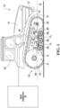
- FIG. 1 shows an example of an off-road tracked vehicle 10 in accordance with an embodiment of the invention.
- the vehicle 10 is a heavy-duty work vehicle for performing agricultural work, construction or other industrial work, or military work. More particularly, in this embodiment, the vehicle 10 is an agricultural vehicle for performing agricultural work. Specifically, in this example, the agricultural vehicle 10 is a tractor. In other examples, the agricultural vehicle 10 may be a combine harvester, another type of harvester, or any other type of agricultural vehicle.
- the agricultural vehicle 10 comprises a frame 12 supporting a prime mover 14, a pair of track systems 16 1 , 16 2 (which can be referred to as "undercarriages"), and an operator cabin 20, which enable an operator to move the agricultural vehicle 10 on the ground to perform agricultural work possibly using a work implement 18.
- the prime mover 14 provides motive power to move the agricultural vehicle 10.
- the prime mover 14 may comprise an internal combustion engine and/or one or more other types of motors (e.g., electric motors, etc.) for generating motive power to move the agricultural vehicle 10.
- the prime mover 14 is in a driving relationship with each of the track systems 16 1 , 16 2 . That is, power derived from the prime mover 14 is transmitted to the track systems 16 1 , 16 2 via a powertrain of the agricultural vehicle 10.
- the work implement 18 is used to perform agricultural work.
- the work implement 18 may be a combine head, a cutter, a scraper, a tiller, or any other type of agricultural work implement.
- the operator cabin 20 is where the operator sits and controls the agricultural vehicle 10. More particularly, the operator cabin 20 comprises a user interface including a set of controls that allow the operator to steer the agricultural vehicle 10 on the ground and operate the work implement 18.
- the track systems 16 1 , 16 2 engage the ground to propel the agricultural vehicle 10.
- Each track system 16 i comprises a track-engaging assembly 21 and a track 22 disposed around the track-engaging assembly 21.
- the track-engaging assembly 21 comprises a plurality of wheels which, in this example, includes a drive wheel 24 and a plurality of idler wheels that includes a front idler wheel 26 and a plurality of roller wheels 28 1 -28 6 .
- the track system 16 i also comprises a frame 13 which supports various components of the track system 16 i , including the roller wheels 28 1 -28 6 .
- the track system 16 i has a longitudinal direction and a first longitudinal end 57 and a second longitudinal end 59 that define a length of the track system 16 i .
- the track system 16 i has a widthwise direction and a width that is defined by a width of the track 22.
- the track system 16 i also has a height direction that is normal to its longitudinal direction and its widthwise direction.
- the track 22 engages the ground to provide traction to the agricultural vehicle 10.
- certain parts of the track 22 are designed to enhance their resistance to deterioration during use, including their resistance to blowout, as further discussed later.
- a length of the track 22 allows the track 22 to be mounted around the track-engaging assembly 21.
- the track 22 can be referred to as an "endless" track.
- the track 22 comprises an inner side 45, a ground-engaging outer side 47, and lateral edges 49 1 , 49 2 .
- the inner side 45 faces the wheels 24, 26, 28 1 -28 6 , while the ground-engaging outer side 47 engages the ground.
- a top run 65 of the track 22 extends between the longitudinal ends 57, 59 of the track system 16 i and over the wheels 24, 26, 28 1 -28 6
- a bottom run 66 of the track 22 extends between the longitudinal ends 57, 59 of the track system 16 i and under the wheels 24, 26, 28 1 -28 6
- the track 22 has a longitudinal axis 19 which defines a longitudinal direction of the track 22 (i.e., a direction generally parallel to its longitudinal axis) and transversal directions of the track 22 (i.e., directions transverse to its longitudinal axis), including a widthwise direction of the track 22 (i.e., a lateral direction generally perpendicular to its longitudinal axis).
- the track 22 has a thickness direction normal to its longitudinal and widthwise directions.
- the track 22 is elastomeric, i.e., comprises elastomeric material, to be flexible around the track-engaging assembly 21.
- the elastomeric material of the track 22 can include any polymeric material with suitable elasticity.
- the elastomeric material of the track 22 includes rubber.
- Various rubber compounds may be used and, in some cases, different rubber compounds may be present in different areas of the track 22.
- the elastomeric material of the track 22 may include another elastomer in addition to or instead of rubber (e.g., polyurethane elastomer).
- the track 22 comprises an endless body 36 underlying its inner side 45 and ground-engaging outer side 47.
- the body 36 will be referred to as a "carcass".
- the carcass 36 is elastomeric in that it comprises elastomeric material 38 which allows the carcass 36 to elastically change in shape and thus the track 22 to flex as it is in motion around the track-engaging assembly 21.
- the carcass 36 comprises an inner surface 32 and a ground-engaging outer surface 31 that are opposite one another.
- the carcass 36 comprises a plurality of reinforcements embedded in its elastomeric material 38. These reinforcements can take on various forms.
- the carcass 36 comprises a layer of reinforcing cables 37 1 -37 M that are adjacent to one another and extend generally in the longitudinal direction of the track 22 to enhance strength in tension of the track 22 along its longitudinal direction.
- each of the reinforcing cables 37 1 -37 M is a cord including a plurality of strands (e.g., textile fibers or metallic wires).
- each of the reinforcing cables 37 1 -37 M may be another type of cable and may be made of any material suitably flexible along the cable's longitudinal axis (e.g., fibers or wires of metal, plastic or composite material).
- the carcass 36 comprises a layer of reinforcing fabric 43.
- the reinforcing fabric 43 comprises thin pliable material made usually by weaving, felting, knitting, interlacing, or otherwise crossing natural or synthetic elongated fabric elements, such as fibers, filaments, strands and/or others, such that some elongated fabric elements extend transversally to the longitudinal direction of the track 22 to have a reinforcing effect in a transversal direction of the track 22.
- the reinforcing fabric 43 may comprise a ply of reinforcing woven fibers (e.g., nylon fibers or other synthetic fibers).
- the carcass 36 has a thickness T c , measured from its inner surface 32 to its ground-engaging outer surface 31, which is relatively large in this embodiment.
- the thickness T c of the carcass 36 may be at least than 20 mm, in some cases at least 25 mm, in some cases at least 30 mm, in some cases at least 35 mm, and in some cases even more (e.g., 40 mm or more).
- the thickness T c of the carcass 36 may have any other suitable value in other embodiments.
- the carcass 36 may be molded into shape in a molding process during which the rubber 38 is cured.
- a mold may be used to consolidate layers of rubber providing the rubber 38 of the carcass 36, the reinforcing cables 37 1 -37 M and the layer of reinforcing fabric 43.
- the endless track 22 is a one-piece "jointless” track such that the carcass 36 is a one-piece jointless carcass.
- the endless track 22 may be a "jointed" track (i.e., having at least one joint connecting adjacent parts of the track 22) such that the carcass 36 is a jointed carcass (i.e., which has adjacent parts connected by the at least one joint).
- the track 22 may comprise a plurality of track sections interconnected to one another at a plurality of joints, in which case each of these track sections includes a respective part of the carcass 36.
- the endless track 22 may be a one-piece track that can be closed like a belt with connectors at both of its longitudinal ends to form a joint.
- the inner side 45 of the endless track 22 comprises an inner surface 55 of the carcass 36 and a plurality of inner wheel-contacting projections 48 1 -48 N that project from the inner surface 55 and are positioned to contact at least some of the wheels 24, 26, 28 1 -28 6 to do at least one of driving (i.e., imparting motion to) the track 22 and guiding the track 22.
- the wheel-contacting projections 48 1 -48 N can be referred to as "wheel-contacting lugs”.
- the wheel-contacting lugs 48 1 -48 N can be referred to as "drive/guide projections" or "drive/guide lugs”.
- a drive/guide lug 48 i may interact with the drive wheel 24 to drive the track 22, in which case the drive/guide lug 48 i is a drive lug.
- a drive/guide lug 48 i may interact with the idler wheel 26 and/or the roller wheels 28 1 -28 6 to guide the track 22 to maintain proper track alignment and prevent de-tracking without being used to drive the track 22, in which case the drive/guide lug 48 i is a guide lug.
- a drive/guide lug 48 i may both (i) interact with the drive wheel 24 to drive the track and (ii) interact with the idler wheel 26 and/or the roller wheels 28 1 -28 6 to guide the track 22 to maintain proper track alignment and prevent de-tracking, in which case the drive/guide lug 48 i is both a drive lug and a guide lug.
- the drive/guide lugs 48 1 -48 N interact with the drive wheel 24 in order to cause the track 22 to be driven, and also interact with the idler wheel 26 and the roller wheels 28 1 -28 6 in order to guide the track 22 as it is driven by the drive wheel 24 to maintain proper track alignment and prevent de-tracking.
- the drive/guide lugs 48 1 -48 N are thus used to both drive the track 22 and guide the track 22 in this embodiment.
- the drive/guide lugs 48 1 -48 N are arranged in a single row disposed longitudinally along the inner side 45 of the track 22.
- the drive/guide lugs 48 1 -48 N may be arranged in other manners in other examples of implementation (e.g., in a plurality of rows that are spaced apart along the widthwise direction of the track 22).
- each drive/guide lug 48 i is an elastomeric drive/guide lug in that it comprises elastomeric material 67.
- the elastomeric material 67 can be any polymeric material with suitable elasticity. More particularly, in this embodiment, the elastomeric material 67 includes rubber. Various rubber compounds may be used and, in some cases, different rubber compounds may be present in different areas of the drive/guide lug 48 i . In other embodiments, the elastomeric material 67 may include another elastomer in addition to or instead of rubber (e.g., polyurethane elastomer).
- the drive/guide lugs 48 1 -48 N may be provided on the inner side 45 in various ways. For example, in this embodiment, the drive/guide lugs 48 1 -48 N are provided on the inner side 45 by being molded with the carcass 36.
- the ground-engaging outer side 47 comprises a ground-engaging outer surface 75 of the carcass 36 and a tread pattern 40 to enhance traction on the ground.
- the tread pattern 40 comprises a plurality of traction projections 58 1 -58 T projecting from the ground-engaging outer surface 75, spaced apart in the longitudinal direction of the endless track 22 and engaging the ground to enhance traction.
- the traction projections 58 1 -58 T may be referred to as "tread projections" or "traction lugs”.
- the traction lugs 58 1 -58 T may have any suitable shape.
- each of the traction lugs 58 1 -58 T has an elongated shape and is angled, i.e., defines an oblique angle ⁇ (i.e., an angle that is not a right angle or a multiple of a right angle), relative to the longitudinal direction of the track 22.
- the traction lugs 58 1 -58 T may have various other shapes in other examples (e.g., curved shapes, shapes with straight parts and curved parts, etc.).
- each traction lug 58 i has a periphery 69 which includes a front surface 80 1 , a rear surface 80 2 , two side surfaces 81 1 , 81 2 , and a top surface 86.
- the front surface 80 1 and the rear surface 80 2 are opposed to one another in the longitudinal direction of the track 22.
- the two side faces 81 1 , 81 2 are opposed to one another in the widthwise direction of the track 22.
- the front surface 80 1 , the rear surface 80 2 , and the side surfaces 81 1 , 81 2 are substantially straight.
- the periphery 69 of the traction lug 58 i may have any other shape in other embodiments (e.g., the front surface 80 1 , the rear surface 80 2 , and/or the side surfaces 81 1 , 81 2 may be curved).
- the traction lug 58 i has a front-to-rear dimension L L in the longitudinal direction of the track 22, a side-to-side dimension L W in the widthwise direction of the track 22, and a height H in the thickness direction of the track 22.
- the track 22 may be constructed in various other manners in other embodiments.
- the track 22 may have recesses or holes that interact with the drive wheel 24 in order to cause the track 22 to be driven (e.g., in which case the drive/guide lugs 48 1 -48 N may be used only to guide the track 22 without being used to drive the track 22, i.e., they may be "guide lugs" only), and/or the ground-engaging outer side 47 of the track 22 may comprise various patterns of traction lugs.
- the drive wheel 24 is rotatable by power derived from the prime mover 14 to drive the track 22. That is, power generated by the prime mover 14 and delivered over the powertrain of the agricultural vehicle 10 can rotate a driven axle, which causes rotation of the drive wheel 24, which in turn imparts motion to the track 22.
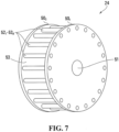
- the drive wheel 24 comprises a drive sprocket comprising a plurality of drive members 52 1 -52 B spaced apart along a circular path to engage the drive/guide lugs 48 1 -48 N of the track 22 in order to drive the track 22.
- the drive wheel 24 and the track 22 thus implement a "positive drive” system.
- the drive wheel 24 comprises two side discs 50 1 , 50 2 which are co-centric and turn about a common axle 51 and between which the drive members 52 1 -52 B extend near respective peripheries of the side discs 50 1 , 50 2 .
- the drive members 52 1 -52 B are thus drive bars that extend between the side discs 50 1 , 50 2 .
- the drive wheel 24 and the track 22 have respective dimensions allowing interlocking of the drive bars 52 1 -52 B of the drive wheel 24 and the drive/guide lugs 48 1 -48 N of the track 22.
- Adjacent ones of the drive bars 52 1 -52 B define an interior space 53 between them to receive one of the drive/guide lugs 48 1 -48 N .
- Adjacent ones of the drive/guide lugs 48 1 -48 N define an inter-lug space 39 between them to receive one of the drive bars 52 1 -52 B .
- the drive/guide lugs 48 1 -48 N and the drive bars 52 1 -52 B have a regular spacing that allows interlocking of the drive/guide lugs 48 1 -48 N and the drive bars 52 1 -52 B over a certain length of the drive wheel's circumference.
- the drive wheel 24 may be configured in various other ways in other embodiments.
- the drive wheel 24 may not have any side discs such as the side discs 50 1 , 50 2 .
- the drive members 52 1 -52 B may be drive teeth that are distributed circumferentially along the drive wheel 24 or any other type of drive members.
- the drive wheel 24 may have teeth that enter these recesses or holes in order to drive the track 22.
- the drive wheel 24 may frictionally engage the inner side 45 of the track 22 in order to frictionally drive the track 22 (i.e., the drive wheel 24 and the track 22 may implement a "friction drive" system).
- the front idler wheel 26 and the roller wheels 28 1 -28 6 are not driven by power supplied by the prime mover 14, but are rather used to do at least one of supporting part of the weight of the agricultural vehicle 10 on the ground via the track 22, guiding the track 22 as it is driven by the drive wheel 24, and tensioning the track 22. More particularly, in this embodiment, the front idler wheel 26 is a leading idler wheel which maintains the track 22 in tension and helps to support part of the weight of the agricultural vehicle 10 on the ground via the track 22. As shown in Figure 8 , the roller wheels 28 1 -28 6 roll on a rolling path 33 of the inner side 45 of the track 22 along the bottom run 66 of the track 22 to apply the bottom run 66 on the ground. In this case, as they are located between frontmost and rearmost ones of the wheels of the track system 16 i , the roller wheels 28 1 -28 6 can be referred to as "mid-rollers".
- the traction lugs 58 1 -58 T can be designed to enhance their resistance to deterioration during use.
- a blowout resistance of each traction lug 58 i can be enhanced to prevent or at least reduce a potential for blowout of the traction lug 58 i under repeated loads which may induce heat buildup within it.
- a wear resistance of the traction lug 58 i may be enhanced such that the traction lug 58 i wears less rapidly. This enhanced resistance to deterioration of the traction lugs 58 1 -58 T may be particularly useful in situations where the track 22 experiences significant roading on hard road surfaces, such as, for example, when the agricultural vehicle 10 travels on paved roads between fields or other agricultural sites.
- the blowout resistance of a traction lug 58 i is greater than a threshold.
- a test may be performed to measure the blowout resistance of the traction lug 58 i .
- a sample of the traction lug 58 i of specified dimensions can be repeatedly compressed at a specified frequency by applying a load causing a specified deformation (e.g., compression) and measuring one or more parameters indicative of the blowout resistance of the traction lug 58 i .
- the test may be a standard test.
- the blowout resistance of the traction lug 58 i may be measured under ASTM D-623 (Method A) conditions (e.g., sample dimensions, load, frequency and deformation specified by ASTM D-623).
- a sample of the traction lug 58 i of specified dimensions can be taken from the traction lug 58 i , subjected to a specified preload (i.e., 110 lbs), conditioned at a specified temperature (i.e., 100°C) for a specified period of time (i.e., 25 minutes), and repeatedly compressed by causing a specified deformation (e.g., compression) (i.e., 0.250 inches in amplitude) at a specified frequency (i.e., 30 Hz) in order to measure one or more parameters indicative of the blowout resistance of the traction lug 58 i .
- a specified preload i.e., 110 lbs
- conditioned at a specified temperature i.e., 100°C
- a specified period of time i.e., 25 minutes
- a specified deformation i.e., compression
- a specified frequency i.e., 30 Hz
- blowout time B of the sample of the traction lug 58 i and/or the blowout temperature T b of the sample of the traction lug 58 i may have any other suitable value in other examples of implementation.
- the wear resistance of a traction lug 58 i is greater than a threshold.
- the wear resistance of the traction lug 58 i may be expressed as an abrasion resistance of the traction lug 58 i .
- a test may be performed to measure the wear resistance of the traction lug 58 i .
- a sample of the traction lug 58 i of specified dimensions can be moved across a surface of an abrasive sheet mounted to a revolving drum to measure the wear of the traction lug 58 i as a volume loss in cubic millimeters or an abrasion resistance index in percent.
- the test may be a standard test.
- the wear resistance of the traction lug 58 i expressed as its abrasion resistance, may be measured under ASTM D-5963 conditions (e.g., sample dimensions; loading conditions; etc.).
- a sample of the traction lug 58 i of dimensions specified by ASTM D-5963 can be taken from the traction lug 58 i and moved against a surface of an abrasive sheet mounted to a revolving drum as specified by ASTM D-5963 and measuring one or more parameters indicative of the abrasion resistance of the traction lug 58 i .
- a volume loss in cubic millimeters of the sample of the traction lug 58 i may be no more than 110 mm 3 , in some cases no more than 100 mm 3 , more than 90 mm 3 , in some cases no more than 80 mm 3 , and in some cases even less (e.g., no more than 70 mm 3 or 60 mm 3 ).
- the volumetric loss of the sample of the traction lug 58 i may have any other suitable value in other examples of implementation.
- Enhancement of the resistance to deterioration of the traction lugs 58 1 -58 T may be achieved in various ways in various embodiments.
- each traction lug 58 i is characterized by a material distribution profile to enhance its resistance to deterioration, including its blowout resistance and its wear resistance.
- the material distribution profile is designed such that the traction lug 58 i has a material composition defining an arrangement of zones of different materials 60 1 -60 Z .
- These different materials 60 1 -60 Z belong to different classes of materials (i.e., polymers, metals, ceramics and composites) and/or exhibit substantially different values of a given material property (e.g., a modulus of elasticity, tensile strength, hardness, friction coefficient, crack growth resistance, etc.).
- the arrangement of zones of different materials 60 1 -60 Z is designed into the traction lug 58 i .
- the arrangement of zones of different materials 60 1 -60 Z does not occur by chance (e.g., during manufacturing or use of the traction lug 58 i ), but is rather achieved by a careful material selection and distribution within the traction lug 58 i during design of the track 22.
- the arrangement of zones of different materials 60 1 -60 Z may comprise two, three, four, five or more zones of different materials. Also, while the arrangement of zones of different materials 60 1 -60 Z may comprise any selection of different materials, in some embodiments, the arrangement of zones of different materials 60 1 -60 Z may comprise a plurality of zones of different elastomeric materials (i.e., two, three, four, five or more zones of different elastomeric materials). For example, such different elastomeric materials may include different rubbers, thermoplastic elastomers (TPE) such as polyurethane elastomers, and/or other elastomers.
- TPE thermoplastic elastomers
- the zones of different materials 60 1 -60 Z may be provided in any suitable way using one or more manufacturing processes, such as, for example, a molding process (e.g., an injection molding process, a compression molding process, etc.), an extrusion process (e.g., a coextrusion process), a pouring process, a gluing process, a coating process, a heat treatment, a penetrating treatment (e.g., an electromagnetic radiation treatment, etc.), and/or any other suitable manufacturing process. Examples of how the zones of different materials 60 1 -60 Z may be provided in various embodiments are discussed below.
- the arrangement of zones of different materials 60 1 -60 Z is configured such that the traction lug 58 i exhibits a desired variation in blowout resistance across the arrangement of zones of different materials 60 1 -60 Z .
- the arrangement of zones of different materials 60 1 -60 Z is configured such that the traction lug 58 i exhibits a desired variation in wear resistance across the arrangement of zones of different materials 60 1 -60 Z .
- Each of these variations is “desired” in that it is designed into the traction lug 58 i by the careful material selection and distribution within the traction lug 58 i to create the arrangement of zones of different materials 60 1 -60 Z during design of the track 22 such that the blowout resistance and the wear resistance vary in an intended manner.
- these desired variations can also be referred to as a "selected", “predetermined”, “intended” or “controlled” variation in blowout resistance and wear resistance.
- the blowout resistance increases inwardly, i.e., in a direction away from the periphery 69 of the traction lug 58 i towards an inside of the traction lug 58 i .
- the blowout resistance of an inner material 60 x of the traction lug 58 i is greater than the blowout resistance of an outer material 60 y of the traction lug 58 i .
- the inner material 60 x and the outer material 60 Y are respectively referred to as being “inner” and “outer” in that the inner material 60 x is disposed inwardly of the outer material 60 y , i.e., the outer material 60 y is disposed between the inner material 60 x and the periphery 69 of the traction lug 58 i (e.g., and may extend to the periphery 69 of the traction lug 58 i ).
- the outer material 60 y is thus closer to the periphery 69 of the traction lug 58 i than the inner material 60 x (e.g., and may extend to the periphery 69 of the traction lug 58 i ).
- the blowout resistance of the inner material 60 x of the traction lug 58 i may be measured by subjecting a sample of the inner material 60 x to a test as described above and measuring one or more parameters indicative of its blowout resistance, such as the blowout temperature T b of the sample of the inner material 60 x and/or the blowout time B of the sample of the inner material 60 x .
- a similar procedure may be followed for measuring the blowout resistance of the outer material 60 y of the traction lug 58 i .
- the wear resistance increases outwardly, i.e., in a direction towards the periphery 69 of the traction lug 58 i . More particularly, in this example, the wear resistance of the outer material 60 y of the traction lug 58 i is greater than the wear resistance of the inner material 60 x of the traction lug 58 i .
- the wear resistance of the outer material 60 y of the traction lug 58 i may be measured by subjecting a sample of the outer material 60 y to a test as described above and measuring one or more parameters indicative of its wear resistance, such as its abrasion resistance. A similar procedure may be followed for measuring the wear resistance of the inner material 60 x of the traction lug 58 i .
- the traction lug 58 i is thus more resistant to blowout in its internal region which would be more susceptible to blowout conditions, while being more wear resistance in its external region which is exposed to wearing effects.
- the variation in blowout resistance and wear resistance across the arrangement of zones of different materials 60 1 -60 Z of the traction lug 58 i may be configured in various ways.
- this may include one or more gradients of blowout resistance and wear resistance across the zones of different materials 60 1 -60 Z of the traction lug 58 i , where each gradient can be a discrete gradient or a continuous gradient.
- the arrangement of zones of different materials 60 1 -60 Z of the traction lug 58 i may exhibit a discrete gradient of blowout resistance and a discrete gradient of wear resistance.
- a discrete gradient of blowout resistance or wear resistance is a discrete variation of the blowout resistance or wear resistance in a specified direction across the arrangement of zones of different materials 60 1 -60 Z of the traction lug 58 i .
- adjacent ones of the zones of different materials 60 1 -60 Z which define the discrete gradient of blowout resistance or wear resistance are discrete zones such that the blowout resistance or the wear resistance varies in discrete steps across the traction lug 58 i .
- a zone is "discrete" in that its dimension along the specified direction of the discrete gradient is macroscopically measurable.
- the arrangement of zones of different materials 60 1 -60 Z includes an outer material 60 1 and an inner material 60 2 .
- the outer material 60 1 is an external material and forms the periphery 69 of the traction lug 58 i while the inner material 60 2 is a core material forming a core of the traction lug 58 i .
- the inner material 60 2 has a higher blowout resistance than the outer material 60 1 .
- the outer material 60 1 has a higher wear resistance than the inner material 60 2 .
- the inner material 60 2 is more resistant to blowout than the outer material 60 1
- the outer material 60 1 is more resistant to wear than the inner material 60 2 .
- the outer material 60 1 and the inner material 60 2 may be different elastomeric materials (e.g., rubbers, thermoplastic elastomers (TPE) such as polyurethane elastomers, and/or other elastomers).
- the inner material 60 2 and the outer material 60 1 may be different types of rubber.
- the different rubber compounds constituted by the inner material 60 2 and the outer material 60 1 may differ by having different base polymers, different concentration and/or types of carbon black, different content of dienes, and/or different content of sulfur or other vulcanizing and/or in any other suitable manner.
- the inner material 60 2 and the outer material 60 1 may be other types of materials, including non-elastomeric materials.
- the outer material 60 1 may be thermoplastic olefin (TPO), nylon, polytetrafluoroethylene (PTFE) or any other thermoplastic material.
- the inner material 60 2 may comprise metal, rigid polymer (e.g., thermoplastic), ceramic or any other material with a suitable blowout resistance, i.e., a blowout resistance higher than that of the outer material 60 1 .
- a ratio V b /V t of a volume V b of the inner material 60 2 over a volume V t of the traction lug 58 i may be at least 0.1, in some cases at least 0.2, in some cases at least 0.3, in some cases at least 0.4, in some cases at least 0.5, in some cases at least 0.6, and in some cases even more (e.g., at least 0.8 or 0.9).
- a ratio G b /G t of a dimension G b of the inner material 60 2 in a given direction (e.g., in the thickness direction of the track 22) over a dimension G t of the traction lug 58 i in that given direction (e.g., the height H of the traction lug 58 i ) may be at least 0.1, in some cases at least 0.2, in some cases at least 0.3, in some cases at least 0.4, in some cases at least 0.5, in some cases at least 0.6, and in some cases even more (e.g., at least 0.8 or 0.9).
- the number of zones and the geometry of the zones may be varied.
- more zones of different materials 60 1 -60 Z may be provided to achieve a more complex blowout resistance and wear resistance variation profile.
- the blowout resistance and the wear resistance vary across the traction lug 58 i in a discrete step, which corresponds to a transition between the outer material 60 1 and the inner material 60 2 .
- blowout resistance and wear resistance values By providing a large number of zones of different materials 60 1 -60 Z having different blowout resistance and wear resistance values, it is possible to approximate a smooth variation in blowout resistance and wear resistance, the actual granularity of which will depend upon the number and size of the zones of different materials 60 1 -60 Z .
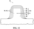
- Figure 12 shows another embodiment of a traction lug 58 i in which the blowout resistance and the wear resistance vary in discrete steps such that the zones of different materials 60 1 -60 Z have different blowout resistance and wear resistance values.
- the arrangement of zones of different materials 60 1 -60 Z of the traction lug 58 i comprises a core material 60 1 and a plurality of layered materials, including a first layered material 60 2 , a second layered material 60 3 , a third layered material 60 4 and a fourth layered material 60 5 , which make up a layered area 1120.
- the layered materials 60 2 -60 5 are approximately equal in thickness. Different ones of the layered materials 60 2 -60 5 may have different thicknesses in other examples.
- Figure 13A is a graph 1200 showing an example of how the blowout resistance 1205 of the traction lug 58 i varies as a function of distance within the traction lug 58 i in a specified direction represented by line B shown in Figure 12 .
- the blowout resistance of the traction lug 58 i takes on five (5) different values ⁇ 60-1 , ⁇ 60-2 , ⁇ 60-3 , ⁇ 60-4 and ⁇ 60-5 , each of which corresponds to the blowout resistance of a respective one of the zones of different materials 60 1 -60 5 .
- the function of the blowout resistance 1205 takes the form of a step function, each step corresponding to a respective one of the zones of different materials 60 1 -60 Z .
- the layered materials 60 2 -60 5 are represented in range 1210 of the graph 1200, while range 1215 represents the core material 60 1 .
- the blowout resistance of the traction lug 58 i approximates a linear function 1220.
- the layered area 1120 can be viewed as exhibiting an approximately linear variation in blowout resistance with an actual granularity defined by the steps in the function of the blowout resistance 1205 corresponding to the layered materials 60 2 -60 5 .
- the overall function blowout resistance 1205 across line B in this example can thus be considered to approximate smooth line 1225.
- blowout resistance ⁇ 60-1 , ⁇ 60-2 , ⁇ 60-3 , ⁇ 60-4 and ⁇ 66-5 vary from one material to the next by approximately the same value, giving steps of approximately equal height in the vertical direction of the graph 1200.
- the layered materials 60 2 -60 5 have approximately equal thicknesses such that the steps have approximately equal width in the horizontal (distance along line B) direction of the graph 1200.
- the linear function 1220 which is approximated by the function of the blowout resistance 1205 in the layered area 1120 can be varied by altering the thicknesses of the layered materials 60 2 -60 5 and/or by varying the blowout resistance values ⁇ 60-2 , ⁇ 60-3 , ⁇ 63-4 and ⁇ 60-5 of the layered materials 60 2 -60 5 .
- the rate of change (slope) of the approximated linear function 1220 may be decreased by increasing the thickness or decreasing the variation in the blowout resistance in the different materials.
- the wear resistance of the traction lug 58 i varies as a function of distance within the traction lug 58 i in a specified direction represented by line B shown in Figure 12 .
- the wear resistance defines an inverse relationship to the blowout resistance. That is, while the blowout resistance is highest at the core material 60 1 and lowest at the layered material 60 5 , the wear resistance is highest at the layered material 60 5 and lowest at the core material 60 1 .
- Figure 13B is a graph 1300 showing an example of how the wear resistance 1305 of the traction lug 58 i varies as a function of distance within the traction lug 58 i in a specified direction represented by line B shown in Figure 11 .
- the wear resistance of the traction lug 58 i takes on five (5) different values ⁇ 60-1 , ⁇ 60-2 , ⁇ 60-3 , ⁇ 60-4 and ⁇ 60-5 , each of which corresponds to the wear resistance of the material of a respective one of the materials 60 1 -60 5 .
- the function of the wear resistance 1305 takes the form of a step function, each step corresponding to a respective one of the zones of different materials 60 1 -60 z .
- the layered materials 60 2 -60 5 are represented in range 1310 of the graph 1300, while range 1315 represents the core material 60 1 .
- the wear resistance of the traction lug 58 i approximates a linear function 1320.
- the layered area 1120 can be viewed as exhibiting an approximately linear variation in wear resistance with an actual granularity defined by the steps in the function of the wear resistance 1305 corresponding to the layered materials 60 2 -60 5 .
- the overall wear resistance 1305 function across line B in this example can thus be considered to approximate smooth line 1325.
- the manner in which approximation of a function is determined may affect the thicknesses of the zones of different materials 60 1 -60 Z required to approximate the function.
- the linear function 1220 may be arrived at by taking a weighted average of the blowout resistance values ⁇ 60-1 , ⁇ 60-2 , ⁇ 60-3 , ⁇ 60-4 and ⁇ 60-5 of each material, wherein the thickness of each material determines the weight, and dividing the result by the average thickness of a material. This may provide the slope of the linear function 1220.
- a similar procedure may be implemented to approximate the linear function 1320.
- Other models may be used in other embodiments to approximate functions of variation of a material property depending on the method used.
- the materials used or available may not provide equal heights for each step in the function of the blowout resistance 1205 and/or the wear resistance 1305.
- the thicknesses of the zones of different materials 60 1 -60 Z may be modified to adjust the weight of each material such that, on average, the linear function 1220 and the linear function 1320 are still approximated.
- the arrangement of zones of different materials 60 1 -60 Z has been selected based on blowout resistance and wear resistance values so as to achieve an approximation, according to a selected curve-fitting method, of the linear functions 1220, 1320.
- the blowout resistance and wear resistance variation may be a nonlinear variation of a function of distance within the traction lug 58 i .
- the various materials for the zones of different materials 60 1 -60 Z may be selected on the basis of the desired blowout resistance and wear resistance in each zone of the zones of different materials 60 1 -60 Z , without regards to any linear or other function.
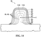
- Figure 14 shows another example of an embodiment of a traction lug 58 i in which the blowout resistance and the wear resistance vary in discrete steps such that the zones of different materials 60 1 -60 Z have different blowout resistance and wear resistance values.
- an entirety of the traction lug 58 i is made up of zones of different materials 60 1 -60 8 that may be considered layered materials.
- the traction lug 58 i comprises an inner area 1140 where the layered materials form thicker layered materials 60 1 -60 4 and an outer area 1145 where the layered materials form thinner layered materials 60 5 -60 8 .
- Figure 15A shows a graph 1250 showing the function of the blowout resistance 1255 of the traction lug 58 i as it varies along line C shown in Figure 14 .
- the blowout resistance decreases in successive ones of the materials 60 1 -60 8 along the line C.
- the function of the blowout resistance 1255 still features steps, however the steps are not of equal size.
- a first range 1240 of the graph 1250 represents the thicker layered materials 60 1 -60 4 in the inner area 1140 of the traction lug 58 i .
- These thicker layered materials 60 1 -60 4 do not vary equally.
- the two first thicker layered materials 60 1 , 60 2 have a particularly high blowout resistance.
- Subsequent thicker layered materials 60 3 , 60 4 have approximately the same thickness as the two first thicker layered materials 60 1 , 60 2 , but they have lower blowout resistance values.
- the variation of blowout resistance is not equal amongst the different materials, and the function of the blowout resistance 1255 in this first range 1240 approximates a polynomial function 1260.
- the materials of the thicker layered materials 60 1 -60 4 have been selected so as to achieve an approximation, according to a selected curve-fitting method, of the polynomial function 1260. In other cases, it may not be necessary or desired to approximate a linear, polynomial, or other function.
- the materials of the thicker layered materials 60 1 -60 4 may simply be selected on the basis of a desired blowout resistance in their respective areas.
- a second range 1245 of the graph 1250 represents the thinner layered materials 60 5 -60 8 .
- These thinner layered materials 60 5 -60 8 are in the outer area 1145 of the traction lug 58 i and provide a reduced blowout resistance region. While a lower blowout resistance may be acceptable towards the exterior of the traction lug 58 i , it may be desired to avoid strong discontinuities, that is, large differences, in the blowout resistance of adjacent ones of the zones of different materials 60 1 -60 8 . In particular, it may be desired to avoid having a relatively highly blowout resistant material adjacent a relatively non-blowout resistant material to avoid a stress concentration at the interface between these materials, which could lead to cracking or tearing at the interface between these materials.
- blowout resistance 1255 in the second range 1245 decreases as a step function with relatively equal steps which approximate a linear function 1265.
- the function 1255 in the second range 1245 need not have equal-sized steps and may not necessarily approximate a linear or other function.
- two areas 1140, 1145 of the traction lug 58 i correspond to two regions 1240, 1245 of the graph approximating different functions.
- a single function linear, polynomial or other
- the thinner layered materials 60 5 -60 8 may be characterized by variations in blowout resistance yielding step sizes proportional to their thinner area such that the zones of different materials 60 1 -60 8 together yield a step function that approximates a straight line.
- the wear resistance of the traction lug 58 i also varies in function of the distance within the traction lug 58 i . More specifically, a function of the wear resistance of the traction lug 58 i varies along line C shown in Figure 14 . However, contrary to the blowout resistance, in this example, the wear resistance increases in successive ones of the zones of different materials 60 1 -60 8 along the line C.
- Figure 15B shows a graph 1550 showing the function of the wear resistance 1555 of the traction lug 58 i as it varies along line C shown in Figure 14 .
- the wear resistance increases in successive ones of the zones of different materials 60 1 -60 8 along the line C.
- the function of the wear resistance 1555 still features steps, however the steps are not of equal size.
- a first range 1540 of the graph 1550 represents the thicker layered materials 60 1 -60 4 in the inner area 1140 of the traction lug 58 i .
- These thicker layered materials 60 1 -60 4 do not vary equally.
- the two first thicker layered materials 60 1 and 60 2 have a particularly low wear resistance.
- Subsequent thicker layered materials 60 3 and 60 4 have approximately the same thickness as the two first thicker layered materials 60 1 and 60 2 , but they have significantly higher wear resistance values.
- the variation of wear resistance is not equal amongst the different zones of different materials 60 1 -60 4 , and the function of the wear resistance 1555 in this first range 1540 approximates a polynomial function 1560.
- the materials of the thicker layered materials 60 1 -60 4 have been selected so as to achieve an approximation, according to a selected curve-fitting method, of the polynomial function 1560. In other cases, it may not be necessary or desired to approximate a linear, polynomial, or other function.
- the materials of the thicker layered materials 60 1 -60 4 may simply be selected on the basis of a desired wear resistance in their respective areas.
- a second range 1545 of the graph 1550 represents the thinner layered materials 60 5 -60 8 .
- These thinner layered materials 60 5 -60 8 are in the outer area 1145 of the traction lug 58 i and provide an increased wear resistance region. While a higher wear resistance may be desired towards the exterior of the traction lug 58 i , it may be desired to avoid strong discontinuities, that is, large differences, in the wear resistance of adjacent ones of the zones of different materials 60 1 -60 8 . In particular, it may be desired to avoid having a relatively highly wear resistant material adjacent a relatively non-wear resistant material to avoid a stress concentration at the interface between these materials, which could lead to cracking or tearing at the interface between these materials.
- two areas 1140, 1145 of the traction lug 58 i correspond to two regions of each of the graphs 1250, 1550 approximating different functions.
- a single function linear, polynomial or other
- the thinner layered materials 60 5 -60 8 may be characterized by variations in blowout resistance yielding step sizes proportional to their thinner area such that the zones of different materials 60 1 -60 8 together yield a step function that approximates a straight line.
- the thinner layered materials 60 5 -60 8 may be characterized by variations in wear resistance yielding step sizes proportional to their thinner area such that the zones of different materials 60 1 -60 8 together yield a step function that approximates a straight line.
- Fewer zones of different materials 60 1 -60 Z may be provided to reduce the complexity or cost of manufacture of the traction lug 58 i (e.g., certain ones of the thicker or thinner layered materials may be omitted).
- the zones of different materials 60 1 -60 Z are layered materials disposed on all sides of the traction lug 58 i .
- the layered materials may be provided only on one part of the traction lug 58 i , such as for example only on one side thereof.
- the zones of different materials 60 1 -60 Z may take forms other than layers (e.g., blocks, bars or plates).
- individual ones of the zones of different materials 60 1 -60 Z may be separate amounts of material which are provided separated and interconnected together. This may be done in various ways using various manufacturing processes. For instance, various molding processes may be used to make the traction lug 58 i with its arrangement of zones of different materials 60 1 -60 Z . For example, in some embodiments, a compression molding process may be used in which different pieces of material, which are to ultimately form the zones of different materials 60 1 -60 Z , may be placed in a mold such that, after molding, they form the arrangement of zones of different materials 60 1 -60 Z .
- an injection molding process may be used in which amounts of different materials which are to ultimately form the zones of different materials 60 1 -60 Z , may be placed in a mold such that, after molding, they form the arrangement of zones of different materials 60 1 -60 Z .
- Interconnection of the zones of different materials 60 1 -60 Z of the traction lug 58 i may be effected in various ways.
- adjacent ones of the zones of different materials 60 1 -60 Z may be adhesively bonded using an adhesive between them.
- these zones of different materials may be created by individually molding each of them prior to gluing them together.
- the zones of different materials may be created by cutting or otherwise machining them out of a substrate prior to gluing them together. Any suitable adhesive may be used.
- various commercially-available adhesives may be used to adhesively bond adjacent different materials (e.g., rubber/metal using a Chemlok TM 253X adhesive, polyurethane/rubber using a Chemlok TM 213 adhesive, polyurethane/metal using a Chemlok TM 213 adhesive, etc.).
- adhesives e.g., Chemlok TM adhesives
- materials e.g., rubber/metal using a Chemlok TM 253X adhesive, polyurethane/rubber using a Chemlok TM 213 adhesive, polyurethane/metal using a Chemlok TM 213 adhesive, etc.
- proprietary adhesives may be used.
- adjacent ones of the zones of different materials 60 1 -60 z may be chemically bonded to one another. That is, a chemical bond may be formed between these adjacent materials during manufacturing of the traction lug 58 i .
- the materials of these zones of different materials may thus be bonded to one another without any adhesive.
- Chemical bonding between materials implies an additional constraint to be considered when selecting the materials for the zones of different materials 60 1 -60 z of the traction lug 58 i , namely the intercompatibility of the materials.
- the materials used in adjacent zones of different materials must be capable of bonding to one another under the right conditions. The conditions must then be applied to ensure that bonding takes place.
- one type of rubber may chemically bond with another type of rubber
- UHMW may chemically bond with rubber
- TPO may chemically bond with rubber, etc.
- a mold having removable portions corresponding to the various materials may be first filled with a first material, then have one or more removable portions removed, then subsequently filled (in the resulting cavities) with a second material, and so on until every zone of the zones of different materials 60 1 -60 Z is filled.
- a first mold can be used to form a first material 60 i of the traction lug 58 i , the resulting structure being removed from the mold and laced into another mold for forming a second material 60 j of the traction lug 58 i and so forth for every material.
- several different materials may be simultaneously injected into a given mold to form adjacent zones of different materials 60 1 -60 Z of the traction lug 58 i .
- pieces of different materials which will eventually make up respective ones of the zones of different materials 60 1 -60 Z are prepared in advance, for instance by molding them or by cutting or otherwise machining them out of a substrate. The pieces are then arranged in their appropriate order and relative positions, and the overall arrangement may be consolidated, for instance by placing it in a heated mold until chemical bonding takes place.
- different rubber pieces such as strips for layered materials, may be vulcanized while together while arranged in their proper relative positions / order, such as to form the traction lug 58 i having different zones of different materials that are chemically bonded together.
- the pieces need not be all arranged and bonded together at once. For instance, if different temperatures are required to cause bonding between different materials, the process may first be applied to the zones of different materials having the highest bonding temperature prior and subsequently applied to the zones of different materials having lower bonding temperatures.
- adjacent ones of the zones of different materials 60 1 -60 Z of the traction lug 58 i may be mechanically interlocked. That is, a material 60 i and a material 60 j adjacent to the material 60 i may be in a mechanical interlock relationship in which they are interconnected via a given one of the material 60 i and the material 60 j extending into the other one of the material 60 i and the material 60 j . More specifically, a first one of the material 60 i and the material 60 j comprises an interlocking space into which extends an interlocking portion of a second one of the material 60 i and the material 60 j .
- the interlocking space may comprise one or more holes, one or more recesses, and/or one or more other hollow areas. This mechanical interlock relationship restrains movement of the material 60 i and the material 60 j relative to one another. Geometric details omitted from many of the embodiments discussed above may be included in the zones of different materials 60 1 -60 Z to implement such a mechanical interlock relationship.
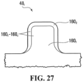
- Figure 16 shows an embodiment in which the arrangement of zones of different materials 60 1 -60 Z of the traction lug 58 i comprise layered materials 60 2 , 60 3 and a core material 60 1 , where each of the layered materials 60 2 , 60 3 comprises an interlocking protuberance 1720, 1725 (e.g., a ridge) that fits into a corresponding interlocking groove in an adjacent material.
- interlocking protuberance 1720, 1725 e.g., a ridge
- Adjacent ones of the zones of different materials 60 1 -60 Z of the traction lug 58 i may be mechanically interlocked in various ways. For example, in some cases, adjacent ones of the zones of different materials 60 1 -60 Z of the traction lug 58 i may be mechanically interlocked by separately creating the different zones of different materials (e.g. by molding separately or cutting or otherwise machining out of a substrate) and then assembling them together such as by snap-fitting them together. In some cases, an adhesive may be applied prior to snap-fitting materials together. As another example, in some cases, adjacent ones of the zones of different materials 60 1 -60 Z of the traction lug 58 i may be mechanically interlocked by being overmolded.
- a material 60 i may be a coated material provided by painting, depositing, spattering or spraying a coating over another material 60 j .
- the coating may be a coating of polyurethane, acrylic, or any other suitable material, and may have a thickness of about 1 to 1.5 mil (thousandth(s) of an inch) or any other suitable value.
- any suitable combination of the above techniques for creating the zones of different materials 60 1 -60 Z of the traction lug 58; may be used.
- individual materials on the interior of the traction lug 58 i may be overmolded (e.g., with chemical bonding and/or mechanical interlocking), while an outer protective layer (e.g., a skin or a cap) can be applied overtop the traction lug 58 i and held thereon by adhesive bonding or by mechanical interlocking.
- a spray-on layer may be provided instead of or additionally to, the protective layer as an outermost layer.
- the arrangement of zones of different materials 60 1 -60 Z of the traction lug 58 i may exhibit a continuous gradient of blowout resistance and a continuous gradient of wear resistance.
- a continuous gradient of blowout resistance or wear resistance is a continuous variation of the blowout resistance or wear resistance in a specified direction across the arrangement of zones of different materials 60 1 -60 Z of the traction lug 58 i .
- adjacent ones of the zones of different materials 60 1 -60 Z which define the continuous gradient of blowout resistance or wear resistance are infinitesimal zones.
- a zone is "infinitesimal" in that it is sufficiently small and has a sufficiently small difference in blowout resistance or wear resistance with an adjacent zone that its dimension along the specified direction of the continuous gradient is not macroscopically measurable.
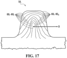
- Figure 17 illustrates an example of an embodiment in which the variation of the blowout resistance and wear resistance across the arrangement of zones of different materials 60 1 -60 z of the traction lug 58 i includes a continuous gradient of blowout resistance and a continuous gradient of wear resistance.
- each continuous gradient extends throughout the traction lug 58 i .
- Figures 18A and 18B respectively illustrate a graph of the variation of the blowout resistance and the wear resistance as a function of distance along line D shown in Figure 17 .
- the spatial variation of the blowout resistance is a generally linear function 1810.
- the spatial variation of the wear resistance is a generally linear function 1910.
- the linear functions 1810, 1910 are shown as perfectly straight, actual realizations of the continuous gradients of blowout resistance and wear resistance in some embodiments may not be perfect and imperfections may result in the variations not being perfectly linear.
- FIG 17 certain materials 60 1 -60 M of the arrangement of zones of different materials 60 1 -60 Z defining the continuous gradients of blowout resistance and wear resistance are represented.
- the materials 60 1 -60 m are represented as isolines, where each isoline links points at which the value of the blowout resistance is the same and the value of the wear resistance is the same.
- the space between adjacent zones of different materials 60 i , 60 j includes other ones of the infinitesimal zones of different materials 60 1 -60 Z defining the continuous gradients of blowout resistance and wear resistance.
- a continuous gradient of blowout resistance and/or wear resistance may be configured in various other ways in other embodiments.
- the spatial variation of the blowout resistance defining the continuous gradient may be a more complex function (e.g., a polynomial function) in other embodiments.
- the continuous gradients of blowout resistance and/or wear resistance may only exist in a limited area of the traction lug 58 i .
- the value of the blowout resistance or the wear resistance may be related to a mixture of two or more constituents which make up material of the traction lug 58 i .
- the relative concentration of each of the constituents may determine the blowout resistance or wear resistance of the resulting material.
- any suitable fabrication method that permits gradual variation in the relative concentration of each of the constituents may be used to produce a continuous gradient of blowout resistance and/or wear resistance.
- a twin injection molding technique may be used whereby two ingredients are injected into a mold.
- the relative intensity of the two jets of ingredients may be varied as the mold fills.
- the two jets may be located at different locations of the mold, and the ingredients may be injected in liquefied form into the mold such that they mix between the two jets and form the traction lug 58 i having a gradual change in relative concentration of the two ingredients varying for almost uniquely a first ingredient near a corresponding first jet location to almost uniquely a second ingredient near a corresponding second jet.
- the traction lug 58 i may be made by taking two or more solid pieces, each made of one of two ingredients, and placing them in relative position and heating them until they melt and mix at their interface.
- two or more zones of the arrangement of zones of different materials 60 1 -60 Z may be formed by subjecting a common base material to a treatment causing at least two areas of the common base material to become different from one another, thus constituting two zones of different materials.
- a continuous gradient of blowout resistance or wear resistance may be achieved by a controlled heat treatment.
- a controlled heat treatment for example, in some cases, an injection molding process may be used in which a rubber to make the traction lug 58 i is injected into a mold at a high temperature and, as the molding process progresses, the temperature may be reduced to cause a smooth variation in the blowout resistance or wear resistance.
- Other heat treatments may be used in other cases.
- a continuous gradient of blowout resistance or wear resistance may be achieved by providing a traction lug 58 i made of a single base material which is altered by applying a penetrating treatment such that the alteration induces a smooth change in the blowout resistance.
- a material from which to make the traction lug 58 i may be radiated with a certain penetrating (e.g. UV) radiation that causes a change in the material characteristics and that diminishes in intensity with depth.
- an additive or impurity may be added to a material from which to make the traction lug 58 i from the outside in.
- the additive or impurity may penetrate the material to a certain depth dropping in intensity as the depth is increased.
- This method can be combined with another penetrating treatment, such as heat application.
- another penetrating treatment such as heat application.
- sulfur or a peroxide, or a urethane crosslinker, or a metal oxide
- the body may be made to have different levels of vulcanization at different depths, resulting in a variation of one or more properties with depth.
- a penetrating treatment may be applied to a single material, in some cases, multiple materials may be subjected to the penetrating treatment. For example, different materials having different sensitivity to the penetrating treatment may be provided at different depths to modify the effective area over which the penetrating treatment is effective and/or to alter the effect of the penetrating treatment. Alternatively or additionally, materials having a different reaction to the penetrating treatment may be placed in different locations within the traction lug 58 i so as to provide areas characterized by different gradients of a same or a different property.
- a continuous gradient of blowout resistance may be achieved by providing a large number of thin layers each of which differs from its neighbors by a small change in blowout resistance. This may result in a step function with a very fine granularity resembling a smooth function. By heating the thin layers, certain effects may take place at the layers' interfaces which may cause a smoothing of the step function.
- adjacent layers when heated to a certain temperature (e.g., at or near a melting point of a material making up a layer), adjacent layers may intermix at their interface which may cause a smoothing of the step function of property variation, material from one layer may diffuse into that of another layer, and/or material from one layer may form cross-links with that of another layer.
- a certain temperature e.g., at or near a melting point of a material making up a layer
- the variation in blowout resistance and wear resistance defined by the arrangement of zones of different materials 60 1 -60 Z of the traction lug 58 i may include at least one discrete gradient of blowout resistance and wear resistance, and at least one continuous gradient of blowout resistance and wear resistance. Certain ones of the zones of different materials 60 1 -60 Z of the traction lug 58 i may be discrete zones that define a discrete gradient, while other ones of the zones of different materials 60 1 -60 Z may be infinitesimal zones of different materials 60 1 -60 Z that define a continuous gradient.
- Figure 19 illustrates an example of such an embodiment, where the zones of different materials 60 1 -60 Z of the traction lug 58 i define an internal area 1410 and an external area 1415.
- the internal area 1410 defines a continuous gradient of blowout resistance and wear resistance, wherein the blowout resistance decreases along line E and the wear resistance increases along line E.
- blowout resistance and wear resistance defined by arrangement of zones of different materials 60 1 -60 Z of a traction lug 48 i may be characterized in various ways.
- a ratio ⁇ i / ⁇ j of the blowout resistance ⁇ i of a material 60 i and the blowout resistance ⁇ j of another material 60 j that is less resistant to blowout than the material 60 i may take on various values.
- the blowout resistance of each of the materials 60 i , 60 j may be measured by subjecting a sample of that material to a test as described above and measuring one or more parameters indicative of its blowout resistance, such as its blowout time B and/or its blowout temperature T b (e.g., under ASTM D-623 conditions).
- a ratio B i /B j of the blowout time of the material 60 i over the blowout time of the material 60 j may be at least 2, in some cases at least 3, in some cases at least 4, in some cases at least 5, in some cases at least 10, in some cases at least 15, and in some cases even more (e.g., at least 20, 30 or 40).
- a ratio T b-i /T b-j of the blowout temperature T b-i of the material 60 i over the blowout temperature T b-j of the material 60 j may be at least 1.1, in some cases at least 1.2, in some cases at least 1.3, in some cases at least 1.4, in some cases at least 1.5, in some cases at least 1.6, and in some cases even more (e.g., at least 2).
- the ratio B 2 /B 1 of the blowout time B 2 of the inner material 60 2 and the blowout time B 1 of the outer material 60 1 of the traction lug 48 i may be may be at least 2, in some cases at least 3, in some cases at least 4, in some cases at least 5, in some cases at least 10, in some cases at least 15, and in some cases even more (e.g., at least 20, 30 or 40), and/or the ratio T b-2 /T b-1 of the blowout temperature T b-2 of the inner material 60 2 over the blowout temperature T b-1 of the outer material 60 1 may be at least 1.1, in some cases at least 1.2, in some cases at least 1.3, in some cases at least 1.4, in some cases at least 1.5, in some cases at least 1.6, in some cases at least 1.7, and in some cases even more (e.g., at least 2).
- a ratio A j /A i of the wear resistance A j of a material 60 j and the wear resistance A i of another material 60 i that is less resistant to wear than the material 60 j may take on various values.
- the wear resistance of each of the materials 60 i , 60 j may be measured by subjecting a sample of that material to a test as described above and measuring one or more parameters indicative of its wear resistance, such as its abrasion resistance (e.g., under ASTM D-5963 conditions).
- the ratio A j /A i may be no more than 0.9, in some cases no more than 0.8, in some cases no more than 0.7, in some cases no more than 0.6, in some cases no more than 0.5, and in some cases even less (e.g., no more than 0.4).
- the ratio A 1 /A 2 of the abrasion resistance A 1 of the outer material 60 1 and the abrasion resistance A 2 of the inner material 60 2 of the traction lug 48 i may be may be no more than 0.9, in some cases no more than 0.8, in some cases no more than 0.7, in some cases no more than 0.6, in some cases no more than 0.5, and in some cases even less (e.g., no more than 0.4).
- a size of one or more of the zones of different materials 60 1 -60 Z of the traction lug 58 i may be considered.
- a first one of the zones of different materials 60 1 -60 Z that is more inward than a second one of the zones of different materials 60 1 -60 Z may be thicker than the second one of the zones of different materials 60 1 -60 Z .
- an example of such an embodiment is shown in Figure 14 where each of the inner zones 60 3 , 60 4 is thicker than the outermost zone 60 8 or the mid zone 60 5 .
- an innermost one of the zones of different materials 60 1 -60 z may be a thickest one of the zones of different materials 60 1 -60 Z .
- the arrangement of zones of different materials 60 1 -60 Z exhibits a variation of the blowout resistance and the wear resistance across the traction lug 58 i
- the arrangement of zones of different materials 60 1 -60 Z may exhibit a variation of one or more other material properties in addition to a variation of the blowout resistance and the wear resistance.
- a modulus of elasticity may increase inwardly.
- an outer material 60 y of the traction lug 58 i may have a lower modulus of elasticity (i.e., higher elasticity) than an inner material 60 x of the traction lug 58 i .
- the variation of the tensile strength may include an increase of the tensile strength inwardly such that a material 60 j is more inward and has a greater tensile strength than another material 60 i
- the variation of the tensile strength may include an increase of the tensile strength outwardly such that a material 60 j is more outward and has a greater tensile strength than another material 60 i .
- the crack propagation resistance of a material 60 x which can also be referred to a crack growth resistance, refers to a resistance of that material to crack propagation.
- the crack propagation resistance of the material 60 x can be evaluated on a basis of a crack growth rate (e.g., in mm per number of cycles) measured using a suitable crack growth test (e.g., a pure-shear crack growth test) on the material 60 x , such that the crack propagation resistance is inversely related to the crack growth rate (i.e., the lower the crack growth rate, the higher the crack propagation resistance).
- the variation of the crack propagation resistance may include an increase of the crack propagation resistance outwardly such that a material 60 j is more outward and has a greater crack propagation resistance (i.e., a lower crack growth rate) than another material 60 i .
- the variation of the crack propagation resistance may include an increase of the crack propagation resistance inwardly such that a material 60 j is more inward and has a greater crack propagation resistance (i.e., a lower crack growth rate) than another material 60 i .
- the agricultural vehicle 10 may comprise a blowout protection system 90 to protect the track 22 against blowout of the traction lugs 58 1 -58 T .
- the blowout protection system 90 is configured to monitor the track 22 and act in respect of a potential occurrence of blowout of one or more of the traction lugs 58 1 -58 T , such as by providing information (e.g., a warning) regarding the potential occurrence of blowout of one or more of the traction lugs 58 1 -58 T to the operator of the vehicle 10 or another individual who may take remedial action (e.g., stop or slow down the vehicle 10) and/or by automatically altering an operational state of the vehicle 10 (e.g., a speed of the vehicle 10 such as to stop or slow down the vehicle 10), before one or more of the traction lugs 58 1 -58 T actually blowout.
- information e.g., a warning
- an operational state of the vehicle 10 e.g., a speed of the vehicle 10 such as to stop or slow down the vehicle 10
- the blowout protection system 90 comprises a blowout sensor 92 for monitoring the track 22 and a processing apparatus 96 connected to the sensor 92 and configured to issue a signal regarding a potential occurrence of blowout of one or more of the traction lugs 58 1 -58 T .
- the sensor 92 is operable to sense a temperature or other physical characteristic of the track 22 that can be used to assess whether a blowout event is impending.
- the sensor 92 is a temperature sensor to sense a temperature of the track 22.
- the sensor 92 may include a thermistor, a thermocouple, a resistance temperature detector, or an infrared sensor.
- the sensor 92 may be any other suitable type of sensor in other embodiments to sense another physical characteristic of the track 22 that can be used to assess whether a blowout event is impending (e.g., a pressure sensor to sense a pressure within one or more of the traction lugs 58 1 -58 T ).
- the senor 92 may be incorporated into the track 22.
- the sensor 92 may comprise a plurality of sensing elements 93 1 -93 S in respective ones of the traction lugs 58 1 -58 T .
- the temperature may be assessed at respective ones of the traction lugs 58 1 -58 T .
- the senor 92 may be external to the track 22.
- the sensor 92 may be an infrared sensor operable to measure infrared light radiating from the track 22.
- the infrared sensor may be installed on the track-engaging assembly 21 such that it is able to measure the infrared light, and thus heat energy, emitted by the track 22.
- the sensor 92 and the processing apparatus 96 may be connected in any suitable way.
- the sensor 92 and the processing apparatus 96 may be connected wirelessly.
- the sensor 92 may include a wireless transmitter that can wirelessly exchange data with a wireless receiver of the processing apparatus 96.
- the sensor 92 and the processing apparatus 96 may be connected by a wire (e.g., the sensor 92 and the processing apparatus 96 may be separate devices connected by a cable or may be housed in a housing of a common device).
- the processing apparatus 96 comprises suitable hardware and/or software configured to implement functionality of the processing apparatus 96.
- the processing apparatus 96 comprises an interface 1620, a processing portion 1640, and a memory portion 1660.
- the interface 1620 comprises one or more inputs and outputs allowing the processing apparatus 96 to receive signals from and send signals to other components to which the processing apparatus 96 is connected (i.e., directly or indirectly connected).
- the processing portion 1640 comprises one or more processors for performing processing operations that implement functionality of the processing apparatus 96.
- a processor of the processing portion 1640 may be a general-purpose processor executing program code stored in the memory portion 1660.
- a processor of the processing portion 1640 may be a specific-purpose processor comprising one or more preprogrammed hardware or firmware elements (e.g., application-specific integrated circuits (ASICs), electrically erasable programmable read-only memories (EEPROMs), etc.) or other related elements.
- ASICs application-specific integrated circuits
- EEPROMs electrically erasable programmable read-only memories
- the memory portion 1660 comprises one or more memories for storing program code executed by the processing portion 1640 and/or data used during operation of the processing portion 1640.
- a memory of the memory portion 1660 may be a semiconductor medium (including, e.g., a solid-state memory), a magnetic storage medium, an optical storage medium, and/or any other suitable type of memory.
- a memory of the memory portion 1660 may be read-only memory (ROM) and/or random-access memory (RAM), for example.
- the processing apparatus 96 may be implemented in various other ways in other embodiments.
- two or more elements of the processing apparatus 96 may be implemented by devices that are physically distinct from one another and may be connected to one another via a bus (e.g., one or more electrical conductors or any other suitable bus) or via a communication link which may be wired, wireless, or both. In other embodiments, two or more elements of the processing apparatus 96 may be implemented by a single device.
- a bus e.g., one or more electrical conductors or any other suitable bus
- a communication link which may be wired, wireless, or both.
- two or more elements of the processing apparatus 96 may be implemented by a single device.
- a signal issued by the processing apparatus 96 may be directed to an output device 98 for outputting information regarding a potential occurrence of blowout of the tractions lugs 58 1 -58 T .
- the output device 98 may be implemented in various ways.
- the output device 98 may comprise a display 100 that is part of the user interface of the operator cabin 20.
- the information regarding a potential occurrence of blowout of the traction lugs 58 1 -58 T may thus be outputted as visual information on the display 100.
- the display 100 may present visual information that is continually provided.
- the display 100 may comprise a parameter reading 106 for indicating a physical quantity related to a potential occurrence of blowout of the traction lugs 58 1 -58 T .
- the parameter reading 106 is continually provided in that it is repeatedly updated to reflect a new parameter reading of the traction lugs 58 1 -58 T .
- the parameter reading 106 is a temperature reading 106 which indicates an average temperature of the traction lugs 58 1 -58 T .
- the temperature reading 106 may alternatively or additionally indicate a temperature of respective ones of the traction lugs 58 1 -58 T .
- the parameter reading 106 may be any other suitable type of parameter reading (e.g., a pressure reading).
- the display 100 may be operable to display a notification 110 to notify the operator when potential occurrence of blowout of one or more of the traction lugs 58 1 -58 T is deemed to be impending.
- the notification 110 which in Figure 24 is illustrated as a "B"
- the display 100 may also be operable to display textual information 108 to inform the operator of any impending blowout occurrence.
- the textual information 108 may read "blowout danger" to indicate a potential impending blowout occurrence or it may simply read "OK" to indicate that there is no potential impending blowout occurrence.
- the display 100 may also present graphical information 112 for notifying the operator when potential occurrence of blowout of one or more of the traction lugs 58 1 -58 T is deemed to be impending.
- the graphical information 112 may include a color coded indicator with different colors attributed different meanings.
- the graphical information 112 may include a green indicator, an orange indicator and a red indicator (represented as "G", "O” and "R” in Figure 24 ) each of which is indicative of a condition of the traction lugs 58 1 -58 T .
- the green indicator indicates that the traction lugs 58 1 -58 T are in an acceptable condition
- the orange indicator indicates that the traction lugs 58 1 -58 T are beginning to show signs of potential blowout occurrence
- the red indicator indicates that the traction lugs 58 1 -58 T are in danger of blowing out.
- the processing apparatus 96 may implement a process which is further described below.
- the visual information indicating potential impending blowout of the traction lugs may simply be implemented by a light indicator on the control panel of the operator cabin 20.
- the light indicator may turn on when it is considered that potential blowout is impending and may turn off when it is considered that there is no danger of blowout of the traction lugs 58 1 -58 T .
- the output device 98 may be operable to provide audible information to the operator of the vehicle 10.
- the output device 98 may comprise a speaker 104 for emitting sound indicative of the state of the traction lugs 58 1 -58 T .
- the speaker 104 may communicate through an automated voice that the traction lugs 58 1 -58 T are in danger of blowing out (e.g., "caution: blowout impending").
- the speaker 104 may simply emit a distinctive noise (e.g., an alert) indicative of an impending blowout of the traction lugs 58 1 -58 T .
- the information regarding a potential occurrence of blowout of the traction lugs 58 1 -58 T may be derived by comparing measured temperatures acquired through the sensor 92 to reference temperature data. For example, this may be the case where the information to be displayed is indicative of a condition of the traction lugs 58 1 -58 T such as when displaying the graphical information 112 or issuing the visual notification 110 or the audible notification through the speaker 104. To this end, the processing apparatus 96 may have access to the reference temperature data (e.g., stored in the memory potion 1660) from which the condition of the traction lugs 58 1 -58 T in respect of potential blowout occurrence may be derived.
- the reference temperature data e.g., stored in the memory potion 1660
- the reference temperature data may define temperature ranges associated with a condition of the traction lugs 58 1 -58 T .
- an "acceptable condition” may be defined by a temperature range including all temperatures below an accepted temperature T A .
- the accepted temperature T A may be a temperature below which there is considered to be no danger for blowout for example.
- a "caution condition” may be defined by a temperature range between the accepted temperature T A and a blowout temperature T B .
- the blowout temperature T B may be a temperature above which blowout of the traction lugs is considered imminent.
- a “danger condition” may be defined by a temperature range including all temperatures above the blowout temperature T B .
- a signal issued by the processing apparatus 96 may be directed to a powertrain (e.g., the prime mover 14) of the vehicle 10 for altering an operational state of the vehicle 10.
- the signal issued may be configured to control the engine or hydraulic drive system of the vehicle 10 to reduce the speed of the vehicle 10, in order to stop it and/or to slow it down.
- the processing apparatus 96 may control the engine of the vehicle 10 or any other component of the powertrain to slow down the vehicle 10.
- a drive/guide lug 48 i may comprise an arrangement of zones of different materials 160 1 -160 Z exhibiting a desired variation in blowout resistance and wear resistance, similar to that described above in connection with the arrangement of zones of different materials 60 1 -60 Z of a traction lug 58 i .
- blowout resistance of an inner material 160 1 of the drive/guide lug 48 i is greater than the blowout resistance of an outer material 160 2 of the drive/guide lug 48 i and the wear resistance of the outer material 160 2 of the drive/guide lug 48 i is greater than the wear resistance of the inner material 160 1 of the drive/guide lug 48 i .
- Each track system 16 i of the agricultural vehicle 10, including its track 22, may be configured in various other ways in other embodiments.
- each track system 16 i may comprise different and/or additional components in other embodiments.
- the track system 16 i may comprise a front drive wheel (e.g., the idler wheel 26 may be replaced by a drive wheel) instead of or in addition to the drive wheel 24.
- the track system 16 i may comprise more or less roller wheels such as the roller wheels 28 1 -28 6 .
- the track system 16 i may have various other configurations (e.g., a generally triangular configuration with the axis of rotation of the drive wheel 24 located between the axes of rotations of leading and trailing idler wheels).
- the vehicle 10 may be an industrial vehicle such as a construction vehicle (e.g., a loader, a bulldozer, an excavator, etc.) for performing construction work or a forestry vehicle (e.g., a feller-buncher, a tree chipper, a knuckleboom loader, etc.) for performing forestry work, or a military vehicle (e.g., a combat engineering vehicle (CEV), etc.) for performing military work, or any other vehicle operable off paved roads.
- a construction vehicle e.g., a loader, a bulldozer, an excavator, etc.
- a forestry vehicle e.g., a feller-buncher, a tree chipper, a knuckleboom loader, etc.
- a military vehicle e.g., a combat engineering vehicle (CEV), etc.
- the vehicle 10 may also be operable on paved roads in some cases.
- the vehicle 10 may be an un
- any feature of any embodiment described herein may be used in combination with any feature of any other embodiment described herein.
Landscapes
- Engineering & Computer Science (AREA)
- Mechanical Engineering (AREA)
- Chemical & Material Sciences (AREA)
- Combustion & Propulsion (AREA)
- Transportation (AREA)
- Tires In General (AREA)
- Physics & Mathematics (AREA)
- General Physics & Mathematics (AREA)
- Combined Controls Of Internal Combustion Engines (AREA)
- Laminated Bodies (AREA)
Claims (27)
- Chenille (22) pour un véhicule (10), la chenille pouvant être montée autour d'un ensemble en prise avec la chenille (21) configuré pour déplacer la chenille autour de l'ensemble en prise avec la chenille (21), l'ensemble en prise avec la chenille (21) comprenant une pluralité de roues pour se mettre en prise avec la chenille, la chenille étant élastomérique pour fléchir autour de l'ensemble en prise avec la chenille, la chenille comprenant :- un côté extérieur en prise avec le sol (47) comprenant une surface extérieure en prise avec le sol (75) et une bande de roulement (40) pour améliorer la traction sur le sol, la bande de roulement (40) comprenant une pluralité de projections de traction (58i-58r) se projetant depuis la surface extérieure en prise avec le sol (75), espacées les unes des autres dans la direction longitudinale de la chenille sans fin et en prise avec le sol pour améliorer la traction ;- une surface intérieure (32) opposée à la surface extérieure en prise avec le sol (75) ; et- un capteur d'éclatement (92) agencé pour détecter une caractéristique physique de la chenille et pour communiquer avec un appareil de traitement (96), configuré pour émettre un signal concernant une occurrence potentielle d'éclatement d'une ou plusieurs des projections de traction (58i-58r).
- Chenille (22) selon la revendication 1, dans laquelle la caractéristique physique de la chenille est une température de la chenille.
- Chenille (22) selon la revendication 1, dans laquelle la caractéristique physique de la chenille est une pression à l'intérieur de la chenille.
- Chenille (22) selon l'une quelconque des revendications précédentes, dans laquelle le capteur d'éclatement (92) est disposé à l'intérieur d'un matériau élastomérique de la chenille.
- Chenille (22) selon l'une quelconque des revendications précédentes, dans laquelle le capteur d'éclatement (92) est situé dans l'une donnée des projections de traction (58i-58r).
- Chenille (22) selon l'une quelconque des revendications précédentes, dans laquelle le capteur d'éclatement (92) comprend un émetteur sans fil configuré pour communiquer sans fil avec l'appareil de traitement (96) .
- Chenille (22) selon l'une quelconque des revendications précédentes, le capteur d'éclatement (92) étant un premier capteur et la chenille comprenant un second capteur d'éclatement configuré pour détecter la caractéristique physique de la chenille.
- Chenille (22) selon l'une quelconque des revendications précédentes, dans laquelle le capteur d'éclatement (92) est configuré pour interagir avec l'appareil de traitement (96) configuré pour émettre un signal relatif au véhicule (10) sur la base de la caractéristique physique de la chenille.
- Chenille (22) selon la revendication 8, dans laquelle le signal relatif au véhicule (10) est dirigé vers un groupe motopropulseur du véhicule pour commander le groupe motopropulseur du véhicule.
- Chenille (22) selon la revendication 9, dans laquelle le signal relatif au véhicule (10) est dirigé vers le groupe motopropulseur du véhicule pour commander une vitesse du véhicule.
- Chenille (22) selon la revendication 9, dans laquelle le signal relatif au véhicule (10) est dirigé vers un moteur d'entraînement (14) du groupe motopropulseur du véhicule pour commander le moteur d'entraînement.
- Chenille (22) selon la revendication 8, dans laquelle le signal relatif au véhicule (10) est dirigé vers un dispositif de sortie (98) pour délivrer une information concernant une occurrence potentielle d'éclatement de la chenille.
- Chenille (22) selon la revendication 12, dans laquelle le dispositif de sortie (98) comprend un dispositif d'affichage (100) pour afficher l'information concernant une occurrence potentielle d'éclatement de la chenille.
- Chenille (22) selon la revendication 13, dans laquelle l'information concernant une occurrence potentielle d'éclatement de la chenille comprend une notification basée sur la caractéristique physique de la chenille.
- Chenille (22) selon l'une quelconque des revendications 12 à 14, dans laquelle le dispositif de sortie (98) fait partie d'une interface utilisateur d'une cabine d'opérateur (20) du véhicule (10).
- Chenille (22) selon la revendication 8, dans laquelle le signal relatif au véhicule (10) se rapporte à une vitesse du véhicule.
- Chenille (22) selon la revendication 16, dans laquelle le signal relatif au véhicule (10) est dirigé vers un groupe motopropulseur du véhicule pour commander la vitesse du véhicule.
- Chenille (22) selon la revendication 17, dans laquelle le signal relatif au véhicule (10) est dirigé vers un moteur d'entraînement (14) du groupe motopropulseur du véhicule pour commander le moteur d'entraînement.
- Chenille (22) selon la revendication 8, dans laquelle la caractéristique physique de la chenille est une température de la chenille.
- Chenille (22) selon la revendication 19, dans laquelle l'appareil de traitement (96) est configuré pour émettre le signal relatif au véhicule (10) sur la base d'une comparaison de la température de la chenille à des données de température de référence.
- Chenille (22) selon la revendication 19, dans laquelle l'appareil de traitement (96) est configuré pour émettre le signal relatif au véhicule (10) lorsque la température de la chenille atteint au moins une température d'éclatement de référence.
- Chenille (22) selon l'une quelconque des revendications précédentes, dans laquelle le capteur d'éclatement (92) et l'appareil de traitement (96) communiquent sans fil.
- Véhicule (10) comprenant une chenille (22) selon l'une quelconque des revendications 1 à 22.
- Système de chenille pour un véhicule, le système de chenille comprenant :- une chenille (22) comprenant un côté extérieur en prise avec le sol (47) comprenant une surface extérieure en prise avec le sol (75) et une bande de roulement (40) pour améliorer la traction sur le sol, la bande de roulement (40) comprenant une pluralité de projections de traction (58i-58r) se projetant depuis la surface extérieure en prise avec le sol (75), espacées les unes des autres dans la direction longitudinale de la chenille sans fin et en prise avec le sol pour améliorer la traction, et une surface intérieure (32) opposée à la surface extérieure en prise avec le sol ;- un ensemble en prise avec la chenille pour déplacer la chenille autour de l'ensemble en prise avec la chenille, l'ensemble en prise avec la chenille comprenant une pluralité de roues pour se mettre en prise avec la chenille, la chenille étant élastomérique pour fléchir autour de l'ensemble en prise avec la chenille ; et- un capteur d'éclatement (92) configuré pour détecter une caractéristique physique de la chenille et communiquer avec un appareil de traitement (96), configuré pour émettre un signal concernant une occurrence potentielle d'éclatement d'une ou plusieurs des projections de traction (58i-58r).
- Système de chenille selon la revendication 24, dans lequel l'appareil de traitement (96) et le capteur d'éclatement (92) sont agencés pour communiquer sans fil.
- Procédé pour une utilisation en ce qui concerne un véhicule (10) comprenant une chenille (22), la chenille comprenant un côté extérieur en prise avec le sol (47) comprenant une surface extérieure en prise avec le sol (75) et une bande de roulement (40) pour améliorer la traction sur le sol, la bande de roulement (40) comprenant une pluralité de projections de traction (58i-58r) se projetant depuis la surface extérieure en prise avec le sol (75), espacées les unes des autres dans la direction longitudinale de la chenille sans fin et en prise avec le sol pour améliorer la traction, et une surface intérieure (32) opposée à la surface extérieure en prise avec le sol et montée autour d'un ensemble en prise avec la chenille configuré pour déplacer la chenille autour de l'ensemble en prise avec la chenille, l'ensemble en prise avec la chenille comprenant une pluralité de roues se mettant en prise avec la chenille, la chenille étant élastomérique pour fléchir autour de l'ensemble en prise avec la chenille, le procédé comprenant :- l'utilisation d'un capteur d'éclatement (92) pour détecter une caractéristique physique de la chenille et communiquer avec un appareil de traitement (96) ; et- l'utilisation de l'appareil de traitement (96) pour émettre un signal concernant une occurrence potentielle d'éclatement d'une ou plusieurs des projections de traction (58i-58r), relatif au véhicule, sur la base de la caractéristique physique de la chenille.
- Support de stockage lisible par ordinateur stockant un programme exécutable par un appareil de traitement (96) pour une utilisation en ce qui concerne un véhicule (10) comprenant une chenille (22), la chenille comprenant un côté extérieur en prise avec le sol (47) comprenant une surface extérieure en prise avec le sol (75) et une bande de roulement (40) pour améliorer la traction sur le sol, la bande de roulement (40) comprenant une pluralité de projections de traction (58i-58r) se projetant depuis la surface extérieure en prise avec le sol (75), espacées les unes des autres dans la direction longitudinale de la chenille sans fin et en prise avec le sol pour améliorer la traction, et une surface intérieure (32) opposée à la surface extérieure en prise avec le sol et montée autour d'un ensemble en prise avec la chenille configuré pour déplacer la chenille autour de l'ensemble en prise avec la chenille, l'ensemble en prise avec la chenille comprenant une pluralité de roues se mettant en prise avec la chenille, la chenille étant élastomérique pour fléchir autour de l'ensemble en prise avec la chenille, le véhicule comprenant un capteur d'éclatement (92) agencé pour détecter une caractéristique physique de la chenille et pour communiquer avec un appareil de traitement (96), le programme comprenant des instructions exécutables par l'appareil de traitement pour amener l'appareil de traitement à :- recevoir des données dérivées à partir du capteur d'éclatement (92) ; et- émettre un signal concernant une occurrence potentielle d'éclatement d'une ou plusieurs des projections de traction (58i-58r), relatif au véhicule, sur la base de la caractéristique physique de la chenille.
Priority Applications (1)
| Application Number | Priority Date | Filing Date | Title |
|---|---|---|---|
| EP20187079.7A EP3747746B1 (fr) | 2015-03-04 | 2016-03-04 | Système de chenille pour la traction d'un véhicule |
Applications Claiming Priority (2)
| Application Number | Priority Date | Filing Date | Title |
|---|---|---|---|
| US201562128183P | 2015-03-04 | 2015-03-04 | |
| PCT/CA2016/050234 WO2016138592A1 (fr) | 2015-03-04 | 2016-03-04 | Ensemble chenille pour la traction d'un véhicule |
Related Child Applications (2)
| Application Number | Title | Priority Date | Filing Date |
|---|---|---|---|
| EP20187079.7A Division EP3747746B1 (fr) | 2015-03-04 | 2016-03-04 | Système de chenille pour la traction d'un véhicule |
| EP20187079.7A Division-Into EP3747746B1 (fr) | 2015-03-04 | 2016-03-04 | Système de chenille pour la traction d'un véhicule |
Publications (4)
| Publication Number | Publication Date |
|---|---|
| EP3265368A1 EP3265368A1 (fr) | 2018-01-10 |
| EP3265368A4 EP3265368A4 (fr) | 2019-04-17 |
| EP3265368B1 EP3265368B1 (fr) | 2020-08-26 |
| EP3265368B2 true EP3265368B2 (fr) | 2024-07-24 |
Family
ID=56849093
Family Applications (2)
| Application Number | Title | Priority Date | Filing Date |
|---|---|---|---|
| EP20187079.7A Active EP3747746B1 (fr) | 2015-03-04 | 2016-03-04 | Système de chenille pour la traction d'un véhicule |
| EP16758408.5A Active EP3265368B2 (fr) | 2015-03-04 | 2016-03-04 | Ensemble chenille pour la traction d'un véhicule |
Family Applications Before (1)
| Application Number | Title | Priority Date | Filing Date |
|---|---|---|---|
| EP20187079.7A Active EP3747746B1 (fr) | 2015-03-04 | 2016-03-04 | Système de chenille pour la traction d'un véhicule |
Country Status (5)
| Country | Link |
|---|---|
| US (4) | US11167810B2 (fr) |
| EP (2) | EP3747746B1 (fr) |
| CA (3) | CA2978482C (fr) |
| ES (1) | ES2830047T3 (fr) |
| WO (1) | WO2016138592A1 (fr) |
Families Citing this family (20)
| Publication number | Priority date | Publication date | Assignee | Title |
|---|---|---|---|---|
| US8967737B2 (en) | 2010-06-30 | 2015-03-03 | Camoplast Solideal Inc. | Wheel of a track assembly of a tracked vehicle |
| US8985250B1 (en) | 2010-12-14 | 2015-03-24 | Camoplast Solideal Inc. | Track drive mode management system and methods |
| EP3747746B1 (fr) | 2015-03-04 | 2023-05-31 | Camso Inc. | Système de chenille pour la traction d'un véhicule |
| CA2991072C (fr) | 2015-06-29 | 2022-02-08 | Camso Inc. | Systemes et procedes pour surveiller un systeme de chenilles pour la traction d'un vehicule |
| US20180265145A1 (en) | 2015-09-21 | 2018-09-20 | Soucy International Inc. | Smart track system having embedded sensors and method of using the same |
| US9989976B2 (en) | 2015-12-22 | 2018-06-05 | Deere & Company | Vehicle control system with track temperature sensing |
| US11738813B2 (en) | 2016-11-01 | 2023-08-29 | Loc Performance Products, Llc | Urethane hybrid agricultural vehicle track |
| US10589809B2 (en) | 2016-11-01 | 2020-03-17 | Contitech Transportbandsysteme Gmbh | Urethane hybrid agricultural vehicle track |
| WO2018190996A1 (fr) * | 2017-04-12 | 2018-10-18 | Contitech Usa, Inc. | Carcasse de chenille en caoutchouc renforcée de tissu pour une durabilité améliorée de charge/vitesse |
| TWI630014B (zh) * | 2017-04-17 | 2018-07-21 | 張仲甫 | 跑步機的按摩耐滑板成形方法及其成品 |
| CA3085012A1 (fr) | 2017-12-08 | 2018-12-07 | Camso Inc. | Systemes et procedes de surveillance de vehicules tout-terrain |
| JP7273619B2 (ja) * | 2018-06-01 | 2023-05-15 | マニタウォック クレイン カンパニーズ, エルエルシー | クレーン下部走行体上のエンジン排気後処理システムのための取り付け配設 |
| CA3111042A1 (fr) | 2018-08-30 | 2020-03-05 | Camso Inc. | Systemes et procedes de surveillance de vehicules ayant des pneus |
| US11131076B2 (en) | 2018-09-05 | 2021-09-28 | Deere & Company | Controlling a work machine based on in-rubber tire/track sensor |
| EP3906184A1 (fr) | 2018-12-31 | 2021-11-10 | ContiTech Transportbandsysteme GmbH | Capteur de température attaché destiné à être utilisé dans des applications intégrées en caoutchouc |
| US20210209869A1 (en) * | 2020-01-06 | 2021-07-08 | Deere & Company | Determination of applied loads on vehicle tracks by sensors on weight-bearing rollers |
| US11707983B2 (en) | 2020-01-30 | 2023-07-25 | Deere & Company | Sensing track characteristics on a track vehicle using replaceable track sensors |
| US11807251B2 (en) * | 2020-08-06 | 2023-11-07 | Deere & Company | Hazard prediction for tracked vehicles |
| US11707980B2 (en) * | 2020-12-16 | 2023-07-25 | Cnh Industrial America Llc | Track assembly with electric motor |
| CN114046774B (zh) * | 2022-01-05 | 2022-04-08 | 中国测绘科学研究院 | 综合cors网和多源数据的地面形变连续监测方法 |
Citations (10)
| Publication number | Priority date | Publication date | Assignee | Title |
|---|---|---|---|---|
| FR2107614A5 (en) † | 1970-09-24 | 1972-05-05 | Stevens J P Et Co Inc | Driving track - for tracked vehicle consisting of moulded elastomer |
| JPS6428080A (en) † | 1987-07-23 | 1989-01-30 | Sumitomo Rubber Ind | Pneumatic caterpillar body |
| US20050045257A1 (en) † | 2003-08-26 | 2005-03-03 | Tomohiko Kogure | Tire breakdown warning device and pneumatic tire |
| JP2011011622A (ja) † | 2009-07-01 | 2011-01-20 | Bridgestone Corp | 履帯装着車両監視装置 |
| CN202753706U (zh) † | 2012-08-29 | 2013-02-27 | 河北永发耐磨拉轮胎制造有限公司 | 轮胎用温度压力监测系统 |
| US20130082846A1 (en) † | 2011-09-30 | 2013-04-04 | Timothy Allen McKinley | Sensor system and method |
| US20150042153A1 (en) † | 2010-12-14 | 2015-02-12 | Alain Lussier | Drive sprocket, drive lug configuration and track drive arrangement for an endless track vehicle |
| US20150337522A1 (en) † | 2014-05-20 | 2015-11-26 | Caterpillar Inc. | System for Monitoring Machine Components of Track-Type Mobile Machines |
| WO2016038592A1 (fr) † | 2014-09-12 | 2016-03-17 | Giftagram | Système, appareil et procédé de contrôle d'accès et d'autorisation |
| WO2017049393A1 (fr) † | 2015-09-21 | 2017-03-30 | Soucy International Inc. | Système de piste intelligente comportant des capteurs intégrés et son procédé d'utilisation |
Family Cites Families (334)
| Publication number | Priority date | Publication date | Assignee | Title |
|---|---|---|---|---|
| US1371472A (en) | 1919-09-06 | 1921-03-15 | Costello Thomas William | Sponge-rubber cushion-tire |
| US1539582A (en) | 1924-04-19 | 1925-05-26 | Landry Joseph Adalbert | Traction device |
| US1673541A (en) | 1924-12-17 | 1928-06-12 | Thew Shovel Co | Endless track-propelled vehicle |
| US2025999A (en) | 1932-01-25 | 1935-12-31 | Edward C Myers | Rubber covered flexible track |
| US2040696A (en) | 1934-08-11 | 1936-05-12 | Int Harvester Co | Track for track type tractors |
| US2369130A (en) | 1942-03-03 | 1945-02-13 | Arthur E Benson | Reinforced rubber tread for track shoes |
| US2461150A (en) | 1944-06-15 | 1949-02-08 | Theodore P Flynn | Endless track |
| US2523182A (en) * | 1947-08-27 | 1950-09-19 | Battaglia Robert | Steelflex tire |
| US2596919A (en) | 1948-03-23 | 1952-05-13 | Goodrich Co B F | Band track |
| US2532182A (en) * | 1948-10-11 | 1950-11-28 | Frank W Murphy | Safety switch for engine cooling systems |
| US2562264A (en) | 1949-03-14 | 1951-07-31 | Product Miniature Company | Tread for crawler models |
| US2854294A (en) | 1955-02-02 | 1958-09-30 | Schield Bantam Company | Crawler tumbler and track shoe |
| US3019061A (en) | 1958-03-20 | 1962-01-30 | William H Schomers | Track mechanism for vehicles |
| US3118709A (en) | 1960-02-25 | 1964-01-21 | Us Rubber Co | Track for track-laying vehicles |
| NL6616744A (fr) | 1966-09-21 | 1968-03-22 | ||
| US3582154A (en) | 1968-06-03 | 1971-06-01 | Gates Rubber Co | Endless track for multiterrain vehicles |
| US3612626A (en) | 1969-09-12 | 1971-10-12 | Stanley F Fuchs | Snowmobile traction belt |
| JPS4713964Y1 (fr) | 1970-10-23 | 1972-05-20 | ||
| JPS4713964U (fr) | 1971-03-13 | 1972-10-18 | ||
| US3747995A (en) | 1971-07-12 | 1973-07-24 | Gates Rubber Co | Reinforcement for endless track |
| US3747996A (en) | 1972-01-05 | 1973-07-24 | Dayco Corp | Track section and endless track using same |
| US3767275A (en) | 1972-04-19 | 1973-10-23 | Gates Rubber Co | Stiffener and traction element for endless track |
| US3781067A (en) | 1972-09-21 | 1973-12-25 | Goodyear Tire & Rubber | Belt track structure |
| CA1043488A (fr) * | 1973-04-13 | 1978-11-28 | Bridgestone Tire Company Limited | Compose de caoutchouc cis-polyisoprene |
| US3858948A (en) | 1973-04-30 | 1975-01-07 | Goodyear Tire & Rubber | Belt track for vehicles |
| US3887244A (en) | 1973-11-30 | 1975-06-03 | Caterpillar Tractor Co | Resilient mid-pitch lug for an endless track |
| US3914990A (en) | 1974-07-18 | 1975-10-28 | Us Army | Dynamic terrain simulator |
| US3944006A (en) | 1974-08-15 | 1976-03-16 | Outboard Marine Corporation | Endless cleated track |
| JPS5279438U (fr) | 1975-12-09 | 1977-06-14 | ||
| JPS5841711B2 (ja) | 1975-12-09 | 1983-09-13 | 松下電器産業株式会社 | ゴ−ストカンソクソウチ |
| US4059313A (en) | 1976-09-27 | 1977-11-22 | Caterpillar Tractor Co. | Track belt assembly |
| JPS5384227A (en) | 1976-12-29 | 1978-07-25 | Nippon Steel Corp | Radiant tube combustion burner |
| US4150858A (en) | 1978-01-16 | 1979-04-24 | Caterpillar Tractor Co. | Tensioned cushioning lug for track-type vehicles |
| US4218101A (en) | 1978-04-03 | 1980-08-19 | De Lorean Manufacturing Company | Low disturbance track cleat and ice calk structure for firm or icy snow |
| US4279449A (en) | 1978-07-20 | 1981-07-21 | The Goodyear Tire & Rubber Company | Slide surface compound for track-driven vehicle |
| US4538860A (en) | 1981-03-05 | 1985-09-03 | Gkn Technology Limited | Wear resistant wheel for track laying vehicle |
| JPS5841711U (ja) | 1981-09-14 | 1983-03-19 | 静岡製機株式会社 | 昇降機用バケツト |
| CH658028A5 (de) | 1982-02-23 | 1986-10-15 | Bloechlinger H Ag | Kettenstollen fuer gleiskettenfahrzeuge. |
| US4587280A (en) | 1983-03-04 | 1986-05-06 | Budd Company | Tank tread pad and composition for making |
| US4583791A (en) | 1984-03-13 | 1986-04-22 | Kabushiki Kaisha Komatsu Seisakusho | Crawler vehicle undercarriage |
| US4607892A (en) | 1984-04-12 | 1986-08-26 | Motor Wheel Corporation | Tracked vehicle road wheel |
| US4614508A (en) | 1985-03-01 | 1986-09-30 | Precision Handling Devices Inc. | Drive mechanism especially for web feed tractors |
| DE3515918C2 (de) | 1985-05-03 | 1987-05-07 | Hoesch Ag, 4600 Dortmund | Laufrad für Kettenfahrzeuge |
| USD298018S (en) | 1985-05-16 | 1988-10-11 | Tracker Industries, Inc. | Crawler-track attachment for an all-terrain vehicle |
| KR960010221B1 (ko) | 1985-11-15 | 1996-07-26 | 알트랙 리밋티드 | 궤도차량용 무한궤도 및 궤도조립체 |
| US4721498A (en) | 1986-04-14 | 1988-01-26 | Caterpillar Inc. | Endless elastomeric drive belt |
| SU1446017A2 (ru) | 1987-06-10 | 1988-12-23 | Белорусский Политехнический Институт | Гусеничный трактор |
| US4844561A (en) | 1987-11-30 | 1989-07-04 | General Motors Corporation | Composite tread for track-laying vehicles |
| US4880283A (en) | 1988-01-11 | 1989-11-14 | General Motors Corporation | Composite tread for track-laying vehicles |
| US4843114A (en) | 1988-01-29 | 1989-06-27 | The United States Of America As Represented By The Secretary Of The Army | Rubber compound for tracked vehicle track pads |
| CA1293757C (fr) | 1988-02-09 | 1991-12-31 | Bronislaw Kadela | Vehicule tout terrain |
| JPH0274476A (ja) | 1988-09-07 | 1990-03-14 | Ohtsu Tire & Rubber Co Ltd :The | 弾性クローラ |
| US4953919A (en) | 1989-02-15 | 1990-09-04 | Phoenix Engineering, Inc. | Track suspension system |
| JPH02110592U (fr) | 1989-02-23 | 1990-09-04 | ||
| JP2550685Y2 (ja) | 1989-03-18 | 1997-10-15 | 福山ゴム工業 株式会社 | ゴムクローラ |
| FR2653731B1 (fr) | 1989-10-31 | 1992-01-03 | Alsthom Cge Alcatel | Procede de determination de parametres d'appui d'un vehicule et vehicule d'intervention pour sols accidentes. |
| US5320585A (en) | 1989-11-06 | 1994-06-14 | Fukuyama Gomu Kogyo Kabushiki Kaisha | Endless track belt assembly |
| EP0500614B1 (fr) | 1989-11-13 | 1996-09-11 | Warane Pty. Ltd. | Vehicule de travaux a chenilles elastomeres avec entrainement direct |
| US5380076A (en) | 1990-02-14 | 1995-01-10 | Kabushiki Kaisha Komatsu Seisakusho | Rubber crawler belt of a tracked vehicle |
| US5050710A (en) | 1990-04-10 | 1991-09-24 | Caterpillar Inc. | Wet disc brake mechanism |
| JPH078660B2 (ja) | 1990-04-17 | 1995-02-01 | 福山ゴム工業株式会社 | 連結リンク式ゴムクローラ |
| US5018591A (en) | 1990-04-24 | 1991-05-28 | Caterpillar Inc. | Track laying work vehicle |
| DE4032766A1 (de) | 1990-10-16 | 1992-04-30 | Basf Ag | Phenylpiperidinoylamine und diese enthaltende arzneimittel |
| CA2062549C (fr) | 1991-05-07 | 1995-11-07 | Robert Willis Brittain | Roue motrice pour tracteur sur chenilles |
| IL102928A (en) | 1991-08-26 | 1996-03-31 | Edwards Harper Mcnew & Co | Caterpillar vehicles |
| US5511869A (en) | 1991-08-26 | 1996-04-30 | Edwards, Harper, Mcnew & Company | Replacement endless vehicle tracks |
| JPH05279438A (ja) | 1992-04-02 | 1993-10-26 | Hitachi Chem Co Ltd | 保護材料用樹脂組成物 |
| US5299860A (en) | 1992-05-07 | 1994-04-05 | Anderson Lynn J | Snowmobile stud fastener |
| AU648220B2 (en) | 1992-07-10 | 1994-04-14 | Bridgestone Corporation | Rubber track assembly |
| US5293948A (en) | 1992-09-25 | 1994-03-15 | Caterpillar Inc. | Undercarriage assembly for a vehicle |
| US5632537A (en) | 1993-06-04 | 1997-05-27 | Honda Giken Kogyo Kabushiki Kaisha | Crawler belt for crawler motor vehicle |
| JPH072151A (ja) | 1993-06-18 | 1995-01-06 | Honda Motor Co Ltd | クローラベルト式車両 |
| US5452949A (en) | 1993-12-13 | 1995-09-26 | Kelderman; Gary L. | Track system for vehicles |
| JP3348747B2 (ja) | 1994-04-26 | 2002-11-20 | 株式会社小松製作所 | ゴム履帯用芯金並びにゴム履帯及びその巻装方法 |
| US5513683A (en) | 1994-07-01 | 1996-05-07 | The Goodyear Tire & Rubber Company | Tires made using elastomers containing springy fibers |
| CA2132807C (fr) | 1994-09-23 | 2001-05-01 | Denis Courtemanche | Courroie de chenille pour vehicules a chenilles |
| US5498188A (en) | 1995-01-05 | 1996-03-12 | Deahr; Christine M. | Child-constructable toys that are assembled using a system of color-coordinated components and tools |
| US6139121A (en) | 1995-05-10 | 2000-10-31 | Bridgestone/Firestone, Inc. | Positive drive rubber track |
| US5529267A (en) | 1995-07-21 | 1996-06-25 | Union Switch & Signal Inc. | Railway structure hazard predictor |
| US5707123A (en) | 1995-09-21 | 1998-01-13 | Caterpillar Inc. | Positive drive rubber belted track system |
| JPH09164980A (ja) | 1995-12-19 | 1997-06-24 | Bridgestone Corp | ゴムクローラ用突起ゴム組成物 |
| US6095275A (en) | 1995-12-19 | 2000-08-01 | Shaw; Charles T. | Conversion system for all terrain vehicles |
| JP3609194B2 (ja) | 1996-02-16 | 2005-01-12 | 本田技研工業株式会社 | 雪上車両 |
| US5866265A (en) | 1996-03-08 | 1999-02-02 | The Goodyear Tire & Rubber Company | Rubber article having a surface design for high abrasion resistance |
| JP3734876B2 (ja) | 1996-03-18 | 2006-01-11 | 住友ゴム工業株式会社 | 弾性クローラ |
| US5984438A (en) | 1996-05-16 | 1999-11-16 | Bridgestone Corporation | Rubber track |
| US6030057A (en) | 1996-06-19 | 2000-02-29 | Fikse; Tyman H. | Tractor endless tread |
| US6186604B1 (en) | 1996-06-19 | 2001-02-13 | Tyman H. Fikse | Tractor endless tread |
| JP3262990B2 (ja) | 1996-06-25 | 2002-03-04 | 本田技研工業株式会社 | クローラベルト装置 |
| US6056656A (en) | 1997-03-04 | 2000-05-02 | Bando Chemical Industries, Ltd. | V-ribbed belt |
| CA2229629C (fr) | 1997-03-13 | 2007-08-14 | The Goodyear Tire & Rubber Company | Composition de courroies a haut module et courroies obtenues avec cette composition |
| US6079802A (en) | 1997-07-23 | 2000-06-27 | Bridgestone Corporation | Rubber crawler |
| KR100604972B1 (ko) | 1997-09-05 | 2006-07-28 | 가부시키가이샤 고마쓰 세이사쿠쇼 | 탄성체 플랫트레드 |
| US5997109A (en) | 1997-09-19 | 1999-12-07 | Caterpillar Paving Products Inc. | Undercarriage assembly for a belted work machine |
| US6024183A (en) | 1997-10-24 | 2000-02-15 | Caterpillar Inc. | Track belt tension management system |
| US6170925B1 (en) | 1997-10-29 | 2001-01-09 | Bridgestone Corporation | Rubber crawler |
| JPH11129946A (ja) | 1997-11-04 | 1999-05-18 | Toyota Autom Loom Works Ltd | クローラ及び車両 |
| US6120405A (en) | 1998-01-06 | 2000-09-19 | Caterpillar Inc. | Drive sprocket which has rotating members which are engaged by drive lugs of a track |
| US6176557B1 (en) | 1998-01-10 | 2001-01-23 | Bridgestone Corporation | Inner periphery driving type rubber crawler |
| US6129426A (en) | 1998-02-25 | 2000-10-10 | Tucker Sno-Cat Corporation | Tracked vehicle with improved guide wheel assembly |
| JPH11245230A (ja) | 1998-03-03 | 1999-09-14 | Bridgestone Corp | クローラー成型方法 |
| US6224172B1 (en) | 1998-03-20 | 2001-05-01 | Cedarapids | Tensioning device for a tracked vehicle |
| US6068354A (en) | 1998-06-05 | 2000-05-30 | Bridgestone/Firestone, Inc. | Non vibration tread angle for rubber track |
| US6065818A (en) | 1998-07-02 | 2000-05-23 | Caterpillar, Inc. | Rubber track belt with improved traction and durability |
| US6074025A (en) | 1998-07-10 | 2000-06-13 | Agtracks, Inc. | Track apparatus incorporating cantilever mounted wheels |
| US6259361B1 (en) | 1998-07-13 | 2001-07-10 | Prince Corporation | Tire monitoring system |
| JP2000053038A (ja) | 1998-08-12 | 2000-02-22 | Yokohama Rubber Co Ltd:The | トラックベルト |
| JP2000053037A (ja) | 1998-08-12 | 2000-02-22 | Yokohama Rubber Co Ltd:The | 雪上車用ゴム履帯 |
| US6386652B1 (en) | 1998-09-02 | 2002-05-14 | The Goodyear Tire & Rubber Company | Pneumatic driver tire for tracked vehicle |
| US6386654B1 (en) | 1998-12-08 | 2002-05-14 | Caterpillar Inc. | Protective cover for guide blocks |
| US6676549B1 (en) | 1998-12-18 | 2004-01-13 | Shimano, Inc. | Motion sensor for use with a bicycle sprocket assembly |
| US6299264B1 (en) | 1999-01-27 | 2001-10-09 | Caterpillar Inc. | Heat shielded mid-roller |
| BE1012772A3 (nl) | 1999-07-02 | 2001-03-06 | Tweco | Rubber ketting. |
| US6193335B1 (en) | 1999-07-06 | 2001-02-27 | John W. Edwards | Endless drive track with improved drive lug configuration |
| US6296329B1 (en) | 1999-05-12 | 2001-10-02 | The Goodyear Tire & Rubber Company | Endless rubber track and vehicle containing such track |
| US6206492B1 (en) | 1999-07-20 | 2001-03-27 | Caterpillar Inc. | Mid-roller for endless track laying work machine |
| US6581449B1 (en) | 1999-09-15 | 2003-06-24 | The Goodyear Tire & Rubber Company | Low pressure warning system for pneumatic tires with RF tags and monitors for each tire |
| US6241327B1 (en) | 1999-11-05 | 2001-06-05 | Torvec, Inc. | Endless track for high speed multi-terrain vehicles |
| JP2001180544A (ja) | 1999-12-24 | 2001-07-03 | Komatsu Ltd | 弾性体履板 |
| US6386653B1 (en) | 2000-03-23 | 2002-05-14 | Caterpillar Paving Products Inc. | Apparatus and method for measuring and realigning track misalignment |
| CA2305924C (fr) | 2000-04-13 | 2003-12-30 | Camoplast Inc. | Chenille de motoneige |
| US6652043B2 (en) | 2000-04-20 | 2003-11-25 | Caterpillar Inc | Reduced sound transmitting idler for track-type vehicles |
| US6416142B1 (en) | 2000-04-20 | 2002-07-09 | Caterpillar Inc. | Reduced sound transmitting idler for track-type vehicles |
| US7740084B2 (en) | 2000-05-02 | 2010-06-22 | Lyn Rosenboom | Agricultural implement frame, track assembly and cart |
| AU2001256754A1 (en) | 2000-05-15 | 2001-11-26 | Fukuyama Gomu Kogyo Kabushiki Kaisha | Rubber crawler |
| JP4567145B2 (ja) | 2000-05-25 | 2010-10-20 | 福山ゴム工業株式会社 | ゴムクローラ |
| US6352320B1 (en) | 2000-06-19 | 2002-03-05 | The Goodyear Tire & Rubber Company | Directional annular elastic track |
| JP4680355B2 (ja) | 2000-08-10 | 2011-05-11 | ヤンマー株式会社 | コンバイン |
| US6474756B2 (en) | 2000-08-30 | 2002-11-05 | Komatsu Ltd. | Rubber crawler belt |
| FR2814238B1 (fr) | 2000-09-15 | 2004-06-25 | Dufournier Technologies S A S | Procede et systeme ou centrale de surveillance de l'etat des pneumatiques, et de detection de presence de chaines ou ou clous a neige, sur un vehicule |
| CA2319934C (fr) | 2000-09-18 | 2004-11-09 | Soucy International Inc. | Chenille en caoutchouc a durete heterogene |
| US20040004395A1 (en) | 2000-09-18 | 2004-01-08 | Gilles Soucy | Endless track for a vehicle |
| US6913329B1 (en) | 2000-10-10 | 2005-07-05 | The Goodyear Tire & Rubber Company | Endless rubber track having guide lugs with guide lug support layer, and vehicle containing such track |
| US6951143B1 (en) | 2000-11-28 | 2005-10-04 | Michelin Recherche Et Technique S.A. | Three-axis sensor assembly for use in an elastomeric material |
| MXPA03004611A (es) | 2000-11-30 | 2004-10-14 | Pirelli | Sistema y metodo para vigilar llantas. |
| JP3805974B2 (ja) | 2000-12-01 | 2006-08-09 | 住友ゴム工業株式会社 | 弾性クローラ |
| US6671609B2 (en) | 2000-12-05 | 2003-12-30 | Lear Corporation | Tire pressure vehicle speed limiting |
| US20020070607A1 (en) | 2000-12-08 | 2002-06-13 | Edwards John W. | Endless drive track system with guiding brace and method |
| US6579930B2 (en) | 2001-02-01 | 2003-06-17 | The Goodyear Tire & Rubber Company | Tire with minimal-marking tread and skid steering, fixed axle, tire/wheel or vehicular track assembly where said tire or track has a minimal-marking tread |
| CA2337466C (fr) | 2001-02-22 | 2004-01-27 | Soucy International Inc. | Chenille a entrainement variable different du pas variable |
| FI115620B (fi) | 2001-03-08 | 2005-06-15 | Turvanasta Dev Oy | Autonrenkaan nasta |
| JP4181314B2 (ja) | 2001-04-16 | 2008-11-12 | 株式会社ブリヂストン | ゴムクローラ |
| US6536853B2 (en) | 2001-04-20 | 2003-03-25 | Caterpillar Inc | Arrangement for supporting a track chain of a track type work machine |
| JP2002347675A (ja) | 2001-05-23 | 2002-12-04 | Ohtsu Tire & Rubber Co Ltd :The | 弾性クローラ |
| KR100747045B1 (ko) | 2001-06-07 | 2007-08-07 | 가부시키가이샤 고마쓰 세이사쿠쇼 | 크롤러 부시, 그 제조방법 및 제조장치 |
| US20030034189A1 (en) | 2001-06-07 | 2003-02-20 | Gary Lemke | Slick track |
| JP4688356B2 (ja) | 2001-07-03 | 2011-05-25 | 住友ゴム工業株式会社 | 弾性クローラ走行装置およびこの弾性クローラ走行装置に用いる履帯用スプロケット |
| US6554377B2 (en) | 2001-07-19 | 2003-04-29 | The Goodyear Tire & Rubber Company | Rubber track and improved method and method for producing the track |
| JP2003034275A (ja) | 2001-07-23 | 2003-02-04 | Komatsu Ltd | 弾性履帯 |
| JP2003034276A (ja) | 2001-07-24 | 2003-02-04 | Komatsu Ltd | 弾性履帯 |
| DE50212854D1 (de) | 2001-07-24 | 2008-11-20 | Tuev Automotive Gmbh Unternehm | Verfahren und System zum Überwachen des Betriebs eines Fahrzeugreifens sowie Fahrzeugreifen |
| CA2390209A1 (fr) | 2001-08-10 | 2003-02-10 | The Goodyear Tire & Rubber Company | Chenille continue en caoutchouc constituee d'une semelle a base de polyurethane et d'une carcasse en caoutchouc, et vehicule pourvu d'une telle chenille |
| CA2357140C (fr) | 2001-09-11 | 2004-11-02 | Soucy International Inc. | Chenille pour vehicules tout terrain grande vitesse |
| CA2394454C (fr) | 2001-09-12 | 2009-12-08 | The Goodyear Tire & Rubber Company | Chenille en caoutchouc pour climats froids et vehicule equipe de cette chenille |
| JP4828059B2 (ja) | 2001-09-18 | 2011-11-30 | 住友ゴム工業株式会社 | 弾性クローラ |
| DE10154651C1 (de) | 2001-10-30 | 2003-05-22 | Kaessbohrer Gelaendefahrzeug | Kettenfahrzeug mit einem Antriebssystem |
| US7676307B2 (en) | 2001-11-05 | 2010-03-09 | Ford Global Technologies | System and method for controlling a safety system of a vehicle in response to conditions sensed by tire sensors related applications |
| TW539627B (en) | 2001-12-17 | 2003-07-01 | Taiheiyo Kogyo Kk | Apparatus and method for monitoring tire condition |
| US6874586B2 (en) | 2002-02-27 | 2005-04-05 | A & D Boivin Design Inc. | Track assembly for an all-terrain vehicle |
| US6948784B2 (en) | 2002-03-06 | 2005-09-27 | Deere & Company | Track pin bushing having a metallurgically bonded coating |
| USD488171S1 (en) | 2002-03-18 | 2004-04-06 | Agtracks, Inc. | Track apparatus for use in place of a vehicle wheel |
| DE20207342U1 (de) | 2002-05-08 | 2002-08-22 | Felasto-PUR GmbH & Co. KG, 27616 Beverstedt | Antriebsrad für ein Laufwerk eines Raupenbandfahrzeugs |
| JP2003335275A (ja) | 2002-05-22 | 2003-11-25 | Fukuyama Rubber Ind Co Ltd | ゴムクローラ |
| US7156474B2 (en) | 2002-06-28 | 2007-01-02 | A.S.V., Inc. | Track and drive mechanism for a vehicle |
| US6733093B2 (en) | 2002-07-25 | 2004-05-11 | Soucy International Inc. | Split wheel and method for installing endless track |
| USD476599S1 (en) | 2002-08-06 | 2003-07-01 | Peter C. Whittington | Vehicle design |
| CA2405908C (fr) | 2002-10-01 | 2016-10-18 | Camoplast Inc. | Chenille pour vehicule tout terrain |
| CA2412182A1 (fr) | 2002-11-20 | 2004-05-20 | Camoplast Inc. | Chenille pour vehicule industriel ou agricole |
| JP3963842B2 (ja) | 2003-01-10 | 2007-08-22 | 株式会社クボタ | 後部走行装置 |
| US7597161B2 (en) | 2003-01-21 | 2009-10-06 | Glen Brazier | Terrain conforming track assembly |
| USD505136S1 (en) | 2003-01-21 | 2005-05-17 | Glen Brazier | Belted track assembly |
| US6904986B2 (en) | 2003-01-21 | 2005-06-14 | Glen Brazier | Terrain conforming track assembly |
| US6923515B2 (en) | 2003-02-24 | 2005-08-02 | Arctic Cat Inc. | Low noise track profile |
| JP2004314938A (ja) | 2003-03-31 | 2004-11-11 | Komatsu Ltd | 履帯張力調整装置 |
| JP4282366B2 (ja) | 2003-05-02 | 2009-06-17 | 住友ゴム工業株式会社 | 弾性クローラ |
| US7114788B2 (en) | 2003-05-19 | 2006-10-03 | Soucy International Inc. | Angled traction lugs for endless band |
| WO2004106148A1 (fr) | 2003-05-28 | 2004-12-09 | Bridgest0Ne Corporation | Chenille en caoutchouc a excellente stabilite en ligne droite |
| FR2855402B1 (fr) | 2003-06-02 | 2006-06-02 | Hmc2Developpement | Vehicule roulant automoteur apte a evoluer sur sol plat, terrain accidente et escalier |
| CN100439182C (zh) | 2003-07-02 | 2008-12-03 | 福山橡胶工业株式会社 | 橡胶履带和橡胶履带用芯铁的制造方法 |
| US20060220456A1 (en) | 2003-08-19 | 2006-10-05 | Shingo Sugahara | Rubber crawler traveling device |
| US6983812B2 (en) | 2003-09-17 | 2006-01-10 | Tucker Sno-Cat Corporation | Tracked vehicle with improved track drive unit |
| US7137675B1 (en) | 2003-09-19 | 2006-11-21 | Gs Engineering, Inc. | Road wheel for tracked vehicles |
| US7077216B2 (en) | 2003-10-21 | 2006-07-18 | Ati, Inc. | Earth scraper with track apparatus |
| EP1682403B1 (fr) | 2003-11-11 | 2007-09-26 | Fargo Products, LLC | Systeme de chenilles pour vehicule tout terrain |
| US20050104449A1 (en) | 2003-11-19 | 2005-05-19 | Denys Lavoie | Mid-roller wheels for endless drive track system |
| US20050103540A1 (en) | 2003-11-19 | 2005-05-19 | Denys Lavoie | Track with low friction reinforced guide blocks |
| JP4272580B2 (ja) | 2003-12-04 | 2009-06-03 | ゼニス産業株式会社 | 弾性クローラ |
| US7202777B2 (en) | 2004-01-09 | 2007-04-10 | Denso Corporation | Tire condition monitoring system |
| CA2455279A1 (fr) | 2004-01-16 | 2005-07-16 | Camoplast Inc. (Power Sports) | Chenille a traction manoeuvrable |
| CA2456455C (fr) | 2004-01-28 | 2007-05-01 | Camoplast Inc Power Sports | Bati de montant renforce |
| DE602005022273D1 (de) | 2004-01-29 | 2010-08-26 | Bridgestone Corp | Fahrvorrichtung mit kernloser gummiraupe |
| JP4069085B2 (ja) | 2004-02-04 | 2008-03-26 | 住友ゴム工業株式会社 | ゴムクローラ |
| US7784884B2 (en) | 2004-03-03 | 2010-08-31 | Soucy International Inc. | Elastomeric track with guide lug reinforcements |
| JP4042858B2 (ja) | 2004-03-09 | 2008-02-06 | 住友ゴム工業株式会社 | 弾性クローラ |
| CA2463399A1 (fr) | 2004-04-06 | 2005-10-06 | Camoplast Inc. (Power Sports) | Roue pour vehicule chenille |
| US20060060395A1 (en) | 2004-06-09 | 2006-03-23 | Denis Boivin | Track assembly for an all-terrain vehicle |
| EP1776268B1 (fr) | 2004-08-11 | 2011-01-12 | Deere & Company | Mecanisme de deplacement pour machines agricoles et vehicules tout-terrains a mecanisme de roulement a courroie continue, et mecanisme de roulement a courroie continue correspondant |
| FR2875737B1 (fr) | 2004-09-29 | 2008-07-04 | Michelin Soc Tech | Pneumatique pour vehicule et procede d'aide a la conduite d'un vehicule |
| JP2006103482A (ja) | 2004-10-05 | 2006-04-20 | Sumitomo Rubber Ind Ltd | 弾性クローラ |
| US7748107B2 (en) | 2004-10-12 | 2010-07-06 | Syron Engineering & Manufacturing, Llc | Bar mounted tool adaptor |
| US20060090558A1 (en) | 2004-10-28 | 2006-05-04 | Raskas Eric J | Tire wear sensor |
| DE602005025012D1 (de) | 2004-12-02 | 2011-01-05 | Bridgestone Corp | Kernlose gummiraupenkette |
| RU2378144C2 (ru) | 2004-12-21 | 2010-01-10 | Бомбардир Рекриейшнл Продактс Инк. | Приводная система с замкнутой лентой для транспортного средства |
| CA2533517C (fr) | 2005-01-28 | 2012-11-20 | Soucy International Inc. | Ensemble de traction pour vehicule |
| JP2006213165A (ja) | 2005-02-03 | 2006-08-17 | Yamaha Motor Co Ltd | 雪上車 |
| US7299432B2 (en) | 2005-04-14 | 2007-11-20 | International Business Machines Corporation | Method for preserving constraints during sequential reparameterization |
| US7197922B2 (en) | 2005-05-17 | 2007-04-03 | Gm Global Technology Operations, Inc. | Tire rotation detection using tire temperature profiling |
| EP1882627B1 (fr) | 2005-05-19 | 2010-10-06 | Bridgestone Corporation | Chenille sans noyau |
| CA2509059A1 (fr) | 2005-06-02 | 2006-12-02 | Camoplast Inc. | Chenille pour motoneige ou vehicule chenille |
| US7367637B2 (en) | 2005-06-15 | 2008-05-06 | Torvec, Inc. | Endless track for high speed multi-terrain vehicles |
| JP4713964B2 (ja) | 2005-07-15 | 2011-06-29 | 株式会社ブリヂストン | クローラの駆動突起構造 |
| US7464997B2 (en) * | 2005-08-02 | 2008-12-16 | Raytheon Company | Load bearing crawler assembly |
| US20070046100A1 (en) | 2005-08-31 | 2007-03-01 | The Goodyear Tire & Rubber Company | Rubber track |
| US20070075456A1 (en) | 2005-10-05 | 2007-04-05 | Feldmann Thomas B | Method to cure endless track belts |
| USD528133S1 (en) | 2005-11-01 | 2006-09-12 | Glen Brazier | Belted track assembly |
| WO2007061013A1 (fr) | 2005-11-24 | 2007-05-31 | Bridgestone Corporation | Chenille en caoutchouc sans noyau |
| US20070126286A1 (en) | 2005-12-02 | 2007-06-07 | Feldmann Thomas B | Endless track belt |
| CA2532292C (fr) | 2006-01-06 | 2011-02-15 | Soucy International Inc. | Bande de traction avec crampons de prise au sol |
| CN101374718B (zh) | 2006-01-24 | 2011-07-20 | 株式会社普利司通 | 无芯骨橡胶履带及行驶装置 |
| CA2537042A1 (fr) * | 2006-02-21 | 2007-08-21 | Soucy International Inc. | Chenille poymerique |
| CN101432186B (zh) | 2006-05-02 | 2011-09-28 | 株式会社普利司通 | 无芯骨橡胶履带 |
| CN101472785B (zh) | 2006-06-22 | 2011-05-04 | 株式会社普利司通 | 橡胶履带的结构 |
| EP2039597B1 (fr) | 2006-07-06 | 2010-10-27 | Bridgestone Corporation | Chenille en caoutchouc |
| CA2770498C (fr) | 2006-07-12 | 2015-07-21 | Jean Despres | Suspension a chenille |
| US7625050B2 (en) | 2006-07-28 | 2009-12-01 | Bair Products, Inc. | Individual drive lug for an endless rubber track |
| US8842886B2 (en) | 2006-08-15 | 2014-09-23 | Avery Glasser | Adaptive tuning of biometric engines |
| US7806487B2 (en) | 2006-09-22 | 2010-10-05 | Camoplast Inc. | Noiseless rubber tracks for tracked vehicles |
| US8327960B2 (en) | 2006-10-06 | 2012-12-11 | Irobot Corporation | Robotic vehicle |
| US8430188B2 (en) | 2006-12-11 | 2013-04-30 | Vermeer Manufacturing Company | Apparatus for converting a wheeled vehicle to a tracked vehicle |
| WO2008073969A1 (fr) | 2006-12-12 | 2008-06-19 | Veyance Technologies, Inc. | Courroie porteuse sans fin et procédé de fabrication de celle-ci |
| US7686109B2 (en) | 2007-01-11 | 2010-03-30 | Glen Brazier | Motorized snowboard |
| RU2440266C2 (ru) * | 2007-01-16 | 2012-01-20 | Поларис Индастриз Инк. | Облегченная гусеница для снегохода |
| US7779947B2 (en) | 2007-01-31 | 2010-08-24 | Caterpillar Inc | Acceleration based automated slip control system |
| US9216784B2 (en) | 2007-02-05 | 2015-12-22 | Bridgestone Corporation | Rubber crawler track |
| WO2008106230A1 (fr) | 2007-02-28 | 2008-09-04 | Mclaren Group Holdings Pte. Ltd. | Route décalée |
| US7533945B2 (en) | 2007-03-01 | 2009-05-19 | Srj, Inc. | Tread pattern for endless track |
| ATE554995T1 (de) | 2007-03-06 | 2012-05-15 | Bridgestone Corp | Gummiraupenkette |
| US7778741B2 (en) | 2007-03-29 | 2010-08-17 | Ford Global Technologies | Vehicle stability control system with tire monitoring |
| ITMI20070188U1 (it) | 2007-05-25 | 2008-11-26 | Rolic Invest Sarl | Veicolo battipista |
| US7798260B2 (en) | 2007-08-22 | 2010-09-21 | Clark Equipment Company | Track vehicle having drive and suspension systems |
| KR100829059B1 (ko) | 2007-08-30 | 2008-05-16 | 현대로템 주식회사 | 전차 궤도의 패드 관리시스템 |
| JP5097482B2 (ja) | 2007-09-04 | 2012-12-12 | 株式会社ブリヂストン | ゴムクローラおよびそのゴムクローラ用芯金 |
| JP4306776B2 (ja) | 2007-09-06 | 2009-08-05 | トヨタ自動車株式会社 | ハイブリッド車両 |
| US20090085398A1 (en) | 2007-09-28 | 2009-04-02 | Bombardier Recreational Products Inc. | Vehicle track and track system |
| CA2881209C (fr) | 2007-10-03 | 2016-09-20 | Camoplast Solideal Inc. | Chenilles pour vehicule tout-terrain |
| EP2217457B1 (fr) | 2007-11-30 | 2018-10-24 | Volvo Lastvagnar AB | Module de contrôle et de roues |
| US8844665B2 (en) | 2007-12-27 | 2014-09-30 | Swissauto Powersport Llc | Skid steered all terrain vehicle |
| EP2096021B1 (fr) | 2008-02-27 | 2010-06-02 | Solideal Holding Sa | Chenille en caoutchouc, procédé de fabrication de chenille en caoutchouc et véhicule équipé d'une telle chenille en caoutchouc |
| US20110057508A1 (en) | 2008-02-28 | 2011-03-10 | Marc Delisle | Endless track for an off-road work vehicle to produce a net non-null lateral force |
| JP5373311B2 (ja) | 2008-04-10 | 2013-12-18 | 株式会社ブリヂストン | ゴムクローラ |
| JP2009274596A (ja) | 2008-05-15 | 2009-11-26 | Sumitomo Rubber Ind Ltd | 弾性体クローラ |
| US8152248B2 (en) | 2008-06-06 | 2012-04-10 | Glen Brazier | Track drive assembly |
| ATE522372T1 (de) * | 2008-06-30 | 2011-09-15 | Yokohama Rubber Co Ltd | Gummizusammensetzung für reifen |
| JP2010018091A (ja) | 2008-07-09 | 2010-01-28 | Sumitomo Rubber Ind Ltd | ゴムクローラ |
| JP2010047040A (ja) | 2008-08-19 | 2010-03-04 | Bridgestone Corp | ゴムクローラ |
| US8279048B2 (en) | 2008-09-29 | 2012-10-02 | Amtech Systems, LLC | RFID tag with piezoelectric sensor for power and input data |
| JP5279438B2 (ja) | 2008-10-10 | 2013-09-04 | 株式会社ブリヂストン | 芯金レスゴムクローラ |
| DE102008059467A1 (de) | 2008-11-28 | 2010-06-10 | Claas Selbstfahrende Erntemaschinen Gmbh | Landwirtschaftliche Zugmaschine |
| US8245800B2 (en) | 2008-12-09 | 2012-08-21 | Vermeer Manufacturing Company | Apparatus for converting a wheeled vehicle to a tracked vehicle |
| JP5009943B2 (ja) | 2009-01-28 | 2012-08-29 | 日立建機株式会社 | 作業車両の走行駆動装置 |
| USD603880S1 (en) | 2009-02-13 | 2009-11-10 | Glen Brazier | Conversion track assembly |
| JP2010274872A (ja) | 2009-06-01 | 2010-12-09 | Komatsu Ltd | 履帯式走行車両の転輪 |
| US20110155482A1 (en) * | 2009-06-29 | 2011-06-30 | Camoplast Inc. | Frictionally Drivable Endless Track for Traction of a Snowmobile or All-Terrain Vehicle (ATV) |
| EP2275326A3 (fr) | 2009-07-17 | 2011-05-11 | Camoplast Inc. | Chenille de traction pour entraînement de véhicule, avec une capacité améliorée de la vulcanisation du matériau élastomere |
| US20110068620A1 (en) | 2009-09-18 | 2011-03-24 | Marc Delisle | Wear protectors for protecting guide and/or drive lugs of an endless track for traction of an off-road vehicle |
| WO2011041704A1 (fr) | 2009-10-01 | 2011-04-07 | Camoplast Inc. | Ensemble chenille pour la traction d'un véhicule |
| US8567876B2 (en) | 2009-11-25 | 2013-10-29 | Veyance Technologies, Inc. | Vehicle track |
| KR101146092B1 (ko) | 2009-12-11 | 2012-05-15 | 한국카모플라스트(주) | 충격흡수 홈을 구성한 고무 크로라 |
| DE102009059789A1 (de) | 2009-12-21 | 2011-06-22 | Continental Automotive GmbH, 30165 | Radelektronik, Fahrzeugrad und Fahrzeug |
| WO2011099337A1 (fr) | 2010-02-10 | 2011-08-18 | 株式会社小松製作所 | Dispositif de mesure de perte d'abrasion, procédé de mesure de perte d'abrasion, programme de mesure de perte d'abrasion et support d'enregistrement |
| JP5841711B2 (ja) | 2010-03-23 | 2016-01-13 | 住友ゴム工業株式会社 | 芯金レスの弾性クローラ |
| WO2011153494A2 (fr) | 2010-06-03 | 2011-12-08 | Polaris Industries Inc. | Commande électronique du papillon des gaz |
| USD644670S1 (en) | 2010-06-21 | 2011-09-06 | Claas Kgaa Mbh | Vehicle crawler mechanism |
| CA2744681C (fr) | 2010-06-28 | 2018-08-28 | Camoplast Solideal Inc. | Vehicule tout-terrain sur roues ou sur chenilles |
| US8967737B2 (en) | 2010-06-30 | 2015-03-03 | Camoplast Solideal Inc. | Wheel of a track assembly of a tracked vehicle |
| US8736147B1 (en) | 2010-08-29 | 2014-05-27 | Daniel Wang | Sound and vibration harnessing energy generator |
| CA2756859C (fr) | 2010-11-02 | 2020-01-21 | Camoplast Solideal Inc. | Ensemble de chenilles pour fournir une traction a un vehicule hors route comme un vehicule tout terrain ou une motoneige |
| KR20120055071A (ko) | 2010-11-23 | 2012-05-31 | 주식회사 훼카 | 자동차 타이어의 상태 검사장치 및 그 방법 |
| US8985250B1 (en) | 2010-12-14 | 2015-03-24 | Camoplast Solideal Inc. | Track drive mode management system and methods |
| US9162718B2 (en) * | 2010-12-14 | 2015-10-20 | Camso Inc. | Endless track for traction of a vehicle |
| EP2502807B1 (fr) | 2011-03-21 | 2018-07-11 | ContiTech USA, Inc. | Chenille de véhicule |
| WO2013002781A1 (fr) | 2011-06-29 | 2013-01-03 | Bombardier Recreational Products Inc. | Chenille d'entraînement pour véhicule à chenilles |
| US8692562B2 (en) | 2011-08-01 | 2014-04-08 | The United States Of America As Represented By The Administrator Of The National Aeronautics And Space Administration | Wireless open-circuit in-plane strain and displacement sensor requiring no electrical connections |
| US20130073157A1 (en) | 2011-09-19 | 2013-03-21 | Hb Performance Systems, Inc. | Enhanced torque model for vehicle having a cvt |
| US20130134773A1 (en) | 2011-11-29 | 2013-05-30 | Camoplast Solideal Inc. | Track system for traction of an off-road vehicle such as a snowmobile or an all-terrain vehicle (atv) |
| JP5946301B2 (ja) | 2012-03-19 | 2016-07-06 | 本田技研工業株式会社 | 車両の制御装置 |
| US10046815B2 (en) | 2012-03-27 | 2018-08-14 | Wearpro Incorporated | Wear monitoring device and method of monitoring undercarriage and roller wear |
| DE202012005265U1 (de) * | 2012-05-26 | 2012-06-27 | Rolf Espe | Presspolster für Ein- und Mehretagenheizpressen mit wärmeleitenden Kontaktschlussfäden in Kett- und/oder Schussrichtung |
| US9043113B2 (en) | 2012-05-31 | 2015-05-26 | Caterpillar Inc. | Drive system having ongoing pull-slip learning |
| JP2014015156A (ja) | 2012-07-10 | 2014-01-30 | Bridgestone Corp | ゴムクローラ |
| USD681071S1 (en) | 2012-10-11 | 2013-04-30 | Camoplast Solidcal Inc. | Endless track of an off-road vehicle |
| USD680561S1 (en) | 2012-10-11 | 2013-04-23 | Camoplast Solideal Inc. | Endless track of an off-road vehicle |
| WO2014056089A1 (fr) | 2012-10-12 | 2014-04-17 | Camoplast Solideal Inc. | Chenille complète pour véhicule tout-terrain |
| US9613413B2 (en) | 2012-10-17 | 2017-04-04 | Caterpillar Inc. | Methods and systems for determining part wear based on digital image of part |
| USD683371S1 (en) | 2012-10-26 | 2013-05-28 | Camoplast Solideal Inc. | Endless track of an off-road vehicle |
| USD683769S1 (en) | 2012-10-26 | 2013-06-04 | Camoplast Solideal Inc. | Endless track of an off-road vehicle |
| US9296437B2 (en) | 2012-11-02 | 2016-03-29 | Caterpillar Inc. | Roller collar configured to reduce seal packing |
| BR102013028645A2 (pt) * | 2012-11-08 | 2016-06-21 | Sumitomo Rubber Ind | composição de borracha para banda de rodagem, e pneumático |
| US9085205B2 (en) | 2012-12-21 | 2015-07-21 | Continental Automotive Systems, Inc. | Tire tread temperature sensor and diagnostics for in-vehicle display |
| WO2014138931A1 (fr) | 2013-03-15 | 2014-09-18 | Camoplast Solideal Inc. | Chenille pour la traction d'un véhicule hors route |
| AU2014241527B2 (en) | 2013-03-25 | 2017-05-04 | Polaris Industries Inc. | Tracked all-terrain vehicle |
| KR102142361B1 (ko) | 2013-04-11 | 2020-08-07 | 웨이모 엘엘씨 | 차량 온보드 센서들을 사용하여 날씨 상태들을 검출하는 방법들 및 시스템들 |
| US9169623B2 (en) | 2013-04-25 | 2015-10-27 | Caterpillar Inc. | Wear monitoring system for track type machine |
| USD711928S1 (en) | 2013-09-10 | 2014-08-26 | Glen Brazier | Track assembly |
| TWI501277B (zh) | 2013-10-18 | 2015-09-21 | Primax Electronics Ltd | 發光鍵盤 |
| GB2520284A (en) | 2013-11-14 | 2015-05-20 | Moorend Ltd | A Support Structure |
| US9475526B2 (en) | 2014-08-23 | 2016-10-25 | Caterpillar Inc. | Track link having a wear sensing device |
| BE1022408B1 (nl) | 2014-09-03 | 2016-03-24 | Cnh Industrial Belgium Nv | Controller voor een voertuig |
| US9868482B2 (en) | 2014-10-29 | 2018-01-16 | Caterpillar Inc. | Track roller assembly with a wear measurement system |
| US9592866B2 (en) | 2014-11-06 | 2017-03-14 | Caterpillar Inc. | Track assembly having a wear monitoring system |
| JP6279163B1 (ja) | 2014-12-22 | 2018-02-14 | ピレリ・タイヤ・ソチエタ・ペル・アツィオーニ | タイヤ製造プロセスでタイヤの欠陥を検出する方法および装置 |
| US9434427B1 (en) | 2015-02-18 | 2016-09-06 | Ati, Inc. | Track-module bogie-suspension system |
| EP3747746B1 (fr) | 2015-03-04 | 2023-05-31 | Camso Inc. | Système de chenille pour la traction d'un véhicule |
| CA2991072C (fr) | 2015-06-29 | 2022-02-08 | Camso Inc. | Systemes et procedes pour surveiller un systeme de chenilles pour la traction d'un vehicule |
| EP3317855B1 (fr) | 2015-06-30 | 2020-08-05 | Pirelli Tyre S.p.A. | Procédé et appareil d'analyse d'une surface d'un pneu |
| US10875591B2 (en) | 2015-08-04 | 2020-12-29 | Camso Inc. | Track system for traction of an agricultural vehicle travelling on fields and roads |
| US10464419B2 (en) | 2015-09-30 | 2019-11-05 | Cnh Industrial America Llc | System and method for automatically controlling vehicle speed based on track-related temperatures of a work vehicle |
| US9883626B2 (en) | 2015-10-02 | 2018-02-06 | Deere & Company | Controlling an agricultural vehicle based on sensed inputs |
| CA2947575A1 (fr) | 2015-11-03 | 2017-05-03 | Camso Inc. | Systeme de chenille pour la traction d'un vehicule |
| US10266217B2 (en) | 2015-11-05 | 2019-04-23 | Agco Corporation | Tracked vehicle with articulating frame |
| US9989976B2 (en) | 2015-12-22 | 2018-06-05 | Deere & Company | Vehicle control system with track temperature sensing |
| CA3217615A1 (fr) | 2016-01-07 | 2017-07-07 | Camso Inc. | Systeme de chenille pour la traction d'un vehicule |
| US9880075B2 (en) | 2016-02-11 | 2018-01-30 | Caterpillar Inc. | Wear measurement system using a computer model |
| US9855843B2 (en) | 2016-02-24 | 2018-01-02 | Cnh Industrial America Llc | System and method for controlling the speed of a track-driven work vehicle based on monitored loads to avoid track overheating |
| US20180172556A1 (en) | 2016-12-15 | 2018-06-21 | General Electric Company | Systems and Methods to Predict Valve Performance in Power Plants |
| CA3085012A1 (fr) | 2017-12-08 | 2018-12-07 | Camso Inc. | Systemes et procedes de surveillance de vehicules tout-terrain |
| JP2021130312A (ja) | 2018-05-24 | 2021-09-09 | 株式会社ブリヂストン | クローラ走行装置の温度測定システム及びクローラ車 |
| CA3111039A1 (fr) | 2018-08-30 | 2020-03-05 | Camso Inc. | Systemes et procedes de surveillance de vehicules a chenilles |
| CA3111042A1 (fr) | 2018-08-30 | 2020-03-05 | Camso Inc. | Systemes et procedes de surveillance de vehicules ayant des pneus |
| US20200070906A1 (en) | 2018-08-30 | 2020-03-05 | Camso Inc. | Systems and methods for monitoring vehicles |
| EP3847079A4 (fr) | 2018-09-07 | 2022-09-28 | Soucy International Inc. | Système de chenille |
| CN110588813A (zh) | 2019-10-21 | 2019-12-20 | 庄锦程 | 易调整形状的履带行进装置 |
| CA3172261A1 (fr) | 2020-03-27 | 2021-09-30 | Gerard Desmarais | Surveillance d'un systeme de courroie sans fin pour la traction d'un vehicule |
| US20220055699A1 (en) | 2020-08-18 | 2022-02-24 | Camso Inc. | Monitoring of track system for traction of a vehicle |
-
2016
- 2016-03-04 EP EP20187079.7A patent/EP3747746B1/fr active Active
- 2016-03-04 EP EP16758408.5A patent/EP3265368B2/fr active Active
- 2016-03-04 ES ES16758408T patent/ES2830047T3/es active Active
- 2016-03-04 WO PCT/CA2016/050234 patent/WO2016138592A1/fr active Application Filing
- 2016-03-04 CA CA2978482A patent/CA2978482C/fr active Active
- 2016-03-04 US US15/555,148 patent/US11167810B2/en active Active
- 2016-03-04 CA CA3100440A patent/CA3100440A1/fr active Pending
- 2016-03-04 CA CA3064100A patent/CA3064100C/fr active Active
-
2017
- 2017-10-04 US US15/724,733 patent/US11046377B2/en active Active
-
2020
- 2020-08-10 US US16/989,823 patent/US11897558B2/en active Active
-
2021
- 2021-11-08 US US17/521,799 patent/US20220063740A1/en active Pending
Patent Citations (10)
| Publication number | Priority date | Publication date | Assignee | Title |
|---|---|---|---|---|
| FR2107614A5 (en) † | 1970-09-24 | 1972-05-05 | Stevens J P Et Co Inc | Driving track - for tracked vehicle consisting of moulded elastomer |
| JPS6428080A (en) † | 1987-07-23 | 1989-01-30 | Sumitomo Rubber Ind | Pneumatic caterpillar body |
| US20050045257A1 (en) † | 2003-08-26 | 2005-03-03 | Tomohiko Kogure | Tire breakdown warning device and pneumatic tire |
| JP2011011622A (ja) † | 2009-07-01 | 2011-01-20 | Bridgestone Corp | 履帯装着車両監視装置 |
| US20150042153A1 (en) † | 2010-12-14 | 2015-02-12 | Alain Lussier | Drive sprocket, drive lug configuration and track drive arrangement for an endless track vehicle |
| US20130082846A1 (en) † | 2011-09-30 | 2013-04-04 | Timothy Allen McKinley | Sensor system and method |
| CN202753706U (zh) † | 2012-08-29 | 2013-02-27 | 河北永发耐磨拉轮胎制造有限公司 | 轮胎用温度压力监测系统 |
| US20150337522A1 (en) † | 2014-05-20 | 2015-11-26 | Caterpillar Inc. | System for Monitoring Machine Components of Track-Type Mobile Machines |
| WO2016038592A1 (fr) † | 2014-09-12 | 2016-03-17 | Giftagram | Système, appareil et procédé de contrôle d'accès et d'autorisation |
| WO2017049393A1 (fr) † | 2015-09-21 | 2017-03-30 | Soucy International Inc. | Système de piste intelligente comportant des capteurs intégrés et son procédé d'utilisation |
Non-Patent Citations (4)
| Title |
|---|
| assignment-pat-55169-588 † |
| Contract signed by Mr. Boily, Code d’ethique" † |
| Proof of change of name from Camoplast Solideal Inc to Camso Inc † |
| Proof of change of name from Camoplast to Camoplast Solideal Inc † |
Also Published As
| Publication number | Publication date |
|---|---|
| EP3265368A1 (fr) | 2018-01-10 |
| EP3265368A4 (fr) | 2019-04-17 |
| EP3747746A1 (fr) | 2020-12-09 |
| EP3265368B1 (fr) | 2020-08-26 |
| US20220063740A1 (en) | 2022-03-03 |
| CA2978482C (fr) | 2020-05-26 |
| CA2978482A1 (fr) | 2016-09-09 |
| CA3100440A1 (fr) | 2016-09-09 |
| US20180043949A1 (en) | 2018-02-15 |
| US11897558B2 (en) | 2024-02-13 |
| WO2016138592A1 (fr) | 2016-09-09 |
| US11046377B2 (en) | 2021-06-29 |
| US20210024150A1 (en) | 2021-01-28 |
| ES2830047T3 (es) | 2021-06-02 |
| CA3064100A1 (fr) | 2016-09-09 |
| US20180093724A1 (en) | 2018-04-05 |
| US11167810B2 (en) | 2021-11-09 |
| CA3064100C (fr) | 2020-12-08 |
| EP3747746B1 (fr) | 2023-05-31 |
Similar Documents
| Publication | Publication Date | Title |
|---|---|---|
| US11897558B2 (en) | Track system for traction of a vehicle | |
| US12049267B2 (en) | Endless track for traction of a vehicle | |
| EP2275326A2 (fr) | Chenille de traction pour entraînement de véhicule, avec une capacité améliorée de la vulcanisation du matériau élastomere | |
| EP2509852B1 (fr) | Chenille sans fin pour la propulsion d'un véhicule présentant de la résistance à l'entaillage des chants | |
| US20230349793A1 (en) | Monitoring of track system for traction of a vehicle | |
| US11932330B2 (en) | Endless track for traction of a vehicle | |
| EP2275325A2 (fr) | Chenille segmentée ou autre chenille élastomère pour la traction d'un véhicule | |
| CA2568585A1 (fr) | Chenille amelioree | |
| CA2793418A1 (fr) | Chenille sans fin pour traction d'un vehicule tout-terrain | |
| WO2023164774A1 (fr) | Système de chenille pour traction d'un véhicule |
Legal Events
| Date | Code | Title | Description |
|---|---|---|---|
| STAA | Information on the status of an ep patent application or granted ep patent |
Free format text: STATUS: THE INTERNATIONAL PUBLICATION HAS BEEN MADE |
|
| PUAI | Public reference made under article 153(3) epc to a published international application that has entered the european phase |
Free format text: ORIGINAL CODE: 0009012 |
|
| STAA | Information on the status of an ep patent application or granted ep patent |
Free format text: STATUS: REQUEST FOR EXAMINATION WAS MADE |
|
| 17P | Request for examination filed |
Effective date: 20171004 |
|
| AK | Designated contracting states |
Kind code of ref document: A1 Designated state(s): AL AT BE BG CH CY CZ DE DK EE ES FI FR GB GR HR HU IE IS IT LI LT LU LV MC MK MT NL NO PL PT RO RS SE SI SK SM TR |
|
| AX | Request for extension of the european patent |
Extension state: BA ME |
|
| DAV | Request for validation of the european patent (deleted) | ||
| DAX | Request for extension of the european patent (deleted) | ||
| RIN1 | Information on inventor provided before grant (corrected) |
Inventor name: RICHARD, SIMON Inventor name: BOILY, PATRICE Inventor name: LAPERLE, GHISLAIN Inventor name: BERGERON, MATTHIEU |
|
| RIN1 | Information on inventor provided before grant (corrected) |
Inventor name: BOILY, PATRICE Inventor name: BERGERON, MATTHIEU Inventor name: RICHARD, SIMON Inventor name: LAPERLE, GHISLAIN |
|
| A4 | Supplementary search report drawn up and despatched |
Effective date: 20190320 |
|
| RIC1 | Information provided on ipc code assigned before grant |
Ipc: B29D 29/00 20060101ALI20190314BHEP Ipc: B62D 55/24 20060101AFI20190314BHEP |
|
| GRAP | Despatch of communication of intention to grant a patent |
Free format text: ORIGINAL CODE: EPIDOSNIGR1 |
|
| STAA | Information on the status of an ep patent application or granted ep patent |
Free format text: STATUS: GRANT OF PATENT IS INTENDED |
|
| RIC1 | Information provided on ipc code assigned before grant |
Ipc: B62D 55/24 20060101AFI20200218BHEP Ipc: B29D 29/00 20060101ALI20200218BHEP |
|
| INTG | Intention to grant announced |
Effective date: 20200316 |
|
| RIN1 | Information on inventor provided before grant (corrected) |
Inventor name: BERGERON, MATTHIEU Inventor name: LAPERLE, GHISLAIN Inventor name: RICHARD, SIMON Inventor name: BOILY, PATRICE |
|
| GRAS | Grant fee paid |
Free format text: ORIGINAL CODE: EPIDOSNIGR3 |
|
| GRAA | (expected) grant |
Free format text: ORIGINAL CODE: 0009210 |
|
| STAA | Information on the status of an ep patent application or granted ep patent |
Free format text: STATUS: THE PATENT HAS BEEN GRANTED |
|
| AK | Designated contracting states |
Kind code of ref document: B1 Designated state(s): AL AT BE BG CH CY CZ DE DK EE ES FI FR GB GR HR HU IE IS IT LI LT LU LV MC MK MT NL NO PL PT RO RS SE SI SK SM TR |
|
| REG | Reference to a national code |
Ref country code: GB Ref legal event code: FG4D |
|
| REG | Reference to a national code |
Ref country code: CH Ref legal event code: EP |
|
| REG | Reference to a national code |
Ref country code: AT Ref legal event code: REF Ref document number: 1306110 Country of ref document: AT Kind code of ref document: T Effective date: 20200915 |
|
| REG | Reference to a national code |
Ref country code: IE Ref legal event code: FG4D |
|
| REG | Reference to a national code |
Ref country code: DE Ref legal event code: R096 Ref document number: 602016042782 Country of ref document: DE |
|
| REG | Reference to a national code |
Ref country code: LT Ref legal event code: MG4D |
|
| PG25 | Lapsed in a contracting state [announced via postgrant information from national office to epo] |
Ref country code: FI Free format text: LAPSE BECAUSE OF FAILURE TO SUBMIT A TRANSLATION OF THE DESCRIPTION OR TO PAY THE FEE WITHIN THE PRESCRIBED TIME-LIMIT Effective date: 20200826 Ref country code: NO Free format text: LAPSE BECAUSE OF FAILURE TO SUBMIT A TRANSLATION OF THE DESCRIPTION OR TO PAY THE FEE WITHIN THE PRESCRIBED TIME-LIMIT Effective date: 20201126 Ref country code: GR Free format text: LAPSE BECAUSE OF FAILURE TO SUBMIT A TRANSLATION OF THE DESCRIPTION OR TO PAY THE FEE WITHIN THE PRESCRIBED TIME-LIMIT Effective date: 20201127 Ref country code: SE Free format text: LAPSE BECAUSE OF FAILURE TO SUBMIT A TRANSLATION OF THE DESCRIPTION OR TO PAY THE FEE WITHIN THE PRESCRIBED TIME-LIMIT Effective date: 20200826 Ref country code: BG Free format text: LAPSE BECAUSE OF FAILURE TO SUBMIT A TRANSLATION OF THE DESCRIPTION OR TO PAY THE FEE WITHIN THE PRESCRIBED TIME-LIMIT Effective date: 20201126 Ref country code: HR Free format text: LAPSE BECAUSE OF FAILURE TO SUBMIT A TRANSLATION OF THE DESCRIPTION OR TO PAY THE FEE WITHIN THE PRESCRIBED TIME-LIMIT Effective date: 20200826 Ref country code: PT Free format text: LAPSE BECAUSE OF FAILURE TO SUBMIT A TRANSLATION OF THE DESCRIPTION OR TO PAY THE FEE WITHIN THE PRESCRIBED TIME-LIMIT Effective date: 20201228 Ref country code: LT Free format text: LAPSE BECAUSE OF FAILURE TO SUBMIT A TRANSLATION OF THE DESCRIPTION OR TO PAY THE FEE WITHIN THE PRESCRIBED TIME-LIMIT Effective date: 20200826 |
|
| REG | Reference to a national code |
Ref country code: NL Ref legal event code: MP Effective date: 20200826 |
|
| REG | Reference to a national code |
Ref country code: AT Ref legal event code: MK05 Ref document number: 1306110 Country of ref document: AT Kind code of ref document: T Effective date: 20200826 |
|
| PG25 | Lapsed in a contracting state [announced via postgrant information from national office to epo] |
Ref country code: PL Free format text: LAPSE BECAUSE OF FAILURE TO SUBMIT A TRANSLATION OF THE DESCRIPTION OR TO PAY THE FEE WITHIN THE PRESCRIBED TIME-LIMIT Effective date: 20200826 Ref country code: LV Free format text: LAPSE BECAUSE OF FAILURE TO SUBMIT A TRANSLATION OF THE DESCRIPTION OR TO PAY THE FEE WITHIN THE PRESCRIBED TIME-LIMIT Effective date: 20200826 Ref country code: NL Free format text: LAPSE BECAUSE OF FAILURE TO SUBMIT A TRANSLATION OF THE DESCRIPTION OR TO PAY THE FEE WITHIN THE PRESCRIBED TIME-LIMIT Effective date: 20200826 Ref country code: RS Free format text: LAPSE BECAUSE OF FAILURE TO SUBMIT A TRANSLATION OF THE DESCRIPTION OR TO PAY THE FEE WITHIN THE PRESCRIBED TIME-LIMIT Effective date: 20200826 Ref country code: IS Free format text: LAPSE BECAUSE OF FAILURE TO SUBMIT A TRANSLATION OF THE DESCRIPTION OR TO PAY THE FEE WITHIN THE PRESCRIBED TIME-LIMIT Effective date: 20201226 |
|
| PG25 | Lapsed in a contracting state [announced via postgrant information from national office to epo] |
Ref country code: SM Free format text: LAPSE BECAUSE OF FAILURE TO SUBMIT A TRANSLATION OF THE DESCRIPTION OR TO PAY THE FEE WITHIN THE PRESCRIBED TIME-LIMIT Effective date: 20200826 Ref country code: EE Free format text: LAPSE BECAUSE OF FAILURE TO SUBMIT A TRANSLATION OF THE DESCRIPTION OR TO PAY THE FEE WITHIN THE PRESCRIBED TIME-LIMIT Effective date: 20200826 Ref country code: CZ Free format text: LAPSE BECAUSE OF FAILURE TO SUBMIT A TRANSLATION OF THE DESCRIPTION OR TO PAY THE FEE WITHIN THE PRESCRIBED TIME-LIMIT Effective date: 20200826 Ref country code: DK Free format text: LAPSE BECAUSE OF FAILURE TO SUBMIT A TRANSLATION OF THE DESCRIPTION OR TO PAY THE FEE WITHIN THE PRESCRIBED TIME-LIMIT Effective date: 20200826 Ref country code: RO Free format text: LAPSE BECAUSE OF FAILURE TO SUBMIT A TRANSLATION OF THE DESCRIPTION OR TO PAY THE FEE WITHIN THE PRESCRIBED TIME-LIMIT Effective date: 20200826 |
|
| REG | Reference to a national code |
Ref country code: DE Ref legal event code: R026 Ref document number: 602016042782 Country of ref document: DE |
|
| PG25 | Lapsed in a contracting state [announced via postgrant information from national office to epo] |
Ref country code: AL Free format text: LAPSE BECAUSE OF FAILURE TO SUBMIT A TRANSLATION OF THE DESCRIPTION OR TO PAY THE FEE WITHIN THE PRESCRIBED TIME-LIMIT Effective date: 20200826 Ref country code: AT Free format text: LAPSE BECAUSE OF FAILURE TO SUBMIT A TRANSLATION OF THE DESCRIPTION OR TO PAY THE FEE WITHIN THE PRESCRIBED TIME-LIMIT Effective date: 20200826 |
|
| REG | Reference to a national code |
Ref country code: ES Ref legal event code: FG2A Ref document number: 2830047 Country of ref document: ES Kind code of ref document: T3 Effective date: 20210602 |
|
| PLBI | Opposition filed |
Free format text: ORIGINAL CODE: 0009260 |
|
| PLAB | Opposition data, opponent's data or that of the opponent's representative modified |
Free format text: ORIGINAL CODE: 0009299OPPO |
|
| PG25 | Lapsed in a contracting state [announced via postgrant information from national office to epo] |
Ref country code: SK Free format text: LAPSE BECAUSE OF FAILURE TO SUBMIT A TRANSLATION OF THE DESCRIPTION OR TO PAY THE FEE WITHIN THE PRESCRIBED TIME-LIMIT Effective date: 20200826 |
|
| 26 | Opposition filed |
Opponent name: SOUCY INTERNATIONAL INC. Effective date: 20210525 |
|
| R26 | Opposition filed (corrected) |
Opponent name: SOUCY INTERNATIONAL INC. Effective date: 20210525 |
|
| PLAX | Notice of opposition and request to file observation + time limit sent |
Free format text: ORIGINAL CODE: EPIDOSNOBS2 |
|
| PG25 | Lapsed in a contracting state [announced via postgrant information from national office to epo] |
Ref country code: SI Free format text: LAPSE BECAUSE OF FAILURE TO SUBMIT A TRANSLATION OF THE DESCRIPTION OR TO PAY THE FEE WITHIN THE PRESCRIBED TIME-LIMIT Effective date: 20200826 |
|
| PG25 | Lapsed in a contracting state [announced via postgrant information from national office to epo] |
Ref country code: MC Free format text: LAPSE BECAUSE OF FAILURE TO SUBMIT A TRANSLATION OF THE DESCRIPTION OR TO PAY THE FEE WITHIN THE PRESCRIBED TIME-LIMIT Effective date: 20200826 |
|
| REG | Reference to a national code |
Ref country code: CH Ref legal event code: PL |
|
| PLBB | Reply of patent proprietor to notice(s) of opposition received |
Free format text: ORIGINAL CODE: EPIDOSNOBS3 |
|
| REG | Reference to a national code |
Ref country code: BE Ref legal event code: MM Effective date: 20210331 |
|
| PG25 | Lapsed in a contracting state [announced via postgrant information from national office to epo] |
Ref country code: LU Free format text: LAPSE BECAUSE OF NON-PAYMENT OF DUE FEES Effective date: 20210304 Ref country code: CH Free format text: LAPSE BECAUSE OF NON-PAYMENT OF DUE FEES Effective date: 20210331 Ref country code: IE Free format text: LAPSE BECAUSE OF NON-PAYMENT OF DUE FEES Effective date: 20210304 Ref country code: LI Free format text: LAPSE BECAUSE OF NON-PAYMENT OF DUE FEES Effective date: 20210331 |
|
| PG25 | Lapsed in a contracting state [announced via postgrant information from national office to epo] |
Ref country code: IS Free format text: LAPSE BECAUSE OF FAILURE TO SUBMIT A TRANSLATION OF THE DESCRIPTION OR TO PAY THE FEE WITHIN THE PRESCRIBED TIME-LIMIT Effective date: 20201226 |
|
| PG25 | Lapsed in a contracting state [announced via postgrant information from national office to epo] |
Ref country code: BE Free format text: LAPSE BECAUSE OF NON-PAYMENT OF DUE FEES Effective date: 20210331 |
|
| PG25 | Lapsed in a contracting state [announced via postgrant information from national office to epo] |
Ref country code: CY Free format text: LAPSE BECAUSE OF FAILURE TO SUBMIT A TRANSLATION OF THE DESCRIPTION OR TO PAY THE FEE WITHIN THE PRESCRIBED TIME-LIMIT Effective date: 20200826 |
|
| PG25 | Lapsed in a contracting state [announced via postgrant information from national office to epo] |
Ref country code: HU Free format text: LAPSE BECAUSE OF FAILURE TO SUBMIT A TRANSLATION OF THE DESCRIPTION OR TO PAY THE FEE WITHIN THE PRESCRIBED TIME-LIMIT; INVALID AB INITIO Effective date: 20160304 |
|
| PG25 | Lapsed in a contracting state [announced via postgrant information from national office to epo] |
Ref country code: MK Free format text: LAPSE BECAUSE OF FAILURE TO SUBMIT A TRANSLATION OF THE DESCRIPTION OR TO PAY THE FEE WITHIN THE PRESCRIBED TIME-LIMIT Effective date: 20200826 |
|
| PGFP | Annual fee paid to national office [announced via postgrant information from national office to epo] |
Ref country code: DE Payment date: 20240320 Year of fee payment: 9 Ref country code: GB Payment date: 20240320 Year of fee payment: 9 |
|
| PGFP | Annual fee paid to national office [announced via postgrant information from national office to epo] |
Ref country code: IT Payment date: 20240329 Year of fee payment: 9 Ref country code: FR Payment date: 20240328 Year of fee payment: 9 |
|
| PUAH | Patent maintained in amended form |
Free format text: ORIGINAL CODE: 0009272 |
|
| STAA | Information on the status of an ep patent application or granted ep patent |
Free format text: STATUS: PATENT MAINTAINED AS AMENDED |
|
| PGFP | Annual fee paid to national office [announced via postgrant information from national office to epo] |
Ref country code: ES Payment date: 20240429 Year of fee payment: 9 |
|
| 27A | Patent maintained in amended form |
Effective date: 20240724 |
|
| AK | Designated contracting states |
Kind code of ref document: B2 Designated state(s): AL AT BE BG CH CY CZ DE DK EE ES FI FR GB GR HR HU IE IS IT LI LT LU LV MC MK MT NL NO PL PT RO RS SE SI SK SM TR |
|
| REG | Reference to a national code |
Ref country code: DE Ref legal event code: R102 Ref document number: 602016042782 Country of ref document: DE |