EP3221748B1 - Vorrichtung zur befestigung eines pellikels - Google Patents
Vorrichtung zur befestigung eines pellikels Download PDFInfo
- Publication number
- EP3221748B1 EP3221748B1 EP15794923.1A EP15794923A EP3221748B1 EP 3221748 B1 EP3221748 B1 EP 3221748B1 EP 15794923 A EP15794923 A EP 15794923A EP 3221748 B1 EP3221748 B1 EP 3221748B1
- Authority
- EP
- European Patent Office
- Prior art keywords
- pellicle
- frame
- patterning device
- stud
- attachment apparatus
- Prior art date
- Legal status (The legal status is an assumption and is not a legal conclusion. Google has not performed a legal analysis and makes no representation as to the accuracy of the status listed.)
- Active
Links
- 230000033001 locomotion Effects 0.000 claims description 61
- 239000003292 glue Substances 0.000 claims description 46
- 238000003384 imaging method Methods 0.000 claims description 25
- 238000000034 method Methods 0.000 claims description 9
- 238000000059 patterning Methods 0.000 description 226
- 230000005855 radiation Effects 0.000 description 80
- 230000007246 mechanism Effects 0.000 description 60
- 239000002245 particle Substances 0.000 description 43
- 238000005192 partition Methods 0.000 description 39
- 238000011109 contamination Methods 0.000 description 34
- 239000007789 gas Substances 0.000 description 32
- 210000003128 head Anatomy 0.000 description 31
- 239000000758 substrate Substances 0.000 description 24
- 238000007689 inspection Methods 0.000 description 16
- 238000005286 illumination Methods 0.000 description 12
- 239000004696 Poly ether ether ketone Substances 0.000 description 9
- 239000000853 adhesive Substances 0.000 description 9
- 230000001070 adhesive effect Effects 0.000 description 9
- 229920002530 polyetherether ketone Polymers 0.000 description 9
- 238000000926 separation method Methods 0.000 description 9
- 238000004140 cleaning Methods 0.000 description 8
- 238000000605 extraction Methods 0.000 description 8
- 239000000463 material Substances 0.000 description 8
- 230000015572 biosynthetic process Effects 0.000 description 6
- 239000011248 coating agent Substances 0.000 description 6
- 238000000576 coating method Methods 0.000 description 6
- 239000000356 contaminant Substances 0.000 description 6
- 238000010438 heat treatment Methods 0.000 description 6
- 230000003287 optical effect Effects 0.000 description 6
- ATJFFYVFTNAWJD-UHFFFAOYSA-N Tin Chemical compound [Sn] ATJFFYVFTNAWJD-UHFFFAOYSA-N 0.000 description 5
- 239000000446 fuel Substances 0.000 description 5
- 238000004519 manufacturing process Methods 0.000 description 5
- 238000005259 measurement Methods 0.000 description 5
- 238000009304 pastoral farming Methods 0.000 description 5
- 230000008569 process Effects 0.000 description 5
- 230000008901 benefit Effects 0.000 description 4
- 230000001143 conditioned effect Effects 0.000 description 4
- 238000013459 approach Methods 0.000 description 3
- 238000005452 bending Methods 0.000 description 3
- 230000007547 defect Effects 0.000 description 3
- 230000005670 electromagnetic radiation Effects 0.000 description 3
- 210000001747 pupil Anatomy 0.000 description 3
- UFHFLCQGNIYNRP-UHFFFAOYSA-N Hydrogen Chemical compound [H][H] UFHFLCQGNIYNRP-UHFFFAOYSA-N 0.000 description 2
- 239000003574 free electron Substances 0.000 description 2
- 230000005484 gravity Effects 0.000 description 2
- 239000001257 hydrogen Substances 0.000 description 2
- 229910052739 hydrogen Inorganic materials 0.000 description 2
- 238000003825 pressing Methods 0.000 description 2
- 230000009467 reduction Effects 0.000 description 2
- 239000012858 resilient material Substances 0.000 description 2
- 230000004044 response Effects 0.000 description 2
- 230000003595 spectral effect Effects 0.000 description 2
- 239000000126 substance Substances 0.000 description 2
- 239000010409 thin film Substances 0.000 description 2
- 229910000831 Steel Inorganic materials 0.000 description 1
- 238000005411 Van der Waals force Methods 0.000 description 1
- 239000000956 alloy Substances 0.000 description 1
- 229910045601 alloy Inorganic materials 0.000 description 1
- 230000000712 assembly Effects 0.000 description 1
- 238000000429 assembly Methods 0.000 description 1
- 230000004888 barrier function Effects 0.000 description 1
- 230000000903 blocking effect Effects 0.000 description 1
- 230000006835 compression Effects 0.000 description 1
- 238000007906 compression Methods 0.000 description 1
- 230000001419 dependent effect Effects 0.000 description 1
- 230000008021 deposition Effects 0.000 description 1
- 238000001514 detection method Methods 0.000 description 1
- 238000009826 distribution Methods 0.000 description 1
- 239000010408 film Substances 0.000 description 1
- 239000011888 foil Substances 0.000 description 1
- 230000006870 function Effects 0.000 description 1
- 150000002500 ions Chemical class 0.000 description 1
- 239000007788 liquid Substances 0.000 description 1
- 239000004973 liquid crystal related substance Substances 0.000 description 1
- 230000005381 magnetic domain Effects 0.000 description 1
- 230000015654 memory Effects 0.000 description 1
- 239000002184 metal Substances 0.000 description 1
- 238000012986 modification Methods 0.000 description 1
- 230000004048 modification Effects 0.000 description 1
- 230000036316 preload Effects 0.000 description 1
- 238000005086 pumping Methods 0.000 description 1
- 239000010453 quartz Substances 0.000 description 1
- 230000006798 recombination Effects 0.000 description 1
- 238000005215 recombination Methods 0.000 description 1
- VYPSYNLAJGMNEJ-UHFFFAOYSA-N silicon dioxide Inorganic materials O=[Si]=O VYPSYNLAJGMNEJ-UHFFFAOYSA-N 0.000 description 1
- 239000002904 solvent Substances 0.000 description 1
- 230000003068 static effect Effects 0.000 description 1
- 239000010959 steel Substances 0.000 description 1
- 230000008646 thermal stress Effects 0.000 description 1
- 238000012546 transfer Methods 0.000 description 1
Images


Classifications
-
- G—PHYSICS
- G03—PHOTOGRAPHY; CINEMATOGRAPHY; ANALOGOUS TECHNIQUES USING WAVES OTHER THAN OPTICAL WAVES; ELECTROGRAPHY; HOLOGRAPHY
- G03F—PHOTOMECHANICAL PRODUCTION OF TEXTURED OR PATTERNED SURFACES, e.g. FOR PRINTING, FOR PROCESSING OF SEMICONDUCTOR DEVICES; MATERIALS THEREFOR; ORIGINALS THEREFOR; APPARATUS SPECIALLY ADAPTED THEREFOR
- G03F7/00—Photomechanical, e.g. photolithographic, production of textured or patterned surfaces, e.g. printing surfaces; Materials therefor, e.g. comprising photoresists; Apparatus specially adapted therefor
- G03F7/70—Microphotolithographic exposure; Apparatus therefor
- G03F7/708—Construction of apparatus, e.g. environment aspects, hygiene aspects or materials
- G03F7/70808—Construction details, e.g. housing, load-lock, seals or windows for passing light in or out of apparatus
- G03F7/70825—Mounting of individual elements, e.g. mounts, holders or supports
-
- G—PHYSICS
- G03—PHOTOGRAPHY; CINEMATOGRAPHY; ANALOGOUS TECHNIQUES USING WAVES OTHER THAN OPTICAL WAVES; ELECTROGRAPHY; HOLOGRAPHY
- G03F—PHOTOMECHANICAL PRODUCTION OF TEXTURED OR PATTERNED SURFACES, e.g. FOR PRINTING, FOR PROCESSING OF SEMICONDUCTOR DEVICES; MATERIALS THEREFOR; ORIGINALS THEREFOR; APPARATUS SPECIALLY ADAPTED THEREFOR
- G03F7/00—Photomechanical, e.g. photolithographic, production of textured or patterned surfaces, e.g. printing surfaces; Materials therefor, e.g. comprising photoresists; Apparatus specially adapted therefor
- G03F7/70—Microphotolithographic exposure; Apparatus therefor
- G03F7/708—Construction of apparatus, e.g. environment aspects, hygiene aspects or materials
- G03F7/70983—Optical system protection, e.g. pellicles or removable covers for protection of mask
-
- G—PHYSICS
- G03—PHOTOGRAPHY; CINEMATOGRAPHY; ANALOGOUS TECHNIQUES USING WAVES OTHER THAN OPTICAL WAVES; ELECTROGRAPHY; HOLOGRAPHY
- G03F—PHOTOMECHANICAL PRODUCTION OF TEXTURED OR PATTERNED SURFACES, e.g. FOR PRINTING, FOR PROCESSING OF SEMICONDUCTOR DEVICES; MATERIALS THEREFOR; ORIGINALS THEREFOR; APPARATUS SPECIALLY ADAPTED THEREFOR
- G03F1/00—Originals for photomechanical production of textured or patterned surfaces, e.g., masks, photo-masks, reticles; Mask blanks or pellicles therefor; Containers specially adapted therefor; Preparation thereof
- G03F1/62—Pellicles, e.g. pellicle assemblies, e.g. having membrane on support frame; Preparation thereof
- G03F1/64—Pellicles, e.g. pellicle assemblies, e.g. having membrane on support frame; Preparation thereof characterised by the frames, e.g. structure or material, including bonding means therefor
Definitions
- the present invention relates to an apparatus.
- the apparatus may be used in connection with a pellicle for a lithographic apparatus.
- a lithographic apparatus is a machine constructed to apply a desired pattern onto a substrate.
- a lithographic apparatus can be used, for example, in the manufacture of integrated circuits (ICs).
- a lithographic apparatus may for example project a pattern from a patterning device (e.g., a mask) onto a layer of radiation-sensitive material (resist) provided on a substrate.
- a patterning device e.g., a mask
- resist radiation-sensitive material
- the wavelength of radiation used by a lithographic apparatus to project a pattern onto a substrate determines the minimum size of features that can be formed on that substrate.
- a lithographic apparatus that uses EUV radiation being electromagnetic radiation having a wavelength within the range 4-20 nm, may be used to form smaller features on a substrate than a conventional lithographic apparatus (which may for example use electromagnetic radiation with a wavelength of 193 nm).
- a patterning device e.g., a mask
- a mask assembly may include a pellicle that protects the patterning device from particle contamination.
- the pellicle may be supported by a pellicle frame.
- JP2004341225 discloses an assembling apparatus for a large-size pellicle.
- a pellicle attachment apparatus is defined in claim 1.
- a method of attaching a pellicle to a pellicle frame according to the invention is defined in claim 12.
- Preferred embodiments are defined in the dependent claims.
- a pellicle attachment apparatus comprising a support structure configured to support a pellicle frame, and a pellicle handling system configured to place the pellicle onto the pellicle frame, wherein the apparatus further comprises actuators configured to provide relative movement between the pellicle frame and the pellicle before the pellicle is placed on the pellicle frame.
- the actuators allow alignment between the pellicle frame and the pellicle to be achieved before the pellicle is placed on the pellicle frame, thus allowing accurate positioning of the pellicle relative to the pellicle frame.
- the actuators may be configured to move the support structure, and thus the pellicle frame, relative to the pellicle.
- the pellicle handling system comprises support arms which are configured to hold the pellicle.
- Each support arm includes a conduit configured to deliver a vacuum to a foot of that arm.
- the foot may be dimensioned to receive a portion of a border of the pellicle.
- the support arm may extend downwardly from a connector arm which extends from a frame of the pellicle handling system.
- the connector arm may include one or more leaf springs which allow the connector arm to move in a generally vertical direction.
- Adjustable end stops may project from the pellicle handling system frame and prevent downward movement of the connector arm beyond a predetermined position.
- Bellows may extend between the support arm and the pellicle handling system frame, the bellows connecting the conduit in the support arm to a conduit in the frame.
- the support structure may include windows positioned to allow pellicle border edges and/or pellicle frame edges to be visible from an opposite side of the support structure.
- Imaging sensors may be provided on one side of the windows and are configured to look through the windows to view the pellicle border edges and/or pellicle frame edges on an opposite side of the window.
- Alignment marks may be provided on the windows
- the pellicle attachment apparatus may further comprise arms which are configured to press downwardly on the pellicle after it has been placed on the pellicle frame, thereby holding the pellicle on the pellicle frame during curing of glue at an interface between the pellicle and the pellicle frame.
- Each arm may be provided with a weight. Downward pressure applied by the arm to the pellicle may be determined by the heaviness of the weight.
- Each arm may include a downwardly extending finger which is configured to press against the pellicle
- the finger may be laterally moveable relative to other parts of the arm.
- Each arm may extend from a support frame and include a portion which is moveable in a generally vertical direction relative to the support frame.
- Each arm may include end stops which limit movement of the moveable portion of that arm relative to a fixed portion of that arm.
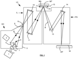
- FIG. 1 shows a lithographic system including a mask assembly.
- the lithographic system comprises a radiation source SO and a lithographic apparatus LA.
- the radiation source SO is configured to generate an extreme ultraviolet (EUV) radiation beam B.
- the lithographic apparatus LA comprises an illumination system IL, a support structure MT configured to support a mask assembly 15 including a patterning device MA (e.g., a mask), a projection system PS and a substrate table WT configured to support a substrate W.
- the illumination system IL is configured to condition the radiation beam B before it is incident upon the patterning device MA.
- the projection system is configured to project the radiation beam B (now patterned by the patterning device MA) onto the substrate W.
- the substrate W may include previously formed patterns. Where this is the case, the lithographic apparatus aligns the patterned radiation beam B with a pattern previously formed on the substrate W.
- the radiation source SO, illumination system IL, and projection system PS may all be constructed and arranged such that they can be isolated from the external environment.
- a gas at a pressure below atmospheric pressure e.g., hydrogen
- a vacuum may be provided in the illumination system IL and/or the projection system PS.
- a small amount of gas (e.g., hydrogen) at a pressure well below atmospheric pressure may be provided in the illumination system IL and/or the projection system PS.
- the radiation source SO shown in Figure 1 is of a type that may be referred to as a laser produced plasma (LPP) source.
- a laser 1 which may for example be a CO2 laser, is arranged to deposit energy via a laser beam 2 into a fuel, such as tin (Sn) that is provided from a fuel emitter 3.
- tin is referred to in the following description, any suitable fuel may be used.
- the fuel may for example be in liquid form, and may for example be a metal or alloy.
- the fuel emitter 3 may comprise a nozzle configured to direct tin, e.g., in the form of droplets, along a trajectory towards a plasma formation region 4.
- the laser beam 2 is incident upon the tin at the plasma formation region 4.
- the deposition of laser energy into the tin creates a plasma 7 at the plasma formation region 4.
- Radiation including EUV radiation, is emitted from the plasma 7 during de-excitation and recombination of ions of the plasma.
- the EUV radiation is collected and focused by a near normal incidence radiation collector 5 (sometimes referred to more generally as a normal incidence radiation collector).
- the collector 5 may have a multilayer structure that is arranged to reflect EUV radiation (e.g., EUV radiation having a desired wavelength such as 13.5 nm).
- the collector 5 may have an elliptical configuration, having two ellipse focal points. A first focal point may be at the plasma formation region 4, and a second focal point may be at an intermediate focus 6, as discussed below.
- the collector 5 may be a so-called grazing incidence collector that is configured to receive EUV radiation at grazing incidence angles and focus the EUV radiation at an intermediate focus.
- a grazing incidence collector may, for example, be a nested collector, comprising a plurality of grazing incidence reflectors.
- the grazing incidence reflectors may be disposed axially symmetrically around an optical axis O.
- the radiation source SO may include one or more contamination traps (not shown).
- a contamination trap may be located between the plasma formation region 4 and the radiation collector 5.
- the contamination trap may for example be a rotating foil trap, or may be any other suitable form of contamination trap.
- the laser 1 may be separated from the radiation source SO. Where this is the case, the laser beam 2 may be passed from the laser 1 to the radiation source SO with the aid of a beam delivery system (not shown) comprising, for example, suitable directing mirrors and/or a beam expander, and/or other optics.
- a beam delivery system (not shown) comprising, for example, suitable directing mirrors and/or a beam expander, and/or other optics.
- the laser 1 and the radiation source SO may together be considered to be a radiation system.
- Radiation that is reflected by the collector 5 forms a radiation beam B.
- the radiation beam B is focused at point 6 to form an image of the plasma formation region 4, which acts as a virtual radiation source for the illumination system IL.
- the point 6 at which the radiation beam B is focused may be referred to as the intermediate focus.
- the radiation source SO is arranged such that the intermediate focus 6 is located at or near to an opening 8 in an enclosing structure 9 of the radiation source.
- the radiation beam B passes from the radiation source SO into the illumination system IL, which is configured to condition the radiation beam.
- the illumination system IL may include a facetted field mirror device 10 and a facetted pupil mirror device 11.
- the faceted field mirror device 10 and faceted pupil mirror device 11 together provide the radiation beam B with a desired cross-sectional shape and a desired angular distribution.
- the radiation beam B passes from the illumination system IL and is incident upon the mask assembly 15 held by the support structure MT.
- the mask assembly 15 includes a patterning device MA and a pellicle 19, which is held in place by a pellicle frame 17.
- the patterning device MA reflects and patterns the radiation beam B.
- the illumination system IL may include other mirrors or devices in addition to or instead of the faceted field mirror device 10 and faceted pupil mirror device 11.
- the projection system PS comprises a plurality of mirrors that are configured to project the radiation beam B onto a substrate W held by the substrate table WT.
- the projection system PS may apply a reduction factor to the radiation beam, forming an image with features that are smaller than corresponding features on the patterning device MA. A reduction factor of 4 may for example be applied.
- the projection system PS has two mirrors in Figure 1 , the projection system may include any number of mirrors (e.g., six mirrors).
- the lithographic apparatus may, for example, be used in a scan mode, wherein the support structure (e.g., mask table) MT and the substrate table WT are scanned synchronously while a pattern imparted to the radiation beam is projected onto a substrate W (i.e., a dynamic exposure).
- the velocity and direction of the substrate table WT relative to the support structure (e.g., mask table) MT may be determined by the demagnification and image reversal characteristics of the projection system PS.
- the patterned radiation beam that is incident upon the substrate W may comprise a band of radiation.
- the band of radiation may be referred to as an exposure slit.
- the movement of the substrate table WT and the support structure MT may be such that the exposure slit travels over an exposure field of the substrate W.
- the radiation source SO and/or the lithographic apparatus that is shown in Figure 1 may include components that are not illustrated.
- a spectral filter may be provided in the radiation source SO.
- the spectral filter may be substantially transmissive for EUV radiation but substantially blocking for other wavelengths of radiation such as infrared radiation.
- the radiation source SO may take other forms.
- the radiation source SO may comprise one or more free electron lasers.
- the one or more free electron lasers may be configured to emit EUV radiation that may be provided to one or more lithographic apparatus.
- the mask assembly 15 includes a pellicle 19 that is provided adjacent to the patterning device MA.
- the pellicle 19 is provided in the path of the radiation beam B such that radiation beam B passes through the pellicle 19 both as it approaches the patterning device MA from the illumination system IL and as it is reflected by the patterning device MA towards the projection system PS.
- the pellicle 19 comprises a thin film that is substantially transparent to EUV radiation (although it will absorb a small amount of EUV radiation).
- EUV transparent pellicle or a film substantially transparent for EUV radiation herein is meant that the pellicle 19 is transmissive for at least 65% of the EUV radiation, preferably at least 80% and more preferably at least 90% of the EUV radiation.
- the pellicle 19 acts to protect the patterning device MA from particle contamination.
- particles may still be present inside the lithographic apparatus LA.
- particles may be deposited onto the patterning device MA. Particles on the patterning device MA may disadvantageously affect the pattern that is imparted to the radiation beam B and the pattern that is transferred to the substrate W.
- the pellicle 19 advantageously provides a barrier between the patterning device MA and the environment in the lithographic apparatus LA in order to prevent particles from being deposited on the patterning device MA.
- the pellicle 19 is positioned at a distance from the patterning device MA that is sufficient that any particles that are incident upon the surface of the pellicle 19 are not in the focal plane of the radiation beam B.
- This separation between the pellicle 19 and the patterning device MA acts to reduce the extent to which any particles on the surface of the pellicle 19 impart a pattern to the radiation beam B. It will be appreciated that where a particle is present in the beam of radiation B, but at a position that is not in a focal plane of the beam of radiation B (i.e., not at the surface of the patterning device MA), then any image of the particle will not be in focus at the surface of the substrate W.
- the separation between the pellicle 19 and the patterning device MA may, for example, be approximately between 1 mm and 10 mm, for example between 1 mm and 5 mm, more preferably between 2 mm and 2.5 mm.
- a mask assembly may be prepared for use in a lithographic apparatus by attaching a pellicle to a pellicle frame and by attaching the pellicle frame to a patterning device.
- a mask assembly comprising a patterning device MA and a pellicle supported adjacent to the patterning device by a pellicle frame may be prepared remotely from a lithographic apparatus LA and the mask assembly may be transported to the lithographic apparatus LA for use in the lithographic apparatus LA.
- a pellicle frame supporting a pellicle may be attached to a patterning device, so as to form a mask assembly, at a site at which a pattern is imparted onto the patterning device.
- the mask assembly may then be transported to a separate site at which a lithographic apparatus LA is situated and the mask assembly may be provided to the lithographic apparatus LA for use in the lithographic apparatus LA.
- a mask assembly in which a pellicle is held in place by a pellicle frame may be delicate and transport of the mask assembly may risk damage to the pellicle.
- Assembling a mask assembly in a separate environment to a lithographic apparatus LA may additionally result in the mask assembly being exposed to a variety of pressure conditions.
- a mask assembly may be transported to a lithographic apparatus under ambient pressure conditions.
- the mask assembly may then be loaded into the lithographic apparatus LA via a load lock which is pumped to vacuum pressure conditions. Changes in the pressure conditions to which a mask assembly is exposed may cause a pressure difference to exist across a pellicle which may cause the pellicle to bend and may risk damage to the pellicle.
- a lithographic system may comprise a lithographic apparatus LA connected to a pellicle frame attachment apparatus.
- a mask assembly comprising a mask and pellicle may be transferred directly from the pellicle frame attachment apparatus to the lithographic apparatus whilst remaining in a controlled environment (e.g. a vacuum environment).
- Figure 2 is a schematic illustration of apparatus suitable for assembling a mask assembly 15 and transferring the mask assembly to a lithographic apparatus LA.
- Figure 2 depicts a pellicle attachment apparatus 855 which may be used to attach a pellicle 19 to a pellicle frame 17, and a pellicle assembly transport device 881 which may be used to transport the pellicle assembly.
- a stud attachment apparatus 840 is depicted, which may be used to attach studs 51 to a patterning device MA.
- the studs 51 allow releasable attachment of the pellicle frame 17 (and pellicle 19) to the patterning device MA.
- a mask transport device 880 which may be used to transport the mask with attached studs is also depicted.
- a pellicle frame attachment apparatus 857 which may be used to attach a pellicle frame 17 (and pellicle 19) to a patterning device MA, thereby forming a mask assembly 15, is also depicted.
- a mask assembly transport device 853 which may be used to transport the mask assembly 15 from the pellicle frame attachment apparatus 857 to the lithographic apparatus LA is also shown.
- the pellicle attachment apparatus 855 may be situated at a different site from the site at which the lithographic apparatus is situated.
- the stud attachment apparatus 840 may be situated at a different site from the site at which the lithographic apparatus LA is situated.
- either or both of the pellicle attachment apparatus 855 and the stud attachment apparatus 840 may be located at the same site as the site at which the lithographic apparatus LA is situated (e.g. in a lithographic fab).
- the pellicle attachment apparatus 855 receives a pellicle 19, a pellicle frame 17 and engagement mechanisms (not illustrated).
- the pellicle 19 and pellicle frame 17 may be manually placed in the pellicle attachment apparatus 855.
- Glue is dispensed at engagement mechanism receiving openings in the pellicle frame 17 (e.g. locations described further below). Glue dispensing may be manual, or may be automated (or partially automated).
- the engagement mechanisms and the pellicle frame 17 are aligned relative to each other (e.g. using an optical alignment apparatus), and the engagement mechanisms are then inserted into the openings in the pellicle frame.
- Glue is also dispensed onto the pellicle frame 17 (e.g. at spaced apart locations around the pellicle frame 17). Glue dispensing may be manual, or may be automated (or partially automated). An optical alignment system is used to align the pellicle 19 relative to the pellicle frame 17, and the pellicle is then pressed against the pellicle frame.
- the pellicle 19 is held pressed against the pellicle frame 17 at room temperature for a period of time sufficient to allow the glue to cure, thereby securing the pellicle to the pellicle frame.
- the pressure on the pellicle 19 is then removed. Additional curing of the glue at an elevated temperature is then performed using a curing oven (which may form part of the pellicle attachment apparatus). This will also cure glue which attaches the engagement mechanisms to the pellicle frame 17. In an alternative approach, some heating may be applied to cure the glue when the pellicle 19 is being held against the pellicle frame (instead of allowing curing to proceed at room temperature).
- the pellicle may be attached to the pellicle frame using any suitable type of bonding (including without using glue).
- the resulting pellicle assembly 16 is inspected using a particle inspection tool.
- the particle inspection tool may form part of the pellicle attachment apparatus 855 (or may be a separate tool).
- the particle inspection tool may be configured to inspect for particles disposed on the pellicle 19 and/or the pellicle frame 17.
- the particle inspection tool may, for example, reject a pellicle assembly which has a number of particles which is greater than a given particle threshold.
- the particle inspection tool may also be used to inspect a pellicle 19 and/or a pellicle frame 17 before the pellicle and pellicle frame are glued together.
- the pellicle attachment apparatus 855 may be configured, following inspection, to seal the pellicle assembly 16 in a pellicle assembly transport device 881 (a sealed box).
- the pellicle assembly transport device 881 may be arranged to hold the pellicle assembly in an orientation in which the pellicle 19 is below the pellicle frame 17. Because the transport device 881 is sealed, the pellicle assembly can be transported without the pellicle assembly 16 being contaminated.
- the pellicle assembly 16 may be transported in the transport device 881 to a pellicle frame attachment apparatus 857.
- the pellicle attachment apparatus 855 may include a clean environment so as to reduce the number of particles inside the sealed environment, thereby reducing the number or particles which may be deposited on the pellicle 19.
- the pellicle attachment apparatus 855 may, for example, be situated at a site at which pellicles are manufactured.
- a pellicle 19 may be provided to the pellicle attachment apparatus 855 directly from a pellicle manufacturing tool (not shown) in which the pellicle 19 is manufactured.
- a pellicle 19 may, for example, be provided to the pellicle attachment apparatus 855 from a pellicle manufacturing tool whilst keeping the pellicle 19 inside a clean environment.
- the clean environment may, for example be a sealed environment (i.e. fully isolated from an external environment).
- the sealed environment may be pumped so as to maintain a vacuum in the sealed environment.
- the attachment of the pellicle 19 to the pellicle frame 17 may be controlled so as to achieve a desirable tension in the pellicle 19.
- the tension in the pellicle 19 may be measured during or after attachment of the pellicle 19 to the pellicle frame 17 and the tension may be adjusted in response to the measurement in order to achieve a desirable tension in the pellicle 19.
- the tension in the pellicle 19 may be maintained, for example, by applying an outward force to components of the pellicle frame 17 so as to stretch the pellicle 19.
- Tension in the pellicle 19 may for example be maintained by using differences in thermal expansion coefficients between the pellicle frame and the pellicle.
- the patterning device (which may be referred to as a mask) MA may be provided with protrusions which are received by engagement mechanisms (e.g. as described further below).
- the patterning device may for instance receive four protrusions (referred to herein as studs).
- the stud attachment apparatus 840 may be used to attach studs 51 to the patterning device MA.
- the studs 51 and the patterning device MA may be manually placed in the stud attachment apparatus 840.
- the patterning device MA may be held in a controlled environment 841 which is separated from the rest of the stud attachment apparatus 840. Separation may be provided by a partition 842 with openings through which the studs 51 may project in order to contact the patterning device MA.
- the controlled environment 841 may be held at a higher pressure than other parts of the stud attachment apparatus 840 (e.g. by delivering gas through an outlet in the controlled environment). This will inhibit or prevent passage of contamination particles into the controlled environment 841 from other parts of the stud attachment apparatus.
- the stud attachment apparatus 840 may include a stud manipulator (not depicted), such as a robot or actuators for accurately placing the studs.
- a suitable actuator for placing studs onto the patterning device is a Lorentz actuator (not depicted).
- the stud attachment apparatus 840 may also include a device for automatically providing a given amount of glue or adhesive to the stud surface to be attached to the patterning device MA (although applying a glue or adhesive may also be done manually in advance). Contamination of the mask MA by contaminants from the glue or adhesive is prevented or reduced by a flow of air from the controlled environment above the partition 842 to below the partition (the flow of air is caused by the pressure above the partition being higher than the pressure below the partition).
- the stud attachment apparatus 840 may further include an optical alignment system which aligns the studs with respect to the alignment markers present on the reticle in order to accurately position the studs.
- the alignment markers conventionally provided on the patterning device MA and used for pattern alignment may also be used for aligning the studs.
- the stud attachment apparatus may include a support structure movable in the X-Y-Z and Rz directions for adjusting the position of the patterning device MA.
- the position of the support structure holding the patterning device MA may be adjustable manually by means of coarse and fine mechanical adjusting devices, or using automated (or semi-automated) actuators or any other type of devices suitable for alignment and positioning which are coupled to the patterning device table.
- the studs 51 and the patterning device MA have been aligned, the studs are then pressed against the patterning device MA.
- the studs 51 may be held against the patterning device MA at room temperature for a period of time which is sufficient to allow the glue to cure, thereby securing the studs to the mask.
- the studs 51 may be heated in order to accelerate curing of the glue. Additional curing of the glue at an elevated temperature may then be performed using a curing oven (which may form part of the stud attachment apparatus 840).
- the patterning device MA and studs 51 may be inspected using a particle inspection tool (which may form part of the stud attachment apparatus 840).
- the stud attachment apparatus 840 seals the patterning device MA and studs 51 in a patterning device MA transport device 880 (a sealed box). Because the mask transport device 880 is sealed, the patterning device MA and studs 51 can be transported without the mask being contaminated. The patterning device MA and studs may be transported in the transport device 880 to the pellicle frame attachment apparatus 857.
- the mask is provided to the stud attachment apparatus 840 in a sealed box (to reduce the risk of contamination).
- the box may remain sealed until just before the studs 51 are to be attached to the patterning device MA, thereby minimizing the time during which contamination could travel to the mask.
- the controlled environment 841 of the stud attachment apparatus 840 may be provided in part by a housing which subsequently forms part of the patterning device MA transport device 880 (a sealed box).
- the housing may form walls and a roof of the transport device 880, with a floor of the transport device being formed by a plate that is fitted after the studs 51 have been attached (e.g. immediately afterwards).
- Using the housing in this way may assist in preventing contamination from being incident upon the patterning device MA.
- the housing may comprise a cover of a pod.
- the mask table of the stud attachment apparatus 840 may be configured to receive the housing.
- the pellicle attachment apparatus 855 may also be formed in part by a housing that subsequently forms part of the pellicle assembly transport device 881.
- the pellicle assembly 16 in the transport device 881 and the patterning device MA (and studs 51) in the transport device 880 are both transported to the pellicle frame attachment apparatus 857.
- the pellicle frame attachment apparatus 857 may be provided in a fab in which one or more lithographic apparatus are also provided.
- the pellicle frame attachment apparatus 857 is configured to attach the pellicle frame 17 of the pellicle assembly 16 to the studs 51 on the patterning device MA so as to form a mask assembly 15.
- the pellicle frame attachment apparatus 857 may include a controlled environment 860 which is separated from the rest of the pellicle frame attachment apparatus. Separation may be provided by a partition 862 with openings through which manipulators extend (not shown in Figure 2 ). The manipulators may be operated by a control system 870 (described further below).
- the controlled environment 860 may be maintained as a clean environment so as to reduce the number of particles inside the controlled environment, thereby reducing the number of particles which may be deposited on the mask assembly 15.
- the controlled environment 860 may be held at a higher pressure than other parts of the pellicle frame attachment apparatus 857 (e.g. by delivering gas through an outlet in the controlled environment). This will inhibit or prevent passage of contamination particles into the controlled environment 860 from other parts of the pellicle frame attachment apparatus 857.
- the mask assembly 15 which is assembled by the pellicle frame attachment apparatus 857 is transported from the pellicle frame attachment apparatus to the lithographic apparatus LA in a mask assembly transport device 853.
- the mask assembly transport device 853 may comprise a sealed and clean environment in which the mask assembly 15 is transported. This reduces the chances of the mask assembly 15 being contaminated or damaged during transport of the mask assembly.
- the sealed and clean environment may, for example, be pumped to a vacuum.
- the pellicle frame attachment apparatus 857 may be used to mount, demount or remount the pellicle assembly 16 to/from the patterning device.
- the pellicle frame attachment apparatus 857 may comprise manipulators arranged to manipulate engagement mechanisms of the pellicle frame (as described further below).
- the patterning device MA may, for example, be provided with alignment marks.
- the pellicle frame 17 may be positioned relative to the alignment marks on the patterning device. Aligning the pellicle frame 17 relative to alignment marks on the patterning device may advantageously increase the accuracy with which the pellicle frame 17 is positioned on the patterning device MA during attachment of the pellicle frame 17 to the patterning device MA.
- the patterning device MA may be cleaned in the pellicle frame attachment apparatus 857, for example, to remove particles from the patterning device MA. In other embodiments cleaning of the patterning device MA may be performed in a dedicated cleaning tool.
- the pellicle frame may be attached at other parts of the mask.
- the pellicle frame may be attached to sides of the mask. This may be achieved for example using sub-mounts which provide releasably engageable attachment between the pellicle frame and sides of the mask.
- the pellicle frame may be attached to the mask through a combination of some attachment locations on sides of the mask and some attachment locations on the front of the mask. Attachment may for example be provided by sub-mounts which releasably engage the pellicle frame and the mask.
- the pellicle frame attachment apparatus 857 may include a particle inspection tool (not shown).
- the particle inspection tool may be configured to inspect the mask assembly 15 for particles disposed on the mask assembly 15.
- the particle inspection tool may, for example, reject mask assemblies 15 which have a number of particles disposed on them which is greater than a given particle threshold.
- the pellicle frame attachment apparatus 857 may include a pattern inspection system which inspects the pattern on the patterning device for any defects.
- the pattern inspection system may inspect the pattern on the patterning device before and/or after the pellicle frame 17 is attached to the patterning device MA.
- the attachment of the pellicle frame 17 to the patterning device MA may be controlled so as to achieve a desirable tension in the pellicle 19.
- the tension in the pellicle 19 may be measured during attachment of the pellicle frame 17 to the patterning device MA and the tension may be adjusted in response to the measurement in order to achieve a desired tension in the pellicle 19.
- the lithographic apparatus LA may, for example, correspond with the lithographic apparatus LA which is depicted in Figure 1 .
- the lithographic apparatus LA may include components which are configured to receive a mask assembly 15 from the mask assembly transport device 853 and load the mask assembly 15 onto a support structure MT of the lithographic apparatus LA.
- the mask assembly 15 may be illuminated with a conditioned radiation beam B provided by an illumination system IL.
- the patterning device MA of the mask assembly 15 may impart the conditioned radiation beam with a pattern in its cross-section to form a patterned radiation beam.
- the patterned radiation beam may be projected by a projection system PS onto a substrate W held by a substrate table WT.
- the conditioned radiation beam may, for example, comprise EUV radiation.
- the pellicle 19 of the mask assembly 15 may be substantially transparent to EUV radiation.
- a pellicle assembly 16 may be attached to a patterning device MA so as to form a mask assembly 15 under vacuum conditions in the pellicle frame attachment apparatus 857.
- the mask assembly 15 may subsequently be transported to the lithographic apparatus LA under vacuum conditions by the mask assembly transport device 853 and may be held under vacuum conditions in the lithographic apparatus LA.
- the mask assembly 15 may therefore be exposed to approximately the same pressure conditions throughout its assembly in the pellicle frame attachment apparatus 857 and use in the lithographic apparatus LA. This advantageously reduces any pressure changes to which the mask assembly 15 is exposed and therefore reduces any pressure differences which may develop across the pellicle 19.
- the patterning device MA and/or the pellicle 19 may be inspected for particles and/or defects in the pellicle frame attachment apparatus 857 whilst the components are held in a vacuum.
- the patterning device MA and/or the pellicle 19 are therefore advantageously inspected under similar pressure conditions to those to which they are exposed during use in the lithographic apparatus LA. This is advantageous since any particles which may be deposited onto patterning device MA and/or the pellicle during pumping down to vacuum conditions may be detected in the pellicle frame attachment apparatus 857.
- the lithographic system LS may further comprise a separate inspection apparatus (not shown) which is configured to inspect one or more components of a mask assembly 15 for particles and/or defects.
- a mask assembly 15 may, for example, be transported to an inspection apparatus (e.g. by the mask assembly transport device 853) after being assembled in the pellicle frame attachment apparatus 857 and prior to transporting the mask assembly 15 to the lithographic apparatus LA.
- Embodiments as described above advantageously allow a mask assembly 15 to be assembled and passed to a lithographic apparatus LA in an automated (or semi-automated) process.
- the assembly and transport of the mask assembly 15 may all be conducted in a sealed clean environment which may, for example, be pumped to vacuum pressure conditions. This may reduce the chance of components of the mask assembly 15 from being contaminated or damaged prior to the use of the mask assembly 15 in a lithographic apparatus LA.
- the useful lifetime of a pellicle 19 may be less than the useful lifetime of a patterning device MA. It may therefore be desirable to remove a pellicle assembly 16 from patterning device MA and replace the pellicle assembly with a new pellicle assembly so as to allow for continued use of the patterning device MA. Replacement of a pellicle assembly 16 may, for example, be carried out in the pellicle frame attachment apparatus 857. For example, after use in the lithographic apparatus LA, a mask assembly 15 may be passed back to the pellicle frame attachment apparatus 857 using the mask assembly transport device 853 for pellicle assembly replacement in the pellicle frame attachment apparatus 857.
- the patterning device MA may be subjected to a cleaning process so as to remove contamination from the patterning device MA after the pellicle assembly 16 has been removed.
- the studs 51 may be removed from the patterning device MA before the patterning device is subjected to the cleaning process.
- the patterned side of the patterning device MA is directed downwards during the various operations that are depicted in Figure 2 . Keeping the patterned side of the patterning device MA facing downwards is advantageous because this reduces the likelihood of a contamination particle being incident upon the pattern. Larger contamination particles tend to fall downwards due to gravity and thus will be incident upon the opposite side of the mask. Smaller contamination particles are less influenced by gravity and may instead be influenced by other transport physics. Apparatus of embodiments of the invention may include devices intended to address this.
- the apparatus may include an ionizer to remove static charges and thereby reduce the risk of electrostatics causing particles to become attached to the pellicle.
- a mask assembly is illustrated in Figures 3-5 .
- a pellicle frame and pellicle are suspended relative to a patterning device (e.g. a mask).
- the pellicle frame is releasably engageable with the patterning device.
- the releasable engagement is provided by a mount which comprises a plurality of sub-mounts (for example 2, 3, 4 or even more sub-mounts).
- the mount allows the pellicle frame (and pellicle) to be removed from the patterning device in an easy and convenient manner.
- the removal of the pellicle frame and pellicle from the patterning device may be clean, i.e. may generate substantially no contamination particles.
- the patterning device may be inspected using an inspection tool (and may be cleaned if necessary).
- the pellicle frame and pellicle can subsequently be easily reattached to the patterning device or may be replaced with a new pellicle frame and pellicle.
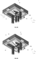
- a pellicle 19 is attached to a pellicle frame 17.
- the pellicle 19 may, for example, be glued to the pellicle frame 17.
- the pellicle frame 17 is provided with four engagement mechanisms 50A-D.
- Each engagement mechanism 50A-D is configured to receive a protrusion (which may for example be referred to as a stud) which extends from a patterning device (as described below in connection with Figure 4 ).
- Two engagement mechanisms 50A,B are provided on one side of the pellicle frame 17 and two engagement mechanisms 50C,D are provided on an opposite side of the pellicle frame.
- Other combinations may also be possible, such as an engagement mechanism on each of the four frame sides etc.
- the engagement mechanisms are provided on sides of the pellicle frame 17 which will be oriented in the scanning direction during use in a lithographic apparatus (indicated in Figure 3 as the y-direction in accordance with conventional notation). However, the engagement mechanisms may also be provided on sides of the pellicle frame 17 which will be oriented perpendicular to the scanning direction during use in a lithographic apparatus (indicated in Figure 3 as the x-direction in accordance with conventional notation).
- the protrusions which are received by the engagement mechanisms 50A-D may be located on the front surface of the patterning device. Additionally or alternatively, the protrusions may be located on sides of the patterning device. Protrusions may extend upwardly from sides of the patterning device. In such an arrangement the protrusions may each have a flattened lateral surface to facilitate secure bonding to a side of the patterning device.
- Figure 3 depicts four engagement mechanisms 50A-D secured to a pellicle frame 17.
- Two of the sub-mounts 50A,D are configured to allow for movement in the y-direction (i.e. provide flexibility or compliance in the y-direction).
- Two sub-mounts 50B,C are configured to allow for movement in the x-direction (i.e. provide flexibility or compliance in the x-direction).
- all four sub-mounts 50A-D are configured to allow engagement to be achieved between the sub-mounts and protrusions (not depicted) via movement in the y-direction and thus, as may be seen, all four sub-mounts include engagement arms 80 which extend in the y-direction.
- all four sub-mounts may include engagement arms which extend in the x-direction (i.e. the non-scanning direction). Having the engagement arms all extending in the non-scanning direction is advantageous because this avoids the possibility of a sudden y-direction deceleration causing disengagement of the engagement mechanisms.
- the engagement arms of each sub-mount may all extend in substantially the same direction.
- arms 62 which support locking members of two of the sub-mounts 50B, C extend in the y-direction. These arms are resiliently flexible in the x-direction and thus provide movement/flexibility in the x-direction.
- engagement arms 80 of two of the sub-mounts 50B,C extend generally parallel to the arms 62 of that sub-mount.
- arms 62 which support locking members of the other two sub-mounts 50A,D extend in the x-direction. These arms are resiliently flexible in the y-direction and thus provide movement/flexibility in the y-direction.
- engagement arms 80 of two of the sub-mounts 50A,D extend generally perpendicular to the arms 62 of that sub-mount.
- the movement/flexibility which is provided by the sub-mounts 50A-D allows flexing of the pellicle frame 17 relative to the patterning device MA as needed when temperature changes occur. This is advantageous because it avoids potentially damaging thermal stresses arising in the pellicle frame 17.
- the sub-mounts 50A-D are depicted with tabs 56 which have a different configuration from the tabs 56 depicted in Figure 5 .
- the tabs provide the same function of facilitating engagement between the sub-mounts 50A-D and the pellicle frame 17. Any suitable configuration of tabs may be used.
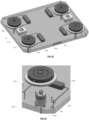
- Figure 4 depicts in cross-section one engagement mechanism 50B along with a protrusion 51 which projects from a patterning device MA.
- the protrusion 51 which may be referred to as a stud, may for example be glued to the patterning device MA or may be attached by other bonding means (optical contacting, magnetic or van der Waals forces, etc).
- the engagement mechanism 50B and the protrusion 51 together form a sub-mount 10.
- the protrusion 51 comprises a distal head 53 located on a shaft 55 which extends from a base 57.
- the base 57 is fixed to the patterning device MA for example by using glue.
- the shaft 55 and distal head 53 may be cylindrical, or they may have any other suitable cross-sectional shape.
- the sub-mount 10 suspends the pellicle frame 17 relative to the patterning device MA such that there is a gap G (which may be considered to be a slit) between the pellicle frame and the patterning device.
- the gap G may be maintained by engagement between a cap 66 of the engagement mechanism 50B and the distal head 53 of the protrusion 51 (or by some other movement limiting component).
- the gap G may be sufficiently wide to allow equalization of pressure between the exterior environment and the space between the pellicle and the patterning device.
- the gap G may also be sufficiently narrow that it provides a desired restriction of the potential route of contamination particles from the exterior environment to the space between the pellicle and the patterning device.
- the gap G may for example be at least 100 microns in order to allow equalization of pressure between the exterior environment and the space between the pellicle and the patterning device.
- the gap G may for example be less than 500 microns, more preferably less than 300 microns.
- the gap G may for example be between 200 microns and 300 microns.
- Figure 5 depicts the sub-mount 10 of Figure 4 in more detail.
- the pellicle frame attached to the engagement mechanism 50B is not depicted in Figure 5 .
- the patterning device from which the protrusion 51 projects is not depicted in Figure 5.
- Figure 5A shows the sub-mount 10 viewed from below and
- Figure 5B shows the sub-mount in a perspective view seen from below.
- the engagement mechanism 50B comprises a rectangular outer wall 60 which is received in an opening in a pellicle frame (see Figure 3 ).
- a pair of arms 62 extend in the y-direction across a space defined by the outer wall 60.
- a connecting member 63 extends between distal ends of the arms 62.
- the arms 62 are examples of resilient members. Other resilient members may be used.
- the arms 62 and connecting member 63 together form a generally U-shaped support.
- a locking member 70 is connected to a distal end of the generally U-shaped support. The locking member 70 engages with the protrusion 51 (which may be referred to as a stud) thereby securing the pellicle frame to the patterning device.
- the locking member 70 comprises a pair of engagement arms 80 provided with engagement tabs 81 and further comprises a cap 66.
- the engagement tabs 81 press against an under-surface of a distal head 53 of the protrusion
- the cap 66 presses against an outer surface of the distal head 53.
- This pressing of the engagement tabs 81 and cap 66 against the distal head 53 of the protrusion 51 secures the engagement mechanism 50B to the protrusion to provide a secure sub-mount 10. This provides a secure connection between the pellicle frame and the patterning device.
- the cap 66 and the engagement arms 80 extend from intermediate arms 82a,b.
- the intermediate arms 82a,b extend from the connecting member 63 and extend in the y-direction back across a space generally defined by the outer wall 60.
- a connecting member 83 extends between the intermediate arms 82a,b.
- the intermediate arms 82a,b and connecting member 83 together form a generally U-shaped support.
- a first generally U-shaped support formed by arms 62 and connecting member 63 extends in the y-direction across the space generally defined by the outer wall 60, and a second U-shaped support formed by support arms 82a,b and connecting member 83 extends back across that space.
- the arms 62 which form the first generally U-shaped support have some flexibility in the x-direction, and this allows some movement in the x-direction of the locking member 70.
- the sub-mount 10 allows some movement in the x-direction of a pellicle frame relative to a patterning device at the location of that sub-mount.
- the arms 62 are formed from resilient material and therefore tend to return to their original orientations.
- the sub-mount 10 may be considered to be a kinematic sub-mount.
- the arms 62 are significantly thicker in the z-direction than in the x-direction (as may best be seen in Figure 5B ), and as a result significantly less bending of the arms in the z-direction is possible compared with bending of the arms in the x-direction. Since the arms extend in the y-direction, they do not provide for significant movement in the y-direction. The arms 62 may thus prevent or substantially prevent local movement of a pellicle frame in the y and z-directions whilst allowing some movement in the x-direction.
- the cap 66 extends from the first support arm 82a, and engagement arms 80 extend from the second support arm 82b.
- the first support arm 82a is significantly thicker in the x-direction than the arms 62, and thus does allow significant movement in the x-direction relative to the arms 62.
- the second support arm 82b has a similar thickness to the arms 62 in the x-direction, but the connecting member 83 which extends between the intermediate arms 82a,b inhibits movement of the second support arm 82b in the x-direction because such movement can only occur if the first support arm 82a also moves.
- the engagement arms 80 extend from the second support arm 82b in the general direction of the cap 66. Proximal ends of the engagement arms 80 extend along the majority of the second support arm 82b (thereby substantially preventing the engagement arms 80 from flexing in directions which are generally parallel to a patterned surface of the patterning device).
- the engagement arms 80 taper as they extend in the general direction of the cap 66.
- Engagement tabs 81 extend inwardly from distal ends of the engagement arms 80 to engage with an under-surface of a distal head 53 of the protrusion 51. Blocks 54 are provided above the engagement tabs 81 and provide actuator receiving surfaces as is explained further below.
- the engagement arms 80 are resiliently deformable in the z-direction.
- the engagement arms 80 may be sufficiently thin that they bend in the z-direction. Additionally or alternatively, some bending in the z-direction of the engagement arms 80 may be facilitated by a groove 59 which extends in the y-direction at the point where the engagement arms 80 connect to the support arm 82b.
- Tabs 56 extend outwardly from the outer wall 60.
- the tabs may be used to secure the engagement mechanism 50B to a pellicle frame. This is depicted in Figure 3 but with a different configuration of tabs.
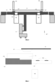
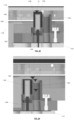
- FIG 6 schematically depicts in cross section a pellicle attachment apparatus 855 which may be used to attach the pellicle 19 to the pellicle frame 17.
- the pellicle attachment apparatus 855 may correspond with the pellicle attachment apparatus depicted in Figure 2 .
- the pellicle frame 17 is supported by a support structure 101.
- the support structure 101 includes a raised portion 102 upon which the pellicle frame 17 rests.
- the pellicle 19 is held by support arms 103 which project downwardly from a frame (not depicted).
- Imaging sensors 105 e.g. cameras
- Alignment marks 109 are provided on the windows.
- the alignment marks 109 allow the imaging sensors 105 to determine the position of both the frame 17 and the pellicle 19 (as discussed below in connection with Figure 7 ).
- Actuators 111 are connected to the support structure 101 and are operable to move the support structure 101 relative to a base (not depicted).
- the actuators 111 are configured to move the support structure 101 in the x, y and z directions (in this document x and y may indicate two orthogonal horizontal directions, and z may indicate the vertical direction).
- the actuators are also configured to rotate the support structure 101 about the z-axis.
- the actuators 111 allow the support structure 101 to be moved in order to position the frame 17 relative to the pellicle 19 before the pellicle is attached to the frame.
- Figure 7 schematically depicts part of the pellicle attachment apparatus of Figure 6 in more detail, including the pellicle 19 and pellicle frame 17.
- the relative positions of the imaging sensor 105, window 107, pellicle frame 17 and pellicle 19 can be seen in Figure 7 .
- the pellicle frame 17 partially projects over the window 107, and as a result the edge of the frame 17 is visible to the imaging sensor 105. This allows the position of the frame 17 to be accurately determined relative to the alignment marks 109 provided on the window 107.
- the pellicle 19 has a border 20 around its outer perimeter which is significantly thicker than the main portion of the pellicle 19. It is this border 20 which is attached to the pellicle frame 17.
- this border 20 which is handled by the support arms 103 (depicted in Figure 6 ). As may be seen from Figure 7 , the border 20 projects beyond an inner edge of the frame 17, and thus an inner edge of the border is visible to the imaging sensor 105. This allows the border 20 (and thus the pellicle 19 in general) to be accurately positioned relative to the alignment marks 109 in the window 107. This in turn allows the border 20 (and pellicle) to be accurately positioned relative to the frame 17 (since the frame is accurately positioned relative to the alignment marks 109 in the window 107).
- the imaging sensor 105 and window 107 may be located at a corner position in the support structure 101, i.e. a position where a corner of the frame 17 is located in use. Imaging sensors 105 may be located at opposite corner positions. By seeing opposite corners of the frame 17 the imaging sensors 105 allow the position of the frame to be determined accurately.
- Figure 8 is a perspective view of a handling system 113 which may be used to handle the pellicle 19.
- a handling system with the same configuration may also be used to handle the pellicle frame 17.
- Support arms 103 of the handling system 113 hold the border 20 of the pellicle 19.
- the support arms are connected by connector arms 115 to a handling system frame 117.
- the handling system frame 117 is fixed in the x and y directions but is moveable in the z direction.
- a vacuum source (not depicted) is connected to a conduit 119 of the handling system frame via a port 120.
- the conduit 119 splits into two and travels along each arm of the handling system frame 117.
- Each support arm 103 contains a conduit (not depicted) which terminates at an opening provided in a foot 104 at the bottom of that support arm.
- Each conduit is connected via bellows 121 to the conduit 119 in the handling system frame 117.
- a vacuum which is applied at the port 120 is connected via the conduit 119 and the bellows 121 to the openings in the feet 104 of the support arms 103.
- the vacuum When the vacuum is applied it sucks the border 20 of the pellicle 19 towards the foot 104 of each support arm 103 and thus secures the border 20 to the support arms.
- Each foot 104 is dimensioned to receive the border 20 of the pellicle 19 (e.g. has a width which corresponds with the width of the border).
- the vacuum is removed the border 20 is no longer sucked towards the feet 104 of the support arms 103 but instead is released from the support arms.
- FIG 9 is a perspective view of part of the handling system 113 in more detail, although with connector arms 115 which have a modified configuration compared with those depicted in Figure 8 .
- Each connector arm 115 comprises a pair of leaf springs 123, the leaf springs extending from the handling system frame 117 to a support arm 103.
- the leaf springs 123 provide flexibility in the z-direction (i.e. vertical) but provide little or no flexibility in the x and y directions. This is achieved by the leaf spring being significantly thinner in the z-direction than it is in the x and y directions.
- the bellows 121 which are used to communicate the vacuum to the support arms 103 are flexible and thus permit relative movement of the support arms 103 relative to the handling system frame 117.
- Movement limiting arms 125 project from the support arms 103 towards the handling system frame 117.
- Adjustable end stops 127 e.g. bolts held in threaded bores
- the adjustable end stops 127 limit downward movement of the movement limiting arms 125 (i.e. movement in the minus z direction). The adjustable end stops 127 thus prevent downward movement of the pellicle 19 beyond a predetermined position.
- a handling system is used to pick up the frame.
- the handling system (not depicted) may be generally the same as the handling system described above in connection with Figures 8 and 9 .
- the foot at the bottom of each support arm may have a size and shape which corresponds with a portion of the frame that will come into contact with the foot.
- the support structure 101 is positioned beneath the pellicle frame.
- the pellicle frame 17 is lowered until it is a few millimetres above the support structure 101.
- the support structure 101 is then moved using the actuators 111 until it is accurately positioned relative to the pellicle frame 17 (as determined using the imaging detectors 105).
- the pellicle frame 17 is then lowered onto the support structure 101.
- the vacuum holding the pellicle frame 17 to the handling system is then released and the handling system is moved away from the pellicle frame 17.
- Glue is then provided on the pellicle frame 17.
- the glue may be provided at spaced apart locations around the frame (rather than providing glue which extends in a line around the frame).
- the pellicle 19 is lifted by the handling system 113 as described above.
- the support structure 101 (together with the frame 17) is then positioned beneath the pellicle 19.
- the pellicle 19 is lowered using the handling system 113 until it is a few millimetres above the support structure 101.
- the support structure 101 is then moved using the actuators 111 until it is accurately positioned relative to the pellicle border 20.
- the pellicle is then lowered onto the pellicle frame. Once the pellicle 19 has been located on the frame 17 the vacuum is released from the support arms 103, and the support arms 103 are moved away from the pellicle 19.
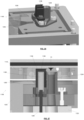
- Figure 10 schematically depicts from above the pellicle 19 in position on the pellicle frame 17 which in turn is held on the support structure 101.
- Figure 10 schematically depicts arms 130 which apply downward pressure to the pellicle border 20 thereby holding the pellicle in place on the frame 17 whilst curing of the glue attaching the pellicle to the pellicle frame 17 takes place.
- the glue may be provided at spaced apart locations on the pellicle frame 17, and the arms 130 may be positioned to apply pressure at the locations at which glue has been provided.
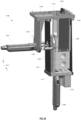
- FIG 11 depicts one of the arms 130 in cross-section.
- the arm 130 comprises a weighted portion 132 which is connected to a support portion 134 that extends from a support frame 136.
- the weighted portion 132 includes a projection 138 which is provided with a vertical bore 140.
- the projection 138 projects into an opening 142 in the support portion 134.
- a pin 144 extends from the top to the bottom of the opening 142 and passes through the bore 140. Because the pin 144 and bore 140 are both oriented in a vertical direction (the z direction), the pin and bore arrangement allows some vertical (or generally vertical) movement of the weighted portion 132 relative to the support portion 134 of the arm 130.
- the range of vertical movement of the weighted portion 132 relative to the support portion 134 is limited by end stops 146 provided at the mouth of the opening 142.
- the end stops are arranged to contact with the projection 138 and thereby prevent further vertical movement of the weighted portion 132.
- a finger 148 extends downwardly from the weighted portion 132 of the arm 130.
- a cap 150 is provided at a bottom end of the finger 148.
- the cap 150 may have a lowermost surface which generally corresponds in size with (or is larger than) an area of glue provided on the pellicle frame 17.
- the finger 148 comprises a vertical rod 152 which is secured at an uppermost end to the weighted portion 132 of the arm 130.
- the vertical rod 152 extends downwardly and passes through an opening 154 provided in the weighted portion 132.
- the opening 154 is significantly wider than the rod 152 and thus permits some lateral movement of the bottom end of the rod to take place (and thus lateral movement of the end of the finger).
- the support frame 136 holds the arms 130 away from the pellicle 19 until the arms are needed.
- the support frame 136 then moves the arms 130 downwards until a downwardly projecting finger 148 of the arm comes into contact with the border 20 of the pellicle 19.
- Downward motion of the support frame 136 ceases before the projection 138 of the weighted portion 132 comes into contact with an upper end stop 146 of the support portion 134.
- the weighted portion 132 rests upon the border 20, pressing on the border 20 via the finger 146, and is not supported by the support frame 136.
- the downward pressure exerted on the border 20 by the weighted portion 132 is determined by the weight of the weighted portion.
- the weighted portion 132 may thus be constructed to have a desired weight in order to apply a desired pressure to the border 20.
- the weighted portion 132 may include a weight receiving recess 149 into which a weight may be placed.
- the weighted portion 132 may include any suitable weight receiving receptacle or projection.
- the arms 130 are used to apply pressure at desired locations around the border 20 of the pellicle 19.
- the weighted portions 132 of the arms are left in place for a period of time sufficient to allow some curing of the glue between the frame 17 and the border 20 to take place.
- the support frame 136 is then moved upwards in order to remove the weighted arms 132 from the border 20.
- the frame 17 and pellicle 19 (which together may be referred to as a pellicle assembly 16) may then be transferred to an oven in order to further cure the glue.
- FIG. 12-15 An embodiment of a pellicle frame attachment apparatus 857 is depicted in Figures 12-15 .
- the pellicle frame attachment apparatus 857 may correspond with the pellicle frame attachment apparatus shown in Figure 2 .
- Figure 12 schematically shows the pellicle frame attachment apparatus 857 in cross-section.
- Figure 13 shows a partition 862 of the pellicle frame attachment apparatus 857 viewed from above.
- Figure 14 is a perspective view of a pin 1090, hooked members 1091 and manipulator pins 1092 of the pellicle frame attachment apparatus, which may collectively be referred to as manipulators.
- the manipulators project through a hole 895 in the partition 862.
- Figure 15 schematically depicts the manner in which the pins 1090, hooked members 1091 and manipulator pins 1092 are capable of moving relative to each other.
- a pellicle assembly 16 comprises a patterning device MA provided with a pellicle frame 17 and a pellicle (not depicted).
- the frame 17 is provided with four engagement mechanisms 50 which correspond with the engagement mechanisms described further above in connection with Figures 3 to 5 .
- Pins 1090 of the pellicle frame attachment apparatus 857 project through holes 895 in a partition 862.
- the partition 862 may correspond with, or be located on top of, a support structure 101.
- the support structure 101 may be the same as the support structure 101 which forms part of the pellicle attachment apparatus (see Figure 6 ). Alternatively, the support structure 101 may be different from but may, optionally, have features in common with the support structure 101 which forms part of the pellicle attachment apparatus.
- Windows 893, 894 are located in the support structure 101, and imaging sensors 105, 106 are located beneath the windows. Alignment marks 109 are provided on the windows 893, 894.
- An additional support structure 97 is provided at an outer perimeter of the pellicle frame attachment apparatus 857.
- the additional support structure may have a fixed position (as depicted), and is referred to herein as the fixed support structure 97.
- An intermediate support structure 98 is provided on top of the fixed support structure 97.
- the intermediate support structure 98 extends inwardly from the fixed support structure 97 as depicted.
- the intermediate support structure 98 supports both the pellicle frame 17 and the patterning device MA prior to attachment of the pellicle frame to the patterning device.
- Contacts 99 between the intermediate support structure 98 and other entities may for example be kinematic connections.
- the contacts 99 may be provided with a coating of PEEK.
- the pellicle frame attachment apparatus 857 includes actuators 111 which may be used to adjust the position of the pellicle assembly 16 in the x, y and z directions and to rotate the pellicle assembly about the z direction.
- Two imaging sensors 105 e.g. cameras
- Two other imaging sensors 106 are positioned to view alignment marks provided on the patterning device MA (which may be a patterning device MA). Alignment of two entities using alignment marks is well-known in the art and is not described further here.
- the actuators 111 and the imaging sensors 105, 106 may collectively be referred to as a control system 870.
- a gas outlet may be configured to supply gas on the pellicle frame 17 side of the partition 862.
- the gas may be delivered at a pressure which is higher than a gas pressure on an opposite side of the partition.
- Figure 13 depicts the partition 862 in more detail.
- the partition 862 is provided with four windows. Two of the windows 893 are positioned to allow the imaging sensors 106 to view alignment marks provided on the patterning device MA.
- the other two windows 894 are positioned to allow the imaging sensors 105 to view the pellicle frame 17 (e.g. to view corners of the pellicle frame).
- the windows 893, 894 may for example be formed from quartz.
- the partition 862 is further provided with holes 895, the holes being positioned to correspond with the positions of engagement mechanisms 50 of the pellicle assembly 16.
- One of the holes 895 is depicted in more detail in Figure 14 .
- the hole 895 is dimensioned to allow a pin 1090 and manipulator pins 1092 to project through the hole.
- hooked members 1091 project from sides of the hole. In other words, the hooked members 1091 are fixed to the partition 862 and project from the partition.
- the pin 1090, hooked members 1091 and manipulator pins 1092 are also depicted in Figures 12 , 13 and 15 .
- the pellicle assembly 16 is loaded onto the pellicle frame attachment apparatus 857. It may be transferred to the pellicle frame attachment apparatus 857 without exposing it to contamination.
- the pellicle assembly transport device 881 may be received in a load lock (not depicted) within the pellicle frame attachment apparatus 857, and the pellicle assembly 16 may be removed from the transport device within the load lock. The pellicle assembly 16 may then be transferred to the controlled environment 857 above the partition 862.
- the pellicle assembly 16 may be manually positioned relative to the pellicle frame attachment apparatus 857, for example using a handling system as depicted in Figure 8 .
- the pellicle assembly 16 is then placed onto the intermediate support structure 98.
- the patterning device MA (with studs 51) may be transferred to the pellicle frame attachment apparatus 857 without exposing it to contamination.
- the mask transport device 881 may be received in a load lock (not depicted) within the pellicle frame attachment apparatus 857, and the patterning device MA may be removed from the transport device within the load lock.
- the patterning device MA may then be transferred to the controlled environment 857 above the partition 862.
- the patterning device MA may be manually positioned relative to the pellicle frame attachment apparatus 857, for example using a handling system generally as depicted in Figure 8 .
- the pattering device is then placed onto the intermediate support structure 98.
- the controlled environment 859 above the partition 862 may be held at a pressure higher than the pressure beneath the partition (e.g. by delivering gas above the partition).
- the openings 895 in the partition 862 are relatively small, thus limiting the likelihood of contamination passing through the openings into the controlled environment. This likelihood is further reduced by the higher pressure of the controlled environment 859 with respect to the environment in the feed partition 862. The higher pressure ensures that air flows downwards through the holes 895, thereby carrying contamination away from the pellicle 19.
- the imaging sensors 105, 106 are used to monitor the positions of the pellicle assembly relative to the patterning device MA. This occurs after the pellicle frame 17 has been lifted from the intermediate support structure 98 by the pins 1090. The position of the pellicle frame 17 is adjusted using the actuators 111. This moves the support structure 101 and thus moves the pellicle frame 17 relative to the patterning device MA. Operation of the actuators 111 may be manual, or may be controlled by an automated controller. The movement of the support structure 101 may continue until the pellicle frame 17 is aligned relative to the patterning device MA.
- the pins 1090, hooked members 1091 and manipulator pins 1092 are used to engage the engagement mechanisms 50 to the studs 51 which project from the patterning device MA.
- the pins 1090, hooked members 1091 and manipulator pins 1092 are capable of moving relative to each other.
- the hooked members extend from the support structure 101 and thus are not capable of movement relative to the support structure.
- the support structure itself 101 may be moved, as explained above, including movement in a generally vertical direction (z-direction).
- the manipulator pins 1092 are moveable in a generally vertical direction (z-direction) by an actuator 320.
- the manipulator pins 1092 are both fixed to the actuator 320 and thus both move together.
- the pin 1090 which supports the pellicle frame 17 is not actively moveable relative to the manipulator pins 1092.
- the pin 1090 is connected via a spring 322 to the actuator 320.
- Figures 16 and 17 schematically depict the manner in which the engagement mechanism 50 is brought into engagement with the protrusion 51 (which may also be referred to as a stud). Both Figures show the engagement mechanism and protrusion in cross-section viewed from one side and also viewed from below. Referring first to Figure 16 , the engagement arms 80 are pushed away from the cap 66 using manipulator pins (not depicted) which push against distal ends of the engagement arms. As may be seen from Figure 16 , there is no contact between the engagement mechanism 50 and the protrusion 51 at this point.
- the engagement mechanism is moved in the x-direction until the distal head 53 of the protrusion 51 is located above the engagement tabs 81 which project from the engagement arms 80. This movement is achieved by moving the pellicle frame to which the engagement mechanism 50 is fixed and thus moves all engagement mechanisms in unison.
- Operation of the pins 1090, hooked members 1091 and manipulator pins 1092 may be manual, automated, or semi-automated.
- the pins 1090, hooked members 1091 and manipulator pins 1092 may for example be formed from steel. Surfaces of the pins 1090, hooked members 1091 and manipulator pins 1092 which contact the engagement mechanism 50 may be provided with a coating of material such as polyether ether ketone (PEEK) or some other robust material. Alternatively, the contact surfaces may simply be polished surfaces of the pins 1090, hooked members 1091 and manipulator pins 1092.
- PEEK polyether ether ketone
- the mask assembly may be placed in a mask assembly transport device 853 for transportation to a lithographic apparatus LA (see Figure 2 ).
- Figures 18A-H depict in more detail one manner in which the engagement mechanism 50 may be engaged with the protrusion 51.
- a pin 1090 is moved in the z-direction until it touches the cap 66 of the engagement mechanism 50.
- the pin 1090 is moved further in the z-direction to lift up the engagement mechanism 50. Since the engagement mechanism is secured to the frame 17 (see Figure 3 ) this lifts the entire pellicle assembly 16.
- the pin 1090 is one of four pins (see Figures 12 and 13 ) and the pins are moved in unison.
- the pellicle assembly 16 is thus lifted by the four pins 1090 and is supported by those pins.
- the position of the pellicle assembly 16 is then adjusted using the actuators 111 (see Figure 12 ) until the pellicle assembly is aligned relative to the patterning device MA.
- two hooked members are then moved in the z-direction until their distal ends are beyond an uppermost surface of the first support arm 82a.
- the hooked members 1091 are then moved in the x-direction until distal ends of the hooked members are above corner plates 1089 of the support arm 82a.
- the hooked members 1091 are then moved downwards until they come into contact with the corner plates 1089 of the support arm 82a.
- the pin 1090 and hooked members 1091 together grip the engagement mechanism 50 to allow subsequent operation of the engagement mechanism.
- manipulator pins 1092 are moved in a generally vertical direction and push against blocks 54 provided at distal ends of the engagement arms 80.
- the manipulator pins 1092 push the engagement arms 80 upwards thereby enlarging a space between the engagement tabs 81 and the cap 66.
- the engagement arms 80 are not bent upwards in Figure 18D due to the limitations of the software used to generate the Figures.
- the engagement mechanism 50 is then moved in the x-direction until the distal end 53 of the protrusion 51 is located above the cap 66 and is located beneath the engagement tabs 81.
- all engagement mechanisms 50A-D are moved in unison via movement of the pins 1090 (see Figure 3 ).
- the patterning device and protrusions 51 may all be moved instead of moving the pellicle frame.
- lateral relative movement between the protrusions and the engagement mechanisms is all that is required. The direction of lateral movement will depend upon the orientation of the engagement arms 80 (and may for example be the y-direction rather than the x-direction).
- the hooked members 1091 are moved upwards and then moved in the x-direction until they are located away from the corner plates 1089 of the support arm 82a. The hooked members 1091 are then retracted.
- the pin 1090 is retracted.
- the pellicle frame 17 is no longer supported by the pins but instead is supported by its connection to the protrusions 51 which project from the patterning device MA. In other words, the pellicle frame 17 is attached to and supported by the patterning device MA.
- the engagement mechanism 50 is secured to the protrusion 51 and thus provides a secure sub-mount 10 for the pellicle frame (see Figure 3 ).
- the pellicle frame is thus securely attached to the patterning device.
- the pellicle, pellicle frame and patterning device (which may together be referred to as a mask assembly) may then be placed in a transport device 853 for transportation to a lithographic apparatus LA (see Figure 2 ).
- An alternative sequence of steps may be used to attach the engagement mechanism 50 to the protrusion 51.
- the hooked members 1091 are moved into position above the engagement tabs 1089 before the pins are used to raise the pellicle frame.
- the pin 1090 is then moved upwards to press against the engagement mechanism.
- the engagement mechanism is thus gripped by the hooked members 1091 and the pin 1090.
- the engagement mechanism 50 is then lifted by moving the hooked members 1091 and the pin 1090 upwards.
- the same actions are performed for other engagement mechanisms, and thus the pellicle assembly is lifted.
- the pellicle assembly is then aligned relative to the patterning device using the actuators 101 and imaging sensors 105, 106 (see Figure 12 ).
- the remaining steps may be as described above with reference to Figures 18A-H .
- Figure 19 schematically depicts in cross-section a stud attachment apparatus 840.
- the stud attachment apparatus 840 has similarities with the pellicle attachment apparatus 855 depicted in Figure 6 and the pellicle frame attachment 857 apparatus depicted in Figure 12 . Parts of the stud attachment apparatus 840 may correspond with parts of those other apparatuses.
- the stud attachment apparatus 840 comprises a support structure 101 and stud manipulators 1100 configured to move protrusions 51 (which may also be referred to as studs) vertically such that they come into contact with the patterning device.
- Windows 107, 108 are provided in the support structure 101 and imaging sensors 105, 106 (e.g. cameras) are positioned to look through the windows towards the patterning device MA.
- Alignment marks 109 are provided on the windows and may be used to align the support structure 101 relative to the patterning device MA.
- Actuators 111 are provided to move the support structure 101, and thus to move studs 51 which are held by the support structure 101.
- the actuators 111 are capable of moving the support structure in the x, y and z directions and are also capable of rotating the support structure about the z direction.
- the actuators 111 may be automated, manual or semi-automated (i.e. partially automated and partially manual).
- the stud attachment apparatus 840 further comprises an additional support structure 97 which is configured to support the patterning device MA. This additional support structure may be fixed, and is referred to herein as the fixed support structure 97.
- each stud 51 glue is provided on the base of each stud 51 whilst the studs are being held by the support structure.
- the patterning device MA is then placed onto the fixed support structure 97, such that the patterning device MA is positioned a few millimeters above the support structure 101.
- the actuators 111 are used to move the support structure 101 until alignment marks 109 provided in the windows 107, 108 are aligned with alignment marks provided on the patterning device MA.
- the studs 51 are held by the stud manipulators 1100 and have fixed positions in the x and y directions relative to the support structure 101.
- the separation between the studs 51 (of which there may be four in practice) is a fixed predetermined separation.
- the separation between the studs 51 corresponds with the separation between the engagement members 50A-D provided on a pellicle frame 17 (see Figure 3 ) which will be attached to the patterning device MA.
- the support structure 101 is moved upwards and closer to the patterning device.
- the stud manipulators 1100 are then used to move the studs 51 upwards from a position in which the bases of the studs do not contact the patterning device MA to a position in which the bases of the studs press against the patterning device.
- Heaters are then used to heat the studs 51 in order to promote curing of the glue at an interface between the bases of the studs 51 and the patterning device MA.
- Figure 20 depicts the stud attachment apparatus 840 in a partially transparent perspective view.
- a partition 842 is depicted which separates the actuators (not visible) from a controlled environment in which the patterning device is provided.
- the actuators are provided in a box 843 located beneath the partition 842.
- the imaging sensors 105, 106 which form part of an alignment measurement system 844 for aligning the studs to the patterning device are also provided beneath the partition 842 (as are other parts of the alignment system).
- a lift unit 845 which may be used to raise and lower a mask support which is used to put the patterning device onto the fixed support 97 (see Figure 19 ).
- the mask support may comprise a housing 879, which will form part of a mask transport device 880 (described further above in connection with Figure 2 ).
- the patterning device (not visible) and housing 879, together with the lift unit 845 may be provided in a controlled environment (walls of which are not depicted).
- the controlled environment may be held at a pressure which is higher than the pressure on an opposite side of the partition 842, such that contamination is inhibited from flowing through openings in the partition and into the controlled environment.
- the controlled environment may be provided with a flow of gas from an inlet and may include an outlet through which gas may flow (the flow being sufficiently constrained that the pressure in the controlled environment can be held at a level which is higher than the pressure below the partition 842). This flow of gas may help to remove contaminants from the controlled environment.
- a filter which collects contaminants may be provided at the gas inlet to prevent or inhibit contaminants from entering the controlled environment.
- Points at which the mask comes into contact with the stud attachment apparatus 840 may be provided with a coating of PEEK or some other robust material.
- points at which the mask comes into contact with the housing 879 may be provided with a coating of PEEK or some other robust material.
- a stud manipulator 1100 is depicted together with a stud 51 and a patterning device MA (e.g. a mask). Also depicted is a partition 842 which separates an environment in which the patterning device is provided from an environment in which the stud manipulator 1100 is provided.
- the stud manipulator 1100 comprises a cup 1102 which is dimensioned to receive a stud 51 (which may also be referred to as a protrusion), such that a bottom face of the stud 51 is facing outwards from the cup.
- the cup 1102 may, for example, be formed from PEEK or some other robust material.
- the cup 1102 is held in a manipulator head 1104 which in turn is supported on a manipulator body 1106.
- a spring 1108 is received against a flange 1109 provided on the manipulator body and biases the manipulator head 1104 and the stud 51 upwards.
- Alignment of the stud 51 relative to the mask is achieved using the imaging sensors 105, 106 and actuators 111 depicted in Figure 19 .
- the actuators have aligned the studs 51 to the patterning device MA
- the stud manipulator 1100 is moved upwards to press the studs against the patterning device.
- the stud manipulator 1100 is moved upwards by an actuator (not depicted) which moves all four stud manipulators upwards at the same time.
- the spring 1108 is compressed when the stud manipulator 1100 presses the stud 51 against the patterning device MA.
- the spring 1108 partially determines the force with which the stud 51 is pressed against the patterning device MA.
- a weaker spring will reduce the force with which the stud is pressed against the patterning device, whereas a stronger spring will increase the force which the stud is pressed against the patterning device.
- the force with which the stud 51 is pressed against the patterning device MA is selectable (at least in part) via selection of a spring 1108 with a desired strength.
- the spring 1108 may for example be pre-loaded with a force which pushes the stud manipulator 1100 and stud 51 upwards.
- the force of the pre-load may for example be less than 5N.
- the stud manipulator 1100 pushes the stud 51 against the patterning device MA and thereby allows the stud to be secured to the mask.
- the stud may be provided with glue or adhesive on its base, and the stud manipulator 1100 may press the stud 51 against the patterning device MA until the glue or adhesive has hardened. Once this has taken place, the stud manipulator 1100 may be moved away from the patterning device MA (and/or the patterning device may be moved away from the stud manipulator 1100).
- the stud manipulator 1100 may include a heater 1111 which is configured to heat the stud 51.
- the heater 1111 may be in the form of an electrical heater (e.g. a resistive electrical heater).
- the heater 1111 is used to heat the stud.
- the localized heating of the stud 51 provided by the heater 1111 is advantageous because it accelerates curing of the glue or adhesive. This increases the throughput of the stud attachment apparatus 840.
- the curing provided by heating the stud 51 may be pre-curing or may be full curing. Where pre-curing is used the patterning device MA and studs 51 may be transferred to an oven for curing. Where heating the stud 51 provides full curing there is no need to transfer the mask and studs to an oven. This is advantageous because the oven may be a source of contamination particles.
- the stud manipulator 1100 may include an actuator (not depicted) which is operative to press the stud 51 against the patterning device MA (in addition to, or instead of, the spring 1108).
- the actuator may in addition move the cup 1102 away from the stud 51 once the stud has been fixed to the patterning device MA.
- a seal 1112 extends around an outer perimeter of the manipulator head 1104.
- the seal 1112 is most clearly seen in Figure 22 , which depicts part of the stud manipulator 1100 as viewed from above (looking through the patterning device MA which is generally transparent in Figure 22 for ease of illustration).
- the seal 1112 is annular in shape.
- the seal may have any suitable shape.
- the seal 1112 is formed from resilient material (e.g. PEEK) and projects above the partition 842 and above the stud 51.
- PEEK resilient material
- the resilient nature of the seal 1112 means that the seal presses against the patterning device MA and thereby forms a seal against the patterning device. This seals the portion of the patterning device MA within the perimeter of the seal 1112 and isolates it from the portion of the patterning device MA which is outside of the perimeter of the seal.
- Gas extraction channels 1114 are provided in the manipulator head 1104, the gas extraction channels extending away from outer face of the manipulator head. An additional gas extraction route is provided by an annular space 1115 around the manipulator head 1104. A gas delivery channel 1118 is provided on one side of the seal 1112 and allows gas to be delivered to the area of the patterning device MA which is located within the seal. This is schematically depicted by arrows in Figure 21 . The gas is extracted via the gas extraction channels 1114 in the manipulator head and the annular space 1115 around the manipulator head. The gas extraction channels 1114 are distributed around the manipulator head 1104, as is best seen in Figure 22 .
- a flow of gas is provided which will transport contaminants out of the gas extraction channels 1114 and the annular space 1115 and thereby prevent those contaminants adhering to the surface of the patterning device MA.
- the contamination may for example be particulates derived from the glue provided on the stud 51 or chemical vapour from the glue. Chemical vapour may in particular be generated when the glue is heated for curing. Removing contamination using the gas glow is advantageous because, as is explained elsewhere, particulates or other contamination on the surface of the patterning device MA may cause errors in a pattern projected on to a substrate by a lithographic apparatus.
- the gas may, for example, be air.
- the seal 1112 may be a complete seal, i.e. no gas flows past the seal.
- the seal 1112 may form an incomplete seal against the patterning device MA, such that some gas can flow between the seal and the mask. This may be referred to as a leakage seal (i.e. the seal 1112 is a leakage seal).
- the seal 1112 may for example not make contact with the patterning device, such that there is a gap between the seal and the patterning device.
- the pressure of the gas within the seal may be lower than the pressure of gas outside of the seal, and as a result gas will flow from outside the seal to inside the seal and then out through the gas extraction channels 1114 and the annular space 1115.
- a further advantage of the leakage seal configuration is that avoiding contact between the seal 1112 and the patterning device MA prevents contamination being transferred from the seal to the patterning device.
- Figure 23 is a perspective view of four studs 51 provided on the support structure 101, each stud being surrounded by a seal 1112. Each seal 1112 is held on a seal support plate 1113 which is secured to the support structure 101. Also shown in Figure 23 are two windows 108 through which imaging sensors 106 (see Figure 19 ) may view the patterning device MA (not depicted).
- Each seal support plate 1113 is removable along with an associated seal 1112 from the support structure 101 (e.g. to allow replacement of a worn seal).
- Figure 24 depicts one seal support plate 1113 and seal 1112 removed from the support structure 101.
- positioning pins 1120 extend upwards from the support structure 101. These positioning pins 1120 are received in holes (one of which is visible in Figure 21 ) in the seal support plate 1113, and thereby ensure that the seal support plate is correctly positioned on the support structure 101.
- Retaining arms 1122 extend from a block 1124.
- the retaining arms 1122 are located over the seal support plate 1113 and press against pins 1126 which extend upwards from the support structure 101.
- the retaining arms 1122 are resiliently biased against the pins 1126 and press against the pins 1126, thereby securely holding the seal support plate 1113 in place on the support structure.
- the resilient retaining arms 1122 can be manually disengaged from the pins 1126 by moving opposing arms towards each other, thereby allowing the seal support plate 1113 (and seal 1112) to be removed.
- the stud manipulator 1100 is flexibly connected to the support structure 101 to allow the stud manipulator to move relative to the support structure when the stud 51 is being pressed onto the patterning device MA. This flexible connection is provided via the spring 1108. As a result, when the stud 51 is pressed against the patterning device MA, the stud manipulator 1100 may move relative to the support structure 101. This is advantageous because it avoids significant lateral forces being applied at the interface between the stud 51 and the patterning device MA, thereby avoiding for example sliding movement of the stud over the surface of the patterning device (such movement would generate contamination and is undesirable).
- a kinematic connection is provided between the stud manipulator 1100 and the support structure 101.
- the kinematic connection is such that the stud manipulator 1100 can press against the support structure when the stud 51 is not in contact with the patterning device, but allows the stud manipulator to disconnect easily from the support structure 101 when the stud 51 contacts the patterning device.
- three protrusions 1130 with rounded heads project from the stud manipulator 1100 and are distributed around the stud manipulator.
- One of the three protrusions 1130 is visible in Figure 21 .
- the protrusions 1130 engage with an angled inner surface 1132 of the seal support plate 1113.
- the angled inner surface 1132 is generally flat, whereas, as mentioned above, the protrusion 1130 has a rounded upper surface. This combination of surfaces is advantageous because it provides a very small contact area between the protrusion 1130 and the angled inner surface 1132. The other two protrusions contact angled inner surfaces of the seal support plate in the same manner.
- the spring 1108 presses the protrusions 1130 against the angled inner surface 1132 of the seal support plate 1113.
- This provides a connection between the stud manipulator 1100 and the support structure 101.
- the connection may be a kinematic connection.
- the spring 1108 is compressed thereby moving the protrusions 1130 away from the angled inner surfaces 1132 of the seal support structure 101.
- the three protrusions 1130 might not all separate from the angled inner surfaces 1132 at exactly the same time, for example if there is a relative tilt between the patterning device MA and the support structure 101. Instead, one will separate followed by a second and then by a third.
- the kinematic connection allows this serial separation to take place and allows the stud 51 to remain substantially perpendicular to the patterning device MA.
- the kinematic connection avoids forcing the stud 51 to have an orientation which is determined by the support structure 101 and instead allows the stud to have an orientation which is determined by the patterning device MA.
- the stud removal apparatus may have a form which generally corresponds with the stud attachment apparatus 840 (e.g. as schematically depicted in Figure 19 ).
- the stud removal apparatus may include a partition which separates a controlled environment in which the patterning device MA is held during stud removal from stud removers and other components.
- the controlled environment may have a higher pressure than other parts of the apparatus.
- the stud removal tool may for example comprise stud removers in a configuration which corresponds with that shown in Figure 19 .
- the imaging sensors 105, 106 and windows 107, 108 may be absent from the stud removal apparatus. Alignment of the heaters and actuators to the studs may be performed using a manual, semi-automated or automated system.
- Figure 25 is a perspective view of a stud remover 1149 which forms part of a stud removal apparatus.
- the stud remover 1149 comprises a stud gripper 1154 connected to a support plate 1155.
- a weight 1157 extends downwardly from the stud gripper 1154.
- a pair of leaf springs 1159 extend downwardly from the support plate 1155 and are configured to allow movement of the stud gripper 1154 in the x-direction (the leaf springs allow movement in a generally vertical direction).
- An actuator 1161 is connected to a flange 1163 which projects downwards from the support plate 1155.
- the actuator includes an arm 1164 which passes through an opening in one of the leaf springs 1159 and connects against a hooked member 1165 that is in contact with the weight 1157.
- a ridge and groove connection 1175 between the hooked member 1165 and the weight 1157 is provided which allows the weight to move vertically relative to the hooked member but prevents relative movement of the hooked member and the weight in the x and y directions.
- moving the arm 1163 in the x-direction using the actuator 1161 will cause the hooked member 1165 and the weight 1157 to move in the x-direction.
- a second pair of leaf springs 1167 allows movement of the stud gripper 1154 in the y-direction. No y-direction actuator is provided. Instead, some passive movement in the y-direction may occur as the stud moves into the stud gripper 1154 (as explained below).
- An actuator 1169 is located beneath the hooked member 1165 which is connected via the ridge and groove connection 1175 to the weight 1157 (the weight in turn being connected to the stud gripper 1154.
- the actuator 1169 is operable to move the stud gripper 1154 in the vertical direction (in this case denoted as the z-direction).
- the weight 1157 may for example be at least 1kg.
- the weight may for example be around 3kg.
- a receptacle 1173 is provided adjacent to the z-direction actuator 1169 and is configured to receive studs which have been removed from patterning devices.
- Figures 26 and 27 depict in perspective view and in cross-section part of the stud remover 1149 in more detail.
- Figure 27 also includes a stud 51 and a patterning device MA (e.g. mask).
- the stud gripper 1154 comprises a pair of opposed flanges 1156 which extend towards each other to establish a gap which is wider than a neck of the stud 51 but narrower than a distal head 853 of the stud.
- recesses 1158 are provided which are wider than the distal head of the stud 51 and can thus receive the distal head of the stud.
- the distal head of the stud 51 is not clearly visible in Figures 26 and 27 because the head extends into and out of the plane of the figures.
- the recesses 1158 and opposed flanges 1156 flare outwardly at one end of the stud gripper 1154.
- the stud remover 1149 includes a heater 1188 which is located beneath the stud gripper 1154.
- the heater is an electrical heater, e.g. a resistive heater, and is configured to locally apply heat to the stud gripper 1154.
- the stud remover further comprises a pusher arm 1200 which is connected to an actuator 1202.
- the pusher arm 1200 is configured to push the stud 51, once removed from the patterning device MA, into a chute 1204.
- the chute 1204 leads to the receptacle 1173 (see Figure 25 ).
- a wire 1206 extends downwards from the heater 1188 and is connected to the weight 1157 (see Figure 25 ).
- the actuator stud gripper 1154 is initially in a position which is to the left of the stud and does not project above a partition 1142 of the apparatus.
- the stud gripper 1154 is then moved upwards using the vertical actuator 1169 (see Figure 25 ) to the position shown in Figure 27 .
- the stud gripper is thus adjacent to but not touching the patterning device MA.
- the x-direction actuator 1161 (see Figure 25 ) then moves the stud gripper 1154 in the x-direction such that the distal head 853 of the stud 51 enters the stud gripper via the flared ends thereof and is then located in the non-flared portion (as depicted in Figure 28 ).
- the vertical actuator 1169 is then moved downwards such that the support plate 1155 no longer supports the stud gripper 1154, the stud gripper instead being pulled downwards by the weight 1157.
- Heat is delivered to the stud 51 from the heater 1188 via the stud gripper 1154 in order to melt the glue or adhesive which secures the stud to the patterning device MA. Once the glue or adhesive has melted the stud 51 becomes detached from the patterning device MA. The stud 51 moves downwards due to the weight that is pulling it downwards.
- the pusher arm 1200 is then moved in the x-direction as depicted in Figure 29 .
- the stud then falls into the receptacle 1173.
- the stud 51 is shown in three positions in Figure 29 in order to illustrate movement of the stud.
- the above process is performed for each stud 51 on the patterning device MA.
- the studs may be removed in series, i.e. one after another. Alternatively, the studs may all be removed together.
- An advantage of removing the studs in series is that the force being applied to the patterning device is limited to the force needed to remove one stud. This in turn limits the force applied to supports which support the patterning device, thereby minimizing the risk of damage to those supports (and also minimizing the risk of damage to the patterning device).
- a partition 1142 separates the majority of the stud removal apparatus from a controlled environment in which the patterning device MA is provided.
- no seal extends around an area of the patterning device MA on which the stud 51 is provided.
- a seal would provide little benefit because the patterning device MA will be cleaned after the stud 51 has been removed, and thus addition of contamination to the patterning device during stud removal does not pose a significant problem.
- a seal may be provided if desired (e.g. a leakage seal).
- the stud removal apparatus may further comprise additional stud grippers 1154 and associated elements.
- additional stud grippers 1154 and associated elements For example, four stud grippers and other elements may be provided, one for each stud on the patterning device MA.
- the stud removal apparatus may generally correspond in form with the stud attachment apparatus 840 depicted in Figure 21 .
- actuators may be used to adjust the positions of the stud grippers in the x, y, Z and Rz directions.
- the actuators may be automated, manual or semi-automated (i.e. partially automated and partially manual).
- the partition 1142 may separate the actuators from a controlled environment in which the mask is provided.
- the actuators may be provided in a box located beneath the partition 1142.
- Alignment measurement systems may also be provided beneath the partition 842.
- the alignment measurement systems may for example comprise imaging systems which are used to ensure that the stud grippers 1154 are positioned at correct locations before they engage with the studs 51.
- Points at which the mask comes into contact with the stud removal apparatus 1150 may be provided with a coating of PEEK or some other robust material.
- points at which the mask comes into contact with the housing may be provided with a coating of PEEK or some other robust material.
- the stud attachment apparatus 840 and stud removal apparatus 1150 may be provided as a single apparatus or may be provided as separate apparatuses.
- a lift unit 845 and housing are depicted only in Figure 20 , and are shown as part of the stud attachment apparatus 840. However, a lift unit may similarly be provided as part of a pellicle frame attachment and/or removal apparatus and/or may similarly be provided as part of a stud removal apparatus.
- the lift unit may be configured to raise and lower a housing which may form part of a mask transport device.
- a patterning device e.g. a mask
- the mask, housing and lift unit may be provided in a controlled environment.
- an actuator may be used to apply downward force to the stud.
- the actuator may for example be a Lorentz actuator.
- the Lorentz actuator may be configured to pull the studs in the z-direction only.
- the patterning device MA instead of heating the stud 51 the patterning device MA may be heated (e.g. using a heater located above the patterning device).
- the glue instead of heating the glue to melt it the glue may be dissolved via application of a suitable solvent.
- Glue may be cleaned from the patterning device MA using a cleaning apparatus.
- the cleaning apparatus may form part of the stud removal apparatus, or may be provided as a separate apparatus.
- the patterning device MA may be placed into a sealed box for transportation to a cleaning apparatus.
- the cleaning apparatus may be configured to remove contamination from the mask (which may include removing glue from the mask).
- the frame 17 and mountings 50 are attached to each other before the pellicle 19 is attached to the frame, attachment of these elements may take place in any suitable order.
- the frame 17 and pellicle 19 may be secured together, following which the mountings 50 may be attached the frame.
- the mountings 50 maybe attached to the frame 17 using an attachment apparatus which generally corresponds with the pellicle attachment apparatus 855.
- references to a mask in this document may be interpreted as references to a patterning device (a mask is an example of a patterning device).
- Embodiments of the invention may form part of a mask inspection apparatus, a metrology apparatus, or any apparatus that measures or processes an object such as a wafer (or other substrate) or mask (or other patterning device). These apparatus may be generally referred to as lithographic tools. Such a lithographic tool may use vacuum conditions or ambient (non-vacuum) conditions.
- EUV radiation may be considered to encompass electromagnetic radiation having a wavelength within the range of 4-20 nm, for example within the range of 13-14 nm. EUV radiation may have a wavelength of less than 10 nm, for example within the range of 4-10 nm such as 6.7 nm or 6.8 nm.
- lithographic apparatus in the manufacture of ICs, it should be understood that the lithographic apparatus described herein may have other applications. Possible other applications include the manufacture of integrated optical systems, guidance and detection patterns for magnetic domain memories, flat-panel displays, liquid-crystal displays (LCDs), thin-film magnetic heads, etc.
Landscapes
- Physics & Mathematics (AREA)
- General Physics & Mathematics (AREA)
- Health & Medical Sciences (AREA)
- Engineering & Computer Science (AREA)
- Environmental & Geological Engineering (AREA)
- Epidemiology (AREA)
- Public Health (AREA)
- Preparing Plates And Mask In Photomechanical Process (AREA)
- Exposure And Positioning Against Photoresist Photosensitive Materials (AREA)
- Crystals, And After-Treatments Of Crystals (AREA)
- Regulation And Control Of Combustion (AREA)
Claims (13)
- Eine Pellikelbefestigungsvorrichtung (855), die eine Tragstruktur (101), die konfiguriert ist, um einen Pellikelrahmen (17) zu tragen, und ein Pellikelhandhabungssystem, das konfiguriert ist, um ein Pellikel (19) auf dem Pellikelrahmen zu platzieren, beinhaltet, wobei die Vorrichtung ferner Aktuatoren (111) beinhaltet, die konfiguriert sind, um eine relative Bewegung zwischen dem Pellikelrahmen und dem Pellikel bereitzustellen, bevor das Pellikel auf dem Pellikelrahmen platziert wird, wobei das Pellikelhandhabungssystem Tragarme (103) beinhaltet, die konfiguriert sind, um das Pellikel zu halten, dadurch gekennzeichnet, dass jeder Tragarm eine Leitung umfasst, die konfiguriert ist, um einem Fuß dieses Arms ein Vakuum zuzuführen.
- Pellikelbefestigungsvorrichtung gemäß Anspruch 1, wobei die Aktuatoren konfiguriert sind, um die Tragstruktur und somit den Pellikelrahmen relativ zu dem Pellikel zu bewegen.
- Pellikelbefestigungsvorrichtung gemäß Anspruch 1, wobei sich jeder Tragarm von einem Verbinderarm (115), der sich von einem Rahmen des Pellikelhandhabungssystems erstreckt, nach unten erstreckt.
- Pellikelbefestigungsvorrichtung gemäß Anspruch 3, wobei der Verbinderarm eine oder mehrere Blattfedern (123) umfasst, die ermöglichen, dass sich der Verbinderarm in einer im Allgemeinen senkrechten Richtung bewegt.
- Pellikelbefestigungsvorrichtung gemäß einem der vorhergehenden Ansprüche, wobei die Tragstruktur Fenster (893, 894) umfasst, die positioniert sind, um zu ermöglichen, dass Pellikelrandkanten und/oder Pellikelrahmenkanten von einer entgegengesetzten Seite der Tragstruktur sichtbar sind.
- Pellikelbefestigungsvorrichtung gemäß Anspruch 5, wobei auf einer Seite der Fenster Abbildungssensoren (105, 106) bereitgestellt sind und konfiguriert sind, um durch die Fenster zu schauen, um die Pellikelrandkanten und/oder Pellikelrahmenkanten anzusehen.
- Pellikelbefestigungsvorrichtung gemäß Anspruch 5 oder Anspruch 6, wobei auf den Fenstern Ausrichtungsmarkierungen (109) bereitgestellt sind.
- Pellikelbefestigungsvorrichtung gemäß einem der vorhergehenden Ansprüche, wobei die Pellikelbefestigungsvorrichtung ferner Arme beinhaltet, die konfiguriert sind, um nach unten auf das Pellikel zu drücken, wenn es auf dem Pellikelrahmen platziert worden ist, und dadurch das Pellikel während des Härtens von Klebstoff an einer Kontaktfläche zwischen dem Pellikel und dem Pellikelrahmen auf dem Pellikelrahmen halten.
- Pellikelbefestigungsvorrichtung gemäß Anspruch 8, wobei jeder Arm mit einem Gewicht versehen ist und wobei der von dem Arm auf das Pellikel angewandte Druck nach unten durch die Schwere des Gewichts bestimmt wird.
- Pellikelbefestigungsvorrichtung gemäß einem der Ansprüche 8 bis 9, wobei sich jeder Arm von einem Tragrahmen (136) erstreckt und einen Abschnitt umfasst, der in einer im Allgemeinen senkrechten Richtung relativ zu dem Tragrahmen bewegbar ist.
- Pellikelbefestigungsvorrichtung gemäß Anspruch 10, wobei jeder Arm Endanschläge (127) umfasst, die die Bewegung des bewegbaren Abschnitts dieses Arms relativ zu einem festen Abschnitt dieses Arms einschränken.
- Ein Verfahren zum Befestigen eines Pellikels an einem Pellikelrahmen, wobei das Verfahren Folgendes beinhaltet:Verwenden einer Pellikelbefestigungsvorrichtung gemäß einem der vorhergehenden Ansprüche, um den Pellikelrahmen auf einer Tragstruktur zu platzieren;Auftragen von Klebstoff auf den Pellikelrahmen;Halten eines Pellikels über dem Pellikelrahmen unter Verwendung des Pellikelhandhabungssystems;Ausrichten des Pellikelrahmens und des Pellikels; undPlatzieren des Pellikels auf dem Pellikelrahmen.
- Verfahren gemäß Anspruch 12, wobei die Ausrichtung des Pellikelrahmens und des Pellikels durch das Bewegen der Tragstruktur, die den Pellikelrahmen trägt, erreicht wird.
Priority Applications (1)
| Application Number | Priority Date | Filing Date | Title |
|---|---|---|---|
| EP23203497.5A EP4286941A3 (de) | 2014-11-17 | 2015-11-16 | Vorrichtung zur befestigung eines pellikels |
Applications Claiming Priority (7)
| Application Number | Priority Date | Filing Date | Title |
|---|---|---|---|
| US201462080561P | 2014-11-17 | 2014-11-17 | |
| US201562108348P | 2015-01-27 | 2015-01-27 | |
| US201562110841P | 2015-02-02 | 2015-02-02 | |
| US201562126173P | 2015-02-27 | 2015-02-27 | |
| US201562149176P | 2015-04-17 | 2015-04-17 | |
| US201562183342P | 2015-06-23 | 2015-06-23 | |
| PCT/EP2015/076688 WO2016079052A2 (en) | 2014-11-17 | 2015-11-16 | Apparatus |
Related Child Applications (2)
| Application Number | Title | Priority Date | Filing Date |
|---|---|---|---|
| EP23203497.5A Division EP4286941A3 (de) | 2014-11-17 | 2015-11-16 | Vorrichtung zur befestigung eines pellikels |
| EP23203497.5A Division-Into EP4286941A3 (de) | 2014-11-17 | 2015-11-16 | Vorrichtung zur befestigung eines pellikels |
Publications (2)
| Publication Number | Publication Date |
|---|---|
| EP3221748A2 EP3221748A2 (de) | 2017-09-27 |
| EP3221748B1 true EP3221748B1 (de) | 2024-01-03 |
Family
ID=54542272
Family Applications (4)
| Application Number | Title | Priority Date | Filing Date |
|---|---|---|---|
| EP15794923.1A Active EP3221748B1 (de) | 2014-11-17 | 2015-11-16 | Vorrichtung zur befestigung eines pellikels |
| EP23206063.2A Pending EP4296778A3 (de) | 2014-11-17 | 2015-11-16 | Maskenanordnung |
| EP23203497.5A Pending EP4286941A3 (de) | 2014-11-17 | 2015-11-16 | Vorrichtung zur befestigung eines pellikels |
| EP15794591.6A Active EP3221747B1 (de) | 2014-11-17 | 2015-11-16 | Maskenanordnung |
Family Applications After (3)
| Application Number | Title | Priority Date | Filing Date |
|---|---|---|---|
| EP23206063.2A Pending EP4296778A3 (de) | 2014-11-17 | 2015-11-16 | Maskenanordnung |
| EP23203497.5A Pending EP4286941A3 (de) | 2014-11-17 | 2015-11-16 | Vorrichtung zur befestigung eines pellikels |
| EP15794591.6A Active EP3221747B1 (de) | 2014-11-17 | 2015-11-16 | Maskenanordnung |
Country Status (9)
| Country | Link |
|---|---|
| US (5) | US10539886B2 (de) |
| EP (4) | EP3221748B1 (de) |
| JP (9) | JP6769954B2 (de) |
| KR (7) | KR102544694B1 (de) |
| CN (5) | CN111458973B (de) |
| CA (4) | CA3206173A1 (de) |
| NL (2) | NL2015796A (de) |
| TW (4) | TWI679491B (de) |
| WO (2) | WO2016079051A2 (de) |
Families Citing this family (53)
| Publication number | Priority date | Publication date | Assignee | Title |
|---|---|---|---|---|
| CN111458973B (zh) * | 2014-11-17 | 2024-02-09 | Asml荷兰有限公司 | 表膜框架附接设备 |
| CA3008050A1 (en) * | 2015-12-14 | 2017-06-22 | Asml Netherlands B.V. | A membrane assembly |
| CA3008474A1 (en) | 2015-12-14 | 2017-06-22 | Asml Netherlands B.V. | A membrane for euv lithography |
| KR102186010B1 (ko) * | 2016-01-26 | 2020-12-04 | 한양대학교 산학협력단 | Euv 펠리클 구조체, 및 그 제조 방법 |
| KR20230023066A (ko) | 2016-04-25 | 2023-02-16 | 에이에스엠엘 네델란즈 비.브이. | Euv 리소그래피를 위한 멤브레인 |
| JP6781864B2 (ja) | 2016-07-05 | 2020-11-11 | 三井化学株式会社 | ペリクル膜、ペリクル枠体、ペリクル、その製造方法、露光原版、露光装置、半導体装置の製造方法 |
| KR102483397B1 (ko) * | 2016-07-29 | 2022-12-29 | 에이에스엠엘 홀딩 엔.브이. | 멤브레인 조립체 및 입자 트랩 |
| JP6607574B2 (ja) * | 2016-08-24 | 2019-11-20 | 信越化学工業株式会社 | ペリクルフレーム及びペリクル |
| KR101848153B1 (ko) * | 2016-09-12 | 2018-05-29 | 한양대학교 산학협력단 | 마스크 보호 모듈, 이를 포함하는 펠리클, 및 이를 포함하는 리소그래피 장치 |
| CN110325908A (zh) | 2017-02-17 | 2019-10-11 | 三井化学株式会社 | 防护膜组件、曝光原版、曝光装置及半导体装置的制造方法 |
| US11183410B2 (en) | 2017-04-24 | 2021-11-23 | Photronics, Inc. | Pellicle removal tool |
| KR20200015766A (ko) | 2017-06-15 | 2020-02-12 | 에이에스엠엘 네델란즈 비.브이. | 펠리클 및 펠리클 조립체 |
| KR20200071080A (ko) * | 2017-10-27 | 2020-06-18 | 에이에스엠엘 네델란즈 비.브이. | 펠리클 프레임 및 펠리클 조립체 |
| US11106127B2 (en) * | 2017-11-08 | 2021-08-31 | Taiwan Semiconductor Manufacturing Co., Ltd. | Structure of pellicle-mask structure with vent structure |
| JP7252950B2 (ja) * | 2017-11-21 | 2023-04-05 | エーエスエムエル ネザーランズ ビー.ブイ. | 多孔質グラファイトペリクル |
| JP6921412B2 (ja) * | 2018-01-25 | 2021-08-18 | 株式会社ブイ・テクノロジー | ペリクルフレーム把持装置及びペリクルフレーム把持方法 |
| PL3530511T3 (pl) | 2018-02-27 | 2020-11-16 | Joseph Vögele AG | Sposób rekonfiguracji układu operacyjnego dla maszyny budowlanej |
| KR102517767B1 (ko) * | 2018-03-05 | 2023-04-03 | 미쯔이가가꾸가부시끼가이샤 | 펠리클, 노광 원판, 노광 장치, 및 반도체 장치의 제조 방법 |
| JP7019472B2 (ja) * | 2018-03-22 | 2022-02-15 | 三井化学株式会社 | カーボンナノチューブ自立膜の製造方法、およびペリクルの製造方法 |
| JP7061494B2 (ja) * | 2018-03-28 | 2022-04-28 | 三井化学株式会社 | 検査方法、ペリクルの製造方法、および検査装置 |
| JP7376518B2 (ja) | 2018-07-04 | 2023-11-08 | エーエスエムエル ネザーランズ ビー.ブイ. | 位置決め及びクランプ硬化のための装置 |
| CN108950475B (zh) * | 2018-07-25 | 2020-11-10 | 京东方科技集团股份有限公司 | 张网结构、张网装置及张网方法 |
| KR20210065113A (ko) | 2018-09-28 | 2021-06-03 | 에이에스엠엘 네델란즈 비.브이. | 리소그래피 시스템 및 방법 |
| NL2024075B1 (en) | 2018-11-16 | 2020-08-19 | Asml Netherlands Bv | A pellicle for euv lithography |
| KR102243367B1 (ko) * | 2018-11-30 | 2021-04-23 | 한양대학교 산학협력단 | 펠리클 홀더, 펠리클 검사 장치, 및 펠리클 검사 방법 |
| US11137693B2 (en) * | 2018-11-30 | 2021-10-05 | Iucf-Hyu (Industry-University Cooperation Foundation Hanyang University) | Pellicle holder, pellicle inspection apparatus, and pellicle inspection method |
| CN113169047A (zh) * | 2018-12-10 | 2021-07-23 | 应用材料公司 | 在极紫外线光刻应用中从光掩模去除附接特征 |
| KR102172722B1 (ko) | 2018-12-26 | 2020-11-02 | 주식회사 에프에스티 | 초극자외선 리소그라피용 펠리클의 검사에 사용되는 캡슐 |
| KR20200088529A (ko) | 2019-01-14 | 2020-07-23 | 주식회사 에프에스티 | 초극자외선 리소그라피용 펠리클 검사 시스템 |
| KR20200088528A (ko) | 2019-01-14 | 2020-07-23 | 주식회사 에프에스티 | 펠리클 장착 시스템, 스터드 부착 장치, 펠리클 부착 장치 및 펠리클 부착 방법 |
| WO2020207774A1 (en) | 2019-04-12 | 2020-10-15 | Asml Netherlands B.V. | Pellicle for euv lithography |
| KR102242356B1 (ko) * | 2019-08-05 | 2021-04-20 | 주식회사 에프에스티 | 일체화된 프레임과 멤브레인을 포함하는 펠리클, 그 제조방법, 펠리클을 포함하는 노광장치 및 펠리클의 제조장치 |
| KR102273266B1 (ko) * | 2019-10-23 | 2021-07-06 | 주식회사 에프에스티 | 일체화된 프레임과 멤브레인을 포함하는 펠리클의 제조방법 |
| KR20210116770A (ko) * | 2020-03-13 | 2021-09-28 | 삼성전자주식회사 | 펠리클 전사 장치 및 펠리클 전사 방법 |
| CN115443434A (zh) * | 2020-04-23 | 2022-12-06 | Asml荷兰有限公司 | 用于极紫外光刻的表膜框架 |
| TWI760062B (zh) * | 2020-05-14 | 2022-04-01 | 家登精密工業股份有限公司 | 提供有保持銷組件之光罩盒及固持光罩的方法 |
| US11822230B2 (en) * | 2020-07-24 | 2023-11-21 | Taiwan Semiconductor Manufacturing Company, Ltd. | EUV pellicle and mounting method thereof on photo mask |
| KR20220043268A (ko) | 2020-09-29 | 2022-04-05 | 삼성전자주식회사 | 온도/압력이 독립으로 제어되는 스터드 부착 장치 및 스터드 부착 방법 |
| KR20220080395A (ko) | 2020-12-07 | 2022-06-14 | 주식회사 에프에스티 | 극자외선 리소그라피용 펠리클 프레임 |
| KR102512243B1 (ko) | 2020-12-16 | 2023-03-21 | 주식회사 에프에스티 | 극자외선 리소그라피용 다공성 펠리클 프레임 |
| US20240047168A1 (en) * | 2020-12-17 | 2024-02-08 | mi2-factory GmbH | Energy Filter Assembly for Ion Implantation System with at least one coupling element |
| KR102581084B1 (ko) | 2021-02-04 | 2023-09-21 | 주식회사 에프에스티 | 극자외선 리소그라피용 펠리클 프레임 |
| KR102279897B1 (ko) | 2021-02-18 | 2021-07-21 | 주식회사 에프에스티 | 다액형 경화성 조성물의 도포 방법 |
| KR102581086B1 (ko) | 2021-03-16 | 2023-09-21 | 주식회사 에프에스티 | 극자외선 리소그라피용 펠리클 막 |
| KR102624936B1 (ko) | 2021-05-21 | 2024-01-15 | 주식회사 에프에스티 | 극자외선 리소그라피용 펠리클 프레임 및 극자외선 리소그라피용 펠리클 프레임용 실링재 |
| KR20230152163A (ko) | 2021-08-26 | 2023-11-02 | 미쯔이가가꾸가부시끼가이샤 | 펠리클막, 펠리클, 노광 원판, 노광 장치 및 펠리클막의 제조 방법 |
| KR20230039294A (ko) | 2021-09-14 | 2023-03-21 | 주식회사 에프에스티 | 극자외선 리소그라피용 펠리클 프레임 및 그 제조방법 |
| WO2023110313A1 (en) | 2021-12-17 | 2023-06-22 | Asml Netherlands B.V. | Method and system for preventing degradation of a material of an optical component for euv-lithography |
| WO2023182186A1 (ja) * | 2022-03-23 | 2023-09-28 | 三井化学株式会社 | 粘着層付きペリクル枠の製造方法、保護フィルム付きペリクル枠、粘着層付きペリクル枠、ペリクル及びペリクル付きフォトマスク |
| WO2023193995A1 (en) | 2022-04-05 | 2023-10-12 | Asml Netherlands B.V. | Pellicle for euv lithography |
| EP4273626A1 (de) | 2022-05-04 | 2023-11-08 | ASML Netherlands B.V. | Vorrichtung und verfahren zur messung von kontamination und lithographisches gerät mit dieser vorrichtung |
| EP4336258A1 (de) * | 2022-09-12 | 2024-03-13 | ASML Netherlands B.V. | Pellikel und verfahren zur bildung des pellikels zur verwendung in einer lithografischen vorrichtung |
| WO2024056548A1 (en) * | 2022-09-12 | 2024-03-21 | Asml Netherlands B.V. | Pellicle and methods for forming pellicle for use in a lithographic apparatus |
Citations (1)
| Publication number | Priority date | Publication date | Assignee | Title |
|---|---|---|---|---|
| JP2004341225A (ja) * | 2003-05-15 | 2004-12-02 | Asahi Kasei Electronics Co Ltd | 大型ペリクルの組立装置 |
Family Cites Families (103)
| Publication number | Priority date | Publication date | Assignee | Title |
|---|---|---|---|---|
| JPS52136390A (en) | 1976-05-11 | 1977-11-15 | Matsushita Electric Ind Co Ltd | Resistance compound |
| US4833051A (en) | 1984-08-20 | 1989-05-23 | Nippon Kogaku K.K. | Protective device for photographic masks |
| JPS61245163A (ja) * | 1985-04-23 | 1986-10-31 | Nippon Kogaku Kk <Nikon> | マスク保護装置 |
| JPS6344824Y2 (de) | 1985-02-28 | 1988-11-21 | ||
| JPH0123137Y2 (de) * | 1985-04-05 | 1989-07-17 | ||
| JPS63220143A (ja) * | 1987-03-09 | 1988-09-13 | Seiko Epson Corp | フオトマスク |
| JPH0324547A (ja) * | 1989-06-22 | 1991-02-01 | Oki Electric Ind Co Ltd | マスク保護用ペリクル |
| JPH0342153U (de) | 1989-08-31 | 1991-04-22 | ||
| US5576125A (en) * | 1995-07-27 | 1996-11-19 | Micro Lithography, Inc. | Method for making an optical pellicle |
| JPH09204039A (ja) | 1996-01-25 | 1997-08-05 | Shin Etsu Chem Co Ltd | ペリクル枠保持具 |
| KR19990051659A (ko) * | 1997-12-19 | 1999-07-05 | 정몽규 | 타이어 변형 경고 장치 |
| JPH11194481A (ja) | 1997-12-26 | 1999-07-21 | Oki Electric Ind Co Ltd | ペリクル装着構造 |
| JP4006659B2 (ja) * | 1998-01-14 | 2007-11-14 | 沖電気工業株式会社 | ペリクルの取付構造 |
| US5976307A (en) * | 1998-03-13 | 1999-11-02 | Dupont Photomasks, Inc. | Method and apparatus for removing a pellicle frame from a photomask plate |
| JPH11258779A (ja) * | 1998-03-13 | 1999-09-24 | Shin Etsu Chem Co Ltd | ペリクルライナー貼り合わせ装置及び方法 |
| JPH11295880A (ja) | 1998-04-07 | 1999-10-29 | Seiko Epson Corp | ペリクルフレーム |
| DE19936308A1 (de) * | 1998-09-09 | 2000-03-16 | Alkor Gmbh | Vorrichtung und Verfahren zur Herstellung von zwei- oder mehrfarbigen Folien, Schalttafelfolien, Armaturenbrettfolien |
| US6197454B1 (en) | 1998-12-29 | 2001-03-06 | Intel Corporation | Clean-enclosure window to protect photolithographic mask |
| JP3601996B2 (ja) | 1999-03-05 | 2004-12-15 | 信越化学工業株式会社 | ペリクル粘着層保護用ライナーおよびこれを具備するペリクル |
| US6192100B1 (en) | 1999-06-18 | 2001-02-20 | International Business Machines Corporation | X-ray mask pellicles and their attachment in semiconductor manufacturing |
| JP2001117213A (ja) | 1999-08-10 | 2001-04-27 | Nikon Corp | フォトマスク、該フォトマスクの製造方法、該フォトマスクを扱う投影露光装置、及び投影露光方法 |
| US6492067B1 (en) * | 1999-12-03 | 2002-12-10 | Euv Llc | Removable pellicle for lithographic mask protection and handling |
| JP2002182373A (ja) * | 2000-12-18 | 2002-06-26 | Shin Etsu Chem Co Ltd | ペリクル及びその製造方法及びフォトマスク |
| US6524754B2 (en) | 2001-01-22 | 2003-02-25 | Photronics, Inc. | Fused silica pellicle |
| US6911283B1 (en) | 2001-02-07 | 2005-06-28 | Dupont Photomasks, Inc. | Method and apparatus for coupling a pellicle to a photomask using a non-distorting mechanism |
| US6894766B1 (en) * | 2001-03-27 | 2005-05-17 | Dupont Photomasks, Inc. | Method for constructing a photomask assembly using an encoded mark |
| US6734445B2 (en) | 2001-04-23 | 2004-05-11 | Intel Corporation | Mechanized retractable pellicles and methods of use |
| US6566018B2 (en) | 2001-04-23 | 2003-05-20 | Intel Corporation | Dual-member pellicle assemblies and methods of use |
| US6573980B2 (en) | 2001-07-26 | 2003-06-03 | Micro Lithography, Inc. | Removable optical pellicle |
| JP2003059801A (ja) | 2001-08-14 | 2003-02-28 | Canon Inc | 露光装置及び露光方法 |
| US6646720B2 (en) | 2001-09-21 | 2003-11-11 | Intel Corporation | Euv reticle carrier with removable pellicle |
| JP2003156836A (ja) | 2001-11-21 | 2003-05-30 | Sony Corp | フォトマスク構造体、露光方法及び露光装置 |
| KR20030041811A (ko) * | 2001-11-21 | 2003-05-27 | 아사히 가라스 가부시키가이샤 | 페리클의 포토마스크에 대한 장착구조 |
| US6906783B2 (en) | 2002-02-22 | 2005-06-14 | Asml Holding N.V. | System for using a two part cover for protecting a reticle |
| JP2003307832A (ja) * | 2002-04-16 | 2003-10-31 | Asahi Glass Co Ltd | ペリクル及びペリクル装着フォトマスク |
| KR20040005355A (ko) * | 2002-07-10 | 2004-01-16 | 주식회사 하이닉스반도체 | 펠리클 분리형 프레임구조 |
| US7094505B2 (en) | 2002-10-29 | 2006-08-22 | Toppan Photomasks, Inc. | Photomask assembly and method for protecting the same from contaminants generated during a lithography process |
| JP2004153122A (ja) | 2002-10-31 | 2004-05-27 | Nikon Corp | 露光装置 |
| JP4027214B2 (ja) | 2002-11-28 | 2007-12-26 | キヤノン株式会社 | 搬送装置、デバイス製造装置、搬送方法およびデバイス製造方法 |
| US6912043B2 (en) * | 2003-01-09 | 2005-06-28 | Asml Holding, N.V. | Removable reticle window and support frame using magnetic force |
| JP2004240221A (ja) * | 2003-02-06 | 2004-08-26 | Semiconductor Leading Edge Technologies Inc | フォトマスク、ペリクル装脱着装置及び基板処理装置 |
| CA2752247C (en) * | 2003-03-28 | 2014-06-17 | Inguran, Llc | Apparatus, methods and processes for sorting particles and for providing sex-sorted animal sperm |
| KR20050003293A (ko) * | 2003-06-30 | 2005-01-10 | 주식회사 하이닉스반도체 | 반도체 소자 제조용 포토 마스크 |
| JP2005070191A (ja) * | 2003-08-21 | 2005-03-17 | Asahi Glass Co Ltd | フレームとペリクル板の貼り合せ装置 |
| US7264853B2 (en) * | 2003-08-26 | 2007-09-04 | Intel Corporation | Attaching a pellicle frame to a reticle |
| US7316869B2 (en) * | 2003-08-26 | 2008-01-08 | Intel Corporation | Mounting a pellicle to a frame |
| CN101268349B (zh) * | 2003-10-06 | 2010-11-24 | 凸版光掩膜公司 | 在光掩模上自动安装薄膜组件的系统和方法 |
| JP2005195992A (ja) | 2004-01-09 | 2005-07-21 | Asahi Glass Co Ltd | ペリクル装着治具、ペリクル装着方法及びペリクル装着構造並びにペリクル |
| US7110195B2 (en) | 2004-04-28 | 2006-09-19 | International Business Machines Corporation | Monolithic hard pellicle |
| JP2006003620A (ja) | 2004-06-17 | 2006-01-05 | Asahi Glass Co Ltd | ペリクル |
| US8721952B2 (en) * | 2004-11-16 | 2014-05-13 | International Business Machines Corporation | Pneumatic method and apparatus for nano imprint lithography having a conforming mask |
| US20060246234A1 (en) | 2005-04-20 | 2006-11-02 | Yazaki Corporation | Photomask assembly incorporating a metal/scavenger pellicle frame |
| JP4880941B2 (ja) * | 2005-08-02 | 2012-02-22 | 株式会社日立ハイテクノロジーズ | 真空搬送装置およびこれを備えた荷電粒子線検査装置 |
| TWI457723B (zh) * | 2006-09-08 | 2014-10-21 | 尼康股份有限公司 | A mask, an exposure device, and an element manufacturing method |
| US7799486B2 (en) * | 2006-11-21 | 2010-09-21 | Infineon Technologies Ag | Lithography masks and methods of manufacture thereof |
| WO2008105531A1 (ja) * | 2007-03-01 | 2008-09-04 | Nikon Corporation | ペリクルフレーム装置、マスク、露光方法及び露光装置並びにデバイスの製造方法 |
| JP2008242346A (ja) * | 2007-03-29 | 2008-10-09 | Omron Corp | レーザ転写装置の転写ヘッド |
| US8139199B2 (en) | 2007-04-02 | 2012-03-20 | Nikon Corporation | Exposure method, exposure apparatus, light converging pattern formation member, mask, and device manufacturing method |
| US8018578B2 (en) * | 2007-04-19 | 2011-09-13 | Asml Netherlands B.V. | Pellicle, lithographic apparatus and device manufacturing method |
| KR101191055B1 (ko) * | 2007-07-06 | 2012-10-15 | 아사히 가세이 이-매터리얼즈 가부시키가이샤 | 대형 펠리클 프레임체 및 그 프레임체의 파지 방법 |
| US7829248B2 (en) | 2007-07-24 | 2010-11-09 | Taiwan Semiconductor Manufacturing Company, Ltd. | Pellicle stress relief |
| KR101357305B1 (ko) * | 2007-08-29 | 2014-01-28 | 삼성전자주식회사 | 펠리클 부착 장치 및 이를 이용한 펠리클 부착 방법 |
| CN101241319B (zh) * | 2008-03-06 | 2010-08-25 | 上海微电子装备有限公司 | 具有对准标记体系的机器视觉对准系统及其对准方法 |
| KR20090101671A (ko) * | 2008-03-24 | 2009-09-29 | 삼성전자주식회사 | 반도체 공정 마스크의 유지보수 방법 |
| JP5382412B2 (ja) * | 2008-10-24 | 2014-01-08 | 株式会社ブイ・テクノロジー | 露光装置及びフォトマスク |
| JP5489499B2 (ja) | 2009-03-18 | 2014-05-14 | オリンパス株式会社 | 薄膜の貼り付け方法、およびそれにより製造されたペリクル光学素子 |
| JP2010261987A (ja) | 2009-04-30 | 2010-11-18 | Shin-Etsu Chemical Co Ltd | フォトマスク |
| US8349525B2 (en) | 2009-06-18 | 2013-01-08 | Nikon Corporation | Protective apparatus, mask, mask fabricating method and conveying apparatus, and exposure apparatus |
| JP5600921B2 (ja) * | 2009-10-19 | 2014-10-08 | 凸版印刷株式会社 | ペリクル貼付装置 |
| JP5610380B2 (ja) | 2009-12-28 | 2014-10-22 | レーザーテック株式会社 | ペリクル装着装置、ペリクル装着方法、及びパターン基板の製造方法 |
| KR20110077976A (ko) * | 2009-12-30 | 2011-07-07 | 주식회사 하이닉스반도체 | 포토마스크와 펠리클 부착장치 및 이를 이용한 부착방법 |
| KR101143628B1 (ko) | 2010-01-07 | 2012-06-28 | 에스케이하이닉스 주식회사 | 펠리클, 펠리클을 포함하는 포토마스크, 포토마스크의 제조방법 |
| JP2011158585A (ja) | 2010-01-29 | 2011-08-18 | Shin-Etsu Chemical Co Ltd | ペリクルおよびペリクルの製造方法 |
| JP5269128B2 (ja) * | 2010-03-12 | 2013-08-21 | エーエスエムエル ネザーランズ ビー.ブイ. | リソグラフィ装置および方法 |
| JP5189614B2 (ja) * | 2010-03-29 | 2013-04-24 | 信越化学工業株式会社 | ペリクル及びその取り付け方法、並びにペリクル付マスク及びマスク |
| NL2006556A (en) * | 2010-05-13 | 2011-11-15 | Asml Holding Nv | Optical system, inspection system and manufacturing method. |
| CN107402417B (zh) * | 2010-06-25 | 2020-08-04 | Asml荷兰有限公司 | 多层反射镜 |
| JP5843307B2 (ja) * | 2010-10-28 | 2016-01-13 | 信越化学工業株式会社 | 帯電防止性粘着剤 |
| US8681310B2 (en) | 2010-12-02 | 2014-03-25 | Globalfoundries Inc. | Mechanical fixture of pellicle to lithographic photomask |
| EP2490073B1 (de) * | 2011-02-18 | 2015-09-23 | ASML Netherlands BV | Substrathalter, lithografische Vorrichtung und Verfahren zur Herstellung eines Substrathalters |
| JP5663376B2 (ja) | 2011-04-04 | 2015-02-04 | 信越化学工業株式会社 | ペリクルフレーム、その製造方法、及びペリクル |
| NL2008695A (en) * | 2011-05-25 | 2012-11-27 | Asml Netherlands Bv | Lithographic apparatus comprising substrate table. |
| WO2012172642A1 (ja) | 2011-06-14 | 2012-12-20 | 松下精機株式会社 | ペリクル貼付装置 |
| NL2008806A (en) | 2011-07-22 | 2013-01-24 | Asml Holding Nv | Lithographic apparatus and device manufacturing method. |
| US8586267B2 (en) | 2011-09-12 | 2013-11-19 | Samsung Austin Semiconductor, L.P. | Removable transparent membrane for a pellicle |
| NL2009284A (en) * | 2011-09-22 | 2013-10-31 | Asml Netherlands Bv | A cleaning substrate for a lithography apparatus, a cleaning method for a lithography apparatus and a lithography apparatus. |
| JP2013109126A (ja) * | 2011-11-21 | 2013-06-06 | Toshiba Corp | ペリクルの製造方法、フォトマスクの製造方法及び半導体装置の製造方法 |
| US9360772B2 (en) | 2011-12-29 | 2016-06-07 | Nikon Corporation | Carrier method, exposure method, carrier system and exposure apparatus, and device manufacturing method |
| US20130250260A1 (en) * | 2012-03-23 | 2013-09-26 | Globalfoundries Inc. | Pellicles for use during euv photolithography processes |
| KR101317206B1 (ko) | 2012-07-24 | 2013-10-10 | 민경준 | 페리클 자동 접착 장치 |
| CN202794840U (zh) * | 2012-10-11 | 2013-03-13 | 中芯国际集成电路制造(北京)有限公司 | 用于光掩膜版的防尘保护装置 |
| JP5854511B2 (ja) | 2012-10-16 | 2016-02-09 | 信越化学工業株式会社 | ペリクルおよびペリクルの貼付け方法 |
| US8968971B2 (en) * | 2013-03-08 | 2015-03-03 | Micro Lithography, Inc. | Pellicles with reduced particulates |
| JP6382298B2 (ja) | 2013-03-27 | 2018-08-29 | エーエスエムエル ネザーランズ ビー.ブイ. | リソグラフィ装置 |
| JP6008784B2 (ja) * | 2013-04-15 | 2016-10-19 | 信越化学工業株式会社 | ペリクルフレーム及びその製作方法とペリクル |
| JP5984187B2 (ja) * | 2013-04-22 | 2016-09-06 | 信越化学工業株式会社 | ペリクルとフォトマスクのアセンブリ |
| JP6303286B2 (ja) | 2013-04-30 | 2018-04-04 | 凸版印刷株式会社 | ペリクル付きフォトマスクの検査方法及びペリクル粘着耐久性検査装置 |
| CN103246157A (zh) * | 2013-05-21 | 2013-08-14 | 上海和辉光电有限公司 | 防尘薄膜框架、光学掩膜版及其安装方法 |
| CN203422554U (zh) * | 2013-08-01 | 2014-02-05 | 上海凸版光掩模有限公司 | 一种光掩模板贴膜装置 |
| CN203650297U (zh) * | 2013-10-25 | 2014-06-18 | 常州市佳和工具有限公司 | 轴承夹具 |
| JP2015138128A (ja) | 2014-01-22 | 2015-07-30 | 凸版印刷株式会社 | ペリクルフレーム除去方法及びペリクルフレーム除去装置 |
| JP6106337B2 (ja) | 2014-05-27 | 2017-03-29 | 三井化学株式会社 | ペリクル製造装置 |
| CN111458973B (zh) | 2014-11-17 | 2024-02-09 | Asml荷兰有限公司 | 表膜框架附接设备 |
-
2015
- 2015-11-16 CN CN201911079900.9A patent/CN111458973B/zh active Active
- 2015-11-16 CN CN202211280390.3A patent/CN115840333A/zh active Pending
- 2015-11-16 TW TW104137749A patent/TWI679491B/zh active
- 2015-11-16 KR KR1020197035271A patent/KR102544694B1/ko active IP Right Grant
- 2015-11-16 WO PCT/EP2015/076687 patent/WO2016079051A2/en active Application Filing
- 2015-11-16 KR KR1020227035015A patent/KR102589077B1/ko active IP Right Grant
- 2015-11-16 CN CN201580062446.XA patent/CN107172884B/zh active Active
- 2015-11-16 KR KR1020227044822A patent/KR102544701B1/ko active IP Right Grant
- 2015-11-16 EP EP15794923.1A patent/EP3221748B1/de active Active
- 2015-11-16 CN CN202410147508.8A patent/CN117826520A/zh active Pending
- 2015-11-16 EP EP23206063.2A patent/EP4296778A3/de active Pending
- 2015-11-16 JP JP2017522010A patent/JP6769954B2/ja active Active
- 2015-11-16 CA CA3206173A patent/CA3206173A1/en active Pending
- 2015-11-16 US US15/526,639 patent/US10539886B2/en active Active
- 2015-11-16 KR KR1020237019875A patent/KR20230092024A/ko active Application Filing
- 2015-11-16 US US15/526,654 patent/US10558129B2/en active Active
- 2015-11-16 EP EP23203497.5A patent/EP4286941A3/de active Pending
- 2015-11-16 CA CA3177744A patent/CA3177744A1/en active Pending
- 2015-11-16 CA CA2968151A patent/CA2968151C/en active Active
- 2015-11-16 KR KR1020237034540A patent/KR20230146669A/ko active Application Filing
- 2015-11-16 WO PCT/EP2015/076688 patent/WO2016079052A2/en active Application Filing
- 2015-11-16 CA CA2968159A patent/CA2968159C/en active Active
- 2015-11-16 KR KR1020177016716A patent/KR102548823B1/ko active IP Right Grant
- 2015-11-16 NL NL2015796A patent/NL2015796A/en unknown
- 2015-11-16 TW TW108140283A patent/TWI724612B/zh active
- 2015-11-16 NL NL2015795A patent/NL2015795A/en unknown
- 2015-11-16 EP EP15794591.6A patent/EP3221747B1/de active Active
- 2015-11-16 TW TW104137750A patent/TWI679492B/zh active
- 2015-11-16 CN CN201580062459.7A patent/CN107111224B/zh active Active
- 2015-11-16 KR KR1020177016691A patent/KR102634793B1/ko active IP Right Grant
- 2015-11-16 JP JP2017522491A patent/JP6837433B2/ja active Active
- 2015-11-16 TW TW108141013A patent/TWI724622B/zh active
-
2019
- 2019-09-16 US US16/572,156 patent/US10969701B2/en active Active
- 2019-09-30 US US16/587,483 patent/US11009803B2/en active Active
- 2019-11-18 US US16/687,535 patent/US11003098B2/en active Active
- 2019-11-20 JP JP2019209301A patent/JP6882431B2/ja active Active
-
2020
- 2020-07-28 JP JP2020127414A patent/JP7037606B2/ja active Active
-
2021
- 2021-02-09 JP JP2021018959A patent/JP7123206B2/ja active Active
-
2022
- 2022-03-04 JP JP2022033068A patent/JP7318040B2/ja active Active
- 2022-08-09 JP JP2022127298A patent/JP7438287B2/ja active Active
-
2023
- 2023-07-19 JP JP2023117230A patent/JP2023143925A/ja active Pending
-
2024
- 2024-02-13 JP JP2024019495A patent/JP2024045512A/ja active Pending
Patent Citations (1)
| Publication number | Priority date | Publication date | Assignee | Title |
|---|---|---|---|---|
| JP2004341225A (ja) * | 2003-05-15 | 2004-12-02 | Asahi Kasei Electronics Co Ltd | 大型ペリクルの組立装置 |
Also Published As
Similar Documents
| Publication | Publication Date | Title |
|---|---|---|
| US10969701B2 (en) | Pellicle attachment apparatus | |
| US20220155675A1 (en) | Apparatus for assembly of a reticle assembly |
Legal Events
| Date | Code | Title | Description |
|---|---|---|---|
| STAA | Information on the status of an ep patent application or granted ep patent |
Free format text: STATUS: THE INTERNATIONAL PUBLICATION HAS BEEN MADE |
|
| PUAI | Public reference made under article 153(3) epc to a published international application that has entered the european phase |
Free format text: ORIGINAL CODE: 0009012 |
|
| STAA | Information on the status of an ep patent application or granted ep patent |
Free format text: STATUS: REQUEST FOR EXAMINATION WAS MADE |
|
| 17P | Request for examination filed |
Effective date: 20170419 |
|
| AK | Designated contracting states |
Kind code of ref document: A2 Designated state(s): AL AT BE BG CH CY CZ DE DK EE ES FI FR GB GR HR HU IE IS IT LI LT LU LV MC MK MT NL NO PL PT RO RS SE SI SK SM TR |
|
| AX | Request for extension of the european patent |
Extension state: BA ME |
|
| DAV | Request for validation of the european patent (deleted) | ||
| DAX | Request for extension of the european patent (deleted) | ||
| STAA | Information on the status of an ep patent application or granted ep patent |
Free format text: STATUS: EXAMINATION IS IN PROGRESS |
|
| STAA | Information on the status of an ep patent application or granted ep patent |
Free format text: STATUS: EXAMINATION IS IN PROGRESS |
|
| 17Q | First examination report despatched |
Effective date: 20201215 |
|
| STAA | Information on the status of an ep patent application or granted ep patent |
Free format text: STATUS: EXAMINATION IS IN PROGRESS |
|
| P01 | Opt-out of the competence of the unified patent court (upc) registered |
Effective date: 20230414 |
|
| GRAP | Despatch of communication of intention to grant a patent |
Free format text: ORIGINAL CODE: EPIDOSNIGR1 |
|
| STAA | Information on the status of an ep patent application or granted ep patent |
Free format text: STATUS: GRANT OF PATENT IS INTENDED |
|
| RIC1 | Information provided on ipc code assigned before grant |
Ipc: G03F 1/64 20120101ALI20230515BHEP Ipc: G03F 1/00 20120101ALI20230515BHEP Ipc: G03F 7/20 20060101ALI20230515BHEP Ipc: G03F 1/62 20120101AFI20230515BHEP |
|
| INTG | Intention to grant announced |
Effective date: 20230616 |
|
| GRAS | Grant fee paid |
Free format text: ORIGINAL CODE: EPIDOSNIGR3 |
|
| GRAA | (expected) grant |
Free format text: ORIGINAL CODE: 0009210 |
|
| STAA | Information on the status of an ep patent application or granted ep patent |
Free format text: STATUS: THE PATENT HAS BEEN GRANTED |
|
| AK | Designated contracting states |
Kind code of ref document: B1 Designated state(s): AL AT BE BG CH CY CZ DE DK EE ES FI FR GB GR HR HU IE IS IT LI LT LU LV MC MK MT NL NO PL PT RO RS SE SI SK SM TR |
|
| REG | Reference to a national code |
Ref country code: GB Ref legal event code: FG4D |
|
| REG | Reference to a national code |
Ref country code: CH Ref legal event code: EP |
|
| REG | Reference to a national code |
Ref country code: DE Ref legal event code: R096 Ref document number: 602015087152 Country of ref document: DE |
|
| REG | Reference to a national code |
Ref country code: IE Ref legal event code: FG4D |
|
| REG | Reference to a national code |
Ref country code: NL Ref legal event code: FP |
|
| REG | Reference to a national code |
Ref country code: LT Ref legal event code: MG9D |
|
| PG25 | Lapsed in a contracting state [announced via postgrant information from national office to epo] |
Ref country code: ES Free format text: LAPSE BECAUSE OF FAILURE TO SUBMIT A TRANSLATION OF THE DESCRIPTION OR TO PAY THE FEE WITHIN THE PRESCRIBED TIME-LIMIT Effective date: 20240103 |
|
| PG25 | Lapsed in a contracting state [announced via postgrant information from national office to epo] |
Ref country code: ES Free format text: LAPSE BECAUSE OF FAILURE TO SUBMIT A TRANSLATION OF THE DESCRIPTION OR TO PAY THE FEE WITHIN THE PRESCRIBED TIME-LIMIT Effective date: 20240103 |