EP3188571B1 - Gerät mit einer antenne mit verwendung eines teils eines geräts als massefläche - Google Patents
Gerät mit einer antenne mit verwendung eines teils eines geräts als massefläche Download PDFInfo
- Publication number
- EP3188571B1 EP3188571B1 EP16204551.2A EP16204551A EP3188571B1 EP 3188571 B1 EP3188571 B1 EP 3188571B1 EP 16204551 A EP16204551 A EP 16204551A EP 3188571 B1 EP3188571 B1 EP 3188571B1
- Authority
- EP
- European Patent Office
- Prior art keywords
- antenna
- door assembly
- glass substrate
- active component
- interior
- Prior art date
- Legal status (The legal status is an assumption and is not a legal conclusion. Google has not performed a legal analysis and makes no representation as to the accuracy of the status listed.)
- Active
Links
Images



Classifications
-
- H—ELECTRICITY
- H05—ELECTRIC TECHNIQUES NOT OTHERWISE PROVIDED FOR
- H05B—ELECTRIC HEATING; ELECTRIC LIGHT SOURCES NOT OTHERWISE PROVIDED FOR; CIRCUIT ARRANGEMENTS FOR ELECTRIC LIGHT SOURCES, IN GENERAL
- H05B6/00—Heating by electric, magnetic or electromagnetic fields
- H05B6/64—Heating using microwaves
- H05B6/6414—Aspects relating to the door of the microwave heating apparatus
-
- H—ELECTRICITY
- H01—ELECTRIC ELEMENTS
- H01Q—ANTENNAS, i.e. RADIO AERIALS
- H01Q1/00—Details of, or arrangements associated with, antennas
- H01Q1/12—Supports; Mounting means
- H01Q1/22—Supports; Mounting means by structural association with other equipment or articles
-
- F—MECHANICAL ENGINEERING; LIGHTING; HEATING; WEAPONS; BLASTING
- F24—HEATING; RANGES; VENTILATING
- F24C—DOMESTIC STOVES OR RANGES ; DETAILS OF DOMESTIC STOVES OR RANGES, OF GENERAL APPLICATION
- F24C7/00—Stoves or ranges heated by electric energy
- F24C7/08—Arrangement or mounting of control or safety devices
- F24C7/082—Arrangement or mounting of control or safety devices on ranges, e.g. control panels, illumination
- F24C7/085—Arrangement or mounting of control or safety devices on ranges, e.g. control panels, illumination on baking ovens
-
- H—ELECTRICITY
- H01—ELECTRIC ELEMENTS
- H01Q—ANTENNAS, i.e. RADIO AERIALS
- H01Q1/00—Details of, or arrangements associated with, antennas
- H01Q1/36—Structural form of radiating elements, e.g. cone, spiral, umbrella; Particular materials used therewith
- H01Q1/38—Structural form of radiating elements, e.g. cone, spiral, umbrella; Particular materials used therewith formed by a conductive layer on an insulating support
-
- H—ELECTRICITY
- H01—ELECTRIC ELEMENTS
- H01Q—ANTENNAS, i.e. RADIO AERIALS
- H01Q1/00—Details of, or arrangements associated with, antennas
- H01Q1/42—Housings not intimately mechanically associated with radiating elements, e.g. radome
-
- H—ELECTRICITY
- H01—ELECTRIC ELEMENTS
- H01Q—ANTENNAS, i.e. RADIO AERIALS
- H01Q1/00—Details of, or arrangements associated with, antennas
- H01Q1/44—Details of, or arrangements associated with, antennas using equipment having another main function to serve additionally as an antenna, e.g. means for giving an antenna an aesthetic aspect
-
- H—ELECTRICITY
- H01—ELECTRIC ELEMENTS
- H01Q—ANTENNAS, i.e. RADIO AERIALS
- H01Q1/00—Details of, or arrangements associated with, antennas
- H01Q1/48—Earthing means; Earth screens; Counterpoises
-
- H—ELECTRICITY
- H01—ELECTRIC ELEMENTS
- H01Q—ANTENNAS, i.e. RADIO AERIALS
- H01Q9/00—Electrically-short antennas having dimensions not more than twice the operating wavelength and consisting of conductive active radiating elements
- H01Q9/04—Resonant antennas
- H01Q9/0407—Substantially flat resonant element parallel to ground plane, e.g. patch antenna
-
- H—ELECTRICITY
- H05—ELECTRIC TECHNIQUES NOT OTHERWISE PROVIDED FOR
- H05B—ELECTRIC HEATING; ELECTRIC LIGHT SOURCES NOT OTHERWISE PROVIDED FOR; CIRCUIT ARRANGEMENTS FOR ELECTRIC LIGHT SOURCES, IN GENERAL
- H05B6/00—Heating by electric, magnetic or electromagnetic fields
- H05B6/64—Heating using microwaves
- H05B6/6447—Method of operation or details of the microwave heating apparatus related to the use of detectors or sensors
-
- H—ELECTRICITY
- H01—ELECTRIC ELEMENTS
- H01Q—ANTENNAS, i.e. RADIO AERIALS
- H01Q9/00—Electrically-short antennas having dimensions not more than twice the operating wavelength and consisting of conductive active radiating elements
- H01Q9/04—Resonant antennas
- H01Q9/30—Resonant antennas with feed to end of elongated active element, e.g. unipole
- H01Q9/42—Resonant antennas with feed to end of elongated active element, e.g. unipole with folded element, the folded parts being spaced apart a small fraction of the operating wavelength
Definitions
- the present device generally relates to household appliances, and more specifically, to an oven appliance.
- Antennas are sensitive to metal surroundings. Metal surroundings can inhibit or disrupt the signal radiation. It is difficult to incorporate an antenna inside an oven cavity due to the metal interior and exterior and the aforementioned style, cleanability, and damage concerns. Where the antenna is a patch antenna, the dielectric substrate used between the patch and the ground plane is sensitive to high temperatures. Such high temperatures can result in signal drop or loss.
- Document WO2013/098330A2 discloses a cooking device suitable for communicating with a wireless communication terminal. The cooking device comprises an antenna that receives the signals coming from the wireless communication terminal, an oven cavity wherein the items to be cooked are placed and a door providing access into the oven cavity. The antenna is situated behind a portion of the door produced from a material that conducts the electromagnetic waves.
- Document EP2116829A1 discloses an oven comprising a cooking chamber and a door.
- the oven further comprises a receiving or transceiving element enabling at least unidirectional wireless communication of signals from and/or to a sensor unit which is placed within the cooking chamber.
- the receiving or transceiving element is integrated in the door, positioned on a surface of the door or positioned within a cavity or an interior of the door.
- Document US2008/0210685A1 discloses a cooking apparatus comprising an interior defined by a housing and a door, an electronic controller and a lighting device operable to illuminate the interior.
- the cooking apparatus is equipped with a measuring device comprising a measuring probe and a probe antenna.
- the lighting device includes a cover permeable to electromagnetic radiation and an antenna sealed from the interior of the cooking apparatus using the cover, the antenna operating the wireless signal transmission between the measuring probe and the electronic controller.
- the cooking appliance comprises a housing including an internal compartment, wherein at least a portion of the housing comprises an electrically conductive portion, and an antenna for at least one of receiving RF signals and transmitting RF signals, wherein the antenna comprises an active component and a connection to the electrically conductive portion such that the electrically conductive portion serves as a ground plane of the antenna.
- the housing further comprises a door assembly having a closed position and an open position for allowing user ingress into the internal compartment, the door assembly including a window for allowing viewing of the internal compartment from outside the internal compartment, and the window including the electrically conductive portion in the form of at least one transparent conductive layer.
- the housing comprises a light fixture for illuminating the internal compartment, wherein the active component of the antenna is disposed in the light fixture.
- the appliance further comprises: a coaxial cable having a center pin and a metal sheath surrounding the metal pin, and a conductive plate electrically coupled to the center pin, wherein the housing further comprises a door frame and a door assembly detachably mounted to the door frame and having a closed position and an open position for allowing user ingress into the internal compartment, wherein the active component of the antenna is disposed at the door assembly, and wherein the conductive plate is mounted to the door frame and is spaced apart but proximate to the door assembly when the door assembly is in the closed position such that the conductive plate is capacitively coupled to the active component of the antenna when the door assembly is in the closed position.
- the cooking appliance according to the present invention further comprises a housing including an internal compartment; a door assembly having a closed position and an open position for allowing user ingress into the internal compartment; a window provided in the door assembly for allowing viewing of the internal compartment from outside the compartment, the window including at least one transparent conductive layer; and an antenna for at least one of receiving RF signals and transmitting RF signals, wherein the antenna comprises an active component and a connection to the at least one transparent conductive layer such that the at least one transparent conductive layer serves as a ground plane of the antenna.
- an appliance in at least another aspect which is not part of the present invention, comprises a housing including an internal compartment, wherein at least a portion of the housing comprises an electrically conductive portion, wherein the housing comprises a light fixture for illuminating the internal compartment, and an antenna for at least one of receiving RF signals and transmitting RF signals, wherein the antenna comprises an active component and a connection to the electrically conductive portion such that the electrically conductive portion serves as a ground plane of the antenna, wherein the active component of the antenna is disposed in the light fixture.
- the terms "upper,” “lower,” “right,” “left,” “rear,” “front,” “vertical,” “horizontal,” and derivatives thereof shall relate to the appliance as oriented in FIG. 1 .
- the device may assume various alternative orientations and step sequences, except where expressly specified to the contrary.
- the specific devices and processes illustrated in the attached drawings and described in the following specification are simply exemplary embodiments of the inventive concepts defined in the appended claims. Hence, specific dimensions and other physical characteristics relating to the embodiments disclosed herein are not to be considered as limiting, unless the claims expressly state otherwise.
- reference numeral 10 generally designates an appliance. Appliance 10 may be any type of appliance, but is described herein with respect to a cooking appliance such as a range or wall oven. The particular appliance shown in FIG. 1 is a range having a cooktop 14 and an oven 16.
- appliance 10 generally includes a housing 12 including an internal compartment 20 and an antenna 30 for at least one of receiving RF signals and transmitting RF signals.
- Antenna 30 includes an active component 32 and a connection to an electrically conductive portion of housing 12 such that the electrically conductive portion serves as a ground plane 34 of antenna 30.
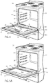
- Housing 12 includes a door assembly 18 having a closed position ( FIG. 1 ) and an open position ( FIG. 4 ) for allowing user ingress into internal compartment 20.
- Door assembly 18 may include a handle 24 and a window 26 for allowing viewing of internal compartment 20 from outside the internal compartment.
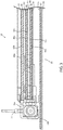
- Window 26 may include the electrically conductive portion in the form of at least one transparent conductive layer 61, 62, 63, 64, 65 ( FIG. 3 ).
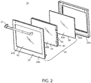
- Window 26 may include multiple spaced glass panes. As shown in FIGS. 2 and 3 , window 26 includes an interior glass substrate 40 having an interior surface 40a facing internal compartment 20 and an exterior surface 40b, and an exterior glass substrate 42 having an interior surface 42a facing exterior surface 40b of interior glass substrate 40 and an exterior surface 42b that may constitute the outermost surface of window 26. Window 26 may also include an insulated window pack 44 including a first glass sheet 46 and a second glass sheet 48. Insulated window pack 44 is disposed between interior glass substrate 40, and said exterior glass substrate 42 First glass sheet 46 is disposed between second glass sheet 48 and interior glass substrate 40. First glass sheet 46 has an interior surface 46a and an exterior surface 46b. Second glass sheet 48 has an interior surface 48a and an exterior surface 48b. As described further below, the at least one transparent conductive layer 61, 62, 63, 64, 65 is disposed on a surface of at least one of interior glass substrate 40, exterior glass substrate 42, first glass sheet 46 and second glass sheet 48.
- a metal skin 28 of door assembly 18 may be disposed around window 26 and have a front side 28a and an interior side 28b.
- Metal skin 28 may be made of various materials including stainless steel.
- the at least one transparent conductive layer may be any one of a plurality of such transparent conductive layers.
- Oven windows often include a number of transparent metal layers used for heat reflection. These layers may be made of tin oxide or silver oxide. Although these layers are not used for their electrical conductivity, the layers can, in fact, conduct electricity and therefore be used as a ground plane 34 for antenna 30.
- a first transparent conductive layer 61 may be provided on interior surface 40a of interior glass substrate 40.
- a second transparent conductive layer 62 may be provided on interior surface 46a of first glass sheet 46.
- a third transparent conductive layer 63 may be provided on exterior surface 46b of first glass sheet 46.
- a fourth transparent conductive layer 64 may be provided on interior surface 48a of second glass sheet 48.
- a fifth transparent conductive layer 65 may be provided on exterior surface 48b of second glass sheet 48. Any one or more of these layers can be used as the ground plane 34 of antenna 30.
- the particular transparent conductive layer used as the ground plane 34 may depend on the configuration and location of the active component 32 of antenna 30. Various possible implementations are described below.
- the at least one transparent conductive layer is first transparent conductive layer 61 disposed on interior surface 40a of interior glass substrate 40.
- first transparent conductive layer 61 serves as ground plane 34 of antenna 30.
- Active component 32 of antenna 30 includes a thin conductive substance (such as metallic ink, wire, etc.) printed on interior surface 40a of interior glass substrate 40.
- the printed thin conductive substance serving as active component 32 may extend along a perimeter of window 26 while being physically separated from ground plane 34 ( FIG. 3 ).
- the antenna would transmit and/or receive signals from within internal compartment 20.
- Multiple printed thin conductive tracings may be disposed about the perimeter of window 26 to form multiple antennas if desired.
- the antenna(s) may be monopole or dipole. Note that in FIG. 4 , active components 32 would be used in place of metal conductor 70 (described below).
- active component 32 may be printed on the interior surface 42a of exterior glass substrate 42 and the at least one transparent conductive layer is fifth transparent conductive layer 65 disposed on exterior surface 48b of second glass sheet 48 such that fifth transparent conductive layer 65 serves as ground plane 34.
- electrical connection to active component 32 and ground plane 34 of antenna 30 may be made using a coaxial cable 100 having a center pin 102 and a metal sheath 104 that is insulated from center pin 102 and surrounds the center pin.
- Metal sheath 104 may be electrically coupled to transparent conductive layer 61, 62, 63, 64, 65 (serving as ground plane 34) and center pin 102 may be electrically coupled to said active component 32.
- Coaxial cable 100 may be run through the hinge that connects door assembly 18 to appliance 10. Another technique for making the coaxial connection is described below with respect to FIGS. 5A and 5B .
- interior side 28a of metal skin 28 (which may be stainless steel) surrounding window 26 of door assembly 18 is electrically coupled to center pin 102 such that interior side 28a of metal skin 28 acts as active component 32 of antenna 30.
- the at least one transparent conductive layer 61, 62, 63, 64, 65 is first transparent conductive layer 61 disposed on interior surface 40a of interior glass substrate 40 such that first transparent conductive layer 61 serves as ground plane 34.
- the antenna 30 communicates with one or more devices within the internal compartment 20.
- the exterior side 28b of metal skin 28 may be used as the active component 32 while the at least one transparent conductive layer 61, 62, 63, 64, 65 is fifth transparent conductive layer 65 disposed on exterior surface 48b of second glass sheet 48 such that fifth transparent conductive layer 65 serves as ground plane 34.
- a physical antenna 30 may be mounted on door assembly 18. More specifically, a separate metal conductor 70 may be mounted on door assembly 18 to serve as active component 32 while at least one transparent layer 61, 62, 63, 64, 65 in window 26 is used as ground plane 34. For interior signal coverage, separate metal conductor 70 may be mounted on the inside door frame of door assembly 18 and the at least one transparent conductive layer 61, 62, 63, 64, 65 is first transparent conductive layer 61 disposed on interior surface 40a of interior glass substrate 40 such that first transparent conductive layer 61 serves as ground plane 34.
- separate metal conductor 70 may be mounted on the outside of door assembly 18 and the at least one transparent conductive layer 61, 62, 63, 64, 65 is fifth transparent conductive layer 65 disposed on exterior surface 48b of second glass sheet 48 such that fifth transparent conductive layer 65 serves as ground plane 34.
- One location for the mounting of separate metal conductor 70 on the outside of door assembly 18 is to provide metal conductor 70 in handle 24. Note that metal conductor 70 would be used in place of active components 32 shown in FIG. 4 .
- a patch antenna may be used for antenna 30.
- active component 32 may comprise one of the transparent conductive layers in window 26 while another one of the transparent conductive layers serves as ground plane 34 and air and/or glass is the dielectric layer between active component 32 and ground plane 34.
- the active component patch 32 may be the first transparent conductive layer 61 disposed on interior surface 40a of interior glass substrate 40 while ground plane 34 may be the first transparent conductive layer 61 disposed on interior surface 46a of first glass sheet 46 as shown in FIG. 3 .
- the active component patch 32 may be the fifth transparent conductive layer 65 disposed on exterior surface 48b of second glass sheet 48 while ground plane 34 may be the fourth transparent conductive layer 64 disposed on interior surface 48a of second glass sheet 48. It should be noted that the two patch antennas may be combined to provide coverage both inside and outside the appliance.
- connections to antenna 30 may be made directly (or indirectly) via coaxial cable 100.
- One way of indirectly coupling antenna 30 to coaxial cable 100 is shown in FIGS. 5A , 5B, and 6 where capacitive coupling is used such that coaxial cable 100 does not need to physically connect to door assembly 18. This provides the benefit that the door assembly 18 may be more easily detached from appliance 10. This can provide a significant advantage in appliances that require detachment of the door assembly due to installation of trim built into the appliance.
- a conductive plate 110 is electrically coupled to center pin 102 of coaxial cable 100.
- Housing 12 may further include a front door frame 29 and door assembly 18 may be detachably mounted to front door frame 29 and having a closed position and an open position for allowing user ingress into internal compartment 20.
- Conductive plate 110 is mounted to door frame 29 and is spaced apart but proximate to door assembly 18 when door assembly 18 is in the closed position such that conductive plate 110 is capacitively coupled to active component 32 of antenna 30 when door assembly 18 is in the closed position.
- the active component 32 is the interior side 28a of metal skin 28, the capacitive coupling may be directly between conductive plate 110 and metal skin 28.
- a second conductive plate may be mounted to the inside of the door assembly 18 opposite conductive plate 110 with the second conductive plate electrically connected to active component 32 via wires or other coaxial cable.
- the conductive plate 110 may be positioned to be opposite first transparent conductive layer 61 so as to be directly capacitively coupled thereto.
- the connection to ground plane 34 may also be made via the door hinge(s) 27, which may serve as a ground conductor.
- Providing multiple antennas 30 can help with signal strength and omnidirectionality inside of the internal compartment 20 or to allow communications both inside and outside the appliance.
- housing 12 may further include a light fixture 150 positioned on an interior wall 22 of internal compartment 20 for illuminating internal compartment 20.
- a light fixture 150 positioned on an interior wall 22 of internal compartment 20 for illuminating internal compartment 20.
- antenna 30 or as a location for an additional antenna to one disposed in door assembly 18, one could provide the antenna 30 in light fixture 150.
- active component 32 of antenna 30 may be disposed in light fixture 150. This location would serve primarily for communication with a device placed inside internal compartment 20. If communication was also desired outside the appliance, an antenna could be disposed elsewhere including the door assembly 18 as described above.
- Light fixture 150 may include the electrically conductive portion constituting ground plane 34 of antenna 30. Alternatively, a portion or all of interior wall 22 of housing 12 may include the electrically conductive portion constituting ground plane 34.
- Light fixture 150 includes an enclosure 152 having at least one metal wall 154, which may serve as ground plane 34.
- Light fixture 150 includes a transparent cover 156, which may be made of glass, through which light from a light source is transmitted into internal compartment 20.
- Active component 32 of antenna 30 may be disposed on either surface of transparent cover 156. As shown, the active component 32 may be a circular F antenna.
- Transparent cover 156 is preferably made of glass, which transmits light and does not inhibit radio waves.
- active component 32 is disposed on the surface of transparent cover 156 that faces internal compartment 20.
- a transparent conductive coating may be provided on the opposite surface of cover 156 to serve as ground plane 34.
- metal sheath 104 of coaxial cable 100 is coupled to the transparent conductive coating serving as ground plane 34 and center pin 102 is connected to active component 32, which may be in the form of a wire or printed conductive material.
- active component 32 is disposed on the surface of transparent cover 156 opposite the one that faces internal compartment 20.
- at least one metal wall 154 of enclosure 152 may serve as ground plane 34. Accordingly, metal sheath 104 of coaxial cable 100 is coupled to metal wall 154 and center pin 102 is connected directly to active component 32 through a hold in the back of enclosure 152 of light fixture 150.
- the active component 32 of the antenna 30 may be disposed in any other component within internal compartment 20 while a portion of housing 12 may be used as the ground plane 34.
- an antenna 30 may be integrated in an appliance in such as way that it does not impact the style or cleanability of the appliance and without raising any damage concerns. Moreover, antennas can be integrated so as to transmit and receive signals into and out of the internal compartment of the appliance. Further, antennas can be integrated into the appliance while using some of the existing structure as a ground plane and/or active component of the antenna and thereby reduce construction time and expense.
- the term "coupled” in all of its forms - couple, coupling, coupled, etc. generally means the joining of two components (electrical or mechanical) directly or indirectly to one another. Such joining may be stationary in nature or movable in nature. Such joining may be achieved with the two components (electrical or mechanical) and any additional intermediate members being integrally formed as a single unitary body with one another or with the two components. Such joining may be permanent in nature or may be removable or releasable in nature unless otherwise stated.
- elements shown as integrally formed may be constructed of multiple parts, elements shown as multiple parts may be integrally formed, the operation of the interfaces may be reversed or otherwise varied, the length or width of the structures and/or members or connector or other elements of the system may be varied, the nature or number of adjustment positions provided between the elements may be varied.
- the elements and/or assemblies of the system may be constructed from any of a wide variety of materials that provide sufficient strength or durability, in any of a wide variety of colors, and textures. Accordingly, all such modifications are intended to be included within the scope of the present innovations.
Landscapes
- Physics & Mathematics (AREA)
- Electromagnetism (AREA)
- Engineering & Computer Science (AREA)
- Chemical & Material Sciences (AREA)
- Combustion & Propulsion (AREA)
- Mechanical Engineering (AREA)
- General Engineering & Computer Science (AREA)
- Support Of Aerials (AREA)
- Details Of Aerials (AREA)
Claims (10)
- Kochgerät (10), umfassend:- ein Gehäuse (12), das einen Innenraum (20) einschließt, wobei zumindest ein Abschnitt des Gehäuses (12) einen elektrisch leitfähigen Abschnitt umfasst; und- eine Antenne (30) für zumindest eines aus einem Empfangen von Hochfrequenzsignalen und einem Übertragen von Hochfrequenzsignalen, wobei die Antenne (30) eine aktive Komponente (32) und eine Verbindung mit dem elektrisch leitfähigen Abschnitt, derart, dass der elektrisch leitfähige Abschnitt als eine Masseplatte (34) der Antenne (30) dient, umfasst,- wobei das Gehäuse (12) weiter eine Türanordnung (18) umfasst, die eine geschlossene Position und eine offene Position, um einem Benutzer einen Zugang zu dem Innenraum (20) zu ermöglichen, aufweist, wobei die Türanordnung (18) ein Fenster (26) einschließt, um eine Betrachtung des Innenraums (20) von außerhalb des Innenraums (20) zu ermöglichen,- dadurch gekennzeichnet, dass das Fenster (26) den elektrisch leitfähigen Abschnitt in der Form zumindest einer transparenten leitfähigen Schicht (61, 62, 63, 64, 65) einschließt.
- Kochgerät (10) nach Anspruch 1 und weiter umfassend:- ein Koaxialkabel (100) das einen Mittelstift (102) und eine den Mittelstift (102) umgebende Metallhülse (104) aufweist; und- eine leitfähige Platte (110), die elektrisch mit dem Mittelstift (102) gekoppelt ist;- wobei das Gehäuse (12) weiter einen Türrahmen (29) und eine Türanordnung (18), die lösbar an dem Türrahmen (29) befestigt ist und eine geschlossene Position und eine offene Position, um einem Benutzer einen Zugang zu dem Innenraum (20) zu ermöglichen, aufweist, umfasst,- wobei die aktive Komponente (32) der Antenne (30) an der Türanordnung (18) angeordnet ist, und- wobei die leitfähige Platte (110) an dem Türrahmen (29) befestigt ist und von der Türanordnung (18) beabstandet jedoch dieser nahegelegen ist, wenn sich die Türanordnung (18) in der geschlossenen Position befindet, derart, dass die leitfähige Platte (110) kapazitiv mit der aktiven Komponente (32) der Antenne (30) gekoppelt ist, wenn sich die Türanordnung (18) in der geschlossenen Position befindet.
- Kochgerät (10) nach Anspruch 2, wobei die Türanordnung (18) eine Metallhaut (28) einschließt, die kapazitiv mit der leitfähigen Platte (110) gekoppelt ist, wenn sich die Türanordnung (18) in der geschlossenen Position befindet, und wobei die Metallhaut (28) als eine aktive Komponente (32) der Antenne (30) dient.
- Kochgerät (10) nach Anspruch 2, wobei die Türanordnung (18) ein Fenster (26) einschließt, um eine Betrachtung des Innenraums (20) von außerhalb des Innenraums (20) zu ermöglichen, wobei das Fenster (26) ein Glassubstrat (40, 46, 48) einschließt, das eine Innenfläche (40a, 46a, 48a) aufweist, wobei die Antenne (30) eine Patchantenne ist und die aktive Komponente (32) der Antenne (30) eine transparente metallische Schicht (61, 62, 64) umfasst, die auf der Innenfläche (40a, 46a, 48a) des Glassubstrats (40, 46, 48) angeordnet ist, und wobei die transparente metallische Schicht (61, 62, 64) kapazitiv mit der leitfähigen Platte (110) gekoppelt ist, wenn sich die Türanordnung (18) in der geschlossenen Position befindet.
- Kochgerät (10) nach einem der Ansprüche 1 bis 4, wobei die zumindest eine transparente leitfähige Schicht (61, 62, 63, 64, 65) eine Schicht aus Zinnoxid ist.
- Kochgerät (10) nach einem der Ansprüche 1 bis 5, wobei das Fenster (26) umfasst:- ein inneres Glassubstrat (40), das eine zu dem Innenraum (20) gewandte Innenfläche (40a) und eine Außenfläche (40b) aufweist;- ein äußeres Glassubstrat (42), das eine Innenfläche (42a) aufweist, die zu der Außenfläche (40b) des inneren Glassubstrats (40) gewandt ist, und eine Außenfläche (42b) aufweist; und- ein eine erste Glasscheibe (46) und eine zweite Glasscheibe (48) umfassendes isoliertes Fensterpaket, das zwischen dem inneren Glassubstrat (40) und dem äußeren Glassubstrat (42) angeordnet ist, wobei die erste Glasscheibe (46) zwischen der zweiten Glasscheibe (48) und dem inneren Glassubstrat (40) angeordnet ist, wobei die erste Glasscheibe (46) eine Innenfläche (46a) und eine Außenfläche (46b) aufweist, wobei die zweite Glasscheibe (48) eine Innenfläche (48a) und eine Außenfläche (48b) aufweist,- wobei die zumindest eine transparente leitfähige Schicht (61, 62, 63, 64, 65) auf einer Oberfläche eines des inneren Glassubstrats (40), des äußeren Glassubstrats (42), der ersten Glasscheibe (46) und der zweiten Glasscheibe (48) angeordnet ist.
- Kochgerät (10) nach einem der Ansprüche 4 bis 6 und weiter umfassend ein Koaxialkabel (100), das einen Mittelstift (102) und eine den Mittelstift (102) umgebende Metallhülse (104) zum elektrischen Koppeln mit der Antenne (30) aufweist, wobei die Metallhülse (104) elektrisch mit der zumindest einen transparenten leitfähigen Schicht (61, 62, 63, 64, 65) gekoppelt ist, die Türanordnung (18) eine Metallhaut (28) einschließt, die das Fenster (26) auf der Türanordnung (18) umgibt, und wobei der Mittelstift (102) derart mit der Metallhaut (28) verbunden ist, dass die Metallhaut (28) als die aktive Komponente (32) der Antenne (30) fungiert.
- Kochgerät (10) nach einem der Ansprüche 1, 2, 5 und 6, wobei die aktive Komponente (32) der Antenne (30) einen separaten Metallleiter (70) umfasst, der an der Türanordnung (18) befestigt ist.
- Kochgerät (10) nach einem der Ansprüche 1, 2, 5 und 6, wobei die aktive Komponente (32) der Antenne (30) eine dünne leitfähige Substanz umfasst, die auf eines der Innenfläche (42a) des äußeren Glassubstrats (42) und der Innenfläche (40a) des inneren Glassubstrats (40) gedruckt ist.
- Kochgerät (10) nach einem der vorstehenden Ansprüche, wobei das Kochgerät (10) ein Herd oder Backofen ist.
Applications Claiming Priority (1)
| Application Number | Priority Date | Filing Date | Title |
|---|---|---|---|
| US14/982,137 US11777190B2 (en) | 2015-12-29 | 2015-12-29 | Appliance including an antenna using a portion of appliance as a ground plane |
Publications (2)
| Publication Number | Publication Date |
|---|---|
| EP3188571A1 EP3188571A1 (de) | 2017-07-05 |
| EP3188571B1 true EP3188571B1 (de) | 2020-03-25 |
Family
ID=57838127
Family Applications (1)
| Application Number | Title | Priority Date | Filing Date |
|---|---|---|---|
| EP16204551.2A Active EP3188571B1 (de) | 2015-12-29 | 2016-12-15 | Gerät mit einer antenne mit verwendung eines teils eines geräts als massefläche |
Country Status (2)
| Country | Link |
|---|---|
| US (1) | US11777190B2 (de) |
| EP (1) | EP3188571B1 (de) |
Cited By (1)
| Publication number | Priority date | Publication date | Assignee | Title |
|---|---|---|---|---|
| DE102023201293A1 (de) | 2023-02-15 | 2024-08-22 | BSH Hausgeräte GmbH | Gargerät mit außerhalb des Garraums angeordneter Antenne |
Families Citing this family (8)
| Publication number | Priority date | Publication date | Assignee | Title |
|---|---|---|---|---|
| KR102462854B1 (ko) * | 2016-03-11 | 2022-11-03 | 디우스 컴퓨팅 피티와이 엘티디 | 에너지 소비 및 발생을 측정하기 위한 시스템, 방법 및 디바이스 |
| USD1009590S1 (en) * | 2016-12-13 | 2024-01-02 | Whirlpool Corporation | Appliance door handle |
| AU2017422539B2 (en) | 2017-07-05 | 2024-01-04 | Electrolux Appliances Aktiebolag | Household appliance |
| US10641498B2 (en) * | 2018-01-08 | 2020-05-05 | Haier Us Appliance Solutions, Inc. | Antenna device for a wireless probe system of an oven appliance |
| IT201800003661A1 (it) * | 2018-03-16 | 2019-09-16 | Italcoppie Sensori S R L | Sistema per la rilevazione di un valore di temperatura all’interno di almeno un alimento in un apparecchio di trattamento termico |
| USD901276S1 (en) | 2018-03-21 | 2020-11-10 | Whirlpool Corporation | Appliance door handle |
| US11083360B2 (en) | 2019-04-26 | 2021-08-10 | Whirlpool Corporation | Appliance with light guide |
| CN110398294A (zh) * | 2019-08-07 | 2019-11-01 | 深圳市海博思科技有限公司 | 一种烧烤温度检测系统及传输终端 |
Family Cites Families (362)
| Publication number | Priority date | Publication date | Assignee | Title |
|---|---|---|---|---|
| US1141176A (en) | 1914-01-23 | 1915-06-01 | Copeman Electric Stove Company | Electrically-heated oven. |
| US1380656A (en) | 1920-06-16 | 1921-06-07 | Lauth Clarence Harold | Electric oven for cooking purposes |
| US1405624A (en) | 1920-10-05 | 1922-02-07 | Ralph J Patterson | Electrically-heated fireless cooker |
| US1598996A (en) | 1925-09-05 | 1926-09-07 | Frank H Wheelock | Gas burner |
| US1808550A (en) | 1930-04-18 | 1931-06-02 | Charles A Harpman | Heat distributor for cook stoves |
| US2024510A (en) | 1933-11-08 | 1935-12-17 | Crisenberry Ruth | Gas burner |
| US2530991A (en) | 1944-09-28 | 1950-11-21 | Florence Stove Co | Gas cookstove burner grate |
| US2536613A (en) | 1947-08-15 | 1951-01-02 | Hotpoint Inc | Oven heating unit |
| NL95825C (de) | 1950-11-17 | |||
| US2791366A (en) | 1951-09-20 | 1957-05-07 | Wilhro Corp | Packing case |
| US2777407A (en) | 1951-10-02 | 1957-01-15 | Babcock & Wilcox Co | Fuel burning apparatus |
| US2781038A (en) | 1953-04-10 | 1957-02-12 | Carroll J Sherman | Cooking burner control and thermostat |
| US2699912A (en) | 1953-10-06 | 1955-01-18 | Walton W Cushman | Knockdown pallet |
| US2815018A (en) | 1954-09-07 | 1957-12-03 | Collins Douglas | Oven door |
| US2847932A (en) | 1955-12-28 | 1958-08-19 | Gen Electric | Rotisserie rack |
| US2930194A (en) | 1956-11-19 | 1960-03-29 | Bendix Aviat Corp | Combustor having high turbulent mixing for turbine-type starter |
| US3065342A (en) | 1958-02-12 | 1962-11-20 | Hall C M Lamp Co | Resilient lamp mounting |
| US2934957A (en) | 1958-11-12 | 1960-05-03 | Micro Controls Inc | Temperature-sensitive heat control unit |
| US3017924A (en) | 1958-12-24 | 1962-01-23 | Preway Inc | Pot type burner apparatus |
| US3051813A (en) | 1960-08-24 | 1962-08-28 | Gen Electric | Temperature control systems |
| US3089407A (en) | 1961-09-21 | 1963-05-14 | Gen Electric | Temperature sensor for roasting oven |
| US3259120A (en) | 1964-04-29 | 1966-07-05 | Richard T Keating | Pie-baking facility |
| US3386431A (en) | 1966-08-09 | 1968-06-04 | Robertshaw Controls Co | Burner construction and method and apparatus for making the same and the like |
| US3463138A (en) | 1968-04-29 | 1969-08-26 | South Bend Range Corp | Convection oven |
| US3489135A (en) | 1968-06-21 | 1970-01-13 | Indian Head Inc | Oven door construction |
| SE331525B (de) | 1968-12-03 | 1971-01-04 | Ankarsrums Bruk Ab | |
| US3602131A (en) | 1969-04-15 | 1971-08-31 | Kelvinator Inc | Pendant cover for rotisserie spit hole |
| US3645249A (en) | 1970-05-05 | 1972-02-29 | Gen Electric | Gas cooktop with integral burners |
| US3780954A (en) | 1970-05-15 | 1973-12-25 | Robertshaw Controls Co | Burner construction |
| US3651300A (en) * | 1971-01-25 | 1972-03-21 | Matsushita Electric Industrial Co Ltd | Microwave heating apparatus with radiation control and monitoring |
| US3691937A (en) | 1971-02-04 | 1972-09-19 | Gen Electric | Combined broiler pan and broil rack |
| US3777985A (en) | 1971-05-17 | 1973-12-11 | Vaskor Ind Inc | Water heater |
| US3731035A (en) | 1971-11-15 | 1973-05-01 | Litton Systems Inc | Microwave oven door |
| US3857254A (en) | 1971-12-15 | 1974-12-31 | S Lobel | Meat treating appliance |
| US3749875A (en) * | 1972-08-07 | 1973-07-31 | Gen Electric | Microwave oven leakage detection system |
| US3877865A (en) | 1972-11-16 | 1975-04-15 | Lincoln Brass Works | Gas burner and aeration pan assembly |
| US3899655A (en) | 1974-01-09 | 1975-08-12 | Electro Therm | Oven, heating element and socket assembly |
| USD245663S (en) | 1975-06-23 | 1977-09-06 | Consumer Products Industries | Burner heat distributor |
| US4104952A (en) | 1976-02-23 | 1978-08-08 | General Mills Fun Group, Inc. | Toy construction system having reusable distensible joining members |
| DE2610937C3 (de) | 1976-03-16 | 1978-11-30 | Licentia Patent-Verwaltungs-Gmbh, 6000 Frankfurt | Back- und Bratrohr mit einer in horizontaler Ebene verschiebbaren Tür |
| DE2845869A1 (de) | 1978-10-21 | 1980-04-30 | Miele & Cie | Luftfuehrungssystem fuer einen herd |
| DE3009961C2 (de) | 1980-03-14 | 1982-10-28 | Schott Glaswerke, 6500 Mainz | Glaskeramik-Kochfeldeinheit zum Einbau in eine Arbeitsplatte |
| DE3014908A1 (de) | 1980-04-18 | 1981-10-22 | Miele & Cie GmbH & Co, 4830 Gütersloh | Luftfuehrungssystem fuer einen herd |
| DE3049521A1 (de) | 1980-12-30 | 1982-07-29 | Karl 7519 Oberderdingen Fischer | Elektrischer heizkoerper |
| US4413610A (en) | 1981-05-04 | 1983-11-08 | Raytheon Company | Ventilated gas range with modular cooking units |
| US4466789A (en) | 1981-11-04 | 1984-08-21 | Robertshaw Controls Company | Igniter/flame sensor assembly for gas burner |
| US4418456A (en) | 1981-11-04 | 1983-12-06 | Robertshaw Controls Company | Tubular burner construction and method of making the same |
| DE3150450A1 (de) | 1981-12-19 | 1983-06-30 | Licentia Patent-Verwaltungs-Gmbh, 6000 Frankfurt | Einbaukochfeld od.-spuele fuer einbaukuechenmoebel |
| DE3238441A1 (de) | 1982-10-16 | 1984-04-19 | Licentia Patent-Verwaltungs-Gmbh, 6000 Frankfurt | Back- und bratofen |
| DE8308713U1 (de) | 1983-03-24 | 1983-07-14 | Buderus Ag, 6330 Wetzlar | Wrasenabzugseinrichtung fuer einen backofen |
| FR2545196B1 (fr) | 1983-04-29 | 1985-08-16 | Gaz De France | Bruleur pour combustibles gazeux a systemes d'allumage et de securite incorpores |
| IT1178820B (it) | 1984-01-16 | 1987-09-16 | Indesit | Gruppo sensore di un sistema di controllo automatico della temperatura raggiunta da alimenti in recipienti riscaldati da fiamma ottenuta da un bruciatore di gas |
| FR2559241B1 (fr) | 1984-02-06 | 1986-12-12 | Dietrich Sa | Perfectionnement permettant la mise et le maintien en depression du moufle d'un four electrodomestique a reacteur catalytique |
| EP0153842B1 (de) | 1984-02-29 | 1988-07-27 | LUCAS INDUSTRIES public limited company | Brennkammer für Gasturbinen |
| DE8413224U1 (de) | 1984-04-30 | 1984-08-16 | Licentia Patent-Verwaltungs-Gmbh, 6000 Frankfurt | Tuer fuer den back- und bratraum eines bratofens |
| US4555606A (en) * | 1984-07-19 | 1985-11-26 | Raytheon Company | Air flow system for common cavity oven |
| US4556771A (en) * | 1984-07-19 | 1985-12-03 | Raytheon Company | Microwave feed for common cavity oven |
| DE3446621C2 (de) | 1984-12-20 | 1987-01-08 | Bosch-Siemens Hausgeräte GmbH, 7000 Stuttgart | Küchen-Arbeitsplatte mit Einsatzelement |
| US4587946A (en) | 1985-02-01 | 1986-05-13 | Jacques Doyon | Mobile baking oven and proofer |
| DE3717728A1 (de) | 1987-05-26 | 1988-12-08 | Kueppersbusch | Kochplatte mit einer glaskeramikplatte |
| US4818824A (en) | 1987-08-19 | 1989-04-04 | American Telephone And Telegraph Company, At&T Bell Laboratories | Closure for aerial telephone cable splices |
| EP0308110B1 (de) | 1987-09-16 | 1990-11-22 | Parkinson Cowan Limited | Gasbrenner |
| US4891936A (en) | 1987-12-28 | 1990-01-09 | Sundstrand Corporation | Turbine combustor with tangential fuel injection and bender jets |
| US4812624A (en) | 1987-12-28 | 1989-03-14 | General Electric Company | Temperature sensor assembly for an automatic surface unit |
| USD309398S (en) | 1988-01-21 | 1990-07-24 | Harper-Wyman Company | Cap for a gas burner |
| US4846671A (en) | 1988-03-09 | 1989-07-11 | Harper-Wyman Company | Integral spark ignited gas burner assembly |
| DE3839657C2 (de) | 1988-11-24 | 1993-11-18 | Miele & Cie | Luftführungssystem für einen Backofen |
| US4989404A (en) | 1988-12-12 | 1991-02-05 | Sundstrand Corporation | Turbine engine with high efficiency fuel atomization |
| US4981416A (en) | 1989-01-31 | 1991-01-01 | Bakers Pride Oven Co. Inc. | Enhanced air-flow blower wheel |
| IT1243760B (it) | 1989-11-17 | 1994-06-23 | Eurodomestici Ind Riunite | Dispositivo atto a rilevare la presenza in un contenitore di cottura per alimento posto su un piano di cottura, ad esempio in vetro ceramica. |
| FR2656786B1 (fr) | 1990-01-10 | 1995-05-12 | Moulinex Sa | Four electrique combine micro-ondes et resistance chauffante. |
| DE4002322A1 (de) | 1990-01-26 | 1991-08-01 | Bosch Siemens Hausgeraete | Kochfeld |
| AU7255791A (en) | 1990-02-20 | 1991-09-18 | Robertshaw Controls Company | Control system for an appliance or the like, control device therefor and methods of making the same |
| US5021762A (en) | 1990-08-03 | 1991-06-04 | Robertshaw Controls Company, Inc. | Thermal cycling switch |
| USD332385S (en) | 1990-09-14 | 1993-01-12 | Adams John S | Handle for a fireplace tool |
| FR2667477A1 (fr) | 1990-09-28 | 1992-04-03 | Philips Electronique Lab | Table chauffante a commandes automatiques. |
| DE4103664C2 (de) | 1991-02-07 | 1994-04-14 | Blanco Gmbh & Co Kg | Einbauvorrichtung für ein Glaskeramik-Kochfeld |
| USD340383S (en) | 1991-08-29 | 1993-10-19 | Addison F Clark | Heat reduction volume compensator with curled fins for disposition between a coffee pot and hot plate |
| USD342865S (en) | 1991-08-29 | 1994-01-04 | Addison F Clark | Heat reduction volume compensator for disposition between a coffee pot and hot plate |
| US5272317A (en) | 1992-02-01 | 1993-12-21 | Samsung Electronics Co., Ltd. | Food support shelf comprising metal grill with heater |
| DE4203668A1 (de) | 1992-02-08 | 1993-08-12 | Elektro Gas Armaturen | Gasbrenner |
| US5215074A (en) | 1992-05-29 | 1993-06-01 | General Electric Company | Lift-up cooktop locator with combined function as support rod race |
| US5316423A (en) | 1992-12-11 | 1994-05-31 | Kin Daniel C C | Acoustic isolation fastener and method for attachment |
| IT1272028B (it) | 1993-03-15 | 1997-06-10 | Whirlpool Italia | Dispositivo per rilevare la presenza di un contenitore per alimenti, quale una pentola, una pirofila o similare, su un piano di cottura in vetroceramica. |
| EP0620698A1 (de) | 1993-04-13 | 1994-10-19 | Whirlpool Europe B.V. | Vorrichtung zur Anwesenheitserkennung eines Nahrungsmittelbehälters, wie einer Kochtopf oder ähnliches, auf einer Glaskeramik-Kochmulde |
| FR2705765B1 (fr) | 1993-04-29 | 1995-08-18 | Eurofours Sa | Porte de four. |
| USD364993S (en) | 1993-10-04 | 1995-12-12 | Andrea George G | Burner pot supporter |
| US5397234A (en) | 1993-11-15 | 1995-03-14 | Harper-Wyman Company | Gas stove top burner assembly |
| USD369517S (en) | 1994-01-24 | 1996-05-07 | Lincoln Brass Works, Inc. | Sealed gas burner |
| USD378578S (en) | 1994-02-25 | 1997-03-25 | Indala Corporation | Identification transponder tag |
| AU703526B2 (en) | 1994-05-10 | 1999-03-25 | Peris Wyn Thomas | Cooking appliance |
| ES2170110T3 (es) | 1994-06-27 | 2002-08-01 | Bsh Bosch Siemens Hausgeraete | Unidad de coccion de control por infrarrojos. |
| US5571434A (en) | 1994-06-29 | 1996-11-05 | Whirlpool Corporation | Cooktop stamping having means for attaching heating elements and an integral trim ring |
| DE4431619A1 (de) | 1994-09-05 | 1996-03-07 | Bosch Siemens Hausgeraete | Herdtür eines Kochherdes |
| US5967021A (en) | 1994-11-29 | 1999-10-19 | Yung; Simon K. C. | Food appliance and a coding system therefor |
| DE4445594C2 (de) | 1994-12-20 | 2000-12-14 | Miele & Cie | Back- und Bratofen mit einem Luftkanal |
| FR2732097B1 (fr) | 1995-03-24 | 1997-05-23 | Seb Sa | Porte de four simplifiee avec module amovible |
| KR100212856B1 (ko) * | 1996-02-23 | 1999-08-02 | 윤종용 | 전자렌지의 고주파누설 차단장치 |
| WO1998015780A1 (fr) | 1996-10-09 | 1998-04-16 | Sourdillon | Appareil de cuisson, bruleur a gaz pour cet appareil et procede pour monter un tel bruleur sur un tel appareil |
| JP3711182B2 (ja) | 1997-01-20 | 2005-10-26 | 株式会社ハーマンプロ | コンロ用ガスバーナ |
| DE59710046D1 (de) | 1997-03-20 | 2003-06-12 | Alstom Switzerland Ltd | Gasturbine mit toroidaler Brennkammer |
| IL120772A0 (en) | 1997-05-04 | 1997-09-30 | White Jason | Gas-saving arrangements for gas ranges |
| US5913675A (en) | 1997-06-09 | 1999-06-22 | State Industries, Inc. | Low NOx gas burner |
| US6078243A (en) | 1997-06-12 | 2000-06-20 | Barnes; Gregory | Adaptive appliance control module including switching relay |
| US5785047A (en) | 1997-07-09 | 1998-07-28 | Gemtrom Corporation | Cooktop or hob top including a planar panel interlocked to an outboard frame by an injection molded encapsulation having injection molded encapsulation having integral fasteners |
| US5842849A (en) | 1997-09-05 | 1998-12-01 | Huang; Hsu-Sheng | Gas burner |
| DE69712060T2 (de) | 1997-10-08 | 2002-09-26 | Sabaf S.P.A., Lumezzane | Gasbrenner für Haushaltsgeräte |
| USD414377S (en) | 1997-10-20 | 1999-09-28 | Thermador Corporation | Stove burner |
| DE19746845C1 (de) | 1997-10-23 | 1998-12-03 | Schott Glas | Anordnung eines keramischen Heizelementes als Kochzone in einer Aussparung einer Fläche |
| DE19746844C1 (de) | 1997-10-23 | 1998-12-03 | Schott Glas | Anordnung eines keramischen Heizelementes als Kochzone in einer Aussparung einer Kochfläche |
| US6469286B1 (en) * | 1997-11-13 | 2002-10-22 | Matsushita Electric Industrial Co., Ltd. | Variable-impedance unit, microwave device using the unit, and microwave heater |
| ATE244380T1 (de) | 1997-11-21 | 2003-07-15 | Alstom | Brenner für den betrieb eines wärmeerzeugers |
| US6133816A (en) | 1998-06-12 | 2000-10-17 | Robertshaw Controls Corp. | Switch and relay using shape memory alloy |
| DE19828640A1 (de) | 1998-06-26 | 1999-12-30 | Bsh Bosch Siemens Hausgeraete | Backofen mit eigenbeheiztem Gargutträger |
| FR2787556B1 (fr) | 1998-12-18 | 2001-05-11 | Cepem | Table de cuisson comportant un moyen de visualisation de la liaison entre un foyer et le moyen de commande qui lui est associe |
| FR2789753B1 (fr) | 1999-02-15 | 2001-05-18 | Seb Sa | Sous-ensemble de chauffe amovible pour four electromenager |
| US6253761B1 (en) | 1999-03-05 | 2001-07-03 | Timothy Edward Shuler | Sensing device for stoves |
| DE19912452B4 (de) | 1999-03-19 | 2007-10-25 | BSH Bosch und Siemens Hausgeräte GmbH | Einbauleiste für ein Kochfeld |
| US6253759B1 (en) | 1999-08-13 | 2001-07-03 | Sunbeam Products, Inc. | Side burner for a grill |
| DE10010226A1 (de) * | 1999-08-31 | 2001-03-01 | Lindenmeier Heinz | Antenne auf dem Fenster eines Kraftfahrzeugs |
| US6320169B1 (en) | 1999-09-07 | 2001-11-20 | Thermal Solutions, Inc. | Method and apparatus for magnetic induction heating using radio frequency identification of object to be heated |
| JP2001141244A (ja) | 1999-11-10 | 2001-05-25 | Osaka Gas Co Ltd | コンロ |
| FR2800846B1 (fr) | 1999-11-10 | 2002-01-25 | Brandt Cooking | Bruleur a gaz pour table de cuisson domestique |
| US6188045B1 (en) | 2000-04-03 | 2001-02-13 | Alto-Shaam, Inc. | Combination oven with three-stage water atomizer |
| US6322354B1 (en) | 2000-07-17 | 2001-11-27 | Wolf Appliance Company, Llc | Stacked dual gas burner |
| FR2814795B1 (fr) | 2000-10-03 | 2005-10-21 | Sourdillon Sa | Bruleur a gaz et appareil de cuisson utilisant un tel bruleur |
| ES2255935T3 (es) | 2000-10-26 | 2006-07-16 | Whirlpool Corporation | Horno de cocina. |
| IT1319292B1 (it) | 2000-11-08 | 2003-10-10 | Whirlpool Co | Dispositivo per rilevare la collocazione di utensili di cottura su unpiano di cottura ad elementi riscaldanti discreti e distribuiti. |
| FR2817354B1 (fr) | 2000-11-27 | 2003-01-24 | Jouan Sa | Ensemble comportant une enceinte et un systeme de communication par ondes radiofrequences avec des objets places dans l'enceinte |
| US6452136B1 (en) | 2000-12-13 | 2002-09-17 | General Electric Company | Monitoring and control system and method for sensing of a vessel and other properties of a cooktop |
| DE10062827A1 (de) | 2000-12-15 | 2002-06-20 | Miele & Cie | Backofen mit Wrasenkanal |
| US6362458B1 (en) | 2001-01-30 | 2002-03-26 | Maytag Corporation | Food grilling system for oven cavity with byproduct removal |
| CA2369527C (en) | 2001-01-31 | 2005-01-04 | Robertshaw Controls Company | Switching system for plural simmer voltages |
| US6806444B2 (en) | 2001-02-21 | 2004-10-19 | William S. Lerner | Heat warning safety device using fiber optic cables |
| EP1258683B1 (de) | 2001-05-14 | 2006-07-19 | Whirlpool Corporation | Gasherd |
| US20020190057A1 (en) | 2001-06-19 | 2002-12-19 | Bsh Home Appliances Corporation | Cooktop control |
| US6452141B1 (en) | 2001-06-30 | 2002-09-17 | Samsung Electronics Co., Ltd. | Microwave oven with magnetic field detecting device |
| US6589046B2 (en) | 2001-08-21 | 2003-07-08 | Uwe Harneit | Gas burner for outdoor cooking |
| US7186955B2 (en) | 2001-10-09 | 2007-03-06 | Electrolux Home Products, Inc. | Electronic power control for cooktop heaters |
| US6718965B2 (en) | 2002-01-29 | 2004-04-13 | Dynamic Cooking Systems, Inc. | Gas “true” convection bake oven |
| JP3640932B2 (ja) * | 2002-02-06 | 2005-04-20 | 株式会社東芝 | 電子レンジ |
| DK1340945T4 (da) | 2002-03-01 | 2010-01-25 | Eloma Gmbh Innovative Koch Und | Apparat til behandling og tilberedning af fødevarer med gasfyret opvarmning samt varmeudveksleranordning til et sådant apparat |
| FR2837067A1 (fr) | 2002-03-12 | 2003-09-19 | Eurofours Sa | Four ventile |
| JP3691447B2 (ja) | 2002-03-20 | 2005-09-07 | リンナイ株式会社 | バーナ |
| JP3691448B2 (ja) | 2002-03-22 | 2005-09-07 | リンナイ株式会社 | バーナ |
| DE10218294B4 (de) | 2002-04-24 | 2021-12-09 | BSH Hausgeräte GmbH | Vorrichtung zur Steuerung von elektrisch ansteuerbaren Geräten, insbesondere von elektrischen Haushaltsgeräten |
| US6619280B1 (en) | 2002-05-30 | 2003-09-16 | Dongsheng Zhou | Converging flame burner |
| US20040031782A1 (en) | 2002-08-15 | 2004-02-19 | Barbara Westfield | Multi-door single chamber oven apparatus |
| KR100514908B1 (ko) | 2002-09-02 | 2005-09-14 | 삼성전자주식회사 | 히터를 구비한 조리 기구 |
| US6837151B2 (en) | 2002-10-23 | 2005-01-04 | Shane Chen | Convertible rotisserie/kebab cooking device |
| FR2848642B1 (fr) | 2002-12-17 | 2005-08-05 | Service Nat Dit Gaz De France | Bruleur a gaz a flamme interne, de compacite elevee |
| ES2223258B1 (es) | 2002-12-20 | 2006-04-16 | Bsh Electrodomesticos España, S.A. | Cocina de induccion. |
| US6733146B1 (en) | 2003-01-10 | 2004-05-11 | Pat J. Vastano | Illuminated knob for indicating the operative condition of an appliance |
| DE10307217B4 (de) * | 2003-02-20 | 2006-04-13 | Schott Ag | Tür mit Sichtfenster für Mikrowellengeräte |
| US6729323B1 (en) | 2003-03-06 | 2004-05-04 | General Electric Company | Air-inlet assembly for a gas cooking appliance |
| KR100526206B1 (ko) | 2003-03-21 | 2005-11-08 | 삼성전자주식회사 | 조리장치 |
| US7829825B2 (en) | 2003-05-23 | 2010-11-09 | Koninklijke Fabriek Inventum B.V. | Oven and its combination with a steam module |
| US7017572B2 (en) | 2003-05-27 | 2006-03-28 | General Electric Company | Method and apparatus for gas ranges |
| JP4115343B2 (ja) | 2003-06-16 | 2008-07-09 | リンナイ株式会社 | コンロ |
| ITMI20031602A1 (it) | 2003-08-04 | 2005-02-05 | Whirlpool Co | Piano di cottura a piazzamento casuale con interfaccia utente |
| DK1512909T3 (da) | 2003-09-05 | 2009-03-09 | Electrolux Home Prod Corp | Gasbrænder |
| US6910342B2 (en) | 2003-10-14 | 2005-06-28 | Robertshaw Controls Company | High temperature limit thermostat with manual lockout safety |
| US7527495B2 (en) | 2003-10-21 | 2009-05-05 | Burner Systems International, Inc. | Cooperating bridge burner system |
| DE102004002466A1 (de) | 2004-01-16 | 2005-08-11 | BSH Bosch und Siemens Hausgeräte GmbH | Haushaltsgerätetür mit einer Vorrichtung mit einer Scharniereinheit |
| CA2557647A1 (en) | 2004-03-02 | 2005-09-15 | M-Management-Tex, Ltd. | Cooktop gasket |
| JP4064936B2 (ja) | 2004-03-11 | 2008-03-19 | リンナイ株式会社 | ガスコンロ |
| EP1586822A1 (de) | 2004-04-14 | 2005-10-19 | CANDY S.p.A. | Kochfläche zum Garen von Lebensmitteln |
| US20050268000A1 (en) | 2004-05-28 | 2005-12-01 | Carlson Mark J | Accessory identifier in an electronic device |
| US20050268794A1 (en) | 2004-06-07 | 2005-12-08 | Yuriy Nesterov | Spool rotisserie system |
| US7291009B2 (en) | 2004-09-08 | 2007-11-06 | General Electric Company | Dual stacked gas burner and a venturi for improving burner operation |
| DE102004052202A1 (de) | 2004-10-20 | 2006-05-04 | E.G.O. Elektro-Gerätebau GmbH | Halter für einen Bauteilträger |
| MY144257A (en) | 2004-10-28 | 2011-08-29 | Electrolux Ab | Improved cooking gas burner |
| KR20080104080A (ko) * | 2004-11-02 | 2008-11-28 | 파나소닉 주식회사 | 가열 장치 |
| WO2006051631A1 (ja) | 2004-11-15 | 2006-05-18 | Paloma Industries, Limited | ガスコンロ |
| KR20060060343A (ko) | 2004-11-30 | 2006-06-05 | 삼성전자주식회사 | 알에프아이디태그의 인식율을 높인 냉장고 |
| US20060157482A1 (en) * | 2004-12-13 | 2006-07-20 | Markus Lingenheil | Cooking appliance with a microwave generator device |
| JP2006183885A (ja) * | 2004-12-27 | 2006-07-13 | Fujikura Ltd | 加熱調理器 |
| USD524105S1 (en) | 2004-12-28 | 2006-07-04 | Gianni Poltronieri | Flame distributor assembly for the cooking surface of a gas stove |
| DE102005001857A1 (de) | 2005-01-07 | 2006-07-20 | E.G.O. Elektro-Gerätebau GmbH | Kochfeld mit Beleuchtung und Verfahren zur Beleuchtung eines Kochfeldes |
| ES2530675T3 (es) | 2005-02-17 | 2015-03-04 | Electrolux Home Prod Corp | Quemador de gas |
| DE102005018015B3 (de) * | 2005-04-18 | 2006-04-27 | Miele & Cie. Kg | Haushaltsgerät, insbesondere Gargerät, mit einer Messeinrichtung zur Messung einer physikalischen Größe |
| US7411160B2 (en) | 2005-06-01 | 2008-08-12 | Whirlpool Corporation | Airflow system for a convection oven |
| DE102005030555A1 (de) | 2005-06-22 | 2007-01-04 | E.G.O. Elektro-Gerätebau GmbH | Sensoreinrichtung für eine Heizeinrichtung |
| US8312873B2 (en) | 2005-08-01 | 2012-11-20 | Western Industries, Inc. | Low depth telescoping downdraft ventilator |
| DE202005019978U1 (de) | 2005-10-12 | 2006-04-20 | E.G.O. Elektro-Gerätebau GmbH | Bedienvorrichtung für ein Elektrogerät |
| US20080223855A1 (en) * | 2005-10-19 | 2008-09-18 | Clearwave Ltd. | Microwave Oven Window |
| JP2007147131A (ja) | 2005-11-25 | 2007-06-14 | Matsushita Electric Ind Co Ltd | ガス調理器 |
| KR100651287B1 (ko) | 2005-12-12 | 2006-11-30 | 엘지전자 주식회사 | 오븐 및 오븐의 가열장치 |
| US8302593B2 (en) | 2005-12-30 | 2012-11-06 | General Electric Company | Gas burner assembly including inner and outer burners and methods for implementing same |
| US7770985B2 (en) | 2006-02-15 | 2010-08-10 | Maytag Corporation | Kitchen appliance having floating glass panel |
| US7417204B2 (en) | 2006-03-15 | 2008-08-26 | Lg Electronics Inc. | Cooking apparatus and method for controlling the same |
| US20070124972A1 (en) | 2006-03-20 | 2007-06-07 | Ratcliffe Peter W | Method and apparatus for advertising on a vehicle |
| US7348520B2 (en) | 2006-03-20 | 2008-03-25 | Ching-Hsiang Wang | Oven with a heat circulating device |
| KR100793794B1 (ko) | 2006-04-20 | 2008-01-11 | 엘지전자 주식회사 | 조리기기 |
| US7220945B1 (en) | 2006-04-28 | 2007-05-22 | Ching-Hsiang Wang | Oven |
| KR100793797B1 (ko) | 2006-05-04 | 2008-01-11 | 엘지전자 주식회사 | 히팅장치 및 이를 포함하는 조리기기 |
| CN2924319Y (zh) | 2006-05-30 | 2007-07-18 | 李胜群 | 一种燃气灶炉头 |
| USD544753S1 (en) | 2006-06-14 | 2007-06-19 | Sing Chen International Co., Ltd. | Burner |
| DE102006034391A1 (de) | 2006-07-25 | 2008-01-31 | BSH Bosch und Siemens Hausgeräte GmbH | Bedienvorrichtung für ein Kochfeld |
| JP4873549B2 (ja) | 2006-07-28 | 2012-02-08 | 株式会社パロマ | ガスコンロ |
| US20080050687A1 (en) | 2006-08-25 | 2008-02-28 | Tsen-Tung Wu | Gas burner assembly |
| DE102006047587A1 (de) | 2006-10-05 | 2008-04-10 | Miele & Cie. Kg | Backofen mit einer Backmuffel und einem Querstromlüfter |
| US7823502B2 (en) | 2006-10-31 | 2010-11-02 | Thermotisserie, Llc | Wireless rotisserie |
| US7468496B2 (en) | 2006-11-15 | 2008-12-23 | Electrolux Home Products, Inc. | Dynamic flow oven cavity vent |
| EP1937032B1 (de) | 2006-12-20 | 2020-11-04 | Electrolux Home Products Corporation N.V. | Haushaltgerät |
| US7628609B2 (en) | 2006-12-29 | 2009-12-08 | Electrolux Home Products, Inc. | Hub and spoke burner with flame stability |
| US20100192784A1 (en) * | 2007-01-11 | 2010-08-05 | Lg Electronics Inc. | Cooking appliance, controlling system for cooking appliance and controlling method for cooking appliance |
| KR20080068775A (ko) | 2007-01-20 | 2008-07-24 | 삼성전자주식회사 | 용기센서와 이를 갖는 발열유닛 및 그 발열유닛을 갖는조리장치와 그 제어방법 |
| DE102007005718A1 (de) | 2007-02-05 | 2008-08-07 | BSH Bosch und Siemens Hausgeräte GmbH | Lüftungsblende und Ofen |
| US7762250B2 (en) | 2007-02-06 | 2010-07-27 | Bsh Home Appliances Corporation | Cooking appliance having a latch plate shield for improved guidance of cooling air and exhaust air |
| US7708008B2 (en) | 2007-02-06 | 2010-05-04 | Bsh Home Appliances Corporation | Double oven combination with an integrated cooling air and exhaust air flow arrangement |
| US7845344B2 (en) | 2007-02-27 | 2010-12-07 | Sologear, Llc | Inclusive single-use heating device |
| DE102007015273A1 (de) | 2007-03-29 | 2008-10-02 | BSH Bosch und Siemens Hausgeräte GmbH | Mehrfachbackofen |
| US8783167B1 (en) * | 2007-04-13 | 2014-07-22 | Alkar-Rapidpak-Mp Equipment, Inc. | Control system and method for thermal processing equipment |
| DE102007019403B4 (de) | 2007-04-23 | 2009-05-14 | Miele & Cie. Kg | Temperaturmesssonde, insbesondere für ein Haushaltsgerät |
| DE102007021297A1 (de) | 2007-05-07 | 2008-11-13 | BSH Bosch und Siemens Hausgeräte GmbH | Kochfeld |
| US7840740B2 (en) | 2007-06-05 | 2010-11-23 | Apple Inc. | Personal media device docking station having an accessory device detector |
| KR101207304B1 (ko) | 2007-06-13 | 2012-12-03 | 삼성전자주식회사 | 디바이더를 구비한 조리기기 |
| USD564296S1 (en) | 2007-06-28 | 2008-03-18 | Isphording Germany Gmbh | Burner |
| WO2009011994A1 (en) | 2007-07-16 | 2009-01-22 | Charley Parks | Energy saving cooktop |
| US20090188396A1 (en) * | 2007-08-06 | 2009-07-30 | Hofmann Matthias C | Oven with wireless temperature sensor for use in monitoring food temperature |
| US8037689B2 (en) | 2007-08-21 | 2011-10-18 | General Electric Company | Turbine fuel delivery apparatus and system |
| KR20090021036A (ko) | 2007-08-24 | 2009-02-27 | 엘지전자 주식회사 | 이중 전기오븐의 냉각 및 배기 시스템 |
| US7964823B2 (en) | 2007-10-30 | 2011-06-21 | General Electric Company | Wall oven and corresponding method |
| DE102007057076B4 (de) | 2007-11-21 | 2012-03-29 | E.G.O. Elektro-Gerätebau GmbH | Kochfeld und Verfahren zum Betrieb eines Kochfeldes |
| DE102007057087B4 (de) | 2007-11-21 | 2009-10-08 | E.G.O. Elektro-Gerätebau GmbH | Bedieneinrichtung für ein Elektrogerät und Verfahren zum Betrieb einer Bedieneinrichtung |
| KR101182530B1 (ko) | 2007-12-14 | 2012-09-12 | 엘지전자 주식회사 | 탑버너 및 이를 포함하는 조리기기 |
| EP2232148B1 (de) | 2007-12-17 | 2016-08-17 | LG Electronics Inc. | Kopfbrenner und herd damit |
| KR100936150B1 (ko) | 2007-12-17 | 2010-01-12 | 엘지전자 주식회사 | 버너 및 이를 포함하는 조리기기 |
| US7614877B2 (en) | 2007-12-20 | 2009-11-10 | General Electric Company | Device and method for a gas burner |
| US8272321B1 (en) | 2007-12-20 | 2012-09-25 | Capital Cooking Equipment, Inc. | Rotisserie for oven |
| US8015821B2 (en) | 2008-01-11 | 2011-09-13 | Spytek Aerospace Corporation | Apparatus and method for a gas turbine entrainment system |
| USD598959S1 (en) | 2008-02-19 | 2009-08-25 | Yard Rat Llc | Game base |
| USD581736S1 (en) | 2008-02-21 | 2008-12-02 | Lacornue | Burner |
| USD592445S1 (en) | 2008-02-27 | 2009-05-19 | Sologear, Llc | Grill plate |
| EP2110601A1 (de) | 2008-04-15 | 2009-10-21 | Siemens Aktiengesellschaft | Brenner |
| EP2116775B1 (de) | 2008-04-18 | 2012-10-17 | Electrolux Home Products Corporation N.V. | Kochfeld |
| EP3121573B1 (de) | 2008-05-08 | 2020-03-25 | Electrolux Home Products Corporation N.V. | Ofen, insbesondere backofen oder mikrowellenofen |
| DE102008027220A1 (de) | 2008-06-02 | 2009-12-03 | E.G.O. Elektro-Gerätebau GmbH | Anzeigevorrichtung für ein Kochfeld, Kochfeld und Verfahren zum Betrieb einer solchen Anzeigevorrichtung |
| US8616193B2 (en) | 2008-06-27 | 2013-12-31 | Electrolux Home Products, Inc. | Cooktop swirl burner |
| EP2144012B1 (de) | 2008-07-09 | 2012-09-19 | Electrolux Home Products Corporation N.V. | Kochfeldanordnung mit Einbaukochfeldplatte |
| JP5410706B2 (ja) | 2008-08-06 | 2014-02-05 | 株式会社ハーマン | こんろ |
| US8535052B2 (en) | 2008-08-11 | 2013-09-17 | General Electric Company | Cap for a gas burner |
| US8006687B2 (en) | 2008-09-12 | 2011-08-30 | General Electric Company | Appliance with a vacuum-based reverse airflow cooling system |
| US8141549B2 (en) | 2008-09-12 | 2012-03-27 | General Electric Company | Appliance with a vacuum-based reverse airflow cooling system using one fan |
| DE102008042467A1 (de) | 2008-09-30 | 2010-04-01 | BSH Bosch und Siemens Hausgeräte GmbH | Ofentür für den Garraum eines Backofens vorzugsweise mit einer Einrichtung zur pyrolytischen Selbstreinigung |
| DE102008042512A1 (de) | 2008-09-30 | 2010-04-01 | BSH Bosch und Siemens Hausgeräte GmbH | Kochfeld und Verfahren zum Betreiben eines Kochfelds |
| CN101737782B (zh) | 2008-11-21 | 2012-08-29 | 博西华电器(江苏)有限公司 | 燃气灶炉头火盖及带有该种火盖的炉头 |
| US8342165B2 (en) | 2008-12-04 | 2013-01-01 | General Electric Company | Appliance with a Venturi based venting system |
| US8304695B2 (en) | 2008-12-16 | 2012-11-06 | Whirlpool Corporation | Priority controlled multi-fan convection oven |
| ES2352772B1 (es) | 2008-12-19 | 2012-01-26 | Bsh Electrodomésticos España, S.A. | Campo de cocción con varios elementos de calentamiento y al menos un grupo constructivo de la electrónica de potencia. |
| US8596259B2 (en) | 2009-01-13 | 2013-12-03 | Electrolux Home Products, Inc. | High efficiency burner |
| EP2387319B1 (de) | 2009-01-16 | 2016-05-25 | Driessen Aircraft Interior Systems, Inc. | Ofendampferzeugungssystem und dampferzeugungsverfahren |
| EP2230451B1 (de) | 2009-03-19 | 2016-11-09 | Electrolux Home Products Corporation N.V. | Gasbrenner |
| EP2239501B1 (de) | 2009-04-06 | 2012-01-04 | Siemens Aktiengesellschaft | Drallvorrichtung, Brennkammer und Gasturbine mit verbessertem Drall |
| DE102009002276A1 (de) | 2009-04-08 | 2010-10-14 | BSH Bosch und Siemens Hausgeräte GmbH | Hausgerätvorrichtung |
| ES2362782B1 (es) | 2009-04-17 | 2012-05-22 | Bsh Electrodomésticos España, S.A. | Campo de cocción con una disposición de detección y procedimiento para accionar un campo de cocción. |
| KR101544551B1 (ko) | 2009-05-04 | 2015-08-13 | 엘지전자 주식회사 | 조리기기 |
| KR101620101B1 (ko) | 2009-05-11 | 2016-05-12 | 엘지전자 주식회사 | 조리기기 |
| USD604098S1 (en) | 2009-05-12 | 2009-11-17 | Hamlin Edward W | Grill plate |
| KR101044143B1 (ko) | 2009-06-15 | 2011-06-24 | 엘지전자 주식회사 | 조리기기 |
| KR101044147B1 (ko) | 2009-06-15 | 2011-06-24 | 엘지전자 주식회사 | 조리기기 및 그 제어방법 |
| KR101044207B1 (ko) | 2009-06-15 | 2011-06-29 | 엘지전자 주식회사 | 조리기기 및 그 제어방법 |
| KR101044155B1 (ko) | 2009-06-15 | 2011-06-24 | 엘지전자 주식회사 | 조리기기 및 그 제어방법 |
| CL2009002125S1 (es) | 2009-06-19 | 2010-04-09 | Whirlpool Sa | Quemador de gas, configurado por un anillo circular central de cubiertas planas, desde la cubierta superior y concéntrico emerge hacia arriba un cuerpo tronco cónico rematado por una cumbrera concéntrica tronco cónica, e inferiormente se dispone concéntricamente un cuerpo tronco cónico invertido. |
| DE102009033404A1 (de) | 2009-07-15 | 2011-01-27 | Miele & Cie. Kg | Haushaltgerät |
| DE102009056060B4 (de) | 2009-08-19 | 2011-09-22 | Vectron International Gmbh & Co.Kg | Messsystem zur drahtlosen positionsunabhängigen Messung der Temperatur |
| DE102009029462A1 (de) | 2009-09-15 | 2011-03-24 | BSH Bosch und Siemens Hausgeräte GmbH | Gargerät mit einem Garraumteiler |
| EP2312218B1 (de) | 2009-10-15 | 2018-12-12 | Electrolux Home Products Corporation N.V. | Gaskocher |
| CN201582887U (zh) | 2009-11-23 | 2010-09-15 | 惠而浦产品研发(深圳)有限公司 | 火盖及灶头 |
| CN201680430U (zh) | 2009-11-27 | 2010-12-22 | 毕言强 | 无面板分体组合嵌入式燃气灶 |
| AU2010324618B2 (en) | 2009-11-30 | 2014-11-13 | Electrolux Home Products, Inc. | Simmer plate attached to burner |
| WO2011070785A1 (ja) | 2009-12-11 | 2011-06-16 | パナソニック株式会社 | 誘導加熱装置およびそれを備えた誘導加熱調理器 |
| US9402505B2 (en) | 2009-12-15 | 2016-08-02 | Whirlpool Corporation | System and method for operating rotisserie oven |
| US8526935B2 (en) | 2009-12-15 | 2013-09-03 | General Electric Company | Appliance demand response antenna design for improved gain within the home appliance network |
| MX345335B (es) | 2009-12-18 | 2017-01-25 | Mabe S A De C V * | Quemador de tres sectores de flama. |
| US8344292B2 (en) | 2009-12-21 | 2013-01-01 | Whirlpool Corporation | Rotary switch with improved simmer performance |
| USD642675S1 (en) | 2010-02-19 | 2011-08-02 | Sit La Precisa S.P.A. Con Socio Unico | Premix gas burner |
| EP2375170B1 (de) | 2010-04-09 | 2017-09-06 | Whirlpool Corporation | Bewegliche Kochvorrichtung |
| ES2385091B1 (es) | 2010-04-27 | 2013-05-28 | Bsh Electrodomésticos España, S.A. | Dispositivo de encimera de cocción. |
| US9179506B2 (en) * | 2010-05-26 | 2015-11-03 | Lg Electronics Inc. | Door choke and cooking apparatus including the same |
| JP5405397B2 (ja) | 2010-06-07 | 2014-02-05 | リンナイ株式会社 | ガスコンロ |
| TR201010169A2 (tr) | 2010-12-07 | 2012-06-21 | Ser Dayanikli Tüketi̇m Mallari İç Ve Diş Ti̇caret Sanayi̇ Li̇mi̇ted Şi̇rketi̇ | Bir yakıcı |
| DE102010063464A1 (de) | 2010-12-17 | 2012-06-21 | BSH Bosch und Siemens Hausgeräte GmbH | Anschlusselement, Haushaltsgerät mit solchem Anschlusselement und Einsetzmodul |
| US8587444B2 (en) | 2010-12-29 | 2013-11-19 | General Electric Company | Method and apparatus for cooking appliance heating element and control identification |
| US20120195734A1 (en) | 2011-02-01 | 2012-08-02 | Cynthia Glencer | Pouring assistance device |
| KR20120119842A (ko) | 2011-04-22 | 2012-10-31 | 엘지전자 주식회사 | 조리기기 |
| EP2520169B1 (de) | 2011-04-29 | 2019-12-04 | Electrolux Home Products Corporation N.V. | Backofentür und Backofen |
| US8430310B1 (en) | 2011-05-24 | 2013-04-30 | Google Inc. | Wireless directional identification and verification using wearable electronic devices |
| DE102011080185A1 (de) * | 2011-08-01 | 2013-02-07 | BSH Bosch und Siemens Hausgeräte GmbH | Haushaltsgerät mit Antenne |
| BRPI1104482A2 (pt) | 2011-09-02 | 2013-08-13 | Whirlpool Sa | conjunto queimador para equipamentos de cocÇço |
| CA145269S (en) | 2011-10-20 | 2013-08-14 | Mabe Sa De Cv | Delta gas burner |
| US9307888B2 (en) | 2011-11-23 | 2016-04-12 | Whirlpool Corporation | System for charging a power supply in a closure element of a household appliance |
| US20140352549A1 (en) | 2011-12-16 | 2014-12-04 | Breville Pty Limited | Toaster Apparatus and Method |
| WO2013098330A2 (en) * | 2011-12-30 | 2013-07-04 | Arcelik Anonim Sirketi | A cooking device comprising an antenna |
| USD665491S1 (en) | 2012-01-25 | 2012-08-14 | Applied Materials, Inc. | Deposition chamber cover ring |
| EP2697567B1 (de) | 2012-02-01 | 2015-06-17 | SABAF S.p.A. | Gasbrenner für gargeräte |
| TW201339505A (zh) | 2012-03-22 | 2013-10-01 | Pro Iroda Ind Inc | 火焰燃燒裝置 |
| US20130255663A1 (en) | 2012-04-02 | 2013-10-03 | Paul Bryan Cadima | Hybrid gas surface burner |
| US20130277353A1 (en) * | 2012-04-23 | 2013-10-24 | Dacor, Inc. | Android controlled oven |
| EP2657615A1 (de) | 2012-04-27 | 2013-10-30 | Miele & Cie. KG | Gargerät und Katalysatoreinrichtung |
| US20130314226A1 (en) * | 2012-05-22 | 2013-11-28 | Wei Zhang | Method and system using mobile communication device to improve home safety |
| EP2859275A1 (de) | 2012-06-06 | 2015-04-15 | Arçelik Anonim Sirketi | Ofen mit erhöhter lüftungseffizienz |
| US9132302B2 (en) | 2012-08-14 | 2015-09-15 | Primaira, Llc | Device and method for cooktop fire mitigation |
| EP2709205A1 (de) | 2012-09-13 | 2014-03-19 | LG Innotek Co., Ltd. | Antennenvorrichtung und Verfahren zur Herstellung davon |
| KR101960820B1 (ko) | 2012-10-08 | 2019-03-21 | 삼성전자주식회사 | 오븐 |
| DE102013218714A1 (de) | 2012-10-11 | 2014-04-17 | BSH Bosch und Siemens Hausgeräte GmbH | Kochfeldvorrichtung |
| US9206985B2 (en) | 2012-10-26 | 2015-12-08 | Sears Brand, L.L.C. | Integrated cooktop assembly |
| DE102012221015A1 (de) * | 2012-11-16 | 2014-05-22 | E.G.O. Elektro-Gerätebau GmbH | Gargerät |
| WO2014086487A1 (en) | 2012-12-04 | 2014-06-12 | Ingo Stork Genannt Wersborg | Heat treatment device with monitoring system |
| US9375125B2 (en) * | 2012-12-20 | 2016-06-28 | Whirlpool Corporation | Household appliance having antennas |
| EP2760252B1 (de) | 2013-01-25 | 2015-06-10 | Electrolux Home Products Corporation N.V. | Induktionsmodul für Induktionskochstelle |
| USD727489S1 (en) | 2013-03-14 | 2015-04-21 | US Draft Co., LLC | Draft inducer |
| FR3003338B1 (fr) | 2013-03-15 | 2017-12-22 | Fagorbrandt Sas | Table de cuisson comprenant un dispositif de fixation d'au moins un plateau de support d'au moins un moyen de chauffage sur un carter |
| WO2014167814A1 (ja) | 2013-04-10 | 2014-10-16 | パナソニック株式会社 | 誘導加熱装置 |
| US9572475B2 (en) | 2013-04-29 | 2017-02-21 | Whirlpool Corporation | Appliance with closure element having an operative device |
| WO2014194176A1 (en) | 2013-05-30 | 2014-12-04 | Knowles Capital Formation Inc. | Wireless culinary probe calibration method and system |
| EP2816291A1 (de) | 2013-06-19 | 2014-12-24 | Electrolux Appliances Aktiebolag | Kochvorrichtung, insbesondere Haushaltskochvorrichtung |
| US9541294B2 (en) | 2013-08-06 | 2017-01-10 | Whirlpool Corporation | Inner swirling flame gas burner |
| EP2846100B1 (de) | 2013-09-10 | 2018-05-30 | Electrolux Appliances Aktiebolag | Kühl- und Abzugsanlage für einen Backofen |
| EP2848867B1 (de) | 2013-09-11 | 2017-09-06 | Electrolux Appliances Aktiebolag | Kochfeld und Verfahren zur Montage und Demontage des Kochfelds |
| US9371992B2 (en) | 2013-10-03 | 2016-06-21 | Plum Combustion, Inc. | Low NOx burner with low pressure drop |
| US20150096974A1 (en) | 2013-10-08 | 2015-04-09 | Bsh Home Appliances Corporation | Modular domestic cooking appliance with customizable cooking bays/ modules |
| US20150136760A1 (en) | 2013-11-15 | 2015-05-21 | Stmicroelectronics (Canada), Inc. | Microwave oven using solid state amplifiers and antenna array |
| US9557063B2 (en) | 2013-11-22 | 2017-01-31 | Haier Us Appliance Solutions, Inc. | Burner assembly for cooktop appliance and method for operating same |
| EP2884580B1 (de) | 2013-12-12 | 2019-10-09 | Electrolux Appliances Aktiebolag | Antennenanordnung und Küchenvorrichtung |
| US9521708B2 (en) | 2014-01-10 | 2016-12-13 | Haier Us Appliance Solutions, Inc. | Oven range appliance |
| US9370791B1 (en) | 2014-01-17 | 2016-06-21 | Trong D Nguyen | Vacuum pump and dispenser for bottles |
| USD718061S1 (en) | 2014-02-12 | 2014-11-25 | Asia Vital Components Co., Ltd. | Heat pipe |
| US20150241069A1 (en) | 2014-02-27 | 2015-08-27 | Electrolux Home Products, Inc. | Wall oven cooling system |
| USD758107S1 (en) | 2014-05-19 | 2016-06-07 | Jeffrey T. Hamilton | Display unit |
| MX383153B (es) | 2014-05-28 | 2025-03-13 | Controladora Mabe Sa De Capital Variable | Quemador de bajo costo. |
| DE102014210672A1 (de) | 2014-06-05 | 2015-12-17 | BSH Hausgeräte GmbH | Gargerät mit Lichtmusterprojektor und Kamera |
| KR102280927B1 (ko) | 2014-06-10 | 2021-07-23 | 삼성전자주식회사 | 오븐 |
| US9513015B2 (en) | 2014-06-19 | 2016-12-06 | Dacor | Oven with control panel cooling system |
| USD766036S1 (en) | 2014-08-13 | 2016-09-13 | Jürgen Koch | Gas burner |
| KR102226003B1 (ko) | 2014-09-02 | 2021-03-10 | 삼성전자주식회사 | 조리기기 |
| AU358873S (en) | 2014-09-03 | 2014-11-20 | Vorwerk Co Interholding | Spatula |
| ES2720227T3 (es) | 2014-09-30 | 2019-07-18 | Electrolux Appliances AB | Conjunto de quemador de gas para una placa de cocina |
| US10524614B2 (en) | 2014-10-07 | 2020-01-07 | Whirlpool Corporation | Powered cooking accessory for an oven cavity |
| JP2016084955A (ja) | 2014-10-24 | 2016-05-19 | リンナイ株式会社 | 燃焼プレート |
| KR102297799B1 (ko) | 2014-12-17 | 2021-09-03 | 엘지전자 주식회사 | 버너 |
| KR102297756B1 (ko) | 2014-12-17 | 2021-09-03 | 엘지전자 주식회사 | 버너 |
| USD750314S1 (en) | 2014-12-22 | 2016-02-23 | Cree, Inc. | Photocontrol receptacle for lighting fixture |
| US9943189B2 (en) | 2014-12-23 | 2018-04-17 | Hula Dog Franchise, Inc. | Infrared toasting device |
| KR101634193B1 (ko) | 2014-12-31 | 2016-06-28 | 엘지전자 주식회사 | 조리기기 |
| US20160201902A1 (en) | 2015-01-13 | 2016-07-14 | General Electric Company | Unitary gas burner |
| US9696039B2 (en) | 2015-01-16 | 2017-07-04 | Haier Us Appliance Solutions, Inc. | Gas burner assembly |
| US11566793B2 (en) | 2015-01-20 | 2023-01-31 | Robertshaw Controls Company | Electro-mechanical energy regulator providing enhanced simmer performance |
| US9814104B2 (en) * | 2015-01-27 | 2017-11-07 | Illinois Tool Works Inc. | Space-efficient choke system for containing RF leakage |
| EP3269204B1 (de) * | 2015-03-09 | 2018-09-26 | Whirlpool Corporation | Mikrowellenofen mit tür mit durchsichtiger platte |
| EP3076754B1 (de) | 2015-03-30 | 2017-09-06 | Whirlpool Corporation | Induktionskochgerät und verfahren zu dessen zusammenbau |
| US10845060B2 (en) * | 2015-05-05 | 2020-11-24 | June Life, Inc. | Connected food preparation system and method of use |
| WO2016196669A1 (en) | 2015-06-01 | 2016-12-08 | June Life, Inc. | Thermal management system and method for a connected oven |
| CA2934675A1 (en) | 2015-07-02 | 2017-01-02 | Mabe, S.A. De C.V. | Multi burner ovni |
| EP3139098A1 (de) | 2015-09-03 | 2017-03-08 | Whirlpool Corporation | Befestigungsmittel für einbaukochfeld |
| US10064244B2 (en) | 2015-09-10 | 2018-08-28 | Brava Home, Inc. | Variable peak wavelength cooking instrument with support tray |
| CN108474562B (zh) | 2015-09-10 | 2021-10-29 | 布拉瓦家居公司 | 烤箱内相机 |
| US9803873B2 (en) | 2015-09-21 | 2017-10-31 | Haier Us Appliance Solutions, Inc. | Oven range appliance |
| KR20170035455A (ko) | 2015-09-23 | 2017-03-31 | 삼성전자주식회사 | 오븐 및 그 제어방법 |
| US10398260B2 (en) | 2016-03-11 | 2019-09-03 | Samsung Electronics Co., Ltd. | Oven and control method thereof |
| WO2018044067A1 (en) | 2016-09-01 | 2018-03-08 | Samsung Electronics Co., Ltd. | Oven |
-
2015
- 2015-12-29 US US14/982,137 patent/US11777190B2/en active Active
-
2016
- 2016-12-15 EP EP16204551.2A patent/EP3188571B1/de active Active
Non-Patent Citations (1)
| Title |
|---|
| None * |
Cited By (2)
| Publication number | Priority date | Publication date | Assignee | Title |
|---|---|---|---|---|
| DE102023201293A1 (de) | 2023-02-15 | 2024-08-22 | BSH Hausgeräte GmbH | Gargerät mit außerhalb des Garraums angeordneter Antenne |
| WO2024170493A1 (de) | 2023-02-15 | 2024-08-22 | BSH Hausgeräte GmbH | Gargerät mit ausserhalb des garraums angeordneter antenne |
Also Published As
| Publication number | Publication date |
|---|---|
| US20170187091A1 (en) | 2017-06-29 |
| US11777190B2 (en) | 2023-10-03 |
| EP3188571A1 (de) | 2017-07-05 |
Similar Documents
| Publication | Publication Date | Title |
|---|---|---|
| US11777190B2 (en) | Appliance including an antenna using a portion of appliance as a ground plane | |
| US20080210685A1 (en) | Household Appliance, Especially Cooking Apparatus, Comprising a Device For Measuring a Physical Parameter | |
| US10779365B2 (en) | Microwave oven having door with transparent panel | |
| EP3555953B1 (de) | Verfahren zum entwurf von schlitzantennen für elektronische wearable-vorrichtungen und leitfähige gehäuse | |
| US8294044B2 (en) | Electromagnetic isolation chamber with unimpeded hand entry | |
| KR101974710B1 (ko) | 안테나를 구비한 환기 시스템을 갖는 전자 디바이스 | |
| US11056763B2 (en) | Wireless communication improvements for cooking appliances | |
| EP2116829B1 (de) | Temperaturbehandlungsvorrichtung zur aktiven Temperaturbehandlung einer Substanz | |
| EP3136002B1 (de) | Türgriff für eine tür eines haushaltsgeräts | |
| USD697068S1 (en) | Housing for an electronic device | |
| US10641498B2 (en) | Antenna device for a wireless probe system of an oven appliance | |
| US9882262B2 (en) | Domestic appliance having an antenna | |
| US8172613B1 (en) | Coaxial cable end connector | |
| CN113208447B (zh) | 用于产生电能的供电单元、厨房用具和厨房系统 | |
| EP2917960B1 (de) | Elektronische vorrichtung mit luftglasdeckel | |
| US11374324B2 (en) | Slotted patch antennas | |
| CN109728419A (zh) | 天线组件和电子设备 | |
| CN205863389U (zh) | 具有天线的电子装置 | |
| JP2006287452A (ja) | アンテナ装置および電子機器 | |
| CN208489357U (zh) | 电子设备 | |
| JP6842901B2 (ja) | 冷蔵庫 | |
| CN110398294A (zh) | 一种烧烤温度检测系统及传输终端 | |
| JP2003227615A (ja) | 電子レンジ | |
| US20250351239A1 (en) | Microwave oven and corresponding door for the microwave oven | |
| EP3908080A1 (de) | Ofen mit antennen und verfahren zur steuerung desselben |
Legal Events
| Date | Code | Title | Description |
|---|---|---|---|
| PUAI | Public reference made under article 153(3) epc to a published international application that has entered the european phase |
Free format text: ORIGINAL CODE: 0009012 |
|
| STAA | Information on the status of an ep patent application or granted ep patent |
Free format text: STATUS: THE APPLICATION HAS BEEN PUBLISHED |
|
| AK | Designated contracting states |
Kind code of ref document: A1 Designated state(s): AL AT BE BG CH CY CZ DE DK EE ES FI FR GB GR HR HU IE IS IT LI LT LU LV MC MK MT NL NO PL PT RO RS SE SI SK SM TR |
|
| AX | Request for extension of the european patent |
Extension state: BA ME |
|
| STAA | Information on the status of an ep patent application or granted ep patent |
Free format text: STATUS: REQUEST FOR EXAMINATION WAS MADE |
|
| 17P | Request for examination filed |
Effective date: 20180105 |
|
| RBV | Designated contracting states (corrected) |
Designated state(s): AL AT BE BG CH CY CZ DE DK EE ES FI FR GB GR HR HU IE IS IT LI LT LU LV MC MK MT NL NO PL PT RO RS SE SI SK SM TR |
|
| GRAP | Despatch of communication of intention to grant a patent |
Free format text: ORIGINAL CODE: EPIDOSNIGR1 |
|
| STAA | Information on the status of an ep patent application or granted ep patent |
Free format text: STATUS: GRANT OF PATENT IS INTENDED |
|
| RIC1 | Information provided on ipc code assigned before grant |
Ipc: H01Q 1/48 20060101ALI20191205BHEP Ipc: H01Q 9/42 20060101ALI20191205BHEP Ipc: F24C 7/08 20060101ALI20191205BHEP Ipc: H01Q 9/04 20060101ALI20191205BHEP Ipc: H05B 6/64 20060101AFI20191205BHEP Ipc: H01Q 1/42 20060101ALI20191205BHEP Ipc: H01Q 1/44 20060101ALI20191205BHEP |
|
| INTG | Intention to grant announced |
Effective date: 20200102 |
|
| GRAS | Grant fee paid |
Free format text: ORIGINAL CODE: EPIDOSNIGR3 |
|
| GRAA | (expected) grant |
Free format text: ORIGINAL CODE: 0009210 |
|
| STAA | Information on the status of an ep patent application or granted ep patent |
Free format text: STATUS: THE PATENT HAS BEEN GRANTED |
|
| AK | Designated contracting states |
Kind code of ref document: B1 Designated state(s): AL AT BE BG CH CY CZ DE DK EE ES FI FR GB GR HR HU IE IS IT LI LT LU LV MC MK MT NL NO PL PT RO RS SE SI SK SM TR |
|
| REG | Reference to a national code |
Ref country code: GB Ref legal event code: FG4D |
|
| REG | Reference to a national code |
Ref country code: AT Ref legal event code: REF Ref document number: 1250113 Country of ref document: AT Kind code of ref document: T Effective date: 20200415 Ref country code: IE Ref legal event code: FG4D |
|
| REG | Reference to a national code |
Ref country code: DE Ref legal event code: R096 Ref document number: 602016032443 Country of ref document: DE |
|
| PG25 | Lapsed in a contracting state [announced via postgrant information from national office to epo] |
Ref country code: FI Free format text: LAPSE BECAUSE OF FAILURE TO SUBMIT A TRANSLATION OF THE DESCRIPTION OR TO PAY THE FEE WITHIN THE PRESCRIBED TIME-LIMIT Effective date: 20200325 Ref country code: NO Free format text: LAPSE BECAUSE OF FAILURE TO SUBMIT A TRANSLATION OF THE DESCRIPTION OR TO PAY THE FEE WITHIN THE PRESCRIBED TIME-LIMIT Effective date: 20200625 Ref country code: RS Free format text: LAPSE BECAUSE OF FAILURE TO SUBMIT A TRANSLATION OF THE DESCRIPTION OR TO PAY THE FEE WITHIN THE PRESCRIBED TIME-LIMIT Effective date: 20200325 |
|
| PG25 | Lapsed in a contracting state [announced via postgrant information from national office to epo] |
Ref country code: SE Free format text: LAPSE BECAUSE OF FAILURE TO SUBMIT A TRANSLATION OF THE DESCRIPTION OR TO PAY THE FEE WITHIN THE PRESCRIBED TIME-LIMIT Effective date: 20200325 Ref country code: HR Free format text: LAPSE BECAUSE OF FAILURE TO SUBMIT A TRANSLATION OF THE DESCRIPTION OR TO PAY THE FEE WITHIN THE PRESCRIBED TIME-LIMIT Effective date: 20200325 Ref country code: GR Free format text: LAPSE BECAUSE OF FAILURE TO SUBMIT A TRANSLATION OF THE DESCRIPTION OR TO PAY THE FEE WITHIN THE PRESCRIBED TIME-LIMIT Effective date: 20200626 Ref country code: BG Free format text: LAPSE BECAUSE OF FAILURE TO SUBMIT A TRANSLATION OF THE DESCRIPTION OR TO PAY THE FEE WITHIN THE PRESCRIBED TIME-LIMIT Effective date: 20200625 Ref country code: LV Free format text: LAPSE BECAUSE OF FAILURE TO SUBMIT A TRANSLATION OF THE DESCRIPTION OR TO PAY THE FEE WITHIN THE PRESCRIBED TIME-LIMIT Effective date: 20200325 |
|
| REG | Reference to a national code |
Ref country code: NL Ref legal event code: MP Effective date: 20200325 |
|
| REG | Reference to a national code |
Ref country code: LT Ref legal event code: MG4D |
|
| PG25 | Lapsed in a contracting state [announced via postgrant information from national office to epo] |
Ref country code: NL Free format text: LAPSE BECAUSE OF FAILURE TO SUBMIT A TRANSLATION OF THE DESCRIPTION OR TO PAY THE FEE WITHIN THE PRESCRIBED TIME-LIMIT Effective date: 20200325 |
|
| PG25 | Lapsed in a contracting state [announced via postgrant information from national office to epo] |
Ref country code: IS Free format text: LAPSE BECAUSE OF FAILURE TO SUBMIT A TRANSLATION OF THE DESCRIPTION OR TO PAY THE FEE WITHIN THE PRESCRIBED TIME-LIMIT Effective date: 20200725 Ref country code: PT Free format text: LAPSE BECAUSE OF FAILURE TO SUBMIT A TRANSLATION OF THE DESCRIPTION OR TO PAY THE FEE WITHIN THE PRESCRIBED TIME-LIMIT Effective date: 20200818 Ref country code: EE Free format text: LAPSE BECAUSE OF FAILURE TO SUBMIT A TRANSLATION OF THE DESCRIPTION OR TO PAY THE FEE WITHIN THE PRESCRIBED TIME-LIMIT Effective date: 20200325 Ref country code: SM Free format text: LAPSE BECAUSE OF FAILURE TO SUBMIT A TRANSLATION OF THE DESCRIPTION OR TO PAY THE FEE WITHIN THE PRESCRIBED TIME-LIMIT Effective date: 20200325 Ref country code: CZ Free format text: LAPSE BECAUSE OF FAILURE TO SUBMIT A TRANSLATION OF THE DESCRIPTION OR TO PAY THE FEE WITHIN THE PRESCRIBED TIME-LIMIT Effective date: 20200325 Ref country code: LT Free format text: LAPSE BECAUSE OF FAILURE TO SUBMIT A TRANSLATION OF THE DESCRIPTION OR TO PAY THE FEE WITHIN THE PRESCRIBED TIME-LIMIT Effective date: 20200325 Ref country code: RO Free format text: LAPSE BECAUSE OF FAILURE TO SUBMIT A TRANSLATION OF THE DESCRIPTION OR TO PAY THE FEE WITHIN THE PRESCRIBED TIME-LIMIT Effective date: 20200325 Ref country code: SK Free format text: LAPSE BECAUSE OF FAILURE TO SUBMIT A TRANSLATION OF THE DESCRIPTION OR TO PAY THE FEE WITHIN THE PRESCRIBED TIME-LIMIT Effective date: 20200325 |
|
| REG | Reference to a national code |
Ref country code: AT Ref legal event code: MK05 Ref document number: 1250113 Country of ref document: AT Kind code of ref document: T Effective date: 20200325 |
|
| REG | Reference to a national code |
Ref country code: DE Ref legal event code: R097 Ref document number: 602016032443 Country of ref document: DE |
|
| PG25 | Lapsed in a contracting state [announced via postgrant information from national office to epo] |
Ref country code: AT Free format text: LAPSE BECAUSE OF FAILURE TO SUBMIT A TRANSLATION OF THE DESCRIPTION OR TO PAY THE FEE WITHIN THE PRESCRIBED TIME-LIMIT Effective date: 20200325 Ref country code: DK Free format text: LAPSE BECAUSE OF FAILURE TO SUBMIT A TRANSLATION OF THE DESCRIPTION OR TO PAY THE FEE WITHIN THE PRESCRIBED TIME-LIMIT Effective date: 20200325 Ref country code: ES Free format text: LAPSE BECAUSE OF FAILURE TO SUBMIT A TRANSLATION OF THE DESCRIPTION OR TO PAY THE FEE WITHIN THE PRESCRIBED TIME-LIMIT Effective date: 20200325 |
|
| PLBE | No opposition filed within time limit |
Free format text: ORIGINAL CODE: 0009261 |
|
| STAA | Information on the status of an ep patent application or granted ep patent |
Free format text: STATUS: NO OPPOSITION FILED WITHIN TIME LIMIT |
|
| PG25 | Lapsed in a contracting state [announced via postgrant information from national office to epo] |
Ref country code: PL Free format text: LAPSE BECAUSE OF FAILURE TO SUBMIT A TRANSLATION OF THE DESCRIPTION OR TO PAY THE FEE WITHIN THE PRESCRIBED TIME-LIMIT Effective date: 20200325 |
|
| 26N | No opposition filed |
Effective date: 20210112 |
|
| PG25 | Lapsed in a contracting state [announced via postgrant information from national office to epo] |
Ref country code: SI Free format text: LAPSE BECAUSE OF FAILURE TO SUBMIT A TRANSLATION OF THE DESCRIPTION OR TO PAY THE FEE WITHIN THE PRESCRIBED TIME-LIMIT Effective date: 20200325 |
|
| REG | Reference to a national code |
Ref country code: CH Ref legal event code: PL |
|
| PG25 | Lapsed in a contracting state [announced via postgrant information from national office to epo] |
Ref country code: MC Free format text: LAPSE BECAUSE OF FAILURE TO SUBMIT A TRANSLATION OF THE DESCRIPTION OR TO PAY THE FEE WITHIN THE PRESCRIBED TIME-LIMIT Effective date: 20200325 |
|
| REG | Reference to a national code |
Ref country code: BE Ref legal event code: MM Effective date: 20201231 |
|
| PG25 | Lapsed in a contracting state [announced via postgrant information from national office to epo] |
Ref country code: IE Free format text: LAPSE BECAUSE OF NON-PAYMENT OF DUE FEES Effective date: 20201215 Ref country code: LU Free format text: LAPSE BECAUSE OF NON-PAYMENT OF DUE FEES Effective date: 20201215 |
|
| PG25 | Lapsed in a contracting state [announced via postgrant information from national office to epo] |
Ref country code: CH Free format text: LAPSE BECAUSE OF NON-PAYMENT OF DUE FEES Effective date: 20201231 Ref country code: LI Free format text: LAPSE BECAUSE OF NON-PAYMENT OF DUE FEES Effective date: 20201231 |
|
| PG25 | Lapsed in a contracting state [announced via postgrant information from national office to epo] |
Ref country code: TR Free format text: LAPSE BECAUSE OF FAILURE TO SUBMIT A TRANSLATION OF THE DESCRIPTION OR TO PAY THE FEE WITHIN THE PRESCRIBED TIME-LIMIT Effective date: 20200325 Ref country code: MT Free format text: LAPSE BECAUSE OF FAILURE TO SUBMIT A TRANSLATION OF THE DESCRIPTION OR TO PAY THE FEE WITHIN THE PRESCRIBED TIME-LIMIT Effective date: 20200325 Ref country code: CY Free format text: LAPSE BECAUSE OF FAILURE TO SUBMIT A TRANSLATION OF THE DESCRIPTION OR TO PAY THE FEE WITHIN THE PRESCRIBED TIME-LIMIT Effective date: 20200325 |
|
| PG25 | Lapsed in a contracting state [announced via postgrant information from national office to epo] |
Ref country code: MK Free format text: LAPSE BECAUSE OF FAILURE TO SUBMIT A TRANSLATION OF THE DESCRIPTION OR TO PAY THE FEE WITHIN THE PRESCRIBED TIME-LIMIT Effective date: 20200325 Ref country code: AL Free format text: LAPSE BECAUSE OF FAILURE TO SUBMIT A TRANSLATION OF THE DESCRIPTION OR TO PAY THE FEE WITHIN THE PRESCRIBED TIME-LIMIT Effective date: 20200325 |
|
| PG25 | Lapsed in a contracting state [announced via postgrant information from national office to epo] |
Ref country code: BE Free format text: LAPSE BECAUSE OF NON-PAYMENT OF DUE FEES Effective date: 20201231 |
|
| P01 | Opt-out of the competence of the unified patent court (upc) registered |
Effective date: 20230522 |
|
| PGFP | Annual fee paid to national office [announced via postgrant information from national office to epo] |
Ref country code: GB Payment date: 20231219 Year of fee payment: 8 |
|
| PGFP | Annual fee paid to national office [announced via postgrant information from national office to epo] |
Ref country code: IT Payment date: 20231221 Year of fee payment: 8 Ref country code: FR Payment date: 20231226 Year of fee payment: 8 |
|
| PGFP | Annual fee paid to national office [announced via postgrant information from national office to epo] |
Ref country code: DE Payment date: 20231227 Year of fee payment: 8 |
|
| REG | Reference to a national code |
Ref country code: DE Ref legal event code: R119 Ref document number: 602016032443 Country of ref document: DE |
|
| GBPC | Gb: european patent ceased through non-payment of renewal fee |
Effective date: 20241215 |
|
| PG25 | Lapsed in a contracting state [announced via postgrant information from national office to epo] |
Ref country code: DE Free format text: LAPSE BECAUSE OF NON-PAYMENT OF DUE FEES Effective date: 20250701 |
|
| PG25 | Lapsed in a contracting state [announced via postgrant information from national office to epo] |
Ref country code: IT Free format text: LAPSE BECAUSE OF NON-PAYMENT OF DUE FEES Effective date: 20241215 |
|
| PG25 | Lapsed in a contracting state [announced via postgrant information from national office to epo] |
Ref country code: GB Free format text: LAPSE BECAUSE OF NON-PAYMENT OF DUE FEES Effective date: 20241215 |
|
| PG25 | Lapsed in a contracting state [announced via postgrant information from national office to epo] |
Ref country code: FR Free format text: LAPSE BECAUSE OF NON-PAYMENT OF DUE FEES Effective date: 20241231 |