EP3019883B1 - Verfahren und vorrichtung für einen magnetsensor zur erzeugung eines wechselnden magnetfeldes - Google Patents
Verfahren und vorrichtung für einen magnetsensor zur erzeugung eines wechselnden magnetfeldes Download PDFInfo
- Publication number
- EP3019883B1 EP3019883B1 EP14742423.8A EP14742423A EP3019883B1 EP 3019883 B1 EP3019883 B1 EP 3019883B1 EP 14742423 A EP14742423 A EP 14742423A EP 3019883 B1 EP3019883 B1 EP 3019883B1
- Authority
- EP
- European Patent Office
- Prior art keywords
- magnetic field
- coil
- target
- sensor
- magnetic
- Prior art date
- Legal status (The legal status is an assumption and is not a legal conclusion. Google has not performed a legal analysis and makes no representation as to the accuracy of the status listed.)
- Active
Links
- 230000005291 magnetic effect Effects 0.000 title claims description 313
- 238000000034 method Methods 0.000 title claims description 38
- 239000000463 material Substances 0.000 claims description 89
- 239000003302 ferromagnetic material Substances 0.000 claims description 32
- 239000000758 substrate Substances 0.000 claims description 23
- 239000004065 semiconductor Substances 0.000 claims description 19
- 230000035945 sensitivity Effects 0.000 claims description 9
- 229910052751 metal Inorganic materials 0.000 claims description 8
- 239000002184 metal Substances 0.000 claims description 8
- 230000004044 response Effects 0.000 claims description 4
- 230000001052 transient effect Effects 0.000 claims description 4
- 230000005294 ferromagnetic effect Effects 0.000 description 20
- 230000008569 process Effects 0.000 description 14
- 230000008859 change Effects 0.000 description 12
- 238000001514 detection method Methods 0.000 description 12
- 238000010586 diagram Methods 0.000 description 10
- 150000001875 compounds Chemical class 0.000 description 9
- 230000004907 flux Effects 0.000 description 9
- 230000001788 irregular Effects 0.000 description 9
- 230000033001 locomotion Effects 0.000 description 9
- 239000000853 adhesive Substances 0.000 description 8
- 230000001070 adhesive effect Effects 0.000 description 8
- 230000007246 mechanism Effects 0.000 description 8
- 230000003068 static effect Effects 0.000 description 8
- 230000005355 Hall effect Effects 0.000 description 7
- 239000004020 conductor Substances 0.000 description 7
- 230000008878 coupling Effects 0.000 description 7
- 238000010168 coupling process Methods 0.000 description 7
- 238000005859 coupling reaction Methods 0.000 description 7
- 238000000465 moulding Methods 0.000 description 7
- 238000013461 design Methods 0.000 description 5
- 238000013459 approach Methods 0.000 description 4
- 238000004519 manufacturing process Methods 0.000 description 4
- 239000004033 plastic Substances 0.000 description 4
- 239000000523 sample Substances 0.000 description 4
- 239000000919 ceramic Substances 0.000 description 3
- WPYVAWXEWQSOGY-UHFFFAOYSA-N indium antimonide Chemical compound [Sb]#[In] WPYVAWXEWQSOGY-UHFFFAOYSA-N 0.000 description 3
- 238000009413 insulation Methods 0.000 description 3
- 239000012811 non-conductive material Substances 0.000 description 3
- 238000004806 packaging method and process Methods 0.000 description 3
- 229910000679 solder Inorganic materials 0.000 description 3
- RYGMFSIKBFXOCR-UHFFFAOYSA-N Copper Chemical compound [Cu] RYGMFSIKBFXOCR-UHFFFAOYSA-N 0.000 description 2
- 239000004593 Epoxy Substances 0.000 description 2
- PXHVJJICTQNCMI-UHFFFAOYSA-N Nickel Chemical compound [Ni] PXHVJJICTQNCMI-UHFFFAOYSA-N 0.000 description 2
- 229910045601 alloy Inorganic materials 0.000 description 2
- 239000000956 alloy Substances 0.000 description 2
- 230000005540 biological transmission Effects 0.000 description 2
- 230000000694 effects Effects 0.000 description 2
- 230000005672 electromagnetic field Effects 0.000 description 2
- 238000002955 isolation Methods 0.000 description 2
- 229920001187 thermosetting polymer Polymers 0.000 description 2
- 230000005641 tunneling Effects 0.000 description 2
- 239000011800 void material Substances 0.000 description 2
- 238000004804 winding Methods 0.000 description 2
- JBRZTFJDHDCESZ-UHFFFAOYSA-N AsGa Chemical compound [As]#[Ga] JBRZTFJDHDCESZ-UHFFFAOYSA-N 0.000 description 1
- 229920001342 Bakelite® Polymers 0.000 description 1
- 229910001030 Iron–nickel alloy Inorganic materials 0.000 description 1
- 229910003266 NiCo Inorganic materials 0.000 description 1
- 239000004677 Nylon Substances 0.000 description 1
- XUIMIQQOPSSXEZ-UHFFFAOYSA-N Silicon Chemical compound [Si] XUIMIQQOPSSXEZ-UHFFFAOYSA-N 0.000 description 1
- 229910000831 Steel Inorganic materials 0.000 description 1
- RTAQQCXQSZGOHL-UHFFFAOYSA-N Titanium Chemical compound [Ti] RTAQQCXQSZGOHL-UHFFFAOYSA-N 0.000 description 1
- 230000000996 additive effect Effects 0.000 description 1
- 230000004075 alteration Effects 0.000 description 1
- 229910052782 aluminium Inorganic materials 0.000 description 1
- XAGFODPZIPBFFR-UHFFFAOYSA-N aluminium Chemical compound [Al] XAGFODPZIPBFFR-UHFFFAOYSA-N 0.000 description 1
- 230000015572 biosynthetic process Effects 0.000 description 1
- 230000000295 complement effect Effects 0.000 description 1
- 239000012141 concentrate Substances 0.000 description 1
- 229910052802 copper Inorganic materials 0.000 description 1
- 239000010949 copper Substances 0.000 description 1
- 230000008021 deposition Effects 0.000 description 1
- -1 e.g. Chemical compound 0.000 description 1
- 238000010292 electrical insulation Methods 0.000 description 1
- 238000009713 electroplating Methods 0.000 description 1
- 239000008393 encapsulating agent Substances 0.000 description 1
- 238000005538 encapsulation Methods 0.000 description 1
- 238000005516 engineering process Methods 0.000 description 1
- 238000005530 etching Methods 0.000 description 1
- 238000011156 evaluation Methods 0.000 description 1
- 229910052732 germanium Inorganic materials 0.000 description 1
- GNPVGFCGXDBREM-UHFFFAOYSA-N germanium atom Chemical compound [Ge] GNPVGFCGXDBREM-UHFFFAOYSA-N 0.000 description 1
- 239000011521 glass Substances 0.000 description 1
- 150000002472 indium compounds Chemical class 0.000 description 1
- 230000006698 induction Effects 0.000 description 1
- 238000001746 injection moulding Methods 0.000 description 1
- 239000011810 insulating material Substances 0.000 description 1
- 239000012212 insulator Substances 0.000 description 1
- 230000005381 magnetic domain Effects 0.000 description 1
- 239000000696 magnetic material Substances 0.000 description 1
- 238000005259 measurement Methods 0.000 description 1
- 238000012544 monitoring process Methods 0.000 description 1
- 229910052759 nickel Inorganic materials 0.000 description 1
- 229920001778 nylon Polymers 0.000 description 1
- 230000005298 paramagnetic effect Effects 0.000 description 1
- 238000000059 patterning Methods 0.000 description 1
- 230000000737 periodic effect Effects 0.000 description 1
- 229910000889 permalloy Inorganic materials 0.000 description 1
- 230000035699 permeability Effects 0.000 description 1
- 238000004382 potting Methods 0.000 description 1
- 238000012545 processing Methods 0.000 description 1
- 230000001681 protective effect Effects 0.000 description 1
- 238000007493 shaping process Methods 0.000 description 1
- 230000011664 signaling Effects 0.000 description 1
- 229910052710 silicon Inorganic materials 0.000 description 1
- 239000010703 silicon Substances 0.000 description 1
- 239000007787 solid Substances 0.000 description 1
- 238000009987 spinning Methods 0.000 description 1
- 239000010959 steel Substances 0.000 description 1
- 230000002123 temporal effect Effects 0.000 description 1
- 229920001169 thermoplastic Polymers 0.000 description 1
- 239000004416 thermosoftening plastic Substances 0.000 description 1
- 229910052719 titanium Inorganic materials 0.000 description 1
- 239000010936 titanium Substances 0.000 description 1
- 238000009966 trimming Methods 0.000 description 1
- 229910000859 α-Fe Inorganic materials 0.000 description 1
Images


Classifications
-
- G—PHYSICS
- G01—MEASURING; TESTING
- G01R—MEASURING ELECTRIC VARIABLES; MEASURING MAGNETIC VARIABLES
- G01R33/00—Arrangements or instruments for measuring magnetic variables
- G01R33/02—Measuring direction or magnitude of magnetic fields or magnetic flux
- G01R33/06—Measuring direction or magnitude of magnetic fields or magnetic flux using galvano-magnetic devices
- G01R33/09—Magnetoresistive devices
- G01R33/093—Magnetoresistive devices using multilayer structures, e.g. giant magnetoresistance sensors
-
- G—PHYSICS
- G01—MEASURING; TESTING
- G01R—MEASURING ELECTRIC VARIABLES; MEASURING MAGNETIC VARIABLES
- G01R33/00—Arrangements or instruments for measuring magnetic variables
- G01R33/02—Measuring direction or magnitude of magnetic fields or magnetic flux
- G01R33/06—Measuring direction or magnitude of magnetic fields or magnetic flux using galvano-magnetic devices
- G01R33/09—Magnetoresistive devices
-
- G—PHYSICS
- G01—MEASURING; TESTING
- G01D—MEASURING NOT SPECIALLY ADAPTED FOR A SPECIFIC VARIABLE; ARRANGEMENTS FOR MEASURING TWO OR MORE VARIABLES NOT COVERED IN A SINGLE OTHER SUBCLASS; TARIFF METERING APPARATUS; MEASURING OR TESTING NOT OTHERWISE PROVIDED FOR
- G01D5/00—Mechanical means for transferring the output of a sensing member; Means for converting the output of a sensing member to another variable where the form or nature of the sensing member does not constrain the means for converting; Transducers not specially adapted for a specific variable
- G01D5/12—Mechanical means for transferring the output of a sensing member; Means for converting the output of a sensing member to another variable where the form or nature of the sensing member does not constrain the means for converting; Transducers not specially adapted for a specific variable using electric or magnetic means
- G01D5/14—Mechanical means for transferring the output of a sensing member; Means for converting the output of a sensing member to another variable where the form or nature of the sensing member does not constrain the means for converting; Transducers not specially adapted for a specific variable using electric or magnetic means influencing the magnitude of a current or voltage
- G01D5/142—Mechanical means for transferring the output of a sensing member; Means for converting the output of a sensing member to another variable where the form or nature of the sensing member does not constrain the means for converting; Transducers not specially adapted for a specific variable using electric or magnetic means influencing the magnitude of a current or voltage using Hall-effect devices
- G01D5/147—Mechanical means for transferring the output of a sensing member; Means for converting the output of a sensing member to another variable where the form or nature of the sensing member does not constrain the means for converting; Transducers not specially adapted for a specific variable using electric or magnetic means influencing the magnitude of a current or voltage using Hall-effect devices influenced by the movement of a third element, the position of Hall device and the source of magnetic field being fixed in respect to each other
-
- G—PHYSICS
- G01—MEASURING; TESTING
- G01D—MEASURING NOT SPECIALLY ADAPTED FOR A SPECIFIC VARIABLE; ARRANGEMENTS FOR MEASURING TWO OR MORE VARIABLES NOT COVERED IN A SINGLE OTHER SUBCLASS; TARIFF METERING APPARATUS; MEASURING OR TESTING NOT OTHERWISE PROVIDED FOR
- G01D5/00—Mechanical means for transferring the output of a sensing member; Means for converting the output of a sensing member to another variable where the form or nature of the sensing member does not constrain the means for converting; Transducers not specially adapted for a specific variable
- G01D5/12—Mechanical means for transferring the output of a sensing member; Means for converting the output of a sensing member to another variable where the form or nature of the sensing member does not constrain the means for converting; Transducers not specially adapted for a specific variable using electric or magnetic means
- G01D5/14—Mechanical means for transferring the output of a sensing member; Means for converting the output of a sensing member to another variable where the form or nature of the sensing member does not constrain the means for converting; Transducers not specially adapted for a specific variable using electric or magnetic means influencing the magnitude of a current or voltage
- G01D5/20—Mechanical means for transferring the output of a sensing member; Means for converting the output of a sensing member to another variable where the form or nature of the sensing member does not constrain the means for converting; Transducers not specially adapted for a specific variable using electric or magnetic means influencing the magnitude of a current or voltage by varying inductance, e.g. by a movable armature
- G01D5/2006—Mechanical means for transferring the output of a sensing member; Means for converting the output of a sensing member to another variable where the form or nature of the sensing member does not constrain the means for converting; Transducers not specially adapted for a specific variable using electric or magnetic means influencing the magnitude of a current or voltage by varying inductance, e.g. by a movable armature by influencing the self-induction of one or more coils
- G01D5/2013—Mechanical means for transferring the output of a sensing member; Means for converting the output of a sensing member to another variable where the form or nature of the sensing member does not constrain the means for converting; Transducers not specially adapted for a specific variable using electric or magnetic means influencing the magnitude of a current or voltage by varying inductance, e.g. by a movable armature by influencing the self-induction of one or more coils by a movable ferromagnetic element, e.g. a core
-
- G—PHYSICS
- G01—MEASURING; TESTING
- G01R—MEASURING ELECTRIC VARIABLES; MEASURING MAGNETIC VARIABLES
- G01R33/00—Arrangements or instruments for measuring magnetic variables
- G01R33/02—Measuring direction or magnitude of magnetic fields or magnetic flux
- G01R33/06—Measuring direction or magnitude of magnetic fields or magnetic flux using galvano-magnetic devices
- G01R33/07—Hall effect devices
-
- G—PHYSICS
- G01—MEASURING; TESTING
- G01R—MEASURING ELECTRIC VARIABLES; MEASURING MAGNETIC VARIABLES
- G01R33/00—Arrangements or instruments for measuring magnetic variables
Definitions
- This disclosure relates to magnetic field sensors and, more particularly, to magnetic field sensors having an integrated coil or magnet.
- magnetic field sensing elements including, but not limited to, Hall Effect elements, magnetoresistance elements, and magnetotransistors.
- Hall Effect elements for example, planar Hall elements, vertical Hall elements, and circular vertical Hall (CVH) elements.
- magnetoresistance elements for example, anisotropic magnetoresistance (AMR) elements, giant magnetoresistance (GMR) elements, tunneling magnetoresistance (TMR) elements, Indium antimonide (InSb) elements, and magnetic tunnel junction (MTJ) elements.
- AMR anisotropic magnetoresistance
- GMR giant magnetoresistance
- TMR tunneling magnetoresistance
- Indium antimonide (InSb) elements Indium antimonide
- MTJ magnetic tunnel junction
- Hall Effect elements generate an output voltage proportional to a magnetic field strength.
- magnetoresistance elements change resistance in proportion to a magnetic field.
- an electrical current can be directed through the magnetoresistance element, thereby generating a voltage output signal proportional to the magnetic field.
- Magnetic field sensors which use magnetic field sensing elements, are used in a variety of devices including current sensors that sense a magnetic field generated by a current carried by a current-carrying conductor, magnetic switches (also referred to herein as a proximity detector) that sense the proximity of a ferromagnetic or magnetic object, rotation detectors that sense passing ferromagnetic articles, for example, gear teeth, and magnetic field sensors that sense magnetic field or magnetic flux densities of a magnetic field.
- DE 10210184 A1 discloses an arrangement for determining the position of a moving signaling element that periodically varies a magnetic field, the variation of which is measured by a magnetoresistive sensor arrangement.
- the arrangement also comprises: an arrangement for generation of an additional magnetic field of varying field strength; an arrangement for temporal variation of the magnetic field strength of the additional magnetic field for detection of values of a measurement signal in response to variations in the additional field; and an evaluation unit.
- DE 102011102483 A1 discloses a method for operating a Hall sensor assembly, in which at least two values of an input signal of a Hall sensor of the Hall sensor assembly having different magnitudes are set and the associated values of an output signal of the Hall sensor are determined. Furthermore, a residual offset value of the output signal is determined according to the values of the output signal that were determined at the at least two values of the input signal.
- EP 2063229 A1 discloses an arrangement comprising a magnetic field sensor, e.g.
- FR 2909756 A1 discloses a system comprising a detector, i.e. Hall Effect detector, detecting magnetic field produced in a metal part, i.e. wheel, that requires detection of its movement. The detector sends an electronic detection signal to an electronic reading circuit that provides a reading signal.
- a high frequency transmission circuit is connected to the reading circuit for receiving the reading signal and sending a high frequency signal to a transmitting antenna.
- a power supplying battery is connected with an output of a rectifier circuit by a battery charging circuit.
- US 6822443 B1 discloses a product for measuring electromagnetic fields.
- One embodiment has at least two coplanar magneto-resistive sensors.
- Each magneto-resistive sensor has a sensitive axis in the plane of the at least two coplanar magneto-resistive sensors.
- the at least two magneto-resistive sensors may be orthogonally arranged about a central point to measure orthogonal components of electromagnetic fields.
- US 2012019236 A1 discloses an eddy current detection probe and related methods.
- the eddy current detection probes are hybrid probes, including a solid state sensor and a detection loop.
- the eddy current detection probes include a drive coil and a detection loop, with the detection loop having a sensitive axis that is not parallel to a principal axis of the drive coil.
- the sensitive axis of the detection loop is perpendicular to the principal axis of the drive coil.
- a magnetic field sensor as defined in claim 1.
- magnetic field sensing element is used to describe a variety of electronic elements that can sense a magnetic field.
- the magnetic field sensing element can be, but is not limited to, a Hall Effect element, a magnetoresistance element, or a magnetotransistor.
- Hall Effect elements for example, a planar Hall element, a vertical Hall element, and a Circular Vertical Hall (CVH) element.
- magnetoresistance elements for example, a semiconductor magnetoresistance element such as Indium Antimonide (InSb), a giant magnetoresistance (GMR) element, an anisotropic magnetoresistance element (AMR), a tunneling magnetoresistance (TMR) element, and a magnetic tunnel junction (MTJ).
- the magnetic field sensing element may be a single element or, alternatively, may include two or more magnetic field sensing elements arranged in various configurations, e.g., a half bridge or full (Wheatstone) bridge.
- the magnetic field sensing element may be a device made of a type IV semiconductor material such as Silicon (Si) or Germanium (Ge), or a type III-V semiconductor material like Gallium-Arsenide (GaAs) or an Indium compound, e.g., Indium-Antimonide (InSb).
- a type IV semiconductor material such as Silicon (Si) or Germanium (Ge)
- a type III-V semiconductor material like Gallium-Arsenide (GaAs) or an Indium compound, e.g., Indium-Antimonide (InSb).
- some of the above-described magnetic field sensing elements tend to have an axis of maximum sensitivity parallel to a substrate that supports the magnetic field sensing element, and others of the above-described magnetic field sensing elements tend to have an axis of maximum sensitivity perpendicular to a substrate that supports the magnetic field sensing element.
- planar Hall elements tend to have axes of sensitivity perpendicular to a substrate
- metal based or metallic magnetoresistance elements e.g., GMR, TMR, AMR
- vertical Hall elements tend to have axes of sensitivity parallel to a substrate.
- magnetic field sensor is used to describe a circuit that uses a magnetic field sensing element, generally in combination with other circuits.
- Magnetic field sensors are used in a variety of applications, including, but not limited to, an angle sensor that senses an angle of a direction of a magnetic field, a current sensor that senses a magnetic field generated by a current carried by a current-carrying conductor, a magnetic switch that senses the proximity of a ferromagnetic object, a rotation detector that senses passing ferromagnetic articles, for example, magnetic domains of a ring magnet or a ferromagnetic target (e.g., gear teeth) where the magnetic field sensor is used in combination with a back-biased or other magnet, and a magnetic field sensor that senses a magnetic field density of a magnetic field.
- target is used to describe an object to be sensed or detected by a magnetic field sensor or magnetic field sensing element.
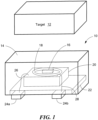
- FIG. 1 is a diagram of an exemplary embodiment of a magnetic field sensor 10 and a target 12.
- Magnetic field sensor 10 may include a package 14, sensing element 16 (transducer), and coil 18. Also included are a semiconductor die or integrated circuit 20, lead frame 22, and leads 24a and 24b. Wire bonds 26 and 28 couple die 20 to leads 24a and 24b.
- the die 20 may be coupled to the leads 24a and 24b using other standard packaging methods, including but not limited to solder bumps, solder balls, or pillar bumps.
- the die may be attached, for example, in a flip-chip or chip-on-lead configuration.
- target 12 produces or provides a magnetic field.
- target 12 comprises a hard ferromagnetic target that produces a magnetic field.
- target 12 can be any type of material that produces a magnetic field including, but not limited to, an electromagnet or other type of circuit.
- target 12 may also comprise a non-ferromagnetic material capable of having eddy currents induced therein.
- Target 12 may also comprise a soft ferromagnetic material that changes the magnitude and or direction of a magnetic field near or in proximity to the target.
- Package 14 can be any type of chip or integrated circuit package known in the art, including, but not limited to a plastic package, ceramic package, a glass sealed ceramic package, a low-temperature co-fired ceramic, or a chip-on-board encapsulant.
- Semiconductor die 20 may comprise one or more integrated circuits that drive coil 18 and sensing element 16.
- coil 18 produces a magnetic field.
- Coil 18 would be a coil of conductive material that, when energized with a current flowing through the material, induces a magnetic field.
- Integrated circuit 20 may be configured to drive a changing current through coil 18 resulting in a changing magnetic field produced by coil 18.
- the changing current may be an alternating current, a ramped current, a pulsed current, transient current, or any type of changing current that causes coil 18 to produce a similarly changing, i.e. complementary, magnetic field.
- the changing magnetic field produced by coil 18 may have sufficient magnitude to intersect the body of, and/or induce eddy currents in, target 12.
- coil 18 is adjacent to integrated circuit 20. However, this is not a requirement. In various embodiments, coil 18 may be placed in any location that allows the magnetic field produced by coil 18 to generate eddy currents in target 12 and to be detected by sensing element 16. Accordingly, coil 18 may be placed within package 14, on the surface of integrated circuit 20, outside of package 14, on the surface of package 14, on a separate substrate within package 14 that is independent of integrated circuit 20, etc.
- Coil 18 may also be independent of package 14 and may, for example, be mounted separately from package 14. Coil 18 may be encapsulated in its own package. In embodiments, if coil 18 is separate from package 14, coil 18 may be electrically coupled to integrated circuit 20 via leads such as leads 24a and 24b. In other embodiments, coil 20 may be electrically coupled to a separate circuit that can drive current through coil 18 to produce the magnetic field. In other embodiments where a static, slowly changing, or near-constant magnetic field is desired, the coil 18 may be replaced with a hard ferromagnetic material (i.e., a permanent magnet). The hard ferromagnetic material may also be placed in any location that allows the ferromagnetic material to be detected by sensing element 16.
- a hard ferromagnetic material i.e., a permanent magnet
- the ferromagnetic material may be placed within package 14, on the surface of integrated circuit 20, outside of package 14, on the surface of package 14, on a separate substrate within package 14 that is independent of integrated circuit 20, etc.
- the ferromagnetic material may also be independent of package 14 and may, for example, be mounted separately from package 14.
- Sensing element 16 may be a magnetic field sensing element, or any other type of circuit that can detect a magnetic field and produce an electrical signal in response to the detected magnetic field. The strength or magnitude of the signal may be proportional to the strength or magnitude of the detected magnetic field.
- sensing element 16 is a Hall Effect element, a magnetoresistive element or circuit, a giant magnetoresistive (GMR) element or circuit, etc.
- sensing element 16 will detect the magnetic field produced by coil 18 and be affected by the presence of target 12. In the absence of target 12, the detected magnetic field (and thus the resulting signal produced by sensing element 16) will have a known value. When this known value is detected, it may indicate the absence of target 12.
- target 12 moves relative to sensor 10, it affects the magnetic field generated by coil 18 and detected by sensing element 16.
- target 12 may produce its own magnetic field.
- the magnetic field produced by target 12 combined with the magnetic field produced by coil 18.
- the presence of target 12 causes perturbations or alterations to the known value of the magnetic field produced by coil 18.
- These perturbations can be detected by sensing element 16.
- magnetic flux detected by sensing element 16 is a vector sum of the magnetic field produced by target 12 and the magnetic field produced by coil 18.
- the signal produced by sensing element 16 represents a combination of the two magnetic fields, i.e. the magnitude of the combined magnetic fields.
- target 12 may be positioned to enhance the effect that it has on the magnetic field produced by coil 18.
- target 12 may be positioned so that its magnetic field vector is in-line with (i.e. in the same or opposite direction to, and/or aligned with) the magnetic field vector of coil 18 and/or so that target 12 is as close as possible to coil 18
- Integrated circuit 20 may compare the magnitude of the detected magnetic field to the expected value of the magnetic field produced by coil 18. If the measured value differs from the expected value, it may indicate the presence or proximity of target 12.
- integrated circuit can also detect the relative distance of target 12. For example, the magnetic field of target 12 can be aligned so that, the more closely target 12 approaches sensor 10, the greater affect the magnetic field produced by target 12 has on the magnetic field produced by coil 18. Thus, as target 12 approaches sensor 10, it will create a greater difference between the measured magnetic field and the expected magnetic field. As this difference changes, sensor 10 can indicate a relative distance between target 12 and sensor 10. Based on the measured, combined magnetic field, sensor 10 may also detect presence or absence of the target.
- target 12 may move toward and/or away from sensor 10 during operation.
- sensor 10 can detect the presence and/or proximity of target 12.
- target 12 may be a feature (such as a tooth) on a rotating wheel or gear.
- sensor 10 can create a signal (e.g. via pins 24a and/or 24b) indicating whether a tooth or valley (i.e. gap) in the gear is adjacent to sensor 10. If a tooth is present, sensor 10 can also indicate a relative distance between the tooth and sensor 10. For example, the signal produced by sensor 10 may change in amplitude based on the sensed proximity of the tooth. Additionally, if no tooth is present, sensor 10 may indicate a relative distance (e.g.
- the signal produced by sensor 10 may be analog, digital, or switched. If the signal is switched, a high output may indicate the presence of target 12 (or a tooth thereon) and a low output may indicate the absence of target 12, or vice versa.
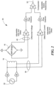
- FIG. 2 an example of a circuit 30 for detecting speed, direction, and/or proximity of target 12 is shown.
- An adjustable, changing current source 32 controls current drivers 34 and 36, which drive coil 18 and produce a differential current through signal lines 38.
- the changing current source may be an AC source, a ramped current source, a switched current source, a pulsed current source, a transient current source, or any other current source that creates a current that changes in magnitude over time.
- the current through coil 18 produces a changing magnetic field which is detected by sensing element 16.
- sensing element 16 is shown as a giant-magnetoresistive (GMR) bridge).
- GMR giant-magnetoresistive
- a differential current amplifier 42 amplifies the differential current applied to the coil 18 for coupling to a peak detector 44.
- a differential voltage amplifier 46 receives the differential voltage signal from sensing element 16 for coupling to a peak detector 48.
- Comparator 50 compares the signals from peak detectors 44 and 48 and produces an output signal 52.
- the current produced by coil drivers 34 and 36, as well as the outputs of amplifiers 46 and 42 can be adjusted.
- the differential current on signal lines 38 will be a known value and the differential voltage produced by sensing element 16 on signal lines 40 will be a known value.
- the magnetic field affected by target 12 may affect the differential voltage on signal lines 40. This change can be compared to the known value on signal lines 38.
- the presence and/or proximity of target 12 can change the output of amplifier 46, peak detector 48, and/or comparator 50.
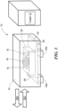
- FIG. 3 shows an alternative embodiment of the sensor 10 in FIG. 1 , which is in accordance with the invention.
- the coil 18 is placed so that the magnetic field vector produced by coil 18 is parallel to the top surface of integrated circuit 20.
- sensing element 16 comprises multiple GMR elements, which may be positioned on either side of coil 18. This arrangement may optimize or improve the ability of sensor 10 to detect target 12 when target 12 is located on either "side" of sensor 10. Because the magnetic field vector produced by coil 18 has a direction as shown by arrow 300 or arrow 302 (depending on the direction of current through coil 18), the magnetic field produced by target 12 may have a greater affect the magnetic field detected by sensing element 16 when target 12 is located on either side of sensor 10.
- FIG. 4A is a top view of an on-chip coil 400 and sensing element 402 in accordance with the invention.
- coil 400 may be the same as or similar to coil 18 and sensing element 402 may be the same as or similar to sensing element 16.
- Coil 400 may comprise a toroid-shaped coil as shown in FIG. 3 .
- coil 400 may comprise fabricated substantially two dimensional elements.
- coil 400 may be a conductive layer masked and fabricated on the surface of integrated circuit 20 to create an alternating pattern of straight and diagonal metal lines on two different levels or layers of integrated circuit 20.
- the pattern may be formed from a single conductive layer or multiple conductive layers on integrated circuit 20, depending upon the fabrication process and design that is used.
- the conductive layers would be formed of multiple layers of metal, for example.
- An example of a single conductive layer would be a meander type of pattern where the conductor zig-zags, but does not cross over itself.
- Sensing element 402 comprises GMR elements 406, 408, 410, and 410. These GMR elements are positioned on either side of coil 400 in line with the magnetic field vector produced by coil 400 to increase sensitivity to the magnetic field.
- FIG. 4B shows an alternative top view layout for an exemplary magnetic field sensor having an on-chip coil 152 and a die 154 supporting a sensing element 156.
- the sensing element 156 is located proximate to coil 152.
- other circuitry of the magnetic field sensor are omitted.
- the position of the sensing element 156 is aligned with one 'side' of coil 152. That is, sensing element 156 is aligned with a portion of coil 152 in which current is flowing in the same direction with respect to one side of the die.
- the sensing element can be generally centered with respect to the coil. In such an embodiment, a sensing element comprising a planar Hall element may be preferred.
- coil 152 is shown as being disposed above sensing element 156.
- coil 152 could instead be disposed beneath the sensing element 156.
- coil 152 may have layers or conductors above and below sensing elements 156. With the latter arrangement, the coil can be fabricated with a standard IC process and then integrated with sensing element 156 in a separate process. The embodiment shown would be advantageous for a sensor sensitive in the plane of the die such as a vertical Hall element or a GMR, AMR, spin-valve, or TMR element.
- Insulation layers may be placed between the coil and sensor material and/or die substrate as required by sensor and substrate material selection so as not to short circuit the materials and coil.
- the particular size and geometry of the coil can vary to meet the needs of a particular application.
- the coil can be formed so that the turns have any practical shape, such as a square or rectangle (as illustrated in the top view of FIGS. 4A and 4B ), or other shapes such as circle, oval, etc., or multiple layers.
- the coil is formed using conventional deposition and or etching processes, or patterning and electroplating processes well known to one of ordinary skill in the art.
- spacing from the coil to the sensing element can vary, in part as a result of voltage isolation requirements and magnetic coupling required, where magnetic coupling is the magnetic field produced by the coil per mA or other unit of current flowing in the coil.
- magnetic coupling is the magnetic field produced by the coil per mA or other unit of current flowing in the coil.
- a higher magnetic coupling level uses less power for a given magnetic field level.
- insulation layers may be placed between the coils and the sensors and/or other die material to prevent shorting of the coil to other electrical layers in the device.
- the coil is shown as having a planar spiral geometry.
- the vias and connections are omitted in the figure (for clarity) but would be apparent to one of ordinary skill in the art. It is understood that multiple metal layers can be used as well as other geometries of metal.
- Other coil geometries including but not limited to meander coils and solenoids may be used.
- a cylindrical coil having coil turns of substantially uniform diameter i.e., a solenoid type coil
- the coil arrangement can include a magnetic flux concentrator, which can be made of a soft magnetic material, to improve the magnetic flux generated by the coil.
- a soft ferromagnetic core may be provided inside a solenoid type coil to concentrate the magnetic field generated by the coil.
- the direction of the magnetic field lines will be parallel to the length of the coil (that is, the longitudinal path of the coil).
- the direction of the field lines at the center of the coil will be substantially perpendicular to the plane of the coil but will be substantially parallel to the die surface under the turns of the coil. Consideration may be given to the direction of the field generated by the coil at various locations in choosing the appropriate position and type of the sensing element.
- an "on-chip” coil as depicted in FIG. 4A and 4B is likely to be much smaller than coils located elsewhere in a sensor, sensor assembly or application. Because magnetic fields generated by the relatively smaller "on-chip” coils may not be particularly strong, high sensitivity elements such as GMR may be more suitable for an on-chip coil design than less sensitive sensing types of elements such as Hall.
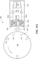
- a magnetic field sensor 160 including a semiconductor die 162 having a first, active surface 162a in which a magnetic field sensing element or sensing element 164 is formed and a second, opposing surface 162b attached to a die attach area 166 on a first surface 168a of a lead frame 168, a first mold portion comprising a non-conductive mold material 170 enclosing the die and at least a portion of the lead frame, and a second mold portion 172 secured to the non-conductive mold material.
- the second mold portion 172 which can be a non-conductive material or a ferromagnetic material, is shown as but not required to be tapered from a first end 172a proximate to the lead frame 168 to a second end 172b distal from the lead frame.
- Sensing element 164 in this and other embodiments may be the same as or similar to sensing element 16.
- the active surface 162a of the semiconductor die 162 is described herein as the surface “in” which the magnetic field sensing element is disposed or formed as is the case with certain types of magnetic field elements (e.g., Hall plate), the element may be disposed “over” or “on” the active semiconductor surface (e.g., magnetoresistance elements).
- the embodiments described herein may utilize any suitable type of magnetic field sensing elements, such elements will be described generally herein as being formed or disposed "in” the active semiconductor surface.
- the magnetic field sensor 160 may be positioned in proximity to a ferromagnetic target, such as the illustrated gear 12', such that the magnetic field sensing element 164 is adjacent to the article 12' and is thereby exposed to a magnetic field altered by movement of the article.
- the magnetic field sensing element 164 generates a magnetic field signal proportional to the magnetic field.
- the magnetic field sensor 160 generally includes additional circuitry formed in the active surface 162a of the die 162 for processing the magnetic field signal provided by the sensing element 164.
- the lead frame 168 includes leads 174a - 174c for coupling the circuitry to system components (not shown), such as a power source or microcontroller. Electrical connection between the leads 174a - 174c and the semiconductor die 162 can be provided with wire bonds 176a - 176c, respectively as shown. While the sensor 160 is shown to include three leads 174a - 174c, it will be appreciated by those of ordinary skill in the art that various numbers of leads are possible. Other techniques for electrically coupling the lead frame leads to the sensor components include solder bumps or balls, or pillar bumps.
- the sensor 160 may be provided in the form of a two to six pin Single In-Line (SIP) package, or some other number of pins as appropriate.
- SIP Single In-Line
- the first mold portion 170 is comprised of a non-conductive material so as to electrically isolate and mechanically protect the die 162 and the enclosed portion of the lead frame 168.
- Suitable materials for the non-conductive mold material 170 include thermoset and thermoplastic mold compounds and other commercially available IC mold compounds.
- the non-conductive mold material of the first mold portion 170 is applied to the lead frame/die subassembly during a molding process to enclose the die 162 and a portion of the lead frame 168.
- the non-conductive first mold portion 170 has a first surface 170a and a second, opposing surface 170b. The shape and dimensions of the non-conductive first mold portion are selected to suit a particular IC package.
- the second mold portion 172 may be the same non-conductive mold compound used to form the first mold portion 170. In some embodiments the second mold portion 172 is a different non-conductive mold compound or other moldable material than the material used for the first mold portion 170.
- the second mold portion 172 is comprised of a soft ferromagnetic material to form a concentrator.
- a soft ferromagnetic material to form a concentrator.
- various materials are suitable for providing the ferromagnetic mold material 172 in the form of a soft ferromagnetic material.
- Suitable soft ferromagnetic materials include, but are not limited to permalloy, NiCo alloys, NiFe alloys, steel, nickel, and soft magnetic ferrites.
- the second mold portion 172 can be secured to the first mold portion 170 during a step or steps of a molding process, or using an adhesive, such as a thermoset adhesive (e.g., a two part epoxy).
- an adhesive such as a thermoset adhesive (e.g., a two part epoxy).
- a portion of the first mold portion 170 that contacts the second mold portion 172 and/or the portion of its mold material that contacts the non-conductive mold material has a securing mechanism in order to improve the adhesion between the two materials and to prevent or reduce lateral slippage or shear between the materials.
- the lead frame 168 has extensions 168c (or "barbs") which extend beyond the non-conductive mold material and are enclosed by the mold material of the second mold portion 172, as shown. Such lead frame extensions additionally enhance the adhesion of the second mold portion/material to the lead frame itself.
- the second mold portion 172 should be non-conductive or have a sufficiently low conductivity to prevent the leads from electrically shorting resulting in the device not operating as intended.
- Alternative forms of securing mechanisms can be used.
- the sensor 160 also includes a coil, indicated in this figure by reference numeral 178.
- coil 178 is a package level coil, i.e. a coil incorporated into package mold portion 172. Coil 178 may perform the same or similar function to coil 18. Coil 178 is positioned relative to sensing element 164 to provide a back bias magnetic field, which can be used to detect the target's profile as it passes the sensor. To this end, the coil 178 is positioned adjacent to the second surface 170b of the non-conductive mold material 170 so that the sensing element 164 is closer to the target 12' than the coil 178, as shown.
- coil 178 can be formed from copper wire of various sizes and with various automated processes so as to provide an insulator between coil windings.
- the coil material selection, wire gauge selection, number of turns, and other design choices can be readily varied to suit a particular application so as to produce a magnetic field of a desired strength.
- the coil 178 may be formed so that each turn is in the general shape of, or approximately the shape of, a circle, rectangle, or other general shapes such as an oval, as desirable to suit a particular application and packaging arrangement.
- Coil 178 may be secured to the second surface 170b of the non-conductive mold material 170 by various means.
- an adhesive such as an epoxy, may be used to secure the coil in place.
- the mold material 172 may be formed by a suitable molding process, such as by injection molding for example.
- a mold cavity used to define the second mold portion 172 may include a mandrel so that the second mold portion forms a ring-shaped structure having a central aperture 180, here extending from the second surface 170b of the non-conductive mold material to a second end 172b of the second mold portion.
- the mold material 172 may form a conventional O-shaped ring structure or a D-shaped structure.
- the mold material 172 may form only a partial ring-like structure, as may be described as a "C" or "U” shaped structure.
- the mold material 172 comprises a non-contiguous central region such that the central region is not formed integrally with its outer region. Such central region may be an open area, such as in the case of aperture 180 in FIG.
- a third mold material may be formed by an additional molding step or other suitable fabrication technique, including but not limited to "potting" or another molding step, so as to secure that third mold material to the second mold portion 172.
- the third mold material may be comprised of a hard ferromagnetic material, a soft ferromagnetic material, or a non-ferromagnetic mold compound.
- the second mold portion 172 is tapered from its first end 172a (or a location close to its first end) to its second end 172b as is apparent from the side view of FIG. 5 .
- the second mold portion has a first taper to its outer circumferential surface 182a and a second taper to its inner central aperture surface 182b.
- the purpose of the taper is to facilitate removal of the sensor 160 from the mold cavity.
- the angle of the taper of the surfaces 182a, 182b may be the same or similar to each other and generally, the angle of the taper of the surfaces 182a, 182b is less than approximately 15 to 20 degrees. In some embodiments, the angle of taper is on the order of 2-7 degrees. In some embodiments the taper 182b may have more than a single slope.
- the sensor can also be arranged in a lead on chip configuration with the lead frame positioned above the die.
- An adhesive may be used to secure the lead frame to the active surface of the die.
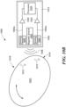
- an alternative magnetic field sensor 190 includes a semiconductor die 192 having a first active surface 192a in which a magnetic field sensing element 194 is disposed and a second, opposing surface 192b attached to a die attach area 196 on a first surface 198a of a lead frame 198, a first mold portion or non-conductive mold material 200 enclosing the die and at least a portion of the lead frame, and a second mold portion or mold material 202 secured to a portion of the non-conductive mold material.
- a securing mechanism, or other suitable mechanisms, may be provided to enhance the adhesion between the first and second mold materials.
- sensor 190 may be the same as or similar to sensor 10.
- the non-conductive mold material 200 has a protrusion 204 extending away from a second surface 198b of the lead frame 198 as shown.
- Protrusion 204 prevents there being a void in the bottom surface of sensor 190 (adjacent to the second end 202b of the mold material), since the presence of a void may make overmolding more difficult.
- the protrusion may extend all or only part of the way to the second end 202b of the second mold material 202.
- protrusion 204 terminates before the second end 202b of the second mold material 202.
- distal end 204a of the protrusion 204 is covered with the second mold material 202, as shown.
- protrusion 204 which is shown extending beyond (e.g. below) coil 206, may extend to a position that is not below coil 206. If protrusion 204 extends to a position that is not below coil 206, the second mold material 202 would generally enclose the protrusion 204 and the coil 206.
- Sensor 190 includes a coil 206 that may be the same as or similar to the coil 18 of FIG. 1 .
- coil 206 is positioned concentrically with respect to the protrusion 204 of the non-conductive mold material 200, although it will be appreciated that concentric positioning is not required. It will be appreciated that the taper to protrusion 204 may be eliminated or altered as suitable for a particular application. In some applications the protrusion may be useful as an aligning feature for coil 206 during assembly or manufacturing.
- coil 206 may be secured to the mold material 200 by an adhesive.
- coil 206 may be sized and shaped to provide an interference fit with respect to the protrusion 204 such that adhesive is not necessary and coil 206 may be sufficiently held in place relative to the mold material 200 by the interference fit when the subassembly, including the mold material 200, lead frame 198 and die 192, are placed into the mold cavity for formation of the mold material 202.
- sensor 190 is shown to have a protrusion 204 extending only partially through mold material 202 to terminate before the second end 202b of the second mold material 202, it will be appreciated that a similar sensor including a coil that may be (although is not required to be) concentrically disposed with respect to a protrusion of the non-conductive mold material can be provided with a protrusion of the type which extends to the second end 202b of second mold material 202 or the protrusion 204 may extend beyond the second end 202b of the second mold material 202.
- the second mold material 202 is tapered from a first end 202a proximate to the lead frame 198 to a second end 202b distal from the lead frame.
- the second mold material 202 is tapered along both its outer circumferential surface 208a and its inner surface 208b from its first end 202a to its second end 202b.
- the angle of taper of the surface 208a may be on the order of less than 15-20 degrees.
- the angle of the taper of the inner surface 208b may be the same as or similar to the angle of the taper of the outer surface 208a.
- the second mold material 202 has a non-contiguous central region, here in the form of a central aperture defined by the inner surface 208b.
- This non-contiguous central region of mold material 202 may take various shapes, so as to form an O-shaped, D-shaped, C-shaped, or U-shaped structure as examples.
- the second mold material can be provided in the form of a non-conductive material or ferromagnetic material such as a soft ferromagnetic material or hard ferromagnetic material.
- a non-conductive material or ferromagnetic material such as a soft ferromagnetic material or hard ferromagnetic material.
- the magnetic field generated by the coil can be focused or otherwise concentrated as desired by the soft ferromagnetic mold material.
- the magnetic field provided by the coil can be used to modulate the magnetic field provided by the hard ferromagnetic material, in order to thereby reduce the peak current otherwise required to provide the same magnetic field strength with just the coil (i.e., if the hard ferromagnetic mold material were not present).
- the second mold portion/material may be eliminated entirely (as is shown in FIG. 10 ) in which case the non-conductive mold material with the coil attached to its surface can be packaged to provide the resulting sensor IC.
- Such an arrangement can be provided in a package of the type described in a U.S. Patent No. 6,265,865 or a U.S. Patent No. 5,581,179 , each of which is assigned to the Assignee of the subject application.
- such mold material may be tapered from a first end proximate to the lead frame to a second end distal from the lead frame (or for some portion thereof) and the sensor may, optionally, include a third mold material in the form of an overmold in order to protect and electrically insulate the device.
- Sensor 190 may, optionally, include a third mold material 210 in the form of an overmold in order to protect and electrically insulate the device.
- the third mold material 210 may be applied during a third molding step/process or alternatively by any suitable fabrication method.
- Overmold 210 is considered optional because its purpose is to provide electrical insulation. In embodiments in which ferromagnetic mold material 202 provides sufficient insulation (e.g., provides more than approximately 1 mega-Ohm of resistance in certain applications), overmold 210 may be eliminated. It will be appreciated that overmold 210 may be provided for the sensor of FIG. 1 , 3 , 4 , 5 and other embodiments.
- Suitable materials for providing overmold material 210 include, but are not limited to standard die encapsulation mold compounds such as PPS, nylon, SUMIKON ® EME of Sumitomo Bakelite Co., Ltd., or Hysol ® mold compounds of Henkel AG & Co. KGaA.
- an alternative magnetic field sensor 220 includes a semiconductor die 222 having a first active surface 222a in which a magnetic field sensing element 224 is disposed and a second, opposing surface 222b attached to a die attach area 226 on a first surface 228a of a lead frame 228 and a non-conductive mold material 230 enclosing the die and at least a portion of the lead frame.
- sensor 220 may be the same as or similar to sensor 10.
- Sensor 220 includes a coil 232 secured to, and more particularly, enclosed by, the non-conductive mold material 230.
- the wire of coil 232 may be wound around a mandrel or bobbin 234, as shown.
- mandrel 234 may be comprised of a soft ferromagnetic material or a plastic and remain part of the final device. In other embodiments, mandrel 234 is used during coil winding but then not made a part of the final package.
- Mandrel 234 and coil 232 may be secured to the surface 228b of lead frame 228 that is opposite the die 222 with an adhesive or other securing mechanism such that coil 232 is secured to the lead frame 228 when the subassembly is placed in a mold cavity and the non-conductive mold material 230 is formed.
- the signal may be provided to the coil through extra pins, allowing an external connection to the coil.
- the signal may be an AC signal, a ramped signal, a pulsed signal, or any other type of changing (e.g. non-DC) signal that, when applied to the coil, can produce a changing magnetic field.
- the signal could be provided through connections to the die.
- a wire coupled to a coil terminal could be soldered to the die or connected to the die via wire bonds.
- a portion of the lead frame could be used to connect to the coil wire and to the die (e.g., via a wire bond). These connection areas of the lead frame could be unconnected to the remainder of the lead frame after molding and trimming. Any other suitable connecting means could be used.
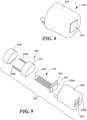
- FIGS. 8-9 illustrate yet another type of packaging for a magnetic field sensor with a coil.
- a magnetic field sensor assembly 240 includes a packaged magnetic field sensor IC 242, a coil unit 244, and a housing having a case (or housing shell) 246 and an end cap 248.
- Case 246 has a first end 250a with an opening (not shown) and a second end 250b that includes a window 252.
- the "fully assembled" magnetic field sensor assembly 240 takes on the form shown in the configuration shown in FIG. 8 .
- the housing is shown as a two-piece housing having a generally cylindrical shape, other types of housings could be used as well.
- the packaged magnetic field sensor IC 242 is shown to include a first package portion 254 corresponding to a magnetic field sensor chip within a protective package body and a second package portion, in the form of conductive leads 256. There may be three conductive leads 256, with a lead to correspond to the power and ground connections and a lead for the output signal (as shown in the embodiments of FIGS. 3 and 6 , for a "three-wire" device), or some other number of leads.
- Coil unit 244 may include a coil body portion 257 containing a coil (which can be, e.g., a spiral coil, a solenoid type coil, solenoid type coil with a soft ferromagnetic core, or other type of coil configuration) and conductive leads 258a and 258b.
- a coil which can be, e.g., a spiral coil, a solenoid type coil, solenoid type coil with a soft ferromagnetic core, or other type of coil configuration
- Materials for the entire coil body portion 257 may include plastic (or other mold compound) or non-ferromagnetic material.
- the top of coil body portion 257 i.e., the part between the coil and the sensing element of the sensor 242 IC
- the sides and bottom of coil body portion 257 could be made of a soft ferromagnetic material to help reduce the reluctance path, i.e., guide the magnetic flux more efficiently.
- One of the leads is a signal input for connecting to the signal source (e.g., coil input line 26, shown in FIG. 1 ).
- the signal source may be a changing signal (i.e. a non-DC signal) that can produce a changing magnetic field when applied to the coil.
- the other lead, e.g., lead 258b is a ground terminal for connecting to a reference potential (e.g. ground).
- the coil of coil unit 244 may be driven in electrical isolation from the sensor IC 242 with no common node. If, however, the sensor IC ground and the coil unit ground are to be tied together, then the assembly 240 could be designed to have one less pin/lead for external connections.
- the leads 256 of the packaged sensor IC and leads 258 of the coil unit 244 extend outwardly from the opening in the first end 250a of the case 246.
- the first package portion 254 is positioned in the case 246 part way through the window 252 so that a first body face 260 extends outwardly from second end 250b of the case 246.
- the first body face 260 will be positioned in proximity to the target's profile.
- the illustrative housing of FIGS. 8-9 can be constructed according to techniques like those described in the above-referenced U.S. Patent No. 5,581,179 , or other suitable techniques.
- the case 246 can be formed of a polymeric insulating material, as described in the aforementioned patent, or, alternatively, a soft ferromagnetic material. In other embodiments, a separate magnetic flux concentrator may be included in the assembly.
- FIG. 10A and FIG. 10B illustrate examples of a magnetic sensor system 1000 for detecting a non-ferromagnetic target 1001.
- sensor system 1000 includes a magnetic field sensor 1003 having one or more magnetic field sensing elements 1002 and 1004.
- Sensor 1003 may include a sensor integrated circuit or die 1015 and one or more magnetic sources (e.g. coils or magnets, such as a back-bias magnet) 1005 capable of producing magnetic field 1006.
- sensor 1003 may contain fewer or more than two sensing elements.
- sensor 1003 may include multiple magnetic sources.
- sensor 1003 has more than one magnetic source, the magnetic fields produced by those sources may be viewed as a single, combined magnetic field 1006 produced by multiple discrete sources. It is also noted that the orientation of the magnetic source to the sensing element or sensing elements shown in Figs. 10A and B is schematic in nature and may be modified in various embodiments. For example, sensor 1003 (and/or die 1015) may be positioned between a magnetic source 1005 and a target 1001. In other embodiments the magnetic source or sources and sensing element or elements have different positions relative to the target.
- Sensing elements 1002 and 1004 may be the same as or similar to any or all of the sensors described above with respect to the preceding figures 1-9 . In other embodiments sensing elements 1002 and 1004 could be separate magnetic field sensors joined by some common circuitry or with the output of one sensor used as an electrical input to another sensor if the two sensors with their sensing elements were in separate packages. As described above, sensing elements 1002 and 1004 may include a magnetic source 1005 (e.g. a coil and/or magnet) to produce a magnetic field 1006. Alternatively, magnetic source 1005 may be mounted separately from die 1015. In such an embodiment, source 1005 may be positioned relative to target 1001 so that a magnetic field 1006 intersects the body of target 1001. Although magnetic source 1005 is shown in FIG.
- a magnetic source 1005 e.g. a coil and/or magnet
- magnetic source 1005 may be separate from die 1015, part of die 1015, mounted or placed adjacent to or on die 1015, etc.
- magnetic source 1005 may be arranged in any configuration or arrangement that allows magnetic source 1005 to produce a magnetic field 1006 that can be detected by sensing elements 1002 and/or 1004. Examples of such configurations and arrangements are described above in relation to Figs. 1-9 .
- magnetic field 1006 or may be a static magnetic field produced by a permanent magnet (e.g. a hard ferromagnetic material) or an electromagnet with a DC or other slowly changing current to produce a magnetic field.
- a permanent magnet e.g. a hard ferromagnetic material
- an electromagnet with a DC or other slowly changing current to produce a magnetic field.
- system 1000 may include only a single sensing element, or may include more than two sensing elements. As will be described below, one or more sensing element(s) can be used to detect proximity, presence, speed, direction, and other properties of target 1001.
- target 1001 is a non-ferromagnetic target.
- Target 1001 may comprise a conductive material such as copper, aluminum, titanium, etc., and may have a size and thickness that allow eddy currents to form within, on, or near the surface of target 1001.
- magnetic source 1005 produces magnetic field 1006 and sensing elements 1002 and 1004 react to or sense magnetic field 1006.
- sensing elements 1002 and 1004 generate signals 1002a and 1004a, respectively.
- Amplifiers 1030 and 1032 receive these signals, amplify them, and supply them to processor 1034.
- Processor 1034 then processes the signals to determine presence, speed, direction, position, or other properties of target 1001. In other embodiments other variations of circuitry could be used to sense the target.
- magnetic field 1006 induces an eddy current (e.g. eddy current 1010 and/or eddy current 1012) on or near the surface of target 1001.
- eddy current e.g. eddy current 1010 and/or eddy current 1012
- changes in the magnetic field will induce the eddy currents in target 1001.
- magnetic field 1006 is a static magnetic field
- motion of the conductive target through the magnetic field cause eddy currents 1010 and 1012 to form within target 1001 or 1001'. Irregular features or shapes of the target can influence the presence or magnitude of the induced eddy currents.
- magnetic field 1006 may induce a single eddy current or multiple eddy currents in target 1001, which may be added or combined together to form a combined eddy current within target 1001.
- magnetic source 1005 may be configured to produce a shaped magnetic field 1006.
- magnetic source 1005 may produce multiple magnetic fields that add together in various patterns so that the resulting, combined magnetic field has local areas that are relatively strong and local areas that are relatively weak.
- magnetic source 1005 may comprise multiple coils, magnets, or other magnetic sources. By shaping the magnetic field 1006, magnetic source 1005 can control the location, direction, and strength of the eddy currents 1010 and 1012 induced in target 1001.
- the eddy currents 1010 and 1012 formed within target 1001 create their own, secondary magnetic fields, which oppose changes in magnetic field 1006 in the target 1001. These magnetic field changes can be due, for example, to magnetic source 1005 changing the strength or shape of magnetic field 1006 over time.
- magnetic field 1006 is a static (e.g. non-changing, or slowly-changing) magnetic field
- the motion (e.g. rotation) of target 1001 through magnetic field 1006 may cause target 1001 to produce eddy currents which result in changes to the magnetic field 1006.
- system 1000 can detect the presence of target 1001 by detecting a change in amplitude of the signals produced by sensing elements 1002 and 1004, and due to the presence of eddy currents in the target.
- magnetic field 1006 is a static magnetic field
- motion of the target through the magnetic field causes changes to eddy currents 1010 and 1012.
- a point 1020 on the surface of target 1001 may have negligible magnetic field when it is relatively distant from magnetic source 1005.
- point 1020 approaches a point 1022 on sensor 1003 it will be exposed to an increasing magnitude of magnetic field 1006, and thereby create eddy current 1010 to oppose that change.
- point 1020 passes point 1024 on sensor 1003, it will see a decrease in the magnetic field from magnetic source 1005, thus creating an eddy current 1012 to oppose this change.
- eddy current 1010 will reduce the field sensed by magnetic field sensing element 1004, and eddy current 1012 will increase the field sensed by magnetic field sensing element 1002.
- eddy currents 1012 and 1010 will be of opposite magnitude, i.e. eddy current 1010 will increase the field sensed by magnetic field sensing element 1004 and eddy current 1012 will decrease the field sensed by magnetic field sensing element 1002.
- the amplitude of the signal produced by magnetic field sensing elements 1002 and 1004 may depend the direction of target rotation. Accordingly, system 1000 can detect the direction of target 1001 rotation by detecting a change in the signals produced by sensing elements 1002 and 1004, spatially located in system 1000.
- Magnetic field sensing elements 1002 and 1004 may be spatially arranged so that there is a physical distance between them. Spacing the sensing elements apart in this way can allow each sensing element 1002 and 1004 to detect magnetic fields produced by eddy current in a different, localized area of target 1001. For example, as shown, sensing element 1002 is closer to eddy current 1012 and sensing element 1004 is closer to eddy current 1010. Thus, the magnetic field sensed by sensing element 1002 will be more greatly affected by eddy current 1012 and the magnetic field sensed by sensing element 1004 will be more greatly affected by eddy current 1010.
- Target 1001 may also have irregular features, such as feature 1014.
- Feature 1014 may be a valley, gap, recess, a non-conductive region, a less conductive region, or any type of region that changes the eddy currents 1010 and 1012 induced by magnetic fields 1006 and 1008.
- the feature 1014 could be a tooth, bump, or protrusion of the target.
- combinations of gaps and protrusions would be possible, for example, but not limited to approximately three different radial distances from the center of rotation, i.e. a valley, a nominal radius, and a tooth.
- the eddy current induced in target 1001 may be different from the eddy current induced when feature 1014 is not adjacent to magnetic field 1006 or 1008.
- the eddy current induced in target 1001 may be different from the eddy current induced when feature 1014 is not adjacent to magnetic field 1006 or 1008.
- feature 1014 is a gap or a non-conductive region, there may be no eddy current induced within region 1014 and no opposing magnetic field.
- an eddy current may be induced in feature 1014, but the eddy current may have a different strength or magnitude than eddy current 1012 or 1010 that are induced in the main body of target 1001.
- the sensor 1003 and sensing elements 1002 or 1004 may detect a change in the magnetic field due to the presence of feature 1014 and produce a signal indicating that feature 1014 has been detected. If the target is rotating at a particular speed, peaks or valleys may appear on signals 1002a and 1004a as feature 1014 passes by sensing element 1002 and 1004. Processor 1034 can detect and process these peaks and valleys to determine speed, presence, position, direction of rotation, etc.
- the main body of target 1001 may be non-conductive, while feature 1014 may be conductive.
- eddy currents may be induced within feature 1014 but not within the main body of target 1001.
- the opposing magnetic field may only be present when feature 1014 is adjacent to sensor 1002 or 1004.
- FIG. 10B illustrates another embodiment of system 1000 that has an irregularly shaped target 1001'. Due to the irregular shape (shown as an oval in FIG. 10B ), as target 1001' rotates past sensors 1002 and 1004, some portions of the body of target 1001' may be closer to sensors 1002 and 1004, while other portions may be further away. For example, as shown, region 1016 of target 1001' is closer to sensor 1004 than region 1018 is to sensor 1002.
- eddy current 1010 may be stronger than eddy current 1012, because the eddy currents are induced by magnetic field 1006. Accordingly, the magnetic field produced by eddy current 1010 may be stronger than the magnetic field produced by eddy current 1012. Additionally, because the magnetic field produced by eddy current 1010 is closer to sensor 1004 than the magnetic field produced by eddy current 1012 is to sensor 1002, the eddy current 1010 may have a greater effect on the magnetic flux flowing through the magnetic sensing element within sensor 1004. Thus, the magnetic field induced in region 1016 may provide a different response in the sensor than the magnetic field induced in region 1018.
- sensors 1002 and 1004 may detect whether the region of target 1001' adjacent to the sensor is relatively close or relatively far away from the sensor based on the extent to which the eddy current affects the magnetic field detected by the sensor.
- System 1000 may thus determine the position, speed, and/or direction of target 1001' based on which regions of irregularly shaped target 1001' are adjacent to the sensors as target 1001' moves.
- target 1001' can have any irregular shape so long as some regions of target 1001' can be closer to the sensors while other regions can be further away.
- target 1001' can be a toothed wheel, a toothed rack in a rack and pinion system, a square or rectangle having corners, or any other shape having protrusions or other features that can move relative to sensors 1002 and 1004.
- magnetic fields 1006 and 1008 are static (i.e. DC) fields
- the irregular features or shapes of targets 1001 and 1001', and/or the motion of the targets may induce the eddy current within the target.
- eddy currents are caused by a changing magnetic field through a conductor. Therefore, if the target is stationary and the magnetic fields are static, no eddy currents will form because the magnetic field intersecting the target will not be changing. However, eddy currents will be created within the body of the target as it moves or rotates through a static magnetic field. If target 1001 or 1001' contains no irregular features or shapes, eddy currents having a constant strength will be induced in the body of target 1001 as it rotates.
- these eddy currents can be used to detect the presence of target 1001.
- the magnitude of the eddy currents, and the strength of the magnetic fields produced by the eddy currents will also change.
- the sensors can also detect the speed of the target by measuring the strength of the magnetic field produced by the eddy currents.
- the eddy currents (and thus the magnetic fields produced by the eddy currents) will change.
- the irregular shape or conductivity of feature 1014 passing through the magnetic field causes changes to the eddy currents within target 1001.
- regions of target 1001' move relatively closer or relatively further away from the sensors. This also causes the eddy currents induced in target 1001' to change.
- system 1000 may be able to detect direction of motion of target 1001.
- the system is comprised of two sensors 1002, 1004, oriented as to detect different locations on the target. For example, if target 1001 is spinning in a clockwise direction, feature 1014 will pass by sensor 1002 first, and pass by sensor 1004 second. Accordingly, the signal produced by sensor 1002 to indicate the presence of feature 1014 will precede the signal produced by sensor 1004. Conversely, if target 1001 is turning in a counter-clockwise direction, the signal produced by sensor 1004 to indicate the presence of feature 1014 will precede the signal produced by sensor 1002.
- system 1000 can determine the speed and direction of target 1001.
- target 1001 can also be a linear target, such as a rack in a rack and pinion system, or any other type of target that can move relative to sensors 1002 and 1004.
- FIG. 11 is a flowchart of a process 1100 for sensing a magnetic field.
- a circuit e.g. integrated circuit 20 in FIG. 1
- the changing current may be a periodic current such as an AC current, a saw tooth pattern current, a pulsed current, a DC, or a near DC current etc.
- the current through the coil produces a changing magnetic field.
- a sensor e.g. sensor 10
- the target may be positioned relative to the sensor.
- the target may be a conductive target, a ferromagnetic target, a magnet, an electromagnet, or another type of target that generates a magnetic field.
- a signal is generated representing the strength of the combined magnetic field from the coil and magnetic field from the target.
- the signal may be generated by sensing element 16, for example.
- the signal is compared to an expected magnetic field strength value.
- a signal is generated that represents changes to the expected magnetic field produced by the presence of target 12.
- the signal may represent the proximity of the target to the sensor.
- the signal may be used to calculate proximity, position, speed, and direction of the target, among other properties of the target.
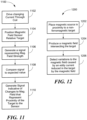
- FIG. 12 is a flowchart of another process 1200 for sensing a magnetic field.
- a non-ferromagnetic target is placed in proximity to magnetic field source.
- the target 1001 in figure 10A may be placed in proximity to sensor 1002 and/or 1004.
- a magnetic field is produced by a magnet or an electromagnet. The field intersects the target and can be sensed by sensing elements 1002 and/or 1004.
- an eddy current is induced in the target, and variations to the magnetic field caused by the eddy current are detected.
- a magnetic sensor with an integrated coil is optimized for seat belt detection.
- a magnetic sensor is optimized for seat position detection with air gaps in the order of about 0.5 to about 3 mm. In other embodiments the sensor may be optimized for air gaps as large as 1 cm.
- a magnetic sensor is optimized to detect motion of an automotive transmission, wheel, or axle.
Landscapes
- Physics & Mathematics (AREA)
- General Physics & Mathematics (AREA)
- Condensed Matter Physics & Semiconductors (AREA)
- Measuring Magnetic Variables (AREA)
- Hall/Mr Elements (AREA)
Claims (14)
- Magnetfeldsensor (402), umfassend:ein Halbleitersubstrat (20);eine Spule (400), die auf einer Oberfläche des Halbleitersubstrats bereitgestellt und konfiguriert ist, ein sich änderndes Magnetfeld bereitzustellen, das einen Magnetfeldvektor mit einer Richtung parallel zu einer Oberfläche des Halbleitersubstrats aufweist, auf der die Spule in Reaktion auf einen sich ändernden Strom in der Spule getragen wird; undeine Vielzahl von riesenmagnetoresistiven Elementen, GMRs, die in einer Brückenkonfiguration angeordnet sind und durch das Substrat (20) getragen werden, um ein Target zu detektieren, indem Variationen in dem sich ändernden Magnetfeld detektiert werden, die durch die Nähe eines Targets (12) verursacht werden, das ein Magnetfeld bereitstellt;dadurch gekennzeichnet, dass:
ein erstes Paar (406, 408) der GMRs der Brückenkonfiguration an einem Ende der Spule (400) positioniert ist und ein zweites Paar (410, 412) der GMRs der Brücke an einem gegenüberliegenden Ende der Spule (18) positioniert ist, um die Empfindlichkeit des Magnetfeldsensors auf ein proximales Target zu erhöhen, das sich in Linie mit dem Magnetfeldvektor befindet. - Magnetfeldsensor (402) nach Anspruch 1, wobei die Spule (400) aus zumindest einer Metallschicht gebildet ist, die auf einer Oberfläche des Substrats (20) angeordnet ist.
- Magnetfeldsensor (402) nach Anspruch 1, ferner beinhaltend eine Stromquelle, die mit der Spule (400) gekoppelt ist.
- Magnetfeldsensor (402) nach Anspruch 1, ferner beinhaltend eine gepulste oder vorübergehende Stromquelle, die mit der Spule (400) gekoppelt ist.
- Magnetfeldsensor (402) nach Anspruch 1, wobei die Spule (400) über oder unter dem Substrat (20) positioniert ist.
- Magnetfeldsensor nach Anspruch 1, wobei die Spule (400) ein separat ausgebildetes Element ist, das in einer gleichen Packung mit dem Substrat (20) beinhaltet ist.
- Magnetfeldsensor (402) nach Anspruch 1, wobei der Magnetfeldvektor (300, 302) eine Richtung aufweist, die entweder auf das Target (12) zu oder von diesem weg ist.
- Magnetfeldsensor (402) nach einem der vorhergehenden Ansprüche, wobei ein Target, das ein Magnetfeld bereitstellt, eines der folgenden umfassen kann: ein hartes ferromagnetisches Material, ein weiches ferromagnetisches Material, ein nichtferromagnetisches Material oder eine Art von Material, das ein Magnetfeld erzeugt.
- Verfahren zum Detektieren eines Magnetfelds, umfassend:Bereitstellen eines Halbleitersubstrats (20);Treiben eines sich ändernden Stroms durch eine Spule (400), die auf einer Oberfläche des Halbleitersubstrats bereitgestellt ist, so dass die Spule (18) ein sich änderndes Magnetfeld erzeugt, das einen Magnetfeldvektor mit einer Richtung parallel zu einer Oberfläche des Halbleitersubstrats (20) aufweist, auf der die Spule (18) getragen wird; undDetektieren, mit einer Vielzahl von riesenmagnetoresistiven Elementen, GMRs, die in einer Brückenkonfiguration angeordnet sind und durch das Substrat (20) getragen werden, eines Targets durch Detektieren von Variationen in dem sich ändernden Magnetfeld, die durch die Nähe eines Targets (12), das ein Magnetfeld bereitstellt, verursacht werden;dadurch gekennzeichnet, dass:
ein erstes Paar (406, 408) der GMRs der Brückenkonfiguration an einem Ende der Spule (400) positioniert ist und ein zweites Paar (410, 412) der GMRs der Brücke an einem gegenüberliegenden Ende der Spule (18) positioniert ist, um die Empfindlichkeit des Magnetfeldsensors auf ein proximales Target zu erhöhen, das sich in Linie mit dem Magnetfeldvektor befindet. - Verfahren nach Anspruch 9, ferner umfassend das Bilden der Spule (400) aus einer oder mehreren Metallschichten, die auf einer Oberfläche des Substrats (20) angeordnet sind.
- Verfahren nach Anspruch 9, ferner umfassend das Zuführen eines gepulsten oder kurzzeitigen Stroms zu der Spule (400).
- Verfahren nach Anspruch 9, ferner umfassend das Anbringen der Spule (400) an einer oberen oder unteren Oberfläche des Substrats (20).
- Verfahren nach Anspruch 9, ferner umfassend das Bereitstellen der Spule (400) als ein separat ausgebildetes Element innerhalb einer gleichen Packung wie das Substrat (20).
- Verfahren nach Anspruch 9, wobei ein Target, das ein Magnetfeld bereitstellt, eines der folgenden umfassen kann: ein hartes ferromagnetisches Material, ein weiches ferromagnetisches Material, ein nichtferromagnetisches Material oder eine beliebige Art von Material, das ein Magnetfeld erzeugt.
Applications Claiming Priority (2)
| Application Number | Priority Date | Filing Date | Title |
|---|---|---|---|
| US13/946,400 US10145908B2 (en) | 2013-07-19 | 2013-07-19 | Method and apparatus for magnetic sensor producing a changing magnetic field |
| PCT/US2014/044993 WO2015009442A1 (en) | 2013-07-19 | 2014-07-01 | Methods and apparatus for magnetic sensor producing a changing magnetic field |
Publications (2)
| Publication Number | Publication Date |
|---|---|
| EP3019883A1 EP3019883A1 (de) | 2016-05-18 |
| EP3019883B1 true EP3019883B1 (de) | 2024-05-01 |
Family
ID=51220895
Family Applications (1)
| Application Number | Title | Priority Date | Filing Date |
|---|---|---|---|
| EP14742423.8A Active EP3019883B1 (de) | 2013-07-19 | 2014-07-01 | Verfahren und vorrichtung für einen magnetsensor zur erzeugung eines wechselnden magnetfeldes |
Country Status (6)
| Country | Link |
|---|---|
| US (4) | US10145908B2 (de) |
| EP (1) | EP3019883B1 (de) |
| JP (1) | JP6427184B2 (de) |
| KR (1) | KR101926383B1 (de) |
| CN (1) | CN105378500B (de) |
| WO (1) | WO2015009442A1 (de) |
Families Citing this family (68)
| Publication number | Priority date | Publication date | Assignee | Title |
|---|---|---|---|---|
| US9001527B2 (en) * | 2008-02-18 | 2015-04-07 | Cyntec Co., Ltd. | Electronic package structure |
| US9678175B2 (en) * | 2010-07-26 | 2017-06-13 | Radiation Monitoring Devices, Inc. | Eddy current detection |
| US9479019B2 (en) * | 2012-01-16 | 2016-10-25 | Hamilton Sundstrand Corporation | Brushless starter generator |
| US9817078B2 (en) | 2012-05-10 | 2017-11-14 | Allegro Microsystems Llc | Methods and apparatus for magnetic sensor having integrated coil |
| US10145908B2 (en) | 2013-07-19 | 2018-12-04 | Allegro Microsystems, Llc | Method and apparatus for magnetic sensor producing a changing magnetic field |
| US10495699B2 (en) | 2013-07-19 | 2019-12-03 | Allegro Microsystems, Llc | Methods and apparatus for magnetic sensor having an integrated coil or magnet to detect a non-ferromagnetic target |
| US9823092B2 (en) | 2014-10-31 | 2017-11-21 | Allegro Microsystems, Llc | Magnetic field sensor providing a movement detector |
| FR3038060B1 (fr) * | 2015-06-26 | 2018-11-02 | Atware | Appareil de mesure d'une quantite de materiau superparamagnetique |
| JP6533004B2 (ja) * | 2015-07-08 | 2019-06-19 | エーエスエムエル ネザーランズ ビー.ブイ. | 測定システム、リソグラフィ装置、デバイス製造方法、および測定方法 |
| US11402440B2 (en) | 2015-07-17 | 2022-08-02 | Allegro Microsystems, Llc | Methods and apparatus for trimming a magnetic field sensor |
| US9939410B2 (en) * | 2015-09-01 | 2018-04-10 | Infineon Technologies Ag | Transmission of information associated with a possible sensor fault of a magnetic sensor |
| CN105242222A (zh) * | 2015-09-11 | 2016-01-13 | 合肥联宝信息技术有限公司 | 用于测量磁场辐射的方法及磁场探头 |
| JP2017083280A (ja) * | 2015-10-28 | 2017-05-18 | 株式会社東海理化電機製作所 | 半導体装置及び磁気センサ装置 |
| JPWO2017073280A1 (ja) * | 2015-10-29 | 2018-08-16 | Tdk株式会社 | 磁気検出装置及び移動体検出装置 |
| US10012518B2 (en) | 2016-06-08 | 2018-07-03 | Allegro Microsystems, Llc | Magnetic field sensor for sensing a proximity of an object |
| US10247758B2 (en) * | 2016-08-08 | 2019-04-02 | Allegro Microsystems, Llc | Current sensor |
| DE102016224856A1 (de) * | 2016-12-13 | 2018-06-14 | Robert Bosch Gmbh | Sensorsystem zur Bestimmung mindestens einer Rotationseigenschaft eines um mindestens eine Rotationsachse rotierenden Elements |
| KR102380348B1 (ko) * | 2017-03-24 | 2022-03-31 | 삼성전자주식회사 | 무선 전력 송신 장치 및 거치 형태에 따른 무선 전력 송신 방법 |
| CN107015171B (zh) * | 2017-03-24 | 2023-10-24 | 江苏多维科技有限公司 | 一种具有磁滞线圈的磁传感器封装结构 |
| US10641842B2 (en) | 2017-05-26 | 2020-05-05 | Allegro Microsystems, Llc | Targets for coil actuated position sensors |
| US11428755B2 (en) * | 2017-05-26 | 2022-08-30 | Allegro Microsystems, Llc | Coil actuated sensor with sensitivity detection |
| US10310028B2 (en) | 2017-05-26 | 2019-06-04 | Allegro Microsystems, Llc | Coil actuated pressure sensor |
| US10837943B2 (en) * | 2017-05-26 | 2020-11-17 | Allegro Microsystems, Llc | Magnetic field sensor with error calculation |
| US10324141B2 (en) * | 2017-05-26 | 2019-06-18 | Allegro Microsystems, Llc | Packages for coil actuated position sensors |
| US10996289B2 (en) * | 2017-05-26 | 2021-05-04 | Allegro Microsystems, Llc | Coil actuated position sensor with reflected magnetic field |
| FR3068463B1 (fr) * | 2017-06-30 | 2019-07-26 | Continental Automotive France | Capteur en courant |
| US10480957B2 (en) * | 2017-07-20 | 2019-11-19 | Allegro Microsystems, Llc | Magnetic field sensor to detect direction of angular rotation of a rotating magnetic structure, speed of the rotating magnetic structure or fault |
| US20210190893A1 (en) | 2017-10-06 | 2021-06-24 | Melexis Technologies Nv | Magnetic sensor sensitivity matching calibration |
| EP3467528B1 (de) * | 2017-10-06 | 2020-05-20 | Melexis Technologies NV | Kalibrierung der empfindlichkeitsanpassung eines magnetsensors |
| KR102387464B1 (ko) | 2017-10-12 | 2022-04-15 | 삼성전자주식회사 | 배선 회로 테스트 장치 및 방법과, 그 방법을 포함한 반도체 소자 제조방법 |
| FR3073354B1 (fr) | 2017-11-06 | 2019-10-18 | Safran | Piece composite a circuit electronique d'instrumentation integre et son procede de fabrication |
| EP3496118A1 (de) * | 2017-12-07 | 2019-06-12 | Koninklijke Philips N.V. | Luftkerninduktoranordnung |
| WO2019131812A1 (ja) | 2017-12-27 | 2019-07-04 | 旭化成エレクトロニクス株式会社 | 磁気センサモジュール及びこれに用いるicチップ |
| US11248971B2 (en) | 2018-02-02 | 2022-02-15 | Analog Devices International Unlimited Company | Magnetic field torque and/or angle sensor |
| US11143732B2 (en) * | 2018-02-21 | 2021-10-12 | Allegro Microsystems, Llc | Magnetic field sensor with modulated diagnostic signal |
| US11112230B2 (en) | 2018-02-23 | 2021-09-07 | Allegro Microsystems, Llc | Angle sensor using eddy currents |
| US10866117B2 (en) | 2018-03-01 | 2020-12-15 | Allegro Microsystems, Llc | Magnetic field influence during rotation movement of magnetic target |
| US10917092B2 (en) | 2018-04-06 | 2021-02-09 | Allegro Microsystems, Llc | Magnetic field sensor with switching network |
| DE102018111011A1 (de) | 2018-05-08 | 2019-11-14 | Infineon Technologies Ag | Magnetfeldsensorvorrichtung |
| US10823586B2 (en) | 2018-12-26 | 2020-11-03 | Allegro Microsystems, Llc | Magnetic field sensor having unequally spaced magnetic field sensing elements |
| US11061084B2 (en) | 2019-03-07 | 2021-07-13 | Allegro Microsystems, Llc | Coil actuated pressure sensor and deflectable substrate |
| JP2020148640A (ja) | 2019-03-14 | 2020-09-17 | 株式会社東芝 | 電流検出装置 |
| US11333232B2 (en) * | 2019-03-14 | 2022-05-17 | Dana Automotive Systems Group, Llc | Eddy current sensor assembly |
| US11165014B2 (en) * | 2019-03-29 | 2021-11-02 | Ablic Inc. | Semiconductor device |
| US10955306B2 (en) | 2019-04-22 | 2021-03-23 | Allegro Microsystems, Llc | Coil actuated pressure sensor and deformable substrate |
| CN109991446B (zh) * | 2019-04-24 | 2021-06-25 | 中广核工程有限公司 | 一种核电站主泵磁电式转速传感器试验装置及试验方法 |
| DE102019110570B4 (de) | 2019-04-24 | 2023-05-25 | Infineon Technologies Ag | Magnetfeldsensorpackage mit integrierter passiver komponente |
| US11150110B2 (en) | 2019-08-01 | 2021-10-19 | Allegro Microsystems, Llc | Sensor having a shaped coil |
| WO2021094587A1 (en) * | 2019-11-13 | 2021-05-20 | eV-Technologies | Spin-wave based magnetic and/or electro-magnetic field sensing device for dc, rf and millimeter-wave applications |
| US11237020B2 (en) | 2019-11-14 | 2022-02-01 | Allegro Microsystems, Llc | Magnetic field sensor having two rows of magnetic field sensing elements for measuring an angle of rotation of a magnet |
| US11280637B2 (en) | 2019-11-14 | 2022-03-22 | Allegro Microsystems, Llc | High performance magnetic angle sensor |
| EP4065935A1 (de) * | 2019-11-29 | 2022-10-05 | HELLA GmbH & Co. KGaA | Linearer bewegungssensor |
| DE102019220492A1 (de) * | 2019-12-20 | 2021-06-24 | Infineon Technologies Ag | Induktiver winkel- und/oder positionssensor |
| US11169223B2 (en) | 2020-03-23 | 2021-11-09 | Allegro Microsystems, Llc | Hall element signal calibrating in angle sensor |
| US11262422B2 (en) | 2020-05-08 | 2022-03-01 | Allegro Microsystems, Llc | Stray-field-immune coil-activated position sensor |
| CN111896899B (zh) * | 2020-07-06 | 2021-06-11 | 苏州佳祺仕信息科技有限公司 | 一种高斯检测探头 |
| US11637482B2 (en) | 2020-10-08 | 2023-04-25 | Analog Devices International Unlimited Company | Magnetic sensor system for motor control |
| US11435206B2 (en) | 2020-10-28 | 2022-09-06 | Allegro Microsystems, Llc | Phase compensation for an inductive position sensor |
| US11326903B1 (en) | 2020-11-13 | 2022-05-10 | Allegro Microsystems, Llc | Rotary inductive sensor |
| US11460286B2 (en) | 2020-11-13 | 2022-10-04 | Allegro Microsystems, Llc | Rotary inductive sensor |
| US11733316B2 (en) | 2020-12-14 | 2023-08-22 | Allegro Microsystems, Llc | Position sensor having harmonic distortion compensation |
| US11927650B2 (en) | 2021-01-04 | 2024-03-12 | Allegro Microsystems, Llc | Magnetic-field closed-loop sensors with diagnostics |
| US11366141B1 (en) | 2021-01-28 | 2022-06-21 | Allegro Microsystems, Llc | Multipath wide bandwidth current sensor |
| US11460323B2 (en) | 2021-02-05 | 2022-10-04 | Analog Devices International Unlimited Company | Magnetic field sensor package |
| US11493361B2 (en) | 2021-02-26 | 2022-11-08 | Allegro Microsystems, Llc | Stray field immune coil-activated sensor |
| US11630130B2 (en) | 2021-03-31 | 2023-04-18 | Allegro Microsystems, Llc | Channel sensitivity matching |
| US11578997B1 (en) | 2021-08-24 | 2023-02-14 | Allegro Microsystems, Llc | Angle sensor using eddy currents |
| WO2023055688A1 (en) * | 2021-09-29 | 2023-04-06 | Lam Research Corporation | Voltage and current probe assemblies for radio frequency current carrying conductors |
Family Cites Families (470)
| Publication number | Priority date | Publication date | Assignee | Title |
|---|---|---|---|---|
| US3132337A (en) | 1960-09-12 | 1964-05-05 | Ibm | Variable reluctance slotted drum position indicating device |
| US3195043A (en) | 1961-05-19 | 1965-07-13 | Westinghouse Electric Corp | Hall effect proximity transducer |
| DE1514822A1 (de) | 1964-08-14 | 1969-06-26 | Telefunken Patent | Verfahren zur Herstellung einer Halbleiteranordnung |
| US3607528A (en) | 1968-02-08 | 1971-09-21 | James S Gassaway | Magnetic memory members and methods of making the same |
| US3661061A (en) | 1969-05-05 | 1972-05-09 | Atomic Energy Commission | Picture position finder |
| US3611138A (en) | 1970-03-05 | 1971-10-05 | Gen Motors Corp | Tachometer system including an rf signal modulator and detector |
| FR2114148A5 (de) | 1970-11-16 | 1972-06-30 | Crouzet Sa | |
| JPS576962Y2 (de) | 1974-07-26 | 1982-02-09 | ||
| DE2518054C2 (de) | 1975-04-23 | 1984-08-02 | Siemens AG, 1000 Berlin und 8000 München | Anordnung zur Bestimmung des Drehsinns einer Drehbewegung |
| US4048670A (en) | 1975-06-30 | 1977-09-13 | Sprague Electric Company | Stress-free hall-cell package |
| US4236832A (en) | 1977-06-29 | 1980-12-02 | Tokyo Shibaura Denki Kabushiki Kaisha | Strain insensitive integrated circuit resistor pair |
| US4204317A (en) | 1977-11-18 | 1980-05-27 | The Arnold Engineering Company | Method of making a lead frame |
| US4180753A (en) | 1978-06-30 | 1979-12-25 | Ford Motor Company | Apparatus for generating electrically distinguishable bipolar signals using a magnetic sensor and an oval wheel with teeth and notches in its minor and major axis |
| US4188605A (en) | 1978-07-21 | 1980-02-12 | Stout Glenn M | Encapsulated Hall effect device |
| US4283643A (en) | 1979-05-25 | 1981-08-11 | Electric Power Research Institute, Inc. | Hall sensing apparatus |
| US4315523A (en) | 1980-03-06 | 1982-02-16 | American Flow Systems, Inc. | Electronically controlled flow meter and flow control system |
| DE3030620A1 (de) | 1980-08-13 | 1982-03-11 | Siemens AG, 1000 Berlin und 8000 München | Anordnung zur aenderung der elektrischen schaltungskonfiguration von integrierten halbleiterschaltkreisen |
| US4670715A (en) | 1983-01-28 | 1987-06-02 | Caterpillar Inc. | Frictionally supported gear tooth sensor with self-adjusting air gap |
| CA1238389A (en) | 1983-02-07 | 1988-06-21 | Nl Industries, Inc. | Spinner transducer |
| CA1212997A (fr) | 1983-12-16 | 1986-10-21 | Gerard Durou | Methode et systeme de test non destructif a courants de foucault utilisant un balayage en frequences |
| JPS60152256A (ja) | 1984-01-18 | 1985-08-10 | Atsugi Motor Parts Co Ltd | モ−タの製造方法 |
| JPS60257546A (ja) | 1984-06-04 | 1985-12-19 | Mitsubishi Electric Corp | 半導体装置及びその製造方法 |
| CH664632A5 (de) | 1984-08-16 | 1988-03-15 | Landis & Gyr Ag | Schaltungsanordnung zur kompensation von schwankungen des uebertragungsfaktors eines magnetfeldsensors. |
| US4614111A (en) | 1985-02-15 | 1986-09-30 | Wolff George D | Position sensor for fuel injection apparatus |
| SE447608B (sv) | 1985-04-03 | 1986-11-24 | Hightech Network Ab | Forfarande och anordning for instellning av en digital regulator |
| KR910002313B1 (ko) | 1985-05-10 | 1991-04-11 | 아사히가세이고오교 가부시끼가이샤 | 자전 변환소자 |
| US4719419A (en) | 1985-07-15 | 1988-01-12 | Harris Graphics Corporation | Apparatus for detecting a rotary position of a shaft |
| JPS6234316A (ja) | 1985-08-07 | 1987-02-14 | Victor Co Of Japan Ltd | 磁気抵抗効果素子を用いた磁気ヘツド、及びその製作法 |
| JPH0665967B2 (ja) | 1985-08-27 | 1994-08-24 | 株式会社エスジー | アブソリュート回転位置検出装置 |
| EP0242492B1 (de) | 1985-12-28 | 1992-08-05 | Yamaha Corporation | Kontaktloser Markierungssensor |
| JPS62235523A (ja) | 1986-03-19 | 1987-10-15 | Honda Motor Co Ltd | 回転角センサの製造方法 |
| US4833406A (en) | 1986-04-17 | 1989-05-23 | Household Commercial Financial Services Inc. | Temperature compensated Hall-effect sensor apparatus |
| US4649796A (en) | 1986-06-18 | 1987-03-17 | The United States Of America As Represented By The Secretary Of The Army | Method and apparatus for setting a projectile fuze during muzzle exit |
| US4745363A (en) | 1986-07-16 | 1988-05-17 | North American Philips Corporation | Non-oriented direct coupled gear tooth sensor using a Hall cell |
| JP2587412B2 (ja) | 1986-09-09 | 1997-03-05 | 日本電気株式会社 | 磁気検知器 |
| DE3632624C1 (de) | 1986-09-25 | 1988-03-10 | Balluff Gebhard Feinmech | Stoerfeldunempfindlicher Naeherungsschalter |
| JPS6384176A (ja) | 1986-09-29 | 1988-04-14 | Toshiba Corp | 磁界収束型ホ−ル素子及びその製造方法 |
| US4746859A (en) | 1986-12-22 | 1988-05-24 | Sundstrand Corporation | Power and temperature independent magnetic position sensor for a rotor |
| US4772929A (en) | 1987-01-09 | 1988-09-20 | Sprague Electric Company | Hall sensor with integrated pole pieces |
| US4789826A (en) | 1987-03-19 | 1988-12-06 | Ampex Corporation | System for sensing the angular position of a rotatable member using a hall effect transducer |
| US4760285A (en) | 1987-03-30 | 1988-07-26 | Honeywell Inc. | Hall effect device with epitaxal layer resistive means for providing temperature independent sensitivity |
| JPS63263782A (ja) | 1987-04-22 | 1988-10-31 | Hitachi Ltd | 磁電変換素子 |
| FR2614695B1 (fr) | 1987-04-28 | 1989-06-23 | Commissariat Energie Atomique | Procede de numerisation et de linearisation d'un capteur a caracteristique periodique quasi sinusoidale et dispositif correspondant |
| GB8711559D0 (en) | 1987-05-15 | 1987-06-17 | Ssd Ltd | Shaft encoders |
| US5012322A (en) | 1987-05-18 | 1991-04-30 | Allegro Microsystems, Inc. | Semiconductor die and mounting assembly |
| JPH0612266B2 (ja) | 1987-05-30 | 1994-02-16 | 株式会社安川電機 | 多回転式絶対値エンコ−ダ |
| US4823075A (en) | 1987-10-13 | 1989-04-18 | General Electric Company | Current sensor using hall-effect device with feedback |
| US5078944A (en) | 1987-11-02 | 1992-01-07 | Matsushita Electric Industrial Co., Ltd. | Method for making permanent magnet type demagnetizing head |
| US4983916A (en) | 1988-01-26 | 1991-01-08 | Yamaha Corporation | Compact magnetic encoder |
| ES2039019T3 (es) | 1988-04-21 | 1993-08-16 | Landis & Gyr Business Support Ag | Circuito semiconductor integrado con un sensor de campo magnetico hecho de material semiconductor. |
| EP0357013A3 (de) | 1988-09-02 | 1991-05-15 | Honeywell Inc. | Schaltung zum Messen eines magnetischen Feldes |
| JPH0248882U (de) | 1988-09-30 | 1990-04-04 | ||
| US4910861A (en) | 1988-10-07 | 1990-03-27 | Emerson Electric Co. | Method of manufacturing retention structure for electric motor rotor magnets |
| KR930004094Y1 (ko) | 1988-10-11 | 1993-06-30 | 미쓰비시전기 주식회사 | 홀 효과형 센서장치 |
| JPH02116753A (ja) | 1988-10-26 | 1990-05-01 | Mitsubishi Electric Corp | 回転方向検出装置 |
| JP2598493B2 (ja) | 1988-11-04 | 1997-04-09 | 大同特殊鋼株式会社 | トルクセンサ |
| JPH02149013A (ja) | 1988-11-30 | 1990-06-07 | Toshiba Corp | 発振回路 |
| EP0388584B1 (de) | 1989-01-17 | 1993-10-27 | Gec Alsthom Sa | Vorrichtung zur Ermittlung der Lage einer mit einem elektrisch diskontinuierlich leitenden Band umgebenen rotierenden Stahlwelle sowie Verfahren zur Herstellung des Bandes |
| KR910004884B1 (ko) | 1989-02-01 | 1991-07-15 | 한국식품개발연구원 | 유지류의 산화억제방법 |
| US5789915A (en) | 1989-02-17 | 1998-08-04 | Nartron Corporation | Magnetic field energy responsive position sensing apparatus and method |
| US4935698A (en) | 1989-03-03 | 1990-06-19 | Sprague Electric Company | Sensor having dual Hall IC, pole piece and magnet |
| JPH02236183A (ja) | 1989-03-09 | 1990-09-19 | Mitsubishi Electric Corp | ホールセンサ装置及びその製造方法 |
| US5196794A (en) | 1989-03-14 | 1993-03-23 | Mitsubishi Denki K.K. | Hall-effect sensor with integrally molded frame, magnet, flux guide and insulative film |
| JPH0329817A (ja) | 1989-06-28 | 1991-02-07 | Fanuc Ltd | ワイヤレス手動エンコーダ |
| JP2522214B2 (ja) | 1989-10-05 | 1996-08-07 | 日本電装株式会社 | 半導体装置およびその製造方法 |
| US5121289A (en) | 1990-01-31 | 1992-06-09 | Honeywell Inc. | Encapsulatable sensor assembly |
| US5021493A (en) | 1990-03-21 | 1991-06-04 | The Goodyear Tire & Rubber Company | Rubber composition and tire with component(s) thereof |
| US5045920A (en) | 1990-06-28 | 1991-09-03 | Allegro Microsystems, Inc. | Dual-Hall ferrous-article-proximity sensor |
| JP2734759B2 (ja) | 1990-08-13 | 1998-04-02 | 株式会社デンソー | 回転検出装置 |
| DE4031560C2 (de) | 1990-10-05 | 1993-10-14 | Dieter Prof Dr Ing Seitzer | Stromsensor mit magnetfeldempfindlichen Bauelementen und Verwendung |
| JPH04152688A (ja) | 1990-10-17 | 1992-05-26 | Fujitsu Ltd | 磁気抵抗素子 |
| US5432444A (en) | 1990-10-23 | 1995-07-11 | Kaisei Engineer Co., Ltd. | Inspection device having coaxial induction and exciting coils forming a unitary coil unit |
| US5038130A (en) | 1990-11-06 | 1991-08-06 | Santa Barbara Research Center | System for sensing changes in a magnetic field |
| US5185919A (en) | 1990-11-19 | 1993-02-16 | Ford Motor Company | Method of manufacturing a molded fuel injector |
| US5139973A (en) | 1990-12-17 | 1992-08-18 | Allegro Microsystems, Inc. | Method for making a semiconductor package with the distance between a lead frame die pad and heat spreader determined by the thickness of an intermediary insulating sheet |
| US5216405A (en) | 1991-01-14 | 1993-06-01 | General Motors Corporation | Package for the magnetic field sensitive device |
| US5167896A (en) | 1991-01-16 | 1992-12-01 | Kyowa Electric & Chemical Co., Ltd. | Method of manufacturing a front cabinet for use with a display |
| US5349743A (en) | 1991-05-02 | 1994-09-27 | At&T Bell Laboratories | Method of making a multilayer monolithic magnet component |
| DE4114835A1 (de) | 1991-05-07 | 1992-11-12 | Vdo Schindling | Schalteinrichtung, insbesondere zur verwendung in kraftfahrzeugen |
| US5491633A (en) | 1991-05-20 | 1996-02-13 | General Motors Corporation | Position sensor for electromechanical suspension |
| JP2958821B2 (ja) | 1991-07-08 | 1999-10-06 | 株式会社村田製作所 | ソリッドインダクタ |
| DE69232236T2 (de) | 1991-07-16 | 2002-08-08 | Asahi Chemical Ind | Halbleiter-sensor und seine herstellungsmethode |
| EP0537419A1 (de) | 1991-10-09 | 1993-04-21 | Landis & Gyr Business Support AG | Anordnung mit einem integrierten Magnetfeldsensor sowie einem ferromagnetischen ersten und zweiten Magnetfluss-Konzentrator und Verfahren zum Einbau einer Vielzahl von Anordnungen in je einem Kunststoffgehäuse |
| KR940004952B1 (ko) | 1991-11-08 | 1994-06-07 | 주식회사 금성사 | 직류모터 가동 제어장치 |
| US5247278A (en) | 1991-11-26 | 1993-09-21 | Honeywell Inc. | Magnetic field sensing device |
| DE4141959A1 (de) | 1991-12-19 | 1993-06-24 | Swf Auto Electric Gmbh | Drehzahlsensor, insbesondere zahnradsensor |
| CA2080177C (en) | 1992-01-02 | 1997-02-25 | Edward Allan Highum | Electro-magnetic shield and method for making the same |
| US5210493A (en) | 1992-02-27 | 1993-05-11 | General Motors Corporation | Method for embedding wires within a powder metal core and sensor assembly produced by such a method |
| US5545983A (en) | 1992-03-02 | 1996-08-13 | Seiko Epson Corporation | Displacement sensor with temperature compensation by combining outputs in a predetermined ratio |
| US5286426A (en) | 1992-04-01 | 1994-02-15 | Allegro Microsystems, Inc. | Assembling a lead frame between a pair of molding cavity plates |
| US5304926A (en) | 1992-04-08 | 1994-04-19 | Honeywell Inc. | Geartooth position sensor with two hall effect elements |
| US5250925A (en) | 1992-05-11 | 1993-10-05 | General Motors Corporation | Package for speed sensing device having minimum air gap |
| US5319543A (en) | 1992-06-19 | 1994-06-07 | First Data Health Services Corporation | Workflow server for medical records imaging and tracking system |
| US5497081A (en) | 1992-06-22 | 1996-03-05 | Durakool Incorporated | Mechanically adjustable linear-output angular position sensor |
| US5757181A (en) | 1992-06-22 | 1998-05-26 | Durakool Incorporated | Electronic circuit for automatically compensating for errors in a sensor with an analog output signal |
| US5332965A (en) | 1992-06-22 | 1994-07-26 | Durakool Incorporated | Contactless linear angular position sensor having an adjustable flux concentrator for sensitivity adjustment and temperature compensation |
| CH683469A5 (de) | 1992-07-03 | 1994-03-15 | Landis & Gyr Business Support | Anordnung mit einem einen Magnetfeldsensor enthaltenden Halbleiterplättchen zwischen einem ersten und einem zweiten Polschuh und Verfahren zur Herstellung einer Vielzahl der Anordnungen. |
| JP2691665B2 (ja) | 1992-07-07 | 1997-12-17 | 日本精機株式会社 | 指針の製造方法 |
| US5691637A (en) | 1992-08-28 | 1997-11-25 | True Position Magnetics, Inc. | Magnetic field position transducer for two or more dimensions |
| US5341097A (en) | 1992-09-29 | 1994-08-23 | Honeywell Inc. | Asymmetrical magnetic position detector |
| US5289344A (en) | 1992-10-08 | 1994-02-22 | Allegro Microsystems Inc. | Integrated-circuit lead-frame package with failure-resistant ground-lead and heat-sink means |
| EP0593925B1 (de) | 1992-10-21 | 1997-12-29 | Robert Bosch Gmbh | Vorrichtung zum Erfassen der Bewegung eines bewegbaren Teils |
| US5469058A (en) | 1992-12-30 | 1995-11-21 | Dunnam; Curt | Feedback enhanced sensor, alternating magnetic field detector |
| JPH06273437A (ja) | 1993-03-22 | 1994-09-30 | Yazaki Corp | 回転検出装置 |
| GB2276727B (en) | 1993-04-01 | 1997-04-09 | Rolls Royce & Ass | Improvements in and relating to magnetometers |
| US5424558A (en) | 1993-05-17 | 1995-06-13 | High Yield Technology, Inc. | Apparatus and a method for dynamically tuning a particle sensor in response to varying process conditions |
| DE4319146C2 (de) | 1993-06-09 | 1999-02-04 | Inst Mikrostrukturtechnologie | Magnetfeldsensor, aufgebaut aus einer Ummagnetisierungsleitung und einem oder mehreren magnetoresistiven Widerständen |
| US5351028A (en) | 1993-06-14 | 1994-09-27 | Honeywell Inc. | Magnetoresistive proximity sensor |
| US5329416A (en) | 1993-07-06 | 1994-07-12 | Alliedsignal Inc. | Active broadband magnetic flux rate feedback sensing arrangement |
| JPH07128295A (ja) | 1993-10-20 | 1995-05-19 | Kobe Steel Ltd | 鋼板の結晶粒径測定方法 |
| JPH07203645A (ja) | 1993-12-30 | 1995-08-04 | Mabuchi Motor Co Ltd | 小型モータ及びその回転子の製造方法 |
| US5477143A (en) | 1994-01-11 | 1995-12-19 | Honeywell Inc. | Sensor with magnetoresistors disposed on a plane which is parallel to and displaced from the magnetic axis of a permanent magnet |
| ATE171546T1 (de) * | 1994-01-31 | 1998-10-15 | Fraunhofer Ges Forschung | Verwendung einer miniaturisierten spulenanordnung hergestellt in planartechnologie zur detektion von ferromagnetischen stoffen |
| US5514953A (en) | 1994-02-24 | 1996-05-07 | Seagate Technology, Inc. | Wafer level test structure for detecting multiple domains and magnetic instability in a permanent magnet stabilized MR head |
| KR100369088B1 (ko) * | 1994-02-28 | 2003-03-28 | 코닌클리케 필립스 일렉트로닉스 엔.브이. | 자기장측정장치 |
| US5414355A (en) | 1994-03-03 | 1995-05-09 | Honeywell Inc. | Magnet carrier disposed within an outer housing |
| US5434105A (en) | 1994-03-04 | 1995-07-18 | National Semiconductor Corporation | Process for attaching a lead frame to a heat sink using a glob-top encapsulation |
| US5508611A (en) | 1994-04-25 | 1996-04-16 | General Motors Corporation | Ultrathin magnetoresistive sensor package |
| US6104231A (en) | 1994-07-19 | 2000-08-15 | Honeywell International Inc. | Temperature compensation circuit for a hall effect element |
| DE9414104U1 (de) | 1994-08-31 | 1994-11-03 | Siemens Ag | Näherungsschalter mit magnetempfindlichem Sensor |
| JPH0897486A (ja) | 1994-09-22 | 1996-04-12 | Hitachi Cable Ltd | ホールセンサ |
| US5581170A (en) | 1994-12-12 | 1996-12-03 | Unitrode Corporation | Battery protector |
| US5488294A (en) | 1995-01-18 | 1996-01-30 | Honeywell Inc. | Magnetic sensor with means for retaining a magnet at a precise calibrated position |
| US5500589A (en) | 1995-01-18 | 1996-03-19 | Honeywell Inc. | Method for calibrating a sensor by moving a magnet while monitoring an output signal from a magnetically sensitive component |
| JPH08201490A (ja) | 1995-01-31 | 1996-08-09 | Mitsumi Electric Co Ltd | センサic |
| EP0807256B1 (de) | 1995-02-02 | 2001-07-04 | Siemens Aktiengesellschaft | Einrichtung zur drehzahlmessung oder drehrichtungserkennung eines drehmagnetfeldes |
| DE19510579C2 (de) | 1995-03-23 | 1997-08-21 | Inst Physikalische Hochtech Ev | Drehwinkel- oder Drehzahlgeber |
| US5627315A (en) | 1995-04-18 | 1997-05-06 | Honeywell Inc. | Accelerometer with a cantilever beam formed as part of the housing structure |
| JP3605880B2 (ja) | 1995-05-12 | 2004-12-22 | 株式会社デンソー | 非接触型回転センサ |
| US5581179A (en) | 1995-05-31 | 1996-12-03 | Allegro Microsystems, Inc. | Hall-effect ferrous-article-proximity sensor assembly |
| US5781005A (en) | 1995-06-07 | 1998-07-14 | Allegro Microsystems, Inc. | Hall-effect ferromagnetic-article-proximity sensor |
| US5705751A (en) | 1995-06-07 | 1998-01-06 | Setra Systems, Inc. | Magnetic diaphragm pressure transducer with magnetic field shield |
| US5719496A (en) | 1995-06-07 | 1998-02-17 | Durakool Incorporated | Dual-element proximity sensor for sensing the direction of rotation of a ferrous target wheel |
| US5818222A (en) | 1995-06-07 | 1998-10-06 | The Cherry Corporation | Method for adjusting ferrous article proximity detector |
| AU6522896A (en) | 1995-08-02 | 1997-03-05 | Durakool Incorporated | Gear tooth sensor with improved resolution and stability |
| US5596272A (en) | 1995-09-21 | 1997-01-21 | Honeywell Inc. | Magnetic sensor with a beveled permanent magnet |
| US5696790A (en) | 1995-10-04 | 1997-12-09 | Tut Systems, Inc. | Method and apparatus for time dependent data transmission |
| US5712562A (en) | 1995-10-13 | 1998-01-27 | Bently Nevada Corporation | Encapsulated transducer with an alignment plug and method of manufacture |
| DE19539458C2 (de) | 1995-10-24 | 2001-03-15 | Bosch Gmbh Robert | Sensor mit Testeingang |
| EP0772046B1 (de) | 1995-10-30 | 2002-04-17 | Sentron Ag | Magnetfeldsensor und Strom- oder Energiesensor |
| DE19540674C2 (de) | 1995-10-31 | 1999-01-28 | Siemens Ag | Adaptionsverfahren zur Korrektur von Toleranzen eines Geberrades |
| US5621319A (en) | 1995-12-08 | 1997-04-15 | Allegro Microsystems, Inc. | Chopped hall sensor with synchronously chopped sample-and-hold circuit |
| JPH09166612A (ja) | 1995-12-18 | 1997-06-24 | Nissan Motor Co Ltd | 磁気センサ |
| US6525531B2 (en) | 1996-01-17 | 2003-02-25 | Allegro, Microsystems, Inc. | Detection of passing magnetic articles while adapting the detection threshold |
| US6297627B1 (en) | 1996-01-17 | 2001-10-02 | Allegro Microsystems, Inc. | Detection of passing magnetic articles with a peak-to-peak percentage threshold detector having a forcing circuit and automatic gain control |
| US5631557A (en) | 1996-02-16 | 1997-05-20 | Honeywell Inc. | Magnetic sensor with encapsulated magnetically sensitive component and magnet |
| FR2748105B1 (fr) | 1996-04-25 | 1998-05-29 | Siemens Automotive Sa | Capteur magnetique et procede de realisation d'un tel capteur |
| JPH09292471A (ja) | 1996-04-26 | 1997-11-11 | Nippon Cement Co Ltd | 金属検出装置 |
| CH690934A5 (fr) | 1996-04-29 | 2001-02-28 | Suisse Electronique Microtech | Dispositif de détection de position et de mouvement à variation de champ magnétique. |
| JP2816668B2 (ja) | 1996-07-04 | 1998-10-27 | 愛知製鋼株式会社 | 磁気異方性樹脂結合型磁石の製造方法 |
| JPH1031784A (ja) | 1996-07-17 | 1998-02-03 | Glory Ltd | 自動販売機の商品収納装置 |
| US6822443B1 (en) | 2000-09-11 | 2004-11-23 | Albany Instruments, Inc. | Sensors and probes for mapping electromagnetic fields |
| DE19634715A1 (de) | 1996-08-28 | 1998-03-05 | Teves Gmbh Alfred | Anordnung zur Erfassung des Drehverhaltens eines Rades |
| US5912347A (en) | 1996-09-30 | 1999-06-15 | Mallinckrodt Inc. | Process for preparing a morphinan derivative |
| US5896030A (en) | 1996-10-09 | 1999-04-20 | Honeywell Inc. | Magnetic sensor with components attached to transparent plate for laser trimming during calibration |
| US6175233B1 (en) | 1996-10-18 | 2001-01-16 | Cts Corporation | Two axis position sensor using sloped magnets to generate a variable magnetic field and hall effect sensors to detect the variable magnetic field |
| US5912556A (en) | 1996-11-06 | 1999-06-15 | Honeywell Inc. | Magnetic sensor with a chip attached to a lead assembly within a cavity at the sensor's sensing face |
| US5729128A (en) | 1996-11-22 | 1998-03-17 | Honeywell Inc. | Magnetic sensor with a magnetically sensitive component that is movable during calibration and rigidly attachable to a formed magnet |
| US5859387A (en) | 1996-11-29 | 1999-01-12 | Allegro Microsystems, Inc. | Semiconductor device leadframe die attach pad having a raised bond pad |
| DE19650935A1 (de) | 1996-12-07 | 1998-06-10 | Teves Gmbh Alfred | Verfahren und Schaltungsanordnung zur Übertragung von Drehzahlinformationen und Zusatzdaten |
| US6323642B1 (en) | 1997-01-24 | 2001-11-27 | Diamond Electric Mfg. Co., Ltd. | Detector for determining rotational speed and position for an internal combustion engine |
| JPH10232242A (ja) | 1997-02-19 | 1998-09-02 | Mitsubishi Electric Corp | 検出装置 |
| US5839185A (en) | 1997-02-26 | 1998-11-24 | Sundstrand Corporation | Method of fabricating a magnetic flux concentrating core |
| JP4093381B2 (ja) | 1997-04-01 | 2008-06-04 | 株式会社デンソー | 回転センサの検出信号処理装置 |
| FR2761772B1 (fr) | 1997-04-07 | 1999-05-21 | Suisse Electronique Microtech | Capteur inductif micro-usine, notamment pour la mesure de la position et/ou du mouvement d'un objet |
| JPH10318784A (ja) | 1997-05-20 | 1998-12-04 | Matsushita Electric Ind Co Ltd | 回転検出装置 |
| US5963028A (en) | 1997-08-19 | 1999-10-05 | Allegro Microsystems, Inc. | Package for a magnetic field sensing device |
| US6198373B1 (en) | 1997-08-19 | 2001-03-06 | Taiyo Yuden Co., Ltd. | Wire wound electronic component |
| JPH1164363A (ja) | 1997-08-25 | 1999-03-05 | Aisin Seiki Co Ltd | 回転検出器 |
| JP3745509B2 (ja) | 1997-08-27 | 2006-02-15 | 株式会社Neomax | 円筒状樹脂磁石の成形装置 |
| EP0944839B1 (de) | 1997-09-15 | 2006-03-29 | AMS International AG | Eine stromüberwachungseinrichtung und ein verfahren zu ihrer herstellung |
| DE69828429T2 (de) | 1997-10-08 | 2005-12-08 | Kaneka Corp. | Ballonkatheter sowie herstellungsverfahren dafür |
| US5883567A (en) | 1997-10-10 | 1999-03-16 | Analog Devices, Inc. | Packaged integrated circuit with magnetic flux concentrator |
| US6452381B1 (en) | 1997-11-28 | 2002-09-17 | Denso Corporation | Magnetoresistive type position detecting device |
| US6011770A (en) | 1997-12-10 | 2000-01-04 | Texas Instrumental Incorporated | Method and apparatus for high-order bandpass filter with linearly adjustable bandwidth |
| US6136250A (en) | 1998-01-30 | 2000-10-24 | Comair Rotron, Inc. | Apparatus and method of encapsulating motors |
| EP1064559A1 (de) | 1998-03-20 | 2001-01-03 | Continental Teves AG & Co. oHG | Sensoranordnung zur erfassung von bewegungen |
| JPH11304414A (ja) | 1998-04-21 | 1999-11-05 | Mitsubishi Electric Corp | 磁気検出装置 |
| JPH11304415A (ja) | 1998-04-23 | 1999-11-05 | Mitsubishi Electric Corp | 磁気検出装置 |
| US6242905B1 (en) | 1998-04-23 | 2001-06-05 | Siemens Aktiengesellschaft | Method for identifying the direction of rotation of a wheel using hall probes |
| JPH11325960A (ja) * | 1998-05-14 | 1999-11-26 | Mitsubishi Electric Corp | 磁気検出素子とその製造方法および磁気検出装置 |
| US6809515B1 (en) | 1998-07-31 | 2004-10-26 | Spinix Corporation | Passive solid-state magnetic field sensors and applications therefor |
| US6032536A (en) | 1998-09-28 | 2000-03-07 | Xerox Corporation | Pressure sensor and method for detecting pressure |
| JP3378816B2 (ja) | 1998-12-21 | 2003-02-17 | 三洋電機株式会社 | 半導体装置およびその製造方法 |
| US20010009367A1 (en) | 1999-02-26 | 2001-07-26 | Dieter Seitzer | Sensor device to record speed and motion direction of an object, especially rotational speed and direction of a rotating object |
| US6278269B1 (en) | 1999-03-08 | 2001-08-21 | Allegro Microsystems, Inc. | Magnet structure |
| DE60007202T2 (de) | 1999-03-15 | 2004-11-04 | Goto, Atsutoshi, Fuchu | Induktiver Stellungsdetektor |
| US6351506B1 (en) | 1999-04-19 | 2002-02-26 | National Semiconductor Corporation | Switched capacitor filter circuit having reduced offsets and providing offset compensation when used in a closed feedback loop |
| JP2001043475A (ja) | 1999-07-27 | 2001-02-16 | Nsk Ltd | センサの検出信号の伝送方法 |
| DE19937155A1 (de) | 1999-08-06 | 2001-03-15 | Bosch Gmbh Robert | System zur Erzeugung eines Signals zur Überlagerung von Informationen |
| US6436748B1 (en) | 1999-08-31 | 2002-08-20 | Micron Technology, Inc. | Method for fabricating CMOS transistors having matching characteristics and apparatus formed thereby |
| JP2001141738A (ja) | 1999-11-18 | 2001-05-25 | Sumitomo Electric Ind Ltd | 回転センサ及びその製造方法 |
| FR2801445A1 (fr) | 1999-11-23 | 2001-05-25 | Koninkl Philips Electronics Nv | Dispositif d'amplification a largeur de bande ajustable |
| JP3506078B2 (ja) * | 1999-11-25 | 2004-03-15 | 株式会社デンソー | 回転検出装置 |
| JP4964358B2 (ja) | 1999-12-07 | 2012-06-27 | 株式会社デンソー | 回転センサの検出信号処理装置および回転センサの検出信号出力方法 |
| JP2001165702A (ja) | 1999-12-10 | 2001-06-22 | Sumitomo Electric Ind Ltd | 磁気変量検出センサ |
| DE19961504A1 (de) | 1999-12-20 | 2001-06-28 | Bosch Gmbh Robert | Verfahren zur Erkennung von Signalfehlern |
| US6640451B1 (en) | 2000-01-28 | 2003-11-04 | Visteon Global Technologies, Inc. | System and method for sensing the angular position of a rotatable member |
| US6504363B1 (en) | 2000-03-07 | 2003-01-07 | Teodor Dogaru | Sensor for eddy current testing and method of use thereof |
| US6492697B1 (en) | 2000-04-04 | 2002-12-10 | Honeywell International Inc. | Hall-effect element with integrated offset control and method for operating hall-effect element to reduce null offset |
| JP3600114B2 (ja) | 2000-04-04 | 2004-12-08 | 株式会社デンソー | 回転角検出装置 |
| US6580269B2 (en) | 2000-04-14 | 2003-06-17 | Melexis Uk Ltd. | Magnetic sensing devices and systems |
| US6724191B1 (en) | 2000-05-09 | 2004-04-20 | Admiralty Corporation | Systems and methods useful for detecting presence and/or location of various materials |
| US6501270B1 (en) | 2000-05-15 | 2002-12-31 | Siemens Vdo Automotive Corporation | Hall effect sensor assembly with cavities for integrated capacitors |
| US6917321B1 (en) | 2000-05-21 | 2005-07-12 | Analog Devices, Inc. | Method and apparatus for use in switched capacitor systems |
| US6853178B2 (en) | 2000-06-19 | 2005-02-08 | Texas Instruments Incorporated | Integrated circuit leadframes patterned for measuring the accurate amplitude of changing currents |
| DE10032530C2 (de) | 2000-07-05 | 2002-10-24 | Infineon Technologies Ag | Verstärkerschaltung mit Offsetkompensation |
| JP2002026419A (ja) | 2000-07-07 | 2002-01-25 | Sanken Electric Co Ltd | 磁電変換装置 |
| US7023205B1 (en) | 2000-08-01 | 2006-04-04 | General Dynamics Advanced Information Systems, Inc. | Eddy current sensor capable of sensing through a conductive barrier |
| JP4936299B2 (ja) | 2000-08-21 | 2012-05-23 | メレクシス・テクノロジーズ・ナムローゼフェンノートシャップ | 磁場方向検出センサ |
| AU2001286745A1 (en) | 2000-08-27 | 2002-03-13 | Corning Intellisense Corporation | Magnetically actuated micro-electro-mechanical apparatus and method of manufacture |
| US6617846B2 (en) | 2000-08-31 | 2003-09-09 | Texas Instruments Incorporated | Method and system for isolated coupling |
| DE60009579D1 (de) | 2000-09-08 | 2004-05-06 | Asm Tech Singapore Pte Ltd | Werkzeug und verfahren zum einkapseln elektronischer teile |
| JP3479275B2 (ja) | 2000-10-05 | 2003-12-15 | 株式会社エヌ・ティ・ティ・データ | 航空経路設定装置及び記録媒体 |
| US6781926B2 (en) | 2000-10-10 | 2004-08-24 | Hitachi Maxell, Limited | Magneto-optical head having heat sink layer |
| JP2002149013A (ja) | 2000-11-06 | 2002-05-22 | Minolta Co Ltd | 画像形成装置 |
| US7190784B2 (en) | 2000-12-29 | 2007-03-13 | Legerity, Inc. | Method and apparatus for adaptive DC level control |
| TW473951B (en) | 2001-01-17 | 2002-01-21 | Siliconware Precision Industries Co Ltd | Non-leaded quad flat image sensor package |
| EP1260825A1 (de) | 2001-05-25 | 2002-11-27 | Sentron Ag | Magnetfeldsensor |
| GB0126014D0 (en) | 2001-10-30 | 2001-12-19 | Sensopad Technologies Ltd | Modulated field position sensor |
| JP4168604B2 (ja) | 2001-05-31 | 2008-10-22 | 日本ゼオン株式会社 | 現像方法及び画像形成方法 |
| US6498474B1 (en) | 2001-06-27 | 2002-12-24 | Kelsey-Hayes Company | Rotational velocity and direction sensing system |
| US8107901B2 (en) | 2001-08-20 | 2012-01-31 | Motorola Solutions, Inc. | Feedback loop with adjustable bandwidth |
| DE10141371A1 (de) | 2001-08-23 | 2003-03-13 | Philips Corp Intellectual Pty | Magnetoresistive Sensoreinrichtung |
| DE10141877B4 (de) | 2001-08-28 | 2007-02-08 | Infineon Technologies Ag | Halbleiterbauteil und Konvertereinrichtung |
| WO2003027661A1 (fr) | 2001-09-25 | 2003-04-03 | Daihatsu Motor Co., Ltd. | Procede d'inspection non destructeur |
| US6727717B2 (en) | 2001-09-27 | 2004-04-27 | Sun Microsystems, Inc. | Integrated circuit chip test adapter |
| DE10148042B4 (de) | 2001-09-28 | 2006-11-09 | Infineon Technologies Ag | Elektronisches Bauteil mit einem Kunststoffgehäuse und Komponenten eines höhenstrukturierten metallischen Systemträgers und Verfahren zu deren Herstellung |
| US6803757B2 (en) | 2001-10-02 | 2004-10-12 | Bentley Nevada, Llc | Multi-coil eddy current proximity probe system |
| JP3835354B2 (ja) | 2001-10-29 | 2006-10-18 | ヤマハ株式会社 | 磁気センサ |
| WO2003038452A1 (fr) | 2001-11-01 | 2003-05-08 | Asahi Kasei Emd Corporation | Capteur de courant et procede de fabrication associe |
| JP3877998B2 (ja) | 2001-11-05 | 2007-02-07 | 株式会社山武 | 角度センサの温度情報検出装置および位置検出装置 |
| US20030107366A1 (en) | 2001-12-06 | 2003-06-12 | Busch Nicholas F. | Sensor with off-axis magnet calibration |
| JP2003177171A (ja) | 2001-12-11 | 2003-06-27 | Sumitomo Electric Ind Ltd | 磁気変量センサ及びその製造方法 |
| US6566872B1 (en) * | 2001-12-31 | 2003-05-20 | Xenosensors, Inc. | Magnetic sensor device |
| US6815944B2 (en) | 2002-01-31 | 2004-11-09 | Allegro Microsystems, Inc. | Method and apparatus for providing information from a speed and direction sensor |
| US6984978B2 (en) * | 2002-02-11 | 2006-01-10 | Honeywell International Inc. | Magnetic field sensor |
| JP3707547B2 (ja) | 2002-02-19 | 2005-10-19 | Jfeスチール株式会社 | 鋼材のSi濃度測定方法、及びおよび電磁鋼板の製造方法 |
| DE10210184A1 (de) * | 2002-03-07 | 2003-09-18 | Philips Intellectual Property | Anordnung zum Bestimmen der Position eines Bewegungsgeberelements |
| JP3888200B2 (ja) | 2002-03-27 | 2007-02-28 | 株式会社デンソー | 回転検出装置 |
| EP1499901A2 (de) | 2002-04-18 | 2005-01-26 | Continental Teves AG & Co. oHG | Verfahren und vorrichtung zur erfassung von ortsverschiebungen und drehbewegungen |
| DE10219091A1 (de) | 2002-04-29 | 2003-11-20 | Siemens Ag | Drehbewegungsdetektor |
| US7106046B2 (en) | 2002-06-18 | 2006-09-12 | Asahi Kasei Emd Corporation | Current measuring method and current measuring device |
| JP4402865B2 (ja) | 2002-07-22 | 2010-01-20 | 旭化成エレクトロニクス株式会社 | 磁電変換素子及びその作製方法 |
| JP3886423B2 (ja) * | 2002-07-23 | 2007-02-28 | カヤバ工業株式会社 | 磁界検出器 |
| US6798193B2 (en) | 2002-08-14 | 2004-09-28 | Honeywell International Inc. | Calibrated, low-profile magnetic sensor |
| JP3980450B2 (ja) | 2002-08-30 | 2007-09-26 | 株式会社東芝 | 放射線検出器および放射線検出方法 |
| US20040046248A1 (en) | 2002-09-05 | 2004-03-11 | Corning Intellisense Corporation | Microsystem packaging and associated methods |
| CN1496076A (zh) | 2002-09-18 | 2004-05-12 | �ձ����ŵ绰��ʽ���� | 数据通信方法,数据发射设备,数据接收设备和数据发射程序 |
| US6781359B2 (en) | 2002-09-20 | 2004-08-24 | Allegro Microsystems, Inc. | Integrated current sensor |
| US6674679B1 (en) | 2002-10-01 | 2004-01-06 | Hewlett-Packard Development Company, L.P. | Adjustable current mode differential amplifier for multiple bias point sensing of MRAM having equi-potential isolation |
| FR2845469B1 (fr) | 2002-10-07 | 2005-03-11 | Moving Magnet Tech | Capteur de position analogique a reluctance variable |
| JP3720801B2 (ja) | 2002-10-24 | 2005-11-30 | 三菱電機株式会社 | 磁気検出装置 |
| DE10250538B4 (de) | 2002-10-29 | 2008-02-21 | Infineon Technologies Ag | Elektronisches Bauteil als Multichipmodul und Verfahren zu dessen Herstellung |
| JP2004152688A (ja) | 2002-10-31 | 2004-05-27 | Toshiba Plant Systems & Services Corp | ケーブル接続部およびその絶縁方法 |
| US6759843B2 (en) | 2002-11-15 | 2004-07-06 | Honeywell International Inc. | Sensing methods and systems for hall and/or MR sensors |
| JP2004207477A (ja) | 2002-12-25 | 2004-07-22 | Sanken Electric Co Ltd | ホール素子を有する半導体装置 |
| US6894485B2 (en) | 2003-02-10 | 2005-05-17 | Delphi Technologies, Inc. | Position sensing by measuring intensity of magnetic flux passing through an aperture in a movable element |
| US7259545B2 (en) | 2003-02-11 | 2007-08-21 | Allegro Microsystems, Inc. | Integrated sensor |
| JP4055609B2 (ja) | 2003-03-03 | 2008-03-05 | 株式会社デンソー | 磁気センサ製造方法 |
| US6995957B2 (en) | 2003-03-18 | 2006-02-07 | Hitachi Global Storage Technologies Netherland B.V. | Magnetoresistive sensor having a high resistance soft magnetic layer between sensor stack and shield |
| JP4292571B2 (ja) | 2003-03-31 | 2009-07-08 | 株式会社デンソー | 磁気センサの調整方法及び磁気センサの調整装置 |
| DE10314602B4 (de) | 2003-03-31 | 2007-03-01 | Infineon Technologies Ag | Integrierter differentieller Magnetfeldsensor |
| JP4034690B2 (ja) | 2003-04-28 | 2008-01-16 | ミネベア株式会社 | 2重化バリアブルリラクタンスレゾルバおよびそれを用いた複速度レゾルバシステム |
| JP2004356338A (ja) | 2003-05-28 | 2004-12-16 | Res Inst Electric Magnetic Alloys | 薄膜磁気センサ及びその製造方法 |
| JP2004357858A (ja) | 2003-06-03 | 2004-12-24 | Samii Kk | 遊技盤の着脱容易化機構 |
| JP3843343B2 (ja) * | 2003-07-22 | 2006-11-08 | 国立大学法人金沢大学 | 非破壊検査用渦電流センサ |
| US20050017709A1 (en) | 2003-07-25 | 2005-01-27 | Honeywell International Inc. | Magnetoresistive turbocharger compressor wheel speed sensor |
| DE10335153B4 (de) | 2003-07-31 | 2006-07-27 | Siemens Ag | Schaltungsanordnung auf einem Substrat, die einen Bestandteil eines Sensors aufweist, und Verfahren zum Herstellen der Schaltungsanordnung auf dem Substrat |
| CN1697980B (zh) | 2003-08-25 | 2010-04-28 | 爱知制钢株式会社 | 磁性传感器 |
| US7476816B2 (en) | 2003-08-26 | 2009-01-13 | Allegro Microsystems, Inc. | Current sensor |
| US20060219436A1 (en) | 2003-08-26 | 2006-10-05 | Taylor William P | Current sensor |
| US20050122095A1 (en) | 2003-12-05 | 2005-06-09 | Dooley Kevin A. | Rotation sensor and method |
| JP2005171769A (ja) | 2003-12-08 | 2005-06-30 | Kokusan Denki Co Ltd | エンジンの回転情報検出装置 |
| US20050146057A1 (en) | 2003-12-31 | 2005-07-07 | Khor Ah L. | Micro lead frame package having transparent encapsulant |
| JP2005249488A (ja) | 2004-03-02 | 2005-09-15 | Denso Corp | 回転センサの検出信号処理回路及び検出信号処理装置 |
| US7199579B2 (en) | 2004-03-08 | 2007-04-03 | Allegro Microsystems, Inc. | Proximity detector |
| WO2005088259A1 (de) | 2004-03-11 | 2005-09-22 | Robert Bosch Gmbh | Magnetsensoranordnung |
| JP4605435B2 (ja) | 2004-03-24 | 2011-01-05 | アイシン精機株式会社 | 回転検出装置 |
| US7193412B2 (en) | 2004-03-24 | 2007-03-20 | Stoneridge Control Devices, Inc. | Target activated sensor |
| US20050225318A1 (en) | 2004-04-08 | 2005-10-13 | Bailey James M | Methods and apparatus for vibration detection |
| US7365530B2 (en) | 2004-04-08 | 2008-04-29 | Allegro Microsystems, Inc. | Method and apparatus for vibration detection |
| EP1751766A1 (de) | 2004-05-18 | 2007-02-14 | Koninklijke Philips Electronics N.V. | Digital-magnetstromsensor und logik |
| DE102004025776B3 (de) | 2004-05-26 | 2005-07-21 | Infineon Technologies Ag | Verfahren zur Detektion von Störungen bei der Ermittlung der Drehgeschwindigkeit eines Rotors und Auswerteschaltung |
| JP2005337866A (ja) | 2004-05-26 | 2005-12-08 | Asahi Kasei Corp | 磁性体検出器及び半導体パッケージ |
| US7961823B2 (en) | 2004-06-02 | 2011-06-14 | Broadcom Corporation | System and method for adjusting multiple control loops using common criteria |
| JP4274051B2 (ja) | 2004-06-03 | 2009-06-03 | 株式会社デンソー | 回転検出装置及び回転検出装置の製造方法 |
| JP2006003116A (ja) | 2004-06-15 | 2006-01-05 | Hitachi Metals Ltd | 磁気センサ |
| JP4969026B2 (ja) | 2004-06-15 | 2012-07-04 | 三菱電機株式会社 | 磁気検出装置 |
| US7112957B2 (en) | 2004-06-16 | 2006-09-26 | Honeywell International Inc. | GMR sensor with flux concentrators |
| JP4476717B2 (ja) | 2004-06-30 | 2010-06-09 | オークマ株式会社 | 電磁誘導型位置センサ |
| US20060038559A1 (en) | 2004-08-20 | 2006-02-23 | Honeywell International, Inc. | Magnetically biased eddy current sensor |
| EP1637898A1 (de) | 2004-09-16 | 2006-03-22 | Liaisons Electroniques-Mecaniques Lem S.A. | Dauerhaft kalibrierter Magnetfeldsensor |
| KR20070060096A (ko) | 2004-09-27 | 2007-06-12 | 코닌클리즈케 필립스 일렉트로닉스 엔.브이. | 자기 센서 |
| US20080258722A1 (en) | 2004-09-27 | 2008-10-23 | Koninklijke Philips Electronics N.V. | Sensor Arrangement |
| US8288046B2 (en) | 2004-09-29 | 2012-10-16 | GM Global Technology Operations LLC | Integrated current sensors for a fuel cell stack |
| US7253613B2 (en) | 2004-11-02 | 2007-08-07 | Denso Corporation | Rotation detecting device |
| DE502004003709D1 (de) | 2004-11-25 | 2007-06-14 | Alcatel Lucent | Verfahren und Vorrichtung zur Fahrtrichtungserkennung |
| EP1679524A1 (de) | 2005-01-11 | 2006-07-12 | Ecole Polytechnique Federale De Lausanne Epfl - Sti - Imm - Lmis3 | Hallsensor und Verfahren zum Betrieb eines Hallsensors |
| US7476953B2 (en) | 2005-02-04 | 2009-01-13 | Allegro Microsystems, Inc. | Integrated sensor having a magnetic flux concentrator |
| KR100909925B1 (ko) | 2005-02-08 | 2009-07-29 | 로무 가부시키가이샤 | 자기 센서 회로 및 그 자기 센서 회로를 갖는 휴대 단말기 |
| DE102005047413B8 (de) | 2005-02-23 | 2012-06-06 | Infineon Technologies Ag | Magnetfeldsensorelement und Verfahren zum Durchführen eines On-Wafer-Funktionstests, sowie Verfahren zur Herstellung von Magnetfeldsensorelementen und Verfahren zur Herstellung von Magnetfeldsensorelementen mit On-Wafer-Funktionstest |
| WO2006109382A1 (ja) | 2005-03-14 | 2006-10-19 | National University Corporation Okayama University | 磁気的インピーダンス計測装置 |
| US20090115412A1 (en) * | 2005-03-24 | 2009-05-07 | Alps Electric Co., Ltd. | Magnetic sensing device and electronic compass using the same |
| JP4613661B2 (ja) | 2005-03-29 | 2011-01-19 | ヤマハ株式会社 | 3軸磁気センサの製法 |
| JP2006300779A (ja) | 2005-04-21 | 2006-11-02 | Denso Corp | 回転検出装置 |
| US7325175B2 (en) | 2005-05-04 | 2008-01-29 | Broadcom Corporation | Phase adjust using relative error |
| US7769110B2 (en) | 2005-05-13 | 2010-08-03 | Broadcom Corporation | Threshold adjust system and method |
| US7425824B2 (en) | 2005-05-20 | 2008-09-16 | Honeywell International Inc. | Magnetoresistive sensor |
| JP4744248B2 (ja) | 2005-05-30 | 2011-08-10 | 財団法人国際超電導産業技術研究センター | Re系酸化物超電導線材の接合方法 |
| DE102005027767A1 (de) | 2005-06-15 | 2006-12-28 | Infineon Technologies Ag | Integriertes magnetisches Sensorbauteil |
| US7269992B2 (en) | 2005-06-15 | 2007-09-18 | Honeywell International Inc. | Magnet orientation and calibration for small package turbocharger speed sensor |
| CN101218673B (zh) | 2005-07-08 | 2011-09-28 | Nxp股份有限公司 | 半导体装置 |
| US7808074B2 (en) | 2005-07-08 | 2010-10-05 | Infineon Technologies Ag | Advanced leadframe having predefined bases for attaching passive components |
| US7126327B1 (en) | 2005-07-22 | 2006-10-24 | Honeywell International Inc. | Asymmetrical AMR wheatstone bridge layout for position sensor |
| US7361531B2 (en) | 2005-11-01 | 2008-04-22 | Allegro Microsystems, Inc. | Methods and apparatus for Flip-Chip-On-Lead semiconductor package |
| US7323780B2 (en) | 2005-11-10 | 2008-01-29 | International Business Machines Corporation | Electrical interconnection structure formation |
| US20070110199A1 (en) | 2005-11-15 | 2007-05-17 | Afshin Momtaz | Receive equalizer with adaptive loops |
| US7362094B2 (en) | 2006-01-17 | 2008-04-22 | Allegro Microsystems, Inc. | Methods and apparatus for magnetic article detection |
| US7768083B2 (en) | 2006-01-20 | 2010-08-03 | Allegro Microsystems, Inc. | Arrangements for an integrated sensor |
| US7292095B2 (en) | 2006-01-26 | 2007-11-06 | Texas Instruments Incorporated | Notch filter for ripple reduction in chopper stabilized amplifiers |
| JP4754985B2 (ja) | 2006-02-17 | 2011-08-24 | 旭化成エレクトロニクス株式会社 | 磁気センサモジュール |
| JP4607049B2 (ja) | 2006-02-23 | 2011-01-05 | 株式会社デンソー | 回転角検出装置 |
| US8063631B2 (en) | 2006-02-24 | 2011-11-22 | Commissariat A L'energie Atomique Et Aux Energies Alternatives | Method and device for non destructive evaluation of defects in a metallic object |
| JP2007240202A (ja) | 2006-03-06 | 2007-09-20 | Alps Electric Co Ltd | 磁気検出装置及びそれを用いた電子方位計 |
| JP4916821B2 (ja) | 2006-03-31 | 2012-04-18 | 株式会社ダイヘン | 電圧検出用プリント基板及びそれを用いた電圧検出器 |
| JP4335887B2 (ja) * | 2006-04-21 | 2009-09-30 | 東光株式会社 | 電流検出装置 |
| WO2007138508A1 (en) | 2006-05-30 | 2007-12-06 | Koninklijke Philips Electronics N. V. | Sensor device with adaptive field compensation |
| DE102006032277B4 (de) | 2006-07-12 | 2017-06-01 | Infineon Technologies Ag | Magnetfeldsensorbauelement |
| US20080013298A1 (en) | 2006-07-14 | 2008-01-17 | Nirmal Sharma | Methods and apparatus for passive attachment of components for integrated circuits |
| DE102006037226B4 (de) | 2006-08-09 | 2008-05-29 | Fraunhofer-Gesellschaft zur Förderung der angewandten Forschung e.V. | Im Messbetrieb kalibrierbarer magnetischer 3D-Punktsensor |
| DE102006045141B9 (de) | 2006-09-25 | 2009-02-19 | Infineon Technologies Ag | Magnetfeld-Sensor-Vorrichtung |
| GB0620307D0 (en) | 2006-10-16 | 2006-11-22 | Ami Semiconductor Belgium Bvba | Auto-calibration of magnetic sensor |
| CA2566933C (en) | 2006-10-17 | 2013-09-24 | Athena Industrial Technologies Inc. | Inspection apparatus and method |
| US7425821B2 (en) | 2006-10-19 | 2008-09-16 | Allegro Microsystems, Inc. | Chopped Hall effect sensor |
| US7818890B2 (en) | 2006-11-27 | 2010-10-26 | Nxp B.V. | Magnetic field sensor circuit |
| FR2909756B1 (fr) | 2006-12-06 | 2009-02-20 | Bosch Gmbh Robert | Systeme de detection de mouvement pour vehicule automobile. |
| US7729675B2 (en) | 2006-12-08 | 2010-06-01 | Silicon Laboratories Inc. | Reducing noise during a gain change |
| JP2008180550A (ja) | 2007-01-23 | 2008-08-07 | Denso Corp | 磁気センサ装置 |
| US8128549B2 (en) | 2007-02-20 | 2012-03-06 | Neuronetics, Inc. | Capacitor failure detection |
| JP4458103B2 (ja) * | 2007-02-27 | 2010-04-28 | Tdk株式会社 | 磁気センサ、磁気方位センサ、磁界検出方法および磁気方位検出方法 |
| US7816772B2 (en) | 2007-03-29 | 2010-10-19 | Allegro Microsystems, Inc. | Methods and apparatus for multi-stage molding of integrated circuit package |
| WO2008120118A2 (en) | 2007-03-30 | 2008-10-09 | Nxp B.V. | Magneto-resistive sensor |
| DE102007018238A1 (de) | 2007-04-18 | 2008-10-23 | Robert Bosch Gmbh | Vorrichtung zur Erfassung der Drehzahl eines rotierbaren Teils |
| JP2008286667A (ja) | 2007-05-18 | 2008-11-27 | Okuma Corp | 電磁誘導型位置センサ |
| EP2000813A1 (de) | 2007-05-29 | 2008-12-10 | Ecole Polytechnique Fédérale de Lausanne | Magnetfeldsensor zum Messen der Richtung eines Magnetfelds |
| DE102007025000B3 (de) | 2007-05-30 | 2008-12-11 | Infineon Technologies Ag | Magnetfeldsensor |
| JP4877095B2 (ja) | 2007-06-25 | 2012-02-15 | Tdk株式会社 | 電流センサおよびその製造方法 |
| US7982454B2 (en) | 2007-06-26 | 2011-07-19 | Allegro Microsystems, Inc. | Calibration circuits and methods for a proximity detector using a first rotation detector for a determined time period and a second rotation detector after the determined time period |
| US7605580B2 (en) | 2007-06-29 | 2009-10-20 | Infineon Technologies Austria Ag | Integrated hybrid current sensor |
| US7800389B2 (en) | 2007-07-13 | 2010-09-21 | Allegro Microsystems, Inc. | Integrated circuit having built-in self-test features |
| US7694200B2 (en) | 2007-07-18 | 2010-04-06 | Allegro Microsystems, Inc. | Integrated circuit having built-in self-test features |
| US7839141B2 (en) | 2007-08-14 | 2010-11-23 | Infineon Technologies Ag | Method of biasing a magneto resistive sensor element |
| JP2009058240A (ja) | 2007-08-30 | 2009-03-19 | Denso Corp | 回転検出装置 |
| DE102007041230B3 (de) | 2007-08-31 | 2009-04-09 | Fraunhofer-Gesellschaft zur Förderung der angewandten Forschung e.V. | Kalibrierbarer mehrdimensionaler magnetischer Punktsensor sowie entsprechendes Verfahren und Computerprogramm dafür |
| US7973635B2 (en) | 2007-09-28 | 2011-07-05 | Access Business Group International Llc | Printed circuit board coil |
| WO2009052635A1 (en) | 2007-10-22 | 2009-04-30 | D-Wave Systems Inc. | Systems, methods, and apparatus for superconducting magnetic shielding |
| US20090102467A1 (en) | 2007-10-22 | 2009-04-23 | Johnson Controls Inc. | Method and apparatus for sensing shaft rotation |
| US8204564B2 (en) | 2007-11-07 | 2012-06-19 | Brookhaven Science Associates, Llc | High temperature interfacial superconductivity |
| EP2063229B1 (de) | 2007-11-21 | 2012-05-02 | Micronas GmbH | Magnetfeldsensoranordnung |
| US8587297B2 (en) | 2007-12-04 | 2013-11-19 | Infineon Technologies Ag | Integrated circuit including sensor having injection molded magnetic material |
| US8575920B2 (en) | 2007-12-05 | 2013-11-05 | Infineon Technologies Ag | Magneto-resistive magnetic field sensor |
| AT506041A1 (de) | 2007-12-10 | 2009-05-15 | Univ Innsbruck | Verfahren zur erhöhung der immunreaktivität |
| US8559139B2 (en) | 2007-12-14 | 2013-10-15 | Intel Mobile Communications GmbH | Sensor module and method for manufacturing a sensor module |
| US8253414B2 (en) | 2007-12-27 | 2012-08-28 | Infineon Technologies Ag | Integrated circuit including a magnetic field sensitive element and a coil |
| US7923996B2 (en) | 2008-02-26 | 2011-04-12 | Allegro Microsystems, Inc. | Magnetic field sensor with automatic sensitivity adjustment |
| US7936144B2 (en) | 2008-03-06 | 2011-05-03 | Allegro Microsystems, Inc. | Self-calibration algorithms in a small motor driver IC with an integrated position sensor |
| JP2009222524A (ja) | 2008-03-14 | 2009-10-01 | Denso Corp | 回転検出装置 |
| GB0805263D0 (en) | 2008-03-25 | 2008-04-30 | Delphi Tech Inc | Sensor arrangement |
| US8080993B2 (en) | 2008-03-27 | 2011-12-20 | Infineon Technologies Ag | Sensor module with mold encapsulation for applying a bias magnetic field |
| US8203335B2 (en) * | 2008-03-28 | 2012-06-19 | Infineon Technologies Austria Ag | System and method for an inductive proximity switch on a common substrate |
| JP4577396B2 (ja) * | 2008-04-03 | 2010-11-10 | 株式会社デンソー | 回転検出装置 |
| JP2009250931A (ja) | 2008-04-10 | 2009-10-29 | Rohm Co Ltd | 磁気センサおよびその動作方法、および磁気センサシステム |
| US7619407B2 (en) * | 2008-04-10 | 2009-11-17 | Magic Technologies, Inc. | Gear tooth sensor with single magnetoresistive bridge |
| US7605647B1 (en) | 2008-04-29 | 2009-10-20 | Allegro Microsystems, Inc. | Chopper-stabilized amplifier and magnetic field sensor |
| US8106654B2 (en) | 2008-05-27 | 2012-01-31 | Infineon Technologies Ag | Magnetic sensor integrated circuit device and method |
| US8610430B2 (en) | 2008-05-30 | 2013-12-17 | Infineon Technologies Ag | Bias field generation for a magneto sensor |
| US8058870B2 (en) | 2008-05-30 | 2011-11-15 | Infineon Technologies Ag | Methods and systems for magnetic sensing |
| US7816905B2 (en) | 2008-06-02 | 2010-10-19 | Allegro Microsystems, Inc. | Arrangements for a current sensing circuit and integrated current sensor |
| US7592803B1 (en) | 2008-06-23 | 2009-09-22 | Magic Technologies, Inc. | Highly sensitive AMR bridge for gear tooth sensor |
| US7915890B2 (en) | 2008-06-23 | 2011-03-29 | Seagate Technology Llc | High sensitivity magnetic sensor |
| US8203332B2 (en) | 2008-06-24 | 2012-06-19 | Magic Technologies, Inc. | Gear tooth sensor (GTS) with magnetoresistive bridge |
| US7956604B2 (en) | 2008-07-09 | 2011-06-07 | Infineon Technologies, Ag | Integrated sensor and magnetic field concentrator devices |
| JP5105200B2 (ja) | 2008-07-14 | 2012-12-19 | Tdk株式会社 | 角度検出装置、及び角度検出方法 |
| US8624588B2 (en) | 2008-07-31 | 2014-01-07 | Allegro Microsystems, Llc | Apparatus and method for providing an output signal indicative of a speed of rotation and a direction of rotation as a ferromagnetic object |
| US8063634B2 (en) | 2008-07-31 | 2011-11-22 | Allegro Microsystems, Inc. | Electronic circuit and method for resetting a magnetoresistance element |
| US20100052424A1 (en) | 2008-08-26 | 2010-03-04 | Taylor William P | Methods and apparatus for integrated circuit having integrated energy storage device |
| US7764118B2 (en) | 2008-09-11 | 2010-07-27 | Analog Devices, Inc. | Auto-correction feedback loop for offset and ripple suppression in a chopper-stabilized amplifier |
| US8253413B2 (en) | 2008-09-22 | 2012-08-28 | Infineon Technologies Ag | System that obtains a switching point with the encoder in a static position |
| FR2936307B1 (fr) | 2008-09-24 | 2010-09-17 | Moving Magnet Tech Mmt | Capteur de position lineaire ou rotatifa aimant permanent pour la detection d'une cible ferromagnetique |
| US8486755B2 (en) | 2008-12-05 | 2013-07-16 | Allegro Microsystems, Llc | Magnetic field sensors and methods for fabricating the magnetic field sensors |
| US20100188078A1 (en) | 2009-01-28 | 2010-07-29 | Andrea Foletto | Magnetic sensor with concentrator for increased sensing range |
| US8289019B2 (en) | 2009-02-11 | 2012-10-16 | Infineon Technologies Ag | Sensor |
| DE112010000848B4 (de) | 2009-02-17 | 2018-04-05 | Allegro Microsystems, Llc | Schaltungen und Verfahren zum Erzeugen eines Selbsttests eines Magnetfeldsensors |
| CN102317743A (zh) | 2009-02-26 | 2012-01-11 | 阿尔卑斯电气株式会社 | 旋转检测装置 |
| FR2944354B1 (fr) | 2009-04-10 | 2011-06-24 | Commissariat Energie Atomique | Dispositif de controle non destructif d'une structure electriquement conductrice |
| US8253210B2 (en) | 2009-04-30 | 2012-08-28 | Infineon Technologies Ag | Semiconductor device including a magnetic sensor chip |
| US8362579B2 (en) | 2009-05-20 | 2013-01-29 | Infineon Technologies Ag | Semiconductor device including a magnetic sensor chip |
| WO2010143666A1 (ja) * | 2009-06-12 | 2010-12-16 | アルプス・グリーンデバイス株式会社 | 磁気平衡式電流センサ |
| US7990209B2 (en) | 2009-06-19 | 2011-08-02 | Allegro Microsystems, Inc. | Switched capacitor notch filter |
| US8473066B2 (en) | 2009-07-06 | 2013-06-25 | Boston Scientific Neuromodulation Company | External charger for a medical implantable device using field sensing coils to improve coupling |
| KR101673185B1 (ko) | 2009-07-22 | 2016-11-07 | 알레그로 마이크로시스템스, 엘엘씨 | 자기장 센서의 진단 동작 모드 생성 회로 및 방법 |
| US8299783B2 (en) | 2009-08-27 | 2012-10-30 | Allegro Microsystems, Inc. | Circuits and methods for calibration of a motion detector |
| DE102009028956A1 (de) | 2009-08-28 | 2011-03-03 | Robert Bosch Gmbh | Magnetfeldsensor |
| JP5324388B2 (ja) | 2009-10-15 | 2013-10-23 | 株式会社東海理化電機製作所 | 近接センサ |
| US10107875B2 (en) | 2009-11-30 | 2018-10-23 | Infineon Technologies Ag | GMR sensor within molded magnetic material employing non-magnetic spacer |
| CH702340A2 (fr) | 2009-12-15 | 2011-06-15 | Posic Sa | Arrangement comportant un capteur de proximité inductif, et procédé mettant en oeuvre un tel capteur. |
| EP2520945B1 (de) | 2009-12-28 | 2016-06-01 | TDK Corporation | Magnetfelderkennungsvorrichtung und stromsensor |
| EP2360455B1 (de) | 2010-02-04 | 2012-12-26 | Nxp B.V. | Magnetfeldwinkelsensor und -messverfahren |
| CA2733621C (en) | 2010-03-10 | 2017-10-10 | Northern Digital Inc. | Multi-field magnetic tracking |
| WO2011126466A1 (en) | 2010-04-06 | 2011-10-13 | Fmc Technologies, Inc. | Inductively interrogated passive sensor apparatus |
| US8760149B2 (en) * | 2010-04-08 | 2014-06-24 | Infineon Technologies Ag | Magnetic field current sensors |
| DE102010031147A1 (de) | 2010-05-07 | 2011-11-10 | Robert Bosch Gmbh | Erfassung eines metallischen oder magnetischen Objekts |
| JP5540882B2 (ja) | 2010-05-19 | 2014-07-02 | 株式会社デンソー | 電流センサ |
| US8680848B2 (en) | 2010-06-03 | 2014-03-25 | Allegro Microsystems, Llc | Motion sensor, method, and computer-readable storage medium providing a motion sensor that adjusts gains of two circuit channels to bring the gains close to each other |
| JP5093304B2 (ja) | 2010-07-02 | 2012-12-12 | ウシオ電機株式会社 | ショートアーク型放電ランプ |
| CN102331587A (zh) | 2010-07-13 | 2012-01-25 | 致茂电子(苏州)有限公司 | 感测装置 |
| US9678175B2 (en) | 2010-07-26 | 2017-06-13 | Radiation Monitoring Devices, Inc. | Eddy current detection |
| JP5518661B2 (ja) * | 2010-09-30 | 2014-06-11 | 株式会社フジクラ | 半導体集積回路、磁気検出装置、電子方位計 |
| DE102010043078A1 (de) | 2010-10-28 | 2012-05-03 | Robert Bosch Gmbh | Sensorvorrichtung, insbesondere Metallsensor, mit feldkompensiertem Magnetfeldsensor |
| US8577634B2 (en) | 2010-12-15 | 2013-11-05 | Allegro Microsystems, Llc | Systems and methods for synchronizing sensor data |
| US8680846B2 (en) | 2011-04-27 | 2014-03-25 | Allegro Microsystems, Llc | Circuits and methods for self-calibrating or self-testing a magnetic field sensor |
| GB2481482B (en) | 2011-04-27 | 2012-06-20 | Univ Manchester | Improvements in sensors |
| JP5333513B2 (ja) | 2011-05-16 | 2013-11-06 | 株式会社デンソー | 回転センサ |
| CN102323554A (zh) * | 2011-05-17 | 2012-01-18 | 杭州电子科技大学 | 集成线圈偏置的巨磁电阻磁敏传感器 |
| DE102011102483A1 (de) | 2011-05-24 | 2012-11-29 | Austriamicrosystems Ag | Verfahren zum Betreiben einer Hallsensoranordnung und Hallsensoranordnung |
| US8604777B2 (en) * | 2011-07-13 | 2013-12-10 | Allegro Microsystems, Llc | Current sensor with calibration for a current divider configuration |
| KR20130019872A (ko) | 2011-08-18 | 2013-02-27 | (주)디엘정보기술 | 임피던스 분석기술을 이용한 금속성 부품소재 물성의 비파괴 검사방법 |
| US8664941B2 (en) | 2011-08-24 | 2014-03-04 | Nxp B.V. | Magnetic sensor with low electric offset |
| DE102011114773B4 (de) | 2011-09-30 | 2017-09-21 | Infineon Technologies Ag | Vorrichtung mit einem Backbias-Magneten und einem Halbleiterchipelement und zugehöriges Herstellungsverfahren |
| DE102011115566A1 (de) * | 2011-10-10 | 2013-04-11 | Austriamicrosystems Ag | Hall-Sensor |
| US9121880B2 (en) | 2011-11-04 | 2015-09-01 | Infineon Technologies Ag | Magnetic sensor device |
| US9201123B2 (en) | 2011-11-04 | 2015-12-01 | Infineon Technologies Ag | Magnetic sensor device and a method for fabricating the same |
| US8629539B2 (en) | 2012-01-16 | 2014-01-14 | Allegro Microsystems, Llc | Methods and apparatus for magnetic sensor having non-conductive die paddle |
| US9201122B2 (en) | 2012-02-16 | 2015-12-01 | Allegro Microsystems, Llc | Circuits and methods using adjustable feedback for self-calibrating or self-testing a magnetic field sensor with an adjustable time constant |
| US9812588B2 (en) | 2012-03-20 | 2017-11-07 | Allegro Microsystems, Llc | Magnetic field sensor integrated circuit with integral ferromagnetic material |
| US9081041B2 (en) | 2012-04-04 | 2015-07-14 | Allegro Microsystems, Llc | High accuracy differential current sensor for applications like ground fault interrupters |
| US9153369B2 (en) | 2012-04-23 | 2015-10-06 | Infineon Technologies Ag | Bias field generator including a body having two body parts and holding a packaged magnetic sensor |
| US9279865B2 (en) | 2012-05-09 | 2016-03-08 | Everspin Technologies, Inc. | Method and structure for testing and calibrating three axis magnetic field sensing devices |
| US9817078B2 (en) | 2012-05-10 | 2017-11-14 | Allegro Microsystems Llc | Methods and apparatus for magnetic sensor having integrated coil |
| US8754640B2 (en) | 2012-06-18 | 2014-06-17 | Allegro Microsystems, Llc | Magnetic field sensors and related techniques that can provide self-test information in a formatted output signal |
| EP2685273A1 (de) | 2012-07-13 | 2014-01-15 | Université Montpellier 2, Sciences et Techniques | Mikromagnetometriedetektionssystem und Verfahren zur Detektion magnetischer Signaturen von magnetischen Materialien |
| EP2713140B1 (de) | 2012-09-26 | 2014-10-08 | Nxp B.V. | Magnetfeldsensorsystem mit einem Vorspannmagnet zur Erzeugung eines räumlich symmetrischen Magnetfelds auf einer von magnetoresistiven Sensorelementen definierten Ebene |
| US9354123B2 (en) | 2012-12-26 | 2016-05-31 | Allegro Microsystems, Llc | Systems and methods for processing temperature data or other signals |
| US9417293B2 (en) | 2012-12-31 | 2016-08-16 | Texas Instruments Incorporated | Magnetic field sensor linearization architecture and method |
| EP2770303B1 (de) | 2013-02-20 | 2017-04-12 | Nxp B.V. | Magnetfeldsensorsystem mit einem um eine Radachse drehenden magnetischen Rad und mit auf einer senkrechten Ebene zur Radachse angeordneten Magnetsensorelementen |
| US9157768B2 (en) | 2013-03-04 | 2015-10-13 | Texas Instruments Incorporated | Inductive sensing including inductance multiplication with series connected coils |
| US9411025B2 (en) | 2013-04-26 | 2016-08-09 | Allegro Microsystems, Llc | Integrated circuit package having a split lead frame and a magnet |
| CN105190323A (zh) | 2013-05-10 | 2015-12-23 | 株式会社村田制作所 | 磁电流传感器以及电流测量方法 |
| US9664494B2 (en) | 2013-05-10 | 2017-05-30 | Allegro Microsystems, Llc | Magnetic field sensor with immunity to external magnetic influences |
| US9810519B2 (en) | 2013-07-19 | 2017-11-07 | Allegro Microsystems, Llc | Arrangements for magnetic field sensors that act as tooth detectors |
| US10145908B2 (en) | 2013-07-19 | 2018-12-04 | Allegro Microsystems, Llc | Method and apparatus for magnetic sensor producing a changing magnetic field |
| US10408892B2 (en) | 2013-07-19 | 2019-09-10 | Allegro Microsystems, Llc | Magnet with opposing directions of magnetization for a magnetic sensor |
| US10495699B2 (en) | 2013-07-19 | 2019-12-03 | Allegro Microsystems, Llc | Methods and apparatus for magnetic sensor having an integrated coil or magnet to detect a non-ferromagnetic target |
| CZ2013822A3 (cs) | 2013-10-25 | 2015-02-04 | České Vysoké Učení Technické V Praze Univerzitní Centrum Energeticky Efektivních Budov | Bezkontaktní magnetický senzor polohy magnetických nebo elektricky vodivých objektů |
| US9787495B2 (en) | 2014-02-18 | 2017-10-10 | Allegro Microsystems, Llc | Signaling between master and slave components using a shared communication node of the master component |
| DE202014004425U1 (de) | 2014-04-28 | 2014-09-12 | Infineon Technologies Ag | Halleffekt-Sensoranordnung |
| US9354284B2 (en) | 2014-05-07 | 2016-05-31 | Allegro Microsystems, Llc | Magnetic field sensor configured to measure a magnetic field in a closed loop manner |
| US9720051B2 (en) | 2014-05-29 | 2017-08-01 | Nxp Usa, Inc. | Sensor package including a magnetic field sensor and a continuous coil structure for enabling z-axis self-test capability |
| DE102014010547B4 (de) | 2014-07-14 | 2023-06-07 | Albert-Ludwigs-Universität Freiburg | Hallsensor |
| US11226211B2 (en) | 2014-09-08 | 2022-01-18 | Texas Instruments Incorporated | Inductive position detection |
| US9719806B2 (en) | 2014-10-31 | 2017-08-01 | Allegro Microsystems, Llc | Magnetic field sensor for sensing a movement of a ferromagnetic target object |
| US9823092B2 (en) | 2014-10-31 | 2017-11-21 | Allegro Microsystems, Llc | Magnetic field sensor providing a movement detector |
| US9841485B2 (en) | 2014-11-14 | 2017-12-12 | Allegro Microsystems, Llc | Magnetic field sensor having calibration circuitry and techniques |
| US9804249B2 (en) | 2014-11-14 | 2017-10-31 | Allegro Microsystems, Llc | Dual-path analog to digital converter |
| TWI582447B (zh) | 2014-12-11 | 2017-05-11 | 財團法人工業技術研究院 | 磁場感測裝置及其磁場感測方法 |
| JP6418063B2 (ja) | 2015-05-20 | 2018-11-07 | 株式会社デンソー | センサ装置、これを用いた電動パワーステアリング装置、および、制御装置 |
| US10261137B2 (en) | 2015-11-09 | 2019-04-16 | Infineon Technologies Ag | Magnetic sensor |
| US10310028B2 (en) | 2017-05-26 | 2019-06-04 | Allegro Microsystems, Llc | Coil actuated pressure sensor |
| DE102017112546B4 (de) | 2017-06-07 | 2021-07-08 | Infineon Technologies Ag | Magnetoresistive Sensoren mit Magnetisierungsmustern mit geschlossenem Fluss |
-
2013
- 2013-07-19 US US13/946,400 patent/US10145908B2/en active Active
-
2014
- 2014-07-01 WO PCT/US2014/044993 patent/WO2015009442A1/en active Application Filing
- 2014-07-01 EP EP14742423.8A patent/EP3019883B1/de active Active
- 2014-07-01 CN CN201480040243.6A patent/CN105378500B/zh active Active
- 2014-07-01 KR KR1020167004178A patent/KR101926383B1/ko active IP Right Grant
- 2014-07-01 JP JP2016528006A patent/JP6427184B2/ja active Active
-
2018
- 2018-07-09 US US16/029,826 patent/US10670672B2/en active Active
-
2020
- 2020-04-23 US US16/856,582 patent/US11313924B2/en active Active
-
2022
- 2022-03-14 US US17/654,624 patent/US20220196763A1/en active Pending
Also Published As
| Publication number | Publication date |
|---|---|
| JP6427184B2 (ja) | 2018-11-21 |
| US10145908B2 (en) | 2018-12-04 |
| KR101926383B1 (ko) | 2018-12-07 |
| CN105378500B (zh) | 2020-02-28 |
| US20180313912A1 (en) | 2018-11-01 |
| US20150022198A1 (en) | 2015-01-22 |
| US10670672B2 (en) | 2020-06-02 |
| US20200249286A1 (en) | 2020-08-06 |
| US11313924B2 (en) | 2022-04-26 |
| EP3019883A1 (de) | 2016-05-18 |
| JP2016525216A (ja) | 2016-08-22 |
| CN105378500A (zh) | 2016-03-02 |
| WO2015009442A1 (en) | 2015-01-22 |
| KR20160033190A (ko) | 2016-03-25 |
| US20220196763A1 (en) | 2022-06-23 |
Similar Documents
| Publication | Publication Date | Title |
|---|---|---|
| US11313924B2 (en) | Method and apparatus for magnetic sensor producing a changing magnetic field | |
| US10495699B2 (en) | Methods and apparatus for magnetic sensor having an integrated coil or magnet to detect a non-ferromagnetic target | |
| JP6522703B2 (ja) | 集積されたコイルを有する磁場センサのための方法及び装置 | |
| EP2992341B1 (de) | Magnetfeldsensor mit immunität gegenüber externen magnetischen einflüssen | |
| JP6506247B2 (ja) | 外部からアクセス可能なコイルを有する磁気センサのための方法及び装置 | |
| KR101953643B1 (ko) | 스플릿 리드 프레임을 갖는 집적 회로 패키지 | |
| US9494660B2 (en) | Integrated circuit package having a split lead frame | |
| US11726148B2 (en) | Sensor devices having soft magnets and associated production methods |
Legal Events
| Date | Code | Title | Description |
|---|---|---|---|
| PUAI | Public reference made under article 153(3) epc to a published international application that has entered the european phase |
Free format text: ORIGINAL CODE: 0009012 |
|
| 17P | Request for examination filed |
Effective date: 20160211 |
|
| AK | Designated contracting states |
Kind code of ref document: A1 Designated state(s): AL AT BE BG CH CY CZ DE DK EE ES FI FR GB GR HR HU IE IS IT LI LT LU LV MC MK MT NL NO PL PT RO RS SE SI SK SM TR |
|
| AX | Request for extension of the european patent |
Extension state: BA ME |
|
| DAX | Request for extension of the european patent (deleted) | ||
| RAP1 | Party data changed (applicant data changed or rights of an application transferred) |
Owner name: ALLEGRO MICROSYSTEMS, LLC |
|
| STAA | Information on the status of an ep patent application or granted ep patent |
Free format text: STATUS: EXAMINATION IS IN PROGRESS |
|
| 17Q | First examination report despatched |
Effective date: 20200127 |
|
| STAA | Information on the status of an ep patent application or granted ep patent |
Free format text: STATUS: EXAMINATION IS IN PROGRESS |
|
| GRAP | Despatch of communication of intention to grant a patent |
Free format text: ORIGINAL CODE: EPIDOSNIGR1 |
|
| STAA | Information on the status of an ep patent application or granted ep patent |
Free format text: STATUS: GRANT OF PATENT IS INTENDED |
|
| RIC1 | Information provided on ipc code assigned before grant |
Ipc: G01R 33/00 20060101ALN20231117BHEP Ipc: G01D 5/20 20060101ALI20231117BHEP Ipc: G01R 33/09 20060101AFI20231117BHEP |
|
| INTG | Intention to grant announced |
Effective date: 20231205 |
|
| GRAS | Grant fee paid |
Free format text: ORIGINAL CODE: EPIDOSNIGR3 |
|
| GRAA | (expected) grant |
Free format text: ORIGINAL CODE: 0009210 |
|
| STAA | Information on the status of an ep patent application or granted ep patent |
Free format text: STATUS: THE PATENT HAS BEEN GRANTED |
|
| AK | Designated contracting states |
Kind code of ref document: B1 Designated state(s): AL AT BE BG CH CY CZ DE DK EE ES FI FR GB GR HR HU IE IS IT LI LT LU LV MC MK MT NL NO PL PT RO RS SE SI SK SM TR |
|
| REG | Reference to a national code |
Ref country code: GB Ref legal event code: FG4D |
|
| REG | Reference to a national code |
Ref country code: CH Ref legal event code: EP |
|
| REG | Reference to a national code |
Ref country code: DE Ref legal event code: R096 Ref document number: 602014090079 Country of ref document: DE |
|
| REG | Reference to a national code |
Ref country code: IE Ref legal event code: FG4D |