EP3019883B1 - Methods and apparatus for magnetic sensor producing a changing magnetic field - Google Patents
Methods and apparatus for magnetic sensor producing a changing magnetic field Download PDFInfo
- Publication number
- EP3019883B1 EP3019883B1 EP14742423.8A EP14742423A EP3019883B1 EP 3019883 B1 EP3019883 B1 EP 3019883B1 EP 14742423 A EP14742423 A EP 14742423A EP 3019883 B1 EP3019883 B1 EP 3019883B1
- Authority
- EP
- European Patent Office
- Prior art keywords
- magnetic field
- coil
- target
- sensor
- magnetic
- Prior art date
- Legal status (The legal status is an assumption and is not a legal conclusion. Google has not performed a legal analysis and makes no representation as to the accuracy of the status listed.)
- Active
Links
- 230000005291 magnetic effect Effects 0.000 title claims description 313
- 238000000034 method Methods 0.000 title claims description 38
- 239000000463 material Substances 0.000 claims description 89
- 239000003302 ferromagnetic material Substances 0.000 claims description 32
- 239000000758 substrate Substances 0.000 claims description 23
- 239000004065 semiconductor Substances 0.000 claims description 19
- 230000035945 sensitivity Effects 0.000 claims description 9
- 229910052751 metal Inorganic materials 0.000 claims description 8
- 239000002184 metal Substances 0.000 claims description 8
- 230000004044 response Effects 0.000 claims description 4
- 230000001052 transient effect Effects 0.000 claims description 4
- 230000005294 ferromagnetic effect Effects 0.000 description 20
- 230000008569 process Effects 0.000 description 14
- 230000008859 change Effects 0.000 description 12
- 238000001514 detection method Methods 0.000 description 12
- 238000010586 diagram Methods 0.000 description 10
- 150000001875 compounds Chemical class 0.000 description 9
- 230000004907 flux Effects 0.000 description 9
- 230000001788 irregular Effects 0.000 description 9
- 230000033001 locomotion Effects 0.000 description 9
- 239000000853 adhesive Substances 0.000 description 8
- 230000001070 adhesive effect Effects 0.000 description 8
- 230000007246 mechanism Effects 0.000 description 8
- 230000003068 static effect Effects 0.000 description 8
- 230000005355 Hall effect Effects 0.000 description 7
- 239000004020 conductor Substances 0.000 description 7
- 230000008878 coupling Effects 0.000 description 7
- 238000010168 coupling process Methods 0.000 description 7
- 238000005859 coupling reaction Methods 0.000 description 7
- 238000000465 moulding Methods 0.000 description 7
- 238000013461 design Methods 0.000 description 5
- 238000013459 approach Methods 0.000 description 4
- 238000004519 manufacturing process Methods 0.000 description 4
- 239000004033 plastic Substances 0.000 description 4
- 239000000523 sample Substances 0.000 description 4
- 239000000919 ceramic Substances 0.000 description 3
- WPYVAWXEWQSOGY-UHFFFAOYSA-N indium antimonide Chemical compound [Sb]#[In] WPYVAWXEWQSOGY-UHFFFAOYSA-N 0.000 description 3
- 238000009413 insulation Methods 0.000 description 3
- 239000012811 non-conductive material Substances 0.000 description 3
- 238000004806 packaging method and process Methods 0.000 description 3
- 229910000679 solder Inorganic materials 0.000 description 3
- RYGMFSIKBFXOCR-UHFFFAOYSA-N Copper Chemical compound [Cu] RYGMFSIKBFXOCR-UHFFFAOYSA-N 0.000 description 2
- 239000004593 Epoxy Substances 0.000 description 2
- PXHVJJICTQNCMI-UHFFFAOYSA-N Nickel Chemical compound [Ni] PXHVJJICTQNCMI-UHFFFAOYSA-N 0.000 description 2
- 229910045601 alloy Inorganic materials 0.000 description 2
- 239000000956 alloy Substances 0.000 description 2
- 230000005540 biological transmission Effects 0.000 description 2
- 230000000694 effects Effects 0.000 description 2
- 230000005672 electromagnetic field Effects 0.000 description 2
- 238000002955 isolation Methods 0.000 description 2
- 229920001187 thermosetting polymer Polymers 0.000 description 2
- 230000005641 tunneling Effects 0.000 description 2
- 239000011800 void material Substances 0.000 description 2
- 238000004804 winding Methods 0.000 description 2
- JBRZTFJDHDCESZ-UHFFFAOYSA-N AsGa Chemical compound [As]#[Ga] JBRZTFJDHDCESZ-UHFFFAOYSA-N 0.000 description 1
- 229920001342 Bakelite® Polymers 0.000 description 1
- 229910001030 Iron–nickel alloy Inorganic materials 0.000 description 1
- 229910003266 NiCo Inorganic materials 0.000 description 1
- 239000004677 Nylon Substances 0.000 description 1
- XUIMIQQOPSSXEZ-UHFFFAOYSA-N Silicon Chemical compound [Si] XUIMIQQOPSSXEZ-UHFFFAOYSA-N 0.000 description 1
- 229910000831 Steel Inorganic materials 0.000 description 1
- RTAQQCXQSZGOHL-UHFFFAOYSA-N Titanium Chemical compound [Ti] RTAQQCXQSZGOHL-UHFFFAOYSA-N 0.000 description 1
- 230000000996 additive effect Effects 0.000 description 1
- 230000004075 alteration Effects 0.000 description 1
- 229910052782 aluminium Inorganic materials 0.000 description 1
- XAGFODPZIPBFFR-UHFFFAOYSA-N aluminium Chemical compound [Al] XAGFODPZIPBFFR-UHFFFAOYSA-N 0.000 description 1
- 230000015572 biosynthetic process Effects 0.000 description 1
- 230000000295 complement effect Effects 0.000 description 1
- 239000012141 concentrate Substances 0.000 description 1
- 229910052802 copper Inorganic materials 0.000 description 1
- 239000010949 copper Substances 0.000 description 1
- 230000008021 deposition Effects 0.000 description 1
- -1 e.g. Chemical compound 0.000 description 1
- 238000010292 electrical insulation Methods 0.000 description 1
- 238000009713 electroplating Methods 0.000 description 1
- 239000008393 encapsulating agent Substances 0.000 description 1
- 238000005538 encapsulation Methods 0.000 description 1
- 238000005516 engineering process Methods 0.000 description 1
- 238000005530 etching Methods 0.000 description 1
- 238000011156 evaluation Methods 0.000 description 1
- 229910052732 germanium Inorganic materials 0.000 description 1
- GNPVGFCGXDBREM-UHFFFAOYSA-N germanium atom Chemical compound [Ge] GNPVGFCGXDBREM-UHFFFAOYSA-N 0.000 description 1
- 239000011521 glass Substances 0.000 description 1
- 150000002472 indium compounds Chemical class 0.000 description 1
- 230000006698 induction Effects 0.000 description 1
- 238000001746 injection moulding Methods 0.000 description 1
- 239000011810 insulating material Substances 0.000 description 1
- 239000012212 insulator Substances 0.000 description 1
- 230000005381 magnetic domain Effects 0.000 description 1
- 239000000696 magnetic material Substances 0.000 description 1
- 238000005259 measurement Methods 0.000 description 1
- 238000012544 monitoring process Methods 0.000 description 1
- 229910052759 nickel Inorganic materials 0.000 description 1
- 229920001778 nylon Polymers 0.000 description 1
- 230000005298 paramagnetic effect Effects 0.000 description 1
- 238000000059 patterning Methods 0.000 description 1
- 230000000737 periodic effect Effects 0.000 description 1
- 229910000889 permalloy Inorganic materials 0.000 description 1
- 230000035699 permeability Effects 0.000 description 1
- 238000004382 potting Methods 0.000 description 1
- 238000012545 processing Methods 0.000 description 1
- 230000001681 protective effect Effects 0.000 description 1
- 238000007493 shaping process Methods 0.000 description 1
- 230000011664 signaling Effects 0.000 description 1
- 229910052710 silicon Inorganic materials 0.000 description 1
- 239000010703 silicon Substances 0.000 description 1
- 239000007787 solid Substances 0.000 description 1
- 238000009987 spinning Methods 0.000 description 1
- 239000010959 steel Substances 0.000 description 1
- 230000002123 temporal effect Effects 0.000 description 1
- 229920001169 thermoplastic Polymers 0.000 description 1
- 239000004416 thermosoftening plastic Substances 0.000 description 1
- 229910052719 titanium Inorganic materials 0.000 description 1
- 239000010936 titanium Substances 0.000 description 1
- 238000009966 trimming Methods 0.000 description 1
- 229910000859 α-Fe Inorganic materials 0.000 description 1
Images


Classifications
-
- G—PHYSICS
- G01—MEASURING; TESTING
- G01R—MEASURING ELECTRIC VARIABLES; MEASURING MAGNETIC VARIABLES
- G01R33/00—Arrangements or instruments for measuring magnetic variables
- G01R33/02—Measuring direction or magnitude of magnetic fields or magnetic flux
- G01R33/06—Measuring direction or magnitude of magnetic fields or magnetic flux using galvano-magnetic devices
- G01R33/09—Magnetoresistive devices
- G01R33/093—Magnetoresistive devices using multilayer structures, e.g. giant magnetoresistance sensors
-
- G—PHYSICS
- G01—MEASURING; TESTING
- G01R—MEASURING ELECTRIC VARIABLES; MEASURING MAGNETIC VARIABLES
- G01R33/00—Arrangements or instruments for measuring magnetic variables
- G01R33/02—Measuring direction or magnitude of magnetic fields or magnetic flux
- G01R33/06—Measuring direction or magnitude of magnetic fields or magnetic flux using galvano-magnetic devices
- G01R33/09—Magnetoresistive devices
-
- G—PHYSICS
- G01—MEASURING; TESTING
- G01D—MEASURING NOT SPECIALLY ADAPTED FOR A SPECIFIC VARIABLE; ARRANGEMENTS FOR MEASURING TWO OR MORE VARIABLES NOT COVERED IN A SINGLE OTHER SUBCLASS; TARIFF METERING APPARATUS; MEASURING OR TESTING NOT OTHERWISE PROVIDED FOR
- G01D5/00—Mechanical means for transferring the output of a sensing member; Means for converting the output of a sensing member to another variable where the form or nature of the sensing member does not constrain the means for converting; Transducers not specially adapted for a specific variable
- G01D5/12—Mechanical means for transferring the output of a sensing member; Means for converting the output of a sensing member to another variable where the form or nature of the sensing member does not constrain the means for converting; Transducers not specially adapted for a specific variable using electric or magnetic means
- G01D5/14—Mechanical means for transferring the output of a sensing member; Means for converting the output of a sensing member to another variable where the form or nature of the sensing member does not constrain the means for converting; Transducers not specially adapted for a specific variable using electric or magnetic means influencing the magnitude of a current or voltage
- G01D5/142—Mechanical means for transferring the output of a sensing member; Means for converting the output of a sensing member to another variable where the form or nature of the sensing member does not constrain the means for converting; Transducers not specially adapted for a specific variable using electric or magnetic means influencing the magnitude of a current or voltage using Hall-effect devices
- G01D5/147—Mechanical means for transferring the output of a sensing member; Means for converting the output of a sensing member to another variable where the form or nature of the sensing member does not constrain the means for converting; Transducers not specially adapted for a specific variable using electric or magnetic means influencing the magnitude of a current or voltage using Hall-effect devices influenced by the movement of a third element, the position of Hall device and the source of magnetic field being fixed in respect to each other
-
- G—PHYSICS
- G01—MEASURING; TESTING
- G01D—MEASURING NOT SPECIALLY ADAPTED FOR A SPECIFIC VARIABLE; ARRANGEMENTS FOR MEASURING TWO OR MORE VARIABLES NOT COVERED IN A SINGLE OTHER SUBCLASS; TARIFF METERING APPARATUS; MEASURING OR TESTING NOT OTHERWISE PROVIDED FOR
- G01D5/00—Mechanical means for transferring the output of a sensing member; Means for converting the output of a sensing member to another variable where the form or nature of the sensing member does not constrain the means for converting; Transducers not specially adapted for a specific variable
- G01D5/12—Mechanical means for transferring the output of a sensing member; Means for converting the output of a sensing member to another variable where the form or nature of the sensing member does not constrain the means for converting; Transducers not specially adapted for a specific variable using electric or magnetic means
- G01D5/14—Mechanical means for transferring the output of a sensing member; Means for converting the output of a sensing member to another variable where the form or nature of the sensing member does not constrain the means for converting; Transducers not specially adapted for a specific variable using electric or magnetic means influencing the magnitude of a current or voltage
- G01D5/20—Mechanical means for transferring the output of a sensing member; Means for converting the output of a sensing member to another variable where the form or nature of the sensing member does not constrain the means for converting; Transducers not specially adapted for a specific variable using electric or magnetic means influencing the magnitude of a current or voltage by varying inductance, e.g. by a movable armature
- G01D5/2006—Mechanical means for transferring the output of a sensing member; Means for converting the output of a sensing member to another variable where the form or nature of the sensing member does not constrain the means for converting; Transducers not specially adapted for a specific variable using electric or magnetic means influencing the magnitude of a current or voltage by varying inductance, e.g. by a movable armature by influencing the self-induction of one or more coils
- G01D5/2013—Mechanical means for transferring the output of a sensing member; Means for converting the output of a sensing member to another variable where the form or nature of the sensing member does not constrain the means for converting; Transducers not specially adapted for a specific variable using electric or magnetic means influencing the magnitude of a current or voltage by varying inductance, e.g. by a movable armature by influencing the self-induction of one or more coils by a movable ferromagnetic element, e.g. a core
-
- G—PHYSICS
- G01—MEASURING; TESTING
- G01R—MEASURING ELECTRIC VARIABLES; MEASURING MAGNETIC VARIABLES
- G01R33/00—Arrangements or instruments for measuring magnetic variables
- G01R33/02—Measuring direction or magnitude of magnetic fields or magnetic flux
- G01R33/06—Measuring direction or magnitude of magnetic fields or magnetic flux using galvano-magnetic devices
- G01R33/07—Hall effect devices
-
- G—PHYSICS
- G01—MEASURING; TESTING
- G01R—MEASURING ELECTRIC VARIABLES; MEASURING MAGNETIC VARIABLES
- G01R33/00—Arrangements or instruments for measuring magnetic variables
Landscapes
- Physics & Mathematics (AREA)
- General Physics & Mathematics (AREA)
- Condensed Matter Physics & Semiconductors (AREA)
- Measuring Magnetic Variables (AREA)
- Hall/Mr Elements (AREA)
Description
- This disclosure relates to magnetic field sensors and, more particularly, to magnetic field sensors having an integrated coil or magnet.
- There are a variety of types of magnetic field sensing elements, including, but not limited to, Hall Effect elements, magnetoresistance elements, and magnetotransistors. As is also known, there are different types of Hall Effect elements, for example, planar Hall elements, vertical Hall elements, and circular vertical Hall (CVH) elements. As is also known, there are different types of magnetoresistance elements, for example, anisotropic magnetoresistance (AMR) elements, giant magnetoresistance (GMR) elements, tunneling magnetoresistance (TMR) elements, Indium antimonide (InSb) elements, and magnetic tunnel junction (MTJ) elements.
- Hall Effect elements generate an output voltage proportional to a magnetic field strength. In contrast, magnetoresistance elements change resistance in proportion to a magnetic field. In a circuit, an electrical current can be directed through the magnetoresistance element, thereby generating a voltage output signal proportional to the magnetic field.
- Magnetic field sensors, which use magnetic field sensing elements, are used in a variety of devices including current sensors that sense a magnetic field generated by a current carried by a current-carrying conductor, magnetic switches (also referred to herein as a proximity detector) that sense the proximity of a ferromagnetic or magnetic object, rotation detectors that sense passing ferromagnetic articles, for example, gear teeth, and magnetic field sensors that sense magnetic field or magnetic flux densities of a magnetic field.
DE 10210184 A1 discloses an arrangement for determining the position of a moving signaling element that periodically varies a magnetic field, the variation of which is measured by a magnetoresistive sensor arrangement. The arrangement also comprises: an arrangement for generation of an additional magnetic field of varying field strength; an arrangement for temporal variation of the magnetic field strength of the additional magnetic field for detection of values of a measurement signal in response to variations in the additional field; and an evaluation unit.
DE 102011102483 A1 discloses a method for operating a Hall sensor assembly, in which at least two values of an input signal of a Hall sensor of the Hall sensor assembly having different magnitudes are set and the associated values of an output signal of the Hall sensor are determined. Furthermore, a residual offset value of the output signal is determined according to the values of the output signal that were determined at the at least two values of the input signal.
EP 2063229 A1 discloses an arrangement comprising a magnetic field sensor, e.g. vertical hall sensor and horizontal hall sensor, integrated in a semiconductor chip. The chip and a magnetic field source, i.e. permanent magnet, are arranged relative to each other in a preset position in an enclosed material, such that the magnetic field produced by the source is detected by the sensor. The source is arranged in the chip and/or in an extension plane of the chip laterally adjacent to the chip, where the source has a magnetic coil connected with a power supply terminal.
FR 2909756 A1
US 6822443 B1 discloses a product for measuring electromagnetic fields. One embodiment has at least two coplanar magneto-resistive sensors. Each magneto-resistive sensor has a sensitive axis in the plane of the at least two coplanar magneto-resistive sensors. The at least two magneto-resistive sensors may be orthogonally arranged about a central point to measure orthogonal components of electromagnetic fields.
US 2012019236 A1 discloses an eddy current detection probe and related methods. In some embodiments, the eddy current detection probes are hybrid probes, including a solid state sensor and a detection loop. In some embodiments, the eddy current detection probes include a drive coil and a detection loop, with the detection loop having a sensitive axis that is not parallel to a principal axis of the drive coil. In some such embodiments, the sensitive axis of the detection loop is perpendicular to the principal axis of the drive coil. - According to a first aspect of the invention there is provided a magnetic field sensor as defined in claim 1.
- According to a second aspect of the invention there is provided a method of detecting a magnetic field signal as defined in claim 9.
- The figures aid in explanation of the disclosed technology and illustrate various exemplary embodiments. They are not intended to limit the scope of the invention, nor are they intended to present every possible embodiment. Like numbers in the figures denote like elements.
-
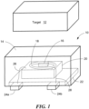
FIG. 1 is a diagram of an example of a magnetic sensor having an integrated coil, not in accordance with the claimed invention. -
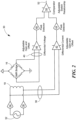
FIG. 2 is a circuit diagram of a magnetic sensor system. -
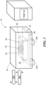
FIG. 3 is a diagram of an embodiment of a magnetic sensor having an integrated coil, which is in accordance with the invention. -
FIGS. 4A and4B are top views of an exemplary coils. -
FIG. 5 is a diagram of an example of a magnetic sensor having an integrated coil and a target, not in accordance with the claimed invention. -
FIG. 6 is a diagram of an example of a magnetic sensor having an integrated coil, not in accordance with the claimed invention. -
FIG. 7 is a diagram of an example of a magnetic sensor having an integrated coil, not in accordance with the claimed invention. -
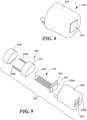
FIG. 8 is a diagram of a magnetic sensor assembly. -
FIG. 9 is a break-out diagram of a magnetic sensor assembly. -
FIG. 10A andFIG. 10B are diagrams of magnetic sensors and targets. -
FIG. 11 is a flowchart of a method for sensing a target. -
FIG. 12 is a flowchart of a method for sensing a target. - Before describing the present invention, some information is provided. As used herein, the term "magnetic field sensing element" is used to describe a variety of electronic elements that can sense a magnetic field. The magnetic field sensing element can be, but is not limited to, a Hall Effect element, a magnetoresistance element, or a magnetotransistor. As is known, there are different types of Hall Effect elements, for example, a planar Hall element, a vertical Hall element, and a Circular Vertical Hall (CVH) element. As is also known, there are different types of magnetoresistance elements, for example, a semiconductor magnetoresistance element such as Indium Antimonide (InSb), a giant magnetoresistance (GMR) element, an anisotropic magnetoresistance element (AMR), a tunneling magnetoresistance (TMR) element, and a magnetic tunnel junction (MTJ). The magnetic field sensing element may be a single element or, alternatively, may include two or more magnetic field sensing elements arranged in various configurations, e.g., a half bridge or full (Wheatstone) bridge. Depending on the device type and other application requirements, the magnetic field sensing element may be a device made of a type IV semiconductor material such as Silicon (Si) or Germanium (Ge), or a type III-V semiconductor material like Gallium-Arsenide (GaAs) or an Indium compound, e.g., Indium-Antimonide (InSb).
- As is known, some of the above-described magnetic field sensing elements tend to have an axis of maximum sensitivity parallel to a substrate that supports the magnetic field sensing element, and others of the above-described magnetic field sensing elements tend to have an axis of maximum sensitivity perpendicular to a substrate that supports the magnetic field sensing element. In particular, planar Hall elements tend to have axes of sensitivity perpendicular to a substrate, while metal based or metallic magnetoresistance elements (e.g., GMR, TMR, AMR) and vertical Hall elements tend to have axes of sensitivity parallel to a substrate.
- As used herein, the term "magnetic field sensor" is used to describe a circuit that uses a magnetic field sensing element, generally in combination with other circuits. Magnetic field sensors are used in a variety of applications, including, but not limited to, an angle sensor that senses an angle of a direction of a magnetic field, a current sensor that senses a magnetic field generated by a current carried by a current-carrying conductor, a magnetic switch that senses the proximity of a ferromagnetic object, a rotation detector that senses passing ferromagnetic articles, for example, magnetic domains of a ring magnet or a ferromagnetic target (e.g., gear teeth) where the magnetic field sensor is used in combination with a back-biased or other magnet, and a magnetic field sensor that senses a magnetic field density of a magnetic field. As used herein, the term "target" is used to describe an object to be sensed or detected by a magnetic field sensor or magnetic field sensing element.
-
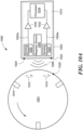
FIG. 1 is a diagram of an exemplary embodiment of amagnetic field sensor 10 and atarget 12.Magnetic field sensor 10 may include apackage 14, sensing element 16 (transducer), andcoil 18. Also included are a semiconductor die or integratedcircuit 20,lead frame 22, and leads 24a and 24b.Wire bonds leads leads - In an embodiment,
target 12 produces or provides a magnetic field. For example, in embodiments,target 12 comprises a hard ferromagnetic target that produces a magnetic field. Alternatively, target 12 can be any type of material that produces a magnetic field including, but not limited to, an electromagnet or other type of circuit. In embodiments, target 12 may also comprise a non-ferromagnetic material capable of having eddy currents induced therein.Target 12 may also comprise a soft ferromagnetic material that changes the magnitude and or direction of a magnetic field near or in proximity to the target. -
Package 14 can be any type of chip or integrated circuit package known in the art, including, but not limited to a plastic package, ceramic package, a glass sealed ceramic package, a low-temperature co-fired ceramic, or a chip-on-board encapsulant. Semiconductor die 20 may comprise one or more integrated circuits that drivecoil 18 andsensing element 16. - In some embodiments,
coil 18 produces a magnetic field.Coil 18 would be a coil of conductive material that, when energized with a current flowing through the material, induces a magnetic field. Integratedcircuit 20 may be configured to drive a changing current throughcoil 18 resulting in a changing magnetic field produced bycoil 18. The changing current may be an alternating current, a ramped current, a pulsed current, transient current, or any type of changing current that causescoil 18 to produce a similarly changing, i.e. complementary, magnetic field. The changing magnetic field produced bycoil 18 may have sufficient magnitude to intersect the body of, and/or induce eddy currents in,target 12. - As shown in
FIG. 1 ,coil 18 is adjacent to integratedcircuit 20. However, this is not a requirement. In various embodiments,coil 18 may be placed in any location that allows the magnetic field produced bycoil 18 to generate eddy currents intarget 12 and to be detected by sensingelement 16. Accordingly,coil 18 may be placed withinpackage 14, on the surface ofintegrated circuit 20, outside ofpackage 14, on the surface ofpackage 14, on a separate substrate withinpackage 14 that is independent ofintegrated circuit 20, etc. -
Coil 18 may also be independent ofpackage 14 and may, for example, be mounted separately frompackage 14.Coil 18 may be encapsulated in its own package. In embodiments, ifcoil 18 is separate frompackage 14,coil 18 may be electrically coupled to integratedcircuit 20 via leads such asleads coil 20 may be electrically coupled to a separate circuit that can drive current throughcoil 18 to produce the magnetic field. In other embodiments where a static, slowly changing, or near-constant magnetic field is desired, thecoil 18 may be replaced with a hard ferromagnetic material (i.e., a permanent magnet). The hard ferromagnetic material may also be placed in any location that allows the ferromagnetic material to be detected by sensingelement 16. Accordingly, the ferromagnetic material may be placed withinpackage 14, on the surface ofintegrated circuit 20, outside ofpackage 14, on the surface ofpackage 14, on a separate substrate withinpackage 14 that is independent ofintegrated circuit 20, etc. The ferromagnetic material may also be independent ofpackage 14 and may, for example, be mounted separately frompackage 14. - Sensing
element 16 may be a magnetic field sensing element, or any other type of circuit that can detect a magnetic field and produce an electrical signal in response to the detected magnetic field. The strength or magnitude of the signal may be proportional to the strength or magnitude of the detected magnetic field. In an embodiment, sensingelement 16 is a Hall Effect element, a magnetoresistive element or circuit, a giant magnetoresistive (GMR) element or circuit, etc. - In operation, sensing
element 16 will detect the magnetic field produced bycoil 18 and be affected by the presence oftarget 12. In the absence oftarget 12, the detected magnetic field (and thus the resulting signal produced by sensing element 16) will have a known value. When this known value is detected, it may indicate the absence oftarget 12. - As
target 12 moves relative tosensor 10, it affects the magnetic field generated bycoil 18 and detected by sensingelement 16. Recall thattarget 12 may produce its own magnetic field. Thus, astarget 12 approachessensor 10, the magnetic field produced bytarget 12 combined with the magnetic field produced bycoil 18. Thus, the presence oftarget 12 causes perturbations or alterations to the known value of the magnetic field produced bycoil 18. These perturbations can be detected by sensingelement 16. For example, magnetic flux detected by sensingelement 16 is a vector sum of the magnetic field produced bytarget 12 and the magnetic field produced bycoil 18. Accordingly, the signal produced by sensingelement 16 represents a combination of the two magnetic fields, i.e. the magnitude of the combined magnetic fields. In embodiments, target 12 may be positioned to enhance the effect that it has on the magnetic field produced bycoil 18. For example, to increase the additive effect of the magnetic fields, target 12 may be positioned so that its magnetic field vector is in-line with (i.e. in the same or opposite direction to, and/or aligned with) the magnetic field vector ofcoil 18 and/or so thattarget 12 is as close as possible tocoil 18 - Integrated
circuit 20 may compare the magnitude of the detected magnetic field to the expected value of the magnetic field produced bycoil 18. If the measured value differs from the expected value, it may indicate the presence or proximity oftarget 12. In embodiments, integrated circuit can also detect the relative distance oftarget 12. For example, the magnetic field oftarget 12 can be aligned so that, the more closely target 12 approachessensor 10, the greater affect the magnetic field produced bytarget 12 has on the magnetic field produced bycoil 18. Thus, astarget 12 approachessensor 10, it will create a greater difference between the measured magnetic field and the expected magnetic field. As this difference changes,sensor 10 can indicate a relative distance betweentarget 12 andsensor 10. Based on the measured, combined magnetic field,sensor 10 may also detect presence or absence of the target. - In an embodiment,
target 12 may move toward and/or away fromsensor 10 during operation. By measuring the magnetic field at sensing element,sensor 10 can detect the presence and/or proximity oftarget 12. In an embodiment,target 12 may be a feature (such as a tooth) on a rotating wheel or gear. As the teeth pass bysensor 10,sensor 10 can create a signal (e.g. viapins 24a and/or 24b) indicating whether a tooth or valley (i.e. gap) in the gear is adjacent tosensor 10. If a tooth is present,sensor 10 can also indicate a relative distance between the tooth andsensor 10. For example, the signal produced bysensor 10 may change in amplitude based on the sensed proximity of the tooth. Additionally, if no tooth is present,sensor 10 may indicate a relative distance (e.g. a relative depth) of the gap based on the amplitude of the signal. Of course, the signal produced bysensor 10 may be analog, digital, or switched. If the signal is switched, a high output may indicate the presence of target 12 (or a tooth thereon) and a low output may indicate the absence oftarget 12, or vice versa. - Turning to
FIG. 2 , an example of acircuit 30 for detecting speed, direction, and/or proximity oftarget 12 is shown. An adjustable, changingcurrent source 32 controlscurrent drivers coil 18 and produce a differential current through signal lines 38. The changing current source may be an AC source, a ramped current source, a switched current source, a pulsed current source, a transient current source, or any other current source that creates a current that changes in magnitude over time. The current throughcoil 18 produces a changing magnetic field which is detected by sensingelement 16. (InFIG. 2 , sensingelement 16 is shown as a giant-magnetoresistive (GMR) bridge). Sensingelement 16 produces a differential voltage signal on signal lines 40. A differentialcurrent amplifier 42 amplifies the differential current applied to thecoil 18 for coupling to apeak detector 44. Adifferential voltage amplifier 46 receives the differential voltage signal from sensingelement 16 for coupling to apeak detector 48.Comparator 50 compares the signals frompeak detectors output signal 52. - The current produced by
coil drivers amplifiers target 12, the differential current onsignal lines 38 will be a known value and the differential voltage produced by sensingelement 16 onsignal lines 40 will be a known value. Astarget 12 moves relative to sensingelement 16, the magnetic field affected bytarget 12 may affect the differential voltage on signal lines 40. This change can be compared to the known value on signal lines 38. Thus, the presence and/or proximity oftarget 12 can change the output ofamplifier 46,peak detector 48, and/orcomparator 50. -
FIG. 3 shows an alternative embodiment of thesensor 10 inFIG. 1 , which is in accordance with the invention. InFIG. 3 , thecoil 18 is placed so that the magnetic field vector produced bycoil 18 is parallel to the top surface ofintegrated circuit 20. In this arrangement, sensingelement 16 comprises multiple GMR elements, which may be positioned on either side ofcoil 18. This arrangement may optimize or improve the ability ofsensor 10 to detecttarget 12 whentarget 12 is located on either "side" ofsensor 10. Because the magnetic field vector produced bycoil 18 has a direction as shown byarrow 300 or arrow 302 (depending on the direction of current through coil 18), the magnetic field produced bytarget 12 may have a greater affect the magnetic field detected by sensingelement 16 whentarget 12 is located on either side ofsensor 10. -
FIG. 4A is a top view of an on-chip coil 400 andsensing element 402 in accordance with the invention. In embodiments,coil 400 may be the same as or similar tocoil 18 andsensing element 402 may be the same as or similar tosensing element 16.Coil 400 may comprise a toroid-shaped coil as shown inFIG. 3 . Alternatively,coil 400 may comprise fabricated substantially two dimensional elements. For example,coil 400 may be a conductive layer masked and fabricated on the surface ofintegrated circuit 20 to create an alternating pattern of straight and diagonal metal lines on two different levels or layers ofintegrated circuit 20. The pattern may be formed from a single conductive layer or multiple conductive layers on integratedcircuit 20, depending upon the fabrication process and design that is used. As shown inFIG. 4A , the conductive layers would be formed of multiple layers of metal, for example. An example of a single conductive layer would be a meander type of pattern where the conductor zig-zags, but does not cross over itself. - When integrated
circuit 20 drives current through the printed coil, it may produce a magnetic field as described above. Similar to the coil shown inFIG. 3 ,coil 400 may produce a magnetic field vector tangent (parallel) to the surface of the die or substrate.Sensing element 402 comprisesGMR elements coil 400 in line with the magnetic field vector produced bycoil 400 to increase sensitivity to the magnetic field. -
FIG. 4B shows an alternative top view layout for an exemplary magnetic field sensor having an on-chip coil 152 and adie 154 supporting asensing element 156. Thesensing element 156 is located proximate tocoil 152. For simplicity, other circuitry of the magnetic field sensor are omitted. - In the illustrated embodiment of
FIG. 4B that does not form part of the claimed subject matter, the position of thesensing element 156 is aligned with one 'side' ofcoil 152. That is, sensingelement 156 is aligned with a portion ofcoil 152 in which current is flowing in the same direction with respect to one side of the die. Other arrangements of coil relative to sensing element position are possible. For example, the sensing element can be generally centered with respect to the coil. In such an embodiment, a sensing element comprising a planar Hall element may be preferred. Also, and again referring to the example embodiment shown inFIG. 4B ,coil 152 is shown as being disposed abovesensing element 156. It will be understood, however, thatcoil 152 could instead be disposed beneath thesensing element 156. Inother embodiments coil 152 may have layers or conductors above and below sensingelements 156. With the latter arrangement, the coil can be fabricated with a standard IC process and then integrated withsensing element 156 in a separate process. The embodiment shown would be advantageous for a sensor sensitive in the plane of the die such as a vertical Hall element or a GMR, AMR, spin-valve, or TMR element. - Insulation layers may be placed between the coil and sensor material and/or die substrate as required by sensor and substrate material selection so as not to short circuit the materials and coil.
- The particular size and geometry of the coil can vary to meet the needs of a particular application. The coil can be formed so that the turns have any practical shape, such as a square or rectangle (as illustrated in the top view of
FIGS. 4A and4B ), or other shapes such as circle, oval, etc., or multiple layers. - In exemplary "on-chip" coil embodiments, the coil is formed using conventional deposition and or etching processes, or patterning and electroplating processes well known to one of ordinary skill in the art. In general, spacing from the coil to the sensing element can vary, in part as a result of voltage isolation requirements and magnetic coupling required, where magnetic coupling is the magnetic field produced by the coil per mA or other unit of current flowing in the coil. In general a higher magnetic coupling level uses less power for a given magnetic field level. It is also understood that insulation layers may be placed between the coils and the sensors and/or other die material to prevent shorting of the coil to other electrical layers in the device.
- In
FIG. 4B , the coil is shown as having a planar spiral geometry. The vias and connections are omitted in the figure (for clarity) but would be apparent to one of ordinary skill in the art. It is understood that multiple metal layers can be used as well as other geometries of metal. Other coil geometries including but not limited to meander coils and solenoids may be used. For example, a cylindrical coil having coil turns of substantially uniform diameter (i.e., a solenoid type coil) may be used. The coil arrangement can include a magnetic flux concentrator, which can be made of a soft magnetic material, to improve the magnetic flux generated by the coil. For example, a soft ferromagnetic core may be provided inside a solenoid type coil to concentrate the magnetic field generated by the coil. - In a cylindrical coil the direction of the magnetic field lines will be parallel to the length of the coil (that is, the longitudinal path of the coil). In a planar spiral coil design the direction of the field lines at the center of the coil will be substantially perpendicular to the plane of the coil but will be substantially parallel to the die surface under the turns of the coil. Consideration may be given to the direction of the field generated by the coil at various locations in choosing the appropriate position and type of the sensing element.
- It will be appreciated that the size of an "on-chip" coil as depicted in
FIG. 4A and4B is likely to be much smaller than coils located elsewhere in a sensor, sensor assembly or application. Because magnetic fields generated by the relatively smaller "on-chip" coils may not be particularly strong, high sensitivity elements such as GMR may be more suitable for an on-chip coil design than less sensitive sensing types of elements such as Hall. - Additional details or alternative techniques for providing a conductive coil on a sensor die may be had with reference to
U.S. Patent Application No. 13/468,478, filed May 10, 2012 U.S. Patent Publication No. 2010/00211347 U.S. Patent No. 8,030,918 , andU.S. Patent No. 8,063,634 , each of which is assigned to the Assignee of the subject application. - Referring to
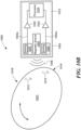
FIG. 5 , another embodiment of amagnetic field sensor 160 including asemiconductor die 162 having a first,active surface 162a in which a magnetic field sensing element orsensing element 164 is formed and a second, opposingsurface 162b attached to a die attacharea 166 on afirst surface 168a of alead frame 168, a first mold portion comprising anon-conductive mold material 170 enclosing the die and at least a portion of the lead frame, and asecond mold portion 172 secured to the non-conductive mold material. Thesecond mold portion 172, which can be a non-conductive material or a ferromagnetic material, is shown as but not required to be tapered from afirst end 172a proximate to thelead frame 168 to asecond end 172b distal from the lead frame. -
Sensing element 164 in this and other embodiments may be the same as or similar tosensing element 16. - It will be appreciated by those of ordinary skill in the art that while the
active surface 162a of the semiconductor die 162 is described herein as the surface "in" which the magnetic field sensing element is disposed or formed as is the case with certain types of magnetic field elements (e.g., Hall plate), the element may be disposed "over" or "on" the active semiconductor surface (e.g., magnetoresistance elements). For simplicity of explanation however, while the embodiments described herein may utilize any suitable type of magnetic field sensing elements, such elements will be described generally herein as being formed or disposed "in" the active semiconductor surface. - In use, the
magnetic field sensor 160 like the other sensor embodiments described herein may be positioned in proximity to a ferromagnetic target, such as the illustrated gear 12', such that the magneticfield sensing element 164 is adjacent to the article 12' and is thereby exposed to a magnetic field altered by movement of the article. The magneticfield sensing element 164 generates a magnetic field signal proportional to the magnetic field. - The
magnetic field sensor 160 generally includes additional circuitry formed in theactive surface 162a of thedie 162 for processing the magnetic field signal provided by thesensing element 164. Thelead frame 168 includesleads 174a - 174c for coupling the circuitry to system components (not shown), such as a power source or microcontroller. Electrical connection between theleads 174a - 174c and the semiconductor die 162 can be provided withwire bonds 176a - 176c, respectively as shown. While thesensor 160 is shown to include threeleads 174a - 174c, it will be appreciated by those of ordinary skill in the art that various numbers of leads are possible. Other techniques for electrically coupling the lead frame leads to the sensor components include solder bumps or balls, or pillar bumps. Thesensor 160 may be provided in the form of a two to six pin Single In-Line (SIP) package, or some other number of pins as appropriate. - The
first mold portion 170 is comprised of a non-conductive material so as to electrically isolate and mechanically protect thedie 162 and the enclosed portion of thelead frame 168. Suitable materials for thenon-conductive mold material 170 include thermoset and thermoplastic mold compounds and other commercially available IC mold compounds. - The non-conductive mold material of the
first mold portion 170 is applied to the lead frame/die subassembly during a molding process to enclose thedie 162 and a portion of thelead frame 168. The non-conductivefirst mold portion 170 has afirst surface 170a and a second, opposingsurface 170b. The shape and dimensions of the non-conductive first mold portion are selected to suit a particular IC package. - The
second mold portion 172 may be the same non-conductive mold compound used to form thefirst mold portion 170. In some embodiments thesecond mold portion 172 is a different non-conductive mold compound or other moldable material than the material used for thefirst mold portion 170. - In some embodiments, the
second mold portion 172 is comprised of a soft ferromagnetic material to form a concentrator. As will be apparent to those of ordinary skill in the art, various materials are suitable for providing theferromagnetic mold material 172 in the form of a soft ferromagnetic material. In some embodiments, it may be desirable for the soft ferromagnetic mold material to have a relatively low coercivity and high permeability. Suitable soft ferromagnetic materials include, but are not limited to permalloy, NiCo alloys, NiFe alloys, steel, nickel, and soft magnetic ferrites. - The
second mold portion 172 can be secured to thefirst mold portion 170 during a step or steps of a molding process, or using an adhesive, such as a thermoset adhesive (e.g., a two part epoxy). - In some embodiments, a portion of the
first mold portion 170 that contacts thesecond mold portion 172 and/or the portion of its mold material that contacts the non-conductive mold material has a securing mechanism in order to improve the adhesion between the two materials and to prevent or reduce lateral slippage or shear between the materials. As one example, thelead frame 168 hasextensions 168c (or "barbs") which extend beyond the non-conductive mold material and are enclosed by the mold material of thesecond mold portion 172, as shown. Such lead frame extensions additionally enhance the adhesion of the second mold portion/material to the lead frame itself. In such embodiments utilizing lead frame portions as a securing mechanism such that the mold material of thesecond mold portion 172 contacts such lead frame portions, it will be appreciated that thesecond mold portion 172 should be non-conductive or have a sufficiently low conductivity to prevent the leads from electrically shorting resulting in the device not operating as intended. Alternative forms of securing mechanisms can be used. - Still referring to
FIG. 5 , thesensor 160 also includes a coil, indicated in this figure byreference numeral 178. In embodiments,coil 178 is a package level coil, i.e. a coil incorporated intopackage mold portion 172.Coil 178 may perform the same or similar function tocoil 18.Coil 178 is positioned relative tosensing element 164 to provide a back bias magnetic field, which can be used to detect the target's profile as it passes the sensor. To this end, thecoil 178 is positioned adjacent to thesecond surface 170b of thenon-conductive mold material 170 so that thesensing element 164 is closer to the target 12' than thecoil 178, as shown. It will be appreciated that it may be desirable in certain applications to rotatesensor 160 by 180° so that thecoil 178 is closer to the target than the sensing element or to rotate the sensor by 90° so that the major face of the sensing element is orthogonal to the target, thereby achieving a different type of magnetically sensitive sensor, as may be desirable when the sensing element is a magnetoresistance element, for example, which has a different axis of sensing element sensitivity than a planar Hall element. It may also be desirable in an embodiment to rotatecoil 178 such that its central axis is parallel to the surface of thedie 162 for certain sensor configurations and sensing element combinations. - Various techniques and materials can be used to form the
coil 178. For example,coil 178 can be formed from copper wire of various sizes and with various automated processes so as to provide an insulator between coil windings. The coil material selection, wire gauge selection, number of turns, and other design choices can be readily varied to suit a particular application so as to produce a magnetic field of a desired strength. Thecoil 178 may be formed so that each turn is in the general shape of, or approximately the shape of, a circle, rectangle, or other general shapes such as an oval, as desirable to suit a particular application and packaging arrangement. -
Coil 178 may be secured to thesecond surface 170b of thenon-conductive mold material 170 by various means. As one example, an adhesive, such as an epoxy, may be used to secure the coil in place. Once secured in place, themold material 172 may be formed by a suitable molding process, such as by injection molding for example. - A mold cavity used to define the
second mold portion 172 may include a mandrel so that the second mold portion forms a ring-shaped structure having acentral aperture 180, here extending from thesecond surface 170b of the non-conductive mold material to asecond end 172b of the second mold portion. Themold material 172 may form a conventional O-shaped ring structure or a D-shaped structure. Alternatively, themold material 172 may form only a partial ring-like structure, as may be described as a "C" or "U" shaped structure. More generally, themold material 172 comprises a non-contiguous central region such that the central region is not formed integrally with its outer region. Such central region may be an open area, such as in the case ofaperture 180 inFIG. 8 , or may contain a mold material, for example, a ferromagnetic mold material. A third mold material may be formed by an additional molding step or other suitable fabrication technique, including but not limited to "potting" or another molding step, so as to secure that third mold material to thesecond mold portion 172. The third mold material may be comprised of a hard ferromagnetic material, a soft ferromagnetic material, or a non-ferromagnetic mold compound. - The
second mold portion 172 is tapered from itsfirst end 172a (or a location close to its first end) to itssecond end 172b as is apparent from the side view ofFIG. 5 . In particular, the second mold portion has a first taper to its outercircumferential surface 182a and a second taper to its innercentral aperture surface 182b. The purpose of the taper is to facilitate removal of thesensor 160 from the mold cavity. The angle of the taper of thesurfaces surfaces taper 182b may have more than a single slope. - The sensor can also be arranged in a lead on chip configuration with the lead frame positioned above the die. An adhesive may be used to secure the lead frame to the active surface of the die.
- Referring to
FIG. 6 , an alternativemagnetic field sensor 190 includes asemiconductor die 192 having a firstactive surface 192a in which a magneticfield sensing element 194 is disposed and a second, opposingsurface 192b attached to a die attacharea 196 on afirst surface 198a of alead frame 198, a first mold portion ornon-conductive mold material 200 enclosing the die and at least a portion of the lead frame, and a second mold portion ormold material 202 secured to a portion of the non-conductive mold material. A securing mechanism, or other suitable mechanisms, may be provided to enhance the adhesion between the first and second mold materials. In embodiments,sensor 190 may be the same as or similar tosensor 10. - The
non-conductive mold material 200 has aprotrusion 204 extending away from asecond surface 198b of thelead frame 198 as shown.Protrusion 204 prevents there being a void in the bottom surface of sensor 190 (adjacent to thesecond end 202b of the mold material), since the presence of a void may make overmolding more difficult. It will be appreciated by those of ordinary skill in the art that the protrusion may extend all or only part of the way to thesecond end 202b of thesecond mold material 202. In the illustrated embodiment ofFIG. 6 ,protrusion 204 terminates before thesecond end 202b of thesecond mold material 202. Thus,distal end 204a of theprotrusion 204 is covered with thesecond mold material 202, as shown. It will also be appreciated that theprotrusion 204, which is shown extending beyond (e.g. below)coil 206, may extend to a position that is not belowcoil 206. Ifprotrusion 204 extends to a position that is not belowcoil 206, thesecond mold material 202 would generally enclose theprotrusion 204 and thecoil 206. -
Sensor 190 includes acoil 206 that may be the same as or similar to thecoil 18 ofFIG. 1 . Here,coil 206 is positioned concentrically with respect to theprotrusion 204 of thenon-conductive mold material 200, although it will be appreciated that concentric positioning is not required. It will be appreciated that the taper toprotrusion 204 may be eliminated or altered as suitable for a particular application. In some applications the protrusion may be useful as an aligning feature forcoil 206 during assembly or manufacturing. Here again,coil 206 may be secured to themold material 200 by an adhesive. Alternatively however,coil 206 may be sized and shaped to provide an interference fit with respect to theprotrusion 204 such that adhesive is not necessary andcoil 206 may be sufficiently held in place relative to themold material 200 by the interference fit when the subassembly, including themold material 200,lead frame 198 and die 192, are placed into the mold cavity for formation of themold material 202. - While
sensor 190 is shown to have aprotrusion 204 extending only partially throughmold material 202 to terminate before thesecond end 202b of thesecond mold material 202, it will be appreciated that a similar sensor including a coil that may be (although is not required to be) concentrically disposed with respect to a protrusion of the non-conductive mold material can be provided with a protrusion of the type which extends to thesecond end 202b ofsecond mold material 202 or theprotrusion 204 may extend beyond thesecond end 202b of thesecond mold material 202. - The
second mold material 202 is tapered from afirst end 202a proximate to thelead frame 198 to asecond end 202b distal from the lead frame. Thesecond mold material 202 is tapered along both its outercircumferential surface 208a and itsinner surface 208b from itsfirst end 202a to itssecond end 202b. Here again, the angle of taper of thesurface 208a may be on the order of less than 15-20 degrees. The angle of the taper of theinner surface 208b may be the same as or similar to the angle of the taper of theouter surface 208a. - The
second mold material 202 has a non-contiguous central region, here in the form of a central aperture defined by theinner surface 208b. This non-contiguous central region ofmold material 202 may take various shapes, so as to form an O-shaped, D-shaped, C-shaped, or U-shaped structure as examples. - The second mold material can be provided in the form of a non-conductive material or ferromagnetic material such as a soft ferromagnetic material or hard ferromagnetic material. For example, in embodiments in which the material is a soft ferromagnetic material, the magnetic field generated by the coil can be focused or otherwise concentrated as desired by the soft ferromagnetic mold material. Alternatively, in embodiments in which the material is a hard ferromagnetic material, the magnetic field provided by the coil can be used to modulate the magnetic field provided by the hard ferromagnetic material, in order to thereby reduce the peak current otherwise required to provide the same magnetic field strength with just the coil (i.e., if the hard ferromagnetic mold material were not present). Since the back bias functionality is provided by the coil, the second mold portion/material may be eliminated entirely (as is shown in
FIG. 10 ) in which case the non-conductive mold material with the coil attached to its surface can be packaged to provide the resulting sensor IC. Such an arrangement can be provided in a package of the type described in aU.S. Patent No. 6,265,865 or aU.S. Patent No. 5,581,179 , each of which is assigned to the Assignee of the subject application. - In applications including the second mold portion/material, such mold material may be tapered from a first end proximate to the lead frame to a second end distal from the lead frame (or for some portion thereof) and the sensor may, optionally, include a third mold material in the form of an overmold in order to protect and electrically insulate the device.
-
Sensor 190 may, optionally, include athird mold material 210 in the form of an overmold in order to protect and electrically insulate the device. Thethird mold material 210 may be applied during a third molding step/process or alternatively by any suitable fabrication method.Overmold 210 is considered optional because its purpose is to provide electrical insulation. In embodiments in whichferromagnetic mold material 202 provides sufficient insulation (e.g., provides more than approximately 1 mega-Ohm of resistance in certain applications),overmold 210 may be eliminated. It will be appreciated thatovermold 210 may be provided for the sensor ofFIG. 1 ,3 ,4 ,5 and other embodiments. Suitable materials for providingovermold material 210 include, but are not limited to standard die encapsulation mold compounds such as PPS, nylon, SUMIKON® EME of Sumitomo Bakelite Co., Ltd., or Hysol® mold compounds of Henkel AG & Co. KGaA. - Referring to
FIG. 7 , an alternativemagnetic field sensor 220 includes asemiconductor die 222 having a firstactive surface 222a in which a magneticfield sensing element 224 is disposed and a second, opposingsurface 222b attached to a die attacharea 226 on afirst surface 228a of alead frame 228 and anon-conductive mold material 230 enclosing the die and at least a portion of the lead frame. In an embodiment,sensor 220 may be the same as or similar tosensor 10. -
Sensor 220 includes acoil 232 secured to, and more particularly, enclosed by, thenon-conductive mold material 230. The wire ofcoil 232 may be wound around a mandrel orbobbin 234, as shown. In one illustrative embodiment,mandrel 234 may be comprised of a soft ferromagnetic material or a plastic and remain part of the final device. In other embodiments,mandrel 234 is used during coil winding but then not made a part of the final package.Mandrel 234 andcoil 232 may be secured to thesurface 228b oflead frame 228 that is opposite thedie 222 with an adhesive or other securing mechanism such thatcoil 232 is secured to thelead frame 228 when the subassembly is placed in a mold cavity and thenon-conductive mold material 230 is formed. - Additional details or alternative techniques for providing a package with one or multiple mold materials may be had with reference to
U.S. Patent Application No. 13/748,999, filed January 24, 2013 - The signal may be provided to the coil through extra pins, allowing an external connection to the coil. The signal may be an AC signal, a ramped signal, a pulsed signal, or any other type of changing (e.g. non-DC) signal that, when applied to the coil, can produce a changing magnetic field. Alternatively, the signal could be provided through connections to the die. For example, a wire coupled to a coil terminal could be soldered to the die or connected to the die via wire bonds. In an alternative embodiment, a portion of the lead frame could be used to connect to the coil wire and to the die (e.g., via a wire bond). These connection areas of the lead frame could be unconnected to the remainder of the lead frame after molding and trimming. Any other suitable connecting means could be used.
-
FIGS. 8-9 illustrate yet another type of packaging for a magnetic field sensor with a coil. Referring toFIGS. 8 and 9 , a magneticfield sensor assembly 240 includes a packaged magneticfield sensor IC 242, acoil unit 244, and a housing having a case (or housing shell) 246 and anend cap 248.Case 246 has afirst end 250a with an opening (not shown) and asecond end 250b that includes awindow 252. When each of these elements is serially placed through theopening 250a of case 246 (in the order ofsensor IC 242, thencoil unit 244 followed by theend cap 248, as shown in the exploded view ofFIG. 9 ), the "fully assembled" magneticfield sensor assembly 240 takes on the form shown in the configuration shown inFIG. 8 . Although the housing is shown as a two-piece housing having a generally cylindrical shape, other types of housings could be used as well. - The packaged magnetic
field sensor IC 242 is shown to include afirst package portion 254 corresponding to a magnetic field sensor chip within a protective package body and a second package portion, in the form of conductive leads 256. There may be threeconductive leads 256, with a lead to correspond to the power and ground connections and a lead for the output signal (as shown in the embodiments ofFIGS. 3 and6 , for a "three-wire" device), or some other number of leads.Coil unit 244 may include acoil body portion 257 containing a coil (which can be, e.g., a spiral coil, a solenoid type coil, solenoid type coil with a soft ferromagnetic core, or other type of coil configuration) andconductive leads - Alternatively, for a coil unit design that integrates a magnetic flux concentrator or guide, the top of coil body portion 257 (i.e., the part between the coil and the sensing element of the
sensor 242 IC) could be made of plastic (or other mold compound) or non-ferromagnetic material, and the sides and bottom ofcoil body portion 257 could be made of a soft ferromagnetic material to help reduce the reluctance path, i.e., guide the magnetic flux more efficiently. - One of the leads, e.g., lead 258a, is a signal input for connecting to the signal source (e.g.,
coil input line 26, shown inFIG. 1 ). As described above, the signal source may be a changing signal (i.e. a non-DC signal) that can produce a changing magnetic field when applied to the coil. The other lead, e.g., lead 258b, is a ground terminal for connecting to a reference potential (e.g. ground). The coil ofcoil unit 244 may be driven in electrical isolation from thesensor IC 242 with no common node. If, however, the sensor IC ground and the coil unit ground are to be tied together, then theassembly 240 could be designed to have one less pin/lead for external connections. In theassembly 240, theleads 256 of the packaged sensor IC and leads 258 of thecoil unit 244 extend outwardly from the opening in thefirst end 250a of thecase 246. Thefirst package portion 254 is positioned in thecase 246 part way through thewindow 252 so that afirst body face 260 extends outwardly fromsecond end 250b of thecase 246. When thesensor assembly 240 is mounted in an application, thefirst body face 260 will be positioned in proximity to the target's profile. - The illustrative housing of
FIGS. 8-9 can be constructed according to techniques like those described in the above-referencedU.S. Patent No. 5,581,179 , or other suitable techniques. Thecase 246 can be formed of a polymeric insulating material, as described in the aforementioned patent, or, alternatively, a soft ferromagnetic material. In other embodiments, a separate magnetic flux concentrator may be included in the assembly. -
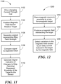
FIG. 10A andFIG. 10B illustrate examples of amagnetic sensor system 1000 for detecting anon-ferromagnetic target 1001. As shown inFIG. 10A ,sensor system 1000 includes amagnetic field sensor 1003 having one or more magneticfield sensing elements Sensor 1003 may include a sensor integrated circuit or die 1015 and one or more magnetic sources (e.g. coils or magnets, such as a back-bias magnet) 1005 capable of producingmagnetic field 1006. Although shown as having two magneticfield sensing elements sensor 1003 may contain fewer or more than two sensing elements. Although shown as having a single magnetic source,sensor 1003 may include multiple magnetic sources. One skilled in the art will recognize that, ifsensor 1003 has more than one magnetic source, the magnetic fields produced by those sources may be viewed as a single, combinedmagnetic field 1006 produced by multiple discrete sources. It is also noted that the orientation of the magnetic source to the sensing element or sensing elements shown inFigs. 10A andB is schematic in nature and may be modified in various embodiments. For example, sensor 1003 (and/or die 1015) may be positioned between amagnetic source 1005 and atarget 1001. In other embodiments the magnetic source or sources and sensing element or elements have different positions relative to the target. -
Sensing elements figures 1-9 . In otherembodiments sensing elements elements magnetic field 1006. Alternatively,magnetic source 1005 may be mounted separately fromdie 1015. In such an embodiment,source 1005 may be positioned relative to target 1001 so that amagnetic field 1006 intersects the body oftarget 1001. Althoughmagnetic source 1005 is shown inFIG. 10A and10B as part of die 1015, this is not a requirement. In various embodiments,magnetic source 1005 may be separate from die 1015, part of die 1015, mounted or placed adjacent to or on die 1015, etc. For example, in various embodiments,magnetic source 1005 may be arranged in any configuration or arrangement that allowsmagnetic source 1005 to produce amagnetic field 1006 that can be detected by sensingelements 1002 and/or 1004. Examples of such configurations and arrangements are described above in relation toFigs. 1-9 . - As described above,
magnetic field 1006 or may be a static magnetic field produced by a permanent magnet (e.g. a hard ferromagnetic material) or an electromagnet with a DC or other slowly changing current to produce a magnetic field. - Although shown having two sensing
elements system 1000 may include only a single sensing element, or may include more than two sensing elements. As will be described below, one or more sensing element(s) can be used to detect proximity, presence, speed, direction, and other properties oftarget 1001. - In an embodiment,
target 1001 is a non-ferromagnetic target.Target 1001 may comprise a conductive material such as copper, aluminum, titanium, etc., and may have a size and thickness that allow eddy currents to form within, on, or near the surface oftarget 1001. - In operation,
magnetic source 1005 producesmagnetic field 1006 andsensing elements magnetic field 1006. In an embodiment,sensing elements signals Amplifiers processor 1034.Processor 1034 then processes the signals to determine presence, speed, direction, position, or other properties oftarget 1001. In other embodiments other variations of circuitry could be used to sense the target. - Through operation of Faraday's law of induction, since the body of
target 1001 is conductive (and/or paramagnetic),magnetic field 1006 induces an eddy current (e.g.eddy current 1010 and/or eddy current 1012) on or near the surface oftarget 1001. In the case wheremagnetic fields 1006 is a changing magnetic field, changes in the magnetic field will induce the eddy currents intarget 1001. In the case wheremagnetic field 1006 is a static magnetic field, motion of the conductive target through the magnetic field, causeeddy currents target 1001 or 1001'. Irregular features or shapes of the target can influence the presence or magnitude of the induced eddy currents. -
Multiple eddy currents magnetic field 1006 may induce a single eddy current or multiple eddy currents intarget 1001, which may be added or combined together to form a combined eddy current withintarget 1001. In certain embodiments,magnetic source 1005 may be configured to produce a shapedmagnetic field 1006. In other words,magnetic source 1005 may produce multiple magnetic fields that add together in various patterns so that the resulting, combined magnetic field has local areas that are relatively strong and local areas that are relatively weak. In such embodiments,magnetic source 1005 may comprise multiple coils, magnets, or other magnetic sources. By shaping themagnetic field 1006,magnetic source 1005 can control the location, direction, and strength of theeddy currents target 1001. - The
eddy currents target 1001 create their own, secondary magnetic fields, which oppose changes inmagnetic field 1006 in thetarget 1001. These magnetic field changes can be due, for example, tomagnetic source 1005 changing the strength or shape ofmagnetic field 1006 over time. In other embodiments, ifmagnetic field 1006 is a static (e.g. non-changing, or slowly-changing) magnetic field, the motion (e.g. rotation) oftarget 1001 throughmagnetic field 1006 may causetarget 1001 to produce eddy currents which result in changes to themagnetic field 1006. The magnetic fields caused byeddy currents magnetic field 1006, and may increase or reduce the amount of magnetic flux flowing through themagnetic sensing elements 1002 and 1004.Thus,eddy currents field sensing elements target 1001 were not present, no eddy currents or opposing magnetic field would be induced, and thus the amplitude of the signals produced by the magnetic field sensing elements would not be increased or reduced. Accordingly,system 1000 can detect the presence oftarget 1001 by detecting a change in amplitude of the signals produced by sensingelements - In the case where
magnetic field 1006 is a static magnetic field, motion of the target through the magnetic field causes changes toeddy currents FIG. 10A , apoint 1020 on the surface oftarget 1001 may have negligible magnetic field when it is relatively distant frommagnetic source 1005. Aspoint 1020 approaches apoint 1022 onsensor 1003, it will be exposed to an increasing magnitude ofmagnetic field 1006, and thereby create eddy current 1010 to oppose that change. Similarly, aspoint 1020 passes point 1024 onsensor 1003, it will see a decrease in the magnetic field frommagnetic source 1005, thus creating aneddy current 1012 to oppose this change. - Given the direction of target rotation shown by arrow 1026,
eddy current 1010 will reduce the field sensed by magneticfield sensing element 1004, andeddy current 1012 will increase the field sensed by magneticfield sensing element 1002. If the direction of rotation is opposite,eddy currents eddy current 1010 will increase the field sensed by magneticfield sensing element 1004 andeddy current 1012 will decrease the field sensed by magneticfield sensing element 1002. Thus, the amplitude of the signal produced by magneticfield sensing elements system 1000 can detect the direction oftarget 1001 rotation by detecting a change in the signals produced by sensingelements system 1000. - Magnetic
field sensing elements sensing element target 1001. For example, as shown,sensing element 1002 is closer toeddy current 1012 andsensing element 1004 is closer toeddy current 1010. Thus, the magnetic field sensed by sensingelement 1002 will be more greatly affected byeddy current 1012 and the magnetic field sensed by sensingelement 1004 will be more greatly affected byeddy current 1010. -
Target 1001 may also have irregular features, such asfeature 1014.Feature 1014 may be a valley, gap, recess, a non-conductive region, a less conductive region, or any type of region that changes theeddy currents magnetic fields 1006 and 1008. In another embodiment, thefeature 1014 could be a tooth, bump, or protrusion of the target. In another embodiments combinations of gaps and protrusions would be possible, for example, but not limited to approximately three different radial distances from the center of rotation, i.e. a valley, a nominal radius, and a tooth. Thus, whenfeature 1014 is adjacent tomagnetic field 1006 or 1008, the eddy current induced intarget 1001 may be different from the eddy current induced whenfeature 1014 is not adjacent tomagnetic field 1006 or 1008. For example, iffeature 1014 is a gap or a non-conductive region, there may be no eddy current induced withinregion 1014 and no opposing magnetic field. Alternatively, an eddy current may be induced infeature 1014, but the eddy current may have a different strength or magnitude than eddy current 1012 or 1010 that are induced in the main body oftarget 1001. - The
sensor 1003 andsensing elements feature 1014 and produce a signal indicating thatfeature 1014 has been detected. If the target is rotating at a particular speed, peaks or valleys may appear onsignals feature 1014 passes by sensingelement Processor 1034 can detect and process these peaks and valleys to determine speed, presence, position, direction of rotation, etc. - In another embodiment, the main body of
target 1001 may be non-conductive, whilefeature 1014 may be conductive. In this case, eddy currents may be induced withinfeature 1014 but not within the main body oftarget 1001. Thus, the opposing magnetic field may only be present whenfeature 1014 is adjacent tosensor -
FIG. 10B illustrates another embodiment ofsystem 1000 that has an irregularly shaped target 1001'. Due to the irregular shape (shown as an oval inFIG. 10B ), as target 1001' rotatespast sensors sensors region 1016 of target 1001' is closer tosensor 1004 thanregion 1018 is tosensor 1002. - Because
region 1016 is closer thanregion 1018 tomagnetic field 1006,eddy current 1010 may be stronger thaneddy current 1012, because the eddy currents are induced bymagnetic field 1006. Accordingly, the magnetic field produced byeddy current 1010 may be stronger than the magnetic field produced byeddy current 1012. Additionally, because the magnetic field produced byeddy current 1010 is closer tosensor 1004 than the magnetic field produced byeddy current 1012 is tosensor 1002, theeddy current 1010 may have a greater effect on the magnetic flux flowing through the magnetic sensing element withinsensor 1004. Thus, the magnetic field induced inregion 1016 may provide a different response in the sensor than the magnetic field induced inregion 1018. In other words,sensors System 1000 may thus determine the position, speed, and/or direction of target 1001' based on which regions of irregularly shaped target 1001' are adjacent to the sensors as target 1001' moves. - Although shown as an elliptical target, target 1001' can have any irregular shape so long as some regions of target 1001' can be closer to the sensors while other regions can be further away. For example, target 1001' can be a toothed wheel, a toothed rack in a rack and pinion system, a square or rectangle having corners, or any other shape having protrusions or other features that can move relative to
sensors - In the case where
magnetic fields 1006 and 1008 are static (i.e. DC) fields, the irregular features or shapes oftargets 1001 and 1001', and/or the motion of the targets, may induce the eddy current within the target. Recall that eddy currents are caused by a changing magnetic field through a conductor. Therefore, if the target is stationary and the magnetic fields are static, no eddy currents will form because the magnetic field intersecting the target will not be changing. However, eddy currents will be created within the body of the target as it moves or rotates through a static magnetic field. Iftarget 1001 or 1001' contains no irregular features or shapes, eddy currents having a constant strength will be induced in the body oftarget 1001 as it rotates. As long as the target is moving, these eddy currents can be used to detect the presence oftarget 1001. As the speed oftarget 1001 changes, the magnitude of the eddy currents, and the strength of the magnetic fields produced by the eddy currents, will also change. Thus, the sensors can also detect the speed of the target by measuring the strength of the magnetic field produced by the eddy currents. - As the features and irregular shapes of
target 1001 and target 1001' move through the magnetic field, the eddy currents (and thus the magnetic fields produced by the eddy currents) will change. For example, astarget 1001 rotates and feature 1014 moves through the magnetic fields, the irregular shape or conductivity offeature 1014 passing through the magnetic field causes changes to the eddy currents withintarget 1001. Similarly, as the irregular shape of target 1001' rotates through the magnetic fields, regions of target 1001' move relatively closer or relatively further away from the sensors. This also causes the eddy currents induced in target 1001' to change. These changes can be detected by thesensors - In certain configurations,
system 1000 may be able to detect direction of motion oftarget 1001. In one embodiment, the system is comprised of twosensors target 1001 is spinning in a clockwise direction, feature 1014 will pass bysensor 1002 first, and pass bysensor 1004 second. Accordingly, the signal produced bysensor 1002 to indicate the presence offeature 1014 will precede the signal produced bysensor 1004. Conversely, iftarget 1001 is turning in a counter-clockwise direction, the signal produced bysensor 1004 to indicate the presence offeature 1014 will precede the signal produced bysensor 1002. By monitoring the phase relationship signals produced bysensor 1002 andsensor 1004,system 1000 can determine the speed and direction oftarget 1001. - Although shown as a rotating target,
target 1001 can also be a linear target, such as a rack in a rack and pinion system, or any other type of target that can move relative tosensors -
FIG. 11 is a flowchart of aprocess 1100 for sensing a magnetic field. Inblock 1102, a circuit (e.g. integratedcircuit 20 inFIG. 1 ) may drive a changing current though a coil (e.g. coil 18). In an embodiment, the changing current may be a periodic current such as an AC current, a saw tooth pattern current, a pulsed current, a DC, or a near DC current etc. As described above, the current through the coil produces a changing magnetic field. Inblock 1104, a sensor (e.g. sensor 10) is positioned relative to a target. Alternatively, the target may be positioned relative to the sensor. The target may be a conductive target, a ferromagnetic target, a magnet, an electromagnet, or another type of target that generates a magnetic field. Inblock 1106, a signal is generated representing the strength of the combined magnetic field from the coil and magnetic field from the target. The signal may be generated by sensingelement 16, for example. Inblock 1108, the signal is compared to an expected magnetic field strength value. Inblock 1110, a signal is generated that represents changes to the expected magnetic field produced by the presence oftarget 12. The signal may represent the proximity of the target to the sensor. The signal may be used to calculate proximity, position, speed, and direction of the target, among other properties of the target. -
FIG. 12 is a flowchart of anotherprocess 1200 for sensing a magnetic field. Inblock 1202, a non-ferromagnetic target is placed in proximity to magnetic field source. For example, thetarget 1001 infigure 10A may be placed in proximity tosensor 1002 and/or 1004. Inblock 1204, a magnetic field is produced by a magnet or an electromagnet. The field intersects the target and can be sensed by sensingelements 1002 and/or 1004. Inblock 1206, an eddy current is induced in the target, and variations to the magnetic field caused by the eddy current are detected. - It is understood that exemplary embodiments of a magnetic sensors and systems that produce a changing magnetic field are applicable to a wide variety of applications. For example, in one embodiment, a magnetic sensor with an integrated coil is optimized for seat belt detection. In another embodiment, a magnetic sensor is optimized for seat position detection with air gaps in the order of about 0.5 to about 3 mm. In other embodiments the sensor may be optimized for air gaps as large as 1 cm. In another embodiment, a magnetic sensor is optimized to detect motion of an automotive transmission, wheel, or axle.
- Having described preferred embodiments, which serve to illustrate various concepts, structures and techniques, which are the subject of this patent, it will now become apparent to those of ordinary skill in the art that other embodiments incorporating these concepts, structures and techniques may be used. It will be appreciated that the various features shown and described in connection with the various embodiments can be selectively combined. Accordingly, it is submitted that that scope of the patent should not be limited to the described embodiments but rather should be limited only by the scope of the following claims.
Claims (14)
- A magnetic field sensor (402) comprising:a semiconductor substrate (20);a coil (400) provided on a surface of the semiconductor substrate and configured to provide a changing magnetic field having a magnetic field vector with a direction parallel to a surface of the semiconductor substrate on which the coil is supported in response to a changing current in the coil; anda plurality of giant magnetoresistive elements, GMRs, arranged in a bridge ) configuration and supported by the substrate (20) for detecting a target by detecting variations in the changing magnetic field caused by proximity of a target (12) that provides a magnetic field;characterized in that:
a first pair (406, 408) of the GMRs of the bridge configuration is positioned at an end of the coil (400) and a second pair (410, 412) of the GMRs of the bridge is positioned at an opposing end of the coil (18) to increase sensitivity of the magnetic field sensor to a proximal target located in line with the magnetic field vector. - The magnetic field sensor (402) of claim 1 wherein the coil (400) is formed from at least one metal layer disposed on a surface of the substrate (20).
- The magnetic field sensor (402) of claim 1 further including a current source coupled to the coil (400).
- The magnetic field sensor (402) of claim 1 further including a pulsed or transient current source coupled to the coil (400).
- The magnetic field sensor (402) of claim 1 wherein the coil (400) is positioned above or below the substrate (20).
- The magnetic field sensor of claim 1 wherein the coil (400) is a separately formed element included in a same package with the substrate (20).
- The magnetic field sensor (402) of claim 1 wherein the magnetic field vector (300, 302) has a direction which is either towards or away from the target (12).
- The magnetic field sensor (402) of any preceding claim wherein a target that provides a magnetic field may comprise any one of: a hard ferromagnetic material, a soft ferromagnetic material, a non-ferromagnetic material, or any type of material that produces a magnetic field.
- A method of detecting a magnetic field comprising:providing a semiconductor substrate (20);driving a changing current through a coil (400) provided on a surface of the semiconductor substrate so that the coil (18) generates a changing magnetic field having a magnetic field vector with a direction parallel to a surface of the semiconductor substrate (20) on which the coil (18) is supported; anddetecting, with a plurality of giant magnetoresistive elements, GMRs, arranged in a bridge configuration and supported by the substrate (20), a target by detecting variations in the changing magnetic field caused by proximity of a target (12) that provides a magnetic field;characterized in that:
a first pair (406, 408) of the GMRs of the bridge configuration is positioned at an end of the coil (400) and a second pair (410, 412) of the GMRs of the bridge is positioned at an opposing end of the coil (18) to increase sensitivity of the magnetic field sensor to a proximal target located in line with the magnetic field vector. - The method of claim 9 further comprising forming the coil (400) from one or more metal layers disposed on a surface of the substrate (20).
- The method of claim 9 further comprising supplying a pulsed or transient current to the coil (400).
- The method of claim 9 further comprising attaching the coil (400) to a top or bottom surface of the substrate (20).
- The method of claim 9 further comprising providing the coil (400) as a separately formed element within a same package as the substrate (20).
- The method of claim 9 wherein a target that provides a magnetic field may comprise any one of: a hard ferromagnetic material, a soft ferromagnetic material, a non-ferromagnetic material, or any type of material that produces a magnetic field.
Applications Claiming Priority (2)
| Application Number | Priority Date | Filing Date | Title |
|---|---|---|---|
| US13/946,400 US10145908B2 (en) | 2013-07-19 | 2013-07-19 | Method and apparatus for magnetic sensor producing a changing magnetic field |
| PCT/US2014/044993 WO2015009442A1 (en) | 2013-07-19 | 2014-07-01 | Methods and apparatus for magnetic sensor producing a changing magnetic field |
Publications (2)
| Publication Number | Publication Date |
|---|---|
| EP3019883A1 EP3019883A1 (en) | 2016-05-18 |
| EP3019883B1 true EP3019883B1 (en) | 2024-05-01 |
Family
ID=51220895
Family Applications (1)
| Application Number | Title | Priority Date | Filing Date |
|---|---|---|---|
| EP14742423.8A Active EP3019883B1 (en) | 2013-07-19 | 2014-07-01 | Methods and apparatus for magnetic sensor producing a changing magnetic field |
Country Status (6)
| Country | Link |
|---|---|
| US (4) | US10145908B2 (en) |
| EP (1) | EP3019883B1 (en) |
| JP (1) | JP6427184B2 (en) |
| KR (1) | KR101926383B1 (en) |
| CN (1) | CN105378500B (en) |
| WO (1) | WO2015009442A1 (en) |
Families Citing this family (68)
| Publication number | Priority date | Publication date | Assignee | Title |
|---|---|---|---|---|
| US9001527B2 (en) * | 2008-02-18 | 2015-04-07 | Cyntec Co., Ltd. | Electronic package structure |
| US9678175B2 (en) * | 2010-07-26 | 2017-06-13 | Radiation Monitoring Devices, Inc. | Eddy current detection |
| US9479019B2 (en) * | 2012-01-16 | 2016-10-25 | Hamilton Sundstrand Corporation | Brushless starter generator |
| US9817078B2 (en) | 2012-05-10 | 2017-11-14 | Allegro Microsystems Llc | Methods and apparatus for magnetic sensor having integrated coil |
| US10145908B2 (en) | 2013-07-19 | 2018-12-04 | Allegro Microsystems, Llc | Method and apparatus for magnetic sensor producing a changing magnetic field |
| US10495699B2 (en) | 2013-07-19 | 2019-12-03 | Allegro Microsystems, Llc | Methods and apparatus for magnetic sensor having an integrated coil or magnet to detect a non-ferromagnetic target |
| US9823092B2 (en) | 2014-10-31 | 2017-11-21 | Allegro Microsystems, Llc | Magnetic field sensor providing a movement detector |
| FR3038060B1 (en) * | 2015-06-26 | 2018-11-02 | Atware | APPARATUS FOR MEASURING A QUANTITY OF SUPERPARAMAGNETIC MATERIAL |
| JP6533004B2 (en) * | 2015-07-08 | 2019-06-19 | エーエスエムエル ネザーランズ ビー.ブイ. | Measurement system, lithography apparatus, device manufacturing method, and measurement method |
| US11402440B2 (en) | 2015-07-17 | 2022-08-02 | Allegro Microsystems, Llc | Methods and apparatus for trimming a magnetic field sensor |
| US9939410B2 (en) * | 2015-09-01 | 2018-04-10 | Infineon Technologies Ag | Transmission of information associated with a possible sensor fault of a magnetic sensor |
| CN105242222A (en) * | 2015-09-11 | 2016-01-13 | 合肥联宝信息技术有限公司 | Method for measuring magnetic field radiation and magnetic field probe |
| JP2017083280A (en) * | 2015-10-28 | 2017-05-18 | 株式会社東海理化電機製作所 | Semiconductor device and magnetic sensor device |
| WO2017073280A1 (en) * | 2015-10-29 | 2017-05-04 | Tdk株式会社 | Magnetism-detecting device and moving-body-detecting device |
| US10012518B2 (en) | 2016-06-08 | 2018-07-03 | Allegro Microsystems, Llc | Magnetic field sensor for sensing a proximity of an object |
| US10247758B2 (en) * | 2016-08-08 | 2019-04-02 | Allegro Microsystems, Llc | Current sensor |
| DE102016224856A1 (en) * | 2016-12-13 | 2018-06-14 | Robert Bosch Gmbh | Sensor system for determining at least one rotational property of an element rotating about at least one axis of rotation |
| CN107015171B (en) * | 2017-03-24 | 2023-10-24 | 江苏多维科技有限公司 | Magnetic sensor packaging structure with hysteresis coil |
| KR102380348B1 (en) * | 2017-03-24 | 2022-03-31 | 삼성전자주식회사 | Wireless power transmitter and method for transmitting wireless power according to an aspect of a cradle in a wireless power transmitter |
| US10837943B2 (en) * | 2017-05-26 | 2020-11-17 | Allegro Microsystems, Llc | Magnetic field sensor with error calculation |
| US10641842B2 (en) | 2017-05-26 | 2020-05-05 | Allegro Microsystems, Llc | Targets for coil actuated position sensors |
| US10996289B2 (en) * | 2017-05-26 | 2021-05-04 | Allegro Microsystems, Llc | Coil actuated position sensor with reflected magnetic field |
| US10310028B2 (en) | 2017-05-26 | 2019-06-04 | Allegro Microsystems, Llc | Coil actuated pressure sensor |
| US10324141B2 (en) * | 2017-05-26 | 2019-06-18 | Allegro Microsystems, Llc | Packages for coil actuated position sensors |
| US11428755B2 (en) * | 2017-05-26 | 2022-08-30 | Allegro Microsystems, Llc | Coil actuated sensor with sensitivity detection |
| FR3068463B1 (en) * | 2017-06-30 | 2019-07-26 | Continental Automotive France | CURRENT SENSOR |
| US10480957B2 (en) * | 2017-07-20 | 2019-11-19 | Allegro Microsystems, Llc | Magnetic field sensor to detect direction of angular rotation of a rotating magnetic structure, speed of the rotating magnetic structure or fault |
| US20210190893A1 (en) | 2017-10-06 | 2021-06-24 | Melexis Technologies Nv | Magnetic sensor sensitivity matching calibration |
| EP3467528B1 (en) * | 2017-10-06 | 2020-05-20 | Melexis Technologies NV | Magnetic sensor sensitivity matching calibration |
| KR102387464B1 (en) | 2017-10-12 | 2022-04-15 | 삼성전자주식회사 | Apparatus and method for testing interconnect circuit, and method for manufacturing semiconductor device comprising the method |
| FR3073354B1 (en) * | 2017-11-06 | 2019-10-18 | Safran | COMPOSITE COMPONENT WITH INTEGRATED INSTRUMENTATION ELECTRONIC CIRCUIT AND METHOD FOR MANUFACTURING THE SAME |
| EP3496118A1 (en) * | 2017-12-07 | 2019-06-12 | Koninklijke Philips N.V. | Air-core inductor assembly |
| WO2019131812A1 (en) | 2017-12-27 | 2019-07-04 | 旭化成エレクトロニクス株式会社 | Magnetic sensor module, and ic chip employed in same |
| US11248971B2 (en) | 2018-02-02 | 2022-02-15 | Analog Devices International Unlimited Company | Magnetic field torque and/or angle sensor |
| US11143732B2 (en) * | 2018-02-21 | 2021-10-12 | Allegro Microsystems, Llc | Magnetic field sensor with modulated diagnostic signal |
| EP3531076B1 (en) | 2018-02-23 | 2021-07-14 | Allegro MicroSystems, LLC | Angle sensor using eddy currents |
| US10866117B2 (en) | 2018-03-01 | 2020-12-15 | Allegro Microsystems, Llc | Magnetic field influence during rotation movement of magnetic target |
| US10917092B2 (en) | 2018-04-06 | 2021-02-09 | Allegro Microsystems, Llc | Magnetic field sensor with switching network |
| DE102018111011A1 (en) * | 2018-05-08 | 2019-11-14 | Infineon Technologies Ag | Magnetic field sensor device |
| US10823586B2 (en) | 2018-12-26 | 2020-11-03 | Allegro Microsystems, Llc | Magnetic field sensor having unequally spaced magnetic field sensing elements |
| US11061084B2 (en) | 2019-03-07 | 2021-07-13 | Allegro Microsystems, Llc | Coil actuated pressure sensor and deflectable substrate |
| US11333232B2 (en) * | 2019-03-14 | 2022-05-17 | Dana Automotive Systems Group, Llc | Eddy current sensor assembly |
| JP2020148640A (en) | 2019-03-14 | 2020-09-17 | 株式会社東芝 | Current detector |
| US11165014B2 (en) * | 2019-03-29 | 2021-11-02 | Ablic Inc. | Semiconductor device |
| US10955306B2 (en) | 2019-04-22 | 2021-03-23 | Allegro Microsystems, Llc | Coil actuated pressure sensor and deformable substrate |
| DE102019110570B4 (en) | 2019-04-24 | 2023-05-25 | Infineon Technologies Ag | MAGNETIC FIELD SENSOR PACKAGE WITH INTEGRATED PASSIVE COMPONENT |
| CN109991446B (en) * | 2019-04-24 | 2021-06-25 | 中广核工程有限公司 | Nuclear power station main pump magnetoelectric speed sensor test device and test method |
| US11150110B2 (en) | 2019-08-01 | 2021-10-19 | Allegro Microsystems, Llc | Sensor having a shaped coil |
| EP4085266A1 (en) * | 2019-11-13 | 2022-11-09 | EV-Technologies | Spin-wave based magnetic and/or electro-magnetic field sensing device for dc, rf and millimeter-wave applications |
| US11237020B2 (en) | 2019-11-14 | 2022-02-01 | Allegro Microsystems, Llc | Magnetic field sensor having two rows of magnetic field sensing elements for measuring an angle of rotation of a magnet |
| US11280637B2 (en) | 2019-11-14 | 2022-03-22 | Allegro Microsystems, Llc | High performance magnetic angle sensor |
| CN114599937A (en) * | 2019-11-29 | 2022-06-07 | 海拉有限双合股份公司 | Linear motion sensor |
| DE102019220492A1 (en) | 2019-12-20 | 2021-06-24 | Infineon Technologies Ag | INDUCTIVE ANGLE AND / OR POSITION SENSOR |
| US11169223B2 (en) | 2020-03-23 | 2021-11-09 | Allegro Microsystems, Llc | Hall element signal calibrating in angle sensor |
| US11262422B2 (en) | 2020-05-08 | 2022-03-01 | Allegro Microsystems, Llc | Stray-field-immune coil-activated position sensor |
| CN111896899B (en) * | 2020-07-06 | 2021-06-11 | 苏州佳祺仕信息科技有限公司 | Gaussian detection probe |
| US11637482B2 (en) | 2020-10-08 | 2023-04-25 | Analog Devices International Unlimited Company | Magnetic sensor system for motor control |
| US11435206B2 (en) | 2020-10-28 | 2022-09-06 | Allegro Microsystems, Llc | Phase compensation for an inductive position sensor |
| US11326903B1 (en) | 2020-11-13 | 2022-05-10 | Allegro Microsystems, Llc | Rotary inductive sensor |
| US11460286B2 (en) | 2020-11-13 | 2022-10-04 | Allegro Microsystems, Llc | Rotary inductive sensor |
| US11733316B2 (en) | 2020-12-14 | 2023-08-22 | Allegro Microsystems, Llc | Position sensor having harmonic distortion compensation |
| US11927650B2 (en) | 2021-01-04 | 2024-03-12 | Allegro Microsystems, Llc | Magnetic-field closed-loop sensors with diagnostics |
| US11366141B1 (en) | 2021-01-28 | 2022-06-21 | Allegro Microsystems, Llc | Multipath wide bandwidth current sensor |
| US11460323B2 (en) | 2021-02-05 | 2022-10-04 | Analog Devices International Unlimited Company | Magnetic field sensor package |
| US11493361B2 (en) | 2021-02-26 | 2022-11-08 | Allegro Microsystems, Llc | Stray field immune coil-activated sensor |
| US11630130B2 (en) | 2021-03-31 | 2023-04-18 | Allegro Microsystems, Llc | Channel sensitivity matching |
| US11578997B1 (en) | 2021-08-24 | 2023-02-14 | Allegro Microsystems, Llc | Angle sensor using eddy currents |
| WO2023055688A1 (en) * | 2021-09-29 | 2023-04-06 | Lam Research Corporation | Voltage and current probe assemblies for radio frequency current carrying conductors |
Family Cites Families (470)
| Publication number | Priority date | Publication date | Assignee | Title |
|---|---|---|---|---|
| US3132337A (en) | 1960-09-12 | 1964-05-05 | Ibm | Variable reluctance slotted drum position indicating device |
| US3195043A (en) | 1961-05-19 | 1965-07-13 | Westinghouse Electric Corp | Hall effect proximity transducer |
| DE1514822A1 (en) | 1964-08-14 | 1969-06-26 | Telefunken Patent | Method for manufacturing a semiconductor device |
| US3607528A (en) | 1968-02-08 | 1971-09-21 | James S Gassaway | Magnetic memory members and methods of making the same |
| US3661061A (en) | 1969-05-05 | 1972-05-09 | Atomic Energy Commission | Picture position finder |
| US3611138A (en) | 1970-03-05 | 1971-10-05 | Gen Motors Corp | Tachometer system including an rf signal modulator and detector |
| FR2114148A5 (en) | 1970-11-16 | 1972-06-30 | Crouzet Sa | |
| JPS576962Y2 (en) | 1974-07-26 | 1982-02-09 | ||
| DE2518054C2 (en) | 1975-04-23 | 1984-08-02 | Siemens AG, 1000 Berlin und 8000 München | Arrangement for determining the direction of rotation of a rotary movement |
| US4048670A (en) | 1975-06-30 | 1977-09-13 | Sprague Electric Company | Stress-free hall-cell package |
| FR2396417A1 (en) | 1977-06-29 | 1979-01-26 | Tokyo Shibaura Electric Co | SEMICONDUCTOR COMPONENT INCLUDING A RESISTOR |
| US4204317A (en) | 1977-11-18 | 1980-05-27 | The Arnold Engineering Company | Method of making a lead frame |
| US4180753A (en) | 1978-06-30 | 1979-12-25 | Ford Motor Company | Apparatus for generating electrically distinguishable bipolar signals using a magnetic sensor and an oval wheel with teeth and notches in its minor and major axis |
| US4188605A (en) | 1978-07-21 | 1980-02-12 | Stout Glenn M | Encapsulated Hall effect device |
| US4283643A (en) | 1979-05-25 | 1981-08-11 | Electric Power Research Institute, Inc. | Hall sensing apparatus |
| US4315523A (en) | 1980-03-06 | 1982-02-16 | American Flow Systems, Inc. | Electronically controlled flow meter and flow control system |
| DE3030620A1 (en) | 1980-08-13 | 1982-03-11 | Siemens AG, 1000 Berlin und 8000 München | ARRANGEMENT FOR CHANGING THE ELECTRICAL CIRCUIT CONFIGURATION OF INTEGRATED SEMICONDUCTOR CIRCUITS |
| US4670715A (en) | 1983-01-28 | 1987-06-02 | Caterpillar Inc. | Frictionally supported gear tooth sensor with self-adjusting air gap |
| CA1238389A (en) | 1983-02-07 | 1988-06-21 | Nl Industries, Inc. | Spinner transducer |
| CA1212997A (en) | 1983-12-16 | 1986-10-21 | Gerard Durou | Frequency scanning eddy current non destructive testing method and system |
| JPS60152256A (en) | 1984-01-18 | 1985-08-10 | Atsugi Motor Parts Co Ltd | Manufacture of motor |
| JPS60257546A (en) | 1984-06-04 | 1985-12-19 | Mitsubishi Electric Corp | Semiconductor device and manufacture thereof |
| CH664632A5 (en) | 1984-08-16 | 1988-03-15 | Landis & Gyr Ag | CIRCUIT ARRANGEMENT FOR COMPENSATING VARIATIONS OF THE TRANSMISSION FACTOR OF A MAGNETIC FIELD SENSOR. |
| US4614111A (en) | 1985-02-15 | 1986-09-30 | Wolff George D | Position sensor for fuel injection apparatus |
| SE447608B (en) | 1985-04-03 | 1986-11-24 | Hightech Network Ab | PROCEDURE AND DEVICE FOR SETTING A DIGITAL REGULATOR |
| KR910002313B1 (en) | 1985-05-10 | 1991-04-11 | 아사히가세이고오교 가부시끼가이샤 | Magneto-electric converting element |
| US4719419A (en) | 1985-07-15 | 1988-01-12 | Harris Graphics Corporation | Apparatus for detecting a rotary position of a shaft |
| JPS6234316A (en) | 1985-08-07 | 1987-02-14 | Victor Co Of Japan Ltd | Magnetic head using magneto-resistance effect element and its manufacture |
| JPH0665967B2 (en) | 1985-08-27 | 1994-08-24 | 株式会社エスジー | Absolute rotational position detector |
| EP0242492B1 (en) | 1985-12-28 | 1992-08-05 | Yamaha Corporation | An improved non-contact type pattern sensor |
| JPS62235523A (en) | 1986-03-19 | 1987-10-15 | Honda Motor Co Ltd | Manufacture of rotational angle sensor |
| US4833406A (en) | 1986-04-17 | 1989-05-23 | Household Commercial Financial Services Inc. | Temperature compensated Hall-effect sensor apparatus |
| US4649796A (en) | 1986-06-18 | 1987-03-17 | The United States Of America As Represented By The Secretary Of The Army | Method and apparatus for setting a projectile fuze during muzzle exit |
| US4745363A (en) | 1986-07-16 | 1988-05-17 | North American Philips Corporation | Non-oriented direct coupled gear tooth sensor using a Hall cell |
| JP2587412B2 (en) | 1986-09-09 | 1997-03-05 | 日本電気株式会社 | Magnetic detector |
| DE3632624C1 (en) | 1986-09-25 | 1988-03-10 | Balluff Gebhard Feinmech | Proximity switch insensitive to interference fields |
| JPS6384176A (en) | 1986-09-29 | 1988-04-14 | Toshiba Corp | Magnetic focusing type hall element and manufacture thereof |
| US4746859A (en) | 1986-12-22 | 1988-05-24 | Sundstrand Corporation | Power and temperature independent magnetic position sensor for a rotor |
| US4772929A (en) | 1987-01-09 | 1988-09-20 | Sprague Electric Company | Hall sensor with integrated pole pieces |
| US4789826A (en) | 1987-03-19 | 1988-12-06 | Ampex Corporation | System for sensing the angular position of a rotatable member using a hall effect transducer |
| US4760285A (en) | 1987-03-30 | 1988-07-26 | Honeywell Inc. | Hall effect device with epitaxal layer resistive means for providing temperature independent sensitivity |
| JPS63263782A (en) | 1987-04-22 | 1988-10-31 | Hitachi Ltd | Magnetoelectric converter |
| FR2614695B1 (en) | 1987-04-28 | 1989-06-23 | Commissariat Energie Atomique | METHOD FOR THE DIGITIZATION AND LINEARIZATION OF A SENSOR WITH QUASI-SINUSOIDAL PERIODIC CHARACTERISTICS AND CORRESPONDING DEVICE |
| GB8711559D0 (en) | 1987-05-15 | 1987-06-17 | Ssd Ltd | Shaft encoders |
| US5012322A (en) | 1987-05-18 | 1991-04-30 | Allegro Microsystems, Inc. | Semiconductor die and mounting assembly |
| JPH0612266B2 (en) | 1987-05-30 | 1994-02-16 | 株式会社安川電機 | Multi-turn absolute value encoder |
| US4823075A (en) | 1987-10-13 | 1989-04-18 | General Electric Company | Current sensor using hall-effect device with feedback |
| US5078944A (en) | 1987-11-02 | 1992-01-07 | Matsushita Electric Industrial Co., Ltd. | Method for making permanent magnet type demagnetizing head |
| US4983916A (en) | 1988-01-26 | 1991-01-08 | Yamaha Corporation | Compact magnetic encoder |
| ES2039019T3 (en) | 1988-04-21 | 1993-08-16 | Landis & Gyr Business Support Ag | INTEGRATED SEMICONDUCTOR CIRCUIT WITH A MAGNETIC FIELD SENSOR MADE OF SEMICONDUCTOR MATERIAL. |
| EP0357013A3 (en) | 1988-09-02 | 1991-05-15 | Honeywell Inc. | Magnetic field measuring circuit |
| JPH0248882U (en) | 1988-09-30 | 1990-04-04 | ||
| US4910861A (en) | 1988-10-07 | 1990-03-27 | Emerson Electric Co. | Method of manufacturing retention structure for electric motor rotor magnets |
| KR930004094Y1 (en) | 1988-10-11 | 1993-06-30 | 미쓰비시전기 주식회사 | Hall eefect type sensing device and magnetic circuit device for a hall effect type sensor |
| JPH02116753A (en) | 1988-10-26 | 1990-05-01 | Mitsubishi Electric Corp | Detector for direction of rotation |
| JP2598493B2 (en) | 1988-11-04 | 1997-04-09 | 大同特殊鋼株式会社 | Torque sensor |
| JPH02149013A (en) | 1988-11-30 | 1990-06-07 | Toshiba Corp | Oscillation circuit |
| EP0388584B1 (en) | 1989-01-17 | 1993-10-27 | Gec Alsthom Sa | Device for determining the position of a steel shaft comprising an electrically discontinuous band and procedure for manufacturing said band |
| KR910004884B1 (en) | 1989-02-01 | 1991-07-15 | 한국식품개발연구원 | Against oxidation of oils |
| US5789915A (en) | 1989-02-17 | 1998-08-04 | Nartron Corporation | Magnetic field energy responsive position sensing apparatus and method |
| US4935698A (en) | 1989-03-03 | 1990-06-19 | Sprague Electric Company | Sensor having dual Hall IC, pole piece and magnet |
| JPH02236183A (en) | 1989-03-09 | 1990-09-19 | Mitsubishi Electric Corp | Hall sensor device and its manufacture |
| US5196794A (en) | 1989-03-14 | 1993-03-23 | Mitsubishi Denki K.K. | Hall-effect sensor with integrally molded frame, magnet, flux guide and insulative film |
| JPH0329817A (en) | 1989-06-28 | 1991-02-07 | Fanuc Ltd | Wireless manual encoder |
| JP2522214B2 (en) | 1989-10-05 | 1996-08-07 | 日本電装株式会社 | Semiconductor device and manufacturing method thereof |
| US5121289A (en) | 1990-01-31 | 1992-06-09 | Honeywell Inc. | Encapsulatable sensor assembly |
| US5021493A (en) | 1990-03-21 | 1991-06-04 | The Goodyear Tire & Rubber Company | Rubber composition and tire with component(s) thereof |
| US5045920A (en) | 1990-06-28 | 1991-09-03 | Allegro Microsystems, Inc. | Dual-Hall ferrous-article-proximity sensor |
| JP2734759B2 (en) | 1990-08-13 | 1998-04-02 | 株式会社デンソー | Rotation detection device |
| DE4031560C2 (en) | 1990-10-05 | 1993-10-14 | Dieter Prof Dr Ing Seitzer | Current sensor with components sensitive to magnetic fields and use |
| JPH04152688A (en) | 1990-10-17 | 1992-05-26 | Fujitsu Ltd | Magnetoresistance element |
| US5432444A (en) | 1990-10-23 | 1995-07-11 | Kaisei Engineer Co., Ltd. | Inspection device having coaxial induction and exciting coils forming a unitary coil unit |
| US5038130A (en) | 1990-11-06 | 1991-08-06 | Santa Barbara Research Center | System for sensing changes in a magnetic field |
| US5185919A (en) | 1990-11-19 | 1993-02-16 | Ford Motor Company | Method of manufacturing a molded fuel injector |
| US5139973A (en) | 1990-12-17 | 1992-08-18 | Allegro Microsystems, Inc. | Method for making a semiconductor package with the distance between a lead frame die pad and heat spreader determined by the thickness of an intermediary insulating sheet |
| US5216405A (en) | 1991-01-14 | 1993-06-01 | General Motors Corporation | Package for the magnetic field sensitive device |
| US5167896A (en) | 1991-01-16 | 1992-12-01 | Kyowa Electric & Chemical Co., Ltd. | Method of manufacturing a front cabinet for use with a display |
| US5349743A (en) | 1991-05-02 | 1994-09-27 | At&T Bell Laboratories | Method of making a multilayer monolithic magnet component |
| DE4114835A1 (en) | 1991-05-07 | 1992-11-12 | Vdo Schindling | SWITCHING DEVICE, IN PARTICULAR FOR USE IN MOTOR VEHICLES |
| US5491633A (en) | 1991-05-20 | 1996-02-13 | General Motors Corporation | Position sensor for electromechanical suspension |
| JP2958821B2 (en) | 1991-07-08 | 1999-10-06 | 株式会社村田製作所 | Solid inductor |
| DE69232236T2 (en) | 1991-07-16 | 2002-08-08 | Asahi Chemical Ind | SEMICONDUCTOR SENSOR AND ITS MANUFACTURING METHOD |
| EP0537419A1 (en) | 1991-10-09 | 1993-04-21 | Landis & Gyr Business Support AG | Device comprising an integrated magnetic field sensor and first and second magnetic flux concentrator, and method to build into a container of synthetic material a plurality of these devices |
| KR940004952B1 (en) | 1991-11-08 | 1994-06-07 | 주식회사 금성사 | Arrangement for starting dc motor |
| US5247278A (en) | 1991-11-26 | 1993-09-21 | Honeywell Inc. | Magnetic field sensing device |
| DE4141959A1 (en) | 1991-12-19 | 1993-06-24 | Swf Auto Electric Gmbh | SPEED SENSOR, IN PARTICULAR GEAR SENSOR |
| CA2080177C (en) | 1992-01-02 | 1997-02-25 | Edward Allan Highum | Electro-magnetic shield and method for making the same |
| US5210493A (en) | 1992-02-27 | 1993-05-11 | General Motors Corporation | Method for embedding wires within a powder metal core and sensor assembly produced by such a method |
| US5545983A (en) | 1992-03-02 | 1996-08-13 | Seiko Epson Corporation | Displacement sensor with temperature compensation by combining outputs in a predetermined ratio |
| US5286426A (en) | 1992-04-01 | 1994-02-15 | Allegro Microsystems, Inc. | Assembling a lead frame between a pair of molding cavity plates |
| US5304926A (en) | 1992-04-08 | 1994-04-19 | Honeywell Inc. | Geartooth position sensor with two hall effect elements |
| US5250925A (en) | 1992-05-11 | 1993-10-05 | General Motors Corporation | Package for speed sensing device having minimum air gap |
| US5319543A (en) | 1992-06-19 | 1994-06-07 | First Data Health Services Corporation | Workflow server for medical records imaging and tracking system |
| US5757181A (en) | 1992-06-22 | 1998-05-26 | Durakool Incorporated | Electronic circuit for automatically compensating for errors in a sensor with an analog output signal |
| US5497081A (en) | 1992-06-22 | 1996-03-05 | Durakool Incorporated | Mechanically adjustable linear-output angular position sensor |
| US5332965A (en) | 1992-06-22 | 1994-07-26 | Durakool Incorporated | Contactless linear angular position sensor having an adjustable flux concentrator for sensitivity adjustment and temperature compensation |
| CH683469A5 (en) | 1992-07-03 | 1994-03-15 | Landis & Gyr Business Support | Semiconductor wafer contg. magnetic field sensor - is installed between pole shoes of laminated ferromagnetic magnetic flux concentrator to measure magnetic field in proximity |
| JP2691665B2 (en) | 1992-07-07 | 1997-12-17 | 日本精機株式会社 | Guideline manufacturing method |
| US5691637A (en) | 1992-08-28 | 1997-11-25 | True Position Magnetics, Inc. | Magnetic field position transducer for two or more dimensions |
| US5341097A (en) | 1992-09-29 | 1994-08-23 | Honeywell Inc. | Asymmetrical magnetic position detector |
| US5289344A (en) | 1992-10-08 | 1994-02-22 | Allegro Microsystems Inc. | Integrated-circuit lead-frame package with failure-resistant ground-lead and heat-sink means |
| ES2110555T3 (en) | 1992-10-21 | 1998-02-16 | Bosch Gmbh Robert | DEVICE FOR THE DETECTION OF THE MOVEMENT OF A MOBILE PART. |
| US5469058A (en) | 1992-12-30 | 1995-11-21 | Dunnam; Curt | Feedback enhanced sensor, alternating magnetic field detector |
| JPH06273437A (en) | 1993-03-22 | 1994-09-30 | Yazaki Corp | Rotation detection apparatus |
| GB2276727B (en) | 1993-04-01 | 1997-04-09 | Rolls Royce & Ass | Improvements in and relating to magnetometers |
| US5424558A (en) | 1993-05-17 | 1995-06-13 | High Yield Technology, Inc. | Apparatus and a method for dynamically tuning a particle sensor in response to varying process conditions |
| DE4319146C2 (en) | 1993-06-09 | 1999-02-04 | Inst Mikrostrukturtechnologie | Magnetic field sensor, made up of a magnetic reversal line and one or more magnetoresistive resistors |
| US5351028A (en) | 1993-06-14 | 1994-09-27 | Honeywell Inc. | Magnetoresistive proximity sensor |
| US5329416A (en) | 1993-07-06 | 1994-07-12 | Alliedsignal Inc. | Active broadband magnetic flux rate feedback sensing arrangement |
| JPH07128295A (en) | 1993-10-20 | 1995-05-19 | Kobe Steel Ltd | Method for measuring crystal grain size of steel plate |
| JPH07203645A (en) | 1993-12-30 | 1995-08-04 | Mabuchi Motor Co Ltd | Manufacture of miniature motor and rotor thereof |
| US5477143A (en) | 1994-01-11 | 1995-12-19 | Honeywell Inc. | Sensor with magnetoresistors disposed on a plane which is parallel to and displaced from the magnetic axis of a permanent magnet |
| US5831431A (en) * | 1994-01-31 | 1998-11-03 | Fraunhofer-Gesellschaft Zur Foerderung Der Angewandten Forschung E.V. | Miniaturized coil arrangement made by planar technology, for the detection of ferromagnetic materials |
| US5514953A (en) | 1994-02-24 | 1996-05-07 | Seagate Technology, Inc. | Wafer level test structure for detecting multiple domains and magnetic instability in a permanent magnet stabilized MR head |
| WO1995023343A1 (en) * | 1994-02-28 | 1995-08-31 | Philips Electronics N.V. | Device for measuring magnetic fields |
| US5414355A (en) | 1994-03-03 | 1995-05-09 | Honeywell Inc. | Magnet carrier disposed within an outer housing |
| US5434105A (en) | 1994-03-04 | 1995-07-18 | National Semiconductor Corporation | Process for attaching a lead frame to a heat sink using a glob-top encapsulation |
| US5508611A (en) | 1994-04-25 | 1996-04-16 | General Motors Corporation | Ultrathin magnetoresistive sensor package |
| US6104231A (en) | 1994-07-19 | 2000-08-15 | Honeywell International Inc. | Temperature compensation circuit for a hall effect element |
| DE9414104U1 (en) | 1994-08-31 | 1994-11-03 | Siemens Ag | Proximity switch with magnetically sensitive sensor |
| JPH0897486A (en) | 1994-09-22 | 1996-04-12 | Hitachi Cable Ltd | Hall sensor |
| US5581170A (en) | 1994-12-12 | 1996-12-03 | Unitrode Corporation | Battery protector |
| US5500589A (en) | 1995-01-18 | 1996-03-19 | Honeywell Inc. | Method for calibrating a sensor by moving a magnet while monitoring an output signal from a magnetically sensitive component |
| US5488294A (en) | 1995-01-18 | 1996-01-30 | Honeywell Inc. | Magnetic sensor with means for retaining a magnet at a precise calibrated position |
| JPH08201490A (en) | 1995-01-31 | 1996-08-09 | Mitsumi Electric Co Ltd | Sensor ic |
| ES2160226T3 (en) | 1995-02-02 | 2001-11-01 | Siemens Ag | DEVICE FOR MEASURING THE NUMBER OF REVOLUTIONS OR TO DETECT THE SENSE OF TURN OF A ROTATING MAGNETIC FIELD. |
| DE19510579C2 (en) | 1995-03-23 | 1997-08-21 | Inst Physikalische Hochtech Ev | Angle of rotation or speed sensor |
| US5627315A (en) | 1995-04-18 | 1997-05-06 | Honeywell Inc. | Accelerometer with a cantilever beam formed as part of the housing structure |
| JP3605880B2 (en) | 1995-05-12 | 2004-12-22 | 株式会社デンソー | Non-contact rotation sensor |
| US5581179A (en) | 1995-05-31 | 1996-12-03 | Allegro Microsystems, Inc. | Hall-effect ferrous-article-proximity sensor assembly |
| US5781005A (en) | 1995-06-07 | 1998-07-14 | Allegro Microsystems, Inc. | Hall-effect ferromagnetic-article-proximity sensor |
| US5705751A (en) | 1995-06-07 | 1998-01-06 | Setra Systems, Inc. | Magnetic diaphragm pressure transducer with magnetic field shield |
| US5818222A (en) | 1995-06-07 | 1998-10-06 | The Cherry Corporation | Method for adjusting ferrous article proximity detector |
| US5719496A (en) | 1995-06-07 | 1998-02-17 | Durakool Incorporated | Dual-element proximity sensor for sensing the direction of rotation of a ferrous target wheel |
| WO1997006404A2 (en) | 1995-08-02 | 1997-02-20 | Durakool Inc | Gear tooth sensor with improved resolution and stability |
| US5596272A (en) | 1995-09-21 | 1997-01-21 | Honeywell Inc. | Magnetic sensor with a beveled permanent magnet |
| US5696790A (en) | 1995-10-04 | 1997-12-09 | Tut Systems, Inc. | Method and apparatus for time dependent data transmission |
| US5712562A (en) | 1995-10-13 | 1998-01-27 | Bently Nevada Corporation | Encapsulated transducer with an alignment plug and method of manufacture |
| DE19539458C2 (en) | 1995-10-24 | 2001-03-15 | Bosch Gmbh Robert | Sensor with test input |
| EP0772046B1 (en) | 1995-10-30 | 2002-04-17 | Sentron Ag | Magnetic field probe and current or energy probe |
| DE19540674C2 (en) | 1995-10-31 | 1999-01-28 | Siemens Ag | Adaptation procedure for correcting tolerances of an encoder wheel |
| US5621319A (en) | 1995-12-08 | 1997-04-15 | Allegro Microsystems, Inc. | Chopped hall sensor with synchronously chopped sample-and-hold circuit |
| JPH09166612A (en) | 1995-12-18 | 1997-06-24 | Nissan Motor Co Ltd | Magnetic sensor |
| US6525531B2 (en) | 1996-01-17 | 2003-02-25 | Allegro, Microsystems, Inc. | Detection of passing magnetic articles while adapting the detection threshold |
| US6297627B1 (en) | 1996-01-17 | 2001-10-02 | Allegro Microsystems, Inc. | Detection of passing magnetic articles with a peak-to-peak percentage threshold detector having a forcing circuit and automatic gain control |
| US5631557A (en) | 1996-02-16 | 1997-05-20 | Honeywell Inc. | Magnetic sensor with encapsulated magnetically sensitive component and magnet |
| FR2748105B1 (en) | 1996-04-25 | 1998-05-29 | Siemens Automotive Sa | MAGNETIC SENSOR AND METHOD FOR PRODUCING SUCH A SENSOR |
| JPH09292471A (en) | 1996-04-26 | 1997-11-11 | Nippon Cement Co Ltd | Metal detector |
| CH690934A5 (en) | 1996-04-29 | 2001-02-28 | Suisse Electronique Microtech | A position detection and motion in magnetic field variation. |
| JP2816668B2 (en) | 1996-07-04 | 1998-10-27 | 愛知製鋼株式会社 | Method for manufacturing magnetically anisotropic resin-bonded magnet |
| JPH1031784A (en) | 1996-07-17 | 1998-02-03 | Glory Ltd | Commodity storing device for automatic vending machine |
| US6822443B1 (en) | 2000-09-11 | 2004-11-23 | Albany Instruments, Inc. | Sensors and probes for mapping electromagnetic fields |
| DE19634715A1 (en) | 1996-08-28 | 1998-03-05 | Teves Gmbh Alfred | Arrangement for detecting the turning behavior of a wheel |
| US5912347A (en) | 1996-09-30 | 1999-06-15 | Mallinckrodt Inc. | Process for preparing a morphinan derivative |
| US5896030A (en) | 1996-10-09 | 1999-04-20 | Honeywell Inc. | Magnetic sensor with components attached to transparent plate for laser trimming during calibration |
| US6175233B1 (en) | 1996-10-18 | 2001-01-16 | Cts Corporation | Two axis position sensor using sloped magnets to generate a variable magnetic field and hall effect sensors to detect the variable magnetic field |
| US5912556A (en) | 1996-11-06 | 1999-06-15 | Honeywell Inc. | Magnetic sensor with a chip attached to a lead assembly within a cavity at the sensor's sensing face |
| US5729128A (en) | 1996-11-22 | 1998-03-17 | Honeywell Inc. | Magnetic sensor with a magnetically sensitive component that is movable during calibration and rigidly attachable to a formed magnet |
| US5859387A (en) | 1996-11-29 | 1999-01-12 | Allegro Microsystems, Inc. | Semiconductor device leadframe die attach pad having a raised bond pad |
| DE19650935A1 (en) | 1996-12-07 | 1998-06-10 | Teves Gmbh Alfred | Method and circuit arrangement for the transmission of speed information and additional data |
| US6323642B1 (en) | 1997-01-24 | 2001-11-27 | Diamond Electric Mfg. Co., Ltd. | Detector for determining rotational speed and position for an internal combustion engine |
| JPH10232242A (en) | 1997-02-19 | 1998-09-02 | Mitsubishi Electric Corp | Detector |
| US5839185A (en) | 1997-02-26 | 1998-11-24 | Sundstrand Corporation | Method of fabricating a magnetic flux concentrating core |
| JP4093381B2 (en) | 1997-04-01 | 2008-06-04 | 株式会社デンソー | Detection signal processing device for rotation sensor |
| FR2761772B1 (en) | 1997-04-07 | 1999-05-21 | Suisse Electronique Microtech | MICRO-MACHINED INDUCTIVE SENSOR, PARTICULARLY FOR MEASURING THE POSITION AND/OR MOVEMENT OF AN OBJECT |
| JPH10318784A (en) | 1997-05-20 | 1998-12-04 | Matsushita Electric Ind Co Ltd | Revolution sensor |
| US6198373B1 (en) | 1997-08-19 | 2001-03-06 | Taiyo Yuden Co., Ltd. | Wire wound electronic component |
| US5963028A (en) | 1997-08-19 | 1999-10-05 | Allegro Microsystems, Inc. | Package for a magnetic field sensing device |
| JPH1164363A (en) | 1997-08-25 | 1999-03-05 | Aisin Seiki Co Ltd | Rotation detector |
| JP3745509B2 (en) | 1997-08-27 | 2006-02-15 | 株式会社Neomax | Cylindrical resin magnet molding equipment |
| ES2262241T3 (en) | 1997-09-15 | 2006-11-16 | Ams International Ag | CURRENT SUPERVISION SYSTEM AND MANUFACTURING PROCEDURE OF THIS SYSTEM. |
| AU9458398A (en) | 1997-10-08 | 1999-04-27 | Kaneka Corporation | Balloon catheter and method of production thereof |
| US5883567A (en) | 1997-10-10 | 1999-03-16 | Analog Devices, Inc. | Packaged integrated circuit with magnetic flux concentrator |
| US6452381B1 (en) | 1997-11-28 | 2002-09-17 | Denso Corporation | Magnetoresistive type position detecting device |
| US6011770A (en) | 1997-12-10 | 2000-01-04 | Texas Instrumental Incorporated | Method and apparatus for high-order bandpass filter with linearly adjustable bandwidth |
| US6136250A (en) | 1998-01-30 | 2000-10-24 | Comair Rotron, Inc. | Apparatus and method of encapsulating motors |
| JP2002507751A (en) | 1998-03-20 | 2002-03-12 | コンティネンタル・テーベス・アクチエンゲゼルシヤフト・ウント・コンパニー・オッフェネ・ハンデルスゲゼルシヤフト | Motion detection sensor device |
| JPH11304414A (en) | 1998-04-21 | 1999-11-05 | Mitsubishi Electric Corp | Magnetism detecting device |
| US6242905B1 (en) | 1998-04-23 | 2001-06-05 | Siemens Aktiengesellschaft | Method for identifying the direction of rotation of a wheel using hall probes |
| JPH11304415A (en) | 1998-04-23 | 1999-11-05 | Mitsubishi Electric Corp | Magnetism detecting device |
| JPH11325960A (en) * | 1998-05-14 | 1999-11-26 | Mitsubishi Electric Corp | Magnetic detecting element, its production and magnetic detector |
| US6809515B1 (en) | 1998-07-31 | 2004-10-26 | Spinix Corporation | Passive solid-state magnetic field sensors and applications therefor |
| US6032536A (en) | 1998-09-28 | 2000-03-07 | Xerox Corporation | Pressure sensor and method for detecting pressure |
| JP3378816B2 (en) | 1998-12-21 | 2003-02-17 | 三洋電機株式会社 | Semiconductor device and manufacturing method thereof |
| US20010009367A1 (en) | 1999-02-26 | 2001-07-26 | Dieter Seitzer | Sensor device to record speed and motion direction of an object, especially rotational speed and direction of a rotating object |
| US6278269B1 (en) | 1999-03-08 | 2001-08-21 | Allegro Microsystems, Inc. | Magnet structure |
| EP1037017B1 (en) | 1999-03-15 | 2003-12-17 | Atsutoshi Goto | Inductive position detector |
| US6351506B1 (en) | 1999-04-19 | 2002-02-26 | National Semiconductor Corporation | Switched capacitor filter circuit having reduced offsets and providing offset compensation when used in a closed feedback loop |
| JP2001043475A (en) | 1999-07-27 | 2001-02-16 | Nsk Ltd | Transmitting method for detection signal of sensor |
| DE19937155A1 (en) | 1999-08-06 | 2001-03-15 | Bosch Gmbh Robert | System for generating a signal for superimposing information |
| US6436748B1 (en) | 1999-08-31 | 2002-08-20 | Micron Technology, Inc. | Method for fabricating CMOS transistors having matching characteristics and apparatus formed thereby |
| JP2001141738A (en) | 1999-11-18 | 2001-05-25 | Sumitomo Electric Ind Ltd | Rotation sensor and manufacturing method thereof |
| FR2801445A1 (en) | 1999-11-23 | 2001-05-25 | Koninkl Philips Electronics Nv | AMPLIFIER WITH ADJUSTABLE BANDWIDTH |
| JP3506078B2 (en) | 1999-11-25 | 2004-03-15 | 株式会社デンソー | Rotation detection device |
| JP4964358B2 (en) | 1999-12-07 | 2012-06-27 | 株式会社デンソー | Rotation sensor detection signal processing apparatus and rotation sensor detection signal output method |
| JP2001165702A (en) | 1999-12-10 | 2001-06-22 | Sumitomo Electric Ind Ltd | Magnetic variate detecting sensor |
| DE19961504A1 (en) | 1999-12-20 | 2001-06-28 | Bosch Gmbh Robert | Rotational speed signal error detection method for anti-slip or anti-lock regulation system of vehicle, involves detecting speed change based on specific condition involving pulse width of falling pulses of measurement signal |
| US6640451B1 (en) | 2000-01-28 | 2003-11-04 | Visteon Global Technologies, Inc. | System and method for sensing the angular position of a rotatable member |
| US6504363B1 (en) | 2000-03-07 | 2003-01-07 | Teodor Dogaru | Sensor for eddy current testing and method of use thereof |
| US6492697B1 (en) | 2000-04-04 | 2002-12-10 | Honeywell International Inc. | Hall-effect element with integrated offset control and method for operating hall-effect element to reduce null offset |
| JP3600114B2 (en) | 2000-04-04 | 2004-12-08 | 株式会社デンソー | Rotation angle detector |
| US6580269B2 (en) | 2000-04-14 | 2003-06-17 | Melexis Uk Ltd. | Magnetic sensing devices and systems |
| US6724191B1 (en) | 2000-05-09 | 2004-04-20 | Admiralty Corporation | Systems and methods useful for detecting presence and/or location of various materials |
| US6501270B1 (en) | 2000-05-15 | 2002-12-31 | Siemens Vdo Automotive Corporation | Hall effect sensor assembly with cavities for integrated capacitors |
| US6917321B1 (en) | 2000-05-21 | 2005-07-12 | Analog Devices, Inc. | Method and apparatus for use in switched capacitor systems |
| US6853178B2 (en) | 2000-06-19 | 2005-02-08 | Texas Instruments Incorporated | Integrated circuit leadframes patterned for measuring the accurate amplitude of changing currents |
| DE10032530C2 (en) | 2000-07-05 | 2002-10-24 | Infineon Technologies Ag | Amplifier circuit with offset compensation |
| JP2002026419A (en) | 2000-07-07 | 2002-01-25 | Sanken Electric Co Ltd | Magnetism-electricity conversion device |
| US7023205B1 (en) | 2000-08-01 | 2006-04-04 | General Dynamics Advanced Information Systems, Inc. | Eddy current sensor capable of sensing through a conductive barrier |
| JP4936299B2 (en) | 2000-08-21 | 2012-05-23 | メレクシス・テクノロジーズ・ナムローゼフェンノートシャップ | Magnetic field direction detection sensor |
| AU2001286745A1 (en) | 2000-08-27 | 2002-03-13 | Corning Intellisense Corporation | Magnetically actuated micro-electro-mechanical apparatus and method of manufacture |
| US6617846B2 (en) | 2000-08-31 | 2003-09-09 | Texas Instruments Incorporated | Method and system for isolated coupling |
| EP1315605B1 (en) | 2000-09-08 | 2004-03-31 | ASM Technology Singapore Pte Ltd. | Mold and method for encapsulating an electronic device |
| JP3479275B2 (en) | 2000-10-05 | 2003-12-15 | 株式会社エヌ・ティ・ティ・データ | Air route setting device and recording medium |
| US6781926B2 (en) | 2000-10-10 | 2004-08-24 | Hitachi Maxell, Limited | Magneto-optical head having heat sink layer |
| JP2002149013A (en) | 2000-11-06 | 2002-05-22 | Minolta Co Ltd | Image forming apparatus |
| US7190784B2 (en) | 2000-12-29 | 2007-03-13 | Legerity, Inc. | Method and apparatus for adaptive DC level control |
| TW473951B (en) | 2001-01-17 | 2002-01-21 | Siliconware Precision Industries Co Ltd | Non-leaded quad flat image sensor package |
| EP1260825A1 (en) | 2001-05-25 | 2002-11-27 | Sentron Ag | Magnetic field probe |
| GB0126014D0 (en) | 2001-10-30 | 2001-12-19 | Sensopad Technologies Ltd | Modulated field position sensor |
| JP4168604B2 (en) | 2001-05-31 | 2008-10-22 | 日本ゼオン株式会社 | Development method and image forming method |
| US6498474B1 (en) | 2001-06-27 | 2002-12-24 | Kelsey-Hayes Company | Rotational velocity and direction sensing system |
| US8107901B2 (en) | 2001-08-20 | 2012-01-31 | Motorola Solutions, Inc. | Feedback loop with adjustable bandwidth |
| DE10141371A1 (en) | 2001-08-23 | 2003-03-13 | Philips Corp Intellectual Pty | Magnetoresistive sensor device |
| DE10141877B4 (en) | 2001-08-28 | 2007-02-08 | Infineon Technologies Ag | Semiconductor device and converter device |
| DE10297359B4 (en) | 2001-09-25 | 2009-11-26 | Daihatsu Motor Co., Ltd., Ikeda | Non-destructive testing method |
| US6727717B2 (en) | 2001-09-27 | 2004-04-27 | Sun Microsystems, Inc. | Integrated circuit chip test adapter |
| DE10148042B4 (en) | 2001-09-28 | 2006-11-09 | Infineon Technologies Ag | Electronic component with a plastic housing and components of a height-structured metallic system carrier and method for their production |
| US6803757B2 (en) | 2001-10-02 | 2004-10-12 | Bentley Nevada, Llc | Multi-coil eddy current proximity probe system |
| JP3835354B2 (en) | 2001-10-29 | 2006-10-18 | ヤマハ株式会社 | Magnetic sensor |
| US7129691B2 (en) | 2001-11-01 | 2006-10-31 | Sentron Ag | Current sensor and current sensor manufacturing method |
| JP3877998B2 (en) | 2001-11-05 | 2007-02-07 | 株式会社山武 | Temperature information detecting device and position detecting device for angle sensor |
| US20030107366A1 (en) | 2001-12-06 | 2003-06-12 | Busch Nicholas F. | Sensor with off-axis magnet calibration |
| JP2003177171A (en) | 2001-12-11 | 2003-06-27 | Sumitomo Electric Ind Ltd | Magnetism variation sensor and its manufacturing method |
| US6566872B1 (en) * | 2001-12-31 | 2003-05-20 | Xenosensors, Inc. | Magnetic sensor device |
| US6815944B2 (en) | 2002-01-31 | 2004-11-09 | Allegro Microsystems, Inc. | Method and apparatus for providing information from a speed and direction sensor |
| US6984978B2 (en) * | 2002-02-11 | 2006-01-10 | Honeywell International Inc. | Magnetic field sensor |
| JP3707547B2 (en) | 2002-02-19 | 2005-10-19 | Jfeスチール株式会社 | Method for measuring Si concentration in steel material and method for producing electrical steel sheet |
| DE10210184A1 (en) * | 2002-03-07 | 2003-09-18 | Philips Intellectual Property | Magnetic field arrangement for detection of the position and rotational velocity of a rotating element has a coil arrangement for generation of an additional time varying magnetic field to reduce finishing tolerance effects |
| JP3888200B2 (en) | 2002-03-27 | 2007-02-28 | 株式会社デンソー | Rotation detector |
| KR20040102113A (en) | 2002-04-18 | 2004-12-03 | 콘티넨탈 테베스 아게 운트 코. 오하게 | Method and device for the detection of local displacements and rotations |
| DE10219091A1 (en) | 2002-04-29 | 2003-11-20 | Siemens Ag | Rotational movement detector comprises a hollow cylindrical induction element inside which are arranged an Eddy current excitation arrangement and an Eddy current sensor arrangement |
| US7106046B2 (en) | 2002-06-18 | 2006-09-12 | Asahi Kasei Emd Corporation | Current measuring method and current measuring device |
| JP4402865B2 (en) | 2002-07-22 | 2010-01-20 | 旭化成エレクトロニクス株式会社 | Magnetoelectric transducer and method for producing the same |
| JP3886423B2 (en) * | 2002-07-23 | 2007-02-28 | カヤバ工業株式会社 | Magnetic field detector |
| US6798193B2 (en) | 2002-08-14 | 2004-09-28 | Honeywell International Inc. | Calibrated, low-profile magnetic sensor |
| JP3980450B2 (en) | 2002-08-30 | 2007-09-26 | 株式会社東芝 | Radiation detector and radiation detection method |
| US20040046248A1 (en) | 2002-09-05 | 2004-03-11 | Corning Intellisense Corporation | Microsystem packaging and associated methods |
| EP1401166A1 (en) | 2002-09-18 | 2004-03-24 | Nippon Telegraph and Telephone Corporation | Method and Device for transmitting speech and music data using return-to-zero-signals |
| US6781359B2 (en) | 2002-09-20 | 2004-08-24 | Allegro Microsystems, Inc. | Integrated current sensor |
| US6674679B1 (en) | 2002-10-01 | 2004-01-06 | Hewlett-Packard Development Company, L.P. | Adjustable current mode differential amplifier for multiple bias point sensing of MRAM having equi-potential isolation |
| FR2845469B1 (en) | 2002-10-07 | 2005-03-11 | Moving Magnet Tech | ANALOGUE POSITION SENSOR WITH VARIABLE RELUCTANCE |
| JP3720801B2 (en) | 2002-10-24 | 2005-11-30 | 三菱電機株式会社 | Magnetic detector |
| DE10250538B4 (en) | 2002-10-29 | 2008-02-21 | Infineon Technologies Ag | Electronic component as multichip module and method for its production |
| JP2004152688A (en) | 2002-10-31 | 2004-05-27 | Toshiba Plant Systems & Services Corp | Method for connection and insulation of cable |
| US6759843B2 (en) | 2002-11-15 | 2004-07-06 | Honeywell International Inc. | Sensing methods and systems for hall and/or MR sensors |
| JP2004207477A (en) | 2002-12-25 | 2004-07-22 | Sanken Electric Co Ltd | Semiconductor device having hall element |
| US6894485B2 (en) | 2003-02-10 | 2005-05-17 | Delphi Technologies, Inc. | Position sensing by measuring intensity of magnetic flux passing through an aperture in a movable element |
| US7259545B2 (en) | 2003-02-11 | 2007-08-21 | Allegro Microsystems, Inc. | Integrated sensor |
| JP4055609B2 (en) | 2003-03-03 | 2008-03-05 | 株式会社デンソー | Magnetic sensor manufacturing method |
| US6995957B2 (en) | 2003-03-18 | 2006-02-07 | Hitachi Global Storage Technologies Netherland B.V. | Magnetoresistive sensor having a high resistance soft magnetic layer between sensor stack and shield |
| JP4292571B2 (en) | 2003-03-31 | 2009-07-08 | 株式会社デンソー | Magnetic sensor adjustment method and magnetic sensor adjustment device |
| DE10314602B4 (en) | 2003-03-31 | 2007-03-01 | Infineon Technologies Ag | Integrated differential magnetic field sensor |
| JP4034690B2 (en) | 2003-04-28 | 2008-01-16 | ミネベア株式会社 | Dual variable reluctance resolver and multi-speed resolver system using the same |
| JP2004356338A (en) | 2003-05-28 | 2004-12-16 | Res Inst Electric Magnetic Alloys | Thin film magnetic sensor and its manufacturing method |
| JP2004357858A (en) | 2003-06-03 | 2004-12-24 | Samii Kk | Attachment/detachment facilitating mechanism for game board |
| JP3843343B2 (en) * | 2003-07-22 | 2006-11-08 | 国立大学法人金沢大学 | Eddy current sensor for nondestructive inspection |
| US20050017709A1 (en) | 2003-07-25 | 2005-01-27 | Honeywell International Inc. | Magnetoresistive turbocharger compressor wheel speed sensor |
| DE10335153B4 (en) | 2003-07-31 | 2006-07-27 | Siemens Ag | Circuit arrangement on a substrate having a component of a sensor, and method for producing the circuit arrangement on the substrate |
| JP3801194B2 (en) | 2003-08-25 | 2006-07-26 | 愛知製鋼株式会社 | Magnetic sensor |
| US7476816B2 (en) | 2003-08-26 | 2009-01-13 | Allegro Microsystems, Inc. | Current sensor |
| US20060219436A1 (en) | 2003-08-26 | 2006-10-05 | Taylor William P | Current sensor |
| US20050122095A1 (en) | 2003-12-05 | 2005-06-09 | Dooley Kevin A. | Rotation sensor and method |
| JP2005171769A (en) | 2003-12-08 | 2005-06-30 | Kokusan Denki Co Ltd | Rotation information detecting device of engine |
| US20050146057A1 (en) | 2003-12-31 | 2005-07-07 | Khor Ah L. | Micro lead frame package having transparent encapsulant |
| JP2005249488A (en) | 2004-03-02 | 2005-09-15 | Denso Corp | Detection signal processing circuit and detection signal processing device for rotation sensor |
| US7199579B2 (en) | 2004-03-08 | 2007-04-03 | Allegro Microsystems, Inc. | Proximity detector |
| WO2005088259A1 (en) | 2004-03-11 | 2005-09-22 | Robert Bosch Gmbh | Magnet sensor arrangement |
| US7193412B2 (en) | 2004-03-24 | 2007-03-20 | Stoneridge Control Devices, Inc. | Target activated sensor |
| JP4605435B2 (en) | 2004-03-24 | 2011-01-05 | アイシン精機株式会社 | Rotation detector |
| US20050225318A1 (en) | 2004-04-08 | 2005-10-13 | Bailey James M | Methods and apparatus for vibration detection |
| US7365530B2 (en) | 2004-04-08 | 2008-04-29 | Allegro Microsystems, Inc. | Method and apparatus for vibration detection |
| JP2008504519A (en) | 2004-05-18 | 2008-02-14 | コーニンクレッカ フィリップス エレクトロニクス エヌ ヴィ | Digital magnetic current sensor and logic |
| DE102004025776B3 (en) | 2004-05-26 | 2005-07-21 | Infineon Technologies Ag | Detecting faults in determining angular speed and/or rotation direction of rotor involves determining phase difference between first angular speed signal and first rotation direction signal to detect faults |
| JP2005337866A (en) | 2004-05-26 | 2005-12-08 | Asahi Kasei Corp | Magnetic substance detector and semiconductor package |
| US7961823B2 (en) | 2004-06-02 | 2011-06-14 | Broadcom Corporation | System and method for adjusting multiple control loops using common criteria |
| JP4274051B2 (en) | 2004-06-03 | 2009-06-03 | 株式会社デンソー | Rotation detection device and method of manufacturing rotation detection device |
| JP2006003116A (en) | 2004-06-15 | 2006-01-05 | Hitachi Metals Ltd | Magnetic sensor |
| JP4969026B2 (en) | 2004-06-15 | 2012-07-04 | 三菱電機株式会社 | Magnetic detector |
| US7112957B2 (en) | 2004-06-16 | 2006-09-26 | Honeywell International Inc. | GMR sensor with flux concentrators |
| JP4476717B2 (en) | 2004-06-30 | 2010-06-09 | オークマ株式会社 | Electromagnetic induction type position sensor |
| US20060038559A1 (en) | 2004-08-20 | 2006-02-23 | Honeywell International, Inc. | Magnetically biased eddy current sensor |
| EP1637898A1 (en) * | 2004-09-16 | 2006-03-22 | Liaisons Electroniques-Mecaniques Lem S.A. | Continuously calibrated magnetic field sensor |
| EP1797497A1 (en) | 2004-09-27 | 2007-06-20 | Koninklijke Philips Electronics N.V. | Sensor arrangement |
| JP2008515043A (en) | 2004-09-27 | 2008-05-08 | コーニンクレッカ フィリップス エレクトロニクス エヌ ヴィ | Magnetic sensor for input device |
| US8288046B2 (en) | 2004-09-29 | 2012-10-16 | GM Global Technology Operations LLC | Integrated current sensors for a fuel cell stack |
| US7253613B2 (en) | 2004-11-02 | 2007-08-07 | Denso Corporation | Rotation detecting device |
| ATE361488T1 (en) | 2004-11-25 | 2007-05-15 | Alcatel Lucent | METHOD AND DEVICE FOR DIRECTION DETECTION |
| EP1679524A1 (en) | 2005-01-11 | 2006-07-12 | Ecole Polytechnique Federale De Lausanne Epfl - Sti - Imm - Lmis3 | Hall sensor and method of operating a Hall sensor |
| US7476953B2 (en) | 2005-02-04 | 2009-01-13 | Allegro Microsystems, Inc. | Integrated sensor having a magnetic flux concentrator |
| US7701208B2 (en) | 2005-02-08 | 2010-04-20 | Rohm Co., Ltd. | Magnetic sensor circuit and portable terminal provided with such magnetic sensor circuit |
| DE102005047413B8 (en) | 2005-02-23 | 2012-06-06 | Infineon Technologies Ag | A magnetic field sensor element and method for performing an on-wafer function test, and methods of fabricating magnetic field sensor elements and methods of fabricating magnetic field sensor elements having an on-wafer function test |
| US7759931B2 (en) | 2005-03-14 | 2010-07-20 | National University Corporation, Okayama University | Device for measuring magnetic impedance |
| US20090115412A1 (en) * | 2005-03-24 | 2009-05-07 | Alps Electric Co., Ltd. | Magnetic sensing device and electronic compass using the same |
| JP4613661B2 (en) | 2005-03-29 | 2011-01-19 | ヤマハ株式会社 | Manufacturing method of 3-axis magnetic sensor |
| JP2006300779A (en) | 2005-04-21 | 2006-11-02 | Denso Corp | Rotation detector |
| US7325175B2 (en) | 2005-05-04 | 2008-01-29 | Broadcom Corporation | Phase adjust using relative error |
| US7769110B2 (en) | 2005-05-13 | 2010-08-03 | Broadcom Corporation | Threshold adjust system and method |
| US7425824B2 (en) | 2005-05-20 | 2008-09-16 | Honeywell International Inc. | Magnetoresistive sensor |
| JP4744248B2 (en) | 2005-05-30 | 2011-08-10 | 財団法人国際超電導産業技術研究センター | RE oxide superconducting wire joining method |
| DE102005027767A1 (en) | 2005-06-15 | 2006-12-28 | Infineon Technologies Ag | Integrated magnetic sensor component for e.g. measuring magnetic field intensity, has contact surfaces electrically connected with flat conductors by flip-chip-contacts and homogenization disk attached between semiconductor chip and magnet |
| US7269992B2 (en) | 2005-06-15 | 2007-09-18 | Honeywell International Inc. | Magnet orientation and calibration for small package turbocharger speed sensor |
| US7808074B2 (en) | 2005-07-08 | 2010-10-05 | Infineon Technologies Ag | Advanced leadframe having predefined bases for attaching passive components |
| EP1905077B1 (en) | 2005-07-08 | 2012-05-23 | Nxp B.V. | Semiconductor device |
| US7126327B1 (en) | 2005-07-22 | 2006-10-24 | Honeywell International Inc. | Asymmetrical AMR wheatstone bridge layout for position sensor |
| US7361531B2 (en) | 2005-11-01 | 2008-04-22 | Allegro Microsystems, Inc. | Methods and apparatus for Flip-Chip-On-Lead semiconductor package |
| US7323780B2 (en) | 2005-11-10 | 2008-01-29 | International Business Machines Corporation | Electrical interconnection structure formation |
| US20070110199A1 (en) | 2005-11-15 | 2007-05-17 | Afshin Momtaz | Receive equalizer with adaptive loops |
| US7362094B2 (en) | 2006-01-17 | 2008-04-22 | Allegro Microsystems, Inc. | Methods and apparatus for magnetic article detection |
| US7768083B2 (en) | 2006-01-20 | 2010-08-03 | Allegro Microsystems, Inc. | Arrangements for an integrated sensor |
| US7292095B2 (en) | 2006-01-26 | 2007-11-06 | Texas Instruments Incorporated | Notch filter for ripple reduction in chopper stabilized amplifiers |
| JP4754985B2 (en) | 2006-02-17 | 2011-08-24 | 旭化成エレクトロニクス株式会社 | Magnetic sensor module |
| JP4607049B2 (en) | 2006-02-23 | 2011-01-05 | 株式会社デンソー | Rotation angle detector |
| US8063631B2 (en) | 2006-02-24 | 2011-11-22 | Commissariat A L'energie Atomique Et Aux Energies Alternatives | Method and device for non destructive evaluation of defects in a metallic object |
| JP2007240202A (en) * | 2006-03-06 | 2007-09-20 | Alps Electric Co Ltd | Magnetic detector and electronic compass using it |
| JP4916821B2 (en) | 2006-03-31 | 2012-04-18 | 株式会社ダイヘン | Voltage detection printed circuit board and voltage detector using the same |
| JP4335887B2 (en) * | 2006-04-21 | 2009-09-30 | 東光株式会社 | Current detector |
| WO2007138508A1 (en) | 2006-05-30 | 2007-12-06 | Koninklijke Philips Electronics N. V. | Sensor device with adaptive field compensation |
| DE102006032277B4 (en) | 2006-07-12 | 2017-06-01 | Infineon Technologies Ag | Magnetic field sensor device |
| US20080013298A1 (en) | 2006-07-14 | 2008-01-17 | Nirmal Sharma | Methods and apparatus for passive attachment of components for integrated circuits |
| DE102006037226B4 (en) | 2006-08-09 | 2008-05-29 | Fraunhofer-Gesellschaft zur Förderung der angewandten Forschung e.V. | Calibratable magnetic 3D-point sensor during measuring operation |
| DE102006045141B9 (en) | 2006-09-25 | 2009-02-19 | Infineon Technologies Ag | Magnetic field sensor device |
| GB0620307D0 (en) | 2006-10-16 | 2006-11-22 | Ami Semiconductor Belgium Bvba | Auto-calibration of magnetic sensor |
| CA2566933C (en) | 2006-10-17 | 2013-09-24 | Athena Industrial Technologies Inc. | Inspection apparatus and method |
| US7425821B2 (en) | 2006-10-19 | 2008-09-16 | Allegro Microsystems, Inc. | Chopped Hall effect sensor |
| US7818890B2 (en) | 2006-11-27 | 2010-10-26 | Nxp B.V. | Magnetic field sensor circuit |
| FR2909756B1 (en) | 2006-12-06 | 2009-02-20 | Bosch Gmbh Robert | MOTION DETECTION SYSTEM FOR MOTOR VEHICLE. |
| US7729675B2 (en) | 2006-12-08 | 2010-06-01 | Silicon Laboratories Inc. | Reducing noise during a gain change |
| JP2008180550A (en) | 2007-01-23 | 2008-08-07 | Denso Corp | Magnetic sensor device |
| US8128549B2 (en) | 2007-02-20 | 2012-03-06 | Neuronetics, Inc. | Capacitor failure detection |
| JP4458103B2 (en) * | 2007-02-27 | 2010-04-28 | Tdk株式会社 | Magnetic sensor, magnetic direction sensor, magnetic field detection method, and magnetic direction detection method |
| US7816772B2 (en) | 2007-03-29 | 2010-10-19 | Allegro Microsystems, Inc. | Methods and apparatus for multi-stage molding of integrated circuit package |
| WO2008120118A2 (en) | 2007-03-30 | 2008-10-09 | Nxp B.V. | Magneto-resistive sensor |
| DE102007018238A1 (en) | 2007-04-18 | 2008-10-23 | Robert Bosch Gmbh | Device for detecting the rotational speed of a rotatable part |
| JP2008286667A (en) | 2007-05-18 | 2008-11-27 | Okuma Corp | Electromagnetic induction type position sensor |
| EP2000813A1 (en) | 2007-05-29 | 2008-12-10 | Ecole Polytechnique Fédérale de Lausanne | Magnetic field sensor for measuring a direction of a magnetic field in a plane |
| DE102007025000B3 (en) | 2007-05-30 | 2008-12-11 | Infineon Technologies Ag | Magnetic field sensor for monitoring wheel movement in anti-skid system of automobiles, has magnetic field sensor arrangement and magnet body |
| JP4877095B2 (en) | 2007-06-25 | 2012-02-15 | Tdk株式会社 | Current sensor and manufacturing method thereof |
| US7982454B2 (en) | 2007-06-26 | 2011-07-19 | Allegro Microsystems, Inc. | Calibration circuits and methods for a proximity detector using a first rotation detector for a determined time period and a second rotation detector after the determined time period |
| US7605580B2 (en) | 2007-06-29 | 2009-10-20 | Infineon Technologies Austria Ag | Integrated hybrid current sensor |
| US7800389B2 (en) | 2007-07-13 | 2010-09-21 | Allegro Microsystems, Inc. | Integrated circuit having built-in self-test features |
| US7694200B2 (en) | 2007-07-18 | 2010-04-06 | Allegro Microsystems, Inc. | Integrated circuit having built-in self-test features |
| US7839141B2 (en) | 2007-08-14 | 2010-11-23 | Infineon Technologies Ag | Method of biasing a magneto resistive sensor element |
| JP2009058240A (en) | 2007-08-30 | 2009-03-19 | Denso Corp | Rotation detector |
| DE102007041230B3 (en) | 2007-08-31 | 2009-04-09 | Fraunhofer-Gesellschaft zur Förderung der angewandten Forschung e.V. | Calibratable multi-dimensional magnetic point sensor and corresponding method and computer program therefor |
| US7973635B2 (en) | 2007-09-28 | 2011-07-05 | Access Business Group International Llc | Printed circuit board coil |
| US20090102467A1 (en) | 2007-10-22 | 2009-04-23 | Johnson Controls Inc. | Method and apparatus for sensing shaft rotation |
| WO2009052635A1 (en) | 2007-10-22 | 2009-04-30 | D-Wave Systems Inc. | Systems, methods, and apparatus for superconducting magnetic shielding |
| US8204564B2 (en) | 2007-11-07 | 2012-06-19 | Brookhaven Science Associates, Llc | High temperature interfacial superconductivity |
| EP2063229B1 (en) | 2007-11-21 | 2012-05-02 | Micronas GmbH | Magnetic field sensor system |
| US8587297B2 (en) | 2007-12-04 | 2013-11-19 | Infineon Technologies Ag | Integrated circuit including sensor having injection molded magnetic material |
| US8575920B2 (en) | 2007-12-05 | 2013-11-05 | Infineon Technologies Ag | Magneto-resistive magnetic field sensor |
| AT506041A1 (en) | 2007-12-10 | 2009-05-15 | Univ Innsbruck | PROCESS FOR INCREASING IMMUNOACTIVITY |
| US8559139B2 (en) | 2007-12-14 | 2013-10-15 | Intel Mobile Communications GmbH | Sensor module and method for manufacturing a sensor module |
| US8253414B2 (en) | 2007-12-27 | 2012-08-28 | Infineon Technologies Ag | Integrated circuit including a magnetic field sensitive element and a coil |
| US7923996B2 (en) | 2008-02-26 | 2011-04-12 | Allegro Microsystems, Inc. | Magnetic field sensor with automatic sensitivity adjustment |
| US7936144B2 (en) | 2008-03-06 | 2011-05-03 | Allegro Microsystems, Inc. | Self-calibration algorithms in a small motor driver IC with an integrated position sensor |
| JP2009222524A (en) * | 2008-03-14 | 2009-10-01 | Denso Corp | Rotation detecting apparatus |
| GB0805263D0 (en) | 2008-03-25 | 2008-04-30 | Delphi Tech Inc | Sensor arrangement |
| US8080993B2 (en) | 2008-03-27 | 2011-12-20 | Infineon Technologies Ag | Sensor module with mold encapsulation for applying a bias magnetic field |
| US8203335B2 (en) * | 2008-03-28 | 2012-06-19 | Infineon Technologies Austria Ag | System and method for an inductive proximity switch on a common substrate |
| JP4577396B2 (en) * | 2008-04-03 | 2010-11-10 | 株式会社デンソー | Rotation detector |
| US7619407B2 (en) * | 2008-04-10 | 2009-11-17 | Magic Technologies, Inc. | Gear tooth sensor with single magnetoresistive bridge |
| JP2009250931A (en) | 2008-04-10 | 2009-10-29 | Rohm Co Ltd | Magnetic sensor, operation method thereof, and magnetic sensor system |
| US7605647B1 (en) | 2008-04-29 | 2009-10-20 | Allegro Microsystems, Inc. | Chopper-stabilized amplifier and magnetic field sensor |
| US8106654B2 (en) | 2008-05-27 | 2012-01-31 | Infineon Technologies Ag | Magnetic sensor integrated circuit device and method |
| US8058870B2 (en) | 2008-05-30 | 2011-11-15 | Infineon Technologies Ag | Methods and systems for magnetic sensing |
| US8610430B2 (en) | 2008-05-30 | 2013-12-17 | Infineon Technologies Ag | Bias field generation for a magneto sensor |
| US7816905B2 (en) | 2008-06-02 | 2010-10-19 | Allegro Microsystems, Inc. | Arrangements for a current sensing circuit and integrated current sensor |
| US7592803B1 (en) | 2008-06-23 | 2009-09-22 | Magic Technologies, Inc. | Highly sensitive AMR bridge for gear tooth sensor |
| US7915890B2 (en) | 2008-06-23 | 2011-03-29 | Seagate Technology Llc | High sensitivity magnetic sensor |
| US8203332B2 (en) | 2008-06-24 | 2012-06-19 | Magic Technologies, Inc. | Gear tooth sensor (GTS) with magnetoresistive bridge |
| US7956604B2 (en) | 2008-07-09 | 2011-06-07 | Infineon Technologies, Ag | Integrated sensor and magnetic field concentrator devices |
| JP5105200B2 (en) | 2008-07-14 | 2012-12-19 | Tdk株式会社 | Angle detection apparatus and angle detection method |
| US8063634B2 (en) | 2008-07-31 | 2011-11-22 | Allegro Microsystems, Inc. | Electronic circuit and method for resetting a magnetoresistance element |
| US8624588B2 (en) | 2008-07-31 | 2014-01-07 | Allegro Microsystems, Llc | Apparatus and method for providing an output signal indicative of a speed of rotation and a direction of rotation as a ferromagnetic object |
| US20100052424A1 (en) | 2008-08-26 | 2010-03-04 | Taylor William P | Methods and apparatus for integrated circuit having integrated energy storage device |
| US7764118B2 (en) | 2008-09-11 | 2010-07-27 | Analog Devices, Inc. | Auto-correction feedback loop for offset and ripple suppression in a chopper-stabilized amplifier |
| US8253413B2 (en) | 2008-09-22 | 2012-08-28 | Infineon Technologies Ag | System that obtains a switching point with the encoder in a static position |
| FR2936307B1 (en) | 2008-09-24 | 2010-09-17 | Moving Magnet Tech Mmt | LINEAR OR PERMANENT MAGNET ROTATING POSITION SENSOR FOR DETECTION OF A FERROMAGNETIC TARGET |
| US8486755B2 (en) | 2008-12-05 | 2013-07-16 | Allegro Microsystems, Llc | Magnetic field sensors and methods for fabricating the magnetic field sensors |
| US20100188078A1 (en) | 2009-01-28 | 2010-07-29 | Andrea Foletto | Magnetic sensor with concentrator for increased sensing range |
| US8289019B2 (en) | 2009-02-11 | 2012-10-16 | Infineon Technologies Ag | Sensor |
| US8447556B2 (en) | 2009-02-17 | 2013-05-21 | Allegro Microsystems, Inc. | Circuits and methods for generating a self-test of a magnetic field sensor |
| EP2402719A1 (en) | 2009-02-26 | 2012-01-04 | Alps Electric Co., Ltd. | Rotation detection device |
| FR2944354B1 (en) | 2009-04-10 | 2011-06-24 | Commissariat Energie Atomique | DEVICE FOR NON-DESTRUCTIVE CONTROL OF AN ELECTRICALLY CONDUCTIVE STRUCTURE |
| US8253210B2 (en) | 2009-04-30 | 2012-08-28 | Infineon Technologies Ag | Semiconductor device including a magnetic sensor chip |
| US8362579B2 (en) | 2009-05-20 | 2013-01-29 | Infineon Technologies Ag | Semiconductor device including a magnetic sensor chip |
| JP5250108B2 (en) * | 2009-06-12 | 2013-07-31 | アルプス・グリーンデバイス株式会社 | Magnetic balanced current sensor |
| US7990209B2 (en) | 2009-06-19 | 2011-08-02 | Allegro Microsystems, Inc. | Switched capacitor notch filter |
| US8473066B2 (en) | 2009-07-06 | 2013-06-25 | Boston Scientific Neuromodulation Company | External charger for a medical implantable device using field sensing coils to improve coupling |
| WO2011011479A1 (en) | 2009-07-22 | 2011-01-27 | Allegro Microsystems, Inc. | Circuits and methods for generating a diagnostic mode of operation in a magnetic field sensor |
| US8299783B2 (en) | 2009-08-27 | 2012-10-30 | Allegro Microsystems, Inc. | Circuits and methods for calibration of a motion detector |
| DE102009028956A1 (en) | 2009-08-28 | 2011-03-03 | Robert Bosch Gmbh | magnetic field sensor |
| JP5324388B2 (en) | 2009-10-15 | 2013-10-23 | 株式会社東海理化電機製作所 | Proximity sensor |
| US10107875B2 (en) | 2009-11-30 | 2018-10-23 | Infineon Technologies Ag | GMR sensor within molded magnetic material employing non-magnetic spacer |
| CH702340A2 (en) | 2009-12-15 | 2011-06-15 | Posic Sa | Arrangement comprising an inductive proximity sensor, and method using such a sensor. |
| WO2011081197A1 (en) | 2009-12-28 | 2011-07-07 | Tdk株式会社 | Magnetic field detecting apparatus and current sensor |
| EP2360455B1 (en) | 2010-02-04 | 2012-12-26 | Nxp B.V. | Magnetic field angular sensor and sensing method |
| DE102011013398A1 (en) | 2010-03-10 | 2011-09-15 | Northern Digital Inc. | Magnetic location system |
| US9506994B2 (en) | 2010-04-06 | 2016-11-29 | Fmc Technologies, Inc. | Inductively interrogated passive sensor apparatus |
| US8760149B2 (en) * | 2010-04-08 | 2014-06-24 | Infineon Technologies Ag | Magnetic field current sensors |
| DE102010031147A1 (en) | 2010-05-07 | 2011-11-10 | Robert Bosch Gmbh | Detecting a metallic or magnetic object |
| JP5540882B2 (en) | 2010-05-19 | 2014-07-02 | 株式会社デンソー | Current sensor |
| US8680848B2 (en) | 2010-06-03 | 2014-03-25 | Allegro Microsystems, Llc | Motion sensor, method, and computer-readable storage medium providing a motion sensor that adjusts gains of two circuit channels to bring the gains close to each other |
| JP5093304B2 (en) | 2010-07-02 | 2012-12-12 | ウシオ電機株式会社 | Short arc type discharge lamp |
| CN102331587A (en) | 2010-07-13 | 2012-01-25 | 致茂电子(苏州)有限公司 | Sensing device |
| US9678175B2 (en) | 2010-07-26 | 2017-06-13 | Radiation Monitoring Devices, Inc. | Eddy current detection |
| JP5518661B2 (en) * | 2010-09-30 | 2014-06-11 | 株式会社フジクラ | Semiconductor integrated circuit, magnetic detector, electronic compass |
| DE102010043078A1 (en) | 2010-10-28 | 2012-05-03 | Robert Bosch Gmbh | Sensor device, in particular metal sensor, with field compensated magnetic field sensor |
| US8577634B2 (en) | 2010-12-15 | 2013-11-05 | Allegro Microsystems, Llc | Systems and methods for synchronizing sensor data |
| GB2481482B (en) | 2011-04-27 | 2012-06-20 | Univ Manchester | Improvements in sensors |
| US8680846B2 (en) | 2011-04-27 | 2014-03-25 | Allegro Microsystems, Llc | Circuits and methods for self-calibrating or self-testing a magnetic field sensor |
| JP5333513B2 (en) | 2011-05-16 | 2013-11-06 | 株式会社デンソー | Rotation sensor |
| CN102323554A (en) * | 2011-05-17 | 2012-01-18 | 杭州电子科技大学 | Integrated coil-biased giant magnetoresistance magneto-dependent sensor |
| DE102011102483A1 (en) | 2011-05-24 | 2012-11-29 | Austriamicrosystems Ag | Method for operating a Hall sensor arrangement and Hall sensor arrangement |
| US8604777B2 (en) * | 2011-07-13 | 2013-12-10 | Allegro Microsystems, Llc | Current sensor with calibration for a current divider configuration |
| KR20130019872A (en) | 2011-08-18 | 2013-02-27 | (주)디엘정보기술 | Method of non-destructive test using impedance analysis technique |
| US8664941B2 (en) | 2011-08-24 | 2014-03-04 | Nxp B.V. | Magnetic sensor with low electric offset |
| DE102011114773B4 (en) | 2011-09-30 | 2017-09-21 | Infineon Technologies Ag | Device with a backbias magnet and a semiconductor chip element and associated manufacturing method |
| DE102011115566A1 (en) * | 2011-10-10 | 2013-04-11 | Austriamicrosystems Ag | Hall sensor |
| US9201123B2 (en) | 2011-11-04 | 2015-12-01 | Infineon Technologies Ag | Magnetic sensor device and a method for fabricating the same |
| US9121880B2 (en) | 2011-11-04 | 2015-09-01 | Infineon Technologies Ag | Magnetic sensor device |
| US8629539B2 (en) | 2012-01-16 | 2014-01-14 | Allegro Microsystems, Llc | Methods and apparatus for magnetic sensor having non-conductive die paddle |
| US9201122B2 (en) | 2012-02-16 | 2015-12-01 | Allegro Microsystems, Llc | Circuits and methods using adjustable feedback for self-calibrating or self-testing a magnetic field sensor with an adjustable time constant |
| US9812588B2 (en) | 2012-03-20 | 2017-11-07 | Allegro Microsystems, Llc | Magnetic field sensor integrated circuit with integral ferromagnetic material |
| US9081041B2 (en) | 2012-04-04 | 2015-07-14 | Allegro Microsystems, Llc | High accuracy differential current sensor for applications like ground fault interrupters |
| US9153369B2 (en) | 2012-04-23 | 2015-10-06 | Infineon Technologies Ag | Bias field generator including a body having two body parts and holding a packaged magnetic sensor |
| US9279865B2 (en) | 2012-05-09 | 2016-03-08 | Everspin Technologies, Inc. | Method and structure for testing and calibrating three axis magnetic field sensing devices |
| US9817078B2 (en) | 2012-05-10 | 2017-11-14 | Allegro Microsystems Llc | Methods and apparatus for magnetic sensor having integrated coil |
| US8754640B2 (en) | 2012-06-18 | 2014-06-17 | Allegro Microsystems, Llc | Magnetic field sensors and related techniques that can provide self-test information in a formatted output signal |
| EP2685273A1 (en) | 2012-07-13 | 2014-01-15 | Université Montpellier 2, Sciences et Techniques | Micromagnetometry detection system and method for detecting magnetic signatures of magnetic materials |
| EP2713140B1 (en) | 2012-09-26 | 2014-10-08 | Nxp B.V. | Magnetic field sensor system with a biasing magnet producing a spatially symmetric magnetic field within a plane being defined by magnetoresistive sensor elements |
| US9354123B2 (en) | 2012-12-26 | 2016-05-31 | Allegro Microsystems, Llc | Systems and methods for processing temperature data or other signals |
| US9417293B2 (en) | 2012-12-31 | 2016-08-16 | Texas Instruments Incorporated | Magnetic field sensor linearization architecture and method |
| EP2770303B1 (en) | 2013-02-20 | 2017-04-12 | Nxp B.V. | Magnetic field sensor system with a magnetic wheel rotatable around a wheel axis and with magnetic sensor elements being arranged within a plane perpendicular to the wheel axis |
| US9157768B2 (en) | 2013-03-04 | 2015-10-13 | Texas Instruments Incorporated | Inductive sensing including inductance multiplication with series connected coils |
| US9411025B2 (en) | 2013-04-26 | 2016-08-09 | Allegro Microsystems, Llc | Integrated circuit package having a split lead frame and a magnet |
| WO2014181382A1 (en) | 2013-05-10 | 2014-11-13 | 株式会社村田製作所 | Magnetic current sensor and current measurement method |
| US9664494B2 (en) | 2013-05-10 | 2017-05-30 | Allegro Microsystems, Llc | Magnetic field sensor with immunity to external magnetic influences |
| US10145908B2 (en) | 2013-07-19 | 2018-12-04 | Allegro Microsystems, Llc | Method and apparatus for magnetic sensor producing a changing magnetic field |
| US9810519B2 (en) | 2013-07-19 | 2017-11-07 | Allegro Microsystems, Llc | Arrangements for magnetic field sensors that act as tooth detectors |
| US10408892B2 (en) | 2013-07-19 | 2019-09-10 | Allegro Microsystems, Llc | Magnet with opposing directions of magnetization for a magnetic sensor |
| US10495699B2 (en) | 2013-07-19 | 2019-12-03 | Allegro Microsystems, Llc | Methods and apparatus for magnetic sensor having an integrated coil or magnet to detect a non-ferromagnetic target |
| CZ304954B6 (en) | 2013-10-25 | 2015-02-04 | České Vysoké Učení Technické V Praze Univerzitní Centrum Energeticky Efektivních Budov | Contactless magnetic position sensor of magnetic or electrically conducting objects |
| US9787495B2 (en) | 2014-02-18 | 2017-10-10 | Allegro Microsystems, Llc | Signaling between master and slave components using a shared communication node of the master component |
| DE202014004425U1 (en) | 2014-04-28 | 2014-09-12 | Infineon Technologies Ag | Hall effect sensor arrangement |
| US9354284B2 (en) | 2014-05-07 | 2016-05-31 | Allegro Microsystems, Llc | Magnetic field sensor configured to measure a magnetic field in a closed loop manner |
| US9720051B2 (en) | 2014-05-29 | 2017-08-01 | Nxp Usa, Inc. | Sensor package including a magnetic field sensor and a continuous coil structure for enabling z-axis self-test capability |
| DE102014010547B4 (en) | 2014-07-14 | 2023-06-07 | Albert-Ludwigs-Universität Freiburg | Hall sensor |
| US11226211B2 (en) | 2014-09-08 | 2022-01-18 | Texas Instruments Incorporated | Inductive position detection |
| US9719806B2 (en) | 2014-10-31 | 2017-08-01 | Allegro Microsystems, Llc | Magnetic field sensor for sensing a movement of a ferromagnetic target object |
| US9823092B2 (en) | 2014-10-31 | 2017-11-21 | Allegro Microsystems, Llc | Magnetic field sensor providing a movement detector |
| US9841485B2 (en) | 2014-11-14 | 2017-12-12 | Allegro Microsystems, Llc | Magnetic field sensor having calibration circuitry and techniques |
| US9804249B2 (en) | 2014-11-14 | 2017-10-31 | Allegro Microsystems, Llc | Dual-path analog to digital converter |
| TWI582447B (en) | 2014-12-11 | 2017-05-11 | 財團法人工業技術研究院 | Magnetic sensing apparatus and magnetic sensing method thereof |
| JP6418063B2 (en) | 2015-05-20 | 2018-11-07 | 株式会社デンソー | Sensor device, electric power steering device using the same, and control device |
| US10261137B2 (en) | 2015-11-09 | 2019-04-16 | Infineon Technologies Ag | Magnetic sensor |
| US10310028B2 (en) | 2017-05-26 | 2019-06-04 | Allegro Microsystems, Llc | Coil actuated pressure sensor |
| DE102017112546B4 (en) | 2017-06-07 | 2021-07-08 | Infineon Technologies Ag | Magnetoresistive sensors with closed flux magnetization patterns |
-
2013
- 2013-07-19 US US13/946,400 patent/US10145908B2/en active Active
-
2014
- 2014-07-01 KR KR1020167004178A patent/KR101926383B1/en active IP Right Grant
- 2014-07-01 EP EP14742423.8A patent/EP3019883B1/en active Active
- 2014-07-01 CN CN201480040243.6A patent/CN105378500B/en active Active
- 2014-07-01 WO PCT/US2014/044993 patent/WO2015009442A1/en active Application Filing
- 2014-07-01 JP JP2016528006A patent/JP6427184B2/en active Active
-
2018
- 2018-07-09 US US16/029,826 patent/US10670672B2/en active Active
-
2020
- 2020-04-23 US US16/856,582 patent/US11313924B2/en active Active
-
2022
- 2022-03-14 US US17/654,624 patent/US20220196763A1/en active Pending
Also Published As
| Publication number | Publication date |
|---|---|
| KR101926383B1 (en) | 2018-12-07 |
| CN105378500B (en) | 2020-02-28 |
| WO2015009442A1 (en) | 2015-01-22 |
| US10145908B2 (en) | 2018-12-04 |
| US10670672B2 (en) | 2020-06-02 |
| US11313924B2 (en) | 2022-04-26 |
| US20150022198A1 (en) | 2015-01-22 |
| JP2016525216A (en) | 2016-08-22 |
| KR20160033190A (en) | 2016-03-25 |
| EP3019883A1 (en) | 2016-05-18 |
| CN105378500A (en) | 2016-03-02 |
| US20200249286A1 (en) | 2020-08-06 |
| JP6427184B2 (en) | 2018-11-21 |
| US20220196763A1 (en) | 2022-06-23 |
| US20180313912A1 (en) | 2018-11-01 |
Similar Documents
| Publication | Publication Date | Title |
|---|---|---|
| US11313924B2 (en) | Method and apparatus for magnetic sensor producing a changing magnetic field | |
| US10495699B2 (en) | Methods and apparatus for magnetic sensor having an integrated coil or magnet to detect a non-ferromagnetic target | |
| JP6522703B2 (en) | Method and apparatus for a magnetic field sensor having an integrated coil | |
| EP2992341B1 (en) | Magnetic field sensor with immunity to external magnetic influences | |
| JP6506247B2 (en) | Method and apparatus for a magnetic sensor having an externally accessible coil | |
| KR101953643B1 (en) | Integrated circuit package having a split lead frame | |
| US9494660B2 (en) | Integrated circuit package having a split lead frame | |
| US11726148B2 (en) | Sensor devices having soft magnets and associated production methods |
Legal Events
| Date | Code | Title | Description |
|---|---|---|---|
| PUAI | Public reference made under article 153(3) epc to a published international application that has entered the european phase |
Free format text: ORIGINAL CODE: 0009012 |
|
| 17P | Request for examination filed |
Effective date: 20160211 |
|
| AK | Designated contracting states |
Kind code of ref document: A1 Designated state(s): AL AT BE BG CH CY CZ DE DK EE ES FI FR GB GR HR HU IE IS IT LI LT LU LV MC MK MT NL NO PL PT RO RS SE SI SK SM TR |
|
| AX | Request for extension of the european patent |
Extension state: BA ME |
|
| DAX | Request for extension of the european patent (deleted) | ||
| RAP1 | Party data changed (applicant data changed or rights of an application transferred) |
Owner name: ALLEGRO MICROSYSTEMS, LLC |
|
| STAA | Information on the status of an ep patent application or granted ep patent |
Free format text: STATUS: EXAMINATION IS IN PROGRESS |
|
| 17Q | First examination report despatched |
Effective date: 20200127 |
|
| STAA | Information on the status of an ep patent application or granted ep patent |
Free format text: STATUS: EXAMINATION IS IN PROGRESS |
|
| GRAP | Despatch of communication of intention to grant a patent |
Free format text: ORIGINAL CODE: EPIDOSNIGR1 |
|
| STAA | Information on the status of an ep patent application or granted ep patent |
Free format text: STATUS: GRANT OF PATENT IS INTENDED |
|
| RIC1 | Information provided on ipc code assigned before grant |
Ipc: G01R 33/00 20060101ALN20231117BHEP Ipc: G01D 5/20 20060101ALI20231117BHEP Ipc: G01R 33/09 20060101AFI20231117BHEP |
|
| INTG | Intention to grant announced |
Effective date: 20231205 |
|
| GRAS | Grant fee paid |
Free format text: ORIGINAL CODE: EPIDOSNIGR3 |
|
| GRAA | (expected) grant |
Free format text: ORIGINAL CODE: 0009210 |
|
| STAA | Information on the status of an ep patent application or granted ep patent |
Free format text: STATUS: THE PATENT HAS BEEN GRANTED |
|
| AK | Designated contracting states |
Kind code of ref document: B1 Designated state(s): AL AT BE BG CH CY CZ DE DK EE ES FI FR GB GR HR HU IE IS IT LI LT LU LV MC MK MT NL NO PL PT RO RS SE SI SK SM TR |
|
| REG | Reference to a national code |
Ref country code: GB Ref legal event code: FG4D |