EP2691038B1 - Dispositifs traversant une occlusion, imagerie et dispositifs d'athérectomie - Google Patents
Dispositifs traversant une occlusion, imagerie et dispositifs d'athérectomie Download PDFInfo
- Publication number
- EP2691038B1 EP2691038B1 EP12774849.9A EP12774849A EP2691038B1 EP 2691038 B1 EP2691038 B1 EP 2691038B1 EP 12774849 A EP12774849 A EP 12774849A EP 2691038 B1 EP2691038 B1 EP 2691038B1
- Authority
- EP
- European Patent Office
- Prior art keywords
- catheter
- lumen
- oct
- tip
- distal
- Prior art date
- Legal status (The legal status is an assumption and is not a legal conclusion. Google has not performed a legal analysis and makes no representation as to the accuracy of the status listed.)
- Active
Links
Images


Classifications
-
- A—HUMAN NECESSITIES
- A61—MEDICAL OR VETERINARY SCIENCE; HYGIENE
- A61B—DIAGNOSIS; SURGERY; IDENTIFICATION
- A61B5/00—Measuring for diagnostic purposes; Identification of persons
- A61B5/0059—Measuring for diagnostic purposes; Identification of persons using light, e.g. diagnosis by transillumination, diascopy, fluorescence
- A61B5/0082—Measuring for diagnostic purposes; Identification of persons using light, e.g. diagnosis by transillumination, diascopy, fluorescence adapted for particular medical purposes
- A61B5/0084—Measuring for diagnostic purposes; Identification of persons using light, e.g. diagnosis by transillumination, diascopy, fluorescence adapted for particular medical purposes for introduction into the body, e.g. by catheters
-
- A—HUMAN NECESSITIES
- A61—MEDICAL OR VETERINARY SCIENCE; HYGIENE
- A61B—DIAGNOSIS; SURGERY; IDENTIFICATION
- A61B17/00—Surgical instruments, devices or methods, e.g. tourniquets
- A61B17/32—Surgical cutting instruments
- A61B17/320016—Endoscopic cutting instruments, e.g. arthroscopes, resectoscopes
- A61B17/32002—Endoscopic cutting instruments, e.g. arthroscopes, resectoscopes with continuously rotating, oscillating or reciprocating cutting instruments
-
- A—HUMAN NECESSITIES
- A61—MEDICAL OR VETERINARY SCIENCE; HYGIENE
- A61B—DIAGNOSIS; SURGERY; IDENTIFICATION
- A61B17/00—Surgical instruments, devices or methods, e.g. tourniquets
- A61B17/32—Surgical cutting instruments
- A61B17/3205—Excision instruments
- A61B17/3207—Atherectomy devices working by cutting or abrading; Similar devices specially adapted for non-vascular obstructions
- A61B17/320758—Atherectomy devices working by cutting or abrading; Similar devices specially adapted for non-vascular obstructions with a rotating cutting instrument, e.g. motor driven
-
- A—HUMAN NECESSITIES
- A61—MEDICAL OR VETERINARY SCIENCE; HYGIENE
- A61B—DIAGNOSIS; SURGERY; IDENTIFICATION
- A61B5/00—Measuring for diagnostic purposes; Identification of persons
- A61B5/0033—Features or image-related aspects of imaging apparatus classified in A61B5/00, e.g. for MRI, optical tomography or impedance tomography apparatus; arrangements of imaging apparatus in a room
- A61B5/0035—Features or image-related aspects of imaging apparatus classified in A61B5/00, e.g. for MRI, optical tomography or impedance tomography apparatus; arrangements of imaging apparatus in a room adapted for acquisition of images from more than one imaging mode, e.g. combining MRI and optical tomography
-
- A—HUMAN NECESSITIES
- A61—MEDICAL OR VETERINARY SCIENCE; HYGIENE
- A61B—DIAGNOSIS; SURGERY; IDENTIFICATION
- A61B5/00—Measuring for diagnostic purposes; Identification of persons
- A61B5/0033—Features or image-related aspects of imaging apparatus classified in A61B5/00, e.g. for MRI, optical tomography or impedance tomography apparatus; arrangements of imaging apparatus in a room
- A61B5/0036—Features or image-related aspects of imaging apparatus classified in A61B5/00, e.g. for MRI, optical tomography or impedance tomography apparatus; arrangements of imaging apparatus in a room including treatment, e.g., using an implantable medical device, ablating, ventilating
-
- A—HUMAN NECESSITIES
- A61—MEDICAL OR VETERINARY SCIENCE; HYGIENE
- A61B—DIAGNOSIS; SURGERY; IDENTIFICATION
- A61B5/00—Measuring for diagnostic purposes; Identification of persons
- A61B5/0059—Measuring for diagnostic purposes; Identification of persons using light, e.g. diagnosis by transillumination, diascopy, fluorescence
- A61B5/0062—Arrangements for scanning
- A61B5/0066—Optical coherence imaging
-
- A—HUMAN NECESSITIES
- A61—MEDICAL OR VETERINARY SCIENCE; HYGIENE
- A61B—DIAGNOSIS; SURGERY; IDENTIFICATION
- A61B5/00—Measuring for diagnostic purposes; Identification of persons
- A61B5/02—Detecting, measuring or recording pulse, heart rate, blood pressure or blood flow; Combined pulse/heart-rate/blood pressure determination; Evaluating a cardiovascular condition not otherwise provided for, e.g. using combinations of techniques provided for in this group with electrocardiography or electroauscultation; Heart catheters for measuring blood pressure
- A61B5/02007—Evaluating blood vessel condition, e.g. elasticity, compliance
-
- A—HUMAN NECESSITIES
- A61—MEDICAL OR VETERINARY SCIENCE; HYGIENE
- A61B—DIAGNOSIS; SURGERY; IDENTIFICATION
- A61B5/00—Measuring for diagnostic purposes; Identification of persons
- A61B5/68—Arrangements of detecting, measuring or recording means, e.g. sensors, in relation to patient
- A61B5/6846—Arrangements of detecting, measuring or recording means, e.g. sensors, in relation to patient specially adapted to be brought in contact with an internal body part, i.e. invasive
- A61B5/6847—Arrangements of detecting, measuring or recording means, e.g. sensors, in relation to patient specially adapted to be brought in contact with an internal body part, i.e. invasive mounted on an invasive device
- A61B5/6852—Catheters
-
- A—HUMAN NECESSITIES
- A61—MEDICAL OR VETERINARY SCIENCE; HYGIENE
- A61B—DIAGNOSIS; SURGERY; IDENTIFICATION
- A61B6/00—Apparatus for radiation diagnosis, e.g. combined with radiation therapy equipment
- A61B6/12—Devices for detecting or locating foreign bodies
-
- A—HUMAN NECESSITIES
- A61—MEDICAL OR VETERINARY SCIENCE; HYGIENE
- A61B—DIAGNOSIS; SURGERY; IDENTIFICATION
- A61B6/00—Apparatus for radiation diagnosis, e.g. combined with radiation therapy equipment
- A61B6/48—Diagnostic techniques
- A61B6/485—Diagnostic techniques involving fluorescence X-ray imaging
-
- A—HUMAN NECESSITIES
- A61—MEDICAL OR VETERINARY SCIENCE; HYGIENE
- A61B—DIAGNOSIS; SURGERY; IDENTIFICATION
- A61B6/00—Apparatus for radiation diagnosis, e.g. combined with radiation therapy equipment
- A61B6/48—Diagnostic techniques
- A61B6/486—Diagnostic techniques involving generating temporal series of image data
- A61B6/487—Diagnostic techniques involving generating temporal series of image data involving fluoroscopy
-
- A—HUMAN NECESSITIES
- A61—MEDICAL OR VETERINARY SCIENCE; HYGIENE
- A61B—DIAGNOSIS; SURGERY; IDENTIFICATION
- A61B8/00—Diagnosis using ultrasonic, sonic or infrasonic waves
- A61B8/08—Detecting organic movements or changes, e.g. tumours, cysts, swellings
- A61B8/0833—Detecting organic movements or changes, e.g. tumours, cysts, swellings involving detecting or locating foreign bodies or organic structures
- A61B8/0841—Detecting organic movements or changes, e.g. tumours, cysts, swellings involving detecting or locating foreign bodies or organic structures for locating instruments
-
- A—HUMAN NECESSITIES
- A61—MEDICAL OR VETERINARY SCIENCE; HYGIENE
- A61B—DIAGNOSIS; SURGERY; IDENTIFICATION
- A61B90/00—Instruments, implements or accessories specially adapted for surgery or diagnosis and not covered by any of the groups A61B1/00 - A61B50/00, e.g. for luxation treatment or for protecting wound edges
- A61B90/36—Image-producing devices or illumination devices not otherwise provided for
- A61B90/37—Surgical systems with images on a monitor during operation
-
- A—HUMAN NECESSITIES
- A61—MEDICAL OR VETERINARY SCIENCE; HYGIENE
- A61B—DIAGNOSIS; SURGERY; IDENTIFICATION
- A61B90/00—Instruments, implements or accessories specially adapted for surgery or diagnosis and not covered by any of the groups A61B1/00 - A61B50/00, e.g. for luxation treatment or for protecting wound edges
- A61B90/39—Markers, e.g. radio-opaque or breast lesions markers
-
- A—HUMAN NECESSITIES
- A61—MEDICAL OR VETERINARY SCIENCE; HYGIENE
- A61B—DIAGNOSIS; SURGERY; IDENTIFICATION
- A61B17/00—Surgical instruments, devices or methods, e.g. tourniquets
- A61B2017/00017—Electrical control of surgical instruments
- A61B2017/00022—Sensing or detecting at the treatment site
- A61B2017/00057—Light
-
- A—HUMAN NECESSITIES
- A61—MEDICAL OR VETERINARY SCIENCE; HYGIENE
- A61B—DIAGNOSIS; SURGERY; IDENTIFICATION
- A61B17/00—Surgical instruments, devices or methods, e.g. tourniquets
- A61B17/00234—Surgical instruments, devices or methods, e.g. tourniquets for minimally invasive surgery
- A61B2017/00292—Surgical instruments, devices or methods, e.g. tourniquets for minimally invasive surgery mounted on or guided by flexible, e.g. catheter-like, means
- A61B2017/003—Steerable
-
- A—HUMAN NECESSITIES
- A61—MEDICAL OR VETERINARY SCIENCE; HYGIENE
- A61B—DIAGNOSIS; SURGERY; IDENTIFICATION
- A61B17/00—Surgical instruments, devices or methods, e.g. tourniquets
- A61B2017/00743—Type of operation; Specification of treatment sites
- A61B2017/00778—Operations on blood vessels
-
- A—HUMAN NECESSITIES
- A61—MEDICAL OR VETERINARY SCIENCE; HYGIENE
- A61B—DIAGNOSIS; SURGERY; IDENTIFICATION
- A61B17/00—Surgical instruments, devices or methods, e.g. tourniquets
- A61B17/22—Implements for squeezing-off ulcers or the like on the inside of inner organs of the body; Implements for scraping-out cavities of body organs, e.g. bones; Calculus removers; Calculus smashing apparatus; Apparatus for removing obstructions in blood vessels, not otherwise provided for
- A61B2017/22051—Implements for squeezing-off ulcers or the like on the inside of inner organs of the body; Implements for scraping-out cavities of body organs, e.g. bones; Calculus removers; Calculus smashing apparatus; Apparatus for removing obstructions in blood vessels, not otherwise provided for with an inflatable part, e.g. balloon, for positioning, blocking, or immobilisation
- A61B2017/22065—Functions of balloons
- A61B2017/22068—Centering
-
- A—HUMAN NECESSITIES
- A61—MEDICAL OR VETERINARY SCIENCE; HYGIENE
- A61B—DIAGNOSIS; SURGERY; IDENTIFICATION
- A61B90/00—Instruments, implements or accessories specially adapted for surgery or diagnosis and not covered by any of the groups A61B1/00 - A61B50/00, e.g. for luxation treatment or for protecting wound edges
- A61B90/30—Devices for illuminating a surgical field, the devices having an interrelation with other surgical devices or with a surgical procedure
- A61B2090/306—Devices for illuminating a surgical field, the devices having an interrelation with other surgical devices or with a surgical procedure using optical fibres
-
- A—HUMAN NECESSITIES
- A61—MEDICAL OR VETERINARY SCIENCE; HYGIENE
- A61B—DIAGNOSIS; SURGERY; IDENTIFICATION
- A61B90/00—Instruments, implements or accessories specially adapted for surgery or diagnosis and not covered by any of the groups A61B1/00 - A61B50/00, e.g. for luxation treatment or for protecting wound edges
- A61B90/36—Image-producing devices or illumination devices not otherwise provided for
- A61B90/361—Image-producing devices, e.g. surgical cameras
- A61B2090/3614—Image-producing devices, e.g. surgical cameras using optical fibre
-
- A—HUMAN NECESSITIES
- A61—MEDICAL OR VETERINARY SCIENCE; HYGIENE
- A61B—DIAGNOSIS; SURGERY; IDENTIFICATION
- A61B90/00—Instruments, implements or accessories specially adapted for surgery or diagnosis and not covered by any of the groups A61B1/00 - A61B50/00, e.g. for luxation treatment or for protecting wound edges
- A61B90/36—Image-producing devices or illumination devices not otherwise provided for
- A61B90/37—Surgical systems with images on a monitor during operation
- A61B2090/373—Surgical systems with images on a monitor during operation using light, e.g. by using optical scanners
- A61B2090/3735—Optical coherence tomography [OCT]
-
- A—HUMAN NECESSITIES
- A61—MEDICAL OR VETERINARY SCIENCE; HYGIENE
- A61B—DIAGNOSIS; SURGERY; IDENTIFICATION
- A61B90/00—Instruments, implements or accessories specially adapted for surgery or diagnosis and not covered by any of the groups A61B1/00 - A61B50/00, e.g. for luxation treatment or for protecting wound edges
- A61B90/36—Image-producing devices or illumination devices not otherwise provided for
- A61B90/37—Surgical systems with images on a monitor during operation
- A61B2090/376—Surgical systems with images on a monitor during operation using X-rays, e.g. fluoroscopy
-
- A—HUMAN NECESSITIES
- A61—MEDICAL OR VETERINARY SCIENCE; HYGIENE
- A61B—DIAGNOSIS; SURGERY; IDENTIFICATION
- A61B90/00—Instruments, implements or accessories specially adapted for surgery or diagnosis and not covered by any of the groups A61B1/00 - A61B50/00, e.g. for luxation treatment or for protecting wound edges
- A61B90/39—Markers, e.g. radio-opaque or breast lesions markers
- A61B2090/3966—Radiopaque markers visible in an X-ray image
-
- A—HUMAN NECESSITIES
- A61—MEDICAL OR VETERINARY SCIENCE; HYGIENE
- A61B—DIAGNOSIS; SURGERY; IDENTIFICATION
- A61B90/00—Instruments, implements or accessories specially adapted for surgery or diagnosis and not covered by any of the groups A61B1/00 - A61B50/00, e.g. for luxation treatment or for protecting wound edges
- A61B90/39—Markers, e.g. radio-opaque or breast lesions markers
- A61B2090/3983—Reference marker arrangements for use with image guided surgery
-
- A—HUMAN NECESSITIES
- A61—MEDICAL OR VETERINARY SCIENCE; HYGIENE
- A61B—DIAGNOSIS; SURGERY; IDENTIFICATION
- A61B2217/00—General characteristics of surgical instruments
- A61B2217/002—Auxiliary appliance
- A61B2217/007—Auxiliary appliance with irrigation system
-
- A—HUMAN NECESSITIES
- A61—MEDICAL OR VETERINARY SCIENCE; HYGIENE
- A61B—DIAGNOSIS; SURGERY; IDENTIFICATION
- A61B2562/00—Details of sensors; Constructional details of sensor housings or probes; Accessories for sensors
- A61B2562/02—Details of sensors specially adapted for in-vivo measurements
- A61B2562/0233—Special features of optical sensors or probes classified in A61B5/00
-
- F—MECHANICAL ENGINEERING; LIGHTING; HEATING; WEAPONS; BLASTING
- F04—POSITIVE - DISPLACEMENT MACHINES FOR LIQUIDS; PUMPS FOR LIQUIDS OR ELASTIC FLUIDS
- F04C—ROTARY-PISTON, OR OSCILLATING-PISTON, POSITIVE-DISPLACEMENT MACHINES FOR LIQUIDS; ROTARY-PISTON, OR OSCILLATING-PISTON, POSITIVE-DISPLACEMENT PUMPS
- F04C2270/00—Control; Monitoring or safety arrangements
- F04C2270/04—Force
- F04C2270/042—Force radial
- F04C2270/0421—Controlled or regulated
Definitions
- catheters and specifically, catheters that may include a rotating distal tip having both a directional cutting element and an OCT imaging sensor, an inner lumen for a guidewire extending the length of the catheter, and an optical fiber that is configured to wind and unwind within the catheter as the OCT imaging sensor at the distal end rotates.
- the catheters described herein may be configured as one or more of: guidewire support and/or placement catheters, imaging catheters, atherectomy catheters, chronic total occlusion crossing catheters, and hybrid support/placement catheters with imaging and/or atherectomy features. Methods of using the catheters described herein are also provided.
- PAD Peripheral artery disease
- Peripheral artery disease is a progressive narrowing of the blood vessels most often caused by atherosclerosis, the collection of plaque or a fatty substance along the inner lining of the artery wall. Over time, this substance hardens and thickens, which may interfere with blood circulation to the arms, legs, stomach and kidneys. This narrowing forms an occlusion, completely or partially restricting flow through the artery. Blood circulation to the brain and heart may be reduced, increasing the risk for stroke and heart disease.
- Interventional treatments for PAD may include endarterectomy and/or atherectomy.
- Endarterectomy is surgical removal of plaque from the blocked artery to restore or improve blood flow.
- Endovascular therapies such as atherectomy are typically minimally invasive techniques that open or widen arteries that have become narrowed or blocked.
- Other treatments may include angioplasty to open the artery.
- a balloon angioplasty typically involves insertion of a catheter into a leg or arm artery and positioning the catheter such that the balloon resides within the blockage. The balloon, connected to the catheter, is expanded to open the artery. Surgeons may then place a wire mesh tube, called a stent, at the area of blockage to keep the artery open.
- Such minimally invasive techniques typically involve the placement of a guidewire through the occlusion.
- one or more interventional devices may be positioned to remove or displace the occlusion.
- placement of the guidewire while critical for effective treatment, may be difficult.
- fluoroscopy is typically used to visualize the location of the lumen of the vessel with respond to the guidewire.
- Atherectomy offers a simple mechanical advantage over alternative therapies. Removing the majority of plaque mass (e.g., debulking) may create a larger initial lumen and dramatically increases the compliance of the arterial wall. As a result, stent deployment is greatly enhanced.
- Atherectomy devices focused on macerating or emulsifying the atherosclerotic plaque such that it may be considered clinically insignificant and remain in the blood stream or aspirated proximally through small spaces in the catheter main body.
- the reliability of these devices to produce clinically insignificant embolization has been questioned when not aspirated through the catheter to an external reservoir.
- Aspiration requires a vacuum be applied to a lumen or annular space within the catheter to remove emulsified tissue.
- the presence of negative pressure at the distal working assembly cause the artery to collapse around the cutting element causing more aggressive treatment, dissections and/or perforations.
- the option for post procedural analysis of any removed disease is extremely limited or impossible.
- Atheromed, Pathway Medical and Cardio Vascular Systems, Inc. are examples of companies working on such product designs.
- US 2011/0021926 discloses off-axis optical coherence tomography imaging system comprising a handle, an elongate catheter body coupled to the handle and an off-axis optical fibre that extends along the length of the catheter body.
- the catheter body and optical fibre are rotatable with respect to the handle.
- US 2010/0280534 discloses an atherectomy system comprising an imaging guidewire, an elongate catheter that slides over the imaging guidewire and a rotatable working head at the distal end of the catheter.
- the present invention provides a catheter device according to claim 1.
- a catheter may include a flexible elongate body, a proximal handle (or handle region), and a distal rotating tip.
- the distal tip may have a corkscrew-like rotating tip which is configured to rotate to enhance forward motion (e.g., at low rates of rotation) without cutting or drilling through the tissue.
- the tip may be configured to prevent or reduce static friction, avoiding damage to the luminal walls of the vessel and preventing the tip from passing through the adventitia.
- the OCT imaging sensor is configured to emit energy perpendicular to a longitudinal axis of the catheter device.
- the region of the body (including the body lumen) immediately outside of the catheter may be imaged.
- OCT may provides images of structures within the tissue, the tissue forming and surrounding the lumen may be imaged. This information may be used to guide the catheter, and/or to confirm when an occlusion has been reached or crossed.
- the image taken with OCT imaging may be aligned with other imaging means, including fluoroscopic imaging.
- the method may include the step of orienting image data taken with the OCT sensor to align with a fluoroscopy image.
- non-claimed methods of crossing a chronic total occlusion including the steps of: advancing an occlusion crossing catheter into an occluded body lumen of a patient; rotating a rotatable distal tip of the catheter relative to an elongate body of the catheter, wherein the distal tip includes at least one helical blade and an OCT imaging sensor; imaging a region of the body lumen surrounding the catheter using the OCT sensor on the rotatable tip, wherein the catheter includes at least one marker configured to obstruct imaging form the OCT sensor at least once per rotation of the rotatable tip; and steering the catheter within the body lumen of the patient based upon the OCT image of the body lumen and the marker.
- the catheter comprises a fixed jog near the rotatable tip having a fixed orientation relative to the at least one marker, and wherein steering comprises rotating the elongate body to orient the fixed jog.
- the steering can include pointing the distal end of the catheter toward unhealthy tissue imaged by the OCT sensor.
- the catheters described herein typically include one or more imaging sensors at the distal end that may be rotated independently of the elongate body of a catheter.
- An imaging sensor may include an optical coherence tomography (OCT) sensor.
- OCT optical coherence tomography
- the rotating distal end may also include one or more tissue cutting or dissecting surfaces that may aid the catheter in advancing within occluded regions of a vessel.
- Examples of the types of catheters that are described herein in detail include: (1) guidewire support/placement catheters; (2) support/placement imaging catheters; (3) occlusion crossing catheters (4) occlusion crossing imaging catheters; (5) atherectomy catheters; and (6) atherectomy imaging catheters.
- Part I describes catheters, including occlusion crossing catheters, that may be used as guidewire placement and support catheters.
- Part I describes catheters configured for imaging from the inside of a vessel, such as an artery, during operation.
- Part II describes atherectomy devices and methods of using them.
- the sections and subsections provided herein are for convenience only; it should be understood that features included in one section or subsection may be included or excluded from devices described in any of the other sections and subsections.
- Imaging may be forward-facing, lateral-facing, adjustable between forward-facing and lateral-facing, and/or rear facing or angled between the forward and lateral facing. Any appropriate imaging modality may be used, but particularly those using one or more optical fibers, such as optical coherent tomography ("OCT").
- OCT optical coherent tomography
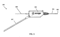
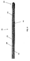
- a catheter (which may be used as a guidewire positioning catheter) 100 includes an elongate flexible shaft 301 and a rotatable distal tip 305 having an imaging sensor, such as an OCT sensor, connected thereto.
- the shaft 301 extends from a handle region 303 and terminates in the rotatable distal tip 305.
- the device 100 in FIG. 1 is not necessarily shown to scale, as the length of the shaft has been reduced to show the other features at a more appropriate scale.
- a guidewire 309 can extend through the guidewire catheter device 100, such as through a guidewire lumen in the shaft 301.
- the guidewire 309 may be held resident in the device 100 as it is positioned within a patient or it may be inserted after the distal end of the shaft 301, or at least the distal tip 305, has been positioned within the lumen of the vessel, such as past an occlusion or lesion.
- the guidewire lumen can be housed inside of a driveshaft (not shown in FIG. 1 ) configured to rotate the tip 305.
- the driveshaft is a tubular shaft such that the driveshaft may surround the guidewire lumen.
- the driveshaft is a solid shaft which extends through the length of the catheter, and runs alongside (e.g., adjacent to) the guidewire lumen.
- the handle region 303 can house the control mechanism for controlling the rotation of the distal tip (and OCT reflector/sensor at the end of the optical fiber).
- the control mechanism controls the direction of the distal tip as well as the number of revolutions before switching direction.
- the handle region 303 can also control the rate of rotation.
- the rate of rotation, as well as the number of clockwise and/or counterclockwise rotations may be optimized to advance the distal end of the device though an otherwise occluded lumen of a vessel while generating a cross sectional image of the lumen, i.e., 360 degrees.
- the outer sheath 284 can include a braided material, such as stainless steel, elgiloy, cobalt-chromium alloys, carbon fiber, or Kevlar.
- the braided material can improve the stiffness of the catheter to help navigate the catheter through vessel.
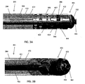
- the shaft 301 can include a guidewire lumen 363 (see FIG. 3B ) extending within a driveshaft 421 (see FIGS. 3A-3D ) from the proximal end to the distal end of the catheter.
- the guidewire lumen 363 can end in an opening in a distal tip 305 of the device.
- the guidewire lumen 363 can thus be configured to pass a guidewire therethrough.
- the distal tip 305 can include an imaging sensor, such as an OCT sensor 286 configured to capture images within a lumen.
- the sensor 286 can be located close the distal end of the tip 305, such as just proximal to the cutting edge 403.
- the sensor 286 can be located within 5mm of the distal end of the tip 305, such as less than 3mm, such as approximately 2mm.
- the resulting image will be a closer approximation of the exact tissue or material being passed by the distal end.
- the sensor 286 may be directed laterally (e.g., to image the sides of the vessel in which the catheter is traveling), or angled forward or backward.
- the sensor 286 can be located off of the central axis of the shaft 301 and close to the outer diameter of the tip 305, such as within 1.27 mm (0.05 inches), e.g. less than 7.62 mm (0.3 inches), less than 0.51 mm (0.02 inches), or less than or substantially equal to 0.25 mm (0.01 inches) of the outer diameter of the tip 305.
- the depth that the OCT system can see into the tissue will be greater, i.e., the amount of tissue lying within the OCT imaging range is increased.
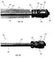
- the rotating tip 305 is held in a chassis 405 that is fixed relative to the shaft 301, i.e., that does not rotate with the rotating tip 305.
- the chassis 405 is any structure within which the distal tip 305 can rotate and which secures the driveshaft 421 and/or the distal tip 305 to the end of the shaft 301; it may also be referred to as a housing.
- the outer sheath 284 can be connected to the chassis 405 such that the outer sheath also remains stationary while the distal tip 305 rotates.
- the chassis 405 can have one or more "window" regions through which the OCT imaging sensor 286 can view the tissue.
- the chassis 405 can include three window regions 346 separated by spines 419 (which may be referred to as posts, struts, dividers, separators, etc.) arranged annularly around the chassis 405.
- spines 419 may serve as reference markers as the imaging sensor 286 rotates, as discussed below.
- the spines 419 may be separated from one another by different distances. For example, one of the windows may be larger than the other two, or smaller than the other two. This asymmetric sizing may provide a visual reference on the display of the OCT imaging.
- the spines 419 can have a predetermined and fixed location relative to the jog 989 in the catheter.
- one of the spines 419 can be aligned relative to the jog 989. In one variation, shown in FIG.
- the second spine 419 is aligned opposite to the jog 989, i.e., such that the catheter points away from the second spine 419 (the inner curved portion of the jog 989 is opposite to the second spine 419 and the outer curved portion of the jog 989 is axially aligned with the second spine 419).
- This alignment can be used to help orient the device in a specific direction with respect to the image and/or vessel, as discussed further below.
- the distal tip 305 can include a groove 392 at the proximal end to engage a bushing 394 (e.g., annular ring).
- the bushing 394 can remain fixed with respect to the shaft 301 and may provide a lubricious surface to eliminate or reduce friction and fix the longitudinal position of the distal tip 305.
- the bushing 394 may be made of PEEK or other hard lubricous material.
- the groove 392 may be crimped or clamped to the stationary chassis 405, thereby allowing the rotatable distal tip 305 to have improved stability during rotation.
- the bushing 394 includes a shoulder 445.
- the shoulder 445 can extend outward into the space between the distal edge of the chassis 405 and the distal tip 305.
- the shoulder 445 can be made of the same lubricous material as the rest of the bushing 394. The shoulder 445 prevents the distal edge of the chassis 405 from rubbing against the tip 305 and further reduces the friction of the system.
- the chassis 405 may engage the groove 392 of the distal tip 305 directly, such as by one or more tabs 407 or locks that can be pushed in when the distal tip 905 is held within the chassis 405 to lock the bushing ring 394 and distal tip 305 in position.
- the chassis 405 or distal tip 305 can be made from a lubricious material.
- the chassis 405 can include one or more openings or ports 422 out of which a clearing fluid, such as saline or water, may be driven to help clear the pathway for imaging the walls of the vessel lumen as the device is operated.
- a clearing fluid such as saline or water
- Blood including red blood cells and other blood components, may degrade the ability of the OCT imaging system from imaging other tissues because OCT may not readily "see” through blood.
- the catheter may be configured to clear the blood from the region of interest, i.e., the region where the optical beam is emitted from the catheter for OCT imaging.
- the ports 422 can thus be configured to emit a clearing fluid from the catheter to clear blood from the imaging sensor.
- the port 422 is located directly adjacent to the imaging sensor and emits fluid to clear blood from the region where the optical beam is being emitted.
- the ports 422 can be less than 2mm from the imaging sensor, such as less than 1.5mm.
- the pressure and amount of clearing fluid required to clear the blood from the region of interest can be low.
- less than 1ml, such as less than 0.5ml, e.g., less than 0.2ml of clearing fluid can be required to clear the blood from the region of interest.
- the required pressure may be nominal and the flow of saline or other clearing fluid may be minimal and still effectively clear blood from the imaging space, greatly improving the resolution of the vessel walls and increasing the depth of penetration.
- using small amounts of clearing fluid can advantageously avoid problems associated with having too much fluid in a small space, such as separation of tissue (e.g., dissection).
- the shaft 301 can be configured such that the clearing fluid enters at the proximal end of the catheter and is transported to the distal end by flowing in a space 472 between the outer sheath 284 and the driveshaft 421.
- the clearing fluid may be pressurized from the proximal end (e.g., using a syringe, etc.) so that it is pushed out of the opening 422 to clear blood from the OCT pathway.
- the OCT portion of the catheter device 100 may be referred to as an off-axis imaging system because the management of the OCT optical fiber 411 is arranged asymmetrically, off-axis with reference to the long axis of the catheter.
- the fiber 411 can be configured to extend freely within the shaft 301 in the space 472 between the driveshaft 421 and the outer sheath 284 except where it is attached at the distal end of the device, e.g., at the rotatable distal tip 305. Accordingly, as shown in FIG. 4 , when the driveshaft 421 is rotated to rotate the distal tip 305, the fiber 411 can wrap around the driveshaft 421. This arrangement can advantageously enhance the flexibility, i.e., allow for movement of the catheter without fracturing the optical fiber 411.
- both the rate of rotation and the number of rotations may be controlled to optimize performance, prevent the fiber 411 from binding within the shaft 301, and prevent the fiber 411 from snapping due to excessive twisting or rotation.
- the distal tip 305 may be configured to alternate its rotation from clockwise to counter clockwise.
- the driveshaft 421 can be configured to rotate (with the distal tip 305) clockwise for a fixed number of rotations and to rotate counterclockwise for the same number of rotation before switching back to clockwise rotations and repeating the process.
- the number of rotations in the clockwise direction can be substantially equivalent to the number of counter clockwise rotations in order to relieve any residual twisting.
- the device is configured to rotate the distal tip n rotations clockwise and n rotations counterclockwise, switching between clockwise and counterclockwise rotational direction after each n rotations.
- the number of rotations n can be any number, including fractional, typically between 1 and 100; preferably it is between 1 and 10, depending on the length of the catheter and the amount of stress the fiber can withstand.
- the device may be configured to rotate approximately 6, 8.5, 10, 12.7, 15, etc. times clockwise, then counterclockwise the same number of rotations.
- the device is configured so that it doesn't continuously spin clockwise or counterclockwise, but has a limited number of rotations in either direction (e.g., less than 25 rotations, such as 10 rotations), after which it automatically switches to rotate the other direction.
- the transition between clockwise and counterclockwise rotation may be performed automatically, which is described in more detail with reference to FIGS. 5A-5E , below.
- the rotation may be driven by a motor or other driver (e.g., within the handle) or it may be manual.
- the rotation is automatic, and is driven at a constant speed that is typically between about 1 and 300 revolutions per minute (rpm); for example, the rotation rate may be about 10 rpm, 20 rpm, 30 rpm, 40 rpm, 50 rpm, 60rpm, etc.
- the distal tip is rotated between about 1 and about 100 rpm, e.g., between about 1 and 80 rpm, such as between about 30 and 60rpm.
- the rate and the consistency of rotation may be optimized for penetration through the occlusion within the vessel, for image stability, and also to produce relatively streak-free imaging using the OCT.
- the rate of rotation may be limited to an upper limit speed that is held relatively constant.
- the rate of rotation may be sufficiently low (e.g., less than 150 or 100 or 50 rpm) so that the distal head rotates but does not 'drill' through the tissue, including one or more occlusions.
- the user can control the rate of rotation, such as by setting the motor to rotate at a particular speed.
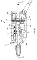
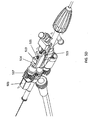
- the handle 303 of the device can be configured to control rotation and advancement of the shaft 301.
- the handle 303 can include a switch 562 configured to turn the system on or off (i.e. to start the rotation of the distal tip and/or the imaging system).
- the handle can be covered by a housing 501 which may be configured to conform to a hand or may be configured to lock into a holder (e.g., for connection to a positioning arm, a bed or gurney, etc.).
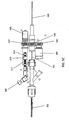
- a drive system including a motor 503 and drive gears 515, 516, 517, may drive the driveshaft 421 to rotate the distal tip 305 of the device and/or the OCT imaging system relative to the shaft 301.
- the drive system is controlled or regulated by a toggling/directional control subsystem for switching the direction of rotation of the driveshaft between the clockwise and counterclockwise direction for a predetermined number of rotations (e.g., 10).
- a mechanical directional control can be configured to switch the direction of rotation between clockwise and counterclockwise when the predetermined number of rotations have been completed.
- the directional control includes a threaded track (or screw) 511 which rotates to drive a nut 513 in linear motion; rotation of the threaded track by the motor 503 results in linear motion of the nut along the rotating (but longitudinally fixed) threaded track 511.
- the nut 513 moves linearly in a first linear direction (e.g., forward) until it hits one arm of a U-shaped toggle switch 516, driving the U-shaped toggle switch in the first linear direction and flipping a switch 523 (visible in FIG 5D ) to change the direction of the motor 503 to a second rotational direction (e.g., counterclockwise), and causing the nut to move linearly in a second linear direction (e.g., backward) until it hits the opposite side of the U-shape toggle switch 516, triggering the switch to again change the direction of rotation back to the first rotational direction (e.g., clockwise).
- a first linear direction e.g., forward
- a second rotational direction e.g., counterclockwise
- a second linear direction e.g., backward
- the motor 503 may be configured to rotate the driveshaft 421 in either direction at a constant speed.
- the system may also include additional elements (e.g., signal conditioners, electrical control elements, etc.) to regulate the motor as it switches direction.
- the number of threads and/or length of the threaded track (screw) 511 may determine the number of rotations that are made by the system between changes in rotational direction. For example, the number of rotations may be adjusted by changing the width of the U-shaped toggle 514 (e.g., the spacing between the arms). Lengthening the arms (or increasing the pitch of the screw) would increase the number of rotational turns between changes in direction (n). The toggle may therefore slide from side-to-side in order to switch the direction of the motor.
- the length of the nut 513 can also determine the number of rotations that are made by the system between changes in rotational direction, i.e., the longer the nut, the fewer the number of rotations before switching direction.
- the motor 503 is rotated in a constant direction, and the switch between clockwise and counterclockwise is achieved by switching between gearing systems, engaging and disengaging an additional gear, or using gears that mechanically change the direction that the driveshaft is driven.
- the drive system includes the motor and three gears that engage each other to drive the driveshaft in rotation.
- the motor 503 rotates a first gear 517, which is engaged with a second gear 516 (shown in this example as a 1:1 gearing, although any other gear ratio may be used, as appropriate).
- a third gear 515 engages with the second gear 516.
- the third gear may drive or regulate an encoder 507 for encoding the rotational motion. This encoded information may in turn be used by the drive system, providing feedback to the drive system, or may be provided to the imaging system.
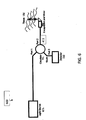
- the fiber 411 can be connected at the proximal end to a common-path OCT system 600.
- the common-path OCT system 600 includes a light source 102, such as a swept frequency laser.
- the light source could be a broadband light source such as a super-luminescent diode (to conduct Time Domain OCT or Spectral Domain OCT using an optical spectrometer).
- the optical fiber 411 transfers radiation from the light source 102 to the target 114.
- the optical fiber 411 is in optical contact with an interface medium 106, i.e. the light exiting the optical fiber and entering the interface medium sees only one interface.
- the end of the optical fiber is embedded in the interface medium 106.
- the interface medium 106 can be, for example, a glue or epoxy.
- the index of refraction of the interface medium 106 is different than the index of refraction of the core of the optical fiber 411. This creates a Fresnel reflection, in which part of the light exits the core, and part of the light is reflected back. Some of the light beam that exits the optical fiber 411 will encounter the target 114 and be reflected or scattered by the target 114. Some of this reflected or scattered light will, in turn, reenter the tip of the optical fiber 411 and travel back down the fiber 411 in the opposite direction.
- the reflected or scattered target light in the OCT system 600 travels a longer distance than the Fresnel reflected reference light
- the reflected or scattered target light can be displaced by frequency, phase and or time with respect to the reference beam.
- the light from the target will be displaced in frequency.
- the difference in displacement in phase, time or frequency between the reflected or scattered target light and the reference light can be used to derive the path length difference between the end of the optical fiber tip and the light reflecting or light scattering region of the target.
- the displacement is encoded as a beat frequency heterodyned on the carrier reference beam.
- the light source 102 can operate at a wavelength within the biological window where both hemoglobin and water do not strongly absorb the light, i.e. between 800 nm and 1.4 ⁇ m.
- the light source 102 can operate at a center wavelength of between about 1300 nm and 1400 nm, such as about 1310 nm to 1340 nm.
- the optical fiber 411 can be a single mode optical fiber for the ranges of wavelengths provided by the light source 102.
- an OCT image 820 On the left is an OCT image 820.
- the distal tip of the catheter rotates at approximately 30 rpm, and the OCT system provides a continuous set of images as the catheter rotates within the vessel.
- the images are combined into a continuously updated OCT image 820 that corresponds to the inside of the lumen in which the catheter is inserted. That is, the OCT image 820 is an image trace of the interior of the vessel just proximal to the distal tip as it rotates.
- the line 822 (extending to almost 12 o'clock in the figure) indicates the current direction of the OCT laser beam as it is rotating.
- the circle 824 in the middle of the image 820 represents the diameter of the catheter, and thus the area surrounding the circle 824 indicates the vessel.
- the OCT imaging can extend more than 1mm from the imaging sensor, such as approximately 2mm or approximately 3mm and thus will extend into the walls of the vessel (particularly in the closer region of the vessel) so that the different layers 826 of the vessel may be imaged.
- the three striped rays 744 (extending at approximately 2 o'clock, between 7 and 8 o'clock, and approximately 11 o'clock) indicate the location of the three spines of the catheter and thus may act as directional markers, indicating the orientation of the distal end of the catheter within the body.
- the user may also be able to determine relative orientation of the OCT image (relative to the patient's body orientation) using these striped rays 744.
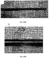
- a waterfall view 830 of the OCT image As it circles the radius of the body.
- This waterfall image 830 may be particularly useful in some applications of the system, for example, indicating the relative longitudinal position of a feature (e.g., layered structures, occlusions, branching region, etc.) as the device is moved longitudinally within the vessel.
- the waterfall view 830 typically includes a time axis (the x-axis) while the y-axis shows the image from the OCT sensor.
- the waterfall view 830 may provide an indication of when the catheter has crossed an occlusion.
- the waterfall view 830 may show the patient's heartbeat when the walls of the vessel move relative to the heartbeat.
- the waterfall view 830 may show the walls of the vessel moving with the heartbeat.
- the distal tip is within an occlusion the wall of the vessel
- the waterfall view will not show movement of the walls since the occlusion material typically prevents the movement of the walls due to the heartbeat, while in healthy vessels the heartbeat is apparent.
- this effect may be automated to provide an indication of when the device is within or has crossed an occlusion.
- crossing the boundary of a total occlusion is not well defined and may result in inadvertently dissecting the vessel.
- the vessel wall may move; if the catheter tip is not in the true lumen all or part of the vessel wall will not move.
- this movement of the wall during heartbeat may reflect the position within the true versus false lumen.
- FIG. 7B shows another screen capture from the same procedure shown in FIG. 7A .
- the distal tip 305 is further within the vessel 814 than in FIG. 7B .
- the OCT image 820 shows a branch 818 of the vessel extending from the vessel in the 2 o'clock position.
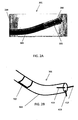
- the shaft 301 can include a fluoroscopy marker 702 (also shown in FIG. 2B and FIG. 4 ) that provides varying contrast in a fluoroscopy image depending on its radial orientation.
- the marker may be a radiopaque band with one or more asymmetric features such as a "C", "T", or dog bone shape that can be used to radially orient the shaft because the fluoroscopic image of the marker will change depending on its orientation.
- the fluoroscopy marker 702 can have a fixed location relative to the spines 419 and/or the jog 989. For example, as shown in FIG. 2B , the fluoroscopy marker 702 can be aligned opposite to the jog 989 and/or axially aligned with the second spine 419 described above. The fluoroscopy marker 702 can be used to align a fluoroscopy image 710 with an OCT image 720 during use of the catheter.
- the shaft 301 can be rotated slightly such that the marker 702 is aligned to a particular side of the screen, such as at the 9 o'clock position.
- the up/down position of the catheter i.e. whether the catheter is pointed down, as shown in FIG. 7 , or pointed up
- the OCT image can then be oriented such that striped ray 744 from the middle marker (the second spine 419 described above) of the shaft 301 is also at the 9 o'clock position in the OCT image 720.
- Fluorosyncing can be performed using manual input from the user, such as information regarding the up/down position and the rotational position, or can be performed automatically.
- the software may draw the OCT image 720 either in a clockwise or counterclockwise direction (depending on the up/down orientation of the catheter in the fluoroscopy image 710) and will rotate the image 90°, 180°, or 270° (depending on the rotational position of the catheter in the fluoroscopy image 710).
- the absolute and relative position and orientation of the catheter within the patient's body may be determined.
- the markers on the chassis/imaging system visible in the OCT system) may therefore provide sufficient orientation markers such that the fluoroscopic imaging may be reduced.
- the displayed images can be used, in combination with steering mechanisms such as the OCT markers, the fluoroscopy marker, and the fixed jog of the device, to steer the catheter and rotatable tip to the desired location.
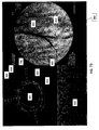
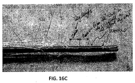
- the OCT image 920 shows healthy tissue 956 in the form of a layered structure and non-healthy tissue 958 in the form of a nonlayered structure.
- the cat ears 962 in the image show a region between the healthy and unhealthy tissue caused by a slight expansion of the vessel around the catheter at that location. Accordingly, during a CTO procedure, one goal may be to steer the catheter towards the unhealthy tissue. Because the middle spine 419 is aligned opposite to the jog 989 (as shown in FIG.
- the ray 744 corresponding to the middle spine 419 can be oriented opposite to the non-healthy tissue 958 to steer the catheter in the correct direction.
- FIG. 9B shows the catheter deflected toward the layered, healthy tissue.
- FIG. 9C shows the catheter rotated such that it is deflected toward the unhealthy, non-layered structure.
- the system may be configured to allow the orientation of the catheter to be rotated into the correct position using the fixed directional markers from the chassis that are visualized by the OCT.
- the distal end of the device may be steerable and may be steered while still rotating the distal end of the device.
- Additional steering members may also be included, such as a selective stiffening member, which may be withdrawn/inserted to help steer the device, and/or one or more tendon members to bend/extend the device for steering.
- Image correction can be performed on the resulting OCT images in order to mask out unwanted or unnecessary portions of the image.
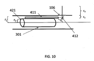
- the fiber 411 can be configured such that it ends within the shaft 301.
- the fiber 411 will image the distance c1 between the fiber 411 distal end and the mirror 412 as well as the axial distance c2 between the mirror 412 and the outer diameter of the shaft 301.
- the resulting image would therefore include portions that correspond to the interior of the shaft. Accordingly, image processing can be performed such that distance c1, c2, or c1 + c2 is masked out in the displayed image.
- the image can be corrected to account for lag of the optical fiber in the amount of rotation at the handle vs. at the distal end of the catheter.
- Images for lag correction can be captured automatically.
- images can be exported and stored, for example in a movie format.
- the images can optionally viewed in adjustable grayscale. Further, the speed of the waterfall view can be adjusted.
- offset or "ghost" image may be overlaid atop the OCT to indicate the difference between the predicted and actual rotational orientation of the catheter.
- a manually rotatable device may be used with an adjunctive device providing a motorized movement of the distal tip.
- the handle portion of the device may set and be secured within a housing that includes a motor and gearing to automatically rotate the distal tip at a predetermined or adjustable speed.
- this motorized accessory device may adapt an otherwise manual device to automatically rotate.
- catheters are possible that include one or more of the features described above.
- the rotatable distal tip includes a fixed or rotatable housing from which dissection elements may extend or retract.
- An imaging element such as an OCT imaging element, may be included in this variation as well.
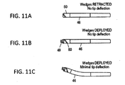
- wedges 49 may be extended from a rotatable distal tip 50.
- FIG. 11A the device is shown with the wedges retracted into the rotatable distal tip 50.
- FIG. 11B the wedges 49 have been extended from the housing 46.
- the distal end of the device can be shared and is shown deflecting upwards (steering in one plane) in FIG. 11C while the wedges are extended from the housing.
- Both the distal tip and the wedges can be configured to rotate.
- the wedges 49 (which may be sharp blades or may be blunt) can be extended from the distal housing and locked in any position (extended, partially extended or retracted) and rotated clockwise and/or counterclockwise while locked in a retracted, extended or partially extended position.
- the wedges may be fully or partially retracted into a distal housing.
- the extension of the wedge from the distal housing may be limited.
- the wedges may be prevented from extending fully out of the distal housing, thereby preventing material (such as a plaque or tissue) from getting caught between the wedges and the housing.
- the wedges at the distal end may be referred to as a blade or blades, even though they may be substantially blunt.
- the wedges are configured so that they are forward-cutting, but not side-cutting. This means that they may include a forward-facing cutting edge, and the more lateral edges may be blunted or less sharp.
- the rotating distal tip includes only a single wedge, rather than multiple wedges.
- the wedge (blade) may be helically arranged at the distal tip.
- the rotating distal end comprises two or more wedges that are radially separated around the tip region (e.g., spaced equally apart radially). It may be advantageous to have three or more wedges spaced around the tip, which may improve centering of the device, as described herein.
- the distal tip of the device is rotated through multiple complete rotations (both clockwise and counterclockwise) to move the distal tip and/or any attached imaging sensor in rotation around the elongate longitudinal axis of the device.
- the distal tip of the device may be rotated through partial rotations. This is illustrated in FIGS. 12A-13D .
- a driveshaft rotates continuously in one direction, e.g., clockwise, but this one-directional rotation is translated at the distal end of the device into oscillating motion.
- the devices described herein are self-centering and are thus configured to help maintain the catheter (e.g., the tip of the catheter) within the true lumen.
- the manually or automatically rotatable distal end of the catheter may guide the catheter in the true lumen, especially when the reaching the distal cap of a lesion.
- the tip may be sufficiently blunt to passive self-center within the lumen of a vessel.
- the device does end up within the "false lumen," it can be configured to self-center back into the true lumen.
- centering self-centering of the catheter may result from the rotation of the distal end for the dimensions of the devices illustrated herein, one or more additional centering features may also be used to help the device to stay in true lumen of the blood vessel.
- the catheter may be configured for use with one or more centering features to help prevent the distal tip from leaving the true lumen.
- the centering feature may project from the distal tip, the lateral sides of the distal tip, or the lateral sides of the distal end region, e.g., proximal to the distal tip.
- the inflation lumen ends between the proximal and distal end of the balloon, e.g., near the center of the balloon, and terminates in a skived opening to allow entry/exit of inflation material.
- the balloon 522 has a slightly smaller diameter at the proximal end compared to the distal end to compensate for the missing inflation lumen at the distal end; thus, the overall outer diameter of the catheter 522 may be remain relatively constant.
- proximal shaft has a diameter between about 1.88 mm (0.074 inches) and 2.13 mm (0.084 inches); the mid-shaft region has a diameter between about 1.88 mm (0.074 inches) and 2.01 mm (0.079 inches); the proximal balloon leg has a diameter between about 2.16 mm (0.085 inches) and 2.39 mm (0.094 inches); the distal balloon leg has a diameter between about 2.01 mm (0.079 inches) and 2.16 mm (0.085 inches); and the mid region of the balloon over the inflation lumen has a diameter between about 1.96 mm (0.077 inches) and 2.16 mm (0.085 inches).
- the cutting edges at the distal tip are sharp (e.g., cutting or knife-edged), while in other variations the cutting edges are substantially blunt.
- the cutting edges are typically curved around or along the longitudinal axis of the distal tip.
- the cutting edge may extend helically around the distal tip end of the device.
- the handle region at the proximal end of the device may also be adapted for handheld use.
- the controls at the handle region may be adapted so that the device may be manipulated by a single hand.
- the handle region may also include one or more indicators or displays for displaying the status of the distal end of the device.
- the handle may include an indicator indicating the extent to which the wedges are extended from the distal tip.
- the indicator may be a dial, slider, or the like.
- the indicator may be marked or unmarked.
- the proximal handle may be otherwise configured to be handheld.
- the controls may be clustered or located at one end of the handle with a gripper region at the other end.
- the controls may be clustered at the proximal portion of the handle (allowing the distal portion of the handle to be gripped in the palm of the hand, and manipulate d by the thumb and forefinger of the right.
- the proximal end of the device typically includes a handle region that may be used to control the distal end.
- the device may include a rotation control, a wedge articulation control and/or a steering control.
- these controls may be combined into one or more controls or these functions may be distributed or divided between different controls. Any appropriate control may be used, including slides, knobs, dials, buttons, levers, switches, etc.
- the controls may be automated or computer-controlled.
- a driver e.g., motor, mechanical driver, etc.
- rotation of the distal tip region may be driven by a motor, and may be geared or otherwise controlled. The rotation may be manually or automatically controlled.
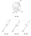
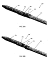
- FIGS. 20A and 20B illustrate one variation of an atherectomy device 200 as described.
- the device includes a cutter 282 rotatable by a driveshaft 294 (see FIG. 21 ) located within an elongated catheter body 201.
- the cutter edge with a comparatively large cross-sectional area, is located along the circumferential surface of the main catheter body 201.
- the driveshaft 294, with a comparatively small cross-sectional area, is located within the central region of the catheter body.
- the cutter diameter is at or near the maximum crossing profile of the main catheter body 201 to maximize cut tissue cross-sectional area and minimize depth of cut.
- the large cross-sectional area may provide more efficient cutting passes, thereby reducing the time of procedure, and may add a degree of safety by reducing the depth of cut required to achieve comparative luminal gain.
- FIG. 20A and 20B portray the distal portion of the device in both the non-activated ( FIG. 15A ) and activated ( FIG. 15B ) positions, respectively.
- the cutter 282 In the closed/non-activated position, the cutter 282 is shielded to prevent unintended damage to the inner diameter of ancillary medical devices and vasculature.
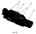
- the open/activated position the cutter 282 is exposed with the tissue packing auger 292 distal of the cutting edge as shown in FIG. 21 .
- the distal tip of the catheter is advanced past the targeted lesion. The catheter is delivered in the non-activated position where the delivery catheter and vasculature is shielded from the cutter edge.
- the distal tip assembly is activated to present the cutter edge 282.
- the driveshaft of the catheter is powered to rotate the cutter 282 as it is passed across the lesion. The rotational motion assists the cutter in cutting the targeted tissue.
- the device is then returned to the non-activated position which assists the cutter in parting off the strip of tissue and packing it into the tissue storage lumen 216.
- the device 200 can include an imaging sensor 279 in a notch 277 near the distal end of the device.
- the imaging sensor 279 can be an OCT sensor similar to that described above.
- the driveshaft 294 can be directly connected to the circumferential cutter 282 and to an auger 292 or Archimedean screw.
- the driveshaft 294 can thus transmit torque to the cutter 282 while allowing tissue to pass through the hollow cutter 282 as it is rotated.
- tissue is then passed through the inner, hollow diameter of the cutter 282.
- the tissue is then cut into segments by the cutting edge 299 of the auger component 292 and passed into the tissue storage area 216 distal to the auger 292.
- FIG. 21 shows the auger component 292 configured in a helical geometry.
- the auger component can have other configurations.
- FIGS. 22A-22D show an auger component 293 that is capable of shearing tissue segments when rotated in either the clockwise or counterclockwise direction.
- the auger can be substantially T-shaped with two cutting edges 298. Rotation of the auger component 293 in either the clockwise or counterclockwise direction would thus cause shearing of tissue.
- the auger component 293 can shear tissue two times per rotation of the driveshaft 294.
- the auger component 293 can further include angled surfaces 297 configured to push cut tissue distally into the tissue storage area 216.
- the auger component 293 can cut in both the clockwise and counterclockwise directions, it can work even if the driveshaft oscillates between clockwise and counterclockwise directions, as described above with respect to the driveshaft 421.
- the cutter edge can be configured for optimal cutting efficiency and is not limited to traditional, continuously rotating cutters.
- the driveshaft may balance flexibility to navigate tortuous anatomy and torsional/ tensile/ compressive rigidity to drive distal mechanisms through hard calcified tissues or tight lesions.
- the cutter concept can be configured in a push-to-cut configuration where the catheter is advanced to perform the cutting operation. Conversely, the cutter concept can also be configured in a pull-to-cut configuration where the catheter is retracted to perform the cutting operation.
- the description herein focuses on the pull-to-cut embodiment, though it should be clear that push-to-cut variations may be used as well.
- minimal longitudinal motion and translational deflection of the tip mechanism such that the tissue entry window is mainly defined by the vertical distance from the shear component base 295 to the cutter edge. This may prevent increased tissue invagination into the exposed tissue entry point with increased apposition force. Depth of cut will then remain relatively constant at varied force of engagement between cutter and tissue.
- the cutting edge orientation may be such that cutting of tissue is performed with longitudinal movement of catheter distal to proximal.
- any of these catheters may include imaging, including the atherectomy catheters.
- the imaging element can provide a cross-sectional view of vessel wall morphology in the cutting plane.
- Ultrasound and/or optical imaging technologies may be used.
- Optical Coherence Tomography (OCT) is one preferred method of image guidance.
- OCT technology currently embodied on prototype devices is capable of achieving approximate 10 micron lateral resolution and requires fiber optic assembly diameters below 0.25 mm (0.010 inches).
- the device may thus include on-board and real time image guidance capabilities. This capability may require an imaging element, or energy emitting assembly, to be positioned at the distal portion of the device such that local images of the vessel may guide device usage.
- the distal energy emitter(s) may be positioned in multiple locations in fixed positions or embodied in a mating assembly that may translate in an eccentric lumen or in the hollow lumen of the driveshaft.
- the emitter may send and receive relevant light or sound signals at 90 degrees from the catheter axis or at angles up to approximately 50 degrees to visualize distal or proximal wall features from a fixed position.
- the emitting element may be positioned distal and/or proximal to the cutting edge.
- proximal placement would provide information during a cutting pass prior to the cutter interacting with the tissue and, therefore, allow the physician to stop or continue cutting as disease changes in depth and/or position.
- Distal placement would also provide guidance regarding cut quality, depth and cutting efficiency.
- the data collected at the distal end of the catheter may drive an automated means of cutter actuation.
- Increased amounts of disease detected by the software may automatically increase open distance between the cutter edge and the tip mechanism therefore increasing cut depth.
- Oscillatory cutter speeds may be adjusted according to feedback from the imaging system.
Claims (15)
- Dispositif de cathéter (100) permettant de traverser des occlusions, le dispositif comprenant:un corps allongé (301) ; etune lumière centrale (363) s'étendant à l'intérieur du corps allongé à partir d'une extrémité proximale du corps allongé vers une extrémité distale du corps allongé,dans lequel le dispositif comprend en outre :une pointe rotative (305) au niveau de l'extrémité distale du corps allongé et configurée pour tourner par rapport au corps allongé,un capteur d'imagerie TCO (286) comprenant une fibre optique (411) couplée à la pointe rotative et configurée pour tourner avec celle-ci, dans lequel la fibre optique est configurée pour envelopper la lumière centrale à l'intérieur du corps allongé lorsque la pointe rotative tourne ; etun mécanisme d'entraînement (421) configuré pour faire tourner en continu la pointe rotative en alternance dans le sens des aiguilles d'une montre et dans le sens inverse des aiguilles d'une montre.
- Dispositif selon la revendication 1, dans lequel le mécanisme d'entraînement (421) est configuré pour faire tourner en continu la pointe rotative (305) en alternance dans le sens des aiguilles d'une montre et dans le sens inverse des aiguilles d'une montre selon un nombre sensiblement équivalent de rotations dans le sens des aiguilles d'une montre et le sens inverse des aiguilles d'une montre.
- Dispositif selon la revendication 1, dans lequel le mécanisme d'entraînement (421) est configuré pour faire tourner la pointe rotative (305) à entre environ 1 et environ 100 tours/min.
- Dispositif selon la revendication 3, dans lequel le mécanisme d'entraînement (421) est configuré pour faire tourner la pointe rotative (305) à entre environ 30 et environ 60 tours/min.
- Dispositif selon la revendication 1, dans lequel chaque rotation dans le sens des aiguilles d'une montre inclut moins de 25 rotations, et dans lequel chaque rotation dans le sens inverse des aiguilles d'une montre inclut moins de 25 rotations.
- Dispositif selon la revendication 1, dans lequel uniquement l'extrémité distale de la fibre optique (411) est fixée au cathéter.
- Dispositif selon la revendication 1, dans lequel le capteur d'imagerie TCO (286) est configuré pour émettre un faisceau optique sensiblement perpendiculaire à un axe longitudinal du dispositif de cathéter.
- Dispositif selon la revendication 1, dans lequel la pointe rotative (305) comprend un tranchant hélicoïdal (403).
- Dispositif selon la revendication 1, dans lequel la pointe rotative (305) comprend une surface externe incurvée et lisse (322) qui présente une surface de contact avec le tissu atraumatique, lorsqu'elle est tournée dans une première direction et qui présente en outre une surface de dissection, lorsqu'elle est tournée dans une seconde direction opposée à la première direction.
- Dispositif selon la revendication 1, dans lequel la région distale du corps allongé (301) est précourbée pour faciliter le pilotage du dispositif de cathéter.
- Dispositif selon la revendication 1, dans lequel le corps allongé (301) inclut au moins un repère (419) configuré pour obstruer l'imagerie à partir du capteur TCO (286) au moins une fois par rotation de la pointe rotative (305).
- Dispositif selon la revendication 11, dans lequel le corps allongé (301) comprend en outre un cran fixe (989) proche de la pointe rotative (305), et dans lequel le cran fixe est dans une orientation fixe par rapport au au moins un repère (419) pour faciliter le pilotage du dispositif.
- Dispositif selon la revendication 1, comprenant en outre un repère (702) sur le corps allongé (301) visible par fluoroscopie, qui n'obstrue pas l'imagerie à partir du capteur TCO (286).
- Dispositif selon la revendication 13, comprenant en outre une unité de commande, l'unité de commande étant configurée pour aligner une image TCO générée à partir du capteur TCO (286) avec l'image de fluoroscopie à l'aide du repère (702).
- Dispositif selon la revendication 1, comprenant en outre un orifice de rinçage comportant une ouverture proche de la pointe rotative (305).
Priority Applications (1)
| Application Number | Priority Date | Filing Date | Title |
|---|---|---|---|
| EP16179580.2A EP3135232B1 (fr) | 2011-03-28 | 2012-03-28 | Dispositifs traversant une occlusion, imagerie et dispositifs d'athérectomie |
Applications Claiming Priority (3)
| Application Number | Priority Date | Filing Date | Title |
|---|---|---|---|
| US201161468396P | 2011-03-28 | 2011-03-28 | |
| US201161548179P | 2011-10-17 | 2011-10-17 | |
| PCT/US2012/030966 WO2012145133A2 (fr) | 2011-03-28 | 2012-03-28 | Dispositifs traversant une occlusion, imagerie et dispositifs d'athérectomie |
Related Child Applications (1)
| Application Number | Title | Priority Date | Filing Date |
|---|---|---|---|
| EP16179580.2A Division EP3135232B1 (fr) | 2011-03-28 | 2012-03-28 | Dispositifs traversant une occlusion, imagerie et dispositifs d'athérectomie |
Publications (3)
| Publication Number | Publication Date |
|---|---|
| EP2691038A2 EP2691038A2 (fr) | 2014-02-05 |
| EP2691038A4 EP2691038A4 (fr) | 2015-01-07 |
| EP2691038B1 true EP2691038B1 (fr) | 2016-07-20 |
Family
ID=47042105
Family Applications (2)
| Application Number | Title | Priority Date | Filing Date |
|---|---|---|---|
| EP12774849.9A Active EP2691038B1 (fr) | 2011-03-28 | 2012-03-28 | Dispositifs traversant une occlusion, imagerie et dispositifs d'athérectomie |
| EP16179580.2A Active EP3135232B1 (fr) | 2011-03-28 | 2012-03-28 | Dispositifs traversant une occlusion, imagerie et dispositifs d'athérectomie |
Family Applications After (1)
| Application Number | Title | Priority Date | Filing Date |
|---|---|---|---|
| EP16179580.2A Active EP3135232B1 (fr) | 2011-03-28 | 2012-03-28 | Dispositifs traversant une occlusion, imagerie et dispositifs d'athérectomie |
Country Status (5)
| Country | Link |
|---|---|
| US (4) | US8644913B2 (fr) |
| EP (2) | EP2691038B1 (fr) |
| JP (1) | JP6205344B2 (fr) |
| CA (1) | CA2831306C (fr) |
| WO (1) | WO2012145133A2 (fr) |
Cited By (1)
| Publication number | Priority date | Publication date | Assignee | Title |
|---|---|---|---|---|
| US11213415B2 (en) | 2017-02-14 | 2022-01-04 | W. L. Gore & Associates, Inc. | Medical device delivery systems and methods |
Families Citing this family (141)
| Publication number | Priority date | Publication date | Assignee | Title |
|---|---|---|---|---|
| US9867530B2 (en) | 2006-08-14 | 2018-01-16 | Volcano Corporation | Telescopic side port catheter device with imaging system and method for accessing side branch occlusions |
| US9622706B2 (en) | 2007-07-12 | 2017-04-18 | Volcano Corporation | Catheter for in vivo imaging |
| US10219780B2 (en) | 2007-07-12 | 2019-03-05 | Volcano Corporation | OCT-IVUS catheter for concurrent luminal imaging |
| US9596993B2 (en) | 2007-07-12 | 2017-03-21 | Volcano Corporation | Automatic calibration systems and methods of use |
| US8062316B2 (en) | 2008-04-23 | 2011-11-22 | Avinger, Inc. | Catheter system and method for boring through blocked vascular passages |
| US9125562B2 (en) | 2009-07-01 | 2015-09-08 | Avinger, Inc. | Catheter-based off-axis optical coherence tomography imaging system |
| US9498600B2 (en) | 2009-07-01 | 2016-11-22 | Avinger, Inc. | Atherectomy catheter with laterally-displaceable tip |
| EP2424608B1 (fr) | 2009-04-28 | 2014-03-19 | Avinger, Inc. | Cathéter de support de fil-guide |
| AU2010253912B2 (en) | 2009-05-28 | 2015-03-05 | Avinger, Inc. | Optical Coherence Tomography for biological imaging |
| WO2011028203A1 (fr) | 2009-09-02 | 2011-03-10 | Reflow Medical Inc. | Système, procédés et dispositifs pour l'ablation, le croisement et la découpe d'occlusions |
| JP2013531542A (ja) | 2010-07-01 | 2013-08-08 | アビンガー・インコーポレイテッド | 長手方向に移動可能なドライブシャフトを有するアテローム切除カテーテル |
| US10363062B2 (en) | 2011-10-17 | 2019-07-30 | Avinger, Inc. | Atherectomy catheters and non-contact actuation mechanism for catheters |
| US11382653B2 (en) | 2010-07-01 | 2022-07-12 | Avinger, Inc. | Atherectomy catheter |
| US10548478B2 (en) | 2010-07-01 | 2020-02-04 | Avinger, Inc. | Balloon atherectomy catheters with imaging |
| WO2014039096A1 (fr) | 2012-09-06 | 2014-03-13 | Avinger, Inc. | Stylet de réintroduction destiné à un cathéter |
| US9107691B2 (en) | 2010-10-19 | 2015-08-18 | Distal Access, Llc | Apparatus for rotating medical devices, systems including the apparatus, and associated methods |
| US8845621B2 (en) | 2010-10-19 | 2014-09-30 | Distal Access, Llc | Apparatus for rotating medical devices, systems including the apparatus, and associated methods |
| US11141063B2 (en) | 2010-12-23 | 2021-10-12 | Philips Image Guided Therapy Corporation | Integrated system architectures and methods of use |
| US11040140B2 (en) | 2010-12-31 | 2021-06-22 | Philips Image Guided Therapy Corporation | Deep vein thrombosis therapeutic methods |
| WO2014059150A1 (fr) * | 2012-10-10 | 2014-04-17 | Avinger, Inc. | Dispositifs de croisement d'occlusion |
| EP2691038B1 (fr) | 2011-03-28 | 2016-07-20 | Avinger, Inc. | Dispositifs traversant une occlusion, imagerie et dispositifs d'athérectomie |
| US9949754B2 (en) * | 2011-03-28 | 2018-04-24 | Avinger, Inc. | Occlusion-crossing devices |
| US9237925B2 (en) | 2011-04-22 | 2016-01-19 | Ablative Solutions, Inc. | Expandable catheter system for peri-ostial injection and muscle and nerve fiber ablation |
| US8663190B2 (en) | 2011-04-22 | 2014-03-04 | Ablative Solutions, Inc. | Expandable catheter system for peri-ostial injection and muscle and nerve fiber ablation |
| US9278196B2 (en) | 2011-08-24 | 2016-03-08 | Ablative Solutions, Inc. | Expandable catheter system for vessel wall injection and muscle and nerve fiber ablation |
| US20130053792A1 (en) | 2011-08-24 | 2013-02-28 | Ablative Solutions, Inc. | Expandable catheter system for vessel wall injection and muscle and nerve fiber ablation |
| US9056185B2 (en) | 2011-08-24 | 2015-06-16 | Ablative Solutions, Inc. | Expandable catheter system for fluid injection into and deep to the wall of a blood vessel |
| WO2013033489A1 (fr) | 2011-08-31 | 2013-03-07 | Volcano Corporation | Raccord optique rotatif et méthodes d'utilisation |
| US11304777B2 (en) | 2011-10-28 | 2022-04-19 | Navigate Surgical Technologies, Inc | System and method for determining the three-dimensional location and orientation of identification markers |
| US9585721B2 (en) | 2011-10-28 | 2017-03-07 | Navigate Surgical Technologies, Inc. | System and method for real time tracking and modeling of surgical site |
| EP2775945B1 (fr) | 2011-11-11 | 2019-05-08 | Avinger, Inc. | Dispositif de traverse d'occlusion, dispositifs d'athérectomie, et imagerie |
| US9345406B2 (en) | 2011-11-11 | 2016-05-24 | Avinger, Inc. | Occlusion-crossing devices, atherectomy devices, and imaging |
| US9345398B2 (en) | 2012-05-14 | 2016-05-24 | Avinger, Inc. | Atherectomy catheter drive assemblies |
| WO2013172972A1 (fr) | 2012-05-14 | 2013-11-21 | Avinger, Inc. | Tomographie à cohérence optique ayant une fibre à gradient d'indice pour imagerie biologique |
| US11406412B2 (en) | 2012-05-14 | 2022-08-09 | Avinger, Inc. | Atherectomy catheters with imaging |
| WO2015120146A1 (fr) | 2014-02-06 | 2015-08-13 | Avinger, Inc. | Cathéters d'athérectomie et dispositifs traversant une occlusion |
| US9498247B2 (en) | 2014-02-06 | 2016-11-22 | Avinger, Inc. | Atherectomy catheters and occlusion crossing devices |
| US11284916B2 (en) | 2012-09-06 | 2022-03-29 | Avinger, Inc. | Atherectomy catheters and occlusion crossing devices |
| WO2014055880A2 (fr) | 2012-10-05 | 2014-04-10 | David Welford | Systèmes et procédés pour amplifier la lumière |
| US11272845B2 (en) | 2012-10-05 | 2022-03-15 | Philips Image Guided Therapy Corporation | System and method for instant and automatic border detection |
| US10568586B2 (en) | 2012-10-05 | 2020-02-25 | Volcano Corporation | Systems for indicating parameters in an imaging data set and methods of use |
| US9367965B2 (en) | 2012-10-05 | 2016-06-14 | Volcano Corporation | Systems and methods for generating images of tissue |
| US10070827B2 (en) | 2012-10-05 | 2018-09-11 | Volcano Corporation | Automatic image playback |
| US9858668B2 (en) | 2012-10-05 | 2018-01-02 | Volcano Corporation | Guidewire artifact removal in images |
| US9286673B2 (en) | 2012-10-05 | 2016-03-15 | Volcano Corporation | Systems for correcting distortions in a medical image and methods of use thereof |
| US9292918B2 (en) | 2012-10-05 | 2016-03-22 | Volcano Corporation | Methods and systems for transforming luminal images |
| US9324141B2 (en) | 2012-10-05 | 2016-04-26 | Volcano Corporation | Removal of A-scan streaking artifact |
| US9307926B2 (en) | 2012-10-05 | 2016-04-12 | Volcano Corporation | Automatic stent detection |
| US9840734B2 (en) | 2012-10-22 | 2017-12-12 | Raindance Technologies, Inc. | Methods for analyzing DNA |
| US10736656B2 (en) | 2012-10-29 | 2020-08-11 | Ablative Solutions | Method for painless renal denervation using a peri-vascular tissue ablation catheter with support structures |
| US9554849B2 (en) | 2012-10-29 | 2017-01-31 | Ablative Solutions, Inc. | Transvascular method of treating hypertension |
| US9526827B2 (en) | 2012-10-29 | 2016-12-27 | Ablative Solutions, Inc. | Peri-vascular tissue ablation catheter with support structures |
| US8740849B1 (en) | 2012-10-29 | 2014-06-03 | Ablative Solutions, Inc. | Peri-vascular tissue ablation catheter with support structures |
| US9301795B2 (en) | 2012-10-29 | 2016-04-05 | Ablative Solutions, Inc. | Transvascular catheter for extravascular delivery |
| US10226278B2 (en) | 2012-10-29 | 2019-03-12 | Ablative Solutions, Inc. | Method for painless renal denervation using a peri-vascular tissue ablation catheter with support structures |
| US10881458B2 (en) | 2012-10-29 | 2021-01-05 | Ablative Solutions, Inc. | Peri-vascular tissue ablation catheters |
| US10945787B2 (en) | 2012-10-29 | 2021-03-16 | Ablative Solutions, Inc. | Peri-vascular tissue ablation catheters |
| EP2916902B1 (fr) * | 2012-11-08 | 2020-09-30 | Minerva Surgical, Inc. | Appareil pour faire tourner des dispositifs médicaux, systèmes comprenant l'appareil. |
| JP6382833B2 (ja) * | 2012-12-07 | 2018-08-29 | ボルケーノ コーポレイション | 高圧の治療用および画像化用カテーテル |
| JP6322210B2 (ja) | 2012-12-13 | 2018-05-09 | ボルケーノ コーポレイション | 標的化された挿管のためのデバイス、システム、および方法 |
| US20140180126A1 (en) * | 2012-12-20 | 2014-06-26 | Volcano Corporation | Catheter with balloon and imaging |
| WO2014099899A1 (fr) | 2012-12-20 | 2014-06-26 | Jeremy Stigall | Cathéters de transition sans heurt |
| US10942022B2 (en) | 2012-12-20 | 2021-03-09 | Philips Image Guided Therapy Corporation | Manual calibration of imaging system |
| US10939826B2 (en) | 2012-12-20 | 2021-03-09 | Philips Image Guided Therapy Corporation | Aspirating and removing biological material |
| JP2016506276A (ja) | 2012-12-20 | 2016-03-03 | ジェレミー スティガール, | 血管内画像の位置の特定 |
| EP2934310A4 (fr) | 2012-12-20 | 2016-10-12 | Nathaniel J Kemp | Système de tomographie en cohérence optique reconfigurable entre différents modes d'imagerie |
| US11406498B2 (en) | 2012-12-20 | 2022-08-09 | Philips Image Guided Therapy Corporation | Implant delivery system and implants |
| US10058284B2 (en) | 2012-12-21 | 2018-08-28 | Volcano Corporation | Simultaneous imaging, monitoring, and therapy |
| CA2895990A1 (fr) | 2012-12-21 | 2014-06-26 | Jerome MAI | Imagerie a ultrasons pourvue d'une densite de ligne variable |
| US9486143B2 (en) | 2012-12-21 | 2016-11-08 | Volcano Corporation | Intravascular forward imaging device |
| EP2934321A4 (fr) * | 2012-12-21 | 2016-07-20 | Paul Hoseit | Cathéter d'imagerie pour l'imagerie depuis l'intérieur d'un ballon |
| WO2014100530A1 (fr) | 2012-12-21 | 2014-06-26 | Whiseant Chester | Système et procédé pour l'orientation et le fonctionnement de cathéter |
| EP2934323A4 (fr) | 2012-12-21 | 2016-08-17 | Andrew Hancock | Système et procédé pour le traitement multivoie de signaux d'image |
| EP2936241B1 (fr) | 2012-12-21 | 2020-10-21 | Nathaniel J. Kemp | Mise en tampon optique efficace en énergie utilisant un commutateur optique actif à maintien de polarisation |
| CA2895993A1 (fr) | 2012-12-21 | 2014-06-26 | Jason Spencer | Systeme et procede de traitement graphique de donnees medicales |
| WO2014099896A1 (fr) | 2012-12-21 | 2014-06-26 | David Welford | Systèmes et procédés permettant de réduire une émission de longueur d'onde de lumière |
| JP2016502884A (ja) | 2012-12-21 | 2016-02-01 | ダグラス メイヤー, | 延在カテーテル本体テレスコープを有する回転可能超音波撮像カテーテル |
| US9612105B2 (en) | 2012-12-21 | 2017-04-04 | Volcano Corporation | Polarization sensitive optical coherence tomography system |
| WO2014121116A2 (fr) * | 2013-02-01 | 2014-08-07 | Deka Products Limited Partnership | Endoscope équipé d'une caméra avec fonction panoramique |
| WO2014138555A1 (fr) | 2013-03-07 | 2014-09-12 | Bernhard Sturm | Segmentation multimodale dans des images intravasculaires |
| US10226597B2 (en) | 2013-03-07 | 2019-03-12 | Volcano Corporation | Guidewire with centering mechanism |
| US20140276923A1 (en) | 2013-03-12 | 2014-09-18 | Volcano Corporation | Vibrating catheter and methods of use |
| WO2014164696A1 (fr) | 2013-03-12 | 2014-10-09 | Collins Donna | Systèmes et procédés de diagnostic d'une maladie microvasculaire coronarienne |
| US9283040B2 (en) | 2013-03-13 | 2016-03-15 | The Spectranetics Corporation | Device and method of ablative cutting with helical tip |
| US9301687B2 (en) | 2013-03-13 | 2016-04-05 | Volcano Corporation | System and method for OCT depth calibration |
| US11026591B2 (en) | 2013-03-13 | 2021-06-08 | Philips Image Guided Therapy Corporation | Intravascular pressure sensor calibration |
| CN105120759B (zh) | 2013-03-13 | 2018-02-23 | 火山公司 | 用于从旋转血管内超声设备产生图像的系统和方法 |
| US10383691B2 (en) | 2013-03-13 | 2019-08-20 | The Spectranetics Corporation | Last catheter with helical internal lumen |
| US9060806B2 (en) * | 2013-03-13 | 2015-06-23 | Mallik Thatipelli | Device and method for treating a chronic total occlusion |
| US9456872B2 (en) | 2013-03-13 | 2016-10-04 | The Spectranetics Corporation | Laser ablation catheter |
| JP6373351B2 (ja) * | 2013-03-13 | 2018-08-15 | アンジオセイフ, インコーポレイテッド | 慢性完全閉塞を治療するためのデバイスおよび方法 |
| US10219887B2 (en) | 2013-03-14 | 2019-03-05 | Volcano Corporation | Filters with echogenic characteristics |
| US10292677B2 (en) | 2013-03-14 | 2019-05-21 | Volcano Corporation | Endoluminal filter having enhanced echogenic properties |
| US10426590B2 (en) | 2013-03-14 | 2019-10-01 | Volcano Corporation | Filters with echogenic characteristics |
| WO2014150401A1 (fr) * | 2013-03-15 | 2014-09-25 | Huennekens Scott | Procédés d'athérectomie utilisant des ensembles de données co-enregistrées |
| US10932670B2 (en) | 2013-03-15 | 2021-03-02 | Avinger, Inc. | Optical pressure sensor assembly |
| EP2967371A4 (fr) | 2013-03-15 | 2016-12-07 | Avinger Inc | Dispositifs de traversée d'occlusion totale chronique à l'aide d'imagerie |
| WO2014142954A1 (fr) | 2013-03-15 | 2014-09-18 | Avinger, Inc. | Dispositif de collecte de tissu pour cathéter |
| US9744008B2 (en) | 2013-05-06 | 2017-08-29 | Zimmer Dental, Inc. | Surgical tool with flexible shaft |
| DE112014002454T5 (de) * | 2013-05-17 | 2016-01-28 | Ninepoint Medical, Inc. | Bestimmen der Winkelorientierung zum Abbilden |
| WO2015006353A1 (fr) | 2013-07-08 | 2015-01-15 | Avinger, Inc. | Identification de limitante élastique pour guider une thérapie interventionnelle |
| EP2829222B1 (fr) * | 2013-07-24 | 2020-05-27 | Cook Medical Technologies LLC | Dispositif de localisation |
| AU2014312387A1 (en) * | 2013-08-27 | 2016-04-14 | Reflow Medical, Inc. | Shapeable re-entry devices and associated systems and methods |
| US9949652B2 (en) | 2013-10-25 | 2018-04-24 | Ablative Solutions, Inc. | Apparatus for effective ablation and nerve sensing associated with denervation |
| US10517666B2 (en) | 2013-10-25 | 2019-12-31 | Ablative Solutions, Inc. | Apparatus for effective ablation and nerve sensing associated with denervation |
| US9931046B2 (en) | 2013-10-25 | 2018-04-03 | Ablative Solutions, Inc. | Intravascular catheter with peri-vascular nerve activity sensors |
| CN105744902A (zh) * | 2013-11-18 | 2016-07-06 | 皇家飞利浦有限公司 | 引导式血栓消散导管 |
| WO2015095536A1 (fr) * | 2013-12-20 | 2015-06-25 | Stryker Corporation | Pince-gouge à instrument coupant sélectivement commandé par moteur de manière à effectuer une coupe de tissu manuelle ou asservie |
| CN111298271B (zh) * | 2014-02-06 | 2022-10-04 | 尼普洛株式会社 | 导管 |
| US10667836B2 (en) | 2014-04-28 | 2020-06-02 | Boston Scientific Scimed, Inc. | Tissue resectors, hand operated tissue resecting systems, and associated methods |
| US10405924B2 (en) * | 2014-05-30 | 2019-09-10 | The Spectranetics Corporation | System and method of ablative cutting and vacuum aspiration through primary orifice and auxiliary side port |
| CA2955242A1 (fr) | 2014-07-08 | 2016-01-14 | Avinger, Inc. | Dispositifs traversant une occlusion totale chronique a vitesse elevee |
| US10206584B2 (en) * | 2014-08-08 | 2019-02-19 | Medlumics S.L. | Optical coherence tomography probe for crossing coronary occlusions |
| US20160213396A1 (en) * | 2015-01-22 | 2016-07-28 | Cook Medical Technologies Llc | Catheter with an auger and method of use thereof |
| US10413318B2 (en) * | 2015-06-01 | 2019-09-17 | Cardiovascular Systems, Inc. | Rotational systems comprising a polymer driveshaft |
| WO2017007853A1 (fr) * | 2015-07-06 | 2017-01-12 | Avinger, Inc. | Mécanisme d'auto-alignement pour cathéter d'imagerie et ensemble d'entraînement |
| WO2017011587A1 (fr) | 2015-07-13 | 2017-01-19 | Avinger, Inc. | Lentille réflectrice anamorphosante micro-moulée pour cathéters à usage diagnostique/thérapeutique guidés par imagerie |
| JP2018521802A (ja) * | 2015-08-05 | 2018-08-09 | コーニンクレッカ フィリップス エヌ ヴェKoninklijke Philips N.V. | 低軸方向滑り摩擦を有するカテーテルアセンブリ |
| JP6927986B2 (ja) * | 2016-01-25 | 2021-09-01 | アビンガー・インコーポレイテッドAvinger, Inc. | 遅延補正を備えたoctイメージングカテーテル |
| WO2017173370A1 (fr) | 2016-04-01 | 2017-10-05 | Avinger, Inc. | Cathéter d'athérectomie avec dispositif de coupe dentelé |
| EP3448243B1 (fr) * | 2016-04-29 | 2023-08-23 | Oncores Medical Pty Ltd | Système de tomographie par cohérence optique |
| WO2017210466A1 (fr) | 2016-06-03 | 2017-12-07 | Avinger, Inc. | Cathéter à extrémité distale détachable |
| JP7061080B2 (ja) | 2016-06-30 | 2022-04-27 | アビンガー・インコーポレイテッド | 賦形な遠位先端を有するアテレクトミーカテーテル |
| JP2019535399A (ja) * | 2016-11-16 | 2019-12-12 | アビンガー・インコーポレイテッドAvinger, Inc. | リアルタイムのカテーテル位置を表示するための方法、システム、及び装置 |
| US11123098B2 (en) * | 2017-02-28 | 2021-09-21 | Angiosafe, Inc. | Device and method for centering and crossing a vascular occlusion |
| US11690645B2 (en) | 2017-05-03 | 2023-07-04 | Medtronic Vascular, Inc. | Tissue-removing catheter |
| CN110582243A (zh) * | 2017-05-03 | 2019-12-17 | 美敦力瓦斯科尔勒公司 | 具有导丝隔离衬套的组织移除导管 |
| US10524820B2 (en) * | 2017-05-16 | 2020-01-07 | Biosense Webster (Israel) Ltd. | Deflectable shaver tool |
| AU2018346252B2 (en) | 2017-10-03 | 2022-09-08 | Research Development Foundation | Systems and methods for coronary occlusion treatment |
| US11304669B2 (en) * | 2017-10-12 | 2022-04-19 | Canon Medical Systems Corporation | X-ray diagnosis apparatus, medical image processing apparatus, medical image processing system, and medical image processing method |
| US20210177265A1 (en) * | 2017-10-25 | 2021-06-17 | The General Hospital Corporation | Systems and methods for imaging and therapy suitable for use in the cardiovascular system |
| WO2019200201A1 (fr) | 2018-04-12 | 2019-10-17 | The Regents Of The University Of Michigan | Système pour effectuer et commander une pression oscillatoire à l'intérieur de cathéters à ballonnet pour fracture de fatigue de calculs |
| JP7299918B2 (ja) * | 2018-04-19 | 2023-06-28 | アビンガー・インコーポレイテッド | 閉塞横断装置 |
| US10849685B2 (en) | 2018-07-18 | 2020-12-01 | Ablative Solutions, Inc. | Peri-vascular tissue access catheter with locking handle |
| WO2020033260A1 (fr) | 2018-08-07 | 2020-02-13 | Cardio Flow, Inc. | Dispositifs et procédés d'athérectomie |
| CN112654311A (zh) | 2018-09-10 | 2021-04-13 | 美敦力瓦斯科尔勒公司 | 具有导丝检测传感器的组织移除导管 |
| US11819236B2 (en) | 2019-05-17 | 2023-11-21 | Medtronic Vascular, Inc. | Tissue-removing catheter |
| WO2022192102A1 (fr) * | 2021-03-12 | 2022-09-15 | Avinger, Inc. | Dispositifs de croisement d'occlusion |
| EP4044942A4 (fr) | 2019-10-18 | 2023-11-15 | Avinger, Inc. | Dispositifs de croisement d'occlusion |
| USD986262S1 (en) * | 2021-07-01 | 2023-05-16 | Olympus Medical Systems Corporation | Display screen with graphical user interface |
| CN116746987B (zh) * | 2023-08-10 | 2023-11-14 | 乐普(北京)医疗器械股份有限公司 | 切割和收集导管及血管内钙化斑块去除装置 |
Family Cites Families (572)
| Publication number | Priority date | Publication date | Assignee | Title |
|---|---|---|---|---|
| US3367727A (en) | 1965-10-22 | 1968-02-06 | Abraham W. Ward | Oral surgery tool with interchangeable blades |
| US3908637A (en) | 1974-04-22 | 1975-09-30 | Louis W Doroshow | Rigid urethral instrument |
| DE2733019C3 (de) | 1977-07-21 | 1981-01-15 | Boris Samoilovitsch Gechman | Vorrichtung zum Zerkleinem von Konkrementen im Harnleiter |
| US4527553A (en) | 1980-04-28 | 1985-07-09 | Upsher Michael S | Laryngoscope with improved light source |
| US4578061A (en) | 1980-10-28 | 1986-03-25 | Lemelson Jerome H | Injection catheter and method |
| US5435805A (en) | 1992-08-12 | 1995-07-25 | Vidamed, Inc. | Medical probe device with optical viewing capability |
| US4621353A (en) | 1982-09-09 | 1986-11-04 | Burroughs Corporation | Optical memory system providing improved focusing control and improved beam combining and separating apparatus |
| US4487206A (en) | 1982-10-13 | 1984-12-11 | Honeywell Inc. | Fiber optic pressure sensor with temperature compensation and reference |
| FR2541784B1 (fr) | 1983-02-25 | 1986-05-16 | Thomson Csf | Dispositif de deflexion statique d'un faisceau infra-rouge |
| US4611600A (en) | 1983-11-21 | 1986-09-16 | Cordis Corporation | Optical fiber pressure transducer |
| US4598710A (en) | 1984-01-20 | 1986-07-08 | Urban Engineering Company, Inc. | Surgical instrument and method of making same |
| US5178153A (en) | 1984-03-08 | 1993-01-12 | Einzig Robert E | Fluid flow sensing apparatus for in vivo and industrial applications employing novel differential optical fiber pressure sensors |
| US5041082A (en) | 1986-06-16 | 1991-08-20 | Samuel Shiber | Mechanical atherectomy system and method |
| US4926858A (en) | 1984-05-30 | 1990-05-22 | Devices For Vascular Intervention, Inc. | Atherectomy device for severe occlusions |
| US4781186A (en) | 1984-05-30 | 1988-11-01 | Devices For Vascular Intervention, Inc. | Atherectomy device having a flexible housing |
| US4552554A (en) | 1984-06-25 | 1985-11-12 | Medi-Tech Incorporated | Introducing catheter |
| US4651753A (en) | 1984-10-12 | 1987-03-24 | Jayco Pharmaceuticals | Endoscopic multiple biopsy instrument |
| US4686982A (en) | 1985-06-19 | 1987-08-18 | John Nash | Spiral wire bearing for rotating wire drive catheter |
| US4681106A (en) | 1985-08-12 | 1987-07-21 | Intravascular Surgical Instruments, Inc. | Catheter based surgical methods and apparatus therefor |
| US4654024A (en) | 1985-09-04 | 1987-03-31 | C.R. Bard, Inc. | Thermorecanalization catheter and method for use |
| US5182291A (en) | 1986-02-14 | 1993-01-26 | Sanofi | Pyrozala-pyridyl aminoabkoxyphenol compounds |
| US5000185A (en) | 1986-02-28 | 1991-03-19 | Cardiovascular Imaging Systems, Inc. | Method for intravascular two-dimensional ultrasonography and recanalization |
| US4771774A (en) | 1986-02-28 | 1988-09-20 | Devices For Vascular Intervention, Inc. | Motor drive unit |
| US4691708A (en) | 1986-03-10 | 1987-09-08 | Cordis Corporation | Optical pressure sensor for measuring blood pressure |
| US4842578A (en) | 1986-03-12 | 1989-06-27 | Dyonics, Inc. | Surgical abrading instrument |
| JPH0732758B2 (ja) | 1986-05-21 | 1995-04-12 | オリンパス光学工業株式会社 | 内視鏡 |
| US4729763A (en) | 1986-06-06 | 1988-03-08 | Henrie Rodney A | Catheter for removing occlusive material |
| SE453561B (sv) | 1986-06-25 | 1988-02-15 | Radisensor Ab | Miniatyriserad sensor for fysiologiska tryckmetningar |
| US4841977A (en) | 1987-05-26 | 1989-06-27 | Inter Therapy, Inc. | Ultra-thin acoustic transducer and balloon catheter using same in imaging array subassembly |
| US4808163A (en) | 1987-07-29 | 1989-02-28 | Laub Glenn W | Percutaneous venous cannula for cardiopulmonary bypass |
| US4850354A (en) | 1987-08-13 | 1989-07-25 | Baxter Travenol Laboratories, Inc. | Surgical cutting instrument |
| US4857046A (en) | 1987-10-21 | 1989-08-15 | Cordis Corporation | Drive catheter having helical pump drive shaft |
| US5529580A (en) | 1987-10-30 | 1996-06-25 | Olympus Optical Co., Ltd. | Surgical resecting tool |
| US5047040A (en) | 1987-11-05 | 1991-09-10 | Devices For Vascular Intervention, Inc. | Atherectomy device and method |
| US4920961A (en) | 1988-06-02 | 1990-05-01 | Circon Corporation | System for disconnetably mounting an endoscope sheath with an endoscope tool |
| DE68925757T2 (de) | 1988-06-13 | 1996-09-05 | Samuel Shiber | Atherectomiesystem mit einem Führungsdraht |
| SE460396B (sv) | 1988-07-29 | 1989-10-09 | Radisensor Ab | Miniatyriserad givaranordning foer maetning av fysiologiska tryck in vivo |
| US5099850A (en) | 1989-01-17 | 1992-03-31 | Olympus Optical Co., Ltd. | Ultrasonic diagnostic apparatus |
| US5431673A (en) | 1989-02-17 | 1995-07-11 | American Biomed, Inc. | Distal atherectomy catheter |
| US4911148A (en) | 1989-03-14 | 1990-03-27 | Intramed Laboratories, Inc. | Deflectable-end endoscope with detachable flexible shaft assembly |
| US5002560A (en) | 1989-09-08 | 1991-03-26 | Advanced Cardiovascular Systems, Inc. | Expandable cage catheter with a rotatable guide |
| US5226909A (en) | 1989-09-12 | 1993-07-13 | Devices For Vascular Intervention, Inc. | Atherectomy device having helical blade and blade guide |
| US5085662A (en) | 1989-11-13 | 1992-02-04 | Scimed Life Systems, Inc. | Atherectomy catheter and related components |
| US5054501A (en) | 1990-05-16 | 1991-10-08 | Brigham & Women's Hospital | Steerable guide wire for cannulation of tubular or vascular organs |
| US5674232A (en) | 1990-06-05 | 1997-10-07 | Halliburton; Alexander George | Catheter and method of use thereof |
| BE1003189A5 (fr) | 1990-07-27 | 1992-01-07 | B A Cosurvey Optics S P R L B | Capteur de pression. |
| AU668854B2 (en) | 1990-08-06 | 1996-05-23 | Acculase, Inc. | Fiber optic laser catheter and method of use |
| US5449372A (en) | 1990-10-09 | 1995-09-12 | Scimed Lifesystems, Inc. | Temporary stent and methods for use and manufacture |
| US5217479A (en) | 1991-02-14 | 1993-06-08 | Linvatec Corporation | Surgical cutting instrument |
| US5142155A (en) | 1991-03-11 | 1992-08-25 | Hewlett-Packard Company | Catheter tip fluorescence-quenching fiber optic pressure sensor |
| US6501551B1 (en) | 1991-04-29 | 2002-12-31 | Massachusetts Institute Of Technology | Fiber optic imaging endoscope interferometer with at least one faraday rotator |
| US6485413B1 (en) | 1991-04-29 | 2002-11-26 | The General Hospital Corporation | Methods and apparatus for forward-directed optical scanning instruments |
| US6564087B1 (en) * | 1991-04-29 | 2003-05-13 | Massachusetts Institute Of Technology | Fiber optic needle probes for optical coherence tomography imaging |
| US5465147A (en) | 1991-04-29 | 1995-11-07 | Massachusetts Institute Of Technology | Method and apparatus for acquiring images using a ccd detector array and no transverse scanner |
| US5956355A (en) | 1991-04-29 | 1999-09-21 | Massachusetts Institute Of Technology | Method and apparatus for performing optical measurements using a rapidly frequency-tuned laser |
| US6134003A (en) | 1991-04-29 | 2000-10-17 | Massachusetts Institute Of Technology | Method and apparatus for performing optical measurements using a fiber optic imaging guidewire, catheter or endoscope |
| EP0581871B2 (fr) | 1991-04-29 | 2009-08-12 | Massachusetts Institute Of Technology | Appareil d'imagerie optique et de mesure |
| US7074231B2 (en) | 1991-06-13 | 2006-07-11 | Advanced Cardiovascular Systems, Inc. | Convertible mode vascular catheter system |
| US5190050A (en) | 1991-11-08 | 1993-03-02 | Electro-Catheter Corporation | Tip deflectable steerable catheter |
| US5192291A (en) | 1992-01-13 | 1993-03-09 | Interventional Technologies, Inc. | Rotationally expandable atherectomy cutter assembly |
| ES2099294T3 (es) | 1992-01-13 | 1997-05-16 | Schneider Usa Inc | Instrumento quirurgico de corte. |
| GB9207532D0 (en) | 1992-04-07 | 1992-05-20 | Innovata Biomed Ltd | Medical connection system |
| JPH0627343A (ja) | 1992-07-06 | 1994-02-04 | Nippon Telegr & Teleph Corp <Ntt> | 光ファイバ増幅器用光ファイバ接続部 |
| US5312415A (en) | 1992-09-22 | 1994-05-17 | Target Therapeutics, Inc. | Assembly for placement of embolic coils using frictional placement |
| US5383460A (en) | 1992-10-05 | 1995-01-24 | Cardiovascular Imaging Systems, Inc. | Method and apparatus for ultrasound imaging and atherectomy |
| US5425371A (en) | 1992-10-05 | 1995-06-20 | Metatech Corporation | Fiberoptic pressure transducer |
| US5333142A (en) | 1992-10-26 | 1994-07-26 | The United States Of America As Represented By The Secretary Of The Navy | Technique for intracavity sum frequency generation |
| US5643297A (en) | 1992-11-09 | 1997-07-01 | Endovascular Instruments, Inc. | Intra-artery obstruction clearing apparatus and methods |
| US5383467A (en) | 1992-11-18 | 1995-01-24 | Spectrascience, Inc. | Guidewire catheter and apparatus for diagnostic imaging |
| US5368564A (en) | 1992-12-23 | 1994-11-29 | Angeion Corporation | Steerable catheter |
| US5460168A (en) | 1992-12-25 | 1995-10-24 | Olympus Optical Co., Ltd. | Endoscope cover assembly and cover-system endoscope |
| US5372601A (en) | 1993-03-30 | 1994-12-13 | Lary; Banning G. | Longitudinal reciprocating incisor |
| US5429136A (en) | 1993-04-21 | 1995-07-04 | Devices For Vascular Intervention, Inc. | Imaging atherectomy apparatus |
| DE69412474T2 (de) | 1993-04-28 | 1998-12-17 | Focal Inc | Vorrichtung, produkt und verwendung betreffend die intraluminale photothermoformgebung |
| US5868778A (en) | 1995-10-27 | 1999-02-09 | Vascular Solutions, Inc. | Vascular sealing apparatus and method |
| US5383896A (en) | 1993-05-25 | 1995-01-24 | Gershony; Gary | Vascular sealing device |
| US5951583A (en) | 1993-05-25 | 1999-09-14 | Vascular Solutions, Inc. | Thrombin and collagen procoagulant and process for making the same |
| US6017359A (en) | 1993-05-25 | 2000-01-25 | Vascular Solutions, Inc. | Vascular sealing apparatus |
| US5579767A (en) | 1993-06-07 | 1996-12-03 | Prince; Martin R. | Method for imaging abdominal aorta and aortic aneurysms |
| US5366464A (en) | 1993-07-22 | 1994-11-22 | Belknap John C | Atherectomy catheter device |
| CH687228A5 (de) | 1993-09-15 | 1996-10-31 | Synthes Ag | Markraumbohrkopf. |
| EP0746374B1 (fr) | 1993-10-07 | 2003-12-10 | Boston Scientific Corporation | Catheter de dilatation |
| US5507760A (en) | 1993-11-09 | 1996-04-16 | Devices For Vascular Intervention, Inc. | Cutter device |
| JPH07184888A (ja) | 1993-12-27 | 1995-07-25 | Toshiba Corp | 超音波診断装置 |
| US5437284A (en) | 1993-12-30 | 1995-08-01 | Camino Laboratories, Inc. | System and method for in vivo calibration of a sensor |
| US5517998A (en) | 1994-01-24 | 1996-05-21 | Medamicus, Inc. | Closed loop pressure determination system and method for fiber optic pressure transducer system |
| JP2869020B2 (ja) | 1994-03-23 | 1999-03-10 | 康男 橋本 | 癌治療器 |
| DE69514262T2 (de) | 1994-03-23 | 2001-10-11 | Yasuo Hashimoto | Katheter mit Lichtleitfaser |
| US5507795A (en) | 1994-04-29 | 1996-04-16 | Devices For Vascular Intervention, Inc. | Catheter with perfusion system |
| US6032673A (en) | 1994-10-13 | 2000-03-07 | Femrx, Inc. | Methods and devices for tissue removal |
| US5836957A (en) | 1994-12-22 | 1998-11-17 | Devices For Vascular Intervention, Inc. | Large volume atherectomy device |
| US5632754A (en) | 1994-12-23 | 1997-05-27 | Devices For Vascular Intervention | Universal catheter with interchangeable work element |
| DE19504261A1 (de) | 1995-02-09 | 1996-09-12 | Krieg Gunther | Angioplastie-Katheter zum Erweitern und/oder Eröffnen von Blutgefäßen |
| US5613981A (en) | 1995-04-21 | 1997-03-25 | Medtronic, Inc. | Bidirectional dual sinusoidal helix stent |
| US5681336A (en) | 1995-09-07 | 1997-10-28 | Boston Scientific Corporation | Therapeutic device for treating vien graft lesions |
| US6615071B1 (en) | 1995-09-20 | 2003-09-02 | Board Of Regents, The University Of Texas System | Method and apparatus for detecting vulnerable atherosclerotic plaque |
| CA2231425A1 (fr) | 1995-09-20 | 1997-03-27 | Texas Heart Institute | Detection d'ecarts thermiques dans les parois des vaisseaux |
| US5556405A (en) | 1995-10-13 | 1996-09-17 | Interventional Technologies Inc. | Universal dilator with reciprocal incisor |
| US6375615B1 (en) * | 1995-10-13 | 2002-04-23 | Transvascular, Inc. | Tissue penetrating catheters having integral imaging transducers and their methods of use |
| RU2185859C2 (ru) * | 1995-10-20 | 2002-07-27 | Надим М. Закка | Устройство для удаления стенозов и поддержки стенки сосуда (варианты) |
| US5907425A (en) | 1995-12-19 | 1999-05-25 | The Board Of Trustees Of The Leland Stanford Junior University | Miniature scanning confocal microscope |
| SE9601541D0 (sv) | 1995-11-08 | 1996-04-23 | Pacesetter Ab | Styrtrådsenhet |
| US5843050A (en) | 1995-11-13 | 1998-12-01 | Micro Therapeutics, Inc. | Microcatheter |
| SE9504334D0 (sv) | 1995-12-04 | 1995-12-04 | Pacesetter Ab | Styrtrådsenhet |
| US5676012A (en) | 1995-12-05 | 1997-10-14 | Spectrum Manufacturing, Inc. | Process for forming endoscopic shaver blade from elongate tube |
| US6373573B1 (en) | 2000-03-13 | 2002-04-16 | Lj Laboratories L.L.C. | Apparatus for measuring optical characteristics of a substrate and pigments applied thereto |
| US5733296A (en) | 1996-02-06 | 1998-03-31 | Devices For Vascular Intervention | Composite atherectomy cutter |
| US5935139A (en) | 1996-05-03 | 1999-08-10 | Boston Scientific Corporation | System for immobilizing or manipulating an object in a tract |
| NL1003172C2 (nl) | 1996-05-20 | 1997-11-21 | Cordis Europ | Katheter-invoerschede met occlusieballon. |
| DE69731322T2 (de) | 1996-06-11 | 2005-03-17 | Roke Manor Research Ltd., Romsey | Katheterverfolgungssystem |
| US5795295A (en) | 1996-06-25 | 1998-08-18 | Carl Zeiss, Inc. | OCT-assisted surgical microscope with multi-coordinate manipulator |
| US6830577B2 (en) | 1996-07-26 | 2004-12-14 | Kensey Nash Corporation | System and method of use for treating occluded vessels and diseased tissue |
| US5779721A (en) | 1996-07-26 | 1998-07-14 | Kensey Nash Corporation | System and method of use for revascularizing stenotic bypass grafts and other blood vessels |
| US6080170A (en) | 1996-07-26 | 2000-06-27 | Kensey Nash Corporation | System and method of use for revascularizing stenotic bypass grafts and other occluded blood vessels |
| US6929481B1 (en) | 1996-09-04 | 2005-08-16 | Immersion Medical, Inc. | Interface device and method for interfacing instruments to medical procedure simulation systems |
| US5830145A (en) | 1996-09-20 | 1998-11-03 | Cardiovascular Imaging Systems, Inc. | Enhanced accuracy of three-dimensional intraluminal ultrasound (ILUS) image reconstruction |
| US5904651A (en) | 1996-10-28 | 1999-05-18 | Ep Technologies, Inc. | Systems and methods for visualizing tissue during diagnostic or therapeutic procedures |
| US5722403A (en) | 1996-10-28 | 1998-03-03 | Ep Technologies, Inc. | Systems and methods using a porous electrode for ablating and visualizing interior tissue regions |
| US5872879A (en) | 1996-11-25 | 1999-02-16 | Boston Scientific Corporation | Rotatable connecting optical fibers |
| JPH10161018A (ja) | 1996-11-27 | 1998-06-19 | Olympus Optical Co Ltd | 光学系 |
| US5899915A (en) | 1996-12-02 | 1999-05-04 | Angiotrax, Inc. | Apparatus and method for intraoperatively performing surgery |
| US6508825B1 (en) | 1997-02-28 | 2003-01-21 | Lumend, Inc. | Apparatus for treating vascular occlusions |
| US6120516A (en) | 1997-02-28 | 2000-09-19 | Lumend, Inc. | Method for treating vascular occlusion |
| US6010449A (en) | 1997-02-28 | 2000-01-04 | Lumend, Inc. | Intravascular catheter system for treating a vascular occlusion |
| US5843103A (en) | 1997-03-06 | 1998-12-01 | Scimed Life Systems, Inc. | Shaped wire rotational atherectomy device |
| US6183487B1 (en) | 1997-03-06 | 2001-02-06 | Scimed Life Systems, Inc. | Ablation device for reducing damage to vessels and/or in-vivo stents |
| US6758854B1 (en) | 1997-05-09 | 2004-07-06 | St. Jude Medical | Splittable occlusion balloon sheath and process of use |
| US5851212A (en) | 1997-06-11 | 1998-12-22 | Endius Incorporated | Surgical instrument |
| US6048349A (en) | 1997-07-09 | 2000-04-11 | Intraluminal Therapeutics, Inc. | Systems and methods for guiding a medical instrument through a body |
| US6013072A (en) | 1997-07-09 | 2000-01-11 | Intraluminal Therapeutics, Inc. | Systems and methods for steering a catheter through body tissue |
| US5987995A (en) | 1997-07-17 | 1999-11-23 | Sentec Corporation | Fiber optic pressure catheter |
| EP1003426A1 (fr) | 1997-07-24 | 2000-05-31 | McGuckin, James F., Jr. | Catheter urinaire |
| GB9717580D0 (en) | 1997-08-19 | 1997-10-22 | Curry Paul | Device for opening blocked tubes |
| US6402719B1 (en) | 1997-09-05 | 2002-06-11 | Cordis Webster, Inc. | Steerable DMR catheter with infusion tube |
| JPH11221229A (ja) | 1997-09-24 | 1999-08-17 | Eclipse Surgical Technol Inc | カテーテル |
| US5951482A (en) | 1997-10-03 | 1999-09-14 | Intraluminal Therapeutics, Inc. | Assemblies and methods for advancing a guide wire through body tissue |
| US6193676B1 (en) | 1997-10-03 | 2001-02-27 | Intraluminal Therapeutics, Inc. | Guide wire assembly |
| EP1030610A1 (fr) | 1997-11-07 | 2000-08-30 | Prolifix Medical, Inc. | Procedes et systemes de traitement des obstructions dans une lumiere organique |
| US6183432B1 (en) | 1997-11-13 | 2001-02-06 | Lumend, Inc. | Guidewire and catheter with rotating and reciprocating symmetrical or asymmetrical distal tip |
| US5938671A (en) | 1997-11-14 | 1999-08-17 | Reflow, Inc. | Recanalization apparatus and devices for use therein and method |
| US6110164A (en) | 1997-12-05 | 2000-08-29 | Intratherapeutics, Inc. | Guideless catheter segment |
| US6027514A (en) | 1997-12-17 | 2000-02-22 | Fox Hollow Technologies, Inc. | Apparatus and method for removing occluding material from body lumens |
| US6231546B1 (en) | 1998-01-13 | 2001-05-15 | Lumend, Inc. | Methods and apparatus for crossing total occlusions in blood vessels |
| US20050171478A1 (en) | 1998-01-13 | 2005-08-04 | Selmon Matthew R. | Catheter system for crossing total occlusions in vasculature |
| US6416527B1 (en) | 1998-01-28 | 2002-07-09 | St. Jude Medical Cardiovascular Group, Inc. | Vessel cutting device |
| US6824550B1 (en) | 2000-04-06 | 2004-11-30 | Norbon Medical, Inc. | Guidewire for crossing occlusions or stenosis |
| US6175669B1 (en) | 1998-03-30 | 2001-01-16 | The Regents Of The Universtiy Of California | Optical coherence domain reflectometry guidewire |
| ATE392858T1 (de) | 1998-03-31 | 2008-05-15 | Medtronic Vascular Inc | Katheter und systeme für einen perkutanen insitu arterio-venösen bypass |
| US6001112A (en) | 1998-04-10 | 1999-12-14 | Endicor Medical, Inc. | Rotational atherectomy device |
| US6666874B2 (en) | 1998-04-10 | 2003-12-23 | Endicor Medical, Inc. | Rotational atherectomy system with serrated cutting tip |
| US6482217B1 (en) | 1998-04-10 | 2002-11-19 | Endicor Medical, Inc. | Neuro thrombectomy catheter |
| US6290668B1 (en) | 1998-04-30 | 2001-09-18 | Kenton W. Gregory | Light delivery catheter and methods for the use thereof |
| US6285903B1 (en) * | 1998-06-30 | 2001-09-04 | Eclipse Surgical Technologies, Inc. | Intracorporeal device with radiopaque marker |
| CA2277409C (fr) | 1998-07-10 | 2003-02-11 | Nippon Telegraph And Telephone Corporation | Systeme de transmission a fibres optiques |
| US6290689B1 (en) | 1999-10-22 | 2001-09-18 | Corazón Technologies, Inc. | Catheter devices and methods for their use in the treatment of calcified vascular occlusions |
| US6440124B1 (en) * | 1998-07-22 | 2002-08-27 | Endovasix, Inc. | Flexible flow apparatus and method for the disruption of occlusions |
| US6319227B1 (en) * | 1998-08-05 | 2001-11-20 | Scimed Life Systems, Inc. | Automatic/manual longitudinal position translator and rotary drive system for catheters |
| US6106515A (en) | 1998-08-13 | 2000-08-22 | Intraluminal Therapeutics, Inc. | Expandable laser catheter |
| US6241744B1 (en) | 1998-08-14 | 2001-06-05 | Fox Hollow Technologies, Inc. | Apparatus for deploying a guidewire across a complex lesion |
| US6657727B1 (en) | 1998-09-11 | 2003-12-02 | Joseph A. Izatt | Interferometers for optical coherence domain reflectometry and optical coherence tomography using nonreciprocal optical elements |
| US6398755B1 (en) | 1998-10-06 | 2002-06-04 | Scimed Life Systems, Inc. | Driveable catheter system |
| US6228076B1 (en) | 1999-01-09 | 2001-05-08 | Intraluminal Therapeutics, Inc. | System and method for controlling tissue ablation |
| US6134002A (en) | 1999-01-14 | 2000-10-17 | Duke University | Apparatus and method for the rapid spectral resolution of confocal images |
| US6445944B1 (en) | 1999-02-01 | 2002-09-03 | Scimed Life Systems | Medical scanning system and related method of scanning |
| US6855123B2 (en) | 2002-08-02 | 2005-02-15 | Flow Cardia, Inc. | Therapeutic ultrasound system |
| EP1168965A1 (fr) | 1999-03-15 | 2002-01-09 | Prolifix Medical, Inc. | Dispositif d'atherectomie protege |
| US6911026B1 (en) * | 1999-07-12 | 2005-06-28 | Stereotaxis, Inc. | Magnetically guided atherectomy |
| US20040044350A1 (en) | 1999-04-09 | 2004-03-04 | Evalve, Inc. | Steerable access sheath and methods of use |
| US6645217B1 (en) | 1999-05-15 | 2003-11-11 | Advanced Cardiovascular Systems, Inc. | Over-the-wire atherectomy catheter |
| US6719769B2 (en) | 1999-11-15 | 2004-04-13 | Cardica, Inc. | Integrated anastomosis tool with graft vessel attachment device and cutting device |
| US6294775B1 (en) | 1999-06-08 | 2001-09-25 | University Of Washington | Miniature image acquistion system using a scanning resonant waveguide |
| US6563105B2 (en) | 1999-06-08 | 2003-05-13 | University Of Washington | Image acquisition with depth enhancement |
| US6890329B2 (en) | 1999-06-15 | 2005-05-10 | Cryocath Technologies Inc. | Defined deflection structure |
| US6546272B1 (en) | 1999-06-24 | 2003-04-08 | Mackinnon Nicholas B. | Apparatus for in vivo imaging of the respiratory tract and other internal organs |
| US6445939B1 (en) * | 1999-08-09 | 2002-09-03 | Lightlab Imaging, Llc | Ultra-small optical probes, imaging optics, and methods for using same |
| US20030120295A1 (en) | 2000-12-20 | 2003-06-26 | Fox Hollow Technologies, Inc. | Debulking catheters and methods |
| US6299622B1 (en) | 1999-08-19 | 2001-10-09 | Fox Hollow Technologies, Inc. | Atherectomy catheter with aligned imager |
| US8328829B2 (en) | 1999-08-19 | 2012-12-11 | Covidien Lp | High capacity debulking catheter with razor edge cutting window |
| US7887556B2 (en) | 2000-12-20 | 2011-02-15 | Fox Hollow Technologies, Inc. | Debulking catheters and methods |
| US7713279B2 (en) | 2000-12-20 | 2010-05-11 | Fox Hollow Technologies, Inc. | Method and devices for cutting tissue |
| US7708749B2 (en) | 2000-12-20 | 2010-05-04 | Fox Hollow Technologies, Inc. | Debulking catheters and methods |
| US6638233B2 (en) | 1999-08-19 | 2003-10-28 | Fox Hollow Technologies, Inc. | Apparatus and methods for material capture and removal |
| US20030125757A1 (en) | 2000-12-20 | 2003-07-03 | Fox Hollow Technologies, Inc. | Debulking catheters and methods |
| US6447525B2 (en) | 1999-08-19 | 2002-09-10 | Fox Hollow Technologies, Inc. | Apparatus and methods for removing material from a body lumen |
| WO2001015609A1 (fr) | 1999-08-31 | 2001-03-08 | Fox Hollow Technologies | Catheter d'atherectomie a couteau telescopique et rotatif |
| US6687010B1 (en) | 1999-09-09 | 2004-02-03 | Olympus Corporation | Rapid depth scanning optical imaging device |
| US6673042B1 (en) | 1999-11-22 | 2004-01-06 | Wilfred J. Samson | Expandable venous cannula and method of use |
| DK176336B1 (da) | 1999-12-22 | 2007-08-20 | Asahi Optical Co Ltd | Endoskopisk vævsindsamlingsinstrument |
| US6929633B2 (en) | 2000-01-25 | 2005-08-16 | Bacchus Vascular, Inc. | Apparatus and methods for clot dissolution |
| CN1397014A (zh) | 2000-01-28 | 2003-02-12 | 旭化成株式会社 | 光热分光镜分析仪 |
| US6629953B1 (en) | 2000-02-18 | 2003-10-07 | Fox Hollow Technologies, Inc. | Methods and devices for removing material from a vascular site |
| US6579298B1 (en) | 2000-02-29 | 2003-06-17 | Scimed Life Systems, Inc. | Method and apparatus for treating vein graft lesions |
| US6565588B1 (en) | 2000-04-05 | 2003-05-20 | Pathway Medical Technologies, Inc. | Intralumenal material removal using an expandable cutting device |
| US8475484B2 (en) | 2000-04-05 | 2013-07-02 | Medrad, Inc. | Liquid seal assembly for a rotating torque tube |
| US7344546B2 (en) | 2000-04-05 | 2008-03-18 | Pathway Medical Technologies | Intralumenal material removal using a cutting device for differential cutting |
| US6818001B2 (en) * | 2000-04-05 | 2004-11-16 | Pathway Medical Technologies, Inc. | Intralumenal material removal systems and methods |
| US10092313B2 (en) | 2000-04-05 | 2018-10-09 | Boston Scientific Limited | Medical sealed tubular structures |
| US20040243162A1 (en) | 2000-04-05 | 2004-12-02 | Pathway Medical Technologies, Inc. | Interventional catheter assemblies and control systems |
| US6454717B1 (en) | 2000-04-13 | 2002-09-24 | Scimed Life Systems, Inc. | Concentric catheter drive shaft clutch |
| US6517528B1 (en) | 2000-04-13 | 2003-02-11 | Scimed Life Systems, Inc. | Magnetic catheter drive shaft clutch |
| US7555333B2 (en) | 2000-06-19 | 2009-06-30 | University Of Washington | Integrated optical scanning image acquisition and display |
| US6975898B2 (en) | 2000-06-19 | 2005-12-13 | University Of Washington | Medical imaging, diagnosis, and therapy using a scanning single optical fiber system |
| US6511474B1 (en) | 2000-07-12 | 2003-01-28 | Corpak, Inc. | Bolus for non-occluding high flow enteral feeding tube |
| US6575995B1 (en) | 2000-07-14 | 2003-06-10 | Advanced Cardiovascular Systems, Inc. | Expandable cage embolic material filter system and method |
| US6572643B1 (en) | 2000-07-19 | 2003-06-03 | Vascular Architects, Inc. | Endoprosthesis delivery catheter assembly and method |
| AU8571801A (en) | 2000-09-04 | 2002-03-22 | Forskningsct Riso | Optical amplification in coherence reflectometry |
| US6451009B1 (en) | 2000-09-12 | 2002-09-17 | The Regents Of The University Of California | OCDR guided laser ablation device |
| US6856712B2 (en) | 2000-11-27 | 2005-02-15 | University Of Washington | Micro-fabricated optical waveguide for use in scanning fiber displays and scanned fiber image acquisition |
| US6845190B1 (en) | 2000-11-27 | 2005-01-18 | University Of Washington | Control of an optical fiber scanner |
| US20020072706A1 (en) | 2000-12-11 | 2002-06-13 | Thomas Hiblar | Transluminal drug delivery catheter |
| US7699790B2 (en) | 2000-12-20 | 2010-04-20 | Ev3, Inc. | Debulking catheters and methods |
| US20050154407A1 (en) | 2000-12-20 | 2005-07-14 | Fox Hollow Technologies, Inc. | Method of evaluating drug efficacy for treating atherosclerosis |
| US20100121360A9 (en) | 2000-12-20 | 2010-05-13 | Fox Hollow Technologies, Inc | Testing a patient population having a cardiovascular condition for drug efficacy |
| US20050222519A1 (en) | 2000-12-20 | 2005-10-06 | Fox Hollow Technologies, Inc. | Debulking catheters and methods |
| JP4080874B2 (ja) * | 2000-12-20 | 2008-04-23 | フォックス ハロウ テクノロジーズ,インコーポレイティド | 減嵩カテーテル |
| US7927784B2 (en) | 2000-12-20 | 2011-04-19 | Ev3 | Vascular lumen debulking catheters and methods |
| US20040167554A1 (en) | 2000-12-20 | 2004-08-26 | Fox Hollow Technologies, Inc. | Methods and devices for reentering a true lumen from a subintimal space |
| US20060032508A1 (en) | 2000-12-20 | 2006-02-16 | Fox Hollow Technologies, Inc. | Method of evaluating a treatment for vascular disease |
| US20060235366A1 (en) | 2000-12-20 | 2006-10-19 | Fox Hollow Technologies, Inc. | Method of evaluating a treatment for vascular disease |
| IL140780A0 (en) | 2001-01-08 | 2002-02-10 | Gaber Benny | Deflectable guiding apparatus |
| US6503261B1 (en) * | 2001-01-17 | 2003-01-07 | Scimed Life Systems, Inc. | Bi-directional atherectomy burr |
| US6497649B2 (en) | 2001-01-21 | 2002-12-24 | University Of Washington | Alleviating motion, simulator, and virtual environmental sickness by presenting visual scene components matched to inner ear vestibular sensations |
| US6760112B2 (en) | 2001-02-17 | 2004-07-06 | Lucent Technologies Inc. | Grin-fiber lens based optical endoscopes |
| US6542665B2 (en) | 2001-02-17 | 2003-04-01 | Lucent Technologies Inc. | GRIN fiber lenses |
| US20020115931A1 (en) | 2001-02-21 | 2002-08-22 | Strauss H. William | Localizing intravascular lesions on anatomic images |
| US20020138091A1 (en) | 2001-03-23 | 2002-09-26 | Devonrex, Inc. | Micro-invasive nucleotomy device and method |
| US6616676B2 (en) | 2001-04-10 | 2003-09-09 | Scimed Life Systems, Inc. | Devices and methods for removing occlusions in vessels |
| WO2002083003A1 (fr) | 2001-04-11 | 2002-10-24 | Clarke Dana S | Identification de structures tissulaires lors de la progression d'un instrument |
| US6522452B2 (en) | 2001-04-26 | 2003-02-18 | Jds Uniphase Corporation | Latchable microelectromechanical structures using non-newtonian fluids, and methods of operating same |
| AT503309B1 (de) | 2001-05-01 | 2011-08-15 | Gen Hospital Corp | Vorrichtung zur bestimmung von atherosklerotischem belag durch messung von optischen gewebeeigenschaften |
| US7616986B2 (en) | 2001-05-07 | 2009-11-10 | University Of Washington | Optical fiber scanner for performing multimodal optical imaging |
| US7329223B1 (en) | 2001-05-31 | 2008-02-12 | Abbott Cardiovascular Systems Inc. | Catheter with optical fiber sensor |
| US6879851B2 (en) | 2001-06-07 | 2005-04-12 | Lightlab Imaging, Llc | Fiber optic endoscopic gastrointestinal probe |
| WO2002100249A2 (fr) | 2001-06-13 | 2002-12-19 | Cardiovascular Innovations, Inc. | Appareil et procede permettant d'identifier la plaque vulnerable par ultrasons |
| US6702744B2 (en) | 2001-06-20 | 2004-03-09 | Advanced Cardiovascular Systems, Inc. | Agents that stimulate therapeutic angiogenesis and techniques and devices that enable their delivery |
| US6728571B1 (en) | 2001-07-16 | 2004-04-27 | Scimed Life Systems, Inc. | Electronically scanned optical coherence tomography with frequency modulated signals |
| WO2003007797A2 (fr) | 2001-07-17 | 2003-01-30 | Kerberos Proximal Solutions | Systeme d'echange de fluide permettant une irrigation et une aspiration localisee et regulee |
| US6599296B1 (en) | 2001-07-27 | 2003-07-29 | Advanced Cardiovascular Systems, Inc. | Ratcheting handle for intraluminal catheter systems |
| US20030045835A1 (en) | 2001-08-30 | 2003-03-06 | Vascular Solutions, Inc. | Method and apparatus for coagulation and closure of pseudoaneurysms |
| US6961123B1 (en) | 2001-09-28 | 2005-11-01 | The Texas A&M University System | Method and apparatus for obtaining information from polarization-sensitive optical coherence tomography |
| US7507245B2 (en) | 2001-10-19 | 2009-03-24 | Cardiovascular Systems, Inc. | Rotational angioplasty device with abrasive crown |
| US6749344B2 (en) | 2001-10-24 | 2004-06-15 | Scimed Life Systems, Inc. | Connection apparatus for optical coherence tomography catheters |
| US20050021075A1 (en) | 2002-12-30 | 2005-01-27 | Bonnette Michael J. | Guidewire having deployable sheathless protective filter |
| FR2832505B1 (fr) | 2001-11-16 | 2008-07-04 | Inst Francais Du Petrole | Refractometre a fibre optique |
| FR2832516B1 (fr) * | 2001-11-19 | 2004-01-23 | Tokendo Sarl | Endoscopes rotatifs a visee distale deviee |
| US7557929B2 (en) | 2001-12-18 | 2009-07-07 | Massachusetts Institute Of Technology | Systems and methods for phase measurements |
| US6947787B2 (en) | 2001-12-21 | 2005-09-20 | Advanced Cardiovascular Systems, Inc. | System and methods for imaging within a body lumen |
| US7729742B2 (en) | 2001-12-21 | 2010-06-01 | Biosense, Inc. | Wireless position sensor |
| US7493156B2 (en) | 2002-01-07 | 2009-02-17 | Cardiac Pacemakers, Inc. | Steerable guide catheter with pre-shaped rotatable shaft |
| US7428001B2 (en) | 2002-03-15 | 2008-09-23 | University Of Washington | Materials and methods for simulating focal shifts in viewers using large depth of focus displays |
| US6869414B2 (en) | 2002-03-22 | 2005-03-22 | Cardiac Pacemakers, Inc. | Pre-shaped catheter with proximal articulation and pre-formed distal end |
| RU2218191C2 (ru) * | 2002-04-11 | 2003-12-10 | Научно-исследовательский институт радиоэлектроники и лазерной техники Московского государственного технического университета им. Н.Э.Баумана | Эндовазальный мини-робот |
| US7738945B2 (en) | 2002-04-19 | 2010-06-15 | University Of Washington | Method and apparatus for pseudo-projection formation for optical tomography |
| US20050085708A1 (en) | 2002-04-19 | 2005-04-21 | University Of Washington | System and method for preparation of cells for 3D image acquisition |
| US7811825B2 (en) | 2002-04-19 | 2010-10-12 | University Of Washington | System and method for processing specimens and images for optical tomography |
| US20110201924A1 (en) | 2002-04-30 | 2011-08-18 | The General Hospital Corporation | Method and Apparatus for Improving Image Clarity and Sensitivity in Optical Tomography Using Dynamic Feedback to Control Focal Properties and Coherence Gating |
| US6852109B2 (en) | 2002-06-11 | 2005-02-08 | Intraluminal Therapeutics, Inc. | Radio frequency guide wire assembly with optical coherence reflectometry guidance |
| US6891984B2 (en) | 2002-07-25 | 2005-05-10 | Lightlab Imaging, Llc | Scanning miniature optical probes with optical distortion correction and rotational control |
| US20040039371A1 (en) | 2002-08-23 | 2004-02-26 | Bruce Tockman | Coronary vein navigator |
| US7359554B2 (en) | 2002-08-26 | 2008-04-15 | Cleveland Clinic Foundation | System and method for identifying a vascular border |
| US7076135B2 (en) | 2002-09-20 | 2006-07-11 | Nippon Telegraph And Telephone Corporation | Optical module and manufacturing method therefor |
| US7087064B1 (en) | 2002-10-15 | 2006-08-08 | Advanced Cardiovascular Systems, Inc. | Apparatuses and methods for heart valve repair |
| US20040147934A1 (en) | 2002-10-18 | 2004-07-29 | Kiester P. Douglas | Oscillating, steerable, surgical burring tool and method of using the same |
| AU2003269460A1 (en) * | 2002-10-18 | 2004-05-04 | Arieh Sher | Atherectomy system with imaging guidewire |
| US7493154B2 (en) * | 2002-10-23 | 2009-02-17 | Medtronic, Inc. | Methods and apparatus for locating body vessels and occlusions in body vessels |
| US6849064B2 (en) | 2002-10-25 | 2005-02-01 | James S. Hamada | Minimal access lumbar diskectomy instrumentation and method |
| US6867753B2 (en) | 2002-10-28 | 2005-03-15 | University Of Washington | Virtual image registration in augmented display field |
| EP1592992B1 (fr) | 2003-01-24 | 2012-05-30 | University of Washington | Systeme de balayage a faisceau optique destine a l'affichage ou l'acquisition d'images compact |
| WO2004073501A2 (fr) | 2003-02-20 | 2004-09-02 | Gutin Mikhail | Tomographie par coherence optique avec balayage par coherence 3d |
| WO2004113962A2 (fr) | 2003-03-03 | 2004-12-29 | Montana State University-Bozeman | Dispositif optique confocal miniaturise, systeme et procede |
| US7715896B2 (en) | 2003-03-21 | 2010-05-11 | Boston Scientific Scimed, Inc. | Systems and methods for internal tissue penetration |
| US20040254599A1 (en) | 2003-03-25 | 2004-12-16 | Lipoma Michael V. | Method and apparatus for pre-lancing stimulation of puncture site |
| US7001369B2 (en) | 2003-03-27 | 2006-02-21 | Scimed Life Systems, Inc. | Medical device |
| US6934444B2 (en) | 2003-04-10 | 2005-08-23 | Sioptical, Inc. | Beam shaping and practical methods of reducing loss associated with mating external sources and optics to thin silicon waveguides |
| US8246640B2 (en) | 2003-04-22 | 2012-08-21 | Tyco Healthcare Group Lp | Methods and devices for cutting tissue at a vascular location |
| DE10323217A1 (de) | 2003-05-22 | 2004-12-16 | Siemens Ag | Optisches Kohärenztomographiesystem zur Untersuchung des menschlichen oder tierischen Gewebes oder von Organen |
| US7488340B2 (en) | 2003-06-02 | 2009-02-10 | Vascular Solutions, Inc. | Vascular access closure system |
| USD489973S1 (en) | 2003-06-02 | 2004-05-18 | Vascular Solutions, Inc. | Medical device package |
| US6943881B2 (en) | 2003-06-04 | 2005-09-13 | Tomophase Corporation | Measurements of optical inhomogeneity and other properties in substances using propagation modes of light |
| US7150749B2 (en) | 2003-06-13 | 2006-12-19 | Sherwood Services Ag | Vessel sealer and divider having elongated knife stroke and safety cutting mechanism |
| US7311723B2 (en) | 2003-07-11 | 2007-12-25 | University Of Washington | Scanning laser device and methods of use |
| JP2007502676A (ja) | 2003-08-21 | 2007-02-15 | アイシェム コーポレイション | 血管プラーク検出および分析のための自動化方法およびシステム |
| US7608048B2 (en) | 2003-08-28 | 2009-10-27 | Goldenberg Alec S | Rotating soft tissue biopsy needle |
| DE202004021943U1 (de) | 2003-09-12 | 2013-05-13 | Vessix Vascular, Inc. | Auswählbare exzentrische Remodellierung und/oder Ablation von atherosklerotischem Material |
| US7758625B2 (en) | 2003-09-12 | 2010-07-20 | Abbott Vascular Solutions Inc. | Delivery system for medical devices |
| EP1667760B1 (fr) | 2003-10-03 | 2010-07-28 | Medtronic, Inc. | GAINE EXPANSIBLE DE GUIDAGE ET instrument |
| CA2541069C (fr) | 2003-10-03 | 2012-08-14 | Michael S. H. Chu | Systemes et methodes pour la mise en place d'un implant medical dans un site anatomique chez un patient |
| JP2005114473A (ja) | 2003-10-06 | 2005-04-28 | Hitachi Medical Corp | 光検出方法及び生体光計測装置 |
| WO2005034776A1 (fr) | 2003-10-07 | 2005-04-21 | Henry Ford Health System | Catheter pour embolectomie |
| EP2293031B8 (fr) | 2003-10-27 | 2024-03-20 | The General Hospital Corporation | Procédé et appareil pour une source de lumière à réglage de longueur d'onde |
| EP1684842B1 (fr) | 2003-10-27 | 2013-03-06 | Petrus Antonius Besselink | Dispositif endoluminal auto-actionneur |
| WO2005058137A2 (fr) | 2003-12-12 | 2005-06-30 | University Of Washington | Systeme de guidage et d'interface en 3d pour catheterscope |
| US20050149096A1 (en) | 2003-12-23 | 2005-07-07 | Hilal Said S. | Catheter with conduit traversing tip |
| US20050141843A1 (en) | 2003-12-31 | 2005-06-30 | Invitrogen Corporation | Waveguide comprising scattered light detectable particles |
| DE102004001498B4 (de) * | 2004-01-09 | 2008-01-10 | Siemens Ag | Katheter zur Einführung in ein Gefäß |
| US20050159731A1 (en) | 2004-01-16 | 2005-07-21 | Lee Don W. | Intravascular catheter |
| US7706863B2 (en) | 2004-01-21 | 2010-04-27 | University Of Washington | Methods for assessing a physiological state of a mammalian retina |
| US20050197623A1 (en) | 2004-02-17 | 2005-09-08 | Leeflang Stephen A. | Variable steerable catheters and methods for using them |
| DE102004008371B4 (de) | 2004-02-20 | 2006-05-24 | Siemens Ag | Atherektomiekatheter |
| DE102004008370B4 (de) | 2004-02-20 | 2006-06-01 | Siemens Ag | Katheter zur Durchführung und Überwachung von Rotablation |
| WO2005084562A2 (fr) | 2004-03-04 | 2005-09-15 | Straub Medical Ag | Catheter concu pour aspirer, fragmenter et evacuer de la matiere extractible de vaisseaux sanguins |
| JP2005249704A (ja) | 2004-03-08 | 2005-09-15 | Fujinon Corp | 断層映像装置 |
| US20050203425A1 (en) | 2004-03-10 | 2005-09-15 | Phil Langston | Coaxial dual lumen pigtail catheter |
| CA2558602C (fr) | 2004-03-23 | 2012-09-11 | California Institute Of Technology | Sonde d'imagerie a fibre optique et balayage vers l'avant |
| US7126693B2 (en) | 2004-03-29 | 2006-10-24 | Carl Zeiss Meditec, Inc. | Simple high efficiency optical coherence domain reflectometer design |
| DE102004015640B4 (de) | 2004-03-31 | 2007-05-03 | Siemens Ag | Vorrichtung zum Durchführen einer "Cutting-Balloon"-Intervention mit OCT-Überwachung |
| US20050228428A1 (en) | 2004-04-07 | 2005-10-13 | Afsar Ali | Balloon catheters and methods for manufacturing balloons for balloon catheters |
| US20050251116A1 (en) | 2004-05-05 | 2005-11-10 | Minnow Medical, Llc | Imaging and eccentric atherosclerotic material laser remodeling and/or ablation catheter |
| US7242480B2 (en) | 2004-05-14 | 2007-07-10 | Medeikon Corporation | Low coherence interferometry for detecting and characterizing plaques |
| JP4750786B2 (ja) | 2004-05-29 | 2011-08-17 | ザ ジェネラル ホスピタル コーポレイション | 光コヒーレンストモグラフィ(oct)イメージングにおける屈折層を用いた色分散補償プロセス、システム及びソフトウェア構成 |
| US7196318B2 (en) | 2004-07-16 | 2007-03-27 | Kin-Man Yip | Fiber-optic sensing system |
| US20060049587A1 (en) | 2004-09-09 | 2006-03-09 | Cornwell Webster R | Tool connector |
| US20060064009A1 (en) * | 2004-09-21 | 2006-03-23 | Webler William E | Vessel imaging devices and methods |
| JP4997112B2 (ja) | 2004-09-29 | 2012-08-08 | ザ ジェネラル ホスピタル コーポレイション | 少なくとも1つの電磁放射を伝送させるための装置およびその製造方法 |
| EP1807722B1 (fr) | 2004-11-02 | 2022-08-10 | The General Hospital Corporation | Dispositif rotationnel a fibres optiques, systeme optique pour imager un echantillon |
| US8409191B2 (en) | 2004-11-04 | 2013-04-02 | Boston Scientific Scimed, Inc. | Preshaped ablation catheter for ablating pulmonary vein ostia within the heart |
| DE102005045071A1 (de) | 2005-09-21 | 2007-04-12 | Siemens Ag | Kathetervorrichtung mit einem Positionssensorsystem zur Behandlung eines teilweisen und/oder vollständigen Gefäßverschlusses unter Bildüberwachung |
| US7995210B2 (en) | 2004-11-24 | 2011-08-09 | The General Hospital Corporation | Devices and arrangements for performing coherence range imaging using a common path interferometer |
| WO2006063199A2 (fr) | 2004-12-09 | 2006-06-15 | The Foundry, Inc. | Reparation de valvule sigmoide aortique |
| US7402151B2 (en) | 2004-12-17 | 2008-07-22 | Biocardia, Inc. | Steerable guide catheters and methods for their use |
| US8983582B2 (en) * | 2004-12-20 | 2015-03-17 | Advanced Cardiovascular Systems, Inc. | Methods and apparatuses for positioning within an internal channel |
| US7455649B2 (en) | 2005-01-05 | 2008-11-25 | Vascular Solutions, Inc. | Abdominal tissue support for femoral puncture procedures |
| WO2006076731A1 (fr) | 2005-01-12 | 2006-07-20 | University Of Florida Research Foundation, Inc. | Sonde d'imagerie intravasculaire oct a balayage circonferentiel complet fondee sur un miroir mems de balayage |
| US7854755B2 (en) | 2005-02-01 | 2010-12-21 | Boston Scientific Scimed, Inc. | Vascular catheter, system, and method |
| ES2573672T3 (es) | 2005-02-04 | 2016-06-09 | Boston Scientific Scimed Inc. | Diseño de aguja para sling transobturador masculino |
| US7848791B2 (en) | 2005-02-10 | 2010-12-07 | Lightlab Imaging, Inc. | Optical coherence tomography apparatus and methods |
| US20060190024A1 (en) | 2005-02-24 | 2006-08-24 | Bei Nianjiong | Recovery catheter apparatus and method |
| US7530948B2 (en) | 2005-02-28 | 2009-05-12 | University Of Washington | Tethered capsule endoscope for Barrett's Esophagus screening |
| US20060252993A1 (en) | 2005-03-23 | 2006-11-09 | Freed David I | Medical devices and systems |
| US20060229646A1 (en) | 2005-04-12 | 2006-10-12 | Sparks Kurt D | Forward-directed atherectomy catheter |
| JP2006288775A (ja) | 2005-04-12 | 2006-10-26 | Hitachi Medical Corp | 内視鏡手術支援システム |
| US7794413B2 (en) | 2005-04-19 | 2010-09-14 | Ev3, Inc. | Libraries and data structures of materials removed by debulking catheters |
| US20060264907A1 (en) | 2005-05-02 | 2006-11-23 | Pulsar Vascular, Inc. | Catheters having stiffening mechanisms |
| DE102005021061B4 (de) | 2005-05-06 | 2011-12-15 | Siemens Ag | Verfahren zur tomographischen Darstellung eines Hohlraumes durch Optische-Kohärenz-Tomographie (OCT) und eine OCT-Vorrichtung zur Durchführung des Verfahrens |
| JP4643361B2 (ja) | 2005-05-30 | 2011-03-02 | オリンパス株式会社 | 内視鏡用処置具及び内視鏡用処置具システム |
| CA2509590A1 (fr) | 2005-06-06 | 2006-12-06 | Solar International Products Inc. | Appareil d'imagerie portable |
| CA2610086A1 (fr) | 2005-06-06 | 2006-12-14 | Board Of Regents, The University Of Texas System | Tomographie a coherence optique utilisant une largeur de bande a resolution spectrale |
| JP2008543511A (ja) * | 2005-06-24 | 2008-12-04 | ヴォルケイノウ・コーポレーション | 脈管の画像作製方法 |
| DE102005029897A1 (de) | 2005-06-27 | 2007-01-04 | Siemens Ag | Verbessertes OCT-basiertes Bildgebungsverfahren |
| US20080228033A1 (en) | 2005-07-04 | 2008-09-18 | Medizinische Universität Wien | Optical Coherence Tomography Probe Device |
| WO2007008788A2 (fr) | 2005-07-08 | 2007-01-18 | Imalux Corporation | Reflectometre optique coherent dans le domaine des frequences a chemin commun et tomographe optique coherent dans le domaine des frequences a chemin commun |
| US7428053B2 (en) | 2005-07-08 | 2008-09-23 | Imalux Corporation | Common path frequency domain optical coherence reflectometry/tomography device |
| DE102005032961A1 (de) | 2005-07-14 | 2007-01-18 | Siemens Ag | Verfahren und Vorrichtung zur Erzeugung eines Bildes mittels optischer Kohärenztomographie |
| US20080132929A1 (en) | 2005-07-19 | 2008-06-05 | O'sullivan Denis F | Surgical bur with anti-chatter flute geometry |
| US20070038173A1 (en) | 2005-07-27 | 2007-02-15 | Fox Hollow Technologies, Inc. | Methods affecting markers in patients having vascular disease |
| US7844348B2 (en) | 2005-08-09 | 2010-11-30 | Greatbatch Ltd. | Fiber optic assisted medical lead |
| US20070088230A1 (en) | 2005-09-06 | 2007-04-19 | Fmd Co., Ltd | Medical instrument and medical equipment for treatment, and rotational handle device |
| DE102005045088B4 (de) | 2005-09-21 | 2007-05-16 | Siemens Ag | Optisches Kohärenztomographie-System |
| DE102005048892B4 (de) | 2005-09-22 | 2009-01-15 | Siemens Ag | Vorrichtung zur Durchführung von Rotablation sowie medizinische Behandlungseinrichtung |
| ATE486520T1 (de) | 2005-09-29 | 2010-11-15 | Bioptigen Inc | Tragbare optische kohärenz-tomographie- vorrichtungen und verwandte systeme |
| JP2007101249A (ja) | 2005-09-30 | 2007-04-19 | Fujifilm Corp | 光断層画像化方法および装置 |
| US20070078500A1 (en) | 2005-09-30 | 2007-04-05 | Cornova, Inc. | Systems and methods for analysis and treatment of a body lumen |
| JP4545696B2 (ja) | 2005-09-30 | 2010-09-15 | 富士フイルム株式会社 | 光プローブ |
| WO2007044612A2 (fr) | 2005-10-07 | 2007-04-19 | Bioptigen, Inc. | Systemes d'imagerie utilisant des lumieres non polarisees, et procedes et controleurs associes |
| JP4850495B2 (ja) | 2005-10-12 | 2012-01-11 | 株式会社トプコン | 眼底観察装置及び眼底観察プログラム |
| US8047996B2 (en) | 2005-10-31 | 2011-11-01 | Volcano Corporation | System and method for reducing angular geometric distortion in an imaging device |
| US20070106147A1 (en) | 2005-11-01 | 2007-05-10 | Altmann Andres C | Controlling direction of ultrasound imaging catheter |
| US7728985B2 (en) | 2005-11-14 | 2010-06-01 | Imalux Corporation | Polarization-sensitive common path optical coherence reflectometry/tomography device |
| JP2007135947A (ja) | 2005-11-21 | 2007-06-07 | Fujifilm Corp | 光プローブおよび光断層画像化装置 |
| JP2009516568A (ja) | 2005-11-23 | 2009-04-23 | ユニヴァーシティ オブ ワシントン | 中断される走査共振を使用する可変順次フレーミングを用いたビームの走査 |
| US7801343B2 (en) * | 2005-11-29 | 2010-09-21 | Siemens Medical Solutions Usa, Inc. | Method and apparatus for inner wall extraction and stent strut detection using intravascular optical coherence tomography imaging |
| DE102005059262B4 (de) * | 2005-12-12 | 2008-02-07 | Siemens Ag | Kathetervorrichtung |
| WO2007084915A2 (fr) | 2006-01-17 | 2007-07-26 | University Of Washington | Imagerie optique non linéaire à balayage par fibre optique et endoscope de spectroscopie |
| US7538859B2 (en) | 2006-02-01 | 2009-05-26 | The General Hospital Corporation | Methods and systems for monitoring and obtaining information of at least one portion of a sample using conformal laser therapy procedures, and providing electromagnetic radiation thereto |
| US7989207B2 (en) | 2006-02-17 | 2011-08-02 | Tyco Healthcare Group Lp | Testing lumenectomy samples for markers of non-vascular diseases |
| JP4454030B2 (ja) | 2006-02-21 | 2010-04-21 | 国立大学法人 筑波大学 | 3次元光断層画像の画像処理方法 |
| EP1991314A2 (fr) | 2006-03-03 | 2008-11-19 | University of Washington | Dispositif de balayage à fibre optique à gaines multiples |
| US7785286B2 (en) | 2006-03-30 | 2010-08-31 | Volcano Corporation | Method and system for imaging, diagnosing, and/or treating an area of interest in a patient's body |
| US7846175B2 (en) | 2006-04-03 | 2010-12-07 | Medrad, Inc. | Guidewire and collapsable filter system |
| DE102006016957B4 (de) | 2006-04-11 | 2010-04-22 | Vimecon Gmbh | Laserapplikator |
| MY144980A (en) | 2006-04-17 | 2011-12-15 | Univ Sains Malaysia | Method for rapid detection of lymphatic filariasis |
| US8808310B2 (en) | 2006-04-20 | 2014-08-19 | Integrated Vascular Systems, Inc. | Resettable clip applier and reset tools |
| US20090221904A1 (en) | 2006-05-04 | 2009-09-03 | Shealy David J | Inflammatory condition progression, diagnosis and treatment monitoring methods, systems, apparatus, and uses |
| US20070270647A1 (en) | 2006-05-19 | 2007-11-22 | Ams Research Corporation | Handle for Multifunction Endoscope |
| US20070276419A1 (en) | 2006-05-26 | 2007-11-29 | Fox Hollow Technologies, Inc. | Methods and devices for rotating an active element and an energy emitter on a catheter |
| US20070288036A1 (en) | 2006-06-09 | 2007-12-13 | Niranjan Seshadri | Assembly for crossing a chronic total occlusion and method therefor |
| US20090018566A1 (en) | 2006-06-30 | 2009-01-15 | Artheromed, Inc. | Atherectomy devices, systems, and methods |
| US9314263B2 (en) | 2006-06-30 | 2016-04-19 | Atheromed, Inc. | Atherectomy devices, systems, and methods |
| US8628549B2 (en) | 2006-06-30 | 2014-01-14 | Atheromed, Inc. | Atherectomy devices, systems, and methods |
| US20080045986A1 (en) | 2006-06-30 | 2008-02-21 | Atheromed, Inc. | Atherectomy devices and methods |
| US8920448B2 (en) | 2006-06-30 | 2014-12-30 | Atheromed, Inc. | Atherectomy devices and methods |
| US8007506B2 (en) | 2006-06-30 | 2011-08-30 | Atheromed, Inc. | Atherectomy devices and methods |
| EP3308725B1 (fr) | 2006-06-30 | 2023-06-14 | Atheromed, Inc. | Ensemble de coupe contrarotative et dispositif d'athérectomie |
| US9492192B2 (en) | 2006-06-30 | 2016-11-15 | Atheromed, Inc. | Atherectomy devices, systems, and methods |
| IL176889A0 (en) | 2006-07-16 | 2006-10-31 | Medigus Ltd | Devices and methods for treating morbid obesity |
| JP4984706B2 (ja) | 2006-07-19 | 2012-07-25 | 株式会社デンソー | マイクロ構造体の製造方法 |
| US20080033396A1 (en) | 2006-08-01 | 2008-02-07 | Percutaneous Systems, Inc. | Vascular sheaths and methods for their deployment |
| US7674253B2 (en) * | 2006-08-18 | 2010-03-09 | Kensey Nash Corporation | Catheter for conducting a procedure within a lumen, duct or organ of a living being |
| US20080058629A1 (en) | 2006-08-21 | 2008-03-06 | University Of Washington | Optical fiber scope with both non-resonant illumination and resonant collection/imaging for multiple modes of operation |
| US7538886B2 (en) | 2006-08-22 | 2009-05-26 | Imalux Corporation | Common path time domain optical coherence reflectometry/tomography device |
| EP1892501A3 (fr) | 2006-08-23 | 2009-10-07 | Heliotis AG | Microscopie tridimensionnelle colorimétrique |
| WO2008023741A1 (fr) | 2006-08-24 | 2008-02-28 | Terumo Kabushiki Kaisha | Accouplement de dispositif, dispositif auxiliaire et élément de fixation d'adaptateur |
| JPWO2008029506A1 (ja) | 2006-09-04 | 2010-01-21 | 学校法人北里研究所 | オプティカル・コヒーレンス・トモグラフィー装置 |
| US7821643B2 (en) | 2006-09-06 | 2010-10-26 | Imalux Corporation | Common path systems and methods for frequency domain and time domain optical coherence tomography using non-specular reference reflection and a delivering device for optical radiation with a partially optically transparent non-specular reference reflector |
| US20080065205A1 (en) | 2006-09-11 | 2008-03-13 | Duy Nguyen | Retrievable implant and method for treatment of mitral regurgitation |
| US7840283B1 (en) | 2006-09-21 | 2010-11-23 | Pacesetter, Inc. | Bipolar screw-in lead |
| US8068921B2 (en) | 2006-09-29 | 2011-11-29 | Vivant Medical, Inc. | Microwave antenna assembly and method of using the same |
| US7824089B2 (en) | 2006-10-03 | 2010-11-02 | Alcon, Inc. | Gradient index surgical illuminator |
| US8852219B2 (en) | 2006-10-04 | 2014-10-07 | Bayer Medical Care Inc. | Interventional catheters having cutter assemblies and differential cutting surfaces for use in such assemblies |
| US8394078B2 (en) | 2006-10-04 | 2013-03-12 | Medrad, Inc. | Interventional catheters incorporating an active aspiration system |
| US8126239B2 (en) * | 2006-10-20 | 2012-02-28 | Siemens Aktiengesellschaft | Registering 2D and 3D data using 3D ultrasound data |
| WO2008051951A1 (fr) | 2006-10-26 | 2008-05-02 | Wilson-Cook Medical Inc. | Dispositif de collecte de biopsie |
| JP4869877B2 (ja) | 2006-11-17 | 2012-02-08 | 富士フイルム株式会社 | 光断層画像化装置 |
| RU2468436C2 (ru) | 2006-11-27 | 2012-11-27 | Конинклейке Филипс Электроникс, Н.В. | Система и способ для объединения ультразвуковых изображений в реальном времени с ранее полученными медицинскими изображениями |
| US7879004B2 (en) | 2006-12-13 | 2011-02-01 | University Of Washington | Catheter tip displacement mechanism |
| US20080146942A1 (en) | 2006-12-13 | 2008-06-19 | Ep Medsystems, Inc. | Catheter Position Tracking Methods Using Fluoroscopy and Rotational Sensors |
| JP2008145376A (ja) | 2006-12-13 | 2008-06-26 | Fujifilm Corp | 光断層画像化システム |
| DE202006018883U1 (de) | 2006-12-14 | 2007-02-15 | Aesculap Ag & Co. Kg | Chirurgischer Obturator |
| US8961551B2 (en) | 2006-12-22 | 2015-02-24 | The Spectranetics Corporation | Retractable separating systems and methods |
| US9028520B2 (en) | 2006-12-22 | 2015-05-12 | The Spectranetics Corporation | Tissue separating systems and methods |
| JP4389032B2 (ja) | 2007-01-18 | 2009-12-24 | 国立大学法人 筑波大学 | 光コヒーレンストモグラフィーの画像処理装置 |
| NZ579126A (en) | 2007-01-19 | 2012-09-28 | Sunnybrook Health Sciences Ct | Image probe comprising an elongated hollow shaft, a drive mechanism, a controller and display means |
| WO2008087613A2 (fr) | 2007-01-20 | 2008-07-24 | Ecole Polytechnique Federale De Lausanne (Epfl) | Tomographie par cohérence optique dans le domaine de fourier hétérodyne à deux faisceaux |
| WO2009134686A1 (fr) | 2008-04-27 | 2009-11-05 | Loma Vista Medical, Inc. | Dispositif de navigation biologique |
| JP2008183208A (ja) | 2007-01-30 | 2008-08-14 | Hoya Corp | Octプローブおよびoctシステム。 |
| US7946997B2 (en) | 2007-02-16 | 2011-05-24 | Radi Medical Systems Ab | Measurement system to measure a physiological condition in a body |
| US20080221388A1 (en) | 2007-03-09 | 2008-09-11 | University Of Washington | Side viewing optical fiber endoscope |
| US8840566B2 (en) | 2007-04-02 | 2014-09-23 | University Of Washington | Catheter with imaging capability acts as guidewire for cannula tools |
| US20080243030A1 (en) | 2007-04-02 | 2008-10-02 | University Of Washington | Multifunction cannula tools |
| JP2008253492A (ja) | 2007-04-04 | 2008-10-23 | Fujifilm Corp | 断層画像処理方法および装置ならびにプログラム |
| US7583872B2 (en) | 2007-04-05 | 2009-09-01 | University Of Washington | Compact scanning fiber device |
| US7813538B2 (en) | 2007-04-17 | 2010-10-12 | University Of Washington | Shadowing pipe mosaicing algorithms with application to esophageal endoscopy |
| EP2667412A1 (fr) | 2007-04-18 | 2013-11-27 | Invisage Technologies, INC. | Matériaux, système et procédés pour dispositifs optoélectroniques |
| US7952718B2 (en) | 2007-05-03 | 2011-05-31 | University Of Washington | High resolution optical coherence tomography based imaging for intraluminal and interstitial use implemented with a reduced form factor |
| WO2008151155A2 (fr) | 2007-05-31 | 2008-12-11 | Board Of Regents, The University Of Texas System | Interférométrie spectrale sensible à la polarisation |
| US8852112B2 (en) | 2007-06-28 | 2014-10-07 | W. L. Gore & Associates, Inc. | Catheter with deflectable imaging device and bendable electrical conductor |
| AU2008269930B2 (en) | 2007-06-28 | 2012-08-02 | W. L. Gore & Associates, Inc. | Improved catheter |
| CA2692463A1 (fr) | 2007-06-29 | 2009-01-08 | Atheromed, Inc. | Dispositifs, systemes et procedes d'atherectomie |
| JP5291304B2 (ja) | 2007-06-29 | 2013-09-18 | テルモ株式会社 | 光ケーブルおよびこれを使用した光干渉画像診断装置 |
| EP2170452B1 (fr) | 2007-07-09 | 2013-02-13 | Cook Medical Technologies LLC | Cathéter à ballonnet avec mécanisme de dégonflage |
| US9622706B2 (en) * | 2007-07-12 | 2017-04-18 | Volcano Corporation | Catheter for in vivo imaging |
| US10219780B2 (en) | 2007-07-12 | 2019-03-05 | Volcano Corporation | OCT-IVUS catheter for concurrent luminal imaging |
| US20090024084A1 (en) | 2007-07-16 | 2009-01-22 | Peritec Biosciences Ltd. | Multi-lumen catheter assembly and method of providing relative motion thereto |
| US20090028507A1 (en) | 2007-07-27 | 2009-01-29 | Ashley Wesley Jones | Fiber optic adapter with integrated shutter |
| JP5608556B2 (ja) | 2007-08-10 | 2014-10-15 | ボード・オブ・リージエンツ,ザ・ユニバーシテイ・オブ・テキサス・システム | 前方結像型光干渉断層(oct)システムおよびプローブ |
| DE102007039556B3 (de) | 2007-08-22 | 2009-01-22 | Carl Mahr Holding Gmbh | Optische Mikrosonde |
| JP5154868B2 (ja) | 2007-09-10 | 2013-02-27 | テルモ株式会社 | 画像診断装置及びその作動方法 |
| JP5022841B2 (ja) | 2007-09-14 | 2012-09-12 | Hoya株式会社 | 内視鏡用高周波処置具 |
| US20090076447A1 (en) | 2007-09-19 | 2009-03-19 | Jack Casas | Method and apparatus for conducting peripheral vascular disease procedures using a novel anchor balloon catheter |
| US8489190B2 (en) | 2007-10-08 | 2013-07-16 | Ais Gmbh Aachen Innovative Solutions | Catheter device |
| US8236016B2 (en) | 2007-10-22 | 2012-08-07 | Atheromed, Inc. | Atherectomy devices and methods |
| US8070762B2 (en) | 2007-10-22 | 2011-12-06 | Atheromed Inc. | Atherectomy devices and methods |
| US8372064B2 (en) | 2007-11-08 | 2013-02-12 | Angiodynamics, Inc. | Articulatable device for delivering therapeutic energy to tissue |
| US8582934B2 (en) | 2007-11-12 | 2013-11-12 | Lightlab Imaging, Inc. | Miniature optical elements for fiber-optic beam shaping |
| US7813609B2 (en) | 2007-11-12 | 2010-10-12 | Lightlab Imaging, Inc. | Imaging catheter with integrated reference reflector |
| US8613721B2 (en) | 2007-11-14 | 2013-12-24 | Medrad, Inc. | Delivery and administration of compositions using interventional catheters |
| US20090137893A1 (en) | 2007-11-27 | 2009-05-28 | University Of Washington | Adding imaging capability to distal tips of medical tools, catheters, and conduits |
| US7791009B2 (en) | 2007-11-27 | 2010-09-07 | University Of Washington | Eliminating illumination crosstalk while using multiple imaging devices with plural scanning devices, each coupled to an optical fiber |
| US8059274B2 (en) | 2007-12-07 | 2011-11-15 | The Spectranetics Corporation | Low-loss polarized light diversion |
| JP5129562B2 (ja) | 2007-12-27 | 2013-01-30 | 富士フイルム株式会社 | 光断層画像化方法およびシステム |
| US8983580B2 (en) | 2008-01-18 | 2015-03-17 | The Board Of Trustees Of The University Of Illinois | Low-coherence interferometry and optical coherence tomography for image-guided surgical treatment of solid tumors |
| US20110009741A1 (en) | 2008-01-21 | 2011-01-13 | The Regents Of The University Of California | Endovascular Optical Coherence Tomography Device |
| US20090185135A1 (en) | 2008-01-22 | 2009-07-23 | Volk Donald A | Real image forming eye examination lens utilizing two reflecting surfaces providing upright image |
| JP2009201969A (ja) | 2008-02-01 | 2009-09-10 | Fujifilm Corp | Oct用光プローブおよび光断層画像化装置 |
| US20090206131A1 (en) | 2008-02-15 | 2009-08-20 | Ethicon Endo-Surgery, Inc. | End effector coupling arrangements for a surgical cutting and stapling instrument |
| US20090208143A1 (en) | 2008-02-19 | 2009-08-20 | University Of Washington | Efficient automated urothelial imaging using an endoscope with tip bending |
| US8784440B2 (en) | 2008-02-25 | 2014-07-22 | Covidien Lp | Methods and devices for cutting tissue |
| DE102008013854A1 (de) | 2008-03-12 | 2009-09-24 | Siemens Aktiengesellschaft | Katheter und zugehörige medizinische Untersuchungs- und Behandlungseinrichtung |
| US8348429B2 (en) | 2008-03-27 | 2013-01-08 | Doheny Eye Institute | Optical coherence tomography device, method, and system |
| US8125645B2 (en) | 2008-03-31 | 2012-02-28 | Fujifilm Corporation | Optical tomographic imaging system, tomographic image acquiring method, and optical tomographic image forming method |
| US8374680B2 (en) | 2008-04-21 | 2013-02-12 | Medtronic Vascular, Inc. | Needleless catheters and methods for true lumen re-entry in treatment of chronic total occlusions and other disorders |
| FI20085345L (fi) | 2008-04-22 | 2009-10-23 | Kemira Oyj | Menetelmä valon aikaansaaman ligniinipitoisen materiaalin kellertymisen vähentämiseksi |
| US7992999B2 (en) | 2008-04-23 | 2011-08-09 | University Of Pittsburgh - Of The Commonwealth System Of Higher Education | Automated assessment of optic nerve head with spectral domain optical coherence tomography |
| US9125562B2 (en) | 2009-07-01 | 2015-09-08 | Avinger, Inc. | Catheter-based off-axis optical coherence tomography imaging system |
| US8062316B2 (en) | 2008-04-23 | 2011-11-22 | Avinger, Inc. | Catheter system and method for boring through blocked vascular passages |
| US9498600B2 (en) | 2009-07-01 | 2016-11-22 | Avinger, Inc. | Atherectomy catheter with laterally-displaceable tip |
| US20100125253A1 (en) | 2008-11-17 | 2010-05-20 | Avinger | Dual-tip Catheter System for Boring through Blocked Vascular Passages |
| US20090270838A1 (en) | 2008-04-24 | 2009-10-29 | Medtronic Vascular, Inc. | Catheter Flushing Mandrel |
| US20090275966A1 (en) | 2008-05-05 | 2009-11-05 | Miroslav Mitusina | Flexible inner members having flexible regions comprising a plurality of intertwined helical cuts |
| EP2677272B1 (fr) | 2008-05-15 | 2018-01-31 | Axsun Technologies LLC | Tomographies par cohérence optique (TCO) combinant des sondes et des systèmes intégrés |
| US8757812B2 (en) | 2008-05-19 | 2014-06-24 | University of Washington UW TechTransfer—Invention Licensing | Scanning laser projection display devices and methods for projecting one or more images onto a surface with a light-scanning optical fiber |
| CN102046071B (zh) | 2008-06-02 | 2013-11-06 | 光学实验室成像公司 | 用于从光学相干断层扫描图像获得组织特性的定量方法 |
| WO2009148317A1 (fr) | 2008-06-05 | 2009-12-10 | Technische Universiteit Delft | Systeme automatique de positionnement de catheter |
| JP5340648B2 (ja) | 2008-06-12 | 2013-11-13 | オリンパスメディカルシステムズ株式会社 | 被検体情報算出装置及び被検体情報算出方法 |
| WO2009154103A1 (fr) | 2008-06-20 | 2009-12-23 | テルモ株式会社 | Dispositif de connexion et dispositif d'imagerie optique |
| JP2010011958A (ja) | 2008-07-02 | 2010-01-21 | Fujifilm Corp | 光断層画像化用プローブ及びこれを用いた光断層画像化装置 |
| US8313493B2 (en) | 2008-07-10 | 2012-11-20 | Cook Medical Technologies Llc | Hydraulic guidewire advancement system |
| US20100023033A1 (en) | 2008-07-25 | 2010-01-28 | Medtronic Vescular, Inc. | Hydrodynamic Thrombectomy Catheter |
| JP2010042182A (ja) | 2008-08-18 | 2010-02-25 | Fujifilm Corp | レーザ治療装置 |
| US8711471B2 (en) | 2008-08-21 | 2014-04-29 | Nlight Photonics Corporation | High power fiber amplifier with stable output |
| JP2010081957A (ja) | 2008-09-29 | 2010-04-15 | Olympus Corp | 光源装置 |
| US20100081873A1 (en) * | 2008-09-30 | 2010-04-01 | AiHeart Medical Technologies, Inc. | Systems and methods for optical viewing and therapeutic intervention in blood vessels |
| US20100082000A1 (en) | 2008-09-30 | 2010-04-01 | Medtronic, Inc. | Catheter system with reinforced member |
| EP2358282B1 (fr) | 2008-10-13 | 2017-12-06 | Covidien LP | Dispositifs de manipulation d'un axe de cathéter |
| ES2615826T3 (es) * | 2008-11-11 | 2017-06-08 | Shifamed Holdings, Llc | Conjunto de electrodos de perfil bajo |
| US8864654B2 (en) | 2010-04-20 | 2014-10-21 | Jeffrey B. Kleiner | Method and apparatus for performing retro peritoneal dissection |
| FR2939281B1 (fr) | 2008-12-10 | 2014-07-04 | Affflex Europ | Dispositif de prelevement d'un echantillon de tissu d'un animal |
| US20100198081A1 (en) | 2009-02-02 | 2010-08-05 | John Harold Hanlin | Scanning light imager |
| US8403916B2 (en) | 2009-02-26 | 2013-03-26 | Enteroptyx | Surgical instrument having a magnetically driven detachable tool assembly |
| DE102009014489B4 (de) | 2009-03-23 | 2011-03-10 | Siemens Aktiengesellschaft | Katheter und medizinische Vorrichtung |
| EP2424608B1 (fr) * | 2009-04-28 | 2014-03-19 | Avinger, Inc. | Cathéter de support de fil-guide |
| ES2532407T3 (es) | 2009-04-29 | 2015-03-26 | Covidien Lp | Dispositivos para cortar y raspar tejido |
| US8632557B2 (en) | 2009-05-12 | 2014-01-21 | Cardiovascular Systems, Inc. | Rotational atherectomy device and method to improve abrading efficiency |
| KR101581091B1 (ko) | 2009-05-14 | 2015-12-30 | 코비디엔 엘피 | 세척이 용이한 죽상반 절제 카테터 및 사용 방법 |
| DE102009021580B3 (de) | 2009-05-15 | 2010-11-25 | Medizinisches Laserzentrum Lübeck GmbH | Vorwärtsscannendes OCT-Endoskop |
| AU2010253912B2 (en) | 2009-05-28 | 2015-03-05 | Avinger, Inc. | Optical Coherence Tomography for biological imaging |
| US8226566B2 (en) | 2009-06-12 | 2012-07-24 | Flowcardia, Inc. | Device and method for vascular re-entry |
| BR112012001042A2 (pt) | 2009-07-14 | 2016-11-22 | Gen Hospital Corp | equipamento e método de medição do fluxo de fluído dentro de estrutura anatômica. |
| US8523867B2 (en) | 2009-07-31 | 2013-09-03 | Zimmer Gmbh | Orthopaedic reamer |
| US8151648B2 (en) | 2009-08-03 | 2012-04-10 | University Of Maryland | Ultra-miniature fiber-optic pressure sensor system and method of fabrication |
| US8435228B2 (en) | 2009-08-12 | 2013-05-07 | Medrad, Inc. | Interventional catheter assemblies incorporating guide wire brake and management systems |
| US8388582B2 (en) | 2009-08-12 | 2013-03-05 | Medrad, Inc. | Systems and methods for operating interventional catheters using a common operating console and adaptive interface components |
| US20110071401A1 (en) | 2009-09-24 | 2011-03-24 | Boston Scientific Scimed, Inc. | Systems and methods for making and using a stepper motor for an intravascular ultrasound imaging system |
| US20110092955A1 (en) | 2009-10-07 | 2011-04-21 | Purdy Phillip D | Pressure-Sensing Medical Devices, Systems and Methods, and Methods of Forming Medical Devices |
| US20130070255A1 (en) | 2009-11-17 | 2013-03-21 | Fumio Nagai | Probe for optical tomograpic image measurement device and method for adjusting probe |
| EP2506783B1 (fr) | 2009-12-02 | 2016-06-29 | Covidien LP | Procédés et dispositifs de coupe de tissu |
| WO2011072068A2 (fr) | 2009-12-08 | 2011-06-16 | Avinger, Inc. | Dispositifs et procédés destinés à prédire et à prévenir la resténose |
| KR20140006106A (ko) | 2009-12-11 | 2014-01-15 | 코비디엔 엘피 | 물질 포획 효율이 향상된 물질 제거 장치 및 사용 방법 |
| US8478384B2 (en) | 2010-01-19 | 2013-07-02 | Lightlab Imaging, Inc. | Intravascular optical coherence tomography system with pressure monitoring interface and accessories |
| US20110208222A1 (en) | 2010-02-25 | 2011-08-25 | Boris Ljahnicky | System and Method for the Treatment of Occluded Vessels |
| AU2011220402B2 (en) | 2010-02-26 | 2016-06-09 | The Board Of Trustees Of The Leland Stanford Junior University | Systems and methods for endoluminal valve creation |
| US8738151B2 (en) | 2010-04-28 | 2014-05-27 | Medtronic, Inc. | Body portal anchors and systems |
| US8764779B2 (en) | 2010-05-13 | 2014-07-01 | Rex Medical, L.P. | Rotational thrombectomy wire |
| US10285568B2 (en) | 2010-06-03 | 2019-05-14 | The General Hospital Corporation | Apparatus and method for devices for imaging structures in or at one or more luminal organs |
| RU2538174C2 (ru) | 2010-06-14 | 2015-01-10 | Ковидиен Лп | Устройство для удаления материала |
| US20110319905A1 (en) | 2010-06-23 | 2011-12-29 | Palme Robert A | Multiple function vascular device |
| US10548478B2 (en) | 2010-07-01 | 2020-02-04 | Avinger, Inc. | Balloon atherectomy catheters with imaging |
| US11382653B2 (en) | 2010-07-01 | 2022-07-12 | Avinger, Inc. | Atherectomy catheter |
| JP2013531542A (ja) | 2010-07-01 | 2013-08-08 | アビンガー・インコーポレイテッド | 長手方向に移動可能なドライブシャフトを有するアテローム切除カテーテル |
| US10363062B2 (en) | 2011-10-17 | 2019-07-30 | Avinger, Inc. | Atherectomy catheters and non-contact actuation mechanism for catheters |
| WO2014039096A1 (fr) | 2012-09-06 | 2014-03-13 | Avinger, Inc. | Stylet de réintroduction destiné à un cathéter |
| AU2011312049B2 (en) | 2010-10-06 | 2015-06-18 | Smith & Nephew, Inc. | A system for use in tissue repair |
| US9084610B2 (en) | 2010-10-21 | 2015-07-21 | Medtronic Ardian Luxembourg S.A.R.L. | Catheter apparatuses, systems, and methods for renal neuromodulation |
| WO2012057940A1 (fr) | 2010-10-28 | 2012-05-03 | Boston Scientific Scimed, Inc. | Systèmes et procédés de réduction de distorsion de rotation non uniforme dans images ultrasonores |
| WO2012061935A1 (fr) | 2010-11-09 | 2012-05-18 | Opsens Inc. | Fil-guide avec capteur de pression interne |
| RU2553930C2 (ru) | 2010-11-11 | 2015-06-20 | Ковидиен Лп | Гибкие фрагментирующие катетеры с визуализацией и способы их использования и изготовления |
| US9232957B2 (en) | 2011-02-04 | 2016-01-12 | Athrex, Inc. | Curved bur |
| GB2518340A (en) | 2011-03-15 | 2015-03-25 | Barts & London Nhs Trust | Steerable element for use in surgery |
| EP2691038B1 (fr) | 2011-03-28 | 2016-07-20 | Avinger, Inc. | Dispositifs traversant une occlusion, imagerie et dispositifs d'athérectomie |
| US9949754B2 (en) | 2011-03-28 | 2018-04-24 | Avinger, Inc. | Occlusion-crossing devices |
| US8801713B2 (en) | 2011-04-07 | 2014-08-12 | DePuy Synthes Products, LLC | Surgical drill instrument with motor and locking mechanism to receive an attachment and a cutting burr |
| JP2012229976A (ja) | 2011-04-26 | 2012-11-22 | Hoya Corp | 光走査型プローブ |
| EP2704786A4 (fr) | 2011-05-03 | 2014-11-26 | Shifamed Holdings Llc | Gaines de pose orientables |
| US20120289971A1 (en) | 2011-05-11 | 2012-11-15 | Merit Medical Systems, Inc. | Multiple lumen retrieval device and method of using |
| EP2713858A1 (fr) | 2011-05-27 | 2014-04-09 | Lightlab Imaging, Inc. | Systèmes et procédés à base de tomographie par cohérence optique et de pression |
| WO2013003757A2 (fr) | 2011-06-30 | 2013-01-03 | The Spectranetics Corporation | Cathéter à réentrée et son procédé d'utilisation |
| JP5989312B2 (ja) | 2011-08-18 | 2016-09-07 | 東芝メディカルシステムズ株式会社 | 画像処理表示装置及び画像処理表示プログラム |
| WO2013033490A1 (fr) | 2011-08-31 | 2013-03-07 | Volcano Corporation | Systèmes d'imagerie rotatifs à stabilisateurs |
| WO2013033489A1 (fr) | 2011-08-31 | 2013-03-07 | Volcano Corporation | Raccord optique rotatif et méthodes d'utilisation |
| EP2755591B1 (fr) | 2011-09-16 | 2020-11-18 | Auris Health, Inc. | Système d'affichage d'un image de l'anatomie d'un patient sur un dispositif d'affichage mobile |
| US20130085514A1 (en) | 2011-09-30 | 2013-04-04 | Tyco Healthcare Group Lp | Rotating occlusion treatment system |
| EP2765930B1 (fr) | 2011-10-13 | 2018-09-26 | Atheromed, Inc. | Appareil d'athérectomie |
| US9345406B2 (en) | 2011-11-11 | 2016-05-24 | Avinger, Inc. | Occlusion-crossing devices, atherectomy devices, and imaging |
| CA2801744C (fr) | 2012-01-17 | 2015-10-13 | Covidien Lp | Dispositif de prelevement de tissu et methode d'utilisation |
| US20130211221A1 (en) | 2012-02-08 | 2013-08-15 | Imricor Medical Systems, Inc. | System and method for identifying and communicating with an interventional medical device |
| US8967885B2 (en) | 2012-02-23 | 2015-03-03 | Corning Incorporated | Stub lens assemblies for use in optical coherence tomography systems |
| GB201203994D0 (en) | 2012-03-07 | 2012-04-18 | Everingham John S | medical applicator |
| US9036966B2 (en) | 2012-03-28 | 2015-05-19 | Corning Incorporated | Monolithic beam-shaping optical systems and methods for an OCT probe |
| JP5579218B2 (ja) | 2012-03-28 | 2014-08-27 | 株式会社東芝 | 圧力検知素子の製造方法 |
| US9345398B2 (en) | 2012-05-14 | 2016-05-24 | Avinger, Inc. | Atherectomy catheter drive assemblies |
| WO2013172972A1 (fr) | 2012-05-14 | 2013-11-21 | Avinger, Inc. | Tomographie à cohérence optique ayant une fibre à gradient d'indice pour imagerie biologique |
| US11406412B2 (en) | 2012-05-14 | 2022-08-09 | Avinger, Inc. | Atherectomy catheters with imaging |
| US9381062B2 (en) | 2012-05-31 | 2016-07-05 | Covidien Lp | Electro-mechanical intravascular device |
| US9498247B2 (en) | 2014-02-06 | 2016-11-22 | Avinger, Inc. | Atherectomy catheters and occlusion crossing devices |
| US11284916B2 (en) | 2012-09-06 | 2022-03-29 | Avinger, Inc. | Atherectomy catheters and occlusion crossing devices |
| WO2015120146A1 (fr) | 2014-02-06 | 2015-08-13 | Avinger, Inc. | Cathéters d'athérectomie et dispositifs traversant une occlusion |
| US10932670B2 (en) | 2013-03-15 | 2021-03-02 | Avinger, Inc. | Optical pressure sensor assembly |
| EP2967371A4 (fr) | 2013-03-15 | 2016-12-07 | Avinger Inc | Dispositifs de traversée d'occlusion totale chronique à l'aide d'imagerie |
| WO2014142954A1 (fr) | 2013-03-15 | 2014-09-18 | Avinger, Inc. | Dispositif de collecte de tissu pour cathéter |
| WO2015002997A2 (fr) | 2013-07-01 | 2015-01-08 | Avinger, Inc. | Gaine d'occlusion pour cathéter d'imagerie |
| WO2015006353A1 (fr) | 2013-07-08 | 2015-01-15 | Avinger, Inc. | Identification de limitante élastique pour guider une thérapie interventionnelle |
| CA2955242A1 (fr) | 2014-07-08 | 2016-01-14 | Avinger, Inc. | Dispositifs traversant une occlusion totale chronique a vitesse elevee |
| CN104494261B (zh) | 2014-12-11 | 2016-08-17 | 昆山市张浦彩印厂 | 可降解evoh高阻隔复合薄膜 |
| WO2017007853A1 (fr) | 2015-07-06 | 2017-01-12 | Avinger, Inc. | Mécanisme d'auto-alignement pour cathéter d'imagerie et ensemble d'entraînement |
| WO2017011587A1 (fr) | 2015-07-13 | 2017-01-19 | Avinger, Inc. | Lentille réflectrice anamorphosante micro-moulée pour cathéters à usage diagnostique/thérapeutique guidés par imagerie |
| JP6927986B2 (ja) | 2016-01-25 | 2021-09-01 | アビンガー・インコーポレイテッドAvinger, Inc. | 遅延補正を備えたoctイメージングカテーテル |
| WO2017173370A1 (fr) | 2016-04-01 | 2017-10-05 | Avinger, Inc. | Cathéter d'athérectomie avec dispositif de coupe dentelé |
| EP3249541B1 (fr) | 2016-05-27 | 2020-07-08 | NXP USA, Inc. | Processeur de données |
| WO2017210466A1 (fr) | 2016-06-03 | 2017-12-07 | Avinger, Inc. | Cathéter à extrémité distale détachable |
| JP7061080B2 (ja) | 2016-06-30 | 2022-04-27 | アビンガー・インコーポレイテッド | 賦形な遠位先端を有するアテレクトミーカテーテル |
| JP2019535399A (ja) | 2016-11-16 | 2019-12-12 | アビンガー・インコーポレイテッドAvinger, Inc. | リアルタイムのカテーテル位置を表示するための方法、システム、及び装置 |
| JP7299918B2 (ja) | 2018-04-19 | 2023-06-28 | アビンガー・インコーポレイテッド | 閉塞横断装置 |
-
2012
- 2012-03-28 EP EP12774849.9A patent/EP2691038B1/fr active Active
- 2012-03-28 WO PCT/US2012/030966 patent/WO2012145133A2/fr active Application Filing
- 2012-03-28 CA CA2831306A patent/CA2831306C/fr not_active Expired - Fee Related
- 2012-03-28 EP EP16179580.2A patent/EP3135232B1/fr active Active
- 2012-03-28 JP JP2014502756A patent/JP6205344B2/ja active Active
- 2012-03-28 US US13/433,049 patent/US8644913B2/en active Active
-
2014
- 2014-02-03 US US14/171,583 patent/US9572492B2/en active Active
-
2017
- 2017-02-16 US US15/434,758 patent/US11134849B2/en active Active
-
2021
- 2021-10-04 US US17/449,867 patent/US11903677B2/en active Active
Cited By (1)
| Publication number | Priority date | Publication date | Assignee | Title |
|---|---|---|---|---|
| US11213415B2 (en) | 2017-02-14 | 2022-01-04 | W. L. Gore & Associates, Inc. | Medical device delivery systems and methods |
Also Published As
| Publication number | Publication date |
|---|---|
| US20170238808A1 (en) | 2017-08-24 |
| US8644913B2 (en) | 2014-02-04 |
| WO2012145133A2 (fr) | 2012-10-26 |
| JP2014514059A (ja) | 2014-06-19 |
| WO2012145133A3 (fr) | 2013-01-24 |
| US9572492B2 (en) | 2017-02-21 |
| EP3135232B1 (fr) | 2018-05-02 |
| US20220095926A1 (en) | 2022-03-31 |
| CA2831306C (fr) | 2018-11-20 |
| US11134849B2 (en) | 2021-10-05 |
| EP2691038A4 (fr) | 2015-01-07 |
| CA2831306A1 (fr) | 2012-10-26 |
| US20140213893A1 (en) | 2014-07-31 |
| EP3135232A1 (fr) | 2017-03-01 |
| US20120253186A1 (en) | 2012-10-04 |
| JP6205344B2 (ja) | 2017-09-27 |
| EP2691038A2 (fr) | 2014-02-05 |
| US11903677B2 (en) | 2024-02-20 |
Similar Documents
| Publication | Publication Date | Title |
|---|---|---|
| US11903677B2 (en) | Occlusion-crossing devices, imaging, and atherectomy devices | |
| US20210330345A1 (en) | Occlusion-crossing devices | |
| US11382653B2 (en) | Atherectomy catheter | |
| US20210345903A1 (en) | Guidewire positioning catheter | |
| US10603467B2 (en) | Reentry catheter and method thereof | |
| US20080319386A1 (en) | Forwardly directable fluid jet crossing catheter | |
| WO2014059150A1 (fr) | Dispositifs de croisement d'occlusion | |
| US20220361743A1 (en) | Imaging catheter, imaging system, and methods of operation thereof | |
| WO2022204447A1 (fr) | Système de traitement d'occlusion totale chronique à l'aide de matériaux à faible indice de réfraction |
Legal Events
| Date | Code | Title | Description |
|---|---|---|---|
| PUAI | Public reference made under article 153(3) epc to a published international application that has entered the european phase |
Free format text: ORIGINAL CODE: 0009012 |
|
| 17P | Request for examination filed |
Effective date: 20131022 |
|
| AK | Designated contracting states |
Kind code of ref document: A2 Designated state(s): AL AT BE BG CH CY CZ DE DK EE ES FI FR GB GR HR HU IE IS IT LI LT LU LV MC MK MT NL NO PL PT RO RS SE SI SK SM TR |
|
| A4 | Supplementary search report drawn up and despatched |
Effective date: 20141210 |
|
| RIC1 | Information provided on ipc code assigned before grant |
Ipc: A61B 17/3207 20060101AFI20141204BHEP Ipc: A61M 25/092 20060101ALI20141204BHEP Ipc: A61B 19/00 20060101ALN20141204BHEP Ipc: A61B 5/00 20060101ALN20141204BHEP |
|
| RIC1 | Information provided on ipc code assigned before grant |
Ipc: A61M 25/092 20060101ALI20160128BHEP Ipc: A61B 17/3207 20060101AFI20160128BHEP Ipc: A61B 34/20 20160101ALN20160128BHEP Ipc: A61B 5/00 20060101ALN20160128BHEP |
|
| GRAP | Despatch of communication of intention to grant a patent |
Free format text: ORIGINAL CODE: EPIDOSNIGR1 |
|
| RIC1 | Information provided on ipc code assigned before grant |
Ipc: A61B 17/3207 20060101AFI20160203BHEP Ipc: A61B 5/00 20060101ALN20160203BHEP Ipc: A61B 34/20 20160101ALN20160203BHEP Ipc: A61M 25/092 20060101ALI20160203BHEP |
|
| INTG | Intention to grant announced |
Effective date: 20160307 |
|
| RIN1 | Information on inventor provided before grant (corrected) |
Inventor name: JACKSON, DENNIS W. Inventor name: PATEL, HIMANSHU N. Inventor name: GUPTA, PRIYANSHU Inventor name: BLACK, JOHN F. Inventor name: WHITE, CHRISTOPHER B. Inventor name: SIMPSON, JOHN B. Inventor name: ZUNG, MICHAEL Inventor name: SPENCER, MAEGAN K. Inventor name: MCNALL, CHARLES W. |
|
| GRAS | Grant fee paid |
Free format text: ORIGINAL CODE: EPIDOSNIGR3 |
|
| GRAA | (expected) grant |
Free format text: ORIGINAL CODE: 0009210 |
|
| AK | Designated contracting states |
Kind code of ref document: B1 Designated state(s): AL AT BE BG CH CY CZ DE DK EE ES FI FR GB GR HR HU IE IS IT LI LT LU LV MC MK MT NL NO PL PT RO RS SE SI SK SM TR |
|
| REG | Reference to a national code |
Ref country code: GB Ref legal event code: FG4D |
|
| REG | Reference to a national code |
Ref country code: CH Ref legal event code: EP |
|
| REG | Reference to a national code |
Ref country code: IE Ref legal event code: FG4D |
|
| REG | Reference to a national code |
Ref country code: AT Ref legal event code: REF Ref document number: 813355 Country of ref document: AT Kind code of ref document: T Effective date: 20160815 |
|
| REG | Reference to a national code |
Ref country code: DE Ref legal event code: R096 Ref document number: 602012020777 Country of ref document: DE |
|
| REG | Reference to a national code |
Ref country code: LT Ref legal event code: MG4D |
|
| REG | Reference to a national code |
Ref country code: NL Ref legal event code: MP Effective date: 20160720 |
|
| REG | Reference to a national code |
Ref country code: AT Ref legal event code: MK05 Ref document number: 813355 Country of ref document: AT Kind code of ref document: T Effective date: 20160720 |
|
| PG25 | Lapsed in a contracting state [announced via postgrant information from national office to epo] |
Ref country code: FI Free format text: LAPSE BECAUSE OF FAILURE TO SUBMIT A TRANSLATION OF THE DESCRIPTION OR TO PAY THE FEE WITHIN THE PRESCRIBED TIME-LIMIT Effective date: 20160720 Ref country code: HR Free format text: LAPSE BECAUSE OF FAILURE TO SUBMIT A TRANSLATION OF THE DESCRIPTION OR TO PAY THE FEE WITHIN THE PRESCRIBED TIME-LIMIT Effective date: 20160720 Ref country code: RS Free format text: LAPSE BECAUSE OF FAILURE TO SUBMIT A TRANSLATION OF THE DESCRIPTION OR TO PAY THE FEE WITHIN THE PRESCRIBED TIME-LIMIT Effective date: 20160720 Ref country code: LT Free format text: LAPSE BECAUSE OF FAILURE TO SUBMIT A TRANSLATION OF THE DESCRIPTION OR TO PAY THE FEE WITHIN THE PRESCRIBED TIME-LIMIT Effective date: 20160720 Ref country code: NL Free format text: LAPSE BECAUSE OF FAILURE TO SUBMIT A TRANSLATION OF THE DESCRIPTION OR TO PAY THE FEE WITHIN THE PRESCRIBED TIME-LIMIT Effective date: 20160720 Ref country code: IT Free format text: LAPSE BECAUSE OF FAILURE TO SUBMIT A TRANSLATION OF THE DESCRIPTION OR TO PAY THE FEE WITHIN THE PRESCRIBED TIME-LIMIT Effective date: 20160720 Ref country code: IS Free format text: LAPSE BECAUSE OF FAILURE TO SUBMIT A TRANSLATION OF THE DESCRIPTION OR TO PAY THE FEE WITHIN THE PRESCRIBED TIME-LIMIT Effective date: 20161120 Ref country code: NO Free format text: LAPSE BECAUSE OF FAILURE TO SUBMIT A TRANSLATION OF THE DESCRIPTION OR TO PAY THE FEE WITHIN THE PRESCRIBED TIME-LIMIT Effective date: 20161020 |
|
| REG | Reference to a national code |
Ref country code: FR Ref legal event code: PLFP Year of fee payment: 6 |
|
| PG25 | Lapsed in a contracting state [announced via postgrant information from national office to epo] |
Ref country code: LV Free format text: LAPSE BECAUSE OF FAILURE TO SUBMIT A TRANSLATION OF THE DESCRIPTION OR TO PAY THE FEE WITHIN THE PRESCRIBED TIME-LIMIT Effective date: 20160720 Ref country code: BE Free format text: LAPSE BECAUSE OF FAILURE TO SUBMIT A TRANSLATION OF THE DESCRIPTION OR TO PAY THE FEE WITHIN THE PRESCRIBED TIME-LIMIT Effective date: 20160720 Ref country code: ES Free format text: LAPSE BECAUSE OF FAILURE TO SUBMIT A TRANSLATION OF THE DESCRIPTION OR TO PAY THE FEE WITHIN THE PRESCRIBED TIME-LIMIT Effective date: 20160720 Ref country code: SE Free format text: LAPSE BECAUSE OF FAILURE TO SUBMIT A TRANSLATION OF THE DESCRIPTION OR TO PAY THE FEE WITHIN THE PRESCRIBED TIME-LIMIT Effective date: 20160720 Ref country code: PT Free format text: LAPSE BECAUSE OF FAILURE TO SUBMIT A TRANSLATION OF THE DESCRIPTION OR TO PAY THE FEE WITHIN THE PRESCRIBED TIME-LIMIT Effective date: 20161121 Ref country code: GR Free format text: LAPSE BECAUSE OF FAILURE TO SUBMIT A TRANSLATION OF THE DESCRIPTION OR TO PAY THE FEE WITHIN THE PRESCRIBED TIME-LIMIT Effective date: 20161021 Ref country code: AT Free format text: LAPSE BECAUSE OF FAILURE TO SUBMIT A TRANSLATION OF THE DESCRIPTION OR TO PAY THE FEE WITHIN THE PRESCRIBED TIME-LIMIT Effective date: 20160720 Ref country code: PL Free format text: LAPSE BECAUSE OF FAILURE TO SUBMIT A TRANSLATION OF THE DESCRIPTION OR TO PAY THE FEE WITHIN THE PRESCRIBED TIME-LIMIT Effective date: 20160720 |
|
| REG | Reference to a national code |
Ref country code: DE Ref legal event code: R097 Ref document number: 602012020777 Country of ref document: DE |
|
| PG25 | Lapsed in a contracting state [announced via postgrant information from national office to epo] |
Ref country code: RO Free format text: LAPSE BECAUSE OF FAILURE TO SUBMIT A TRANSLATION OF THE DESCRIPTION OR TO PAY THE FEE WITHIN THE PRESCRIBED TIME-LIMIT Effective date: 20160720 Ref country code: EE Free format text: LAPSE BECAUSE OF FAILURE TO SUBMIT A TRANSLATION OF THE DESCRIPTION OR TO PAY THE FEE WITHIN THE PRESCRIBED TIME-LIMIT Effective date: 20160720 |
|
| PLBE | No opposition filed within time limit |
Free format text: ORIGINAL CODE: 0009261 |
|
| STAA | Information on the status of an ep patent application or granted ep patent |
Free format text: STATUS: NO OPPOSITION FILED WITHIN TIME LIMIT |
|
| PG25 | Lapsed in a contracting state [announced via postgrant information from national office to epo] |
Ref country code: SK Free format text: LAPSE BECAUSE OF FAILURE TO SUBMIT A TRANSLATION OF THE DESCRIPTION OR TO PAY THE FEE WITHIN THE PRESCRIBED TIME-LIMIT Effective date: 20160720 Ref country code: BG Free format text: LAPSE BECAUSE OF FAILURE TO SUBMIT A TRANSLATION OF THE DESCRIPTION OR TO PAY THE FEE WITHIN THE PRESCRIBED TIME-LIMIT Effective date: 20161020 Ref country code: DK Free format text: LAPSE BECAUSE OF FAILURE TO SUBMIT A TRANSLATION OF THE DESCRIPTION OR TO PAY THE FEE WITHIN THE PRESCRIBED TIME-LIMIT Effective date: 20160720 Ref country code: SM Free format text: LAPSE BECAUSE OF FAILURE TO SUBMIT A TRANSLATION OF THE DESCRIPTION OR TO PAY THE FEE WITHIN THE PRESCRIBED TIME-LIMIT Effective date: 20160720 Ref country code: CZ Free format text: LAPSE BECAUSE OF FAILURE TO SUBMIT A TRANSLATION OF THE DESCRIPTION OR TO PAY THE FEE WITHIN THE PRESCRIBED TIME-LIMIT Effective date: 20160720 |
|
| 26N | No opposition filed |
Effective date: 20170421 |
|
| PG25 | Lapsed in a contracting state [announced via postgrant information from national office to epo] |
Ref country code: SI Free format text: LAPSE BECAUSE OF FAILURE TO SUBMIT A TRANSLATION OF THE DESCRIPTION OR TO PAY THE FEE WITHIN THE PRESCRIBED TIME-LIMIT Effective date: 20160720 |
|
| REG | Reference to a national code |
Ref country code: CH Ref legal event code: PL |
|
| PG25 | Lapsed in a contracting state [announced via postgrant information from national office to epo] |
Ref country code: MC Free format text: LAPSE BECAUSE OF FAILURE TO SUBMIT A TRANSLATION OF THE DESCRIPTION OR TO PAY THE FEE WITHIN THE PRESCRIBED TIME-LIMIT Effective date: 20160720 |
|
| REG | Reference to a national code |
Ref country code: IE Ref legal event code: MM4A |
|
| PG25 | Lapsed in a contracting state [announced via postgrant information from national office to epo] |
Ref country code: LU Free format text: LAPSE BECAUSE OF NON-PAYMENT OF DUE FEES Effective date: 20170328 |
|
| REG | Reference to a national code |
Ref country code: FR Ref legal event code: PLFP Year of fee payment: 7 |
|
| PG25 | Lapsed in a contracting state [announced via postgrant information from national office to epo] |
Ref country code: CH Free format text: LAPSE BECAUSE OF NON-PAYMENT OF DUE FEES Effective date: 20170331 Ref country code: IE Free format text: LAPSE BECAUSE OF NON-PAYMENT OF DUE FEES Effective date: 20170328 Ref country code: LI Free format text: LAPSE BECAUSE OF NON-PAYMENT OF DUE FEES Effective date: 20170331 |
|
| PG25 | Lapsed in a contracting state [announced via postgrant information from national office to epo] |
Ref country code: MT Free format text: LAPSE BECAUSE OF NON-PAYMENT OF DUE FEES Effective date: 20170328 |
|
| PG25 | Lapsed in a contracting state [announced via postgrant information from national office to epo] |
Ref country code: AL Free format text: LAPSE BECAUSE OF FAILURE TO SUBMIT A TRANSLATION OF THE DESCRIPTION OR TO PAY THE FEE WITHIN THE PRESCRIBED TIME-LIMIT Effective date: 20160720 |
|
| PG25 | Lapsed in a contracting state [announced via postgrant information from national office to epo] |
Ref country code: HU Free format text: LAPSE BECAUSE OF FAILURE TO SUBMIT A TRANSLATION OF THE DESCRIPTION OR TO PAY THE FEE WITHIN THE PRESCRIBED TIME-LIMIT; INVALID AB INITIO Effective date: 20120328 |
|
| PG25 | Lapsed in a contracting state [announced via postgrant information from national office to epo] |
Ref country code: CY Free format text: LAPSE BECAUSE OF NON-PAYMENT OF DUE FEES Effective date: 20160720 |
|
| PG25 | Lapsed in a contracting state [announced via postgrant information from national office to epo] |
Ref country code: MK Free format text: LAPSE BECAUSE OF FAILURE TO SUBMIT A TRANSLATION OF THE DESCRIPTION OR TO PAY THE FEE WITHIN THE PRESCRIBED TIME-LIMIT Effective date: 20160720 |
|
| PG25 | Lapsed in a contracting state [announced via postgrant information from national office to epo] |
Ref country code: TR Free format text: LAPSE BECAUSE OF FAILURE TO SUBMIT A TRANSLATION OF THE DESCRIPTION OR TO PAY THE FEE WITHIN THE PRESCRIBED TIME-LIMIT Effective date: 20160720 |
|
| PGFP | Annual fee paid to national office [announced via postgrant information from national office to epo] |
Ref country code: GB Payment date: 20200318 Year of fee payment: 9 |
|
| PGFP | Annual fee paid to national office [announced via postgrant information from national office to epo] |
Ref country code: FR Payment date: 20200214 Year of fee payment: 9 |
|
| GBPC | Gb: european patent ceased through non-payment of renewal fee |
Effective date: 20210328 |
|
| PG25 | Lapsed in a contracting state [announced via postgrant information from national office to epo] |
Ref country code: FR Free format text: LAPSE BECAUSE OF NON-PAYMENT OF DUE FEES Effective date: 20210331 Ref country code: GB Free format text: LAPSE BECAUSE OF NON-PAYMENT OF DUE FEES Effective date: 20210328 |
|
| PGFP | Annual fee paid to national office [announced via postgrant information from national office to epo] |
Ref country code: DE Payment date: 20230131 Year of fee payment: 12 |