EP3135232B1 - Dispositifs traversant une occlusion, imagerie et dispositifs d'athérectomie - Google Patents
Dispositifs traversant une occlusion, imagerie et dispositifs d'athérectomie Download PDFInfo
- Publication number
- EP3135232B1 EP3135232B1 EP16179580.2A EP16179580A EP3135232B1 EP 3135232 B1 EP3135232 B1 EP 3135232B1 EP 16179580 A EP16179580 A EP 16179580A EP 3135232 B1 EP3135232 B1 EP 3135232B1
- Authority
- EP
- European Patent Office
- Prior art keywords
- catheter
- lumen
- distal end
- oct
- tip
- Prior art date
- Legal status (The legal status is an assumption and is not a legal conclusion. Google has not performed a legal analysis and makes no representation as to the accuracy of the status listed.)
- Active
Links
Images


Classifications
-
- A—HUMAN NECESSITIES
- A61—MEDICAL OR VETERINARY SCIENCE; HYGIENE
- A61B—DIAGNOSIS; SURGERY; IDENTIFICATION
- A61B5/00—Measuring for diagnostic purposes; Identification of persons
- A61B5/0059—Measuring for diagnostic purposes; Identification of persons using light, e.g. diagnosis by transillumination, diascopy, fluorescence
- A61B5/0082—Measuring for diagnostic purposes; Identification of persons using light, e.g. diagnosis by transillumination, diascopy, fluorescence adapted for particular medical purposes
- A61B5/0084—Measuring for diagnostic purposes; Identification of persons using light, e.g. diagnosis by transillumination, diascopy, fluorescence adapted for particular medical purposes for introduction into the body, e.g. by catheters
-
- A—HUMAN NECESSITIES
- A61—MEDICAL OR VETERINARY SCIENCE; HYGIENE
- A61B—DIAGNOSIS; SURGERY; IDENTIFICATION
- A61B17/00—Surgical instruments, devices or methods, e.g. tourniquets
- A61B17/32—Surgical cutting instruments
- A61B17/320016—Endoscopic cutting instruments, e.g. arthroscopes, resectoscopes
- A61B17/32002—Endoscopic cutting instruments, e.g. arthroscopes, resectoscopes with continuously rotating, oscillating or reciprocating cutting instruments
-
- A—HUMAN NECESSITIES
- A61—MEDICAL OR VETERINARY SCIENCE; HYGIENE
- A61B—DIAGNOSIS; SURGERY; IDENTIFICATION
- A61B17/00—Surgical instruments, devices or methods, e.g. tourniquets
- A61B17/32—Surgical cutting instruments
- A61B17/3205—Excision instruments
- A61B17/3207—Atherectomy devices working by cutting or abrading; Similar devices specially adapted for non-vascular obstructions
- A61B17/320758—Atherectomy devices working by cutting or abrading; Similar devices specially adapted for non-vascular obstructions with a rotating cutting instrument, e.g. motor driven
-
- A—HUMAN NECESSITIES
- A61—MEDICAL OR VETERINARY SCIENCE; HYGIENE
- A61B—DIAGNOSIS; SURGERY; IDENTIFICATION
- A61B5/00—Measuring for diagnostic purposes; Identification of persons
- A61B5/0033—Features or image-related aspects of imaging apparatus classified in A61B5/00, e.g. for MRI, optical tomography or impedance tomography apparatus; arrangements of imaging apparatus in a room
- A61B5/0035—Features or image-related aspects of imaging apparatus classified in A61B5/00, e.g. for MRI, optical tomography or impedance tomography apparatus; arrangements of imaging apparatus in a room adapted for acquisition of images from more than one imaging mode, e.g. combining MRI and optical tomography
-
- A—HUMAN NECESSITIES
- A61—MEDICAL OR VETERINARY SCIENCE; HYGIENE
- A61B—DIAGNOSIS; SURGERY; IDENTIFICATION
- A61B5/00—Measuring for diagnostic purposes; Identification of persons
- A61B5/0033—Features or image-related aspects of imaging apparatus classified in A61B5/00, e.g. for MRI, optical tomography or impedance tomography apparatus; arrangements of imaging apparatus in a room
- A61B5/0036—Features or image-related aspects of imaging apparatus classified in A61B5/00, e.g. for MRI, optical tomography or impedance tomography apparatus; arrangements of imaging apparatus in a room including treatment, e.g., using an implantable medical device, ablating, ventilating
-
- A—HUMAN NECESSITIES
- A61—MEDICAL OR VETERINARY SCIENCE; HYGIENE
- A61B—DIAGNOSIS; SURGERY; IDENTIFICATION
- A61B5/00—Measuring for diagnostic purposes; Identification of persons
- A61B5/0059—Measuring for diagnostic purposes; Identification of persons using light, e.g. diagnosis by transillumination, diascopy, fluorescence
- A61B5/0062—Arrangements for scanning
- A61B5/0066—Optical coherence imaging
-
- A—HUMAN NECESSITIES
- A61—MEDICAL OR VETERINARY SCIENCE; HYGIENE
- A61B—DIAGNOSIS; SURGERY; IDENTIFICATION
- A61B5/00—Measuring for diagnostic purposes; Identification of persons
- A61B5/02—Detecting, measuring or recording pulse, heart rate, blood pressure or blood flow; Combined pulse/heart-rate/blood pressure determination; Evaluating a cardiovascular condition not otherwise provided for, e.g. using combinations of techniques provided for in this group with electrocardiography or electroauscultation; Heart catheters for measuring blood pressure
- A61B5/02007—Evaluating blood vessel condition, e.g. elasticity, compliance
-
- A—HUMAN NECESSITIES
- A61—MEDICAL OR VETERINARY SCIENCE; HYGIENE
- A61B—DIAGNOSIS; SURGERY; IDENTIFICATION
- A61B5/00—Measuring for diagnostic purposes; Identification of persons
- A61B5/68—Arrangements of detecting, measuring or recording means, e.g. sensors, in relation to patient
- A61B5/6846—Arrangements of detecting, measuring or recording means, e.g. sensors, in relation to patient specially adapted to be brought in contact with an internal body part, i.e. invasive
- A61B5/6847—Arrangements of detecting, measuring or recording means, e.g. sensors, in relation to patient specially adapted to be brought in contact with an internal body part, i.e. invasive mounted on an invasive device
- A61B5/6852—Catheters
-
- A—HUMAN NECESSITIES
- A61—MEDICAL OR VETERINARY SCIENCE; HYGIENE
- A61B—DIAGNOSIS; SURGERY; IDENTIFICATION
- A61B6/00—Apparatus for radiation diagnosis, e.g. combined with radiation therapy equipment
- A61B6/12—Devices for detecting or locating foreign bodies
-
- A—HUMAN NECESSITIES
- A61—MEDICAL OR VETERINARY SCIENCE; HYGIENE
- A61B—DIAGNOSIS; SURGERY; IDENTIFICATION
- A61B6/00—Apparatus for radiation diagnosis, e.g. combined with radiation therapy equipment
- A61B6/48—Diagnostic techniques
- A61B6/485—Diagnostic techniques involving fluorescence X-ray imaging
-
- A—HUMAN NECESSITIES
- A61—MEDICAL OR VETERINARY SCIENCE; HYGIENE
- A61B—DIAGNOSIS; SURGERY; IDENTIFICATION
- A61B6/00—Apparatus for radiation diagnosis, e.g. combined with radiation therapy equipment
- A61B6/48—Diagnostic techniques
- A61B6/486—Diagnostic techniques involving generating temporal series of image data
- A61B6/487—Diagnostic techniques involving generating temporal series of image data involving fluoroscopy
-
- A—HUMAN NECESSITIES
- A61—MEDICAL OR VETERINARY SCIENCE; HYGIENE
- A61B—DIAGNOSIS; SURGERY; IDENTIFICATION
- A61B8/00—Diagnosis using ultrasonic, sonic or infrasonic waves
- A61B8/08—Detecting organic movements or changes, e.g. tumours, cysts, swellings
- A61B8/0833—Detecting organic movements or changes, e.g. tumours, cysts, swellings involving detecting or locating foreign bodies or organic structures
- A61B8/0841—Detecting organic movements or changes, e.g. tumours, cysts, swellings involving detecting or locating foreign bodies or organic structures for locating instruments
-
- A—HUMAN NECESSITIES
- A61—MEDICAL OR VETERINARY SCIENCE; HYGIENE
- A61B—DIAGNOSIS; SURGERY; IDENTIFICATION
- A61B90/00—Instruments, implements or accessories specially adapted for surgery or diagnosis and not covered by any of the groups A61B1/00 - A61B50/00, e.g. for luxation treatment or for protecting wound edges
- A61B90/36—Image-producing devices or illumination devices not otherwise provided for
- A61B90/37—Surgical systems with images on a monitor during operation
-
- A—HUMAN NECESSITIES
- A61—MEDICAL OR VETERINARY SCIENCE; HYGIENE
- A61B—DIAGNOSIS; SURGERY; IDENTIFICATION
- A61B90/00—Instruments, implements or accessories specially adapted for surgery or diagnosis and not covered by any of the groups A61B1/00 - A61B50/00, e.g. for luxation treatment or for protecting wound edges
- A61B90/39—Markers, e.g. radio-opaque or breast lesions markers
-
- A—HUMAN NECESSITIES
- A61—MEDICAL OR VETERINARY SCIENCE; HYGIENE
- A61B—DIAGNOSIS; SURGERY; IDENTIFICATION
- A61B17/00—Surgical instruments, devices or methods, e.g. tourniquets
- A61B2017/00017—Electrical control of surgical instruments
- A61B2017/00022—Sensing or detecting at the treatment site
- A61B2017/00057—Light
-
- A—HUMAN NECESSITIES
- A61—MEDICAL OR VETERINARY SCIENCE; HYGIENE
- A61B—DIAGNOSIS; SURGERY; IDENTIFICATION
- A61B17/00—Surgical instruments, devices or methods, e.g. tourniquets
- A61B17/00234—Surgical instruments, devices or methods, e.g. tourniquets for minimally invasive surgery
- A61B2017/00292—Surgical instruments, devices or methods, e.g. tourniquets for minimally invasive surgery mounted on or guided by flexible, e.g. catheter-like, means
- A61B2017/003—Steerable
-
- A—HUMAN NECESSITIES
- A61—MEDICAL OR VETERINARY SCIENCE; HYGIENE
- A61B—DIAGNOSIS; SURGERY; IDENTIFICATION
- A61B17/00—Surgical instruments, devices or methods, e.g. tourniquets
- A61B2017/00743—Type of operation; Specification of treatment sites
- A61B2017/00778—Operations on blood vessels
-
- A—HUMAN NECESSITIES
- A61—MEDICAL OR VETERINARY SCIENCE; HYGIENE
- A61B—DIAGNOSIS; SURGERY; IDENTIFICATION
- A61B17/00—Surgical instruments, devices or methods, e.g. tourniquets
- A61B17/22—Implements for squeezing-off ulcers or the like on the inside of inner organs of the body; Implements for scraping-out cavities of body organs, e.g. bones; Calculus removers; Calculus smashing apparatus; Apparatus for removing obstructions in blood vessels, not otherwise provided for
- A61B2017/22051—Implements for squeezing-off ulcers or the like on the inside of inner organs of the body; Implements for scraping-out cavities of body organs, e.g. bones; Calculus removers; Calculus smashing apparatus; Apparatus for removing obstructions in blood vessels, not otherwise provided for with an inflatable part, e.g. balloon, for positioning, blocking, or immobilisation
- A61B2017/22065—Functions of balloons
- A61B2017/22068—Centering
-
- A—HUMAN NECESSITIES
- A61—MEDICAL OR VETERINARY SCIENCE; HYGIENE
- A61B—DIAGNOSIS; SURGERY; IDENTIFICATION
- A61B90/00—Instruments, implements or accessories specially adapted for surgery or diagnosis and not covered by any of the groups A61B1/00 - A61B50/00, e.g. for luxation treatment or for protecting wound edges
- A61B90/30—Devices for illuminating a surgical field, the devices having an interrelation with other surgical devices or with a surgical procedure
- A61B2090/306—Devices for illuminating a surgical field, the devices having an interrelation with other surgical devices or with a surgical procedure using optical fibres
-
- A—HUMAN NECESSITIES
- A61—MEDICAL OR VETERINARY SCIENCE; HYGIENE
- A61B—DIAGNOSIS; SURGERY; IDENTIFICATION
- A61B90/00—Instruments, implements or accessories specially adapted for surgery or diagnosis and not covered by any of the groups A61B1/00 - A61B50/00, e.g. for luxation treatment or for protecting wound edges
- A61B90/36—Image-producing devices or illumination devices not otherwise provided for
- A61B90/361—Image-producing devices, e.g. surgical cameras
- A61B2090/3614—Image-producing devices, e.g. surgical cameras using optical fibre
-
- A—HUMAN NECESSITIES
- A61—MEDICAL OR VETERINARY SCIENCE; HYGIENE
- A61B—DIAGNOSIS; SURGERY; IDENTIFICATION
- A61B90/00—Instruments, implements or accessories specially adapted for surgery or diagnosis and not covered by any of the groups A61B1/00 - A61B50/00, e.g. for luxation treatment or for protecting wound edges
- A61B90/36—Image-producing devices or illumination devices not otherwise provided for
- A61B90/37—Surgical systems with images on a monitor during operation
- A61B2090/373—Surgical systems with images on a monitor during operation using light, e.g. by using optical scanners
- A61B2090/3735—Optical coherence tomography [OCT]
-
- A—HUMAN NECESSITIES
- A61—MEDICAL OR VETERINARY SCIENCE; HYGIENE
- A61B—DIAGNOSIS; SURGERY; IDENTIFICATION
- A61B90/00—Instruments, implements or accessories specially adapted for surgery or diagnosis and not covered by any of the groups A61B1/00 - A61B50/00, e.g. for luxation treatment or for protecting wound edges
- A61B90/36—Image-producing devices or illumination devices not otherwise provided for
- A61B90/37—Surgical systems with images on a monitor during operation
- A61B2090/376—Surgical systems with images on a monitor during operation using X-rays, e.g. fluoroscopy
-
- A—HUMAN NECESSITIES
- A61—MEDICAL OR VETERINARY SCIENCE; HYGIENE
- A61B—DIAGNOSIS; SURGERY; IDENTIFICATION
- A61B90/00—Instruments, implements or accessories specially adapted for surgery or diagnosis and not covered by any of the groups A61B1/00 - A61B50/00, e.g. for luxation treatment or for protecting wound edges
- A61B90/39—Markers, e.g. radio-opaque or breast lesions markers
- A61B2090/3966—Radiopaque markers visible in an X-ray image
-
- A—HUMAN NECESSITIES
- A61—MEDICAL OR VETERINARY SCIENCE; HYGIENE
- A61B—DIAGNOSIS; SURGERY; IDENTIFICATION
- A61B90/00—Instruments, implements or accessories specially adapted for surgery or diagnosis and not covered by any of the groups A61B1/00 - A61B50/00, e.g. for luxation treatment or for protecting wound edges
- A61B90/39—Markers, e.g. radio-opaque or breast lesions markers
- A61B2090/3983—Reference marker arrangements for use with image guided surgery
-
- A—HUMAN NECESSITIES
- A61—MEDICAL OR VETERINARY SCIENCE; HYGIENE
- A61B—DIAGNOSIS; SURGERY; IDENTIFICATION
- A61B2217/00—General characteristics of surgical instruments
- A61B2217/002—Auxiliary appliance
- A61B2217/007—Auxiliary appliance with irrigation system
-
- A—HUMAN NECESSITIES
- A61—MEDICAL OR VETERINARY SCIENCE; HYGIENE
- A61B—DIAGNOSIS; SURGERY; IDENTIFICATION
- A61B2562/00—Details of sensors; Constructional details of sensor housings or probes; Accessories for sensors
- A61B2562/02—Details of sensors specially adapted for in-vivo measurements
- A61B2562/0233—Special features of optical sensors or probes classified in A61B5/00
-
- F—MECHANICAL ENGINEERING; LIGHTING; HEATING; WEAPONS; BLASTING
- F04—POSITIVE - DISPLACEMENT MACHINES FOR LIQUIDS; PUMPS FOR LIQUIDS OR ELASTIC FLUIDS
- F04C—ROTARY-PISTON, OR OSCILLATING-PISTON, POSITIVE-DISPLACEMENT MACHINES FOR LIQUIDS; ROTARY-PISTON, OR OSCILLATING-PISTON, POSITIVE-DISPLACEMENT PUMPS
- F04C2270/00—Control; Monitoring or safety arrangements
- F04C2270/04—Force
- F04C2270/042—Force radial
- F04C2270/0421—Controlled or regulated
Definitions
- catheters and specifically, catheters that may include a rotating distal tip having both a directional cutting element and an OCT imaging sensor, an inner lumen for a guidewire extending the length of the catheter, and an optical fiber that is configured to wind and unwind within the catheter as the OCT imaging sensor at the distal end rotates.
- the catheters described herein may be configured as one or more of: guidewire support and/or placement catheters, imaging catheters, atherectomy catheters, chronic total occlusion crossing catheters, and hybrid support/placement catheters with imaging and/or atherectomy features. Exemplary methods of using the catheters described herein are also provided.
- PAD Peripheral artery disease
- Peripheral artery disease is a progressive narrowing of the blood vessels most often caused by atherosclerosis, the collection of plaque or a fatty substance along the inner lining of the artery wall. Over time, this substance hardens and thickens, which may interfere with blood circulation to the arms, legs, stomach and kidneys. This narrowing forms an occlusion, completely or partially restricting flow through the artery. Blood circulation to the brain and heart may be reduced, increasing the risk for stroke and heart disease.
- Interventional treatments for PAD may include endarterectomy and/or atherectomy.
- Endarterectomy is surgical removal of plaque from the blocked artery to restore or improve blood flow.
- Endovascular therapies such as atherectomy are typically minimally invasive techniques that open or widen arteries that have become narrowed or blocked.
- Other treatments may include angioplasty to open the artery.
- a balloon angioplasty typically involves insertion of a catheter into a leg or arm artery and positioning the catheter such that the balloon resides within the blockage. The balloon, connected to the catheter, is expanded to open the artery. Surgeons may then place a wire mesh tube, called a stent, at the area of blockage to keep the artery open.
- Such minimally invasive techniques typically involve the placement of a guidewire through the occlusion.
- one or more interventional devices may be positioned to remove or displace the occlusion.
- placement of the guidewire while critical for effective treatment, may be difficult.
- fluoroscopy is typically used to visualize the location of the lumen of the vessel with respond to the guidewire.
- Atherectomy offers a simple mechanical advantage over alternative therapies. Removing the majority of plaque mass (e.g., debulking) may create a larger initial lumen and dramatically increases the compliance of the arterial wall. As a result, stent deployment is greatly enhanced.
- Atherectomy devices focused on macerating or emulsifying the atherosclerotic plaque such that it may be considered clinically insignificant and remain in the blood stream or aspirated proximally through small spaces in the catheter main body.
- the reliability of these devices to produce clinically insignificant embolization has been questioned when not aspirated through the catheter to an external reservoir.
- Aspiration requires a vacuum be applied to a lumen or annular space within the catheter to remove emulsified tissue.
- the presence of negative pressure at the distal working assembly cause the artery to collapse around the cutting element causing more aggressive treatment, dissections and/or perforations.
- the option for post procedural analysis of any removed disease is extremely limited or impossible.
- Atheromed, Pathway Medical and Cardio Vascular Systems, Inc. are examples of companies working on such product designs.
- Atherectomy devices include the directional atherectomy devices such as those developed by Devices for Vascular Intervention and Fox Hollow. These catheters use cupped cutters that cut and direct the tissue distal into a storage reservoir in the distal tip of the device. This approach preserves the "as cut” nature of the plaque but requires large distal collection elements. These large distal tip assemblies can limit the capabilities of the system to access small lesions and create additional trauma to the vessel.
- Atherectomy devices also do not include, and are poorly adapted for use with, real time image guidance. Physician practice is often to treat target lesion as if they contain concentric disease even though intravascular diagnostic devices have consistently shown significantly eccentric lesions. This circumferential treatment approach virtually ensures that native arterial wall and potentially healthy vessel will be cut from the vasculature.
- occlusion crossing catheter devices In light of the needs described above, occlusion crossing catheter devices, atherectomy catheter devices, imaging catheters (including imaging guidewire placement devices and imaging atherectomy devices) and systems and exemplary methods for using them are described herein in order to address at least some of the concerns described and illustrated above.
- US 2008/065125 discloses an atherectomy catheter comprising a handle, an elongate catheter body coupled to the handle, a deflectable nose region at the distal end of the catheter body and a rotary cutting knife also positioned at the distal end of the catheter body.
- US 2008/177183 discloses an imaging probe that uses optical coherence tomography.
- US 2010/0280534 which is considered to represent the prior art closest to the invention, discloses an atherectomy system comprising an imaging guidewire, an elongate catheter that slides over the imaging guidewire and a rotatable working head at the distal end of the catheter.
- the present invention provides a catheter device according to claim 1.
- the present invention relates to catheters having a rotating distal tip region that includes an OCT imaging sensor and may include one or more tissue dissecting elements. These catheters may also include a central passage or lumen that opens distally, extending along the length of the catheter body, that may be used to pass a guidewire.
- the catheters described herein may be configured as: (1) guidewire support/placement catheters; (2) support/placement imaging catheters; (3) occlusion crossing catheters (4) occlusion crossing imaging catheters; (5) atherectomy catheters; and (6) atherectomy imaging catheters. Any of these catheter variations may include one or more of the elements described herein, and any of these catheter variations may be used to treat a disorder, particularly peripheral artery disease. Systems including any of these catheters are also described. For convenience, in the description below, these catheters may be referred to as occlusion crossing catheters. It is to be understood that any of the catheters described herein may be configured as occlusion crossing catheters.
- a catheter may include a flexible elongate body, a proximal handle (or handle region), and a distal rotating tip.
- the distal tip may have a corkscrew-like rotating tip which is configured to rotate to enhance forward motion (e.g., at low rates of rotation) without cutting or drilling through the tissue.
- the tip may be configured to prevent or reduce static friction, avoiding damage to the luminal walls of the vessel and preventing the tip from passing through the adventitia.
- the tip may be configured to rotate at very low speeds (e.g., less than about 300 revolutions/min, less than 100 rev/min, less than 50 rev/min, less than 30 rev/min, e.g., between about 1 and about 30 rev/min, etc.) at a constant or variable rate.
- very low speeds e.g., less than about 300 revolutions/min, less than 100 rev/min, less than 50 rev/min, less than 30 rev/min, e.g., between about 1 and about 30 rev/min, etc.
- the tip may rotate automatically both clockwise and counterclockwise, alternately.
- the device or system may be configured to rotate the distal tip first clockwise, then counterclockwise.
- the clockwise and counterclockwise rotations may be performed continuously for a predetermined number of revolutions or partial revolutions, such as more than one revolution (e.g., approximately 2 revolutions, 2.5 revolutions, 3 revolutions, 5 revolutions, 8 revolutions, 10 revolutions, 12 revolutions, 20 revolutions, 50 revolutions, 100 revolutions, or any number of revolution between 1 and 500, including fractions of revolutions).
- the number of rotations is not predetermined, but may be based on timing or on feedback from the catheter or system.
- the distal tip and therefore the OCT imaging sensor
- any of the catheters described herein may include one or more tissue dissecting cutting edges on the rotating distal tip.
- the forward edge of the catheter includes one or more helical edges, which may be referred to as wedges.
- the helical edges may be arranged at the distal end of the device.
- the edge may have a small diameter, particularly as compared with the ultimate diameter of the device. These edges may be sharp, rough, or otherwise dissecting.
- any of the catheter variations described herein may include a central lumen through which a guidewire may be passed for placement across an occlusion using the device.
- the central lumen typically extends along the length of the device from the proximal end or a region distal to the proximal end, to the distal end of the catheter.
- the catheter may include a distal opening.
- This central lumen may be referred to as a guidewire lumen.
- the device is configured to pass through a lesion or occlusion (or an occluded region or regions of a vessel) to position the catheter beyond the occlusion before a guidewire is passed through the catheter.
- the guidewire may be housed or held within the lumen while the device is advanced through the occlusion or occluded region of a vessel, such as an artery, vein, or duct, for example a peripheral artery, vein, or bile duct.
- a vessel such as an artery, vein, or duct, for example a peripheral artery, vein, or bile duct.
- the catheters described herein are configured to apply optical coherence tomography (OCT) to image the tissue.
- OCT optical coherence tomography
- the catheters described herein can include an imaging sensor, such as an OCT imaging sensor.
- An OCT imaging sensor may include the distal end of an optical fiber and a mirror for directing light in/out of the optical fiber.
- the optical fiber may be affixed to the distal tip structure.
- the imaging sensor may be oriented to image the vessel ahead of the device, perpendicular to the device, and/or behind the device tip.
- the mirror or reflector may be used to direct the light path entering and exiting the end of the optical fiber to fix the imaging direction for the device.
- the optical fiber and mirror may be fixed to the rotating distal tip region and may be embedded in a transparent or translucent medium (including transparent cement or other fixative).
- An optical fiber of the OCT system can be attached only to the rotating distal tip and at a proximal end but be free to move within the device lumen.
- the optical fiber may wrap and unwrap around the inner lumen as the distal end/tip is rotated clockwise and counterclockwise.
- the length of the optical fiber extending from this affixed region at the rotatable distal tip to the proximal end of the catheter is loose within the catheter body and free to wind/unwind around the catheter body.
- the inventors have discovered that this loose arrangement of the optical fiber creates advantages compared to systems in which an optical fiber is held along its length or prohibited from off-axis winding, including ease of construction and enhanced catheter flexibility.
- any of the catheters described herein may be adapted to allow and control the winding/unwinding of the optical fiber within the catheter, and the optical fiber may be located within the catheter in an off-axis position.
- the distal end of the device is steerable, pre-bent, or both.
- the distal end may be biased or curved at an angle off the axis of the shaft.
- a control member e.g., tendon or other actuator
- the catheter includes a prebiased shape or fixed jog so that the distal end of the device (e.g., the rotatable distal tip) forms an angle with the region of the catheter's elongate body immediately proximal to the fixed jog.
- a fixed jog may help with steering and navigation of the catheter.
- the jog may be in a plane that is in-line with one or more fiduciary markers that are visible by fluoroscopy or other imaging modality (e.g., ultrasound, etc.).
- the catheter may include one or more flush or fluid delivery ports for providing a flushing fluid to clear the visualization pathway for the device. Saline or other flush fluids may be released from the fluid delivery ports to clear the field of view. Flushing may be achieved at a sufficient fluid flow rate to clear help clear the field of view (e.g., by flushing away red blood cells or other material that may inhibit visualization of the vessel walls).
- the flush port opening(s) at the distal end may be positioned and sized to minimize the amount of fluid (or the fluid flow rate) need to flush the imaging field.
- a flush port may be located near the imaging sensor.
- a flush port may be less than 2 mm from the imaging sensor. Flushing may be controlled manually or automatically.
- the catheter may have an outer protective housing along the elongate length extending between the distal tip region and the proximal handle or connector region.
- a space within the outer protective housing and an inner lumen may be referred to as the outer lumen or outer lumen region.
- An inner lumen which may be referred to in some variations as a guidewire lumen, may be located within the outer lumen and used to pass the guidewire through the elongate length of the device.
- the inner lumen may be formed by an internal housing extending along the length of the device.
- the space between the outer protective housing and the inner lumen may also be referred to as the device lumen.
- the optical fiber may be housed within the device lumen/outer lumen. Further, in devices including flushing, the flushing fluid can flow through the outer lumen.
- catheters including one or more expandable and/or inflatable (e.g., balloon) elements.
- the inflatable element(s) may be used to help center the distal end of the device within the lumen of the device, helping to prevent the tip of the device from passing through the adventitia.
- the inflatable member could also be used to limit or prevent the flow of a fluid that would normally block the field of view.
- the expandable/inflatable region may be located near the distal tip of the device, which may include a rotating distal tip/end region.
- catheters configured as atherectomy catheters that may also include imaging.
- atherectomy catheters that are side-facing/side-opening and configured to cut occlusive material from a vessel using a circular cutter than can be rotated or oscillated to cut the tissue. Tissue cut in this manner may be stored within the body of the device. The tissue may be masticated or ground up as it is removed.
- catheters and particularly occlusion crossing catheters that may be used to place a guidewire across an occlusion, are provided below.
- catheter devices for crossing chronic total occlusions that include: an elongate body; a guidewire lumen extending within the elongate body from a proximal end of the elongate body to a distal end of the elongate body; a rotatable tip at the distal end of the elongate body and configured to rotate relative to the elongate body; and an OCT imaging sensor comprising an optical fiber coupled with the rotatable tip and configured to rotate therewith, wherein the optical fiber is configured to wrap around the central lumen within the elongate body as the rotatable tip rotates.
- These catheter devices may also include a drive mechanism configured to continuously rotate the rotatable tip alternately clockwise then counterclockwise.
- the drive mechanism may be configured to rotate the rotatable tip at between about 1 and about 100 rotations per minute (rpm), between about 30 and about 60 rpm, or greater than 100 rpm.
- a catheter may be configured so that the number of rotations clockwise and counterclockwise is limited.
- the number of rotations clockwise may be less than 15 rotations before switching to rotate counterclockwise another 15 rotations, then repeating this pattern of rotation.
- the number of clockwise/counterclockwise rotation is between about 1 and about 200, between about 1 and about 100, between about 1 and about 50, between about 1 and about 20, etc.
- the OCT imaging sensor is configured to emit energy perpendicular to a longitudinal axis of the catheter device.
- the region of the body (including the body lumen) immediately outside of the catheter may be imaged.
- OCT may provides images of structures within the tissue, the tissue forming and surrounding the lumen may be imaged. This information may be used to guide the catheter, and/or to confirm when an occlusion has been reached or crossed.
- the rotatable distal tip may comprise a helical blade edge or wedge.
- the helical wedge comprises a substantially smooth, curved outer surface that presents an atraumatic tissue-contacting surface when rotated in a first direction (e.g., clockwise) and that further presents a tissue dissection and/or sharp or rough tissue-cutting surface when rotated in an opposite direction to the first direction (e.g., counterclockwise).
- one or more imaging markers may be included to help orient, and guide the operation of the device, including positioning the device within the body.
- a marker may be a radiopaque material (e.g., a metal) that can be seen in high contrast during fluoroscopy) or a material that reflexes or absorbs optical beams from the OCT system (e.g., metal, dense polymer, carbon powder).
- the catheter including a fixed jog the fixed jog may act as a marker, or in conjunction with a marker, to aid in steering the catheter device.
- the elongate body includes at least one marker configured to obstruct imaging from the OCT sensor at least once per rotation of the rotatable tip. More than one marker may also be used (e.g., three markers).
- the device includes a driveshaft that is concentric to the central lumen (e.g., surrounds the central lumen) so that the central lumen extends through the driveshaft.
- the driveshaft typically rotates the rotatable distal tip.
- the imaging sensor may be proximal to (though near) or incorporated within the distal tip.
- the distal end of the rotatable tip may be less than 3 mm from the imaging sensor.
- catheter devices for crossing occlusions, the device comprising: an elongate body; a central lumen extending within the elongate body from a proximal end of the elongate body to a distal end of the elongate body; a rotatable tip having spiral wedges at the distal end of the elongate body and configured to rotate relative to the elongate body; an OCT imaging sensor comprising an optical fiber coupled with the rotatable tip and configured to rotate therewith, wherein the optical fiber is configured to wrap around the central lumen within the elongate body as the rotatable tip rotates; and a drive mechanism configured to continuously rotate the rotatable tip alternately clockwise then counterclockwise.
- a catheter device for crossing occlusions includes: an elongate body; a central lumen extending within the elongate body from a proximal end of the elongate body to a distal end of the elongate body; a rotatable tip at the distal end of the elongate body and configured to rotate relative to the elongate body; an OCT imaging sensor comprising an optical fiber coupled with the rotatable tip and configured to rotate therewith, wherein the distal end of the elongate body comprises one or more fiduciary markers configured to occlude the OCT imaging sensor as it rotates; and a fixed jog region proximal to the distal end of the catheter, the fixed jog positioning the distal end of the catheter at an angle relative to the region of the catheter proximal to the fixed jog.
- the fixed jog may form an angle of between about 10 to 45 degrees, so that the distal end is at this angle relative to the region of the elongate body
- a method of crossing an occlusion or lesion may include: advancing an occlusion crossing catheter into a body lumen; rotating a rotatable distal tip at a distal end of an elongate body of the occlusion crossing catheter; imaging a region of the body lumen surrounding the catheter using an OCT sensor coupled to the rotatable distal tip; and passing the rotatable distal tip past an occlusion.
- a guidewire may be placed after passing the occlusion or lesion, so the method may include the step of advancing a guidewire past the occlusion by passing the guidewire through a central lumen within the elongate body of the occlusion crossing catheter.
- the method may include the step of displaying the imaged region surrounding the body lumen on a screen.
- Rotating the rotatable tip may include winding an optical fiber forming the OCT sensor around the central lumen of the occlusion crossing catheter.
- the step of rotating may include alternately rotating the rotatable tip clockwise and then counterclockwise.
- the entire catheter may also be rotated to orient it within the body lumen.
- the catheter body may be rotated to orient a fixed jog and steer the catheter towards damaged tissue.
- Image correction may be used to enhance the imaging and user interface.
- the image may be corrected, modified or enhanced prior (or concurrent with) display.
- the image may be corrected prior to displaying the image data to account for lag of the OCT imaging senor relative to the detector.
- the image data may be corrected to mask out portions of the image, including regions of the catheter, noise, and the like.
- the image may be an annular region with the innermost (donut hole) region being shown as blank to represent the catheter diameter, while the outermost region (edge of the annulus) may be masked to remove artifact.
- the image taken with OCT imaging may be aligned with other imaging means, including fluoroscopic imaging.
- the method may include the step of orienting image data taken with the OCT sensor to align with a fluoroscopy image.
- Also described herein are exemplary methods of crossing a chronic total occlusion including the steps of: advancing an occlusion crossing catheter into an occluded body lumen of a patient; rotating a rotatable distal tip of the catheter relative to an elongate body of the catheter, wherein the distal tip includes at least one helical blade and an OCT imaging sensor; imaging a region of the body lumen surrounding the catheter using the OCT sensor on the rotatable tip, wherein the catheter includes at least one marker configured to obstruct imaging form the OCT sensor at least once per rotation of the rotatable tip; and steering the catheter within the body lumen of the patient based upon the OCT image of the body lumen and the marker.
- the catheter comprises a fixed jog near the rotatable tip having a fixed orientation relative to the at least one marker, and wherein steering comprises rotating the elongate body to orient the fixed jog.
- the steering can include pointing the distal end of the catheter toward unhealthy tissue imaged by the OCT sensor.
- the catheters described herein typically include one or more imaging sensors at the distal end that may be rotated independently of the elongate body of a catheter.
- An imaging sensor may include an optical coherence tomography (OCT) sensor.
- OCT optical coherence tomography
- the rotating distal end may also include one or more tissue cutting or dissecting surfaces that may aid the catheter in advancing within occluded regions of a vessel.
- Examples of the types of catheters that are described herein in detail include: (1) guidewire support/placement catheters; (2) support/placement imaging catheters; (3) occlusion crossing catheters (4) occlusion crossing imaging catheters; (5) atherectomy catheters; and (6) atherectomy imaging catheters.
- Part I describes catheters, including occlusion crossing catheters, that may be used as guidewire placement and support catheters.
- Part I describes catheters configured for imaging from the inside of a vessel, such as an artery, during operation.
- Part II describes atherectomy devices and methods of using them.
- the sections and subsections provided herein are for convenience only; it should be understood that features included in one section or subsection may be included or excluded from devices described in any of the other sections and subsections.
- occlusion crossing catheters such as guidewire placement and/or support catheters (which may be referred to as "occlusion crossing catheters" for convenience) may be used to cross an occlusion or lesion. These catheters may be used to place a guidewire within an occluded lumen of a vessel. Any of the catheters described herein may include a guidewire lumen spanning all or most of the length of the device and a rotating and/or oscillating (clockwise and/or counterclockwise relative to the long axis of the catheter) distal tip, which may include one or more dissecting (e.g., cutting) surfaces. The rotatable distal tip region may be used to position a catheter through an occluded lumen of a vessel, including for treatment of chronic total occlusions.
- Imaging may be forward-facing, lateral-facing, adjustable between forward-facing and lateral-facing, and/or rear-facing or angled between the forward and lateral facing. Any appropriate imaging modality may be used, but particularly those using one or more optical fibers, such as optical coherent tomography ("OCT").
- OCT optical coherent tomography
- the catheters described herein can be dimensioned to fit within vessels of the body, such as blood vessels.
- the catheters can be configured to be placed within the peripheral blood vessels.
- the catheters can have an outer diameter of less than 2.54 mm (0.1 inch), such as less than 2.29 mm (0.09 inches), such as less than or equal to 2.03 mm (0.08 inches).
- a catheter device in one embodiment, includes a distal tip that is rotatable and an onboard imaging system for visualizing the vessel as the device is positioned.
- the system includes an OCT imaging system for visualizing the structure and morphology of the vessel walls. The system can see a distance of up to 3mm, such as up to 2mm, into the depth of the vessel walls.
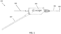
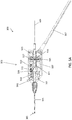
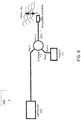
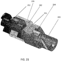
- a catheter (which may be used as a guidewire positioning catheter) 100 includes an elongate flexible shaft 301 and a rotatable distal tip 305 having an imaging sensor, such as an OCT sensor, connected thereto.
- the shaft 301 extends from a handle region 303 and terminates in the rotatable distal tip 305.
- the device 100 in FIG. 1 is not necessarily shown to scale, as the length of the shaft has been reduced to show the other features at a more appropriate scale.
- a guidewire 309 can extend through the guidewire catheter device 100, such as through a guidewire lumen in the shaft 301.
- the guidewire 309 may be held resident in the device 100 as it is positioned within a patient or it may be inserted after the distal end of the shaft 301, or at least the distal tip 305, has been positioned within the lumen of the vessel, such as past an occlusion or lesion.
- the guidewire lumen can be housed inside of a driveshaft (not shown in FIG. 1 ) configured to rotate the tip 305.
- the driveshaft is a tubular shaft such that the driveshaft may surround the guidewire lumen.
- the driveshaft is a solid shaft which extends through the length of the catheter, and runs alongside (e.g., adjacent to) the guidewire lumen.
- the system can include an optical fiber (not shown in FIG. 1 ) that is fixed at one end to the distal tip 305, but is otherwise free to move around, such as within an internal lumen between a lumen housing the guidewire 309 and an outer casing of the shaft 301.
- Power and imaging lines 307 (“cabling") may extend from the handle region 303 to connect the optical fiber with a power source and a light source for the OCT system.
- the handle region 303 can house the control mechanism for controlling the rotation of the distal tip (and OCT reflector/sensor at the end of the optical fiber).
- the control mechanism controls the direction of the distal tip as well as the number of revolutions before switching direction.
- the handle region 303 can also control the rate of rotation.
- the rate of rotation, as well as the number of clockwise and/or counterclockwise rotations may be optimized to advance the distal end of the device though an otherwise occluded lumen of a vessel while generating a cross sectional image of the lumen, i.e., 360 degrees.
- the rate and number of rotations may also be optimized to prevent damage to the optical fiber used for the OCT imaging which is attached only at the distal end of the device such that the rest of the fiber can extend along the length of the shaft 301 can wrap, off-axis, around the internal lumen (e.g., guidewire lumen) of the catheter without breaking.
- the internal lumen e.g., guidewire lumen
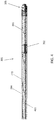
- the shaft 301 can include a fixed jog 989, or a J-shaped bend, near or just proximal to the distal tip 305.
- the fixed jog 989 can have an angle of 10 to 45 degrees, such as between 20 and 30 degrees.
- the jog is shapeable by the user prior to placing the catheter in the body lumen, i.e., the user can fix the jog 989 at the desired angle prior to use.
- the fixed jog 989 can aid in steering the shaft 301 to the point of interest.
- the shaft 301 can include an outer sheath 284.
- the outer sheath 284 can include a braided material, such as stainless steel, elgiloy, cobalt-chromium alloys, carbon fiber, or Kevlar.
- the braided material can improve the stiffness of the catheter to help navigate the catheter through vessel.
- the shaft 301 can include a guidewire lumen 363 (see FIG. 3B ) extending within a driveshaft 421 (see FIGS. 3A-3D ) from the proximal end to the distal end of the catheter.
- the guidewire lumen 363 can end in an opening in a distal tip 305 of the device.
- the guidewire lumen 363 can thus be configured to pass a guidewire therethrough.
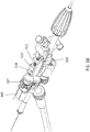
- the distal tip 305 can include an imaging sensor, such as an OCT sensor 286 configured to capture images within a lumen.
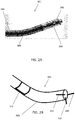
- one variation of the distal end of the shaft 301 can have a distal tip 305 that is roughly corkscrew or helically shaped.
- the distal tip 305 can thus include spiral flutes, such as two spiral flutes.
- the distal tip 305 rotates and does not extend or retract into a housing, i.e. remains exposed from the shaft 301.
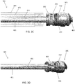
- the distal tip 305 can be attached to a driveshaft 421 that rotates within the outer sheath 284 and can be configured to rotate in both the clockwise and counterclockwise directions.
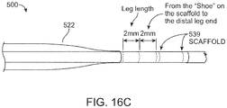
- the distal tip 305 can include a substantially smooth, curved outer surface 322 that presents an atraumatic tissue-contacting surface when rotated in one direction, i.e., the counterclockwise direction in FIGS. 3A-3D , and that further presents a sharp, tissue-cutting surface or edge 403 when rotated in the opposite direction, i.e. the clockwise direction in FIGS. 3A-3D .
- At least a portion of the tip 305 can have a diameter that is substantially equal to or greater than the diameter of the shaft 301. That is, the cutting edge 403 can be helical such that at the distal end, the diameter of the cutting geometry is reduced to the size of the guidewire lumen and gradually increases to the approximate outer diameter of the shaft 301 as it moves proximally. Further, the tip 305 can be configured such that it cuts only in the forward direction and not substantially in the lateral direction. That is, the cutting edge 403 can be substantially forward-facing.
- An OCT imaging sensor 286 (including the distal end of the optical fiber 411 and the mirror 412) can be fixed to the rotatable distal tip 305 and rotate with it.
- the distal end of the optical fiber 411 can be secured in a notch 344 formed in the rotatable distal tip 305.
- An epoxy or other securing material that has a refractive index appropriately mismatched with the end of the optical fiber 411 can hold the end of the optical fiber 411 in the notch 344, as described in U.S. Patent Application No. 12/790,703 , Publication No. US-2010-0305452-A1 .
- the imaging sensor 286 can direct the optical beam for OCT imaging from the distal tip 305 of the catheter into the tissue.
- the imaging system is oriented so that the mirror 412 directs the optical beam approximately or substantially perpendicular to the catheter axis. In some variations, this angle is different or is adjustable. For example, the orientation of the mirror 412 may be changed (including adjusted by the user) to change the direction of imaging and/or image more distally or proximally.
- substantially perpendicular may include plus or minus 10 degrees, plus or minus 5 degrees, or plus or minus 2 degrees, off of the 90 degree angle that is perpendicular from the elongate axis of the distal tip and/or catheter body.
- the sensor 286 can be located close the distal end of the tip 305, such as just proximal to the cutting edge 403.
- the sensor 286 can be located within 5mm of the distal end of the tip 305, such as less than 3mm, such as approximately 2mm.
- the resulting image will be a closer approximation of the exact tissue or material being passed by the distal end.
- the sensor 286 may be directed laterally (e.g., to image the sides of the vessel in which the catheter is traveling), or angled forward or backward.
- the sensor 286 can be located off of the central axis of the shaft 301 and close to the outer diameter of the tip 305, such as within 1.27 mm (0.05 inches), e.g. less than 7.62 mm (0.3 inches), less than 0.51 mm (0.02 inches), or less than or substantially equal to 0.25 mm (0.01 inches) of the outer diameter of the tip 305.
- the depth that the OCT system can see into the tissue will be greater, i.e., the amount of tissue lying within the OCT imaging range is increased.
- the rotating tip 305 is held in a chassis 405 that is fixed relative to the shaft 301, i.e., that does not rotate with the rotating tip 305.
- the chassis 405 is any structure within which the distal tip 305 can rotate and which secures the driveshaft 421 and/or the distal tip 305 to the end of the shaft 301; it may also be referred to as a housing.
- the outer sheath 284 can be connected to the chassis 405 such that the outer sheath also remains stationary while the distal tip 305 rotates.
- the chassis 405 can have one or more "window" regions through which the OCT imaging sensor 286 can view the tissue.
- the chassis 405 can include three window regions 346 separated by spines 419 (which may be referred to as posts, struts, dividers, separators, etc.) arranged annularly around the chassis 405.
- spines 419 may serve as reference markers as the imaging sensor 286 rotates, as discussed below.
- the spines 419 may be separated from one another by different distances. For example, one of the windows may be larger than the other two, or smaller than the other two. This asymmetric sizing may provide a visual reference on the display of the OCT imaging.
- the spines 419 can have a predetermined and fixed location relative to the jog 989 in the catheter.
- one of the spines 419 can be aligned relative to the jog 989. In one embodiment, shown in FIG.
- the second spine 419 is aligned opposite to the jog 989, i.e., such that the catheter points away from the second spine 419 (the inner curved portion of the jog 989 is opposite to the second spine 419 and the outer curved portion of the jog 989 is axially aligned with the second spine 419).
- This alignment can be used to help orient the device in a specific direction with respect to the image and/or vessel, as discussed further below.
- the distal tip 305 can include a groove 392 at the proximal end to engage a bushing 394 (e.g., annular ring).
- the bushing 394 can remain fixed with respect to the shaft 301 and may provide a lubricious surface to eliminate or reduce friction and fix the longitudinal position of the distal tip 305.
- the bushing 394 may be made of PEEK or other hard lubricous material.
- the groove 392 may be crimped or clamped to the stationary chassis 405, thereby allowing the rotatable distal tip 305 to have improved stability during rotation.
- the bushing 394 includes a shoulder 445.
- the shoulder 445 can extend outward into the space between the distal edge of the chassis 405 and the distal tip 305.
- the shoulder 445 can be made of the same lubricous material as the rest of the bushing 394. The shoulder 445 prevents the distal edge of the chassis 405 from rubbing against the tip 305 and further reduces the friction of the system.
- the chassis 405 may engage the groove 392 of the distal tip 305 directly, such as by one or more tabs 407 or locks that can be pushed in when the distal tip 905 is held within the chassis 405 to lock the bushing ring 394 and distal tip 305 in position.
- the chassis 405 or distal tip 305 can be made from a lubricious material.
- the chassis 405 can include one or more openings or ports 422 out of which a clearing fluid, such as saline or water, may be driven to help clear the pathway for imaging the walls of the vessel lumen as the device is operated.
- a clearing fluid such as saline or water
- Blood including red blood cells and other blood components, may degrade the ability of the OCT imaging system from imaging other tissues because OCT may not readily "see” through blood.
- the catheter may be configured to clear the blood from the region of interest, i.e., the region where the optical beam is emitted from the catheter for OCT imaging.
- the ports 422 can thus be configured to emit a clearing fluid from the catheter to clear blood from the imaging sensor.
- the port 422 is located directly adjacent to the imaging sensor and emits fluid to clear blood from the region where the optical beam is being emitted.
- the ports 422 can be less than 2mm from the imaging sensor, such as less than 1.5mm.
- the pressure and amount of clearing fluid required to clear the blood from the region of interest can be low.
- less than 1ml, such as less than 0.5ml, e.g., less than 0.2ml of clearing fluid can be required to clear the blood from the region of interest.
- the required pressure may be nominal and the flow of saline or other clearing fluid may be minimal and still effectively clear blood from the imaging space, greatly improving the resolution of the vessel walls and increasing the depth of penetration.
- using small amounts of clearing fluid can advantageously avoid problems associated with having too much fluid in a small space, such as separation of tissue (e.g., dissection).
- the shaft 301 can be configured such that the clearing fluid enters at the proximal end of the catheter and is transported to the distal end by flowing in a space 472 between the outer sheath 284 and the driveshaft 421.
- the clearing fluid may be pressurized from the proximal end (e.g., using a syringe, etc.) so that it is pushed out of the opening 422 to clear blood from the OCT pathway.
- the OCT portion of the catheter device 100 may be referred to as an off-axis imaging system because the management of the OCT optical fiber 411 is arranged asymmetrically, off-axis with reference to the long axis of the catheter.
- the fiber 411 can be configured to extend freely within the shaft 301 in the space 472 between the driveshaft 421 and the outer sheath 284 except where it is attached at the distal end of the device, e.g., at the rotatable distal tip 305. Accordingly, as shown in FIG. 4 , when the driveshaft 421 is rotated to rotate the distal tip 305, the fiber 411 can wrap around the driveshaft 421. This arrangement can advantageously enhance the flexibility, i.e., allow for movement of the catheter without fracturing the optical fiber 411.
- both the rate of rotation and the number of rotations may be controlled to optimize performance, prevent the fiber 411 from binding within the shaft 301, and prevent the fiber 411 from snapping due to excessive twisting or rotation.
- the distal tip 305 may be configured to alternate its rotation from clockwise to counter clockwise.
- the driveshaft 421 can be configured to rotate (with the distal tip 305) clockwise for a fixed number of rotations and to rotate counterclockwise for the same number of rotation before switching back to clockwise rotations and repeating the process.
- the number of rotations in the clockwise direction can be substantially equivalent to the number of counter clockwise rotations in order to relieve any residual twisting.
- the device is configured to rotate the distal tip n rotations clockwise and n rotations counterclockwise, switching between clockwise and counterclockwise rotational direction after each n rotations.
- the number of rotations n can be any number, including fractional, typically between 1 and 100; preferably it is between 1 and 10, depending on the length of the catheter and the amount of stress the fiber can withstand.
- the device maybe configured to rotate approximately 6, 8.5, 10, 12.7, 15, etc. times clockwise, then counterclockwise the same number of rotations.
- the device is configured so that it doesn't continuously spin clockwise or counterclockwise, but has a limited number of rotations in either direction (e.g., less than 25 rotations, such as 10 rotations), after which it automatically switches to rotate the other direction.
- the transition between clockwise and counterclockwise rotation may be performed automatically, which is described in more detail with reference to FIGS. 5A-5E , below.
- the rotation may be driven by a motor or other driver (e.g., within the handle) or it may be manual.
- the rotation is automatic, and is driven at a constant speed that is typically between about 1 and 300 revolutions per minute (rpm); for example, the rotation rate may be about 10 rpm, 20 rpm, 30 rpm, 40 rpm, 50 rpm, 60rpm, etc.
- the distal tip is rotated between about 1 and about 100 rpm, e.g., between about 1 and 80 rpm, such as between about 30 and 60rpm.
- the rate and the consistency of rotation may be optimized for penetration through the occlusion within the vessel, for image stability, and also to produce relatively streak-free imaging using the OCT.
- the rate of rotation may be limited to an upper limit speed that is held relatively constant.
- the rate of rotation may be sufficiently low (e.g., less than 150 or 100 or 50 rpm) so that the distal head rotates but does not 'drill' through the tissue, including one or more occlusions.
- the user can control the rate of rotation, such as by setting the motor to rotate at a particular speed.
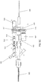
- the handle 303 of the device can be configured to control rotation and advancement of the shaft 301.
- the handle 303 can include a switch 562 configured to turn the system on or off (i.e. to start the rotation of the distal tip and/or the imaging system).
- the handle can be covered by a housing 501 which may be configured to conform to a hand or may be configured to lock into a holder (e.g., for connection to a positioning arm, a bed or gurney, etc.).
- a drive system including a motor 503 and drive gears 515, 516, 517, may drive the driveshaft 421 to rotate the distal tip 305 of the device and/or the OCT imaging system relative to the shaft 301.
- the drive system is controlled or regulated by a toggling/directional control subsystem for switching the direction of rotation of the driveshaft between the clockwise and counterclockwise direction for a predetermined number of rotations (e.g., 10).
- a mechanical directional control can be configured to switch the direction of rotation between clockwise and counterclockwise when the predetermined number of rotations have been completed.
- the directional control includes a threaded track (or screw) 511 which rotates to drive a nut 513 in linear motion; rotation of the threaded track by the motor 503 results in linear motion of the nut along the rotating (but longitudinally fixed) threaded track 511.
- the nut 513 moves linearly in a first linear direction (e.g., forward) until it hits one arm of a U-shaped toggle switch 516, driving the U-shaped toggle switch in the first linear direction and flipping a switch 523 (visible in FIG 5D ) to change the direction of the motor 503 to a second rotational direction (e.g., counterclockwise), and causing the nut to move linearly in a second linear direction (e.g., backward) until it hits the opposite side of the U-shape toggle switch 516, triggering the switch to again change the direction of rotation back to the first rotational direction (e.g., clockwise).
- a first linear direction e.g., forward
- a second rotational direction e.g., counterclockwise
- a second linear direction e.g., backward
- the motor 503 may be configured to rotate the driveshaft 421 in either direction at a constant speed.
- the system may also include additional elements (e.g., signal conditioners, electrical control elements, etc.) to regulate the motor as it switches direction.
- the number of threads and/or length of the threaded track (screw) 511 may determine the number of rotations that are made by the system between changes in rotational direction. For example, the number of rotations may be adjusted by changing the width of the U-shaped toggle 514 (e.g., the spacing between the arms). Lengthening the arms (or increasing the pitch of the screw) would increase the number of rotational turns between changes in direction ( n ). The toggle may therefore slide from side-to-side in order to switch the direction of the motor.
- the length of the nut 513 can also determine the number of rotations that are made by the system between changes in rotational direction, i.e., the longer the nut, the fewer the number of rotations before switching direction.
- the motor 503 is rotated in a constant direction, and the switch between clockwise and counterclockwise is achieved by switching between gearing systems, engaging and disengaging an additional gear, or using gears that mechanically change the direction that the driveshaft is driven.
- the drive system includes the motor and three gears that engage each other to drive the driveshaft in rotation.
- the motor 503 rotates a first gear 517, which is engaged with a second gear 516 (shown in this example as a 1:1 gearing, although any other gear ratio may be used, as appropriate).
- a third gear 515 engages with the second gear 516.
- the third gear may drive or regulate an encoder 507 for encoding the rotational motion. This encoded information may in turn be used by the drive system, providing feedback to the drive system, or may be provided to the imaging system.
- the cabling 307 can include both a fluid flush line 552 configured to be attached to a fluid source and an optical fiber 411 configured to be connected to the OCT system.
- the flush line 552 and the fiber 411 can both run through the handle 303.
- the fiber 411 and the flush line 552 can be bonded at a bonding point 566 in the handle 303, creating a seal to prevent fluid from leaking into the handle.
- the flush line 552 can end at the bonding point 566, allowing the fluid to exit the flush line and continue down the shaft 301 in the space 572 between the outer sheath 284 and the driveshaft 421.
- the fiber 411 can extend through the bonding point 566 and wrap around the driveshaft 421 in the space 572. As shown, because the fiber 411 is configured to wrap around the guidewire lumen, a separate fiber management system is not necessary.
- a protective coating 564 can surround the optical fiber until distal of the bonding point 566.
- the fiber 411 can be connected at the proximal end to a common-path OCT system 600.
- the common-path OCT system 600 includes a light source 102, such as a swept frequency laser.
- the light source could be a broadband light source such as a super-luminescent diode (to conduct Time Domain OCT or Spectral Domain OCT using an optical spectrometer).
- the optical fiber 411 transfers radiation from the light source 102 to the target 114.
- the optical fiber 411 is in optical contact with an interface medium 106, i.e. the light exiting the optical fiber and entering the interface medium sees only one interface.
- the end of the optical fiber is embedded in the interface medium 106.
- the interface medium 106 can be, for example, a glue or epoxy.
- the index of refraction of the interface medium 106 is different than the index of refraction of the core of the optical fiber 411. This creates a Fresnel reflection, in which part of the light exits the core, and part of the light is reflected back. Some of the light beam that exits the optical fiber 411 will encounter the target 114 and be reflected or scattered by the target 114. Some of this reflected or scattered light will, in turn, reenter the tip of the optical fiber 411 and travel back down the fiber 411 in the opposite direction.
- a Faraday isolation device 112 such as a Faraday Effect optical circulator, can be used to separate the paths of the outgoing light source signal and the target and reference signals returning from the distal end of the fiber.
- the reflected or scattered target light and the Fresnel-reflected reference light from the fiber face can travel back to a detector 110 located at the proximal end of the optical fiber 411.
- the reflected or scattered target light in the OCT system 600 travels a longer distance than the Fresnel reflected reference light
- the reflected or scattered target light can be displaced by frequency, phase and or time with respect to the reference beam.
- the light from the target will be displaced in frequency.
- the difference in displacement in phase, time or frequency between the reflected or scattered target light and the reference light can be used to derive the path length difference between the end of the optical fiber tip and the light reflecting or light scattering region of the target.
- the displacement is encoded as a beat frequency heterodyned on the carrier reference beam.
- the light source 102 can operate at a wavelength within the biological window where both hemoglobin and water do not strongly absorb the light, i.e. between 800 nm and 1.4 ⁇ m.
- the light source 102 can operate at a center wavelength of between about 1300 nm and 1400 nm, such as about 1310 nm to 1340 nm.
- the optical fiber 411 can be a single mode optical fiber for the ranges of wavelengths provided by the light source 102.
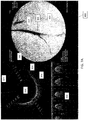
- FIGS. 7A and 7B are exemplary screen captures of an imaging output from the system described herein.
- the displayed image 800 is divided into three components.
- On the right is a fluoroscopic image 810 showing the distal end 805 of the catheter within a vessel 814. Contrast has been inserted into the vessel 814 to show the extent of the vessel 814 and any occluded regions.
- an OCT image 820 On the left is an OCT image 820.
- the distal tip of the catheter rotates at approximately 30 rpm, and the OCT system provides a continuous set of images as the catheter rotates within the vessel.
- the images are combined into a continuously updated OCT image 820 that corresponds to the inside of the lumen in which the catheter is inserted. That is, the OCT image 820 is an image trace of the interior of the vessel just proximal to the distal tip as it rotates.
- the line 822 (extending to almost 12 o'clock in the figure) indicates the current direction of the OCT laser beam as it is rotating.
- the circle 824 in the middle of the image 820 represents the diameter of the catheter, and thus the area surrounding the circle 824 indicates the vessel.
- the OCT imaging can extend more than 1mm from the imaging sensor, such as approximately 2mm or approximately 3mm and thus will extend into the walls of the vessel (particularly in the closer region of the vessel) so that the different layers 826 of the vessel may be imaged.
- the three striped rays 744 (extending at approximately 2 o'clock, between 7 and 8 o'clock, and approximately 11 o'clock) indicate the location of the three spines of the catheter and thus may act as directional markers, indicating the orientation of the distal end of the catheter within the body.
- the user may also be able to determine relative orientation of the OCT image (relative to the patient's body orientation) using these striped rays 744.
- a waterfall view 830 of the OCT image As it circles the radius of the body.
- This waterfall image 830 may be particularly useful in some applications of the system, for example, indicating the relative longitudinal position of a feature (e.g., layered structures, occlusions, branching region, etc.) as the device is moved longitudinally within the vessel.
- the waterfall view 830 typically includes a time axis (the x-axis) while the y-axis shows the image from the OCT sensor.
- the waterfall view 830 may provide an indication of when the catheter has crossed an occlusion.
- the waterfall view 830 may show the patient's heartbeat when the walls of the vessel move relative to the heartbeat.
- the waterfall view 830 may show the walls of the vessel moving with the heartbeat.
- the distal tip is within an occlusion the wall of the vessel
- the waterfall view will not show movement of the walls since the occlusion material typically prevents the movement of the walls due to the heartbeat, while in healthy vessels the heartbeat is apparent.
- this effect may be automated to provide an indication of when the device is within or has crossed an occlusion.
- crossing the boundary of a total occlusion is not well defined and may result in inadvertently dissecting the vessel.
- the vessel wall may move; if the catheter tip is not in the true lumen all or part of the vessel wall will not move.
- this movement of the wall during heartbeat may reflect the position within the true versus false lumen.
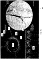
- FIG. 7B shows another screen capture from the same procedure shown in FIG. 7A .
- the distal tip 305 is further within the vessel 814 than in FIG. 7B .
- the OCT image 820 shows a branch 818 of the vessel extending from the vessel in the 2 o'clock position.
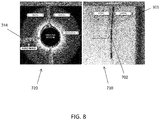
- the shaft 301 can include a fluoroscopy marker 702 (also shown in FIG. 2B and FIG. 4 ) that provides varying contrast in a fluoroscopy image depending on its radial orientation.
- the marker may be a radiopaque band with one or more asymmetric features such as a "C", "T", or dog bone shape that can be used to radially orient the shaft because the fluoroscopic image of the marker will change depending on its orientation.
- the fluoroscopy marker 702 can have a fixed location relative to the spines 419 and/or the jog 989. For example, as shown in FIG. 2B , the fluoroscopy marker 702 can be aligned opposite to the jog 989 and/or axially aligned with the second spine 419 described above. The fluoroscopy marker 702 can be used to align a fluoroscopy image 710 with an OCT image 720 during use of the catheter.
- the shaft 301 can be rotated slightly such that the marker 702 is aligned to a particular side of the screen, such as at the 9 o'clock position.
- the up/down position of the catheter i.e. whether the catheter is pointed down, as shown in FIG. 7 , or pointed up
- the OCT image can then be oriented such that striped ray 744 from the middle marker (the second spine 419 described above) of the shaft 301 is also at the 9 o'clock position in the OCT image 720.
- Fluorosyncing can be performed using manual input from the user, such as information regarding the up/down position and the rotational position, or can be performed automatically.
- the software may draw the OCT image 720 either in a clockwise or counterclockwise direction (depending on the up/down orientation of the catheter in the fluoroscopy image 710) and will rotate the image 90°, 180°, or 270° (depending on the rotational position of the catheter in the fluoroscopy image 710).
- the absolute and relative position and orientation of the catheter within the patient's body may be determined.
- the markers on the chassis/imaging system visible in the OCT system) may therefore provide sufficient orientation markers such that the fluoroscopic imaging may be reduced.
- the displayed images can be used, in combination with steering mechanisms such as the OCT markers, the fluoroscopy marker, and the fixed jog of the device, to steer the catheter and rotatable tip to the desired location.
- the OCT image 920 shows healthy tissue 956 in the form of a layered structure and non-healthy tissue 958 in the form of a nonlayered structure.
- the cat ears 962 in the image show a region between the healthy and unhealthy tissue caused by a slight expansion of the vessel around the catheter at that location. Accordingly, during a CTO procedure, one goal may be to steer the catheter towards the unhealthy tissue. Because the middle spine 419 is aligned opposite to the jog 989 (as shown in FIG.
- the ray 744 corresponding to the middle spine 419 can be oriented opposite to the non-healthy tissue 958 to steer the catheter in the correct direction.
- FIG. 9B shows the catheter deflected toward the layered, healthy tissue.
- FIG. 9C shows the catheter rotated such that it is deflected toward the unhealthy, non-layered structure.
- the system may be configured to allow the orientation of the catheter to be rotated into the correct position using the fixed directional markers from the chassis that are visualized by the OCT.
- the distal end of the device may be steerable and may be steered while still rotating the distal end of the device.
- Additional steering members may also be included, such as a selective stiffening member, which may be withdrawn/inserted to help steer the device, and/or one or more tendon members to bend/extend the device for steering.
- Image correction can be performed on the resulting OCT images in order to mask out unwanted or unnecessary portions of the image.
- the fiber 411 can be configured such that it ends within the shaft 301.
- the fiber 411 will image the distance c1 between the fiber 411 distal end and the mirror 412 as well as the axial distance c2 between the mirror 412 and the outer diameter of the shaft 301.
- the resulting image would therefore include portions that correspond to the interior of the shaft. Accordingly, image processing can be performed such that distance c1, c2, or c1 + c2 is masked out in the displayed image.
- c1 and c2 are masked out, only the area c3 would show up on the image (where the total imaging distance or capability of the fiber is equal to c1 + c2 + c3).
- up to 100 pixels can be masked out, such as between 20 and 60 pixels, for example approximately 40 pixels.
- the image can be corrected to account for lag of the optical fiber in the amount of rotation at the handle vs. at the distal end of the catheter.
- Images for lag correction can be captured automatically.
- images can be exported and stored, for example in a movie format.
- the images can optionally viewed in adjustable grayscale. Further, the speed of the waterfall view can be adjusted.
- offset or "ghost" image may be overlaid atop the OCT to indicate the difference between the predicted and actual rotational orientation of the catheter.
- a manually rotatable device may be used with an adjunctive device providing a motorized movement of the distal tip.
- the handle portion of the device may set and be secured within a housing that includes a motor and gearing to automatically rotate the distal tip at a predetermined or adjustable speed.
- this motorized accessory device may adapt an otherwise manual device to automatically rotate.
- catheters are possible that include one or more of the features described above.
- the rotatable distal tip includes a fixed or rotatable housing from which dissection elements may extend or retract.
- An imaging element such as an OCT imaging element, may be included in this example as well.
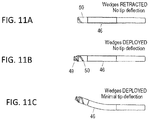
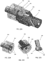
- wedges 49 may be extended from a rotatable distal tip 50.
- FIG. 11A the device is shown with the wedges retracted into the rotatable distal tip 50.
- FIG. 11B the wedges 49 have been extended from the housing 46.
- the distal end of the device can be shared and is shown deflecting upwards (steering in one plane) in FIG. 11C while the wedges are extended from the housing.
- Both the distal tip and the wedges can be configured to rotate.
- the wedges 49 (which may be sharp blades or may be blunt) can be extended from the distal housing and locked in any position (extended, partially extended or retracted) and rotated clockwise and/or counterclockwise while locked in a retracted, extended or partially extended position.
- the wedges may be fully or partially retracted into a distal housing.
- the extension of the wedge from the distal housing may be limited.
- the wedges may be prevented from extending fully out of the distal housing, thereby preventing material (such as a plaque or tissue) from getting caught between the wedges and the housing.
- the wedges at the distal end may be referred to as a blade or blades, even though they may be substantially blunt.
- the wedges are configured so that they are forward-cutting, but not side-cutting. This means that they may include a forward-facing cutting edge, and the more lateral edges may be blunted or less sharp.
- the rotating distal tip includes only a single wedge, rather than multiple wedges.
- the wedge (blade) may be helically arranged at the distal tip.
- the rotating distal end comprises two or more wedges that are radially separated around the tip region (e.g., spaced equally apart radially). It may be advantageous to have three or more wedges spaced around the tip, which may improve centering of the device, as described herein.
- the distal tip of the device is rotated through multiple complete rotations (both clockwise and counterclockwise) to move the distal tip and/or any attached imaging sensor in rotation around the elongate longitudinal axis of the device.
- the distal tip of the device may be rotated through partial rotations. This is illustrated in FIGS. 12A-13D .
- a driveshaft rotates continuously in one direction, e.g., clockwise, but this one-directional rotation is translated at the distal end of the device into oscillating motion.
- FIG. 12A shows a partially transparent view of one variation of an oscillatory motion system for rotating the distal end portion of a catheter back and forth (clockwise and counterclockwise) though a partial rotation, such as less than 360 degrees, e.g., less than 180 degree, etc.
- the system is shown connected to an oscillation/rotating element 801 to which the imaging sensor, including a mirror 811 and the distal end of an optical fiber 813 for the exemplary OCT system, are connected.
- oscillation of the oscillation/rotating element 801 moves the OCT sensor to image an angular view of the field of view.
- the oscillation/rotating element 801 may be moveably housed within an outer housing 802 which may remain "fixed" relative to the inner oscillation/rotating element 801.
- the outer housing 802 may be connected to the rest of the catheter.
- this catheter is strictly configured for OCT imaging and is not configured for atherectomy or for guidewire positioning.
- FIG. 12B shows the device of FIG. 12A with the outer housing 802 removed.
- the oscillation/rotating element 801 includes a C-shaped end region into which a camming member 805 that is attached to the rotating/rotatable driveshaft 803 is housed.
- the camming member 805 in this example is a cylindrical member to which the driveshaft 803 is eccentrically connected, so that the center of the longitudinal axis of the driveshaft 803 is off-axis for the center of the longitudinal axis of the camming member 805.
- FIG. 13A shows the camming member 805 and attached driveshaft 803 within the C-shaped cut-out of the oscillation/rotating element 801.
- any of the catheters described herein may be used to treat peripheral vascular disease.
- the catheters may be used to place one or more guidewires across an occlusion, so that the occlusion may be imaged, removed, and/or displaced.
- the devices described herein are centering or self-centering within the lumen of the vessel.
- the vessel 441 (shown in cross-section on the left a transverse section on the right of each figure) includes the media 442 (e.g., tunica media) surrounded by adventitia 443 (e.g., tunica adventitia).
- the devices 400 remain centered within the "true" lumen 445 (the center) of the vessel 441 as shown in FIG. 14A , rather than a "false” lumen 446, i.e., the region between the adventitia 443 and media 442 as shown in FIG. 14B .
- the catheter device does end up in the sub-intimal plane (e.g., false lumen 446), as illustrated in FIG. 14B , the device may reside between the media 442 on one side and the adventitia 443 on the other.
- the devices may be configured for both passive centering (self-centering) and active centering (including a centering mechanism).
- the devices described herein are self-centering and are thus configured to help maintain the catheter (e.g., the tip of the catheter) within the true lumen.
- the manually or automatically rotatable distal end of the catheter may guide the catheter in the true lumen, especially when the reaching the distal cap of a lesion.
- the tip may be sufficiently blunt to passive self-center within the lumen of a vessel.
- the device does end up within the "false lumen," it can be configured to self-center back into the true lumen.
- adventitia typically prevents the tip from engaging and tearing the tissue.
- the rotating tip it is easy for the rotating tip to engage with the media if it is presented in the front of the device, which may include the tissue-cutting surface(s).
- the rotating tip may selectively dissect its way through the media and not through adventitia. Once the device dissects its way through the medial, it returns to the true lumen.
- centering self-centering of the catheter may result from the rotation of the distal end for the dimensions of the devices illustrated herein, one or more additional centering features may also be used to help the device to stay in true lumen of the blood vessel.
- the catheter may be configured for use with one or more centering features to help prevent the distal tip from leaving the true lumen.
- the centering feature may project from the distal tip, the lateral sides of the distal tip, or the lateral sides of the distal end region, e.g., proximal to the distal tip.
- the centering feature is a balloon that expands (or is expandable, inflatable, or otherwise extendable from the lateral sides of the distal end region of the device) to keep the distal tip centered in the lumen.
- the device may also be deflectable or steerable at the distal tip region, as previously described, and/or may include one or more sensors (e.g., OCT imaging as described above), to help detect when the tip is approaching or has passed into the false lumen or otherwise left the true lumen.
- FIG. 15A illustrates one variation of a catheter (as described in patent application USSN 12/689,748 ) which may have a rotating distal tip region.
- FIG. 15B shows a catheter 500, similar to the catheter of FIG. 15A , but including a balloon 522 located proximal to the rotating distal tip.
- the centering mechanism could apply to any of the catheter configurations described herein.
- the balloon may cover or extend over the rotating distal tip region.
- the distal end region may include a balloon 522 that is collapsed around the outer diameter of the catheter shaft 103, but may be inflated and expanded against the walls of the vessel. In addition to centering the distal end of the catheter shaft 103, expanding the balloon 522 may also expand the opening or passageway through the vessel. This may, in turn, improve treatment outcomes with the device, perhaps by loosening or preparing the atheroma (or other occlusion) for removal or displacement.
- the proximal region of the catheter shaft 103 includes a port 524, for example a y-type connector, for inflation fluid, that may be use to inflate and deflate the balloon 522. Any appropriate inflation fluid may be used, including water, saline, lubricant, dye, or some combination of these.
- the catheter 500 is fabricated similarly to the catheters described previously, i.e., to include an inner lumen for passage of a guidewire, surrounded by a driveshaft for rotating/oscillating the distal tip, and again surrounded by an outer diameter jacket (e.g., of a flexible, braided stainless steel, polymer, etc.).
- an additional tube 533 to form the inflation lumen 535 e.g., a 0.28 mm (0.011") ID polyimide tube
- a mandrel 539 e.g., a 0.23 mm (0.009”) stainless steel mandrel
- a balloon 522 may be attached near the distal end (e.g., proximal to the distal end of the catheter 500, as illustrated in FIG. 15B , and also FIGS. 16A-16C .
- the balloon 522 can have a nominal dimension of approximately 10 cm in length and a diameter of 5 mm (expanded).
- the balloon 522 has two rounded shoulder regions, one at the proximal end and one at the distal end; in some variations one or both ends may be tapered. In FIG.
- the inflation lumen ends between the proximal and distal end of the balloon, e.g., near the center of the balloon, and terminates in a skived opening to allow entry/exit of inflation material.
- the balloon 522 has a slightly smaller diameter at the proximal end compared to the distal end to compensate for the missing inflation lumen at the distal end; thus, the overall outer diameter of the catheter 522 may be remain relatively constant.
- the balloon 522 may be fused to the outer portion of the distal end of the catheter, as shown in FIGS. 16A-C .
- a short length of PEBAX tubing may be added to the shaft at the locations where the distal and proximal ends (legs) of the balloon will be located. These PEBAX lengths may be used to ensure that enough material seals and fuses the balloon to the outer shaft.
- FIGS. 16B and C show the fused proximal ("rear leg”) and distal ("front leg”) regions of the balloon.
- the inflation lumen 535 (polyimide tube) is skived at the distal end to correspond to a location of the distal inflation/deflation hole approximately midway along the length of the balloon 522.
- the balloon 522 may be folded, sealed and/or heat set (e.g., to maintain the small delivery diameter, etc.).
- the balloon 522 may be pleated, folded and heat set.
- FIG. 17 shows one variation of the handle region 725 of a catheter 500 including a balloon-type centering feature.
- the proximal end of the device includes a Y-arm with an inflation/deflation port or lumen 535, and sealed in position, to prevent leakage.
- a separate inflation lumen is not included, but all or a portion of the region between the outer sleeve and the inner catheter (e.g., the central or offset guidewire lumen) is used as the inflation lumen connecting the inflation port to the balloon.
- proximal shaft has a diameter between about 1.88 mm (0.074 inches) and 2.13 mm (0.084 inches); the mid-shaft region has a diameter between about 1.88 mm (0.074 inches) and 2.01 mm (0.079 inches); the proximal balloon leg has a diameter between about 2.16 mm (0.085 inches) and 2.39 mm (0.094 inches); the distal balloon leg has a diameter between about 2.01 mm (0.079 inches) and 2.16 mm (0.085 inches); and the mid region of the balloon over the inflation lumen has a diameter between about 1.96 mm (0.077 inches) and 2.16 mm (0.085 inches).
- the double wall thickness of the balloon is approximately 0.11 mm (0.0045 inches), and the catheter has a length from the distal end of the proximal assembly to the distal tip of the device of 111 cm, while the length from the distal end of the Y-arm to the distal tip of the device is approximately 91cm.
- the balloon When inflated to 608 kPa (6 atm pressure), the balloon has a proximal diameter of about 5.54 mm (0.218 inches), a mid-diameter of approximately 5.36 mm (0.211 inches), and a distal diameter of approximately 5.33 mm (0.210 inches) (at 1013 kPa (10 atm) in this example, the proximal diameter was about 5.64 mm (0.222 inches), the mid-diameter was approximately 5.49 mm (0.216 inches), and the distal diameter was approximately 5.46 mm (0.215 inches).
- FIG. 18 shows one example of the catheter 500 with a balloon 522 inflated to approximately 608 kPa (6 atm) with water. Deflation may be achieved using the inflation/deflation lumen 535. In one example, complete deflation took approximately 3 min. However, this may be faster or may be performed slower by adjusting the annular size of the inflation lumen or the viscosity of the inflation fluid. The balloon 522 was deflated until little or no residual inflation fluid was present in the balloon.
- FIGS. 19A-C illustrate the balloon 522 of FIG. 18 after deflation and removal of the inflation fluid.
- the balloon 522 has not been folded and/or pleated (or heat-set into this folded/pleated configuration), so the balloon collapses as shown.
- the outer diameter of the catheter may be kept small in the deflated configuration.
- centering feature may be used as well, not limited to the annular/toroidal balloon described above.
- one or more arms may extend from the outer shaft of the device and apply lateral force against the walls of the vessel to center it within the lumen.
- a coil located near the distal end and coiling around the distal end region may be expanded to extend loops outward and center the device.
- Any appropriate material, including shape memory materials (e.g., nickel titanium) may be used, and the centering feature may be configured to be atraumatic when contacting the vessel lumen (e.g., having rounded or flat, large-diameter tissue-contacting surfaces, etc.).
- the guidewire positioning devices described herein may be configured as single-use, over-the-wire, devices.
- the device may be compatible other guidewires of standard sizes used in minimally invasive procedures.
- the outer diameter of the elongate device (including the distal end region) may fit within a 7F sheath.
- the devices may be used with any appropriate guidewire, including steerable guidewires.
- the guidewire may be a .89 mm (0.035”) guidewire.
- These devices may generally be described as "steering" a guidewire, although they may be used with a guidewire within the catheter, or the guidewire may be positioned within the device after the catheter has been positioned.
- these devices may provide support and guidance for positioning a guidewire across an occlusion.
- the devices may support probing and exchange of an assortment of guidewires, by traversing an occlusion in a vessel.
- the catheters are inserted ahead of the guidewire (or with the guidewire retracted within the catheter) to provide a safe pathway thorough the occluded vessel, and thereby reduce or eliminate unnecessary damage to the vessel.
- the devices described herein may be used to deliver contrast.
- the internal lumen which may be used by the guidewire and/or the outer lumen may also be used for local dye or fluoroscopic contrast injections without removing the device from the vessel.
- the rotating/oscillating distal tip allows the device to be passed through an occlusion such as a plaque occluding a blood vessel (or artery) without requiring removal of the plaque.
- the device may be used to bluntly form a pathway through a plaque using the retractable/extendable rotating wedges at the distal tip, or simply using the rotating distal tip alone.
- the cutting edges at the distal tip may also allow for helical and blunt micro-dissection. It is important to note that the catheter may be used without substantially dissecting or cutting the tissue, and that the distal tip is not necessarily intended (and may not) remove tissue, but merely form a passage through an occluded vessel. Once in position, the guidewire may be used to insert other devices, including atherectomy catheters.
- the cutting edges at the distal tip are sharp (e.g., cutting or knife-edged), while in other variations the cutting edges are substantially blunt.
- the cutting edges are typically curved around or along the longitudinal axis of the distal tip.
- the cutting edge may extend helically around the distal tip end of the device.
- the catheters described herein may be used (e.g., inserted) in to the body in a 7F guide sheath for placement into the body.
- the elongate catheter is flexible, and the outer surface(s) may be coated so that the catheter can be readily inserted into a lumen of a sheath, catheter, or directly into a body lumen.
- the elongate outer sheath is typically tubular, and may be coated (either or both inner and outer diameter surfaces) with a protective cover.
- the elongate outer sheath may be referred to as a shaft (e.g., catheter shaft), and may be coated with a lubricious material or may be formed of a smooth and/or lubricious material.
- the distal tip of the catheter is retractable into an expanded approximately toroidal-shaped distal balloon that is expanded proximal to the distal tip. This variation may allow re-centering or re-orientation of the catheter.
- the distal end of the catheters described herein may be steerable.
- the distal end region may be steerable in any appropriate manner.
- the distal end region may be steerable by defecting in one direction (e.g., 'down') or in more than one direction (e.g., down/up, right/left, etc.).
- the degree of deflection may also be controlled.
- the tip may be deflected a maximum of 10 degrees, 15 degrees, 20 degrees, 25 degrees, 30 degrees, 45 degrees, 60 degrees, 90 degrees, or any angle there between.
- the distal end region of the device is pre-biased to be straight.
- the straight configuration of the distal tip may be restored once the deflection (controlled at the proximal end) is restored to the straight configuration.
- the distal end of the device is flexible.
- the end region may include the tip (e.g., the rotating tip) or it may include the region immediately proximal to the tip.
- the "tip region” may refer to the rotatable tip region at the distal end.
- the deflection may be performed by any appropriate method, including a pullwire coupled to a hinged distal region, a prebiased curve which can be released (e.g., by a pullwire, etc.), etc.
- the deflectable/steerable distal end region (which may be referred to as the "steerable tip") may allow the catheter to re-enter the true lumen of the vessel if it becomes subintimal (e.g., if it extends into the fascia or region around the vessel).
- the distal region of the catheter is prebent, e.g., includes a jog.
- the catheter includes a bendable distal end. Steering these catheters may be aided by visualization and may include rotating the length of the catheter body, which may be guided by imaging. Rotation or turning of the catheter body may be used to orient the distal tip region because of the bend in the catheter, in both fixed bend and bendable catheters.
- proximal handle may act as an interface with the operator, and may include one or more controls.
- the handle region may also include connections to power (e.g., in automatic rotating/oscillating variations), imaging (e.g., connection to imaging source and processing), or the like.
- the devices described herein may be any appropriate length, but relatively short length catheters may be particularly useful.
- the device may be approximately 100 cm, allowing the device to reach any occlusion down to the popliteal and ease physician handling outside the body.
- the device is between about 50 and 150 cm, between about 70 and 120 cm, etc.
- the distal tip may be driven by an elongate driveshaft (or “torque shaft”) that extends the length of the device.
- This driveshaft is typically robust, allowing increased torque precision and manipulation during the operation.
- the torque shaft may be made of a braided stainless steel material having a hollow lumen (forming or surrounding a central, e.g., guidewire, lumen of the device).
- Rotation of the driveshaft typically drives the distal tip rotation.
- the driveshaft is typically flexible and connects to the rotational control at the proximal end (e.g., handle).
- the distal tip, including the wedges and housing may rotate both clockwise and counterclockwise.
- the handle region at the proximal end of the device may also be adapted for handheld use.
- the controls at the handle region may be adapted so that the device may be manipulated by a single hand.
- the handle region may also include one or more indicators or displays for displaying the status of the distal end of the device.
- the handle may include an indicator indicating the extent to which the wedges are extended from the distal tip.
- the indicator may be a dial, slider, or the like.
- the indicator may be marked or unmarked.
- the proximal handle may be otherwise configured to be handheld.
- the controls may be clustered or located at one end of the handle with a gripper region at the other end.
- the controls may be clustered at the proximal portion of the handle (allowing the distal portion of the handle to be gripped in the palm of the hand, and manipulate d by the thumb and forefinger of the right.
- the elongate outer sheath of the catheter is flexible, and may be coated so that it can be readily inserted into a lumen of a sheath, catheter, or directly into a body lumen.
- the elongate outer sheath of the catheter may be formed of a braided stainless steel, a polymer, or the like.
- the elongate outer sheath is typically tubular, and may be coated (either or both inner and outer diameter) with a protective cover.
- the elongate outer sheath may be referred to as a shaft (e.g., catheter shaft), and may be coated with a lubricious material or may be formed of a smooth and/or lubricious material.
- the forward cutting blades may prevent cutting on the sides/walls of the lumen.
- This configuration may also help with self-centering, as mentioned.
- the device may be configured so that the diameter of the blade (e.g., wedge) region is the same as the diameter of the rest of the catheter.
- the diameter of the distal end having the rotatable wedge is maximized so that the blades are the same crossing profile as the rest of the catheter, which may allow for optimal engagement within the occlusion in the vessel.
- the guidewire lumen described herein is not central, but is offset along all or a portion of the length of the device.
- the lumen (or a separate lumen) may also be used to pass a material such as a contrast dye, saline, an imaging device, etc.
- An outer lumen may surround the inner (guidewire) lumen, and may enclose this space to form a separate lumen in which one or more additional lumens (e.g., inflation lumen in variations including a balloon or expandable feature) may be included; a driveshaft for rotating or controlling rotation of the distal tip may also be included.
- the proximal end of the device typically includes a handle region that may be used to control the distal end.
- the device may include a rotation control, a wedge articulation control and/or a steering control.
- these controls may be combined into one or more controls or these functions may be distributed or divided between different controls. Any appropriate control may be used, including slides, knobs, dials, buttons, levers, switches, etc.
- the controls may be automated or computer-controlled.
- a driver e.g., motor, mechanical driver, etc.
- rotation of the distal tip region may be driven by a motor, and may be geared or otherwise controlled. The rotation may be manually or automatically controlled.
- an atherectomy catheter (which may be used after placement of a guidewire as described above) is illustrated in FIGS. 20A-22D and described below.
- an atherectomy catheter may access the vasculature using conventional catheterization techniques employing sheath and/or guiding catheter access and tracking over a positioned guidewire.
- the device may track through the vasculature to the target lesion.
- a fiber e.g., a Single Mode fiber
- imaging e.g., OCT imaging
- the device may be rotationally oriented toward the diseased sector of the artery, and activated using proximal physician controls to preferentially expose the cutting edge to the diseased tissue.
- a circular cutter will begin rotational movement at approximately 10 to 10000 revolutions per minute (rpm) of the driveshaft.
- the device may be translated through the lesion to plane and cut the diseased tissue while the OCT image provides real time feedback regarding wall and disease characterization, cutter apposition and relative cut depth.
- the tissue may travel through the circular hollow cutter into a tissue reservoir that is distal to the cutter.
- proximal controls may be used to articulate the device, returning the cutter to its shielded position for further delivery and placement. Multiple runs through this procedure may occur to fully treat the disease.
- FIGS. 20A and 20B illustrate one variation of an atherectomy device 200 as described.
- the device includes a cutter 282 rotatable by a driveshaft 294 (see FIG. 21 ) located within an elongated catheter body 201.
- the cutter edge with a comparatively large cross-sectional area, is located along the circumferential surface of the main catheter body 201.
- the driveshaft 294, with a comparatively small cross-sectional area, is located within the central region of the catheter body.
- the cutter diameter is at or near the maximum crossing profile of the main catheter body 201 to maximize cut tissue cross-sectional area and minimize depth of cut.
- the large cross-sectional area may provide more efficient cutting passes, thereby reducing the time of procedure, and may add a degree of safety by reducing the depth of cut required to achieve comparative luminal gain.
- the cutter 282 can cut tissue from the wall of the artery, pass directly through the hollow portions, and be stored in a tissue storage area, such as tissue storage area 216.
- FIG. 20A and 20B portray the distal portion of the device in both the non-activated ( FIG. 15A ) and activated ( FIG. 15B ) positions, respectively.
- the cutter 282 In the closed/non-activated position, the cutter 282 is shielded to prevent unintended damage to the inner diameter of ancillary medical devices and vasculature.
- the open/activated position the cutter 282 is exposed with the tissue packing auger 292 distal of the cutting edge as shown in FIG. 21 .
- the distal tip of the catheter is advanced past the targeted lesion. The catheter is delivered in the non-activated position where the delivery catheter and vasculature is shielded from the cutter edge.
- the distal tip assembly is activated to present the cutter edge 282.
- the driveshaft of the catheter is powered to rotate the cutter 282 as it is passed across the lesion. The rotational motion assists the cutter in cutting the targeted tissue.
- the device is then returned to the non-activated position which assists the cutter in parting off the strip of tissue and packing it into the tissue storage lumen 216.
- the device 200 can include an imaging sensor 279 in a notch 277 near the distal end of the device.
- the imaging sensor 279 can be an OCT sensor similar to that described above.
- the driveshaft 294 can be directly connected to the circumferential cutter 282 and to an auger 292 or Archimedean screw.
- the driveshaft 294 can thus transmit torque to the cutter 282 while allowing tissue to pass through the hollow cutter 282 as it is rotated.
- tissue is then passed through the inner, hollow diameter of the cutter 282.
- the tissue is then cut into segments by the cutting edge 299 of the auger component 292 and passed into the tissue storage area 216 distal to the auger 292.
- FIG. 21 shows the auger component 292 configured in a helical geometry.
- the auger component can have other configurations.
- FIGS. 22A-22D show an auger component 293 that is capable of shearing tissue segments when rotated in either the clockwise or counterclockwise direction.
- the auger can be substantially T-shaped with two cutting edges 298. Rotation of the auger component 293 in either the clockwise or counterclockwise direction would thus cause shearing of tissue.
- the auger component 293 can shear tissue two times per rotation of the driveshaft 294.
- the auger component 293 can further include angled surfaces 297 configured to push cut tissue distally into the tissue storage area 216.
- the auger component 293 can cut in both the clockwise and counterclockwise directions, it can work even if the driveshaft oscillates between clockwise and counterclockwise directions, as described above with respect to the driveshaft 421.
- the cutter edge can be configured for optimal cutting efficiency and is not limited to traditional, continuously rotating cutters.
- the driveshaft may balance flexibility to navigate tortuous anatomy and torsional/ tensile/ compressive rigidity to drive distal mechanisms through hard calcified tissues or tight lesions.
- the cutter concept can be configured in a push-to-cut configuration where the catheter is advanced to perform the cutting operation. Conversely, the cutter concept can also be configured in a pull-to-cut configuration where the catheter is retracted to perform the cutting operation.
- the description herein focuses on the pull-to-cut examples, though it should be clear that push-to-cut variations may be used as well.
- minimal longitudinal motion and translational deflection of the tip mechanism such that the tissue entry window is mainly defined by the vertical distance from the shear component base 295 to the cutter edge. This may prevent increased tissue invagination into the exposed tissue entry point with increased apposition force. Depth of cut will then remain relatively constant at varied force of engagement between cutter and tissue.
- the cutting edge orientation may be such that cutting of tissue is performed with longitudinal movement of catheter distal to proximal.
- the auger mechanism may be configured to function in a continuously rotating system where the auger is configured with a helical geometry 292.
- the auger 293 may assume a geometry that is capable of shearing tissue segments in either direction of rotation.
- any of these catheters may include imaging, including the atherectomy catheters.
- the imaging element can provide a cross-sectional view of vessel wall morphology in the cutting plane.
- Ultrasound and/or optical imaging technologies may be used.
- Optical Coherence Tomography (OCT) is one preferred method of image guidance.
- OCT technology currently embodied on prototype devices is capable of achieving approximate 10 micron lateral resolution and requires fiber optic assembly diameters below 0.25 mm (0.010 inches).
- the device may thus include on-board and real time image guidance capabilities. This capability may require an imaging element, or energy emitting assembly, to be positioned at the distal portion of the device such that local images of the vessel may guide device usage.
- the distal energy emitter(s) may be positioned in multiple locations in fixed positions or embodied in a mating assembly that may translate in an eccentric lumen or in the hollow lumen of the driveshaft.
- the emitter may send and receive relevant light or sound signals at 90 degrees from the catheter axis or at angles up to approximately 50 degrees to visualize distal or proximal wall features from a fixed position.
- the emitting element may be positioned distal and/or proximal to the cutting edge.
- proximal placement would provide information during a cutting pass prior to the cutter interacting with the tissue and, therefore, allow the physician to stop or continue cutting as disease changes in depth and/or position.
- Distal placement would also provide guidance regarding cut quality, depth and cutting efficiency.
- the data collected at the distal end of the catheter may drive an automated means of cutter actuation.
- Increased amounts of disease detected by the software may automatically increase open distance between the cutter edge and the tip mechanism therefore increasing cut depth.
- Oscillatory cutter speeds may be adjusted according to feedback from the imaging system.
Claims (13)
- Dispositif cathéter (100) pour des occlusions croisées, le dispositif comprenant :un corps allongé (301) ;une lumière centrale (363) s'étendant au sein du corps allongé depuis une extrémité proximale du corps allongé jusqu'à une extrémité distale du corps allongé ;une pointe rotative (305) au niveau de l'extrémité distale du corps allongé et configurée pour tourner par rapport au corps allongé ;un capteur d'imagerie OCT (286) comprenant une fibre optique (411), dans lequel la fibre optique est couplée à la pointe rotative et configurée pour tourner avec celle-ci, et dans lequel l'extrémité distale du corps allongé comprend un ou plusieurs marqueurs configurés pour occlure le capteur d'imagerie OCT lorsque la fibre optique tourne ; etune région distale pliable (989) dans le corps allongé proximale à l'extrémité distale du corps allongé, la région distale pliable étant conformable par l'utilisateur avant de placer le dispositif cathéter dans une lumière corporelle pour positionner l'extrémité distale du corps allongé à un angle par rapport à la région du corps allongé proximale à la région distale pliable.
- Dispositif selon la revendication 1, comprenant en outre un ou plusieurs marqueurs fiduciaires (702) sur le corps allongé (301) visibles par fluoroscopie qui n'obstruent pas l'imagerie du capteur OCT.
- Dispositif selon la revendication 2, dans lequel la région distale pliable (989) est dans un plan qui est en ligne avec les un ou plusieurs marqueurs fiduciaires.
- Dispositif selon la revendication 2, comprenant en outre un dispositif de commande, le dispositif de commande étant configuré pour aligner une image OCT générée par le capteur OCT (286) avec l'image de fluoroscopie à l'aide du marqueur de fluoroscopie.
- Dispositif selon la revendication 2, dans lequel les un ou plusieurs marqueurs sont radioopaques.
- Dispositif selon la revendication 1, dans lequel les un ou plusieurs marqueurs comprennent trois marqueurs.
- Dispositif cathéter selon la revendication 1, dans lequel la région distale pliable (989) forme un angle entre 10 et 45 degrés.
- Dispositif selon la revendication 1, comprenant en outre un mécanisme d'entraînement (421) configuré pour faire tourner en alternance la pointe rotative (305) dans une première direction et une seconde direction.
- Dispositif selon la revendication 1, dans lequel la pointe rotative (305) comprend un tranchant de lame hélicoïdal (403).
- Dispositif selon la revendication 1, dans lequel la pointe rotative (305) comprend une surface extérieure incurvée sensiblement lisse (322) qui présente une surface de contact avec le tissu atraumatique lorsqu'elle est tournée dans une première direction et qui présente une surface de dissection lorsqu'elle est tournée dans une seconde direction.
- Dispositif selon la revendication 1, dans lequel une extrémité distale de la pointe rotative (305) est à moins de 3 mm du capteur d'imagerie.
- Dispositif selon la revendication 1, dans lequel la lumière centrale (363) s'étend à travers un arbre d'entraînement (421), l'arbre d'entraînement étant configuré pour faire tourner la pointe rotative (305).
- Dispositif selon la revendication 1, comprenant en outre un mécanisme d'entraînement (421) configuré pour faire tourner la pointe rotative (305) entre 1 et 100 tr/min.
Applications Claiming Priority (3)
| Application Number | Priority Date | Filing Date | Title |
|---|---|---|---|
| US201161468396P | 2011-03-28 | 2011-03-28 | |
| US201161548179P | 2011-10-17 | 2011-10-17 | |
| EP12774849.9A EP2691038B1 (fr) | 2011-03-28 | 2012-03-28 | Dispositifs traversant une occlusion, imagerie et dispositifs d'athérectomie |
Related Parent Applications (1)
| Application Number | Title | Priority Date | Filing Date |
|---|---|---|---|
| EP12774849.9A Division EP2691038B1 (fr) | 2011-03-28 | 2012-03-28 | Dispositifs traversant une occlusion, imagerie et dispositifs d'athérectomie |
Publications (2)
| Publication Number | Publication Date |
|---|---|
| EP3135232A1 EP3135232A1 (fr) | 2017-03-01 |
| EP3135232B1 true EP3135232B1 (fr) | 2018-05-02 |
Family
ID=47042105
Family Applications (2)
| Application Number | Title | Priority Date | Filing Date |
|---|---|---|---|
| EP12774849.9A Active EP2691038B1 (fr) | 2011-03-28 | 2012-03-28 | Dispositifs traversant une occlusion, imagerie et dispositifs d'athérectomie |
| EP16179580.2A Active EP3135232B1 (fr) | 2011-03-28 | 2012-03-28 | Dispositifs traversant une occlusion, imagerie et dispositifs d'athérectomie |
Family Applications Before (1)
| Application Number | Title | Priority Date | Filing Date |
|---|---|---|---|
| EP12774849.9A Active EP2691038B1 (fr) | 2011-03-28 | 2012-03-28 | Dispositifs traversant une occlusion, imagerie et dispositifs d'athérectomie |
Country Status (5)
| Country | Link |
|---|---|
| US (4) | US8644913B2 (fr) |
| EP (2) | EP2691038B1 (fr) |
| JP (1) | JP6205344B2 (fr) |
| CA (1) | CA2831306C (fr) |
| WO (1) | WO2012145133A2 (fr) |
Families Citing this family (142)
| Publication number | Priority date | Publication date | Assignee | Title |
|---|---|---|---|---|
| US9867530B2 (en) | 2006-08-14 | 2018-01-16 | Volcano Corporation | Telescopic side port catheter device with imaging system and method for accessing side branch occlusions |
| US10219780B2 (en) | 2007-07-12 | 2019-03-05 | Volcano Corporation | OCT-IVUS catheter for concurrent luminal imaging |
| WO2009009799A1 (fr) | 2007-07-12 | 2009-01-15 | Volcano Corporation | Cathéter pour imagerie in-vivo |
| US9596993B2 (en) | 2007-07-12 | 2017-03-21 | Volcano Corporation | Automatic calibration systems and methods of use |
| US9125562B2 (en) | 2009-07-01 | 2015-09-08 | Avinger, Inc. | Catheter-based off-axis optical coherence tomography imaging system |
| US8696695B2 (en) | 2009-04-28 | 2014-04-15 | Avinger, Inc. | Guidewire positioning catheter |
| US8062316B2 (en) | 2008-04-23 | 2011-11-22 | Avinger, Inc. | Catheter system and method for boring through blocked vascular passages |
| US9498600B2 (en) | 2009-07-01 | 2016-11-22 | Avinger, Inc. | Atherectomy catheter with laterally-displaceable tip |
| AU2010253912B2 (en) | 2009-05-28 | 2015-03-05 | Avinger, Inc. | Optical Coherence Tomography for biological imaging |
| WO2011028203A1 (fr) | 2009-09-02 | 2011-03-10 | Reflow Medical Inc. | Système, procédés et dispositifs pour l'ablation, le croisement et la découpe d'occlusions |
| US11382653B2 (en) | 2010-07-01 | 2022-07-12 | Avinger, Inc. | Atherectomy catheter |
| US9345510B2 (en) | 2010-07-01 | 2016-05-24 | Avinger, Inc. | Atherectomy catheters with longitudinally displaceable drive shafts |
| US10548478B2 (en) | 2010-07-01 | 2020-02-04 | Avinger, Inc. | Balloon atherectomy catheters with imaging |
| US9107691B2 (en) | 2010-10-19 | 2015-08-18 | Distal Access, Llc | Apparatus for rotating medical devices, systems including the apparatus, and associated methods |
| US11000307B2 (en) | 2010-10-19 | 2021-05-11 | Minerva Surgical Inc. | Apparatus for rotating medical devices, systems including the apparatus, and associated methods |
| US8845621B2 (en) | 2010-10-19 | 2014-09-30 | Distal Access, Llc | Apparatus for rotating medical devices, systems including the apparatus, and associated methods |
| US11141063B2 (en) | 2010-12-23 | 2021-10-12 | Philips Image Guided Therapy Corporation | Integrated system architectures and methods of use |
| US11040140B2 (en) | 2010-12-31 | 2021-06-22 | Philips Image Guided Therapy Corporation | Deep vein thrombosis therapeutic methods |
| JP6205344B2 (ja) | 2011-03-28 | 2017-09-27 | アビンガー・インコーポレイテッドAvinger, Inc. | 閉塞クロッシング用デバイス、撮像用デバイスおよびアテローム切除用デバイス |
| US9949754B2 (en) | 2011-03-28 | 2018-04-24 | Avinger, Inc. | Occlusion-crossing devices |
| WO2014059150A1 (fr) * | 2012-10-10 | 2014-04-17 | Avinger, Inc. | Dispositifs de croisement d'occlusion |
| US9237925B2 (en) | 2011-04-22 | 2016-01-19 | Ablative Solutions, Inc. | Expandable catheter system for peri-ostial injection and muscle and nerve fiber ablation |
| US8663190B2 (en) | 2011-04-22 | 2014-03-04 | Ablative Solutions, Inc. | Expandable catheter system for peri-ostial injection and muscle and nerve fiber ablation |
| US20130053792A1 (en) | 2011-08-24 | 2013-02-28 | Ablative Solutions, Inc. | Expandable catheter system for vessel wall injection and muscle and nerve fiber ablation |
| US9056185B2 (en) | 2011-08-24 | 2015-06-16 | Ablative Solutions, Inc. | Expandable catheter system for fluid injection into and deep to the wall of a blood vessel |
| US9278196B2 (en) | 2011-08-24 | 2016-03-08 | Ablative Solutions, Inc. | Expandable catheter system for vessel wall injection and muscle and nerve fiber ablation |
| WO2013033592A1 (fr) | 2011-08-31 | 2013-03-07 | Volcano Corporation | Joint rotatif électro-optique et procédés d'utilisation |
| JP6356604B2 (ja) | 2011-10-17 | 2018-07-11 | アビンガー・インコーポレイテッドAvinger, Inc. | アテローム切除カテーテルおよびカテーテル用の非接触型作動機構 |
| US9585721B2 (en) | 2011-10-28 | 2017-03-07 | Navigate Surgical Technologies, Inc. | System and method for real time tracking and modeling of surgical site |
| US11304777B2 (en) | 2011-10-28 | 2022-04-19 | Navigate Surgical Technologies, Inc | System and method for determining the three-dimensional location and orientation of identification markers |
| WO2013071299A2 (fr) | 2011-11-11 | 2013-05-16 | Avinger, Inc. | Dispositif de traverse d'occlusion, dispositifs d'athérectomie, et imagerie |
| US9345406B2 (en) | 2011-11-11 | 2016-05-24 | Avinger, Inc. | Occlusion-crossing devices, atherectomy devices, and imaging |
| WO2013172972A1 (fr) | 2012-05-14 | 2013-11-21 | Avinger, Inc. | Tomographie à cohérence optique ayant une fibre à gradient d'indice pour imagerie biologique |
| WO2013172974A1 (fr) | 2012-05-14 | 2013-11-21 | Avinger, Inc. | Ensembles de pilotage de cathéter d'athérectomie |
| US11406412B2 (en) | 2012-05-14 | 2022-08-09 | Avinger, Inc. | Atherectomy catheters with imaging |
| US9498247B2 (en) | 2014-02-06 | 2016-11-22 | Avinger, Inc. | Atherectomy catheters and occlusion crossing devices |
| US10335173B2 (en) | 2012-09-06 | 2019-07-02 | Avinger, Inc. | Re-entry stylet for catheter |
| US11284916B2 (en) | 2012-09-06 | 2022-03-29 | Avinger, Inc. | Atherectomy catheters and occlusion crossing devices |
| US9286673B2 (en) | 2012-10-05 | 2016-03-15 | Volcano Corporation | Systems for correcting distortions in a medical image and methods of use thereof |
| US9307926B2 (en) | 2012-10-05 | 2016-04-12 | Volcano Corporation | Automatic stent detection |
| US11272845B2 (en) | 2012-10-05 | 2022-03-15 | Philips Image Guided Therapy Corporation | System and method for instant and automatic border detection |
| US9292918B2 (en) | 2012-10-05 | 2016-03-22 | Volcano Corporation | Methods and systems for transforming luminal images |
| US10070827B2 (en) | 2012-10-05 | 2018-09-11 | Volcano Corporation | Automatic image playback |
| US9858668B2 (en) | 2012-10-05 | 2018-01-02 | Volcano Corporation | Guidewire artifact removal in images |
| US9324141B2 (en) | 2012-10-05 | 2016-04-26 | Volcano Corporation | Removal of A-scan streaking artifact |
| US9367965B2 (en) | 2012-10-05 | 2016-06-14 | Volcano Corporation | Systems and methods for generating images of tissue |
| US10568586B2 (en) | 2012-10-05 | 2020-02-25 | Volcano Corporation | Systems for indicating parameters in an imaging data set and methods of use |
| JP2015532536A (ja) | 2012-10-05 | 2015-11-09 | デイビッド ウェルフォード, | 光を増幅するためのシステムおよび方法 |
| US9840734B2 (en) | 2012-10-22 | 2017-12-12 | Raindance Technologies, Inc. | Methods for analyzing DNA |
| US9301795B2 (en) | 2012-10-29 | 2016-04-05 | Ablative Solutions, Inc. | Transvascular catheter for extravascular delivery |
| US9554849B2 (en) | 2012-10-29 | 2017-01-31 | Ablative Solutions, Inc. | Transvascular method of treating hypertension |
| US10881458B2 (en) | 2012-10-29 | 2021-01-05 | Ablative Solutions, Inc. | Peri-vascular tissue ablation catheters |
| US10945787B2 (en) | 2012-10-29 | 2021-03-16 | Ablative Solutions, Inc. | Peri-vascular tissue ablation catheters |
| US10226278B2 (en) | 2012-10-29 | 2019-03-12 | Ablative Solutions, Inc. | Method for painless renal denervation using a peri-vascular tissue ablation catheter with support structures |
| US9526827B2 (en) | 2012-10-29 | 2016-12-27 | Ablative Solutions, Inc. | Peri-vascular tissue ablation catheter with support structures |
| US8740849B1 (en) | 2012-10-29 | 2014-06-03 | Ablative Solutions, Inc. | Peri-vascular tissue ablation catheter with support structures |
| US10736656B2 (en) | 2012-10-29 | 2020-08-11 | Ablative Solutions | Method for painless renal denervation using a peri-vascular tissue ablation catheter with support structures |
| JP6382833B2 (ja) * | 2012-12-07 | 2018-08-29 | ボルケーノ コーポレイション | 高圧の治療用および画像化用カテーテル |
| JP6322210B2 (ja) | 2012-12-13 | 2018-05-09 | ボルケーノ コーポレイション | 標的化された挿管のためのデバイス、システム、および方法 |
| US10939826B2 (en) | 2012-12-20 | 2021-03-09 | Philips Image Guided Therapy Corporation | Aspirating and removing biological material |
| US11406498B2 (en) | 2012-12-20 | 2022-08-09 | Philips Image Guided Therapy Corporation | Implant delivery system and implants |
| JP2016504589A (ja) | 2012-12-20 | 2016-02-12 | ナサニエル ジェイ. ケンプ, | 異なる撮像モード間で再構成可能な光コヒーレンストモグラフィシステム |
| WO2014099899A1 (fr) | 2012-12-20 | 2014-06-26 | Jeremy Stigall | Cathéters de transition sans heurt |
| US20140180126A1 (en) * | 2012-12-20 | 2014-06-26 | Volcano Corporation | Catheter with balloon and imaging |
| EP2934282B1 (fr) | 2012-12-20 | 2020-04-29 | Volcano Corporation | Localisation d'images intravasculaires |
| US10942022B2 (en) | 2012-12-20 | 2021-03-09 | Philips Image Guided Therapy Corporation | Manual calibration of imaging system |
| US9486143B2 (en) | 2012-12-21 | 2016-11-08 | Volcano Corporation | Intravascular forward imaging device |
| WO2014099760A1 (fr) | 2012-12-21 | 2014-06-26 | Mai Jerome | Imagerie à ultrasons pourvue d'une densité de ligne variable |
| US9383263B2 (en) | 2012-12-21 | 2016-07-05 | Volcano Corporation | Systems and methods for narrowing a wavelength emission of light |
| JP2016508757A (ja) | 2012-12-21 | 2016-03-24 | ジェイソン スペンサー, | 医療データのグラフィカル処理のためのシステムおよび方法 |
| US9612105B2 (en) | 2012-12-21 | 2017-04-04 | Volcano Corporation | Polarization sensitive optical coherence tomography system |
| JP2016501623A (ja) | 2012-12-21 | 2016-01-21 | アンドリュー ハンコック, | 画像信号のマルチ経路処理のためのシステムおよび方法 |
| US10191220B2 (en) | 2012-12-21 | 2019-01-29 | Volcano Corporation | Power-efficient optical circuit |
| CA2895769A1 (fr) | 2012-12-21 | 2014-06-26 | Douglas Meyer | Catheter d'imagerie ultrasonore rotatif muni d'un telescope de corps de catheter etendu |
| US10413317B2 (en) | 2012-12-21 | 2019-09-17 | Volcano Corporation | System and method for catheter steering and operation |
| US10058284B2 (en) | 2012-12-21 | 2018-08-28 | Volcano Corporation | Simultaneous imaging, monitoring, and therapy |
| CA2895790A1 (fr) * | 2012-12-21 | 2014-06-26 | Paul Hoseit | Catheter d'imagerie pour l'imagerie depuis l'interieur d'un ballon |
| US9907457B2 (en) * | 2013-02-01 | 2018-03-06 | Deka Products Limited Partnership | Endoscope with pannable camera |
| US9770172B2 (en) | 2013-03-07 | 2017-09-26 | Volcano Corporation | Multimodal segmentation in intravascular images |
| US10226597B2 (en) | 2013-03-07 | 2019-03-12 | Volcano Corporation | Guidewire with centering mechanism |
| CN105228518B (zh) | 2013-03-12 | 2018-10-09 | 火山公司 | 用于诊断冠状微脉管疾病的系统和方法 |
| US20140276923A1 (en) | 2013-03-12 | 2014-09-18 | Volcano Corporation | Vibrating catheter and methods of use |
| US9283040B2 (en) | 2013-03-13 | 2016-03-15 | The Spectranetics Corporation | Device and method of ablative cutting with helical tip |
| WO2014158866A1 (fr) * | 2013-03-13 | 2014-10-02 | Thatipelli Mallik | Dispositif et procédé pour traiter une occlusion totale chronique |
| US9060806B2 (en) * | 2013-03-13 | 2015-06-23 | Mallik Thatipelli | Device and method for treating a chronic total occlusion |
| US9456872B2 (en) | 2013-03-13 | 2016-10-04 | The Spectranetics Corporation | Laser ablation catheter |
| US9301687B2 (en) | 2013-03-13 | 2016-04-05 | Volcano Corporation | System and method for OCT depth calibration |
| US10383691B2 (en) | 2013-03-13 | 2019-08-20 | The Spectranetics Corporation | Last catheter with helical internal lumen |
| CN105120759B (zh) | 2013-03-13 | 2018-02-23 | 火山公司 | 用于从旋转血管内超声设备产生图像的系统和方法 |
| US11026591B2 (en) | 2013-03-13 | 2021-06-08 | Philips Image Guided Therapy Corporation | Intravascular pressure sensor calibration |
| US10219887B2 (en) | 2013-03-14 | 2019-03-05 | Volcano Corporation | Filters with echogenic characteristics |
| CN105208947B (zh) | 2013-03-14 | 2018-10-12 | 火山公司 | 具有回声特性的过滤器 |
| US10292677B2 (en) | 2013-03-14 | 2019-05-21 | Volcano Corporation | Endoluminal filter having enhanced echogenic properties |
| WO2014150401A1 (fr) * | 2013-03-15 | 2014-09-25 | Huennekens Scott | Procédés d'athérectomie utilisant des ensembles de données co-enregistrées |
| WO2014142954A1 (fr) | 2013-03-15 | 2014-09-18 | Avinger, Inc. | Dispositif de collecte de tissu pour cathéter |
| US9854979B2 (en) | 2013-03-15 | 2018-01-02 | Avinger, Inc. | Chronic total occlusion crossing devices with imaging |
| JP6291025B2 (ja) | 2013-03-15 | 2018-03-14 | アビンガー・インコーポレイテッドAvinger, Inc. | 光学圧力センサアセンブリ |
| US9744008B2 (en) | 2013-05-06 | 2017-08-29 | Zimmer Dental, Inc. | Surgical tool with flexible shaft |
| DE112014002454T5 (de) * | 2013-05-17 | 2016-01-28 | Ninepoint Medical, Inc. | Bestimmen der Winkelorientierung zum Abbilden |
| EP3019096B1 (fr) | 2013-07-08 | 2023-07-05 | Avinger, Inc. | Système d'identification de limitante élastique pour guider une thérapie interventionnelle |
| EP2829222B1 (fr) * | 2013-07-24 | 2020-05-27 | Cook Medical Technologies LLC | Dispositif de localisation |
| US10799255B2 (en) | 2013-08-27 | 2020-10-13 | Reflow Medical, Inc. | Shapeable re-entry devices and associated systems and methods |
| US9931046B2 (en) | 2013-10-25 | 2018-04-03 | Ablative Solutions, Inc. | Intravascular catheter with peri-vascular nerve activity sensors |
| US9949652B2 (en) | 2013-10-25 | 2018-04-24 | Ablative Solutions, Inc. | Apparatus for effective ablation and nerve sensing associated with denervation |
| US10517666B2 (en) | 2013-10-25 | 2019-12-31 | Ablative Solutions, Inc. | Apparatus for effective ablation and nerve sensing associated with denervation |
| EP3076881B1 (fr) * | 2013-11-18 | 2022-01-05 | Koninklijke Philips N.V. | Cathéter guidé de dispersion de thrombus |
| WO2015095536A1 (fr) * | 2013-12-20 | 2015-06-25 | Stryker Corporation | Pince-gouge à instrument coupant sélectivement commandé par moteur de manière à effectuer une coupe de tissu manuelle ou asservie |
| CA2938972A1 (fr) | 2014-02-06 | 2015-08-13 | Avinger, Inc. | Catheters d'atherectomie et dispositifs traversant une occlusion |
| EP3753502B1 (fr) * | 2014-02-06 | 2022-11-09 | Nipro Corporation | Cathéter avec élément de coupe avec arbre de torsion |
| US10667836B2 (en) | 2014-04-28 | 2020-06-02 | Boston Scientific Scimed, Inc. | Tissue resectors, hand operated tissue resecting systems, and associated methods |
| US10405924B2 (en) * | 2014-05-30 | 2019-09-10 | The Spectranetics Corporation | System and method of ablative cutting and vacuum aspiration through primary orifice and auxiliary side port |
| WO2016007652A1 (fr) * | 2014-07-08 | 2016-01-14 | Avinger, Inc. | Dispositifs traversant une occlusion totale chronique à vitesse élevée |
| US10206584B2 (en) | 2014-08-08 | 2019-02-19 | Medlumics S.L. | Optical coherence tomography probe for crossing coronary occlusions |
| US20160213396A1 (en) * | 2015-01-22 | 2016-07-28 | Cook Medical Technologies Llc | Catheter with an auger and method of use thereof |
| US10413318B2 (en) | 2015-06-01 | 2019-09-17 | Cardiovascular Systems, Inc. | Rotational systems comprising a polymer driveshaft |
| EP3319680A4 (fr) * | 2015-07-06 | 2018-12-19 | Avinger, Inc. | Mécanisme d'auto-alignement pour cathéter d'imagerie et ensemble d'entraînement |
| US10568520B2 (en) | 2015-07-13 | 2020-02-25 | Avinger, Inc. | Micro-molded anamorphic reflector lens for image guided therapeutic/diagnostic catheters |
| JP2018521802A (ja) * | 2015-08-05 | 2018-08-09 | コーニンクレッカ フィリップス エヌ ヴェKoninklijke Philips N.V. | 低軸方向滑り摩擦を有するカテーテルアセンブリ |
| US11278248B2 (en) | 2016-01-25 | 2022-03-22 | Avinger, Inc. | OCT imaging catheter with lag correction |
| JP6959255B2 (ja) | 2016-04-01 | 2021-11-02 | アビンガー・インコーポレイテッドAvinger, Inc. | 粥腫切除用カテーテルデバイス |
| WO2017185145A1 (fr) * | 2016-04-29 | 2017-11-02 | The University Of Western Australia | Système de tomographie par cohérence optique |
| JP2019518543A (ja) | 2016-06-03 | 2019-07-04 | アビンガー・インコーポレイテッドAvinger, Inc. | 着脱可能な遠位端部を有するカテーテル装置 |
| US11224459B2 (en) | 2016-06-30 | 2022-01-18 | Avinger, Inc. | Atherectomy catheter with shapeable distal tip |
| WO2018094041A1 (fr) * | 2016-11-16 | 2018-05-24 | Avinger, Inc. | Procédés, systèmes et appareils pour afficher une position de cathéter en temps réel |
| ES2952776T3 (es) | 2017-02-14 | 2023-11-06 | Gore & Ass | Sistemas de colocación de dispositivos médicos implantables |
| US11123098B2 (en) | 2017-02-28 | 2021-09-21 | Angiosafe, Inc. | Device and method for centering and crossing a vascular occlusion |
| US11690645B2 (en) | 2017-05-03 | 2023-07-04 | Medtronic Vascular, Inc. | Tissue-removing catheter |
| CN114948106A (zh) | 2017-05-03 | 2022-08-30 | 美敦力瓦斯科尔勒公司 | 具有导丝隔离衬套的组织移除导管 |
| US10524820B2 (en) * | 2017-05-16 | 2020-01-07 | Biosense Webster (Israel) Ltd. | Deflectable shaver tool |
| US11517374B2 (en) | 2017-10-03 | 2022-12-06 | Research Development Foundation | Systems and methods for coronary occlusion treatment |
| US11304669B2 (en) * | 2017-10-12 | 2022-04-19 | Canon Medical Systems Corporation | X-ray diagnosis apparatus, medical image processing apparatus, medical image processing system, and medical image processing method |
| WO2019084316A1 (fr) * | 2017-10-25 | 2019-05-02 | The General Hospital Corporation | Systèmes et procédés d'imagerie et de thérapie appropriés pour être utilisés dans le système cardiovasculaire |
| WO2019200201A1 (fr) | 2018-04-12 | 2019-10-17 | The Regents Of The University Of Michigan | Système pour effectuer et commander une pression oscillatoire à l'intérieur de cathéters à ballonnet pour fracture de fatigue de calculs |
| US20210059713A1 (en) * | 2018-04-19 | 2021-03-04 | Avinger, Inc. | Occlusion-crossing devices |
| US10849685B2 (en) | 2018-07-18 | 2020-12-01 | Ablative Solutions, Inc. | Peri-vascular tissue access catheter with locking handle |
| US11272954B2 (en) | 2018-08-07 | 2022-03-15 | Cardio Flow, Inc. | Atherectomy devices and methods |
| US11419628B2 (en) | 2018-09-10 | 2022-08-23 | Medtronic Vascular, Inc. | Tissue-removing catheter with guidewire detection sensor |
| US11819236B2 (en) | 2019-05-17 | 2023-11-21 | Medtronic Vascular, Inc. | Tissue-removing catheter |
| WO2022192102A1 (fr) * | 2021-03-12 | 2022-09-15 | Avinger, Inc. | Dispositifs de croisement d'occlusion |
| US11793400B2 (en) | 2019-10-18 | 2023-10-24 | Avinger, Inc. | Occlusion-crossing devices |
| USD986262S1 (en) * | 2021-07-01 | 2023-05-16 | Olympus Medical Systems Corporation | Display screen with graphical user interface |
| CN116746987B (zh) * | 2023-08-10 | 2023-11-14 | 乐普(北京)医疗器械股份有限公司 | 切割和收集导管及血管内钙化斑块去除装置 |
Family Cites Families (572)
| Publication number | Priority date | Publication date | Assignee | Title |
|---|---|---|---|---|
| US3367727A (en) | 1965-10-22 | 1968-02-06 | Abraham W. Ward | Oral surgery tool with interchangeable blades |
| US3908637A (en) | 1974-04-22 | 1975-09-30 | Louis W Doroshow | Rigid urethral instrument |
| GB1531659A (en) | 1977-07-21 | 1978-11-08 | Gekhman B | Apparatus for disintegration of urinary concretions |
| US4527553A (en) | 1980-04-28 | 1985-07-09 | Upsher Michael S | Laryngoscope with improved light source |
| US4578061A (en) | 1980-10-28 | 1986-03-25 | Lemelson Jerome H | Injection catheter and method |
| US5435805A (en) | 1992-08-12 | 1995-07-25 | Vidamed, Inc. | Medical probe device with optical viewing capability |
| US4621353A (en) | 1982-09-09 | 1986-11-04 | Burroughs Corporation | Optical memory system providing improved focusing control and improved beam combining and separating apparatus |
| US4487206A (en) | 1982-10-13 | 1984-12-11 | Honeywell Inc. | Fiber optic pressure sensor with temperature compensation and reference |
| FR2541784B1 (fr) | 1983-02-25 | 1986-05-16 | Thomson Csf | Dispositif de deflexion statique d'un faisceau infra-rouge |
| US4611600A (en) | 1983-11-21 | 1986-09-16 | Cordis Corporation | Optical fiber pressure transducer |
| US4598710A (en) | 1984-01-20 | 1986-07-08 | Urban Engineering Company, Inc. | Surgical instrument and method of making same |
| US5178153A (en) | 1984-03-08 | 1993-01-12 | Einzig Robert E | Fluid flow sensing apparatus for in vivo and industrial applications employing novel differential optical fiber pressure sensors |
| US5041082A (en) | 1986-06-16 | 1991-08-20 | Samuel Shiber | Mechanical atherectomy system and method |
| US4781186A (en) | 1984-05-30 | 1988-11-01 | Devices For Vascular Intervention, Inc. | Atherectomy device having a flexible housing |
| US4926858A (en) | 1984-05-30 | 1990-05-22 | Devices For Vascular Intervention, Inc. | Atherectomy device for severe occlusions |
| US4552554A (en) | 1984-06-25 | 1985-11-12 | Medi-Tech Incorporated | Introducing catheter |
| US4651753A (en) | 1984-10-12 | 1987-03-24 | Jayco Pharmaceuticals | Endoscopic multiple biopsy instrument |
| US4686982A (en) | 1985-06-19 | 1987-08-18 | John Nash | Spiral wire bearing for rotating wire drive catheter |
| US4681106A (en) | 1985-08-12 | 1987-07-21 | Intravascular Surgical Instruments, Inc. | Catheter based surgical methods and apparatus therefor |
| US4654024A (en) | 1985-09-04 | 1987-03-31 | C.R. Bard, Inc. | Thermorecanalization catheter and method for use |
| US5182291A (en) | 1986-02-14 | 1993-01-26 | Sanofi | Pyrozala-pyridyl aminoabkoxyphenol compounds |
| US4771774A (en) | 1986-02-28 | 1988-09-20 | Devices For Vascular Intervention, Inc. | Motor drive unit |
| US5000185A (en) | 1986-02-28 | 1991-03-19 | Cardiovascular Imaging Systems, Inc. | Method for intravascular two-dimensional ultrasonography and recanalization |
| US4691708A (en) | 1986-03-10 | 1987-09-08 | Cordis Corporation | Optical pressure sensor for measuring blood pressure |
| US4842578A (en) | 1986-03-12 | 1989-06-27 | Dyonics, Inc. | Surgical abrading instrument |
| JPH0732758B2 (ja) | 1986-05-21 | 1995-04-12 | オリンパス光学工業株式会社 | 内視鏡 |
| US4729763A (en) | 1986-06-06 | 1988-03-08 | Henrie Rodney A | Catheter for removing occlusive material |
| SE453561B (sv) | 1986-06-25 | 1988-02-15 | Radisensor Ab | Miniatyriserad sensor for fysiologiska tryckmetningar |
| US4841977A (en) | 1987-05-26 | 1989-06-27 | Inter Therapy, Inc. | Ultra-thin acoustic transducer and balloon catheter using same in imaging array subassembly |
| US4808163A (en) | 1987-07-29 | 1989-02-28 | Laub Glenn W | Percutaneous venous cannula for cardiopulmonary bypass |
| US4850354A (en) | 1987-08-13 | 1989-07-25 | Baxter Travenol Laboratories, Inc. | Surgical cutting instrument |
| US4857046A (en) | 1987-10-21 | 1989-08-15 | Cordis Corporation | Drive catheter having helical pump drive shaft |
| US5529580A (en) | 1987-10-30 | 1996-06-25 | Olympus Optical Co., Ltd. | Surgical resecting tool |
| US5047040A (en) | 1987-11-05 | 1991-09-10 | Devices For Vascular Intervention, Inc. | Atherectomy device and method |
| US4920961A (en) | 1988-06-02 | 1990-05-01 | Circon Corporation | System for disconnetably mounting an endoscope sheath with an endoscope tool |
| EP0347098B1 (fr) | 1988-06-13 | 1996-02-28 | Samuel Shiber | Système d'athérectomie avec guide métallique |
| SE460396B (sv) | 1988-07-29 | 1989-10-09 | Radisensor Ab | Miniatyriserad givaranordning foer maetning av fysiologiska tryck in vivo |
| US5099850A (en) | 1989-01-17 | 1992-03-31 | Olympus Optical Co., Ltd. | Ultrasonic diagnostic apparatus |
| US5431673A (en) | 1989-02-17 | 1995-07-11 | American Biomed, Inc. | Distal atherectomy catheter |
| US4911148A (en) | 1989-03-14 | 1990-03-27 | Intramed Laboratories, Inc. | Deflectable-end endoscope with detachable flexible shaft assembly |
| US5002560A (en) | 1989-09-08 | 1991-03-26 | Advanced Cardiovascular Systems, Inc. | Expandable cage catheter with a rotatable guide |
| US5226909A (en) | 1989-09-12 | 1993-07-13 | Devices For Vascular Intervention, Inc. | Atherectomy device having helical blade and blade guide |
| US5085662A (en) | 1989-11-13 | 1992-02-04 | Scimed Life Systems, Inc. | Atherectomy catheter and related components |
| US5054501A (en) | 1990-05-16 | 1991-10-08 | Brigham & Women's Hospital | Steerable guide wire for cannulation of tubular or vascular organs |
| US5674232A (en) | 1990-06-05 | 1997-10-07 | Halliburton; Alexander George | Catheter and method of use thereof |
| BE1003189A5 (fr) | 1990-07-27 | 1992-01-07 | B A Cosurvey Optics S P R L B | Capteur de pression. |
| JP3467268B2 (ja) | 1990-08-06 | 2003-11-17 | アキュレイズ,インコーポレイテッド | ファイバー光学によるレーザーカテーテル |
| US5449372A (en) | 1990-10-09 | 1995-09-12 | Scimed Lifesystems, Inc. | Temporary stent and methods for use and manufacture |
| US5217479A (en) | 1991-02-14 | 1993-06-08 | Linvatec Corporation | Surgical cutting instrument |
| US5142155A (en) | 1991-03-11 | 1992-08-25 | Hewlett-Packard Company | Catheter tip fluorescence-quenching fiber optic pressure sensor |
| US6134003A (en) * | 1991-04-29 | 2000-10-17 | Massachusetts Institute Of Technology | Method and apparatus for performing optical measurements using a fiber optic imaging guidewire, catheter or endoscope |
| US6485413B1 (en) | 1991-04-29 | 2002-11-26 | The General Hospital Corporation | Methods and apparatus for forward-directed optical scanning instruments |
| WO1992019930A1 (fr) | 1991-04-29 | 1992-11-12 | Massachusetts Institute Of Technology | Procede et appareil d'imagerie optique et de mesure |
| US6564087B1 (en) * | 1991-04-29 | 2003-05-13 | Massachusetts Institute Of Technology | Fiber optic needle probes for optical coherence tomography imaging |
| US5956355A (en) | 1991-04-29 | 1999-09-21 | Massachusetts Institute Of Technology | Method and apparatus for performing optical measurements using a rapidly frequency-tuned laser |
| US5465147A (en) | 1991-04-29 | 1995-11-07 | Massachusetts Institute Of Technology | Method and apparatus for acquiring images using a ccd detector array and no transverse scanner |
| US6501551B1 (en) | 1991-04-29 | 2002-12-31 | Massachusetts Institute Of Technology | Fiber optic imaging endoscope interferometer with at least one faraday rotator |
| US7074231B2 (en) | 1991-06-13 | 2006-07-11 | Advanced Cardiovascular Systems, Inc. | Convertible mode vascular catheter system |
| US5190050A (en) | 1991-11-08 | 1993-03-02 | Electro-Catheter Corporation | Tip deflectable steerable catheter |
| US5192291A (en) | 1992-01-13 | 1993-03-09 | Interventional Technologies, Inc. | Rotationally expandable atherectomy cutter assembly |
| ATE150953T1 (de) | 1992-01-13 | 1997-04-15 | Schneider Usa Inc | Chirurgisches schneidinstrument |
| GB9207532D0 (en) | 1992-04-07 | 1992-05-20 | Innovata Biomed Ltd | Medical connection system |
| JPH0627343A (ja) | 1992-07-06 | 1994-02-04 | Nippon Telegr & Teleph Corp <Ntt> | 光ファイバ増幅器用光ファイバ接続部 |
| US5312415A (en) | 1992-09-22 | 1994-05-17 | Target Therapeutics, Inc. | Assembly for placement of embolic coils using frictional placement |
| US5383460A (en) | 1992-10-05 | 1995-01-24 | Cardiovascular Imaging Systems, Inc. | Method and apparatus for ultrasound imaging and atherectomy |
| US5425371A (en) | 1992-10-05 | 1995-06-20 | Metatech Corporation | Fiberoptic pressure transducer |
| US5333142A (en) | 1992-10-26 | 1994-07-26 | The United States Of America As Represented By The Secretary Of The Navy | Technique for intracavity sum frequency generation |
| US5643297A (en) | 1992-11-09 | 1997-07-01 | Endovascular Instruments, Inc. | Intra-artery obstruction clearing apparatus and methods |
| US5383467A (en) | 1992-11-18 | 1995-01-24 | Spectrascience, Inc. | Guidewire catheter and apparatus for diagnostic imaging |
| US5368564A (en) | 1992-12-23 | 1994-11-29 | Angeion Corporation | Steerable catheter |
| US5460168A (en) | 1992-12-25 | 1995-10-24 | Olympus Optical Co., Ltd. | Endoscope cover assembly and cover-system endoscope |
| US5372601A (en) | 1993-03-30 | 1994-12-13 | Lary; Banning G. | Longitudinal reciprocating incisor |
| US5429136A (en) | 1993-04-21 | 1995-07-04 | Devices For Vascular Intervention, Inc. | Imaging atherectomy apparatus |
| JPH08509642A (ja) | 1993-04-28 | 1996-10-15 | フォーカル,インコーポレイテッド | 管腔内フォトサーモフォーミングの装置およびその方法 |
| US5951583A (en) | 1993-05-25 | 1999-09-14 | Vascular Solutions, Inc. | Thrombin and collagen procoagulant and process for making the same |
| US6017359A (en) | 1993-05-25 | 2000-01-25 | Vascular Solutions, Inc. | Vascular sealing apparatus |
| US5868778A (en) | 1995-10-27 | 1999-02-09 | Vascular Solutions, Inc. | Vascular sealing apparatus and method |
| US5383896A (en) | 1993-05-25 | 1995-01-24 | Gershony; Gary | Vascular sealing device |
| US5579767A (en) | 1993-06-07 | 1996-12-03 | Prince; Martin R. | Method for imaging abdominal aorta and aortic aneurysms |
| US5366464A (en) | 1993-07-22 | 1994-11-22 | Belknap John C | Atherectomy catheter device |
| CH687228A5 (de) | 1993-09-15 | 1996-10-31 | Synthes Ag | Markraumbohrkopf. |
| DE69433410T2 (de) | 1993-10-07 | 2004-10-07 | Boston Scient Corp | Dilatationskatheter |
| US5507760A (en) | 1993-11-09 | 1996-04-16 | Devices For Vascular Intervention, Inc. | Cutter device |
| JPH07184888A (ja) | 1993-12-27 | 1995-07-25 | Toshiba Corp | 超音波診断装置 |
| US5437284A (en) | 1993-12-30 | 1995-08-01 | Camino Laboratories, Inc. | System and method for in vivo calibration of a sensor |
| US5517998A (en) | 1994-01-24 | 1996-05-21 | Medamicus, Inc. | Closed loop pressure determination system and method for fiber optic pressure transducer system |
| DE69514262T2 (de) | 1994-03-23 | 2001-10-11 | Yasuo Hashimoto | Katheter mit Lichtleitfaser |
| JP2869020B2 (ja) | 1994-03-23 | 1999-03-10 | 康男 橋本 | 癌治療器 |
| US5507795A (en) | 1994-04-29 | 1996-04-16 | Devices For Vascular Intervention, Inc. | Catheter with perfusion system |
| US6032673A (en) | 1994-10-13 | 2000-03-07 | Femrx, Inc. | Methods and devices for tissue removal |
| US5836957A (en) | 1994-12-22 | 1998-11-17 | Devices For Vascular Intervention, Inc. | Large volume atherectomy device |
| US5632754A (en) | 1994-12-23 | 1997-05-27 | Devices For Vascular Intervention | Universal catheter with interchangeable work element |
| DE19504261A1 (de) | 1995-02-09 | 1996-09-12 | Krieg Gunther | Angioplastie-Katheter zum Erweitern und/oder Eröffnen von Blutgefäßen |
| US5613981A (en) | 1995-04-21 | 1997-03-25 | Medtronic, Inc. | Bidirectional dual sinusoidal helix stent |
| US5681336A (en) | 1995-09-07 | 1997-10-28 | Boston Scientific Corporation | Therapeutic device for treating vien graft lesions |
| US6615071B1 (en) | 1995-09-20 | 2003-09-02 | Board Of Regents, The University Of Texas System | Method and apparatus for detecting vulnerable atherosclerotic plaque |
| JP2000511786A (ja) | 1995-09-20 | 2000-09-12 | テキサス・ハート・インスティチュート | 管壁における温度差の検出 |
| US5556405A (en) | 1995-10-13 | 1996-09-17 | Interventional Technologies Inc. | Universal dilator with reciprocal incisor |
| US6375615B1 (en) * | 1995-10-13 | 2002-04-23 | Transvascular, Inc. | Tissue penetrating catheters having integral imaging transducers and their methods of use |
| RU2185859C2 (ru) | 1995-10-20 | 2002-07-27 | Надим М. Закка | Устройство для удаления стенозов и поддержки стенки сосуда (варианты) |
| US5907425A (en) | 1995-12-19 | 1999-05-25 | The Board Of Trustees Of The Leland Stanford Junior University | Miniature scanning confocal microscope |
| SE9601541D0 (sv) | 1995-11-08 | 1996-04-23 | Pacesetter Ab | Styrtrådsenhet |
| US5843050A (en) | 1995-11-13 | 1998-12-01 | Micro Therapeutics, Inc. | Microcatheter |
| SE9504334D0 (sv) | 1995-12-04 | 1995-12-04 | Pacesetter Ab | Styrtrådsenhet |
| US5676012A (en) | 1995-12-05 | 1997-10-14 | Spectrum Manufacturing, Inc. | Process for forming endoscopic shaver blade from elongate tube |
| US6373573B1 (en) | 2000-03-13 | 2002-04-16 | Lj Laboratories L.L.C. | Apparatus for measuring optical characteristics of a substrate and pigments applied thereto |
| US5733296A (en) | 1996-02-06 | 1998-03-31 | Devices For Vascular Intervention | Composite atherectomy cutter |
| US5935139A (en) | 1996-05-03 | 1999-08-10 | Boston Scientific Corporation | System for immobilizing or manipulating an object in a tract |
| NL1003172C2 (nl) | 1996-05-20 | 1997-11-21 | Cordis Europ | Katheter-invoerschede met occlusieballon. |
| EP0812568B1 (fr) | 1996-06-11 | 2003-10-22 | Roke Manor Research Limited | Système de poursuite de cathéter |
| US5795295A (en) | 1996-06-25 | 1998-08-18 | Carl Zeiss, Inc. | OCT-assisted surgical microscope with multi-coordinate manipulator |
| US6080170A (en) | 1996-07-26 | 2000-06-27 | Kensey Nash Corporation | System and method of use for revascularizing stenotic bypass grafts and other occluded blood vessels |
| US6830577B2 (en) | 1996-07-26 | 2004-12-14 | Kensey Nash Corporation | System and method of use for treating occluded vessels and diseased tissue |
| US5779721A (en) | 1996-07-26 | 1998-07-14 | Kensey Nash Corporation | System and method of use for revascularizing stenotic bypass grafts and other blood vessels |
| US6929481B1 (en) | 1996-09-04 | 2005-08-16 | Immersion Medical, Inc. | Interface device and method for interfacing instruments to medical procedure simulation systems |
| US5830145A (en) | 1996-09-20 | 1998-11-03 | Cardiovascular Imaging Systems, Inc. | Enhanced accuracy of three-dimensional intraluminal ultrasound (ILUS) image reconstruction |
| US5722403A (en) | 1996-10-28 | 1998-03-03 | Ep Technologies, Inc. | Systems and methods using a porous electrode for ablating and visualizing interior tissue regions |
| US5904651A (en) | 1996-10-28 | 1999-05-18 | Ep Technologies, Inc. | Systems and methods for visualizing tissue during diagnostic or therapeutic procedures |
| US5872879A (en) | 1996-11-25 | 1999-02-16 | Boston Scientific Corporation | Rotatable connecting optical fibers |
| JPH10161018A (ja) | 1996-11-27 | 1998-06-19 | Olympus Optical Co Ltd | 光学系 |
| US5899915A (en) | 1996-12-02 | 1999-05-04 | Angiotrax, Inc. | Apparatus and method for intraoperatively performing surgery |
| US6010449A (en) | 1997-02-28 | 2000-01-04 | Lumend, Inc. | Intravascular catheter system for treating a vascular occlusion |
| US6508825B1 (en) | 1997-02-28 | 2003-01-21 | Lumend, Inc. | Apparatus for treating vascular occlusions |
| US6120516A (en) | 1997-02-28 | 2000-09-19 | Lumend, Inc. | Method for treating vascular occlusion |
| US5843103A (en) | 1997-03-06 | 1998-12-01 | Scimed Life Systems, Inc. | Shaped wire rotational atherectomy device |
| US6183487B1 (en) | 1997-03-06 | 2001-02-06 | Scimed Life Systems, Inc. | Ablation device for reducing damage to vessels and/or in-vivo stents |
| US6758854B1 (en) | 1997-05-09 | 2004-07-06 | St. Jude Medical | Splittable occlusion balloon sheath and process of use |
| US5851212A (en) | 1997-06-11 | 1998-12-22 | Endius Incorporated | Surgical instrument |
| US6013072A (en) | 1997-07-09 | 2000-01-11 | Intraluminal Therapeutics, Inc. | Systems and methods for steering a catheter through body tissue |
| US6048349A (en) | 1997-07-09 | 2000-04-11 | Intraluminal Therapeutics, Inc. | Systems and methods for guiding a medical instrument through a body |
| US5987995A (en) | 1997-07-17 | 1999-11-23 | Sentec Corporation | Fiber optic pressure catheter |
| WO1999004700A1 (fr) | 1997-07-24 | 1999-02-04 | Mcguckin James F Jr | Catheter urinaire |
| GB9717580D0 (en) | 1997-08-19 | 1997-10-22 | Curry Paul | Device for opening blocked tubes |
| US6402719B1 (en) | 1997-09-05 | 2002-06-11 | Cordis Webster, Inc. | Steerable DMR catheter with infusion tube |
| EP0904797A3 (fr) | 1997-09-24 | 2000-08-09 | ECLIPSE SURGICAL TECHNOLOGIES, Inc. | Catheter orientable à alignement de la pointe et detedteur de contacte |
| US5951482A (en) | 1997-10-03 | 1999-09-14 | Intraluminal Therapeutics, Inc. | Assemblies and methods for advancing a guide wire through body tissue |
| US6193676B1 (en) | 1997-10-03 | 2001-02-27 | Intraluminal Therapeutics, Inc. | Guide wire assembly |
| WO1999023958A1 (fr) | 1997-11-07 | 1999-05-20 | Prolifix Medical, Inc. | Procedes et systemes de traitement des obstructions dans une lumiere organique |
| US6183432B1 (en) | 1997-11-13 | 2001-02-06 | Lumend, Inc. | Guidewire and catheter with rotating and reciprocating symmetrical or asymmetrical distal tip |
| US5938671A (en) | 1997-11-14 | 1999-08-17 | Reflow, Inc. | Recanalization apparatus and devices for use therein and method |
| US6110164A (en) | 1997-12-05 | 2000-08-29 | Intratherapeutics, Inc. | Guideless catheter segment |
| US6027514A (en) | 1997-12-17 | 2000-02-22 | Fox Hollow Technologies, Inc. | Apparatus and method for removing occluding material from body lumens |
| US20050171478A1 (en) | 1998-01-13 | 2005-08-04 | Selmon Matthew R. | Catheter system for crossing total occlusions in vasculature |
| US6231546B1 (en) | 1998-01-13 | 2001-05-15 | Lumend, Inc. | Methods and apparatus for crossing total occlusions in blood vessels |
| US6416527B1 (en) | 1998-01-28 | 2002-07-09 | St. Jude Medical Cardiovascular Group, Inc. | Vessel cutting device |
| US6824550B1 (en) | 2000-04-06 | 2004-11-30 | Norbon Medical, Inc. | Guidewire for crossing occlusions or stenosis |
| US6175669B1 (en) | 1998-03-30 | 2001-01-16 | The Regents Of The Universtiy Of California | Optical coherence domain reflectometry guidewire |
| ES2304807T3 (es) | 1998-03-31 | 2008-10-16 | Medtronic Vascular, Inc. | Cateteres y sistemas percutaneos de desviacion arteriovenosa in situ. |
| US6666874B2 (en) | 1998-04-10 | 2003-12-23 | Endicor Medical, Inc. | Rotational atherectomy system with serrated cutting tip |
| US6482217B1 (en) | 1998-04-10 | 2002-11-19 | Endicor Medical, Inc. | Neuro thrombectomy catheter |
| US6001112A (en) | 1998-04-10 | 1999-12-14 | Endicor Medical, Inc. | Rotational atherectomy device |
| US6290668B1 (en) | 1998-04-30 | 2001-09-18 | Kenton W. Gregory | Light delivery catheter and methods for the use thereof |
| US6285903B1 (en) * | 1998-06-30 | 2001-09-04 | Eclipse Surgical Technologies, Inc. | Intracorporeal device with radiopaque marker |
| US6307985B1 (en) | 1998-07-10 | 2001-10-23 | Micro Therapeutics, Inc. | Optical transmission system |
| US6290689B1 (en) | 1999-10-22 | 2001-09-18 | Corazón Technologies, Inc. | Catheter devices and methods for their use in the treatment of calcified vascular occlusions |
| US6440124B1 (en) * | 1998-07-22 | 2002-08-27 | Endovasix, Inc. | Flexible flow apparatus and method for the disruption of occlusions |
| US6319227B1 (en) * | 1998-08-05 | 2001-11-20 | Scimed Life Systems, Inc. | Automatic/manual longitudinal position translator and rotary drive system for catheters |
| US6106515A (en) | 1998-08-13 | 2000-08-22 | Intraluminal Therapeutics, Inc. | Expandable laser catheter |
| US6241744B1 (en) | 1998-08-14 | 2001-06-05 | Fox Hollow Technologies, Inc. | Apparatus for deploying a guidewire across a complex lesion |
| JP2003524758A (ja) | 1998-09-11 | 2003-08-19 | ジョセフ エイ. イザット, | 相反光学素子を用いた光コヒーレンス領域反射測定法および光コヒーレンス断層撮影法のための干渉計 |
| US6398755B1 (en) | 1998-10-06 | 2002-06-04 | Scimed Life Systems, Inc. | Driveable catheter system |
| US6228076B1 (en) | 1999-01-09 | 2001-05-08 | Intraluminal Therapeutics, Inc. | System and method for controlling tissue ablation |
| US6134002A (en) | 1999-01-14 | 2000-10-17 | Duke University | Apparatus and method for the rapid spectral resolution of confocal images |
| US6445944B1 (en) | 1999-02-01 | 2002-09-03 | Scimed Life Systems | Medical scanning system and related method of scanning |
| US6855123B2 (en) | 2002-08-02 | 2005-02-15 | Flow Cardia, Inc. | Therapeutic ultrasound system |
| CA2365291A1 (fr) | 1999-03-15 | 2000-09-21 | David Forster | Dispositif d'atherectomie protege |
| US6911026B1 (en) * | 1999-07-12 | 2005-06-28 | Stereotaxis, Inc. | Magnetically guided atherectomy |
| US20040044350A1 (en) | 1999-04-09 | 2004-03-04 | Evalve, Inc. | Steerable access sheath and methods of use |
| US6645217B1 (en) | 1999-05-15 | 2003-11-11 | Advanced Cardiovascular Systems, Inc. | Over-the-wire atherectomy catheter |
| US6719769B2 (en) | 1999-11-15 | 2004-04-13 | Cardica, Inc. | Integrated anastomosis tool with graft vessel attachment device and cutting device |
| US6563105B2 (en) | 1999-06-08 | 2003-05-13 | University Of Washington | Image acquisition with depth enhancement |
| US6294775B1 (en) | 1999-06-08 | 2001-09-25 | University Of Washington | Miniature image acquistion system using a scanning resonant waveguide |
| US6890329B2 (en) | 1999-06-15 | 2005-05-10 | Cryocath Technologies Inc. | Defined deflection structure |
| US6546272B1 (en) | 1999-06-24 | 2003-04-08 | Mackinnon Nicholas B. | Apparatus for in vivo imaging of the respiratory tract and other internal organs |
| US6445939B1 (en) * | 1999-08-09 | 2002-09-03 | Lightlab Imaging, Llc | Ultra-small optical probes, imaging optics, and methods for using same |
| US20030120295A1 (en) | 2000-12-20 | 2003-06-26 | Fox Hollow Technologies, Inc. | Debulking catheters and methods |
| US6447525B2 (en) | 1999-08-19 | 2002-09-10 | Fox Hollow Technologies, Inc. | Apparatus and methods for removing material from a body lumen |
| US7708749B2 (en) | 2000-12-20 | 2010-05-04 | Fox Hollow Technologies, Inc. | Debulking catheters and methods |
| US8328829B2 (en) | 1999-08-19 | 2012-12-11 | Covidien Lp | High capacity debulking catheter with razor edge cutting window |
| US7713279B2 (en) | 2000-12-20 | 2010-05-11 | Fox Hollow Technologies, Inc. | Method and devices for cutting tissue |
| US6638233B2 (en) | 1999-08-19 | 2003-10-28 | Fox Hollow Technologies, Inc. | Apparatus and methods for material capture and removal |
| US6299622B1 (en) | 1999-08-19 | 2001-10-09 | Fox Hollow Technologies, Inc. | Atherectomy catheter with aligned imager |
| US20030125757A1 (en) | 2000-12-20 | 2003-07-03 | Fox Hollow Technologies, Inc. | Debulking catheters and methods |
| US7887556B2 (en) | 2000-12-20 | 2011-02-15 | Fox Hollow Technologies, Inc. | Debulking catheters and methods |
| WO2001015609A1 (fr) | 1999-08-31 | 2001-03-08 | Fox Hollow Technologies | Catheter d'atherectomie a couteau telescopique et rotatif |
| US6687010B1 (en) | 1999-09-09 | 2004-02-03 | Olympus Corporation | Rapid depth scanning optical imaging device |
| US6673042B1 (en) | 1999-11-22 | 2004-01-06 | Wilfred J. Samson | Expandable venous cannula and method of use |
| DK176336B1 (da) | 1999-12-22 | 2007-08-20 | Asahi Optical Co Ltd | Endoskopisk vævsindsamlingsinstrument |
| US6929633B2 (en) | 2000-01-25 | 2005-08-16 | Bacchus Vascular, Inc. | Apparatus and methods for clot dissolution |
| US7036979B2 (en) | 2000-01-28 | 2006-05-02 | Asahi Kasei Kabushiki Kaisha | Photothermal transducing spectroscopic analyzer |
| US6629953B1 (en) | 2000-02-18 | 2003-10-07 | Fox Hollow Technologies, Inc. | Methods and devices for removing material from a vascular site |
| US6579298B1 (en) | 2000-02-29 | 2003-06-17 | Scimed Life Systems, Inc. | Method and apparatus for treating vein graft lesions |
| US20040243162A1 (en) | 2000-04-05 | 2004-12-02 | Pathway Medical Technologies, Inc. | Interventional catheter assemblies and control systems |
| EP1267989B1 (fr) | 2000-04-05 | 2006-07-19 | Pathway Medical Technologies, Inc. | Systemes et procedes de retrait de matiere intraluminale |
| US6565588B1 (en) | 2000-04-05 | 2003-05-20 | Pathway Medical Technologies, Inc. | Intralumenal material removal using an expandable cutting device |
| US10092313B2 (en) | 2000-04-05 | 2018-10-09 | Boston Scientific Limited | Medical sealed tubular structures |
| US7344546B2 (en) | 2000-04-05 | 2008-03-18 | Pathway Medical Technologies | Intralumenal material removal using a cutting device for differential cutting |
| US8475484B2 (en) | 2000-04-05 | 2013-07-02 | Medrad, Inc. | Liquid seal assembly for a rotating torque tube |
| US6454717B1 (en) | 2000-04-13 | 2002-09-24 | Scimed Life Systems, Inc. | Concentric catheter drive shaft clutch |
| US6517528B1 (en) | 2000-04-13 | 2003-02-11 | Scimed Life Systems, Inc. | Magnetic catheter drive shaft clutch |
| US7555333B2 (en) | 2000-06-19 | 2009-06-30 | University Of Washington | Integrated optical scanning image acquisition and display |
| US6975898B2 (en) | 2000-06-19 | 2005-12-13 | University Of Washington | Medical imaging, diagnosis, and therapy using a scanning single optical fiber system |
| US6511474B1 (en) | 2000-07-12 | 2003-01-28 | Corpak, Inc. | Bolus for non-occluding high flow enteral feeding tube |
| US6575995B1 (en) | 2000-07-14 | 2003-06-10 | Advanced Cardiovascular Systems, Inc. | Expandable cage embolic material filter system and method |
| US6572643B1 (en) | 2000-07-19 | 2003-06-03 | Vascular Architects, Inc. | Endoprosthesis delivery catheter assembly and method |
| AU8571801A (en) | 2000-09-04 | 2002-03-22 | Forskningsct Riso | Optical amplification in coherence reflectometry |
| US6451009B1 (en) | 2000-09-12 | 2002-09-17 | The Regents Of The University Of California | OCDR guided laser ablation device |
| US6856712B2 (en) | 2000-11-27 | 2005-02-15 | University Of Washington | Micro-fabricated optical waveguide for use in scanning fiber displays and scanned fiber image acquisition |
| US6845190B1 (en) | 2000-11-27 | 2005-01-18 | University Of Washington | Control of an optical fiber scanner |
| US20020072706A1 (en) | 2000-12-11 | 2002-06-13 | Thomas Hiblar | Transluminal drug delivery catheter |
| US20040167554A1 (en) | 2000-12-20 | 2004-08-26 | Fox Hollow Technologies, Inc. | Methods and devices for reentering a true lumen from a subintimal space |
| US20060235366A1 (en) | 2000-12-20 | 2006-10-19 | Fox Hollow Technologies, Inc. | Method of evaluating a treatment for vascular disease |
| US20060032508A1 (en) | 2000-12-20 | 2006-02-16 | Fox Hollow Technologies, Inc. | Method of evaluating a treatment for vascular disease |
| US20100121360A9 (en) | 2000-12-20 | 2010-05-13 | Fox Hollow Technologies, Inc | Testing a patient population having a cardiovascular condition for drug efficacy |
| EP1345542B1 (fr) | 2000-12-20 | 2011-02-23 | Fox Hollow Technologies, Inc. | Catheter de reduction de volume |
| US20050222519A1 (en) | 2000-12-20 | 2005-10-06 | Fox Hollow Technologies, Inc. | Debulking catheters and methods |
| US7699790B2 (en) | 2000-12-20 | 2010-04-20 | Ev3, Inc. | Debulking catheters and methods |
| US20050154407A1 (en) | 2000-12-20 | 2005-07-14 | Fox Hollow Technologies, Inc. | Method of evaluating drug efficacy for treating atherosclerosis |
| US7927784B2 (en) | 2000-12-20 | 2011-04-19 | Ev3 | Vascular lumen debulking catheters and methods |
| IL140780A0 (en) | 2001-01-08 | 2002-02-10 | Gaber Benny | Deflectable guiding apparatus |
| US6503261B1 (en) * | 2001-01-17 | 2003-01-07 | Scimed Life Systems, Inc. | Bi-directional atherectomy burr |
| US6497649B2 (en) | 2001-01-21 | 2002-12-24 | University Of Washington | Alleviating motion, simulator, and virtual environmental sickness by presenting visual scene components matched to inner ear vestibular sensations |
| US6760112B2 (en) | 2001-02-17 | 2004-07-06 | Lucent Technologies Inc. | Grin-fiber lens based optical endoscopes |
| US6542665B2 (en) | 2001-02-17 | 2003-04-01 | Lucent Technologies Inc. | GRIN fiber lenses |
| US20020115931A1 (en) | 2001-02-21 | 2002-08-22 | Strauss H. William | Localizing intravascular lesions on anatomic images |
| US20020138091A1 (en) | 2001-03-23 | 2002-09-26 | Devonrex, Inc. | Micro-invasive nucleotomy device and method |
| US6616676B2 (en) | 2001-04-10 | 2003-09-09 | Scimed Life Systems, Inc. | Devices and methods for removing occlusions in vessels |
| WO2002083003A1 (fr) | 2001-04-11 | 2002-10-24 | Clarke Dana S | Identification de structures tissulaires lors de la progression d'un instrument |
| US6522452B2 (en) | 2001-04-26 | 2003-02-18 | Jds Uniphase Corporation | Latchable microelectromechanical structures using non-newtonian fluids, and methods of operating same |
| DE10297689B4 (de) | 2001-05-01 | 2007-10-18 | The General Hospital Corp., Boston | Verfahren und Gerät zur Bestimmung von atherosklerotischem Belag durch Messung von optischen Gewebeeigenschaften |
| US7616986B2 (en) | 2001-05-07 | 2009-11-10 | University Of Washington | Optical fiber scanner for performing multimodal optical imaging |
| US7329223B1 (en) | 2001-05-31 | 2008-02-12 | Abbott Cardiovascular Systems Inc. | Catheter with optical fiber sensor |
| US6879851B2 (en) | 2001-06-07 | 2005-04-12 | Lightlab Imaging, Llc | Fiber optic endoscopic gastrointestinal probe |
| US20030032880A1 (en) | 2001-06-13 | 2003-02-13 | Pauliina Moore | Apparatus and method for ultrasonically identifying vulnerable plaque |
| US6702744B2 (en) | 2001-06-20 | 2004-03-09 | Advanced Cardiovascular Systems, Inc. | Agents that stimulate therapeutic angiogenesis and techniques and devices that enable their delivery |
| US6728571B1 (en) | 2001-07-16 | 2004-04-27 | Scimed Life Systems, Inc. | Electronically scanned optical coherence tomography with frequency modulated signals |
| JP4326942B2 (ja) | 2001-07-17 | 2009-09-09 | フォックス・ホロー・テクノロジーズ・インコーポレーテッド | 液体量を制御しつつ局所的な灌注及び吸引を行うための液体交換システム |
| US6599296B1 (en) | 2001-07-27 | 2003-07-29 | Advanced Cardiovascular Systems, Inc. | Ratcheting handle for intraluminal catheter systems |
| US20030045835A1 (en) | 2001-08-30 | 2003-03-06 | Vascular Solutions, Inc. | Method and apparatus for coagulation and closure of pseudoaneurysms |
| US6961123B1 (en) | 2001-09-28 | 2005-11-01 | The Texas A&M University System | Method and apparatus for obtaining information from polarization-sensitive optical coherence tomography |
| US7507245B2 (en) | 2001-10-19 | 2009-03-24 | Cardiovascular Systems, Inc. | Rotational angioplasty device with abrasive crown |
| US6749344B2 (en) | 2001-10-24 | 2004-06-15 | Scimed Life Systems, Inc. | Connection apparatus for optical coherence tomography catheters |
| US20050021075A1 (en) | 2002-12-30 | 2005-01-27 | Bonnette Michael J. | Guidewire having deployable sheathless protective filter |
| FR2832505B1 (fr) | 2001-11-16 | 2008-07-04 | Inst Francais Du Petrole | Refractometre a fibre optique |
| FR2832516B1 (fr) * | 2001-11-19 | 2004-01-23 | Tokendo Sarl | Endoscopes rotatifs a visee distale deviee |
| US7557929B2 (en) | 2001-12-18 | 2009-07-07 | Massachusetts Institute Of Technology | Systems and methods for phase measurements |
| US7729742B2 (en) | 2001-12-21 | 2010-06-01 | Biosense, Inc. | Wireless position sensor |
| US6947787B2 (en) | 2001-12-21 | 2005-09-20 | Advanced Cardiovascular Systems, Inc. | System and methods for imaging within a body lumen |
| US7493156B2 (en) | 2002-01-07 | 2009-02-17 | Cardiac Pacemakers, Inc. | Steerable guide catheter with pre-shaped rotatable shaft |
| WO2003079272A1 (fr) | 2002-03-15 | 2003-09-25 | University Of Washington | Systemes et procedes pour simuler des decalages focaux chez des spectateurs au moyen d'affichages a grande profondeur de foyer |
| US6869414B2 (en) | 2002-03-22 | 2005-03-22 | Cardiac Pacemakers, Inc. | Pre-shaped catheter with proximal articulation and pre-formed distal end |
| RU2218191C2 (ru) * | 2002-04-11 | 2003-12-10 | Научно-исследовательский институт радиоэлектроники и лазерной техники Московского государственного технического университета им. Н.Э.Баумана | Эндовазальный мини-робот |
| US20050085708A1 (en) | 2002-04-19 | 2005-04-21 | University Of Washington | System and method for preparation of cells for 3D image acquisition |
| US7738945B2 (en) | 2002-04-19 | 2010-06-15 | University Of Washington | Method and apparatus for pseudo-projection formation for optical tomography |
| US7811825B2 (en) | 2002-04-19 | 2010-10-12 | University Of Washington | System and method for processing specimens and images for optical tomography |
| US20110201924A1 (en) | 2002-04-30 | 2011-08-18 | The General Hospital Corporation | Method and Apparatus for Improving Image Clarity and Sensitivity in Optical Tomography Using Dynamic Feedback to Control Focal Properties and Coherence Gating |
| US6852109B2 (en) | 2002-06-11 | 2005-02-08 | Intraluminal Therapeutics, Inc. | Radio frequency guide wire assembly with optical coherence reflectometry guidance |
| US6891984B2 (en) | 2002-07-25 | 2005-05-10 | Lightlab Imaging, Llc | Scanning miniature optical probes with optical distortion correction and rotational control |
| US20040039371A1 (en) | 2002-08-23 | 2004-02-26 | Bruce Tockman | Coronary vein navigator |
| US7359554B2 (en) | 2002-08-26 | 2008-04-15 | Cleveland Clinic Foundation | System and method for identifying a vascular border |
| US7076135B2 (en) | 2002-09-20 | 2006-07-11 | Nippon Telegraph And Telephone Corporation | Optical module and manufacturing method therefor |
| US7087064B1 (en) | 2002-10-15 | 2006-08-08 | Advanced Cardiovascular Systems, Inc. | Apparatuses and methods for heart valve repair |
| WO2004034869A2 (fr) * | 2002-10-18 | 2004-04-29 | Arieh Sher | Systeme d'atherectomie a fil-guide d'imagerie |
| US20040147934A1 (en) | 2002-10-18 | 2004-07-29 | Kiester P. Douglas | Oscillating, steerable, surgical burring tool and method of using the same |
| US7493154B2 (en) * | 2002-10-23 | 2009-02-17 | Medtronic, Inc. | Methods and apparatus for locating body vessels and occlusions in body vessels |
| US6849064B2 (en) | 2002-10-25 | 2005-02-01 | James S. Hamada | Minimal access lumbar diskectomy instrumentation and method |
| US6867753B2 (en) | 2002-10-28 | 2005-03-15 | University Of Washington | Virtual image registration in augmented display field |
| EP1592992B1 (fr) | 2003-01-24 | 2012-05-30 | University of Washington | Systeme de balayage a faisceau optique destine a l'affichage ou l'acquisition d'images compact |
| US7474407B2 (en) | 2003-02-20 | 2009-01-06 | Applied Science Innovations | Optical coherence tomography with 3d coherence scanning |
| WO2004113962A2 (fr) | 2003-03-03 | 2004-12-29 | Montana State University-Bozeman | Dispositif optique confocal miniaturise, systeme et procede |
| US7715896B2 (en) | 2003-03-21 | 2010-05-11 | Boston Scientific Scimed, Inc. | Systems and methods for internal tissue penetration |
| US20040254599A1 (en) | 2003-03-25 | 2004-12-16 | Lipoma Michael V. | Method and apparatus for pre-lancing stimulation of puncture site |
| US7001369B2 (en) | 2003-03-27 | 2006-02-21 | Scimed Life Systems, Inc. | Medical device |
| US6934444B2 (en) | 2003-04-10 | 2005-08-23 | Sioptical, Inc. | Beam shaping and practical methods of reducing loss associated with mating external sources and optics to thin silicon waveguides |
| US8246640B2 (en) | 2003-04-22 | 2012-08-21 | Tyco Healthcare Group Lp | Methods and devices for cutting tissue at a vascular location |
| DE10323217A1 (de) | 2003-05-22 | 2004-12-16 | Siemens Ag | Optisches Kohärenztomographiesystem zur Untersuchung des menschlichen oder tierischen Gewebes oder von Organen |
| USD489973S1 (en) | 2003-06-02 | 2004-05-18 | Vascular Solutions, Inc. | Medical device package |
| US7488340B2 (en) | 2003-06-02 | 2009-02-10 | Vascular Solutions, Inc. | Vascular access closure system |
| US6943881B2 (en) | 2003-06-04 | 2005-09-13 | Tomophase Corporation | Measurements of optical inhomogeneity and other properties in substances using propagation modes of light |
| US7150749B2 (en) | 2003-06-13 | 2006-12-19 | Sherwood Services Ag | Vessel sealer and divider having elongated knife stroke and safety cutting mechanism |
| US7311723B2 (en) | 2003-07-11 | 2007-12-25 | University Of Washington | Scanning laser device and methods of use |
| AU2004268576A1 (en) | 2003-08-21 | 2005-03-10 | Ischem Corporation | Automated methods and systems for vascular plaque detection and analysis |
| US7608048B2 (en) | 2003-08-28 | 2009-10-27 | Goldenberg Alec S | Rotating soft tissue biopsy needle |
| US7758625B2 (en) | 2003-09-12 | 2010-07-20 | Abbott Vascular Solutions Inc. | Delivery system for medical devices |
| EP3045136B1 (fr) | 2003-09-12 | 2021-02-24 | Vessix Vascular, Inc. | Remodelage excentrique et/ou ablation d'une matière athéroscléreuse |
| DE602004028382D1 (de) | 2003-10-03 | 2010-09-09 | Medtronic Inc | Erweiterbare führungsschleuse und gerät |
| AU2004279388B2 (en) | 2003-10-03 | 2010-10-14 | Boston Scientific Limited | Systems for a delivering a medical implant to an anatomical location in a patient |
| JP2005114473A (ja) | 2003-10-06 | 2005-04-28 | Hitachi Medical Corp | 光検出方法及び生体光計測装置 |
| US20070255252A1 (en) | 2003-10-07 | 2007-11-01 | Mehta Bharat A | Embolectomy Catheter |
| EP3009815B1 (fr) | 2003-10-27 | 2022-09-07 | The General Hospital Corporation | Procédé et appareil pour réaliser l'imagerie optique à l'aide d'une interférométrie de domaine de fréquence |
| US7776062B2 (en) | 2003-10-27 | 2010-08-17 | Besselink Petrus A | Self-activating endoluminal device |
| EP1691666B1 (fr) | 2003-12-12 | 2012-05-30 | University of Washington | Systeme de guidage et d'interface en 3d pour catheterscope |
| US20050149096A1 (en) | 2003-12-23 | 2005-07-07 | Hilal Said S. | Catheter with conduit traversing tip |
| US20050141843A1 (en) | 2003-12-31 | 2005-06-30 | Invitrogen Corporation | Waveguide comprising scattered light detectable particles |
| DE102004001498B4 (de) * | 2004-01-09 | 2008-01-10 | Siemens Ag | Katheter zur Einführung in ein Gefäß |
| US20050159731A1 (en) | 2004-01-16 | 2005-07-21 | Lee Don W. | Intravascular catheter |
| US7706863B2 (en) | 2004-01-21 | 2010-04-27 | University Of Washington | Methods for assessing a physiological state of a mammalian retina |
| US20050197623A1 (en) | 2004-02-17 | 2005-09-08 | Leeflang Stephen A. | Variable steerable catheters and methods for using them |
| DE102004008371B4 (de) | 2004-02-20 | 2006-05-24 | Siemens Ag | Atherektomiekatheter |
| DE102004008370B4 (de) | 2004-02-20 | 2006-06-01 | Siemens Ag | Katheter zur Durchführung und Überwachung von Rotablation |
| CA2555966C (fr) | 2004-03-04 | 2012-07-10 | Straub Medical Ag | Catheter pour l'aspiration, la fragmentation et l'enlevement de materiaux extractibles de vaisseaux sanguins |
| JP2005249704A (ja) | 2004-03-08 | 2005-09-15 | Fujinon Corp | 断層映像装置 |
| US20050203425A1 (en) | 2004-03-10 | 2005-09-15 | Phil Langston | Coaxial dual lumen pigtail catheter |
| EP1750569B1 (fr) | 2004-03-23 | 2012-05-09 | California Institute Of Technology | Sonde d'imagerie a fibre optique et balayage vers l'avant |
| US7126693B2 (en) | 2004-03-29 | 2006-10-24 | Carl Zeiss Meditec, Inc. | Simple high efficiency optical coherence domain reflectometer design |
| DE102004015640B4 (de) | 2004-03-31 | 2007-05-03 | Siemens Ag | Vorrichtung zum Durchführen einer "Cutting-Balloon"-Intervention mit OCT-Überwachung |
| US20050228428A1 (en) | 2004-04-07 | 2005-10-13 | Afsar Ali | Balloon catheters and methods for manufacturing balloons for balloon catheters |
| US20050251116A1 (en) | 2004-05-05 | 2005-11-10 | Minnow Medical, Llc | Imaging and eccentric atherosclerotic material laser remodeling and/or ablation catheter |
| US7242480B2 (en) | 2004-05-14 | 2007-07-10 | Medeikon Corporation | Low coherence interferometry for detecting and characterizing plaques |
| WO2005117534A2 (fr) | 2004-05-29 | 2005-12-15 | The General Hospital Corporation | Procede, systeme et logiciel destines a la compensation de dispersion chromatique au moyen de couches reflechissantes dans l'imagerie par tomographie par coherence optique (oct) |
| US7196318B2 (en) | 2004-07-16 | 2007-03-27 | Kin-Man Yip | Fiber-optic sensing system |
| US20060049587A1 (en) | 2004-09-09 | 2006-03-09 | Cornwell Webster R | Tool connector |
| US20060064009A1 (en) * | 2004-09-21 | 2006-03-23 | Webler William E | Vessel imaging devices and methods |
| WO2006037132A1 (fr) | 2004-09-29 | 2006-04-06 | The General Hospital Corporation | Systeme et procede d'imagerie a coherence optique |
| EP1807722B1 (fr) | 2004-11-02 | 2022-08-10 | The General Hospital Corporation | Dispositif rotationnel a fibres optiques, systeme optique pour imager un echantillon |
| US8409191B2 (en) | 2004-11-04 | 2013-04-02 | Boston Scientific Scimed, Inc. | Preshaped ablation catheter for ablating pulmonary vein ostia within the heart |
| DE102005045071A1 (de) | 2005-09-21 | 2007-04-12 | Siemens Ag | Kathetervorrichtung mit einem Positionssensorsystem zur Behandlung eines teilweisen und/oder vollständigen Gefäßverschlusses unter Bildüberwachung |
| EP1825214A1 (fr) | 2004-11-24 | 2007-08-29 | The General Hospital Corporation | Interferometre a trajet commun pour oct endoscopique |
| CN101076290B (zh) | 2004-12-09 | 2011-11-23 | 铸造品股份有限公司 | 主动脉瓣修复 |
| US7402151B2 (en) | 2004-12-17 | 2008-07-22 | Biocardia, Inc. | Steerable guide catheters and methods for their use |
| US8983582B2 (en) * | 2004-12-20 | 2015-03-17 | Advanced Cardiovascular Systems, Inc. | Methods and apparatuses for positioning within an internal channel |
| US7455649B2 (en) | 2005-01-05 | 2008-11-25 | Vascular Solutions, Inc. | Abdominal tissue support for femoral puncture procedures |
| WO2006076731A1 (fr) | 2005-01-12 | 2006-07-20 | University Of Florida Research Foundation, Inc. | Sonde d'imagerie intravasculaire oct a balayage circonferentiel complet fondee sur un miroir mems de balayage |
| US7854755B2 (en) | 2005-02-01 | 2010-12-21 | Boston Scientific Scimed, Inc. | Vascular catheter, system, and method |
| CA2596277C (fr) | 2005-02-04 | 2012-07-10 | Ams Research Corporation | Conception d'aiguille pour bandelette trans-obturatrice homme |
| WO2006086700A2 (fr) | 2005-02-10 | 2006-08-17 | Lightlab Imaging, Inc. | Appareil de tomographie a coherence optique et procedes associes |
| US20060190024A1 (en) | 2005-02-24 | 2006-08-24 | Bei Nianjiong | Recovery catheter apparatus and method |
| US7530948B2 (en) | 2005-02-28 | 2009-05-12 | University Of Washington | Tethered capsule endoscope for Barrett's Esophagus screening |
| US20060252993A1 (en) | 2005-03-23 | 2006-11-09 | Freed David I | Medical devices and systems |
| JP2006288775A (ja) | 2005-04-12 | 2006-10-26 | Hitachi Medical Corp | 内視鏡手術支援システム |
| US20060229646A1 (en) | 2005-04-12 | 2006-10-12 | Sparks Kurt D | Forward-directed atherectomy catheter |
| US7794413B2 (en) | 2005-04-19 | 2010-09-14 | Ev3, Inc. | Libraries and data structures of materials removed by debulking catheters |
| US20060264907A1 (en) | 2005-05-02 | 2006-11-23 | Pulsar Vascular, Inc. | Catheters having stiffening mechanisms |
| DE102005021061B4 (de) | 2005-05-06 | 2011-12-15 | Siemens Ag | Verfahren zur tomographischen Darstellung eines Hohlraumes durch Optische-Kohärenz-Tomographie (OCT) und eine OCT-Vorrichtung zur Durchführung des Verfahrens |
| JP4643361B2 (ja) | 2005-05-30 | 2011-03-02 | オリンパス株式会社 | 内視鏡用処置具及び内視鏡用処置具システム |
| CA2509590A1 (fr) | 2005-06-06 | 2006-12-06 | Solar International Products Inc. | Appareil d'imagerie portable |
| EP1887946A2 (fr) | 2005-06-06 | 2008-02-20 | The Board Of Regents, The University Of Texas System | Tomographie a coherence optique utilisant une largeur de bande a resolution spectrale |
| EP1903944B1 (fr) * | 2005-06-24 | 2017-04-19 | Volcano Corporation | Co-registration de donnees d'images graphiques representant des elements vasculaires tridimensionnels |
| DE102005029897A1 (de) | 2005-06-27 | 2007-01-04 | Siemens Ag | Verbessertes OCT-basiertes Bildgebungsverfahren |
| WO2007002969A1 (fr) | 2005-07-04 | 2007-01-11 | Medizinische Universität Wien | Dispositif à sonde pour tomographie à cohérence optique |
| US7428053B2 (en) | 2005-07-08 | 2008-09-23 | Imalux Corporation | Common path frequency domain optical coherence reflectometry/tomography device |
| WO2007008788A2 (fr) | 2005-07-08 | 2007-01-18 | Imalux Corporation | Reflectometre optique coherent dans le domaine des frequences a chemin commun et tomographe optique coherent dans le domaine des frequences a chemin commun |
| DE102005032961A1 (de) | 2005-07-14 | 2007-01-18 | Siemens Ag | Verfahren und Vorrichtung zur Erzeugung eines Bildes mittels optischer Kohärenztomographie |
| US20080132929A1 (en) | 2005-07-19 | 2008-06-05 | O'sullivan Denis F | Surgical bur with anti-chatter flute geometry |
| US20070038173A1 (en) | 2005-07-27 | 2007-02-15 | Fox Hollow Technologies, Inc. | Methods affecting markers in patients having vascular disease |
| US7844348B2 (en) | 2005-08-09 | 2010-11-30 | Greatbatch Ltd. | Fiber optic assisted medical lead |
| US20070088230A1 (en) | 2005-09-06 | 2007-04-19 | Fmd Co., Ltd | Medical instrument and medical equipment for treatment, and rotational handle device |
| DE102005045088B4 (de) | 2005-09-21 | 2007-05-16 | Siemens Ag | Optisches Kohärenztomographie-System |
| DE102005045373A1 (de) | 2005-09-22 | 2007-04-05 | Siemens Ag | Kathetervorrichtung |
| DE602006018032D1 (de) | 2005-09-29 | 2010-12-16 | Bioptigen Inc | Tragbare optische kohärenz-tomographie-vorrichtungen und verwandte systeme |
| JP4545696B2 (ja) | 2005-09-30 | 2010-09-15 | 富士フイルム株式会社 | 光プローブ |
| JP2007101249A (ja) | 2005-09-30 | 2007-04-19 | Fujifilm Corp | 光断層画像化方法および装置 |
| WO2007041542A2 (fr) * | 2005-09-30 | 2007-04-12 | Cornova, Inc. | Systemes et methodes d'analyse et de traitement d'une lumiere corporelle |
| WO2007044612A2 (fr) | 2005-10-07 | 2007-04-19 | Bioptigen, Inc. | Systemes d'imagerie utilisant des lumieres non polarisees, et procedes et controleurs associes |
| JP4850495B2 (ja) | 2005-10-12 | 2012-01-11 | 株式会社トプコン | 眼底観察装置及び眼底観察プログラム |
| US8047996B2 (en) | 2005-10-31 | 2011-11-01 | Volcano Corporation | System and method for reducing angular geometric distortion in an imaging device |
| US20070106147A1 (en) | 2005-11-01 | 2007-05-10 | Altmann Andres C | Controlling direction of ultrasound imaging catheter |
| US7728985B2 (en) | 2005-11-14 | 2010-06-01 | Imalux Corporation | Polarization-sensitive common path optical coherence reflectometry/tomography device |
| JP2007135947A (ja) | 2005-11-21 | 2007-06-07 | Fujifilm Corp | 光プローブおよび光断層画像化装置 |
| US8537203B2 (en) | 2005-11-23 | 2013-09-17 | University Of Washington | Scanning beam with variable sequential framing using interrupted scanning resonance |
| US7801343B2 (en) * | 2005-11-29 | 2010-09-21 | Siemens Medical Solutions Usa, Inc. | Method and apparatus for inner wall extraction and stent strut detection using intravascular optical coherence tomography imaging |
| DE102005059262B4 (de) * | 2005-12-12 | 2008-02-07 | Siemens Ag | Kathetervorrichtung |
| US20070213618A1 (en) | 2006-01-17 | 2007-09-13 | University Of Washington | Scanning fiber-optic nonlinear optical imaging and spectroscopy endoscope |
| EP2659851A3 (fr) | 2006-02-01 | 2014-01-15 | The General Hospital Corporation | Appareil pour appliquer une pluralité de rayonnements électromagnétiques à un échantillon |
| US7989207B2 (en) | 2006-02-17 | 2011-08-02 | Tyco Healthcare Group Lp | Testing lumenectomy samples for markers of non-vascular diseases |
| JP4454030B2 (ja) | 2006-02-21 | 2010-04-21 | 国立大学法人 筑波大学 | 3次元光断層画像の画像処理方法 |
| EP1991314A2 (fr) | 2006-03-03 | 2008-11-19 | University of Washington | Dispositif de balayage à fibre optique à gaines multiples |
| US7785286B2 (en) | 2006-03-30 | 2010-08-31 | Volcano Corporation | Method and system for imaging, diagnosing, and/or treating an area of interest in a patient's body |
| US7846175B2 (en) | 2006-04-03 | 2010-12-07 | Medrad, Inc. | Guidewire and collapsable filter system |
| DE102006016957B4 (de) | 2006-04-11 | 2010-04-22 | Vimecon Gmbh | Laserapplikator |
| MY144980A (en) | 2006-04-17 | 2011-12-15 | Univ Sains Malaysia | Method for rapid detection of lymphatic filariasis |
| US8808310B2 (en) | 2006-04-20 | 2014-08-19 | Integrated Vascular Systems, Inc. | Resettable clip applier and reset tools |
| WO2007131078A2 (fr) | 2006-05-04 | 2007-11-15 | Centocor, Inc. | Procédés, systèmes appareil de suivi d'évolution, diagnostic et traitement de condition inflammatoire, et utilisations |
| US20070270647A1 (en) | 2006-05-19 | 2007-11-22 | Ams Research Corporation | Handle for Multifunction Endoscope |
| US20070276419A1 (en) | 2006-05-26 | 2007-11-29 | Fox Hollow Technologies, Inc. | Methods and devices for rotating an active element and an energy emitter on a catheter |
| US20070288036A1 (en) | 2006-06-09 | 2007-12-13 | Niranjan Seshadri | Assembly for crossing a chronic total occlusion and method therefor |
| US20080045986A1 (en) | 2006-06-30 | 2008-02-21 | Atheromed, Inc. | Atherectomy devices and methods |
| US8628549B2 (en) | 2006-06-30 | 2014-01-14 | Atheromed, Inc. | Atherectomy devices, systems, and methods |
| US7981128B2 (en) | 2006-06-30 | 2011-07-19 | Atheromed, Inc. | Atherectomy devices and methods |
| US9314263B2 (en) | 2006-06-30 | 2016-04-19 | Atheromed, Inc. | Atherectomy devices, systems, and methods |
| EP2037821B1 (fr) | 2006-06-30 | 2022-06-22 | Atheromed, Inc. | Dispositifs d'athérectomie |
| US20090018566A1 (en) | 2006-06-30 | 2009-01-15 | Artheromed, Inc. | Atherectomy devices, systems, and methods |
| US8007506B2 (en) | 2006-06-30 | 2011-08-30 | Atheromed, Inc. | Atherectomy devices and methods |
| US9492192B2 (en) | 2006-06-30 | 2016-11-15 | Atheromed, Inc. | Atherectomy devices, systems, and methods |
| IL176889A0 (en) | 2006-07-16 | 2006-10-31 | Medigus Ltd | Devices and methods for treating morbid obesity |
| JP4984706B2 (ja) | 2006-07-19 | 2012-07-25 | 株式会社デンソー | マイクロ構造体の製造方法 |
| US20080033396A1 (en) | 2006-08-01 | 2008-02-07 | Percutaneous Systems, Inc. | Vascular sheaths and methods for their deployment |
| US7674253B2 (en) * | 2006-08-18 | 2010-03-09 | Kensey Nash Corporation | Catheter for conducting a procedure within a lumen, duct or organ of a living being |
| US20080058629A1 (en) | 2006-08-21 | 2008-03-06 | University Of Washington | Optical fiber scope with both non-resonant illumination and resonant collection/imaging for multiple modes of operation |
| US7538886B2 (en) | 2006-08-22 | 2009-05-26 | Imalux Corporation | Common path time domain optical coherence reflectometry/tomography device |
| EP1892501A3 (fr) | 2006-08-23 | 2009-10-07 | Heliotis AG | Microscopie tridimensionnelle colorimétrique |
| JP5139298B2 (ja) | 2006-08-24 | 2013-02-06 | テルモ株式会社 | 接続装置および補助装置ならびにアダプタ固定部材 |
| JPWO2008029506A1 (ja) | 2006-09-04 | 2010-01-21 | 学校法人北里研究所 | オプティカル・コヒーレンス・トモグラフィー装置 |
| US7821643B2 (en) | 2006-09-06 | 2010-10-26 | Imalux Corporation | Common path systems and methods for frequency domain and time domain optical coherence tomography using non-specular reference reflection and a delivering device for optical radiation with a partially optically transparent non-specular reference reflector |
| US20080065205A1 (en) | 2006-09-11 | 2008-03-13 | Duy Nguyen | Retrievable implant and method for treatment of mitral regurgitation |
| US7840283B1 (en) | 2006-09-21 | 2010-11-23 | Pacesetter, Inc. | Bipolar screw-in lead |
| US8068921B2 (en) | 2006-09-29 | 2011-11-29 | Vivant Medical, Inc. | Microwave antenna assembly and method of using the same |
| US7824089B2 (en) | 2006-10-03 | 2010-11-02 | Alcon, Inc. | Gradient index surgical illuminator |
| EP3103404B1 (fr) | 2006-10-04 | 2021-09-01 | Boston Scientific Limited | Cathéters chirurgicaux |
| US8394078B2 (en) | 2006-10-04 | 2013-03-12 | Medrad, Inc. | Interventional catheters incorporating an active aspiration system |
| US8126239B2 (en) * | 2006-10-20 | 2012-02-28 | Siemens Aktiengesellschaft | Registering 2D and 3D data using 3D ultrasound data |
| AU2007309000B2 (en) | 2006-10-26 | 2013-02-28 | Cook Medical Technologies Llc | Biopsy collection device |
| JP4869877B2 (ja) | 2006-11-17 | 2012-02-08 | 富士フイルム株式会社 | 光断層画像化装置 |
| EP2104919A2 (fr) | 2006-11-27 | 2009-09-30 | Koninklijke Philips Electronics N.V. | Système et procédé permettant de fondre en temps réel des images ultrasons et des clichés médicaux préalablement acquis |
| US7879004B2 (en) | 2006-12-13 | 2011-02-01 | University Of Washington | Catheter tip displacement mechanism |
| JP2008145376A (ja) | 2006-12-13 | 2008-06-26 | Fujifilm Corp | 光断層画像化システム |
| US20080146942A1 (en) | 2006-12-13 | 2008-06-19 | Ep Medsystems, Inc. | Catheter Position Tracking Methods Using Fluoroscopy and Rotational Sensors |
| DE202006018883U1 (de) | 2006-12-14 | 2007-02-15 | Aesculap Ag & Co. Kg | Chirurgischer Obturator |
| US8961551B2 (en) | 2006-12-22 | 2015-02-24 | The Spectranetics Corporation | Retractable separating systems and methods |
| US9028520B2 (en) | 2006-12-22 | 2015-05-12 | The Spectranetics Corporation | Tissue separating systems and methods |
| JP4389032B2 (ja) | 2007-01-18 | 2009-12-24 | 国立大学法人 筑波大学 | 光コヒーレンストモグラフィーの画像処理装置 |
| KR101517252B1 (ko) | 2007-01-19 | 2015-05-04 | 써니브룩 헬스 사이언시즈 센터 | 영상 탐침 장치의 스캐닝 메카니즘 |
| US20100141956A1 (en) | 2007-01-20 | 2010-06-10 | Rainer Leitgeb | Dual beam heterodyne fourier domain optical coherence tomography |
| JP2008183208A (ja) | 2007-01-30 | 2008-08-14 | Hoya Corp | Octプローブおよびoctシステム。 |
| WO2009134686A1 (fr) | 2008-04-27 | 2009-11-05 | Loma Vista Medical, Inc. | Dispositif de navigation biologique |
| US7946997B2 (en) | 2007-02-16 | 2011-05-24 | Radi Medical Systems Ab | Measurement system to measure a physiological condition in a body |
| US20080221388A1 (en) | 2007-03-09 | 2008-09-11 | University Of Washington | Side viewing optical fiber endoscope |
| US20080243030A1 (en) | 2007-04-02 | 2008-10-02 | University Of Washington | Multifunction cannula tools |
| US8840566B2 (en) | 2007-04-02 | 2014-09-23 | University Of Washington | Catheter with imaging capability acts as guidewire for cannula tools |
| JP2008253492A (ja) | 2007-04-04 | 2008-10-23 | Fujifilm Corp | 断層画像処理方法および装置ならびにプログラム |
| US7583872B2 (en) | 2007-04-05 | 2009-09-01 | University Of Washington | Compact scanning fiber device |
| US7813538B2 (en) | 2007-04-17 | 2010-10-12 | University Of Washington | Shadowing pipe mosaicing algorithms with application to esophageal endoscopy |
| EP2432015A1 (fr) | 2007-04-18 | 2012-03-21 | Invisage Technologies, Inc. | Matériaux, système et procédés pour dispositifs optoélectroniques |
| US7952718B2 (en) | 2007-05-03 | 2011-05-31 | University Of Washington | High resolution optical coherence tomography based imaging for intraluminal and interstitial use implemented with a reduced form factor |
| WO2008151155A2 (fr) | 2007-05-31 | 2008-12-11 | Board Of Regents, The University Of Texas System | Interférométrie spectrale sensible à la polarisation |
| WO2009006335A1 (fr) | 2007-06-28 | 2009-01-08 | Gore Enterprise Holdings, Inc. | Cathéter perfectionné |
| US8852112B2 (en) | 2007-06-28 | 2014-10-07 | W. L. Gore & Associates, Inc. | Catheter with deflectable imaging device and bendable electrical conductor |
| JP5291304B2 (ja) | 2007-06-29 | 2013-09-18 | テルモ株式会社 | 光ケーブルおよびこれを使用した光干渉画像診断装置 |
| WO2009005779A1 (fr) | 2007-06-29 | 2009-01-08 | Atheromed, Inc. | Dispositifs, systèmes et procédés d'athérectomie |
| US7972299B2 (en) | 2007-07-09 | 2011-07-05 | Cook Medical Technologies Llc | Balloon catheter with deflation mechanism |
| US10219780B2 (en) | 2007-07-12 | 2019-03-05 | Volcano Corporation | OCT-IVUS catheter for concurrent luminal imaging |
| WO2009009799A1 (fr) | 2007-07-12 | 2009-01-15 | Volcano Corporation | Cathéter pour imagerie in-vivo |
| US20090024084A1 (en) | 2007-07-16 | 2009-01-22 | Peritec Biosciences Ltd. | Multi-lumen catheter assembly and method of providing relative motion thereto |
| US20090028507A1 (en) | 2007-07-27 | 2009-01-29 | Ashley Wesley Jones | Fiber optic adapter with integrated shutter |
| JP5608556B2 (ja) | 2007-08-10 | 2014-10-15 | ボード・オブ・リージエンツ,ザ・ユニバーシテイ・オブ・テキサス・システム | 前方結像型光干渉断層(oct)システムおよびプローブ |
| DE102007039556B3 (de) | 2007-08-22 | 2009-01-22 | Carl Mahr Holding Gmbh | Optische Mikrosonde |
| JP5154868B2 (ja) | 2007-09-10 | 2013-02-27 | テルモ株式会社 | 画像診断装置及びその作動方法 |
| JP5022841B2 (ja) | 2007-09-14 | 2012-09-12 | Hoya株式会社 | 内視鏡用高周波処置具 |
| US20090076447A1 (en) | 2007-09-19 | 2009-03-19 | Jack Casas | Method and apparatus for conducting peripheral vascular disease procedures using a novel anchor balloon catheter |
| US8489190B2 (en) | 2007-10-08 | 2013-07-16 | Ais Gmbh Aachen Innovative Solutions | Catheter device |
| US8070762B2 (en) | 2007-10-22 | 2011-12-06 | Atheromed Inc. | Atherectomy devices and methods |
| US8236016B2 (en) | 2007-10-22 | 2012-08-07 | Atheromed, Inc. | Atherectomy devices and methods |
| WO2009062105A2 (fr) | 2007-11-08 | 2009-05-14 | Angiodynamics, Inc. | Dispositif et procédé de fourniture d'énergie à des éléments d'éclairage pour une utilisation comme indicateur visuel dans une sonde médicale |
| US8582934B2 (en) | 2007-11-12 | 2013-11-12 | Lightlab Imaging, Inc. | Miniature optical elements for fiber-optic beam shaping |
| US7813609B2 (en) | 2007-11-12 | 2010-10-12 | Lightlab Imaging, Inc. | Imaging catheter with integrated reference reflector |
| US8613721B2 (en) | 2007-11-14 | 2013-12-24 | Medrad, Inc. | Delivery and administration of compositions using interventional catheters |
| US20090137893A1 (en) | 2007-11-27 | 2009-05-28 | University Of Washington | Adding imaging capability to distal tips of medical tools, catheters, and conduits |
| US7791009B2 (en) | 2007-11-27 | 2010-09-07 | University Of Washington | Eliminating illumination crosstalk while using multiple imaging devices with plural scanning devices, each coupled to an optical fiber |
| US8059274B2 (en) | 2007-12-07 | 2011-11-15 | The Spectranetics Corporation | Low-loss polarized light diversion |
| JP5129562B2 (ja) | 2007-12-27 | 2013-01-30 | 富士フイルム株式会社 | 光断層画像化方法およびシステム |
| US8983580B2 (en) | 2008-01-18 | 2015-03-17 | The Board Of Trustees Of The University Of Illinois | Low-coherence interferometry and optical coherence tomography for image-guided surgical treatment of solid tumors |
| US20110009741A1 (en) | 2008-01-21 | 2011-01-13 | The Regents Of The University Of California | Endovascular Optical Coherence Tomography Device |
| WO2009094214A1 (fr) | 2008-01-22 | 2009-07-30 | Volk Donald A | Lentille d'examen ophtalmologique à formation d'image réelle qui utilise deux surfaces réfléchissantes |
| JP2009201969A (ja) | 2008-02-01 | 2009-09-10 | Fujifilm Corp | Oct用光プローブおよび光断層画像化装置 |
| US20090206131A1 (en) | 2008-02-15 | 2009-08-20 | Ethicon Endo-Surgery, Inc. | End effector coupling arrangements for a surgical cutting and stapling instrument |
| US20090208143A1 (en) | 2008-02-19 | 2009-08-20 | University Of Washington | Efficient automated urothelial imaging using an endoscope with tip bending |
| US8784440B2 (en) | 2008-02-25 | 2014-07-22 | Covidien Lp | Methods and devices for cutting tissue |
| DE102008013854A1 (de) | 2008-03-12 | 2009-09-24 | Siemens Aktiengesellschaft | Katheter und zugehörige medizinische Untersuchungs- und Behandlungseinrichtung |
| US8348429B2 (en) | 2008-03-27 | 2013-01-08 | Doheny Eye Institute | Optical coherence tomography device, method, and system |
| US8125645B2 (en) | 2008-03-31 | 2012-02-28 | Fujifilm Corporation | Optical tomographic imaging system, tomographic image acquiring method, and optical tomographic image forming method |
| US8374680B2 (en) | 2008-04-21 | 2013-02-12 | Medtronic Vascular, Inc. | Needleless catheters and methods for true lumen re-entry in treatment of chronic total occlusions and other disorders |
| FI20085345L (fi) | 2008-04-22 | 2009-10-23 | Kemira Oyj | Menetelmä valon aikaansaaman ligniinipitoisen materiaalin kellertymisen vähentämiseksi |
| US7992999B2 (en) | 2008-04-23 | 2011-08-09 | University Of Pittsburgh - Of The Commonwealth System Of Higher Education | Automated assessment of optic nerve head with spectral domain optical coherence tomography |
| US8062316B2 (en) | 2008-04-23 | 2011-11-22 | Avinger, Inc. | Catheter system and method for boring through blocked vascular passages |
| US9498600B2 (en) | 2009-07-01 | 2016-11-22 | Avinger, Inc. | Atherectomy catheter with laterally-displaceable tip |
| US9125562B2 (en) | 2009-07-01 | 2015-09-08 | Avinger, Inc. | Catheter-based off-axis optical coherence tomography imaging system |
| US8696695B2 (en) | 2009-04-28 | 2014-04-15 | Avinger, Inc. | Guidewire positioning catheter |
| US20100125253A1 (en) | 2008-11-17 | 2010-05-20 | Avinger | Dual-tip Catheter System for Boring through Blocked Vascular Passages |
| US20090270838A1 (en) | 2008-04-24 | 2009-10-29 | Medtronic Vascular, Inc. | Catheter Flushing Mandrel |
| US20090275966A1 (en) | 2008-05-05 | 2009-11-05 | Miroslav Mitusina | Flexible inner members having flexible regions comprising a plurality of intertwined helical cuts |
| JP5538368B2 (ja) | 2008-05-15 | 2014-07-02 | アクサン・テクノロジーズ・インコーポレーテッド | Octの結合プローブおよび一体化システム |
| US8757812B2 (en) | 2008-05-19 | 2014-06-24 | University of Washington UW TechTransfer—Invention Licensing | Scanning laser projection display devices and methods for projecting one or more images onto a surface with a light-scanning optical fiber |
| ES2517915T3 (es) | 2008-06-02 | 2014-11-04 | Lightlab Imaging, Inc. | Métodos cuantitativos para obtener características de un tejido a partir de imágenes de tomografía por coherencia óptica |
| WO2009148317A1 (fr) | 2008-06-05 | 2009-12-10 | Technische Universiteit Delft | Systeme automatique de positionnement de catheter |
| JP5340648B2 (ja) | 2008-06-12 | 2013-11-13 | オリンパスメディカルシステムズ株式会社 | 被検体情報算出装置及び被検体情報算出方法 |
| CN102066998B (zh) | 2008-06-20 | 2014-04-16 | 泰尔茂株式会社 | 连接装置及光成像装置 |
| JP2010011958A (ja) | 2008-07-02 | 2010-01-21 | Fujifilm Corp | 光断層画像化用プローブ及びこれを用いた光断層画像化装置 |
| US8313493B2 (en) | 2008-07-10 | 2012-11-20 | Cook Medical Technologies Llc | Hydraulic guidewire advancement system |
| US20100023033A1 (en) | 2008-07-25 | 2010-01-28 | Medtronic Vescular, Inc. | Hydrodynamic Thrombectomy Catheter |
| JP2010042182A (ja) | 2008-08-18 | 2010-02-25 | Fujifilm Corp | レーザ治療装置 |
| US8711471B2 (en) | 2008-08-21 | 2014-04-29 | Nlight Photonics Corporation | High power fiber amplifier with stable output |
| JP2010081957A (ja) | 2008-09-29 | 2010-04-15 | Olympus Corp | 光源装置 |
| US20100081873A1 (en) * | 2008-09-30 | 2010-04-01 | AiHeart Medical Technologies, Inc. | Systems and methods for optical viewing and therapeutic intervention in blood vessels |
| US20100082000A1 (en) | 2008-09-30 | 2010-04-01 | Medtronic, Inc. | Catheter system with reinforced member |
| US8414604B2 (en) | 2008-10-13 | 2013-04-09 | Covidien Lp | Devices and methods for manipulating a catheter shaft |
| ES2615826T3 (es) * | 2008-11-11 | 2017-06-08 | Shifamed Holdings, Llc | Conjunto de electrodos de perfil bajo |
| US8864654B2 (en) | 2010-04-20 | 2014-10-21 | Jeffrey B. Kleiner | Method and apparatus for performing retro peritoneal dissection |
| FR2939281B1 (fr) | 2008-12-10 | 2014-07-04 | Affflex Europ | Dispositif de prelevement d'un echantillon de tissu d'un animal |
| US20100198081A1 (en) | 2009-02-02 | 2010-08-05 | John Harold Hanlin | Scanning light imager |
| US8403916B2 (en) | 2009-02-26 | 2013-03-26 | Enteroptyx | Surgical instrument having a magnetically driven detachable tool assembly |
| DE102009014489B4 (de) | 2009-03-23 | 2011-03-10 | Siemens Aktiengesellschaft | Katheter und medizinische Vorrichtung |
| RU2509537C2 (ru) | 2009-04-29 | 2014-03-20 | ТАЙКО ХЕЛСКЕА ГРУП эЛПи | Способы и устройства для срезания и очищения ткани |
| US8632557B2 (en) | 2009-05-12 | 2014-01-21 | Cardiovascular Systems, Inc. | Rotational atherectomy device and method to improve abrading efficiency |
| CA2761774C (fr) | 2009-05-14 | 2014-09-16 | Tyco Healthcare Group Lp | Catheter d'atherectomie facilement nettoyable et procedes d'utilisation |
| DE102009021580B3 (de) | 2009-05-15 | 2010-11-25 | Medizinisches Laserzentrum Lübeck GmbH | Vorwärtsscannendes OCT-Endoskop |
| AU2010253912B2 (en) | 2009-05-28 | 2015-03-05 | Avinger, Inc. | Optical Coherence Tomography for biological imaging |
| US8226566B2 (en) | 2009-06-12 | 2012-07-24 | Flowcardia, Inc. | Device and method for vascular re-entry |
| CN102469943A (zh) | 2009-07-14 | 2012-05-23 | 通用医疗公司 | 用于测量脉管内流动和压力的设备、系统和方法 |
| US8523867B2 (en) | 2009-07-31 | 2013-09-03 | Zimmer Gmbh | Orthopaedic reamer |
| US8151648B2 (en) | 2009-08-03 | 2012-04-10 | University Of Maryland | Ultra-miniature fiber-optic pressure sensor system and method of fabrication |
| US8435228B2 (en) | 2009-08-12 | 2013-05-07 | Medrad, Inc. | Interventional catheter assemblies incorporating guide wire brake and management systems |
| US8388582B2 (en) | 2009-08-12 | 2013-03-05 | Medrad, Inc. | Systems and methods for operating interventional catheters using a common operating console and adaptive interface components |
| US20110071401A1 (en) | 2009-09-24 | 2011-03-24 | Boston Scientific Scimed, Inc. | Systems and methods for making and using a stepper motor for an intravascular ultrasound imaging system |
| US20110092955A1 (en) | 2009-10-07 | 2011-04-21 | Purdy Phillip D | Pressure-Sensing Medical Devices, Systems and Methods, and Methods of Forming Medical Devices |
| JP5704516B2 (ja) | 2009-11-17 | 2015-04-22 | コニカミノルタ株式会社 | 光断層画像測定装置のプローブ及びプローブの調整方法 |
| EP2506783B1 (fr) | 2009-12-02 | 2016-06-29 | Covidien LP | Procédés et dispositifs de coupe de tissu |
| EP2509498B1 (fr) | 2009-12-08 | 2020-09-16 | Avinger, Inc. | Dispositifs destinés à prédire et à prévenir la resténose |
| EP2509519B1 (fr) | 2009-12-11 | 2019-08-07 | Covidien LP | Dispositif de retrait de matériau doté d'une efficacité de capture de matériau améliorée |
| US8478384B2 (en) | 2010-01-19 | 2013-07-02 | Lightlab Imaging, Inc. | Intravascular optical coherence tomography system with pressure monitoring interface and accessories |
| US20110208222A1 (en) | 2010-02-25 | 2011-08-25 | Boris Ljahnicky | System and Method for the Treatment of Occluded Vessels |
| CA2787496C (fr) | 2010-02-26 | 2018-04-10 | The Board Of Trustees Of The Leland Stanford Junior University | Systemes et procedes de creation de valve endoluminale |
| US8738151B2 (en) | 2010-04-28 | 2014-05-27 | Medtronic, Inc. | Body portal anchors and systems |
| US8764779B2 (en) | 2010-05-13 | 2014-07-01 | Rex Medical, L.P. | Rotational thrombectomy wire |
| US10285568B2 (en) | 2010-06-03 | 2019-05-14 | The General Hospital Corporation | Apparatus and method for devices for imaging structures in or at one or more luminal organs |
| JP5690928B2 (ja) | 2010-06-14 | 2015-03-25 | コヴィディエン リミテッド パートナーシップ | 物質除去デバイス |
| US20110319905A1 (en) | 2010-06-23 | 2011-12-29 | Palme Robert A | Multiple function vascular device |
| US11382653B2 (en) | 2010-07-01 | 2022-07-12 | Avinger, Inc. | Atherectomy catheter |
| US9345510B2 (en) | 2010-07-01 | 2016-05-24 | Avinger, Inc. | Atherectomy catheters with longitudinally displaceable drive shafts |
| US10548478B2 (en) | 2010-07-01 | 2020-02-04 | Avinger, Inc. | Balloon atherectomy catheters with imaging |
| JP2013542776A (ja) | 2010-10-06 | 2013-11-28 | スミス アンド ネフュー インコーポレーテッド | 組織修復において使用するためのシステム |
| TWI556849B (zh) | 2010-10-21 | 2016-11-11 | 美敦力阿福盧森堡公司 | 用於腎臟神經協調的導管裝置 |
| EP2632338B1 (fr) | 2010-10-28 | 2015-07-01 | Boston Scientific Scimed, Inc. | Systèmes et procédés de réduction de distorsion de rotation non uniforme dans images ultrasonores |
| WO2012061935A1 (fr) | 2010-11-09 | 2012-05-18 | Opsens Inc. | Fil-guide avec capteur de pression interne |
| BR112013011632A2 (pt) | 2010-11-11 | 2016-08-09 | Covidien Lp | cateteres de citorredução flexíveis com imagiologia e métodos de uso e fabricação |
| US9232957B2 (en) | 2011-02-04 | 2016-01-12 | Athrex, Inc. | Curved bur |
| GB2518340A (en) | 2011-03-15 | 2015-03-25 | Barts & London Nhs Trust | Steerable element for use in surgery |
| JP6205344B2 (ja) | 2011-03-28 | 2017-09-27 | アビンガー・インコーポレイテッドAvinger, Inc. | 閉塞クロッシング用デバイス、撮像用デバイスおよびアテローム切除用デバイス |
| US9949754B2 (en) | 2011-03-28 | 2018-04-24 | Avinger, Inc. | Occlusion-crossing devices |
| US8801713B2 (en) | 2011-04-07 | 2014-08-12 | DePuy Synthes Products, LLC | Surgical drill instrument with motor and locking mechanism to receive an attachment and a cutting burr |
| JP2012229976A (ja) | 2011-04-26 | 2012-11-22 | Hoya Corp | 光走査型プローブ |
| CN103764216B (zh) | 2011-05-03 | 2016-08-17 | 施菲姆德控股有限责任公司 | 可转向输送护套 |
| US20120289971A1 (en) | 2011-05-11 | 2012-11-15 | Merit Medical Systems, Inc. | Multiple lumen retrieval device and method of using |
| WO2012166332A1 (fr) | 2011-05-27 | 2012-12-06 | Lightlab Imaging, Inc. | Systèmes et procédés à base de tomographie par cohérence optique et de pression |
| WO2013003757A2 (fr) | 2011-06-30 | 2013-01-03 | The Spectranetics Corporation | Cathéter à réentrée et son procédé d'utilisation |
| JP5989312B2 (ja) | 2011-08-18 | 2016-09-07 | 東芝メディカルシステムズ株式会社 | 画像処理表示装置及び画像処理表示プログラム |
| WO2013033490A1 (fr) | 2011-08-31 | 2013-03-07 | Volcano Corporation | Systèmes d'imagerie rotatifs à stabilisateurs |
| WO2013033592A1 (fr) | 2011-08-31 | 2013-03-07 | Volcano Corporation | Joint rotatif électro-optique et procédés d'utilisation |
| WO2013040498A1 (fr) | 2011-09-16 | 2013-03-21 | Translucent Medical, Inc. | Système et procédé de suivi virtuel d'un outil chirurgical sur un dispositif d'affichage mobile |
| US20130085514A1 (en) | 2011-09-30 | 2013-04-04 | Tyco Healthcare Group Lp | Rotating occlusion treatment system |
| CN103957825B (zh) | 2011-10-13 | 2018-12-07 | 阿瑟罗迈德公司 | 粥样斑块切除装置、系统和方法 |
| JP6356604B2 (ja) | 2011-10-17 | 2018-07-11 | アビンガー・インコーポレイテッドAvinger, Inc. | アテローム切除カテーテルおよびカテーテル用の非接触型作動機構 |
| US9345406B2 (en) | 2011-11-11 | 2016-05-24 | Avinger, Inc. | Occlusion-crossing devices, atherectomy devices, and imaging |
| CA2801744C (fr) | 2012-01-17 | 2015-10-13 | Covidien Lp | Dispositif de prelevement de tissu et methode d'utilisation |
| US20130211221A1 (en) | 2012-02-08 | 2013-08-15 | Imricor Medical Systems, Inc. | System and method for identifying and communicating with an interventional medical device |
| US8967885B2 (en) | 2012-02-23 | 2015-03-03 | Corning Incorporated | Stub lens assemblies for use in optical coherence tomography systems |
| GB201203994D0 (en) | 2012-03-07 | 2012-04-18 | Everingham John S | medical applicator |
| JP5579218B2 (ja) | 2012-03-28 | 2014-08-27 | 株式会社東芝 | 圧力検知素子の製造方法 |
| US9036966B2 (en) | 2012-03-28 | 2015-05-19 | Corning Incorporated | Monolithic beam-shaping optical systems and methods for an OCT probe |
| WO2013172974A1 (fr) | 2012-05-14 | 2013-11-21 | Avinger, Inc. | Ensembles de pilotage de cathéter d'athérectomie |
| WO2013172972A1 (fr) | 2012-05-14 | 2013-11-21 | Avinger, Inc. | Tomographie à cohérence optique ayant une fibre à gradient d'indice pour imagerie biologique |
| US11406412B2 (en) | 2012-05-14 | 2022-08-09 | Avinger, Inc. | Atherectomy catheters with imaging |
| US9381062B2 (en) | 2012-05-31 | 2016-07-05 | Covidien Lp | Electro-mechanical intravascular device |
| US9498247B2 (en) | 2014-02-06 | 2016-11-22 | Avinger, Inc. | Atherectomy catheters and occlusion crossing devices |
| US10335173B2 (en) | 2012-09-06 | 2019-07-02 | Avinger, Inc. | Re-entry stylet for catheter |
| US11284916B2 (en) | 2012-09-06 | 2022-03-29 | Avinger, Inc. | Atherectomy catheters and occlusion crossing devices |
| WO2014142954A1 (fr) | 2013-03-15 | 2014-09-18 | Avinger, Inc. | Dispositif de collecte de tissu pour cathéter |
| US9854979B2 (en) | 2013-03-15 | 2018-01-02 | Avinger, Inc. | Chronic total occlusion crossing devices with imaging |
| JP6291025B2 (ja) | 2013-03-15 | 2018-03-14 | アビンガー・インコーポレイテッドAvinger, Inc. | 光学圧力センサアセンブリ |
| EP3016601A4 (fr) | 2013-07-01 | 2017-03-15 | Avinger, Inc. | Gaine d'occlusion pour cathéter d'imagerie |
| EP3019096B1 (fr) | 2013-07-08 | 2023-07-05 | Avinger, Inc. | Système d'identification de limitante élastique pour guider une thérapie interventionnelle |
| CA2938972A1 (fr) | 2014-02-06 | 2015-08-13 | Avinger, Inc. | Catheters d'atherectomie et dispositifs traversant une occlusion |
| WO2016007652A1 (fr) | 2014-07-08 | 2016-01-14 | Avinger, Inc. | Dispositifs traversant une occlusion totale chronique à vitesse élevée |
| CN104494261B (zh) | 2014-12-11 | 2016-08-17 | 昆山市张浦彩印厂 | 可降解evoh高阻隔复合薄膜 |
| EP3319680A4 (fr) | 2015-07-06 | 2018-12-19 | Avinger, Inc. | Mécanisme d'auto-alignement pour cathéter d'imagerie et ensemble d'entraînement |
| US10568520B2 (en) | 2015-07-13 | 2020-02-25 | Avinger, Inc. | Micro-molded anamorphic reflector lens for image guided therapeutic/diagnostic catheters |
| US11278248B2 (en) | 2016-01-25 | 2022-03-22 | Avinger, Inc. | OCT imaging catheter with lag correction |
| JP6959255B2 (ja) | 2016-04-01 | 2021-11-02 | アビンガー・インコーポレイテッドAvinger, Inc. | 粥腫切除用カテーテルデバイス |
| EP3249541B1 (fr) | 2016-05-27 | 2020-07-08 | NXP USA, Inc. | Processeur de données |
| JP2019518543A (ja) | 2016-06-03 | 2019-07-04 | アビンガー・インコーポレイテッドAvinger, Inc. | 着脱可能な遠位端部を有するカテーテル装置 |
| US11224459B2 (en) | 2016-06-30 | 2022-01-18 | Avinger, Inc. | Atherectomy catheter with shapeable distal tip |
| WO2018094041A1 (fr) | 2016-11-16 | 2018-05-24 | Avinger, Inc. | Procédés, systèmes et appareils pour afficher une position de cathéter en temps réel |
| US20210059713A1 (en) | 2018-04-19 | 2021-03-04 | Avinger, Inc. | Occlusion-crossing devices |
-
2012
- 2012-03-28 JP JP2014502756A patent/JP6205344B2/ja active Active
- 2012-03-28 US US13/433,049 patent/US8644913B2/en active Active
- 2012-03-28 WO PCT/US2012/030966 patent/WO2012145133A2/fr active Application Filing
- 2012-03-28 EP EP12774849.9A patent/EP2691038B1/fr active Active
- 2012-03-28 CA CA2831306A patent/CA2831306C/fr not_active Expired - Fee Related
- 2012-03-28 EP EP16179580.2A patent/EP3135232B1/fr active Active
-
2014
- 2014-02-03 US US14/171,583 patent/US9572492B2/en active Active
-
2017
- 2017-02-16 US US15/434,758 patent/US11134849B2/en active Active
-
2021
- 2021-10-04 US US17/449,867 patent/US11903677B2/en active Active
Non-Patent Citations (1)
| Title |
|---|
| None * |
Also Published As
| Publication number | Publication date |
|---|---|
| EP2691038A4 (fr) | 2015-01-07 |
| US8644913B2 (en) | 2014-02-04 |
| JP6205344B2 (ja) | 2017-09-27 |
| JP2014514059A (ja) | 2014-06-19 |
| US20120253186A1 (en) | 2012-10-04 |
| US20220095926A1 (en) | 2022-03-31 |
| US11903677B2 (en) | 2024-02-20 |
| CA2831306C (fr) | 2018-11-20 |
| US20140213893A1 (en) | 2014-07-31 |
| EP2691038A2 (fr) | 2014-02-05 |
| US11134849B2 (en) | 2021-10-05 |
| EP3135232A1 (fr) | 2017-03-01 |
| US20170238808A1 (en) | 2017-08-24 |
| WO2012145133A2 (fr) | 2012-10-26 |
| US9572492B2 (en) | 2017-02-21 |
| EP2691038B1 (fr) | 2016-07-20 |
| WO2012145133A3 (fr) | 2013-01-24 |
| CA2831306A1 (fr) | 2012-10-26 |
Similar Documents
| Publication | Publication Date | Title |
|---|---|---|
| US11903677B2 (en) | Occlusion-crossing devices, imaging, and atherectomy devices | |
| US20210330345A1 (en) | Occlusion-crossing devices | |
| US11382653B2 (en) | Atherectomy catheter | |
| US20210345903A1 (en) | Guidewire positioning catheter | |
| US10603467B2 (en) | Reentry catheter and method thereof | |
| US20080319386A1 (en) | Forwardly directable fluid jet crossing catheter | |
| WO2014059150A1 (fr) | Dispositifs de croisement d'occlusion | |
| US20220361743A1 (en) | Imaging catheter, imaging system, and methods of operation thereof | |
| WO2022204447A1 (fr) | Système de traitement d'occlusion totale chronique à l'aide de matériaux à faible indice de réfraction |
Legal Events
| Date | Code | Title | Description |
|---|---|---|---|
| PUAI | Public reference made under article 153(3) epc to a published international application that has entered the european phase |
Free format text: ORIGINAL CODE: 0009012 |
|
| STAA | Information on the status of an ep patent application or granted ep patent |
Free format text: STATUS: REQUEST FOR EXAMINATION WAS MADE |
|
| 17P | Request for examination filed |
Effective date: 20160714 |
|
| AC | Divisional application: reference to earlier application |
Ref document number: 2691038 Country of ref document: EP Kind code of ref document: P |
|
| AK | Designated contracting states |
Kind code of ref document: A1 Designated state(s): AL AT BE BG CH CY CZ DE DK EE ES FI FR GB GR HR HU IE IS IT LI LT LU LV MC MK MT NL NO PL PT RO RS SE SI SK SM TR |
|
| RIC1 | Information provided on ipc code assigned before grant |
Ipc: A61B 5/00 20060101ALI20170920BHEP Ipc: A61B 90/30 20160101ALN20170920BHEP Ipc: A61B 17/3207 20060101AFI20170920BHEP Ipc: A61M 25/01 20060101ALI20170920BHEP Ipc: A61B 1/04 20060101ALI20170920BHEP |
|
| GRAP | Despatch of communication of intention to grant a patent |
Free format text: ORIGINAL CODE: EPIDOSNIGR1 |
|
| STAA | Information on the status of an ep patent application or granted ep patent |
Free format text: STATUS: GRANT OF PATENT IS INTENDED |
|
| INTG | Intention to grant announced |
Effective date: 20171031 |
|
| GRAS | Grant fee paid |
Free format text: ORIGINAL CODE: EPIDOSNIGR3 |
|
| GRAA | (expected) grant |
Free format text: ORIGINAL CODE: 0009210 |
|
| STAA | Information on the status of an ep patent application or granted ep patent |
Free format text: STATUS: THE PATENT HAS BEEN GRANTED |
|
| AC | Divisional application: reference to earlier application |
Ref document number: 2691038 Country of ref document: EP Kind code of ref document: P |
|
| AK | Designated contracting states |
Kind code of ref document: B1 Designated state(s): AL AT BE BG CH CY CZ DE DK EE ES FI FR GB GR HR HU IE IS IT LI LT LU LV MC MK MT NL NO PL PT RO RS SE SI SK SM TR |
|
| REG | Reference to a national code |
Ref country code: GB Ref legal event code: FG4D |
|
| REG | Reference to a national code |
Ref country code: CH Ref legal event code: EP Ref country code: AT Ref legal event code: REF Ref document number: 994395 Country of ref document: AT Kind code of ref document: T Effective date: 20180515 |
|
| REG | Reference to a national code |
Ref country code: IE Ref legal event code: FG4D |
|
| REG | Reference to a national code |
Ref country code: DE Ref legal event code: R096 Ref document number: 602012046091 Country of ref document: DE |
|
| REG | Reference to a national code |
Ref country code: NL Ref legal event code: MP Effective date: 20180502 |
|
| REG | Reference to a national code |
Ref country code: LT Ref legal event code: MG4D |
|
| PG25 | Lapsed in a contracting state [announced via postgrant information from national office to epo] |
Ref country code: NO Free format text: LAPSE BECAUSE OF FAILURE TO SUBMIT A TRANSLATION OF THE DESCRIPTION OR TO PAY THE FEE WITHIN THE PRESCRIBED TIME-LIMIT Effective date: 20180802 Ref country code: FI Free format text: LAPSE BECAUSE OF FAILURE TO SUBMIT A TRANSLATION OF THE DESCRIPTION OR TO PAY THE FEE WITHIN THE PRESCRIBED TIME-LIMIT Effective date: 20180502 Ref country code: BG Free format text: LAPSE BECAUSE OF FAILURE TO SUBMIT A TRANSLATION OF THE DESCRIPTION OR TO PAY THE FEE WITHIN THE PRESCRIBED TIME-LIMIT Effective date: 20180802 Ref country code: ES Free format text: LAPSE BECAUSE OF FAILURE TO SUBMIT A TRANSLATION OF THE DESCRIPTION OR TO PAY THE FEE WITHIN THE PRESCRIBED TIME-LIMIT Effective date: 20180502 Ref country code: SE Free format text: LAPSE BECAUSE OF FAILURE TO SUBMIT A TRANSLATION OF THE DESCRIPTION OR TO PAY THE FEE WITHIN THE PRESCRIBED TIME-LIMIT Effective date: 20180502 Ref country code: LT Free format text: LAPSE BECAUSE OF FAILURE TO SUBMIT A TRANSLATION OF THE DESCRIPTION OR TO PAY THE FEE WITHIN THE PRESCRIBED TIME-LIMIT Effective date: 20180502 |
|
| PG25 | Lapsed in a contracting state [announced via postgrant information from national office to epo] |
Ref country code: LV Free format text: LAPSE BECAUSE OF FAILURE TO SUBMIT A TRANSLATION OF THE DESCRIPTION OR TO PAY THE FEE WITHIN THE PRESCRIBED TIME-LIMIT Effective date: 20180502 Ref country code: NL Free format text: LAPSE BECAUSE OF FAILURE TO SUBMIT A TRANSLATION OF THE DESCRIPTION OR TO PAY THE FEE WITHIN THE PRESCRIBED TIME-LIMIT Effective date: 20180502 Ref country code: HR Free format text: LAPSE BECAUSE OF FAILURE TO SUBMIT A TRANSLATION OF THE DESCRIPTION OR TO PAY THE FEE WITHIN THE PRESCRIBED TIME-LIMIT Effective date: 20180502 Ref country code: GR Free format text: LAPSE BECAUSE OF FAILURE TO SUBMIT A TRANSLATION OF THE DESCRIPTION OR TO PAY THE FEE WITHIN THE PRESCRIBED TIME-LIMIT Effective date: 20180803 Ref country code: RS Free format text: LAPSE BECAUSE OF FAILURE TO SUBMIT A TRANSLATION OF THE DESCRIPTION OR TO PAY THE FEE WITHIN THE PRESCRIBED TIME-LIMIT Effective date: 20180502 |
|
| REG | Reference to a national code |
Ref country code: AT Ref legal event code: MK05 Ref document number: 994395 Country of ref document: AT Kind code of ref document: T Effective date: 20180502 |
|
| PG25 | Lapsed in a contracting state [announced via postgrant information from national office to epo] |
Ref country code: DK Free format text: LAPSE BECAUSE OF FAILURE TO SUBMIT A TRANSLATION OF THE DESCRIPTION OR TO PAY THE FEE WITHIN THE PRESCRIBED TIME-LIMIT Effective date: 20180502 Ref country code: PL Free format text: LAPSE BECAUSE OF FAILURE TO SUBMIT A TRANSLATION OF THE DESCRIPTION OR TO PAY THE FEE WITHIN THE PRESCRIBED TIME-LIMIT Effective date: 20180502 Ref country code: EE Free format text: LAPSE BECAUSE OF FAILURE TO SUBMIT A TRANSLATION OF THE DESCRIPTION OR TO PAY THE FEE WITHIN THE PRESCRIBED TIME-LIMIT Effective date: 20180502 Ref country code: AT Free format text: LAPSE BECAUSE OF FAILURE TO SUBMIT A TRANSLATION OF THE DESCRIPTION OR TO PAY THE FEE WITHIN THE PRESCRIBED TIME-LIMIT Effective date: 20180502 Ref country code: RO Free format text: LAPSE BECAUSE OF FAILURE TO SUBMIT A TRANSLATION OF THE DESCRIPTION OR TO PAY THE FEE WITHIN THE PRESCRIBED TIME-LIMIT Effective date: 20180502 Ref country code: CZ Free format text: LAPSE BECAUSE OF FAILURE TO SUBMIT A TRANSLATION OF THE DESCRIPTION OR TO PAY THE FEE WITHIN THE PRESCRIBED TIME-LIMIT Effective date: 20180502 Ref country code: SK Free format text: LAPSE BECAUSE OF FAILURE TO SUBMIT A TRANSLATION OF THE DESCRIPTION OR TO PAY THE FEE WITHIN THE PRESCRIBED TIME-LIMIT Effective date: 20180502 |
|
| REG | Reference to a national code |
Ref country code: DE Ref legal event code: R097 Ref document number: 602012046091 Country of ref document: DE |
|
| PG25 | Lapsed in a contracting state [announced via postgrant information from national office to epo] |
Ref country code: SM Free format text: LAPSE BECAUSE OF FAILURE TO SUBMIT A TRANSLATION OF THE DESCRIPTION OR TO PAY THE FEE WITHIN THE PRESCRIBED TIME-LIMIT Effective date: 20180502 |
|
| PLBE | No opposition filed within time limit |
Free format text: ORIGINAL CODE: 0009261 |
|
| STAA | Information on the status of an ep patent application or granted ep patent |
Free format text: STATUS: NO OPPOSITION FILED WITHIN TIME LIMIT |
|
| 26N | No opposition filed |
Effective date: 20190205 |
|
| PGFP | Annual fee paid to national office [announced via postgrant information from national office to epo] |
Ref country code: GB Payment date: 20190130 Year of fee payment: 11 |
|
| PG25 | Lapsed in a contracting state [announced via postgrant information from national office to epo] |
Ref country code: SI Free format text: LAPSE BECAUSE OF FAILURE TO SUBMIT A TRANSLATION OF THE DESCRIPTION OR TO PAY THE FEE WITHIN THE PRESCRIBED TIME-LIMIT Effective date: 20180502 |
|
| PG25 | Lapsed in a contracting state [announced via postgrant information from national office to epo] |
Ref country code: MC Free format text: LAPSE BECAUSE OF FAILURE TO SUBMIT A TRANSLATION OF THE DESCRIPTION OR TO PAY THE FEE WITHIN THE PRESCRIBED TIME-LIMIT Effective date: 20180502 |
|
| REG | Reference to a national code |
Ref country code: CH Ref legal event code: PL |
|
| PG25 | Lapsed in a contracting state [announced via postgrant information from national office to epo] |
Ref country code: AL Free format text: LAPSE BECAUSE OF FAILURE TO SUBMIT A TRANSLATION OF THE DESCRIPTION OR TO PAY THE FEE WITHIN THE PRESCRIBED TIME-LIMIT Effective date: 20180502 Ref country code: LU Free format text: LAPSE BECAUSE OF NON-PAYMENT OF DUE FEES Effective date: 20190328 |
|
| REG | Reference to a national code |
Ref country code: BE Ref legal event code: MM Effective date: 20190331 |
|
| PG25 | Lapsed in a contracting state [announced via postgrant information from national office to epo] |
Ref country code: CH Free format text: LAPSE BECAUSE OF NON-PAYMENT OF DUE FEES Effective date: 20190331 Ref country code: LI Free format text: LAPSE BECAUSE OF NON-PAYMENT OF DUE FEES Effective date: 20190331 Ref country code: IE Free format text: LAPSE BECAUSE OF NON-PAYMENT OF DUE FEES Effective date: 20190328 |
|
| PG25 | Lapsed in a contracting state [announced via postgrant information from national office to epo] |
Ref country code: BE Free format text: LAPSE BECAUSE OF NON-PAYMENT OF DUE FEES Effective date: 20190331 |
|
| PG25 | Lapsed in a contracting state [announced via postgrant information from national office to epo] |
Ref country code: TR Free format text: LAPSE BECAUSE OF FAILURE TO SUBMIT A TRANSLATION OF THE DESCRIPTION OR TO PAY THE FEE WITHIN THE PRESCRIBED TIME-LIMIT Effective date: 20180502 |
|
| PG25 | Lapsed in a contracting state [announced via postgrant information from national office to epo] |
Ref country code: PT Free format text: LAPSE BECAUSE OF FAILURE TO SUBMIT A TRANSLATION OF THE DESCRIPTION OR TO PAY THE FEE WITHIN THE PRESCRIBED TIME-LIMIT Effective date: 20180903 Ref country code: MT Free format text: LAPSE BECAUSE OF NON-PAYMENT OF DUE FEES Effective date: 20190328 |
|
| PGFP | Annual fee paid to national office [announced via postgrant information from national office to epo] |
Ref country code: FR Payment date: 20200214 Year of fee payment: 9 |
|
| PG25 | Lapsed in a contracting state [announced via postgrant information from national office to epo] |
Ref country code: CY Free format text: LAPSE BECAUSE OF FAILURE TO SUBMIT A TRANSLATION OF THE DESCRIPTION OR TO PAY THE FEE WITHIN THE PRESCRIBED TIME-LIMIT Effective date: 20180502 |
|
| PG25 | Lapsed in a contracting state [announced via postgrant information from national office to epo] |
Ref country code: IS Free format text: LAPSE BECAUSE OF FAILURE TO SUBMIT A TRANSLATION OF THE DESCRIPTION OR TO PAY THE FEE WITHIN THE PRESCRIBED TIME-LIMIT Effective date: 20180902 |
|
| PG25 | Lapsed in a contracting state [announced via postgrant information from national office to epo] |
Ref country code: HU Free format text: LAPSE BECAUSE OF FAILURE TO SUBMIT A TRANSLATION OF THE DESCRIPTION OR TO PAY THE FEE WITHIN THE PRESCRIBED TIME-LIMIT; INVALID AB INITIO Effective date: 20120328 |
|
| PG25 | Lapsed in a contracting state [announced via postgrant information from national office to epo] |
Ref country code: IT Free format text: LAPSE BECAUSE OF NON-PAYMENT OF DUE FEES Effective date: 20200328 |
|
| GBPC | Gb: european patent ceased through non-payment of renewal fee |
Effective date: 20210328 |
|
| PG25 | Lapsed in a contracting state [announced via postgrant information from national office to epo] |
Ref country code: FR Free format text: LAPSE BECAUSE OF NON-PAYMENT OF DUE FEES Effective date: 20210331 Ref country code: GB Free format text: LAPSE BECAUSE OF NON-PAYMENT OF DUE FEES Effective date: 20210328 |
|
| PG25 | Lapsed in a contracting state [announced via postgrant information from national office to epo] |
Ref country code: MK Free format text: LAPSE BECAUSE OF FAILURE TO SUBMIT A TRANSLATION OF THE DESCRIPTION OR TO PAY THE FEE WITHIN THE PRESCRIBED TIME-LIMIT Effective date: 20180502 |
|
| PGFP | Annual fee paid to national office [announced via postgrant information from national office to epo] |
Ref country code: DE Payment date: 20230131 Year of fee payment: 12 |