EP2685348A2 - Tragbare elektronische Vorrichtung mit zweiteiligem Gehäuse - Google Patents
Tragbare elektronische Vorrichtung mit zweiteiligem Gehäuse Download PDFInfo
- Publication number
- EP2685348A2 EP2685348A2 EP13181996.3A EP13181996A EP2685348A2 EP 2685348 A2 EP2685348 A2 EP 2685348A2 EP 13181996 A EP13181996 A EP 13181996A EP 2685348 A2 EP2685348 A2 EP 2685348A2
- Authority
- EP
- European Patent Office
- Prior art keywords
- assembly
- electronic device
- housing
- display
- frame
- Prior art date
- Legal status (The legal status is an assumption and is not a legal conclusion. Google has not performed a legal analysis and makes no representation as to the accuracy of the status listed.)
- Granted
Links
- 229910052751 metal Inorganic materials 0.000 claims abstract description 60
- 239000002184 metal Substances 0.000 claims abstract description 57
- 239000004033 plastic Substances 0.000 claims abstract description 38
- 229920003023 plastic Polymers 0.000 claims abstract description 38
- 230000000712 assembly Effects 0.000 claims description 10
- 238000000429 assembly Methods 0.000 claims description 10
- 239000006059 cover glass Substances 0.000 abstract description 27
- 230000014759 maintenance of location Effects 0.000 abstract description 21
- 238000004891 communication Methods 0.000 description 31
- 239000000463 material Substances 0.000 description 18
- 238000000034 method Methods 0.000 description 16
- 230000001413 cellular effect Effects 0.000 description 14
- 230000008901 benefit Effects 0.000 description 12
- 230000008439 repair process Effects 0.000 description 11
- 238000004519 manufacturing process Methods 0.000 description 10
- 230000008569 process Effects 0.000 description 9
- 230000006870 function Effects 0.000 description 8
- 239000011521 glass Substances 0.000 description 7
- 238000012545 processing Methods 0.000 description 7
- 239000010935 stainless steel Substances 0.000 description 7
- 229910001220 stainless steel Inorganic materials 0.000 description 7
- 238000003860 storage Methods 0.000 description 7
- 238000005452 bending Methods 0.000 description 5
- 239000004020 conductor Substances 0.000 description 5
- 239000004973 liquid crystal related substance Substances 0.000 description 5
- 230000013011 mating Effects 0.000 description 5
- 239000000853 adhesive Substances 0.000 description 4
- 230000001070 adhesive effect Effects 0.000 description 4
- 230000005540 biological transmission Effects 0.000 description 4
- 238000003780 insertion Methods 0.000 description 4
- 230000002093 peripheral effect Effects 0.000 description 4
- 238000010586 diagram Methods 0.000 description 3
- 230000037431 insertion Effects 0.000 description 3
- 229910001092 metal group alloy Inorganic materials 0.000 description 3
- 239000012790 adhesive layer Substances 0.000 description 2
- 239000000470 constituent Substances 0.000 description 2
- 230000001066 destructive effect Effects 0.000 description 2
- 239000003989 dielectric material Substances 0.000 description 2
- 230000009977 dual effect Effects 0.000 description 2
- 239000010410 layer Substances 0.000 description 2
- 230000007246 mechanism Effects 0.000 description 2
- 150000002739 metals Chemical class 0.000 description 2
- 239000000758 substrate Substances 0.000 description 2
- 229920002803 thermoplastic polyurethane Polymers 0.000 description 2
- 230000000007 visual effect Effects 0.000 description 2
- 239000002699 waste material Substances 0.000 description 2
- 239000010963 304 stainless steel Substances 0.000 description 1
- WHXSMMKQMYFTQS-UHFFFAOYSA-N Lithium Chemical compound [Li] WHXSMMKQMYFTQS-UHFFFAOYSA-N 0.000 description 1
- 239000004642 Polyimide Substances 0.000 description 1
- 229910000589 SAE 304 stainless steel Inorganic materials 0.000 description 1
- 230000009286 beneficial effect Effects 0.000 description 1
- 239000000919 ceramic Substances 0.000 description 1
- 239000002537 cosmetic Substances 0.000 description 1
- 230000007547 defect Effects 0.000 description 1
- 230000002950 deficient Effects 0.000 description 1
- 238000010329 laser etching Methods 0.000 description 1
- 229910052744 lithium Inorganic materials 0.000 description 1
- 238000012986 modification Methods 0.000 description 1
- 230000004048 modification Effects 0.000 description 1
- 239000002991 molded plastic Substances 0.000 description 1
- 230000000737 periodic effect Effects 0.000 description 1
- 229920006267 polyester film Polymers 0.000 description 1
- 229920001721 polyimide Polymers 0.000 description 1
- 229920000642 polymer Polymers 0.000 description 1
- 229920001296 polysiloxane Polymers 0.000 description 1
- 238000003825 pressing Methods 0.000 description 1
- 239000007779 soft material Substances 0.000 description 1
- 229910000679 solder Inorganic materials 0.000 description 1
- 239000007787 solid Substances 0.000 description 1
- 230000003068 static effect Effects 0.000 description 1
- 238000012360 testing method Methods 0.000 description 1
- 239000012780 transparent material Substances 0.000 description 1
- 238000003466 welding Methods 0.000 description 1
Images


Classifications
-
- H—ELECTRICITY
- H04—ELECTRIC COMMUNICATION TECHNIQUE
- H04B—TRANSMISSION
- H04B1/00—Details of transmission systems, not covered by a single one of groups H04B3/00 - H04B13/00; Details of transmission systems not characterised by the medium used for transmission
- H04B1/38—Transceivers, i.e. devices in which transmitter and receiver form a structural unit and in which at least one part is used for functions of transmitting and receiving
- H04B1/3827—Portable transceivers
- H04B1/3888—Arrangements for carrying or protecting transceivers
-
- G—PHYSICS
- G06—COMPUTING; CALCULATING OR COUNTING
- G06F—ELECTRIC DIGITAL DATA PROCESSING
- G06F1/00—Details not covered by groups G06F3/00 - G06F13/00 and G06F21/00
- G06F1/16—Constructional details or arrangements
- G06F1/1613—Constructional details or arrangements for portable computers
- G06F1/1626—Constructional details or arrangements for portable computers with a single-body enclosure integrating a flat display, e.g. Personal Digital Assistants [PDAs]
-
- G—PHYSICS
- G06—COMPUTING; CALCULATING OR COUNTING
- G06F—ELECTRIC DIGITAL DATA PROCESSING
- G06F1/00—Details not covered by groups G06F3/00 - G06F13/00 and G06F21/00
- G06F1/16—Constructional details or arrangements
- G06F1/1613—Constructional details or arrangements for portable computers
- G06F1/1633—Constructional details or arrangements of portable computers not specific to the type of enclosures covered by groups G06F1/1615 - G06F1/1626
- G06F1/1637—Details related to the display arrangement, including those related to the mounting of the display in the housing
-
- G—PHYSICS
- G06—COMPUTING; CALCULATING OR COUNTING
- G06F—ELECTRIC DIGITAL DATA PROCESSING
- G06F1/00—Details not covered by groups G06F3/00 - G06F13/00 and G06F21/00
- G06F1/16—Constructional details or arrangements
- G06F1/1613—Constructional details or arrangements for portable computers
- G06F1/1633—Constructional details or arrangements of portable computers not specific to the type of enclosures covered by groups G06F1/1615 - G06F1/1626
- G06F1/1656—Details related to functional adaptations of the enclosure, e.g. to provide protection against EMI, shock, water, or to host detachable peripherals like a mouse or removable expansions units like PCMCIA cards, or to provide access to internal components for maintenance or to removable storage supports like CDs or DVDs, or to mechanically mount accessories
- G06F1/1658—Details related to functional adaptations of the enclosure, e.g. to provide protection against EMI, shock, water, or to host detachable peripherals like a mouse or removable expansions units like PCMCIA cards, or to provide access to internal components for maintenance or to removable storage supports like CDs or DVDs, or to mechanically mount accessories related to the mounting of internal components, e.g. disc drive or any other functional module
-
- H—ELECTRICITY
- H04—ELECTRIC COMMUNICATION TECHNIQUE
- H04M—TELEPHONIC COMMUNICATION
- H04M1/00—Substation equipment, e.g. for use by subscribers
- H04M1/02—Constructional features of telephone sets
- H04M1/0202—Portable telephone sets, e.g. cordless phones, mobile phones or bar type handsets
- H04M1/0249—Details of the mechanical connection between the housing parts or relating to the method of assembly
- H04M1/0252—Details of the mechanical connection between the housing parts or relating to the method of assembly by means of a snap-on mechanism
-
- H—ELECTRICITY
- H04—ELECTRIC COMMUNICATION TECHNIQUE
- H04M—TELEPHONIC COMMUNICATION
- H04M1/00—Substation equipment, e.g. for use by subscribers
- H04M1/02—Constructional features of telephone sets
- H04M1/0202—Portable telephone sets, e.g. cordless phones, mobile phones or bar type handsets
- H04M1/026—Details of the structure or mounting of specific components
- H04M1/0266—Details of the structure or mounting of specific components for a display module assembly
-
- H—ELECTRICITY
- H04—ELECTRIC COMMUNICATION TECHNIQUE
- H04M—TELEPHONIC COMMUNICATION
- H04M1/00—Substation equipment, e.g. for use by subscribers
- H04M1/02—Constructional features of telephone sets
- H04M1/0202—Portable telephone sets, e.g. cordless phones, mobile phones or bar type handsets
- H04M1/026—Details of the structure or mounting of specific components
- H04M1/0274—Details of the structure or mounting of specific components for an electrical connector module
-
- H—ELECTRICITY
- H04—ELECTRIC COMMUNICATION TECHNIQUE
- H04M—TELEPHONIC COMMUNICATION
- H04M1/00—Substation equipment, e.g. for use by subscribers
- H04M1/02—Constructional features of telephone sets
- H04M1/0202—Portable telephone sets, e.g. cordless phones, mobile phones or bar type handsets
- H04M1/026—Details of the structure or mounting of specific components
- H04M1/0277—Details of the structure or mounting of specific components for a printed circuit board assembly
-
- H—ELECTRICITY
- H04—ELECTRIC COMMUNICATION TECHNIQUE
- H04M—TELEPHONIC COMMUNICATION
- H04M2250/00—Details of telephonic subscriber devices
- H04M2250/22—Details of telephonic subscriber devices including a touch pad, a touch sensor or a touch detector
-
- Y—GENERAL TAGGING OF NEW TECHNOLOGICAL DEVELOPMENTS; GENERAL TAGGING OF CROSS-SECTIONAL TECHNOLOGIES SPANNING OVER SEVERAL SECTIONS OF THE IPC; TECHNICAL SUBJECTS COVERED BY FORMER USPC CROSS-REFERENCE ART COLLECTIONS [XRACs] AND DIGESTS
- Y10—TECHNICAL SUBJECTS COVERED BY FORMER USPC
- Y10T—TECHNICAL SUBJECTS COVERED BY FORMER US CLASSIFICATION
- Y10T29/00—Metal working
- Y10T29/49—Method of mechanical manufacture
- Y10T29/49002—Electrical device making
Definitions
- This invention relates generally to portable electronic devices, and more particularly, to portable electronic devices such as handheld electronic devices.
- Handheld electronic devices and other portable electronic devices are becoming increasingly popular. Examples of handheld devices include handheld computers, cellular telephones, media players, and hybrid devices that include the functionality of multiple devices of this type. Popular portable electronic devices that are somewhat larger than traditional handheld electronic devices include laptop computers and tablet computers.
- a portable electronic device such as a handheld electronic device is provided.
- the device may be formed from a tilt assembly and a housing assembly. During manufacturing, the tilt assembly may be inserted into the housing assembly.
- the tilt assembly may include a frame.
- the frame may have a plastic frame member that is overmolded on top of metal frame struts.
- a planar mid-plate member may be connected to the frame to provide additional rigidity.
- Retention clips may be connected to one end of the frame. Threads in the retention clips may receive screws that may be used in securing the tilt assembly to the housing assembly.
- Components such as a display unit, touch sensor, and cover glass may be mounted within the frame.
- the housing assembly may include a plastic housing member, a bezel connected to the plastic housing member, and electrical components mounted within the plastic housing such as printed circuit boards, integrated circuits, etc.
- Engagement members may be connected to the tilt assembly and housing assembly. During assembly, the engagement members may nondestructively engage one another to hold the tilt assembly within the housing assembly.
- the top surface of the cover glass may lie flush with the bezel on the housing assembly.
- the bezel may surround the cover glass.
- the frame may have a protrusion that surrounds the cover glass. The protrusion and other portions of the frame may form a shelf that supports the cover glass.
- an elastomeric gasket may be interposed between the bezel and the cover glass. The gasket may be formed over the protrusion.
- One or both of the engagement members may be flexible enough to allow the tilt assembly and the housing assembly to be taken apart without damaging the engagement members. This allows the portable electronic device to be disassembled for rework or repair operations.
- the engagement members may include metal clips and metal springs.
- the metal clips may be welded to the frame struts.
- the metal springs may be welded to the bezel.
- the metal clips may have elongated planar members with cut-out portions.
- the cut-out portions may define holes and may be formed by bending planar portions of the elongated planar members so that they are angled inwardly.
- the bent planar portions of the clips form shelf-like members adjacent to the holes.
- the springs may have spring prongs that flex during assembly. Following assembly operations, the prongs protrude into the holes and hold the tilt assembly to the housing assembly.
- the prongs may have curved portions that bear against the planar shelf portions of the clips that are formed by the bent planar portions of the elongated members. The use of curves and the bent planar portions in the spring prongs and clip structures may help reduce harshness when inserting and removing the tilt assembly into the housing assembly and can improve mechanical tolerances.
- Assembly instructions may be included within the housing. For example, laser etching techniques may be used to imprint instructions onto a metal can within the housing. Numbers or other assembly order indicators may be formed next to parts of the device. For example, a number may be placed next to each electrical connection that is to be formed. The electrical connections that are formed may include, zero-insertion-force connections, board-to-board connections, and coaxial cable connections. The instructions may refer to the assembly order indicators.
- the present invention relates generally to electronic devices, and more particularly, to portable electronic devices such as handheld electronic devices.
- the electronic devices may be portable electronic devices such as laptop computers or small portable computers of the type that are sometimes referred to as ultraportables.
- Portable electronic devices may also be somewhat smaller devices. Examples of smaller portable electronic devices include wrist-watch devices, pendant devices, headphone and earpiece devices, and other wearable and miniature devices. With one suitable arrangement, the portable electronic devices may be wireless electronic devices.
- the wireless electronic devices may be, for example, handheld wireless devices such as cellular telephones, media players with wireless communications capabilities, handheld computers (also sometimes called personal digital assistants), remote controllers, global positioning system (GPS) devices, and handheld gaming devices.
- the wireless electronic devices may also be hybrid devices that combine the functionality of multiple conventional devices. Examples of hybrid portable electronic devices include a cellular telephone that includes media player functionality, a gaming device that includes a wireless communications capability, a cellular telephone that includes game and email functions, and a portable device that receives email, supports mobile telephone calls, has music player functionality and supports web browsing. These are merely illustrative examples.
- Device 10 of FIG. 1 may be, for example, a handheld electronic device that supports 2G and/or 3G cellular telephone and data functions, global positioning system capabilities, and local wireless communications capabilities (e.g., IEEE 802.11 and Bluetooth ® ) and that supports handheld computing device functions such as internet browsing, email and calendar functions, games, music player functionality, etc.
- a handheld electronic device that supports 2G and/or 3G cellular telephone and data functions, global positioning system capabilities, and local wireless communications capabilities (e.g., IEEE 802.11 and Bluetooth ® ) and that supports handheld computing device functions such as internet browsing, email and calendar functions, games, music player functionality, etc.
- local wireless communications capabilities e.g., IEEE 802.11 and Bluetooth ®
- Device 10 may have housing 12. Antennas for handling wireless communications may be housed within housing 12 (as an example).
- Housing 12 which is sometimes referred to as a case, may be formed of any suitable materials including, plastic, glass, ceramics, metal, or other suitable materials, or a combination of these materials. In some situations, housing 12 or portions of housing 12 may be formed from a dielectric or other low-conductivity material, so that the operation of conductive antenna elements that are located in proximity to housing 12 is not disrupted. Housing 12 or portions of housing 12 may also be formed from conductive materials such as metal. An advantage of forming housing 12 from a dielectric material such as plastic is that this may help to reduce the overall weight of device 10 and may avoid potential interference with wireless operations.
- housing 12 is formed from metal elements
- one or more of the metal elements may be used as part of the antennas in device 10.
- metal portions of housing 12 may be shorted to an internal ground plane in device 10 to create a larger ground plane element for that device 10.
- Housing 12 may have a bezel 14.
- the bezel 14 may be formed from a conductive material or other suitable material.
- Bezel 14 may serve to hold a display or other device with a planar surface in place on device 10 and/or may serve to form an esthetically pleasing trim around the edge of device 10. As shown in FIG. 1 , for example, bezel 14 may be used to surround the top of display 16. Bezel 14 and/or other metal elements associated with device 10 may be used as part of the antennas in device 10. For example, bezel 14 may be shorted to printed circuit board conductors or other internal ground plane structures in device 10 to create a larger ground plane element for device 10.
- Display 16 may be a liquid crystal display (LCD), an organic light emitting diode (OLED) display, or any other suitable display.
- the outermost surface of display 16 may be formed from one or more plastic or glass layers.
- touch screen functionality may be integrated into display 16 or may be provided using a separate touch pad device.
- Display screen 16 is merely one example of an input-output device that may be used with electronic device 10.
- electronic device 10 may have other input-output devices.
- electronic device 10 may have user input control devices such as button 19, and input-output components such as port 20 and one or more input-output jacks (e.g., for audio and/or video).
- Button 19 may be, for example, a menu button.
- Port 20 may contain a 30-pin data connector (as an example).
- Openings 22 and 24 may, if desired, form speaker and microphone ports.
- Speaker port 22 may be used when operating device 10 in speakerphone mode. Opening 23 may also form a speaker port.
- speaker port 23 may serve as a telephone receiver that is placed adjacent to a user's ear during operation.
- display screen 16 is shown as being mounted on the front face of handheld electronic device 10, but display screen 16 may, if desired, be mounted on the rear face of handheld electronic device 10, on a side of device 10, on a flip-up portion of device 10 that is attached to a main body portion of device 10 by a hinge (for example), or using any other suitable mounting arrangement.
- buttons e.g., alphanumeric keys, power on-off, power-on, power-off, and other specialized buttons, etc.
- a touch pad e.g., pointing stick, or other cursor control device
- a microphone for supplying voice commands, or any other suitable interface for controlling device 10.
- buttons such as button 19 and other user input interface devices may generally be formed on any suitable portion of electronic device 10.
- a button such as button 19 or other user interface control may be formed on the side of electronic device 10.
- Buttons and other user interface controls can also be located on the top face, rear face, or other portion of device 10. If desired, device 10 can be controlled remotely (e.g., using an infrared remote control, a radio-frequency remote control such as a Bluetooth ® remote control, etc.).
- Electronic device 10 may have ports such as port 20.
- Port 20 which may sometimes be referred to as a dock connector, 30-pin data port connector, input-output port, or bus connector, may be used as an input-output port (e.g., when connecting device 10 to a mating dock connected to a computer or other electronic device).
- Port 20 may contain pins for receiving data and power signals.
- Device 10 may also have audio and video jacks that allow device 10 to interface with external components.
- Typical ports include power jacks to recharge a battery within device 10 or to operate device 10 from a direct current (DC) power supply, data ports to exchange data with external components such as a personal computer or peripheral, audio-visual jacks to drive headphones, a monitor, or other external audio-video equipment, a subscriber identity module (SIM) card port to authorize cellular telephone service, a memory card slot, etc.
- DC direct current
- SIM subscriber identity module
- Components such as display 16 and other user input interface devices may cover most of the available surface area on the front face of device 10 (as shown in the example of FIG. 1 ) or may occupy only a small portion of the front face of device 10. Because electronic components such as display 16 often contain large amounts of metal (e.g., as radio-frequency shielding), the location of these components relative to the antenna elements in device 10 should generally be taken into consideration. Suitably chosen locations for the antenna elements and electronic components of the device will allow the antennas of electronic device 10 to function properly without being disrupted by the electronic components.
- Examples of locations in which antenna structures may be located in device 10 include region 18 and region 21. These are merely illustrative examples. Any suitable portion of device 10 may be used to house antenna structures for device 10 if desired.
- Portable device 10 may be a mobile telephone, a mobile telephone with media player capabilities, a handheld computer, a remote control, a game player, a global positioning system (GPS) device, a laptop computer, a tablet computer, an ultraportable computer, a hybrid device that includes the functionality of some or all of these devices, or any other suitable portable electronic device.
- GPS global positioning system
- Storage 34 may include one or more different types of storage such as hard disk drive storage, nonvolatile memory (e.g., flash memory or other electrically-programmable-read-only memory), volatile memory (e.g., battery-based static or dynamic random-access-memory), etc.
- nonvolatile memory e.g., flash memory or other electrically-programmable-read-only memory
- volatile memory e.g., battery-based static or dynamic random-access-memory
- Processing circuitry 36 may be used to control the operation of device 10.
- Processing circuitry 36 may be based on a processor such as a microprocessor and other suitable integrated circuits. With one suitable arrangement, processing circuitry 36 and storage 34 are used to run software on device 10, such as internet browsing applications, voice-over-internet-protocol (VOIP) telephone call applications, email applications, media playback applications, operating system functions, etc.
- processing circuitry 36 and storage 34 may be used in implementing suitable communications protocols.
- Communications protocols that may be implemented using processing circuitry 36 and storage 34 include internet protocols, wireless local area network protocols (e.g., IEEE 802.11 protocols -- sometimes referred to as Wi-Fi ® ), protocols for other short-range wireless communications links such as the Bluetooth ® protocol, protocols for handling 3G communications services (e.g., using wide band code division multiple access techniques), 2G cellular telephone communications protocols, etc.
- Wi-Fi ® wireless local area network protocols
- Bluetooth ® protocols for handling 3G communications services
- 3G communications services e.g., using wide band code division multiple access techniques
- 2G cellular telephone communications protocols etc.
- processing circuitry 36 may include power management circuitry to implement power management functions. During operation, the power management circuitry or other processing circuitry 36 may be used to adjust power supply voltages that are provided to portions of the circuitry on device 10. For example, higher direct-current (DC) power supply voltages may be supplied to active circuits and lower DC power supply voltages may be supplied to circuits that are less active or that are inactive.
- DC direct-current
- Input-output devices 38 may be used to allow data to be supplied to device 10 and to allow data to be provided from device 10 to external devices.
- Display screen 16, button 19, microphone port 24, speaker port 22, and dock connector port 20 are examples of input-output devices 38.
- Input-output devices 38 can include user input-output devices 40 such as buttons, touch screens, joysticks, click wheels, scrolling wheels, touch pads, key pads, keyboards, microphones, cameras, etc.
- a user can control the operation of device 10 by supplying commands through user input devices 40.
- Display and audio devices 42 may include liquid-crystal display (LCD) screens or other screens, light-emitting diodes (LEDs), and other components that present visual information and status data.
- Display and audio devices 42 may also include audio equipment such as speakers and other devices for creating sound.
- Display and audio devices 42 may contain audio-video interface equipment such as jacks and other connectors for external headphones and monitors.
- Wireless communications devices 44 may include communications circuitry such as radio-frequency (RF) transceiver circuitry formed from one or more integrated circuits, power amplifier circuitry, passive RF components, antennas, and other circuitry for handling RF wireless signals. Wireless signals can also be sent using light (e.g., using infrared communications).
- RF radio-frequency
- Device 10 can communicate with external devices such as accessories 46, computing equipment 48, and wireless network 49 as shown by paths 50 and 51.
- Paths 50 may include wired and wireless paths.
- Path 51 may be a wireless path.
- Accessories 46 may include headphones (e.g., a wireless cellular headset or audio headphones) and audio-video equipment (e.g., wireless speakers, a game controller, or other equipment that receives and plays audio and video content), a peripheral such as a wireless printer or camera, etc.
- Computing equipment 48 may be any suitable computer. With one suitable arrangement, computing equipment 48 is a computer that has an associated wireless access point (router) or an internal or external wireless card that establishes a wireless connection with device 10.
- the computer may be a server (e.g., an internet server), a local area network computer with or without internet access, a user's own personal computer, a peer device (e.g., another portable electronic device 10), or any other suitable computing equipment.
- Wireless network 49 may include any suitable network equipment, such as cellular telephone base stations, cellular towers, wireless data networks, computers associated with wireless networks, etc.
- wireless network 49 may include network management equipment that monitors the wireless signal strength of the wireless handsets (cellular telephones, handheld computing devices, etc.) that are in communication with network 49.
- wireless communications devices 44 may be used to cover communications frequency bands such as cellular telephone voice and data bands at 850 MHz, 900 MHz, 1800 MHz, 1900 MHz, and 2100 MHz (as examples).
- Devices 44 may also be used to handle the Wi-Fi ® (IEEE 802.11) bands at 2.4 GHz and 5.0 GHz (also sometimes referred to as wireless local area network or WLAN bands), the Bluetooth ® band at 2.4 GHz, and the global positioning system (GPS) band at 1575 MHz.
- Wi-Fi ® IEEE 802.11
- WLAN bands also sometimes referred to as wireless local area network or WLAN bands
- Bluetooth ® band at 2.4 GHz
- GPS global positioning system
- Device 10 can cover these communications bands and/or other suitable communications bands with proper configuration of the antenna structures in wireless communications circuitry 44.
- Any suitable antenna structures may be used in device 10.
- device 10 may have one antenna or may have multiple antennas.
- the antennas in device 10 may each be used to cover a single communications band or each antenna may cover multiple communications bands. If desired, one or more antennas may cover a single band while one or more additional antennas are each used to cover multiple bands.
- a pentaband cellular telephone antenna may be provided at one end of device 10 (e.g., in region 18) to handle 2G and 3G voice and data signals and a dual band antenna may be provided at another end of device 10 (e.g., in region 21) to handle GPS and 2.4 GHz signals.
- the pentaband antenna may be used to cover wireless bands at 850 MHz, 900 MHz, 1800 MHz, 1900 MHz, and 2100 MHz (as an example).
- the dual band antenna 63 may be used to handle 1575 MHz signals for GPS operations and 2.4 GHz signals (for Bluetooth ® and IEEE 802.11 operations). These are merely illustrative arrangements. Any suitable antenna structures may be used in device 10 if desired.
- device 10 may be formed from two intermediate assemblies, representing upper and lower portions of device 10.
- the upper or top portion of device 10 is sometimes referred to as a tilt assembly.
- the lower or bottom portion of device 10 is sometimes referred to as a housing assembly.
- the tilt and housing assemblies are each formed from a number of smaller components.
- the tilt assembly may be formed from components such as display 16 and an associated touch sensor.
- the housing assembly may include a plastic housing portion 12 and printed circuit boards. Integrated circuits and other components may be mounted on the printed circuit boards.
- the tilt assembly is formed from its constituent parts and the housing assembly is formed from its constituent parts. Because essentially all components in device 10 make up part of these two assemblies, the finished assemblies represent a nearly complete version of device 10. The finished assemblies may, if desired, be tested. If testing reveals a defect, repairs may be made or defective assemblies may be discarded.
- the tilt assembly is inserted into the housing assembly. With one suitable arrangement, one end of the tilt assembly is inserted into the housing assembly. The tilt assembly is then rotated ("tilted") into place so that the upper surface of the tilt assembly lies flush with the upper edges of the housing assembly.
- the tilt assembly As the tilt assembly is rotated into place within the housing assembly, clips on the tilt assembly engage springs on the housing assembly.
- the clips and springs form a detent that helps to align the tilt assembly properly with the housing assembly. Should rework or repair be necessary, the insertion process can be reversed by rotating the tilt assembly up and away from the housing assembly.
- the springs flex to accommodate movement.
- the springs press into holes in the clips to prevent relative movement between the tilt and housing assemblies. Rework and repair operations need not be destructive to the springs, clips, and other components in the device. This helps to prevent waste and complications that might otherwise interfere with the manufacturing of device 10.
- screws or other fasteners may be used to help secure the tilt assembly to the housing assembly.
- the screws may be inserted into the lower end of device 10. With one suitable arrangement, the screws are inserted in an unobtrusive portion of the end of device 10 so that they are not noticeable following final assembly operations. Prior to rework or repair operations, the screws can be removed from device 10.
- FIG. 3 An exploded perspective view showing illustrative components of device 10 is shown in FIG. 3 .
- Tilt assembly 60 may include components such as cover 62, touch sensitive sensor 64, display unit 66, and frame 68.
- Cover 62 may be formed of glass or other suitable transparent materials (e.g., plastic, combinations of one or more glasses and one or more plastics, etc.).
- Display unit 66 may be, for example, a color liquid crystal display.
- Frame 68 may be formed from one or more pieces. With one suitable arrangement, frame 68 may include metal pieces to which plastic parts are connected using an overmolding process. If desired, frame 68 may be formed entirely from plastic or entirely from metal.
- Housing assembly 70 may include housing 12.
- Housing 12 may be formed of plastic and/or other materials such as metal (metal alloys).
- housing 12 may be formed of plastic to which metal members are mounted using fasteners, a plastic overmolding process, or other suitable mounting arrangement.
- handheld electronic device 10 may have a bezel such as bezel 14.
- Bezel 14 may be formed of plastic or other dielectric materials or may be formed from metal or other conductive materials.
- An advantage of a metal (metal alloy) bezel is that materials such as metal may provide bezel 14 with an attractive appearance and may be durable. If desired, bezel 14 may be formed from shiny plastic or plastic coated with shiny materials such as metal films.
- Bezel 14 may be mounted to housing 12. Following final assembly, bezel 14 may surround the display of device 10 and may, if desired, help secure the display onto device 10. Bezel 14 may also serve as a cosmetic trim member that provides an attractive finished appearance to device 10.
- Housing assembly 70 may include battery 74.
- Battery 74 may be, for example, a lithium polymer battery having a capacity of about 1300 mA-hours. Battery 74 may have spring contacts that allow battery 74 to be serviced.
- Housing assembly 70 may also include one or more printed circuit boards such as printed circuit board 72. Components may be mounted to printed circuit boards such as microphone 76 for microphone port 24, speaker 78 for speaker port 22, and dock connector 20, integrated circuits, a camera, ear speaker, audio jack, buttons, SIM card slot, etc.
- FIG. 4 A top view of an illustrative device 10 is shown in FIG. 4 .
- device 10 may have controller buttons such as volume up and down buttons 80, a ringer A/B switch 82 (to switch device 10 between ring and vibrate modes), and a hold button 88 (sleep/wake button).
- a subscriber identity module (SIM) tray 86 (shown in a partially extended state) may be used to receive a SIM card for authorizing cellular telephone services.
- Audio jack 84 may be used for attaching audio peripherals to device 10 such as headphone, a headset, etc.
- SIM subscriber identity module
- FIG. 5 An interior bottom view of device 10 is shown in FIG. 5 .
- device 10 may have a camera 90.
- Camera 90 may be, for example, a two megapixel fixed focus camera.
- Vibrator 92 may be used to vibrate device 10.
- Device 10 may be vibrated at any suitable time.
- device 10 may be vibrated to alert a user to the presence of an incoming telephone call, an incoming email message, a calendar reminder, a clock alarm, etc.
- Battery 74 may be a removable battery that is installed in the interior of device 10 adjacent to dock connector 20, microphone 76, and speaker 78.
- FIG. 6 shows the relative vertical positions of device components such as housing 12, battery 74, printed circuit board 72, liquid crystal display unit 66, touch sensor 64, and cover glass 62 within device 10.
- FIG. 6 also shows how bezel 14 may surround the top edge of device 10 (e.g., around the portion of device 10 that contains the components of display 16 such as cover 62, touch screen 64, and display unit 66).
- Bezel 14 may be a separate component or, if desired, one or more bezel-shaped structures may be formed as integral parts of housing 12 or other device structures.
- FIGS. 7 , 8 , and 9 An illustrative process for assembling device 10 from tilt assembly 60 and housing assembly 70 is shown in FIGS. 7 , 8 , and 9 .
- the assembly process may begin by inserting upper end 100 of tilt assembly 60 into upper end 104 of housing assembly 70. This process involves inserting tilt assembly 60 into housing assembly 70 along direction 118 until protrusions (not shown in FIG. 7 ) on the upper end of tilt assembly 60 engage mating holes on housing assembly 70. Once the protrusions on tilt assembly 60 have engaged with housing assembly 70, lower end 102 of tilt assembly 60 may be inserted into lower end 106 of housing assembly 70. Lower end 102 may be inserted into lower end 106 by pivoting tilt assembly 60 about axis 122. This causes tilt assembly 60 to rotate into place as indicated by arrow 120.
- Tilt assembly 60 may have clips such as clips 112 and housing assembly 70 may have matching springs 114.
- the springs and clips mate with each other to hold tilt assembly 60 in place within housing assembly 70.
- Tilt assembly 60 may have one or more retention clips such as retention clips 116.
- Retention clips 116 may have threaded holes that mate with screws 108. After tilt assembly has been inserted into housing assembly, screws 108 may be screwed into retention clips 116 through holes 110 in housing assembly 70. This helps to firmly secure tilt assembly 60 to housing assembly 70. Should rework or repair be desired, screws 108 may be removed from retention clips 116 and tilt assembly 60 may be released from housing assembly 70. During the removal of tilt assembly 60 from housing assembly 70, springs 114 may flex relative to clips 112 without permanently deforming. Because no damage is done to tilt assembly 60 or housing assembly 70 in this type of scenario, nondestructive rework and repair operations are possible.
- FIG. 10 A cross-sectional side view of device 10 that shows how screws 108 may pass through bezel 14 is shown in FIG. 10 .
- screw 108 may have head 124 and tip 126.
- a screwdriver or other tool engages a groove or other features on head 124 to rotate screw 108 into place.
- Hole 110 in housing 12 may be a through hole that provides radial clearance between the outer edges of head 124 and inner walls 140 of hole 110.
- Hole 138 in bezel 14 may be sized so that the underside of head 124 presses against bezel 14. In particular, hole 138 may have a diameter that is small enough to allow head surfaces 144 to bear against bezel surfaces 142. This pulls bezel 14 in direction 154.
- Retention clip 116 may have a threaded hole 128 into which tip 126 of screw 108 may be screwed. This pulls retention clip 116 in direction 160.
- Retention clip 116 may be attached to frame 68 using any suitable technique (e.g., fasteners, adhesive, etc.). With one particularly suitable arrangement, which is illustrated in FIG. 10 , retention clip 116 may have an upper end with enlarged portion 132 and constricted portion 130. Retention clip 116 may be formed from a durable material such as metal. (All metal parts in device 10 may be formed from elemental metals or metal alloys.) Frame 68 may be formed at least partly from a moldable material such as plastic. At end 102, the plastic of frame 68 in region 134 may be molded over enlarged portion 132 of retention clip 116, thereby holding retention clip to frame 68.
- any suitable technique e.g., fasteners, adhesive, etc.
- Frame 68 may have lip-shaped protrusions such as protrusions 148.
- Protrusions 148 may help form a shelf for cover glass 62.
- protrusions 148 may form a shelf with inner surfaces 150 that hold outer edges 152 of cover 62.
- a gasket such as gasket 146 may be interposed between bezel 14 and the display of device 10.
- gasket 146 may be used to prevent cover glass 62 from directly bearing against bezel 14. This may help to prevent rubbing between bezel 14 and cover glass 62, thereby preventing chips or scratches from forming in cover glass 62.
- Gasket 146 may be formed of thermoplastic urethane (TPU), silicone, polyester film, or other soft plastic (as an example). Gasket 146 may have any suitable cross-sectional shape. For example, gasket 146 may have a circular cross section, gasket 146 may have a rectangular cross-section, etc. Gasket 146 may help to seal the surface of the display portion of device 10 to prevent debris from entering device 10.
- Gasket 146 may also help to center the display within bezel 14 and may help to hide potentially unsightly portions of the display from view.
- the cover glass portion of display 16 may have one or more holes or cut-away portions.
- glass 62 may have a hole that accommodates button 19 ( FIG. 1 ).
- Glass 62 may also have a hole that forms receiver port 23 ( FIG. 1 ) to accommodate sound from a speaker.
- frame 68 may have one or more protrusions such as protrusion 136. These protrusions, which are sometimes referred to as teeth, tabs, or fingers, are used to hold end 100 of the tilt assembly into place within the housing assembly.
- bezel 14 may have recesses such as hole 162 that receive teeth such as tooth 136. Holes such as hole 162 are preferably shallow enough to allow tilt assembly 60 to rotate in direction 120 as shown in FIGS. 7 , 8 , and 9 without damaging the teeth. Nondestructive rotation may also be facilitated by use of a curved underside portion in the teeth.
- tilt assembly 60 may include frame 68.
- Metal clips such as clip 112 may be mounted onto the frame (e.g., along length 164, as shown in FIG. 11 ).
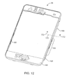
- Frame 68 may be formed of a single material (e.g., plastic or metal) or, more preferably, multiple materials. In embodiments in which frame 68 is formed from multiple materials, the weight of frame 68 may be minimized while providing sufficient structural strength where most beneficial. As shown in FIG. 12 , for example, frame 68 may have a main portion formed from a molded plastic frame member 166. One or more metal members may be attached to member 166. For example, metal frame struts 168 may be attached to member 166. Any suitable attachment mechanism may be used to connect frame struts 168 to frame member 166. With one particularly suitable arrangement, plastic frame member 166 molded onto metal frame struts 168 during manufacturing. This forms an integral frame 68 having both metal and plastic parts.
- plastic frame member 166 molded onto metal frame struts 168 during manufacturing. This forms an integral frame 68 having both metal and plastic parts.
- clips 112 may be attached to frame struts 168.
- clips 112 may be welded to frame struts 168 or may be attached to frame struts 168 using fasteners or adhesive.
- Clips 112 may be attached to struts 168 in regions such as region 164 (as an example).
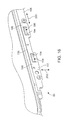
- FIG. 13 shows a cross-sectional side view of frame 68 taken along dotted line 170 and viewed in direction 172 of FIG. 12 .
- frame struts 168 may be connected to plastic frame member 166 to form frame 68.
- Frame struts 168 may have holes or other interlocking features at periodic locations along their lengths that help the plastic of frame member 166 to securely engage frame struts 168 (e.g., in engagement region 174).
- Plastic frame member 166 may form a shelf that supports cover glass 62.
- the shelf may be formed by inner surface 150 of frame member protrusion 148 and upper peripheral frame member surface 176.
- An advantage of using a shelf that is formed of relatively soft materials is that this helps prevent the shelf from damaging cover glass 62.
- portions of gasket 146 such as gasket portion 178 of FIG. 13 may be interposed between edge 152 of cover glass 62 and shelf edge 150. This type of arrangement may provide additional cushioning and may therefore further help to prevent damage to cover glass 62.
- Gasket 146 may bear against bezel 14 along surface 178, which helps to prevent cover glass 62 from directly touching bezel 14.
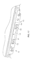
- FIG. 14 A perspective view of an interior portion of housing assembly 70 is shown in FIG. 14 .
- bezel 14 may be mounted to plastic housing portion 12.
- Spring 114 may be mounted to housing assembly 70 by welding spring 114 to bezel 14 or by otherwise attaching spring 114 securely (e.g., using fasteners, adhesive, etc.).
- An advantage of using springs and a bezel that are formed of metal is that this allows secure attachment mechanisms such as welds to be used to attach the springs. Satisfactory welds may be facilitated by using metals that do not have disparate properties.
- springs 114 may be formed from the same material or substantially the same material as bezel 14.
- springs 114 may also be formed from stainless steel.
- the same principle applies to clips 112 and frame struts 168.
- the use of the same material for clips 112 and struts 168 e.g., stainless steel
- An example of a stainless steel that may provide suitable strength for use in components such as frame struts 168 and bezel 14 is 304 stainless (e.g., 3/4 hard 304 stainless).
- clips 112 and springs 114 may be formed from 304 stainless, so that clips 112 may be readily welded to frame struts 168 and so that springs 114 may be readily welded to bezel 14.
- the use of 3/4 hard heat-treated stainless steel allows these parts to be relatively strong while being bendable when sufficiently thin.
- frame struts 168 may be about 0.4 mm thick and clips 112 and springs 114 may be about 0.2 mm thick (as an example).
- Springs such as spring 114 of FIG. 14 may be formed from elongated spring members such as spring member 180.
- Spring member 180 may be cut and bent to form spring prongs 182 (also sometimes referred to as spring members or springs).
- Spring prongs 182 may have any suitable shape.
- An advantage of forming spring prongs with relatively narrow widths (as measured along longitudinal housing dimension 184) is that this allows the springs to flex during assembly.
- springs may be mounted on other portions of housing 12 (e.g., on the edge of housing 12 that lies along end 106 ( FIG. 7 ).
- An advantage of using springs and clips along the sides of device 10 is that this helps to ensure that cover glass 62 lies flush with the upper surfaces of bezel 14, giving device 10 an attractive finished appearance.
- springs 114 may be used to form a support structure to which components in device 10 may be mounted.
- spring member 180 may have portions that form a bracket 186.
- Vibrator 92 (or other suitable components) may be attached to spring member 180 using bracket 186.
- screws 192 may be used to connect vibrator mounting bracket 190 to bent tip portion 188 of bracket 186 to hold vibrator 92 in place.
- each clip 112 may have a main elongated member 198.
- Elongated members such as elongated member 198 may be welded to frame struts 168 and may extend along the edge of tilt assembly 60 parallel to longitudinal dimension 200.
- Elongated member 198 may be substantially planar (as an example) and may have a planar surface aligned with longitudinal dimension 200 and vertical dimension 202. Portions 194 of elongated member 198 may be bent with respect to vertical dimension 202 and with respect to the planar surface defined by dimensions 202 and 200.
- Bending portions 194 inwardly away from the plane of elongated member 198 angles portions 194 inwardly so that bent portions 194 are angled with respect to vertical dimension 202.
- This forms holes 196 that can receive protruding spring prongs 182 ( FIGS. 14 and 15 ) when tilt assembly 60 and housing assembly 70 are connected to each other. Holes may also be formed by removing portions of elongated member 198, by bending or otherwise manipulating portions of member 198 sideways or in other directions, by bending multiple portions of member 198 within each hole, etc.
- the arrangement of FIG. 16 in which holes 196 have been formed by bending portions 194 down and inwards is merely illustrative.
- tilt assembly 60 there is a member such as member 198 that forms a clip on each side of tilt assembly 60.
- the perspective view of FIG. 16 shows an illustrative clip 112 that has been formed on the right side of tilt assembly 60.
- the perspective view of FIG. 17 shows an illustrative clip 112 that has been formed on the left side of tilt assembly 60.
- FIG. 18 A lateral cross-sectional view of an illustrative device 10 is shown in FIG. 18 .
- cover glass 62 may be mounted on top of device 10.
- An adhesive layer such as adhesive layer 204 may be formed between cover glass layer 62 and touch sensor 64.
- Touch sensor 64 may be, for example, a capacitive multitouch sensor (as an example).
- Touch sensor 64 may be mounted above a display unit such as liquid crystal display unit 66.
- Display unit 66 may be mounted above frame member 206.
- Frame member 206 which is sometimes referred to as a "mid-plate member” may be formed of a strong material such as metal (e.g., 304 stainless steel).
- Frame member 206 may have vertical portions 208.
- Frame member 206 helps form a rigid platform for the components (such as display unit 66, sensor 64, and cover glass 62) that are associated with the tilt assembly.
- mid-plate frame member 206 may also provide electrical grounding (e.g., for integrated circuits, printed circuit board structures, for antennas in wireless devices 44, etc.).
- frame struts 168 may be attached to frame member 166 of frame 68.
- frame member 166 may be formed from plastic that is molded over frame struts 168 and that engages frame struts 168 in engagement region 174.
- Frame protrusion 148 and gasket 146 may be used to separate glass 62 from bezel 14.
- Springs 114 may be welded or otherwise mounted to bezel 14. When the tilt assembly is mounted in the housing assembly as shown in FIG. 18 , spring prongs 182 protrude into the holes such as holes 196 that are formed by bent portions 194 in clips 112.
- FIG. 19 A cross-sectional view of spring 114 and clip 112 is shown in FIG. 19 .
- angled portion 194 of clip 112 forms a rigid substantially planar shelf-like member that biases the tip of spring prong 182 upwards at lower biasing point 210.
- Spring prong 182 is also engaged by member 198 of clip 112 at upper biasing point 216.
- Biasing point 210 retards movement of spring 114 and housing assembly 70 in downward direction 220 relative to tilt assembly 60.
- Biasing point 216 retards movement of spring 114 and housing assembly 70 in upward direction 218 relative to tilt assembly 60.
- Planar member 194 is oriented along axis 222 and is angled with respect to vertical dimension 202. If desired, member 194 may flex somewhat along its length and may pivot somewhat about point 224.
- spring prongs 182, the optional flexibility of planar member 194, and the angled orientation of planar member 194 makes the engagement arrangement formed by springs 114 and clips 112 tolerant to manufacturing deviations. For example, consider the situation in which manufacturing deviations cause spring prong 182 to be positioned where indicated by dashed outline 214 in FIG. 19 . This type of position might result, for example, from a weld location misalignment in spring 114 or in clip 112 (or both) or a deviation in the desired bend angle for member 194 or prong 182. As a result of such misalignment, spring prong 182 presses against biasing member 194 at biasing point 212 instead of at biasing point 210.
- spring prong 182 Despite this deviation in the biasing point location from its nominal position, there will still be good engagement between spring prong 182 and clip member 198.
- upper biasing point 216 will still generally bias clip 114 in downwards direction 220 toward its desired location.
- the angled orientation of member 194 and the curved shape of spring prong 182 therefore helps to accommodate manufacturing variations.
- the smoothly curved shape of spring prongs 182 may also help to prevent the insertion and removal process from being too harsh when engaging and disengaging the tilt and housing assemblies from each other.
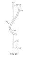
- FIG. 20 An example of an alternative spring and clip configuration is shown in FIG. 20 . As shown in FIG. 20 , it is not necessary to form a bent member in clip 112. Rather, spring prongs such as spring prong 182 of FIG. 20 may be accommodated in a hole 196 that has been formed by removing a region of metal (or other suitable material) from within elongated member 198 of clip 112.
- holes 196 have been formed from recesses in housing 12.
- FIG. 21 demonstrates, it is not necessary to form clips 112 on tilt assembly 60 and springs 114 on housing assembly 70.
- springs 114 and spring prongs 182 may be attached to tilt assembly 60 and holes 196 (whether integral to housing 12 or whether formed from clips 112) may be formed as part of housing assembly 70.
- An advantage of forming springs 114 on housing assembly 70 is that this reduces the likelihood that springs 114 might scratch bezel 14 during insertion of tilt assembly 60 into housing assembly 70.
- springs 114 may be used to form a mounting structure for components such as vibrator 92.
- a spring such as spring 114 of FIG. 22 may be configured to form a mounting bracket 186 having a horizontal planar member 188.
- fasteners such as screws 192 of FIG. 15 may be inserted into holes 226 ( FIG. 22 ).
- electrical connections may be made between the circuitry associated with the printed circuit board structures of housing assembly 70 and the display unit and sensor in display 16. Electrical connections may also be made between the printed circuit board circuitry and components such as the receiver speaker of port 23, microphone 76, speaker 78, and a proximity sensor (e.g., a sensor that detects the presence of a human body in close proximity to device 10). Such electrical connections may be made using a flexible circuit structure formed from a pattern of conductive traces on a flexible printed circuit substrate such as a polyimide-based substrate (sometimes referred to as a "flex circuit"). Electrical connections should generally also be made for buttons such as volume up and down buttons, ringer on/off buttons, hold buttons, etc. Antennas in regions 18 and 21 may also be electrically connected to circuitry on the printed circuit board structures of housing assembly 70.
- radio-frequency signals that are conveyed to and from the antennas in device 10 may be carried over transmission lines such as coaxial cable transmission lines (i.e., micro-coax). Connections in this type of radio-frequency transmission line path may therefore involve micro-coax connectors.
- transmission lines such as coaxial cable transmission lines (i.e., micro-coax).
- connections in this type of radio-frequency transmission line path may therefore involve micro-coax connectors.
- board-to-board connectors Flex circuits can be connected using connectors such as zero-insertion-force (ZIF) connectors. Still other connectors may be used in other contexts.
- ZIF zero-insertion-force
- Device 10 may therefore use a numbering system in which the connections that are to be made are numbered.
- the numbering system that is used may, for example, number the connections that are to be made in a preferred or required order of assembly.
- Instructions may be included in the interior of the device. For example, instructions may be laser-etched into a metal surface such as an electromagnetic shielding "can" that covers one or more integrated circuits on the printed circuit board structures of housing assembly 70.
- FIG. 23 A top view of an illustrative coaxial cable connector is shown in FIG. 23 .
- coaxial cable 228 may be attached to coaxial cable connector 230.
- Coaxial cable connector 230 may be connected to another coaxial cable, a printed circuit board, a flex circuit, an antenna, combinations of such structures, or any other suitable electrical structure.
- FIG. 24 is a side view of an illustrative coaxial cable connector of the type shown in FIG. 23 .
- coaxial connector 230 is shown in a disconnected state.
- Upper portion 232 of connector 230 is connected to coaxial cable 228.
- Lower portion 234 of connector 230 is mounted to electrical structures 236 such as a flex circuit, printed circuit board, etc. Traces within structure 236 such as traces 238 may be used to electrically connect lower connector half 234 of coaxial cable connector 230 to circuitry within device 10 (e.g., an antenna, a transceiver, etc.).
- Connector portions 232 and 234 may be interconnected during assembly as indicated schematically by dotted line 240.
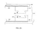
- board-to-board connector 242 may include an upper-half connector portion 244 and a lower-half connector portion 250. Both the upper and lower portions of connector 242 may have numerous pins such as pins 246 on connector portion 244 and pin 248 on connector portion 250.
- connector 242 is disassembled, because male connector part 244 has not yet been connected to female connector part 250. During assembly, this connection is made to interconnect electrical structures to which connector parts 244 and 250 are mounted. As shown in the FIG. 25 example, connector part 244 may be electrically connected to traces 258 in electrical structure 260 and connector part 250 may be electrically connected to traces 250 in electrical structure 254. Structures 260 and 254 may be printed circuit boards.
- FIG. 26 A top view of board-to-board connector 242, which presents an illustrative layout for pins such as pints 246 and 248 is shown in FIG. 26 .
- Board-to-board connectors such as connector 242 of FIGS. 25 and 26 may be used whenever it is desired to electrically interconnect structures such as printed circuit boards (e.g., when they are mounted on top of each other). Because there are typically numerous pins in a board-to-board connector such as a printed circuit board, the use of a board-to-board connector may be preferable to using wires or cables to make a connection. Moreover, unlike hardwired solder connectors, board-to-board connectors may be readily disconnected when desired for rework or repair.
- Flex circuits may be used to form connections between different parts of device 10. Flex circuits have advantages over conventional parallel bus wires such as reduced size and weight. Flex circuits may also be less expensive to manufacture in large quantities than other types of interconnects and provide geometric flexibility when designing and assembly complex structures.
- a flex circuit might be attached at one end to a series of components (e.g., dock connector 20, acoustic components, sensors, etc.). At the other end, the flex circuit may need to be connected to circuitry on a printed circuit board. This type of connection may be formed using a socket-type connector that is configured to receive a flex circuit (sometimes referred to as a zero-insertion-force or ZIF connector).
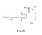
- FIG. 27 A top view of an illustrative flex circuit 262 and zero-insertion force flex circuit connector 264 is shown in FIG. 27 .
- flex circuit 262 is inserted into connector 264 in direction 266. This causes exposed traces 268 in region 274 to electrically connect with mating conductors 270 in region 272 of connector 264.
- connector 264 may have a lever 276 that may be actuated by pressing downwards in direction 278. When lever 276 is pressed downwards in this way, the pins of connector 264 engage the flex circuit traces of flex circuit 262 and form a solid set of electrical connections.
- Device 10 may use one, two, three, or more than three different types of connectors in interconnecting its electrical components. Some or all of these connectors may, if desired, be non-destructive connectors having mating parts that can be disconnected if desired for rework or repair operations. An advantage to using connectors that can be repeatedly connected and disconnected is that this may reduce waste in the event of a rework or repair.
- Device 10 may therefore include a set of numbers to help guide workers during the assembly process.
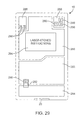
- An example of this type of arrangement is shown in FIG. 29 .
- FIG. 29 shows an illustrative interior view of device 10.
- device 10 may include components such as integrated circuits encased in electromagnetic shielding ("cans") such as housings 280 and 282.
- Device 10 may also include one or more modules such as module 284.
- Module 284 may be, for example, a module that includes acoustic components such as a microphone, speaker, etc.
- Dock connector 20 may be connected to a module such as module 284.
- Regions such as regions 286 and 288 may include exposed circuit boards, one or more discrete components, flex circuits, or other suitable electrical components.
- the components of device 10 may be interconnected by communications paths.
- the communications paths may be, for example, transmission line paths such as coaxial cable paths, flex circuits, board-to-board paths supported by printed circuit board traces, etc., as described in connection with FIGS. 23-28 .
- An illustrative communications path is shown as path 292 in FIG. 29 .
- assembly order indicators such as numbers 290 may be formed on device 10.
- the assembly order indicators may be provided in the form of any suitable markings that indicate a preferred or required order of assembly for the connectors that are used in interconnecting the electrical components of device 10.
- suitable indicators include Arabic numerals (e.g., 1, 2, 3, ...), Roman numerals, Chinese numerals, letters (e.g., A, B, C... or comparable letters in other alphabets), combinations of numerals and letters (e.g., A1, A2, B1, B2, B3, C1, ...), or symbols (e.g., *, **, ***, etc.).
- the indicators preferably denote a desired assembly order or orders and may, if desired, be followed in reverse order by a worker who wishes to partly or fully disassembly a device for rework or repair.
- device 10 may include instructions such as instructions 294.
- Instructions 294 may be laser-etched on the metal surface of cans such as can 280, may be printed on can 280 or other suitable surface of the components of device 10, may be printed on a label that is affixed within device 10, may be inscribed on an interior portion of case 12, or may be otherwise formed on device 10.
- Assembly and disassembly instructions e.g., instructions referring to the assembly order
- Instructions 294 may be written instructions that include, for example, explanatory text (e.g., in English, Chinese, or other suitable language). Instructions 294 may also be partly or completely formed from symbolic instructions (e.g., a diagram showing how parts should be connected, a list of corresponding assembly order indicators, etc.). Instructions 294 may, if desired, include information on the proper use of device 10, legal notices, etc.
- a portable electronic device in accordance with an embodiment, includes a first assembly having at least one clip and a second assembly having at least one spring that engages the clip when the first assembly is inserted into the second assembly and that nondestructively disengages from the clip when the first assembly is removed from the second assembly.
- a portable electronic device wherein the first assembly includes at least one protrusion and wherein the second assembly includes at least one recess that receives the protrusion so that the first assembly tilts and rotates into the second assembly, pivoting about a pivot axis defined by the protrusion and the recess.
- a portable electronic device wherein the first assembly includes a display.
- a portable electronic device wherein the first assembly includes a plastic frame having metal frame struts.
- a portable electronic device wherein the first assembly includes a frame formed at least partly of metal and wherein the clip is welded to the metal of the frame.
- a portable electronic device wherein the second assembly includes a metal bezel and wherein the spring is welded to the bezel.
- a portable electronic device wherein the first assembly includes a frame and includes a display unit and a touch screen mounted to the frame, wherein the clip is connected to the frame and has at least one hole, wherein the second assembly includes at least one printed circuit board and a metal structure to which the spring is connected, and wherein the spring has a spring prong that protrudes into the hole in the clip when the first assembly is inserted into the second assembly.
- a portable electronic device wherein the first assembly and the second assembly each have upper and lower ends and left and right sides, wherein there are two of the clips located respectively on the left and right sides of the first assembly, and wherein there are two of the springs located respectively on the left and right sides of the second assembly.
- a portable electronic device wherein the first assembly and the second assembly each have upper and lower ends and left and right sides, wherein there are two of the clips located respectively on the left and right sides of the first assembly, and wherein there are two of the springs located respectively on the left and right sides of the second assembly, and wherein the first and second assemblies include mating features that are engaged at a pivot axis at an end of the portable electronic device, so that the first assembly tilts and rotates into the second assembly about the pivot axis during assembly.
- a portable electronic device wherein the portable electronic device includes a handheld electronic device with wireless communications circuitry.
- a portable electronic device that also includes screws that screw into the first assembly through the second assembly.
- a method for assembling a handheld electronic device from a first assembly and a second assembly wherein the first assembly has a first member with holes and the second assembly has a second member with flexible prongs that mate with the holes, wherein the method includes inserting an end of the first assembly into an end of the second assembly so that a portion of the first assembly engages a portion of the second assembly at an engagement axis, and rotating the first assembly into the second assembly about the engagement axis so that the prongs compress then expand to press into the holes and hold the first assembly in place within the second assembly.
- a method in accordance with another embodiment, also includes screwing the second assembly to the first assembly with screws that are inserted into the second assembly at an end of the assembly opposing the engagement axis.
- a portable electronic device in accordance with another embodiment, includes a first portion having clips with holes and a second portion having springs with prongs that protrude into the holes and that hold the first portion to the second portion, wherein the clips include elongated members having bent planar portions that form the holes.
- a portable electronic wherein the springs and clips include stainless steel.
- a portable electronic device wherein the first portion includes a plastic frame and metal frame struts connected to the plastic frame and wherein the clips are connected to the metal frame struts.
- a portable electronic device wherein the metal frame struts include stainless steel.
- a portable electronic device wherein the first portion includes a plastic frame member, a display unit, and a cover glass that covers the display unit, wherein the plastic frame member has a protrusion defining a shelf that supports the cover glass.
- a portable electronic device that also includes a bezel that is connected to the second portion and that surrounds the cover glass.
- a portable electronic device that also includes a gasket that is connected to the protrusion and that is interposed between the cover glass and the bezel.
- a portable electronic device wherein the springs are welded to the bezel.
- a portable electronic device wherein the prongs include curved portions that bear against the bent planar portions.
- a handheld electronic device in accordance with another embodiment, includes a first assembly having a display, a touch screen, a frame that supports the display and the touch screen, and first engagement members that are connected to the frame, and a second assembly having a housing and second engagement members that nondestructively engage the first engagement members when the first assembly is inserted into the second assembly to form the handheld electronic device.
- a handheld electronic device wherein the first engagement members include first metal members with holes and wherein the second engagement members includes second metal members with flexible prongs that mate with the holes in the first metal members.
- a handheld electronic device wherein the second assembly includes a bezel that is connected to the housing and that surrounds the display when the first assembly is inserted into the second assembly to form the handheld electronic device.
- a handheld electronic device wherein the second metal members are connected to the bezel.
- a handheld electronic device wherein the first assembly includes retention clips connected to the frame and wherein screws are screwed into the retention clips through the housing and the bezel.
- a handheld electronic device wherein the second metal members are welded to the bezel.
- a handheld electronic device wherein the frame includes metal frame struts to which the first metal members are connected.
- a portable electronic device in accordance with another embodiment, includes a housing, electrical components that are contained within the housing and that are interconnected by communications paths, electrical connectors that are connected in the communications paths to interconnect the electrical components with each other, and a plurality of assembly order indicators that indicate an order in which the electrical connectors are to be connected during assembly of the portable electronic device.
- a portable electronic device wherein the plurality of assembly order indicators include numerals, each numeral being formed adjacent to a respective one of the electrical connectors.
- a portable electronic device wherein the electrical connectors include zero-insertion-force connectors for flex circuit connections, coaxial cable connectors for coaxial cable connections, and board-to-board connectors for connecting printed circuit boards.
- a portable electronic device wherein the electrical components include at least one electromagnetic shielding can, the portable electronic device further comprising laser-etched assembly instructions on the can.
- an electronic device having an external body and having external surfaces includes a single housing portion that has sides and that forms the external body of the electronic device, the single housing portion having walls that form a pocket in a front face of the electronic device and that form the sides of the single housing portion including an edge portion, where the front face of the electronic device has a surface area, and a display portion that has a periphery and that is mounted within the pocket of the single housing portion, the edge portion of the single housing portion surrounding the periphery of the display portion, the display portion covering most of the surface area of the front face of the electronic device, the display portion and single housing portion cooperating to form the external surfaces of the electronic device.
- the single housing portion includes a housing frame member and the edge portion is a bezel that is connected to the housing frame member.
- the bezel is formed from metal and the housing frame member is formed from plastic.
- the electronic device also includes a gasket disposed between the display portion and the edge portion of the single housing portion.
- the display portion includes a display and a display frame that carries the display.
- the display includes a touch sensor.
- the single housing portion includes a printed circuit board and a housing frame member that carries the printed circuit board.
- the display portion includes first engagement members that are connected to the display frame
- the single housing portion includes second engagement members that are connected to the housing frame member, and the second engagement members nondestructively engage the first engagement members when the display portion is mounted within the pocket of the single housing portion.
Priority Applications (2)
| Application Number | Priority Date | Filing Date | Title |
|---|---|---|---|
| EP17202080.2A EP3343312B1 (de) | 2008-04-11 | 2009-03-31 | Tragbare elektronische vorrichtung mit zweiteiligem gehäuse |
| EP20000298.8A EP3761150A1 (de) | 2008-04-11 | 2009-03-31 | Tragbare elektronische vorrichtung mit zweiteiligem gehäuse |
Applications Claiming Priority (3)
| Application Number | Priority Date | Filing Date | Title |
|---|---|---|---|
| US4444508P | 2008-04-11 | 2008-04-11 | |
| US12/119,986 US7933123B2 (en) | 2008-04-11 | 2008-05-13 | Portable electronic device with two-piece housing |
| EP09729266.8A EP2263367B1 (de) | 2008-04-11 | 2009-03-31 | Tragbare elektronische vorrichtung mit zweiteiligem gehäuse |
Related Parent Applications (2)
| Application Number | Title | Priority Date | Filing Date |
|---|---|---|---|
| EP09729266.8A Division EP2263367B1 (de) | 2008-04-11 | 2009-03-31 | Tragbare elektronische vorrichtung mit zweiteiligem gehäuse |
| EP09729266.8A Division-Into EP2263367B1 (de) | 2008-04-11 | 2009-03-31 | Tragbare elektronische vorrichtung mit zweiteiligem gehäuse |
Related Child Applications (2)
| Application Number | Title | Priority Date | Filing Date |
|---|---|---|---|
| EP17202080.2A Division EP3343312B1 (de) | 2008-04-11 | 2009-03-31 | Tragbare elektronische vorrichtung mit zweiteiligem gehäuse |
| EP20000298.8A Division EP3761150A1 (de) | 2008-04-11 | 2009-03-31 | Tragbare elektronische vorrichtung mit zweiteiligem gehäuse |
Publications (3)
| Publication Number | Publication Date |
|---|---|
| EP2685348A2 true EP2685348A2 (de) | 2014-01-15 |
| EP2685348A3 EP2685348A3 (de) | 2014-05-28 |
| EP2685348B1 EP2685348B1 (de) | 2017-12-06 |
Family
ID=40626906
Family Applications (4)
| Application Number | Title | Priority Date | Filing Date |
|---|---|---|---|
| EP17202080.2A Active EP3343312B1 (de) | 2008-04-11 | 2009-03-31 | Tragbare elektronische vorrichtung mit zweiteiligem gehäuse |
| EP13181996.3A Active EP2685348B1 (de) | 2008-04-11 | 2009-03-31 | Tragbare elektronische Vorrichtung mit zweiteiligem Gehäuse |
| EP09729266.8A Active EP2263367B1 (de) | 2008-04-11 | 2009-03-31 | Tragbare elektronische vorrichtung mit zweiteiligem gehäuse |
| EP20000298.8A Pending EP3761150A1 (de) | 2008-04-11 | 2009-03-31 | Tragbare elektronische vorrichtung mit zweiteiligem gehäuse |
Family Applications Before (1)
| Application Number | Title | Priority Date | Filing Date |
|---|---|---|---|
| EP17202080.2A Active EP3343312B1 (de) | 2008-04-11 | 2009-03-31 | Tragbare elektronische vorrichtung mit zweiteiligem gehäuse |
Family Applications After (2)
| Application Number | Title | Priority Date | Filing Date |
|---|---|---|---|
| EP09729266.8A Active EP2263367B1 (de) | 2008-04-11 | 2009-03-31 | Tragbare elektronische vorrichtung mit zweiteiligem gehäuse |
| EP20000298.8A Pending EP3761150A1 (de) | 2008-04-11 | 2009-03-31 | Tragbare elektronische vorrichtung mit zweiteiligem gehäuse |
Country Status (6)
| Country | Link |
|---|---|
| US (8) | US7933123B2 (de) |
| EP (4) | EP3343312B1 (de) |
| CN (2) | CN103744486B (de) |
| HK (1) | HK1153328A1 (de) |
| MX (1) | MX2010011083A (de) |
| WO (1) | WO2009126480A2 (de) |
Families Citing this family (235)
| Publication number | Priority date | Publication date | Assignee | Title |
|---|---|---|---|---|
| USD628205S1 (en) * | 2007-06-23 | 2010-11-30 | Apple Inc. | Graphical user interface for a display screen or portion thereof |
| USD602486S1 (en) * | 2007-08-31 | 2009-10-20 | Apple Inc. | Electronic device |
| USD957385S1 (en) | 2007-08-31 | 2022-07-12 | Apple Inc. | Electronic device |
| KR101385747B1 (ko) | 2007-09-21 | 2014-04-21 | 삼성전자주식회사 | 전자 종이 표시 유니트 및 이를 갖는 이동 통신 단말기 |
| US8101859B2 (en) * | 2008-01-03 | 2012-01-24 | Apple Inc. | Metal retaining features for handheld electronic device casing |
| US8417298B2 (en) | 2008-04-01 | 2013-04-09 | Apple Inc. | Mounting structures for portable electronic devices |
| US8238087B2 (en) | 2010-01-06 | 2012-08-07 | Apple Inc. | Display module |
| US8102319B2 (en) | 2008-04-11 | 2012-01-24 | Apple Inc. | Hybrid antennas for electronic devices |
| JP2009301144A (ja) * | 2008-06-10 | 2009-12-24 | Fujitsu Ltd | 電子機器 |
| CN201238309Y (zh) * | 2008-08-13 | 2009-05-13 | 深圳华为通信技术有限公司 | 一种通信设备 |
| CN101666896B (zh) * | 2008-09-05 | 2014-04-30 | 深圳富泰宏精密工业有限公司 | 具有视窗镜片的壳体组件 |
| US8023261B2 (en) | 2008-09-05 | 2011-09-20 | Apple Inc. | Electronic device assembly |
| TWI376180B (en) * | 2008-09-12 | 2012-11-01 | Asustek Comp Inc | Electronic device |
| JP5451149B2 (ja) * | 2009-04-08 | 2014-03-26 | キヤノン株式会社 | 電子機器 |
| JP5222229B2 (ja) * | 2009-05-29 | 2013-06-26 | 株式会社ジャパンディスプレイイースト | 表示装置 |
| US8199469B2 (en) | 2009-06-06 | 2012-06-12 | Apple Inc. | Battery |
| US8309245B2 (en) | 2009-06-06 | 2012-11-13 | Apple Inc. | Battery pack and connector |
| US8456586B2 (en) | 2009-06-11 | 2013-06-04 | Apple Inc. | Portable computer display structures |
| US8948824B2 (en) | 2009-08-05 | 2015-02-03 | Apple Inc. | Electronic devices with clips |
| JP5742035B2 (ja) * | 2009-08-07 | 2015-07-01 | メソード・エレクトロニクス・インコーポレーテッド | 回路基板を通じて照明するためのアセンブリ及び方法 |
| CN102006739A (zh) * | 2009-09-03 | 2011-04-06 | 鸿富锦精密工业(深圳)有限公司 | 壳体 |
| KR102480780B1 (ko) * | 2009-09-16 | 2022-12-22 | 가부시키가이샤 한도오따이 에네루기 켄큐쇼 | 발광 장치 및 이의 제조 방법 |
| US8892238B2 (en) | 2009-10-06 | 2014-11-18 | Edward T. Sweet | Edge break details and processing |
| US8111505B2 (en) | 2009-10-16 | 2012-02-07 | Apple Inc. | Computer housing |
| US8233109B2 (en) | 2009-10-16 | 2012-07-31 | Apple Inc. | Portable computer display housing |
| US8854801B2 (en) * | 2009-10-16 | 2014-10-07 | Apple Inc. | Portable computer display housing |
| US8553907B2 (en) | 2009-10-16 | 2013-10-08 | Apple Inc. | Portable computer electrical grounding and audio system architectures |
| AU2012216762B2 (en) * | 2009-10-16 | 2014-02-20 | Apple Inc. | Computer housing |
| US8333862B2 (en) | 2009-10-16 | 2012-12-18 | Apple Inc. | Self fixturing assembly techniques |
| US8199468B2 (en) | 2009-10-16 | 2012-06-12 | Apple Inc. | Computer housing |
| MX2012004365A (es) | 2009-10-16 | 2012-07-17 | Apple Inc | Sistema de computo portatil. |
| US8408780B2 (en) | 2009-11-03 | 2013-04-02 | Apple Inc. | Portable computer housing with integral display |
| US8743309B2 (en) | 2009-11-10 | 2014-06-03 | Apple Inc. | Methods for fabricating display structures |
| US9651812B1 (en) | 2009-12-04 | 2017-05-16 | Cypress Semiconductor Corporation | Partially filled contact and trace layout |
| US9778685B2 (en) | 2011-05-04 | 2017-10-03 | Apple Inc. | Housing for portable electronic device with reduced border region |
| US8576561B2 (en) | 2010-02-02 | 2013-11-05 | Apple Inc. | Handheld device enclosure |
| CN102131356B (zh) * | 2010-02-02 | 2014-06-18 | 苹果公司 | 具有外部玻璃表面的便携电子设备壳体 |
| US8797721B2 (en) | 2010-02-02 | 2014-08-05 | Apple Inc. | Portable electronic device housing with outer glass surfaces |
| AU2015268683B2 (en) * | 2010-02-02 | 2017-07-13 | Apple Inc. | Portable electronic device housing with outer glass surfaces |
| CA2731606C (en) * | 2010-02-15 | 2014-06-17 | Research In Motion Limited | Electronic device including a front bezel operable to secure the device together |
| US8607444B2 (en) | 2010-03-06 | 2013-12-17 | Apple Inc. | Method for forming a housing of an electronic device |
| US8351057B2 (en) | 2010-03-18 | 2013-01-08 | Xerox Corporation | Self-powered user interface providing assembly instructions |
| US8576202B2 (en) | 2010-03-25 | 2013-11-05 | Elo Touch Solutions, Inc. | Bezel-less acoustic touch apparatus |
| USD627778S1 (en) * | 2010-04-19 | 2010-11-23 | Apple Inc. | Electronic device |
| US8264837B2 (en) | 2010-04-19 | 2012-09-11 | Apple Inc. | Systems and methods for cover assembly retention of a portable electronic device |
| KR101654940B1 (ko) * | 2010-04-22 | 2016-09-06 | 엘지전자 주식회사 | 디스플레이 장치 및 이 디스플레이 장치의 윈도우 제조방법 |
| DE102010019841A1 (de) * | 2010-05-07 | 2011-11-10 | Ident Technology Ag | Leiterplatte für Display und Anzeigemodul mit Display und Leiterplatte |
| US20110285652A1 (en) * | 2010-05-21 | 2011-11-24 | Kabushiki Kaisha Toshiba | Broadcast receiving device and electronic device |
| US8655422B2 (en) | 2010-06-04 | 2014-02-18 | Apple Inc. | Ring-shaped cover for portable electronic device |
| US20120007810A1 (en) * | 2010-07-10 | 2012-01-12 | Chi-Ming Tseng | Touch-sensitive display apparatus |
| US20120009973A1 (en) * | 2010-07-12 | 2012-01-12 | Sony Ericsson Mobile Communications Ab | Module Connection in a Printed Wiring Board |
| CN101895798B (zh) * | 2010-07-29 | 2013-03-13 | 青岛海信移动通信技术股份有限公司 | 扬声器音腔密封结构以及便携式移动终端 |
| TWI449490B (zh) * | 2010-08-12 | 2014-08-11 | Hon Hai Prec Ind Co Ltd | 電子裝置殼體及其製造方法 |
| USD642563S1 (en) | 2010-08-16 | 2011-08-02 | Apple Inc. | Electronic device |
| US8638549B2 (en) * | 2010-08-24 | 2014-01-28 | Apple Inc. | Electronic device display module |
| EP2434367B1 (de) * | 2010-09-24 | 2015-05-06 | BlackBerry Limited | Dichtungs- und Anzeigeanordnung für eine elektronische mobile Vorrichtung |
| US8508927B2 (en) | 2010-09-24 | 2013-08-13 | Research In Motion Limited | Gasket and display assembly for an electronic mobile device |
| FI124625B (fi) | 2010-10-15 | 2014-11-14 | Perlos Oyj | Elektroniikkalaite, kuori ja menetelmä |
| TWI398891B (zh) * | 2010-10-15 | 2013-06-11 | Altek Corp | 電子裝置及其按鍵支撐結構 |
| US8467177B2 (en) | 2010-10-29 | 2013-06-18 | Apple Inc. | Displays with polarizer windows and opaque masking layers for electronic devices |
| US9143668B2 (en) | 2010-10-29 | 2015-09-22 | Apple Inc. | Camera lens structures and display structures for electronic devices |
| US9235240B2 (en) | 2010-11-11 | 2016-01-12 | Apple Inc. | Insert molding around glass members for portable electronic devices |
| TWI426431B (zh) * | 2010-11-15 | 2014-02-11 | Delta Electronics Inc | 觸控裝置 |
| US9870093B2 (en) | 2010-11-23 | 2018-01-16 | Ge Aviation Systems Llc | System and method for improving touch screen display use under vibration and turbulence |
| EP2461479B1 (de) * | 2010-12-01 | 2013-03-06 | Nxp B.V. | Funkfrequenzschaltung mit Impedanzanpassung |
| US8462517B2 (en) * | 2010-12-22 | 2013-06-11 | Motorola Mobility Llc | Reworkable mobile electronic device |
| JP5830858B2 (ja) * | 2010-12-24 | 2015-12-09 | 株式会社豊田自動織機 | 電子機器 |
| US8772650B2 (en) | 2011-01-10 | 2014-07-08 | Apple Inc. | Systems and methods for coupling sections of an electronic device |
| JP5379176B2 (ja) | 2011-01-25 | 2013-12-25 | 株式会社ソニー・コンピュータエンタテインメント | 携帯型電子機器 |
| US8717751B2 (en) * | 2011-01-28 | 2014-05-06 | Thomas Michael Marker | Protective enclosure |
| US8460018B2 (en) | 2011-01-31 | 2013-06-11 | Apple Inc. | Flat object ejector assembly |
| US8587939B2 (en) | 2011-01-31 | 2013-11-19 | Apple Inc. | Handheld portable device |
| US8570736B2 (en) | 2011-01-31 | 2013-10-29 | Apple Inc. | Component assembly |
| EP3407160A1 (de) * | 2011-01-31 | 2018-11-28 | Apple Inc. | Handhaltbare tragbare vorrichtung |
| US8665160B2 (en) | 2011-01-31 | 2014-03-04 | Apple Inc. | Antenna, shielding and grounding |
| US8911280B2 (en) | 2011-01-31 | 2014-12-16 | Apple Inc. | Apparatus for shaping exterior surface of a metal alloy casing |
| USD671947S1 (en) | 2011-02-18 | 2012-12-04 | Apple Inc. | Housing for an electronic device |
| US9407984B2 (en) * | 2011-02-24 | 2016-08-02 | Htc Corporation | Method and apparatus for adjusting sound quality |
| US9182789B2 (en) | 2011-03-01 | 2015-11-10 | Apple Inc. | Transparent electronic device components with opaque edge coverings |
| TWI471086B (zh) * | 2011-03-14 | 2015-01-21 | E Ink Holdings Inc | 一種於電子紙顯示器上形成電磁波屏蔽層之方法 |
| JP5621690B2 (ja) * | 2011-03-31 | 2014-11-12 | 富士通株式会社 | 電子装置及びフレキシブル基板 |
| US9128666B2 (en) | 2011-05-04 | 2015-09-08 | Apple Inc. | Housing for portable electronic device with reduced border region |
| USD657329S1 (en) * | 2011-05-19 | 2012-04-10 | Samsung Electronics Co., Ltd. | Portable telephone |
| USD654454S1 (en) * | 2011-05-19 | 2012-02-21 | Samsung Electronics Co., Ltd. | Portable telephone |
| USD654452S1 (en) * | 2011-05-19 | 2012-02-21 | Samsung Electronics Co., Ltd. | Portable telephone |
| USD657328S1 (en) * | 2011-05-19 | 2012-04-10 | Samsung Electronics Co., Ltd. | Portable telephone |
| CN102810717A (zh) * | 2011-06-01 | 2012-12-05 | 鸿富锦精密工业(深圳)有限公司 | 天线固定结构 |
| BR202012004686Y1 (pt) | 2011-07-13 | 2019-05-14 | Google Technology Holdings LLC | Dispositivo eletrônico móvel com redução de impacto reforçada. |
| BR202012004687U8 (pt) * | 2011-07-13 | 2016-11-22 | Motorola Mobility Inc | Dispositivo eletrônico móvel com chassi aperfeiçoado |
| BR202012004685Y1 (pt) | 2011-07-13 | 2019-04-02 | Google Technology Holdings LLC | Dispositivo eletrônico móvel com construção laminada aprimorada |
| KR200471325Y1 (ko) | 2011-07-13 | 2014-02-19 | 모토로라 모빌리티 엘엘씨 | 강화된 공차 누적기를 구비하는 모바일 전자 장치 |
| KR20130025118A (ko) * | 2011-09-01 | 2013-03-11 | 현대자동차주식회사 | 전자파 차단 케이스 |
| US8493743B2 (en) | 2011-09-09 | 2013-07-23 | Htc Corporation | Handheld device |
| WO2013043462A1 (en) | 2011-09-19 | 2013-03-28 | Speculative Product Design, Llc | Case for a portable electronic device with over-molded thermo-formed film |
| US20130080932A1 (en) | 2011-09-27 | 2013-03-28 | Sanjiv Sirpal | Secondary single screen mode activation through user interface toggle |
| CN103108506A (zh) * | 2011-11-14 | 2013-05-15 | 深圳富泰宏精密工业有限公司 | 便携式电子装置 |
| US8837143B2 (en) * | 2011-11-25 | 2014-09-16 | Htc Corporation | Handheld electronic device |
| TW201324084A (zh) * | 2011-12-06 | 2013-06-16 | Quanta Comp Inc | 可重工之電子設備及其溫感拆解方法 |
| US8975540B2 (en) * | 2011-12-19 | 2015-03-10 | Htc Corporation | Electronic deviceswith support frames and mechanically-bonded plastic and methods for forming such electronic devices |
| US8712233B2 (en) * | 2012-02-24 | 2014-04-29 | Apple Inc. | Electronic device assemblies |
| US9201452B2 (en) | 2012-02-28 | 2015-12-01 | Apple Inc. | Electronic device with illuminated logo structures |
| USD694755S1 (en) | 2012-03-07 | 2013-12-03 | Apple Inc. | Component for a portable display device |
| CN103369897B (zh) * | 2012-04-03 | 2016-08-03 | 深圳富泰宏精密工业有限公司 | 防尘防水结构及应用该防尘防水结构的便携式电子装置 |
| KR101929879B1 (ko) * | 2012-04-09 | 2019-03-15 | 삼성전자주식회사 | 휴대 단말기 |
| JP2013239812A (ja) * | 2012-05-14 | 2013-11-28 | Sharp Corp | 携帯端末 |
| USD732539S1 (en) | 2012-05-29 | 2015-06-23 | Apple Inc. | Enclosure for communications device |
| USD718753S1 (en) | 2012-09-10 | 2014-12-02 | Apple Inc. | Component for an electronic device |
| US9364861B2 (en) * | 2012-06-28 | 2016-06-14 | Nokia Technologies Oy | Tube-shaped part and an associated method of manufacture |
| US10067535B2 (en) | 2012-09-28 | 2018-09-04 | Apple Inc. | Multiple-element light-bending structures for minimizing display borders |
| WO2014024900A1 (en) * | 2012-08-10 | 2014-02-13 | Semiconductor Energy Laboratory Co., Ltd. | Method for manufacturing light-emitting device |
| US8893373B2 (en) * | 2012-08-24 | 2014-11-25 | Fletcher R. Rothkopf | Method for assembling a portable electronic device |
| US9084338B2 (en) * | 2012-08-27 | 2015-07-14 | Shenzhen China Star Optoelectronics Technology Co., Ltd. | Display device |
| US8988866B2 (en) * | 2012-08-27 | 2015-03-24 | Shenzhen China Star Optoelectronics Technology Co., Ltd. | Display device |
| US8988875B2 (en) * | 2012-08-27 | 2015-03-24 | Shenzhen China Star Optoelectronics Technology Co., Ltd. | Display device |
| US9072167B2 (en) * | 2012-08-27 | 2015-06-30 | Shenzhen China Star Optoelectronics Technology Co., Ltd. | Display device |
| US9210242B2 (en) | 2012-08-31 | 2015-12-08 | Apple Inc. | Device housings with hidden fasteners |
| US8804355B2 (en) | 2012-09-11 | 2014-08-12 | Apple Inc. | Connector bracket |
| TWD163334S (zh) | 2012-09-11 | 2014-10-01 | 蘋果公司 | 用於電子裝置之殼體 |
| US8804354B2 (en) * | 2012-09-11 | 2014-08-12 | Apple Inc. | Load sharing device and I/O architecture against imparted abuse loads |
| US9054779B2 (en) | 2012-09-14 | 2015-06-09 | Hewlett-Packard Development Company, L.P. | Radio frequency interference shield |
| US9106310B2 (en) | 2012-09-18 | 2015-08-11 | Google Technology Holdings LLC | Apparatus for securing memory modules and/or subscriber identity module in an electronic device |
| US9946302B2 (en) | 2012-09-19 | 2018-04-17 | Apple Inc. | Exposed glass article with inner recessed area for portable electronic device housing |
| USD717800S1 (en) | 2012-10-17 | 2014-11-18 | Apple Inc. | Housing for an electronic device |
| US8897007B2 (en) | 2012-10-18 | 2014-11-25 | Apple Inc. | Grounding features of a portable computing device |
| US8982582B2 (en) * | 2012-11-30 | 2015-03-17 | Apple Inc. | Electronic device with antenna cable bracket |
| KR101467867B1 (ko) * | 2012-11-30 | 2014-12-03 | 주식회사 팬택 | 이동 통신 단말기 |
| FR3000590B1 (fr) * | 2012-12-27 | 2018-01-05 | Valeo Systemes Thermiques | Module d'affichage et dispositif d'affichage comportant un tel module |
| FR3000591B1 (fr) * | 2012-12-27 | 2018-05-18 | Valeo Systemes Thermiques | Module d'affichage et dispositif d'affichage comportant un tel module |
| CN103909689A (zh) * | 2013-01-07 | 2014-07-09 | 深圳富泰宏精密工业有限公司 | 陶瓷与塑料的复合体及应用该复合体的电子装置 |
| KR20140095851A (ko) * | 2013-01-25 | 2014-08-04 | 삼성디스플레이 주식회사 | 유기 발광 표시 장치 |
| KR102047457B1 (ko) * | 2013-02-07 | 2019-11-21 | 삼성전자주식회사 | 전자 장치 |
| US20140239781A1 (en) | 2013-02-25 | 2014-08-28 | Motorola Mobility Llc | Electronic Device Having a Display and Method of Manufacture |
| US9736956B2 (en) * | 2013-03-12 | 2017-08-15 | Samsung Electronics Co., Ltd. | Electronic device having display module |
| KR101467196B1 (ko) * | 2013-03-29 | 2014-12-01 | 주식회사 팬택 | 전도성 테두리를 이용한 다중 대역 안테나를 포함하는 단말기 |
| US9871898B2 (en) | 2013-05-08 | 2018-01-16 | Apple Inc. | Ceramic cover for electronic device housing |
| US11476605B2 (en) | 2013-05-23 | 2022-10-18 | Qorvo Biotechnologies, Llc | Interconnect device and module using same |
| CN105408747A (zh) | 2013-05-23 | 2016-03-16 | 快速诊断技术公司 | 谐振器传感器模块系统和方法 |
| CN103268168B (zh) * | 2013-06-07 | 2016-01-06 | 友达光电(苏州)有限公司 | 触控显示模块 |
| US9578757B2 (en) | 2013-07-18 | 2017-02-21 | Hewlett-Packard Development Company, L.P. | Slidable engagement of enclosure housings |
| CN103974577B (zh) * | 2013-07-19 | 2015-08-12 | 富准精密工业(深圳)有限公司 | 电子装置壳体及其制造方法 |
| CN103974576B (zh) * | 2013-07-19 | 2015-07-22 | 富准精密工业(深圳)有限公司 | 电子装置壳体及其制造方法 |
| US10331170B2 (en) * | 2013-09-09 | 2019-06-25 | Apple Inc. | Component assembly in pre bent state |
| USD765084S1 (en) | 2013-09-10 | 2016-08-30 | Apple Inc. | Input for an electronic device |
| EP3050157A4 (de) * | 2013-09-27 | 2017-07-26 | Nokia Technologies Oy | Übertragungsleitungsstruktur und verfahren zur befestigung der übertragungsleitungsstruktur an einem leitfähigen körper |
| KR102119660B1 (ko) | 2013-10-17 | 2020-06-08 | 엘지전자 주식회사 | 이동 단말기 |
| EP3081002B1 (de) * | 2013-12-12 | 2021-05-26 | Nokia Technologies Oy | Lautsprechergehäuse mit angeformten elektrischen leitern |
| CN105849666B (zh) * | 2013-12-25 | 2019-07-16 | 松下知识产权经营株式会社 | 电子设备 |
| CN103777816A (zh) * | 2014-01-21 | 2014-05-07 | 北京京东方显示技术有限公司 | 一种触摸显示装置 |
| US10051724B1 (en) * | 2014-01-31 | 2018-08-14 | Apple Inc. | Structural ground reference for an electronic component of a computing device |
| USD756951S1 (en) * | 2014-02-03 | 2016-05-24 | Lg Electronics Inc. | Cellular phone |
| CN103927052B (zh) * | 2014-04-09 | 2016-12-14 | 重庆文润科技有限公司 | 一种边框式多点触控系统及方法 |
| US10133314B2 (en) * | 2014-05-26 | 2018-11-20 | Apple Inc. | Portable computing system |
| US10228721B2 (en) | 2014-05-26 | 2019-03-12 | Apple Inc. | Portable computing system |
| US10649497B2 (en) * | 2014-07-23 | 2020-05-12 | Apple Inc. | Adaptive processes for improving integrity of surfaces |
| WO2016014047A1 (en) | 2014-07-23 | 2016-01-28 | Apple Inc. | Adaptive processes for improving integrity of surfaces |
| US9977467B2 (en) * | 2014-08-19 | 2018-05-22 | Apple Inc. | Electronic device with an enclosure stiffener |
| TWI540948B (zh) * | 2014-09-11 | 2016-07-01 | 緯創資通股份有限公司 | 可攜式電子裝置及其遮蓋機構 |
| US9671780B2 (en) | 2014-09-29 | 2017-06-06 | Sonos, Inc. | Playback device control |
| US9575514B2 (en) | 2015-01-09 | 2017-02-21 | Apple Inc. | Enclosure features of a portable computing device |
| CN207586791U (zh) | 2014-09-30 | 2018-07-06 | 苹果公司 | 便携式计算系统 |
| US10585518B2 (en) * | 2014-10-15 | 2020-03-10 | Microsoft Technology Licensing, Llc | Display module support |
| WO2016094400A1 (en) * | 2014-12-08 | 2016-06-16 | Yang Jinrong | Terminal equipped with a removable intelligent multifunction device |
| US9955570B2 (en) | 2015-01-09 | 2018-04-24 | Apple Inc. | Features of a flexible connector in a portable computing device |
| US10162390B2 (en) | 2015-01-16 | 2018-12-25 | Apple Inc. | Hybrid acoustic EMI foam for use in a personal computer |
| CN204463819U (zh) * | 2015-01-20 | 2015-07-08 | 环旭电子股份有限公司 | 一种组合式外壳及固态硬盘 |
| US20160227869A1 (en) * | 2015-02-11 | 2016-08-11 | Eddie James WILLIAMS, JR. | Revolutionz the ultimate shoe |
| CN104683908A (zh) * | 2015-03-03 | 2015-06-03 | 深圳市智科通讯有限公司 | 一种移动终端的音响结构 |
| US9838607B2 (en) | 2015-04-17 | 2017-12-05 | mPerpetuo, Inc. | Passive optical electronic camera viewfinder apparatus |
| US10122914B2 (en) | 2015-04-17 | 2018-11-06 | mPerpetuo, Inc. | Method of controlling a camera using a touch slider |
| JP6507017B2 (ja) * | 2015-04-20 | 2019-04-24 | シャープ株式会社 | 電子機器 |
| US9900698B2 (en) * | 2015-06-30 | 2018-02-20 | Apple Inc. | Graphene composite acoustic diaphragm |
| US10579097B2 (en) * | 2015-09-04 | 2020-03-03 | Apple Inc. | Electronic device with contacts flush with housing |
| US10148000B2 (en) * | 2015-09-04 | 2018-12-04 | Apple Inc. | Coupling structures for electronic device housings |
| US9948018B2 (en) | 2015-09-08 | 2018-04-17 | Apple Inc. | Low-profile power and data contacts |
| US10224661B2 (en) * | 2015-09-08 | 2019-03-05 | Apple Inc. | Low-profile spring-loaded contacts |
| US9893452B2 (en) | 2015-09-08 | 2018-02-13 | Apple Inc. | Low-profile spring-loaded contacts |
| US9740245B2 (en) | 2015-10-05 | 2017-08-22 | Microsoft Technology Licensing, Llc | Locking mechanism |
| WO2017142870A1 (en) * | 2016-02-15 | 2017-08-24 | Neocoil, Llc | Magnetic resonance imaging compatible mobile computing device |
| EP3232751B1 (de) * | 2016-04-12 | 2018-07-18 | MD Elektronik GmbH | Elektrische steckkupplungsvorrichtung |
| US9800975B1 (en) * | 2016-04-18 | 2017-10-24 | mPerpetuo, Inc. | Audio system for a digital camera |
| US10932380B2 (en) | 2016-08-29 | 2021-02-23 | Microsoft Technology Licensing, Llc | Systems and methods for display integration |
| US9870033B1 (en) * | 2016-08-30 | 2018-01-16 | Apple Inc. | Sensor assemblies for electronic devices |
| CN106374186A (zh) * | 2016-08-31 | 2017-02-01 | 深圳天珑无线科技有限公司 | 一种应用于智能手表的天线结构和智能手表 |
| US10889084B2 (en) | 2016-10-12 | 2021-01-12 | Microsoft Technology Licensing, Llc | Systems and apparatus having joined portions and methods of manufacture |
| WO2018071023A1 (en) * | 2016-10-13 | 2018-04-19 | Hewlett-Packard Development Company, L.P. | Mounting displays |
| CN107343060A (zh) * | 2016-11-09 | 2017-11-10 | 广东欧珀移动通信有限公司 | 显示屏组件、移动终端及其装配方法 |
| US10098245B2 (en) * | 2017-01-09 | 2018-10-09 | Guangdong Oppo Mobile Telecommunications Corp., Ltd. | Display assembly, electronic device and method for assembling the same |
| US10564749B2 (en) * | 2017-01-09 | 2020-02-18 | Guangdong Oppo Mobile Telecommunications Corp., Ltd. | Display screen assembly, assembling method thereof and electronic device |
| CN106843388B (zh) * | 2017-01-09 | 2020-02-21 | Oppo广东移动通信有限公司 | 显示屏组件及其组装方法与电子装置 |
| CN206452628U (zh) * | 2017-02-17 | 2017-08-29 | 华硕电脑股份有限公司 | 电子装置及其壳体组件 |
| TWI612412B (zh) * | 2017-02-22 | 2018-01-21 | 啓碁科技股份有限公司 | 免持電子裝置 |
| US10698443B2 (en) * | 2017-05-01 | 2020-06-30 | Microsoft Technology Licensing, Llc | Computing devices with an adhered cover and methods of manufacturing thereof |
| CN107094194B (zh) * | 2017-05-09 | 2019-12-27 | 京东方科技集团股份有限公司 | 一种移动终端及其跌落保护方法 |
| KR102372809B1 (ko) | 2017-07-04 | 2022-03-15 | 삼성전자주식회사 | 틸팅 구조를 갖는 이미징 센서 어셈블리 및 그것을 포함하는 전자 장치 |
| US10707627B2 (en) | 2017-09-29 | 2020-07-07 | Apple Inc. | Hybrid connector |
| US10303214B2 (en) | 2017-10-17 | 2019-05-28 | Microsoft Technology Licensing, Llc | Docking mechanisms and methods of restraining two portions of a computing device |
| CN107979929A (zh) * | 2017-11-29 | 2018-05-01 | 宇龙计算机通信科技(深圳)有限公司 | 壳体制作方法、壳体和移动终端 |
| KR102439590B1 (ko) * | 2017-11-30 | 2022-09-01 | 엘지디스플레이 주식회사 | 디스플레이 장치 |
| KR102522285B1 (ko) * | 2018-03-05 | 2023-04-19 | 삼성디스플레이 주식회사 | 표시 장치 |
| US10444795B2 (en) * | 2018-03-16 | 2019-10-15 | Wuhan China Star Optoelectronics Semiconductor Display Technology Co., Ltd. | Glass cover plate for a display assembly, display assembly, and terminal |
| US10875561B1 (en) | 2018-04-12 | 2020-12-29 | Thomas M. Marker | Transportation assembly for a display device |
| US11402669B2 (en) | 2018-04-27 | 2022-08-02 | Apple Inc. | Housing surface with tactile friction features |
| JP1628209S (de) * | 2018-05-10 | 2019-04-01 | ||
| CN108711577B (zh) * | 2018-05-24 | 2022-01-07 | 京东方科技集团股份有限公司 | 一种显示面板及其制备方法、显示装置 |
| EP3576506A1 (de) * | 2018-05-31 | 2019-12-04 | Apple Inc. | Doppelscherschweissverbindung für elektronikgehäuse |
| KR102411482B1 (ko) * | 2018-06-11 | 2022-06-22 | 삼성전자 주식회사 | 용량성 구조물을 포함하는 전자 장치 |
| US11112827B2 (en) | 2018-07-20 | 2021-09-07 | Apple Inc. | Electronic device with glass housing member |
| KR102040318B1 (ko) * | 2018-08-08 | 2019-11-04 | 삼성전자주식회사 | 전자 장치 및 이에 사용되는 하우징 구조물 |
| US10564672B1 (en) * | 2018-08-10 | 2020-02-18 | Google Llc | Electronic subassembly and manufacturing method thereof |
| USD909388S1 (en) | 2018-09-04 | 2021-02-02 | Apple Inc. | Housing module for an electronic device |
| US11606450B2 (en) | 2018-09-11 | 2023-03-14 | Apple Inc. | Structural support member for a data port of a device housing |
| US10791207B2 (en) | 2018-09-14 | 2020-09-29 | Apple Inc. | Method and apparatus for attaching display to enclosure |
| US10853608B2 (en) * | 2018-12-06 | 2020-12-01 | The Code Corporation | Barcode-reading accessory for interacting with a touch interface on a mobile device |
| US11691912B2 (en) | 2018-12-18 | 2023-07-04 | Apple Inc. | Chemically strengthened and textured glass housing member |
| US11199929B2 (en) * | 2019-03-21 | 2021-12-14 | Apple Inc. | Antireflective treatment for textured enclosure components |
| US11372137B2 (en) | 2019-05-29 | 2022-06-28 | Apple Inc. | Textured cover assemblies for display applications |
| US10761356B1 (en) * | 2019-05-31 | 2020-09-01 | Apple Inc. | Electronic device including a display assembly |
| US10827635B1 (en) | 2019-06-05 | 2020-11-03 | Apple Inc. | Electronic device enclosure having a textured glass component |
| US11192823B2 (en) | 2019-06-05 | 2021-12-07 | Apple Inc. | Electronic devices including laser-textured glass cover members |
| KR20200139977A (ko) * | 2019-06-05 | 2020-12-15 | 삼성전자주식회사 | 지지 부재의 도전 구조를 포함하는 전자 장치 |
| US11109500B2 (en) | 2019-06-05 | 2021-08-31 | Apple Inc. | Textured glass component for an electronic device enclosure |
| KR20210001050A (ko) * | 2019-06-26 | 2021-01-06 | 삼성전자주식회사 | 디스플레이를 포함하는 전자 장치 |
| WO2021029872A1 (en) * | 2019-08-12 | 2021-02-18 | Hewlett-Packard Development Company, L.P. | Body panels with connectors |
| CN110764568B (zh) * | 2019-10-31 | 2022-11-01 | 维沃移动通信有限公司 | 一种电子设备 |
| US11637919B2 (en) | 2019-12-03 | 2023-04-25 | Apple Inc. | Handheld electronic device |
| US11503143B2 (en) | 2019-12-03 | 2022-11-15 | Apple Inc. | Handheld electronic device |
| US20210034115A1 (en) * | 2020-06-15 | 2021-02-04 | Intel Corporation | Serviceable displays with narrow bezels |
| TWI733533B (zh) * | 2020-07-23 | 2021-07-11 | 眾福科技股份有限公司 | 顯示裝置及其之透光蓋板 |
| US11897809B2 (en) | 2020-09-02 | 2024-02-13 | Apple Inc. | Electronic devices with textured glass and glass ceramic components |
| CN114447604A (zh) | 2020-11-05 | 2022-05-06 | 英业达科技有限公司 | 天线装置 |
| TWI751799B (zh) * | 2020-11-19 | 2022-01-01 | 英業達股份有限公司 | 天線裝置 |
| CN113644920B (zh) * | 2021-06-16 | 2022-10-14 | 北京协同创新研究院 | 一种用于脑部成像的微波多路收发系统 |
| US11800600B2 (en) * | 2021-07-30 | 2023-10-24 | Dell Products L.P. | Information handling system coaxial cable grounding |
| US11656652B1 (en) * | 2022-02-15 | 2023-05-23 | Dell Products L.P. | Rigid plate for a display of an information handling system |
| US20230333606A1 (en) * | 2022-04-14 | 2023-10-19 | Dell Products L.P. | Laser welding of hinge bracket to an information handling system casing |
Family Cites Families (214)
| Publication number | Priority date | Publication date | Assignee | Title |
|---|---|---|---|---|
| US3414902A (en) | 1965-12-06 | 1968-12-03 | Ppg Industries Inc | Laminated windshield with radio antenna |
| US3453377A (en) | 1967-12-04 | 1969-07-01 | Amp Inc | Grounding connector |
| US3573628A (en) | 1968-07-15 | 1971-04-06 | Motorola Inc | Antenna for miniature radio receiver including portions of receiver housing and chassis |
| US3546365A (en) | 1969-11-20 | 1970-12-08 | Amp Inc | Grounding connector for connection onto a shield of a conductor means |
| US3858019A (en) | 1973-04-30 | 1974-12-31 | R Muri | Flex spring contact switch for push buttons |
| US4127752A (en) | 1977-10-13 | 1978-11-28 | Sheldahl, Inc. | Tactile touch switch panel |
| FR2571323B1 (fr) | 1984-10-04 | 1987-01-30 | Saint Gobain Vitrage | Dispositif automatique d'actionnement des organes de nettoyage d'un vitrage de vehicule automobile |
| CA1250634A (en) | 1984-11-19 | 1989-02-28 | Melvin C. Maki | Simulated targets for detection systems |
| USD296440S (en) | 1985-02-11 | 1988-06-28 | Delta Technical Services Limited | Data logger |
| US4723305A (en) | 1986-01-03 | 1988-02-02 | Motorola, Inc. | Dual band notch antenna for portable radiotelephones |
| US4894663A (en) | 1987-11-16 | 1990-01-16 | Motorola, Inc. | Ultra thin radio housing with integral antenna |
| JPH01307302A (ja) * | 1988-06-06 | 1989-12-12 | Nec Corp | 携帯無線機用ループアンテナ |
| US4980694A (en) | 1989-04-14 | 1990-12-25 | Goldstar Products Company, Limited | Portable communication apparatus with folded-slot edge-congruent antenna |
| US5048118A (en) * | 1989-07-10 | 1991-09-10 | Motorola, Inc. | Combination dual loop antenna and bezel with detachable lens cap |
| US5051543A (en) | 1989-09-22 | 1991-09-24 | E. I. Du Pont De Nemours And Company | Slotted grounding ferrule |
| US4973259A (en) | 1989-09-29 | 1990-11-27 | Isaac Sachs | Ground connector for shielded cable |
| DE68928987T2 (de) | 1989-10-02 | 1999-11-11 | Koninkl Philips Electronics Nv | Datenverarbeitungssystem mit einer Berührungsanzeige und einem Digitalisiertablett, beide integriert in einer Eingabevorrichtung |
| US5181044A (en) | 1989-11-15 | 1993-01-19 | Matsushita Electric Works, Ltd. | Top loaded antenna |
| USD319050S (en) | 1989-11-22 | 1991-08-13 | Digital Equipment Corporation | Keycap for a computer disk drive control switch |
| US5041838A (en) | 1990-03-06 | 1991-08-20 | Liimatainen William J | Cellular telephone antenna |
| US5061827A (en) | 1990-06-27 | 1991-10-29 | Amp Incorporated | Termination of a small coaxial cable |
| US5021010A (en) | 1990-09-27 | 1991-06-04 | Gte Products Corporation | Soldered connector for a shielded coaxial cable |
| US5278351A (en) * | 1991-04-02 | 1994-01-11 | Zeos International, Inc. | Personal computer cabinet cover with EMI clips |
| US5383098A (en) * | 1991-09-19 | 1995-01-17 | Motorola, Inc. | Shield assembly |
| US5379182A (en) * | 1991-11-29 | 1995-01-03 | Nec Corporation | Hinged display panel with outer cover and display panel unit separately connected to an inner cover and information machine including the same |
| US5217392A (en) | 1992-11-13 | 1993-06-08 | The Whitaker Corporation | Coaxial cable-to-cable splice connector |
| USD361731S (en) | 1993-10-18 | 1995-08-29 | Roland Stegar | Transmitter for controlling traffic lights for emergency vehicles |
| US5982355A (en) | 1993-11-05 | 1999-11-09 | Jaeger; Denny | Multiple purpose controls for electrical systems |
| US5393244A (en) | 1994-01-25 | 1995-02-28 | John Mezzalingua Assoc. Inc. | Twist-on coaxial cable end connector with internal post |
| USD360195S (en) | 1994-01-31 | 1995-07-11 | Dell Usa, L.P. | Handheld computing device |
| US5473117A (en) | 1994-02-17 | 1995-12-05 | Alcatel Network Systems, Inc. | Flexible cable grounding scheme |
| USD382603S (en) | 1994-04-11 | 1997-08-19 | Sony Corporation | Controller for computer game |
| JPH0822024A (ja) | 1994-07-05 | 1996-01-23 | Mitsubishi Electric Corp | アクティブマトリクス基板およびその製法 |
| US5561437A (en) | 1994-09-15 | 1996-10-01 | Motorola, Inc. | Two position fold-over dipole antenna |
| US5713466A (en) | 1994-09-30 | 1998-02-03 | Oi Electric Co., Ltd. | Water-resistant portable receiver case |
| US5470253A (en) * | 1994-10-03 | 1995-11-28 | Caterpillar Inc. | Engine wiring system |
| US5777583A (en) | 1995-04-26 | 1998-07-07 | International Business Machines Corporation | High gain broadband planar antenna |
| USD380783S (en) | 1995-10-03 | 1997-07-08 | Tyler Kelly D | Control pad |
| JPH09297542A (ja) * | 1996-05-09 | 1997-11-18 | Toshiba Corp | 表示装置およびこの表示装置を有する携帯形機器 |
| USD396452S (en) | 1996-07-11 | 1998-07-28 | Kabushiki Kaisha Toshiba | Portable character and image processing apparatus |
| JP3725633B2 (ja) * | 1996-10-21 | 2005-12-14 | 株式会社東芝 | 携帯形機器 |
| US5754143A (en) | 1996-10-29 | 1998-05-19 | Southwest Research Institute | Switch-tuned meandered-slot antenna |
| CH690525A5 (fr) | 1996-11-22 | 2000-09-29 | Ebauchesfabrik Eta Ag | Pièce d'horlogerie comportant une antenne de réception et/ou de transmission d'un signal radio-diffusé. |
| SE511295C2 (sv) | 1997-04-30 | 1999-09-06 | Moteco Ab | Antenn för radiokommunikationsapparat |
| US6128010A (en) * | 1997-08-05 | 2000-10-03 | Assistive Technology, Inc. | Action bins for computer user interface |
| US6011699A (en) | 1997-10-15 | 2000-01-04 | Motorola, Inc. | Electronic device including apparatus and method for routing flexible circuit conductors |
| GB2331888B (en) * | 1997-11-28 | 2002-02-20 | Nokia Mobile Phones Ltd | Radiotelephone |
| US6285327B1 (en) | 1998-04-21 | 2001-09-04 | Qualcomm Incorporated | Parasitic element for a substrate antenna |
| US6005208A (en) * | 1998-03-03 | 1999-12-21 | General Electric Company | Industrial draw-out circuit breaker electrical connection indication |
| US6477061B1 (en) * | 1998-03-23 | 2002-11-05 | Amesbury Group, Inc. | I/O port EMI shield |
| US6194653B1 (en) * | 1998-03-24 | 2001-02-27 | General Instrument Corporation | Enclosure design having an integrated system of retention, electromagnetic interference containment and structural load distribution |
| FI112573B (fi) | 1998-06-04 | 2003-12-15 | Nokia Corp | Kamerallinen matkaviestin |
| US6097345A (en) | 1998-11-03 | 2000-08-01 | The Ohio State University | Dual band antenna for vehicles |
| US6532152B1 (en) * | 1998-11-16 | 2003-03-11 | Intermec Ip Corp. | Ruggedized hand held computer |
| KR200215120Y1 (ko) * | 1998-12-01 | 2001-03-02 | 윤종용 | 휴대형 컴퓨터 |
| USD421972S (en) | 1998-12-28 | 2000-03-28 | Sharp Kabushiki Kaisha | Electronic computer |
| US6266240B1 (en) * | 1999-02-04 | 2001-07-24 | Palm, Inc. | Encasement for a handheld computer |
| GB2346759B (en) * | 1999-02-12 | 2003-06-18 | Nokia Mobile Phones Ltd | Radiotelephone |
| JP2003502886A (ja) * | 1999-04-21 | 2003-01-21 | シーメンス アクチエンゲゼルシヤフト | ハウジング |
| TW433621U (en) | 1999-11-11 | 2001-05-01 | Hon Hai Prec Ind Co Ltd | Plug connector |
| TWI228616B (en) * | 1999-11-30 | 2005-03-01 | Samsung Electronics Co Ltd | Liquid crystal display device |
| GB2357546B (en) * | 1999-12-21 | 2003-08-27 | Nokia Mobile Phones Ltd | Housing assembly for portable electronic apparatus |
| AU143402S (en) | 1999-12-22 | 2001-04-06 | Sharp Kk | Electronic computer with camera |
| AU2625601A (en) * | 2000-01-03 | 2001-07-16 | Tranz-Send Broadcasting Network, Inc. | Portable apparatus for providing wireless media access and storage and method thereof |
| US6469668B1 (en) | 2000-01-20 | 2002-10-22 | 3Com Corporation | Method and apparatus for connection to a rotatable antenna |
| US6171138B1 (en) * | 2000-01-28 | 2001-01-09 | Motorola, Inc. | Electrical connector for removable components |
| US6545642B1 (en) | 2000-02-09 | 2003-04-08 | Ericsson Inc. | Antenna/push-button assembly and portable radiotelephone including the same |
| US6545624B2 (en) | 2000-02-11 | 2003-04-08 | Hyundai Electronics Industries Co., Ltd. | Image sensor with analog-to-digital converter that generates a variable slope ramp signal |
| US6483719B1 (en) * | 2000-03-21 | 2002-11-19 | Spraylat Corporation | Conforming shielded form for electronic component assemblies |
| US6542128B1 (en) | 2000-03-31 | 2003-04-01 | Tyco Electronics Logistics Ag | Wide beamwidth ultra-compact antenna with multiple polarization |
| USD437594S1 (en) | 2000-04-13 | 2001-02-13 | Systemax Inc. | Computer product |
| USD451505S1 (en) | 2000-06-22 | 2001-12-04 | Hitachi, Ltd. | Portable computer |
| AU2001270015A1 (en) * | 2000-06-23 | 2002-01-08 | Automated Car Rental, L.L.C. | System and method for the automated release of vehicles from a moter pool |
| US6622031B1 (en) | 2000-10-04 | 2003-09-16 | 3Com Corporation | Antenna flip-up on removal of stylus for handheld device |
| US7688315B1 (en) * | 2000-11-30 | 2010-03-30 | Palm, Inc. | Proximity input detection system for an electronic device |
| USD452250S1 (en) | 2000-12-06 | 2001-12-18 | Perfect Union Co., Ltd. | MP3 player |
| FI20002841A (fi) * | 2000-12-22 | 2002-06-23 | Nokia Corp | Menetelmä päätelaitteen näytön ohjaamiseksi |
| US7711400B2 (en) * | 2000-12-29 | 2010-05-04 | Vertu Limited | Casing |
| USD453158S1 (en) | 2000-12-29 | 2002-01-29 | Inventec Appliances Corp. | Portable presentation device |
| US6558189B2 (en) * | 2001-03-14 | 2003-05-06 | Palm, Inc. | Connector system for use with handheld computers and accessory devices |
| JP2002280942A (ja) | 2001-03-15 | 2002-09-27 | Nec Corp | 可変指向性アンテナを備えた情報端末装置 |
| US6714778B2 (en) | 2001-05-15 | 2004-03-30 | Nokia Corporation | Context sensitive web services |
| KR100425167B1 (ko) * | 2001-07-10 | 2004-03-30 | 엘지.필립스 엘시디 주식회사 | 평판형 표시장치의 결합구조 |
| US6931125B2 (en) | 2001-07-10 | 2005-08-16 | Gregory N. Smallwood | Telephone equipment compatible, twelve button alphanumeric keypad |
| GB0117882D0 (en) | 2001-07-21 | 2001-09-12 | Koninkl Philips Electronics Nv | Antenna arrangement |
| JP4659291B2 (ja) * | 2001-07-27 | 2011-03-30 | 富士通東芝モバイルコミュニケーションズ株式会社 | 表示装置および携帯端末装置 |
| JP2003060422A (ja) * | 2001-08-09 | 2003-02-28 | Matsushita Electric Ind Co Ltd | ディスプレイ−アンテナ一体型構造体、通信装置 |
| US6574098B2 (en) * | 2001-09-19 | 2003-06-03 | Palm, Inc. | Handheld computer casing with grooved feature formed on a decorative surface |
| USD480720S1 (en) | 2001-09-28 | 2003-10-14 | Abb Ab | Teach pendant unit |
| US7280100B2 (en) | 2001-10-11 | 2007-10-09 | Palm, Inc. | Accessory module for handheld devices |
| US6835923B2 (en) * | 2001-11-16 | 2004-12-28 | Nokia Corporation | Method and apparatus for self-monitoring of proximity sensors |
| US7079119B2 (en) * | 2002-02-28 | 2006-07-18 | Palm, Inc. | Cover for electronic device |
| USD470523S1 (en) | 2002-03-08 | 2003-02-18 | Logitech Europe S.A. | Camera |
| GB0209818D0 (en) | 2002-04-30 | 2002-06-05 | Koninkl Philips Electronics Nv | Antenna arrangement |
| CA101263S (en) | 2002-05-27 | 2004-01-29 | Hitachi Ltd | Computer |
| TW524423U (en) * | 2002-06-28 | 2003-03-11 | Hon Hai Prec Ind Co Ltd | An enclosure assembly for portable electronic device |
| US6670923B1 (en) | 2002-07-24 | 2003-12-30 | Centurion Wireless Technologies, Inc. | Dual feel multi-band planar antenna |
| US6968508B2 (en) | 2002-07-30 | 2005-11-22 | Motorola, Inc. | Rotating user interface |
| US6790092B2 (en) * | 2002-08-13 | 2004-09-14 | The Chamberlain Group, Inc. | Modular terminal block with surge protection |
| US7027838B2 (en) | 2002-09-10 | 2006-04-11 | Motorola, Inc. | Duel grounded internal antenna |
| US6796625B2 (en) * | 2002-09-10 | 2004-09-28 | Hewlett-Packard Development Company, L.P. | One-motion installation slide assembly |
| US7181172B2 (en) | 2002-09-19 | 2007-02-20 | Centurion Wireless Technologies, Inc. | Methods and apparatuses for an integrated wireless device |
| US6956530B2 (en) | 2002-09-20 | 2005-10-18 | Centurion Wireless Technologies, Inc. | Compact, low profile, single feed, multi-band, printed antenna |
| US7050764B2 (en) * | 2002-09-27 | 2006-05-23 | Motorola, Inc. | Illuminated interchangeable bezel assembly for a cellular telephone |
| USD486133S1 (en) | 2002-10-15 | 2004-02-03 | First International Digital | Digital audio player |
| USD489063S1 (en) | 2002-10-24 | 2004-04-27 | High Tech Computer Corp. | Personal digital assistant |
| TW569558B (en) | 2002-10-24 | 2004-01-01 | Conwise Technology Corp Ltd | Signal processing method for a walkie-talkie device |
| US6741214B1 (en) | 2002-11-06 | 2004-05-25 | Centurion Wireless Technologies, Inc. | Planar Inverted-F-Antenna (PIFA) having a slotted radiating element providing global cellular and GPS-bluetooth frequency response |
| US7522889B2 (en) * | 2002-12-30 | 2009-04-21 | Symbol Technologies, Inc. | Rugged design for hand held mobile terminals |
| DE10301125B3 (de) | 2003-01-14 | 2004-06-24 | Eads Deutschland Gmbh | Verfahren zur Kalibrierung von Sende- und Empfangspfaden von Antennensystemen |
| US6831607B2 (en) | 2003-01-28 | 2004-12-14 | Centurion Wireless Technologies, Inc. | Single-feed, multi-band, virtual two-antenna assembly having the radiating element of one planar inverted-F antenna (PIFA) contained within the radiating element of another PIFA |
| EP1445821A1 (de) * | 2003-02-06 | 2004-08-11 | Matsushita Electric Industrial Co., Ltd. | Tragbares Funkkommunikationsgerät mit einem Auslegerteil |
| US8488308B2 (en) * | 2003-02-12 | 2013-07-16 | 3M Innovative Properties Company | Sealed force-based touch sensor |
| USD490418S1 (en) | 2003-02-13 | 2004-05-25 | Elitegroup Computer Systems Co., Ltd. | Notebook computer |
| TWM242728U (en) * | 2003-02-27 | 2004-09-01 | Hannstar Display Corp | Liquid crystal module |
| US6876543B2 (en) * | 2003-03-07 | 2005-04-05 | Motorola, Inc. | Housing for a communication device and method assembling the same |
| USD519502S1 (en) | 2003-03-17 | 2006-04-25 | Palm, Inc. | Handheld device |
| CN100454533C (zh) * | 2003-04-15 | 2009-01-21 | 波零公司 | 用于电子元件封装的emi屏蔽 |
| US6809265B1 (en) | 2003-04-15 | 2004-10-26 | Delphi Technologies, Inc. | Terminal assembly for a coaxial cable |
| KR100556845B1 (ko) * | 2003-05-12 | 2006-03-10 | 엘지전자 주식회사 | 휴대용 단말기의 케이스 조립구조 |
| US20040263359A1 (en) * | 2003-06-27 | 2004-12-30 | Hampton Patrick A. | Transducer assembly |
| JP2005086531A (ja) * | 2003-09-09 | 2005-03-31 | Sony Corp | 無線通信装置 |
| USD494188S1 (en) | 2003-09-22 | 2004-08-10 | Benq Corporation | Portable jukebox |
| US6980154B2 (en) | 2003-10-23 | 2005-12-27 | Sony Ericsson Mobile Communications Ab | Planar inverted F antennas including current nulls between feed and ground couplings and related communications devices |
| JP4650997B2 (ja) | 2003-11-14 | 2011-03-16 | ユーエムイー・インシュアランス・インク | 多機能携帯電話機 |
| GB2409582B (en) | 2003-12-24 | 2007-04-18 | Nokia Corp | Antenna for mobile communication terminals |
| USD498754S1 (en) | 2003-12-29 | 2004-11-23 | Alloy Ltd. | Personal digital assistant |
| TWM256628U (en) | 2004-01-16 | 2005-02-01 | Hon Hai Prec Ind Co Ltd | Cable connector |
| TWM257522U (en) | 2004-02-27 | 2005-02-21 | Hon Hai Prec Ind Co Ltd | Multi-band antenna |
| ES2425313T3 (es) * | 2004-02-27 | 2013-10-14 | Blackberry Limited | Sistema de entrada de texto para un dispositivo electrónico y métodos para el mismo |
| USD506195S1 (en) | 2004-03-05 | 2005-06-14 | Motion Computing, Inc. | Tablet personal computer |
| USD501476S1 (en) | 2004-03-18 | 2005-02-01 | Hewlett-Packard Development Company, L.P. | Computing device |
| USD502945S1 (en) | 2004-04-01 | 2005-03-15 | Inventec Appliances Corporation | Personal digital assistant |
| US7529097B2 (en) * | 2004-05-07 | 2009-05-05 | Rackable Systems, Inc. | Rack mounted computer system |
| USD520020S1 (en) | 2004-05-28 | 2006-05-02 | Seiko Epson Corporation | Portable multimedia player |
| DE602004003351T2 (de) * | 2004-06-01 | 2007-03-15 | Research In Motion Ltd., Waterloo | Deckel für eine Anzeige eines Kommunikationsgerätes |
| US7068230B2 (en) | 2004-06-02 | 2006-06-27 | Research In Motion Limited | Mobile wireless communications device comprising multi-frequency band antenna and related methods |
| USD527015S1 (en) | 2004-06-07 | 2006-08-22 | Tatung Co., Ltd. | Mini portable photo juckbox |
| USD507267S1 (en) | 2004-06-07 | 2005-07-12 | Hewlett-Packard Development Company, L.P. | Handheld computer |
| USD516550S1 (en) | 2004-06-16 | 2006-03-07 | Pfu Limited | Computing device |
| JP4196888B2 (ja) * | 2004-06-25 | 2008-12-17 | セイコーエプソン株式会社 | 電気光学装置及び電子機器 |
| USD514568S1 (en) | 2004-07-02 | 2006-02-07 | Hon Hai Precision Ind. Co., Ltd. | Liquid crystal display |
| TWM263730U (en) * | 2004-08-10 | 2005-05-01 | Au Optronics Corp | A frame structure for a liquid crystal module |
| US20060046792A1 (en) * | 2004-08-31 | 2006-03-02 | Hassemer Brian J | Hinge apparatus and methods therefor |
| JP4388870B2 (ja) * | 2004-08-31 | 2009-12-24 | 京セラ株式会社 | 外装ケースの取付け構造及び携帯型情報端末 |
| US7374308B2 (en) * | 2004-10-25 | 2008-05-20 | Lloyd Sevack | Linear spring clip for securing lighting reflectors or housings into mounting frames |
| JP4372158B2 (ja) * | 2004-10-28 | 2009-11-25 | パナソニック株式会社 | 放送用受信機付き携帯電話 |
| US7052553B1 (en) | 2004-12-01 | 2006-05-30 | Lam Research Corporation | Wet cleaning of electrostatic chucks |
| US7182625B2 (en) | 2004-12-03 | 2007-02-27 | Antaya Technologies Corporation | Grounding connector |
| KR100664561B1 (ko) | 2004-12-24 | 2007-01-04 | 삼성전자주식회사 | 휴대용 무선단말기의 안테나 특성 튜닝 방법 및 이를이용한 내장형 안테나 장치 |
| KR20060080274A (ko) * | 2005-01-04 | 2006-07-10 | 삼성전자주식회사 | 표시장치 |
| US7737897B2 (en) * | 2005-02-01 | 2010-06-15 | Panasonic Corporation | Portable wireless apparatus |
| WO2006105274A2 (en) * | 2005-03-29 | 2006-10-05 | Wells-Gardner Electronics Corporation | Video display and touchscreen assembly, system and method |
| USD536337S1 (en) | 2005-04-01 | 2007-02-06 | Aaeon Technology Inc. | Multipurpose computer |
| JP2006303911A (ja) * | 2005-04-20 | 2006-11-02 | Toshiba Matsushita Display Technology Co Ltd | 電子機器 |
| US20060244663A1 (en) | 2005-04-29 | 2006-11-02 | Vulcan Portals, Inc. | Compact, multi-element antenna and method |
| USD577705S1 (en) | 2005-06-14 | 2008-09-30 | Robert Bosch Gmbh | Voice receiver/transmitter |
| USD528542S1 (en) | 2005-06-22 | 2006-09-19 | Dell Products L.P. | Handheld information handling system |
| US7667151B2 (en) * | 2005-06-30 | 2010-02-23 | Symbol Technologies, Inc. | Arrangement including rigid housing and display |
| KR100646563B1 (ko) * | 2005-07-04 | 2006-11-14 | 삼성에스디아이 주식회사 | 플라즈마 표시장치 |
| US20070052100A1 (en) * | 2005-09-07 | 2007-03-08 | Nokia Corporation | Spring clip for a portable electronic device |
| US7202825B2 (en) | 2005-09-15 | 2007-04-10 | Motorola, Inc. | Wireless communication device with integrated battery/antenna system |
| US8270915B2 (en) | 2007-01-06 | 2012-09-18 | Apple Inc. | Antenna and button assembly for wireless devices |
| KR101232951B1 (ko) * | 2005-11-07 | 2013-02-13 | 삼성전자주식회사 | 시청이 편리한 휴대 단말기 및 그의 슬라이딩 거치 장치 |
| JP4663492B2 (ja) * | 2005-11-17 | 2011-04-06 | パナソニック株式会社 | 携帯無線装置 |
| US20070120878A1 (en) * | 2005-11-29 | 2007-05-31 | Chih-Chun Hsiao | Flat panel monitor including a frame having a protrusion |
| JP2007179525A (ja) * | 2005-11-30 | 2007-07-12 | Casio Comput Co Ltd | 携帯型電子機器 |
| USD567254S1 (en) | 2005-12-22 | 2008-04-22 | Coby Electronics Corporation | Digital player |
| US7467001B2 (en) * | 2005-12-30 | 2008-12-16 | Inventec Corporation | Handheld electronic device having a replaceable glass cover for LCD thereof |
| US7400302B2 (en) | 2006-01-30 | 2008-07-15 | Centurion Wireless Technologies, Inc. | Internal antenna for handheld mobile phones and wireless devices |
| CA2641810A1 (en) * | 2006-02-09 | 2007-08-16 | Nissha Printing Co., Ltd. | Electronic apparatus with protective panel |
| USD610141S1 (en) | 2006-02-13 | 2010-02-16 | Research In Motion Limited | Hand-held electronic device |
| JP2007226285A (ja) * | 2006-02-21 | 2007-09-06 | Sharp Corp | 携帯電子機器 |
| US7663878B2 (en) | 2006-03-23 | 2010-02-16 | Harris Kent Swan | Modular protective housing with peripherals for a handheld communications device |
| KR100751943B1 (ko) * | 2006-03-28 | 2007-08-24 | 엘지전자 주식회사 | 외장 케이스 및 이를 갖는 휴대 단말기 |
| USD560230S1 (en) | 2006-06-12 | 2008-01-22 | Matsushita Electric Industrial Co., Ltd. | Semiconductor memory card recorder with radio tuner |
| USD560229S1 (en) | 2006-06-12 | 2008-01-22 | Matsushita Electric Industrial Co., Ltd. | Semiconductor memory card recorder with radio tuner |
| US20070293282A1 (en) * | 2006-06-14 | 2007-12-20 | Nokia Corporation | Metal cover assembly |
| US7773041B2 (en) * | 2006-07-12 | 2010-08-10 | Apple Inc. | Antenna system |
| JP4699955B2 (ja) * | 2006-07-21 | 2011-06-15 | シャープ株式会社 | 情報処理装置 |
| US7620175B2 (en) * | 2006-07-24 | 2009-11-17 | Motorola, Inc. | Handset device with audio porting |
| USD561782S1 (en) | 2006-07-27 | 2008-02-12 | Lg Electronics Inc. | Mp3 player |
| KR100778483B1 (ko) * | 2006-07-27 | 2007-11-21 | 엘지전자 주식회사 | 휴대 단말기 |
| USD573144S1 (en) | 2006-08-04 | 2008-07-15 | Jow Tong Technology Co., Ltd. | Multimedia video and audio wireless receiving device |
| US20080047135A1 (en) * | 2006-08-28 | 2008-02-28 | Chipstack Inc. | Rigid flex printed circuit board |
| US7639187B2 (en) | 2006-09-25 | 2009-12-29 | Apple Inc. | Button antenna for handheld devices |
| US7688267B2 (en) | 2006-11-06 | 2010-03-30 | Apple Inc. | Broadband antenna with coupled feed for handheld electronic devices |
| USD568310S1 (en) | 2006-11-21 | 2008-05-06 | General Instrument Corporation | Voice over internet protocol base |
| USD557243S1 (en) | 2006-12-04 | 2007-12-11 | Lg Electronics Inc. | Mobile phone |
| KR100810266B1 (ko) * | 2006-12-14 | 2008-03-06 | 삼성전자주식회사 | 보강 부재를 구비하는 휴대용 단말기 |
| US7595759B2 (en) | 2007-01-04 | 2009-09-29 | Apple Inc. | Handheld electronic devices with isolated antennas |
| US7889139B2 (en) | 2007-06-21 | 2011-02-15 | Apple Inc. | Handheld electronic device with cable grounding |
| US7688574B2 (en) * | 2007-01-05 | 2010-03-30 | Apple Inc. | Cold worked metal housing for a portable electronic device |
| US9001047B2 (en) * | 2007-01-07 | 2015-04-07 | Apple Inc. | Modal change based on orientation of a portable multifunction device |
| US20080176359A1 (en) * | 2007-01-18 | 2008-07-24 | Nokia Corporation | Method For Manufacturing Of Electronics Package |
| USD558726S1 (en) | 2007-01-31 | 2008-01-01 | Quanta Computer Inc. | Mobile phone |
| KR100856238B1 (ko) * | 2007-03-20 | 2008-09-03 | 삼성전자주식회사 | 슬라이딩형 휴대용 단말기 |
| TWI339910B (en) * | 2007-04-23 | 2011-04-01 | Simplo Technology Co Ltd | An encapsulation process and a product of a special thin battery |
| US20080291169A1 (en) * | 2007-05-21 | 2008-11-27 | Brenner David S | Multimodal Adaptive User Interface for a Portable Electronic Device |
| USD590825S1 (en) | 2007-05-31 | 2009-04-21 | Compal Electronics, Inc. | Mobile personal computer |
| US7612725B2 (en) * | 2007-06-21 | 2009-11-03 | Apple Inc. | Antennas for handheld electronic devices with conductive bezels |
| US7876274B2 (en) * | 2007-06-21 | 2011-01-25 | Apple Inc. | Wireless handheld electronic device |
| US7911387B2 (en) | 2007-06-21 | 2011-03-22 | Apple Inc. | Handheld electronic device antennas |
| USD565596S1 (en) | 2007-07-23 | 2008-04-01 | Samsung Electronics Co., Ltd. | Multimedia player |
| USD561204S1 (en) | 2007-08-02 | 2008-02-05 | Creative Technology Ltd | Media player |
| US8060168B2 (en) * | 2007-08-20 | 2011-11-15 | Sony Ericsson Mobile Communications Ab | Dust sealing tape and display using same and method of sealing |
| US8218306B2 (en) * | 2007-09-04 | 2012-07-10 | Apple Inc. | Assembly of a handheld electronic device |
| US20090064038A1 (en) | 2007-09-04 | 2009-03-05 | Apple Inc. | Configuration of Device Settings |
| USD599345S1 (en) | 2007-10-29 | 2009-09-01 | Fih (Hong Kong) Limited | Network memory device |
| US7558054B1 (en) * | 2008-01-03 | 2009-07-07 | Apple Inc. | Display window securing system |
| US8982055B2 (en) * | 2008-01-15 | 2015-03-17 | Sony Corporation | Wireless mobile communication terminals and methods for forming the same |
| US7733639B2 (en) * | 2008-01-31 | 2010-06-08 | Imation Corp. | Tamper evident portable memory housing and device |
| US8417298B2 (en) * | 2008-04-01 | 2013-04-09 | Apple Inc. | Mounting structures for portable electronic devices |
| US8339250B2 (en) * | 2008-10-10 | 2012-12-25 | Motorola Mobility Llc | Electronic device with localized haptic response |
-
2008
- 2008-05-13 US US12/119,986 patent/US7933123B2/en active Active
-
2009
- 2009-03-31 EP EP17202080.2A patent/EP3343312B1/de active Active
- 2009-03-31 CN CN201410053612.7A patent/CN103744486B/zh active Active
- 2009-03-31 EP EP13181996.3A patent/EP2685348B1/de active Active
- 2009-03-31 EP EP09729266.8A patent/EP2263367B1/de active Active
- 2009-03-31 MX MX2010011083A patent/MX2010011083A/es active IP Right Grant
- 2009-03-31 EP EP20000298.8A patent/EP3761150A1/de active Pending
- 2009-03-31 WO PCT/US2009/039000 patent/WO2009126480A2/en active Application Filing
- 2009-03-31 CN CN200980119813.XA patent/CN102047645B/zh active Active
-
2011
- 2011-04-11 US US13/084,490 patent/US20110188225A1/en not_active Abandoned
- 2011-07-14 HK HK11107318.7A patent/HK1153328A1/xx unknown
-
2012
- 2012-06-18 US US13/525,725 patent/US9344539B2/en active Active
-
2016
- 2016-04-14 US US15/098,742 patent/US10594351B2/en active Active
-
2019
- 2019-12-18 US US16/718,627 patent/US10944443B2/en active Active
-
2021
- 2021-02-11 US US17/174,158 patent/US11438024B2/en active Active
-
2022
- 2022-08-26 US US17/897,003 patent/US11683063B2/en active Active
-
2023
- 2023-04-23 US US18/305,360 patent/US20230261685A1/en active Pending
Non-Patent Citations (1)
| Title |
|---|
| None |
Also Published As
| Publication number | Publication date |
|---|---|
| US20110188225A1 (en) | 2011-08-04 |
| US20220416833A1 (en) | 2022-12-29 |
| CN103744486B (zh) | 2018-04-20 |
| US7933123B2 (en) | 2011-04-26 |
| CN103744486A (zh) | 2014-04-23 |
| US20230261685A1 (en) | 2023-08-17 |
| EP3343312B1 (de) | 2020-08-19 |
| WO2009126480A3 (en) | 2009-12-10 |
| EP3761150A1 (de) | 2021-01-06 |
| US9344539B2 (en) | 2016-05-17 |
| US20160233913A1 (en) | 2016-08-11 |
| US10594351B2 (en) | 2020-03-17 |
| EP2685348B1 (de) | 2017-12-06 |
| EP2685348A3 (de) | 2014-05-28 |
| US20200127697A1 (en) | 2020-04-23 |
| EP2263367B1 (de) | 2015-08-12 |
| EP3343312A1 (de) | 2018-07-04 |
| MX2010011083A (es) | 2010-12-21 |
| US20090257207A1 (en) | 2009-10-15 |
| US20210167808A1 (en) | 2021-06-03 |
| US11438024B2 (en) | 2022-09-06 |
| HK1153328A1 (en) | 2012-03-23 |
| CN102047645B (zh) | 2014-03-12 |
| WO2009126480A2 (en) | 2009-10-15 |
| US20120257341A1 (en) | 2012-10-11 |
| EP2263367A2 (de) | 2010-12-22 |
| CN102047645A (zh) | 2011-05-04 |
| US11683063B2 (en) | 2023-06-20 |
| US10944443B2 (en) | 2021-03-09 |
Similar Documents
| Publication | Publication Date | Title |
|---|---|---|
| US11683063B2 (en) | Portable electronic device with two-piece housing | |
| US20170311456A1 (en) | Portable Electronic Device Housing Structures | |
| US11297172B2 (en) | Mounting structures for portable electronic devices | |
| US20200379519A1 (en) | Handheld device enclosure | |
| US8102319B2 (en) | Hybrid antennas for electronic devices | |
| EP2109185B1 (de) | Hybridantennen für elektronische Geräte |
Legal Events
| Date | Code | Title | Description |
|---|---|---|---|
| PUAI | Public reference made under article 153(3) epc to a published international application that has entered the european phase |
Free format text: ORIGINAL CODE: 0009012 |
|
| 17P | Request for examination filed |
Effective date: 20130828 |
|
| AC | Divisional application: reference to earlier application |
Ref document number: 2263367 Country of ref document: EP Kind code of ref document: P |
|
| AK | Designated contracting states |
Kind code of ref document: A2 Designated state(s): AT BE BG CH CY CZ DE DK EE ES FI FR GB GR HR HU IE IS IT LI LT LU LV MC MK MT NL NO PL PT RO SE SI SK TR |
|
| PUAL | Search report despatched |
Free format text: ORIGINAL CODE: 0009013 |
|
| AK | Designated contracting states |
Kind code of ref document: A3 Designated state(s): AT BE BG CH CY CZ DE DK EE ES FI FR GB GR HR HU IE IS IT LI LT LU LV MC MK MT NL NO PL PT RO SE SI SK TR |
|
| RIC1 | Information provided on ipc code assigned before grant |
Ipc: G06F 1/16 20060101AFI20140423BHEP Ipc: H04M 1/02 20060101ALI20140423BHEP |
|
| 17Q | First examination report despatched |
Effective date: 20150401 |
|
| RIC1 | Information provided on ipc code assigned before grant |
Ipc: G06F 1/16 20060101AFI20170425BHEP |
|
| GRAP | Despatch of communication of intention to grant a patent |
Free format text: ORIGINAL CODE: EPIDOSNIGR1 |
|
| INTG | Intention to grant announced |
Effective date: 20170616 |
|
| GRAS | Grant fee paid |
Free format text: ORIGINAL CODE: EPIDOSNIGR3 |
|
| GRAA | (expected) grant |
Free format text: ORIGINAL CODE: 0009210 |
|
| AC | Divisional application: reference to earlier application |
Ref document number: 2263367 Country of ref document: EP Kind code of ref document: P |
|
| AK | Designated contracting states |
Kind code of ref document: B1 Designated state(s): AT BE BG CH CY CZ DE DK EE ES FI FR GB GR HR HU IE IS IT LI LT LU LV MC MK MT NL NO PL PT RO SE SI SK TR |
|
| REG | Reference to a national code |
Ref country code: GB Ref legal event code: FG4D |
|
| REG | Reference to a national code |
Ref country code: AT Ref legal event code: REF Ref document number: 952937 Country of ref document: AT Kind code of ref document: T Effective date: 20171215 Ref country code: CH Ref legal event code: EP |
|
| REG | Reference to a national code |
Ref country code: IE Ref legal event code: FG4D |
|
| REG | Reference to a national code |
Ref country code: DE Ref legal event code: R096 Ref document number: 602009049813 Country of ref document: DE |
|
| REG | Reference to a national code |
Ref country code: NL Ref legal event code: MP Effective date: 20171206 |
|
| REG | Reference to a national code |
Ref country code: LT Ref legal event code: MG4D |
|
| PG25 | Lapsed in a contracting state [announced via postgrant information from national office to epo] |
Ref country code: ES Free format text: LAPSE BECAUSE OF FAILURE TO SUBMIT A TRANSLATION OF THE DESCRIPTION OR TO PAY THE FEE WITHIN THE PRESCRIBED TIME-LIMIT Effective date: 20171206 Ref country code: FI Free format text: LAPSE BECAUSE OF FAILURE TO SUBMIT A TRANSLATION OF THE DESCRIPTION OR TO PAY THE FEE WITHIN THE PRESCRIBED TIME-LIMIT Effective date: 20171206 Ref country code: SE Free format text: LAPSE BECAUSE OF FAILURE TO SUBMIT A TRANSLATION OF THE DESCRIPTION OR TO PAY THE FEE WITHIN THE PRESCRIBED TIME-LIMIT Effective date: 20171206 Ref country code: NO Free format text: LAPSE BECAUSE OF FAILURE TO SUBMIT A TRANSLATION OF THE DESCRIPTION OR TO PAY THE FEE WITHIN THE PRESCRIBED TIME-LIMIT Effective date: 20180306 Ref country code: LT Free format text: LAPSE BECAUSE OF FAILURE TO SUBMIT A TRANSLATION OF THE DESCRIPTION OR TO PAY THE FEE WITHIN THE PRESCRIBED TIME-LIMIT Effective date: 20171206 |
|
| REG | Reference to a national code |
Ref country code: AT Ref legal event code: MK05 Ref document number: 952937 Country of ref document: AT Kind code of ref document: T Effective date: 20171206 |
|
| PG25 | Lapsed in a contracting state [announced via postgrant information from national office to epo] |
Ref country code: LV Free format text: LAPSE BECAUSE OF FAILURE TO SUBMIT A TRANSLATION OF THE DESCRIPTION OR TO PAY THE FEE WITHIN THE PRESCRIBED TIME-LIMIT Effective date: 20171206 Ref country code: BG Free format text: LAPSE BECAUSE OF FAILURE TO SUBMIT A TRANSLATION OF THE DESCRIPTION OR TO PAY THE FEE WITHIN THE PRESCRIBED TIME-LIMIT Effective date: 20180306 Ref country code: GR Free format text: LAPSE BECAUSE OF FAILURE TO SUBMIT A TRANSLATION OF THE DESCRIPTION OR TO PAY THE FEE WITHIN THE PRESCRIBED TIME-LIMIT Effective date: 20180307 Ref country code: HR Free format text: LAPSE BECAUSE OF FAILURE TO SUBMIT A TRANSLATION OF THE DESCRIPTION OR TO PAY THE FEE WITHIN THE PRESCRIBED TIME-LIMIT Effective date: 20171206 |
|
| PG25 | Lapsed in a contracting state [announced via postgrant information from national office to epo] |
Ref country code: NL Free format text: LAPSE BECAUSE OF FAILURE TO SUBMIT A TRANSLATION OF THE DESCRIPTION OR TO PAY THE FEE WITHIN THE PRESCRIBED TIME-LIMIT Effective date: 20171206 |
|
| REG | Reference to a national code |
Ref country code: CH Ref legal event code: PCOW Free format text: NEW ADDRESS: ONE APPLE PARK WAY, CUPERTINO CA 95014 (US) |
|
| PG25 | Lapsed in a contracting state [announced via postgrant information from national office to epo] |
Ref country code: SK Free format text: LAPSE BECAUSE OF FAILURE TO SUBMIT A TRANSLATION OF THE DESCRIPTION OR TO PAY THE FEE WITHIN THE PRESCRIBED TIME-LIMIT Effective date: 20171206 Ref country code: EE Free format text: LAPSE BECAUSE OF FAILURE TO SUBMIT A TRANSLATION OF THE DESCRIPTION OR TO PAY THE FEE WITHIN THE PRESCRIBED TIME-LIMIT Effective date: 20171206 Ref country code: CZ Free format text: LAPSE BECAUSE OF FAILURE TO SUBMIT A TRANSLATION OF THE DESCRIPTION OR TO PAY THE FEE WITHIN THE PRESCRIBED TIME-LIMIT Effective date: 20171206 |
|
| RAP2 | Party data changed (patent owner data changed or rights of a patent transferred) |
Owner name: APPLE INC. |
|
| PG25 | Lapsed in a contracting state [announced via postgrant information from national office to epo] |
Ref country code: IT Free format text: LAPSE BECAUSE OF FAILURE TO SUBMIT A TRANSLATION OF THE DESCRIPTION OR TO PAY THE FEE WITHIN THE PRESCRIBED TIME-LIMIT Effective date: 20171206 Ref country code: AT Free format text: LAPSE BECAUSE OF FAILURE TO SUBMIT A TRANSLATION OF THE DESCRIPTION OR TO PAY THE FEE WITHIN THE PRESCRIBED TIME-LIMIT Effective date: 20171206 Ref country code: PL Free format text: LAPSE BECAUSE OF FAILURE TO SUBMIT A TRANSLATION OF THE DESCRIPTION OR TO PAY THE FEE WITHIN THE PRESCRIBED TIME-LIMIT Effective date: 20171206 Ref country code: RO Free format text: LAPSE BECAUSE OF FAILURE TO SUBMIT A TRANSLATION OF THE DESCRIPTION OR TO PAY THE FEE WITHIN THE PRESCRIBED TIME-LIMIT Effective date: 20171206 |
|
| REG | Reference to a national code |
Ref country code: DE Ref legal event code: R097 Ref document number: 602009049813 Country of ref document: DE |
|
| PLBE | No opposition filed within time limit |
Free format text: ORIGINAL CODE: 0009261 |
|
| STAA | Information on the status of an ep patent application or granted ep patent |
Free format text: STATUS: NO OPPOSITION FILED WITHIN TIME LIMIT |
|
| REG | Reference to a national code |
Ref country code: CH Ref legal event code: PL |
|
| 26N | No opposition filed |
Effective date: 20180907 |
|
| GBPC | Gb: european patent ceased through non-payment of renewal fee |
Effective date: 20180331 |
|
| PG25 | Lapsed in a contracting state [announced via postgrant information from national office to epo] |
Ref country code: SI Free format text: LAPSE BECAUSE OF FAILURE TO SUBMIT A TRANSLATION OF THE DESCRIPTION OR TO PAY THE FEE WITHIN THE PRESCRIBED TIME-LIMIT Effective date: 20171206 Ref country code: MC Free format text: LAPSE BECAUSE OF FAILURE TO SUBMIT A TRANSLATION OF THE DESCRIPTION OR TO PAY THE FEE WITHIN THE PRESCRIBED TIME-LIMIT Effective date: 20171206 Ref country code: DK Free format text: LAPSE BECAUSE OF FAILURE TO SUBMIT A TRANSLATION OF THE DESCRIPTION OR TO PAY THE FEE WITHIN THE PRESCRIBED TIME-LIMIT Effective date: 20171206 |
|
| REG | Reference to a national code |
Ref country code: BE Ref legal event code: MM Effective date: 20180331 |
|
| REG | Reference to a national code |
Ref country code: IE Ref legal event code: MM4A |
|
| PG25 | Lapsed in a contracting state [announced via postgrant information from national office to epo] |
Ref country code: LU Free format text: LAPSE BECAUSE OF NON-PAYMENT OF DUE FEES Effective date: 20180331 |
|
| PG25 | Lapsed in a contracting state [announced via postgrant information from national office to epo] |
Ref country code: IE Free format text: LAPSE BECAUSE OF NON-PAYMENT OF DUE FEES Effective date: 20180331 |
|
| PG25 | Lapsed in a contracting state [announced via postgrant information from national office to epo] |
Ref country code: BE Free format text: LAPSE BECAUSE OF NON-PAYMENT OF DUE FEES Effective date: 20180331 Ref country code: LI Free format text: LAPSE BECAUSE OF NON-PAYMENT OF DUE FEES Effective date: 20180331 Ref country code: CH Free format text: LAPSE BECAUSE OF NON-PAYMENT OF DUE FEES Effective date: 20180331 Ref country code: GB Free format text: LAPSE BECAUSE OF NON-PAYMENT OF DUE FEES Effective date: 20180331 |
|
| PG25 | Lapsed in a contracting state [announced via postgrant information from national office to epo] |
Ref country code: FR Free format text: LAPSE BECAUSE OF NON-PAYMENT OF DUE FEES Effective date: 20180331 |
|
| PG25 | Lapsed in a contracting state [announced via postgrant information from national office to epo] |
Ref country code: MT Free format text: LAPSE BECAUSE OF NON-PAYMENT OF DUE FEES Effective date: 20180331 |
|
| PG25 | Lapsed in a contracting state [announced via postgrant information from national office to epo] |
Ref country code: TR Free format text: LAPSE BECAUSE OF FAILURE TO SUBMIT A TRANSLATION OF THE DESCRIPTION OR TO PAY THE FEE WITHIN THE PRESCRIBED TIME-LIMIT Effective date: 20171206 |
|
| PG25 | Lapsed in a contracting state [announced via postgrant information from national office to epo] |
Ref country code: PT Free format text: LAPSE BECAUSE OF FAILURE TO SUBMIT A TRANSLATION OF THE DESCRIPTION OR TO PAY THE FEE WITHIN THE PRESCRIBED TIME-LIMIT Effective date: 20171206 Ref country code: HU Free format text: LAPSE BECAUSE OF FAILURE TO SUBMIT A TRANSLATION OF THE DESCRIPTION OR TO PAY THE FEE WITHIN THE PRESCRIBED TIME-LIMIT; INVALID AB INITIO Effective date: 20090331 |
|
| PG25 | Lapsed in a contracting state [announced via postgrant information from national office to epo] |
Ref country code: MK Free format text: LAPSE BECAUSE OF NON-PAYMENT OF DUE FEES Effective date: 20171206 Ref country code: CY Free format text: LAPSE BECAUSE OF FAILURE TO SUBMIT A TRANSLATION OF THE DESCRIPTION OR TO PAY THE FEE WITHIN THE PRESCRIBED TIME-LIMIT Effective date: 20171206 |
|
| PG25 | Lapsed in a contracting state [announced via postgrant information from national office to epo] |
Ref country code: IS Free format text: LAPSE BECAUSE OF FAILURE TO SUBMIT A TRANSLATION OF THE DESCRIPTION OR TO PAY THE FEE WITHIN THE PRESCRIBED TIME-LIMIT Effective date: 20180406 |
|
| P01 | Opt-out of the competence of the unified patent court (upc) registered |
Effective date: 20230523 |
|
| PGFP | Annual fee paid to national office [announced via postgrant information from national office to epo] |
Ref country code: DE Payment date: 20240206 Year of fee payment: 16 |