EP2681389B1 - Kraftfahrzeugtürschloss - Google Patents
Kraftfahrzeugtürschloss Download PDFInfo
- Publication number
- EP2681389B1 EP2681389B1 EP12717154.4A EP12717154A EP2681389B1 EP 2681389 B1 EP2681389 B1 EP 2681389B1 EP 12717154 A EP12717154 A EP 12717154A EP 2681389 B1 EP2681389 B1 EP 2681389B1
- Authority
- EP
- European Patent Office
- Prior art keywords
- vehicle door
- door lock
- motor vehicle
- lock according
- lever
- Prior art date
- Legal status (The legal status is an assumption and is not a legal conclusion. Google has not performed a legal analysis and makes no representation as to the accuracy of the status listed.)
- Active
Links
- 230000007246 mechanism Effects 0.000 claims description 56
- 206010037660 Pyrexia Diseases 0.000 claims 1
- 238000000034 method Methods 0.000 description 9
- 230000008569 process Effects 0.000 description 8
- 230000009471 action Effects 0.000 description 4
- 238000010276 construction Methods 0.000 description 2
- 230000007704 transition Effects 0.000 description 2
- 230000001133 acceleration Effects 0.000 description 1
Images
Classifications
-
- E—FIXED CONSTRUCTIONS
- E05—LOCKS; KEYS; WINDOW OR DOOR FITTINGS; SAFES
- E05B—LOCKS; ACCESSORIES THEREFOR; HANDCUFFS
- E05B85/00—Details of vehicle locks not provided for in groups E05B77/00 - E05B83/00
- E05B85/20—Bolts or detents
- E05B85/24—Bolts rotating about an axis
- E05B85/243—Bolts rotating about an axis with a bifurcated bolt
-
- E—FIXED CONSTRUCTIONS
- E05—LOCKS; KEYS; WINDOW OR DOOR FITTINGS; SAFES
- E05B—LOCKS; ACCESSORIES THEREFOR; HANDCUFFS
- E05B77/00—Vehicle locks characterised by special functions or purposes
- E05B77/02—Vehicle locks characterised by special functions or purposes for accident situations
-
- E—FIXED CONSTRUCTIONS
- E05—LOCKS; KEYS; WINDOW OR DOOR FITTINGS; SAFES
- E05B—LOCKS; ACCESSORIES THEREFOR; HANDCUFFS
- E05B81/00—Power-actuated vehicle locks
- E05B81/02—Power-actuated vehicle locks characterised by the type of actuators used
- E05B81/04—Electrical
- E05B81/05—Electrical moving in one direction only
-
- E—FIXED CONSTRUCTIONS
- E05—LOCKS; KEYS; WINDOW OR DOOR FITTINGS; SAFES
- E05B—LOCKS; ACCESSORIES THEREFOR; HANDCUFFS
- E05B81/00—Power-actuated vehicle locks
- E05B81/02—Power-actuated vehicle locks characterised by the type of actuators used
- E05B81/04—Electrical
- E05B81/06—Electrical using rotary motors
-
- E—FIXED CONSTRUCTIONS
- E05—LOCKS; KEYS; WINDOW OR DOOR FITTINGS; SAFES
- E05B—LOCKS; ACCESSORIES THEREFOR; HANDCUFFS
- E05B81/00—Power-actuated vehicle locks
- E05B81/12—Power-actuated vehicle locks characterised by the function or purpose of the powered actuators
- E05B81/14—Power-actuated vehicle locks characterised by the function or purpose of the powered actuators operating on bolt detents, e.g. for unlatching the bolt
-
- E—FIXED CONSTRUCTIONS
- E05—LOCKS; KEYS; WINDOW OR DOOR FITTINGS; SAFES
- E05B—LOCKS; ACCESSORIES THEREFOR; HANDCUFFS
- E05B81/00—Power-actuated vehicle locks
- E05B81/24—Power-actuated vehicle locks characterised by constructional features of the actuator or the power transmission
- E05B81/32—Details of the actuator transmission
- E05B81/34—Details of the actuator transmission of geared transmissions
-
- E—FIXED CONSTRUCTIONS
- E05—LOCKS; KEYS; WINDOW OR DOOR FITTINGS; SAFES
- E05B—LOCKS; ACCESSORIES THEREFOR; HANDCUFFS
- E05B81/00—Power-actuated vehicle locks
- E05B81/24—Power-actuated vehicle locks characterised by constructional features of the actuator or the power transmission
- E05B81/32—Details of the actuator transmission
- E05B81/42—Cams
-
- E—FIXED CONSTRUCTIONS
- E05—LOCKS; KEYS; WINDOW OR DOOR FITTINGS; SAFES
- E05B—LOCKS; ACCESSORIES THEREFOR; HANDCUFFS
- E05B85/00—Details of vehicle locks not provided for in groups E05B77/00 - E05B83/00
- E05B85/20—Bolts or detents
- E05B85/24—Bolts rotating about an axis
-
- Y—GENERAL TAGGING OF NEW TECHNOLOGICAL DEVELOPMENTS; GENERAL TAGGING OF CROSS-SECTIONAL TECHNOLOGIES SPANNING OVER SEVERAL SECTIONS OF THE IPC; TECHNICAL SUBJECTS COVERED BY FORMER USPC CROSS-REFERENCE ART COLLECTIONS [XRACs] AND DIGESTS
- Y10—TECHNICAL SUBJECTS COVERED BY FORMER USPC
- Y10T—TECHNICAL SUBJECTS COVERED BY FORMER US CLASSIFICATION
- Y10T292/00—Closure fasteners
- Y10T292/08—Bolts
- Y10T292/1043—Swinging
- Y10T292/1075—Operating means
- Y10T292/1079—Gear
Definitions
- the invention relates to a motor vehicle door lock, with a locking mechanism and with a mechanical lever mechanism and a motorized opening unit, which are each individually set up to open the locking mechanism.
- Such motor vehicle door locks are, for example, by the relevant prior art according to the DE 20 2008 003 845 U1 the applicant or by the DE 196 42 698 A1 known. In the latter case the DE 196 42 698 A1 The procedure is such that a handle part of a door handle is fixed in its normal position under normal or normal operation. After unlocking the door lock, an associated vehicle door without pivoting of the handle part can be opened by simply pulling the handle.
- an electronic control unit evaluates a signal of an associated impact sensor. As a result, a locking bolt is withdrawn, which has previously blocked the handle part of the door handle. As a result, the door lock can be opened mechanically. In contrast, an opening of the door lock in normal operation by an electric motor or a motorized opening unit takes place.
- the document DE 101 39 975 A discloses a motor vehicle door lock according to the preamble of claim 1.
- the invention is based on the technical problem of further developing a motor vehicle door lock of the construction described above so that, with perfect functionality, there is the additional possibility of mechanically supporting the per se motor opening process. In addition, this should succeed in a structurally simple and inexpensive construction.
- the normal operation corresponds to the fact that the motor vehicle door lock or its locking mechanism is not opened and also take appropriate measures.
- the opening operation means that the ratchet undergoes an opening by lifting a pawl from an associated ratchet. Because this process has the consequence that a previously captured by the catch locking bolt is released.
- Such unintentional openings can be caused, for example, in an accident or in the event of a crash by the acceleration forces occurring there.
- the motorized opening unit ensures that the mechanical lever mechanism in the associated normal operation (this also belongs the crash case) performs a freewheel over the locking mechanism.
- any operations of the mechanical lever mechanism result in normal operation (even in a crash) in associated pivoting movements, but free running or idling relative to the locking mechanism, so do not cause the pawl to lift off the catch or take off.
- An unwanted opening of the associated motor vehicle door is therefore excluded.
- the locking mechanism Only when and only if the motor opening unit is actuated by a corresponding opening command is given to an electric motor of the motor opening unit, the locking mechanism is opened. Because in this case, the opening operation is present and the motor opening unit ensures that the mechanical lever mechanism is brought into engagement with the locking mechanism. Then, an action on the mechanical lever mechanism causes the pawl is lifted from the catch and can also be lifted.
- the motorized opening unit provides for the opening of the locking mechanism during opening operation. Rather, the locking opening is supported by the lever mechanism then engaged with the locking mechanism. In most cases, in this context, even a minimal Verfahrwerg of the electric motor of the motor opening unit is sufficient, so that the mechanical lever mechanism comes into engagement with the locking mechanism. As a result, even situations can be mastered without problems, in which, for example, the force of the electric motor is not sufficient to lift the pawl as such from the catch. Because this process is mechanically supported according to the invention.
- the motor opening unit according to the invention operates unidirectionally, this unidirectional operation is sufficient even in the event of a crash, thus under Recourse to the mechanical lever mechanism of the opening process of the locking supported or even (if necessary) can be completed.
- expensive electronic measures are not required and, moreover, they can be operated with a simply constructed electromotive drive by its unidirectional design.
- a spring in accordance with the invention which is usually provided in addition in this context on the drive, ensures that the motorized opening unit is acted upon in the opposite direction to the (unidirectional) drive direction. This allows the motorized opening unit with the help of the spring after the loss of the drive easily in their original position (again) convict. This corresponds to the normal operation and consequently the freewheel of the lever mechanism relative to the locking mechanism.
- the locking mechanism can be easily and reliably opened in any case as a result of the realized mechanical redundancy. Because it is sufficient that the electric motor of the motor opening unit completed only a small travel, which as such is not or not enough for lifting the pawl of the catch sufficient or sufficient. In fact, this small travel is (only) capable of bringing the lever mechanism from the freewheel into engagement with the ratchet. As a result, the mechanical lever mechanism can support or completely take over the opening process of the locking mechanism. All of this succeeds with astonishingly simple means and therefore particularly cost-effectively. Here are the main benefits.
- the mechanical lever mechanism has an interacting with the locking mechanism release lever. That is, the release lever located immediately near the ratchet provides the core ensure that the lever mechanism free-runs in normal operation with respect to the locking mechanism and is engaged with the locking mechanism during opening operation.
- the release lever usually has a contour for a pin engaging therein.
- This pin is usually formed as a mechanical connecting pin between the pawl and the release lever.
- the pin may be mounted on a slide or in a slot, which is arranged between the release lever and the pawl. The pin is perpendicular to this backdrop and connects the pawl mechanically with the release lever.
- the contour in the release lever is typically formed in two parts. In fact, the contour is usually subdivided into a freewheeling area and an engagement area. In this case, it has further proven, if the contour is designed L-shaped. Because in this context, one L-leg acts as a freewheeling area, while the other L-leg is formed as an engagement area.
- the L-leg designed as a freewheeling area is typically the vertical L-leg, whereas the L-leg defining the engagement area is designed as a horizontal L-leg.
- the connecting pin between the pawl and the release lever in the freewheel area or the associated L-leg of the L-shaped contour in the release lever the release lever can be pivoted about its axis without these pivotal movements are transmitted to the pawl. Rather, the pin in question moves in this process along the freewheel area or along the vertical L-leg. The pivoting movements of the release lever thus go empty.
- the mechanical lever mechanism runs free. Normal operation corresponds to this.
- the release lever and the pawl of the locking mechanism are designed coaxially with each other.
- the release lever and the pawl are usually received together on the matching axis in a lock case of the door lock.
- the motorized opening unit operates unidirectionally and has an electric motor.
- This electric motor works on a driven by him drive pulley.
- the drive pulley as such usually carries an eccentric.
- the eccentric is usually designed as a drive cam.
- the drive cam on the one hand interact with a stop element on the pawl and on the other hand with an actuating element. Once the drive cam moves against the stop element on the pawl, the pawl is lifted by means of the drive cam of the catch.
- the Rotary latch can open as a result of this. Before or at the same time, the drive cam on the other hand ensures that the already mentioned actuating element is acted upon.
- the actuator ensures the position changes of the pin or the mechanical connecting pin between the pawl and the release lever.
- the pin can be placed on the one hand in the freewheel area of the contour of the release lever and on the other hand in its engagement region. This defines the normal operation on the one hand and the opening operation on the other hand.
- the actuator works on the pin.
- the actuator is acted upon by the motor opening unit in turn.
- the actuator operates on the pin such that the pin is arranged in normal operation in the freewheeling area and in the opening operation in the engagement region of the contour on the release lever.
- the adjusting element is advantageously designed as a pivot lever.
- the actuator or the pivot lever is thus functionally between the motor drive and the pin or connecting pin.
- the adjusting element may be arranged between the pawl and the release lever and act directly on the pin bearing the backdrop.
- the adjusting element or the pivot lever is generally mounted approximately centrally on an axle.
- One end of the pivot lever is equipped with a stop or stop pin on which abuts the eccentric of the motor opening unit to pivot the pivot lever.
- the pivot lever mechanically couples the eccentric of the drive disc of the motorized opening unit with the pin.
- An additional control element or swivel lever associated return spring ensures ensure that when eliminating the action of the motorized opening unit of the pivot lever or the actuator again assumes its original position.
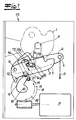
- a motor vehicle door lock is shown, which is constructed in its basic structure with a ratchet 1, 2 of a rotary latch 1 and with the rotary latch 1 in a manner usually interacting pawl 2.
- the ratchet 1, 2 may also have a pawl lever 2 instead of the pawl 2 shown, which then interacts with a pawl, not shown in the usual manner.
- the functionality of the pawl lever 2 in question corresponds to that of the pawl 2 in the following considerations.
- the lever with the reference numeral 2 may basically be a pawl lever 2, which operates on a pawl, not shown, which in turn interacts with the catch 1.
- this pawl lever 2 is not realized, but rather the figured pawl 2. All functions described below, however, both with respect to the pawl 2 shown and to the alternative pawl lever 2 in the context of the example not shown conceivable and are encompassed by the invention.
- the Fig. 1 now shows the normal operation of the motor vehicle door lock with the opposite of the catch 1 sunken pawl 2.
- a merely indicated locking pin 3 is caught and an associated and not shown motor vehicle door is closed.
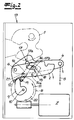
- - represents the Fig. 2 the opening operation.
- the pawl 2 has been lifted from the catch 1 and can open the catch 1 by a spring, not shown, and release the locking pin 3. The same applies to the motor vehicle door.
- the mechanical lever mechanism 4, 5 is composed of a release lever 4 and one or more operating on the release lever 4 further levers 5 together. To be able to lift off the pawl 2 from the closed rotary latch 1 with the help of the release lever 4, the release lever 4 must be pivoted about its axis 6 in the clockwise direction, as a in Fig. 1 indicated arrow shows. That is, the mechanical lever mechanism 4, 5 is arranged to open the locking mechanism 1, 2.
- the motorized opening unit 7 to 9 in the exemplary embodiment is composed of an electric motor 7 and a drive pulley 8 driven by the electric motor 7.
- the drive pulley 8 carries an eccentric 9.
- the eccentric 9 is formed as a drive cam.
- this stop element 12 may be a stop edge, a stop contour, etc., which dips into the adjustment of the drive cam 9 in normal operation.
- the drive cam 9 is able to act on the pawl 2 on its stop element 12 after completion of a certain travel.
- the pawl 2 is pivoted about its axis 6 in a clockwise direction, as an arrow in Fig. 1 suggests.
- the pawl 2 is lifted from the catch 1 and the locking mechanism 1, 2 is opened.
- the pawl 2 and the release lever 4 are coaxially mounted on the common axis 6 in a merely indicated lock case 13. Also in the lock case 13 experiences the motor opening unit 7 to 9 or the drive pulley 8 with its associated axis respectively axis of rotation 10 a storage.
- the electric motor 7 operates with a known drive worm on the drive pulley 8 by the drive worm engages in an external toothing of the drive pulley 8 in a known manner.
- the drive cam 9 provides for the application of an actuating element 14.
- This actuator 14 is designed as a pivot lever.
- the actuator or the pivot lever 14 is functionally and topologically between the pawl 2 and the release lever 4.
- a link 15 is arranged, which carries a pin 16.
- the pin 16 is present as a mechanical connection pin 16th formed between the pawl 2 and the release lever 4.
- the L-shaped contour 17 in the release lever 4 is designed with a free-wheeling region 17a in the vertical one leg 17a and an engagement region 17b in the horizontal other L-leg 17b.
- the pawl 2 has a contour 18, but the overall is applied horizontally and slit-like.
- the pin or connecting pin 16 passes through the contour 18 of the pawl 2, the link 15 and finally the contour 17 in the release lever 4 in this order. This is of course not mandatory and only on the embodiment coins. Consequently, the pin or connecting pin 16 extends perpendicular to the plane of the drawing and, accordingly, perpendicular to the two levers 2, 4.
- the operation is as follows. Im in Fig. 1 illustrated normal operation, the motor opening unit 7 to 9 ensures that the lever mechanism 4, 5 performs a freewheeling with respect to the locking mechanism 1, 2. Because the normal operation corresponds to the fact that the drive cam 9 rests on the drive pulley 8 on a stop pin 19 of the actuating element or pivot lever 14, that the actuating element or the pivot lever 14, the connecting pin 16 is not applied. The actuator or the pivot lever 14 is located as well as the drive cam 9 in its normal position.
- the opening operation may be initiated, for example, by a switch operation, a handle operation, etc., which corresponds to a total that the electric motor 7 of the motor opening unit 7 to 9 undergoes an application.
- the pin 16 follows the pivotal movement of the pivot lever 14. In this way, the connecting pin 16 of the freewheel portion 17a of the contour 17 in the release lever 4 transferred into the engaging portion 17b. At the same time the connecting pin 16 from the left end of the slot-like contour 18 in the pawl 2 in the right end over. This is dot-dashed in the Fig. 1 shown and the final position shows the Fig. 2 ,
- the adjusting element or pivot lever 14 may be assigned a return spring.
Landscapes
- Lock And Its Accessories (AREA)
Applications Claiming Priority (2)
| Application Number | Priority Date | Filing Date | Title |
|---|---|---|---|
| DE102011012999A DE102011012999A1 (de) | 2011-03-04 | 2011-03-04 | Kraftfahrzeugtürschloss |
| PCT/DE2012/000215 WO2012119581A2 (de) | 2011-03-04 | 2012-03-05 | Kraftfahrzeugtürschloss |
Publications (2)
| Publication Number | Publication Date |
|---|---|
| EP2681389A2 EP2681389A2 (de) | 2014-01-08 |
| EP2681389B1 true EP2681389B1 (de) | 2016-10-12 |
Family
ID=46017735
Family Applications (1)
| Application Number | Title | Priority Date | Filing Date |
|---|---|---|---|
| EP12717154.4A Active EP2681389B1 (de) | 2011-03-04 | 2012-03-05 | Kraftfahrzeugtürschloss |
Country Status (8)
Cited By (3)
| Publication number | Priority date | Publication date | Assignee | Title |
|---|---|---|---|---|
| DE102022121657A1 (de) * | 2022-08-26 | 2024-02-29 | Kiekert Aktiengesellschaft | Kraftfahrzeug-Schloss |
| DE102022121653A1 (de) * | 2022-08-26 | 2024-02-29 | Kiekert Aktiengesellschaft | Kraftfahrzeug-Schloss |
| DE102022121655A1 (de) * | 2022-08-26 | 2024-02-29 | Kiekert Aktiengesellschaft | Kraftfahrzeug-Schloss |
Families Citing this family (22)
| Publication number | Priority date | Publication date | Assignee | Title |
|---|---|---|---|---|
| TWI458882B (zh) * | 2012-05-15 | 2014-11-01 | Wfe Technology Corp | 電子鎖之作動馬達組 |
| DE102012023236A1 (de) * | 2012-11-28 | 2014-05-28 | Kiekert Aktiengesellschaft | Kraftfahrzeugtürschloss |
| DE102013103245A1 (de) * | 2013-03-28 | 2014-10-02 | Kiekert Aktiengesellschaft | Kraftfahrzeugtürverschluss |
| DE102013110752A1 (de) * | 2013-09-27 | 2015-04-02 | Kiekert Aktiengesellschaft | Kraftfahrzeugtürschloss |
| JP6318420B2 (ja) * | 2014-02-07 | 2018-05-09 | 三井金属アクト株式会社 | ロック装置 |
| DE102014004552A1 (de) * | 2014-03-31 | 2015-10-01 | Kiekert Aktiengesellschaft | Betätigungseinrichtung für ein Kraftfahrzeugschloss |
| DE102014004550A1 (de) * | 2014-03-31 | 2015-10-01 | Kiekert Aktiengesellschaft | Betätigungseinrichtung für ein Kraftfahrzeugschloss |
| GB201408075D0 (en) * | 2014-05-07 | 2014-06-18 | Chevalier John P | Closure and latching mechanisms |
| US9915082B2 (en) * | 2014-11-07 | 2018-03-13 | Southco, Inc. | Cam latch |
| US20160168883A1 (en) * | 2014-12-15 | 2016-06-16 | GM Global Technology Operations LLC | Double pull action vehicle hood latch |
| US10378252B2 (en) * | 2015-02-25 | 2019-08-13 | Magna Closures S.P.A. | Dual motor latch assembly with power cinch and power release having soft opening function |
| DE102016101885A1 (de) * | 2016-02-03 | 2017-08-03 | Kiekert Ag | Kraftfahrzeugtürschloss |
| US10415275B2 (en) | 2016-04-15 | 2019-09-17 | Hyundai Motor Company | Trunk latch module for vehicle |
| KR102681036B1 (ko) | 2016-12-19 | 2024-07-03 | 현대자동차주식회사 | 차량용 테일게이트의 개폐장치 |
| WO2018115949A1 (en) * | 2016-12-19 | 2018-06-28 | Kiekert Aktiengesellschaft | Motor vehicle door latch |
| DE102017105657A1 (de) * | 2017-03-16 | 2018-09-20 | Kiekert Ag | Stellantrieb für kraftfahrzeugtechnische anwendungen |
| DE102017124517A1 (de) | 2017-10-20 | 2019-04-25 | Kiekert Ag | Kraftfahrzeugschließsystem mit elektrischer Öffnungseinrichtung |
| JP6777679B2 (ja) | 2018-04-18 | 2020-10-28 | 三井金属アクト株式会社 | 車両ドアラッチ装置 |
| DE102018125137A1 (de) * | 2018-10-11 | 2020-04-16 | Kiekert Aktiengesellschaft | Elektromotorische Kraftfahrzeug-Antriebseinheit |
| JP7044079B2 (ja) * | 2019-01-10 | 2022-03-30 | トヨタ自動車株式会社 | 車両用ドア開閉装置 |
| CN110847709B (zh) * | 2019-10-30 | 2021-06-04 | 广州通达汽车电气股份有限公司 | 锁具结构及投币箱 |
| CN115874879A (zh) * | 2021-09-27 | 2023-03-31 | 开开特股份公司 | 机动车锁、特别是机动车门锁 |
Family Cites Families (29)
| Publication number | Priority date | Publication date | Assignee | Title |
|---|---|---|---|---|
| US3614146A (en) * | 1969-08-15 | 1971-10-19 | Atwood Vacuum Machine Co | Vehicle door latch |
| US3697105A (en) * | 1969-12-24 | 1972-10-10 | Atwood Vacuum Machine Co | Latch for vehicle doors |
| US4334704A (en) * | 1980-03-31 | 1982-06-15 | Mitsui Kinzoku Kogyo Kabushiki Kaisha | Automobile door locking mechanism |
| US5997055A (en) * | 1996-04-20 | 1999-12-07 | Kiekert Ag | Power-actuated motor-vehicle door latch |
| DE19638700C2 (de) * | 1996-09-21 | 1999-05-27 | Kiekert Ag | Kraftfahrzeug-Türschloß mit Kindersicherungssystem |
| DE19642698C2 (de) | 1996-10-16 | 2000-11-09 | Valeo Gmbh & Co Schliessyst Kg | Türgriff für ein Kraftfahrzeug |
| US6000257A (en) * | 1998-03-13 | 1999-12-14 | Ford Global Technologies, Inc. | Electric latch mechanism with an integral auxiliary mechanical release |
| ITTO980438A1 (it) * | 1998-05-22 | 1999-11-22 | Atoma Roltra Spa | Serratura per una porta di un veicolo. |
| DE19904663C2 (de) * | 1999-02-04 | 2001-02-15 | Bosch Gmbh Robert | Kraftfahrzeugtürschloß mit elektrischer Schließhilfe und Öffnungshilfe |
| ATE287016T1 (de) * | 1999-10-29 | 2005-01-15 | Kiekert Ag | Kraftfahrzeugtürverschluss |
| DE10139975A1 (de) * | 2000-09-07 | 2002-04-25 | Bosch Gmbh Robert | Kraftfahrzeug-Türschloß mit kombiniertem Zentralverriegelungs- und Öffnungsantrieb |
| EP1317596B1 (de) * | 2000-09-07 | 2006-11-22 | Brose Schliesssysteme GmbH & Co. KG | Kraftfahrzeug-türschloss mit kombiniertem zentralverriegelungs- und öffnungsantrieb |
| DE10048709A1 (de) * | 2000-09-30 | 2002-04-18 | Kiekert Ag | Kraftfahrzeugtürverschluss |
| US20040094971A1 (en) * | 2000-12-07 | 2004-05-20 | Werner Warmke | Lock with a latch held in a closed position by a detent pawl |
| US6776442B2 (en) * | 2001-01-09 | 2004-08-17 | Strattec Security Corporation | Latch apparatus and method |
| US20030038485A1 (en) * | 2001-08-22 | 2003-02-27 | Schwaiger Dennis D. | Vehicle closure member latch assembly having hold open mode |
| DE10143366A1 (de) * | 2001-09-04 | 2003-03-20 | Kiekert Ag | Kraftfahrzeugtürverschluss |
| CA2460818C (en) * | 2001-09-19 | 2010-07-20 | Intier Automotive Closures Inc. | Latch with uni-directional power release mechanism |
| US7467815B2 (en) * | 2001-12-12 | 2008-12-23 | Intier Automotive Closures Inc. | Snow load lever with two part pawl lever construction |
| DE10222136A1 (de) * | 2002-05-17 | 2003-12-04 | Kiekert Ag | Kraftfahrzeug-Türverschluss |
| KR100988394B1 (ko) * | 2002-08-20 | 2010-10-18 | 인티어 오토모티브 클로우져스 인크. | 도어 래치용 파워 액츄에이터 |
| US7152890B2 (en) * | 2004-09-02 | 2006-12-26 | Kiekert Ag | Power-open motor-vehicle latch |
| EP1635018A1 (en) * | 2004-09-08 | 2006-03-15 | ArvinMeritor Light Vehicle Systems (UK) Ltd | Latch Release Mechanism |
| DE602006019839D1 (de) * | 2005-03-23 | 2011-03-10 | Magna Closures Inc | Globales seitentürschloss |
| GB2428733B (en) * | 2005-07-30 | 2010-03-10 | Arvinmeritor Light Vehicle Sys | Vehicle door latch |
| DE202006012091U1 (de) * | 2006-08-04 | 2007-12-20 | BROSE SCHLIEßSYSTEME GMBH & CO. KG | Kraftfahrzeugschloß |
| JP4794403B2 (ja) * | 2006-10-02 | 2011-10-19 | 三井金属アクト株式会社 | ドアロック装置 |
| US20100072761A1 (en) * | 2008-02-04 | 2010-03-25 | Kris Tomaszewski | Global Side Door Latch |
| DE202008003845U1 (de) | 2008-03-19 | 2009-08-13 | Kiekert Ag | Türverschlusseinheit für ein Kraftfahrzeug |
-
2011
- 2011-03-04 DE DE102011012999A patent/DE102011012999A1/de not_active Withdrawn
-
2012
- 2012-03-05 KR KR1020137025675A patent/KR20140010123A/ko not_active Withdrawn
- 2012-03-05 WO PCT/DE2012/000215 patent/WO2012119581A2/de active Application Filing
- 2012-03-05 US US14/002,690 patent/US9677305B2/en active Active
- 2012-03-05 EP EP12717154.4A patent/EP2681389B1/de active Active
- 2012-03-05 CN CN201280021448.0A patent/CN103534429B/zh active Active
- 2012-03-05 JP JP2013555753A patent/JP6123100B2/ja active Active
- 2012-03-05 CA CA2828111A patent/CA2828111A1/en not_active Abandoned
Cited By (4)
| Publication number | Priority date | Publication date | Assignee | Title |
|---|---|---|---|---|
| DE102022121657A1 (de) * | 2022-08-26 | 2024-02-29 | Kiekert Aktiengesellschaft | Kraftfahrzeug-Schloss |
| WO2024041700A1 (de) * | 2022-08-26 | 2024-02-29 | Kiekert Aktiengesellschaft | Kraftfahrzeug-schloss |
| DE102022121653A1 (de) * | 2022-08-26 | 2024-02-29 | Kiekert Aktiengesellschaft | Kraftfahrzeug-Schloss |
| DE102022121655A1 (de) * | 2022-08-26 | 2024-02-29 | Kiekert Aktiengesellschaft | Kraftfahrzeug-Schloss |
Also Published As
| Publication number | Publication date |
|---|---|
| US9677305B2 (en) | 2017-06-13 |
| EP2681389A2 (de) | 2014-01-08 |
| WO2012119581A2 (de) | 2012-09-13 |
| DE102011012999A1 (de) | 2012-09-06 |
| JP6123100B2 (ja) | 2017-05-10 |
| CN103534429B (zh) | 2016-05-04 |
| US20150233157A1 (en) | 2015-08-20 |
| CA2828111A1 (en) | 2012-09-13 |
| CN103534429A (zh) | 2014-01-22 |
| WO2012119581A3 (de) | 2012-11-08 |
| KR20140010123A (ko) | 2014-01-23 |
| JP2014511447A (ja) | 2014-05-15 |
Similar Documents
| Publication | Publication Date | Title |
|---|---|---|
| EP2681389B1 (de) | Kraftfahrzeugtürschloss | |
| EP2681388B1 (de) | Kraftfahrzeugtürverschluss | |
| EP1178171B1 (de) | Kraftfahrzeugtürverschluss | |
| EP1489252B1 (de) | Kraftfahrzeugtürverschluss | |
| EP3832056A1 (de) | Kraftfahrzeugschloss, insbesondere kraftfahrzeugtürschloss | |
| DE102017106707A1 (de) | Kraftfahrzeugtürverschluss | |
| WO2012119580A1 (de) | Kraftfahrzeugtürschloss | |
| DE102019111936A1 (de) | Kraftfahrzeugtürschloss | |
| EP2173955B1 (de) | Kraftfahrzeugtürverschluss | |
| DE102022128469A1 (de) | Kraftfahrzeug-Schloss insbesondere Kraftfahrzeug-Türschloss | |
| EP1629166B1 (de) | Kraftfahrzeugtürverschluss | |
| EP1658410A1 (de) | Kraftfahrzeugt rverschluss | |
| EP2235304B1 (de) | Kraftfahrzeugtürverschluss | |
| EP1039080B1 (de) | Zentralverriegelungsanlage für ein Kraftfahrzeug | |
| EP1288408B1 (de) | Kraftfahrzeugtürverschluss | |
| DE10222136A1 (de) | Kraftfahrzeug-Türverschluss | |
| EP1503012A1 (de) | Kraftfahrzeugtürverschluss | |
| DE102018125137A1 (de) | Elektromotorische Kraftfahrzeug-Antriebseinheit | |
| EP4577714A1 (de) | Kraftfahrzeug-schloss | |
| DE102021006216A1 (de) | Kraftfahrzeug-Schloss | |
| DE102022113045A1 (de) | Kraftfahrzeug-Schloss | |
| DE102021128439A1 (de) | Kraftfahrzeug-Schloss | |
| EP4555168A1 (de) | Kraftfahrzeug-schloss | |
| WO2021205251A1 (de) | Kraftfahrzeug-schloss | |
| EP4555163A1 (de) | Kraftfahrzeugschloss insbesondere kraftfahrzeug-türschloss |
Legal Events
| Date | Code | Title | Description |
|---|---|---|---|
| PUAI | Public reference made under article 153(3) epc to a published international application that has entered the european phase |
Free format text: ORIGINAL CODE: 0009012 |
|
| 17P | Request for examination filed |
Effective date: 20130912 |
|
| AK | Designated contracting states |
Kind code of ref document: A2 Designated state(s): AL AT BE BG CH CY CZ DE DK EE ES FI FR GB GR HR HU IE IS IT LI LT LU LV MC MK MT NL NO PL PT RO RS SE SI SK SM TR |
|
| DAX | Request for extension of the european patent (deleted) | ||
| REG | Reference to a national code |
Ref country code: DE Ref legal event code: R079 Ref document number: 502012008499 Country of ref document: DE Free format text: PREVIOUS MAIN CLASS: E05B0065320000 Ipc: E05B0081140000 |
|
| GRAP | Despatch of communication of intention to grant a patent |
Free format text: ORIGINAL CODE: EPIDOSNIGR1 |
|
| RIC1 | Information provided on ipc code assigned before grant |
Ipc: E05B 81/42 20140101ALI20160531BHEP Ipc: E05B 81/14 20140101AFI20160531BHEP Ipc: E05B 81/06 20140101ALI20160531BHEP Ipc: E05B 81/34 20140101ALI20160531BHEP |
|
| INTG | Intention to grant announced |
Effective date: 20160617 |
|
| GRAS | Grant fee paid |
Free format text: ORIGINAL CODE: EPIDOSNIGR3 |
|
| GRAA | (expected) grant |
Free format text: ORIGINAL CODE: 0009210 |
|
| AK | Designated contracting states |
Kind code of ref document: B1 Designated state(s): AL AT BE BG CH CY CZ DE DK EE ES FI FR GB GR HR HU IE IS IT LI LT LU LV MC MK MT NL NO PL PT RO RS SE SI SK SM TR |
|
| REG | Reference to a national code |
Ref country code: GB Ref legal event code: FG4D Free format text: NOT ENGLISH |
|
| REG | Reference to a national code |
Ref country code: CH Ref legal event code: EP |
|
| REG | Reference to a national code |
Ref country code: AT Ref legal event code: REF Ref document number: 836673 Country of ref document: AT Kind code of ref document: T Effective date: 20161015 |
|
| REG | Reference to a national code |
Ref country code: IE Ref legal event code: FG4D Free format text: LANGUAGE OF EP DOCUMENT: GERMAN |
|
| REG | Reference to a national code |
Ref country code: DE Ref legal event code: R096 Ref document number: 502012008499 Country of ref document: DE |
|
| REG | Reference to a national code |
Ref country code: LT Ref legal event code: MG4D |
|
| REG | Reference to a national code |
Ref country code: NL Ref legal event code: MP Effective date: 20161012 |
|
| PG25 | Lapsed in a contracting state [announced via postgrant information from national office to epo] |
Ref country code: LV Free format text: LAPSE BECAUSE OF FAILURE TO SUBMIT A TRANSLATION OF THE DESCRIPTION OR TO PAY THE FEE WITHIN THE PRESCRIBED TIME-LIMIT Effective date: 20161012 |
|
| REG | Reference to a national code |
Ref country code: FR Ref legal event code: PLFP Year of fee payment: 6 |
|
| PG25 | Lapsed in a contracting state [announced via postgrant information from national office to epo] |
Ref country code: SE Free format text: LAPSE BECAUSE OF FAILURE TO SUBMIT A TRANSLATION OF THE DESCRIPTION OR TO PAY THE FEE WITHIN THE PRESCRIBED TIME-LIMIT Effective date: 20161012 Ref country code: LT Free format text: LAPSE BECAUSE OF FAILURE TO SUBMIT A TRANSLATION OF THE DESCRIPTION OR TO PAY THE FEE WITHIN THE PRESCRIBED TIME-LIMIT Effective date: 20161012 Ref country code: GR Free format text: LAPSE BECAUSE OF FAILURE TO SUBMIT A TRANSLATION OF THE DESCRIPTION OR TO PAY THE FEE WITHIN THE PRESCRIBED TIME-LIMIT Effective date: 20170113 Ref country code: NO Free format text: LAPSE BECAUSE OF FAILURE TO SUBMIT A TRANSLATION OF THE DESCRIPTION OR TO PAY THE FEE WITHIN THE PRESCRIBED TIME-LIMIT Effective date: 20170112 |
|
| PG25 | Lapsed in a contracting state [announced via postgrant information from national office to epo] |
Ref country code: ES Free format text: LAPSE BECAUSE OF FAILURE TO SUBMIT A TRANSLATION OF THE DESCRIPTION OR TO PAY THE FEE WITHIN THE PRESCRIBED TIME-LIMIT Effective date: 20161012 Ref country code: PT Free format text: LAPSE BECAUSE OF FAILURE TO SUBMIT A TRANSLATION OF THE DESCRIPTION OR TO PAY THE FEE WITHIN THE PRESCRIBED TIME-LIMIT Effective date: 20170213 Ref country code: RS Free format text: LAPSE BECAUSE OF FAILURE TO SUBMIT A TRANSLATION OF THE DESCRIPTION OR TO PAY THE FEE WITHIN THE PRESCRIBED TIME-LIMIT Effective date: 20161012 Ref country code: HR Free format text: LAPSE BECAUSE OF FAILURE TO SUBMIT A TRANSLATION OF THE DESCRIPTION OR TO PAY THE FEE WITHIN THE PRESCRIBED TIME-LIMIT Effective date: 20161012 Ref country code: PL Free format text: LAPSE BECAUSE OF FAILURE TO SUBMIT A TRANSLATION OF THE DESCRIPTION OR TO PAY THE FEE WITHIN THE PRESCRIBED TIME-LIMIT Effective date: 20161012 Ref country code: IS Free format text: LAPSE BECAUSE OF FAILURE TO SUBMIT A TRANSLATION OF THE DESCRIPTION OR TO PAY THE FEE WITHIN THE PRESCRIBED TIME-LIMIT Effective date: 20170212 Ref country code: FI Free format text: LAPSE BECAUSE OF FAILURE TO SUBMIT A TRANSLATION OF THE DESCRIPTION OR TO PAY THE FEE WITHIN THE PRESCRIBED TIME-LIMIT Effective date: 20161012 Ref country code: NL Free format text: LAPSE BECAUSE OF FAILURE TO SUBMIT A TRANSLATION OF THE DESCRIPTION OR TO PAY THE FEE WITHIN THE PRESCRIBED TIME-LIMIT Effective date: 20161012 |
|
| REG | Reference to a national code |
Ref country code: DE Ref legal event code: R097 Ref document number: 502012008499 Country of ref document: DE |
|
| PG25 | Lapsed in a contracting state [announced via postgrant information from national office to epo] |
Ref country code: SK Free format text: LAPSE BECAUSE OF FAILURE TO SUBMIT A TRANSLATION OF THE DESCRIPTION OR TO PAY THE FEE WITHIN THE PRESCRIBED TIME-LIMIT Effective date: 20161012 Ref country code: RO Free format text: LAPSE BECAUSE OF FAILURE TO SUBMIT A TRANSLATION OF THE DESCRIPTION OR TO PAY THE FEE WITHIN THE PRESCRIBED TIME-LIMIT Effective date: 20161012 Ref country code: DK Free format text: LAPSE BECAUSE OF FAILURE TO SUBMIT A TRANSLATION OF THE DESCRIPTION OR TO PAY THE FEE WITHIN THE PRESCRIBED TIME-LIMIT Effective date: 20161012 Ref country code: EE Free format text: LAPSE BECAUSE OF FAILURE TO SUBMIT A TRANSLATION OF THE DESCRIPTION OR TO PAY THE FEE WITHIN THE PRESCRIBED TIME-LIMIT Effective date: 20161012 |
|
| PLBE | No opposition filed within time limit |
Free format text: ORIGINAL CODE: 0009261 |
|
| STAA | Information on the status of an ep patent application or granted ep patent |
Free format text: STATUS: NO OPPOSITION FILED WITHIN TIME LIMIT |
|
| PG25 | Lapsed in a contracting state [announced via postgrant information from national office to epo] |
Ref country code: BG Free format text: LAPSE BECAUSE OF FAILURE TO SUBMIT A TRANSLATION OF THE DESCRIPTION OR TO PAY THE FEE WITHIN THE PRESCRIBED TIME-LIMIT Effective date: 20170112 Ref country code: IT Free format text: LAPSE BECAUSE OF FAILURE TO SUBMIT A TRANSLATION OF THE DESCRIPTION OR TO PAY THE FEE WITHIN THE PRESCRIBED TIME-LIMIT Effective date: 20161012 Ref country code: SM Free format text: LAPSE BECAUSE OF FAILURE TO SUBMIT A TRANSLATION OF THE DESCRIPTION OR TO PAY THE FEE WITHIN THE PRESCRIBED TIME-LIMIT Effective date: 20161012 |
|
| 26N | No opposition filed |
Effective date: 20170713 |
|
| REG | Reference to a national code |
Ref country code: CH Ref legal event code: PL |
|
| GBPC | Gb: european patent ceased through non-payment of renewal fee |
Effective date: 20170305 |
|
| PG25 | Lapsed in a contracting state [announced via postgrant information from national office to epo] |
Ref country code: SI Free format text: LAPSE BECAUSE OF FAILURE TO SUBMIT A TRANSLATION OF THE DESCRIPTION OR TO PAY THE FEE WITHIN THE PRESCRIBED TIME-LIMIT Effective date: 20161012 Ref country code: MC Free format text: LAPSE BECAUSE OF FAILURE TO SUBMIT A TRANSLATION OF THE DESCRIPTION OR TO PAY THE FEE WITHIN THE PRESCRIBED TIME-LIMIT Effective date: 20161012 |
|
| REG | Reference to a national code |
Ref country code: IE Ref legal event code: MM4A |
|
| PG25 | Lapsed in a contracting state [announced via postgrant information from national office to epo] |
Ref country code: LU Free format text: LAPSE BECAUSE OF NON-PAYMENT OF DUE FEES Effective date: 20170305 |
|
| PG25 | Lapsed in a contracting state [announced via postgrant information from national office to epo] |
Ref country code: CH Free format text: LAPSE BECAUSE OF NON-PAYMENT OF DUE FEES Effective date: 20170331 Ref country code: GB Free format text: LAPSE BECAUSE OF NON-PAYMENT OF DUE FEES Effective date: 20170305 Ref country code: IE Free format text: LAPSE BECAUSE OF NON-PAYMENT OF DUE FEES Effective date: 20170305 Ref country code: LI Free format text: LAPSE BECAUSE OF NON-PAYMENT OF DUE FEES Effective date: 20170331 |
|
| REG | Reference to a national code |
Ref country code: BE Ref legal event code: MM Effective date: 20170331 |
|
| REG | Reference to a national code |
Ref country code: FR Ref legal event code: PLFP Year of fee payment: 7 |
|
| REG | Reference to a national code |
Ref country code: AT Ref legal event code: MM01 Ref document number: 836673 Country of ref document: AT Kind code of ref document: T Effective date: 20170305 |
|
| PG25 | Lapsed in a contracting state [announced via postgrant information from national office to epo] |
Ref country code: BE Free format text: LAPSE BECAUSE OF NON-PAYMENT OF DUE FEES Effective date: 20170331 |
|
| PG25 | Lapsed in a contracting state [announced via postgrant information from national office to epo] |
Ref country code: AT Free format text: LAPSE BECAUSE OF NON-PAYMENT OF DUE FEES Effective date: 20170305 |
|
| PG25 | Lapsed in a contracting state [announced via postgrant information from national office to epo] |
Ref country code: MT Free format text: LAPSE BECAUSE OF FAILURE TO SUBMIT A TRANSLATION OF THE DESCRIPTION OR TO PAY THE FEE WITHIN THE PRESCRIBED TIME-LIMIT Effective date: 20161012 |
|
| PG25 | Lapsed in a contracting state [announced via postgrant information from national office to epo] |
Ref country code: HU Free format text: LAPSE BECAUSE OF FAILURE TO SUBMIT A TRANSLATION OF THE DESCRIPTION OR TO PAY THE FEE WITHIN THE PRESCRIBED TIME-LIMIT; INVALID AB INITIO Effective date: 20120305 |
|
| PG25 | Lapsed in a contracting state [announced via postgrant information from national office to epo] |
Ref country code: CY Free format text: LAPSE BECAUSE OF NON-PAYMENT OF DUE FEES Effective date: 20161012 |
|
| PG25 | Lapsed in a contracting state [announced via postgrant information from national office to epo] |
Ref country code: MK Free format text: LAPSE BECAUSE OF FAILURE TO SUBMIT A TRANSLATION OF THE DESCRIPTION OR TO PAY THE FEE WITHIN THE PRESCRIBED TIME-LIMIT Effective date: 20161012 |
|
| PG25 | Lapsed in a contracting state [announced via postgrant information from national office to epo] |
Ref country code: TR Free format text: LAPSE BECAUSE OF FAILURE TO SUBMIT A TRANSLATION OF THE DESCRIPTION OR TO PAY THE FEE WITHIN THE PRESCRIBED TIME-LIMIT Effective date: 20161012 |
|
| PG25 | Lapsed in a contracting state [announced via postgrant information from national office to epo] |
Ref country code: AL Free format text: LAPSE BECAUSE OF FAILURE TO SUBMIT A TRANSLATION OF THE DESCRIPTION OR TO PAY THE FEE WITHIN THE PRESCRIBED TIME-LIMIT Effective date: 20161012 |
|
| P01 | Opt-out of the competence of the unified patent court (upc) registered |
Effective date: 20230529 |
|
| PGFP | Annual fee paid to national office [announced via postgrant information from national office to epo] |
Ref country code: DE Payment date: 20250319 Year of fee payment: 14 |
|
| PGFP | Annual fee paid to national office [announced via postgrant information from national office to epo] |
Ref country code: FR Payment date: 20250324 Year of fee payment: 14 Ref country code: CZ Payment date: 20250220 Year of fee payment: 14 |