EP2681389B1 - Motor vehicle door lock - Google Patents
Motor vehicle door lock Download PDFInfo
- Publication number
- EP2681389B1 EP2681389B1 EP12717154.4A EP12717154A EP2681389B1 EP 2681389 B1 EP2681389 B1 EP 2681389B1 EP 12717154 A EP12717154 A EP 12717154A EP 2681389 B1 EP2681389 B1 EP 2681389B1
- Authority
- EP
- European Patent Office
- Prior art keywords
- vehicle door
- door lock
- motor vehicle
- lock according
- lever
- Prior art date
- Legal status (The legal status is an assumption and is not a legal conclusion. Google has not performed a legal analysis and makes no representation as to the accuracy of the status listed.)
- Active
Links
Images
Classifications
-
- E—FIXED CONSTRUCTIONS
- E05—LOCKS; KEYS; WINDOW OR DOOR FITTINGS; SAFES
- E05B—LOCKS; ACCESSORIES THEREFOR; HANDCUFFS
- E05B85/00—Details of vehicle locks not provided for in groups E05B77/00 - E05B83/00
- E05B85/20—Bolts or detents
- E05B85/24—Bolts rotating about an axis
- E05B85/243—Bolts rotating about an axis with a bifurcated bolt
-
- E—FIXED CONSTRUCTIONS
- E05—LOCKS; KEYS; WINDOW OR DOOR FITTINGS; SAFES
- E05B—LOCKS; ACCESSORIES THEREFOR; HANDCUFFS
- E05B77/00—Vehicle locks characterised by special functions or purposes
- E05B77/02—Vehicle locks characterised by special functions or purposes for accident situations
-
- E—FIXED CONSTRUCTIONS
- E05—LOCKS; KEYS; WINDOW OR DOOR FITTINGS; SAFES
- E05B—LOCKS; ACCESSORIES THEREFOR; HANDCUFFS
- E05B81/00—Power-actuated vehicle locks
- E05B81/02—Power-actuated vehicle locks characterised by the type of actuators used
- E05B81/04—Electrical
- E05B81/05—Electrical moving in one direction only
-
- E—FIXED CONSTRUCTIONS
- E05—LOCKS; KEYS; WINDOW OR DOOR FITTINGS; SAFES
- E05B—LOCKS; ACCESSORIES THEREFOR; HANDCUFFS
- E05B81/00—Power-actuated vehicle locks
- E05B81/02—Power-actuated vehicle locks characterised by the type of actuators used
- E05B81/04—Electrical
- E05B81/06—Electrical using rotary motors
-
- E—FIXED CONSTRUCTIONS
- E05—LOCKS; KEYS; WINDOW OR DOOR FITTINGS; SAFES
- E05B—LOCKS; ACCESSORIES THEREFOR; HANDCUFFS
- E05B81/00—Power-actuated vehicle locks
- E05B81/12—Power-actuated vehicle locks characterised by the function or purpose of the powered actuators
- E05B81/14—Power-actuated vehicle locks characterised by the function or purpose of the powered actuators operating on bolt detents, e.g. for unlatching the bolt
-
- E—FIXED CONSTRUCTIONS
- E05—LOCKS; KEYS; WINDOW OR DOOR FITTINGS; SAFES
- E05B—LOCKS; ACCESSORIES THEREFOR; HANDCUFFS
- E05B81/00—Power-actuated vehicle locks
- E05B81/24—Power-actuated vehicle locks characterised by constructional features of the actuator or the power transmission
- E05B81/32—Details of the actuator transmission
- E05B81/34—Details of the actuator transmission of geared transmissions
-
- E—FIXED CONSTRUCTIONS
- E05—LOCKS; KEYS; WINDOW OR DOOR FITTINGS; SAFES
- E05B—LOCKS; ACCESSORIES THEREFOR; HANDCUFFS
- E05B81/00—Power-actuated vehicle locks
- E05B81/24—Power-actuated vehicle locks characterised by constructional features of the actuator or the power transmission
- E05B81/32—Details of the actuator transmission
- E05B81/42—Cams
-
- E—FIXED CONSTRUCTIONS
- E05—LOCKS; KEYS; WINDOW OR DOOR FITTINGS; SAFES
- E05B—LOCKS; ACCESSORIES THEREFOR; HANDCUFFS
- E05B85/00—Details of vehicle locks not provided for in groups E05B77/00 - E05B83/00
- E05B85/20—Bolts or detents
- E05B85/24—Bolts rotating about an axis
-
- Y—GENERAL TAGGING OF NEW TECHNOLOGICAL DEVELOPMENTS; GENERAL TAGGING OF CROSS-SECTIONAL TECHNOLOGIES SPANNING OVER SEVERAL SECTIONS OF THE IPC; TECHNICAL SUBJECTS COVERED BY FORMER USPC CROSS-REFERENCE ART COLLECTIONS [XRACs] AND DIGESTS
- Y10—TECHNICAL SUBJECTS COVERED BY FORMER USPC
- Y10T—TECHNICAL SUBJECTS COVERED BY FORMER US CLASSIFICATION
- Y10T292/00—Closure fasteners
- Y10T292/08—Bolts
- Y10T292/1043—Swinging
- Y10T292/1075—Operating means
- Y10T292/1079—Gear
Definitions
- the invention relates to a motor vehicle door lock, with a locking mechanism and with a mechanical lever mechanism and a motorized opening unit, which are each individually set up to open the locking mechanism.
- Such motor vehicle door locks are, for example, by the relevant prior art according to the DE 20 2008 003 845 U1 the applicant or by the DE 196 42 698 A1 known. In the latter case the DE 196 42 698 A1 The procedure is such that a handle part of a door handle is fixed in its normal position under normal or normal operation. After unlocking the door lock, an associated vehicle door without pivoting of the handle part can be opened by simply pulling the handle.
- an electronic control unit evaluates a signal of an associated impact sensor. As a result, a locking bolt is withdrawn, which has previously blocked the handle part of the door handle. As a result, the door lock can be opened mechanically. In contrast, an opening of the door lock in normal operation by an electric motor or a motorized opening unit takes place.
- the document DE 101 39 975 A discloses a motor vehicle door lock according to the preamble of claim 1.
- the invention is based on the technical problem of further developing a motor vehicle door lock of the construction described above so that, with perfect functionality, there is the additional possibility of mechanically supporting the per se motor opening process. In addition, this should succeed in a structurally simple and inexpensive construction.
- the normal operation corresponds to the fact that the motor vehicle door lock or its locking mechanism is not opened and also take appropriate measures.
- the opening operation means that the ratchet undergoes an opening by lifting a pawl from an associated ratchet. Because this process has the consequence that a previously captured by the catch locking bolt is released.
- Such unintentional openings can be caused, for example, in an accident or in the event of a crash by the acceleration forces occurring there.
- the motorized opening unit ensures that the mechanical lever mechanism in the associated normal operation (this also belongs the crash case) performs a freewheel over the locking mechanism.
- any operations of the mechanical lever mechanism result in normal operation (even in a crash) in associated pivoting movements, but free running or idling relative to the locking mechanism, so do not cause the pawl to lift off the catch or take off.
- An unwanted opening of the associated motor vehicle door is therefore excluded.
- the locking mechanism Only when and only if the motor opening unit is actuated by a corresponding opening command is given to an electric motor of the motor opening unit, the locking mechanism is opened. Because in this case, the opening operation is present and the motor opening unit ensures that the mechanical lever mechanism is brought into engagement with the locking mechanism. Then, an action on the mechanical lever mechanism causes the pawl is lifted from the catch and can also be lifted.
- the motorized opening unit provides for the opening of the locking mechanism during opening operation. Rather, the locking opening is supported by the lever mechanism then engaged with the locking mechanism. In most cases, in this context, even a minimal Verfahrwerg of the electric motor of the motor opening unit is sufficient, so that the mechanical lever mechanism comes into engagement with the locking mechanism. As a result, even situations can be mastered without problems, in which, for example, the force of the electric motor is not sufficient to lift the pawl as such from the catch. Because this process is mechanically supported according to the invention.
- the motor opening unit according to the invention operates unidirectionally, this unidirectional operation is sufficient even in the event of a crash, thus under Recourse to the mechanical lever mechanism of the opening process of the locking supported or even (if necessary) can be completed.
- expensive electronic measures are not required and, moreover, they can be operated with a simply constructed electromotive drive by its unidirectional design.
- a spring in accordance with the invention which is usually provided in addition in this context on the drive, ensures that the motorized opening unit is acted upon in the opposite direction to the (unidirectional) drive direction. This allows the motorized opening unit with the help of the spring after the loss of the drive easily in their original position (again) convict. This corresponds to the normal operation and consequently the freewheel of the lever mechanism relative to the locking mechanism.
- the locking mechanism can be easily and reliably opened in any case as a result of the realized mechanical redundancy. Because it is sufficient that the electric motor of the motor opening unit completed only a small travel, which as such is not or not enough for lifting the pawl of the catch sufficient or sufficient. In fact, this small travel is (only) capable of bringing the lever mechanism from the freewheel into engagement with the ratchet. As a result, the mechanical lever mechanism can support or completely take over the opening process of the locking mechanism. All of this succeeds with astonishingly simple means and therefore particularly cost-effectively. Here are the main benefits.
- the mechanical lever mechanism has an interacting with the locking mechanism release lever. That is, the release lever located immediately near the ratchet provides the core ensure that the lever mechanism free-runs in normal operation with respect to the locking mechanism and is engaged with the locking mechanism during opening operation.
- the release lever usually has a contour for a pin engaging therein.
- This pin is usually formed as a mechanical connecting pin between the pawl and the release lever.
- the pin may be mounted on a slide or in a slot, which is arranged between the release lever and the pawl. The pin is perpendicular to this backdrop and connects the pawl mechanically with the release lever.
- the contour in the release lever is typically formed in two parts. In fact, the contour is usually subdivided into a freewheeling area and an engagement area. In this case, it has further proven, if the contour is designed L-shaped. Because in this context, one L-leg acts as a freewheeling area, while the other L-leg is formed as an engagement area.
- the L-leg designed as a freewheeling area is typically the vertical L-leg, whereas the L-leg defining the engagement area is designed as a horizontal L-leg.
- the connecting pin between the pawl and the release lever in the freewheel area or the associated L-leg of the L-shaped contour in the release lever the release lever can be pivoted about its axis without these pivotal movements are transmitted to the pawl. Rather, the pin in question moves in this process along the freewheel area or along the vertical L-leg. The pivoting movements of the release lever thus go empty.
- the mechanical lever mechanism runs free. Normal operation corresponds to this.
- the release lever and the pawl of the locking mechanism are designed coaxially with each other.
- the release lever and the pawl are usually received together on the matching axis in a lock case of the door lock.
- the motorized opening unit operates unidirectionally and has an electric motor.
- This electric motor works on a driven by him drive pulley.
- the drive pulley as such usually carries an eccentric.
- the eccentric is usually designed as a drive cam.
- the drive cam on the one hand interact with a stop element on the pawl and on the other hand with an actuating element. Once the drive cam moves against the stop element on the pawl, the pawl is lifted by means of the drive cam of the catch.
- the Rotary latch can open as a result of this. Before or at the same time, the drive cam on the other hand ensures that the already mentioned actuating element is acted upon.
- the actuator ensures the position changes of the pin or the mechanical connecting pin between the pawl and the release lever.
- the pin can be placed on the one hand in the freewheel area of the contour of the release lever and on the other hand in its engagement region. This defines the normal operation on the one hand and the opening operation on the other hand.
- the actuator works on the pin.
- the actuator is acted upon by the motor opening unit in turn.
- the actuator operates on the pin such that the pin is arranged in normal operation in the freewheeling area and in the opening operation in the engagement region of the contour on the release lever.
- the adjusting element is advantageously designed as a pivot lever.
- the actuator or the pivot lever is thus functionally between the motor drive and the pin or connecting pin.
- the adjusting element may be arranged between the pawl and the release lever and act directly on the pin bearing the backdrop.
- the adjusting element or the pivot lever is generally mounted approximately centrally on an axle.
- One end of the pivot lever is equipped with a stop or stop pin on which abuts the eccentric of the motor opening unit to pivot the pivot lever.
- the pivot lever mechanically couples the eccentric of the drive disc of the motorized opening unit with the pin.
- An additional control element or swivel lever associated return spring ensures ensure that when eliminating the action of the motorized opening unit of the pivot lever or the actuator again assumes its original position.
- a motor vehicle door lock is shown, which is constructed in its basic structure with a ratchet 1, 2 of a rotary latch 1 and with the rotary latch 1 in a manner usually interacting pawl 2.
- the ratchet 1, 2 may also have a pawl lever 2 instead of the pawl 2 shown, which then interacts with a pawl, not shown in the usual manner.
- the functionality of the pawl lever 2 in question corresponds to that of the pawl 2 in the following considerations.
- the lever with the reference numeral 2 may basically be a pawl lever 2, which operates on a pawl, not shown, which in turn interacts with the catch 1.
- this pawl lever 2 is not realized, but rather the figured pawl 2. All functions described below, however, both with respect to the pawl 2 shown and to the alternative pawl lever 2 in the context of the example not shown conceivable and are encompassed by the invention.
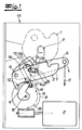
- the Fig. 1 now shows the normal operation of the motor vehicle door lock with the opposite of the catch 1 sunken pawl 2.
- a merely indicated locking pin 3 is caught and an associated and not shown motor vehicle door is closed.
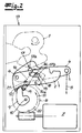
- - represents the Fig. 2 the opening operation.
- the pawl 2 has been lifted from the catch 1 and can open the catch 1 by a spring, not shown, and release the locking pin 3. The same applies to the motor vehicle door.
- the mechanical lever mechanism 4, 5 is composed of a release lever 4 and one or more operating on the release lever 4 further levers 5 together. To be able to lift off the pawl 2 from the closed rotary latch 1 with the help of the release lever 4, the release lever 4 must be pivoted about its axis 6 in the clockwise direction, as a in Fig. 1 indicated arrow shows. That is, the mechanical lever mechanism 4, 5 is arranged to open the locking mechanism 1, 2.
- the motorized opening unit 7 to 9 in the exemplary embodiment is composed of an electric motor 7 and a drive pulley 8 driven by the electric motor 7.
- the drive pulley 8 carries an eccentric 9.
- the eccentric 9 is formed as a drive cam.
- this stop element 12 may be a stop edge, a stop contour, etc., which dips into the adjustment of the drive cam 9 in normal operation.
- the drive cam 9 is able to act on the pawl 2 on its stop element 12 after completion of a certain travel.
- the pawl 2 is pivoted about its axis 6 in a clockwise direction, as an arrow in Fig. 1 suggests.
- the pawl 2 is lifted from the catch 1 and the locking mechanism 1, 2 is opened.
- the pawl 2 and the release lever 4 are coaxially mounted on the common axis 6 in a merely indicated lock case 13. Also in the lock case 13 experiences the motor opening unit 7 to 9 or the drive pulley 8 with its associated axis respectively axis of rotation 10 a storage.
- the electric motor 7 operates with a known drive worm on the drive pulley 8 by the drive worm engages in an external toothing of the drive pulley 8 in a known manner.
- the drive cam 9 provides for the application of an actuating element 14.
- This actuator 14 is designed as a pivot lever.
- the actuator or the pivot lever 14 is functionally and topologically between the pawl 2 and the release lever 4.
- a link 15 is arranged, which carries a pin 16.
- the pin 16 is present as a mechanical connection pin 16th formed between the pawl 2 and the release lever 4.
- the L-shaped contour 17 in the release lever 4 is designed with a free-wheeling region 17a in the vertical one leg 17a and an engagement region 17b in the horizontal other L-leg 17b.
- the pawl 2 has a contour 18, but the overall is applied horizontally and slit-like.
- the pin or connecting pin 16 passes through the contour 18 of the pawl 2, the link 15 and finally the contour 17 in the release lever 4 in this order. This is of course not mandatory and only on the embodiment coins. Consequently, the pin or connecting pin 16 extends perpendicular to the plane of the drawing and, accordingly, perpendicular to the two levers 2, 4.
- the operation is as follows. Im in Fig. 1 illustrated normal operation, the motor opening unit 7 to 9 ensures that the lever mechanism 4, 5 performs a freewheeling with respect to the locking mechanism 1, 2. Because the normal operation corresponds to the fact that the drive cam 9 rests on the drive pulley 8 on a stop pin 19 of the actuating element or pivot lever 14, that the actuating element or the pivot lever 14, the connecting pin 16 is not applied. The actuator or the pivot lever 14 is located as well as the drive cam 9 in its normal position.
- the opening operation may be initiated, for example, by a switch operation, a handle operation, etc., which corresponds to a total that the electric motor 7 of the motor opening unit 7 to 9 undergoes an application.
- the pin 16 follows the pivotal movement of the pivot lever 14. In this way, the connecting pin 16 of the freewheel portion 17a of the contour 17 in the release lever 4 transferred into the engaging portion 17b. At the same time the connecting pin 16 from the left end of the slot-like contour 18 in the pawl 2 in the right end over. This is dot-dashed in the Fig. 1 shown and the final position shows the Fig. 2 ,
- the adjusting element or pivot lever 14 may be assigned a return spring.
Description
Die Erfindung betrifft ein Kraftfahrzeugtürschloss, mit einem Gesperre und mit einem mechanischen Hebelwerk sowie einer motorischen Öffnungseinheit, welche jeweils einzeln zum Öffnen des Gesperres eingerichtet sind.The invention relates to a motor vehicle door lock, with a locking mechanism and with a mechanical lever mechanism and a motorized opening unit, which are each individually set up to open the locking mechanism.
Derartige Kraftfahrzeugtürschlösser sind beispielsweise durch den einschlägigen Stand der Technik nach der
Kommt es zu einem Notfall oder Crash, beispielsweise einem Aufprallunfall, wertet eine Steuerelektronik ein Signal eines zugehörigen Aufprallsensors aus. Dadurch wird ein Sperrriegel zurückgezogen, welcher zuvor das Griffteil des Türgriffes blockiert hat. Als Folge hiervon lässt sich das Türschloss mechanisch öffnen. Dagegen findet eine Öffnung des Türschlosses in Normalbetrieb durch einen Elektromotor bzw. eine motorische Öffnungseinheit statt.If there is an emergency or crash, such as a crash accident, an electronic control unit evaluates a signal of an associated impact sensor. As a result, a locking bolt is withdrawn, which has previously blocked the handle part of the door handle. As a result, the door lock can be opened mechanically. In contrast, an opening of the door lock in normal operation by an electric motor or a motorized opening unit takes place.
Die bekannte Vorgehensweise hat sich prinzipiell bewährt, stößt jedoch dann an Grenzen, wenn die motorische Öffnungseinheit im Normalbetrieb nicht oder nicht mehr zum Öffnen des Gesperres in der Lage ist. Denn in dieser Funktionsstellung ist ehemals keine mechanische Öffnung vorgesehen. Außerdem ist der konstruktive und folglich finanzielle Aufwand bei Realisierung eines solches Kraftfahrzeugtürschlosses enorm.The known approach has proven itself in principle, but then reaches its limits when the motorized opening unit is not or no longer able to open the locking mechanism in normal operation. Because in this functional position formerly no mechanical opening is provided. In addition, the constructive and therefore financial expense in the realization of such a motor vehicle door lock is enormous.
Das Dokument
Der Erfindung liegt das technische Problem zugrunde, ein Kraftfahrzeugtürschloss des eingangs beschriebenen Aufbaus so weiter zu entwickeln, dass bei einwandfreier Funktionalität die zusätzliche Möglichkeit besteht, den an sich motorischen Öffnungsvorgang mechanisch zu unterstützen. Außerdem soll dies bei einem konstruktiv einfachen und preiswerten Aufbau gelingen.The invention is based on the technical problem of further developing a motor vehicle door lock of the construction described above so that, with perfect functionality, there is the additional possibility of mechanically supporting the per se motor opening process. In addition, this should succeed in a structurally simple and inexpensive construction.
Zur Lösung dieser technischen Problemstellung ist ein Kraft-fahrzeugtürschloss gemäß Anspruch 1 vorgeschlagen.To solve this technical problem, a motor vehicle door lock according to
Im Rahmen der Erfindung korrespondiert der Normalbetrieb dazu, dass das Kraftfahrzeugtürschloss bzw. dessen Gesperre nicht geöffnet wird und auch entsprechende Maßnahmen unterbleiben. Dagegen gehört der Öffnungsbetrieb dazu, dass das Gesperre eine Öffnung erfährt, indem eine Sperrklinke von einer zugehörigen Drehfalle abgehoben wird. Denn dieser Vorgang hat zur Folge, dass ein zuvor von der Drehfalle gefangener Schließbolzen freikommt.In the context of the invention, the normal operation corresponds to the fact that the motor vehicle door lock or its locking mechanism is not opened and also take appropriate measures. On the other hand, the opening operation means that the ratchet undergoes an opening by lifting a pawl from an associated ratchet. Because this process has the consequence that a previously captured by the catch locking bolt is released.
Da der Schließbolzen im Regelfall an eine Kraftfahrzeugtür angeschlossen ist, korrespondiert dieser Vorgang dazu, dass eine zugehörige Kraftfahrzeugtür, Kraftfahrzeugklappe etc. geöffnet werden kann. Das ist gewünscht. Allerdings sollen unbeabsichtigte Öffnungen unterbleiben.Since the locking bolt is usually connected to a motor vehicle door, this process corresponds to the fact that an associated motor vehicle door, motor vehicle door, etc. can be opened. That is desired. However, unintentional openings should be omitted.
Solche unbeabsichtigten Öffnungen können beispielsweise bei einem Unfall oder im Crashfall durch die dort auftretenden Beschleunigungskräfte hervorgerufen werden. Erfindungsgemäß werden solche unbeabsichtigten Öffnungen nicht zugelassen, weil die motorische Öffnungseinheit dafür sorgt, dass das mechanische Hebelwerk in dem zugehörigen Normalbetrieb (hierzu gehört auch der Crashfall) einen Freilauf gegenüber dem Gesperre vollführt. Anders ausgedrückt, resultieren etwaige Betätigungen des mechanischen Hebelwerkes im Normalbetrieb (auch bei einem Crash) in zugehörigen Schwenkbewegungen, die jedoch gegenüber dem Gesperre freilaufen oder leerlaufen, also nicht dazu führen, dass die Sperrklinke von der Drehfalle abhebt bzw. abheben kann. Eine ungewollte Öffnung der zugehörigen Kraftfahrzeugtür ist also ausgeschlossen. Erst und nur dann, wenn die motorische Öffnungseinheit betätigt wird, indem ein entsprechender Öffnungsbefehl an einen Elektromotor der motorischen Öffnungseinheit gegeben wird, wird das Gesperre geöffnet. Denn in diesem Fall liegt der Öffnungsbetrieb vor und sorgt die motorische Öffnungseinheit dafür, dass das mechanische Hebelwerk in Eingriff mit dem Gesperre gebracht wird. Dann führt eine Beaufschlagung des mechanischen Hebelwerkes dazu, dass die Sperrklinke von der Drehfalle abgehoben wird und auch abgehoben werden kann.Such unintentional openings can be caused, for example, in an accident or in the event of a crash by the acceleration forces occurring there. According to the invention, such unintentional openings are not allowed because the motorized opening unit ensures that the mechanical lever mechanism in the associated normal operation (this also belongs the crash case) performs a freewheel over the locking mechanism. In other words, any operations of the mechanical lever mechanism result in normal operation (even in a crash) in associated pivoting movements, but free running or idling relative to the locking mechanism, so do not cause the pawl to lift off the catch or take off. An unwanted opening of the associated motor vehicle door is therefore excluded. Only when and only if the motor opening unit is actuated by a corresponding opening command is given to an electric motor of the motor opening unit, the locking mechanism is opened. Because in this case, the opening operation is present and the motor opening unit ensures that the mechanical lever mechanism is brought into engagement with the locking mechanism. Then, an action on the mechanical lever mechanism causes the pawl is lifted from the catch and can also be lifted.
Hinzu kommt, dass im Öffnungsbetrieb nicht nur die motorische Öffnungseinheit für die Öffnung des Gesperres sorgt bzw. sorgen kann. Vielmehr wird die Gesperreöffnung durch das dann mit dem Gesperre in Eingriff befindliche Hebelwerk unterstützt. Meistens reicht in diesem Zusammenhang bereits ein minimaler Verfahrwerg des Elektromotors der motorischen Öffnungseinheit aus, damit das mechanische Hebelwerk in Eingriff mit dem Gesperre kommt. Dadurch lassen sich auch Situationen problemlos beherrschen, bei welchen beispielsweise die Kraft des Elektromotors nicht ausreicht, die Sperrklinke als solche von der Drehfalle abzuheben. Denn dieser Vorgang wird erfindungsgemäß mechanisch unterstützt.In addition, not only the motorized opening unit provides for the opening of the locking mechanism during opening operation. Rather, the locking opening is supported by the lever mechanism then engaged with the locking mechanism. In most cases, in this context, even a minimal Verfahrwerg of the electric motor of the motor opening unit is sufficient, so that the mechanical lever mechanism comes into engagement with the locking mechanism. As a result, even situations can be mastered without problems, in which, for example, the force of the electric motor is not sufficient to lift the pawl as such from the catch. Because this process is mechanically supported according to the invention.
Da darüber hinaus die motorische Öffnungseinheit erfindungsgemäß unidirektional arbeitet, reicht dieser unidirektionale Betrieb auch im Crashfall aus, damit unter Rückgriff auf das mechanische Hebelwerk der Öffnungsvorgang des Gesperres unterstützt bzw. überhaupt (bei Bedarf) vollzogen werden kann. Es sind folglich aufwendige elektronische Maßnahmen nicht erforderlich, kann im Übrigen mit einem einfach aufgebauten elektromotorischen Antrieb durch dessen unidirektionale Auslegung gearbeitet werden.In addition, since the motor opening unit according to the invention operates unidirectionally, this unidirectional operation is sufficient even in the event of a crash, thus under Recourse to the mechanical lever mechanism of the opening process of the locking supported or even (if necessary) can be completed. As a result, expensive electronic measures are not required and, moreover, they can be operated with a simply constructed electromotive drive by its unidirectional design.
Eine in diesem Zusammenhang üblicherweise ergänzend vorgesehene erfindungsgemäße Feder am Antrieb sorgt dafür, dass die motorische Öffnungseinheit entgegengesetzt zur (unidirektionalen) Antriebsrichtung beaufschlagt wird. Dadurch lässt sich die motorische Öffnungseinheit mit Hilfe der Feder nach Wegfall des Antriebs unschwer in ihre Ursprungsposition (wieder) überführen. Diese korrespondiert zum Normalbetrieb und folglich dem Freilauf des Hebelwerkes gegenüber dem Gesperre.A spring in accordance with the invention, which is usually provided in addition in this context on the drive, ensures that the motorized opening unit is acted upon in the opposite direction to the (unidirectional) drive direction. This allows the motorized opening unit with the help of the spring after the loss of the drive easily in their original position (again) convict. This corresponds to the normal operation and consequently the freewheel of the lever mechanism relative to the locking mechanism.
So oder so lässt sich das Gesperre in Folge der realisierten mechanischen Redundanz problemlos und zuverlässig in jedem Fall öffnen. Denn es reicht aus, dass der Elektromotor der motorischen Öffnungseinheit einen nur geringen Stellweg absolviert, der als solcher nicht oder noch nicht zum Abheben der Sperrklinke von der Drehfalle ausreicht oder ausreichen mag. Tatsächlich ist dieser geringe Stellweg nämlich (nur) in der Lage, das Hebelwerk vom Freilauf in Eingriff mit dem Gesperre zu bringen. Dadurch kann das mechanische Hebelwerk den Öffnungsvorgang des Gesperres unterstützen bzw. gänzlich übernehmen. Das alles gelingt mit erstaunlich einfachen Mitteln und folglich besonders kostengünstig. Hierin sind die wesentlichen Vorteile zu sehen.Either way, the locking mechanism can be easily and reliably opened in any case as a result of the realized mechanical redundancy. Because it is sufficient that the electric motor of the motor opening unit completed only a small travel, which as such is not or not enough for lifting the pawl of the catch sufficient or sufficient. In fact, this small travel is (only) capable of bringing the lever mechanism from the freewheel into engagement with the ratchet. As a result, the mechanical lever mechanism can support or completely take over the opening process of the locking mechanism. All of this succeeds with astonishingly simple means and therefore particularly cost-effectively. Here are the main benefits.
Nach weiterer vorteilhafter Ausgestaltung verfügt das mechanische Hebelwerk über einen mit dem Gesperre wechselwirkenden Auslösehebel. Das heißt, der unmittelbar in der Nähe des Gesperres angeordnete Auslösehebel sorgt im Kern dafür, dass das Hebelwerk im Normalbetrieb gegenüber dem Gesperre freiläuft und im Öffnungsbetrieb mit dem Gesperre in Eingriff ist.According to a further advantageous embodiment, the mechanical lever mechanism has an interacting with the locking mechanism release lever. That is, the release lever located immediately near the ratchet provides the core ensure that the lever mechanism free-runs in normal operation with respect to the locking mechanism and is engaged with the locking mechanism during opening operation.
Zu diesem Zweck verfügt der Auslösehebel im Regelfall über eine Kontur für einen hierin eingreifenden Zapfen. Dieser Zapfen ist meistens als mechanischer Verbindungszapfen zwischen der Sperrklinke und dem Auslösehebel ausgebildet. Tatsächlich mag der Zapfen auf einer Kulisse oder in einer Kulisse gelagert sein, die zwischen dem Auslösehebel und der Sperrklinke angeordnet ist. Der Zapfen steht senkrecht zu dieser Kulisse und verbindet die Sperrklinke mechanisch mit dem Auslösehebel.For this purpose, the release lever usually has a contour for a pin engaging therein. This pin is usually formed as a mechanical connecting pin between the pawl and the release lever. In fact, the pin may be mounted on a slide or in a slot, which is arranged between the release lever and the pawl. The pin is perpendicular to this backdrop and connects the pawl mechanically with the release lever.
Die Kontur im Auslösehebel ist typischerweise zweiteilig ausgebildet. Tatsächlich unterteilt sich die Kontur im Regelfall in einen Freilaufbereich und einen Eingriffbereich. Dabei hat es sich des Weiteren bewährt, wenn die Kontur L-förmig ausgelegt ist. Denn in diesem Zusammenhang fungiert der eine L-Schenkel als Freilaufbereich, während der andere L-Schenkel als Eingriffbereich ausgebildet ist. Bei dem als Freilaufbereich ausgeführten L-Schenkel handelt es sich typischerweise um den vertikalen L-Schenkel, wohingegen der den Eingriffbereich definierende L-Schenkel als waagerechter L-Schenkel ausgebildet ist.The contour in the release lever is typically formed in two parts. In fact, the contour is usually subdivided into a freewheeling area and an engagement area. In this case, it has further proven, if the contour is designed L-shaped. Because in this context, one L-leg acts as a freewheeling area, while the other L-leg is formed as an engagement area. The L-leg designed as a freewheeling area is typically the vertical L-leg, whereas the L-leg defining the engagement area is designed as a horizontal L-leg.
Befindet sich der Verbindungszapfen zwischen der Sperrklinke und dem Auslösehebel im Freilaufbereich bzw. dem zugehörigen L-Schenkel der L-förmigen Kontur im Auslösehebel, so kann der Auslösehebel um seine Achse verschwenkt werden, ohne dass diese Schwenkbewegungen auf die Sperrklinke übertragen werden. Vielmehr bewegt sich der fragliche Zapfen bei diesem Vorgang entlang des Freilaufbereiches bzw. entlang des vertikalen L-Schenkels. Die Schwenkbewegungen des Auslösehebels gehen also leer. Das mechanische Hebelwerk läuft frei. Hierzu korrespondiert der Normalbetrieb.The connecting pin between the pawl and the release lever in the freewheel area or the associated L-leg of the L-shaped contour in the release lever, the release lever can be pivoted about its axis without these pivotal movements are transmitted to the pawl. Rather, the pin in question moves in this process along the freewheel area or along the vertical L-leg. The pivoting movements of the release lever thus go empty. The mechanical lever mechanism runs free. Normal operation corresponds to this.
Wird jedoch der Öffnungsbetrieb eingeleitet und hierzu die motorische öffnungseinheit beaufschlagt, so sorgt diese dafür, dass der Zapfen bzw. Verbindungszapfen den Freilaufbereich verlässt und in den Eingriffbereich übergeht. Als Folge hiervon taucht der mechanische Verbindungszapfen zwischen der Sperrklinke und dem Auslösehebel in den Eingriffbereich bzw. waagerechten L-Schenkel der L-förmigen Kontur des Auslösehebels ein. Dadurch führen Schwenkbewegungen in dieser Funktionsstellung dazu, dass diese Schwenkbewegungen des Auslösehebels auf den Verbindungszapfen übertragen werden und der Verbindungszapfen die Sperrklinke "mitnimmt". Auf diese Weise wird die Sperrklinke von der Drehfalle abgehoben und kann die Drehfalle federunterstützt öffnen. Ein zuvor gefangener Schließbolzen mit den sich daraus ergebenden Konsequenzen kommt frei.If, however, the opening operation is initiated and for this purpose the motorized opening unit is acted upon, then this ensures that the journal or connecting pin leaves the freewheel area and merges into the engagement area. As a result, the mechanical connecting pin between the pawl and the release lever dips into the engagement area or horizontal L-leg of the L-shaped contour of the release lever. As a result, pivoting movements in this functional position cause these pivoting movements of the release lever are transmitted to the connecting pin and the connecting pin "takes along" the pawl. In this way, the pawl is lifted from the catch and can open the catch spring-assisted. A previously captured locking pin with the resulting consequences is released.
Um dies weiter im Detail realisieren zu können, sind der Auslösehebel und die Sperrklinke des Gesperres achsgleich zueinander ausgelegt. Tatsächlich werden der Auslösehebel und die Sperrklinke üblicherweise gemeinsam auf der übereinstimmenden Achse in einem Schlosskasten des Türschlosses aufgenommen.To be able to realize this in more detail, the release lever and the pawl of the locking mechanism are designed coaxially with each other. In fact, the release lever and the pawl are usually received together on the matching axis in a lock case of the door lock.
Wie einleitend bereits erläutert, arbeitet die motorische Öffnungseinheit unidirektional und verfügt über einen Elektromotor. Dieser Elektromotor arbeitet auf eine von ihm angetriebene Antriebsscheibe. Die Antriebsscheibe als solche trägt üblicherweise einen Exzenter. Der Exzenter ist meistens als Antriebsnocken ausgebildet.As already explained in the introduction, the motorized opening unit operates unidirectionally and has an electric motor. This electric motor works on a driven by him drive pulley. The drive pulley as such usually carries an eccentric. The eccentric is usually designed as a drive cam.
Dabei kann der Antriebsnocken einerseits mit einem Anschlagelement an der Sperrklinke und andererseits mit einem Stellelement wechselwirken. Sobald der Antriebsnocken gegen das Anschlagelement an der Sperrklinke fährt, wird die Sperrklinke mit Hilfe des Antriebsnockens von der Drehfalle abgehoben. Die Drehfalle kann sich in Folge dessen öffnen. Zuvor oder gleichzeitig sorgt der Antriebsnocken andererseits dafür, dass das bereits angesprochene Stellelement beaufschlagt wird.In this case, the drive cam on the one hand interact with a stop element on the pawl and on the other hand with an actuating element. Once the drive cam moves against the stop element on the pawl, the pawl is lifted by means of the drive cam of the catch. The Rotary latch can open as a result of this. Before or at the same time, the drive cam on the other hand ensures that the already mentioned actuating element is acted upon.
Das Stellelement sorgt für die Positionsänderungen des Zapfens bzw. des mechanischen Verbindungszapfens zwischen der Sperrklinke und dem Auslösehebel. Wie bereits beschrieben, kann der Zapfen einerseits im Freilaufbereich der Kontur des Auslösehebels und andererseits in dessen Eingreifbereich platziert werden. Dadurch wird einerseits der Normalbetrieb und andererseits der Öffnungsbetrieb definiert. Um nun die verschiedenen Stellungen zu erreichen, arbeitet das Stellelement auf den Zapfen. Dazu wird das Stellelement von der motorischen Öffnungseinheit seinerseits beaufschlagt.The actuator ensures the position changes of the pin or the mechanical connecting pin between the pawl and the release lever. As already described, the pin can be placed on the one hand in the freewheel area of the contour of the release lever and on the other hand in its engagement region. This defines the normal operation on the one hand and the opening operation on the other hand. In order to reach the different positions, the actuator works on the pin. For this purpose, the actuator is acted upon by the motor opening unit in turn.
Das Stellelement arbeitet auf den Zapfen derart, dass der Zapfen im Normalbetrieb im Freilaufbereich und im Öffnungsbetrieb im Eingriffbereich der Kontur am Auslösehebel angeordnet ist. Zu diesem Zweck ist das Stellelement vorteilhaft als Schwenkhebel ausgebildet. Das Stellelement bzw. der Schwenkhebel findet sich folglich funktional zwischen dem motorischen Antrieb und dem Zapfen bzw. Verbindungszapfen. Dazu mag das Stellelement zwischen der Sperrklinke und dem Auslösehebel angeordnet sein und direkt die den Zapfen tragende Kulisse beaufschlagen.The actuator operates on the pin such that the pin is arranged in normal operation in the freewheeling area and in the opening operation in the engagement region of the contour on the release lever. For this purpose, the adjusting element is advantageously designed as a pivot lever. The actuator or the pivot lever is thus functionally between the motor drive and the pin or connecting pin. For this purpose, the adjusting element may be arranged between the pawl and the release lever and act directly on the pin bearing the backdrop.
Zu diesem Zweck ist das Stellelement bzw. der Schwenkhebel in der Regel in etwa mittig auf einer Achse gelagert. Ein Ende des Schwenkhebels ist mit einem Anschlag oder Anschlagzapfen ausgerüstet, an dem der Exzenter der motorischen Öffnungseinheit anschlägt, um den Schwenkhebel zu verschwenken. Jedenfalls koppelt der Schwenkhebel den Exzenter der Antriebsscheibe der motorischen Öffnungseinheit mit dem Zapfen mechanisch. Eine dem Stellelement bzw. Schwenkhebel zusätzlich zugeordnete Rückstellfeder sorgt dafür, dass bei Wegfall der Beaufschlagung durch die motorische Öffnungseinheit der Schwenkhebel bzw. das Stellelement erneut seine Ursprungsposition einnimmt.For this purpose, the adjusting element or the pivot lever is generally mounted approximately centrally on an axle. One end of the pivot lever is equipped with a stop or stop pin on which abuts the eccentric of the motor opening unit to pivot the pivot lever. In any case, the pivot lever mechanically couples the eccentric of the drive disc of the motorized opening unit with the pin. An additional control element or swivel lever associated return spring ensures ensure that when eliminating the action of the motorized opening unit of the pivot lever or the actuator again assumes its original position.
Im Folgenden wird die Erfindung anhand einer lediglich ein Ausführungsbeispiel darstellenden Zeichnung näher erläutert; es zeigen:
- Fig. 1
- das erfindungsgemäße Kraftfahrzeugtürschloss ausschnittsweise im Normalbetrieb und
- Fig. 2
- den Gegenstand nach
Fig. 1 im Öffnungsbetrieb.
- Fig. 1
- the motor vehicle door lock according to the invention in sections in normal operation and
- Fig. 2
- the object after
Fig. 1 in opening operation.
In den Figuren ist ein Kraftfahrzeugtürschloss dargestellt, welches in seinem grundsätzlichen Aufbau mit einem Gesperre 1, 2 aus einer Drehfalle 1 und einer mit der Drehfalle 1 in üblicherweise Weise wechselwirkenden Sperrklinke 2 aufgebaut ist. Grundsätzlich kann das Gesperre 1, 2 auch einen Sperrklinkenhebel 2 anstelle der dargestellten Sperrklinke 2 aufweisen, welcher dann mit einer nicht gezeigten Sperrklinke in üblicher Art und Weise wechselwirkt. Die Funktionalität des fraglichen Sperrklinkenhebels 2 entspricht derjenigen wie der Sperrklinke 2 in den nachfolgenden Betrachtungen. D. h., bei dem Hebel mit dem Bezugszeichen 2 kann es sich grundsätzlich um einen Sperrklinkenhebel 2 handeln, der auf eine nicht dargestellte Sperrklinke arbeitet, die ihrerseits mit der Drehfalle 1 wechselwirkt. Im Rahmen des gezeigten Beispielfalls ist jedoch dieser Sperrklinkenhebel 2 nicht realisiert, finden sich vielmehr die figürlich dargestellte Sperrklinke 2. Sämtliche nachfolgend beschriebenen Funktionen sind jedoch sowohl mit Bezug zu der gezeigten Sperrklinke 2 als auch zu dem alternativen Sperrklinkenhebel 2 im Rahmen des nicht dargestellten Beispiels denkbar und werden von der Erfindung umfasst.In the figures, a motor vehicle door lock is shown, which is constructed in its basic structure with a
Die
Zum weiteren grundsätzlichen Aufbau des Kraftfahrzeugtürschlosses gehört ein mechanisches Hebelwerk 4, 5. Das mechanische Hebelwerk 4, 5 setzt sich aus einem Auslösehebel 4 und einem oder mehreren auf den Auslösehebel 4 arbeitenden weiteren Hebeln 5 zusammen. Um mit Hilfe des Auslösehebels 4 die Sperrklinke 2 von der geschlossenen Drehfalle 1 abheben zu können, muss der Auslösehebel 4 um seine Achse 6 im Uhrzeigersinn verschwenkt werden, wie ein in
Ebenfalls zum Öffnen des Gesperres 1, 2 ist eine motorische Öffnungseinheit 7 bis 9 in der Lage. Zu diesem Zweck setzt sich die motorische Öffnungseinheit 7 bis 9 im Ausführungsbeispiel aus einem Elektromotor 7 sowie einer von dem Elektromotor 7 angetriebenen Antriebsscheibe 8 zusammen. Die Antriebsscheibe 8 trägt einen Exzenter 9. Der Exzenter 9 ist als Antriebsnocken ausgebildet.Also for opening the
Ausgehend von der Funktionsstellung nach
Bei diesem Anschlagelement 12 mag es sich um eine Anschlagkante, eine Anschlagkontur etc. handeln, welche im Normalbetrieb in den Verstellweg des Antriebsnockens 9 eintaucht. Dadurch ist der Antriebsnocken 9 nach Absolvierung eines bestimmten Stellweges in der Lage, die Sperrklinke 2 an ihrem Anschlagelement 12 zu beaufschlagen. Als Folge hiervon wird die Sperrklinke 2 um ihre Achse 6 im Uhrzeigersinn verschwenkt, wie ein Pfeil in
Die Sperrklinke 2 und der Auslösehebel 4 sind achsgleich auf der gemeinsamen Achse 6 in einem lediglich angedeuteten Schlosskasten 13 gelagert. Ebenfalls im Schlosskasten 13 erfährt die motorische Öffnungseinheit 7 bis 9 bzw. die Antriebsscheibe 8 mit Ihrer zugehörigen Achse respektive Drehachse 10 eine Lagerung. Der Elektromotor 7 arbeitet mit einer bekannten Antriebsschnecke auf die Antriebsscheibe 8, indem die Antriebsschnecke in eine außenseitige Verzahnung der Antriebsscheibe 8 in bekannter Art und Weise eingreift.The pawl 2 and the
Bevor es zu der beschriebenen motorischen Öffnung des Gesperres 1, 2 bzw. dazu kommt, dass der Antriebsnocken 9 über das Anschlagelement 12 die Sperrklinke 2 von der Drehfalle 1 abhebt oder auch gleichzeitig, sorgt der Antriebsnocken 9 für die Beaufschlagung eines Stellelementes 14. Dieses Stellelement 14 ist als Schwenkhebel ausgebildet. Im Ausführungsbeispiel findet sich das Stellelement bzw. der Schwenkhebel 14 funktional und topologisch zwischen der Sperrklinke 2 und dem Auslösehebel 4. Ebenfalls zwischen den beiden vorgenannten Hebeln 2, 4 ist eine Kulisse 15 angeordnet, welche einen Zapfen 16 trägt. Der Zapfen 16 ist vorliegend als mechanischer Verbindungszapfen 16 zwischen der Sperrklinke 2 und dem Auslösehebel 4 ausgebildet. Schließlich erkennt man noch eine L-förmige und somit wenigstens zweiteilige Kontur 17 im Auslösehebel 4 für den hierin eingreifenden Zapfen 16.Before it comes to the described motor opening of the
Die L-förmige Kontur 17 im Auslösehebel 4 ist mit einem Freilaufbereich 17a im vertikalen einen Schenkel 17a und einem Eingriffbereich 17b im waagerechten anderen L-Schenkel 17b ausgelegt. Auch die Sperrklinke 2 verfügt über eine Kontur 18, die insgesamt jedoch waagerecht und schlitzartig angelegt ist. Der Zapfen bzw. Verbindungszapfen 16 durchgreift die Kontur 18 der Sperrklinke 2, die Kulisse 15 und schließlich die Kontur 17 im Auslösehebel 4 in dieser Reihenfolge. Das ist selbstverständlich nicht zwingend und lediglich auf das Ausführungsbeispiel gemünzt. Folglich erstreckt sich der Zapfen bzw. Verbindungszapfen 16 senkrecht zur Zeichenebene und dementsprechend auch senkrecht zu den beiden Hebeln 2, 4.The L-shaped
Die Funktionsweise ist wie folgt. Im in
In dieser Grundstellung ist der Elektromotor 7 nicht bestromt. Außerdem sorgt eine entgegengesetzt der Antriebsrichtung 11 arbeitende Feder 20, welche der motorischen Öffnungseinheit 7 bis 9 zugeordnet ist, dafür, dass der Antriebsnocken 9 die betreffende Grundstellung einnimmt und beibehält. Gleiches gilt für das Stellelement bzw. den Schwenkhebel 14, dem ebenfalls eine nicht dargestellte Feder zugeordnet ist und diesen in der Grundstellung in
In dieser Grundposition der motorischen Öffnungseinheit 7 bis 9 und folglich des Stellelementes bzw. des Schwenkhebels 14 befindet sich der von der Kulisse 15 getragene Zapfen 16 im Freilaufbereich 17a der Kontur 17 des Auslösehebels 4. Außerdem ist der fragliche Zapfen 16 am linken Ende der waagerecht schlitzartigen Kontur 18 in der Sperrklinke 2 angeordnet. Sobald in diesem Normalbetrieb das mechanische Hebelwerk 4, 5 beaufschlagt wird, wandert der Verbindungszapfen 16 entlang des vertikalen L-Schenkels bzw. des Freilaufbereiches 17a des Auslösehebels 4. Die Beaufschlagung des mechanischen Hebelwerkes 4, 5 im Normalbetrieb erfolgt derart, dass der Auslösehebel 4 um seine mit der Sperrklinke 2 gemeinsame Achse 6 eine in der
Geht das dargestellte Kraftfahrzeugtürschloss allerdings in den Öffnungsbetrieb über, so wird am Ende der damit verbundenen Stellbewegung der motorischen Öffnungseinheit 7 bis 9 die Funktionsstellung nach
Wegen der unidirektionalen Auslegung der motorischen Öffnungseinheit 7 bis 9 sorgt die Bestromung des Elektromotors 7 dafür, dass sich die Antriebsscheibe 8 in der Antriebsrichtung 11 im Gegenuhrzeigersinn um ihre Achse 10 bewegt. Dadurch entfernt sich der Antriebsnocken 9 von dem Anschlagzapfen 19 am Schwenkhebel 14. Als Folge hiervon dreht sich der Schwenkhebel 14 um seine Achse 21 federunterstützt im Uhrzeigersinn. Das erkennt man bei einem Vergleich der Funktionsstellungen des Schwenkhebels 14 beim Übergang von der
Da der Schwenkhebel bzw. das Stellelement 14 mit einem U-förmigen Führungsbereich 14a für den darin aufgenommenen Zapfen 16 ausgerüstet ist, folgt der Zapfen 16 der Schwenkbewegung des Schwenkhebels 14. Auf diese Weise wird der Verbindungszapfen 16 von dem Freilaufbereich 17a der Kontur 17 im Auslösehebel 4 in den Eingriffbereich 17b überführt. Gleichzeitig geht der Verbindungszapfen 16 vom linken Ende der schlitzartigen Kontur 18 in der Sperrklinke 2 in das rechte Ende über. Das ist strichpunktiert in der
Sobald also der Antriebsnocken 9 den Schwenkhebel bzw. das Stellelement 14 freigibt, kann der Schwenkhebel bzw. das Stellelement 14 - beaufschlagt durch die angesprochene Rückstellfeder - die Bewegung beim Übergang von der
Tatsächlich sorgt nämlich eine Beaufschlagung des Auslösehebels 4 des mechanischen Hebelwerkes 4, 5 um seine Achse 6 im Uhrzeigersinn nun dafür, dass der im Eingriffbereich 17b befindliche Verbindungszapfen 16 die Sperrklinke 2 gleichsam "mitnimmt". Sollte also beispielsweise die Kraft des Elektromotors 7 nicht ausreichen, die Sperrklinke 2 von der Drehfalle 1 abzuheben, so kann das mechanische Hebelwerk 4, 5 an dieser Stelle unterstützend eingreifen. Dazu mag der Auslösehebel 4 bzw. das Hebelwerk 4, 5 von einem nicht ausdrücklich dargestellten Türgriff, beispielsweise einem Innentürgriff und/ oder Außentürgriff, beaufschlagt werden.In fact, an action on the
Claims (13)
- A motor vehicle door lock comprising a locking mechanism (1, 2) and comprising a mechanical lever system (4, 5) as well as a motor opening unit (7, 8, 9) which are respectively and individually adapted to open the locking mechanism (1, 2), wherein during normal operation the motor opening unit (7, 8, 9) provides a free run of the lever system (4, 5) with respect to the locking mechanism (1, 2) and ensures that the lever system (4, 5) engages into the locking mechanism (1, 2) during opening operation, characterized in that the motor opening unit (7, 8, 9) works in a unidirectional manner and a spring (20) which acts in the opposite direction with respect to the unidirectional drive direction is allocated to the motor opening unit (7, 8, 9).
- A motor vehicle door lock according to claim 1, characterized in that the mechanical lever system (4, 5) comprises a release lever (4) which interacts with the locking mechanism (1, 2).
- A motor vehicle door lock according to claim 2, characterized in that the release lever (4) comprises a contour (17) adapted for a stud (16) which engages into this one.
- A motor vehicle door lock according to claim 3, characterized in that the stud (16) is designed as a mechanical connecting stud (16) between a safety catch (2) of the locking mechanism (1, 2) and the release lever (4).
- A motor vehicle door lock according to claim 3 or 4, characterized in that the contour (17) in the release fever (4) is divided into at least two parts comprising a free run portion (17a) and an engagement portion (17b).
- A motor vehicle door lock according to one of the claims 3 through 5, characterized in that the contour (17) is L-shaped, wherein the one L-leg (17a) is designed as free run portion (17a) and the other L-leg (17b) is designed as engagement portion (17b).
- A motor vehicle door lock according to one of the claims 2 through 6, characterized in that the release lever (4) and the safety catch (2) of the locking mechanism (1, 2) are coaxial one to another.
- A motor vehicle door lock according to one of the claims 1 through 7, characterized in that the motor opening unit (7, 8, 9) comprises a drive disk (8) driven by an electric motor (7).
- A motor vehicle door lock according to claim 8, characterized in that the drive disk (8) carries an eccentric (9).
- A motor vehicle door lock according to claim 9, characterized in that the eccentric (9) is designed as a drive cam (9) which interacts with a stop element (12) on the safety catch (2), on the one hand, and with an actuator (14), on the other hand.
- A motor vehicle door lock according to claim 10, characterized in that the actuator (14) acts upon the stud (16) such that this one is arranged in the free run portion (17a) in normal operation and in the engagement portion (17b) of the contour (17) on the release lever (4) in the opening operation.
- A motor vehicle door lock according to claim 10 or 11, characterized in that the actuator (14) is designed as a swiveling lever which mechanically couples the eccentric (9) of the drive disk (8) to the stud (16).
- A motor vehicle door lock according to one of the claims 10 through 12, characterized in that a return spring is allocated to the actuator (14).
Applications Claiming Priority (2)
| Application Number | Priority Date | Filing Date | Title |
|---|---|---|---|
| DE102011012999A DE102011012999A1 (en) | 2011-03-04 | 2011-03-04 | Motor vehicle door lock |
| PCT/DE2012/000215 WO2012119581A2 (en) | 2011-03-04 | 2012-03-05 | Motor vehicle door lock |
Publications (2)
| Publication Number | Publication Date |
|---|---|
| EP2681389A2 EP2681389A2 (en) | 2014-01-08 |
| EP2681389B1 true EP2681389B1 (en) | 2016-10-12 |
Family
ID=46017735
Family Applications (1)
| Application Number | Title | Priority Date | Filing Date |
|---|---|---|---|
| EP12717154.4A Active EP2681389B1 (en) | 2011-03-04 | 2012-03-05 | Motor vehicle door lock |
Country Status (8)
| Country | Link |
|---|---|
| US (1) | US9677305B2 (en) |
| EP (1) | EP2681389B1 (en) |
| JP (1) | JP6123100B2 (en) |
| KR (1) | KR20140010123A (en) |
| CN (1) | CN103534429B (en) |
| CA (1) | CA2828111A1 (en) |
| DE (1) | DE102011012999A1 (en) |
| WO (1) | WO2012119581A2 (en) |
Cited By (3)
| Publication number | Priority date | Publication date | Assignee | Title |
|---|---|---|---|---|
| DE102022121655A1 (en) | 2022-08-26 | 2024-02-29 | Kiekert Aktiengesellschaft | Motor vehicle lock |
| DE102022121653A1 (en) | 2022-08-26 | 2024-02-29 | Kiekert Aktiengesellschaft | Motor vehicle lock |
| WO2024041700A1 (en) * | 2022-08-26 | 2024-02-29 | Kiekert Aktiengesellschaft | Motor vehicle lock |
Families Citing this family (20)
| Publication number | Priority date | Publication date | Assignee | Title |
|---|---|---|---|---|
| TWI458882B (en) * | 2012-05-15 | 2014-11-01 | Wfe Technology Corp | Actuating motor set of electronic lock |
| DE102012023236A1 (en) * | 2012-11-28 | 2014-05-28 | Kiekert Aktiengesellschaft | Motor vehicle door lock |
| DE102013103245A1 (en) * | 2013-03-28 | 2014-10-02 | Kiekert Aktiengesellschaft | Motor vehicle door lock |
| DE102013110752A1 (en) * | 2013-09-27 | 2015-04-02 | Kiekert Aktiengesellschaft | Motor vehicle door lock |
| JP6318420B2 (en) * | 2014-02-07 | 2018-05-09 | 三井金属アクト株式会社 | Locking device |
| DE102014004552A1 (en) * | 2014-03-31 | 2015-10-01 | Kiekert Aktiengesellschaft | Actuation device for a motor vehicle lock |
| DE102014004550A1 (en) * | 2014-03-31 | 2015-10-01 | Kiekert Aktiengesellschaft | Actuation device for a motor vehicle lock |
| GB201408075D0 (en) * | 2014-05-07 | 2014-06-18 | Chevalier John P | Closure and latching mechanisms |
| US9915082B2 (en) * | 2014-11-07 | 2018-03-13 | Southco, Inc. | Cam latch |
| US20160168883A1 (en) * | 2014-12-15 | 2016-06-16 | GM Global Technology Operations LLC | Double pull action vehicle hood latch |
| US10378252B2 (en) * | 2015-02-25 | 2019-08-13 | Magna Closures S.P.A. | Dual motor latch assembly with power cinch and power release having soft opening function |
| US10415275B2 (en) | 2016-04-15 | 2019-09-17 | Hyundai Motor Company | Trunk latch module for vehicle |
| KR20180071435A (en) | 2016-12-19 | 2018-06-28 | 현대자동차주식회사 | Switchger of tailgate for vehicle |
| WO2018115949A1 (en) * | 2016-12-19 | 2018-06-28 | Kiekert Aktiengesellschaft | Motor vehicle door latch |
| DE102017105657A1 (en) * | 2017-03-16 | 2018-09-20 | Kiekert Ag | ACTUATOR FOR MOTOR VEHICLE APPLICATIONS |
| DE102017124517A1 (en) | 2017-10-20 | 2019-04-25 | Kiekert Ag | Motor vehicle locking system with electrical opening device |
| JP6777679B2 (en) * | 2018-04-18 | 2020-10-28 | 三井金属アクト株式会社 | Vehicle door latch device |
| DE102018125137A1 (en) * | 2018-10-11 | 2020-04-16 | Kiekert Aktiengesellschaft | Electromotive motor vehicle drive unit |
| JP7044079B2 (en) * | 2019-01-10 | 2022-03-30 | トヨタ自動車株式会社 | Vehicle door switchgear |
| CN110847709B (en) * | 2019-10-30 | 2021-06-04 | 广州通达汽车电气股份有限公司 | Lock structure and coin box |
Family Cites Families (29)
| Publication number | Priority date | Publication date | Assignee | Title |
|---|---|---|---|---|
| US3614146A (en) * | 1969-08-15 | 1971-10-19 | Atwood Vacuum Machine Co | Vehicle door latch |
| US3697105A (en) * | 1969-12-24 | 1972-10-10 | Atwood Vacuum Machine Co | Latch for vehicle doors |
| US4334704A (en) * | 1980-03-31 | 1982-06-15 | Mitsui Kinzoku Kogyo Kabushiki Kaisha | Automobile door locking mechanism |
| US5997055A (en) * | 1996-04-20 | 1999-12-07 | Kiekert Ag | Power-actuated motor-vehicle door latch |
| DE19638700C2 (en) * | 1996-09-21 | 1999-05-27 | Kiekert Ag | Motor vehicle door lock with child safety system |
| DE19642698C2 (en) | 1996-10-16 | 2000-11-09 | Valeo Gmbh & Co Schliessyst Kg | Door handle for a motor vehicle |
| US6000257A (en) * | 1998-03-13 | 1999-12-14 | Ford Global Technologies, Inc. | Electric latch mechanism with an integral auxiliary mechanical release |
| ITTO980438A1 (en) * | 1998-05-22 | 1999-11-22 | Atoma Roltra Spa | LOCK FOR A VEHICLE DOOR. |
| DE19904663C2 (en) * | 1999-02-04 | 2001-02-15 | Bosch Gmbh Robert | Motor vehicle door lock with electrical locking aid and opening aid |
| EP1226325B1 (en) * | 1999-10-29 | 2005-01-12 | Kiekert Aktiengesellschaft | Locking system for the door of a motor vehicle |
| DE10139975A1 (en) | 2000-09-07 | 2002-04-25 | Bosch Gmbh Robert | Vehicle door lock, with a central locking system, has a linkage which can be operated mechanically from the door handle for normal use and especially in an emergency |
| DE50111505D1 (en) * | 2000-09-07 | 2007-01-04 | Brose Schliesssysteme Gmbh | MOTOR VEHICLE DOOR LOCK WITH COMBINED CENTRAL LOCKING AND OPENING DRIVE |
| DE10048709A1 (en) * | 2000-09-30 | 2002-04-18 | Kiekert Ag | Vehicle door lock has electrical drive actuating locking mechanism and coupled to operating lever for emergency opening |
| WO2002046557A2 (en) * | 2000-12-07 | 2002-06-13 | Witte-Strattec Llc | Lock with a latch held in a closed position by a detent pawl |
| US6776442B2 (en) * | 2001-01-09 | 2004-08-17 | Strattec Security Corporation | Latch apparatus and method |
| US20030038485A1 (en) * | 2001-08-22 | 2003-02-27 | Schwaiger Dennis D. | Vehicle closure member latch assembly having hold open mode |
| DE10143366A1 (en) * | 2001-09-04 | 2003-03-20 | Kiekert Ag | Motor vehicle door lock |
| CN100422497C (en) * | 2001-09-19 | 2008-10-01 | 因蒂尔汽车封闭装置公司 | Latch with uni-directional power release mechanism |
| CA2469258C (en) * | 2001-12-12 | 2010-11-16 | Intier Automotive Closures Inc. | Snowload lever with two part pawl lever construction |
| DE10222136A1 (en) * | 2002-05-17 | 2003-12-04 | Kiekert Ag | Motor vehicle door lock |
| DE10393123B4 (en) * | 2002-08-20 | 2021-02-18 | Intier Automotive Closures Inc. | Power actuator for a door lock |
| US7152890B2 (en) * | 2004-09-02 | 2006-12-26 | Kiekert Ag | Power-open motor-vehicle latch |
| EP1635018A1 (en) * | 2004-09-08 | 2006-03-15 | ArvinMeritor Light Vehicle Systems (UK) Ltd | Latch Release Mechanism |
| JP5356013B2 (en) * | 2005-03-23 | 2013-12-04 | マグナ クロージャーズ インコーポレイテッド | Global side door latch |
| GB2428733B (en) * | 2005-07-30 | 2010-03-10 | Arvinmeritor Light Vehicle Sys | Vehicle door latch |
| DE202006012091U1 (en) * | 2006-08-04 | 2007-12-20 | BROSE SCHLIEßSYSTEME GMBH & CO. KG | Motor vehicle lock |
| JP4794403B2 (en) * | 2006-10-02 | 2011-10-19 | 三井金属アクト株式会社 | Door lock device |
| US20100072761A1 (en) * | 2008-02-04 | 2010-03-25 | Kris Tomaszewski | Global Side Door Latch |
| DE202008003845U1 (en) | 2008-03-19 | 2009-08-13 | Kiekert Ag | Door lock unit for a motor vehicle |
-
2011
- 2011-03-04 DE DE102011012999A patent/DE102011012999A1/en not_active Withdrawn
-
2012
- 2012-03-05 CN CN201280021448.0A patent/CN103534429B/en active Active
- 2012-03-05 EP EP12717154.4A patent/EP2681389B1/en active Active
- 2012-03-05 WO PCT/DE2012/000215 patent/WO2012119581A2/en active Application Filing
- 2012-03-05 JP JP2013555753A patent/JP6123100B2/en active Active
- 2012-03-05 CA CA2828111A patent/CA2828111A1/en not_active Abandoned
- 2012-03-05 KR KR1020137025675A patent/KR20140010123A/en not_active Application Discontinuation
- 2012-03-05 US US14/002,690 patent/US9677305B2/en active Active
Cited By (4)
| Publication number | Priority date | Publication date | Assignee | Title |
|---|---|---|---|---|
| DE102022121655A1 (en) | 2022-08-26 | 2024-02-29 | Kiekert Aktiengesellschaft | Motor vehicle lock |
| DE102022121653A1 (en) | 2022-08-26 | 2024-02-29 | Kiekert Aktiengesellschaft | Motor vehicle lock |
| WO2024041700A1 (en) * | 2022-08-26 | 2024-02-29 | Kiekert Aktiengesellschaft | Motor vehicle lock |
| DE102022121657A1 (en) | 2022-08-26 | 2024-02-29 | Kiekert Aktiengesellschaft | Motor vehicle lock |
Also Published As
| Publication number | Publication date |
|---|---|
| KR20140010123A (en) | 2014-01-23 |
| CA2828111A1 (en) | 2012-09-13 |
| WO2012119581A3 (en) | 2012-11-08 |
| WO2012119581A2 (en) | 2012-09-13 |
| CN103534429A (en) | 2014-01-22 |
| US9677305B2 (en) | 2017-06-13 |
| DE102011012999A1 (en) | 2012-09-06 |
| CN103534429B (en) | 2016-05-04 |
| US20150233157A1 (en) | 2015-08-20 |
| JP2014511447A (en) | 2014-05-15 |
| JP6123100B2 (en) | 2017-05-10 |
| EP2681389A2 (en) | 2014-01-08 |
Similar Documents
| Publication | Publication Date | Title |
|---|---|---|
| EP2681389B1 (en) | Motor vehicle door lock | |
| EP2681388B1 (en) | Motor vehicle door lock | |
| EP1178171B1 (en) | Locking device for motor vehicle doors | |
| EP1489252B1 (en) | Motor vehicle door lock | |
| EP3697989B1 (en) | Vehicle door lock | |
| EP3087237B1 (en) | Locking device for a vehicle hood and process | |
| DE102017106707A1 (en) | Motor vehicle door lock | |
| EP3832056A1 (en) | Motor vehicle lock, in particular motor vehicle door lock | |
| DE102019111936A1 (en) | Motor vehicle door lock | |
| WO2012119580A1 (en) | Motor vehicle door lock | |
| WO2014169889A1 (en) | Motor vehicle door lock | |
| EP2173955B1 (en) | Motor vehicle door lock | |
| EP2235304B1 (en) | Motor vehicle door lock | |
| EP1629166B1 (en) | Motor vehicle door lock | |
| WO2005005757A1 (en) | Motor vehicle door lock | |
| EP1039080B1 (en) | Central locking system for a motor vehicle | |
| EP1288408B1 (en) | Motor vehicle door lock | |
| DE10222136A1 (en) | Motor vehicle door lock | |
| EP1503012A1 (en) | Motor vehicle door lock | |
| WO2024041698A1 (en) | Motor vehicle lock | |
| DE102021006216A1 (en) | motor vehicle lock | |
| WO2023227159A1 (en) | Motor vehicle lock | |
| DE102021128439A1 (en) | motor vehicle lock | |
| WO2024012622A1 (en) | Motor vehicle lock | |
| WO2024012616A1 (en) | Motor vehicle lock, in particular motor vehicle door lock |
Legal Events
| Date | Code | Title | Description |
|---|---|---|---|
| PUAI | Public reference made under article 153(3) epc to a published international application that has entered the european phase |
Free format text: ORIGINAL CODE: 0009012 |
|
| 17P | Request for examination filed |
Effective date: 20130912 |
|
| AK | Designated contracting states |
Kind code of ref document: A2 Designated state(s): AL AT BE BG CH CY CZ DE DK EE ES FI FR GB GR HR HU IE IS IT LI LT LU LV MC MK MT NL NO PL PT RO RS SE SI SK SM TR |
|
| DAX | Request for extension of the european patent (deleted) | ||
| REG | Reference to a national code |
Ref country code: DE Ref legal event code: R079 Ref document number: 502012008499 Country of ref document: DE Free format text: PREVIOUS MAIN CLASS: E05B0065320000 Ipc: E05B0081140000 |
|
| GRAP | Despatch of communication of intention to grant a patent |
Free format text: ORIGINAL CODE: EPIDOSNIGR1 |
|
| RIC1 | Information provided on ipc code assigned before grant |
Ipc: E05B 81/42 20140101ALI20160531BHEP Ipc: E05B 81/14 20140101AFI20160531BHEP Ipc: E05B 81/06 20140101ALI20160531BHEP Ipc: E05B 81/34 20140101ALI20160531BHEP |
|
| INTG | Intention to grant announced |
Effective date: 20160617 |
|
| GRAS | Grant fee paid |
Free format text: ORIGINAL CODE: EPIDOSNIGR3 |
|
| GRAA | (expected) grant |
Free format text: ORIGINAL CODE: 0009210 |
|
| AK | Designated contracting states |
Kind code of ref document: B1 Designated state(s): AL AT BE BG CH CY CZ DE DK EE ES FI FR GB GR HR HU IE IS IT LI LT LU LV MC MK MT NL NO PL PT RO RS SE SI SK SM TR |
|
| REG | Reference to a national code |
Ref country code: GB Ref legal event code: FG4D Free format text: NOT ENGLISH |
|
| REG | Reference to a national code |
Ref country code: CH Ref legal event code: EP |
|
| REG | Reference to a national code |
Ref country code: AT Ref legal event code: REF Ref document number: 836673 Country of ref document: AT Kind code of ref document: T Effective date: 20161015 |
|
| REG | Reference to a national code |
Ref country code: IE Ref legal event code: FG4D Free format text: LANGUAGE OF EP DOCUMENT: GERMAN |
|
| REG | Reference to a national code |
Ref country code: DE Ref legal event code: R096 Ref document number: 502012008499 Country of ref document: DE |
|
| REG | Reference to a national code |
Ref country code: LT Ref legal event code: MG4D |
|
| REG | Reference to a national code |
Ref country code: NL Ref legal event code: MP Effective date: 20161012 |
|
| PG25 | Lapsed in a contracting state [announced via postgrant information from national office to epo] |
Ref country code: LV Free format text: LAPSE BECAUSE OF FAILURE TO SUBMIT A TRANSLATION OF THE DESCRIPTION OR TO PAY THE FEE WITHIN THE PRESCRIBED TIME-LIMIT Effective date: 20161012 |
|
| REG | Reference to a national code |
Ref country code: FR Ref legal event code: PLFP Year of fee payment: 6 |
|
| PG25 | Lapsed in a contracting state [announced via postgrant information from national office to epo] |
Ref country code: SE Free format text: LAPSE BECAUSE OF FAILURE TO SUBMIT A TRANSLATION OF THE DESCRIPTION OR TO PAY THE FEE WITHIN THE PRESCRIBED TIME-LIMIT Effective date: 20161012 Ref country code: LT Free format text: LAPSE BECAUSE OF FAILURE TO SUBMIT A TRANSLATION OF THE DESCRIPTION OR TO PAY THE FEE WITHIN THE PRESCRIBED TIME-LIMIT Effective date: 20161012 Ref country code: GR Free format text: LAPSE BECAUSE OF FAILURE TO SUBMIT A TRANSLATION OF THE DESCRIPTION OR TO PAY THE FEE WITHIN THE PRESCRIBED TIME-LIMIT Effective date: 20170113 Ref country code: NO Free format text: LAPSE BECAUSE OF FAILURE TO SUBMIT A TRANSLATION OF THE DESCRIPTION OR TO PAY THE FEE WITHIN THE PRESCRIBED TIME-LIMIT Effective date: 20170112 |
|
| PG25 | Lapsed in a contracting state [announced via postgrant information from national office to epo] |
Ref country code: ES Free format text: LAPSE BECAUSE OF FAILURE TO SUBMIT A TRANSLATION OF THE DESCRIPTION OR TO PAY THE FEE WITHIN THE PRESCRIBED TIME-LIMIT Effective date: 20161012 Ref country code: PT Free format text: LAPSE BECAUSE OF FAILURE TO SUBMIT A TRANSLATION OF THE DESCRIPTION OR TO PAY THE FEE WITHIN THE PRESCRIBED TIME-LIMIT Effective date: 20170213 Ref country code: RS Free format text: LAPSE BECAUSE OF FAILURE TO SUBMIT A TRANSLATION OF THE DESCRIPTION OR TO PAY THE FEE WITHIN THE PRESCRIBED TIME-LIMIT Effective date: 20161012 Ref country code: HR Free format text: LAPSE BECAUSE OF FAILURE TO SUBMIT A TRANSLATION OF THE DESCRIPTION OR TO PAY THE FEE WITHIN THE PRESCRIBED TIME-LIMIT Effective date: 20161012 Ref country code: PL Free format text: LAPSE BECAUSE OF FAILURE TO SUBMIT A TRANSLATION OF THE DESCRIPTION OR TO PAY THE FEE WITHIN THE PRESCRIBED TIME-LIMIT Effective date: 20161012 Ref country code: IS Free format text: LAPSE BECAUSE OF FAILURE TO SUBMIT A TRANSLATION OF THE DESCRIPTION OR TO PAY THE FEE WITHIN THE PRESCRIBED TIME-LIMIT Effective date: 20170212 Ref country code: FI Free format text: LAPSE BECAUSE OF FAILURE TO SUBMIT A TRANSLATION OF THE DESCRIPTION OR TO PAY THE FEE WITHIN THE PRESCRIBED TIME-LIMIT Effective date: 20161012 Ref country code: NL Free format text: LAPSE BECAUSE OF FAILURE TO SUBMIT A TRANSLATION OF THE DESCRIPTION OR TO PAY THE FEE WITHIN THE PRESCRIBED TIME-LIMIT Effective date: 20161012 |
|
| REG | Reference to a national code |
Ref country code: DE Ref legal event code: R097 Ref document number: 502012008499 Country of ref document: DE |
|
| PG25 | Lapsed in a contracting state [announced via postgrant information from national office to epo] |
Ref country code: SK Free format text: LAPSE BECAUSE OF FAILURE TO SUBMIT A TRANSLATION OF THE DESCRIPTION OR TO PAY THE FEE WITHIN THE PRESCRIBED TIME-LIMIT Effective date: 20161012 Ref country code: RO Free format text: LAPSE BECAUSE OF FAILURE TO SUBMIT A TRANSLATION OF THE DESCRIPTION OR TO PAY THE FEE WITHIN THE PRESCRIBED TIME-LIMIT Effective date: 20161012 Ref country code: DK Free format text: LAPSE BECAUSE OF FAILURE TO SUBMIT A TRANSLATION OF THE DESCRIPTION OR TO PAY THE FEE WITHIN THE PRESCRIBED TIME-LIMIT Effective date: 20161012 Ref country code: EE Free format text: LAPSE BECAUSE OF FAILURE TO SUBMIT A TRANSLATION OF THE DESCRIPTION OR TO PAY THE FEE WITHIN THE PRESCRIBED TIME-LIMIT Effective date: 20161012 |
|
| PLBE | No opposition filed within time limit |
Free format text: ORIGINAL CODE: 0009261 |
|
| STAA | Information on the status of an ep patent application or granted ep patent |
Free format text: STATUS: NO OPPOSITION FILED WITHIN TIME LIMIT |
|
| PG25 | Lapsed in a contracting state [announced via postgrant information from national office to epo] |
Ref country code: BG Free format text: LAPSE BECAUSE OF FAILURE TO SUBMIT A TRANSLATION OF THE DESCRIPTION OR TO PAY THE FEE WITHIN THE PRESCRIBED TIME-LIMIT Effective date: 20170112 Ref country code: IT Free format text: LAPSE BECAUSE OF FAILURE TO SUBMIT A TRANSLATION OF THE DESCRIPTION OR TO PAY THE FEE WITHIN THE PRESCRIBED TIME-LIMIT Effective date: 20161012 Ref country code: SM Free format text: LAPSE BECAUSE OF FAILURE TO SUBMIT A TRANSLATION OF THE DESCRIPTION OR TO PAY THE FEE WITHIN THE PRESCRIBED TIME-LIMIT Effective date: 20161012 |
|
| 26N | No opposition filed |
Effective date: 20170713 |
|
| REG | Reference to a national code |
Ref country code: CH Ref legal event code: PL |
|
| GBPC | Gb: european patent ceased through non-payment of renewal fee |
Effective date: 20170305 |
|
| PG25 | Lapsed in a contracting state [announced via postgrant information from national office to epo] |
Ref country code: SI Free format text: LAPSE BECAUSE OF FAILURE TO SUBMIT A TRANSLATION OF THE DESCRIPTION OR TO PAY THE FEE WITHIN THE PRESCRIBED TIME-LIMIT Effective date: 20161012 Ref country code: MC Free format text: LAPSE BECAUSE OF FAILURE TO SUBMIT A TRANSLATION OF THE DESCRIPTION OR TO PAY THE FEE WITHIN THE PRESCRIBED TIME-LIMIT Effective date: 20161012 |
|
| REG | Reference to a national code |
Ref country code: IE Ref legal event code: MM4A |
|
| PG25 | Lapsed in a contracting state [announced via postgrant information from national office to epo] |
Ref country code: LU Free format text: LAPSE BECAUSE OF NON-PAYMENT OF DUE FEES Effective date: 20170305 |
|
| PG25 | Lapsed in a contracting state [announced via postgrant information from national office to epo] |
Ref country code: CH Free format text: LAPSE BECAUSE OF NON-PAYMENT OF DUE FEES Effective date: 20170331 Ref country code: GB Free format text: LAPSE BECAUSE OF NON-PAYMENT OF DUE FEES Effective date: 20170305 Ref country code: IE Free format text: LAPSE BECAUSE OF NON-PAYMENT OF DUE FEES Effective date: 20170305 Ref country code: LI Free format text: LAPSE BECAUSE OF NON-PAYMENT OF DUE FEES Effective date: 20170331 |
|
| REG | Reference to a national code |
Ref country code: BE Ref legal event code: MM Effective date: 20170331 |
|
| REG | Reference to a national code |
Ref country code: FR Ref legal event code: PLFP Year of fee payment: 7 |
|
| REG | Reference to a national code |
Ref country code: AT Ref legal event code: MM01 Ref document number: 836673 Country of ref document: AT Kind code of ref document: T Effective date: 20170305 |
|
| PG25 | Lapsed in a contracting state [announced via postgrant information from national office to epo] |
Ref country code: BE Free format text: LAPSE BECAUSE OF NON-PAYMENT OF DUE FEES Effective date: 20170331 |
|
| PG25 | Lapsed in a contracting state [announced via postgrant information from national office to epo] |
Ref country code: AT Free format text: LAPSE BECAUSE OF NON-PAYMENT OF DUE FEES Effective date: 20170305 |
|
| PG25 | Lapsed in a contracting state [announced via postgrant information from national office to epo] |
Ref country code: MT Free format text: LAPSE BECAUSE OF FAILURE TO SUBMIT A TRANSLATION OF THE DESCRIPTION OR TO PAY THE FEE WITHIN THE PRESCRIBED TIME-LIMIT Effective date: 20161012 |
|
| PG25 | Lapsed in a contracting state [announced via postgrant information from national office to epo] |
Ref country code: HU Free format text: LAPSE BECAUSE OF FAILURE TO SUBMIT A TRANSLATION OF THE DESCRIPTION OR TO PAY THE FEE WITHIN THE PRESCRIBED TIME-LIMIT; INVALID AB INITIO Effective date: 20120305 |
|
| PG25 | Lapsed in a contracting state [announced via postgrant information from national office to epo] |
Ref country code: CY Free format text: LAPSE BECAUSE OF NON-PAYMENT OF DUE FEES Effective date: 20161012 |
|
| PG25 | Lapsed in a contracting state [announced via postgrant information from national office to epo] |
Ref country code: MK Free format text: LAPSE BECAUSE OF FAILURE TO SUBMIT A TRANSLATION OF THE DESCRIPTION OR TO PAY THE FEE WITHIN THE PRESCRIBED TIME-LIMIT Effective date: 20161012 |
|
| PG25 | Lapsed in a contracting state [announced via postgrant information from national office to epo] |
Ref country code: TR Free format text: LAPSE BECAUSE OF FAILURE TO SUBMIT A TRANSLATION OF THE DESCRIPTION OR TO PAY THE FEE WITHIN THE PRESCRIBED TIME-LIMIT Effective date: 20161012 |
|
| PG25 | Lapsed in a contracting state [announced via postgrant information from national office to epo] |
Ref country code: AL Free format text: LAPSE BECAUSE OF FAILURE TO SUBMIT A TRANSLATION OF THE DESCRIPTION OR TO PAY THE FEE WITHIN THE PRESCRIBED TIME-LIMIT Effective date: 20161012 |
|
| PGFP | Annual fee paid to national office [announced via postgrant information from national office to epo] |
Ref country code: FR Payment date: 20230320 Year of fee payment: 12 Ref country code: CZ Payment date: 20230221 Year of fee payment: 12 |
|
| PGFP | Annual fee paid to national office [announced via postgrant information from national office to epo] |
Ref country code: DE Payment date: 20230320 Year of fee payment: 12 |
|
| P01 | Opt-out of the competence of the unified patent court (upc) registered |
Effective date: 20230529 |