EP2665449B1 - Adaptive arm support systems and methods for use - Google Patents
Adaptive arm support systems and methods for use Download PDFInfo
- Publication number
- EP2665449B1 EP2665449B1 EP12736374.5A EP12736374A EP2665449B1 EP 2665449 B1 EP2665449 B1 EP 2665449B1 EP 12736374 A EP12736374 A EP 12736374A EP 2665449 B1 EP2665449 B1 EP 2665449B1
- Authority
- EP
- European Patent Office
- Prior art keywords
- arm
- user
- bracket
- support
- movement
- Prior art date
- Legal status (The legal status is an assumption and is not a legal conclusion. Google has not performed a legal analysis and makes no representation as to the accuracy of the status listed.)
- Not-in-force
Links
Images


Classifications
-
- A—HUMAN NECESSITIES
- A61—MEDICAL OR VETERINARY SCIENCE; HYGIENE
- A61H—PHYSICAL THERAPY APPARATUS, e.g. DEVICES FOR LOCATING OR STIMULATING REFLEX POINTS IN THE BODY; ARTIFICIAL RESPIRATION; MASSAGE; BATHING DEVICES FOR SPECIAL THERAPEUTIC OR HYGIENIC PURPOSES OR SPECIFIC PARTS OF THE BODY
- A61H1/00—Apparatus for passive exercising; Vibrating apparatus; Chiropractic devices, e.g. body impacting devices, external devices for briefly extending or aligning unbroken bones
- A61H1/02—Stretching or bending or torsioning apparatus for exercising
- A61H1/0274—Stretching or bending or torsioning apparatus for exercising for the upper limbs
-
- A—HUMAN NECESSITIES
- A61—MEDICAL OR VETERINARY SCIENCE; HYGIENE
- A61F—FILTERS IMPLANTABLE INTO BLOOD VESSELS; PROSTHESES; DEVICES PROVIDING PATENCY TO, OR PREVENTING COLLAPSING OF, TUBULAR STRUCTURES OF THE BODY, e.g. STENTS; ORTHOPAEDIC, NURSING OR CONTRACEPTIVE DEVICES; FOMENTATION; TREATMENT OR PROTECTION OF EYES OR EARS; BANDAGES, DRESSINGS OR ABSORBENT PADS; FIRST-AID KITS
- A61F5/00—Orthopaedic methods or devices for non-surgical treatment of bones or joints; Nursing devices ; Anti-rape devices
- A61F5/01—Orthopaedic devices, e.g. long-term immobilising or pressure directing devices for treating broken or deformed bones such as splints, casts or braces
- A61F5/0102—Orthopaedic devices, e.g. long-term immobilising or pressure directing devices for treating broken or deformed bones such as splints, casts or braces specially adapted for correcting deformities of the limbs or for supporting them; Ortheses, e.g. with articulations
- A61F5/0104—Orthopaedic devices, e.g. long-term immobilising or pressure directing devices for treating broken or deformed bones such as splints, casts or braces specially adapted for correcting deformities of the limbs or for supporting them; Ortheses, e.g. with articulations without articulation
- A61F5/0118—Orthopaedic devices, e.g. long-term immobilising or pressure directing devices for treating broken or deformed bones such as splints, casts or braces specially adapted for correcting deformities of the limbs or for supporting them; Ortheses, e.g. with articulations without articulation for the arms, hands or fingers
-
- A—HUMAN NECESSITIES
- A61—MEDICAL OR VETERINARY SCIENCE; HYGIENE
- A61F—FILTERS IMPLANTABLE INTO BLOOD VESSELS; PROSTHESES; DEVICES PROVIDING PATENCY TO, OR PREVENTING COLLAPSING OF, TUBULAR STRUCTURES OF THE BODY, e.g. STENTS; ORTHOPAEDIC, NURSING OR CONTRACEPTIVE DEVICES; FOMENTATION; TREATMENT OR PROTECTION OF EYES OR EARS; BANDAGES, DRESSINGS OR ABSORBENT PADS; FIRST-AID KITS
- A61F5/00—Orthopaedic methods or devices for non-surgical treatment of bones or joints; Nursing devices ; Anti-rape devices
- A61F5/01—Orthopaedic devices, e.g. long-term immobilising or pressure directing devices for treating broken or deformed bones such as splints, casts or braces
- A61F5/0102—Orthopaedic devices, e.g. long-term immobilising or pressure directing devices for treating broken or deformed bones such as splints, casts or braces specially adapted for correcting deformities of the limbs or for supporting them; Ortheses, e.g. with articulations
- A61F5/013—Orthopaedic devices, e.g. long-term immobilising or pressure directing devices for treating broken or deformed bones such as splints, casts or braces specially adapted for correcting deformities of the limbs or for supporting them; Ortheses, e.g. with articulations for the arms, hands or fingers
-
- A—HUMAN NECESSITIES
- A61—MEDICAL OR VETERINARY SCIENCE; HYGIENE
- A61H—PHYSICAL THERAPY APPARATUS, e.g. DEVICES FOR LOCATING OR STIMULATING REFLEX POINTS IN THE BODY; ARTIFICIAL RESPIRATION; MASSAGE; BATHING DEVICES FOR SPECIAL THERAPEUTIC OR HYGIENIC PURPOSES OR SPECIFIC PARTS OF THE BODY
- A61H1/00—Apparatus for passive exercising; Vibrating apparatus; Chiropractic devices, e.g. body impacting devices, external devices for briefly extending or aligning unbroken bones
- A61H1/02—Stretching or bending or torsioning apparatus for exercising
- A61H1/0274—Stretching or bending or torsioning apparatus for exercising for the upper limbs
- A61H1/0281—Shoulder
-
- B—PERFORMING OPERATIONS; TRANSPORTING
- B25—HAND TOOLS; PORTABLE POWER-DRIVEN TOOLS; MANIPULATORS
- B25J—MANIPULATORS; CHAMBERS PROVIDED WITH MANIPULATION DEVICES
- B25J9/00—Program-controlled manipulators
- B25J9/0006—Exoskeletons, i.e. resembling a human figure
-
- A—HUMAN NECESSITIES
- A61—MEDICAL OR VETERINARY SCIENCE; HYGIENE
- A61F—FILTERS IMPLANTABLE INTO BLOOD VESSELS; PROSTHESES; DEVICES PROVIDING PATENCY TO, OR PREVENTING COLLAPSING OF, TUBULAR STRUCTURES OF THE BODY, e.g. STENTS; ORTHOPAEDIC, NURSING OR CONTRACEPTIVE DEVICES; FOMENTATION; TREATMENT OR PROTECTION OF EYES OR EARS; BANDAGES, DRESSINGS OR ABSORBENT PADS; FIRST-AID KITS
- A61F2/00—Filters implantable into blood vessels; Prostheses, i.e. artificial substitutes or replacements for parts of the body; Appliances for connecting them with the body; Devices providing patency to, or preventing collapsing of, tubular structures of the body, e.g. stents
- A61F2/50—Prostheses not implantable in the body
- A61F2/78—Means for protecting prostheses or for attaching them to the body, e.g. bandages, harnesses, straps, or stockings for the limb stump
- A61F2002/7862—Harnesses or straps
-
- A—HUMAN NECESSITIES
- A61—MEDICAL OR VETERINARY SCIENCE; HYGIENE
- A61F—FILTERS IMPLANTABLE INTO BLOOD VESSELS; PROSTHESES; DEVICES PROVIDING PATENCY TO, OR PREVENTING COLLAPSING OF, TUBULAR STRUCTURES OF THE BODY, e.g. STENTS; ORTHOPAEDIC, NURSING OR CONTRACEPTIVE DEVICES; FOMENTATION; TREATMENT OR PROTECTION OF EYES OR EARS; BANDAGES, DRESSINGS OR ABSORBENT PADS; FIRST-AID KITS
- A61F5/00—Orthopaedic methods or devices for non-surgical treatment of bones or joints; Nursing devices ; Anti-rape devices
- A61F5/01—Orthopaedic devices, e.g. long-term immobilising or pressure directing devices for treating broken or deformed bones such as splints, casts or braces
- A61F5/0102—Orthopaedic devices, e.g. long-term immobilising or pressure directing devices for treating broken or deformed bones such as splints, casts or braces specially adapted for correcting deformities of the limbs or for supporting them; Ortheses, e.g. with articulations
- A61F2005/0132—Additional features of the articulation
- A61F2005/0134—Additional features of the articulation with two orthogonal pivots
-
- A—HUMAN NECESSITIES
- A61—MEDICAL OR VETERINARY SCIENCE; HYGIENE
- A61F—FILTERS IMPLANTABLE INTO BLOOD VESSELS; PROSTHESES; DEVICES PROVIDING PATENCY TO, OR PREVENTING COLLAPSING OF, TUBULAR STRUCTURES OF THE BODY, e.g. STENTS; ORTHOPAEDIC, NURSING OR CONTRACEPTIVE DEVICES; FOMENTATION; TREATMENT OR PROTECTION OF EYES OR EARS; BANDAGES, DRESSINGS OR ABSORBENT PADS; FIRST-AID KITS
- A61F5/00—Orthopaedic methods or devices for non-surgical treatment of bones or joints; Nursing devices ; Anti-rape devices
- A61F5/01—Orthopaedic devices, e.g. long-term immobilising or pressure directing devices for treating broken or deformed bones such as splints, casts or braces
- A61F5/0102—Orthopaedic devices, e.g. long-term immobilising or pressure directing devices for treating broken or deformed bones such as splints, casts or braces specially adapted for correcting deformities of the limbs or for supporting them; Ortheses, e.g. with articulations
- A61F2005/0132—Additional features of the articulation
- A61F2005/0155—Additional features of the articulation with actuating means
-
- A—HUMAN NECESSITIES
- A61—MEDICAL OR VETERINARY SCIENCE; HYGIENE
- A61F—FILTERS IMPLANTABLE INTO BLOOD VESSELS; PROSTHESES; DEVICES PROVIDING PATENCY TO, OR PREVENTING COLLAPSING OF, TUBULAR STRUCTURES OF THE BODY, e.g. STENTS; ORTHOPAEDIC, NURSING OR CONTRACEPTIVE DEVICES; FOMENTATION; TREATMENT OR PROTECTION OF EYES OR EARS; BANDAGES, DRESSINGS OR ABSORBENT PADS; FIRST-AID KITS
- A61F5/00—Orthopaedic methods or devices for non-surgical treatment of bones or joints; Nursing devices ; Anti-rape devices
- A61F5/01—Orthopaedic devices, e.g. long-term immobilising or pressure directing devices for treating broken or deformed bones such as splints, casts or braces
- A61F5/0102—Orthopaedic devices, e.g. long-term immobilising or pressure directing devices for treating broken or deformed bones such as splints, casts or braces specially adapted for correcting deformities of the limbs or for supporting them; Ortheses, e.g. with articulations
- A61F2005/0132—Additional features of the articulation
- A61F2005/0179—Additional features of the articulation with spring means
-
- A—HUMAN NECESSITIES
- A61—MEDICAL OR VETERINARY SCIENCE; HYGIENE
- A61H—PHYSICAL THERAPY APPARATUS, e.g. DEVICES FOR LOCATING OR STIMULATING REFLEX POINTS IN THE BODY; ARTIFICIAL RESPIRATION; MASSAGE; BATHING DEVICES FOR SPECIAL THERAPEUTIC OR HYGIENIC PURPOSES OR SPECIFIC PARTS OF THE BODY
- A61H2201/00—Characteristics of apparatus not provided for in the preceding codes
- A61H2201/01—Constructive details
- A61H2201/0165—Damping, vibration related features
-
- A—HUMAN NECESSITIES
- A61—MEDICAL OR VETERINARY SCIENCE; HYGIENE
- A61H—PHYSICAL THERAPY APPARATUS, e.g. DEVICES FOR LOCATING OR STIMULATING REFLEX POINTS IN THE BODY; ARTIFICIAL RESPIRATION; MASSAGE; BATHING DEVICES FOR SPECIAL THERAPEUTIC OR HYGIENIC PURPOSES OR SPECIFIC PARTS OF THE BODY
- A61H2201/00—Characteristics of apparatus not provided for in the preceding codes
- A61H2201/12—Driving means
- A61H2201/1207—Driving means with electric or magnetic drive
- A61H2201/1215—Rotary drive
-
- A—HUMAN NECESSITIES
- A61—MEDICAL OR VETERINARY SCIENCE; HYGIENE
- A61H—PHYSICAL THERAPY APPARATUS, e.g. DEVICES FOR LOCATING OR STIMULATING REFLEX POINTS IN THE BODY; ARTIFICIAL RESPIRATION; MASSAGE; BATHING DEVICES FOR SPECIAL THERAPEUTIC OR HYGIENIC PURPOSES OR SPECIFIC PARTS OF THE BODY
- A61H2201/00—Characteristics of apparatus not provided for in the preceding codes
- A61H2201/12—Driving means
- A61H2201/1238—Driving means with hydraulic or pneumatic drive
-
- A—HUMAN NECESSITIES
- A61—MEDICAL OR VETERINARY SCIENCE; HYGIENE
- A61H—PHYSICAL THERAPY APPARATUS, e.g. DEVICES FOR LOCATING OR STIMULATING REFLEX POINTS IN THE BODY; ARTIFICIAL RESPIRATION; MASSAGE; BATHING DEVICES FOR SPECIAL THERAPEUTIC OR HYGIENIC PURPOSES OR SPECIFIC PARTS OF THE BODY
- A61H2201/00—Characteristics of apparatus not provided for in the preceding codes
- A61H2201/16—Physical interface with patient
- A61H2201/1602—Physical interface with patient kind of interface, e.g. head rest, knee support or lumbar support
- A61H2201/1614—Shoulder, e.g. for neck stretching
- A61H2201/1616—Holding means therefor
-
- A—HUMAN NECESSITIES
- A61—MEDICAL OR VETERINARY SCIENCE; HYGIENE
- A61H—PHYSICAL THERAPY APPARATUS, e.g. DEVICES FOR LOCATING OR STIMULATING REFLEX POINTS IN THE BODY; ARTIFICIAL RESPIRATION; MASSAGE; BATHING DEVICES FOR SPECIAL THERAPEUTIC OR HYGIENIC PURPOSES OR SPECIFIC PARTS OF THE BODY
- A61H2201/00—Characteristics of apparatus not provided for in the preceding codes
- A61H2201/16—Physical interface with patient
- A61H2201/1602—Physical interface with patient kind of interface, e.g. head rest, knee support or lumbar support
- A61H2201/165—Wearable interfaces
-
- A—HUMAN NECESSITIES
- A61—MEDICAL OR VETERINARY SCIENCE; HYGIENE
- A61H—PHYSICAL THERAPY APPARATUS, e.g. DEVICES FOR LOCATING OR STIMULATING REFLEX POINTS IN THE BODY; ARTIFICIAL RESPIRATION; MASSAGE; BATHING DEVICES FOR SPECIAL THERAPEUTIC OR HYGIENIC PURPOSES OR SPECIFIC PARTS OF THE BODY
- A61H2201/00—Characteristics of apparatus not provided for in the preceding codes
- A61H2201/16—Physical interface with patient
- A61H2201/1657—Movement of interface, i.e. force application means
- A61H2201/1671—Movement of interface, i.e. force application means rotational
-
- A—HUMAN NECESSITIES
- A61—MEDICAL OR VETERINARY SCIENCE; HYGIENE
- A61H—PHYSICAL THERAPY APPARATUS, e.g. DEVICES FOR LOCATING OR STIMULATING REFLEX POINTS IN THE BODY; ARTIFICIAL RESPIRATION; MASSAGE; BATHING DEVICES FOR SPECIAL THERAPEUTIC OR HYGIENIC PURPOSES OR SPECIFIC PARTS OF THE BODY
- A61H2201/00—Characteristics of apparatus not provided for in the preceding codes
- A61H2201/50—Control means thereof
- A61H2201/5007—Control means thereof computer controlled
-
- A—HUMAN NECESSITIES
- A61—MEDICAL OR VETERINARY SCIENCE; HYGIENE
- A61H—PHYSICAL THERAPY APPARATUS, e.g. DEVICES FOR LOCATING OR STIMULATING REFLEX POINTS IN THE BODY; ARTIFICIAL RESPIRATION; MASSAGE; BATHING DEVICES FOR SPECIAL THERAPEUTIC OR HYGIENIC PURPOSES OR SPECIFIC PARTS OF THE BODY
- A61H2201/00—Characteristics of apparatus not provided for in the preceding codes
- A61H2201/50—Control means thereof
- A61H2201/5058—Sensors or detectors
- A61H2201/5064—Position sensors
-
- A—HUMAN NECESSITIES
- A61—MEDICAL OR VETERINARY SCIENCE; HYGIENE
- A61H—PHYSICAL THERAPY APPARATUS, e.g. DEVICES FOR LOCATING OR STIMULATING REFLEX POINTS IN THE BODY; ARTIFICIAL RESPIRATION; MASSAGE; BATHING DEVICES FOR SPECIAL THERAPEUTIC OR HYGIENIC PURPOSES OR SPECIFIC PARTS OF THE BODY
- A61H2230/00—Measuring physical parameters of the user
- A61H2230/62—Posture
- A61H2230/625—Posture used as a control parameter for the apparatus
Definitions
- the present invention relates to systems, devices, and methods for supporting a user's arms, for example, to adaptive arm support systems that support one or both of a user's arms, while allowing substantially free motion, e.g., to allow the user to perform one or more tasks for extended periods of time with one or both arms extended.
- EP 2 198 810 discloses a rotation adjustment apparatus comprising a rotary apparatus which has a plurality of members coupled to each other via a plurality of rotation axes, the rotary apparatus providing a rotational movement of one of the members rotating around the rotation axis with respect to another one of the members; and a rotation restraining means which restrains at least one of a plurality of rotational movements provided by the rotary apparatus.
- the apparatus may be a wearable motion assisting apparatus, which may be called a robot exoskeleton or a powered exoskeleton.
- the present invention is directed to systems, devices, and methods for supporting a user's arms, for example, to adaptive arm support systems or devices that support one or both of a user's arms, while allowing substantially free motion, e.g., to allow the user to perform one or more tasks for extended periods of time with one or both arms extended.
- an apparatus or system for supporting an arm of a user that includes a harness configured to be worn on a torso of a user; and an arm support coupled to the harness and configured to support a portion of an arm of the user, the arm support configured to accommodate movement of the arm while following the movement without substantially interfering with the movement.
- the arm support may be configured to at least partially offset a gravitational force acting on the arm as the user moves and the arm support follows the movement of the user's arm.
- the arm support may transfer at least a portion of the weight of the user's arm to the torso or other region of the user's body and/or may apply an opposing force to at least partially offset the gravitational force acting on the arm.
- the system includes one or more compensation elements coupled to the arm support to at least partially offset a gravitational force acting on the arm as the user moves and the arm support follows the movement of the user's arm.
- the compensation element(s) include one or more springs coupled to the arm support to at least partially offset the gravitational force acting on the arm of the user as the user moves without substantially interfering with movement of the user's arm.
- the compensation element(s) may include an electric, hydraulic, or pneumatic system coupled to the arm support to apply forces to the arm support to at least partially offset the gravitational force acting on the arm.
- the compensation element(s) may include one or more sensors for detecting an orientation of the arm support to determine a component of gravitational force acting on the user's arm, and one or more actuators for applying a force to at least partially offset the component of gravitational force.
- the apparatus or system includes a harness configured to be worn on a torso of a user, the harness defining a vertical axis extending generally parallel to a spine of the user wearing the harness.
- An arm support is coupled to the harness and including an arm rest configured to support a portion of an arm of the user, the support rotatable about a vertical pivot point generally parallel to the vertical axis and about a horizontal pivot point generally orthogonal to the vertical axis without substantially interfering in movement of the user's arm while the user's arm received in the arm rest.
- One or more compensation elements are coupled to the arm support to at least partially offset a gravitational force acting on the arm of the user as the user moves and the arm support follows the user's movement.
- a pair of arm supports and associated compensation elements may be coupled to the harness for supporting both arms of the user.
- a method for supporting an arm of a user during one or more tasks.
- a harness may be placed on the user, the harness comprising an arm support movable relative to the harness and including an arm rest.
- a portion of the user's arm may be supported using the arm rest such that the arm support subsequently follows movement of the user's arm.
- the user may then perform one or more tasks involving movement of the user's arm, the arm support at least partially offsetting a gravitational force acting on the user's arm during the movement without substantially interfering in the movement.
- the devices, systems, and methods herein may counterbalance all or part of the weight of one or both of a user's arms as the user performs one or more tasks, which may reduce arm and/or shoulder muscle fatigue.
- the arm support systems herein may adaptively reposition with the user, e.g., following movement of the user's arms as the user performs normal tasks without substantially interfering with the tasks.
- the weight of one or both of the user's arms may be transmitted into the harness via a system of arm rests, links, pivots, and/or energy sources, such as springs.
- the system may transmit at least a portion of the weight of the user's arm(s) to the user's abdomen, shoulder, hips, sides, or other regions of the user's torso, which may be more readily adapted to receive and resist such forces without undue muscle fatigue and/or discomfort.
- the present application provides various adaptive arm support systems that support one or both of a user's arms, e.g., substantially vertically, while allowing substantially free motion of the arm(s), e.g., about multiple axes, to allow the user to perform one or more tasks for extended periods of time with the arm(s) extended.
- vertical generally means substantially vertical, i.e., along a vertical axis extending generally parallel to the spinal column of the user U.
- horizontal generally means substantially horizontal, i.e., along a horizontal axis that extends orthogonally, e.g., substantially perpendicular, to the vertical axis extending generally parallel to the spinal column of the user U.
- the horizontal axis may extend generally parallel to an axis extending between the shoulders of the user U.
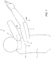
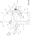
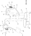
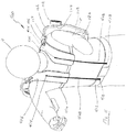
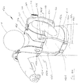
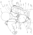
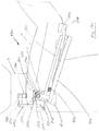
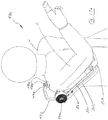
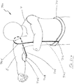
- FIGS. 2A and 2B show a user U wearing a first arrangement of an adaptive arm support system 10.
- Torso brackets 105, 126 are connected to attachment band 122, and together form a harness connected to the abdomen 7 of user U, which may define a substantially vertical axis aligned with the spine of the user U for the components carried by or otherwise coupled to the torso brackets 105, 126.
- the attachment band 122 may be secured around the user's waist, hips, or other region of the user's torso such that the torso brackets 105, 126 extend from the region to adjacent the user's shoulder.
- the torso brackets 105, 126 may extend generally parallel to a substantially vertical axis along the spine of the user U and provide a reference frame relative to which other components of the system 10 may move.
- the torso brackets 105, 126 may be formed from a single rigid member or separate members joined together, e.g., with a coupling portion (not shown) extending along the attachment band 122 between the lower ends of the brackets 105, 126.
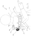
- the torso brackets 105, 126 provide mounting points for shoulder brackets 106, which connect to the torso brackets 105, 126 at vertical pivot joints 107.
- the vertical pivot joints 107 define vertical axes Vr, VI.
- Bearings, bushings, and/or other friction reduction features may be employed in vertical pivot joints 107, e.g., to provide minimal resistance to movement of the user U, as described further elsewhere herein.
- Shoulder brackets 106 may rotate about the vertical pivot joints 107 as shown by arrows 115, 116, providing the user U with the ability to rotate the shoulder brackets 106 as desired about vertical axes Vr, VI.
- the shoulder brackets 106 connect to arm brackets 108, 124 at horizontal pivot joints 109, 125.
- the horizontal pivot joints 109, 125 define horizontal axes Hr1, Hl1.
- the sets of vertical and horizontal axes Vr, Hr1 and VI, Hl1 may intersect one another or may be offset but still generally orthogonal to one another. Bearings, bushings, and/or other friction reduction features (not shown) may also be employed in the horizontal pivot joints 109, 125, as desired.
- the arm brackets 108, 124 may rotate about the horizontal axes Hr1, Hr2, as shown by arrows 114, 117.
- the arm brackets 108, 124 carry arm rests or pads 120 or other features at their free ends for supporting the arm 5 of the user U.
- the arms 5 of the user U rest in the arm pads 120, which may have a concave shape to enhance support of the arm 5.
- the arm pads 120 may include cushioning elements, e.g., foam, fabric, or other material to provide additional comfort to the user U.
- straps or other features may be provided on the arm brackets 108, 124 and/or arm pads 120 that may be wrapped around the arms 5 or otherwise used to secure the arms 5 relative to the arm pads 120.
- Torque elements 112 are connected to the shoulder brackets 106 and arm brackets 108, 124, e.g., at the horizontal pivot joints 109, 125, and apply torsional loads 118, 119 to the arm brackets 108, 124, as indicated by the directions of arrows 118, 119.
- the torsional loads 118, 119 may act to counterbalance all, or a portion of, the force of gravity Wl, Wr on the arms 5 of the user U.
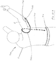
- the vertical pivot joints 107 permit shoulder brackets 106 to rotate about vertical axes VI, Vr.
- the shoulder brackets 106 generally define horizontal axes Hl1, Hr1.
- the User U may rotate the shoulder brackets 106 to any desired position consistent with the needs of the task being performed. For example, as shown in FIG. 3B , the user U has moved arm 5 laterally or horizontally, resulting in rotation 130 of the shoulder bracket 106, and defining a new horizontal axis Hr2.
- there may be infinite positions of the horizontal axes as determined by the motion of the arm(s) 5 of the user U.
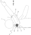
- FIG. 4A shows the user's arm 5 in an essentially horizontal attitude.
- the force of gravity Wr acts to pull the user's arm 5 downward.
- Torsional load 118 applied about horizontal axis Hr1 by the torque element 112, acts to counterbalance all or a portion of the gravitational force Wr, and reduce the muscular effort the user U needs to employ to hold the arm 5 outstretched.
- FIG. 4B shows the user's arm 5 raised above horizontal along path 134.
- the torsional load 118 continues to act to at least partially counterbalance gravitational force Wr.
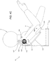
- FIG. 4C shows the user's arm 5 lowered below the horizontal along path 136.
- the torsional load 118 may continue to act to at least partially counterbalance gravitational force Wr.
- the user U may be able to move their arms 5 to desired positions, while the adaptive arm support system 10 moves with (or “adapts to") the arms 5, simultaneously supporting them without substantially interfering with the movement.
- FIG. 4D is a detail view taken from FIG. 4C , showing an exemplary embodiment of the torque element 112.
- the torque element 112 may include a clock spring located at or near horizontal pivot joint 125.
- a pivot shaft 155 is rigidly attached to shoulder bracket 106.
- the arm bracket 124 is free to rotate about the pivot shaft 155.
- a first torque element connection feature 158 on the torque element 112 may be captured in pivot shaft connection feature 156, and a second torque element connection feature 160 on torque element 112 may be captured behind arm bracket connection feature 164.
- the torque element 112 coupled to the arm bracket 124 and shoulder bracket 106 may be able to impart a counterbalancing torque 118 to the arm bracket 124.
- Retaining pin 162 holds the torque element 112 in place on the pivot shaft 155.
- An optional torsional damping element 170 may be located in or adjacent to the horizontal pivot joint 125, e.g., to restrict rotational speed.
- a housing or casing may be provided around the torque elements 112, e.g., to protect internal components and/or provide a desired appearance or finish for the system 10.
- the torque element(s) 112 may be removable to permit the user U to adjust the torsional load 118.
- a torque adjustment mechanism 175 may be located in or adjacent to the horizontal pivot joint 125, e.g., to permit the user U to adjust the torsional force 118 of the torque element 112, as desired.
- the user U may prefer a light counterbalancing torque that compensates for approximately 40% of the gravitational forces Wl, Wr that may act on the user's arms 5 (under-compensation).
- the user U may prefer a high counterbalancing torque that compensates for approximately 115% of the gravitational forces Wl, Wr on the user's arms 5 (overcompensation).
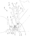
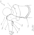
- FIGS. 5A and 5B show the adaptive arm support system 10 with the user U omitted merely for clarity.
- the forces of gravity Wl, Wr on the outstretched arms 5 of the user U may be transmitted through the arm brackets 108, 124, horizontal pivot joints 109, 125, shoulder brackets 106, and vertical pivot joints 107 to the torso brackets 105, 126.
- the torso brackets 105, 126 are, in turn coupled to one or more attachment bands or other features secured to the user U (one band 122 shown).
- reaction forces Rb, Ra, Rw applied by the user's abdomen 7 by the adaptive arm support system 10 may balance the load of the user's arms 5.
- Reaction force Rb for example, may be applied to the adaptive arm support system 10 by a force from a portion of the user's back.
- the torso brackets 105, 126 may be rigid, semi-rigid, or flexible, or may have portions of any or all of these.
- the torso brackets 105 and 126 may have rigid portions joined to semi-rigid portions.
- each of the torso brackets 105, 126 include a single element that extends substantially parallel to a vertical axis defined by the user's spine from a first end attached to the attachment band 122 to a second end coupled to the vertical pivot joints 107.
- the torso brackets 105, 126 may include multiple elements attached together.
- a pair of bracket elements may be adjustably coupled together such that the distance between the first and second ends, i.e., between the attachment band 122 and the vertical pivot joints 107 may be adjusted and fixed, e.g., to accommodate different height users (not shown).
- the attachment band 122 may be rigid, semi-rigid, flexible, or may have portions of any or all of these.
- the attachment band 122 may include one or more band adjustment features 140, e.g., to provide a mechanism for adjusting and fixing attachment band 122, e.g., a buckle, hook and eye fasteners, snaps, laces, and the like (not shown), which may facilitate the system 10 being secured around the waist or hips of the user U.
- the first ends of the torso brackets 105, 126 may be fixed relative to the attachment band 122 or may be adjustable relative to the attachment band 122, for example, laterally along path 150, e.g., using buckles, hook and eye fasteners, and the like (not shown).
- first ends of the torso brackets 105, 126 may also be adjustable vertically relative to the attachment band 122, e.g., to accommodate different height users.
- multiple systems may be provided, having different dimensions, such that a user may select a system best suited to their body's size and shape.
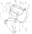
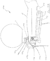
- an alternative embodiment of an adaptive arm support system 20 is shown that includes many features similar to system 10 (with like features including reference numbers increased by 100). Unlike the adaptive arm support system 10, however, the alternative adaptive arm support system 20 includes torso brackets 205, 226 that are configured to extend over the shoulders of the user U and/or that join the attachment band(s) 222 at multiple points.
- the system 20 may include a band adjustment feature 224, e.g., to provide a mechanism for adjusting and/or securing the attachment band 222 around the torso of the user U.
- Reaction forces Rc, Rs, Rr shown in FIGS. 7A and 7B ), applied by the user's abdomen 7 on the adaptive arm support system 20, may balance the load Wl, Wr of the user's arms 5.
- other mounting features may be provided for securing the adaptive arm support system 10 or 20 to the torso of a user U, in addition to or instead of the torso brackets and attachment bands, for example, harnesses, backpacks, laces, belts, jackets, and/or other garments, and the like (not shown).
- Such mounting systems may support the system 10 or 20 at one or more locations, e.g., at the shoulders, around the chest, the waist, hips, and/or other regions of the torso, depending on the degrees of freedom of movement desired by the user. For example, a system supported at the shoulders and/or chest may allow the user U to pivot about their waist easier than a system supported at the waist or hips.
- a system 30 is shown that is generally similar to the systems 10 or 20, but includes alternative torque elements 360 at horizontal pivot joints 309, 325.
- the alternative torque elements 360 may be electric, magnetic, pneumatic, hydraulic, and the like.
- the alternative torque elements 360 may be battery-powered, self-contained, tethered, attached to external power sources, e.g., by one or more cables (not shown), and the like.
- one or more sensors may be provided on the arm support, e.g., sensor 365 shown on arm bracket 308 in FIG. 8 , and one or more controllers (not shown) may be coupled to the sensor(s) and to one or more actuators or other compensation elements, in turn, coupled to the arm support.
- the controller may periodically, intermittently, or substantially continuously acquire data from the sensor(s) to determine the orientation and/or obtain other information regarding the arm support, and activate the actuator(s) or other compensation element(s) based on the data to apply a force to the arm support to at least partially offset the component of gravitational force and/or otherwise transfer a portion of the weight of the user's arm to the harness and/or other region of the user's body.
- the torsional loads applied by the torque elements 360 may be adjustable, for example, by adjusting current to an electric torque element 360 (or, similarly, fluid pressure to a pneumatic or hydraulic torque element, not shown), e.g., using a controller (not shown) carried on the system or at a nearby location.
- attitude sensor(s) 365 may be provided, e.g., attached to or otherwise carried by arm brackets 308, that provide position and/or angle feedback to the controller.
- the controller may determine a component of gravitational force acting on the user's arm and activate the torque element 360 (or other actuators or other compensation elements, not shown) to adjust a counterbalancing torsional load 370, 380 generated by the alternative torque elements 360 to suit the user's requirements.
- the attitude sensor 365 may signal that the user's arm is in a certain position, requiring an increase in the current to an electric torque element 360 to increase the opposing force to enhance support of the arm or, conversely, requiring a decrease in the current to reduce the opposing force if less support is needed.
- damping may be provided, e.g., by mechanical, pneumatic, hydraulic, electric elements, and the like.
- mechanical dampers, flow controls, electrical controls, and the like may be employed, e.g., to restrict rotational speeds.
- FIG. 9 shows an adaptive arm support system 10, similar to that shown in FIGS. 1-5 , with the right arm support locked in a back or inactive position out of the way of the user's arm 5.
- Various locking mechanisms may be employed, for example, clips, hooks, straps, magnets, threaded fasteners, hook-and-loop fasteners, and the like.
- Such a lock-out feature may be provided for one or both of the arm supports 108 of the system 10 of FIG. 9 or for the arm support of a system including only a single arm support, such as those described elsewhere herein.
- torque elements 360 may include lock-out features, such as those listed above, which may be activated, e.g., utilizing electric current, pneumatic pressure, hydraulic pressure, and the like, to direct the arm support to a back position away from the user's arm 5 such that the user may move the arm 5 independent of the system 10.
- the user may manually or otherwise control the torque elements 360 to direct the arm support to the back or inactive position.
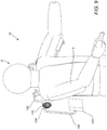
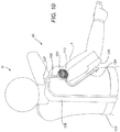
- FIG. 10 shows an adaptive arm support system 40 that supports only the right arm 5 of the user U.
- the adaptive arm support system 40 may employ any or all of the features of the other adaptive arm support systems described elsewhere herein, such as systems 10, 20, or 30.
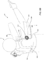
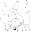
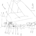
- FIG. 11 a user U is shown wearing an adaptive arm support system 400 that includes a shoulder harness 404, a pair of attachment bands 412, 410, and one or more elongate support elements 408 (two shown).
- the shoulder harness 404 may include left and right panels 406 formed to fit over or around the user's shoulders, each of which may have a torso bracket 416 mounted thereto.
- the shoulder harness 404 may be formed from flexible material, such as polymers, leather, composite materials, and the like, or may be formed from rigid, semi-rigid, and/or malleable materials, such as metals, plastics, composite materials, and the like.
- the attachment bands 412, 410 may be formed from flexible or semi-rigid materials, and/or elastic or inelastic materials, similar to other embodiments herein.
- the torso bracket 416 is coupled to a shoulder bracket 106 at vertical pivot joint 107, e.g., similar to other embodiments herein.
- An arm bracket 108 is coupled to the shoulder bracket 106 at horizontal pivot joint 109, and carries an arm pad 120, also similar to other embodiments herein.
- the vertical and/or horizontal pivot joints 107, 109 may be substantially concentric or otherwise aligned with the user's shoulder joint (not shown), which may enhance the arm bracket 108 following movement of the user's arm 5 with minimal interference.
- One or more torque or other compensation elements 112 may be coupled to the shoulder and arm brackets 106, 108, similar to other embodiments herein, e.g., to provide a torsional load to compensate at least partially for the weight of the user's arm 5.
- a pair of elongate support element(s) 408 are provided as part of the harness, e.g., connected to the shoulder harness 404 at a first or upper end 414, and to the optional waist strap or attachment band 412 at a second or lower end 418.
- the optional chest strap or attachment band 410 may be provided, e.g., to enhance securing the left and right forms 406 of the shoulder harness 404 to the user U.
- the elongate support element(s) 408 may include springs, rods, cables, and/or other components, which may be formed from elastomeric or polymeric, solid, hollow, pressurized, rigid, semi-rigid, and/or flexible materials.
- the support element(s) 408 may enhance transmitting the weight of the user's Arm 5 to the waist strap 412, thus distributing the weight over the waist and hips of the user.
- the support element(s) 408 may be substantially straight as shown, or may be curved, angled, or twisted, as desired to provide desired support with minimal discomfort or inconvenience to the user wearing the system 400.
- the support elements 408 may include one or more telescoping or pivoting elements (not shown).
- the top and/or bottom junctions 414, 418 may be rigid or may include pivoting joints, similar to other embodiments herein.
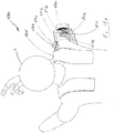
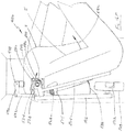
- FIGS. 12A and 12B still another alternate adaptive arm support system 420 is shown that is generally similar to the system 400 shown in FIG. 11 .
- the adaptive arm support system includes a pair of support elements 422 that are attached to a shoulder harness 415 and a waist attachment band 417 by upper and lower pivoting junctions 424, 426, which may pivot about axes 430, 431.
- the support elements 422 may also pivot about longitudinal axes 436, 441.
- motion of the user U bending forward to achieve a task may result in rotation or pivoting of the support elements 422, e.g., to accommodate the user's motion approximately along path 440.
- the pivoting junctions 424, 426 may pivot about axes 430, 431, and the support elements 422 may pivot about the longitudinal axes 436, 441, e.g., to allow the support elements 422 to bend freely.
- the support elements 422 may continue to transmit at least a portion of the weight of the user's Arm 5 to the waist support band 417, although by bending along path 440, the support elements 422 may accommodate bending motion of the User U.
- the support elements 422 may be fixedly coupled to one or both of the shoulder harness 415 and the attachment band 417.
- the support element(s) 422 may include one or more of springs, rods, cables, and the like, may be formed from elastomeric or polymeric, solid, hollow, pressurized, rigid, semi-rigid, and/or flexible materials, similar to other embodiments herein.
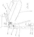
- an adaptive arm support system 450 is shown that is generally similar to other embodiments herein.
- the system 450 includes one or more support element 445 (two shown) joined to a shoulder harness 444 at joint 454 and joined to a waist support strap 417 at axis mount 446.
- a longitudinal axis 448 may be substantially concentric and/or aligned with the axis mount 446 and the user's shoulder joint.
- the support element(s) 445 may optionally pivot within the axis mount 446, e.g., approximately along path 452.
- the axis mount 446 may be mounted at any location around the periphery of the waist support strap 417 and/or may be appropriately angled relative to the vertical axis of the system 450.
- the axis mount 446 itself may optionally pivot about pivot axis 449, e.g., approximately along path 447.
- the support element(s) 445 may be constructed similar to other embodiments herein, e.g., including springs, rods, cables, and the like, formed from elastomeric or polymeric, solid, hollow, pressurized, rigid, semi-rigid, and/or flexible materials.
- an adaptive arm support system 460 that includes support element(s) 458 coupled to a shoulder harness 456 at joint 464 and to a waist support strap 417 at axis mount 462.
- the axis mount 462 may be mounted at any location on the waist support strap 417, and/or may be appropriately angled.
- the axis mount 462 may define a longitudinal axis 468 that is non-concentric or off-axis with user's shoulder joint, e.g., such that the axes may intersect or otherwise extend non-parallel to one another.
- the support element(s) 445 may pivot within the axis mount 446, e.g., approximately along path 468.
- the support element(s) 458 may be springs, rods, cables, and the like, formed from elastomeric or polymeric, solid, hollow, pressurized, rigid, semi-rigid, and/or flexible materials, similar to other embodiments herein.
- FIGS. 15A and 15B another embodiment of an adaptive arm support system 480 is shown that is generally similar to other embodiments herein, although the system 480 includes only one arm support.
- the adaptive arm support system 480 includes a torso bracket 486 mounted on a shoulder harness 484, a shoulder bracket 492 pivotally coupled to the torso bracket 486, and an arm bracket 502 pivotally coupled to the shoulder bracket 492, e.g., generally similar to other embodiments herein.
- the system 480 includes an adjustment mechanism for adjusting a torque element 500 thereon.
- the torque element 500 may be mounted substantially concentrically with and/or otherwise coupled to a shaft 517, e.g., to at least partially compensate for the gravitational force acting on the arm support 502, similar to other embodiments herein.
- the adjustment mechanism includes a torque adjustment knob 514 coupled to a worm screw 516, which is, in turn, coupled to a work gear 518 coupled to the shaft 517.
- the torque adjustment knob 514 When the torque adjustment knob 514 is rotated, the worm screw 516 rotates the worm gear 518, which consequently rotates the shaft 517 to increases or decreases the torque provided by the torque element 500, thereby modifying the compensation for the user's Arm 5.
- a torque adjustment knob 514 coupled to a worm screw 516, which is, in turn, coupled to a work gear 518 coupled to the shaft 517.
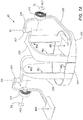
- FIGS. 16A-16H an adaptive arm support system 480 is shown, similar to that shown in FIGS. 15A and 15B , that includes a locking mechanism to "lock" the arm bracket 502 and/or other components of the arm support out of the way when the arm bracket 502 is not needed, and/or a safety "brake” to prevent the arm support from moving unexpectedly, which may also be provided on any of the other embodiments herein.
- FIGS. 16A through 16H illustrate these features (where, for clarity, the torque element 500 shown in FIGS. 15A and 15B has been omitted to show features of the locking mechanism). As shown in FIG.
- the adaptive arm support system 480 includes an arm bracket 502 that is coupled at a first end to a pivot block 528 and that carries an arm pad 508 on its second, free end, similar to other embodiments herein.
- the pivot block 528 may pivot freely about shaft 517.
- a safety bar 504 also pivots about the shaft 517.
- a spring or other biasing mechanism 526 applies a desired separation force between the arm bracket 502 and safety bar 504. However, pressure from the user's arm 5 on the safety bar 504 may compress the spring 526, and hold the safety bar 504 generally parallel to the arm bracket 502. In this "active" position, the adaptive arm support system 480 is active and at least partially compensating for the weight of user's Arm 5.
- a safety pawl 546 (attached to the pivot block 528) is in its normal position, with a tip 550 of the safety pawl 546 disengaged from safety plate teeth 536 on a safety plate 534 mounted on the shoulder bracket 492.
- the user U may move the arm 5 as desired, with a compensation force being provided by the torque element 500 (not shown, see FIGS. 15A and 15B ). Consequently, similar to other embodiments herein, the arm bracket 502 may rotate about the shaft 517 relative to the shoulder bracket 492, and "follow" movement of the arm 5.
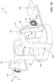
- FIGS. 16B and 16C which shows a back view of the adaptive arm support system 480.
- the user U may then rotate the arm bracket 502 generally along path 574, as shown in Fig 16D , which causes the arm bracket 502 to "hook” on or otherwise engage a lock-out pin 566 mounted on a hub block 529 on the shoulder bracket 492.
- FIG. 16E shows a back view of the user U moving the arm 5 away from locked-out arm bracket 502, while FIG. 16F shows this motion from the side.
- the arm bracket 502 is restrained by the lock-out pin 566, and consequently remains substantially stationary.
- the safety bar 504 is then urged away from the arm bracket 502 generally along the path 588 under the influence of the spring 526.
- a cam feature 540 on the safety bar 504 engages the safety pawl 546 and pushes the safety pawl 546 outwardly generally along the path 586.
- the safety pawl tip 550 engages the safety plate teeth 536 on the safety plate 534, preventing rotation of the arm bracket 502.
- the user U may use the arm 5 independently, i.e., without the adaptive arm support 480 following the movement and/or compensating for the arm's weight (as shown in FIGS. 16G and 16H ).
- the user U may perform the steps shown in FIGS. 16A through 16H in reverse order, e.g., to reengage the safety bar 502, release the safety pawl 546, and disengage the lock-out pin 566, thereby allowing the arm bracket 502 to subsequently support the arm 5.
- the system 480 may include safety "brake" features to prevent unwanted and/or uncontrolled motion.
- FIG. 17A the user U is shown using the adaptive arm support system 480 normally. If the user's arm 5 slips out of the arm pad 508, as shown in FIG. 17B , the torque element 500 may try to urge the arm bracket 502 generally along path 600 in an uncontrolled motion. The absence of the user's Arm 5 on the safety bar tab 506 of the safety bar 504 permits the safety bar 504 to separate from the arm bracket 502 under the influence of the spring 526, generally along path 602.
- any of the embodiments herein may include one or more features to ease reaching overhead.
- FIGS. 18A and 18B another embodiment of an adaptive arm support system 590 is shown that includes a shoulder bracket 492 and arm bracket 502, generally similar to other embodiments.
- the system 590 includes an additional pivot joint 596, anchored on a stanchion 594, which is mounted or otherwise secured to a shoulder harness 484.
- an extension bracket 592 is attached to a torso bracket 486 and is pivotally coupled to the stanchion 594 at the pivot joint 596.
- the torso bracket 486 may contact a stop feature 597 on the shoulder harness 484, preventing clockwise rotation (from the perspective of FIG. 18A ).
- the system 590 may operate similar to other embodiments herein.
- the extension bracket 592 coupled to the torso bracket 486 and other brackets of the system 590, may pivot generally along path 598, thereby avoiding interference between the user's shoulder and the adaptive arm support system 590. It will be appreciated that such a configuration may be provided on any of the embodiments described elsewhere herein.
- an adaptive arm support system 610 includes a torso brackets 612, 614 or other harness (not shown), a shoulder bracket 618 pivotally coupled to the torso bracket 614, and an arm bracket 624 pivotally coupled to the shoulder bracket 618, similar to other embodiments herein.
- the system 610 includes a biasing mechanism, e.g., an extension spring 632 that may be coupled to or otherwise interact with a set of gears to provide a compensating force.
- the shoulder bracket 618 includes an extension bracket 638 attached or otherwise fixed thereto, and a sector gear 620 pivotally coupled thereto by pivot joint 630.
- Each of the extension bracket 638 and the sector gear 620 include a pin or other connector 636, 634, respectively.
- the extension spring 632 is coupled between the extension bracket 638 and the sector gear 620, at the pins 636, 634.
- the sector gear 620 includes a plurality of teeth 621, which mesh with corresponding teeth 630 on an arm bracket gear 628 attached to the arm bracket 624. As shown in FIG. 19A , as the user U raises the arm 5, the arm bracket 624 follows the movement under the influence of the extension spring 632, generally along path 644, providing a compensating force.
- the sector gear 620 pivots about the pivot joint 622 generally along path 642.
- the arm bracket 624 follows generally along path 646, as the sector gear 620 pivots about the pivot joint 622, generally along path 648.
- an extension spring 632 is shown, it will be appreciated that other biasing mechanisms may be provided instead, such as an air spring, a polymer strap, an elastomer strap, and the like (not shown).
- FIGS. 20A and 20B still another embodiment of an adaptive arm support system 660 is shown that includes a compensation element.
- the system 660 includes a tension element 680 coupled between a belt or other harness 686 of the system 660 and an arm support, e.g., including an arm bracket 672 and arm pad 674 generally similar to other embodiments herein.
- the tension element 680 include a first end attached or otherwise coupled to a belt 686, e.g., at junction 684.
- Optional straps 687 are shown that are attached to or otherwise extend from the belt 686, e.g., further secure the belt 686 to the user U (which may also be included in any of the other embodiments herein, if desired).
- the tension element 680 also includes a second end attached or otherwise coupled to an extension bracket 678 on the arm bracket 672, e.g., at junction 682.
- the arm bracket 672 may follow the movement under the influence of the tension element 680, generally along path 688, thereby providing a compensating force.
- the tension element 680 may be an extension spring, an elastomer spring, a cable, a strap, a cord, and the like.
- an adaptive arm support system 700 includes a compensation rod 704 as a compensation element to provide a compensating force to a user's arm 5.
- a first end of the compensation rod 704 is attached to or otherwise coupled to an attachment band or other harness, e.g., to the front of an abdomen mount 710 at junction 712.
- a second end of the compensation rod 704 is coupled to and/or carries an arm pad 706, e.g., via an optional spherical or other pivotal joint 708.
- the compensation rod 704 may contact or engage the torso of the user U at other locations, including the shoulder, chest, side, and/or back.
- an adaptive arm support system 720 may be provided that includes a compensation rod 722 attached to the back or side of an abdomen mount 710 or other harness, e.g., at junction 724. Similar to the compensation rod 704, the compensation rod 722 may be coupled to or carry an arm pad 706, e.g., via an optional spherical or other pivotal joint 708. The compensation rod 722 may support the user's arm 5, providing a compensating force, and/or may optionally contact the user's torso at other locations, including the shoulder, chest, side, and back.
- the compensation rods 604, 704 may be formed from flexible or semi-rigid materials that may be biased to a predetermined shape or configuration and/or may otherwise provide a compensating force to at least partially compensate for the gravitational force acting on the users arm 5 as the user U performs one or more tasks, similar to other embodiments.
- the systems described above may be used in a variety of fields and applications.
- the systems may be worn by physicians, e.g., surgeons, dentists, and the like, to facilitate extension of the physician's arm(s) during an extended surgical, medical, or dental procedure.
- the systems may be worn by construction workers, e.g., painters, carpenters, and the like, manufacturing workers, e.g., involved in product assembly, and the like, disabled individuals, and/or other users who perform tasks for an extended period of time in which one or both arms may be extended outwardly from the user's body.
- the systems herein may be worn or otherwise placed on the user's body, e.g., by securing a harness onto the user's torso, e.g., their waist, hips, shoulders, back, chest, and the like.
- An arm support of the system e.g., coupled to or otherwise carried by the harness, may be used to support the user's arm such that the arm support subsequently follows movement of the user's arm.
- the user may then perform one or more tasks involving movement of the user's arm, the arm support at least partially offsetting a gravitational force acting on the user's arm and/or at least partially transferring the gravitational force to the user's torso during the movement without substantially interfering in the movement.
- the systems may facilitate the user performing the task(s) for greater lengths of time and/or with reduced fatigue and/or injury.
Landscapes
- Health & Medical Sciences (AREA)
- Engineering & Computer Science (AREA)
- Life Sciences & Earth Sciences (AREA)
- Veterinary Medicine (AREA)
- Public Health (AREA)
- General Health & Medical Sciences (AREA)
- Animal Behavior & Ethology (AREA)
- Pain & Pain Management (AREA)
- Rehabilitation Therapy (AREA)
- Physical Education & Sports Medicine (AREA)
- Epidemiology (AREA)
- Orthopedic Medicine & Surgery (AREA)
- Biomedical Technology (AREA)
- Nursing (AREA)
- Heart & Thoracic Surgery (AREA)
- Vascular Medicine (AREA)
- Robotics (AREA)
- Mechanical Engineering (AREA)
- Manipulator (AREA)
- Orthopedics, Nursing, And Contraception (AREA)
- Prostheses (AREA)
Applications Claiming Priority (3)
| Application Number | Priority Date | Filing Date | Title |
|---|---|---|---|
| US201161433840P | 2011-01-18 | 2011-01-18 | |
| US201161507535P | 2011-07-13 | 2011-07-13 | |
| PCT/US2012/021770 WO2012099995A2 (en) | 2011-01-18 | 2012-01-18 | Adaptive arm support systems and methods for use |
Publications (3)
| Publication Number | Publication Date |
|---|---|
| EP2665449A2 EP2665449A2 (en) | 2013-11-27 |
| EP2665449A4 EP2665449A4 (en) | 2015-04-29 |
| EP2665449B1 true EP2665449B1 (en) | 2017-11-15 |
Family
ID=46491303
Family Applications (1)
| Application Number | Title | Priority Date | Filing Date |
|---|---|---|---|
| EP12736374.5A Not-in-force EP2665449B1 (en) | 2011-01-18 | 2012-01-18 | Adaptive arm support systems and methods for use |
Country Status (7)
| Country | Link |
|---|---|
| US (4) | US9205017B2 (enExample) |
| EP (1) | EP2665449B1 (enExample) |
| JP (1) | JP6027025B2 (enExample) |
| CA (1) | CA2861566C (enExample) |
| ES (1) | ES2658982T3 (enExample) |
| HU (1) | HUE038127T2 (enExample) |
| WO (1) | WO2012099995A2 (enExample) |
Cited By (6)
| Publication number | Priority date | Publication date | Assignee | Title |
|---|---|---|---|---|
| RU2687897C1 (ru) * | 2018-03-26 | 2019-05-16 | Александр Александрович Воробьёв | Экзоскелет эндохирурга |
| RU2727231C1 (ru) * | 2019-12-25 | 2020-07-21 | Александр Александрович Воробьёв | Экзоскелет нейрохирурга |
| RU202453U1 (ru) * | 2020-06-11 | 2021-02-18 | Общество с ограниченной ответственностью "Экзомед" | Пассивный экзоскелет верхних конечностей |
| DE102021208903A1 (de) | 2021-08-13 | 2023-02-16 | Festool Gmbh | Exoskelett-Vorrichtung und Verfahren |
| US12193985B2 (en) | 2020-11-20 | 2025-01-14 | Hyundai Motor Company | Strength assist device |
| RU2855621C1 (ru) * | 2025-04-07 | 2026-02-02 | Радик Гилфанович Хабибуллин | Бионический экзоскелет верхней конечности |
Families Citing this family (119)
| Publication number | Priority date | Publication date | Assignee | Title |
|---|---|---|---|---|
| US20120061155A1 (en) | 2010-04-09 | 2012-03-15 | Willow Garage, Inc. | Humanoid robotics system and methods |
| WO2012099995A2 (en) | 2011-01-18 | 2012-07-26 | Doyle Mark C | Adaptive arm support systems and methods for use |
| US9872789B2 (en) * | 2012-02-07 | 2018-01-23 | Ossur Iceland Ehf | Joint for rehabilitation device |
| JP5397712B2 (ja) * | 2012-02-27 | 2014-01-22 | ジャパンマリンユナイテッド株式会社 | 筋力補助装置 |
| US9999534B2 (en) * | 2012-07-31 | 2018-06-19 | Enhance Technologies, LLC | Adaptive arm support systems and methods for use |
| JP5902065B2 (ja) * | 2012-08-08 | 2016-04-13 | 株式会社クボタ | 姿勢保持具 |
| JP5985974B2 (ja) * | 2012-12-10 | 2016-09-06 | 株式会社クボタ | 姿勢保持具 |
| EP2931484B1 (en) * | 2012-12-11 | 2018-03-21 | Enhance Technologies, LLC | Adaptive arm support systems and methods for use |
| JP6145866B2 (ja) * | 2013-03-11 | 2017-06-14 | ジャパンマリンユナイテッド株式会社 | 作業支援装置 |
| JP5973980B2 (ja) * | 2013-05-17 | 2016-08-23 | 国立研究開発法人農業・食品産業技術総合研究機構 | 腕支持器具 |
| WO2014200343A2 (en) * | 2013-06-12 | 2014-12-18 | Gaurav Genani | Device with improved actuating means and method for use thereof |
| JP2017511180A (ja) | 2014-03-24 | 2017-04-20 | レヴィテイト テクノロジーズ, インコーポレイテッドLevitate Technologies, Inc. | 脚増強システム及び使用方法 |
| EP3129197B1 (en) | 2014-04-08 | 2021-03-31 | Enhance Technologies, LLC | Heavy capacity arm support systems |
| US10406676B2 (en) * | 2014-05-06 | 2019-09-10 | Sarcos Lc | Energy recovering legged robotic device |
| JP6358427B2 (ja) * | 2014-06-13 | 2018-07-18 | 国立大学法人 筑波大学 | 装着式動作補助装置 |
| JP6709214B2 (ja) * | 2014-10-24 | 2020-06-10 | エンハンス テクノロジーズ, リミテッド ライアビリティー カンパニーEnhance Technologies, LLC | 腕支持システム |
| JP2016130160A (ja) * | 2015-01-14 | 2016-07-21 | 株式会社クボタ | アシストスーツ |
| ITPI20150027A1 (it) * | 2015-04-11 | 2016-10-11 | Azienda Ospedaliera Pisana | Sistema esoscheletrico ad alta ergonomia per l'arto superiore |
| KR102312527B1 (ko) | 2015-05-18 | 2021-10-14 | 더 리전츠 오브 더 유니버시티 오브 캘리포니아 | 인간 팔 지지 외골격용 방법 및 장치 |
| US10639785B2 (en) * | 2015-05-18 | 2020-05-05 | The Regents Of The University Of California | Variable force generators for arm supporting exoskeletons |
| JP6495128B2 (ja) * | 2015-07-15 | 2019-04-03 | 株式会社キトー | 作業アシスト装置 |
| CN108472807A (zh) | 2015-10-30 | 2018-08-31 | 埃克苏仿生公司 | 用于重型工具支承和使用的人体外骨骼装置 |
| JP6460966B2 (ja) * | 2015-12-04 | 2019-01-30 | 株式会社クボタ | 姿勢保持具 |
| US10058994B2 (en) * | 2015-12-22 | 2018-08-28 | Ekso Bionics, Inc. | Exoskeleton and method of providing an assistive torque to an arm of a wearer |
| US10569413B2 (en) * | 2015-12-22 | 2020-02-25 | Ekso Bionics, Inc. | Exoskeleton and method of providing an assistive torque to an arm of a wearer |
| WO2017117299A1 (en) * | 2015-12-28 | 2017-07-06 | Levitate Technologies, Inc. | Head support systems and methods for use |
| DE102016104879B4 (de) | 2016-03-16 | 2024-12-12 | Ottobock Se & Co. Kgaa | Orthese |
| DE102016121201B4 (de) | 2016-11-07 | 2025-09-04 | Ottobock Se & Co. Kgaa | Orthese |
| WO2017157861A1 (de) * | 2016-03-16 | 2017-09-21 | Otto Bock Healthcare Gmbh | Orthese |
| DE102016104880A1 (de) | 2016-03-16 | 2017-09-21 | Otto Bock Healthcare Gmbh | Orthopädietechnische Vorrichtung |
| CN105640739B (zh) * | 2016-03-21 | 2017-08-25 | 哈尔滨工业大学 | 一种基于空间重力平衡的上肢康复外骨骼 |
| FI126770B (fi) | 2016-04-04 | 2017-05-15 | David Health Solutions Ltd | Kuntoutuslaite ja sen käyttö olkapään alueen harjoittamiseen |
| JP2017185101A (ja) * | 2016-04-07 | 2017-10-12 | 株式会社イノフィス | 上体サポート装置 |
| WO2017192772A1 (en) * | 2016-05-03 | 2017-11-09 | Levitate Technologies, Inc. | Arm support systems |
| JP6560157B2 (ja) * | 2016-05-27 | 2019-08-14 | 公立大学法人前橋工科大学 | パワーアシスト装置 |
| CN105963103A (zh) * | 2016-06-08 | 2016-09-28 | 上海电气集团股份有限公司 | 一种便携穿戴式外骨骼上肢机器人 |
| JP2016190319A (ja) * | 2016-08-04 | 2016-11-10 | 株式会社クボタ | 姿勢保持具 |
| JP6738699B2 (ja) * | 2016-09-12 | 2020-08-12 | サンコール株式会社 | 上腕補助装置 |
| SE541542C2 (en) * | 2016-10-05 | 2019-10-29 | Bioservo Tech Aktiebolag | Armlifting support device |
| CN110167726B (zh) * | 2016-10-21 | 2022-09-30 | 外骨骼控股有限公司 | 力平衡支撑件、机械设备和可穿戴支撑装置 |
| DE102016121202A1 (de) | 2016-11-07 | 2018-05-09 | Otto Bock Healthcare Gmbh | Vorrichtung zum Unterstützen eines Armes |
| DE202016009088U1 (de) | 2016-11-07 | 2022-02-04 | Ottobock Se & Co. Kgaa | Vorrichtung zum Unterstützen eines Armes |
| DE102016121203A1 (de) * | 2016-11-07 | 2018-05-09 | Otto Bock Healthcare Gmbh | Vorrichtung zum Unterstützen eines Armes |
| DE102016122282A1 (de) | 2016-11-18 | 2018-05-24 | Helmut-Schmidt-Universität Universität der Bundeswehr Hamburg | System und verfahren zur reduktion von auf eine wirbelsäule wirkenden kräften |
| JP6759357B2 (ja) * | 2016-11-28 | 2020-09-23 | 国立大学法人 香川大学 | 筋力補助装置 |
| JP6759356B2 (ja) * | 2016-11-28 | 2020-09-23 | 国立大学法人 香川大学 | 筋力補助装置 |
| DE102016123153A1 (de) | 2016-11-30 | 2018-05-30 | Helmut-Schmidt-Universität Universität der Bundeswehr Hamburg | Vorrichtung und verfahren zur muskelkraftunterstützung |
| JP2018122394A (ja) * | 2017-01-31 | 2018-08-09 | 株式会社マキタ | 作業補助具 |
| CN116059025B (zh) * | 2017-02-13 | 2024-12-06 | 康辉医疗科技(苏州)有限公司 | 辅助手臂托架 |
| US20180295998A1 (en) * | 2017-04-14 | 2018-10-18 | Lockheed Martin Corporation | Dynamically adjustable arm lift (daal) accessory device |
| JP6925850B2 (ja) * | 2017-04-21 | 2021-08-25 | 三菱重工業株式会社 | パワーアシストスーツ |
| EP3614989B1 (en) | 2017-04-25 | 2022-08-17 | Ossur Iceland EHF | Interface system in an exoskeleton |
| EP3621560A4 (en) * | 2017-05-12 | 2021-06-16 | Exonetik Inc. | EXOSKELETON, ORTHESIS, BODY PORTABLE DEVICE OR MOBILE ROBOT WITH MAGNETORHEOLOGICAL FLUID COUPLING DEVICE |
| EP3624996A4 (en) | 2017-05-15 | 2021-03-24 | Enhance Technologies, LLC | ARM SUPPORT SYSTEMS |
| JP7017064B2 (ja) * | 2017-05-26 | 2022-02-08 | 株式会社ジェイテクト | アシスト装置 |
| DE102017112436B4 (de) * | 2017-06-06 | 2019-05-29 | Ottobock Se & Co. Kgaa | Vorrichtung zum Unterstützen wenigstens eines Armes eines Benutzers |
| KR101945516B1 (ko) * | 2017-06-26 | 2019-02-08 | 한양대학교 에리카산학협력단 | 상지 외골격 어시스트 장치 |
| IT201700081177A1 (it) | 2017-07-18 | 2019-01-18 | Iuvo S R L | "Sistema di assistenza agli sforzi da parte di un operatore" |
| US12440303B2 (en) | 2017-08-11 | 2025-10-14 | Roger J. Malcolm | Body worn body part support device and method |
| JP7004530B2 (ja) * | 2017-09-11 | 2022-02-10 | 株式会社竹中工務店 | 疲労軽減ウェア |
| US11000439B2 (en) | 2017-09-28 | 2021-05-11 | Ossur Iceland Ehf | Body interface |
| US20190099877A1 (en) * | 2017-09-29 | 2019-04-04 | Airbus Operations Gmbh | Exoskeleton System |
| FR3072598B1 (fr) * | 2017-10-24 | 2019-11-22 | Safran Electronics & Defense | Structure d'exosquelette adapte a l'epaule |
| CN108107788B (zh) * | 2017-12-26 | 2019-11-05 | 广东美的安川服务机器人有限公司 | 康复训练机器人的模式切换方法和装置 |
| FR3076237B1 (fr) * | 2017-12-28 | 2021-02-19 | Safran Electronics & Defense | Structure d'exosquelette |
| DE102018108416A1 (de) | 2018-04-10 | 2019-10-10 | Ottobock Se & Co. Kgaa | Vorrichtung zum Unterstützen wenigstens eines Armes |
| USD876654S1 (en) | 2018-04-24 | 2020-02-25 | Ossur Iceland Ehf | Posterior strut |
| JP7170418B2 (ja) * | 2018-05-15 | 2022-11-14 | ユーピーアール株式会社 | 動作支援装置 |
| JP6656312B2 (ja) * | 2018-06-26 | 2020-03-04 | 株式会社クボタ | 姿勢保持具 |
| JP6820295B2 (ja) * | 2018-07-20 | 2021-01-27 | ナブテスコ株式会社 | 筋力補助装置 |
| DE102018119755A1 (de) | 2018-08-14 | 2020-02-20 | Ottobock Se & Co. Kgaa | Vorrichtung zum Unterstützen wenigstens eines Armes eines Benutzers |
| DE102018119754A1 (de) | 2018-08-14 | 2020-02-20 | Ottobock Se & Co. Kgaa | Vorrichtung zum Unterstützen wenigstens eines Armes eines Benutzers |
| WO2020038850A1 (de) | 2018-08-22 | 2020-02-27 | Exoiq Gmbh | System und verfahren zur reduktion von auf einen arm eines menschen wirkenden kräften |
| DE102018127553B4 (de) * | 2018-11-05 | 2020-11-05 | Ottobock Se & Co. Kgaa | Vorrichtung zum Unterstützen wenigstens eines Armes eines Benutzers |
| PH12018000369B1 (en) * | 2018-11-14 | 2022-05-25 | De La Salle Univ | Device for upper limb rehabilitation |
| CN109262594B (zh) * | 2018-11-19 | 2020-10-27 | 西安交通大学 | 一种助力外骨骼髋关节结构 |
| KR102603041B1 (ko) * | 2018-12-12 | 2023-11-16 | 현대자동차주식회사 | 착용식 근력 보조 장치 |
| EP3670105A1 (de) | 2018-12-17 | 2020-06-24 | Hilti Aktiengesellschaft | Überkopf-exoskelett |
| EP3670103A1 (de) | 2018-12-17 | 2020-06-24 | Hilti Aktiengesellschaft | Vorrichtung zum ausgleich einer schulterelevation bei einem passiven exoskelett |
| EP3670104A1 (de) | 2018-12-17 | 2020-06-24 | Hilti Aktiengesellschaft | Passives exoskelett mit einem ratschenmechanismus mit nackenschaltung |
| JP2020120585A (ja) * | 2019-01-29 | 2020-08-13 | 大栄産業株式会社 | アームアシスト |
| KR102660352B1 (ko) | 2019-02-19 | 2024-04-24 | 현대자동차주식회사 | 착용식 근력 보조 장치 |
| DE102019104344A1 (de) | 2019-02-20 | 2020-08-20 | Pohlig Gmbh | Vorrichtung zum Unterstützen wenigstens eines Armes eines Benutzers und Kopfstütze |
| US11458061B1 (en) * | 2019-03-21 | 2022-10-04 | Empower Robotics Corporation | Control of multiple joints of an upper body support system |
| KR102142578B1 (ko) | 2019-04-04 | 2020-08-10 | 현대자동차(주) | 착용식 장치의 결합 구조 |
| KR102681476B1 (ko) | 2019-04-04 | 2024-07-04 | 현대자동차주식회사 | 착용식 근력 보조 장치 |
| KR102663601B1 (ko) | 2019-04-04 | 2024-05-08 | 현대자동차주식회사 | 착용식 근력 보조 장치의 상완 모듈 및 이를 포함한 착용식 근력 보조 장치 |
| EP3959043B1 (en) * | 2019-04-22 | 2024-01-10 | Iuvo S.r.L. | System for assisting an operator in exerting efforts |
| US20220228710A1 (en) * | 2019-05-02 | 2022-07-21 | Virginia Tech Intellectual Properties, Inc. | Gravity compensation mechanisms and methods |
| FR3095608B1 (fr) * | 2019-05-03 | 2021-06-11 | Fm France Sas | Dispositif d’assistance physique non robotisé/non motorisé de type exosquelette pour le transport manuel de charges |
| DE102019113684A1 (de) | 2019-05-22 | 2020-11-26 | Ottobock Se & Co. Kgaa | Vorrichtung zum Unterstützen wenigstens eines Armes |
| IT201900007848A1 (it) | 2019-06-03 | 2020-12-03 | Milano Politecnico | Dispositivo di compensazione di carichi, in particolare di carichi gravitazionali, applicabile ad esoscheletri |
| JP6831873B2 (ja) * | 2019-06-21 | 2021-02-17 | ナブテスコ株式会社 | 筋力補助装置 |
| TR201909434A2 (tr) * | 2019-06-25 | 2021-01-21 | Goekhan Bursoy | Üst Uzuvlar İçin Giyilebilir Kuvvet Destek Sistemi |
| DE102019121797A1 (de) * | 2019-08-13 | 2021-02-18 | Otto Bock Healthcare Products Gmbh | System aus Federadapter und orthopädietechnische Gelenkeinrichtung sowie Federadapter |
| CN110731842B (zh) * | 2019-09-20 | 2021-11-19 | 上海健康医学院 | 一种用于智能手的气动肌肉驱动的拇指装置 |
| EP3797933A1 (en) | 2019-09-27 | 2021-03-31 | Fraunhofer-Gesellschaft zur Förderung der angewandten Forschung e.V. | Arrangement for a controlled movement of an arm of human |
| CN110946739B (zh) * | 2019-12-13 | 2021-10-29 | 寿光市人民医院 | 一种神经偏瘫康复日常锻炼辅助装置 |
| CN111000699B (zh) * | 2019-12-26 | 2022-03-04 | 中国科学院宁波工业技术研究院慈溪生物医学工程研究所 | 一种刚柔混合式上肢辅助运动装置 |
| US12029699B2 (en) | 2020-03-19 | 2024-07-09 | Suitx, Inc. | Remote center shoulder joint for shoulder supporting exoskeleton |
| CN111759659B (zh) * | 2020-05-18 | 2022-07-19 | 力之医疗科技(广州)有限公司 | 一种便携的可穿戴式上肢康复机器人 |
| DE102020206806B4 (de) | 2020-05-29 | 2024-12-05 | Fraunhofer-Gesellschaft zur Förderung der angewandten Forschung eingetragener Verein | Arm-Unterstützungsmechanismus |
| KR102315697B1 (ko) * | 2020-07-07 | 2021-10-21 | 성균관대학교산학협력단 | 작업 보조용 외골격 장치 |
| JP7596836B2 (ja) * | 2021-02-12 | 2024-12-10 | マツダ株式会社 | アシストデバイス |
| JP7631861B2 (ja) * | 2021-02-12 | 2025-02-19 | マツダ株式会社 | アシストデバイス |
| EP4067009B1 (de) | 2021-03-31 | 2023-09-06 | Ottobock SE & Co. KGaA | Vorrichtung zum unterstützen wenigstens eines oberarms |
| EP4373641A4 (en) * | 2021-07-19 | 2025-02-26 | Levitate Technologies, Inc. | FLEXIBLE EXOSKELETON FRAMES AND ARM REST SYSTEMS AND METHODS OF USE THEREOF |
| KR102676812B1 (ko) * | 2021-07-23 | 2024-06-20 | 아주대학교산학협력단 | 상완 근력 보조 장치 |
| USD1005361S1 (en) | 2021-08-13 | 2023-11-21 | Festool Gmbh | Wearable robotic exoskeleton with belts |
| DE102021208907A1 (de) | 2021-08-13 | 2023-02-16 | Festool Gmbh | Exoskelett und Verfahren |
| US12083369B2 (en) * | 2021-08-20 | 2024-09-10 | John-Thomas Cameron | Handsfree, body-mounted apparatus for supporting high-pressure hoses |
| US20240335938A1 (en) * | 2021-08-27 | 2024-10-10 | Mawashi science & technologies inc. | An exoskeleton for handling objects and method of using the same |
| US20230095909A1 (en) * | 2021-09-27 | 2023-03-30 | Olympus Medical Systems Corp. | Wearable support structures for medical devices |
| DE102022105745B3 (de) | 2022-03-11 | 2023-08-17 | Ottobock Se & Co. Kgaa | Vorrichtung zum Unterstützen wenigstens eines Armes |
| US20250186288A1 (en) | 2022-03-22 | 2025-06-12 | Ossur Iceland Ehf | Interface for an exoskeleton |
| EP4676689A1 (en) * | 2023-03-06 | 2026-01-14 | Auxivo AG | Exoskeleton |
| WO2024184299A1 (en) * | 2023-03-06 | 2024-09-12 | Auxivo Ag | Shoulder exoskeleton |
| NO349171B1 (en) * | 2024-03-12 | 2025-10-27 | Vilje Bionics As | Assistive device |
| US12588778B2 (en) * | 2024-05-01 | 2026-03-31 | Sergio Castaneda | Uplifted hands assist device for praying like moses |
Family Cites Families (32)
| Publication number | Priority date | Publication date | Assignee | Title |
|---|---|---|---|---|
| US3120332A (en) * | 1962-09-05 | 1964-02-04 | Theodore R White | Umbrella support |
| DE2615209A1 (de) * | 1975-04-15 | 1976-10-28 | Teufel Wilh Jul Fa | Universal-orthese |
| US4298149A (en) * | 1978-01-17 | 1981-11-03 | Panavision, Incorporated | Body harness for cinematographer |
| US5020521A (en) * | 1982-11-10 | 1991-06-04 | Salort Guy J | External apparatus for motor handicaps of at least one upper limb |
| US4651719A (en) * | 1985-01-22 | 1987-03-24 | Danninger Medical Technology, Inc. | Continuous passive motion shoulder unit |
| US5111983A (en) | 1986-02-10 | 1992-05-12 | Simmons Elex M | Camera stabilizing device |
| US4896659A (en) * | 1986-10-24 | 1990-01-30 | Regents Of The University Of Minnesota | Gravity lumbar traction device |
| US4862878A (en) * | 1988-01-07 | 1989-09-05 | Richards Medical Company | Orthopedic prosthesis to aid and support the shoulder muscles in movement of the human arm |
| JP2659774B2 (ja) * | 1988-11-25 | 1997-09-30 | 多摩川精機株式会社 | 発電制御方法 |
| US5170777A (en) * | 1990-12-28 | 1992-12-15 | The University Of Akron | Arm rehabilitation and testing device |
| JP2721438B2 (ja) * | 1991-04-01 | 1998-03-04 | 裕章 金子 | 腕の疲労軽減装置 |
| JPH07107861A (ja) * | 1993-10-13 | 1995-04-25 | Techno Mach:Kk | 肩掛け式腕支え補助装具 |
| JP2889859B2 (ja) | 1996-08-29 | 1999-05-10 | 保 柳沢 | 肩支え装置 |
| US5873847A (en) * | 1996-11-14 | 1999-02-23 | Lenjoy Engineering, Inc. | Articulated splints and goniometric hinge for the same |
| KR100299210B1 (ko) * | 1999-03-12 | 2001-09-22 | 박호군 | 인간팔 장착형 힘 재현기능을 갖는 마스터 장치 |
| US7918808B2 (en) * | 2000-09-20 | 2011-04-05 | Simmons John C | Assistive clothing |
| JP2002153115A (ja) | 2000-11-24 | 2002-05-28 | Haimuun Kk | 人体装着型対高所所在物向け作業用両腕支持装置 |
| US20060271043A1 (en) * | 2005-05-27 | 2006-11-30 | Gonzalez Lupe A | User-attached, manually operated fluid-driven arm lift device |
| JP5209924B2 (ja) * | 2006-10-03 | 2013-06-12 | 国立大学法人 筑波大学 | 動作補助装置及び動作補助装置の保守管理システム |
| JP4585542B2 (ja) | 2007-05-31 | 2010-11-24 | 博 宇土 | 上肢挙上作業用支援装置 |
| CA2697600C (en) | 2007-08-30 | 2017-03-14 | Garrett W. Brown | Articulated human arm support |
| KR101393290B1 (ko) * | 2007-09-27 | 2014-05-09 | 고쿠리쯔 다이가쿠 호징 츠쿠바 다이가쿠 | 회동 조정 장치 및 회동 장치의 제어 방법 |
| JP5150444B2 (ja) * | 2007-10-11 | 2013-02-20 | 一浩 北村 | ブドウ栽培等の作業補助具 |
| US20110021962A1 (en) * | 2007-12-19 | 2011-01-27 | S.A.M. Bracing PTY Ltd. | Shoulder brace |
| JP5194213B2 (ja) * | 2008-05-12 | 2013-05-08 | 学校法人 芝浦工業大学 | 肩甲骨鎖骨機構 |
| JP5169469B2 (ja) | 2008-05-15 | 2013-03-27 | 学校法人東京理科大学 | 上腕保持装置、及び、上腕補助装置 |
| GB2472036B (en) | 2009-07-22 | 2013-12-04 | David George Sherry | A mechanical device to relieve the pain of repetitive strain injury in the muscles, joints and tendons of the human arm shoulder and back |
| FR2949669B1 (fr) * | 2009-09-09 | 2011-11-18 | Commissariat Energie Atomique | Mecanisme d'epaule pour orthese |
| KR101572852B1 (ko) * | 2010-01-06 | 2015-12-01 | 삼성전자 주식회사 | 팔 보조 장치 |
| WO2012099995A2 (en) | 2011-01-18 | 2012-07-26 | Doyle Mark C | Adaptive arm support systems and methods for use |
| US9095981B2 (en) | 2012-01-11 | 2015-08-04 | Garrett W. Brown | Load and torque resistant caliper exoskeleton |
| EP2836097B1 (en) | 2012-04-09 | 2017-06-07 | John Christopher Fawcett | Support vest |
-
2012
- 2012-01-18 WO PCT/US2012/021770 patent/WO2012099995A2/en not_active Ceased
- 2012-01-18 ES ES12736374.5T patent/ES2658982T3/es active Active
- 2012-01-18 CA CA2861566A patent/CA2861566C/en active Active
- 2012-01-18 US US13/353,268 patent/US9205017B2/en active Active
- 2012-01-18 JP JP2013549619A patent/JP6027025B2/ja active Active
- 2012-01-18 EP EP12736374.5A patent/EP2665449B1/en not_active Not-in-force
- 2012-01-18 HU HUE12736374A patent/HUE038127T2/hu unknown
-
2015
- 2015-12-04 US US14/960,243 patent/US10383785B2/en active Active
-
2019
- 2019-08-19 US US16/544,649 patent/US11337880B2/en active Active
-
2022
- 2022-05-23 US US17/751,028 patent/US20220401283A1/en not_active Abandoned
Non-Patent Citations (1)
| Title |
|---|
| None * |
Cited By (7)
| Publication number | Priority date | Publication date | Assignee | Title |
|---|---|---|---|---|
| RU2687897C1 (ru) * | 2018-03-26 | 2019-05-16 | Александр Александрович Воробьёв | Экзоскелет эндохирурга |
| RU2727231C1 (ru) * | 2019-12-25 | 2020-07-21 | Александр Александрович Воробьёв | Экзоскелет нейрохирурга |
| RU202453U1 (ru) * | 2020-06-11 | 2021-02-18 | Общество с ограниченной ответственностью "Экзомед" | Пассивный экзоскелет верхних конечностей |
| US12193985B2 (en) | 2020-11-20 | 2025-01-14 | Hyundai Motor Company | Strength assist device |
| DE102021208903A1 (de) | 2021-08-13 | 2023-02-16 | Festool Gmbh | Exoskelett-Vorrichtung und Verfahren |
| WO2023017173A1 (de) | 2021-08-13 | 2023-02-16 | Festool Gmbh | Exoskelett-vorrichtung und verfahren |
| RU2855621C1 (ru) * | 2025-04-07 | 2026-02-02 | Радик Гилфанович Хабибуллин | Бионический экзоскелет верхней конечности |
Also Published As
| Publication number | Publication date |
|---|---|
| US9205017B2 (en) | 2015-12-08 |
| EP2665449A4 (en) | 2015-04-29 |
| US11337880B2 (en) | 2022-05-24 |
| US20160081871A1 (en) | 2016-03-24 |
| CA2861566A1 (en) | 2012-07-26 |
| HUE038127T2 (hu) | 2018-10-29 |
| JP6027025B2 (ja) | 2016-11-16 |
| WO2012099995A2 (en) | 2012-07-26 |
| US20220401283A1 (en) | 2022-12-22 |
| US20200038278A1 (en) | 2020-02-06 |
| WO2012099995A3 (en) | 2013-01-03 |
| US20120184880A1 (en) | 2012-07-19 |
| EP2665449A2 (en) | 2013-11-27 |
| JP2014503320A (ja) | 2014-02-13 |
| CA2861566C (en) | 2019-09-17 |
| ES2658982T3 (es) | 2018-03-13 |
| US10383785B2 (en) | 2019-08-20 |
Similar Documents
| Publication | Publication Date | Title |
|---|---|---|
| US11337880B2 (en) | Adaptive arm support systems and methods for use | |
| EP2879843B1 (en) | Adaptive arm support systems and methods for use | |
| CN105050774B (zh) | 适应性手臂支撑件系统及使用方法 | |
| KR102083035B1 (ko) | 트렁크 지지 외골격 및 그 사용방법 | |
| US20200323724A1 (en) | Upper torso wearable orthotic device with dynamic leveling system | |
| Zhang et al. | A spring-loaded compliant neck brace with adjustable supports | |
| US11938074B2 (en) | Neck supporting exoskeleton | |
| WO2024095202A1 (en) | Active pelvic orthosis including a physical human-robot interface |
Legal Events
| Date | Code | Title | Description |
|---|---|---|---|
| PUAI | Public reference made under article 153(3) epc to a published international application that has entered the european phase |
Free format text: ORIGINAL CODE: 0009012 |
|
| 17P | Request for examination filed |
Effective date: 20130717 |
|
| AK | Designated contracting states |
Kind code of ref document: A2 Designated state(s): AL AT BE BG CH CY CZ DE DK EE ES FI FR GB GR HR HU IE IS IT LI LT LU LV MC MK MT NL NO PL PT RO RS SE SI SK SM TR |
|
| DAX | Request for extension of the european patent (deleted) | ||
| REG | Reference to a national code |
Ref country code: DE Ref legal event code: R079 Ref document number: 602012039802 Country of ref document: DE Free format text: PREVIOUS MAIN CLASS: A61F0005000000 Ipc: A61H0001020000 |
|
| A4 | Supplementary search report drawn up and despatched |
Effective date: 20150331 |
|
| RIC1 | Information provided on ipc code assigned before grant |
Ipc: A61H 1/02 20060101AFI20150325BHEP Ipc: B25J 9/00 20060101ALI20150325BHEP |
|
| 17Q | First examination report despatched |
Effective date: 20160324 |
|
| GRAP | Despatch of communication of intention to grant a patent |
Free format text: ORIGINAL CODE: EPIDOSNIGR1 |
|
| INTG | Intention to grant announced |
Effective date: 20170519 |
|
| GRAS | Grant fee paid |
Free format text: ORIGINAL CODE: EPIDOSNIGR3 |
|
| GRAA | (expected) grant |
Free format text: ORIGINAL CODE: 0009210 |
|
| RAP1 | Party data changed (applicant data changed or rights of an application transferred) |
Owner name: LEVITATE TECHNOLOGIES, INC. |
|
| AK | Designated contracting states |
Kind code of ref document: B1 Designated state(s): AL AT BE BG CH CY CZ DE DK EE ES FI FR GB GR HR HU IE IS IT LI LT LU LV MC MK MT NL NO PL PT RO RS SE SI SK SM TR |
|
| REG | Reference to a national code |
Ref country code: CH Ref legal event code: EP Ref country code: GB Ref legal event code: FG4D Ref country code: AT Ref legal event code: REF Ref document number: 945556 Country of ref document: AT Kind code of ref document: T Effective date: 20171115 |
|
| REG | Reference to a national code |
Ref country code: IE Ref legal event code: FG4D |
|
| REG | Reference to a national code |
Ref country code: DE Ref legal event code: R096 Ref document number: 602012039802 Country of ref document: DE |
|
| REG | Reference to a national code |
Ref country code: FR Ref legal event code: PLFP Year of fee payment: 7 |
|
| REG | Reference to a national code |
Ref country code: NL Ref legal event code: FP |
|
| REG | Reference to a national code |
Ref country code: ES Ref legal event code: FG2A Ref document number: 2658982 Country of ref document: ES Kind code of ref document: T3 Effective date: 20180313 |
|
| REG | Reference to a national code |
Ref country code: LT Ref legal event code: MG4D |
|
| REG | Reference to a national code |
Ref country code: DE Ref legal event code: R081 Ref document number: 602012039802 Country of ref document: DE Owner name: ENHANCE TECHNOLOGIES, LLC, SAN DIEGO, US Free format text: FORMER OWNER: LEVITATE TECHNOLOGIES, INC., SAN DIEGO, CALIF., US |
|
| REG | Reference to a national code |
Ref country code: AT Ref legal event code: MK05 Ref document number: 945556 Country of ref document: AT Kind code of ref document: T Effective date: 20171115 |
|
| RAP2 | Party data changed (patent owner data changed or rights of a patent transferred) |
Owner name: ENHANCE TECHNOLOGIES, LLC |
|
| PG25 | Lapsed in a contracting state [announced via postgrant information from national office to epo] |
Ref country code: LT Free format text: LAPSE BECAUSE OF FAILURE TO SUBMIT A TRANSLATION OF THE DESCRIPTION OR TO PAY THE FEE WITHIN THE PRESCRIBED TIME-LIMIT Effective date: 20171115 Ref country code: FI Free format text: LAPSE BECAUSE OF FAILURE TO SUBMIT A TRANSLATION OF THE DESCRIPTION OR TO PAY THE FEE WITHIN THE PRESCRIBED TIME-LIMIT Effective date: 20171115 Ref country code: SE Free format text: LAPSE BECAUSE OF FAILURE TO SUBMIT A TRANSLATION OF THE DESCRIPTION OR TO PAY THE FEE WITHIN THE PRESCRIBED TIME-LIMIT Effective date: 20171115 Ref country code: NO Free format text: LAPSE BECAUSE OF FAILURE TO SUBMIT A TRANSLATION OF THE DESCRIPTION OR TO PAY THE FEE WITHIN THE PRESCRIBED TIME-LIMIT Effective date: 20180215 |
|
| REG | Reference to a national code |
Ref country code: GB Ref legal event code: 732E Free format text: REGISTERED BETWEEN 20180412 AND 20180418 |
|
| REG | Reference to a national code |
Ref country code: NL Ref legal event code: PD Owner name: ENHANCE TECHNOLOGIES, LLC; US Free format text: DETAILS ASSIGNMENT: CHANGE OF OWNER(S), ASSIGNMENT; FORMER OWNER NAME: LEVITATE TECHNOLOGIES, INC. Effective date: 20180410 |
|
| PG25 | Lapsed in a contracting state [announced via postgrant information from national office to epo] |
Ref country code: AT Free format text: LAPSE BECAUSE OF FAILURE TO SUBMIT A TRANSLATION OF THE DESCRIPTION OR TO PAY THE FEE WITHIN THE PRESCRIBED TIME-LIMIT Effective date: 20171115 Ref country code: HR Free format text: LAPSE BECAUSE OF FAILURE TO SUBMIT A TRANSLATION OF THE DESCRIPTION OR TO PAY THE FEE WITHIN THE PRESCRIBED TIME-LIMIT Effective date: 20171115 Ref country code: LV Free format text: LAPSE BECAUSE OF FAILURE TO SUBMIT A TRANSLATION OF THE DESCRIPTION OR TO PAY THE FEE WITHIN THE PRESCRIBED TIME-LIMIT Effective date: 20171115 Ref country code: RS Free format text: LAPSE BECAUSE OF FAILURE TO SUBMIT A TRANSLATION OF THE DESCRIPTION OR TO PAY THE FEE WITHIN THE PRESCRIBED TIME-LIMIT Effective date: 20171115 Ref country code: BG Free format text: LAPSE BECAUSE OF FAILURE TO SUBMIT A TRANSLATION OF THE DESCRIPTION OR TO PAY THE FEE WITHIN THE PRESCRIBED TIME-LIMIT Effective date: 20180215 Ref country code: GR Free format text: LAPSE BECAUSE OF FAILURE TO SUBMIT A TRANSLATION OF THE DESCRIPTION OR TO PAY THE FEE WITHIN THE PRESCRIBED TIME-LIMIT Effective date: 20180216 |
|
| REG | Reference to a national code |
Ref country code: BE Ref legal event code: PD Owner name: ENHANCE TECHNOLOGIES, LLC; US Free format text: DETAILS ASSIGNMENT: CHANGE OF OWNER(S), CESSION, 2544; FORMER OWNER NAME: LEVITATE TECHNOLOGIES, INC. Effective date: 20180328 |
|
| REG | Reference to a national code |
Ref country code: HU Ref legal event code: FH1C Free format text: FORMER REPRESENTATIVE(S): SBGK SZABADALMI UEGYVIVOEI IRODA, HU Representative=s name: SBGK SZABADALMI UEGYVIVOEI IRODA, HU Ref country code: HU Ref legal event code: GB9C Owner name: ENHANCE TECHNOLOGIES, LLC, US Free format text: FORMER OWNER(S): LEVITATE TECHNOLOGIES, INC., US |
|
| PG25 | Lapsed in a contracting state [announced via postgrant information from national office to epo] |
Ref country code: EE Free format text: LAPSE BECAUSE OF FAILURE TO SUBMIT A TRANSLATION OF THE DESCRIPTION OR TO PAY THE FEE WITHIN THE PRESCRIBED TIME-LIMIT Effective date: 20171115 Ref country code: CY Free format text: LAPSE BECAUSE OF FAILURE TO SUBMIT A TRANSLATION OF THE DESCRIPTION OR TO PAY THE FEE WITHIN THE PRESCRIBED TIME-LIMIT Effective date: 20171115 Ref country code: SK Free format text: LAPSE BECAUSE OF FAILURE TO SUBMIT A TRANSLATION OF THE DESCRIPTION OR TO PAY THE FEE WITHIN THE PRESCRIBED TIME-LIMIT Effective date: 20171115 Ref country code: DK Free format text: LAPSE BECAUSE OF FAILURE TO SUBMIT A TRANSLATION OF THE DESCRIPTION OR TO PAY THE FEE WITHIN THE PRESCRIBED TIME-LIMIT Effective date: 20171115 |
|
| REG | Reference to a national code |
Ref country code: DE Ref legal event code: R097 Ref document number: 602012039802 Country of ref document: DE |
|
| PG25 | Lapsed in a contracting state [announced via postgrant information from national office to epo] |
Ref country code: PL Free format text: LAPSE BECAUSE OF FAILURE TO SUBMIT A TRANSLATION OF THE DESCRIPTION OR TO PAY THE FEE WITHIN THE PRESCRIBED TIME-LIMIT Effective date: 20171115 Ref country code: SM Free format text: LAPSE BECAUSE OF FAILURE TO SUBMIT A TRANSLATION OF THE DESCRIPTION OR TO PAY THE FEE WITHIN THE PRESCRIBED TIME-LIMIT Effective date: 20171115 Ref country code: RO Free format text: LAPSE BECAUSE OF FAILURE TO SUBMIT A TRANSLATION OF THE DESCRIPTION OR TO PAY THE FEE WITHIN THE PRESCRIBED TIME-LIMIT Effective date: 20171115 |
|
| REG | Reference to a national code |
Ref country code: CH Ref legal event code: PL |
|
| PLBE | No opposition filed within time limit |
Free format text: ORIGINAL CODE: 0009261 |
|
| STAA | Information on the status of an ep patent application or granted ep patent |
Free format text: STATUS: NO OPPOSITION FILED WITHIN TIME LIMIT |
|
| 26N | No opposition filed |
Effective date: 20180817 |
|
| REG | Reference to a national code |
Ref country code: HU Ref legal event code: AG4A Ref document number: E038127 Country of ref document: HU |
|
| PG25 | Lapsed in a contracting state [announced via postgrant information from national office to epo] |
Ref country code: LU Free format text: LAPSE BECAUSE OF NON-PAYMENT OF DUE FEES Effective date: 20180118 |
|
| REG | Reference to a national code |
Ref country code: IE Ref legal event code: MM4A |
|
| PG25 | Lapsed in a contracting state [announced via postgrant information from national office to epo] |
Ref country code: SI Free format text: LAPSE BECAUSE OF FAILURE TO SUBMIT A TRANSLATION OF THE DESCRIPTION OR TO PAY THE FEE WITHIN THE PRESCRIBED TIME-LIMIT Effective date: 20171115 Ref country code: LI Free format text: LAPSE BECAUSE OF NON-PAYMENT OF DUE FEES Effective date: 20180131 Ref country code: CH Free format text: LAPSE BECAUSE OF NON-PAYMENT OF DUE FEES Effective date: 20180131 |
|
| PG25 | Lapsed in a contracting state [announced via postgrant information from national office to epo] |
Ref country code: IE Free format text: LAPSE BECAUSE OF NON-PAYMENT OF DUE FEES Effective date: 20180118 |
|
| PG25 | Lapsed in a contracting state [announced via postgrant information from national office to epo] |
Ref country code: MC Free format text: LAPSE BECAUSE OF FAILURE TO SUBMIT A TRANSLATION OF THE DESCRIPTION OR TO PAY THE FEE WITHIN THE PRESCRIBED TIME-LIMIT Effective date: 20171115 |
|
| PG25 | Lapsed in a contracting state [announced via postgrant information from national office to epo] |
Ref country code: MT Free format text: LAPSE BECAUSE OF NON-PAYMENT OF DUE FEES Effective date: 20180118 |
|
| PG25 | Lapsed in a contracting state [announced via postgrant information from national office to epo] |
Ref country code: TR Free format text: LAPSE BECAUSE OF FAILURE TO SUBMIT A TRANSLATION OF THE DESCRIPTION OR TO PAY THE FEE WITHIN THE PRESCRIBED TIME-LIMIT Effective date: 20171115 |
|
| PG25 | Lapsed in a contracting state [announced via postgrant information from national office to epo] |
Ref country code: PT Free format text: LAPSE BECAUSE OF FAILURE TO SUBMIT A TRANSLATION OF THE DESCRIPTION OR TO PAY THE FEE WITHIN THE PRESCRIBED TIME-LIMIT Effective date: 20171115 |
|
| PG25 | Lapsed in a contracting state [announced via postgrant information from national office to epo] |
Ref country code: MK Free format text: LAPSE BECAUSE OF NON-PAYMENT OF DUE FEES Effective date: 20171115 |
|
| PG25 | Lapsed in a contracting state [announced via postgrant information from national office to epo] |
Ref country code: AL Free format text: LAPSE BECAUSE OF FAILURE TO SUBMIT A TRANSLATION OF THE DESCRIPTION OR TO PAY THE FEE WITHIN THE PRESCRIBED TIME-LIMIT Effective date: 20171115 Ref country code: IS Free format text: LAPSE BECAUSE OF FAILURE TO SUBMIT A TRANSLATION OF THE DESCRIPTION OR TO PAY THE FEE WITHIN THE PRESCRIBED TIME-LIMIT Effective date: 20180315 |
|
| REG | Reference to a national code |
Ref country code: DE Ref legal event code: R081 Ref document number: 602012039802 Country of ref document: DE Owner name: LEVITATE TECHNOLOGIES, INC., SAN DIEGO, US Free format text: FORMER OWNER: ENHANCE TECHNOLOGIES, LLC, SAN DIEGO, CALIF., US |
|
| REG | Reference to a national code |
Ref country code: GB Ref legal event code: 732E Free format text: REGISTERED BETWEEN 20230316 AND 20230322 |
|
| PGFP | Annual fee paid to national office [announced via postgrant information from national office to epo] |
Ref country code: ES Payment date: 20230222 Year of fee payment: 12 Ref country code: CZ Payment date: 20230117 Year of fee payment: 12 |
|
| REG | Reference to a national code |
Ref country code: BE Ref legal event code: PD Owner name: LEVITATE TECHNOLOGIES, INC.; US Free format text: DETAILS ASSIGNMENT: CHANGE OF OWNER(S), ASSIGNMENT; FORMER OWNER NAME: LEVITATE TECHNOLOGIES, INC. Effective date: 20230314 |
|
| PGFP | Annual fee paid to national office [announced via postgrant information from national office to epo] |
Ref country code: IT Payment date: 20230119 Year of fee payment: 12 Ref country code: HU Payment date: 20230126 Year of fee payment: 12 Ref country code: BE Payment date: 20230117 Year of fee payment: 12 |
|
| REG | Reference to a national code |
Ref country code: NL Ref legal event code: PD Owner name: LEVITATE TECHNOLOGIES, INC.; US Free format text: DETAILS ASSIGNMENT: CHANGE OF OWNER(S), ASSIGNMENT; FORMER OWNER NAME: LEVITATE TECHNOLOGIES, INC. Effective date: 20230608 |
|
| REG | Reference to a national code |
Ref country code: ES Ref legal event code: PC2A Owner name: LEVITATE TECHNOLOGIES, INC. Effective date: 20230616 |
|
| PGFP | Annual fee paid to national office [announced via postgrant information from national office to epo] |
Ref country code: NL Payment date: 20230117 Year of fee payment: 12 |
|
| PGFP | Annual fee paid to national office [announced via postgrant information from national office to epo] |
Ref country code: DE Payment date: 20240123 Year of fee payment: 13 Ref country code: GB Payment date: 20240118 Year of fee payment: 13 |
|
| PGFP | Annual fee paid to national office [announced via postgrant information from national office to epo] |
Ref country code: FR Payment date: 20240117 Year of fee payment: 13 |
|
| REG | Reference to a national code |
Ref country code: NL Ref legal event code: MM Effective date: 20240201 |
|
| PG25 | Lapsed in a contracting state [announced via postgrant information from national office to epo] |
Ref country code: BE Free format text: LAPSE BECAUSE OF NON-PAYMENT OF DUE FEES Effective date: 20240131 |
|
| PG25 | Lapsed in a contracting state [announced via postgrant information from national office to epo] |
Ref country code: NL Free format text: LAPSE BECAUSE OF NON-PAYMENT OF DUE FEES Effective date: 20240201 |
|
| PG25 | Lapsed in a contracting state [announced via postgrant information from national office to epo] |
Ref country code: CZ Free format text: LAPSE BECAUSE OF NON-PAYMENT OF DUE FEES Effective date: 20240118 |
|
| PG25 | Lapsed in a contracting state [announced via postgrant information from national office to epo] |
Ref country code: HU Free format text: LAPSE BECAUSE OF NON-PAYMENT OF DUE FEES Effective date: 20240119 |
|
| PG25 | Lapsed in a contracting state [announced via postgrant information from national office to epo] |
Ref country code: NL Free format text: LAPSE BECAUSE OF NON-PAYMENT OF DUE FEES Effective date: 20240201 Ref country code: HU Free format text: LAPSE BECAUSE OF NON-PAYMENT OF DUE FEES Effective date: 20240119 Ref country code: CZ Free format text: LAPSE BECAUSE OF NON-PAYMENT OF DUE FEES Effective date: 20240118 Ref country code: BE Free format text: LAPSE BECAUSE OF NON-PAYMENT OF DUE FEES Effective date: 20240131 |
|
| REG | Reference to a national code |
Ref country code: BE Ref legal event code: MM Effective date: 20240131 |
|
| PG25 | Lapsed in a contracting state [announced via postgrant information from national office to epo] |
Ref country code: IT Free format text: LAPSE BECAUSE OF NON-PAYMENT OF DUE FEES Effective date: 20240118 |
|
| REG | Reference to a national code |
Ref country code: ES Ref legal event code: FD2A Effective date: 20250228 |
|
| PG25 | Lapsed in a contracting state [announced via postgrant information from national office to epo] |
Ref country code: ES Free format text: LAPSE BECAUSE OF NON-PAYMENT OF DUE FEES Effective date: 20240119 |
|
| REG | Reference to a national code |
Ref country code: DE Ref legal event code: R119 Ref document number: 602012039802 Country of ref document: DE |
|
| GBPC | Gb: european patent ceased through non-payment of renewal fee |
Effective date: 20250118 |
|
| PG25 | Lapsed in a contracting state [announced via postgrant information from national office to epo] |
Ref country code: DE Free format text: LAPSE BECAUSE OF NON-PAYMENT OF DUE FEES Effective date: 20250801 |
|
| PG25 | Lapsed in a contracting state [announced via postgrant information from national office to epo] |
Ref country code: GB Free format text: LAPSE BECAUSE OF NON-PAYMENT OF DUE FEES Effective date: 20250118 |
|
| PG25 | Lapsed in a contracting state [announced via postgrant information from national office to epo] |
Ref country code: FR Free format text: LAPSE BECAUSE OF NON-PAYMENT OF DUE FEES Effective date: 20250131 |